DESIGN OPTIMIZATION OF WIND TURBINE BLADE Presented By - Pawan Rama Mali BASP-002

DESIGN OPTIMIZATION OF WIND TURBINE BLADE
Aug 07, 2015
Welcome message from author
This document is posted to help you gain knowledge. Please leave a comment to let me know what you think about it! Share it to your friends and learn new things together.
Transcript

DESIGN OPTIMIZATION OF WIND TURBINE BLADE
Presented By - Pawan Rama Mali
BASP-002

OBJECTIVE OF THE STUDY
The objective of this project is to design a wind turbine that is optimized for the constraints that come with residential use. The main tasks of this project are:
• To study the design process and methodology of wind turbine
• Derive the Blade Element Momentum (BEM) theory then use it to conduct a parametric study that will determine if the optimized values of blade pitch and chord length create the most efficient blade geometry
• Analyze different airfoils to determine which one creates the most efficient wind turbine blade.

STATEMENT OF THE PROBLEM
• Wind turbines are machines that remove energy from the wind by leveraging the aerodynamic principals of lift and drag. Lift and drag forces move the turbine blades which convert kinetic wind energy to rotational energy.
• The objective of turbine blade design is also to maximize the lift force on the blade and reduce drag so that the force on the blade that acts in the tangential direction is maximized.
• In air turbine design, it is crucial to reduce the thrust on the turbine blades because it wastes energy and it requires a stronger blade to withstand its loading.

INTRODUCTION
• “Rotary engine in which the kinetic energy of a moving fluid is converted into mechanical energy by causing a bladed rotor to rotate”
• Turbine blades spin from the wind and make energy, instead of using energy to make wind
• Wind rotates the turbine blades• spins a shaft connected to a generator • The spinning of the shaft in the
generator makes electricity

WHY ?
oClean, zero emissions- NOx, SO2, CO, CO2
- Air quality, water quality- Climate change
oReduce fossil fuel dependence- Energy independence- Domestic energy—national security
oRenewable- No fuel-price volatility

GLOBAL WIND PATTERNS

ORIENTATIONTurbines can be categorized into two overarching
classes based on the orientation of the rotor Vertical Axis Horizontal Axis

VERTICAL AXIS TURBINES
Advantages• Omnidirectional
– Accepts wind from any angle
• Components can be mounted at ground level– Ease of service– Lighter weight towers
• Can theoretically use less materials to capture the same amount of wind
Disadvantages• Rotors generally near
ground where wind poorer
• Centrifugal force stresses blades
• Poor self-starting capabilities
• Requires support at top of turbine rotor
• Requires entire rotor to be removed to replace bearings
• Overall poor performance and reliability
• Have never been commercially successful

HORIZONTAL AXIS WIND TURBINES
• Rotors are usually Up-wind of tower
• Some machines have down-wind rotors, but only commercially available ones are small turbines

COEFFICIENT OF POWER FOR LIFT AND DRAG TYPE TURBINES


ACTIVE VS. PASSIVE YAW• Active Yaw (all medium
& large turbines produced today, & some small turbines from Europe)
• Anemometer on nacelle tells controller which way to point rotor into the wind
• Yaw drive turns gears to point rotor into wind
• Passive Yaw (Most small turbines)
• Wind forces alone direct rotor
• Tail vanes• Downwind turbines

WIND TURBINES USE THE SAME AERODYNAMIC PRINCIPALS AS AIRCRAFT

EFFICIENCY OF WIND TURBINE

BETZ LIMIT
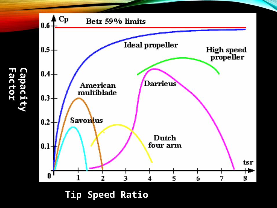
Tip Speed Ratio
Capacity Factor
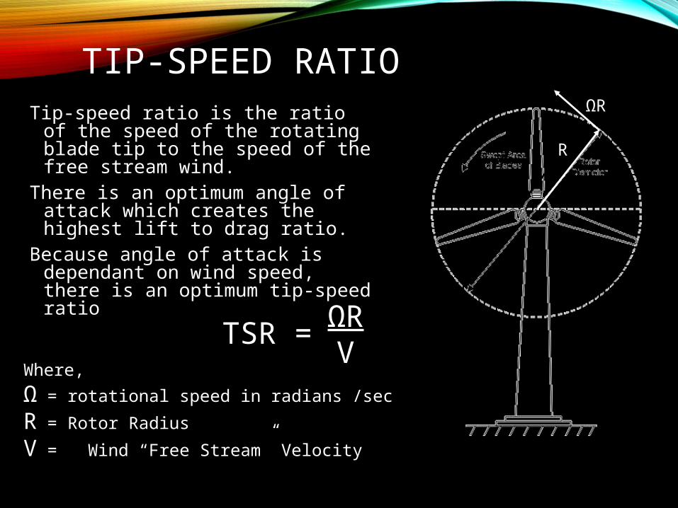
TIP-SPEED RATIOTip-speed ratio is the ratio of the
speed of the rotating blade tip to the speed of the free stream wind.
There is an optimum angle of attack which creates the highest lift to drag ratio.
Because angle of attack is dependant on wind speed, there is an optimum tip-speed ratio
ΩRV
TSR =
ΩR
R
Where,
Ω = rotational speed in radians /sec
R = Rotor Radius
V = Wind “Free Stream” Velocity
ΩR
R
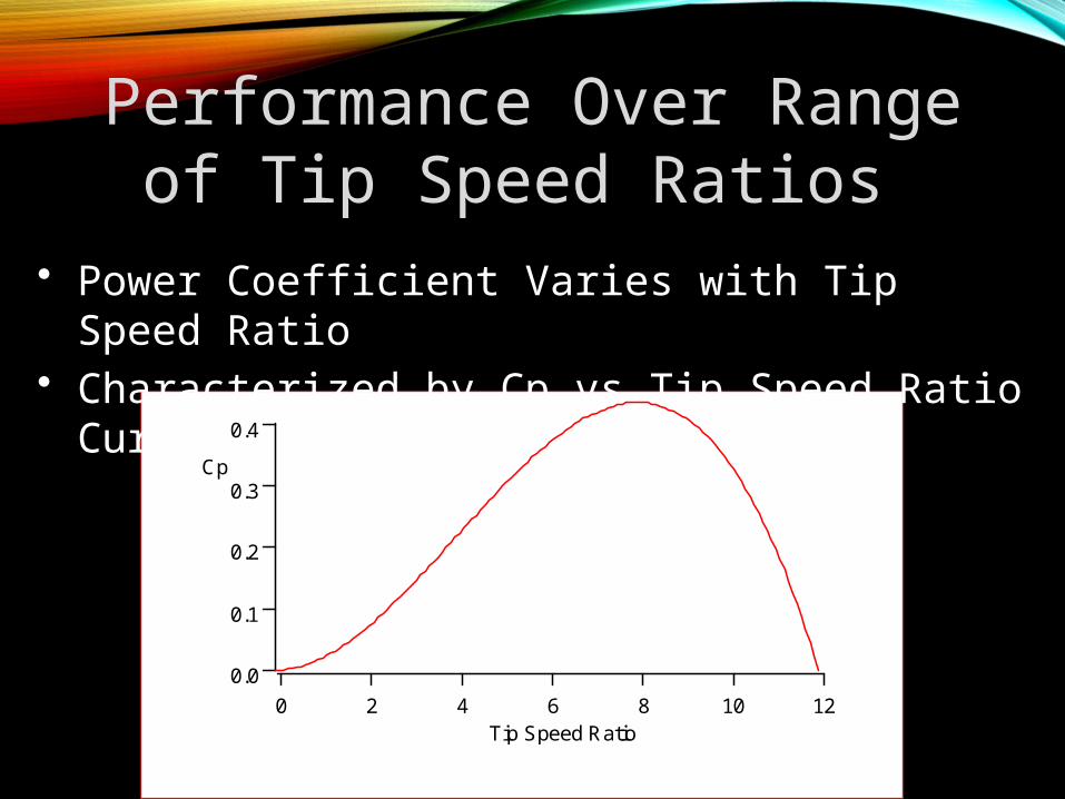
Performance Over Range of Tip Speed Ratios
• Power Coefficient Varies with Tip Speed Ratio• Characterized by Cp vs Tip Speed Ratio Curve
0.4
0.3
0.2
0.1
0.0
Cp
121086420Tip Speed Ratio

TWIST & TAPER
• Speed through the air of a point on the blade changes with distance from hub
• Therefore, tip speed ratio varies as well
• To optimize angle of attack all along blade, it must twist from root to tip

ROTOR SOLIDITY
Solidity is the ratio of total rotor planform area to total swept area
Low solidity (0.10) = high speed, low torque
High solidity (>0.80) = low speed, high torque
R
A
a
Solidity = 3a/A

NUMBER OF BLADES – ONE• Rotor must move more
rapidly to capture same amount of wind
– Gearbox ratio reduced– Added weight of
counterbalance negates some benefits of lighter design
– Higher speed means more noise, visual, and wildlife impacts
• Blades easier to install because entire rotor can be assembled on ground
• Captures 10% less energy than two blade design
• Ultimately provide no cost savings

NUMBER OF BLADES - TWO
• Advantages & disadvantages similar to one blade
• Need teetering hub and or shock absorbers because of gyroscopic imbalances
• Capture 5% less energy than three blade designs

NUMBER OF BLADES - THREE
• Balance of gyroscopic forces
• Slower rotation– increases gearbox &
transmission costs– More aesthetic, less
noise, fewer bird strikes

AIRFOIL SELECTION

BLADE ELEMENT MOMENTUM (BEM) THEORY
• BEM theory is a compilation of both momentum theory and blade element theory.
• Momentum theory, which is useful in predicted ideal efficiency and flow velocity, is the determination of forces acting on the rotor to produce the motion of the fluid.
• Blade element theory determines the forces on the blade as a result of the motion of the fluid in terms of the blade geometry.

ASSUMPTIONS FOR MOMENTUM THEORY
• Blades operate without frictional drag.
• A slipstream that is well defined separates the flow passing through the rotor disc from that outside disc.
• The static pressure in and out of the slipstream far ahead of and behind the rotor are equal to the undisturbed free-stream static pressure (p1=p3).
• Thrust loading is uniform over the rotor disc.
• No rotation is imparted to the flow by the disc.

ASSUMPTIONS FOR BLADE ELEMENT
THEORY• There is no interference between successive
blade elements along the blade.
• Forces acting on the blade element are solely
due to the lift and drag characteristics of the
sectional profile of a blade element.

TIP LOSS FLOW
DESIGN CONSTRAINTS
• SIZE OF THE WIND TURBINE
• HEIGHT OF THE STRUCTURE
• BLADE LENGTH
• NOISE EMISSIONS

BEM RESULTS
• The average wind speed at the maximum allowable height of
11.5 meters is about 5 m/s with a corresponding blade radius
of 2.5 meters.
• The tip speed ratio is initially defined as 7 to get a baseline
value of performance and will be varied in the parametric
study to determine the ideal ratio.
• The coefficient of lift CL is initially defined as 0.88 based on
the value of the coefficient of lift at the maximum glide ratio
(CL/CD).

OPTIMIZED DIMENSIONLESS WIND TURBINE BLADE
GEOMETRY
Blade Segment
- 1 2 3 4 5 6 7 8 9
Relative radius
r/R 0.150 0.250 0.350 0.450 0.550
0.650
0.750
0.850 0.950
Speed ratio X 1.050 1.750 2.450 3.150 3.850
4.550
5.250
5.950 6.650
Angle, optimal
phi 29.069
19.830
14.802
11.742
9.707
8.264
7.190
6.360 5.701
Pitch beta
22.069
12.830
7.802 4.742 2.707
1.264
0.190
-0.640
-1.29
9Rel. chord
lengthc/R 0.18
00.14
10.11
10.09
00.07
50.06
40.05
60.05
00.04
5
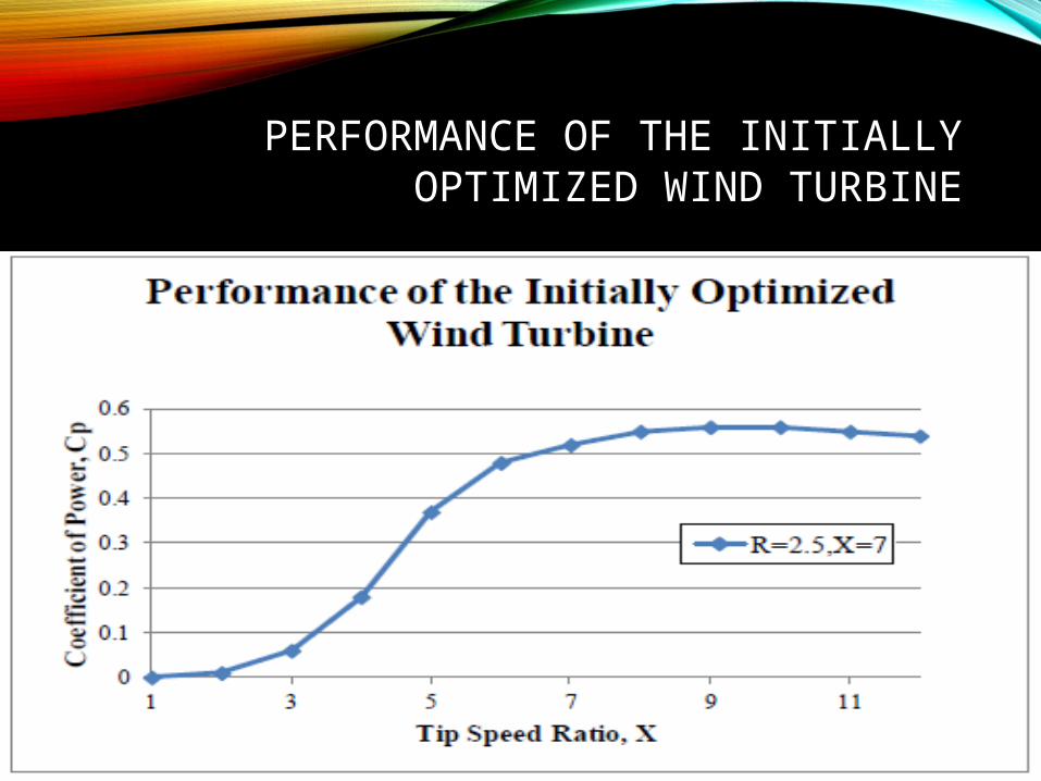
PERFORMANCE OF THE INITIALLY OPTIMIZED WIND
TURBINE
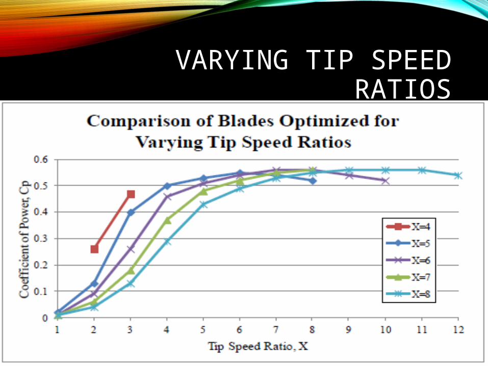
VARYING TIP SPEED RATIOS

VARYING THE AIRFOIL
CONCLUSION
• The tip speed ratio of the turbine should be designed for a tip speed ratio less than what it will be experiencing.
• Blades designed for larger tip speed ratios have a larger range of efficient speed ratios.
• Based on a tip speed ratio of 10 and the conclusions mentioned above, designing the blade for a tip speed ratio of 8 would create the optimal blade.

CONCLUSION
• The allowable size of the turbine creates constraints that reduce the number of parameters required to maximize the efficiency of the turbine.
• For a small wind turbine, the allowable size of the turbine creates constraints that reduce the number of parameters required to maximize the efficiency of the turbine.
• The main parameters constrained due to the size requirement are the length of the blade and the height of the center of the hub. While it was shown that the coefficient of power is not affected by either wind velocity or blade length alone, power output will increase with an increase in both parameters.

FUTURE SCOPE
• The structural modelling can be improved by using realistic models of composite blades where material properties and topology will be considered with greater importance.
• The structural optimization method can be modified using more structural theory models like classical lamination theory, linear (eigenvalue) buckling theory and also some in depth finite- element model analysis.
• Composite layup analysis can be extended for optimization for minimizing blade mass subjected to constraints like maximum allowable laminae stresses, blade tip deflection, panel buckling stresses and separation of blade natural frequencies.

THANK YOU
Related Documents