Design of Steel Structures Prof. Dr. Damodar Maity Department of Civil Engineering Indian Institute of Technology, Guwahati Module - 07 Gantry Girders and Plate Girders Lecture - 02 Design of Gantry Girders Hello, today I will be working out one example. So, once again I am repeating. Hello, in last lecture, we have discussed the design procedures and the different codal provisions on gantry girder. We have seen how to, step by step, design a gantry girder. Today, we will go through one workout example through which we will understand how a design can be made for a particular case. (Refer Slide Time: 01:39) So, let us go through that example. Design a gantry girder for a mill building to carry an overhead travelling crane having the following data. So, crane capacity; so let assume crane capacity as say 190 kilo Newton. And, weight of crane excluding the crab is equal to say 150 kilo Newton; so weight of crane is 150 kilo Newton. And, weight of the rail, this is say 0.2 kilo Newton per meter. And, span of the crane between rails say 14 meter.

Welcome message from author
This document is posted to help you gain knowledge. Please leave a comment to let me know what you think about it! Share it to your friends and learn new things together.
Transcript

Design of Steel Structures
Prof. Dr. Damodar Maity
Department of Civil Engineering
Indian Institute of Technology, Guwahati
Module - 07
Gantry Girders and Plate Girders
Lecture - 02
Design of Gantry Girders
Hello, today I will be working out one example. So, once again I am repeating. Hello, in
last lecture, we have discussed the design procedures and the different codal provisions
on gantry girder. We have seen how to, step by step, design a gantry girder. Today, we
will go through one workout example through which we will understand how a design
can be made for a particular case.
(Refer Slide Time: 01:39)
So, let us go through that example. Design a gantry girder for a mill building to carry an
overhead travelling crane having the following data. So, crane capacity; so let assume
crane capacity as say 190 kilo Newton. And, weight of crane excluding the crab is equal
to say 150 kilo Newton; so weight of crane is 150 kilo Newton. And, weight of the rail,
this is say 0.2 kilo Newton per meter. And, span of the crane between rails say 14 meter.

(Refer Slide Time: 03:40)
And, minimum hook approach say this will be say 1 meter, let us consider. And, wheel
base is 3 meter. And, span of girder is given say 6 meter. And, another thing, height of
the railway section equal to 70 millimeter. And, assume f y say 250 M Pa. And, E value,
let us assume, 2 into 10 to the power 5 M Pa. So, these are the data we have.
(Refer Slide Time: 04:45)
So, what we have seen? That, crane capacity is given 190 kilo Newton; weight of the
crane excluding crab or trolley weight has been given 150 kilo Newton; then weight of
the trolley, 60 kilo Newton; weight of the rail, 0.2 kilo Newton per meter; span of the

crane between the rails, this is given 14 meter; and, minimum hook approach is 1 meter;
wheel base 3 meter; and, span of the gantry girder is 6 meter.
(Refer Slide Time: 05:16)
So, if we draw the diagram of the gantry girder, we will see this span is, crane span is 14
meter. And, weight of the crane excluding the trolley that is 150 kilo Newton. And, the
crane capacity has been given as 190 kilo Newton; so this is 190 kilo Newton. So, let us
put this as A and this is as B this point because we will be requiring to find the moment,
etcetera.
(Refer Slide Time: 05:56)
So, what we will do? Now, we will go for step 1; in step 1, calculate the maximum
vertical load. So, first we will calculate maximum wheel load that will become W c,
weight of the crane that is 150 kilo Newton. And, weight of the trolley was 60 kilo
Newton. So, 190 was the capacity and 60, so 250 kilo Newton. So, this maximum static
wheel load will occur when the crane hook is at a minimum distance of 1 meter means,
because crab will be here, so at a minimum distance of 1 meter it will be occur.
(Refer Slide Time: 06:48)
I can show here that maximum static wheel load at A wheel occur when the crane hook
is at a minimum distance of, a, that is 1 meter because this is minimum hook approach;
minimum hook approach was given 1 meter, so the reaction force R A, we can find out;
one is W c by 2, W c, this is W c; so W c by 2 because this will be acting at a L by 2
distance. So, this will become W c by 2 plus, W c into B minus a by B, sorry, W t into B
minus a by B because the W t is acting where, somewhere here, right.
So, we have to find out the total value as 150 by 2 plus, 250 into 14 minus 1 by, 14, is
the length of the crane. So, after calculating we will get this kilo Newton that is 307.14
kilo Newton. Now, since 2 wheel loads I have at A, so W will become half of this trolley
load. So, W, the value will be becoming half of 307.14 that is 153.57 kilo Newton. So, in
this way we can find out.

(Refer Slide Time: 08:38)
Then what we will do? We will go to step 2. In step 2, what will be that calculate
maximum bending moment due to vertical load. Now, we will calculate the maximum
bending moment due to the vertical load. Maximum bending moment again, we know we
have to find out the position where the maximum bending moment will occur; the worst
condition we have to consider.
So, first is static wheel load is given say 153.57 kilo Newton. And, we can add some
impact allowance; so 25 percent additional load, additional 25 percent of the static load
that is; so 25 percent means 25 by 100 into 153.57. So, this will be becoming 38.39 kilo
Newton. So, the total load will become 153.57 plus 38.39 kilo Newton. So, this will be
the total load. So, this value is becoming 191.96 kilo Newton.
Now, wheel base is given; wheel base length that b is given, 3 meter; and, span of the
girder, span was given 6 meter. Now, we have to check whether it is, means where the
maximum load will come that has been given; that whether it is 0.586 L, greater than
0.586 L or less than 0.586 L; that we have to check and accordingly we have find out.
So, what is the value of 0.586 L, we have to find out.

(Refer Slide Time: 10:51)
So, 0.586 L will become 0.586 into 6; that is 3.516 meter. So, static wheel load we have,
we have the total load due to impact, and now we have seen that b is the base is 3 meter.
(Refer Slide Time: 11:15)
And, we can now check that b is less than 0.586 meter, 0.586 into L meter because this
value is, this is, b is 3 meter, and this is coming 3.156 meter. So, since b is less than this,
maximum bending moment will occur when center of span is midway between CG of
loads and one wheel load. Now, so in this way we can make it; I will come with this

picture. Hence, the distance of one wheel from center will become, half into b, that is,
half into 3, that will be 0.75 meter.
(Refer Slide Time: 12:13)
So, let we draw the picture first then we will understand. Say, this is 6 meter, say let us
give the point C and D, say this is the span of the girder. Now, CG distance is here; that
means, this is 3 meter, this is 3 meter. Now, wheel load has to be placed in such a way
that the CG of the wheel load and CG of the span will be at the middle of, from one load,
means from one wheel, say this is the wheel.
So, this is 3 meter, wheel base is 3 meter. So, the wheel base CG is here and CG of the
span is here. So, the CG has to be middle in between one wheel and CG of the wheel.
This is the condition where the maximum moment will develop, what we have discussed
yesterday. So, this will become b by 2, this will become b by 2. So, b by 2 will become
how much, sorry, this will become b by 2, so this will become b by 4 and b by 4.
So, b by 4 will be becoming b is 3 meter by 4, so 0.75 meter; that means, one wheel has
to be placed at a distance of 0.75 meter from CG of the span. So, this is the 0.75 meter.
So, if we keep this, then only we will get the maximum bending moment. And, W we
have calculated; they are 2, sorry, 2 base load means 2 wheel load is calculated; let us
say 191.96 kilo Newton, and this is 191.96 kilo Newton. So, in this way we can make it.
Now, other things we have to calculate. So, this is how 0.75 meter has come. And, other
thing is that this should be half of half, right. So, now if the self weight as we have

considered earlier that is 2 W by 250. So, 2 into, W was given, W we have calculated
here. So, from this we can find out, 2 W by 250. So, that is 1.535 kilo Newton per meter.
The self weight has been assumed as per the discussions in earlier lecture we have seen
that that will be 2 W by 250. So, W has been calculated earlier. So, from that we can find
out the self weight; self weight means approximate self weight of the girder that is 1.535
kilo Newton per meter.
And, weight of rail also let us assume; let us say 0.2 kilo Newton per meter; weight of
rail we are assuming 0.2 kilo Newton per meter. So, the total UDL load will become W 1
plus W 2 that is 0.2 plus 1.535, that is becoming 1.735 kilo Newton per meter. So, the
UDL load we are going to get, 1.735 kilo Newton per meter that is throughout the girder
it is there. So, another load will come into picture like this, that is 1.735 kilo Newton per
meter. So, this is another load. So, this will be the position of vertical load for maximum
bending moment. So, this is how we can find out.
(Refer Slide Time: 17:00)
So, that we have drawn here; that again I am just repeating. That, here W will be 191.96
kilo Newton, the wheel load. Similarly, here 191.96 kilo Newton; and, this is 1.735 kilo
Newton per meter which has been calculated. And, this value is 0.75 meter. And, this is,
again if we calculate, this would be also at 0.75 meter; and this should become 2.25
meter. So, these are the diagram we can have.
Now, what we will do? We will calculate the maximum bending moment. So, maximum
bending moment will occur in this way. So, first to calculate the maximum bending

moment we have to find out, if this is C and if this is D, we have find out the reaction
forces here, then we can find out the value.
(Refer Slide Time: 18:09)
So, what will be the reaction forces? Say, R D. R D will be what? So, to find out reaction
forces at D, let us take moment about C. So, then what will happen? R D into will be
equal to this all load, we have to take moment about this, right. So, RD into 6 equal to
1.735 into 6, mean W l square by 2 into, 6 into, 6 by 2; this is 1; plus, sorry, plus 191.96
into 0.75 plus, 3.75. How it is coming?
See, 0.75 is this one, for this load this is 0.75, and for this load this will become 0.75 plus
3, so 3.75, right. So, taking moment about C, we can find out R D into 6 is equal to this.
So, from this I can find out R D. R D value will become 149.175 kilo Newton, right.
And similarly, R C, I can find out now. If I take moment about D, we can find out R C
which will become, 1 by 6, similar way, 1.735 into, 6 into, 6 by 2 plus, 191.96 into, 2.25
one, another will be 5.25, from D point. So, this is becoming 245. 15; otherwise, we can
make summation of v, mean summation of F v, right; that summation of F v means the
total load along vertical direction. So, we know total load is this one plus, this one plus,
this into L. So, that minus R D will become R C. So, this way also we can find out. So,
total load on the girder, we can find out that will be becoming basically, R C plus R D;
that will be 149.175 plus 245.15, right. So, if we add, this should become, total of it will
become 394.325. So, this is the total load on the girder, right.
(Refer Slide Time: 21:32)
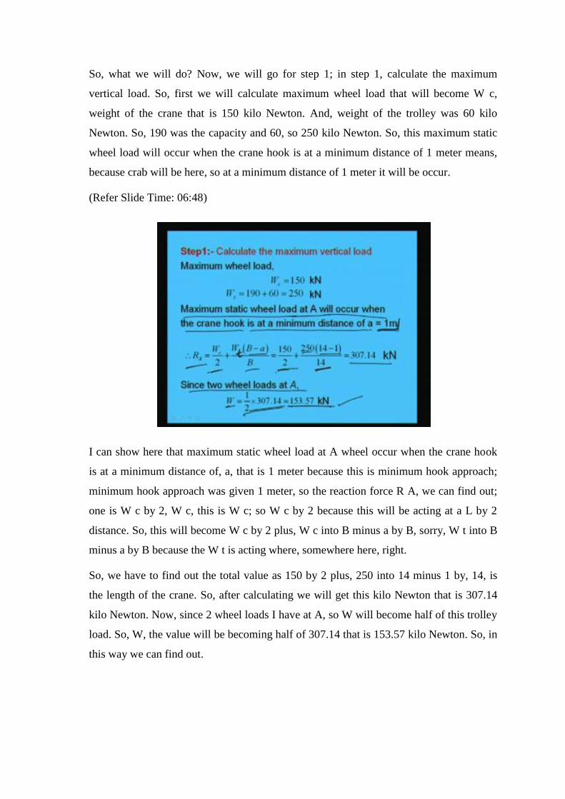
Similarly, we can find out the moment. Now, maximum moment we can find out. So, the
moment we are going to get the total load we can find out maximum moment; maximum
moment will be how much? That R D into 2.25, because maximum moment will develop
here; so R D into 2.25 minus, W l square by 2, 1.735 into, L is 2.25 by 2. So, from this I
can find out maximum moment as 331.25 kilo Newton meter. So, in this way we can find
out maximum moment.
How we found? The reaction force at D we know, so R D into that distance where the
maximum moment is coming minus, the downward load that is W l square by 2, right.
So, in this way we can find out the maximum moment. And, where the maximum
moment will occur, that we understood now; the position how it has been made, now I
think we have understood.

(Refer Slide Time: 22:32)
So, we will go step 3; in step 3 we will select a suitable section. That means, to select
suitable section what we will do? Sigma b t will be 165 M Pa we will assume; sigma b t
we will assume 165 M Pa. So, we can find out z required; z required will be M by sigma
b t. So, M maximum moment we already found, 331.25 kilo Newton meter that is 33; so
331.25 kilo Newton meter into 10 to the power 6 will become Newton millimeter by 165.
So, this will become 2007575.7 millimeter cube. So, the required z we have.
Now, as we know we have to increase little higher section because the finally, we have
to find out a composite section means combined section, right. And, also the sigma b c
value will be less because the beam is laterally unrestrained. So, from compression point
of view it will not be safe if we consider the same. So, now we will increase say 15
percent let us increase. So, z will be 1.15 into z required, means 15 percent we are going
to increase. So, this will become 2308.7 into 10 to the power 3 meter millimeter cube.
So, now what we will do? Now, let us see what type of section we can use. Say, let us
use I S, means I section let us use; say with this z value if we go through the S P 6, we
will see that I S W B 600 maybe one of them which we can try. So, let us try with I S W
B 600 at 133.7 Kg per meter. So, this sections we are going to try, where z x is equal to
3450 into 10 to cube millimeter.
You see that we have taken little higher side because as we know that we have to check
lot of things; we have to check not only for bending stress in tension, but also for
bending stress in compression with unrestrained, laterally unrestrained. Then again
combinedly with the horizontal load, vertical load plus horizontal load that also we have
to check. Then again, shear stress we have to check. So, once if we take as little lesser
value means little close to the required value then it may not be safe.
So, here for the sake of making safety, means to make all the things safe, let us consider
little higher value, so that all the things will be under safe, right. However, for practical
purpose of design we can check with a lower value whether it is ok or not to safe the
means to make the size economic.
(Refer Slide Time: 26:21)
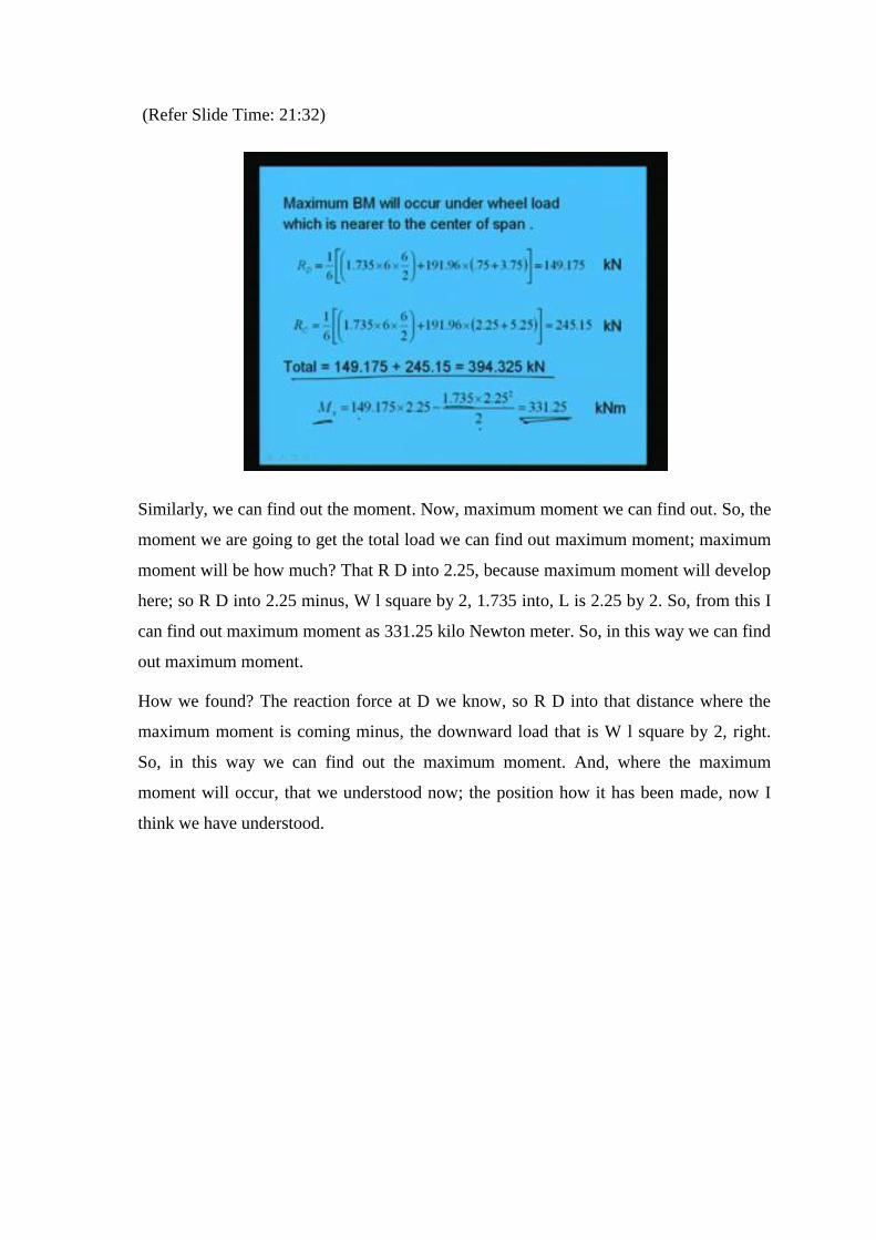
Next, what we will do? We will find out other values like I x x, that is 106198.5 into 10
to the power 4. So, from S P 6, the structural handbook, we can find out the required
value of the section. So, I x x is there which was given; I y y is given 4702.5 into 10 to
the power 4, this is 10 to the power 4 millimeter to the power 4, right. . So, this has been
also given.
Other things are like, a, area of the section has been given, 17038 millimeter square. D,
the depth, overall depth is given 600 because I S W B 600 we are using; b is given 250
millimeter; and, t f, the thickness of flange, t f that is given 21.3 millimeter; and, t w is
given as 11.2 millimeter. Also, we have to provide a channel and as we told that if I
section is having some b width, then channel depth has to be little higher size, and
around 50 millimeter higher as we told earlier.

So, considering this into mind, let us say I S M C 300 say at 35.8 kg per meter. So, what
we did? That, as the flange width of the I section is 250 millimeter, so atleast we should
choose I S M C, means channel section 300 millimeter because flange, means channel
section depth has to be atleast 50 millimeter higher than the width of the flange of the I
section.
So, if, as width is 250, we are going to consider 350; so this is 25 and this is 300. So, 50
millimeter higher we are making. So, from this, again we can find out I x x for channel
section; that will be 6362.6 into 10 to the power 4 millimeter to the power 4, this is
given. Similarly, I y y c, that is given 310.8 into 10 to the power 4 millimeter to the 4;
and, C y y for channel that is given 23.6 millimeter; and, thickness of web of the channel
is given 7.6 millimeter; and, area of channel is given 4564 millimeter square.
So, these are the values which are given in S P 6, we need for the calculation of the
combined properties. Like, I x x c, means the moment of inertia about x x of the channel,
6362.6; and, I y y is 310.8 into 10 to the power 4 millimeter between the millimeter to
the power 4; C y y that is 23.6 millimeter; and thickness of the web is given 7.6
millimeter; and, area of the channel is given 4564 millimeter square. So, with this now
we have to calculate the neutral axis of the combined section, neutral axis and the
moment of inertia and other things of the combined section.
(Refer Slide Time: 30:45)
So, what will be the combined section? How it looks like? Say, this is the I section we
have chosen; this is the I section. Then, we are providing channel section, sorry, right;

this is the channel section which is placed at the top. Now, we know all the dimensions
of the I section as well as the channel section. Say, this is 250, and this is the thickness of
the flange that is given 21.3 millimeter. And then thickness of the web also is given, that
is 11.2 millimeter. And, this total distance is, this is 600 millimeter; and this is 300
millimeter.
And now, other things are like this depth web, thickness of the web of the channel that is
given 7.6 millimeter. So, with this we have to find out the neutral axis. So, neutral axis
we will find out now; yes, this is gantry girder; so neutral axis we have to find out. Now,
overall depth how much it is coming here for the section? Overall depth will be 600 plus
7.6; that is 607.6. Now, we have to find out the neutral axis depth. Say, this is neutral
axis depth; say this y bar; the distance from top place to the neutral axis there, right. So,
this we have to find out. Now, this is placed, remember, the centrally; that means, it will
be 150, and this will be also 150, placed centrally.
(Refer Slide Time: 33:42)
Now, so what we will do? We will calculate the neutral axis and moment of inertia. So,
if we see, the y bar will become area of channel into C y y because we know the center
of gravity of the channel is C y y, CG distance. Then, plus area of web into h by 2; h is
the depth of the I section plus, t w c; t w c means thickness of the web of the channel by,
a plus ac; a is the area of the channel, I am sorry, ac is the area of the channel and a is the
area of the I section.

So, how we are getting that we are taking moment about this. So, if we take moment
about this, what will happen? Total area into y bar is equal to this area, area of channel
into its CG distance, and then area of web, area of I section into its CG distance; that is
300, CG distance will be 300 from top and 300 from bottom. But from top because of
presence of channel it will be 300 plus 7.6.
So, now if we make this is 7.6; so area of channel section into its CG distance 23.6 which
is given. Then, area of I section into, CG distance that will become 300 plus channel, so
this one; and the area will be divided. Now, from this we can find out y bar as 247.6
millimeter. So, y bar is becoming 247.6 millimeter.
So, how do we get, I think it is clear to you; that we are taking moment about, moment
area about this, about top flange, then we are getting the neutral axis of the combined
section. So, from here it is 300; now this is 247.6, so we can find out this value also. So,
this value will become, now we can find out that 607.6 minus 247.6 because total depth
is 607.6, and neutral axis from top is 247.6. So, this will be, neutral axis from bottom
will be this one; so that we can find out.
So, y t will become, means from tension side that will become 600 plus 7.6, means 607.6
minus, this. So, this will become 360; so this is becoming 360. So, this is called y t, and
this is called y c; y t means the in tension zone, and y c is in compression zone. The
depth of the neutral axis in compression zone means this one, and this will be the y t for
tension zone. So, in this way we can find out the neutral axis.
(Refer Slide Time: 37:46)

Now, we can find out I x x. I x x will be how much? Moment of inertia of the combined
section. So, if we calculate moment of inertia of the combined section, what will happen?
That, if we see here, this is the I section and another is as, sorry; this is I section and this
is channel section. So, when we are going to find out moment of inertia about the
combined section, what will happen?
This is the neutral axis shifted from here because of combined action. So, because of
shifting, what we are doing? I x x will be I x x about its own axis plus, area into r square
means shifting, because of shifting; this is the r; r value will become, how much? 307.6
minus 247.6, how? If you see the diagram, this is 307.6; this total distance if we see, this
total distance is 300 plus 7.6, that means, 307.6; and this is 247.6.
So, this distance will become 307.6 minus 247.6. So, shifting of moment of inertia from
neutral axis of its individual to neutral axis of the combined one; so for that we are
making in this way, 307.6 minus 247.6 whole square. So, I x x equal to I x x dash plus a
r square. So, this is the moment of inertia about the CG of the combined section due to
the I section, similarly due to the channel section, this is the due to the channel section.
In case of channel section, we have to see this is the I and that will be I y y, whatever I y
y will be here I x x. So, 310.8 is the I y y value of the channel section that has been taken
because I x x is generally taken in this way, I y y is taken in this way. So, as it has been
rotated, so I y y will become I x x, and I x x will become I y y.
So, I y y plus area into r square, r square means just shifting because shifting is we know
the CG distance of the channel section; suppose CG distance of the channel section is
here, so because of shifting we know. So, total minus this will become r square; so 4564
into 247.6 minus 23.6 whole square. So, this will finally, become 112332 into 10 to the
power 4 plus, 23211 into 10 to the power 4 millimeter to the 4. So, if we add, finally we
will get, 135543 into 10 to the power 4 millimeter to the 4. So, I x x we are getting, I x x
means I x x of the combined section.
So, step 4 is over, now will go for step 5. In step 5, what we will do? We will find out the
stress that is bending stress, bending tensile stress, and we will check for that. Bending
tensile stress we know, we can find out sigma b t cal; sigma b t calculate will be M x by I
x into y t; y t is the distance from CG of the combined section to the extreme fiber of the
tensile zone, y t.

So, we can find out, that is 331.25 into 10 to the power 6 by I x; that is 135543 into 10 to
the 4 into y t; y t is 360 that we found earlier, this 360 y t value. So, from this I can find
out the value as 87.98 Newton per millimeter square which is less than 0.66 f y that is
165 M Pa. So, as it is less than 0.66 f y we can say this is safe. So, from bending tensile
stress point of view the chosen section is safe.
(Refer Slide Time: 43:16)
Next, what we will do? Next we will go for compression one. So, for compression one
what we will do? We will determine the sigma b c for the whole section. Now, this is a
new thing which we have not discussed earlier; new things means we have not worked
means we have not done any example, means how to find out sigma b c, why? Because
this is not only the beam is unrestrained against lateral direction, but also the beam is not
symmetric; the cross section of the beam is not symmetric.
So, because of that we have to find out from the formulas. In case of equal flanges with
unrestrained beam we have the tabular form results in the IS code in table 6.1 to 6, 6.1 A
to 6.1 F, but in this case we have to find out. So, for that let us see So, for whole section
first we will find out say I y; I y means we have the section and we have the channel
section. So, I y in this direction let us find out.
So, what will be in this direction I y y of I section, that is 4702.5 into 10 to the 4 plus, I y
y of, means I x x of channel section. So, simply because CG of the combined section is
not going to change along y axis; in y direction CG of the combined section is not going

to shift. So, simply, the summation of the 2 I, means 2 section of I values can be made.
So, this is becoming 11065.1 into 10 to the power 4 millimeter to the 4, right.
Now, I y of the compression of the flange about Y-Y of the whole section; now, again
we will find out the I y of the compression flange; that is, we know this is I section, this
is neutral axis, sorry, neutral axis, right. So, we will find out what is the I y y value of
this compression flange because that is required also as we have seen yesterday, this
value is required to find out the stresses, so I y in compression flange. So, that will
become how much? Half of 4702.5 into 10 to the power 4 plus, 6362.6; 6362.6 is this
one, and half of the I section. So, this is becoming 8713.85 into 10 to the power 4. So, I
y, in compression flange is becoming 8713.85 into 10 the power 4 millimeter to the
power 4.
Now, what we have to find out? We have to find the ratio. The ratio of the moment of
inertia of compression flange alone to that of the summation of the flanges, so that
omega would become I Y C F by I Y. So, I Y C F is 8713.85 into 10 to the power 4, and
I y is 11065.1 into 10 to the power 4. So, the ratio is becoming 0.788.
(Refer Slide Time: 47:17)
So, on that ratio we can find out from table 6.4 of IS 800: 1984, the value of K 2. Now,
value of K 2 against this omega can be find out from table 6.4 which is given 0.288. So,
this has been given. Now, r y, we can find out; r y is I Y by A, and I y y and A are
already calculated. I y y was calculated as from this formula I y, that is 11065.1 into 10
the power 4. So, I y y is, I y is 11065.1 into 10 to the power 4; and area is, total area, area

of I section plus area of channel section. So, square root of I y by A is equal to becoming
71.57 millimeter. So, the r y, radius of gyration about y axis we are going to get as 71.57
millimeter.
Now, assuming the end of the girder to be restrained against torsion, but no lateral
restraint; that means, for that L will become, this effective length will become the total
length that is 6 meter because we have to find out the slenderness ratio: l by r y. So, the
moment we find out the slenderness, means effective length, we can find out the
slenderness ratio as l by r y; l is 6000 millimeter, r y is 71.57. So, we can find out the
value lambda as 83.83, the slenderness ratio now we are finding out as 83.83.
(Refer Slide Time: 49:25)
Now, as we know, y c is 247.6; that means, y c which one, and if we draw the combined
section, this is y c, and nothing but this is called in code at C 1, and this is y t as C 2. So,
C 1 is given as this value, C 2 is given as this value, and from that we can find out psi as
1. If we see the table in IS code we will find out the k 1 value as 1. And, this Y value
which was given in the formula that 26.5 into 10 to the power 5 by, l by r y whole
square. So, that also we can find out from this formula as this. So, Y is getting as 377.1.
And overall depth of the section as we have calculated, overall depth of the section will
be 600 plus, the web thickness of the channel that is 7.6; so that is 607.6 millimeter. So,
overall depth of the section we have 607.6 millimeter.
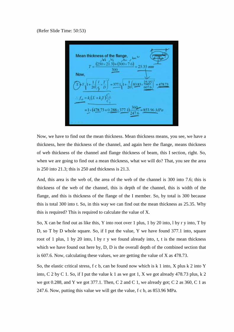
(Refer Slide Time: 50:53)
Now, we have to find out the mean thickness. Mean thickness means, you see, we have a
thickness, here the thickness of the channel, and again here the flange, means thickness
of web thickness of the channel and flange thickness of beam, this I section, right. So,
when we are going to find out a mean thickness, what we will do? That, you see the area
is 250 into 21.3; this is 250 and thickness is 21.3.
And, this area is the web of, the area of the web of the channel is 300 into 7.6; this is
thickness of the web of the channel, this is depth of the channel, this is width of the
flange, and this is thickness of the flange of the I member. So, by total is 300 because
this is total 300 into t. So, in this way we can find out the mean thickness as 25.35. Why
this is required? This is required to calculate the value of X.
So, X can be find out as like this, Y into root over 1 plus, 1 by 20 into, l by r y into, T by
D, so T by D whole square. So, if I put the value, Y we have found 377.1 into, square
root of 1 plus, 1 by 20 into, l by r y we found already into, t, t is the mean thickness
which we have found out here by, D, D is the overall depth of the combined section that
is 607.6. Now, calculating these values, we are getting the value of X as 478.73.
So, the elastic critical stress, f c b, can be found now which is k 1 into, X plus k 2 into Y
into, C 2 by C 1. So, if I put the value k 1 as we got 1, X we got already 478.73 plus, k 2
we got 0.288, and Y we got 377.1. Then, C 2 and C 1, we already got; C 2 as 360, C 1 as
247.6. Now, putting this value we will get the value, f c b, as 853.96 MPa.

(Refer Slide Time: 54:06)
So, now again T by t w ratio will become the, this 25.35 by 11.2, that is 2.26. So, f c b,
should not be increased by 20 percent because of this. So, sigma b c can be calculated
from this formula, that is 0.66 into, f c b into f y by, f c b to the power n plus, f y to the
power n, whole to the power 1 by n. So, in this way sigma b c can be found.
So, what will be the sigma b c? That is 0.66 into, f c b value is 853.96 into 250 by, f c b
853.96 whole to power 1.4 plus, 250 whole to the power 1.4, whole to the power 1 by 1.4
which is becoming 146.68 MPa. So, we are getting sigma b c value that is permissible
bending stress in compression as 146.68 MPa.
(Refer Slide Time: 55:16)

So, what we will do now? Now, we will go for step 6 to check compressive stress,
permissible bending compressive stress. So, bending compressive stress will be, M x by I
x into y c. Now, M x is 331.25 into 10 to the power 6; I x is 135543 into 10 to the power
4 into, 247.6 is y c. So, this is becoming 60.51 which is less than sigma b c because
sigma b c value we got 146.68. So, from compressive stress point of view also the
section whatever we have chosen is ok.
(Refer Slide Time: 56:04)
Next, we will calculate the bending moment due to horizontal load; so bending moment
due to horizontal load that will be F H equal to 1 by 10 into, 60 plus 190, so 25. And, W
H will become F H by 2, that is 25 by 2 is equal to 12.5. So, the arrangement of wheel
load for the maximum bending moment due to horizontal loads will be the same as that
for the vertical load, means the whatever arrangement we have done for vertical load, the
same arrangement will be working for the horizontal load to get the maximum bending
moment. So, we can find out the maximum bending moment and for that we can find out
the horizontal reaction force R H; that will be simply 1 by 6 into 12.5 into 0.75 plus 3.75
is equal to 9.375, right. So, RH we got.

(Refer Slide Time: 57:04)
Now, what we will do? Now, M y, M y we can find out from this that is 9.375 into 2.25
which will be equal to 21.1 kilo Newton meter. Now, we can calculate the compressive
stress due to horizontal loading. So, we know I Y C F, so we can find out, sigma b c cal
horizontal; that will be M y by I Y C F into, h c by 2. That is, 331.25 into 10 to the power
6 by, 135543 into 10 to the power 4 into, 300 by 2 which is coming 36.66 MPa.
(Refer Slide Time: 57:46)
So, now what we will do? We will check for the combined, means for the vertical load
and for horizontal load, what is the stresses are coming, that stress has to be less than, 1.1

sigma b c, as per the codal provision as we have discussed earlier. So, sigma b c cal
vertical and sigma b c cal horizontal is becoming 60.51 plus 36.66 that is 97.17. And,
permissible value will become 10 percent more than the calculated one; so 1.1 into
146.68. So, that is becoming 161.348 MPa. So, this is becoming 97.17, hence it is safe.
(Refer Slide Time: 58:32)
Now, we will calculate the stress due to longitudinal force. So, due to longitudinal force
F L H will be the 5 percent of the total wheel load; so 0.05 into, 2 into, wheel load
191.96; so this is becoming 19.196. Similarly, M L H will become F L H into, h r plus y
c. So, this value will become 6.096 into 10 to the power 6 Newton millimeter, where h r
is the height of the rail.

(Refer Slide Time: 59:07)
So, we can find out the stress in longitudinal direction from this formula - F L H by A
plus, M L H by I x into y c. And, we will find the value as 1.99 MPa which is very small,
as we told that this stress is becoming very small.
(Refer Slide Time: 59:23)
So, next in step 11, what we will do? We will check for shear; and because of shortage of
time I am not going to calculate that; you can do as I have discussed in last lecture, check
for shear stress, then the pitch of the rivet, that also we can find out.

(Refer Slide Time: 59:51)
So, with this we will get the pitch, just I am showing; the pitch can be find out as this.
Pitch will become, if you calculate you will get maximum permissible spacing is 12 into
t; so 91.2. So, we are providing 25 PDS in 2 rows at a staggered pitch of 90 millimeter.
As I told, the example is very big. So, it is difficult to conclude, to complete in one
lecture. However, I hope you have understood the process; and, the remaining 2 steps if
you do at your own you will be able to do. So, with this I like to conclude today’s
lecture.
Thank you very much.
Related Documents