Hindawi Publishing Corporation International Journal of Antennas and Propagation Volume 2013, Article ID 713680, 9 pages http://dx.doi.org/10.1155/2013/713680 Research Article Design of Fully Digital Controlled Shaped Beam Synthesis Using Differential Evolution Algorithm D. Mandal, 1 A. Chatterjee, 2 and A. K. Bhattacharjee 3 1 Department of Electronics and Communication Engineering, Bengal College of Engineering and Technology, West-Bengal, Durgapur-713212, India 2 Department of Electronics and Communication Engineering, Dr. B. C. Roy Engineering College, West-Bengal, Durgapur-713206, India 3 Department of Electronics and Communication Engineering, National Institute of Technology Durgapur, West-Bengal, Durgapur-713209, India Correspondence should be addressed to D. Mandal; [email protected] Received 20 August 2013; Revised 3 October 2013; Accepted 3 October 2013 Academic Editor: Dau-Chyrh Chang Copyright © 2013 D. Mandal et al. is is an open access article distributed under the Creative Commons Attribution License, which permits unrestricted use, distribution, and reproduction in any medium, provided the original work is properly cited. A shaped beam synthesis from a concentric ring array has been presented. Two different cases are considered. In the first case, a flat-top beam pattern and, in the second case, a cosec 2 beam pattern have been generated. In both the cases, it has been ensured that the obtained beam patterns are not restricted in any single predefined -cut of the patterns; rather, their characteristics are retaining within a range of predefined -planes with some minor variations. e desired beam pattern under each of the individual case is obtained by finding optimum discrete excitations of the array elements. e optimum 4-bit amplitudes generated by four-bit digital attenuators and 5-bit phases generated by 5-bit digital phase shiſters are computed using Differential Evolution (DE) Algorithm. To illustrate the effectiveness of DE, the two beam patterns with specified characteristics are computed from the same array using Particle Swarm Optimization (PSO) algorithm and Genetic algorithm (GA) by finding out optimum discrete excitations among the elements. Results clearly show the superiority of DE over PSO and GA to handle the presented problem. 1. Introduction In mobile, satellite, and radar communication the impor- tant parameters are signal quality, system coverage, spectral efficiency, and so forth. To achieve these, efficient antenna design is the primary requirement. Antenna array synthesis is required to find radiation patterns from different array geometry and make these obtain patterns closer to their desired patterns either by varying its elements amplitude and phase or by reconfiguration of the array geometry. In various applications shaped beams are oſten required but major problems faced by shaped beams are high side lobe level and ripple. To minimize high sidelobe and ripple, an efficient evolutionary optimization algorithm has been chosen which is able to find out 4-bit optimum discrete elements amplitude and 5-bit optimum discrete phases of the array elements to achieve the desired shaped beam. Several approaches reported in the literature for generating shaped beams [1–6] are as follows. Azevedo proposed a technique based on FFT to generate shaped beams of cosec and flat-top pattern from a linear array antenna through the control of nonuniformly samples of the array factor, both in amplitude and phase [3]. Lei et al. generate low sidelobe cosecant square-shaped beam from linear antenna array by finding optimum amplitudes and phases of the array elements using the modified least square method [4]. Chatterjee et al. [5] proposed a technique based on finding optimum phases of the array elements modifying which over existing “zero” phases generates two different patterns. e search has been carried out using Gravitational Search Algorithm (GSA) [5]. In [6], a new technique has been proposed by Chatterjee et al. for obtaining dual beam pair where the states (“on/off ”) of the array elements are modified using Firefly Algorithm (FA) for generating two different beam pairs. e method greatly simplified the design of the feed network [6]. e paper presents shaped beam synthesis of two ring concentric array of isotropic elements. Two different cases

Welcome message from author
This document is posted to help you gain knowledge. Please leave a comment to let me know what you think about it! Share it to your friends and learn new things together.
Transcript
Hindawi Publishing CorporationInternational Journal of Antennas and PropagationVolume 2013 Article ID 713680 9 pageshttpdxdoiorg1011552013713680
Research ArticleDesign of Fully Digital Controlled Shaped BeamSynthesis Using Differential Evolution Algorithm
D Mandal1 A Chatterjee2 and A K Bhattacharjee3
1 Department of Electronics and Communication Engineering Bengal College of Engineering and TechnologyWest-Bengal Durgapur-713212 India
2Department of Electronics andCommunication Engineering Dr B C Roy Engineering CollegeWest-Bengal Durgapur-713206 India3 Department of Electronics and Communication Engineering National Institute of Technology Durgapur West-BengalDurgapur-713209 India
Correspondence should be addressed to D Mandal debmandal22gmailcom
Received 20 August 2013 Revised 3 October 2013 Accepted 3 October 2013
Academic Editor Dau-Chyrh Chang
Copyright copy 2013 D Mandal et al This is an open access article distributed under the Creative Commons Attribution Licensewhich permits unrestricted use distribution and reproduction in any medium provided the original work is properly cited
A shaped beam synthesis from a concentric ring array has been presented Two different cases are considered In the first case aflat-top beam pattern and in the second case a cosec2 beam pattern have been generated In both the cases it has been ensured thatthe obtained beam patterns are not restricted in any single predefined 120593-cut of the patterns rather their characteristics are retainingwithin a range of predefined 120593-planes with some minor variations The desired beam pattern under each of the individual case isobtained by finding optimum discrete excitations of the array elementsThe optimum 4-bit amplitudes generated by four-bit digitalattenuators and 5-bit phases generated by 5-bit digital phase shifters are computed using Differential Evolution (DE) AlgorithmTo illustrate the effectiveness of DE the two beam patterns with specified characteristics are computed from the same array usingParticle Swarm Optimization (PSO) algorithm and Genetic algorithm (GA) by finding out optimum discrete excitations amongthe elements Results clearly show the superiority of DE over PSO and GA to handle the presented problem
1 Introduction
In mobile satellite and radar communication the impor-tant parameters are signal quality system coverage spectralefficiency and so forth To achieve these efficient antennadesign is the primary requirement Antenna array synthesisis required to find radiation patterns from different arraygeometry and make these obtain patterns closer to theirdesired patterns either by varying its elements amplitudeand phase or by reconfiguration of the array geometry Invarious applications shaped beams are often required butmajor problems faced by shaped beams are high side lobelevel and ripple To minimize high sidelobe and ripplean efficient evolutionary optimization algorithm has beenchosen which is able to find out 4-bit optimum discreteelements amplitude and 5-bit optimum discrete phases of thearray elements to achieve the desired shaped beam Severalapproaches reported in the literature for generating shapedbeams [1ndash6] are as follows
Azevedo proposed a technique based on FFT to generateshaped beams of cosec and flat-top pattern from a lineararray antenna through the control of nonuniformly samplesof the array factor both in amplitude and phase [3] Lei et algenerate low sidelobe cosecant square-shaped beam fromlinear antenna array by finding optimum amplitudes andphases of the array elements using the modified least squaremethod [4] Chatterjee et al [5] proposed a technique basedon finding optimum phases of the array elements modifyingwhich over existing ldquozerordquo phases generates two differentpatterns The search has been carried out using GravitationalSearchAlgorithm (GSA) [5] In [6] a new technique has beenproposed by Chatterjee et al for obtaining dual beam pairwhere the states (ldquoonoffrdquo) of the array elements are modifiedusing Firefly Algorithm (FA) for generating two differentbeam pairs The method greatly simplified the design of thefeed network [6]
The paper presents shaped beam synthesis of two ringconcentric array of isotropic elements Two different cases
2 International Journal of Antennas and Propagation
025 075 125 175minus175
minus125
minus075
minus025
025
075
125
175
minus175 minus125 minus075 minus025
Y[in
term
s of120582
]
X [in terms of 120582]
Figure 1 Concentric ring array of isotropic antennas in119883-119884 plane
minus20minus18minus16minus14minus12minus10minus8minus6minus4minus2
0
Flat-top (Case I)cosec2 (Case II)
minus90 minus75 minus60 minus45 minus30 minus15 0 15 30 45 60 75 90120579 (deg)
|D(120579120593)|dB
120593 isin (0ndash10) degree plane
Figure 2 Desired patterns under two different design cases
have been considered In the first case a flat-top beam isgenerated from the presented array by finding optimum 4-bit amplitudes and 5-bit phases and in the second case acosec2 pattern is generated from the same array by findingout another optimum 4-bit amplitudes and 5-bit phasesof the elements In both the cases the optimum discreteexcitations are computed in such a manner that the obtainedpatterns are retaining their desired characteristics within arange of predefined 120593-planes with some minor variationsThe optimum discrete amplitudes and phases for the twodifferent cases are computed using Differential Evolution(DE) algorithm [7ndash11] To illustrate the effectiveness of DEthe shaped beams under two different cases are computedseparately following the above procedure from the same arrayconfiguration using Particle Swarm Optimization (PSO)
Mut
atio
nCr
osso
ver
Sele
ctio
n
Compute XbestG
i = 1
Set G = 0 and randomlyinitialize XiG
G gt Gmax
Save the result and stopNo
No
No
Yes
Yes
Yes
ViG = XbestG + F middot (Xr1G minus Xr2G)
Start
i = i + 1
XiG = XiG+1
f(UiG) lt f(XiG)
G = G + 1
f(UiG) = f(XiG+1)
ujiG =jiGxjiG
if rand(01) le CRotherwise
i = NP
Figure 3 Flow chart of Differential Evolution (DE) algorithm
[6 9 12] algorithm and Genetic Algorithm (GA) [12ndash16]Results clearly show the effectiveness of DE over PSO andGAfor both the design cases presented in this problem
2 Problem Formulation
A concentric ring array of isotropic elements is consideredThe far field pattern of the array shown in Figure 1 can bewritten as [6]
119860119865 (120579 120593) =
119872
sum
119898=1
119873119898
sum
119899=1
119868119898119899
119890119895[119896119903119898sin 120579 cos(120593minus120593
119898119899)+120572119898119899] (1)
where 119872 is the number of concentric rings 119873119898
is thenumber of isotropic elements in119898th ring 119868
119898119899is the excitation
amplitude of119898119899th element 119903119898is the119873
1198981198891198982120587 radius of the
119898th ring 119889119898is the inter element arc spacing of 119898th circle
119896 = 2120587120582 represents wave number 120582 is the wave length 120579 120593is the polar and azimuth angle 120593
119898119899= 2119899120587119873
119898is the angular
location of the119898119899th element with 1 le 119899 le 119873119898 and 120572
119898119899is the
phase excitation of119898119899th elementThe fitness function for the shaped beam pattern is
defined as follows
119865 (120588) = 1198961(peakSLL119889 minusmax
120579isin119860
119860119865120588
119889119861(120579 120593))
2
+ 1198962times Δ (2)
where Δ is defined asΔ = sum
120579ripple
10038161003816100381610038161003816119860119865120588
119889119861(120579ripple 120593) minus 119863(120579ripple 120593)
119889119861
10038161003816100381610038161003816 (3)
In (2) and (3) 120593 isin (0∘ndash10∘) plane
International Journal of Antennas and Propagation 3
minus90 minus75 minus60 minus45 minus30 minus15 0 15 30 45 60 75 90minus20
minus15
minus10
minus5
0
120579 (deg)
|AF| dB
(a)
minus90 minus75 minus60 minus45 minus30 minus15 0 15 30 45 60 75 90minus20
minus15
minus10
minus5
0
120579 (deg)
|AF| dB
(b)
minus90 minus75 minus60 minus45 minus30 minus15 0 15 30 45 60 75 90minus20
minus15
minus10
minus5
0
120579 (deg)
|AF| dB
(c)
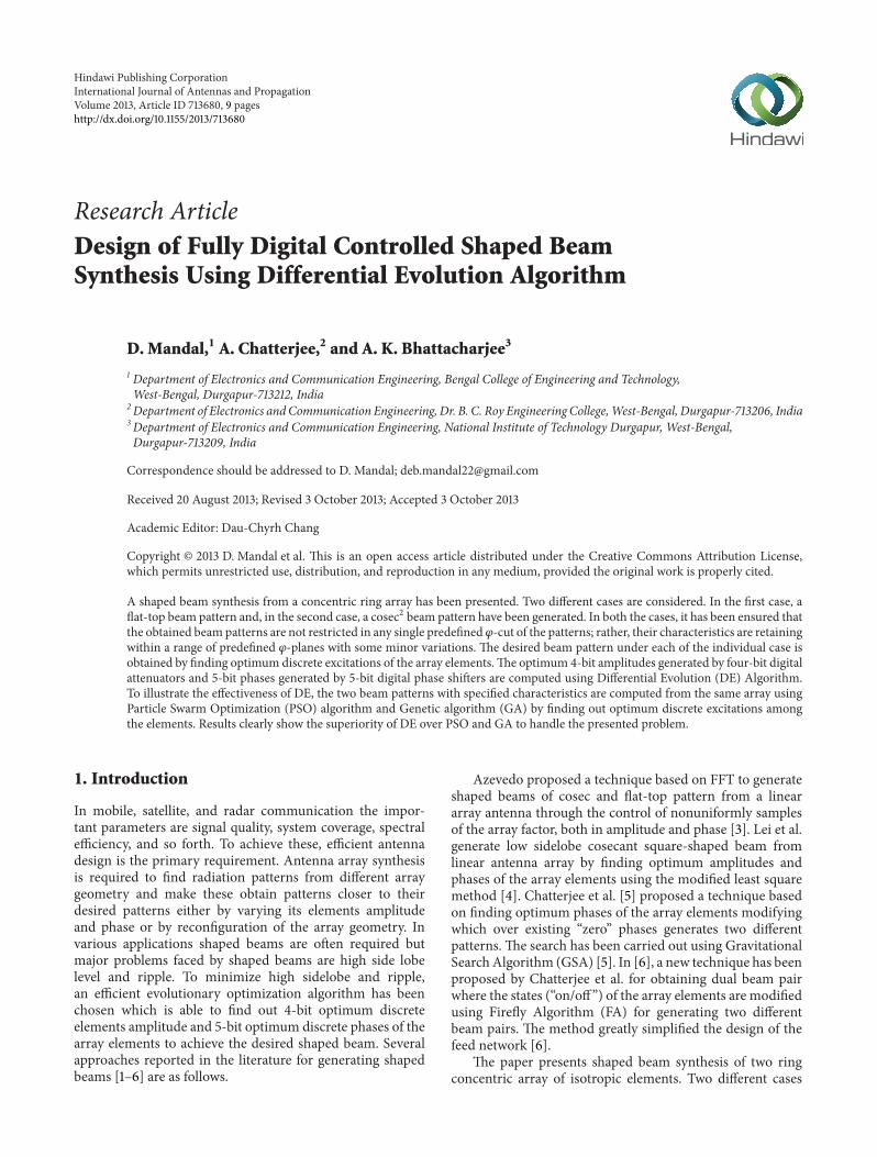
Figure 4 Optimized flat-top patterns from the concentric ring array (a) for 120593 = 0 degree plane (b) for 120593 = 5 degree plane (c) for 120593 = 10
degree plane
minus90 minus75 minus60 minus45 minus30 minus15 0 15 30 45 60 75 90minus20
minus15
minus10
minus5
0
DEPSOGA
120579 (deg)
120593 = 15 degree plane
|AF|
dB
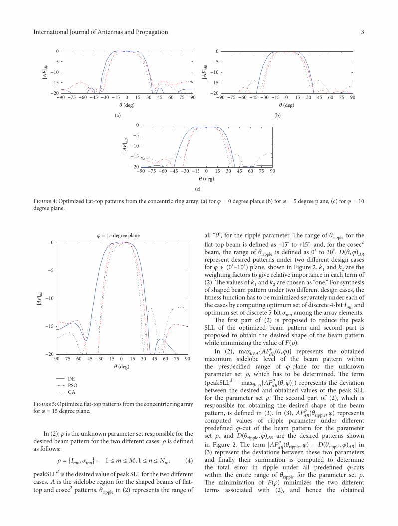
Figure 5Optimized flat-top patterns from the concentric ring arrayfor 120593 = 15 degree plane
In (2) 120588 is the unknown parameter set responsible for thedesired beam pattern for the two different cases 120588 is definedas follows
120588 = 119868119898119899
120572119898119899
1 le 119898 le 119872 1 le 119899 le 119873119898 (4)
peakSLL119889 is the desired value of peak SLL for the two differentcases 119860 is the sidelobe region for the shaped beams of flat-top and cosec2 patterns 120579ripple in (2) represents the range of
all ldquo120579rdquo for the ripple parameter The range of 120579ripple for theflat-top beam is defined as minus15∘ to +15∘ and for the cosec2beam the range of 120579ripple is defined as 0∘ to 30∘ 119863(120579 120593)
119889119861
represent desired patterns under two different design casesfor 120593 isin (0
∘ndash10∘) plane shown in Figure 2 1198961and 119896
2are the
weighting factors to give relative importance in each term of(2) The values of 119896
1and 1198962are chosen as ldquoonerdquo For synthesis
of shaped beam pattern under two different design cases thefitness function has to beminimized separately under each ofthe cases by computing optimum set of discrete 4-bit 119868
119898119899and
optimum set of discrete 5-bit 120572119898119899
among the array elementsThe first part of (2) is proposed to reduce the peak
SLL of the optimized beam pattern and second part isproposed to obtain the desired shape of the beam patternwhile minimizing the value of 119865(120588)
In (2) max120579isin119860
119860119865120588
119889119861(120579 120593) represents the obtained
maximum sidelobe level of the beam pattern withinthe prespecified range of 120593-plane for the unknownparameter set 120588 which has to be determined The term(peakSLL119889 minus max
120579isin119860119860119865120588
119889119861(120579 120593)) represents the deviation
between the desired and obtained values of the peak SLLfor the parameter set 120588 The second part of (2) which isresponsible for obtaining the desired shape of the beampattern is defined in (3) In (3) 119860119865
120588
119889119861(120579ripple 120593) represents
computed values of ripple parameter under differentpredefined 120593-cut of the beam pattern for the parameterset 120588 and 119863(120579ripple 120593)119889119861 are the desired patterns shownin Figure 2 The term |119860119865
120588
119889119861(120579ripple 120593) minus 119863(120579ripple 120593)119889119861| in
(3) represent the deviations between these two parametersand finally their summation is computed to determinethe total error in ripple under all predefined 120593-cutswithin the entire range of 120579ripple for the parameter set 120588The minimization of 119865(120588) minimizes the two differentterms associated with (2) and hence the obtained
4 International Journal of Antennas and Propagation
minus90 minus75 minus60 minus45 minus30 minus15 0 15 30 45 60 75 90minus20
minus15
minus10
minus5
0
120579 (deg)
|AF|
dB
(a)
minus90 minus75 minus60 minus45 minus30 minus15 0 15 30 45 60 75 90minus20
minus15
minus10
minus5
0
120579 (deg)
|AF|
dB
(b)
DEPSOGA
minus90 minus75 minus60 minus45 minus30 minus15 0 15 30 45 60 75 90minus20
minus15
minus10
minus5
0
120579 (deg)
|AF|
dB
(c)
Figure 6 Optimized cosec2 patterns from the concentric ring array (a) for 120593 = 0 degree plane (b) for 120593 = 5 degree plane (c) for 120593 = 10
degree plane
DEPSOGA
minus90 minus75 minus60 minus45 minus30 minus15 0 15 30 45 60 75 90120579 (deg)
minus20
minus15
minus10
minus5
0120593 = 15 degree plane
|AF|
dB
Figure 7 Optimized cosec2 patterns from the concentric ring arrayfor 120593 = 15 degree plane
beam-pattern approaches towards its desired one forthe computed parameter set 120588 In this manner the fitnessfunction of (2) serves the purpose of generating desiredshaped beams while minimizing it individually under eachof the design cases using DE PSO and GA
3 Algorithm Overviews and Parametric Setup
31 Overview of Differential Evolution Algorithm DifferentialEvolution (DE) algorithmwas introduced by Storn and PriceSimilar to GA [12ndash16] DE is also based on population Itis a stochastic optimization method used to minimize anobjective function It has an advantage to find out trueglobal minima and fast convergence using a few controlparameters [7ndash11] DE algorithm generates a population of119873119875 in 119863 dimensional search space called individuals Theindividual of population in generation 119866 can be written as119883119894119866
= 1199091119894119866
1199092119894119866
119909119863119894119866
119894 = 1 2 119873119875 The initialpopulation covered the entire search space At a generation119866 = 0 the initial value of the 119895th parameter defined asfollows 119909
1198951198940= rand(0 1) sdot (119909
up119895
minus 119909low119895
) + 119909low119895
where119894 = 1 2 119873119875 119895 = 1 2 119863 rand(0 1) is uniformlydistributed random variable within the range (0 1) 119909low
119895and
119909up119895are lower and upper bounds of 119895th parameter Three steps
mutation crossover and selection can be described as follows
Mutation Operation DE performs mutation operation togenerate a mutant vector 119881
119894119866= V1119894119866
V2119894119866
V119863119894119866
foreach target vector 119883
119894119866 In this work the DE strategy used
is ldquoDEbest1binrdquo which is defined as follows [7ndash10] 119881119894119866
=
119883best119866 +119865 sdot (1198831199031119866minus1198831199032119866) 1199031 1199032isin [1119873119875] and 119903
1= 1199032
= 119894 119865 isa real and constant factor satisfying 119865 isin [0 2] and 119883best119866 isthe vector which has best fitness at 119866th generationCrossover Operation In this operation trial vector 119880
119894119866=
1199061119894119866
1199062119894119866
119906119863119894119866
is generated from the target vector119883119894119866
International Journal of Antennas and Propagation 5
Table 1 Desired and obtained results for Case I of the design problem
Specific 120593 cut Design parameters DE PSO GA
120593 = 0 degree planePeak SLL in 119889119861
Desired minus1500 minus1500 minus1500
Obtained minus1743 minus1401 minus1559
Deviation (Δ) 119889119861 Desired 000 000 000Obtained 960 1633 1511
120593 = 5 degree planePeak SLL in 119889119861
Desired minus1500 minus1500 minus1500
Obtained minus1922 minus1708 minus1454
Deviation (Δ) 119889119861 Desired 000 000 000Obtained 999 1470 1528
120593 = 10 degree planePeak SLL in 119889119861
Desired minus1500 minus1500 minus1500
Obtained 1889 minus1684 minus1375
Deviation (Δ) 119889119861 Desired 000 000 000Obtained 950 1444 1852
and mutant vector 119881119894119866 The crossover strategy is defined
follows
119906119895119894119866
= V119895119894119866
if rand (0 1) le CR119909119895119894119866
otherwise(5)
Crossover factor CR is const in the range of (1 0) Thevalue of CR is taken as 02
Selection The operation performs comparison between theobjective function values at each trial vector 119891(119880
119894119866) and
target vector 119891(119883119894119866
) The vector which has smaller fitnessfunction value remains in the next generation Selectionoperation can be expressed as
119883119894119866+1
= 119880119894119866
if 119891 (119880119894119866
) lt 119891 (119883119894119866
)
119883119894119866
otherwise(6)
These three steps are repeated generation by generationuntil it reaches to its termination condition Return the bestvector in the current population (119883best119866) as the solutionof the optimization problem The flow chart of DifferentialEvolution is given in Figure 3
32 Details of Parametric Setup The individuals of thepopulation for DE PSO and GA are considered as
119883 = [11986811198682
sdot sdot sdot 119868119870
12057211205722
sdot sdot sdot 120572119870] (7)
The limits of the variables are defined as follows
0 le 119868119898
le 1 for119898 = 1 2 119870
minus120587 le 120572119898
le 120587 for119898 = 1 2 119870
(8)
The value of119870 in this problem becomes 30 and the searchspace dimension becomes 60
Based on the guideline provided in [7ndash11] the populationsize scale factor (119865) and crossover rate (CR) ofDE are chosenas 50 08 and 02 The DE scheme used is ldquoDEbest1binrdquoand the maximum iteration number is chosen as 3000
Swarm size in PSO is taken as 50 and the initial popula-tion is chosen randomly The values of 1198621 and 1198622 are chosen
as 2 [6 9] Time-varying inertia weight (119908) is considered asdecreasing linearly from 09 to 04
The maximum allowable velocity for each of the particleon 119889th dimension is considered as 09119903
119889[6 9] where
119903119889is the difference between the maximum and minimum
possible values of decision variables on 119889th dimension Thetermination condition is chosen as a maximum iteration of3000
Population size in GA is taken as 50 and two-pointcrossover is chosen Crossover probability and mutationprobability are taken as 008 and 001 ldquoRoulette WheelrdquoSelection is considered for the proposed problem and thetermination condition is chosen as a maximum iterationof 3000 Other parametric setups of GA are taken fromguidelines given in [12ndash16]
4 Simulation Results
A two ring concentric array of total 30 isotropic elements hasbeen considered The number of elements in each ring of thearray is taken 10119898 where119898 is the ring number
The interelement spacing is considered as 05120582 that is119889 =
05120582 and the ring radii are computed as 0795120582 and 159120582The presented results in this section are the best set of resultsobtained from 20 different runs of each of the algorithm foreach individual case
The design specifications of flat-top beam patterns com-puted separately using DE PSO and GA and their corre-sponding obtained results in different 120593-planes are shown inTable 1 From Table 1 it can be seen that the obtained valuesof the design parameters using DE are better than PSO andGA for the flat-top beam pattern
Three different 120593-cuts of the obtained flat-top beamscomputed individually using DE PSO and GA are shownin Figure 4 In Figure 4 the presented 120593-cuts are 0 degree 5degrees and 10 degrees It can be ensured from Figure 4 thatthe obtained flat-top beams are not restricted in any single120593-plane within the prespecified range of 0∘ le 120593 le 10
∘ Toobserve the flat-top beam patterns from a different 120593-planewhich is outside its prespecified range (0∘ le 120593 le 10
∘) a 15-degree 120593-cut of the optimized beam patterns is presented in
6 International Journal of Antennas and Propagation
Table2Com
puted4-bitamplitu
desa
nd5-bitp
hasesfor
Case
Iofthe
desig
nprob
lem
Algorith
mRing
num-
ber
Excitatio
nElem
ents
12
34
56
78
910
1112
1314
1516
1718
1920
DE
2Ph
aseminus18000minus18000
3375minus18000minus18000
18000minus9000minus5625
18000minus4500minus18000minus18000minus3375
18000
16875
18000minus14625minus2250minus14625minus4500
Amp
00625
00625
00625
03125
08125
1000
001875
07500
01250
07500
01250
00625
00625
01250
09375
1000
010
000
08125
01250
06875
1Ph
aseminus10125
18000
16875minus14625
18000
18000
18000
18000
1575
018000
mdashmdash
mdashmdash
mdashmdash
mdashmdash
mdashmdash
Amp
00625
1000
010
000
00625
1000
000625
1000
010
000
01875
00625
mdashmdash
mdashmdash
mdashmdash
mdashmdash
mdashmdash
PSO
2Ph
aseminus13500
18000minus2250minus13500minus2250minus3375minus3375minus4500
5625minus9000minus13500
5625minus9000minus2250minus1125
1125minus9000
14625minus2250
1575
0Amp
01875
06875
06875
00625
05000
09375
04375
03750
05000
06250
05000
05000
03750
07500
1000
006875
01250
02500
01875
04375
1Ph
aseminus4500minus2250
2250
3375minus1125
11250
1125
1125
4500minus18000
mdashmdash
mdashmdash
mdashmdash
mdashmdash
mdashmdash
Amp
09375
06875
08750
05000
04375
03750
02500
03750
06875
07500
mdashmdash
mdashmdash
mdashmdash
mdashmdash
mdashmdash
GA
2Ph
ase
1012
5minus9000
13500minus6750minus4500minus4500minus3375minus5625
1125minus1125
18000
11250minus3375
1125minus1125minus2250minus11250
5625minus12375minus11250
Amp
1000
002500
05000
09375
08125
06875
06875
02500
03125
01250
05625
01250
08125
05625
08125
03750
05000
02500
03125
06250
1Ph
aseminus112500
1125minus112500
14625
4500minus6750
1125
1125
5625
18000
mdashmdash
mdashmdash
mdashmdash
mdashmdash
mdashmdash
Amp
06875
03125
08125
00625
01875
08125
09375
02500
06875
05000
mdashmdash
mdashmdash
mdashmdash
mdashmdash
mdashmdash
International Journal of Antennas and Propagation 7
Table 3 Desired and obtained results for Case II of the design problem
Specific 120593 cut Design parameters DE PSO GA
120593 = 0 degree planePeak SLL in dB Desired minus1500 minus1500 minus1500
Obtained minus1503 minus1234 minus1229
Deviation (Δ) Desired 000 000 000Obtained 1118 2291 1368
120593 = 5 degree planePeak SLL in dB Desired minus1500 minus1500 minus1500
Obtained minus1569 minus1397 minus1241
Deviation (Δ) Desired 000 000 000Obtained 1284 1555 1590
120593 = 10 degree planePeak SLL in dB Desired minus1500 minus1500 minus1500
Obtained minus1471 minus1409 minus1013
Deviation (Δ) Desired 000 000 000Obtained 1370 1600 1520
0 500 1000 1500 2000 2500 30000
100
200
300
400
500
Generations
Best
fitne
ss
DEPSOGA
(a)
0 500 1000 1500 2000 2500 30000
100
200
300
400
500
Generations
Best
fitne
ss
DEPSOGA
(b)
Figure 8 Convergence characteristics of DE PSO and GA (a) for Case I of the design problem (b) and for Case II of the design problem
Figure 5 From Figure 5 it can be seen that the patterns aredeviated from its desired flat-top pattern of Figure 3 becausethey are not optimized for 120593 = 15 degree planeThe optimum4-bit amplitudes and 5-bit phases of the array elements for theflat-top beams computed individually usingDE PSO andGAare shown in Table 2
The design specification for cosec2 beam patterns(Case II) and their corresponding obtained results in threedifferent 120593-planes are shown in Table 3 From Table 3 itcan be observed that the performance of DE in terms ofcomputing the design parameters for cosec2 beam pattern isbetter than PSO and GA
Figure 6 shows three different 120593-cuts of the obtainedcosec2 beam patterns computed individually using DE PSOand GA In Figure 6 the presented 120593-cuts of the optimizedcosec2 beam patterns are 0 degree 5 degrees and 10 degrees
Figure 7 shows a 15-degree 120593-cut of the optimized cosec2beam patterns which clearly shows deviation from its desiredcosec2 pattern of Figure 3 because they are not optimized for120593 = 15 degree planeThe optimum 4-bit amplitudes and 5-bitphases of the array elements for the cosec2 beams computedindividually using DE PSO and GA are shown in Table 4
The comparative performance of DE PSO and GA forthe two different cases of design problem is shown in Table 5
Lowest mean fitness value of DE over PSO and GA provesitself best performing algorithm over PSO and GA
The convergence characteristics of the three algorithmsfor the two different cases of the presented problem areshown in Figure 8 From Figure 8(a) it can be noticedthat the convergence of DE is better than PSO and GA interms of minimizing the fitness function of (2) for the flat-top beam pattern Similarly Figure 8(b) clearly shows betterconvergence of DE over PSO and GA in terms of minimizingthe fitness function of (2) for the cosec2 beam pattern
Table 6 shows the 119875 values obtained through Wilcoxonrsquosrank sum test [12 17] between DE PSO and GA for twodifferent cases of design considerations All the 119875 values areless than 005 (5 significant level) which is a strong proofagainst null hypothesis indicating that better final fitnessvalue obtained by the best algorithm is statistically significantand has not occurred by chance
5 Conclusions
Synthesis of shaped beam patterns from a concentric ringarray antenna using Differential Evolution algorithm hasbeen presented For synthesis of shaped beam patterns con-strained side lobe and ripple are contemporarily taken into
8 International Journal of Antennas and Propagation
Table4Com
puted4-bitamplitu
desa
nd5-bitp
hasesfor
Case
IIof
thed
esignprob
lem
Algorith
mRing
num-
ber
Excitatio
nElem
ents
12
34
56
78
910
1112
1314
1516
1718
1920
DE
2Ph
ase
18000minus18000minus18000
9000
12375minus12375minus18000minus13500
18000minus18000minus18000minus6750minus18000minus18000minus18000
18000minus18000minus18000minus1125minus13500
Amp
09375
00625
01250
05000
1000
003125
00625
05000
00625
1000
000625
03125
07500
06250
07500
01875
05625
00625
07500
09375
1Ph
ase
18000minus18000
18000
18000minus11250minus18000
16875minus18000
11250minus9000
mdashmdash
mdashmdash
mdashmdash
mdashmdash
mdashmdash
Amp
00625
00625
1000
010
000
1000
000625
04375
1000
005000
03125
mdashmdash
mdashmdash
mdashmdash
mdashmdash
mdashmdash
PSO
2Ph
ase
5625minus9000
2250minus2250
5625
5625minus1125
4500
13500minus1125minus4500
1125minus1125minus13500
6750minus2250
1125minus6750minus1125minus15750
Amp
06875
06250
08125
06250
06250
04375
03750
01875
05625
03125
05625
06250
04375
04375
02500
04375
08125
03125
05000
04375
1Ph
ase
4500
5625
1125
4500
3375
11250
7875
4500
6750minus3375
mdashmdash
mdashmdash
mdashmdash
mdashmdash
mdashmdash
Amp
08125
05625
05000
05625
05000
02500
05625
07500
02500
05000
mdashmdash
mdashmdash
mdashmdash
mdashmdash
mdashmdash
GA
2Ph
aseminus9000minus9000minus9000minus16875minus15750minus12375minus6750minus1125minus11250minus6750minus1125minus1125minus7875minus4500minus7875minus67501125minus1125minus6750minus1125
Amp
01875
03125
01875
03125
02500
03750
04375
01250
00625
01875
00625
02500
05000
05000
04375
03750
05000
00625
00625
03125
1Ph
aseminus13500minus7875minus11250minus7875minus7875minus10125minus10125minus18000minus6750minus15750
mdashmdash
mdashmdash
mdashmdash
mdashmdash
mdashmdash
Amp
01250
01250
03125
01875
00625
01875
01875
03750
02500
03125
mdashmdash
mdashmdash
mdashmdash
mdashmdash
mdashmdash
International Journal of Antennas and Propagation 9
Table 5 Comparative performance of DE PSO and GA
Different cases Algorithm Best fitness (out of 20) Worst Mean Standard deviation
Case IDE 2910 3514 3125 191PSO 4747 5696 5133 289GA 5425 6773 5827 389
Case IIDE 3918 4585 4235 197PSO 6403 7990 7440 349GA 7367 9387 8569 432
Table 6 119875 values for Wilcoxonrsquos two sided rank sum test
Different cases Comparison pair P-value
Case IDEPSO 70473119890 minus 008
DEGA 10109119890 minus 007
PSOGA 41549119890 minus 006
Case IIDEPSO 67860119890 minus 008
DEGA 67956119890 minus 008
PSOGA 39339119890 minus 007
account by minimizing properly formulated fitness functionusing Evolutionary Algorithm based procedure Presentedmethod is capable of producing beam patterns which retainstheir desired characteristics within a range of predefined 120593-planes with some minor variations Results clearly indicate agood agreement between the obtained and desired one
The presented method incorporates 4-bit amplitudes ofthe array elements which ensure that the dynamic range ratio(DRR) remains within the limit of 16 which is helpful forreliable design of the feed network Discrete excitations alsoreduced the number of attenuators and the phase shifters andhence are capable of reducing the cost and complexity of thesystem
The comparative performance ofDE PSO andGAclearlyshows the superiority of DE over PSO and GA in terms offinding optimum solutions for the presented problem Thequality of the solutions produced individually usingDE PSOand GA for the two different cases of design considerations isanalysed statistically and the superiority of DE is proven overPSO and GA for the proposed problem
References
[1] C A Balanis Antenna Theory Analysis and Design John Willyamp Sons New York NY USA 2nd edition 1997
[2] R S Elliott Antenna Theory and Design John Wiley amp SonsNew York NY USA Revised edition 2003
[3] J A R Azevedo ldquoShaped beam pattern synthesis with non-uniform sample phasesrdquo Progress in Electromagnetics ResearchB vol 5 pp 77ndash90 2008
[4] J Lei G Fu L Yang and D-M Fu ldquoWide band linear printedantenna array with low sidelobe cosecant square-shaped beampatternrdquo Progress in Electromagnetics Research C vol 15 pp233ndash241 2010
[5] A Chatterjee G K Mahanti and P R S Mahapatra ldquoDesignof fully digital controlled reconfigurable dual-beam concen-tric ring array antenna using gravitational search algorithmrdquoProgress in Electromagnetics Research C vol 18 pp 59ndash72 2011
[6] A Chatterjee G K Mahanti and A Chatterjee ldquoDesignof a fully digital controlled reconfigurable switched beamconcentric ring array antenna using firefly and particle swarmoptimization algorithmrdquo Progress in Electromagnetics ResearchB vol 36 pp 113ndash131 2012
[7] R Storn and K Price ldquoDifferential evolution a simple andefficient heuristic for global optimization over continuousspacesrdquo Journal of Global Optimization vol 11 no 4 pp 341ndash359 1997
[8] K V Price R M Storn and J A Lampinen DifferentialEvolutionmdashA Practical Approach to Global Optimization Nat-ural Computing Springer New York NY USA 2005
[9] M A Panduro C A Brizuela L I Balderas and D A AcostaldquoA comparison of genetic algorithms particle swarm optimiza-tion and the differential evolution method for the design ofscannable circular antenna arraysrdquo Progress in ElectromagneticsResearch B vol 13 pp 171ndash186 2009
[10] S Das A Abraham U K Chakraborty and A KonarldquoDifferential evolution using a neighborhood-based mutationoperatorrdquo IEEE Transactions on Evolutionary Computation vol13 no 3 pp 526ndash553 2009
[11] J Guo and J Li ldquoPattern synthesis of conformal array antenna inthe presence of platform using differential evolution algorithmrdquoIEEE Transactions on Antennas and Propagation vol 57 no 9pp 2615ndash2621 2009
[12] R LHaupt ldquoIntroduction to genetic algorithms for electromag-neticsrdquo IEEE Antennas and PropagationMagazine vol 37 no 2pp 7ndash15 1995
[13] K F Man K S Tang and S Kwong ldquoGenetic algorithmsconcepts and applicationsrdquo IEEE Transactions on IndustrialElectronics vol 43 no 5 pp 519ndash534 1996
[14] J M Johnson and Y Rahmat-Samii ldquoGenetic algorithms inengineering electromagneticsrdquo IEEE Antennas and PropagationMagazine vol 39 no 4 pp 7ndash21 1997
[15] D Marcano and F Duran ldquoSynthesis of antenna arrays usinggenetic algorithmsrdquo IEEE Antennas and Propagation Magazinevol 42 no 3 pp 12ndash20 2000
[16] M A Panduro A L Mendez R Dominguez and G RomeroldquoDesign of non-uniform circular antenna arrays for side lobereduction using the method of genetic algorithmsrdquo Interna-tional Journal of Electronics and Communications vol 60 no10 pp 713ndash717 2006
[17] M Hollander and D A Wolfe Nonparametric Statistical Meth-ods JohnWiley amp Sons New York NY USA 2nd edition 1999
Submit your manuscripts athttpwwwhindawicom
Control Scienceand Engineering
Journal of
Hindawi Publishing Corporationhttpwwwhindawicom Volume 2013
International Journal of
RotatingMachinery
Hindawi Publishing Corporationhttpwwwhindawicom
Volume 2013Part I
Hindawi Publishing Corporationhttpwwwhindawicom Volume 2013
DistributedSensor Networks
International Journal of
ISRN Signal Processing
Hindawi Publishing Corporationhttpwwwhindawicom Volume 2013
Hindawi Publishing Corporationhttpwwwhindawicom Volume 2013
Mechanical Engineering
Advances in
Modelling amp Simulation in EngineeringHindawi Publishing Corporationhttpwwwhindawicom Volume 2013
Advances inOptoElectronics
Hindawi Publishing Corporationhttpwwwhindawicom
Volume 2013
ISRN Sensor Networks
Hindawi Publishing Corporationhttpwwwhindawicom Volume 2013
VLSI Design
Hindawi Publishing Corporationhttpwwwhindawicom Volume 2013
Hindawi Publishing Corporation httpwwwhindawicom Volume 2013Hindawi Publishing Corporation httpwwwhindawicom Volume 2013
The Scientific World Journal
ISRN Robotics
Hindawi Publishing Corporationhttpwwwhindawicom Volume 2013
International Journal of
Antennas andPropagation
Hindawi Publishing Corporationhttpwwwhindawicom Volume 2013
ISRN Electronics
Hindawi Publishing Corporationhttpwwwhindawicom Volume 2013
Hindawi Publishing Corporationhttpwwwhindawicom Volume 2013
thinspJournalthinspofthinsp
Sensors
Hindawi Publishing Corporationhttpwwwhindawicom Volume 2013
Active and Passive Electronic Components
Chemical EngineeringInternational Journal of
Hindawi Publishing Corporationhttpwwwhindawicom Volume 2013
Hindawi Publishing Corporationhttpwwwhindawicom Volume 2013
Electrical and Computer Engineering
Journal of
ISRN Civil Engineering
Hindawi Publishing Corporationhttpwwwhindawicom Volume 2013
Advances inAcoustics ampVibration
Hindawi Publishing Corporationhttpwwwhindawicom Volume 2013

2 International Journal of Antennas and Propagation
025 075 125 175minus175
minus125
minus075
minus025
025
075
125
175
minus175 minus125 minus075 minus025
Y[in
term
s of120582
]
X [in terms of 120582]
Figure 1 Concentric ring array of isotropic antennas in119883-119884 plane
minus20minus18minus16minus14minus12minus10minus8minus6minus4minus2
0
Flat-top (Case I)cosec2 (Case II)
minus90 minus75 minus60 minus45 minus30 minus15 0 15 30 45 60 75 90120579 (deg)
|D(120579120593)|dB
120593 isin (0ndash10) degree plane
Figure 2 Desired patterns under two different design cases
have been considered In the first case a flat-top beam isgenerated from the presented array by finding optimum 4-bit amplitudes and 5-bit phases and in the second case acosec2 pattern is generated from the same array by findingout another optimum 4-bit amplitudes and 5-bit phasesof the elements In both the cases the optimum discreteexcitations are computed in such a manner that the obtainedpatterns are retaining their desired characteristics within arange of predefined 120593-planes with some minor variationsThe optimum discrete amplitudes and phases for the twodifferent cases are computed using Differential Evolution(DE) algorithm [7ndash11] To illustrate the effectiveness of DEthe shaped beams under two different cases are computedseparately following the above procedure from the same arrayconfiguration using Particle Swarm Optimization (PSO)
Mut
atio
nCr
osso
ver
Sele
ctio
n
Compute XbestG
i = 1
Set G = 0 and randomlyinitialize XiG
G gt Gmax
Save the result and stopNo
No
No
Yes
Yes
Yes
ViG = XbestG + F middot (Xr1G minus Xr2G)
Start
i = i + 1
XiG = XiG+1
f(UiG) lt f(XiG)
G = G + 1
f(UiG) = f(XiG+1)
ujiG =jiGxjiG
if rand(01) le CRotherwise
i = NP
Figure 3 Flow chart of Differential Evolution (DE) algorithm
[6 9 12] algorithm and Genetic Algorithm (GA) [12ndash16]Results clearly show the effectiveness of DE over PSO andGAfor both the design cases presented in this problem
2 Problem Formulation
A concentric ring array of isotropic elements is consideredThe far field pattern of the array shown in Figure 1 can bewritten as [6]
119860119865 (120579 120593) =
119872
sum
119898=1
119873119898
sum
119899=1
119868119898119899
119890119895[119896119903119898sin 120579 cos(120593minus120593
119898119899)+120572119898119899] (1)
where 119872 is the number of concentric rings 119873119898
is thenumber of isotropic elements in119898th ring 119868
119898119899is the excitation
amplitude of119898119899th element 119903119898is the119873
1198981198891198982120587 radius of the
119898th ring 119889119898is the inter element arc spacing of 119898th circle
119896 = 2120587120582 represents wave number 120582 is the wave length 120579 120593is the polar and azimuth angle 120593
119898119899= 2119899120587119873
119898is the angular
location of the119898119899th element with 1 le 119899 le 119873119898 and 120572
119898119899is the
phase excitation of119898119899th elementThe fitness function for the shaped beam pattern is
defined as follows
119865 (120588) = 1198961(peakSLL119889 minusmax
120579isin119860
119860119865120588
119889119861(120579 120593))
2
+ 1198962times Δ (2)
where Δ is defined asΔ = sum
120579ripple
10038161003816100381610038161003816119860119865120588
119889119861(120579ripple 120593) minus 119863(120579ripple 120593)
119889119861
10038161003816100381610038161003816 (3)
In (2) and (3) 120593 isin (0∘ndash10∘) plane
International Journal of Antennas and Propagation 3
minus90 minus75 minus60 minus45 minus30 minus15 0 15 30 45 60 75 90minus20
minus15
minus10
minus5
0
120579 (deg)
|AF| dB
(a)
minus90 minus75 minus60 minus45 minus30 minus15 0 15 30 45 60 75 90minus20
minus15
minus10
minus5
0
120579 (deg)
|AF| dB
(b)
minus90 minus75 minus60 minus45 minus30 minus15 0 15 30 45 60 75 90minus20
minus15
minus10
minus5
0
120579 (deg)
|AF| dB
(c)
Figure 4 Optimized flat-top patterns from the concentric ring array (a) for 120593 = 0 degree plane (b) for 120593 = 5 degree plane (c) for 120593 = 10
degree plane
minus90 minus75 minus60 minus45 minus30 minus15 0 15 30 45 60 75 90minus20
minus15
minus10
minus5
0
DEPSOGA
120579 (deg)
120593 = 15 degree plane
|AF|
dB
Figure 5Optimized flat-top patterns from the concentric ring arrayfor 120593 = 15 degree plane
In (2) 120588 is the unknown parameter set responsible for thedesired beam pattern for the two different cases 120588 is definedas follows
120588 = 119868119898119899
120572119898119899
1 le 119898 le 119872 1 le 119899 le 119873119898 (4)
peakSLL119889 is the desired value of peak SLL for the two differentcases 119860 is the sidelobe region for the shaped beams of flat-top and cosec2 patterns 120579ripple in (2) represents the range of
all ldquo120579rdquo for the ripple parameter The range of 120579ripple for theflat-top beam is defined as minus15∘ to +15∘ and for the cosec2beam the range of 120579ripple is defined as 0∘ to 30∘ 119863(120579 120593)
119889119861
represent desired patterns under two different design casesfor 120593 isin (0
∘ndash10∘) plane shown in Figure 2 1198961and 119896
2are the
weighting factors to give relative importance in each term of(2) The values of 119896
1and 1198962are chosen as ldquoonerdquo For synthesis
of shaped beam pattern under two different design cases thefitness function has to beminimized separately under each ofthe cases by computing optimum set of discrete 4-bit 119868
119898119899and
optimum set of discrete 5-bit 120572119898119899
among the array elementsThe first part of (2) is proposed to reduce the peak
SLL of the optimized beam pattern and second part isproposed to obtain the desired shape of the beam patternwhile minimizing the value of 119865(120588)
In (2) max120579isin119860
119860119865120588
119889119861(120579 120593) represents the obtained
maximum sidelobe level of the beam pattern withinthe prespecified range of 120593-plane for the unknownparameter set 120588 which has to be determined The term(peakSLL119889 minus max
120579isin119860119860119865120588
119889119861(120579 120593)) represents the deviation
between the desired and obtained values of the peak SLLfor the parameter set 120588 The second part of (2) which isresponsible for obtaining the desired shape of the beampattern is defined in (3) In (3) 119860119865
120588
119889119861(120579ripple 120593) represents
computed values of ripple parameter under differentpredefined 120593-cut of the beam pattern for the parameterset 120588 and 119863(120579ripple 120593)119889119861 are the desired patterns shownin Figure 2 The term |119860119865
120588
119889119861(120579ripple 120593) minus 119863(120579ripple 120593)119889119861| in
(3) represent the deviations between these two parametersand finally their summation is computed to determinethe total error in ripple under all predefined 120593-cutswithin the entire range of 120579ripple for the parameter set 120588The minimization of 119865(120588) minimizes the two differentterms associated with (2) and hence the obtained
4 International Journal of Antennas and Propagation
minus90 minus75 minus60 minus45 minus30 minus15 0 15 30 45 60 75 90minus20
minus15
minus10
minus5
0
120579 (deg)
|AF|
dB
(a)
minus90 minus75 minus60 minus45 minus30 minus15 0 15 30 45 60 75 90minus20
minus15
minus10
minus5
0
120579 (deg)
|AF|
dB
(b)
DEPSOGA
minus90 minus75 minus60 minus45 minus30 minus15 0 15 30 45 60 75 90minus20
minus15
minus10
minus5
0
120579 (deg)
|AF|
dB
(c)
Figure 6 Optimized cosec2 patterns from the concentric ring array (a) for 120593 = 0 degree plane (b) for 120593 = 5 degree plane (c) for 120593 = 10
degree plane
DEPSOGA
minus90 minus75 minus60 minus45 minus30 minus15 0 15 30 45 60 75 90120579 (deg)
minus20
minus15
minus10
minus5
0120593 = 15 degree plane
|AF|
dB
Figure 7 Optimized cosec2 patterns from the concentric ring arrayfor 120593 = 15 degree plane
beam-pattern approaches towards its desired one forthe computed parameter set 120588 In this manner the fitnessfunction of (2) serves the purpose of generating desiredshaped beams while minimizing it individually under eachof the design cases using DE PSO and GA
3 Algorithm Overviews and Parametric Setup
31 Overview of Differential Evolution Algorithm DifferentialEvolution (DE) algorithmwas introduced by Storn and PriceSimilar to GA [12ndash16] DE is also based on population Itis a stochastic optimization method used to minimize anobjective function It has an advantage to find out trueglobal minima and fast convergence using a few controlparameters [7ndash11] DE algorithm generates a population of119873119875 in 119863 dimensional search space called individuals Theindividual of population in generation 119866 can be written as119883119894119866
= 1199091119894119866
1199092119894119866
119909119863119894119866
119894 = 1 2 119873119875 The initialpopulation covered the entire search space At a generation119866 = 0 the initial value of the 119895th parameter defined asfollows 119909
1198951198940= rand(0 1) sdot (119909
up119895
minus 119909low119895
) + 119909low119895
where119894 = 1 2 119873119875 119895 = 1 2 119863 rand(0 1) is uniformlydistributed random variable within the range (0 1) 119909low
119895and
119909up119895are lower and upper bounds of 119895th parameter Three steps
mutation crossover and selection can be described as follows
Mutation Operation DE performs mutation operation togenerate a mutant vector 119881
119894119866= V1119894119866
V2119894119866
V119863119894119866
foreach target vector 119883
119894119866 In this work the DE strategy used
is ldquoDEbest1binrdquo which is defined as follows [7ndash10] 119881119894119866
=
119883best119866 +119865 sdot (1198831199031119866minus1198831199032119866) 1199031 1199032isin [1119873119875] and 119903
1= 1199032
= 119894 119865 isa real and constant factor satisfying 119865 isin [0 2] and 119883best119866 isthe vector which has best fitness at 119866th generationCrossover Operation In this operation trial vector 119880
119894119866=
1199061119894119866
1199062119894119866
119906119863119894119866
is generated from the target vector119883119894119866
International Journal of Antennas and Propagation 5
Table 1 Desired and obtained results for Case I of the design problem
Specific 120593 cut Design parameters DE PSO GA
120593 = 0 degree planePeak SLL in 119889119861
Desired minus1500 minus1500 minus1500
Obtained minus1743 minus1401 minus1559
Deviation (Δ) 119889119861 Desired 000 000 000Obtained 960 1633 1511
120593 = 5 degree planePeak SLL in 119889119861
Desired minus1500 minus1500 minus1500
Obtained minus1922 minus1708 minus1454
Deviation (Δ) 119889119861 Desired 000 000 000Obtained 999 1470 1528
120593 = 10 degree planePeak SLL in 119889119861
Desired minus1500 minus1500 minus1500
Obtained 1889 minus1684 minus1375
Deviation (Δ) 119889119861 Desired 000 000 000Obtained 950 1444 1852
and mutant vector 119881119894119866 The crossover strategy is defined
follows
119906119895119894119866
= V119895119894119866
if rand (0 1) le CR119909119895119894119866
otherwise(5)
Crossover factor CR is const in the range of (1 0) Thevalue of CR is taken as 02
Selection The operation performs comparison between theobjective function values at each trial vector 119891(119880
119894119866) and
target vector 119891(119883119894119866
) The vector which has smaller fitnessfunction value remains in the next generation Selectionoperation can be expressed as
119883119894119866+1
= 119880119894119866
if 119891 (119880119894119866
) lt 119891 (119883119894119866
)
119883119894119866
otherwise(6)
These three steps are repeated generation by generationuntil it reaches to its termination condition Return the bestvector in the current population (119883best119866) as the solutionof the optimization problem The flow chart of DifferentialEvolution is given in Figure 3
32 Details of Parametric Setup The individuals of thepopulation for DE PSO and GA are considered as
119883 = [11986811198682
sdot sdot sdot 119868119870
12057211205722
sdot sdot sdot 120572119870] (7)
The limits of the variables are defined as follows
0 le 119868119898
le 1 for119898 = 1 2 119870
minus120587 le 120572119898
le 120587 for119898 = 1 2 119870
(8)
The value of119870 in this problem becomes 30 and the searchspace dimension becomes 60
Based on the guideline provided in [7ndash11] the populationsize scale factor (119865) and crossover rate (CR) ofDE are chosenas 50 08 and 02 The DE scheme used is ldquoDEbest1binrdquoand the maximum iteration number is chosen as 3000
Swarm size in PSO is taken as 50 and the initial popula-tion is chosen randomly The values of 1198621 and 1198622 are chosen
as 2 [6 9] Time-varying inertia weight (119908) is considered asdecreasing linearly from 09 to 04
The maximum allowable velocity for each of the particleon 119889th dimension is considered as 09119903
119889[6 9] where
119903119889is the difference between the maximum and minimum
possible values of decision variables on 119889th dimension Thetermination condition is chosen as a maximum iteration of3000
Population size in GA is taken as 50 and two-pointcrossover is chosen Crossover probability and mutationprobability are taken as 008 and 001 ldquoRoulette WheelrdquoSelection is considered for the proposed problem and thetermination condition is chosen as a maximum iterationof 3000 Other parametric setups of GA are taken fromguidelines given in [12ndash16]
4 Simulation Results
A two ring concentric array of total 30 isotropic elements hasbeen considered The number of elements in each ring of thearray is taken 10119898 where119898 is the ring number
The interelement spacing is considered as 05120582 that is119889 =
05120582 and the ring radii are computed as 0795120582 and 159120582The presented results in this section are the best set of resultsobtained from 20 different runs of each of the algorithm foreach individual case
The design specifications of flat-top beam patterns com-puted separately using DE PSO and GA and their corre-sponding obtained results in different 120593-planes are shown inTable 1 From Table 1 it can be seen that the obtained valuesof the design parameters using DE are better than PSO andGA for the flat-top beam pattern
Three different 120593-cuts of the obtained flat-top beamscomputed individually using DE PSO and GA are shownin Figure 4 In Figure 4 the presented 120593-cuts are 0 degree 5degrees and 10 degrees It can be ensured from Figure 4 thatthe obtained flat-top beams are not restricted in any single120593-plane within the prespecified range of 0∘ le 120593 le 10
∘ Toobserve the flat-top beam patterns from a different 120593-planewhich is outside its prespecified range (0∘ le 120593 le 10
∘) a 15-degree 120593-cut of the optimized beam patterns is presented in
6 International Journal of Antennas and Propagation
Table2Com
puted4-bitamplitu
desa
nd5-bitp
hasesfor
Case
Iofthe
desig
nprob
lem
Algorith
mRing
num-
ber
Excitatio
nElem
ents
12
34
56
78
910
1112
1314
1516
1718
1920
DE
2Ph
aseminus18000minus18000
3375minus18000minus18000
18000minus9000minus5625
18000minus4500minus18000minus18000minus3375
18000
16875
18000minus14625minus2250minus14625minus4500
Amp
00625
00625
00625
03125
08125
1000
001875
07500
01250
07500
01250
00625
00625
01250
09375
1000
010
000
08125
01250
06875
1Ph
aseminus10125
18000
16875minus14625
18000
18000
18000
18000
1575
018000
mdashmdash
mdashmdash
mdashmdash
mdashmdash
mdashmdash
Amp
00625
1000
010
000
00625
1000
000625
1000
010
000
01875
00625
mdashmdash
mdashmdash
mdashmdash
mdashmdash
mdashmdash
PSO
2Ph
aseminus13500
18000minus2250minus13500minus2250minus3375minus3375minus4500
5625minus9000minus13500
5625minus9000minus2250minus1125
1125minus9000
14625minus2250
1575
0Amp
01875
06875
06875
00625
05000
09375
04375
03750
05000
06250
05000
05000
03750
07500
1000
006875
01250
02500
01875
04375
1Ph
aseminus4500minus2250
2250
3375minus1125
11250
1125
1125
4500minus18000
mdashmdash
mdashmdash
mdashmdash
mdashmdash
mdashmdash
Amp
09375
06875
08750
05000
04375
03750
02500
03750
06875
07500
mdashmdash
mdashmdash
mdashmdash
mdashmdash
mdashmdash
GA
2Ph
ase
1012
5minus9000
13500minus6750minus4500minus4500minus3375minus5625
1125minus1125
18000
11250minus3375
1125minus1125minus2250minus11250
5625minus12375minus11250
Amp
1000
002500
05000
09375
08125
06875
06875
02500
03125
01250
05625
01250
08125
05625
08125
03750
05000
02500
03125
06250
1Ph
aseminus112500
1125minus112500
14625
4500minus6750
1125
1125
5625
18000
mdashmdash
mdashmdash
mdashmdash
mdashmdash
mdashmdash
Amp
06875
03125
08125
00625
01875
08125
09375
02500
06875
05000
mdashmdash
mdashmdash
mdashmdash
mdashmdash
mdashmdash
International Journal of Antennas and Propagation 7
Table 3 Desired and obtained results for Case II of the design problem
Specific 120593 cut Design parameters DE PSO GA
120593 = 0 degree planePeak SLL in dB Desired minus1500 minus1500 minus1500
Obtained minus1503 minus1234 minus1229
Deviation (Δ) Desired 000 000 000Obtained 1118 2291 1368
120593 = 5 degree planePeak SLL in dB Desired minus1500 minus1500 minus1500
Obtained minus1569 minus1397 minus1241
Deviation (Δ) Desired 000 000 000Obtained 1284 1555 1590
120593 = 10 degree planePeak SLL in dB Desired minus1500 minus1500 minus1500
Obtained minus1471 minus1409 minus1013
Deviation (Δ) Desired 000 000 000Obtained 1370 1600 1520
0 500 1000 1500 2000 2500 30000
100
200
300
400
500
Generations
Best
fitne
ss
DEPSOGA
(a)
0 500 1000 1500 2000 2500 30000
100
200
300
400
500
Generations
Best
fitne
ss
DEPSOGA
(b)
Figure 8 Convergence characteristics of DE PSO and GA (a) for Case I of the design problem (b) and for Case II of the design problem
Figure 5 From Figure 5 it can be seen that the patterns aredeviated from its desired flat-top pattern of Figure 3 becausethey are not optimized for 120593 = 15 degree planeThe optimum4-bit amplitudes and 5-bit phases of the array elements for theflat-top beams computed individually usingDE PSO andGAare shown in Table 2
The design specification for cosec2 beam patterns(Case II) and their corresponding obtained results in threedifferent 120593-planes are shown in Table 3 From Table 3 itcan be observed that the performance of DE in terms ofcomputing the design parameters for cosec2 beam pattern isbetter than PSO and GA
Figure 6 shows three different 120593-cuts of the obtainedcosec2 beam patterns computed individually using DE PSOand GA In Figure 6 the presented 120593-cuts of the optimizedcosec2 beam patterns are 0 degree 5 degrees and 10 degrees
Figure 7 shows a 15-degree 120593-cut of the optimized cosec2beam patterns which clearly shows deviation from its desiredcosec2 pattern of Figure 3 because they are not optimized for120593 = 15 degree planeThe optimum 4-bit amplitudes and 5-bitphases of the array elements for the cosec2 beams computedindividually using DE PSO and GA are shown in Table 4
The comparative performance of DE PSO and GA forthe two different cases of design problem is shown in Table 5
Lowest mean fitness value of DE over PSO and GA provesitself best performing algorithm over PSO and GA
The convergence characteristics of the three algorithmsfor the two different cases of the presented problem areshown in Figure 8 From Figure 8(a) it can be noticedthat the convergence of DE is better than PSO and GA interms of minimizing the fitness function of (2) for the flat-top beam pattern Similarly Figure 8(b) clearly shows betterconvergence of DE over PSO and GA in terms of minimizingthe fitness function of (2) for the cosec2 beam pattern
Table 6 shows the 119875 values obtained through Wilcoxonrsquosrank sum test [12 17] between DE PSO and GA for twodifferent cases of design considerations All the 119875 values areless than 005 (5 significant level) which is a strong proofagainst null hypothesis indicating that better final fitnessvalue obtained by the best algorithm is statistically significantand has not occurred by chance
5 Conclusions
Synthesis of shaped beam patterns from a concentric ringarray antenna using Differential Evolution algorithm hasbeen presented For synthesis of shaped beam patterns con-strained side lobe and ripple are contemporarily taken into
8 International Journal of Antennas and Propagation
Table4Com
puted4-bitamplitu
desa
nd5-bitp
hasesfor
Case
IIof
thed
esignprob
lem
Algorith
mRing
num-
ber
Excitatio
nElem
ents
12
34
56
78
910
1112
1314
1516
1718
1920
DE
2Ph
ase
18000minus18000minus18000
9000
12375minus12375minus18000minus13500
18000minus18000minus18000minus6750minus18000minus18000minus18000
18000minus18000minus18000minus1125minus13500
Amp
09375
00625
01250
05000
1000
003125
00625
05000
00625
1000
000625
03125
07500
06250
07500
01875
05625
00625
07500
09375
1Ph
ase
18000minus18000
18000
18000minus11250minus18000
16875minus18000
11250minus9000
mdashmdash
mdashmdash
mdashmdash
mdashmdash
mdashmdash
Amp
00625
00625
1000
010
000
1000
000625
04375
1000
005000
03125
mdashmdash
mdashmdash
mdashmdash
mdashmdash
mdashmdash
PSO
2Ph
ase
5625minus9000
2250minus2250
5625
5625minus1125
4500
13500minus1125minus4500
1125minus1125minus13500
6750minus2250
1125minus6750minus1125minus15750
Amp
06875
06250
08125
06250
06250
04375
03750
01875
05625
03125
05625
06250
04375
04375
02500
04375
08125
03125
05000
04375
1Ph
ase
4500
5625
1125
4500
3375
11250
7875
4500
6750minus3375
mdashmdash
mdashmdash
mdashmdash
mdashmdash
mdashmdash
Amp
08125
05625
05000
05625
05000
02500
05625
07500
02500
05000
mdashmdash
mdashmdash
mdashmdash
mdashmdash
mdashmdash
GA
2Ph
aseminus9000minus9000minus9000minus16875minus15750minus12375minus6750minus1125minus11250minus6750minus1125minus1125minus7875minus4500minus7875minus67501125minus1125minus6750minus1125
Amp
01875
03125
01875
03125
02500
03750
04375
01250
00625
01875
00625
02500
05000
05000
04375
03750
05000
00625
00625
03125
1Ph
aseminus13500minus7875minus11250minus7875minus7875minus10125minus10125minus18000minus6750minus15750
mdashmdash
mdashmdash
mdashmdash
mdashmdash
mdashmdash
Amp
01250
01250
03125
01875
00625
01875
01875
03750
02500
03125
mdashmdash
mdashmdash
mdashmdash
mdashmdash
mdashmdash
International Journal of Antennas and Propagation 9
Table 5 Comparative performance of DE PSO and GA
Different cases Algorithm Best fitness (out of 20) Worst Mean Standard deviation
Case IDE 2910 3514 3125 191PSO 4747 5696 5133 289GA 5425 6773 5827 389
Case IIDE 3918 4585 4235 197PSO 6403 7990 7440 349GA 7367 9387 8569 432
Table 6 119875 values for Wilcoxonrsquos two sided rank sum test
Different cases Comparison pair P-value
Case IDEPSO 70473119890 minus 008
DEGA 10109119890 minus 007
PSOGA 41549119890 minus 006
Case IIDEPSO 67860119890 minus 008
DEGA 67956119890 minus 008
PSOGA 39339119890 minus 007
account by minimizing properly formulated fitness functionusing Evolutionary Algorithm based procedure Presentedmethod is capable of producing beam patterns which retainstheir desired characteristics within a range of predefined 120593-planes with some minor variations Results clearly indicate agood agreement between the obtained and desired one
The presented method incorporates 4-bit amplitudes ofthe array elements which ensure that the dynamic range ratio(DRR) remains within the limit of 16 which is helpful forreliable design of the feed network Discrete excitations alsoreduced the number of attenuators and the phase shifters andhence are capable of reducing the cost and complexity of thesystem
The comparative performance ofDE PSO andGAclearlyshows the superiority of DE over PSO and GA in terms offinding optimum solutions for the presented problem Thequality of the solutions produced individually usingDE PSOand GA for the two different cases of design considerations isanalysed statistically and the superiority of DE is proven overPSO and GA for the proposed problem
References
[1] C A Balanis Antenna Theory Analysis and Design John Willyamp Sons New York NY USA 2nd edition 1997
[2] R S Elliott Antenna Theory and Design John Wiley amp SonsNew York NY USA Revised edition 2003
[3] J A R Azevedo ldquoShaped beam pattern synthesis with non-uniform sample phasesrdquo Progress in Electromagnetics ResearchB vol 5 pp 77ndash90 2008
[4] J Lei G Fu L Yang and D-M Fu ldquoWide band linear printedantenna array with low sidelobe cosecant square-shaped beampatternrdquo Progress in Electromagnetics Research C vol 15 pp233ndash241 2010
[5] A Chatterjee G K Mahanti and P R S Mahapatra ldquoDesignof fully digital controlled reconfigurable dual-beam concen-tric ring array antenna using gravitational search algorithmrdquoProgress in Electromagnetics Research C vol 18 pp 59ndash72 2011
[6] A Chatterjee G K Mahanti and A Chatterjee ldquoDesignof a fully digital controlled reconfigurable switched beamconcentric ring array antenna using firefly and particle swarmoptimization algorithmrdquo Progress in Electromagnetics ResearchB vol 36 pp 113ndash131 2012
[7] R Storn and K Price ldquoDifferential evolution a simple andefficient heuristic for global optimization over continuousspacesrdquo Journal of Global Optimization vol 11 no 4 pp 341ndash359 1997
[8] K V Price R M Storn and J A Lampinen DifferentialEvolutionmdashA Practical Approach to Global Optimization Nat-ural Computing Springer New York NY USA 2005
[9] M A Panduro C A Brizuela L I Balderas and D A AcostaldquoA comparison of genetic algorithms particle swarm optimiza-tion and the differential evolution method for the design ofscannable circular antenna arraysrdquo Progress in ElectromagneticsResearch B vol 13 pp 171ndash186 2009
[10] S Das A Abraham U K Chakraborty and A KonarldquoDifferential evolution using a neighborhood-based mutationoperatorrdquo IEEE Transactions on Evolutionary Computation vol13 no 3 pp 526ndash553 2009
[11] J Guo and J Li ldquoPattern synthesis of conformal array antenna inthe presence of platform using differential evolution algorithmrdquoIEEE Transactions on Antennas and Propagation vol 57 no 9pp 2615ndash2621 2009
[12] R LHaupt ldquoIntroduction to genetic algorithms for electromag-neticsrdquo IEEE Antennas and PropagationMagazine vol 37 no 2pp 7ndash15 1995
[13] K F Man K S Tang and S Kwong ldquoGenetic algorithmsconcepts and applicationsrdquo IEEE Transactions on IndustrialElectronics vol 43 no 5 pp 519ndash534 1996
[14] J M Johnson and Y Rahmat-Samii ldquoGenetic algorithms inengineering electromagneticsrdquo IEEE Antennas and PropagationMagazine vol 39 no 4 pp 7ndash21 1997
[15] D Marcano and F Duran ldquoSynthesis of antenna arrays usinggenetic algorithmsrdquo IEEE Antennas and Propagation Magazinevol 42 no 3 pp 12ndash20 2000
[16] M A Panduro A L Mendez R Dominguez and G RomeroldquoDesign of non-uniform circular antenna arrays for side lobereduction using the method of genetic algorithmsrdquo Interna-tional Journal of Electronics and Communications vol 60 no10 pp 713ndash717 2006
[17] M Hollander and D A Wolfe Nonparametric Statistical Meth-ods JohnWiley amp Sons New York NY USA 2nd edition 1999
Submit your manuscripts athttpwwwhindawicom
Control Scienceand Engineering
Journal of
Hindawi Publishing Corporationhttpwwwhindawicom Volume 2013
International Journal of
RotatingMachinery
Hindawi Publishing Corporationhttpwwwhindawicom
Volume 2013Part I
Hindawi Publishing Corporationhttpwwwhindawicom Volume 2013
DistributedSensor Networks
International Journal of
ISRN Signal Processing
Hindawi Publishing Corporationhttpwwwhindawicom Volume 2013
Hindawi Publishing Corporationhttpwwwhindawicom Volume 2013
Mechanical Engineering
Advances in
Modelling amp Simulation in EngineeringHindawi Publishing Corporationhttpwwwhindawicom Volume 2013
Advances inOptoElectronics
Hindawi Publishing Corporationhttpwwwhindawicom
Volume 2013
ISRN Sensor Networks
Hindawi Publishing Corporationhttpwwwhindawicom Volume 2013
VLSI Design
Hindawi Publishing Corporationhttpwwwhindawicom Volume 2013
Hindawi Publishing Corporation httpwwwhindawicom Volume 2013Hindawi Publishing Corporation httpwwwhindawicom Volume 2013
The Scientific World Journal
ISRN Robotics
Hindawi Publishing Corporationhttpwwwhindawicom Volume 2013
International Journal of
Antennas andPropagation
Hindawi Publishing Corporationhttpwwwhindawicom Volume 2013
ISRN Electronics
Hindawi Publishing Corporationhttpwwwhindawicom Volume 2013
Hindawi Publishing Corporationhttpwwwhindawicom Volume 2013
thinspJournalthinspofthinsp
Sensors
Hindawi Publishing Corporationhttpwwwhindawicom Volume 2013
Active and Passive Electronic Components
Chemical EngineeringInternational Journal of
Hindawi Publishing Corporationhttpwwwhindawicom Volume 2013
Hindawi Publishing Corporationhttpwwwhindawicom Volume 2013
Electrical and Computer Engineering
Journal of
ISRN Civil Engineering
Hindawi Publishing Corporationhttpwwwhindawicom Volume 2013
Advances inAcoustics ampVibration
Hindawi Publishing Corporationhttpwwwhindawicom Volume 2013
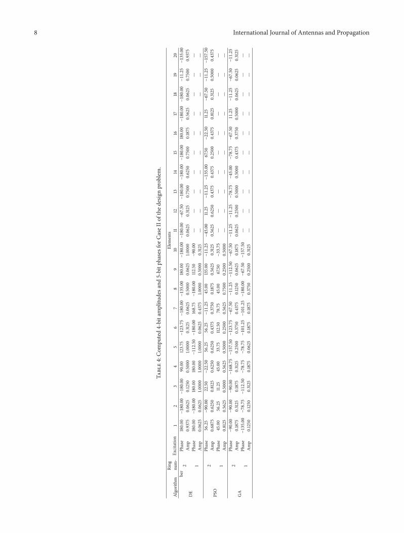
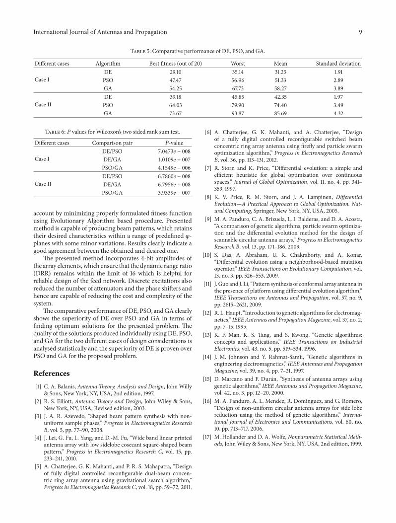
Related Documents


