Design of agitated Design of agitated Heat transfer vessel Heat transfer vessel

Design of agitated Heat transfer vessel. GROUP MEMBERS SABA 06-CHEM-02 FARIHA 06-CHEM-16 SHAZIA 06-CHEM-38.
Dec 30, 2015
Welcome message from author
This document is posted to help you gain knowledge. Please leave a comment to let me know what you think about it! Share it to your friends and learn new things together.
Transcript

Design of agitated Design of agitated
Heat transfer vesselHeat transfer vessel

GROUP MEMBERSGROUP MEMBERS
SABA 06-CHEM-02SABA 06-CHEM-02
FARIHA 06-CHEM-16FARIHA 06-CHEM-16
SHAZIA 06-CHEM-38SHAZIA 06-CHEM-38
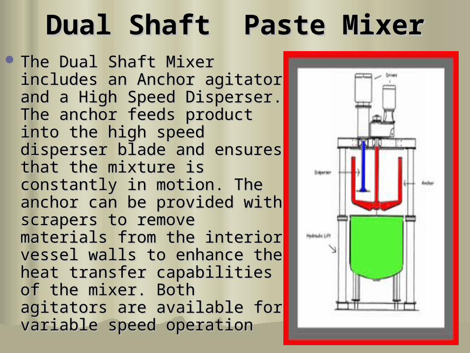
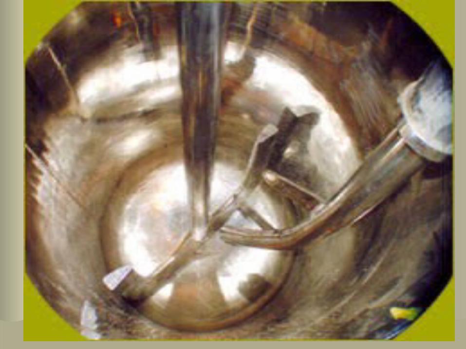
Dual ShaftDual Shaft Paste MixerPaste Mixer The Dual Shaft Mixer The Dual Shaft Mixer
includes an Anchor agitator includes an Anchor agitator and a High Speed Disperser. and a High Speed Disperser. The anchor feeds product The anchor feeds product into the high speed disperser into the high speed disperser blade and ensures that the blade and ensures that the mixture is constantly in mixture is constantly in motion. The anchor can be motion. The anchor can be provided with scrapers to provided with scrapers to remove materials from the remove materials from the interior vessel walls to interior vessel walls to enhance the heat transfer enhance the heat transfer capabilities of the mixer. capabilities of the mixer. Both agitators are available Both agitators are available for variable speed operation for variable speed operation

Dual ShaftDual Shaft Paste MixerPaste Mixer

Jacked and coil heat transfer Jacked and coil heat transfer agitator vesselagitator vessel

Heat transfer coil in side Heat transfer coil in side vesselvessel

Use of bafflesUse of baffles
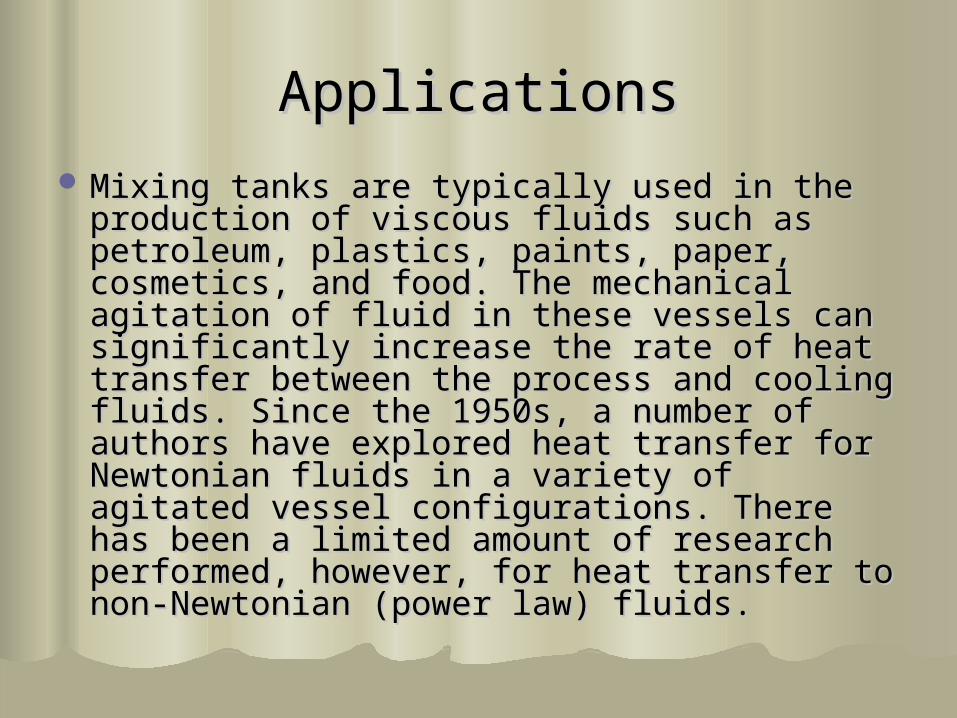
ApplicationsApplications Mixing tanks are typically used in the Mixing tanks are typically used in the
production of viscous fluids such as production of viscous fluids such as petroleum, plastics, paints, paper, petroleum, plastics, paints, paper, cosmetics, and food. The mechanical cosmetics, and food. The mechanical agitation of fluid in these vessels can agitation of fluid in these vessels can significantly increase the rate of heat significantly increase the rate of heat transfer between the process and cooling transfer between the process and cooling fluids. Since the 1950s, a number of authors fluids. Since the 1950s, a number of authors have explored heat transfer for Newtonian have explored heat transfer for Newtonian fluids in a variety of agitated vessel fluids in a variety of agitated vessel configurations. There has been a limited configurations. There has been a limited amount of research performed, however, for amount of research performed, however, for heat transfer to non-Newtonian (power law) heat transfer to non-Newtonian (power law) fluids.fluids.
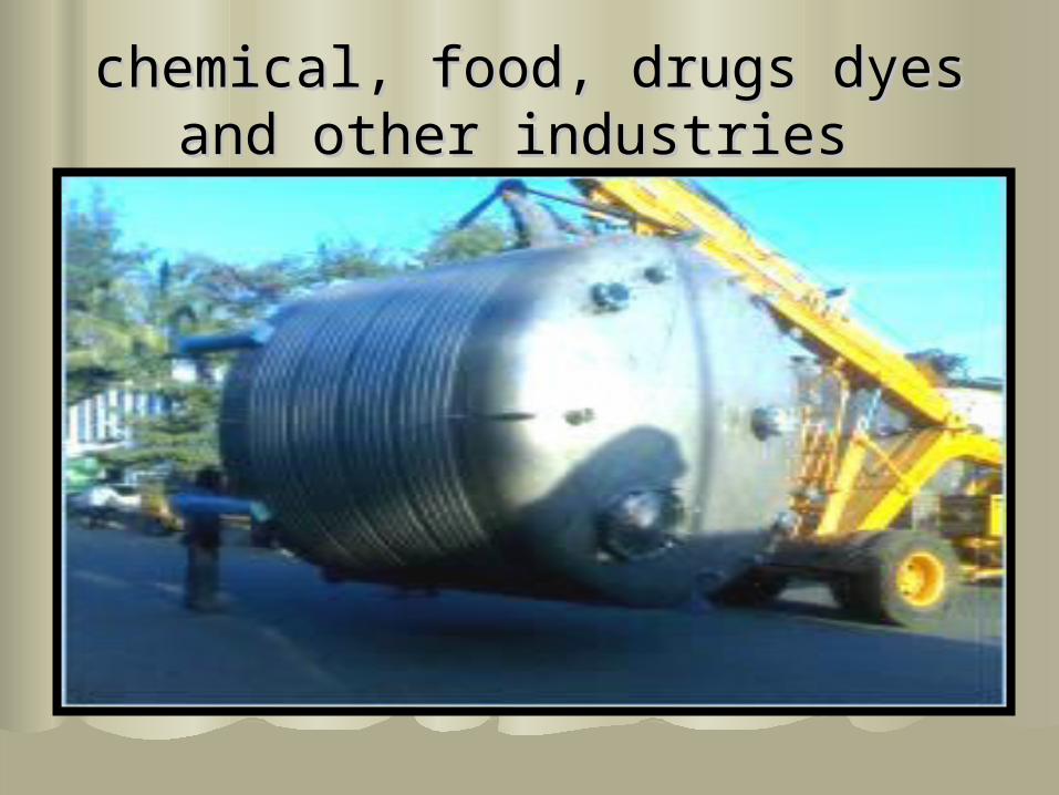
chemical, food, drugs dyes and chemical, food, drugs dyes and other industries other industries

Use for Pharmaceutical Use for Pharmaceutical Application Application

used in chemical and pharmaceutical used in chemical and pharmaceutical industriesindustries
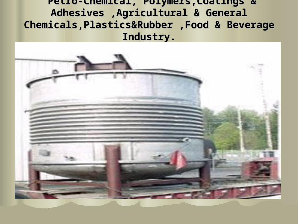
Petro-Chemical, Polymers,Coatings & Petro-Chemical, Polymers,Coatings & Adhesives ,Agricultural & General Adhesives ,Agricultural & General
Chemicals,Plastics&Rubber ,Food & Beverage Chemicals,Plastics&Rubber ,Food & Beverage Industry.Industry.
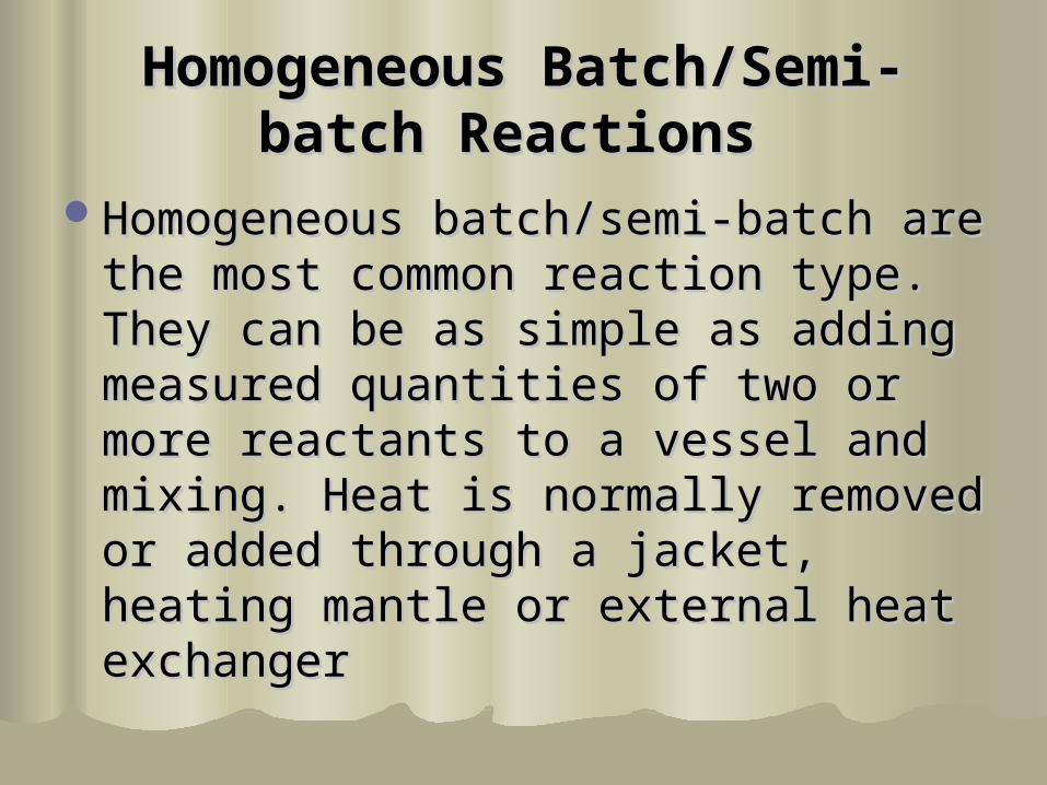
Homogeneous Batch/Semi-Homogeneous Batch/Semi-batch Reactionsbatch Reactions
Homogeneous batch/semi-batch are Homogeneous batch/semi-batch are the most common reaction type. the most common reaction type. They can be as simple as adding They can be as simple as adding measured quantities of two or more measured quantities of two or more reactants to a vessel and mixing. reactants to a vessel and mixing. Heat is normally removed or added Heat is normally removed or added through a jacket, heating mantle or through a jacket, heating mantle or external heat exchanger external heat exchanger


STATEMENTSTATEMENT
Calculate the time required to heat Calculate the time required to heat 1268 gal. of liquid from 801268 gal. of liquid from 80OOF to 180F to 180OOF F in a jacketed, agitated vessel in a jacketed, agitated vessel conforming to standard configuration conforming to standard configuration as shown in the figure. The vessel is as shown in the figure. The vessel is assumed to be clean, free of fouling assumed to be clean, free of fouling films and heated with 212films and heated with 212OOF steam.F steam.
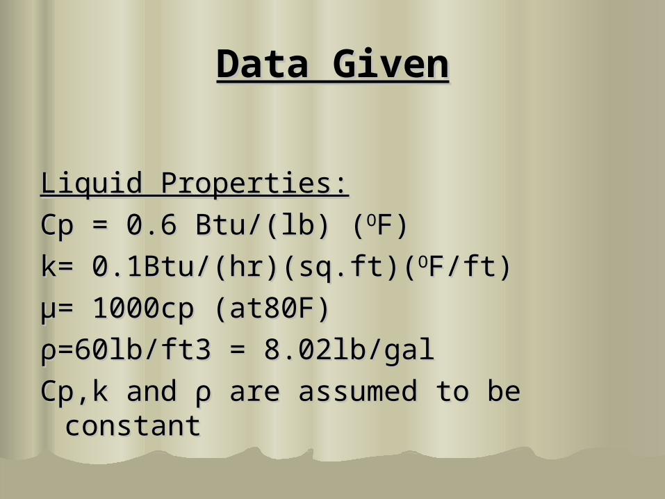
Data GivenData Given
Liquid Properties:Liquid Properties:
Cp = 0.6 Btu/(lb) (Cp = 0.6 Btu/(lb) (OOF)F)
k= 0.1Btu/(hr)(sq.ft)(k= 0.1Btu/(hr)(sq.ft)(OOF/ft)F/ft)
μμ= 1000cp (at80F)= 1000cp (at80F)
ρρ=60lb/ft3 = 8.02lb/gal=60lb/ft3 = 8.02lb/gal
Cp,k and Cp,k and ρρ are assumed to be constant are assumed to be constant

Steam properties:Steam properties:
hhss=1000 Btu/(hr)(sq.ft)(=1000 Btu/(hr)(sq.ft)(OOF)F)
Vessel Properties:Vessel Properties:
Wall thickness= 0.125 inWall thickness= 0.125 in
K of vessel = 9.4 Btu/(hr)(sq.ft)(K of vessel = 9.4 Btu/(hr)(sq.ft)(OOF/ft)F/ft)
Eq used for calculating heat transfer Eq used for calculating heat transfer coefficientcoefficient
NNNUNU = 0.73(N = 0.73(NRERE))0.650.65(N(NPRPR))0.33(0.33(μμww/ / μμbb))0.140.14


STEP 1:STEP 1:
Diameter of the vessel DDiameter of the vessel DTT =6 ft. =6 ft.6-ft diameter agitated vessel conforming to 6-ft diameter agitated vessel conforming to
standard configuration as shown in the standard configuration as shown in the figure. The vessel is equipped with the 2 ft figure. The vessel is equipped with the 2 ft diameter 6-blade, flat-blade turbine diameter 6-blade, flat-blade turbine impeller running at 100 rpm.impeller running at 100 rpm.
Diameter of impeller = 2ftDiameter of impeller = 2ft Impeller blade width=0.5 ftImpeller blade width=0.5 ft Impeller blade height=0.4 ftImpeller blade height=0.4 ft Baffle width=0.6 ftBaffle width=0.6 ft
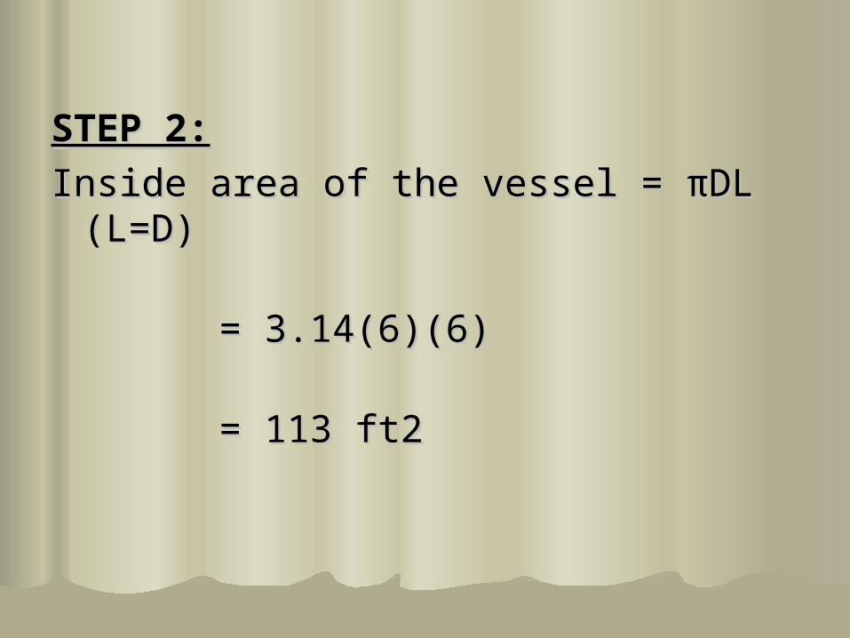
STEP 2:STEP 2:
Inside area of the vessel = Inside area of the vessel = ππDL (L=D)DL (L=D)
= 3.14(6)(6)= 3.14(6)(6)
= 113 ft2= 113 ft2
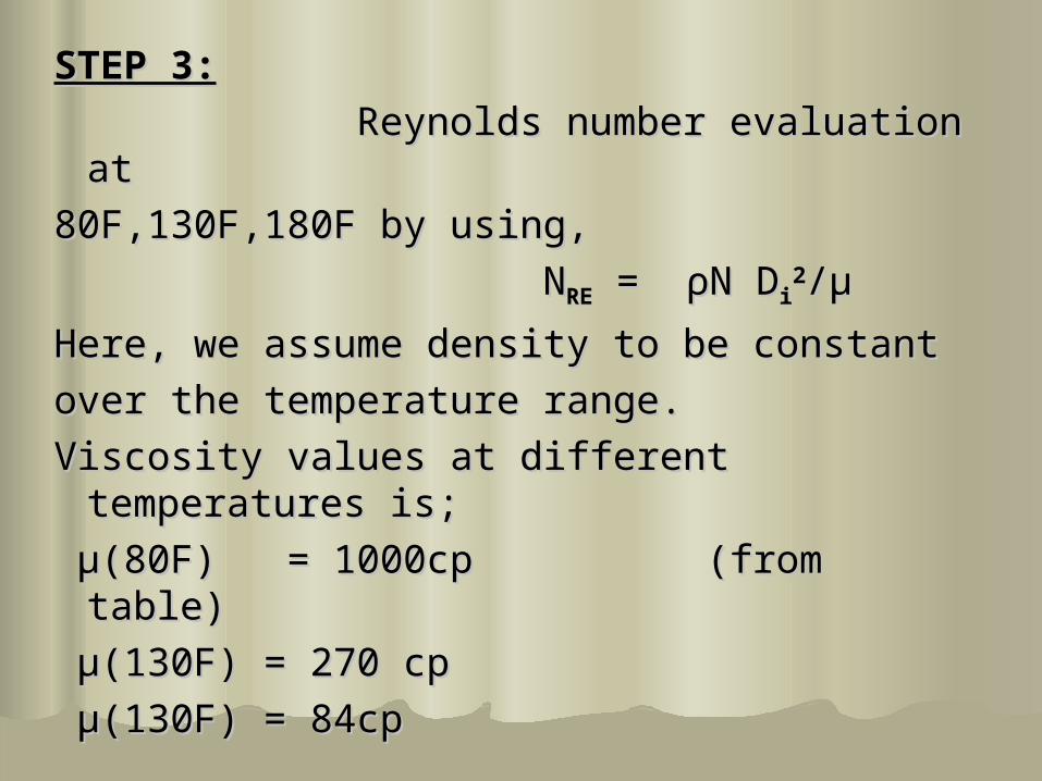
STEP 3:STEP 3:
Reynolds number evaluation at Reynolds number evaluation at
80F,130F,180F by using,80F,130F,180F by using,
NNRERE = = ρρN DN Dii22//μμ
Here, we assume density to be constantHere, we assume density to be constant
over the temperature range.over the temperature range.
Viscosity values at different Viscosity values at different temperatures is;temperatures is;
μμ((80F80F) = 1000cp (from table)) = 1000cp (from table)
μμ((130F130F) = 270 cp) = 270 cp
μμ((130F130F) = 84cp) = 84cp


Diameter of impeller, DDiameter of impeller, Dii = 2 ft = 2 ft
From these values , the Reynolds From these values , the Reynolds number is,number is,
NNRERE(80F) = (60)(6000)(4)/(2420)(80F) = (60)(6000)(4)/(2420)
= 595= 595
NNRERE(130F)= 2200(130F)= 2200
NNRERE (130F)=7080 (130F)=7080
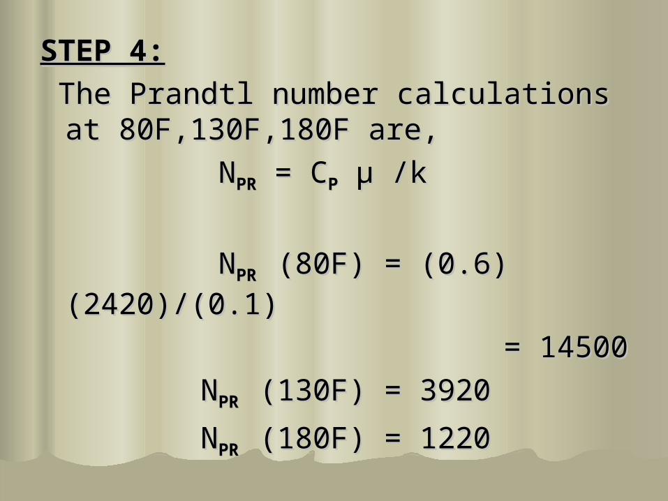
STEP 4:STEP 4:
The Prandtl number calculations at The Prandtl number calculations at 80F,130F,180F are,80F,130F,180F are,
NNPRPR = C = CPP μμ /k /k
NNPR PR (80F) = (0.6)(2420)/(0.1)(80F) = (0.6)(2420)/(0.1)
= 14500= 14500
NNPR PR (130F) = 3920(130F) = 3920
NNPR PR (180F) = 1220(180F) = 1220

STEP 5:STEP 5:
Approximate the value of Approximate the value of inside heat transfer coefficient from inside heat transfer coefficient from given equation;given equation;
NNNUNU = h = hii D DTT/k = 0.73(N/k = 0.73(NRERE))0.650.65(N(NPRPR))0.330.33
substitutingsubstituting the appropriate values the appropriate values into this relationship gives:into this relationship gives:
hhii(80F) =18.4 Btu/(F) (hr) (sq.ft)(80F) =18.4 Btu/(F) (hr) (sq.ft)
hhii(130F) =27.6 Btu/(F) (hr) (sq.ft)(130F) =27.6 Btu/(F) (hr) (sq.ft)
hhii(180F) =40.4 Btu/(F) (hr) (sq.ft)(180F) =40.4 Btu/(F) (hr) (sq.ft)
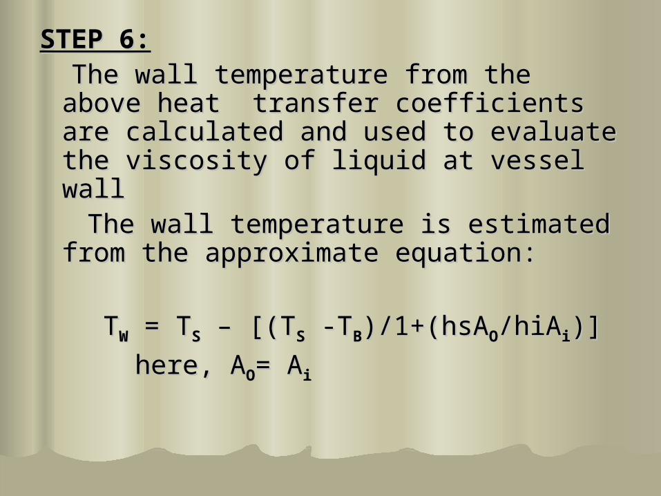
STEP 6:STEP 6: The wall temperature from the above The wall temperature from the above
heat transfer coefficients are heat transfer coefficients are calculated and used to evaluate the calculated and used to evaluate the viscosity of liquid at vessel wall viscosity of liquid at vessel wall
The wall temperature is estimated The wall temperature is estimated from the approximate equation:from the approximate equation:
TTWW = T = TSS – [(T – [(TSS -T -TBB)/1+(hsA)/1+(hsAOO/hiA/hiAii)])]
here, Ahere, AOO= A= Aii

Solving wall temperature Solving wall temperature
TTW W (at T(at TB B = 80F) = 209.6 F= 80F) = 209.6 F
TTW W (at T(at TB B = 130F) = 209.8 F= 130F) = 209.8 F
TTW W (at T(at TB B = 180F) = 210.7 F= 180F) = 210.7 F
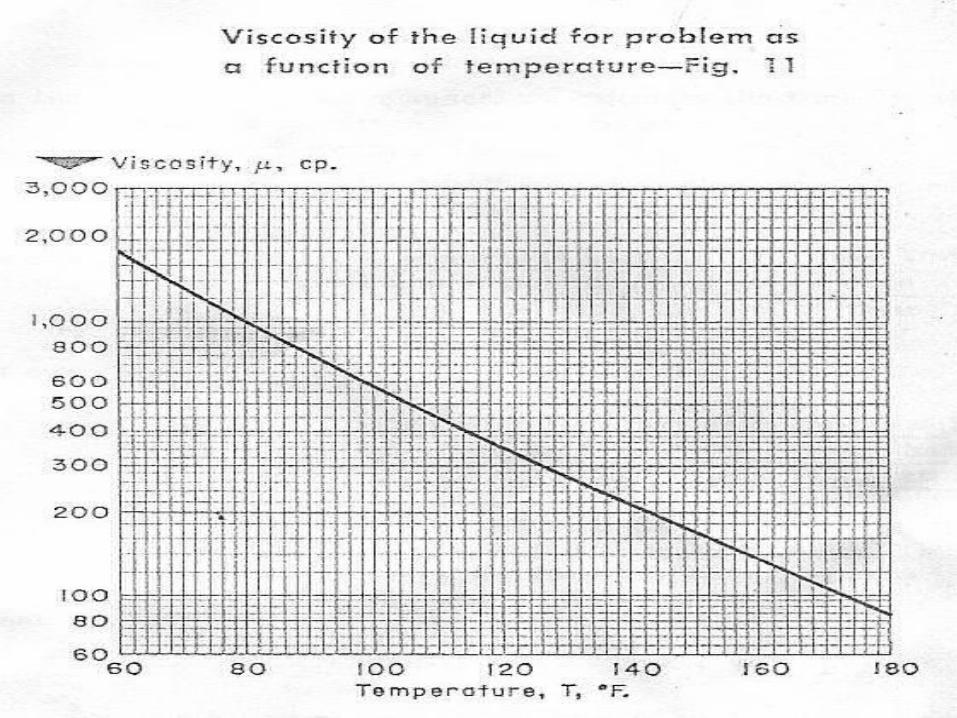
Viscosity values at different Viscosity values at different temperatures is;temperatures is;
μμ((209.6F209.6F) = 47cp (from table)) = 47cp (from table) μμ((209.8F209.8F) = 47cp) = 47cp μμ((210.7F210.7F) = 46 cp) = 46 cp

Calculate the viscosities ratios equals to Calculate the viscosities ratios equals to
μμww/ / μμbb
At TAt TBB =80F and T =80F and TWW = 209.6F = 209.6F
VVISIS=47/1000=0.047=47/1000=0.047
At TAt TBB =130F and T =130F and TWW = 209.8F = 209.8F
VVISIS=47/270=0.174=47/270=0.174
At TAt TBB =80F and T =80F and TWW = 209.6F = 209.6F
VVISIS=46/85=0.541=46/85=0.541
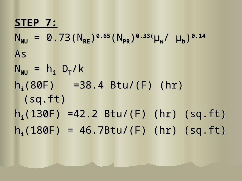
STEP 7:STEP 7:
NNNUNU = 0.73(N = 0.73(NRERE))0.650.65(N(NPRPR))0.33(0.33(μμww/ / μμbb))0.140.14
As As
NNNUNU = h = hii D DTT/k/k
hhii(80F) =38.4 Btu/(F) (hr) (sq.ft)(80F) =38.4 Btu/(F) (hr) (sq.ft)
hhii(130F) =42.2 Btu/(F) (hr) (sq.ft)(130F) =42.2 Btu/(F) (hr) (sq.ft)
hhii(180F) = 46.7Btu/(F) (hr) (sq.ft)(180F) = 46.7Btu/(F) (hr) (sq.ft)

STEP 8:STEP 8:1/Ui = 1/hi+ x/k +1/hs 1/Ui = 1/hi+ x/k +1/hs hi= as calculated in step 7hi= as calculated in step 7x= 1/8 in =0.0104 ftx= 1/8 in =0.0104 ftK= 9.4 Btu/(hr)(sq.ft)(F/ft) for the vessel K= 9.4 Btu/(hr)(sq.ft)(F/ft) for the vessel
wallwall
hhss= 1000 Btu/(F) (hr) (sq.ft) = 1000 Btu/(F) (hr) (sq.ft)
UUii(Tb=80 F) =0.0281 Btu/(F) (hr) (sq.ft) (Tb=80 F) =0.0281 Btu/(F) (hr) (sq.ft)
UUii(Tb=130 F) =38.7 Btu/(F) (hr) (sq.ft) (Tb=130 F) =38.7 Btu/(F) (hr) (sq.ft)
UUii(Tb=180 F)= 42.5 Btu/(F) (hr) (sq.ft) (Tb=180 F)= 42.5 Btu/(F) (hr) (sq.ft)

Ui at different time intervals
35
36
37
38
39
40
41
42
43
0 50 100 150 200
Tb(F)
Ui
Ui


STEP 9:STEP 9:
Time taken to heat the liq over each Time taken to heat the liq over each temp increment is calculated by this temp increment is calculated by this formulaformula
TThrhr=(MC=(MCPP/U/UiiAAii) ln [T) ln [TSS – T – TII/T/TSS –T –Tff]]
Liquid mass= Liquid mass= ππ(D(Dtt22/4)(H/4)(Htt)()(ρρ))
= = ππ(36/4)(6)(60)(36/4)(6)(60)
=10180 lb =10180 lb

Time reqd to heat the nass from 80 to 100 F Time reqd to heat the nass from 80 to 100 F is calculated asis calculated as
t(80-100F) t(80-100F)
= (10180)(0.6) ln (212-80)= (10180)(0.6) ln (212-80)
(36.15)(113) (212-100)(36.15)(113) (212-100)
=0.242 hr=0.242 hr
t(100 -120F) = 0.283 hrt(100 -120F) = 0.283 hr
t(120 -140F) = 0.340 hrt(120 -140F) = 0.340 hr
t(140-160F) = 0.439 hrt(140-160F) = 0.439 hr
t(160-180F) =0.630 hrt(160-180F) =0.630 hr
Total Time = 1.934 hrTotal Time = 1.934 hr
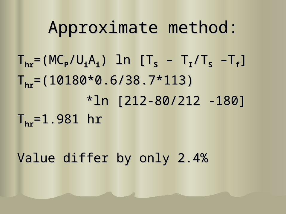
Approximate method:Approximate method:
TThrhr=(MC=(MCPP/U/UiiAAii) ln [T) ln [TSS – T – TII/T/TSS –T –Tff]]
TThrhr=(10180*0.6/38.7*113) =(10180*0.6/38.7*113)
*ln [212-80/212 -180]*ln [212-80/212 -180]
TThrhr=1.981 hr=1.981 hr
Value differ by only 2.4%Value differ by only 2.4%
Related Documents