e University of Akron IdeaExchange@UAkron Honors Research Projects e Dr. Gary B. and Pamela S. Williams Honors College Spring 2015 Design of a Horizontal Creep Testing Machine Michael Presby [email protected] Please take a moment to share how this work helps you through this survey. Your feedback will be important as we plan further development of our repository. Follow this and additional works at: hp://ideaexchange.uakron.edu/honors_research_projects Part of the Mechanical Engineering Commons is Honors Research Project is brought to you for free and open access by e Dr. Gary B. and Pamela S. Williams Honors College at IdeaExchange@UAkron, the institutional repository of e University of Akron in Akron, Ohio, USA. It has been accepted for inclusion in Honors Research Projects by an authorized administrator of IdeaExchange@UAkron. For more information, please contact [email protected], [email protected]. Recommended Citation Presby, Michael, "Design of a Horizontal Creep Testing Machine" (2015). Honors Research Projects. 54. hp://ideaexchange.uakron.edu/honors_research_projects/54

Welcome message from author
This document is posted to help you gain knowledge. Please leave a comment to let me know what you think about it! Share it to your friends and learn new things together.
Transcript
The University of AkronIdeaExchange@UAkron
Honors Research Projects The Dr. Gary B. and Pamela S. Williams HonorsCollege
Spring 2015
Design of a Horizontal Creep Testing MachineMichael [email protected]
Please take a moment to share how this work helps you through this survey. Your feedback will beimportant as we plan further development of our repository.Follow this and additional works at: http://ideaexchange.uakron.edu/honors_research_projects
Part of the Mechanical Engineering Commons
This Honors Research Project is brought to you for free and open access by The Dr. Gary B. and Pamela S. WilliamsHonors College at IdeaExchange@UAkron, the institutional repository of The University of Akron in Akron, Ohio,USA. It has been accepted for inclusion in Honors Research Projects by an authorized administrator ofIdeaExchange@UAkron. For more information, please contact [email protected], [email protected].
Recommended CitationPresby, Michael, "Design of a Horizontal Creep Testing Machine" (2015). Honors Research Projects. 54.http://ideaexchange.uakron.edu/honors_research_projects/54

The University of Akron
Design of a Horizontal Creep Testing MachineSenior Design/Honors Research Project
Michael Presby
5-1-2015
The University of Akron
Design of a Horizontal Creep Testing Machine Senior Design/Honors Research Project
Horizontal Creep
1
Contents
Abstract ........................................................................................................................................... 2
Introduction ..................................................................................................................................... 3
Design Criteria ................................................................................................................................ 4
Design Process for the Frame ......................................................................................................... 6
Grips for High Temperature Tensile Test ..................................................................................... 13
Conclusion .................................................................................................................................... 20
References ..................................................................................................................................... 21
Appendix ....................................................................................................................................... 22

2
Abstract The design process for a horizontal creep testing machine is presented along with the
material selection of grips for high temperature tensile tests. The design process consisted of
creating multiple sketches of the testing machine in order to determine the best design to satisfy
the given design parameters. The critical points of the frame were determined and derivations
were performed in order to determine the maximum stress at the critical points and the maximum
deflection due to the applied load. The information gathered from these derivations will be useful
in comparing the two material choices for the frame which are aluminum structural framing and
steel.
The material selection process for the grips was also presented. The material of choice for
the grips must be able to withstand high temperature as well as have high strength and high
stiffness. The economic side of choosing a material was also taken into account in order to
determine the material that provides the best performance while minimizing cost. It was
determined that the ideal material is silicon carbide and the best shaping process for a small
batch size is to use conventional machining.
3
Introduction A creep testing machine is used to measure the creep of a test specimen. Creep is the
behavior of materials to deform at elevated temperatures and at a constant stress or load. Creep is
important in determining how much strain (load) an object can handle in order to determine
which material to use for a specific application.
The basic design of a creep testing machine is the support structure, the loading device
(deadweight or actuator), the fixture device (grips and pull rods), and the furnace. The specimen
being tested is held in place by the grips and a furnace surrounds the test section and maintains a
constant temperature. The alignment of the test specimen is crucial to gather an accurate reading
of the creep of the material. The load is transmitted to the test specimen via the fixture devices
and the specimen is held in constant tension throughout the test.
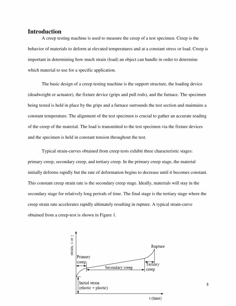
Typical strain-curves obtained from creep tests exhibit three characteristic stages:
primary creep, secondary creep, and tertiary creep. In the primary creep stage, the material
initially deforms rapidly but the rate of deformation begins to decrease until it becomes constant.
This constant creep strain rate is the secondary creep stage. Ideally, materials will stay in the
secondary stage for relatively long periods of time. The final stage is the tertiary stage where the
creep strain rate accelerates rapidly ultimately resulting in rupture. A typical strain-curve
obtained from a creep-test is shown in Figure 1.

4
Figure 1. Typical strain-curve obtained from creep test
Creep can be measured using a vertical test machine or a horizontal test machine. In both
cases, the specimen is held in a constant tensile load and subjected to a constant temperature.
However, if one were to use a burner assembly to apply a flame directly to the test specimen, a
horizontal test frame would be ideal. Compared to a vertical test frame, a horizontal frame
prevents a chimney effect which results in a more precise application of the flame to the
specimen. The design process of a horizontal test frame is developed and presented along with
the material selection for the grips.
Design Criteria Any machine that measures the creep of a material must be perfectly aligned in order to
provide an accurate representation of the material’s creep behavior. Therefore, the machine
should have some sort of self-aligning mechanism. In addition, the test frame must be able to
withstand any applied load. For this design, the maximum load that a test specimen will be
subjected to will be 10kN. In order to provide a factor of safety, the design of the frame should
be able to withstand between 15kN and 20kN.
Furthermore, the distance from the floor to the test specimen should be at a comfortable
distance for the user to easily handle the test specimen and make any necessary adjustments. The
frame should also allow the specimen to be visible from all sides in order to allow for
observation and the use of cameras to record the test. The user should also have the capability to

5
move additional test equipment such as a furnace, extensometer, cameras, etc. in and out of
position easily. This can be accomplished by the use of a track system.
Additional design requirements include having space for a burner assembly and for the
specimen to not travel far after rupture. Ideally, once the specimen ruptures, half of the specimen
will be pulled out of the furnace. Table 1 displays the design criteria in order of importance for
the test frame.
In addition to the design of the test frame, grips will also need to be designed and
machined. The grips should be able to withstand high temperatures, must not fail or deflect too
much under the design load, and have a minimal thermal expansion coefficient. Table 2 shows
the translation for the material selection of the grips for high temperature tensile test.
Table 1. Design criteria for test frame
Function Grip for high temperature tensile test
Strength - must not fail under design load
Stiffness - must not deflect too much under design load
Withstand high temperature (max service temp ≥ 700°C)
Minimal thermal expansion coefficient
Objective Minimize cost
Free Variables Choice of Material
Constraints
Function Creep Testing Machine
Design Criteria
Design load 15kN - 20kN
Self-aligning mechanism
Load applied using deadweight
Half of specimen should pull out of furnace after rupture
Track system for addition test equipment
Distance from floor to specimen approximately 48"
Specimen must be visible from all sides
Space to slide burner assembly under specimen

Design Process for the Frame The initial design process entailed observing other creep test machines and drawing
multiple sketches. These sketches were then analyzed to see which ones best met the design
criteria and the most suitable sketch was selected to move on in the design proce
Figure 2 shows a typical test area for a v
wedge grips as well as an aluminum track system to move the furnace into position once the
specimen is positioned within the grips.
Figure 2.
Figure 3 illustrates how the extensometer is attached
track system. The track system is an important part of the frame design due to the extra test
equipment that is necessary during a creep test.
Table 2. Translation for grips
for the Frame The initial design process entailed observing other creep test machines and drawing
multiple sketches. These sketches were then analyzed to see which ones best met the design
criteria and the most suitable sketch was selected to move on in the design proce
Figure 2 shows a typical test area for a vertical tensile test. This test are uses hydraulic
wedge grips as well as an aluminum track system to move the furnace into position once the
specimen is positioned within the grips.
Figure 2. Vertical tensile test setup
Figure 3 illustrates how the extensometer is attached and moves using the
The track system is an important part of the frame design due to the extra test
equipment that is necessary during a creep test.
6
The initial design process entailed observing other creep test machines and drawing
multiple sketches. These sketches were then analyzed to see which ones best met the design
criteria and the most suitable sketch was selected to move on in the design process.
uses hydraulic
wedge grips as well as an aluminum track system to move the furnace into position once the
using the aluminum
The track system is an important part of the frame design due to the extra test
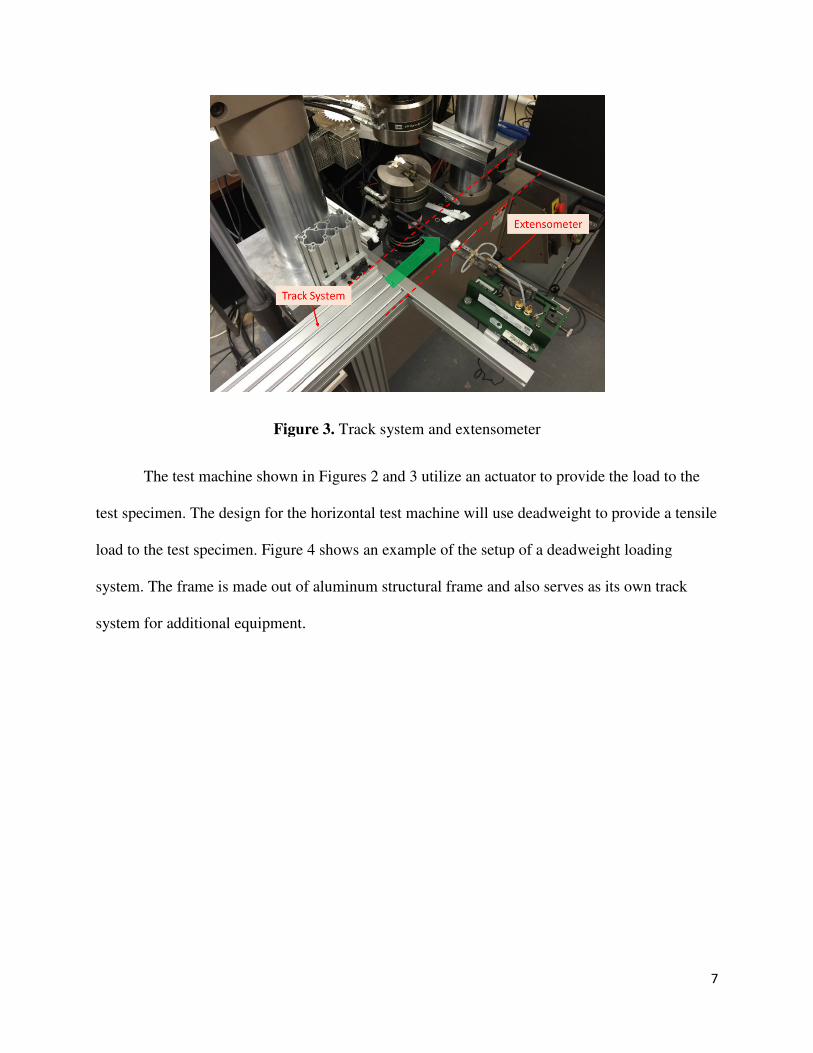
Figure 3.
The test machine shown in F
test specimen. The design for the horizontal test machine will use deadweight to provide a tensile
load to the test specimen. Figure 4 shows an example of the setup of a deadweight loading
system. The frame is made out of aluminum structural frame and also serves as its own track
system for additional equipment.
Figure 3. Track system and extensometer
The test machine shown in Figures 2 and 3 utilize an actuator to provide the load to the
test specimen. The design for the horizontal test machine will use deadweight to provide a tensile
Figure 4 shows an example of the setup of a deadweight loading
The frame is made out of aluminum structural frame and also serves as its own track
system for additional equipment.
7
igures 2 and 3 utilize an actuator to provide the load to the
test specimen. The design for the horizontal test machine will use deadweight to provide a tensile
Figure 4 shows an example of the setup of a deadweight loading
The frame is made out of aluminum structural frame and also serves as its own track

Figure 4. Vertical tensile test
The initial sketch for a horizontal creep tes
initial design incorporates a hydraulic actuator to apply the load and does not meet the design
requirement that the test specimen must be visible from all sides for o
satisfy the requirement that the test specimen should be easily handled by the user at a height o
approximately 48 inches, the test machine would have to be placed on a support fixture.
addition, this design incorporated a hydra
designs. It was later decided to primarily focus on a design incorporating deadweight.
Vertical tensile test with deadweight loading system
he initial sketch for a horizontal creep testing machine is illustrated in F
initial design incorporates a hydraulic actuator to apply the load and does not meet the design
requirement that the test specimen must be visible from all sides for observation. I
satisfy the requirement that the test specimen should be easily handled by the user at a height o
test machine would have to be placed on a support fixture.
addition, this design incorporated a hydraulic actuator because the initial plan included two
designs. It was later decided to primarily focus on a design incorporating deadweight.
8
ting machine is illustrated in Figure 5. The
initial design incorporates a hydraulic actuator to apply the load and does not meet the design
bservation. In order to
satisfy the requirement that the test specimen should be easily handled by the user at a height of
test machine would have to be placed on a support fixture. In
included two
designs. It was later decided to primarily focus on a design incorporating deadweight.

9
Figure 5. Initial design sketch
The design was updated following the initial sketch and is illustrated in Figure 6. This
design featured a pulley system to transfer the load to the specimen. Due to the large amount of
mass required to provide a force of 10 kN, the frame had two pulleys attached in order to have
the mass located in the center of the test frame. This would allow for the center of gravity to
remain approximately in the center of the test frame and therefore preventing any sort of moment
(tipping force) that would need to be counterbalanced.
The frame was redesigned to allow for full observation
of the test specimen.
Figure 6. Second design sketch
Due to the possibility of implementing a burner assembly at a later time, an updated
version of the test frame was designed and shown in Figure 7.

10
Figure 7. Third design sketch
This design moved the mass from the center of the frame to the side as well as
implementing a track system for the camera, high temp furnace, and extensometer. The track
system is implemented by making the frame out of aluminum structural framing. This design
however, poses two problems. First, it does not satisfy the requirement that the specimen is
pulled out of the furnace and then supported after rupture. Second, the light weight of the

11
aluminum may not be enough to counterbalance the weight of the applied load without being
additionally supported or fixed to the ground.
The next sketch is an attempt to solve both of the problems posed by the previous sketch.
Figure 8 illustrates the design updates. The frame was changed from the aluminum structural
framing to steel in order to provide additional weight and the test area was shortened to provide a
stop for the specimen to pull out of the furnace after rupture.
Figure 8. Fourth design sketch
In this design, the track system is added to the steel frame in order to provide for the
additional test equipment. Once the test specimen ruptures, the weight is released and the

12
specimen is pulled out of the furnace. A stop exists with an impact absorbent pad to protect the
grip from contacting the steel structure. Since the test area has been shrunk to the middle of the
frame, the additional weight from the structure outside the test area acts as a counterbalance.
Because this sketch satisfies the design criteria it was chosen to move forward in the design
process.
The critical points of the frame are where the maximum flexural stress and the maximum
deflection will occur. For the current design, there are two components that will see the most
stress and deflection. The first component is the beam that the left grip is attached to, and the
second component is the rod that connects the pulley to the frame. The beam that the left grip is
attached to is fixed at both ends as shown in figure 9.
Figure 9. Fixed, Fixed beam
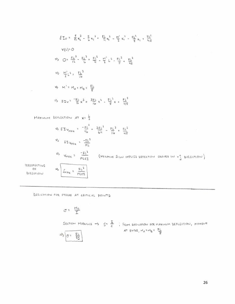
The maximum deflection of the beam will occur at L/2 and is given as
���� ����
192� �1�
F
δ
L

13
where F is the force of the applied load, L is the length of the beam, E is the elastic modulus and
I is the area moment of inertia. The maximum flexural stress will occur at the fixed ends of the
beam and is given as
� � ��
8� �2�
where F is the force of the applied load, L is the length of the beam and S is the section modulus
given as
� � ���
6 �3�
where b is the length and h is the height of the beam. The deflection and flexural stresses of the
rod that the pulley is attached to are given by (1) and (2) respectively, but the area moment of
inertia for a rod is
� �
4�� �4�
and the section modulus is
� � �
4��. �5�
The derivations for (1) and (2) are shown in the appendix. A future study will be conducted in
order to determine which material (aluminum structural framing or steel) is best suited for the
frame design.
Grips for High Temperature Tensile Test Gripping devices are used to transmit the load applied by the testing machine to the test
specimen [1]. The grips for this design must be able to withstand the applied load and withstand

14
high temperatures. Additionally, the grips will be designed for a contoured, edge-loaded test
specimen as shown in Figure 10.
Figure 10. Contoured, Edge-Loaded Test Specimen Geometry [1]
Passive grip interfaces transmit the force applied by the test machine to the test specimen
through a direct mechanical link [1]. Mechanical links utilize the geometrical features of the test
specimen and uniform contact between the grip faces and the gripped section of the test
specimen is crucial. Figure 11 shows an example of an edge-loaded, passive grip interface [1].
Figure 11. Edge-Loaded, Passive Grip Interface [1]

15
Material selection is very important in the design of the gripping devices. The material
indices to be maximized in determining the ideal material for this application are M1 = σy (yield
strength) and M2 = E (stiffness). In addition, the material must be able to withstand temperatures
greater than or equal to 700 degrees Celsius and have a minimal thermal expansion coefficient.
The material selection process also considers cost and manufacturing.
Using CES Selector, the material indices are defined and the materials that maximize
performance (high strength and stiffness) are highlighted. Figure 12 displays the materials that
maximize performance.
Figure 12. Performance graph: Young’s modulus vs. Yield Strength
The performance graph shows that the best materials are technical ceramics such as:
tungsten carbides, silicon carbide, silicon nitride, boron carbide, alumina, and zirconia, and

metals such as: stainless steel, medium carbon steel, high carbon steel, low allow steel, and
nickel-based superalloys.
In addition to high strength and high stiffness, the material used for the grips should be
able to operate at temperatures higher than 700 degree Cel
software eliminates medium carbon steel, and high carbon steel. Even though materials can
withstand high temperatures, this does not imply that they have a low thermal expansion
coefficient. The extent at which a materi
minimized for this application and thus the ideal material will have a low thermal expansion
coefficient. Figure 13 shows us that technical ceramics have a lower thermal expansion
coefficient compared to metals and alloys.
Figure 13
The ideal material for the grips seems to be a technical ceramic due to their great
mechanical and thermal properties, but a cost and manufacturing process analysis must be
performed before a final selection can be made.
stainless steel, medium carbon steel, high carbon steel, low allow steel, and
In addition to high strength and high stiffness, the material used for the grips should be
able to operate at temperatures higher than 700 degree Celsius. Adding this limit into the CES
software eliminates medium carbon steel, and high carbon steel. Even though materials can
withstand high temperatures, this does not imply that they have a low thermal expansion
coefficient. The extent at which a material expands due to high temperatures should be
minimized for this application and thus the ideal material will have a low thermal expansion
shows us that technical ceramics have a lower thermal expansion
and alloys.
Figure 13. Thermal expansion coefficient
The ideal material for the grips seems to be a technical ceramic due to their great
mechanical and thermal properties, but a cost and manufacturing process analysis must be
election can be made.
16
stainless steel, medium carbon steel, high carbon steel, low allow steel, and
In addition to high strength and high stiffness, the material used for the grips should be
sius. Adding this limit into the CES
software eliminates medium carbon steel, and high carbon steel. Even though materials can
withstand high temperatures, this does not imply that they have a low thermal expansion
al expands due to high temperatures should be
minimized for this application and thus the ideal material will have a low thermal expansion
shows us that technical ceramics have a lower thermal expansion
The ideal material for the grips seems to be a technical ceramic due to their great
mechanical and thermal properties, but a cost and manufacturing process analysis must be
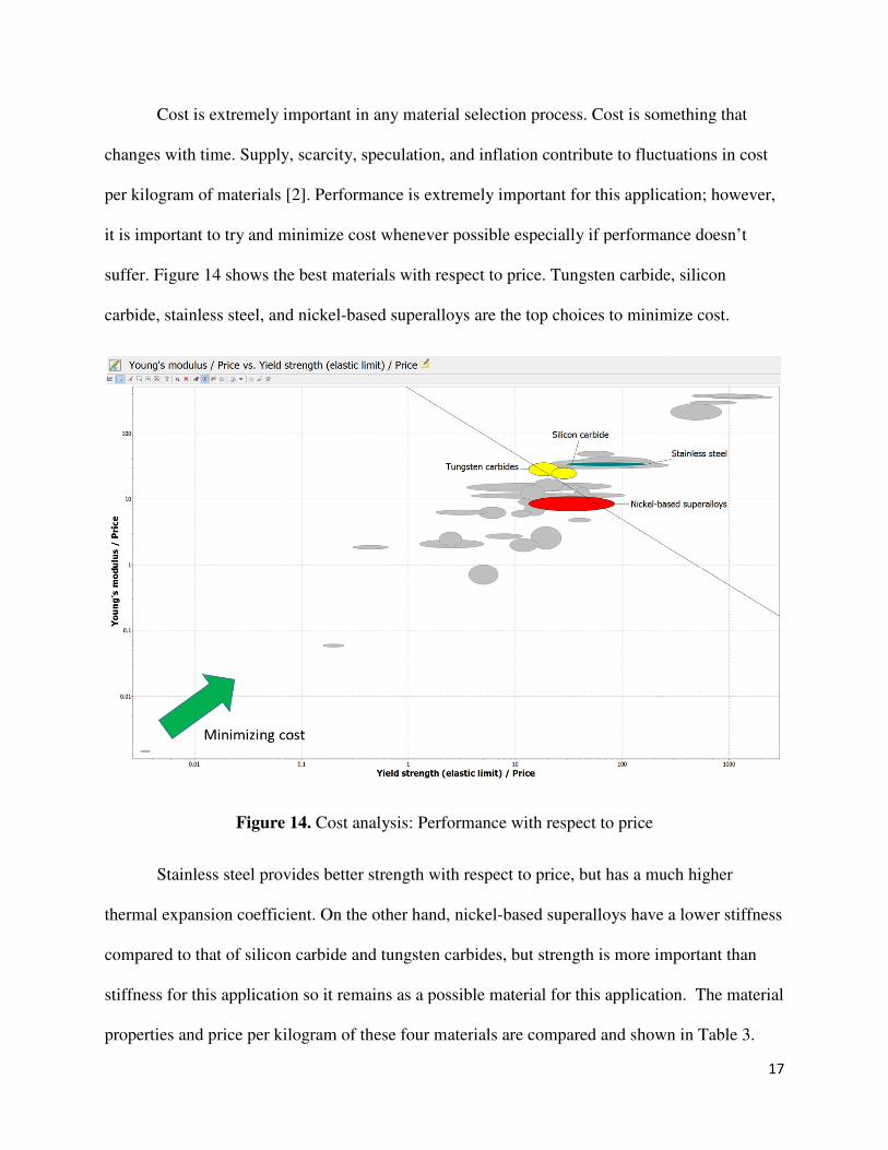
Cost is extremely important in any material selection process. Cost is something that
changes with time. Supply, scarcity, speculation, and inflation contribute to fluctuations in cost
per kilogram of materials [2]. Performance is e
it is important to try and minimize cost whenever possible especially if performance doesn’t
suffer. Figure 14 shows the best materials with respect to price. Tungsten carbide, silicon
carbide, stainless steel, and nickel
Figure 14. Cost analysis: Performance with respect to price
Stainless steel provides better strength with respect to price, but has a much higher
thermal expansion coefficient. On
compared to that of silicon carbide and tungsten carbides, but strength is more important than
stiffness for this application so it remains as a possible m
properties and price per kilogram of these four mater
Cost is extremely important in any material selection process. Cost is something that
changes with time. Supply, scarcity, speculation, and inflation contribute to fluctuations in cost
per kilogram of materials [2]. Performance is extremely important for this application; however,
it is important to try and minimize cost whenever possible especially if performance doesn’t
shows the best materials with respect to price. Tungsten carbide, silicon
eel, and nickel-based superalloys are the top choices to minimize cost.
Cost analysis: Performance with respect to price
Stainless steel provides better strength with respect to price, but has a much higher
thermal expansion coefficient. On the other hand, nickel-based superalloys have a lower stiffness
compared to that of silicon carbide and tungsten carbides, but strength is more important than
stiffness for this application so it remains as a possible material for this application. The ma
properties and price per kilogram of these four materials are compared and shown in T
17
Cost is extremely important in any material selection process. Cost is something that
changes with time. Supply, scarcity, speculation, and inflation contribute to fluctuations in cost
xtremely important for this application; however,
it is important to try and minimize cost whenever possible especially if performance doesn’t
shows the best materials with respect to price. Tungsten carbide, silicon
based superalloys are the top choices to minimize cost.
Stainless steel provides better strength with respect to price, but has a much higher
based superalloys have a lower stiffness
compared to that of silicon carbide and tungsten carbides, but strength is more important than
aterial for this application. The material
ials are compared and shown in Table 3.

18
Silicon Carbide Tungsten Carbides Stainless SteelNickel-based super alloys
Yield Strength (MPa) 500 443 585 900
Tensile Strength (MPa) 500 460 480 600
Stiffness (GPa) 530 663 200 198
Thermal Expansion Coefficent (µstrain/°C) 4.4 6.15 17 13
Max Service Temperature (°C) 1550 875 785 1050
Hardness (HV) 2450 2900 350 400
Fracture Toughness (Mpa.m0.5) 4.3 2.9 106 85
Price per kg ($/kg) $17.60 $23.85 $5.86 $22.55
Table 3. Material properties and price per kg
From Table 3, tungsten carbides are eliminated from the selection process since the
objective is to minimize cost and tungsten carbides cost the most per kilogram. Nickel-based
superalloys have great yield and tensile strength but have poor stiffness in comparison to that of
silicon carbide. Silicon carbide has great strength and stiffness properties as well as a low
thermal expansion coefficient and excellent hardness. Hardness is important for this application
because the grip will impact the stop once the specimen ruptures. Since the yield strength and
tensile strength of silicon carbide is more than sufficient for this application we can eliminate
nickel-based superalloys due to the comparison with silicon carbide and the fact that silicon
carbide is cheaper. Stainless steel meets the service temperature requirement and has good yield
and tensile strength so it remains only as an economical choice due its low cost per kilogram;
however, overall performance suffers in comparison with silicon carbide.
Based on this analysis, silicon carbide is the ideal material for this application.
Performance is extremely important for a creep testing machine because it must be able to
accurately represent the true creep of the material.
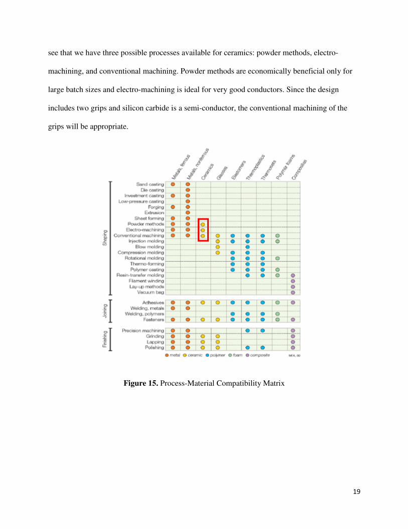
Now that a material has been selected, it is important to determine the best shaping
process for the material. Figure 15 shows the process-material compatibility matrix and we can
19
see that we have three possible processes available for ceramics: powder methods, electro-
machining, and conventional machining. Powder methods are economically beneficial only for
large batch sizes and electro-machining is ideal for very good conductors. Since the design
includes two grips and silicon carbide is a semi-conductor, the conventional machining of the
grips will be appropriate.
Figure 15. Process-Material Compatibility Matrix
20
Conclusion With a final design to move forward with, the next step is to develop a comparison
between the aluminum structural framing and steel. The goal of this analysis will be to see which
material is better suited to withstand the applied load and the resulting moment that will be
created. The aluminum structural framing is the preferred material due to its t-slotted modular
profile which would be utilized as the track system. After this analysis is complete, a preliminary
CAD drawing can be made and structural simulations can be performed to see how the frame
performs under the applied load.
The material selection process is completed for the grips and the next step is to design the
grips for the contoured-edge loaded test specimen geometry as shown in Figure 10. Once the
grips are designed, manufacturing can begin.
Overall, the design for the horizontal creep test is moving forward and further work will
continue to take this proof of concept to the manufacturing stage.

21
References
[1] Standard Test Method for Monotonic Tensile Behavior of Continuous Fiber-Reinforced
Advanced Ceramics with Solid Rectangular Cross-Section Test Specimens at Ambient
Temperature. ASTM C 1275 – 00.
[2] Ashby, Michael, F. 2011. Materials Selection in Mechanical Design. Fourth Edition.
Kidlington, Oxford: Elsevier Ltd.

22
Appendix
Maximum deflection……………………………………………………………..........................23
Stress at critical points…………………………………………………………………………...25

23

24

25
26
Related Documents