DESIGN OF A DYNAMOMETER-ENGINE COUPLING SHAFT MOHD HASNUN ARIF BIN HASSAN PERPUSTAKAAN UNIVERSfl - I MALAYSIA PAHANG No. Perolehan Tarikh No. Pangyiian -t) 1-51 H3f vs T"i eç RESEARCH REPORT SUBMITTED IN PARTIAL FULFILMENT OF THE REQUIREMENTS FOR THE DEGREE OF MASTER OF ENGINEERING FACULTY OF ENGINEERING UNIVERSITY OF MALAYA KUALA LUMPUR 2012

Welcome message from author
This document is posted to help you gain knowledge. Please leave a comment to let me know what you think about it! Share it to your friends and learn new things together.
Transcript

DESIGN OF A DYNAMOMETER-ENGINE
COUPLING SHAFT
MOHD HASNUN ARIF BIN HASSAN PERPUSTAKAAN
UNIVERSfl-I MALAYSIA PAHANG No. Perolehan
Tarikh
No. Pangyiian -t) 1-51 H3f
vs T"i eç
RESEARCH REPORT SUBMITTED
IN PARTIAL FULFILMENT OF THE
REQUIREMENTS FOR THE DEGREE OF
MASTER OF ENGINEERING
FACULTY OF ENGINEERING
UNIVERSITY OF MALAYA
KUALA LUMPUR
2012
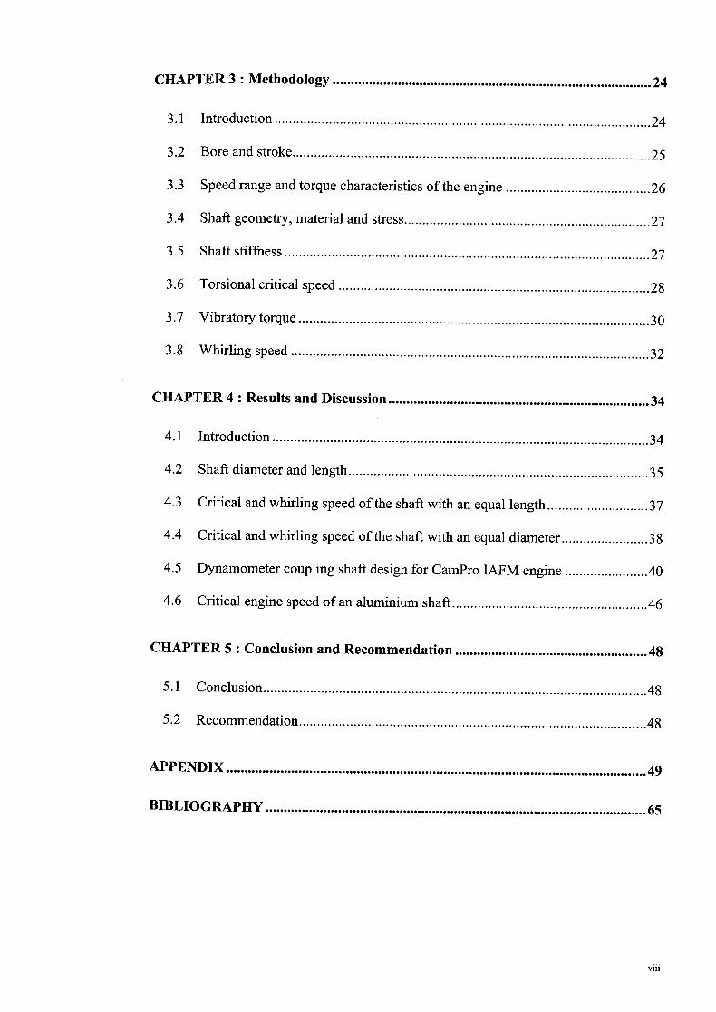
Abstract
In measuring the power output of an engine, the engine has to be coupled to a load
device known as dynamometer. The coupling is done by means of a solid shaft. The
proper couplings and shaft are required for the connection to avoid any failure to the
engine or the dynamometer. Unsuitable selection could lead to undesired problems such
as torsional vibrations, vibration of the engine and dynamometer, whirling of the
coupling shaft, damage of the bearings, engine starting problem or immoderate wear of
the shaft line components. The commonly encountered problem is the resonance in
torsional vibration, which results in disastrous failure of the shaft due to excessive
vibration. This project is aimed to study the appropriate design of the shaft to be used in
the dynamometer-engine coupling to prevent the system from undergoing unwanted
problems. The theoretical calculations involve in the design are presented. The
dimension of the coupling shafts for engines with various maximum torques are
estimated. It is shown that the diameter of the shaft is proportional to the maximum
torque of the engine given that the same coupling is used for every system, whereas the
length of the shaft is almost equal for every engine. The diameter of the shaft is a vital
parameter compared to its length. For engines with the maximum torque vary from 40
to 200 Nm, the same shaft length of 500 mm can be used but with increasing shaft
diameter as the maximum torque increases. For a 40 Nm engine, the shaft diameter of
20 mm generated acceptable result. The shaft diameter was increased by 5 mm as the
maximum torque increases and acceptable results were obtained. On the other hand, by
using aluminium instead of steel as the material of the shaft, lower critical engine speed
is obtained given that the same dimension of the shaft is used. This is due to the fact that
aluminium possesses lower modulus of rigidity in comparison to steel.

Abstrak
Di dalam mengukur kuasa yang dijana oleh sesebuah enjin, enjin perlu disambungkan
kepada sebuah mesin dikenali sebagai dinamometer. Penyambungan dilakukan dengan
menggunakan syaf yang padat. Syaf dan perangkai yang sesuai diperlukan untuk
mengelakkan sebarang kerosakan pada enjin atau dinamometer. Pemilihan yang tidak
bersesuaian boleh mengakibatkan berlakunya masalah-masalah yang tidak diingini
seperti getaran kilasan, getaran pada enjin dan dinamometer, pemusingan pada syaf
perangkai, kerosakan pada galas, masalah untuk menhidupkan enjin dan kerosakan
teruk pada komponen-komponen syaf. Masalah yang paling biasa dihadapi ialah
resonan pada getaran kilasan yang boleh mengakibatkan kerosakan teruk pada syaf
disebabkan oleh lebihan getaran. Projek mi disasarkan untuk mengkaji tentang
rekabentuk syaf yang sesuai untuk diaplikasikan di dalam sistem dinamometer-enjin
bagi mengelakkan sistem daripada dilanda masalah yang tidak diingini. Pengiraan
secara teori yang terlibat didalam proses merekabentuk dipersembahkan didalam kajian
mi. Dimensi syaf perangkai bagi enjin-enjin yang berlainan nilai tork maksimum adalah
dianggarkan. Kajian mi menunjukkan bahawa diameter syafberkadar terus dengan nilai
tork maksimum enjin, dengan semua system menggunakan perangkai yang sama, tetapi
panjang syaf adalah hampir sama bagi semua enjin. mi menunjukkan diameter syaf
adalah lebih penting daripada panjangnya. Bagi enjin-enjin dengan nilai tork maksimum
berbeza daripada 40 hingga 200 Nm, panjang syaf yang sama iaitu 500 mm boleh
digunakan tetapi dengan diameter syaf bertambah bagi setiap peningkatan nilai tork
maksimum. Bagi engine dengan 40 Nm tork, diameter syaf sebesar 20 mm
menghasilkan keputusan yang boleh diterima. Diameter syaf dibesarkan sebanyak 5 mm
dengan nilaj tork maksimum enjin meningkat dan keputusan yang memuaskan
diperoleh. Dalam pada itu, dengan menggunakan syaf yang diperbuat daripada
aluminium berbanding besi, kelajuan kritikal enjin yang !ebih rendah diperolehi dengan
iv

menggunakan syaf yang berdimensi sama. mi kerana aluminium mempunyai modulus
ketegaran yang lebih rendah berbanding besi.

Table of Contents
CHAPTER 1 : Introduction .1
1.1 Overview .............................................................................................................. 1
1.2 Background of the study ......................................................................................3
1.3 Objectives of the study......................................................................................... 5
1.4 Scope and limitation............................................................................................. 5
CHAPTER2: Literature review ................................................................................... 6
2.1 Introduction..........................................................................................................6
2.2 Engine dynamometer............................................................................................ 6
2.2.1 Frictional (brake) dynamometer.................................................................... 7
2.2.2 Hydraulic (water brake) dynamometer.......................................................... 8
2.2.3 Eddy current dynamometer ........................................................................... 8
2.2.4 Generator type dynamometer........................................................................ 9
2.2.5 Different types of dynamometer.................................................................. 10
2.3 Operating mechanism of a dynamometer........................................................... 11
2.3.1 Principle of operation.................................................................................. 12
2.3.2 Operating quadrants..................................................................................... 13
2.4 Torsional vibration............................................................................................. 15
2.4.1 Overview ..................................................................................................... 15
2.4.2 Literature review.......................................................................................... 15
2.4.3 The resonant frequency ............................................................................... 17
2.4.4 The harmonic components........................................................................... 18
2.5 Couplings ........................................................................................................... 21
V11
CHAPTER 3: Methodology .24
3.1 Introduction........................................................................................................24
3.2 Bore and stroke................................................................................................... 25
3.3 Speed range and torque characteristics of the engine ........................................26
3.4 Shaft geometry, material and stress....................................................................27
3.5 Shaft stiffness.....................................................................................................27
3.6 Torsional critical speed ......................................................................................28
3.7 Vibratory torque.................................................................................................30
3.8 Whirling speed...................................................................................................32
CHAPTER4: Results and Discussion........................................................................34
4.1 Introduction........................................................................................................34
4.2 Shaft diameter and length...................................................................................35
4.3 Critical and whirling speed of the shaft with an equal length............................37
4.4 Critical and whirling speed of the shaft with an equal diameter........................38
4.5 Dynamometer coupling shaft design for CamPro IAFM engine .......................40
4.6 Critical engine speed of an aluminium shaft......................................................46
CHAPTER5: Conclusion and Recommendation.....................................................48
5.1 Conclusion..........................................................................................................48
5.2 Recommendation................................................................................................48
APPENDIX ........................................................................................ ............................ 49
BIBLIOGRAPHY ......................................................................................................... 65
VIII

List of Figures
Figure 1.1: Torque variation during power stroke. [Heisler, 19981 .................................2
Figure 1.2 : Dynamometer-engine setup. [Gitano, 2008b] ...............................................3
Figure 1.3 : (a) A broken shaft. (b) A broken coupling. [DynoTech-Research, 2010].....4
Figure 2.1: Frictional dynamometer. [Gitano, 2008a] .....................................................7
Figure 2.2: Hydraulic dynamometer. [Gitano, 2008a].....................................................8
Figure 2.3 : Eddy current dynamometer. [Gitano, 2008a] ................................................9
Figure 2.4: Generator type dynamometer. [Gitano, 2008a] .............................................9
Figure 2.5 : Dynamometer operation simulated by a spring balance. [Atkins, 2009] .... 11
Figure 2.6: The mechanism of torque measurement [Atkins, 2009]..............................12
Figure 2.7 : Operating quadrants of a dynamometer. [Atkins, 2009] .............................13
Figure 2.8 : Two mass system. [Martyr & Punt, 2007b] ................................................15
Figure 2.9: Effect of damped and undamped vibration. [Jayabalan, 2004] ...................18
Figure 2.10 : Harmonics of engine exciting torque. [Jayabalan, 2004] ..........................19
Figure 2.11: Couplings installed on a shaft. [Ringfeder-Corp., 2006]...........................21
Figure 2.12 : Cardan shaft with universal joints. [Gitano, 2008a]..................................23
Figure 2.13 : Multiple steel disc type flexible coupling. [Martyr & Plint, 2007b].........23
Figure 4.1: Shaft and diameter length . ........................................................................... 36
Figure 4.2 : Critical and whirling speed of the shafts with constant length....................37
Figure 4.3 : Critical and whirling speed of the shafts with constant diameter................39
Figure 4.4: Critical engine speed of steel and aluminium shaft . .................................... .47
ix

List of Tables
Table 2.1 : Pros and cons of different types of dynamometer. [Martyr & Punt, 2007a] 10
Table 2.2 : List of dynamometers and their operating quadrants. [Atkins, 2009] ..........14
Table 3.1: Typical brake mean effective pressure of engines. [Heywood, 1988].......... 25
Table 3.2: Service factors for engine-dynamometer setup. [Martyr & Punt, 2007b] ....26
Table 3.3 :p-factors. [Hartog, 1985]............................................................................... 30
Table 3.4: Dynamic magnifier, M [Jayabalan, 2004]....................................................31
Table 4.1 : Estimated moment of inertia of the engines . ................................................ 34
Table 4.2 : Characteristics of the multi-bush coupling . .................................................. 35
Table 4.3 : Shaft diameter and length . ............................................................................ 35
Table 4.4: Critical and whirling speed of the shafts with constant length . .................... 37
Table 4.5 : Critical and whirling speed of the shafts with constant diameter . ................ 38
Table 4.6: CamPro IAFM engine specifications ............................................................ 40
Table 4.7: Critical engine speed of steel and aluminium shaft . ..................................... 46
x

List of Symbols and Abbreviations
n Frequency of torsional vibration [cycles/mm]
nc Critical frequency of torsional vibration [cycles/mm]
C, Stiffness of coupling shaft [Nmlrad]
Rotational inertia of the engine [kg m2]
Ib Rotational inertia of the dynamometer [kg m2]
T Torque [Nm]
Amplitude of exciting torque [Nm]
0 Amplitude of torsional vibration [rad]
00 Static deflection of shaft [rad]
M Dynamic magnifier
M Dynamic magnifier of critical frequency
No Order of harmonic component
N 1 Number of cylinders
Mnzea, Mean turning moment [Nm]
imep Indicated mean effective pressure [bar]
B Cylinder bore [mm]
S Stroke [mm]
Tm Component of tangential effort [Nm]
T Amplitude of vibratory torque [Nm]
Engine speed corresponding to n [rev/mm]
Maximum shear stress in shaft [N/m2]
N. Whirling speed of shaft [rev/mm]
N1 Transverse critical frequency [cycles/mm]
Dynamic torsional stiffness of coupling [Nmlrad]
Damping energy ratio
E Modulus of elasticity [Pa]
G Modulus of rigidity [Pa]
Xi
CHAPTER 1: Introduction
1.1 Overview
In the automotive industry, there are a wide variety of tests conducted on the
engine to measure the performance, responsiveness for acceleration/deceleration,
emissions, fuel economy, durability, noise and vibration. Parameters affecting an
engine's performance include the basic engine design, compression ratio, valve timing,
ignition timing, fuel, lubricant and temperature [Gitano, 2008c]. Therefore, the
development of vehicle cannot be realised without engine testing. However, some of
these targets or parameters often work against each other [Tominaga, 2010]. Hence
there are a number of specialist systems and control systems that requires isolated
execution of the test.
The most commonly used prime mover in an automotive vehicle is the internal
combustion engine. It produces the power through the conversion of the chemical
energy in the fuel into heat followed by the conversion of the heat into mechanical work
[Klingebiel & Dietsche, 2007; Pulkrabek, 2004]. This conversion takes place by means
of combustion. The conversion of thermal energy into mechanical work occurs through
a transmission of the energy to a working medium, which hereupon increases its
pressure and subsequently produce power [Klingebiel & Dietsche, 20071. Hence, it can
be said that the internal combustion engine is an energy transformer [Crolla, 2009].
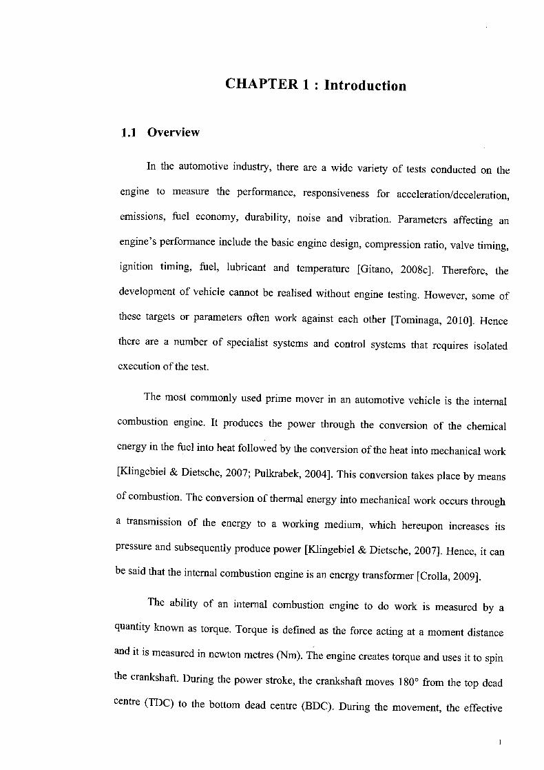
The ability of an internal combustion engine to do work is measured by a
quantity known as torque. Torque is defined as the force acting at a moment distance
and it is measured in newton metres (Nm). The engine creates torque and uses it to spin
the crankshaft During the power stroke, the crankshaft moves 180° from the top dead
centre (TDC) to the bottom dead centre (BDC). During the movement, the effective
P
1,
F
Figure 1.1: Torque variation during power stroke. [Heisler, 1998]
P
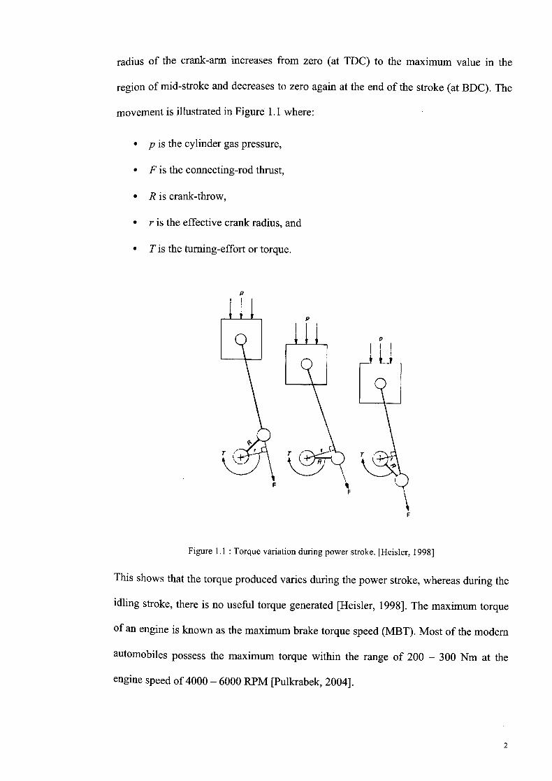
radius of the crank-arm increases from zero (at TDC) to the maximum value in the
region of mid-stroke and decreases to zero again at the end of the stroke (at BDC). The
movement is illustrated in Figure 1.1 where:
p is the cylinder gas pressure,
F is the connecting-rod thrust,
R is crank-throw,
r is the effective crank radius, and
T is the turning-effort or torque.
This shows that the torque produced varies during the power stroke, whereas during the
idling stroke, there is no useful torque generated [Heisler, 1998]. The maximum torque
of an engine is known as the maximum brake torque speed (MBT). Most of the modern
automobiles possess the maximum torque within the range of 200 - 300 Nm at the
engine speed of 4000 - 6000 RPM [Pulkrabek, 2004].
OA

$REDSØR]
I
IK
The torque produced by an internal combustion engine is measured using a
device known as dynamometer. The dynamometer resists the torque produced by the
engine connected to it and measures the torque [Martyr & Punt, 2007a]. In engine
testing, it is important to recreate the actual on-road situation in the most effective way
in order to obtain accurate data. However, the test conducted must be safe and
repeatable, thus the engine can be tested with different desired conditions [Atkins,
2009].
1.2 Background of the study
As mentioned in previous section, the internal combustion engine has to be
coupled to a dynamometer in order to measure its torque. Figure 1.2 shows the
illustration of dynamometer-engine setup. The engine is connected to the dynamometer
by means of a shaft. The shaft has to be properly designed since a poorly designed shaft
could lead to serious impairments not only to the engine, the dynamometer or the shaft,
but also to the human conducting the test.
Figure 1.2 : Dynamometer-engine setup. [Gitano, 2008b]
Figure 1.3 depicts a broken shaft and a broken coupling as a result of improper
designing prior to the test. The inappropriate design of the shaft could lead to various
problems, namely excessive torsional vibrations, whirling of the coupling shaft, bearing
damages, excessive wear of the shaft line components, engine starting problem and so
3

forth [Martyr & Punt, 2007b]. The most commonly encountered problem in a
dynamometer-engine system is the resonance of torsional vibration. The frequency of
the torsional vibration depends on the inertia of the engine and dynamometer, and the
stiffness of the coupling shaft. Therefore, it is vital to design a shaft with the proper
stiffness to avoid the problem.
(a)
(b)
Figure 1.3 (a) A broken shaft. (b) A broken coupling. [DynoTech-Research, 2010]
4

1.3 Objectives of the study
This project is aimed to study the design shaft to be used in a dynamometer-
engine system. As stated in [Martyr & Punt, 2007b], the design of the shaft for different
engines may differ. The objectives of this study are as follows:
1. To study the relation between the maximum torque of an engine and the design
of the shaft to couple it to a dynamometer.
2. To investigate the importance of the dimensions of the shaft (i.e. shaft diameter
and length) to the dynamometer-engine coupling.
3. To study the impact of using different material such as aluminium instead of
steel in fabricating the shaft.
1.4 Scope and limitation
In this study, five hypothetical engines with different maximum torque values (i.e.
40, 80, 120, 160 and 200 Nm) were used. The shafts to couple these engines to a
dynamometer were virtually designed to investigate the impact of maximum torque
value on the shaft design. From the results, the dimensions of the shaft for each case
will be observed. This study only involves theoretical calculations and the actual shafts
are not fabricated. The study was conducted analytically rather than experimentally.
Since hypothetical engines were used in the calculations, some parameters such as the
displacement volume, bore, stroke and the moment of inertia of the engines were
estimated.

CHAPTER 2: Literature review
2.1 Introduction
There are only a few studies that were conducted regarding this topic. One of the
relevant journals was published in year 2004 [Jayabalan, 2004]. In addition to it, there is
a book entitled Engine Testing that contains a chapter dedicated to the dynamometer-
engine coupling [Martyr & Punt, 2007b]. However, no comparison can be made since
the design of the shaft differs for every dynamometer-engine setup (i.e. different
engines and/or different types of dynamometer). In this chapter, the theories involve in
this topic, namely the engine dynamometer and its operating mechanism, the torsional
vibration/oscillation, damping and coupling, and so forth, are presented and described.
They were reviewed from various journals, books, articles and brochures from
manufacturers.
2.2 Engine dynamometer
To measure the torque and power output of an engine in a laboratory, the engine
is coupled directly to a device known as engine dynamometer. It introduces variable
loading conditions on the engine under test across the range of engine speeds and
durations. Hence, the torque and power output of the engine can be accurately measured
[Atkins, 2009]. Direct coupling means that the dynamometer shaft is connected to the
driveshaft or propeller shaft of the engine under test resulting both the engine and the
dynamometer running at the same speed [Gitano, 2008a]. In addition, since the
dynamometer rotor is coupled to the shaft, its speed is also identical to the speed of
engine crankshaft [Atkins, 2009].
Force on brake
otation Rotation
William Froude introduced the first modern dynamometer when he designed a
dynamometer for HMS Conquest, a C-class light cruiser of the Royal Navy [Atkins,
20091. Nowadays, there are many types of dynamometers used in the industry. Each of
them has its own advantages and disadvantages over its counterparts. Commonly used
dynamometers in the industry include [Gitano, 2008a]:
Frictional (brake) dynamometer,
Hydraulic (water brake) dynamometer,
Eddy current dynamometer,
Generator type dynamometer, and so forth.
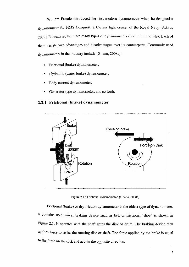
2.2.1 Frictional (brake) dynamometer
Figure 2.1: Frictional dynamometer. [Gitano, 2008a]
Frictional (brake) or dry friction dynamometer is the oldest type of dynamometer.
It contains mechanical braking device such as belt or frictional 'shoe' as shown in
Figure 2.1. It operates with the shaft spins the disk or drum. The braking device then
applies force to resist the rotating disc or shaft. The force applied by the brake is equal
to the force on the disk and acts in the opposite direction.
7

2.2.2 Hydraulic (water brake) dynamometer
Hydraulic dynamometer is fundamentally a hydraulic pump. The engine rotates
the shaft, which hereupon spins the impeller. Water is pumped from a reservoir through
a hydraulic circuit via a throttling valve as shown in Figure 2.2. Hydraulic drag induced
by the water resists the motion of the impeller. The load is varied through opening and
closing of the valve. Hydraulic dynamometers typically have the highest power
densities.
Figure 2.2 : Hydraulic dynamometer. [Gitano, 2008a]
2.2.3 Eddy current dynamometer
Eddy current dynamometer is an electromagnetic load device consists of a disk
placed inside its housing. The coupling shaft spins the disk, which contains large
electromagnetic coils as shown in Figure 2.3. This initiates electric current. As the
current passes through the coils that surround the disk, a strong magnetic field is
induced. The magnetic field creates a so-called 'eddy current' in the disk that resists its
rotation. This produces a torque between the housing and the disk. Varying the current
varies the torque generated as well as the load on the engine.
8

Force on Disk Electromagnet
Rotation Rotation
Figure 2.3 : Eddy current dynamometer. [Gitano, 2008a]
Force on Coil
2.2.4 Generator type dynamometer
In a system comprising of generator type dynamometer, the coupling shaft spins
the rotor of a generator as depicted in Figure 2.4. Electrical load is applied to the output
of the generator creating an electromagnetic force.
Power Supply
Rotation
Water Tank
Figure 2.4 : Generator type dynamometer. [Gitano, 2008a]
This force resists the motion of the rotor. A resistor bank (heater) is commonly used as
the load, which is either air or water-cooled. In order to vary the mechanical load, the
field winding current is controlled.
9
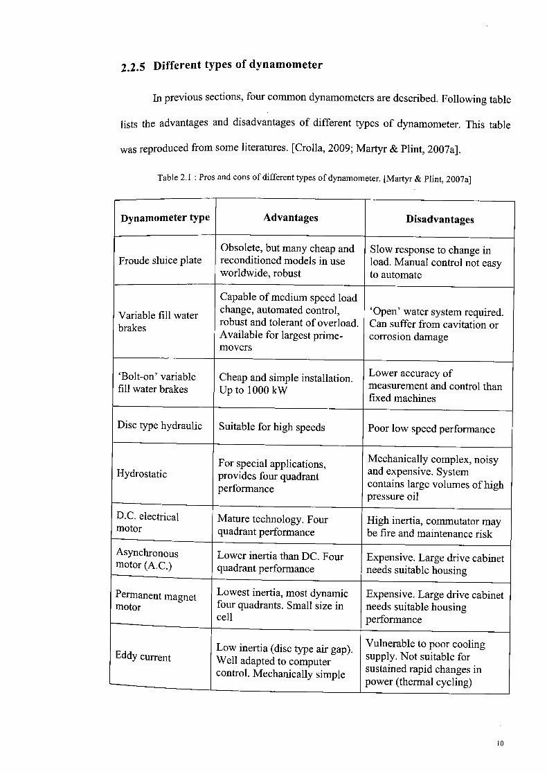
2.2.5 Different types of dynamometer
In previous sections, four common dynamometers are described. Following table
lists the advantages and disadvantages of different types of dynamometer. This table
was reproduced from some literatures. [Crolla, 2009; Martyr & Plint, 2007a].
Table 2.1: Pros and cons of different types of dynamometer. [Martyr & Punt, 2007a]
Dynamometer type Advantages Disadvantages
Obsolete, but many cheap and Slow response to change in Froude sluice plate reconditioned models in use load. Manual control not easy
worldwide, robust to automate
Capable of medium speed load
Variable fill water change, automated control, 'Open' water system required.
brakes robust and tolerant of overload. Can suffer from cavitation or Available for largest prime- corrosion damage movers
'Bolt-on' variable Cheap and simple installation. Lower accuracy of fill water brakes Up to 1000 kW measurement and control than
fixed machines
Disc type hydraulic Suitable for high speeds Poor low speed performance
For special applications, Mechanically complex, noisy Hydrostatic provides four quadrant and expensive. System
performance contains large volumes of high pressure oil
D.C. electrical Mature technology. Four High inertia, commutator may motor quadrant performance be fire and maintenance risk
Asynchronous Lower inertia than DC. Four Expensive. Large drive cabinet motor (A.C.) quadrant performance needs suitable housing
Permanent magnet Lowest inertia, most dynamic Expensive. Large drive cabinet motor four quadrants. Small size in needs suitable housing __________________ cell performance
Vulnerable to poor cooling Low inertia (disc type air gap). Eddy current Well adapted to computer supply. Not suitable for
control. Mechanically simple sustained rapid changes in power (thermal cycling)
10

Special purpose applications
Friction brake for very high torques at low Limited speed range speed
Cheap. Very little support Noisy. Limited control Air brake services needed accuracy -
Possible cost advantage over Complexity of construction Hybrid sole electrical machine and control
In this study, the eddy current dynamometer is used throughout the analysis. Different
results will be obtained, given that other type of dynamometer is used.
2.3 Operating mechanism of a dynamometer
The operation of a dynamometer can be simulated by a spring balance, anchored
to the ground, with a rope attached to the top eye and wrapped around a drum with a
slipknot as shown in Figure 2.5. As the drum rotates, the slipknot tightens, tensioning
the rope. The tension is indicated as a weight by the spring balance.
Figure 2.5 : Dynamometer operation simulated by a spring balance. [Atkins, 2009]
There is a friction between the rope and the drum, which slows down the motion of the
drum and its driving engine until a certain speed, for example 'x' RPM, and the spring
balance shows a reading of 'y ' kg. This shows that the weight lifted is '' kg, and
therefore the speed of the drum or the engine recorded is used to calculate the
111

horsepower. In real application, the engine is clamped on a test bed with a drive shaft
coupled to it. The other end of the drive shaft is coupled to the dynamometer, which
replaces the system containing the drum and the spring balance as described previously
[Atkins, 2009].
2.3.1 Principle of operation
The operating principle of a dynamometer is illustrated in Figure 2.6. Depending
on the type of dynamometer, the rotor is coupled to a stator electromagnetically,
hydraulically or by mechanical friction. The stator is supported in low-friction bearings.
It is stationary balanced with the rotor via static calibration. By balancing it with
weights, springs or pneumatic means, the torque exerted on it with the rotor turning can
be measured [Atkins, 2009].
O pnf Al flitiniA P
Figure 2.6 : The mechanism of torque measurement [Atkins, 2009].
Given that the torque T is exerted, then it can be calculated as follows:
T=FB (2.1)
On the other hand, the power P generated by the engine under test is as the matter of
fact the product of torque and angular speed as given by following equation:
12

P=2irNT (2.2)
where N is the engine speed in revolution per minute (RPM).
As previously mentioned, torque denotes the ability of an engine to do work,
whereas power indicates the rate at which the work is done. The power calculated from
Equation ( 2.2 ) is known as brake power, designated as Pb. This is the useful power
delivered by the engine to the applied load. Basically, the dynamometer applies a
resistive force to oppose the rotation of the drive shaft (or the torque of the engine's
crankshaft). This causes the engine to work harder to retain its rotational speed.
2.3.2 Operating quadrants
Figure 2.7 depicts the four quadrants, which the dynamometer may be operated.
+ ye Torque
Counterclockwise rotation Clockwise rotation ABSORBS TORQUE ABSORBS TORQUE
4
Counterclockwise rotation Clockwise rotation DEVELOPS TORQUE DEVELOPS
- ye Torque
Figure 2.7 : Operating quadrants of a dynamometer. [Atkins, 2009]
In general, most of the engines testing takes place in the first quadrant with the engine
running counter-clockwise if viewed from the flywheel end. All types of dynamometer
are normally able to operate in the first or second quadrant [Atkins, 2009; Martyr &
Plint, 2007a].
13

A dynamometer needs to operate in third and fourth quadrants when it is
required to produce power as well as to absorb it. However, the choice is limited since
only DC machines, AC machines, hydrostatic and hybrid dynamometers are able to
operate in such quadrants. These dynamometers are reversible, thus able to operate in
all four quadrants. An eddy-current dynamometer is also basically reversible.
Nevertheless, a hydraulic dynamometer is normally designed for one directional
rotation, albeit it could be operated in reverse at low fill state without damage.
In present, the transient testing (very rapid load changes and torque reversals) is
growing resulting an increase in demands for four-quadrant operation. A notable feature
of a four-quadrant dynamometer is its ability to start the engine. Table 2.2 lists some
common types of dynamometer and their particular operating quadrant, which is
reproduced from [Atkins, 2009].
Table 2.2 : List of dynamometers and their operating quadrants. [Atkins, 2009]
Type of Machine Operating Quadrant(s)
Hydraulic sluice plate 1 or 2
Variable fill hydraulic 1 or 2
Hydrostatic 1, 2, 3, 4
DC electrical 1, 2, 3, 4
AC electrical 1, 2, 3, 4
Eddy current 1 and 2
Friction brake 1 and 2
14

2.4 Torsional vibration
2.4.1 Overview
A dynamometer-engine system can be considered as identical to a system
comprises of two rotating masses connected by a flexible shaft as illustrated in Figure
2.8. Both masses possess a tendency to vibrate 1800 out of phase about an arbitrary
point located along the connecting shaft. The oscillatory movement is superimposed on
any steady rotation of the shaft. Hence, such system tends to generate torsional
vibrations [Martyr & Punt, 2007b]. The twisting of the shaft while the engine rotates is
known as torsional vibration. It occurs due to the periodical nature of actuating torque
[Meirelles et al., 2007]. Excessive amount of torsional vibration can bring about failures
of the crankshaft, couplings, engine dampers and so forth [Feese & Hill, 2009].
Figure 2.8 Two mass system. [Martyr & Punt, 2007b]
2.4.2 Literature review
The importance of the knowledge and understanding of torsional vibration has
led to publishing of many journals and articles regarding the subject. A method to
predict the behaviour of the torsional vibrations in internal combustion engines at
transient and steady state regime by the modal superposing method was developed in
1987 [Johnston & Shusto, 1987]. In some systems, excessive vibrations are exhibited on
15
Related Documents