Pub. No.: 190322 Rev.: 5 February 2020 Operator Manual www.SuperFlow.com Original Instructions SF- Powermark Engine Dynamometer

Welcome message from author
This document is posted to help you gain knowledge. Please leave a comment to let me know what you think about it! Share it to your friends and learn new things together.
Transcript
Pub. No.: 190322 Rev.: 5February 2020Operator Manual
www.SuperFlow.comOriginal Instructions
SF- PowermarkEngine Dynamometer
ii
Please keep this manual for future reference.
This manual is intended to assist operating personnel in becoming familiar with the product and as guidance in ordering necessary parts inclusive of SuperFlow's warranty requirements. Maximum operating efficiency and life of any SuperFlow product will be attained through complete understanding of the instructions and recommendations contained within this manual.
Services performed beyond preventive maintenance by personnel other than SuperFlow Service Technicians on any SuperFlow products during the warranty period may void the warranty.
! WARNING
When available, please include the model number and serial number of the product in any correspondence.
IMPORTANT
Copyright 2018 by SuperFlow Dynamometers & Flowbenches. All rights reserved. No part of this publication may be reproduced, transcribed, or translated by any means without the prior written permission of SuperFlow Dynamometers & Flowbenches, N60 W22700 Silver Spring Drive, Sussex, WI 53089 USA.No part of the software or firmware provided with this product may be upgraded, modified, or changed by any means without the prior written permission of SuperFlow Dynamometers & Flowbenches.
SuperFlow, WinDyn, ProFilter, SF902, XConsole, XDyno, XCart, NSCR, CycleDyn, AutoDyn, FlowCom, SuperBench, ProExport, SF-110/120/260/450/600/750, SF-1020, SF1200, ProBench, SuperBench, TD-1200, TDAC, Axiline, TCRS, Hicklin, Racer’s Pack, and SuperShifter are trademarks of Power Test, Inc. Other trademarks and trade names may be used in this document that refer to the entities claiming the marks and names or their products. Power Test, Inc. does not hold any proprietary interest in trademarks or trade names other than its own.
Trademark Notices
iii
1.0 Introduction ...................................................................................................................11.1 About This Manual .................................................................................................11.2 Target Audience .....................................................................................................11.3 Product Features ...................................................................................................11.4 Principles of Water Brake Dynamometer Operation ..............................................2
2.0 Safety Guidelines ..........................................................................................................32.1 At Installation .........................................................................................................52.2 During Operation ....................................................................................................52.3 Lockout/Tagout Procedures ...................................................................................6
3.0 System Overview ..........................................................................................................73.1 Overview ................................................................................................................73.2 Dynamometer ........................................................................................................8
SF-Powermark .......................................................................................................83.3 Data Acquisition ...................................................................................................10
Components .........................................................................................................10The Sensor Box ...................................................................................................10The Computer System .........................................................................................11Electrical Requirements .......................................................................................11Sensor Panel Modules .........................................................................................12
3.4 Accessories and Options .....................................................................................154.0 Installation ...................................................................................................................21
4.1 Location ...............................................................................................................214.2 Plumbing Diagram ...............................................................................................224.3 Unpacking ............................................................................................................234.4 Engine Docking Cart ............................................................................................234.5 Absorber Stand ....................................................................................................244.6 Sensor Box ..........................................................................................................244.7 Cooling Towers ....................................................................................................254.8 Computer System ................................................................................................27
Communication ....................................................................................................27Software ...............................................................................................................27
4.9 System Cable Connections ..................................................................................27Power ...................................................................................................................27System Interconnect Panel ..................................................................................28Sensor Interconnect Panel ...................................................................................31
4.10 Expansion Panels ................................................................................................32Pressure Connections ..........................................................................................32Thermocouple Connections .................................................................................33Analog Voltage Expansion ...................................................................................34
4.11 Throttle System ....................................................................................................354.12 Initial Check-out ...................................................................................................36
5.0 Operation .....................................................................................................................375.1 Introduction ..........................................................................................................375.2 Safety ...................................................................................................................37
Emergency Stop ..................................................................................................38
Table of Contents
iv
Electrical Safety ...................................................................................................38Fuses ...................................................................................................................38Safety Procedures ...............................................................................................39
5.3 Test Preparation ...................................................................................................40Mounting the Front of the Engine .........................................................................40Mounting the Engine ............................................................................................40Dyno Shaft Connection ........................................................................................41
5.4 Engine Water Cooling System .............................................................................425.5 Throttle System ....................................................................................................435.6 Sensor Connections .............................................................................................44
Stand Connections ...............................................................................................44Engine Connections .............................................................................................44
5.7 Running an Automated Test .................................................................................45Infrastructure and Engine Setup ..........................................................................45Operator Console and Computer .........................................................................47Test Group Dialog ................................................................................................48WinDyn Prep ........................................................................................................48WinDyn Setup Dialog ...........................................................................................48ValPos Adjustment ...............................................................................................49Running a Test .....................................................................................................50Post Test ..............................................................................................................51Shutdown .............................................................................................................51
5.8 Analyzing the Test Results ...................................................................................526.0 Maintenance ................................................................................................................54
6.1 Maintenance Schedule ........................................................................................54Preventative Maintenance ...................................................................................55
6.2 Calibration ............................................................................................................566.3 2640 Circuit Board LEDs ....................................................................................586.4 Servo Valve Indexing ...........................................................................................59
Inlet Servo Valve ..................................................................................................59Outlet Servo Valve ...............................................................................................61
6.5 Reverse Rotation ................................................................................................657.0 Troubleshooting ..........................................................................................................69
7.1 Servo Valve ..........................................................................................................69Manual test mode: ...............................................................................................69Automated test mode: ..........................................................................................70Control Electronics: ..............................................................................................71Servo Valve Diagnosis: ........................................................................................73
7.2 Absorber ..............................................................................................................747.3 Water System.......................................................................................................77
8.0 Appendix .....................................................................................................................78
Table of Contents
1
1.0 Introduction1.1 About This ManualThis manual is provided as a reference to explain the operation of the SuperFlow dynamometer system as used on an engine test system and also covers the operation and maintenance of the SF-PowerMark engine test stand.
An electronic PDF copy of this manual is provided on the system configuration thumb-drive sent with the SuperFlow system.
Please read the complete manual in detail, prior to operating the dynamometer. Contact SuperFlow immediately if you experience problems to avoid any warranty issues.
IMPORTANT
1.2 Target AudienceThis manual is intended to be used by skilled operators trained in the operation of the equipment by a SuperFlow representative.
1.3 Product Features• A system consists of two major components: - Dynamometer stand with a Power Absorption Unit (PAU).
- Data Acquisition and Control (DAC) system – Computer system with WinDyn software.
2
1.0 Introduction1.4 Principles of Water Brake Dynamometer OperationAn engine dynamometer (dyno) is a service tool that allows the operator to safely place a controlled load on an engine. A loaded engine test is the only method of verifying engine capability. With the use of a dyno, an engine can be properly operated throughout its power range without being placed into service. Assembly deficiencies may be detected before the engine is installed into a chassis and an actual evaluation of an engine’s operating condition may be performed. The dynamometer is the final quality test before an engine is installed.
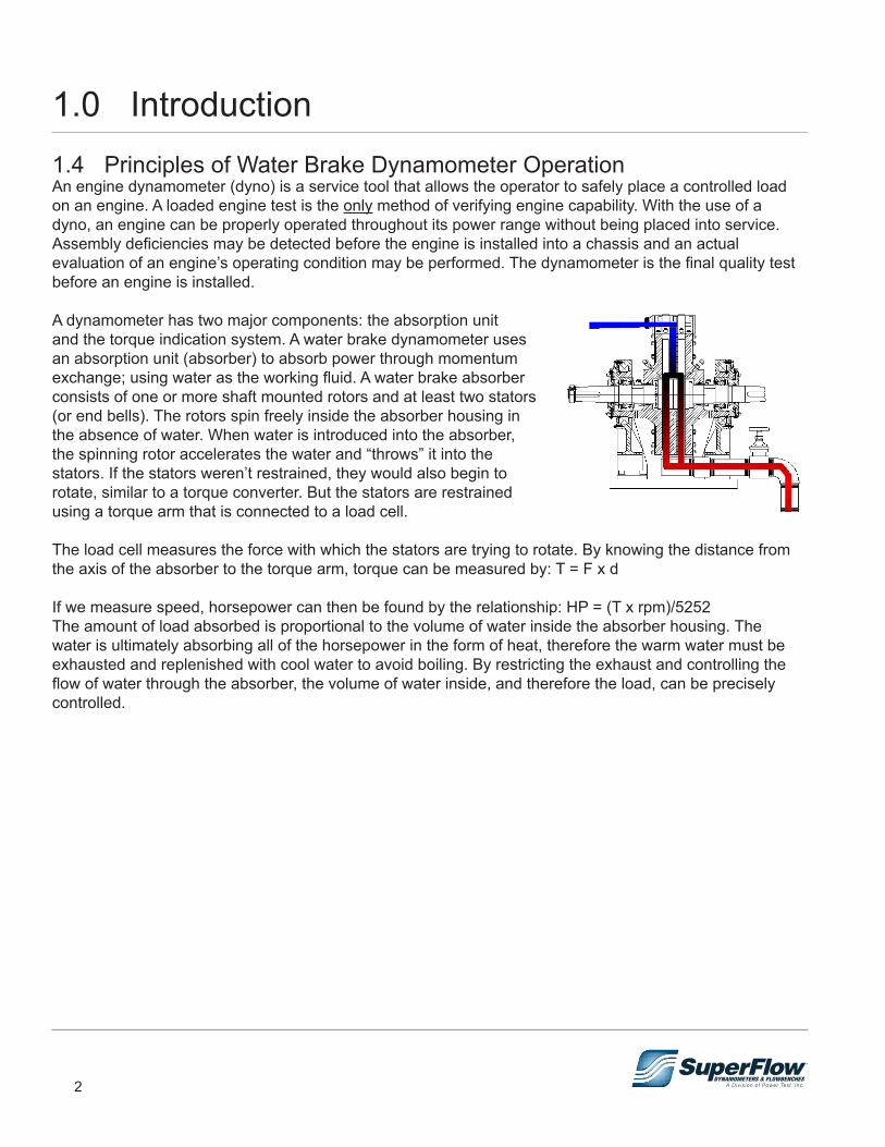
A dynamometer has two major components: the absorption unit and the torque indication system. A water brake dynamometer uses an absorption unit (absorber) to absorb power through momentum exchange; using water as the working fluid. A water brake absorber consists of one or more shaft mounted rotors and at least two stators (or end bells). The rotors spin freely inside the absorber housing in the absence of water. When water is introduced into the absorber, the spinning rotor accelerates the water and “throws” it into the stators. If the stators weren’t restrained, they would also begin to rotate, similar to a torque converter. But the stators are restrained using a torque arm that is connected to a load cell.
The load cell measures the force with which the stators are trying to rotate. By knowing the distance from the axis of the absorber to the torque arm, torque can be measured by: T = F x d
If we measure speed, horsepower can then be found by the relationship: HP = (T x rpm)/5252The amount of load absorbed is proportional to the volume of water inside the absorber housing. The water is ultimately absorbing all of the horsepower in the form of heat, therefore the warm water must be exhausted and replenished with cool water to avoid boiling. By restricting the exhaust and controlling the flow of water through the absorber, the volume of water inside, and therefore the load, can be precisely controlled.
3
2.0 Safety GuidelinesSafety is the most important consideration when operating any dynamometer system. Operators and service personnel should read this manual and become familiar with its content before attempting to operate this machine or to perform service or maintenance to it. Familiarization with this manual will minimize the possibility of accidents or injuries. Although the procedures covered in this manual have proven safe in use, Power Test assumes no responsibility for personal injury or damage to equipment resulting from its applications. All operators must be aware that there are several hazards present to anyone in the test cell. Some of these hazards are:
• Objects rotating at high speeds • Pressurized hoses • Hot solids or liquids • Electrical shock • Flammable liquids • Exhaust emissions • Noise
Certain precautions must be exercised. They are:
• DO NOT operate without ALL shields, guards, and emergency cutoffs in place and operating. • DO NOT enter the test cell during an engine test unless necessary. • DO NOT wear loose fitting clothing in the test cell. • Warning decals are located near areas of potential danger. Replace damaged or lost decals. • DO NOT make any connections while power is applied to the system. • DO NOT open any panels while power is applied to the system. • DO NOT make any plumbing connections without shutting down all water supplies and pumps. • DO bleed air pressure from all lines before connecting or disconnecting any air hoses. • ALWAYS wear eye protection. • ALWAYS wear eye and hearing protection whenever the engine is operating. • ALWAYS keep work area clean. If a spill occurs, eliminate the hazard immediately. • NO smoking or open flame in the test area.
These are general guidelines for working with a dynamometer system. It is often helpful to prepare a safety checklist that is distributed to all personnel who enter the test cell. Proper safety is achieved through reinforcement and discipline.
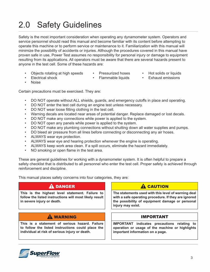
This manual places safety concerns into four categories, they are:
This is the highest level statement. Failure to follow the listed instructions will most likely result in severe injury or death.
! DANGER
The statements used with this level of warning deal with a safe operating procedure. If they are ignored the possibility of equipment damage or personal injury may exist.
! CAUTION
This is a statement of serious hazard. Failure to follow the listed instructions could place the individual at risk of serious injury or death.
! WARNING
IMPORTANT indicates precautions relating to operation or usage of the machine or highlights important information on a page.
IMPORTANT
4
2.0 Safety Guidelines
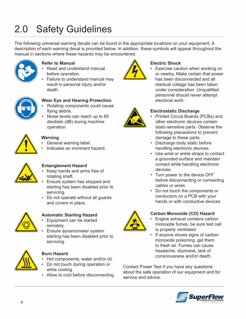
Refer to Manual• Read and understand manual
before operation.• Failure to understand manual may
result in personal injury and/or death.
Wear Eye and Hearing Protection• Rotating components could cause
flying debris.• Noise levels can reach up to 85
decibels (dB) during machine operation.
Warning• General warning label.• Indicates an imminent hazard.
Entanglement Hazard• Keep hands and arms free of
rotating shaft.• Ensure system has stopped and
starting has been disabled prior to servicing.
• Do not operate without all guards and covers in place.
Automatic Starting Hazard• Equipment can be started
remotely.• Ensure dynamometer system
starting has been disabled prior to servicing.
Burn Hazard• Hot components, water and/or oil.• Do not touch during operation or
while cooling. • Allow to cool before disconnecting.
Electric Shock• Exercise caution when working on
or nearby. Make certain that power has been disconnected and all residual voltage has been taken under consideration. Unqualified personnel should never attempt electrical work.
Electrostatic Discharge• Printed Circuit Boards (PCBs) and
other electronic devices contain static-sensitive parts. Observe the following precautions to prevent damage to these parts.
• Discharge body static before handling electronic devices.
• Use wrist or ankle straps to contact a grounded surface and maintain contact while handling electronic devices.
• Turn power to the device OFF before disconnecting or connecting cables or wires.
• Do not touch the components or conductors on a PCB with your hands or with conductive devices
Carbon Monoxide (CO) Hazard• Engine exhaust contains carbon
monoxide fumes, be sure test cell is properly ventilated
• If anyone shows signs of carbon monoxide poisoning, get them to fresh air. Fumes can cause headache, dizziness, lack of consciousness and/or death.
Contact Power Test if you have any questions about the safe operation of our equipment and for service and advice.
The following universal warning decals can be found in the appropriate locations on your equipment. A description of each warning decal is provided below. In addition, these symbols will appear throughout the manual in sections where these hazards may be encountered.
5
2.0 Safety Guidelines2.1 At Installation
• Do NOT lift the dynamometer by the input shaft. This may damage the dynamometer and void its warranty.
! WARNING
2.2 During Operation
• Extreme care should be taken in the area of the drive shaft that connects the engine to the dynamometer.
• All rotating parts must have their guards secured in place.
• A drive shaft is considered the fuse in the test setup. In the event of a failure in the engine or dynamometer, the shaft may break. This will save on costly repairs to an engine or dynamometer. However, because of this possible failure, the machine should NEVER be operated without a shaft guard.
! DANGER
• Engine exhaust contains carbon monoxide fumes, be sure test cell is properly ventilated
• If anyone shows signs of carbon monoxide poisoning, get them to fresh air. Fumes can cause headache, dizziness, lack of consciousness and/or death.
! DANGER
• Take care that the dynamometer is not dropped or set down sharply. This could cause damage to the bearing races and brinelling of the bearings.
• The load cell should be handled with equal care. Distortion of this cell will hinder its proper operation.
! CAUTION
WEAR EYE and HEARING PROTECTION. Proper eye and hearing protection should be worn at all times when the equipment is operating.
! WARNING
AUTOMATIC STARTING HAZARD.The dynamometer could be started remotely. Ensure starting has been disabled prior to servicing.
! WARNING
BURN HAZARD.During operation water temperature inside the dynamometer can reach over 125° F. Do NOT touch discharge water, piping or the dynamometer surface during operation. Allow to cool before servicing.
! WARNING

6
2.0 Safety Guidelines
• Inspect the equipment monthly to ensure that there are no broken or worn parts which could cause injury to personnel or damage to the equipment.
• Only qualified operators and maintenance personnel should perform the procedures covered in this manual.
! WARNING
2.3 Lockout/Tagout Procedures
Figure 2.1: Lockout/Tagout
XXXXXXXXXXXX
XXXXXXXXXXX
OPERATE
DONOT
The Occupational Safety and Health Administration (OSHA) requires, in addition to posting safety warnings and barricading the work area (including, but not limited to, control room and testing bay), that the power supply has been locked in the OFF position or disconnected. It is mandatory that an approved lockout device is utilized. An example of a lockout device is illustrated in figure 2.1. The proper lockout procedure requires that the person responsible for the repairs is the only person who has the ability to remove the lockout device.
In addition to the lockout device, it is also a requirement to tag the power control in a manner that will clearly note that repairs are under way and state who is responsible for the lockout condition. Tagout devices have to be constructed and printed so that exposure to weather conditions, or wet and damp locations, will not cause the tag to deteriorate or become unreadable.
Power Test does not recommend any particular lockout device, but recommends the utilization of an OSHA approved device (refer to OSHA regulation 1910.147). Power Test also recommends the review and implementation of an entire safety program for the Control of Hazardous Energy (Lockout/Tagout). These regulations are available through OSHA publication 3120.
• Personnel should NOT be in the test cell during operation and observation areas MUST be constructed to protect personnel.
• Personnel and other equipment should be kept clear of the drive shaft guard area and NEVER cause an obstruction or block doorways.
! CAUTION
The dynamometer is a tool. All personnel should be kept clear of the area and only be in the test area on a “need to be” basis.
IMPORTANT
When working with electrical or electronic controls, make sure that the power source has been locked out and tagged out according to OSHA regulations and approved local electrical codes.
! WARNING

7
3.0 System Overview3.1 OverviewThe WinDyn dynamometer software system is an instrumentation package designed for complete test control and data acquisition of an engine or chassis dynamometer. Typical applications include:
• Research and development (R&D)• Performance testing• Durability and quality control testing• Fuel consumption and emissions testing • Education• Certification testing
You can configure WinDyn for your specific testing needs and can expand it with additional data acquisition capabilities and interfaces as needed. For highest productivity, you can share test data over a facility computer network.
A dynamometer system consists primarily of two major components: the Power Absorption Unit (PAU) on a stand with its associated equipment, and the Data Acquisition and Control (DAC) system with its associated accessories.• The absorber stand also holds auxiliary equipment such as a flow measurement system, and an engine
cooling system.• The DAC system is made of the Central Processing Unit (CPU), an operator control interface, a device
to control the load applied to the absorber, and a network of sensors to collect data from the absorber and the engine. The WinDyn software on a stand-alone Personal Computer (PC) allows users to display and analyze the data during and after a test.
The purpose of using a dynamometer is to test the performance of an engine prior to putting it back in service. It allows for the break-in of a new or newly rebuilt engine in a controllable environment. Typically the SF-Powermark system is distributed to racing engine manufactures or rebuilders. They have proven this type of break-in procedure through many years of experience. Properly run-in engines last longer, run better and cost less to maintain.
8
3.0 System Overview3.2 DynamometerThe dynamometer stand provides all of the connections from the sensors to the data acquisition system and the mount for the power absorber.
SF-PowermarkThe SF-Powermark system utilizes a floor-mounted absorber stand and a roll-around engine docking cart to maximize test efficiency in high-volume environments. The versatile docking engine carts are used to pre-stage and dress the engines before they are installed in the test cell. The dynamometer stays in the test cell connected to all its supply lines and support systems. Roll the engine into the cell, dock the cart to the dyno, and attach the fuel supply, airflow turbine, oil and coolant lines, and sensors. The cart is clamped to the absorber stand for testing.
The boom provides clean routing of cables, fuel lines, and cooling pipes. It keeps all the accessories and engine support lines close and available when needed.
The docking cart and boom system keep the test cell safe, organized, and attractive while allowing rapid engine changes. Additional mounts for ignition boxes and work tools can be added if desired. Optional features include cooling flow measurement, and temperature control on oil and engine coolant.
Specifications• Absorber Type: Water brake• Maximum Absorber Speed: 11,000 rpm• Horsepower Capacity: 3,000 hp (2,237 kW)• Torque Capacity: 2,500 lb.-ft. (3,390 Nm)
Water QualityThe quality of the water used in a dynamometer affects absorber and water pump operation. Contamination, salt water, or water with a high mineral count can reduce their life and increase maintenance costs. The load control valve and water seals in the absorber can quickly deteriorate with bad water. Provisions should be made to prevent the growth of algae and bacteria, as well as corrosion or scale formation within the equipment. Water system maintenance is essential to efficient operation, consult a water system specialist to create the proper program to monitor your system.
Filters:For both open water and recirculating systems, install a filter to clean the water before it enters the dynamometer and engine cooling tower. Install a differential pressure gauge across the filter to determine when the filter needs cleaning. The water should be filtered to remove 0.004- inch diameter particles [100 microns]. In recirculating systems, a filter installed on the return water line back to the supply tank helps keep particles from the engine and dynamometer from getting into the supply water system.
9
3.0 System Overview
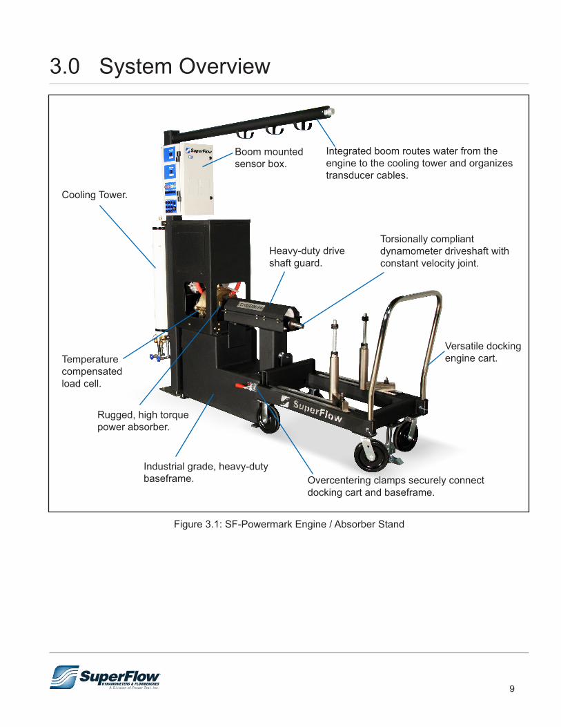
Figure 3.1: SF-Powermark Engine / Absorber Stand
Integrated boom routes water from the engine to the cooling tower and organizes transducer cables.
Boom mounted sensor box.
Heavy-duty drive shaft guard.
Torsionally compliant dynamometer driveshaft with constant velocity joint.
Versatile docking engine cart.
Overcentering clamps securely connect docking cart and baseframe.
Industrial grade, heavy-duty baseframe.
Rugged, high torque power absorber.
Temperature compensated load cell.
Cooling Tower.
10
3.3 Data AcquisitionComponentsA WinDyn data acquisition system consists of at least two components. They are the sensor system and the computer system. NOTE: Additional options and accessories that can be added to the system are described later in this
chapter.
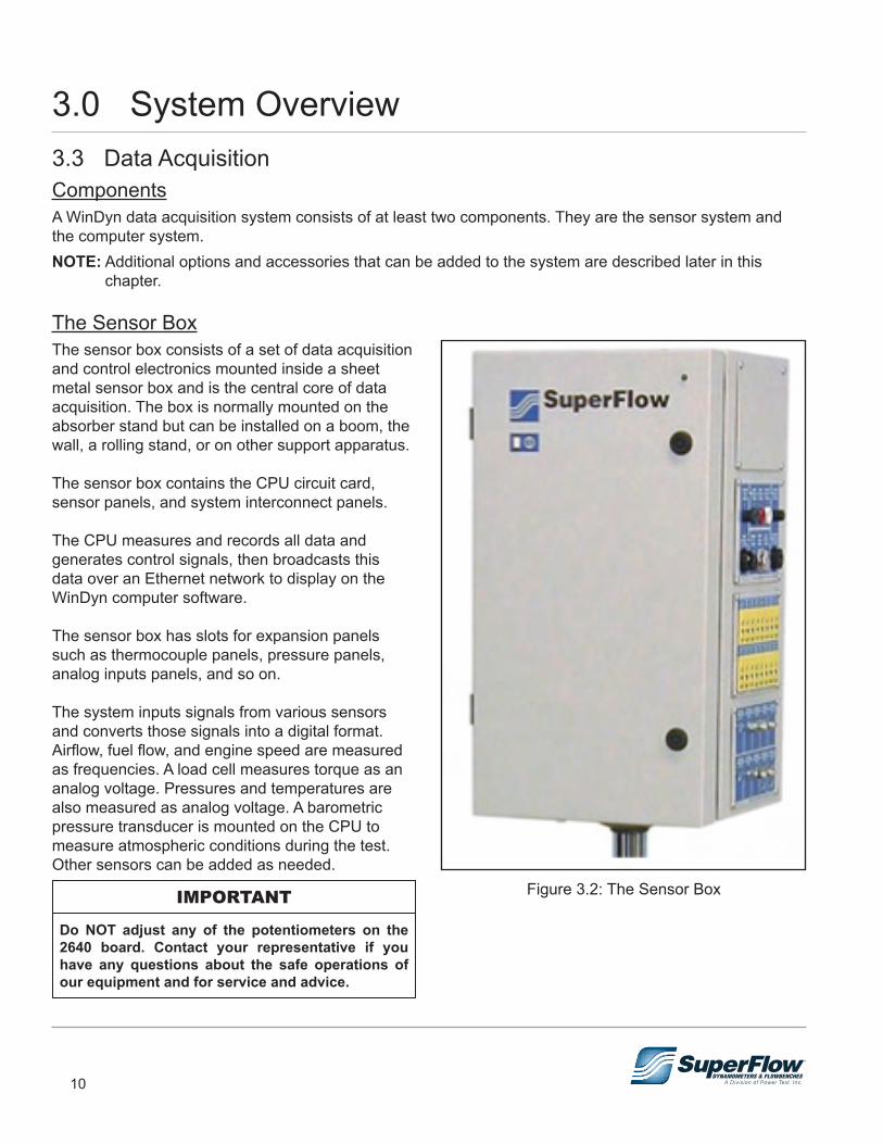
The Sensor BoxThe sensor box consists of a set of data acquisition and control electronics mounted inside a sheet metal sensor box and is the central core of data acquisition. The box is normally mounted on the absorber stand but can be installed on a boom, the wall, a rolling stand, or on other support apparatus.
The sensor box contains the CPU circuit card, sensor panels, and system interconnect panels.
The CPU measures and records all data and generates control signals, then broadcasts this data over an Ethernet network to display on the WinDyn computer software.
The sensor box has slots for expansion panels such as thermocouple panels, pressure panels, analog inputs panels, and so on.
The system inputs signals from various sensors and converts those signals into a digital format. Airflow, fuel flow, and engine speed are measured as frequencies. A load cell measures torque as an analog voltage. Pressures and temperatures are also measured as analog voltage. A barometric pressure transducer is mounted on the CPU to measure atmospheric conditions during the test. Other sensors can be added as needed.
Do NOT adjust any of the potentiometers on the 2640 board. Contact your representative if you have any questions about the safe operations of our equipment and for service and advice.
IMPORTANT Figure 3.2: The Sensor Box
3.0 System Overview

11
3.0 System OverviewThe Computer SystemThe computer system consists of a standard computer with up to three monitors installed, a color printer, and WinDyn dynamometer software. Other than the network connection and minimum performance specifications, no special requirements must be met.
SuperFlow’s WinDyn dynamometer software was designed for Microsoft® Windows®-based computers.
The computer communicates with the sensor system through an Ethernet Local Area Network (LAN) cable. Commands to the test system can only be issued from this computer.
All printers supported by Windows can be used. A color printer is recommended for highest impact and clarity of test graphs. The printer is connected to the computer.
Electrical RequirementsThe WinDyn instrumentation system requires a dedicated, stable electrical power source for proper operation. SuperFlow recommends using an Uninterruptible Power Supply (UPS) that has a minimum rating of 750 VA or a high-quality surge suppressor for the sensor box and computer. This may protect the electronics from damage in the event of a power surge and keep the engine running if the power goes out. It is best to connect all instrumentation devices to the same circuit to minimize ground loop noise. Adding devices such as battery chargers and fan motors to the same circuit can cause noise problems.
The total power requirement for a basic instrumentation system is 120V/15A or 240V/8A.
TIP: Your electrician can wire the electrical circuits in your test cell with outlets for the sensor box and computer wired to a special protected circuit.
Figure 3.3: Operator Console
SuperFlow recommends dedicating the computer connected to the dynamometer for dynamometer use only and not utilizing it for other purposes. Multiple programs and Internet access could possibly slow down the computer and affect the dynamometer operation.
IMPORTANT
12
Sensor Panel Modules
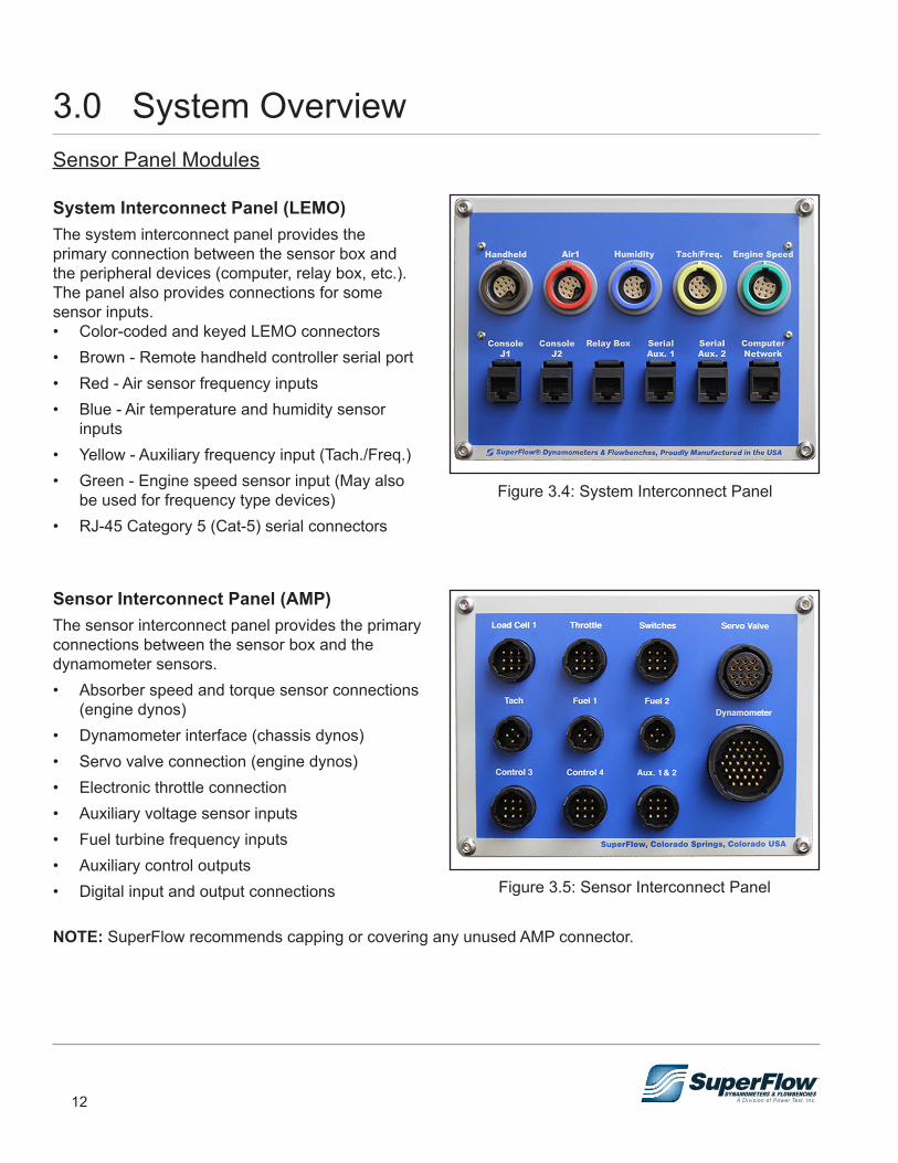
System Interconnect Panel (LEMO)The system interconnect panel provides the primary connection between the sensor box and the peripheral devices (computer, relay box, etc.). The panel also provides connections for some sensor inputs.• Color-coded and keyed LEMO connectors• Brown - Remote handheld controller serial port• Red - Air sensor frequency inputs• Blue - Air temperature and humidity sensor
inputs • Yellow - Auxiliary frequency input (Tach./Freq.)• Green - Engine speed sensor input (May also
be used for frequency type devices)• RJ-45 Category 5 (Cat-5) serial connectors
Sensor Interconnect Panel (AMP)The sensor interconnect panel provides the primary connections between the sensor box and the dynamometer sensors.• Absorber speed and torque sensor connections
(engine dynos)• Dynamometer interface (chassis dynos)• Servo valve connection (engine dynos)• Electronic throttle connection• Auxiliary voltage sensor inputs• Fuel turbine frequency inputs• Auxiliary control outputs• Digital input and output connections
NOTE: SuperFlow recommends capping or covering any unused AMP connector.
Figure 3.4: System Interconnect Panel
Figure 3.5: Sensor Interconnect Panel
3.0 System Overview

13
3.0 System OverviewThermocouple Input PanelThe thermocouple panel provides 16 channels for temperature measurements on the test device.• 16 channels per panel• Type K, (grounded or ungrounded)• Type K thermocouple range, -454° to 2,300°F
(–270° to 1260°C), linearized• Universal panel jacks accept both standard and
miniature connectors
Pressure Input PanelThe pressure panel provides up to 10 channels of pressure measurements on the test device. The standard system ships with three channels installed. These are:• Channels 63, 67 & 68: 0–150 psi [0–1034 kPa] 63 = Man_P 67 = Oil_P 68 = DynWTP
Figure 3.6: Thermocouple Input Panel
Figure 3.7: Pressure Input Panel
14
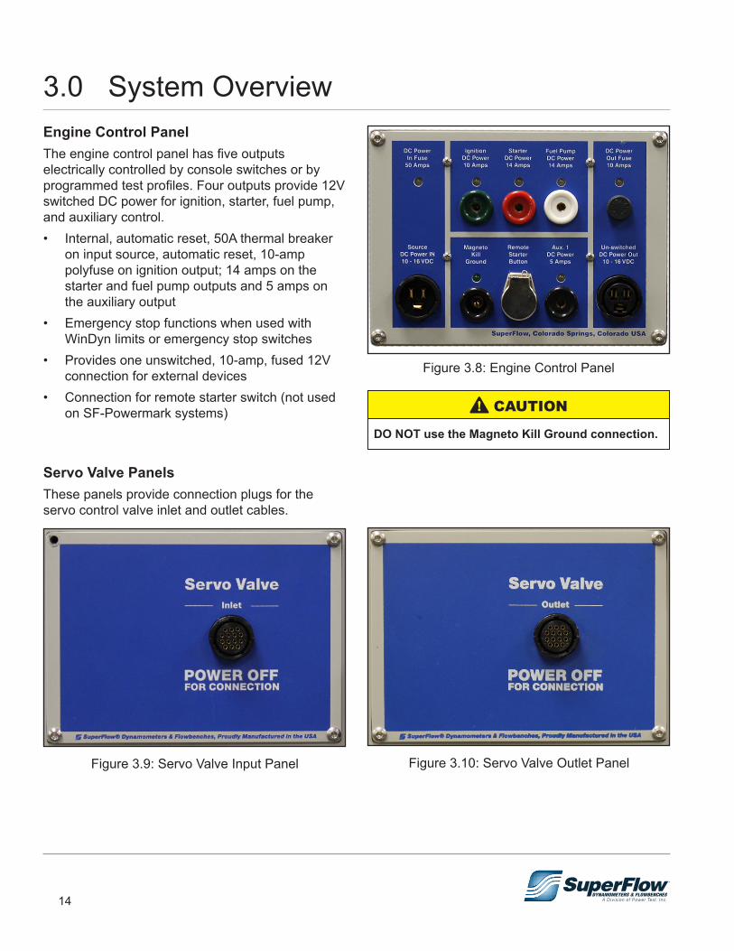
3.0 System OverviewEngine Control PanelThe engine control panel has five outputs electrically controlled by console switches or by programmed test profiles. Four outputs provide 12V switched DC power for ignition, starter, fuel pump, and auxiliary control. • Internal, automatic reset, 50A thermal breaker
on input source, automatic reset, 10-amp polyfuse on ignition output; 14 amps on the starter and fuel pump outputs and 5 amps on the auxiliary output
• Emergency stop functions when used with WinDyn limits or emergency stop switches
• Provides one unswitched, 10-amp, fused 12V connection for external devices
• Connection for remote starter switch (not used on SF-Powermark systems)
Servo Valve PanelsThese panels provide connection plugs for theservo control valve inlet and outlet cables.
Figure 3.9: Servo Valve Input Panel
Figure 3.8: Engine Control Panel
DO NOT use the Magneto Kill Ground connection.
! CAUTION
Figure 3.10: Servo Valve Outlet Panel

15
3.0 System Overview3.4 Accessories and OptionsA wide selection of additional sensors, adapters, and engine accessories are available. Contact SuperFlow Sales or Customer Service for additional details.
Analog Voltage Input PanelThe analog voltage panel is an optional accessory that provides up to eight channels of voltage measurements on the test device.• Eight channels per panel• Adjustable gain and offset. Available gain
headers are: 0-1, 0-5, 0-8, 0-10, 0-20 & 0-30• Color-coded and keyed 11-pin LEMO
connectorsRecommended levels of excitation and reference voltages available on each of the front panel connections for sensors or other devices:• +5F: +5VDC @ 100 mA, poly-fused at 0.1A• +12F: +12VDC @ 500 mA, poly-fused at 0.5A
Air Fuel KitAEM’s 4-Channel Wideband UEGO Controller allows users to simultaneously monitor individual cylinder Air/Fuel Ratios (AFR) on up to four cylinders. Pair multiple units together for use on 6, 8, 10 or 12 cylinders.• Allows for monitoring of individual cylinder
AFRs for maximum engine power and safety• Two status lights per sensor for error detection
and operating status• Compact (4.8" x 4.55" x 1.44"), weather &
shock proof enclosure• Accurate to 0.1 AFR• Refer to the AEM Performance Electronics Wideband UEGO Controller instruction manual for detailed
information.
Figure 3.11: Analog Voltage Input Panel
Figure 3.12: Air/Fuel Monitor
16
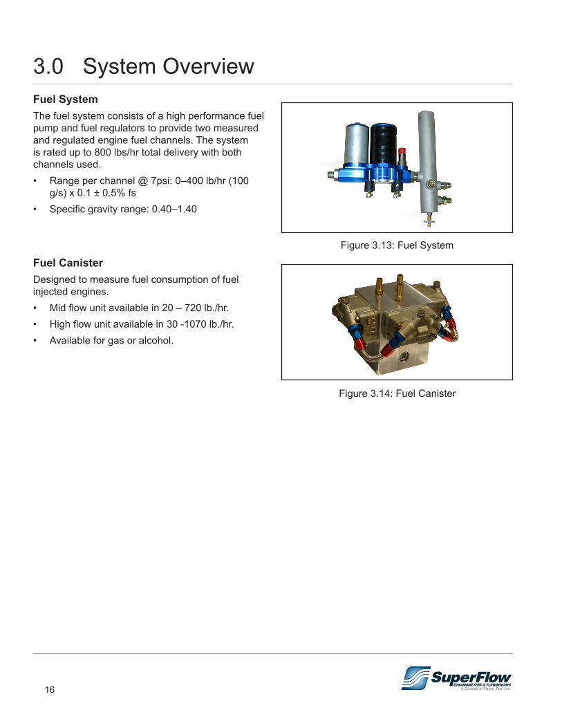
Fuel SystemThe fuel system consists of a high performance fuel pump and fuel regulators to provide two measured and regulated engine fuel channels. The system is rated up to 800 lbs/hr total delivery with both channels used.• Range per channel @ 7psi: 0–400 lb/hr (100
g/s) x 0.1 ± 0.5% fs• Specific gravity range: 0.40–1.40
Fuel CanisterDesigned to measure fuel consumption of fuel injected engines. • Mid flow unit available in 20 – 720 lb./hr.• High flow unit available in 30 -1070 lb./hr.• Available for gas or alcohol.
Figure 3.13: Fuel System
Figure 3.14: Fuel Canister
3.0 System Overview
17
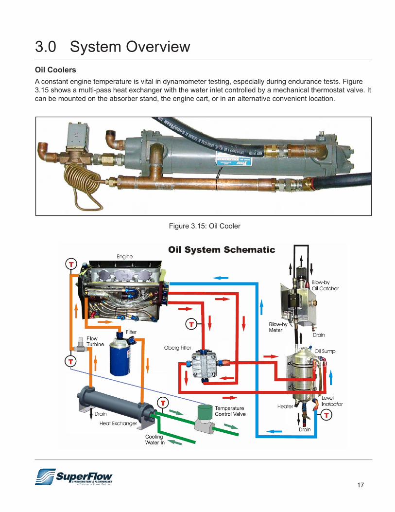
Oil CoolersA constant engine temperature is vital in dynamometer testing, especially during endurance tests. Figure 3.15 shows a multi-pass heat exchanger with the water inlet controlled by a mechanical thermostat valve. It can be mounted on the absorber stand, the engine cart, or in an alternative convenient location.
Figure 3.15: Oil Cooler
3.0 System Overview
18
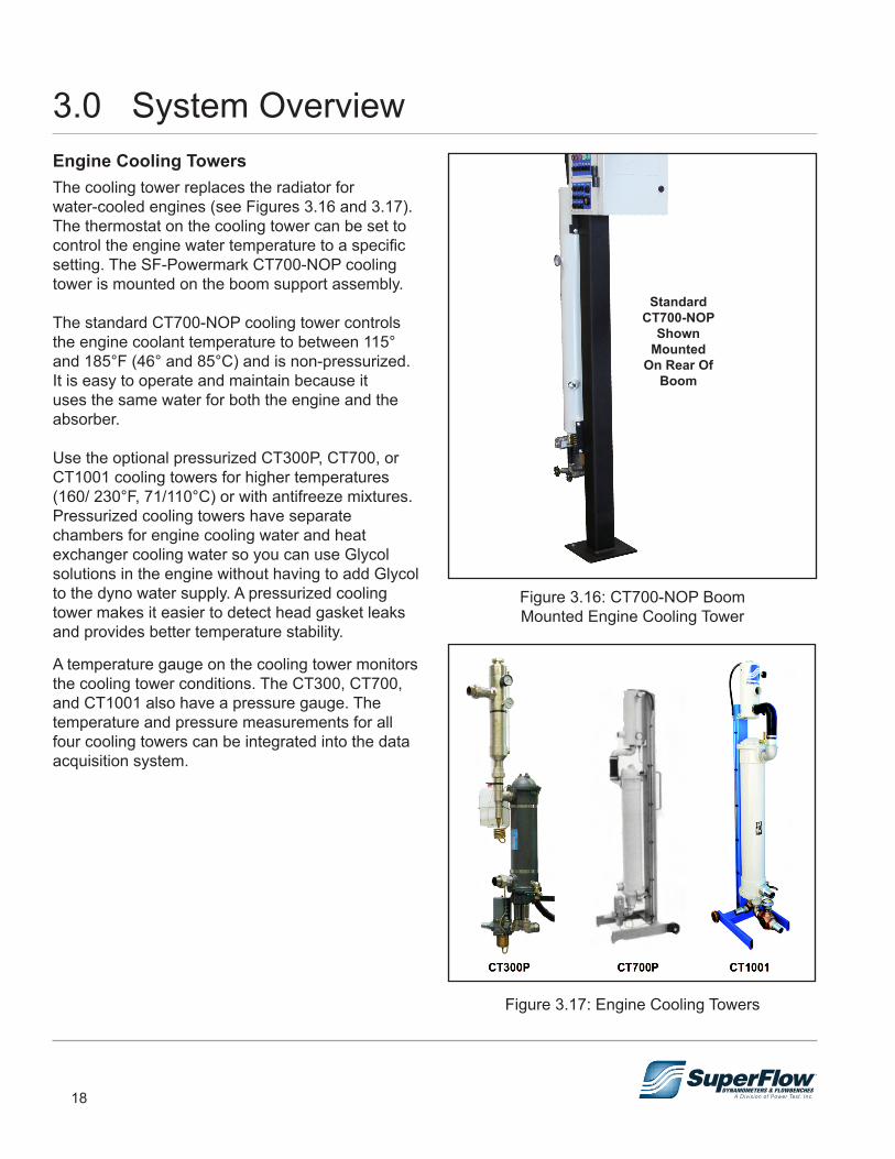
Engine Cooling TowersThe cooling tower replaces the radiator for water-cooled engines (see Figures 3.16 and 3.17). The thermostat on the cooling tower can be set to control the engine water temperature to a specific setting. The SF-Powermark CT700-NOP cooling tower is mounted on the boom support assembly.
The standard CT700-NOP cooling tower controls the engine coolant temperature to between 115° and 185°F (46° and 85°C) and is non-pressurized. It is easy to operate and maintain because it uses the same water for both the engine and the absorber.
Use the optional pressurized CT300P, CT700, or CT1001 cooling towers for higher temperatures (160/ 230°F, 71/110°C) or with antifreeze mixtures. Pressurized cooling towers have separate chambers for engine cooling water and heat exchanger cooling water so you can use Glycol solutions in the engine without having to add Glycol to the dyno water supply. A pressurized cooling tower makes it easier to detect head gasket leaks and provides better temperature stability.
A temperature gauge on the cooling tower monitors the cooling tower conditions. The CT300, CT700, and CT1001 also have a pressure gauge. The temperature and pressure measurements for all four cooling towers can be integrated into the data acquisition system.
Figure 3.17: Engine Cooling Towers
Figure 3.16: CT700-NOP BoomMounted Engine Cooling Tower
Standard CT700-NOP
Shown Mounted
On Rear Of Boom
3.0 System Overview
19
3.0 System Overview
20
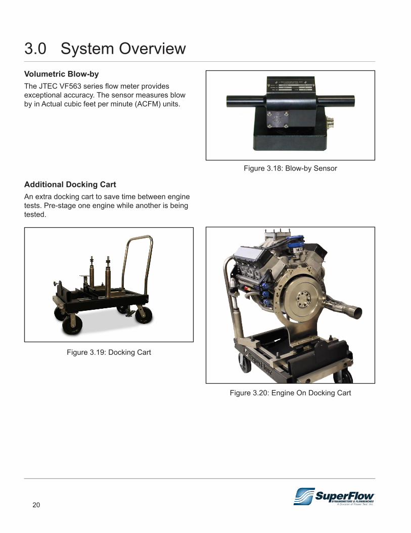
Volumetric Blow-byThe JTEC VF563 series flow meter provides exceptional accuracy. The sensor measures blow by in Actual cubic feet per minute (ACFM) units.
Additional Docking CartAn extra docking cart to save time between enginetests. Pre-stage one engine while another is beingtested.
Figure 3.19: Docking Cart
Figure 3.18: Blow-by Sensor
Figure 3.20: Engine On Docking Cart
3.0 System Overview
21
4.0 Installation4.1 LocationLocation and positioning of the dynamometer is an important factor in creating a functional, easy-to-use test cell. The following guidelines have been provided to assist in positioning your dynamometer:
• The engine dynamometer test cell should be located in an area that is easily accessible from the rebuild area.
• The dynamometer should be located in an area where the noise generated by its operation will not interfere with other processes.
• The electrical and mechanical requirements must be mechanically feasible to install. • Adequate space must be provided for testing operations.
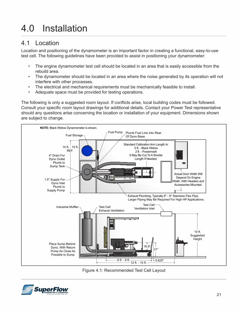
The following is only a suggested room layout. If conflicts arise, local building codes must be followed. Consult your specific room layout drawings for additional details. Contact your Power Test representative should any questions arise concerning the location or installation of your equipment. Dimensions shown are subject to change.
Figure 4.1: Recommended Test Cell Layout
10 ft.Suggested
Height
Test CellVentilation Inlet
12 ft. - 15 ft.8 ft. - 9 ft.
Place Sump BehindDyno, With ReturnPump As Close AsPossible to Sump.
Test CellExhaust Ventilation
Industrial Muffler
Exhaust Plumbing. Typically 6" - 9" Stainless Flex Pipe.Larger Piping May Be Required For High HP Applications.
NOTE: Black Widow Dynamometer is shown.
31"
3.625"
Plumb Fuel Line Into RearOf Dyno Base.
Fuel PumpFuel Storage
10 ft. - 15 ft.REF.
1.5" Supply ForDyno InletPlumb to
Supply Pump
4" Drain ForDyno Outlet
Plumb toSump Tank
16.9"
Standard Calibration Arm Length Is:5 ft. - Black Widow2 ft. - Powermark
It May Be Cut To A ShorterLength If Needed.
Actual Door Width WillDepend On Engine
Width, With Headers andAccessories Mounted.
22
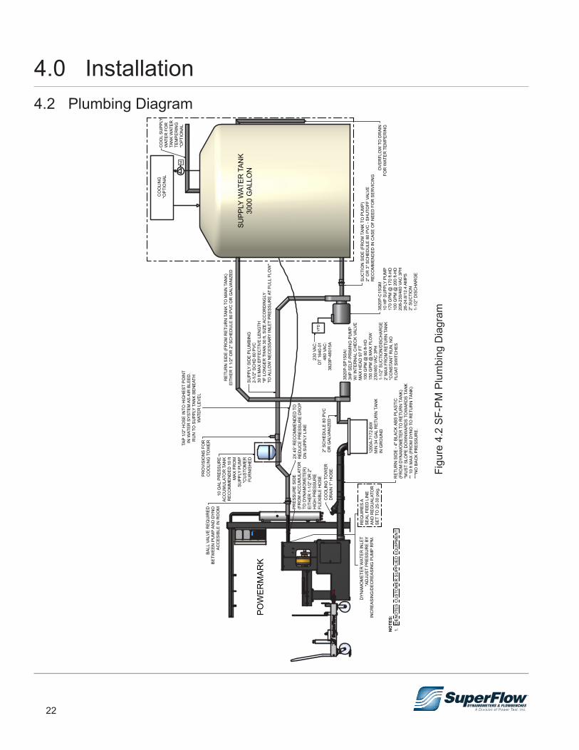
4.0 Installation4.2 Plumbing Diagram
VFD
M
DYN
AMO
MET
ER W
ATER
INLE
T*A
DJU
ST P
RES
SUR
E BY
INC
REA
SIN
G/D
ECR
EASI
NG
PU
MP
RPM
.
POW
ERM
ARK
RET
UR
N S
IDE
- 4" B
LAC
K AB
S PL
ASTI
C(F
RO
M D
YNAM
OM
ETER
TO
RET
UR
N T
ANK)
*MU
ST S
LOPE
DO
WN
WAR
DS
TOW
ARD
S TA
NK
** 1
0 ft
MAX
(FR
OM
DYN
O T
O R
ETU
RN
TAN
K)**
*NO
BAC
K PR
ESSU
RE.
1200
A-71
72-B
WM
IN 3
4 G
AL R
ETU
RN
TAN
KIN
GR
OU
ND
2" S
CH
EDU
LE 8
0 PV
CO
R G
ALVA
NIZ
EDC
OO
LIN
G T
OW
ERD
RAI
N 1
" HO
SE
PRES
SUR
E SI
DE
(FR
OM
AC
CU
MU
LATO
RTO
DYN
AMO
MET
ER)
EITH
ER 1
-1/2
" OR
2"
HIG
H P
RES
SUR
EFL
EXIB
LE H
OSE
2X 4
5° R
ECO
MM
END
ED T
OR
EDU
CE
PRES
SUR
E D
RO
PO
N S
UPP
LY L
INE
BALL
VAL
VE R
EQU
IRED
BETW
EEN
PU
MP
AND
DYN
OAC
CES
IBLE
IN R
OO
M10
GAL
PR
ESSU
RE
ACC
UM
ULA
TOR
TAN
KR
ECO
MM
END
ED 1
0 ft
MAX
FR
OM
SUPP
LY P
UM
P*C
UST
OM
ERFU
RN
ISH
ED
PRO
VISI
ON
S FO
RC
OO
LIN
G T
OW
ERTAP
1/2"
HO
SE IN
TO H
IGH
EST
POIN
TIN
WAT
ER S
YSTE
M A
S AI
R B
LEED
.R
UN
TO
SU
PPLY
TAN
K BE
NEA
THW
ATER
LEV
EL
RET
UR
N S
IDE
(FR
OM
RET
UR
N T
ANK
TO M
AIN
TAN
K)EI
THER
1 1
/2" O
R 2
" SC
HED
ULE
80
PVC
OR
GAL
VAN
IZED
SUPP
LY S
IDE
PLU
MBI
NG
2-1/
2" S
CH
D 8
0 PV
C30
ft M
AX E
FFEC
TIVE
LEN
GTH
*IF L
ON
GER
TH
AN 3
0 ft,
SIZ
E AC
CO
RD
ING
LYTO
ALL
OW
NEC
ESSA
RY
INLE
T PR
ESSU
RE
AT F
ULL
FLO
W*
230
VAC
:D
T 16
40-0
148
0 VA
C:
3820
P-48
015A
3820
P-SP
150A
I3H
P SE
LF-P
RIM
ING
PU
MP
W/ I
NTE
RN
AL C
HEC
K VA
LVE
MAX
HEA
D 9
7 FT
100
GPM
@ 6
0 ft-
HD
150
GPM
@ M
AX F
LOW
230/
460
VAC
3PH
1-1/
2" S
UC
TIO
N/D
ISC
HAR
GE
2' M
AX F
RO
M R
ETU
RN
TAN
K*C
ON
STAN
T R
UN
, NO
FLO
AT S
WIT
CH
ES
OVE
RFL
OW
TO
DR
AIN
FOR
WAT
ER T
EMPE
RIN
G
SUC
TIO
N S
IDE
(FR
OM
TAN
K TO
PU
MP)
2" O
R 3
" SC
HED
ULE
80
PVC
- SH
UTO
FF V
ALVE
REC
OM
MEN
DED
IN C
ASE
OF
NEE
D F
OR
SER
VIC
ING
3820
P-C
15G
M10
HP
SUPP
LY P
UM
P17
0 G
PM @
170
ft-H
D10
0 G
PM @
200
ft-H
D20
8-23
0/46
0 VA
C 3
PH26
-24.
8/12
.4 A
MPS
2" S
UC
TIO
N1-
1/2"
DIS
CH
ARG
E
SUPP
LY W
ATER
TAN
K30
00 G
ALLO
N
CO
OLI
NG
*OPT
ION
ALC
OO
L SU
PPLY
WAT
ER F
OR
TAN
K W
ATER
TE
MPE
RIN
G*O
PTIO
NAL
NO
TES:
1.
DEN
OTE
S C
UST
OM
ER S
UPP
LIED
EQ
UIP
MEN
T
REQ
UIR
ES A
SEAL
FEE
D L
INE
AND
REG
UAL
ATO
RSE
T TO
25-
30 p
sig.
Figu
re 4
.2 S
F-PM
Plu
mbi
ng D
iagr
am
23
4.3 UnpackingThe SF-Powermark system is shipped partially assembled. Some parts are left off for protection during shipping. Interconnect and sensor cables require installation prior to use.
1. Inspect the crates and boxes for external damage. Be sure to check underneath the crate for possible forklift damage. Report any damage to the shipping company and SuperFlow Customer Service.
2. Remove all components and accessories from the crates or boxes.3. Inspect all components for loose parts or any damage.4. Open the rear panel of the operator’s console and inspect for loose parts or damage. Ensure that all
circuit cards are secure and cables are properly seated in their connectors.5. Position the sensor box on a stable surface. Locate the sensor box door key. Carefully open the sensor
box door, and inspect the inside of the sensor box for any loose parts or visible damage. Ensure all circuit cards are secure and cables are properly seated in their connectors.
HEAVY OBJECTS.Use lifting aids and proper lifting techniques.
! WARNING
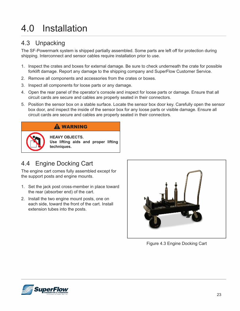
4.4 Engine Docking CartThe engine cart comes fully assembled except for the support posts and engine mounts.
1. Set the jack post cross-member in place toward the rear (absorber end) of the cart.
2. Install the two engine mount posts, one on each side, toward the front of the cart. Install extension tubes into the posts.
Figure 4.3 Engine Docking Cart
4.0 Installation
24
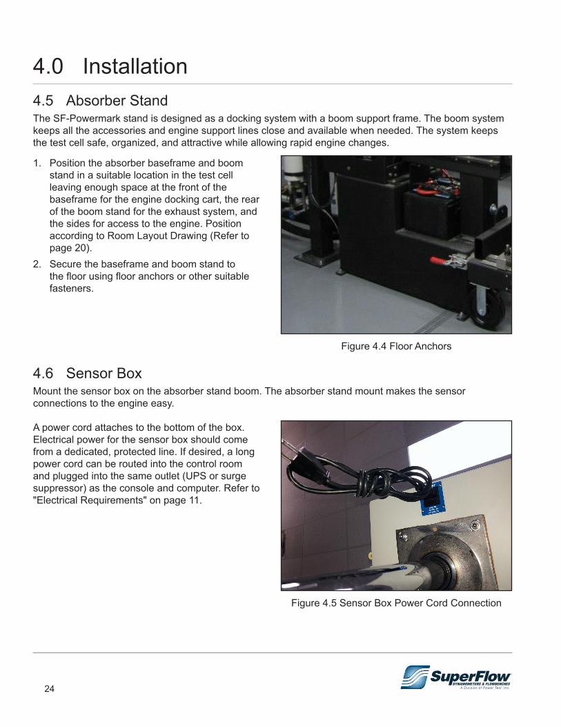
4.0 Installation4.5 Absorber StandThe SF-Powermark stand is designed as a docking system with a boom support frame. The boom system keeps all the accessories and engine support lines close and available when needed. The system keeps the test cell safe, organized, and attractive while allowing rapid engine changes.
1. Position the absorber baseframe and boom stand in a suitable location in the test cell leaving enough space at the front of the baseframe for the engine docking cart, the rear of the boom stand for the exhaust system, and the sides for access to the engine. Position according to Room Layout Drawing (Refer to page 20).
2. Secure the baseframe and boom stand to the floor using floor anchors or other suitable fasteners.
4.6 Sensor BoxMount the sensor box on the absorber stand boom. The absorber stand mount makes the sensor connections to the engine easy.
A power cord attaches to the bottom of the box. Electrical power for the sensor box should come from a dedicated, protected line. If desired, a long power cord can be routed into the control room and plugged into the same outlet (UPS or surge suppressor) as the console and computer. Refer to "Electrical Requirements" on page 11.
Figure 4.4 Floor Anchors
Figure 4.5 Sensor Box Power Cord Connection
25
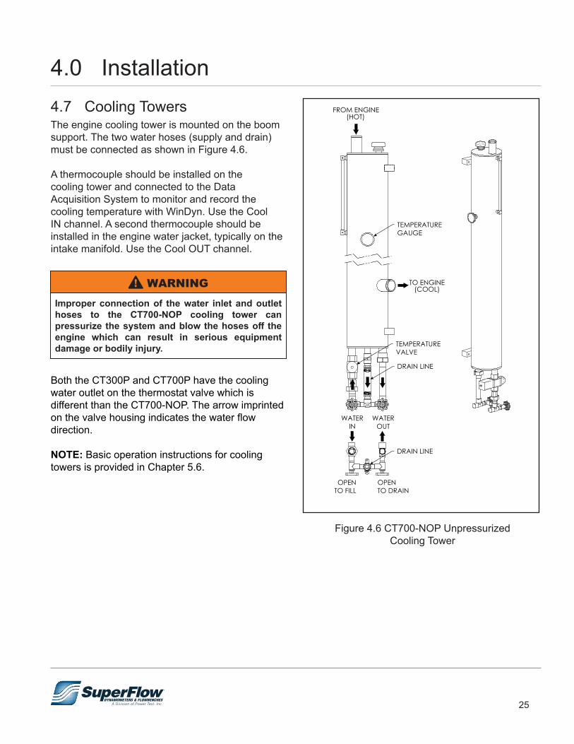
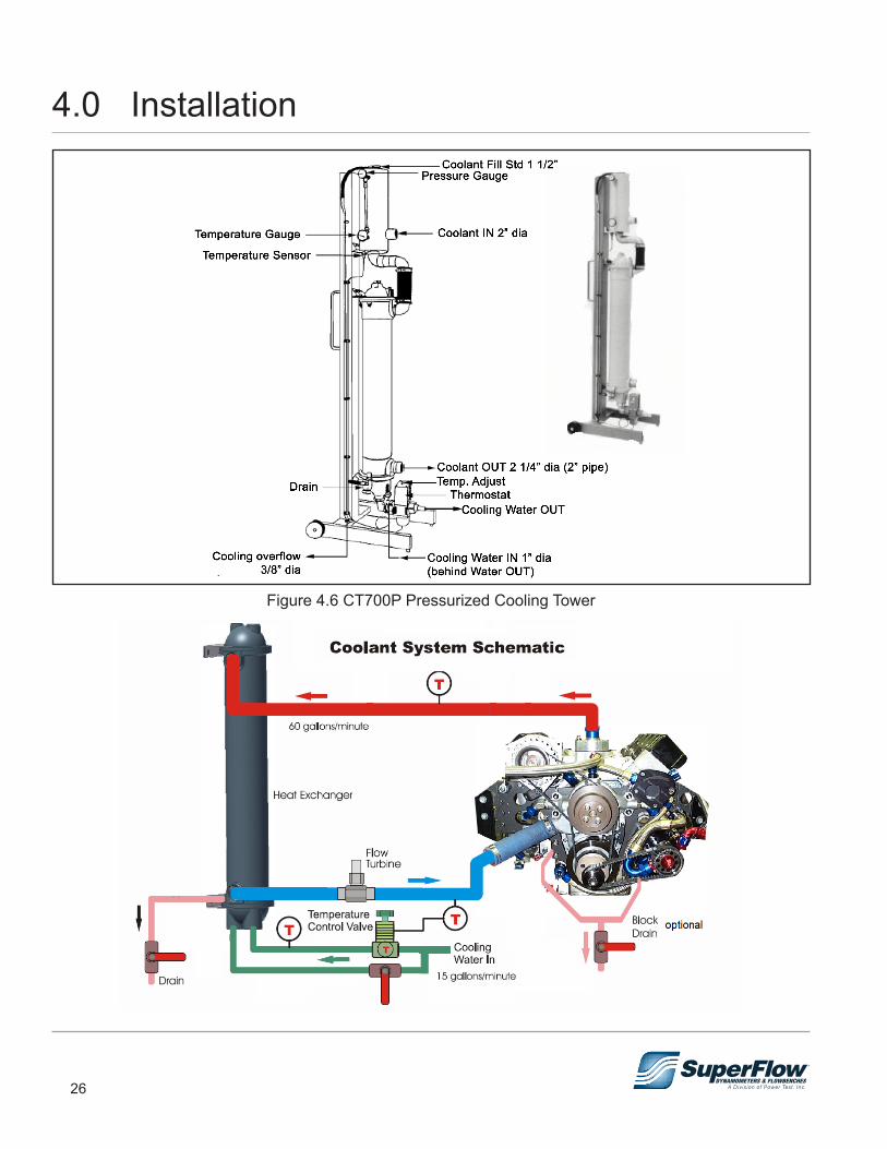
4.7 Cooling TowersThe engine cooling tower is mounted on the boom support. The two water hoses (supply and drain) must be connected as shown in Figure 4.6.
A thermocouple should be installed on the cooling tower and connected to the Data Acquisition System to monitor and record the cooling temperature with WinDyn. Use the Cool IN channel. A second thermocouple should be installed in the engine water jacket, typically on the intake manifold. Use the Cool OUT channel.
Improper connection of the water inlet and outlet hoses to the CT700-NOP cooling tower can pressurize the system and blow the hoses off the engine which can result in serious equipment damage or bodily injury.
! WARNING
Both the CT300P and CT700P have the cooling water outlet on the thermostat valve which is different than the CT700-NOP. The arrow imprinted on the valve housing indicates the water flow direction.
NOTE: Basic operation instructions for cooling towers is provided in Chapter 5.6.
Figure 4.6 CT700-NOP UnpressurizedCooling Tower
DRAIN LINE
FROM ENGINE(HOT)
WATEROUT
WATERIN
OPENTO FILL
OPENTO DRAIN
TO ENGINE(COOL)
DRAIN LINE
TEMPERATUREVALVE
TEMPERATUREGAUGE
4.0 Installation
26
Figure 4.6 CT700P Pressurized Cooling Tower
4.0 Installation
27
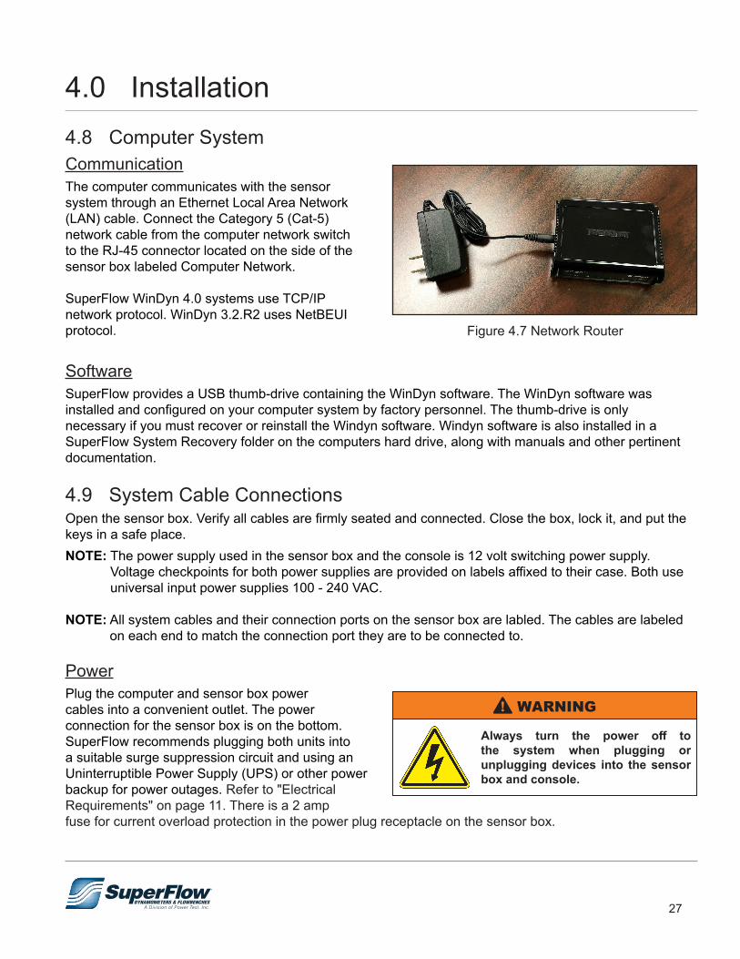
4.8 Computer SystemCommunicationThe computer communicates with the sensor system through an Ethernet Local Area Network (LAN) cable. Connect the Category 5 (Cat-5) network cable from the computer network switch to the RJ-45 connector located on the side of the sensor box labeled Computer Network.
SuperFlow WinDyn 4.0 systems use TCP/IP network protocol. WinDyn 3.2.R2 uses NetBEUI protocol.
SoftwareSuperFlow provides a USB thumb-drive containing the WinDyn software. The WinDyn software was installed and configured on your computer system by factory personnel. The thumb-drive is only necessary if you must recover or reinstall the Windyn software. Windyn software is also installed in a SuperFlow System Recovery folder on the computers hard drive, along with manuals and other pertinent documentation.
4.9 System Cable ConnectionsOpen the sensor box. Verify all cables are firmly seated and connected. Close the box, lock it, and put the keys in a safe place.NOTE: The power supply used in the sensor box and the console is 12 volt switching power supply.
Voltage checkpoints for both power supplies are provided on labels affixed to their case. Both use universal input power supplies 100 - 240 VAC.
NOTE: All system cables and their connection ports on the sensor box are labled. The cables are labeled on each end to match the connection port they are to be connected to.
PowerPlug the computer and sensor box power cables into a convenient outlet. The power connection for the sensor box is on the bottom. SuperFlow recommends plugging both units into a suitable surge suppression circuit and using an Uninterruptible Power Supply (UPS) or other power backup for power outages. Refer to "Electrical Requirements" on page 11. There is a 2 amp fuse for current overload protection in the power plug receptacle on the sensor box.
Figure 4.7 Network Router
Always turn the power off to the system when plugging or unplugging devices into the sensor box and console.
! WARNING
4.0 Installation

28
System Interconnect PanelThe system interconnect panel has connections for several different types of sensors and features plus provides the connections to the console and the computer (Figure 4.8).
Figure 4.8 System Interconnect Panel
Air 1SuperFlow airflow measurement turbines are connected to the sensor box system interconnect panel. Use cable 1200A-2044 to connect to the red receptacle labeled Air 1. Calibration tables for each flow turbine are entered in the configuration file. Other TTL or MAG frequency devices can be connected here as well but require modification to the definition of channel 7.
HumidityThe humidity and air temperature probe plugs into the blue receptacle on the sensor box system interconnect panel labeled Humidity. The humidity sensor is sensitive to contamination, so place it in a fresh air stream for the engine intake system and away from potential engine oil, gasoline, and exhaust spray. It is also sensitive to sunlight, so keep it out of direct sunlight.
4.0 Installation
29
Tach/FreqA second SuperFlow air turbine can be connected to the yellow receptacle labeled Tach/Freq if desired. Calibration tables for each flow turbine are entered in the configuration file. Other TTL or MAG frequency devices can be connected here as well but require modification to the definition of channel 12.
Engine SpeedOther TTL or MAG frequency devices can be connected here as well but require modification to the definition of channel 11.
Console J1/J2These connections are used with an operator’s console. Cables connected between the console and this panel carry several signals:• Serial data: Transmit and receive signals
allowing the console to display real-time data from the CPU and control the system from the console.
• Power-on: When the power switch on the console is turned on, the sensor box is also turned on. The push-button power switch on the sensor box should never be used when a console is connected.
• Emergency Stop: When the ES button on the console is pressed, a system ES action initiates.1. Connect a Cat-5 serial cable (supplied) from the RJ-45 connector J2 on the back of the console to the
Console J2 connector on the sensor box system interconnect panel. Make sure the cable is properly secured and protected.
2. Connect a second Cat-5 cable (supplied) from the RJ-45 connector J1 on the back of the console to the Console J1 connector on the sensor box interconnect panel.
Relay BoxA Cat-5 cable connects to the optional SF-1843 relay control enclosure.
Serial Aux 1 & 2These are for optional serial interface connections.
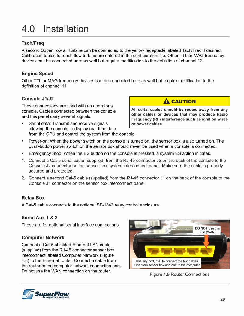
Computer NetworkConnect a Cat-5 shielded Ethernet LAN cable (supplied) from the RJ-45 connector sensor box interconnect labeled Computer Network (Figure 4.8) to the Ethernet router. Connect a cable from the router to the computer network connection port. Do not use the WAN connection on the router.
All serial cables should be routed away from any other cables or devices that may produce Radio Frequency (RF) interference such as ignition wires or power cables.
! CAUTION
Figure 4.9 Router Connections
DO NOT Use this Port (WAN)
Use any port, 1-4, to connect the two cables. One from sensor box and one to the computer.
4.0 Installation
30
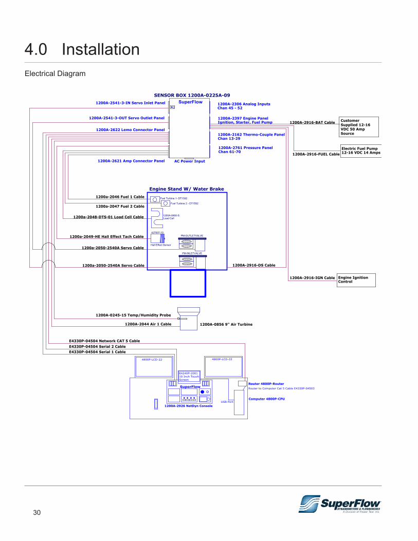
Electrical Diagram
4.0 Installation
31
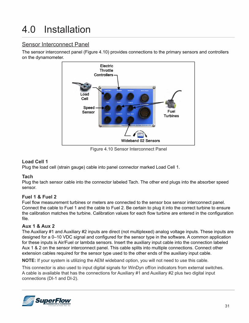
Sensor Interconnect PanelThe sensor interconnect panel (Figure 4.10) provides connections to the primary sensors and controllers on the dynamometer.
Figure 4.10 Sensor Interconnect Panel
Load Cell 1Plug the load cell (strain gauge) cable into panel connector marked Load Cell 1.
TachPlug the tach sensor cable into the connector labeled Tach. The other end plugs into the absorber speed sensor.
Fuel 1 & Fuel 2Fuel flow measurement turbines or meters are connected to the sensor box sensor interconnect panel. Connect the cable to Fuel 1 and the cable to Fuel 2. Be certain to plug it into the correct turbine to ensure the calibration matches the turbine. Calibration values for each flow turbine are entered in the configuration file.
Aux 1 & Aux 2The Auxiliary #1 and Auxiliary #2 inputs are direct (not multiplexed) analog voltage inputs. These inputs are designed for a 0–10 VDC signal and configured for the sensor type in the software. A common application for these inputs is Air/Fuel or lambda sensors. Insert the auxiliary input cable into the connection labeled Aux 1 & 2 on the sensor interconnect panel. This cable splits into multiple connections. Connect other extension cables required for the sensor type used to the other ends of the auxiliary input cable.NOTE: If your system is utilizing the AEM wideband option, you will not need to use this cable.This connector is also used to input digital signals for WinDyn off/on indicators from external switches. A cable is available that has the connections for Auxiliary #1 and Auxiliary #2 plus two digital input connections (DI-1 and DI-2).
4.0 Installation
32
ThrottleIf you have the optional electronic actuator, the throttle connector on the sensor interconnect panel connects to an SF-1805 electric throttle controller or other device using a 0–10VDC control signal.
4.10 Expansion Panels
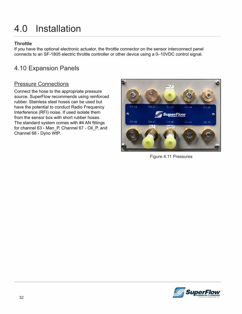
Pressure ConnectionsConnect the hose to the appropriate pressure source. SuperFlow recommends using reinforced rubber. Stainless steel hoses can be used but have the potential to conduct Radio Frequency Interference (RFI) noise. If used isolate them from the sensor box with short rubber hoses. The standard system comes with #4 AN fittings for channel 63 - Man_P, Channel 67 - Oil_P, and Channel 68 - Dyno WtP.
Figure 4.11 Pressures
4.0 Installation
33
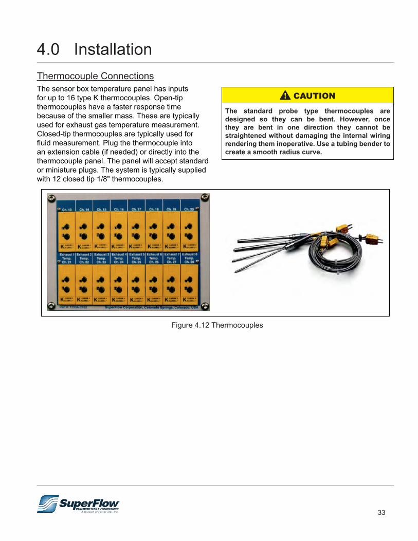
Thermocouple ConnectionsThe sensor box temperature panel has inputs for up to 16 type K thermocouples. Open-tip thermocouples have a faster response time because of the smaller mass. These are typically used for exhaust gas temperature measurement. Closed-tip thermocouples are typically used for fluid measurement. Plug the thermocouple into an extension cable (if needed) or directly into the thermocouple panel. The panel will accept standard or miniature plugs. The system is typically supplied with 12 closed tip 1/8" thermocouples.
Figure 4.12 Thermocouples
The standard probe type thermocouples are designed so they can be bent. However, once they are bent in one direction they cannot be straightened without damaging the internal wiring rendering them inoperative. Use a tubing bender to create a smooth radius curve.
! CAUTION
4.0 Installation

34
Analog Voltage ExpansionThis is an eight-channel analog DC voltage input panel used to integrate exhaust gas analyzers, multi-channel Lambda sensors, O2 sensors, pressure transducers, and other voltage output devices. The standard configuration is seven 0–10 VDC channels (45 to 51) and one 0–20 VDC channel (52). Other configurations are available upon request including 0–1 V, 0–5 V, and 0–30 V in any combination. Excitation and reference voltages are available if needed. The +12F excitation voltage is limited to 500 mA output. All others are limited to 100 mA.
Figure 4.13 Analog Expansion
Receptacles are color coded. All are keyed the same and use the same pin out. The channels are configured in the software as to the type of sensor used. Prefabricated cables are available to connect to this panel:• 1200A-2462-x: Un-terminated cable for input
only, x=color• 1200A-2462-01-x: BNC terminated cable for
input only, x=color• 1200A-2860 w/1200A-2188: Battery voltage
input cable for 20 V channel only• 1200A-2469-x: For pressure transducers or
other devices requiring a +5.00VDC excitation voltage, x=color
The input circuitry can be damaged if more voltage is applied by the sensor than what the channel is designed for.
! CAUTION
Use of custom sensors requires special modification to the system configuration file.
IMPORTANT
Figure 4.14 Lemo Connector
4.0 Installation
35
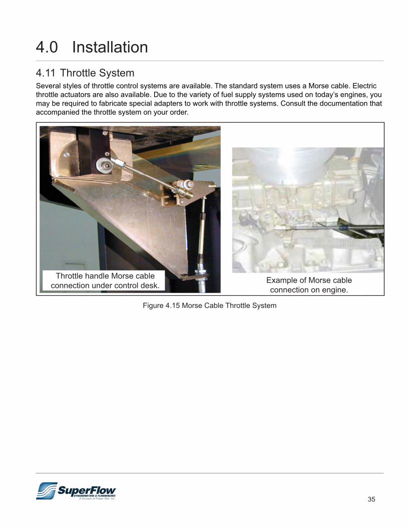
4.11 Throttle SystemSeveral styles of throttle control systems are available. The standard system uses a Morse cable. Electric throttle actuators are also available. Due to the variety of fuel supply systems used on today’s engines, you may be required to fabricate special adapters to work with throttle systems. Consult the documentation that accompanied the throttle system on your order.
Throttle handle Morse cable connection under control desk.
Figure 4.15 Morse Cable Throttle System
Example of Morse cable connection on engine.
4.0 Installation
36
4.12 Initial Check-outAfter the sensor box is secured and all the cables are connected, the system can be tested for operation.
1. Ensure the power cables for the sensor box are plugged into a suitable power source.2. Turn console key switch ON to power ON to the sensor box.
• Notice that a small green light in the upper right corner on the front of the sensor box illuminates.NOTE: The white power button on the sensor box is disabled; do not use it.
3. Turn the computer ON and start the WinDyn and NetDyn programs from desktop.
Prior to first using the dynamometer, SuperFlow recommends calibrating the systems torque measurement sensor. Refer to "Calibrating the Sensors" on page 56 in Chapter 6.
IMPORTANT
The system is now ready for use. Proceed to Chapter 5 for operation instructions. Consult the WinDyn Operators Manual for detailed information on how to use the software.NOTE: Refer to Chapter 6 for instructions on calibrating the various sensors in the system. If you
experience any problems in getting the system operational, or if the system fails to communicate with the console or with WinDyn, contact SuperFlow Customer Service for assistance.
Sensor calibration is a critical function of accurate measurements. Do not attempt to calibrate any of the sensors in a SuperFlow Data Acquisition System without the proper calibration equipment.
IMPORTANT
4.0 Installation
37
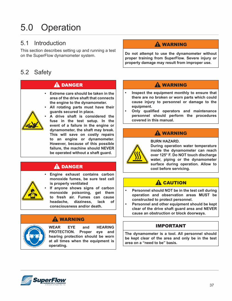
5.0 Operation5.1 IntroductionThis section describes setting up and running a test on the SuperFlow dynamometer system.
5.2 Safety
• Extreme care should be taken in the area of the drive shaft that connects the engine to the dynamometer.
• All rotating parts must have their guards secured in place.
• A drive shaft is considered the fuse in the test setup. In the event of a failure in the engine or dynamometer, the shaft may break. This will save on costly repairs to an engine or dynamometer. However, because of this possible failure, the machine should NEVER be operated without a shaft guard.
! DANGER
• Engine exhaust contains carbon monoxide fumes, be sure test cell is properly ventilated
• If anyone shows signs of carbon monoxide poisoning, get them to fresh air. Fumes can cause headache, dizziness, lack of consciousness and/or death.
! DANGER
WEAR EYE and HEARING PROTECTION. Proper eye and hearing protection should be worn at all times when the equipment is operating.
! WARNING
Do not attempt to use the dynamometer without proper training from SuperFlow. Severe injury or property damage may result from improper use.
! WARNING
BURN HAZARD.During operation water temperature inside the dynamometer can reach over 125° F. Do NOT touch discharge water, piping or the dynamometer surface during operation. Allow to cool before servicing.
! WARNING
• Inspect the equipment monthly to ensure that there are no broken or worn parts which could cause injury to personnel or damage to the equipment.
• Only qualified operators and maintenance personnel should perform the procedures covered in this manual.
! WARNING
• Personnel should NOT be in the test cell during operation and observation areas MUST be constructed to protect personnel.
• Personnel and other equipment should be kept clear of the drive shaft guard area and NEVER cause an obstruction or block doorways.
! CAUTION
The dynamometer is a tool. All personnel should be kept clear of the area and only be in the test area on a “need to be” basis.
IMPORTANT
38
5.0 OperationAn engine test cell can be a dangerous environment. The dynamometer operator will be exposed to a number of hazards. These risks are generally associated with the engine under test rather than with the dynamometer itself and it is thus not possible for SuperFlow to protect the operator against all these hazards by the design of the dynamometer instrumentation system.
A proper test cell environment eliminates or reduces the risks associated with dynamometer testing as much as possible. Examples of risks are: • Excessive noise• Risk of fire due to the fuel used• Risk of burns due to hot engine and exhaust system parts• Exposure to rotating parts• Exposure to parts being projected from the engine during operation • Excessive exhaust gas concentrationsNOTE: WinDyn is capable of automating test cell controls and integrating certain safety features in these
controls. Contact a SuperFlow Customer Service or Sales representative for more information or advice.
Emergency StopAn Emergency Stop switch is mounted near the computer system. Additional emergency stop switches can be installed in the test cell and control room. In the event of an emergency, press the nearest emergency stop switch. The emergency stop command will trigger a shutdown of the dynamometer system and return it to a safe mode.
When the emergency condition has been resolved, turn the switch clockwise to release it, or pull the switch back out depending on switch type. Then clear E-stop in the NetDyn pop-up window to reset the system. If the emergency stop condition was not cleared (the push-button released), the condition will remain active.
Electrical SafetyThe sensor box and electric throttle control (if equipped) require 110/230 VAC power. They each have internal power supplies. Opening, adjusting, and repairing the power supplies should not be attempted. Defective power supplies should be replaced.
FusesAll SuperFlow equipment is electrically protected by appropriate fuses. If a fuse blows, the cause must be found and removed. Do not replace fuses with a different type. This may result in a severe hazard for the user and/or damage to the equipment.
Repairs to the sensor box, console, or throttle controller should only be performed by a qualified Customer Service technician.
IMPORTANT
39
5.0 OperationSafety ProceduresThe WinDyn instrumentation system controls the engine and the dynamometer. As a result, there is a possibility that a certain function or equipment is activated at a time when this creates a hazard to a person in the area. Avoid such hazards by strictly enforcing the following policies:• Only authorized personnel, trained in the operation of the complete test system, should have access to
the dynamometer area.• Never allow anyone in the test cell during a test. Access during warm-up periods and when the engine
is idling is permissible.• Power OFF the system during periods when the dynamometer is not in use.• Ensure good visibility of the complete test cell area from the operator position.• Ensure circuit breakers are easily accessible and have the proper rating.• Ensure fuel and water shut-off valves are easily accessible.• Ensure fire extinguishers are available and certified.• Allow only authorized personnel to perform maintenance and repairs on electrical and mechanical
equipment.• Always turn power OFF to the system before plugging in cables and sensors to the Data Acquisition
sensor box.• Always turn power OFF to the system when changing engines.
40
5.0 Operation5.3 Test PreparationPrior to the start of dynamometer testing, the entire system should be checked to ensure everything is ready. Some of the items to check are:• Ensure: – The water supply and cooling systems are operational. Top off the water supply tank if necessary . – The water pressure to the system is set between 60-90psi when deadheaded. – You have an adequate supply of fuel. – You have an adequate supply of engine oil.• Verify the computer is communicating with the system.
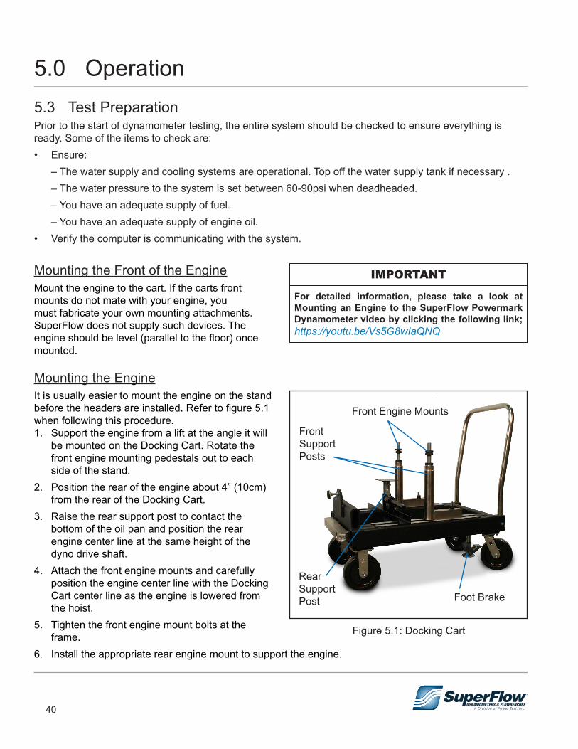
Mounting the Front of the EngineMount the engine to the cart. If the carts front mounts do not mate with your engine, you must fabricate your own mounting attachments. SuperFlow does not supply such devices. The engine should be level (parallel to the floor) once mounted.
Mounting the EngineIt is usually easier to mount the engine on the stand before the headers are installed. Refer to figure 5.1 when following this procedure.1. Support the engine from a lift at the angle it will
be mounted on the Docking Cart. Rotate the front engine mounting pedestals out to each side of the stand.
2. Position the rear of the engine about 4” (10cm) from the rear of the Docking Cart.
3. Raise the rear support post to contact the bottom of the oil pan and position the rear engine center line at the same height of the dyno drive shaft.
4. Attach the front engine mounts and carefully position the engine center line with the Docking Cart center line as the engine is lowered from the hoist.
5. Tighten the front engine mount bolts at the frame.
6. Install the appropriate rear engine mount to support the engine.
For detailed information, please take a look at Mounting an Engine to the SuperFlow Powermark Dynamometer video by clicking the following link; https://youtu.be/Vs5G8wIaQNQ
IMPORTANT
Figure 5.1: Docking Cart
Foot Brake
Front Support Posts
Front Engine Mounts
Rear Support Post
41
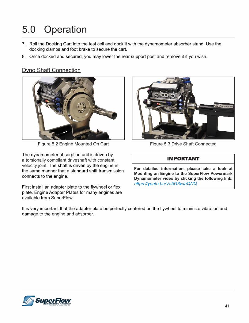
7. Roll the Docking Cart into the test cell and dock it with the dynamometer absorber stand. Use the docking clamps and foot brake to secure the cart.
8. Once docked and secured, you may lower the rear support post and remove it if you wish.
Dyno Shaft Connection
Figure 5.2 Engine Mounted On Cart
The dynamometer absorption unit is driven by a torsionally compliant driveshaft with constant velocity joint. The shaft is driven by the engine in the same manner that a standard shift transmission connects to the engine.
First install an adapter plate to the flywheel or flex plate. Engine Adapter Plates for many engines are available from SuperFlow.
It is very important that the adapter plate be perfectly centered on the flywheel to minimize vibration and damage to the engine and absorber.
Figure 5.3 Drive Shaft Connected
For detailed information, please take a look at Mounting an Engine to the SuperFlow Powermark Dynamometer video by clicking the following link; https://youtu.be/Vs5G8wIaQNQ
IMPORTANT
5.0 Operation
42
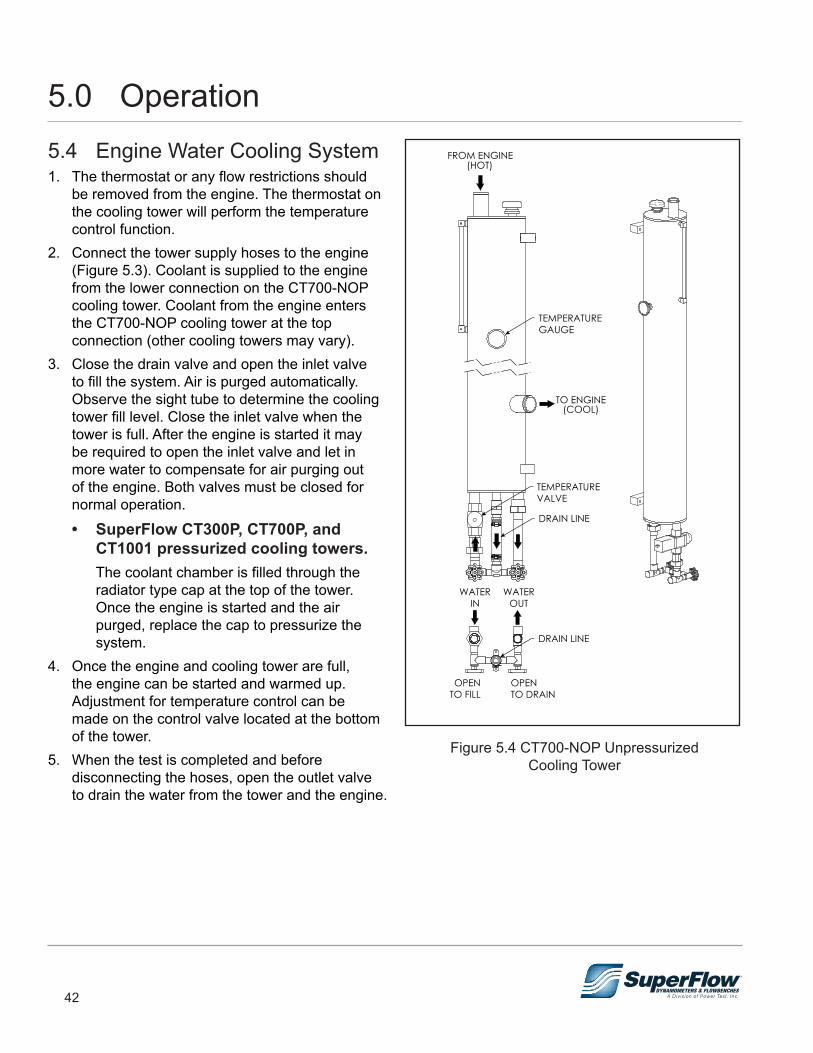
5.4 Engine Water Cooling System1. The thermostat or any flow restrictions should
be removed from the engine. The thermostat on the cooling tower will perform the temperature control function.
2. Connect the tower supply hoses to the engine (Figure 5.3). Coolant is supplied to the engine from the lower connection on the CT700-NOP cooling tower. Coolant from the engine enters the CT700-NOP cooling tower at the top connection (other cooling towers may vary).
3. Close the drain valve and open the inlet valve to fill the system. Air is purged automatically. Observe the sight tube to determine the cooling tower fill level. Close the inlet valve when the tower is full. After the engine is started it may be required to open the inlet valve and let in more water to compensate for air purging out of the engine. Both valves must be closed for normal operation.
• SuperFlow CT300P, CT700P, and CT1001 pressurized cooling towers.The coolant chamber is filled through the radiator type cap at the top of the tower. Once the engine is started and the air purged, replace the cap to pressurize the system.
4. Once the engine and cooling tower are full, the engine can be started and warmed up. Adjustment for temperature control can be made on the control valve located at the bottom of the tower.
5. When the test is completed and before disconnecting the hoses, open the outlet valve to drain the water from the tower and the engine.
Figure 5.4 CT700-NOP UnpressurizedCooling Tower
DRAIN LINE
FROM ENGINE(HOT)
WATEROUT
WATERIN
OPENTO FILL
OPENTO DRAIN
TO ENGINE(COOL)
DRAIN LINE
TEMPERATUREVALVE
TEMPERATUREGAUGE
5.0 Operation

43
5.5 Throttle SystemSeveral styles of throttle control systems are available. The standard system uses a Morse cable. Electric throttle actuators are also available. Due to the variety of fuel supply systems used on today’s engines, you may be required to fabricate special adapters to work with throttle systems. Consult the documentation that accompanied the throttle system on your order.
Throttle handle Morse cable connection under control desk.
Figure 5.5 Morse Cable Throttle System
Example of Morse cable connection on engine.
5.0 Operation
44
5.6 Sensor Connections
Stand Connections1. Place the Air Temperature and Humidity sensor
in a location close to or in the airflow to the engine air intake. Do not put too close to the engine as heat from the engine could affect the readings or a backfire from the engine air inlet could damage it. As a rule, put the sensor in the same general location for every test. The data from this sensor is used to apply power correction factors, so its repeatability is critical to your dyno testing results.
2. Connect the DC Power In cable to the connector labeled DC Input on the engine control panel. The other end of the cable is connected to the 12VDC battery or power supply source.
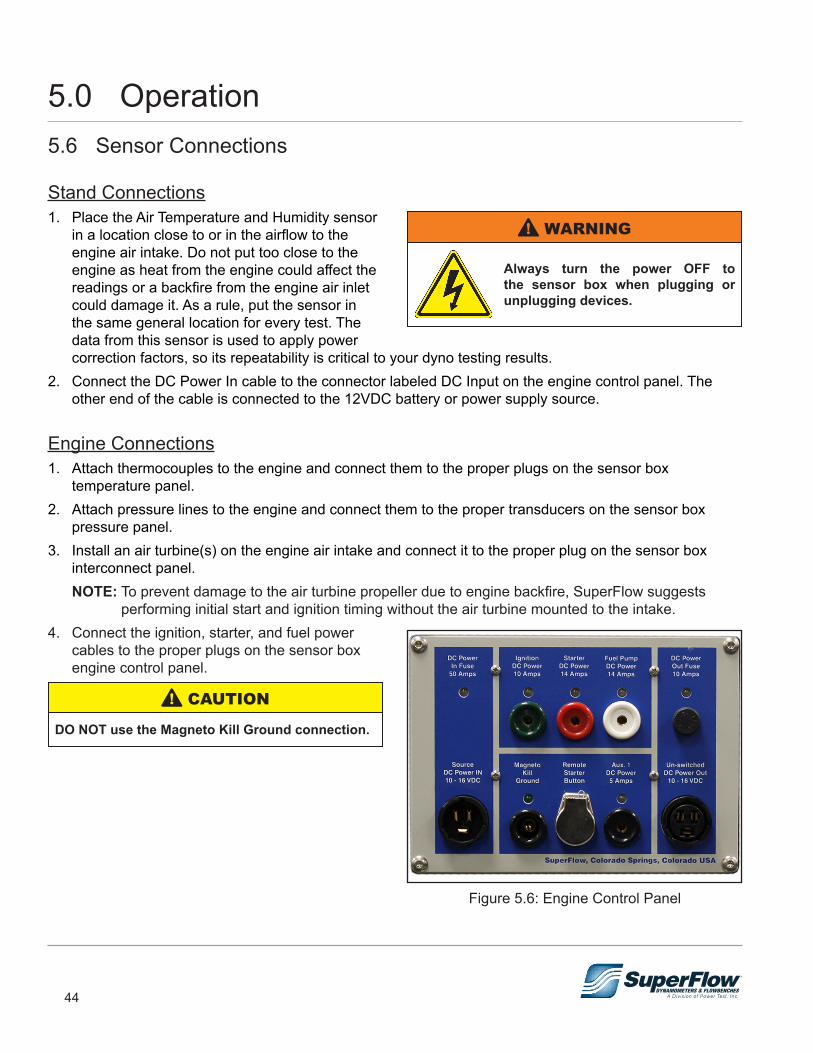
Engine Connections1. Attach thermocouples to the engine and connect them to the proper plugs on the sensor box
temperature panel.2. Attach pressure lines to the engine and connect them to the proper transducers on the sensor box
pressure panel.3. Install an air turbine(s) on the engine air intake and connect it to the proper plug on the sensor box
interconnect panel. NOTE: To prevent damage to the air turbine propeller due to engine backfire, SuperFlow suggests
performing initial start and ignition timing without the air turbine mounted to the intake.4. Connect the ignition, starter, and fuel power
cables to the proper plugs on the sensor box engine control panel.
DO NOT use the Magneto Kill Ground connection.
! CAUTION
Always turn the power OFF to the sensor box when plugging or unplugging devices.
! WARNING
Figure 5.6: Engine Control Panel
5.0 Operation
45
5.7 Running an Automated TestFollow this procedure for running each test. Repeatable and accurate test results are obtained by consistent test methods. Quick reference instructions are provided with this manual as a stand alone document that can be placed near the console for easy viewing.
Infrastructure and Engine Setup1. Verify the engine installation and all connections to the engine.2. Ensure:
• That the connection between engine and dynamometer is aligned and secure and that all guards are properly installed.
• No tools are left on the engine or dynamometer.3. Verify:
• Oil and water levels in the engine and heat exchanger(s).
• Fuel connections.• Electrical connections to the engine.• Battery hook-ups and battery charge condition.• Throttle connections and adjust throttle end stops, insure you have idle and WOT.• Sensors are connected as required for the test.
4. Ensure no sensor cables, electrical wires, or pressure lines interfere with the engine exhaust system or other hot or rotating parts.
5. Verify that dyno water supply valves are in the correct position.6. Secure all objects that might move due to air flow in the test cell.7. Verify:
• The fuel supply is adequate for the test.• The power is on at the console, sensor box, computer, printer, and any additional control
equipment.8. Open ventilation air shutters in the test cell.9. Open fuel supply valves.10. Turn ON water pumps and ventilation fans.
DO NOT use the Magneto Kill Ground connection on the Sensor Boxes Engine Control Panel.
! CAUTION
ALWAYS turn ON water pumps and ventilation fans BEFORE starting engine. Damage to the absorber seals may occur if the engine is run without water supplied to the absorber.
! CAUTION
5.0 Operation
46
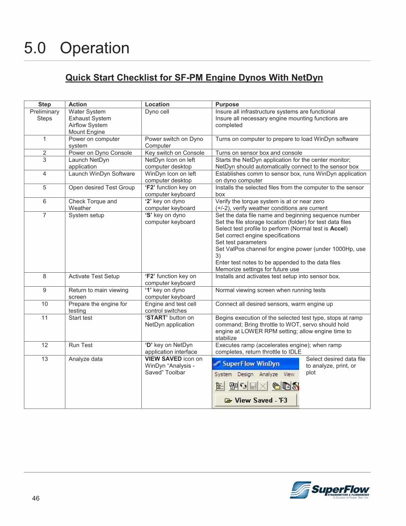
SuperFlow Technical Support
Quick Start Checklist for SF-PM Engine Dynos with NetDyn.doc Page 1 of 1 Created on 3/27/2018 2:38 PM Created by Bret E. Williamson
Quick Start Checklist for SF-PM Engine Dynos With NetDyn
Step Action Location Purpose Preliminary
Steps Water System Exhaust System Airflow System Mount Engine
Dyno cell Insure all infrastructure systems are functional Insure all necessary engine mounting functions are completed
1 Power on computer system
Power switch on Dyno Computer
Turns on computer to prepare to load WinDyn software
2 Power on Dyno Console Key switch on Console Turns on sensor box and console 3 Launch NetDyn
application NetDyn Icon on left computer desktop
Starts the NetDyn application for the center monitor; NetDyn should automatically connect to the sensor box
4 Launch WinDyn Software WinDyn Icon on left computer desktop
Establishes comm to sensor box, runs WinDyn application on dyno computer
5 Open desired Test Group ‘F2’ function key on computer keyboard
Installs the selected files from the computer to the sensor box
6 Check Torque and Weather
‘2’ key on dyno computer keyboard
Verify the torque system is at or near zero (+/-2), verify weather conditions are current
7 System setup ‘S’ key on dyno computer keyboard
Set the data file name and beginning sequence number Set the file storage location (folder) for test data files Select test profile to perform (Normal test is Accel) Set correct engine specifications Set test parameters Set ValPos channel for engine power (under 1000Hp, use 3) Enter test notes to be appended to the data files Memorize settings for future use
8 Activate Test Setup ‘F2’ function key on computer keyboard
Installs and activates test setup into sensor box.
9 Return to main viewing screen
‘1’ key on dyno computer keyboard
Normal viewing screen when running tests
10 Prepare the engine for testing
Engine and test cell control switches
Connect all desired sensors, warm engine up
11 Start test ‘START’ button on NetDyn application
Begins execution of the selected test type, stops at ramp command; Bring throttle to WOT, servo should hold engine at LOWER RPM setting; allow engine time to stabilize
12 Run Test ‘D’ key on NetDyn application interface
Executes ramp (accelerates engine); when ramp completes, return throttle to IDLE
13 Analyze data VIEW SAVED icon on WinDyn “Analysis - Saved” Toolbar
Select desired data file to analyze, print, or plot
5.0 Operation
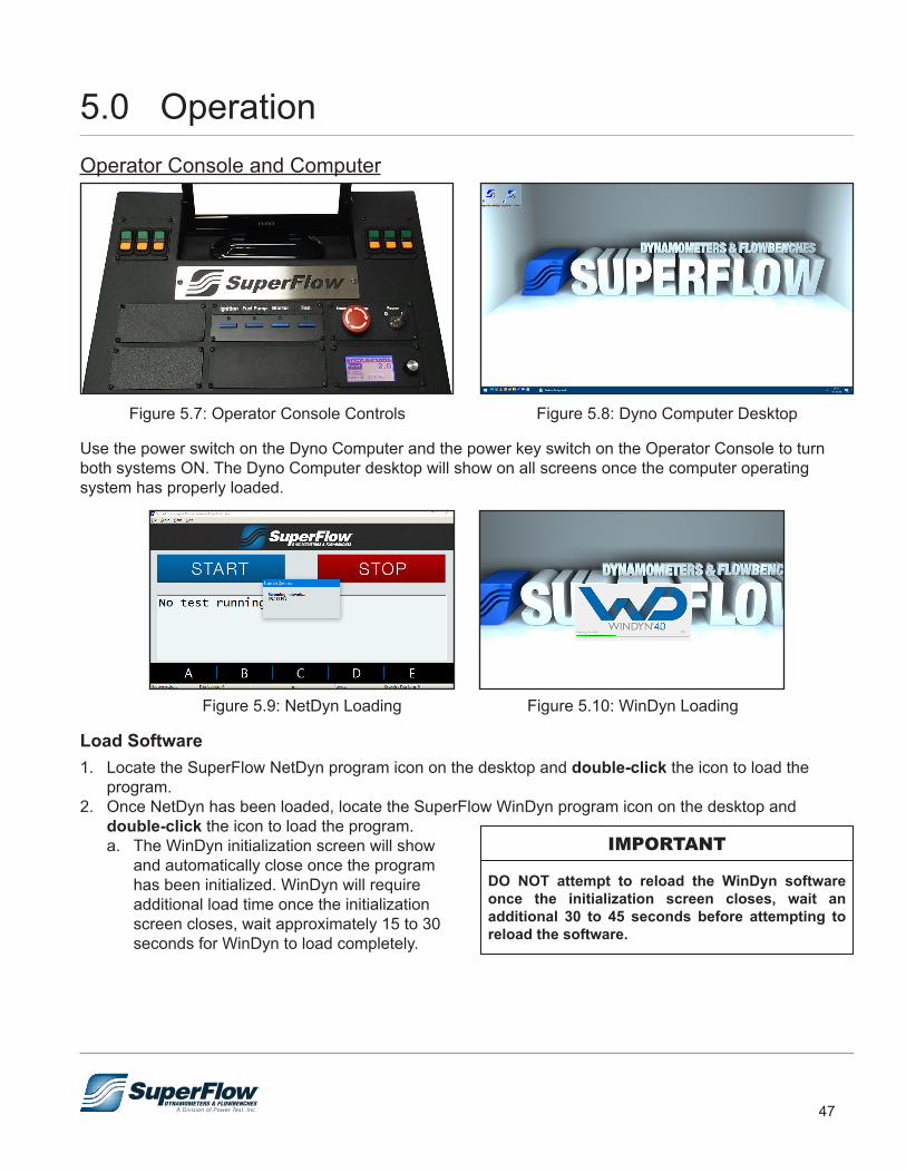
47
Operator Console and Computer
Figure 5.8: Dyno Computer DesktopFigure 5.7: Operator Console Controls
Use the power switch on the Dyno Computer and the power key switch on the Operator Console to turn both systems ON. The Dyno Computer desktop will show on all screens once the computer operating system has properly loaded.
Figure 5.9: NetDyn Loading Figure 5.10: WinDyn Loading
Load Software1. Locate the SuperFlow NetDyn program icon on the desktop and double-click the icon to load the
program.2. Once NetDyn has been loaded, locate the SuperFlow WinDyn program icon on the desktop and
double-click the icon to load the program.a. The WinDyn initialization screen will show
and automatically close once the program has been initialized. WinDyn will require additional load time once the initialization screen closes, wait approximately 15 to 30 seconds for WinDyn to load completely.
DO NOT attempt to reload the WinDyn software once the initialization screen closes, wait an additional 30 to 45 seconds before attempting to reload the software.
IMPORTANT
5.0 Operation
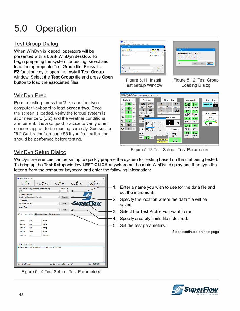
48
Test Group DialogWhen WinDyn is loaded, operators will be presented with a blank WinDyn desktop. To begin preparing the system for testing, select and load the appropriate Test Group file. Press the F2 function key to open the Install Test Group window. Select the Test Group file and press Open button to load the associated files.
WinDyn PrepPrior to testing, press the '2' key on the dyno computer keyboard to load screen two. Once the screen is loaded, verify the torque system is at or near zero (± 2) and the weather conditions are current. It is also good practice to verify other sensors appear to be reading correctly. See section "6.2 Calibration" on page 56 if you feel calibration should be performed before testing.
WinDyn Setup DialogWinDyn preferences can be set up to quickly prepare the system for testing based on the unit being tested. To bring up the Test Setup window LEFT-CLICK anywhere on the main WinDyn display and then type the letter s from the computer keyboard and enter the following information:
1. Enter a name you wish to use for the data file and set the increment.
2. Specify the location where the data file will be saved.
3. Select the Test Profile you want to run.4. Specify a safety limits file if desired.5. Set the test parameters.
Steps continued on next page
Figure 5.14 Test Setup - Test Parameters
Figure 5.11: InstallTest Group Window
Figure 5.12: Test GroupLoading Dialog
Figure 5.13 Test Setup - Test Parameters
5.0 Operation
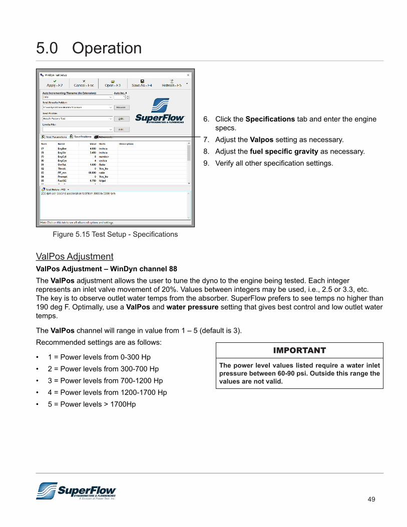
49
6. Click the Specifications tab and enter the engine specs.
7. Adjust the Valpos setting as necessary.8. Adjust the fuel specific gravity as necessary.9. Verify all other specification settings.
Figure 5.15 Test Setup - Specifications
ValPos AdjustmentValPos Adjustment – WinDyn channel 88 The ValPos adjustment allows the user to tune the dyno to the engine being tested. Each integer represents an inlet valve movement of 20%. Values between integers may be used, i.e., 2.5 or 3.3, etc. The key is to observe outlet water temps from the absorber. SuperFlow prefers to see temps no higher than 190 deg F. Optimally, use a ValPos and water pressure setting that gives best control and low outlet water temps.
The ValPos channel will range in value from 1 – 5 (default is 3). Recommended settings are as follows:
• 1 = Power levels from 0-300 Hp• 2 = Power levels from 300-700 Hp• 3 = Power levels from 700-1200 Hp• 4 = Power levels from 1200-1700 Hp• 5 = Power levels > 1700Hp
The power level values listed require a water inlet pressure between 60-90 psi. Outside this range the values are not valid.
IMPORTANT
5.0 Operation
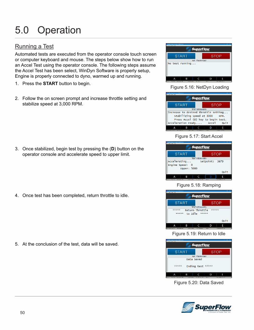
50
Running a TestAutomated tests are executed from the operator console touch screen or computer keyboard and mouse. The steps below show how to run an Accel Test using the operator console. The following steps assume the Accel Test has been select, WinDyn Software is properly setup, Engine is properly connected to dyno, warmed up and running. 1. Press the START button to begin.
2. Follow the on screen prompt and increase throttle setting and stabilize speed at 3,000 RPM.
3. Once stabilized, begin test by pressing the (D) button on the operator console and accelerate speed to upper limit.
4. Once test has been completed, return throttle to idle.
5. At the conclusion of the test, data will be saved.
Figure 5.16: NetDyn Loading
Figure 5.17: Start Accel
Figure 5.19: Return to Idle
Figure 5.20: Data Saved
Figure 5.18: Ramping
5.0 Operation
51
Post TestEach test can be viewed after it is saved. Current data is stored in memory in the Data Acquisition sensor box. Saved data is on the computer in the location and with the filename specified in the Test Setup screen. Press “Shift + F3” to select and view the saved test data.
ShutdownLet the engine cool down as necessary in idle mode, then turn off fuel and ignition. When the test cell ambient temperature and the engine coolant temperature are normal, shut down the test cell pumps and fans.
5.0 Operation
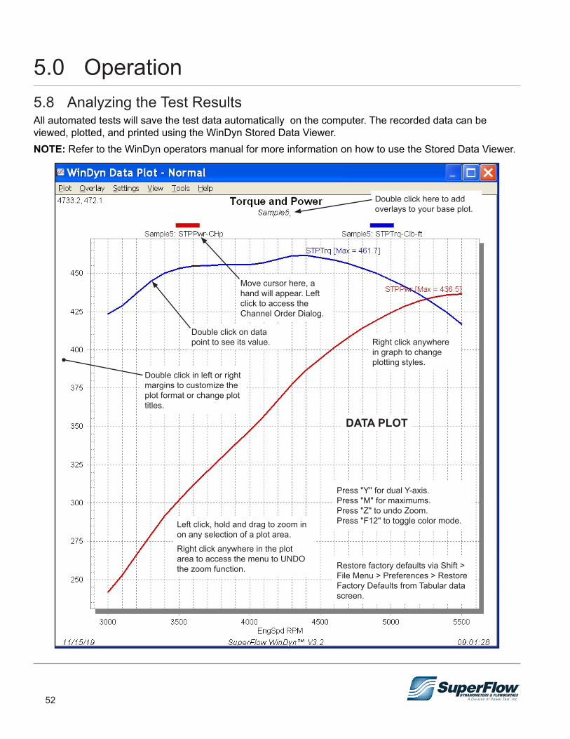
52
5.8 Analyzing the Test ResultsAll automated tests will save the test data automatically on the computer. The recorded data can be viewed, plotted, and printed using the WinDyn Stored Data Viewer.NOTE: Refer to the WinDyn operators manual for more information on how to use the Stored Data Viewer.
Double click here to add overlays to your base plot.
Move cursor here, a hand will appear. Left click to access the Channel Order Dialog.
Double click on data point to see its value.
Double click in left or right margins to customize the plot format or change plot titles.
Right click anywhere in graph to change plotting styles.
Press "Y" for dual Y-axis.Press "M" for maximums.Press "Z" to undo Zoom.Press "F12" to toggle color mode.
Restore factory defaults via Shift > File Menu > Preferences > Restore Factory Defaults from Tabular data screen.
Left click, hold and drag to zoom in on any selection of a plot area.Right click anywhere in the plot area to access the menu to UNDO the zoom function.
DATA PLOT
5.0 Operation
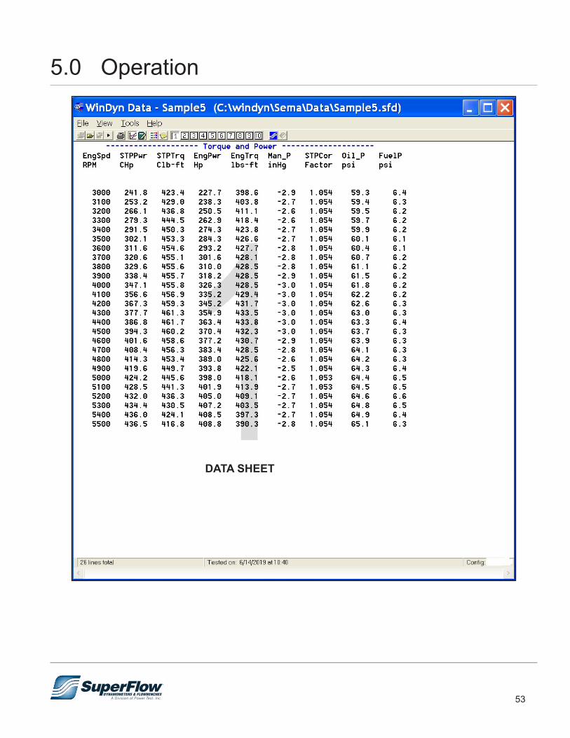
53
DATA SHEET
5.0 Operation
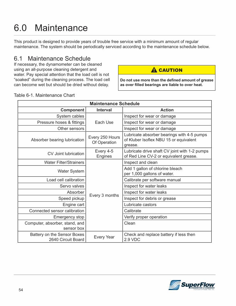
54
6.0 MaintenanceThis product is designed to provide years of trouble free service with a minimum amount of regular maintenance. The system should be periodically serviced according to the maintenance schedule below.
6.1 Maintenance ScheduleIf necessary, the dynamometer can be cleaned using an all-purpose cleaning detergent and water. Pay special attention that the load cell is not “soaked” during the cleaning process. The load cell can become wet but should be dried without delay.
Table 6-1. Maintenance Chart
Maintenance ScheduleComponent Interval Action
System cablesEach Use
Inspect for wear or damagePressure hoses & fittings Inspect for wear or damage
Other sensors Inspect for wear or damage
Absorber bearing lubrication Every 250 Hours Of Operation
Lubricate absorber bearings with 4-5 pumps of Kluber Isoflex NBU 15 or equivalent grease.
CV Joint lubrication Every 4-5 Engines
Lubricate drive shaft CV joint with 1-2 pumps of Red Line CV-2 or equivalent grease.
Water Filter/Strainers
Every 3 months
Inspect and clean
Water System Add 1 gallon of chlorine bleach per 1,000 gallons of water.
Load cell calibration Calibrate per software manualServo valves Inspect for water leaks
Absorber Inspect for water leaksSpeed pickup Inspect for debris or grease
Engine cart Lubricate castorsConnected sensor calibration Calibrate
Emergency stop Verify proper operationComputer, absorber, stand, and
sensor boxClean
Battery on the Sensor Boxes 2640 Circuit Board Every Year Check and replace battery if less then
2.9 VDC
Do not use more than the defined amount of grease as over filled bearings are liable to over heat.
! CAUTION
55
6.0 Maintenance
• Post safety warnings and barricade work area to prevent unauthorized use of the dynamometer before maintenance has been completed.
• Only qualified machine operators and maintenance personnel should perform the procedures covered in this manual.
! WARNING
Preventative MaintenanceThe absorber requires very little maintenance. Follow the suggestions below to increase the life and reliability of your absorber.
Water SupplyHigh inlet temperatures increase the occurrence of cavitation, which destroys the internal components of the absorber. High water inlet temperatures increase the possibility of unloading because the water inside the absorber turns to steam. Keeping the inlet water temperature as cool as possible greatly reduces these risks. Ensure inlet water temperature remains below 100 degrees F.
Water QualityContaminated or hard water can reduce the life of an absorber and increase maintenance cost. Ensure that any filters or strainers incorporated in the system are inspected regularly. Strainers should be cleaned and if necessary filters serviced.
LeaksWater leaks indicate problems that may lead to failure if left unattended. Check for leaks frequently, and repair as necessary.
AUTOMATIC STARTING HAZARD.An engine connected to dynamometer could be started remotely. Ensure starting has been disabled prior to servicing.
! WARNING
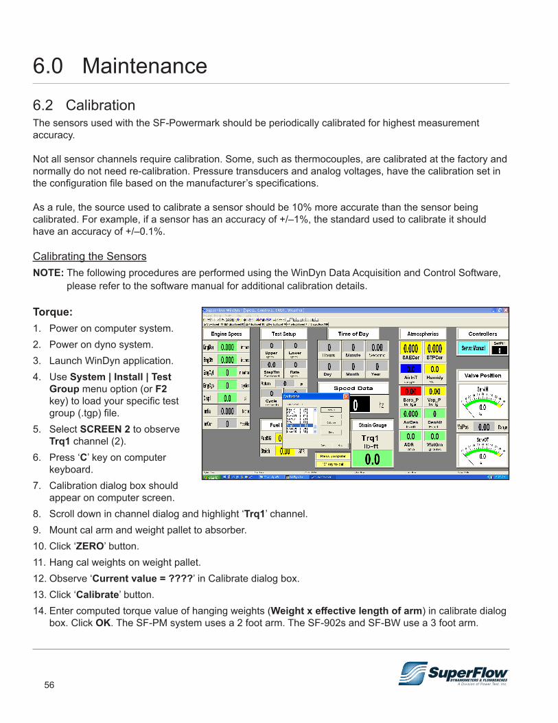
56
6.2 CalibrationThe sensors used with the SF-Powermark should be periodically calibrated for highest measurement accuracy.
Not all sensor channels require calibration. Some, such as thermocouples, are calibrated at the factory and normally do not need re-calibration. Pressure transducers and analog voltages, have the calibration set in the configuration file based on the manufacturer’s specifications.
As a rule, the source used to calibrate a sensor should be 10% more accurate than the sensor being calibrated. For example, if a sensor has an accuracy of +/–1%, the standard used to calibrate it should have an accuracy of +/–0.1%.
Calibrating the SensorsNOTE: The following procedures are performed using the WinDyn Data Acquisition and Control Software,
please refer to the software manual for additional calibration details.
Torque:1. Power on computer system.2. Power on dyno system.3. Launch WinDyn application.4. Use System | Install | Test
Group menu option (or F2 key) to load your specific test group (.tgp) file.
5. Select SCREEN 2 to observe Trq1 channel (2).
6. Press ‘C’ key on computer keyboard.
7. Calibration dialog box should appear on computer screen.
8. Scroll down in channel dialog and highlight ‘Trq1’ channel.9. Mount cal arm and weight pallet to absorber.10. Click ‘ZERO’ button.11. Hang cal weights on weight pallet.12. Observe ‘Current value = ????’ in Calibrate dialog box.13. Click ‘Calibrate’ button.14. Enter computed torque value of hanging weights (Weight x effective length of arm) in calibrate dialog
box. Click OK. The SF-PM system uses a 2 foot arm. The SF-902s and SF-BW use a 3 foot arm.
6.0 Maintenance
57
6.0 Maintenance15. Remove weights and calibration arm16. Click ‘ZERO’ button again.17. Click ‘SAVE’ and overwrite existing calibration file by continuing to click ‘OK’ as dialogs appear.18. Click ‘DONE’ to exit calibration dialog box.Torque calibration is now complete. If the readings do not correspond with the procedure or are not within acceptable limits, contact SuperFlow Customer Service.
Pressure Transducers:If you have pressure sources and calibrated pressure measurement equipment with a higher accuracy than the transducer, it is possible to calibrate the pressure sensors using the procedures similar to those used to calibrate the torque sensor. However, scroll and locate the desired pressure channel and apply a known pressure to the sensor within range to verify calibration.
Atmospheric Transducers:Check the calibration of the weather channels, AirInt, Humidy, and BaroP using a weather station of your choice.
– AirInt is calibrated via the AirSen channel 1. – Humidy is calibrated via the HumSen channel 6.
Raise or lower the voltage values in either channel to perform calibration. SuperFlow uses a Kestrel 3500 pocket weather station to calibrate these channels. Any similar device will suffice.
Temperature:There is no adjustment for the calibration of the temperature sensors. If a temperature is reading incorrectly, try using a different probe. If available, the temperature may be verified with a thermocouple simulator. If that does not work, contact your SuperFlow representative.
Speed:There is no adjustment for the calibration of the speed sensor. If the speed is reading incorrectly, check the cables, connectors, and, if possible, the gap between the pickup and the gear. If it is still reading incorrectly, repair parts or service may be required. If available, the speed may be verified with a hand tachometer.
Speed pickup gap .015"-.020"
An abrupt change in pressure may result in damage to the sensor being calibrated. Make certain that the regulated air supply is set to zero before introducing pressure at a slow pace. When finished calibrating, slowly bleed off the air supply before removing from the sensor being tested.
WARNING
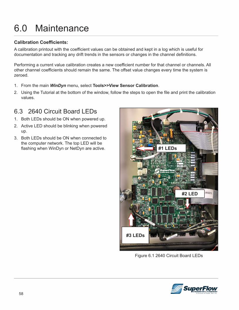
58
Calibration Coefficients:A calibration printout with the coefficient values can be obtained and kept in a log which is useful for documentation and tracking any drift trends in the sensors or changes in the channel definitions.
Performing a current value calibration creates a new coefficient number for that channel or channels. All other channel coefficients should remain the same. The offset value changes every time the system is zeroed.
1. From the main WinDyn menu, select Tools>>View Sensor Calibration.2. Using the Tutorial at the bottom of the window, follow the steps to open the file and print the calibration
values.
6.3 2640 Circuit Board LEDs 1. Both LEDs should be ON when powered up.2. Active LED should be blinking when powered
up.3. Both LEDs should be ON when connected to
the computer network. The top LED will be flashing when WinDyn or NetDyn are active.
Figure 6.1 2640 Circuit Board LEDs
#1 LEDs
#2 LED
#3 LEDs
6.0 Maintenance
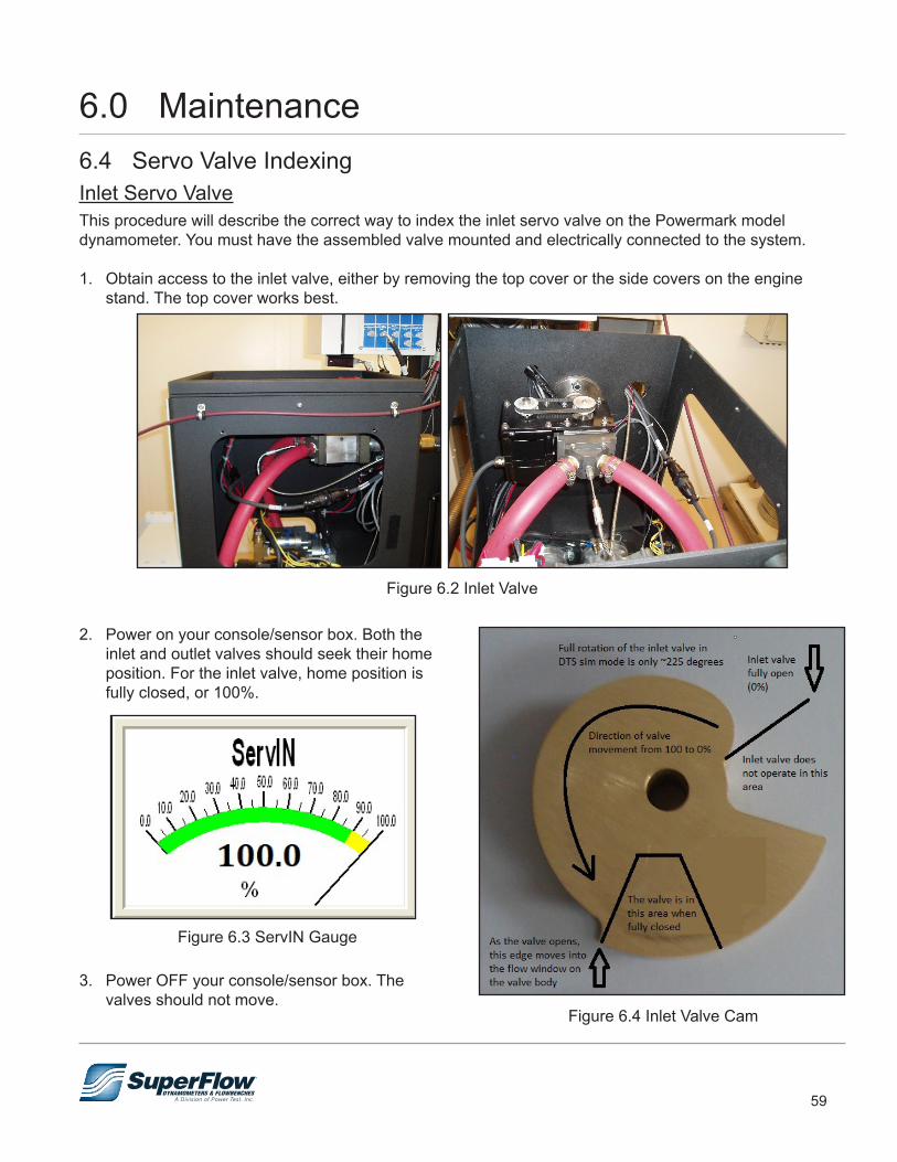
59
6.4 Servo Valve IndexingInlet Servo ValveThis procedure will describe the correct way to index the inlet servo valve on the Powermark model dynamometer. You must have the assembled valve mounted and electrically connected to the system.
1. Obtain access to the inlet valve, either by removing the top cover or the side covers on the engine stand. The top cover works best.
Figure 6.2 Inlet Valve
2. Power on your console/sensor box. Both the inlet and outlet valves should seek their home position. For the inlet valve, home position is fully closed, or 100%.
Figure 6.3 ServIN Gauge
3. Power OFF your console/sensor box. The valves should not move.
Figure 6.4 Inlet Valve Cam
6.0 Maintenance
60
4. Turn ON your water system and go out to the engine stand.5. Listen for water flowing at the inlet valve. It should not be flowing.
a. Slightly turn the valve spool pulley counter clockwise until you hear water flowing. b. You should only turn it one or two belt teeth until water flows, less is better. c. Rotate it back until you hear water stop flowing. Do this a couple of times to get a feel for it. d. We are trying to see how close that sharp edge in Figure 6.4 is to the valve body flow window.
6. If you were already hearing water flow, turn the valve spool pulley clockwise until you no longer hear water flowing. Again, do this a couple of times to get a good feel of how far off the sharp edge you are.
7. Turn OFF your water system.8. Turn your system back ON so the motor will seek home (100%, fully closed). With system power ON,
the motor should not turn if you try to do so with your fingers.9. To make any adjustment, you will have to loosen the set screws on the valve spool pulley so it can be
moved independent of the motor. 10. You can turn ON your water system while rotating the valve spool and again listen to when the water
just stops flowing. When you hear that, lock down the spool set screws and you are done.
NOTE: Some valve spool pulleys can be very tight to their shafts, making easy adjustment difficult if not impossible. You may have to remove the pulleys from their shaft and slightly dress the shaft down to allow for an easy slip fit so you can make your adjustments. You can also perform the adjustment by simply relocating the toothed belt on the pulley. Err towards the fully closed position, rather than allowing some water to flow at fully closed (100%). If water is flowing through the absorber before the engine is running, it can apply just enough load to make starting your engine difficult.
This completes the inlet valve indexing process. If you have any questions or concerns, please contact SuperFlow Technical Support for additional information.
6.0 Maintenance
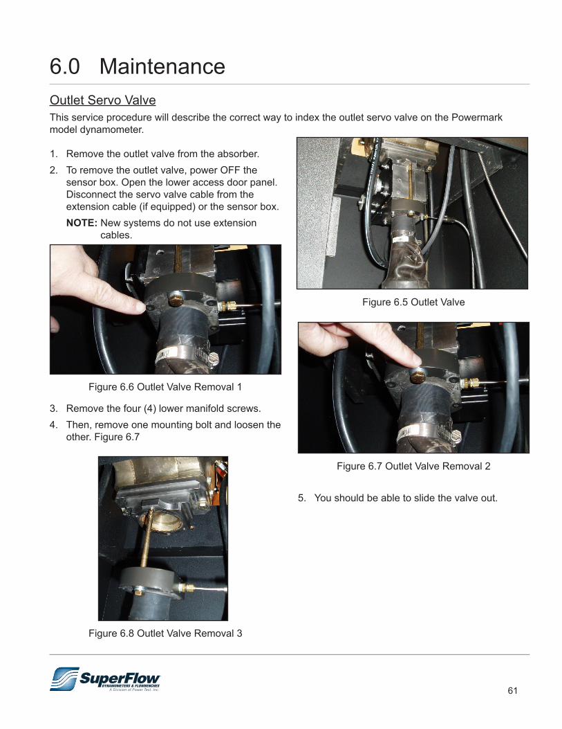
61
Outlet Servo ValveThis service procedure will describe the correct way to index the outlet servo valve on the Powermark model dynamometer.
1. Remove the outlet valve from the absorber.2. To remove the outlet valve, power OFF the
sensor box. Open the lower access door panel. Disconnect the servo valve cable from the extension cable (if equipped) or the sensor box.
NOTE: New systems do not use extension cables.
Figure 6.6 Outlet Valve Removal 1
3. Remove the four (4) lower manifold screws. 4. Then, remove one mounting bolt and loosen the
other. Figure 6.7
5. You should be able to slide the valve out.
Figure 6.5 Outlet Valve
Figure 6.7 Outlet Valve Removal 2
Figure 6.8 Outlet Valve Removal 3
6.0 Maintenance
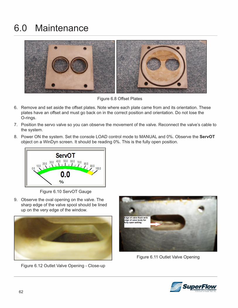
62
Figure 6.8 Offset Plates
6. Remove and set aside the offset plates. Note where each plate came from and its orientation. These plates have an offset and must go back on in the correct position and orientation. Do not lose the O-rings.
7. Position the servo valve so you can observe the movement of the valve. Reconnect the valve’s cable to the system.
8. Power ON the system. Set the console LOAD control mode to MANUAL and 0%. Observe the ServOT object on a WinDyn screen. It should be reading 0%. This is the fully open position.
Figure 6.10 ServOT Gauge
9. Observe the oval opening on the valve. The sharp edge of the valve spool should be lined up on the very edge of the window.
Figure 6.12 Outlet Valve Opening - Close-up
Figure 6.11 Outlet Valve Opening
6.0 Maintenance
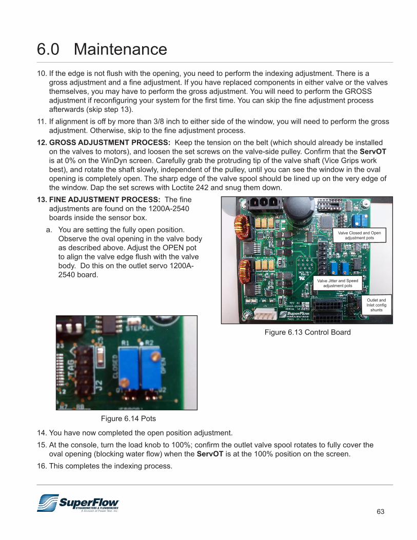
63
Figure 6.14 Pots
14. You have now completed the open position adjustment. 15. At the console, turn the load knob to 100%; confirm the outlet valve spool rotates to fully cover the
oval opening (blocking water flow) when the ServOT is at the 100% position on the screen. 16. This completes the indexing process.
10. If the edge is not flush with the opening, you need to perform the indexing adjustment. There is a gross adjustment and a fine adjustment. If you have replaced components in either valve or the valves themselves, you may have to perform the gross adjustment. You will need to perform the GROSS adjustment if reconfiguring your system for the first time. You can skip the fine adjustment process afterwards (skip step 13).
11. If alignment is off by more than 3/8 inch to either side of the window, you will need to perform the gross adjustment. Otherwise, skip to the fine adjustment process.
12. GROSS ADJUSTMENT PROCESS: Keep the tension on the belt (which should already be installed on the valves to motors), and loosen the set screws on the valve-side pulley. Confirm that the ServOT is at 0% on the WinDyn screen. Carefully grab the protruding tip of the valve shaft (Vice Grips work best), and rotate the shaft slowly, independent of the pulley, until you can see the window in the oval opening is completely open. The sharp edge of the valve spool should be lined up on the very edge of the window. Dap the set screws with Loctite 242 and snug them down.
13. FINE ADJUSTMENT PROCESS: The fine adjustments are found on the 1200A-2540 boards inside the sensor box.
a. You are setting the fully open position. Observe the oval opening in the valve body as described above. Adjust the OPEN pot to align the valve edge flush with the valve body. Do this on the outlet servo 1200A-2540 board.
6.0 Maintenance
Figure 6.13 Control Board
Valve Closed and Open adjustment pots
Valve Jitter and Speed adjustment pots
Outlet and Inlet config
shunts
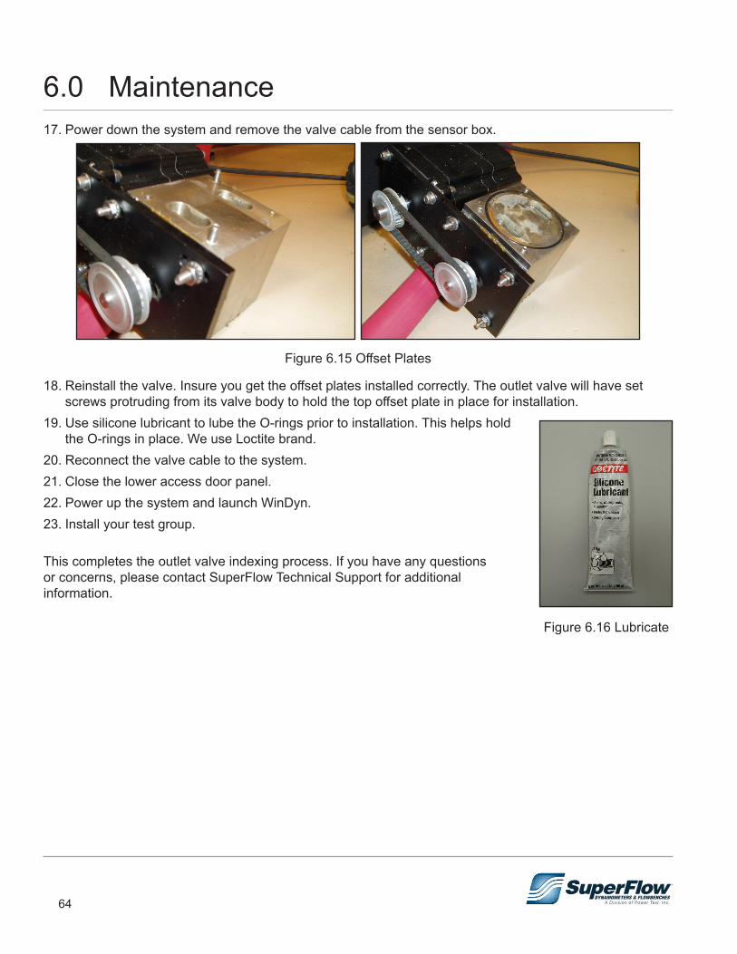
64
17. Power down the system and remove the valve cable from the sensor box.
Figure 6.15 Offset Plates
18. Reinstall the valve. Insure you get the offset plates installed correctly. The outlet valve will have set screws protruding from its valve body to hold the top offset plate in place for installation.
19. Use silicone lubricant to lube the O-rings prior to installation. This helps hold the O-rings in place. We use Loctite brand.
20. Reconnect the valve cable to the system.21. Close the lower access door panel.22. Power up the system and launch WinDyn.23. Install your test group.
This completes the outlet valve indexing process. If you have any questions or concerns, please contact SuperFlow Technical Support for additional information.
Figure 6.16 Lubricate
6.0 Maintenance
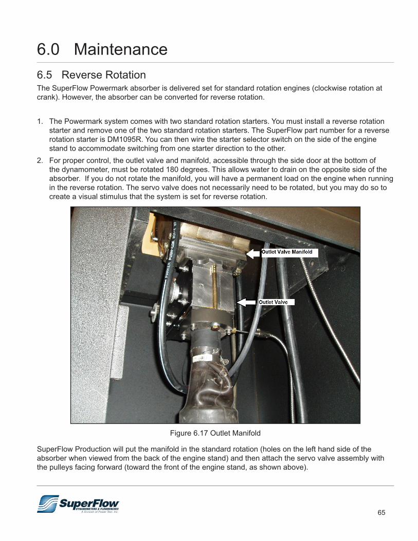
65
6.5 Reverse Rotation The SuperFlow Powermark absorber is delivered set for standard rotation engines (clockwise rotation at crank). However, the absorber can be converted for reverse rotation.
1. The Powermark system comes with two standard rotation starters. You must install a reverse rotation starter and remove one of the two standard rotation starters. The SuperFlow part number for a reverse rotation starter is DM1095R. You can then wire the starter selector switch on the side of the engine stand to accommodate switching from one starter direction to the other.
2. For proper control, the outlet valve and manifold, accessible through the side door at the bottom of the dynamometer, must be rotated 180 degrees. This allows water to drain on the opposite side of the absorber. If you do not rotate the manifold, you will have a permanent load on the engine when running in the reverse rotation. The servo valve does not necessarily need to be rotated, but you may do so to create a visual stimulus that the system is set for reverse rotation.
Figure 6.17 Outlet Manifold
SuperFlow Production will put the manifold in the standard rotation (holes on the left hand side of the absorber when viewed from the back of the engine stand) and then attach the servo valve assembly with the pulleys facing forward (toward the front of the engine stand, as shown above).
6.0 Maintenance
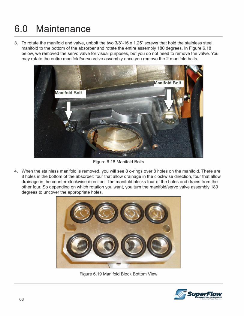
66
3. To rotate the manifold and valve, unbolt the two 3/8”-16 x 1.25” screws that hold the stainless steel manifold to the bottom of the absorber and rotate the entire assembly 180 degrees. In Figure 6.18 below, we removed the servo valve for visual purposes, but you do not need to remove the valve. You may rotate the entire manifold/servo valve assembly once you remove the 2 manifold bolts.
Figure 6.18 Manifold Bolts
4. When the stainless manifold is removed, you will see 8 o-rings over 8 holes on the manifold. There are 8 holes in the bottom of the absorber: four that allow drainage in the clockwise direction, four that allow drainage in the counter-clockwise direction. The manifold blocks four of the holes and drains from the other four. So depending on which rotation you want, you turn the manifold/servo valve assembly 180 degrees to uncover the appropriate holes.
Figure 6.19 Manifold Block Bottom View
6.0 Maintenance
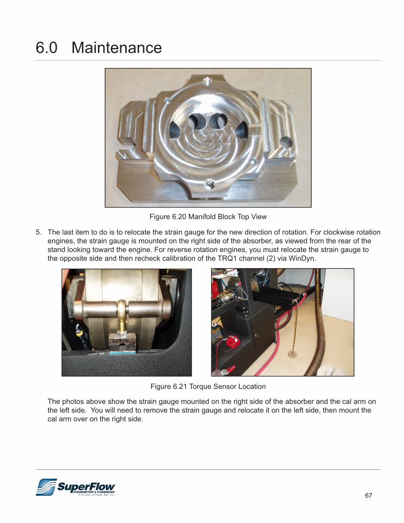
67
Figure 6.20 Manifold Block Top View
5. The last item to do is to relocate the strain gauge for the new direction of rotation. For clockwise rotation engines, the strain gauge is mounted on the right side of the absorber, as viewed from the rear of the stand looking toward the engine. For reverse rotation engines, you must relocate the strain gauge to the opposite side and then recheck calibration of the TRQ1 channel (2) via WinDyn.
Figure 6.21 Torque Sensor Location
The photos above show the strain gauge mounted on the right side of the absorber and the cal arm on the left side. You will need to remove the strain gauge and relocate it on the left side, then mount the cal arm over on the right side.
6.0 Maintenance
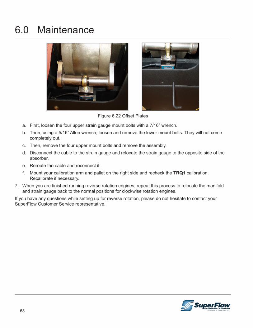
68
Figure 6.22 Offset Plates
a. First, loosen the four upper strain gauge mount bolts with a 7/16” wrench.b. Then, using a 5/16” Allen wrench, loosen and remove the lower mount bolts. They will not come
completely out. c. Then, remove the four upper mount bolts and remove the assembly. d. Disconnect the cable to the strain gauge and relocate the strain gauge to the opposite side of the
absorber. e. Reroute the cable and reconnect it. f. Mount your calibration arm and pallet on the right side and recheck the TRQ1 calibration.
Recalibrate if necessary.7. When you are finished running reverse rotation engines, repeat this process to relocate the manifold
and strain gauge back to the normal positions for clockwise rotation engines.If you have any questions while setting up for reverse rotation, please do not hesitate to contact your SuperFlow Customer Service representative.
6.0 Maintenance
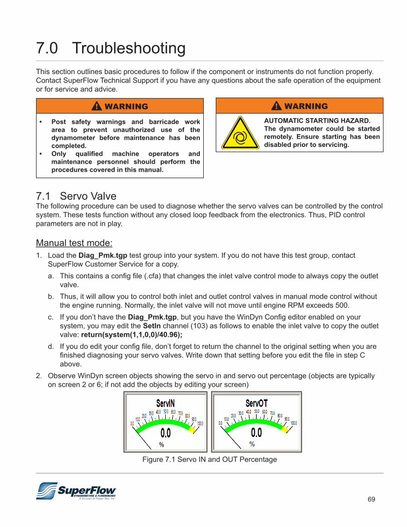
69
7.0 TroubleshootingThis section outlines basic procedures to follow if the component or instruments do not function properly. Contact SuperFlow Technical Support if you have any questions about the safe operation of the equipment or for service and advice.
• Post safety warnings and barricade work area to prevent unauthorized use of the dynamometer before maintenance has been completed.
• Only qualified machine operators and maintenance personnel should perform the procedures covered in this manual.
! WARNING
7.1 Servo ValveThe following procedure can be used to diagnose whether the servo valves can be controlled by the control system. These tests function without any closed loop feedback from the electronics. Thus, PID control parameters are not in play.
Manual test mode:1. Load the Diag_Pmk.tgp test group into your system. If you do not have this test group, contact
SuperFlow Customer Service for a copy.a. This contains a config file (.cfa) that changes the inlet valve control mode to always copy the outlet
valve.b. Thus, it will allow you to control both inlet and outlet control valves in manual mode control without
the engine running. Normally, the inlet valve will not move until engine RPM exceeds 500.c. If you don’t have the Diag_Pmk.tgp, but you have the WinDyn Config editor enabled on your
system, you may edit the SetIn channel (103) as follows to enable the inlet valve to copy the outlet valve: return(system(1,1,0,0)/40.96);
d. If you do edit your config file, don’t forget to return the channel to the original setting when you are finished diagnosing your servo valves. Write down that setting before you edit the file in step C above.
2. Observe WinDyn screen objects showing the servo in and servo out percentage (objects are typically on screen 2 or 6; if not add the objects by editing your screen)
Figure 7.1 Servo IN and OUT Percentage
AUTOMATIC STARTING HAZARD.The dynamometer could be started remotely. Ensure starting has been disabled prior to servicing.
! WARNING
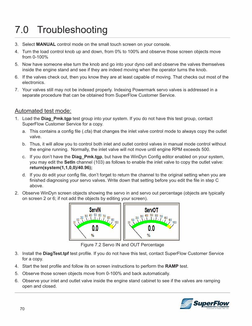
70
3. Select MANUAL control mode on the small touch screen on your console.4. Turn the load control knob up and down, from 0% to 100% and observe those screen objects move
from 0-100%5. Now have someone else turn the knob and go into your dyno cell and observe the valves themselves
inside the engine stand and see if they are indeed moving when the operator turns the knob.6. If the valves check out, then you know they are at least capable of moving. That checks out most of the
electronics. 7. Your valves still may not be indexed properly. Indexing Powermark servo valves is addressed in a
separate procedure that can be obtained from SuperFlow Customer Service.
Automated test mode:1. Load the Diag_Pmk.tgp test group into your system. If you do not have this test group, contact
SuperFlow Customer Service for a copy.a. This contains a config file (.cfa) that changes the inlet valve control mode to always copy the outlet
valve.b. Thus, it will allow you to control both inlet and outlet control valves in manual mode control without
the engine running. Normally, the inlet valve will not move until engine RPM exceeds 500.c. If you don’t have the Diag_Pmk.tgp, but have the WinDyn Config editor enabled on your system,
you may edit the SetIn channel (103) as follows to enable the inlet valve to copy the outlet valve: return(system(1,1,0,0)/40.96);
d. If you do edit your config file, don’t forget to return the channel to the original setting when you are finished diagnosing your servo valves. Write down that setting before you edit the file in step C above.
2. Observe WinDyn screen objects showing the servo in and servo out percentage (objects are typically on screen 2 or 6; if not add the objects by editing your screen).
Figure 7.2 Servo IN and OUT Percentage
3. Install the DiagTest.tpf test profile. If you do not have this test, contact SuperFlow Customer Service for a copy.
4. Start the test profile and follow its on screen instructions to perform the RAMP test.5. Observe those screen objects move from 0-100% and back automatically.6. Observe your inlet and outlet valve inside the engine stand cabinet to see if the valves are ramping
open and closed.
7.0 Troubleshooting
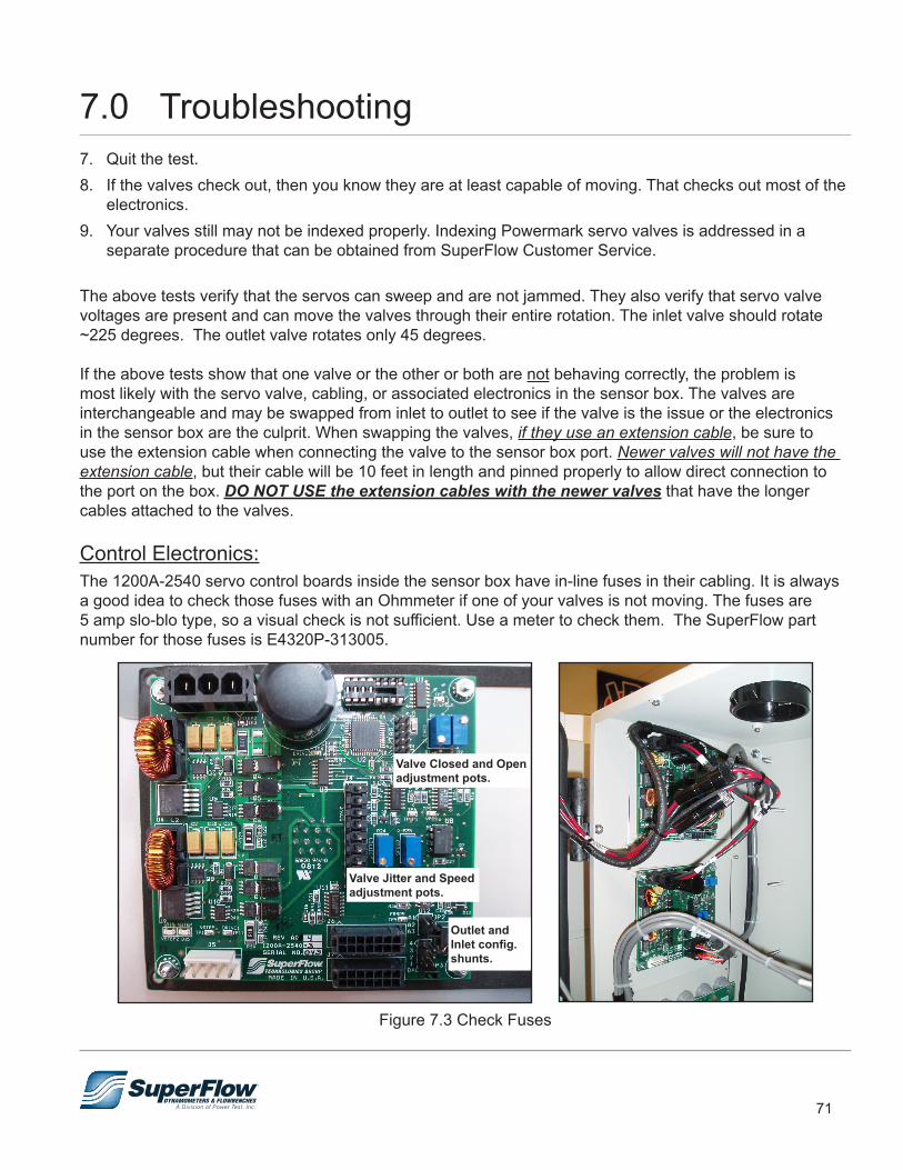
71
7. Quit the test.8. If the valves check out, then you know they are at least capable of moving. That checks out most of the
electronics. 9. Your valves still may not be indexed properly. Indexing Powermark servo valves is addressed in a
separate procedure that can be obtained from SuperFlow Customer Service.
The above tests verify that the servos can sweep and are not jammed. They also verify that servo valve voltages are present and can move the valves through their entire rotation. The inlet valve should rotate ~225 degrees. The outlet valve rotates only 45 degrees.
If the above tests show that one valve or the other or both are not behaving correctly, the problem is most likely with the servo valve, cabling, or associated electronics in the sensor box. The valves are interchangeable and may be swapped from inlet to outlet to see if the valve is the issue or the electronics in the sensor box are the culprit. When swapping the valves, if they use an extension cable, be sure to use the extension cable when connecting the valve to the sensor box port. Newer valves will not have the extension cable, but their cable will be 10 feet in length and pinned properly to allow direct connection to the port on the box. DO NOT USE the extension cables with the newer valves that have the longer cables attached to the valves.
Control Electronics:The 1200A-2540 servo control boards inside the sensor box have in-line fuses in their cabling. It is always a good idea to check those fuses with an Ohmmeter if one of your valves is not moving. The fuses are 5 amp slo-blo type, so a visual check is not sufficient. Use a meter to check them. The SuperFlow part number for those fuses is E4320P-313005.
Figure 7.3 Check Fuses
Valve Closed and Open adjustment pots.
Valve Jitter and Speed adjustment pots.
Outlet and Inlet config. shunts.
7.0 Troubleshooting

72
The 1200A-2540 controller boards are basically the same, except for jumpers that are installed on each board to determine whether the board is for an inlet or an outlet valve. If you receive a replacement board from SuperFlow, you must insure the jumpers are installed correctly for the location where you plan to use the board (inlet or outlet valve). You must also check you valve’s fully open and fully closed indexing and adjust as necessary. There is a separate procedure documenting how to perform those adjustments.
Figure 7.4 Check Jumpers
Outlet control uses shunts in A2 and the DAC1 positions.
Inlet control uses shunts in A1 and the DAC3 positions.
Another important checkpoint on the 1200A-2540 controller boards is to observe the two LEDs on those boards, VSTEP and VSTEP2. They both must be lit for the board to work properly. If one or both of the LEDs is not lit, the control circuitry will not function properly. If you do find the LEDs not lit, the board will have to be sent to SuperFlow for repair. See photo below for the location of the LEDs on the boards.
Figure 7.5 Check LEDs
7.0 Troubleshooting
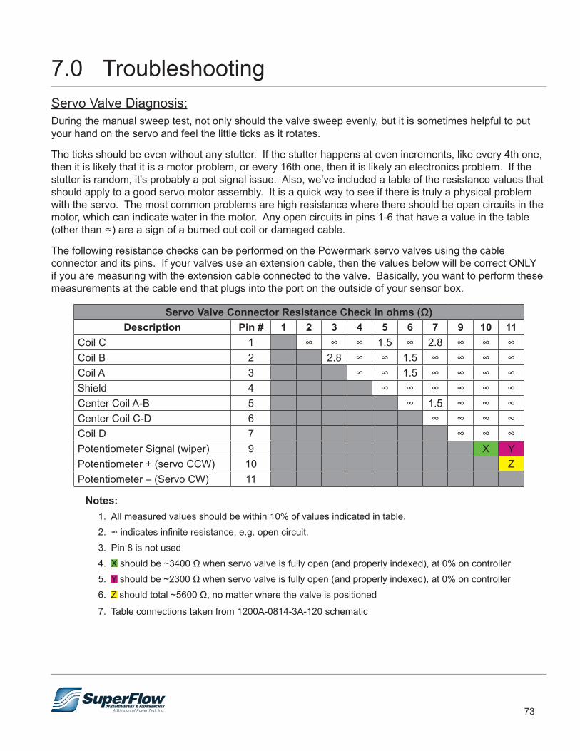
73
Servo Valve Diagnosis:During the manual sweep test, not only should the valve sweep evenly, but it is sometimes helpful to put your hand on the servo and feel the little ticks as it rotates.
The ticks should be even without any stutter. If the stutter happens at even increments, like every 4th one, then it is likely that it is a motor problem, or every 16th one, then it is likely an electronics problem. If the stutter is random, it's probably a pot signal issue. Also, we’ve included a table of the resistance values that should apply to a good servo motor assembly. It is a quick way to see if there is truly a physical problem with the servo. The most common problems are high resistance where there should be open circuits in the motor, which can indicate water in the motor. Any open circuits in pins 1-6 that have a value in the table (other than ∞) are a sign of a burned out coil or damaged cable.
The following resistance checks can be performed on the Powermark servo valves using the cable connector and its pins. If your valves use an extension cable, then the values below will be correct ONLY if you are measuring with the extension cable connected to the valve. Basically, you want to perform these measurements at the cable end that plugs into the port on the outside of your sensor box.
Servo Valve Connector Resistance Check in ohms (Ω)Description Pin # 1 2 3 4 5 6 7 9 10 11
Coil C 1 ∞ ∞ ∞ 1.5 ∞ 2.8 ∞ ∞ ∞Coil B 2 2.8 ∞ ∞ 1.5 ∞ ∞ ∞ ∞Coil A 3 ∞ ∞ 1.5 ∞ ∞ ∞ ∞Shield 4 ∞ ∞ ∞ ∞ ∞ ∞Center Coil A-B 5 ∞ 1.5 ∞ ∞ ∞Center Coil C-D 6 ∞ ∞ ∞ ∞Coil D 7 ∞ ∞ ∞Potentiometer Signal (wiper) 9 X YPotentiometer + (servo CCW) 10 ZPotentiometer – (Servo CW) 11
Notes:1. All measured values should be within 10% of values indicated in table.2. ∞ indicates infinite resistance, e.g. open circuit.3. Pin 8 is not used4. X should be ~3400 Ω when servo valve is fully open (and properly indexed), at 0% on controller 5. Y should be ~2300 Ω when servo valve is fully open (and properly indexed), at 0% on controller 6. Z should total ~5600 Ω, no matter where the valve is positioned
7. Table connections taken from 1200A-0814-3A-120 schematic
7.0 Troubleshooting
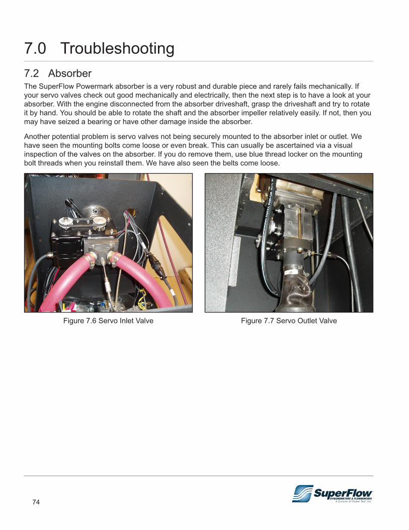
74
7.2 AbsorberThe SuperFlow Powermark absorber is a very robust and durable piece and rarely fails mechanically. If your servo valves check out good mechanically and electrically, then the next step is to have a look at your absorber. With the engine disconnected from the absorber driveshaft, grasp the driveshaft and try to rotate it by hand. You should be able to rotate the shaft and the absorber impeller relatively easily. If not, then you may have seized a bearing or have other damage inside the absorber.
Another potential problem is servo valves not being securely mounted to the absorber inlet or outlet. We have seen the mounting bolts come loose or even break. This can usually be ascertained via a visual inspection of the valves on the absorber. If you do remove them, use blue thread locker on the mounting bolt threads when you reinstall them. We have also seen the belts come loose.
Figure 7.6 Servo Inlet Valve Figure 7.7 Servo Outlet Valve
7.0 Troubleshooting
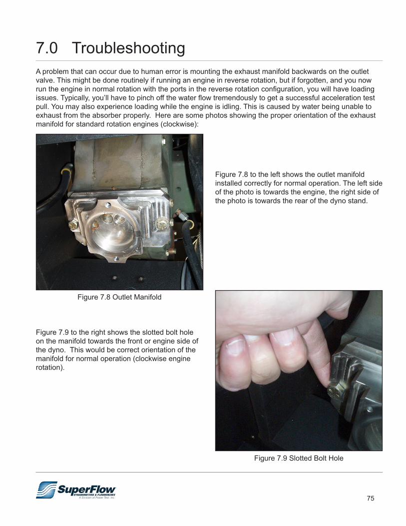
75
A problem that can occur due to human error is mounting the exhaust manifold backwards on the outlet valve. This might be done routinely if running an engine in reverse rotation, but if forgotten, and you now run the engine in normal rotation with the ports in the reverse rotation configuration, you will have loading issues. Typically, you’ll have to pinch off the water flow tremendously to get a successful acceleration test pull. You may also experience loading while the engine is idling. This is caused by water being unable to exhaust from the absorber properly. Here are some photos showing the proper orientation of the exhaust manifold for standard rotation engines (clockwise):
Figure 7.8 Outlet Manifold
Figure 7.9 Slotted Bolt Hole
Figure 7.8 to the left shows the outlet manifold installed correctly for normal operation. The left side of the photo is towards the engine, the right side of the photo is towards the rear of the dyno stand.
Figure 7.9 to the right shows the slotted bolt hole on the manifold towards the front or engine side of the dyno. This would be correct orientation of the manifold for normal operation (clockwise engine rotation).
7.0 Troubleshooting
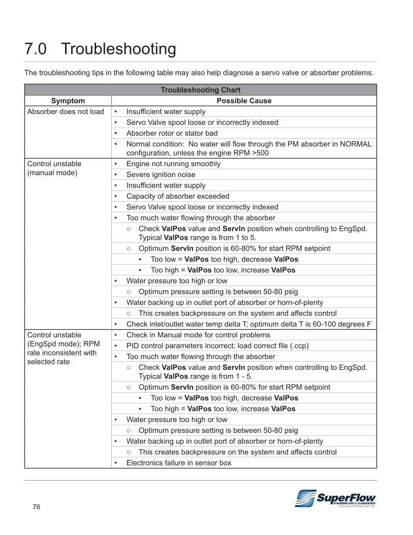
76
The troubleshooting tips in the following table may also help diagnose a servo valve or absorber problems.
Troubleshooting ChartSymptom Possible Cause
Absorber does not load • Insufficient water supply• Servo Valve spool loose or incorrectly indexed• Absorber rotor or stator bad• Normal condition: No water will flow through the PM absorber in NORMAL
configuration, unless the engine RPM >500Control unstable (manual mode)
• Engine not running smoothly• Severe ignition noise• Insufficient water supply• Capacity of absorber exceeded• Servo Valve spool loose or incorrectly indexed• Too much water flowing through the absorber
○ Check ValPos value and ServIn position when controlling to EngSpd. Typical ValPos range is from 1 to 5.
○ Optimum ServIn position is 60-80% for start RPM setpoint ▪ Too low = ValPos too high, decrease ValPos ▪ Too high = ValPos too low, increase ValPos
• Water pressure too high or low ○ Optimum pressure setting is between 50-80 psig
• Water backing up in outlet port of absorber or horn-of-plenty ○ This creates backpressure on the system and affects control
• Check inlet/outlet water temp delta T; optimum delta T is 60-100 degrees F Control unstable (EngSpd mode); RPM rate inconsistent with selected rate
• Check in Manual mode for control problems• PID control parameters incorrect; load correct file (.ccp)• Too much water flowing through the absorber
○ Check ValPos value and ServIn position when controlling to EngSpd. Typical ValPos range is from 1 - 5.
○ Optimum ServIn position is 60-80% for start RPM setpoint ▪ Too low = ValPos too high, decrease ValPos ▪ Too high = ValPos too low, increase ValPos
• Water pressure too high or low ○ Optimum pressure setting is between 50-80 psig
• Water backing up in outlet port of absorber or horn-of-plenty ○ This creates backpressure on the system and affects control
• Electronics failure in sensor box
7.0 Troubleshooting
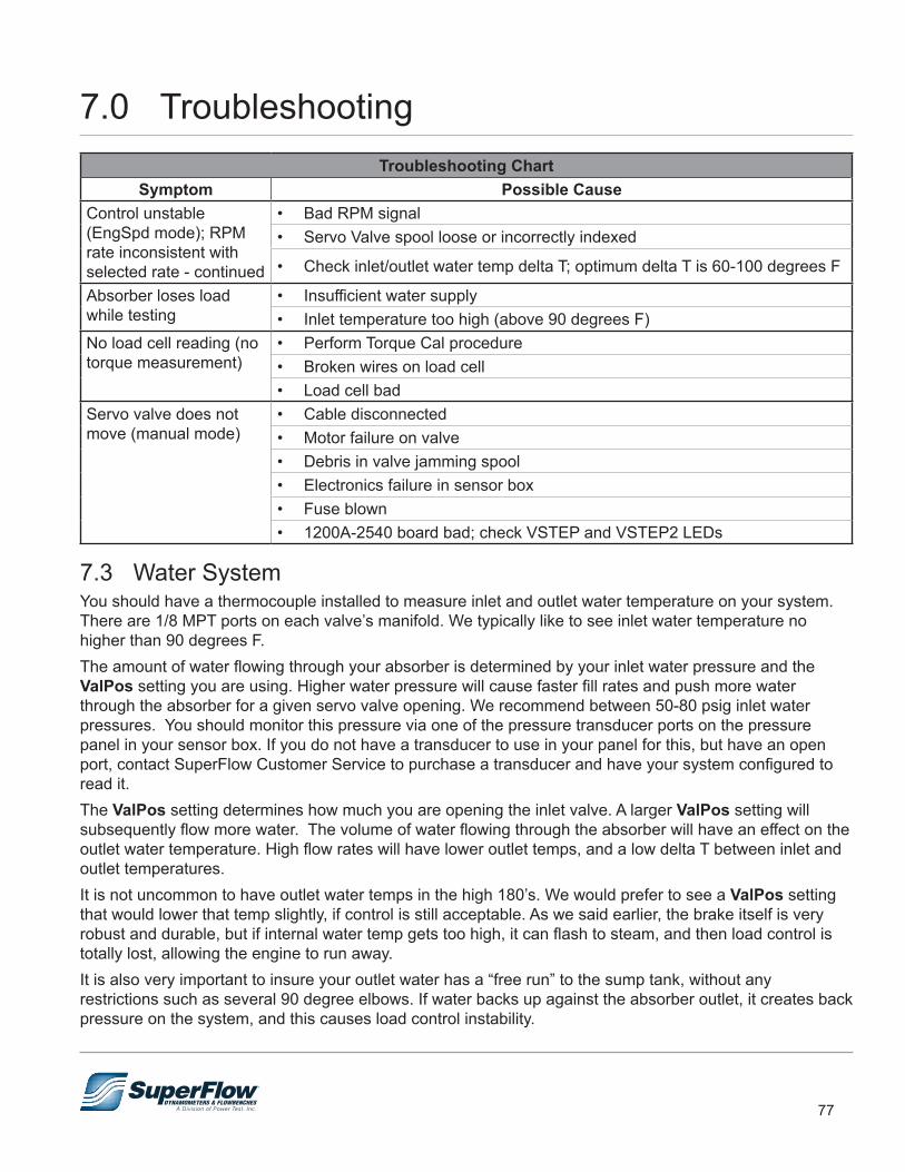
77
Troubleshooting ChartSymptom Possible Cause
Control unstable (EngSpd mode); RPM rate inconsistent with selected rate - continued
• Bad RPM signal • Servo Valve spool loose or incorrectly indexed
• Check inlet/outlet water temp delta T; optimum delta T is 60-100 degrees F
Absorber loses load while testing
• Insufficient water supply• Inlet temperature too high (above 90 degrees F)
No load cell reading (no torque measurement)
• Perform Torque Cal procedure• Broken wires on load cell• Load cell bad
Servo valve does not move (manual mode)
• Cable disconnected• Motor failure on valve• Debris in valve jamming spool• Electronics failure in sensor box• Fuse blown• 1200A-2540 board bad; check VSTEP and VSTEP2 LEDs
7.3 Water SystemYou should have a thermocouple installed to measure inlet and outlet water temperature on your system. There are 1/8 MPT ports on each valve’s manifold. We typically like to see inlet water temperature no higher than 90 degrees F. The amount of water flowing through your absorber is determined by your inlet water pressure and the ValPos setting you are using. Higher water pressure will cause faster fill rates and push more water through the absorber for a given servo valve opening. We recommend between 50-80 psig inlet water pressures. You should monitor this pressure via one of the pressure transducer ports on the pressure panel in your sensor box. If you do not have a transducer to use in your panel for this, but have an open port, contact SuperFlow Customer Service to purchase a transducer and have your system configured to read it. The ValPos setting determines how much you are opening the inlet valve. A larger ValPos setting will subsequently flow more water. The volume of water flowing through the absorber will have an effect on the outlet water temperature. High flow rates will have lower outlet temps, and a low delta T between inlet and outlet temperatures. It is not uncommon to have outlet water temps in the high 180’s. We would prefer to see a ValPos setting that would lower that temp slightly, if control is still acceptable. As we said earlier, the brake itself is very robust and durable, but if internal water temp gets too high, it can flash to steam, and then load control is totally lost, allowing the engine to run away.It is also very important to insure your outlet water has a “free run” to the sump tank, without any restrictions such as several 90 degree elbows. If water backs up against the absorber outlet, it creates back pressure on the system, and this causes load control instability.
7.0 Troubleshooting

78
8.0 AppendixThe following pages contain information specific to the SuperFlow SF-Powermark dynamometer. As specifications and part numbers change, these documents will be updated to reflect the equipment and requirements for your machine at the time of shipment. Contact your sales representative for further information.
Related Documents