1 - - ELSEVIER Journal of Systems Architecture 43 (1997) 47-57 JOURNAL OF SYSTEMS ARCHITECTURE Design method, fail-stop safety model, and embedded application v Miroslav Sveda I Technical University of B"IO. Department of Compurer Science and Engineering. Bozelec1lOva 2. 6/2 66 Brno, Cue" Republic Abstract The paper presents a design method aimed ut embedded distributed systems using a dispenser control development based on fail-stop safety model as a running example. The method meets not only design errors elimination but also operational errors management from the beginning of design cycle. The techniques used stem from local time concept (omitting global clocks) and configurations (domain knowledge representation). However, the role of designer is considered dominant and not replaceable by any automated design tools. Key..... ords: Realtime distributed systems; Dependable computing; Fail-stop safety models 1. Introduction Many design methods, namely those employing formal specification techniques, focus on elimination of design errors; on the other hand, operational errors caused by hardware faults or varied environment are treated by fault tolerance and fault avoidance tech- niques, usually during implementation [1 l. This pa- per presents a design method addressing operational errors management from the beginning through all phases of design cycle. The development of a dis- penser control device demonstrates a real-world ap- plication of the method for an embedded system I Email: [email protected]. employing a fail-stop safety model that appears to be useful conception for safety critical applications. Next section restates the principles of the original design method. which enables to consider depend- able computing concepts from the very beginning of the design; still, the aims addressed cover support but not replacement of the designer. In Section 3, the design of a dispenser counter/controller introduces an employment of the method for a nontrivial appli- cation. 2. Local-time method The design and development of small embedded industrial applications, where the system enables to 1333-7621/0165-6074/97/$17.00 © 1997 Elsevier Science a.v. All rights reserved PI1 S1383-7621/0165-6074(96)00065-3

Welcome message from author
This document is posted to help you gain knowledge. Please leave a comment to let me know what you think about it! Share it to your friends and learn new things together.
Transcript
~
1-
~-
-ELSEVIER Journal ofSystems Architecture 43 (1997) 47-57
JOURNAL OFSYSTEMSARCHITECTURE
Design method, fail-stop safety model, and embedded applicationv
Miroslav Sveda I
Technical University ofB"IO. Department of Compurer Science and Engineering. Bozelec1lOva 2. 6/2 66 Brno, Cue" Republic
Abstract
The paper presents a design method aimed ut embedded distributed systems using a dispenser control development basedon fail-stop safety model as a running example. The method meets not only design errors elimination but also operationalerrors management from the beginning of design cycle. The techniques used stem from local time concept (omitting globalclocks) and configurations (domain knowledge representation). However, the role of designer is considered dominant andnot replaceable by any automated design tools.
Key.....ords: Realtime distributed systems; Dependable computing; Fail-stop safety models
1. Introduction
Many design methods, namely those employingformal specification techniques, focus on eliminationofdesign errors; on the other hand, operational errorscaused by hardware faults or varied environment aretreated by fault tolerance and fault avoidance techniques, usually during implementation [1 l. This paper presents a design method addressing operationalerrors management from the beginning through allphases of design cycle. The development of a dispenser control device demonstrates a real-world application of the method for an embedded system
I Email: [email protected].
employing a fail-stop safety model that appears tobeuseful conception for safety critical applications.
Next section restates the principles of the originaldesign method. which enables to consider dependable computing concepts from the very beginning ofthe design; still, the aims addressed cover supportbut not replacement of the designer. In Section 3, thedesign of a dispenser counter/controller introducesan employment of the method for a nontrivial application.
2. Local-time method
The design and development of small embeddedindustrial applications, where the system enables to
1333-7621/0165-6074/97/$17.00 © 1997 Elsevier Science a.v. All rights reservedPI1 S1383-7621/0165-6074(96)00065-3
48 M. SuMa / Journal (IfSystems Architecture 43 (1997) 47-57
employ only limited resources, demand specificmethods and tools. Moreover, distributed applications consider for each node a distinctive local time,i.e. the time of a local physical clock, based on someperiodic physical oscillation, whose frequency suitsto measuring a duration of local process actions. Inthe area of embedded systems, limited system resources force to respect constraints, naturally interpretable in the local-time context, from the verybeginning during all stages of design and development. Evidently, the proposed local-time methodappears as implementation driven: dealing with time,the solution requires to respect not only the behaviour of the system environment but also thepossible response timing of the final implementation.
Local-time method employs communicating finite-state automata with local timing. The proposedmethod stems from local-time conception not onlyfor the simplified "local" specifications but also forstraightforward, robust, and efficient implementations: in distributed systems, local timers at nodeprocessors fulfil directly the required local clockfunctions.
The proposed design method, stemming from thelocal-time paradigm. consists of the following steps:environment specification. system functional specification, logical structure description, prototyping, andimplementation.
2./. Environment and system specification
A specification of the environment and systembehaviour creates the first design steps. The environment of the designed system S is described by a setV of variables which can be read or written. This setis decomposed onto the classes VIT of equivalenceT defined by time locality: the variables related tothe same local time Ij belong to the same class Vj'where
and vj denotes a total function from a local time tj
u,i:tj~Rj
with R j being the range of "rTiming constraints, which restrict value changes
of input/output variables in time, relate to the localtime naturally. The behavioral timing constraints relate to the application requirements. The systemperformance constraints represent the first roughguess of the system implementation requirements;they are imposed mostly by physical reseictions andbasic dependability considerations. Evidently, bothtypes of the constraints specify dependability requirements.
The system's behaviour R(S) fitting imposed constraints is represented by a set A of timed finite-stateautomata (timed Mealy machines) a with individualtiming mechanisms:
A={a\'1 U a - B(S)}.
a= (Q, 1,0, Z, F, a, qo, Qr),
where Q is a finite set of states, 1 and 0 are finiteinput and output alphabets, mapping Z: Q~ TC associates timing constraints to states, F: Q X 1-+ Qis a transition function, G: Q X I -+ 0 is an outputfunction, qo E Q is an initial state, and Qrc Q is aset of final states. Usually, one of the final statescoincides to the initial state - such correspondenceserves for simulation of cyclical behaviour while theother final states represent system blocking. Eachautomaton can have its own clocking mechanism fordetermining additional transition instances based, inthis ~:ase, on time-outs as additional inputs. Moreover, timing constraints TC can create also guardsinterfering with regular inputs.
Communication among the automata for synchronization or value passing reasons is possible; in thiscase, receiver's input alphabet matches transmitter'soutput alphabet. To respect different local clocks, theautomata are equipped by a point-to-point messagepassing aid in order that they may communicate
M. SUedu / Journal of Systems Architecture 43 (1997' 47-57 49
asynchronously through an input buffer (for singlevalue only) at each destination.
A top-down design of the system corresponds tothe automata hierarchy so a state or a transition,together with incident states, can expand to one ormore automata of a lower level; thus, the hierarchicaldecomposition is based on automata homomorphism.Evidently, me refinement of an automaton structurenecessitates some improvements of timing mechanisms.
2.2. Logical structure description
The local time represents a concept of physicaltiming; still, its semantic specification is based on alogical time and a physical generator of periodicevents. In his pioneer work [2], Lamport defineslogical time in a distributed system as a partialordering of events in the system. Reed 1110 Kanodia[3] modify somewhat his formalization to allow definition of eventcoun; abstraction for signalling andobserving the progress of concurrent processes. Thisabstraction can support a specification of local timeboth outside and inside a distributed system; especially, it brings operational semantics for timingmechanisms used by the specification language oflocal-time method [4]. An eventcount E is an objectthat keeps a count of a type of events that haveoccurred so far in the execution of the system. Suchevent occurrence calls the internal operation ADVANCE(E): E:= E + 1. The external operationAWAlT(E, (J') suspends the calling process until thevalue of the eventcount E is at least a . The eventcount can monitor extemal events of a class thatrepresents local physical timing of the distinctivepart of system environment. Also, periodical eventsimplemented by internal timer/counter circuit canadvance the eventcount that embodies local-timeclock. Evidently, such local clocks are independentto each other.
The description of the system's logical structureemploys non-nested sequential processes, communi-
eating asynchronously by message passing. From theabove mentioned behavioral specifications, the firstrough logical structure design proceeds directly bydescription of timed finite-state automata using aproper specification language. In this step, the timingmechanisms mentioned above are expressed with thehelp of local timers with properly chosen time scales.The mappings of behavioral and performance timingconstraints (from automata onto processes) dependon the expressive power of the specification language used. These mappings are not usually one-toone; indeed, they bring new refinements to the implementation considerations. The local-time methodspecification language can be viewed as an extendedPascal. The most important added primitives relate tosynchronization, liming, and communication:
process name (s: signals; i: messages;0: destinations): ... endprocess;
wait( _,timeout); wait( event, - );wait( event t timeout, test);
sendt.message, destination);loop ... [... when-action-exits' ... endloop;timeloopuimeinteroal) . .. [.. . when-action-
exit]· ..• endloop.Non-nested static processes represent sequences
of statements executed at the nodes of a distributedsystem. As supposed at the beginning of the system'slogical structure design, every process drives its ownnode; if a process is suspended, its node remainsidle. The signals, messages,and destinations at theprocess header declare the lnterprocess synchronization and communication, whose operation is drivenby statements waitteuenr.;'), wair(event,timeout,test), and sendimessage.destination). While signalsand messages specify event types, destinations identify names of destination processes or channels. Theprimitive waitL,timeout) suspends a process for theinterval defined by the value timeout. An exactoperational semantics of this primitive can be obtained through the eventcount abstraction, introducedabove. In this case, an event isevery tick of the localclock, so the related operation is AWAIT
50 M. SuMu / Journal of S)'.~/e",sArchitecture 43 (/997)47-57
(local, ticks.timeout, value). For the primitive wait(event, _), which suspends a process until the specified event (external signal or message) appears.themodel operation is AWAIT(evenL type, l), The semantics of the combined statement waitCevellf,timeout.test] requires two eventcounts for explanation: the first monitors the specified event and thesecond, with lower priority, observes the local clock.The reason of process activation can be checkedthrough the value of logical variable test: when thevalue is true, the event occurred within the intervaltimeout. The primitive sendimessage.destination)implements asynchronous communication with nonblocking semantics - if any synchronization is required, it must be described explicitly, using waitstatements. The control structure primitives loop ...endloop delimit an indefinite cycle, which can be leftwith the positive result of testing the condition following a primitive when. Consequently, the statements between the appended primitives action andexit proceed and next execution follows the endloopprimitive. 1111' control structure timeloopi.timeinteroal) . . . endloop specifies an isochronous loop,which is periodically initiated whenever the timeinterval expires, and which can be left like theindefinite cycle. The operation AWAIT(IocaL ticks,timeinterval; value) defines the exact semantics oftiming this structure.
The specification language presented in this paperwas prototyped by attribute grammars and macros,which enables to validate the design by executablespecifications.
2.3. Configurations
Each of the design steps deserve decisions basedon an application domain knowledge that includesfacts about previous similar implementations. Evidently, such decisions, called as configurations, detennine implementation attributes including dependability. Configurations car. be introduced by an assignment of objects, e.g. automata or processes, to
roles restricting their behaviour. The configurationscorrespond to template models described by Calvez[l J. Domain knowledge is inherent in the suitableconfigurations. Apparently, configurations enable theintroduction of proper structures for dependablecomputing. Concrete configuration examples aredemonstrated in the subsequent sections.
3. Application
The application example concerns a dispenserwith the electronic counter/controller for a petrolpumping station. The application appears as safetycritical from the points of view of (I) danger ofexplosion in the case of uncontrolled petrol issue and(2) loss of money in the case of unregistered issue.This application isdesigned according to the fail-stopmodel. A fail-stop system never performs an erroneous state transformation due to a fault [4]. Instead,the system halts and its state is irretrievably lost. Thefail stop model, originally developed for theoreticalpurposes, appears as a simple and useful conceptionsupporting the implementation of fail-safe systems.Since any real solution can only approximate thefail-stop behaviour and, moreover, the hailed systemoffers no services for its environment, commonfault-tolerance and fault-avoidance techniques mustsupport such implementation.
3.1. Functional specifications
A dispenser control system communicates with itsenvironment through two classes of I/O variables.The first class describes an interface with volumemeter (I), pump motor (0), and main and by-passvalves (0) that enables full or throttled issue. Thetiming for this class is defined by flow velocity andmeasurement precision requirements. The secondclass of I/O variables models human interface, whichmust respect human-physiology timing constants.This class contains release signal, unhooked nozzle
M. SuMu / Journal of Systems Archi{f!('{ure 43 (1997) 47--57 51
detection, and product's unit prices as inputs; as foroutputs, volume and price displays belong to thisclass.
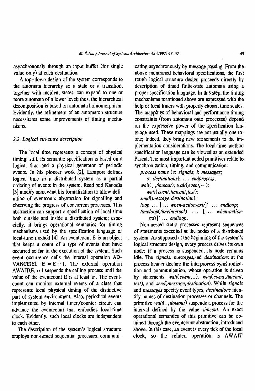
Demonstrating an automata-hierarchy, the upperlevel automaton with states "BLOCKED-IDLE","READY", "FULL FUEL''. "TIIROTTLE","BLOCKED-ERROR''. and "CLOSED" and withinputs "release", "nozzle hung on/off", "close"(the preset or maximal volume achieved), "throttle",and "error" depicts the overall behaviour (Fig. 0.
The states "FULL FUEL" and "THROTTLE",which are underlined, appear to be hazardous fromthe viewpoint of unchecked issue because the motoris on and the liquid is under pressure - the onlynozzle valve controls an issue in this case. Also, thestate "READY" tends to be hazardous: when thenozzle is unhooked, the system transfers to the state"FULL FUEL" with issue enabled. Hence, the failstop conception necessitates the detected error management in the form of transfers to the state"BLOCKED-ERROR". To initiate such transfersfor issue blocking, the error detections in the hazardous states are necessary.
Fuel measurement and issue control represents themain functions of the hazardous states. The first
Fig. 1. Dispenser automaton model.
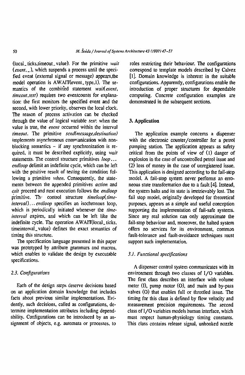
Table IState-table of recognition automaton
Last state, qj New state, C//+ I for inputs:
0 I
.-. I I 22 2 3
11- \ 11 n-I
" II
applied configuration on this level, incremental measuring, means the recognition and counting of elementary volumes represented by rectangular impulses, which are generated by a photoelectricalpulser. The maximal frequency of impulses and apattern for their recognition, depending on electromagnetic interference characterlstics, defines bothbehavioral and performance timing constraints. Thestate-table (Table 1) defines an automaton describingthe periodic sampling of the input variable withvalues 0 and l, The automaton recognizes an impulse after n/2 (n ~ 4) samples with the value Ifollowed by n/2 samples with the value O.
For the sake of fault-detection requirements, theincremental detector and transfer path are doubled.Hence, a second, identical impulse-recognition automaton appears necessary. The next automaton isthe reversible counter, which starts with the value(h + 1)/2 and increments or decrements the valueaccording to the signal from the first or secondrecognition automaton. Overflow or underflow of thepre-set values of h or I indicate an error. Anothercounter that counts the recognized impulses fromone of the recognition automata maintains the wholemeasured volume. The output variable refines to twodisplays with local memories not only for the reasonof robustness but also for functional requirement's(double-face stand). The display refreshment subsides to a different timing mechanism, dependent onthe physiologic constants of human sight.
S2 M. SuMa I Journal of Sy,\'WI1/S Ardlitt!t'mre 43 (1997) 47-57
3.2. Logical structure description
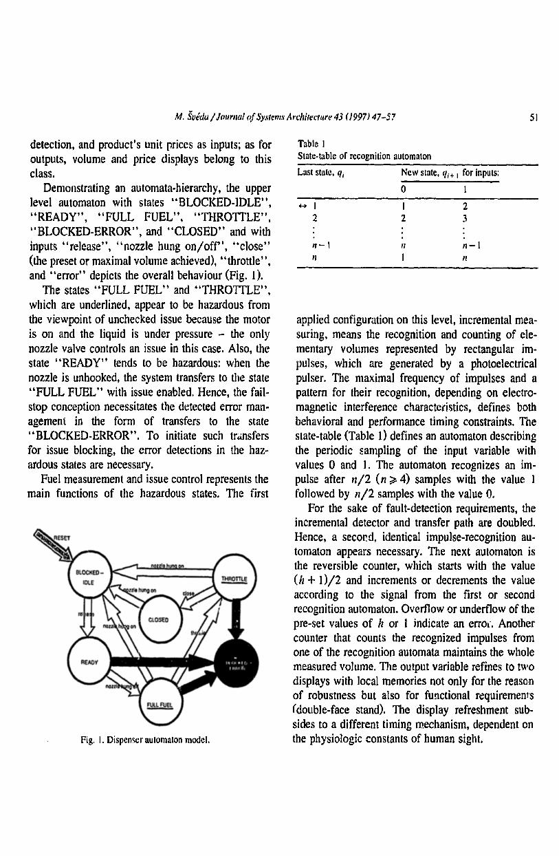
The demonstration of logical structure descriptionemploys a fast process simulating both of the twoimpulse-recognition automata together with the reversible counter (Fig. 2). The detection process sendsa message about a detected impulse to the slowermeter process, which sends a fuel-volume messageto the display process.
A high-level process simulates the previously discussed behaviour of the dispenser. For that reason, acommunication between the dispenser-control process and the above described lower-level processesmust proceed. Usually, the design progresses topdown. Hence, the primarily designed fuel-stand pro-
cess reads the input variable "fuel volume". A nextrefinement replaces the simple reading by the communication with the meter process from the lowerlevel. Similarly, the write commands to block outputexpands to a communications with the blocking process.
3.3. Refining configurations
The reviewed design example complies with suchdecisions as incremental measuring, periodic sampling of impulses, doubling the incremental detectorand transfer path, and choosing the nozzle positionfor synchronization. Evidently, these configurationssupport the considered fail-stop model.
process detecuon ~": hang_of/. hang_on; 0; meier):loop qO:= I; ql :"" /; count :» (h+l)/2; wail(hang_off,j;
limeloop(sample_interval)read(inO,inpu/O); read(inl,inputJ);ifqO <:: nil then begin ifinO :: I then qO ,'::qO + I endelse ifinO =0 then qO::: qO + I:ifql <:: nil then begin ifinl :: I then q/ := ql + I endelse ifinl :: f) then ql := ql + I,'ifq(} >= n then begin qO:= I; count :» count -I,' sendttmpulse.meter) end:ifqJ >:: n then begin ql := I; count:= caunt + I end:when I >count orcount> haction write(/rue, block) exit;
endloop;WlJi!(hang_on,J:
endloop;endprocess;
process meter (s: hang_off; t: impulse,' 0:display),'loop vol:= 0..
loop read(positiolt,nozzle);ifposiuon =hang_on then begin vol:= 0: wait(lIang_off,J,' send(vol,display) end;waiuimpulse.]; vol:=vol+ I..when vol> maxvol action write(true, block) exit;send(vo/,display):
endloop;endloop;endprocess;
process display (i,'vol):loop write(vol, displayI): write(vo/,display2); wait(vol,update_interval,lest),' endloop;endprocess,'
Fig. 2. Logical struclure ofvolume measurement.
M. SuMu / Journa! of Sy.~tems Arc!lir(!CIUre 43 (1997) 47-57 S3
Next configurations have to bring suitable solution of the dispenser control system for achievingbroader applicability. Dispenser is a ranged product.so the minima! production costs are required. Thisrequirement leads to a multi-purpose device forpetrol, octane mixture. petrol and oil mixture, orhigh speed diesel-oil issue, for the attendant stationor for the self-service station with cashier or withdebit or credit automaton or slot machine. One of thefunctions enables to preset the fuel (centrally by thecashier or locally on the stand) in volume or cashwith the automatic termination of the dose.
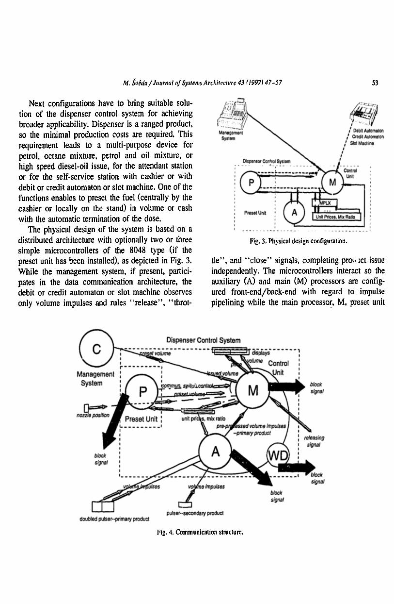
The physical design of the system is based on adistributed architecture with optionally two or threesimple microcontrollers of the 8048 type (if thepreset unit has been installed), as depicted in Fig. 3.While the management system, if present, participates in the data communication architecture, thedebit or credit automaton or slot machine observesonly volume impulses and rules "release", "throt-
Fig. 3.Physical design configuration.
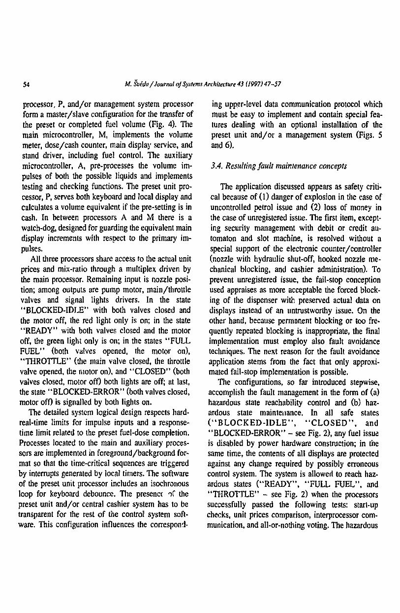
tle", and "close" signals, completing pro.oct issueindependently. The microcontrollers interact so theauxiliary (A) and main (M) processors are configured front-end/back-end with regard to impulsepipelining while the main processor, M, preset unit
b10cks(g 1
,Preset UnIt :
1.. __ •• __ •• ',II,,,I,,,'.. -_.. -
Dispenser Control System£E~~~ -.- -Ys. -- _••- ~
fum Control :Unit :,
p ser-secondary product
Fig. 4. Communication struciure,
54 M. SUidalJournal of Systems Architecture 43 (/997) 47-57
processor, P, and/or management system processorform a master/slave configuration for the transfer ofthe preset or completed fuel volume (Fig. 4). Themain microcontroller, M, implements the volumemeter, dose/cash counter, main display service, andstand driver, including fuel control. The auxiliarymicrocontroller, A, pre-processes the volume impulses of both the possible liquids and implementstesting and checking functions. The preset unit processor, P, serves both keyboard and local display andcalculates a volume equivalent if the pre-setting is incash. In between processors A and M there is awatch-dog, designed for guarding the equivalent maindisplay increments with respect to the primary impulses.
All three processors share access to the actual unitprices and mix-ratio through a multiplex driven bythe main processor. Remaining input is nozzle position; among outputs are pump motor, main/throttlevalves and signal lights drivers. In the state"BLOCKED-IDLE" with both valves closed andthe motor off, the red light only is on; in the state"READY" with both valves, closed and the motoroff, the green light only is on; in the states "FULLFUEL" (both valves opened, the motor on),"TIIROTILE" (the main valve closed, the throttlevalve opened, the motor on), and "CLOSEDtt (bothvalves closed, motor off) both lights are off; at last,the state "BLOCKED-ERROR" (both valves closed,motor off) is signalled by both lights on.
The detailed system logical design respects hardreal-time limits for impulse inputs and a responsetime limit related to the preset fuel-dose completion.Processes located to the main and auxiliary processors are implemented in foreground/background format so that the time-critical sequences are triggeredby interrupts generated by 10c.1\1 timers. The softwareof the preset unit processor includes an isochronousloop for keyboard debounce. The presence ")( thepreset unit and/or central cashier system has to betransparent for the rest of the control system software. This configuration influences the correspond-
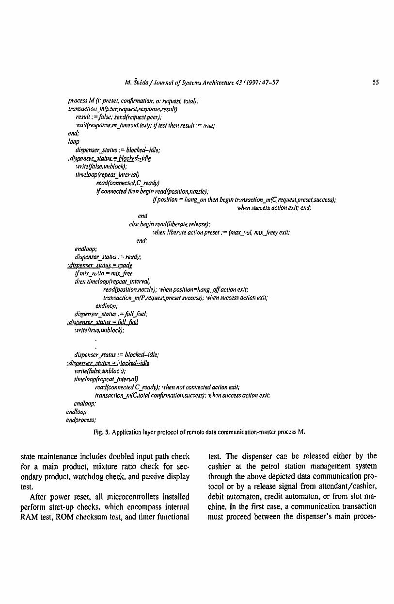
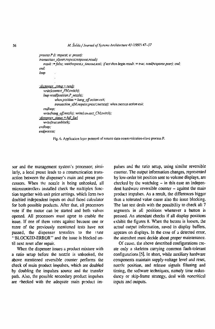
ing upper-level data communication protocol whichmust be easy to implement and contain special features dealing with an optional installation of thepreset unit and/or a management system (Figs. 5and 6).
3.4. Resulting fault maintenance concepts
The application discussed appears as safety critical because of (1) danger of explosion in the case ofuncontrolled petrol issue and (2) loss of money inthe case of unregistered issue. The first item, excepting security management with debit or credit automaton and slot machine, is resolved without aspecial support of the electronic counter/controller(nozzle with hydraulic shut-off, hooked nozzle mechanical blocking, and cashier administration). Toprevent unregistered issue, the fail-stop conceptionused appraises as more acceptable the forced blocking of the dispenser with preserved actual data ondisplays instead of an untrustworthy issue. On theother hand, because permanent blocking or too frequently repeated blocking is inappropriate, the finalimplementation must employ also fault avoidancetechniques. The next reason for the fault avoidanceapplication stems from the fact that only approximated fail-stop implementation is possible.
The configurations, so far introduced stepwise,accomplish the fault management in the form of (a)hazardous state reachability control and (b) hazardous state maintenance. In all safe states("BLOCKED-IDLE", "CLOSED", and"BLOCKED-ERROR" - see Fig. 2), any fuel issueis disabled by power hardware construction; in thesame time, the contents of all displays are protectedagainst any change required by possibly erroneouscontrol system. The system is allowed to reach hazardous states (HREADY" , "FULL FUEL", and"THROTILE" - see Fig. 2) when the processorssuccessfully passed the following tests: start-upchecks, unit prices comparison, interprocessor communication, and ali-or-nothing voting. The hazardous
M, SvMa / Journal ofSystems Architecture 43'1997) 47-57
process M (i: preset, conftrmation; 0: request, total):transactkn,_m(paer,request,response,result)
result := false; send(reques/,peel');wai/(response,tn_tfmeout,tesl); if tes: then result :» true;
end;loop
dispenser_status := blocked-idle;;dispenser status =blocked•• jdle
lI'rite(false.unblock);timeloop(repeal)nterval)
read/connected;C-,eady)ifconnected then begin readipositlon.nozsle);
tfposition =hang_on then begin lr~nsaction_m(C ,reques/,prese/,success);
when success action exit; end;end
else begin readtliberaterelease);when liberate action preset := (max_vol, mixfree) exit;
end;endloop;dispenser_statlls "= ready:
;dispenser .~t(1tus =readYi/mix_;" i,tio = mixfreethen timeloop(repeaUn/erval)
readtpostttonnozzle); when posilion=hang_offaction exit:/ronsac/ion_m(P,request,preset,success),' when success action exit;
endloop;dispenserstatus :»/uilJuel,'
:dispenser statllS =fuil OmllIIrite(tn,e, unblock):
dispenser_status := blocked-idle,'..di,menser 510/1.:5 =..:.tocked··klle
lI'rite(fa/se,unbloc .~) ;
timeloop(repeaUnterval)read(connected,C-,eady),' when notconnectedaction exit:/ransaction_m(C,total,conjirmation,success); when success action exit;
endloop;endloopendprocess;
Fig. 5. Application layer protocol of remote data communication-master process M,
55
state maintenance includes doubled input path checkfor a main product, mixture ratio check for secondary product, watchdog check, and passive displaytest.
After power reset, all microcontrollers installedperform start-up checks. which encompass internalRAM test, ROM checksum test, and timer functional
test. The dispenser car. be released either by thecashier at the petrol station management systemthrough the above depicted data communication protocol or by a release signal from attendant/cashier,debit automaton, credit automaton. or from slot machine. In the first case, a communication transactionmust proceed between the dispenser's main proces-
S6 M. suMa / Journal OJ'S)'stL'm,\' Architecture 43 (1997) 47-57
process P (i: request; 0: preset):transactionsspeerrequestrespouseresult)
result :=false; waittrequest.stimeout.testl; if test then begin result :» true,' sendtresponse.peer); end;end;loop
:d;s.pctl.rer i;lntlls:: remi)'write(collnect PM,slI'itch);1001' readtposition.P_nozzle);
when position =hang_of!action exit;trallSaction_s(M,request,preset,succass); when success actlon exit;
endloop;II'rile(han8_of!.no:zle): II'rile(c,'olllll!ct_CAf,slI'itch);
:cliseemer stallis =6{// filclwritettrue.unblock};
endloop;endprocess;
Fig. 6. Application layer protocol of remote data commnnlcation-slnvc process P.
sor and the management system's processor: similarly, a local preset leads to a communication transaction between the dispenser's main and preset processors. When the nozzle is being unhooked, allmicrocontrollers installed check the multiplex function together with unit price settings. which form twodoubled independent inputs on dual faced calculatorfor both possible products. After that, all processorsvote if the motor can be started and both valvesopened. All processors must agree to enable theissue. If one of them votes against because one ormore of thc previously mentioned tests have notpassed, the dispenser transfers to the rl.<lte•• BLOCKED-ERROR" and the issue is blocked until next reset after repair.
When the dispenser issues a product mixture witha ratio setup before the nozzle is unhooked, theabove mentioned reversible counter performs thecheck of main product impulses, which are doubledby doubling the impulses source and the transferpath, Also, the possible secondary product impulsesare checked with the adequate main product im-
pulses and the ratio setup, using similar reversiblecounter. The output information changes, representedby low-order bit position sent to volume displays, arechecked by the watchdog - in this case an independent hardware reversible counter - against the mainproduct impulses. As a result, the differences biggerthan a tolerated value cause also the issue blocking.The last test deals with the possibility to check all 7segments in all positions whenever a button ispressed. An attendant checks jf all display positionsexhibit the figures 8. W!len the button is loosen, theactual output information, saved in display buffers,appears on displays. In the case of a detected error,the attendant must decide about proper maintenance.
Of cause. the above described configurations create only a skeleton carrying common fault-tolerantconfigurations [5]. In short, while auxiliary hardwarecomponents maintain supply-voltage level and reset,nozzle position, and release signals filterisg andtiming, the software techniques, namely time redundancy or skip-frame strategy, deal with noncriticalinputs and outputs.
M. SuMulJournalofSyste/lls Archilecture 43 (1997) 47·-57 57
4. Conclusions
The designer's role cannot be entirely substitutedby any automated design system; namely, the globaldecisions about appropriate method and conceptualmodel may hardly be generated immediate!y fromfunctional requirements (besides, too few designersrefuse such intellectually attractive work). Thedemonstrated original design method attempts onlyto prop the designer of an embedded distributedapplication by concepts and tools. The method addresses not only early elimination of design errorsbut also management of operational errors from thebeginning of design cycle. The techniques used arisefrom local time conception and configurations asdomain knowledge embodiment. The paper dealswith the principles of the design method that permittoconsider dependable computing concepts. Further-
more, the design of the dispenser counter/controlleraccording to the fail-stop safety model offers a nontrivial real-world application for the demonstrationof the method.
References
[I] J.P. Calvez, Embedded Real-Time SySletll.~ (Wiley. Chichester, UK. 1993).
{2] L. Lamport. Time, clocks, and the ordering of events in adistributed system. Comm. ACM 21 (7)(1978) 558-565.
{3] D.P. Reed and R.K. Kanodia, Synchronization with eventcounts and sequencers, COIIIIII. ACM 22 (2) (I979) IIS-123.
[4] F.B. Schneider, Fail-stop processors, in: COMPCON'83SPRING, Proc. 26111 lE~E CS Internal, Catrj: (1983) 66-70.
[SJ A. Sieininger and H. Schwelnzer, Towards an optimal combination of error detection mechanisms, Mic:roprocessillK andMicroprogrtJlllmillg 32 (1991) 253-260.
Related Documents