ISSN No: 2348-4845 International Journal & Magazine of Engineering, Technology, Management and Research A Peer Reviewed Open Access International Journal ABSTRACT: In this project “Two way “C” clamp” can hold fixtures like tube light fixtures in vertical and horizontal positions. Sketching, part, assembly and drafting and modules are used to design the complete model is developed using the software catia-v5 r19. The study of this project is about the design and the machining methods for making core and cavity of plastic injection mold. Plastic mold is a tool to obtain a desired shape out of plastic, specifically from plastic melt using the process of molding. In this process the molten plastic is poured or injected in the die of desired shape, corresponding to the shape of product we need and then allowed to solidify till it solidifies and obtains its shape.The core and cavity of the mold is good enough to be used to run the injection molding process for producing the sample product the manufacturing process- es involved like milling and drilling operation are well planned and all the parameters are defined and prepared carefully to produce the core and the cavity based on the desired design and quality. Extensive study on the design and machining methods of core and cavity of injection mold is done in order for the core and the cavity to be fabricated and used to run the injection molding process. The mold’s core and cavity are fabricated based on the design and planned machining processes and parameters. All the works done in this project are discussed in this technical report. 1.INTRODUCTION: In this process the molten plastic is poured in the die of desired shape, corresponding to the shape of product we need and then allowed to solidify till it solidifies and ob- tains its shape. Plastic molding is the process of obtaining a desired shape of plastic using the process of molding. The process of plastic molding usually begins with an in- dustrial designer or engineer who designs a product. This is followed up by the work of a toolmaker or mold maker who makes the mold to fit the design created. When mol- ten, they can then be manipulated (injection molded, ex- truded etc.) to a new shape. When formed to their new shape they must then be cooled to solidify them.Polymers are the substances whose mol- ecules have higher molar masses and are composed of large number of repeating units. In some cases two or three different monomers will combine to form as poly- mers. These repeating units are called monomers and the process of forming as polymer is called polymerization. Injection molding is a manufacturing process for produc- ing parts by injecting material into a mold. Injection mold- ing can be performed with a host of materials, including metals, glasses, elastomers, confections, and most com- monlythermosetting and thermoplastic polymers. 2.PLASTICS: They are either natural or synthetic, and are processed by forming or molded into different shapes.Plastics are moldable organic resins. 2.1 PROPERTIES OF PLASTICS: Light weight + adequate strength Easy to meld into different shapes Low thermal and electrical conductivity Wide range of colours Less brittle & Good toughness Good resistance to acids, bases and moisture Better resistance to shocks and vibrations compared to metal etc. 2.2 TYPES OF PLASTICS: Plastics are again classified based on their mechanical and thermal behavior, Thermo Plastics (Thermoplastic poly- mers) Thermosets (Thermosetting polymers) 3.PLASTIC MOLDING PROCESSES: The basic idea in plastic molding is inserting molten liquid plastic into a ready shaped mold then allowed to cool. 3.1 INJECTION MOLDING: Injection molding is a manufacturing process for produc- ing parts by injecting material into a mold. Volume No: 2 (2015), Issue No: 12 (December) December 2015 www.ijmetmr.com Page 678 Design and Manufacture of C-Clamp by Injection Molding Process H.V. Naveen Sekar M.Tech Student, Department of Mechanical Engineering, ASRCE, Tanuku. V. Vijaya Kumar Associate professor, Department of Mechanical Engineering, ASRCE, Tanuku.

Welcome message from author
This document is posted to help you gain knowledge. Please leave a comment to let me know what you think about it! Share it to your friends and learn new things together.
Transcript
ISSN No: 2348-4845International Journal & Magazine of Engineering,
Technology, Management and ResearchA Peer Reviewed Open Access International Journal
ABSTRACT:
In this project “Two way “C” clamp” can hold fixtures like tube light fixtures in vertical and horizontal positions. Sketching, part, assembly and drafting and modules are used to design the complete model is developed using the software catia-v5 r19. The study of this project is about the design and the machining methods for making core and cavity of plastic injection mold. Plastic mold is a tool to obtain a desired shape out of plastic, specifically from plastic melt using the process of molding. In this process the molten plastic is poured or injected in the die of desired shape, corresponding to the shape of product we need and then allowed to solidify till it solidifies and obtains its shape.The core and cavity of the mold is good enough to be used to run the injection molding process for producing the sample product the manufacturing process-es involved like milling and drilling operation are well planned and all the parameters are defined and prepared carefully to produce the core and the cavity based on the desired design and quality. Extensive study on the design and machining methods of core and cavity of injection mold is done in order for the core and the cavity to be fabricated and used to run the injection molding process. The mold’s core and cavity are fabricated based on the design and planned machining processes and parameters. All the works done in this project are discussed in this technical report.
1.INTRODUCTION:
In this process the molten plastic is poured in the die of desired shape, corresponding to the shape of product we need and then allowed to solidify till it solidifies and ob-tains its shape. Plastic molding is the process of obtaining a desired shape of plastic using the process of molding. The process of plastic molding usually begins with an in-dustrial designer or engineer who designs a product. This is followed up by the work of a toolmaker or mold maker who makes the mold to fit the design created. When mol-ten, they can then be manipulated (injection molded, ex-truded etc.) to a new shape.
When formed to their new shape they must then be cooled to solidify them.Polymers are the substances whose mol-ecules have higher molar masses and are composed of large number of repeating units. In some cases two or three different monomers will combine to form as poly-mers. These repeating units are called monomers and the process of forming as polymer is called polymerization.Injection molding is a manufacturing process for produc-ing parts by injecting material into a mold. Injection mold-ing can be performed with a host of materials, including metals, glasses, elastomers, confections, and most com-monlythermosetting and thermoplastic polymers.
2.PLASTICS:They are either natural or synthetic, and are processed by forming or molded into different shapes.Plastics are moldable organic resins.
2.1 PROPERTIES OF PLASTICS:Light weight + adequate strengthEasy to meld into different shapesLow thermal and electrical conductivityWide range of coloursLess brittle & Good toughnessGood resistance to acids, bases and moistureBetter resistance to shocks and vibrations compared to metal etc.
2.2 TYPES OF PLASTICS:Plastics are again classified based on their mechanical and thermal behavior, Thermo Plastics (Thermoplastic poly-mers)Thermosets (Thermosetting polymers)3.PLASTIC MOLDING PROCESSES:The basic idea in plastic molding is inserting molten liquid plastic into a ready shaped mold then allowed to cool.
3.1 INJECTION MOLDING:Injection molding is a manufacturing process for produc-ing parts by injecting material into a mold.
Volume No: 2 (2015), Issue No: 12 (December) December 2015 www.ijmetmr.com Page 678
Design and Manufacture of C-Clamp by Injection Molding Process
H.V. Naveen SekarM.Tech Student,
Department of Mechanical Engineering,ASRCE, Tanuku.
V. Vijaya KumarAssociate professor,
Department of Mechanical Engineering,ASRCE, Tanuku.
ISSN No: 2348-4845International Journal & Magazine of Engineering,
Technology, Management and ResearchA Peer Reviewed Open Access International Journal
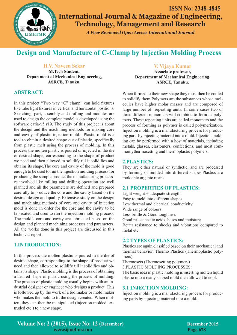
Fig 1. Injection Molding Process
3.2 EXTRUSION MOLDING:
Extrusion molding is a manufacturing process used to make pipes, hoses, drinking straws, curtain tracks, rods, and fiber. The granules melt into a liquid which is forced through a die, forming a long ‘tube like’ shape. The shape of the die determines the shape of the tube. The extrusion is then cooled and forms a solid shape.
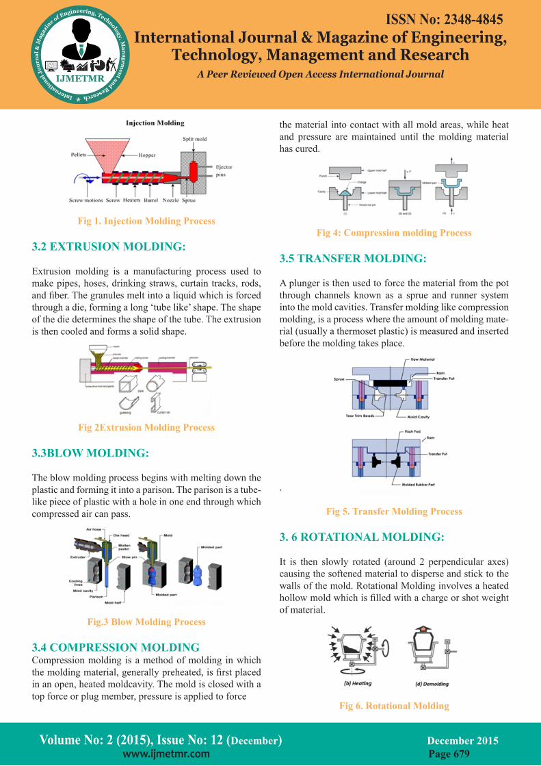
Fig 2Extrusion Molding Process
3.3BLOW MOLDING:
The blow molding process begins with melting down the plastic and forming it into a parison. The parison is a tube-like piece of plastic with a hole in one end through which compressed air can pass.
Fig.3 Blow Molding Process
3.4 COMPRESSION MOLDINGCompression molding is a method of molding in which the molding material, generally preheated, is first placed in an open, heated moldcavity. The mold is closed with a top force or plug member, pressure is applied to force
the material into contact with all mold areas, while heat and pressure are maintained until the molding material has cured.
Fig 4: Compression molding Process
3.5 TRANSFER MOLDING:
A plunger is then used to force the material from the pot through channels known as a sprue and runner system into the mold cavities. Transfer molding like compression molding, is a process where the amount of molding mate-rial (usually a thermoset plastic) is measured and inserted before the molding takes place.
.
Fig 5. Transfer Molding Process
3. 6 ROTATIONAL MOLDING:
It is then slowly rotated (around 2 perpendicular axes) causing the softened material to disperse and stick to the walls of the mold. Rotational Molding involves a heated hollow mold which is filled with a charge or shot weight of material.
Fig 6. Rotational Molding
Volume No: 2 (2015), Issue No: 12 (December) December 2015 www.ijmetmr.com Page 679
ISSN No: 2348-4845International Journal & Magazine of Engineering,
Technology, Management and ResearchA Peer Reviewed Open Access International Journal
3.7 STRUCTURAL FOAM MOLDING:
Structural foam molding is a process of plastic molding usually used for parts that require thicker walls than stan-dard injection molding. This type of plastic molding can be used with any thermoplastic. A thin plastic skin forms and solidifies in the mold wall. Foaming happens as the melted plastic material enters the mold cavity Inserting a small amount of nitrogen or chemical blow agent into the plastic material makes the walls thicker.
3.8 THERMOFORMING:
In this plastic molding process, sheets of pre-extruded rig-id plastics are horizontally heated and sucked down into hollow one-piece tools. When the hot plastic solidifies, its shape conforms to that of the mold.
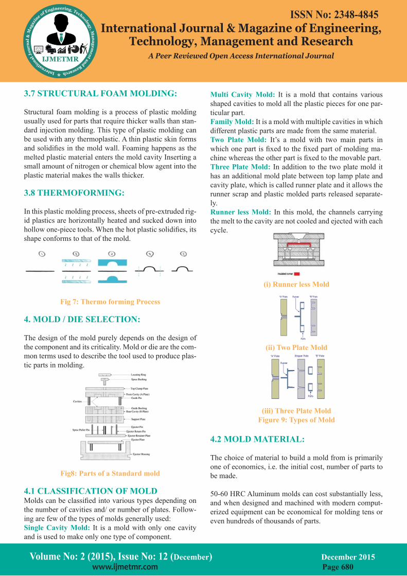
Fig 7: Thermo forming Process
4. MOLD / DIE SELECTION:
The design of the mold purely depends on the design of the component and its criticality. Mold or die are the com-mon terms used to describe the tool used to produce plas-tic parts in molding.
Fig8: Parts of a Standard mold
4.1 CLASSIFICATION OF MOLDMolds can be classified into various types depending on the number of cavities and/ or number of plates. Follow-ing are few of the types of molds generally used:Single Cavity Mold: It is a mold with only one cavity and is used to make only one type of component.
Multi Cavity Mold: It is a mold that contains various shaped cavities to mold all the plastic pieces for one par-ticular part.Family Mold: It is a mold with multiple cavities in which different plastic parts are made from the same material.Two Plate Mold: It’s a mold with two main parts in which one part is fixed to the fixed part of molding ma-chine whereas the other part is fixed to the movable part.Three Plate Mold: In addition to the two plate mold it has an additional mold plate between top lamp plate and cavity plate, which is called runner plate and it allows the runner scrap and plastic molded parts released separate-ly.Runner less Mold: In this mold, the channels carrying the melt to the cavity are not cooled and ejected with each cycle.
(i) Runner less Mold
(ii) Two Plate Mold
(iii) Three Plate MoldFigure 9: Types of Mold
4.2 MOLD MATERIAL:
The choice of material to build a mold from is primarily one of economics, i.e. the initial cost, number of parts to be made.
50-60 HRC Aluminum molds can cost substantially less, and when designed and machined with modern comput-erized equipment can be economical for molding tens or even hundreds of thousands of parts.
Volume No: 2 (2015), Issue No: 12 (December) December 2015 www.ijmetmr.com Page 680
ISSN No: 2348-4845International Journal & Magazine of Engineering,
Technology, Management and ResearchA Peer Reviewed Open Access International Journal
5.DESIGN OF CLAMP AND MOLD COM-PONENTS :
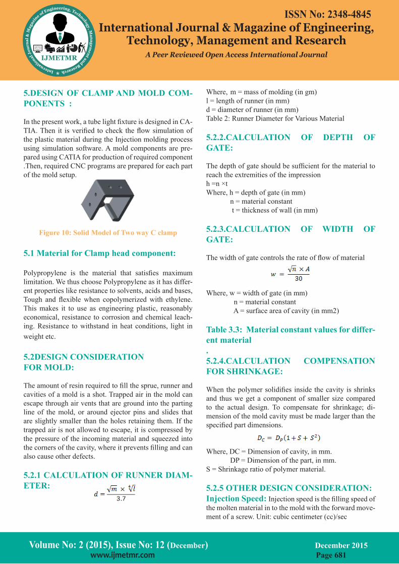
In the present work, a tube light fixture is designed in CA-TIA. Then it is verified to check the flow simulation of the plastic material during the Injection molding process using simulation software. A mold components are pre-pared using CATIA for production of required component .Then, required CNC programs are prepared for each part of the mold setup.
Figure 10: Solid Model of Two way C clamp
5.1 Material for Clamp head component:
Polypropylene is the material that satisfies maximum limitation. We thus choose Polypropylene as it has differ-ent properties like resistance to solvents, acids and bases, Tough and flexible when copolymerized with ethylene. This makes it to use as engineering plastic, reasonably economical, resistance to corrosion and chemical leach-ing. Resistance to withstand in heat conditions, light in weight etc.
5.2DESIGN CONSIDERATION FOR MOLD:
The amount of resin required to fill the sprue, runner and cavities of a mold is a shot. Trapped air in the mold can escape through air vents that are ground into the parting line of the mold, or around ejector pins and slides that are slightly smaller than the holes retaining them. If the trapped air is not allowed to escape, it is compressed by the pressure of the incoming material and squeezed into the corners of the cavity, where it prevents filling and can also cause other defects.
5.2.1 CALCULATION OF RUNNER DIAM-ETER:
Where, m = mass of molding (in gm)l = length of runner (in mm)d = diameter of runner (in mm)Table 2: Runner Diameter for Various Material
5.2.2.CALCULATION OF DEPTH OF GATE:
The depth of gate should be sufficient for the material to reach the extremities of the impressionh =n ×tWhere, h = depth of gate (in mm) n = material constant t = thickness of wall (in mm)
5.2.3.CALCULATION OF WIDTH OF GATE:
The width of gate controls the rate of flow of material
Where, w = width of gate (in mm) n = material constant A = surface area of cavity (in mm2)
Table 3.3: Material constant values for differ-ent material.5.2.4.CALCULATION COMPENSATION FOR SHRINKAGE:
When the polymer solidifies inside the cavity is shrinks and thus we get a component of smaller size compared to the actual design. To compensate for shrinkage; di-mension of the mold cavity must be made larger than the specified part dimensions.
Where, DC = Dimension of cavity, in mm. DP = Dimension of the part, in mm. S = Shrinkage ratio of polymer material.
5.2.5 OTHER DESIGN CONSIDERATION:Injection Speed: Injection speed is the filling speed of the molten material in to the mold with the forward move-ment of a screw. Unit: cubic centimeter (cc)/sec
Volume No: 2 (2015), Issue No: 12 (December) December 2015 www.ijmetmr.com Page 681
ISSN No: 2348-4845International Journal & Magazine of Engineering,
Technology, Management and ResearchA Peer Reviewed Open Access International Journal
3.7 STRUCTURAL FOAM MOLDING:
Structural foam molding is a process of plastic molding usually used for parts that require thicker walls than stan-dard injection molding. This type of plastic molding can be used with any thermoplastic. A thin plastic skin forms and solidifies in the mold wall. Foaming happens as the melted plastic material enters the mold cavity Inserting a small amount of nitrogen or chemical blow agent into the plastic material makes the walls thicker.
3.8 THERMOFORMING:
In this plastic molding process, sheets of pre-extruded rig-id plastics are horizontally heated and sucked down into hollow one-piece tools. When the hot plastic solidifies, its shape conforms to that of the mold.
Fig 7: Thermo forming Process
4. MOLD / DIE SELECTION:
The design of the mold purely depends on the design of the component and its criticality. Mold or die are the com-mon terms used to describe the tool used to produce plas-tic parts in molding.
Fig8: Parts of a Standard mold
4.1 CLASSIFICATION OF MOLDMolds can be classified into various types depending on the number of cavities and/ or number of plates. Follow-ing are few of the types of molds generally used:Single Cavity Mold: It is a mold with only one cavity and is used to make only one type of component.
Multi Cavity Mold: It is a mold that contains various shaped cavities to mold all the plastic pieces for one par-ticular part.Family Mold: It is a mold with multiple cavities in which different plastic parts are made from the same material.Two Plate Mold: It’s a mold with two main parts in which one part is fixed to the fixed part of molding ma-chine whereas the other part is fixed to the movable part.Three Plate Mold: In addition to the two plate mold it has an additional mold plate between top lamp plate and cavity plate, which is called runner plate and it allows the runner scrap and plastic molded parts released separate-ly.Runner less Mold: In this mold, the channels carrying the melt to the cavity are not cooled and ejected with each cycle.
(i) Runner less Mold
(ii) Two Plate Mold
(iii) Three Plate MoldFigure 9: Types of Mold
4.2 MOLD MATERIAL:
The choice of material to build a mold from is primarily one of economics, i.e. the initial cost, number of parts to be made.
50-60 HRC Aluminum molds can cost substantially less, and when designed and machined with modern comput-erized equipment can be economical for molding tens or even hundreds of thousands of parts.
Volume No: 2 (2015), Issue No: 12 (December) December 2015 www.ijmetmr.com Page 680
ISSN No: 2348-4845International Journal & Magazine of Engineering,
Technology, Management and ResearchA Peer Reviewed Open Access International Journal
5.DESIGN OF CLAMP AND MOLD COM-PONENTS :
In the present work, a tube light fixture is designed in CA-TIA. Then it is verified to check the flow simulation of the plastic material during the Injection molding process using simulation software. A mold components are pre-pared using CATIA for production of required component .Then, required CNC programs are prepared for each part of the mold setup.
Figure 10: Solid Model of Two way C clamp
5.1 Material for Clamp head component:
Polypropylene is the material that satisfies maximum limitation. We thus choose Polypropylene as it has differ-ent properties like resistance to solvents, acids and bases, Tough and flexible when copolymerized with ethylene. This makes it to use as engineering plastic, reasonably economical, resistance to corrosion and chemical leach-ing. Resistance to withstand in heat conditions, light in weight etc.
5.2DESIGN CONSIDERATION FOR MOLD:
The amount of resin required to fill the sprue, runner and cavities of a mold is a shot. Trapped air in the mold can escape through air vents that are ground into the parting line of the mold, or around ejector pins and slides that are slightly smaller than the holes retaining them. If the trapped air is not allowed to escape, it is compressed by the pressure of the incoming material and squeezed into the corners of the cavity, where it prevents filling and can also cause other defects.
5.2.1 CALCULATION OF RUNNER DIAM-ETER:
Where, m = mass of molding (in gm)l = length of runner (in mm)d = diameter of runner (in mm)Table 2: Runner Diameter for Various Material
5.2.2.CALCULATION OF DEPTH OF GATE:
The depth of gate should be sufficient for the material to reach the extremities of the impressionh =n ×tWhere, h = depth of gate (in mm) n = material constant t = thickness of wall (in mm)
5.2.3.CALCULATION OF WIDTH OF GATE:
The width of gate controls the rate of flow of material
Where, w = width of gate (in mm) n = material constant A = surface area of cavity (in mm2)
Table 3.3: Material constant values for differ-ent material.5.2.4.CALCULATION COMPENSATION FOR SHRINKAGE:
When the polymer solidifies inside the cavity is shrinks and thus we get a component of smaller size compared to the actual design. To compensate for shrinkage; di-mension of the mold cavity must be made larger than the specified part dimensions.
Where, DC = Dimension of cavity, in mm. DP = Dimension of the part, in mm. S = Shrinkage ratio of polymer material.
5.2.5 OTHER DESIGN CONSIDERATION:Injection Speed: Injection speed is the filling speed of the molten material in to the mold with the forward move-ment of a screw. Unit: cubic centimeter (cc)/sec
Volume No: 2 (2015), Issue No: 12 (December) December 2015 www.ijmetmr.com Page 681
ISSN No: 2348-4845International Journal & Magazine of Engineering,
Technology, Management and ResearchA Peer Reviewed Open Access International Journal
Injection Pressure (Pmax): Injection pressure is the term for the pressure applied to the molten material when a screw moves forward to inject it from the nozzle at high speed. Unit: BarScrew Speed: The rotational speed of the screw during dosing. It is expressed in rpm.Holding Pressure: The pressure applied to the mol-ten material after Injection phase. It pushes further plastic melt into the cavity before gate freezing. Unit: BarShot Capacity: The maximum amount of plastic melt that can be injected from the barrel of an injection mold-ing machine in a single shot. Unit: grams of polystyrene.Injection Rate: The injection rate is expressed in terms of the volume of the molten material which can be injected in the unit time. Unit: cm3/s.
Back Pressure: The molten material is plasticated and kneaded by the rotation of a screw and transferred to the tip of the screw. To suppress this movement, slight pressure is applied to the injection cylinder side which is called back pressure. Unit: bar.Clamping Force: Clamping force (CF) is the force which keeps the mold closed during injection.Required Mold Clamping Force (F) should be bigger than the force (f) which makes the mold open during injectionCF=Projeted Area of the component×constantThe value of constant is different for different types of material.
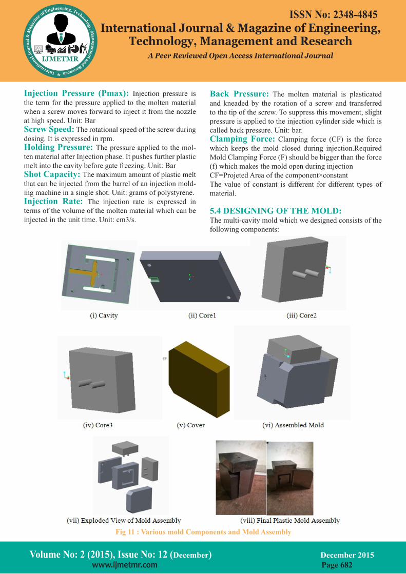
5.4 DESIGNING OF THE MOLD:The multi-cavity mold which we designed consists of the following components:
Volume No: 2 (2015), Issue No: 12 (December) December 2015 www.ijmetmr.com Page 682
ISSN No: 2348-4845International Journal & Magazine of Engineering,
Technology, Management and ResearchA Peer Reviewed Open Access International Journal
6. MANUFACTURING:
Manufacturing is the production of goods for use or sale using labor and machines, tools, chemical and biological processing or formulation. The term may refer to a range of human activity from handicraft to high-tech but is most commonly applied to industrial production in which raw materials are formed into finished goods on a large scale.In this project we used Delcam for generating NC pro-gram, since it is easy to generate NC program required for our project and also it’s easy to operate.It is a global developer of product design and manufacturing software. It consists of many operations related to 2D and 3D ma-chining that are used in CNC milling machines with 2 to 5 axis.
Again under 3D machining there are so many set of op-erations for Roughing, Finishing and other operations like drilling.For manufacturing the component by CNC milling, we have generated programs for facing, contour milling and drilling etc. These programs are very large, and thus, we cannot put all of it here. Just for some brief idea we have copied some of the lines below from the NC program related to contouring operation done on cavity plate with end-mill cutter of 5mm diameter.
7.CONCLUSION:
The goal of this project was to design a safer, easier to operate plastic mold without significantly increasing cost and weight or compromising on its capabilities. A lot of industries starting from household equipment manufac-turers to automobile and aerospace industries use the plastic mold to manufacture different parts and products. In the future plastic mold will meet with the industries’ production requirement. In this project we studied plastic molding theory, design and modeling using catia v5 and manufactured a prototype model to meet with the indus-trial requirement.
In Present scenario we find only j clamp to hold tube light fixtures. Based on this case we can hold or carry only one side i.e. vertical side we cannot hold it in other side. By this C-clamp we can use either vertical or horizontal positions of tube light fixture.We have thoroughly gone through the various specifications that are required in the process of manufacturing of the Plastic Injection Mold.
8.ACKNOWLEDGEMENT:
With a sense of achievement and satisfaction, as we re-flect up on our project activity, we are filled with a deep sense of gratitude towards the few whose help and sup-port was instrumental in the completion of the project. I also thank my friends and one and all who, directly or indirectly, have lent their helping hand without which this report would have been a distance reality.
9. REFERENCES:
[1] Fundamentals Modern Manufacturing byMikell P. Groover
[2] Basic Die Making By D. Eugene Ostergaard
[3] Tool Design 4 Edition, By: George H. Lecain, Cyrill Donaldson, V.C. Goold, JoyjeetGhose
[4] Design ofMachine Tools 5th Edition, By: S.K. Basu, D.K. Pal
[5] Machine Tool Design and Numerical Control 3 Edi-tion, By: N. K. Mehta
[6] Injection Mold Design Engineering by David Ka-zmer
[7] Plastic Injection Molding: Manufacturing Process Fundamentals by Douglas M. Bryce
[8] http://www.wikipedia.org
[9] https://www.google.co.in
[10] https://images.google.co.in
[11] http://www.plasticmoulding.ca
[12] http://www.custompartnet.com/wu/InjectionMold-ing
[13] http://www.bpf.co.uk/plastipedia/processes/injec-tion_moulding.aspx
Volume No: 2 (2015), Issue No: 12 (December) December 2015 www.ijmetmr.com Page 683
Fig 11 : Various mold Components and Mold Assembly
ISSN No: 2348-4845International Journal & Magazine of Engineering,
Technology, Management and ResearchA Peer Reviewed Open Access International Journal
Injection Pressure (Pmax): Injection pressure is the term for the pressure applied to the molten material when a screw moves forward to inject it from the nozzle at high speed. Unit: BarScrew Speed: The rotational speed of the screw during dosing. It is expressed in rpm.Holding Pressure: The pressure applied to the mol-ten material after Injection phase. It pushes further plastic melt into the cavity before gate freezing. Unit: BarShot Capacity: The maximum amount of plastic melt that can be injected from the barrel of an injection mold-ing machine in a single shot. Unit: grams of polystyrene.Injection Rate: The injection rate is expressed in terms of the volume of the molten material which can be injected in the unit time. Unit: cm3/s.
Back Pressure: The molten material is plasticated and kneaded by the rotation of a screw and transferred to the tip of the screw. To suppress this movement, slight pressure is applied to the injection cylinder side which is called back pressure. Unit: bar.Clamping Force: Clamping force (CF) is the force which keeps the mold closed during injection.Required Mold Clamping Force (F) should be bigger than the force (f) which makes the mold open during injectionCF=Projeted Area of the component×constantThe value of constant is different for different types of material.
5.4 DESIGNING OF THE MOLD:The multi-cavity mold which we designed consists of the following components:
Volume No: 2 (2015), Issue No: 12 (December) December 2015 www.ijmetmr.com Page 682
ISSN No: 2348-4845International Journal & Magazine of Engineering,
Technology, Management and ResearchA Peer Reviewed Open Access International Journal
6. MANUFACTURING:
Manufacturing is the production of goods for use or sale using labor and machines, tools, chemical and biological processing or formulation. The term may refer to a range of human activity from handicraft to high-tech but is most commonly applied to industrial production in which raw materials are formed into finished goods on a large scale.In this project we used Delcam for generating NC pro-gram, since it is easy to generate NC program required for our project and also it’s easy to operate.It is a global developer of product design and manufacturing software. It consists of many operations related to 2D and 3D ma-chining that are used in CNC milling machines with 2 to 5 axis.
Again under 3D machining there are so many set of op-erations for Roughing, Finishing and other operations like drilling.For manufacturing the component by CNC milling, we have generated programs for facing, contour milling and drilling etc. These programs are very large, and thus, we cannot put all of it here. Just for some brief idea we have copied some of the lines below from the NC program related to contouring operation done on cavity plate with end-mill cutter of 5mm diameter.
7.CONCLUSION:
The goal of this project was to design a safer, easier to operate plastic mold without significantly increasing cost and weight or compromising on its capabilities. A lot of industries starting from household equipment manufac-turers to automobile and aerospace industries use the plastic mold to manufacture different parts and products. In the future plastic mold will meet with the industries’ production requirement. In this project we studied plastic molding theory, design and modeling using catia v5 and manufactured a prototype model to meet with the indus-trial requirement.
In Present scenario we find only j clamp to hold tube light fixtures. Based on this case we can hold or carry only one side i.e. vertical side we cannot hold it in other side. By this C-clamp we can use either vertical or horizontal positions of tube light fixture.We have thoroughly gone through the various specifications that are required in the process of manufacturing of the Plastic Injection Mold.
8.ACKNOWLEDGEMENT:
With a sense of achievement and satisfaction, as we re-flect up on our project activity, we are filled with a deep sense of gratitude towards the few whose help and sup-port was instrumental in the completion of the project. I also thank my friends and one and all who, directly or indirectly, have lent their helping hand without which this report would have been a distance reality.
9. REFERENCES:
[1] Fundamentals Modern Manufacturing byMikell P. Groover
[2] Basic Die Making By D. Eugene Ostergaard
[3] Tool Design 4 Edition, By: George H. Lecain, Cyrill Donaldson, V.C. Goold, JoyjeetGhose
[4] Design ofMachine Tools 5th Edition, By: S.K. Basu, D.K. Pal
[5] Machine Tool Design and Numerical Control 3 Edi-tion, By: N. K. Mehta
[6] Injection Mold Design Engineering by David Ka-zmer
[7] Plastic Injection Molding: Manufacturing Process Fundamentals by Douglas M. Bryce
[8] http://www.wikipedia.org
[9] https://www.google.co.in
[10] https://images.google.co.in
[11] http://www.plasticmoulding.ca
[12] http://www.custompartnet.com/wu/InjectionMold-ing
[13] http://www.bpf.co.uk/plastipedia/processes/injec-tion_moulding.aspx
Volume No: 2 (2015), Issue No: 12 (December) December 2015 www.ijmetmr.com Page 683
Related Documents