Project Title: Design and Development of Gas-Liquid Cylindrical Cyclone Compact Separators for Three-Phase Flow Type of Report: Technical Progress Report (Semi-Annual) Reporting Period Start Date: October 1, 1999 Reporting Period End Date: March 31, 2000 Principal Authors: Dr. Ram S. Mohan and Dr. Ovadia Shoham Date Report was Issued: April 28, 2000 DOE Award Number: DE-FG26-97BC15024 --06 Name and Address of Submitting Organization: The University of Tulsa L169 Keplinger Hall 600 South College Avenue Tulsa, OK 74104-3189 Submitted to: The U.S. Department of Energy Tulsa University Separation Technology Projects (TUSTP) April 2000

Welcome message from author
This document is posted to help you gain knowledge. Please leave a comment to let me know what you think about it! Share it to your friends and learn new things together.
Transcript
Project Title:
Design and Development of Gas-Liquid Cylindrical Cyclone Compact
Separators for Three-Phase Flow
Type of Report: Technical Progress Report (Semi-Annual) Reporting Period Start Date: October 1, 1999 Reporting Period End Date: March 31, 2000 Principal Authors: Dr. Ram S. Mohan and Dr. Ovadia Shoham Date Report was Issued: April 28, 2000 DOE Award Number: DE-FG26-97BC15024 --06 Name and Address of Submitting Organization:
The University of Tulsa L169 Keplinger Hall 600 South College Avenue Tulsa, OK 74104-3189
Submitted to: The U.S. Department of Energy
Tulsa University Separation Technology Projects (TUSTP)
April 2000
1. Disclaimer
This report was prepared as an account of work sponsored by an agency of the United States Government. Neither the United States Government nor any agency thereof, nor any of their employees, makes any warranty, express or implied, or assumes any legal liability or responsibility for the accuracy, completeness or usefulness of any informa tion, apparatus, product, or process disclosed, or represents that its use would not infringe privately owned rights. Reference herein to any specific commercial product, process, or service by trade name, trademark, manufacturer, or otherwise does not ne cessarily constitute or imply its endorsement, recommendation, or favoring by the United States Government or any agency thereof. The views and opinions of authors expressed herein do not necessarily state or reflect those of the United States Government or any agency thereof.
2. Executive Summary
The objective of this five -year project (October, 1997 – September, 2002) is to expand the current research activities of Tulsa University Separation Technology Projects (TUSTP) to multiphase oil/water/gas separ ation. This project will be executed in two phases. Phase I (1997 - 2000) will focus on the investigations of the complex multiphase hydrodynamic flow behavior in a three -phase Gas-Liquid Cylindrical Cyclone (GLCC ) Separator. The activities of this phase will include the development of a mechanistic model, a computational fluid dynamics (CFD) simulator, and detailed experimentation on the three -phase GLCC . The experimental and CFD simulation results will be suitably integrated with the mechanistic mod el. In Phase II (2000 - 2002), the developed GLCC separator will be tested under high pressure and real crudes conditions. This is crucial for validating the GLCC design for field application and facilitating easy and rapid technology deployment. Desig n criteria for industrial applications will be developed based on these results and will be incorporated into the mechanistic model by TUSTP.
This report presents a brief overview of the activities and tasks accomplished during the first half year (October 1, 1999 – March 31, 2000) of the budget period (October 1, 1999 – September 30, 2000). The total tasks of the budget period are given initially, followed by the technical and scientific results achieved till date. The report concludes with a detailed description of the plans for the conduct of the project for the second half year (April 1, 2000 – September 30, 2000) of the current budget period.
3. Tasks of the Current Budget Period (Oct. 1, 1999 – Sept. 31, 2000)
Objective: Liquid Carry-over and Model Refinement:
a. Measurement of the operational envelope of the GLCC for liquid carry -over. b. Detailed measurement of liquid carry -over beyond the operational envelope. c. Development of constitutive models for CFD code for simulation of liquid carry -over. d. Completion of CFX simulations and refinement of mechanistic model for liquid carry -
over. e. Combining gas -carry under and liquid -carry over mechanistic models into a
comprehensive model. f. Interim reports preparation.
4. Technical and Scientific Results Achieved in the Reporting Period
(October 1, 1999 – March 31, 2000)
As a part of the tasks identified for the current budget period, the following specific activities have been completed:
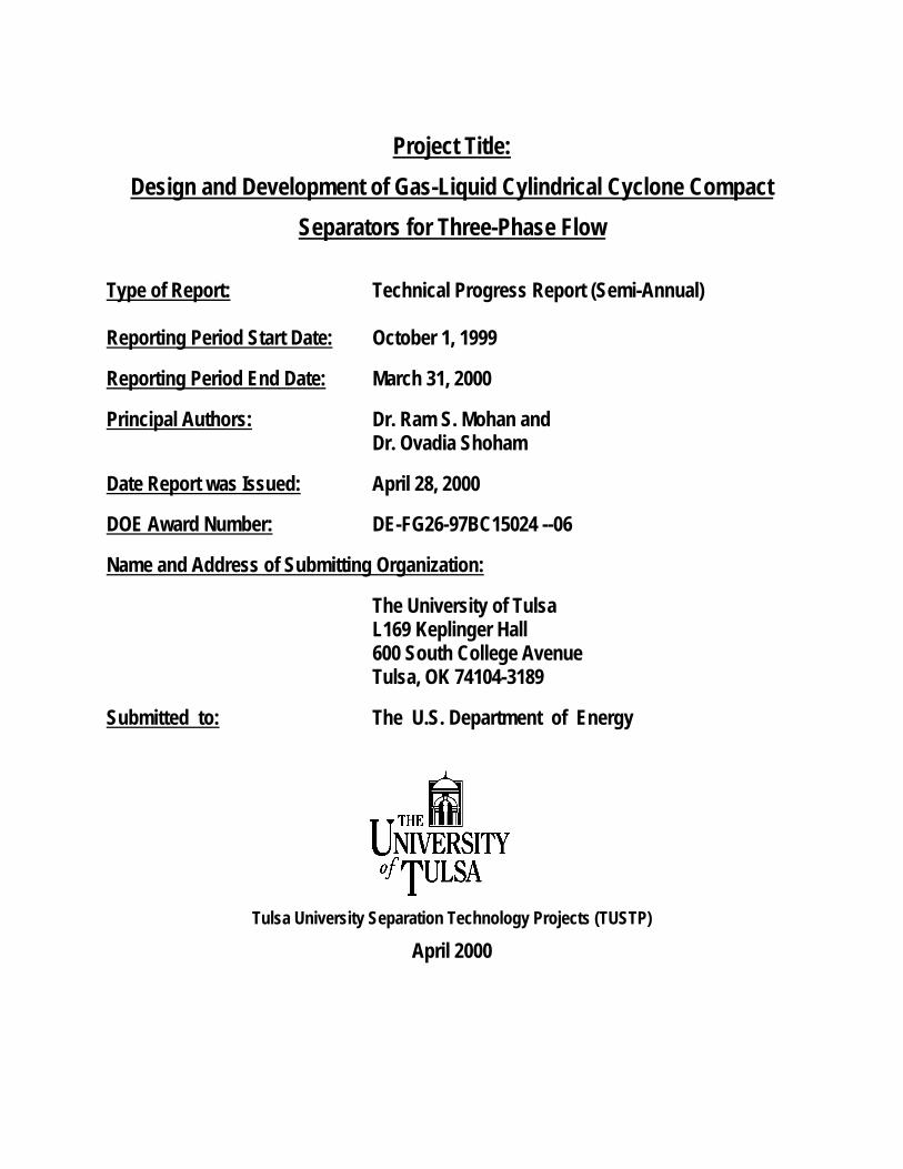
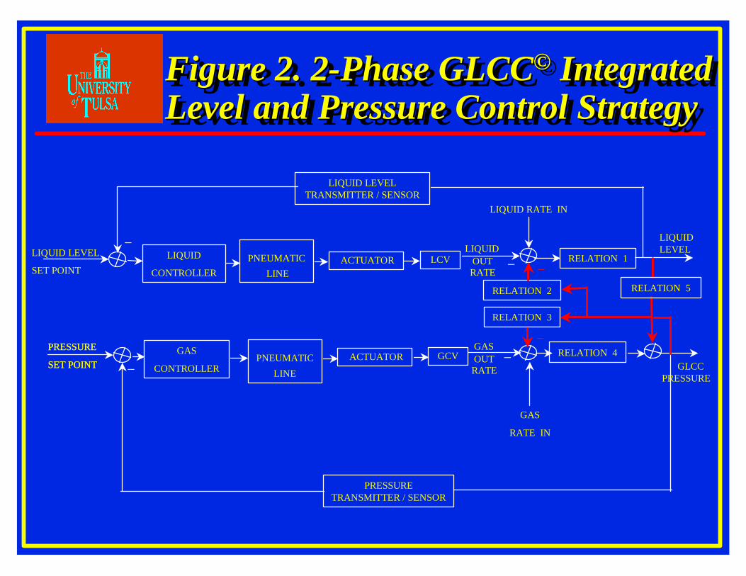
1. Control System Design and Experimental Results Several GLCC© control strategies have been developed based on the liquid level control by controlling the liquid leg valve, pressure control by controlling the gas leg valve, integrated level and pressure control, and integrated liquid level control by controlling both the liquid and gas leg valves. Schematic of two strategies is given in Figures 1 and 2. Mathematical models have been developed for these strategies and computer -based dedicated simulators have been built. Simulation studies indicated that the integrated control strategies are more suitable for slug flow due to faster response. The set point pressure control is crucial for integrated liquid level and pressure control. The experimental investigations are being conducted in out -door experimental facility using a dedicated GLCC capable of withstanding higher pressures. Preliminary investigations indicate that (see Fig. 3) there is considerable improvement (more than three -fold) in the operational envelope of a 2 -phase GLCC equipped with a control system. However, the mechanism s responsible for liquid carry -over in a GLCC with control system are different from those responsible in the case of a GLCC without control systems. For example, churn flow is responsible for liquid carry -over in a GLCC with control systems even for re latively large liquid flow rates, whereas in the case of a GLCC without control system, it is primarily caused by annular flow conditions. Current focus on the experimental investigations is on detailed measurement of gas carry -under beyond the operationa l envelope. Towards this objective, characterization of gas carry -under and quantification of amount of entrained gas in the liquid leg are in progress. Detailed experimental investigations are in progress to evaluate the sensitivity of the control paramet ers on the GLCC performance and optimization of control strategies. 2. Predictive Control of GLCC © Using Slug Detection A strategy for GLCC© predictive control has been developed which incorporates the slug characteristics in terms of holdup, length and vel ocity, and calculation of the volumetric liquid flow rate. This predictive control system is designed to operate only when huge slugs are encountered. Based upon the design, a predictive control model is being developed for control system simulation integr ating feedback and feed forward control systems. Experimental investigations are in progress to verify and implement the strategy. 3. Three-Phase GLCC© Separators Construction of the experimental facility for three -phase flow loop is completed and is shown i n Figure 4. Air is supplied from a compressor and is stored in a high -pressure gas tank. The air flows through a metering section consisting of Micro -Motion® mass flow meter and control valve. The liquid phases (water and oil) are pumped from the respect ive storage tanks and are metered with two sets of Micro -Motion® mass flow meters and control valves, before being mixed. Several mixing sections have been designed to evaluate and control the oil -water mixing characteristics at the inlet. The liquid and gas phases are then mixed at a tee junction and sent to the test section. State -of-the-art Micro-Motion® net oil computers (NOC) are being used to

quantify the watercut, Gas -Oil ratio (GOR), and mixture density. The test section consists of 2 dual stage GLCC s. Initially the test section will be equipped with one dual stage GLCC and later it will be upgraded to 2 dual stage GLCC s. The three -phases from the GLCC outlets will also metered using micro -motion mass flow meters. The test section construc tion is modular so that in place of GLCC any other separators such as hydro -cyclones could be used in series to form compact separation systems. Control valves placed along the flow loop control the flow into and out of the test sections. The flow loop i s also equipped with several temperature sensors and pressure transducers for measurement of the in -situ pressure and temperature conditions. Installation of the data acquisition system and electrical schematics, and calibration of the flow meters, pressu re transducers, temperature transducers and net oil computers have also been completed.
Design and fabrication of the three -phase GLCC is completed and has been installed in the flow loop. A schematic of the single stage 3 -phase GLCC© is shown in Figure 5 . Preliminary experimental investigations are in progress to evaluate the performance of the first generation three-phase GLCC laboratory prototype. The results of preliminary feasibility testing of 3 -phase GLCC© separator are shown in Figures 6 and 7. Th ese tests demonstrate that it is feasible to separate an oil -water-gas flow in a single stage 3 -phase GLCC©. A schematic of the oil -water interface and the gas -liquid interface is shown in Figure 8. Detailed experimental testing of the 3 -phase GLCC© will be conducted in the next half year of this project period to evaluate the operating performance. The data will help in the development of a mechanistic model for the GLCC©. The model will be computer coded which could be used for design of 3 -phase GLCC© units. 4. Oil/Water Separation in LLCC © Separators Installation of the support structure for the experimental facility, a 3 -inch oil -water test Liquid -Liquid Cylindrical Cyclone (LLCC ©) separator and downstream metering section has been completed. The LLCC © installed in the flow loop is shown in Figure 9. The preliminary phase of this project is completed. Several literature have been identified to provide more information into the nature of the oil -water interface for cyclonic separators of low G -forces such as the GLCC©s
and formulation of appropriate separation strategies for the GLCC ©. Inlet flow patterns in the LLCC© separator are given in Figure 10. The feasibility of utilization of the Liquid -Liquid Cylindrical Cyclone (LLCC ©) compact separator for free water knockout bulk separation of oil -water mixtures has been established by experimental testing of the lab LLCC © prototype, with measured efficiencies greater than 90% for some flow conditions. The typical flow pattern in an LLCC© is a combination of fr ee vortex and forced vortex. The schematic of the axial and tangential velocity profile is given in Figure 11. A mechanistic model for the LLCC © has been developed to predict the tangential and axial velocity profiles. The developed correlations are given in Figures 12 and 13. The mechanistic model will be used to design LLCC © field applications and comparison with experimental data. 5. Mechanistic Model and Experimental Investigation of Hydrocyclones Two dedicated graduate students are investigating strateg ies to identify techniques for integration of GLCC s with hydrocyclones for building three -phase compact separation systems. As a part of the detailed study of compact separation systems, investigations are in progress to develop mechanistic model for liq uid hydrocyclones (LHC). During the second half

of the current project period, a velocity field correlation will be completed for the LHC. The velocity field will be incorporated into a mechanistic model for prediction of separation efficiencies in the LHC . Modular Production Equipment (MPE), a TUSTP member company has provided us with two 2 -inch LHCs, one of them fabricated from transparent plastic and the other from steel. The modular construction of the TUSTP 3 -phase flow loop will be capitalized to enable easy installation of both LHCs. Subsequently, data acquisition on separation efficiency of oil/water flow in the LHC will be conducted. The data will be used to test and refine the mechanistic model for the LHC.
5. Descriptions of Project Work Planned for the next Reporting Period
(April 1, 2000 - September 30, 2000)
The next reporting project research activity will be similar to the second year project activity, only difference being that the emphasis will be on liquid carry -over. The mechanistic modeling of gas carry -under will be continued in the third year also and will be completed so that it can be integrated with the constitutive model for liquid carry -over. The third project year activities are divided into three main parts, which will be carrie d out in parallel. The first part is continuation of the experimental program that includes a study of the oil/water two -phase behavior and control system development for the three -phase GLCC . The second part consists of the development of a simplified mechanistic model incorporating the control strategies and behavior of dispersion of oil in water and water in oil. This will provide an insight into the hydrodynamic flow behavior and serve as the design tool for the industry. Although useful for sizing GLCC s for proven applications, the mechanistic model will not provide detailed hydrodynamic flow behavior information needed to screen new geometric variations or to study the effect of fluid property variations. Therefore, in the third part, the more ri gorous approach of computational fluid dynamics (CFD) will be utilized. Multidimensional multiphase flow simulation will provide much greater depth into the understanding of the physical phenomena and the mathematical analysis of three -phase GLCC design and performance. Further investigations will be carried out, as part of this study, to enhance the potential of a commercial CFD code called CFX to three -phase applications. Following is a more detailed description of the three parts of the upcoming year activities.
A. Experimental Program: The experimental program will be conducted in two facilities, indoor and outdoor. A
dedicated GLCC is built outdoors, which is capable of withstanding higher pressures, for conducting detailed controls experiments. Control strategy developed in the outdoor facility, will be an essential part of the indoor, three -phase GLCC . This experimental investigation will provide necessary and vital information about the control system design for the three -phase flow loop. The indoor experimental facility for three -phase flow, which has been constructed as a part of the second year activity, will be used for the experimentation.
Two types of GLCC configurations will be considered namely single stage GLCC and dual stage GLCC , as described previously. The above flow loop can be used for both configurations. The GLCC for the indoor facility is being built using transparent PVC pipes so as to enable visual observations of the hydrodynamic flow phenomena, which is essential for the

modeling. The modular design of the GLCC will allow easy modification of the inlet, outlet and piping configurations. Finally, the effect of fluid properties can be investigated through use of viscosity and surface tension modifiers to water.
In addition to the inlet flow rates of the three -phases, the following measurements will be acquired for each experimental run:
1. Absolute pressure, temperature and pressure drop in the GLCC ; 2. Equilibrium liquid level; 3. Interface shape and location; 4. Gas core filament shape and dynamics; 5. Churn region and droplet region lengths (in the upper part of the GLCC ); 6. Global separation efficiency namely oil fraction in the water outlet, water fraction in the
oil outlet; 7. Total gas carry-under in liquid streams. 8. Observation of oil/water interface, 9. Observation of bubble size distribution; 10. Response of three -phase GLCC to liquid level control.
B. Mechanistic Model: The mechanistic model development initiated in the second year of project activity will
be continued during the third year which will lead to an integrated model. A mechanistic model for operational envelope of liquid carry -over and gas carry -under will be developed for the prediction of the hydrodynamic flow behavior and performance of the three -phase GLCC separator.
The input parameters to the model would include the following: • Operational parameters: range of oil -water-gas flow rates, pressure and
temperature; • Physical properties: oil, gas and water densities, viscosities and surface
tensions; • Geometrical par ameters: complete geometric description of the GLCC such as,
GLCC configurations, inlet pipe I.D, inclination angle and roughness, outlet piping I.D, length and roughness;
• Performance characteristics of liquid level control.
The mechanistic model will e nable determination of the performance characteristics of the GLCC , namely:
• plot of the operational envelopes for both liquid carry -over and gas carry -under; • percent liquid carry -over and gas carry -under beyond the operational envelopes; • oil in water and water in oil fractions; • pressure drop across the GLCC ; • liquid level in the separator; • sensitivity to flow rate fluctuations (with and without active control). The simplified integrated mechanistic model will enable insight into the hydrodynamic
flow behavior in the three -phase GLCC . It will also allow the user to optimize the GLCC design accounting for tradeoffs in the I.D, height and inlet slot size of the GLCC . The model

will also provide the trends of the effect of fluid physical properties and t he information required for determining when the active controls will be needed.
C. Computational Fluid Dynamics (CFD) Simulator: The purpose of the computational fluid dynamics (CFD) modeling is to provide both
macroscopic and microscopic scale inform ation on multidimensional multiphase flow hydrodynamic behavior. The CFD model will be general so that it can be utilized for the analysis of the GLCC and other complicated multiphase flow systems. Thus, the numerical simulator will provide a powerful a nalytical tool, which will also reduce experimental costs associated with testing of a variety of different operating conditions. Constitutive models for the CFD code (CFX) will be developed and will be added to the simulator to capture the important physics of three-phase separation. The CFD activity initiated during 1998 -1999 will be continued through the current project (October 1999 to September 2000).
A general numerical solution procedure for simulating three -dimensional three -phase flow in complex pipe geometries will be developed based on CFX. The numerical model will employ the three -fluid model. A turbulent flow model is also required for specifying the constitutive relations in the momentum equations. The eddy viscosity concept will be used t o define an effective viscosity for the mixture. Both Prantl mixing -length model and a more sophisticated k-ε model will be used for modeling this complex flow geometry.
The experimental data acquired on the GLCC and other available data from complex three-phase systems, such as flow splitting at tee junctions, will be used to test and refine the numerical code. For the current project, the CFD model will be used for initial parametric studies of possible design modifications to the GLCC . Moreover, the model will provide detailed performance prediction for untried applications for which no data are available, such as high -pressure subsea separation.
LIQUID LEVEL
SET POINT LIQUID LEVELLIQUID
CONTROLLERRELATION 1
LIQUID
RATE IN
TRANSMITTER / SENSOR
GAS
CONTROLLERRELATION 4
GLCC
PRESSURE
GAS
RATE IN
+ACTUATOR & LIQUID CONTROL
VALVE
LIQUIDOUT
RATE
GASOUT
RATE +
+
−
−
−PNEUMATIC
LINE
PNEUMATICLINE
−
RELATION 5
RELATION 2
RELATION 3
++ACTUATOR
& GAS CONTROL
VALVE
Figure 1. 2-Phase GLCC©
Integrated Level Control StrategyFigure 1. 2Figure 1. 2--Phase GLCCPhase GLCC©©
Integrated Level Control StrategyIntegrated Level Control Strategy
LIQUID LEVELLIQUID LEVEL
SET POINT
GLCCPRESSURE
PRESSURE
SET POINT
LIQUID
CONTROLLER
LIQUID LEVEL TRANSMITTER / SENSOR
GAS
CONTROLLER
RELATION 1
RELATION 4
PRESSURE TRANSMITTER / SENSOR
+
+LCV
LIQUIDOUT
RATE
LIQUID RATE IN
GAS
RATE IN
−
−PNEUMATIC
LINE
PNEUMATICLINE
GASOUT
RATE +
+
−
−
PRESSURE
SET POINT
ACTUATOR
ACTUATOR
RELATION 3
RELATION 2
GCV
RELATION 5
−
−
+
+
Figure 2. 2-Phase GLCC© Integrated Level and Pressure Control StrategyFigure 2. 2Figure 2. 2--Phase GLCCPhase GLCC©© Integrated Integrated Level and Pressure Control StrategyLevel and Pressure Control Strategy
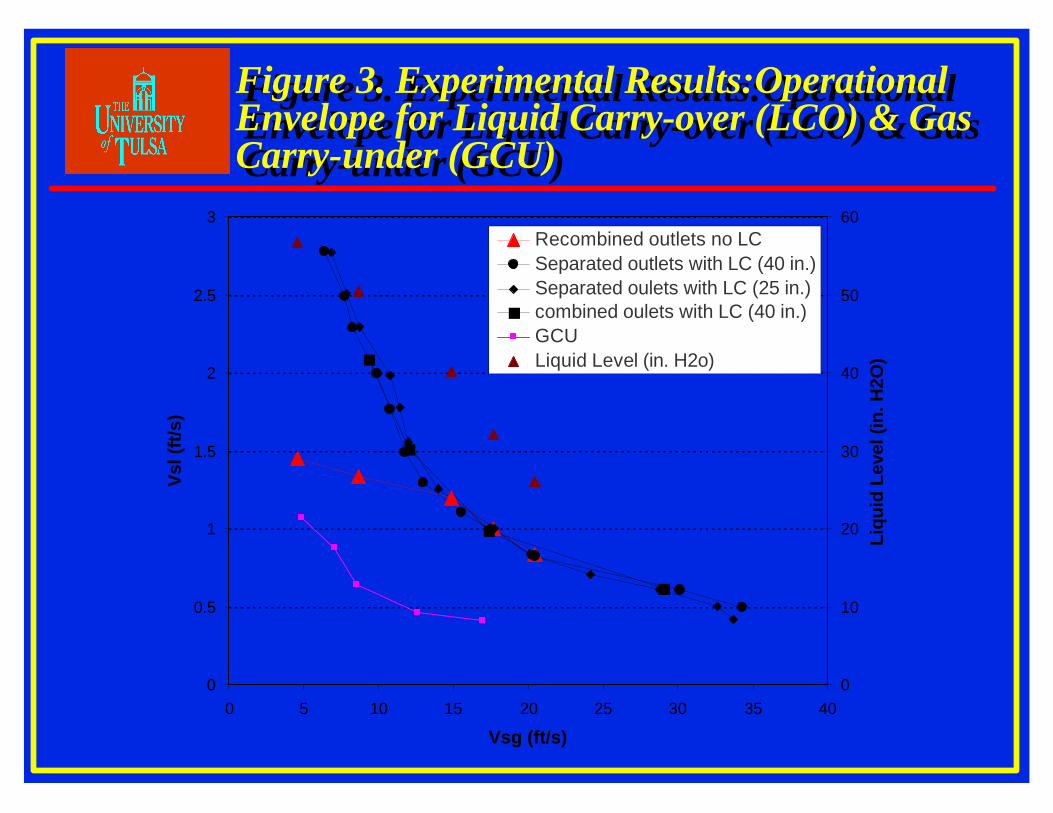
Figure 3. Experimental Results:Operational Envelope for Liquid Carry-over (LCO) & Gas Carry-under (GCU)
Figure 3. Experimental Results:Operational Envelope for Liquid Carry-over (LCO) & Gas Carry-under (GCU)
0
0.5
1
1.5
2
2.5
3
0 5 10 15 20 25 30 35 40
Vsg (ft/s)
Vsl
(ft/s
)
0
10
20
30
40
50
60
Liqu
id L
evel
(in.
H2O
)
Recombined outlets no LCSeparated outlets with LC (40 in.)Separated oulets with LC (25 in.)combined oulets with LC (40 in.)GCULiquid Level (in. H2o)

Figure 4. Experimental Facility for 3-Phase Flow Loop

Figure 5. Schematic of Single Stage 3-Phase GLCC© DesignFigure 5. Schematic of Single Stage 3-Phase GLCC© Design
3 3 -- Phase FlowPhase Flow

Figure 6. Operation of 3-phase GLCC© - Experimental Visualization

Figure 7. Operation of 3-phase GLCC© - Oil and Water Legs

Figure 8. Schematics of Oil - Water and Gas-Liquid InterfacesFigure 8. Schematics of Oil - Water and Gas-Liquid Interfaces
OILOIL
WATERWATER
Oil / Water Interface
GASGAS
LIQUIDLIQUID
Gas/Liquid Interface
OILOIL--WATER WATER FLOWFLOW
GASGAS--LIQUID LIQUID FLOWFLOW
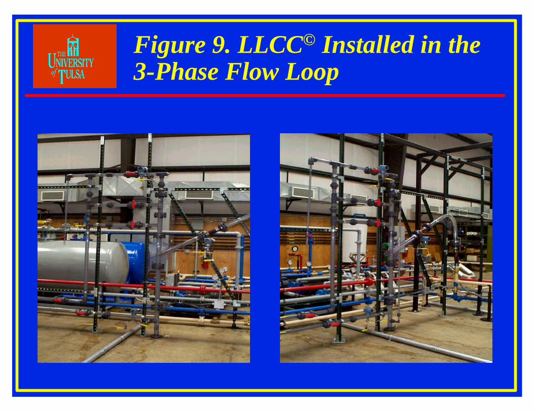
Figure 9. LLCC© Installed in the 3-Phase Flow Loop
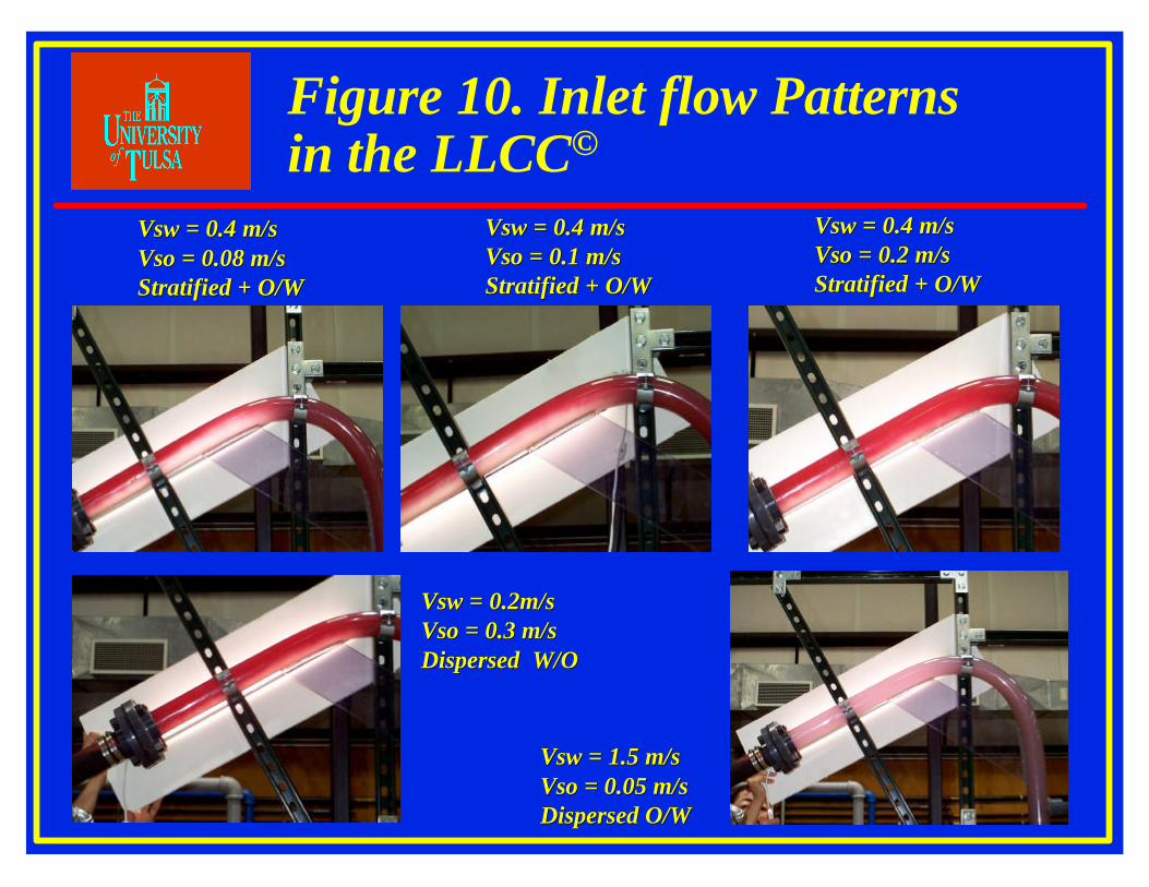
Vsw Vsw = 0.4 m/s= 0.4 m/sVso Vso = 0.08 m/s= 0.08 m/sStratified + O/WStratified + O/W
Vsw Vsw = 0.4 m/s= 0.4 m/sVso Vso = 0.1 m/s = 0.1 m/s Stratified + O/WStratified + O/W
Vsw Vsw = 0.4 m/s= 0.4 m/sVso Vso = 0.2 m/s = 0.2 m/s Stratified + O/WStratified + O/W
Vsw Vsw = 0.2m/s= 0.2m/sVso Vso = 0.3 m/s= 0.3 m/sDispersed W/ODispersed W/O
Vsw Vsw = 1.5 m/s= 1.5 m/sVso Vso = 0.05 m/s= 0.05 m/sDispersed O/WDispersed O/W
Figure 10. Inlet flow Patterns in the LLCC©
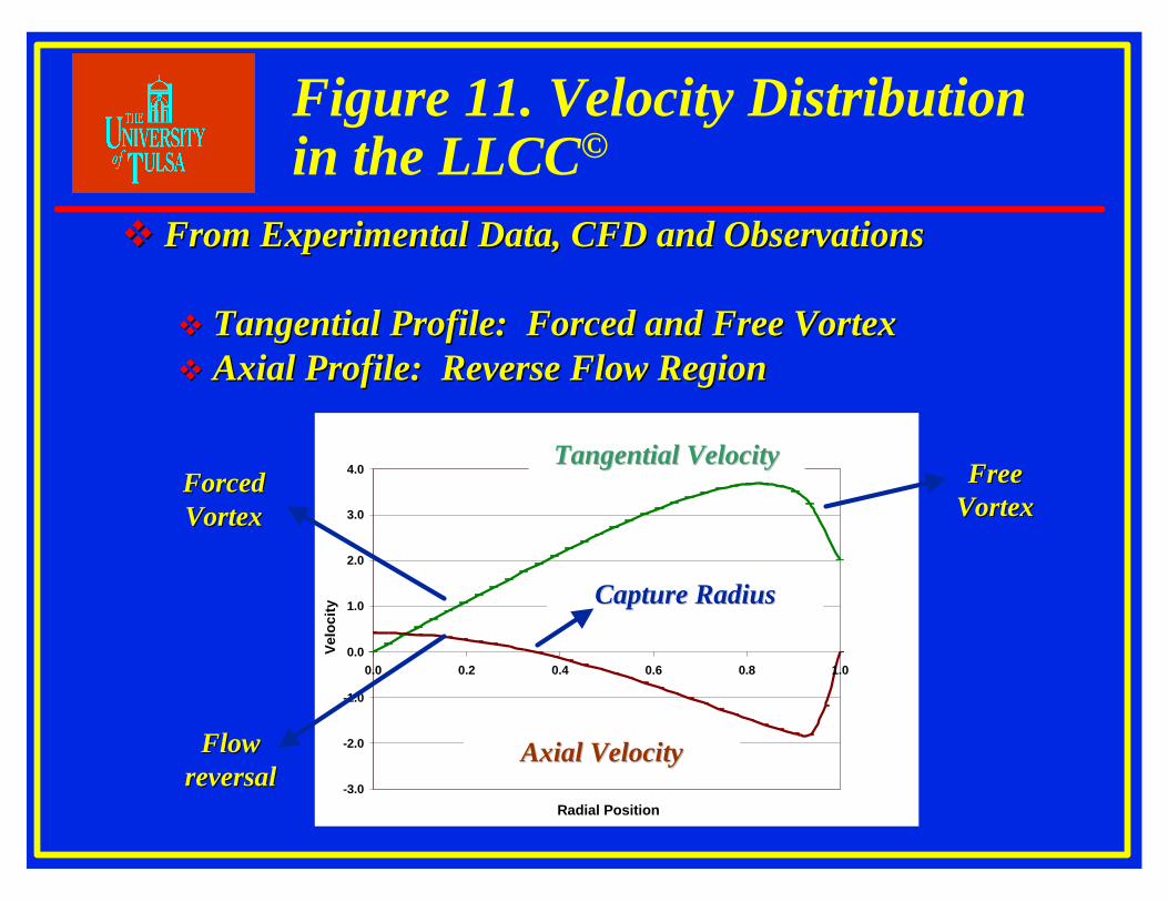
vv From Experimental Data, CFD and ObservationsFrom Experimental Data, CFD and Observations
vv Tangential Profile: Forced and Free VortexTangential Profile: Forced and Free Vortexvv Axial Profile: Reverse Flow RegionAxial Profile: Reverse Flow Region
ForcedForcedVortexVortex
FreeFreeVortexVortex
FlowFlowreversalreversal -3.0
-2.0
-1.0
0.0
1.0
2.0
3.0
4.0
0.0 0.2 0.4 0.6 0.8 1.0
Radial Position
Vel
ocity
Tangential VelocityTangential Velocity
Capture RadiusCapture Radius
Axial VelocityAxial Velocity
Figure 11. Velocity Distribution in the LLCC©
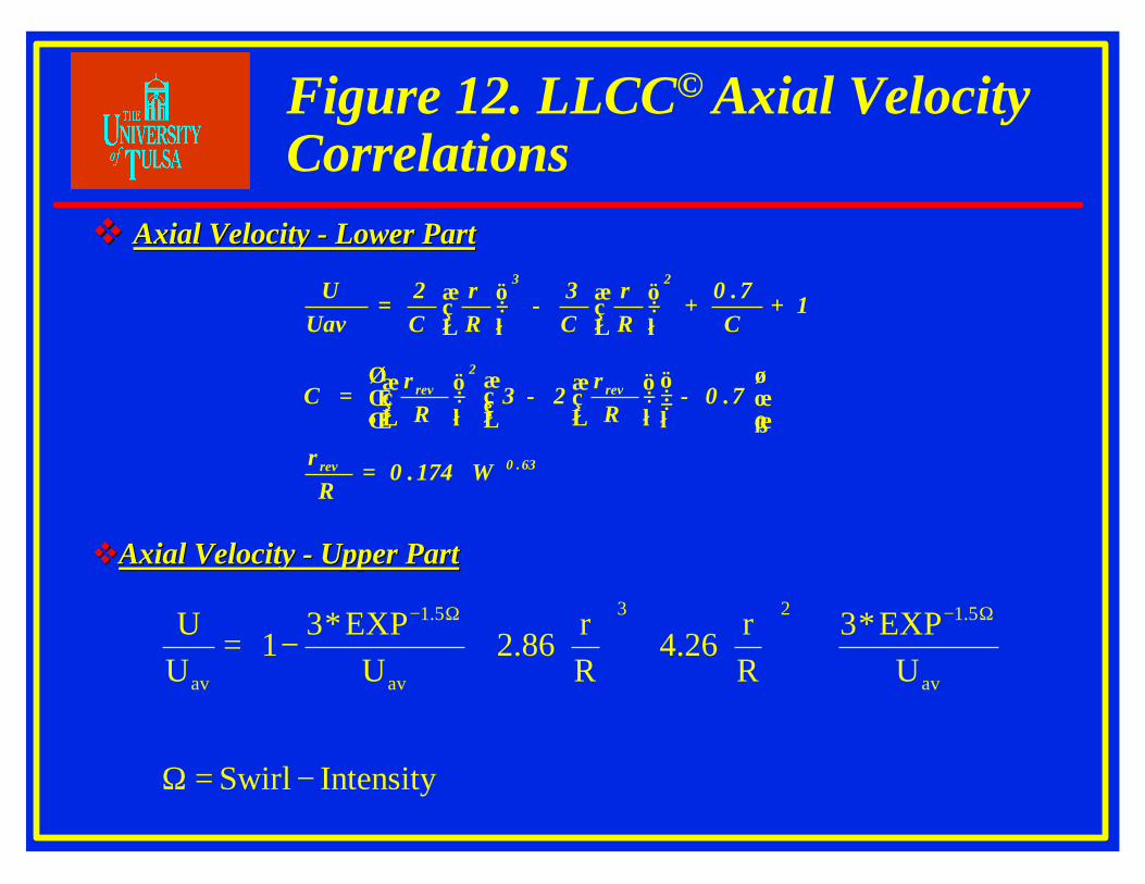
vv Axial Velocity Axial Velocity -- Lower PartLower Part
vvAxial Velocity Axial Velocity -- Upper PartUpper Part
63.0rev
rev2
rev
23
174.0R
r
7.0R
r23
Rr
C
1C
7.0Rr
C3
Rr
C2
UavU
Ω=
−
−
=
++
−
=
IntensitySwirl
UEXP*3
Rr
26.4Rr
86.2U
EXP*31
UU
av
5.123
av
5.1
av
−=Ω
+
+
−=
Ω−Ω−
Figure 12. LLCC© Axial Velocity Correlations

3056.1
3056.1
2
7152.0Tm
1433.1Tm
Rr
85.1exp1
Rr
TmUavW
Ω
Ω
=
=
−−
=
vvTangential VelocityTangential Velocity
Lower Part of the LLCCLower Part of the LLCC
Upper Part of the LLCCUpper Part of the LLCC
Tm is Related to Maximum Momentum of TangentialTm is Related to Maximum Momentum of TangentialVelocityVelocity
Figure 13. LLCC© Tangential Velocity Correlation
Related Documents


