http://www.iaeme.com/IJDMT/index.asp 1 [email protected] International Journal of Design and Manufacturing Technology (IJDMT) Volume 7, Issue 3, Sep–Dec 2016, pp. 1–11, Article ID: IJDMT_07_03_001 Available online at http://iaeme.com/ijdmt/issues.asp?JType=IJDMT&VType=7&IType=3 Journal Impact Factor (2016): 5.7682 (Calculated by GISI) www.jifactor.com ISSN Print: 0976 – 6995 and ISSN Online: 0976 – 7002 © IAEME Publication DESIGN AND DEVELOPMENT METHODOLOGY OF ADAPTIVE VIBRATION ABSORBER Rushi Vyas, Rajan Zinzala and Hiren Prajapati Institute of Technology, Nirma University, Ahmedabad, Gujarat, India ABSTRACT The aim of this project is to how to reduce vibration through dual cantilever mass mechanism which is call adaptive vibration absorber that is different than the tune vibration absorber. Design incorporates the use of two concentrated masses cantilevered from two rods. The adaptive solution is achieved by moving the two masses along the length of the rod, producing a changing natural frequency for the absorber device. To do so we applied this system to frequency range of 30 to 80 Hz .For our design we take concentrated masses of 1.2 kg. When we change length from 81.5mm to 210 mm. So, our frequency range will be in range of 80 to 30 Hz (natural frequency).We would design the absorber for the setup having maximum acceleration at 50 Hz frequency and observe the amount of vibrations absorbed by it. Key words: Vibration Absorber and FFT Analysis Cite this Article: Design and Development Methodology of Adaptive Vibration Absorber, Rushi Vyas, Rajan Zinzala and Hiren Prajapati International Journal of Design and Manufacturing Technology 7(3), 2016, pp. 1–11. http://www.iaeme.com/IJDMT/issues.asp?JType=IJDMT&VType=7&IType=2 1. INTRODUCTION In an engineering application there may be one or multiple motion / power transferring elements. There may be linear, sliding or rotary elements. For any such element, while transferring power/motion there are certain amount of vibrations which are caused. The cause of vibrations may be: - Unbalance, configuration of the system itself, inaccurate machining, improper tolerances of dimensions etc. These vibrations may cause many problems in operation and it may lead to failures too. So it is very necessary to eliminate these vibrations in order to achieve a perfect stable system for power transmission.

Welcome message from author
This document is posted to help you gain knowledge. Please leave a comment to let me know what you think about it! Share it to your friends and learn new things together.
Transcript

http://www.iaeme.com/IJDMT/index.asp 1 [email protected]
International Journal of Design and Manufacturing Technology (IJDMT)
Volume 7, Issue 3, Sep–Dec 2016, pp. 1–11, Article ID: IJDMT_07_03_001
Available online at
http://iaeme.com/ijdmt/issues.asp?JType=IJDMT&VType=7&IType=3
Journal Impact Factor (2016): 5.7682 (Calculated by GISI) www.jifactor.com
ISSN Print: 0976 – 6995 and ISSN Online: 0976 – 7002
© IAEME Publication
DESIGN AND DEVELOPMENT
METHODOLOGY OF ADAPTIVE
VIBRATION ABSORBER
Rushi Vyas, Rajan Zinzala and Hiren Prajapati
Institute of Technology, Nirma University, Ahmedabad, Gujarat, India
ABSTRACT
The aim of this project is to how to reduce vibration through dual
cantilever mass mechanism which is call adaptive vibration absorber that is
different than the tune vibration absorber. Design incorporates the use of two
concentrated masses cantilevered from two rods. The adaptive solution is
achieved by moving the two masses along the length of the rod, producing a
changing natural frequency for the absorber device. To do so we applied this
system to frequency range of 30 to 80 Hz .For our design we take
concentrated masses of 1.2 kg. When we change length from 81.5mm to 210
mm. So, our frequency range will be in range of 80 to 30 Hz (natural
frequency).We would design the absorber for the setup having maximum
acceleration at 50 Hz frequency and observe the amount of vibrations
absorbed by it.
Key words: Vibration Absorber and FFT Analysis
Cite this Article: Design and Development Methodology of Adaptive
Vibration Absorber, Rushi Vyas, Rajan Zinzala and Hiren Prajapati
International Journal of Design and Manufacturing Technology 7(3), 2016,
pp. 1–11. http://www.iaeme.com/IJDMT/issues.asp?JType=IJDMT&VType=7&IType=2
1. INTRODUCTION
In an engineering application there may be one or multiple motion / power
transferring elements. There may be linear, sliding or rotary elements. For any such
element, while transferring power/motion there are certain amount of vibrations
which are caused.
The cause of vibrations may be: - Unbalance, configuration of the system itself,
inaccurate machining, improper tolerances of dimensions etc.
These vibrations may cause many problems in operation and it may lead to
failures too. So it is very necessary to eliminate these vibrations in order to achieve a
perfect stable system for power transmission.
Rushi Vyas, Rajan Zinzala and Hiren Prajapati
http://www.iaeme.com/IJDMT/index.asp
1.1. Vibration elimination
Vibrations can be eliminated completely or partially by attaching an additional system
to our element. We can use various dampers, isolators or Absorbers. Damper is a
system having very high damping,
amount by adding such stiffness or damping element to our existing system.
Isolators are the system which tries to isolate the element or the existing system in
order to decrease or completely eliminate th
While absorbers are the systems that decrease the amount of vibrations simply by
using the concept of negative superposition. Superposition is the process of adding the
existing vibrations with the vibrations caused by an exte
1.2. Vibration absorbers
As explained earlier the absorber is a system which tries to eliminate vibrations by
negative superposition. Basically what happens is
Suppose the nature of my vibrations occurring on an element is
X(t) = Asin(wt+Q)
So, we can add a particular system which has same nature of vibration function by
opposite nature:
X’(t)=-Asin(wt+Q)
So:
x(t)+x’(t) = 0
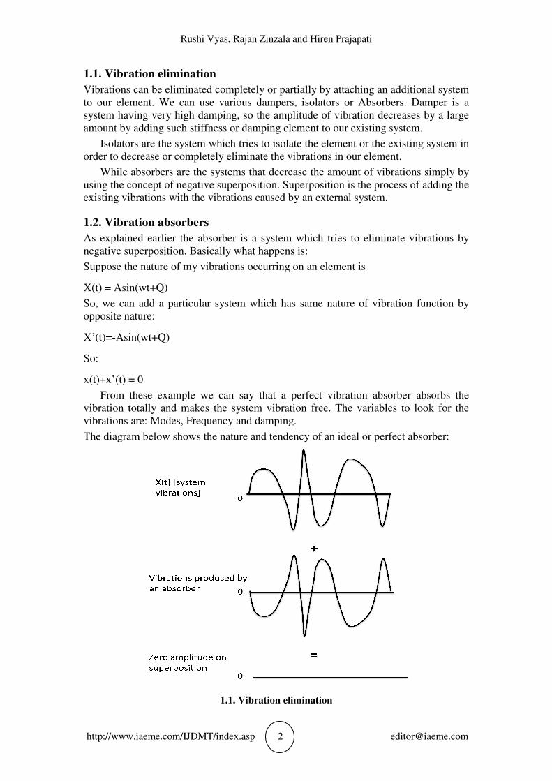
From these example we can say that a perfect vibration absorber absorbs the
vibration totally and makes the system
vibrations are: Modes, Frequency and damping.
The diagram below shows the nature and tendency of an ideal or perfect absorber:
Rushi Vyas, Rajan Zinzala and Hiren Prajapati
http://www.iaeme.com/IJDMT/index.asp 2 [email protected]
elimination
Vibrations can be eliminated completely or partially by attaching an additional system
to our element. We can use various dampers, isolators or Absorbers. Damper is a
system having very high damping, so the amplitude of vibration decrease
amount by adding such stiffness or damping element to our existing system.
Isolators are the system which tries to isolate the element or the existing system in
order to decrease or completely eliminate the vibrations in our element.
While absorbers are the systems that decrease the amount of vibrations simply by
using the concept of negative superposition. Superposition is the process of adding the
existing vibrations with the vibrations caused by an external system.
absorbers
As explained earlier the absorber is a system which tries to eliminate vibrations by
negative superposition. Basically what happens is:
Suppose the nature of my vibrations occurring on an element is
So, we can add a particular system which has same nature of vibration function by
example we can say that a perfect vibration absorber absorbs the
vibration totally and makes the system vibration free. The variables to look for the
vibrations are: Modes, Frequency and damping.
The diagram below shows the nature and tendency of an ideal or perfect absorber:
1.1. Vibration elimination
Vibrations can be eliminated completely or partially by attaching an additional system
to our element. We can use various dampers, isolators or Absorbers. Damper is a
so the amplitude of vibration decreases by a large
amount by adding such stiffness or damping element to our existing system.
Isolators are the system which tries to isolate the element or the existing system in
e vibrations in our element.
While absorbers are the systems that decrease the amount of vibrations simply by
using the concept of negative superposition. Superposition is the process of adding the
As explained earlier the absorber is a system which tries to eliminate vibrations by
So, we can add a particular system which has same nature of vibration function by
example we can say that a perfect vibration absorber absorbs the
ibration free. The variables to look for the
The diagram below shows the nature and tendency of an ideal or perfect absorber:
Design and Development Methodology of Adaptive Vibration Absorber
http://www.iaeme.com/IJDMT/index.asp 3 [email protected]
An ideal absorber: Absorbers all vibrations, consumes minimum power, has minimum
material and cost.
1.3. Types of vibration absorbers
Basically there are categories based on nature of frequency and dynamic characteristic
of vibration absorbers.
On the basis of Nature of frequency the vibration absorber may be Dynamic
vibration absorber or static vibration absorber (Tuned vibration absorber).
The basic difference between both of these are: In Dynamic vibration absorber the
absorbing system senses the vibrations, gives actuating signal accordingly and
absorbs vibration in a very high range of frequencies.
While for tuned vibration absorber: It is only tuned for a particular frequency and
it cannot be used for wide range of frequencies.
In the classification based on the dynamic characteristic of vibration absorber may
be of: 1) Active vibration absorber, 2) Passive vibration absorber.
Active vibration absorber Passive vibration absorber
-In active vibration absorber the actuating
signal is given to the system that is all masses
- In passive vibration type only the actuating
signals given is in the form of waves.
-In this absorber more power is consumed to
actuate
- Power consumed is less.
-Vibrations of the object may increase or
decrease
-Vibration can only decrease in magnitude in
this case
-It may produce negative or positive damping -It only produces positive damping
-Forced frequency is applied in this case -Natural frequency is used in this case.
In passive type dynamic absorber system there is one more advantage that is we
only get positive damping and not the negative damping in order to achieve only
decrease in vibration magnitude.
So, our design is based on: Adaptive passive dynamic tuned vibration absorber.
2. CONCEPTUALISATION
2.1. Our concept of design
The design approach for the adaptive passive tuned dynamic vibration absorber is to
make it of the design of double cantilever type. We designed it based on strength and
further the length of the cantilever beams are designed based on the natural frequency
to be obtained.
The double cantilever structure is attached to several other components to make it
sense the vibration and actuate thereafter.
As shown in the figure, there is a column that supports two cantilever beams
containing two point masses each of 1200 gram.

Rushi Vyas, Rajan Zinzala and Hiren Prajapati
http://www.iaeme.com/IJDMT/index.asp
The point masses suspended creates a bending and due to that there is also a
stiffness of this structure. Due to this stiffness there is a natural frequency of the
structure itself and thus we can calculate various lengths in order to damp a
system.
There are two point masses at the two extreme points of the rods. Two rods are
being used one is threaded and another one is normal rod to constraint the rotational
motion of the point mass when the threaded rod is given actuation using m
For complete vibration absorption we must assure that the vibration absorber
system is vibrating on its 1
may be vibrating. These are as follows:
2.2. Overall design
The overall design consists of the various elements like
used the accelerometer ADXL335 sensor, the actuator which is our double cantilever
structure, the processor which in our case is the Arduino Uno R3 which can be
programmed to get a certain output and there is a stepper motor which is used for the
actuation purpose connected with Arduino and the mechanical setup. The input of
arduino is from the sensor accelerometer ADXL335.
Rushi Vyas, Rajan Zinzala and Hiren Prajapati
http://www.iaeme.com/IJDMT/index.asp 4 [email protected]
The point masses suspended creates a bending and due to that there is also a
stiffness of this structure. Due to this stiffness there is a natural frequency of the
structure itself and thus we can calculate various lengths in order to damp a
There are two point masses at the two extreme points of the rods. Two rods are
being used one is threaded and another one is normal rod to constraint the rotational
motion of the point mass when the threaded rod is given actuation using m
For complete vibration absorption we must assure that the vibration absorber
system is vibrating on its 1st mode. There may be several modes in which the system
may be vibrating. These are as follows:
2.1. Modes of the structure
The overall design consists of the various elements like sensor: In our case we have
used the accelerometer ADXL335 sensor, the actuator which is our double cantilever
, the processor which in our case is the Arduino Uno R3 which can be
ogrammed to get a certain output and there is a stepper motor which is used for the
actuation purpose connected with Arduino and the mechanical setup. The input of
arduino is from the sensor accelerometer ADXL335.
The point masses suspended creates a bending and due to that there is also a
stiffness of this structure. Due to this stiffness there is a natural frequency of the
structure itself and thus we can calculate various lengths in order to damp a vibrating
There are two point masses at the two extreme points of the rods. Two rods are
being used one is threaded and another one is normal rod to constraint the rotational
motion of the point mass when the threaded rod is given actuation using motors.
For complete vibration absorption we must assure that the vibration absorber
mode. There may be several modes in which the system
In our case we have
used the accelerometer ADXL335 sensor, the actuator which is our double cantilever
, the processor which in our case is the Arduino Uno R3 which can be
ogrammed to get a certain output and there is a stepper motor which is used for the
actuation purpose connected with Arduino and the mechanical setup. The input of

Design and Development Methodology
http://www.iaeme.com/IJDMT/index.asp
2.3. FFT analysis readings
The curve above shows the curve of acceleration v
magnitude of maximum acceleration at a particular frequency which means maximum
force at a particular frequency which is at 50 Hz so that frequ
at 50 Hz and corresponding acceleration is to be damped.
So the natural frequency of the adaptive tuned dynamic vibration absorber must be
equal to the frequency of structure equal to 50 Hz to eliminate the vibrations.
nd Development Methodology of Adaptive Vibration Absorber
http://www.iaeme.com/IJDMT/index.asp 5 [email protected]
2.2. Design of vibration absorber
analysis readings
2.3 FFT readings
The curve above shows the curve of acceleration v/s frequency which gives
magnitude of maximum acceleration at a particular frequency which means maximum
force at a particular frequency which is at 50 Hz so that frequency to be damped at is
at 50 Hz and corresponding acceleration is to be damped.
So the natural frequency of the adaptive tuned dynamic vibration absorber must be
equal to the frequency of structure equal to 50 Hz to eliminate the vibrations.
f Adaptive Vibration Absorber
s frequency which gives
magnitude of maximum acceleration at a particular frequency which means maximum
ency to be damped at is
So the natural frequency of the adaptive tuned dynamic vibration absorber must be
equal to the frequency of structure equal to 50 Hz to eliminate the vibrations.
Rushi Vyas, Rajan Zinzala and Hiren Prajapati
http://www.iaeme.com/IJDMT/index.asp
3. DESIGN BASED ON STRENGTH
The setup which is explained above has some mechanical parts and some electronic
part. For the mechanical part we have to provide a sturdy design so as to assure the
safe application of the whole setup in action.
So the various mechanical elem
Basically, various iterations are carried out based on the values of diameter of rod
and the point mass attached at the end of rod.
The factor of safety considered for the design is: 3.5
The point mass is decided based on iterations using software MS excel is 600 grams,
and the diameter of rod is found out as 4.732 mm which is rounded off as 4.8
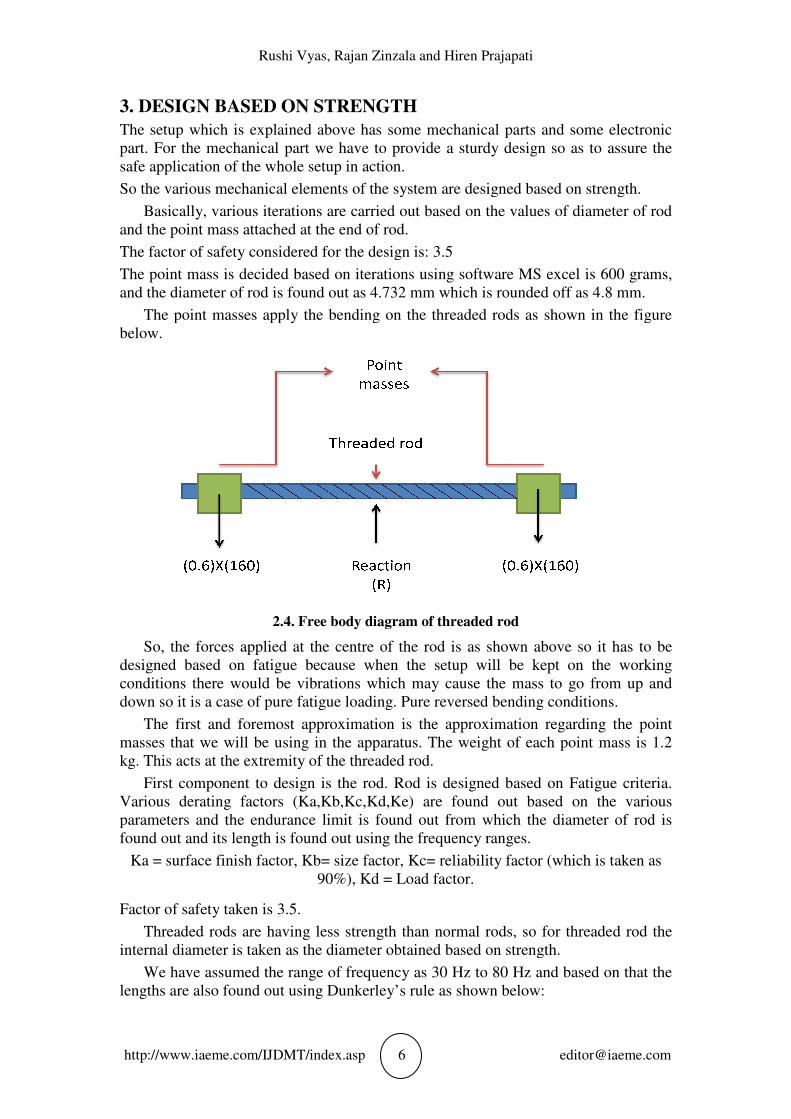
The point masses apply the bending on the threaded rods as shown in the figure
below.
2.4
So, the forces applied at the centre of the rod is as shown above so it has to be
designed based on fatigue because when the setup will be kept on the working
conditions there would be vibrations which may cause the mass to go from up a
down so it is a case of pure fatigue loading. Pure reversed bending conditions.
The first and foremost approximation is the approximation regarding the point
masses that we will be using in the apparatus. The weight of each point mass is 1.2
kg. This acts at the extremity of the threaded rod.
First component to design is the rod. Rod is designed based on Fatigue criteria.
Various derating factors (Ka,Kb,Kc,Kd,Ke) are found out based on the various
parameters and the endurance limit is found out from whi
found out and its length is found out using the frequency ranges.
Ka = surface finish factor, Kb= size factor, Kc= reliability factor (
Factor of safety taken is 3.5.
Threaded rods are having less strength than normal rods, so for threaded rod the
internal diameter is taken as the diameter obtained based on strength.
We have assumed the range of frequency as 30 Hz to 80 Hz and based on that the
lengths are also found out using Dunkerley’
Rushi Vyas, Rajan Zinzala and Hiren Prajapati
http://www.iaeme.com/IJDMT/index.asp 6 [email protected]
ON STRENGTH
The setup which is explained above has some mechanical parts and some electronic
part. For the mechanical part we have to provide a sturdy design so as to assure the
safe application of the whole setup in action.
So the various mechanical elements of the system are designed based on strength.
Basically, various iterations are carried out based on the values of diameter of rod
and the point mass attached at the end of rod.
The factor of safety considered for the design is: 3.5
decided based on iterations using software MS excel is 600 grams,
ter of rod is found out as 4.732 mm which is rounded off as 4.8
The point masses apply the bending on the threaded rods as shown in the figure
2.4. Free body diagram of threaded rod
So, the forces applied at the centre of the rod is as shown above so it has to be
designed based on fatigue because when the setup will be kept on the working
conditions there would be vibrations which may cause the mass to go from up a
down so it is a case of pure fatigue loading. Pure reversed bending conditions.
The first and foremost approximation is the approximation regarding the point
masses that we will be using in the apparatus. The weight of each point mass is 1.2
ts at the extremity of the threaded rod.
First component to design is the rod. Rod is designed based on Fatigue criteria.
Various derating factors (Ka,Kb,Kc,Kd,Ke) are found out based on the various
parameters and the endurance limit is found out from which the diameter of rod is
found out and its length is found out using the frequency ranges.
Ka = surface finish factor, Kb= size factor, Kc= reliability factor (which is taken as
90%), Kd = Load factor.
Factor of safety taken is 3.5.
having less strength than normal rods, so for threaded rod the
internal diameter is taken as the diameter obtained based on strength.
We have assumed the range of frequency as 30 Hz to 80 Hz and based on that the
lengths are also found out using Dunkerley’s rule as shown below:
The setup which is explained above has some mechanical parts and some electronic
part. For the mechanical part we have to provide a sturdy design so as to assure the
ents of the system are designed based on strength.
Basically, various iterations are carried out based on the values of diameter of rod
decided based on iterations using software MS excel is 600 grams,
ter of rod is found out as 4.732 mm which is rounded off as 4.8 mm.
The point masses apply the bending on the threaded rods as shown in the figure
So, the forces applied at the centre of the rod is as shown above so it has to be
designed based on fatigue because when the setup will be kept on the working
conditions there would be vibrations which may cause the mass to go from up and
down so it is a case of pure fatigue loading. Pure reversed bending conditions.
The first and foremost approximation is the approximation regarding the point
masses that we will be using in the apparatus. The weight of each point mass is 1.2
First component to design is the rod. Rod is designed based on Fatigue criteria.
Various derating factors (Ka,Kb,Kc,Kd,Ke) are found out based on the various
diameter of rod is
which is taken as
having less strength than normal rods, so for threaded rod the
We have assumed the range of frequency as 30 Hz to 80 Hz and based on that the

Design and Development Methodology of Adaptive Vibration Absorber
http://www.iaeme.com/IJDMT/index.asp 7 [email protected]
3.1. Analysis part
For the analysis purpose we can follow several approaches. The approach may be of
discrete type or continuous type. We are following the discrete type approach for ease
of analysis and calculations.
The assumption we made here is that the threaded rod is fixed from between so
each side behaves as a cantilever beam. Thus it is considered as the double cantilever
beam for analysis point of view.
Dunkerley’s rule is applied on it as follows:
The two masses at the end as considered as the point masses and the threaded rod is
also considered as a cantilever beam.
wb of a cantilevered beam of mass, m1
Total stiffness by two rods: Kt = K1 + K2
Where,
I= Moment of inertia of rod
E = modulus of elasticity of rod
L = length of cantilever
m= mass due to rod element= (density) X (volume)
Due to point mass attached at the end in the cantilever the natural frequency is
Where,
m is the total mass = 600 g+600 g= 1.2 kg
E=modulus of Elasticity of rod
L=length at which masses are suspended from middle

Rushi Vyas, Rajan Zinzala and Hiren Prajapati
http://www.iaeme.com/IJDMT/index.asp
I = moment of inertia
From this by keeping a certain value like in our case
Mass (m) = 0.6 kg, E = 200 GPa, L=
Frequency obtained is 47.56 Hz
3.2. Reasons for consideration of various elements
The reason we considered the accelerometer ADXL335 is that the maximum
acceleration we obtained using FFT curve was 15 m/s
electronics available on internet we found out that the sensor ADXL335 can sense the
acceleration of upto +3g
vibrations cannot increase more than this.
The actuator we are using to actuate the point masses in our double cantilever
structure is the stepper motor. The reason for using stepper motor is the cost
consideration and the signals that can be input in it which are in steps so an exact
amount of displacement of the masses can be achieved simply by knowing the least
count of actuation of the stepper motor and the pitch of the threads of the threaded rod
of double cantilever structure.
For programming purpose the controller that we have used is the
for its
Cost effectiveness and the serve of our purpose.
The mechanical and electric circuit must
constant monitoring and correction which can be done by considering this closed
circuit.
3.3. Solidworks modelling of the setup
For the modelling in the CAD modelling software we have used the software
Solidworks for the modelling and we have considered the setup to be completely
made up of a column which supports two threaded rods and two point masses attached
at the end of the threaded rods. As we know from the analysis part that the length we
obtain for 50 Hz frequency is
import it for analysis purpose.
Rushi Vyas, Rajan Zinzala and Hiren Prajapati
http://www.iaeme.com/IJDMT/index.asp 8 [email protected]
From this by keeping a certain value like in our case:
Mass (m) = 0.6 kg, E = 200 GPa, L= 150 mm
47.56 Hz
nsideration of various elements
reason we considered the accelerometer ADXL335 is that the maximum
acceleration we obtained using FFT curve was 15 m/s2 and from the data book of
electronics available on internet we found out that the sensor ADXL335 can sense the
acceleration of upto +3g to -3g. So it is in our desired range of vibrations and
vibrations cannot increase more than this.
The actuator we are using to actuate the point masses in our double cantilever
structure is the stepper motor. The reason for using stepper motor is the cost
consideration and the signals that can be input in it which are in steps so an exact
amount of displacement of the masses can be achieved simply by knowing the least
count of actuation of the stepper motor and the pitch of the threads of the threaded rod
of double cantilever structure.
For programming purpose the controller that we have used is the arduino UNO R3
3.1. Closed loop of the system
ost effectiveness and the serve of our purpose.
The mechanical and electric circuit must further become a closed loop system for
constant monitoring and correction which can be done by considering this closed
lidworks modelling of the setup
For the modelling in the CAD modelling software we have used the software
delling and we have considered the setup to be completely
made up of a column which supports two threaded rods and two point masses attached
at the end of the threaded rods. As we know from the analysis part that the length we
obtain for 50 Hz frequency is 110 mm so we have kept the masses at 110 mm to
import it for analysis purpose.
reason we considered the accelerometer ADXL335 is that the maximum
and from the data book of
electronics available on internet we found out that the sensor ADXL335 can sense the
3g. So it is in our desired range of vibrations and
The actuator we are using to actuate the point masses in our double cantilever
structure is the stepper motor. The reason for using stepper motor is the cost
consideration and the signals that can be input in it which are in steps so an exact
amount of displacement of the masses can be achieved simply by knowing the least
count of actuation of the stepper motor and the pitch of the threads of the threaded rod
arduino UNO R3
become a closed loop system for
constant monitoring and correction which can be done by considering this closed
For the modelling in the CAD modelling software we have used the software
delling and we have considered the setup to be completely
made up of a column which supports two threaded rods and two point masses attached
at the end of the threaded rods. As we know from the analysis part that the length we
110 mm so we have kept the masses at 110 mm to
Design and Development Methodology of Adaptive Vibration Absorber
http://www.iaeme.com/IJDMT/index.asp 9 [email protected]
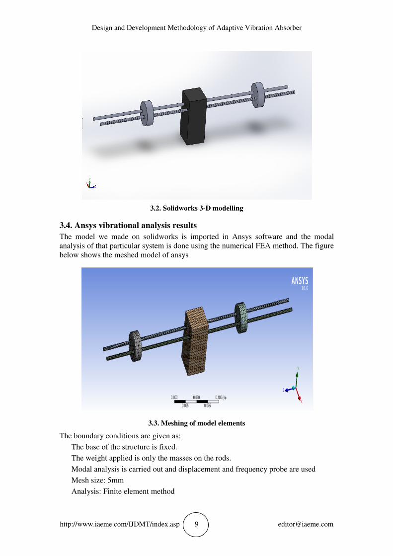
3.2. Solidworks 3-D modelling
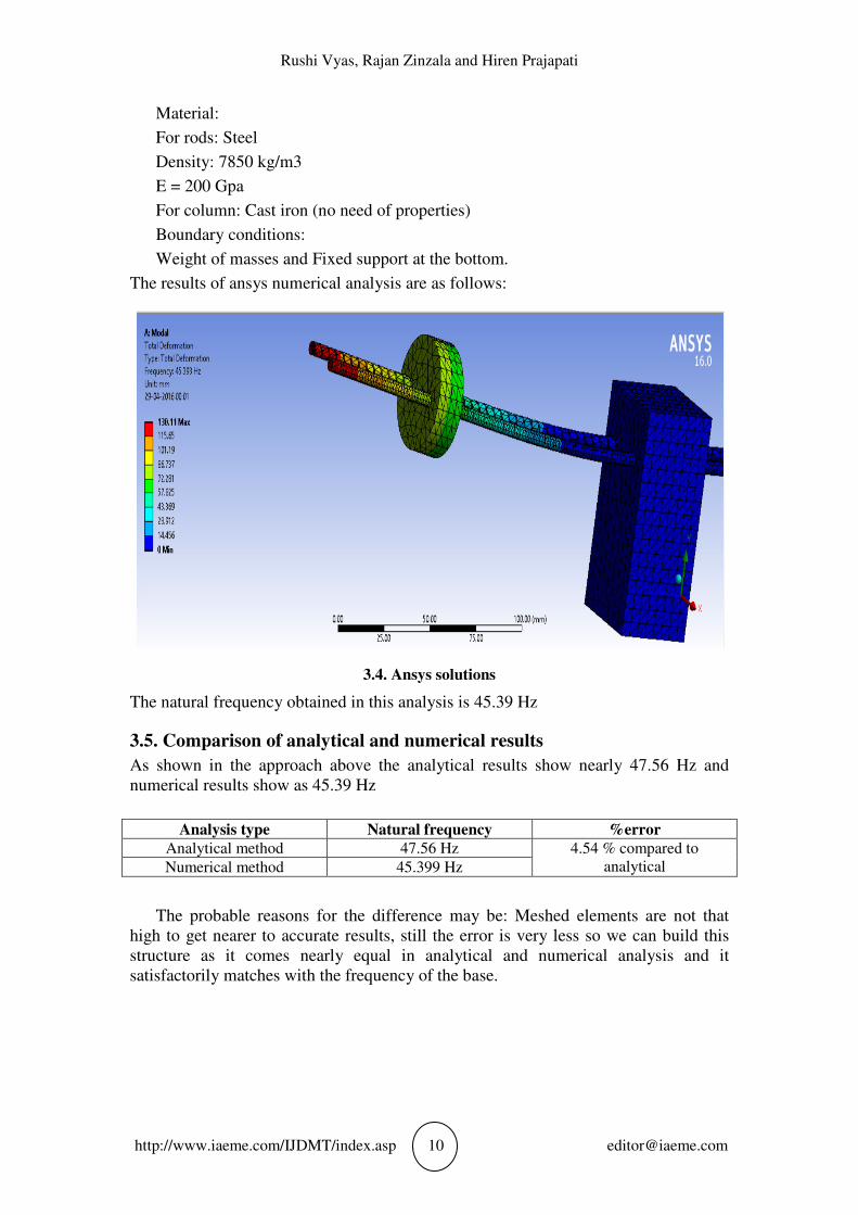
3.4. Ansys vibrational analysis results
The model we made on solidworks is imported in Ansys software and the modal
analysis of that particular system is done using the numerical FEA method. The figure
below shows the meshed model of ansys
3.3. Meshing of model elements
The boundary conditions are given as:
The base of the structure is fixed.
The weight applied is only the masses on the rods.
Modal analysis is carried out and displacement and frequency probe are used
Mesh size: 5mm
Analysis: Finite element method
Rushi Vyas, Rajan Zinzala and Hiren Prajapati
http://www.iaeme.com/IJDMT/index.asp 10 [email protected]
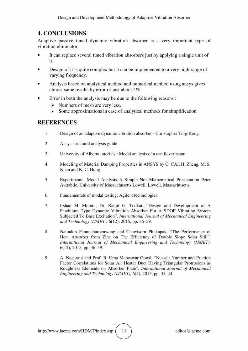
Material:
For rods: Steel
Density: 7850 kg/m3
E = 200 Gpa
For column: Cast iron (no need of properties)
Boundary conditions:
Weight of masses and Fixed support at the bottom.
The results of ansys numerical analysis are as follows:
3.4. Ansys solutions
The natural frequency obtained in this analysis is 45.39 Hz
3.5. Comparison of analytical and numerical results
As shown in the approach above the analytical results show nearly 47.56 Hz and
numerical results show as 45.39 Hz
Analysis type Natural frequency %error
Analytical method 47.56 Hz 4.54 % compared to
analytical Numerical method 45.399 Hz
The probable reasons for the difference may be: Meshed elements are not that
high to get nearer to accurate results, still the error is very less so we can build this
structure as it comes nearly equal in analytical and numerical analysis and it
satisfactorily matches with the frequency of the base.
Design and Development Methodology of Adaptive Vibration Absorber
http://www.iaeme.com/IJDMT/index.asp 11 [email protected]
4. CONCLUSIONS
Adaptive passive tuned dynamic vibration absorber is a very important type of
vibration eliminator.
• It can replace several tuned vibration absorbers just by applying a single unit of
it.
• Design of it is quite complex but it can be implemented to a very high range of
varying frequency.
• Analysis based on analytical method and numerical method using ansys gives
almost same results by error of just about 4%
• Error in both the analysis may be due to the following reasons :
� Numbers of mesh are very less.
� Some approximations in case of analytical methods for simplification
REFERENCES
1. Design of an adaptive dynamic vibration absorber - Christopher Ting-Kong
2. Ansys structural analysis guide
3. University of Alberta tutorials : Modal analysis of a cantilever beam
4. Modeling of Material Damping Properties in ANSYS by C. CAI, H. Zheng, M. S.
Khan and K. C. Hung
5. Experimental Modal Analysis A Simple Non-Mathematical Presentation Peter
Avitabile, University of Massachusetts Lowell, Lowell, Massachusetts
6. Fundamentals of modal testing: Agilent technologies
7. Irshad M. Momin, Dr. Ranjit G. Todkar, “Design and Development of A
Pendulum Type Dynamic Vibration Absorber For A SDOF Vibrating System
Subjected To Base Excitation”. International Journal of Mechanical Engineering
and Technology (IJMET), 6(12), 2015, pp. 36–59.
8. Nattadon Pannucharoenwong and Chawisorn Phukapak, “The Performance of
Heat Absorber from Zinc on The Efficiency of Double Slope Solar Still”.
International Journal of Mechanical Engineering and Technology (IJMET),
6(12), 2015, pp. 36–59.
9. A. Nagaraju and Prof. B. Uma Maheswar Gowd, “Nusselt Number and Friction
Factor Correlations for Solar Air Heater Duct Having Triangular Protrusions as
Roughness Elements on Absorber Plate”. International Journal of Mechanical
Engineering and Technology (IJMET), 6(4), 2015, pp. 35–44.
Related Documents