Civil Engineering Design (1) Dr. C. Caprani 1 Civil Engineering Design (1) Analysis and Design of Slabs 2006/7 Dr. Colin Caprani, Chartered Engineer

Welcome message from author
This document is posted to help you gain knowledge. Please leave a comment to let me know what you think about it! Share it to your friends and learn new things together.
Transcript
Civil Engineering Design (1)
Dr. C. Caprani 1
Civil Engineering Design (1) Analysis and Design of Slabs
2006/7
Dr. Colin Caprani, Chartered Engineer
Civil Engineering Design (1)
Dr. C. Caprani 2
Contents 1. Elastic Methods.................................................................................................... 3
1.1 Introduction...................................................................................................... 3
1.2 Grillage Analysis ............................................................................................. 4
1.3 Finite Element Analysis................................................................................... 6
2. Yield Line Theory................................................................................................ 9
2.1 Introduction...................................................................................................... 9
2.2 Example 1: Ultimate Behavior of One-Way Spanning Slab......................... 11
2.3 Yield Line Basis ............................................................................................ 18
2.4 Example 2 – Yield Lines not Parallel to Axes .............................................. 26
2.5 Example – Simply-supported Rectangular 2-way Slab................................. 28
2.6 Example – General Solution of Continuous Rectangular 2-way Slab .......... 31
2.7 Example ......................................................................................................... 35
2.8 Exam Question 2006 – Q6(b)........................................................................ 37
3. Lower Bound Methods...................................................................................... 39
Civil Engineering Design (1)
Dr. C. Caprani 3
1. Elastic Methods
1.1 Introduction
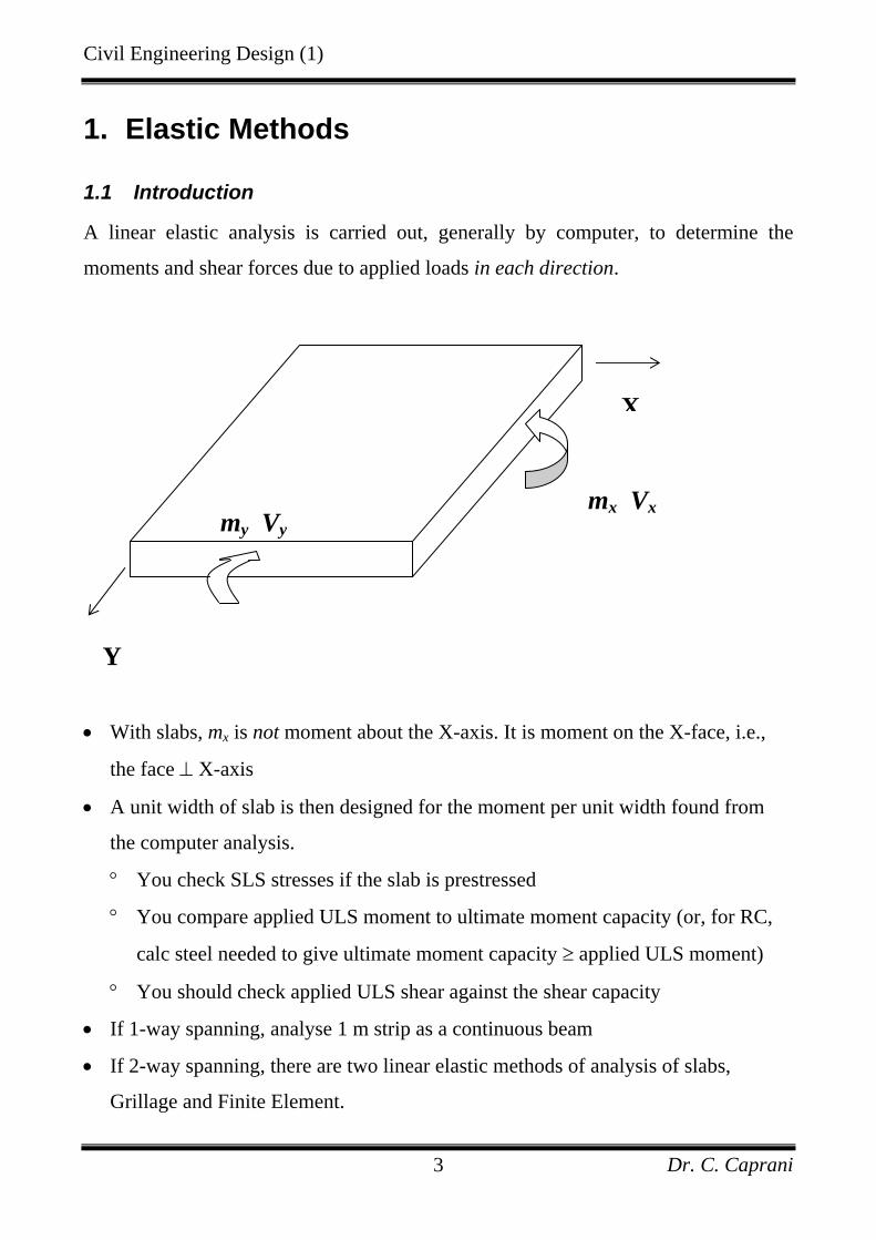
A linear elastic analysis is carried out, generally by computer, to determine the
moments and shear forces due to applied loads in each direction.
• With slabs, mx is not moment about the X-axis. It is moment on the X-face, i.e.,
the face ⊥ X-axis
• A unit width of slab is then designed for the moment per unit width found from
the computer analysis.
° You check SLS stresses if the slab is prestressed
° You compare applied ULS moment to ultimate moment capacity (or, for RC,
calc steel needed to give ultimate moment capacity ≥ applied ULS moment)
° You should check applied ULS shear against the shear capacity
• If 1-way spanning, analyse 1 m strip as a continuous beam
• If 2-way spanning, there are two linear elastic methods of analysis of slabs,
Grillage and Finite Element.
Y
my Vy
X
mx Vx
Civil Engineering Design (1)
Dr. C. Caprani 4
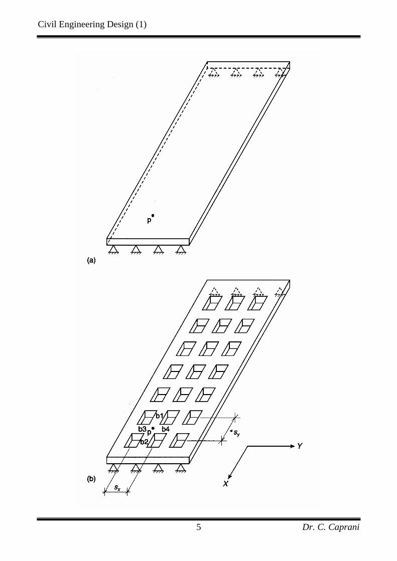
1.2 Grillage Analysis
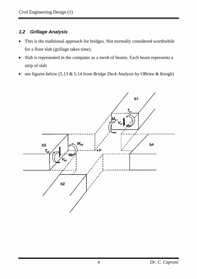
• This is the traditional approach for bridges. Not normally considered worthwhile
for a floor slab (grillage takes time).
• Slab is represented in the computer as a mesh of beams. Each beam represents a
strip of slab
• see figures below (5.13 & 5.14 from Bridge Deck Analysis by OBrien & Keogh)
Civil Engineering Design (1)
Dr. C. Caprani 5
Civil Engineering Design (1)
Dr. C. Caprani 6
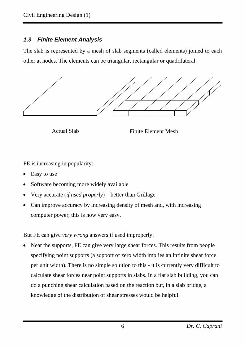
1.3 Finite Element Analysis
The slab is represented by a mesh of slab segments (called elements) joined to each
other at nodes. The elements can be triangular, rectangular or quadrilateral.
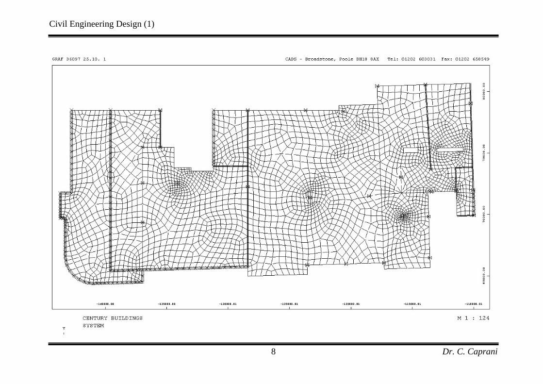
FE is increasing in popularity:
• Easy to use
• Software becoming more widely available
• Very accurate (if used properly) – better than Grillage
• Can improve accuracy by increasing density of mesh and, with increasing
computer power, this is now very easy.
But FE can give very wrong answers if used improperly:
• Near the supports, FE can give very large shear forces. This results from people
specifying point supports (a support of zero width implies an infinite shear force
per unit width). There is no simple solution to this - it is currently very difficult to
calculate shear forces near point supports in slabs. In a flat slab building, you can
do a punching shear calculation based on the reaction but, in a slab bridge, a
knowledge of the distribution of shear stresses would be helpful.
Actual Slab Finite Element Mesh
Civil Engineering Design (1)
Dr. C. Caprani 7
• Compatibility between elements can only be guaranteed at the nodes (where it is
made to happen). Therefore, avoid 'T-junctions' unless the elements have mid-side
nodes.
• Avoid long narrow elements - can lead to round-off errors in some software.
Some benefits of FE analysis of slabs are:
Transfer slabs can be used instead of beam-and-slab construction:
- This saves on formwork over beams;
- Easier to achieve repetition which means a shorter learning curve on site.
Civil Engineering Design (1)
Dr. C. Caprani 8
Civil Engineering Design (1)
Dr. C. Caprani 9
2. Yield Line Theory
2.1 Introduction
Yield line analysis is an analysis approach for determining the ultimate load capacity
of reinforced concrete slabs and was pioneered by K.W. Johansen in the 1940s. It is
closely related to the plastic collapse or limit analysis of steel frames, and is an Upper
Bound or Mechanism approach.
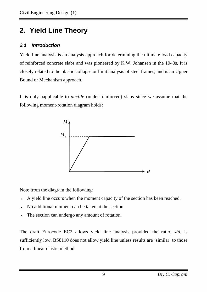
It is only aapplicable to ductile (under-reinforced) slabs since we assume that the
following moment-rotation diagram holds:
Note from the diagram the following:
• A yield line occurs when the moment capacity of the section has been reached.
• No additional moment can be taken at the section.
• The section can undergo any amount of rotation.
The draft Eurocode EC2 allows yield line analysis provided the ratio, x/d, is
sufficiently low. BS8110 does not allow yield line unless results are ‘similar’ to those
from a linear elastic method.
M
yM
θ
Civil Engineering Design (1)
Dr. C. Caprani 10
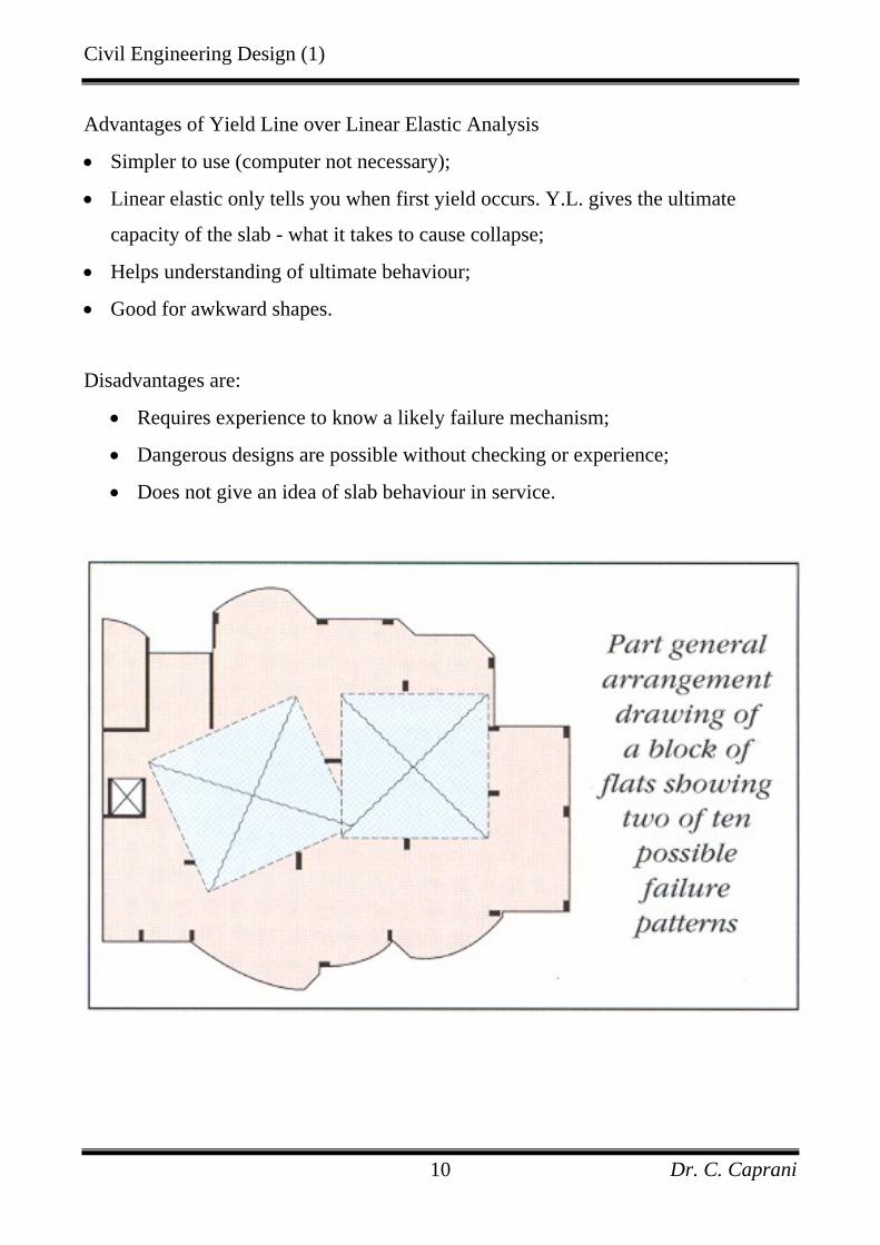
Advantages of Yield Line over Linear Elastic Analysis
• Simpler to use (computer not necessary);
• Linear elastic only tells you when first yield occurs. Y.L. gives the ultimate
capacity of the slab - what it takes to cause collapse;
• Helps understanding of ultimate behaviour;
• Good for awkward shapes.
Disadvantages are:
• Requires experience to know a likely failure mechanism;
• Dangerous designs are possible without checking or experience;
• Does not give an idea of slab behaviour in service.
Civil Engineering Design (1)
Dr. C. Caprani 11
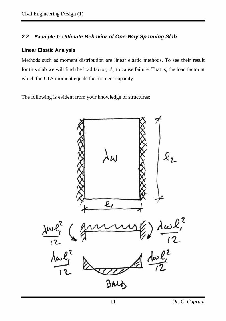
2.2 Example 1: Ultimate Behavior of One-Way Spanning Slab
Linear Elastic Analysis
Methods such as moment distribution are linear elastic methods. To see their result
for this slab we will find the load factor, λ , to cause failure. That is, the load factor at
which the ULS moment equals the moment capacity.
The following is evident from your knowledge of structures:
Civil Engineering Design (1)
Dr. C. Caprani 12
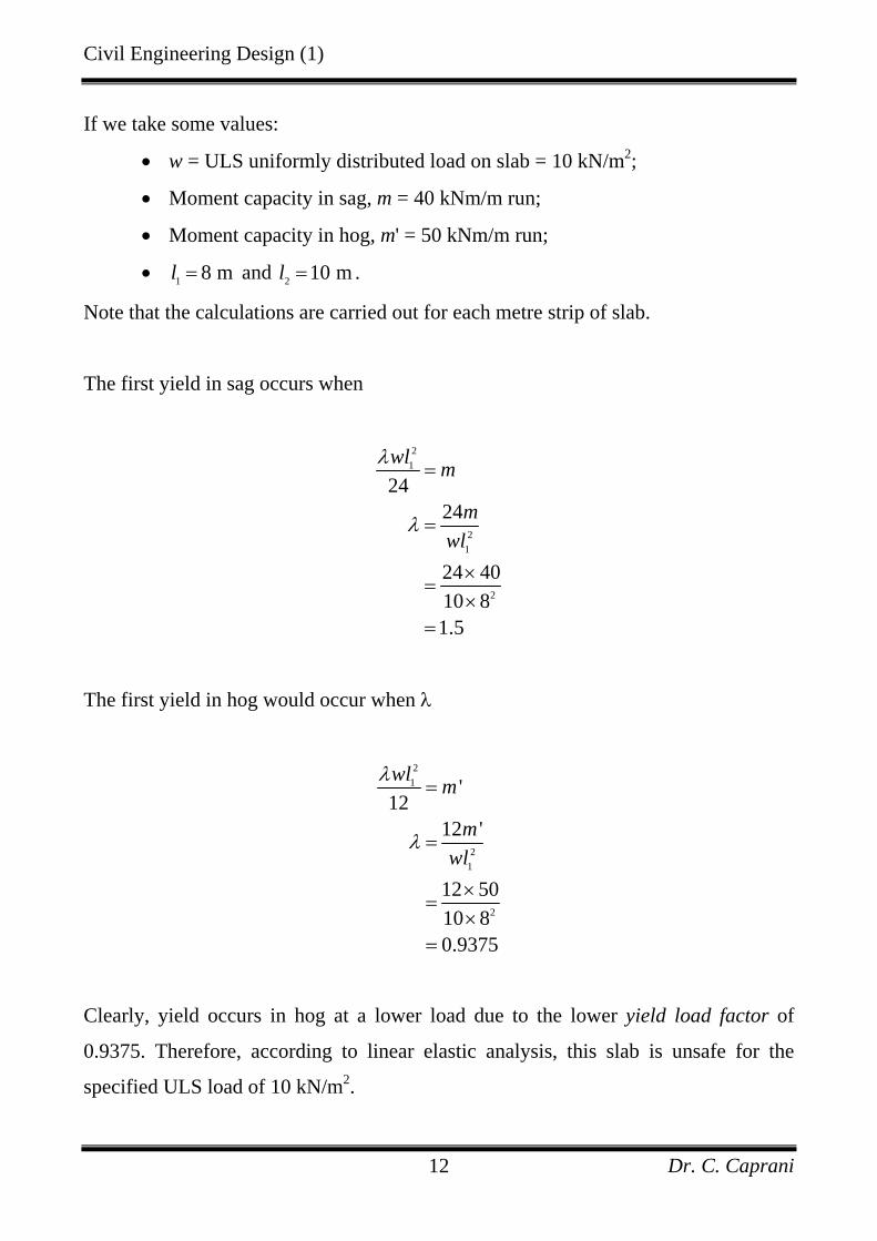
If we take some values:
• w = ULS uniformly distributed load on slab = 10 kN/m2;
• Moment capacity in sag, m = 40 kNm/m run;
• Moment capacity in hog, m' = 50 kNm/m run;
• 1 8 ml = and 2 10 ml = .
Note that the calculations are carried out for each metre strip of slab.
The first yield in sag occurs when
21
21
2
2424
24 4010 81.5
wl m
mwl
λ
λ
=
=
×=
×=
The first yield in hog would occur when λ
2
1
21
2
'12
12 '
12 5010 80.9375
wl m
mwl
λ
λ
=
=
×=
×=
Clearly, yield occurs in hog at a lower load due to the lower yield load factor of
0.9375. Therefore, according to linear elastic analysis, this slab is unsafe for the
specified ULS load of 10 kN/m2.
Civil Engineering Design (1)
Dr. C. Caprani 13
Elastic Plastic Analysis
Again we are to find the load factor, λ , to cause collapse. The steps are:
Step 1
Do a linear elastic analysis to find the point at which yield first begins. From before,
we know that the first yield occurs in hog when 0.9375yλ λ= = .
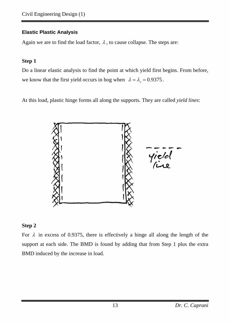
At this load, plastic hinge forms all along the supports. They are called yield lines:
Step 2
For λ in excess of 0.9375, there is effectively a hinge all along the length of the
support at each side. The BMD is found by adding that from Step 1 plus the extra
BMD induced by the increase in load.

Civil Engineering Design (1)
Dr. C. Caprani 14
So as the load increase past yλ , the bending moment diagram moves downwards:

Civil Engineering Design (1)
Dr. C. Caprani 15
The next yield occurs when the moment at the centre reaches m:
( ) 2211
21
21
2
2
24 88
12
8 0.9375 10 84010 8 121.125
yy
y
wlwlm
wlm
wl
λ λλ
λλ
−+ =
⎛ ⎞= +⎜ ⎟
⎝ ⎠× ×⎛ ⎞
= +⎜ ⎟× ⎝ ⎠=
This is the collapse load factor, cλ .
Civil Engineering Design (1)
Dr. C. Caprani 16
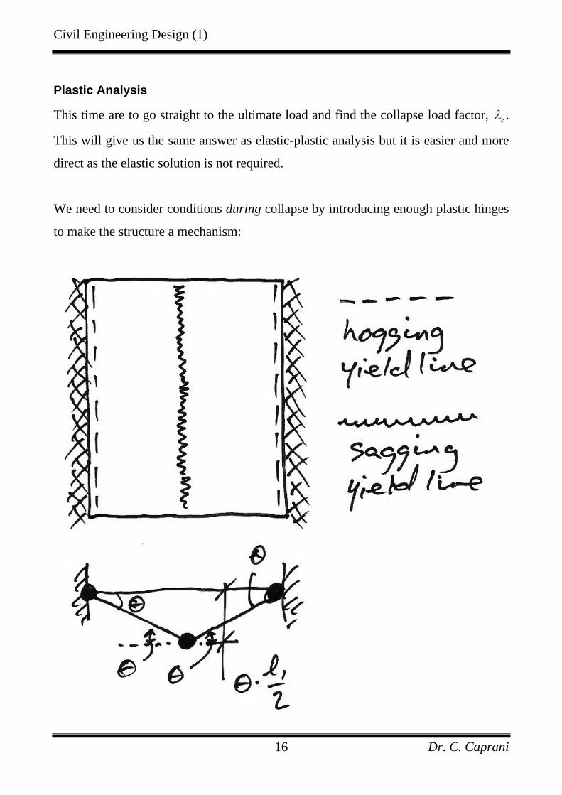
Plastic Analysis
This time are to go straight to the ultimate load and find the collapse load factor, cλ .
This will give us the same answer as elastic-plastic analysis but it is easier and more
direct as the elastic solution is not required.
We need to consider conditions during collapse by introducing enough plastic hinges
to make the structure a mechanism:
Civil Engineering Design (1)
Dr. C. Caprani 17
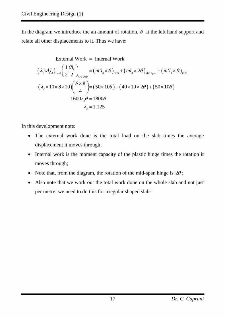
In the diagram we introduce the an amount of rotation, θ at the left hand support and
relate all other displacements to it. Thus we have:
( ) ( ) ( ) ( )
( ) ( ) ( ) ( )
11 2 2 2 2Load LHS Mid Span RHS
Ave Disp
External Work Internal Work1 ' 2 '2 2
810 8 10 50 10 40 10 2 50 104
1600 18001.125
c
c
c
c
lwl l m l ml m lθλ θ θ θ
θλ θ θ θ
λθ θλ
=
⎛ ⎞ = × + × + ×⎜ ⎟⎝ ⎠
×⎛ ⎞× × × = × + × × + ×⎜ ⎟⎝ ⎠
==
In this development note:
• The external work done is the total load on the slab times the average
displacement it moves through;
• Internal work is the moment capacity of the plastic hinge times the rotation it
moves through;
• Note that, from the diagram, the rotation of the mid-span hinge is 2θ ;
• Also note that we work out the total work done on the whole slab and not just
per metre: we need to do this for irregular shaped slabs.
Civil Engineering Design (1)
Dr. C. Caprani 18
2.3 Yield Line Basis
Procedure
Yield line analysis proceeds as:
1. Assume a collapse mechanism by choosing a pattern of yield lines;
2. Calculate the load factor corresponding to that yield line pattern;
3. Repeat for a range of yield line patterns;
4. Actual failure occurs at the lowest collapse load factor.
Note that it requires the slab to have the moment-rotation relationship previously
given: it must be ductile.
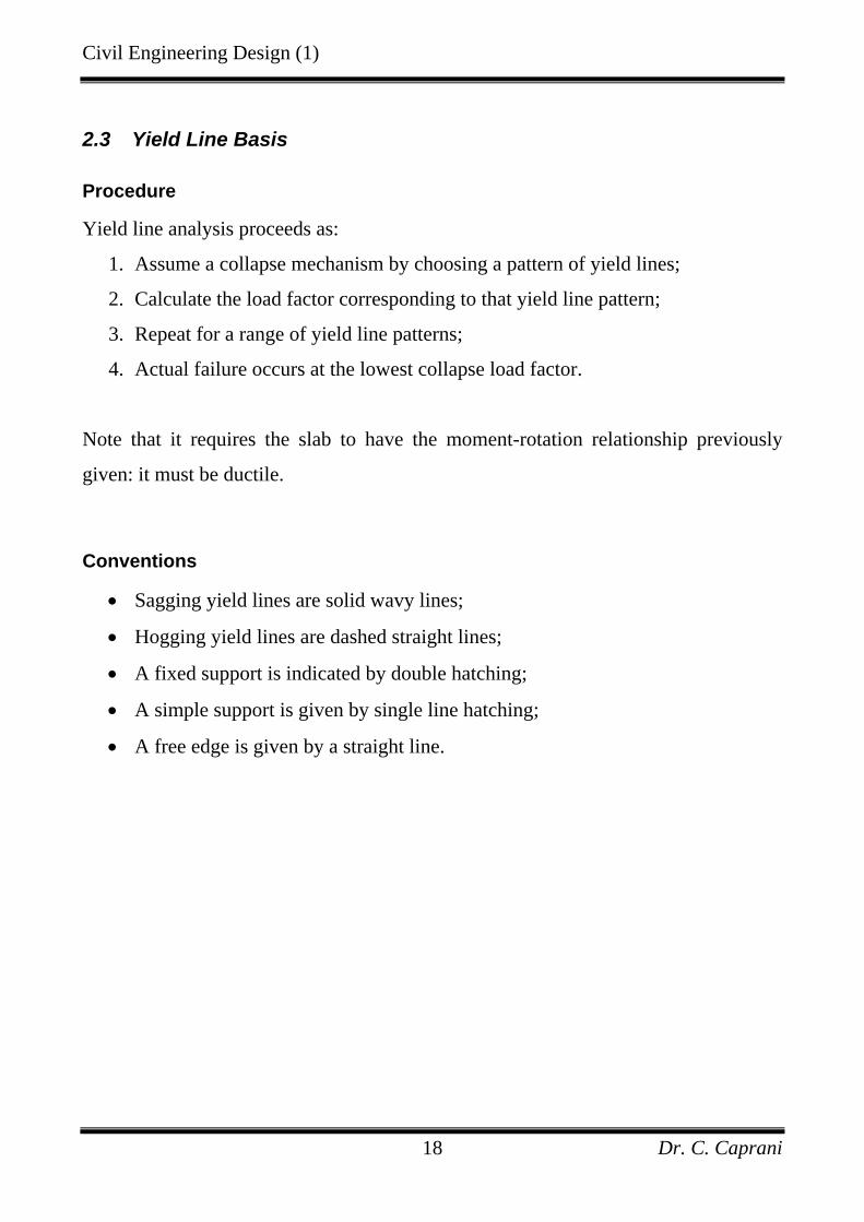
Conventions
• Sagging yield lines are solid wavy lines;
• Hogging yield lines are dashed straight lines;
• A fixed support is indicated by double hatching;
• A simple support is given by single line hatching;
• A free edge is given by a straight line.
Civil Engineering Design (1)
Dr. C. Caprani 19
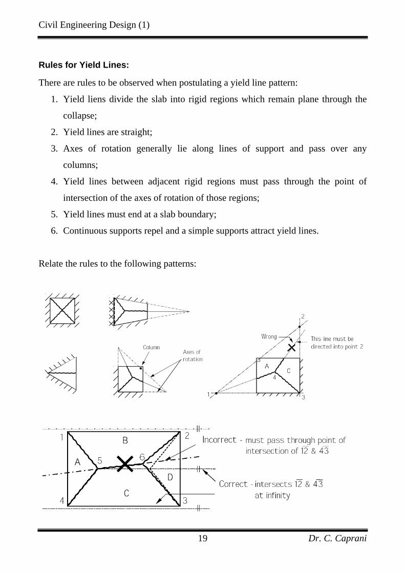
Rules for Yield Lines:
There are rules to be observed when postulating a yield line pattern:
1. Yield liens divide the slab into rigid regions which remain plane through the
collapse;
2. Yield lines are straight;
3. Axes of rotation generally lie along lines of support and pass over any
columns;
4. Yield lines between adjacent rigid regions must pass through the point of
intersection of the axes of rotation of those regions;
5. Yield lines must end at a slab boundary;
6. Continuous supports repel and a simple supports attract yield lines.
Relate the rules to the following patterns:
Civil Engineering Design (1)
Dr. C. Caprani 20
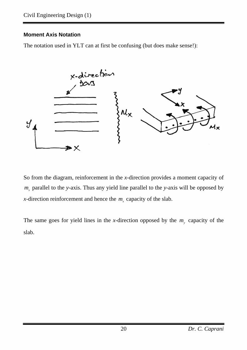
Moment Axis Notation
The notation used in YLT can at first be confusing (but does make sense!):
So from the diagram, reinforcement in the x-direction provides a moment capacity of
xm parallel to the y-axis. Thus any yield line parallel to the y-axis will be opposed by
x-direction reinforcement and hence the xm capacity of the slab.
The same goes for yield lines in the x-direction opposed by the ym capacity of the
slab.
Civil Engineering Design (1)
Dr. C. Caprani 21
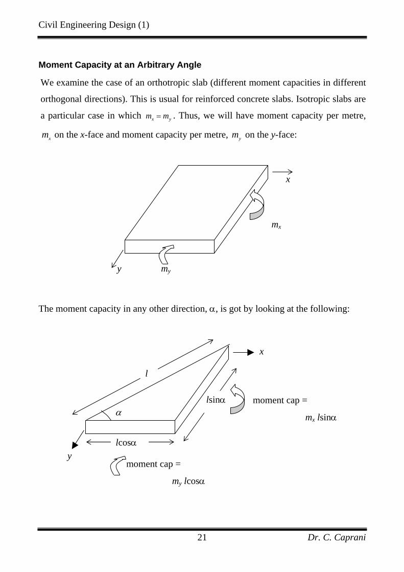
Moment Capacity at an Arbitrary Angle
We examine the case of an orthotropic slab (different moment capacities in different
orthogonal directions). This is usual for reinforced concrete slabs. Isotropic slabs are
a particular case in which x ym m= . Thus, we will have moment capacity per metre,
xm on the x-face and moment capacity per metre, ym on the y-face:
The moment capacity in any other direction, α, is got by looking at the following:
my
mx
y
x
l
α lsinα
x
moment cap =
mx lsinα
y lcosα
moment cap =
my lcosα
Civil Engineering Design (1)
Dr. C. Caprani 22
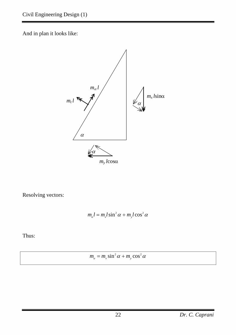
And in plan it looks like:
Resolving vectors:
2 2sin cosx ym l m l m lα α α= +
Thus:
2 2sin cosx ym m mα α α= +
mt l
mα l
α
α
α
mx lsinα
my lcosα
Civil Engineering Design (1)
Dr. C. Caprani 23
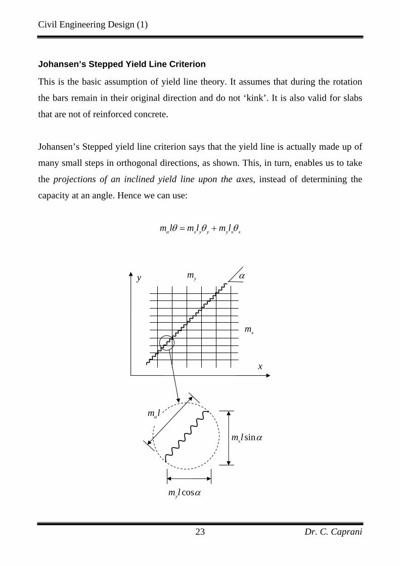
Johansen’s Stepped Yield Line Criterion
This is the basic assumption of yield line theory. It assumes that during the rotation
the bars remain in their original direction and do not ‘kink’. It is also valid for slabs
that are not of reinforced concrete.
Johansen’s Stepped yield line criterion says that the yield line is actually made up of
many small steps in orthogonal directions, as shown. This, in turn, enables us to take
the projections of an inclined yield line upon the axes, instead of determining the
capacity at an angle. Hence we can use:
x y y y x xm l m l m lα θ θ θ= +
y
x
ym
xm
α
sinxm l α
m lα
cosym l α
Civil Engineering Design (1)
Dr. C. Caprani 24
Internal Work Done
For an orthotropic slab, there are two ways of calculating internal work done:
1. Take a section perpendicular to the yield line and find its rotation. Then let
internal work done be the moment capacity at that angle times the length of the
yield line and the rotation.
2. Use Johansen’s approach in which the projections of the yield lines onto the axes
of rotations is used.
The latter method is generally easier to apply.
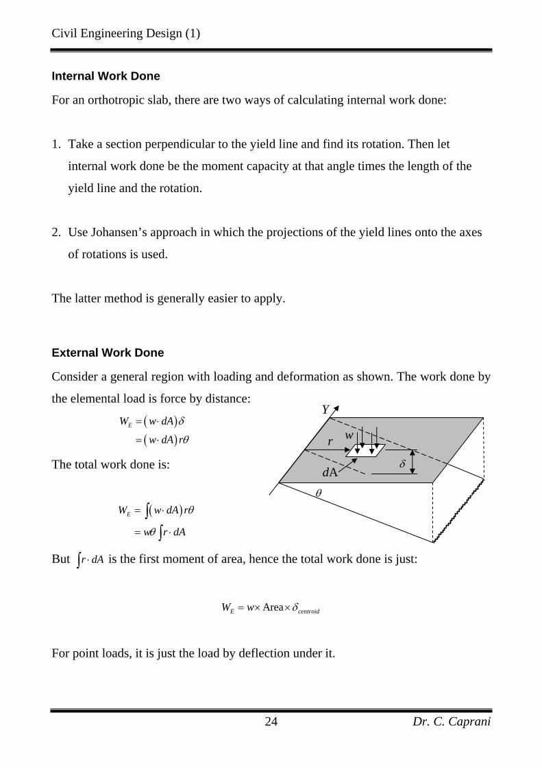
External Work Done
Consider a general region with loading and deformation as shown. The work done by
the elemental load is force by distance:
( )( )
EW w dA
w dA r
δ
θ
= ⋅
= ⋅
The total work done is:
( )EW w dA r
w r dA
θ
θ
= ⋅
= ⋅
∫∫
But r dA⋅∫ is the first moment of area, hence the total work done is just:
AreaE centroidW w δ= × ×
For point loads, it is just the load by deflection under it.
θ
r
dA
w
δ
Y
Civil Engineering Design (1)
Dr. C. Caprani 25
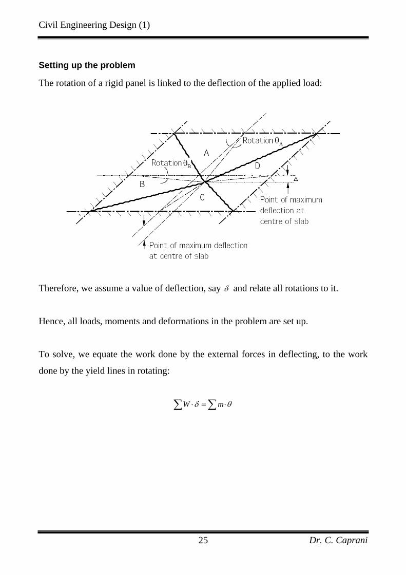
Setting up the problem
The rotation of a rigid panel is linked to the deflection of the applied load:
Therefore, we assume a value of deflection, say δ and relate all rotations to it.
Hence, all loads, moments and deformations in the problem are set up.
To solve, we equate the work done by the external forces in deflecting, to the work
done by the yield lines in rotating:
W mδ θ⋅ = ⋅∑ ∑
Civil Engineering Design (1)
Dr. C. Caprani 26
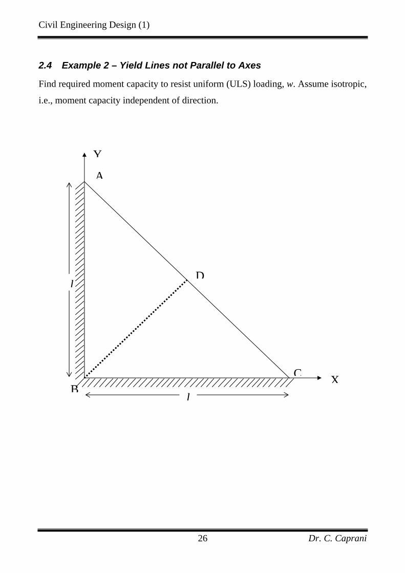
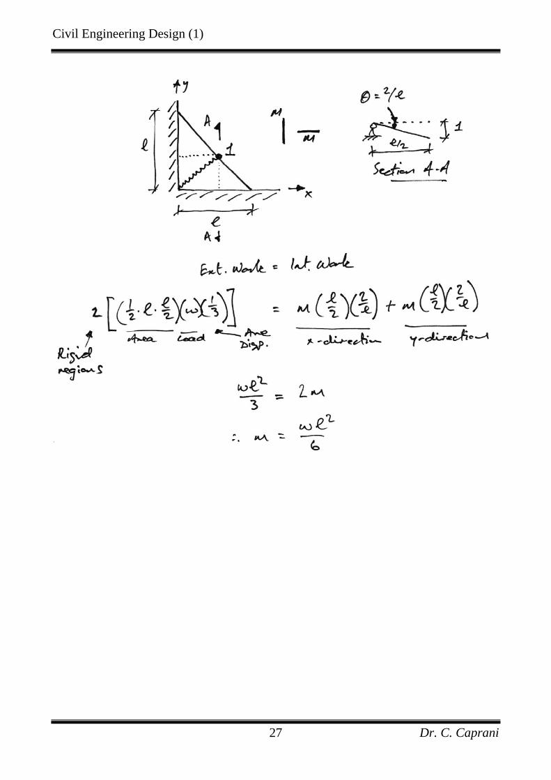
2.4 Example 2 – Yield Lines not Parallel to Axes
Find required moment capacity to resist uniform (ULS) loading, w. Assume isotropic,
i.e., moment capacity independent of direction.
CB
A
D
Y
l
l
X
Civil Engineering Design (1)
Dr. C. Caprani 27
Civil Engineering Design (1)
Dr. C. Caprani 28
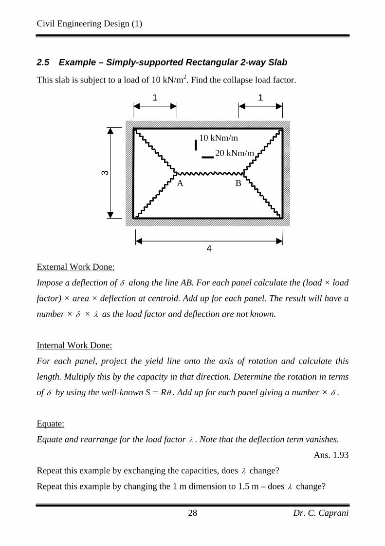
2.5 Example – Simply-supported Rectangular 2-way Slab
This slab is subject to a load of 10 kN/m2. Find the collapse load factor.
External Work Done:
Impose a deflection of δ along the line AB. For each panel calculate the (load × load
factor) × area × deflection at centroid. Add up for each panel. The result will have a
number × δ × λ as the load factor and deflection are not known.
Internal Work Done:
For each panel, project the yield line onto the axis of rotation and calculate this
length. Multiply this by the capacity in that direction. Determine the rotation in terms
of δ by using the well-known S = Rθ . Add up for each panel giving a number × δ .
Equate:
Equate and rearrange for the load factor λ . Note that the deflection term vanishes.
Ans. 1.93
Repeat this example by exchanging the capacities, does λ change?
Repeat this example by changing the 1 m dimension to 1.5 m – does λ change?
3
4
1 1
10 kNm/m
20 kNm/m
A B
Civil Engineering Design (1)
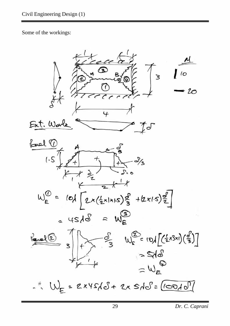
Dr. C. Caprani 29
Some of the workings:
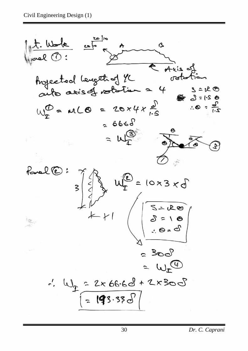
Civil Engineering Design (1)
Dr. C. Caprani 30
Civil Engineering Design (1)
Dr. C. Caprani 31
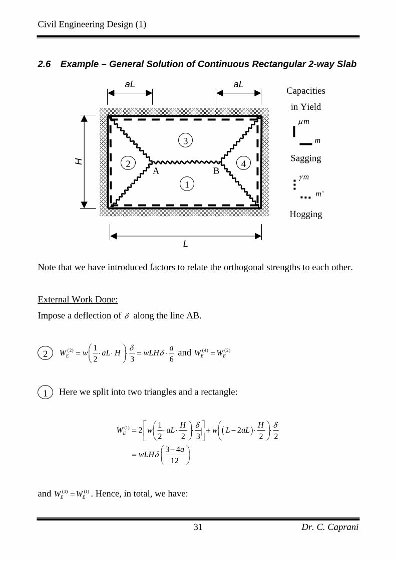
2.6 Example – General Solution of Continuous Rectangular 2-way Slab
Note that we have introduced factors to relate the orthogonal strengths to each other.
External Work Done:
Impose a deflection of δ along the line AB.
(2) 12 3 6E
aW w aL H wLHδ δ⎛ ⎞= ⋅ ⋅ ⋅ = ⋅⎜ ⎟⎝ ⎠
and (4) (2)E EW W=
Here we split into two triangles and a rectangle:
( )(1) 12 22 2 3 2 2
3 412
EH HW w aL w L aL
awLH
δ δ
δ
⎡ ⎤⎛ ⎞ ⎛ ⎞= ⋅ ⋅ ⋅ + − ⋅ ⋅⎜ ⎟ ⎜ ⎟⎢ ⎥⎝ ⎠ ⎝ ⎠⎣ ⎦−⎛ ⎞= ⎜ ⎟
⎝ ⎠
and (3) (1)E EW W= . Hence, in total, we have:
H
L
aL aL
mµ
m
Sagging
mγ
'm
Hogging
A B1
2
3
4
Capacities
in Yield
2
1

Civil Engineering Design (1)
Dr. C. Caprani 32
(1) (2) (3) (4)
3 42 26 12
3 26
E E E E EW W W W W
a awLH
awLH
δ
δ
= + + +
⎡ ⎤−⎛ ⎞= ⋅ + ⋅⎜ ⎟⎢ ⎥⎝ ⎠⎣ ⎦−⎛ ⎞= ⎜ ⎟
⎝ ⎠
Internal Work Done:
Sagging Yield Lines:
The projection of the YL onto the axis of rotation gives us a length of L. Hence
the work done is:
(1)
0.5IW m LH
δ= ⋅ ⋅ and (3) (1)
I IW W= .
This time we have a length of H. Hence the work done is:
(2)IW m H
aLδµ= ⋅ ⋅ and (4) (2)
I IW W= .
Thus the total sagging work done is:
2 20.5
2 2
IW m L m HH aL
L HmH a L
δ δµ
µ δ
⎡ ⎤ ⎡ ⎤= ⋅ ⋅ + ⋅ ⋅⎢ ⎥ ⎢ ⎥⎣ ⎦ ⎣ ⎦⎡ ⎤= +⎢ ⎥⎣ ⎦
Hogging Yield Lines:
There is no projection needed in these cases and so the problem is simpler:
1
2
Civil Engineering Design (1)
Dr. C. Caprani 33
(1) (2) (3) (4)
2 ' '0.5
2 ' 2
I I I I IW W W W W
m L m HH aL
L HmH a L
δ δγ
γ δ
= + + +
⎡ ⎤= +⎢ ⎥⎣ ⎦⎡ ⎤= +⎢ ⎥⎣ ⎦
Total internal work done is thus:
2 2 2 ' 2IL H L HW m mH a L H a L
µ γδ δ⎡ ⎤ ⎡ ⎤= + + +⎢ ⎥ ⎢ ⎥⎣ ⎦ ⎣ ⎦
Equate:
3 2 2 2 2 ' 26
a L H L HwLH m mH a L H a L
µ γδ δ δ−⎛ ⎞ ⎛ ⎞ ⎛ ⎞= + + +⎜ ⎟ ⎜ ⎟ ⎜ ⎟⎝ ⎠ ⎝ ⎠ ⎝ ⎠
Divide both sides by 2δ , and multiply by HL
, and extract m to get:
( )2 2 2
2 2
'3 2 2 212
wH H m Ha ma L m a Lµ γ⎡ ⎤⎛ ⎞ ⎛ ⎞
− = + + +⎢ ⎥⎜ ⎟ ⎜ ⎟⎝ ⎠ ⎝ ⎠⎣ ⎦
Introduce 'mmm
= , 2
2
HnL
= and divide across and multiply top and bottom by a:
( )( ) ( )
22 3 2
12 2 2
a awHma n m a nµ γ
−= ⋅
+ + +
The maximum value of m with respect to a changing a occurs at:
Civil Engineering Design (1)
Dr. C. Caprani 34
( ) ( ) ( ) ( )( )22 1 3 4 3 2 2 2 0dm m n a m a a a mda
µ γ⎡ ⎤= + + + − − − + =⎣ ⎦
This is a quadratic in a – solve to get:
( ) ( ) ( )( ) ( )2 13 1
2 1na m n m m m
mµ γ µ γ µ γ−⎡ ⎤= + + + + − +⎢ ⎥⎣ ⎦+
It is for this value of a that the slab will fail, given the dimensional and strength data.
This example shows that although a multitude of yield line patterns are possible,
given one particular mode, the critical dimension can be obtained.
Exercise:
Derive the general solution for the simply supported case. This is a subset of the
calculations presented here. Use this to verify the results of the first example.
Civil Engineering Design (1)
Dr. C. Caprani 35
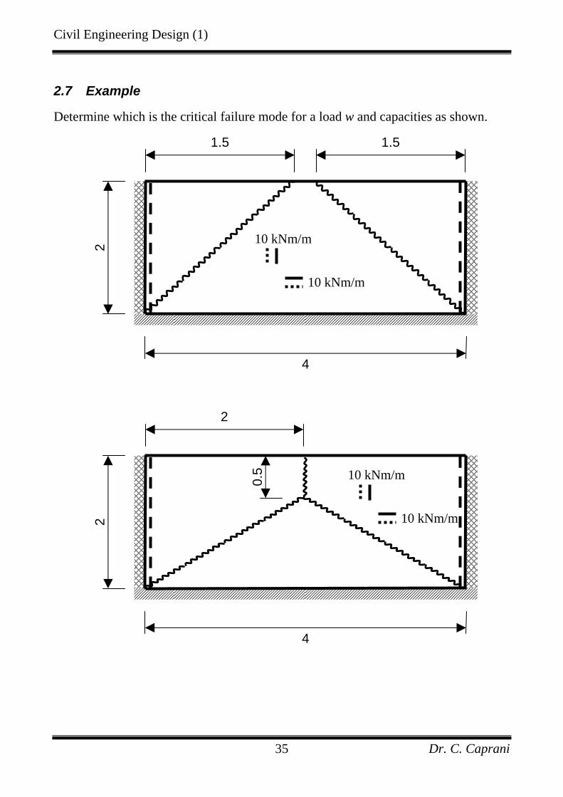
2.7 Example
Determine which is the critical failure mode for a load w and capacities as shown.
2
4
2
10 kNm/m
10 kNm/m
0.5
2
4
1.5 1.5
10 kNm/m
10 kNm/m

Civil Engineering Design (1)
Dr. C. Caprani 36
Long Exercise (on the basis of Tb. 9 of IS 325):
Using the calculations for this exercise as a basis, derive the general solutions for
both failure modes. Reduce to the case when 'm m= and γ µ= . Derive a table for each
mode for various values of µ and HL
. Combine the tables showing the critical mode.
Civil Engineering Design (1)
Dr. C. Caprani 37
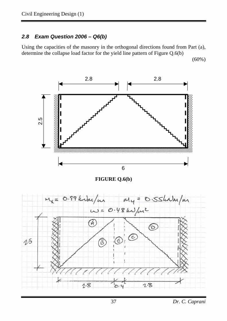
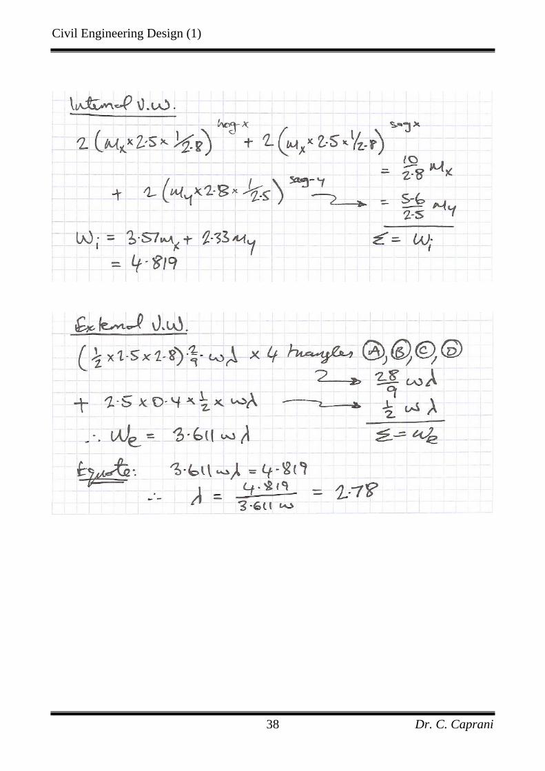
2.8 Exam Question 2006 – Q6(b)
Using the capacities of the masonry in the orthogonal directions found from Part (a), determine the collapse load factor for the yield line pattern of Figure Q.6(b)
(60%)
FIGURE Q.6(b)
2.5
6
2.8 2.8
Civil Engineering Design (1)
Dr. C. Caprani 38
Civil Engineering Design (1)
Dr. C. Caprani 39
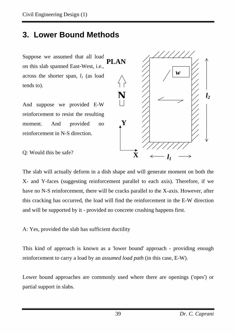
3. Lower Bound Methods
Suppose we assumed that all load
on this slab spanned East-West, i.e.,
across the shorter span, l1 (as load
tends to).
And suppose we provided E-W
reinforcement to resist the resulting
moment. And provided no
reinforcement in N-S direction.
Q: Would this be safe?
The slab will actually deform in a dish shape and will generate moment on both the
X- and Y-faces (suggesting reinforcement parallel to each axis). Therefore, if we
have no N-S reinforcement, there will be cracks parallel to the X-axis. However, after
this cracking has occurred, the load will find the reinforcement in the E-W direction
and will be supported by it - provided no concrete crushing happens first.
A: Yes, provided the slab has sufficient ductility
This kind of approach is known as a 'lower bound' approach - providing enough
reinforcement to carry a load by an assumed load path (in this case, E-W).
Lower bound approaches are commonly used where there are openings ('opes') or
partial support in slabs.
l1
PLAN
N
Y
X
l2
w

Civil Engineering Design (1)
Dr. C. Caprani 40
Eg (partially supported):
Panel B is designed as a 1-way slab spanning NS to the supports. The reaction from
Panel A is applied as a load to Panel B. To take this load, we need a strong band of
reinforcement in Panel B.
Lower bound approaches are widely used in practice.
• They are safe at ULS if the slab is sufficiently ductile
• They do not guarantee a satisfactory design at SLS - cracking may occur (as in the
first eg) if the load path is not reasonable.
• A special case of the Lower Bound approach is the well known 'Hillerborg Strip'
method - more of this in the optional Structural Design course.
Load on Panel A spans E-
W onto Panel B. This in
turn spans N-S onto the
supports.
Panel A is designed as a
PLAN
w
Panel A
Panel B
Related Documents