Design and Analysis of Flapping Wing Unmanned Aerial Vehicle R. Jagadeesh Department of Aeronautical Engineering KCG College of Technology Chennai, India S. Madhu Mathi Department of Aeronautical Engineering KCG College of Technology Chennai, India Dr. K. Vijayaraja Department of Aeronautical Engineering KCG College of Technology Chennai, India Abstract— This project presents the design of a Flapping wing UAV which is inspired by various bird mechanism and its action during flight. In this project, the real actions have been tried to convert into a perfect mechanism in order to get a stable flight manuvering. Biomemic plays a major role in this design. The design has been made CATIA V5 with all the parameters calculated according to the bird selected. The moving mesh analysis is completed with the help of ANSYS 19.0. This UAV can be widely used for surveillance for civilian and military applications. Keywords—CATIA; ANSYS; flapping; UAV; lift; dynamic; meshing; I. INTRODUCTION The flapping wing aircraft which will produce lift and thrust by the flapping mechanism. Using Bio-mimic various Ornithopter, designs have been suggested for civil and military applications especially for the purpose of surveillance. In this paper, the highly aerodynamic design for flapping wing UAV with advanced specifications have been created. The flapping wing UAV made which can be used for surveillance or reconnaissance of a particular target and also for a specific environment without its own consciousness. The Ornithopter uses battery power, gear mechanism, which enables to increase the number of flaps. We are bringing down the specifications of various birds and trying it to convert it into perfect real time mechanism. As of the first initiative, the basic and operating principles of flight have been studied in order to understand the flapping mechanism. • For an airplane/ bird to stay at a constant height, Lift force upwards = Weight force downwards • For an airplane/bird to stay at a constant speed, Thrust force forwards = opposing force of Drag Ease of Use Figure 1 Flight Action of Flapping Wing UAV Figure 2 Up stroke And Down stroke action Figure 3 Flight Operating Principle The parameter has been calculated for the design. After the analysis of 2D design, the 3D design has been created with the respect. International Journal of Engineering Research & Technology (IJERT) ISSN: 2278-0181 http://www.ijert.org IJERTV8IS040062 (This work is licensed under a Creative Commons Attribution 4.0 International License.) Published by : www.ijert.org Vol. 8 Issue 04, April-2019 27

Welcome message from author
This document is posted to help you gain knowledge. Please leave a comment to let me know what you think about it! Share it to your friends and learn new things together.
Transcript
Design and Analysis of Flapping Wing Unmanned
Aerial Vehicle
R. Jagadeesh Department of Aeronautical Engineering
KCG College of Technology
Chennai, India
S. Madhu Mathi Department of Aeronautical Engineering
KCG College of Technology
Chennai, India
Dr. K. Vijayaraja Department of Aeronautical Engineering
KCG College of Technology
Chennai, India
Abstract— This project presents the design of a Flapping
wing UAV which is inspired by various bird mechanism and its
action during flight. In this project, the real actions have been
tried to convert into a perfect mechanism in order to get a stable
flight manuvering. Biomemic plays a major role in this design.
The design has been made CATIA V5 with all the parameters
calculated according to the bird selected. The moving mesh
analysis is completed with the help of ANSYS 19.0. This UAV
can be widely used for surveillance for civilian and military
applications.
Keywords—CATIA; ANSYS; flapping; UAV; lift; dynamic;
meshing;
I. INTRODUCTION
The flapping wing aircraft which will produce lift and
thrust by the flapping mechanism. Using Bio-mimic various
Ornithopter, designs have been suggested for civil and
military applications especially for the purpose of
surveillance. In this paper, the highly aerodynamic design for
flapping wing UAV with advanced specifications have been
created. The flapping wing UAV made which can be used for
surveillance or reconnaissance of a particular target and also
for a specific environment without its own consciousness. The
Ornithopter uses battery power, gear mechanism, which
enables to increase the number of flaps. We are bringing down
the specifications of various birds and trying it to convert it
into perfect real time mechanism. As of the first initiative,
the basic and operating principles of flight have been studied
in order to understand the flapping mechanism.
• For an airplane/ bird to stay at a constant height,
Lift force upwards = Weight force downwards
• For an airplane/bird to stay at a constant speed,
Thrust force forwards = opposing force of Drag
Ease of Use
Figure 1 Flight Action of Flapping Wing UAV
Figure 2 Up stroke And Down stroke action
Figure 3 Flight Operating Principle
The parameter has been calculated for the design. After the
analysis of 2D design, the 3D design has been created with
the respect.
International Journal of Engineering Research & Technology (IJERT)
ISSN: 2278-0181http://www.ijert.org
IJERTV8IS040062(This work is licensed under a Creative Commons Attribution 4.0 International License.)
Published by :
www.ijert.org
Vol. 8 Issue 04, April-2019
27
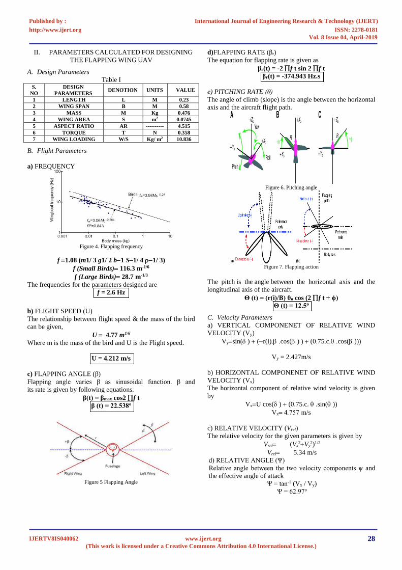
II. PARAMETERS CALCULATED FOR DESIGNING
THE FLAPPING WING UAV
A. Design Parameters
Table I S.
NO
DESIGN
PARAMETERS DENOTION UNITS VALUE
1 LENGTH L M 0.23
2 WING SPAN B M 0.58
3 MASS M Kg 0.476
4 WING AREA S m2 0.0745
5 ASPECT RATIO AR ---------- 4.515
6 TORQUE T N 0.358
7 WING LOADING W/S Kg/ m2 10.836
B. Flight Parameters
a) FREQUENCY
Figure 4. Flapping frequency
f =1.08 (m1/ 3 g1/ 2 b−1 S−1/ 4 −1/ 3)
f (Small Birds)= 116.3 m-1/6
f (Large Birds)= 28.7 m-1/3
The frequencies for the parameters designed are
f = 2.6 Hz
b) FLIGHT SPEED (U)
The relationship between flight speed & the mass of the bird
can be given,
U = 4.77 m1/6
Where m is the mass of the bird and U is the Flight speed.
U = 4.212 m/s
c) FLAPPING ANGLE (β)
Flapping angle varies β as sinusoidal function. β and
its rate is given by following equations.
β(t) = βmax cos2 f t
β (t) = 22.538o
Figure 5 Flapping Angle
d)FLAPPING RATE (βr)
The equation for flapping rate is given as
βr(t) = -2 f t sin 2 f t
βr(t) = -374.943 Hz.s
e) PITCHING RATE (θ)
The angle of climb (slope) is the angle between the horizontal
axis and the aircraft flight path.
Figure 6. Pitching angle
Figure 7. Flapping action
The pitch is the angle between the horizontal axis and the
longitudinal axis of the aircraft.
Θ (t) = (r(i)/B) θo cos (2 f t + ϕ)
Θ (t) = 12.5o
C. Velocity Parameters
a) VERTICAL COMPONENET OF RELATIVE WIND
VELOCITY (Vy)
Vy=sin( ) + (−r(i). .cos( ) ) + (0.75.c. .cos( )))
Vy = 2.427m/s
b) HORIZONTAL COMPONENET OF RELATIVE WIND
VELOCITY (Vx)
The horizontal component of relative wind velocity is given
by
Vx=U cos( ) + (0.75.c. .sin( ))
Vx= m/s
c) RELATIVE VELOCITY (Vrel)
The relative velocity for the given parameters is given by
Vrel= (Vx2+Vy
2)1/2
Vrel= 5.34 m/s
d) RELATIVE ANGLE (Ψ)
Relative angle between the two velocity components ψ and
the effective angle of attack
Ψ = tan-1 (Vx / Vy)
Ψ = 62.97o
International Journal of Engineering Research & Technology (IJERT)
ISSN: 2278-0181http://www.ijert.org
IJERTV8IS040062(This work is licensed under a Creative Commons Attribution 4.0 International License.)
Published by :
www.ijert.org
Vol. 8 Issue 04, April-2019
28
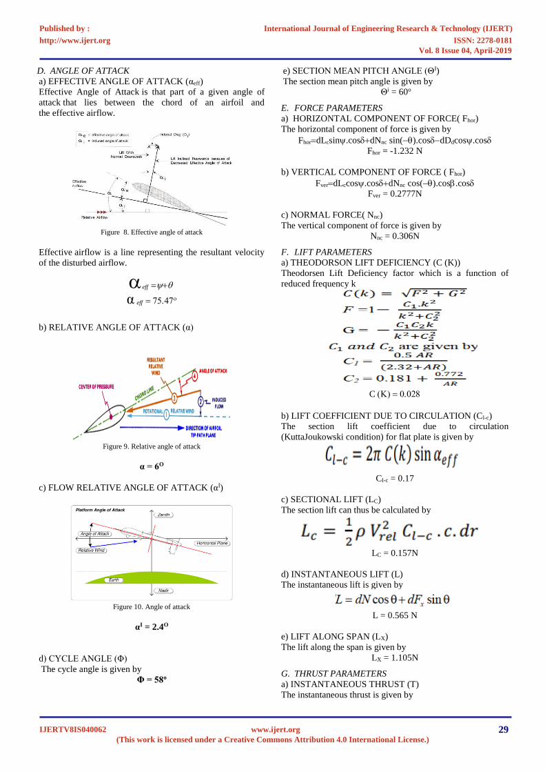
D. ANGLE OF ATTACK
a) EFFECTIVE ANGLE OF ATTACK (αeff)
Effective Angle of Attack is that part of a given angle of
attack that lies between the chord of an airfoil and
the effective airflow.
Figure 8. Effective angle of attack
Effective airflow is a line representing the resultant velocity
of the disturbed airflow.
eff =+
α eff =
b) RELATIVE ANGLE OF ATTACK (α)
Figure 9. Relative angle of attack
α = 6O
c) FLOW RELATIVE ANGLE OF ATTACK (αI)
Figure 10. Angle of attack
αI = 2.4O
d) CYCLE ANGLE (Φ)
The cycle angle is given by
Φ = 58o
e) SECTION MEAN PITCH ANGLE (ΘI)
The section mean pitch angle is given by
Θi = 60o
E. FORCE PARAMETERS
a) HORIZONTAL COMPONENT OF FORCE( Fhor)
The horizontal component of force is given by
Fhor=dLcsin.cos+dNnc sin(−).cos−dDdcos.cos
Fhor = -1.232 N
b) VERTICAL COMPONENT OF FORCE ( Fhor)
Fver=dLccos.cos+dNnc cos(−).cos.cos
Fver = 0.2777N
c) NORMAL FORCE( Nnc)
The vertical component of force is given by
Nnc = 0.306N
F. LIFT PARAMETERS
a) THEODORSON LIFT DEFICIENCY (C (K))
Theodorsen Lift Deficiency factor which is a function of
reduced frequency k
C () =
b) LIFT COEFFICIENT DUE TO CIRCULATION (Cl-c)
The section lift coefficient due to circulation
(KuttaJoukowski condition) for flat plate is given by
Cl-c = 0.17
c) SECTIONAL LIFT (LC)
The section lift can thus be calculated by
LC = 0.157N
d) INSTANTANEOUS LIFT (L)
The instantaneous lift is given by
L = 0.565 N
e) LIFT ALONG SPAN (LX)
The lift along the span is given by
LX = 1.105N
G. THRUST PARAMETERS
a) INSTANTANEOUS THRUST (T)
The instantaneous thrust is given by
International Journal of Engineering Research & Technology (IJERT)
ISSN: 2278-0181http://www.ijert.org
IJERTV8IS040062(This work is licensed under a Creative Commons Attribution 4.0 International License.)
Published by :
www.ijert.org
Vol. 8 Issue 04, April-2019
29
T = 0.204 N
b) THRUST ALONG SPAN (TX)
The thrust along span is given by
Tx = 1.16
H. DRAG PARAMETERS
a) INDUCED DRAG COEFFICIENT (Cdi)
Cdi = 0.002468
b) INDUCED DRAG ( Di)
Di = 0.001708 N
c) PARASITE DRAG COEFFICIENT (Cdp)
Cdp = 11.1257
d) PARASITE DRAG (Dp)
e) TOTAL DRAG (Dd)
Dd = Dp + Di
Dd = 2.888 N
f) SKIN FRICTIONAL DRAG COEFFICIENT (Cf)
Cf = 2.529
I. PRESSURE DIFFERENCE BETWEEN UPPER AND
LOWER SURFACE
Pressure (symbol: p or P) is the force applied perpendicular to
the surface of an object per unit area over which that force is
distributed.
Figure 11. Pressure difference
Gauge pressure is the pressure relative to the
ambient pressure.
Δ p = 0.507 BAR
J. POWER
a) POWER INPUT (Pin)
Pin = 0.9 W
b) POWER OUTPUT (Pout)
Pout = 0.72 W
b) EFFICIENCY (η)
η = 82.22
III. DESIGN
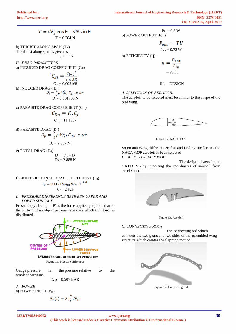
A. SELECTION OF AEROFOIL
The aerofoil to be selected must be similar to the shape of the
bird wing.
Figure 12. NACA 4309
So on analyzing different aerofoil and finding similarities the
NACA 4309 aerofoil is been selected
B. DESIGN OF AEROFOIL
The design of aerofoil in
CATIA V5 by importing the coordinates of aerofoil from
excel sheet.
Figure 13. Aerofoil
C. CONNECTING RODS
The connecting rod which
connects the two gears and two sides of the assembled wing
structure which creates the flapping motion.
Figure 14. Connecting rod
Dp = 2.887 N
International Journal of Engineering Research & Technology (IJERT)
ISSN: 2278-0181http://www.ijert.org
IJERTV8IS040062(This work is licensed under a Creative Commons Attribution 4.0 International License.)
Published by :
www.ijert.org
Vol. 8 Issue 04, April-2019
30
D. WING SKELETON STRUCTURE
The aerofoil and different crank that are used to
connect the aerofoil to construct the skeleton structure of the
wing which is driven by the gear mechanism.
Figure 15. Wing skeleton structure
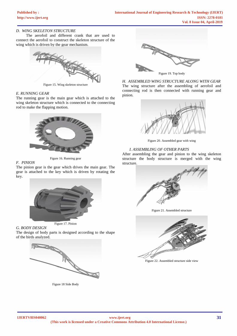
E. RUNNING GEAR
The running gear is the main gear which is attached to the
wing skeleton structure which is connected to the connecting
rod to make the flapping motion.
Figure 16. Running gear
F. PINION
The pinion gear is the gear which drives the main gear. The
gear is attached to the key which is driven by rotating the
key.
Figure 17. Pinion
G. BODY DESIGN
The design of body parts is designed according to the shape
of the birds analyzed.
Figure 18 Side Body
Figure 19. Top body
H. ASSEMBLED WING STRUCTURE ALONG WITH GEAR
The wing structure after the assembling of aerofoil and
connecting rod is then connected with running gear and
pinion.
Figure 20. Assembled gear with wing
I. ASSEMBLING OF OTHER PARTS
After assembling the gear and pinion to the wing skeleton
structure the body structure is merged with the wing
structure.
Figure 21. Assembled structure
Figure 22. Assembled structure side view
International Journal of Engineering Research & Technology (IJERT)
ISSN: 2278-0181http://www.ijert.org
IJERTV8IS040062(This work is licensed under a Creative Commons Attribution 4.0 International License.)
Published by :
www.ijert.org
Vol. 8 Issue 04, April-2019
31

Figure 23. Assembled structure cross view
Figure 24. Assembled structure front view
J. SHEET METAL APPLICATION
Figure 24 Applied Skin Over The Wing
IV. RESULTS
A. Dynamic velocity
Figure 25 Velocity
B. Mesh Deformation X Velocity
Figure 26 Mesh X Velocity
C. Mesh Deformation Y Velocity
Figure 27 Mesh Y Velocity
D. Relative X Velocity
Figure 28 Relative X Velocity
E. Relative Y Velocity
Figure 29 Relative Y Velocity
F. Vorticity
Figure 30 Vorticity
G. Tangential Velocity
Figure 31 Tangential Velocity
International Journal of Engineering Research & Technology (IJERT)
ISSN: 2278-0181http://www.ijert.org
IJERTV8IS040062(This work is licensed under a Creative Commons Attribution 4.0 International License.)
Published by :
www.ijert.org
Vol. 8 Issue 04, April-2019
32
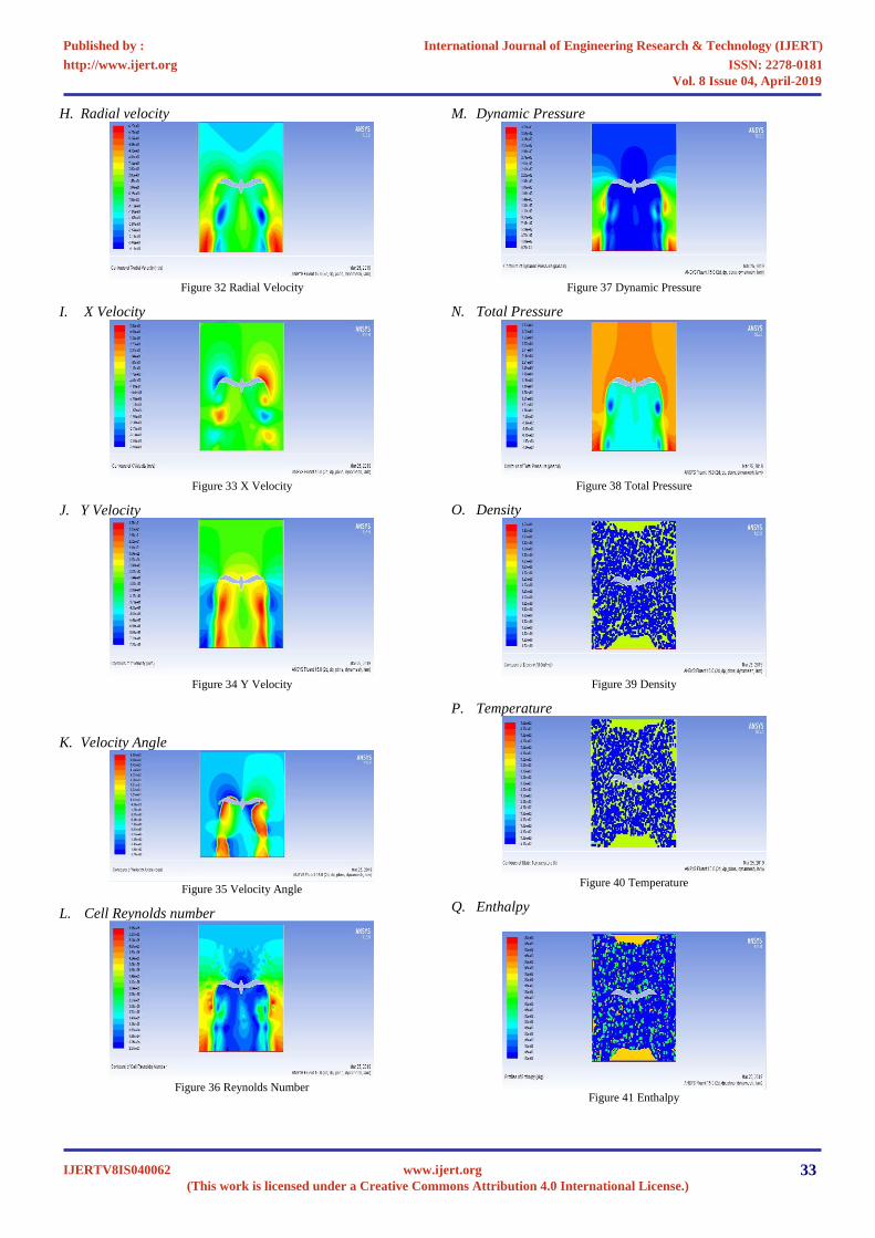
H. Radial velocity
Figure 32 Radial Velocity
I. X Velocity
Figure 33 X Velocity
J. Y Velocity
Figure 34 Y Velocity
K. Velocity Angle
Figure 35 Velocity Angle
L. Cell Reynolds number
Figure 36 Reynolds Number
M. Dynamic Pressure
Figure 37 Dynamic Pressure
N. Total Pressure
Figure 38 Total Pressure
O. Density
Figure 39 Density
P. Temperature
Figure 40 Temperature
Q. Enthalpy
Figure 41 Enthalpy
International Journal of Engineering Research & Technology (IJERT)
ISSN: 2278-0181http://www.ijert.org
IJERTV8IS040062(This work is licensed under a Creative Commons Attribution 4.0 International License.)
Published by :
www.ijert.org
Vol. 8 Issue 04, April-2019
33
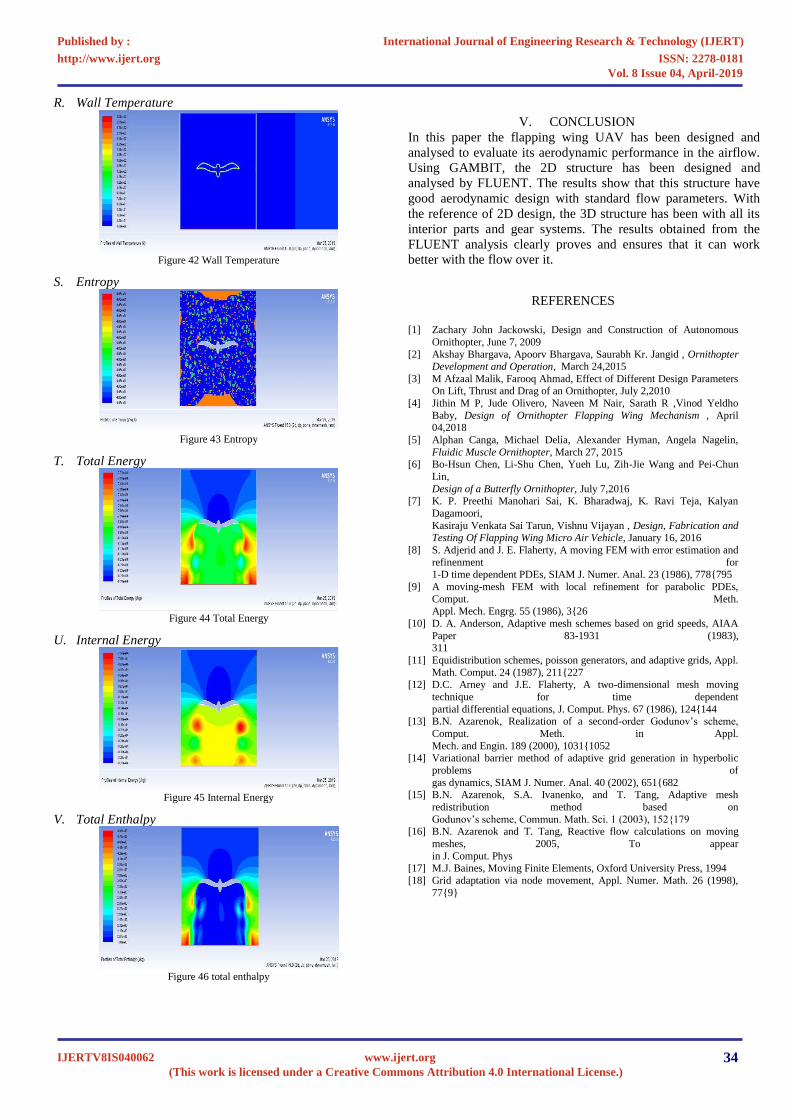
R. Wall Temperature
Figure 42 Wall Temperature
S. Entropy
Figure 43 Entropy
T. Total Energy
Figure 44 Total Energy
U. Internal Energy
Figure 45 Internal Energy
V. Total Enthalpy
Figure 46 total enthalpy
V.
CONCLUSION
In this paper the flapping wing UAV has been designed and
analysed to evaluate its aerodynamic performance in the airflow.
Using GAMBIT, the 2D structure has been designed and
analysed by FLUENT. The results show that this structure have
good aerodynamic design with standard flow parameters. With
the reference of 2D design, the 3D structure has been with all its
interior parts and gear systems. The results obtained from the
FLUENT analysis clearly proves and ensures that it can work
better with the flow over it.
REFERENCES
[1]
Zachary John Jackowski, Design and Construction of Autonomous
Ornithopter, June 7, 2009
[2]
Akshay Bhargava, Apoorv Bhargava, Saurabh Kr. Jangid , Ornithopter
Development and Operation, March 24,2015
[3]
M Afzaal Malik, Farooq Ahmad, Effect of Different Design Parameters
On Lift, Thrust and Drag of an Ornithopter, July 2,2010
[4]
Jithin M P, Jude Olivero, Naveen M Nair, Sarath R ,Vinod Yeldho
Baby, Design of Ornithopter Flapping Wing Mechanism , April 04,2018
[5]
Alphan Canga, Michael Delia, Alexander Hyman, Angela Nagelin,
Fluidic Muscle Ornithopter, March 27, 2015
[6]
Bo-Hsun Chen, Li-Shu Chen, Yueh Lu, Zih-Jie Wang and Pei-Chun
Lin,
Design of a Butterfly Ornithopter,
July 7,2016
[7]
K. P. Preethi Manohari Sai, K. Bharadwaj, K. Ravi Teja, Kalyan
Dagamoori,
Kasiraju Venkata Sai Tarun, Vishnu Vijayan ,
Design, Fabrication and Testing Of Flapping Wing Micro Air Vehicle, January 16, 2016
[8]
S. Adjerid and J. E. Flaherty, A moving FEM with error estimation and
refinenment for
1-D time dependent PDEs, SIAM J. Numer. Anal. 23 (1986), 778{795
[9]
A moving-mesh FEM with local refinement for parabolic PDEs,
Comput. Meth.
Appl. Mech. Engrg. 55 (1986), 3{26
[10]
D. A. Anderson, Adaptive mesh schemes based on grid speeds, AIAA
Paper 83-1931 (1983),
311
[11]
Equidistribution schemes, poisson generators, and adaptive grids, Appl.
Math. Comput. 24 (1987), 211{227
[12]
D.C. Arney and J.E. Flaherty, A two-dimensional mesh moving
technique for time dependent
partial differential equations, J. Comput. Phys. 67 (1986), 124{144
[13]
B.N. Azarenok, Realization of a second-order Godunov’s scheme,
Comput. Meth. in Appl.
Mech. and Engin. 189 (2000), 1031{1052
[14]
Variational barrier method of adaptive grid generation in hyperbolic
problems of
gas dynamics, SIAM J. Numer. Anal. 40 (2002), 651{682
[15]
B.N. Azarenok, S.A. Ivanenko, and T. Tang, Adaptive mesh
redistribution method based on
Godunov’s scheme, Commun. Math. Sci. 1 (2003), 152{179
[16]
B.N. Azarenok and T. Tang, Reactive flow calculations on moving
meshes, 2005, To appear
in J. Comput. Phys
[17]
M.J. Baines, Moving Finite Elements, Oxford University Press, 1994
[18]
Grid adaptation via node movement, Appl. Numer. Math. 26 (1998),
77{9}
International Journal of Engineering Research & Technology (IJERT)
ISSN: 2278-0181http://www.ijert.org
IJERTV8IS040062(This work is licensed under a Creative Commons Attribution 4.0 International License.)
Published by :
www.ijert.org
Vol. 8 Issue 04, April-2019
34
Related Documents


![Ornithopter Final Report · smaller Kinkade Park Hawk ornithopter. In this system, live video was transmitted to a portable LCD display unit [8]. Although ornithopter research and](https://static.cupdf.com/doc/110x72/5e7f3dc14d823774c40e3e8b/ornithopter-final-report-smaller-kinkade-park-hawk-ornithopter-in-this-system.jpg)