VOL. 10, NO. 20, NOVEMBER 2015 ISSN 1819-6608 ARPN Journal of Engineering and Applied Sciences ©2006-2015 Asian Research Publishing Network (ARPN). All rights reserved. www.arpnjournals.com 9999 COMPUTATIONAL STUDY ON THE INFLUENCE OF DYNAMIC STALL ON THE UNSTEADY AERODYNAMICS OF FLAPPING WING ORNITHOPTER Alif Syamim Syazwan Ramli and Harijono Djojodihardjo Department of Aerospace Engineering, Faculty of Engineering, Universiti Putra Malaysia, UPM Serdang, Selangor, Malaysia E-Mail: [email protected] ABSTRACT The potential of Flapping Wing Micro Air Vehicles (MAVs) for sensing and information gathering relevant for environmental and disaster monitoring and security surveillance leads to the identification and modeling the salient features and functional significance of the various components in the flying reasonably sized biosystems. The dynamics, kinematics and aerodynamics of their wing systems and the production of mechanical power output for lift and thrust will be synthesized following a simplified and generic, but meticulous, model for a flapping wing ornithopter. Basic unsteady aerodynamic approach incorporating viscous effect and leading-edge suction is utilized. The study is focused on a bi-wing ornithopter. Numerical computation under effect of specified stall conditions is executed to inspect the behavior of lift and thrust forces. Also, the incorporation of non-linear aerodynamic modeling is introduced. Results are discussed in comparison with various selected simple models in the literature and the parametric study of phase shift between pitching and flapping motion is done, with a view to develop a practical ornithopter model. Keywords: bi-wing ornithopter, flapping wing aerodynamics, micro air vehicle, unsteady aerodynamics. INTRODUCTION Most of the researchers are mimicking the flying mammalians due to its inherent flexibility and light weight, for the purpose of developing mechanical ornithopter. It is a challenging goal to deal with the design of bio-inspired flying micro air vehicle, a very small size, with low Reynolds number (Re < 50,000). In such regime, one of the drawbacks is the total separation of the attached flow from leading edge, which can affect, as well as impair, the aerodynamic performance. The phenomenon of dynamic stall on airfoils in unsteady-flow environment has been studied for many years, for example, airfoil’s performance at such Re range was investigated by Mueller and Batill [19] on a laminar profile using force measurements and smoke visualization. Figure-1. Schematic showing the essential flow morphology and the unsteady airloads during the dynamic stall process on an oscillating 2-D airfoil (Adapted from [3] and [18]). Carr also has provided a comprehensive review on dynamic stall effect, which the main focus is discussing the effect of various parameters like stream velocity and pitch amplitude during the dynamic stall event [3]. Figure- 1 shows the process taking place during the occurrence of dynamic stall. It is likely that lift can be generated through unsteady aerodynamic mechanisms such as dynamic stall [18], where the formation and delayed convection of a leading-edge vortex (LEV) over the downstroke can be very beneficial to lift production [12]. Based on this aforementioned overview, it is very interesting to study the influence of dynamic stall and non- linear aerodynamic model modification, as further development of earlier work elaborated in [8] and [10]. In addition, however, the leading edge vortex effects will not be considered here. The latter, has been addressed in a companion paper [11], that introduces a simple and heuristic leading edge vortex modeling which associate the shed vortices with rapid pronation of the wing. In modeling and simulating the influence of the leading edge vortex, information gained from many recent approaches such as those of Ansari et al [2] and Wang [28], has been taken into consideration. Figure-2. A generic semi-elliptical wing planform considered in Djojodihardjo and Ramli [6]-[8] and utilized as a baseline here.

Welcome message from author
This document is posted to help you gain knowledge. Please leave a comment to let me know what you think about it! Share it to your friends and learn new things together.
Transcript
VOL. 10, NO. 20, NOVEMBER 2015 ISSN 1819-6608
ARPN Journal of Engineering and Applied Sciences
©2006-2015 Asian Research Publishing Network (ARPN). All rights reserved.
www.arpnjournals.com
9999
COMPUTATIONAL STUDY ON THE INFLUENCE OF DYNAMIC STALL ON THE UNSTEADY AERODYNAMICS OF FLAPPING WING
ORNITHOPTER
Alif Syamim Syazwan Ramli and Harijono Djojodihardjo Department of Aerospace Engineering, Faculty of Engineering, Universiti Putra Malaysia, UPM Serdang, Selangor, Malaysia
E-Mail: [email protected]
ABSTRACT The potential of Flapping Wing Micro Air Vehicles (MAVs) for sensing and information gathering relevant for environmental and disaster monitoring and security surveillance leads to the identification and modeling the salient features and functional significance of the various components in the flying reasonably sized biosystems. The dynamics, kinematics and aerodynamics of their wing systems and the production of mechanical power output for lift and thrust will be synthesized following a simplified and generic, but meticulous, model for a flapping wing ornithopter. Basic unsteady aerodynamic approach incorporating viscous effect and leading-edge suction is utilized. The study is focused on a bi-wing ornithopter. Numerical computation under effect of specified stall conditions is executed to inspect the behavior of lift and thrust forces. Also, the incorporation of non-linear aerodynamic modeling is introduced. Results are discussed in comparison with various selected simple models in the literature and the parametric study of phase shift between pitching and flapping motion is done, with a view to develop a practical ornithopter model. Keywords: bi-wing ornithopter, flapping wing aerodynamics, micro air vehicle, unsteady aerodynamics. INTRODUCTION
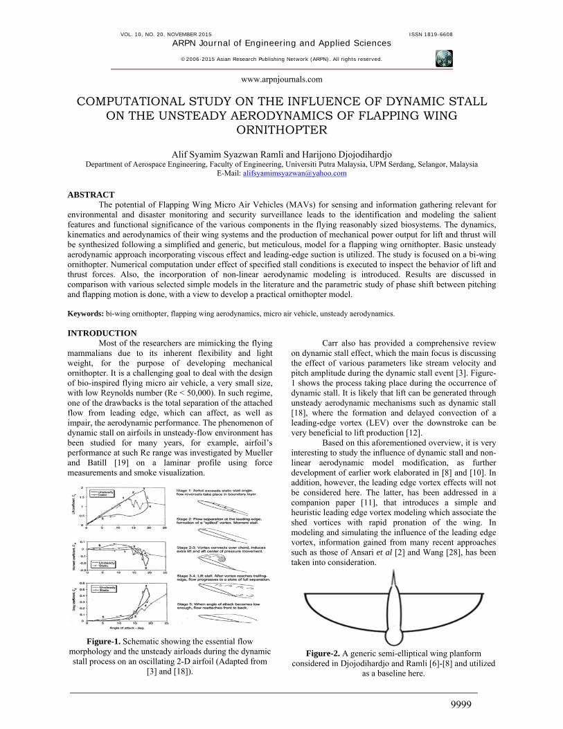
Most of the researchers are mimicking the flying mammalians due to its inherent flexibility and light weight, for the purpose of developing mechanical ornithopter. It is a challenging goal to deal with the design of bio-inspired flying micro air vehicle, a very small size, with low Reynolds number (Re < 50,000). In such regime, one of the drawbacks is the total separation of the attached flow from leading edge, which can affect, as well as impair, the aerodynamic performance. The phenomenon of dynamic stall on airfoils in unsteady-flow environment has been studied for many years, for example, airfoil’s performance at such Re range was investigated by Mueller and Batill [19] on a laminar profile using force measurements and smoke visualization.
Figure-1. Schematic showing the essential flow morphology and the unsteady airloads during the dynamic stall process on an oscillating 2-D airfoil (Adapted from
[3] and [18]).
Carr also has provided a comprehensive review
on dynamic stall effect, which the main focus is discussing the effect of various parameters like stream velocity and pitch amplitude during the dynamic stall event [3]. Figure-1 shows the process taking place during the occurrence of dynamic stall. It is likely that lift can be generated through unsteady aerodynamic mechanisms such as dynamic stall [18], where the formation and delayed convection of a leading-edge vortex (LEV) over the downstroke can be very beneficial to lift production [12]. Based on this aforementioned overview, it is very interesting to study the influence of dynamic stall and non-linear aerodynamic model modification, as further development of earlier work elaborated in [8] and [10]. In addition, however, the leading edge vortex effects will not be considered here. The latter, has been addressed in a companion paper [11], that introduces a simple and heuristic leading edge vortex modeling which associate the shed vortices with rapid pronation of the wing. In modeling and simulating the influence of the leading edge vortex, information gained from many recent approaches such as those of Ansari et al [2] and Wang [28], has been taken into consideration.
Figure-2. A generic semi-elliptical wing planform
considered in Djojodihardjo and Ramli [6]-[8] and utilized as a baseline here.
VOL. 10, NO. 20, NOVEMBER 2015 ISSN 1819-6608
ARPN Journal of Engineering and Applied Sciences
©2006-2015 Asian Research Publishing Network (ARPN). All rights reserved.
www.arpnjournals.com
10000
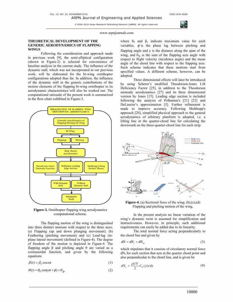
THEORETICAL DEVELOPMENT OF THE GENERIC AERODYNAMICS OF FLAPPING WINGS Following the consideration and approach made in previous work [9], the semi-elliptical configuration (shown in Figure-2) is selected for convenience of baseline analysis in the current study. The influence of the dynamic stall, which was not incorporated in our previous work, will be elaborated for the bi-wing ornithopter configurations adopted thus far. In addition, the influence of the dynamic stall in the generic contributions of the motion elements of the flapping bi-wing ornithopter to its aerodynamic characteristics will also be worked out. The computational rationale of the present work is summarized in the flow-chart exhibited in Figure-3.
Figure-3. Ornithopter flapping wing aerodynamics computational scheme.
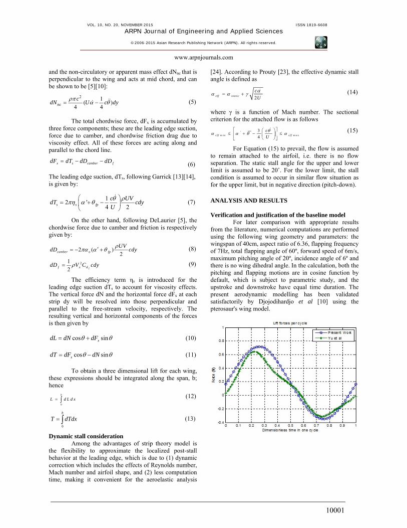
The flapping motion of the wing is distinguished into three distinct motions with respect to the three axes; (a) Flapping (up and down plunging movement); (b) Feathering (pitching movement) and (c) Lead-lag (in-plane lateral movement) (defined in Figure-4). The degree of freedom of the motion is depicted in Figure-4. The flapping angle β and pitching angle θ are varied as a cosinusoidal function, and given by the following equations
0( ) cost t (1)
0( ) cos( ) fpt t
(2)
where θ0 and βo indicate maximum value for each variables, is the phase lag between pitching and
flapping angle and y is the distance along the span of the wing, and fp is the sum of the flapping axis angle with respect to flight velocity (incidence angle) and the mean angle of the chord line with respect to the flapping axis. Such scheme indicates that these motions start from specified values. A different scheme, however, can be adopted. Three dimensional effects will later be introduced by using Scherer’s modified Theodorsen-Jones Lift Deficiency Factor [25], in addition to the Theodorsen unsteady aerodynamics [27] and its three dimensional version by Jones [15]. Leading edge suction is included following the analysis of Polhamus's [21] [22] and DeLaurier’s approximation [5]. Further refinement is made to improve accuracy. Following Multhopp's approach [20], simplified physical approach to the general aerodynamics of arbitrary planform is adopted, i.e. a lifting line in the quarter-chord line for calculating the downwash on the three-quarter-chord line for each strip.
Figure-4. (a) Sectional force of the wing; (b),(c),(d) Flapping and pitching motion of the wing.
In the present analysis no linear variation of the wing’s dynamic twist is assumed for simplification and instructiveness. However, in principle, such additional requirements can easily be added due to its linearity. The total normal force acting perpendicularly to the chord line and given by
c ncdN dN dN (3)
which stipulates that it consists of circulatory normal force dNc for each section that acts at the quarter chord point and also perpendicular to the chord line, and is given by
( )2c nUV
dN C y cdy
(4)
VOL. 10, NO. 20, NOVEMBER 2015 ISSN 1819-6608
ARPN Journal of Engineering and Applied Sciences
©2006-2015 Asian Research Publishing Network (ARPN). All rights reserved.
www.arpnjournals.com
10001
and the non-circulatory or apparent mass effect dNnc that is perpendicular to the wing and acts at mid chord, and can be shown to be [5][10]:
2 1( )
4 4ncc
dN U c dy
(5)
The total chordwise force, dFx is accumulated by three force components; these are the leading edge suction, force due to camber, and chordwise friction drag due to viscosity effect. All of these forces are acting along and parallel to the chord line.
x s camber fdF dT dD dD (6)
The leading edge suction, dTs, following Garrick [13][14], is given by:
12 '
4 2s s fp
c UVdT cdy
U
(7)
On the other hand, following DeLaurier [5], the chordwise force due to camber and friction is respectively given by:
2 ( ) 2camber o fp
UVdD cdy
(8)
21
2 ff x ddD V C cdy
(9)
The efficiency term ηs is introduced for the leading edge suction dTs to account for viscosity effects. The vertical force dN and the horizontal force dFx at each strip dy will be resolved into those perpendicular and parallel to the free-stream velocity, respectively. The resulting vertical and horizontal components of the forces is then given by
cos sinxdL dN dF (10)
cos sinxdT dF dN (11)
To obtain a three dimensional lift for each wing, these expressions should be integrated along the span, b; hence
0
b
L d L d x
(12)
0
b
T dTdx
(13)
Dynamic stall consideration Among the advantages of strip theory model is the flexibility to approximate the localized post-stall behavior at the leading edge, which is due to (1) dynamic correction which includes the effects of Reynolds number, Mach number and airfoil shape, and (2) less computation time, making it convenient for the aeroelastic analysis
[24]. According to Prouty [23], the effective dynamic stall angle is defined as
2e ff s ta tic
c
U
(14)
where γ is a function of Mach number. The sectional criterion for the attached flow is as follows
'm in m a x
3
4e f f e f f
c
U
(15)
For Equation (15) to prevail, the flow is assumed to remain attached to the airfoil, i.e. there is no flow separation. The static stall angle for the upper and lower limit is assumed to be 20˚. For the lower limit, the stall condition is assumed to occur in similar flow situation as for the upper limit, but in negative direction (pitch-down). ANALYSIS AND RESULTS Verification and justification of the baseline model For later comparison with appropriate results from the literature, numerical computations are performed using the following wing geometry and parameters: the wingspan of 40cm, aspect ratio of 6.36, flapping frequency of 7Hz, total flapping angle of 60º, forward speed of 6m/s, maximum pitching angle of 20º, incidence angle of 6º and there is no wing dihedral angle. In the calculation, both the pitching and flapping motions are in cosine function by default, which is subject to parametric study, and the upstroke and downstroke have equal time duration. The present aerodynamic modelling has been validated satisfactorily by Djojodihardjo et al [10] using the pterosaur's wing model.
VOL. 10, NO. 20, NOVEMBER 2015 ISSN 1819-6608
ARPN Journal of Engineering and Applied Sciences
©2006-2015 Asian Research Publishing Network (ARPN). All rights reserved.
www.arpnjournals.com
10002
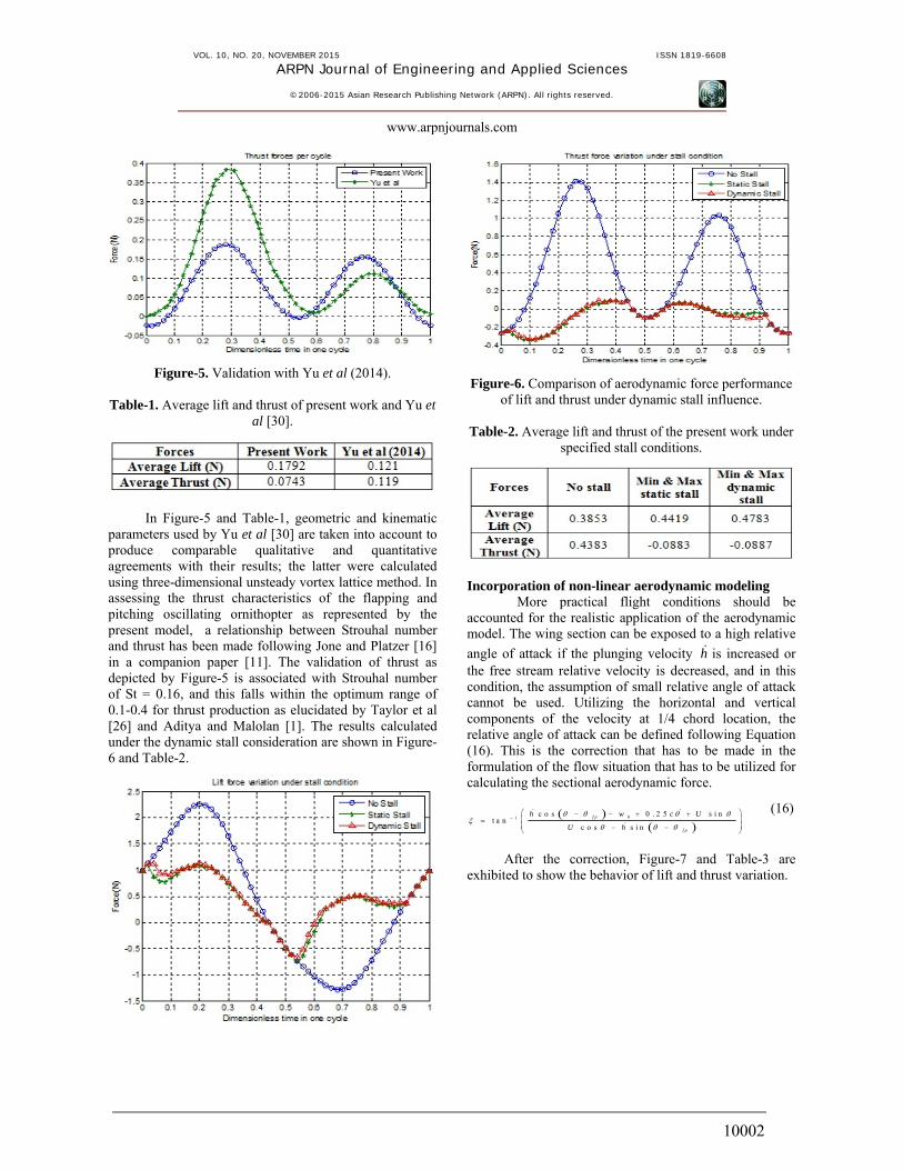
Figure-5. Validation with Yu et al (2014). Table-1. Average lift and thrust of present work and Yu et
al [30].
In Figure-5 and Table-1, geometric and kinematic parameters used by Yu et al [30] are taken into account to produce comparable qualitative and quantitative agreements with their results; the latter were calculated using three-dimensional unsteady vortex lattice method. In assessing the thrust characteristics of the flapping and pitching oscillating ornithopter as represented by the present model, a relationship between Strouhal number and thrust has been made following Jone and Platzer [16] in a companion paper [11]. The validation of thrust as depicted by Figure-5 is associated with Strouhal number of St = 0.16, and this falls within the optimum range of 0.1-0.4 for thrust production as elucidated by Taylor et al [26] and Aditya and Malolan [1]. The results calculated under the dynamic stall consideration are shown in Figure-6 and Table-2.
Figure-6. Comparison of aerodynamic force performance of lift and thrust under dynamic stall influence.
Table-2. Average lift and thrust of the present work under
specified stall conditions.
Incorporation of non-linear aerodynamic modeling More practical flight conditions should be accounted for the realistic application of the aerodynamic model. The wing section can be exposed to a high relative
angle of attack if the plunging velocity h is increased or the free stream relative velocity is decreased, and in this condition, the assumption of small relative angle of attack cannot be used. Utilizing the horizontal and vertical components of the velocity at 1/4 chord location, the relative angle of attack can be defined following Equation (16). This is the correction that has to be made in the formulation of the flow situation that has to be utilized for calculating the sectional aerodynamic force.
01c o s 0 . 2 5 s i n
t a nc o s s i n
f p
f p
h w c U
U h
(16)
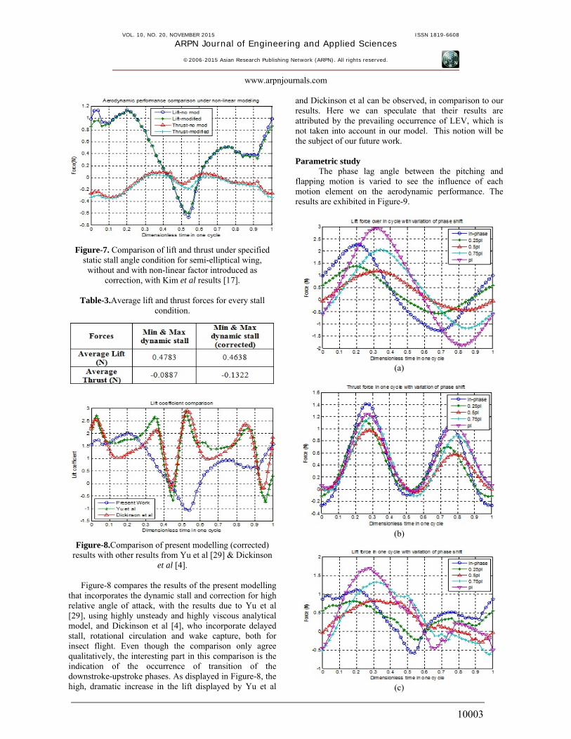
After the correction, Figure-7 and Table-3 are exhibited to show the behavior of lift and thrust variation.
VOL. 10, NO. 20, NOVEMBER 2015 ISSN 1819-6608
ARPN Journal of Engineering and Applied Sciences
©2006-2015 Asian Research Publishing Network (ARPN). All rights reserved.
www.arpnjournals.com
10003
Figure-7. Comparison of lift and thrust under specified static stall angle condition for semi-elliptical wing,
without and with non-linear factor introduced as correction, with Kim et al results [17].
Table-3.Average lift and thrust forces for every stall
condition.
Figure-8.Comparison of present modelling (corrected) results with other results from Yu et al [29] & Dickinson
et al [4].
Figure-8 compares the results of the present modelling that incorporates the dynamic stall and correction for high relative angle of attack, with the results due to Yu et al [29], using highly unsteady and highly viscous analytical model, and Dickinson et al [4], who incorporate delayed stall, rotational circulation and wake capture, both for insect flight. Even though the comparison only agree qualitatively, the interesting part in this comparison is the indication of the occurrence of transition of the downstroke-upstroke phases. As displayed in Figure-8, the high, dramatic increase in the lift displayed by Yu et al
and Dickinson et al can be observed, in comparison to our results. Here we can speculate that their results are attributed by the prevailing occurrence of LEV, which is not taken into account in our model. This notion will be the subject of our future work.
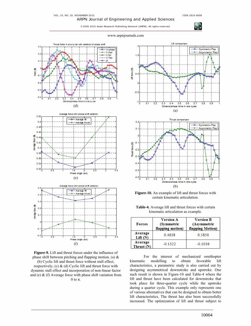
Parametric study The phase lag angle between the pitching and flapping motion is varied to see the influence of each motion element on the aerodynamic performance. The results are exhibited in Figure-9.
(a)
(b)
(c)
VOL. 10, NO. 20, NOVEMBER 2015 ISSN 1819-6608
ARPN Journal of Engineering and Applied Sciences
©2006-2015 Asian Research Publishing Network (ARPN). All rights reserved.
www.arpnjournals.com
10004
(d)
(e)
(f)
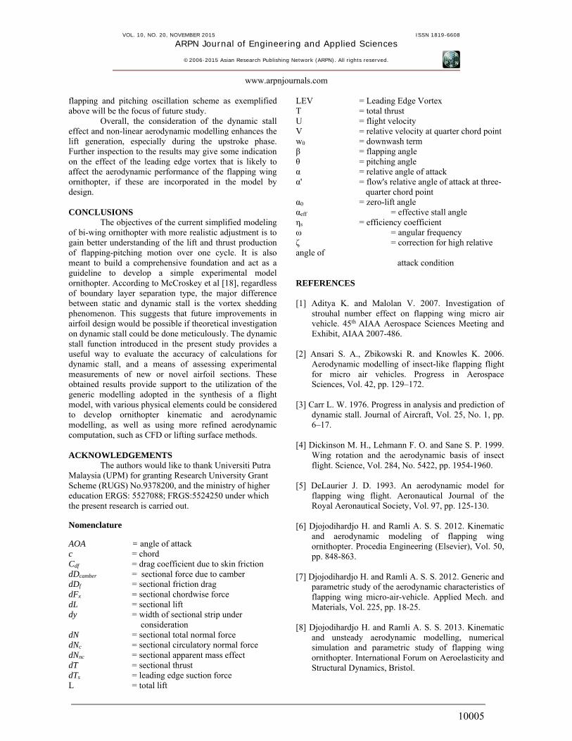
Figure-9. Lift and thrust forces under the influence of phase shift between pitching and flapping motion. (a) &
(b) Cyclic lift and thrust force without stall effect, respectively; (c) & (d) Cyclic lift and thrust force with
dynamic stall effect and incorporation of non-linear factor and (e) & (f) Average force with phase shift variation from
0 to π.
(a)
(b)
Figure-10. An example of lift and thrust forces with certain kinematic articulation.
Table-4. Average lift and thrust forces with certain
kinematic articulation as example.
For the interest of mechanized ornithopter kinematic modelling to obtain favorable lift characteristics, a parametric study is also carried out by designing asymmetrical downstroke and upstroke. One such result is shown in Figure-10 and Table-4 where the lift and thrust have been calculated for downstroke that took place for three-quarter cycle while the upstroke during a quarter cycle. This example only represents one of various alternatives that can be designed to obtain better lift characteristics. The thrust has also been successfully increased. The optimization of lift and thrust subject to
VOL. 10, NO. 20, NOVEMBER 2015 ISSN 1819-6608
ARPN Journal of Engineering and Applied Sciences
©2006-2015 Asian Research Publishing Network (ARPN). All rights reserved.
www.arpnjournals.com
10005
flapping and pitching oscillation scheme as exemplified above will be the focus of future study.
Overall, the consideration of the dynamic stall effect and non-linear aerodynamic modelling enhances the lift generation, especially during the upstroke phase. Further inspection to the results may give some indication on the effect of the leading edge vortex that is likely to affect the aerodynamic performance of the flapping wing ornithopter, if these are incorporated in the model by design. CONCLUSIONS The objectives of the current simplified modeling of bi-wing ornithopter with more realistic adjustment is to gain better understanding of the lift and thrust production of flapping-pitching motion over one cycle. It is also meant to build a comprehensive foundation and act as a guideline to develop a simple experimental model ornithopter. According to McCroskey et al [18], regardless of boundary layer separation type, the major difference between static and dynamic stall is the vortex shedding phenomenon. This suggests that future improvements in airfoil design would be possible if theoretical investigation on dynamic stall could be done meticulously. The dynamic stall function introduced in the present study provides a useful way to evaluate the accuracy of calculations for dynamic stall, and a means of assessing experimental measurements of new or novel airfoil sections. These obtained results provide support to the utilization of the generic modelling adopted in the synthesis of a flight model, with various physical elements could be considered to develop ornithopter kinematic and aerodynamic modelling, as well as using more refined aerodynamic computation, such as CFD or lifting surface methods. ACKNOWLEDGEMENTS The authors would like to thank Universiti Putra Malaysia (UPM) for granting Research University Grant Scheme (RUGS) No.9378200, and the ministry of higher education ERGS: 5527088; FRGS:5524250 under which the present research is carried out. Nomenclature
AOA = angle of attack c = chord Cdf = drag coefficient due to skin friction dDcamber = sectional force due to camber dDf = sectional friction drag dFx = sectional chordwise force dL = sectional lift dy = width of sectional strip under consideration dN = sectional total normal force dNc = sectional circulatory normal force dNnc = sectional apparent mass effect dT = sectional thrust dTs = leading edge suction force L = total lift
LEV = Leading Edge Vortex T = total thrust U = flight velocity V = relative velocity at quarter chord point w0 = downwash term β = flapping angle θ = pitching angle α = relative angle of attack α' = flow's relative angle of attack at three- quarter chord point α0 = zero-lift angle αeff = effective stall angle ηs = efficiency coefficient ω = angular frequency ζ = correction for high relative angle of attack condition REFERENCES [1] Aditya K. and Malolan V. 2007. Investigation of
strouhal number effect on flapping wing micro air vehicle. 45th AIAA Aerospace Sciences Meeting and Exhibit, AIAA 2007-486.
[2] Ansari S. A., Zbikowski R. and Knowles K. 2006.
Aerodynamic modelling of insect-like flapping flight for micro air vehicles. Progress in Aerospace Sciences, Vol. 42, pp. 129–172.
[3] Carr L. W. 1976. Progress in analysis and prediction of
dynamic stall. Journal of Aircraft, Vol. 25, No. 1, pp. 6–17.
[4] Dickinson M. H., Lehmann F. O. and Sane S. P. 1999.
Wing rotation and the aerodynamic basis of insect flight. Science, Vol. 284, No. 5422, pp. 1954-1960.
[5] DeLaurier J. D. 1993. An aerodynamic model for
flapping wing flight. Aeronautical Journal of the Royal Aeronautical Society, Vol. 97, pp. 125-130.
[6] Djojodihardjo H. and Ramli A. S. S. 2012. Kinematic
and aerodynamic modeling of flapping wing ornithopter. Procedia Engineering (Elsevier), Vol. 50, pp. 848-863.
[7] Djojodihardjo H. and Ramli A. S. S. 2012. Generic and
parametric study of the aerodynamic characteristics of flapping wing micro-air-vehicle. Applied Mech. and Materials, Vol. 225, pp. 18-25.
[8] Djojodihardjo H. and Ramli A. S. S. 2013. Kinematic
and unsteady aerodynamic modelling, numerical simulation and parametric study of flapping wing ornithopter. International Forum on Aeroelasticity and Structural Dynamics, Bristol.
VOL. 10, NO. 20, NOVEMBER 2015 ISSN 1819-6608
ARPN Journal of Engineering and Applied Sciences
©2006-2015 Asian Research Publishing Network (ARPN). All rights reserved.
www.arpnjournals.com
10006
[9] Djojodihardjo H., Bari M. A. A., Rafie A. S. M. and Wiriadidjaja S. 2014. Further development of the kinematic and aerodynamic modeling and analysis of flapping wing ornithopter from basic principles. Applied Mech. and Materials, Vol. 629, pp. 9-17.
[10] Djojodihardjo H., Ramli A. S. S. and Bari M. A. A.
2015. Kinematic and unsteady aerodynamic study on bi- and quad-wing ornithopter. Journal of Aeroelasticity and Structural Dynamics (ASDJ), revision submitted.
[11] Djojodihardjo H., Ramli A. S. S. and Bari M. A. A.
2015. Aerodynamic performance of a generic flapping bi- & quad-wing ornithopter models. Submitted for publication.
[12] Ellington C. P. 1999. The novel aerodynamics of
insect flight: Applications to micro-air vehicles. Journal of Experimental Biology, Vol. 202, pp. 3439-3448.
[13] Garrick I. E. 1936. Propulsion of a flapping and
oscillating aerofoil. NACA Report No. 567. [14] Garrick I. E. 1938. On some reciprocal relations in
the theory of non-stationary flows. NACA Report No. 629.
[15] Jones R. T. 1940. The unsteady lift of a wing of finite
aspect ratio. NACA Report No.681. [16] Jones K. D. and Platzer M.F. 2000. Flapping-wing
propulsion for a micro air vehicle.38th Aerospace Sciences Meeting & Exhibit,AIAA-2000-0897.
[17] Kim D.-K., Lee J.-S., Lee J.-Y. and Han J.-H. 2008.
An aeroelastic analysis of a flexible flapping wing using modified strip theory. SPIE 15th Annual Symposium Smart Structures and Materials, Vol. 6928, 692810.
[18] McCroskey W. J., Carr L. W. and McAlister K. W.
1976. Dynamic stall experiments on oscillating airfoils. AIAA Journal, Vol. 14, No. 1.
[19] Mueller T. J. and Batill S. M. 1982. Experimental
studies of separation on a two-dimensional airfoil at low Reynolds number. AIAA Journal, Vol. 20, No. 4, pp. 457-463.
[20] Multhopp H. 1955. Methods for calculating the lift
distribution of wings (Subsonic lifting-surface theory).ARC R&M No. 2884.
[21] Polhamus E. C. 1966. A concept of the vortex lift of
sharp-edge delta wings based on a leading-edge-suction analogy. NASA TN D-3767.
[22] Polhamus E. C. 1968. Application of the leading-edge-suction analogy of vortex lift to the drag due to lift of sharp-edge delta wings. NASA TN D-4739.
[23] Prouty R. W. 1986. Airfoils for rotor blades,
helicopter performance, stability and control. PWS Engineering, Boston.
[24] Reddy T. S. R. and Kaza K. R. V. 1987.A
comparative study of some dynamic stall models.NASA TM 88917.
[25] Scherer J. O. 1968. Experimental and theoretical
investigation of large amplitude oscillating foil propulsion systems. Hydronautics, Laurel, Md.
[26] Taylor G. K., Nudds R. L. and Thomas A. R.L. 2003.
Flying and swimming animals cruise at a strouhal number tuned for high power efficiency. Nature, Vol. 425, pp. 707-711.
[27] Theodorsen T. 1935. General theory of aerodynamic
instability and the mechanism of flutter. NACA Report No. 496.
[28] Wang Z. J. 2005. Dissecting insect flight. Annu. Rev.
Fluid Mech., Vol. 37, pp. 183-210. [29] Yu Y.L., Tong B.G. and Ma H.Y. 2003.An analytic
approach to theoretical modeling of highly unsteady viscous flow excited by wing flapping in small insects. Acta Mechanica Sinica, vol. 19, no. 6, pp. 508–516.
[30] Yu C.J., Kim D. and Zhao Y. 2014. Lift and thrust
characteristics of flapping wing aerial vehicle with pitching and flapping motion. Journal of Applied Mathematics and Physics, Vol. 2, pp. 1031-1038.
Related Documents