Department of Civil Engineering Senior Design Project Fall 2011 Final Report for Ottawa River East Storm Water Remediation Project Submitted to: Dr. Patrick Lawrence Submitted by: Ashley Frey Thomas Hasson Brandon Heaney Tara Nemcik Christopher Wancata Advisor: Cyndee Gruden, Ph.D., P.E.

Welcome message from author
This document is posted to help you gain knowledge. Please leave a comment to let me know what you think about it! Share it to your friends and learn new things together.
Transcript
Department of Civil Engineering
Senior Design Project
Fall 2011
Final Report for
Ottawa River East
Storm Water Remediation Project
Submitted to: Dr. Patrick Lawrence
Submitted by: Ashley Frey
Thomas Hasson
Brandon Heaney
Tara Nemcik
Christopher Wancata
Advisor: Cyndee Gruden, Ph.D., P.E.
Page 2 of 69 Ottawa River East Remediation Group
Fall 2011 CIVE 4750 Senior Design
Table of Contents
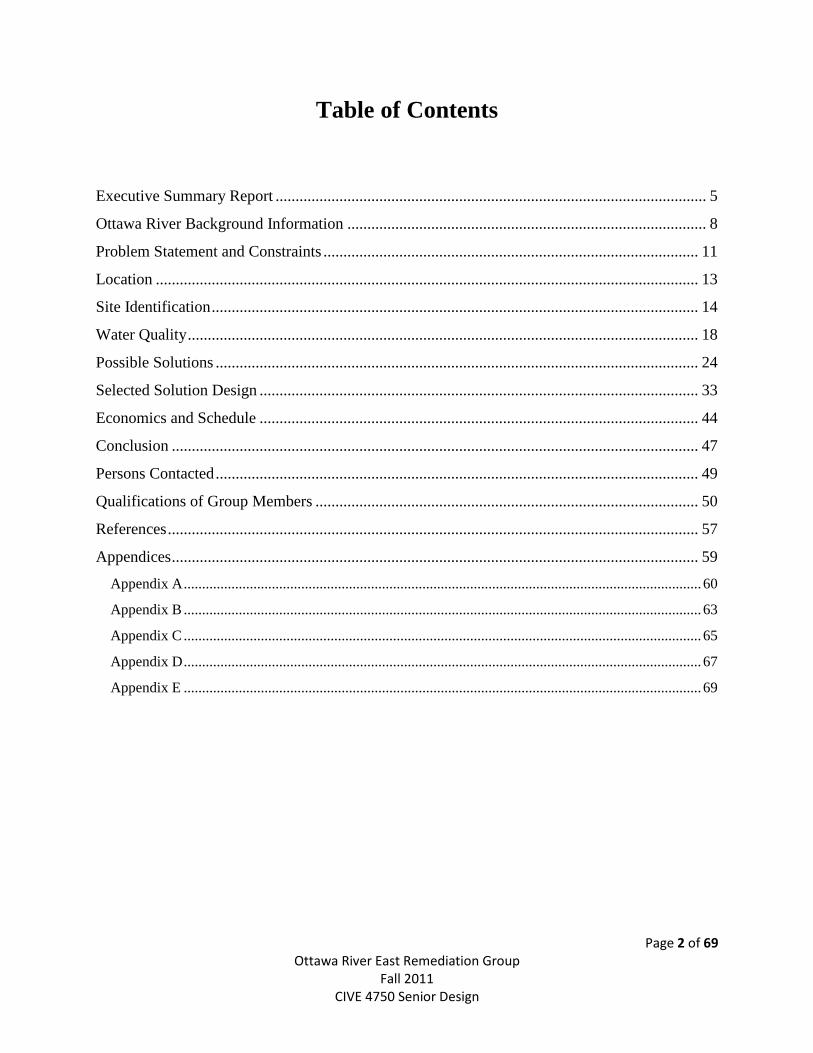
Executive Summary Report ............................................................................................................ 5
Ottawa River Background Information .......................................................................................... 8
Problem Statement and Constraints .............................................................................................. 11
Location ........................................................................................................................................ 13
Site Identification .......................................................................................................................... 14
Water Quality ................................................................................................................................ 18
Possible Solutions ......................................................................................................................... 24
Selected Solution Design .............................................................................................................. 33
Economics and Schedule .............................................................................................................. 44
Conclusion .................................................................................................................................... 47
Persons Contacted ......................................................................................................................... 49
Qualifications of Group Members ................................................................................................ 50
References ..................................................................................................................................... 57
Appendices .................................................................................................................................... 59
Appendix A ............................................................................................................................................. 60
Appendix B ............................................................................................................................................. 63
Appendix C ............................................................................................................................................. 65
Appendix D ............................................................................................................................................. 67
Appendix E ............................................................................................................................................. 69
Page 3 of 69 Ottawa River East Remediation Group
Fall 2011 CIVE 4750 Senior Design
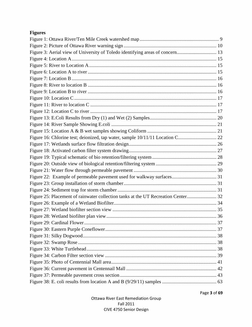
Figures
Figure 1: Ottawa River/Ten Mile Creek watershed map ................................................................ 9
Figure 2: Picture of Ottawa River warning sign ........................................................................... 10
Figure 3: Aerial view of University of Toledo identifying areas of concern ................................ 13
Figure 4: Location A ..................................................................................................................... 15
Figure 5: River to Location A ....................................................................................................... 15
Figure 6: Location A to river ........................................................................................................ 15
Figure 7: Location B ..................................................................................................................... 16
Figure 8: River to location B ........................................................................................................ 16
Figure 9: Location B to river ........................................................................................................ 16
Figure 10: Location C ................................................................................................................... 17
Figure 11: River to location C ...................................................................................................... 17
Figure 12: Location C to river ...................................................................................................... 17
Figure 13: E.Coli Results from Dry (1) and Wet (2) Samples...................................................... 20
Figure 14: River Sample Showing E.coli ..................................................................................... 21
Figure 15: Location A & B wet samples showing Coliform ........................................................ 21
Figure 16: Chlorine test; deionized, tap water, sample 10/11/11 Location C............................... 22
Figure 17: Wetlands surface flow filtration design....................................................................... 26
Figure 18: Activated carbon filter system drawing....................................................................... 27
Figure 19: Typical schematic of bio retention/filtering system .................................................... 28
Figure 20: Outside view of biological retention/filtering system ................................................. 29
Figure 21: Water flow through permeable pavement ................................................................... 30
Figure 22: Example of permeable pavement used for walkway surfaces .................................... 31
Figure 23: Group installation of storm chamber ........................................................................... 31
Figure 24: Sediment trap for storm chamber ................................................................................ 31
Figure 25: Placement of rainwater collection tanks at the UT Recreation Center ........................ 32
Figure 26: Example of a Wetland Biofilter................................................................................... 34
Figure 27: Wetland biofilter section view .................................................................................... 35
Figure 28: Wetland biofilter plan view ......................................................................................... 36
Figure 29: Cardinal Flower ........................................................................................................... 37
Figure 30: Eastern Purple Coneflower .......................................................................................... 37
Figure 31: Silky Dogwood ............................................................................................................ 38
Figure 32: Swamp Rose ................................................................................................................ 38
Figure 33: White Turtlehead ......................................................................................................... 38
Figure 34: Carbon Filter section view .......................................................................................... 39
Figure 35: Photo of Centennial Mall area ..................................................................................... 41
Figure 36: Current pavement in Centennail Mall ......................................................................... 42
Figure 37: Permeable pavement cross section .............................................................................. 43
Figure 38: E. coli results from location A and B (9/29/11) samples ............................................ 63
Page 4 of 69 Ottawa River East Remediation Group
Fall 2011 CIVE 4750 Senior Design
Figure 39: E.coli results from location C and the river (9/29/11) samples ................................... 63
Figure 40: E.coli results from locations A, C, and the river (10/11/11) sample ........................... 64
Figure 41: E.coli results from location B (10/11/11) sample........................................................ 64
Figure 42: Rigid pavement design chart 1 .................................................................................... 67
Figure 43: Rigid pavement design chart 2 .................................................................................... 68
Figure 44: Methylene green dye curve ......................................................................................... 69
Tables
Table 1: Carbon filter design ........................................................................................................ 40
Table 2: Wetland biofilter economic analysis .............................................................................. 44
Table 3: Wetland biofilter plant economic breakdown ................................................................. 45
Table 4: Activated carbon filter economic analysis ...................................................................... 45
Table 5: Permeable pavement economic analysis ........................................................................ 45
Table 6: Water quality data for location A ................................................................................... 65
Table 7: Water quality data for location B.................................................................................... 65
Table 8: Water quality data for location C.................................................................................... 66
Table 9: Water quality data for the river ....................................................................................... 66

Page 5 of 69 Ottawa River East Remediation Group
Fall 2011 CIVE 4750 Senior Design
Executive Summary Report
Page 6 of 69 Ottawa River East Remediation Group
Fall 2011 CIVE 4750 Senior Design
Department of Civil Engineering
Senior Project
Executive Summary Report
Main Campus – Storm Water East
Fall Semester 2011
Team Members:
Ashley Frey
Thomas Hasson
Brandon Heaney
Tara Nemcik
Christopher Wancata
Faculty Mentor:
Cyndee Gruden, Ph.D, P.E.
Associate Professor
419.530.4128
Consulting Mentor:
Patrick L. Lawrance, Ph.D.
Chair A&S Dept. Geog. & Professor
419.530.4128
For copies of this final report go to
http://www.eng.utoledo.edu/civil/classes/c32
10.html#4750
Or call 419.53.8120
University of Toledo
Department of Civil Engineering
2801 W. Bancroft Street
Toledo, Ohio 43606
Mail Stop #307
Problem Statement
The University of Toledo has asked for an
evaluation of the section of the Ottawa River
running though main campus, with regards
to present contaminants. Additionally, there
have been concerns that the university
contributes large flows during heavy
rainfall. The Ohio EPA has previously been
on campus and noted discharge points
belonging to the university as areas of
concern. Our group has been tasked with
determining potential eco-hazards and large
flow concentrations discharged by the
university, as well as developing solutions
for any problems encountered.
Objectives
Examine the university’s storm water
discharge into the Ottawa River for
major health and ecosystem hazards.
Determine areas of campus that
contribute to heavy storm water flow and
look to reduce.
Trace outfalls from the river back to
source(s).
Evaluate possible solutions to reduce
pollution and storm water flows into the
Ottawa River.
Establish a plan to put solutions into
effect with limited installation and
continued maintenance costs.
Page 7 of 69 Ottawa River East Remediation Group
Fall 2011 CIVE 4750 Senior Design
Constraints
Funding by the University of Toledo and
supporting agencies
Available space on campus for proposed
solutions
Preservation of animal habitats along the
river
Maintaining the aesthetic appeal of the
University’s campus
Ease of construction
Sustainability and reliability of low
maintenance costs
Solution Approach
It is very important that the concerns about
volume and quality of water discharged by
the university be addressed and corrected.
Solutions will be evaluated based on:
Initial capital involved with installation
Aesthetic appeal to the university
Maintenance costs and possible LEED
certifications
Design creativity
Ability of design to change based on
future needs
Schedule
Proposal submittal and presentation to the
GEPL delivered October 7, 2011. Final
presentation to Geological Department Chair
and interested member of the university
community will be delivered the week of
December 5, 2011. The design project will
be showcased in the University of Toledo
Senior Design Expo December 9, 2011 with
a final report being turned in December 9,
2011.
Economics
Estimate for construction materials and
installation will be delivered with final
report.
Implementation Potential
Each solution will be evaluated on the basis
of constructability within the campus limits,
feasibility, and sustainability. A strategy for
implementation will be delivered with the
final report.
Conclusions and Recommendations
Summary of design project will be included
after final design.
Overall design of flow reduction and
contaminant treatment system
Area of impact associated with
construction
Estimated costs associated with project
implementation
Benefits from installing designed system

Page 8 of 69 Ottawa River East Remediation Group
Fall 2011 CIVE 4750 Senior Design
Ottawa River Background Information
Page 9 of 69 Ottawa River East Remediation Group
Fall 2011 CIVE 4750 Senior Design
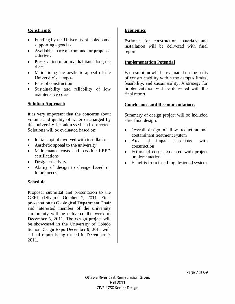
Located in the center of The University of Toledo’s main campus is the Ottawa River;
originating in Fulton County and running through Lucas County to eventually draining into
Maumee Bay and Lake Erie. The Ottawa River was established with the connection of two
creeks; North Ten Mile Creek and Ten Mile Creek. Roughly 48 miles in length, with 220 square
miles of drainage basin and an average slope of four feet per mile, the Ottawa River is home to
approximately 40 species of fish. Figure 1 below shows a map of the Ottawa River and Ten
Mile Creek watershed
Figure 1: Ottawa River/Ten Mile Creek watershed map
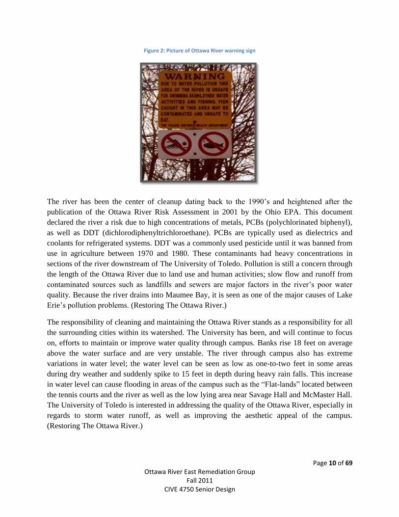
Unfortunately, signs are posted through The University of Toledo’s campus stating “Due to
water pollution this area of the river is unsafe for swimming, skiing, other water activities and
fishing. Fish caught in this area may be contaminated and unsafe to eat” as seen in Figure 2.
Maintenance of the river is done primarily by the cities and municipalities through which the
river passes. (Restoring The Ottawa River.)
Page 10 of 69 Ottawa River East Remediation Group
Fall 2011 CIVE 4750 Senior Design
Figure 2: Picture of Ottawa River warning sign
The river has been the center of cleanup dating back to the 1990’s and heightened after the
publication of the Ottawa River Risk Assessment in 2001 by the Ohio EPA. This document
declared the river a risk due to high concentrations of metals, PCBs (polychlorinated biphenyl),
as well as DDT (dichlorodiphenyltrichloroethane). PCBs are typically used as dielectrics and
coolants for refrigerated systems. DDT was a commonly used pesticide until it was banned from
use in agriculture between 1970 and 1980. These contaminants had heavy concentrations in
sections of the river downstream of The University of Toledo. Pollution is still a concern through
the length of the Ottawa River due to land use and human activities; slow flow and runoff from
contaminated sources such as landfills and sewers are major factors in the river’s poor water
quality. Because the river drains into Maumee Bay, it is seen as one of the major causes of Lake
Erie’s pollution problems. (Restoring The Ottawa River.)
The responsibility of cleaning and maintaining the Ottawa River stands as a responsibility for all
the surrounding cities within its watershed. The University has been, and will continue to focus
on, efforts to maintain or improve water quality through campus. Banks rise 18 feet on average
above the water surface and are very unstable. The river through campus also has extreme
variations in water level; the water level can be seen as low as one-to-two feet in some areas
during dry weather and suddenly spike to 15 feet in depth during heavy rain falls. This increase
in water level can cause flooding in areas of the campus such as the “Flat-lands” located between
the tennis courts and the river as well as the low lying area near Savage Hall and McMaster Hall.
The University of Toledo is interested in addressing the quality of the Ottawa River, especially in
regards to storm water runoff, as well as improving the aesthetic appeal of the campus.
(Restoring The Ottawa River.)

Page 11 of 69 Ottawa River East Remediation Group
Fall 2011 CIVE 4750 Senior Design
Problem Statement and Constraints
Page 12 of 69 Ottawa River East Remediation Group
Fall 2011 CIVE 4750 Senior Design
Problem Statement
The water quality of the Ottawa River has been a concern for the University of Toledo for many
years. High levels of contamination such as dissolved solids, oils and greases, and nutrients have
been a large concern along with the suspicion of E. coli being present. The Environmental
Protection Agency (EPA), combined with The University of Toledo, has flagged a few areas of
storm water concern. To address these concerns, two cases need to be addressed: short term
solutions (in-situ treatment of current storm water) and long term (ways to reduce quantity of
flow into the Ottawa River) solutions.
Short term solutions to the contaminants in the water involve finding a way to reduce
contaminants into the Ottawa River given the current rate of flow of storm water into the river.
During various site visits, the Storm Water East Senior Design Group identified three areas of
concern along the banks of the Ottawa River. Through testing of samples collected from each of
the three sites, The Senior Design Group determined that the following water quality benchmarks
need to be addressed:
Conductivity
Coliform presence
Dissolved oxygen (DO)
Biochemical Oxygen Demand
pH
Currently, storm water is collected from various parts of campus, and is drained into outlets
along the river. Certain university outfalls are of concern because the source of flow and
potential pollutants are unknown. Even during periods of little to no rain fall, these outfalls still
exhibit steady flow. Some of these outlets also have raised levels of solids and dissolved solids,
suggesting that there may be sanitary sewer issues as well.
Long term solutions to the storm water issue involve finding a way to reduce the amount of
storm water runoff that is being drained into the Ottawa River on campus. As stated above, most
storm water collected on campus is drained into the Ottawa River. By reducing the amount of
flow, you in turn reduce the amount of contaminants in the water.
Constraints
Limiting factors for our design proposal have been established as:
Funding by the University of Toledo and supporting agencies
Available space on campus for proposed solutions
Sustainability and relatively low maintenance costs
Preservation of animal habitats along the river
Maintaining the aesthetic appeal of the University’s campus
Ease of construction
It is important that the proposed solution meets all environmental standards set by the EPA and
the University of Toledo. Construction needs to be simple and easy to install without interrupting
the everyday flow of the campus.
Page 13 of 69 Ottawa River East Remediation Group
Fall 2011 CIVE 4750 Senior Design
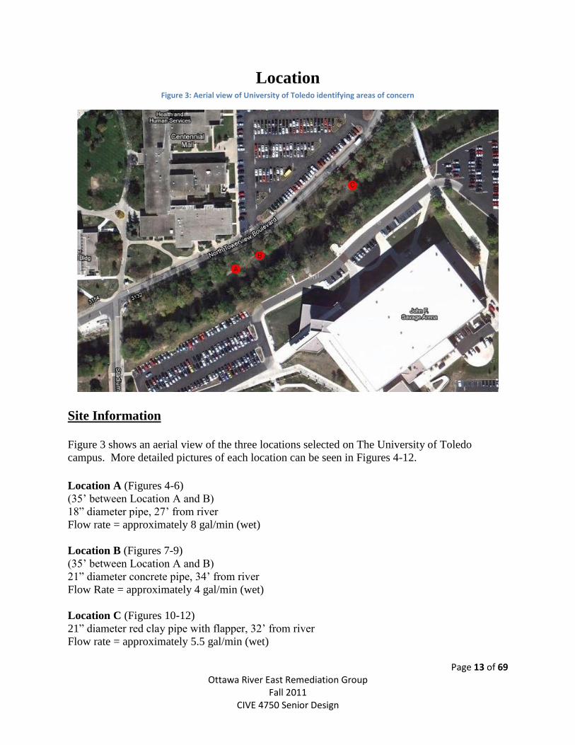
Location Figure 3: Aerial view of University of Toledo identifying areas of concern
Site Information
Figure 3 shows an aerial view of the three locations selected on The University of Toledo
campus. More detailed pictures of each location can be seen in Figures 4-12.
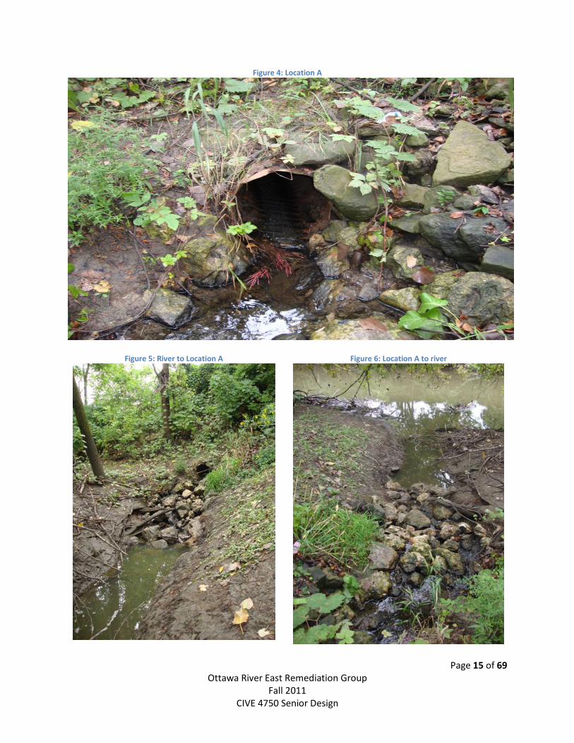
Location A (Figures 4-6)
(35’ between Location A and B)
18” diameter pipe, 27’ from river
Flow rate = approximately 8 gal/min (wet)
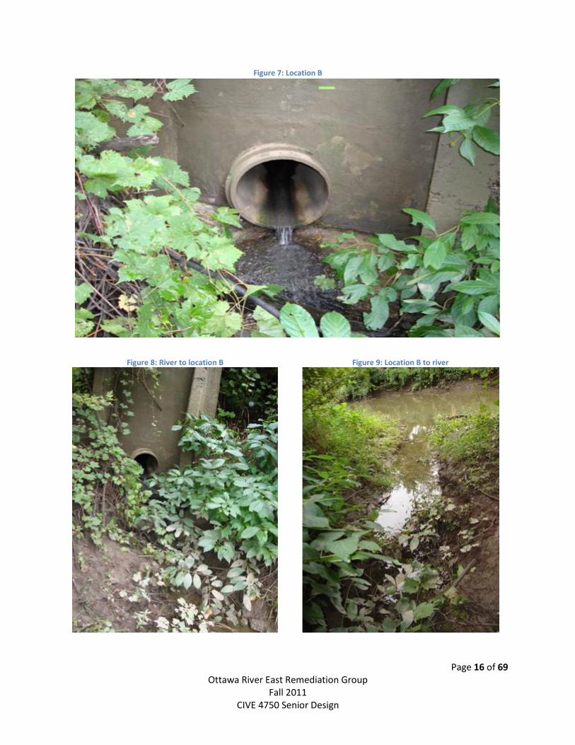
Location B (Figures 7-9)
(35’ between Location A and B)
21” diameter concrete pipe, 34’ from river
Flow Rate = approximately 4 gal/min (wet)
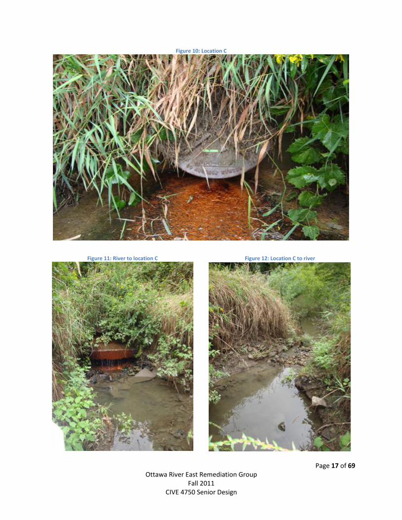
Location C (Figures 10-12)
21” diameter red clay pipe with flapper, 32’ from river
Flow rate = approximately 5.5 gal/min (wet)

Page 14 of 69 Ottawa River East Remediation Group
Fall 2011 CIVE 4750 Senior Design
Site Identification
Page 15 of 69 Ottawa River East Remediation Group
Fall 2011 CIVE 4750 Senior Design
Figure 4: Location A
Figure 5: River to Location A
Figure 6: Location A to river
Page 16 of 69 Ottawa River East Remediation Group
Fall 2011 CIVE 4750 Senior Design
Figure 7: Location B
Figure 8: River to location B
Figure 9: Location B to river
Page 17 of 69 Ottawa River East Remediation Group
Fall 2011 CIVE 4750 Senior Design
Figure 10: Location C
Figure 11: River to location C
Figure 12: Location C to river

Page 18 of 69 Ottawa River East Remediation Group
Fall 2011 CIVE 4750 Senior Design
Water Quality
Page 19 of 69 Ottawa River East Remediation Group
Fall 2011 CIVE 4750 Senior Design
Testing samples from the three outfalls of concern will provide a benchmark to determine the
quality of water discharging into the river. Additionally, water testing will also indicate where
the water is originating allowing for more treatment options to be explored. Both the University
of Toledo and the Ohio EPA have suspected high levels of contaminates being released from the
identified points. During dry weather, flow from these outlet points is still present, raising
question of both where it’s coming from and what it contains.
Multiple samples were taken from September 2011-October 2011 at each location during wet
and dry weather to ensure that the full spectrum of potential hazards could be identified. During
winter months higher levels of conductivity is to be expected due to the addition of road salts.
During times of heavy rainfall, higher levels of suspended soils along with oils and greases will
be flushed from the parking lots into the river.
Due to the flows observed during dry weather, the Ohio EPA has suggested that a cross
connection between storm water and wastewater lines could be present; such a connection would
result in wastewater E. coli contamination of the discharging waters.
To ensure the most infallible collection of water discharge, the sample was taken directly from
the pipe outlet point without contacting any outside sources such as soil or surrounding river
water. Each sample bottle was filled and flushed with outfall water prior to sample collection.
Each bottle was accurately labeled, sealed, and stored until tests were conducted.
The following tests were conducted on each sample:
Dissolved Oxygen (DO)
pH
Total Organic Carbon (TOC)
Turbidity
Escherichia coli (E. coli)
Biochemical Oxygen Demand (BOD)
Conductivity
Total Suspended Solids (TSS)
Chlorine (only on Location C)
Nitrates
Phosphorus
Procedures for each test can be found in Appendix A.
An example of what the US EPA considers healthy levels is provided below:
(Based on USEPA Gold Book – standards are safe for fish habitats and human contact)
Page 20 of 69 Ottawa River East Remediation Group
Fall 2011 CIVE 4750 Senior Design
DO: 0.5 mg/L
pH: 6.5-8.2
TOC: 300 µg/L
Turbidity: 5 NTU safe for human swimming
80 NTU shown to cause death to microscopic invertebrates
5000 NTU shown to directly cause fish deaths
Coliform: Less than 235 colony forming units 235 CFU/100 mL
BOD5: 2-8 mg/L
Conductivity: Expected levels of 300-700µs/cm
TSS: ≤ 1000 mg/L expected for ecosystems containing mixed cultures of fish
Chlorine: >0 begins to affect aquatic life
Nitrates: >0.5 mg/L begins to impact aquatic life
Phosphorus: 0.1 mg/L is recommended maximum for rivers and streams
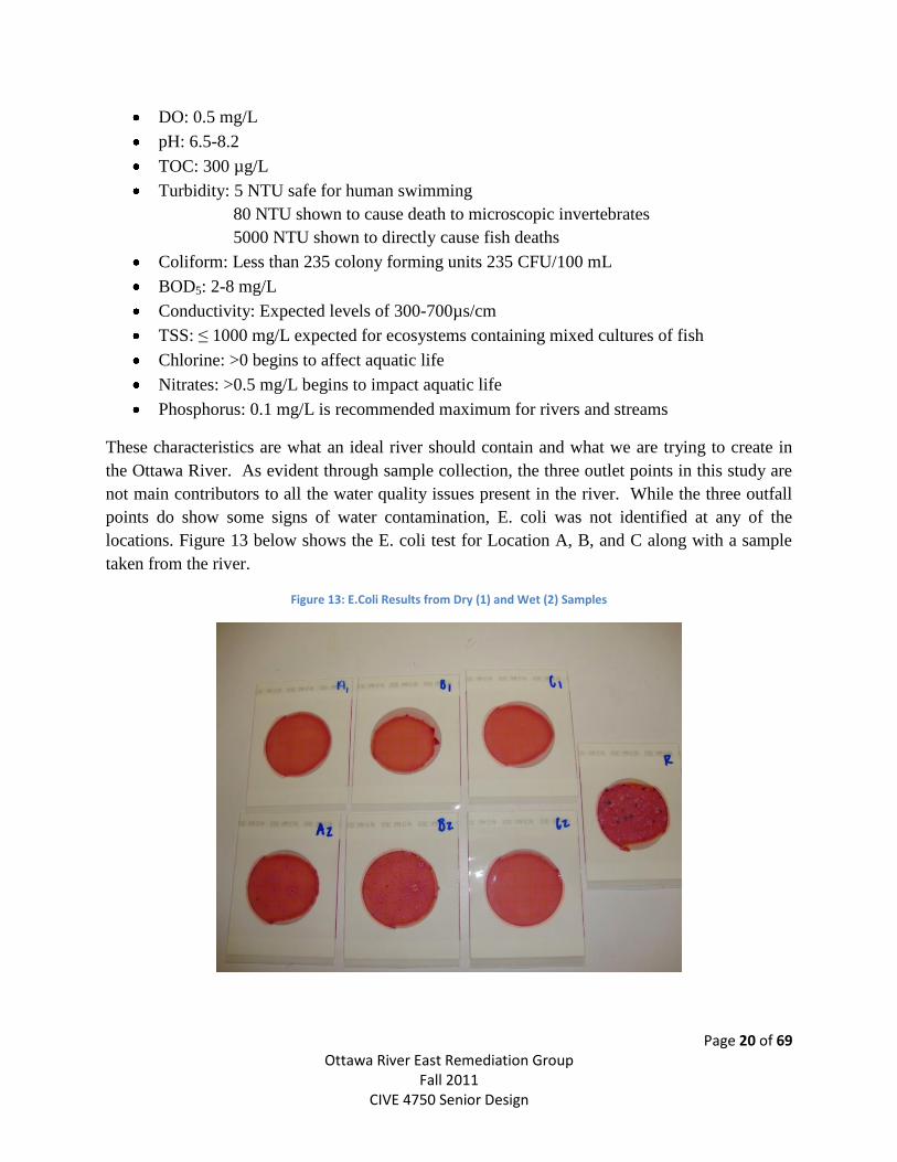
These characteristics are what an ideal river should contain and what we are trying to create in
the Ottawa River. As evident through sample collection, the three outlet points in this study are
not main contributors to all the water quality issues present in the river. While the three outfall
points do show some signs of water contamination, E. coli was not identified at any of the
locations. Figure 13 below shows the E. coli test for Location A, B, and C along with a sample
taken from the river.
Figure 13: E.Coli Results from Dry (1) and Wet (2) Samples
Page 21 of 69 Ottawa River East Remediation Group
Fall 2011 CIVE 4750 Senior Design
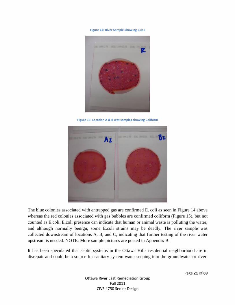
Figure 14: River Sample Showing E.coli
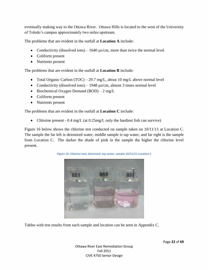
Figure 15: Location A & B wet samples showing Coliform
The blue colonies associated with entrapped gas are confirmed E. coli as seen in Figure 14 above
whereas the red colonies associated with gas bubbles are confirmed coliform (Figure 15), but not
counted as E.coli. E.coli presence can indicate that human or animal waste is polluting the water,
and although normally benign, some E.coli strains may be deadly. The river sample was
collected downstream of locations A, B, and C, indicating that further testing of the river water
upstream is needed. NOTE: More sample pictures are posted in Appendix B.
It has been speculated that septic systems in the Ottawa Hills residential neighborhood are in
disrepair and could be a source for sanitary system water seeping into the groundwater or river,
Page 22 of 69 Ottawa River East Remediation Group
Fall 2011 CIVE 4750 Senior Design
eventually making way to the Ottawa River. Ottawa Hills is located to the west of the University
of Toledo’s campus approximately two miles upstream.
The problems that are evident in the outfall at Location A include:
Conductivity (dissolved ions) – 1640 µs/cm, more than twice the normal level
Coliform present
Nutrients present
The problems that are evident in the outfall at Location B include:
Total Organic Carbon (TOC) – 29.7 mg/L, about 10 mg/L above normal level
Conductivity (dissolved ions) – 1948 µs/cm, almost 3 times normal level
Biochemical Oxygen Demand (BOD) – 2 mg/L
Coliform present
Nutrients present
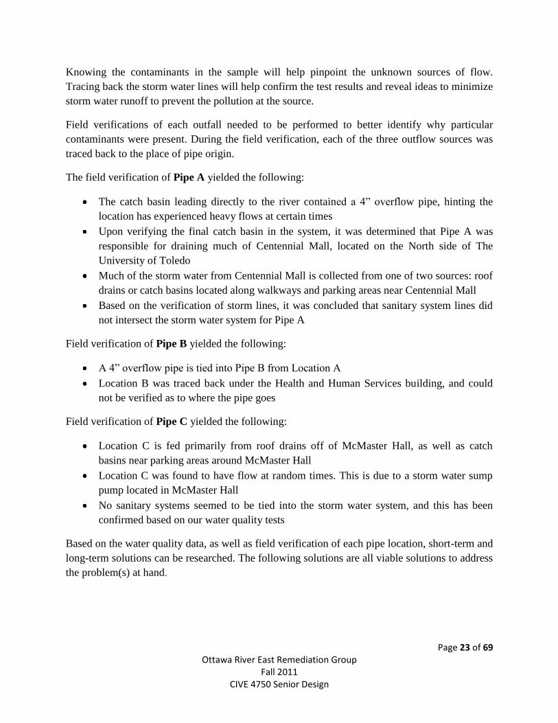
The problems that are evident in the outfall at Location C include:
Chlorine present - 0.4 mg/L (at 0.25mg/L only the hardiest fish can survive)
Figure 16 below shows the chlorine test conducted on sample taken on 10/11/11 at Location C.
The sample the far left is deionized water, middle sample is tap water, and far right is the sample
from Location C. The darker the shade of pink in the sample the higher the chlorine level
present.
Figure 16: Chlorine test; deionized, tap water, sample 10/11/11 Location C
Tables with test results from each sample and location can be seen in Appendix C.
Page 23 of 69 Ottawa River East Remediation Group
Fall 2011 CIVE 4750 Senior Design
Knowing the contaminants in the sample will help pinpoint the unknown sources of flow.
Tracing back the storm water lines will help confirm the test results and reveal ideas to minimize
storm water runoff to prevent the pollution at the source.
Field verifications of each outfall needed to be performed to better identify why particular
contaminants were present. During the field verification, each of the three outflow sources was
traced back to the place of pipe origin.
The field verification of Pipe A yielded the following:
The catch basin leading directly to the river contained a 4” overflow pipe, hinting the
location has experienced heavy flows at certain times
Upon verifying the final catch basin in the system, it was determined that Pipe A was
responsible for draining much of Centennial Mall, located on the North side of The
University of Toledo
Much of the storm water from Centennial Mall is collected from one of two sources: roof
drains or catch basins located along walkways and parking areas near Centennial Mall
Based on the verification of storm lines, it was concluded that sanitary system lines did
not intersect the storm water system for Pipe A
Field verification of Pipe B yielded the following:
A 4” overflow pipe is tied into Pipe B from Location A
Location B was traced back under the Health and Human Services building, and could
not be verified as to where the pipe goes
Field verification of Pipe C yielded the following:
Location C is fed primarily from roof drains off of McMaster Hall, as well as catch
basins near parking areas around McMaster Hall
Location C was found to have flow at random times. This is due to a storm water sump
pump located in McMaster Hall
No sanitary systems seemed to be tied into the storm water system, and this has been
confirmed based on our water quality tests
Based on the water quality data, as well as field verification of each pipe location, short-term and
long-term solutions can be researched. The following solutions are all viable solutions to address
the problem(s) at hand.

Page 24 of 69 Ottawa River East Remediation Group
Fall 2011 CIVE 4750 Senior Design
Possible Solutions
Page 25 of 69 Ottawa River East Remediation Group
Fall 2011 CIVE 4750 Senior Design
As part of the design process, the group has developed six different solution alternatives to the
given water quality issues. Solution types have been broken down into in-situ (in stream) and
out of stream. In-situ solutions are to treat the current water quality issues at the pipe outfall
before entering the river, whereas the out of stream solutions are treating the water at or closer to
the source. The in-situ solutions are more immediate and short term options, and the out of
stream solutions are more long term and sustainable. The six solutions options our group has
identified are outline here and detailed further in the following pages.
In stream:
Wetland biofilter
Activated carbon filter system
Out of Stream:
Biological screening system
Permeable pavement
Storm chambers
Rainwater harvesting
In Stream Solutions
In-situ solutions offer the benefit of immediate treatment for contaminants being released into
the river, without needing to identify the contaminant origin. This would allow for a stronger
ecosystem to develop within the Ottawa River quickly. The high river banks would reduce
visibility of any installed systems, allowing for water treatment without detracting from the
aesthetic appeal of the surroundings.
Wetland Biofilter
One potential solution is to install a bio-filtration area enclosing Locations A and B and the area
up to the edge of river bank. In the design below (see Figure 17) water from the outfalls at
Locations A and B would flow into the wetland filtration system, be treated, and the flow out
into the river. The river banks will also keep the treatment systems hidden from view, providing
protection for the system.
Page 26 of 69 Ottawa River East Remediation Group
Fall 2011 CIVE 4750 Senior Design
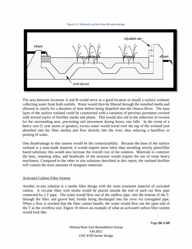
Figure 17: Wetlands surface flow filtration design
The area between locations A and B would serve as a good location to install a surface wetland,
collecting water from both outfalls. Water would then be filtered through the installed media and
allowed to clarify for a duration of time before being dispelled into the Ottawa River. The base
layer of the surface wetland could be constructed with a variation of pervious pavement covered
with several layers of biofilter media and plants. This would also aid in the reduction of erosion
for the surrounding area, preventing soil movement during heavy rain falls. In the event of a
heavy rain (5 year storm or greater), excess water would travel over the top of the wetland (not
absorbed into the filter media) and flow directly into the river, thus reducing a backflow or
pooling of water.
One disadvantage to this system would be the constructability. Because the base of the surface
wetland is a man-made material, it would require more labor than installing strictly plant/filter
based solutions; this would also increase the overall cost of the solution. Materials to construct
the base, retaining sides, and headwalls of the structure would require the use of some heavy
machinery. Compared to the other in situ solutions described in this report, the wetland biofilter
will contain the most amounts of inorganic materials.
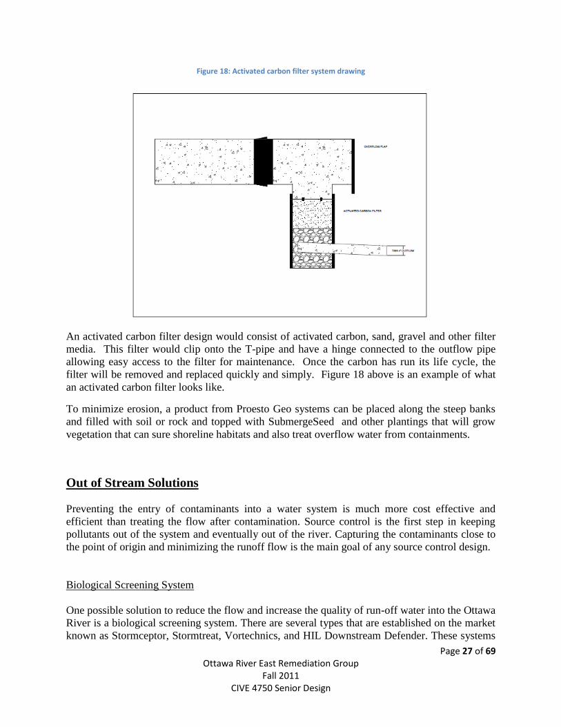
Activated Carbon Filter System
Another in-situ solution is a media filter design with the main treatment material of activated
carbon. A circular filter with media would be placed outside the end of each out flow pipe
connected by a T-pipe. The water would flow out of the outflow pipe, into the bottom of the T,
through the filter and gravel bed, finally being discharged into the river via corrugated pipe.
When a flow is reached that the filter cannot handle, the water would flow out the open end of
the T as the overflow exit. Figure 18 shows an example of what an activated carbon filter system
would look like.
Page 27 of 69 Ottawa River East Remediation Group
Fall 2011 CIVE 4750 Senior Design
Figure 18: Activated carbon filter system drawing
An activated carbon filter design would consist of activated carbon, sand, gravel and other filter
media. This filter would clip onto the T-pipe and have a hinge connected to the outflow pipe
allowing easy access to the filter for maintenance. Once the carbon has run its life cycle, the
filter will be removed and replaced quickly and simply. Figure 18 above is an example of what
an activated carbon filter looks like.
To minimize erosion, a product from Proesto Geo systems can be placed along the steep banks
and filled with soil or rock and topped with SubmergeSeed and other plantings that will grow
vegetation that can sure shoreline habitats and also treat overflow water from containments.
Out of Stream Solutions
Preventing the entry of contaminants into a water system is much more cost effective and
efficient than treating the flow after contamination. Source control is the first step in keeping
pollutants out of the system and eventually out of the river. Capturing the contaminants close to
the point of origin and minimizing the runoff flow is the main goal of any source control design.
Biological Screening System
One possible solution to reduce the flow and increase the quality of run-off water into the Ottawa
River is a biological screening system. There are several types that are established on the market
known as Stormceptor, Stormtreat, Vortechnics, and HIL Downstream Defender. These systems
Page 28 of 69 Ottawa River East Remediation Group
Fall 2011 CIVE 4750 Senior Design
are different primarily in patent right but similar in overall layout. The systems consist of
influent piping, a retention area, metal filters, biological filters, and regulated effluent piping.
These systems can be installed to remove:
Grit
Suspended solids
Biological Oxygen Demand (BOD)
Petroleum Products (oil and fuel from paved areas)
Hydrocarbons
Metals
Nitrogen
Phosphorus
Bacteria (Coliforms)
Two kinds of units are typically installed, recharge and closed. A recharge unit is used to
cleanse run-off water and allow it to reenter the environment through soil absorption. Closed
units are installed as a portion of an entire loop of water treatment. The best choice for
University of Toledo’s needs would be the recharge unit, which would be used to treat and
release water to be absorbed in surrounding soils, gardens, or runoff into the Ottawa River.
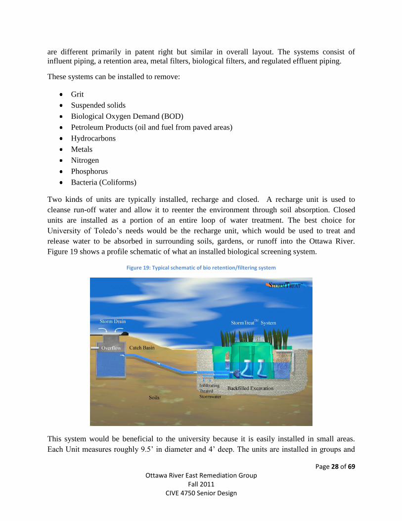
Figure 19 shows a profile schematic of what an installed biological screening system.
Figure 19: Typical schematic of bio retention/filtering system
This system would be beneficial to the university because it is easily installed in small areas.
Each Unit measures roughly 9.5’ in diameter and 4’ deep. The units are installed in groups and
Page 29 of 69 Ottawa River East Remediation Group
Fall 2011 CIVE 4750 Senior Design
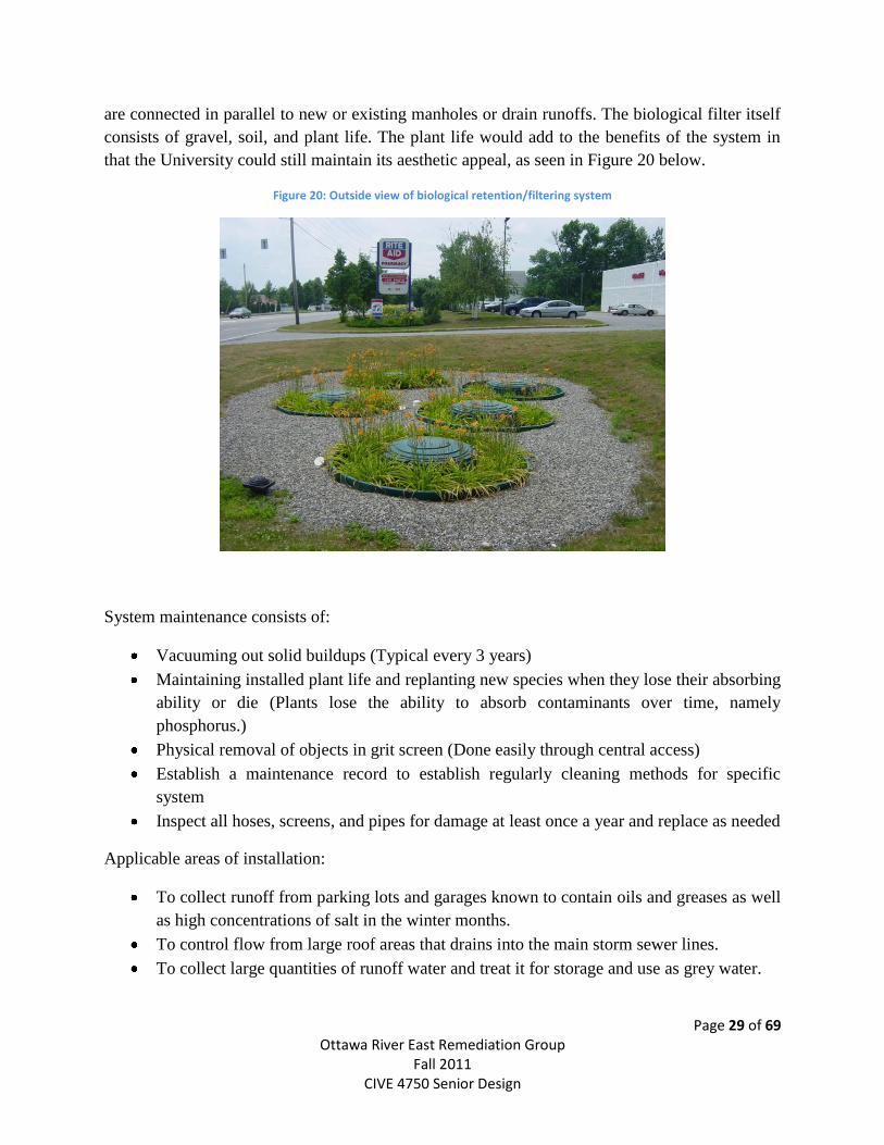
are connected in parallel to new or existing manholes or drain runoffs. The biological filter itself
consists of gravel, soil, and plant life. The plant life would add to the benefits of the system in
that the University could still maintain its aesthetic appeal, as seen in Figure 20 below.
Figure 20: Outside view of biological retention/filtering system
System maintenance consists of:
Vacuuming out solid buildups (Typical every 3 years)
Maintaining installed plant life and replanting new species when they lose their absorbing
ability or die (Plants lose the ability to absorb contaminants over time, namely
phosphorus.)
Physical removal of objects in grit screen (Done easily through central access)
Establish a maintenance record to establish regularly cleaning methods for specific
system
Inspect all hoses, screens, and pipes for damage at least once a year and replace as needed
Applicable areas of installation:
To collect runoff from parking lots and garages known to contain oils and greases as well
as high concentrations of salt in the winter months.
To control flow from large roof areas that drains into the main storm sewer lines.
To collect large quantities of runoff water and treat it for storage and use as grey water.
Page 30 of 69 Ottawa River East Remediation Group
Fall 2011 CIVE 4750 Senior Design
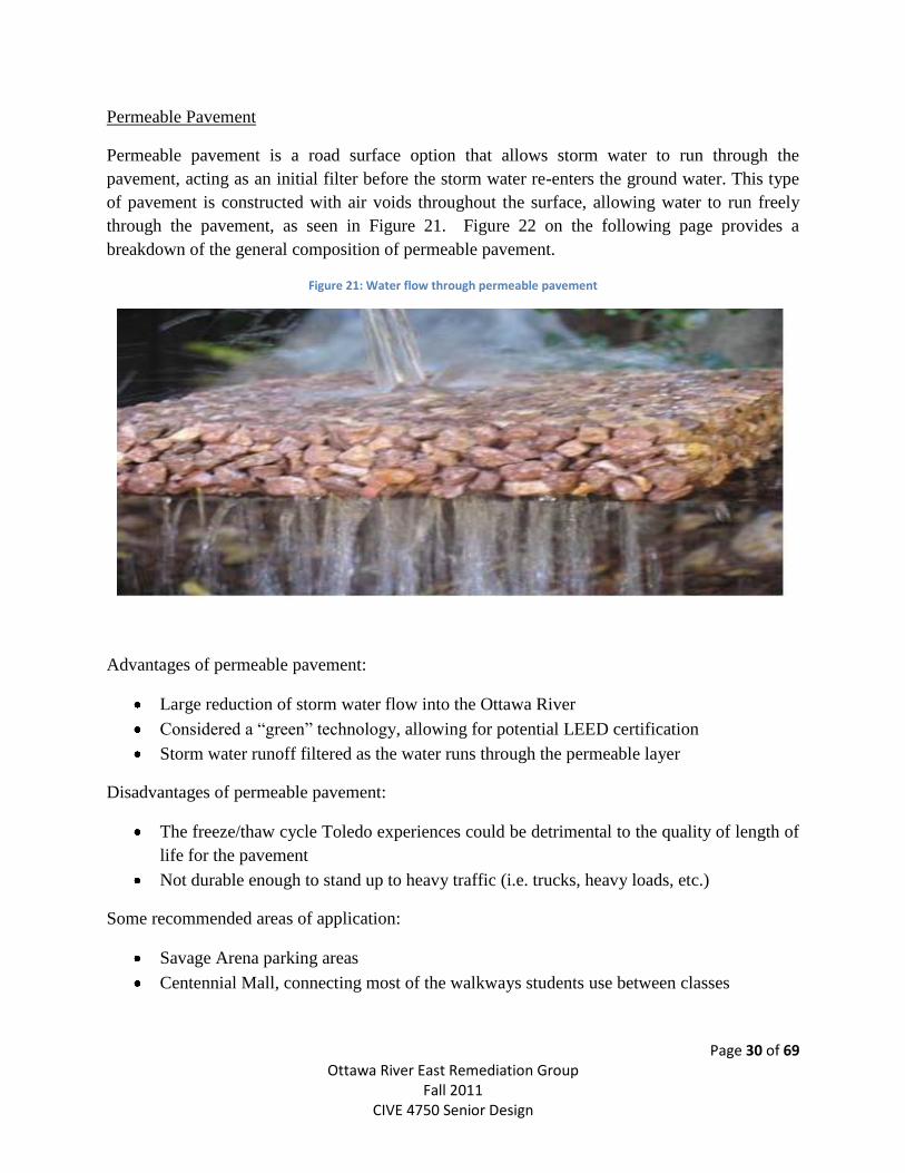
Permeable Pavement
Permeable pavement is a road surface option that allows storm water to run through the
pavement, acting as an initial filter before the storm water re-enters the ground water. This type
of pavement is constructed with air voids throughout the surface, allowing water to run freely
through the pavement, as seen in Figure 21. Figure 22 on the following page provides a
breakdown of the general composition of permeable pavement.
Figure 21: Water flow through permeable pavement
Advantages of permeable pavement:
Large reduction of storm water flow into the Ottawa River
Considered a “green” technology, allowing for potential LEED certification
Storm water runoff filtered as the water runs through the permeable layer
Disadvantages of permeable pavement:
The freeze/thaw cycle Toledo experiences could be detrimental to the quality of length of
life for the pavement
Not durable enough to stand up to heavy traffic (i.e. trucks, heavy loads, etc.)
Some recommended areas of application:
Savage Arena parking areas
Centennial Mall, connecting most of the walkways students use between classes
Page 31 of 69 Ottawa River East Remediation Group
Fall 2011 CIVE 4750 Senior Design
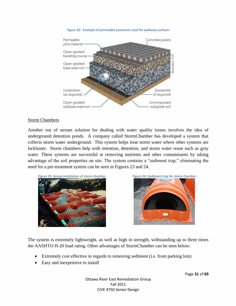
Figure 22: Example of permeable pavement used for walkway surfaces
Storm Chambers
Another out of stream solution for dealing with water quality issues involves the idea of
underground detention ponds. A company called StormChamber has developed a system that
collects storm water underground. This system helps treat storm water where other systems are
lackluster. Storm chambers help with retention, detention, and storm water reuse such as gray
water. These systems are successful at removing nutrients and other contaminants by taking
advantage of the soil properties on site. The system contains a “sediment trap,” eliminating the
need for a pre-treatment system can be seen in Figures 23 and 24.
Figure 23: Group installation of storm chamber
Figure 24: Sediment trap for storm chamber
The system is extremely lightweight, as well as high in strength, withstanding up to three times
the AASHTO H-20 load rating. Other advantages of StormChamber can be seen below:
Extremely cost effective in regards to removing sediment (i.e. from parking lots)
Easy and inexpensive to install
Page 32 of 69 Ottawa River East Remediation Group
Fall 2011 CIVE 4750 Senior Design
Effectively removes high levels of pollutants through soil filtration and bio-remediation
Green technology, capable of up to 18 LEED points
Effective under or around parking areas, due to high strength of the system
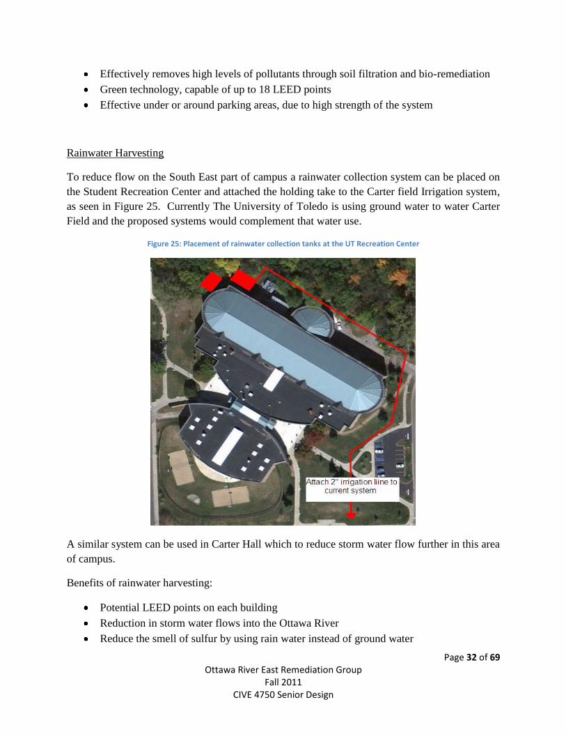
Rainwater Harvesting
To reduce flow on the South East part of campus a rainwater collection system can be placed on
the Student Recreation Center and attached the holding take to the Carter field Irrigation system,
as seen in Figure 25. Currently The University of Toledo is using ground water to water Carter
Field and the proposed systems would complement that water use.
Figure 25: Placement of rainwater collection tanks at the UT Recreation Center
A similar system can be used in Carter Hall which to reduce storm water flow further in this area
of campus.
Benefits of rainwater harvesting:
Potential LEED points on each building
Reduction in storm water flows into the Ottawa River
Reduce the smell of sulfur by using rain water instead of ground water

Page 33 of 69 Ottawa River East Remediation Group
Fall 2011 CIVE 4750 Senior Design
Selected Solution Design
Page 34 of 69 Ottawa River East Remediation Group
Fall 2011 CIVE 4750 Senior Design
After reviewing all potential solutions, the group determined to move forward with two in-stream
solutions and two out-of-stream solutions. The in-stream solutions included the wetland biofilter
and activated carbon filter designs. Out-of-stream solutions included the rainwater harvesting
system for The University of Toledo recreation center and installation of permeable pavement.
Detailed designed of each of the selected solutions can be seen in the following section.
Rainwater Harvesting:
Because rainwater harvesting was one of the solutions of interest to the client the group wanted
to highlight the works of another group in the Senior Design class working solely on rainwater
harvesting at the University of Toledo campus. The group has currently developed plans to
harvest rainwater at the University of Toledo Law Center and Rocket Hall. These same designs
could be expanded to incorporate the areas around University of Toledo Recreation Center.
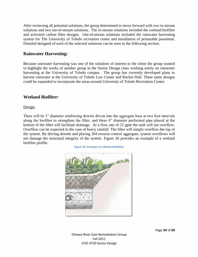
Wetland Biofilter:
Design:
There will be 1” diameter reinforcing dowels driven into the aggregate base at two foot intervals
along the biofilter to strengthen the filter, and three 4” diameter perforated pipe placed at the
bottom of the filter will facilitate drainage. At a flow rate of 12 gpm the tank will not overflow.
Overflow can be expected in the case of heavy rainfall. The filter will simply overflow the top of
the system. By driving dowels and placing 304 erosion control aggregate, system overflows will
not damage the structural integrity of the system. Figure 26 provides an example of a wetland
biofilter profile. Figure 26: Example of a Wetland Biofilter
Page 35 of 69 Ottawa River East Remediation Group
Fall 2011 CIVE 4750 Senior Design
Drawings/Specifications:
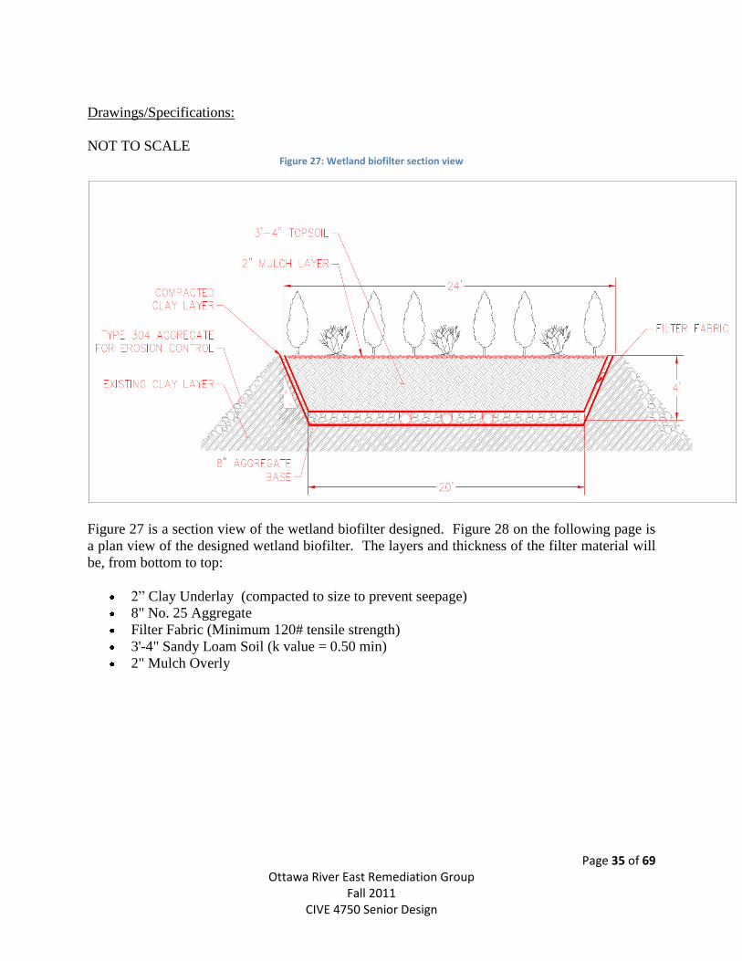
NOT TO SCALE Figure 27: Wetland biofilter section view
Figure 27 is a section view of the wetland biofilter designed. Figure 28 on the following page is
a plan view of the designed wetland biofilter. The layers and thickness of the filter material will
be, from bottom to top:
2” Clay Underlay (compacted to size to prevent seepage)
8" No. 25 Aggregate
Filter Fabric (Minimum 120# tensile strength)
3'-4" Sandy Loam Soil (k value = 0.50 min)
2" Mulch Overly
Page 36 of 69 Ottawa River East Remediation Group
Fall 2011 CIVE 4750 Senior Design
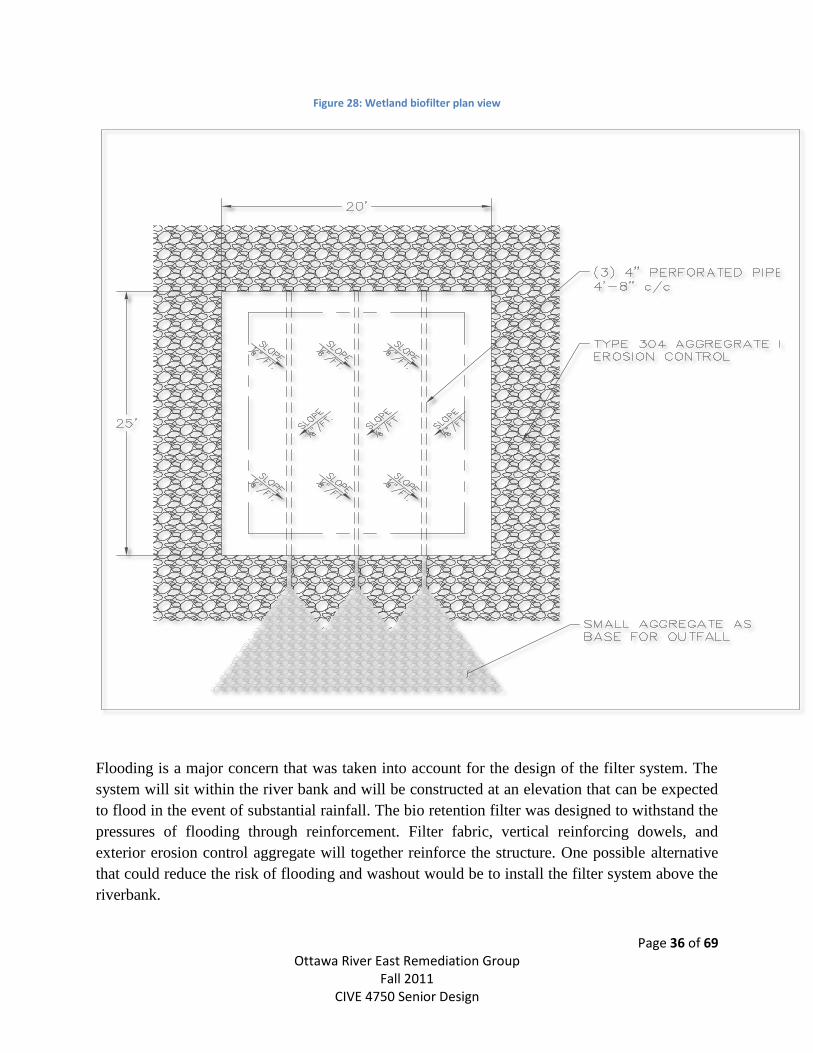
Figure 28: Wetland biofilter plan view
Flooding is a major concern that was taken into account for the design of the filter system. The
system will sit within the river bank and will be constructed at an elevation that can be expected
to flood in the event of substantial rainfall. The bio retention filter was designed to withstand the
pressures of flooding through reinforcement. Filter fabric, vertical reinforcing dowels, and
exterior erosion control aggregate will together reinforce the structure. One possible alternative
that could reduce the risk of flooding and washout would be to install the filter system above the
riverbank.
Page 37 of 69 Ottawa River East Remediation Group
Fall 2011 CIVE 4750 Senior Design
Installing the system above the river bank rather than in river bed would require different
construction methods. The outfall pipe would have to be demolished back to accommodate an
acceptable elevation, and the filter system would need an additional outfall height of roughly ten
feet. This would require a significant amount of demolition and additional excavation. We are
unaware of the exact slope of the pipe, but visual inspection shows a very shallow slope. It
appears that excavating back along the pipe would not increase the elevation enough for a
significant change to the filter position. The only way to determine if this is a feasible option
would be to physically trace the storm system and determine actual elevations of the pipes.
Installing the filter system above the river bank would reduce the risk for flooding and remove
any costs associated with reinforcement of the system but would increase the excavation costs as
well as add costs for pipe tracing and demolition. It is in the best interest of the funding agencies
to build the system in the river, reinforce it according to plans, and plant species of vegetation
that can handle the increased water levels.
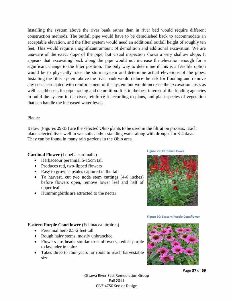
Plants:
Below (Figures 29-33) are the selected Ohio plants to be used in the filtration process. Each
plant selected lives well in wet soils and/or standing water along with drought for 3-4 days.
They can be found in many rain gardens in the Ohio area.
Cardinal Flower (Lobelia cardinalis)
Herbaceour perennial 5-15cm tall
Produces red, two-lipped flowers
Easy to grow, capsules captured in the fall
To harvest, cut two node stem cuttings (4-6 inches)
before flowers open, remove lower leaf and half of
upper leaf
Hummingbirds are attracted to the nectar
Eastern Purple Coneflower (Echinacea pirpirea)
Perennial herb 0.5-2 feet tall
Rough hairy stems, mostly unbranched
Flowers are heads similar to sunflowers, redish purple
to lavender in color
Takes three to four years for roots to reach harvestable
size
Figure 29: Cardinal Flower
Figure 30: Eastern Purple Coneflower
Page 38 of 69 Ottawa River East Remediation Group
Fall 2011 CIVE 4750 Senior Design
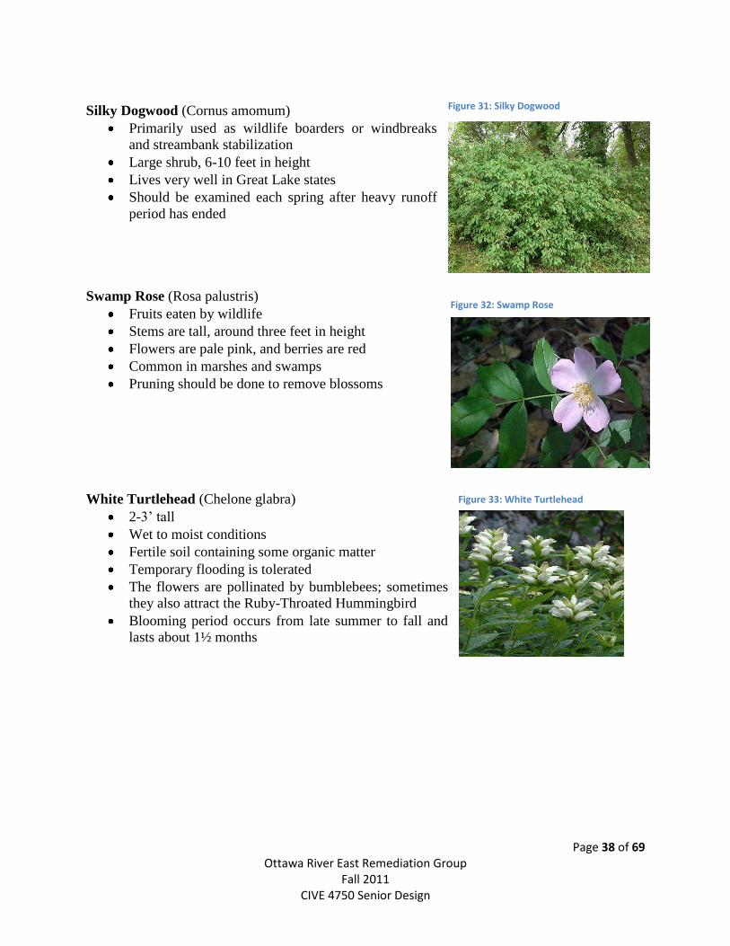
Silky Dogwood (Cornus amomum)
Primarily used as wildlife boarders or windbreaks
and streambank stabilization
Large shrub, 6-10 feet in height
Lives very well in Great Lake states
Should be examined each spring after heavy runoff
period has ended
Swamp Rose (Rosa palustris)
Fruits eaten by wildlife
Stems are tall, around three feet in height
Flowers are pale pink, and berries are red
Common in marshes and swamps
Pruning should be done to remove blossoms
White Turtlehead (Chelone glabra)
2-3’ tall
Wet to moist conditions
Fertile soil containing some organic matter
Temporary flooding is tolerated
The flowers are pollinated by bumblebees; sometimes
they also attract the Ruby-Throated Hummingbird
Blooming period occurs from late summer to fall and
lasts about 1½ months
Figure 31: Silky Dogwood
Figure 32: Swamp Rose
Figure 33: White Turtlehead
Page 39 of 69 Ottawa River East Remediation Group
Fall 2011 CIVE 4750 Senior Design
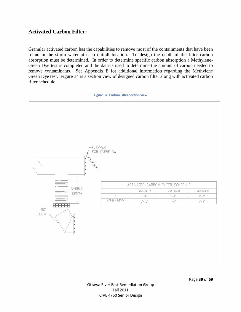
Activated Carbon Filter:
Granular activated carbon has the capabilities to remove most of the containments that have been
found in the storm water at each outfall location. To design the depth of the filter carbon
absorption must be determined. In order to determine specific carbon absorption a Methylene-
Green Dye test is completed and the data is used to determine the amount of carbon needed to
remove contaminants. See Appendix E for additional information regarding the Methylene
Green Dye test. Figure 34 is a section view of designed carbon filter along with activated carbon
filter schedule.
Figure 34: Carbon Filter section view
Page 40 of 69 Ottawa River East Remediation Group
Fall 2011 CIVE 4750 Senior Design
In order to supply sufficient carbon to treat the outflow water, the above design was selected. If
carbon were to be placed along the bottom of the pipe the filter would need to be nearly 20 feet
long and become a challenge to replace and handle. With the design selected the filter will be
easily maintain and accessible for replacement. It will also allow for a filter design that uses the
entire cross-sectional area of the pipe.
Each filter is designed for constant wet flows, in Toledo over a sixth month period there are 52
wet days. This creates a safety factor of 3.5 which insures that the filter will still be functioning
at full capacity at end of its sixth month life expectancy.
Table 1: Carbon filter design
Location Pipe Diameter Depth of Carbon
A 18” 34”
B 21” 16”
C 21” 16”
Table 1 above shows the pipe diameter, and carbon depth required at each outfall location.
Minimal maintenance will be needed at each filter because debris will be able to flow over the
filter and out the overflow flap. The filters will be bolted down to surrounding concrete
structures so the filter will not move or become dislodged with heavy river or outfall flows.
Granular activated carbon has the ability to effectively target:
Chlorine
o The EPA does not recognize GAC as a removal media for chlorine, but after
many laboratory tests GAC is proving to be the best media for removal.
BOD
o Laboratory testing has proven GAC to effectively remove BOD at a rate of up to
70% depending on flow rate and concentration.
TOC
o GAC can remove any organic or ionized compound, and is incredibly effective at
removing carbon based containments.
Other additives such as phosphorus will be needed to remove nitrates in the storm event
outflows. Special GAC formulations can be made to remove nutrients, but that could become
extremely costly to design and test for the correct formulation.
Page 41 of 69 Ottawa River East Remediation Group
Fall 2011 CIVE 4750 Senior Design
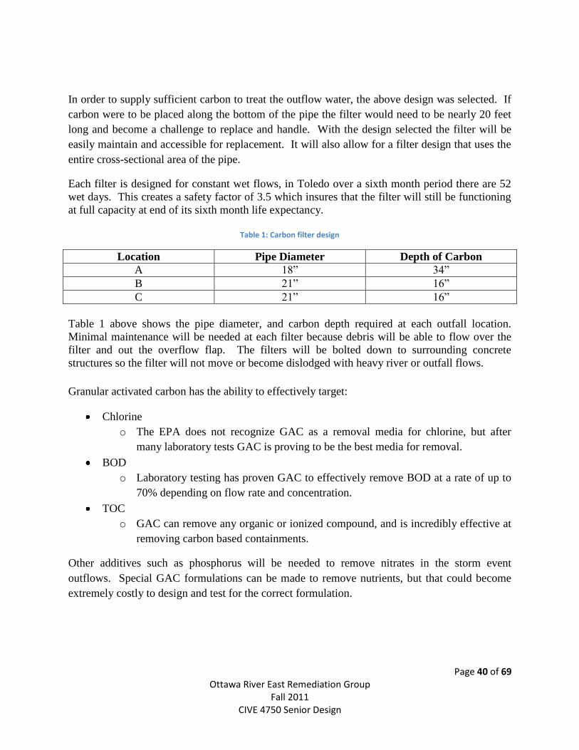
Permeable Pavement:
Permeable pavement provides a valuable storm water management tool under requirements of
the EPA Storm Water Phase II Final Rule by reducing the overall runoff and level of runoff
contamination for the designed area. Unlike traditional pavement, permeable pavement allows
water to flow through and drain into the aggregate and soil beneath. Because permeable
pavement is most typically used in areas of low-volume pavements, parking lots, residential
roads, sidewalks, and pathways the Centennial Mall of the University of Toledo’s main campus
was chosen for pavement replacement based on the low vehicular traffic and high foot traffic.
The main benefit would be runoff reduction because few oils and/or greases will be
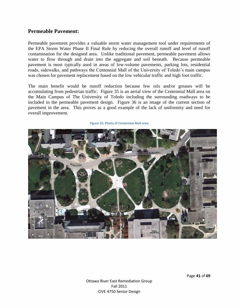
accumulating from pedestrian traffic. Figure 35 is an aerial view of the Centennial Mall area on
the Main Campus of The University of Toledo including the surrounding roadways to be
included in the permeable pavement design. Figure 36 is an image of the current section of
pavement in the area. This proves as a good example of the lack of uniformity and need for
overall improvement.
Figure 35: Photo of Centennial Mall area
Page 42 of 69 Ottawa River East Remediation Group
Fall 2011 CIVE 4750 Senior Design
Figure 36: Current pavement in Centennial Mall
Increased air voids in permeable pavement reduce the harmful effects of the freeze-thaw process
during the winter months. Fewer water droplets would remain on the pavement surface, when
frozen the concrete can expand into the gaps between the aggregate. Reduced damage from
freeze-thaw will increase the overall life of the pavement. Icing will also be significantly limited
for the permeable pavement sections which will increase safety of individuals walking during the
winter months, and limiting the amount of road salt that will be needed to keep the area clear.
To enhance the efficiently of the permeable pavement, a steam line has been designed into the
aggregate base of the pavement to be installed. This will additionally aid the necessity for
deicing or snow removal during the winter.
Installation of the permeable pavement requires less intensive labor techniques compared to
traditional pavement. Because additional compaction is not warranted during the installation of
permeable pavement fewer pieces of machinery are required for installation. Maintenance of
permeable pavement requires a sweeper-vacuum system. This would need to be used on the
pavement at least four times a year (approximately once per season) to insure the pavement is
working to the highest effectiveness.
Design
Pavement design was completed using the ODOT Rigid Pavement Design Charts (302-2 & 302-
3) see Appendix D for detailed design chart used.
Design of the permeable pavement to be used was based on a 20 year design life and an average
of 15 ESAL trucks per day. Typical pervious pavement design parameters were used (given by
Kuhlman Concrete) and are as follows:
Depth of stone = 12” (used 12 inches for allow for pooling in heavy rain event)
ESAL’s/20 years = 109.200 trucks
ESTONE = 30,000 psi
ECONCRETE = 5,000,000 psi
S’C = 700 psi
J = 3.2
Cd = 1.0
Page 43 of 69 Ottawa River East Remediation Group
Fall 2011 CIVE 4750 Senior Design
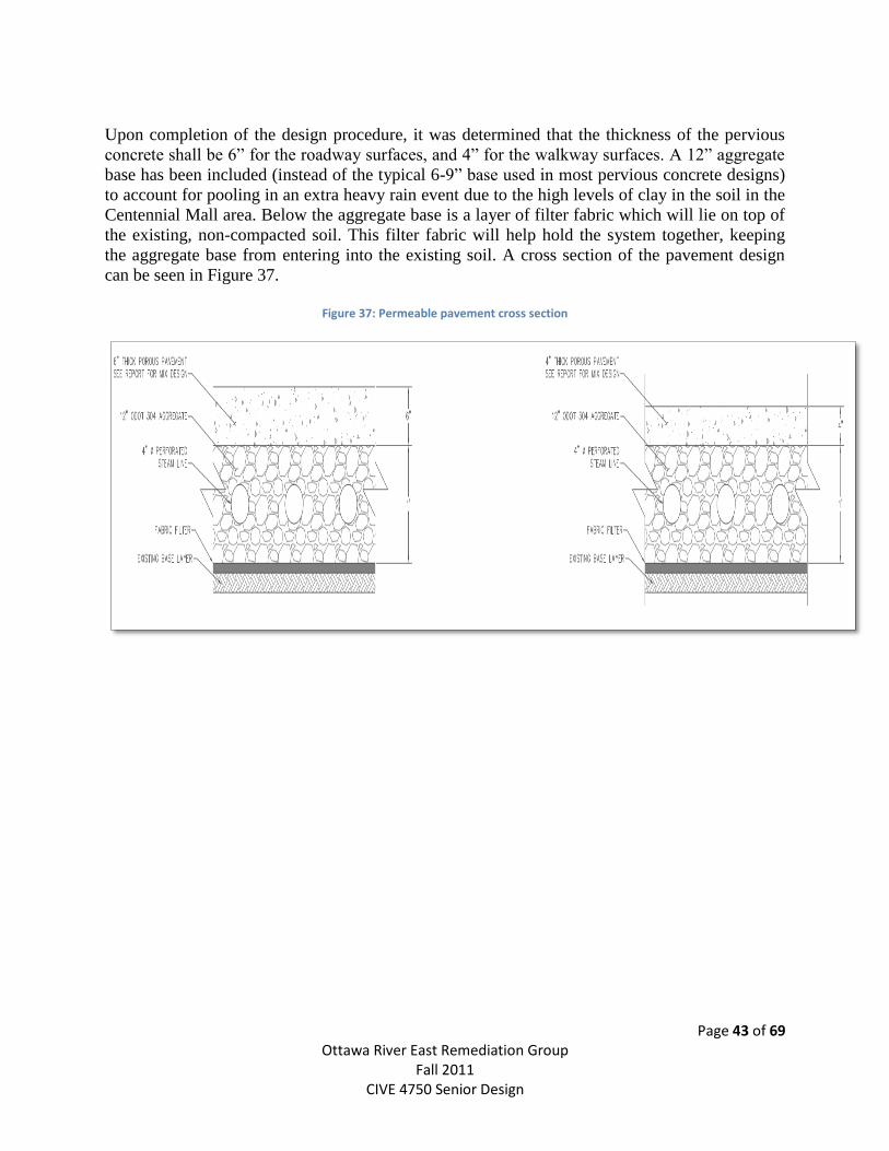
Upon completion of the design procedure, it was determined that the thickness of the pervious
concrete shall be 6” for the roadway surfaces, and 4” for the walkway surfaces. A 12” aggregate
base has been included (instead of the typical 6-9” base used in most pervious concrete designs)
to account for pooling in an extra heavy rain event due to the high levels of clay in the soil in the
Centennial Mall area. Below the aggregate base is a layer of filter fabric which will lie on top of
the existing, non-compacted soil. This filter fabric will help hold the system together, keeping
the aggregate base from entering into the existing soil. A cross section of the pavement design
can be seen in Figure 37.
Figure 37: Permeable pavement cross section
Page 44 of 69 Ottawa River East Remediation Group
Fall 2011 CIVE 4750 Senior Design
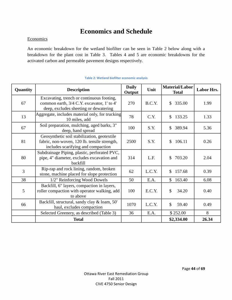
Economics and Schedule Economics
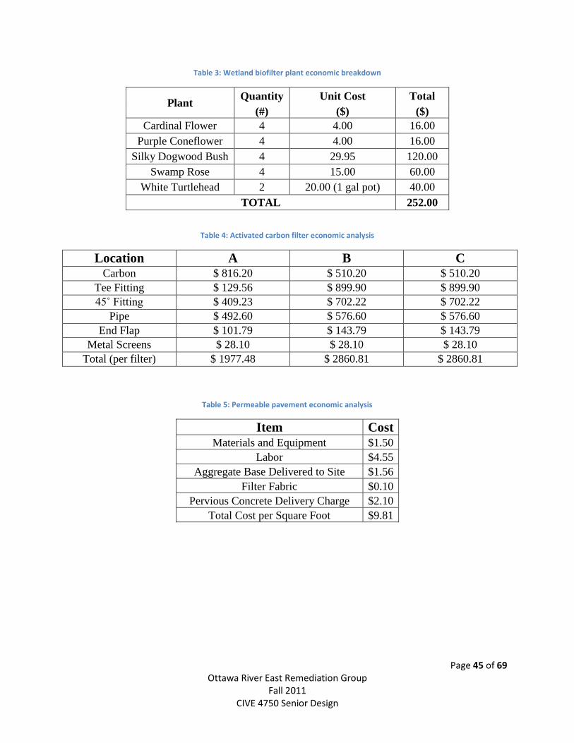
An economic breakdown for the wetland biofilter can be seen in Table 2 below along with a
breakdown for the plant cost in Table 3. Tables 4 and 5 are economic breakdowns for the
activated carbon and permeable pavement designs respectively.
Table 2: Wetland biofilter economic analysis
Quantity Description Daily
Output Unit
Material/Labor
Total Labor Hrs.
67
Excavating, trench or continuous footing,
common earth, 3/4 C.Y. excavator, 1' to 4'
deep, excludes sheeting or dewatering
270 B.C.Y. $ 335.00 1.99
13 Aggregate, includes material only, for trucking
10 miles, add 78 C.Y. $ 133.25 1.33
67 Soil preparation, mulching, aged barks, 3"
deep, hand spread 100 S.Y. $ 389.94 5.36
81
Geosynthetic soil stabilization, geotextile
fabric, non-woven, 120 lb. tensile strength,
includes scarifying and compaction
2500 S.Y. $ 106.11 0.26
80
Subdrainage Piping, plastic, perforated PVC,
pipe, 4" diameter, excludes excavation and
backfill
314 L.F. $ 703.20 2.04
3 Rip-rap and rock lining, random, broken
stone, machine placed for slope protection 62 L.C.Y. $ 157.68 0.39
38 1/2" Reinforcing Wood Dowels 50 E.A. $ 163.40 6.08
5
Backfill, 6" layers, compaction in layers,
roller compaction with operator walking, add
to above
100 E.C.Y. $ 34.20 0.40
66 Backfill, structural, sandy clay & loam, 50'
haul, excludes compaction 1070 L.C.Y. $ 59.40 0.49
Selected Greenery, as described (Table 3) 36 E.A. $ 252.00 8
Total
$2,334.00 26.34
Page 45 of 69 Ottawa River East Remediation Group
Fall 2011 CIVE 4750 Senior Design
Table 3: Wetland biofilter plant economic breakdown
Plant Quantity Unit Cost Total
(#) ($) ($)
Cardinal Flower 4 4.00 16.00
Purple Coneflower 4 4.00 16.00
Silky Dogwood Bush 4 29.95 120.00
Swamp Rose 4 15.00 60.00
White Turtlehead 2 20.00 (1 gal pot) 40.00
TOTAL 252.00
Table 4: Activated carbon filter economic analysis
Location A B C Carbon $ 816.20 $ 510.20 $ 510.20
Tee Fitting $ 129.56 $ 899.90 $ 899.90
45˚ Fitting $ 409.23 $ 702.22 $ 702.22
Pipe $ 492.60 $ 576.60 $ 576.60
End Flap $ 101.79 $ 143.79 $ 143.79
Metal Screens $ 28.10 $ 28.10 $ 28.10
Total (per filter) $ 1977.48 $ 2860.81 $ 2860.81
Table 5: Permeable pavement economic analysis
Item Cost Materials and Equipment $1.50
Labor $4.55
Aggregate Base Delivered to Site $1.56
Filter Fabric $0.10
Pervious Concrete Delivery Charge $2.10
Total Cost per Square Foot $9.81
Page 46 of 69 Ottawa River East Remediation Group
Fall 2011 CIVE 4750 Senior Design
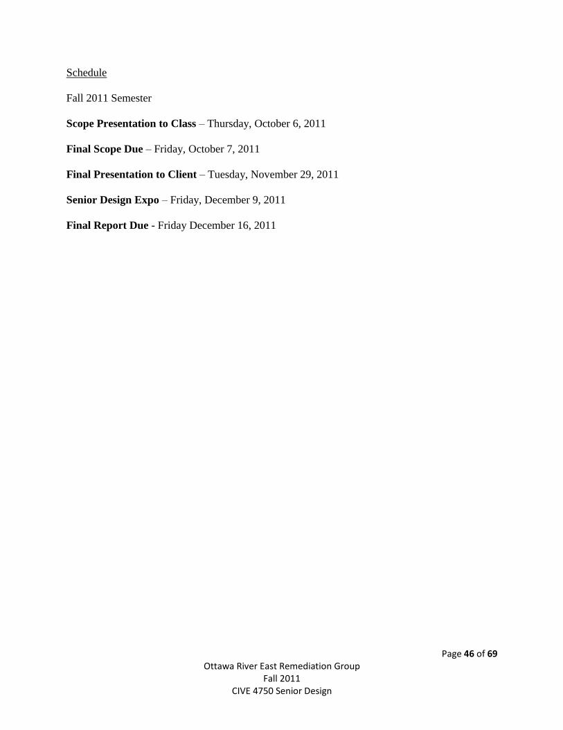
Schedule
Fall 2011 Semester
Scope Presentation to Class – Thursday, October 6, 2011
Final Scope Due – Friday, October 7, 2011
Final Presentation to Client – Tuesday, November 29, 2011
Senior Design Expo – Friday, December 9, 2011
Final Report Due - Friday December 16, 2011

Page 47 of 69 Ottawa River East Remediation Group
Fall 2011 CIVE 4750 Senior Design
Conclusion
Page 48 of 69 Ottawa River East Remediation Group
Fall 2011 CIVE 4750 Senior Design
The Ottawa River has been flagged as a problem area by the Environmental Protection Agency
for years. Recently, the University of Toledo has approached the Storm Water East Senior
Design Group to analyze the water quality coming from the eastern portion of campus, which
drains directly into the Ottawa River.
Once samples were collected from each of the three (3) sites the group has targeted, water
quality tests were performed. The tests included items such as the BOD test, E. coli, and TOC.
The results from these tests have allowed the Senior Design Group to start analyzing short and
long-term solutions for dealing with the contaminants entering into the Ottawa River.
Considering an economical design, the Senior Design Group began the design phase of the
project. Uneconomical solutions were eliminated, which left the group with four different
solutions:
1. Rainwater harvesting
2. Wetland Biofilter
3. Carbon Filter
4. Permeable pavement
Rainwater harvesting has been analyzed by another senior design group, and should be
referenced for further information. Taking economics, aesthetics, and creativity of design into
account, the Senior Design Group has design a wetland biofilter to be placed at Location A, an
Activated Carbon filtration system to be placed at all locations of interest. Finally, a permeable
pavement system will be installed in all walkways and private drives in the Centennial Mall area.
These solutions effectively reduce contaminants entering the river, as well as help reduce the
quantity of flow into the river.
Upon conclusion of the design phase, the Senior Design Group has recommended and designed
the most effective, cost minimizing solution to the water quality/flow quantity issue they were
presented with.
Page 49 of 69 Ottawa River East Remediation Group
Fall 2011 CIVE 4750 Senior Design
Persons Contacted
Karen Gallagher
Research GA Doctoral
University of Toledo - Geography Department
Email: [email protected]
Gottgens, Johan F. Professor/Associate Chair
Environmental Sciences
Phone: 419.530.8451
Email: [email protected]
Dr. Cyndee Gruden
Associate Professor
University of Toledo – Civil Engineering
Department
Phone: 419.530.8128
Cell: 734.417.1359
Email: [email protected]
Mike Kovacs
Environmental Specialist
Health & Safety – Main Campus
Phone: 419.530.3605
Email: [email protected]
Dr. Patrick Lawrence
Chair A&S Dept. Geog. & Professor
University of Toledo - Geography Department
Phone: 419.530.4128
Email: [email protected]
Abdulkaleen Mohammed
Research GA Masters
Facilities Planning
Email:
Michael Valigosky
Director, Safety and Health
Division of Human Resources and Campus
Safety
Phone: 419.530.4521
Email: [email protected]
Xiaozhong Zhang
Program Database Analyst
Facilities Planning
Email: [email protected]
Phone: 419.530.1458
Tim Casey
Senior Sales Representative
Kuhlman Concrete
Phone: 419-879-6000

Page 50 of 69 Ottawa River East Remediation Group
Fall 2011 CIVE 4750 Senior Design
Qualifications of Group Members
Page 51 of 69 Ottawa River East Remediation Group
Fall 2011 CIVE 4750 Senior Design
Ashley Frey
Tommy Hasson
Brandon Heaney
Tara Nemcik
Chris Wancata
Page 52 of 69 Ottawa River East Remediation Group
Fall 2011 CIVE 4750 Senior Design
ASHLEY FREY
6805 Glencairn Court
Mentor, Ohio
(440)759-6015
OBJECTIVE To secure a challenging position in the field of Civil Engineering in
order to enhance my knowledge and work experience.
EDUCATION The University of Toledo, Toledo, Ohio
August 2007- Bachelor of Science, Civil Engineering; Business Admin. Minor Present
•Anticipated Graduation Date: December 2011
•Grade Point Average: 3.594
COMPUTER •Microsoft Office Suite 2003-2010
SKILLS •Experience with AutoCAD 2007
•Microsoft Windows 95/98/XP/Vista/7
.
EXPERIENCE
May 2011- The Toledo Zoo, Toledo, Ohio
Present •Customer Service/Cashier
May-August Lake County Engineers, Painesville, Ohio
2008-2010 Engineering Co-op
•Worked on designs using AutoCAD and ARCMap
•Worked directly with professional engineers and surveyors
•Inspected roadway and storm water construction and repairs
•Conducted/analyzed traffic counts and speed studies
September 2006- Dave’s Cosmic Subs, Mentor, Ohio
August 2007 •Receptionist/Cashier
•Restocked shelves
June 2005- A.C.E Tennis Camp, Highland Heights, Ohio
August 2005 Club Ultimate Fitness & Sports Club
•Tennis Instructor for children
COLLEGIATE •University of Toledo Women’s Varsity Tennis, Captain 2011
ACTIVITIES •Full Athletic Scholarship
& AWARDS •Tower Prestige Scholarship
•Presidents List 2008, 2011 Deans List 2008, 2010
•Student Athletic Advisory Committee
SPECIAL SKILLS •Well organized and effectively manages time
& INTERESTS •Thrives on challenges and works well under pressure
•Motivated and dedicated to the task until completion
•Enjoys working with others and being team orientated
REFERENCES Available upon request.
Page 53 of 69 Ottawa River East Remediation Group
Fall 2011 CIVE 4750 Senior Design
THOMAS HASSON
11221 Hampshire Ct. North Royalton, OH 44133
440-590-3421 [email protected]
OBJECTIVE To secure a cooperative education position in the Civil Engineering field that will complement my academic endeavors with hands-on experience.
EDUCATION August 2007-Present
The University of Toledo, Toledo, Ohio Bachelor of Science, Civil Engineering Minor in Economics
Anticipated Graduation Date: December 2011
Grade Point Average: 3.098 EXPERIENCE January 2011 - Present May 2008- August 2008 May 2009- August 2009 May 2010- August 2010 June 2005-August 2007
AQUABLOK Ltd. (Hull & Associates Inc.) Sales and Marketing Intern
Target market research
Marketing preparation for trade shows Ohio Department of Transportation, District 12 Project Inspector/Internship
Daily work reports
Grade test/ Concrete tests
Small individual projects The City of Parma, Service Department Parma, Ohio Summer Labor
(Summers) Cleaned buildings
Cut grass
Maintained streets
\COMPUTER SKILLS HONORS & AWARDS
Microsoft Office Suite AutoCAD University of Toledo Tower and Prestige Scholarship University of Toledo Shapiro Economics Scholarship
COLLEGIATE ACTIVITIES Intramural flag football, basketball, softball and golf Intramural referee Volunteer Teaching Assistant Student Advisory Board

Page 54 of 69 Ottawa River East Remediation Group
Fall 2011 CIVE 4750 Senior Design
Brandon M. Heaney
2363 Garden Creek Dr.
Maumee, Ohio 43537
419-822-7609
OBJECTIVE To secure a full time position with a competitive, engineering base firm.
EDUCATION
June 2007-Present
The University of Toledo, Toledo, Ohio
Bachelor of Science, Civil Engineering
Anticipated Graduation Date: December 2011
Grade Point Average: 3.17
EXPERIENCE
August 2009 – December
2009,
Ulliman Schutte Construction, Rockville, MD
Co-op Engineer (Estimator)
March 2011 – May 2011
May 2010 – August 2010,
January 2011 – March 2011
Architectural take-off
Coordinate with vendors and subcontractors
Create and distribute architectural information packets pertaining to specific
trades/materials
Revise plans and specification based on addenda changes issued
Maintain a high level of attention to detail while working to complete tasks in a timely
fashion
Maintain an up to date understanding of plans and specifications involved with current
jobs
Determine potential risks associated with upcoming job and create construction
timelines
Ulliman Schutte Construction, Washington, D.C & Savage, MD
Co-op Engineer (Project Engineer)
Acquire materials and custom fabrications and coordinate deliveries on schedule
Coordinate with vendors, subcontractors, construction managers, and design
engineers
Prepare and submit product submittals, temporary operation plans, and operation
and maintenance manuals
Develop and maintain a precise construction schedule
November 2006-Present Minuteman Press Toledo, Toledo, Ohio
Bindery Worker
Operate and maintain hydraulic cutter, folder, booklet maker, and mailing equipment
Sort and pack mailings
Box and deliver finished product to customers and maintain customer appreciation
Work expeditiously to complete job within scheduled time frame
Demonstrate a high level of attention to detail
HONORS & AWARDS University of Toledo Pride Scholarship
University of Toledo College of Engineering Dean’s List (Spring 2008)
University of Toledo College of Engineering Dean’s List (Fall 2008)
North American Honor Consortium – Member with Honor
Page 55 of 69 Ottawa River East Remediation Group
Fall 2011 CIVE 4750 Senior Design
TARA MARIE NEMCIK (419) 306-0489
Permanent Address: Current Address: 3107 Co Rd 26-2 1131 North Byrne Stryker, Ohio 43557 Toledo, Ohio 43607
EDUCATION August 2007-P`resent
The University of Toledo; Toledo, Ohio
Bachelor of Science, Civil Engineering; Minor, General Business Administration
Anticipated Graduation Date: December 2011
Cumulative Grade Point Average: 3.384
COMPUTER SKILLS AutoCAD 2007
Microsoft Office Suite 2007-Excel, PowerPoint, Word
C++
EXPERIENCE
August-December 2011 & August- December 2008 January 2011- May 2011
May 2010- August 2010
August 2009-
December 2009
January 2009-May 2009
The University of Toledo; Toledo, Ohio
Teaching Assistant-Introduction to Civil Engineering course
Answered questions from students.
Assisted the professor in preparing and conducting experiments.
Provided expertise and assistance in class instruction
Marathon Petroleum Company; Findlay, Ohio
Major Projects-Woodhaven Facility Upgrade Co-op
Provided assistance to project leaders with Woodhaven flare project.
Lead and oversaw exploratory dig sub-project.
Assisted with project documentation and organization of documentation.
Marathon Petroleum Company; Findlay, Ohio
Environmental Technical Services Engineering Co-op
Coordinated soil remediation and demolition projects.
Worked with the law and real estate departments to sell Marathon owned properties.
Assisted in oversight of soil remediation and building demolition site work.
Marathon Petroleum Company; Indianapolis, Indiana
Terminal Engineering Processes-Pipe Integrity Program Co-op
Updated location drawings.
Organized and interpreted collected data.
Assisted in the oversight of terminal project site work. Marathon Petroleum Company; Findlay, Ohio
Pipeline Engineering Co-op
Closed projects for engineering project leaders, including required paperwork.
Provided assistance to project leaders on various pipeline projects.
Assisted in the oversight of pipeline project site work. COLLEGIATE ACTIVITIES
Order of Omega, Greek Leaders Honor Society (Spring 2010-Present)
Society of Women in Engineering (Spring 2010-Present)
Alpha Omicron Pi, Social Sorority (Fall 2009-Present)
Carter Hall Activities Personnel, Vice President (Fall 2007-Spring 2008)
AWARDS & HONORS
Recipient of the Tower Prestige Scholarship
Recipient Ohio Environmental Science and Engineering Scholarship
Page 56 of 69 Ottawa River East Remediation Group
Fall 2011 CIVE 4750 Senior Design
CHRISTOPHER MICHAEL WANCATA
1535 Lourdes Drive
Parma, OH, 44134
216-571-0966
EDUCATION
August 2007-Present
The University of Toledo, Toledo, Ohio
Bachelor of Science, Civil Engineering
Anticipated Graduation Date: December 2011
Grade Point Average: 3.658
Minor in Business Administration
COMPUTER SKILLS Microsoft Office Suite 2010
AutoCAD 2010
On-Screen Take Off
Adobe CS 3 Master Collection
EXPERIENCE
May 2010-August 2010
August 2009-
December 2009
Diamond Z Engineering Cleveland, OH
Pipelines and Logistics Co-op
Inspected various BP refueling terminals along the east coast in order to update piping
and instrumentation diagrams
Upon completing on-site inspections, performed updates to P&IDs in AutoCAD
Performed equipment list updates to all sites inspected after January 1, 2010
Lucas Metropolitan Housing Authority Toledo, OH
Modernization Co-op
Inspected 220+ homes for LMHA for structural/conditional issues
Performed project take-offs and estimates for various modernization projects
Assisted in environmental reviews for LMHA
Assisted in creating a tree trimming/landscaping removal package, while providing site
drawings in AutoCAD 2010
January 2009-May 2009
The Douglas Company
Project Coordinator Co-op
Assisted in estimating projects in all phases of construction
Acted as a liaison between clients and sub-contractors
Discussed and implemented value engineering in all current projects and estimates
HONORS & AWARDS University of Toledo Tower of Excellence Scholarship
Gretchen Koo Memorial Award – Fall 2010
COLLEGIATE ACTIVITIES Part-Time Job with Northwood Industries
Teaching Assistant for Civil Engineering Orientation - Fall 2008
Teaching Assistant for Civil Engineering Professional Development – Spring 2011
Cleveland Engineering Society Member
University of Toledo Men’s Club Lacrosse – Coach
National Society of Collegiate Scholars Member
SPECIAL SKILLS &
INTERESTS Goal oriented person who takes pride in his work
Enjoy challenging athletic situations
Excellent listening skills with well-developed oral communication skills
Excellent time-management skills; thrives with high responsibility projects/situations
Page 57 of 69 Ottawa River East Remediation Group
Fall 2011 CIVE 4750 Senior Design
References
(6), In Scopus. "ScienceDirect - Desalination : Effect of Activated Carbon on BOD and COD Removal
in a Dissolved Air Flotation Unit Treating Refinery Wastewater." ScienceDirect - Home. Web.
05 Dec. 2011. <http://www.sciencedirect.com/science/article/pii/S0011916407004298>.
"Activated Carbon Water Filters and Purification (Granular/Granulated and Carbon Block)." Water
Filters and Purifiers for Your Home - Reverse Osmosis, Ultraviolet, Counter Top, and More...
Web. 05 Dec. 2011. <http://www.home-water-purifiers-and-filters.com/carbon-water-filter.php>.
"AQUA-TT Media." Aqua Treatment Technologies. Web. 30 Sept. 2011.
<http://www.aqua-tt.com/media>
"Carbon Filtration – Pure Water Products, LLC." Water Filtration Products Catalog – Pure Water
Products, LLC. Web. 05 Dec. 2011. <http://www.purewaterproducts.com/carbon.html>.\
"Important Water Quality Factors." Welcome to Hach Company's H20 University, Dedicated to
Environmental and Waterscience Education! Web. 13 Oct. 2011.
<http://www.h2ou.com/h2wtrqual.htm>.
Ohio EPA. "Fish Tissue, Bottom Sediment, Surface Water, Organic & Metal Chemical Composition,
Ottawa River/Tenmile Creek." Division of Water Quality Planning and Assessment, 17 May
1991. Web. 23 Sept. 2011. <http://www.epa.ohio.gov/portals/35/documents/ottawa91.pdf>
"Oregon DEQ" State of Oregon: Department of Environmental Quality. Web. 30 Sept. 2011.
<http://www.deq.state.or.us/wq/stormwater/docs/nwr/biofilters>
"Restoring The Ottawa River." Status of Natural Resource Damage Assessment. Toledo Metropolitan
Council of Governments. Web. 23 Sept. 2011.
<http://www.tmacog.org/environment/Ottawa%20River%20web%20page/Ottawa_River_Remed
iation.htm>
"Storm Treat Systems." StormTreat Systems - Stormwater Treatment Solutions: Multistage System,
Bioretention, Filtration, Adsorption, Water Remediation. Storm Treat Systems. Web. 23 Sept.
2011. <http://www.stormtreat.com/>.
Page 58 of 69 Ottawa River East Remediation Group
Fall 2011 CIVE 4750 Senior Design
Stormwater BMPS - Urban Stormwater Best Management Practices (BMPS). Web. 02 Oct. 2011.
<http://www.stormchambers.com/>.
“TOC Destruction/Total Organic Carbon (TOC) Fact Sheet.” Cal Water Industrial Water Purification.
Web. 05. Dec. 2011. <http://www.cal-water.com/pdf/TOC_Info.pdf>.
United States. US Environmental Protection Agency. Office of Water Regulations and Standards.
Quality Criteria for Water. 1986. Quality Criteria for Water 1986. US EPA. Web. 23 Sept. 2011.
<http://water.epa.gov/scitech/swguidance/standards/criteria/aqlife/upload/2009_01_13_criteria_g
oldbook.pdf>.

Page 59 of 69 Ottawa River East Remediation Group
Fall 2011 CIVE 4750 Senior Design
Appendices
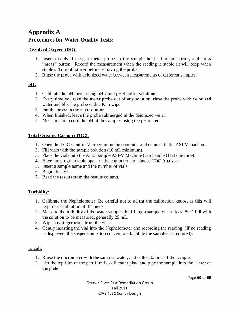
Page 60 of 69 Ottawa River East Remediation Group
Fall 2011 CIVE 4750 Senior Design
Appendix A
Procedures for Water Quality Tests:
Dissolved Oxygen (DO):
1. Insert dissolved oxygen meter probe in the sample bottle, turn on stirrer, and press
“meas” button. Record the measurement when the reading is stable (it will beep when
stable). Turn off stirrer before removing the probe.
2. Rinse the probe with deionized water between measurements of different samples.
pH:
1. Calibrate the pH meter using pH 7 and pH 9 buffer solutions.
2. Every time you take the meter probe out of any solution, rinse the probe with deionized
water and blot the probe with a Kim wipe.
3. Put the probe in the next solution.
4. When finished, leave the probe submerged in the deionized water.
5. Measure and record the pH of the samples using the pH meter.
Total Organic Carbon (TOC):
1. Open the TOC-Control V program on the computer and connect to the ASI-V machine.
2. Fill vials with the sample solution (10 mL minimum).
3. Place the vials into the Auto Sample ASI-V Machine (can handle 68 at one time).
4. Have the program table open on the computer and choose TOC Analysis.
5. Insert a sample name and the number of vials.
6. Begin the test.
7. Read the results from the results column.
Turbidity:
1. Calibrate the Nephelometer. Be careful not to adjust the calibration knobs, as this will
require recalibration of the meter.
2. Measure the turbidity of the water samples by filling a sample vial at least 80% full with
the solution to be measured, generally 25 mL.
3. Wipe any fingerprints from the vial.
4. Gently inserting the vial into the Nephelometer and recording the reading. (If no reading
is displayed, the suspension is too concentrated. Dilute the samples as required).
E. coli:
1. Rinse the micrometer with the samples water, and collect 0.5mL of the sample.
2. Lift the top film of the petrifilm E. coli count plate and pipe the sample into the center of
the plate
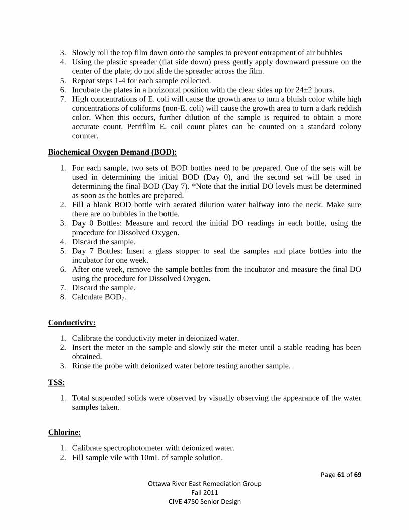
Page 61 of 69 Ottawa River East Remediation Group
Fall 2011 CIVE 4750 Senior Design
3. Slowly roll the top film down onto the samples to prevent entrapment of air bubbles
4. Using the plastic spreader (flat side down) press gently apply downward pressure on the
center of the plate; do not slide the spreader across the film.
5. Repeat steps 1-4 for each sample collected.
6. Incubate the plates in a horizontal position with the clear sides up for 24±2 hours.
7. High concentrations of E. coli will cause the growth area to turn a bluish color while high
concentrations of coliforms (non-E. coli) will cause the growth area to turn a dark reddish
color. When this occurs, further dilution of the sample is required to obtain a more
accurate count. Petrifilm E. coil count plates can be counted on a standard colony
counter.
Biochemical Oxygen Demand (BOD):
1. For each sample, two sets of BOD bottles need to be prepared. One of the sets will be
used in determining the initial BOD (Day 0), and the second set will be used in
determining the final BOD (Day 7). *Note that the initial DO levels must be determined
as soon as the bottles are prepared.
2. Fill a blank BOD bottle with aerated dilution water halfway into the neck. Make sure
there are no bubbles in the bottle.
3. Day 0 Bottles: Measure and record the initial DO readings in each bottle, using the
procedure for Dissolved Oxygen.
4. Discard the sample.
5. Day 7 Bottles: Insert a glass stopper to seal the samples and place bottles into the
incubator for one week.
6. After one week, remove the sample bottles from the incubator and measure the final DO
using the procedure for Dissolved Oxygen.
7. Discard the sample.
8. Calculate BOD7.
Conductivity:
1. Calibrate the conductivity meter in deionized water.
2. Insert the meter in the sample and slowly stir the meter until a stable reading has been
obtained.
3. Rinse the probe with deionized water before testing another sample.
TSS:
1. Total suspended solids were observed by visually observing the appearance of the water
samples taken.
Chlorine:
1. Calibrate spectrophotometer with deionized water.
2. Fill sample vile with 10mL of sample solution.
Page 62 of 69 Ottawa River East Remediation Group
Fall 2011 CIVE 4750 Senior Design
3. Empty contents of DPD free chlorine reagent packet into sample vile.
4. Swirl until completely dissolved, will begin to turn pink if chlorine present.
5. Put vile into spectrophotometer and press “Test” button.
6. Record value projected on screen of spectrophotometer.
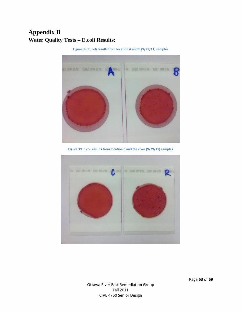
Page 63 of 69 Ottawa River East Remediation Group
Fall 2011 CIVE 4750 Senior Design
Appendix B
Water Quality Tests – E.coli Results:
Figure 38: E. coli results from location A and B (9/29/11) samples
Figure 39: E.coli results from location C and the river (9/29/11) samples
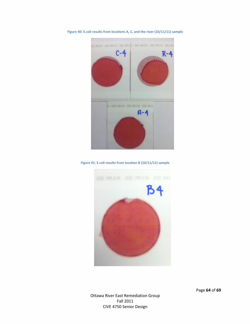
Page 64 of 69 Ottawa River East Remediation Group
Fall 2011 CIVE 4750 Senior Design
Figure 40: E.coli results from locations A, C, and the river (10/11/11) sample
Figure 41: E.coli results from location B (10/11/11) sample
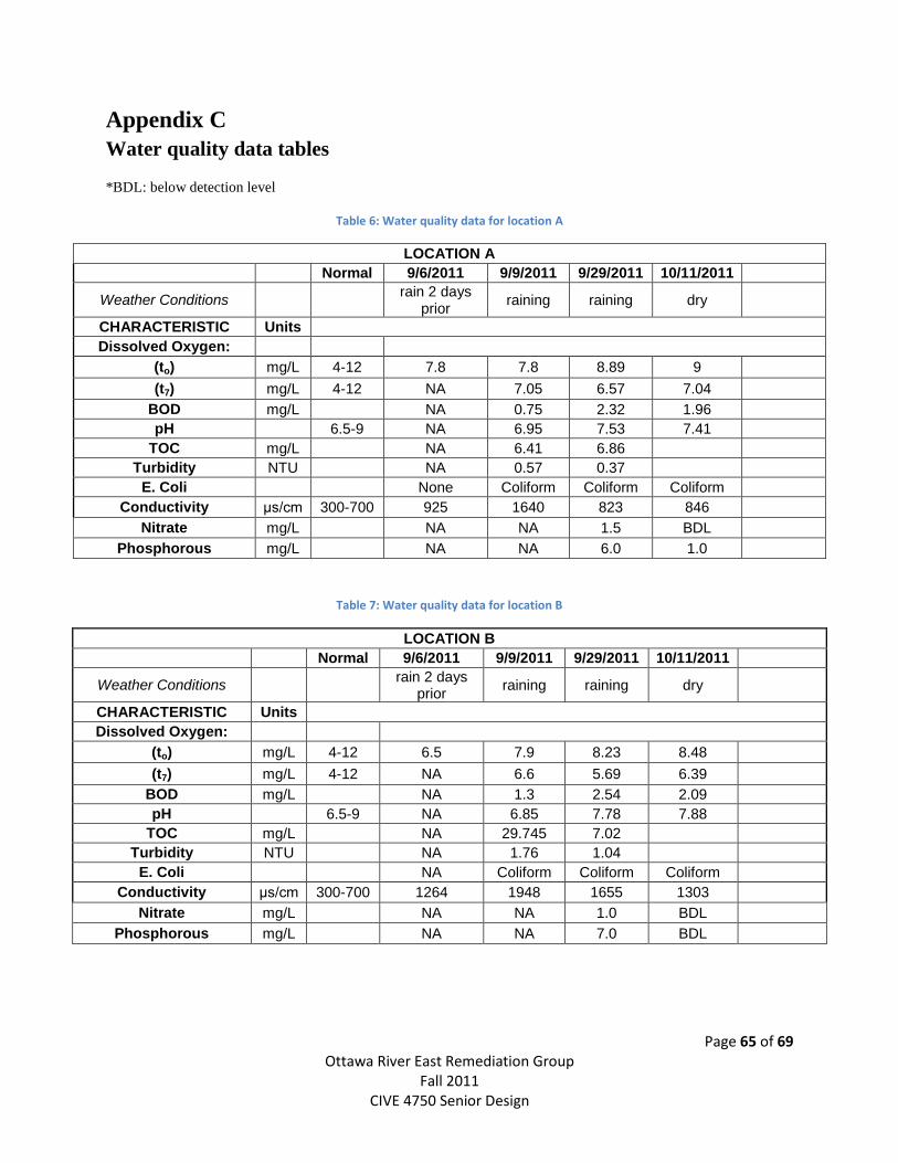
Page 65 of 69 Ottawa River East Remediation Group
Fall 2011 CIVE 4750 Senior Design
Appendix C
Water quality data tables
*BDL: below detection level
Table 6: Water quality data for location A
LOCATION A
Normal 9/6/2011 9/9/2011 9/29/2011 10/11/2011
Weather Conditions
rain 2 days prior
raining raining dry
CHARACTERISTIC Units
Dissolved Oxygen:
(to) mg/L 4-12 7.8 7.8 8.89 9
(t7) mg/L 4-12 NA 7.05 6.57 7.04
BOD mg/L
NA 0.75 2.32 1.96
pH
6.5-9 NA 6.95 7.53 7.41
TOC mg/L
NA 6.41 6.86
Turbidity NTU
NA 0.57 0.37
E. Coli
None Coliform Coliform Coliform
Conductivity μs/cm 300-700 925 1640 823 846
Nitrate mg/L NA NA 1.5 BDL
Phosphorous mg/L NA NA 6.0 1.0
Table 7: Water quality data for location B
LOCATION B
Normal 9/6/2011 9/9/2011 9/29/2011 10/11/2011
Weather Conditions
rain 2 days prior
raining raining dry
CHARACTERISTIC Units
Dissolved Oxygen:
(to) mg/L 4-12 6.5 7.9 8.23 8.48
(t7) mg/L 4-12 NA 6.6 5.69 6.39
BOD mg/L
NA 1.3 2.54 2.09
pH
6.5-9 NA 6.85 7.78 7.88
TOC mg/L
NA 29.745 7.02
Turbidity NTU
NA 1.76 1.04
E. Coli
NA Coliform Coliform Coliform
Conductivity μs/cm 300-700 1264 1948 1655 1303
Nitrate mg/L NA NA 1.0 BDL
Phosphorous mg/L NA NA 7.0 BDL
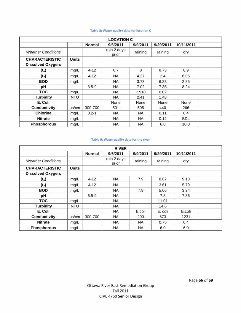
Page 66 of 69 Ottawa River East Remediation Group
Fall 2011 CIVE 4750 Senior Design
Table 8: Water quality data for location C
LOCATION C
Normal 9/6/2011 9/9/2011 9/29/2011 10/11/2011
Weather Conditions
rain 2 days prior
raining raining dry
CHARACTERISTIC Units
Dissolved Oxygen:
(to) mg/L 4-12 6.7 8 8.73 8.9
(t7) mg/L 4-12 NA 4.27 2.4 6.05
BOD mg/L
NA 3.73 6.33 2.85
pH
6.5-9 NA 7.02 7.35 8.24
TOC mg/L
NA 7.518 6.02
Turbidity NTU
NA 2.41 1.48
E. Coli
None None None None
Conductivity μs/cm 300-700 501 505 440 266
Chlorine mg/L 0.2-1 NA NA 0.11 0.4
Nitrate mg/L NA NA 0.12 BDL
Phosphorous mg/L NA NA 6.0 10.0
Table 9: Water quality data for the river
RIVER
Normal 9/6/2011 9/9/2011 9/29/2011 10/11/2011
Weather Conditions
rain 2 days prior
raining raining dry
CHARACTERISTIC Units
Dissolved Oxygen:
(to) mg/L 4-12 NA 7.9 8.67 9.13
(t7) mg/L 4-12 NA
3.61 5.79
BOD mg/L
NA 7.9 5.06 3.34
pH
6.5-9 NA
7.8 7.86
TOC mg/L
NA
11.01
Turbidity NTU
NA
14.6
E. Coli
NA E.coli E. coli E.coli
Conductivity μs/cm 300-700 NA 290 673 1231
Nitrate mg/L NA NA 0.75 0.4
Phosphorous mg/L NA NA 6.0 6.0
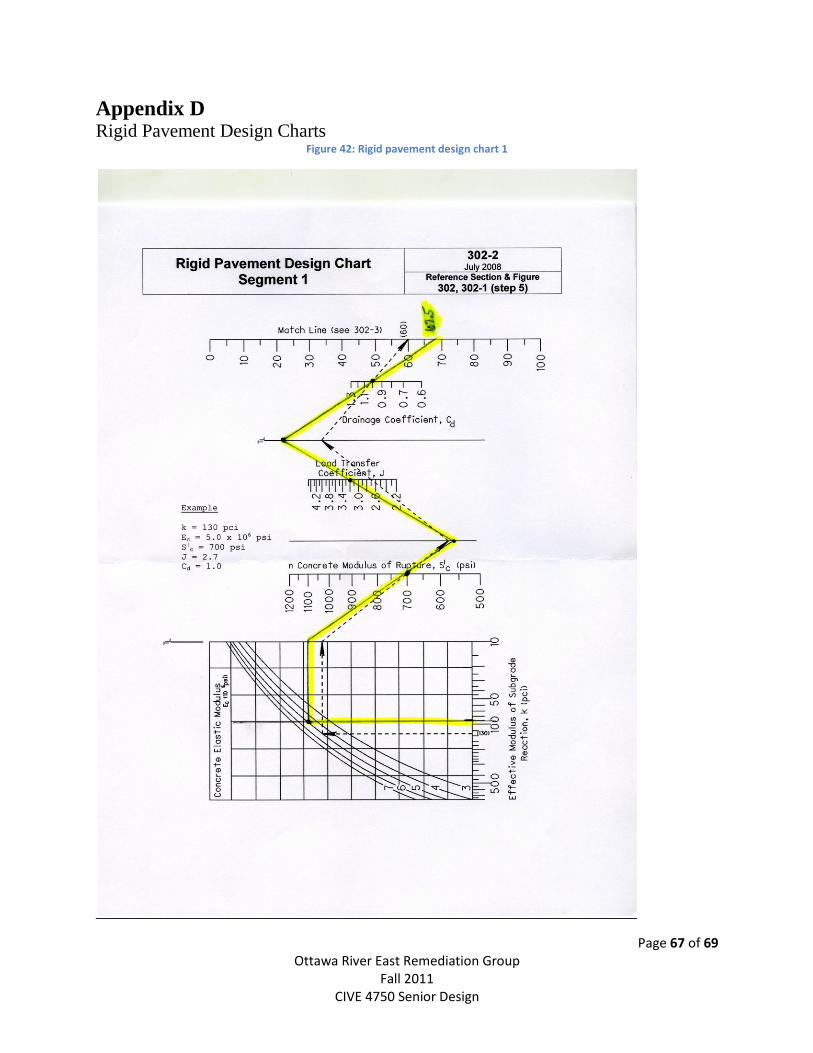
Page 67 of 69 Ottawa River East Remediation Group
Fall 2011 CIVE 4750 Senior Design
Appendix D Rigid Pavement Design Charts
Figure 42: Rigid pavement design chart 1
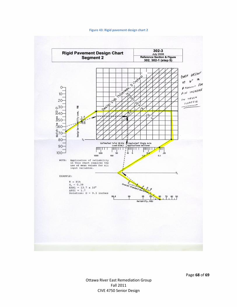
Page 68 of 69 Ottawa River East Remediation Group
Fall 2011 CIVE 4750 Senior Design
Figure 43: Rigid pavement design chart 2
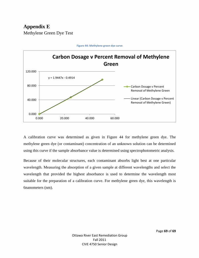
Page 69 of 69 Ottawa River East Remediation Group
Fall 2011 CIVE 4750 Senior Design
Appendix E
Methylene Green Dye Test
Figure 44: Methylene green dye curve
A calibration curve was determined as given in Figure 44 for methylene green dye. The
methylene green dye (or contaminant) concentration of an unknown solution can be determined
using this curve if the sample absorbance value is determined using spectrophotometric analysis.
Because of their molecular structures, each contaminant absorbs light best at one particular
wavelength. Measuring the absorption of a given sample at different wavelengths and select the
wavelength that provided the highest absorbance is used to determine the wavelength most
suitable for the preparation of a calibration curve. For methylene green dye, this wavelength is
6nanometers (nm).
y = 1.9447x - 0.4914
0.000
40.000
80.000
120.000
0.000 20.000 40.000 60.000
Carbon Dosage v Percent Removal of Methylene Green
Carbon Dosage v PercentRemoval of Methylene Green
Linear (Carbon Dosage v PercentRemoval of Methylene Green)
Related Documents