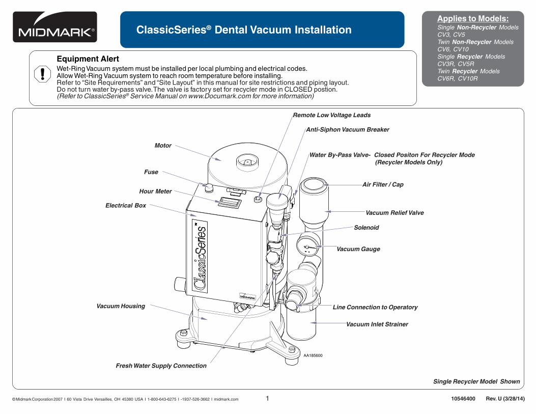
© Midmark Corporation 2007 1 AA185600 ClassicSeries ® Dental Vacuum Installation Applies to Models: Single Non-Recycler Models CV3, CV5 Twin Non-Recycler Models CV6, CV10 Single Recycler Models CV3R, CV5R Twin Recycler Models CV6R, CV10R 10546400 Rev. U (3/28/14) Anti-Siphon Vacuum Breaker Vacuum Relief Valve Vacuum Gauge Line Connection to Operatory Vacuum Inlet Strainer Remote Low Voltage Leads Air Filter / Cap Solenoid Motor Fuse Hour Meter Electrical Box Vacuum Housing Fresh Water Supply Connection Single Recycler Model Shown Water By-Pass Valve- Closed Positon For Recycler Mode (Recycler Models Only) Equipment Alert Wet-Ring Vacuum system must be installed per local plumbing and electrical codes. Allow Wet-Ring Vacuum system to reach room temperature before installing. Refer to “Site Requirements” and “Site Layout” in this manual for site restrictions and piping layout. Do not turn water by-pass valve. The valve is factory set for recycler mode in CLOSED postion. (Refer to ClassicSeries ® Service Manual on www.Documark.com for more information) I 60 Vista Drive Versailles, OH 45380 USA I 1-800-643-6275 I -1937-526-3662 I midmark.com

Welcome message from author
This document is posted to help you gain knowledge. Please leave a comment to let me know what you think about it! Share it to your friends and learn new things together.
Transcript
© Midmark Corporation 2007 1
AA185600
ClassicSeries® Dental Vacuum InstallationApplies to Models:Single Non-Recycler ModelsCV3, CV5Twin Non-Recycler ModelsCV6, CV10Single Recycler ModelsCV3R, CV5RTwin Recycler ModelsCV6R, CV10R
10546400 Rev. U (3/28/14)
Anti-Siphon Vacuum Breaker
Vacuum Relief Valve
Vacuum Gauge
Line Connection to Operatory
Vacuum Inlet Strainer
Remote Low Voltage Leads
Air Filter / Cap
Solenoid
Motor
Fuse
Hour Meter
Electrical Box
Vacuum Housing
Fresh Water Supply Connection
Single Recycler Model Shown
Water By-Pass Valve- Closed Positon For Recycler Mode (Recycler Models Only)
Equipment AlertWet-Ring Vacuum system must be installed per local plumbing and electrical codes.Allow Wet-Ring Vacuum system to reach room temperature before installing.Refer to “Site Requirements” and “Site Layout” in this manual for site restrictions and piping layout.Do not turn water by-pass valve. The valve is factory set for recycler mode in CLOSED postion.(Refer to ClassicSeries® Service Manual on www.Documark.com for more information)
I 60 Vista Drive Versailles, OH 45380 USA I 1-800-643-6275 I -1937-526-3662 I midmark.com
2© Midmark Corporation 2007
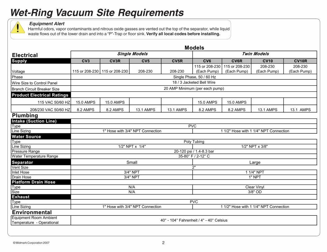
Wet-Ring Vacuum Site Requirements Equipment Alert
Harmful odors, vapor contaminants and nitrous oxide gasses are vented out the top of the separator, while liquid waste flows out of the lower drain and into a “P”-Trap or floor sink. Verify all local codes before installing.
ElectricalSupply CV3 CV3R CV5 CV5R CV6 CV6R CV10 CV10R
Voltage 115 or 208-230 115 or 208-230 208-230 208-230
115 or 208-230
(Each Pump)
115 or 208-230
(Each Pump)
208-230
(Each Pump)
208-230
(Each Pump)
Phase
Wire Size to Control Panel
Branch Circuit Breaker Size
Product Electrical Ratings
115 VAC 50/60 HZ 15.0 AMPS 15.0 AMPS 15.0 AMPS 15.0 AMPS
208/230 VAC 50/60 HZ 8.2 AMPS 8.2 AMPS 13.1 AMPS 13.1 AMPS 8.2 AMPS 8.2 AMPS 13.1 AMPS 13.1 AMPS
Intake (Suction Line)Type
Line Sizing
Water SourceType
Line Sizing
Pressure Range
Water Temperature Range
SeparatorVent Size
Inlet Hose
Drain Hose
Platform Drain HoseType
Size
ExhaustType
Line Sizing
Equipment Room Ambient
Temperature - Operational40° - 104° Fahrenheit / 4° - 40° Celsius
2"
Environmental
Small Large
3/4" NPT 1 1/4" NPT
3/4" NPT
PVC
1" Hose with 3/4" NPT Connection 1 1/2" Hose with 1 1/4" NPT Connection
35-80° F / 2-12° C
20-120 psi / 1.4-8.3 bar
Clear Vinyl
3/8" OD
N/A
N/A
1" NPT
Single Models Twin Models
Plumbing
18 / 3 Jacketed Bell Wire
Single Phase, 50 / 60 Hz
Models
1/2" NPT x 3/8"
Poly Tubing
1" Hose with 3/4" NPT Connection 1 1/2" Hose with 1 1/4" NPT Connection
1/2" NPT x 1/4"
20 AMP Minimum (per each pump)
PVC
© Midmark Corporation 2007 3
Specification SheetLubricated Compressors
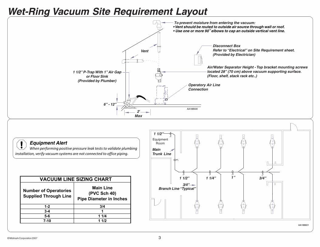
Wet-Ring Vacuum Site Requirement Layout
AA188500
Disconnect BoxRefer to “Electrical” on Site Requirement sheet.(Provided by Electrician)
Operatory Air LineConnection
To prevent moisture from entering the vacuum:• Vent should be routed to outside air source through wall or roof.• Use one or more 90°elbows to cap an outside vertical vent line.
Vent
2’Max
1 1/2” P-Trap With 1” Air Gapor Floor Sink
(Provided by Plumber)
6” - 12”
Air/Water Separator Height - Top bracket mounting screwslocated 28” (70 cm) above vacuum supporting surface.(Floor, shelf, stack rack etc..)
VACUUM LINE SIZING CHART
Number of Operatories
Supplied Through Line
Main Line
(PVC Sch 40)
Pipe Diameter in Inches
1-2 3/4
3-4 1
5-6 1 1/4
7-10 1 1/2
Equipment AlertWhen performing positive pressure leak tests to validate plumbing
installation, verify vacuum systems are not connected to office piping.
AA188601
MainTrunk Line
Branch Line “Typical”3/4”
1 1/2” 1 1/4” 1” 3/4”
1 1/2”Equipment
Room

4© Midmark Corporation 2007
Vacuum Piping to be Type M or Schedule 40 PVCMaintain a 1/4” Slope per 10 feet of Piping (toward pump)
Always Stagger branch lines from main trunkDo not use 4-way Cross Fittings
VacuumSystem
3/4” Inverted P-Trap
1/2” Vent Line Installed With VRVAbove Inverted P-Trap Allows AirInto System to Prevent Gurgling in
Vacuum Lines
Micro Mini Muffler / VRV (pn77005027) to be Installed at Top of
Vent Line in Each Operatory
Trunk Lines: Follow Sizing Guide for UnderFloor Installation and Add One User
Equipment AlertSubfloor plumbing is preferred. Operatory utilization to bemodified to allow flow up walls.Upsize pump as per number
of operatories. At least ½ user per VRV and 8 ft. riser. More than 8ft riserrequires more pump capacity.
Wet-Ring Vacuum SiteRequirement Layout continued...

© Midmark Corporation 2007 5
Safety SymbolsIntended UseTo provide suction during general examinations and procedures conducted by qualified dental professionals.
Electromagnetic InterferenceThis Midmark Wet-Ring Vacuum is designed and built to minimizeelectromagnetic interference with other devices.However, if interference is noticed between another device and these units:
• Remove interfering device from room• Plug interfering device into an isolated circuit• Increase separation between unit and interfering device• Contact Midmark if interference persists
Disposal of EquipmentAt the end of product life, the unit(s), accessory, and other consumable goods may becomecontaminated from normal use. Consult local codes and ordinances for proper disposal ofequipment, accessories and other consumable goods.
Transportation / Storage ConditionsAmbient Temperature Range: .............................. 40°F to 104°F (4°C to 37°C)Relative Humidity ................................................10% to 90% (non-condensing)Atmospheric Pressure ......................................... 500hPa to 1060hPa (0.49atm to 1.05atm)
Important Information
CAUTIONIndicates a potentially hazardous situation
which may result in minor or moderate injury if notavoided. It may also be used to alert against unsafepractices.
NoteAmplifies a procedure, practice, or condition.
WARNINGIndicates a potentially hazardous situation
which could result in serious injury if not avoided.
This product has been evaluated with respect toelectrical shock, fire & mechanical hazards only, inaccordance with UL60601-1 and CAN/CSA C22.2 NO.601.1.
Consult User Guidefor important information.
Proper shipping orientation
Fragile
Protective earth ground
DANGERIndicates an imminently hazardous
situation which will result in serious or fatalinjury if not avoided. This symbol is used onlyin the most extreme conditions.
Keep dry
Maximum stacking height (palletted units)
Fuse rating specification
Caution hot surface
Ordinary EquipmentIPXO
Equipment AlertIndicates a potentially hazardous situation which
could result in equipment damage if not avoided
6© Midmark Corporation 2007
AA185800
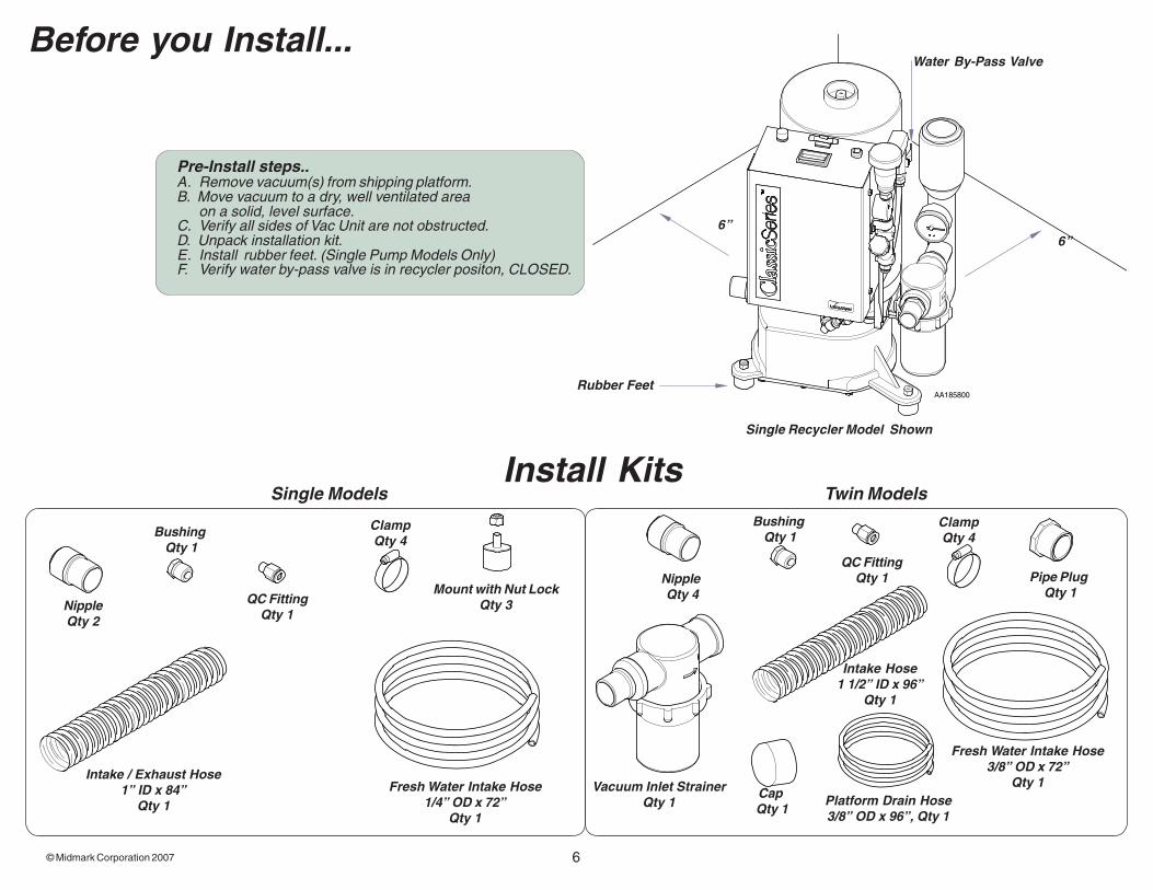
Before you Install...
Rubber Feet
6”6”
Pre-Install steps..A. Remove vacuum(s) from shipping platform.B. Move vacuum to a dry, well ventilated area
on a solid, level surface.C. Verify all sides of Vac Unit are not obstructed.D. Unpack installation kit.E. Install rubber feet. (Single Pump Models Only)F. Verify water by-pass valve is in recycler positon, CLOSED.
Single Models Twin ModelsInstall Kits
QC FittingQty 1
NippleQty 2
Intake / Exhaust Hose1” ID x 84”
Qty 1Vacuum Inlet Strainer
Qty 1Fresh Water Intake Hose
1/4” OD x 72”Qty 1
ClampQty 4
Mount with Nut LockQty 3
Bushing Qty 1
ClampQty 4
Bushing Qty 1
QC FittingQty 1
Fresh Water Intake Hose3/8” OD x 72”
Qty 1
Nipple Qty 4
Pipe Plug Qty 1
Intake Hose1 1/2” ID x 96”
Qty 1
Platform Drain Hose3/8” OD x 96”, Qty 1
Water By-Pass Valve
Single Recycler Model Shown
Cap Qty 1

© Midmark Corporation 2007 7
AA185900
InstallationPlumbing Connections - Single Models with Air/Water Separator
Single Models Air/Water Plumbing...A. Mount Separator 28” (70 cm) above vacuum supporting surface.B. Install exhaust silencer into 1” exhaust hose from vacuum to P-trap if applicable.
If not using an exhaust silencer....C. Connect exhaust hose from vacuum to separator.D. Connect 3/4” hose from separator to drain or P-trap.E. Connect 2” PVC to top of separator and out to vent.F. Connect 1/4” poly tube from vacuum to water supply.G. Connect 3/4” NPT fitting and hose clamp from vacuum line to operatory.
Drain
Exhaust Hose Line*Install ExhaustSilencer Here”
Vent
Water Source
Vent
ExhaustFrom Pumps
P-Trap drainwith Air/WaterSeparator
In from Operatory
NoteExhaust silencer installation is an optional for the Wet-Ring Vacuums.Wet-Ring Vacuums are operational without exhaust silencer.

8© Midmark Corporation 2007
© Midmark Corporation 2007 9
AA199200
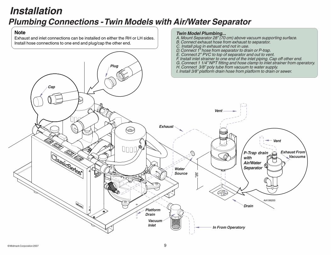
Drain
Exhaust
Vent
WaterSource
Vent
Exhaust From Vacuums
P-Trap drainwithAir/WaterSeparator
In From Operatory
Cap
VacuumInlet
Plug
InstallationPlumbing Connections - Twin Models with Air/Water Separator
Twin Model Plumbing...A. Mount Separator 28” (70 cm) above vacuum supporting surface.B. Connect exhaust hose from exhaust to separator.C. Install plug in exhaust end not in use.D. Connect 1” hose from separator to drain or P-trap.E. Connect 2” PVC to top of separator and out to vent.F. Install inlet strainer to one end of the inlet piping. Cap off other end.G. Connect 1 1/4” NPT fitting and hose clamp to inlet strainer from operatory.H. Connect 3/8” poly tube from vacuum to water supply.I. Install 3/8” platform drain hose from platform to drain or sewer.
NoteExhaust and inlet connections can be installed on either the RH or LH sides.Install hose connections to one end and plug/cap the other end.
PlatformDrain
at

10© Midmark Corporation 2007

© Midmark Corporation 2007 11
AA186200
Installation - Single ModelsElectrical - Convert 1 1/4 HP model to 115 Voltage (if applicable)
Conduit Entry
Proceed to Supply Box and Remote Panel Installation
NoteCV3 and CV3R Models are factory configured for 208-230 Volt operation and can be rewired to operate on 115 Voltage.All vacuum systems are to be installed according to local electrical codes.Refer to Specification Sheet for Electrical Ratings located in this manual.
To convert 1 1/4 HP Motor from 208-230V to 115V...A. Loosen screws on electrical box to remove cover.B. Install line voltage conduit with conduit connector in side of vacuum electrical box.C. Connect line voltage to leads at terminals X1 (Black) and X4 (White-Neutral).D. Connect ground wire to ground (green/yellow) lead.E. Remove all three jumpers from terminal block and relocate at ...
X3 and X4X5 and X6X7 and X8
115 Voltage Configuration
12© Midmark Corporation 2007
AA186300
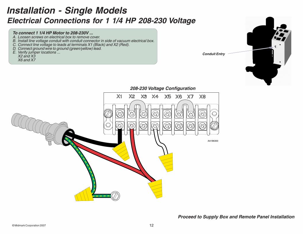
Electrical Connections for 1 1/4 HP 208-230 VoltageInstallation - Single Models
Proceed to Supply Box and Remote Panel Installation
Conduit Entry
To connect 1 1/4 HP Motor to 208-230V ...A. Loosen screws on electrical box to remove cover.B. Install line voltage conduit with conduit connector in side of vacuum electrical box.C. Connect line voltage to leads at terminals X1 (Black) and X2 (Red).D. Connect ground wire to ground (green/yellow) lead.E. Verify jumper locations ...
X2 and X3X6 and X7
208-230 Voltage Configuration
© Midmark Corporation 2007 13
AA186400
CONTACTOR
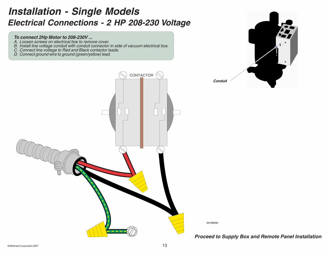
Electrical Connections - 2 HP 208-230 Voltage
Conduit
Installation - Single Models
To connect 2Hp Motor to 208-230V ...A. Loosen screws on electrical box to remove cover.B. Install line voltage conduit with conduit connector in side of vacuum electrical box.C. Connect line voltage to Red and Black contactor leads.D. Connect ground wire to ground (green/yellow) lead.
Proceed to Supply Box and Remote Panel Installation

14© Midmark Corporation 2007
AA200100
CONTACTOR
Electrical Connections - Convert 1 1/4 HP models to 115 Voltage (if applicable)
Installation - Twin Models
NoteCV6 and CV6R Models are factory configured for 208-230 Volt operation and can be rewired to operate on 115 Voltage.All vacuum systems are to be installed according to local electrical codes.Refer to Specification Sheet for Electrical Ratings located in this manual.
Proceed to Supply Box and Remote Panel Installation
To convert 1 1/4 HP Motor from 208-230V to 115V...A. Loosen screws on electrical box to remove cover.B. Disconnect red line voltage wire from red jumper. Replace nut on red jumper wire.C. Connect red voltage wire with white jumper from X4.D. Remove all three jumpers from terminal block and relocate at ...
X3 and X4X5 and X6X7 and X8
115 Voltage Configuration
© Midmark Corporation 2007 15
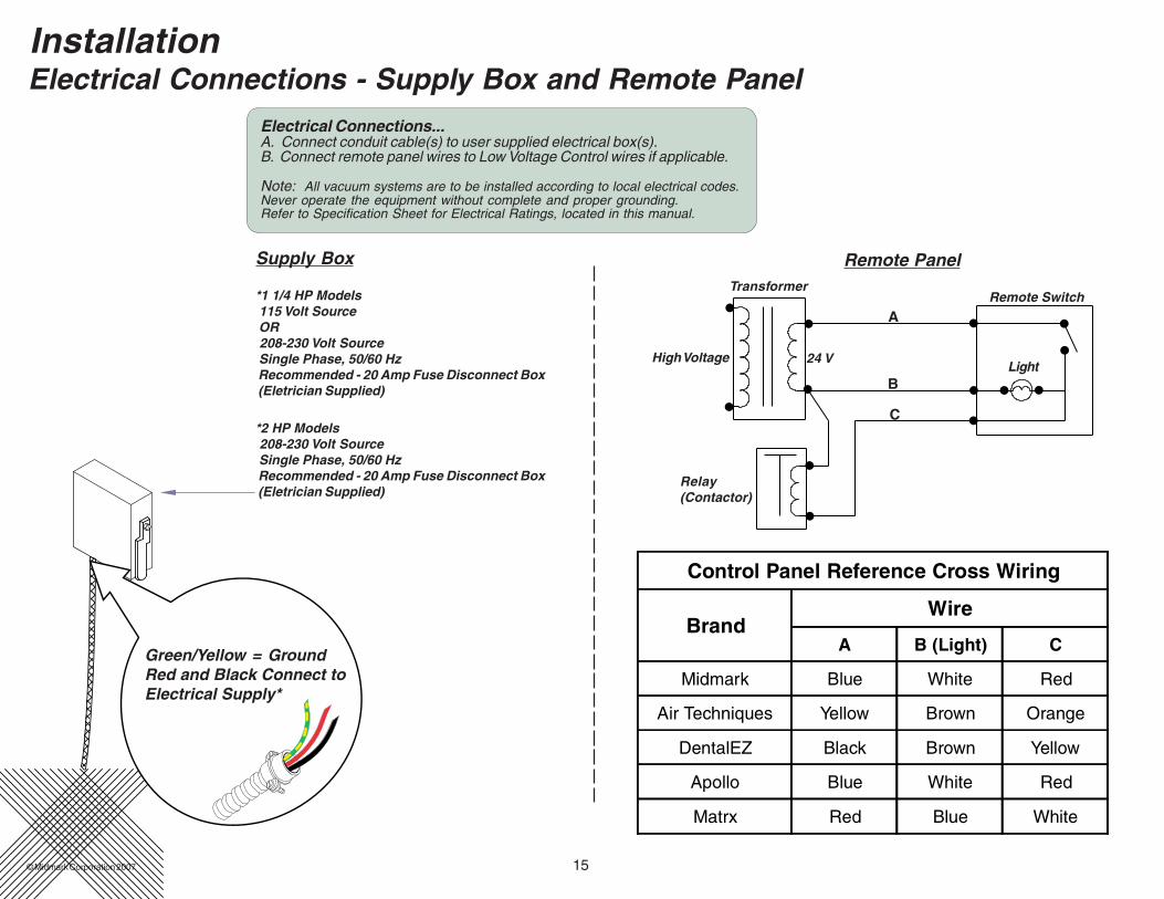
InstallationElectrical Connections - Supply Box and Remote Panel
Green/Yellow = GroundRed and Black Connect toElectrical Supply*
*2 HP Models 208-230 Volt Source Single Phase, 50/60 Hz Recommended - 20 Amp Fuse Disconnect Box (Eletrician Supplied)
*1 1/4 HP Models 115 Volt Source OR 208-230 Volt Source Single Phase, 50/60 Hz Recommended - 20 Amp Fuse Disconnect Box (Eletrician Supplied)
TransformerRemote Switch
Light
Relay(Contactor)
High Voltage
A
B
C
24 V
Supply Box Remote Panel
Control Panel Reference Cross Wiring
BrandWire
A B (Light) C
Midmark Blue White Red
Air Techniques Yellow Brown Orange
DentalEZ Black Brown Yellow
Apollo Blue White Red
Matrx Red Blue White
Electrical Connections...A. Connect conduit cable(s) to user supplied electrical box(s).B. Connect remote panel wires to Low Voltage Control wires if applicable.
Note: All vacuum systems are to be installed according to local electrical codes.Never operate the equipment without complete and proper grounding.Refer to Specification Sheet for Electrical Ratings, located in this manual.
16© Midmark Corporation 2007
AA186500
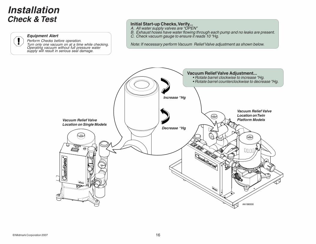
Equipment AlertPerform Checks before operation.Turn only one vacuum on at a time while checking.Operating vacuum without full pressure watersupply will result in serious seal damage.
InstallationCheck & Test
Initial Start-up Checks, Verify...A. All water supply valves are “OPEN”B. Exhaust hoses have water flowing through each pump and no leaks are present.C. Check vacuum gauge to ensure it reads 10 “Hg.
Note: If necessary perform Vacuum Relief Valve adjustment as shown below.
Vacuum Relief Valve Adjustment...• Rotate barrel clockwise to increase “Hg.• Rotate barrel counterclockwise to decrease “Hg.
Increase “Hg
Decrease “Hg
Vacuum Relief ValveLocation on TwinPlatform ModelsVacuum Relief Valve
Location on Single Models
© Midmark Corporation 2007 17
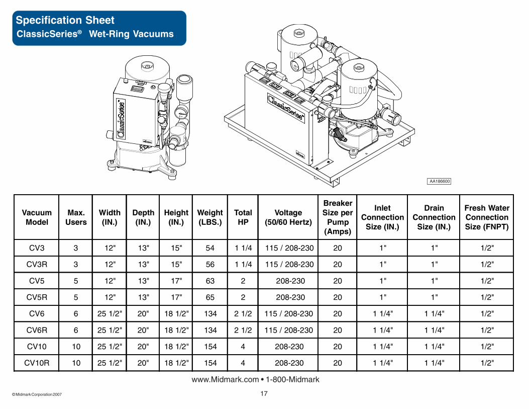
Specification Sheet
www.Midmark.com • 1-800-Midmark
ClassicSeries® Wet-Ring Vacuums
AA186600
VacuumModel
Max.Users
Width(IN.)
Depth(IN.)
Height(IN.)
Weight(LBS.)
TotalHP
Voltage(50/60 Hertz)
BreakerSize per
Pump(Amps)
InletConnection
Size (IN.)
DrainConnection
Size (IN.)
Fresh WaterConnectionSize (FNPT)
CV3 3 12" 13" 15" 54 1 1/4 115 / 208-230 20 1" 1" 1/2"
CV3R 3 12" 13" 15" 56 1 1/4 115 / 208-230 20 1" 1" 1/2"
CV5 5 12" 13" 17" 63 2 208-230 20 1" 1" 1/2"
CV5R 5 12" 13" 17" 65 2 208-230 20 1" 1" 1/2"
CV6 6 25 1/2" 20" 18 1/2" 134 2 1/2 115 / 208-230 20 1 1/4" 1 1/4" 1/2"
CV6R 6 25 1/2" 20" 18 1/2" 134 2 1/2 115 / 208-230 20 1 1/4" 1 1/4" 1/2"
CV10 10 25 1/2" 20" 18 1/2" 154 4 208-230 20 1 1/4" 1 1/4" 1/2"
CV10R 10 25 1/2" 20" 18 1/2" 154 4 208-230 20 1 1/4" 1 1/4" 1/2"

18© Midmark Corporation 2007
This page was intentionally left blank.

© Midmark Corporation 2007 19
Midmark CorporationFor contact information, go to:www.midmark.com
Related Documents