AMVAC™ Medium Voltage Vacuum Circuit Breakers Installation and Operation Manual

Welcome message from author
This document is posted to help you gain knowledge. Please leave a comment to let me know what you think about it! Share it to your friends and learn new things together.
Transcript

AMVAC™ Medium Voltage Vacuum Circuit Breakers Installation and Operation Manual

2 1VAL050601-MB Rev C

3 1VAL050601-MB Rev C
TABLE OF CONTENTS FOREWORD .............................................................................................................................................................. 4 INTRODUCTION & SAFE PRACTICES ................................................................................................................... 5 RECEIVING, HANDLING, AND STORAGE ............................................................................................................. 6 ACCESSORIES ......................................................................................................................................................... 7 Lifting Hook ................................................................................................................................................ ...7 Racking Handle ............................................................................................... ............................................ 8 Manual Opening Handle............................................................................................... ............................... 8 INSERTION AND REMOVAL ................................................................................................................................... 9 Racking ....................................................................................................................................................... 11 STRUCTURE AND FUNCTION .............................................................................................................................. 13 OPERATION, INSTALLATION AND MAINTENANCE .......................................................................................... 18 Interlocks ...................................................................................................................................................... 18 Manual Operation ........................................................................................................................................ 18 Maintenance ............................................................................................................................................... 19 Truck ............................................................................................................................................................ 20 Control Wiring .............................................................................................................................................. 21 Primary Circuit ............................................................................................................................................. 22 APPENDICES .......................................................................................................................................................... 23 Appendix A: Basic Breaker Layout ............................................................................................................ 23 Appendix B: Basic Breaker Dimensions and Weights .......................................................................... 24-32 Appendix C: ED2 Electronic Control Board ............................................................................................. 33 Overview .............................................................................................................................................. 34 Available boards .................................................................................................................................. 35 Binary Inputs ................................................................................................................................... 35-36 Binary Outputs ............................................................................................................................... 36-37 Output contact specifications ............................................................................................................... 38 Features ............................................................................................................................................... 39 Power considerations .......................................................................................................................... 40 Ready not Ready status ..................................................................................................................... 41 ED2 connections Jumpers and DIP settings ...................................................................................... 42 Appendix D: Wiring Diagrams ............................................................................................................... 43-44 Appendix E: Wiring Diagrams .................................................................................................................... 45 Appendix F: Auxiliary Contact ratings ........................................................................................................ 46 Appendix G: Service Conditions ............................................................................................................... 47 PRODUCT QUALITY AND ENVIROMENTAL PROTECTION ............................................................................... 48

4 1VAL050601-MB Rev C
FOREWORD
This booklet provides information for the Medium Voltage (5kV to 27kV) AMVACTM indoor circuit breakers as described below. Note: not all sections of this bulletin appllies to all the types of AMVACTM circuit breakers. For example, the racking and interlock sections only apply to the draw-out (removable) versions and do not apply to the fixed-mount breaker styles. Also sections on the ED2 board contains all options available on the board but may not be utilized de-pending upon options ordered. All information in this booklet was current at the time of printing. All references in this booklet are determined from viewing the circuit breaker from the front.
DRAWOUT (REMOVEABLE): A drawout circuit breaker is a breaker that may be removed from a cell without the unbolting of any connections or mounting supports. It utilizes specific interlock devices that function according to ANSI standards, which allow for the safe removal of the device with minimal risk to personnel. It is intended for use in SafeGear®, ADVANCETM, or abbreviated versions of ABB and OEM switchgear. It also contains plug-in primary and secondary disconnects with three physical ANSI operating positions within the cell: Disconnect, Test, and Connected. In the disconnected position there are no electrical connections. In the test position only, the secondary control wiring is connected via a patented disconnect mechanism which allows for remote testing of the breaker operations. The connected position, both primary and secondary circuits are connected and the breaker is ready for normal operation.
FIXED-MOUNT:
A Fixed-mount circuit breaker is intended to be mounted as a stationary device. It does not contain any racking related interlocks and/or primary leads. Primary connections are hard bussed to the associated gear in which the breaker is installed by the consumer. Secondary wiring is terminated on a 5 foot length of wire from the module to secondary plugs that are the same as the draw-out versions. Plugs and associated pins can be purchased for plug in connection or the wires may be cut to provide direct connections. The fixed mount version must be provided with the plugs in this manner to meet UL listing and to insure proper testing of the breaker. The customer is responsible for any damage to the breaker that is due to mis-wiring of the breaker.

5 1VAL050601-MB Rev C
SAFE PRACTICES:
AMVAC™ circuit breakers are equipped with high energy electrical storage capacitors. The design includes several interlocks and safety features which help ensure safe and proper operating sequences. To ensure safety of personnel associated with installation, operation, removal, and maintenance of these circuit breakers, the following recommendations must be followed:
Only qualified persons, as defined in the National Electric Safety Code, who are familiar with the installation and maintenance of medium voltage circuits and equipment should be permitted to work on these circuit breakers.
Read these instructions carefully before attempting any installation, operation, or maintenance of these power circuit breakers.
DO NOT work on an energized circuit breaker.
DO NOT work on a circuit breaker unless all components are disconnected by means of a visible break and securely grounded.
DO NOT work on a circuit breaker with power supplied to the secondary control circuit.
DO NOT defeat safety interlocks. This may result in bodily injury, death and/or equipment damage.
DO NOT work on a closed circuit breaker.
DO NOT work on a circuit breaker with charged energy (springs, capacitors, etc.).
DO NOT use a circuit breaker by itself as the sole means of isolating a medium or high voltage circuit.
DO NOT leave a circuit breaker in an intermediate position in a cell. Always place the circuit breaker in the Disconnect, Test or Connect position without hesitation between positions.
THE CIRCUIT BREAKERS DESCRIBED IN THIS BOOK ARE DESIGNED AND TESTED TO OPERATE WITHIN THEIR NAMEPLATED RATING. OPERATION OUTSIDE OF THESE RATINGS MAY CAUSE THE EQUIPMENT TO FAIL, RESULTING IN PROPERTY DAMAGE, BODILY INJURY AND/OR DEATH.
ALL ANSI AND NEC SAFETY CODES, SAFETY STANDARDS AND/OR REGULATIONS AS THEY MAY BE APPLIED TO THIS TYPE OF EQUIPMENT MUST BE ADHERED TO STRICTLY.
WARNING
INTRODUCTION:
The purpose of this manual is to provide instructions for unpacking, storage, installation, operation, and maintenance for AMVAC™ vacuum circuit breakers. This manual should be carefully read and used as a guide during installation, initial operation, and maintenance.
The specific ratings of each model circuit breaker are listed on the individual nameplates. The AMVAC™ circuit breakers are protective devices. As such, they are maximum rated devices. Therefore under no circumstances should they be applied outside of their nameplate ratings. Refer to ANSI and IEEE guidelines referring to the use of circuit breaker applications.
NOTICE
FAILURE TO OBSERVE THE REQUIREMENTS OF OSHA STANDARD 1910.269 CAN CAUSE DEATH OR SEVERE BURNS AND DISFIGUREMENT. THIS STANDARD SPECIFICALLY PROHIBITS THE WEARING OF POLYESTER, ACETATE, NYLON, OR RAYON CLOTHING BY EMPLOYEES WORKING WITH EXPOSURE TO ELECTRIC ARCS OR FLAMES.
INTRODUCTION & SAFE PRACTICES
6 1VAL050601-MB Rev C
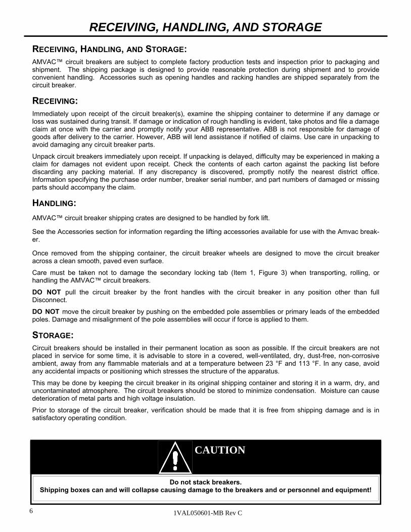
RECEIVING, HANDLING, AND STORAGE:
AMVAC™ circuit breakers are subject to complete factory production tests and inspection prior to packaging and shipment. The shipping package is designed to provide reasonable protection during shipment and to provide convenient handling. Accessories such as opening handles and racking handles are shipped separately from the circuit breaker.
RECEIVING: Immediately upon receipt of the circuit breaker(s), examine the shipping container to determine if any damage or loss was sustained during transit. If damage or indication of rough handling is evident, take photos and file a damage claim at once with the carrier and promptly notify your ABB representative. ABB is not responsible for damage of goods after delivery to the carrier. However, ABB will lend assistance if notified of claims. Use care in unpacking to avoid damaging any circuit breaker parts.
Unpack circuit breakers immediately upon receipt. If unpacking is delayed, difficulty may be experienced in making a claim for damages not evident upon receipt. Check the contents of each carton against the packing list before discarding any packing material. If any discrepancy is discovered, promptly notify the nearest district office. Information specifying the purchase order number, breaker serial number, and part numbers of damaged or missing parts should accompany the claim.
HANDLING:
AMVAC™ circuit breaker shipping crates are designed to be handled by fork lift.
See the Accessories section for information regarding the lifting accessories available for use with the Amvac break-er.
Once removed from the shipping container, the circuit breaker wheels are designed to move the circuit breaker across a clean smooth, paved even surface.
Care must be taken not to damage the secondary locking tab (Item 1, Figure 3) when transporting, rolling, or handling the AMVAC™ circuit breakers.
DO NOT pull the circuit breaker by the front handles with the circuit breaker in any position other than full Disconnect.
DO NOT move the circuit breaker by pushing on the embedded pole assemblies or primary leads of the embedded poles. Damage and misalignment of the pole assemblies will occur if force is applied to them.
STORAGE: Circuit breakers should be installed in their permanent location as soon as possible. If the circuit breakers are not placed in service for some time, it is advisable to store in a covered, well-ventilated, dry, dust-free, non-corrosive ambient, away from any flammable materials and at a temperature between 23 °F and 113 °F. In any case, avoid any accidental impacts or positioning which stresses the structure of the apparatus.
This may be done by keeping the circuit breaker in its original shipping container and storing it in a warm, dry, and uncontaminated atmosphere. The circuit breakers should be stored to minimize condensation. Moisture can cause deterioration of metal parts and high voltage insulation.
Prior to storage of the circuit breaker, verification should be made that it is free from shipping damage and is in satisfactory operating condition.
CAUTION
Do not stack breakers. Shipping boxes can and will collapse causing damage to the breakers and or personnel and equipment!
RECEIVING, HANDLING, AND STORAGE

7 1VAL050601-MB Rev C
CAUTION
Always follow safe work practices when lifting the circuit breakers to protect the safety of personnel and equipment.
Always inspect lifting hook for signs of wear or damage before use.
Do not use a lifting hook that is damaged or worn.
The lifting device (i.e. hoist, wench) should be suitably rated for lifting the circuit breaker load (500lbs).
Always refer to Fig 6 below for the proper installation of the lifting hook.
The lifting hook IS NOT to be used for insertion of drawout circuit breakers into switchgear compartments.
The lifting hook IS NOT to be used as the sole means of support when servicing the circuit breaker.
LIFTING HOOK: The lifting hook is specifically designed for general lifting and lowering of the vacuum circuit breaker, from shipping pallets or for lifting onto and off of work tables. The lifting hook is not designed to be used for insertion or removal of the circuit breaker from the switchgear compartment, instead, the use of an appropriate lift truck is required or serious damage to the breaker may occur. There are two types of lifting hooks available,
1) Chain - The chain type lifting hook is designed to attach to the circuit breaker in the long oval holes on each side of the frame (see lifting hook detail). This lifting hook is more compact and easier to store than the metal frame style. 2) Metal frame - The metal frame lifting hook is designed to attach to the circuit breaker in the long oval holes as well as the additional mounting point on each side. This lifting hook provides for more level transfer of the circuit breaker but is less compact than the chain style.
ACCESSORIES
Chain hook: Attach one lifting hook to each side of the circuit breaker on lifting hook angle. NOTE: Lifting angles must be removed before breaker is inserted into switchgear compartment.
Lifting Hook Detail

8 1VAL050601-MB Rev C
2
ACCESSORIES
MANUAL TRIP HANDLE: The manual opening handle (1) is designed to open the AMVAC circuit breaker manually. Insert the handle into the opening in the front panel (2) and turn it counter-clockwise until the circuit break-er opens. The manual opening handle shall be stored in close proximity to the circuit breaker switchgear for easy access.
RACKING HANDLE: The racking handle is designed to easily adjust the device into and out of a switchgear enclosure. It is also used to change the position of the device from the Disconnect, Test, and Connect positions. Press down on the release lever (1) and rotate racking handle (2) clockwise to rack in (toward Connect) and counter clockwise to rack out (from Connect).
Racking Handle
1
2
Manual Trip Handle
(1)
1
CAUTION
Use of any other racking device not approved by ABB will void the warranty!!
ABB will not be responsible for damage caused by the use of racking tools other than ABB’s.

9 1VAL050601-MB Rev C
INSERTION AND REMOVAL This section describes the necessary steps for inserting and removing a circuit breaker to and from the switchgear’s “Disconnect” position. Racking the circuit breaker to and from Disconnect, Test and Connected positions is covered in the next section. The following rules should always be observed when inserting a circuit breaker into the switchgear compartment.
NOTE: ABB has specific accessories to be used with ABB breakers.
ALWAYS compare the breaker ratings nameplate with the switchgear ratings nameplate. Verify breaker secondary control voltage ratings are in agreement with the switchgear control voltage ratings.
ALWAYS make sure lifting hooks and lifting angles (see photo below) are removed prior to inserting breaker into cell.
DO NOT attempt to insert the circuit breaker prior to a complete inspection of both breaker and switchgear compartment. Breaker and compartment must be free of tools, obstructions or foreign objects.
DO NOT attempt to insert or rack a closed circuit breaker.
DO NOT force a breaker into or out of the cell.
DO NOT remove or rotate interference blocking plate in switchgear compartment. Interference plate prevents improper rating circuit breaker from being inserted into switchgear compartment.
INSERTION AND REMOVAL
Remove the lifting angle before inserting breaker in cell
DO NOT use Embedded pole assemblies or primary contacts to move or lift breaker
Do not attempt to remove the breaker from the circuit breaker compartment without the required ramp, dolly or lift truck. Refer to the specific switchgear Installation and Maintenance manual for details.
WARNING
10 1VAL050601-MB Rev C
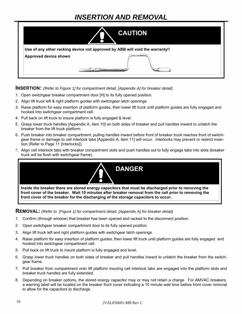
INSERTION: (Refer to Figure 1] for compartment detail, [Appendix A] for breaker detail)
1. Open switchgear breaker compartment door [H] to its fully opened position.
2. Align lift truck left & right platform guides with switchgear latch openings.
3. Raise platform for easy insertion of platform guides, then lower lift truck until platform guides are fully engaged and hooked into switchgear compartment cell.
4. Pull back on lift truck to insure platform is fully engaged & level.
5. Grasp lower truck handles [Appendix A, item 10] on both sides of breaker and pull handles inward to unlatch the breaker from the lift truck platform.
6. Push breaker into breaker compartment, pulling handles inward before front of breaker truck reaches front of switch-gear frame or damage to cell interlock tabs [Appendix A, item 11] will occur. Interlocks may prevent or restrict inser-tion (Refer to Page 11 [Interlocks]).
7. Align cell interlock tabs with breaker compartment slots and push handles out to fully engage tabs into slots (breaker truck will be flush with switchgear frame).
REMOVAL: (Refer to [Figure 1] for compartment detail, [Appendix A] for breaker detail)
1. Confirm (through window) that breaker has been opened and racked to the disconnect position.
2. Open switchgear breaker compartment door to its fully opened position.
3. Align lift truck left and right platform guides with switchgear latch openings.
4. Raise platform for easy insertion of platform guides, then lower lift truck until platform guides are fully engaged and hooked into switchgear compartment cell.
5. Pull back on lift truck to insure platform is fully engaged and level.
6. Grasp lower truck handles on both sides of breaker and pull handles inward to unlatch the breaker from the switch-gear frame.
7. Pull breaker from compartment onto lift platform insuring cell interlock tabs are engaged into the platform slots and breaker truck handles are fully extended.
8. Depending on breaker options, the stored energy capacitor may or may not retain a charge. For AMVAC breakers, a warning label will be located on the breaker front cover indicating a 10 minute wait time before front cover removal to allow for the capacitors to discharge.
INSERTION AND REMOVAL
DANGER
Inside the breaker there are stored energy capacitors that must be discharged prior to removing the front cover of the breaker. Wait 10 minutes after breaker removal from the cell prior to removing the front cover of the breaker for the discharging of the storage capacitors to occur.
CAUTION
Use of any other racking device not approved by ABB will void the warranty!!
Approved device shown
11 1VAL050601-MB Rev C
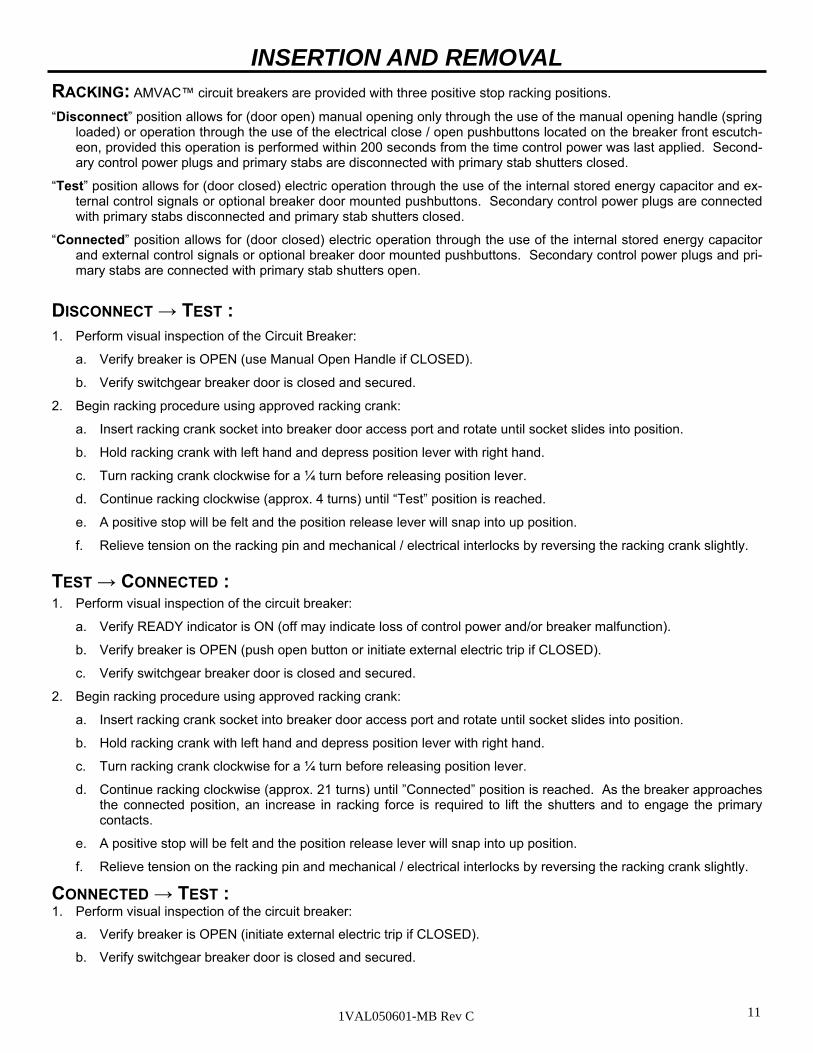
RACKING: AMVAC™ circuit breakers are provided with three positive stop racking positions.
“Disconnect” position allows for (door open) manual opening only through the use of the manual opening handle (spring loaded) or operation through the use of the electrical close / open pushbuttons located on the breaker front escutch-eon, provided this operation is performed within 200 seconds from the time control power was last applied. Second-ary control power plugs and primary stabs are disconnected with primary stab shutters closed.
“Test” position allows for (door closed) electric operation through the use of the internal stored energy capacitor and ex-ternal control signals or optional breaker door mounted pushbuttons. Secondary control power plugs are connected with primary stabs disconnected and primary stab shutters closed.
“Connected” position allows for (door closed) electric operation through the use of the internal stored energy capacitor and external control signals or optional breaker door mounted pushbuttons. Secondary control power plugs and pri-mary stabs are connected with primary stab shutters open.
TEST → CONNECTED : 1. Perform visual inspection of the circuit breaker:
a. Verify READY indicator is ON (off may indicate loss of control power and/or breaker malfunction).
b. Verify breaker is OPEN (push open button or initiate external electric trip if CLOSED).
c. Verify switchgear breaker door is closed and secured.
2. Begin racking procedure using approved racking crank:
a. Insert racking crank socket into breaker door access port and rotate until socket slides into position.
b. Hold racking crank with left hand and depress position lever with right hand.
c. Turn racking crank clockwise for a ¼ turn before releasing position lever.
d. Continue racking clockwise (approx. 21 turns) until ”Connected” position is reached. As the breaker approaches the connected position, an increase in racking force is required to lift the shutters and to engage the primary contacts.
e. A positive stop will be felt and the position release lever will snap into up position.
f. Relieve tension on the racking pin and mechanical / electrical interlocks by reversing the racking crank slightly.
CONNECTED → TEST : 1. Perform visual inspection of the circuit breaker:
a. Verify breaker is OPEN (initiate external electric trip if CLOSED).
b. Verify switchgear breaker door is closed and secured.
DISCONNECT → TEST : 1. Perform visual inspection of the Circuit Breaker:
a. Verify breaker is OPEN (use Manual Open Handle if CLOSED).
b. Verify switchgear breaker door is closed and secured.
2. Begin racking procedure using approved racking crank:
a. Insert racking crank socket into breaker door access port and rotate until socket slides into position.
b. Hold racking crank with left hand and depress position lever with right hand.
c. Turn racking crank clockwise for a ¼ turn before releasing position lever.
d. Continue racking clockwise (approx. 4 turns) until “Test” position is reached.
e. A positive stop will be felt and the position release lever will snap into up position.
f. Relieve tension on the racking pin and mechanical / electrical interlocks by reversing the racking crank slightly.
INSERTION AND REMOVAL
12 1VAL050601-MB Rev C
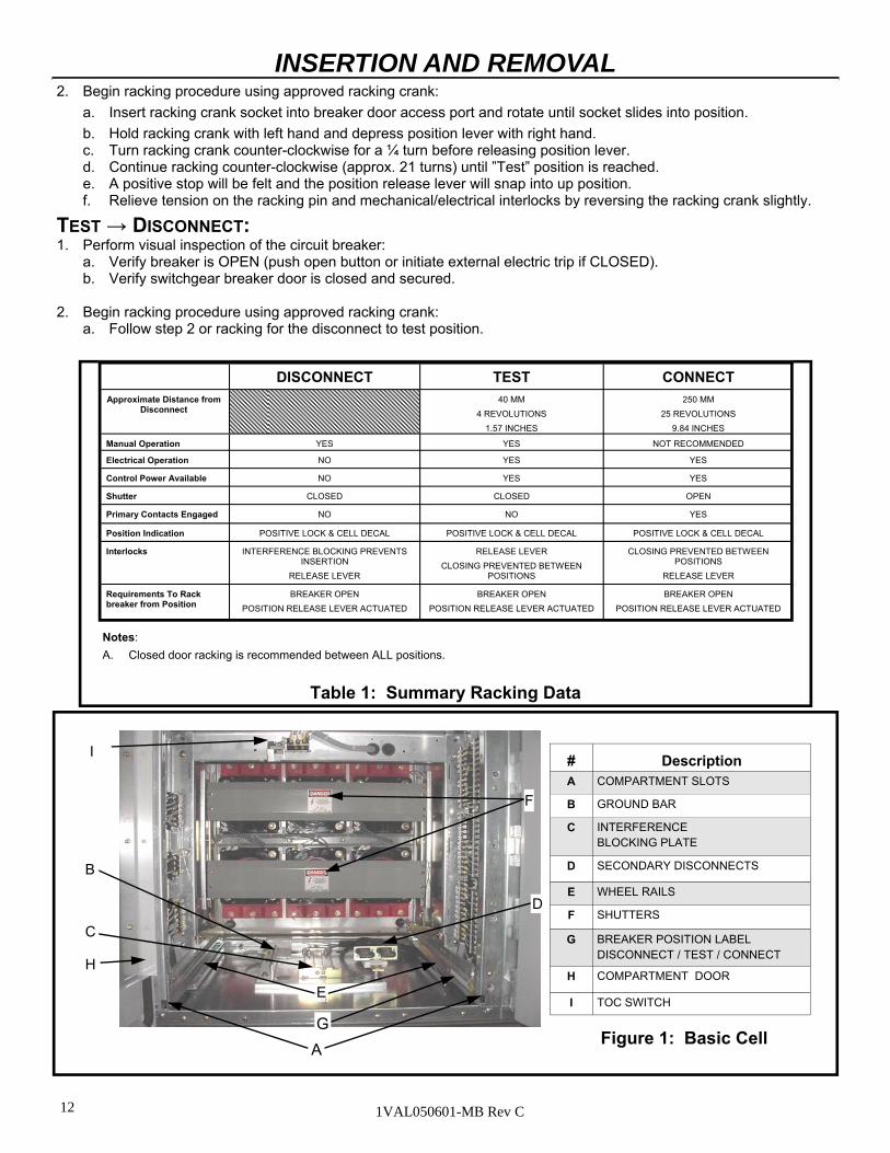
2. Begin racking procedure using approved racking crank:
a. Insert racking crank socket into breaker door access port and rotate until socket slides into position.
b. Hold racking crank with left hand and depress position lever with right hand. c. Turn racking crank counter-clockwise for a ¼ turn before releasing position lever. d. Continue racking counter-clockwise (approx. 21 turns) until ”Test” position is reached. e. A positive stop will be felt and the position release lever will snap into up position. f. Relieve tension on the racking pin and mechanical/electrical interlocks by reversing the racking crank slightly.
TEST → DISCONNECT: 1. Perform visual inspection of the circuit breaker:
a. Verify breaker is OPEN (push open button or initiate external electric trip if CLOSED). b. Verify switchgear breaker door is closed and secured.
2. Begin racking procedure using approved racking crank: a. Follow step 2 or racking for the disconnect to test position.
INSERTION AND REMOVAL
Notes:
A. Closed door racking is recommended between ALL positions.
DISCONNECT TEST CONNECT
Approximate Distance from Disconnect
40 MM
4 REVOLUTIONS
1.57 INCHES
250 MM
25 REVOLUTIONS
9.84 INCHES
Manual Operation YES YES NOT RECOMMENDED
Electrical Operation NO YES YES
Control Power Available NO YES YES
Shutter CLOSED CLOSED OPEN
Primary Contacts Engaged NO NO YES
Position Indication POSITIVE LOCK & CELL DECAL POSITIVE LOCK & CELL DECAL POSITIVE LOCK & CELL DECAL
Interlocks INTERFERENCE BLOCKING PREVENTS INSERTION
RELEASE LEVER
RELEASE LEVER
CLOSING PREVENTED BETWEEN POSITIONS
CLOSING PREVENTED BETWEEN POSITIONS
RELEASE LEVER
Requirements To Rack breaker from Position
BREAKER OPEN
POSITION RELEASE LEVER ACTUATED
BREAKER OPEN
POSITION RELEASE LEVER ACTUATED
BREAKER OPEN
POSITION RELEASE LEVER ACTUATED
Table 1: Summary Racking Data
# Description A COMPARTMENT SLOTS
B GROUND BAR
C INTERFERENCE BLOCKING PLATE
D SECONDARY DISCONNECTS
E WHEEL RAILS
F SHUTTERS
G BREAKER POSITION LABEL DISCONNECT / TEST / CONNECT
H COMPARTMENT DOOR
I TOC SWITCH
Figure 1: Basic Cell
D
E
A
B
G
F
C
H
I

13 1VAL050601-MB Rev C
CIRCUIT BREAKER STRUCTURE: (Refer to Figure 2)
STRUCTURE OF THE CIRCUIT BREAKER POLES: The encapsulated poles are mounted on the rear flat section of the circuit breaker enclosure. The live parts of the circuit breaker poles are enclosed in cast resin and protected from impacts and other external influences.
With the circuit breaker closed the current path for each pole leads from the upper circuit breaker terminal (25) to the fixed contact (24.2) in the vacuum interrupter (24), then via the moving contact (24.1) and the flexible connector (21) to the lower circuit breaker terminal (22). This path can be reversed.
The change of contact state is delivered by means of the insulated link rod (19) with internal contact force springs (20).
STRUCTURE OF THE OPERATING MECHANISM:
The operating mechanism consists of a magnetic actuator (10), control module (27) with sensor systems, storage capacitor(s) (26), and linkages which transmit the force to the breaker poles.
In addition, there are supplementary components for emergency manual opening and the controls are located on the front of the enclosure.
The actuator (10) transmits the actuating force on the three circuit breaker poles by way of the lever shaft (18). The storage capacitor(s) (26) provides the necessary actuating energy on demand.
The positions of the poles, in the circuit breaker are detected by two sensors (15) and (16) directly at the lever shaft (18).
There are name plates with the ratings of the circuit breaker on the front panel (1.1) and on the inside rear wall just left of the actuator (depending on options the label may be located on the inside lower left wall).
The basic version of the magnetic actuator mechanism is fitted with the following controls and instruments:
Signal lamp for switching readiness (“READY” indication lamp) (2)
CLOSE push-button (3)
OPEN push-button (4)
Mechanical operating cycle counter (5)
Mechanical CLOSE/OPEN indicator (6)
STRUCTURE OF THE CONTROL MODULE:
The control module consists of a single circuit board (27). This board contains a series of components:
AC/DC converter
Logic circuit / Power Electronics
Electric optoccouplers for input
Relays for output
Power electronics to control the actuator coils
Sockets for control and signals
The board is connected by a plug connector which ensures safe and trouble-free wiring. The boards and components are not user serviceable.
STRUCTURE AND FUNCTION

14 1VAL050601-MB Rev C
STORAGE CAPACITORS: (Figure 2c)
The energy for the operation of the circuit breaker is stored electrically in two storage capacitors. The breaker is de-signed in such a way that when the capacitors are fully charged, there is enough energy for an O-C-O (Open-Close-Open)* operating sequence without the recharging of the capacitors.
The energy stored by the capacitor is continuously monitored. This is achieved by the control unit constantly measuring the capacitor voltage.
The “READY” lamp indicates whether the circuit breaker is functional or not, and indicates if the circuit breaker is ready or not ready to operate. Note: Observe connecting the auxiliary voltage as described in the Operation, Installation, and Maintenance section.
The energy available in relation to the relevant switch position after auxiliary power loss is the criteria which determines whether a switching operation can be performed or an error message is issued:
Case 1: Circuit breaker in the OPEN position
The energy available is sufficient for a CLOSE and OPEN switching operation.
Case 2: Circuit breaker in the CLOSED position
The energy available is sufficient for a OPEN-CLOSE-OPEN switching sequence.
The energy available is sufficient for an OPEN switching operation up to 200 seconds after failure of the auxiliary power supply.
* 0.3 seconds for each operation
SENSOR SYSTEM: (Figure 2d)
The systematic use of sensors permits control of the circuit breaker without auxiliary switches.
Two inductive proximity switches (15) and (16) are used to detect the mechanical limit positions. These two proximity switches also provide self-monitoring of the system.
CIRCUIT BREAKER FUNCTION
MAGNETIC ACTUATOR: (Figures 2b and 2c)
The magnetic actuator is the heart of the circuit breaker operating mechanism. It combines the following integrated functions:
Latching in the limit positions
Release
Switching
The actuator is a bistable permanent magnet system in which the armature motion is affected by activating the close or open coil. In the limit positions the armature is held in place magnetically by the fields of the two permanent magnets. Changing of the breaker’s switched position is performed by exciting one of the two electromagnet coils (open or close) until the latching force of the permanent magnets (13) are exceeded and the magnet armature (12) is shifted up or down depending upon the operation.
STRUCTURE AND FUNCTION
DANGER
Inside the breaker there are stored energy capacitors that must be discharged prior to removing the front cover of the breaker. Wait 10 minutes after breaker removal from the cell prior to removing the front cover of the breaker for the discharging of the storage capacitors to occur.

15 1VAL050601-MB Rev C
CIRCUIT BREAKER CONTROL:
All the conditions for control of the magnetic actuator mechanism are defined in a permanently programmed logic module. These conditions are:
Auxiliary voltage must be applied to the AC/DC converter.
The storage capacitors must have sufficient charge for the next switching operation.
The moving contacts in the circuit breaker poles must be in a defined CLOSE or OPEN limit position.
The closing coil can only be activated with the circuit breaker in the OPEN position and there is sufficient energy.
The opening coil can only be activated with the circuit breaker in the CLOSE position and there is sufficient energy.
Closing is blocked when an opening command is simultaneously active.
Activation of the closing coil can be disabled by an external blocking signal.
The antipumping system ensures that, when a closing command is applied and followed by an opening command, only one CLOSE-OPEN switching operation is performed. For the next closing operation, the active closing command has to be cleared and must be issued again.
Deactivation of the opening or closing coil takes place when the relevant limit position has been reached.
All close signals must be by momentary contacts with a close time of 6-300ms.
OPENING AND CLOSING PROCEDURE: (Figures 2a to 2c, Page 16)
The opening and closing processes are initiated either by remote control via momentary closing contacts or locally by manual operation of push-buttons (3) or (4).
In the closing process, the armature motion acts directly via the lever shaft (18) on the moving contact (24.1) until the vacuum interrupter contacts meet.
In the full motion sequence, the spring arrangement (20) is tensioned to 100% and the necessary contact force thus applied. The available overtravel is greater than the maximum contact burn-off throughout the life of the vacuum interrupter.
AUTORECLOSING SEQUENCE: The operating mechanism is fundamentally prepared for autoreclosing, and with the short recharging time of the storage capacitor it is also suitable for multi-shot autoreclosing.
VACUUM INTERRUPTER QUENCHING PRINCIPLE: Due to the extremely low static interrupter chamber pressure of 10-4 to 10-8 mbar, only a relatively small contact gap is required to achieve a high dielectric strength. The vacuum arc is extinguished on one of the first natural current zeros. Due to the small contact gap, high conductivity of the metal vapor plasma, and short arcing time, the associated arc energy is extremely low, which has advantageous effects on the life of the contacts and thus on that of the vacuum interrupters.
Switch Position: Storage Capacitor Energy For:
OPEN CLOSE and OPEN
CLOSE OPEN
STRUCTURE AND FUNCTION
16 1VAL050601-MB Rev C
PACKAGES: AMVACTM circuit breakers are available with three control packages. The standard package (package 1) comes as an ADVAC® (spring stored energy mechanism) replacement circuit breaker. It comes with all functions of an ADVAC®
circuit breaker having one secondary disconnect. There are 2 versions of package 1, with or without trip coil monitoring. The optional package (package 2) includes everything in package 1 with a total of 9a and 8b auxiliary contacts (approx. 5 to 10 amps) for customer use. This package directly replaces an ADVAC® circuit breaker having two secondary dis-connects. Package 3 is an AMVACTM circuit breaker with all control board options available. See Appendix D for more detail regarding the wiring and termination points for each package.
STRUCTURE AND FUNCTION
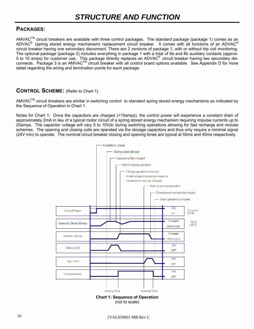
Chart 1: Sequence of Operation (not to scale)
CONTROL SCHEME: (Refer to Chart 1) AMVACTM circuit breakers are similar in switching control to standard spring stored energy mechanisms as indicated by the Sequence of Operation in Chart 1. Notes for Chart 1: Once the capacitors are charged (<10amps), the control power will experience a constant drain of approximately 2mA in lieu of a typical motor circuit of a spring stored energy mechanism requiring impulse currents up to 20amps. The capacitor voltage will vary 5 to 10Vdc during switching operations allowing for fast recharge and reclose schemes. The opening and closing coils are operated via the storage capacitors and thus only require a minimal signal (24V min) to operate. The nominal circuit breaker closing and opening times are typical at 55ms and 40ms respectively.

17 1VAL050601-MB Rev C
STRUCTURE AND FUNCTION
Figure 2a: Circuit breaker front with controls 1 Breaker enclosure 1.1 Front Plate 1.2 Lifting bracket, both sides 2 “Ready” indicator 3 CLOSE push-button 4 OPEN push-button 5 Mechanical operating cycle counter 6 Mechanical CLOSE/OPEN indicator 7 Rating plate 8 Socket for emergency open operation lever
Figure 2b: Sectional view of a circuit breaker type, AMVAC schematic diagram 1 Circuit breaker enclosure 1.1 Front panel, removable 9 Emergency manual opening mechanism 10 Magnetic actuator 11 OPEN coil 12 Magnet armature 13 Permanent magnets 14 CLOSE coil 17 Stroke adjuster 18 Lever shaft 19 Insulated link rod 20 Contact force spring 21 Flexible connector 22 Lower breaker terminal 23 Cast insulation 24 Vacuum interrupter 24.1 Moving Contact 24.2 Fixed Contact 25 Upper breaker terminal
Figure 2c: View of the magnetic actuator mechanism and auxiliary systems with the front cover removed
5 Mechanical operating cycle counter 6 Mechanical switch position indicator 10 Actuator 26 Storage Capacitors 27 Circuit breaker control unit (ED2 board) 28 Auxiliary switches
7
5
6
2
3
4
1.2
1.1
1
8
8
10
5
6
27 28
Figure 2d: Switch position indicator
6 Mechanical switch position indicator 15 Sensor for “Circuit-breaker OPEN” signal 16 Sensor for “Circuit-breaker CLOSED” signal
6
15
16
2
3
4
26

18 1VAL050601-MB Rev C
INTERLOCKS:
The AMVAC™ circuit breaker contains a number of interlocks. A description of each interlock follows as encountered during racking of the circuit breaker into the compartment.
POSITION INTERLOCKS: The position release lever must be depressed in order to begin racking the circuit breaker in any direction from any positive position (Disconnect, Test, or Connect). The release lever is blocked from actuation when the circuit breaker is CLOSED. The ability to close the circuit breaker is blocked mechanically and elec-trically unless it is in one of the three positive positions. If the circuit breaker is in between positions, the remote close signal and front panel close signal are disengaged and the circuit breaker cannot be closed.
MANUAL OPERATION: (Opening)
(Refer to Table 2, Appendix A, and Fig. 8)
The circuit breaker can be operated manually (opening only) or electrically. The manual Opening Handle is required for manual operation.
1. Inspect the initial state of the circuit breaker to determine the operations available (Refer to Table 1 and Fig. 2)
a. Close/Open indicator (6)
b. Stored Energy Charged/Discharged “Ready” Indicator (2) 2. Manual opening may be performed in any position, but should be avoided when the circuit breaker is in the Connect position. Any manual operation while the circuit breaker is racked onto live bus should be avoided to insure added safety to the operator.
INTERFERENCE BLOCKING: A interference blocking plate (Fig. 1) in the circuit breaker compartment prevents under rated circuit breakers from being inserted into higher rated compartments. The code plate rating includes continuous current, interrupting current, close and latch capability, and maximum voltage.
POSITIVE POSITION FOR RACKING: The racking mechanism is blocked unless the interlock tabs are fully extended into the compartment slots.
POSITIVE POSITION FOR REMOVAL: The handle release pin prevents withdrawing the circuit breaker from the compartment by blocking withdrawal of the locking tabs. The handle release pin blocks the handles unless the circuit breaker is in the Disconnect position.
OPERATION, INSTALLATION, AND MAINTENANCE
DANGER
Inside the breaker there are stored energy capacitors that must be discharged prior to removing the front cover of the breaker. Wait 20 minutes after breaker removal from the cell prior to removing the front cover of the breaker for the discharging of the storage capacitors to occur.
DANGER
MODIFICATION TO INTERLOCKS CAN RESULT IN HAZARDOUS CONDITIONS TO PERSONNEL AND EQUIPMENT. DO NOT OVERRIDE, BY-PASS OR ADJUST INTERLOCKS.

19 1VAL050601-MB Rev C
MAINTENANCE:
The mechanism requires visual inspection of hardware, lubrication and operation during routine inspection.
Before beginning any maintenance, remove the control power, and initiate the discharge of the storage capacitors by pulling the truck handles inward. Wait at least 10 minutes for the discharge circuit to discharge the storage capacitors before beginning work on the breaker. Remove the front cover by unfastening the screws and hardware located on the front of the breaker.
Always lubricate the working surface of the moving parts. Verify lubrication on the connections of the actuator and lever arm. Remove any grease on the circuit breaker frame. Use Isotopaz grease for lubrication If the grease becomes caked and dirty, remove with a clean cloth and reapply lubrication.
Maintenance Schedule Establishing a periodic maintenance and inspection schedule are critical to ensure a safe, reliable operating AMVAC circuit breaker. Although the magnetically actuated operating mechanism of the AMVAC circuit breaker is maintenance free, visual inspection and maintenance on other components is required.
The servicing interval and their aim depend on the environmental conditions and frequency of operations along with ex-perienced fault currents.
AMVAC’s installed in normal indoor climate controlled environment, require a visual inspection every five years or 10,000 normal load operations, whichever comes first.
AMVAC’s installed in contaminated or corrosive environments, or subjected to unusual service conditions, or experi-ence greater than 2,000 operations per year require inspection and maintenance annually.
Following each interrupted fault, an inspection and primary circuit testing of the breaker is required. DO NOT work on an energized circuit breaker.
DO NOT work on a circuit breaker unless all of the components are disconnected by means of a visible break and securely grounded.
DO NOT work on a circuit breaker with power supplied to the secondary control circuit.
DO NOT defeat safety interlocks. This may result in bodily injury, death and/or equipment damage.
DO NOT work on a closed circuit breaker.
DO NOT work on a circuit breaker with charged energy (springs, capacitors, etc.).
DO NOT use a circuit breaker by itself as the sole means of isolating a high voltage circuit.
DO NOT leave a circuit breaker in an intermediate position in a cell. Always have the circuit breaker in the Disconnect, Test, or Connect position.
Always lubricate the working surface of the moving parts. Verify lubrication on the connections of the actuator and lever arm. Remove any grease on the circuit breaker frame. Use Isotopaz grease for lubrication If the grease becomes caked and dirty, remove with a clean cloth and reapply lubrication.
OPERATION, INSTALLATION, AND MAINTENANCE
Stored Energy “READY” Indicator (2)
Mechanism (10) Operations Available
Discharged (Lamp OFF) Open None Available
Discharged (Lamp OFF) Closed Open
Charged (Lamp ON) Open Close-Open
Charged (Lamp ON) Closed Open-Close-Open
Table 2: Operations
20 1VAL050601-MB Rev C
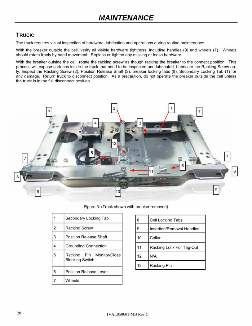
TRUCK: The truck requires visual inspection of hardware, lubrication and operations during routine maintenance.
With the breaker outside the cell, verify all visible hardware tightness, including handles (9) and wheels (7). Wheels should rotate freely by hand movement. Replace or tighten any missing or loose hardware.
With the breaker outside the cell, rotate the racking screw as though racking the breaker to the connect position. This process will expose surfaces inside the truck that need to be inspected and lubricated. Lubricate the Racking Screw on-ly. Inspect the Racking Screw (2), Position Release Shaft (3), breaker locking tabs (8), Secondary Locking Tab (1) for any damage. Return truck to disconnect position. As a precaution, do not operate the breaker outside the cell unless the truck is in the full disconnect position.
MAINTENANCE
Figure 3: (Truck shown with breaker removed)
1 Secondary Locking Tab
2 Racking Screw
3 Position Release Shaft
4 Grounding Connection
5 Racking Pin Monitor/Close Blocking Switch
6 Position Release Lever
7 Wheels
8 Cell Locking Tabs
9 Insertion/Removal Handles
10 Collar
11 Racking Lock For Tag-Out
12 N/A
13 Racking Pin
1 2
3 4
5
6
7 7
7 7
8 8
9 9 10
13
11

21 1VAL050601-MB Rev C
PRIMARY CIRCUIT ASSEMBLY: (Pole)
The primary circuit requires visual inspection of hardware, low-frequency withstand voltage testing to insure vacuum, and lubrication during routine maintenance.
All insulation material should be clean and free of structural cracks. Some minor cracks are inherent in the insulation material. Inspect for structural cracks and replace damaged parts.
Dirt or dust may create a dielectric path to ground on the insulation. Remove dust and dirt with a clean, lint-free cloth. Apply distilled water to the cloth to remove any difficult dirt. DO NOT return the circuit breaker into service until the insulation surfaces are completely dry.
Lubrication on the primary contacts should be inspected during routine maintenance. Use NO-OX-ID special grade-A grease for the lubrication of primary contacts.
OPERATION, INSTALLATION, AND MAINTENANCE
To verify the integrity of the primary insulation, perform the following low-frequency withstand voltage test:
1. Close the circuit breaker (no control power supplied). a. Connect the high potential lead to one pole. b. Ground the remaining poles and the circuit breaker frame. 2. Start machine with output potential at 0 (zero) VAC. 3. Increase the potential to the required voltage (see Table 3; note that new condition test is a factory test only and is not valid for field condition tests). 4. Hold for one minute. 5. Decrease potential to 0 (zero) VAC and turn off machine. 6. Repeat for the remaining poles. A successful withstand indicates satisfactory insulation strength of the primary circuit.
Rated Max Voltage
Dielectric Test Value, 1 Minute
Dry AC rms
New Condition reference c37.06
Dielectric Test Value, 1 Minute
Dry AC rms
Field Condition reference c37.20.2
4.76kV 19kV 15kV
8.25kV 36kV 27kV
15kV 36kV 27kV
27kV 60kV 45kV
Table 3: Primary Low-Frequency withstand Test Voltages
High voltage applied across an open gap in a vacuum can produce X-radiation. No radiation is emitted when the breaker is closed, since no gap exists. Also, when the breaker is open to the specified contact spacing in ser-vice or tested within the voltages specified, X-radiation at one meter is below the level of concern. A danger could exist at voltages above or contact spacing below that specified.
22 1VAL050601-MB Rev C
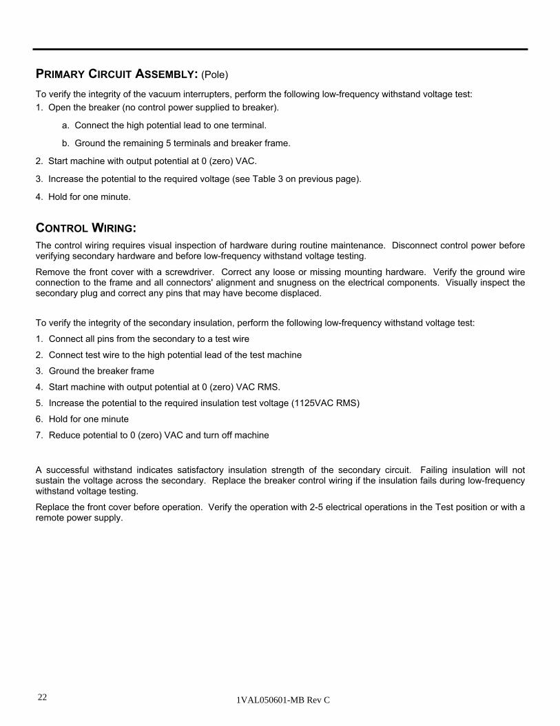
CONTROL WIRING:
The control wiring requires visual inspection of hardware during routine maintenance. Disconnect control power before verifying secondary hardware and before low-frequency withstand voltage testing.
Remove the front cover with a screwdriver. Correct any loose or missing mounting hardware. Verify the ground wire connection to the frame and all connectors' alignment and snugness on the electrical components. Visually inspect the secondary plug and correct any pins that may have become displaced.
To verify the integrity of the secondary insulation, perform the following low-frequency withstand voltage test:
1. Connect all pins from the secondary to a test wire
2. Connect test wire to the high potential lead of the test machine
3. Ground the breaker frame
4. Start machine with output potential at 0 (zero) VAC RMS.
5. Increase the potential to the required insulation test voltage (1125VAC RMS)
6. Hold for one minute
7. Reduce potential to 0 (zero) VAC and turn off machine
A successful withstand indicates satisfactory insulation strength of the secondary circuit. Failing insulation will not sustain the voltage across the secondary. Replace the breaker control wiring if the insulation fails during low-frequency withstand voltage testing.
Replace the front cover before operation. Verify the operation with 2-5 electrical operations in the Test position or with a remote power supply.
PRIMARY CIRCUIT ASSEMBLY: (Pole)
To verify the integrity of the vacuum interrupters, perform the following low-frequency withstand voltage test:
1. Open the breaker (no control power supplied to breaker).
a. Connect the high potential lead to one terminal.
b. Ground the remaining 5 terminals and breaker frame.
2. Start machine with output potential at 0 (zero) VAC.
3. Increase the potential to the required voltage (see Table 3 on previous page).
4. Hold for one minute.
23 1VAL050601-MB Rev C
15
2
1
4
3
9
19
18
17
16
10
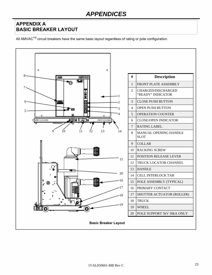
# Description
1 FRONT PLATE ASSEMBLY
2 CHARGED/DISCHARGED “READY” INDICATOR
3 CLOSE PUSH BUTTON
4 OPEN PUSH BUTTON
5 OPERATION COUNTER
6 CLOSE/OPEN INDICATOR
7 RATING LABEL
8 MANUAL OPENING HANDLE SLOT
9 COLLAR
10 RACKING SCREW
11 POSITION RELEASE LEVER
12 TRUCK LOCATOR CHANNEL
13 HANDLE
14 CELL INTERLOCK TAB
15 POLE ASSEMBLY (TYPICAL)
16 PRIMARY CONTACT
17 SHUTTER ACTUATOR (ROLLER)
18 TRUCK
19 WHEEL
20 POLE SUPPORT 5kV 50kA ONLY
Basic Breaker Layout
APPENDIX A BASIC BREAKER LAYOUT
APPENDICES
All AMVACTM circuit breakers have the same basic layout regardless of rating or pole configuration.
13 11 14
5
6
8
12
7
20
24 1VAL050601-MB Rev C
APPENDIX B BASIC BREAKER DIMENSIONS AND WEIGHTS
APPENDICES
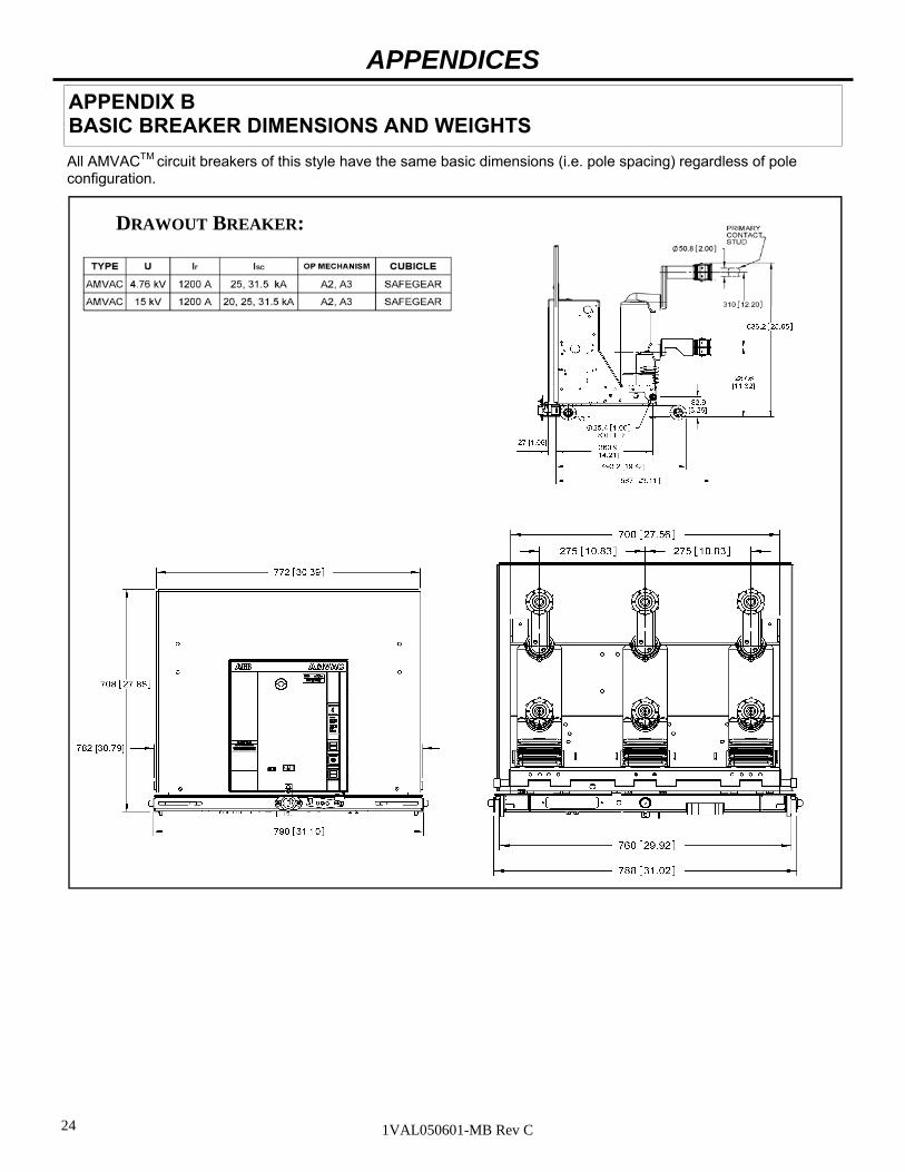
DRAWOUT BREAKER:
All AMVACTM circuit breakers of this style have the same basic dimensions (i.e. pole spacing) regardless of pole configuration.

25 1VAL050601-MB Rev C
APPENDIX B BASIC BREAKER DIMENSIONS AND WEIGHTS
APPENDICES
All AMVACTM circuit breakers of this style have the same basic dimensions (i.e. pole spacing) regardless of pole configuration.

26 1VAL050601-MB Rev C
APPENDIX B BASIC BREAKER DIMENSIONS AND WEIGHTS
APPENDICES
All AMVACTM circuit breakers of this style have the same basic dimensions (i.e. pole spacing) regardless of pole configuration.

27 1VAL050601-MB Rev C
APPENDIX B BASIC BREAKER DIMENSIONS AND WEIGHTS
APPENDICES
All AMVACTM circuit breakers of this style have the same basic dimensions (i.e. pole spacing) regardless of pole configuration.

28 1VAL050601-MB Rev C
APPENDIX B BASIC BREAKER DIMENSIONS AND WEIGHTS
APPENDICES
All AMVACTM circuit breakers of this style have the same basic dimensions (i.e. pole spacing) regardless of pole configuration.

29 1VAL050601-MB Rev C
APPENDIX B BASIC BREAKER DIMENSIONS AND WEIGHTS
APPENDICES
All AMVACTM circuit breakers of this style have the same basic dimensions (i.e. pole spacing) regardless of pole configuration.

30 1VAL050601-MB Rev C
APPENDIX B BASIC BREAKER DIMENSIONS AND WEIGHTS
APPENDICES
All AMVACTM circuit breakers of this style have the same basic dimensions (i.e. pole spacing) regardless of pole configuration.

31 1VAL050601-MB Rev C
APPENDIX B
APPENDICES
TYPE U Ir ISC MECHANISM CUBILE
AMVAC 15kV 1200-2000A 50kA A5 SAFEGEAR HDTM
Weight 410lbs, 186Kg

32 1VAL050601-MB Rev C
APPENDIX B
APPENDICES
TYPE U Ir ISC MECHANISM CUBILE
AMVAC 15kV 3000A 50kA A5 SAFEGEAR HDTM
Weight 420lbs, 190Kg

33 1VAL050601-MB Rev C
APPENDIX C ED2 ELECTRONIC CONTROL BOARD
APPENDIX C
Following are the basic characteristics for the control power and close and open operations of the AMVACTM circuit breaker.
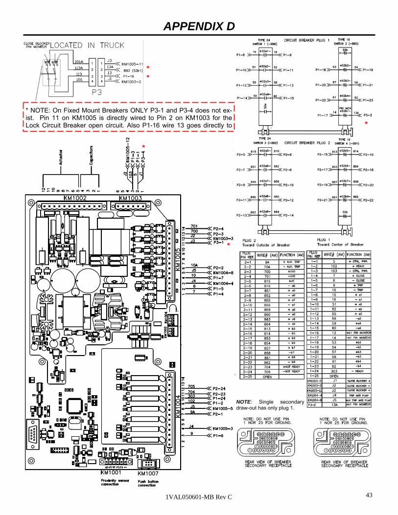
DRAWOUT - STANDARD WIRING: The schematic illustrates the basic wiring scheme for a drawout circuit breaker with standard wiring. The point-to-point diagram illustrates the physical connections and wire numbers used in the wiring harness.
FIXED-MOUNT - STANDARD WIRING: The wiring scheme for the fixed-mount circuit breakers is exactly the same except that there is no pin monitor/close blocker switch so these connections are the same as if the switch in the truck is always closed. Also fixed mount break-ers will come with 5 feet length of secondary wiring.
Principal Connection Points
Control Circuit Board
CONTROL RANGE LOW VOLTAGE UNIT HIGH VOLTAGE UNIT
Binary Inputs AC or DC KM10051,2 (Includes Trip and Close)
21V to 264V Opening command can go as low as 16.8V
21V to 264V Opening command can go as low as 16.8V
Auxiliary Power
AC or DC — KM10031
20-75VDC, 23-50 VAC 77-280VDC, 85-264 VAC

34 1VAL050601-MB Rev C
ELECTRONIC CONTROL BOARD
1.0 OVERVIEW The actuator control board is comprised of a Power Supply Recharge Unit, Control Unit, and FET Switching circuit which connects the Storage Capacitors to the Magnetic Actuator coils.
The power supply recharge circuitry adapts to whatever input voltage that is supplied within the specified in-put range on page 31 in order to maintain an 80 V charge across the storage capacitors. The Control Unit hardware and software configurations monitors the binary inputs, outputs, capacitor charge, and switches the FET switching circuit to connect the capacitor voltage to the appropriate Magnetic Actuator coil following an open or close command.
The Capacitor Storage Unit consists of two 0.1 farad Aluminum Electrolytic capacitors connected in parallel to provide a total capacitance of 0.2 farads. When called to energize the Magnetic Actuator coils, the capacitors will deliver a peak current of up to 170A and a pulse width of 45 milliseconds for opening operations and 60 milliseconds for closing operations.
The ED2 control board, with external circuitry, system Block Diagram is given in Apx. Figure 1 Electrical Sys-tem Block Diagram below.
Apx. Figure 1 Electrical System Block Diagram
APPENDIX C
35 1VAL050601-MB Rev C
BINARY INPUTS
There is a removable filter card plugged into the control board. This filter card has five metal jumpers on the board. When these jumpers are cut, the binary input threshold is raised by 20 Volts. It is recommended that these jumpers are cut for 125VDC applications. Jumpers are not cut at the factory it is up to each respective customer to determine if it is needed and perform the work for their application.
Binary input channels work properly with a voltage range of 24 to 264 VAC/DC regardless of which board is used. All inputs have a low threshold at about 18 VDC and 19 VAC with the exception of the Protection Relay input, which has a low threshold of about 7 VDC. To avoid false triggering by noise, the inputs must be active for at least 6 milliseconds. The current draw for most inputs is < 2 milliamperes. The exception is the Remote Open and Close inputs, which draw up to approximately 20 milliamperes. The input impedance (Z) is 300kΩ except for binary inputs 1 and 2 (Remote Open and Close) which are around 14 kΩ input Z.
There are seven different input channels. Only six of them are used for the AMVAC breaker (channel 5 is not used).
ED2 CONTROL BOARDS AVAILABLE 1. Low voltage full optional board (17 – 75 VDC or 20 – 52 VAC).
2. High voltage full optional board (77 – 280 VDC or 85 – 264 VAC).
3. 0.1 farad aluminum electrolytic capacitors.
Refer to Appendix D, Page 40 for connector (KM), pin locations and associated wires.
Close (KM1005, CH 1, Pins 1 and 2)
The Remote Close input is used to close the breaker remotely. The input impedance is approximately 14 kΩ.
Open (KM1005, CH 2, Pins 3 and 4) The Remote Open input is used to trip the breaker remotely. The input impedance is approximately 14 kΩ. When tripping with electro-mechanical relays, an additional resistor will be required to drop the trip flags.
Auxiliary Open / Safe Open (KM1005, CH 3, Pins 5 and 6)
This input can be configured as either an Auxiliary Open function or a Safe Open function. The position of dip switch I1002 determines which is selected. If it is Off, it is used as Auxiliary. If the dip switch is On, it is used as Safe Open.
The Auxiliary Open functions the same as the Remote Open function, with the exception of the input imped-ance which is approximately 300 kΩ.
The Safe Open function allows the user to open the circuit breaker when the on-board microcontroller is faulty. During normal conditions, all opening inputs work, but if the microcontroller is damaged, only the Safe Open input can perform the opening command. When the microcontroller is damaged, capacitor monitoring is not active so other inputs will be ignored. In order for the breaker to open correctly, there must be sufficient energy in the capacitors.
APPENDIX C
ELECTRONIC CONTROL BOARD

36 1VAL050601-MB Rev C
APPENDIX C
Second Trip (KM1005, CH 4, Pins 7 and 8)
This input can be configured as either a Protection Trip or Second Trip function. It is programmed via Jumper JP1001 Pins 1 and 2 or as a normal input by jumping JP1001 pins 2 and 3. The Protection Trip input is designed to work at a lower threshold of 7 VDC. This input is provided to be used with special protection relay requirements. It can also be used as a normal trip input. The Second Trip is often referred to as “Shunt Trip.” It functions the same as the Remote Input with the ex-ception of the input impedance which is 300 kOhms.
Under Voltage Trip (KM1005, CH 7, Pins 13 and 14) The Under Voltage Trip input will perform an auto trip in the event the voltage source being monitored by this input falls between 35% to 70% of nominal. It is enabled through DIP Switch I1004/2-3-4. The response of this input also has a programmable time delay from 50 milliseconds to 5 seconds. The delay is set by the vari-ous combinations of DIP Switch I1004/2-3-4 (see section 8.0). The Under Voltage Threshold is set by I1001. See page 40 ED2.0 board for switch location and settings.
ELECTRONIC CONTROL BOARD
Lock Circuit Breaker Open (KM1005, CH 6, Pins 11 and 12)
The Circuit Breaker Locked Open feature functions with the closed blocking circuit. When control power is applied and the closed blocking switch (located in the truck on Removable breakers only) is closed, power is supplied to this input to allow the breaker to function normally. When power is supplied to breaker and re-moved from this input by the opening of the closed blocking switch (during racking, i.e. if truck is in intermit-tent racking position), the breaker goes into the Open Lock Mode. During this mode the breaker cannot return to the closed position until this input has power restored to it (i.e. the closed blocking switch is Closed and breaker is in the Test or connected positions). On fixed breakers control power is supplied to pins 11 and 12 via jumper wires on the wiring harness.
If Dip Switch I1004-1 is set to the “on” position and then power is removed from the unit, the breaker will automatically trip in approximately 3 minutes. Make sure personnel and tools are cleared from breaker pri-or to the removal of power from unit, due to risk of death or serious bodily injury.

37 1VAL050601-MB Rev C
APPENDIX C
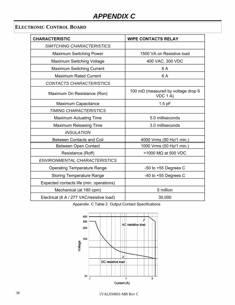
BINARY OUTPUTS Binary outputs are pairs of mechanical wipe relay contacts. They can be employed to switch in other circuitry or to an alarm indicator. See Illustration 3 and 4 for the power limitations of the contacts. Notice the flat curve for AC voltage in Illustration 4. On the inside of the low voltage cabinet there is a membrane style button plate that contains a “Ready” LED. The Ready light will either flash or turn off depending on the state of the Capaci-tor voltage and Coil continuity. The “Unit Ready” output contact can be used to alarm for the more serious of the three types of problems, but will not signal for all levels of the above problems.
Circuit Breaker Opened (KM1004 Pins 1 and 2)
The Circuit Breaker Opened contacts are normally open. They close only when the circuit breaker is in the Open position.
Circuit Breaker Closed (KM1004 Pins 3 and 4)
The Circuit Breaker Closed contacts are normally open. They close only when the circuit breaker is in the Closed position.
Circuit Breaker Auxiliary Open (KM1004 Pins 5 and 6)
The Circuit Breaker Auxiliary Open contacts close whenever the breaker is in the Open position.
Circuit Breaker Auxiliary Closed (KM1004 Pins 7 and 8)
Additional set of normally open contacts close whenever the breaker is in the Close position.
Unit Ready (KM1004 Pins 9 and 10)
These contacts are normally open. They close when the breaker is ready. They are used to monitor capacitor charge (O-CO operation ready), valid circuit breaker position and coil continuity.
Unit Not Ready (KM1004 Pins 11 and 12)
The Unit Not Ready contacts are normally closed. They open when the Unit is Ready. These contacts are the inverse (negative) of the Unit Ready contacts.
When using the Not Ready contacts to provide an alarm to SCADA, an 8 second delay is recommended since the unit will go to Not Ready when the capacitors are below 49 V. The 8 second delay allows the capac-itors to charge prior to alarming.
Circuit Breaker Remote Open (KM1004 Pins 13 and 14)
The Circuit Breaker Remote Open contacts are referred to as the “Fleeting Output Contacts.” This means that they only close for 100 milliseconds after a Remote Operation or Under Voltage is performed.
ELECTRONIC CONTROL BOARD
38 1VAL050601-MB Rev C
APPENDIX C
CHARACTERISTIC WIPE CONTACTS RELAY
SWITCHING CHARACTERISTICS
Maximum Switching Power 1500 VA on Resistive load
Maximum Switching Voltage 400 VAC, 300 VDC
Maximum Switching Current 6 A
Maximum Rated Current 6 A
CONTACTS CHARACTERISTICS
Maximum On Resistance (Ron) 100 mΩ (measured by voltage drop 6
VDC 1 A)
Maximum Capacitance 1.5 pF
TIMING CHARACTERISTICS
Maximum Actuating Time 5.0 milliseconds
Maximum Releasing Time 3.0 milliseconds
INSULATION
Between Contacts and Coil 4000 Vrms (50 Hz/1 min.)
Between Open Contact 1000 Vrms (50 Hz/1 min.)
Resistance (Roff) >1000 MΩ at 500 VDC
ENVIRONMENTAL CHARACTERISTICS
Operating Temperature Range -50 to +55 Degrees C
Storing Temperature Range -40 to +55 Degrees C
Expected contacts life (min. operations)
Mechanical (at 180 cpm) 5 million
Electrical (6 A / 277 VAC/resistive load) 30,000
Appendix. C Table 2 Output Contact Specifications
ELECTRONIC CONTROL BOARD

39 1VAL050601-MB Rev C
APPENDIX C
ELECTRONIC CONTROL BOARD
FEATURES Temperature Protection
The Temperature Protection circuit monitors the average temperature of a critical area on the ED2.0 power supply. The output power will be linearly reduced to zero as the temperature increases from 172 to 203 de-grees F (78 to 98 degrees C).
Wrong Position Auto Trip
An Auto Trip command will be issued in the event the breaker does not perform a successful close operation within 95 milliseconds after the close command is issued.
Energy Failure Auto Trip
The Energy Failure Auto Trip function is selected by Dip Switch I1004-1 (Appendix C) and will cause the breaker to auto trip in the event the capacitor voltage falls below 49 volts. Necessary precautions must be tak-en when power is removed (i.e., power removed for maintenance) as the breaker will automatically trip if I1004-1 is in the “On” position.
Reduced Power Consumption
The Reduced Power Consumption setting will lower the power output of the power supply recharge unit, on the ED2.0 board, from 75 W power to 33 W. This enables the ED2.0 board to be supplied with the energy de-livered by a voltage transformer if necessary. The Power Supply Recharge Unit is 80% efficient. This means that the Auxiliary Power supply input must be at least 93.75 W for the 75 W setting or 41.3 W for the 33 W setting. The 33 W option is hardware selectable with Jumper JP1019.
RS-232 Port / JTAG Communication Port
Used by ABB factory only.
40 1VAL050601-MB Rev C
APPENDIX C
ELECTRONIC CONTROL BOARD
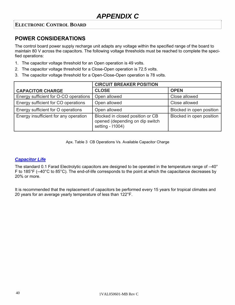
Capacitor Life
The standard 0.1 Farad Electrolytic capacitors are designed to be operated in the temperature range of --40°F to 185°F (--40°C to 85°C). The end-of-life corresponds to the point at which the capacitance decreases by 20% or more.
It is recommended that the replacement of capacitors be performed every 15 years for tropical climates and 20 years for an average yearly temperature of less than 122°F.
POWER CONSIDERATIONS The control board power supply recharge unit adapts any voltage within the specified range of the board to maintain 80 V across the capacitors. The following voltage thresholds must be reached to complete the speci-fied operations:
1. The capacitor voltage threshold for an Open operation is 49 volts.
2. The capacitor voltage threshold for a Close-Open operation is 72.5 volts.
3. The capacitor voltage threshold for a Open-Close-Open operation is 78 volts.
Apx. Table 3 CB Operations Vs. Available Capacitor Charge
CAPACITOR CHARGE CIRCUIT BREAKER POSITION CLOSE OPEN
Energy sufficient for O-CO operations Open allowed Close allowed Energy sufficient for CO operations Open allowed Close allowed
Energy sufficient for O operations Open allowed Blocked in open position Energy insufficient for any operation Blocked in closed position or CB
opened (depending on dip switch setting - I1004)
Blocked in open position
41 1VAL050601-MB Rev C
ELECTRONIC CONTROL BOARD
APPENDIX C
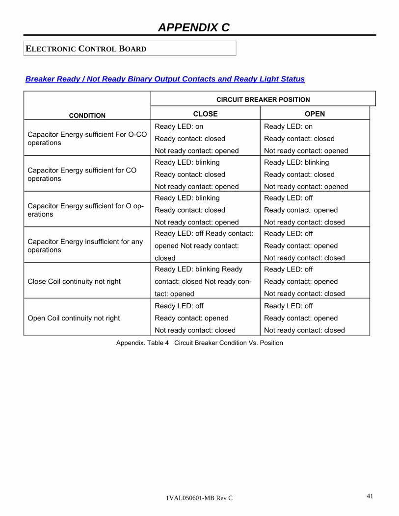
Breaker Ready / Not Ready Binary Output Contacts and Ready Light Status
CONDITION
CIRCUIT BREAKER POSITION
CLOSE OPEN
Capacitor Energy sufficient For O-CO operations
Ready LED: on
Ready contact: closed
Not ready contact: opened
Ready LED: on
Ready contact: closed
Not ready contact: opened
Capacitor Energy sufficient for CO operations
Ready LED: blinking
Ready contact: closed
Not ready contact: opened
Ready LED: blinking
Ready contact: closed
Not ready contact: opened
Capacitor Energy sufficient for O op-erations
Ready LED: blinking
Ready contact: closed
Not ready contact: opened
Ready LED: off
Ready contact: opened
Not ready contact: closed
Capacitor Energy insufficient for any operations
Ready LED: off Ready contact:
opened Not ready contact:
closed
Ready LED: off
Ready contact: opened
Not ready contact: closed
Close Coil continuity not right
Ready LED: blinking Ready
contact: closed Not ready con-
tact: opened
Ready LED: off
Ready contact: opened
Not ready contact: closed
Open Coil continuity not right
Ready LED: off
Ready contact: opened
Not ready contact: closed
Ready LED: off
Ready contact: opened
Not ready contact: closed
Appendix. Table 4 Circuit Breaker Condition Vs. Position
42 1VAL050601-MB Rev C
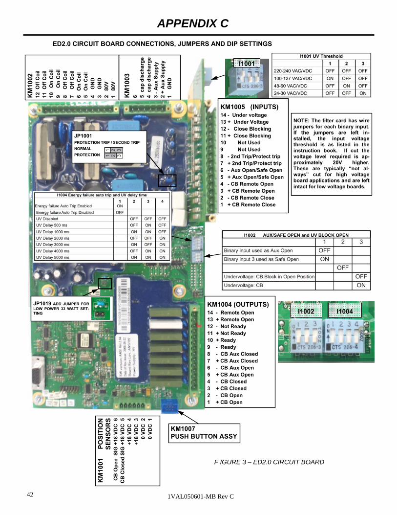
APPENDIX C
I1002 I1004
KM1005 (INPUTS) 14 - Under voltage 13 + Under Voltage 12 - Close Blocking 11 + Close Blocking 10 Not Used 9 Not Used 8 - 2nd Trip/Protect trip 7 + 2nd Trip/Protect trip 6 - Aux Open/Safe Open 5 + Aux Open/Safe Open 4 - CB Remote Open 3 + CB Remote Open 2 - CB Remote Close 1 + CB Remote Close
KM1004 (OUTPUTS) 14 - Remote Open 13 + Remote Open 12 - Not Ready 11 + Not Ready 10 + Ready 9 - Ready 8 - CB Aux Closed 7 + CB Aux Closed 6 - CB Aux Open 5 + CB Aux Open 4 - CB Closed 3 + CB Closed 2 - CB Open 1 + CB Open
ED2.0 CIRCUIT BOARD CONNECTIONS, JUMPERS AND DIP SETTINGS
F IGURE 3 – ED2.0 CIRCUIT BOARD
KM
1002
12
Off
Co
il
11 O
ff C
oil
10
O
n C
oil
9
O
n C
oil
8
O
ff C
oil
7
O
ff C
oil
6
On
Co
il
5 O
n C
oil
4
G
ND
3
G
ND
2
80V
1
80V
KM
1003
6
5 c
ap d
isch
arg
e
4 c
ap d
isch
arg
e
3 -
Au
x S
up
ply
2
+ A
ux
Su
pp
ly
1
GN
D
KM
1001
P
OS
ITIO
N
SE
NS
OR
S
CB
Op
en S
IG +
18 V
DC
6
CB
Clo
sed
SIG
+18
VD
C 5
+
18 V
DC
4
+18
VD
C 3
0
VD
C 2
0
VD
C 1
KM1007 PUSH BUTTON ASSY
JP1001 PROTECTION TRIP / SECOND TRIP
NORMAL
PROTECTION
NOTE: The filter card has wire jumpers for each binary input. If the jumpers are left in-stalled, the input voltage threshold is as listed in the instruction book. If cut the voltage level required is ap-proximately 20V higher. These are typically “not al-ways” cut for high voltage board applications and are left intact for low voltage boards.
I1002 AUX/SAFE OPEN and UV BLOCK OPEN
JP1019 ADD JUMPER FOR LOW POWER 33 WATT SET-TING
I1001
43 1VAL050601-MB Rev C
APPENDIX D
NOTE: Single secondary draw-out has only plug 1.
* NOTE: On Fixed Mount Breakers ONLY P3-1 and P3-4 does not ex-ist. Pin 11 on KM1005 is directly wired to Pin 2 on KM1003 for the Lock Circuit Breaker open circuit. Also P1-16 wire 13 goes directly to
* *
*
*
*

44 1VAL050601-MB Rev C
APPENDIX D
* N
OT
E:
On
Fix
ed M
ount
B
reak
ers
ON
LY P
3-1
and
P3-
4 do
es n
ot e
xist
. P
in
11 o
n K
M10
05 i
s di
rect
ly
wire
d to
Pin
2 o
n K
M10
03
for
the
Lock
Circ
uit
Bre
ak-
er o
pen
circ
uit.
Als
o P
1-1
6 w
ire
13
goes
di
rect
ly
to
52b1
on
BB
3
*
*

45 1VAL050601-MB Rev C
APPENDIX E
Procedure for setting Under Voltage Trip option:
Note: Breaker must have dual secondary disconnect to use under voltage option.
The Under Voltage Trip input will perform an auto trip in the event the voltage source being monitored by this input falls between 35% to 70% of nominal. It is enabled through DIP Switch I1004/2-3-4. The response of this input also has a programmable time delay from 50 milliseconds to 5 seconds. The delay is set by the vari-ous combinations of DIP Switch I1004/2-3-4 (see section 8.0). The Under Voltage Threshold is set by I1001. See page 40 ED2.0 board for switch location and settings.
1. With power off and breaker removed from cell.
2. Wait 10 minutes for power to drain out of capacitor inside of breaker.
3. Remove 4 screws holding front cover then remove front cover of breaker and locate dip switches I1001, I1002 and I1004 using page 40 of AMVAC IB for reference.
4. Turn SW I1001 switches ON in need configuration for UV voltage to be monitored. (example: 120V I1001-1 = ON, I1001-2 = OFF, I1001-1 = OFF).
5. Turn SW I1002 switch 3 to ON position ( this will prevent breaker from closing if there is no power to UV circuit but breaker is powered).
6. Turn SW I1004 switch 3 to ON position (this will enable the UV and trip with in 0.5 sec of UV failure) If an additional time delay is needed set SW I1004 to the needed settings according to Page 40 of the AMVAC IB.
7. Replace front cover, connect power to breaker and test (insure you have supplied UV power to be moni-tored to breaker inputs on Plug 2-3 (+UVD) and Plug 2-4 (-UVD) shown on page 42 of IB).
DANGER
Inside the breaker there are stored energy capacitors that must be discharged prior to removing the front cover of the breaker. Wait 10 minutes after breaker removal from the cell prior to removing the front cover of the breaker for the discharging of the storage capacitors to occur.

46 1VAL050601-MB Rev C
APPENDIX F

47 1VAL050601-MB Rev C
APPENDIX G

48 1VAL050601-MB Rev C
Product Quality and Environmental Protection
ABB products are manufactured to meet or exceed the standards of compliance for quality and environmental manage-ment systems in accordance with ISO 9001 and ISO 14001. All of these items can be supplied with a certificate of quali-ty.
End of life of product
ABB is committed to complying with all legal and other relevant requirements for environmental protection in accordance with the ISO 14 001 standards.
The responsibility of the company is to facilitate subsequent recycling or disposal at the end of the product’s life. During disposal of the product, it is always necessary to act in accordance with all local and national legal requirements that are in effect at the time of disposal.
Methods of disposal
Disposal can either be carried out in a manner of ways depending upon material of product. Below is the recommended method of disposal for various raw material.
RAW MATERIAL RECCOMMENDED METHOD OF DISPOSAL
Metal material (Fe, Cu, Al, Ag, Zn, W, ect.) Separation and recycling
Thermoplasts Recycling or disposal
Epoxy resin Separation of metal and disposal of remains
Rubber Disposal
Oil (transformer oil) Draining and recycling or proper disposal
SF6 gas Discharging from equipment
Packing material Recycling or disposal

49 1VAL050601-MB Rev C
NOTES
50 1VAL050601-MB Rev C
Contact Us
ABB Inc.
655 Century Point
Lake Mary, FL 32746
Phone: +1 407 732 2000
Customer service +1 800 929 7947 ext. 5
+1 407 732 2000 ext. 2510
E-Mail: [email protected]
www.abb.com/mediumvoltage
All sales are subject to ABB Inc.
General Terms and Conditions of Sale.
While every effort has been made to assure accuracy, the information in this document is subject to change without notice.
© Copyright 2015 ABB Inc. All rights reserved.
1VA
L05
0601
-MB
Rev
C (
repl
aces
1V
AL
0564
82-M
B)
Related Documents