HAL Id: hal-01055448 https://hal-mines-paristech.archives-ouvertes.fr/hal-01055448 Submitted on 12 Aug 2014 HAL is a multi-disciplinary open access archive for the deposit and dissemination of sci- entific research documents, whether they are pub- lished or not. The documents may come from teaching and research institutions in France or abroad, or from public or private research centers. L’archive ouverte pluridisciplinaire HAL, est destinée au dépôt et à la diffusion de documents scientifiques de niveau recherche, publiés ou non, émanant des établissements d’enseignement et de recherche français ou étrangers, des laboratoires publics ou privés. Delamination of pipeline steels : determination of an anisotropic cleavage criterion Franck Tankoua, Jérôme Crépin, P. Thibaux, M. Arafin, Steven Cooreman, Anne-Françoise Gourgues To cite this version: Franck Tankoua, Jérôme Crépin, P. Thibaux, M. Arafin, Steven Cooreman, et al.. Delamination of pipeline steels : determination of an anisotropic cleavage criterion. Mechanics & Industry, EDP Sciences, 2014, 15, pp.45-50. 10.1051/meca/2014001. hal-01055448

Welcome message from author
This document is posted to help you gain knowledge. Please leave a comment to let me know what you think about it! Share it to your friends and learn new things together.
Transcript
HAL Id: hal-01055448https://hal-mines-paristech.archives-ouvertes.fr/hal-01055448
Submitted on 12 Aug 2014
HAL is a multi-disciplinary open accessarchive for the deposit and dissemination of sci-entific research documents, whether they are pub-lished or not. The documents may come fromteaching and research institutions in France orabroad, or from public or private research centers.
L’archive ouverte pluridisciplinaire HAL, estdestinée au dépôt et à la diffusion de documentsscientifiques de niveau recherche, publiés ou non,émanant des établissements d’enseignement et derecherche français ou étrangers, des laboratoirespublics ou privés.
Delamination of pipeline steels : determination of ananisotropic cleavage criterion
Franck Tankoua, Jérôme Crépin, P. Thibaux, M. Arafin, Steven Cooreman,Anne-Françoise Gourgues
To cite this version:Franck Tankoua, Jérôme Crépin, P. Thibaux, M. Arafin, Steven Cooreman, et al.. Delaminationof pipeline steels : determination of an anisotropic cleavage criterion. Mechanics & Industry, EDPSciences, 2014, 15, pp.45-50. �10.1051/meca/2014001�. �hal-01055448�

Mechanics & Industry 15, 45–50 (2014)c© AFM, EDP Sciences 2014DOI: 10.1051/meca/2014001www.mechanics-industry.org
Mechanics&Industry
Delamination of pipeline steels: determination of an anisotropiccleavage criterion
F. Tankoua1,a, J. Crepin1, P. Thibaux2, M. Arafin2, S. Cooreman2
and A.F. Gourgues1
1 MINES ParisTech, Centre des Materiaux, UMR CNRS 7633, BP 87, 91003 Evry Cedex, France2 ArcelorMittal R&D Gent, Pres. J.F. Kennedylaan 3, 9060 Zelzate, Belgium
Received 17 June 2013, Accepted 3 January 2014
Abstract – Cleavage fracture anisotropy has been studied on a ferrite-bainite low alloy pipeline steelplate. Mechanical tests have been performed on smooth and notched bars taken along the three principaldirections of the plate at temperatures between 20 ◦C and −196 ◦C, and analyzed by finite elementcalculations with an anisotropic plasticity model. The fracture mode of specimens tested along the normaldirection differs from that of specimens taken along the two other directions, together with a lower criticalcleavage stress. This difference seems to be related to microtexture anisotropy and might explain thesensitivity of this steel to delamination at low temperatures.
Key words: Delamination fracture / anisotropy / cleavage / microtexture / pipeline steels
Resume – Delaminage des aciers pour gazoducs : determination d’un critere anisotrope de
rupture par clivage. L’anisotropie de rupture par clivage a ete etudiee sur une tole d’acier faible-ment allie, ferrito-bainitique, pour gazoducs. Des essais mecaniques ont ete effectues sur eprouvettes axi-symetriques lisses et entaillees dans les trois directions principales de la tole, pour des temperatures com-prises entre 20 ◦C et −196 ◦C, et analyses par elements finis a l’aide d’un modele de plasticite anisotrope.Le mode de rupture dans la direction normale a la tole differe de celui dans les deux autres directions, avecune contrainte critique de clivage plus basse. Cette difference est reliee a l’anisotropie de microtexture etpourrait expliquer la sensibilite de cet acier au delaminage a froid.
Mots cles : Delaminage / anisotropie / clivage / microtexture / gazoducs
1 Introduction
Delamination cracking is commonly observed duringCharpy or Battelle impact tests on high strength pipelinesteels. It involves brittle cracking parallel to the rollingplane and tends to reduce the steel toughness at low tem-peratures [1–3]. Many authors [1–11] have investigatedpossible causes and effects of delamination on the me-chanical properties of steels. Delamination fracture hasbeen attributed to texture and microstructure anisotropy.It seems to be more pronounced for temperatures withinthe ductile-to-brittle transition but there is no agreementon the effect of delamination as there are only scarce re-sults on delamination initiation and the interaction ofdelamination cracks with the main crack propagation.Kalyanam [12] investigated the stress state induced by a
a Corresponding author: [email protected]
static delamination crack in Al-Li alloys, but with no ini-tiation criterion for that crack. Baldi [13] showed that de-lamination in low alloy steels occurs when the stress alongthe normal direction (ND) of the plate exceeds a criti-cal value, which is lower than the critical cleavage stressalong the rolling (RD) and long transverse (TD) direc-tions. This difference was attributed to shape anisotropyof ferrite grains. The present study aims at providingan anisotropic critical cleavage stress criterion in rela-tion with microstructural parameters, to be used for themodeling of delamination crack initiation. Tensile tests onsmooth and notched bars from a pipeline steel plate havebeen performed at various temperatures, followed by aninvestigation of the fracture mechanisms. An anisotropicyield criterion has been set to analyze the tests and toderive a value for the critical cleavage stress along RD,TD and ND, and was related to microtexture anisotropyof the plate.
Article published by EDP Sciences

46 F. Tankoua et al.: Mechanics & Industry 15, 45–50 (2014)
NT1
M10
x1.5
Ø4
Ø7
.2
R 0
.8
R 2.0 10 mm
NT1
M10
x1.5
Ø4
Ø7
.2
R 0
.8
R 2.0 10 mm10 mm
M5x0
.8
5 mmNT2: R = 0.40
NT3: R = 0.60
Ø2.
6
M5x0
.8
5 mm5 mmNT2: R = 0.40
NT3: R = 0.60
Ø2.
6
ND
RD a) b)
Fig. 1. (a) Optical micrograph of the steel. (b) Geometry of NT1 (top), NT2 and NT3 (bottom) specimens.
Table 1. Summary of tensile tests, indexed using corresponding specimen geometries.
−196 ◦C −100 ◦C −90 ◦C −80 ◦C −70 ◦C −60 ◦C −55 ◦C −50 ◦C −40 ◦C 20 ◦C
RD NT3 NT1 NT1, UT1
TD NT3 NT1, UT1 NT1, UT1
ND NT2, UT2 NT2 NT2 NT2 NT2 NT2 NT2 NT2 NT2, UT2
2 Experimental procedure
2.1 Material
A 19.5-mm thick, ferritic-bainitic plate obtained af-ter thermomechanical controlled processing was used(Fig. 1a). It is a micro-alloyed low carbon manganesesteel. Its 0.2% proof stress, tensile strength and frac-ture elongation at room temperature are respectively580 MPa, 640 MPa, and 42%.
2.2 Mechanical tests
Tensile tests on smooth and notched specimens havebeen performed by using a 250 kN servohydraulic Instron8500 machine. Cooling was ensured using a climate cham-ber, except for the tests performed at −196 ◦C; temper-ature was controlled using a thermocouple spot-weldedon the top of the specimen. Tests at −196 ◦C were per-formed in liquid nitrogen. Two (resp. three) geometries,UT1-2 (resp. NT1-3) were considered for smooth (resp.notched) specimens (Fig. 1b). UT specimens were testedwith an elongation rate of 10−3 s−1; a load line displace-ment velocity of 10−3 mm.s−1 was used for notched spec-imens. The gauge length of smooth specimens was 36 mm(resp. 5 mm) for UT1 (resp. UT2). NT2 and NT3 speci-men geometries were designed for this study [14], so thatspecimens could be taken along ND. At 30% of diameterreduction, axial stresses up to 2000 MPa (typical value forcleavage normal to ND) [13] were expected to be foundover a region containing both equiaxed and bainitic fer-rite. More temperature levels were considered for tests
along ND because of the lower amount of literature dataalong ND (Tab. 1).
Elongation of smooth specimens was measured usingan extensometer (UT1 geometry) or by applying a stiff-ness correction on the load vs. load line displacementcurve (UT2 geometry). For notched specimens, a radialextensometer was used to measure the reduction of diam-eter along ND (resp. TD) for specimens taken along RDand TD (resp. along ND). Some tests were (repeatedly)interrupted at room temperature, after which the exten-someter was temporarily rotated by 90◦ with respect tothe tensile axis, and the new value of the reduction ofdiameter was recorded. The ratio of these two values wasused as an anisotropy coefficient.
2.3 Observations
Fracture surfaces were observed with scanning elec-tron microscopy (SEM) in secondary electron imaging.This allowed first identification of fracture modes andestimate of the shear percentage, i.e. the ratio of duc-tile fracture area to the total area of the fracture surface(projected along the tensile axis). Then, cleavage fracturewas more quantitatively studied. The propagation pathof the first cleavage crack was studied using stereologi-cal pairs, 3D reconstruction of the fracture surface (MeXsoftware) together with in-house software to calculate tiltand twist components of misorientation between neigh-boring facets [15]. Microtexture was analyzed using elec-tron backscatter diffraction (EBSD) on polished sections(190× 190 µm2) with a step size of 1 µm. The mean free

F. Tankoua et al.: Mechanics & Industry 15, 45–50 (2014) 47
RD
NT3 geometry
e)
TD
NT3 geometry
f)
interrupted test
UT1 and UT2 geometries
a)
ND
NT2 geometry b)
RD
NT1 geometry
-100°C
20°C
Anisotropy Coef=0.75
c) TD
-100°C
20°C
NT1 geometry
Anisotropy Coef=0.81
d)
Fig. 2. Tensile curves of (a) smooth, (b)–(f) notched specimens. Symbols: experiments; lines: model predictions.
path of cleavage microcracks was determined by consid-ering crystals with a nearly common orientation of {001}planes normal to the investigated loading axis. The sizedistribution of such “potential cleavage facets” was com-pared to the fracture surface appearance.
3 Experimental results
3.1 Tensile tests (smooth and notched specimens)
Figure 2 summarizes the results of the tensile tests,together with the simulated curves. More information on
the numerical model can be found in Section 4. The ef-fective stress was calculated as the load divided by theinitial cross-section and diameter reduction was normal-ized by the initial diameter of the minimal section. Testreproducibility was good (difference in stress lower than5%), so that only one curve per condition is plotted inFigure 2.
Work hardening is higher at −100 ◦C than at 20 ◦C.Anisotropy in strength is not significant but a constantanisotropy coefficient (defined in 2.2), lower than 1, wasfound along RD and TD (Figs. 2c, 2d). At −100 ◦C alongND, the minimal section of (brittle) NT specimens re-mained circular all along the test (anisotropy ratio setto 1.0). These curves also showed a brutal drop of the

48 F. Tankoua et al.: Mechanics & Industry 15, 45–50 (2014)
NT1 Geometry
200µm
ND
TD
Central delamination crack
a)
NT3 Geometry
200µm
Delamination micro-crack
ND
RD
b)
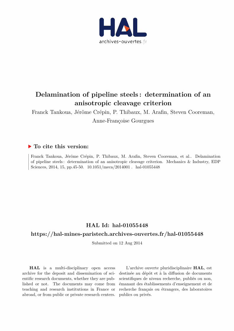
Fig. 3. Fracture surfaces (a) of a NT1 specimen (RD, −100 ◦C) and (b) of a NT3 specimen (TD, −196 ◦C).
Ductile fracture initiation
Cleavage fracture
NT2 Geometry
100µm a)
ND
b)
Fig. 4. (a) Fracture surface of a NT2 specimen (ND, −90 ◦C). (b) Evolution of the shear percentage and diameter reduction(at fracture) with testing temperature (NT2 specimens tested along ND).
effective stress at the end of tests at −100 ◦C. At thistemperature, pop-ins were observed before final failure,in the load vs. load line displacement curves (not shownhere).
3.2 Fracture mechanisms
For specimens pulled along RD and TD, three fracturemodes were in competition: ductile, delamination and(flat) cleavage fracture. At 20 ◦C, fully ductile fracturewas observed. At −100 ◦C, ductile fracture with a centraldelamination crack was observed (Fig. 3a). At −196 ◦C,flat cleavage cracking, starting far from the notch rootswas accompanied with some delamination micro-cracks(Fig. 3b). Specimens tested along ND only exhibited duc-tile and (flat) cleavage fracture. Three temperature do-mains were distinguished from these fracture mechanisms:the upper shelf (T > −80 ◦C) with fully ductile frac-ture, the transition domain (−100 ◦C up to −80 ◦C) withductile initiation followed by cleavage fracture (Fig. 4a),the lower shelf (T < −100 ◦C) with large cleavage facetselongated along RD. Figure 4b shows that the transitionin shear percentage is steeper than the transition in di-ameter reduction at fracture.
Quantitative fractography was performed on a largefacet where cleavage fracture was found to have initiated
(Fig. 5a). Tilt and twist angles between two neighbor-ing regions across the facet boundary (no direct cleavagecrack propagation from one region to the other) andwithin the considered facet (i.e., with easy cleavage crackpropagation between the two regions) are presented inFigure 5b. A boundary curve separating the tilt and twistangles for which the propagation of the crack in the samefacet, from those which lead to the generation of a newfacet was tentatively plotted despite the low number ofdata for high values of the twist angle. According to thatcurve, a tilt angle of 20◦, or a twist angle up to about 13◦
(yet with almost no tilt component) was not high enoughto arrest cleavage crack propagation. In a first approxi-mation, a misorientation angle of 15◦ was considered todelimit so-called “potential cleavage facets” from EBSDmaps.
3.3 Microtexture
The shape and size of the largest cleavage facets, de-termined using EBSD in the (RD, TD) plane (Fig. 6)are similar to those of the large elongated cleavage facetof Figure 5a. From Figure 6c, cleavage crack initiationcould possibly be favored in the delamination plane dueto the microtexture of the material.

F. Tankoua et al.: Mechanics & Industry 15, 45–50 (2014) 49
b)50 µm a)
Fig. 5. (a) Fracture surface of an NT2 specimen tested along ND at −100 ◦C. (b) Local cleavage propagation or arrest accordingto measured tilt and twist components of misorientation (region delineated in black in (a)).
Area (µm²)
Number
(RD, TD) plane (RD, ND) plane
RD RD )c )b )a
mµ 07 mµ 07
Fig. 6. (a,b) Potential cleavage facets using a threshold misorientation angle of 15◦ between {100} planes and normal to theobserved sample plane. (c) Area distribution (in number) of potential cleavage facets.
4 Anisotropic cleavage failure criterion
The critical cleavage stress at the onset of fracture ofNT specimens was estimated from mechanical analysis.An elastic-plastic constitutive model, with an isotropichardening rule coupling a linear and an exponential term(Voce equation) was chosen. At 20 ◦C and −100 ◦C,the Bron-Besson anisotropy yield criterion [16] was used.Constitutive parameters were identified from notched andsmooth tensile curves along all directions, together withanisotropy coefficients [14]. At −196 ◦C, a von Mises yieldcriterion was used because of the low number of availableresults (only two tensile tests on notched specimens). Fi-nite element calculations were performed using quadraticbricks with reduced integration, finite strain formalism, aNewton-Raphson iterative scheme for global convergenceand an implicit integration scheme for constitutive equa-tions. After a study of the mesh size effect, a minimumelement size at notch root equal to 100 µm (ensuring con-vergence with respect to the mesh size) was considered forcalculations. One-eighth of the specimen was modeled anduniform displacement was prescribed at the bottom edgetogether with usual symmetry conditions. Experimentaland predicted curves are in good agreement before theonset of fracture (Fig. 3).
From axial stress distributions at the onset of fracture(Fig. 7), the value of axial stress was determined at thenode corresponding to the experimentally observed cleav-age initiation crack site, at −100 ◦C (resp. −196 ◦C) forspecimens tested along ND (resp. RD and TD). The crit-ical cleavage stresses obtained are 2010 ± 50 MPa and2500 ± 100 MPa respectively along ND and RD. Thevalue of this critical stress was not easy to estimate alongTD because the fracture surface showed multiple crackinitiation sites, and sometimes delamination. The only in-formation extracted from calculations is that the criticalstress is at least equal to 2300 MPa.
5 Discussion and concluding remarks
NT specimens revealed a strong anisotropy in plasticyield, with easier deformation along ND compared to RDand TD, and also in cleavage fracture. At T > −80 ◦C,ductile fracture occurs whatever the specimen geometryand loading direction. For −100 ◦C < T < −80 ◦C,ductile crack initiation followed by cleavage propagationoccurred when pulling along ND. At T < −100 ◦C, cleav-age fracture occurred for specimens taken along ND, anddelamination cracks (microcracks at −196 ◦C) were still

50 F. Tankoua et al.: Mechanics & Industry 15, 45–50 (2014)
0
400
800
1200
1600
max: 2256
min: -201 0
500
1000
1500
2000
max: 2558
min: -17
2500
0
400
800
1200
1600
max: 2256
min: -201
0
400
800
1200
1600
max: 2256
min: -201 0
500
1000
1500
2000
max: 2558
min: -17
2500
0
500
1000
1500
2000
max: 2558
min: -17
2500
0
500
1000
1500
2000
max: 2558
min: -17
2500
Fig. 7. Axial stress at fracture (MPa) (a) NT2 specimen (ND, −100 ◦C). (b) NT3 specimen (RD, −100 ◦C).
observed for specimens taken along RD and TD. In fact,for temperatures lower than −100 ◦C the stress along NDwithin the notched specimen becomes higher than its crit-ical value, which is much lower than that along RD andTD.
From our preliminary EBSD measurements, therolling plane contains rather large zones susceptible tofacilitate the propagation of cleavage cracks by becominglarge cleavage facets, in agreement with fractographic ob-servations. Cleavage facets after tension along RD and TDappear smaller, corresponding to small, well-separatedzones found with microtexture analysis. More EBSD dataare needed to confirm this.
In summary, from tensile tests of notched and smoothspecimens in a range of temperature and pulling di-rections, the occurrence of delamination fracture in apipeline steel plate has been quantitatively described byan anisotropic critical cleavage stress. This anisotropyseems to be linked to anisotropy in microtexture. Im-provement of the resistance of the steel against delamina-tion might be achieved by avoiding the formation of largezones well oriented for cleavage fracture during thermo-mechanical processing.
References
[1] B.L. Bramfitt, A.R. Marder, A study of the delaminationbehavior of a very low-carbon steel, Metall. Mater. Trans.A 8 (1977) 1263−1273
[2] Y.S. Shin, S.M. Hong, J.H. Bae, et al., Separation phe-nomenon occurring during the Charpy impact test of APIX80 pipeline steels, Metall. Mater. Trans. A 40 (2009)2333−2349
[3] T. Inoue, F. Yin, Y. Kimura, et al., Delamination effecton impact properties of ultrafine-grained low carbon steelprocessed by warm caliber rolling, Metall. Mater. Trans.A 41 (2010) 341−355
[4] T. Hara, Y. Shinohara, Y. Terada, et al., DWTT proper-ties for high strength line pipe steels, Proceedings of theEighteenth International Offshore and Polar EngineeringConference, 2008
[5] T. Hara, Y. Shinohara, H. Asahi, Y. Terada, Effects ofmicrostructure and texture on DWTT properties for highstrength line pipe steels, Proceeding of IPC, InternationalPipeline Conference, 2006
[6] T. Fujishiro, T. Hara, Effects of separation on ductilecrack propagation behavior during drop weight tear test,Proceedings of Twenty-first International Offshore andPolar Engineering Conference, 2011
[7] Z. Yang, W.L. Guo, C.Y. Huo, Y. Wang, Fracture appear-ance evaluation of high performance pipeline steel DWTTspecimen with delamination cracks, Key Eng. Mater. 324-325 (2006) 59−62
[8] M.S. Joo, D.-W. Suh, J.H. Bae, H.K.D.H. Bhadeshia,Role of delamination and crystallography on anisotropyof Charpy toughness in API-X80 steel, Mater. Sci. Eng.A 546 (2012) 314−322
[9] W. Yan, W. Sha, L. Zhu, W. Wang, Y.-Y. Shan, K.Yang, Delamination fracture related to tempering in ahigh-strength low-alloy steel, Metall. Mater. Transa. A41 (2010) 159−171
[10] D.A. Mirzaev, I.L. Yakovleva, N.A. Tereshchenko, et al.,Structural aspect of delamination crack formation duringthe HTMT of steels with a ferritic structure, The Physicsof Metals and Metallography 106 (2008) 186−194
[11] Z. Yang, C. Huo, W. Guo, The Charpy notch impact testof X70 pipeline steel with delamination cracks, Key Eng.Mater. 297−300 (2005) 2391−2396
[12] S. Kalyanam, A.J. Beaudoin, R.H. Dodds Jr., F. Barlat,Delamination cracking in advanced aluminium-lithiumalloys-Experimental and computational studies, Eng.Fract. Mech. 76 (2009) 2174−2191
[13] G. Baldi, G. Buzzichelli, Critical stress for delaminationfracture in HSLA steels, Metal Science 12 (1978) 459−472
[14] F. Tankoua, ArcelorMittal internal Ph.D. progress re-port, 2013
[15] A. Andrieu, Mechanisms and multi-scale modeling ofbrittle fracture modifications induced by the thermal age-ing of a pressurised water reactor steel, Ph.D. disserta-tion, Ecole des Mines de Paris, France, 2013
[16] F. Bron, J. Besson, A yield function for anisotropic ma-terials, application to aluminium alloys, Int. J. Plast. 20(2004) 937−963
Related Documents