TECHNICAL ARTICLE Defects in Friction Stir Welding of Steel M. Al-Moussawi 1,2 • A. J. Smith 1 Received: 14 December 2017 / Revised: 14 February 2018 / Accepted: 26 February 2018 / Published online: 22 March 2018 Ó The Author(s) 2018 Abstract Defects associated with friction stir welding of two steel grades including DH36 and EH46 were investigated. Different welding parameters including tool rotational and tool traverse (linear) speeds were applied to understand their effect on weld seam defects including microcracks and voids formation. SEM images and infinite focus microscopy were employed to identify the defects types. Two new defects associated with the friction stir welding process are introduced in this work. The first defect identified in this work is a microcrack found between the plunge and the steady state region and attributed to the traverse moving of the tool with unsuitable speed from the plunge-dwell to the steady state stage. The tool traverse speed has recommended to travel 20 mm more with accelerated velocity range of 0.1 from the maximum traverse speed until reaching the steady state. The maximum recommended traverse speed in the steady state was also suggested to be less than 400 mm/min in order to avoid the lack in material flow. The second type of defect observed in this work was microcracks inside the stirred zone caused by elemental precipitations of TiN. The precipitates of TiN were attributed to the high tool rotational speed which caused the peak temperature to exceed 1200 °C at the top of the stirred zone and based on previous work. The limit of tool rotational speed was recommended to be maintained in the range of 200-500 RPM based on the mechanical experiments on the FSW samples. Keywords Friction stir welding Á TiN precipitation Á Microcracks Á DH36 and EH46 steel grades Á SEM Introduction Despite many advantages associated with the friction stir welding (FSW) process, the technique does not always produce defect free joints [1]. Controlling the FSW process in order to produce high-quality weld joints is a challenge due to the number of parameters associated with the FSW process. Such parameters include independent (such as tool rotational/traverse speeds) and dependent (such as forces and torque) welding process parameters, tool material, tool design, workpiece material and thickness. The following types of defects were reported previously in FSW of alu- minum and steel joints: • Wormholes, voids, and tunnels in the bottom of the weld joints Probably due to insufficient heat input and the lack in material flow [1–3]. • Kissing Bonds Cracks but in close contact usually located at the weld root, they are materials in lack of chemical and mechanical bonding [4]. • Root sticking is caused by excessive heat and contact time resulting in the workpiece sticking to the backing plate [3]. • Incomplete Fusion Laps As a result of impurities present at the top surface and edges of the workpiece as there is no cleaning of these surfaces before FSW process [5]. • Flash formation and material thinning: caused mainly by excessive heat as a result of excessive axial forces [6]. • Weld Root Flaw Cracks starting from the bottom of the workpiece at uneven surfaces toward the welded zone [5]. • Oxidation Resulted from higher temperatures with no gas shield during the FSW process [7]. & M. Al-Moussawi [email protected]; [email protected] 1 Sheffield Hallam University, Sheffield, UK 2 Al-Furat Al-Awsat Technical University, Kufa, Iraq 123 Metallography, Microstructure, and Analysis (2018) 7:194–202 https://doi.org/10.1007/s13632-018-0438-1

Welcome message from author
This document is posted to help you gain knowledge. Please leave a comment to let me know what you think about it! Share it to your friends and learn new things together.
Transcript

TECHNICAL ARTICLE
Defects in Friction Stir Welding of Steel
M. Al-Moussawi1,2 • A. J. Smith1
Received: 14 December 2017 / Revised: 14 February 2018 / Accepted: 26 February 2018 / Published online: 22 March 2018� The Author(s) 2018
AbstractDefects associated with friction stir welding of two steel grades including DH36 and EH46 were investigated. Different
welding parameters including tool rotational and tool traverse (linear) speeds were applied to understand their effect on
weld seam defects including microcracks and voids formation. SEM images and infinite focus microscopy were employed
to identify the defects types. Two new defects associated with the friction stir welding process are introduced in this work.
The first defect identified in this work is a microcrack found between the plunge and the steady state region and attributed
to the traverse moving of the tool with unsuitable speed from the plunge-dwell to the steady state stage. The tool traverse
speed has recommended to travel 20 mm more with accelerated velocity range of 0.1 from the maximum traverse speed
until reaching the steady state. The maximum recommended traverse speed in the steady state was also suggested to be less
than 400 mm/min in order to avoid the lack in material flow. The second type of defect observed in this work was
microcracks inside the stirred zone caused by elemental precipitations of TiN. The precipitates of TiN were attributed to
the high tool rotational speed which caused the peak temperature to exceed 1200 �C at the top of the stirred zone and based
on previous work. The limit of tool rotational speed was recommended to be maintained in the range of 200-500 RPM
based on the mechanical experiments on the FSW samples.
Keywords Friction stir welding � TiN precipitation � Microcracks � DH36 and EH46 steel grades � SEM
Introduction
Despite many advantages associated with the friction stir
welding (FSW) process, the technique does not always
produce defect free joints [1]. Controlling the FSW process
in order to produce high-quality weld joints is a challenge
due to the number of parameters associated with the FSW
process. Such parameters include independent (such as tool
rotational/traverse speeds) and dependent (such as forces
and torque) welding process parameters, tool material, tool
design, workpiece material and thickness. The following
types of defects were reported previously in FSW of alu-
minum and steel joints:
• Wormholes, voids, and tunnels in the bottom of the weld
joints Probably due to insufficient heat input and the
lack in material flow [1–3].
• Kissing Bonds Cracks but in close contact usually
located at the weld root, they are materials in lack of
chemical and mechanical bonding [4].
• Root sticking is caused by excessive heat and contact
time resulting in the workpiece sticking to the backing
plate [3].
• Incomplete Fusion Laps As a result of impurities
present at the top surface and edges of the workpiece as
there is no cleaning of these surfaces before FSW
process [5].
• Flash formation and material thinning: caused mainly
by excessive heat as a result of excessive axial forces
[6].
• Weld Root Flaw Cracks starting from the bottom of the
workpiece at uneven surfaces toward the welded zone
[5].
• Oxidation Resulted from higher temperatures with no
gas shield during the FSW process [7].
& M. Al-Moussawi
[email protected]; [email protected]
1 Sheffield Hallam University, Sheffield, UK
2 Al-Furat Al-Awsat Technical University, Kufa, Iraq
123
Metallography, Microstructure, and Analysis (2018) 7:194–202https://doi.org/10.1007/s13632-018-0438-1(0123456789().,-volV)(0123456789().,-volV)

• Lack-of-Fill Defect Resulting mainly from losing
material support at the trailing side of the tool due to
excessive heat input [7].
A significant amount of data is reported in the literature
on investigations into the types and sources of defects in
FSW including numerical and experimental techniques.
However, much of this has focused on low melting point
alloys with far less information available about defect
formation in FSW steels. Schmidt and Hattel [8] included
the formation of the void in modeling the FSW by estab-
lishing the dwell and weld periods. The formation of the
void at the lower advancing-trailing side of the
probe/workpiece interface has interpreted as a lack of the
contact between the tool and workpiece material because of
the high traverse tool speed. Toumpis et al. [9] studied the
formation of flaws during the FSW process of DH36 steel
experimentally by examining the microstructure and car-
rying out fatigue test. They showed that the interruption in
the surrounding phase led to a cavity caused by nonmetallic
inclusions. Failla [10] related void defect formation to
FSW tool travel speed. It was reported that increasing the
linear travel speed reduced the heat input which resulted in
a faster cooling of the material before this region becomes
filled with stirred material. Tingey et al. [11] investigated
defects in DH36 steel during FSW due to tool deviation
from its centerline. It was found that ductile fracture was
observed when the tool deviates by at least 2.5 mm and the
critical tolerance to the tool centerline deviation should not
exceed 4 mm. The material tensile strength was signifi-
cantly reduced when the tool centerline deviation exceeds
4 mm. Stevenson et al. [5] studied the defects and its
effects on materials properties including fatigue and
microstructure evolution of FSW 6-mm-thickness DH36
steel. Defects were divided into several types including
incomplete fusion paths arising from impurities on the top
surface of the workpiece as there is no preparation of plate
edges prior the FSW process. Additionally, weld root flaws
at the plate bottom interpreted as a result of insufficient
tool plunge depth and deviation of the tool from the normal
centerline. Lower embedded flaws (Type 1) as a result of
the lack in material stirring due to lower heat input were
reported. Lower embedded flaws (Type 2) which exist in
the SZ of the welded joints was the result of the lack in
axial force. Upper embedded flaw (swirl zone) at the AS
was reported as a result of combination of two flows
coming from shoulder and probe. Connectivity flaws
between TMAZ and HAZ boundary has also been found in
the welded joints. It was found that fatigue resistance
decreased significantly with the existence of flaws at the
weld root, especially wormholes defects. The longitudinal
residual stresses measured by the hole drilling technique
were also found to reduce the fatigue resistance [5]. As the
embedded flaws have sharp edges, they can act as stress
concentration points leading to a crack initiation toward the
top and bottom surfaces of the workpiece [5]. Toumpis
et al. [12] stated that flaws in FSW of DH36 steel can be
created when the heat input from the tool is insufficient,
and thus, a lack in material flow may occur. The authors
also found in another experiment including hot compres-
sion test with wide ranges of temperatures and strain rates
that the flow stress increases with the decrease in temper-
ature and the increase in strain rate. This was the case when
tool traverse speed increases, leading to a lack in material
flow and defects formation [5]. Morisada et al. [13] showed
experimentally, by the aid of an x-ray transmission real-
time imaging system and by monitoring the three-dimen-
sional material flow during FSW of steel, that defects
formation on the advancing side is the result of material
stagnation. Gibson et al. [14] showed that flaws in FSW are
the result of unsuitable welding parameters and the source
of surface breaking flaws comes from surface oxides pen-
etration into the stirred zone.
Workpiece geometry can also be a challenge especially
in material with high thickness, Seaman and Thompson [7]
investigated challenges in FSW of thick steel and found
that the possibility of defects formation in the welded joints
increases with increasing workpiece thickness due to the
increase in thermal diffusion distance. As the time to dif-
fuse heat by the tool into the depth of workpiece is insuf-
ficient to create a uniform distribution of temperature
throughout the thickness of the weld, isotherms will
develop inside the FSW region. In this case, the top of the
workpiece around the tool shoulder is expected to experi-
ence better stirring conditions than the bottom of the weld;
thus, the possibility of defects formation such as worm-
holes will increase. The authors attributed defects to a lack
of forging forces or the heat imbalance. Defects such as
lack-of-fill were also found in the thick steel joints when
the tool rotational speed and axial force increased, causing
a loss in material support behind the tool. Reducing heat
input by increasing weld heat extraction or by increasing
the shoulder radius has been suggested in order to constrain
the stirred material.
The effect of dependent welding parameters such as
welding forces on defect formation has also been investi-
gated. Kim et al. [6] studied the effects of plunge forces on
FSW of aluminum die casting and found that increasing
plunge downforce results in improved weld quality. They
found that excessive heat input can increase the possibility
of flash forming, while insufficient heat input or abnormal
stirring may cause a cavity defect.
Previous studies reported in the literature did not
investigate the possible effect of elemental precipitation/
segregation on defects formation. Additionally, there is no
previous investigation of the effect of tool traverse speed
Metallography, Microstructure, and Analysis (2018) 7:194–202 195
123

especially when traveling from the plunge to steady state
region. In this work, the defects in FSW of two types of
steels including DH36 and EH46 grades have been inves-
tigated. SEM images and IFM mechanism were employed
to reveal these defects in the stirred zone. Mechanical tests
including tensile and fatigue were applied to investigate the
effect of defects on the physical properties. Recommen-
dations have been established in order to avoid defects and
to improve the welded joints.
Materials and Methods
Two FSW samples of 6-8 mm-thick hot rolled DH36 and
two samples of 14-mm-thick EH46 steel grades were
investigated; chemical composition as supplied by the
manufacturer is shown in Tables 1 and 2. Friction stir
welding has been carried out at TWI/Yorkshire by using
PowerStir FSW machine; hybrid FSW PCBN tool (com-
mercially known as Q70) with shoulder diameter of 24-
and 5.7-mm probe length was used for welding 6- and
8-mm-thick plates. Another PCBN tool with diameter of
38- and 11-mm probe length was used for welding 14-mm-
thick plates. Note that maximum plunge depth expected
from this tool is 12 mm. The welding parameters including
tool rotational/traverse speeds, plunge depth, torque, and
forces are shown in Table 3.
SEM and EDS
The weld defects were investigated by accurately cutting
the sample from the longitudinal direction between the
advancing and retreating sides using miter saw with 1-mm
cutting wheel. Defects inside the SZ microstructure were
revealed by SEM technique after grinding, polishing and
etching by 2% Nital solution. EDS-based SEM was used to
detect the type of elemental precipitations. The SEM pro-
duced high-quality and high-resolution images of micro-
constituents by employing the secondary electron (SE)
imaging mode with an accelerated voltages (10-20 kV)
which gives relatively high penetration. The working dis-
tance (WD) used was 5 mm but in some cases altered
(decreased or increased) to enhance the contrast at high
magnification.
Fatigue and Tensile Tests
Samples for tensile and fatigue test (dimension shown in
Fig. 1) were cut from the steady state welding by using
Table 1 Chemical composition
(wt.%) of DH36 as received
from the manufacturer
C Si Mn P S Al N Nb V Ti Cu Cr Ni Mo
0.16 0.15 1.2 0.01 0.005 0.043 0.02 0.02 0.002 0.001 0.029 0.015 0.014 0.002
Table 2 Chemical composition (wt.%) of EH46 steel grade
C Si Mn P S Al N Nb V Ti
0.20 0.55 1.7 0.03 0.03 0.015 0.02 0.03 0.1 0.02
Table 3 Welding conditions of FSW DH36 and EH46 steel at the steady state
Weld
no.
Tool
rotational
speed RPM
Traverse
speed, mm/
min
Rotational/traverse
speeds, rev/mm
Plunge
depth,
mm
Average
spindle
torque, N.m
Average
tool torque,
N.m
Axial force
(average),
KN
longitudinal
force
(average), KN
Heat
inputx�torque
V
, W/mm
W1D 200 100 2 5.8 278 105 57.55 12.8 210
W2D 550 400 1.375 5.8 163 62 47 12 64.625
W1E 150 50 3 11.67 300 114 66 13 342
W2E 150 100 1.5 11.67 450 171 72 14 256.5
Fig. 1 Tensile and fatigue sample dimensions (in mm) according to
EN-BS 895:1995 and BS 7270 standards [5]
196 Metallography, Microstructure, and Analysis (2018) 7:194–202
123
water jet technique in order to reduce distortion associated
with cutting by a heat source, the cut was in a direction
normal to the welding line. Samples taken from plate were
prepared for the Fatigue test based on BS 7270 standard.
The sides of samples were polished in the longitudinal
direction to reduce the effects of any sharp edges that act as
a stress concentration. The tensile samples were tested
using a machine equipped with a 250-KN load cell, preload
was 2 MPa, and test speed was 0.0067 1/s. Fatigue tests
were carried out according to BS 7270 standard with load
set of 0.8 of the yield stress, amplitude of 137.5 MPa and
stress frequency of 10 HZ during the testing program [5].
Infinite Focus Microscopy (IFM)
Infinite focus microscopy IFM has been employed to create
accurate optical light microscopy images of the welded
joint. The IFM is a device based on optical 3-dimensional
measurements which has the ability to varying the focus in
order to obtain a 3D vertical scanned image of the surface.
The scanned area of interest can be transferred into a 3D
image by the aid of Lyceum software; thus, the surface area
can be calculated accurately.
Results
Defects in the as-received FSW samples were investigated
by the aid of IFM and SEM–EDS. Two defects were
identified using the specific conditions during the FSW
process and are introduced in this work. The first type of
defect is a microcrack in the longitudinal direction between
plunge and steady state region. The second types of defects
are microcracks caused by interstitial elements precipita-
tion/segregation. The first type of defects was found in
FSW DH36 W1D (8-mm-thick plate) as shown in Fig. 2a
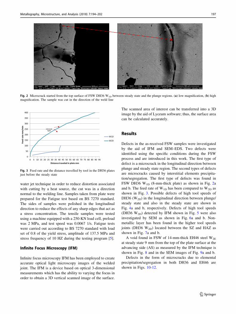
and b. The feed rate of W1D has been compared to W2D as
shown in Fig. 3. Possible defects of high tool speeds of
DH36 (W2D) in the longitudinal direction between plunge/
steady state and also in the steady state are shown in
Fig. 4a and b, respectively. Defects of high tool speeds
(DH36 W2D) detected by IFM shown in Fig. 5 were also
investigated by SEM as shown in Fig. 6a and b. Non-
metallic layer has been found in the higher tool speeds
joints (DH36 W2D) located between the SZ and HAZ as
shown in Fig. 7a and b.
A void found in FSW of 14-mm-thick EH46 steel W2E
at steady state 9 mm from the top of the plate surface at the
advancing side (AS) as measured by the IFM technique is
shown in Fig. 8 and in the SEM images of Fig. 9a and b.
Defects in the form of microcracks due to elemental
precipitation/segregation in both DH36 and EH46 are
shown in Figs. 10-12.
Fig. 2 Microcrack started from the top surface of FSW DH36 W1D between steady state and the plunge regions. (a) low magnification, (b) highmagnification. The sample was cut in the direction of the weld line
0
50
100
150
200
250
300
350
400
0 5 10 15 20 25 30 35 40 45 50 55 60 65 70 75 80 85 90 95
Feed
rate
mm
/min
Distance traveled in plate mm
W1D
W2D
microcrack region
Fig. 3 Feed rate and the distance travelled by tool in the DH36 plates
just before the steady state
Metallography, Microstructure, and Analysis (2018) 7:194–202 197
123

Discussion
W1D FSW DH36 has showed a microcrack of 2-5 lmwidth as shown in Fig. 2a and b when the tool has travelled
a distance 38-42 mm in the plate weld line just before the
steady state. Figure 3 compares curves of feed rate with the
distance travelled by the FSW tool just before the start of
the steady state of W1D with W2D. The figure shows that
W1D experienced rapid traverse speed (from 50 to 100 mm/
min with distance travelled of 2 mm), whereas in W2D the
travelled distance was 5 mm with a gradual increase
(50 mm/min) in traverse speed. Insufficient heat coming
from low tool rotational speed and the sudden increase in
traverse speed have been caused a lack in material flow of
W1D which in turn has resulted in the mentioned crack
initiation. The crack is initiated from the top surface of the
weld toward the steady state of the SZ depth. This type of
defects can weaken the weld joints, and thus, poor
mechanical properties are expected. W2D FSW DH36 has
showed different types of microcracks created inside the
SZ in the direction of welding line between plunge-steady
state region as shown in Fig. 4a and b, respectively.
Despite the higher rotational speed of the tool (500 RPM)
compared to W1D, the higher traverse speed (400 mm/min)
overrides the rotational speed. The lack in material flow
due to low heat input can be the main reason for these
defects as reported in previous work [3, 5, 15].
Figure 5 shows W2D macrograph scanned by IFM
technique; two types of defects have been detected
including weld root defect at the weld joint bottom and
kissing bond defect at the AS of the weld. The first
macrocrack (weld root defect) which starts from plate back
and reach 2 mm length into the SZ as shown in Fig. 6a can
be attributed to the lack in material flow as a result of high
traverse speed. This type of defect coincides with previous
study by Stevenson et al. [5] which specified as weld root
defects resulted from the lack in plunge depth of the FSW
tool. The insufficient heat input accompanied by the lack in
material flow may be caused in a stagnant zone formation
as proved by modeling studies [15]. The material in this
region will be vulnerable to crack formation under the
normal plunge force, so any uneven surface or sharp edge
will act as a stress concentration point as labeled in Fig. 6a.
The second crack on the AS of W2D at the weld root as
shown in Fig. 6b can be classified as a kissing bond which
is materials in lack of chemical and mechanical bonding
but in close contact. This type of defect is difficult to
identify by using the nondestructive tests such as ultra-
sound, and thus, it needs to be investigated carefully using
optical or SEM scanning of a polished etched sample. The
size of kissing bond defect can affect on the mechanical
properties of the weld joints especially fatigue strength [4].
Figure 7a and b shows a nonmetallic layer of (Fe, Mn,
Si, Al and O) as identified by SEM–EDS between the SZ
and HAZ. This was found in W2D at (a) plunge period with
10 lm width and (b) at steady state period with width of
1.3 lm. This type of defects can be the result of higher tool
Fig. 4 Microcracks inside the SZ. (a) Between plunge-steady state regions of FSW DH36 W2D (b) between plunge-steady state regions of FSW
DH36 W2D. The sample was cut in the direction of the welding line
Fig. 5 Weld root and kissing bond in 6-mm FSW DH36 (W2D)
198 Metallography, Microstructure, and Analysis (2018) 7:194–202
123

rotational speed which caused in a temperature close to the
local melting, and thus, elemental segregation of Mn, Si, Al
and O has occurred [16]. The experiments on the same
grade of steel showed that elemental precipitation/segre-
gation only occurs when the temperature equals or exceeds
1450 �C [16]. The tool centrifugal forces caused influx of
these elements toward the edge of the SZ, and thus, they
have deposited in the region between the SZ and HAZ.
Void on the AS of FSW EH46 W2E as shown in Fig. 8
has been found at 9.8 mm distance from the top surface of
the weld joint between the SZ and HAZ as detected by the
IFM. Figure 9a shows SEM image of the void which has a
diameter of about 250 lm; high amount of BN particles
which separated from the PCBN FSW tool were also found
near and around the void as shown in Fig. 9b. The void
defect is likely to happen as a result of the lack in material
stirring due to the high tool traverse speed. This result
coincides with previous work on FSW process where
Schmidt and Hattel [17] included the formation of the void
Fig. 6 SEM of the first and
second defects of DH36 6-mm
W2D shown in Fig. 5. (a) Weld
root, (b) kissing bond
Fig. 7 Nonmetallic layer of (Fe, Mn, Si, Al and O) between the SZ and HAZ found in W2D, (a) 10 lm at plunge period, (b) 1.3 lm at steady
state period
Fig. 8 A void found in EH46 steel W2E (steady state) in AS
Metallography, Microstructure, and Analysis (2018) 7:194–202 199
123

in modeling the FSW by establishing the dwell and steady
state periods and interpreted its formation at the lower
advancing-trailing side of the probe/workpiece interface as
a lack in contact between the tool and matrix interface
which in turn coming from the high traverse tool speed.
Toumpis et al. [9] also explained the formation of voids
experimentally; it was shown that the interruption in the
surrounding phase has led to a minor cavity caused by
nonmetallic inclusions. Failla [10] related the void defect
formation to the FSW tool travel speed. It was found that
the increase in linear travel speed has caused in a fast
cooling to the material before the region becomes filled
with the stirred material, leading to the void formation.
Figure 10a and b shows SEM images which include TiN
and Al, P, S precipitates, respectively, in the SZ
microstructure of FSW DH36 W2D as identified by SEM–
EDS. This weld also contained microcracks initiated from
TiN particle and also Al, P, S. This elemental precipitation
especially TiN in the SZ microstructure is usually the result
of a high peak temperature experience exceeds 1200 �C[18–20]. Orlando et al. [21] proved by the aid of optical
microscope and SEM that cubic TiN particles can cause
voids during the tensile test of IF steels. They interpreted
this type of defect as a fragmentation of weak particles
coming from stresses generated from TiN particles corners.
An extensive study about microphysical process of cleav-
age fracture in steel can be found in Chen and Cao [22]
which focuses on the steps of crack initiation, nucleation
and propagation under internal residual stresses caused by
TiN precipitation. Figure 11a and b shows microcracks
Fig. 9 High amount of BN particles found near the void at AS, EH46 steel W2E (steady state)
Fig. 10 SEM of the SZ of DH36 W2D (a) microcrack caused by TiN particle, (b) microcrack caused by Al P S elemental precipitates
200 Metallography, Microstructure, and Analysis (2018) 7:194–202
123

caused by TiN particles (exceeds 1 lm) in FSW EH46 W2E
SZ at steady state and DH36 sample heat-treated to
1300 �C with slow cooling rate (cooling inside furnace),
respectively. Figure 12 shows elemental segregation of
Mn, Si, Al and O in the SZ of FSW DH36 W2D which can
also play as a stress concentration and microcracks initia-
tion sites.
Mechanical properties of FSW joints are expected to
decrease with the existence of the previously mentioned
defects. Samples of tensile test including FSW DH36 W2D
have been failed outside the welded region which means
that welding is still accepted despite the presence of
microcracks coming from elemental precipitations. The
tensile strength is also increased to 580 MPa for W1D
compared to the strength of parent metal (475 MPa) as a
result of microstructure refinement. Samples of fatigue test
of W2D have been showed a decrease in fatigue resistance
compared to W1D as a result of defects existence in the SZ
of the welded joints. The average cycles of failure for W2D
were 115,078 cycles, whereas W1D has showed more
resistance to fatigue failure with failure cycles reached to
642,935. Comparing the FSW process with SAW, the
fatigue resistance has improved significantly as a result of
microstructure refinement [9]. Microcracks coming from
unsuitable welding parameters and also from the elemental
precipitation, especially TiN, have certainly played the
main role in this reduction in fatigue resistance. It is rec-
ommended to reduce the peak temperature when welding
this type of steel by reducing the tool rotational speed
below 500 RPM in order to avoid elemental precipitation/
segregation.
Conclusion
In conclusion, defects associated with the FSW process of
DH36 and EH46 steel grades have been studied. High tool
traverse speed as in DH36 W2D and in EH46 W2E was
found to cause defects formation such as voids, weld root
defect and kissing bonds. The lack in material flow as a
result of stagnant zone formation was the main reason of
these defects. Microcracks between the plunge and steady
states are also examples of defects caused by the lack in
material flow resulted from using unsuitable tool traverse
speed. Defects were also found in the FSW joints
microstructure as a result of the increase in welding tem-
perature higher than 1250 �C when using high tool rota-
tional speed exceeds 500 RPM. Mainly elemental
precipitation such as TiN and elemental segregation of Mn,Fig. 11 SEM images show microcracks caused by TiN precipitates
(exceeds 1 lm), FSW EH46 W2E SZ at steady state
Fig. 12 SEM-EDS shows elemental segregation of Mn, O and Si in the SZ of FSW DH36 at high tool speeds (W2D)
Metallography, Microstructure, and Analysis (2018) 7:194–202 201
123

Si, Al and O was the results of using high tool rotational
speed. These elementals precipitation/segregation can
cause in microcracks and stress concentration initiation
sites causing in decreasing the mechanical properties of the
welded joints.
Acknowledgments The author would like to thank the ministry of
higher education/Iraq for funding this work. The authors also would
like to thank TWI company for providing data and samples.
Open Access This article is distributed under the terms of the Creative
Commons Attribution 4.0 International License (http://creative
commons.org/licenses/by/4.0/), which permits unrestricted use, dis-
tribution, and reproduction in any medium, provided you give
appropriate credit to the original author(s) and the source, provide a
link to the Creative Commons license, and indicate if changes were
made.
References
1. A. Pradeep, A review on friction stir welding of steel. Int. J. Eng.
Res. Dev. 3(11), 75–91 (2012). e-ISSN: 2278-067X, p-ISSN:
2278-800X. www.ijerd.com
2. K. Elangovan, V. Balasubramanian, Influences of pin profile and
rotational speed of the tool on the formation of friction stir pro-
cessing zone in AA2219 aluminium alloy. Mater. Sci. Eng. A
459(2007), 7–18 (2007)
3. A.K. Lakshminarayanan, V. Balasubramanian, Understanding the
parameters controlling friction stir welding of AISI 409 M ferritic
stainless steel. Met. Mater. Int. 17(6), 969–998 (2011)
4. R. Ruzek, M. Kadlec, Friction stir welded structures: kissing
bond defects. Int. J. Terraspace Sci. Eng. 6(2), 77–83 (2014)
5. S. Ryan, A. Toumpis, A. Galloway, Defect tolerance of friction
stir welds in DH36 steel. Mater. Des. 87(15), 701–711 (2015)
6. Y.G. Kim, H. Fujii, T. Tsumura, T. Komazaki, K. Nakata, Three
defect types in friction stir welding of aluminum die casting
alloy. Mater. Sci. Eng. A 415, 250–254 (2006)
7. J.M. Seaman, B. Thompson, Challenges of friction stir welding of
thick-section steel, in Proceedings of the Twenty-First Interna-
tional Offshore and Polar Engineering Conference, Maui,
Hawaii, USA, 2011, 19–24 June 2011
8. S. Cater, Forge welding turns full circle: friction stir welding of
steel. Ironmak. Steelmak. 40(7), 490–495 (2013). https://doi.org/
10.1179/0301923313Z.000000000224
9. A. Toumpis, A. Gallawi, H. Polezhayeva, L. Molter, Fatigue
assessment of friction stir welded DH36 steel. Frict. Stir Weld.
Process. VIII, 11–19 (2015)
10. D.M. Failla, Friction stir welding and microstructure simulation
of HSLA-65 and austenitic stainless steels, Thesis, The Ohio
State University, 2009
11. C. Tingey, A. Galloway, A. Toumpis, S. Cater, Effect of tool
centreline deviation on the mechanical properties of friction stir
welded DH36 steel. Mater. Des. (1980–2015) 65, 896–906 (2015)12. A. Toumpis, A. Gallawi, S. Cater, N. McPherson, Development
of a process envelope for friction stir welding of DH36 steel—a
step change. Mater. Des. 62, 64–75 (2014)
13. Y. Morisada, T. Imaizumi, H. Fujii, Clarification of material flow
and defect formation during friction stir welding. Sci. Technol.
Weld. Join. 20(2), 130–137 (2015)
14. B.T. Gibson, D.H. Lammlein, T.J. Prater, W.R. Longhurst, C.D.
Cox, M.C. Ballun, Friction stir welding: process, automation, and
control. J. Manuf. Process. 16, 56–73 (2014)
15. M. Al-Moussawi, A.J. Smith, A. Young, S. Cater, M. Faraji,
Modelling of friction stir welding of DH36 steel. Int. J. Adv. Manuf.
Technol. (2017). https://doi.org/10.1007/s00170-017-0147-y
16. M. Almoussawi, A.J. Smith, M. Faraji, S. Cater, Segregation of
Mn, Si, Al, and oxygen during the friction stir welding of DH36
steel. Metallogr. Microstruct. Anal. 6, 569 (2017). https://doi.org/
10.1007/s13632-017-0401-6
17. R.M. Hooper, J.I. Shakib, C.A. Brookes, Microstructure and wear
of TiC cubic BN tools. Mater. Sci. Eng. A A106, 429–433 (1988)
18. W. Ming-lin, G. Cheng, S. Qiu, P. Zhao, Y. Gan, Roles of tita-
nium-rich precipitates as inoculants during solidification in low
carbon steel. Int. J. Miner. Metall. Mater. 17(3), 276–281 (2010)
19. S. Yamini, Effect of titanium additions to low carbon, low
manganese steel on sulphide precipitation, Ph.D. theses,
University of Wollongong, 2008
20. Y. Zhang, G. Xu, M.X. Zhou, H.L. Yang, M. Wang, The effect of
reheating temperature on precipitation of a high strength
microalloyed steel. Appl. Mech. Mater. 508, 8–11 (2014)
21. O. Leon-Garcıa, R. Petrov, L.A.I. Kestens, Void initiation at TiN
precipitates in IF steels during tensile deformation. Mater. Sci.
Eng. A 527, 4202–4209 (2010)
22. J.H. Chen, R. Cao, Micromechanism of Cleavage Fracture of
Metals, Chapter 3, Copyright� 2015 (Elsevier Inc, Amsterdam,
2015), pp. 81–140
202 Metallography, Microstructure, and Analysis (2018) 7:194–202
123
Related Documents