4514 IEEE TRANSACTIONS ON MICROWAVE THEORY AND TECHNIQUES, VOL. 67, NO. 11, NOVEMBER 2019 Decomposition and Synthesis of High-Order Compensated Inductive Power Transfer Systems for Improved Output Controllability Rong He, Student Member, IEEE, Peng Zhao, Student Member, IEEE, Minfan Fu , Member, IEEE, Yu Liu, Member, IEEE, Haoyu Wang , Senior Member, IEEE , and Junrui Liang , Member, IEEE Abstract— High-order compensation provides more design freedom for inductive power transfer systems and can help improve output voltage/current controllability. This paper devel- ops a simplified decomposition and synthesis method for high- order-compensated inductive power transfer systems. It can achieve load-independent (LI) output under coupling variation, and easily fulfill the various charging requirements, such as constant voltage or constant current. The coupling independent resonance is ensured by using the induced source model, and the whole resonant tank is effectively decomposed as three parts. The power transfer characteristics are discussed for each part, and the requirements for LI output and zero phase angle (ZPA) operation are combined to generate the compensation candidates for both sides. Two families of topologies are synthesized for four kinds of conversions, i.e., voltage to voltage, voltage to current, current to voltage, and current to current. Meanwhile, the proposed method dramatically simplifies the evaluation for the influence of the coil equivalent series resistors on the transfer function and efficiency. These resistor-caused effects are quite different for two families of topologies. Finally, a 6.78-MHz system with 10-W output is designed to verify the difference between two-family topologies. Index Terms— Coupling-independent (CI) resonance, decom- position and synthesis, high-order compensation, inductive power transfer, load-independent (LI) output, zero phase angle (ZPA) operation. I. I NTRODUCTION I NDUCTIVE power transfer (IPT) has been widely applied to charge wearable devices, cellphones, and electric vehi- cles [1], [2]. Usually, each specific application has its own demands on the power level, efficiency, size, and spatial freedom, which would finally determine the suitable reso- nant frequency, topology, system configuration, and control scheme [3]–[5]. For all these IPT systems, the selection and Manuscript received February 20, 2019; revised May 16, 2019; accepted June 16, 2019. Date of publication August 2, 2019; date of current version November 5, 2019. This work was supported in part by the Shanghai Sailing Program under Grant 19YF1433700 and in part by the Shanghai Program for Professor of Special Appointment (Eastern Scholar, Youth). (Corresponding author: Minfan Fu.) The authors are with the School of Information Science and Tech- nology, ShanghaiTech University, Shanghai 201210, China (e-mail: [email protected]). Color versions of one or more of the figures in this article are available online at http://ieeexplore.ieee.org. Digital Object Identifier 10.1109/TMTT.2019.2929143 design of proper compensation is a common issue. About 15 years ago, the group from the University of Auckland proposed four basic compensations, i.e., series–series (SS), parallel–series (PS), series–parallel (SP), and parallel– parallel (PP), to boost the power transfer capability and achieve zero phase angle (ZPA) operation [6], [7]. Since then, many IPT systems have been developed. However, most of the reported systems have to use complicated switch-mode circuits to maintain good controllability for various objectives, such as constant output voltage, dynamic impedance matching, and optimal efficiency tracking [8]–[10]. Recently, the four basic compensations are also explored for load-independent (LI) output voltage or current to improve the controllability and simplify the system configuration [11]–[14]. However, most systems cannot keep LI output and ZPA operation when the coupling varies. Therefore, it is challenging to achieve various objectives with simple circuits and control scheme. In theory, the four basic compensations are difficult to meet various demands simultaneously because of the limited design freedom. Therefore, it is possible to employ high-order compensations to overcome this issue, and then additional objectives can be fulfilled [15]–[17]. For example, the LC compensation offers an input-voltage-controlled current to drive the transmitter (TX) coil, and then power demands of each receiver (RX) are effectively decoupled [15]. The LCC compensation is proposed in [16] for zero-current- switching (ZCS). The double-sided LCC compensation can achieve the LI output, zero-voltage-switching (ZVS), and ZPA operation simultaneously [17]. When the compensation order increases, the possible combination of resonant compo- nents would dramatically increase as well. Several papers are devoted to the design and selection of proper compensations. In [18], the basic circuit networks for LI output are summa- rized and used to explain the existing compensations. Based on these findings, several rules have been abstracted to synthesize high-order compensations by representing the coupling coils as a T-type circuit or classical transformer [19], [20]. However, this kind of coil modeling is hard to analyze the coupling variation cases. This issue is effectively avoided in [21] by using the induced source model, i.e., modeling the coils as the 0018-9480 © 2019 IEEE. Personal use is permitted, but republication/redistribution requires IEEE permission. See http://www.ieee.org/publications_standards/publications/rights/index.html for more information.

Welcome message from author
This document is posted to help you gain knowledge. Please leave a comment to let me know what you think about it! Share it to your friends and learn new things together.
Transcript
4514 IEEE TRANSACTIONS ON MICROWAVE THEORY AND TECHNIQUES, VOL. 67, NO. 11, NOVEMBER 2019
Decomposition and Synthesis of High-OrderCompensated Inductive Power Transfer
Systems for Improved OutputControllability
Rong He, Student Member, IEEE, Peng Zhao, Student Member, IEEE, Minfan Fu , Member, IEEE,
Yu Liu, Member, IEEE, Haoyu Wang , Senior Member, IEEE, and Junrui Liang , Member, IEEE
Abstract— High-order compensation provides more designfreedom for inductive power transfer systems and can helpimprove output voltage/current controllability. This paper devel-ops a simplified decomposition and synthesis method for high-order-compensated inductive power transfer systems. It canachieve load-independent (LI) output under coupling variation,and easily fulfill the various charging requirements, such asconstant voltage or constant current. The coupling independentresonance is ensured by using the induced source model, and thewhole resonant tank is effectively decomposed as three parts. Thepower transfer characteristics are discussed for each part, and therequirements for LI output and zero phase angle (ZPA) operationare combined to generate the compensation candidates for bothsides. Two families of topologies are synthesized for four kinds ofconversions, i.e., voltage to voltage, voltage to current, current tovoltage, and current to current. Meanwhile, the proposed methoddramatically simplifies the evaluation for the influence of the coilequivalent series resistors on the transfer function and efficiency.These resistor-caused effects are quite different for two familiesof topologies. Finally, a 6.78-MHz system with 10-W output isdesigned to verify the difference between two-family topologies.
Index Terms— Coupling-independent (CI) resonance, decom-position and synthesis, high-order compensation, inductive powertransfer, load-independent (LI) output, zero phase angle (ZPA)operation.
I. INTRODUCTION
INDUCTIVE power transfer (IPT) has been widely appliedto charge wearable devices, cellphones, and electric vehi-
cles [1], [2]. Usually, each specific application has its owndemands on the power level, efficiency, size, and spatialfreedom, which would finally determine the suitable reso-nant frequency, topology, system configuration, and controlscheme [3]–[5]. For all these IPT systems, the selection and
Manuscript received February 20, 2019; revised May 16, 2019; acceptedJune 16, 2019. Date of publication August 2, 2019; date of current versionNovember 5, 2019. This work was supported in part by the Shanghai SailingProgram under Grant 19YF1433700 and in part by the Shanghai Program forProfessor of Special Appointment (Eastern Scholar, Youth). (Correspondingauthor: Minfan Fu.)
The authors are with the School of Information Science and Tech-nology, ShanghaiTech University, Shanghai 201210, China (e-mail:[email protected]).
Color versions of one or more of the figures in this article are availableonline at http://ieeexplore.ieee.org.
Digital Object Identifier 10.1109/TMTT.2019.2929143
design of proper compensation is a common issue. About15 years ago, the group from the University of Aucklandproposed four basic compensations, i.e., series–series (SS),parallel–series (PS), series–parallel (SP), and parallel–parallel (PP), to boost the power transfer capability and achievezero phase angle (ZPA) operation [6], [7]. Since then, manyIPT systems have been developed. However, most of thereported systems have to use complicated switch-mode circuitsto maintain good controllability for various objectives, suchas constant output voltage, dynamic impedance matching, andoptimal efficiency tracking [8]–[10]. Recently, the four basiccompensations are also explored for load-independent (LI)output voltage or current to improve the controllability andsimplify the system configuration [11]–[14]. However, mostsystems cannot keep LI output and ZPA operation when thecoupling varies. Therefore, it is challenging to achieve variousobjectives with simple circuits and control scheme.
In theory, the four basic compensations are difficult tomeet various demands simultaneously because of the limiteddesign freedom. Therefore, it is possible to employ high-ordercompensations to overcome this issue, and then additionalobjectives can be fulfilled [15]–[17]. For example, the LCcompensation offers an input-voltage-controlled current todrive the transmitter (TX) coil, and then power demandsof each receiver (RX) are effectively decoupled [15]. TheLCC compensation is proposed in [16] for zero-current-switching (ZCS). The double-sided LCC compensation canachieve the LI output, zero-voltage-switching (ZVS), andZPA operation simultaneously [17]. When the compensationorder increases, the possible combination of resonant compo-nents would dramatically increase as well. Several papers aredevoted to the design and selection of proper compensations.In [18], the basic circuit networks for LI output are summa-rized and used to explain the existing compensations. Based onthese findings, several rules have been abstracted to synthesizehigh-order compensations by representing the coupling coils asa T-type circuit or classical transformer [19], [20]. However,this kind of coil modeling is hard to analyze the couplingvariation cases. This issue is effectively avoided in [21] byusing the induced source model, i.e., modeling the coils as the
0018-9480 © 2019 IEEE. Personal use is permitted, but republication/redistribution requires IEEE permission.See http://www.ieee.org/publications_standards/publications/rights/index.html for more information.
HE et al.: DECOMPOSITION AND SYNTHESIS OF HIGH-ORDER COMPENSATED IPT SYSTEMS 4515
combination of self-inductance and induced voltage source.Since the self-inductance is used for resonance, the derivedfrequencies for LI output and ZPA operation can be naturallycoupling independent (CI).
This paper proposes a novel perspective to simplify thedecomposition and synthesis for high-order-compensated IPTsystems. All kinds of LI conversions, i.e., voltage to volt-age (V2V), voltage to current (V2I), current to voltage (I2V),and current to current (I2I) are discussed based on the inducedsource model, which can naturally help analyze the CI reso-nance. The self-inductance of the TX coil is aborted by the TXcompensation to form a resonant tank, so as for the RX side.The whole resonant tank can then be decomposed into threeparts, i.e., a TX tank, a pair of induced voltage sources, and anRX tank. This system decomposition dramatically simplifiesthe system analysis and each part can be designed in adecoupled manner. Since the transfer functions of the inducedvoltage source are well known, the main challenge becomeshow to develop high-order resonant tank candidates (for bothsides) that enable LI output and ZPA operation. In orderto solve this challenge, many well-developed methods forconventional high-order resonant converters can be modifiedand applied in this paper [22]. The basic requirements for LIoutput and ZPA operation are gradually applied to generateall the tank candidates. To the best of author’s knowledge,it is the first time to propose a rule to generate all the tankcandidates (up to fourth order) for all kinds of conversions,which would finally help synthesize the high-order IPT topol-ogy. Finally, two families of fundamental topologies for allkinds of conversions are found, and two example topologiesfor V2V conversion are studied and compared.
II. COUPLING-INDEPENDENT (CI) RESONANCE
A. Limitation of Transformer Model or T Model
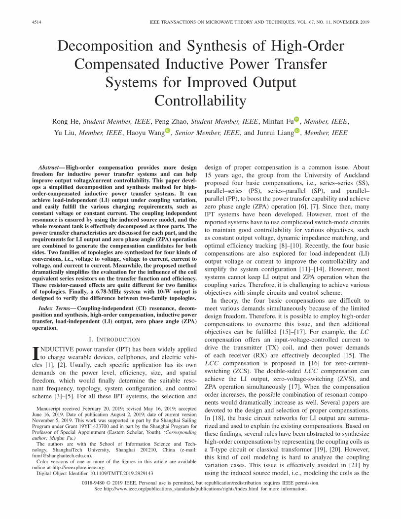
A typical IPT system is shown in Fig. 1. The poweris coupled from the TX coil (L tx) to the RX coil (Lrx).Since the mutual inductance (M) is small, both TX and RXcompensations are necessary to boost the power transfer capa-bility. In this paper, high-order compensations are employedto improve the system controllability. In practice, the outputcurrent or voltage should be regulated to meet specific powerdemand and port requirements. When a resonant tank is able toprovide LI transfer function under coupling variation, the out-put regulation complexity could be significantly reduced. Forexample, if the resonant tank can offer LI V2V gain and itsassociated operation frequency will not shift under couplingvariation (i.e., coupling-independent resonance), it means theinput voltage vin can be used to directly control the outputvoltage vo. Therefore, this paper is devoted to the decomposi-tion and synthesis of high-order compensation with LI output,CI resonance, and ZPA operation.
In order to analyze the resonant tank, a straightforward andconvenient method is to apply the classical transformer modelfor the coupling coils, and then an IPT system can be treatedas an entity, which is actually a special isolated resonantconverter. Fig. 1 shows the transformer model, in which themagnetizing inductance Lm , the leakage inductance Ll , and
Fig. 1. IPT system block diagram.
Fig. 2. IPT system decomposition.
the equivalent turn ratio N (not the real one) can be repre-sented in terms of the self-inductance and mutual inductance(i.e., L tx, Lrx, and M)
Lm = M2/Lrx
Ll = L tx − M2/Lrx
N = M/Lrx. (1)
It shows all the transformer parameters are actually coupling-dependent. Once these varied inductances join the resonance,the resonance frequency will shift when the coil positionvaries. The T-type model has similar issues (refer to Fig. 1).Therefore, all the compensation analysis based on these mod-els (including coupling-dependent inductance) naturally facemore challenges [19], [20].
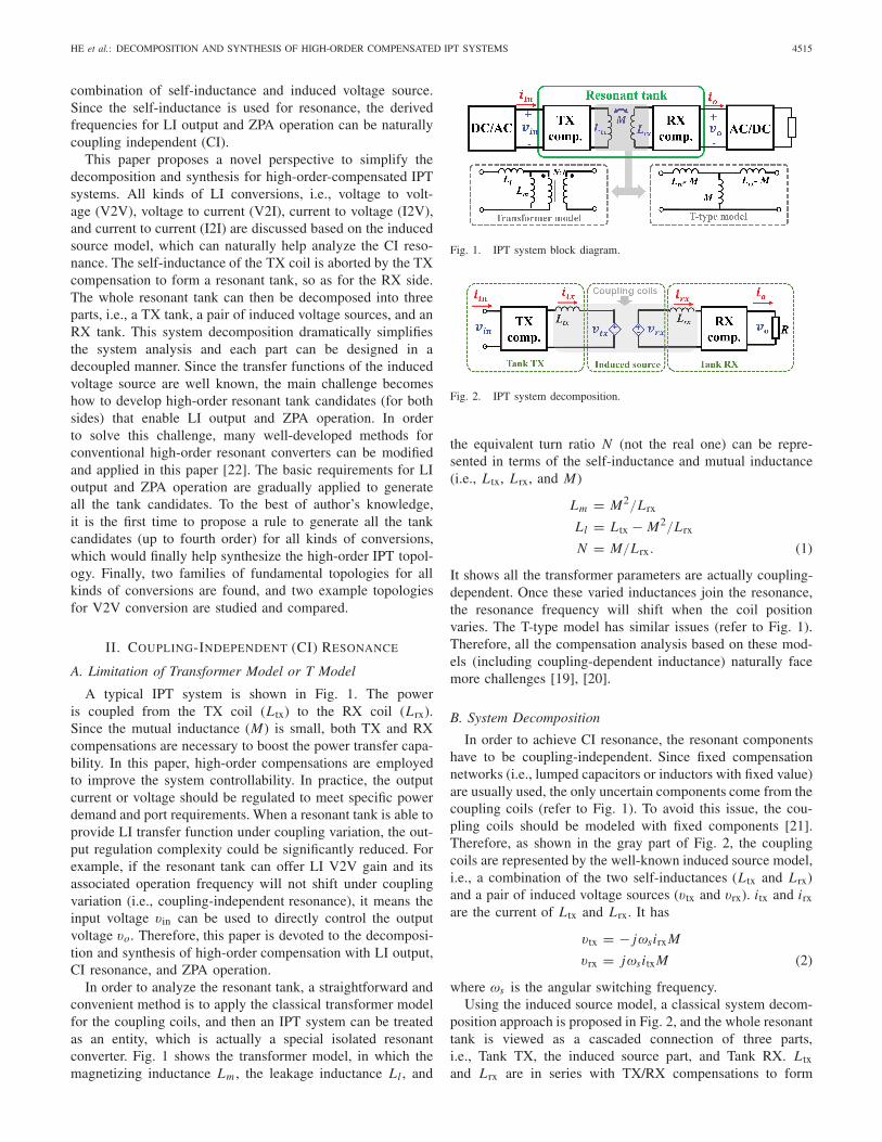
B. System Decomposition
In order to achieve CI resonance, the resonant componentshave to be coupling-independent. Since fixed compensationnetworks (i.e., lumped capacitors or inductors with fixed value)are usually used, the only uncertain components come from thecoupling coils (refer to Fig. 1). To avoid this issue, the cou-pling coils should be modeled with fixed components [21].Therefore, as shown in the gray part of Fig. 2, the couplingcoils are represented by the well-known induced source model,i.e., a combination of the two self-inductances (L tx and Lrx)and a pair of induced voltage sources (vtx and vrx). itx and irxare the current of L tx and Lrx. It has
vtx = − jωsirx M
vrx = jωsitxM (2)
where ωs is the angular switching frequency.Using the induced source model, a classical system decom-
position approach is proposed in Fig. 2, and the whole resonanttank is viewed as a cascaded connection of three parts,i.e., Tank TX, the induced source part, and Tank RX. L txand Lrx are in series with TX/RX compensations to form

4516 IEEE TRANSACTIONS ON MICROWAVE THEORY AND TECHNIQUES, VOL. 67, NO. 11, NOVEMBER 2019
Tank TX/RX, respectively. The induced source part onlyincludes vtx and vrx. For Tank TX, vin and iin are the inputvoltage and current. Similarly, vo and io are the output voltageand current of Tank RX. In this paper, Tank TX and Tank RXcan be analyzed individually for a target resonant frequency,and then various objectives (like loading-independent outputand ZPA operation) can be achieved by proper selection anddesign of resonant tanks. Since all the resonant componentsare fixed, the proposed decomposition method can naturallyhelp to synthesize all coupling-independent IPT topologies.
III. LOAD-INDEPENDENT OUTPUT
A. Transfer Function of the Induced Source Part
The LI output (voltage or current) is preferred for an IPTsystem due to its good controllability. In this paper, G isused to define the input to output transfer function, and thesubscript is used to denote the conversion type (like V2V)and different parts of the IPT system. For example, Gcoil,vimeans the transfer function from vtx to irx in Fig. 2. Sincethe system is a cascaded connection of three parts, the overalltransfer function is the product of the gain of each sub part.According to (2), the induced source part can naturally provideLI transfer function, that is,
Gcoil,iv = vrx
itx= jωs M
Gcoil,vi = irx
vtx= − 1
jωs M. (3)
It shows there are only two approaches to achieve LI volt-age/current transfer. Therefore, two families of IPT topologiesare defined. If an IPT topology is synthesized based on LIGcoil,iv, it belongs to Family A, and LI Gcoil,vi is used togenerate the topologies of Family B.
B. Basic LI Resonant Networks
Given LI conversions for the induced source part, the nextobjective is to find the suitable LI resonant tanks for TankTX/RX. Usually, the LI output happens at a certain frequencyfor a given resonant tank. For example, a L LC resonantconverter provides a LI output voltage when working atits series resonant frequency. Many studies on high-orderresonant converters can help to find proper candidates. Thebasic network with LI output has been discussed in [18] andshown in Fig. 3. The impedance requirements and the transferfunction are summarized in Table I. For example, a LC circuitprovides LI Gvi, which can be easily explained by the Norton’stheory [refer to Fig. 3(c)]. Note that Z2 = ∞ in Fig. 3(a) alsoprovides LI Gvv, and Z1 = Z3 = ∞ in Fig. 3(b) offers LIGii. These fundamental blocks are used to generate high-ordernetwork with LI transfer functions.
In [20], the overall IPT resonant tank can be viewed as acascaded connection of these basic LI networks. As shownin Fig. 4, the coupling coils are usually modeled as a T-typenetwork. Although this modeling method can help explain theexisting high-order IPT systems, it is inconvenient to analyzethe coupling-independent resonance. For example, Zhang et al.[11] and Costanzo et al. [14] used the SS compensation for
Fig. 3. Basic circuit network with LI output. (a) LI Gvv. (b) LI G ii.(c) LI Gvi. (d) LI G iv.
TABLE I
IMPEDANCE REQUIREMENT FOR LI TRANSFER FUNCTIONS
Fig. 4. Synthesis method in [20].
Fig. 5. SS compensation for LI output. (a) Coupling-dependent Gvv.(b) Coupling-independent Gvi.
LI output voltage. Two LI resonant frequencies (ωH and ωL )are analytically derived and shown in Fig. 5(a). Using thesynthesis approach of [20], the corresponding resonant net-works for each LI resonant frequency can be easily identified,i.e., the resonance of the red block used to derive ωH and theresonance of the green part used to derive ωL . It is obviousthat both ωH and ωL are coupling-dependent because of thevaried M .
The SS compensation is also used for LI Gvi as shownin Fig. 5(b) [13]. The proposed decomposition in this papercan be used to easily analyze the resonance condition. ForTank TX, the resonance between L tx and Ct1 makes vtx

HE et al.: DECOMPOSITION AND SYNTHESIS OF HIGH-ORDER COMPENSATED IPT SYSTEMS 4517
Fig. 6. Second-order resonant tanks (the red inductor means thecoupling coil).
clamped by vin, i.e., LI Gtx,vv, which further leads to aclamped irx, i.e., LI Gcoil,vi [refer to (3)]. Finally, TankRX is also a series LC branch with LI Grx,ii. Therefore,the overall voltage to current transfer function is a productform, i.e., Gvi = Gtx,vvGcoil,viGrx,ii. Instead of analyzing thewhole tank, this paper chooses to analyze the LI transferfunction of each parts, based on which the derived resonancefrequency is naturally CI.
C. Candidate Resonant Tanks for Topology Synthesis
The proposed decomposition method can not only betterexplain the existing IPT topologies, but also provide aneffective way for topology synthesis. It helps the IPT systemto have LI output capability at CI resonant frequency. Dueto the source or load type (i.e., voltage or current), thereare totally four types of transfer functions (i.e., Gvv, Gii,Gvi, and Giv). For each type of conversion, there are twoeffective ways to utilize the coupling coils, i.e., Gcoil,vi andGcoil,iv, which are used to define two-family topologies. Forexample, the overall gain for V2V conversion (Gvv) can bedecomposed either as Gvv = Gtx,vvGcoil,viGrx,iv (belongingto Family A) or as Gvv = Gtx,viGcoil,ivGrx,vv (belonging toFamily B). Therefore, this paper needs to develop a candidatepool for Tank TX and Tank RX for all kinds of conversions(i.e., V2V, V2I, I2V, and I2I).
The study of high-order resonant converter is not new, andthere is a continuous effort on topology synthesis for the tra-ditional resonant converter. The major difference between thetraditional resonant converter and the IPT system is the variedcoupling. In this paper, the induced source and the fixed self-inductance of the coupling coils are treated separately, and ithelps to directly utilize the analysis methods of the traditionalhigh-order resonant converter. Up until now, there is no paperto summarize all the possible high-order compensated IPTsystems for various conversions, i.e., V2V, V2I, I2V, and I2I.
Due to the symmetry, Tank TX and RX actually share thesame candidate pool. For example, a candidate for Tank TXwith LI Gtx,vi can directly serve as Tank RX for LI Grx,iv.The following discussion only needs to focus on the TX side.As shown in Fig. 2, all the tank candidates should ensurethere is at least a series inductor (used as the L tx) at theoutput terminal. Therefore, the simplest resonant tank withLI output capability is to combine a series or shunt capacitorwith L tx. Fig. 6 shows all the second-order tanks. Based on theconclusion of Fig. 3 and Table I, only Tank A1 and Tank A2(including L tx, the red inductor) can serve as the candidateswith LI output capability.
Fig. 7. Third-order tank candidates with LI output capability (the red inductormeans the coupling coil).
Fig. 8. Fourth-order tank candidates with LI output capability (the redinductor means the coupling coil).
The third-order tank candidates are generated based onthe second-order tanks in Fig. 6, i.e., adding a series L txto the output port. Note that Tank A1 and A2 should notbe used because two inductors will merge to form a lower-order tank at the output port. In Fig. 7, six tanks (i.e., TanksB1–B6) are generated based on this principle. Tanks B7 andB8 are created based on two-capacitor networks, which are notincluded in Fig. 6. There are totally 36 third-order resonanttanks, among which only 28 tanks (excluding those in Fig. 7)can be used to generate the fourth-order candidates (refer toTanks C1–C28 in Fig. 8). Tanks C29 and C30 are generated bythree-capacitor networks. The proposed candidate generationapproach is valid for even higher-order tanks, and more thanone hundred candidates can be generated for fifth-order tanks.Presently, the benefit for further increasing the tank order isnot obvious, and this paper would focus on the proposed tanksup to fourth-order.
D. Candidate Tank Classification
The LI transfer functions of the proposed candidates aredetermined based on Fig. 3. For example, if a candidate
4518 IEEE TRANSACTIONS ON MICROWAVE THEORY AND TECHNIQUES, VOL. 67, NO. 11, NOVEMBER 2019
Fig. 9. Tank candidates with LI output and CI resonance.
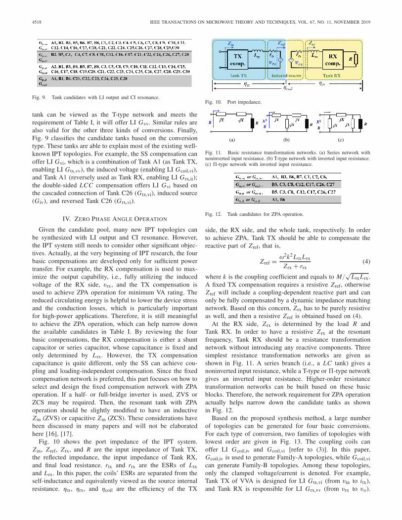
tank can be viewed as the T-type network and meets therequirement of Table I, it will offer LI Gvv. Similar rules arealso valid for the other three kinds of conversions. Finally,Fig. 9 classifies the candidate tanks based on the conversiontype. These tanks are able to explain most of the existing well-known IPT topologies. For example, the SS compensation canoffer LI Gvi, which is a combination of Tank A1 (as Tank TX,enabling LI Gtx,vv), the induced voltage (enabling LI Gcoil,vi),and Tank A1 (reversely used as Tank RX, enabling LI Grx,ii);the double-sided LCC compensation offers LI Gvi based onthe cascaded connection of Tank C26 (Gtx,vi), induced source(Giv), and reversed Tank C26 (Grx,vi).
IV. ZERO PHASE ANGLE OPERATION
Given the candidate pool, many new IPT topologies canbe synthesized with LI output and CI resonance. However,the IPT system still needs to consider other significant objec-tives. Actually, at the very beginning of IPT research, the fourbasic compensations are developed only for sufficient powertransfer. For example, the RX compensation is used to max-imize the output capability, i.e., fully utilizing the inducedvoltage of the RX side, vrx, and the TX compensation isused to achieve ZPA operation for minimum VA rating. Thereduced circulating energy is helpful to lower the device stressand the conduction losses, which is particularly importantfor high-power applications. Therefore, it is still meaningfulto achieve the ZPA operation, which can help narrow downthe available candidates in Table I. By reviewing the fourbasic compensations, the RX compensation is either a shuntcapacitor or series capacitor, whose capacitance is fixed andonly determined by Lrx. However, the TX compensationcapacitance is quite different, only the SS can achieve cou-pling and loading-independent compensation. Since the fixedcompensation network is preferred, this part focuses on how toselect and design the fixed compensation network with ZPAoperation. If a half- or full-bridge inverter is used, ZVS orZCS may be required. Then, the resonant tank with ZPAoperation should be slightly modified to have an inductiveZ in (ZVS) or capacitive Z in (ZCS). These considerations havebeen discussed in many papers and will not be elaboratedhere [16], [17].
Fig. 10 shows the port impedance of the IPT system.Z in, Zref, Zrx, and R are the input impedance of Tank TX,the reflected impedance, the input impedance of Tank RX,and final load resistance. rtx and rrx are the ESRs of L txand Lrx. In this paper, the coils’ ESRs are separated from theself-inductance and equivalently viewed as the source internalresistance. ηtx, ηrx, and ηcoil are the efficiency of the TX
Fig. 10. Port impedance.
Fig. 11. Basic resistance transformation networks. (a) Series network withnoninverted input resistance. (b) T-type network with inverted input resistance.(c) �-type network with inverted input resistance.
Fig. 12. Tank candidates for ZPA operation.
side, the RX side, and the whole tank, respectively. In orderto achieve ZPA, Tank TX should be able to compensate thereactive part of Zref, that is,
Zref = ω2k2 L txLrx
Zrx + rrx(4)
where k is the coupling coefficient and equals to M/√
L txLrx.A fixed TX compensation requires a resistive Zref, otherwiseZref will include a coupling-dependent reactive part and canonly be fully compensated by a dynamic impedance matchingnetwork. Based on this concern, Zrx has to be purely resistiveas well, and then a resistive Zref is obtained based on (4).
At the RX side, Zrx is determined by the load R andTank RX. In order to have a resistive Zrx at the resonantfrequency, Tank RX should be a resistance transformationnetwork without introducing any reactive components. Threesimplest resistance transformation networks are given asshown in Fig. 11. A series branch (i.e., a LC tank) gives anoninverted input resistance, while a T-type or �-type networkgives an inverted input resistance. Higher-order resistancetransformation networks can be built based on these basicblocks. Therefore, the network requirement for ZPA operationactually helps narrow down the candidate tanks as shownin Fig. 12.
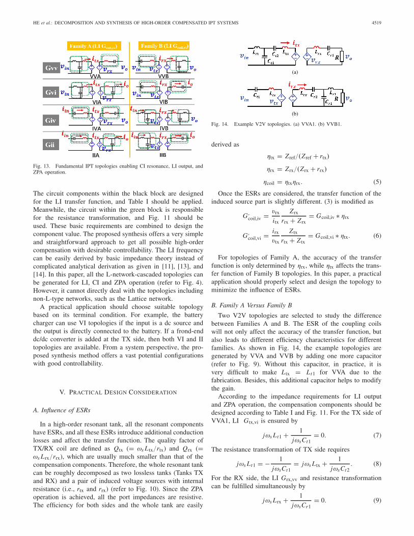
Based on the proposed synthesis method, a large numberof topologies can be generated for four basic conversions.For each type of conversion, two families of topologies withlowest order are given in Fig. 13. The coupling coils canoffer LI Gcoil,iv and Gcoil,vi [refer to (3)]. In this paper,Gcoil,iv is used to generate Family-A topologies, while Gcoil,vican generate Family-B topologies. Among these topologies,only the clamped voltage/current is denoted. For example,Tank TX of VVA is designed for LI Gtx,vi (from vin to itx),and Tank RX is responsible for LI Grx,vv (from vrx to vo).
HE et al.: DECOMPOSITION AND SYNTHESIS OF HIGH-ORDER COMPENSATED IPT SYSTEMS 4519
Fig. 13. Fundamental IPT topologies enabling CI resonance, LI output, andZPA operation.
The circuit components within the black block are designedfor the LI transfer function, and Table I should be applied.Meanwhile, the circuit within the green block is responsiblefor the resistance transformation, and Fig. 11 should beused. These basic requirements are combined to design thecomponent value. The proposed synthesis offers a very simpleand straightforward approach to get all possible high-ordercompensation with desirable controllability. The LI frequencycan be easily derived by basic impedance theory instead ofcomplicated analytical derivation as given in [11], [13], and[14]. In this paper, all the L-network-cascaded topologies canbe generated for LI, CI and ZPA operation (refer to Fig. 4).However, it cannot directly deal with the topologies includingnon-L-type networks, such as the Lattice network.
A practical application should choose suitable topologybased on its terminal condition. For example, the batterycharger can use VI topologies if the input is a dc source andthe output is directly connected to the battery. If a frond-enddc/dc converter is added at the TX side, then both VI and IItopologies are available. From a system perspective, the pro-posed synthesis method offers a vast potential configurationswith good controllability.
V. PRACTICAL DESIGN CONSIDERATION
A. Influence of ESRs
In a high-order resonant tank, all the resonant componentshave ESRs, and all these ESRs introduce additional conductionlosses and affect the transfer function. The quality factor ofTX/RX coil are defined as Qtx (= ωs L tx/rtx) and Qrx (=ωs Lrx/rrx), which are usually much smaller than that of thecompensation components. Therefore, the whole resonant tankcan be roughly decomposed as two lossless tanks (Tanks TXand RX) and a pair of induced voltage sources with internalresistance (i.e., rtx and rrx) (refer to Fig. 10). Since the ZPAoperation is achieved, all the port impedances are resistive.The efficiency for both sides and the whole tank are easily
Fig. 14. Example V2V topologies. (a) VVA1. (b) VVB1.
derived as
ηtx = Zref/(Zref + rtx)
ηrx = Zrx/(Zrx + rrx)
ηcoil = ηtxηrx. (5)
Once the ESRs are considered, the transfer function of theinduced source part is slightly different. (3) is modified as
G,coil,iv = vrx
itx
Zrx
rrx + Zrx= Gcoil,iv ∗ ηrx
G,coil,vi = irx
vtx
Z tx
rtx + Z tx= Gcoil,vi ∗ ηtx. (6)
For topologies of Family A, the accuracy of the transferfunction is only determined by ηrx, while ηtx affects the trans-fer function of Family B topologies. In this paper, a practicalapplication should properly select and design the topology tominimize the influence of ESRs.
B. Family A Versus Family B
Two V2V topologies are selected to study the differencebetween Families A and B. The ESR of the coupling coilswill not only affect the accuracy of the transfer function, butalso leads to different efficiency characteristics for differentfamilies. As shown in Fig. 14, the example topologies aregenerated by VVA and VVB by adding one more capacitor(refer to Fig. 9). Without this capacitor, in practice, it isvery difficult to make L tx = Lt1 for VVA due to thefabrication. Besides, this additional capacitor helps to modifythe gain.
According to the impedance requirements for LI outputand ZPA operation, the compensation components should bedesigned according to Table I and Fig. 11. For the TX side ofVVA1, LI Gtx,vi is ensured by
jωs Lt1 + 1
jωsCt1= 0. (7)
The resistance transformation of TX side requires
jωs Lt1 = − 1
jωsCt1= jωs L tx + 1
jωsCt2. (8)
For the RX side, the LI Grx,vv and resistance transformationcan be fulfilled simultaneously by
jωs Lrx + 1
jωsCr1= 0. (9)

4520 IEEE TRANSACTIONS ON MICROWAVE THEORY AND TECHNIQUES, VOL. 67, NO. 11, NOVEMBER 2019
Fig. 15. Gvv comparison between VVA1 and VVB1 for different G ideal. (a) G ideal = 0.5. (b) G ideal = 1. (c) G ideal = 2.
Fig. 16. ηcoil comparison between VVA1 and VVB1 for different G ideal. (a) G ideal = 0.5. (b) G ideal = 1. (c) G ideal = 2.
Fig. 17. Gvv and ηcoil of VVA1 when k decreases. (a) Gvv. (b) ηcoil.
Fig. 18. Experiment setup.
Defining mt = Lt1/L tx, the transfer function is thenderived as
Gtx,vi = 1
jmtωs L tx
Gcoil,iv = jωsk√
L tx Lrx
Grx,vv = 1
Gvv = Gtx,viGcoil,ivGrx,vv = k
mt
√Lrx
L tx. (10)
Fig. 19. Full-load waveforms of VVA1 and VVB1.
Similarly, the impedance requirement and the transfer functionfor VVB1 are derived as follows:
jωs L tx + 1
jωsCt1= 0
jωs Lr1 + 1
jωsCr1= 0
jωs Lr1 = jωs Lrx + 1
jωsCr2mr = Lr1/Lrx
Gvv = mr
k
√Lrx
L tx. (11)
For a specific application, the power level and output voltagetogether determine the range of R, i.e., from full load (R =Rmin) to light load (R = +∞). In this paper, both VVA1 andVVB1 can be properly designed for a target voltage gain,Gideal. A simulation is built based on Table II, and all theother resonant components are designed according to (7)-(11).For different Gideal in Fig. 15, there is an error between Gvvand Gideal due to the coils’ ESRs. Heavier load causes largererror.
According to (6), the real gain of Family A topologies isonly affected by ηrx. Since VVA1 uses series compensation atthe RX side, all the Gvv curves are exactly the same in Fig. 15.In a different manner, the real gain of Family-B topologies is

HE et al.: DECOMPOSITION AND SYNTHESIS OF HIGH-ORDER COMPENSATED IPT SYSTEMS 4521
Fig. 20. Gvv comparison. (a) VVA1. (b) VVB1. (c) VVA1 versus VVB1: r .
Fig. 21. ηcoil comparison. (a) VVA1. (b) VVB1.
affected by ηtx, which means Gvv of VVB1 is dependent onboth-side ESRs. Therefore, the Gvv curves of VVB1 are quitedifferent in Fig. 15 for different Gideal. Usually a low-costand simple IPT system may prefer working in an open-loopmanner, and no other switch-mode circuits are used. For thiscase, VVB1 is better than VVA1 when Gideal < 1. WhenGideal = 1, both topologies have the same error due to thecircuit duality. If Gideal > 1, VVA1 works better. It should benoted that all the discussion above is valid for fixed or roughlyfixed coupling case. If an IPT system has a large couplingvariation or wants to achieve accurate Gvv, additional dc/dcconverters are still required, as such a frond-end state at theTX side.
For high-power applications, ηcoil has to be considered whenselecting the topology. For VVA1, the coil efficiency defined
Fig. 22. Influence of decreased k. (a) Gvv. (b) ηcoil.
by (5) can be further derived as
ηcoil = ω2 L txLrx
ω2 L txLrx + rtx(R + rrx)∗ R
R + rrx(12)
which is independent on Gideal. However, the case for VVB1 isquite different. The final load R is inverted by the secondaryside compensation. The coil efficiency is derived as
ηcoil = ω2 L txLrx
ω2 L tx Lrx + rtx
(X2
R + rrx
) ∗X2
RX2
R + rrx
(13)
where X = ωk√
L txLrxGideal. This efficiency depends onGideal. Fig. 16 compares ηcoil for different Gideal. If Gideal < 1,VVB1 works better than VVA1 for heavy load condition, butits efficiency drops much faster than that of VVA1 when theload becomes lighter [refer to Fig. 16(a)]. However, the con-clusion is reversed when Gideal > 1 [refer to Fig. 16(c)].

4522 IEEE TRANSACTIONS ON MICROWAVE THEORY AND TECHNIQUES, VOL. 67, NO. 11, NOVEMBER 2019
TABLE II
COIL PARAMETERS
When k drops due to the position change, vin should beused to compensate the decreased Gvv for constant vo [referto (10)]. Here VVA1 with Gideal < 1 is used as a study casebecause it shows good efficiency for a wide load range [refer toFig. 16(a)]. As shown in Fig. 17, Gvv is linearly proportionalto k, and decreased k directly leads to an efficiency drop.
C. Experimental Verification
The final experiment setup is shown in Fig. 18. A Class-A power amplifier (PA) is used to drive the high-order-compensated coils. This linear PA can provide a puresinusoidal driving voltage. The coils’ parameters are givenin Table II. High-Q capacitors (about 2000) and inductors(about 800) are used for compensation. A 6.78-MHz IPTsystem is built with k = 0.22, vin = 20 V, and Rmin = 10 �.It is hard to exactly achieve the same Gideal for VVA1 andVVB1 under fixed k, because it is impossible to continu-ously tune the compensation inductors (refer to Lt1 and Lr1in Fig. 14). In the experiment, the Gideal < 1 case is studied.Lt1 of VVA1 is tuned at 1.47 μH to provide Gideal = 0.5;Lr1 of VVB1 is tuned at 0.35 μH to have Gideal = 0.505.
First of all, both VVA1 and VVB1 are built to verify theZPA operation. The waveforms of vin, vo, and iin are measuredfor full-load condition as shown in Fig. 19. It clearly shows vinis in phase with iin, and ZPA is achieved for both topologies.vo is also in phase with vin as predicted by (10) and (11).
The measured Gvv is compared with the simulationin Fig. 20(a) and (b). For both topologies, the measuredGvv are well-matched with the simulation results. In orderto compare VVA1 and VVB1, the ratio between the achievedGvv and the target gain Gideal is defined as r = Gvv/Gideal.Then, the results of Fig. 20(a) and (b) can be converted andcompared in Fig. 20(c). The difference between VVA1 andVVB1 validates that VVB1 has smaller error than VVA1 [referto Fig. 15(a)]. The measured ηcoil are compared in Fig. 21.A good consistency is also observed between the experimentand the simulation. The small error is mainly caused by theESRs of other resonant components. The peak efficiencies forboth topologies are all above 93%.
When k drops, the input source is tuned to ensure a constantoutput voltage. In this case, vo is maintained at 10 V bymanually fine tuning vin. Fig. 22 compares the measured Gvvand ηcoil with the simulation results for different couplingconditions. When k drops from 0.22 to 0.11, the measured Gvvalso drops as the simulation predicts. Besides, the measuredηcoil are also well consistent with the simulation results, andthe efficiency drop is observed due to the drop of k.
VI. CONCLUSION
A novel and simple system deposition and synthesis methodis proposed in this paper for IPT systems. The induced voltage
source model is effectively employed to fully utilize theLI transfer functions between the coupling coils. The self-inductances are aborted by both-side compensations. Usingthis modeling approach, the high-order IPT resonant tank isno longer treated as an entity and is effectively decomposed asthree parts. This paper modifies the mature topology synthesismethod for the conventional resonant converter and applies thismethod for IPT compensation synthesis. The tank candidatesare generated to achieve coupling-independent resonance,loading-independent output, and ZPA operation. Many noveltopologies are developed for four kinds of conversion. Basedon the coil transfer function, two families of IPT topologiesare proposed and compared. Besides, the proposed modelingmethod can easily deal with the coil ESRs, and it shows thatthe actual transfer function and efficiency of two families oftopologies are affected by the coil ESR in a quite differentmanner. Finally, the experimental results well explain theinfluence of ESRs on the two-family topologies. The proposedmethod dramatically simplifies the selection, analysis, anddesign of high-order-compensated IPT systems.
REFERENCES
[1] N. B. Carvalho et al., “Wireless power transmission: R&D activitieswithin Europe,” IEEE Trans. Microw. Theory Techn., vol. 62, no. 4,pp. 1031–1045, Apr. 2014.
[2] M. Fu, T. Zhang, C. Ma, and X. Zhu, “Efficiency and optimal loadsanalysis for multiple-receiver wireless power transfer systems,” IEEETrans. Microw. Theory Techn., vol. 63, no. 3, pp. 801–812, Mar. 2015.
[3] Z. Liu, Z. Zhong, and Y. Guo, “In vivo high-efficiency wireless powertransfer with multisine excitation,” IEEE Trans. Microw. Theory Techn.,vol. 65, no. 9, pp. 3530–3540, Sep. 2017.
[4] M. Fu, H. Yin, and C. Ma, “Megahertz multiple-receiver wireless powertransfer systems with power flow management and maximum efficiencypoint tracking,” IEEE Trans. Microw. Theory Techn., vol. 65, no. 11,pp. 4285–4293, Nov. 2017.
[5] A. Pacini, A. Costanzo, S. Aldhaher, and P. D. Mitcheson, “Load-and position-independent moving MHz WPT system based on GaN-distributed current sources,” IEEE Trans. Microw. Theory Techn., vol. 65,no. 12, pp. 5367–5376, Dec. 2017.
[6] C.-S. Wang, G. A. Covic, and O. H. Stielau, “Power transfer capabilityand bifurcation phenomena of loosely coupled inductive power transfersystems,” IEEE Trans. Ind. Electron., vol. 51, no. 1, pp. 148–157,Feb. 2004.
[7] C.-S. Wang, O. H. Stielau, and G. A. Covic, “Design considerations for acontactless electric vehicle battery charger,” IEEE Trans. Ind. Electron.,vol. 52, no. 5, pp. 1308–1314, Oct. 2005.
[8] T. C. Beh, M. Kato, T. Imura, S. Oh, and Y. Hori, “Automatedimpedance matching system for robust wireless power transfer viamagnetic resonance coupling,” IEEE Trans. Ind. Electron., vol. 60, no. 9,pp. 3689–3698, Sep. 2013.
[9] M. Fu, C. Ma, and X. Zhu, “A cascaded boost-buck converter for highefficiency wireless power transfer systems,” IEEE Trans. Ind. Inform.,vol. 10, no. 3, pp. 1972–1980, Jul. 2015.
[10] M. Fu, H. Yin, M. Liu, Y. Wang, and C. Ma, “A 6.78 MHz multiple-receiver wireless power transfer system with constant output voltageand optimum efficiency,” IEEE Trans. Power Electron., vol. 33, no. 6,pp. 5330–5340, Jun. 2018.
[11] W. Zhang, S.-C. Wong, C. K. Tse, and Q. Chen, “Design for efficiencyoptimization and voltage controllability of series-series compensatedinductive power transfer systems,” IEEE Trans. Power Electron., vol. 29,no. 1, pp. 191–200, Jan. 2014.
[12] Y. H. Sohn, B. H. Choi, E. S. Lee, G. C. Lim, G. H. Cho, and C. T. Rim,“General unified analyses of two-capacitor inductive power transfersystems: Equivalence of current-source SS and SP compensations,” IEEETrans. Power Electron., vol. 30, no. 11, pp. 6030–6045, Nov. 2015.
[13] X. Qu, W. Zhang, S.-C. Wong, and C. K. Tse, “Design of a current-source-output inductive power transfer LED lighting system,” IEEEJ. Emerg. Sel. Topics Power Electron., vol. 3, no. 1, pp. 306–314,Mar. 2015.

HE et al.: DECOMPOSITION AND SYNTHESIS OF HIGH-ORDER COMPENSATED IPT SYSTEMS 4523
[14] A. Costanzo et al., “Conditions for a load-independent operating regimein resonant inductive WPT,” IEEE Trans. Microw. Theory Techn., vol. 65,no. 4, pp. 1066–1076, Apr. 2017.
[15] G. A. Covic, J. T. Boys, M. L. G. Kissin, and H. G. Lu, “A three-phaseinductive power transfer system for roadway-powered vehicles,” IEEETrans. Ind. Electron., vol. 54, no. 6, pp. 3370–3378, Dec. 2007.
[16] Z. Pantic, S. Bai, and S. M. Lukic, “ZCS LCC-compensated resonantinverter for inductive-power-transfer application,” IEEE Trans. Ind.Electron., vol. 58, no. 5, pp. 3500–3510, Aug. 2011.
[17] S. Li, W. Li, J. Deng, T. D. Nguyen, and C. C. Mi, “A double-sidedLCC compensation network and its tuning method for wireless powertransfer,” IEEE Trans. Veh. Technol., vol. 64, no. 6, pp. 2261–2273,Jun. 2015.
[18] W. Zhang and C. C. Mi, “Compensation topologies of high-powerwireless power transfer systems,” IEEE Trans. Veh. Technol., vol. 65,no. 6, pp. 4768–4778, Jun. 2016.
[19] X. Qu, Y. Jing, H. Han, S.-C. Wong, and C. K. Tse, “Higher ordercompensation for inductive-power-transfer converters with constant-voltage or constant-current output combating transformer parameterconstraints,” IEEE Trans. Power Electron., vol. 32, no. 1, pp. 394–405,Jan. 2017.
[20] J. Lu, G. Zhu, D. Lin, S.-C. Wong, and J. Jiang, “Load-independentvoltage and current transfer characteristics of high-order resonant net-work in IPT system,” IEEE Trans. Emerg. Sel. Topics Power Electron.,vol. 7, no. 1, pp. 422–436, Mar. 2018.
[21] J. Hou, Q. Chen, Z. Zhang, S.-C. Wong, and K. T. Chi, “Analysis ofoutput current characteristics for higher order primary compensation ininductive power transfer systems,” IEEE Trans. Power Electron., vol. 33,no. 8, pp. 6807–6821, Aug. 2018.
[22] I. Batarseh, “Resonant converter topologies with three and four energystorage elements,” IEEE Trans. Power Electron., vol. 9, no. 1, pp. 64–73,Jan. 1994.
Rong He (S’19) was born in Hengyang, Hunan,China, in 1996. She received the B.S. degree in elec-trical engineering and automation from the HarbinInstitute of Technology, Weihai, China, in 2018.She is currently pursuing the M.S. degree in powerelectronics at the School of Information Scienceand Technology, ShanghaiTech University, Shang-hai, China.
In September 2018, she joined the AdvancedElectronic Power Conversion Laboratory, School ofInformation Science and Technology, ShanghaiTech
University. Her current research interests include the compensation networkof the inductive power transfer (IPT) system and multiple-coil IPT systems.
Peng Zhao (S’19) was born in Luan, Anhui, China,in 1995. He received the B.S. degree in electricalengineering from the Hefei University of Technol-ogy, Hefei, China, in 2017. He is currently pursuingthe M.S. degree in power electronics from Shang-haiTech University, Shanghai, China.
His current research interests include the small andmedium power application of the inductive powertransfer system and resonant converters.
Minfan Fu (S’13–M’16) received the B.S., M.S.,and Ph.D. degrees in electrical and computer engi-neering from the University of Michigan–ShanghaiJiao Tong University Joint Institute, Shanghai JiaoTong University, Shanghai, China, in 2010, 2013,and 2016, respectively.
From 2016 to 2018, he held a post-doctoral posi-tion with the Center for Power Electronics Systems,Virginia Polytechnic Institute and State University,Blacksburg, VA, USA. He is currently an AssistantProfessor with the School of Information Science
and Technology, ShanghaiTech University, Shanghai. His current researchinterests include megahertz wireless power transfer, high-frequency powerconversion, high-frequency magnetic design, and application of wide bandgapdevices.
Yu Liu (S’13–M’17) received the B.S. and M.S.degrees in electrical engineering from Shanghai JiaoTong University, Shanghai, China, in 2011 and 2013,respectively, and the M.S. and Ph.D. degrees inelectrical engineering from the Georgia Institute ofTechnology, Atlanta, GA, USA, in 2013 and 2017,respectively.
He is currently a Tenure-Track Assistant Professorwith the School of Information Science and Technol-ogy, ShanghaiTech University, Shanghai. His currentresearch interests include modeling, protection, fault
location, and state/parameter estimation of power systems and power elec-tronic systems.
Haoyu Wang (S’12–M’14–SM’18) received thebachelor’s degree (Hons.) in electrical engineeringfrom Zhejiang University, Hangzhou, China, andthe master’s and Ph.D. degrees in electrical engi-neering from the University of Maryland at CollegePark, College Park, MD, USA.
He is currently a Tenure-Track Assistant Profes-sor with the School of Information Science andTechnology at ShanghaiTech University, Shanghai,China. His current research interests include powerelectronics, plug-in electric and hybrid electric vehi-
cles, the applications of wide bandgap semiconductors, renewable energyharvesting, and power management integrated circuits.
Dr. Wang is an Associate Editor of the IEEE TRANSACTIONS ON TRANS-PORTATION ELECTRIFICATION and an Associate Editor of the CPSS Trans-actions on Power Electronics and Applications.
Junrui Liang (S’09–M’10) received the B.E. andM.E. degrees in instrumentation engineering fromShanghai Jiao Tong University, Shanghai, China,respectively, and the Ph.D. degree in mechanical andautomation engineering from The Chinese Univer-sity of Hong Kong, Hong Kong, in 2010.
Since 2013, he has been an Assistant Professorwith the School of Information Science and Technol-ogy, ShanghaiTech University, Shanghai. His currentresearch interests include energy conversion andpower conditioning circuits, kinetic energy harvest-
ing and vibration suppression, mechatronics, and IoT devices. He has filedtwo Chinese patents. His research has led to publications including more than50 technical papers in international journals and conference proceedings
Dr. Liang serves as a member in the Technical Committee of Power andEnergy Circuits and Systems of the IEEE Circuits and Systems Societyand the Energy Harvesting Technical Committee in Adaptive Structures andMaterial Systems Branch, ASME Aerospace Division. He has also served as aProgram Committee member of the SPIE Smart Structures + NondestructiveEvaluation Conference. He was a recipient of one Best Student ContributionsAward of the 19th International Conference on Adaptive Structures andTechnologies, two Best Paper Awards of the IEEE International Conferenceon Information and Automation, the Postgraduate Research Output Awardfrom The Chinese University of Hong Kong, and the Excellent ResearchAward 2018 from ShanghaiTech University. He is an Associate Editor of IETCircuits, Devices and Systems and the General Chair of the 2nd InternationalConference on Vibration and Energy Harvesting Applications.
Related Documents