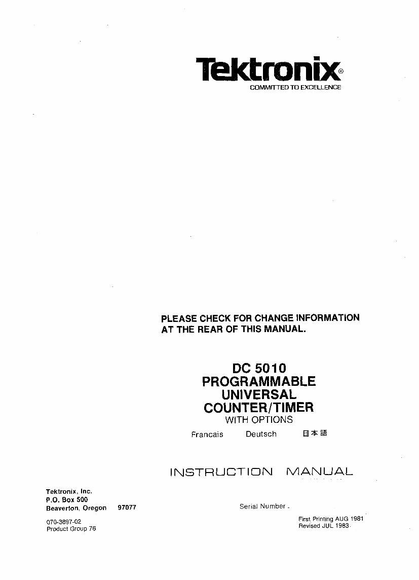
Tektronix, Inc. P.O. Box 500 Beaverton, Oregon 97077 070-3897-02 Product Group 76 COMMITTED TO EXCELLENCE PLEASE CHECK FOR CHANGE INFORMATION AT THE REAR OF THIS MANUAL. DC 5010 PROGRAMMABLE UNIVERSAL COUNTER/TIMER WITH OPTIONS Francais Deutsch EE El n INSTRUCTION MANUAL Serial Number First Printing AUG 1981 Revised JUL 1983

Welcome message from author
This document is posted to help you gain knowledge. Please leave a comment to let me know what you think about it! Share it to your friends and learn new things together.
Transcript
Tektronix, Inc. P.O. Box 500 Beaverton, Oregon 97077
070-3897-02 Product Group 76
COMMITTED TO EXCELLENCE
PLEASE CHECK FOR CHANGE INFORMATION AT THE REAR OF THIS MANUAL.
DC 5010 PROGRAMMABLE
UNIVERSAL COUNTER/TIMER
WITH OPTIONS
Francais Deutsch EE El n
INSTRUCTION MANUAL
Serial Number
First Printing AUG 1981 Revised JUL 1983
Copyright @ 1981, 1983 Tektronix, lnc. All rights reserved. Contents of this publication may not be reproduced in any form without the written permission of Tektronix, Inc.
Products of Tektronix, Inc. and its subsidiaries arecovered by U.S. and foreign patents and/or pending patents.
TEKTRONIX, TEK, SCOPE-MOBILE, and are reg- istered trademarks of Tektronix, I nc.
Printed in U.S.A. Specification and price change privileges are reserved.
Copyright @ 1981, 1983 TEKTRONI X INC.Tous droits reserves. Le contenu de ce manuel ne peut etre reproduit sous quelque for- me que ce soit sans I'accord de Tektronix Inc.
Tous les produits TEKTRONIX sont brevetes US et Etranger et les logotypes TEKTRONI X, TEK SCOPE MOB1 LE, sont deposes .
lmprime aux USA. TEKTRONI X se reserve le droit de modifier : caracteristiques et prix dans le cadre de d6veloppements techno- logiques.
Copyright O 1981, 1983 durch Tektronix, Inc. Alle Rechte vorbe- halten. Der lnhalt dieser Publikation dad ohne Gienehmigung von Tektronix, Inc. nicht weitergegeben werden.
Produkte von Tektronix, Inc. und seinen Tochtergesellschaften sind durch US- und Auslandspatente undloder schwebende Patente abgedeckt.
TEKTRONIX, TEK, SCOPE-MOBILE und Warenzeichen von Tektronix, Inc.
Gedruckt in U.S.A. Spezifikations- und Preisanderungen bleiben vorbehalten.
TEKTRONIX, TEK, SCOPE-MOBILE,
( i f 3 t- a = 3 ~ + i m ~ P $ ~ ~ ~ T - i t o
INSTRUMENT SERIAL NUMBERS
Each instrument has a serial number on a panel insert, tag, or stamped on the chassis. The first number or letter designates the country of manufacture. The last five digits of the serial number are assigned sequentially and are unique to each instrument. Those manufactured in the United States have six unique digits. The country of manufacture is identified as follows:
BOO0000 Tektronix, Inc., Beaverton, Oregon, USA
100000 Tektronix Guernsey, Ltd., Channel Islands
200000 Tektronix United Kingdom, Ltd., London
300000 Sony/Tektronix, Japan 700000 Tektronix Holland, NV, Heerenveen,
The Netherlands
LANGUAGES
. . . . . . . . . . . . . . . . . . . . . . . INSTRUCTIONS D'UTILIZATION
BEDIENUNGSALLEITUNG . . . . . . . . . . . . . . . . . . . . . . . . . . . . . . . . . . . . . . . . . . . . . . . . . . . . . .
TABLE OF CONTENTS Page
LIST OF ILLIUSTRATIONS .................... iv OPERATORS SAFETY SUMMARY ............. v SERVICE SAFETY SUMMARY ................. vii
Section 1 SPECIFICATION Instrument Description . . . . . . . . . . . . 1-1 Instrument Options . . . . . . . . . . . . . . . 1-1
. . . . . . . . . . . . Standard Accessories 1-1 Performance Conditions . . . . . . . . . . . 1-1 Safety Certification . . . . . . . . . . . . . . . 1-1 Electrical Characteristics . . . . . . . . . . 1-2 Miscellaneous . . . . . . . . . . . . . . . . . . . 1-1 2 Environmental . . . . . . . . . . . . . . . . . . . 1-1 2 Physical Characteristics . . . . . . . . . . . 1-1 3
Section 2 OPERATING INSTRUCTIONS Introduction . . . . . . . . . . . . . . . . . . . . . 2-1 Preparation For Use . . . . . . . . . . . . . . 2-1 Front Panel Operation . . . . . . . . . . . . 2-2
. . . . . . OPERATORS FAMILIARIZATION 2-7 Introduction . . . . . . . . . . . . . . . . . . . . . 2-7 Input Considerations . . . . . . . . . . . . . 2-7 Measurement Considerations . . . . . . . 2-8
Page
. . . . . . . . . . . Measurement Examples 2-9
. . . . . . . . . . . . . . . . . . PROGRAMMING 2-16 . . . . . . . . . . . . . . . . . . . . . Introduction 2-16 . . . . . . . . . . . . . . . . . . . . . Commands 2-18
Functional Command List . . . . . . . . . . 2-18 . . . . . . . . . . . Detailed Command List 2-20
Messages and Communication . . . . . . . . . . . . . . . . . . . . . . . Protocol 2-40
. . . . . . . . Status and Error Reporting 2-44 Sending Interface Control Messages . 2-46
. . . . . . . . . . . . . . . Example Programs 2-46
. . . . . . . . . . . . . . . Programming Hints 2-48
Chapitre 2 INSTRUCTIONS D'UTILISATION ................................................... lntroduction
Preparation .................................................... ................... Utilisation du panneau avant ................... Procedure de familiarisation
Introduction .............................................. Conditions d'entree ...............................
........................... Conditions de mesure Exemples de mesure .............................
Programmation ............................................. Introduction ..............................................
REV DEC 19812
TABLE OF CONTENTS (cont)
Commandes .............................................. Liste detaillee des commandes .......... Messages et protocole de communication ........................................
.......... Indications d'etats et d'erreurs Transmission de messages de
............................ contr6le de I'interface .................... Exemples de programmes .................. Apercus de programmation
Page
2-1 8 2-1 9
2-40 2-44
2-46 2-46 2-48
Seite
Abschnitt 2 BEDIENUNGSANLEITUNG Einfuhrung ...................... 2-1 Vorbereitende Hinweise . . . . . . . . . 2-1 Bedienung von der Frontplatte .............. 2-2
BEDIENUNGSHINWEISE ............ 2-7 Einfuhrung ...................... 2-7 Eingange ........................ 2-7 Messungen ...................... 2-8 MeObeispiele .................... 2-9
PROGRAMMIERUNG ............... 2-1 6 Einfuhrung ...................... 2-1 6 Befehle .......................... 2-18 Liste der Funktionsbefehle ...... 2-1 8 Detaillierte Liste der Befehle ..... 2-20 Mitteilungen und Kommunikation .................. 2-40 Status- und Fehleranzeige ....... 2-44 Interface Steuermitteilungen .... 2-46 Programm beispiele .............. 2-46 Programmierungshinweise ...... 2-48
I W A R N I N G 1
THE FOLLOWING SERVICING INSTRUCTIONS ARE FOR USE BY QUALIFIED PERSONNEL ONLY . TO AVOID PERSONAL INJURY. DO RIOT PER- FORMANYSERVICING OTHER THAN THATCON- TAINED IN OPERATING INSTRUCTIONS UNLESS YOU ARE QUALIFIED TO DO SO .
Page ' -\
Section 3 THEORY OF OPERATION BLOCK DIAGRAM DESCRIPTION . . . . 3-1
Detailed Circuit Description . . . . . . . . 3-3
Section 4 CALIBRATION PERFORMANCE CHECK PROCEDURE
Introduction . . . . . . . . . . . . . . . . . . . . . 4-1 Calibration Interval . . . . . . . . . . . . . . . 4-1 Service Available . . . . . . . . . . . . . . . . 4-1 Test Equipment Required . . . . . . . . . . 4-1 PRELIMINARY CONTROL SETTINGS . . . . . . . . . . . . . . . . . . . . . 4-1 Check Oscillator Frequency (Standard Timebase) . . . . . . . . . . . . . 4-1 Check Time Base Oscillator Frequency (Option 01) . . . . . . . . . . . . . . . . . . . . . 4-1 Check The Trigger Level CH A and CH B Accuracy . . . . . . . . . . . . . . 4-3 Check lnput Impedance: 50 Q. a 3%; 1 MQ. +lOh . . . . . . . . . . . . . . . . . . . . 4-4 Check the Arming lnput Pulse
v Response a100 ns ( H a2.4 V. 'L ~ 0 . 4 V ) . . . . . . . . . . . . . . . . . . . . . . . . 4-5 - Check lnput Capacitance: 23 pF. a 10% . . . . . . . . . . . . . . . . . . . 4-6
FlEV DEC 1982
TABLE OF CONTENTS (cont) Page
Section 4 C:ALIBRATION (cont)
Check RISEIFALL lnput Impedance: 50 Q. + 3%. 1 MQ. 500 kQ. + 2%
. . . . . (60 MHz sinewave at high level) 4-8 Check the lnput Sensitivity: XI Attenuator. DC and AC Coupled;
. . . . . . . . . . . . . . . 50 Q 4 7 0 mV p-p: 4-8 Check the lnput Sensitivity: X5 Attenuation. DC and AC Coupled; 50 Q ~ 3 5 0 mV p-p . . . . . . . . . . . . . . . 4-9 Check lnput Sensitivity: XI Attenuation. DC and AC Coupled;
. . . 1 MQ. ~ 4 2 mV p-p at ~ 3 0 0 MHz 4-1 0
Check lnput Sensitivity: X5 Attenuation. DC and AC Coupled;
. . . . . 1 MQ. ~ 3 5 0 mV at ~ 2 0 0 MHz 4-10 Check lnput Sensitivity: X I Attenuation. DC and AC Coupled;
. . . . . . 1 MQ. ~ 7 0 mV at ~ 2 0 0 MHz 4-1 1 Check lnput Sensitivity: X5 Attenuation. DC and AC Coupled; 1 MQ. ~ 2 1 0 mV p-p at ~ 3 0 0 MHz . . 4-1 1 Check Width A: Range G 4 ns; Minimum Time Stop Edge To
. . . . . . . . . . . . . . Start Edge. ~ 8 . 5 ns 4-1 2 Check EVENTS B DUR A Minimum Pulse Width.
. . . . . . . . . . . . . ~ 4 . 0 n s a n d ~ 8 . 5 n s 4-12 Check Delay Mismatch: Int. G2 ns . . 4-12 Check Minimum TIME B -, A. ~ 1 2 . 5 ns . . . . . . . . . . . . . . . . . . . . . . 4-12
. . . . . . . . Check Probe Compensation 4-1 4 Check the GPlB Bus
. . . . . . . . . . . . Through the Controller 4-1 4 ADJUSTMENT PROCEDURE
Introduction . . . . . . . . . . . . . . . . . . . . . 4-1 5 Test Equipment Required . . . . . . . . . . 4-1 5 PRELIMINARY CONTROL SETTINGS . . . . . . . . . . . . . . . . . . . . . 4-1 5 Preparation . . . . . . . . . . . . . . . . . . . . . 4-1 5 Check the Digital Board + 12 V Accuracy ( + 2%) . . . . . . . . . . . . . . . . . 4-1 5 Check the Digital Board -1 2.2 V Accuracy ( + 2%) . . . . . . . . . . . . . . . . . 4-1 5 Check the Digital Board +5 V Accuracy ( k 2%) . . . . . . . . . . . . . . . . . 4-1 5 Check the Digital Board +2.5 V (V,) Accuracy ( + 1 %) . . . . . . . . . . . . . 4-1 5
Page Section 4 CALIBRATION (cont)
Check the Analog Board +5 V . . . . . . . . . . . . . . . . . Accuracy ( + 2%) 4-16
Check the Analog Board + 12 V . . . . . . . . . . . . . . . . . Accuracy (+ 2%) 4-16
Check the Analog Board -5 V Accuracy ( + 5%) . . . . . . . . . . . . . . . . . 4-16 Adjust the Standard Timebase Accuracy. C1521. Osc Adj . . . . . . . . . 4-16 Adjust the Optional Timebase Accuracy. Y1 530 . . . . . . . . . . . . . . . . 4-16 Adjust R1205. A Off. and R1207. B Off . . . . . . . . . . . . . . . . . . . . . . . . . . 4-16 Adjust R1206. B Rng. and R1204. A Rng . . . . . . . . . . . . . . . . . . . . . . . . . 4-17 Adjust AT1 505 (Channel A) and AT1 533 (Channel B). Attenuator Compensation . . . . . . . . . 4-17 Adjust AT1 505 (Channel A) and AT1 533 (Channel B). Attenuator Input Capacitance . . . . . . . . . . . . . . . . 4-18 Adjust ECL Threshold Reference . . . . 4-18
Section 5 MAINTENANCE Static-Sensitive Components . . . . . . . 5-1 Test Equipment . . . . . . . . . . . . . . . . . . 5-1 Circuit Board Removal and Replacement . . . . . . . . . . . . . . . . 5-2 Magnetic Latch Relays . . . . . . . . . . . . 5-2 Cleaning Instructions . . . . . . . . . . . . . 5-4 Obtaining Replacement Parts . . . . . . . 5-4 Ordering Parts . . . . . . . . . . . . . . . . . . 5-5 Soldering Techniques . . . . . . . . . . . . . 5-5 Interconnecting Pins . . . . . . . . . . . . . . 5-5 Square Pin Assemblies . . . . . . . . . . . . 5-5 Bottom Entry and Side Entry Circuit Board Pin Sockets . . . . . . . . . 5-6 Multipin Connectors . . . . . . . . . . . . . . 5-6
. . . . REAR INTERFACE CONNECTORS 5-7 Functions Available at Right Rear Interface Connector (PI 600) . . . . . . . 5-7 Functions Available at Left Rear Interface Connector (P1820) . . . . . . . . . . . . . . . . . . . . . . . . 5-8 GPlB Rear lnterface Connector (P1001) . . . . . . . . . . . . . . . . . . . . . . . . 5-8 Functions Available at GPlB Connector . . . . . . . . . . . . . . . . . . . . . . 5-8
REV DEC 1982 iii
TABLE OF CONTENTS (cont) Page
Section 5 MAINTENANCE (cont)
BUS ADDRESS AND MESSAGE TERMINATOR SWITCHES. . . . . . . . . . . 5-8
Setting the GPlB Address Switches.. . . . . . . . . . . . . . . . . . . . . . 5-8 Setting the InputIOutput Message Terminator Switch. . . . . . . . 5-9
DIAGNOSTICS . . . . . . . . . . . . . . . . . . . . 5-1 0 Introduction. . . . . . . . . . . . . . . . . . . . . 5-1 0 Equipment Required. . . . . . . . . . . . . . 5-1 0 Adjustment and Test Point Locations . . . . . . . . . . . . . . . . . . . . . . 5-1 0 Self Test . . . . . . . . . . . . . . . . . . . . . . . 5-1 0 Test Function . . . . . . . . . . . . . . . . . . . 5-1 1
TROUBLESHOOTING. . . . . . . . . . . . . . . 5-1 1
SIGNATURE ANALYSIS. . . . . . . . . . . . . 5-1 1 Introduction. . . . . . . . . . . . . . . . . . . . . 5-1 1 Internal Signature Analysis. . . . . . . . . 5-1 1 Kernel Signature Analysis . . . . . . . . . 5-1 1 Selected Components (R1307 and Rl326) . . . . . . . . . . . . . . . . . . . . . . . . 5-1 3
Section 6 OPTIONS OPTION 01 . . . . . . . . . . . . . . . . . . . . . . . 6-1
Section 7 REPLACEABLE ELECT RlCAL PARTS
Section 8 DIAGRAMS AND ILLUSTRATIONS
Section 9 REPLACEABLE MECHANICAL PARTS
REV DEC 1982
"--
Fig. No.
2-1 2-2
2-3 2-4
2-5
2-6
2-7
2-8 2-9 2-1 0 2-1 1 4- 1 4-2 4-3 4-4 4-5
L
4-6 5-1 5-2
5-3 5-4 5-5
LIST OF ILLUSTRATIONS
Page DC 501 0 Programmable Universal Coutnter/Timer Plug-in installation and removal . . . . . . . . . 2-2 DC 501 0 front panel display, controls and connectors.. . . . . . . . . . . . . . . . . . . . . . . . . 2-3 Advantages in signal attenuation . . . . . . . . 2-8 Typiical triggering levels and sources of trig- geri~ng errors . . . . . . . . . . . . . . . . . . . . . . . . 2-1 0 Measurement examples for WIDTH A and TIME A + B . . . . . . . . . . . . . . . . . . . . . . . . . 2-1 1 Measurement example for synchronous in- put signals. . . . . . . . . . . . . . . . . . . . . . . . . . 2-1 1 Measurement example, EVENTS B DURING A. . . . . . . . . . . . . . . . . . . . . . . . . . 2-12 Measurement example for risetime. . . . . . . 2-13 Examples of arming . . . . . . . . . . . . . . . . . . 2-1 5 Quick command list. . . . . . . . . . . . . . . . . . . 2-1 7 ASCII and IEEE 488 (GPIB) code chart . . . 2-41 Performance Check setup for step 3 . . . . . 4-3 Performance Check setup for steps 4 and 7 4-4 Performance Check setup for steps 5 and 14 4-5 Performance Check setup for step 6 . . . . . 4-7 Performance Check setup for steps 8, 9, 10, 11,12,and13 . . . . . . . . . . . . . . . . . . . . . . . 4-9 Performance Check setup for step 15 . . . . 4-1 3 Circuit boards removal and replacement . . 5-3 Method of removing magnetic latch relay
. . . . . . . . . . . . . . . . . . . . . . . . . armature.. 5-4 Typ~ical square pin assembly. . . . . . . . . . . . 5-5 Bottom entry circuit board pin socket . . . . 5-6 Orientation and disassembly of multipin conmectors.. . . . . . . . . . . . . . . . . . . . . . . . . 5-6
Fig. No. Page 5-6 Right rear interface connector assignments 5-7 5-7 Left rear interface connector assignments . 5-8 5-8 Rear GPIB interface connector assignments 5-8 5-9 Bus address and message terminator
switches.. . . . . . . . . . . . . . . . . . . . . . . . . . . 5-9 . . . . 5-1 0 Kernel signature analysis connections 5-12
NOTE
The following illustrations are located in the diagrams section at the rear of this manual.
Analog Board (A1 2). Auxiliary Board (A1 8). Adjustment setup for steps 10 and 11. Adjustment setup for steps 12 and 13. General troubleshooting flow chart. lnternal signature analysis "A" (Digital Board). lnternal signature analysis "B" (Digital Board). lnternal signature analysis (Analog Board). lnternal signature analysis (Auxiliary Board). Kernel signature analysis (Digital Board). Kernel signature analysis (GPIB Board). Analog board (A1 2). Digital board (A1 6). Auxiliary board (A1 8). Display board (A1 0). GPIB board (A14).
REV DEC 1982
The general safety information in this part of the summary is for both operating and servicing personnel. Specific warnings and cautions will be found throughout the manual where they apply, but may not appear in this summary.
TERMS
In This Manual
CAUTION statements identify conditions or practices that could result in damage to the equipment or other property.
WARNING statements identify conditions or practices that could result in personal injury or loss of life.
As Marked on Equipment
CAUTION indicates a personal injury hazard not immediate- ly accessible as one reads the marking, or a hazard to prop- erty including the equipment itself.
DANGER indicates a personal injury hazard immediately ac- cessible as one reads the marking.
SYMBOLS
In This Manual
This symbol indicates where applicable cau- tionary or other information is to be found.
As Marked on Equipment
DANGER - High voltage.
@ Protective ground (earth) terminal.
ATTENTION - refer to manual.
Power Source
This product is intended to operate from a power module whose power source will not apply more than 250 volts rms between the supply conductors or between either supply conductor and ground. A protective ground connection by way of the grounding conductor in the power cord is essen- tial for safe operation.
Grounding the Product
This product is grounded through the grounding conductor of the power module power cord. To avoid electrical shock, plug the mainframe power cord into a properly wired recep- tacle before connecting to the product input or output termi- nals. A protective ground connection by way of the grounding conductor in the power cord is essential for safe operation.
Danger Arising From Loss of Ground
Upon loss of the protective-ground connection, all accessi- ble conductive parts (including knobs and controls that may appear to be insulating) can render an electric: shock. ----
Use the Proper Fuse
To avoid fire hazard, use only the fuse of correct type, volt- age rating and current rating as specified in the parts list for your product.
Refer fuse replacement to qualified service personnel.
Do Not Operate in Explosive Atmosphe!res
To avoid explosion, do not operate this product in an explo- sive atmosphere unless it has been specifically certified for such operation.
Do Not Operate Without Covers
To avoid personal injury, do not operate this product with- out covers or panels installed. Do not apply power to the plug-in via a plug-in extender.
ADD DEC 1982
SERVICE SAFETY SUMMARY
FOR QUA LlFlED SERVICE PERSONNEL ONLY
Refer also to the preceding Operators Safety Summary.
Do Not Service Alone Power Source
Do not perform internal service or adjustment of this prod- This product is intended to operate in a power module con- uct unless another person capable of rendering first aid and nected to a power source that will not apply more than resuscitation is present. 250 volts rms between the supply conductors or between
either supply conductor and ground. A protective ground connection by way of the grounding conductor in the
Use Care When Servicing With Power On mainframe power cord is essential for safe operation.
Dangerous voltages may exist at several points in this prod- uct. To avoid personal injury, do not touch exposed connec- tions and components while power is on.
Disconnect power before removing protective panels, sol- dering, or replacing components.
REV DEC 1982 vii
RECAPITULATIF DES CONSIGNES DE SECURITE
Termes utilis6s dans ce manuel Les paragraphes intitules ATTENTION identifient les cir- constances ou operations pouvant entraher la deterioration de I'appareil ou de tout autre equipement.
Les paragraphes intitules AVERTISSEMENT indiquent les circonstances dangereuses pour I'utilisateur (danger de mort ou risque de blessure).
Reperes grav6s sur I'apparei l CAUTION (ATTENTION) : ce mot identifie les zones de ris- que de blessure non perceptibles immediatement ou un risque eventuel de deterioration de I'appareil.
DANGER (DANGER) : ce mot indique les zones de risque immediat pouvant entraiiner blessures ou mort.
Syrnboles graves sur If6quipement
DANGER - Haute tension
@ Borne de masse de protection (terre)
ATTENTION - se reporter au manuel
Source d'alimentation L'appareil est coqu pour fonctionner a partir d'une source d'alimentation maximale de 250 V efficaces entre les conduc- teurs d'alimentation ou entre chaque conducteur d'alimenta- tion et la terre. Pour utiliser I'appareil en toute securite, une connexion 5 la masse, realisee au moyen d'un conducteur prevu dam le cordon d'alimentation, est indispensable.
Mise a la masse de I'appareil Une fois installe dans le chissis d'alimentation, I'appareil est relie a la masse a I'aide d'un conducteur du cordon d'alimen- tation. Pour eviter tout choc electrique, inserer la prise du cordon d'alimentation dans une prise de distribution corres- pondante avant de connecter I'entree ou les sorties de I'appa- reil. Pour utiliser I'appareil en toute securite, une connexion a la masse realisee au moyen d'un conducteur prevu dans le cordon d'alimentation, est indispensable.
Danger provoqu6 par la coupure de connexion de masse En cas de coupure de la connexion de masse, tous les elements conducteurs accessibles (y compris boutons ot commandes apparaissant isolants) peuvent provoquer un choc electrique.
Utiliser le cordon d'alimentation appropri6 N'utiliser que le cordon d'alimentation et la prise recom- mandes pour votre appareil. Utiliser un cordon d'alimen- tation en parfait &at. Seul, un personnel qualifie peut proceder a un changement de cordon et prises.
Utiliser le fusible approprie Pour eviter tout risque d'accident (incendie ...) n'uti liser - - que le fusible recommande pour votre appareil. Le fusible de remplacement doit toujours correspondre au fusible remplace : rneme type, meme tension et merne courant. Un remplacement de fusible ne doit &re effectue que par un personnel qualifie.
Ne pas utiliser I'appareil en atmosphere explosive Pour eviter toute explosion, ne pas utiliser cet appareil dans une atmosph6re de gaz explosifs.
Ne pas dhonter les capots Pour eviter toute blessure, ne pas utiliser cet appareil sans capots ou panneaux. Ne pas alimenter le tiroir a travers un prolongateur.
viii REV DEC 1982
CONSIGNES D E SECURITE
UNIQUEMENT DESTINEES AU PERSONNEL DE MA1 NTENANCE
Ne depannez pas seul Ces consignes s'adressent exclusivement B un personnel qua- lifie. II est kgalement indispensable de se reporter aux consi- gnes de secu~rite precbdantes. Toute intervention interne ou reglage doit s'effectuer en presence d'une autre personne ca- pable d'assurer les premiers secours en cas de danger.
Agir avec precaution lorsque I'appareil est sous ten- sion Des potentiels dangereux existent en differents points de I'appareil. Pour eviter toute blessure, ne pas intervenir sur les connexions et les composants alors que I'appareil est sous
tension. Dbbrancher I'alimentation avant le demontage des panneaux, soudure ou remplacement de composants.
Source d'alimentation Cet appareil est conp pour fonctionner 2 partir d'une sour- ce d'alimentation qui n'applique pas plus de 250 V efficaces entre les conducteurs d'alimentation ou entre un conduc- teur e t la masse. Pour utiliser I'appareil en toute s6curit6, une connexion B la masse realisee au moyen d'un conduc- teur prevu dans le cordon d'alimentation est indispensable.
ADD DEC 1982

SICHERHEITSANGABEN F~JR DEN ANWENDER -
Die allgemeinen Sicherheitsinformationen in diesem Teil der Angaben dienen dem Anwender- und Serviceperso- nal. Spezielle Warnungen und Hinweise sind uberall im Handbuch zu finden, mussen jedoch in diesen Angaben nicht erscheinen.
In diesem Handbuch VORSICHTSHINWEISE erlautern Bedingungen, die zur Zerstorung des Gerates oder anderer Gegenstande fuh- ren konnen.
WARNUNGSHINWEISE erlautern Bedingungen, die zu Personenschaden fuhren konnen oder lebensgefahr- lich sind.
Markierungen auf dem Gerat CAUTION - VORSlCHTweist darauf hin, daR durch zufalli- ges Beruhren an einer nicht unmittelbar zuganglichen Stelle Personenschaden entstehen kann, oder Schaden am Gerat selbst.
DANGER - GEFAHR weist darauf hin, daR durch zufalliges Beruhren an einer zuganglichen Stelle Personenscha- den entstehen kann.
In diesem Handbuch Dieses Symbol zeigt an, wo Vorsicht walten A zu lassen ist, oder wo lnformationen zu finden sind.
Markierungen auf dem Gerat
f GEFAHR - Hochspannung.
@ Schutzerdungskontakt.
ACHTUNG - beziehen Sie sich auf das Handbuch.
Netzspannungsversorgung Die Betriebsspannung fur dieses Gerat darf 250 Veff nicht uberschreiten und ist an die Versorgungsleitungen bzw. an eine Versorgungsleitung und Masse anzulegen. Inner- halb des NetzanschluRkabels mu8 ein Schutzleiter vor- handen sein, der mit Geratemasse verbunden ist.
MasseanschluB des Gerates Dieses Gerat wird uber den Schutzleiter der Versor- gungseinheit mit Erdpotential verbunden. Zur Vermei-
dung von elektrischen Schlagen vor der Beschaltung der Ein- und Ausgange ist der Netzstecker in eine korrekt ver- drahtete Steckdose einzustecken. Verwer~den Sie den Schutzleiter nicht als einzige Verbindung zwischen zwei der mehreren Geraten. Zur Vermeidung von elektri- schen Schlagen sind die Gerate untereinander mit sepa- raten Leitungen zu verbinden.
Gefahr durch fehlende Schutzerde Durch eine fehlende Schutzerde konnen alle beruhr- baren, leitenden Teile (einschlieBlich Knopfe und andere Bedienungselemente, die isoliert sind) einen elektri- schen Schlag bei der Beruhrung auslosen.
Vetwendung eines richtigen Netzkabebls Verwenden Sie nur Netzkabel, die fur die Versorgungs- einheit geeignet sind und die sich in gutem Zustand be- finden.
Fur detaillierte lnformationen uber Kabel und Stecker be- ziehen Sie sich bitte auf Abbildungen innerhalb des Handbuches.
Ein Austausch von Kabeln und Steckern isit nur von ge- schultem Personal vorzunehmen. -
Vetwendung einer richtigen Sicherung Zur Vermeidung von Brandschaden sind nur Sicherun- gen zu verwenden, die in den Teilelisten dieses Gerates aufgefuhrt sind und die in Spannungs- unld Stromwert entsprechend sind.
Ersatz von Sicherungen ist nur von geschultem Personal vorzunehmen.
Arbeiten Sie nicht in explosiver Umgebung Zur Vermeidung von Explosionen ist die Inbetriebnahme dieses Gerates in explosiver Umgebung zu unterlassen, wenn das Gerat nicht dafijr geeignet ist.
Entfernen Sie keine Gehauseabdeckungen Zur Vermeidung von Personenschaden sind keine Ge- hauseteile zu entfernen. Auch ist das Gerat ohne Gehau- se nicht in Betrieb zu nehmen.
Arbeiten Sie nicht ohne Gehauseabdelckung Zur Vermeidung von Personenschaden ist das Gerat - nicht ohne Gehause in Betrieb zu nehmen. Dler Einschub sollte nicht uber einen Verlangerungsadaptler betrieben werden.
A'DD DEC 1982
SICHERHEITSANGABEN FLJR DEN SERVICE NUR F ~ J R GESCHULTES PERSONAL
Beziehen Sie sich auch auf die vorangehenden Sicherheitsangaben fijr den Anwender.
Netzspannungsversorgung Lassen Sie besondere Vorsicht waken, wenn Die Betriebsspannung fur dieses Gerat darf 250 V,,, nicht
an einctm 'liter Spannung stehenden Gerat uberschreiten und ist an die Versorgungsleitungen bzw. arbeiten an eine Versorgungsleitung und Masse anzulegen. Inner- An verschiedenen Stellen im Gerat liegen hohe und damit halb des NetzanschluBkabels mu6 ein Schutzleiter vor- gefahrliche Spannungen. Zur Vermeidung von Personen- handen sein, der mit Geratemasse verbunden ist.
ADD DEC 1982
xii ADD DEC 1982
ADD DEC 19821 xiii
The DC 5010 Programmable Universal CounterITimer Plug-in Unit.
xiv ADD DEC 1982
Section 1 -DC 50 10
SPECIFICATION lnstrument Description
The Tektronix DC 5010 is a programmable universal counterltimer plug-in. It features reciprocal frequency, Peri- od, Ratio, and Events B During A measurements to 350 MHz. For timing measurements, the time interval, width, risetime and falltime functions feature 3.1 25 nsec sin- gle-shot resolution. For these measurements, averaging and identical A and B channels provide increased accuracy. Also included is a time manual mode, as well as three 350 MHz totalize modes (A, A+ B, and A- B). The DC 501 0 also has
Standard Accessories
1 Instruction Manual
1 Reference Guide
1 Cable Assembly, bnc-to-slide on connector
NOTE an auto-trigger feature, a probe-compensation feature, an auto averages function, and an extensive set of automatic Refer to the tabbed Accessories page at the rear of
power-up sell' tests. this manual for more information.
The DC 51010 is an IEEE 488 (GPIB) Digital Interface programmablle counter that allows any manually selectable function or mode to be operated over the GPlB bus, includ- performance Conditions ing all input conditioning controls.
The limits stated in the Performance Requirements col- umns of the following tables are valid only if the DC 5010
The IEEE standard identifies the interface functions of an has been calibrated at an ambient temperature between instrument or) the GPlB in terms of interface function sub- +20oC and +300c and is operating at an ambient tern- sets. The subsets are defined in the standard. The subsets perature between ooc and +500~ , unless otherwise that apply to the DC 501 0 are listed in Table 1-5 at the end of this section.
lnformation given in the Supplemental lnformation and The DC 5010 has a DVM mode that reads Out the Description columns of the following tables is provided for nel A and channel B trigger level voltages. Shaped outputs
and an arming input are available at the front panel. Also user information only and should not be interpreted as Per-
available at the front panel is a signal for use with the probe formance Check requirements.
compensation function.
The DC 5010 must be operated or stored in an environ-
The operating modes and front-panel settings of the ment whose limits are described under Environmental
DC 501 0 can be set and read by programming mnemonics Characteristics.
set to it in ASCII code over the bus. The DC 5010 connects to the bus when installed in a GPIB-compatible TM 5000- Series power module. Allow at least 30 minutes warm-up time for operation to
specified accuracy, 60 minutes after storage in a high- humidity environment.
The DC 50110 can be equipped with an optional, oven- controlled, 10 MHz crystal oscillator to obtain an even more stable and precise internal time base.
Instrument Options Safety Certification
Option 01 replaces the internal 10 MHz time base (clock) This instrument is listed with Underwriters Laboratories circuit with a self-contained proportional temperature con- Inc. under UL Standard 1244 (Electrical and Electronic Mea- trolled oven oscillator for increased accuracy and stability. suring and Testing Equipment).
REV MAY 1982
Table 1-1 ELECTRICAL CHARACTERISTICS rl
lnput Frequency Range Coupling
DC AC
Characteristics
lnput Sensitivity
Sinewave
Coupling Attenuation
CHANNEL A and CHANNEL B INPUTS (also see RiseIFall MEASUREMENT MODE INPUT SPECIFICATION)
Performance Requirements
Dynamic Range Attenuation
XI
Supplemental Information
Trigger Level Range Attenuator
X1
Trigger Level Accuracy
50 Q 1 MQ >O to a350 MHz >O to a300 MHz 100 kHz to a350 MHz 16 Hz to a300 MHz
50 Q (Term low) 1 MQ (Term high)
~ 2 5 mV rms* ~ 2 5 mV rms to 200 MHz ~ 4 2 mV rrns from 200 MHz to 300 MHz
~ 7 0 mV p-p pulse* ~ 7 0 mV p-p pulse ( t 2 0 0 MHz)
~ 1 2 5 mV rms* GI 25 mV rms to 200 MHz ~ 2 1 0 mV rrns from 200 MHz to 300 MHz
~ 3 5 0 mV p-p pulse* ~ 3 5 0 mV p-p pulse
~ 2 5 mV rms* ~ 2 5 mV rms to 200 MHz 42 mV rrns to 300 MHz
+ 3 d B a t ~ 1 0 0 k H z + 3 d B a t ~ 1 6 H z ~ 7 0 mV p-p pulse ~ 7 0 mV p-p pulse
(<200 MHz)
~ 1 2 5 mV rms* ~ 1 2 5 mV rms to 200 MHz 21 0 mV rrns to 300 MHz
+ 3 d B a t ~ 1 0 0 k H z + 3 d B a t ~ 1 6 ' ~ z ~ 3 5 0 mV p-p pulse ~ 3 5 0 mV p-p pulse
( ~ 2 0 0 MHz)
+2% of reading for a dc input voltage + 40 mVx atten.
1 MQ performance is from a 25 Q source impedance.
Typical sensitivity is 50 mV p-p +20 mV.
70 mV p-p to 4 V p-p
350 mV p-p to 20 V p-p
n approximately 4 mV steps.
n approximately 20 mlV steps.
rrigger level is calibrated n + slope and is firm,ware :ompensated in - slc~pe.
*O°C to 40°C; sensitivity decreases by 31 % for 40°C to 50°C.
REV JUL 1983
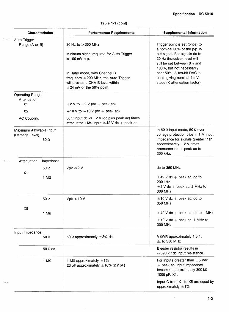
Table 1-1 (cont)
Characteristics
Auto Trigger Range (A or B)
Operating Range Attenuation
X1
X5
AC Coupling
Maximum Alilowable lnput (Damage Level)
50 Q
-- Attenuation Impedance
lnput Imped'ance 50 Q
Performance Requirements
20 Hz to a350 MHz
Minimum signal required for Auto Trigger is 100 mV p-p.
In Ratio mode, with Channel B frequency 2200 MHz, the Auto Trigger will provide a CHA B level within k 24 mV of the 50% point.
+ 2 V to -2 V (dc + peak ac)
+10 V to -10 V (dc + peak ac)
50 Q input dc G a 2 V (dc plus peak ac) times attenuator 1 MQ input ~ 4 2 V dc + peak ac
Vpk ~2 V
Vpk 4 0 V
50 Q approximately + 3% dc
1 MQ approximately + l0/0
23 pF approximately a 10% (2.2 pF)
Supplemental Information
Trigger point is set (once) to a nominal 50% of the p-p in- put signal. For signals dc to 20 Hz (inclusive), level will still be set between 0% and 1 0O0/0, but not necessarily near 50%. A ten-bit DAC is used, giving nominal 4 mV steps (X attenuation factor).
In 50 Q input mode, 50 Q over- voltage protection trips in 1 M input impedance for signals greater than approximately -t 2 V times attenuator dc + peak ac to 200 kHz.
dc to 350 MHz
+ 42 V dc + peak ac, dc to 200 kHz a 2 V dc + peak ac, 2 MHz to 300 MHz
+10Vdc + peak ac, dc to 350 MHz
+ 42 V dc + peak ac, dc to 1 MHz
+ 10 V dc + peak ac, 1 MHz to 300 MHz
VSWR approximately 1.5:1, dc to 350 MHz
Bleeder resistor results in =390 kQ dc input resistance.
For inputs greater than a 5 Vdc + peak ac, input impedance becomes approximately 300 kQ 1000 pF, XI.
lnput C from XI to X5 are equal by approximately a 1 %.
Characteristics
Table 1-1 (cont)
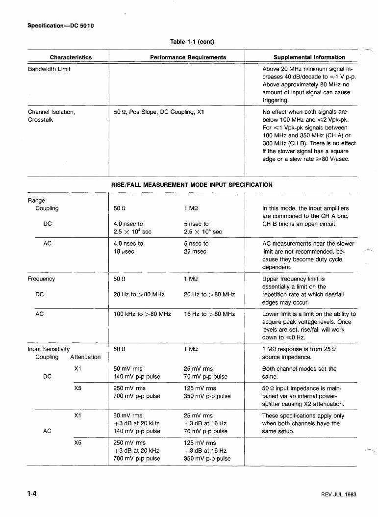
Bandwidth Limit
Performance Requirements
Channel Isolation, Crosstalk
n
Supplemental Information
Above 20 MHz minimum signal in- creases 40 dB/decade to =l V p-p. Above approximately 80 MHz no amount of input signal can cause triggering.
50 Q, Pos Slope, DC Coupling, XI No effect when both signals are below 100 MHz and ~ 1 2 Vpk-pk. For 6 1 Vpk-pk signals; between 100 MHz and 350 MHz (CH A) or 300 MHz (CH B). There is no effect if the slower signal has a square edge or a slew rate 380 Vlpsec.
RISEIFALL MEASUREMENT MODE INPUT SPECIFICATION
Range Coupling In this mode, the input amplifiers
are commoned to the CH A bnc. CH B bnc is an open circuit. 4.0 nsec to 5 nsec to
2.5 x 1 o4 sec 2.5 x l o 4 sec
4.0 nsec to 18 psec
5 nsec to 22 msec
AC measurements near the slower limit are not recommended, be- cause they become duty cycle dependent.
Frequency Upper frequency limit is essentially a limit on thle repetition rate at which riselfall edges may occur.
Lower limit is a limit on the ability to acquire peak voltage levels. Once levels are set, riselfall will work down to GO Hz.
20 Hz to >80 MHz 20 Hz to >80 MHz
100 kHz to >80 MHz 16 Hz to >80 MHz
Input Sensitivity Coupling Attenuation
1 MQ response is from 25 Q
source impedance.
50 mV rms 25 mV rms 140 mV p-p pulse 70 mV p-p pulse
Both channel modes set the same.
250 mV rms 125 mV rms 700 mV p-p pulse 350 mV p-p pulse
50 Q input impedance is main- tained via an internal power- splitter causing X2 attenuation.
These specifications apply only when both channels have the same setup.
-- - -
50 mV rms 25 mV rms +3 dB at 20 kHz +3 dB at 16 Hz 140 mV p-p pulse 70 mV p-p pulse
250 mV rms 125 mV rms +3 dB at 20 kHz +3 dB at 16 Hz 700 mV p-p pulse 350 mV p-p pulse
REV JUL 1983
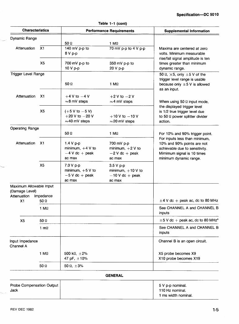
Table 1-1 (cont)
Characteristics
-- Dynamic Range
Performance Requirements Supplemental Information
50 Q 1 MQ 140 mV p-p to 70 mV p-p to 4 V p-p
8 v P-P
Attenuation X I Maxima are centered at zero volts. Minimum measurable riselfall signal amplitude is ten times greater than minimum dynamic range.
50 Q, x5 , only a 5 V of the trigger level range is usable because only 2 5 V is allowed as an input.
700 mV p-p to 350 mV p-p to 10 v p-p 20 v p-p
Trigger Level Range
Attenuation X I + 4 V t 0 - 4 V + 2 V t 0 - 2 V -8 mV steps -4 mV steps When using 50 Q input mode,
the displayed trigger level is 112 true trigger level due to 50 Q power splitter divider action.
(+5 V to -5 V) +20 V to -20 V + I 0 V to -10 V -40 mV steps -20 mV steps
Operating Range For 10% and 90% trigger point. For inputs less than minimum, 10% and 90% points are not achievable due to sensitivity. Mimimum signal is 10 times minimum dynamic range.
Attenuation X1 1.4 v p-p minimum, +4 V to -4 V dc + peak ac max
700 mV p-p minimum, +2 V to -2 V dc + peak ac max
3.5 v p-p minimum, + 10 V to -10 V dc + peak ac max
7.0 V p-p minimum, +5 V to -5 V dc + peak ac max
Maximum Allowable lnput (Damage Level) Attenuation lmpedance
X1 50 Q +4 V dc + peak ac, dc to 80 MHz
See CHANNEL A and CHANNEL B inputs
+5 V dc + peak ac, dc to 80 MHza
See CHANNEL A and CHANNEL B inputs
lnput lmpedance Channel A
Channel B is an open circuit.
X5 probe becomes X9 X1 0 probe becomes XI 9
GENERAL
Probe Compensation Output I 5 V p-p nominal. 11 0 Hz nominal. 1 ms width nominal.
Jack
REV DEC 198,2 1-5
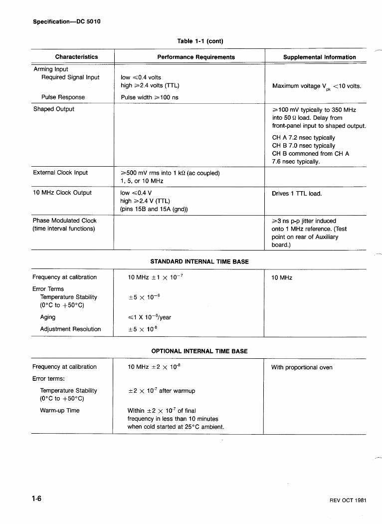
Characteristics
Arming lnput Required Signal lnput
Pulse Response
Shaped Output
External Clock lnput
10 MHz Clock Output
Table 1-1 (cont)
Performance Requirements
low ~ 0 . 4 volts high a2.4 volts (TTL)
Pulse width a 1 00 ns
a500 mV rms into 1 kQ (ac coupled) 1, 5, or 10 MHz
low ~ 0 . 4 V high 32.4 V (TTL) (pins 15B and 15A (gnd))
Phase Modulated Clock (time interval functions)
STANDARD INTERNAL TlME BASE
Frequency at calibration
Error Terms Temperature Stability (0°C to +50°C)
Aging
Adjustment Resolution
Frequency at calibration
Error terms:
Temperature Stability (0°C to +50°C)
Warm-up Time
Supplemental Information
Maximum voltage Vpk <10 volts.
a100 mV typically to :350 MHz into 50 Q load. Delay from front-panel input to shisped output.
CH A 7.2 nsec typicalky CH B 7.0 nsec typicallly CH B commoned from CH A 7.6 nsec typically.
Drives 1 TTL load.
a 3 ns p-p jitter induced onto 1 MHz reference. (Test point on rear of Auxi1ia.r~ board.)
10 MHz
OPTIONAL INTERNAL TlME BASE
10 MHz +2 x
+ 2 x 1 after warmup
Within + 2 x 1 of final frequency in less than 10 minutes when cold started at 25°C ambient.
With proportional oven
R;EV OCT 1981
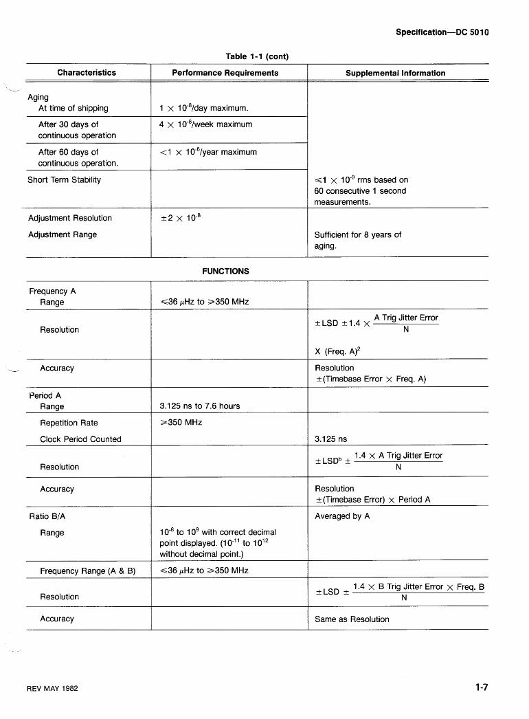
Table I -1 (cont)
Characteristics
-- Aging
At time of shipping
Performance Requirements
1 x 10-~/day maximum. I
Supplemental Information
After 30 days of continuous operation
4 x 1 week maximum
After 60 days of continuous operation.
Short Term Stability
< 1 x 1 year maximum
6 1 x 1 o-' rms based on 60 consecutive 1 second measurements.
Adjustment Resolution
Adjustment Range Sufficient for 8 years of aging.
FUNCTIONS
Frequency A Range ~ 3 6 pHz to 3350 MHz
kLSD k1.4 x A Trig Jitter Error N
X (Freq. A ) ~
Resolutioni
--
. Accuracy Resolution + (Timebase Error x Freq. A)
Period A Range 3.1 25 ns to 7.6 hours
Repetition Rate
C l ~ c k Period Counted
a350 MHz
1.4 x A Trig Jitter Error + LSDb k N
Resolution k (Timebase Error) x Period A
Accuracy
Ratio B/A
Range
Averaged by A
1 to 10' with correct decimal point displayed. (1 0-" to 1 012 without decimal point.)
~ 3 6 pHz to a350 MHz Frequency Range (A & B)
+LSD + 1.4 x B Trig Jitter Error x Freq. B N Resolutioni
Accuracy Same as Resolution
REV MAY 1982
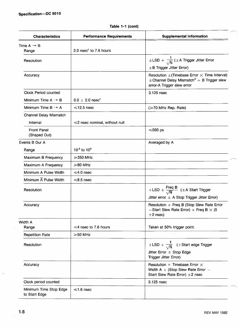
Table 1-1 (cont)
Characteristics
Time A -+ B Range
Resolution
Performance Requirements Supplemental Information
2.0 nsecC to 7.6 hours
1 a LSD + - (+ A Trigger Jitter Error fl + B Trigger Jitter Error)
Accuracy Resolution + (Timebase Error x 'Time Interval) t- Channel Delay is match^ + B Trigger slew error-A Trigger slew error
Clock Period counted - -
3.1 25 nsec
Minimum Time A - B
Minimum Time B - A =s 12.5 nsec (a70 MHz Rep. Rate)
Channel Delay Mismatch
Internal ~2 nsec nominal, without null
Front Panel (Shaped Out)
Events B Dur A
Range
Averaged by A
Maximum B Frequency 3350 MHz
Maximum A Frequency a 8 0 MHz
Minimum A Pulse Width ~ 4 . 0 nsec
Minimum A Pulse Width ~ 8 . 5 nsec
Freq ( + A Start Trigger +LSD + - fl
Jitter error a A Stop Trigger Jitter Error)
Resolution
Accuracy Resolution + Freq B (Stop Slew Rate Error -Start Slew Rate Error) + Freq B x (5 1- 2 nsec)
Width A . Range
Repetition Rate
Resolution
~4 nsec to 7.6 hours
a 5 0 MHz
Taken at 5ooh trigger point.
1 + LSD + - (+ Start edge Trigger fl
Jitter Error a Stop Edge Trigger Jitter Error)
Accuracy Resolution a Timebase Error x Width A + (Stop Slew Rate Error - Start Slew Rate Error) + 2 nsec
--
Clock period counted
Minimum Time Stop Edge to Start Edge
3.1 25 nsec -\
4 . 6 nsec
REV MAY 1982
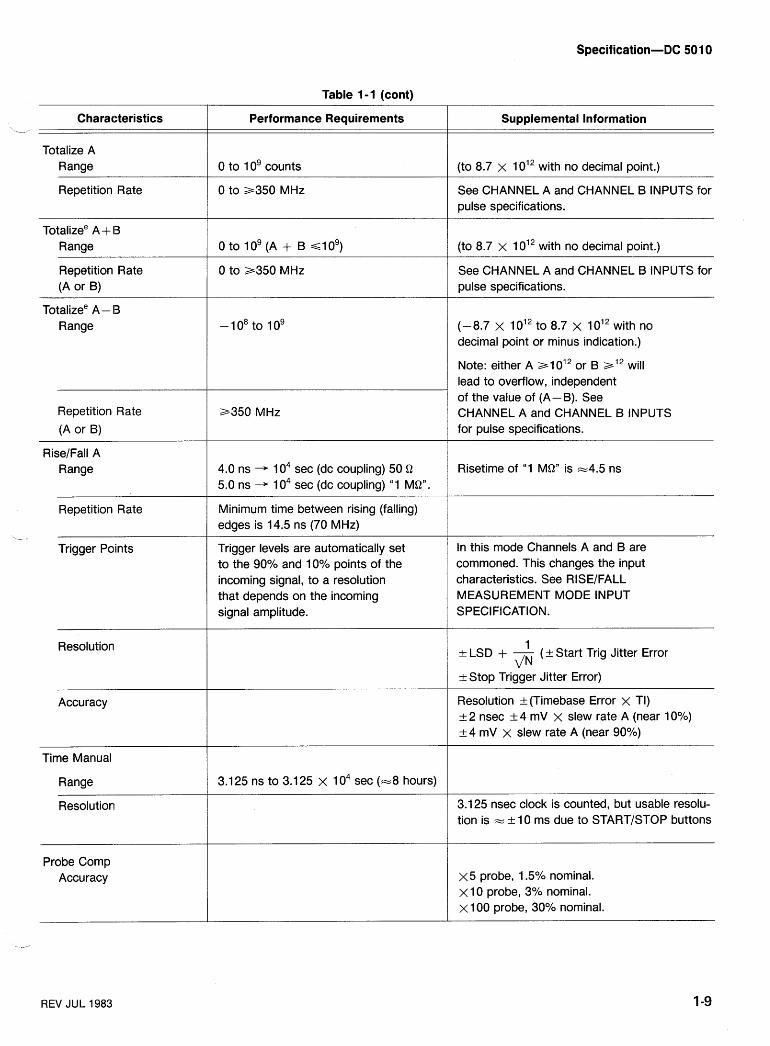
Table 1 - 1 (cont)
Performance Requirements Characteristics .- Supplemental Information
Totalize A Range 0 to 10' counts (to 8.7 x 1 012 with no decimal point.)
Repetition Rate 0 to a350 MHz See CHANNEL A and CHANNEL B INPUTS for pulse specifications.
Totalizee A + IB Range (to 8.7 x 10¹² with no decimal point.)
Repetition Rate (A or B)
0 to a350 MHz See CHANNEL A and CHANNEL B INPUTS for pulse specifications.
Totalizee A - I5 Range (-8.7 x 10¹² to 8.7 x 10¹² with no
decimal point or minus indication.)
Note: either A a1 012 or B al* will lead to overflow, independent of the value of (A- B). See CHANNEL A and CHANNEL B INPUTS for pulse specifications.
Repetition Rate
(A or B)
a350 MHz
RiseIFall A Range 4.0 ns + 1 o4 sec (dc coupling) 50 Q
5.0 ns -+ 1 o4 sec (dc coupling) "1 MQ". Risetime of "1 MQ" is -4.5 ns
Repetition Rate Minimum time between rising (falling) edges is 14.5 ns (70 MHz)
,.- .
Trigger Points Trigger levels are automatically set to the 90% and 10% points of the incoming signal, to a resolution that depends on the incoming signal amplitude.
In this mode Channels A and B are commoned. This changes the input characteristics. See RISEIFALL MEASUREMENT MODE INPUT SPECIFICATION.
Resolution 1 + LSD + - (+Start Trig Jitter Error d N
+ Stop Trigger Jitter Error)
Resolution + (Timebase Error x TI) + 2 nsec + 4 mV x slew rate A (near 10%) + 4 mV x slew rate A (near 90%)
Accuracy
Time Manual
Range 3.1 25 ns to 3.1 25 x 1 o4 sec (-8 hours)
3.125 nsec clock is counted, but usable resolu- tion is = + 10 ms due to STARTISTOP buttons
Probe Comp Accuracy x5 probe, 1.5% nominal.
X 10 probe, 3% nominal. X I00 probe, 30% nominal.
REV JUL 1983
Specification-DC 501 0
Table 1-1 (cont)
Characteristics Performance Requirements Supplemental Information --
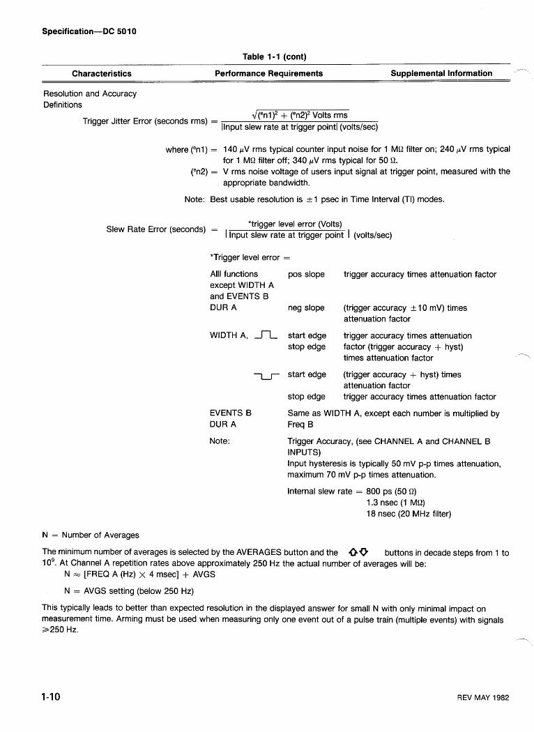
Resolution and Accuracy Definitions
Trigger Jitter Error (seconds rms) =
where ("nl) =
d(enl )2 + (en2)2 Volts rms [Input slew rate at trigger point1 (voltslsec)
140 pV rms typical counter input noise for 1 MQ filter on; 240 pV rms typical for 1 MQ filter off; 340 pV rms typical for 50 Q.
V rms noise voltage of users input signal at trigger point, measured with the appropriate bandwidth.
Note: Best usable resolution is + 1 psec in Time Interval (TI) modes.
*trigger level error (Volts) Slew Rate Error (seconds) = I lnput slew rate at trigger point I (volts/sec)
*Trigger level error =
Alll functions pos slope trigger accuracy times attenua.tion factor except WIDTH A and EVENTS B DUR A neg slope (trigger accuracy + 10 mV) tim~es
attenuation factor
WIDTH A, n start edge trigger accuracy times attenuation stop edge factor (trigger accuracy + hyst)
times attenuation factor
l ~ - start edge (trigger accuracy + hyst) times attenuation factor
stop edge trigger accuracy times attenuation factor
EVENTS B Same as WIDTH A, except each number is rriultiplied by DUR A Freq B
Note: Trigger Accuracy, (see CHANNEL A and CHANNEL B INPUTS) lnput hysteresis is typically 50 mV p-p times attenuation, maximum 70 mV p-p times attenuation.
Internal slew rate = 800 ps (50 Q) 1.3 nsec (1 MQ) 18 nsec (20 MHz filter)
N = Number of Averages
The minimum number of averages is selected by the AVERAGES button and the 69 buttons in decade steps from 1 to 10'. At Channel A repetition rates above approximately 250 Hz the actual number of averages will be:
N = [FREQ A (Hz) x 4 msec] + AVGS
N = AVGS setting (below 250 Hz)
This typically leads to better than expected resolution in the displayed answer for small N with only minimal impact on measurement time. Arming must be used when measuring only one event out of a pulse train (multiple events) with signals a250 Hz. -
REV MAY 1982
Table 1-1 (cont)
Characteristics Performance Requirements Supplemental Information L
In the AUTO mode the counter measures with a fixed measurement time of about 300 msec (or the time for one event, whichever is greater).
N =S Freq A (Hz)
LSD:
FREQ
PER
RATIO
TIME A-*B
& RISEIFALL
WIDTH A,
EVENTS 6 DUR A
x .3 seconds (N always >I)
(Freq A)2
10 nsec 3.1 25 nsec for N ~ 1 0 , ----
N for N >10
Freq A Freq B x N
10 nsec 3.125 nsec for N ~ 1 0 , --_ for N >10
10 nsec 3.125 nsecfor N ~ 1 0 , - for N >10
JN Period B x Events B dur A
Width A x N
Time Base Efrror: The sum of all the errors specified for the time base used.
- - aOver voltage protection still functions, but in riselfall, (50 51 and X5) it may not always protect the 25 51 series input resistor.
bWith 109 Averages selected, LSD can be as small as 31.25 attosec. =Can be set to 0.0 ns by use of "NULL" function. dCan be removed by use of "NULL". eThe B channel will not count events until after the first valid A channel count.
REV JUL 1983
Table 1-2 MISCELLANEOUS /-.
Characteristics
Power Requirements
Description
TM 500 series power module TM5000 series power module
DC 5010 DC 501 0 Opt 01
Recommended Calibration Interval
GPlB Data Output Rate I = 1 0 readingslsec max
Not 14.5 W Allowed 19.3 W
2000 hours or 6 months whichever occurs first
Minimum Display Time
Auto Averages Measurement Time
Characteristics
100 msec (typical)
300 msec (typical)
- -
Temperature
Operating Non-operating
Humidity
Altitude
Operating Non-operating
Vibration
Shock
Bench HandlingC
EMC
Electrical Discharge
aWith power module.
Table 1-3 ENVIRONMENTALa
Description
Meets MI L-T-28800B, class 5.
95% RH, 0°C to 30°C 75% RH to 40°C 45% RH to 50°C
Exceeds MI L-T-28800B, class 5. -
Exceeds M IL-T-28800B, class 5.
4.6 km (1 5,000 ft) 15 km (50,000 ft)
0.38 mm (0.015") peak to peak, Exceeds MIL-1-288008, class 5 when 5 Hz to 55 Hz, 75 minutes. installed in qualified power mod~les.~
30 g's (112 sine), 11 ms duration, Meets MIL-T-28800B, class 5 when 3 shocks in each direction along installed in qualified power mod~les.~ 3 major axes, 18 total shocks.
12 drops from 45", 4" or equilibrium, Meets MIL-T-28800B, class 5. whichever occurs first.
Qualified under National Safe Transit Association Preshipment Test Procedures 1A-B-1 and 1A-B-2.
Within limits of MIL-461A, with exceptions d, and F.C.C. Regulations, Part 15, Subpart J, Class A.
Unused plug-in compartments must be filled with blank plug-ins.
20 kV maximum charge applied to instrument case.
bRefer to TM 5000-Series power module specifications. -. =Without power module. dWithin 4 dB of RE02 at 130 MHz and 960 MHz. Within 20 dB of RE02 at 320 MHz.
FIEV MAY 1982
Specif ication-DC 50 1 0
Table 1-4 PHYSICAL CHARACTERISTICS
Net Weight (nominal) DC 5010
Option 01
- -- Characteristics
Finish
3 Ib. 7 oz. 3 Ib. 11 oz.
Description
Anodized aluminum chassis.
Nominal Overall Dimensions Height Width Length
126.0 mm (4.96 inches) 134.5 mm (5.29 inches) 278.8 mm (1 0.98 inches)
Enclosure Type and Style per MI L-T-28800lB
TY pe Style
I I I E (Style F in rackmount power module)
Function
Source Handshake
Acceptor Handshake
Basic Talker
Basic Listener
Service Request
Remote-Local
Parallel Poll
Device Clear
Device Trigger
Controller
Table 1-5
IEEE 488 (GPIB) INTERFACE FUNCTION SUBSETS
Subset
SH1
AH1
T6
L4
SR1
RLI
PPO
DC1
DT1
co
Capability
Complete.
Complete.
Responds to Serial Poll.
Unlisten if My Talk Address (MTA) is received.
Complete.
Complete
Does not respond to Parallel Poll.
Complete
Complete
No controller function.
REV MAY 1982

Section 2-DC 501 0
OPERATING INSTRUCTIONS
INTRODUCTION
First Time hispection
Inspect the instrument for visible damage (dents, scratches, etc.). Keep the original shipping container and packing material for future use. If the instrument is damaged, notify the carrier and the nearest Tektronix Ser- vice Center or representative.
Repackaging for Shipment
Should it blecome necessary to return the instrument to a Tektronix Service Center for service or repair, attach a tag to the instrument showing the owner (with address) and the name of the irldividual to be contacted, complete instrument serial number, option number, and a description of the ser- vice required.
If the original container and packaging material is unfit for use or not available, repackage the instrument as follows:
1. Obtain a1 carton of corrugated cardboard having inside \-- dimensions no less than six inches more than the instru-
ment dimensions; this will allow for cushioning. The shipping carton test st~rength for your instrument is 200 pounds.
2. Surroun'd the instrument with polyethylene sheeting to protect the finish.
3. Cushion the instrument on all sides by tightly packing dunnage or urethane foam between carton and instrument, allowing at least three inches on all sides.
4. Seal the carton with shipping tape or industrial staples.
5. Mark the shipping carton "FRAGILE INSTRUMENTn to indicate special handling.
Operating and Non-Operating Environments
The instrument may be operated, stored, or shipped within the environmental limits stated in the Specification section of this manual. However, the counter should be pro- tected at all times from temperature extremes which can
- cause condensation to occur within the instrument.
PREPARATION FOR USE
Rear Interface Considerations
A slot between pins 21 and 22 on the rear connector identifies this instrument as a member of the TM 5000 counter family. If you desire to use your counter to build a system, insert a family barrier key (Tektronix Part No. 214- 1593-02) in the corresponding position of the selected pow- er module jack in order to prevent plug-ins belonging to a different family from being used in that compartment of the power module.
To avoid electric shock, disconnect the power module power cord before inserting the family barrier key in the power module jack. Refer the barrier key insertion to qualified service personnel.
The DC 501 0 has the following rear interface input and out- put features:
Arming lnput
10 MHz Clock Output
External Clock lnput (1, 5, 10 MHz)
Prescaler Function
Reset lnput
NOTE
Rear interface information will be found in the Mainte- nance section of this manual. Refer the interface con- nections to qualified service personnel.
Installation and Removal
The DC 5010 can only be used in the TM 5000-Series power modules.
NOTE
Refer to the Operator's Safety Summary in the front of this manual before installing this instrument in the power module.
Operating Instructions-DC SO 10
Refer to the power module instruction manual and make sure that the line jumpers are positioned correctly for the line voltage in use. Check the counter and the power module for the proper fuses. Be certain that the power plug for the power module has the proper grounding conductor.
C A U T I O N a To prevent damage to the instrument, turn the power module off before installation or removal from the power module. Do not use excessive force to install or remove the instrument from the power module.
Check to see that the plastic barrier keys on the interconnecting jack of the selected powei. module compart- ment match the cutouts in the rear interface connector for the counter. If they do not match, do not insert the counter until the reason is investigated.
If the cutouts and barrier keys match, align the chassis of the counter with the upper and lower guides of the selected -- compartment. See Fig. 2-1 . Insert the counter into the com- partment and press firmly to seat the rear inteirface connec- tor. Apply power by operating the POWER switch on the power module.
The plastic lockouts (see Fig. 2-1) prevent programmable instruments from being used in the TM 500-Series (manual instruments) Power Module.
To remove the counter from the power module, turn off the POWER switch, pull the release latch knob (located in the lower left front corner) until the interconnecting jack dis- engages. Pull the counter straight out of the power module compartment.
FRONT PANEL OPERATION
The following information is a brief, functional description FRONT PANEL DISPLAY of the front panel display, controls, and connectors (See Fig. 2-2). @ Display
The display contains nine seven-segmenls LEDS and eight annunciators. All measurement results (are displayed with the best possible resolution. The readout (result) for the
Lockout Guide Plastic I Lockout
Fig. 2-1. Plug-in installation and removal.
Operating hstructions-DC 501 0
Fig. 2-2. DC 5010 front panel display, controls and connectors.
Operating Instructions-DC 501 0
measurement is always displayed in a right-hand justified SLOPE -,+. When unlighted, selects +; when lighted, format with the decimal point automatically positioned. Dis- selects -. This button selects the slope of the signal at the /-
played count overflow is indicated by a flashing display. In trigger level crossing, which is recognized a!; a countable measurements such as Time A--6, where the number of event. CHANNEL A slope also selects between risetime (+ resolved digits increases more slowly with an increase in Slope) and fall time (- Slope); it must be set before the averaging, only correct (resolvable) digits are displayed. RISEIFALL A button is pushed.
Five of the annunciators are used to indicate the units of COUPL-AC, DC. When unlighted selects DC; when measurements: HzISEC for Hertz or seconds, kHz/mSEC lighted selects AC. DC is direct coupled. AC inserts a ca- for kilohertz or milliseconds, MHzlPSEC for megahertz or pacitor in series with the input which allows small signals microseconds, GHzlnSEC for gigahertz or nanoseconds, with large dc offsets to be measured. and VOLTSIAVGS for (trigger level) Volts, and (the expo- nent of) the number of Averages.
FRONT PANEL CONNECTORS
The GATE annunciator, when illuminated, indicates that the counter is in the process of accumulating counts for the @ CHANNEL A - CHANNEL B (Identical in measurement. performance)
The REMOTE annunciator indicates the instrument is in 1 MQ 23 pF/50 Q. Signal input connectors. a remotely-programmed state, when illuminated. The AD- Vpk + 2 V max (50 Q) DRESS light indicates that the instrument is actually being Vpk + 42 V max (1 MQ) addressed over the GPlB bus.
@ CH A, SHAPED OUT - CH B, SHAPED OUT In addition to displaying the measurement results, the (Shaped Out A/B/COM)
counter uses the extreme left three digits of the seven-seg- These outputs provide an exact replica of the internal merit LED to indicate internal Or 'perating error signal that is being measured. It is an aid to proper trigger- ?
codes. The two digits (extreme left-digit Channel A and the ing complex waveforms. The outputs provide a mV extreme right-digit Channel B, On the report the re- signal near ground from 50 Q (200 mV unterminated). These sults of compensating external signal probes. See Self Test are full bandwidth outputs, and function well beyond Display and Probe Compensation. 350 MHz.
In addition, many of the front-panel pushbuttons are illuminated.
@ ARM, IN - Vpk < 10 V (Arming TTL)
This input (normally high) allows the counter to measure only when in the high state. When in the low state, this input prevents the counter from measuring. (Alternatively, this in- put may be provided through the rear interface.)
FRONT PANEL CONTROLS
@ TERM, SLOPE, ATTEN, and COMPL (CHANNEL A and CHANNEL B)
@ PROBE COMP
This test point provides a rectangular waveform ( ~ 5 volts) that can be used in conjunction with the "PROBE
TERM-50 0, 1 MO (termination). When unlighted, se- COMP" function to compensate test probes (see Probe
lects 1 MQ, 23 pF; when lighted, selects 50 Q. Allows user to Compensation in this section.)
properly terminate 50 Q inputs when required. (Unit will automatically revert to 1 MQ, 23 pF in the event of an overload.)
FRONT PANEL PUSH BUTTONS ATTEN-XI, X5. When unlighted, selects X5; when
lighted, selects XI. Allows the signal to be applied directly to the amplifier without attenuation or attenuated by a factor of
@ Function Pushbuttons n
five. The attenuator effectively increases the input hyster- FREQ A (Frequency A). Measures the period of the esis and trigger level range by a factor of five. Channel A signal, calculates and then displays frequency.
2-4 REV JUL 1983
Operating Instructions-DC 501 0
PERIOD A. Measures and displays the period of the Channel A signal.
L'
WIDTH A,, Measures the width of a pulse on Channel A. When CHANNEL A SLOPE is +, the positive pulse width is measured. When CHANNEL A SLOPE is negative, the neg- ative pulse width is measured.
TlME A t. B. Measures the time between the first occur- rence of an event on Channel A and the first succeeding event on Channel B.
RISEIFALL A (Risetime A - Falltime A). Automatically measures the risetimelfalltime (10% and 9O0/0) of the signal appearing on CHANNEL A. The appropriate trigger levels are measured and calculated at the time the button is pressed. If the signal amplitude changes, the button may be pressed agai~n. When CHANNEL A SLOPE is +, risetime is measured; for falltime, press CHANNEL A SLOPE = (-) before pressing RISEIFALL A. Since this measurement uses the B channel, its settings are automatically updated to match those of CHANNEL A. After pressing RISEIFALL A, the user is free to modify either CHANNEL A or CHANNEL B separately to suit special measurement needs, though the result may no longer be a traditional RiseIFall time. (See Risetime A and Falltime A later in this section).
RATIO BIA. Measures and displays the ratio of events occurring on Channel B divided by the events occurring on Channel A over the same time interval.
The three totalize modes of operation count the events that are the occurrences of pulses on Channel A and B.
TOTAL A, (Totalized A). In Total A, only Channel A events are displayed.
TOTAL A+B. Displays the total number of events on Channel A plus the total number of events on Channel B. Channel B events are counted only after the first valid Chan- nel A event.
TOTAL A.-B. Displays the total number of events on Channel A minus the total number of events on Channel B. Channel B events are counted only after the first valid Chan- nel A event. If A-B is negative, a minus sign is lighted.
NOTE
After a TOTALIZE button is pushed, the \ STA RT/STOP button lights to indicate a "STOPped"
condition. It must then be pressed to stat? the Totalize process.
Also, the number of digits displayed is "scaled" by the AVGS setting. This scaling does not affect the actual count process, and therefore may be changed while counting without losing counts. Even when counting has been stopped, the display may be moved to the right or left.
PROBE COMP. When in this mode, a visual indication is given (in the display area) that allows the user to easily com- pensate attached high impedance probes. (See Probe Com- pensation in this section.)
TlME MAN (Time Manual). Measures time after pressing the MEASUREMENT STARTISTOP pushbutton (once to start and once to stop). The accumulated count (time) is not reset until the RESET pushbutton is depressed. Like the Totalize modes, this function defaults to the STOPped state when first selected, as indicated by the STARTISTOP but- ton being illuminated.
EVENTS B DUR A (Events B During A). Measures the number of occurrences of pulses on Channel B during the time interval where the Channel A input signal is greater than (+ SLOPE) or less than (- SLOPE) the Channel A trigger level.
@ LEVEL CH A, CH B
Displays the chosen trigger level. Trigger level settings may be set for either channel by depressing the appropriate LEVEL button and then using the increment or decrement buttons (labeled 10). To exit this mode, the user can press the LEVEL A (B) button a second time or press any function button.
@ AVGS (Averages)
Pressing this button displays the current AVGS setting and readies the instrument for a new setting. The user can then choose between several modes.
AUTO - (push the AUTO button, a - 1 will be displayed). This mode provides the best resolution possible with a mea- surement time of approximately 300 mS.
0 - (decrement exponent to zero). The selected measure- ment is made with at least one event. This is the mode to be used for single-shot measurements. At most frequencies, more than one event will actually be averaged; see the Specification section for further detail.
REV OCT 1981
Operating Instructions-DC SO 10
I On, n = I to 9 - Provides selection of minimum number of averages in decade steps.
49 The incrementldecrement keys are used to in- crease or decrease the exponent to the next legal setting.
NOTE
The AVGS settings affects the number of digits dis- played for Totalize measurements. When in Auto on n=O, the first nine digits to the left of the decimal point are displayed. When n= 1 to 9, the measure- ment result is "scaled" by 10 " and displayed.
This button increments the appropriate trigger level if LEVEL CH A -CH B is selected, or the number of averages if AVGS has been selected. Voltage levels are incremented or decremented in steps of 4 mV x attenuating setting.
i(t This button decrements the appropriate trigger level if LEVEL CH A - CH B is selected, or the number of averages if AVGS has been selected.
@ AUTO TRIOIAUTO
If the LEVEL buttons and the AVGS button i ~ e unlighted, - pressing this button causes an auto trigger on lboth Channel A and Channel B (the maximum and minimum^ peak values of the Channel A and B input signals are measured and the trigger levels are set at the midpoints). If LEVEL CH A is selected, pressing this button causes an Auto trigger on Channel A only, and similarly for LEVEL B lighted. If AVGS is lighted, pressing the button enters a -1, which is the code for Auto Averages.
@ NULL
Pressing the NULL button stores the present measure- ment result and then subtracts that number from all subse- quent measurements (while the button remains lighted). It is most useful in Time A-B measurements, wh'ere it can be used to null out systematic errors such as unequal cable lengths and channel mismatches; however, it is available in all measurement functions.
The averages setting may be changed without losing the NULL stored measurement. Now, the instrument will be subtracting two numbers of differing resolutioln. Since the result of such a subtraction actually has the resdution of the lesser resolution number, that is the one that the counter automatically uses to determine how many digits to display. ---,
LIMIT Pressing the button again will re-null the result.
This light goes on whenever either the increment (t) or To exit the Null mode, press any function b~~ t ton (includ- decrement (1) button has incremented or decremented a ing that of the function already chosen). setting to its limit. This light goes out when increment (7) or decrement (1) button is released.
When either of the LEVEL CH A, LEVEL CH B buttons or the AVGS button is lighted, this button alternates what is being displayed in the seven-segment readout. Pressing it once makes the readout revert back to displaying the func- tional results (frequency, period, etc.) while still leaving the incrementldecrement buttons active. Pressing the button again will alternate the display back to showing the voltage level or averages exponent. This allows the user to view either the parameter being changed or the effect of that change on the functional results.
When the LEVEL buttons or the AVGS button is unlighted, the ,TESTIDISPLAY button is used to select the Test mode. In this mode a portion of the power up test (all but the RAM portion) is repeated. If an error is ever encoun- tered, the test stops, with the appropriate error code dis- played. To exit Test mode, push any other function key.
This pushbutton, when pressed, displays the current GPlB address and message terminator selected in the DC 501 0. It will send an SRQ if enabled, even when in Local Lockout, and it's therefore a useful way for art operator to signal the controller during the running of a program.
@ MEASUREMENT STARTISTOP
This pushbutton can be used in all of the Function modes except Probe Comp and Test. When it's lighted, measure- ment is in the "STOPped" state. Pressing the button causes a "STOPped", Totalize, or Time Manual measurement to "Startn from the displayed result. Other measurements (ex-. cept Probecomp and Test) will "Startn a new measurement. When "Started", pressing the button causes all measure- ments (except Probecomp and Test) to stop counting. When "STOPpedn, Totalize and Time Manuial measure- -?, ments read the final count in the count chains; and update the display one more time.
Operating Instructions-DC 50 10
@ RESET @ FILTER (20 MHz) (CHANNEL A end
When a measurement has been stopped, this CHANNEL B)
-- pushbutton, when pressed, will initiate another single mea- When this button is lighted, the bandwidth of both chan- surement. If RESET is pressed while the counter is in the nels is reduced to 20 MHz. This allows rejection of high fre- middle of a measurement, the current measurement will be quency noise. It may also be used when initially setting Auto aborted and a new measurement started. RESET, while trigger levels or RiseIFall levels for a signal with overshoot pressed, also provides a segment test for all the front panel or undershoot. LEDs, including pushbuttons and annunciators.
OPERATORS FAMILIARIZATION
INTRODUCTION
General Operating Characteristics
The DC 501 0 is a programmable universal counter based on a microprocessor system. The counter is capable of 11 measurement functions with full nine-digit resolution, plus two specialiired functions; probe compensations (PROBE COMP) and self-test (TEST).
The micrc~processor system automatically sets the mea- surement gate interval, performs the necessary calculations on the acquired data, and causes the result to be displayed with the best possible resolution for the selected measure- ment FUNCTION, number of averages (AVGS), and operat- ing conditions.
Self Test Display
When power is applied, one of the error codes listed in Table 2-1 may appear in the display window if the counter fails its self-test routine. Refer the error code condition to qualified service personnel.
NOTE
At power up, a signal with a large dc offset voltage connected to the input terminals for either channel may cause the entire input signal to be outside the triggering level range. If this condition exists, an error code may be displayed. If any of these conditions oc- cur, disconnect all inputs and reapply power. This er- ror condition can also be caused by a low level ARM input signal during power-up.
NOPE
Refer efiror code conditions to qualified service \ L personnel.
Table 2-1 FRONT-PANEL DISPLAY ERROR CODES
Serial I10 Fault Channel A
Counter Integrity Channel B
Counter Integrity System RAM Error U1410 System RAM Error U1610 System RAM Error U1311 ROM placement error U1610 ROM placement error U1102
31 3
320-324, 329
330-334, 339 340 341 342 361 374
ROM placement error U1201 ROM placement error U1410
ROM checksum error U1201 I 395
375 380
ROM checksum error U1610 ROM checksum error U1102
INPUT CONSIDERATIONS
381 394
Maximum Safe Input Voltage Limits A
To avoid instrument damage, make certain that the input voltages to the front panel connectors or rear interface inputs do not exceed their specified limits. See Specification section.
The outer shell of the front panel bnc connectors is connected to earth ground through the ground con- nection for the power module power cord.
Always use a s tep-do wn isolation transformer (less than 15 V output) when measuring power line fre- quencies (50 or 60 Hz).
Be careful with high- frequency, high-amplitude signals (above 80 MHz). The front panel maximum safe input voltage at these high frequencies is 4 V, peak- to-peak times a ttenuator setting.
Operating Instructions-DC SO 10
Connecting External and Internal Signal Sources
The DC 5010 can be used to measure input signals to either channel from the front panel. The SLOPE, TERM, ATTEN, and COUPL pushbuttons are effective in condition- ing the signal.
If a high impedance signal probe is to be used between the front panel bnc connectors and the measurement source, use a probe capable of compensating for the input capacitance of the counter (less than 24 pF). A probe is recommended for all digital logic applications; the TEKTRONIX P6125 has been designed specifically for these counters, and its use is recommended. The counter has been designed, however, to properly trigger on ECL signals even when a XI0 attenuator probe is used.
Input Coupling, Noise, and Attenuation
You can use either the ac coupling (AC COUPL) or dc coupling (DC COUPL) mode to couple the input signal to the CHANNEL A or CHANNEL B input amplifiers. If the signal to be measured is riding on a dc level, its amplitude limits may not fall within the triggering level range. The AC COUPL mode should be used for repetitive signals having a fixed frequency and a constant duty cycle, or for signals riding on a large dc level. Slope selection is relatively unimportant when measuring the frequency or period of sine-waves. The 50 Q Termination is selected for high frequency 50 Q sys- tems, while 1 Mil is selected for high impedance probes and
I Noise
for other high impedance situations. When in 50 Q, the inter- nal termination resistor could be damaged if tlhe user acci- ,
dentally applied an overly large signal. To prevent this, the DC 501 0 automatically reverts to 1 MQ for most signals that might damage the 50 8 resistor. See the Specification sec- tion for more detail.
If the signal frequency or duty cycle changes, the trigger- ing point may shift, stopping the measurement process. Use the DC COUPL mode for low frequency ac signals, signals with a low duty cycle, and during any time interval measure- ment (Time A-B, RiseIFall A, Events B Dur A, and Width A).
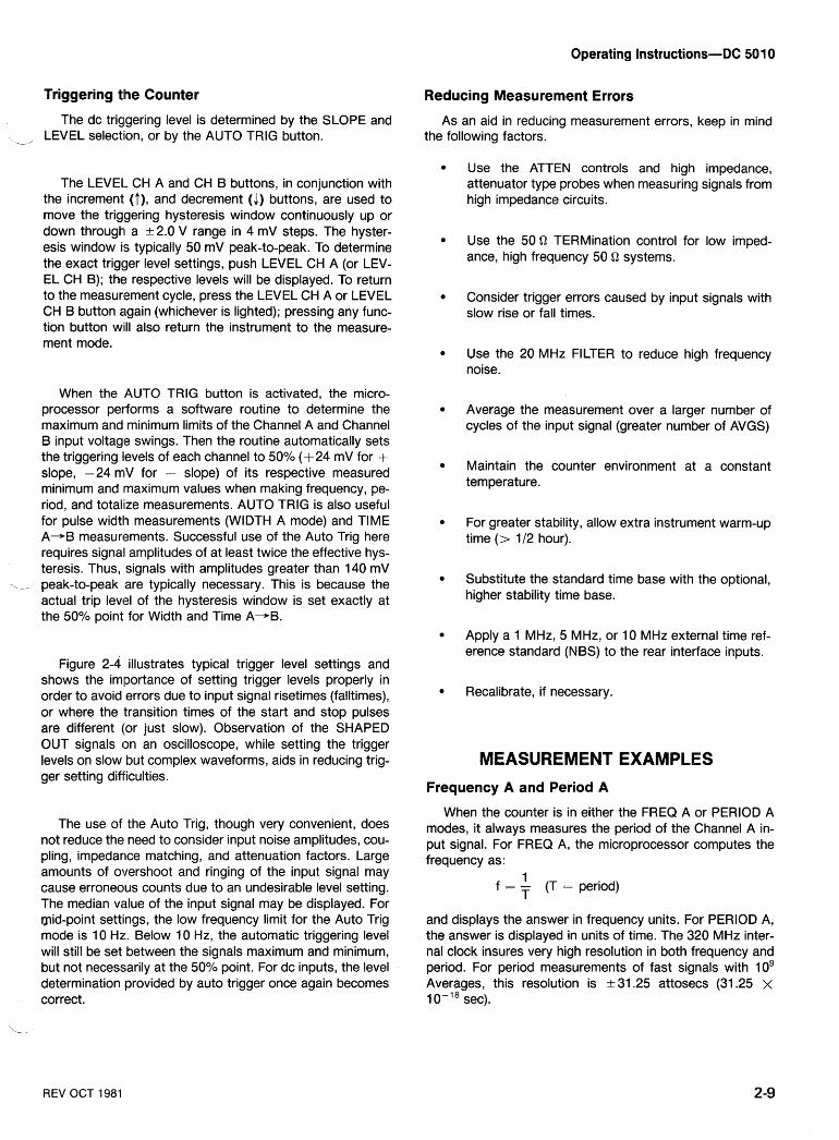
Noise may be coupled to the input amplifier's along with the signal to be measured. Noise may originate from the operating environment, the signal source, or ble caused by improper connections. If the noise is of sufficient amplitude, it can result in inaccurate measurements due to false trig- gering. See Fig. 2-3. The DC 5010 has a 20 MHz low pass filter (FILTER) that is helpful in removing or reducing noise.
The linear operating range describes the voltage limits that will allow proper triggering without distortion. The mini- mum signal amplitudes are defined by the input sensitivity requirements for the AC COUPL and DC COUF'L modes for either the 1 MQ or 50 Q Termination selection (see the Specification section). Proper use of the ATTEN (attenu- ation) controls will ensure operation within the maximum limits; t 2.0 V for X I ATTEN, t 10 V for X5 AT'TEN.
Erroneous Count
Triggering1 Level
Shaped Out
Correct Count
3464-04
Fig. 2-3. Advantages in signal attenuation.
Operating Instructions-DC 501 0
Triggering tlhe Counter Reducing Measurement Errors
The dc triggering level is determined by the SLOPE and I/ LEVEL selecti~on, or by the AUTO TRIG button.
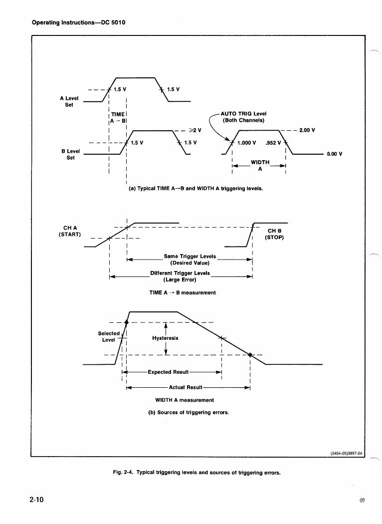
The LEVEL CH A and CH B buttons, in conjunction with the increment (t), and decrement (J) buttons, are used to move the triggering hysteresis window continuously up or down through1 a k2.0 V range in 4 mV steps. The hyster- esis window is typically 50 mV peak-to-peak. To determine the exact trigger level settings, push LEVEL CH A (or LEV- EL CH B); the respective levels will be displayed. To return to the measurlement cycle, press the LEVEL CH A or LEVEL CH B button again (whichever is lighted); pressing any func- tion button will1 also return the instrument to the measure- ment mode.
When the AUTO TRlG button is activated, the micro- processor performs a software routine to determine the maximum and minimum limits of the Channel A and Channel B input voltage swings. Then the routine automatically sets the triggering levels of each channel to 50% (+24 mV for + slope, -24 rniV for - slope) of its respective measured minimum and maximum values when making frequency, pe- riod, and totahze measurements. AUTO TRlG is also useful for pulse width measurements (WIDTH A mode) and TIME A-B measurements. Successful use of the Auto Trig here requires signall amplitudes of at least twice the effective hys- teresis. Thus, signals with amplitudes greater than 140 mV
- _, peak-to-peak are typically necessary. This is because the actual trip level of the hysteresis window is set exactly at the 50% point for Width and Time A 4 B .
Figure 2-4 illustrates typical trigger level settings and shows the imiportance of setting trigger levels properly in order to avoid errors due to input signal risetimes (falltimes), or where the transition times of the start and stop pulses are different (,or just slow). Observation of the SHAPED OUT signals on an oscilloscope, while setting the trigger levels on slow but complex waveforms, aids in reducing trig- ger setting difficulties.
The use of the Auto Trig, though very convenient, does not reduce the need to consider input noise amplitudes, cou- pling, impedarlce matching, and attenuation factors. Large amounts of overshoot and ringing of the input signal may cause erroneous counts due to an undesirable level setting. The median vdue of the input signal may be displayed. For mid-point settings, the low frequency limit for the Auto Trig mode is 10 Hz:. Below 10 Hz, the automatic triggering level will still be set between the signals maximum and minimum, but not necessarily at the 50% point. For dc inputs, the level determination provided by auto trigger once again becomes correct.
As an aid in reducing measurement errors, keep in mind the following factors.
Use the ATTEN controls and high impedance, attenuator type probes when measuring signals from high impedance circuits.
Use the 50 Q TERMination control for low imped- ance, high frequency 50 Q systems.
Consider trigger errors caused by input signals with slow rise or fall times.
Use the 20 MHz FILTER to reduce high frequency noise.
Average the measurement over a larger number of cycles of the input signal (greater number of AVGS)
Maintain the counter environment at a constant temperature.
For greater stability, allow extra instrument warm-up time (> 112 hour).
Substitute the standard time base with the optional, higher stability time base.
Apply a 1 MHz, 5 MHz, or 10 MHz external time ref- erence standard (NBS) to the rear interface inputs.
Recalibrate, if necessary.
MEASUREMENT
Frequency A and Period A
When the counter is in either
EXAMPLES
the FREQ A or PERIOD A modes, it always measures the period of the Channel A in- put signal. For FREQ A, the microprocessor computes the frequency as:
1 f = - (T = period) P
and displays the answer in frequency units. For PERIOD A, the answer is displayed in units of time. The 320 MHz inter- nal clock insures very high resolution in both frequency and period. For period measurements of fast signals with 10' Averages, this resolution is k31.25 attosecs (31.25 x
sec).
REV OCT 1981
Operating Instructions-DC 50 10
A Level Set
B Level Set
AUTO TRIG Level (Both Channels)
I (a) Typical TlME A+B and WIDTH A triggering levels.
CH A (START) .X- - - I ,,,, bn I
I Same Trigger Levels I I " (Desired Value) '-7 I Different Trigger Levels
I - (Large Error) - TlME A - B measurement
Expected Result -W I I
I I I W- Actual Result -y
WIDTH A measurement
(b) Sources of triggering errors.
Fig. 2-4. Typical triggering levels and sources of triggering errors.
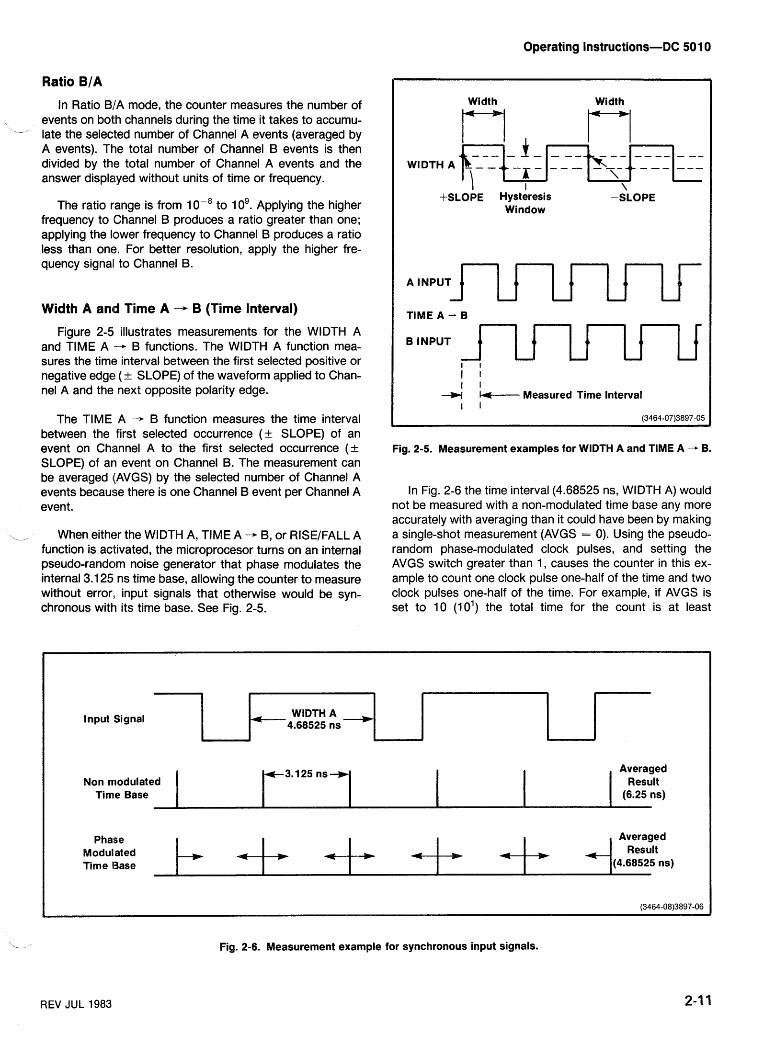
Operating Instructions-DC 501 0
Ratio B/A
In Ratio B/A mode, the counter measures the number of events on both channels during the time it takes to accumu-
-' late the selected number of Channel A events (averaged by A events). The total number of Channel B events is then divided by the total number of Channel A events and the answer displayed without units of time or frequency.
The ratio range is from 1 op8 to 10'. Applying the higher frequency to Channel B produces a ratio greater than one; applying the lower frequency to Channel B produces a ratio less than one. For better resolution, apply the higher fre- quency signal to Channel B.
Width A an4d Time A -+ B (Time Interval)
Figure 2-5 illustrates measurements for the WIDTH A and TlME A - B functions. The WIDTH A function mea- sures the time interval between the first selected positive or negative edge (+ SLOPE) of the waveform applied to Chan- nel A and the next opposite polarity edge.
The TlME A - B function measures the time interval between the first selected occurrence (a SLOPE) of an event on Channel A to the first selected occurrence (+ SLOPE) of an event on Channel B. The measurement can be averaged (AVGS) by the selected number of Channel A events because there is one Channel B event per Channel A event .
,, WheneithertheWlDTHA,TlMEA-B,orRISE/FALLA function is activated, the microprocesor turns on an internal pseudo-random noise generator that phase modulates the internal 3.1 25 ns time base, allowing the counter to measure without error,, input signals that otherwise would be syn- chronous with its time base. See Fig. 2-5.
Width Width
4 --- - - - - - - - - - - - - - - - WIDTH A b - -.,
-i - - - -*%,-4k - -- ---
\ , I \
+SLOPE Hysteresis -SLOPE Window
A INPUT 1uuUu TlME A - B
I I I I u k----- Measured Time Interval
I I (3464-07)3897-05
Fig. 2-5. Measurement examples for WIDTH A and TlME A + 6.
In Fig. 2-6 the time interval (4.68525 ns, WIDTH A) would not be measured with a non-modulated time base any more accurately with averaging than it could have been by making a single-shot measurement (AVGS = 0). Using the pseudo- random phase-modulated clock pulses, and setting the AVGS switch greater than 1, causes the counter in this ex- ample to count one clock pulse one-half of the time and two clock pulses one-half of the time. For example, if AVGS is set to 10 (10') the total time for the count is at least
l nput Signal
Non rrrodulated Time Base
Phalse Modulated Time Base
Fig. 2-6. Measurement example for synchronous input signals.
REV JUL 1983
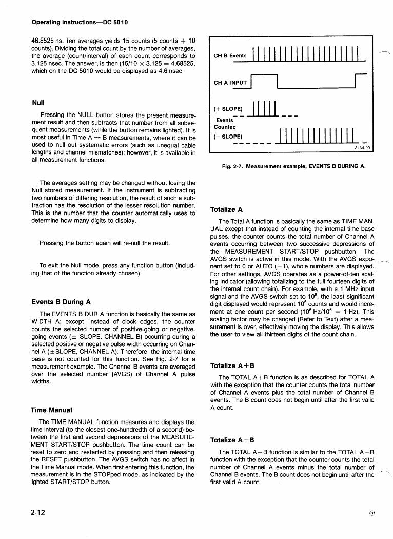
Operating Instructions-DC 501 0
46.8525 ns. Ten averages yields 15 counts (5 counts + 10 counts). Dividing the total count by the number of averages, the average (countlinterval) of each count corresponds to 3.1 25 nsec. The answer, is then (1 511 0 x 3.1 25 = 4.68525, which on the DC 501 0 would be displayed as 4.6 nsec.
Null
Pressing the NULL button stores the present measure- ment result and then subtracts that number from all subse- quent measurements (while the button remains lighted). It is most useful in Time A -- B measurements, where it can be used to null out systematic errors (such as unequal cable lengths and channel mismatches); however, it is available in all measurement functions.
The averages setting may be changed without losing the Null stored measurement. If the instrument is subtracting two numbers of differing resolution, the result of such a sub- traction has the resolution of the lesser resolution number. This is the number that the counter automatically uses to determine how many digits to display.
Pressing the button again will re-null the result.
To exit the Null mode, press any function button (includ- ing that of the function already chosen).
Events B During A
The EVENTS B DUR A function is basically the same as WIDTH A; except, instead of clock edges, the counter counts the selected number of positive-going or negative- going events (t- SLOPE, CHANNEL B) occurring during a selected positive or negative pulse width occurring on Chan- nel A (+ SLOPE, CHANNEL A). Therefore, the internal time base is not counted for this function. See Fig. 2-7 for a measurement example. The Channel B events are averaged over the selected number (AVGS) of Channel A pulse widths.
Time Manual
The TlME MANUAL function measures and displays the time interval (to the closest one-hundredth of a second) be- tween the first and second depressions of the MEASURE- MENT STARTISTOP pushbutton. The time count can be reset to zero and restarted by pressing and then releasing the RESET pushbutton. The AVGS switch has no affect in the Time Manual mode. When first entering this function, the measurement is in the STOPped mode, as indicated by the lighted STARTISTOP button.
CH B Events
Events
~~ CH A INPUT
Counted
(- SLOPE) ------
-I
Fig. 2-7. Measurement example, EVENTS B DURING A.
Totalize A
The Total A function is basically the same as TlME MAN- UAL except that instead of counting the internal time base pulses, the counter counts the total number of Channel A events occurring between two successive depressions of the MEASUREMENT STARTISTOP pushbutton. The AVGS switch is active in this mode. With the AVGS expo- ,, nent set to 0 or AUTO (-I), whole numbers iare displayed. For other settings, AVGS operates as a power-of-ten scal- ing indicator (allowing totalizing to the full fourteen digits of the internal count chain). For example, with a 1 MHz input signal and the AVGS switch set to lo6, the leisst significant digit displayed would represent 1 o6 counts and would incre- ment at one count per second (1 O6 Hz11 o6 == 1 Hz). This scaling factor may be changed (Refer to Text:) after a mea- surement is over, effectively moving the display. This allows the user to view all thirteen digits of the count chain.
Totalize A+B
The TOTAL A+B function is as described for TOTAL A with the exception that the counter counts the total number of Channel A events plus the total number 'of Channel B events. The B count does not begin until after the first valid A count.
Totalize A - B
The TOTAL A- B function is similar to the TOTAL A+ B function with the exception that the counter counts the total number of Channel A events minus the total number of
/T Channel B events. The B count does not begin until after the first valid A count.
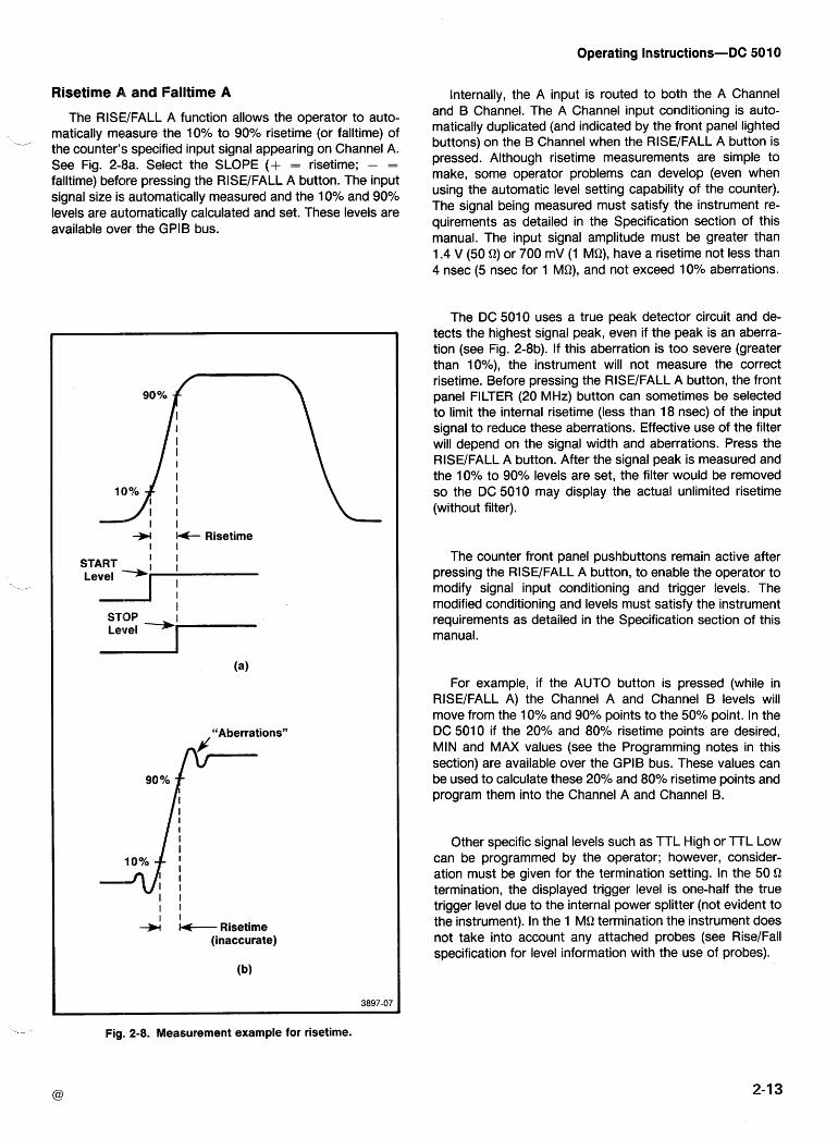
Operating Instructions-DC 501 0
Risetime A, and Falltime A
The RISEYFALL A function allows the operator to auto-
_, matically measure the 10% to 90% risetime (or falltime) of the counter's specified input signal appearing on Channel A. See Fig. 2-8a. Select the SLOPE (+ = risetime; - =
falltime) before pressing the RISEIFALL A button. The input signal size is automatically measured and the 10% and 90% levels are automatically calculated and set. These levels are available over the GPlB bus.
If- Risetime I I
START
I
I I I I
--)I Risetime (inaccurate)
Fig. 2-8. Measurement example for risetime.
Internally, the A input is routed to both the A Channel and B Channel. The A Channel input conditioning is auto- matically duplicated (and indicated by the front panel lighted buttons) on the B Channel when the RISEIFALL A button is pressed. Although risetime measurements are simple to make, some operator problems can develop (even when using the automatic level setting capability of the counter). The signal being measured must satisfy the instrument re- quirements as detailed in the Specification section of this manual. The input signal amplitude must be greater than 1.4 V (50 Q) or 700 mV (1 MQ), have a risetime not less than 4 nsec (5 nsec for 1 MQ), and not exceed 10% aberrations.
The DC 5010 uses a true peak detector circuit and de- tects the highest signal peak, even if the peak is an aberra- tion (see Fig. 2-8b). If this aberration is too severe (greater than lo%), the instrument will not measure the correct risetime. Before pressing the RISEIFALL A button, the front panel FILTER (20 MHz) button can sometimes be selected to limit the internal risetime (less than 18 nsec) of the input signal to reduce these aberrations. Effective use of the filter will depend on the signal width and aberrations. Press the RISEIFALL A button. After the signal peak is measured and the 10% to 90% levels are set, the filter would be removed so the DC 5010 may display the actual unlimited risetime (without filter).
The counter front panel pushbuttons remain active after pressing the RISEIFALL A button, to enable the operator to modify signal input conditioning and trigger levels. The modified conditioning and levels must satisfy the instrument requirements as detailed in the Specification section of this manual.
For example, if the AUTO button is pressed (while in RISEIFALL A) the Channel A and Channel B levels will move from the 10% and 90% points to the 50% point. In the DC 5010 if the 20% and 80% risetime points are desired, MIN and MAX values (see the Programming notes in this section) are available over the GPlB bus. These values can be used to calculate these 20% and 80% risetime points and program them into the Channel A and Channel B.
Other specific signal levels such as TTL High or TTL Low can be programmed by the operator; however, consider- ation must be given for the termination setting. In the 50 Q termination, the displayed trigger level is one-half the true trigger level due to the internal power splitter (not evident to the instrument). In the 1 MQ termination the instrument does not take into account any attached probes (see RiseIFall specification for level information with the use of probes).
Operating Instructions-DC 50 10
Probe Compensation The DC 5010 has been specifically designed to be com-
patible with standard probes when in 1 MQ termination; however, the operator must still be sure that the probe is properly compensated.
In the DC 5010, a probe compensation (PROBE COMP) function is built into the counter. It allows the user to com- pensate the probe in place and without the use of an exter- nal oscilloscope.
A square-wave signal of approximately 1 kHz and an am- plitude of approximately 5 V is provided at the front panel PROBE COMP tip jack.
Connect the probe tip to the PROBE COMP tip jack be- fore entering the PROBE COMP mode.
The counter should display a zero for the most significant digit (far left) and a zero for the least significant digit (far right). The far left digit is for a probe connected to CHAN- NEL A and the far right digit for a probe connected to CHANNEL B. No decimal points or annunciators should be illuminated.
With the probe connected and the square-wave signal applied, perform the following steps.
1. Slowly rotate the probe adjustment in either direction until the display changes to a continuous 1 reading for the channel being compensated.
2. Slowly reverse the rotation of the probe adjustment until the display just goes back to a 0. At this point, the probe will be compensated. A 1 indicates that the probe is over compensated; a 0 indicates under compensation. Final adjustment should be made in the direction where the 1 just changes to a 0.
NOTE
If a display goes to a I and remains in that condition for one or more complete revolutions of the probe ad- justment, press the RESET pushbutton to clear the condition. This can occur if the connection to the square-wave source became open during the adjust- ment procedure.
Test Function
A 000 display in the three MSD's for the TEST function is an indication that the microprocessor has checked itself. The test also checks the internal serial data path, the integ- rity of the internal counter chain (accumulators), and, as a by-product, the operation of the digital-to-anallog converter (trigger levels) and input amplifier circuits.
The random-access memory space (RAM) is not checked during this front panel self-test; the RAM is checked only at power-up.
NOTE
If the CHANNEL A or CHANNEL B input,; are con- nected, the peaks of the input signals must be within the triggering level range of the counter fcr the test function to operate properly. If a failure occurs, first disconnect any CHANNEL A or CHANNEL. B inputs and repeat the test. A connection to the arming input may also cause improper operation.
The gate light will flash once each time a full test cycle has been completed. If a failure is ever noted, the error code of that failure will be displayed in the three extreme left digits of the seven-segment display and the cycling will halt. The DC 5010 will stay in test mode until another function is selected.
Arming (ARM Input)
Arming provides a means by which single events or sets of events can be selected for measurement within a com- plex analog or digital signal. Figure 2-9 shows three different examples of arming.
The ARM input requires TTL signal levels. With no signal attached the ARM input is normally pulled high and is thus continuously armed. When the ARM input is pulled low, the counter is prevented from starting a measurement. Arming may be used in all measurement functions with the excep- tion of TIME MANUAL, PROBE COMP, and TEST. In these three functions the ARM signal must be high.
When the arming signal changes to a high state, the first subsequent Channel A event will start the rrieasurement process. When the arming signal changes to a low state, the next Channel A event will stop the measurement process. Therefore, the counter can be controlled as to wlhen, in time, a measurement will be made (even in complex waveforms).
Operating Instructions-DC 50 10
Input Signal, (+ SLOPE)
ARM lnput
Measured Signal
CH A lnput (+ SLOPE)
CH B lnput (+ SLOPE)
ARM Input
CH A lnput ( + SLOPE)
Signal Measured
"Burst" Single Period
a. Use of ARM with FREQ, PERIOD, and RATIO functions.
b. Use of a triggered delay pulse generator to generate a TIME A -, B arming signal.
I I I I
I Trigger Desired Time Possible Erroneous I
I A - B Pulse Delay to I I Measurement -W
c. Use of ARM with WIDTH A and EVENTS B DUR A functions.
Generator
Fig. 2-9. Examples of arming.
I I I I I I I without Arming ere +'
Here I I I I
Operating Instructions-DC 501 0
These armed measurements can then be averaged much like time interval averaging. The counter determines the number of digits to display (best possible resolution) based on the number of Channel A events averaged. Typically, each total measurement of Frequency, Period, and Ratio contains a 1 count error and the counter displays the num- ber of digits that can be justified given this error. When using arming in the Frequency Period, or Ratio modes (non- time interval modes), each act of arming and disarming can introduce 1 count errors. The counter does not take this into account, however, and displays the number of digits based only on the total number of events per overall measurement, independent of the number of times the instrument was armed and disarmed.
The actual resolution for a period measurement using arming will be less than that displayed. It can be found using - the following relationship:
Tc m P Resolution = - - N TB
Tc = clock period
Tp = input period (CH A)
T, = time from starting A event to stopping A
N = number of averages, i.e., 1 o6 or 1 09, efc.
event
PROGRAMMING Introduction
Instrument commands are presented in threle formats: This section of the manual provides information for pro-
gramming the DC 501 0 by remote control via the IEEE-488 A front panel illustration-showing command relation-
General Purpose Interface Bus (GPIB). The following infor- ships to front panel operation (see Fig. 2-10).
mation assumes the reader is knowledgeable in GPlB com- Functional Command List-a list divided ihto function- munication and has some exposure to programming al groups with brief descriptions. controllers. Communication via the GPIB is specified and /--
described in the IEEE Standard 488-1 978, "Standard Digital a Detailed Command List-an alphabetical listing of
Interface for Programmable ~nstrumentation"' All GPlB commands with complete descriptions.
references in this manual refer to the IEEE-488 GPIB. TM 5000 instruments are designed to communicate with TM 5000 programmable instruments connect to the any GPIB-compatible controller that sends and receives GplB through a TM 5000 power module. Refer to installa-
messages @Ommands) Over the GPIBm These 'Om- tion and Removal earlier in this section for information on mands program the instrument Or request information from installing the instrument in the power module. Also, review the instrument. the Front Panel Operation portions of this section to be-
come familiar with front panel and internally selectable in- strument functions. The GPIB primary address for this
Commands for TM 'OoO programmable are instrument may be internally changed by qualified service designed for among instrument The personnel. The DC 5010 is shippedewiith the address set to same command is used in different instruments to control decimal 20. The message terminator may also be internally similar functions. In addition, commands are specified in selected by qualified service personnel. termina- mnemonics related to the functions they implement. For ex- tors are discussed in Messages and Communication Proto- ample, the command INIT initializes instrument settings to col (in this section). TM 5000 instruments are shipped with their power-up states' For further ease Of programming, this terminator set to EOI ONLY. Refer qualified service per- 'Ornmand mnemonics match those On the front panel in sonnel to the Maintenance section of this manual for loca- most cases. tions and setting information. Pressing the INST ID button
causes the instrument to display its selected GPIB primary ' Published by the Institute of Electrical and Electronics Engi- address; the far right decimal point lights if the selected neers, Inc., 345 East 47th Street, New York, N.Y., 10017. message terminator is LFIEOI.
Operating Instructions-DC 501 0
Fig. 2- 10. Quick command list.
Operating Instructions-DC 501 0
COMMANDS /---
The instrument is controlled by the front panel or via com- Each command begins with a header-a word that de- mands received from the controller. These commands are of scribes the function implemented. Many comrnands require three types: an argument following the header, a word or tiumber which
specifies the desired state for the function. Setting commands-control instrument settings.
Query-output commands-ask for data.
Operational commands-cause a particular action.
Using fewer characters than the abbreviated header or argument should be done with caution since erro-
The instrument responds to and executes all commands neous results or damage could result if this data is when in the remote state. When in the local state, setting sent to the wrong instrument. and operational commands generate errors since instru- ment functions are under front panel control; only query- output commands are executed.
FUNCTIONAL
INSTRUMENT COMMANDS
Function Commands
EVE BA
FALL A
FREQ A
FUNC?
PER A
PROB A&B
RAT B/A
RISE A
TEST
TIME AB
TMAN
TOT A
TOT A+B
TOT A-B
WID A
- Counts Channel B during Channel A pulse width
- Measures the falltime of the signal on Channel A
- Measures frequency of input signal on Channel A
- Query returns current instrument function
- Measures period of Channel A signal
- Enables probe compensation
- Measures ratio of B events to A events
- Measures the risetime of the signal on Channel A
- Tests ROM, 110, accumulator
- Measures time from A event to B event
- Manual timing function (stop watch)
- Totalizes Channel A events
- Measures the total number of events on Channel A plus the total of events on Channel B
- Measures the total number of events on Channel A minus the total number of events on Channel B
- Measures pulse width of Channel A signal
COMMAND LIST
Measurement Control
AVE or AVGS
AVE? or AVGS?
NULL ON
NULL OFF
NULL ?
RDY?
RES
START
STOP
Sets number of measurements averaged (in decades only), or auto - averaging
Query returns AVE cnunn>; (- 1 for AUTO Averages)
Subtracts present rneasurement results from all succeeding measure- ments
Resets Null value
Query returns NULL ON cr NULL OFF
Query returns RDY 1 for new data ready or RDY 0 for new data not ready
Resets counters, restarts current measurement
Starts TMANual, STOPped, or TOTal- ize measurement
Stops any measurement except TEST or PROBECOMP
Operating Instructions-DC 501 0
INPUT/OlJTPUT CONTROL SYSTEM COMMANDS
ATT 1 or 5 - x 1 or x 5 Attenuation DT GATE - <GET> controls Start and Stop
_, ATT?
AUTO A
- Query returns ATT
- Sets trigger level (CH A)
- Sets trigger level (CH B)
- Sets trigger level (Both channels)
DT TRIG - <GET> performs RESET tnum>
to signal midpoint DT OFF - Disables Device Trigger
DT? - Query returns DT TRIG, DT OFF, or DT GATE AUTO B to signal midpoint
ERR? - Returns error code for most recent event reported by serial poll when RQS is ON; with RQS OFF it returns the highest priority status
AUTO A&13 to signal midpoint
CHA A or B
CHA?
COU AC or DC
COU?
FIL ON
- Selects channel for succeeding input settings ID? - Query returns instrument type and
firmware versions - Query returns CHA A or CHA B IN IT - Initializes instrument to power-on
settings - Sets input coupling mode
SET? - Query returns current instrument settings - Query returns COU AC or COU DC
- Limits the channel A and B bandwidth to approximately 20 MHz
TEST - Tests ROM, 110, accumulator
FILL OF
FIL ?
LEV
- Turns off filter
- Query returns FIL ON at FIL OFF
- Sets selected channel trigger level Num range = +2.000 to -2.000 (X I ) or + 10.000 to - 10.000 (X5)
STATUS COMMANDS
OPC ON
OPC OFF
OPC?
OVER ON
OVER OFF
OVER?
RQS ON
RQS OFF
RQS?
USER ON
USER OFF
USER?
- Enables assertion of SRQ on OPER- ATION COMPLETE
- Disables SRQ on OPERATION COMPLETE
-Query returns OPC ON or OPC OFF
-Enables asserting of SRQ on counter overflow
-Disables SRQ on counter overflow
-Query returns OVER ON or OVER OFF
-Enables SRQ assertion
-Disables SRQ assertion and clears SRQ
-Query returns RQS ON or RQS OFF
-Enables asserting of SRQ when INST ID button is pushed
-Disables asserting of SRQ when INST ID is pushed
-Query returns USER ON or USER OFF
LEV? L
MAX?
-Query returns trigger level setting of selected channel
- Query returns last AUTOtrig maximum peak voltage
MIN? - Query returns last AUTOtrig minimum peak voltage
PRE ON
PRE OFF
PRE?
SEND
- Enables prescaler and internal scaling
- Disables prescaler and internal scaling
- Query returns PRE ON or PRE OFF
-Obtains and formats new measure- ment results
SLO POS
SLO NEG
SLO?
TER HI
- Triggers on positive slope
- Triggers on negative slope
- Query returns SLO NEG or SLO POS
- Sets channel input to termination 1 megohm, 23 pF
- Sets channel input termination to 50 Q TER LO
TER? - Query returns TER HI or TER LO
Operating Instructions-DC 501 0
DETAILED COMMAND LIST
ATTENUATION
Type:
Setting or Query
Setting Syntax:
ATT <number>
Examples:
ATT .999999 ATT 5.00001 ATTENUATION 1
Query Syntax:
ATT?
Query Response:
ATT 1 ; ATT 5;
Discussion:
The ATTENUATION command sets the input signal at- tenuation for the selected channel to x 1 (no attenuation) or x5 . The argument is rounded to an integer and if it is not a 1 or a 5 an execution error (ERR 205) is issued indicating the argument is out of range.
The power-on initial setting is ATT 1.
For information on selecting channels see discussion of the CHANNEL command.
ATTENUATION
Type:
Operational
Syntax:
AUTO A B A&B (argument is optional)
Examples:
AUTO AUTO A AUTOTRIG A&B
Discussion:
The AUTOTRIG command causes the DC !SO10 to auto- matically set the trigger levels for channels to1 the approxi- mate midpoints of the input signals. The rrlaximum and minimum peak values for both channels are saved and may be read out using the MAX? and MIN? queries. The AUTOTRIG command accepts the following valid arguments:
A - Automatically sets trigger level for Channel A '-' only. Saves minimum and maximum peak val- ues for both channels.
B - Automatically sets trigger level for Channel B only. Saves minimum and maximum peak val- ues for both channels.
A&B - Automatically sets trigger levels for both chan- nels. Also saves minimum and maximum peak values for both channels.
If no argument is specified, AUTO A&B is assumed.
When an AUTOTRIG is performed, previously set trigger levels for affected channels are replaced by the new values. These new values may not be at the midpoints if the input signals are outside the range of the instrument. Previously measured minimum and maximum peak values for both channels are always replaced.
The time required for the AUTOTRIG operation to com- plete is dependent on both Channel A and Channel B ampli- tudes and frequencies. Worst case time is alpproximately 2.5 seconds.
The following command sequence causes an AUTO TRIGGER to be performed and the resulting tri!gger levels to be output when the AUTOTRIG completes:
/-~,
AUT0;CH A; LEV?;CH B;LEV?
Operating Instructions-DC 50 10
AVERAGES
--_, Type:
Setting or Query
Setting Syntax:
AVE <number> or
AVGS <number>
Examples:
AVE -1 AVGS 1 .EI+2 AVERAGES 100
Query Syntax:
AVE? or AVGS?
Query Response:
AVE -1; AVE 1 .Ed-4;
Discussion:
The AVERAGES command sets the minimum number of events to be counted on Channel A before calculating mea- surement re!jults. Valid <number> arguments are:
<number> GO - Sets DC 5010 to "auto-averagesn mode. In "auto-averages", the instrument accumulates counts for e . 3 seconds.
When in "auto-averagesn query returns AVE - 1.
<number> = 1, I.E+1, l.E+2, l.E+3, l.E+4, l.E+5, l.E+6, l.E+7, l.E+8, l.E+9.
The argument <number> is first rounded to the nearest power of ten. If the resulting value is not one of the above valid values, the averages setting is left unchanged and an execution error (ERR 205) is issued.
The AVERAGES setting is also used to scale the dis- played results for TOTALIZE measurements. Results output to the IEEE-488 bus, however are not scaled.
The power-on initial settings is AVE -1.
AVERAGES
CHANNEL (CHANNEL SELECT)
Type:
Setting or Query
Setting Syntax:
CHA A B
Examples:
CHANNEL A CHA B
Query Syntax:
CHA?
Query Response:
CHA A; CHA B;
Discussion:
The CHANNEL command selects the channel that the subsequent input setting commands affect. The input settings commands are SLOPE, SOURCE, ATTENUATION, COUPLING, and LEVEL. Valid arguments are:
A - Channel A is affected by input setting commands.
B - Channel B is affected by input setting commands. The power-on initial setting is CHA A.
CHANNEL (CHANNEL SELECT)
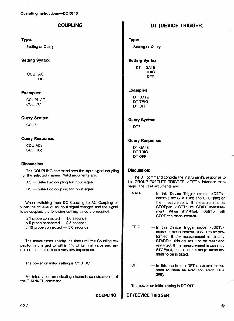
Operating Instructions-DC 50 1 0
COUPLING
Type:
Setting or Query
Setting Syntax:
COU AC DC
Examples:
COUPL AC COU DC
Query Syntax:
COU?
Query Response:
COU AC; COU DC;
Discussion:
The COUPLING command sets the input signal coupling for the selected channel. Valid arguments are:
AC - Select ac coupling for input signal.
DC - Select dc coupling for input signal.
When switching from DC Coupling to AC Coupling or when the dc level of an input signal changes and the signal is ac coupled, the following settling times are required:
x 1 probe connected - 1.0 seconds x 5 probe connected - 2.5 seconds x10 probe connected - 5.0 seconds
The above times specify the time until the Coupling ca- pacitor is charged to within 1% of its final value and as- sumes the source has a very low impedance.
The power-on initial setting is COU DC.
For information on selecting channels see discussion of the CHANNEL command.
COUPLING
DT (DEVICE TRIGGER)
Type:
Setting or Query
Setting Syntax:
DT GATE TRlG OFF
Examples:
DT GATE DT TRlG DT OFF
Query Syntax:
DT?
Query Response:
DT GATE DT TRlG DT OFF
Discussion:
The DT command controls the instrument's response to the GROUP EXECUTE TRIGGER <GET> interface mes- sage. The valid arguments are:
GATE - In this Device Trigger mode, <GET> controls the STARTing and STOPping of the measurement. If measurement is STOPped, <GET> will STAIRT measure- ment. When STARTed, <:GET> will STOP the measurement.
TRIG - In this Device Trigger mode, <GET> causes a measurement RESE:T to be per- formed. If the measurement is already STARTed, this causes it to be reset and restarted. If the measurement is currently STOPped, this causes a single measure- ment to be initiated.
OFF - In this mode a <GET> causes instru- ment to issue an execution error (ERR 206). -
The power on initial setting is DT OFF.
DT (DEVICE TRIGGER)
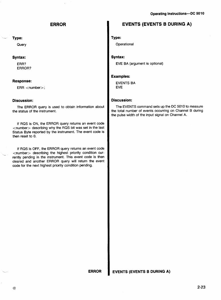
Operating Instructions-DC 501 0
ERROR
- Type:
Query
Syntax:
ERR? ERROR?
Response:
ERR <number>;
Discussion:
The ERRlOR query is used to obtain information about the status of the instrument.
If RQS is ON, the ERROR query returns an event code <number> describing why the RQS bit was set in the last Status Byte reported by the instrument. The event code is then reset to 0.
If RQS is OFF, the ERROR query returns an event code
, - <number> describing the highest priority condition cur- rently pending in the instrument. This event code is then cleared and another ERROR query will return the event code for the next highest priority condition pending.
ERROR
EVENTS (EVENTS B DURING A)
Type:
Operational
Syntax:
EVE BA (argument is optional)
Examples:
EVENTS BA EVE
Discussion:
The EVENTS command sets up the DC 501 0 to measure the total number of events occurring on Channel B during the pulse width of the input signal on Channel A.
EVENTS (EVENTS B DURING A)
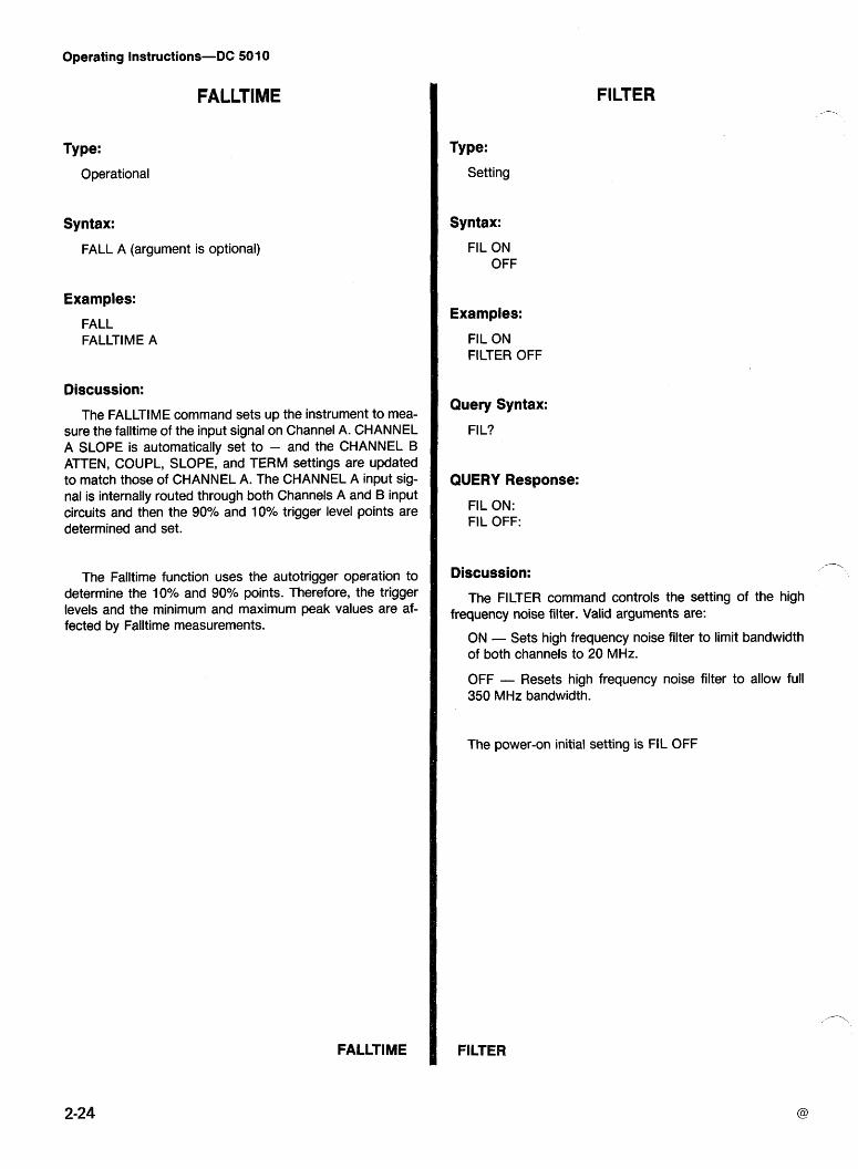
Operating Instructions-DC 501 0
FALLTIME
Type:
Operational
Syntax:
FALL A (argument is optional)
Examples:
FALL FALLTIME A
Discussion:
The FALLTIME command sets up the instrument to mea- sure the falltime of the input signal on Channel A. CHANNEL A SLOPE is automatically set to - and the CHANNEL B ATTEN, COUPL, SLOPE, and TERM settings are updated to match those of CHANNEL A. The CHANNEL A input sig- nal is internally routed through both Channels A and B input circuits and then the 90% and 10% trigger level points are determined and set.
The Falltime function uses the autotrigger operation to determine the 10% and 90% points. Therefore, the trigger levels and the minimum and maximum peak values are af- fected by Falltime measurements.
FILTER
Type:
Setting
Syntax:
FIL ON OFF
Examples:
FIL ON FILTER OFF
Query Syntax:
FI L?
QUERY Response:
FIL ON: FIL OFF:
Discussion: -7
The FILTER command controls the setting of the high frequency noise filter. Valid arguments are:
ON - Sets high frequency noise filter to limit bandwidth of both channels to 20 MHz.
OFF - Resets high frequency noise filter to allow full 350 MHz bandwidth.
The power-on initial setting is FIL OFF
FILTER
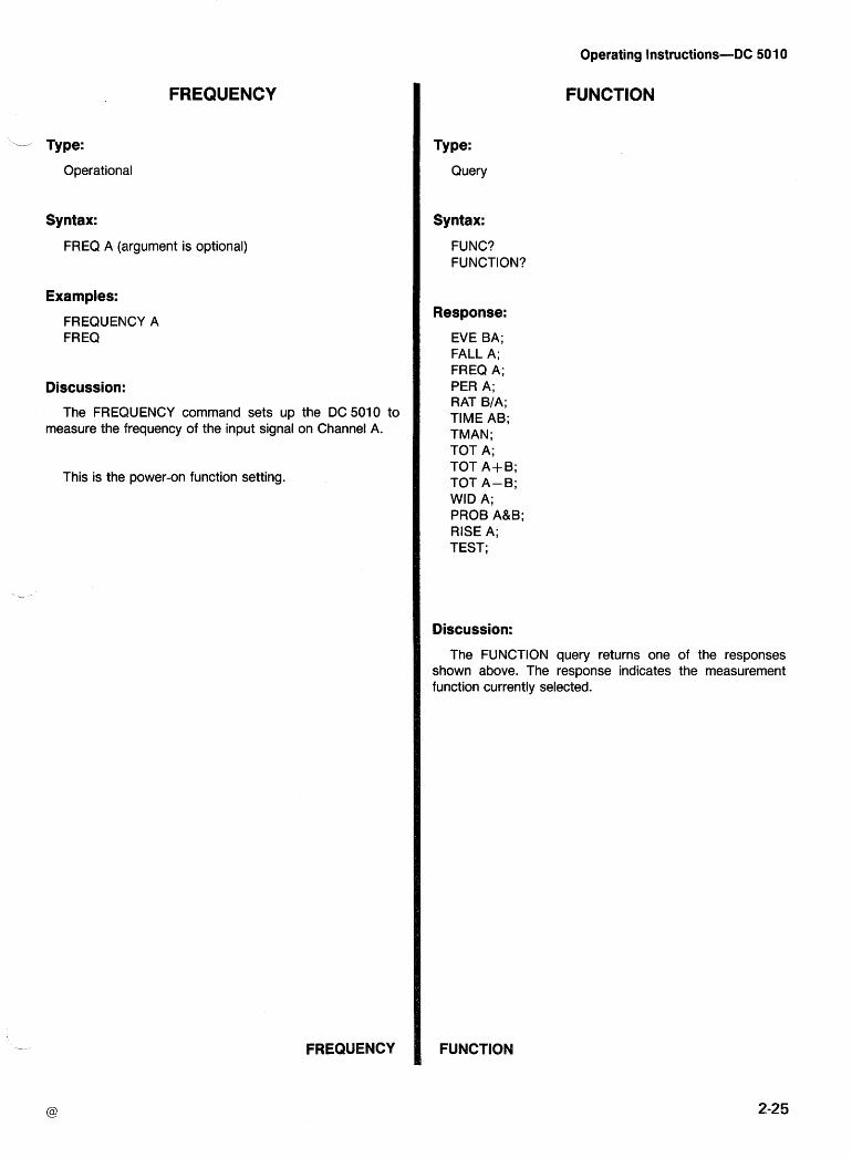
FREQUENCY
--- Type:
Operational
Syntax:
FREQ A (argument is optional)
Examples:
FREQUENCY A FREQ
Discussion:
The FREQUENCY command sets up the DC 5010 to measure the frequency of the input signal on Channel A.
This is the power-on function setting.
FREQUENCY
Operating Instructions-DC 501 0
FUNCTION
Type:
Query
Syntax:
FUNC? FUNCTION?
Response:
EVE BA; FALL A; FREQ A; PER A; RAT BIA; TIME AB; TMAN; TOT A; TOT A+B; TOT A-B; WID A; PROB A&B; RISE A; TEST;
Discussion:
The FUNCTION query returns one of the responses shown above. The response indicates the measurement function currently selected.
FUNCTION
Operating Instructions-DC SO 10
IDENTIFY
Type:
Query
Syntax:
ID? IDENTIFY?
Response:
ID TEK/DCSOlO,V79.l ,Fx.y ;
Discussion:
The IDENTIFY query returns the above response where:
TEKIDC 501 0 - Identifies the instrument type.
V79.1 - Identifies the version of Tektronix Codes and Format Standard to which the instrument conforms.
- ldentifies the firmware version of the instrument, where x.y is a decimal number.
IDENTIFY
INITIALIZE
Type:
Operational
Syntax:
IN IT INITIALIZE
Discussion:
The INIT command performs a power-on ir~itialization of the instrument's settings. The power-on settings for the DC 501 0 are:
FREQ A AVE -1 FIL OFF NULL OFF SLO POS (Channels A&B) ATT 1 (Channels A&B) COU DC (Channels A&B) TERM HI (Channels A&B) CHA A OPC OFF OVER OFF PRE OFF DT OFF USER OFF RQS ON
In addition, an autotrigger is performed to set the trigger levels. With the maximum and minimum peak values of autotrigger performed, the maximum execution time for the INlT function is 2.5 seconds.
The INIT command does not generate a power-on SRQ nor does it put the instrument in LOCAL mode! as a normal power-on does.
INITIALIZE
LEVEL (TRIGGER LEVEL)
.- Type:
Setting or Query
Setting Syntax:
LEVEL <number>
Examples:
LEVEL - 1.025 LEV 0.005 LEV 7.5
Query Syntax:
LEV?
Query Response:
LEV - 1.0:25; LEV 0.000;
-_- Discussion:
The LEVEL command sets the trigger level of the pre- viously selected channel to the value specified. The value is expressed in volts and has a range of -2.000 to 2.000 when in x 1 attenuation and -10.000 to 10.000 when in x 5 attenuation. The resolution is 0.004 for x 1 attenuation and 0.020 for x 5 attenuation.
The value is rounded to the nearest step and if this is not within the range of the DC 5010 the trigger level is left un- changed and an execution error (ERR 205) is issued.
For information on selecting Channels, see discussion of the CHANNEL command.
LEVEL (TRIGGER LEVEL)
MAXIMUM
Type:
Query
Syntax:
MAX? MAXIMUM?
Response:
MAX <number>;
Discussion:
The MAX? query returns a value indicating the maximum input signal voltage for the selected channel measured dur- ing the last autotrigger cycle. If the signal has changed and/or the input signal conditioning has changed since the last autotrigger, another AUTOTRIG is required to obtain the new MAX values.
An autotrigger cycle occurs for each AUTOTRIG, PROBECOMP, RISE, or FALL operation. The maximum ex- ecution time for each operation is 2.5 sec, (1.5 sec, typical).
MAXIMUM
Operating Instructions-DC 501 0
MINIMUM
Type:
Query
Syntax:
MIN?
Response:
MIN <number>
Discussion:
The MINIMUM? query returns a value indicating the mini- mum input signal voltage for the selected channel measured during the last autotrigger cycle. If the signal has changed and/or the signal conditioning has changed since the last autotrigger, another AUTOTRIG is required to obtain the new MIN values.
An autotrigger cycle occurs for each AUTOTRIG, PROBECOMP, RISE, or FALL operation. The maximum ex- ecution time for each operation is 2.5 sec, (1.5 sec, typical).
MINIMUM
MULL
Type:
Operational
Syntax:
NULL ON NULL OFF
Examples:
NULL ON NULL OFF
QUERY Syntax:
NULL?
Query Response:
NULL ON; NULL OFF;
Discussion: /-\
The NULL command controls the storing of measure- ment results to be subtracted from all subseql~ent measure- ments. Valid arguments are:
ON - Store current measurement result and subtract it from all following measurements.
OFF - Reset stored Null value.
The Null value is reset each time the NULL OFF com- mand is executed and each time a FUNCTION COMMAND IS EXECUTED. For Time interval measurement (TIME, WIDTH, RISE, FALL) the Null value is reset to 5.2 nsec to provide compensation for propagation delay time between Channels A and B input circuitry. For all other measure- ments, the Null value is reset to 0.
The power-on initial setting is NULL OFF.
NULL
Operating Instructions-DC 501 0
OPC (OPERATION COMPLETE)
- Type:
Setting or Query
Setting Syntax:
OPC or4 OFF
Examples:
OPC ON OPC OFF:
Query Synitax:
OPC?
Query Reslponse:
OPC ON; OPC OFF:;
Discussion:
.- The OPC command controls the asserting of SRQ when a measurement is completed. This command allows a con- troller to start a measurement, and then process some other task while waiting for an SRQ to inform it that measurement data is ready.
When OPC is ON and a measurement completes, SRQ is asserted and remains asserted until the status is read via a serial poll or until cleared by RQS OFF or a Device Clear. Operation Complete is indicated by a Status Byte of 66 or 82 and an ERROR query response of ERR 402.
For more Status Byte and ERROR information, see "Er- ror and Status Reporting".
The Power on initial setting is OPC OFF.
OPC (OPERATION COMPLETE)
OVERFLOW
Type:
Setting or Query
Setting Syntax: OVER ON
OFF
Examples:
OVER ON OVERFLOW OFF
Query Syntax:
OVER?
Query Response:
OVER ON; OVER OFF;
Discussion:
The OVERFLOW command controls the asserting of SRQ when the internal counting capacity of the DC 5010 is exceeded. This command allows the controller to detect and to respond to overflow conditions.
When making measurements, the DC 5010 uses two in- ternal 43-bit counters, one for Channel A and one for Chan- nel B.
For EVENTS, FREQUENCY, PERIOD, RATIO, TIME, or WIDTH measurements, OVERFLOW usually indicates that one of the input channels is not set up properly.
For TMANUAL and TOTALIZE measurements, OVER- FLOW can easily be used by the controller to extend the range of the measurement. When making TMANUAL mea- surements, an OVERFLOW indicates that the Channel B counter has counted 243 internal time base pulses (m87960.9 seconds). When making TOTALIZE measure- ments, an OVERFLOW indicates that the Channel A counter has counted 243 ( - 8 . 8 ~ 1 012) on the Channel A in- put. For both TMANUAL and TOTALIZE, the measurement result is reset and the measurement continues after an over- flow is detected.
PROBECOMP and TEST measurements do not gener- ate overflow conditions.
When OVERFLOW is ON and the instrument's internal capacity is exceeded, SRQ is asserted and remains assert- ed until the status is read via a serial poll or until cleared by RQS OFF or a Device Clear. Channel A overflow is indicated by a Status Byte of 193 or 209 and an ERROR query re- sponse of ERR 71 1. Channel B overflow is indicated by a Status Byte of 194 or 21 0 and an ERROR query response of ERR 71 2.
The power-on initial state is OVER OFF.
OVERFLOW
Operating Instructions-DC 501 0
PERIOD
Type:
Operational
Syntax:
PER A (argument is optional)
Example:
PERIOD A PER
Discussion:
The PERIOD command sets up the DC 5010 to measure the period of the input signal on Channel A.
PERIOD
PRESCALE
Type:
Setting or Query
Setting Syntax:
PRE ON OFF
Examples:
PRESCALE ON PRE OFF
Query Syntax:
PRE?
Query Response:
PRE ON; PRE OFF;
Discussion: -- , .
The PRESCALE command multiplies the Channel A count by 16 before calculating FREQUENCY, PERIOD, RA- TIO, and TOTALIZE. This command should be used when a divide by 16 prescaler is attached to Channel A, otherwise erroneous measurelnents will result. Valid arguments are:
ON - The Channel A input is multiplied by 16 before calculating results.
OFF - The Channel A input is not scalecl before the results are calculated.
When the PRESCALE command is used and a compati- ble prescaler is not connected to the DC 501 0 an execution warning (ERR 604) is issued.
The power-on initial setting is PRE OFF.
PRESCALE
PROBECOMP (PROBE COMPENSATION)
- Type:
Operational
Syntax:
PROBE I~&B (argument is optional)
Examples:
PROBECOMP A&B PROB
Discussion:
The PROIBE COMP command sets up the DC 5010 to provide information which can be used to help compensate probes.
This function generates 2-digit results. The most signifi- cant digit is the result for Channel A and the least significant digit is the result for Channel B.
The PROBECOMP function uses the autotrigger oper- , ation in the compensation process. Therefore, trigger levels
and MIN and MAX values will be affected by PROBECOMP measurements.
The autotrigger, used by PROBECOMP, is a fast version of auto, with fmi, approximately 100 Hz and maximum ex- ecution time approximately 0.25 second. This fast auto may be used to quickly update MIN and MAX values for signals greater than 100 Hz.
For more information see description of Probe Compen- sation in this manual.
PROBECOMP (PROBE COMPENSATION)
Operating Instructions-DC 501 0
RATIO
Type:
Operational
Syntax:
RAT B/A
Examples:
RATIO B/A RAT
Discussion:
The RATIO command sets up the DC 5010 to measure the ratio of events on Channel B to the events on Channel A.
RATIO
Operating Instructions-DC 501 0
RDY (DATA READY)
Type:
Query
Syntax:
RDY?
Response:
RDY 0; RDY 1;
Discussion:
The RDY query returns "data readyn status. If the value returned is 0, measurement data is not currently available. If the value returned is 1, measurement data is available.
When measurement data is not available and the DC 5010 is "talkedn by the controller, the instrument re- sponds in one of two ways. If "talkedn after receiving the SEND command and data is not ready, the DC 5010 waits for data to become ready and then sends it. If "talkedn and the instrument has not received the SEND command and data is not ready, the DC 5010 responds by sending FF,, (all data lines asserted).
Data becomes ready when a measurement is completed. It remains ready until the data is read out of the instrument or until an instrument setting, except averages, is changed. Data Ready is also cleared by a RESET.
RDY (DATA READY)
RESET
Type:
Operational
Syntax:
RES RESET
Discussion:
The RESET command resets the instrument's count chains and initiates a new measurement. For EVENTS, FALL, FREQUENCY, PERIOD, RATIO, RISE, TIME, OR WIDTH measurements, a single result is determined if the measurement had been "STOPpedn before the RESET. For PROBECOMP measurement, RESET clears current com- pensation status and restarts compensation process. For TMAN and TOTALIZE measurements, counts are reset to zero and a new measurement is restarted if not "Stoppedn before the RESET. For TEST measurement, RESET clears any existing error result and restarts TEST process.
RESET
Operating Instructions-DC 501 0
RlSETlME
' -- Type:
Operational
Syntax:
RlSE A (argument is optional)
Examples:
RlSETlME A RlSE
Discussion:
The RISET'IME command sets up the instrument to mea- sure the risetime of the input signal on Channel A. CHAN- NEL A SLOPE is automatically set to + and the CHANNEL B ATTEN, COUPL, SLOPE, and TERM settings are updat- ed to match those of CHANNEL A. The CHANNEL A input signal is internally routed through both Channels A and B input circuits, and then the 10% and 90% trigger level points are determined and set.
The Risetirne function used the autotrigger operation to determine the 10% and 90% points. Therefore, the trigger levels and the minimum and maximum peak values are af- fected by Risetime measurements.
RQS (REQUEST FOR SERVICE)
Type:
Setting or Query
Setting Syntax:
RQS ON OFF
Examples:
RQS ON RQS OFF
Query Syntax:
RQS?
Query Response:
RQS ON; RQS OFF;
Discussion:
The RQS command is a global control for assertion of SRQ by the DC 5010. When RQS is OFF the DC 5010 will not assert SRQ under any circumstance. When RQS is ON the DC 5010 is allowed to assert SRQ under appropriate circumstances; i.e., errors, operation complete, etc.
The ERROR? query can be used while RQS is OFF to see if any SRQ type conditions have occurred.
SRQ will be asserted for any previously unreported SRQ event when RQS is turned ON after being OFF.
The power-on initial setting is "RQS ONn.
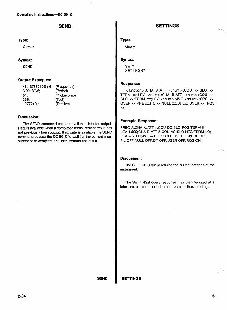
Operating Instructions-DC 501 0
SEND
Type:
Output
Syntax:
SEND
Output Examples:
45.1 375501 9E + 6; (Frequency) 3.001 8E-6; (Period) 01 ; (Pro becomp) 395; (Test) 1 977249.; (Totalize)
Discussion:
The SEND command formats available data for output. Data is available when a completed measurement result has not previously been output. If no data is available the SEND command causes the DC 501 0 to wait for the current mea- surement to complete and then formats the result.
SEND
SETTINGS
Type:
Query
Syntax:
SET? SETTINGS?
Response:
cfunction>;CHA A;ATT cnum>;COU xx;SLO xx; TERM xx;LEV cnum>;CHA B;ATT cnum>;COU xx; SLO xx;TERM xx;LEV tnum>;AVE tnunn>;OPC xx; OVER xx;PRE xx;FIL xx;NULL xx;DT xx; USER xx; RQS xx;
Example Response:
FREQ A;CHA A;ATT 1 ;COU DC;SLO P0S;TEiRM HI; LEV 1.500;CHA B;ATT 5;COU AC;SLO NEG;TERM LO; LEV -5.000;AVE -1 ;OPC 0FF;OVER 0N;PRE OFF; FIL 0FF;NULL 0FF:DT 0FF;USER 0FF;RQS ON;
Discussion:
The SETTINGS query returns the current settings of the instrument.
The SETTINGS query response may then be used at a later time to reset the instrument back to those settings.
SETTINGS
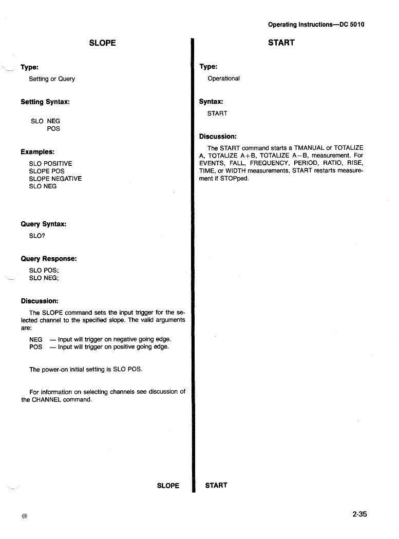
SLOPE
,, Type: Setting or Query
Setting Syntax:
SLO NEG POS
Examples:
SLO POSITIVE SLOPE PCIS SLOPE NEGATIVE SLO NEG
Query Syntax:
SLO?
Query Response:
SLO POS; i- SLO NEG;
Discussion:
The SLOPE command sets the input trigger for the se- lected channel to the specified slope. The valid arguments are:
NEG - lnput will trigger on negative going edge. POS - lnput will trigger on positive going edge.
The power-on initial setting is SLO POS.
For information on selecting channels see discussion of the CHANNEL. command.
SLOPE
Operating Instructions-DC 50 10
START
Type:
Operational
Syntax:
START
Discussion:
The START command starts a TMANUAL or TOTALIZE A, TOTALIZE A+B, TOTALIZE A-B, measurement. For EVENTS, FALL, FREQUENCY, PERIOD, RATIO, RISE, TIME, or WIDTH measurements, START restarts measure- ment if STOPped.
START
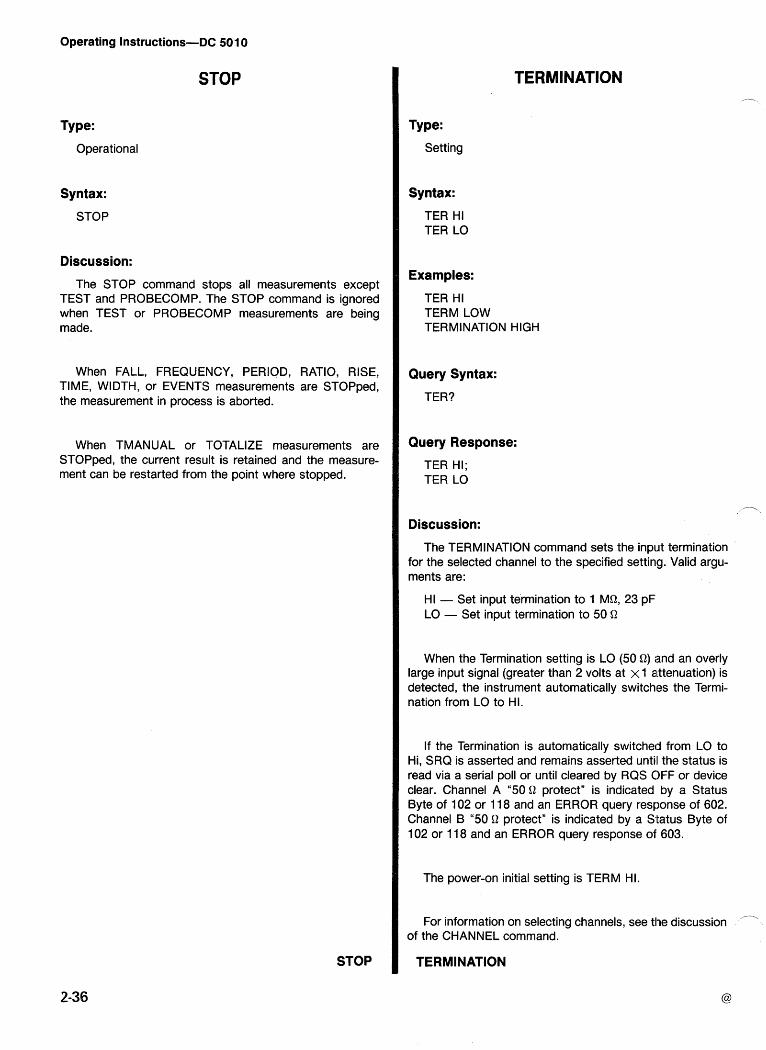
Operating Instructions-DC 50 10
STOP
Type:
Operational
Syntax:
STOP
Discussion:
The STOP command stops all measurements except TEST and PROBECOMP. The STOP command is ignored when TEST or PROBECOMP measurements are being made.
When FALL, FREQUENCY, PERIOD, RATIO, RISE, TIME, WIDTH, or EVENTS measurements are STOPped, the measurement in process is aborted.
When TMANUAL or TOTALIZE measurements are STOPped, the current result is retained and the measure- ment can be restarted from the point where stopped.
STOP
TERMINATION
Type:
Setting
Syntax:
TER HI TER LO
Examples:
TER HI TERM LOW TERMINATION HIGH
Query Syntax:
TER?
Query Response:
TER HI; TER LO
- Discussion:
The TERMINATION command sets the input termination for the selected channel to the specified setting. Valid argu- ments are:
HI - Set input termination to 1 MQ, 23 pF LO - Set input termination to 50 Q
When the Termination setting is LO (50 Q) and an overly large input signal (greater than 2 volts at XI attenuation) is detected, the instrument automatically switches the Termi- nation from LO to HI.
If the Termination is automatically switched from LO to Hi, SRQ is asserted and remains asserted until the status is read via a serial poll or until cleared by RQS OFF or device clear. Channel A "50 Q protect" is indicated by a Status Byte of 102 or 11 8 and an ERROR query response of 602. Channel B "50 Q protect" is indicated by a Status Byte of 102 or 11 8 and an ERROR query response of 603.
The power-on initial setting is TERM HI.
For information on selecting channels, see the discussion of the CHANNEL command.
TERMINATION
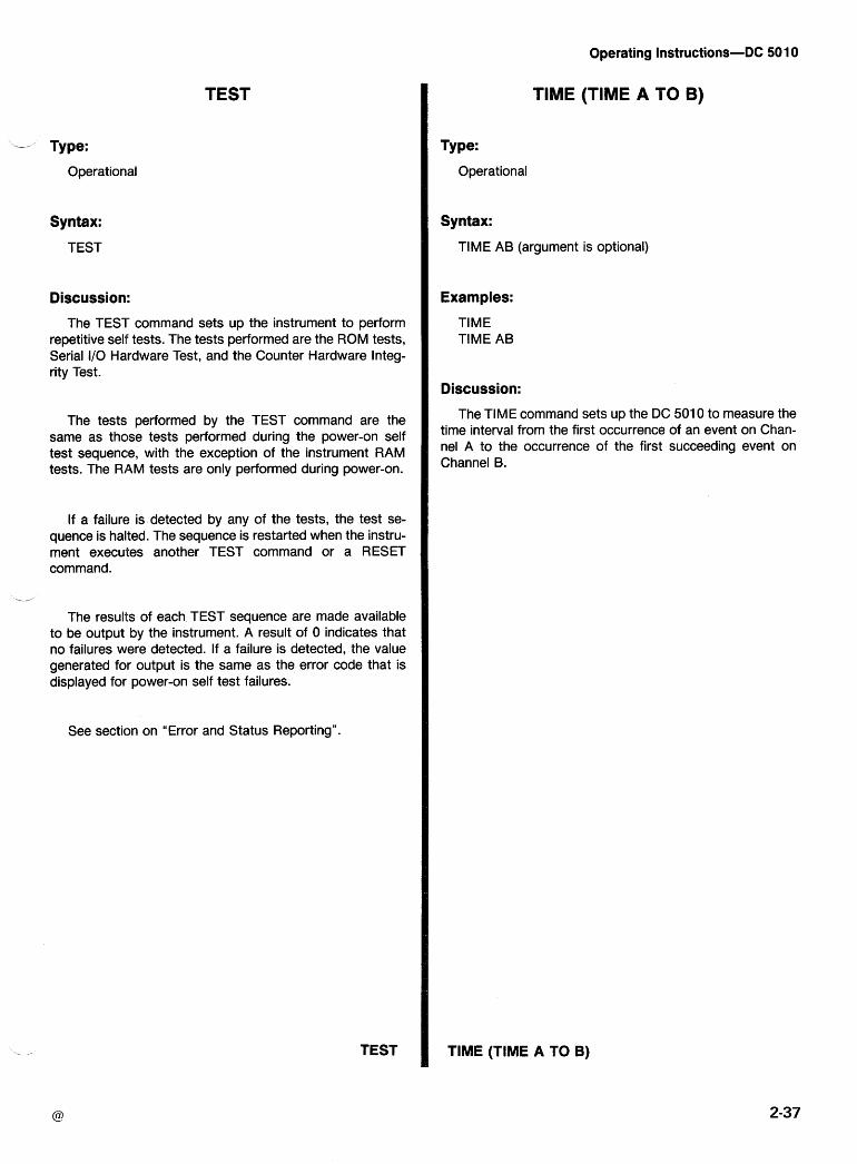
Operating Instructions-DC 501 0
TEST
- A Type:
Operational
Syntax:
TEST
Discussion:
The TEST command sets up the instrument to perform repetitive self tests. The tests performed are the ROM tests, Serial I10 Hardware Test, and the Counter Hardware Integ- rity Test.
The tests performed by the TEST command are the same as those tests performed during the power-on self test sequence, with the exception of the instrument RAM tests. The RAM tests are only performed during power-on.
If a failure is detected by any of the tests, the test se- quence is halted. The sequence is restarted when the instru- ment executes another TEST command or a RESET command.
L-'
The results of each TEST sequence are made available to be output by the instrument. A result of 0 indicates that no failures were detected. If a failure is detected, the value generated for output is the same as the error code that is displayed for power-on self test failures.
See section on "Error and Status Reporting".
TEST
TlME (TIME A TO B)
Type:
Operational
Syntax:
TlME AB (argument is optional)
Examples:
TlME TlME AB
Discussion:
The TlME command sets up the DC 501 0 to measure the time interval from the first occurrence of an event on Chan- nel A to the occurrence of the first succeeding event on Channel B.
TlME (TIME A TO B)
Operating Instructions-DC 501 0
TMANUAL (TIME MANUAL)
Type:
Operational
Syntax:
TMAN TMANUAL
Discussion:
The TMANUAL command sets up the DC 5010 to mea- sure time in a "stop watch" type operation. Measurement is started by the "START" command and is halted by the "STOP" command. If in "DT GATEn mode, TMANUAL oper- ation is started and stopped alternately using the Group Ex- ecute Trigger <GET> interface message.
See discussions of START, STOP, and DT commands.
See discussion of <GET> in Sending IEEE lnterface Control Messages in this section.
TMANUAL (TIME MANUAL)
TOTALIZE
Type:
Operational
Syntax:
TOT A (argument is optional) A+B A-B
Examples:
TOTALIZE A+B TOT A-B TOT A
Discussion:
This command sets up the DC 501 0 to measure and cal- culate the total number of events on the specified channel or channels. The measurement is started by the "START" command and stopped by the "STOP" command. If in "DT GATE" mode, TOTALIZE operation is started and stopped alternately using the Group Execute Trigger <GET> inter- face message.
In the A+ B and A- B modes, the DC 50'1 0 will only count B events after the first valid A event.
If no argument is specified, TOT A is assumed.
See discussions of START, STOP, and DT commands.
See discussion of <GET> in sending in IEEiE lnterface Control Messages in this section.
TOTALIZE
REV JUL 1983
USEREQ (USER REQUEST)
L Type:
Setting or Query
Setting Symtax:
USER ON OFF
Examples:
USER ON USEREQ OFF
Query Syntax:
USER?
Query Reslponse:
USER ON; USER OFF;
Discussion:
,, The USEREQ command controls the asserting of SRQ when the front panel INST ID button is pushed. This pro- vides a communication capability between the instrument and a controller that can be initiated from the front panel of the instrument.
When USER is ON and the INST ID button is pushed, SRQ is asserted and remains asserted until the status is read via a serial poll or until cleared by RQS OFF or a De- vice Clear. The User Request is indicated by a Status Byte of 67 or 83 a.nd an ERROR query response of ERR 403.
The power-on initial setting is USER OFF.
USEREQ (USER REQUEST)
Operating Instructions-DC 50 10
WIDTH
Type:
Operational
Syntax:
WID A (argument is optional)
Examples:
WIDTH A WID
Discussion:
This command sets up the DC 5010 to measure the pulse width of the input signal on Channel A. The slope setting of Channel A determines whether positive going pulse width or negative-going pulse width is measured.
WIDTH
Operating Instructions-DC 501 0
MESSAGES AND COMMUNICATION PROTOCOL
Command Separator
A message consists of one command or a series of com- mands, followed by a message terminator. Messages con- sisting of multiple commands must have the commands separated by semicolons. A semicolon at the end of a mes- sage is optional. For example, each line below is a message.
INIT TEST;INIT;RQS 0N;USER OFF;ID?;SET? TEST;
Message Terminator
Messages may be terminated with EOI or the ASCll line feed (LF) character. Some controllers assert EOI concur- rently with the last data byte; others use only the LF charac- ter as a terminator. The instrument can be internally set to accept either terminator. With EOI ONLY selected as the terminator, the instrument interprets a data byte received with EOI asserted as the end of the input message; it also asserts EOI concurrently with the last byte of the output message. With the LFIEOI setting, the instrument interprets the LF character without EOI asserted (or any data byte received with EOI asserted) as the end of an input message; it transmits carriage return (CR) followed by line feed (the LF with EOI asserted) to terminate output messages. Refer service personnel to the Maintenance section of the manual for information on setting the message terminator. TM 5000 instruments are shipped with EOI ONLY selected.
Formatting A Message
Commands sent to TM 5000 instruments must have the proper format (syntax) to be understood; however, this for- mat is flexible and many variations are acceptable. The fol- lowing describes this format and the acceptable variations.
The instruments expect all commands to be encoded in ASCII; however, they accept both upper and lower case ASCll characters. All data output is in upper case (see Fig. 2-1 1).
As previously discussed, a command consists of a head- er followed, if necessary, by arguments. A command with arguments must have a header delimiter which is the space character SP between the header and the argument.
RQSspON
If extra formatting characters SP, CR, and LF (the LF can- not be used for format in the LFIEOI terminator mode) are -, added between the header delimiter and the argument, they are ignored by the instrument. (SP) (CR) and (LF) are shown as subscripts in the following examples:
Example 1 : RQS,,ON;
Example 2: RQS,, ,,ON;
Example 3: RQS,, ,, ,, ,, ,, ON
In the command list, some headers and arguments are listed in two forms, a full-length version and an abbreviated version. The instrument accepts any header 'or argument containing at least the characters listed in the short form; any characters added to the abbreviated version must be those given in the full-length version. For documentation of programs, the user may add alpha characters to the full- length version. Alpha characters may also be added to a query header, provided the question mark is at the end.
USER? USERE? USEREQ? USEREQUEST?
Multiple arguments are separated by a comma; however, the instrument will also accept a space or spaces as a delimiter. -
293
2sP3
2cP3
NOTE
In the last example, the space is treated as a format character because it follows the comma (the argument delimiter).
Number Formats
The instrument accepts the following kinds of numbers for any of the numeric arguments.
Signed or unsigned integers (including 3-0 and -0). Unsigned integers are interpreted as positive. Exam- ples: + I , 2, -1, -10
Signed or unsigned decimal numbers. Un~signed deci- mal numbers are interpreted to be positive. Examples: -3.2, +5.0, 1.2
Floating point numbers expressed in scientific nota- tion. Examples: +1 .OE-2, 1 .OE-2, 0.01 E-k0
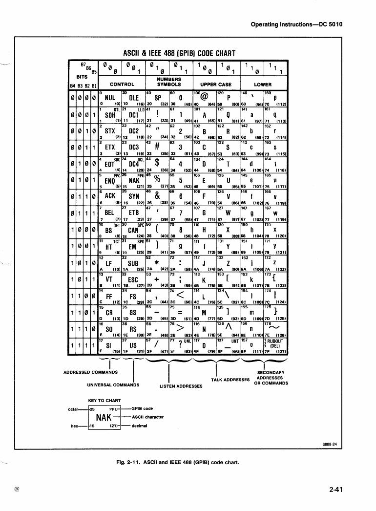
Operating Instructions-DC 501 0
ASCII & IEEE 488 (GPIB] CODE CHART
B 7 ~ 6 B5 O o l a O 1 I I I 1
1
BITS I 0 0 I 0 NUMBERS
34 83 82 B1l CONTROL I SYMBOLS I UPPER CASE I LOWER I
20 40 60 120
0 IlOO"@ 1 P 140 , 160
~ I ~ I ~ I ~ O N U L I DLE SP I I P 0 (0) 10 (16) 20 (32) 30 (48) 40 (64) 50 (80) 60 (96) 70 (112 1 GTL 21 LLO 41 61 101 121 141 161 I 0 0 0 1 SOH DC1 1 A Q a 9
3 (3113 (19123 (35)33 (51143 (67153 (83163 (99173 (115
4 SoC 4 64 104 124 144 164 0 1 0 0 EOT 0cJCL 44 $ 4 D T d t
6 (6) 16 (22) 26 (38) 36 (54) 46 (70) 56 (86) 66 (102) 76 (118 7 27 67 107 127 147 167
47 , 0 1 1 1 BEL ETB 7 G W 4 w
17 37 57 77 7 UNL 117 137 UNT 157
US 0 0 7 RUBOUT
1 1 1 1 SI - (DELI -- --- ADDRESSED COMMANDS ' I I I
I SECONDARY
TALK ADDRESSES ADDRESSES UNIVERSAL COMMANDS LISTEN ADDRESSES OR COMMANDS
KEY T O CHART
GBlB code
ASCII character
Fig. 2-1 1. ASCII and IEEE 488 (GPIB) code chart.
Operating Instructions-DC 50 1 0
Rounding of Numeric Arguments
The instrument rounds numeric arguments to the nearest unit of resolution and then checks for out-of-range conditions.
Message Protocol
As the instrument receives a message it is stored in the lnput Buffer, processed, and executed. Processing a mes- sage consists of decoding commands, detecting delimiters, and checking syntax. For setting commands, the instrument then stores the indicated changes in the Pending Settings Buffer. If an error is detected during processing the instru- ment asserts SRQ, ignores the remainder of the message, and resets the Pending Settings Buffer. Resetting the Pend- ing Settings Buffer avoids undesirable states which could occur if some Setting Commands are executed while others in the same message are not.
Executing a message consists of performing the actions specified by its command(s). For setting commands, this in- volves updating the instrument settings and recording these updates in the Current Settings Buffer. The setting com- mands are executed in groups-that is, a series of setting commands is processed and recorded in the Pending Settings Buffer before execution takes place. This allows the user to specify a new instrument state without having to consider whether a particular sequence would be valid. Ex- ecution of the settings occurs when the instrument pro- cesses the message terminator, a query-output command, or an operational command in a message.
When the instrument processes a query-output com- mand in a message, it executes any preceding setting com- mands to update the state of the instrument. It then executes the query-output command by retrieving the ap- propriate data and putting it in the Output Buffer. Then, pro- cessing and execution continue for the remainder of the message. The data are sent to the controller when the in- strument is made a talker.
When the instrument processes an operational command in a message, it executes any preceding setting commands before executing the operational command.
Multiple Messages
The lnput Buffer has finite capacity and a single message may be long enough to fill it. In this case, a portion of the message is processed before the instrument accepts addi- tional input. During command processing the instrument holds off additional data (by asserting NRFD) until space is available in the buffer.
When space is available, the instrument can accept a second message before the first has been processed. How- ,, ever, it holds off additional messages with INRFD until it completes processing the first.
After the instrument executes a query-output command in a message, it holds the response in its Outplut Buffer until the controller makes the instrument a talker. If the instru- ment receives a new message before all of the output from the previous message is read it clears the Output Buffer before executing the new message. This prevents the con- troller from getting unwanted data from old messages.
One other situation may cause the instrument to delete output. The execution of a long message might cause both the lnput and Output buffers to become full. When this oc- curs, the instrument cannot finish executing the message because it is waiting for the controller to read tlhe data it has generated; but the controller cannot read the data because it is waiting to finish sending its message. Because the in- strument's lnput buffer is full and it is holding off the rest of the controllers message with NRFD, the system is hung up with the controller and instrument waiting for each other. When the instrument detects this condition, it generates an error, asserts SRQ and deletes the data in the Output buff- er. This action allows the controller to transmit the rest of the message and informs the controller that the message was executed and that the output was deleted. -
A TM 5000 instrument can be made a talker without hav- ing received a message which specifies what it should out- put. In this case, acquisition instruments (counters and digital multimeters) return a measurement if one is ready. If no measurement is ready, they return a single byte message with all bits equal to 1 (with message terminator); other TM 5000 instruments will return only this message.
Instrument Response to IEEE-488 Interface Messages
lnterface messages and their effects on the instrument's interface functions are defined in IEEE Standard 488-1978. Abbreviations from the standard are used in this discussion which describes the effects of interface messages on instru- ment operation.
When the UNL command is received, the instrument's listener function goes to its idle state (unaddressed). In the idle state, the instrument will not accept instrument com- mands from the GPIB. -
Operating Instructions-DC 501 0
The talker $'unction goes to its idle state when the instru- LLO-Local Lockout ment receives the UNT command. In this state, the instru- ment cannot output data via the GPIB. In response to LLO, the instrument goes to a lockout
state-from LOCS to LWLS or from REMS to RWLS.
The ADDRESSED light is off when both the talker and listener functions are idle, If the instrument is either talk ad- dressed or listen addressed, the light is on.
IFC-Interface Clear
This uniline message has the same effect as both the UNT and UNL messages. The front panel ADDRESS light is off.
DCL-Device Clear
REN-Remote Enable
If REN is true, the instrument goes to a remote state (from LOCS to REMS or from LWLS to RWLS) when its listen address is received. REN false causes a transition from any state to LOCS; the instrument stays in LOCS as long as REN is false.
A REN transition may occur after message processing has begun. In this case execution of the message being processed is not affected by a transition.
The Device Clear message reinitializes communication between the instrument and controller. In response to DCL, GTL-Go To Local the instrument clears any input and output messages and any unexecutsd settings in the Pending Settings Buffer. Only instruments that are listen addressed respond to
Also cleared are any errors or events waiting to be reported, GTL by going to a local state. Remote-to-local transitions caused by GTL do not affect the execution of the message except the power-on event. If the SRQ line is asserted for being when GTL was any reason other than power-on, when DCL is received the
SRQ is unasserted.
SDC-Selected Device Clear
This message performs the same function as DCL; how- ever, only instruments that are listen addressed respond to - SDC.
GET-Group Execute Trigger
The instrurnent responds to GET only if it is listen ad- dressed and the instrument device trigger function has been enabled by the Device Trigger command (DT). The GET message is ignored and an SRQ generated if the DT func- tion is disabled (DT OFF), the instrument is in the local state, or if a message is being processed when GET is received.
SPE-Serial lPoll Enable SPD-Serial lPoll Disable
Remote-Local Operation
The preceding discussion of interface messages de- scribes the state transitions caused by GTL and REN. Most front panel controls cause a transition from REMS to LOCS by asserting a message called return-to-local (rtl). This tran- sition may occur during message execution; but in contrast to GTL and REN transitions, a transition initiated by rtl does affect message execution. In this case, the instrument gen- erates an error if there are any unexecuted setting or oper- ational commands. Front panel controls that only change the display (like ID) do not affect the remote-local states-only front panel controls that change settings as- sert rtl. Rtl is unasserted after processing the front panel control change.
Local State (LOCS)
The SPE message enables the instrument to output In LOCS, instrument settings are controlled by the opera- serial poll status bytes when it is talk addressed. The SPD tor via front panel controls. When in LOCS, only bus corn- message switches the instrument back to its normal oper- mands that do not change instrument settings are executed ation of sending the data from the Output buffer. (query-output commands); all other bus commands (setting
and operational) generate an error since their functions are under front panel control.
MLA-My Listen Address MTA-My Tallk Address
The primary listen and talk addresses are established by With Lockout State (LWLS) the instrumenits GPlB address (internally set). The current setting of the GPlB address is displayed on the front panel The instrument operates the same as it does in LOCS, when the INST ID button is pressed. except that rtl will not inhibit a transition to RWLS.
'-
Operating Instructions-DC 501 0
Remote With Lockout State (RWLS)
The instrument operation is identical to except that the rtl message is ignored.
REMS operation
Remote State (REMS)
In this state, the instrument executes all instrument com- mands. Changing a front panel control, except trigger level controls, generates an rtl and causes the instrument to re- turn to local (LOCS).
Because the STB conveys limited information about an event, the events are divided into classes; the Status Byte - reports the class. The classes of events are defined as
'
follows:
COMMAND ERROR
EXECUTION ERROR
INTERNAL ERROR
STATUS AND ERROR REPORTING
Through the Service Request function (defined in the IEEE-488 Standard), the instrument may alert the controller that it needs service. This service request is also a means of indicating that an event (a change in status or an error) has occurred. To service a request the controller performs a Serial Poll; in response the instrument returns a Status Byte (STB) which indicates whether it was requesting service or not. The STB can also provide a limited amount of informa- tion about the request. The format of the information en- coded in the STB is given in Table 2-2. When data bit 8 is set, the STB conveys Device Status information which is indicated by bits 1 through 4.
Table 2-2 DEFINITION OF STATUS BYTE BITS
If 0, ST6 indicates event class If 1, ST6 indicates device status
I I I r - - 1 if requesting service I I I I
I I r - - 1 indicates an abnormal event ' 1 1 ' I 1
I : - - 1 if message processor is busy I I I I
I l l ' I I I I DATA BITS I I I I l I * I I
DECIMAL /I I t I? I I I \ -
SYSTEM EVENTS
EXECUTION WARNING
INTERNAL WARNING
DEVICE STATUS
lndicates the instrument has received a command which it cannot understand.
lndicates that the instrument has received a command that it cannot execute. This is caused by arguments out of range or settings that conflict.
lndicates that the instrument has detected a hardware condition or firmware problem that prevents operation.
Events that are common to instruments in a system (e.g., power-on, User Request, etc.).
The instrument is operating but the user should be aware of potential problems.
Internal warning indicates that the instru- ment has detected a problem. The instru- ment remains operational, but the problem should be corrected (e.g., out of calibration).
Device dependent events.
The instrument can provide additional information about many of the events, particularly the errors reported in the Status Byte. After determining that the instrument request- ed service (by examining the STB) the controller may re- quest the additional information by sending an error query (ERR?). In response, the instrument returns a code which defines the event. These codes are described in Table 2-3.
If there is more than one event to be reported, the instru- ment continues to assert SRQ until it reporits all events. Each event is automatically cleared when it is reported via Serial Poll. The Device Clear (DCL) interface rnessage may be used to clear all events except power-on.
Commands are provided to control the reporting of some individual events and to disable all service requests. For ex- ample, the User Request command (USEREQ) provides in- dividual control over the reporting of the user request event which occurs when the front panel INST ID button is pressed. The Requests for Service command (RQS) con- trols whether the instrument reports any events with SRQ. --,
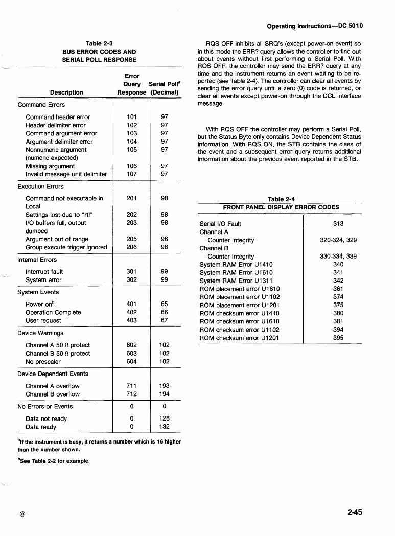
Operating Instructions-DC 50 10
Table 2-3 BUS ERROR CODES AND SERIAL POLL RESPONSE
i_
RQS OFF inhibits all SRQ's (except power-on event) so in this mode the ERR? query allows the controller to find out about events without first performing a Serial Poll. With RQS OFF, the controller may send the ERR? query at any time and the instrument returns an event waiting to be re- ported (see Table 2-4). The controller can clear all events by sending the error query until a zero (0) code is returned, or clear all events except power-on through the DCL interface message.
Error Query Serial Polla
Decimal)
97 97 97 97 97
97 97
Description Response
101 1 02 1 03 1 04 105
106 1 07
Command Errors
Command header error Header delimiter error Command argument error Argument delimiter error Nonnumeric argument (numeric expected) Missing argument Invalid message unit delimiter
With RQS OFF the controller may perform a Serial Poll, but the Status Byte only contains Device Dependent Status information. With RQS ON, the STB contains the class of the event and a subsequent error query returns additional information about the previous event reported in the STB.
Execution Errors
Command not executable in Local Settings lost due to "rtln I10 buffers full, output dumped Argument out of range Group execute trigger ignored
Table 2-4 FRONT PANEL DISPLAY ERROR CODES
Serial I10 Fault Channel A
Counter Integrity Channel B
Counter Integrity System RAM Error Ul4lO System RAM Error U1610 System RAM Error U 131 1 ROM placement error U1610 ROM placement error U1102 ROM placement error U1201 ROM checksum error U1410 ROM checksum error U1610 ROM checksum error U1102 ROM checksum error U1201
Internal Errors
L
Interrupt fault System error
System Even~ts
Power ont' Operation Complete User requlest
Device Warnings
Channel P, 50 Q protect Channel El 50 Q protect No prescaier
Device Dependent Events
Channel Pi overflow Channel El overflow
No Errors or Events
Data not ready Data ready
alf the instrument is busy, it returns a number which is 16 higher than the number shown.
b ~ e e Table 2-2 for example.
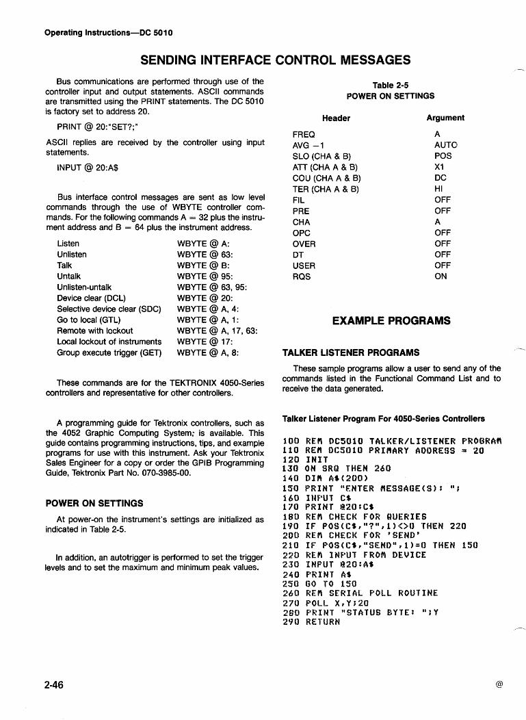
Operating Instructions-DC 501 0
Bus communications are performed through use of the controller input and output statements. ASCll commands are transmitted using the PRINT statements. The DC 5010 is factory set to address 20.
PRINT @ 20:"SET?;"
ASCII replies are received by the controller using input statements.
INPUT @ 20:A$
Bus interface control messages are sent as low level commands through the use of WBYTE controller com- mands. For the following commands A = 32 plus the instru- ment address and B = 64 plus the instrument address.
Listen Unlisten Tal k Untalk Unlisten-untalk Device clear (DCL) Selective device clear (SDC) Go to local (GTL) Remote with lockout Local lockout of instruments Group execute trigger (GET)
WBYTE @ A: WBYTE @ 63: WBYTE @ B: WBYTE @ 95: WBYTE @ 63,95: WBYTE @ 20: WBYTE @ A, 4: WBYTE @ A, 1 : WBYTE @ A, 17,63: WBYTE @ 17: WBYTE @ A, 8:
These commands are for the TEKTRONIX 4050-Series controllers and representative for other controllers.
A programming guide for Tektronix controllers, such as the 4052 Graphic Computing System; is available. This guide contains programming instructions, tips, and example programs for use with this instrument. Ask your Tektronix Sales Engineer for a copy or order the GPlB Programming Guide, Tektronix Part No. 070-3985-00.
POWER ON SETTINGS
At power-on the instrument's settings are initialized as indicated in Table 2-5.
In addition, an autotrigger is performed to set the trigger levels and to set the maximum and minimum peak values.
Table 2-5 POWER ON SETTINGS
Header Argument
FREQ AVG -1 SLO (CHA & B) ATT (CH A A & 8) COU (CHA A & B) TER (CHA A & B) FI L PRE CHA OPC OVER DT USER RQS
A AUTO1 POS X I DC HI OFF OFF A OFF OFF OFF OFF ON
EXAMPLE PROGRAMS
TALKER LISTENER PROGRAMS Y
These sample programs allow a user to send any of the commands listed in the Functional Command List and to receive the data generated.
Talker Listener Program For 4050-Series Controllers
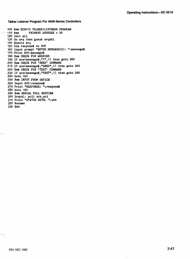
Operating Instructions-DC 501 0
Talker Listener Program For 4040-Series Controllers
100 Rem DC5010 TALKER/LISTENER PROGRAM - 110 Rem PRIMARY ADDRESS = 20
120 Init all 130 On srq then gosub srqhdl 140 Enable srq 150 Dim respons$ to 200 160 Input prompt "ENTER MESSAGE(S) : :message$ 170 Print #20:message$ 180 Rem CHECK FOR QUERIES 190 If pos(message$ ,"?", 1) then goto 260 200 Rem CHECK FOR lSEND1 COMMAND 210 If pos(mes~age$,~SEND~,l) then goto 260 220 R e m CHECK FOR 'TEST1 COMMAND 230 If pos(message$, "TESTn, 1 ) then goto 260 240 Goto 160 250 Rem INPUT FROM DEVICE 260 Input #20:respons$ 270 Print llRESPONSE: u;respons$ 280 Goto 160 290 Rem SEfiIAL POLL ROUTINE 300 Srqhdl: poll stb,pri 310 Print llSTATUS BYTE: ";stb 320 Resume 330 End
REV DEC 1982
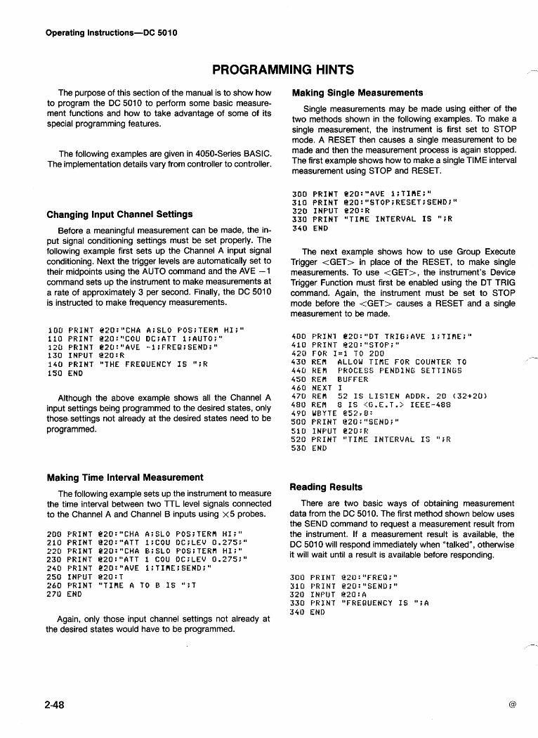
Operating Instructions-DC 501 0
PROGRAMMING HINTS
The purpose of this section of the manual is to show how to program the DC 5010 to perform some basic measure- ment functions and how to take advantage of some of its special programming features.
The following examples are given in 4050-Series BASIC. The implementation details vary from controller to controller.
Changing Input Channel Settings
Before a meaningful measurement can be made, the in- put signal conditioning settings must be set properly. The following example first sets up the Channel A input signal conditioning. Next the trigger levels are automatically set to their midpoints using the AUTO command and the AVE -1 command sets up the instrument to make measurements at a rate of approximately 3 per second. Finally, the DC 501 0 is instructed to make frequency measurements.
I00 PRINT @20:I1CHA A;SLO P0S;TERH HI;" 110 PRINT B20:"COU DCiATT 1;AUTO;" 120 PRINT L2O:"AVE -1;FREQ;SEND;" 130 INPUT g20:R 140 PRINT "THE FREQUENCY IS "JR 150 END
Although the above example shows all the Channel A input settings being programmed to the desired states, only those-settings not already at the desired states need to be programmed.
Making Time Interval Measurement
The following example sets up the instrument to measure the time interval between two TTL level signals connected to the Channel A and Channel B inputs using x 5 probes.
200 PRINT e20:"CHA A;SLO POS;TERfl HI;" 210 PRINT e20:"ATT 1;COU 0C;LEV 0.275;" 220 PRINT Q20:"CHA B;SLO POSrTERH HI;" 230 PRINT B20:"ATT 1 COU DC;LEV 0.275:" 240 PRINT P2O:"AVE 1;TIPIE;SEND;" 250 INPUT @20:T 260 PRINT "TIRE A TO E IS ";T 270 END
Making Single Measurements
Single measurements may be made using either of the two methods shown in the following examples. To make a single measurement, the instrument is first set to STOP mode. A RESET then causes a single measurement to be made and then the measurement process is again stopped. The first example shows how to make a single TIME interval measurement using STOP and RESET.
300 PRINT Q20:"AVE I;TI#E;" 310 PRINT @20:"STOP;RESET;SEND;" 320 INPUT @20:R 330 PRINT "TIflE INTERVAL IS ";R 340 END
The next example shows how to use Group Execute Trigger <GET> in place of the RESET, to make single measurements. To use <GET>, the instrument's Device Trigger Function must first be enabled using the DT TRIG command. Again, the instrument must be set to STOP mode before the <GET> causes a RESET and a single measurement to be made.
400 PRIN7 e20:"DT TR1G;AVE I;TIPlE;"' 410 PRINT B20:HSTOP;u 420 FOR I=1 TO 200 430 RER ALLOW T I f i E FOR COUNTER TO 440 RE# PROCESS PENDING SETTINGS 450 REM BUFFER 460 NEXT I 470 REPI 52 IS LIS1EN ADDR. 20 (32+20) 480 HEM 8 IS (G.E.T.;; IEEE-48s 490 WBYTE @ 5 2 r 8: SO0 PRINT @2U:"SEND;" 510 INPUT @20:R 520 PRINT "TIME INTERVAL IS ";I? 530 END
Reading Results
There are two basic ways of obtaining measurement data from the DC 5010. The first method shown below uses the SEND command to request a measurement result from the instrument. If a measurement result is available, the DC 501 0 will respond immediately when "talkedn, otherwise it will wait until a result is available before responding.
300 ~ ~ Z U : ~ F R E Q ; ~ 310 PRINT @20:"SEND;" 520 INPUT I220:A 330 FRXNT "FREQUENCY IS " ; A 340 END
Again, only those input channel settings not already at the desired states would have to be programmed.
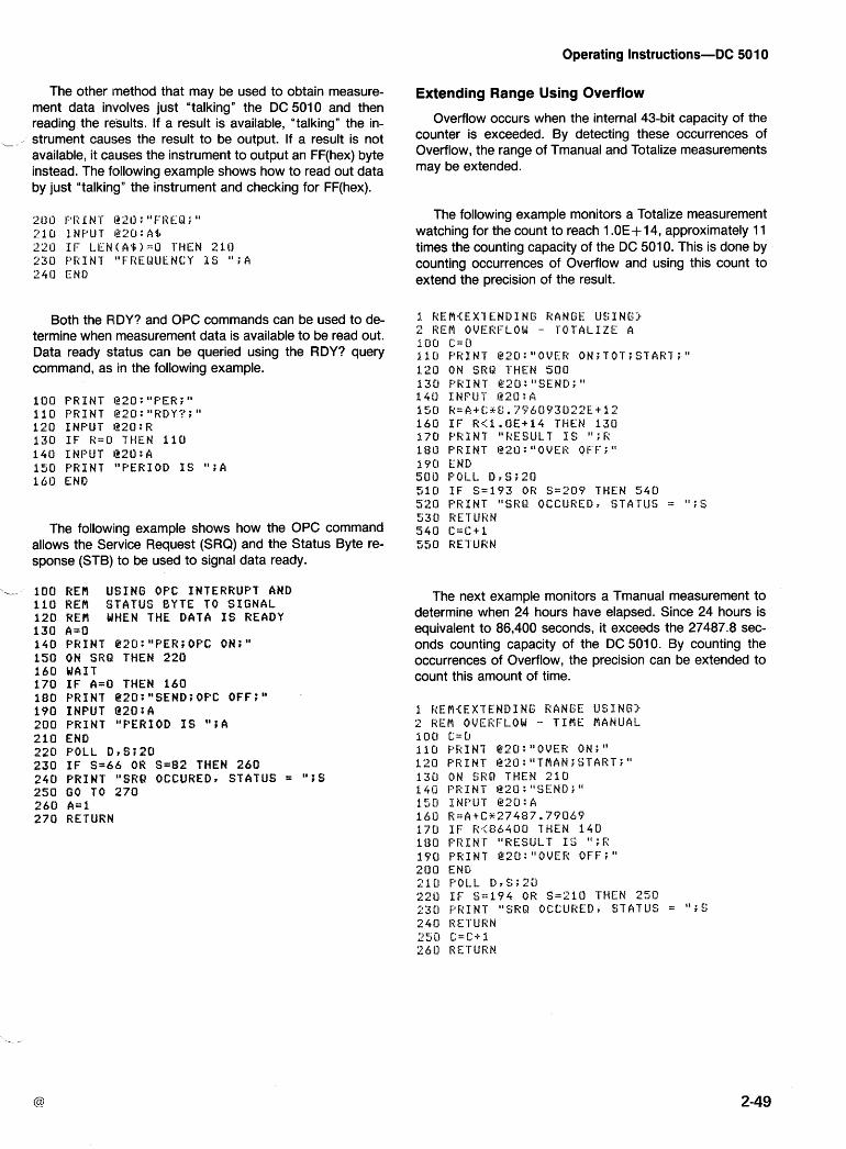
Operating Instructions-DC 501 0
The other method that may be used to obtain measure- ment data involves just "talkingn the DC 5010 and then reading the results. If a result is available, "talkingn the in-
-- - strument causes the result to be output. If a result is not available, it causes the instrument to output an FF(hex) byte instead. The f~ollowing example shows how to read out data by just "talking" the instrument and checking for FF(hex).
Both the PIDY? and OPC commands can be used to de- termine when measurement data is available to be read out. Data ready status can be queried using the RDY? query command, as in the following example.
1 0 0 PRINT 1320: "PER; " 1 1 0 PRINT I ? ~ ~ : ~ R D Y ? ; " 1 2 0 I N P U T 1220:A 130 IF K c 0 THEN 1 1 0 1 4 0 INPUT 1220:A 1 5 0 PRINT "PERIOD I S " ; A 160 END
The following example shows how the OPC command allows the Service Request (SRQ) and the Status Byte re- sponse (STB) to be used to signal data ready.
,-- 1 0 0 REPI USING OPC INTERRUPT AND 1 1 0 RER STATUS 8YTE TO S I G N A L 1 2 0 REt! WHEN THE DATA I S READY 1 3 0 CI=O 140 PRINT C2O:"PEH;OPC ON;" 1 5 0 ON SRQ THEN 2 2 0 1 6 0 WAIT 1 7 0 I F A=O THEN 1 6 0 1 8 0 PRINT @20:"SEND;OPC OFF;" 1 9 0 INPUT i220:A 2 0 0 PRINT "PERIOD I S ";A 2 1 0 END 2 2 0 POLL D r S Z 2 0 2 3 0 I F S=66 OR S = 8 2 THEN 2 6 0 240 PRINT "SRQ OCCURED, STATUS = " ; S 2513 GO TO 2 7 0 260 A=l 2 7 0 RETURN
Extending Range Using Overflow
Overflow occurs when the internal 43-bit capacity of the counter is exceeded. By detecting these occurrences of Overflow, the range of Tmanual and Totalize measurements may be extended.
The following example monitors a Totalize measurement watching for the count to reach 1 .OE+ 14, approximately 1 1 times the counting capacity of the DC 5010. This is done by counting occurrences of Overflow and using this count to extend the precision of the result.
The next example monitors a Tmanual measurement to determine when 24 hours have elapsed. Since 24 hours is equivalent to 86,400 seconds, it exceeds the 27487.8 sec- onds counting capacity of the DC 5010. By counting the occurrences of Overflow, the precision can be extended to count this amount of time.
Operating Instructions-DC 501 0
Using INST ID Button
Communication between the controller and an instru- ment operator can be accomplished using the INST ID but- ton and the USER command. The following example allows a front panel operator to compensate probes and then in- form the controller that the Probecomp is complete. As shown, the probes can be compensated and the INST ID button used even while the rest of the front panel controls are locked out.
1 RE# {US ING THE INS ' l ' I D BUTTON3 1 0 0 ORINT "COMPENSATE 1:'ROBES - 'I;
1 1 0 P R I N T "F'USH I N S T I D BUTTON "; 1 2 0 P R I N T "WHEN DONE." 1 3 0 1 - 0 1 4 0 YRIN7 @ 2 0 : "USER ON;PROBE; " 150 REM GIz'L' "LLO" I S 1 7 1 6 0 WFIYTE @ 1 7 : 1 7 0 ON SKQ T H E N 3(10 1 8 0 W A I I 1913 I F I = 0 THEN 180 2011 F'F;INI' g 2 0 : n I N I T ; u 2 1 0 P R I N T "COMPENSATION DONE." 2 2 0 END 3 0 0 POLL D r S ; 2 0 3 1 0 I F S = 6 7 OR S = 9 3 THEN 3 4 0 3 2 0 P R I N T "SRQ OCCUREDr STATUS = " ' r l a
330 GO TO 3 6 0 3 4 0 F'RINT " I N S T I D E?*UTTON SENSED." 35u 1 = 1 3 6 0 HEIIURN
The INST ID button can also be used to inform the con- troller that the instrument has been set up properly to mea- sure the input signals. Once informed, the controller can then "learnn the current instrument settings, using the SET? query command, and save the setup for later use.
8 0 0 KEM LEARN SETT INGS 8 1 U P R I N T "SET UB THE INSTRUMENT -- "; 8 2 0 PFi INT "PUSH I N S T I D WHEN DONE." G X I o m A S ~ W 8 4 0 I = U 8 5 0 PRJ.N7 @20: "USER ON;'' 8 6 0 ON SRQ THEN 9 4 0 8 7 0 WAIT a s 0 IF r=o THEN 8 7 0 1 3 0 F'RINT @ 2 0 : " S E T ? ; " 9 0 0 I N P U T @20 :A$ 9 1 0 P R I N I "STORED SETT INGS ARE: " ; A $ 9 2 0 P R I N T 1220:"USER OF'F;" 9 3 0 END 9 4 0 POLL D r S i 2 C I 350 I F S = 6 7 OR S=Y3 THEN 9 8 0 9 6 0 P R I N T "SRU OCCUREO~ STATUS = " i s 5'70 GO TO ?YO 98U I = 1 9 9 0 R E T U R N
Duty Cycle Measurement
Duty Cycle measurements can easily be rnade using a combination of Width and Period measurements. The fol- lowing example determines the Duty Cycle of the positive going pulse of the Input signal. This example assumes the trigger level is already set to the desired value.
4 0 0 REM DUTY CYCLE MEASUREMENT 4 1 0 P K I N T B20:"CHA A;SLO PUS;" 4 2 0 P R I N T I ? ~ ~ : ~ W I D ; S E N D ; " 4 3 0 I N P U T l220:W 4 4 0 F'RINT @ZO:"PER;SEND;" 4 5 0 I N P U T 1220:P 4 6 0 D-W/P 4 7 0 P K I N T "THE DUTY CYCLE I S " i D 4 8 0 END
Phase Measurement
A combination of Period and Time measurements can be used to make Phase measurements. The following example determines the phase difference between the Channel A and Channel B signals by first measuring the Period of one sig- nal and then using the Time function to measure the time difference between the two signals. The phase angle is then computed using these two measurements. This example as- sumes that the appropriate signals are connected to input channels A and B and assumes that the trig!ger levels are set correctly. - -
Operating Instructions-DC 501 0
Slew Rate Measurements
Slew Rate measurements can be made using a combina- tion of the RASE and MIN?; MAX? commands. The RISE - command measures the risetime between the 10% and 90% points. The signal level difference between the 10% and 9O0/0 points is then calculated using the results returned for the MIN? and MAX? query commands. Using the signal lev- el difference and risetime values, the slew rate is determined.
Additional assistance in developing specific application oriented software is available in the following Tektronix manuals.
070-3985-00-GPIB Programming Guide. This man- ual is specifically written for applications of this in- strument in IEEE-488 systems. It contains pro- gramming instructions, tips and some specific example programs.
070-2270-00-4051 GPlB Hardware Support Man- ual. This manual gives an indepth discussion of IEEE-488 bus operation, explanations of bus timing details and early bus interface circuitry.
070-2058-01 -Programming In BASIC
070-2059-01 -Graphic Programming In BASIC
062-5971 -01 -4050-Series Programming Aids, T1 (includes software)
062-5972-01 -4050-Series Programming Aids, T2 (includes software)
070-2380-01 -4907 File Manager Operators manual
070-21 28-00-4924 Users manual
070-1 940-01 -4050 Series Graphic System Operators manual
070-2056-01 -4050 Series Graphic System Reference manual
070-391 8-00-4041 Operators manual
061 -2546-00-4041 Programming Reference manual

Chapitre 2-DC 5010
INSTRUCTIONS D'UTILISATION
INTRODUCTION
Premiere in~spection
lnspecter I'instrument pour reperer tout dommage ap- parent (bosses, eraflures, etc..). Garder le carton et le materiel d'ernballage d'origine en vue d'une utilisation ulterieure. Si I'appareil presente des defauts exterieurs, en aviser le centre Tektronix le plus proche.
Instructions de reemballage
Si cet instrument doit gtre renvoye a un centre de maintenance Tektronix pour une revision ou une repara- tion, y apposer une etiquette portant le nom (et I'a- dresse) de la societe utilisatrice et le nom de la per- sonne a y contacter, ainsi que le numero de serie com- plet de I'instrument et la description du defaut constate.
Si I'emballage d'origine n'est plus disponible, emballer \/ I'appareil de la facon suivante :
1. Se procurer un carton resistant dont les dimen- sions internes soient superieures de 15 cm aux dimen- sions de I'appareil. La resistance de I'emballage doit gtre de 90 kg/cmz.
2. Entourer I'instrument d'une feuille de polyethylene.
3. Tapisser le fond et les bords du carton de mousse d'urethane sur une epaisseur de 7'5 cm.
4. Fermer le carton au moyen d'une bande adhesive.
PREPARATION
Interface arriere
Une encoche entre les contacts 21 et 22 du connec- teur arriere indenfie cet instrument comme appartenant aux compteurs de la serie TM 5000. S'il doit &re utilise en conjonction avec d'autres instruments, installer un detrompeur (n+ de reference 21 4-1 593-02) dans la po- sition correspondante du connecteur du module d'ali- mentation pour prevenir I'utilisation dans ce m6me module de tiroirs appartenant a des familles differentes.
AVERTISSEMENT
En vue d'eviter tout danger d'electrocution, de- brancher le cordon d'alimentation du module dJali- mentation avant d'installer le detrompeur. Cette operation ne doit 6tre effectuee que par un person- nel de maintenance qualifie.
Le DC 5010 presente les possibilites d'entree et de sortie suivantes sur I'interface du panneau arriere :
Entree de validation
Sortie de I'horloge 10 MHz
Entree de I'horloge externe (1'5, 10 MHz)
Fonction de Predivision
Entree de reinitialisation
NOTE
Les indications relatives 3 I'interface arriere figu- rent au chapitre Maintenance de ce manuel. Toute connexion doit &re effectuee par un personnel de maintenance qualifi6.
5. Y inscrire la mention "FRAGILE".
Installation et retrait de I'instrument
Conditions d'environnement
Les caracteristiques d'utilisation (en et hors fonction- nement) de cet instrument ne sont valables que dans les conditions definies au chapitre Caracteristiques de ce manuel. Toutefois, eviter d'utiliser le DC 501 0 a des temperatures extremes (possi bilite de condensation in-
*--- terne).
Le DC 501 0 ne peut 6tre utilise que dans les modules d'alimentation de la Serie 5000.
NOTE
Se r6ferer aux Consignes de securite en premiere page de ce manuel avant d'installer cet appareil dans le module d'alimentation.
ADD DEC 1g82 French 2-1
Instructions d'utilisation-DC 5010
Se referer au manuel d'instructions correspondant au module d'alimentation et s'assurer que le selecteur de tension se trouve sur la position correspondant a la ten- sion reseau utilisee. Verifier que les fusibles appropries ont ete installes (compteur, module d'alimentation). S'assurer que la fiche d'alimentation du module d'ali- mentation a son conducteur de masse.
ATTENTION
Veiller a ce que les detrompeurs (du colnnecteur du compartiment selectionne du module d'alimentation) coihcident avec les encoches du connecteur du tiroir.
Aligner les rainures supkrieure et inferieure du tiroir avec les guides du compartiment sklectionne (v. figure 2-1). Inserer le Compteur dans le compartiment et le pousser a fond pour que le circuit imprime se place cor- rectement. Mettre le module en service (commutateur POWER).
En vue de prhvenir toute dhthrioration de cet Pour extraire le compteur du module d'alimentation, instrument, couper I'alimentation du module d'ali- couper I'alimentation (commutateur POWER), tirer le mentation avant I'installation ou le retrait de tout bouton de deverrouillage (coin gauche I'avant du tiroir. Installer et 6ter le tiroir a vec prhcaution. tiroir). Tirer I'instrument hors du compartiment en le
maintenant dans la position horizontale.
UTlLlSATlON DU PANNEAU AVANT
Les informations ci-dessous decrivent le fonctionne- COMMANDES DE VISUALISATION ment des commandes et connecteurs de la face avant (voir Fig. 2-2). @ Affichage
L'affichage du resultat de chaque mesure est assure par neuf DELs 7 segments et 8 indicateurs. La resolu- tion de I'affichage est excellente. Les caracteres sont justifies a droite avec positionnement automatique du point decimal. Un clignotement de I'affichage indique un depassement de capacite de comptage.
French 2-2
Fig. 2-1. Installation et retrait du tiroir.
ADD DEC 1982
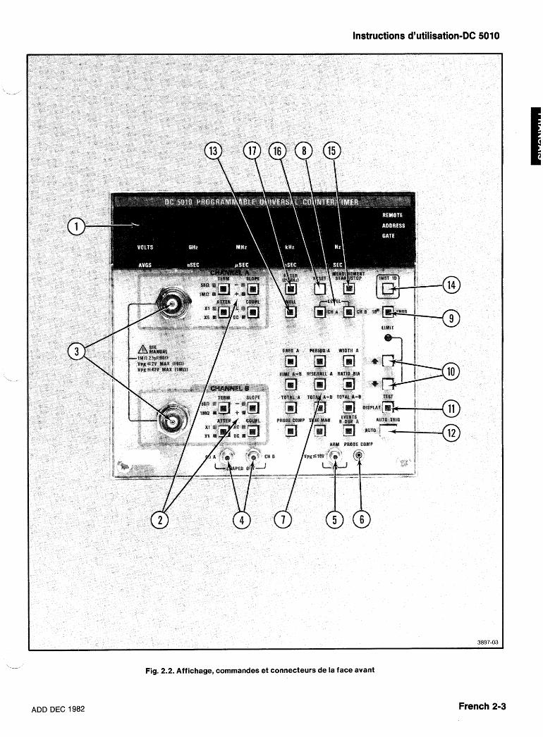
ADD DEC 1982
Instructions d'utilisation-DC 5010
Fig. 2.2. Affichage, cornrnandes et connecteurs de la face avant
French 2-3
Instructions d'utilisation-DC 5010
Pour les mesures telles que la mesure de temps A - B, dans lesquelles la resolution de I'affichage est inverse- ment proportionnelle au nombre de moyennes a effec- tuer, seuls les chiffres corrects (bonne resolution) sont affiches.
Cinq des indicateurs d'unites de mesure sont : Hz/SEC - Hertz ou seconde. KHz/mSEC - kilohertz ou milliseconde, MHz/pSEC - megahertz ou microseconde. GHz/nSEC - gigahertz ou nanoseconde, VOLTS/AVGS - (niveau de declenchement en) Volts/(exposant du) nombre de moyennes
L'allumage de I'indicateur GATE signale que le pro- cessus de comptage est en cours.
SLOPE -, +. Non allume, selectionne + (pente posi- tive). Allume, selectionne - (pente negative). Ce bouton
,--
selectionne la pente du signal a I'intersection du niveau '
de declenchement, qui est identifie comme un evene- ment pris en compte par la mesure. La commande SLOPE de la Voie A est egalement utilisee pour la mesure de temps de montee (SLOPE +) ou de descente (SLOPE -). Elle doit gtre positionnee avanl: I'utilisation du bouton poussoir RISE/FALL A.
COUPL-AC, DC. Non allume, selectionne le couplage continu (DC). Allume, selectionne le couplage alternatif (AC). DC correspond au couplage direct. AC; insere une capacite en serie avec I'entree, permettant de mesurer les petits signaux alternatifs superposes a une tension continue importante.
L'indicateur REMOTE (allume) indique que I'instru- ment est dans I'etat Commande a Distance. L'indicateur ADDRESS indique que I'instrument est actuellement adresse sur le Bus GPIB.
Le compteur n'affiche pas que les resultats de la mesure. I1 utilise les trois chiffres de gauche pour signal-
CONNECTEURS DE LA FACE AVANT er toute erreur interne ou toute erreur d'utilisation. Les deux chiffres aux deux extremites de I'affichage (Voie A @ CHANNEL A - CHANNEL B (perfor- : chiffre de gauche, Voie B : chiffre de droite) fournissent mances identiques) les resultats de la compensation de la sonde. Se repor- 1 M R23 pF/50 R . Connecteurs d'entree. ter aux paragraphes Auto-test et Compensation de V crgte 2 2 V max (50 R) Sondes. V crgte 2 42 V max (1 MR)
Une indication supplementaire est fournie par I'illumi- nation de nombreux boutons poussoirs en face avant. @ CHA, SHAPED OUT - CHB, SHAPED
OUT (Mise en forme des signaux A, B, et ,, Commun)
\
Ces sorties fournissent la replique exacte des signaux utilises interieurement pour la mesure. Elles permettent un declenchement stable sur des signaux complexes. Elles fournissent un signal d'une amplitude de 100 mV, proche de la masse, issu d'une source 50 R (200 mV, si non terminee). Ces sorties sont a la pleine bande passante (plus de 350 MHz).
COMMANDES DE LA FACE AVANT
@ ARM, IN - V crgte S 1 0 V (niveau TTL)
Entree de niveau TTL haut. Un niveau TTL. bas inhibe le Compteur (entree egalement disponible sur I'interface arriere).
@ TERM, SLOPE, ATTEN et COMPL (Voie PROBECOMP
A et Voie B) Fournit un signal rectangulaire ==: 5 V) utilisable en TERM - 50 R, 1 M R (terminaison). Non allume, conjonction avec la fonction "PROBE COMP" pour la
selectionne 1 M R , 23 pF. Allume, selectionne 50 R . compensation de sondes (se reporter au paragraphe Permet a I'utilisateur de terminer correctement les Compensation de Sondes de ce I T - I & ~ chapitre). entrees en 50 R si necessaire. (Dans le cas d'un depassement de capacite, I'instrument reviendra auto- matiquement a 1 M a , 23 pF.)
ATTEN - X I , X5. Non allume, selectionne le facteur d'attenuation X5. Allume, selectionne le facteur d'atte- BOUTONS POUSSOIRS EN FACE AVANT nuationX1. Permet d'appliquer le signal directement a I'amplificateur sans attenuation, ou attenue d'un facteur 5. L'attenuateur accroTt automatiquement I'hysterese
@ Commandes de fonctions -.,
d'entree et la plage de niveaux de beclenchement d'un FREQ A (Frequence A). Mesure la periode du signal facteur 5. de la Voie A, calcule et affiche la frequence.
French 2-4 ADD DEC 1982
Instructions d'utilisation-DC 5010
PERIOD A. Mesure et affiche la periode du signal de la Voie A.
ii WIDTH A. Mesure la largeur du signal de la Voie A. Mesure de la largeur d'une impulsion positive lorsque la pente positive du signal est selectionnee (SLOPE +, CHANNEL A). Mesure de la largeur d'une impulsion negative lorsque la pente negative du signal est selec- tionnee (SLOPE -, CHANNEL A).
TlME A + E3. Mesure I'intervalle de temps entre la pre- miere occurence d'un evenement sur la Voie A et le pre- mier evenement qui suit sur la Voie B.
RISE/FALL. A (Temps de montee A - Temps dedes- cente A). Mesure -automatiquement le temps de montee ou de descente (niveaux 10 % et 90 %) du signal de la Voie Pi. Une pression sur ce bouton valide la mesure et le calcul des niveaux de declenchement ap- propries. Enfoncer de nouveau ce bouton lors de tout changement ccf'amplitude du signal en entree. Mesure le temps de montee si SLOPE +, CHANNEL A, sont selec- tionnes. Mesure le temps de descente si SLOPE -, CHANNEL A ont ete selectionnes avant la pression sur RISE/FALL A. Cette mesure utilisant la Voie B, cette der- n iere est reg lee automatiquement en concordance avec la Voie A. Apres avoir appuye sur la touche RISE/FALL A, I'utilisateur est libre de modifier separement la Voie A ou la Voie B pour repondre a des conditions de mesure specifiques. 'Toutefois, le resultat peut ne plus etre un temps de mor~tee ou de descente. (Se reporter aux para- graphes Temps de Montee A et Temps de Descente A
- plus loin dans ce chapitre.)
RATIO B/A. Mesure et affiche le rapport des evene- ments de la Voie B sur les evenements de la Voie A, durant le meme intervalle de temps. Les trois modes Totalisation consistent en le comptage des evenements (ou occurences d'impulsions) sur les Voies A et B.
TOTAL A (Totalisation des evenements A). Seuls les evenements de la Voie A sont affiches.
TOTAL A -k 6. Affiche le nombre total d'evenements de la Voie A plus le nombre total d'evenements de la Voie B. Le comptage des evenements de la Voie B n'a lieu qu'apres le premier evenement valide de la Voie A.
TOTAL A - B. Affiche le nombre total d'evenements de la Voie A moins le nombre total d'evenements de la Voie B. Le comptage des evenements de la Voie B n'a lieu qu'apres le premier evenement valide de la Voie A. Si A-B est negatif, le signe - est eclaire.
NOTE
Une fois I'un des trois modes TOTALIZE selec- tionne, le bouton STARTBTOP s'allume pour indi- quer la condition STOP (arr6t de la mesure). Enfon- cer ce bouton pour demarrer le processus de
\--- Totalisa tion.
Le nombre de chiffres affiches est "mis a I'echelle" selon le reglage de la commande AVGS. Cette operation n'affecte pas le processus de comptage en cours. L'affichage peut 6tre modifib en cours de comptage sans incidence sur le nombre de comptes. La valeur affichee peut &re deplacee sur la droite ou sur la gauche meme a I'arrgt du comp- tage.
PROBE COMP. Dans ce mode, une indication visuelle (affichee) permet a I'uti lisateur de compenser aisement les sondes haute impedance (se reporter au paragraphe Compensation des Sondes de ce meme chapitre).
TlME MAN. Mesure manuelle du temps. Mesure I'in- tervalle de temps entre deux pressions successives du bouton poussoir MEASUREMENT STOP/START. On peut reinitialiser le comptage en enfoncant le bouton poussoir RESET. Comme en mode Totalisation, la fonc- tion STARTBTOP par defaut (lors d'une premiere selec- tion de la commande TMAN) est STOP, comme indique par I'illumination du bouton STARTSTOP.
EVENTS B DUR. Compte le nombre d'impulsions ap- pliquees a la voie B durant I'intervalle de temps o i le signal de la Voie A est superieur (+ SLOPE) ou inferieur (- SLOPE) au niveau de declenchement de la Voie A.
@ LEVEL CHA, CHB
Affichent le niveau de declenchement selectionne. Pour regler le niveau de declenchement de I'une des voies, appuyer sur le bouton LEVEL approprie, puis utiliser les boutons permettant d'incrementer ou de decrementer le niveau de declenchement (numero 10). Pour mettre fin a cette fonction, I'utilisateur peut appu- yersur le bouton LEVEL A (B) ou appuyer sur une autre touche de fonction.
AVGS (Moyennes).
Une pression sur ce bouton affiche I'etat actuel de la commande AVGS, et prepare I'instrument pour un nou- veau reglage de cette commande. L'utilisateur a alors le choix entre differents modes de Moyennage.
AUTO - (Enfoncer la touche AUTO, -1 est affiche). Permet d'obtenir la meilleure resolution possible avec une porte de mesure d'environ 300 ms.
0 - (Remet I'exposant a 0). La mesure selectionnee repose sur au moins un evenement. Mode utilise pour les mesures uniques. A la plupart des frequences uti- lisees, le Moyennage porte sur plus d'un evenement. Se reporter au chapitre Caracteristiques pour plus de details.
ADD DEC 1982 French 2-5
Instructions d'utilisation-DC 5010
lon, n = 1 a 9 - Permet la selection par decades du nombre minimal de moyennes.
69 Touches incrementant ou decrementant I'expo- sant d'une decade a I'autre.
NOTE
Le reglage de la commande AVGS affecte le nombre de chiffres affiches en mode Totalisation. En mode Moyennage Automatique (AUTO), et I'ex- posant (n) etant "O", les neufs premiers chiffres a gauche du point decimal sont affichbs. Lorsque I'exposant (n) est compris entre 1 et 9, le resultat de la mesure est "mis 2 I'Qchelle" (eleve a une puissance de 10) puis affiche.
Ce bouton incremente le niveau de declenchement approprie (si LEVEL CHA-CHB a ete selectionne) ou le nombre de moyennes (si AVGS a ete selectionne). Les niveaux de tension sont incrementes ou decrementes par pas de 4 mV X facteur d'attenuation.
+ Ce bouton decremente le niveau de declenche- ment approprie (LEVEL CHA-CHB) ou le nombre de moyennes (AVGS).
LIMIT
Voyant eclaire lorsqu'une valeur ou decrementee (1) au dela de sa limite. S'eteint bouton (1) ou (1).
est incrementee ( f )
lorsqu'on libere le
@ TEST DISPLAY
L'eclairage des boutons LEVEL CHA, LEVEL CHB, ou AVGS reflete le contenu de la fen6tre d'affichage (9 chif- fres a 7 segments). Une pression sur I'un de ces boutons entraine I'affichage des resultats de la mesure (Fre- quence, Periode, etc ... ) sans inhiber le reglage d'incre- mentation/decrementation. Une nouvelle pression sur I'un de ces boutons entraine I'affichage du niveau de declenchement ou du nombre de moyennes. Ceci permet a I'utilisateur de visualiser le parametre modifie, ou I'effet de ce changement sur les resultats de la mesure.
Lorsque ni les boutons LEVEL, ni le bouton AVGS, ne sont eclaires, le bouton TEST/DISPLAY est utilise pour selectionner le mode de Test. Ceci permet de repeter une partie du test de mise en service (a I'exception du test des RAMS). A I'occurence d'une erreur, le test s'arrGte, et le code d'erreur approprie est affiche. Pour mettre fin a la fonction TEST, enfoncer une autre touche de fonction.
@ AUTO TRIG/AUTO
Lorsque ni les boutons LEVEL, ni le bouton AVGS ne -- sont eclaires, une pression sur cette commande valide un declenchement automatique sur la Voie A et la Voie B (les valeurs cr6te maximale et minimale des signaux d'entree sont mesurees, et les niveaux de declenche- ment positionnes a mi-amplitude). Si LEVEL CH A est selectionne, une pression sur cette comrnande valide un declenchement automatique sur la Voie A, de m6me si LEVEL CH B est eclaire. Si AVGS est eclair& une pression sur ce bouton entraine I'affichage de "-1 ", code signifiant "Moyennage Automatique".
@ NULL
Une pression sur le bouton NULL memorise le resultat de la mesure actuelle et soustrait ce dernier de toutes les mesures ulterieures (le bouton NULL restant allume). Ce mode est particulierement utile dans les me- sures de temps de A vers B ( A - B) dans lesquelles il peut 6tre utilise pour annuler des erreurs systematiques dues a des longueurs de cBble inegales 011 a des diffe- rences entre les Voies. Toutefois, ce mode est disponi- ble dans toutes les fonctions de mesure.
Le reglage de la commande de Moyennage peut 6tre modifie sans incidence sur le resultat de la mesure, memorise par la fonction NULL. L'instrument soustrait maintenant deux nombres de la resolution resultante, ce qui donne la plus faible resolution, utilisee automati- quement pour determiner le nombre de chiffres a afficher.
Une nouvelle pression sur ce bouton annule de nou- veau la mesure.
Pour mettre fin a la fonction NULL, appuyer sur n'im- porte quelle touche de fonction (y compris la fonction precedemment selectionnee).
Une pression sur ce bouton entraine I'affichage de I'a- dresse GPlB et de la Fin de Message selectionnees. Elle valide egalement la transmission d'une dernande de ser- vice (si la ligne correspondante est validee), m6me en mode Blocage du Contr6le Local. Ceci represente une facon commode de s'adresser au contr6leur durant I'execution d'un programme.
@ MEASUREMENT START/STOP Ce bouton poussoir peut 6tre utilise dans tous les
modes de mesure a I'exception de Compensation des Sondes et de Test. L'eclairage de ce bouton indique I'arr6t de la mesure (STOP). Une pression sur ce bouton entraine 11arr6t de la mesure, ou le depart d'une Totalisa- tion (START), ou d'une mesure manuelle de temps a partir du resultat affiche. Dans les autres modes de mesure (a I'exception de Compensation des Sondes, et de Test), START demarre une nouvelle mesure. En mode "START", une pression sur ce bouton entraine 11arr6t de toute mesure en cours (a I'exception de Com- pensation des Sondes et de Test). En mode "STOP", si I'on se trouve en mode Totalisation ou Mesure Manuelle - de Temps, le compte final (dans les registres) est affiche, et I'affichage est remis a jour une fois de plus.
French 2-6 ADD DEC 1982
Instructions d'utilisation-DC 5010
RESET @ FILTER (20 MHZ) (CHANNEL A et
Reinitialise une mesure apres un arret (STOP). Une CHANNEL B)
,- pression sur ce bouton au milieu d'une mesure met fin a Lorsque ce bouton est eclaire, la bande passante des la mesure en cours et demarre une nouvelle mesure. deux voies est reduite a 20 MHz. Ceci permet la rejec- Permet egalement de tester toutes les DELs de la face tion de bruit haute frequence. Peut egalement Btre avant, y compris celles des boutons poussoirs et des in- utilise lors du reglage des niveaux de declenchement dicateurs. automatiques ou des niveaux de mesure de temps de
descente ou de montee d'un signal presentant une suroscillation ou un affaiblissement.
PROCEDURE DE FAMILIARISATION INTRODUCTION
Caracteristiques generales d'utilisation Le DC 501 0 est un compteur universe1 programmable
base sur un microprocesseur. II assure 11 fonctions de mesure avec une resolution d'affichage de 9 chiffres, plus deux fonctions specialisees : compensation des sondes (PROBE COMP) et auto-test (TEST).
Le microprocesseur etablit automatiquement la porte de mesure, execute les calculs necessaires sur les donnees acquises, et affiche les resultats avec une resolution optimale, selon la fonction de mesure selec- tionnee (FUNCTION), le nombre de moyennes (AVGS) et les conditions d'utilisation.
Affichage en mode Auto-test A la mise sous tension, I'un des codes d'erreur definis
au tableau 2-1 peut appara'itre dans la fenetre d'affi- chage si le resultat de la procedure d'auto-test est negatif. Pour idecouvrir la cause de I'erreur, s'adresser a un personnel de maintenance qualifie.
NOTE
A la mise en service, un signal 6 composante continue relie aux deux connecteurs d'entrke peut provoquer une sortie de la plage de dbclenche- ment. Dans ce cas, un code d'erreur pelit 6tre a ffiche. Dbconnecter toutes les entrees, ou r6duire la tension de decalage et remettre I'instrument en service. Un signal d'armement (ARM) de niveau bas duranit la mise sous tension peut bgalement provoquer une erreur.
NOTE
Pour decouvrir la cause d'une erreur, s'adresser A un personnel de maintenance qualifie.
Tableau 2-1 CODES D'ERREUR AFFICHES EN FACE AVANT
Les Entrees/Sorties serie sont defectueuses 1 31 3 Voie A
Test du fonctionnernent du Compteur Voie B
Test du fonctionnement du Compteur La RAM U1410 du systeme est defectueuse La RAM U1610 du systeme est defectueuse La RAM U1311 du systeme est defectueuse La ROM U161O est ma1 positionnee
La ROM U1410 est ma1 positionnee Le checksum de la ROM U1610 est errone Le cheksum de la ROM U1102 est errone
320-324,329
330-334,339
340
341
342 36 1
La ROM U1102 est mat positionnee La ROM U1201 est ma1 positionnee
Le checksum de la ROM U1201 est errone
374 375
CONDITIONS D'ENTREE
Tension maximale autorisCe A ATTENTION
Pour bviter toute dbteriora tion de I'instrument, s'assurer que les tensions d'entree appliquees aux connecteurs de la face avant ou aux entrees de I'interface arri6re n'excedent pas les limites au- torisees. Voir chapitre Caracteristiques Elec- triques.
La partie externe des connecteurs BNC en face avant est reliee 2 la masse par la connexion de masse du cordon d'alimentation du module d'ali- mentation. Eviter qu'elle ne soit en contact avec le fil de liaison du signal.
Veiller B utiliser un transformateur d'isolation (ten- sion de sortie infkrieure 2 15V) lors de la mesure de la frequence du reseau (50 ou 60 Hz).
Attention, lors de I'utilisation de signaux haute frb- quence, haute amplitude (plus de 80 MHz) : la ten- sion d'entrke maximale (par rapport 2 la face avant) autorisee 6 ces hautes frequences est 4V cr6te 2 crkte.
ADD DEC 198:! French 2-7
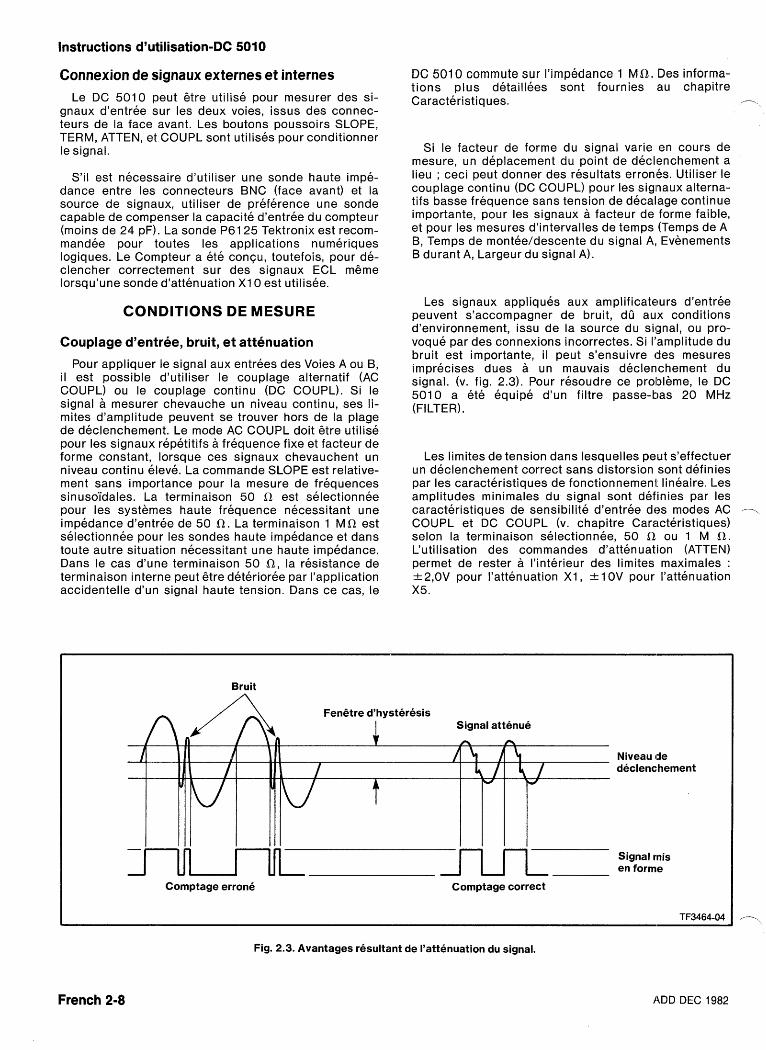
Instructions d'utilisation-DC 5010
Connexion de signaux externes et internes Le DC 5010 peut etre utilise pour mesurer des si-
gnaux d'entree sur les deux voies, issus des connec- teurs de la face avant. Les boutons poussoirs SLOPE, TERM, ATTEN, et COUPL sont utilises pour conditionner le signal.
S'il est necessaire d'utiliser une sonde haute impe- dance entre les connecteurs BNC (face avant) et la source de signaux, utiliser de preference une sonde capable de compenser la capacite d'entree du compteur (moins de 24 pF). La sonde P6125 Tektronix est recom- mandee pour toutes les applications numeriques logiques. Le Compteur a ete concu, toutefois, pour de- clencher correctement sur des signaux ECL m6me lorsqu'une sonde d'attenuation X I 0 est utilisee.
CONDITIONS DE MESURE
Couplage d'entree, bruit, et attenuation
Pour appliquer le signal aux entrees des Voies A ou B, il est possible d'utiliser le couplage alternatif (AC COUPL) ou le couplage continu (DC COUPL). Si le signal a mesurer chevauche un niveau continu, ses li- mites d'amplitude peuvent se trouver hors de la plage de declenchement. Le mode AC COUPL doit 6tre utilise pour les signaux repetitifs a frequence fixe et facteur de forme constant, lorsque ces signaux chevauchent un niveau continu eleve. La commande SLOPE est relative- ment sans importance pour la mesure de frequences sinusoi'dales. La terminaison 50 R est selectionnee pour les systemes haute frequence necessitant une impedance d'entree de 50 R . La terminaison 1 MR est selectionnee pour les sondes haute impedance et dans toute autre situation necessitant une haute impedance. Dans le cas d'une terminaison 50 R , la resistance de terminaison interne peut gtre deterioree par I'application accidentelle d'un signal haute tension. Dans ce cas, le
DC 501 0 commute sur I'impedance 1 M a . Des informa- tions plus detaillees sont fournies au chapitre Caracteristiques. .-.
Si le facteur de forme du signal varie en cours de mesure, un deplacement du point de declenchement a lieu ; ceci peut donner des resultats erronles. Utiliser le couplage continu (DC COUPL) pour les sig~naux alterna- tifs basse frequence sans tension de decalage continue importante, pour les signaux a facteur de forme faible, et pour les mesures d'intervalles de temps (Temps de A B, Temps de montee/descente du signal A, Evenements B durant A, Largeur du signal A).
Les signaux appliques aux amplificateurs d'entree peuvent s'accompagner de bruit, dO aux conditions d'environnement, issu de la source du signal, ou pro- voque par des connexions incorrectes. Si I'amplitude du bruit est importante, il peut s'ensuivre des mesures imprecises dues a un mauvais declenchement du signal. (v. fig. 2.3). Pour resoudre ce prololeme, le DC 501 0 a ete equipe d'un filtre passe-bas 20 MHz (FILTER).
Les limites de tension dans lesquelles peut s'effectuer un declenchement correct sans distorsion sont definies par les caracteristiques de fonctionnement lineaire. Les amplitudes minimales du signal sont definies par les caracteristiques de sensibilite d'entree des modes AC --, COUPL et DC COUPL (v. chapitre Caracteristiques) selon la terminaison selectionnee, 50 R ou 1 M 0. Cutilisation des commandes d'attenuation (ATTEN) permet de rester a I'interieur des limites maximales : * 2,0V pour I'attenuation X I , k 1 0V pour I'attenuation X5.
Bruit
Niveau tde declenchement
Signal rnis en forme
Comptage errone Comptage correct
TF3464-04
Fig. 2.3. Avantages resultant de I'attenuation du signal.
French 2-8 ADD DEC 1982
Instructions d'utilisation-DC 5010
Declenchement du compteur
Le niveau~ de declenchement est determine par les commandes SLOPE et LEVEL ou par le commutateur AUTO TRIG.
Les comrnandes LEVEL (CH A et CH B), utilisees en conjonction avec les boutons (1) et (1) permettent de faire varier continfiment I'hysterese de la fenetre de de- clenchement, de haut en bas, dans une plage de * 2,0V par pas de 4 mV. La fenetre d'hysterese est normale- ment de 50 mV crete a crete. Pour determiner le reglage des niveaux de declenchement, appuyer sur le bouton LEVEL CH A (ou LEVEL CH B) : les niveaux de de- clenchemerit respectifs seront affiches. Pour revenir en mode de Mesure, appuyer de nouveau sur les boutons LEVEL CH A ou LEVEL CH B (bouton allume). Une pres- sion sur une touche de fonction permet de revenir dans le mode Mesure.
Dans le mode AUTO TRlG (commande enclenchee), le microprocesseu r execute un programme etabl issant les tensions cretes maximale et minimale des signaux des deux voies. Puis le programme regle automatiquement le niveau de declenchement de chaque voie (50 % + 24 mV pour la pente +, 50 % - 24 mV pour la pente -) pour les mesures de frequence, de periode et les totalisa- tions. Le mode AUTO TRlG est egalement utilise pour les mesures de largeur d'impulsions (mode WIDTH A) et de temps dle A vers B (TIME A --+ B). Le mode AUTO TRlG necessite des signaux d'amplitudes d'au moins deux fois I'hysterese, soit des signaux d'amplitudes su- perieures a 140 mV crete a crete. Ceci est dfi au fait que la plage de fonctionnement de la fenetre d'hysterese est centre exactement a 50 % pour les mesures de largeur d'impulsions et de temps de A -+ B.
La figure 2-4 contient quelques exemples de niveaux de declenchement et montre la necessite de les regler correctement pour eviter les erreurs dues au temps de montee (ou de descente) du signal ou dues a la diffe- rence des temps de transition des impulsions de demar- rage et d'arret. L'observation sur un oscilloscope des si- gnaux issus des connecteurs SHAPED OUT reduit les erreurs de declenchement lors du declenchement sur des signaux lents mais complexes.
L'utilisation du Declenchement Automatique ne sup- prime pas les problemes poses par I'amplitude du bruit en entree, le couplage, I'adaptation d'impedances, et I'attenuation. Un depassement et une oscillation impor- tants du signal d'entree se traduisent par des mesures imprecises, provenant d'un niveau de declenchement errone. La valeur mediane du signal peut etre affichee. La frequence basse limite en mode AUTO TRIG est 10 Hz (points milieux). Aux frequences inferieures, un niveau de declenchement automatique sera defini mais pas necessairement a mi-amplitude. Le Declenchement Automatique permet egalement d'obtenir un de- clenchement correct dans le cas d'une tension continue en entree.
Reduction des erreurs de mesure
Pour I'obtention d'une precision optimale, il convient de respecter les consignes suivantes :
- Utiliser les commandes ATTEN appropriees et des sondes attenuatrices de haute impedance pour la mesure de signaux provenant de circuits haute impedance.
- Utiliser la commande TERMinaison 50 R pour les systemes basse impedance, haute frequence, impe- dance 50 R .
- Prendre garde aux erreurs de declenchement causees par des signaux a temps de montee ou de descente lents.
- Utiliser le filtre (FILTER) 20 MHz pour reduire le bruit haute frequence.
- Effectuer un moyennage sur un grand nombre de periodes du signal (commande AVERAGES).
- Garder I'environnement du compteur a temperature constante.
- Pour une meilleure stabilite de fonctionnement, lais- ser I'instrument chauffer plus d'une demi-heure.
- Substituer la base de temps optionnelle a la base de temps standard (meilleure stabilite).
- Appliquer une reference de temps etalon externe de 1 MHz, 5 MHz, ou 10 MHz aux entrees de I'interface arriere.
- Reetalonner I'instrument si necessaire.
EXEMPLES DE MESURE
Frequence A et Periode A
Dans les modes PERIOD A ou FREQUENCY A, le compteur mesure toujours la duree d'u ne periode du signal de la Voie A. Le resultat est affiche en unites de temps. En mode FREQUENCY A, le microprocesseur calcule la frequence de ce signal, en appliquant la formule :
1 f= - (T = periode)
T
et affiche le resultat en unites de frequence. En mode PERIOD A, le resultat est affiche en unites de temps. L'horloge interne 350 MHz assure une tres bonne reso- lution pour les mesures de frequence et de periode. Pour les mesures de periode de signaux rapides avec un nombre de moyennes de 1 09, cette resolution est * 31'25 attosecondes (31'25 X 1 0-I 8sec).
ADD DEC 1982 French 2-9
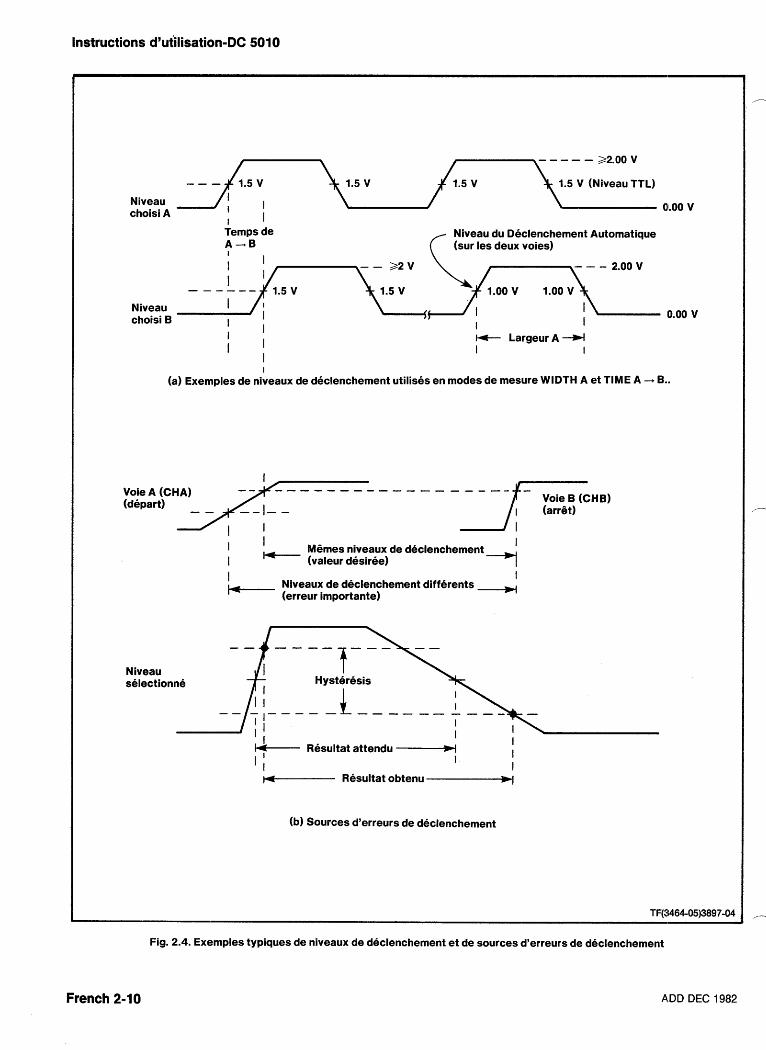
Instructions d'utilisation-DC 5010
22.00 v
1.5 V (Niveau TTL)
Niveau choisi A a1.00 v
Temps de Niveau du Declenchement Automatique A--B (sur les deux voies)
Niveau choisi B I 0.00 v
I + Largeur A -W I I
I
(a) Exemples de niveaux de declenchement utilises en modes de mesure WIDTH A et TIME A -+ B..
Voie A (CHA) Voie B (CHB)
I ,, Memes niveaux de declenchement I I (valeur desiree) -7
Niveau selectionne
I I Niveaux de declenchement differents (erreur importante)
Hysteresis
Resultat attendu - I I I
I I
w- Resultat obtenu -w
(b) Sources d'erreurs de declenchement
French 2-10
Fig. 2.4. Exemples typiques de niveaux de declenchement et de sources d'erreurs de declenchement
A,DD DEC 1982
Instructions d'utilisation-DC 5010
Rapport B/,A
En mode RATIO B/A, le compteur mesure le nombre
U' d'evenements sur les deux voies durant le temps de I'ac- cumulation clu nombre selectionne d'evenements de la voie A (moyennage par les evenements A). Le total des evenements B est alors divise par le total des evene- ments A et Ie resultat est affiche sans unite (de temps ou de frequence).
La plage cle rapports est comprise entre 1 0-8 et 1 09. En appliquarlt la plus haute frequence a la Voie B, on ob- tient un rapport superieur a 1. En lui appliquant la plus basse frequence, on obtient un rapport inferieur a 1. Ap- pliquer le signal de plus haute frequence a la Voie B pour assurer la meilleure resolution.
Largeur de A et Mesure de temps de A --, B (Inter- valle de temps)
La figure :2-5 contient des exemples de mesure ob- tenus a I'aide des fonctions WIDTH A et TlME A - B. La fonction WIDTH A consiste en la mesure de I'intervalle de temps entre le premier front montant ou descendant selectionne (a SLOPE) du signal applique a la Voie A et le front de polarite opposee suivant.
La fonction TlME A - B consiste en la mesure de I'in- tervalle de temps entre le premier front selectionne (* SLOPE) d'un evenement sur la Voie A et le premier front selectionne (+ SLOPE) d'un evenement sur la Voie B. Un moyennage (AVERAGES) peut gtre effectue par le nombre selectionne d'evenements en A, du fait qu'il se
. -' produit un evenement B pour un evenement A.
Les fonctions WIDTH A ou TlME A -+ B utilisent un generateur interne de bruit pseudo-aleatoire modulant en phase la base de temps interne 3.1 25 ns et permet- tant au compteur de moyenner correctement les signaux d'entree synchrones avec sa base de temps. Voir Figure 2-5.
Largeur Largeur
LARGEUR A h - - .+ , \
1 \
PENTE + FenQtre PENTE - d'hysteresis
r - SIGNAL YENTREE All I I 1 1 t 1 1
- - - L
TEMPS A 4 B
SIGNAL
I I I I I I + + lntervalle de temps mesure I I
TF(3464-07)3897-05
Fig. 2.5. Exemples de mesures effectuees a I'aide des fonc- tions WIDTH A et TlMEA - B.
Figure 2-6, I'intervalle de temps (4,68525 ns, largeur A,) ne pourrait 6tre mesure plus precisement (avec une base de temps non modulee) qu'en mono-coup avec moyennage nu1 (AVGS = 0). L'utilisation d'une horloge pseudo-aleatoire modulee en phase, avec un nombre de moyennes superieur a 1, oblige le compteur a compter une impulsion d'horloge la moitie du temps et deux im- pulsions d'horloge I'autre moitie du temps. Par exemple, si 10 largeurs sont moyennees (1 01), la duree totale du comptage est 46.8525 ns. Dix moyennes donnent 15 c o m p t a g e s ( 5 + 1 0 ) . En d i v i s a n t
Signal d'entree LARGEUR A + 4,68525 n s
-10 ns+ Resultat
ADD DEC 1982
Base de temps non rr~odulee
Base dce temps Resultat
Fig. 2-6. Exemple de mesure de signaux d'entree synchrones.
du moyennage (6'25 ns)
French 2-1 1
w modulee en phase
du moyennaye (4,68525 ns) 4 4 * t 4 4 *
Instructions d'utilisation-DC 501 0
ce rhsultat par le nombre de moyennes effectuhes, la moyenne (compte/intervalle) de chaque compte corres- pond a 3,125 nsec). Le DC 501 0 affiche la reponse 4'6 ns (1 5/10 X 3.1 25 = 4.68525).
NULL
Une pression sur le bouton NULL memorise le resultat de la mesure actuelle, et soustrait ce dernier de toutes les mesures ulterieures (le bouton NULL restant allume). Ce mode est particulierement utile dans les me- sures de temps de A vers B ( A - B) pour lesquelles il peut 6tre utilise pour annuler des erreurs systematiques dues a des longueurs de ciible inegales ou a des diffe- rences entre les Voies. Toutefois, ce mode est disponi- ble dans tous les modes de mesure.
Le reglage de la commande de Moyennage peut 6tre modifie sans incidence sur le resultat de la mesure (memorise par la fonction NULL). L'instrument soustrait maintenant deux nombres de la resolution resultante, ce qui donne la plus faible resolution (utilisee automati- quement pour determiner le nombre de chiffres a affi- cher).
Une nouvelle pression sur ce bouton annule le resul- tat.
Pour mettre fin a la fonction NULL, appuyer sur n'im- porte quelle touche de fonction (y compris la fonction precedemment selectionnee).
Evenements 5 durant A
La fonction EVENTS B DUR A est pratiquement iden- tique a la fonction WIDTH A (Largeur A), excepte que le comptage porte sur un nombre defini d'evenements dans le sens positif ou negatif (+ SLOPE, Voie B) pen- dant une largeur d'impulsion (positive ou negative) selectionnee (* SLOPE, Voie A). La base de temps in- terne n'est pas utilisee pour cette fonction. Voir Figure 2-7 pour exemple de mesure. Les evenements B sont moyennes par le nombre selectionne de largeurs d'im- pulsions de la Voie A.
Mesure manuelle de temps
La fonction TlME MANUAL consiste a mesurer et a afficher (jusqu'au 100eme de seconde) I'intervalle de temps entre la premiere et la deuxieme pressions sur la touche MEASUREMENT STARTBTOP. Le comptage peut 6tre remis a 0 puis redeclenche en enfoncant et en liberant le bouton poussoir RESET. Le commutateur AVGS est sans effet en mode TlME MANUAL. Lorsqu'on entre cette fonction pour la premiere fois, la mesure est arr6tee (STOP) comme indique par le bouton START/STOP illumine.
Evenements de la Voie B
(PENTE +) -- lull--- Evenements comptes
(PENTE -) ------
Fig. 2.7. Exemple de mesure d'Evenements B durant A
Totalisation des evenements A
La fonction TOTAL A est pratiquement identique a la fonction TlME MANUAL, a I'exception du liait qu'au lieu de compter les impulsions de la base de temps interne, le compteur totalise le nombre total d1ev6nements ap- pliques a la Voie A entre deux pressions s~~ccessives du bouton poussoir MEASUREMENT START/STOP. Le commutateur AVGS est utilisable dans ce mode. Avec I'exposant 0, ou en mode Moyennage Automatique, (-1 ,- etant affiche), des nombres entiers peuvent 6tre af- fiches. Sinon le commutateur AVGS opere comme un in- dicateur de facteur d'echelle, par puissance de 10 (per- mettant un comptage utilisant les quatorze chiffres de la chaine de comptage interne). Par exemple, avec un signal d'entree de 1 MHz et I'indication 1 O6 du commuta- teur AVGS, le chiffre de poids faible represente 106 comptes et s'incremente d'un compte par seconde (106Hz/106= 1 Hz). Ce facteur d'echelle peut 6tre change (voir le texte) apres un depassement de la mesure et deplace effectivement la visualisation. L'utili- sateur peut ainsi voir tous les treize chiffres de la chaTne de comptage.
Totalisation des evenements A + 5
La fonction TOTAL A + B est similaire a la fonction TOTAL A, excepte que le compteur calcule le nombre total d'evenements de la Voie A, plus le nombre total d'evenements de la Voie B. Le comptage des evene- ments B ne commence qu'apres le premier comptage d'evenements A valide.
Totalisation des evenements A - 5
La fonction TOTAL A - B est similaire a la fonction TOTAL A + B, excepte que le comptelur calcule le nombre total d'evenements de la Voie A, moins le nombre total d'evenements de la Voie B. Le comptage - des evenements B ne commence qu'aprik le premier comptage d'evenements A valide.
French 2-12 ADD DEC 1982
Instructions d'utilisation-DC 5010
Temps de montee A et temps de descente A
La fonction RISE/FALL A permet a I'operateur de mesurer automatiquement le temps de montee ou de
-, descente (enitre les niveaux 10 % et 90 %) du signal d'entree applique a la Voie A. Voir figure 2-8a. Selection- ner a I'aide de la commande SLOPE (+ = temps de montee ; - = temps de descente) la partie de signal a mesurer, avant d'appuyer sur le bouton RISE/FALL A. La dimension1 du signal d'entree est mesuree automati- quement et les niveaux 10 % et 90 % sont automatique- ment calcules et positionnes.
-4 ;' Temps de montee I I
Niveau I I
de depart -3- -
I Nivealu -i
I I e ~ e m p s de montee
(imprecis)
--- Fig. 2.8. Exemples de mesures de temps de montee.
ADD DEC 1982
Le signal d'entree du connecteur A est achemine in- terieurement vers les Voies A et B. Lorsqu'on appuie sur le bouton RISE/FALL A, les reglages de la Voie A sont automatiquement reproduits (comme indique par I'al- lumage des boutons en face avant) sur la Voie B. Les mesures de temps de montee sont parfois difficiles a realiser. Des problemes peuvent surgir, m6me avec le reglage automatique des niveaux. Le signal mesure doit satisfaire aux conditions d'utilisation de I'instrument (decrites au chapitre Caracteristiques de ce manuel). L'amplitude du signal doit 6tre superieure a 1'4 V (50 Q) ou 700 mV (1 MQ), avoir un temps de montee su- perieur ou egal a 4 nsec (5 ns pour 1 MQ) et ne doit pas presenter plus de 10 O/O d'aberrations.
Le DC 5010 possede un circuit de detection de cr6tes. II detecte la cr6te maximale du signal, m6me si cette cr6te correspond a une aberration (v. Fig. 2-8b). Si cette aberration est trop importante ( > I 0 %), le temps de montee mesure est errone. Dans ce cas, avant d'ap- puyer sur le bouton RISE/FALL A, enfoncer le bouton FILTER (20 MHz) pour limiter a moins de 18 ns le temps de montee interne du signal d'entree. L'utilisation, ou non, du filtre dependra de la largeur et du pourcentage d'aberration du signal. Puis appuyer sur le bouton RISE/FALL A. Une fois la cr6te du signal mesuree, et les niveaux 10 % et 90 % determines, le filtre pourra 6tre inhibe. Le DC 5010 affichera alors le temps de montee reel (non limite).
Les boutons de la face avant du DC 501 0 demeurent operants apres I'utilisation du bouton RISE/FALL A, pour permettre a I'operateur de modifier les conditions d'entree d'un signal et les niveaux de declenchement. Ces reglages doivent satisfaire aux conditions d'utilisa- tion de I'instrument (v. chapitre Caracteristiques).
Par exemple, si le bouton AUTO est enfonce (en mode de mesure RISE/FALL A), les niveaux des Voies A et B passeront des points 1 0 % et 90 % au point 50 %. D'autres niveaux du signal, tels un niveau TTL haut ou bas, peuvent 6tre programmes par I'operateur ; toute- fois, le reglage de la terminaison doit 6tre pris en compte.
En terminaison 50 a, le niveau de declenchement affiche represente 50 % du niveau reel, du fait de la reduction interne de tension (peu pratique). En terminai- 8 son 1 M a I'instrument n'a pas a se preoccuper du type de sondes connectees (voir dans les Caracteristiques de temps de montee/descente, les niveaux propres aux differents types de sondes).
French 2-13
Instructions d'utilisation-DC 5010
Compensation de la sonde Le DC 501 0 a ete concu pour 6tre compatible. avec
les sondes standard (terminaison 1 M R). Toutefois, 1'0- perateur doit s'assurer que la sonde est correctement compensee.
La fonction PROBE COMP permet a I'operateur d'adapter une sonde externe a la capacite interne du compteur sans recourir a un oscilloscope.
Fonction Test L'affichage de la valeur "000" (sur les trois chiffres -
les plus a gauche) apres I'execution du te.st indique que le microprocesseur s'est lui-meme verifie (transferts de donnees internes, compteurs internes (ac~cumulateurs), fonctionnement du convertisseur numerique-analogique (niveaux de declenchement) et circuits des amplifica- teurs d'entree).
La memoire a acces aleatoire (RAM) n'est pas verifiee au cours de cette procedure automatique par commande en face avant (testee uniquement a la mise en service).
Un signal carre d'environ 1 KHz et d'une amplitude d'environ 5 V est disponible sur le connecteur (jack) PROBE COMP en face avant.
NOTE
Connecter I'embout de la sonde au connecteur PROBE COMP avant de passer en mode Compensation de la Sonde.
A I'affichage, le chiffre de poids fort (a I'extremite gauche), correspondant a la Voie A doit 6tre un zero, ainsi que le chiffre de poids faible (a I'extremite droite), correspondant a la Voie B. II ne doit pas appara'itre de point decimal et aucun indicateur ne doit 6tre allume.
Tout signal applique 4 la Voie A ou 4 la Voie B doit etre dans la plage de niveaux de declenchement du compteur. Si une erreur apparait, deconnecter en premier les entrees des Voies A et B, puis recommencer le test. L'erreur peut provenir egale- ment d'une connexion 4 I'entree ARM.
L'indicateur GATE clignote a I'issue de chaque test complet. En cas d'erreur, le code d'erreur du defaut est affiche sur trois chiffres a I'extremite gauche de I'af- fichage, et le programme de test s'interrompt. Toute selection d'une autre fonction met fin au mode Test.
/--
Une fois la sonde connectee et le signal carre ap- plique, executer la procedure suivante :
Armement (entree ARM)
1. Tourner lentement la vis dans les deux sens, jusqu'a ce que la valeur affichee de la voie compensee soit "1 ".
2. lnverser le sens de rotation et tourner de nouveau lentement la vis jusqu'a ce que la valeur affichee soit "0". La sonde est maintenant compensee. Un "1 " indique une compensation excessive, un "0" une compensation insuffisante. Le reglage optimal est optenu dans le sens "1 -On, juste au changement d'etat.
NOTE
Si, en un point de la procedure, la valeur affichee est toujours "1 " apres une rotation compl&te de la vis, appuyer sur la touche RESET et essayer de nouveau. Ceci peut se produire dans le cas d'une deconnexion a la source du signal carre durant la procedure de reglage.
Cette entree permet d'isoler un evenement unique ou un ensemble particulier d'evenements inclus dans un signal numerique ou analogique complexe. La figure 2.9 illustre trois applications du mode Armement.
Seuls des signaux de niveau TTL doivent 6tre ap- pliques a I'entree ARM. En I'absence de signal, I'entree ARM passe a I'etat haut (armement continu). Lorsque cette entree est a I'etat bas, aucune mesure n'est possi- ble. Elle peut 6tre utilisee pour toutes les fonctions de mesure, a I'exception de TIME MANUAL, PROBE COMP, et TEST (pour ces trois fonctions, I'entree ARM doit 6tre a I'etat haut).
Lorsque le signal d'armement passe a I'etat haut, le premier evenement de la Voie A qui suit dtimarre le pro- cessus de mesure. Lorsque le signal d'arnnement passe a I'etat bas, I'evenement de la Voie A suivant arr6te le processus de mesure. Ceci permet de contr6ler I'occu- renceet la duree des mesures (meme sur des signaux complexes). Ces mesures peuvent 6tre moyennees tout comme des mesures d'intervalles de temps. Le Comp- teur determine le nombre de chiffres a afficher (selon la - meilleure resolution possible) en fonction du nom bre d'evenements moyennes de la Voie A.
French 2-14 ADD DEC 1982
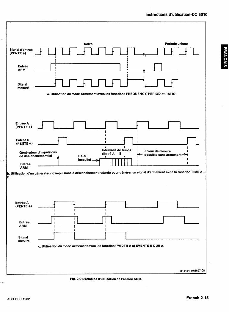
Instructions d'utilisation-DC 5010
Salve Periode unique
Signal d'entr6e (PENTE +) 1
I ..\ I ,
Signal mesure
a. Utilisation du mode Armement avec les fonctions FREQUENCY, PERIOD et RATIO.
Entree A (PENTE +) I I I I
I I I
I I
Entree B I I (PENTE -t) I I
I I I I hte rvak de temps i Erreur de mesure
I
Generateur d'impulsions desire A -+ B I de declenchement ici Delai I possible sans armement *
jusqu'ici I I Entree I 1 ARM
1. Utilisation d'un generateur d'impulsions a declenchement retarde pour generer un signal d'armement avec la fonction TIME A -
Entree A (PENTE 4-)
Entree ARM
Signal mesure
c. Utilisation du mode Armement avec les fonctions WIDTH A et EVENTS B DUR A.
Fig. 2.9 Exemples d'utilisation de I'entree ARM.
ADD DEC 1982 French 2-15
Instructions d'utilisation-DC 5010
En modes FREQUENCY A, PERIOD A ou RATIO B/A, I'affichage est formatte pour une erreur d'un compte. Lorsque le mode Armement est utilise avec ces modes (ne mesurant pas d'intervalle de temps), chaque arme- ment ou desarmement peut introduire une erreur d'un compte. Toutefois, le compteur n'en tient pas compte et affiche un nombre de chiffres base uniquement sur le nombre total d'evenements par mesure (independam- ment du nombre d'armements effectues).
La resolution d'une mesure de periode en mode Arme- ment est inferieure a la resolution affich~ie. Elle peut etre calculee a I'aide dehformule suivante :
,---
T, J N T ~ Resolution =- -
N TBP
T, = periode d'horloge T, = periode du signal d'entree (CH A) T, = temps entre le depart et I1arr6t de I'evenement A N = nombre de moyennes, 1 06, 1 09, etc ...
PROGRAMMATION
Introduction
Ce chapitre est relatif a la programmation a distance du DC 501 0, par I'intermediaire d'un Bus d'lnterface General (GPIB) IEEE-488. Les informations qui suivent s'adressent a un lecteur deja familiarise avec les com- munications sur le GPlB et la programmation des contr6- leurs. Le protocole des messages transmis sur le GPlB est specifie et decrit dans les normes IEEE 488-1 978, "Interface Numerique Standard pour Instruments Pro- grammable~", . Les instruments de la serie TM 5000 sont concus pour communiquer avec tout contr6leur compatible GPlB transmettant et recevant des messages ASCII (commandes) sur; le bus GPIB. Ces messages sont constitues de commandes de program- mation de I'instrument ou de demandes d'informations issues de I'instrument.
Les commandes des instruments programmables de la serie TM 5000 sont compatibles avec d'autres types d'instruments. La meme commande peut etre utilisee par differents instruments pour le contr6le de fonctions similaires. En outre, chaque commande se presente sous forme d'un mnemonique decrivant sa fonction. Par exemple, la commande INIT reinitialise les reglages d'un instrument en restaurant les conditions de mise en service. De plus, les mnemoniques de commande co'incident avec les appellations en face avant (program- mation simplifiee).
Institute of Electrical and Electronic Engineers, New York
Les commandes de I'instrument sont presentees , '- dans ce manuel sous trois formes :
. Une illustration de la face avant - et lesl commandes ayant trait aux differents modes d'utilisation (v. fig. 2.1 0).
Une liste des commandes fonctionnelles - reparties par groupes. Chaque fonction est decrite brievement.
Une liste de commandes detaillee - liste alphabe- tique des commandes. Chaque commande est suivie de sa description complete.
Les instruments programmables de la sQrie TM 5000 sont connectes sur le Bus GPlB par I'interrnediaire d'un module d'alimentation TM 5003 ou TM 5006. Des infor- mations sur I'instal lation de I'instrument dans le module d'alimentation, ainsi que la description cles diverses fonctions en face avant et des fonctions sel~ectionnables (internes) sont donnees au chapitre Instruc:tions d1Utili- sation. L'adresse primaire ciu DC 501 0 (20) peut etre modifiee par un personnel de maintenance qualifie, ainsi que la Fin de Message (v. dans ce m6me chapitre le paragraphe Messages et Protocole de Communica- tion). Cette Fin de Message est reglee sur EOI ONLY (a la livraison). Pour toute information sur une localisation ou un reglage interne, se referer au chapitre Mainte- nance. Une pression sur le bouton INST ID entra'ine I'af- ,-
fichage de I'adresse primaire ; le point decirnal droit s'al- lume si la Fin de Message selectionnee est 1-F/EOI.
French 2-16 ADD DEC 1982
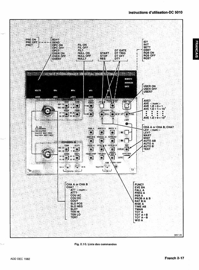
ADD DEC 19182
Instructions d'utilisation-DC 5010
Fig. 2.1 0. Liste des commandes
French 2-17
lnstructipns d'utilisation-DC 5010
COMMANDES
L'instrument est contrble soit par la face avant, soit Chaque commande debute par un mnbmonique - par les commandes recues (envoyees par le contr6leur). prefixe decrivant la fonction executee. De nombreuses Ces commandes sont de trois types : commandes necessitent un argument a lla suite du
prefixe, pour decrire I'etat desire de la fonction concer- Commandes de r6glage - permettent de regler I'instru- nee.
ment
Demandes d'informations - requierent des donnees
Commandes d'utilisation - provoquent une operation specifique.
Le DC 5010 repond a et execute toute commande lorsqu'il est dans le mode Commande a Distance. En mode Local, les fonctions du DC 5010 etant sous le contr6le de la face avant, toute commande de r6glage et de fonction transmise par le contrbleur donne lieu a un message d'erreur. Seules les demandes d'informations sont executees.
Prendre garde 2 ne pas transmettre un nombre de caracthres inf6rieur B celui du pr6fixe ou de I'argu- ment (abrbgb). Toute transmission a un instrument non concern6 pourrait entrainer un risque d'erreur.
LlSTE DES COMMANDES DE FONCTIONS
COMMANDES DE L91NSTRUMENT
Commandes de fonctions du DC 501 0
EVE BA
FALL A
FREQ A
FUNC?
PER A
PROB A&B RAT B/A
RISE A
TEST
TIME AB
TMAN
TOT A TOT A+B
TOT A-B
WID A
Compte les evenements de la voie B durant la largeur de I'impulsion de la Voie A Mesure le temps de descente du signal de la Voie A Mesure la frequence du signal de la Voie A Renvoie la fonction actuellement uti- lisee par le Compteur Mesure la periode du signal de la Voie A Valide la compensation des sondes Mesure le rapport des evenements B sur les evenements A Mesure le temps de montee du signal de la Voie A Valide le test des ROMs, des En- trees/Sorties et de I'accumulateur Mesure le temps de I'evenement A vers I'evenement B Mesure de Temps Manuelle (chro- nometre) Totalise les evenements de la Voie A Mesure le nombre total d'evene- ments de la Voie A plus le nombre total d'evenements de la Voie B Mesure le nombre total d'evene- ments de la Voie A moinS le nombre total d'evenements de IaVoie B Mesure la largeur de I'impulsion du signal de la Voie A
Commandes de mesure
AVE ou AVGS Determine le nombre de moyen- nages a effectuer (par decades) ou le mode Moyennage Automatique
AVE? ou AVGS?
NULL ON
NULL OFF
NULL?
RDY?
RES
START
STOP
Renvoie AVE <nombre:> ; (-1 en mode Moyennage Automatique) (AUTO AVERAGES)
Soustrait les resultats de la mesure actuelle de toutes les mesures sui- vantes
Reinitialise la valeur NULL
Renvoie NULL ON ou NULL OFF
Renvoie RDY 1 (nouvelle donnee pr6te) ou RDY 0 (nouvelle donnee non prgte)
Reinitialise les compteurs et rede- marre la mesure en cours
Declenche une Mesure de Temps Manuelle (TMANUAL), une mesure apres un arr6t (STOP) ou une totali- sation (TOTALIZE)
Met fin a toute mesure en cours, a I'exception des fonctions TEST et PROBECOMP ,---
French 2-18 ADD DEC 1982
Instructions d'utilisation-DC 5010
COMMANDES D'ENTREEBORTIE ATT1 o u 5
- ATT?
AUTO A&B
AUTO A
AUTO B
CHA A ou E3
CHA?
COU AC OLI DC
COU?
FIL ON
FIL OFF
FI L?
LEV
- LEV?
MAX?
MIN?
PRE ON
PRE OFF
PRE?
SEND
SLO NEG
SLO POS
SLO?
TER HI
TER LO
- TER?
Attenuation 1 X ou 5X
Renvoie ATT <nombre> pour la voie designee
Place le niveau de declenchement a mi-amplitude du signal sur les deux voies
Place le niveau de declenchement de la Voie A a mi-amplitude du signal
Place le niveau de declenchement de la Voie B a mi-amplitude du signal
Selectionne la voie d'entree sur laquelle porteront les reglages sui- vants
Renvoie CHA A ou CHA B
Determine le mode de couplage (al- ternatif ou continu) de I'entree
Renvoie COU AC ou COU DC
Limite la bande passante de la Voie A et de la Voie B a environ 20 MHz
lnhibe le filtre
Renvoie FIL ON ou FIL OFF
Posit ionne le niveau de de- clenchement de la voie selec- tionnee. Plage de declenchement : de +2000 a -2000 (XI) ou de +I 0.000 a -1 0.000 (X5)
Renvoie le niveau de declenchement de la voie selectionnee
Renvoie la derniere tension crgte MAXimale en mode Declenchement Automatique (AUTO TRIG)
Renvoie la derniere tension crgte minimale en mode Declenchement Automatique (AUTO TRIG)
Valide la predivision et la mise a I'ec- helle interne
lnhibe la predivison et la mise a I'echelle interne
Renvoie : PRE ON ou PRE OFF
Obtient et formatte les resultats de la nouvelle mesure
Declenche sur la pente negative du signal d'entree
Declenche sur la pente positive du signal d'entree
Renvoie SLO NEG ou SLO POS
Regle I'impedance d'entree de la voie selectionnee a 1 M R , 23 pF
Regle I'impedance d'entree de la voie selectionnee a 50 R
Renvoie TER HI ou TER LO
COMMANDES DU SYSTEME DT GATE Declenchement (START) et arr6t
(STOP) commandes par un De- clenchement Simultane de tous les
DT TRIG
DT OFF
Instruments (<GET>)
Rei n i t ia l isat ion (RESET) com- mandee par un Declenchement Simultane de tous les Instruments (<GET>)
Inhibition du declenchement de I'instrument
DT? Renvoie DT TRIG, DT OFF ou DT GATE
ERR? Renvoie le code d'erreur correspon- dant a I'evenement le plus recent obtenu par le contr6leur, a I'aide d'un appel selectif en serie (com- mande RQS ON) ; sinon renvoie I'etat de la plus haute priorite (RQS OFF)
ID? Renvoie le type de I'instrument et la version logicielle
INIT Restaure les reglages en face avant et les conditions d'utilisation exis- tant a la mise en service
SET? Renvoie I'etat des reglages actuels de I'instrument
TEST Valide le test des ROMs, des En- trees/Sorties et de I'accumulateur
COMMANDES D'ETAT OPC ON
OPC OFF
OPC? OVER ON
OVER OFF
OVER?
RQS ON RQS OFF
RQS?
USER ON
USER OFF
USER?
Valide la ligne SRQ (etat bas) a I'issue d'une operation complete (OPERATION COMPLETE)
lnhibe la ligne SRQ (etat haut) a I'issue d'une operation complete (OPERATION COMPLETE) Renvoie OPC ON ou OPC OFF Valide la ligne SRQ lors d'un depassement de la capacite du compteur (OVERFLOW) lnhibe la ligne SRQ lors d'un depassement de la capacite du compteur (OVERFLOW)
Renvoie OVER ON ou OVER OFF Valide la ligne SRQ lnhibe la ligne SRQ et annule la demande d'interruption
Renvoie : RQS ON ou RQS OFF
Valide la ligne SRQ (etat bas) lorsque le bouton INST ID est enfonce lnhibe la ligne SRQ (etat haut) lorsque le bouton INST ID est enfonce Renvoie USER ON ou USER OFF
ADD DEC 1982 French 2-19
Instructions d'utilisation-DC 501 0
LISTE DETAILLEE DES COMMANDES
ATTENUATION
Type :
Reglage ou interrogation
Syntaxe de reglage
ATT < nombre >
Exemples :
ATT.999999 ATT 5.00001 ATTENUATION 1
Syntaxe d'interrogation
ATT?
Reponse a une interrogation
ATT 1 ; ATT 5;
Explication
Cette commande attenue le signal d'entree (sur la voie selectionnee) de X I (pas d'attenuation) ou de X5. L'argument est arrondi a un entier et, si I'attenuation n'est pas 1 ou 5, une erreur d'execution (ERR 205) est generee pour indiquer que la valeur de I'argument est erronee.
Le reglage initial (a la mise en service) est ATT 1.
Des informations plus detaillees sur la selection des voies sont donnees a la commande CHANNEL.
ATTENUATION French 2-20
AUTOTRIG (Declenchement automatiqure)
Type :
Commande d'utilisation
Syntaxe :
AUTO A AUTO B AUTO A&B (I'argument est optionnel)
Exemples
AUTO AUTO A AUTOTRIG A&B
Explication :
Cette commande positionne les niveaux de de- clenchement des deux voies approximativement a mi- amplitude des signaux d'entree. Les vakurs cretes minimale et maximale des deux voies sont sauvegardees et peuvent etre obtenues par les interrogations MAX? et MIN?. Les arguments vali,des sont :
A Regle automatiquement le niveau de de- clenchement de la Voie A. Sauvegarde les valeurs cretes minimale et maximale des - deux voies.
B Regle automatiquement le niveau de de- clenchement de la Voie B. Sauvegarde les valeurs cretes minimale et maximale des deux voies.
A&B Regle automatiquement les niveaux de de- clenchement des deux voies. Sauvegarde les valeurs crete minimale et maximale des deux voies.
Si aucun argument n'est specific, I'argumenl: par defaut est A&B.
Si un AUTOTRIG est realise, tout niveau de de- clenchement defini precedemment est remplace par les nouvelles valeurs et le contr6le en face avant des niveaux de declenchement est inhibe. Si les signaux d'entree ne sont pas dans la plage de declenchement du DC 501 0, les niveaux de declenchement automatique ne seront pas positionnes a mi-amplitude. Les prece- dentes valeurs MIN et MAX des deux voies sont toujours remplacees.
Le temps necessaire a I'execution de AUTOTRIG depend de I'amplitude et de la frequence des signaux A et B. II est de 2'5 secondes dans le cas le plus defavora- ble.
La sequence de commandes qui suit provoque I'exe- cution d'un declenchement automatique suivi de la
,- transmission des niveaux de declenchement :
AUTO ; CH A ; LEV? ; CH B ; LEV?
ADD DEC 1982
Instructions d'utilisation-DC 5010
AVERAGES (Moyennages)
- Type :
Reglage ou interrogation.
Syntaxe de reglage :
AVE < nombre > OU
AVGS < nom bre >
Exemples :
AVE -1 AVGS 1 .E 4-2 AVERAGES 1 00
Syntaxe d'interrogation :
AVE? ou AVGS?
Reponse :
AVE -1 ; AVE 1 .E +4;
Explication :
La commande AVERAGES determine le nombre mini- nal d'evenements devant etre comptes sur la Voie A avant le calcul des resultats de la mesure. Les argu- ments valides <nombre> sont :
/
<nombre:> S O - fait passer le DC 501 0 en mode Moyennage Automatique (Auto Averages). L'instru- ment accumule alors les comptes durant =0,3 seconde environ.
En mode Moyennage automatique, la reponse a I'inter- rogation (NE?) est AVE -1.
<nombre:> § 1, l .E +1, 1.E +2, l .E +3, l .E +4, l .E +5, 1 .E06, '1 .E +7, 1 .E +8, 1 .E +9 L'argument: <nombre> est d'abord arrondi a la plus
proche puissance de 10. Si la valeur resultante n'appar- tient pas aux valeurs donnees ci-dessus, le nombre de moyennes sblectionne reste le meme et une erreur d'execution (ERR 205) est generee.
Le nombre de moyennes est egalement utilise pour mettre a I'echelle les resultats affiches lors de mesures en mode Totalisation. Les resultats transmis sur le bus IEEE-488, toutefois, ne sont pas mis a I'echelle.
Le reglage initial a la mise en service est AVE -1.
AVERAGES
ADD DEC 1984!
CHANNEL (CHANNEL SELECT) (Choix de la voie)
Type :
Reglage ou interrogation
Syntaxe de reglage :
CHA A B
Exemples :
CHANNEL A CHA B
Syntaxe d'interrogation
CHA?
Reponses :
CHA A; CHA B;
Explication :
La commande CHANNEL selectionne la voie sur laquelle seront effectues les reglages SLOPE (pente), SOURCE, ATTENUATION, COUPLING (couplage) et LEVEL (niveau). Les arguments valides sont :
A - Reglages de la Voie A.
B - Reglages de la Voie B. La Voie A est choisie a la mise en service (CHA A).
CHANNEL
French 2-21
Instructions d'utilisation-DC 5010
COUPLING (Couplage)
Type :
Reglage ou interrogation
Syntaxe de reglage :
COU AC DC
Exemples :
COUPL AC COU DC
Syntaxe d'interrogation :
COU?
Reponses :
COU AC; COU DC;
Explication :
La commande COUPLING determine le couplage du signal en entree : AC ou DC. Les arguments valides sont
AC - couplage alternatif
DC - couplage continu.
Lors de la commutation DC-AC ou de la modification du niveau continu du signal, en couplage alternatif, les delais suivants sont necessaires :
Sonde X I connectee - 1 ,O seconde Sonde X5 connectee - 2'5 secondes Sonde X I 0 connectee - 5'0 secondes
Ces delais sont necessaires a la charge du condensa- teur de couplage jusqu'a 1 % (ou moins) de sa valeur finale (avec une faible impedance de source).
Le couplage continu COU DC est choisi a la mise en service.
Des informations sur la selection des voies sont donnees dans I'explication de la commande CHANNEL.
COUPLING
French 2-22
DT (DEVICE TRIGGER) (L7instrument est declenche
par le controleur)
Type :
Reglage ou interrogation
Syntaxe de reglage :
DT GATE TRIG OFF
Exemples :
DT GATE DT TRlG DT OFF
Syntaxe d'interrogation :
DT?
Reponses :
DT GATE DT TRlG DT OFF
Explication :
La commande DT determine la reponse de I'instru- ment au message de I'interface GROUP EXECUTE -- TRIGGER <GET> (Declenchement simultane de tous les instruments). Les arguments valides sont :
GATE
TRlG
OFF
Dans ce mode de declenchement, <GET> contr6le le demarrage (START) et I'arrgt (STOP) de la mesure. Si la mesure est arrgtee, le message <GET> demarrera la mesure ; si la rnesure est en cours, un <GET> I'arretera.
Dans ce mode de declenchement, <GET> reinitialise la mesure (RESET). A la suite d'un START, <GET:> initialise et redeclenche une mesure. A la suite d'un STOP, <GET> initialise une mesure unique.
Dans ce mode, <GET> provoque I'affi- chage d'une erreur d'execution (ERR 206).
Le reglage initia
DT
.I (a la mise en service) est : DT OFF.
ADD DEC 1982
Instructions d'utilisation-DC 5010
'-- Type :
Interrogation
Syntaxe :
ERR? ERROR?
Reponse :
ERR < nonnbre > ;
ERROR (Erreur)
Cette com~mande est utilisee pour obtenir des informa- tions sur I'etat de I'instrument.
Si la ligne RQS est validee (etat bas - ON), la com- mande ERROR renvoie un code d'evenement <nom- bre> decrivant la raison pour laquelle le bit RQS a ete place dans le dernier mot d'etat transmis par I'instru- ment. Le code d'evenernent est alors remis a 0.
Si la ligne RQS est inhibee (etat haut - OFF), l'interro- gation ERROR renvoie un code d'evenement <nombre> definissant la plus haute priorite en attente dans I'instrument. Ce code d'evenement est alors remis a 0 pour la prochaine interrogation ERROR.
ERROR
ADD DEC 1982
EVENTS (EVENTS B DURING A) (Evenements B pendant A)
Type :
Commande d'utilisation
Syntaxe :
EVE BA (argument optionnel)
Exemples :
EVENTS BA EVE
Explication :
La commande EVENTS determine la mesure du nombre total d'evenements survenant sur la Voie B durant la largeur de I'impulsion du signal de la Voie
EVENTS
French 2-23
Instructions d'utilisation-DC 501Q
FALLTIME (Temps de descente)
Type :
Commande d'utilisation
Syntaxe :
FALL A (argument optionnel)
Exemples :
FALL FALLTIME A
Explication :
La commande FALL TIME regle I'instrument pour la mesure du temps de descente du signal de la Voie A. La commande SLOPE de la Voie A est automatiquement placee sur la position -, et les reglages ATTEN, COUPL, SLOPE et TERM de la Voie B reproduisent ceux de la Voie A. Le signal de la Voie A est automatiquement ache- mine vers les circuits d'entree des Voies A et B et les niveaux 10 % et 90 % sont determines et positionnes.
Cette fonction utilise le mode Autodeclenchement (AUTOTRIG) pour determiner les points 10 % et 90 %. Elle affecte donc les niveaux de declenchement et les valeurs crgte maximale et minimale.
French 2-24
FILTER (Filtre)
Type :
Commande de reglage
Syntaxe :
FIL ON FIL OFF
Exemples :
FIL ON FILTER OFF
Syntaxe d'interrogation :
FIL?
Reponse a I'interrogation :
FIL ON: FIL OFF:
Explication :
La commande FILTER contr6le le reglage du filtre de bruit haute frequence. Les arguments valides sont :
ON - limite la bande passante des deux voies a 20 MHz.
OFF - permet d'utiliser la pleine bande passante, 350 MHz.
- Le reglage initial (a la mise en service) est FIL OFF.
FILTER
,ADD DEC 1982
Instructions d'utilisation-DC 5010
FREQUENCY (Frequence)
L-, Type:
Commandle d'utilisation
Syntaxe :
FREQ A (argument optionnel)
Exemples :
FREQUEbJCY A FREQ
Explication :
Cette cornmande regle le DC 501 0 pour la mesure de la frequence du signal de la Voie A.
FREQUENCY
ADD DEC 1982
FUNCTION (Fonction)
Type :
l nterrogation
Syntaxe :
FUNC? FUNCTION?
Reponses :
EVE BA; FALL A; FREQ A; PER A; RAT B/A; TIME AB; TMAN; TOT A; TOT A+B TOT A-B WID A; PROB A&B; RISE A; TEST;
Explication :
Cette commande d'interrogation renvoie I'une des reponses ci-dessus, indiquant la fonction de mesure selectionnee.
FUNCTION
French 2-25
Instructions d'utilisation-DC 5010
IDENTIFY (Identification)
Type :
Interrogation
Syntaxe :
ID? IDENTIFY?
Reponse :
Explication :
Cette interrogation renvoie la reponse ci-dessus, dans laquelle :
TEK/DC 501 0 ldentifie le type de I'instrument.
V79.1 ldentifie la version de la norme Codes et Formats TEKTRONIX a laquelle se conforme I'instrument.
Fx. y ldentifie la version du logiciel de I'instrument. x.y est un nombre decimal.
IDENTIFY
French 2-26
INITIALIZE (Initialisation)
Type :
Commande d'utilisation
Syntaxe :
INIT INITIALIZE
Explication :
La commande INIT restaure les reglages imposes a la mise en service. Les reglages-du DC 501 0 a la mise en service sont :
FREQ A AVE- 1 FIL OFF NULL OFF SLO POS (Voies A et B) ATT 1 (Voies A et B) COU DC (Voies A et B) TERM HI (Voies A et B) CHA A OPC OFF OVER OFF PRE OFF DT OFF USER OFF RQS ON - De plus, une sequence AUTOTRIG regle les niveaux
de declenchement. En incluant les valeurs cretes minimale et maximale, le temps d'execution maximum necessaire a une fonction INIT est 2,5 secondes.
La commande INIT ne genere pas de demande de ser- vice (SRQ) a la mise en route et ne fait pas passer I'instrument en mode LOCAL comme une imise en ser- vice normale.
INITIALIZE
ADD DEC 1982
LEVEL (TRIGGER LEVEL) (Niveau de declenchement)
-L-'
Type :
Reglage ou interrogation
Syntaxe de reglage
LEVEL < nlombre >
Exemples :
LEVEL - 1.025 LEV 0.005 LEV 7.5
Syntaxe d'imterrogation
LEV?
Reponses :
LEVEL - 1.025; LEV 0.000:;
Explication :
La commande LEVEL positionne le niveau de de- lenchement tJe la voie selectionnee sur la valeur speci- fiee. Cette valeur est exprimee en volts dans une plage de -2.000 a 2.000 pour une attenuation par 1 (XI) et de -1 0.000 a 10.000 pour une attenuation par 5 (X5). La resolution est 0.004 pour I'attenuation par 1 et 0.020 pour I'attenuation par 5.
L
Cette valeur est arrondie au pas le plus proche ; elle n'est pas modifiee si elle n'est pas incluse dans la plage de niveaux tJe declenchement du DC 5010, mais une erreur dlexec;ution (ERR 205) est generee.
LEVEL
ADD DEC 1982
Instructions d'utilisation-DC 5010
MAXIMUM
Type :
Interrogation
Syntaxe :
MAX? MAXIMUM?
Reponse :
MAX <nombre>;
Explication :
L'interrogation MAX? renvoie la valeur de la tension maximale du signal, valeur mesuree durant le dernier cycle de declenchement automatique. Si le signal et/ou les conditions d'entree ont change depuis le dernier declenchement automatique, une autre commande AUTOTRIG est necessaire pour obtenir la nouvelle valeur MAX.
Un cycle AUTOTRIG est utilise pour chaque utilisation de AUTOTRIG, PROBECOMP, RISE et FALL. Le temps d'execution maximum pour chaque operation est 2,5 secondes (1,5 seconde typique).
MAXIMUM
French 2-27
Instructions d'utilisation-DC 501 0
MINIMUM
Type :
l nterrogation
Syntaxe :
MIN?
Reponse:
MIN <nombre>
Explication :
L'interrogation MIN? renvoie la valeur de la tension minimale du signal (de la voie selectionnee), valeur mesuree au cours du dernier declenchement automa- tique. Si le signal et/ou les conditions d'entree ont change depuis le dernier declenchement automatique, une autre commande AUTOTRIG est necessaire pour obtenir la nouvelle valeur MIN.
Un cycle AUTOTRIG est utilise pour chaque utilisation de AUTOTRIG, PROBECOMP, RISE et FALL. Le temps d'execution maximum pour chaque operation est 2,5 secondes ( 1 3 seconde typique).
MINIMUM
French 2-28
NULL (Fonction NULL)
Type :
Commande d'utilisation
Syntaxe :
NULL ON NULL OFF
Exemples :
NULL ON NULL OFF
Syntaxe d'interrogation :
NULL ?
Reponse a I'interrogation :
NULL ON; NULL OFF;
Explication :
La commande NULL memorise les resultats de la mesure, et les soustrait ainsi de toutes les lnesures ul- terieures. Les arguments valides sont :
ON - memorise le resultat de la mesure, et le soustrait des mesures suivantes.
,--
OFF - reinitialise la valeur memorisee.
La valeur memorisee par la fonction NULLest reinitiali- see a chaque execution de la commande NlJLL OFF ou d'une commande de fonction. Pour les mesures d'inter- valles de temps (TIME, WIDTH, RISE, FALL.), la valeur NULL est reinitialisee a 5,2 ns, pour la compensation du delai de propagation entre les circuits dkntree des Voies A et B. Pour toutes les autres mesures, la valeur NULL est remise a 0.
Le reglage initial (a la mise en service) est NULL OFF.
NULL
ADD DEC 1982
Instructions d'utilisation-DC 5010
OPC (Operation complete)
-- - Type :
Reglage ou interrogation
Syntaxe de reglage :
OPC ON OFF
Exemples :
OPC ON OPC OFF
Syntaxe d'interrogation :
OPC?
Reponses :
OPC ON; OPC OFF;
Explication :
La commande OPC valide ou inhibe la ligne SRQ a I'issue d'une mesure. Elle permet au contraleur de demarrer une mesure, lequel passe a une autre tsche en attendant une demande de service lorsque les donnees de la mesure sont pr6tes.
OPC ON : a. I'issue d'une mesure, valide et maintient
-, . la ligne SRQ jusqu'a ce que le mot d'etat soit lu par un appel selectif en serie, ou jusqu'a I'execution d'une fonction Device Clear. Une operation complete (OPERATION COMPLETE) est indiquee par le mot d'etat 66 (ou 82) et la reponse "ERR 402" a l'interrogation ERROR.
Des informations detaillees sur le Mot d'Etat (Status Byte) et la commande ERROR sont fournies au para- graphe "Liste des Erreurs et des Etats".
Le reglage initial (a la mise en service) est : OPC OFF.
OPC
ADD DEC 1982
OVERFLOW (Depassement de capacite)
Type :
Reglage ou interrogation
Syntaxe de reglage :
OVER ON OFF
Exemples :
OVER ON OVERFLOW OFF
Syntaxe d'interrogation :
OVER?
Reponses :
OVER ON; OVER OFF;
Explication :
La commande OVERFLOW valide la ligne SRQ (etat bas) lors du depassement de la capacite de comptage du DC 5010. Elle permet au contr6leur ds detecter un depassement et d'y repondre.
Le DC 5010 dispose de deux compteurs internes 40 bits (I'un pour la Voie A et I'autre pour la Voie B) pour realiser les mesures.
Pour les mesures d'evenements (EVENTS), de fre- quences (FREQUENCY), de periodes (PERIOD), de rap- ports de frequences (RATIO), de temps (TIME) et de lar- geurs d'impulsions (WIDTH), I'etat OVERFLOW indique generalement une erreur de reglage de I'une des voies d'entree.
Pour les mesures manuelle de temps (TMANUAL) et de totalisation (TOTALIZE), I'etat OVERFLOW permet au contr6leur d'etendre la plage de la mesure. Lors de me- sures manuelles de temps, le depassement indique que le compteur de la Voie B a compte 243 impulsions de la base de temps interne (= 87960.9 seconded. Lors de mesures de totalisation, le depassement indique que le compteur de la Voie A a compte 2 * O (env. 8.8 X 1 012) evenements a I'entree de la Voie A. Pour ces deux types de mesure, le resultat est reinitialise, et la mesure conti- nue apres une detection de depassement de capacite.
Les fonct ions Compensation de la sonde (PROBECOMP) et Test (TEST) ne generent pas de depassement de capacite.
OVER ON : valide la ligne SRQ (si depassement) jusqu'a I'obtention par le contreleur de I'etat de I'instru- ment (par un appel selectif en serie) ou jusqu'a I'execu- tion d'une fonction Device Clear. Un depassement de la Voie A est indique par le mot d'etat 193 (ou 209) et par la reponse "ERR 71 1" a I'interrogation ERROR. Un depassement de la Voie B est indique par le mot d'etat 194 (ou 21 0) et par la reponse "ERR 71 2" a I'interroga- tion ERROR.
Le reglage initial (a la mise en service) est : OVER OFF.
OVERFLOW
French 2-29
Instructions d'utilisation-DC 5010
PERIQD (Periode)
Type :
Commande d'utilisation
Syntaxe :
PER A (argument optionnel)
Exemple :
PERIOD A PER
Explication :
La commande PERIOD regle le DC 5010 pour la mesure de la periode du signal de la Voie A.
PERIOD
French 2-30
PRESCALE (Predivision)
Type :
Reglage ou interrogation
Syntaxe de reglage :
PRE ON OFF
Exemples :
PRESCALE ON PRE OFF
Syntaxe d'interrogation :
PRE?
Reponses :
PRE ON; PRE OFF;
Explication :
La commande PRESCALE multiplie le compte de la Voie A par 16 avant tout calcul de faequence, de periode, de rapport de frequences et de totalisation. Elle doit etre utilisee dans le cas d'une predivision par 16 du signal de la Voie A, pour eviter toute erreur de mesure. Les arguments valides sont : -
ON - Le signal de la Voie A est multipliQ par 16 avant le calcul des resultats.
OFF - Le signal de la Voie A n'est pas mis a I'echelle avant le calcul des resultats. Si un prediviseur compatible n'est pas connecte au
DC 5010, I'utilisation de la commande PRESCALE donne lieu a un avertissement (ERR 604).
Le reglage initial (a la mise en service) est : PRE OFF.
PRESCALE
ADD DEC 1982
PROBE COMP (Compensation de la sonde)
ii Type :
Commande d'utilisation
Syntaxe :
PROBE A&t3 (argument optionnel)
Exemples :
PROBECOMP A&B PROB
Explication ::
Cette comrnande entraine la fourniture par le DC 501 0 des informations necessaires a la compensation des sondes.
Cette fonction genere deux resultats d'un chiffre. Le chiffre de poids fort represente le resultat de la Voie A a gauche de I'affichage, et le chiffre de poids faible le resultat de la 'Voie B (a droite de I'affichage).
La fonction PROBECOMP utilise le mode AUTOTRIG, dans la procbdure de compensation. Aussi, les niveaux de declenchement et les valeurs MIN et MAX peuvent etre affectees par les mesures PROBECOMP.
L a fonc t i on AUTOTRIGGER, u t i l i see par PROBECOMF', est une version rapide du mode AUTO, avec une frequence minimale f,,, d'environ 100 Hz et un
- temps maxirrtum d'execution d'environ 0,25 sec. Ce mode AUTO rapide peut Btre utilise pour mettre rapide- ment a jour les valeurs MIN et MAX de signaux su- perieurs a 100 Hz.
Des informations plus detaillees sont donnees au paragraphe Compensation des Sondes de ce manuel.
PROBECOMP
Instructions d'utilisation-DC 5010
RATIO (Rapport)
Type :
Commande d'utilisation
Syntaxe :
RAT B/A
Exemples :
RATIO B/A RAT
Explication :
La commande RATIO regle le DC 5010 pour mesurer le rappport entre les evenements de la voie B et les evenements de la Voie A.
RATIO
ADD DEC 1982 French 2-31
Instructions d'utilisation-DC 5010
RDY (DATA READY) (Donnees pretes)
Type :
Interrogation
Syntaxe :
RDY?
Reponse :
RDY 0; RDY 1 ;
Explication :
La commande RDY renvoie I'etat "Data Ready" (donnees prgtes). La valeur 0 indique que les donnees de la mesure ne sont pas encore disponibles. La valeur 1 indique que les donnees de la mesure sont pretes.
Dans le premier cas (donnees non disponibles), le DC 5010 est interroge par le contr6leur et transmet I'une des reponses suivantes :
apres reception de la commande SEND : il attend que la donnee requise soit disponible pour la transmettre
avant reception de la commande SEND : il repond en envoyant FF,, (toutes les lignes de donnees sont validees).
Une donnee est prete des qu'une mesure est complete. Elle reste prete jusqu'a ce qu'elle soit extraite du DC 501 0, ou qu'un reglage soit retouche (a I'excep- tion du moyennage). L'information Data Ready peut aussi etre annulee par une commande RESET.
RDY
RESET (Reinitialisation)
Type :
Commande d'utilisation
Syntaxe :
RES RESET
Explication :
La commande RESET reinitialise la chaFne de compta- ge et initialise une nouvelle mesure. Pour les mesures de frequences, de periodes, de rapports, de temps, de largeur d'impulsions, de temps de montee ou de des- cente ou d'evenements, un resultat unique est obtenu si la mesure a ete arretee (STOP) avant I'envoi de la com- mande RESET. Pour la compensation des sondes (PROBECOMP), cette commande efface I'etat de compensation actuel et redemarre le processus de compensation. Pour les tests (TESTS), elle annule les resultats d'erreurs existants (erreurs) et redeclenche un processus de test. Pour les mesures rnanuelles de temps (TMAN) et les totalisations (TOTALIZE), les compteurs sont remis a zero, et une nouvelle mesure est initialisee, si elle n'est pas arrgtee par un STOP avant le RESET.
RESET
French 2-32 ADD DEC 1982
Instructions d'utilisation-DC 5010
RISETIME (Temps de montee)
Commande d'utilisation
Syntaxe :
RlSE A (argument optionnel)
Exemple :
RlSETlME A RlSE
Explication :
La cornmande RlSETlME regle I'instrument pour la mesure du temps de montee du signal de la Voie A. La commande SLOPE de la Voie A est placee automatique- ment sur la position +, et les reglages ATTEN, COUPL, SLOPE et TERM de la Voie B reproduisent ceux de la Voie A. Le signal d'entree de la Voie A est achemine vers les circuits d'entree des Voies A et B, puis les niveaux de declenchement 10 % et 90 % sont determines et posi- tionnes. Ce1:te fonction utilise le Declenchement Auto- matique pour determiner les points 10 % et 90 %. De ce fait, les niveaux de declenchement et les valeurs crktes maximale et minimale sont affectes par les mesures de temps de montee.
RlSETlME
RQS (REQUEST FOR SERVICE) (Demande de service)
Type :
Reglage ou interrogation
Syntaxe de reglage :
RQS ON OFF
Exemples :
RQS ON RQS OFF
Syntaxe d'interrogation :
RQS?
Reponses :
RQS ON; RQS OFF;
Explication :
La commande RQS est une commande globale de la ligne SRQ par le DC 501 0.
RQS OFF : le DC 501 0 ne peut jamais faire passer la ligne SRQ a I'etat bas. RQS ON : le DC 501 0 peut faire passer la ligne SRQ a I'etat bas dans les circonstances appropriees : erreur, operation complete, etc ...
L'interrogation ERROR? peut ktre utilisee avec RSQ OFF pour s'informer d'eventuelles conditions de Demande de Service. Lorsque la commande RQS passe de I'etat OFF a I'etat ON, la ligne SRQ est validee pour toute condition de demande de service survenue prece- demment.
Le reglage initial (a la mise en service) est : RQS ON.
RQS
ADD DEC 1982 French 2-33
Instructions d'utilisation-DC 5010
SEND (Envoi)
Type :
Commande de sortie
Syntaxe :
SEND
Exemples de sortie :
45.1 375501 9E +6 (Frequence) 3.001 8E -6; (Periode) 01 (Compensation de sonde) 395 (Test) 1977249; (Totalisation)
Explication :
La commande SEND formatte les donnees disponibles en sortie. Une donnee est disponible tant qu'un resultat de mesure complet n'a pas ete sorti. Si aucune donnee n'est disponi'ble, la commande SEND fait attendre le DC 5009 jusqu'a la fin de la mesure complete et formatte le resultat.
SEND
SETTINGS (Reglages)
Type :
Interrogation
Syntaxe :
SET? SETTINGS?
<fonction> ; CHA A ; ATT <nombre> ; COU xx ; SLO xx ; TERM xx ; LEV <nombre> ; C:HA B ; ATT <nombre> ; COU xx ; SLO xx ; SOUR xx ; LEV < n o w bre> ; AVE < nombre> ; OPC xx ; OVER xx ; PRE xx ; DT xx ; USER xx ; RQS xx ;
Exemple de reponse :
FREQ A;CHA A; ATT 1 ; COU DC ; SLO POS ; TERM HI :LEV1 500;CHAB;ATT5; COU AC ; SLO NEG ; TERM LO ; LEV -5 000 ; AVE -1 ; OPC OFF ; OVER ON ; PRE OFF ; FIL OFF ; NULL OFF ; DT OFF ; USER OFF ; RQS ON ;
Explication :
L'interrogation SETTINGS renvoie les reglages ac- tuels d'un instrument.
La reponse peut 6tre utilisee ulterieurement pour reinialiser I'instrument dans les conditions specifiees. *-
SETTINGS
French 2-34 ADD DEC 1982
Instructions d'utilisation-DC 5010
SLOPE (Pente)
- Type :
Reglage ou interrogation
Syntaxe de reglage
SLO NEG POS
Exemples ::
SLO POSI'TIVE SLOPE PCE SLOPE NEGATIVE SLO NEG
Syntaxe d'interrogation :
SLO?
SLO POS; SLO NEG;
Explication :
La commande SLOPE positionne le declenchement de la voie s6lectionn~e sur la pente specifiee. Les argu- ments valides sont :
NEG Declenchement sur la pente nega- tive.
--. POS Declenchement sur la pente posi- tive.
Le reglage initial (a la mise en service) est SLO POS.
Des informations sur la selection des voies sont donnees a la commande.
SLOPE
START (Demarrage)
Type :
Commande d'utilisation
Syntaxe :
START
Explication :
La commande START demarre une mesure manuelle (TMANUAL) ou de totalisation (TOTALIZE). Pour les me- su res d'evenements (EVENTS), de frequences (FREQUENCY), de periodes (PERIOD), de rapports de frequences (RATIO), de temps (TIME) ou de largeurs (WIDTH), cette commande redeclenche la mesure apres un arrgt (STOP).
START
ADD DEC 1982 French 2-35
Instructions d'utilisation-DC 5010
Type :
Commande d'utilisation
Syntaxe :
STOP
Explication :
La commande STOP met fin a toutes les mesures a I'exception des tests et de la compensation des sondes. Elle est ignoree dans ces deux cas.
Pour toutes les mesures de frequences (FREQUEN- CY), de periodes (PERIOD), de temps de montee (RISE), de temps de descente (FALL), de rapports de fre- quences (RATIO), de temps (TIME), de largeurs d'impul- sions (WIDTH) ou d'evenements (EVENTS), la com- mande STOP met fin au processus en cours.
Lorsque cette commande est utilisee en mode Mesure Manuelle de Temps (TMANUAL) ou dans les modes Totalisation (TOTALIZE), le resultat actuel est garde en memoire et la mesure peut etre redemarree a partir du point d'arrgt.
STOP
TERMINATION (Terminaison de la source du siignal)
Type :
Reglage
Syntaxe :
TER HI TER LO
Exemples :
TER HI TERM LOW TERMINATION HIGH
Syntaxe d'interrogation :
TER?
Reponse a I'interrogation :
TER HI; TER LO;
Explication :
Cette commande regle I'impedance d'entree de la voie selectionnee a la valeur specifiee. Les arguments valides sont :
HI Regle automatiquement: la terminai- son a 1 M e , 23 pF. -
LO Regle la terminaison a 50 .-. Dans le cas d'une impedance d'entree de 50 = (LO)
et de la detection d'un signal d'entree trop grand (>2 volts a I'attenuation par 1 ), I'instrument commute auto- matiquement I'impedance d'entree de LO a HI.
Dans ce cas, la ligne SRQ est validee et 1.e demeure jusqu'a ce que I'etat de I'instrument soit lu par le contr6- leur (a la suite d'un appel selectif en serie), ou jusqu'a ce qu'elle soit inhibee par une commande RQS OFF, ou par une fonction initialisation de I'instrument (DC). L'etat "Protection de la 50 a ' ' de I'entree de la Voie A est indique par le mot d'etat 102 ou 1 18, et la rkponse 602 a I'interrogation ERROR. L'etat "Protection de! la 50 0 ' ' de la Voie B est indique par le mot d'etat 102 ou 11 8 et la reponse 603 a I'interrogation ERROR.
Le reglage initial (a la mise en service) est TERM HI.
Des informations sur la selection des voies sont donnees a la commande CHANNEL.
TERMINATION
French 2-36 ADD DEC 1982
Instructions d'utilisation-DC 5010
TEST
\Y'
Type :
Commande d'utilisation
Syntaxe :
TEST
Explication :
Cette comrnande declenche I'execution d'auto tests repetitifs : test des memoires ROM, des entrees/sorties series et du bon fonctionnement du compteur.
Les tests executes par la commande TEST sont iden- tiques a ceux operes a la mise en service (procedure d'auto-test). Ils ne comprennent pas les tests des memoires RAM qui ne sont effectues qu'a la mise en ser- vice.
Toute detection d'une erreur met fin a la sequence de test. Celle-ci est declenchee de nouveau a I'execution (par le DC 501 0) d'une autre commande TEST ou par la commande RESET.
Les resultats de chaque sequence de test sont prepares pour 6tre sortis. "0" indique I'absence d'erreur. En cas d'erreur, la valeur generee en sortie est la meme que le code d'erreur affiche a la mise en service.
- Se reporter au chapitre "Indication d'etats et d'er- reurs".
TEST
TlME (TIME A TO B) (Temps de A vers B)
Type :
Commande d'utilisation
Syntaxe :
TIME AB (argument optionnel).
Exemples :
TlME TlME AB
Explication :
La commande TlME regle le DC 5010 pour mesurer I'intervalle de temps entre la premiere occurence d'un evenement de la Voie A et I'occurence de I'evenement suivant de la Voie B.
TlME
ADD DEC 1982 French 2-37
Instructions d'utilisation-DC 5010
TMANUAL (TIME MANUAL) (Mesure manuelle de temps)
Type :
Commande d'utilisation
Syntaxe :
TMAN TMANUAL
Explication :
La commande TMANUAL permet d'effectuer des me- sures manuelles de temps (chronometre). Une com- mande START demarre la mesure et une commande STOP I'arrete. En mode DT GATE, la mesure manuelle est declenchee et arretee alternativement par le message de I'interface <GET> (Declenchement simul- tane de tous les instruments).
Voir les explications des commandes START, STOP et DT.
Voir I'explication de <GET> a la rubrique Transmis- sion des Messages de Contr6le de I'lnterface IEEE de ce chapitre.
TMAMUAL
TOTALIZE (Totalisation)
Type :
Commande d'utilisation
Syntaxe :
TOT A (argument optionnel) TOT A+B TOT A-B
Exemples :
TOTALIZE A+B TOT A-B TOT
Explication :
Cette commande regle le DC 5010 pour mesurer et calculer le nombre total d'evenements survenant sur une des deux voies. Une commande STAFlT demarre la mesure et une commande STOP y met fin. En mode "DT GATE", la totalisation est declenchee et arretee alterna- tivement par le message de I'interface <GET> (Dec- lenchement simultane de tous les instruments).
Dans les modes A+B et A-B, le DC 5010 ne peut compter les evenements B qu'apres le premier evene- ment correct A.
-- Se reporter aux explications des commandes START,
STOP, et DT.
Voir I'explication de <GET> a la rubrique Transmis- sion de Messages de Contr6le de I'lnterface IEEE de ce chapitre.
TOTALIZE
French 2-38 ADD DEC 1982
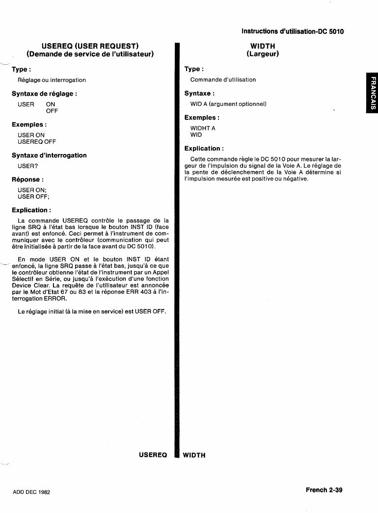
Instructions d'utilisation-DC 5010
USEREQ (USER REQUEST) (Dernande de service de I'utilisateur)
L-'
Type :
Reglage ou interrogation
Syntaxe de reglage :
USER ON OFF
Exemples :
USER ON USEREQ OFF
Syntaxe d'interrogation
USER?
Reponse :
USER ON; USER OFF;
Explication :
La commande USEREQ contr6le le passage de la ligne SRQ a I'etat bas lorsque le bouton INST ID (face avant) est enfonce. Ceci permet a I'instrument de com- muniquer avec le contr6leur (communication qui peut &re initialisee a partir de la face avant du DC 501 0).
En mode IJSER ON et le bouton INST ID etant xu enfonce, la ligne SRQ passe a I'etat bas, jusqu'a ce que
le contr6leur obtienne I'etat de I'instrument par un Appel Selectif en Shrie, ou jusqu'a I'execution d'une fonction Device Clear. La requgte de I'utilisateur est annoncee par le Mot d'Etat 67 ou 83 et la reponse ERR 403 a I'in- terrogation ERROR.
Le reglage initial (a la mise en service) est USER OFF.
USEREQ
WIDTH (Largeur)
Type :
Commande d'utilisation
Syntaxe :
WID A (argument optionnel)
Exemples :
WlDHT A WID
Explication :
Cette commande regle le DC 501 0 pour mesurer la lar- geur de I'impulsion du signal de la Voie A. Le reglage de la pente de declenchement de la Voie A determine si I'i mpulsion mesuree est positive ou negative.
ADD DEC 1982 French 2-39
MESSAGES ET PROTOCOLE DE COMMUNICATION
Delimiteur de commande
Un message consiste en une commande ou une serie de commandes, suivies d'une fin de message. Dans le cas de messages constitues de plusieurs commandes, celles-ci doivent 6tre separees par des points virgules. Un point virgule n'est pas obligatoire en fin de message. Chacune des lignes ci-dessous est un message :
INIT TEST;INIT;RQS 0N;USER OFF;ID?;SET? TEST;
Fin de message
Les messages peuvent 6tre termines par EOI ou le caractere ASCII de saut de ligne (LF). Certains contr6- leurs valident la ligne EOI concurremment avec la trans- mission du dernier octet de donnees ; d'autres n'utili- sent que le caractere LF comme fin de message. L'un ou I'autre peut 6tre selectionne a I'interieur du DC 501 0. Si EOI ONLY est selectionne, I'instrument interprete comme fin du message entre tout octet de donnees recu. De meme, i l valide la ligne EOI concurremment avec la transmission du dernier octet du message sorti. Si LF/EOI est selectionne, I'instrument interprete le caractere LF comme fin du message entre si la ligne EOI est inhibee (ou tout octet de donnees recu lorsque la ligne EOI est validee). II transmet un retour chariot (CR) suivi d'un saut de ligne (LF avec la ligne EOI validee) pour mettre fin aux messages en sortie. Lire le chapitre Maintenance avant la selection manuelle interne (per- sonnel qualifie) de la fin de message. Les instruments de la serie TM 5000 sont livres avec la fin de message EOI ONLY selectionnee.
Si les caracteres formattes speciaux, SP, CR, et LF (LF ne pouvant 6tre utilise si le mode LF/EOI est selec- - tionne) sont ajoutes entre le delimiteur de prefixe et I'argument, ils sont ignores par le DC 501 0. (SP) (CR) et (LF) sont indiques en indices dans les exemples qui sui- vent :
Exemple 1 : RQSspON; Exemple 2 : RQSspspON; Exemple 3 : RQSsp ,, ,,spspON
Dans la liste des commandes, certairls prefixes et arguments sont presentes sous une forme complete et sous une forme abregee. L'instrument accepte tout prefixe ou argument contenant au moins les caracteres de la forme abregee. Les caracteres ajoutes a celle-ci doivent etre ceux de la forme complete. Pour documen- ter ses programmes, I'utilisateur peut ajouter des caracteres alphanumeriques a un mot complet. Des caracteres alphanumeriques peuvent egalement etre ajoutes a une interrogation, a condition d'6tre places avant le point d'interrogation.
USER? USERE? USEREQ? USEREQUEST?
De nombreux arguments sont separes plar une virgule ; toutefois, I'instrument acceptera comme delimiteur un (OU des) espace(s1.
NOTE
Dans le dernier exemple, I'espace est traite comme un caractere formatte parce clu'il suit la virgule (delimiteur de I'argument).
Formattage d'un message
Pour 6tre comprises, les commandes transmises aux instruments de la serie TM 5000 doivent avoir le format (ou syntaxe) approprie. Toutefois, ce format est tres souple et peut subir de Formats num&iques nombreuses variations. Une description de ce format et des variations admises est donnee ci-apres : L'instrument accepte les nom bres suivants comme
arguments numeriques : Toutes les commandes doivent 6tre en code ASCII. nombres entiers avec ou sans signe (y compris +O
Toutefois, les minuscules et majuscules sont acceptees. et -0). Les nombres entiers sans signe sont inter- Toute donnee sortie doit 6tre en majuscules (voir figure pretes comme des nombres positifs. Exemples : +I , 2.1 1). 2' -1, -1 0
Comme explique precedemment, une commande w nombres decimaux avec ou sans signe. Les nom- consiste en un prefixe suivi, si necessaire, par des argu- bres decimaux sans signes sont interpretes comme ments. Une commande suivie d'arauments doit posseder des nombres positifs. Exem~les : -3.2. +5.0. 1.2 un delimiteur, le caractere SP (SPACE = espace), entre I-
le prefixe et I'argument. les nombres a virgules flottantes exprimes en nota- tion scientifique. Exemples : + I .C)E-2, 1 .OE-2,
French 2-40 .ADD DEC 1982
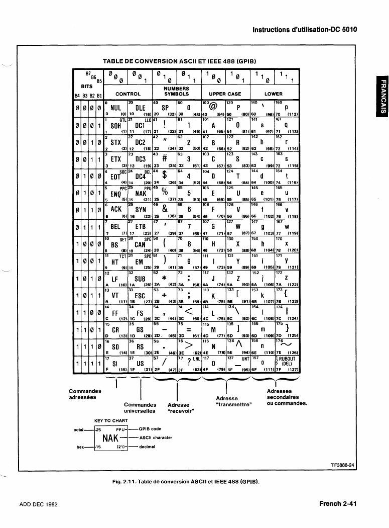
Instructions d'utilisation-DC 5010
Commandes I I I Adresses adressees Adresse secondaires
Commandes Adresse <'transmettrey' ou commandes. universelles "recevoir"
KEY TO CHART
BITS
octal-t25 NR K P U - ~ GPlB code
-- ASCII character
hex- 15 (21 1- - decimal
I 1 I I I ---
34
0
0
0
0
0
0
0
i
1
1
--
Fig. 2.1 I. Table de conversion ASCII et IEEE 488 (GPIB).
O00
TABLE DE
ADD DEC 1982
83
0
0
0
0
1
i
1
0
1 0 0 1
0
0
1 1 1 1
French 2-41
0 ° 1
CONVERSION ASCII ET IEEE 488 (GPIB) 7
82
0
0
1
1
0
1
1
0
1
1
1 1 0 0
1 1 0 1
1 1 1 0
0
NUL 0 (0)
1 GTL SOH
1 2
STX 2 (2) 3
ETX 3 (3)
B1
0
1
0
1
0
0
1
0
0
1
1 0 I 0
M OLE
10 (16) 21 LLO
DC1 ( 1 ) 1 1 (17121
22
DC2 12 (18) 23
DC3 13 (19)
O 1 1
LOWER
140 , 60 (96) 141
a (97171
142
b 62 (98) 143
c 63 (99) 144
d 64 (100) 145
e 65 (101) 146
f (102176
147
9 67 (103) 150
h 68 (104) 151
i 69 (105) 152
i 6A (106) 153
k 6B (107) 154
I (10817C
155
m 6 0 (109) 156 n
6E (110) 157
0 6F (111)
NUMBERS
4 S I C EOT
4 (4)
0 1 0 1 5 E N ~ P c 2 5 N A ~ p U 4 5 % 5 (5) 6
ACK 6 (6) 7
BEL 7 (7)
160
P 70 (112) 161
9 (113)
162 r
72 (114) 163
s 73 (115) 164
t 74 (116) 165
U 75 (117) 166
v (118)
167
w 77 (119) 170
x 78 (120) 171
Y 79 (121) 172
z 7A (122)
1 78 (123)
I (124)
175 1 7D (125) 176 cv
7E (126)
RUBOUT ~ ( D E L ) 7F (127)
SYMBOLS
40
SP 20 (32) 41 1
( 3 3 3 1
42 ,, 22 (34)
43 # 23 (35)
44 $ 24 (36)
25 (37)
46 & (38136
47 , 27 (39)
50 ( 28 (40)
51 1 29 (41) 52 * 2A (42) 53 + 2B (43) 54
9 (44J3C
55 - 2 0 (45) 56
m
2E (46) 57
2F (47)
UPPER
loo"@
40 (64) 101
A (65151
102
B 42 (66) 103
C 43 (67) 104
D 44 (68) 105
E 45 (69) 106
F (70156
107
G 47 (71) 110
H 48 (72) 111
I 49 (73) 112
J 4A (74) 113
K 48 (75) 114
L (76)5C
115
M 4 0 (77) 116
N 4E (78) 117
0 4F (79)
4
0c lCL 14 (20)
15 (21)
26SYN 16 (22126
27
ETB 17 (23)
1 0
60
0 30 (48) 6 1
1 (49141
62
2 32 (50) 63
3 33 (51) 64
4 34 (52) 65
5 35 (53) 66
6 (54146
67
7 37 (55) 70
8 38 (56) 71
9 39 (57) 72
3A (58)
73 . 9
38 (59)
7 4 < (6014C
75 - - 3 0 (61)
76 > 3E (62)
77 7 UNL
3F (63)
CASE
120
P 50 (80) 121
0 (81161
122
R 52 (82) 123
S 53 (83) 124
T 54 (84) 125
u 55 (85) 126
V (86166
127 W
57 (87) 130
X 58 (88) 131
Y 59 (89) 132
Z 5A (90)
133 [ 58 (91) 134\
(9216C
135 1 5 0 (93) 136 A 5E (94) 137 UNT - 5F (95)
1 1
lo GET BS
8 (81 11 TCT
HT 9 (9) 12
LF A (10) 13
VT B (11) 14
FF C ( 1 2 ) l C 15
CR D (13) 16
so E (14) 17
SI F (15) --
O CAN"^ 18 (241 31
EM 19 (25) 32
SUB 1A (26) 33
ESC l B (27)
34
Fs ( 2 8 ) z c
3 5
GS I D (29) 36
RS 1E (30) 37
US I F (31)
-7
Arguments numeriques arrondis
L'instrument arrondit les arguments numeriques a I'unite de resolution la plus proche puis recherche toute condition hors de la plage autorisee.
Protocole des messages
Tout message recu par le DC 501 0 est stocke dans la Memoire Tampon d'Entree, traite, puis execute. Le traitement d'un message consiste en le decodage des commandes, la detection des delimiteurs, et la verifica- tion de la syntaxe. En ce qui concerne les commandes de reglage, I'instrument consigne les modifications in- diquees dans la memoire Reglages en Attente. Si une erreur est detectee en cours de traitement, I'instrument fait passer la ligne SRQ a I'etat bas, ignore le reste du message, et reinitialise la memoire Reglages en Attente. Ceci evite toute condition de fonctionnement incorrecte pouvant resulter de I'execution partielle des commandes de reglage contenues dans un message.
L'execution d'un message consiste en I'execution des actions specifiees par la (ou les) commande(s) qu'il contient. S'agissant des Commandes de Reglage, ceci signifie la remise a jour des reglages de I'instrument, et leur stockage dans la memoire tampon Reglages Ac- tuels. Les commandes de reglage sont executees par groupes - une serie de commandes de reglage est traitee et consignee dans la memoire Reglages en At- tente avant leur execution. Ceci permet a I'utilisateur de specifier de nouveaux reglages sans avoir a se preocup- per de la validite d'une sequence particuliere. Leur exe- cution survient lors du traitement par I'instrument de la fin du message, d'une commande d'interrogation en sortie, ou d'une commande d'utilisation contenue dans un message.
Lors du traitement d'une commande d'interrogation en sortie (contenue dans un message), I'instrument execute toutes les commandes de reglage qui precedent (remise a jour de ses conditions de fonctionnement). II execute alors la commande d'interrogation en extrayant la donnee appropriee et en la placant dans la Memoire Tampon de Sortie. Puis il traite et execute le reste du message. Lorsque I'instrument est designe comme Emetteur, cette donnee est transmise au contr6leur.
L'instrument pourra alors accepter un second message avant que le premier ne soit traite complete- ,-
merit, mais non un troisieme (signal NRFD).
Apres I'execution d'une commande d'interrogation de sortie, I'instrument garde la reponse dans sa Memoire Tampon de Sortie jusqu'a ce qu'il soit designe comme Emetteur par le contr6leur. S'il recoit un nouveau message avant la lecture de toute la sortie du precedent, il annule le contenu de la Memoire Tampon de Sortie avant d'executer ce nouveau message. Ceci evite au contr6leur de recevoir des donnees indesirees issues d'anciens messages.
Autre situation pouvant annuler une sortie : I'execu- tion d'un long message peut remplir completement les memoires tampons d'entree et de sortie. Clans ce cas, I'instrument ne peut finir d'executer le message avant que le contr6leur ait lu les donnees transmises. Mais le contr6leur ne peut lire ces donnees avant d'avoir fini de transmettre son message. La Memoire Tampon d1Entree, etant pleine, rejette le reste du message du contr6leur (signal NRFD). Cette situation suspend I'activite du systeme, le contr6leur et I'instrurnent s'at- tendant reciproquement. Le DC 501 0 genere alors un message d'erreur, fait passer la ligne SRQ a I'etat bas, et annule le contenu de la Memoire Tampon de Sortie. Cette action permet au contr6leur de transmettre le reste de son message, puis I'informe de I'execution du message et de la disparition des autres donnees en sortie.
Un instrument de la serie TM 5000 peut 6tre designe -
comme Emetteur sans avoir recu de message lui specifi- ant ce qu'il doit transmettre. Dans ce cas, les instru- ments d'acquisition (compteurs et multimetres nume- riques) renvoient une mesure (si elle est prete). Sinon, ils renvoient un message unique sur un octet dont tous les bits sont egaux a 1 (avec une Fin de Message) ; les autres instruments de la serie TM 5000 ne renverront que ce message.
Reponse de I'instrument aux messages de I'inter- dace IEEE-488
Lors du traitement d'une commande d'utilisation (con- Les messages de I'interface et leurs effets sur les
tenue dans un message), I'instrument execute dlabord fonctions de I'interface de I'instrument sont definis
toutes les commandes de reglages precedentes avant dans les nOrmes lEEE 488-I g78. Ce paragraphe' qui en
de I'executer. decrit les effets sur le fonctionnement de I'appareil, uti- lise des abreviations de ces normes.
Messages multiples
La Memoire Tampon d'Entree a une capacite limitee et un message unique peut 6tre assez long pour la rem- UNL, Unlisten - (N'est pas Rkcepteur) plir. Dans ce cas, une partie du message est traitee UNT - Untalk - (N9est pas Emetteur) avant que I'appareil accepte une entree supplementaire.
7
Durant un traitement de commande, il rejette toute autre La commande UNL fait passer la fonction Recepteur a donnee (en validant la ligne NRFD) jusqu'a ce que de I'etat inactif (non adresse) ; I'instrument n'accepte pas I'espace soit disponible en memoire tampon. de commande du GPIB.
French 2-42 AlDD DEC 1982
Instructions d'utilisation-DC 5010
La commande UNT fait passer la fonction Emetteur a LLO - Local Lockout (Ne fonctionne plus en I'etat inactif ; I'instrument ne peut transmettre de mode Local)
-- , donnees sur le GPIB. En reponse a LLO, I'intrument passe a I'etat "bloque" -
Le voyant ADDRESSED est eteint lorsque ces deux de LOCS a LWLS ou de REMS a RWLS. fonctions sont a I'etat inactif. II est allume si I'instrument est adresse soit en tant qu 'het teur , soit en tant qUe REN - Remote Enable (Commande 5 Distance) Recepteur.
Si la ligne REN est a I'etat bas (validee), I'instrument IFC - Interface Clear (Initialisation de I'interface) passe en mode ContrBle a distance (de LOCS a REMS
ou de LWLS a RWLS) une fois recue son adresse Recep- Ce message a jigne unique a le meme effet que les teur. Si la ligne REN est l'etat haut (inhibee), IYinstru- messages et UNL' Le 'Oyant ADDRESSED (face ment passe en mode Local (LOCS), et y reste tant que la avant) est eteint. ligne REN est a I'etat haut.
DCL - Device Clear (Initialisation de I'instrument) Cette transition REN peut se produire apres le debut du traitement d'un message. Dans ce cas, I'execution de
Ce message reinitialise les communications entre celui-ci pas affectee par une transition. I'instrument et le contr6leur. En reponse a ce message, I'instrument annule tout message en entree et en sortie GTL - Go To Local (ContrBle Local) et toute commande de reglage dans la memoire tampon Reglages en Attente. II enest de meme pour toute erreur Seu Is les instruments adresses comme Recepteurs ou tout evenement non encore transmis, a I'exception repondent a cette commande en passant en mode de la mise en service. Si la ligne SRQ est a I'etat bas Local. Les transitions Contr6le a Distance-ContrBle (validee) pour une autre raison que la mise en service, Local provoquees par cette commande n'affectent pas elle passe a I'etat haut a la reception du message DCL. I'execution du message en cours de traitement (quand
SDC - Selected Device Clear (Initialisation par- ticuliere de I'instrument)
Ce message execute la meme fonction que DCL ; tou- tefois, seuls les instruments adresses comme Recep- teurs (Listen) repondent a ce message.
GET - Group Execute Trigger (Declenchement simultane cde tous les instruments par le contr6-
L leur)
L'instrument n'execute cette commande que s'il est adresse comme Recepteur (Listen) et si la fonction Device Trigger (declenchement de I'instrument par le contr6leur) a ete validee par la commande Device Trig- ger (DT). Le message GET est ignore et une demande de service est generee si la fonction DT est inhibee (DT OFF), si I'instrument est en mode Local, ou si un message est en cours de tralitement a la reception de GET.
SPE - Serial Poll Enable (Validation de I'appel selectif) SPD - Serial Poll Disable (Inhibition de I'appel selectif)
Le message SPE valide la generation par I'instrument de mots d'etat (en reponse a un appel selectif en serie) lorsqu'il est adresse comme Emetteur (Talk). Le message SP'D ramene I'instrument en mode d'utilisation normal (transmission de donnees issues de la Memoire Tampon de Sortie).
MLA - My Listen Address (Mon adresse en tant que Recepteur) M IA - My Talk Address (Mon adresse en tant qu'Emetteur)
Les adresses primaires "Talk" et "Listen" sont deter- minees par I'adresse des instruments sur le GPIB
L (selectionn6e a I'interieur). L'adresse GPlB actuelle est affichee en face avant lorsque le bouton ID est enfonce.
GTL est recu).
Remote (ContrBle a Distance) - Local Operation (ContrBle Local)
Les lignes qui precedent decrivent les transitions d'un etat a I'autre provoquees par les messages GTL et REN. La plupart des commandes en face avant provo- quent une transition entre REMS et LOCS en validant le message "Retour en mode Local" (rtl). Cette transition peut se produire durant I'execution d'un message ; mais, par opposition aux transitions GTL et REN, elle en affecte I'execution. Dans ce cas, I'instrument genere une erreur s'il subsiste des commandes de reglage ou d'utilisation non executees. Les commandes en face avant n'affectant que I'affichage (telle ID) n'ont pas d'incidence sur les etats "A distance-Local" - seules les commandes agissant sur les reglages (a I'exception des commandes de declenchement) generent le message rtl. Celui-ci est valide par I'entree de plusieurs com- mandes au clavier, et est inhibe apres le tralitement de ces commandes.
L'instrument conserve une copie de ses reglages dans la memoire tampon Reglages Actuels ; ceux-ci sont remis a jour par tous nouveaux reglages issus de la face avant ou du contr6leur.
Local State (LOCS) - (Etat Local)
Les reglages de I'instrument sont contr6les en face avant par I'operateur. Seules les commandes du bus n'agissant pas sur les reglages sont executees (interro- gations) ; toutes les autres commandes du bus (de reglage et d'utilisation) generent une erreur car leurs fonctions sont contrelees en face avant.
Local With Lockout State (LWLS) - (Etat Local avec blocage de I'Etat Local)
L'instrument opere de la meme facon qu'en mode LOCS, excepte que le message rtl n'inhibe pas le passage dans I'etat RWLS.
ADD DEC 1982 French 2-43
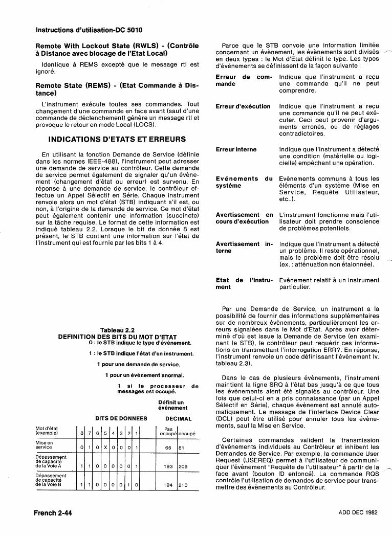
Instructions d'utilisation-DC 5010
Remote With Lockout State (RWLS) - (Contr6le a Distance avec blocage de I'Etat Local)
ldentique a REMS excepte que le message rtl est ignore.
Remote State (REMS) - (Etat Commande a Dis- tance)
L'instrument execute toutes ses commandes. Tout changement d'une commande en face avant (sauf d'une commande de declenchement) genere un message rtl et provoque le retour en mode Local (LOCS).
INDICATIONS D'ETATS ET ERREURS
En utilisant la fonction Demande de Service (definie dans les normes IEEE-488)' I'instrument peut adresser une demande de service au contr6leur. Cette demande de service permet egalement de signaler qu'un evene- ment (changement d'etat ou erreur) est survenu. En reponse a une demande de service, le contr6leur ef- fectue un Appel Selectif en Serie. Chaque instrument renvoie alors un mot d'etat (STB) indiquant s'il est, ou non, a l'origine de la demande de service. Ce mot d'etat peut egalement contenir une information (succincte) sur la t iche requise. Le format de cette information est indique tableau 2.2. Lorsque le bit de donnee 8 est present, lec STB contient une information sur I'etat de I'instrument qui est fournie par les bits 1 a 4.
Tableau 2.2 DEFINITION DES BlTS DU MOT D'ETAT
0 : le STB indique le type d'evenement.
1 : le STB indique I'etat d'un instrument.
1 pour une demande de service.
1 pour un evenement anormal.
1 si le processeur de messages est occupe.
Definit un evenement
BITS DE DONNEES DECIMAL
Parce que le STB convoie une information limitee concernant un evenement, les evenements sont divises - en deux types : le Mot dlEtat definit le type. Les types d'evenements se definissent de la facon suivante :
Erreur de com- mande
Erreur d'execution
Erreur interne
Evenements du systeme
Avertissement en cours d'execution
Avertissement in- terne
Etat de I'instru- ment
lndique que I'instrurnent a recu une commande qu'il ne peut comprendre.
lndique que I'instrument a recu une commande qu'il ne peut exe- cuter. Ceci peut provenir d'argu- ments errones, ou de reglages contradictoires.
lndique que I'instrument a detecte une condition (materielle ou logi- cielle) empgchant une operation.
Evenements commurls a tous les elements d'un systeme (Mise en Service, RequGte Utilisateur, etc..).
L'instrument fonctionne mais I'uti- lisateur doit prendre conscience de problemes potentiels.
lndique que I'instrument a detecte un probleme. II reste operationnel, mais le probleme doit Gtre resolu -_ (ex. : attenuation non etalonnee).
Evenement relatif a un instrument particulier.
Par une Demande de Service, un instrument a la possibilite de fournir des informations supplementaires sur de nombreux evenernents, particulierement les er- reurs signalees dans le Mot dlEtat. Apres avoir deter- mine d'ou est issue la Demande de Service (en exami- nant le STB), le contr6leur peut requerir ces informa- tions en transmettant I'interrogation ERR?,. En reponse, l'instrument renvoie un code definissant I'bvenement (v. tableau 2.3).
Dans le cas de plusieurs evenernents, I'instrument maintient la ligne SRQ a I'etat bas jusqu'a ce que tous les evenements aient ete signales au contr6leur. Une fois que celui-ci en a pris connaissance par un Appel Selectif en Serie), chaque evenement est annule auto- matiquement. Le message de I'interface Device Clear (DCL) peut gtre utilise pour annuler tous les evene- ments, sauf la Mise en Service.
Certaines commandes valident la transmission d'evenements individuels au Contrdleur el' inhibent les Demandes de Service. Par exemple, la comrnande User Request (USEREQ) permet a I'utilisateur de communi- quer I'evenement "Requgte de I'utilisateur" a partir de la - face avant (bouton ID enfonce). La corrrmande RQS contr6le I'utilisation de demandes de service pour trans- mettre des evenements au Contr6leur.
French 2-44 ADD DEC 1982
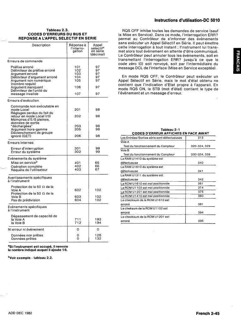
Instructions d'utilisation-DC 5010
Tableau 2.3. CODES D'ERREURS DU BUS ET
REPONSE A L'APPEL SELECTIF EN SERlE
Description
Erreurs de comrnande
Prefixe erronk Delimiteur de prefixe errone Argument errone Delimiteur d'argument errone Argument nor) numerique (nombre requis) Argument manquant Delimiteur de I'unite du message invalide
Erreurs d'execution
Commande non executable en mode Local Reglages perldus du fait du retour en mode Local (rtl) Memoires dlE/S pleines, donnees de sortie "dechargees" Argument hors-gamme Declenchement de groupe ignore (GET)
Erreurs internes
Erreur d'interruption Erreur du systeme
Evenements du systeme Mise en serviceb
. Operation complete Requete de I'utilisateur
Avertissements specifiques a I'instrument
Protection de la 50 R de la Voie A Protection de la 50 R de la Voie B Pas de predivision
Evenements specifiques a I'instrument
Depassement de capacite de la Voie A la Voie B
Ni erreur ni evenement
Donnees non pretes Donnees pr6l:es
Reponse a I'interro- gation
APP~.' selec$fa en sene (decimal)
RQS OFF inhibe toutes les demandes de service (sauf la Mise en Service). Dans ce mode, I'interrogation ERR? permet au Contr6leur de s'informer des evenements sans executer un Appel Selectif en Serie. II peut emettre cette interrogation a tout instant ; I'instrument lui trans- met alors tout evenement en attente d'gtre communique. Le Contr6leur peut annuler tous les evenements, soit en transmettant I'interrogation ERR? jusqu'a ce que le code zero (0) soit renvoye, soit par I'intermediaire du message DCL de I'interface (Mise en Service exceptee).
En mode RQS OFF, le Contr6leur peut executer un Appel Selectif en Serie, mais le mot d'etat obtenu ne contient que I'indication dlEtat propre a I'appareil. En mode RQS ON, le STB (mot d'etat) contient le type de I'evenement et un message d'erreur.
Tableau 2-1 CODES D'ERREUR AFFICHES EN FACE AVANT
La RAM U 1 61 0 du systerne est I
Les EntreesSorties serie sont defectueuses Voie A
Test du fonctionnement du Compteur Voie B
Test du fonctionnement du Com~teur La RAM U1410 du systeme est defectueuse
31 3
320-324,329
330-334,339
340
defectueuse La ROM U161O est ma1 positionnee La ROM U1102 est ma1 positionnee La ROM U1201 est ma1 positionnee La ROM U1410 est ma1 positionnee Le checksum de la ROM U1610 est
defectueuse La RAM U1311 du systeme est
errone I 381
34 1
Le cheksum de la ROM U1102 est errone I 394 Lechecksum de la ROM U1201 est I errone I 395
'Si I'instrument est occupe, il renvoie le nombre indique auquel il ajoute 16.
b ~ o i r exemple -. tableau 2.2.
ADD DEC 1982 French 2-45
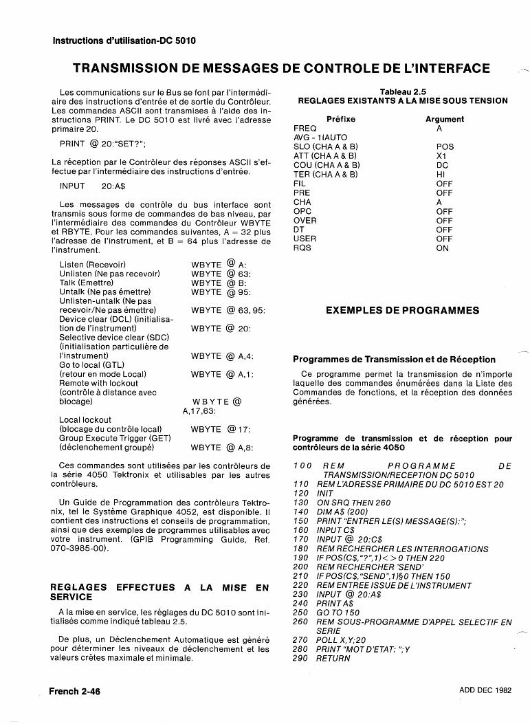
Instructions d'utilisation-DC 5010
TRANSMISSION DE MESSAGES DE CONTROLE DE L'INTERFACE - Les communications sur le Bus se font par I'intermedi-
aire des instructions d'entree et de sortie du Contr6leur. Les commandes ASCll sont transmises a I'aide des in- structions PRINT. Le DC 5010 est livre avec I'adresse primaire 20.
PRINT @ 20:"SET?";
La reception par le ContrBleur des reponses ASCll s'ef- fectue par I'intermediaire des instructions d'entree.
INPUT 20:A$
Les messages de contr6le du bus interface sont transmis sous forme de commandes de bas niveau, par I'intermediaire des commandes du Contr6leur WBYTE et RBYTE. Pour les commandes suivantes, A = 32 plus I'adresse de I'instrument, et B = 64 plus I'adresse de I'instrument.
Listen (Recevoir) Unlisten (Ne pas recevoir) Talk (Emettre) Untalk (Ne pas emettre) Unlisten-untalk (Ne pas recevoir/Ne pas emettre) Device clear (DCL) (initialisa- tion de I'instrument) Selective device clear (SDC) (initialisation particuliere de I'instrument) Go to local (GTL) (retour en mode Local) Remote with lockout (contr6le a distance avec blocage)
Local lockout (blocage du contr6le local) Group Execute Trigger (GET) (declenchement groupe)
WBYTE @ A: WBYTE @ 63: WBYTE @ B: WBYTE @ 95:
WBYTE @ 63'95:
WBYTE @ 20:
WBYTE @ A,4:
WBYTE @ A,1:
W B Y T E @ A,17,63:
WBYTE @17:
WBYTE @ A,8:
Ces commandes sont utilisees par les contr6leurs de la serie 4050 Tektronix et utilisables par les autres contr6leurs.
Un Guide de Programmation des contr6leurs Tektro- nix, tel le Systeme Graphique 4052, est disponible. ll contient des instructions et conseils de programmation, ainsi que des exemples de programmes utilisables avec votre instrument. (GPIB Programming Guide, Ref. 070-3985-00).
REGLAGES EFFECTUES A LA MlSE EN SERVICE
A la mise en service, les reglages du DC 501 0 sont ini- tialises comme indique tableau 2.5.
De plus, un Declenchement Automatique est genere pour determiner les niveaux de declenchement et les valeurs crgtes maximale et minimale.
Tableau 2.5 REGLAGES EXISTANTS A LA MlSE SOUS TENSION
Pref ixe FREQ AVG - 1 IAUTO SLO (CHA A & B) ATT (CHA A & B) COU (CHA A & 9) TER (CHA A & B) FI L PRE CHA OPC OVER DT USER RQS
Argument A
POS X I DC HI OFF OFF A OFF OFF OFF OFF ON
EXEMPLES DE PROGRAMMES
- Programmes de Transmission et de Rbception
Ce programme permet la transmission de n'importe laquelle des commandes enumerees dans la Liste des Commandes de fonctions, et la reception des donnees generees.
Programme de transmission et de reception pour contrdleurs de la serie 4050
1 0 0 R E M P R O G R A M M E DE TRANSMISSION/RECEPTlON DC 501 0
REM L'ADRESSE PRIMAIRE DU DC 5101 0 EST 20 INIT ON SRQ THEN 260 DIM A$ (200) PRINT "ENTRER LE(S) MESSAGE(S):"; INPUT C$ INPUT @ 20:C$ REM RECHERCHER LES INTERROGATIONS IF POS(C$,"?", I ) < > 0 THEN 220 REM RECHERCHER 'SEND' IF POS(C$,"SEND", 1)§O THEN 150 REM ENTREE ISSUE DE L'INSTRUMENT INPUT @ 20:A$ PRINT A$ GO TO 150 REM SOUS-PROGRAMME D'APPEL SELECTIF EN SERlE F-
POLL X, Y;20 PRINT "MOT D'ETAT: ";Y RETURN
French 2-46 ADD DEC 1982
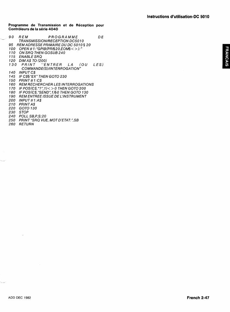
Instructions d'utilisation-DC 5010
Programme de Transmission et de Reception pour Contr6leurs de la serie 4040
4
9 0 R E M P R O G R A M M E D E TRANSMISSION/RECEPTlON DC5O 10
95 REM ADRESSE PRIMAIRE DU DC 501 0 § 20 OPEN #1:"GPIB(PR1§20,EOM§< >):" ON SRQ THEN GOSUB 240 ENABLE SRQ DIM A$ TO (200)
P R I N T " E N T R E R L A ( O U L E S ) COMMANDE(S)/INTERROGATlON"
INPUT C$ IF C$§ "EX" THEN GOT0 230 PRlN T .# 1 :C$ REM RECHERCHER LES INTERROGATIONS IF POS(C$, "?", 1)< > 0 THEN GOT0 200 IF POS(C$,"SEND", 1)§O THEN GOT0 130 REM ENTREE ISSUE DE L'INSTRUMENT INPUT #?:A$ PRINTLA$ GOT0 130 STOP POLL SB,P,S;20 PRINT "SRQ VUE, MOT D'ETAT:",SB RETURN
-- -
ADD DEC 1982 French 2-47
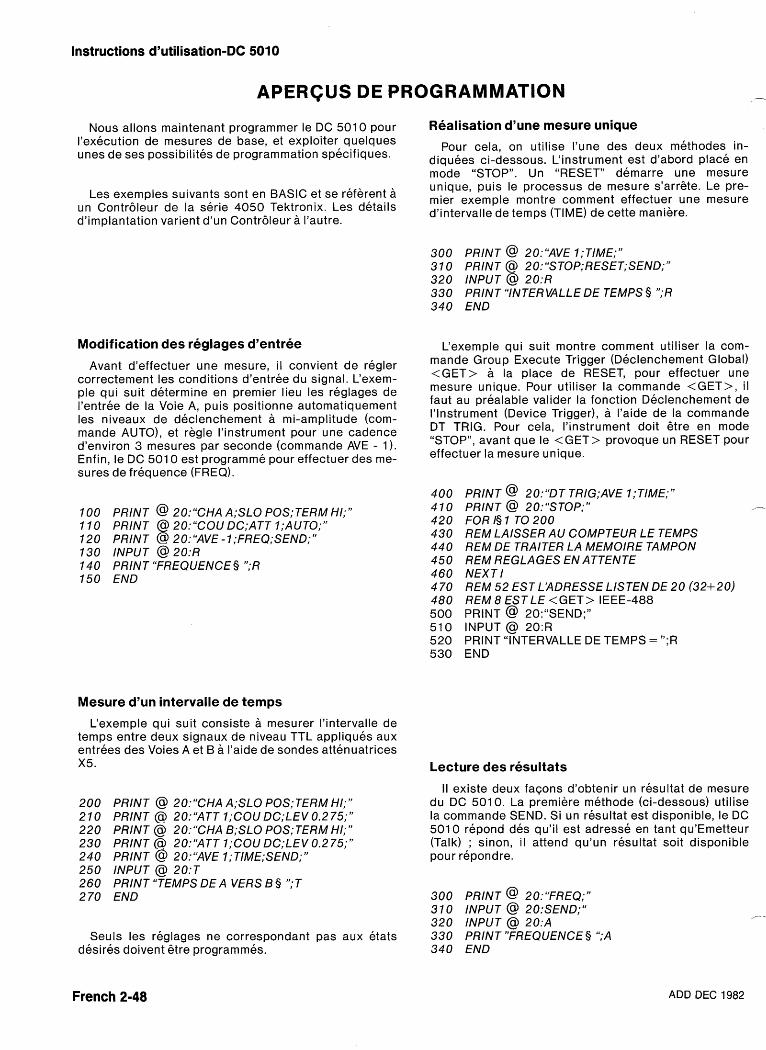
Instructions d'utilisation-DC 5060
APERCUS DE PROGRAMMATION -
Nous allons maintenant programmer le DC 501 0 pour I'execution de mesures de base, et exploiter quelques unes de ses possibilites de programmation specifiques.
Les exemples suivants sont en BASIC et se referent a un Contrbleur de la serie 4050 Tektronix. Les details d'implantation varient d'un Contrbleur a I'autre.
Modification des reglages d'entree
Avant d'effectuer une mesure, il convient de regler correctement les conditions d'entree du signal. L'exem- ple qui suit determine en premier lieu les reglages de I'entree de la Voie A, puis positionne automatiquement les niveaux de declenchement a mi-amplitude (com- mande AUTO), et regle I'instrument pour une cadence d'environ 3 mesures par seconde (commande AVE - 1). Enfin, le DC 501 0 est programme pour effectuer des me- sures de frequence (FREQ).
100 PRlNT @ 20:"CHA A;SLO POS; TERM HI;" 110 PRlNT @ 20:"COU DC;ATT 1;AUTO;" 120 PRlNT @ 20:"AVE -1;FREQ;SEND;" 130 INPUT @ 20:R 140 PRINT "FREQUENCE § ";R 150 END
Mesure d'un intervalle de temps
L'exemple qui suit consiste a mesurer I'intervalle de temps entre deux signaux de niveau TTL appliques aux entrees des Voies A et B a I'aide de sondes attenuatrices X5.
PRlNT @ 20:"CHA A;SLO P0S;TERM HI;" PRlNT @ 20:'MTT 1;COU DC;LEV 0.2 75;" PRlNT @ 20:"CHA B;SLO P0S;TERM HI;" PRlNT 0 20:'MTT 1;COU DC;LEV 0.2 75;" PRlNT @ 20:"AVE 1;TIME;SEND;" INPUT @ 20:T PRlNT "TEMPS DE A VERS B § ";T END
Seuls les reglages ne correspondant pas aux etats desires doivent &re programmes.
Realisation d'une mesure unique
Pour cela, on utilise I'une des deux methodes in- diquees ci-dessous. L'instrument est d'abord place en mode "STOP". Un "RESET" demarre une mesure unique, puis le processus de mesure s'arrgte. Le pre- mier exemple montre comment effectuer une mesure d'intervalle de temps (TIME) de cette manilere.
300 PRlNT @ 20:YVE 1;TIME;" 310 PRlNT @ 20:"STOP;RESET;SEND;" 320 INPUT @ 20:R 330 PRINT "INTERVALLE DE TEMPS 9 ";R 340 END
L'exemple qui suit montre comment utiliser la com- mande Group Execute Trigger (Declenchement Global) <GET> a la place de RESET, pour effectuer une mesure unique. Pour utiliser la commande <GET>, i l faut au prealable valider la fonction Declenchement de I'lnstrument (Device Trigger), a I'aide de la commande DT TRIG. Pour cela, I'instrument doit etre en mode "STOP", avant que le <GET> provoque mn RESET pour effectuer la mesure unique.
PRlNT @ 20:"DT TR1G;AVE 1;TIME;" PRINT @ 20:"STOP;" - FOR I§ 1 TO 200 REM LAISSER AU COMPTEUR LE TEMPS REM DE TRAITER LA MEMOIRE TAMPON REM REGLAGES EN ATTENTE NEXT I REM 52 EST L'ADRESSE LISTEN DE 20 (32+20) REM 8 EST LE <GET> IEEE-488 PRlNT @ 20:"SEND;" INPUT @ 20:R PRlNT "INTERVALLE DE TEMPS = ";R END
Lecture des resultats
II existe deux facons d'obtenir un resultat de mesure du DC 501 0. La premiere methode (ci-dessous) utilise la commande SEND. Si un resultat est disponible, le DC 5010 repond des qu'il est adresse en tant qu'Emetteur (Talk) ; sinon, i l attend qu'un resultat soit disponible pour repond re.
300 PRlNT @ 20:"FREQ;" 31 0 INPUT @ 20:SEND;" 320 INPUT @ 20:A
,- -
330 PRINT7'FREQUENCE § ";A 340 END
French 2-48 ADD DEC 1982
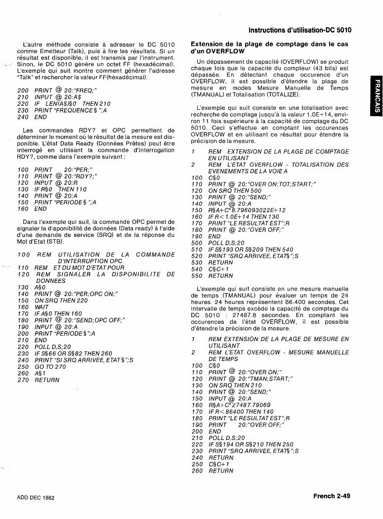
Instructions d'utilisation-DC 5010
Cautre mC?thode consiste a adresser le DC 5010 comme Emetteur (Talk), puis a l ire les resultats. Si un resultat est disponi ble, il est transmis par I'instrument.
- Sinon, le DC: 5010 genere un octet FF (hexadecimal). L'exemple qwi suit montre comment generer I'adresse "Talk" et rechercher la valeur FF(hexadecima1).
200 PRlNT @ 20:"FREQ;" 210 INPUT @ 20:A$ 220 IF LEN(A$)§O THEN210 230 PRINT "FREQUENCE § ";A 240 END
Les comrnandes RDY? et OPC permettent de determiner le moment oG le resultat de la mesure est dis- ponible. L'etat Data Ready (Donnees Pretes) peut gtre interroge en utilisant la commande d'interrogation RDY?, comrne dans I'exemple suivant :
100 PRlN T 20: "PER;" 11 0 PRlNT @ 20:"RDY?;" 120 INPUT @ 20:R 130 IFRSO THEN 110 140 PRINT @ 20:A 150 PRINT "PERIODE § ";A 160 END
Dans I'exemple qui suit, la commande OPC permet de signaler la disponibilite de donnees (Data ready) a I'aide d'une demande de service (SRQ) et de la reponse du Mot d'Etat (STB).
REM UT lL lSAT lON DE L A COMMANDE D'INTERRUPTION OPC
REM ET DU MOT D'ETAT POUR REM SIGNALER L A D lSPONlB lL lTE DE DONNEES
A§ 0 PRINT @ 20:"PER;OPC ON;" ON SRQ THEN 220 WAl T IF A§ 0 THEN 160 PRINT @ 20:"SEND;OPC OFF;" INPUT @ 20:A PRINT "PERIODE §";A END POLL D,S;20 IF S§66 OR S§82 THEN 260 PRINT "S/ SRQARRIVEE, €TAT§ ";S GO TC) 270 A§ 1 RETURN
Extension de la plage de comptage dans le cas d'un OVERFLOW
Un depassement de capacite (OVERFLOW) se produ it chaque fois que la capacite du compteur (43 bits) est depassee. En detectant chaque occurence d'un OVERFLOW, il est possible d'etendre la plage de mesure en modes Mesure Manuelle de Temps (TMANUAL) et Totalisation (TOTALIZE).
L'exemple qui suit consiste en une totalisation avec recherche de comptage jusqu'a la valeur 1 .OE+14, envi- ron 11 fois superieure a la capacite de comptage du DC 5010. Ceci s'effectue en comptant les occurences OVERFLOW et en utilisant ce resultat pour etendre la precision de la mesure.
REM EXTENSION DE LA PLAGE DE COMPTAGE EN UTILISANT REM L'ETAT OVERFLOW - TOTALISATION DES EVENEMENTS DE LA VOlE A C§O PRlNT @ 20:"OVER 0N;TOT;START;" ON SRQ THEN 500 PRlNT @ 20:"SEND;" INPUT @ 20:A R§A+C*8.796093022E+ 12 IFR< 1.OE+14 THEN 130 PRlNT "LE RESULTAT ESTV;R PRlNT @ 20:"OVER OFF;" END POLL D,S;20 IF S§ 193 OR S§209 THEN 540 PRlNT "SRQ ARRIVEE, ETAT§";S RETURN C§C+ 1 RETURN
L'exemple qui suit consiste en une mesure manuelle de temps (TMANUAL) pour evaluer un temps de 24 heures. 24 heures representent 86.400 secondes. Cet intervalle de temps excede la capacite de comptage du DC 5010 : 27487.8 secondes. En comptant les occurences de I'etat OVERFLOW, il est possible d'etendre la precision de la mesure.
REM EXTENSION DE LA PLAGE DE MESURE EN UTILISANT REM LJETAT OVERFLOW - MESURE MANUELLE DE TEMPS C§ 0 PRlNT @ 20:"OVER ON;" PRlNT @ 20:"TMAN;START;" ON SRQ THEN 2 10 PRINT @ 20:"SEND;" INPUT @ 20:A R§A+ C* 2 748 7.79069 IF R< 86400 THEN 140 PRlNT "LE RESULTAT ESTn;R PRlNT 20:"OVER OFF;" END POLL DJS;20 IF S§ 194 OR S§210 THEN 250 PRlNT "SRQ ARRIVEE, ETAT§";S RETURN C§ C+ 1 RETURN
ADD DEC 1982 French 2-49
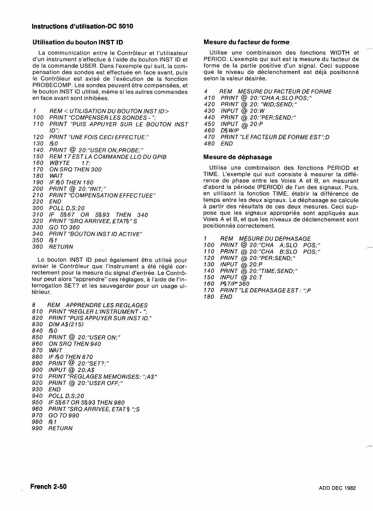
Instructions d'utilisation-DC 5010
Utilisation du bouton INST ID
La communication entre le Contr6leur et I'utilisateur d'un instrument s'effectue a I'aide du bouton INST ID et de la commande USER. Dans I'exemple qui suit, la com- pensation des sondes est effectuee en face avant, puis le Contr6leur est avise de I'execution de la fonction PROBECOMP. Les sondes peuvent etre compensees, et le bouton INST ID utilise, meme si les autres commandes en face avant sont inhibees.
REM < UTILISATION DU BOUTON INST ID> PRINT "COMPENSER LES SONDES - "; PRINT "PUIS APPUYER SUR LE BOUTON INST ID"; PRINT "UNE FOlS CECl EFFECTUE." I§ 0 PRINT @ 20:"USER 0N;PROBE;" REM 1 7 EST LA COMMANDE LLO DU GPlB WBYTE 17: ON SRQ THEN 300 WAlT IFIS0 THEN 180 PRINT @ 20:"INIT;" PRINT "COMPENSATION EFFECTUEE" END POLL D,S;20 IF S§67 OR S§93 THEN 340 PRINT "SRQ ARRIVEE, ETAG" S GO TO 360 PRINT "BOUTON INST ID ACTIVE" I§ 1 RETURN
Le bouton INST ID peut egalement etre utilise pour aviser le Contr6leur que I'instrument a ete regle cor- rectement pour la mesure du signal d'entree. Le Contr6- leur peut alors "apprendre" ces reglages, a I'aide de I'in- terrogation SET? et les sauvegarder pour un usage ul- terieur.
REM APPRENDRE LES REGLAGES PRINT "REGLER L'INSTRUMENT - "; PRINT "PUIS APPUYER SUR INST ID." DIM A$(2 15) I§ 0 PRINT @ 20:"USER ON;" ON SRQ THEN 940 WAlT IF I§ 0 THEN 8 70 PRINT @ 20:"SET?;" INPUT @ 20:A$ PRINT "REGLAGES MEMORISES: ";A$" PRINT @ 20:"USER OFF;" END POLL D,S;20 IFSS67OR S§93 THEN 980 PRlNT7'SRQ ARRIVEE, ETATS ";S GO TO 990 I§ 1 RETURN
Mesure du facteur de forme ?-. .
Utilise une combinaison des fonctions WIDTH et PERIOD. L'exemple qui suit est la mesure du facteur de forme de la partie positive d'un signal. Ceci suppose que le niveau de declenchement est de j i positionne selon la valeur desiree.
REM MESURE DU FACTEUR DE FORME PRINT @ 20:"CHA A;SLO POS;" PRINT @ 20: "W1D;SEND;" INPUT @ 20:W PRINT @ 20:"PER;SEND;" INPUT @ 20:P D§ W/P PRlNT7'LE FACTEUR DE FORME EST6';D END
Mesure de dephasage
Utilise une combinaison des fonctions PERIOD et TIME. L'exemple qui suit consiste a mesurer la diffe- rence de phase entre les Voies A et B, en mesurant d'abord la periode (PERIOD) de I'un des signaux. Puis, en utilisant la fonction TIME, etablir la difference de temps entre les deux signaux. Le dephasage se calcule a partir des resultats de ces deux mesures. Ceci sup- pose que les signaux appropries sont appliques aux Voies A et B, et que les niveaux de declenchement sont positionnes correctement.
REM MESURE DU DEPHASAGE PRINT @ 20:"CHA A;SLO POS;" PRINT @ 20:"CHA B;SLO POS;" PRINT @ 20:"PER;SEND;" INPUT @ 20:P PRINT @ 2O:"TIME;SEND;" INPUT @ 20:T 6 T / P 360 PRINT "LE DEPHASAGE EST: ";P END
French 2-50 ADD DEC 1982
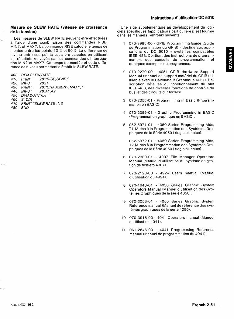
Instructions d'utilisation-DC 5010
Mesure de! SLEW RATE (vitesse de croissance de la tension)
_ Les mesures de SLEW RATE peuvent 6tre effectuees a I'aide d'une combinaison des commandes RISE, MIN?, et MAX?. La commande RISE calcule le temps de montee entre les points 10 % et 90 O/O. La difference de niveau entre ces points est alors calculee en utilisant les resultats renvoyes par les commandes d'interroga- tion MIN? et MAX?. Ce temps de montee et cette diffe- rence de niveau permettent d'etablir le SLEW RATE.
REM SLEW RATE PRINT 20: "R1SE;SEND;" INPUT 20:R PRINT 20:"CHA A;MIN?;MAX?;" INPUT 20:Al ,A2 D§ (A2-A I)* 0.8 S§ D/R PRINT "SLEW RATE : ";S END
Une aide supplementaire au developpement de logi- ciels specifiques (applications particulieres) est fournie dans les manuels Tektronix suivants :
070-3985-00 - GPIB Programming Guide (Guide de Programmation du GPIB) - destine aux appli- cations du DC 5010 - systemes compatibles IEEE-488. Contient des instructions de program- mation, des conseils de programmation, et quelques exemples de programmes.
070-2270-00 - 4051 GPIB Hardware Support Manual (Manuel de support materiel du GPIB uti- lisable avec le Calculateur Graphique 4051 ). De- scription detaillee du fonctionnement du bus IEEE-488, des diverses fonctions de contr6le du bus, et des circuits d'interface.
070-2058-01 - Programming in Basic (Program- mation en BASIC).
070-2059-01 - Graphic Programming in BASIC (Programmation graphique en BASIC).
062-5971 -01 - 4050-Series Programming Aids, T I (Aides a la Programmation des Systemes Gra- phiques de la Serie 4050 ) (logiciel inclus).
062-5972-01 - 4050-Series Programming Aids, T2 (Aides a la Programmation des Systemes Gra- phiques de la Serie 4050 ) (logiciel inclus).
070-2380-01 - 4907 f i l e Manager Operators Manual (Manuel d'utilisation du systeme de ges- tion de fichiers 4907).
070-2128-00 - 4924 Users manual (Manuel d'utilisation du 4924).
070-1940-01 - 4050 Series Graphic System Operators Manual (Manuel d'utilisation des Sys- temes Graphiques de la serie 4050).
070-2056-01 - 4050 Series Graphic System Reference manual (Manuel de reference des sys- temes graphiques de la serie 4050).
070-391 8-00 - 4041 Operators manual (Manuel d'utilisation 4041 1.
061 -2546-00 - 4041 Programming Reference manual (Manuel de programmation du 4041 1.
ADD DEC 1982 French 2-51 .

Abschnitt 2 - DC 5010
BEDIENUNGSANLEITUNG
Untersuchung auf Beschadigung
Prufen Sie das Gerat auf sichtbare Beschadigungen (Beulen, Kratizer usw.). Die Originalverpackung sollte zur spateren Verwendung aufbewahrt werden. Wenn das Gerat beschildigt ist, benachrichtigen Sie das Trans- portunternehmen und die nachstgelegene Tektronix Geschaftsstelle.
Versandhinweise
Wenn das Gerat fur Servicearbeiten oder zur Repara- tur an ein Tektronix Service-Center eingeschickt werden muO, befestigen Sie daran einen Zettel mit folgenden Angaben: Name und Anschrift des Besitzers, Name einer Kontaktperson, vollstandige Seriennummer und Option- Nummer des Gerates und eine Beschreibung der gewunschterl Servicearbeiten.
Wenn die Originalverpackung nicht mehr zur Ver- fugung steht, verpacken Sie das Gerat wie folgt:
L
1. Nehmer~ Sie einen Karton aus Wellpappe, dessen lnnenabmessungen wenigstens 15 cm groOer sind als die auOeren Abmessungen des Gerates. Die Pruffestig- keit des Versandkartons fur Ihr Gerat betragt 90 kg.
2. Zum Schutz der Oberflache hullen Sie das Gerat in eine Plastikfodie.
3. Polstern Sie die Zwischenraume zwischen Karton und Gerat mit Schaumstoff oder Papierschnitzeln fest aus.
4. VerschlieOen Sie den Karton mit Klebeband oder Industrie-Heft klammern.
5. Bringen Sie einen Aufkleber ,,VORSICHT GLAS" oder ,,ZERBRECHLICHU an.
Umweltbedirngungen in- und auBer Betrieb
Das Gerait kann innerhalb der Grenzen der im Abschnitt Spezifikationen genannten Umweltbedingun- gen betrieberi, gelagert und versandt werden. Der Zahler sollte jedoch immer vor Temperaturen geschutzt wer-
-- den, die zu Feuchtigkeits-Kondensation im lnneren des Gerates fuhren konnen.
VORBEREITENDE HlNWElSE
Hintere Interface Steckverbindungen
Eine Aussparung zwischen den Stiften 21 und 22 der hinteren Steckverbindung identifiziert dieses Gerat als ein Mitglied der TM 5000 Zahlerfamilie. Wenn Sie mit lhrem Zahler ein System aufbauen mochten, bringen Sie an der entsprechenden Stelle der Steckverbindung der Versorgungseinheit eine Familiensperre an (Tektronix Teile-Nr.: 214-1593-02) um zu verhindern, daO Ein- schube, die zu einer anderen Familie gehoren in diesem Abteil der Versorgungseinheit verwendet werden.
I WARNUNG ) Um elektrische Schlage zu vermeiden, mu8 vor Ein- bau der Sperre in die Steckverbindung der Versor- gungseinheit das Netzkabel abgenommen werden. ~berlassen Sie das Einsetzen der Sperre dem quali- fizierten Servicepersonal.
Der DC 5010 hat an der hinteren Schnittstelle die nachstehenden Eingange und Ausgange:
Arming Eingang
10 MHz-Takt Ausgang
Externer Takt Eingang (1, 5,10 MHz)
Vorzahler-Funktion
Ruckstell-Eingang
ANMERKUNG
Informationen iiber die hintere Schnittstelle finden Sie im Abschnitt Wartung. ~berlassen Sie die Anschliisse an die Schnittstelle dem qualifizierten Servicepersonal.
Ein- und Ausbau des Einschubes
Der DC 5010 kann nur in Versorgungseinheiten der Serie TM 5000 betrieben werden.
ANMERKUNG
Beach ten Sie die Anga ben zur Bedienungssicher- heit im vorderen Teil dieses Handbuches, bevor Sie das Gerat in die Versorgungseinheit einsetzen.
ADD DEC 1982: German 2-1
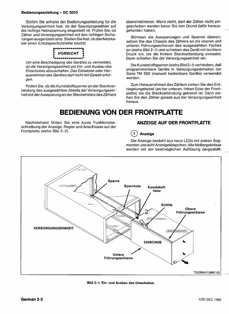
Bedienungsanleitung - DC 5010
Stellen Sie anhand der Bedienungsanleitung fur die ubereinstimmen. Wenn nicht, darf der Zahler nicht ein- Versorgungseinheit fest, ob der Spannungswahler auf geschoben werden bevor Sie den Grund clafur heraus- die richtige Netzspannung eingestellt ist. Prufen Sie, ob gefunden haben. - Zahler und Versorgungseinheit mit den richtigen Siche- rungen ausgerustet sind. Stellen Sie fest, ob das Netzka- be1 einen Erdungsschutzleiter besitzt.
VORSICHT a Um eine Beschadigung des Gerates zu vermeiden, ist die Versorgungseinheit vor Ein- und Ausbau des Einschubes abzuschalten. Das Einsetzen oder Her- ausnehmen des Gerates darf nicht mit Gewalt erfol- gen.
Stimmen die Aussparungen und Sperren uberein, setzen Sie das Chassis des Zahlers an die oberen und unteren Fu hrungsschienen des ausgewahlten Faches an (siehe Bild 2-1) und schieben das Gerat mit leichtem Druck ein, bis die hintere Steckverbindung einrastet. Dann schalten Sie die Versorgungseinheit ein.
Die Kunststoffsperren (siehe Bild 2-1) verhindern, daO programmierbare Gerate in Versorgungseinheiten der Serie TM 500 (manuell bedienbare Gerate) verwendet werden.
Nachstehend finden Sie eine kurze Funktionsbe- ANZEIGE AUF DER FRONTPLAlTE schreibung der Anzeige, Regler und Anschlusse auf der Frontplatte (siehe Bild 2-2). @ Anzeige
Die Anzeige besteht aus neun LEDs mit sieben Seg- menten und acht Anzeigelampchen. Alle MeBergebnisse werden mit der bestmoglichen Auflosung dargestellt.
I nase
'A 1111 / Schlitz
Untere Fuhrungsschiene
Bild 2-1. Ein- und Ausbau des Einschubes.
German 2-2 ADD DEC 1982
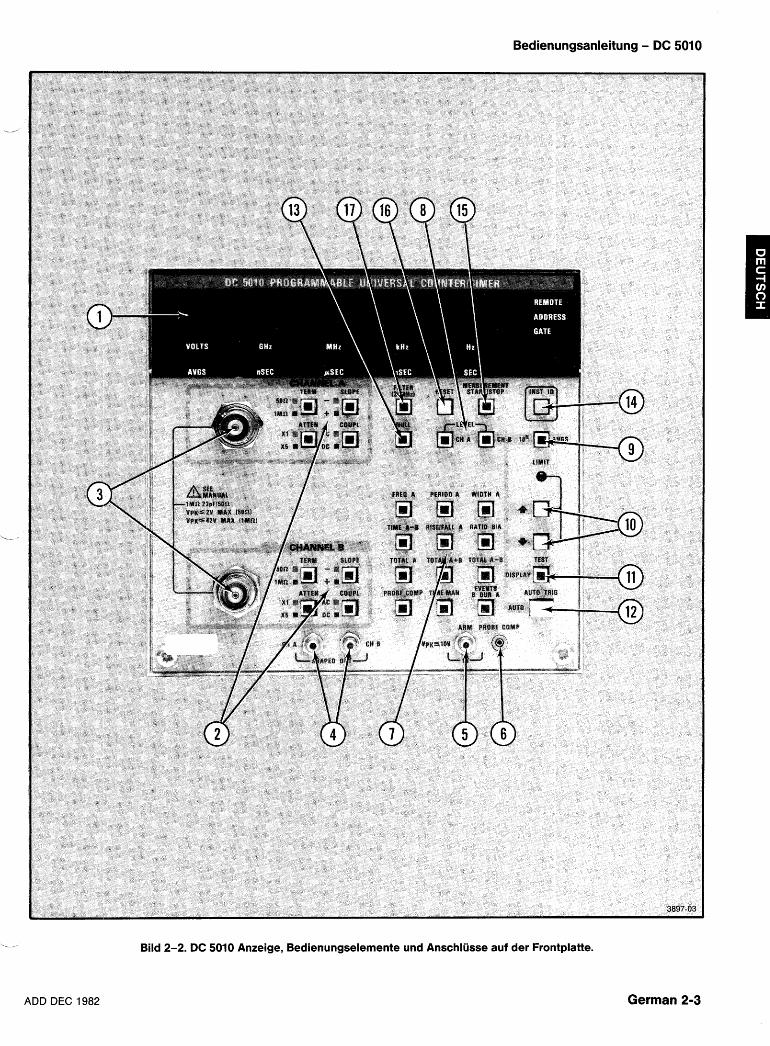
Bedienungsanleitung - DC 5010
,__ Bild 2-2. DC 5010 Anzeige, Bedienungselemente und Anschliisse auf der Frontplatte.
ADD DEC 1982 German 2-3
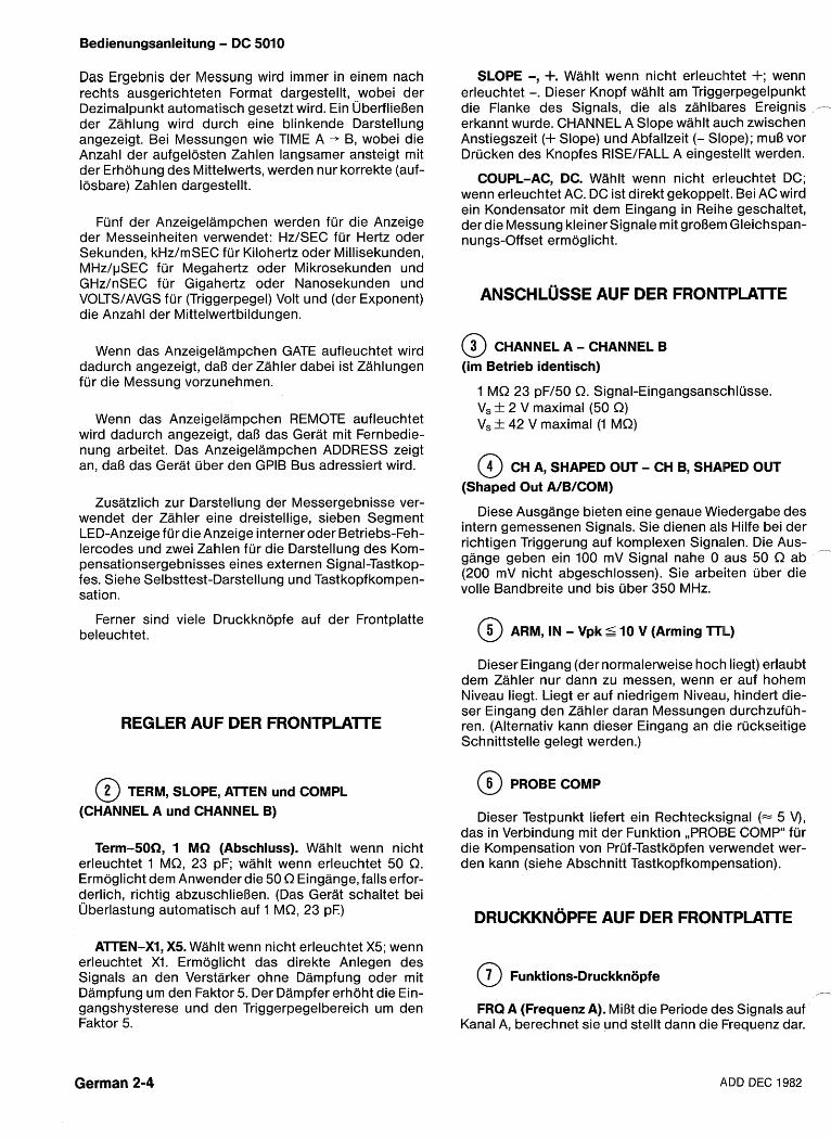
Bedienungsanleitung - BC 5010
Das Ergebnis der Messung wird immer in einem nach rechts ausgerichteten Format dargestellt, wobei der Dezimalpunkt automatisch gesetzt wird. Ein ~berflieOen der Zahlung wird durch eine blinkende Darstellung angezeigt. Bei Messungen wie TIME A - B, wobei die Anzahl der aufgelosten Zahlen langsamer ansteigt mit der Erhohung des Mittelwerts, werden nur korrekte (auf- Iosbare) Zahlen dargestellt.
Funf der Anzeigelampchen werden fur die Anzeige der Messeinheiten verwendet: HzISEC fur Hertz oder Sekunden, kHz1mSEC fur Kilohertz oder Millisekunden, MHzIpSEC fur Megahertz oder Mikrosekunden und GHzInSEC fur Gigahertz oder Nanosekunden und VOLTSIAVGS fur (Triggerpegel) Volt und (der Exponent) die Anzahl der Mittelwertbildungen.
Wenn das Anzeigelampchen GATE aufleuchtet wird dadurch angezeigt, dal3 der Zahler dabei ist Zahlungen fur die Messung vorzunehmen.
Wenn das Anzeigelampchen REMOTE aufleuchtet wird dadurch angezeigt, dal3 das Gerat mit Fernbedie- nung arbeitet. Das Anzeigelampchen ADDRESS zeigt an, dal3 das Gerat uber den GPlB Bus adressiert wird.
Zusatzlich zur Darstellung der Messergebnisse ver- wendet der Zahler eine dreistellige, sieben Segment LED-Anzeige fur die Anzeige interner oder Betriebs-Feh- lercodes und zwei Zahlen fur die Darstellung des Kom- pensationsergebnisses eines externen Signal-Tastkop- fes. Siehe Selbsttest-Darstellung und Tastkopfkompen- sation.
Ferner sind viele Druckknopfe auf der Frontplatte beleuchtet.
REGLER AUF DER FRONTPLATE
@ TERM, SLOPE, ATTEN und COMPL (CHANNEL A und CHANNEL B)
Term-50R, 1 MR (Abschluss). Wahlt wenn nicht erleuchtet 1 MQ, 23 pF; wahlt wenn erleuchtet 50 Q. Ermoglicht dem Anwender die 50 Q Eingange, falls erfor- derlich, richtig abzuschliel3en. (Das Gerat schaltet bei ~berlastung automatisch auf 1 MQ, 23 pE)
ATTEN-XI, X5. Wahlt wenn nicht erleuchtet X5; wenn erleuchtet XI. Ermoglicht das direkte Anlegen des Signals an den Verstarker ohne Dampfung oder mit Dampfung um den Faktor 5. Der Dampfer erhoht die Ein- gangshysterese und den Triggerpegelbereich um den Faktor 5.
SLOPE -, +. Wahlt wenn nicht erleuchtet +; wenn erleuchtet -. Dieser Knopf wahlt am Triggerpegelpunkt die Flanke des Signals, die als zahlbares Ereignis - erkannt wurde. CHANNEL A Slope wahlt a i~ch zwischen Anstiegszeit (+ Slope) und Abfallzeit (- Slope); mul3 vor Drucken des Knopfes RISEIFALL A eingestellt werden.
COUPL-AC, DC. Wahlt wenn nicht erleuchtet DC; wenn erleuchtet AC. DC ist direkt gekoppek. Bei AC wird ein Kondensator mit dem Eingang in Reihe geschaltet, der die Messung kleiner Signale mit grol3erri Gleichspan- nungs-Offset ermoglicht.
ANSCHLUSSE AUF DER FRONTPLAlTE
@ CHANNEL A - CHANNEL B (im Betrieb identisch)
1 MQ 23 pFI50 Q. Signal-Eingangsansc:hlusse. Vs f 2 V maximal (50 Q) Vs + 42 V maximal (1 MQ)
@ CH A, SHAPED OUT - CH B, SHAPED OUT (Shaped Out AIBICOM)
Diese Ausgange bieten eine genaue Wiedergabe des intern gemessenen Signals. Sie dienen als Hilfe bei der richtigen Triggerung auf komplexen Signalen. Die Aus- - gange geben ein 100 mV Signal nahe 0 aus 50 Q ab (200 mV nicht abgeschlossen). Sie arbeiten uber die volle Bandbreite und bis uber 350 MHz.
@ ARM, IN - Vpk % 10 V (Arming lTL)
Dieser Eingang (der normalerweise hoch liegt) erlaubt dem Zahler nur dann zu messen, wenn er auf hohem Niveau liegt. Liegt er auf niedrigem Niveau, hindert die- ser Eingang den Zahler daran Messungeru durchzufuh- ren. (Alternativ kann dieser Eingang an die ruckseitige Schnittstelle gelegt werden.)
@ PROBE COMP
Dieser Testpunkt liefert ein Rechtecksignal (= 5 V), das in Verbindung mit der Funktion ,,PROBE COMP" fur die Kompensation von Pruf-Tastkopfen verwendet wer- den kann (siehe Abschnitt Tastkopfkompensation).
DRUCKKNOPFE AUF DER FRONTPLAITE
fl
FRQ A (Frequenz A). MiBt die Periode des Signals auf Kanal A, berechnet sie und stellt dann die I-requenz dar.
German 2-4 ADD DEC 1982
Bedienungsanleitung - DC 5010
PERIOD A. MiOt die Periode des Signals auf Kanal A und stellt sie dar.
b
WIDTH A. MiOt die Breite eines Impulses auf Kanal A. Steht CHANNELA SLOPE auf +, wird die positive Impuls- breite gemessen. Steht CHANNEL A SLOPE auf -, wird die negative lmpulsbreite gemessen.
TlME A+ B. MiBt die Zeit zwischen dem ersten Auftre- ten eines Ereignisses auf Kanal A und dem ersten, darauffolger~den Ereignis auf Kanal B.
RISE/FAL,L A (Anstiegszeit A - Abfallzeit A). MiOt automatisch die AnstiegszeitIAbfallzeit (10% und 90%) des Signals auf Kanal A. Wenn der Knopf gedruckt wird, werden die entsprechenden Triggerpegel gemessen und berechnet. Wenn sich die Signalamplitude andert, kann der Knopf nochmals gedruckt werden. Bei CHAN- NEL A SLOPE +, wird die Anstiegszeit gemessen; fur die Abfallzeit drUcken Sie CHANNEL A SLOPE -, vor RISE1 FALL A. Da bei dieser Messung der Kanal B verwendet wird, werderi dessen Einstellungen automatisch so ein- gestellt, daO sie denen auf Kanal A entsprechen. Nach dem Drucken von RISEIFALL A steht es dem Anwender frei Kanal A oder Kanal B an spezielle Messanforderun- gen anzupassen, auch wenn das Ergebnis keine traditio- nelle Anstiegs-IAbfallzeit mehr ist. (Siehe Anstiegszeit A und Abfallzeit A weiter hinten in diesem Abschnitt).
'-1 RATIO B/A. Das Verhaltnis der Ereignisse auf Kanal B, geteilt durch die Ereignisse auf Kanal A im gleichen Zeit- intervall, wird gemessen und dargestellt.
In den drei Totalize-Betriebsarten werden die Ereig- nisse die auf Kanal A und Kanal B auftreten gezahlt.
TOTAL A. In der Betriebsart Total A werden nur die Ereignisse auf Kanal A dargestellt.
TOTALAn+ B. Stellt die Gesamtzahl der Ereignisse auf Kanal A plus der Gesamtzahl der Ereignisse auf Kanal B dar. Die Ereignisse auf Kanal B werden erst nach dem ersten gultigen Ereignis auf Kanal A gezahlt.
TOTALA - B. Stellt die Gesamtzahl der Ereignisse auf Kanal A minus der Gesamtzahl der Ereignisse auf Kanal B dar. Die Ereignisse auf Kanal B werden erst nach dem ersten gijltigen Ereignis auf Kanal A gezahlt. Wenn A-B negativ ist, Oeuchtet ein Minuszeichen auf.
ANMERKUNG
Nach Drilcken eines Totalize-Knopfes leuchtet der Knop f STARTISTOP auf und zeigt an, daB ein Stopp-
Zustand besteht. Um den Totalize-Vorgang zu star- ten, muB der Knopf STA RT/STOP gedriickt werden.
Auch die Anzahl der dargestellten Zahlen wird durch die A VGS-Einstellung ,,skaliert". Der Zahlvor- gang wird durch diese Skalierung nicht beeinfluBt und kann daher wahrend des Zahlens, ohne Verlust von Zahlungen, verandert werden. Auch wenn die Zahlung gestoppt wurde, kann die Darstellung nach rechts oder links verschoben werden.
PROBE COME In dieser Betriebsart wird im Anzeige- bereich ein sichtbares Zeichen gegeben, das dem Anwender ermoglicht, angeschlossene Tastkopfe mit hoher Impedanz, einfach zu kompensieren. (Siehe Abschnitt Tastkopf-Kompensation.)
TlME MAN (Time Manual). MiOt die Zeit nach Drucken des Knopfes MEASUREMENT STARTISTOP (einmal fur Start und einmal fur Stopp). Die summierte Zahlung (Zeit) wird nicht zuruckgestellt, bis der Druckknopf RESETgedruckt wird. Wie bei den Totalize-Betriebsarten geht diese Funktion beim ersten Anwahlen in den Stopp- Status, was durch das Aufleuchten des Knopfes START/ STOP angezeigt wird.
EVENTS B DUR A (Ereignisse B wahrend A). MiOt die Anzahl der Impulse auf Kanal B in der Zeitspanne, wah- rend der das Eingangssignal auf Kanal A groOer (+ SLOPE), oder kleiner (- SLOPE) als der Triggerpegel von Kanal A ist.
@ LEVEL CH A, CH B.
Stellt den gewahlten Triggerpegel dar. Die Triggerpegel konnen fur beide Kanale durch Eindrijcken des ent- sprechenden LEVEL-Knopfes und dann Anwendung der Erhohungs-, oder Verminderungs-Taste (10) eingestellt werden. Um aus dieser Betriebsart wieder herauszu- kommen, kann der Anwender den Knopf LEVELA (B) ein zweites Mal oder irgendeinen Funktionsknopf drucken.
@ AVGS (Averages)
Nach Drucken dieses Knopfes wird die derzeitige AVGS- Einstellung dargestellt und das Geriit fijr eine neue Ein- stellung bereit gemacht. Der Anwender kann dann zwi- schen mehreren Betriebsarten wahlen.
AUTO - (drucken Sie den Knopf AUTO, -1 wird darge- stellt). Diese Betriebsart bietet die bestmogliche Auf- losung bei einer MeBzeit von etwa 300 ms.
0 - (setzt den Exponenten auf Null). Die gewahlte Messung wird mit mindestens einem Ereignis durchge- fuhrt. Diese Betriebsart wird fur die Messung einzelner Signale verwendet. Bei den meisten Frequenzen wird in Wirklichkeit aus mehr als einem Ergebnis der Mittelwert gebildet; weitere Einzelheiten finden Sie im Abschnitt Spezifikationen.
ADD DEC 19232 German 2-5
Bedienungsanleitung - DC 5010
lon, = 1 bis 9 - Bietet Auswahl der Mindestanzahl von Mittelwertbildungen in dekadischen Stufen.
4- Die Erhohungs-Iverminderungstasten werden zur ErhohungIVerminderung des Exponenten auf die nachste gultige Einstellung verwendet.
ANMERKUNG
Die A VGS-Einstellungen beeinflussen bei Totalize- Messungen die Anzahl der dargestellten Zahlen. In Stellung Auto bei n = 0, werden die ersten neun Zahlen links vom Dezimalpunkt dargestellt. Bein =I bis 9, wird das MeBergebnis mit 10" ,,skaliert" und dargestellt.
@ 4 Dieser Knopf erhdht den entsprechenden Triggerpe- gel, wenn LEVEL CH A - CH B gewahlt wurde oder die Anzahl der Mittelwertbildungen, wenn AVGS gewahlt wurde. Die Spannungspegel werden in Stufen von 4 mVx eingestellter Dampfungsfaktor erhoht oder vermindert.
Dieser Knopf vermindert den entsprechenden Trig- gerpegel, wenn LEVEL CH A - CH B gewahlt wurde oder die Anzahl der Mittelwertbildungen wenn AVGS gewahlt wurde.
Dieses Licht leuchtet auf, wenn entweder die Erho- hungs- (t) oder die Verminderungstaste (4) eine Einstel- lung bis zu ihrem Grenzwert erhoht oder vermindert hat. Das Licht geht aus, wenn die Erhohungs- (t) oder Ver- minderungstaste (4) losgelassen wird.
Wenn entweder die Knopfe LEVEL CH A, LEVEL CH B oder der Knopf AVGS erleuchtet sind, kann die Darstel- lung der Sieben-Segment-Anzeige mit diesem Knopf abwechselnd dargestellt werden. Einmaliges Drucken schaltet die Darstellung zuruck auf die Wiedergabe der Funktionsergebnisse (Frequenz, Periode usw.), wobei die Erhohungs-IVerminderungstasten aktiv bleiben. Bei nochmaligem Drucken wechselt die Anzeige zuruck auf die Darstellung des Spannungspegels oder des Mittel- wertexponenten. Dies ermoglicht dem Anwender, ent- weder die ~nderung der Parameter oder den EinfluB den diese ~nderung auf die Funktionsergebnisse hat, zu beobachten.
Wenn die Knopfe LEVEL oder der Knopf AVGS nicht aufleuchten, wird der Knopf TESTIDISPLAY fur die Wahl der Betriebsart Test verwendet. In dieser Betriebsart wird ein Teil des Einschalt-Tests (ohne RAM) wiederholt. Wird ein Fehler entdeckt halt der Test an und der entspre- chende Fehlercode wird dargestellt. Um die Betriebsart Test zu verlassen, drucken Sie irgendeine Funktions- taste.
@ AUTO TRIWAUTO
Wenn die Knopfe LEVEL und AVGS nicht erleuchtet '
sind, veranlaOt ein Drucken dieses Knopfes eine auto- matische Triggerung auf beiden Kanalen A und B (die maximalen und minimalen Spitzenwerte der Eingangs- signale auf den Kanalen A und B werden gemessen und die Triggerpegel auf die Mittelpunkte gestellt). 1st LEVEL CH A gewahlt, veranlaOt das Drucken dieses Knopfes eine automatische Triggerung nur auf Kanal A, wenn LEVEL CH B erleuchtet ist nur auf Kanal B. 1st AVGS erleuchtet, wird mit Drucken des Knopfes -1 eingege- ben, der Code fur Auto Averages.
@ NULL Durch Drucken des Knopfes NULL wird das derzeitige
MeOergebnis gespeichert und diese Zahl dann von allen darauf folgenden Messungen abgezogen (wobei der Knopf erleuchtet bleibt). Dies ist besonders nutzlich bei Time A + B Messungen, wo es fur das Ausnullen syste- matisch auftretender Fehler, wie ungleiche Kabellangen und Fehlanpassungen verwendet werden kann; es steht jedoch fiir alle Messfunktionen zur Verfugung.
Die Average-Einstellung kann verandsrt werden, ohne daB die mit NULL gespeicherte Messung verloren- geht. Jetzt zieht das Gerat zwei Zahlen unterschiedlicher Auflosung ab. Das Ergebnis einer solchen Subtraktion hat in Wirklichkeit die Auflosung der niedrigeren Auf- Itisungszahl, das ist die Zahl, die der Zahler automatisch zu der Bestimmung verwendet, wieviele Zahlen darzu- stellen sind.
Nochmaliges Drucken des Knopfes stellt das Ergeb- nis auf Null zuruck.
Um die Betriebsart Null zu verlassen, tjrucken Sie irgendeinen Funktionsknopf (einschlieOlich des Knop- fes fur die bereits gewahlte Funktion).
@ INST ID Wird dieser Druckknopf gedruckt, wird die Darstel-
lung ausgetastet. Bei programmierbaren Geraten wird bei Drucken dieses Knopfes die derzeitige GPlB Adresse und das Mitteilungs-Endezeichen dargestellt.
@ MEASUREMENT STARTSTOP
Dieser Druckknopf kann bei allen Funktioris-Betriebs- arten, mit Ausnahme von Probe Comp und Test, verwen- det werden. 1st er erleuchtet, ist die Messung ,,geSTOPptU. Durch Drucken des Knopfes wird eine ,,geSTOPpteU Totalize oder Time Manual Messung an dem dargestellten Ergebnis ,,geSTARTedU. Andere Mes- sungen (mit Ausnahme von Probe Comp und Test) ,,STARTenU eine neue Messung. 1st die Messung ,,geSTARTetU, veranlaBt das Drucken des Knopfes alle Messungen (mit Ausnahme von Probe Corrtp und Test) die Zahlung anzuhalten.
1st ,,geSTOPptU, lesen Totalize und Time Manual Mes- sungen die letzte Zahlung in der Zahlerkette ab und stel- len die Darstellung noch einmal auf den neuesten Stand.
German 2-6 ADD DEC 1982
Bedienungsanleitung - DC 5010
@) RESET @ FILTER (20 MHz) (Kanal A und Kanal B)
.v, Wenn eine Messung gestoppt worden ist, wird durch Wenn dieser Knopf aufleuchtet, wird die Bandbreite Drucken dieses Knopfes eine weitere Einzelmessung beider Kanale auf 20 MHz reduziert. Dies ermoglicht die ausgelost. Wird RESETgedruckt wenn derzahlersich in Unterdruckung von HF-Brumm. Es kann auch fur die der Mitte eirier Messung befindet, wird die laufende Mes- erste Einstellung der Auto Triggerpegel oder der sung unterbrochen und eine neue Messung gestartet. Anstiegs-IAbfallpegeI bei einem Signal mit positivem Wahrend RESET gedruckt ist, wird auch ein Segment- oder negativem ~berschwingen verwendet werden. Test aller LED'S auf der Frontplatte, einschlieBlich der Druckknopfe und Anzeigelampchen durchgefuhrt.
Allgemeine Angaben
Der DC 5010 ist ein Universalzahler, der auf einem Mikroprozessorsystem aufgebaut ist. Der Zahler kann elf MeOfunktionen mit neunstelliger Auflosung und zwei spezielle Funktionen - Tastkopfkompensation (PROBE COMP) uncl Selbst-Test (TEST) - durchfuhren.
Das Mikroprozessorsystem stellt automatisch das MeBintervaUl ein, fuhrt die erforderlichen Berechnungen auf den erfaOten Daten durch und veranlaOt die Darstel- lung des Ergebnisses mit der fur die jeweils gewahlte MeO-FUNCTION, die Anzahl der Messungen (AVERA- - GES) und die Betriebsbedingungen, bestmoglichen Auf- Iosung.
Darstellung Selbst-Test
Wenn die Selbst-Test-Routine beim Einschalten einen Fehler entdeckt, kann im Anzeigefenster einer der in Tabelle 2-1 angegebenen Fehlerkodes erscheinen. ~berlassen Sie die Behebung des Fehlers dem qualifi- zierten Servicepersonal.
ANMERKUNG
Ein Signal mit einem groBen Gleichspannungs-Off- set, das beim Einschalten an einem der Kanalein- gange liegt, kann das gesamte Eingangssignal aus dem Triggerbereich bringen. Wenn dieser Zustand besteht, kann ein Fehlerkode angezeigt werden. Klemmen Sie alle Eingangsverbindungen ab oder reduzieren Sie das Offset und schalten dann wieder ein. Dieser Fehlerzustand kann auch durch ein ARM Eingangssignal mit niedrigem Pegel wahrend des Einschaltvorgangs verursacht werden.
ANMERKUNG
L ijberlassen Sie die Behebung von Fehlerzustanden dem qualifizierten Servicepersonal.
Tabelle 2-1 FEHLERCODES DER FRONPLATTEN-DARSTELLUNG
Serieller I10 Fehler Kanal A
Zahler Integritat Kanal B
Zahler Integritat System RAM Fehler U1410 System RAM Fehler U1610 System RAM Fehler U1311 ROM Plazierungsfehler U1610 ROM Plazierungsfehler U1102 ROM Plazierungsfehler U1201 ROM Plazierungsfehler U1410 ROM Prijfsummenfehler U1610 ROM Prufsummenfehler U1102 ROM Prufsummenfehler U1201
Maximale Eingangsspannungen
VORSICHT D Um Beschadigungen des Gerates zu vermeiden achten Sie darauf, daB die an die Anschliisse auf der Frontplatte und die riickseitigen Interface-Eingange angeiegten Spannungen nicht die angegebenen Grenzwerte iibersteigen. Siehe Abschnitt Spezifi- kationen.
Der AuBenmantel der BNC-Buchse auf der Front- platte ist iiber den Erdungsschutzleiter des Netzka- bels mit Masse verbunden. Achten Sie darauf, daB der Leiter der Eingangssignal-Leitung diesen AuBenmantel nicht beriihrt.
Bei der Messung von Netzfrequenzen (50 oder 60 Hz) sol1 immer ein Trenntransformator (mit weniger als 15 V Ausgang) verwendet werden.
Vorsicht bei Signalen mit hoher Frequenz und groBer Amplitude (iiber 80 MHz). Bei diesen hohen Frequenzen betragt die hochstzulassige Eingangs- spannung 4 V,,.
ADD DEC 19132 German 2-7
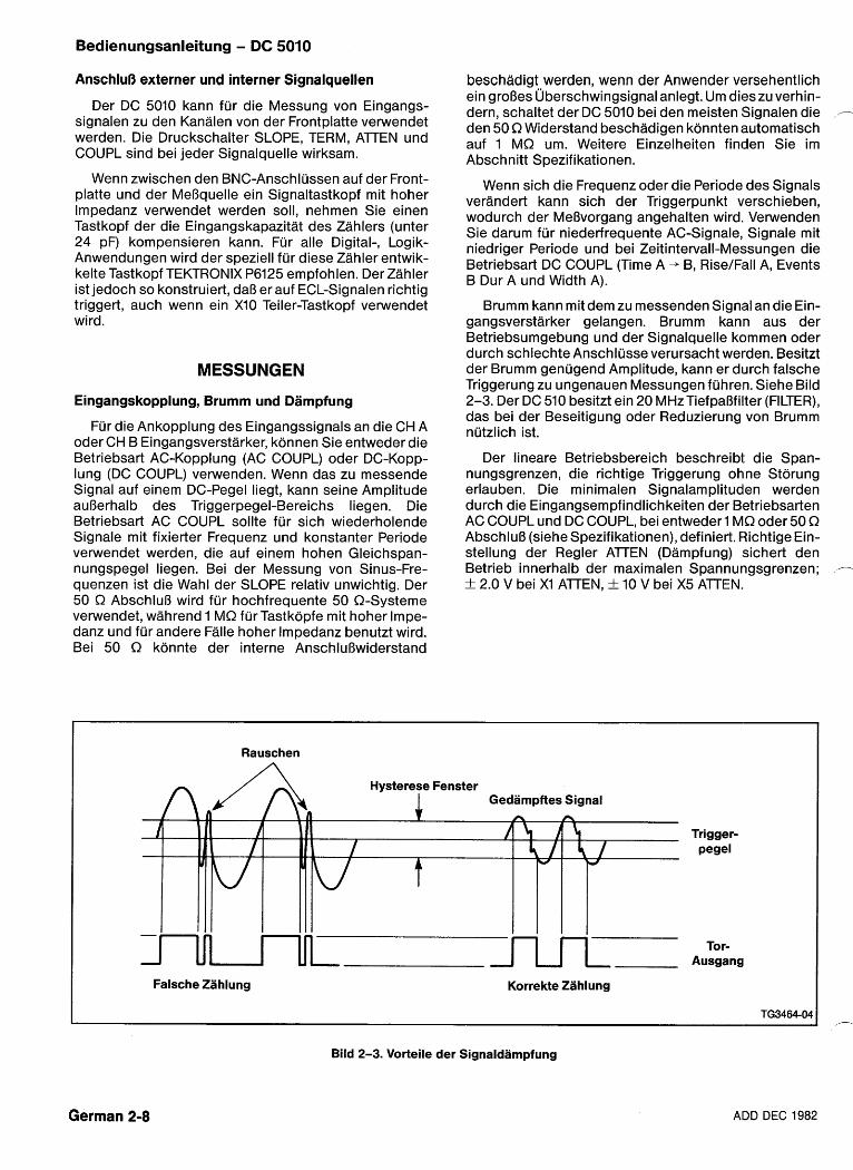
Bedienungsanleitung - DC 5010
AnschluO externer und interner Signalquellen
Der DC 5010 kann fur die Messung von Eingangs- signalen zu den Kanalen von der Frontplatte verwendet werden. Die Druckschalter SLOPE, TERM, ATTEN und COUPL sind bei jeder Signalquelle wirksam.
Wenn zwischen den BNC-Anschlussen auf der Front- platte und der MeOquelle ein Signaltastkopf mit hoher lmpedanz verwendet werden soll, nehmen Sie einen Tastkopf der die Eingangskapazitat des Zahlers (unter 24 pF) kompensieren kann. Fur alle Digital-, Logik- Anwendungen wird der speziell fur diese Zahler entwik- kelte Tastkopf TEKTRONIX P6125 empfohlen. Der Zahler ist jedoch so konstruiert, daB er auf ECL-Signalen richtig triggert, auch wenn ein XI0 Teiler-Tastkopf verwendet wird.
MESSUNGEN
Eingangskopplung, Brumm und Dampfung
Fur die Ankopplung des Eingangssignals an die CH A oder CH B Eingangsverstarker, konnen Sie entweder die Betriebsart AC-Kopplung (AC COUPL) oder DC-Kopp- lung (DC COUPL) verwenden. Wenn das zu messende Signal auf einem DC-Pegel liegt, kann seine Amplitude auBerhalb des Triggerpegel-Bereichs liegen. Die Betriebsart AC COUPL sollte fur sich wiederholende Signale mit fixierter Frequenz und konstanter Periode verwendet werden, die auf einem hohen Gleichspan- nungspegel liegen. Bei der Messung von Sinus-Fre- quenzen ist die Wahl der SLOPE relativ unwichtig. Der 50 Q AbschluB wird fur hochfrequente 50 0-Systeme verwendet, wahrend 1 MQ fur Tastkopfe mit hoher Impe- danz und fur andere Falle hoher lmpedanz benutzt wird. Bei 50 Q konnte der interne AnschluBwiderstand
beschadigt werden, wenn der Anwender versehentlich ein groOes 1Jberschwingsignal anlegt. Um dieszu verhin- dern, schaltet der DC 5010 bei den meisten Signalen die 7 den 50 Q Widerstand beschadigen konnten automatisch auf 1 MQ um. Weitere Einzelheiten finden Sie im Abschnitt Spezifikationen.
Wenn sich die Frequenz oder die Periode des Signals verandert kann sich der Triggerpunkt verschieben, wodurch der MeBvorgang angehalten wird. Verwenden Sie darum fur niederfrequente AC-Signale, Signale mit niedriger Periode und bei Zeitintervall-Messungen die Betriebsart DC COUPL (Time A + B, RiseIFaII A, Events B Dur A und Width A).
Brumm kann mit dem zu messenden Signal an die Ein- gangsverstarker gelangen. Brumm kann aus der Betriebsumgebung und der Signalquelle kommen oder durch schlechte Anschlusse verursacht werden. Besitzt der Brumm genugend Amplitude, kann er durch falsche Triggerung zu ungenauen Messungen fuhren. Siehe Bild 2-3. Der DC 510 besitzt ein 20 MHzTiefpaOfiBter (FILTER), das bei der Beseitigung oder Reduzierung von Brumm nutzlich ist.
Der lineare Betriebsbereich beschreibl: die Span- nungsgrenzen, die richtige Triggerung ohne Storung erlauben. Die minimalen Signalamplituden werden durch die Eingangsempfindlichkeiten der Betriebsarten AC COUPL und DC COUPL, bei entwederl MQ oder 50 Q AbschluO (siehe Spezifikationen), definiert. Richtige Ein- stellung der Regler ATTEN (Dampfung) sichert den Betrieb innerhalb der maximalen Spannungsgrenzen; -- + 2.0 V bei XI ATTEN, + 10 V bei X5 ATTEN.
Rauschen
Gedampftes Signal
Trigger- pegel
I
Tor- Ausgang
Falsche Zahlung Korrekte Zahlung
TG3464-01
Bild 2-3. Vorteile der Signaldampfung
German 2-8 ADD DEC 1982
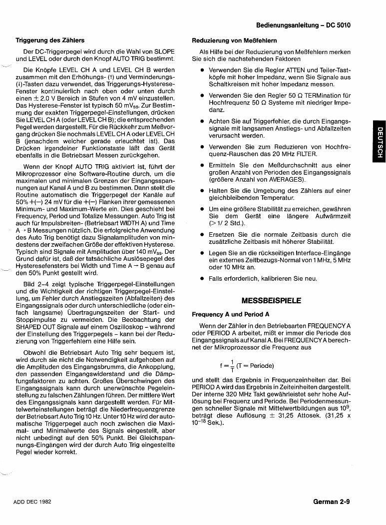
Bedienungsanleitung - DC 5010
Triggerung des Zahlers Reduzierung von MeOfehlern
Der DC-Triggerpegel wird durch die Wahl von SLOPE und LEVEL oder durch den Knopf AUTO TRlG bestimmt.
w
Die Knopfe LEVEL CH A und LEVEL CH B werden zusammen mit den Erhohungs- (t) und Verminderungs- (4)-Tasten dazu verwendet, das Triggerungs-Hysterese- Fenster kontinuierlich nach oben oder unten durch einen t 2.0 V Bereich in Stufen von 4 mV einzustellen. Das Hysterese-Fenster ist typisch 50 mV,,. Zur Bestim- mung der exakten Triggerpegel-Einstellungen, drucken Sie LEVEL CH A (oder LEVEL CH B); die entsprechenden Pegel werden dargestellt. Fur die Ruckkehrzum MeOvor- gang drucken Sie nochmals LEVEL CH A oder LEVEL CH B (jenachdem welcher gerade erleuchtet ist). Das Drucken irgendeiner Funktionstaste IaOt das Gerat ebenfalls in die Betriebsart Messen zuruckgehen.
Wenn der Knopf AUTO TRlG aktiviert ist, fuhrt der Mi kroprozessor eine Software-Routine durch, um die maximalen und minimalen Grenzen der Eingangsspan- nungen auf Kanal A und B zu bestimmen. Dann stellt die Routine automatisch die Triggerpegel der Kanale auf 50% +(-) 24 mV fur die +(-) Flanken ihrer gemessenen Minimum- urld Maximum-Werte ein. Dies geschieht bei Frequency, Period und Totalize Messungen. Auto Trig ist auch fur Impulsbreiten- (Betriebsart WIDTH A) und Time A + B Messungen nutzlich. Die erfolgreiche Anwendung des Auto Trig benotigt dazu Signalamplituden von min- destens der zweifachen GroOe der effektiven Hysterese. Typisch sind Signale mit Amplituden uber 140 mVss. Der Grund dafur ist, daO der tatsachliche Auslosepegel des
i- Hysteresefensters bei Width und Time A - B genau auf den 50% Purlkt gestellt wird.
Bild 2-4 zeigt typische Triggerpegel-Einstellungen und die Wichtigkeit der richtigen Triggerpegel-Einstel- lung, um Fehler durch Anstiegszeiten (Abfallzeiten) des Eingangssignals oder durch unterschiedliche (oder ein- fach langsame) ljbertragungszeiten der Start- und Stoppimpulse zu vermeiden. Die Beobachtung der SHAPED OUT Signale auf einem Oszilloskop - wahrend der Einstellung des Triggerpegels - kann bei der Redu- zierung von 'Triggerfehlern eine Hilfe sein.
Obwohl die Betriebsart Auto Trig sehr bequem ist, wird durch sie nicht die Notwendigkeit aufgehoben auf die Amplituden des Eingangsbrumms, die Ankopplung, den passenden Eingangswiderstand und die Damp- fungsfaktoren zu achten. GroOes ljberschwingen des Eingangssignals kann durch unerwunschte Pegelein- stellung zu falschen Zahlungen fuhren. Der mittlere Wert des Eingangssignals kann dargestellt werden. Fur Mit- telwerteinstellungen betragt die Niederfrequenzgrenze der Betriebsart Auto Trig 10 Hz. Unter 10 Hz wird der auto- matische Triggerpegel auch noch zwischen die Maxi- mal- und Minimalwerte des Signals eingestellt, aber nicht unbedingt auf den 50% Punkt. Bei Gleichspan- nungs-Eingangen wird der durch Auto Trig eingestellte Pegel wieder korrekt.
Als Hilfe bei der Reduzierung von MeOfehlern merken Sie sich die nachstehenden Faktoren
Verwenden Sie die Regler AlTEN und Teiler-Tast- kopfe mit hoher Impedanz, wenn Sie Signale aus Schaltkreisen mit hoher lmpedanz messen.
Verwenden Sie den Regler 50 R TERMination fur Hochfrequenz 50 R Systeme mit niedriger Impe- danz.
Achten Sie auf Triggerfehler, die durch Eingangs- signale mit langsamen Anstiegs- und Abfallzeiten verursacht werden.
Verwenden Sie zum Reduzieren von Hochfre- quenz-Rauschen das 20 MHz FILTER.
Ermitteln Sie den MeOdurchschnitt aus einer groOen Anzahl von Perioden des Eingangssignals (groOere Anzahl von AVERAGES).
Halten Sie die Umgebung des Zahlers auf einer gleichbleibenden Temperatur.
Um eine groOere Stabilitat zu erreichen, gewahren Sie dem Gerat eine Iangere Aufwarmzeit (> I/ 2 Std.).
Ersetzen Sie die normale Zeitbasis durch die zusatzliche Zeitbasis mit hoherer Stabilitat.
Legen Sie an die ruckseitigen Interface-Eingange ein externes Zeitbezugs-Normal von 1 MHz, 5 MHz oder 10 MHz an.
Falls erforderlich, kalibrieren Sie neu.
Frequency A und Period A
Wenn der Zahler in den Betriebsarten FREQUENCY A oder PERIOD A arbeitet, miOt er immer die Periode des Eingangssignals auf Kanal A. Bei FREQUENCY A berech- net der Mikroprozessor die Frequenz aus
1 f = - (T = Periode)
T
und stellt das Ergebnis in Frequenzeinheiten dar. Bei PERIOD A wird das Ergebnis in Zeiteinheiten dargestellt. Der interne 320 MHz Takt gewahrleistet sehr hohe Auf- losung bei Frequenz und Periode. Bei Periodenmessun- gen schneller Signale mit Mittelwertbildungen aus lo9, betragt diese Auflosung + 31,25 Attosek. (31,25 x 10-l8 Sek.).
ADD DEC 1982 German 2-9
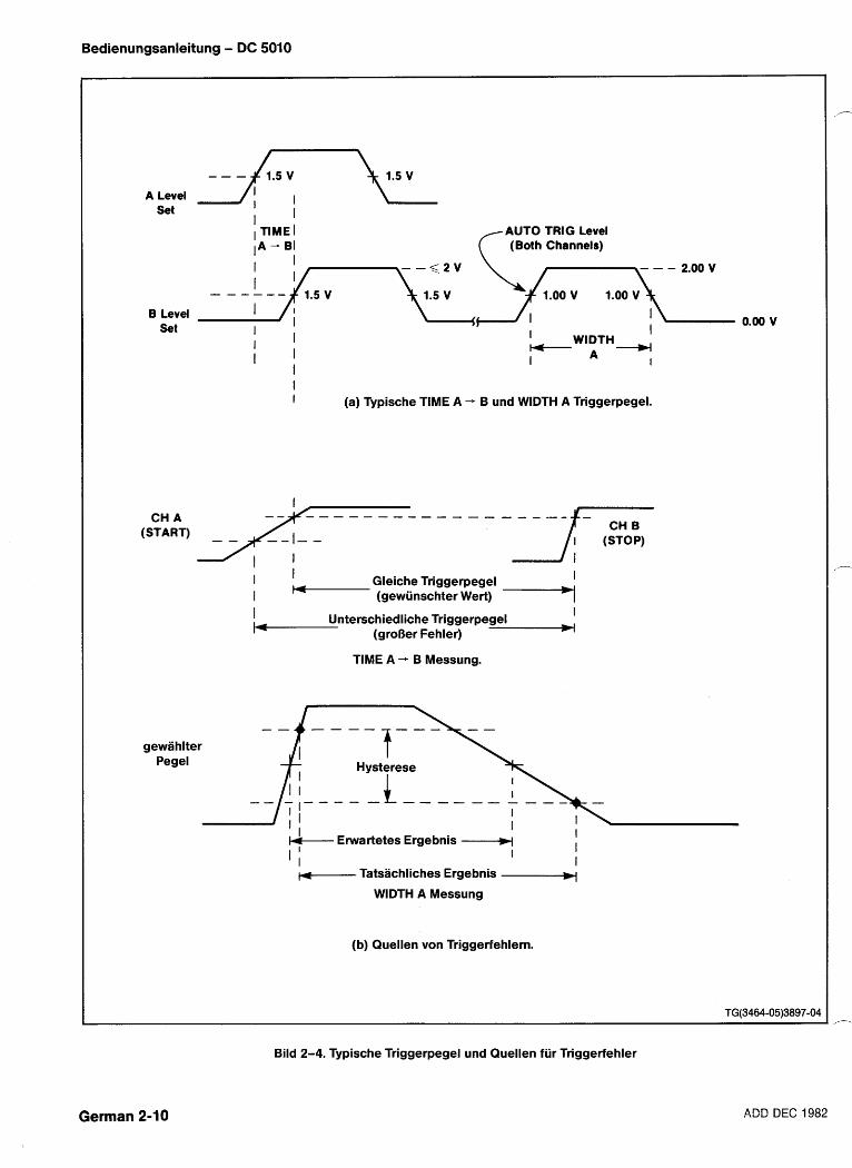
Bedienungsanleitung - DC 5010
A Level
rAUTO TRIG Level (Both Channels)
-
;;\[-~-2*oov
1.00v 1.00v B Level
Set I 0.00 v I I I I WIDTH - [ I - I A I
I I I (a) Typische TIME A + B und WIDTH A Triggerpegel.
CHA &------------p-& (START)
I I Gleiche Triggerpegel I I - (gewiinschter Wert) -1 I Unterschiedliche Triggerpegel I
(groOer Fehler) w
TlME A + B Messung.
gewahlter Pegel
'1.- Erwartetes Ergebnis -W I
I I I I I
w-- Tatsachliches Ergebnis -- WIDTH A Messung
(b) Quellen von Triggerfehlern.
Bild 2-4. Typische Triggerpegel und Quellen fiir Triggerfehler
German 2-10 ADD DEC 1982
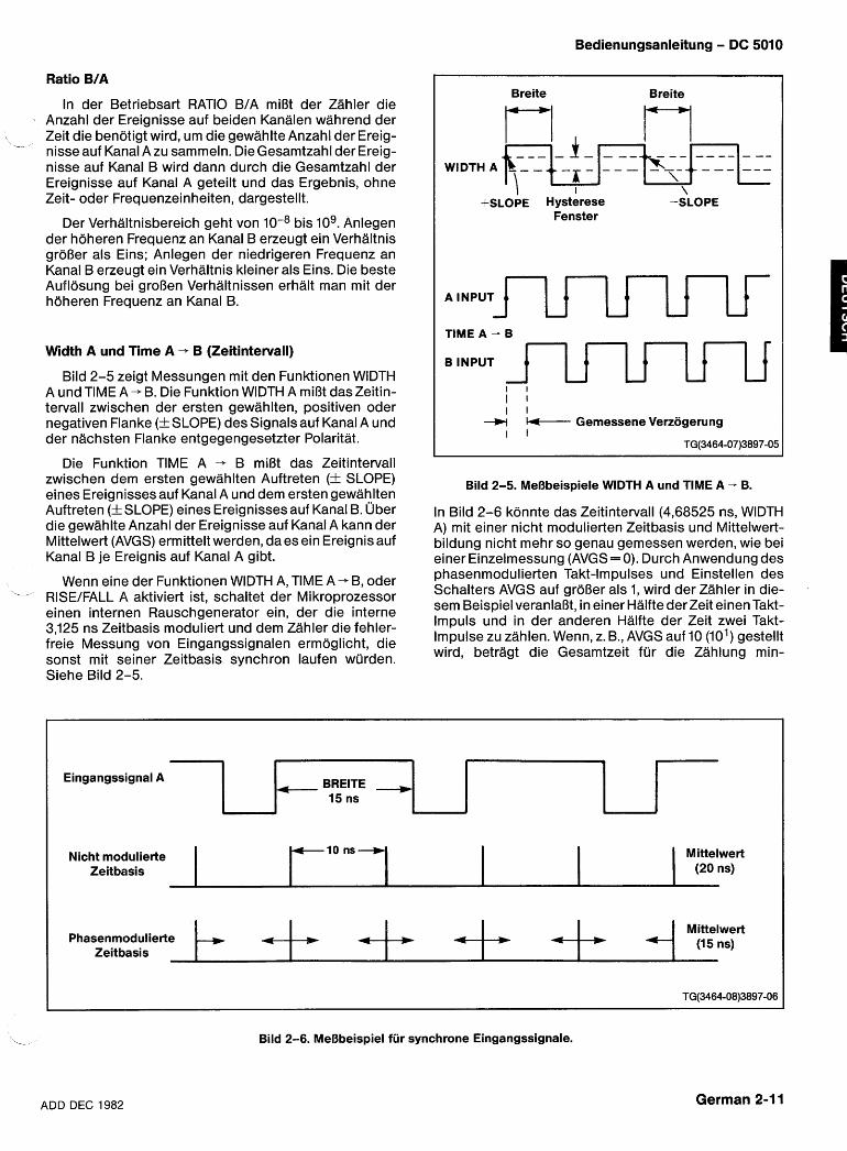
Bedienungsanleitung - DC 5010
Ratio B/A
In der Betriebsart RATIO BIA miOt der Zahler die Anzahl der Ereignisse auf beiden Kanalen wahrend der Zeit die bendtigt wird, um die gewahlte Anzahl der Ereig-
- nisse auf Karial A zu sammeln. Die Gesamtzahl der Ereig- nisse auf Kanal B wird dann durch die Gesamtzahl der Ereignisse auf Kanal A geteilt und das Ergebnis, ohne Zeit- oder Frequenzeinheiten, dargestellt.
Der Verhaltnisbereich geht von bis lo9. Anlegen der hoheren Frequenz an Kanal B erzeugt ein Verhaltnis groOer als Eins; Anlegen der niedrigeren Frequenz an Kanal B erzeugt ein Verhaltnis kleiner als Eins. Die beste Auflosung bei groOen Verhaltnissen erhalt man mit der hoheren Frequenz an Kanal B.
Width A und Time A - B (Zeitintervall)
Bild 2-5 zeigt Messungen mit den Funktionen WlDTH A und TlME A + B. Die Funktion WlDTH A miOt das Zeitin- tervall zwischen der ersten gewahlten, positiven oder negativen Flanke (+SLOPE) des Signals auf Kanal A und der nachsten Flanke entgegengesetzter Polaritat.
Die Funktion TlME A - B miOt das Zeitintervall zwischen dem ersten gewahlten Auftreten (+ SLOPE) eines Ereignisses auf Kanal A und dem ersten gewahlten Auftreten (f SLOPE) eines Ereignisses auf Kanal B. 1Jber die gewahlte Anzahl der Ereignisse auf Kanal A kann der Mittelwert (AVGS) ermittelt werden, da es ein Ereignis auf Kanal B je Ereignis auf Kanal A gibt.
Wenn eine der Funktionen WlDTH A, TlME A+ B, oder -- RISEIFALL A aktiviert ist, schaltet der Mi kroprozessor einen internen Rauschgenerator ein, der die interne 3,125 ns Zeitbasis moduliert und dem Zahler die fehler- freie Messung von Eingangssignalen ermoglicht, die sonst mit seiner Zeitbasis synchron laufen wurden. Siehe Bild 2-5.
Breite Breite
A INPUT 1uuUu
- -- - I - - --- - - - -- -- - --
TlME A - B
B INPUT J-lJImT I I I I I I u + Gemessene Verzogerung
I I TG(3464-07)3897-05
I \ +SLOPE Hysterese -SLOPE
Fenster
--,,--- k \
WIDTHA
Bild 2-5. MeBbeispiele WlDTH A und TlME A - B.
---
In Bild 2-6 k~nn te das Zeitintervall (4,68525 ns, WlDTH A) mit einer nicht modulierten Zeitbasis und Mittelwert- bildung nicht mehr so genau gemessen werden, wie bei einer Einzelmessung (AVGS= 0). Durch Anwendung des phasenmodulierten Takt-Impulses und Einstellen des Schalters AVGS auf groOer als 1, wird der Zahler in die- sem Beispiel veranlaBt, in einer Halfte der Zeit einen Takt- lmpuls und in der anderen Halfte der Zeit zwei Takt- Impulse zu zahlen. Wenn, z. B., AVGS auf 10 (10') gestellt wird, betragt die Gesamtzeit fur die Zahlung min-
h - - , , - r - ---
Eingangssignal A
- Bild 2-6. MeBbeispiel fiir synchrone Eingangssignale.
4 BREITE - 15 ns
Mittelwert (20 ns)
Nicht moclulierte Zeitbasis
ADD DEC 1982
-10 ns+
German 2-1 1
- 4 Phasenmodulierte Zeitbasis
b Mittelwert
(1511s) 4 * 4 + 4
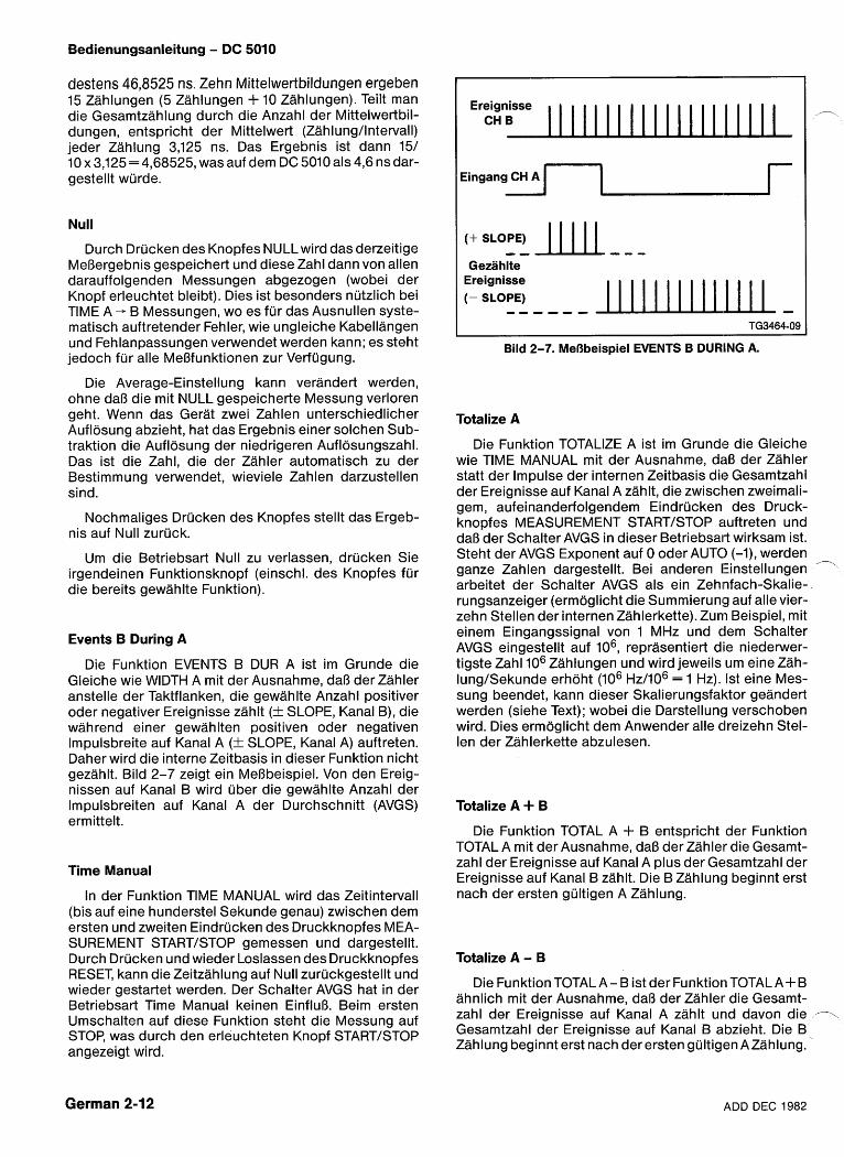
Bedienungsanleitung - DC 5010
destens 46,8525 ns. Zehn Mittelwertbildungen ergeben 15 Zahlungen (5 Zahlungen + 10 Zahlungen). Teilt man die Gesamtzahlung durch die Anzahl der Mittelwertbil- dungen, entspricht der Mittelwert (Zahlungllntervall) jeder Zahlung 3,125 ns. Das Ergebnis ist dann 151 10 x 3,125 = 4,68525, was auf dem DC 5010 als 4,6 ns dar- gestellt wurde.
Null
Durch Drucken des Knopfes NULLwird das derzeitige MeOergebnis gespeichert und diese Zahl dann von allen darauffolgenden Messungen abgezogen (wobei der Knopf erleuchtet bleibt). Dies ist besonders nutzlich bei TlME A -- B Messungen, wo es fur das Ausnullen syste- matisch auftretender Fehler, wie ungleiche Kabellangen und Fehlanpassungen verwendet werden kann; es steht jedoch fur alle MeOfunktionen zur Verfugung.
Die Average-Einstellung kann verandert werden, ohne daO die mit NULL gespeicherte Messung verloren geht. Wenn das Gerat zwei Zahlen unterschiedlicher Auflosung abzieht, hat das Ergebnis einer solchen Sub- traktion die Auflosung der niedrigeren Auflosungszahl. Das ist die Zahl, die der Zahler automatisch zu der Bestimmung verwendet, wieviele Zahlen darzustellen sind.
Nochmaliges Drucken des Knopfes stellt das Ergeb- nis auf Null zuruck.
Um die Betriebsart Null zu verlassen, drucken Sie irgendeinen Funktionsknopf (einschl. des Knopfes fur die bereits gewahlte Funktion).
Events B During A
Die Funktion EVENTS B DUR A ist im Grunde die Gleiche wie WIDTH A mit der Ausnahme, daO der Zahler anstelle der Taktflanken, die gewahlte Anzahl positiver oder negativer Ereignisse zahlt (+ SLOPE, Kanal B), die wahrend einer gewahlten positiven oder negativen lmpulsbreite auf Kanal A (f SLOPE, Kanal A) auftreten. Daher wird die interne Zeitbasis in dieser Funktion nicht gezahlt. Bild 2-7 zeigt ein MeObeispiel. Von den Ereig- nissen auf Kanal B wird uber die gewahlte Anzahl der lmpulsbreiten auf Kanal A der Durchschnitt (AVGS) ermittelt.
Time Manual
In der Funktion TlME MANUAL wird das Zeitintervall (bis auf eine hunderstel Sekunde genau) zwischen dem ersten und zweiten Eindrucken des Druckknopfes MEA- SUREMENT STARTISTOP gemessen und dargestellt. Durch Drucken und wieder Loslassen des Druckknopfes RESET, kann die Zeitzahlung auf Null zuruckgestellt und wieder gestartet werden. Der Schalter AVGS hat in der Betriebsart Time Manual keinen EinfluO. Beim ersten Umschalten auf diese Funktion steht die Messung auf STOP, was durch den erleuchteten Knopf STARTISTOP angezeigt wird.
Ereignisse CH B
Gezahlte
Eingang CH A
Ereignisse (- SLOPE) ------ -
1
Bild 2-7. MeBbeispiel EVENTS B DURING A.
Totalize A
Die Funktion TOTALIZE A ist im Grunde die Gleiche wie TlME MANUAL mit der Ausnahme, dal3 der Zahler statt der Impulse der internen Zeitbasis die Gesamtzahl der Ereignisse auf Kanal A zahlt, die zwischen zweimali- gem, aufeinanderfolgendem Eindrucken des Druck- knopfes MEASUREMENT STARTISTOP auftreten und daO der Schalter AVGS in dieser Betriebsai-t wirksam ist. Steht der AVGS Exponent auf 0 oder AUTO (-I), werden ganze Zahlen dargestellt. Bei anderen Einstellungen arbeitet der Schalter AVGS als ein Zehnfach-Skalie- rungsanzeiger (ermoglicht die Summierung auf alle vier- zehn Stellen der internen Zahlerkette). Zum Beispiel, mit einem Eingangssignal von 1 MHz und dem Schalter AVGS eingestellt auf lo6, reprasentiert die niederwer- tigste Zahl lo6 Zahlungen und wird jeweils um eine Zah- IungISekunde erhoht (lo6 ~ ~ 1 1 0 ~ = 1 Hz). 1st eine Mes- sung beendet, kann dieser Skalierungsfaldor geandert werden (siehe Text); wobei die Darstellung verschoben wird. Dies ermoglicht dem Anwender alle clreizehn Stel- len der Zahlerkette abzulesen.
Totalize A + B
Die Funktion TOTAL A + B entspricht der Funktion TOTAL A mit der Ausnahme, daO der Zahler die Gesamt- zahl der Ereignisse auf Kanal A plus der Gesamtzahl der Ereignisse auf Kanal B zahlt. Die B Zahlung beginnt erst nach der ersten gultigen A Zahlung.
Totalize A - B
Die Funktion TOTALA- B ist der Funktiori TOTALAi-B ahnlich mit der Ausnahme, daB der Zahler die Gesamt- zahl der Ereignisse auf Kanal A zahlt und davon die --\ Gesamtzahl der Ereignisse auf Kanal B abzieht. Die B Zahlung beginnt erst nach derersten gultigen AZahlung.
German 2-12 ADD DEC 1982
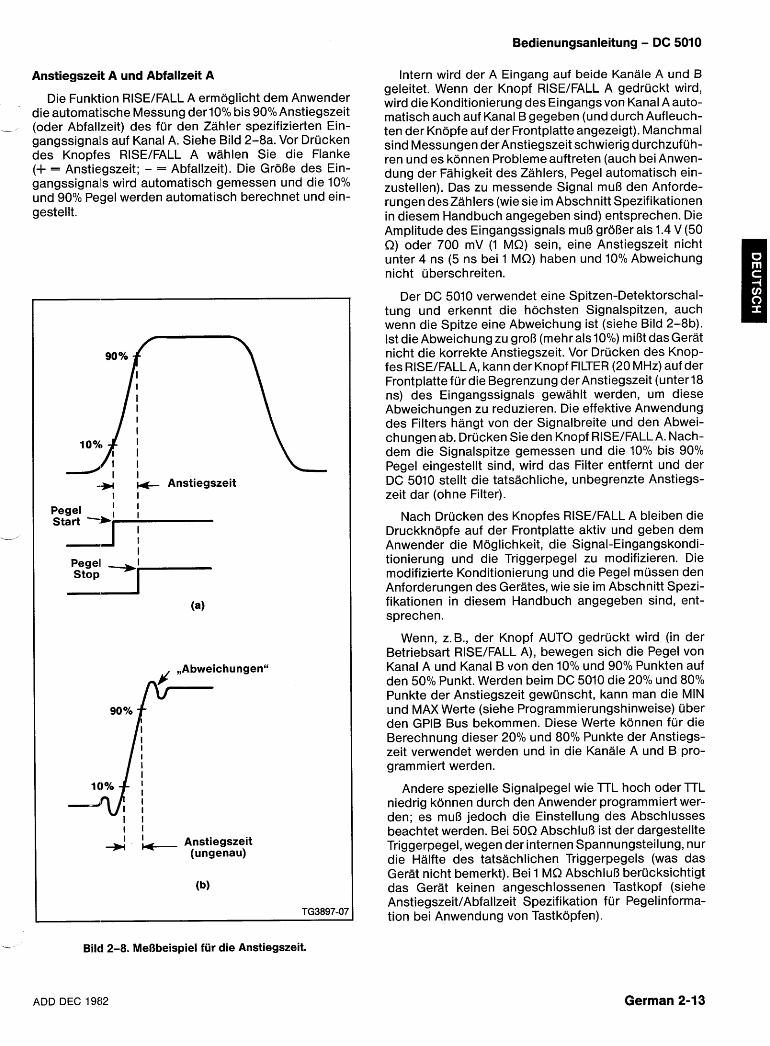
Bedienungsanleitung - DC 5010
Anstiegszeit A und Abfallzeit A
Die Funktion RISEIFALL A ermoglicht dem Anwender die automatkche Messung derlO0l0 bis 9O01~Anstiegszeit
- (oder Abfallzeit) des fur den Zahler spezifizierten Ein- gangssignals auf Kanal A. Siehe Bild 2-8a. Vor Drucken des Knopfes RISEIFALL A wahlen Sie die Flanke (+ = Anstiegszeit; - = Abfallzeit). Die GroOe des Ein- gangssignals wird automatisch gemessen und die 10% und 90% Pegel werden automatisch berechnet und ein- gestellt.
Anstiegszeit I I
Pegel start -i '
I
Stop pegel' -I---
I I I I + - ,, Anstiegszeit
(ungenau)
Bild 2-8. MeBbeispiel fiir die Anstiegszeit.
Intern wird der A Eingang auf beide Kanale A und B geleitet. Wenn der Knopf RISEIFALL A gedruckt wird, wird die Konditionierung des Eingangs von Kanal A auto- matisch auch auf Kanal B gegeben (und durch Aufleuch- ten der Knopfe auf der Frontplatte angezeigt). Manchmal sind Messungen der Anstiegszeit schwierig durchzufuh- ren und es konnen Probleme auftreten (auch bei Anwen- dung der Fahigkeit des Zahlers, Pegel automatisch ein- zustellen). Das zu messende Signal muO den Anforde- rungen deszahlers (wie sie im Abschnitt Spezifikationen in diesem Handbuch angegeben sind) entsprechen. Die Amplitude des Eingangssignals mu8 groOer als 1.4 V (50 R) oder 700 mV (1 MS2) sein, eine Anstiegszeit nicht unter 4 ns (5 ns bei 1 MS2) haben und 10% Abweichung nicht uberschreiten.
Der DC 5010 vewendet eine Spitzen-Detektorschal- tung und erkennt die hochsten Signalspitzen, auch wenn die Spitze eine Abweichung ist (siehe Bild 2-8b). 1st die Abweichung zu groO (mehr als 10%) miOt das Gerat nicht die korrekte Anstiegszeit. Vor Drucken des Knop- fes RISEIFALLA, kann der Knopf FILTER (20 MHz) auf der Frontplatte fur die Begrenzung der Anstiegszeit (unterl8 ns) des Eingangssignals gewahlt werden, um diese Abweichungen zu reduzieren. Die effektive Anwendung des Filters hangt von der Signalbreite und den Abwei- chungen ab. Drucken Sie den Knopf RISEIFALLA. Nach- dem die Signalspitze gemessen und die 10% bis 90% Pegel eingestellt sind, wird das Filter entfernt und der DC 5010 stellt die tatsachliche, unbegrenzte Anstiegs- zeit dar (ohne Filter).
Nach Drucken des Knopfes RISEIFALL A bleiben die Druckknopfe auf der Frontplatte aktiv und geben dem Anwender die Moglichkeit, die Signal-Eingangskondi- tionierung und die Triggerpegel zu modifizieren. Die modifizierte Konditionierung und die Pegel mussen den Anforderungen des Gerates, wie sie im Abschnitt Spezi- fikationen in diesem Handbuch angegeben sind, ent- sprechen.
Wenn, z.B., der Knopf AUTO gedruckt wird (in der Betriebsart RISEIFALL A), bewegen sich die Pegel von Kanal A und Kanal B von den 10% und 90% Punkten auf den 50% Punkt. Werden beim DC 5010 die 20% und 80% Punkte der Anstiegszeit gewunscht, kann man die MIN und MAX Werte (siehe Programmierungshinweise) uber den GPlB Bus bekommen. Diese Werte konnen fur die Berechnung dieser 20% und 80% Punkte der Anstiegs- zeit verwendet werden und in die Kanale A und B pro- grammiert werden.
Andere spezielle Signalpegel wie l TL hoch oder lTL niedrig konnen durch den Anwender programmiert wer- den; es muO jedoch die Einstellung des Abschlusses beachtet werden. Bei 50R AbschluO ist der dargestellte Triggerpegel, wegen der internen Spannungsteilung, nur die Halfte des tatsachlichen Triggerpegels (was das Gerat nicht bemerkt). Bei 1 MR AbschluB berucksichtigt das Gerat keinen angeschlossenen Tastkopf (siehe AnstiegszeitIAbfallzeit Spezifikation fur Pegelinforma- tion bei Anwendung von Tastkopfen).
ADD DEC 1982 German 2-1 3
Bedienungsanleitung - DC 5010
Tastkopf kompensation
Bei 1 M a AbschluO wurde der DC 5010 speziell fur Kompatibilitat mit serienmaOigen Tastkopfen ausgelegt; der Anwender mu6 jedoch darauf achten, daO der Tast- kopf richtig kompensiert ist.
Im DC 5010 ist in den Zahler eine Funktion zur Tast- kopf kompensation (PROBE COMP) eingebaut. Sie ermoglicht dem Anwender, ohne Oszilloskop, den Tast- kopf am Ort zu kompensieren.
Am AnschluO PROBE COMP auf der Frontplatte, steht ein Rechtecksignal von etwa 1 kHz, mit einer Amplitude von etwa 5 V zur Verfugung.
Bevor Sie auf die Betriebsart PROBE COMP umschal- ten, verbinden Sie die Spitze des Tastkopfes mit dem AnschluO PROBE COME
Der Zahler sollte als hochstwertigste Zahl (ganz links) eine Null und als niedrigstwertigste Zahl (ganz rechts) eine Null anzeigen. Die Zahl ganz links gilt fur einen Tast- kopf an Kanal A und die Zahl ganz rechts fur einen Tast- kopf an Kanal B. Es sollten keine Dezimalpunkte oder Anzeigen erleuchtet sein.
Bei angeschlossenem Tastkopf und angelegtem Rechtecksignal gehen Sie wie folgt vor.
1. Drehen Sie langsam die Tastkopfeinstellung in beide Richtungen, bis die Anzeige fur den zu kompen- sierenden Kanal auf 1 wechselt.
2. Wechseln Sie langsam die Drehrichtung der Tast- kopfeinstellung, bis die Anzeige gerade auf 0 zuruck- springt. An diesem Punkt ist der Tastkopf kompensiert. Eine I zeigt an, daB der Tastkopf uberkompensiert ist; eine 0 zeigt Unterkompensation an. Die Feineinstellung sollte in der Richtung erfolgen, in der die 1 gerade auf 0 uberspringt.
ANMERKUNG
Wenn eine Anzeige auf 1 geht und dort wahrend einer oder mehrerer vollstandiger Umdrehungen der Tastkopfeinstellung bleibt, drijcken Sie den Knopf RESET urn diesen Zustand zu Ioschen. Dies kann vorkommen, wenn die Verbindung zum Recht- ecksignal wahrend des Einstellvorgangs unterbro- chen wurde.
Test-Fun ktion
Bei der Funktion TEST ist die Darstellung 000 eine ,,- Anzeige dafur, daO der Mikroprozessor sich selbst gepruft hat. Der Test pruft auch die internen seriellen Datenpfade, die Integritat der internen Zahlerkette (Akkumulatoren) und, nebenbei, die Arbeitsweise des DIA-Wandlers (Triggerpegel) und der Eingangsverstar- ke r.
Das RAM wird bei diesem Selbst-Test nicht gepriift; das RAM wird nur beim Einschaltvorgang yepruft.
ANMERKUNG
Wenn die Eingange von Kanal A oder Kanal B ange- schlossen sind, mussen die Spitzen der Eingangs- signale innerhalb des Triggerpegel-Bereichs des Za hlers liegen, damit die Test-Funktion ein wandfrei arbeiten kann. Tritt ein Fehler auf, losen Sie zuerst die Verbindungen zu den Eingangen von Kanal A und Kanal B und wiederholen dann den Test. Eine Verbindung am Eingang Arming kann auch eine feh- lerhafte Arbeitsweise verursachen.
Das Anzeigelampchen GATE blinkt jedesmal, wenn ein ganzer Testzyklus abgelaufen ist. Wird ein Fehler erkannt, wird der Code dieses Fehlers auf den drei au8ersten linken Stellen der siebenstelligen Anzeige - dargestellt und derTestzyklus halt an. Der DC 5010 bleibt in der Betriebsart Test, bis eine andere Funktion gewahlt wird.
Arming (Eingang ARM)
Arming bietet ein Mittel, mit dem einzelne Ereignisse oder Gruppen von Ereignissen fur die Messung inner- halb eines komplexen analogen oder digitalen Signals ausgewahlt werden konnen.
Der Eingang ARM benotigt TTL-Signalpegel. Ohne angelegtes Signal liegt der Eingang ARM normaler- weise hoch und ist so kontinuierlich in Betrieb. Liegt der Eingang ARM auf einem niedrigen Pegel, wird derzahler daran gehindert eine Messung zu beginnen. Arming kann bei allen MeOfunktionen verwendet werden auOer bei TIME MANUAL, PROBE COMP und TEST Bei diesen drei Funktionen mu6 das ARM-Signal hoch liegen.
Wenn das Arming-Signal auf ein hohes Niveau uber- geht, startet das erste darauffolgende Ereignis auf Kanal A den MeOvorgang. Geht das Arming-Signal auf ein nie- driges Niveau uber, stoppt das nachste Ereignis auf Kanal A den MeOvorgang. Daher ist eine Steuerung des Zahlers, hinsichtlich des Zeitpunktes an dem eine Mes- sung durchgefuhrt wird, moglich (auch bei komplexen Signalen).
,-
German 2-14 ADD DEC 1982
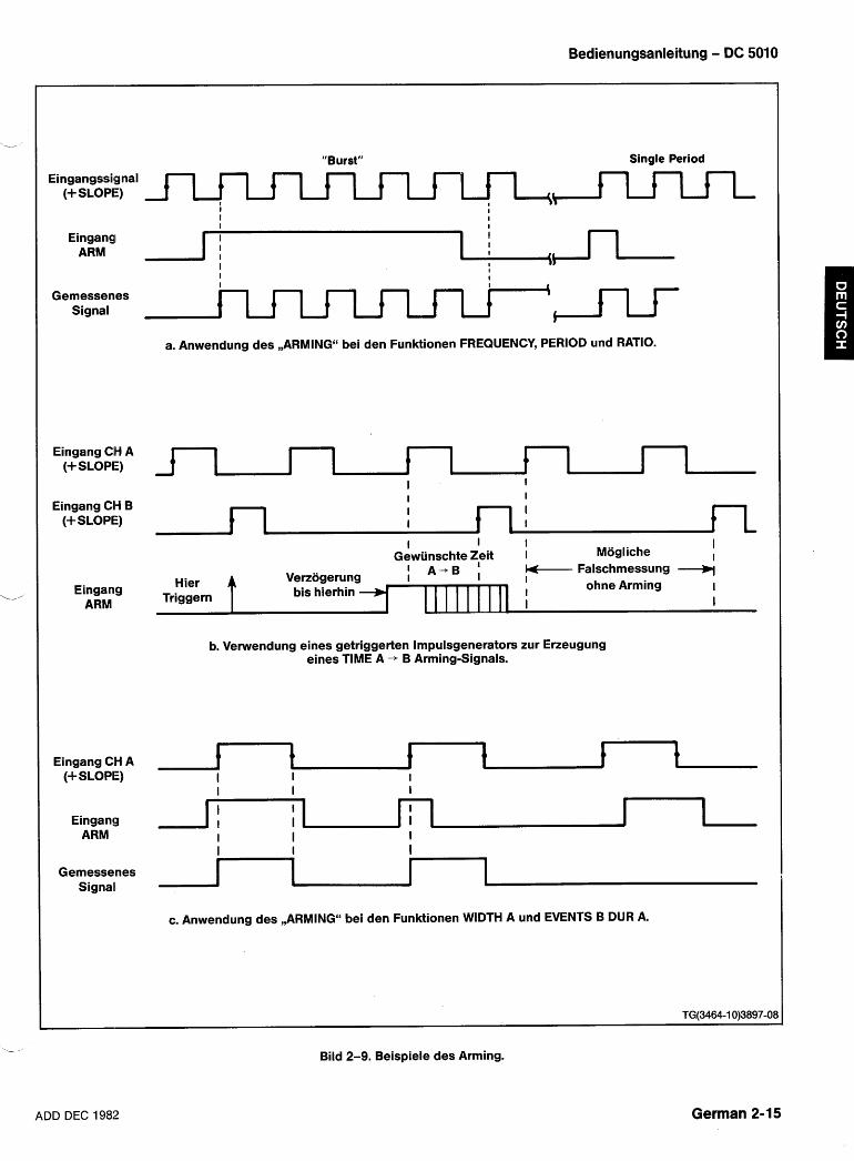
Bedienungsanleitung - DC 5010
Eingangssignal (+SLOPE)
Eingangl ARM
Gemessenes Signal
Eingang CH A (+SLOPE)
Eingang CH B (+ SLOPE)
Eingang ARM
"Burst" Single Period
a. Anwendung des ,,ARMINGu bei den Funktionen FREQUENCY, PERIOD und RATIO.
I I I Mogliche
I Gewiinschte Zeit I I
A -B Falschmessung Verzijgerung I bis hierhin 1 1 1 1 1 1 1 1 1 I
ohne Arming I
I I
b. Vetwendung eines getriggerten lmpulsgenerators zur Erzeugung eines TIME A + B Arming-Signals.
Eingang CH A (+SLOPE)
Eingang ARM
Gemessenes Signal
c. Anwendung des ,,ARMINGu bei den Funktionen WIDTH A und EVENTS B DUR A.
Bild 2-9. Beispiele des Arming.
ADD DEC 1982 German 2-15
Bedienungsanleitung - DC 5010
Aus diesen Arming-Messungen kann dann der Mittel- wert gebildet werden, ahnlich der Mittelwertbildung beim Zeitintervall. Der Zahler bestimmt die Anzahl der darzustellenden Zahlen (mit der bestmoglichen Auf- losung) nach der mittleren Anzahl der Ereignisse auf Kanal A. Typisch ist, daO jede Gesamtzahlung von Fre- quenz, Periode und Verhaltnis einen Zahlfehler enthalt und, dal3 der Zahler die Anzahl von Zahlen darstellt, die unter Berucksichtigung dieses Fehlers richtig ist. Bei Anwendung des Arming in den Betriebsarten Frequency, Period oder Ratio (keine Zeitintervall-Betriebsarten), kann bei jedem Arming und Disarming 1 Zahlfehler auf- treten. Der Zahler berucksichtigt dies jedoch nicht und stellt nur die Anzahl von Zahlen dar, die auf der Gesamt- anzahl der Ereignisse pro Gesamtmessung basieren, unabhangig davon, wie oft das Gerat im Zustand des Arming oder Disarming war.
Die tatsachliche Auflosung bei Periodenrnessung rnit Arming, ist niedrigerals die, die dargestellt wird. Sie kann mit der nachstehenden Verhaltnisformel berechnet wer- --
den:
Tc = Taktperiode
T, = Eingangsperiode (CH A)
TB = Zeit vom Startereignis A bis Stoppereignis A
N = Anzahl der Mittelwertbildungen, d. t i . lo6 oder 109 USW.
Einfiihrung
Dieser Abschnitt des Handbuches informiert uber die Programmierung des DC 5010 durch Fernsteuerung uber den IEEE-488 General Purpose Interface Bus (GPIB). Die nachstehenden lnformationen setzen voraus, da8 der Leser rnit der GPIB-Kommunikation vertraut ist und einige Erfahrung rnit der Programmierung von Control- lern hat. Mitteilungs-Protokolle sind in der Norm IEEE- 488-1978, ,,Standard Digital Interface for Program- mable ~nstrumentation"~ beschrieben und spezifiziert. Alle Bezugnahmen auf GPIB in diesem Handbuch bezie- hen sich auf den IEEE-488 GPIB. TM 5000 Gerate wurden fur die Kommunikation mit allen GPIB-kompatiblen Con- trollern entwicklet, die ASCII Mitteilungen (Befehle) uber den GPIB senden und empfangen. Diese Befehle pro- grammieren das Gerat, oder fragen lnformationen vom Gerat ab.
Die Befehle fur programmierbare Gerate der Serie TM 5000 wurden fur Kompatibilitat unter den Geratety- pen entwickelt. Der gleiche Befehl wird bei verschiede- nen Geraten fur die Steuerung ahnlicher Funktionenver- wendet. Ferner sind die Befehle in Mnemoniken spezifi- ziert, die sich auf die jeweilige Funktion beziehen. Der Befehl INIT, z. B., stellt das Gerat auf seinen Einschalt- Zustand ein. Zur weiteren Erleichterung der Program- mierung, entsprechen die Befehls-Mnemoniken in den meisten Fallen denen auf der Frontplatte.
Veroffentlicht durch das Institute of Electrical and Electronics Engineers, Inc., 345 East 47th Street, New York, N.Y., 1001 7.
Die Gerate-Befehle werden in drei Forniaten darge- stellt:
Eine Abbildung der Frontplatte - die die Bezie- hung der Befehle zu den Bedienungselementen auf der Frontplatte zeigt (siehe Bild 2-10).
Liste der funktionellen Befehle - eine Liste, die in Funktionsgruppen rnit kurzen Beschreibungen aufgestellt ist.
Detaillierte Befehlsliste - eine alphabetische Auf- listung der Befehle rnit vollstandiger Beschrei- bung.
Programmierbare Gerate der Serie TM 5000 werden uber eine Versorgungseinheit TM 500x mit dem GPIB verbunden. Der Abschnitt Bedienungsanleitung in die- sem Handbuch gibt Hinweise fur den Einbau des Gera- tes in die Versorgungseinheit. Dieser Abschnitt macht Sie auch mit den Bedienungselementen auf der Front- platte und'den intern wahlbaren Geratefumktionen ver- traut. Die GPIB Primaradresse fur dieses Gerat kann in- tern durch qualifiziertes Servicepersonal vsrandert wer- den. Bei Versand ist der DC 5010 auf die Adresse mit dem Dezimalaquivalent 20 eingestellt. Auch das Endezei- chen kann intern durch qualifiziertes Servicepersonal ausgewahlt werden. Endezeichen werden in diesem Handbuch im Abschnitt ,,Mitteilungen und Kommunika- tions-Protokoll" beschrieben. Bei Versand von TM 5000 Geraten ist dieses Endezeichen auf EOI ONLY einge- stellt. Hinweise fur qualifiziertes Servicepersonal, wo und wie die Einstellung erfolgt, sind in diesem Handbuch im Abschnitt Wartung enthalten. Eindrucken des Druck- knopfes INST ID veranlaOt das Gerat seine gewahlte GPIB-Primaradresse darzustellen; der Dezimalpunkt ganz rechts leuchtet auf, wenn das gewaklte Endezei- chen LFIEOI ist.
German 2-16 ,ADD DEC 1982
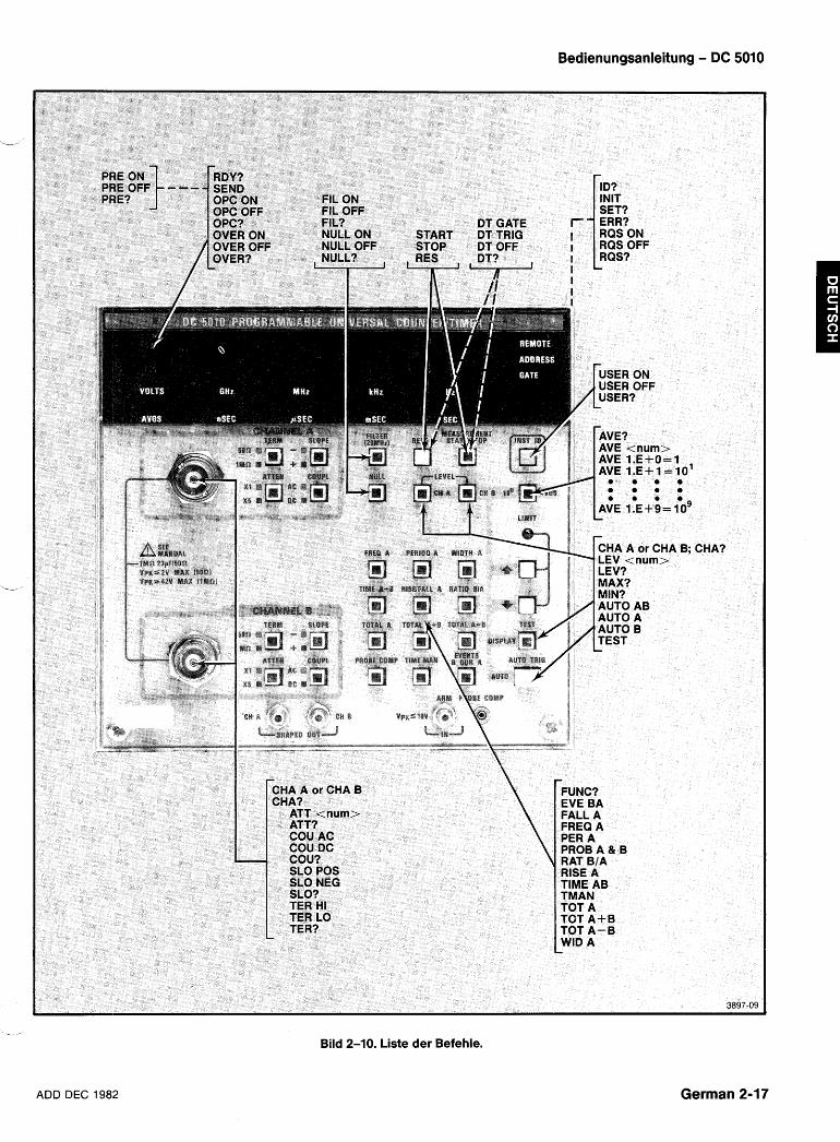
ADD DEC 1982
Bedienungsanleitung - DC 5010
Bild 2-10. Liste der Befehle.
German 2-17
Bedienungsanleitung - DC 5010
BEFEHLE Das Gerat wird uber die Bedienungselemente auf der Jeder Befehl beginnt mit einem Kopfteil - einem Wort Frontplatte, oder uber Befehle vom Controller gesteuert. das die jeweilige Funktion beschreibt. Viele Befehle Es gibt drei Befehlsarten: mussen durch ein Argument nach dem Kopfteil erganzt
werden, einem Wort oder einerzahl, die die gewunschte Einstell-Befehle - steuern die Einstellung des Gera- Funktion naher beschreibt. tes.
Abfrage-Befehle - fragen nach Daten.
Betriebs-Befehle - veranlassen eine bestimmteTatig- keit.
1st das Gerat auf Fernbedienung eingestellt, werden alle Befehle beantwortet und ausgefu hrt. Im ,,Localu Sta- tus erzeugen ,,Einstellungs-" und ,,Betriebs-Befehle" Fehler, da die Geratefunktionen uber die Bedienungsele- mente auf der Frontplatte gesteuert werden; nur ,,Abfra-
Vorsicht bei der Verwendung von weniger Zeichen als im abgekijrzten Kopfteil oder Argument enthal- ten sind; falsche Ergebnisse und Beschadigungen konnen auftreten wenn diese Daten an das falsche Gerat gelangen.
ge-Befehle" werden beantwortet.
LlSTE DER FUNKTIONELLEN BEFEHLE
GER~~TE BEFEHLE
Funktions-Befehle
EVE BA - Zahlt Kanal B wahrend der Impuls- breite von Kanal A
FALL A - MiBt die Abfallzeit des Signals auf Kanal A
FREQ A - MiBt die Frequenz des Eingangs- signals auf Kanal A
FUNC? - Abfrage nach der derzeitigen Gera- tefunktion
PER A - MiBt die Periode des Signals auf Kanal A
PROB A & B - Gibt die Tastkopfkompensation frei
RAT BIA - MiOt das Verhaltnis der Ereignisse B zu den Ereignissen A
RISE A - MiBt die Anstiegszeit des Signals auf Kanal A
TIME AB - MiBt die Zeit vom Ereignis A zum Ereignis B
TEST - Pruft ROM, I10 und Akkumulator
TMAN - Manuelle Zeitfunktion (Stoppuhr)
TOT A - Summiert die Ereignisse auf Kanal A
Messungs-Steuerung
AVE oder AVGS
AVE? oder AVGS?
NULL ON
NULL OFF
NULL?
RDY?
RES
START
STOP
- Stellt die Anzahl der Messungen fur die Durchschnittsbildung ein
- - Abfrage nach AVE < num >; (-1 fur
AUTO Averages)
- Subtrahiert das derzeitige MeOer- gebnis von allen folgenden Messun- gen
- Stellt auf Nullwert zuribck
- Abfrage nach NULL ON oder NULL OFF
- Abfrage nach RDY 1 fertig fur neue Daten, oder RDY 0 nicht fertig fur neue Daten
- Stellt die Zahler zuruck, beginnt wie- der mit der derzeitigen Messung
- Startet die Messungen TMANual, STOPped, oder TOTalize
- Stoppt jede Messung auOer TEST und PROBE COMP
WID A - Mint die lmpulsbreite des Signals auf Kanal A
German 2-18 ADD DEC 1982
Bedienungsanleitung - DC 5010
SYSTEM-BEFEHLE - A n 1 oder 5
, A n ?
AUTO A
AUTO B
AUTO A &B
- 1X oder 5X Dampfung DA GATE - < GET > steuert Start und Stop
DT TRIG - < GET > fuhrt RESET aus - Abfrage nach A T < num > - Stellt den Triggerpegel auf den Mit-
telpunkt des Signals (Kanal A) DT OFF - Sperrt die Geratetriggerung
DT? - Abfrage nach DT TRIG, DT OFF oder DT GATE - Stellt den Triggerpegel auf den Mit-
telpunkt des Signals (Kanal B) ERR? - Bringt den Fehlercode fur das letzte,
uber Serial-Poll berichtete Ereignis wenn RQS ON; bei RQS OFF bringt er den hochsten Prioritatsstatus
ID? - Anfrage nach Geratetyp und Firm- ware
INIT - Stellt auf die derzeitigen Einstellun- gen auf der Frontplatte und die Ein- schalt-Parameter ein
I - Stellt den Triggerpegel auf den Mit-
telpunkt des Signals (beide Kanale)
- Wahlt den Kanal fijr die nachfol- gende Eingangs-Einstellung
CHA A oder CHA B
CHA?
COU AC oder DC
COU?
FIL ON
- Abfrage nach CHA A oder CHA B
- Stellt die Ankopplungsart des Ein- gangs ein
- Abfrage nach COU AC oder COU DC SET? - Abfrage nach den derzeitigen Ein- stellungen - Begrenzt die Bandbreite von Kanal A
und B auf etwa 20 MHz TEST - Pruft ROM, 110, Akkumulator FIL OFF
FI L?
LEV
- Schaltet den Filter ab
- Abfrage nach FIL ON oder FIL OFF
STATUS-BEFEHLE - Stellt den gewahlten Kanal-Trigger- pegel ein. Num Bereich =+ 2.000 bis - 2.000 (XI) oder + 10.000 bis - 10.000 (X5)
OPC ON
OPC OFF
OPC?
OVER ON
OVER OFF
OVER?
RQS ON
RQS OFF
RQS?
USER ON
USER OFF
USER?
- Gibt die Bedienungsanfrage nach OPERATION COMPLETE frei
- Sperrt die Bedienungsanfrage nach OPERATION COMPLETE
-Abfrage nach OPC ON oder OPC OFF
- Gibt Bedienungsanfrage nach ~ b e r - flieOen des Zahlers frei
- Sperrt Bedienungsanfrage nach ~ b e r f l i e ~ e n des Zahlers
- Abfrage nach OVER ON oder OVER OFF
- Gibt Bedienungsanfrage (SRQ) frei
- Sperrt Bedienungsanfrage (SRQ) und loscht SRQ
-Abfrage nach RQS ON oder RQS OFF
- Gibt SRQ frei wenn der Knopf INST ID gedruckt wird
- Sperrt SRQ wenn der Knopf INST ID gedruckt wird
- Abfrage nach USER ON oder USER OFF
- Abfrage nach der Triggerpegelein- stellung des gewahlten Kanals
LEV? 1-
MAX? - Abfrage nach der letzten, maximalen AUTOtrig Spitzenspannung
MIN? - Anfrage nach der letzten, minimalen AUTOtrig Spitzenspannung
- Gibt den Vorteiler und die interne Skalierung frei
PRE ON
PRE OFF - Sperrt den Vorteiler und die interne Skalierung
PRE?
SEND
- Anfrage nach PRE ON oder PRE OFF
- Erhalt und formatiert neue MeOer- gebnisse
SLO POS
SLO NEG
SLO?
- Triggert auf positiven Flanken
- Triggert auf negativen Flanken
- Abfrage nach SLO POS oder SLO NEG
TER HI - Stellt den Kanal-EingangsabschluO auf 1 MQ, 23 pF
- Stellt den Kanal-Eingangsabschluss auf 50 Q
TER LO
- Abfrage nach TER HI oder TER LO TER? \ - -
German 2-19 ADD DEC 1982
Bedienungsanleitung - DC 5010
DETAILLIERTE BEFEHLSLISTE
DAMPFUNG Art:
Einstellung oder Abfrage
Einstell-Syntax: Al-r < number >
Beispiele: Al-r .999999 Al-r 5.00001 Al-rENUATlON 1
Abf rage-Syntax: Al-r?
Abf rage-Antwort: Al-r 1; Al-r 5;
Beschreibung:
Der Befehl AlTENUATlON stellt die Dampfung des gewahlten Kanals auf XI (keine Dampfung) oder X5. Das Argument wird auf eine ganze Zahl gerundet und wenn diese nicht 1 oder 5 ist, wird ein Ausfuhrungsfehler (ERR 205) ausgegeben der anzeigt, daO das Argument auOer- halb des Bereichs liegt.
Die Anfangseinstellung beim Einschalten ist Al-r 1.
Hinweise uber die Auswahl der Kanale finden Sie in der Beschreibung des CHANNEL-Befehls.
AlTENUATlON
Art: Betrieb
Syntax: AUTO A
B A&B
Beispiele: AUTO AUTO A AUTOTRIG A & B
Beschrei bung
Der Befehl AUTOTRIG veranlaOt den DC 5010 die Trig- gerpegel automatisch fur beide Kanale aluf den Mittel- punkt des Eingangssignals zu stellen. Die maximalen und minimalen Spitzenwerte werden gespeichert und konnen mit den Abfragen MAX? und MIN?abgerufen und abgelesen werden. Der Befehl AUTOTRIG akzeptiert die folgenden, gultigen Argumente:
A - Stellt automatisch den Triggerpegel nur fur Kanal A ein. Speichert die minimalen maxi- malen Spitzenwerte beider Kanale.
B - Stellt automatisch den Triggerpegel nur fiir -- Kanal B ein. Speichert die minimalen und maximalen Spitzenwerte beider Kanale.
A&B - Stellt automatisch die Triggerpegel beider Kanale ein. Speichert auch die minimalen und maximalen Spitzenwerte beider Kanale.
1st kein Argmuent angegeben, gilt AUTO A&B.
Bei AUTOTRIG werden die vorher eingestellten Trig- gerpegel der betroffenen Kanale durch die neuen Werte ersetzt. Wenn die Eingangssignale auOerhalb des Gera- tebereichs liegen kann es sein, daO diese neuen Werte nicht auf den Mittelpunkten liegen. Vorher gemessene minimum und maximum Spitzenwerte beider Kanale werden immer ersetzt.
Die fur AUTOTRIG erforderliche Zeit hangt von den Amplituden und Frequenzen auf Kanal A urld Kanal B ab. Die ungunstigste Zeit betragt etwa 2,5 Sekunden.
Die nachstehende Befehlsfolge veranlaBt die Ausfuh- rung des AUTOTRIG und macht die sich ergebenden Triggerpegel zum Ausgang wenn AUTOTRIG beendet ist:
AUTO; CH A; LEV?; CH B; LEV?
German 2-20 ADD DEC 1982
Bedienungsanleitung - DC 5010
Art:
L Einstellung oder Abfrage
Einstell-Syntax: AVE < number> oder AVGS < number >
Beispiele: AVE - 1 AVGS 1 .E+2 AVERAGES 100
Abf rage-Syntax: AVE? oder AVGS?
Abf rage-Antwort: AVE - 1 AVE 1. E+4 ;
Beschreibung
Der Befehl AVERAGES stellt die Anzahl der zu zahlen- den Ereignisse auf Kanal A vor der Berechnung der Mefiergebnisse ein. Gultige < number > Argumente sind:
< numbelr>5 0 - Stellt den DC 5010 in die Betriebsart ,,auto-averages". In der Betriebsart ,,auto-averages" summiert das Gerat die Zahlungen wahrend =,3 Sekun- den.
In der Betriebsart ,,auto-averages" ergibt die Anfrage
L' AVE -1.
< number > = 1, l.E+1, 1 .E+2, 1 .E+3, l.E+4, 1 .E+5, 1 E+6,1 .E+7,1 .E+8, 1 .E+9.
Das Argument < number > wird zuerst auf die der Zehn nachstliegende Zahl gerundet. 1st der resultie- rende Wert nicht einer der 0.g. gultigen Werte, bleibt die Averages-Einstellung unverandert und ein Ausfuh- rungsfehler (ERR 205) wird ausgegeben.
Die Einstellung AVERAGES wird auch fur die Skalie- rung der dargestellten Ergebnisse bei TOTALIZE Mes- sungen vewendet. Ergebnisse die uber den IEEE-488 Bus gehen, werden jedoch nicht skaliert.
Die Anfangseinstellung beim Einschalten ist AVE -1.
AVERAGES
CHANNEL (Kanal Wahl) Art:
Einstellung oder Abfrage
Einstell-Syntax: CH A
B
Beispiele: CHANNEL A CHA B
Abf rage-Syntax: CHA?
Abfrage-Antwort: CHA A; CHA B;
Beschreibung:
Der Befehl CHANNEL wahlt den Kanal, der von den darauffolgenden Eingangs-Einstellbefehlen beeinflufit wird. Die Eingangs-Einstellbefehle sind: SLOPE, SOURCE, ATTENUATION, COUPLING und LEVEL. Gul- tige Argumente sind:
A - Kanal A wird durch Eingangs-Einstellbe- fehle beeinflufit.
B - Kanal B wird durch Eingangs-Einstellbe- fehle beeinflufit. Nach dem Einschalten ist die Einstellung CHA A.
CHANNEL (Kanal-Wahl)
ADD DEC 19132 German 2-21
Bedienungsanleitung - DC 5010
Art: Einstellung oder Abfrage
Einstell-Syntax: COU AC
DC
Beispiele: COUPL AC COU DC
Abfrage-Syntax: COU?
Abf rage-Antwort: COU AC; COU DC;
Beschreibung:
Der Befehl COUPLING stellt die Kopplung des Ein- gangssignals auf AC oder DC. Gultige Argumente sind:
AC - Wahle AC-Kopplung fur das Eingangs- signal.
DC - Wahle DC-Kopplung fur das Eingangs- signal.
Bei der Umschaltung von DC-Kopplung auf AC-Kopp- lung, oder wenn sich der DC-Pegel eines Eingangs- signals andert und das Signal AC-gekoppelt ist, werden die nachstehenden Einstellzeiten benotigt:
XI Tastkopf - 1,O Sek. X5 Tastkopf - 2,5 Sek. XI0 Tastkopf - 5,O Sek.
Die vorstehenden Zeiten geben die Zeit bis zur Auf- ladung des Kopplungskondensators auf l0l0 seines End- wertes an, vorausgesetzt die Quelle hat eine sehr nie- drige Impedanz.
Hinweise uber die Kanalwahl finden Sie in der Beschreibung des Befehls CHANNEL.
COUPLING
DT (DEVICE TRIGGER) Art:
Einstellung oder Abfrage
Einstell-Syntax: DT GATE
TRlG OFF
Beispiele: DT GATE DT TRlG DT OFF
Abf rage-syntax: DT?
Abf rage-Antwort: DT GATE DT TRlG DT OFF
Beschreibung:
Der Befehl DT steuert die Antwort des Gerates auf die Interface-Mitteilung GROUP EXECUTE TRIGGER < GET >.
Giiltige Argumente sind:
GATE - In dieser DT-Betriebsart steuert < GET > START und STOP der Messung. 1st die Mes- sung geSTOPpt, wird sie durch < GET > geSTARTet. 1st sie geSTARTet, wird sie --- durch < GET > geSTOPpt.
TRlG - In dieser DT-Betriebsart verursacht < GET > ein RESET der Messung. 1st die Messung bereits geSTARTet, wird sie dadurch zuruckgestellt und wieder gestartet. 1st die Messung geSTOPpt, wird eine einzelne Messung begonnen.
OFF - In dieser Betriebsart verursacht ein <GET> die Ausgabe eines Ausfuhrungsfehlers (ERR 206).
Die erste Einstellung beim Einschalten ist DT OFF:
DT (DEVICE TRIGGER)
German 2-22 ADD DEC 1982
Bedienungsanleitung - DC 5010
ERROR Art:
Abfrage L. /,
Syntax: ERR? ERROR?
Antwort: ERR < number >
Beschrei bung:
Die Anfrage ERROR wird verwendet um lnformationen uber den Status des Gerates zu erhalten.
Wenn RQS ON ist, ergibt die Anfrage ERROR eine Ereigniscode < number > die beschreibt, warum das RQS Bit in das letzte, vom Gerat gesendete Status-Byte gesetzt wurde. Der Ereigniscode wird dann auf 0 zuruck- gestellt.
Wenn RQS OFF, ist, ergibt die Anfrage ERROR eine Ereigniscode < number > die die hochste Prioritat beschreibt, die derzeit im Gerat besteht. Dieser Ereignis- code wird dann geloscht und die nachste ERROR- Anfrage ergibt dann die nachst hohere Prioritatsstufe.
ERROR
EVENTS (EVENTS B DURING A) Art:
Betrieb
Syntax: EVE BA (Argument ist zusatzlich)
Beispiele: EVENTS BA EVE
Beschrei bung:
Der Befehl EVENTS wird zur Einstellung des DC 5010 fur die Messung der Gesamtzahl der Ereignisse auf Kanal B wahrend der lmpulsbreite des Eingangssignals auf Kanal A auftreten.
EVENTS (EVENTS B DURING A)
ADD DEC 1982 German 2-23
Bedienungsanleitung - DC 5010
FALLTIME Art:
Betrieb
Syntax: FALL A (Argument zusatzlich)
Beispiele:
FALL FALLTIME A
Beschrei bung:
Der Befehl FALLTIME stellt das Gerat fur die Messung der Abfallzeit des Eingangssignals auf Kanal A ein. CHANNEL A SLOPE wird automatisch auf - gestellt und die Einstellungen CHANNEL B AlTEN, COUPL, SLOPE und TERM werden so eingestellt, dafi sie denen auf CHANNEL A entsprechen. Das Eingangssignal auf Kanal A wird intern uberdie Eingangsschaltungen der KanaleA und B geleitet und dann werden die 10% und 90% Punkte der Triggerpegel bestimmt und eingestellt.
Die Funktion Falltime verwendet den Autotrigger zur Bestimmung derlOO% und 90% Punkte. Darum werden bei Messungen der Abfallzeit die Triggerpegel und die mini- mum und maximum Spitzenwerte beeinflufit.
German 2-24
Art: Einstellung
Syntax: FIL ON
OFF
Beispiele: FIL ON FILTER OFF
Abfrage-Syntax: FI L?
Abf rage-Antwort: FIL ON: FIL OFF:
Beschreibung:
Der Befehl FILTER steuert die Einstellung des HF- Rauschfilters. Gultige Argumente sind:
ON - Stellt das HF-Rauschfilter fur eine Begren- zung der Bandbreite auf 20 MHz auf beiden Kanalen ein.
OFF - Stellt das HF-Rauschfilter zuruck und gibt die gesamte Bandbreite von 350 MHz frei.
Die Anfangseinstellung beim Einschalten ist FIL OFF:
FILTER ,-
ADD DEC 1982
FREQUENCY Art:
Betrieb .-l'
Syntax: FREQ A (Argument zusatzlich)
Beispiele: FREQUENCY A FREQ
Beschrei bung:
Der Befehl FREQUENCY stellt den DC 5010 fiir die Messung der Frequenz des Eingangssignals auf Kanal A ein.
Dies ist die Einstellung beim Einschalten.
FREQUENCY
Bedienungsanleitung - DC 5010
FUNCTION Art:
Abfrage
Syntax: FUNC? FUNCTION?
Antworten: EVE BA; FALL A; FREQ A; PER A; RAT BIA; TIME AB; TMAN; TOT A; TOT A+B; TOT A-B; WID A; PROB A & B; RISE A; TEST;
Beschreibung:
Die Abfrage FUNCTION ergibt eine der o. g. Antworten. Die Antwort zeigt die derzeit gewahlte MeOfunktion an.
FUNCTION
ADD DEC 1982 German 2-25
Bedienungsanleitung - DC 5010
INDENTIFY Art:
Abfrage
Syntax: ID IDENTIFY?
Antwort: ID TEWDC5010,V79.1,Fx.y;
Beschrei bung:
Die Abfrage IDENTY ergibt die 0.g. Antwort.
TEWDC 5010 - ldentifiziert das Gerat.
V79.1 - ldentifiziert die Art der Tektronix Codes und Fomate denen das Gerat entspricht.
Fx.y - Identifiziert die Firmware des Gerates, wobei x.y eine Dezimalzahl ist.
IDENTIFY
Art: Betrieb
Syntax: INIT INITIALIZE
Beschreibung:
Der Befehl INIT fuhrt eine Einschalt-Anfangseinstel- lung der Einstellungen des Gerates durcli. Beim Ein- schalten sind die Anfangs-Einstellungen des DC 5010:
FREQ A AVE -1 FIL OFF NULL OFF SLO POS (Kanale A&B) A T 1 (Kanale A&B) COU DC (Kanale A&B) TERM HI (Kanale A&B) CHA A OPC OFF OVER OFF PRE OFF DT OFF USER OFF RQS ON
Ferner wird eine automatische Triggerung durchge- fuhrt, um die Triggerpegel einzustellen. Mit den maxima- len und minimalen Spitzenwerten der automatischen -- Triggerung betragt die maximale Ausfuhrungszeit fur die Funktion INIT 2,5 Sekunden.
Der Befehl INIT erzeugt kein Einschalt-SRQ und stellt auch nicht das Gerat in die Betriebsart LOCAL, wie es bei einem normalen Einschaltvorgang der Fall ist.
INITIALIZE
German 2-26 ADD DEC 1982
LEVEL (Triggerpegel) Art:
Einstellung oder Abfrage '-I
Einstell-Syntax: LEVEL < number >
Beispiele: LEVEL -1.025 LEV 0.005 LEV 7.5
Abf rage-Syntax: LEV?
Abfrage-Anwort: LEV -1.025; LEV 0.000;
Beschreibung:
Der Befehl LEVEL stellt den Triggerpegel des vorher gewahlten Kanals auf den spezifizierten Wert ein. Der Wert wird in Volt angegeben und hat einen Bereich von -2.000 bis 2000 bei XI Dampfung und -10.000 bis 10.000 bei X5 Dampfung. Die Auflosung betragt 0,004 bei XI und 0,020 bei X5 Dampfung.
Der Wert wird auf die nachste Stufe aufgerundet und wenn er nicht im Bereich des DC 5010 liegt, bleibt der Triggerpegel unverandert und ein Ausfuhrungsfehler (ERR 205) wird ausgegeben.
Hinweise uber die Auswahl der Kanale finden Sie in der Beschreibung des Befehls CHANNEL.
i/
LEVEL (Triggerpegel)
Bedienungsanleitung - DC 5010
MAXIMUM Art:
Abfrage
Syntax: MAX? MAXIMUM?
Antwort: MAX < number >
Beschreibung:
Die Abfrage MAX? wird mit einem Wert beantwortet, der die wahrend des letzten automatischen Trigger- zyklus gemessene Maximalspannung des Eingangssig- nals anzeigt. Wenn das Signal undloder die Bedingung des Eingangssignals sich seit der letzten automatischen Triggerung geandert hat muO, um neue MAX-Werte zu erhalten, eine weitere automatische Triggerung durch- gefuhrt werden.
Ein Autotrigger-Zyklus findet fur jeden AUTOTRIG, PROBECOMP, RISE oder FALL statt. Die maximale Aus- fuhrungszeit betragt 2.5 Sek. (typisch 1.5 Sekunden).
MAXIMUM
ADD DEC 1982 German 2-27
Bedienungsanleitung - DC 5010
Art: Abfrage
Syntax: MIN?
Antwort: MIN < number >
Beschrei bung:
Die Abfrage MIN? wird mit einem Wert beantwortet, der die wahrend des letzten automatischen Trigger- zyklus gemessene Minimalspannung des Eingangssig- nals anzeigt. Wenn das Signal undloder die Bedingung des Eingangssignals sich seit der letzten automatischen Triggerung geandert hat muO, um neue MIN-Werte zu erhalten, eine weitere automatische Triggerung durch- gefuhrt werden.
Ein Autotrigger-Zyklus findet fur jeden AUTOTRIG, PROBECOMP, RISE oder FALL statt. Die maximale Zeit fur jede Ausfuhrung betragt 2.5 Sek. (typisch 1.5 Sekun- den).
MINIMUM
NULL Art:
Betrieb
Syntax: NULL ON NULL OFF
Beispiele: NULL ON NULL OFF
Abf rage-Syntax: NULL?
Abf rage-Antwort: NULL ON; NULL OFF;
Beschreibung:
Der Befehl NULL steuert die Speicherung der MeOer- gebnisse, die von allen darauf folgender~ Messungen abgezogen werden sollen. Gultige Argumente sind:
ON - Speichere die laufenden MeOergebnisse und ziehe sie von allen folgenden Messun- gen ab.
OFF - Stelle den gespeicherten Nullwert zuruck.
Der Nullwert wird bei jeder Ausfuhrung des Befehls NULL OFF zuruckgestellt und jedesmal wenn ein FUNC- TION-Befehl ausgefuhrt wird. Bei Zeitintewall-Messun- gen (TIME, WIDTH, RISE, FALL) wird der Nullwert auf ---\
5.2 nsec zurikkgestellt, um die Verzogerungszeit zwi- schen den Eingangsschaltkreisen der Kanale A und B zu kompensieren. Bei allen anderen Messungen wird der Nullwert auf 0 zuruckgestellt.
Die Einstellung beim Einschalten ist NULL OFF:
NULL
German 2-28 ADD DEC 1982
Bedienungsanleitung - DC 5010
OPC (OPERATION COMPLETE) Art:
Einstellung oder Abfrage 'v'
Einstell-Syntax: OPC ON
OFF
Beispiele: OPC ON OPC OFF
Abfrage-Syntax: OPC?
Abfrage-Antwort: OPC ON; OPC OFF;
Beschrei bung:
Der Befehl OPC steuert die Bedienungsabfrage wenn eine Messung beendet ist. Dieser Befehl ermoglicht dem Controller nach dem Beginn einer Messung irgend- welche Berechnungen durchzufuhren bis ein SRQ anzeigt, daS neue MeOdaten zur Verfugung stehen.
Wenn OPC ON ist, und eine Messung beendet ist, wird eine Bedienungsabfrage gesetzt die bestehen bleibt, bis der Status Uber einen Serial Poll abgelesen ist, oder ein Device Clear durchgefijhrt ist. Operation Complete wird durch ein Status Byte von 66 oder 82 angezeigt und eine ERROR Abfrage-Antwort ERR 402.
Weitere Informationen uber Status Byte und ERROR finden Sie in ,,ERROR und Status-Bericht".
Die Anfangseinstellung beim Einschalten ist OPC OFF:
OPC (OPERATION COMPLETE)
OVERFLOW Art:
Einstellung oder Abfrage
Einstell-Syntax: OVER ON
OFF
Beispiele: OVER ON OVERFLOW OFF
Abfrage-S yntax: OVER?
Abfrage-Antwort: OVER ON; OVER OFF;
Beschreibung:
Der Befehl OVERFLOW steuert die Bedienungsab- frage wenn die interne Zahlerkapazitat des DC 5010 uberschritten ist. Dieser Befehl ermoglicht dem Control- ler ein ~berlaufen zu erkennen und darauf zu reagieren.
Bei der Messung verwendet der DC 5010 zwei 40-Bit Zahler, einen fur Kanal A und einen fiir Kanal B.
Bei EVENTS-, FREQUENCY-, PERIOD-, RATIO-, TIME- oder WIDTH-Messungen, zeigt OVERFLOW gewohnlich an, da8 einer der Eingangskanale nicht richtig eingestellt wurde.
Bei TMANUAL und TOTALIZE Messungen kann OVER- FLOW durch den Controller verwendet werden um den MeObereich zu erweitern. Bei TMANUAL-Messungen zeigt ein OVERFLOW an, daB der Zahler von Kanal B 243 Impulse der internen Zeitbasis gezahlt hat (= 87960,9 Sek.). Bei TOTALIZE-Messungen zeigt ein OVERFLOW an, daB der Zahler von Kanal A 243 (= 8.8 x 10¹²) auf dem Eingang von Kanal A gezahlt hat. Bei beiden, TMANUAL und TOTALIZE, wird das MeOer- gebnis zurikkgestellt und die Messung fortgesetzt nachdem ein ~berlaufen erkannt wurde.
PROBE COMP und TEST Messungen erzeugen kei- nen ~ber lauf .
Wenn OVERFLOW ON ist und die irsterne Kapazitat des Gerates wird uberschritten, wird die Bedienungsab- frage gesetzt die bestehen bleibt, bis der Status uber einen Serial Poll abgelesen ist, oder ein Device Clear durchgefuhrt ist. ~berlaufen von Kanal A wird durch ein Status Byte von 193 oder 209 und eine ERROR Abfrage- Antwort ERR 711 angezeigt. ~berlaufen von Kanal B wird durch ein Status Byte von 194 oder 210 und eine ERROR Abfrage-Antwort ERR 712 angezeigt.
Die Einschalt-Einstellung ist OVERFLOW OFF:
OVERFLOW
ADD DEC 1982 German 2-29
Bedienungsanleitung - DC 5010
Art: Betrieb
Syntax: PER A (Argument zusatzlich)
Beispiele: PERIOD A PER
Beschreibung:
Der Befehl PERIOD stellt den DC 5010furdie Messung der Periode des Eingangssignals auf Kanal A ein.
PERIOD
Art: Einstellung oder Abfrage
Syntax: PRE ON
OFF
Beispiele: PRESCALE ON PRE OFF
Abf rage-Syntax: PRE?
Abf rage-Antwort: PRE ON; PRE OFF;
Beschreibung:
Der Befehl PRESCALE multipliziert die Zahlung auf Kanal A mit 16, ehe FREQUENCY, PERIOD, RATIO und TOTALIZE berechnet werden, wenn ein 16er Vorteiler an Kanal A angeschlossen ist, andernfalls ergeben sich falsche Messungen. Gultige Argumente sind:
ON - Der Eingang von Kanal A wird vor Berech- nung des Ergebnisses mit 16 multipliziert.
OFF - Der Eingang von Kanal A wird vor Berech- nung der Ergebnisse nicht skaliert.
Wenn der Befehl PRESCALE eingegeben wird und kein kompatibler Vorteiler mit dem DC 5010 verbunden
- ist, wird eine Ausfuhrungswarnung (ERR 604) ausgege- ben.
Die Anfangseinstellung beim Einschalten ist PRE OFF:
PRESCALE
German 2-30 ADD DEC 1982
PROBECOMP (PROBE COMPENSATION) Art:
Betrieb
Syntax: PROBE A&B (Argument zus.)
Beispiele: PROBECOMP A&B PROB
Beschrei bung:
Der Befehl PROBE COMP stellt den DC 5010 so ein, daO er lnformationen liefert die als Hilfe bei der Kompen- sation von Tastkopfen verwendet werden konnen.
Diese Funktion erzeugt 2-stellige Ergebnisse. Die hochstwertige Zahl stellt das Ergebnis fur Kanal A und die niedrigstwertige Zahl das Ergebnis fur Kanal B dar.
Die Funktion PROBECOMP verwendet im Kompensa- tionsvorgang die automatische Triggerung. Daher wer- den bei PROBECOMP Messungen die Triggerpegel und die MIN und MAX Werte beeinflufit.
Die von PROBECOMP verwendete automatische Trig- gerung ist eine schnelle Version, wobei fmin etwa 100 Hz und die maximale Durchfuhrungszeit etwa 0,25 Sek. betragt. Diese schnelle Autotriggerung kann fur die schnelle Feststellung der MIN und MAX Werte bei Signa- len uber 100 Hz verwendet werden.
Weitere lnformationen finden Sie im Abschnitt Tast- i kopfkompensation in diesem Handbuch.
PROBECOMP (PROBE COMPENSATION)
Bedienungsanleitung - DC 5010
RATIO Art:
Betrieb
Syntax: RAT BIA
Beispiele: RATIO BIA RAT
Beschreibung:
Der Befehl RATIO stellt den DC 5010 fur die Messung des Verhaltnisses der Ereignisse auf Kanal B zu den Ereignissen auf Kanal A ein.
RATIO
ADD DEC 1982 German 2-31
Bedienungsanleitung - DC 5010
RDY (DATA READY) Art:
Abfrage
Syntax: RDY?
Antwort: RDY 0; RDY 1;
Beschreibung:
Die Antwort auf die Anfrage RDY ist der ,,data ready" Status. Wenn der Antwortwert 0 ist, sind derzeit keine Messungen verfugbar. 1st der Antwortwert 1, sind MeO- daten verfugbar.
Wenn keine MeOdaten verfiigbar sind und das Gerat vom Controller ,,angesprochenU (talked) wird, antwortet es auf eine von zwei Arten. Wird es angesprochen nach- dem es den Befehl SEND erhalten hat und die Daten sind nicht fertig, wartet der DC 5010 bis die Daten fertig sind und sendet sie dann. Wird das Gerat angesprochen und es hat keinen Befehl SEND erhalten und die Daten sind nicht fertig, antwortet der DC 5010 mit FF16 (alle Datenzei- len aufgerufen).
Daten sind fertig, wenn eine Messung beendet ist. Sie bleiben fertig, bis sie aus dem Gerat ausgelesen werden, oder bis eine Gerateeinstellung geandert wird - mit Aus- nahme von Averages. Daten werden auch durch ein RESET geloscht.
R DY (DATA READY)
RESET Art:
Betrieb
Syntax: RES RESET
Beschreibung:
Der Befehl RESET stellt die Zahlerketten des Gerates zuruck und veranlaOt eine neue Messung. Bei den Mes- sungen FALL, FREQUENCY, PERIOD, RATIO, TIME, WIDTH, RISE oder EVENTS wird ein einzelnes Ergebnis bestimmt, wenn die Messung vor RESET geSTOPpt wurde. Bei der Messung PROBE COMP wird durch RESET der derzeitige Kompensationsstatus geloscht und ein neuer Kompensationsvorgang wird begonnen. Bei der Messung TEST, loscht RESET jedes bestehende Fehlerergebnis und startet einen neuen TEST-Vorgang.
RESET
German 2-32 ADD DEC 1982
Bedienungsanleitung - DC 5010
RISETIME 9rt:
. / Betrieb
Syntax: RlSE A (Argument zusatzl.)
Beispiele: RlSETlME A RlSE
Beschreibung:
Der Befehl RlSETlME stellt das Gerat fur die Messung der Anstiegszeit des Eingangssignals auf Kanal A ein. CHANNEL A SLOPE wird automatisch auf + gestellt und die Einstellungen von CHANNEL B AlTEN, COUPL, SLOPE und TERM werden so eingestellt, daB sie denen auf Kanal A entsprechen. Das Eingangssignal auf Kanal A wird intern durch die Schaltkreise der Kanale A und B gefuhrt und dann werden dielOO/~ und 90°/~Triggerpunkte bestimmt und eingestellt.
Die Funkton RlSETlME verwendet die automatische Triggerung zur Bestimmung der 10% und 90% Punkte. Daher werden die Triggerpegel und die minimalen und maximalen Spitzenwerte bei RlSETlME Messungen beein- fluBt.
ADD DEC 1982
RlSETlME
RQS (REQUEST FOR SERVICE) Art:
Einstellung oder Abfrage
Einstell-Syntax: RQS ON
OFF
Beispiele: RQS ON RQS OFF
Abfrage-Syntax: RQS?
Beschrei bung:
Der Befehl RQS ist eine allgemeine Steuerung fiir die Geltendmachung einer Bedienungsanfrage durch den 1 DC 5010. 1st RQS OFF wird der I% 5010-unter keinen
-
Umstanden eine Bedienungsanfrage geltend machen. Bei RQS ON ist dem DC 5010 erlaubt, unter entsprechen- den Umstanden, d. h. bei Fehlern, Betrieb beendet usw., eine Bedienungsanfrage geltend zu machen.
Wenn RQS OFF ist, kann die Anfrage ERROR? dazu verwendet werden nachzusehen, ob irgendeine Bedin- gung der SRQ-Art aufgetreten ist.
SRQ wird fur jedes vorher nicht gemeldete SRQ- Ereignis geltend gemacht, wenn RQS nach OFF auf ON gestellt wird.
Die Einschalt-Einstellung ist ,,RQS ON".
RQS (REQUEST FOR SERVICE)
German 2-33
Bedienungsanleitung - DC 5010
SEND Art:
Ausgang
Syntax: SEND
Ausgangs-Beispiele: 45.13755019E+6; (Frequency) 3.001 8E-6; (Period) 01 ; (Pro becom p) 395; (Test) 1977249; (Totalize)
Beschrei bung:
Der Befehl SEND formatiert verfugbare Daten fur den Ausgang. Daten sind verfugbar, wenn eine beendete Messung nicht vorher ausgegeben wurde.
Sind keine Daten verfugbar, veranlaOt der Befehl SEND den DC 5010 auf die Beendigung der laufenden Messung zu warten und dann das Ergebnis zu formatie- ren.
SEND
Art: Abfrage
Syntax: SET? SETTINGS?
Antwort:
< function >; CHA A; ATT < num >; COU xx; SLO xx; TERM xx; LEV < num >; CHA B; AlT < num >; COU xx; SLO xx; TERM xx; LEV< num >; AVE < num >; OPC xx; OVER xx; PRE xx; FIL xx; NULL xx; DT xx; USER xx; RQS xx;
Antwort Beispiel:
FREQ A; CHA A; AlT 1; COU DC; SLO POS; TERM HI; LEV 1.500; CHA B; AlT 5; COU AC; SLO NEG; TERM LO; LEV -5.000; AVE -1; OPC OFF; OVER ON; PRE OFF; FIL OFF; NULL OFF; DT OFF; USER OFF; RQS ON;
Beschreibung:
Die Abfrage SETTINGS ergibt die derzeitigen Einstel- lungen des Gerates.
Die Antwort auf die Abfrage SETTINGS kann dann spater fur die Ruckstellung des Gerates auf diese Ein- stellungen verwendet werden.
German 2-34 ADD DEC 1982
SLOPE Art:
Einstellung oder Abfrage . - Einstell-Syntax:
SLO NEG POS
Beispiele: SLO POSITIVE SLOPE POS SLOPE NEGATIVE SLO NEG
Abf rage-Syntax: SLO?
Abf rage-Antwort: SLO POS; SLO NEG;
Beschrei bung:
Der Befehl SLOPE stellt die Eingangstriggerung des gewahlten Kanals auf die angegebene Flanke ein. Gul- tige Argumente sind:
NEG - Eingang triggert auf der negativen Flanke.
POS - Eingang triggert auf der positiven Flanke.
Informationen uber die Kanalwahl enthalt die Beschreibung des Befehls CHANNEL
SLOPE
Bedienungsanleitung - DC 5010
START Art:
Betrieb
Syntax: START
Beschreibung:
Der Befehl START beginnt eine TMANUAL oder TOTA- LIZE A, TOTALIZE A + B, TOTALIZE A - B Messung. Bei den Messungen EVENTS, FALL, FREQUENCY, PERIOD, RATIO, TIME oder WIDTH, beginnt START eine Messung wenn geSTOPpt ist.
START
ADD DEC 1982 German 2-35
Bedienungsanleitung - DC 5010
Art: Betrieb
Syntax: STOP
Beschrei bung:
Der Befehl STOP stoppt alle Messungen mit Aus- nahme von TEST und PROBECOMP. Wenn TEST oder PROBECOMP Messungen durchgefuhrt werden, wird der Befehl STOP ignoriert.
Bei den Messungen FREQUENCY, PERIOD, RATIO, TIME, WIDTH, FALL, RISE oder EVENTS wird durch STOP die laufende Messung unterbrochen.
Werden die Messungen TMANUAL oder TOTALIZE geSTOPpt, wird das jeweilige Ergebnis erhalten und die Messung kann an dem Punkt wo sie gestoppt wurde wie- der begonnen werden.
STOP
TERMINATION Art:
Einstellung
Syntax: TER HI TER LO
Beispiele: TER HI TERM LOW TERMINATION HIGH
Abfrage-Syntax: TER?
Abf rage-Antwort: TER HI; TER LO;
Beschreibung:
Der Befehl TERMINATION stellt den Eingangsab- schluO des gewahlten Kanals auf den angegebenen Wert ein. Gultige Argumente sind:
HI - Stellt den EingangsabschluO auf 1 MR, 23 pF
LO - Stellt den EingangsabschluO auf 50 C2
1st der AbschluO auf LO (50 R) eingestellt und es wird ein zu groOes Signal entdeckt (uber 2 V bei XI Damp- fung), schaltet das Gerat automatisch den AbschluB von - - LO auf HI.
Bei der automatischen Umschaltung von LO auf HI wird ein SRQ gesetzt das bleibt, bis der Status uber eine Serial Poll abgelesen ist, oder durch RQS OFF oder Device Clear geloscht wird. Kanal A ,,50 C2 protect" wird durch ein Status Byte von 102 oder l l 8 und eine ERROR Abfrage-Antwort 602 angezeigt. Kanal B ,,50 R protect" wird durch ein Status Byte von 102 oder 118 und eine ERROR Abfrage-Antwort 603 angezeigt.
Die Einschalt-Einstellung ist TERM HI.
Hinweise fur die Kanalwahl finden Sie in der Beschrei- bung des Befehls CHANNEL.
TERMINATION
German 2-36 ADD DEC 1982
Bedienungsanleitung - DC 5010
TEST Art:
- -_, Einstellung
Syntax: TEST
Beschreibung:
Der Befehl TEST stellt das Gerat auf die Durchfuhrung sich wiederholender Selbsttests ein. Die durchgefuhr- ten Tests sind die ROM-Tests, Serial I10 Hardware Test und der Zahler Hardware Integrity Test.
Die durch den TEST-Befehl durchgefuhrten Tests sind die Gleichen, die wahrend der Einschalt-Selbsttestfolge durchgefuhrt werden, mit Ausnahme der Gerate RAM- Tests. RAM-Tests werden nur wahrend des Einschaltvor- gangs durchgefuhrt.
Wird durch einen der Tests ein Fehler entdeckt, wird die Testfolge angehalten. Die Folge wird wieder begon- nen, wenn das Gerat einen weiteren TEST- oder RESET- Befehl ausfuhrt.
Die Ergebnisse jeder Testfolge werden durch das Gerat als Ausgang zur Verfugung gestellt. Das Ergebnis 0 zeigt an, da8 kein Fehler entdeckt wurde. Wird ein Feh- ler entdeckt, ist der als Ausgang erzeugte Wert der Gleiche, wie der Fehlercode der bei Selbsttestfehlern beim Einschaltvorgang dargestellt wird.
Siehe Abschnitt ,,Error und Status Mitteilung."
TEST
TlME (TIME A TO B) Art:
Betrieb
Syntax: TlME AB (Argument zus.)
Beispiele: TlME TlME AB
Beschreibung: -
Der Befehl TlME stellt den DC 5010 fur die Messung des Zeitintervalls zwischen dem ersten Auftreten eines Ereignisses auf Kanal A und dem Auftreten des ersten darauf folgenden Ereignisses auf Kanal B ein.
TlME (TIME A TO B)
ADD DEC 1982 German 2-37
Bedienungsanleitung - DC 5010
TMANUAL (TIME MANUAL) Art:
Betrieb
Syntax: TMAN TMANUAL
Beschreibung:
Der Befehl TMANUAL stellt den DC 5010 fur die Mes- sung von Zeit, wie bei einer Stoppuhr ein. Die Messung wird mit dem Befehl ,,START" begonnen und mit dem Befehl ,,STOPu angehalten. In der Betriebsart ,,DTGATEU wird die Betriebsart TMANUAL durch die Group Execute Trigger < GET > lnterface Mitteilung abwechselnd gestartet und gestoppt.
Siehe Beschreibung der Befehle START, STOP und DT.
Siehe Beschreibung im Abschnitt <GET> IEEE Sen- ding lnterface Control Messages.
TMANUAL (TIME MANUAL)
TOTALIZE Art:
Betrieb
Syntax: TOT A (Argument zus.)
Beispiele: TOTALIZE A+ B TOT A-B TOT
Beschrei bung:
Dieser Befehl stellt den DC 5010 fur die Messung der Gesamtzahl der Ereignisse auf dem angegebenen Kanal bzw. Kanalen ein. Die Messung wird mit dem Befehl ,,START" gestartet und mit dem Befehl ,,STOPu gestoppt. In der Betriebsart ,,DT GATE" wird TOTALIZE durch die Group Execute Trigger < GET > lnterface Mitteilung abwechselnd gestartet und gestoppt.
In den Betriebsarten A+ B und A - B zahlt der DC 5010 nach dem ersten gultigen A Ereignis nur B Ereignisse.
Wenn kein Argument angegeben ist wird TOTA ange- nommen.
Siehe Beschreibung der Befehle START, STOP und DT.
Siehe Beschreibung im Abschnitt < GET> IEEE Sen- ding lnterface Control Messages.
TOTALIZE
German 2-38 ADD DEC 1982
USEREQ (USER REQUEST) Art:
Einstellung oder Abfrage -1
Einstell-Syntax: USER ON
OFF
Beispiele: USER ON USERREQ OFF
Abfrage-Syntax: USER?
Abf rage-Antwort: USER ON; USER OFF;
Beschrei bung:
Der Befehl USEREQ steuert die Geltendmachung der Bedienungsanfrage wenn der Knopf INST ID auf der Frontplatte gedruckt ist. Damit wird eine Kommunika- tionsmoglichkeit zwischen dem Gerat und einem Con- troller geboten, die uber die Frontplatte gesteuert wer- den kann.
Wenn USER ON und der Knopf INST ID gedruckt ist, ist die Bedienungsanfrage geltend gemacht und das bleibt sie, bis der Status uber ein Serial Poll abgelesen ist oder ein Device Clear durchgefuhrt wurde. User Request wird durch ein Status Byte von 67 oder 83 und eine Anfrage- Antwort ERROR von ERR 403 angezeigt.
- Die Einschalt-Einstellung ist USER OFF:
USEREQ (USER REQUEST)
Bedienungsanleitung - DC 5010
WIDTH Art:
Betrieb
Syntax: WID A (Argument zus.)
Beispiele: WIDTH A WID
Beschreibung:
Dieser Befehl stellt den DC 5010 fur die Messung der lmpulsbreite des Eingangssignals auf Kanal A ein. Die Flankeneinstellung auf Kanal A bestimmt, ob die positive oder die negative lmpulsbreite gemessen wird.
WIDTH
ADD DEC 1982 German 2-39
Bedienungsanleitung - DC 5010
MllTElLUNGEN UND KOMMUNlKATlONS= PROTOKOLL
Befehls-Trennzeichen
Eine Mitteilung besteht aus einem, oder einer Reihe von Befehlen und einem Endezeichen. Bei Mitteilungen die aus mehreren Befehlen bestehen, mussen die Befehle durch Strichpunkte getrennt sein. Ein Strich- punkt am Ende einer Mitteilung ist zusatzlich. So ist, z. B., jede der nachstehenden Zeilen eine Mitteilung.
IN IT TEST;INIT;RQS 0N;USER OFF;ID?;SET? TEST;
Mitteilungs-Endezeichen
Mitteilungen konnen mit EOI oder dem ASCII-Zeichen LF beendet sein. Einige Controller machen EOI rnit dem letzten Daten-Byte geltend; andereverwenden nur LFals Endezeichen. Das Gerat kann intern so eingestellt wer- den, daB es beide Endezeichen annimmt. Wird EOI ONLY als Endezeichen gewahlt, interpretiert das Gerat den Empfang eines Daten-Bytes rnit EOI als Ende der Ein- gangsmitteilung; es macht dann auch EOI rnit dem letz- ten Byte der Ausgangsmitteilung geltend. Bei der LF/EOI Einstellung, interpretiert das Gerat das LF-Zeichen ohne EOI (oder irgendein Datenbyte rnit EOI) als Ende einer Eingangsmitteilung; es ubertragt CR (carriage return) gefolgt von ,,line feed" (LF rnit EOI), um Ausgangsmittei- lungen zu beenden. Servicepersonal findet Informati- onen uber die Einstellung des Mitteilungs-Ende- zeichens im Abschnitt ,,WartungU. Beim Versand sind TM 5000 Gerate auf EOI ONLY eingestellt.
Formatierung einer Mitteilung
Um verstanden zu werden, mussen Befehle die an TM 5000 Gerate gesandt werden das richtige Format (Syntax) haben; dieses Format ist jedoch flexibel und es werden viele Variationen angenommen. Nachstehend wird dieses Format und die annehmbaren Variationen beschrieben.
Die Gerate erwarten, daB alle Befehle in ASCII kodiert sind; sie nehmen jedoch groBe und kleine ASCII-Zei- chen an. Die Datenausgabe erfolgt in groBen Zeichen (siehe Bild 2-11).
Wie vorher besprochen, besteht ein Befehl aus einem Kopfteil dem, falls erforderlich, Argumente folgen. Ein Befehl mit Argumenten mu6 ein Kopfteil-Endezeichen haben, das aus dem Zwischenraumzeichen SP zwischen Kopfteil und Argument besteht.
Werden zusatzliche Formatierungzeichen SP, CR und LF (LF kann zur Formatierung nicht verwendet werden, wenn LF/EOI Endezeichen sind) zwischen Kopfteilende- zeichen und Argument eingefugt, werden sie vom Gerat ignoriert. (SP), (CR) und (LF) werden als Unterzeichen in den nachstehenden Beispielen gezeigt:
Beispiel 1: RQSspON;
Beispiel 2: RQSsp spON;
Beispiel 3: RQSsp CR LF SP sPON
In der Betriebsliste sind einige Kopfteile und Argu- mente in zwei Versionen aufgefuhrt, in der voll aus- geschriebenen Form und einer abgeyurzten Form. Das Gerat nimmt alle Kopfteile und Argumente an, die zumin- dest die in der abgekurzten Form enthdtenen Zeichen besitzen; jedes weitere Zeichen muB dem in dervoll aus- geschriebenen Form entsprechen. Zur Dokumentation von Programmen, konnen der voll ausgeschriebenen Form Alphazeichen angehangt werden. Alphazeichen konnen auch einem Fragekopfteil angehangt werden, vorausgesetzt am Ende steht ein Fragezeichen.
USER? USERE? USEREQ? USEREQUEST?
Mehrfachargumente werden durch ein Komma getrennt; das Gerat nimmt jedoch auch einen Zwischen- raum, oder Zwischenraume als Trennzeichen an.
ANMERKUNG
Im letzten Beispiel wird der Zwischenraum als For- matzeichen angesehen, da er hinter dem Komma steht (dem Argument- Trennzeichen).
Zahlen-Formate
Das Gerat akzeptiert die nachstehenden Zahlenarten fur jedes numerische Argument.
Ganze Zahlen rnit und ohne Vorzeichen (einschl. +O und -0). Ganze Zahlen ohne Vorzeichen wer- den als positiv angesehen. Beispiele: +1,2,-1,-10
Dezimalzahlen mit und ohne Vorzeichen. Dezimal- zahlen ohne Vorzeichen werden als positiv ange- sehen. Beispiele: -3.2, +5.0, 1.2
Gleitkommazahlen in wissenschaftlicher Schreib- weise. Beispiele: +l.OE-2, 1.OE-2, 0.01E+O
German 2-40 ADD DEC 1982
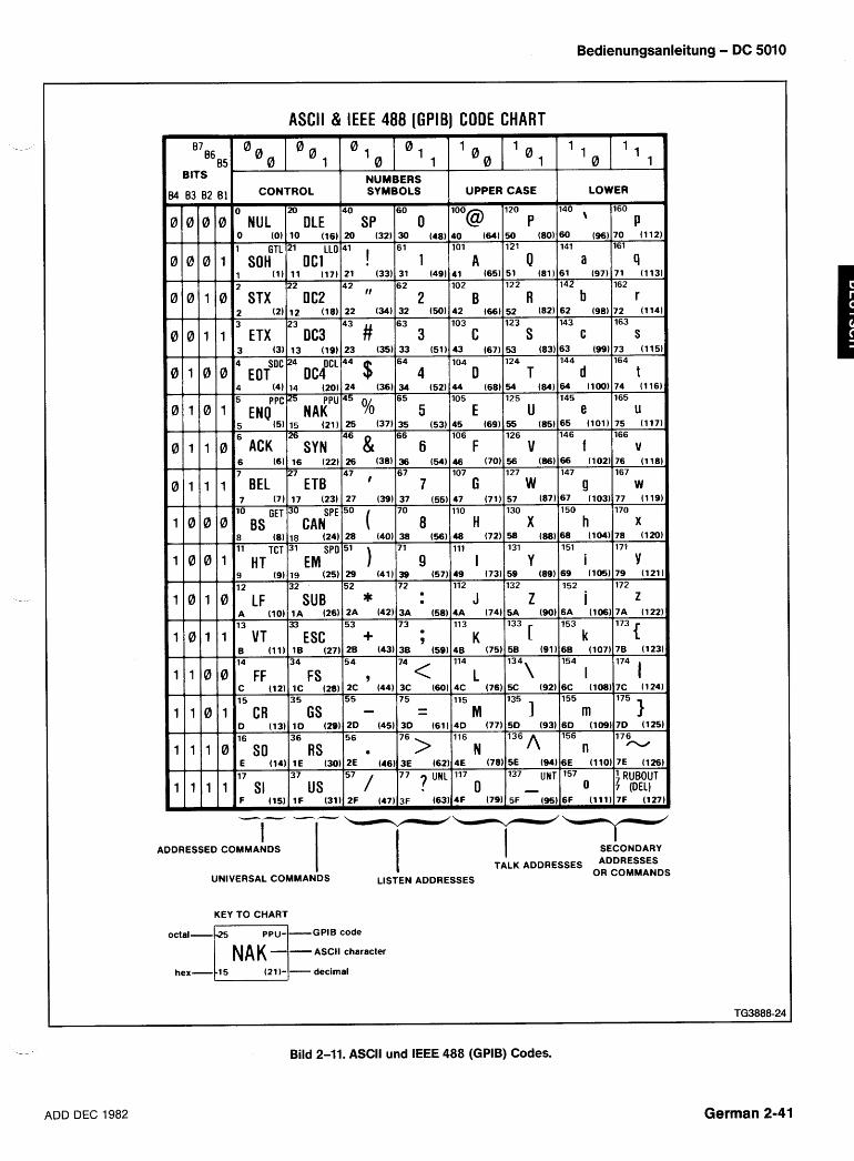
Bedienungsanleitung - DC 5010
- - -
87 B6
B5 BITS
I4 83 82 B1
ASCl l & IEEE 488 [GPlB] CODE CHART
CONTROL
NUL Irn OLE
SOH (1) 11 (17)
2 22
sTx(2)1;; Dc:181
ETX DC3
NUMBERS SYMBOLS UPPER CASE I LO\
4 (4) 14 (20) 24 (36) 34 (52) 44 (68) 54 (84) 64 (100) 74 (116 65 105 125 145 165
EN{PC25 NAiPU 45 % 5 E u e u 5 (5) 15 (21) 25 (37) 35 (53) 45 (69) 55 (85) 65 (101) 75 (117
66 106 126 146 166 ACK SYN 46 & 6 F V f v
6 (6) 16 (22) 26 (381 36 (541 46 (70) 56 (86) 66 (102) 76 (110 7 27 67 107 127 147 167
47 , BEL ETB 7 G W 9 w 7 (7) 17 (23) 27 (39) 37 (55) 47 (71) 57 (87) 67 (103) 77 (119
lo GET 70 110 130 150 170
BS O CAN"^ 50 ( 8 H X h x - - 8 (8) 18 (24) 28 (40) 38 (56) 48 (72) 58 (88) 68 (104) 78 (120
11 TCT 31 51
EM 71 111 131 151 171
HT 9 I Y i Y - - -
9 (9) 19 (25) 29 (41) 39 (57) 49 (73) 59 (89) 69 (105) 79 (121 12 32 52 72 112 132 152 172
LF SUB * rn J z i w z
D (13) l D (29) 2D (45) 30 (61) 4D (77) 50 (93) 6 0 (109) 7D (12I 16 36 56
w 76 > 116 176
1 1 1 0 SO RS N 136 A 156 n -
E (14) 1E (30) 2E (46Y 3E (62) 4E (78) 5E (94) 6E (110) 7E (12t 17 37 57 77 7 UNL 117 137 UNT 157 ' RUBOUT
us 1 1 1 1 SI 0 - 0 ~ ( D E L )
ADDRESSED COMMANDS I I I SECONDARY
I I TATLK ADDRESSES ADDRESSES UNIVERSAL COMMANDS
OR COMMANDS LISTEN ADDRESSES
KEY TO CHART
I N A K -1- ASCII character
hex-tl5 (21 1-1- decimal
Bild 2-11. ASCll und IEEE 488 (GPIB) Codes.
ADD DEC 1982 German 2-41
Bedienungsanleitung - DC 5010
Rundung numerischer Argumente
Das Gerat rundet numerische Argumente zur nach- sten Auflosungseinheit auf oder ab und pruft dann, ob sie aul3erhalb des Bereichs liegen.
Mitteilungs-Protokoll
Wenn das Gerat eine Mitteilung erhalt, wird sie im Ein- gangs-Puffer gespeichert, bearbeitet und ausgefuhrt. Die Bearbeitung einer Mitteilung besteht aus der Deko- dierung von Befehlen, dem Erkennen von Trennzeichen und dem ~berprufen der Syntax. Bei Einstellbefehlen speichert das Gerat die angezeigten ~nderungen im Ein- stell-Puffer. Wird wahrend der Bearbeitung ein Fehler entdeckt, gibt das Gerat eine Bedienungsanfrage (SRQ) aus, ignoriert den Rest der Mitteilung und stellt den Ein- stell-Puffer zuruck. Durch Ruckstellen des Einstell-Puf- fers werden unerwunschte Zustande vermieden die dadurch entstehen konnen, dal3 einige Einstellbefehle der gleichen Mitteilung ausgefuhrt werden und andere nicht.
Die Ausfuhrung einer Mitteilung besteht in der Durch- fuhrung der Tatigkeiten, die durch ihre Befehle spezifi- ziert sind. Bei Einstellbefehlen bedeutet das die Neu- Einstellung der Gerateeinstellungen und die Aufnahme dieser neuen Einstellungen in den Einstell-Puffer. Die Einstellbefehle werden in Gruppen ausgefuhrt - d. h., eine Reihe von Einstellbefehlen wird bearbeitet und in den Einstell-Puffer aufgenommen, bevor'die Ausfuhrung erfolgt. Das erlaubt dem Anwender einen neuen Status zu spezifizieren ohne darauf zu achten, ob eine beson- dere Reihenfolge Gultigkeit hat. Die Durchfuhrung der Einstellungen erfolgt, wenn das Gerat das Mitteilungs- Endezeichen, einen Abfragebefehl oder einen Betriebs- befehl in einer Mitteilung bearbeitet.
Bearbeitet das Gerat einen Abfragebefehl in einer Mit- teilung, dann werden zuerst alle vorhergehenden Ein- stellbefehle ausgefuhrt, um den Status des Gerates auf den neuesten Stand zu bringen. Dann wird der Abfrage- befehl ausgefuhrt, indem es die entsprechenden Daten abruft und sie in den Ausgangspuffer gibt. Danach wird die Bearbeitung und Ausfuhrung des Rests der Mittei- lung fortgesetzt. Wenn das Gerat zum Sprecher (talker) gemacht wird, werden die Daten an den Controller wei- tergegeben.
Wenn das Gerat in einer Mitteilung einen Betriebsbe- fehl bearbeitet, werden vor dem Betriebsbefehl alle vor- hergehenden Einstellbefehle ausgefuhrt.
Mehtfach-Mitteilungen
Der Eingangs-Puffer hat eine begrenzte Kapazitat und eine einzelne Mitteilung kann so lang sein, dal3 er damit ausgefullt ist. In diesem Falle wird ein Teil der Mitteilung bearbeitet, bevor das Gerat weitere Daten annimmt. Wahrend der Befehlsaufuhrung halt das Gerat zusatz- liche Daten zuruck (durch NRFD) bis im Puffer Platz zur Verfugung steht.
Wenn Platz vorhanden ist, kann das Gerat vor Ausfuh- rung der ersten eine zweite Mitteilung annehmen. Es halt jedoch zusatzliche Mitteilungen mit NFRD zuruck, bis die -- erste Mitteilung vollstandig durchgefuhrt ist.
Nachdem das Gerat in einer Mitteilung einen Abfrage- befehl ausgefuhrt hat halt es die Antwort zuruck, bis es vom Controller zum Sprecher (talker) gemacht wird. Empfangt das Gerat eine neue Mitteilung bevor der gesamte Ausgang der vorherigen Mitteilung ausgelesen ist, macht es vor der Ausfuhrung der neuen Mitteilung den Ausgangs-Puffer frei. Dadurch wird verhindert, dal3 der Controller unerwunschte Daten aus alten Mitteilun- gen erhalt.
Eine weitere Situation kann das Gerat veranlassen den Ausgang zu Ioschen. Die Ausfuhrung einer langen Mitteilung kann dazu fuhren, daO Eingangs- und Aus- gangs-Puffer voll werden. Wenn dies geschieht, kann das Gerat die Ausfuhrung der Mitteilung nicht beenden weil es darauf wartet, daO der Controller die erzeugten Daten ausliest; der Controller kann die Daten aber nicht auslesen weil er mit der ~bertragung seiner Mitteilung noch nicht zu Ende ist. Da der Eingangs-Puffer voll ist und das Gerat den Rest der Mitteilung des Controllers mit NRFD zuruckhalt, hangt das System in der Schwebe weil Controller und Gerat aufeinander warten. Erkennt das Gerat diesen Zustand erzeugt es eine Fehlermel- dung, gibt ein SRQ aus und loscht die Daten im Aus- gangs-Puffer. Das ermoglicht dem Controller den Rest der Mitteilung zu ubertragen und der Controller wird --,
informiert, dal3 die Mitteilung ausgefuhrt und der Aus- gang geloscht wurde.
Ein TM 5000 Gerat kann als Sprecher (talker) adres- siert werden, ohne dal3 es eine Mitteilung erhalt die angibt, was es ausgeben soll. In diesem Falle geben Erfassungsgerate (Zahler und Vervielfacher) eine Mes- sung aus, wenn sie beendet ist. 1st keine Messung fertig, geben sie eine ein Byte-Mitteilung zuruck bei der alle Bits gleich 1 sind (mit Endezeichen); andere TM 5000 Gerate geben nur diese Mitteilung zuruck.
Geratereaktionen auf IEEE-488 Interface Mitteilungen
Interface Mitteilungen und ihre Auswirkungen auf die Interface-Funktionen des Gerates sind im IEEE Standard 488-1978 definiert. Abkurzungen dieser Norm werden in dieser Diskussion verwendet, in der die Auswirkungen der Interface-Mitteilungen auf die Betriebsweise des Gerates beschrieben werden.
UNL-Unlisten UNT-Untalk
Wird der Befehl UNL empfangen, geht die Horer-(liste- ner) Funktion des Gerates in ihren Ruhestand (nicht -- adressiert). Im Ruhezustand nimmt das Gerat keine Befehle vom GPlB an.
German 2-42 ADD DEC 1982
Bedienungsanleitung - DC 5010
Die Sprecher-(talker) Funktion geht in ihren Ruhezu- stand, wenn das Gerat den Befehl UNT empfangt. In die- sem Zustand kann das Gerat uber den GPlB keine Daten ausgeben.
Wenn Talker- und Listener-Funktion im Ruhezustand sind, ist das Lampchen ,,ADDRESSEDu aus. 1st das Gerat entweder Talk- oder Listenadressiert, ist das Lampchen an.
IFC-Interface Clear
Diese einzeilige Mitteilung hat die gleiche Auswirkung wie die UNL- und UNT-Mitteilungen. Das Lampchen ,,ADDRESSEDu auf der Frontplatte ist aus.
DCL-Device Clear
Die Mitteilung Device Clear stellt die Kommunikation zwischen Controller und Gerat wieder her. Als Antwort auf DCL loscht das Gerat alle Eingangs- und Ausgangs- mitteilungen und jede nicht ausgefuhrte Einstellung im Einstellungs-Puffer. Ebenso werden alle auf Abruf war- tenden Fehler und Ereignisse geloscht, mit Ausnahme des Einschalt-SRQ's. Wenn aus irgendeinem anderen Grund als dem Einschaltvorgang ein SRQ ausgegeben ist, wird beim Empfang von DCL die SRQ geloscht.
SDC-Selected Device Clear
Diese Mitteilung erfullt die gleiche Funktion wie DCL; jedoch nur Gerate die als Listener adressiert sind ant- worten auf SDC.
GET-Group Execute Trigger
Das Gerat spricht auf GET nuran, wenn es als Listener adressiert ist und die Gerate-Triggerfunktion durch den Befehl Device Trigger (DT) freigegeben worden ist. Wenn die DT-Funktion gesperrt ist (DT OFF), das Gerat auf Frontplattenbedienung eingestellt ist, oder beim Emp- fang von GET eine Mitteilung ausfuhrt, wird die Mittei- lung GET ignoriert und ein SRQ erzeugt.
SPE-Serial Poll Enable SPD-Serial Poll Disable
Die Mitteilung SPE gibt das Gerat fur die Ausgabe des Serial Poll Status Bytes frei, wenn es als Talker adressiert ist. Durch die Mitteilung SPD wird das Gerat auf seinen normalen Betrieb, die Sendung von Daten aus dem Aus- gangs-Puffer, zuruckgeschaltet.
MLA-My Listen Address MTA-My Talk Address
LLO-Local Lockout
LLO wird von dem Gerat mit einem Umschaltvorgang beantwortet - von LOCS auf LWLS oder von REMS auf RWLS.
REN-Remote Enable
Wenn REN aktiviert ist und das Gerat hat seine Listen- Adresse empfangen, schaltet es auf einen Fernbedie- nungsstatus um (von LOCS auf REMS oder von LWLS auf RWLS). 1st REN nicht aktiv, also falsch, wird aus jedem Status eine Umschaltung auf LOCS veranlal3t; das Gerat bleibt so lange in LOCS wie REN falsch ist.
Eine REN-Umschaltung kann nach dem Beginn einer Mitteilungsbearbeitung vorkommen. In diesem Falle wird die Ausfuhrung der in Bearbeitung befindlichen Mittei- lung durch eine Umschaltung nicht beeinflul3t.
GTL-Go To Local
Nur listen-adressierte Gerate antworten auf GTL durch Umschalten auf Eigenbedienung. Umschaltun- gen von Fern-auf-Eigenbedienung durch GTL beeinflus- sen nicht die Ausfuhrung von Mitteilungen, die beim Empfang von GTL bearbeitet werden.
Remote-Local Operation
Die vorstehende Diskussion der Interface-Mitteilun- gen beschreibt die Status-Umschaltungen durch GTL und REN. Die meisten Bedienungselemente auf der Frontplatte verursachen eine Umschaltung von REMS auf LOCS durch eine Mitteilung, die return-to-local (rtl) genannt wird. Diese Umschaltung kann wahrend der Mit- teilungs-Ausfuhrung vorkommen; aber im Gegensatz zu GTL- und REN-Umschaltungen, wird durch eine Umschaltung die durch rtl veraniaBt wurde die Mittei- lungs-Ausfuhrung beeinfluot. In diesem Fall erzeugt das Gerat einen Fehler, wenn es irgendwelche nicht aus- gefuhrten Einstell- oder Betriebsbefehle gibt. Bedie- nungselemente auf der Frontplatte die nur die Darstel- lung andern (wie ID) beeinflussen die Fern-Eigenbedie- nungszustande nicht - nur Bedienungselemente die Einstellungen andern, konnen rtl geltend machen. Rtl wird ungultig nach ~nderung der Einstellungen auf der Frontplatte.
Local State (LOCS) In LOCS werden die Einstellungen des Gerates durch
die Bedienungsperson uber die Bedienungselemente auf der Frontplatte gesteuert. In diesem Status werden nur Bus-Befehle ausgefuhrt, die die Einstellungen des Gerates nicht verandern (Abfragebefehle); alle anderen Bus-Befehle (Einstellung oder Betrieb) erzeugen einen Fehler, da ihre Funktionen uber die Frontplatte gesteuert werden.
Die primaren Listen- und Talkadressen werden durch die GPlB Adresse des Gerates erstellt (intern einge- Local With Lockout State (LWLS) stellt). Die jeweilige Einstellung der GPlB Adresse wird Das Gerat arbeitet in gleicher Weise wie bei LOCS mit auf der Frontplatte dargestellt, wenn der Knopf ID der Ausnahme, dal3 rtl keine Umschaltung auf Fernbe-
- gedruckt wird. dienung beinhaltet.
ADD DEC 1982 German 2-43
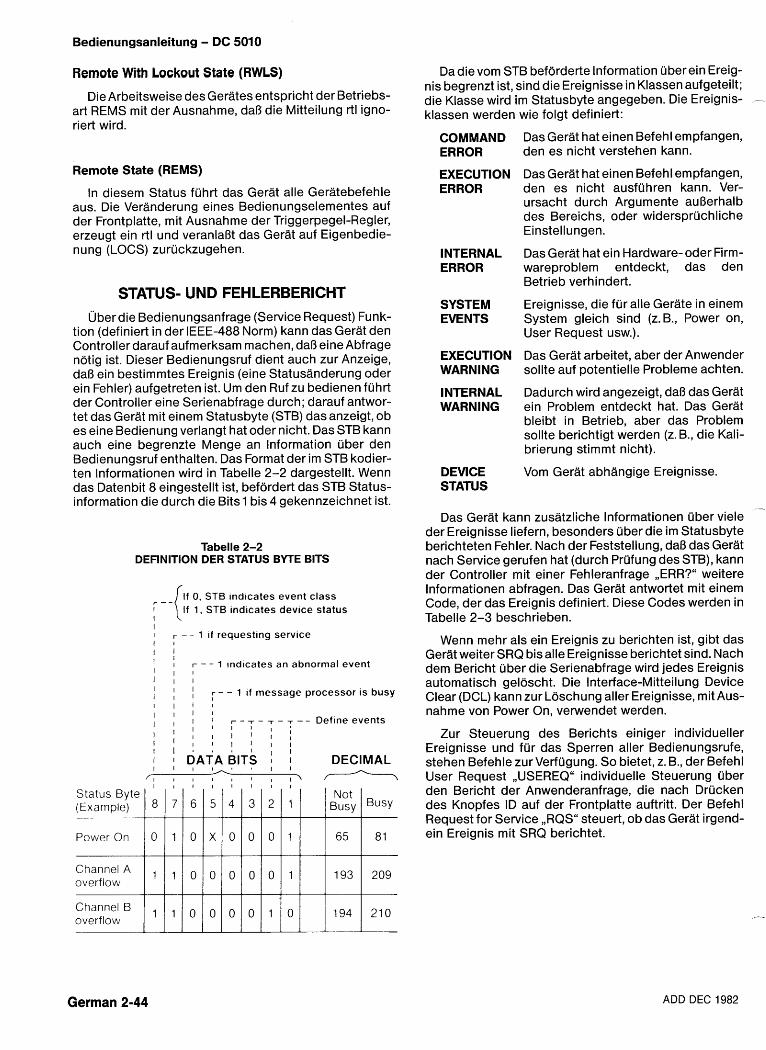
Bedienungsanleitung - DC 5010
Remote With Lockout State (RWLS)
Die Arbeitsweise des Gerates entspricht der Betriebs- art REMS mit der Ausnahme, daB die Mitteilung rtl igno- riert wird.
Remote State (REMS)
In diesem Status fuhrt das Gerat alle Geratebefehle aus. Die Veranderung eines Bedienungselementes auf der Frontplatte, mit Ausnahme der Triggerpegel-Regler, erzeugt ein rtl und veranlaOt das Gerat auf Eigenbedie- nung (LOCS) zuruckzugehen.
STATUS- UND FEHLERBERICHT 1Jber die Bedienungsanfrage (Service Request) Funk-
tion (definiert in der IEEE-488 Norm) kann das Gerat den Controller darauf aufmerksam machen, daO eine Abfrage notig ist. Dieser Bedienungsruf dient auch zur Anzeige, daO ein bestimmtes Ereignis (eine Statusanderung oder ein Fehler) aufgetreten ist. Um den Ruf zu bedienen fuhrt der Controller eine Serienabfrage durch; darauf antwor- tet das Gerat mit einem Statusbyte (STB) das anzeigt, ob es eine Bedienung verlangt hat oder nicht. Das STB kann auch eine begrenzte Menge an lnformation uber den Bedienungsruf enthalten. Das Format der im STB kodier- ten lnformationen wird in Tabelle 2-2 dargestellt. Wenn das Datenbit 8 eingestellt ist, befordert das STB Status- information die durch die Bits 1 bis 4 gekennzeichnet ist.
Tabelle 2-2 DEFINITION DER STATUS BYTE BITS
0, ST, indicates event class I If 1, ST6 indicates device status I I I r - - 1 ~f requesting service I 4 I I
I f r - - 1 indicates an abnormal event I l l I l l
I I I : - - 1 if message processor is busy I I I I I l l 1 I I I 1 r - T - - r - T - - D e f i n e e v e n t s l I I I I I I ;
1 1 1 1 I 1 : I I ; , I I I "
I I I 1 DATA BITS I I I I I S I ( I
DECIMAL I I I - 1 1 I \ r-----7
Da die vom STB beforderte lnformation uber ein Ereig- nis begrenzt ist, sind die Ereignisse in Klassen aufgeteilt; die Klasse wird im Statusbyte angegeben. Die Ereignis- .--
klassen werden wie folgt definiert:
COMMAND ERROR
EXECUTION ERROR
INTERNAL ERROR
SYSTEM EVENTS
EXECUTION WARNING
INTERNAL WARNING
DEVlCE STATUS
Das Gerat hat einen Befehl empfangen, den es nicht verstehen kann.
Das Gerat hat einen Befehl empfangen, den es nicht ausfuhren kann. Ver- ursacht durch Argumente auOerhalb des Bereichs, oder widerspruchliche Einstellungen.
Das Gerat hat ein Hardware- oder Firm- wareproblem entdeckt, das den Betrieb verhindert.
Ereignisse, die fur alle Gerate in einem System gleich sind (z. B., Power on, User Request usw.).
Das Gerat arbeitet, aber der Anwender sollte auf potentielle Probleme achten.
Dadurch wird angezeigt, da8 das Gerat ein Problem entdeckt hat. Das Gerat bleibt in Betrieb, aber das Problem sollte berichtigt werden (z. B., die Kali- brierung stimmt nicht).
Vom Gerat abhangige Ereignisse.
Das Gerat kann zusatzliche lnformationen uber viele der Ereignisse liefern, besonders uber die im Statusbyte berichteten Fehler. Nach der Feststellung, daO das Gerat nach Service gerufen hat (durch Prufung des STB), kann der Controller mit einer Fehleranfrage ,,ERR?" weitere lnformationen abfragen. Das Gerat antwortet mit einem Code, der das Ereignis definiert. Diese Codes werden in Tabelle 2-3 beschrieben.
Wenn mehr als ein Ereignis zu berichten ist, gibt das Gerat weiter SRQ bisalle Ereignisse berichtet sind. Nach dem Bericht uber die Serienabfrage wird jedes Ereignis automatisch geloscht. Die Interface-Mitteilung Device Clear (DCL) kann zur Loschung aller Ereignisse, mit Aus- nahme von Power On, verwendet werden.
Zur Steuerung des Berichts einiger individueller Ereignisse und fur das Sperren aller Bedienungsrufe, stehen Befehle zur Verfugung. So bietet, z. B., der Befehl User Request ,,USEREQ" individuelle Steuerung uber den Bericht der Anwenderanfrage, die nach Drucken des Knopfes ID auf der Frontplatte auftritt. Der Befehl Request for Service ,,RQS6' steuert, ob das Gerat irgend- ein Ereignis mit SRQ berichtet.
German 2-44 ADD DEC 1982
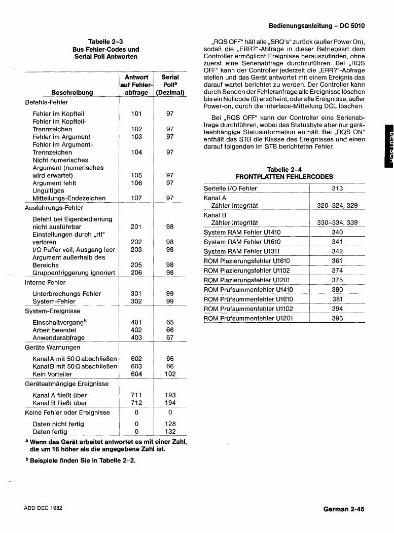
Tabelle 2-3 Bus Fehler-Codes und Serial Poll Antworten
Beschreibung Befehls-Fehler
Fehler im Kopfteil Fehler im Kopfteil- Trennzeichen Fehler im Argument Fehler im Argument- Trennzeichen Nicht numerisches Argument (numerisches wird erwartet) Argument fehlt Ungultiges Mitteilungs-Endezeichen
Ausfu hrungs-Fehler
Befehl bei Eigenbedienung nicht ausfuhrbar Einstellungen durch ,,rtlU verloren I10 Puffer voll, Ausgang leer Argument aufierhalb des Bereichs
-- Gruppentriggerung ignoriert
Interne Fehler
Unterbrechungs-Fehler System-Fehler
System-Ereignisse
~inschaltvorgang~ Arbeit beendet Anwenderabfrage
Gerate Warnungen
KanalA mit 50 QabschlieBen Kanal B mit 50 QabschlieBen Kein Vorteiler
Gerateabhangige Ereignisse
Kanal A fiieBt uber Kanal B flieBt uber
Keine Fehler oder Ereignisse
Daten nicht fertig Daten fertig
Antwort auf Fehler- abfrage
101
102 1 03
104
105 106
107
Serial Polla
(Dezimal)
97
97 97
97
97 97
97
a Wenn das Gerat arbeitet antwortet es mit einer Zahl, die urn 16 hoher als die angegebene Zahl ist.
Beispiele finden Sie in Tabelle 2-2.
Bedienungsanleitung - DC 5010
,,RQS OFF halt alle ,,SRQ'sU zuruck (auOer Power On), social3 die ,,ERR?"-Abfrage in dieser Betriebsart dem Controller ermoglicht Ereignisse herauszufinden, ohne zuerst eine Serienabfrage durchzufijhren. Bei ,,RQS OFF" kann der Controller jederzeit die ,,ERR?"-Abfrage stellen und das Gerat antwortet mit einem Ereignis das darauf wartet berichtet zu werden. Der Controller kann durch Senden der Fehleranfrage alle Ereignisse loschen bis ein Nullcode (0) erscheint, oder alle Ereignisse, auRer Power-on, durch die Interface-Mitteilung DCL loschen.
Bei ,,RQS OFFii kann der Controller eine Serienab- frage durchfuhren, wobei das Statusbyte aber nur gera- teabhangige Statusinformation enthalt. Bei ,,RQS ON" enthalt das STB die Klasse des Ereignisses und einen darauf folgenden im STB berichteten Fehler.
Tabelle 2-4 FRONTPLAITEN FEHLERCODES
ADD DEC 1982
Serielle I/O Fehler
Kanal A Zahler Integritat
Kanal B Zahler Integritat
System RAM Fehler U1410 System RAM Fehler U1610
System RAM Fehler U1311 ROM Plazierungsfehler U1610
ROM Plazierungsfehler U1102
German 2-45
31 3
320-324,329
330-334,339 340 341
342 361
374
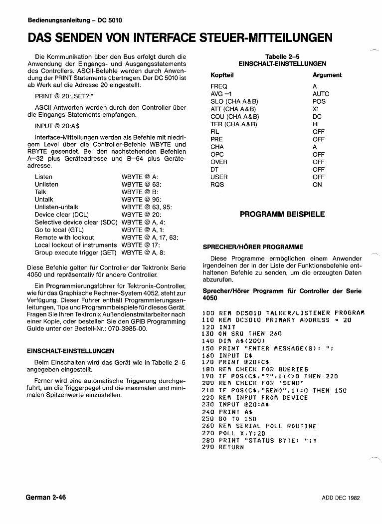
Bedienungsanleitung - DC 5010
DAS SENDEN VON INTERFACE STEUER-MlTTElLUNGEN Die Kommunikation uber den Bus erfolgt durch die
Anwendung der Eingangs- und Ausgangsstatements des Controllers. ASCII-Befehle werden durch Anwen- dung der PRINT Statements ubertragen. Der DC 5010 ist ab Werk auf die Adresse 20 eingestellt.
PRINT @ 20:,,SET?;"
ASCII Antworten werden durch den Controller uber die Eingangs-Statements empfangen.
INPUT @ 20:A$
Interface-Mitteilungen werden als Befehle mit niedri- gem Level uber die Controller-Befehle WBYTE und RBYTE gesendet. Bei den nachstehenden Befehlen A=32 plus Gerateadresse und B=64 plus Gerate- adresse.
Listen WBYTE @ A: Unlisten WBYTE @ 63: Talk WBYTE @ B: Untalk WBYTE @ 95: Unlisten-untalk WBYTE @ 63,95: Device clear (DCL) WBYTE @ 20: Selective device clear (SDC) WBYTE @ A, 4: Go to local (GTL) WBYTE @ A, 1: Remote with lockout WBYTE @ A, 17, 63: Local lockout of instruments WBYTE @ 17: Group execute trigger (GET) WBYTE @ A, 8:
Diese Befehle gelten fur Controller der Tektronix Serie 4050 und reprasentativ fur andere Controller.
Ein Programmierungsfuhrer fur Tektronix-Controller, wie fur das Graphische Rechner-System 4052, steht zur Verfugung. Dieser Fuhrer enthalt Programmierungsan- leitungen, Tips und Programmbeispiele fur dieses Gerat. Fragen Sie lhren Tektronix AuBendienstmitarbeiter nach einer Kopie, oder bestellen Sie den GPlB Programming Guide unter der Bestell-Nr.: 070-3985-00.
EINSCHALT-EINSTELLUNGEN
Beim Einschalten wird das Gerat wie in Tabelle 2-5 angegeben eingestellt.
Ferner wird eine automatische Triggerung durchge- fuhrt, um die Triggerpegel und die maximalen und mini- malen Spitzenwerte einzustellen.
Tabelle 2-5 EINSCHALT-EINSTELLUNGEN
Kopfteil Argument
FREQ A AVG -1 AUTO SLO (CHA A& B) POS A7T (CHA A& B) XI COU (CHA A& B) DC TER (CHA A&B) HI FI L PRE CHA OPC OVER DT USER RQS
OFF OFF A OFF OFF OFF OFF ON
PROGRAMM BElSPlELE
SPRECHER/HORER PROGRAMME - Diese Programme ermoglichen einem Anwender
irgendeinen der in der Liste der Funktionsbefehle ent- haltenen Befehle zu senden, um die erzeugten Daten abzurufen.
Sprecher/Horer Programm f i r Controller der Serie 4050
German 2-46 ADD DEC 1982
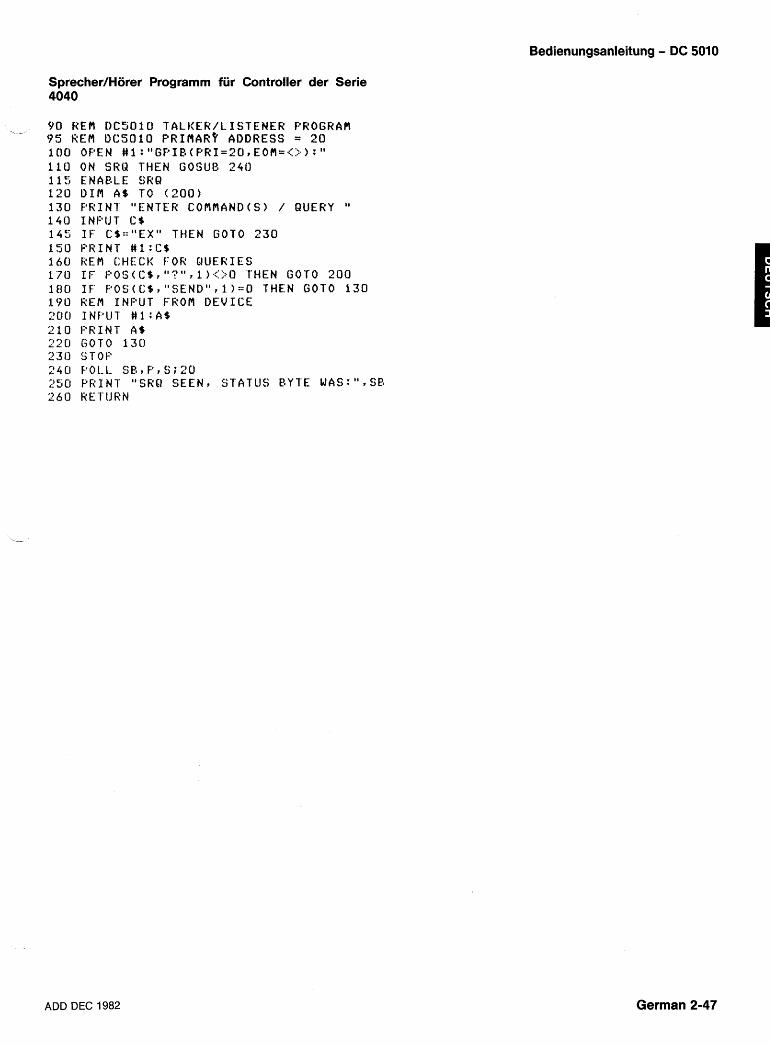
Bedienungsanleitung - DC 5010
Sprecher/Horer Programm fiir Controller der Serie 4040
, - 90 KEM D C 5 0 1 0 T A L E E R / L I S T E N E R PROGHAfi 9 5 REM U C S O l O P R I ~ ~ A R ? ADDRESS = 2 0 1 0 0 OF:@EN # 1 : "GPIB(F'RI=201E0f i=( : : . ) :" 1 1 0 ON SRU THEN GOSUB 24U 1 1 5 ENABLE SRQ 1 2 0 U I M A$ TO ( 2 0 0 ) 1 3 0 P R I N T "ENTER COf iMAND(S> / QUERY " 1 4 0 I N P U T C$ 1 4 5 I F C$=="EXH THEN GOT0 2 3 0 1 5 0 P R I N T #l:C$ 1 6 0 REM CHECK FOR Q U E R I E S 1 7 0 I F P O S ( C $ r " ? " r I ) . : : : ? . O THEN GOT0 2 0 0 1 8 0 I F ' F'OCj(C$r "SEND1'r l ) : = O THEN GOT0 1 3 0 190 REU I N P U T FROM D E V I C E 2 0 0 INF"U1' # 1 : A$ 2 1 0 P R I N T AS 2 2 0 GOT0 1 3 0 2 3 0 STOF 2 4 0 POLL. SB? P r S ; 2 0 250 P R I N T " S K R S E E N ? STATUS BYTE WAS:" ,SB 260 RE'I'IJRN
ADD DEC 1982 German 2-47
Bedienungsanleitung - DC 5010
PROGRAMMIERUNGSHINWEISE Dieser Abschnitt sol1 zeigen wie der DC 5010 program-
miert wird, um einige grundlegende MeOfunktionen zu erfullen und wie man aus einigen seiner besonderen Programmierungseinrichtungen Vorteile ziehen kann.
Die nachstehenden Beispiele sind in BASIC der Serie 4050 geschrieben. Die Eingabedetails variieren je nach Controller.
~nderung der Einstellungen des Eingangskanals
Vor Durchfuhrung einer sinnvollen Messung, mussen die Bedingungen fur das Eingangssignal richtig einge- stellt werden. Im nachstehenden Beispiel wird zuerst die Bedingung fur das Eingangssignal auf Kanal A einge- stellt. Dann werden die Triggerpegel mit dem Befehl AUTO automatisch auf ihre Mittelwerte gesetzt und der Befehl AVE-1 stellt das Gerat fur etwa 3 MessungenISek. ein. Zuletzt wird dem DC 5010 befohlen FREQ (Fre- quenz) Messungen durchzufuhren.
1 0 0 P R I N T I ? ~ O : ~ ~ C H A A;SLO Y 0 S ; T E R f l H I ; " 1 1 0 P R I N T e 2 0 : " C O U DC;ATT 1;AUTO;" 12U P R I N T I220 : "AVE -1 ;FRER;SEND;" 1 3 0 I N P U T @ 2 0 : R 1 4 0 P R I N T " T H E FREQUENCY I S " ;R 1 5 0 END
Obwohl das vorstehende Beispiel alle programmier- ten Eingangseinstellungen fur Kanal Azeigt, mussen nur die Einstellungen programmiert werden, die nicht bereits den gewunschten Status haben.
Zeitintervall-Messung
Im nachstehenden Beispiel wird das Gerat fur Zeitin- tervall-Messungen zwischen zwei lTL-Signalpegeln ein- gestellt, die an die Eingange der Kanale A und B mit X5 Tastkopfen angeschlossen sind.
2 0 0 P R I N T g 2 0 : " C H A A ; S L 0 P 0 S ; T E K f l H I ; " 2 1 0 P R I N T Q 2 0 : " A T T 1;COU DC;LEV 0 . 2 7 5 : " 220 P R I N T e 2 0 : " C H A B;SLO P 0 S ; T E R f l H I ; " 230 P R I N T 1220 : "ATT I COU DC;LEV 0 . 2 7 5 ; " 240 P R I N T @ 2 0 : " A V E 1 ; T I A E ; S E N D ; " 250 INF'UT g 2 0 : T 2 6 0 P R I N T " T I B E A TO E3 IS " ;T 270 END
Auch hier muBten nur die Einstellungen programmiert werden, die nicht bereits den gewunschten Status haben.
Durchfiihrung von Einzelmessungen
Einzelmessungen konnen mit einer der in den nach- stehenden Beispielen gezeigten Methoden durchge- fuhrt werden. Fur eine Einzelmessung wird das Gerat zuerst auf ,,STOPu gestellt. Ein ,,RESET" veranlaOt dann die Durchfuhrung einer einzelnen Messung und danach wird der MeBvorgang wieder angehalten. Das erste Bei- spiel zeigt, wie eine einzelne TIME Intervall-Messung mit STOP und RESET durchgefuhrt wird.
300 P R I N T e 2 0 : " A V E 1 ; T I A E ; " 3 1 0 P R I N T @2O:"STOP;RESET;SEND;" 320 I N P U T @ 2 0 : R 3 3 0 P R I N T " T I H E I N T E R V A L I S " ; R 340 END
Das nachste Beispiel zeigt, wie die Gruppentrigge- rung < GET> anstelle von RESET fur Einzelmessungen angewendet wird. Um < GET > anwenden zu konnen, muO zuerst mit dem Befehl DT TRIG die Triggerfunktion des Gerates freigegeben werden. Auch hierbei muO das Gerat auf ,,STOP" gestellt werden, bevor das < GET> ein RESET und damit eine Einzelmessung veranlaOt.
Auslesen der Ergebnisse
Es gibt zwei grundsatzliche Wege um MeOdaten vom DC 5010 zu erhalten. Die erste, nachstehend gezeigte Methode verwendet fiir die Abfrage von MeBergebnis- sen den Befehl SEND. Steht ein MeOergebnis zur Ver- fugung, antwortet der DC 5010 sofort wenn er ,,angespro- chen" wird, sonst wartet er mit der Antwort bis ein MeOer- gebnis da ist.
German 2-48 ADD DEC 1982
Bedienungsanleitung - DC 5010
Die andere Methode MeOdaten zu erhalten besteht Erweiterung des Bereichs durch Zahlen des Uberlaufs einfach darin den DC 5010 zu adressieren und dann die Ergebnisse abzulesen. Steht ein Ergebnis zur Ver- fugung, veranlaOt das Adressieren des Gerates die Aus- gabe des Ergebnisses. Steht kein Ergebnis zur Ver- fugung, wird das Gerat veranlaOt stattdessen ein FF(hex)Byte auszugeben. Das nachstehende Beispiel zeigt, wie Daten durch einfaches ,,AnsprechenU des Gerates und Prufen auf FF(hex) ausgelesen werden kon- nen.
Mit den Befehlen ,,RDY?" und ,,OPCU kann festgestellt werden, ob Daten fijr die Auslesung zur Verfugung ste- hen. Der Status ,,Daten bereit" kann, wie im folgenden Beispiel, mit dem Abfrage-Befehl ,,RDY?" abgefragt wer- den.
Das nachstehende Beispiel zeigt, wie der Befehl "OPC" es ermoglicht den Bedienungsruf (SRQ) und das Statusbyte (STB) fur die Meldung zu verwenden, dal3 Daten bereit sind.
lot ! k E f l U S l N G OF'C 1N'ICRkUFr7 A N D 11C !?EM STATUS !2YTE TO SIGNAL 120 R E R UHCN THL DATA I S [ ; L A D Y 1 3 0 A:=O 1 4 0 Faf<IN7 t 2 5 : " F ' E R ; OT'C O N ; " 1 5 0 ON 31 i;l THEN 2 2 0 : 6 i ~ W A 1 ' 1 1 7 0 I F A=O THEN 1 6 0 I 8 0 F'FiIN'I @2C: " S E N D ; OF'C OFF; " 1 9 0 INPUT f i 20 :A 2 0 0 P k l N T " F ' T R I O D IS " ; A 2 1 0 ENC 22i, i a O L L D , S ; 2 0 230 I F S = 6 6 O R S = 8 2 THEN 260 2 4 0 P R I N l "SHQ O C C U k E D , S I A T U E = " ; S 2 5 0 G O TO 2 7 0 2 6 0 A - 1 270 KETURN
Wenn die interne 43-Bit Kapazitat des Zahlers ijber- schritten wird Iauft er uber (OVERFLOW). Durch Zahlen dieser OVERFLOW'S kann der Bereich bei TMANUAL und TOTALIZE Messungen erweitert werden.
Das nachfolgende Beispiel u berwacht eine TOTALIZE Messung und beobachtet wann die Zahlung 1.OE+14 erreicht, etwa das 11-fache der Zahlkapazitat des DC5010. Dies geschieht durch Zahlen der OVER- FLOWS'S und die Verwendung dieser Zahl zur Erweite- rung der Genauigkeit des Ergebnisses.
I FiE M - : f . X l [ _ N U 1 N C k A N C k lJSlNI : ;> 2 R f i R O V E R I : L O I A - T C T A L I Z L A ![![I ; :.(I 1 l [ j F , [ ; l N - l @ ~ L I : " G V [ . f ( O N ; T(j.1 ; S7 A R 1 ; " 121; O N SSRd '[ldc:N 5(]C
Das nachste Beispiel uberwacht eine TMANUAL Mes- sung die bestimmen SOH, wann 24 Stunden vergangen sind. Da 24 Stunden gleich 86.400 Sekunden sind, uber- steigt dies die Zahlerkapazitat des DC 5010 von 27.487,8 Sekunden. Durch Zahlen der OVERFLOW'S kann die Genauigkeit fur das Zahlen dieser Zeitspanne erweitert werden.
ADD DEC 1982 German 2-49
Bedienungsanleitung - DC 5010
Anwendung der Drucktaste INST ID
Die Kommunikation zwischen dem Controller und einer Bedienungsperson kann mit dem Knopf INST ID und dem Befehl USER hergestellt werden. Das nachste- hende Beispiel erlaubt einer Bedienungsperson an der Frontplatte Tastkopfe zu kompensieren und dann den Controller zu informieren, dal3 PROBECOMP beendet ist. Wie gezeigt konnen Tastkopfe kompensiert und der Knopf INST ID benutzt werden, auch wenn die anderen Bedienungselemente auf der Frontplatte gesperrt sind.
Der INST ID Knopf kann auch dazu verwendet werden, dem Controller mitzuteilen, dal3 das Gerat fur die Mes- sung des Eingangssignals richtig eingestellt ist. Einmal informiert, kann der Controller mit dem Anfrage-Befehl SET? die derzeitige Gerateeinstellung ,,lernenU und fur spatere Anwendung speichern.
Messung der lmpulsdauer
Mit einer KombhaWn von WIDTH und PERIOD Mes- - sungen konnen Messungen der lmpulsdauer leicht durchgefuhrt werden. Im nachstehenden Beispiel wird die Dauer des positiven Impulses des Eingangssignals bestimmt. Dieses Beispiel setzt voraus, dal3 der Trigger- pegel bereits auf den gewunschten Wert eingestellt ist.
Phasen-Messungen
Mit einer Kombination von PERIOD und TlME Messun- gen konnen Phasenmessungen durchgefuhrt werden. Im folgenden Beispiel wird die Phasendifferenz zwi- schen den Signalen auf Kanal A und Kanal B bestimmt, indem zuerst die PERIOD des einen Signals gemessen wird und dann die Funktion TlME fur die Messung der Zeitdifferenz zwischen den beiden Signalen verwendet wird. Dieses Beispiel setzt voraus, dal3 die entsprechen- -
den Signale an die Eingangskanale A und B angeschlos- sen und die Triggerpegel richtig eingestellt sind.
German 2-50 ADD DEC 1982
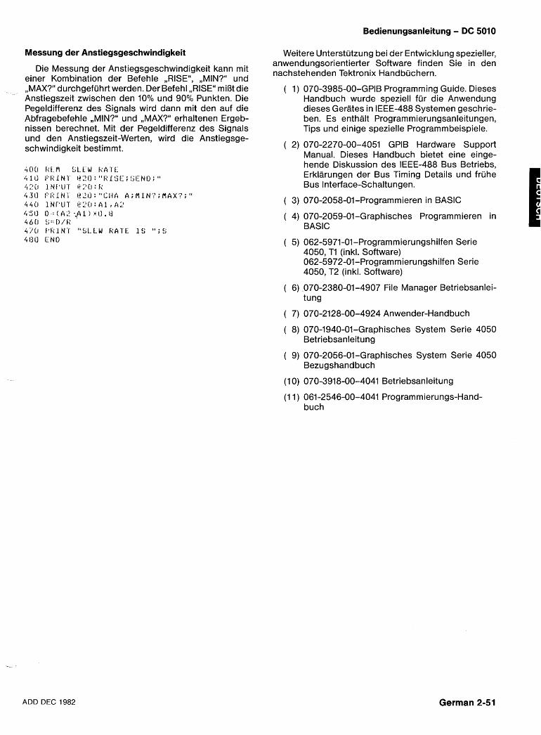
Bedienungsanleitung - DC 5010
Messung der Anstiegsgeschwindigkeit
Die Messung der Anstiegsgeschwindigkeit kann mit einer Kombination der Befehle ,,RISEu, ,,MIN?" und ,,MAX?" durchgefuhrt werden. Der Befehl ,,RISEu miOt die Anstiegszeit zwischen den 10% und 90% Punkten. Die Pegeldifferenz des Signals wird dann mit den auf die Abfragebefehle ,,MIN?" und ,,MAX?" erhaltenen Ergeb- nissen berechnet. Mit der Pegeldifferenz des Signals und den Anstiegszeit-Werten, wird die Anstiegsge- schwindigkeit bestimmt.
Weitere Unterstutzung bei der Entwicklung spezieller, anwendungsorientierter Software finden Sie in den nachstehenden Tektronix Handbuchern.
( 1 ) 070-3985-00-GPIB Programming Guide. Dieses Handbuch wurde speziell fur die Anwendung dieses Gerates in IEEE-488 Systemen geschrie- ben. Es enthalt Programmierungsanleitungen, Tips und einige spezielle Programmbeispiele.
( 2) 070-2270-00-4051 GPlB Hardware Support Manual. Dieses Handbuch bietet eine einge- hende Diskussion des IEEE-488 Bus Betriebs, Erklarungen der Bus Timing Details und fruhe Bus Interface-Schaltungen.
( 3) 070-2058-01-Programmieren in BASIC
( 4) 070-2059-01-Graphisches Programmieren in BASIC I
( 5) 062-5971-01-Programmierungshilfen Serie 4050, TI (inkl. Software) 062-5972-01-Programmierungsh ilfen Serie 4050, T2 (inkl. Software)
( 6) 070-2380-01-4907 File Manager Betriebsanlei- tung
( 7) 070-2128-00-4924 Anwender-Handbuch
( 8) 070-1940-01-Graphisches System Serie 4050 Betriebsanleitung
( 9) 070-2056-01-Graphisches System Serie 4050 Bezugshandbuch
(1 0) 070-3918-00-4041 Betriebsanleitung
(1 1 ) 061-2546-00-4041 Programmierungs-Hand- buch
ADD DEC 1982 German 2-51

mm%B D C501 09tA T M5000 2 'I - x'9+ W L . B * f * (1 @& &AT'-
@ R L 2 T o *@BtAi"FBhB%, #i%€$JB%, S!IRB% t 9, I:" S P E C I F I -
CATION" 9Sfz 3 ilf:iim~%~%@i~z L 3 T fi3.;t"&% Sk - 9 n s ~ @~%ZBT 6 t a, f i ~ , ~ ~ s w i z j ~ ~ 6 A 5 a fg *~#a>aaaa~$=i3~~:, * T = ~ ~ ) L ~ > E
PffT'9lER t 2 . 7 3 b-P?CtBCf T7 ;3 I > . +AC:&Q~E+&Z~SM~)?L&C:J ??ZESTS L \ ,
ADD DEC 1982 Japanese 2-1
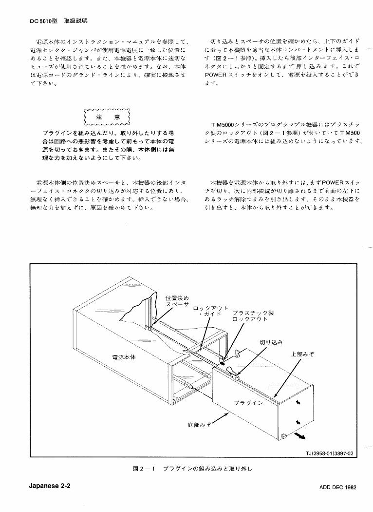
Japanese 2-2 ADD DEC 1982
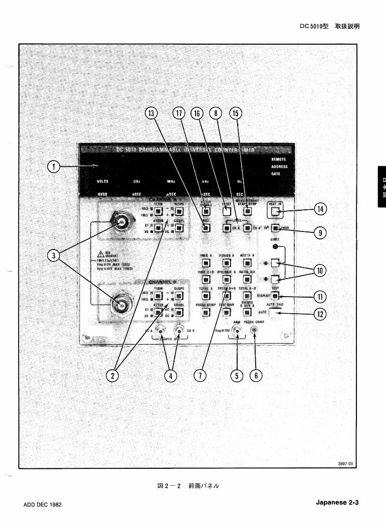
ADD DEC 1982 Japanese 2-3
@PROBE COMP -
$J5v93%3'i&75'?31;$2.67;;i I. %.f 2 bT"To PROBE COMPS.37 2 @.fp L T, ?- x F. 7 " ~ -YQ+fi_iE @4-7-14 T ( P . 2 - 1 4 "PROBE COMP" %,!g).
Japanese 2-4 REV JUL 1983
bC~affQ t &7YT?4%TO
PROB COMP-@% L f z s 4 .f to-3f.f 2*7 "~ -7 " 9@iEfi'LED%Z@$JRJ LTBEi:4'j-k 3 T o
TIME MAN (+$hi: Q B%Fs7WZ) - X b 77" 9 A- .;I
ADD DEC 1982 Japanese 2-5
LIMIT t ~ E . 5 7 ~ ) Z ; , + * 3 7 2 @;fW L T 1 > 68$1:. @i?B&fir%11PE
t:j3L1:2 t @ % L T , 6 1 k g L d 3 - o * 3 7 2 f i ~ % f ~ @ W E - F t i'8'Ikg L d 3 0
@ MEASUREMENT START/STOP
7"~-~ '4 j# jE+--F, T X +-F'@P&( - 6 - d T 9 7
7 2 3 2 3 2 * * - F t : f 2 a - J T " 3 d T 0 , 6 * 2 L T 1 > 6 f & 5 3 1: Id: x b Y 7 ' 4 K E @ S L , ~ ~ % Z t Z k i I l l Z ? + ~ b 8 ~ ~ ~ 7 B ~ l Z 9 fg*, t 9 4 A E f i h b 9) 5 1 E*'372@;fW3 t , S % + 9 f & 75'l;@;i37- b f iT$Tbd'Ld To fJb9iNIZ+- FT'.trk%fif:k @ J Z f i l ~ 9- b 3 6 2 t (1 fd: 9 3 To st: X 37- b4XEC: -'
& & f & & t : ~ . 3 7 2 @ ; f T 3 t 7 5 T f 2 b f i T X b ~ 7 ~ L d - j - 0
~Zt%kiHlJ>2)Z;,+$~B$~~7iHlJSfp X b 7 7°4k%!t~ L f:f%&. 5% f&t:2 9 2 F. 3 h f : @ % 2 % Z m 9 . %fif:?2SZ?@ji-1- 3 -4-0
Japanese 2-6 ADD DEC 1982
ADD DEC 1982 Japanese 2-7
AfJ3f.f f < y P ~ > 9 9 i j Z $ @ 6 ~ f i 2 1;. 322 LT"%tJ 'I < y p fi"" c: I. 'I $@fi>cf a r t n V 3 EL+- w~WR92. &
3, l M Q , &f : td :50Q9--<j . ->~ 2@%@Lf : f&&9 AC/DC$E&€- F'1:$$tf & jHl ]Z~$~a~~j~fg%-fE@~i%, " S P E C I F I C ATION" 9 ~ 9 " I n p u t Sens i t iv i ty7* 9~l; lT" Z$&3 92.f:% 9 -f'TO r 9ZE 1) < 7 F1 t2ATTEN X 4'y-f
(:.A oigh 9 , x I -c'iz+a.ovt:, it ex 5 < i ~ + i o . v
1 - a 9 i t30
Japanese 2-8 ADD DEC 1982
A 7 f 2 P75'FREQ A & #: id: PERIOD A*-FG: ?# 9 -C
1>6fi&, 7 5 9 2 S 7 m i $ b - C " t % % ~ - ? ~ ~ 2 - 1 v A A h i Z % 9 JZj?Q@i!lIlZ L T l 3 3 To F R E Q A + - FT'.id:, 7 4 3 ~ 7 "
?-Ti: k 9 . iNJZ Lf :R8d9Z%k@Sf-S L. P 9 % %
@mj&%k$f3T"Si? L 3 To 3 7:PERIOD A *-FT"id:i!31 ~ $ g g 7 5 % % b 7 4 q 3 T " z % 3 & & To RB%;FfZ~ b: GEI8Jl iHllzT'13:. 320MHz mf4bP Y 3 Gl b: 9 ,9E%d:gl%-fiB%
A 5?3$+%&2 To fRj;ii$, &i$ZiZ%??109H741/-$?
St.8iHllzT"id:. t 95? f i $8~ id :+31 .25a t t ose~s (31 .25X lO-~
s e c ) 4-2 4 $ T o
ADD DEC 1982 Japanese 2-9
I I WIDTH - - A I I
Japanese 2-10 ADD DEC 1982
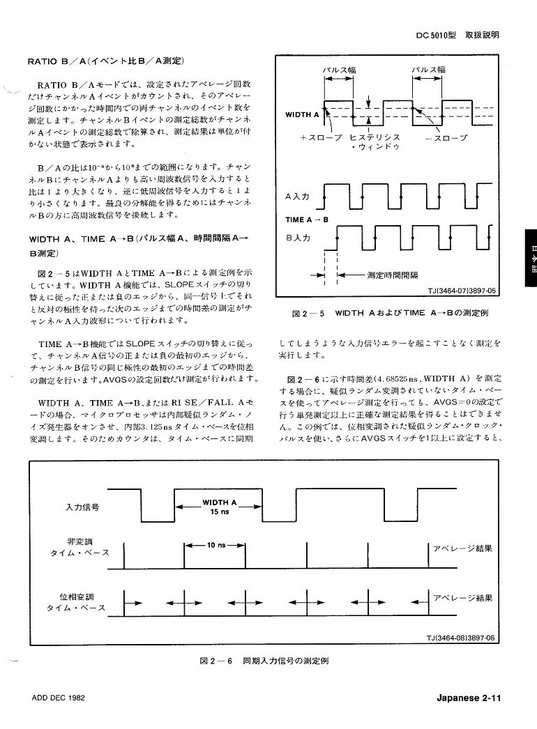
TlME A - B
ADD DEC 1982 Japanese 2-1 1
4 WIDTH A
15ns - A B E g i
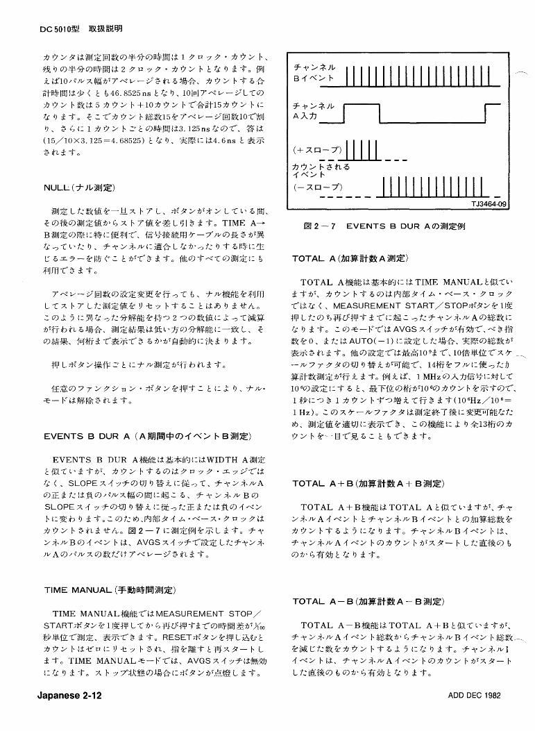
TIME MANUAL&$jEfl3. MEASUREMENT STOP/ START.S .92 @ 1 ESP L T 15' G % 0 3 ' F ' ; f - & - f ' ~ > ~ + p ~ ? ' s E f f i % o o $rl:l$-fZCilUJZ, &ZT"3 2 To R E S E T S . 9 2 @SF L&b t a r t 2 b t 2 - V ' ~ t : Y - i s b3&, f g @ % E T t S x 9 - b L 3 T o TIME MANUAL +-F.T'.tcft. AVGS X 4 ~?t2@>h
t:k 9 2 To x b ~7~4RkF@f%&t:S.92fi~,6+BL 2 T o
T O T A L A--BP&kgt2TOTAL A + B kIU.T1.&-d-fiP, 5 F 3 - > ; i . / v A 4 4 2 b $ & & f i > L ; F - y 2 ; i \ / V B 4 4 2 b$$%k-
@ j & C f : & @ & 9 ~ b T 5 L j t - t d : 9 3 T 0 F T ~ ; ~ * I ~ I .f-.> b id , F ~ > ; ? . / v A 4 4 2 b 9 7 ! 7 9 2 b f i P X 9 - b
~ m z w ~ e a , f i ~ ~ ; + j - m fd: 9 ;;t:.t-.
Japanese 2-12 ADD DEC 1982
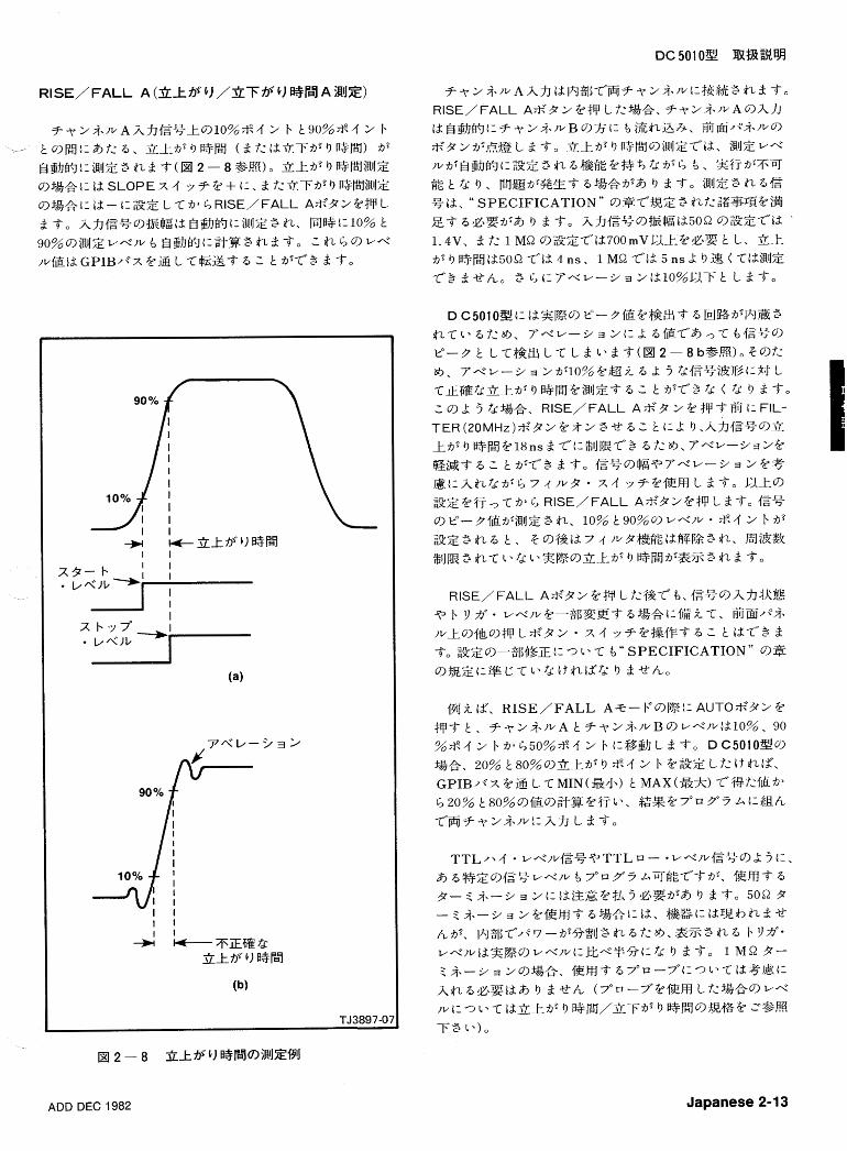
F ~ 2 5 j ~ / v A A f 7 f S ~ k 9 1 0 % * 4 2 b L90%%4 2 f. 1- t (1 & I: 6 , 3275' 9 R ~ H ! ( 6 7',' t d 3 7 ; f i ' 9 RPB'J) 75'
$ijhb9i:iRqZ3 & 6 T ( H 2-8S,!E)0 3 k - f i S 9 @p~fiRlJZ
9f&&i: td SLOPE ;t 4 y ? @ + 4:. 6 f : 3 T f i 1 9 D$Ps'l'i!#JZ 9 fgAl : I=I id - c: SZ L T f i l I; RISE/ FALL AS.92 @;fP L 6 To AhfS%9tElp8td$ghb?i:iHlIZ3 &, Ri%d:lO% t ~ O % ~ @ J Z I / ~ I V 9, Bij&b91:33$I3 & 6 To L $2- I; 9 ~4
ADD DEC 1982 Japanese 2-1 3
- ~ ~ 5 0 1 0 g 1 % 1 M Q ~ S ~ - - < ~ ~ - - ? Z I ~ ~ $ R I % ~ - , $Z@ 7 4 3 ~ 7 " ~ - k y f f f i f - k / ~ 7 7 - X b @%$TLf:$Z%.
370u -7+fi:@pT+3 1 \)L a . i ~ m g - c - ~ f i < en!%, ~ i ~ t - + i f ; s 7 4 3 ~ 7 ~ u - k ~ - f f$1*1 -~4 f t f i ' t d : i t I ~ Z ~ Z O O O t s % 3 &
Z3 $2f :7"~ -7'@I$FBT 6GZ75'& 9 3 To d To d f: 2 97 x F. -f't%, Flgl39~EB901"--37$3&? - i g 9 ~ g r ; A ' r f 2 3 7 ( 7 + z L ~ P - 5 7 ) % f i P F l . 9 3 3 & \ e $2(:f9~~-f".;i'57,~--7f u 3 2 2 ~ - ~ ? ~ f 7 @ $ ~ @ ~ 9 g m ~ ~ . IL 33 b ewc-t.ihw: 2 t tz L -c 1. 3 T,
D C 5 0 1 0 3 1 1 t % P R O B E C O M P e - F f i P & ! I , & ? m Z 3 -7°%{$m%.t.'1c- 7 " u -7"9+%iEfi?iE;f;Blc-$T ;i d To
[email protected] - f x b f 1 % R A M 9 F ~ ~ 3 t ; t : % T h $ 2 ~ * A o RAM tbS iR#2hF%t :92+Fr Y 3 3 $23 To
2 . +@t%%slfrll:3%fl9-.,< 9 t 3 q % @ F f i @ m L d T o $Z%fi:l aa L; 0 t:+J 9 B h -.,1:{3ET'lEJ$Z@k&3 d To ct
9{3E'ir"3if;siEfi13Z7 L 7: 2 t tc- 0 9 d To 1 9S3t%&-k +%iE@S,%L, 0 9 ~ 3 1 ; t : & ~ J ~ + i f ; s i E @ S , p ! L d T 0 S$%B9 1: 13. 1 fif 0 t:+n 9 Bh, tTB9{3ET"+%Xfi'%T L 3 To
ARMi$$?-9hf7 I : t% T T L P < . I v . ~ ' ~ ~ ~ ~ T ' . T , {gy-fi" $ % % 3 & T l b ? # l > % 6 , 7- < 2yAf713 . j&s1 \44kE1 : $ 1 3 4-tYL; $2, e 91: &3&EbSt1 7- < 27'3 $27 1 x 3 To 7-< 2Th f7 f i ' ~ -4kE1~$13~ iTL;$27 : fg&, 2192 S r t % i N I Z @ + l f i L d T o 7-< 23f1%TIME MANUAL, P R O B E COMP, 3 1: TESTLZ+9T--'-C 9@IZ&6E-C- i E m m 3 T~ ~ 2 2 3 9 9 ~ 2 m 7 + t 2 . 7- < ~ P Y Z ~ - W \ 4 f t d : i t $212'0 9 3 % A o
Japanese 2-14 ADD DEC 1982
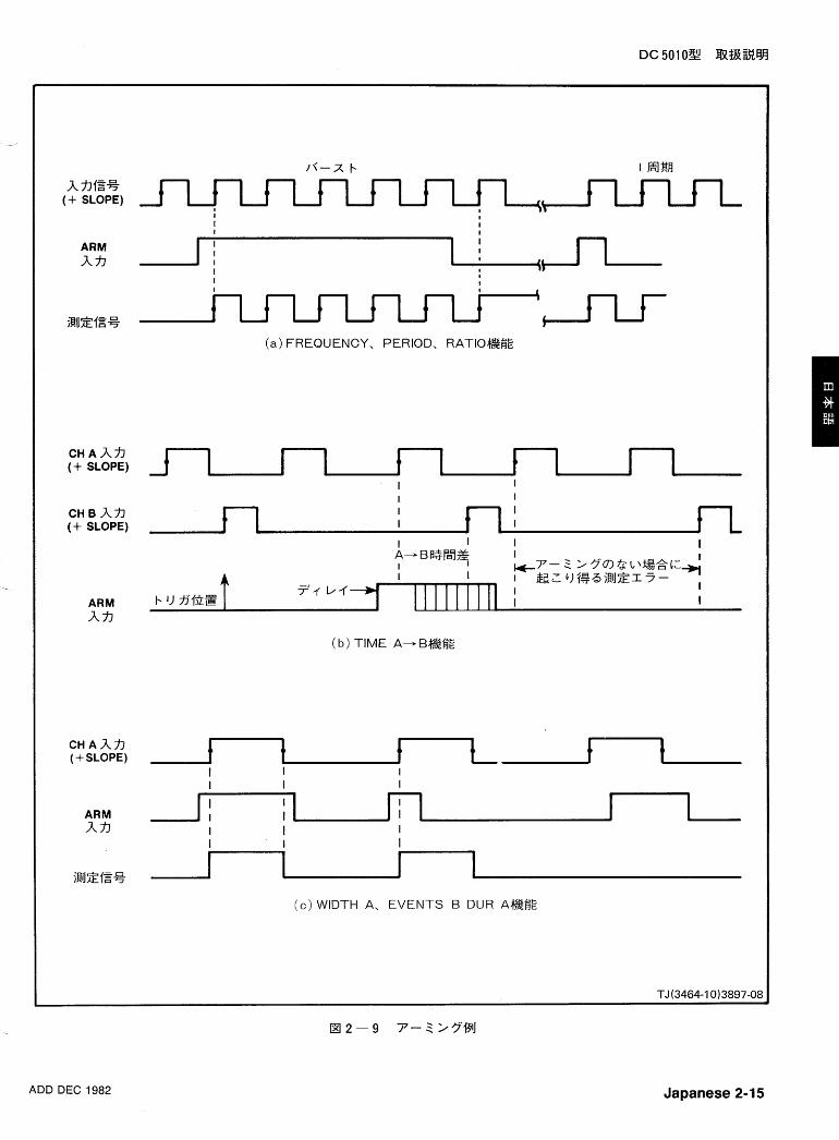
AhE% (+ SLOPE)
ARM A h
C H A A ~ (+ SLOPE)
C H B A ? ~ (+ SLOPE)
ARM Af7
ARM Af7
(a) FREQUENCY, PERIOD, RATIOe3E
( b ) TIME A-Be3E
( c ) WIDTH A, EVENTS B DUR AeWE
ADD DEC 1982 Japanese 2-1 5
lpublished by the Institute of Elec tr ica l and E l e c -
tronics Engineers,Inc.,345 E a s t 47 th S treet ,New
York, N.Y., 10017.
Japanese 2-16
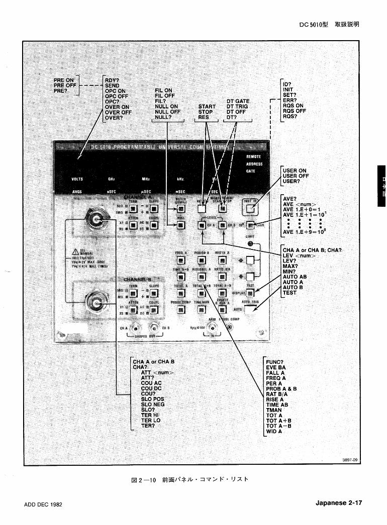
ADD DEC 1982 Japanese 2-17
Japanese 2-18 ADD DEC 1982
D T G A T E p < G E T > t - L 9 X 9 - b , X b ~ 7 " % ~ 2 b ~ - - / ~ L 3 3 , D T T R I G p < G E T > (1 L 9 RESET@$EP%$? L 2 3, D T OFF-7"7<4 X b Y 'Ifj'@@$2hi- L ;if: 3, D T ? P D T T R I G IS>DT O F F , 2 f: ",- D T G A T E fi '
%Fu71+?b+? 2 3 0
E R R ? - R Q S ON9@j&, ? 1 ) 7 / v 0 % - / ~ C I L ~
T 4 Z L ; i l . 6 1 3 - * ~ - ~ T ' . 6 ~ L & T o R Q S O F F 9 %%-e, s 9 , @ % ~ 1 ~ i 2 9 & 1 ~ ~ F-9 X T " G ~ L 3 To ID ?-p&%a)94 7 ° ? 7 7 - ~ r f z 7 * 7 9 - * - 2.322 Fu71\&ih+? 2 To
O P C ON-OPERATION C O M P L E T E S R Q % & L L T o O P C OFF-OPERATION C O M P L E T E 4XET"& 9 T 9 , S R Q @ L l i L 2 + ? h 0 O P C ?-OPC ON&' , O P C O F F f i ~ 4 ? F F J l ~ & b + ? 2 30 O V E R ON-75 rf 2 9 7 5 " & - 7 ~ 7 - L7P,-B$1- S R Q
@ X L 3 T O O V E R 0 F F - k r f 2 9 f i " - - - , T 7 ~ - Lf:D+T"&, T 9, S R Q t 2 X L a + ? k o O V E R ? -OVER ON f i l , O V E R O F F ?I>?? FL7 L.& h + ? 2 3 0 R Q S O N - S R Q % X T L t fi'T"3 2 3, RQS OFF-SRQW Y 7 ~ , ~ l i ~ r t f i ~ t a + ? k o R Q S ? ----RQS ON fi', R Q S O F F fi.%Fw7b'jl.&h+?2 3, U S E R ON-INST ID*'312@;fPLf:D+1: S R Q 2 X L 3 3 0
U S E R OFF-INST I D * ' 9 2 @ ; f P L f ~ D + - f ' & 9 T 9,
S R Q t d X L 2 +?Ao U S E R ?-USER O N & ' , U S E R O F F fi.2 Fu7 1- & b + ? 2 3 0
ADD DEC 1982 Japanese 2-19
ATTENUATION AUTOTRIG
AUTO; C H A; LEV ? ; C H B; LEV ?
Japanese 2-20 ADD DEC 1982
AVERAGES
ADD DEC 1982 Japanese 2-21
COUPLING
Japanese 2-22 ADD DEC 1982
ERROR
9 < 7 O
& ~ V - - P ; . + / / L /
> > 9 Y 9 X EVE BA (7 -+'z 9 2 b a L L"b ~ & ! & % O
i 9 J EVENTS BA EVE Z&
- f ~ 2 i j . / ~ A ~ ~ ~ ~ : ~ C ~ ) / P / ~ X @ ~ ~ ~ ~ ~ , E ~ I ~ . L 25. ? ~ 2
i 8 w B 4 4 2 b @?&??jBlJZ L ;ik To
ADD DEC 1982 Japanese 2-23
FALL TIME FILTER
Japanese 2-24 ADD DEC 1982
FREQUENCY
DC Solo%! B!a%s8
FUNCTION
ADD DEC 1982 Japanese 2-25
DC5010% maam
IDENTIFY
9 I' 7 O
%7 6 * 5>9Y37(
ID ? I D E N T I F Y ? 6s
ID TEK/DC5010, V79.1, F x . y; fg 5 -
I D E N T I F Y B ~ E ~ & * I ~ $ ~ - 6kl;129~$$1%\
INITIALIZE
F R E Q A A V E -1
F I L O F F N U L L O F F S L O P O S ( f - ~ 2 i j - l v A , B ) A T T l ( - f ~ 2 i j . / ~ A , B ) COU DC(f-- t . 2ij.1vA.B) T E R M H I ( ~ - T ~ $ . / ~ A , B ) CHA A O P C O F F
O V E R O F F
P R E O F F
D T O F F U S E R O F F -
R Q S ON
Japanese 2-26 ADD DEC 1982
DC5010W J$!#Jt%W
MAXIMUM
ADD DEC 1982 Japanese 2-27
MINIMUM
AUTOTRIG, P R O B C O M P , R I S E , 2 7: 12 FALL $$
1 FI9i@J#2 L 1- 1 9 4 311 .9%- I. b 1) f j ' f i y g ~ 9 2 T o %SfifF9Z?7-11d\Zafl3p~7i2, i&sl.5$$, sA-C'.122.5$$
c:tb 9 2d-0
NULL
Japanese 2-28 ADD DEC 1982
OVERFLOW
ADD DEC 1982 Japanese 2-29
PERIOD
9 .r 7 O
3 < l / - p 3 + / v
2 > 9 - y 9 X P E R A ( 7 - Y z 3 2 F ? d LT"bR@6E0)
@J P E R I O D A P E R
@ EA
-f -r 2 2 . w A hhlS+la>R$4i!1JZ@i:5-i-l~ 3 T o
PRESCALE
Japanese 2-30 ADD DEC 1982
RATIO
ADD DEC 1982 Japanese 2-31
RDY (DATA READY) RESET
Japanese 2-32 ADD DEC 1982
RISETIME RQS (REQUEST FOR SERVICE)
ADD DEC 1982 Japanese 2-33
SEND SETTING
9 -f To b7 e *
- i i 9 ~ 3 X S E T ? S E T T I N G S ?
EB < 7 7 2 3 ' ; / 3 > > ; CHA A ; A T T < % k > ; C O U x x ;
S L O xx ; T E R M xx ; L E V <&> ; CHA B ; A T T <%k> ; COU xx ; S L O xx ; T E R M x x ; L E V <%k> ; A V E <%k> ; O P C xx ; OVER xx ; P R E xx ; F I L xx ; N U L L xx ; D T x x ; U S E R x x ; R Q S x x ;
EB@l F R E Q A ; C H A A ; A T T 1 ; C O U D C ; S L O P O S ;
T E R M H I ; L E V 1 .500 ; CHA B ; A T T 5 ;
COU A C ; S L O N E G ; T E R M L O ; L E V -5.OOO; A V E - l ; O P C 0 F F ; O V E R 0 N ; P R E O F F ; F I L O F F ; N U L L O F F ; D T O F F ; U S E R O F F ; R Q S O N ; #Z&
S E T T I N G S F n i e * jT$ L , -?9~~,~!XT'.9$&%9 SZ @ 6 g L & T O
Japanese 2-34 ADD DEC 1982
SLOPE START
9 + 7 O
4-dl/-2 3+1v
> > 9 y 9 x S T A R T
ffjq iiiq T M A N U A L , 3 ?': i d T O T A L I Z E A/A+B/A-BI:WlIz
f i fX 9- F. L 2 T o E V E N T S , F A L L , F R E Q U E N C Y , P E R I O D , R A T I O , R I S E , T I M E , 3 'P,- t%WIDTH9&1:Wll Z f i " X F. 7"$&FC:bj at$$&, S T A R T I : L !I 1:IlJzfif@X
P-bL3-4-0
ADD DEC 1982 Japanese 2-35
STOP
FALL, F R E Q U E N C Y , P E R I O D , R A T I O , R I S E , TIME, WIDTH, 5%- .L U ; ' E V E N T S ~ & ~ W ~ ~ Z T ' . ~ % . S T O P 1: .L 9 l : ~ l J ~ 7 5 " $ g # J G - fb 9 3 $ 0
TERM INATION
Japanese 2-36 ADD DEC 1982
TEST
ADD DEC 1982 Japanese 2-37
TMANUAL (TIME MANUAL) TOTALIZE
Japanese 2-38 ADD DEC 1982
USEREQ (USER REQUEST) W I D T H
ADD DEC 1982 Japanese 2-39
IN IT TEST ; INIT ; RQS ON ; USER OFF ; ID ? ; SET ? TEST;
USER ? USERE ? USEREQ ? USEREQUEST ?
Japanese 2-40 ADD DEC 1982
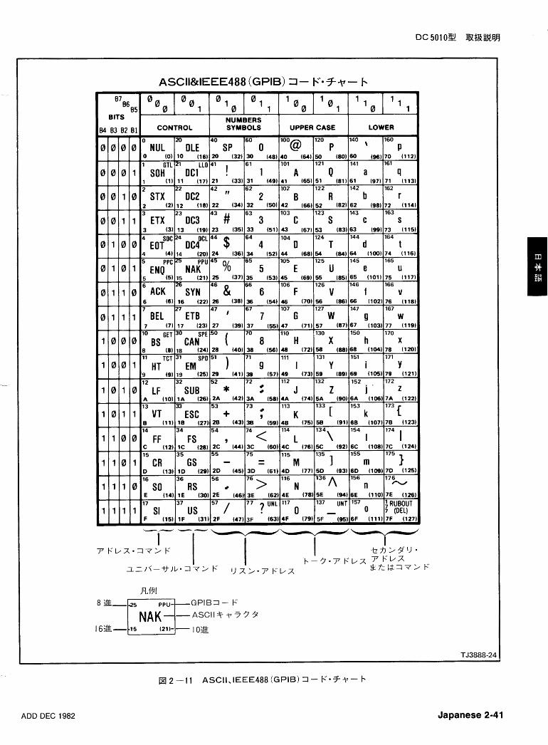
0°0 0
O 1 1 1 1 1
BITS ' I0 0 1 I0
NUMBERS - 0
NUL 0 (0)
1 GTL SOH
1 (1) 2
STX
DCl I !
'ER - 160
P 70 (112 161
9 71 (113 162
r 72 (114 163
S 73 (115 164
t 74 (116 $65
6 (6) 16 (22) 26 (38) 36 (54) 46 (70) 56 (861 66 (102) 76 (118 7 27 47 , 67 107 127 147 167
0 1 1 1 BEL ETB 7 G W Y w 7 (7) 17 (23) 27 (39) 37 (55) 47 (71) 57 (87) 67 (103) 77 (119
lo GET 70 110 130 150 170
1 0 0 0 BS ( 8 H X h o ~ ~ ~ S P E 5 0
X 8 (8) 18 (24) 28 (40) 38 (56) 48 (72) 58 (88) 68 (104) 78 (12C 11 TCT 31 71 111 131 151 171
1 0 0 1 HT 9 I Y i Y E M S P 0 5 1 )
9 (9) 19 (25) 29 (41) 39 (57) 49 (73) 59 (89) 69 (105) 79 (121 12 32 52 112 132 152 ,
72 172
1 0 1 0 LF SUB * J z i z A (10) 1A (26) 2A (42) 3A (58) 4A (74) 5A (90) 6A (106) 7A (12i 13 33 53 73
113 133 [
153
1 0 1 1 VT ESC + 9 K k C B (11) 18 (27) 2B (43) 38 (59) 48 (75) 58 (91) 6B (107) 78 (12:
-- .~ 14 34 5 4 114
9 7 4 < L 134\
154
1 1 0 0 FF Fs I 174 1 C (12) 1C (28) 2C (44) 3C (60) 4C (76) 5C (92) 6C (108) 7C (124 15 35 55 75 115
1 155
1 1 0 1 CR GS - - - M m 1 D (13) I D (29 )ZD (45 )3D (61 )4D (77150 (93160 (109)7D (12! 16 36 56
76 > 116 176
1 1 1 8 SO RS N A 156 n -
E (14) 1E (30) 2E (46) 3E (62) 4E (78) 5E (34) 6E (110) 7E (124 17 37 57 77 7 UNL 117 137 UNT 157 ' RUBOUT us 1 1 1 1 SI 0 - 0 ~ ( D E L ) F (15) I F (31) 2F (47) 3F (63) 4F (79) 5F (95) 6F (111) 7F (12'
ADD DEC 1982 Japanese 2-41
UNL-Unlis ten UNT-Untalk --
U N L = ? 3 Fi2, p&E9 '1 xt@#k%*';;; fi L, 7 7~ L 2 T o X ? $ ! $ f i ~ ~ $ ~ ~ ~ ~ ~ i ~ a 6 f i ,
;t"&Z1BGPIB1@~?2 ' f % * ~ L J I ! i Q 1 )I fi:T-3 2 @Ao
Japanese 2-42 ADD DEC 1982
LLO-Loca l Lockout p&%t%u y 3 7 9 bjREi- td: 9 3 " 6 ( L O C S f i ' G L W L S .
R E M S f i ' G R W L S ) o
ADD DEC 1982 Japanese 2-43
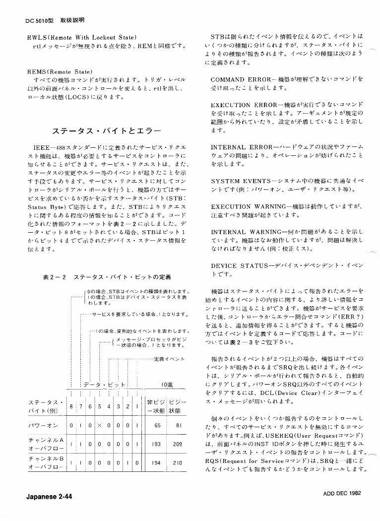
IEEE-488X 3'29"- F 1 ~ s S 3 $L7Pc--tf-v~ 11 3 1
X b@j+gtcft. @ ~ f i ' ; g - f ; T t T 6 ~ - - ~ ~ @ = 2 b u - 5 3 : % [ l t , - e 6 L Lfi'T-3 & T o -tJ--Y'X Y 3 Z X b i d , 2 7 2 , X ~ - P X ~ ' & E T ' Z Y - $ $ ~ ~ ~ ~ b f i ' S $ ? < L t @?j?
T T - f & T + b h 9 & T o -tf-Y'X 9 3 Z X b t I 3 f L T ~ 2 /, a - j fir? 7/r/ % - ~ r / @ f ~ j - 5 t , #j&g9xT'l$.tf- Y X ??$t+T l > 6 f i 2 3 f i 1 @ 5 T x 7-37 ~ * 7 < 4 b ( S T B S t a t u s B y t e ) T ' . G g L 2 T 0 2 1:. S T B I - L 9 Y 3 x X b 6 6 6;FZl%91]S$E@%[~6 L t fifT"3 2 To 3- F
I L 3 $ 2 1 : @ $ E 9 7 ; s - - ~ r ~ b @ S 2 - 2 1:?j?L& Lf:, 7 -37. y . ~ b 8 f i ' - k ~ b 3 $ L T l . 6 % $ @ , S T B I A F Y b 1
fi. t, b 4 2 TVT'-?j?3 $27:7'7<'4 X X 7-37 X J ~ ~ $ E @ {Zk 3 To
#J479442 b @ 1 3 < 7 h 1 $ E f $ T 6 9 ? k 3 2 b U - J V L $ 2 9 , % ~ T C I ) - ~ ~ - E ' X * ! l P x ~ b @ e $ h i ~ T 6 = ? 2
Ffi'h 9 3 Tof9tJ k ig', U S E R E Q ( U s e r R e q u e s t 3 7 2 b") Id, j $ j j j 3 7 P 4 - . ) ~ 9 INST IDS.9 2 @;fp L ?:El*~z @ g T 6 =I- --tf"* '1 P Z X b * 4 e . 2 bCT)$$ i$5@29 b u - W L 2T0 -- R Q S ( R e q u e s t f o r S e r v i c e z ~ 2 F ) id. S R Q t--i%:%l~ F k Q 4 d 2 F T " b $ E $ 5 T 6 f i > F j f i 1 @ 3 2 b u - . ) v L & T 0
Japanese 2-44 ADD DEC 1982
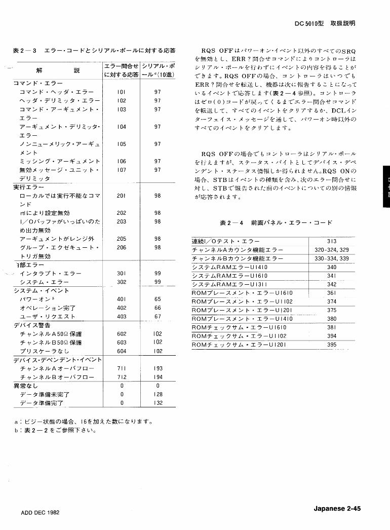
Japanese 2-45
R O M f r ,y 3 V L 1 5 ' - U 1610
R O M F r %y 3 V L 1 7 - U 1102
R O M f r ,y 3 Y L 117-U1201
ADD DEC 1982
38 1
394
395
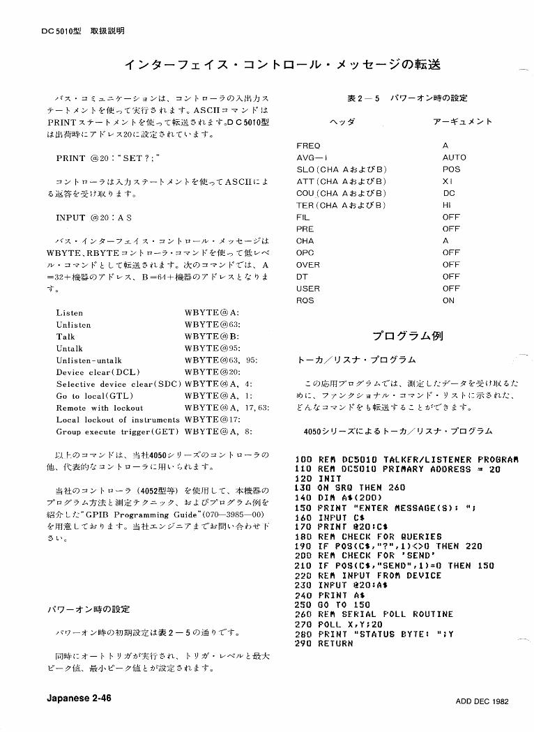
P R I N T @ 20 : " S E T ? ; "
I N P U T @ 2 0 : A $
L i s t e n W B Y T E @ A :
Unl i s ten W B Y T E @ 6 3 : T a l k W B Y T E @ B : Untalk W B Y T E @ 9 5 : Unlis ten-untalk W B Y T E @63, 95: Device c l e a r ( D C L ) WBYTE@20: S e l e c t i v e device c l e a r ( S D C ) W B Y T E @ A, 4:
Go to l o c a l ( G T L ) W B Y T E @ A , 1: Remote with lockout W B Y T E @ A, 17,63: L o c a l lockout of ins t ruments W B Y T E @IT:
Group execu te t r igger ( G E T ) W B Y T E @ A, 8:
?!$$I9 3 2 b a - 3 (40522%) @l!EfB, L T, *?&%9 7"~3"3 At.;f7j% t BIJZ? 3 3 .;1 3. h.L t;7"a 3"3 A~$IJ@
fg* L f< ,-" G P I B Programming Guide" (070-3985-00) 4?msLTh9 3-4-0 ?!$; tkz29 '=72T*hrD7t>eb*T 3 t > o
FREQ
AVG- I
SLO (CHA A A A U ' B )
A T T (CHA A f i A U ' B )
COU,(CHA AAAU'B)
TER (CHA A A k U ' B )
F I L
PRE
CHA
OPC
OVER
D T
USER
RQS
A
AUTO
POS
X I
DC
HI
OFF
OFF
A
OFF
OFF
OFF
OFF
ON
Japanese 2-46 ADD DEC 1982
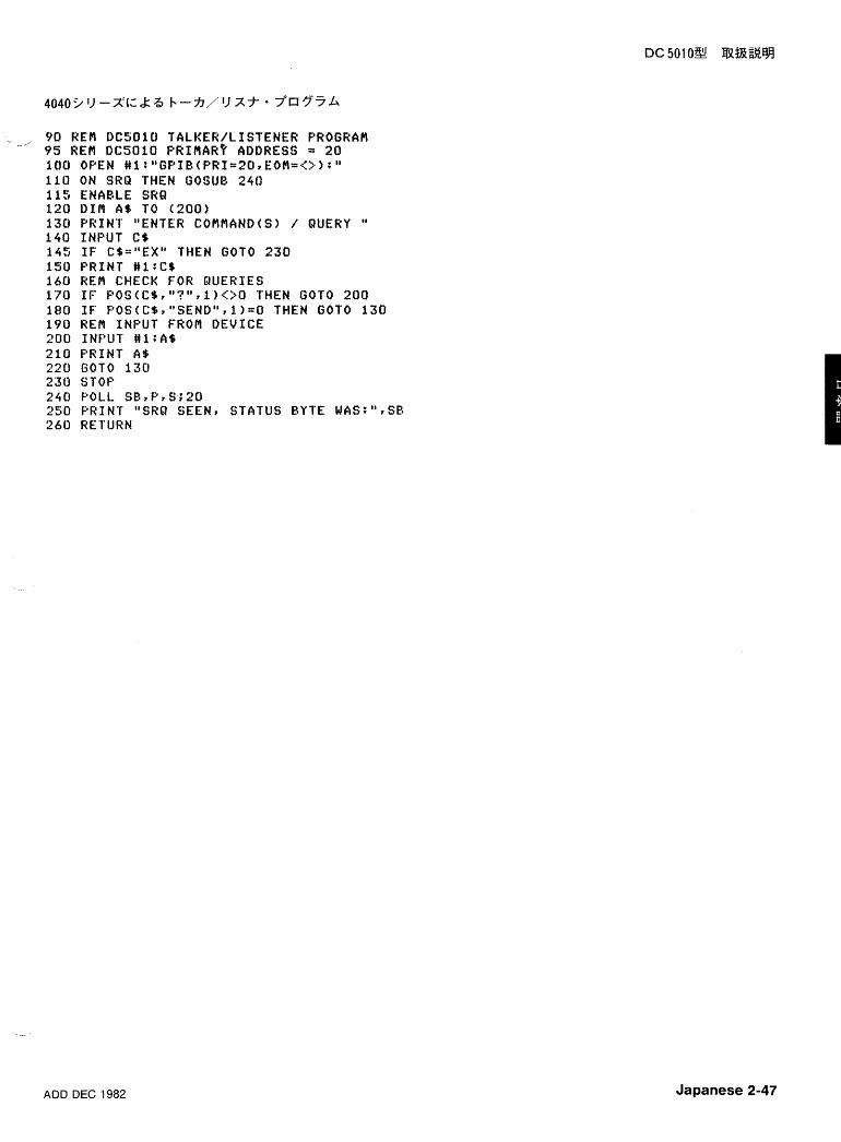
9 0 HEM DCSOID TALKER/LISTENEW PROGRAPI --"
95 REfl DCSOlO PRIMR? A D D R E S S = 2 0 1 0 0 OPEN #l:"GPIB(PKI=20~EOM=<>~):" 1 1 0 ON SRU THEN GOSUB 2 4 0 1 1 5 ENABLE SRQ 1 2 0 D I M A * TO ( 2 0 0 ) 1 3 0 PR INT "ENTER COflf iAND(S) / QUERY " 1 4 0 INPUT C$ 145 I F C$="EXU THEN GOT0 2 3 0 1 9 0 P R I N T # l : C $ 1 6 0 REfl CHECK FOR QUERIES 170 I F P O S ( C S r " ? " r l ) . < > O THEN GOT0 2 0 0 1 8 0 I F P O S ( C $ ? " S E N D " r l ) ~ O THEN GOT0 1 3 0 19U REfl INPUT FROM DEVICE 200 I N f W T # l :A$ 2 1 0 P R I N T A9 220 GOT0 1 3 0 ZJU STOP 2 4 0 POLL SB,PrS;20 250 PRINT "SRR SEEN? STATUS BYTE WAS:"rSB 26U RETURN
ADD DEC 1982 Japanese 2-47
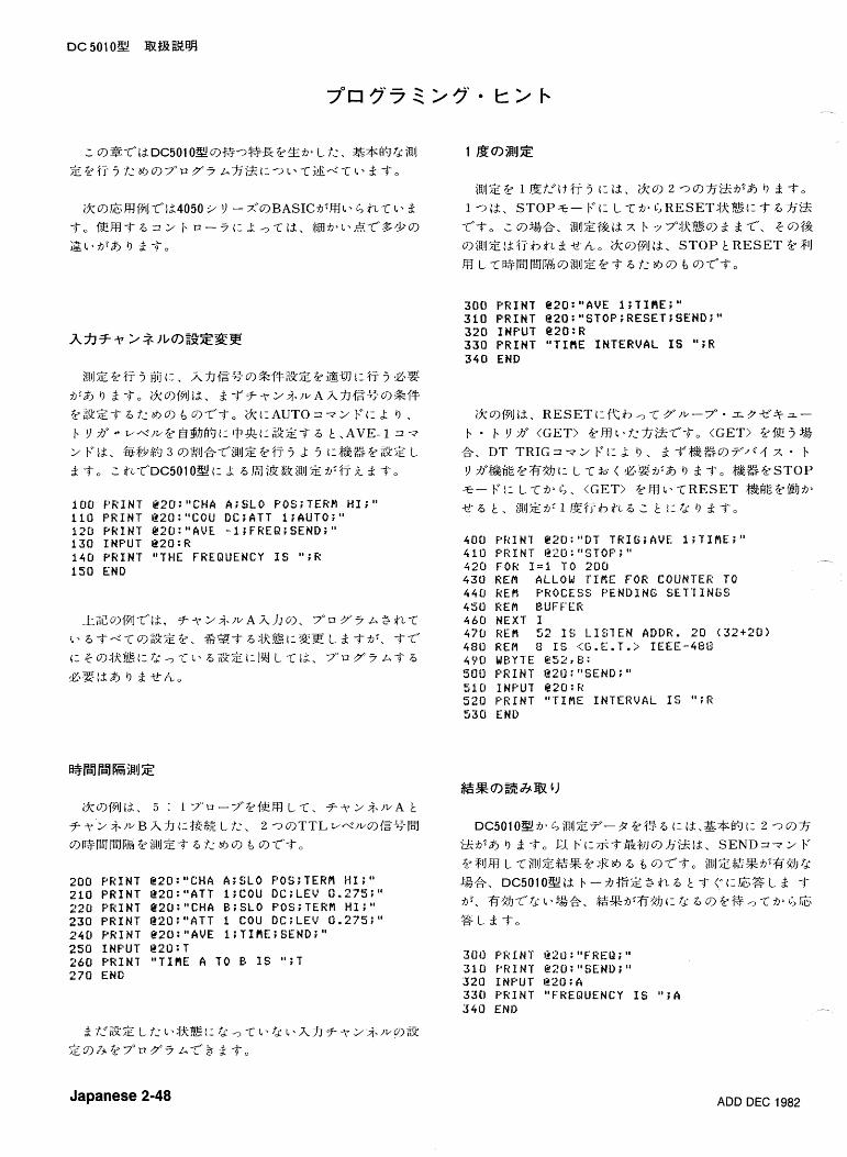
i a ~ J Z @ % j - j 51:. hfJ{=ri9&f+5fi" a 3 DXZ ??i@iY t: $7 j GZ! 75:& I) d -if-. ik9l?I]t2. d T F - r 2 i . / v A h h l Z % 9 % f T &GSZ-if-a7:at,a) e 9~--if-, i k t : A u ~ O = + F t 3 I), b Y 3' W<./L.@ $@B';It: +*t:-SZ-if- a Ir . A V E - 1 3 -;z
2 F t2, &%$$$? 3 9~ lJ&T+iRiJZ 2fT- j A 5 1:&%2 222 L
d -if-, 2 &T'DC5010%t: A ZiH8Z&iRIZ&'%7;i d -if-.
100 PKINT Q20:"CHA A;SLO Y0S;TERPl HI;" 110 PRINT @20:"COU DC;ATT 1;AUTO;" 120 PRINT g20:"AVE -1;FREQ;SEND;" 130 INPUT e20:R i40 PRINT "THE FREQUENCY IS ";R 150 END
300 PRINT e20:"AVE 1;TlRE;" 310 PRINT @20:"STOF;RESET;SEND;" 320 INPUT e20:R 330 PRINT "TIRE INTERVAL IS ";R 340 END
400 PRINT E20:"DT TR1G;AVE 1;TIPlE;" 410 PRINT l22fJ:"STOP;" 420 f O K I = L TO 200 430 REPI ALLOW TIME FOR COUNTER TO 4 4 0 kEtl PROCESS PENDING SETTINGS 450 REM I3UFFER 460 NEXT 1 4 7 0 REtl 52 IS LISTEN ADDK. 20 (32+20) 480 REM 3 IS (G.E.T.;:. IEEE-488 490 UEYTE @52r8: 50U PRINT @2U:"SEND;" 510 INPUT Q20:K 520 PRINT "TIME INTERVAL If ";I? 53Ci END
200 PRINT @20:"CHA A;SLO P0S;TEKPI HI;" 210 PRINT g20:"ATT 1;COU DC;LEV 0.275;" 220 PRINT @ZO:"CHA B;SLO POS;TER# HI;" 230 PRINT @20:"ATT 1 COU DC;LEV 0.275;" 240 PKINT e20:"AVE 1;TIPlE;SEND;" 250 INPUT g20:T 260 PRINT "TIRE A TO E?- IS ll;T 270 END
Japanese 2-48 ADD DEC 1982
Y J p c 3 - ' J H - v m ~ n T ? n s O T ~ a ? ~ x m 11 o ~ ~ o x ~ x ~ ~ ~ z ~ 11 m m m 4 r n r b w P w u ~ 0 3 3 3 c 4 x m r X C Z D - + ~ Z
0 -4 I 1 0.0
U = * - urn V) one-
m ~ n y G ? ~ H ~ r n ~ r H ~ o ~ x - r ! ~ ~ a . ~ = 4 ' 9 G y y m 11 X 0 7 7 ~ Q X 7 3 X T D Z T l ' l X 1: 2 3 X X ~ r w H r a ~ u I+ 4 3 u c n w u ~
qogJ-. u s-7- c Z ~ Z L ? I - Z Z W - - - I C ~ - I z z z r c u s 4 I 3 LI X -!04II 4 4 1 1 XFI -I 4 4 4 ~ ~ Z 0. 0 0 1 3 0 I-! 1 9 @ \I,," I
= a = q - :1w 6 = = = x q , u ? @ d \ I , uecii ~ t - ~ i i w e t . ~ E T O O z c m o - O O I I ~ ~ C z c o 8 ~ s g K w o a . 3 - 4 m m a d rnc5zs- r -i 0 ., = Z 2 : = Z X y l 3 7 9 Ps = d %
O L ~ m u r c u 0 11 ~ z r w TU? o u z m r 7 m U a b * - C $ u 0.0 ~ ~ U C C ; G o m O X G U G 1 8 ' 4 "
CGI - 4 0 =r Z L ? I > Z 3 4 d$ !J y 8 TJ 72 -I -. n + - i ~ c m - c n : : -4 03 0
- 0 m-7 3 2 , 4 Y 7 u L O Z - u
I * m z *. W T U 3 u O - 7 - Z i ' i r T Z U '4 z m 0 ' < : . I ( a P r p
o c m a 2 y 2 1 J \I m n : g 5 cn s ! \ I \ d 9 *. 0 4 - ' y d $ ; ; * = X i 0 -,i 1
z E q j l g 3 - Y = = v *. 1 4 % , - 7 - - 4 . F F u
(3) 070-2058-01-Programming In B A S I C
(4 ) 070-2059-01-Graphic Programming In B A S I C
( 5 ) 062-5971-01-4050 S e r i e s Programming.Aids , T 1
( ~ 7 79rf77S'ki.) 062-5972- 01-4050 S e r i e s Programming ~ i d s , T 2
( ~ 7 b9=.7k&b)
(6) 070-2380-01-4907 F i l e Manager Opera to r s manual
(7) 070-2128-00-4924 U s e r s manual
(8) 070-1940-01-4050 S e r i e s Graphic Sys tem Opera -
t o r s manual
(9) 070-2056-01-4050 S e r i e s Graphic Sys tem Refe r -
ence manual
(10) 070-39 l8-00-404l Opera to r s manual
(11) 061-2546-00-4041 Programming Reference manual
ADD DEC 1982 Japanese 2-51


Section 3 D C 501 0
THEORY OF OPERATION
Introduction
Refer to the Block Diagram illustration located in the foldout pages at the rear of this manual during the following discussion.
Signal Conditioning and Amplifiers
The functional blocks for the Signal Conditioning and Amplifiers (Channel A and Channel B) are essentially identi- cal. Each channel amplifier circuit contains seven magnetic latching relays, which control the input conditioning and routing of the front-panel input signals. Six relays control the ac or dc coupling modes, the 1 or 5 attenuation factors, and the termination impedance. The seventh relay provides for a Channel A and Channel B commoning function. The data for these relays are sent from the microprocessor via
-_ data shifted through serial-to-parallel shift registers, in these functional blocks.
The Channel A and Channel B amplifiers use matched DMOS FET followers that buffer the input signal and trigger
' level. The buffered signal and trigger level are combined and amplified in a differential cascode integrated circuit (IC). This IC also provides for switching the output into a low pass filter or straight through at full bandwidth.
Schmitt Triggers
The amplified signal and trigger level are applied to the inputs of the Schmitt trigger IC. The differential Schmitt out- put is applied to transistors that select the triggered slope. This circuit also provides the Shaped Out signals.
D/A9s, Relay Protect, and Arming
The 50 Q protect circuitry consists of two "windown com- parators (Channel A and Channel B). These comparators receive the protect sense levels from the Channel A or Channel B inputs (relays) and operate within a + 2 volts win- dow sense level. If these voltage levels vary up or down from this window, the comparators will send a protection signal (50 Q protect) to the microprocessor. The micro- processor automatically changes the input impedance to 1 Mil and protects the 50 Q circuitry.
The arming input is applied from the front panel or rear interface. This circuit consists of a 1 TTL input load with appropriate input protection and a Schmitt trigger circuit for noise immunity. The output provides the arming signal (ARM).
Main Gating
After the Schmitt trigger, the signals to be measured are routed through the proper logic gates for the operating mode selected. These gates are enabled (or disabled) via latched data in a serial-to-parallel shift register located in this functional block.
The counter has what is sometimes called a "ratio archi- tecture". That is, events are always accumulated in one count chain, called Accumulator A, and a time related or Channel B event count is accumulated in another counter chain, called Accumulator B. The microprocessor actually controls the measurement interval, which is typically asyn- chronous with the input signals. Thus, two flip flop synchro- nizers are used to guarantee that the accumulators always see a whole number of pulses of input signals (Q1112) or a whole number of pulses (U11 IOC) from the internal time base that is being counted. %
This functional block contains triggering level control and 10-bit digital-to-analog converters (DIA converters) for The arming input (ARM), from D/A's, RELAY PROTECT Channel A and Channel B. The operational amplifiers driven AND ARMING functional block, is applied to this block from the D/A converter output, set both the offset and range where it is logically ANDed with the measurement GATE for the individual channels. generated by the microprocessor.
REV OCT 1981
Theory of Operation-DC 50 1 0
Time Base, 320 MHz PLL, and Noise Generator Pusbuttons and LED9s/Display
This block contains the 10 MHz crystal controlled time base, a 320 MHz PLL (phase-locked loop) and a pseudo- random noise generator that is activated for time interval averaging measurements.
The 320 MHz PLL circuit contains a frequency and phase comparator, a filter circuit, a Varactor diode for 320 MHz tuning, and a feedback loop consisting of a fast divide-by-4 section followed by a divide-by-80 section.
The key element in this functional block is a ten-state - decade counter that provides the time slot decoding for - scanning the front panel pushbuttons and other controls. The counter also provides the multiplexing functions for the seven-segment LED display and annunciators. Information is presented to the display by latching six bits of data from the microprocessor parallel data bus. Four bits of the latched data are then decoded from binary coded decimal to seven-segment information. The remaining two bits are used to drive the annunciators and decimal points.
CH A and CH B Count Chains The display consists of nine seven-segment LEDs,
The Channel A signal is divided or counted by four ECL binary stages, five LS TTL binary stages, and then by four binary stages in a single CMOS counter. The CH A SLOW output from the CMOS counter is then applied to a micro- processor peripheral device on schematic 9, where the sig- nal is counted by another 16 binary stages internal to that device.
The CH B Accumulator is similar to the CH A Accumula- tor with four ECL binary stages, five LS TTL binary stages, followed by 15 binary stages in two CMOS counters. The CH B SLOW signal is also applied to the microprocessor peripheral device on schematic 9. Each accumulator circuit has ECL to TTL or ECL to CMOS translator circuits where required.
The outputs of these counters are applied to the parallel inputs of five parallel-to-serial shift registers (two for CH A and three for CH B). To obtain the binary count accumulated in these counters, the microprocessor asserts the Serial Read Latch Line at least once for every measurement interval.
Processor and Display Drivers
The microprocessor located on the GPlB board controls the measurement gate interval, generates the relay strobe signal, and by using address decoding circuits enables the shift registers, display strobe circuits, and the data buffer for the front panel button sensing. This functional block has a microprocessor peripheral device containing a 128 x 8 stat- ic RAM, a 2048 x 8 ROM, a programmable counter, an 8- bit serial data channel, bidirectional data lines, and interrupt inputs. Additional program memory space is provided by a 4096 x 8 ROM and a 256 x 8 RAM.
annunicators, and the LEDs of the lighted pushbuttons. The time slot lines generated by a ten-state decade counter drives the common cathodes of the seven-segment LEDs and scans the buttons and annunciators. The anodes of the seven-segment LEDs are connected to a buffer circuit through current limiting resistors.
Power Supplies
The instrument draws power from both of its power mod- ule connectors to derive its four primary supplies: +5V and +12 V on the Auxiliary board and another +5 V and a - 12 V supply on the Digital board. Each supply is current limited and individually fused, and all four are referenced to a single precision 2.5 V reference IC. Several secondary sup- ,, plies include +2.7 V for the ECL terminator, a + 18 V three- terminal regulator chip (in option 01 timebase only), a -5 V supply derived from the - 12 V, a 2.5 V supply to drive the reference IC, and several isolated versions of +5 V, sepa- rated by L-C filters.
GPlB Interface
The GPlB consists mainly of a microprocessor, two ROM's, one RAM, and a GPlB controller chip. An address switch is also available, which sets the listen and talk ad- dresses for the DC 501 0. In the DC 5010, the GPlB board connects to the digital board and is used to communicate with the IEEE-488 Digital Interface.
The microprocessor uses a serial data loop, an 8-bit par- allel data bus, and a 16-bit address bus to communicate with the instrument functions. The microprocessor fetches instructions from memory via the parallel data path, de- codes the desired operation, and executes the instruction. The activities of the microprocessor occur in cycles generat- ed by its own 1 MHz system clock.
REV OCT 1981
Theory of Operation-DC SO 10
DETAILED CIRCUIT DESCRIPTION
SIGNAL CONDITIONING AND
AMPLIFIERS-DIAGRAM @
NOTE
Since the Channel B Signal Conditioning and Amplifier circuitry is essentially identical to the Channel A cir- cuitry, this description discusses the theory of opration for the Channel A circuits only.
The Channel A input signal is routed to two magnetic latching relays. Relays K1612S (Channel A) and K1632S (Channel B) provide a normal mode operation (separate channels) or common mode operation (both channels). In the common mode operation (Common Separate), Channel B input becomes an open circuit. The common mode oper- ation is used when making risetime and falltime measure- ments. In this mode, with the input impedance set to 50 Q, the leadless chip component, R1611, in conjunction with the 50 Q (TERM) in each channel, becomes an internal power splitter. Relays K1611 S and K1510S provide for 50 52 or 1 MQ (TERM) input impedance selection. Resistor R1511 provides the 50 Q termination. When in 50 Q input imped- ance, relay K1610S selects either ac or dc coupling
- (COUPL). In the dc coupling position, resistor R1612 dis- charges the ac coupling capacitor, C1610. Component R1512 is the isolate resistor for the 50 Q Protect A sense line, which will be discussed later. Relay K1511 selects ei- ther the XI or X5 attenuation (ATTEN), when in 50 Q (TERM).
In the 1 MQ termination, selected by K1611S, relay K1600 selects either ac or dc coupling (COUPL). In the dc coupling position, resistor R1601 discharges the ac coupling capacitor, C1601. If X5 attenuation is selected, the signal enters the hybrid attenuator, AT1505. The component C1504 is a compensation capacitor and R1504 is the 1 MQ termination resistor. When attenuated, resistors R1506 and R1507 provide damping for optimum ac performance.
Input signal protection is provided by diode network, CRl512, CRl510, C R l 5 l l l CRl513, and resistor Rl5lO and capacitor C1518.
A matched pair of DMOS field effect transistors (FET), Q1410, provide buffering for both the input signal (at pin 8) and the triggering level signal (at pin 4). These matched FET devices cause a matched level shift from 0 volts to approxi- mately -4.5 volts. Diodes CRl411, VRl412 and CRl410, VR1413 will limit large (overdriving) signals and protect inte-
grated circuit (IC) U1311. In common mode operation, differ- ential transformer, TI410 converts a single-ended signal into a differential signal at high frequencies. This helps to provide for better high frequency performance and helps to reject noise. The FET source followers each have a current source. Transistor Q1402 is the current source for the trig- gering level source follower output. Transistor Q1403 is the current source for the input signal source follower output.
The IC U1311 is a cascode differential amplifier with switched signal output capability. Signals can be either passed straight through at full bandwidth or through a two- pole low pass filter that passes frequencies from dc to ap- proximately 20 MHz. These signals are switched by control voltages generated from the logic signal at pins 12 and 11 of U13l l . Being complimentary, through Q1211 (sig- nal inverter) and (2121 0 (buffer) they appear in the Channel B circuitry as well. Therefore, the filters may or may not be selected by these inputs.
Resistor R1417 sets the gain for U1311 (pins 2 and 3). This leadless chip component is soldered directly to the IC pins for optimum ac performance. Transistors Q1400 and Q1401 are current sources for the cascode differential input. Low frequency peaking is provided by components R1406, R1405, and C1403.
SCHMITT TRIGGERS-DIAGRAM @ The buffered and amplified differential signal is applied to
pins 2 and 3 of U1310 (Schmitt Trigger circuit). These sig- nals are looped through this IC and appear at pins 12 and 1 1, with the load resistors R1313 and R1216. Transistor Q1303 is a current source for the Schmitt Trigger latch de- vices. The Schmitt Trigger differential output (pins 6 and 8 of U1310) is level shifted by transistors Q1204, Q1302, Q1300, and Q1301. Positive slopes are selected by Q1204 and Q1302 and negative slopes are selected by Q1300 and Q1301. These common base stage level shifters are driven by the + SLOPE A and - SLOPE A signals through tran- sistors Q1202, Q1201, and associated circuitry. The shaped output signal from Q1204 or Q1300 enters Q1203 base, inverts and outputs to J1201 (CH A SHAPED OUT). The output signal (CH A ECL) from (21302 or Q1301 routes to the ECL logic circuitry (Diagram 3). An operational amplifier, U1202B (Diagram 2) sets the mean dc level of the ECL sig- nal to the correct value. A threshold level generated by an ECL signal (Diagram 3) is sensed at pin 5, U1202B and compared to the mean level sensed at pin 6, U1202B. The output (pin 7, U1202B) supplies the current necessary to adjust the level shifted output to the correct mean ECL threshold level.
REV DEC 1982
Theory of Operation-DC 501 0
MAIN GATING-DIAGRAM @ The microprocessor controls the measurement gate in-
terval through the GATE signal going to pin 4 of U111 OB. The IC's U1000C and U1000B operate as synchronizers to ensure that the accumulator gates, U1001 C and U111OA open and close at the proper time for the desired measure- ment. Synchronizing the accumulator gates with the signals to be counted ensures that the accumulators will contain a count corresponding only to a whole number of input and time-base pulses. In the absence of the synchronizers, the gates would sometimes pass fractional pulses, and the count chains might not be able to make a reliable count. The signals to be counted clock the synchronizers at pin 16, U1000C and pin 1, U1000B.
Before each measurement is initiated by the micro- processor, U 1 000C and U 1 000B are set by a M R, (Master Reset) pulse on connector J1010 pin 1. The IC's UlOOlC and U111 OA are thus disabled by the high level synchronizer outputs at pins 14 (U1000C) and 1 1 (U1000B) until the mea- surement begins.
For those modes that use the Channel A Amplifier with positive slope triggering, negative going edges are generat- ed on pin 6 of U1001 B. Pin 7 of shift register U1200 is latched high for all operating modes except the time interval modes (TIME A+B, WIDTH A, RISEIFALL Time, and EVENTS B DUR A). With pin 7 of U1200 high, U1210D pin 12 is low, so Q1114 is enabled. The Channel A signal is then inverted by U1001C and clocks U1000A on pin 5. The Channel A complement signal appearing on pin 6 of U1001 B, is inverted by U1001 E and clocks the synchronizer flip flop U100C pin 16 after passing through U1001 D.
NOTE
Transistors Q1110, Q1114, Q1111, Q1112 and QlOOO operate as switches to route the Channel A, Channel B, and 320 MHz time base signals through the proper logic gates for the selected front panel function. These transistors are either completely "on" or completely "off", depending on whether their base resistors are pulled high or low. Transistor Q 1 100 is used to disable U 1001A. See Table 3- 1.
FREQ A and PERIOD A
If the GATE signal from the microprocessor (U1200 pin 4) and the arming signal (m) on J1102-1 are both low, a low is set on the D input (pin 15) of U1000C after passing through U111OB. This low is transferred to pin 14 on the first Channel A edge that clocks U1000C after the measure- ment gate started. The low on pin 14 enables the second synchronizer, U1 OOOB, and the Channel A accumulator
gate, U1001 C. With U1001C enabled, the next negative edge of the Channel A signal is allowed to pass through - UlOOlC, gets inverted, and is counted by the first binary stage of the Channel A accumulator (U1 OOOA, pin 5).
For the FREQ A and PERIOD A functions, pin 14 of shift register U1200 is latched low. This turns on U111OC and turns off Q1112, allowing the 320 MHz time base signal to clock U1000B on pin 1. The first positive time base edge to clock U1000B after U1000C changed state, sets a low on pin 11 of UlOOOB, enabling the Channel B accumulator gate, U111 OA. The next negative edge of the 320 MHz time base signal then passes through U111OA in its inverted form and is counted by the first binary stage of the Channel B accumulator (U1011 C).
Table 3-1 SIGNAL ROUTING SWITCHING LOGIC FOR U1200
(X = low, blank = high) PIN NUMBERS
Function
FREQ A PERIOD A WIDTH A TlME MAN TlME A + B RISEIFALL A RATIO B/A TOTALA, A+B, A-B PROBE COMP EVENTS B DUR A
After the synchronizers and accumulator gates have been enabled, all succeeding input pulses are counted by the Channel A accumulator and all succeeding time base pulses are counted by the Channel B accumulator.
The counting process continues until the selected num- ber of averages have been satisfied or the time out period, while in the auto mode, has been satisfied. At this point, the gate signal from the microprocessor goes high, setting the D input (pin 15) of U1000C high. The next positive edge of the Channel A input signal then clocks U1000C and pin 14 goes high, disabling U1000B and U1001C. The next 320 MHz time base edge then clocks U1 0008, disabling U111 OC and sending END low alerting the microprocessor that the mea- surement cycle has ended.
When the measurement cycle has ended, the micro- - processor reads the total counts in both accumulators. The Channel A accumulator contains the number of events or
REV JUL 1983
Theory of Operation-DC 50 10
periods and the Channel B accumulator contains the num- ber of time base clock pulses counted over the same inter- val. The microprocessor divides the number of events in the
. Channel A accumulator by the total time in the Channel B accumulator to obtain the frequency (FREQ A) or divides the total time in the Channel B accumulator by the number of events in the Channel A accumulator to obtain the period, or time per Channel A event (PERIOD A).
RATIO B/A
The RATIO B/A mode is the same as FREQ A and PERI- OD A, except that instead of counting 320 MHz time base pulses, U111 OC is disabled by a high on pin 14 of shift regis- ter U1200, and Q1112 is enabled by a low from inverter U1210E. This allows the Channel B signal to clock U1000B. The counts are accumulated over the time interval deter- mined by the number of averages selected. The RATIO B/A result is then calculated by dividing the number of Channel B events by the number of Channel A events. The AVGS ex- ponent refers to the count in Channel A.
TlME A -, B
For the TlME A -+ B function, Q1110 and Q1112 are disabled; Q1111, Q1114, Q1000, U1001 E, U111 OC, and U1001 D are enabled. The first Channel A pulse slope that is selected, is inverted by UlOOlB, inverted again by U10001 E, and then applied to pin 19 of U1001 D. The syn- chronizers have been set by the MR, (Master Reset) pulse and the Channel A pulse clocks on pin 16 of U1000C.
As soon as the gate signal from the microprocessor sets pin 4 of U111OB low, the next Channel A clock edge to U1000C transfers the low on pin 15 to pin 14 and sets pin 13 high.The high on pin 13 passes through Q1000, disables U1001 E, and prevents U1001 D from being clocked by suc- ceeding Channel A pulses. The Q output of UlOOOC (pin 14), being low, enables U1001A and allows the first suc- ceeding Channel B pulse edge to clock UlOOOC via U1001 D, setting pin 14 high and pin 13 low again. Pin 13, going low with the Channel B edge, also re-enables U1001 E again for the next Channel A edge to clock U1000C.
During the period of time that pin 14 of U1000C is low, U1000B is enabled. The 320 MHz time base clock pulses are synchronized and gated by UIOOOB and U11 IOA, and then counted by the binary stages in the Channel B accumu- lator, beginning with U1011 C.
Since Q1114 is disabled, U1001 C is enabled with a low on pin 17 and also enabled each TlME A + B interval ap- pears as a negative pulse on pin 18. This negative time interval pulse is converted to a positive time interval pulse by U1001 C and then counted by the binary stages in Chan-
- nel A accumulator. Thus, for each TlME A + B interval, a
count is accumulated in the Channel A accumulator; and during each of these intervals, the 320 MHz clock pulses are accumulated in the Channel B accumulator.
The microprocessor is continually reading the counts (ac- cumulated time intervals) in the Channel A accumulator. When it finally reads a count greater than or equal to the selected number of averages (loN) or when the measure- ment time in the auto mode ( ~ 0 . 3 seconds) has been satis- fied, the microprocessor sets the gate signal on pin 4 of U111 OB to a high level. The next Channel A pulse clocks a high through U1000C to pin 18 of U1001 C and disables U1000B. The next 320 MHz clock pulse then toggles U1 0008, disabling U111 OA and allows the END signal line (J1102-1) to go low. This alerts the microprocessor that the measurement cycle has been completed. The micro- processor then makes a final reading of both accumulators, divides the total time by the number of intervals, and up- dates the display during the next measurement cycle.
WIDTH A
The WIDTH A function is essentially the same as the TlME A + B except that Q1110 is enabled. This then al- lows the leading edge of the Channel A pulse width to be measured, and applied to pin 23 of U1001 E and the training edge to be applied to pin 2 of UlOOlA, through the 3.5 ns delay line (DL 500).
The synchronizers (U1000C and U1000B) and the accu- mulator gates (U1001 C and U111 OA) function exactly like they did in TlME A + B. The pulse widths are regenerated on pin 14 of U1000C and during each of the negative pulse intervals, U1000B and U1001C are enabled so that the 320 MHz clock pulses (via Q111 OC) can be counted by the Channel B accumulator. Also, each regenerated pulse is passed through U1001 C and counted by the Channel A ac- cumulator. Again, when the average conditions have been satisfied, the microprocessor stops the measurement gate, reads both the accumulators, and divides the total time by the number of regenerated time intervals to obtain the aver- age pulse width.
EVENTSBDURA
The EVENTS B DUR A function is the same as WIDTH A except that instead of counting 320 MHz clock pulses via U11 IOC, the instrument is counting Channel B events dur- ing the selected Channel A pulse width via Q1112. To do this, Q1110, Q1112, and Q1000 are enabled. The leading and trailing edges of the Channel A pulse are again applied to pin 23 of U1000E and pin 2 of U1001 A.
The Channel 8 signal passes through Q1112 to clock the second synchronizer, U1000B. When the gate signal on pin 15 of U1000C goes low, the synchronizers and accumulator
REV JUL 1983
Theory of Operation-DC 501 0
gates function exactly as they did in WIDTH A (and de- scribed for TlME A + B). With U1001 C enabled on pin 18, the Channel A pulse widths are counted in the Channel A accumulator while the Channel B events are counted in the Channel B accumulator. In EVENTS B DUR A the instru- ment is counting Channel B events only during Channel A pulse widths and averaging by the selected number of Channel A events.
When the selected or auto averages condition has been satisfied, the microprocessor sends the gate signal on pin 15 of U1000C high. The next Channel A trailing edge dis- ables U1000B (pin 2 high) and the succeeding Channel B edge sets a low on pin 12 of U1000B. This completes the measurement cycle.
TlME MANUAL and TOTALize A
For the TlME MAN and TOTAL A functions, the micro- processor asserts the gate signal on pin 15 of U100C after the MEASUREMENT STARTISTOP pushbutton on the front panel is pressed to start the measurement. The gate is unasserted (set high) when the pushbutton is pressed to stop the measurement.
For the TlME MAN function, (21114, Q1100, and U111OC are enabled. Immediately after asserting the gate signal, the microprocessor momentarily changes the Chan- nel A triggering slope from its current setting to the opposite setting and then back again. This change provides an artifi- cial Channel A signal that enables U1000C and allows the 320 MHz clock signal count to be accumulated in the Chan- nel B accumulator. The accumulation continues until the measurement is stopped, at which time the microprocesor unasserts the gate signal and provides another trigger slope change to disable U1000C. This stops the accumulation of time base clock count. Throughout the measurement, the B Channel is continually red and then directly displayed with the proper annunciator illuminated.
While taking this reading, the display will occasionally flicker during the measurement. This is not the result of mis- counting by the Channel A or Channel B accumulators; the correct count will be displayed when the measurement is finished.
For the TOTAL A function, (21114, Q1100, and Q1112 are enabled. When the gate signal is asserted, Channel A events are counted (totalized) in the Channel A accumulator until the measurement is stopped. In this case, the micro- processor does not read the Channel B accumulator; only the Channel A accumulator counts are displayed. Display scaling is accomplished by the microprocessor using the AVGS setting to select the desired scaling factor (power-of- ten). This scaling is independent of the actual counting pro-
cess and can be changed during or after a measurement without affecting the count. Thus, the full 13 digits of the -
internal count chain can be examined by changing the AVGS exponent. Time, frequency units, and decimal point are not displayed for this function.
PROBE COMP and TEST
For the PROBE COMP function, the operator applies probe compensating signals to either Channel A or Channel B. For either of these modes, the counter is set up (internal- ly) in RATIO B/A mode. This allows the Channel A or Chan- nel B signals to pass straight through to the accumulators.
For the TEST function, the microprocessor generates ar- tificial signals by programming the digital-to-analog convert- ers (Diagram 6) through their full range. The outputs of the digital-to-analog converters are applied as trigger level changes to the differential amplifier circuits in the Channel A and Channel B Amplifiers (Diagram 2) and end up as counts in the two count chains. If an illegally large signal is present on an input (a signal beyond the range of the digital-to-ana- log converters), this process does not produce counts, and the TEST may fail. When a failure is indicated, all inputs should be disconnected and the TEST rerun.
A complete description of the self test function is in the Maintenance section. Front panel procedures for the -- PROBE COMP function are found in the Operating Instructions.
CHANNEL A AND
The Channel A and Channel B accumulators are two nearly symmetrical binary ripple counters, each having the capabilities for its contents being "read" serially by the microprocessor. Each accumulator begins with high speed ECL. Then, as the maximum toggle rates decrease, goes to medium speed ECL, then to LS TTL, and eventually CMOS. Wherever possible, a counter IC of a given family is shared: one half is used by Channel A and one half by Channel B.
The Channel A accumulator begins on the Analog board (A1 2) with signals clocking U1 OOOA, pin 5 (see Diagram 3). The Channel B accumulator signal clocks UlOllC, pin 1. The first two binary stages for each accumulator are ECL 100k and consist of U1000A and U l 01 1 A (Channel A) and U1011 C and U1011 B (Channel B).
The counts (CH A FAST and CH B FAST) are routed from the Analog board to the Digital board (A16) through -- coaxial cables (W520 and W530). The next two binary stages for each count chair) are ECL 10k and use IC's
REV OCT 1981
Theory of Operation-DC 501 0
U1810A and U1801 A (Channel A) and U1810B and U1801 B (Channel B). Transistors Ql7O2, Ql7O1, Ql7O4, and (21703, with associated circuitry, operate as fast ECL to LS
_ TTL converters. These converters provide drive for the fol- lowing LS TTL stages and must operate reliably up to 25 MHz. The counts in these (and the preceeding) ECL stages must also be converted to CMOS levels for eventual readout by the microprocessor. However, since this conver- sion occurs long after the count chains have stopped count- ing and are stabilized, these translators need not be fast. The comparators U1710A, B, C, D and U1102A, B, and C have one input set at a voltage half-way between an ECL high and low. This voltage is set by resistors R1712 and R1710. With pull up resistors R1420 (fixed resistor net- work), R1207, R1208 and R1209 tied to +5 volts, the ECL transition from high to low (on the other input) results in a full CMOS swing on the comparators output. This results in a highly reliable translator that draws little power.
The next bit of each chain is a single LS TTL flip flop, U1120A, Channel A (U1120B, Channel B). Following this IC is an LS TTL 4-bit counter, U1113A, Channel A (U1113B, Channel B) followed by a lower power CMOS 4-bit counter, U1115A, Channel A (U1115B, Channel B). These stages, too, must be read by the microprocessor. The LS TTL out- puts are pulled high by the fixed resistor network, R1014, to ensure valid CMOS levels to the serial readout circuitry. At this point, the two accumulator chains lose their symmetry (not for functional reasons but for more economical use of the components). The Channel A accumulator uses the 16- bit counter contained in U1410 (see Diagram 9). The Chan- nel B accumulator (Diagram 4) uses 11 of the 12 bits available in the CMOS counter, U1212. The circuitry, de- scribed, provides a total of 29 hardwired bits for the Chan- nel A accumulator and 24 hardwired bits for the Channel B accumulator. Since each accumulator requires 43 bits, the firmware counters supply 14 bits (Channel A) and 19 bits (Channel B) respectively.
Five CMOS parallel-to-serial shift registers consisting of U1121, U1114, U1122, U1211, and U1312 are used by the microprocessor to read out the contents of the Channel A and B accumulators. When the ILATCH control line (pin 9 of each register) is brought high, data are applied into the reg- isters asychronously with the clock. When pin 9 is brought low again, data can be shifted into (pin 11 of each register) and out of (pin 3 of each register) the registers synchronous- ly with the positive transition of the SERIAL CLOCK signal (pin 10 of each register).
Before each measurement is initiated by the micro- processor, the MR (Master Reset) signal is asserted via pin 33 of U1410 (see Diagram 9). This reset signal is inverted by U1520D (Diagram 4) applying to pin 1 of U1120A. The - MR signal is also inverted and buffered again by U1314D, U1314F, and U1520E to provide an ECL, LS TTL, and
- CMOS compatible reset signal (MR, signal also guarantees
the two synchronizer flip flops (located on Diagram 3), U1000C and U1 OOOB, will begin set.
TlME BASE AND 32 MHz PLL-DIAGRAM 6
The 10 MHz standard time base consists of a 10 MHz crystal, Y1520, and a Colpitts oscillator circuit, Q1420, and associated components. The frequency of the standard time base is adjusted by variable capacitor, C1521 (accessed through the instrument's back plate).
The Option 01 high stability time base consists of a self contained, oven controlled 10 MHz oscillator, Y1530. This time base is adjusted via a hole in the rear of the case (accessed through the instrument back plate). The 18 volts input to the time base is derived from the fused +26 volts in the power module and regulated by a three-terminal regula- tor circuit, U1430, and associated components.
NOTE
The single-starred schematic diagram 5 components for the standard time base circuit are removed if the Option 01 time base circuit is installed.
The 10 MHz output signal from either the internal time bases or an external source (1, 5, 10 MHz) is applied to the base of Q1500. The buffered signal at the collector of Q1500 can be either 1 MHz, 5 MHz or 10 MHz. This signal is buffered again by U1500F. If the input signal frequency is 1 MHz, jumper plug PI 51 0 (located on the Auxiliary board) connects pins 4 and 5 of J1510. A 5 MHz external input signal requires that IC U1411 divide-by-five (s5), therefore, P I 51 0 connects J1510 pins 2 and 3 or pins 3 and 4. A 10 MHz time base signal requires U1411 to divide-by-ten (+ 10). Component PI51 0 then connects J151 Q then con- nects J1510 pins 1 and 2. The signal to the base of Q1401, in all cases, must be 1 MHz.
Emitter follower Q1401 and associated components op- erate as a single-pole filter generating a sawtooth type sig- nal at the negative input pin of comparator U1400. For the TlME A + B, WIDTH A, and EVENTS B DUR A functions, the base of Q1300 is set low via pin 7 of shift register U1200 (as shown on Diagram 3). In these functions, the Noise Gen- erator (Diagram 5), U1410, is enabled by applying +5 volts to the V,, input, pin 4. The output from U1410 (pin 3) will be - 12 volts to +5 volts signal with a pseudo-random edge distribution. This signal is then attenuated by resistor, R1410 and applied to pin 2 (+) of U1400. Also, with these functions, U1400 operates as a phase modulator circuit. The output (pin 7) of U1400 is a 1 MHz signal that is phase
REV JUL 1983
Theory of Operation-DC 501 0
modulated by the noise signal generated by U1410. For the other remaining functions, transistor Q1300 is turned off, U1410 is disabled, and U1400 operates only as a buffer stage.
The 1 MHz squarewave signal from U1400 (pin 7) is ap- plied to pin 1, U1021 with the negative edge (falling edge) used as a reference edge for the Phase Locked Loop (PLL) U1021. This IC compares the signals negative edge (pin 1) with the positive edge (pin 3) and produces an output pro- portional to the phase difference between these two input signals. The output at pins 5 and 10 (U1021) is then filtered by a low pass filter with its bandpass providing the proper phase noise bandwidth for time interval measurements. This filter, U1030A with associated components, is amplified and inverted by operational amplifier U1030B. The amplifier out- put is a dc level proportional to the phase difference be- tween the 1 MHz reference and the output of the PLL multiplier. The dc level voltage is coupled to a Colpitts oscil- lator circuit, Q1130 and associated components, and is in- ductor-tuned by the varactor diode, CR1130, and series capacitor C1032. The PLL adjusts the varactor diode volt- age, which adjusts the oscillator frequency producing a pre- cise 320 MHz output signal. The oscillator output is ac coupled to U1022A and a threshold reference voltage is generated by sensing the complementary outputs of U1022C through resistors R1021 and R1036. The voltage, at the junction of these two resistors, establishes this threshold reference at pin 3 of U1022A. The oscillator out- put rate on pin 3, produces a 320 MHz reference sinewave from pin 8. This sinewave is the clock that is counted for the different measurement modes of the counter. The 320 MHz signal is applied to pin 1 of U1022B (a setlreset latch that resets itself at 320 MHz, and buffers and provides proper ECL drive). This signal is then divided down to 160 MHz at pin 12, Q1022B. Another divide-by-two (-2) IC, U1022C, results in an 80 MHz output. This output is ac coupled to U1020, pin 7 and divided-by-eighty, (+80) producing the 1 MHz signal at pin 2. Any error in output at pin 2 of U1020 is sensed by U1021. This sensed voltage, applied to varac- tor diode CR1130, adjusts the Colpitts oscillator producing the precise 1 MHz signal at pin 3 of U1021.
D/A9s, 50 Q PROTECT, ND ARMING DIAGRAM $
The isolation resistors for the 50 Q Protect A (B) sense lines were discussed earlier (Diagram 1). The sense lines are routed from the Analog board to the Auxiliary board via jacks J1510 and J1520.
The 50 Q Protect circuit is composed of a quad compara- tor (U1111) with associated components. Two of these comparators are arranged as "window" comparators (Chan- nel A and B), that receive the protect sense levels from the Channel A or B inputs. These voltage sense levels normally
operate within a +2 V window. If the sense levels go out- side this window (high or low), the comparator output
- -
changes states (to a low state) and issues a 50 Q A (B) PROTECT signal to the microprocessor. The microproc- essor recognizes this protect line and automatically changes the input relays from the 50 Q TERM to the 1 MQ TERM.
Trigger levels (CH A LEVEL and CH B LEVEL) are estab- lished, using a 10-bit D/A converter, U1210 and U1310 (Channel A and B). The data (SERIAL DATA lines) are re- ceived from the microprocessor through serial-to-parallel converters U1010 and U1020 (Channel A and B - see Dia- gram 7). These parallel output lines (Diagram 6) form the digital word that is applied to the D/A converter. The digital word corresponds to a unique current that is sinked at pin 3 of the D/A converters (U1210, Channel A; U1310, Channel B). This current, appearing at pin 2 of the operational ampli- fier circuits, U1200A (Channel A) and U1200B (Channel B), is converted to a voltage. This voltage can be offset by po- tentiometer R1205, (R1207, Channel B) and the voltage range adjusted by potentiometer R1204 (R1206, Channel B). The output of U1200A (U1200B) at pin 1 is the trigger voltage that is routed to the amplifier circuitry on the Analog board (see Diagram 1).
The arming circuit input load (Diagram 6) is 1 standard TTL load. The input is positive overvoltage protected by di- ode CR1510 (reverse biases upon receiving an excessive ,-
positive overvoltage). Diode CR1511 is the negative over- voltage protection component (clamps the output to a diode below ground) and is current limited by resistor R1500.
Transistors Q1510 and Q1511 form a Schmitt trigger providing noise immunity to the arming inputs (ARM In and EXT ARM IN). The ARM output signal is routed to the digital circuitry (Diagram 3).
RELAY DRIVE-DIAGRAM @ The serial-to-parallel converters, U1010 (Channel A) and
U1020 (Channel B), are used to change the serial data from the microprocessor to the parallel daa. This data will select the particular relay to be activiated. The converter output data are applied to U1110 (U1020, Channel B) that consists of seven Darlington NPN transistors (shown as inverters). These devices are used as current sinks to drive the relay coils. With one end of the selected relay coil brought low via one of the inverters (U111 O), a voltage pulse is applied to the opposite coil end. This voltage pulse is generated by the microprocessor (see Diagram 9) and then amplified and reg- ulated by the pulse amplifier circuit consisting of transistors Q1031, Q1030, (21032 and associated circuitry (Diagram 7). The pulse is approximately 8 V in amplitude with a 25 ms -.
width; therefore, when a relay coil is energized, the inverter output is brought low and the microprocessor pulses the
REV JUL 1983
Theory of Operation-DC 50 1 0
pulse amplifier to direct the current flow to the selected relay coil. This causes the relay to change state and latch.
The Darlington transistors, Q1121 and Q1120 (with as- sociated circuitry), are used to drive the relay coils, K1612 (K1632, Channel B), that provide for the Common Separate channel input function (see Diagram 1).
POWER SUPPLIES-DIAGRAM @ The four main supplies derive power input (through the
instrument's two rear interface connectors) from the TM 5000-Series power module. These primary supplies are the +12 V and +5 V, located on the Auxiliary board, and the other +5 V and a - 12.2 V, located on the Digital board. They are individually fused and current limited. The four sup- plies are referenced to the +2.5 V (Master Reference) preci- sion voltage reference supply on the Auxiliary board.
The secondary supplies include the +2.7 V (ECL Termi- nation), +5.7 V (derived from the + 12 V supply), -5 V (three-terminal regulator derived from the - 12.2 V supply), and the + 18 V (three-terminal regulator derived from the +26 V from the power module) that is used in the Option 01 timebase only (see Diagram 5).
-- The + 12 V supply (located on the Auxiliary board - Dia- gram 8) is derived from the unregulated +26 V dc power in the power module. The + 12 V regulator circuit consists of U1420 and associated components. Load current for this supply passes through resistor R1425 (current limit sensing component) and the PNP series-pass transistor located in the power module. The + 12 V supply is regulated within design limits by varying the voltage on the base of the se- ries-pass transistor via P I 600 pin 11 A. The Zener diodes, VR1410 and VR1411, reduce the voltages to appropriate levels for U1420. Should the load current exceed 0.4 A, the voltage drop across R1425 becomes great enough to cur- rent limit U1420. This voltage is sensed at U1420 (pins 2 and 3) and reduces the base-to-collector voltage of the se- ries-pass transistor. Feedback signals for voltage regulation of the +12 V supply appear on pin 4 (U1420) and are com- pared with the +2.5 V reference voltage on pin 5. Capacitor C1310 provides for frequency compensation.
Emitter follower Q1330 uses pin 6 (V,,) of U1420 to pro- vide an input voltage for the precision voltage reference, U1223. The +2.5 output voltage is used for all major sup- plies and is a master reference source for the DIA's.
The +5 V supply (located on the Auxiliary board) is de- rived from the unregulated +8 V dc power in the power
- - module. The +5 V regulator circuit consists of U1320 and
associated components. Load current for this supply passes through current limit sensing resistor R1426 and the NPN series-pass transistor (located in the power module). This supply is also regulated by varying the voltage on the series-pass transistor base (PI600 pin 6A). If the load cur- rent is exceeded, the voltage drop across R1426 will cause U1320 to limit this current. This voltage (sensed at pins 2 and 3 of U1320) causes the series-pass transistor to even- tually turn off. The feedback signal for the voltage regulator occurs on pin 4 (U1320) and is compared to the reference voltage on pin 5. Capacitor C1320 provides for frequency compensation.
The other +5 V supply (located on the Digital board) is identical in operation to the +5 V supply just discussed. It consists of the regulator, U1720 and associated compo- nents, and an NPN series-pass transistor (located in the power module). An additional filter network consisting of C1022 and L1020 provides the display power and isolates its noise from the rest of the instrument.
The -5 V supply (located on the Auxiliary board) con- sists of a three-terminal regulator, U1330, that provides reg- ulated -5 V from the - 12.2 V input.
The +2.7 V supply (located on the Auxiliary board) is the ECL termination supply and is used as a terminating supply for all the pull-down resistors located in the ECL circuits on the Analog board (see Diagrams 3 and 5). The +2.7 V sup- ply is derived from the +5 V supply and consists of an error amplifier, (2133, an amplifier stage, Q1331, an emitter-fol- lower output stage, Q1332, and associated components.
The - 12.2 V supply (located on the Digital board) is de- rived from the unregulated -26 V dc power in the power module. This supply consists of error amplifier Q1723 and Q1722, error signal amplifier Q1721, current limit sense am- plifier Q1720, and associated components. The reference voltage on the base of (21723 is approximately 0 V. Diode CR1620 provides temperature compensation for the error amplifier circuit. This supply is regulated within design limits by varying the voltage on the base of the PNP series-pass transistor, located in the power module, via the collector of Q1721. An excessive load current through current limit re- sistor R1718 causes (21720 to increase conduction and the bases of Q1723 and Q172l to go more negative. The PNP series-pass transistor base goes more positive, thereby re- ducing the load current below the design limit.
PROCESSOR AND DlSP AY DRIVERS-DIAGRAM 9 6
Introduction
The DC 5010 is a digital counter based on a micro- computer system. The microprocessor, U1301 (located on
REV OCT 1981
Theory of Operation-DC 501 0
the GPlB board - Diagram 12), controls the internal oper- ations of the DC 501 0. The microprocessor recognizes, ac- cepts, and decodes commands (keypushes and control setting) from the front panel logic circuits (Diagram 10) and sets the operating parameters in response to these commands.
lntegrated circuit U1410 contains a random access mem- ory (RAM) space that provides a maximum of 128 locations (addresses) which the microprocessor uses to temporarily store 8-bit data bytes. The data are not permanent and will be lost whenever the instrument power is turned off. When power is first applied, the RAM data occur as random bits and are therefore meaningless. During instrument operation, the microprocessor writes data into the RAM at various ad- dresses for later recall and use.
The instructions for the microprocessor concerning GPlB operation are stored in the EPROMS U1102 and U1201 (lo- cated on the GPlB board). These IC's each contain 4 k bytes memory. The instructions (firmware) concerning man- ual operation of the DC 501 0 are stored in EPROM U1610 (also a 4 k byte memory) and in the ROM section of U1410 (a 2 k byte memory). The other RAM is located in U1311 (located on Digital board) and U1210 (located on the GPlB board).
System Clock
The microprocessor, U1301, contains a single phase in- ternal clock generator at pins 37 and 39, whose 1 ps period (approximately) is controlled by inverter U1312D and the rc feedback network consisting of R1301 and C1302. The ac- tivity of U1301, when it is reading data from or writing data to a memory device, occurs in machine (U1301) cycles. Since no critical system timing relies on the microprocessor clock, a crystal is not needed.
Power Up Reset Cycle
When the instrument is powered up, comparator U1102D (and associated components) operates as a delay1 comparator circuit to provide a pulse to reset the micro- processor to its reset vector address location.
Pin 14 of U1102D is held low for approximately 1.5 sec- onds (to allow all supplies to come up to 0peratin.g status in the TM 5000-Series power modules). During this time all of the internal registers of U1410 (except the 16-bit counter and serial shift register) are cleared to logic zero. This action places all of the bidirectional inputloutput lines of U1410 in the input state and disables the internal shift register, Dis- play lnterrupt Clock input (pin 37), and the interrupt output (pin 4). Also, during the low level period of the micro- processor reset signal, the writing of data to or from U1301 is inhibited, and a bright digit may be displayed on the DC 501 0's front panel.
When the positive edge is detected on pin 1 of U1301, the internal mask interrupt flag will be set and the micro- .
processor will load its internal program counter from the reset vector address listed in Table 3-2. This is the start location for program control.
lnterrupt Vector (m) lntegrated circuit U1410 has two internal registers for
interrupt control, an interrupt enable register and interrupt flag register. Corresponding bits in these registers are logi- cally ANDed to set an interrupt request pending flag. When U1410 detects the pending flag bit, it asserts pin 4 as a low output, generating an interrupt request to the micro- processor.
When a low level is set on pin 4 of U1410, the micro- processor completes the current instruction before recog- nizing the interrupt request and examining its own interrupt mask flag bit. If the interrupt mask flag bit is not set, the microprocessor starts an interrupt routine. The contents of its program counter and status register are temporarily stored in RAM, the interrupt mask flag bit will be set to prevent further interrupts, and the program counter will then be loaded with the high and low bytes of the interrupt vector address listed in Table 3-2. This is the start location for the interrupt routine for U1410.
Table 3-2 DC 501 0 INTERRUPT VECTORS
Vector ~ddress' Type of Interrupt
$FFFE - $FFFF Interrupt Request (U1410)
' Dollar sign ($) indicates that address code is in hexidecimal notation.
There are three possible reasons why U1410 sets an in- terrupt pending flag, two external events and one internal event. The two external events are: a negative edge detect- ed on pin 36 (CH B SLOW) or a negative edge detected on pin 37 (Display lnterrupt Clock); the one internal event oc- curs when the 16-bit counter inside U1410 overflows.
Address Decoding
The microprocessor addresses Ul610, Ul410, and U1313 when communicating with the instrument functions. --. Table 3-3 lists the hexadecimal address ranges for these devices.
REV OCT 1981
Theory of Operation-DC 50 1 0
Table 3-3 DC 501 0 MEMORY ADDRESS RANGES
Hexadecimal Address Range
$0000 - $007F $0080 - $0087
$0400 - $04FF $0700 - $070F $0800 - $OFFF $1 000 - $1 FFF $COO0 - $COFF $E000 - $EFFF $FOOO - $FFFF
Comments
U1311 (128 X 8 RAM) U 131 3 (Front panel display, Serial data latches, and GPIB address switches) U1311 (256 X 8 RAM) U1410 110' U1410(2 k X 8 ROM) U1610 (4 k X 8 ROM) U1210 (256 X 8 RAM) U1102 (4 k X 8 ROM) U1201 (4 k X 8 ROM)
See Table 3-4.
Memory select decoders U 1 31 3, U 1 420 and related com- ponents, operate to select the proper memory device during program control.
The inputloutput sections internal to U1410 are acces- sed by the microprocessor using address bits A0 through A3 for specific control of the internal functions. See Table 3-4.
NOTE
Due to the complexity of the internal functions associ- ated with U 14 10, a detailed description of this device will not be attempted in this manual. If more detailed information is needed, refer to the manufacturer's data sheets.
Address Bits
Serial Data Path. The serial data path is shown on the block diagram (see Figs. 8-6 and 8-7). Serial data are writ- ten, via pins 38 and 40 of U1410, to five serial-to-parallel shift registers located on the Auxiliary circuit board (A18 assembly), and one serial-to-parallel shift register on the Analog board (A1 2) assembly. This is done when the micro- processor sets the instruments internal circuits for the de- sired function. These registers are, in sequence:
A18- U1010 7 A18-U1020 7 A18-U1222 6 A18-U1220 6 A18-U1221 6 A12-U1200 3
The serial data output from A1 2 - U1200 then goes, via P I 102-6 (Diagram 3), to five parallel-to-serial shift registers (Channel A and Channel B accumulators) located on the Digital circuit board (A16 assembly). Serial data are shifted through these registers and returned to the microprocessor via the data buffer, U1310B. Serial data are read from the following parallel-to-serial shift registers:
A l 6 - U1122 4 A16-U1211 4 A16- U1312 4 A16-U1121 4 A l 6 - U l l l 4 4
Pin 40 of U1410 serves both as an input and output for serial data. When the microprocessor is in the serial write mode, pin 40 is configured as an output and bytes of infor- mation are loaded into the internal serial data registers of U1410. They are then shifted out serially to the shift regis- ters on the A1 2 assembly (Analog board). During the writing of serial data the three-state data buffer, U1310B, is dis- abled with a high level on pin 15, preventing the serial data
Table 3-4 ADDRESS CODE FOR Ul4lO
Internal Functions
Port A Port B Read Lower CounterIWriter Lower Latch Read Upper CounterIWriter Upper Latch and Download Write Lower Latch Write Upper Latch Serial Data Register lnterrupt Flag Register lnterrupt Enable Register Auxiliary Control Register Peripheral Control Register Data Direction Register - Port A Data Direction Register - Port B
REV OCT 1981
Theory of Operation-DC 501 0
input from contending with the serial data output via U1114- 3. The microprocessor addresses U1313, causing a nega- tive pulse on pin 14 (OLATCH) to latch the serial data in the serial-to-parallel shift registers.
When the microprocessor is reading the serial data from the Channel A and Channel B accumulators, pin 15 of U1310B is set low at the same time pin 40 of U1410 is configured as an input. The serial data are then read in as five consecutive bytes. The microprocessor addresses U1313 and uses pin 15 (m) to latch data during the serial read process.
Display lnterrupt Clock. The front panel keyboard and displays are interrupt driven by the timing circuit consisting of U1520A, U15208, and associated components. This cir- cuit operates at approximately 1.1 kHz. The negative edges of the signal on pin 37 of U1410 interrupt the micro- processor, telling it to update the display and search for a new keypush or control setting. The microprocessor ad- dresses U1313 and uses pins 7, 9, 10, 11, and 12 during this process.
Power Up Sequence. After the microprocessor and pe- ripheral device U1410 have been reset at power up, the DC 501 0 microprocessor generates the following sequence of events.
Loads a 0 in the most significant bit position of the front panel display.
Tests the RAM, starting at address $0000. If a RAM failure is found, error code 340 will be displayed. The RAM on the GPlB board is similarly tested, starting at address $C0000.
Tests the four ROMs for byte location and deter- mines the checksum. If a ROM error is found, error code 361, 374, 375, 380, 381, 394, or 395 will be displayed.
Checks to see if the Channel A TERM button is held in, and, therefore, if signature analysis (SA) is being requested. If the SA is not requested, the interrupt registers in U1410 are enabled.
Initializes peripheral device U1410.
Performs a serial inputloutput test. If an error is found, error code 313 will be displayed.
Sets up the hardware to determine the state of the front panel, loads the serial-to-parallel shift registers, and generates the relay strobe signals via pin 26 of U1410.
Performs the counter chain (Channel A and Channel B accumulators) integrity test. If this test fails, an - error code (320 through 324 and 329 for Channel A or 330 through 334 and 339 for Channel B) will be displayed.
Starts the measurement cycle by pulsing the master reset line (pin 33 of U1410).
After the master reset pulse, the measurement gate on pin 4 of U1200 (Diagram 3) is started. During the measurement gate interval, the microprocessor is continually reading the contents of the Channel A accumulator for a count that is greater than or equal to the number of averages requested by the user. When that count is reached, the measurement gate is unasserted and the microprocessor waits for the signal on pin 35 of U1410 to go low, indicating the end of the measurement cycle. The accumulators are then read again for their final count and a new measurement cycle is started after the result is cal- culated and the display is updated.
Rear Interface Signals. The PRESCALE for U1410 (pin 29) operates as an input that indicates to the micro- processor the presence of an external prescaling counter. When an external prescaler is used, the microprocessor multiplies the Channel A accumulated counts by 16 before ..
the display is updated.
The microprocessor interprets the reset input from U1500A (Diagram 6) to pin 32 of U1410 as the electrical equivalent of the front panel MEASUREMENT START/ STOP pushbutton.
NOTE
Complete data for all of the rear interface signals are given in the Maintenance section of this manual.
PUSHBUTTONS AND
LEDs-DIAGRAM @ The microprocessor uses five control lines and the 8-bit
data bus to communicate with the Pushbuttons and LEDs and Display circuits. The five control lines are all derived from U1313 located on Diagram 9.
The interrupt signal from the Display lnterrupt Clock (Timer) circuit to U1410 (Diagram 9, previously discussed) occurs approximately once every 900 ps. Each interrupt - causes the microprocessor to start a software routine for servicing the Pushbuttons and LEDs, and Display circuitry.
REV OCT 1981
Theory of Operation-DC 50 10
Each digit and annunciator in the display, each push- button LED, and each control or pushbutton is assigned a time slot period approximately equal to the period between successive interrupts. The time slots are generated by U1121, a decade counter with 10 decode decimal outputs. The counter provides time slot decoding for scanning the front panel controls and multiplexing the seven-segment LEDs and LED annunciators located on Diagrams 10 and 11. The logic high outputs of U1121 are buffered by nine Darlington amplifiers (Q1121, Q1122, etc.)
Each interrupt signal causes the microprocessor to clock U1121 with a negative pulse of approximately 500 ns on pin 14, advancing the count to the next time slot. Immediately after clocking U1121, the microprocessor updates the digit associated with that time slot by sending data to U1112 and U1111, which contain six D-type flipflops each. Data are latched in U1112 and U1111 when pin 9 goes low and trans- fers to the outputs on the positive edge of the CLOCK signal.The BCD output of U1112 is then decoded to seven- segment information by U1101. Data latches into U1111 and are inverted and buffered by U1110 to drive the decimal point (DP), the pushbuttons, and annunciator LEDs. The display drive power supply filter is a pi-network consisting of C1022, L1020, C1020, and C1021 (Diagram 8). This filter circuit prevents display noise pulses from disturbing the sensitive instrument circuits.
After updating the display and checking the front panel status, the microprocessor returns to the routine of re- setting the input circuits (if necessary), monitoring the mea- surement cycle, or collecting the data for the selected function. This continues until the next front panel interrupt signal occurs, when it again clocks U1121 for the next time slot and repeats the procedure.
DISPLAY-DIAGRAM @ The nine digits in the display are seven-segment, com-
mon anode LEDs; DS1001 is the Most Significant Digit (MSD) and DS1301 is the Least Significant Digit (LSD). The time slot lines (previously discussed) are generated by a nine-state decade counter, U1121 (diagram 10). The micro- processor sends all 1's (Dl -D4) for the seven-segment infor- mation when leading zero suppression is indicated. All 1's are decoded by U1101 (Diagram 9) as a blank.
To illuminate the proper LED or indicator in the display, the microprocessor sets pins 9, 25, 30, 33, and 36 of PI001 low only during the time slot that corresponds to the dis- played units of measurement or indicator.
The pushbutton switches are common to one of the four sense lines (MISC, FUNCTION, RELAYS, and MORE). The
microprocessor senses the switch closure during an active time slot (logic high) by addressing U1310 (tri-state buffer).
The illumination interval of the GATE light (DS1034) dur- ing time slot six, is only approximately equal to the actual measurement gate interval. The GATE light is turned on and then off only to tell the operator that the counter has been triggered and that the microprocessor has completed the functional measurement for the selected number of aver- ages. The gate light is not directly connected to the actual hardware gate.
GPIB-DIAGRAM @ The GPlB circuit board (A14 assembly), with micro-
processor U1301, controls the operating system for the instrument.
Two ROMs (U1102, U1201), one RAM (U121.0), and a 9914 GPlB controller IC (U1101) are used to communicate with the IEEE 488 Digital Interface.
The microprocessor recognizes, accepts, and decodes commands (keypushes and control settings) from the front panel logic circuits on Diagram 10 and sets the operating parameters in response to these commands.
The microprocessor is an 8-bit parallel processor with an 8-bit data bus (DO-D7, pins 26 through 33), and a 16-bit address bus, AO-A15 (pins 9 through 20 and pins 22 through 25). The data bus is bidirectional; the address bus is not. The address bus is used by the microprocessor to address the other internal functions of the instrument. The 16 address lines provide up to 76,000 discrete addresses, commonly referred to as 64 kilobytes of memory. Basically, any device addressed by the microprocessor is considered to be a memory device.
System Clock. The microprocessor contains a single phase internal clock generator (U1301, pins 37 and 39) whose 1 ps period (approximately is controlled by inverter U1312D and the rc feedback network consisting of R1301 and C1302. An instruction cycle consisting of two to twelve machine cycles is required to fetch and execute the instruc- tion words or data from memory. A machine cycle is defined as the interval between two successive negative-going tran- sitions of the system clock. The number of machine cycles required depends on the instruction and addressing modes used for the microprocessor.
NOTE
Due to the complexity of the internal operation of the internal operation of a microprocessor, a detailed de- scription of U 1301 will not be attempted in this man- ual. If more detailed information is needed, refer to the manufacturer's data sheet.
REV OCT 1981
Theory of Operation-DC SO 1 0
Logic gate U1313B, along with address bit A15, is used to enable or disable the proper memory space during the communication process. When pin 5 of U1313B and pin 6 of U 131 1 are low (A1 5 = O), the microprocessor is using the low memory space on the Digital board to communicate with the instrument's internal functions. When A15 is high (=I), the upper memory space on the GPlB board is used to communicate with other instruments on the IEEE 488 Digital Interface. Logic IC U1311 operates as a three-line to four-line decoder to select the proper memory spaces that have starting addresses of C000, D000, E000, and FOOO (see Table 3-5). The memory devices associated with these addresses are indicated as such on Diagram 12. The inter- rupt vector addresses for U1301 are FFFA through FFFF.
The GPlB controller, IC U1101, performs the interface functions between the microprocessor and other devices on the bus. Due to its internal architecture, it relieves the micro- processor from the task of maintaining the protocol as de- fined in the IEEE 488-1978 standard. The handshake pro- cess is handled automatically within U1101.
The GPlB output lines, pins 22 through 29 and 31 through 38 on U1101, are connected to the IEEE 488 bus via tranceivers U1001 and U1002. The direction of data flow is controlled by the talk enable (TE, pin 21) and CONTROL- LER (pin 30) outputs generated on U1101. Since the IEEE 488 controller function is not implemented in the DC 5010, pin 30 is always false (high). The TE line will be high for talk, low for listen. The TE and CONTROLLER out- puts are routed within U1001 and U1002 so that the internal buffers for particular lines are controlled as required. Tran- sistor Q1101 operates as an output buffer for the TE signal. Pins 9 and 10 on P I 001 are not connected to the IEEE 488 Digital Interface; they are reserved for future use.
Communication between the microprocessor and U1101 is carried out with thirteen internal, memory-mapped regis- ters in U1101. Fourteen internal registers are available, but one register (parallel poll) is not used. A microprocessor read operation passes control data back to U1301, while the write operation passes status information or measure- ment data to the IEEE 488 bus.
The three least significant address bits (AO, A1 , A2) con- nected to pins 6, 7, and 8 of U1101 determine the particular register selected. The high order address bits (A15, A14, A13, A1 2) are decoded by U1311, U1312C, U1313A, and the system clock to cause pin 3 of U1101 to go low for a read or write operation on an internal register. Reading and writing to the same location will not access the same regis- ter within U1101, since they are "read only" or "write only" registers. When reading a register internal to U1101, the microprocessor sets pins 4 and 5 high; when writing to a register, pins 4 and 5 are set low.
Each device on the IEEE 488 interface is given a five-bit address (A1-A5) enabling it to be addressed as a talker or
,-
listener. The DC 5010 address and end-of-message termi- nator (TC) is set on S1210 (located on the digital board, Diagram 9) before power-up. The switch, S1210, located on the GPlB board (Diagram 12) is not used in the DC 501 0. For more details, refer to the GPlB board (Diagram 12) and to the GPlB switch discussion in the Maintenance section. As part of the system initialization procedure, the microprocessor enables U1310, reads the address that was set, and stores it in an internal register of U1101. When U1101 detects the DC 501 0 talk or listen address on the interfa.;e, it responds by entering the required addressed state and generating an interrupt signal (IRQ, pin 9) to the microprocessor. Interrupts to the microprocessor from U1101 are generated by the following.
A data byte has been received (byte input). U1101 is ready to accept the next (or first) data byte for output. EOI has occurred with ATN = 0. Interface Clear (IFC) has been received. A remote/local state change has occurred. A Group Execute Trigger command (GET) has been received. An Unidentified Universal command has occurred. An Unidentified Addressed command has occurred. Device Clear Active State (DCAS) has occurred. A Serial Poll Active State (SPAS) has occurred with data bit 7 set in the serial poll register.
NOTE
For more complete and specific details concerning the internal registers and architecture for U 1 101, refer to the manufacturer's literature for the 9914 micro- processor.
Table 3-5 DC 501 0 MEMORY ADDRESS RANGES
' Dollar sign ($) means that address code is in hexadecimal notation.
Hexadecimal Address Range'
$COO0 - $COFF $DO00 - $DO08 $E000 - $EFFF $FOOO - $FFFF
REV JUL 1983
Comments
U1210 (256 X 8 RAM) U l 101 (GPIB IC) U1102 (4K X 8 ROM) U1201 (4K X 8 ROM)
Section 4 D C 501 0
CALIBRATION
Introduction
This procedure checks the electrical performance re- quirements as listed in the Specification section in this man- ual. Perform the Adjustment Procedure if the instrument fails to meet these checks. In some cases, recalibration may not correct the discrepancy; circuit troubleshooting is then indicated. Also, use this procedure to determine acceptabil- ity of performance in an incoming inspection facility.
Calibration Interval
To ensure instrument accuracy, check the calibration ev- ery 2000 hours of operation or at a minimum of every six months if used infrequently.
Service Available
Tektronix, Inc. provides complete instrument repair and adjustment at local field service centers and at the factory service center. Contact your local Tektronix field office or
-- representative for further information.
1. Check Oscillator Frequency (Standard Timebase)
NOTE
The timebase accuracy is a function of temperature and time. The temperature stability for the standard time base is _t 5 pprn (0" C to 50" C) with an aging rate of _t 1 ppm/year.
After one year of operation (since the time base was calibrated), the 1 MHz frequency standard should read 1.0000000, 6.0 pprn for any temperature be- tween 0" C to 50" C. The _t 6.0 pprn are determined by _t 5 pprn due to temperature, k 1 pprn due to aging, and _t 1 count to synchronization error. After this check is completed, the user should determine if a time base recalibration is required.
a. Connect a coaxial cable from the 1 MHz frequency standard output to the DC 5010 CHANNEL A input.
b. Press the DC 501 0 AUTO TRIG button. Test Equipment Required
The test equipment (or equivalent) listed in Table 4-1 is suggested to perform the Performance Check and Adjust- ment Procedure.
PRELIMINARY CONTROL SETTINGS
FREQ A (lighted) CHANNEL A and CHANNEL B
SLOPE + (unlighted) ATTEN XI (lighted) COUPL DC (unlighted) TERM 1 MQ (unlighted)
c. CHECK-that the DC5010 readout is within 999.99399 kHz and 1 .OOOOO6l MHz (a 6.0 ppm, -t 1 count).
2. Check Time Base Oscillator Frequency (Option 01 1
NOTE
The temperature stability for the Option 01 time-base is 0.2ppm (0" C to 50" C) with an aging rate of
1 ppm/year and 1 count.
a. Connect a coaxial cable from the 1 MHz frequency standard output to the DC 5010 CHANNEL A input.
b. Press to light the DC 5010 FREQ A button, then press the AUTO TRlG button.
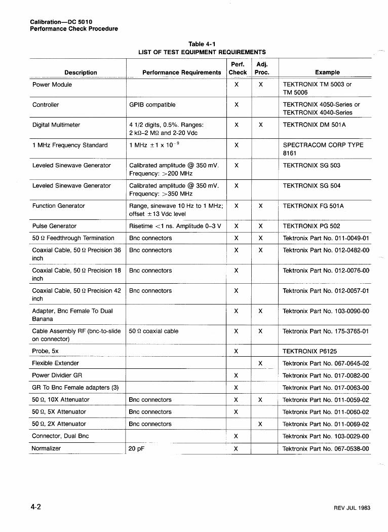
Calibration-DC 501 0 Performance Check Procedure
Table 4-1 LIST OF TEST EQUIPMENT REQUIREMENTS
Perf. Adj. I Example
TEKTRONIX TM 5003 or TM 5006
Description Performance Requirements
Power Module
Controller GPlB compatible TEKTRONIX 4050-Series or TEKTRONIX 4040-Series
Digital Multimeter 4 112 digits, 0.5%. Ranges: 2 kQ-2 MQ and 2-20 Vdc
TEKTRONIX DM 501A
1 MHz Frequency Standard 1 MHz +1 x lo- ' SPECTRACOM CORP TYPE 81 61
Leveled Sinewave Generator Calibrated amplitude @ 350 mV. Frequency: >200 MHz
TEKTRONIX SG 503
Leveled Sinewave Generator Calibrated amplitude @ 350 mV. Frequency: >350 MHz
TEKTRONIX SG 504
Function Generator Range, sinewave 10 Hz to 1 MHz; offset + 13 Vdc level
TEKTRONIX FG 501A
Pulse Generator
50 R Feedthrough Termination
Coaxial Cable, 50 Q Precision 36 inch
Coaxial Cable, 50 Q Precision 18 inch
Coaxial Cable, 50 Q Precision 42 inch
Risetime (1 ns. Amplitude 0-3 V TEKTRONIX PG 502
Bnc connectors
Bnc connectors
Tektronix Part No. 01 1-0049-01
Tektronix Part No. 01 2-0482-00
Tektronix Part No. 01 2-0076-00 Bnc connectors
Bnc connectors Tektronix Part No. 01 2-0057-01
Adapter, Bnc Female To Dual Banana
Tektronix Part No. 103-0090-00
Cable Assembly RF (bnc-to-slide on connector)
50 Q coaxial cable Tektronix Part No. 175-3765-01
Probe, 5x
Flexible Extender
TEKTRONIX P6125
Tektronix Part No. 067-0645-02
Tektronix Part No. 01 7-0082-00
Tektronix Part No. 01 7-0063-00
Power Dividier GR
GR To Bnc Female adapters (3)
50 Q, 1 OX Attenuator Bnc connectors Tektronix Part No. 01 1-0059-02
50 R, 5X Attenuator Bnc connectors Tektronix Part No. 01 1-0060-02
50 R, 2X Attenuator Bnc connectors Tektronix Part No. 01 1-0069-02
Connector, Dual Bnc
Normalizer
Tektronix Part No. 103-0029-00
Tektronix Part No. 067-0538-00
REV JUL 1983
Calibration-DC 501 0 Performance Check Procedure
c. CHECK-that the DC5010 readout is within b. Press the DC 5010 AUTO TRIG button, and then 999.99879 kHz and 1.0000020 MHz. press LEVEL CH A.
L'
d. Remove all cable connections from the DC 501 0. c. Press the DC 5010 (increment) button until the digi- tal multimeter display just changes to a low readout, if it is not already low. Press the DC 5010 4 (decrement) button until the digital multimeter display just changes to a high readout.
3. Check the Trigger Level CH A and CH B Accuracy d. CHECK-that the DC 501 0 display readout indicates
Refer to Fig. 4-1, performance check setup. Use the fol- b e h ~ e e ~ +0-040 and -0.040.
lowing control settings.
Digital Multimeter
Function-Range 2 V
DC 5010
CHANNEL A and CHANNEL B
ATTEN XI (lighted)
e. Connect a coaxial cable from the pulse generator out- put to the digital multimeter input using a bnc-to-banana adapter.
f. Set the pulse generator for Ext Trig and Ext Dur and adjust the output for a displayed readout of approximately + 1.97 on the digital multimeter. Note this reading.
a. Connect the DC 501 0 CH A SHAPED OUT to the digi- g. Disconnect the cable from the digital multimeter bnc- tal multimeter input using the bnc-to-slide on connector as- to-banana adapter and connect to the DC 5010 CHANNEL sembly (standard accessory). A input.
Power Module \
Pulse Generator
Digital Multimeter
Fig. 4-1. Performance Check setup for step 3.
REV JUL 1983
Calibration-DC 501 0 Performance Check Procedure
h. Reconnect the accessory cable assembly to the digi- tal multimeter input.
i. Press the t (increment) button until the digital multimeter display just changes to a low readout. Press the 4 (decrement) button until the digital multimeter display just changes to a high readout. Then press the DC 5010 AUTO TRIG button.
j. CHECK-that the DC 501 0 display readout indicates the same value as was noted on step 3-f, +40 mV.
k. Repeat steps a through k using CHANNEL B.
4. Check Input Impedance: 50 0, &3%; 1 M0, & 1 Yo
Refer to Fig. 4-2 performance check setup. Use the fol- lowing control settings.
Digital Multimeter
Function-Range 2 MQ
DC 5010
CHANNEL A and CHANNEL B
ATTEN X I (lighted) TERM 1 mQ (unlighted)
a. Connect a coaxial cable from the DC 501 0 CHANNEL -7
A input to the digital multimeter input using a bnc-to-banana adapter.
b. CHECK-that the digital multimeter display readout indicates between .9800 and 1.0200 (MQ).
c. Press the DC 5010 CHANNEL A ATTEN X5 button (unlighted).
d. CHECK-that the digital multimeter display readout indicates between .9800 and 1.0200 (MQ).
e. Change the digital multimeter Function-Range switch to 2 kQ.
f. Press the DC 5010 CHANNEL A TERM 50 Q button (lighted).
g. CHECK-that the digital multimeter display readout indicates between .0490 and .0510 (kQ).
--, h. Press DC 501 0 CHANNEL A ATTEN X I button
(lighted).
Digital Multimeter
REV JUL 1983
Calibration-DC 50 1 0 Performance Check Procedure
i. CHECK-that the digital multimeter display readout in- dicates betwen .0490 and .0510 (kQ).
j. Move the cable connection from the DC 5010 CHAN- NEL A input to the CHANNEL B input.
k. Change the digital multimeter Function-Range switch to 2 MQ.
q. CHECK-that the digital multimeter display readout indicates between .0490 and .0510 (kQ).
r. Press the DC 501 0 CHANNEL B ATTEN X I button (lighted).
s. CHECK-that the digital multimeter display readout indicates between .0490 and .0510 (kQ).
I. CHECK-that the digital multimeter display readout in- dicates between .9800 and 1.0200 (MQ).
5. Check the Arming In ut Pulse Response a I00 ns 32.4 V, $ ~ 0 . 4 V)
m. Press the DC 5010 CHANNEL B ATTEN X5 button (unlighted).
n. CHECK-that the digital multimeter display readout indicates betwen .9800 and 1.0200 (MQ).
o. Change the digital multimeter Function-Range switch to 2 kQ.
p. Press the DC 5010 CHANNEL B TERM 50 Q button (lighted).
Power Module \
Refer to Fig. 4-3, performance check setup. Use the fol- lowing control settings.
Pulse Duration Period Back Term
Pulse Generator
Squarewave .1 ps
(in)
Sinewave Generator
Frequency Range (MHz) 50-1 00 Output Amplitude 1.25 V
Pulse Sinewave Generator Generator
CHANNEL A lnput
CHANNEL B lnput
0 OUT
Q
Attenuator I
C 1 --,,,,A
Fig. 4-3. Performance Check setup for steps 5 and 14.
Calibration-DC 50 10 Performance Check Procedure
DC 5010
PERIOD A (lighted) CHANNEL A and CHANNEL B
ATTEN XI (lighted) TERM 50 Q (lighted)
k. CHECK-that the DC 501 0 readout stops changing values and the display GATE light is not blinking (but may be lighted).
a. Connect a coaxial cable from the pulse generator out- put to the DC 5010 CHANNEL A input. Do not use the XI0 attenuator for this test.
6. Check Input Capacitance: 23 pF, + 10%
b. Adjust the pulse generator Period Variable control un- til the DC 501 0 display readout indicates about 200 (ns).
c. Adjust the high level on the pulse generator for 2.5 V.
d. With the pulse generator High Level control set, ad- just the Low Level control to <.4 V.
e. Remove the DC 5010 CHANNEL A input connection and connect the sinewave generator output to the CHAN- NEL A input.
f. Set the DC 5010 to Freq A mode.
g. Adjust the sinewave generator Frequency Variable control until the DC 501 0 display readout indicates approxi- mately 75.OXXXX MHz (the last four digits can vary due to source instability).
h. Press the DC 501 0 AUTO TRIG button, then connect the pulse generator output to the ARM IN, using a "shaped out" cable.
i. CHECK-that the DC 5010 proximately 75.OXXXX MHz (the due to source instability) with blinking.
display still indicates ap- last four digits can vary the display GATE light
j. Disconnect the cable that runs from the pulse genera- tor to the counter arming input at the pulse generator end. At that end of the cable, connect a 50 Q terminator (that will pull the arming input down to a TTL low, and hence should disable the counter).
Refer to Fig. 4-4, performance check lowing control settings.
Frequency Hz Multiplier Function Offset Output
CHANNEL A and CHANNEL 6
TERM SLOPE ATTEN COUPL
FREQ A FILTER (20 MHz)
Function Generator
setup. Use the fol-
(sine) (midrange)
(cw)
1 MQ (unlighted) + (unlighted) XI (lighted) DC (unlighted) (lighted) (lighted)
a. Connect the 20 pF normalizer with a 50 Q terminator and 5X attenuator from the DC 5010 CHANNEL A input through a coaxial cable to the function generator output.
b. Press the DC 5010 LEVEL CH A button.
c. Adjust the DC 5010 Channel A triggering level using the (increment) button until the GATE annunciator light (on the display) just stops blinking.
d. Note the DC 5010 display readout (peak input voltage).
e. Change the function generator Multiplier switch to 105.
REV JUL 1983
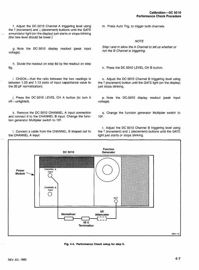
Calibration-DC 501 0 Performance Check Procedure
f. Adjust the DC 5010 Channel A triggering level using the t (increment) and 4 (decrement) buttons until the GATE
- annunciator light (on the display) just starts or stops blinking (the new level should be lower.)
g. Note the DC 5010 display readout (peak input voltage).
h. Divide the readout on step 6d by the readout on step 6g.
i. CHECK-that the ratio between the two readings is between 1.03 and 1 . I3 (ratio of input capacitance value to the 20 pF normalization).
j. Press the DC 5010 LEVEL CH A button (to turn it off-unlighted).
k. Remove the DC 5010 CHANNEL A input connection and connect it to the CHANNEL B input. Change the func- tion generator Multiplier switch to 102.
I. Connect a cable from the CHANNEL B shaped out to the CHANNEL A input
m. Press Auto Trig, to trigger both channels.
NOTE
Step 1 and m a110 w the A Channel to tell us whether or not the B Channel is triggering.
n. Press the DC 501 0 LEVEL CH B button.
o. Adjust the DC 5010 Channel B triggering level using the t (increment) button until the GATE light (on the display) just stops blinking.
p. Note the DC-5010 display readout (peak input voltage).
q. Change the function generator Multiplier switch to I 05.
r. Adjust the DC 5010 Channel B triggering level using the t (increment) and 4 (decrement) buttons until the GATE light just starts or stops blinking.
Function Generator
Power Module \
I Normalizer 5X
Attenuator I 50 B
Termination
Fig. 4-4. Performance Check setup for step 6.
REV JUL 1983
Calibration-DC 501 0 Performance Check Procedure
s. Note the DC 5010 display readout (peak input voltage).
t. Divide the readout on step 6p by the readout on step 6s.
u. CHECK-that the ratio between the two readings is between 1.03 and 1.13 (ratio of input capacitance to the 20 pF normalization).
7. Check RISEIFALL lnput Impedance: 50 O, +3%, 1 MO, 500 kO, +2% (60 MHz sinewave at high level)
Refer to Fig. 4-2, performance check setup.
a. Set the digital multimeter Function Range switch to 2 kQ.
b. Press the DC 501 0 CHANNEL A ATTEN XI button (lighted) and the 50 52 button (lighted), and press to light the RISEIFALL A button.
c. CHECK-that the digital multimeter display readout indicates between .0490 and .0510.
d. Press both DC 5010 CHANNEL A and B TERM 1 MQ buttons (unlighted).
e. Change the digital multimeter Function-Range switch to 2000 kQ.
f. CHECK-that the digital multimeter display readout indicates between .4900 and 5 1 00 (kQ).
8. Check the lnput Sensitivity: X I Attenuation, DC - and AC Coupled; 50 O, ~ 7 0 mV p-p
Refer to Fig. 4-5, performance check setup. Use the fol- lowing control settings.
Sinewave Generator
Frequency MHz 350 Range LOW Amplitude 0.70
DC 5010
FREQ A (lighted) CHANNEL A and B
COUPL DC (unlighted) TERM 50 Q (lighted) SLOPE + (unlighted) ATTEN XI (lighted)
a. Connect a coaxial cable with a 10X attenuator from the sinewave generator output to the DC 501 0 CHANNEL A input.
b. Press the DC 501 0 AUTO TRlG button, LEVEL CH A button, and the DISPLAY-TEST button.
c. Press the DC 501 0 t (increment) or & (decrement) but- tons to adjust the trigger level for a stable display readout.
d. CHECK-that the DC 501 0 display readout indicates approximately 350.00XXXX (the last four digits can vary due to source instability).
e. Move the DC 5010 CHANNEL A input connection to the CHANNEL B input.
f. Connect the 1 MHz frequency standard to the DC 5010 CHANNEL A input and press the RATIO BIA but- ton (lighted).
g. Press the DC 5010 AUTO TRlG button, LEVEL CH B button, and the DISPLAY-TEST button.
h. Press the DC 501 0 f (increment) or & (decrement) but- tons to adjust the trigger level for a stable display readout.
i. CHECK-that the DC 5010 display readout indicates ,- approximately 350.00XXX (the last three digits can vary due to source instability).
REV JUL 1983
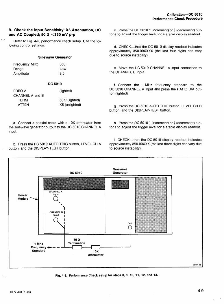
Calibration-DC 50 10 Performance Check Procedure
9. Check the Input Sensitivity: X5 Attenuation, DC and AC Coupled; 50 D ~ 3 5 0 mV p-p
Refer to Fig. 4-5, performance check setup. Use the fol- lowing control settings.
Sinewave Generator
Frequency MHz 350 Range Low Amplitude 3.5
DC 5010
FREQ A (lighted) CHANNEL A and B
TERM 50 Q (lighted) ATTEN X5 (unlighted)
a. Connect a coaxial cable with a 10X attenuator from the sinewave generator output to the DC 501 0 CHANNEL A input.
b. Press the DC 501 0 AUTO TRlG button, LEVEL CH A button, and the DISPLAY-TEST button.
c. Press the DC 501 0 (increment) or (decrement) but- tons to adjust the trigger level for a stable display readout.
d. CHECK-that the DC 501 0 display readout indicates approximately 350.00XXXX (the last four digits can vary due to source instability).
e. Move the DC 5010 CHANNEL A input connection to the CHANNEL B input.
f. Connect the 1 MHz frequency standard to the DC 5010 CHANNEL A input and press the RATIO B/A but- ton (lighted).
g. Press the DC 501 0 AUTO TRlG button, LEVEL CH 6 button, and the DISPLAY-TEST button.
h. Press the DC 501 0 (increment) or 4 (decrement) but- tons to adjust the trigger level for a stable display readout.
i. CHECK-that the DC 501 0 display readout indicates approximately 350.00XXX (the last three digits can vary due to source instability).
Sinewave DC 5010 Generator
Power Module >
1 MHz Frequency -) - - 1 1 I Standard 1 OX
Attenuator
Fig. 4-5. Performance Check setup for steps 8, 9, 10, 1 1, 12, and 13.
REV JUL 1983
Calibration-DC 501 0 Performance Check Procedure
10. Check Input Sensitivity: X I Attenuation, DC 11. Check Input Sensitivity: X5 Attenuation, DC and AC Coupled; 1 MO, ~ 1 2 0 mV p-p at ~ 3 0 0 MHz and AC coupled; 1 MO, ~ 3 5 0 mV p-p at G200 MHz --
Refer to Fig. 4-5, performance check setup. Use the fol- Refer to Fig. 4-5, performance check setup. Use the fol- lowing control settings. lowing control settings.
Sinewave Generator Sinewave Generator
Frequency MHz 300 Amplitude =I20 mV
CHANNEL A and B TERM 1 MQ (unlighted) ATTEN XI (lighted)
Frequency Range 100-250 Frequency Variable 200 Amplitude Multiplier X I Output Amplitude 3.5
RATIO B/A ATTEN
(lighted) X5
a. Remove the DC 5010 CHANNEL B input connection a. Connect the 1 MHz frequency standard to the and attach a 50 Q termination to the end of the coaxial ca- DC 5010 CHANNEL A input. ble. Reconnect this cable with the termination and 1 0 ~ attenuator to the CHANNEL B input.
b. Connect a coaxial cable with a 10X ajtenuation and 50 Q termination from the sinewave generator output to the
b. Press the DC 501 0 AUTO TRlG button, LEVEL CH B DC 501 0 CHANNEL B input.
button, and the DISPLAY-TEST button.
c. Press the DC 501 0 AUTO TRlG button, LEVEL CH B button, and the DISPLAY-TEST button.
c. Press the DC 501 0 ? (increment) or 4 (decrement) but- ton to adjust the trigger level for a stable display readout.
d. Press the DC 501 0 f (increment) or 4 (decrement) but- ton to adjust the trigger level for a stable display readout.
d. CHECK-that the DC 501 0 display readout indicates approximately 300.0XXXX (the last four digits can vary due to source instability). e. CHECK-that the DC 501 0 display readout indicates
approximately 200.00XXX (the last three digits can vary due to source instability).
e. Remove the 1 MHz frequency standard from the DC 501 0 CHANNEL A input.
f. Press to light the DC 501 0 FREQ A button.
f. Move the DC 5010 CHANNEL B input connection to the CHANNEL A input. g. Remove the 1 MHz frequency standard from the
DC 501 0 CHANNEL A input.
g. Press to light the DC 5010 FREQ A button, AUTO h. Move the DC 5010 CHANNEL B input connection to TRlG button, LEVEL CH A button, and the DISPLAY-TEST
the CHANNEL A input. button.
i. Press the DC 501 0 AUTO TRlG button, LEVEL CH A h. Press the DC 501 0 f (increment) or I (decrement) but- button, and the DISpLAY-TEST button.
ton to adjust the trigger level for a stable display readout.
j. Press the DC 5010 7 (increment) or 1 (decrement) but- i. CHECK-that the DC 5010 display readout indicates ton to adjust the trigger level for a stable display readout.
approximately 300.00XXXX (the last four digits can vary due to source instability).
k. CHECK-that the DC 5010 display readout indicates - approximately 200.00XXXX (the last four digits can vary
j. Remove the cable connections. due to source instability).
REV JUL 1983
Calibration-DC SO 10 Performance Check Procedure
12. Check lnput Sensitivity: X I Attenuation, DC and AC coupled; 1 MJZ, <70 mV p-p at G200 MHz
- Refer to Fig. 4-5, performance check setup. Use the fol-
lowing control settings.
Sinewave Generator
Frequency Range 100-250 Frequency Variable 200 Amplitude Multiplier X 1 Output Amplitude 0.70
DC 5010 RATIO B/A (lighted)
a. Connect the 1 MHz frequency standard to the DC 501 0 CHANNEL A input.
b. Connect a coaxial cable with a 1 0 x attenuation and 50 Q termination from the sinewave generator Output to the DC 501 0 CHANNEL B input.
13. Check lnput Sensitivity: X5 Attenuation, DC and AC Coupled: 1 MQ, ~ 5 9 4 mV p-p at ~ 3 0 0 MHz
Refer to Fig. 4-5 performance check setup. Use the fol- lowing control settings.
Sinewave Generator
Frequency MHz 300 Amplitude &94 mV p-p
DC 5010
CHANNEL A and B TERM 1 MQ (unlighted) ATTEN X5 (unlighted)
a. Remove the DC 5010 CHANNEL B input connection and insert a 50 Q termination to the coaxial cable. Recon- nect this cable to the CHANNEL B input.
b. Press the DC 501 0 AUTO TRlG button, LEVEL CH B button, and the DISPLAY-TEST button.
c. Press the DC 5010 AUTO TRlG button, LEVEL CH B button, and the DISPLAY-TEST button.
c. Press the DC 501 0 f (increment) or 1 (decrement) but- ton to adjust the trigger level for a stable display readout.
d. Press the DC 501 0 (increment) or 1 (decrement) but- ton to adjust the trigger level for a stable display readout.
e. CHECK-that the DC 5010 display readout indicates approximately 200.00XXX (the last three digits can vary due to source instability).
f. Press to light the DC 5010 FREQ A button.
d. CHECK-that the DC 5010 display readout indicates approximately 300.00XXX (the last three digits can vary due to source instability).
e. Remove the 1 MHz frequency standard from the DC 5010 CHANNEL A input.
f. Move the DC 5010 CHANNEL B input connection to g. Remove the 1 MHz frequency standard from the the CHANNEL A input.
DC 501 0 CHANNEL A input.
h. Move the DC 5010 CHANNEL B input connection to g. Press to light the DC 501 0 FREQ A button, AUTO
the CHANNEL A input. TRlG button, LEVEL CH A button, and the DISPLAY-TEST button.
i. Press the DC 501 0 AUTO TRlG button, LEVEL CH A button, and the DISPLAY-TEST button. h. Press the DC 501 0 f (increment) or 1 (decrement) but-
ton to adjust the trigger level for a stable display readout.
j. Press the DC 5010 f (increment) or 1 (decrement) but- ton to adjust the trigger level for a stable display readout. i. CHECK-that the DC 501 0 display readout indicates
approximately 300.00XXXX (the last four digits can vary due to source instability).
k. CHECK-that the DC 501 0 display readout indicates approximately 200.00XXXX (the last four digits can vary due to source instability). j. Remove the cable connections.
REV JUL 1983
Calibration-DC SO 10 Performance Check Procedure
14. Check Width A: Range = ~ 4 ns; Minimum Time Stop Edge To Start Edge, ~ 8 . 5 ns
Refer to Fig. 4-3 (using sinewave generator only), perfor- mance check setup. Use the following control settings.
Sinewave Generator
Frequency 50 MHz Output Amplitude 2.5 V p-p Amplitude Multiplier X I
DC 5010
CHANNEL A and B ATTEN X l (lighted) TERM 50 Q (lighted)
FREQ A (lighted)
a. Connect a coaxial cable from the sinewave generator output to the DC 5010 CHANNEL A input. Do not use the attenuator shown in Fig. 4-3.
b. Press to light the LEVEL CH A button, and use f (in- crement) to set the CH A trigger level to .920 volts.
c. Press to light the DC 501 0 WIDTH A button.
d. CHECK-that the DC 501 0 display readout indicates between 2.000 and 6.000 (ns).
Time A + B CHANNEL A and CHANNEL B
ATTEN TERM SLOPE
DC 5010
(lighted)
X I (lighted) 50 Q (lighted) + (unlighted)
EVENTS B DUR A check:
a. Connect a coaxial cable from the pulse generator out- put to one connector of a 50 Q power divider (using the GR- to-bnc adapter).
b. Connect an 18-inch coaxial cable from another power divider connector to the DC 501 0 CHANNEL A input (using the GR-to-bnc adapter).
NOTE
In this and other steps calling for exact lengths, it is important to use the lengths called for.
c. Connect a 42-inch coaxial cable from the other power divider connector to the DC 5010 CHANNEL B input (using the GR-to-bnc adapter).
d. Press the DC 501 0 AUTO TRIG button, then press to light the NULL button.
e. Press the DC 5010 CHANNEL B - SLOPE button (lighted).
15. Check EVENTS B DUR A Minimum Pulse f. Adjust the pulse generator Duration Variable control until the DC 501 0 display readout indicates between 3.95 ns
Width, ~ 4 . 0 ns and ~ 8 . 5 ns and 4.05 ns. Check Delay Mismatch: Int, G 2 ns Check Minimum TIME B -+ A, G12.5 ns
Refer to Fig. 4-6, performance check setup. Use the fol- g. Remove the DC 5010 CHANNEL B input cable and
lowing control settings. terminate this cable end with a 50 fl terminator.
Pulse Period Pulse Duration Low Level High Level Back Term
Pulse Generator h. Set the sinewave generator for 300 MHz at approxi- mately 150 mV, and connect the generator output to the DC 501 0 CHANNEL B input.
- i. Change the pulse generator Pulse Period to 10 ns
range (pulse width setting remains at 4.0 ns).
REV JUL 1983
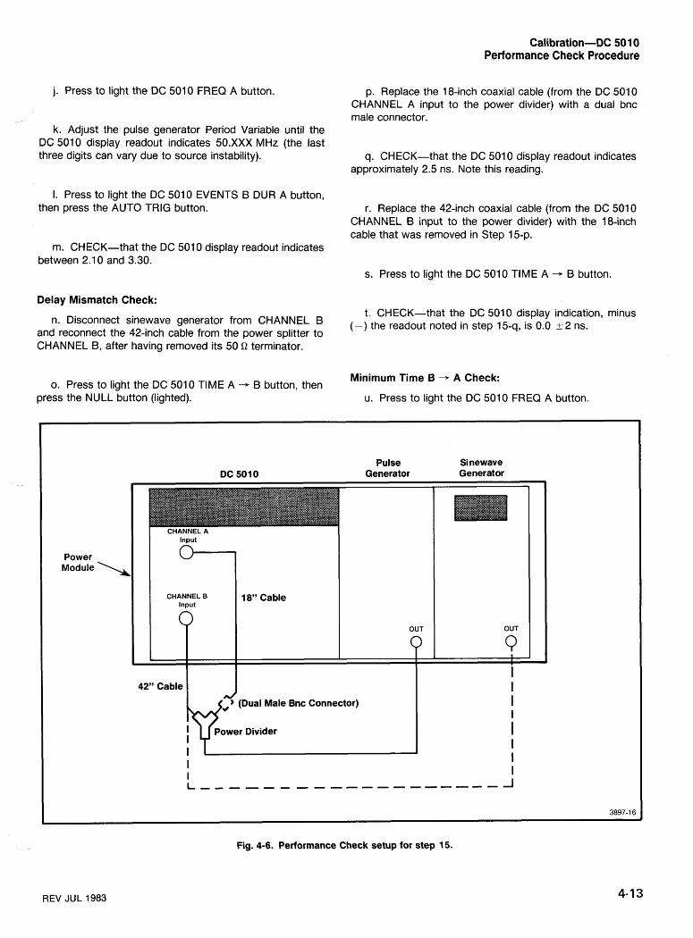
Calibration-DC 501 0 Performance Check Procedure
j. Press to light the DC 5010 FREQ A button.
k. Adjust the pulse generator Period Variable until the DC 5010 display readout indicates 50.XXX MHz (the last three digits can vary due to source instability).
I. Press to light the DC 5010 EVENTS B DUR A button, then press the AUTO TRIG button.
p. Replace the 18-inch coaxial cable (from the DC 5010 CHANNEL A input to the power divider) with a dual bnc male connector.
q. CHECK-that the DC 501 0 display readout indicates approximately 2.5 ns. Note this reading.
r. Replace the 42-inch coaxial cable (from the DC 5010 CHANNEL B input to the power divider) with the 18-inch cable that was removed in Step 15-p.
m. CHECK-that the DC 501 0 display readout indicates between 2.10 and 3.30.
s. Press to light the DC 5010 TlME A - B button.
Delay Mismatch Check:
n. Disconnect sinewave generator from CHANNEL B and reconnect the 42-inch cable from the power splitter to CHANNEL B, after having removed its 50 !J terminator.
o. Press to light the DC 5010 TlME A + B button, then press the NULL button (lighted).
t. CHECK-that the DC 5010 display indication, minus (-) the readout noted in step 15-q, is 0.0 4 2 ns.
Minimum Time B -, A Check:
u. Press to light the DC 5010 FREQ A button.
Power Module \
CHANNEL B Input
18" Cable
Pulse Sinewave Generator Generator
OUT
9 OUT
Q
Fig. 4-6. Performance Check setup for step 15.
REV JUL 1983
Calibration-DC 50 1 0 Performance Check Procedure
v. Adjust the pulse generator Period Variable until the d. Press the DC 5010 WIDTH A function button. DC 5010 display readout indicates 67.XXX MHz (the last three digits can vary due to source instability).
e. CHECK-that the DC 501 0 display readout indicates greater than 600.000 ps and less than 1.3 ms.
w. Press to light the DC 5010 TIME A - B button.
f. Press the DC 5010 LEVEL CH A button. x. CHECK-that the DC 501 0 display readout indicates
between 0 and 6.0 ns. g. CHECK-that the DC 5010 display readout indicates
between 2.000 and 3.250 V (50% voltage point; peak volt- age equals 4 V to 6.5 V).
16. Check Probe Compensation
Use the following control settings.
CHANNEL A and CHANNEL B
ATTEN X5 TERM 1 Mil (unlighted)
FREQ A (lighted)
17. Check the GPlB Bus Through the Controller
Refer to TalkerIListener sample programs in the Operat- ing instructions.
a. Connect the controller to the TM 5000 power module.
a. Connect a bnc-to-slide on cable asembly from the b. Run the sample program for your selected controller DC 501 0 PROBE COMP output to the CHANNEL A input. using settings and queries commands.
b. Press the DC 501 0 AUTO TRIG button. c. CHECK-the DC 501 0 display readout and front-pan- el lighted buttons for returned query data.
c. CHECK-that the DC 5010 display readout indicates between 70.0000 and 170.0000 Hz. This completes the Performance Check.
REV JUL 1983
Calibration-DC 501 0 Adjustment Procedure
PROCEDURE
Introduction b
Use this Adjustment Procedure to restore the DC 5010 to original performance -requirements. This Adjustment Pro- cedure need not be performed unless the instrument fails to meet the Performance Requirements of the Electrical Char- acteristics listed in the Specification section. If the instru- ment has undergone repairs, the Adjustment Procedure is recommended. Allow thirty minutes warmup time for oper- ation to specified accuracy (sixty minutes after storage in a high humidity environment).
Satisfactory completion of all adjustment steps in this procedure assures that the instrument will meet the Perfor- mance Requirements, providing the instrument is function- ing properly.
NOTE
Make adjustments at an ambient temperature be- tween + 20" C and + 30" C.
1. Check the Digital Board + 12 V Accuracy ( 2 2 % )
a. Set the digital multimeter Function-Range switch to 20 Vdc and connect the Low test lead to the DC 501 0 chas- sis ground. Connect the VoltslQ test lead to the Digital board + 12 test point.
b. Check that the digital multimeter readout indicates be- tween 1 1.40 and 12.60 (volts).
Test Equipment Required
The test equipment (or equivalent) listed in Table 4-1 is required for adjustment of the DC 501 0. Specifications giv- en for the test equipment are the minimum necessary for accurate adjustment. All test equipment is assumed to be correctly calibrated and operating within specifications.
If other test equipment is substituted, calibration setup may need to be altered to meet the requirements of the equipment used.
PRELIMINARY CONTROL SETTINGS
FREQ A CHANNEL A and CHANNEL B
ATTEN SLOPE COUPL TERM
AVGS
(lighted)
XI (lighted) + (unlighted) DC (unlighted) 50 Q (lighted) 1 06
Preparation
Access to the internal adjustments is achieved most easily when the DC 5010 is connected to the power module with a flexible plug-in extender. Remove the top and side covers of the DC 501 0 to reach the adjustments and checks on the Auxiliary, Digital, and Analog boards. Refer to the Adjustment Locations and Setups in the pullout pages at the rear of this manual.
2. Check the Digital Board - 12.2 V Accuracy (&2%)
a. Remove the VoltslQ test lead from the + 12 test point and connect it to the -12 test point (Digital board).
b. Check that the digital multimeter readout indicates be- tween - 1 1.40 and - 12.60 (volts).
3. Check the Digital Board +5 V Accuracy (+2%)
a. Remove the digital multimeter VoltslQ test lead from the -12 test point and connect it to the +5 test point (Digi- tal board).
b. Check that the digital multimeter readout indicates be- tween +4.90 and +5.10 (volts).
c. Remove the VoltslQ test lead from the +5 test point.
4. Check the Digital Board +2.5 V (V ref) Accuracy (& I Yo)
a. Connect the digital multimeter VoltsIQ test lead to the Digital board Vref test point.
b. Check that the digital multimeter readout indicates be- tween 2.475 and 2.525 (volts).
REV JUL 1983
Calibration-DC 501 0 Adjustment Procedure
5. Check the Analog Board +5 V Accuracy ( t 2 % )
a. Remove the digital multimeter VoltslQ test lead from the Vref test point and connect it to the +5 test point (Ana- log board).
b. Check that the digital multimeter readout indicates be- tween 4.90 and 5.1 50 (volts).
6. Check the Analog Board + 12 V Accuracy ( k 2 % )
a. Remove the digital multimeter VoltslQ test lead from the +5 test point and connect to the + 12 test point (Analog board).
b. Check that the digital multimeter readout indicates be- tween 1 1.76 and 12.24 (volts).
7. Check the Analog Board - 5 V Accuracy (+,5%)
a. Remove the digital multimeter VoltslQ test lead from the + 12 test point and connect it to the -5 test point (Ana- log board).
b. Check that the digital multimeter readout indicates be- tween -4.75 and -5.25 (volts).
c. Remove the test lead connections.
8. Adjust the Standard Timebase Accuracy, C1521, Osc Adj
a. Connect a coaxial cable from the 1 MHz Frequency Standard to the DC 501 0 CHANNEL A input.
b. Press the DC 501 0 AUTO TRIG button.
c. ADJUST-C1521 (through a hole in the back plate) until the DC 501 0 readout indicates between 999.99990 and 1.0000005 MHz.
NOTE
This sets the DC 5010 oscillator within one part in lo7. It will take approximately one second for the dis- play to update.
9. Adjust the Optional Tirnebase Accuracy, Y 1530 -
NOTE
The Option 0 1 Timebase adjustment is made through an access hole in the back of the oven timebase. Y1530 is located on the back side of the Auxiliary board.
a. Connect a coaxial cable from the 1 MHz Frequency Standard to the DC 5010 CHANNEL A input.
b. Set the DC 5010 LEVEL CH A for a stable display readout.
c. ADJUST-Y1530 until the DC 501 0 display readout indicates 1.0000000 MHz.
d. Press to light the PERIOD A button.
e. ADJUST-Y1530 until the DC 5010 display readout indicates between 999.99998 and 999.99999.
- f. Remove the cable connections from the DC 5010.
10. Adjust R1205, A Off, and R1207, B Off
Refer to Fig. 8-3, adjustment setup, in the pullout pages. Use the following control settings.
DC 5010
CHANNEL A and CHANNEL B
TERM 1 MQ (unlighted) SLOPE + (unlighted) ATTEN X1 (lighted) COUPL AC (unlighted)
FREQ A (lighted) Digital Multimeter
Function-Range 2 V Pulse Generator
Output low level (CW) Output high level (CW) Pulse Period Ext Duration Pulse Duration Ext
a. Connect the interconnecting cable from the DC 5010 -
CH A SHAPED OUT to the digital multimeter input using an rf connector-to-banana adapter.
REV JUL 1983
Calibration-DC SO 10 Adjustment Procedure
b. Set the DC 5010 LEVEL CH A to display 0 V.
c. ADJUST-R1205 counterclockwise to the point where the digital multimeter display readout changes from approximately 0 V to approximately .2 V.
d. Move the DC 5010 CH A SHAPED OUT connection to the CH B SHAPED OUT.
e. Set the DC 501 0 LEVEL CH B to display 0 V.
f. ADJUST-R1207 counterclockwise to the point where the digital multimeter display readout changes from approximately 0 V to approximately .2 V.
g. Disconnect the digital multimeter cable connection.
11. Adjust R1206, B Rng, and R1204, A Rng
Refer to Fig. 8-3, adjustment setup, in the pullout pages.
a. Connect a coaxial cable with 50 Q termination from the pulse generator output to the digital multimeter input connectors using a bnc-to-banana adapter.
b. Set the DC 5010 CHANNEL A and B COUPL for DC.
c. Adjust the pulse generator Low and High level con- trols until the display readout (digital multimeter) indicates between 1.900 and 2.000 volts. Note this reading.
d. Move the coaxial cable with the 50 Q termination from the digital multimeter input to the DC 5010 CHANNEL input.
e. Reconnect the cable from the DC5010 CH SHAPED OUT to the digital multimeter input connectors
f. Set the DC 5010 LEVEL CH B to display the reading obtained in step 1 1 c (within 4 mV).
g. ADJUST-41206 to the point where the digital multimeter display readout changes from approximately 0 V to approximately .2 V.
h. Move the coaxial cable with 50 Q termination from the DC 501 0 CHANNEL B input to the CHANNEL A input.
i. Set the DC 5010 LEVEL CH A to display the reading obtained in step 11 c (within 4 mV).
j. ADJUST-R1204 to the point where the digital muiltimeter display readout changes from approximately 0 V to approximately .2 V.
12. Adjust AT1 505 (Channel A) and AT1 533 (Channel B), Attenuator Compensation .
Refer to Fig. 8-4, adjustment setup, in the pullout pages. Use the following control setings.
CHANNEL A and CHANNEL B
TERM 1 MQ (unlighted) SLOPE + (unlighted) ATTEN X5 (unlighted) COUPL AC (lighted)
PROBE COMP (lighted) FILTER (lighted)
Function Generator
Frequency Hz Multiplier Function Off set Output
1 1 o3 Squarewave (midrange) 5 V p-to-p (Amplitude)
a. Connect a 50 Q terminator and X2 attenuator from the function generator output through a coaxial cable to the DC 5010 CHANNEL A input.
b. Press the DC 501 0 PROBE COMP button.
c. ADJUST-the lower adjustment on AT1505 until the digit on the far left side of the DC 5010 display just changes from a steady 1 to a 0. The Channel A X5 attenuation is now compensated.
d. Move the DC 5010 CHANNEL A input connection to the CHANNEL B input and again press the PROBE COMP button.
Calibration - DC 5010 Adjustment Procedure
e. ADJUST-the lower adjustment on AT1533 until the DC 5010 digit on the far right side of the display just changes from a steady 1 to a 0. The Channel B X5 attenua- tion is now compensated.
f. Remove all cable connections.
13. Adjust AT1505 (Channel A) and AT1533 (Channel B), Attenuator Input Capacitance.
Function Generator
Output cw (max amplitude)
a. Compensate a X5 test probe to the DC 5010 CHAN- NEL A input and set for XI attenuation. Refer to Probe Compensation in the Operating Instructions of this manual.
b. After the probe has been properly compensated, con- nect the probe tip to the function generator output using a probe tip-to-bnc connector.
c. Set the DC 5010 CHANNEL A ATTEN to X5 (lighted button) and press to light the PROBE COMP button.
d. ADJUST-the upper adjustment on AT1505, located on the Analog board, until the digit located on the far left side of the DC 501 0 display just changes from a steady 1 to a 0. The X5 input capacitance is now equal to the XI input capacitance.
e. Remove the test probe from the CHANNEL A input and the function generator. Then Compensate the probe (see step 13a) to the DC 501 0 CHANNEL B XI attenuator.
f. Reconnect the probe tip to the function generator output.
14. Adjust RI l42 and RIl43, ECL Threshold Reference Level. -
NOTE
This procedure should only be performed if U1000, U1001, UlOl1, U1022, or U1110 have been replaced.
CHANNEL A and CHANNEL B
TERM 50 Q ATTEN XI SLOPE + COUPLING DC
a. Pre-set both variable resistors to mid-range (R1142 & R1143).
NOTE
R 1 142 and R 1 143 are located on the Analog board (A 12) at location 3-0.
Set the DC 5010 to TIME MAN.
Push MEASUREMENT STARTISTOP in.
ADJUST- R1142 until the instrument counts.
Connect a coaxial cable from the 1 MHz frequency standard output to the DC 501 0 CHANNEL A input. Adjust for a 100 mV signal.
f. Go to FREQ A mode and push in AUTO TRIG.
g. Check that the instrument counts correctly. Note that R1143 may need adjustment for proper counting. Remove the coaxial cable.
g. Set the DC 501 0 CHANNEL B ATTEN to x 5 (lighted) and press the PROBE COMP button.
h. Connect a coaxial cable and XI 0 attenuator from the Signal Generator (SG 504) to the CHANNEL A input.
h. ADJUST-the upper adjustment on AT1 533, located on the Analog board until the digit on the far right side of the display just changes from a steady 1 to a 0. The Channel B x 5 attenuation is now compensated.
--
i. Adjust the Signal Generator for a 350 MHz, 70 mV peak-to-peak signal.
REV JUL 1983
Calibration-DC 501 0 Adjustment Procedure
j. ADJUST- R1143 clock-wise and c~unter-clockwise; o. Adjust the signal generator for a 10 MHz, 1 V (RMS) noting the two extremes where the instrument still counts. signal, and push in AUTO TRIG. Center R1143 between the extremes in that range.
.. -- p. ADJUST- R1143 (staying within the set range) to get
k. Repeat the procedure of part j., except for R1142. a correct and stable readout display.
I. Go to RATIO B/A mode. This completes the Adjustment Procedure.
m. Move the coaxial cable to the CHANNEL B input.
n. Connect a coaxial cable from a second signal genera- tor (SG 503) to the CHANNEL A input.
REV JUL 1983

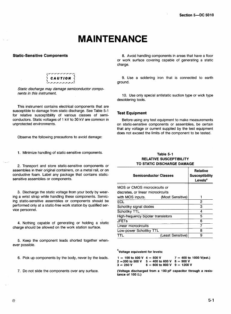
Section 5 D C 501 0
MAINTENANCE
Static-Sensitive Components
C A U T I O N a Static discharge may damage semiconductor compo- nents in this instrument.
This instrument contains electrical components that are susceptible to damage from static discharge. See Table 5-1 for relative susceptibility of various classes of semi- conductors. Static voltages of 1 kV to 30 kV are common in unprotected environments.
Observe the following precautions to avoid damage:
1. Minimize handling of static-sensitive components.
2. Transport and store static-sensitive components or assemblies in their original containers, on a metal rail, or on conductive foam. Label any package that contains static- sensitive assemblies or components.
3. Discharge the static voltage from your body by wear- ing a wrist strap while handling these components. Servic- ing static-sensitive assemblies or components should be performed only at a static-free work station by qualified ser- vice personnel.
8. Avoid handling components in areas that have a floor or work surface covering capable of generating a static charge.
9. Use a soldering iron that is connected to earth ground.
10. Use only special antistatic suction type or wick type desoldering tools.
Test Equipment
Before using any test equipment to make measurements on static-sensitive components or assemblies, be certain that any voltage or current supplied by the test equipment does not exceed the limits of the component to be tested.
Table 5-1 RELATIVE SUSCEPTIBILITY
TO STATIC DISCHARGE DAMAGE
Semiconductor Classes Relative
Susceptibility Levelsa
MOS or CMOS microcircuits or I
Schottkv sianal diodes I 3
discretes, or linear microcircuits with MOS inputs. (Most Sensitive) ECL
1 2
4. Nothing capable of generating or holding a static charge should be allowed on the work station surface.
. - Schottky TTL High-frequency bipolar transistors
4 5
TTL (Least Sensitive) I 9
JFETS Linear microcircuits Low-power Schottky TTL
5. Keep the component leads shorted together when- ever possible.
6 7 8
'voltage equivalent for levels:
6. Pick up components by the body, never by the leads.
7. Do not slide the components over any surface. (Voltage discharged from a 100 pF capacitor through a resis- tance of 100 Q.)
Circuit Board Removal and Replacement
Qualified service personnel will find the DC 501 0 instru- ment cover and board removal quite simple using the follow- ing procedure. Refer to Fig. 5-1 and the Parts Location Grids in the pullout pages.
1. Remove the two side covers (four 114 turn fasteners).
2. Remove the top and back covers (may be easily re- moved as a single unit).
Remove the top cover screws (2).
Remove the back cover 311 6" hex. bullet connec- tors (2). Remove the screw that secures the GPlB board to the back cover.
Carefully pull the covers up and back to remove.
3. To remove the Digital board and GPlB board (re- moved as a single unit).
Repeat steps 1 and 2 above.
Remove the bottom cover screw that secures the Digital board.
Disconnect the connector, PI 61 1 (J161 I), from the Auxiliary board.
Carefully remove the Digital and interconnected GPlB boards.
4. To remove the GPlB board from the Digital board.
a. Remove the screws (2) that secure the GPlB board to the Digital board.
b. Separate the two boards taking care not to dam- age the interconnector pins.
5. To remove the Analog board or the Auxiliary board (these boards are interconnected and must be removed together).
Repeat steps 1 and 2 above.
Remove the 9/16" nuts (2) from the front-panel Channel A and B bnc input connectors.
Remove the bottom cover screws (2) securing both the Analog and Auxiliary boards.
Disconnect the two connectors, P I 201 (J1201) and PI 130 (J1130), from the Analog board. , -
Disconnect the connectors, PI 500 (J1500) and PI 61 1 (J161 I), from the Auxiliary board.
Carefully pull the interconnected boards away from the connector (front panel back) using a gen- tle up and down rocking motion. Allow sufficient clearance for the input connectors through the front panel.
Gently pull the two boards apart, taking care not to damage the interface connector pins. Often it is easier to begin at one end of the board and separate the connectors one at a time.
NOTE
With the Analog board out of the instrument, the Channel A and B bnc connectors are subject to damage. Care should be taken to prevent breaking the bnc solder connection.
6. To remove the Display board. (Use the following to access the seven-segment LEDS and annunciator LEDS)
procedure.
Repeat steps 1 through 5 above.
Disconnect the single-pin connector, PI 321.
Remove the screws (4) that secure the Display board to the front panel (back).
Carefully remove the Display board, pulling up and away from the bottom and lifting out.
replace the circuit boards, reverse the above
Magnetic Latch Relays
To prevent damage to these relays, do not remove them from the Analog circuit board unless absolutely necessary. If the relay contacts become noisy or the relay fails to operate, remove the relay from the circuit board. The relays may be individually removed. Remove the two relay hold down screws located on the rear of the Analog board and carefully remove the relay.
Clean the circuit board contacts with a small brush and isopropyl alcohol. Do not use any solvent that may attack polycarbonates such as hydrocarbon chlorides, ketones, _ _ esters, etc. Do not use a cotton swab as small cotton fila- ments may remain on the contact area.
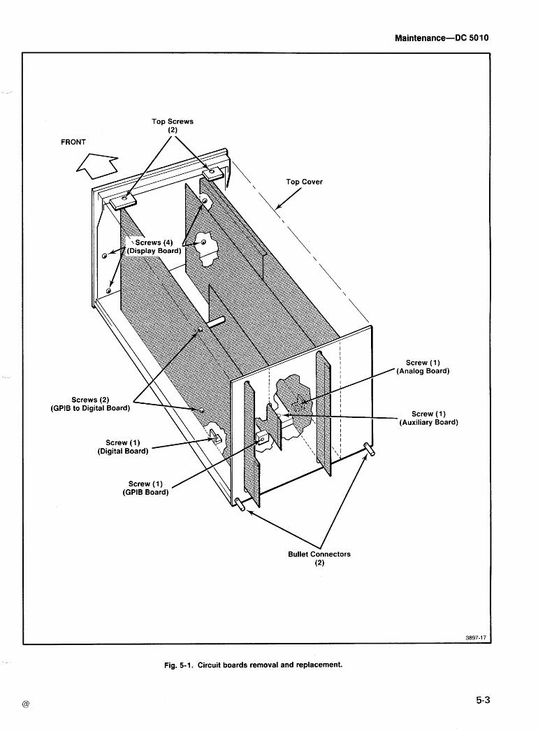
FRONT
Top Screws (2)
/\
Screw (1) / (Analog Board)
(GPIB - Screw (1) (Auxiliary Board)
Bullet connectors (2)
Fig. 5-1. Circuit boards removal and replacement.
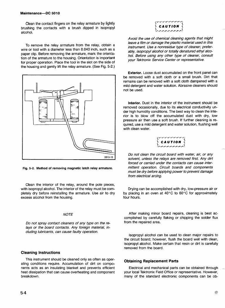
Clean the contact fingers on the relay armature by lightly brushing the contacts with a brush dipped in isopropyl alcohol.
To remove the relay armature from the relay, obtain a wire or tool with a diameter less than 0.040 inch, such as a paper clip. Before removing the armature, mark the orienta- tion of the armature to the housing. Orientation is important for proper operation. Place the tool in the slot on the side of the housing and gently lift the relay armature. (See Fig. 5-2.)
Fig. 5-2. Method of removing magnetic latch relay armature.
Clean the interior of the relay, around the pole pieces, with isopropyl alcohol. The interior of the relay must be com- pletely dry before reinstalling the armature. Use air to dry excess alcohol from the housing.
NOTE
Do not spray contact cleaners of any type on the re- lays or the board contacts. Any foreign material, in- cluding lubricants, can cause faulty operation.
Cleaning Instructions
This instrument should be cleaned only as often as oper- ating conditions require. Accumulation of dirt on compo- nents acts as an insulating blanket and prevents efficient heat dissipation that can cause overheating and component breakdown.
C A U T I O N a Avoid the use of chemical cleaning agents that might leave a film or damage the plastic material used in this instrument. Use a nonresidue type of cleaner; prefer- ably, isopropyl alcohol or totally denatured ethyl alco- hol. Before using any other type of cleaner, consult your Tektronix Service Center or representative.
Exterior. Loose dust accumulated on the front panel can be removed with a soft cloth or a small brush. Dirt that remains can be removed with a soft cloth dampened with a mild detergent and water solution. Abrasive cleaners should not be used.
Interior. Dust in the interior of the instrument should be removed occasionally, due to its electrical conductivity un- der high humidity conditions. The best way to clean the inte- rior is to blow off the accumulated dust with dry, low pressure air then use a soft brush. If further cleaning is re- quired, use a mild detergent and water solution, flushing well with clean water.
Do not clean the circuit board with water, air, or any solvent, unless the relays are removed first. Any dirf forced or carried under the contacts can cause inter- mittent opera tion. Circuit boards and components must be dry before applying power to prevent damage from electrical arcing.
Drying can be accomplished with dry, low-pressure air or by placing in an oven at 40°C to 60°C for approximately four hours.
After making minor board repairs, cleaning is best ac- complished by carefully flaking or chipping the solder flux from the repaired area.
lsopropyl alcohol can be used to clean major repairs to the circuit board; however, flush the board well with clean, isopropyl alcohol. Make certain that resin or dirt is carefully removed from the board.
Obtaining Replacement Parts
Electrical and mechanical parts can be obtained through your local Tektronix Field Office or representative. However, many of the standard electronic components can be ob-
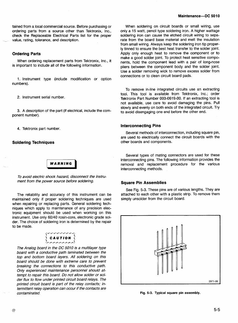
tained from a local commercial source. Before purchasing or ordering parts from a source other than Tektronix, Inc., check the Replaceable Electrical Parts list for the proper value, rating, tolerance, and description.
Ordering Parts
When ordering replacement parts from Tektronix, Inc., it is important to include all of the following information.
1. lnstrument type (include modification or option numbers).
2. lnstrument serial number.
3. A description of the part (if electrical, include the com- ponent number).
4. Tektronix part number.
Soldering Techniques
I W A R N I N G )
To avoid electric shock hazard, disconnect the instru- ment from the power source before soldering.
The reliability and accuracy of this instrument can be maintained only if proper soldering techniques are used when repairing or replacing parts. General soldering tech- niques which apply to maintenance of any precision elec- tronic equipment should be used when working on this instrument. Use only 60140 rosin-core, electronic grade sol- der. The choice of soldering iron is determined by the repair to be made.
The Analog board in the DC 501 0 is a multilayer type board with a conductive path laminated between the top and bottom board layers. All soldering on this board should be done with extreme care to prevent breaking the connections to this conductive path. Only experienced maintenance personnel should at- tempt to repair this board. Do not allow solder or sol- der flux to flow under printed circuit board relays. The printed circuit board is part of the relay contacts; in- termittent relay operation can occur if the contacts are contaminated.
When soldering on circuit boards or small wiring, use only a 15 watt, pencil type soldering iron. A higher wattage soldering iron can cause the etched circuit wiring to sepa- rate from the board base material and melt the insulation from small wiring. Always keep the soldering iron tip proper- ly tinned to ensure the best heat transfer to the solder joint. Apply only enough heat to remove the component or to make a good solder joint. To protect heat sensitive compo- nents, hold the component lead with a pair of long-nose pliers between the component body and the solder joint. Use a solder removing wick to remove excess solder from connections or to clean circuit board pads.
To remove in-line integrated circuits use an extracting tool. This tool is available from Tektronix, Inc.; order Tektronix Part Number 003-0619-00. If an extracting tool is not available, use care to avoid damaging the pins. Pull slowly and evenly on both ends of the integrated circuit. Try to avoid disengaging one end before the other end.
Interconnecting Pins
Several methods of interconnection, including square pin, are used to electrically connect the circuit boards with the other boards and components.
Several types of mating connectors are used for these interconnecting pins. The following information provides the removal and replacement procedure for the various interconnecting methods.
Square Pin Assemblies
See Fig. 5-3. These pins are of various lengths. They are attached to each other with a plastic strip. To remove them simply unsolder from the circuit board.
Fig. 5-3. Typical square pin assembly.
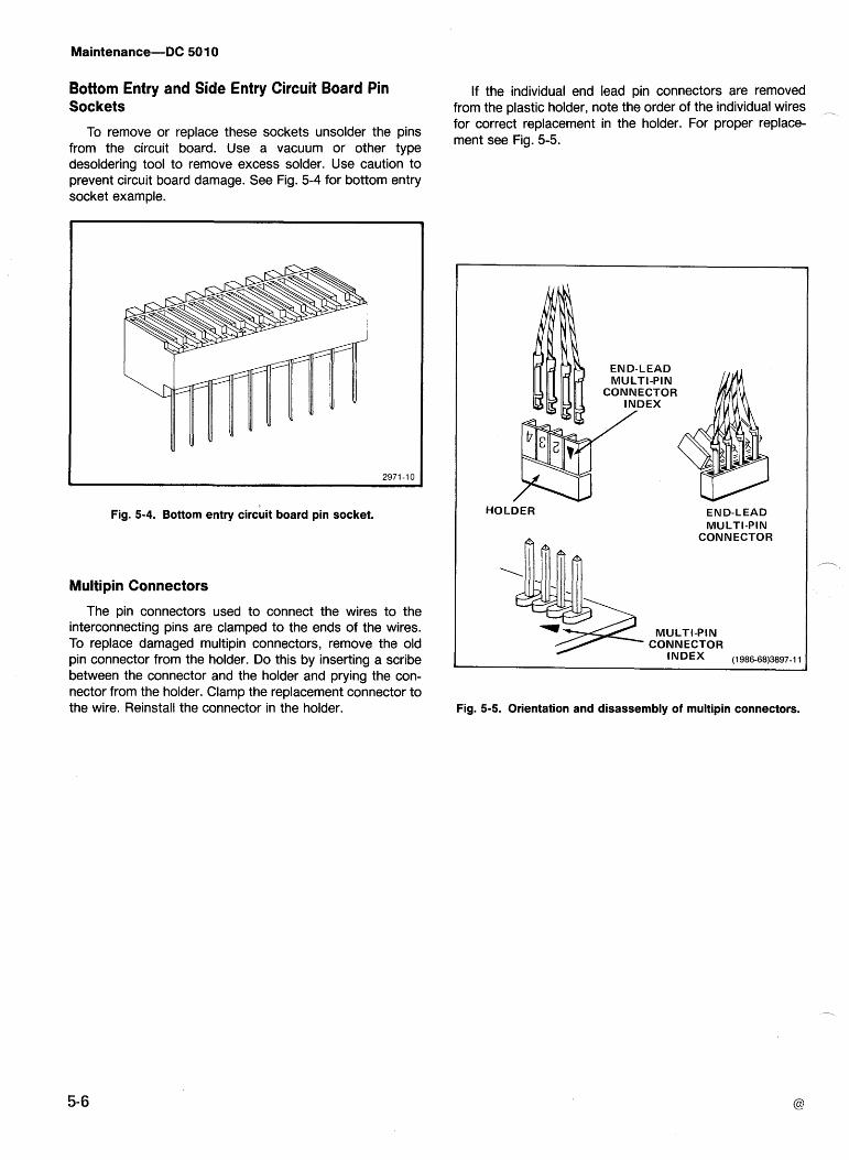
Bottom Entry and Side Entry Circuit Board Pin Sockets
To remove or replace these sockets unsolder the pins from the circuit board. Use a vacuum or other type desoldering tool to remove excess solder. Use caution to prevent circuit board damage. See Fig. 5-4 for bottom entry socket example.
Fig. 5-4. Bottom entry circuit board pin socket.
Multipin Connectors
The pin connectors used to connect the wires to the interconnecting pins are clamped to the ends of the wires. To replace damaged multipin connectors, remove the old pin connector from the holder. Do this by inserting a scribe between the connector and the holder and prying the con- nector from the holder. Clamp the replacement connector to the wire. Reinstall the connector in the holder.
If the individual end lead pin connectors are removed from the plastic holder, note the order of the individual wires - for correct replacement in the holder. For proper replace- ment see Fig. 5-5.
END-LEAD MULTI-PIN
CONNECTOR
HOLDER END-LEAD MULTI-PIN
CONNECTOR
MULTI-PIN CONNECTOR
INDEX
Fig. 5-5. Orientation and disassembly of multipin connectors.
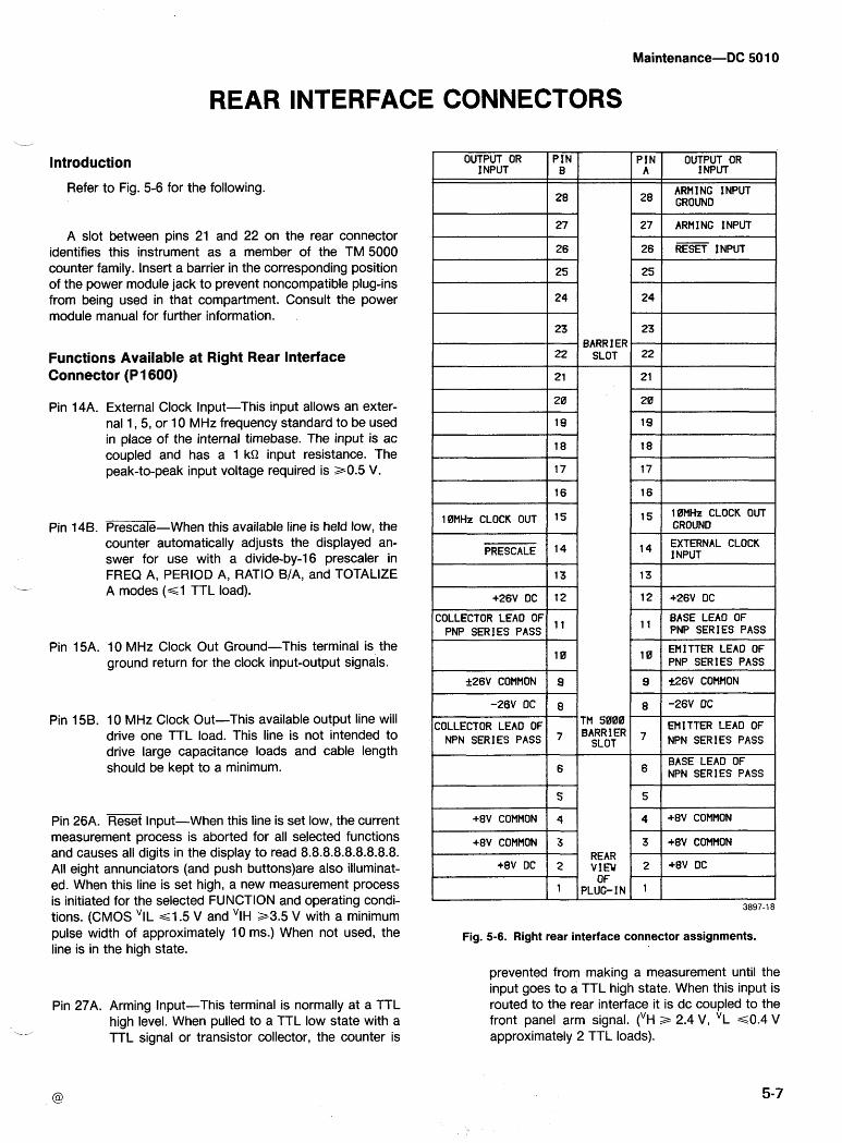
REAR INTERFACE CONNECTORS --
Introduction
Refer to Fig. 5-6 for the following. I OUTPUT OR
1 NPUT
A slot between pins 21 and 22 on the rear connector identifies this instrument as a member of the TM 5000 counter family. Insert a barrier in the corresponding position of the power module jack to prevent noncompatible plug-ins from being used in that compartment. Consult the power module manual for further information.
28
PIN B
Functions Available at Right Rear Interface Connector (P 1 600)
I
23
22
21
Pin 14A.
Pin 148.
Pin 15A.
Pin 158.
Pin 26A.
PIN A
28
External Clock Input-This input allows an exter- nal 1,5, or 10 MHz frequency standard to be used in place of the internal timebase. The input is ac coupled and has a 1 kQ input resistance. The peak-to-peak input voltage required is a0.5 V.
OUTPUT OR INPUT
ARMING INPUT GROUND
BARRIER SLOT
GROUND Fl
23 ,
22
21
Prescale-When this available line is held low, the counter automatically adjusts the displayed an- swer for use with a divide-by-16 prescaler in FREQ A, PERIOD A, RATIO BIA, and TOTALIZE A modes (GI TTL load).
I PRESCALE 1 14 1
1 :l 1 BASE LEAO OF 1 PNP SERIES PASS
EMITTER LEAD OF PNP SERIES PASS
10 MHz Clock Out Ground-This terminal is the ground return for the clock input-output signals. I t f26V COMMON 9
COLLECTOR LEAO OF EMITTER LEAD OF NPN SERIES PASS
10 MHz Clock Out-This available output line will drive one TTL load. This line is not intended to drive large capacitance loads and cable length should be kept to a minimum.
TM 5000 BARRIER
SLOT
Reset Input-When this line is set low, the current
pulse width of approximately 10 ms.) When not used, the Fig. 5-6. Right rear interface connector assignments. line is in the high state.
measurement process is aborted for all selected functions and causes all digits in the display to read 8.8.8.8.8.8.8.8.8. All eight annunciators (and push buttons)are also illuminat- ed. When this line is set high, a new measurement process
prevented from making a measurement until the input goes to a TTL high state. When this input is routed to the rear interface it is dc coupled to the front panel arm signal. ('H a 2.4 V, "L ~ 0 . 4 V approximately 2 TTL loads).
Pin 27A. Arming Input-This terminal is normally at a TTL high level. When pulled to a TTL low state with a
1- TTL signal or transistor collector, the counter is
is initiated for the selected FUNCTION and operating condi- 3897-1 8 tions. (CMOS 'IL ~ 1 . 5 V and 'IH a3.5 V with a minimum
*8v COMMON
+8V DC
3
2
1
REAR VIEW
OF PLUG-IN
3 '
2
1
*8v COMMON
*8V DC
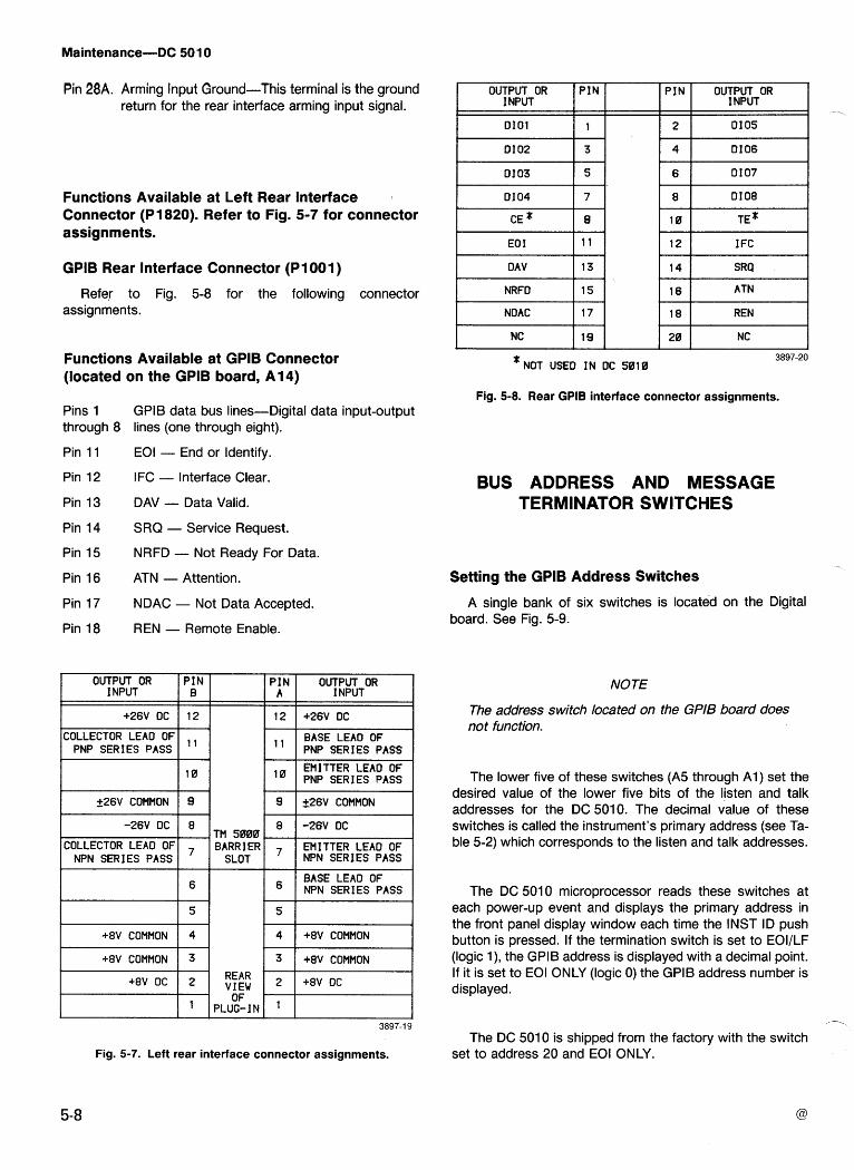
Pin 28A. Arming Input Ground-This terminal is the ground return for the rear interface arming input signal.
Functions Available at Left Rear Interface Connector (PI 820). Refer to Fig. 5-7 for connector assignments.
GPlB Rear Interface Connector (PI 001 )
Refer to Fig. 5-8 for the following connector assignments.
Functions Available at GPlB Connector (located on the GPlB board, A14)
Pins 1 GPlB data bus lines-Digital data input-output through 8 lines (one through eight).
Pin 11 EOI - End or Identify.
Pin 12 IFC - lnterface Clear.
Pin 13 DAV - Data Valid.
Pin 14 SRQ - Service Request.
Pin 15 NRFD - Not Ready For Data.
Pin 16 ATN - Attention.
Pin 17 NDAC - Not Data Accepted.
Pin 18 REN - Remote Enable.
OUTPUT OR INPUT
EMITTER LEAO OF PNP SERIES PASS
P IN B
t
COLLECTOR LEAD OF EMITTER LEAD OF NPN SERIES PASS NPN SERIES PASS
12
, , +26V DC
COLLECTOR LEAD OF PNP SERIES PASS
+26V COMMON
I BASE LEAO OF 1 6 1 1 6 1 N P N S E R l E S P A S S I
P IN A
+26V DC
BASE LEAD OF PNP SERIES PASS
12
I I
I +8V COMMON 1 4 4 +8V COMMON I
OUTPUT OR 1 NPUT
i
9
I I
+8V COMMON 1 3 3 +8V COMMON
9
Fig. 5-7. Left rear interface connector assignments.
226V COMMON
+8V DC
I OUTPUTOR IP IN I I P I N I OUTPUTOR 1 NPUT INPUT
3897-20 * NOT USED I N DC 501 0
Fig. 5-8. Rear GPlB interface connector assignments.
3897-1 9
2
BUS ADDRESS AND MESSAGE TERMINATOR SWITCHES
Setting the GPlB Address Switches
OF PLUG-IN
A single bank of six switches is located on the Digital board. See Fig. 5-9.
NOTE
2
The address switch located on the GPIB board does not function.
+8V DC
The lower five of these switches (A5 through A l ) set the desired value of the lower five bits of the listen and talk addresses for the DC 5010. The decimal value of these switches is called the instrument's primary address (see Ta- ble 5-2) which corresponds to the listen and talk addresses.
The DC 5010 microprocessor reads these switches at each power-up event and displays the primary address in the front panel display window each time the INST ID push button is pressed. If the termination switch is set to EOIILF (logic I ) , the GPlB address is displayed with a decimal point. If it is set to EOI ONLY (logic 0) the GPlB address number is displayed.
-\
The DC 501 0 is shipped from the factory with the switch set to address 20 and EOI ONLY.
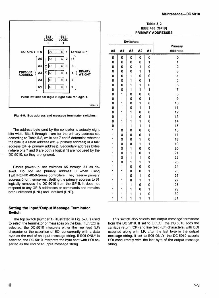
SET I
SET LOGIC LOGIC
0 1 1
EOI ONLY = 0 I I 1-1 1 I LF/EOI = 1
PRIMARY ADDRESS
BINARY WEIGHT
Push: left side for logic 0, right side for logic 1.
Fig. 5-9. Bus address and message terminator switches.
The address byte sent by the controller is actually eight bits wide. Bits 5 through 1 are for the primary address set according to Table 5-2, while bits 7 and 6 determine whether the byte is a listen address (32 + primary address) or a talk address (64 + primary address). Secondary address bytes (where bits 7 and 6 are both a logical 1) are not used by the DC 501 0, so they are ignored.
Before power-up; set switches A5 through A1 as de- sired. Do not set primary address 0 when using TEKTRONIX 4050-Series controllers. They reserve primary address 0 for themselves. Setting the primary address to 31 logically removes the DC 501 0 from the GPIB. It does not respond to any GPIB addresses or commands and remains both unlistened (UNL) and untalked (UNT).
Setting the InputlOutput Message Terminator Switch
The top switch (number I ) , illustrated in Fig. 5-9, is used to select the terminator of messages on the bus. If LF/EOI is selected, the DC 5010 interprets either the line feed (LF) character or the assertion of EOI concurrently with a data byte as the end of an input message string. If EOI ONLY is selected, the DC 501 0 interprets the byte sent with EOI as- serted as the end of an input message string.
Table 5-2 IEEE 488 (GPIB)
PRIMARY ADDRESSES
Switches Primary
A5 A4 A3 A2 A1 Address
This switch also selects the output message terminator from the DC 5010. If set to LFIEOI, the DC 5010 adds the carriage return (CR) and line feed (LF) characters, with EOI asserted along with LF, after the last byte in the output message string. If set to EOI ONLY, the DC 5010 asserts EOI concurrently with the last byte of the output message string.
Introduction
The following information is intended to aid in the diagno- sis and repair of a malfunctioning instrument. With power-on Self Test, signature analysis checks, and other troubleshooting data, the qualified service personnel will be able to verify proper operation or detect malfunction in this instrument.
Not all of the instrument faults may be isolated by this information or indicated by the instrument's built-in self test features. The service personnel should then refer to the Theory of Operation section, in this manual for a better un- derstanding of the circuit details.
Equipment Required
The recommended diagnostic tests require the following equipment or equivalent.
Data analyzer.
Digital counter.
Digital multimeter.
TEKTRONIX type SA 501 or type 308 Data Analyzer (for signature analysis)
TEKTRONIX type DC 503A (for time- base frequency checks)
TEKTRONIX type DM 501A (for checking power supplies)
Also refer to the equipment list in the Calibration section of this manual for suggestions on oscilloscope systems, probes, adapters, terminations and other equipment that may be useful for troubleshooting purposes.
Adjustment and Test Point Locations
When locating adjustable components and test points, refer to the Adjustment and Setups Location in the pullout pages of this manual.
Self Test
The DC 501 0 has three modes of self test. The automatic test sequence at power on, the TEST function selected by the front panel FUNCTION switch and the TEST function via the GPIB.
The automatic test sequence at power-on (Power On Self Test) is initiated each time the power is applied to the instrument. The microprocessor sequences through special data patterns to test the operation of the circuits in the in- strument. At power-on, after the microprocessor reset line has been released, the following tests are performed:
1. The display (time slot generator, schematic 10) is reset to the most significant digit (digit to extreme left) and a 0 readout is displayed.
2. The RAM is tested by writing a known bit pattern into the RAM and reading it back. Each byte in the RAM is veri- fied. If any byte does not verify, the RAM test error code is displayed on the front panel and the test sequence stops. The patterns written are FF, AA, 55, 00 (hexidecimal) in suc- cession leaving the RAM cleared when the test is finished. If this test is not successfully completed, the proper error code is displayed and the self test sequence stops.
3. The ROM's are checked for both placement and also proper checksums. If any of these tests fail, the power on self test sequence is stopped and the proper error code is displayed.
4. Next, the automatic test sequence sets the instru- ment gating to the RATIO B/A function.
5. The serial I/O data loop is checked next, by writing -. out a data pattern to the serial-to-parallel shift registers. The data pattern is read back through the parallel-to-serial shift registers. If the data are correct, the power-on sequence continues. If the data are not correct, the error code for this test is displayed and the test sequence stops. This test checks the shift registers and the data path, including the serial clock but does not check the input or output stages of the shift registers or the latch control lines. Troubleshooting of the serial I/O loop is best accomplished using signature analysis.
6. The next test is the counter integrity test. This test first resets the instrument's Channel A and Channel B accu- mulators by pulsing the MR (master reset) line. It then checks each of the tested counter stages to verify that all bits are reset. If any bits are not reset, the proper error code is displayed and the test sequence stops. Next, the signal, (schematic 3) is asserted. The instrument theninputs counts to the accumulators. These counts are generated by changing the trigger levels for both Channel A and Channel B using the' D/A converters. The D/A converter level changes (cycles) from its current setting to +2.0 V then to -2.0 V and back to +2.0 V. This cycle represents one count if the Channel A and Channel B input voltages are within this voltage range and the ARM signal, (schematic 6) is in the high state.
After each cycle or set of cycles, the accumulators are read and checked to see if the proper count has been
reached. If a count greater than or equal to the proper count has not been accumulated, the error code for that accumu- lator stage is displayed and the self test sequence stops.
-
An improper count might occur because of a bad counter chip, a bad readout chip, or a disconnected cable.
NOTE
The signal path starts at the D/A converters and the cycle must pass through the amplifiers, gating, and the accumulators. A first bit error (320, 330) may indi- cate an amplifier, FET or Schmitt error.
7. If the counter integrity test fails for any of the de- scribed reasons, the D/A converters will be set to -2 V. The gating (schematic 3), remains in the RATIO B/A func-
Internal signature analysis-this is a microprocessor driven pattern generator contained in the ROM. This meth- od will only work when the kernel microprocessor and its associated ROM, RAM, and connections are functional.
Kernel signature analysis-this requires the use of an external kernel test service kit (Tektronix part number 067- 1007-00). This method allows qualified service personnel to test and isolate problems in the kernel of the instrument.
Internal Signature Analysis
The internal signature analysis mode is entered at power- on by pressing the CHANNEL A TERM button (50 Q) as power is applied. This mode will not operate if the instru- ment fails the power on RAM test. Refer to Figs. 8-6, 8-7, 8- 8, and 8-9 in the pullout pages, for the inter~al signatures setup information for each circuit board.
tion and by applying a signal, that crosses the -2 V Trigger level settings, to the appropriate channel input, the service In the internal signature analysis mode, the serial loop is personnel can trace this signal through the amplifier, gating, easily The START, and and accumulator circuits. Also refer to Table 8-2 in the edge polarities r ~ s t be properly set as shown on the appro- pullout pages. priate signature diagram. When the instrument is in this
mode, all segments and annunciators in the display are
TEST Function
The TEST function from the front panel and over the bus is similar to the Power On Self Test sequence with one ex- ception. The RAM test is not executed, thereby preventing the instrument's settings from being lost while in the TEST function.
TROUBLESHOOTING
The following is a general troubleshooting procedure to use when the instrument malfunctions.
First, verify that the instrument is properly connected to the appropriate power module and that this power module is operable. Then refer to Fig. 8-5, General Troubleshooting Flowchart, in the pullout pages. This flowchart is a guide for qualified service personnel to locate various areas of circuit- ry, depending on the instrument symptoms. It may also refer the service personnel to the following signature analysis procedure.
SIGNATURE ANALYSIS
Introduction
The DC 501 0 was designed to be compatible with two signature analysis methods.
lighted, with the extreme left digit brighter than the other digits. The pushbuttons are also lighted.
To exit the Internal Signature Analysis mode, the instru- ment must be powered down and then powered up.
Kernel Signature Analysis
The Digital board microprocessor, U 130 1, is removed (observing proper static handling procedures) before making the kernel test.
The kernel signature analysis mode is used to diagnose problems that prevent the microprocessor kernel circuitry from functioning properly. It is used with a signature analyz- er to verify signatures in the kernel circuitry.
Make certain the power module power is off when con- necting this service kit to the instrument. To make the DC 501 0 kernel board connections, the GPlB board (A1 4) must first be removed (refer to Circuit Boards Removal and Replacement). Then, connect J1002 and J1003 of the Ker- nel Test board to J1210 and J1211 on the instrument Digital board (A16), respectively, using the cables and square pin adapters provided with the kit. Make sure that the cables do
not get twisted. The GPlB board is attached to the Kernel Test board as shown in Fig. 5-10. Connect the START, STOP, CLOCK, and GROUND connections of the analyzer to the test points as indicated on the appropriate Kernel Signature (Fig. 8-1 0 and Fig. 8-1 1) in the pullout pages. Also make sure that the START, STOP, and CLOCK polarities have been properly selected on the analyzer.
In troubleshooting the kernel, the following information may be helpful.
Microprocessor kernel problems in the DC 5010 can be isolated to either the GPlB board (A14) or the Digital board
(A1 6). This may be accomplished by first removing the GPlB board from the instrument. Then, insert the microprocessor S-,
(see the Electrical Parts list for U1510) in the U1510 IC socket on the Digital board. If the problem remains, check the Digital board. Troubleshoot the Digital board with the Kernel Test board and signature analyzer, as shown in Fig. 8-10. If the instrument operates properly, the problem is most likely on the GPlB board. Troubleshoot the GPlB board for kernel problems using the previously described kernel test and referring to Fig. 8-1 1.
The Kernel Test Service Kit may also be used to extend the GPlB board from the Digital board to troubleshoot com- ponents on the Digital board. This may be done by using just the cables and square pin adapters provided in the kit.
P I 21 1 (on GPlB board) J 100 1 (on Kernel test board) StartlSto~
DIGITAL BOARD (rear view)
Fig. 5- 10. Kernel signature analysis connections.
5-1 2
Two physically adjacent points having the same signa- ture, whether one or both are incorrect, may indicate they are shorted together.
A point with 0000 signature is grounded, or in a low state. A point with the +5 V signature (noted on each signa- ture diagram) may be opened or the driving node may be stuck in the high state. The point might also be shorted to +5 v.
When the malfunction has been identified and corrected, carefully re-insert the Digital board microprocessor, making certain that pin 1 is properly oriented and all pins insert in the socket properly. DO NOT FORCE the pins.
Selected Components (R1307 and R1326)
Refer to diagram 2 (board A12) in the pullout pages for the following.
If IC's U1310 and U1330 (M234 Type) are replaced and the input sensitivity (50 a) is found to exceed 57 mV peak- to-peak at 100 MHz (25°C ambient temperature), the fol- lowing procedure is recommended.
NOTE
If IC's U 1310 and U 1330 (M234) should have to be replaced, the input sensitivity is unlikely to vary.
The values of selected resistors, R1307 and R1326 (nominal value of 1.4 KC? each) may be changed to alter the input sensitivity for channels A and B respectively.
If the instrument requires more than a 57 mV peak-to- peak signal to trigger it, the resistance values of R1307 and R1326 will need to increase. The sensitivity will change ap- proximately 10 mV p-p forleach 500 ohms of resistance change.
REV OCT 1981

Section 6-DC SO1 0
OPTIONS Your instrument may be equipped with one or more instrument options or optional accessories. A brief description of
each instrument option is given below. For further information on instrument options or optional accessories, see your Tektronix Catalog or contact your Tektronix Field Office. If additional options are made available for this instrument, they may be described in a Change lnformation insert at the back of this manual or in this section.
OPTION 01
Replaces the standard 10 MHz oscillator with a self contained, proportional temperature controlled oven oscillator for increased accuracy and stability. Information relative to Option 01 can be found on schematic @ , and in the Specification, Calibration, and Theory of Operation sections.

Section 7-DC 50 10
REPLAC ELECTRICAL PARTS PARTS ORDERING INFORMATION
Replacement parts are available from or through your local Tektronix, Inc. Field Office or representative.
Only the circuit number will appear on the diagrams and circuit board illustrations. Each diagram and circuit board illustration is clearly marked with the assembly number. Assembly numbers are also marked on the mechanical exploded views located in the Mechanical Parts List. The component number is obtained by adding the assembly number prefix to the circuit number.
Changes to Tektronix instruments are sometimes made to accommodate improved components as they become available, and to give you the benefit of the latest circuit improvements developed in our engineering department. It is therefore impor- tant, when ordering parts, to include the following information in your order: Part number, instrument type or number, serial number, and modification number if applicable.
The Electrical Parts List is divided and arranged by assemblies in numerical sequence (e.g., assembly A1 with its subassemblies and parts, precedes assembly A2 with its sub- assemblies and parts). If a part you have ordered has been replaced with a new or
improved part, your local Tektronix, I nc. Field Office or represen- tative will contact you concerning any change in part number. Chassis-mounted parts have no assembly number prefix
and are located at the end of the Electrical Parts List. Change information, if any, is located at the rear of this
manual.
TEKTRONIX PART NO. (column two of the Electrical Parts List)
LIST OF ASSEMBLIES
A list of assemblies can be found at the beginning of the Electrical Parts List. The assemblies are listed in numerical order. When thecompletecomponent number of a part is known, this list will identify the assembly in which the part is located.
lndicates part number to be used when ordering replace- ment part from Tektronix.
CROSS INDEX-MFR. CODE NUMBER TO MANUFACTURER
SERIAL/MODEL NO. (columns three and four of the Electrical Parts List)
The Mfr. Code Number to Manufacturer index for the Electrical Parts List is located immediately after this page. The Cross Index provides codes, names and addresses of manufac- turers of components listed in the Electrical Parts List.
Column three (3) indicates the serial number at which the part was first used. Column four (4) indicatestheserial number at which the part was removed. No serial number entered indicates part is good for all serial numbers.
ABBREVIATIONS
Abbreviations conform to American National Standard Y1 .l. NAME 8a DESCRIPTION (column five ~f the Electrical Parts List)
In the Parts List, an ltem Name is separated from the description by a colon (:). Because of space limitations, an ltem Name may sometimes appear as incomplete. For further ltem Name identification, the U.S. Federal Cataloging Handbook H6-1 can be utilized where possible.
COMPONENT NUMBER (column one of the Electrical Parts List)
A numbering method has been used to identify assemblies, subassemblies and parts. Examples of this numbering method and typical expansions are illustrated by the following:
Example a. component number - A23R 1 234 A23 R1234 MFR. CODE (column six of the Electrical Parts
List) Assembly number \ Circuit number
lndicates the code number of the actual manufacturer of the part. (Code to name and address cross reference can be found immediately after this page.)
Read: Resistor 1234 of Assembly 23
Example b. component number - A23A2R1234 A23 A2 R1234
Assembly Subassembly Circuit number //- T u m b e r
MFR. PART NUMBER (column seven of the Electrical Parts List)
Read: Resistor 1234 of Subassembly 2 of Assembly 23 l ndicates actual manufacturers part number
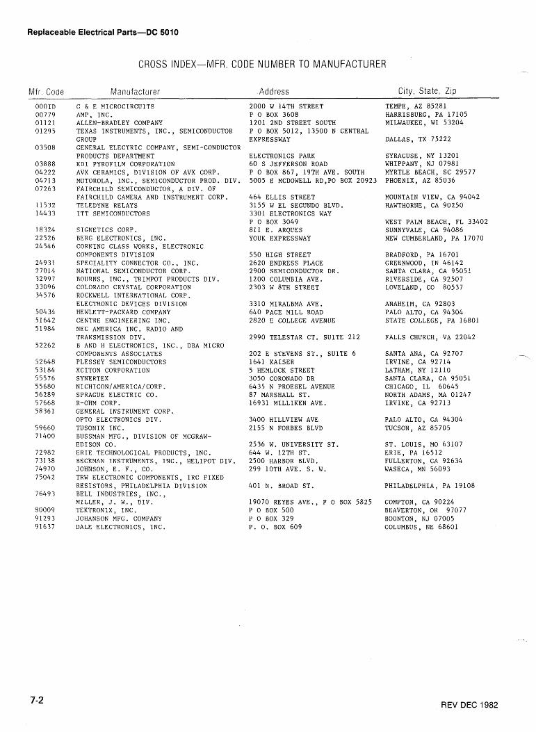
Replaceable Electrical Parts-DC 5010
CROSS INDEX-MFR. CODE NUMBER TO MANUFACTURER
Mfr. Code Manufacturer Address City, State, Zip
O O O I D 00779 01121 01295
03508
03888 04222 04713 07263
11532 144 3 3
18324 22526 24546
249 3 1 2 70 14 32997 33096 34576
50434 51642 5 1984
52262
52648 53184 55576 55680 56289 57668 58361
59660 7 1400
72982 731 38 74970 7 5042
76493
80009 91293 01637
G & E MICROCIRCUITS AMP, INC. ALLEN-BRADLEY COMPANY TEXAS INSTRUMENTS, INC., SEMICONDUCTOR GROUP GENERAL ELECTRIC COMPANY, SEMI-CONDUCTOR PRODUCTS DEPARTMENT KDI PYROFILM CORPORATION AVX CERAMICS, DIVISION OF AVX CORP. MOTOROLA, INC., SEMICONDUCTOR PROD. DIV. FAIRCHILD SEMICONDUCTOR, A DIV. OF FAIRCHILD CAMERA AND INSTRUMENT CORP. TELEDYNE RELAYS ITT SEMICONDUCTORS
SIGNETICS CORP. BERG ELECTRONICS, INC. CORNING GLASS WORKS, ELECTRONIC COMPONENTS DIVISION SPECIALITY CONNECTOR CO., INC. NATIONAL SEMICONDUCTOR CORP. BOURNS, INC., TRIMPOT PRODUCTS DIV. COLORADO CRYSTAL CORPORATION ROCKWELL INTERNATIONAL CORP. ELECTRONIC DEVICES DIVISION HEWLETT-PACKARD COMPANY CENTRE ENGINEERING INC. NEC AMERICA INC. RADIO AND TRANSMISSION DIV. B AND H ELECTRONICS, INC., DBA MICRO COMPONENTS ASSOCIATES PLESSEY SEMICONDUCTORS XCITON CORPORATION SYNERTEX NICH1CON/AMERICA/CORP. SPRAGUE ELECTRIC CO. R-OHM CORP. GENERAL INSTRUMENT CORP. OPT0 ELECTRONICS DIV. TUSONIX INC. BUSSMAN MFG., DIVISION OF MCGRAW- EDISON CO. ERIE TECHNOLOGICAL PRODUCTS, INC. BECKMAN INSTRUMENTS, INC., HELIPOT DIV. JOHNSON, E. F., CO. TRW ELECTRONIC COMPONENTS, IRC FIXED RESISTORS, PHILADELPHIA DIVISION BELL INDUSTRIES, INC., MILLER, J. W., DIV. TEKTRONIX , INC . JOHANSON MFG. COMPANY DALE ELECTRONICS, INC.
2000 W 14TH STREET P 0 BOX 3608 1201 2ND STREET SOUTH P 0 BOX 5012, 13500 N CENTRAL EXPRESSWAY
ELECTRONICS PARK 60 S JEFFERSON ROAD P 0 BOX 867, 19TH AVE. SOUTH 5005 E MCDOWELL RD,PO BOX 20923
464 ELLIS STREET 3155 W EL SEGUNDO BLVD. 3301 ELECTRONICS WAY P 0 BOX 3049 811 E. ARQUES YOUK EXPRESSWAY
550 HIGH STREET 2620 ENDRESS PLACE 2900 SEMICONDUCTOR DR. 1200 COLUMBIA AVE. 2303 W 8TH STREET
3310 MIRALBMA AVE. 640 PAGE MILL ROAD 2820 E COLLEGE AVENUE
2990 TELESTAR CT. SUITE 212
202 E STEVENS ST., SUITE 6 1641 KAISER 5 HEMLOCK STREET 3050 CORONADO DR 6435 N PROESEL AVENUE 87 MARSHALL ST. 16931 MILLIKEN AVE.
3400 HILLVIEW AVE 2155 N FORBES BLVD
2536 W. UNIVERSITY ST. 644 W. 12TH ST. 2500 HARBOR BLVD. 299 lOTH AVE. S. W.
401 N. BROAD ST.
19070 REYES AVE., P 0 BOX 5825 P 0 BOX 500 P 0 BOX 329 P. 0. BOX 609
TEMPE, AZ 85281 HARRISBURG, PA 17105 MILWAUKEE, WI 53204
DALLAS
SYRACUSE, NY 13201 WHIPPANY, NJ 07981 MYRTLE BEACH, SC 29577 PHOENIX, AZ 85036
MOUNTAIN VIEW, CA 94042 HAWTHORNE, CA 90250
WEST PALM BEACH, FL 33402 SUNNYVALE, CA 94086 NEW CUMBERLAND, PA 17070
BRADFORD, PA 16701 GREENWOOD, IN 46142 SANTA CLARA, CA 9505! RIVERSIDE, CA 92507 LOVELAND, CO 80537
ANAHEIM, CA 92803 PAL0 ALTO, CA 94304 STATE COLLEGE, PA 16801
FALLS CHURCH, VA 22042
SANTA ANA, CA 92707 IRVINE, CA 92714 LATHAM, NY 12110 SANTA CLARA, CA 95051 CHICAGO, IL 60645 NORTH ADAMS, MA 01247 IRVINE, CA 92713
PAL0 ALTO, CA 94304 TUCSON, AZ 85705
ST. LOUIS, MO 63107 ERIE, PA 16512 FULLERTON, CA 92634 WASECA, MN 56093
PHILADELPHIA, PA 19108
COMPTON, CA 90224 BEAVERTON, OR 97077 BOONTON, NJ 07005 COLUMBUS, NE 68601
REV DEC 1982
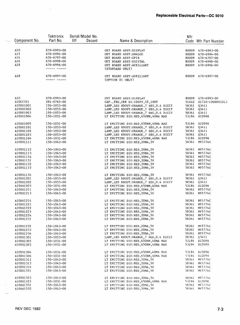
Replaceable Electrical Parts-DC 501 0
Tektronix SerialIModel No. Mf r -- Component No. Part No. Eff Dscont Name & Description Code Mfr Part Number
CKT BOARD ASSY:DISPLAY CKT BOARD ASSY:ANALOG CKT BOARD ASSY:GPIB CKT BOARD ASSY:DIGITAL CKT BOARD ASSY:AUXILIARY (STANDARD ONLY)
CKT BOARD ASSY:AUXILIARY (OPTION 01 ONLY)
CKT BOARD ASSY:DISPLAY CAP.,FXD,CER DI:lOOPF,5%,10OV LAMPSLED RDOUT:ORANGE,7 SEG,0.4 DIGIT LAMP,LED RDOUT:ORANGE,7 SEG,0.4 DIGIT LAMP,LED RDOUT:ORANGE,7 SEG,0.4 DIGIT LT EMITTING DIO:RED,650NMY40MA MAX
AlODS1005 AlODSllOl AlODS1102 AlODS1103 AlODS1104 AlODSllll
LT EMITTING DIO:RED,650NM,40MA MAX LAMP,LED RDOUT:ORANGE,7 SEG,0.4 DIGIT LAMP,LED RDOUT:ORANGE,7 SEG,0.4 DIGlT LAMP,LED RDOUT:ORANGE,7 SEG,0.4 DIGIT LT EMITTING DIO:RED,650NM,40MA MAX LT EMITTING DIO :RED, 20MA, 5V
LT EMITTING DIO:REDY20MA,5V LT EMITTING DIO:REDy20MA,5V LT EMITTING DIO:REDy20MA,5V LT EMITTING DIO : RED, 20MA, 5V LT EMITTING DIO:REDy20MA,5V LT EMITTING DIO:REDy20MA,5V
LT EMITTING DIO:REDy20MA,5V LAMP,LED RDOUT:ORANGE,7 SEG,0.4 DIGIT LAMP,LED RDOUT:ORANGE,7 SEG,0.4 DIGIT LT EMITTING DIO:RED,650NMY40MA MAX LT EMITTING DIO:RED,20MAY5V LT EMITTING DIO:RED,20MAY5V
LT EMlTTING DIO:REDy20MA,5V LT EMITTING DIO:RED,2OMAY5V LT EMITTING DIO:REDY20MA,5V LT EMITTING DIO:REDY20MA,5V LT EMITTlNG DIO:REDy20MA,5V LT EMITTING DIO:RED,20MA,5V
LT EMITTING DIO:RED,20MAY5V LT EMITTING DIO:REDy20MA,5V LT EMITTING DlO:RED,20MA,5V LAMP,LED RDOUT:ORANGE,7 SEG,0.4 DlGlT LT EMITTING DIO:RED,650NM,40MA MAX LT EMITTING DIO:RED,650NMY40MA MAX
LT EMITTlNG DlO:RED,650NM,40MA MAX LT EMITTlNG DlO:RED,650NM,40MA MAX LT EMITTING D1O:RED,20MAY5V LT EMITTING DIO:RED,20MA,5V LT EMITTING DIO:RED,20MA,5V LT EMITTING D1O:RED,20MAy5V
LT EMITTING D10: RED, 20MA, 5V LT EMlTTlNG DLO:RED,650NM,40MA MAX LT EMlTTlNG DIO:REDy20MA,5V LT EMlTTlNG DIO:RED,20MA,5V
REV DEC 1982
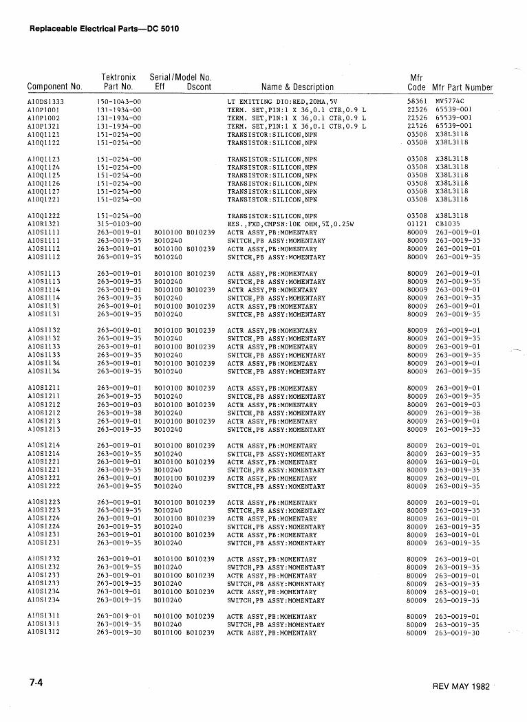
Replaceable Electrical Parts-DC 5010
Tektronix Serial /Model No. Mf r Component No. Part No. Eff Dscont Name & Description Code Mfr Part Number AlODS1333 AlOPlOOl A10P1002 A10P1321 A10Q1121 A10Q1122
AlOQ1123 AlOQll24 A10Q1125 A10Q1126 A10Q1127 A10Q1221
A1041222 A10R1321 AlOSllll AlOSllll A10S1112 A10S1112
A10S1113 A10S1113 A10S1114 A10S1114 A10S1131 A10S1131
AlOSll32 A10S1132 A10S1133 A10S1133 A10S1134 A10S1134
A10S1211 A10S1211 A10S1212 A10S1212 A10S1213 A10S1213
A10S1214 A10S1214 A10S1221 A10S1221 A10S1222 A10S1222
A10S1223 A10S1223 A10S1224 A10S1224 A10S1231 A10S1231
AlOS1232 A10S1232 A10S1233 A10S1233 A10S1234 A1 0s 1234
A10S1311 A10S1311 AlOSl312
LT EMITTING DIO:RED,20MA,5V 58361 MV5774C TERM. SET,PIN:l X 36,O.l CTR,0.9 L 22526 65539-001 TERM. SET,PIN:l X 36,O.l CTR,0.9 L 22526 65539-001 TERM. SET,PIN:l X 36,O.l CTR,0.9 L 22526 65539-001
TRANSISTOR:SILICON,NPN RES.,FXD,CMPSN:lOK OHM,5%,0.25W ACTR ASSY,PB:MOMENTARY SWITCH,PB ASSY:MOMENTARY ACTR ASSY,PB:MOMENTARY SWITCH,PB ASSY:MOMENTARY
BOlOlOO B010239 B010240 BOlOlOO B010239 B010240
BOlOlOO B010239 B010240 BOlOlOO B010239 B010240 BOlOlOO B010239 B010240
ACTR ASSY,PB:MOMENTARY SWITCH,PB ASSY:MOMENTARY ACTR ASSY,PB:MOMENTARY SWITCH,PB ASSY:MOMENTARY ACTR ASSY,PB:MOMENTARY SWITCH,PB ASSY:MOMENTARY
BOlOlOO B010239 B010240 BOlOlOO B010239 B010240 BOlOlOO B010239 B010240
ACTR ASSY,PB:MOMENTARY SWITCH,PB ASSY:MOMENTARY ACTR ASSY,PB:MOMENTARY SWITCH,PB ASSY:MOMENTARY ACTR ASSY,PB:MOMENTARY SWITCH,PB ASSY:MOMENTARY
BOlOlOO B010239 B010240 BOlOlOO B010239 B010240 BOlOlOO B010239 B010240
ACTR ASSY,PB:MOMENTARY SWITCH,PB ASSY:MOMENTARY ACTR ASSY,PB:MOMENTARY SWITCH,PB ASSY:MOMENTARY ACTR ASSY,PB:MOMENTARY SWITCH,PB ASSY:MOMENTARY
BOlOlOO B010239 B0 10 240 BOlOlOO B010239 B010240 BOlOlOO B010239 B010240
ACTR ASSY,PB:MOMENTARY SWITCH,PB ASSY:MOMENTARY ACTR ASSY,PB:MOMENTARY SWITCH,PB ASSY:MOMENTARY ACTR ASSY,PB:MOMENTARY SWITCH,PB ASSY:MOMENTARY
BOlOlOO B010239 B010240 BOlOlOO B010239 B010240 BOlOlOO B010239 B010240
ACTR ASSY,PB:MOMENTARY SWITCH,PB ASSY:MOMENTARY ACTR ASSY,PB:MOMENTARY SWITCH,PB ASSY:MOMENTARY ACTR ASSY,PB:MOMENTARY SWITCH,PB ASSY:MOMENTARY
BOlOlOO B010239 B010240 BOlOlOO B010239 B010240 BOlOlOO B010239 B010240
ACTR ASSY,PB:MOMENTARY SWITCH,PB ASSY:MOMENTARY ACTR ASSY,PB:MOMENTARY SWITCH,PB ASSY:MOMENTARY ACTR ASSY,PB:MOMENTARY SWITCH,PB ASSY:MOMENTARY
BOlOlOO B010239 B010240 BOlOlOO B010239
ACTR ASSY,PB:MOMENTARY SWITCH,PB ASSY:MOMENTARY ACTR ASSY,PB:MOMENTARY
REV MAY 1982
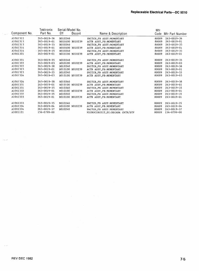
Replaceable Electrical Parts-DC 5010
Tektronix SerialIModel No. Mf r Component No. Part No. Eff Dscont Name & Description Code Mfr Part Number
B010240 BOlOlOO B010239 B010240 BOlOlOO B010239 B010240 BOlOlOO B010239
B010240 BOlOlOO B010239 B010240 BOlOlOO B010239 B010240 BOlOlOO B010239
B010240 BOlOlOO B010239 B010240 BOlOlOO B010239 B010240 BOlOlOO B010239
B010240 BOlOlOO B010239 B010240
SWITCH,PB ASSY:MOMENTARY ACTR ASSY,PB:MOMENTARY SWITCH,PB ASSY:MOMENTARY ACTR ASSY,PB:MOMENTARY SWITCH,PB ASSY:MOMENTARY ACTR ASSY,PB:MOMENTARY
SWITCH,PB ASSY:MOMENTARY ACTR ASSY,PB:MOMENTARY SWITCH,PB ASSY:MOMENTARY ACTR ASSY,PB:MOMENTARY SWITCH,PB ASSY:MOMENTARY ACTR ASSY,PB:MOMENTARY
SWITCH,PB ASSY:MOMENTARY ACTR ASSY,PB:MOMENTARY SWITCH,PB ASSY:MOMENTARY ACTR ASSY,PB:MOMENTARY SWITCH,PB ASSY:MOMENTARY ACTR ASSY,PB:MOMENTARY
SWITCH,PB ASSY:MOMENTARY ACTR ASSY,PB:MOMENTARY SWITCH,PB ASSY:MOMENTARY MICROCIRCUIT,DI:DECADE CNTR~DTV
REV DEC 1982
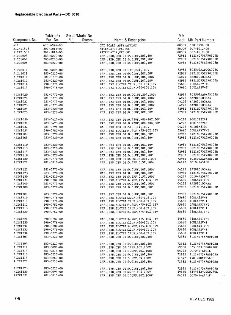
Replaceable Electrical Parts-DC 5010
Tektronix SerialIModel No. Component No. Part No. Eff Dscont Name & Descri~tion
Mf r Code Mfr Part Number
CKT BOARD ASSY:ANALOG ATTENUATOR,FXD:5X ATTENUATORyFXD:5X CAP.,FXD,CER DI:O.OlUF,20%,5oV CAP.,FXD,CER ~1:0.01~~,20%,50V CAP.,FXD,CER DI:O.OlUF,20%,5OV
REV DEC 1982
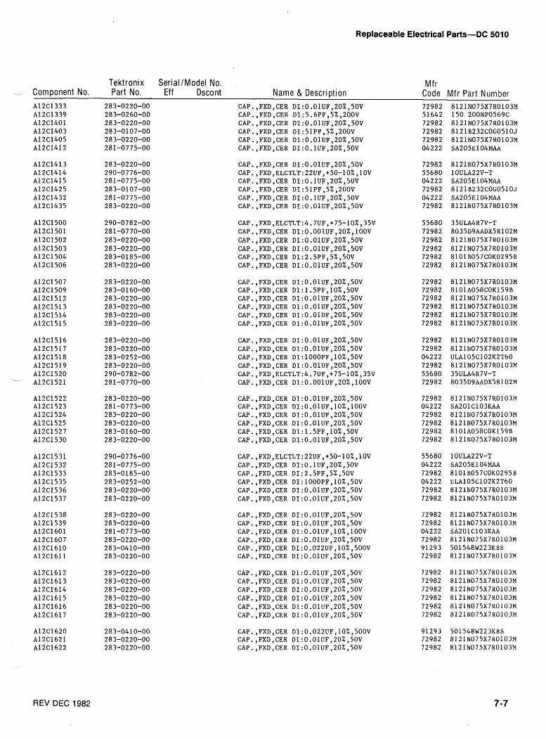
Replaceable Electrical Parts-DC 5010
Tektronix SerialIModel No. Mf r - Component No. Part No. Eff Dscont Name & Description Code Mfr Part Number
REV DEC 1982
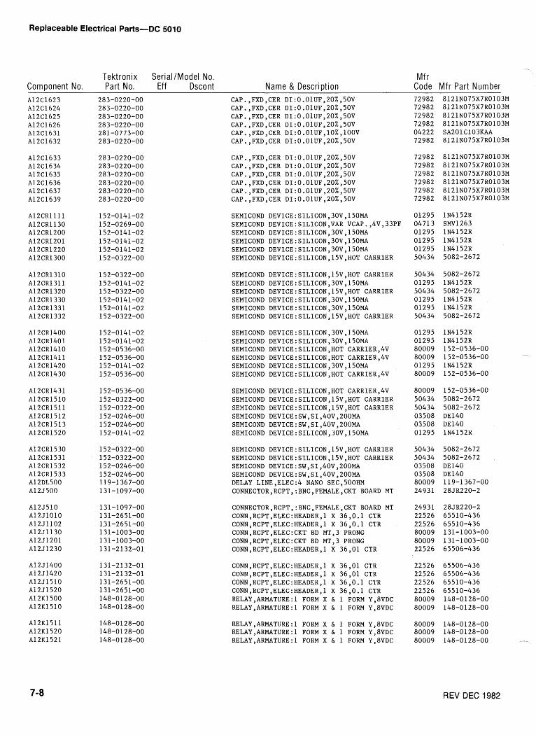
Replaceable Electrical Parts-DC 5010
Tektronix SeriallModel No. Component No. Part No. Eff Dscont Name & Description
Mfr Code Mf r Part N um ber
SEMICOND DEVICE:SILICON,30V,150MA SEMICOND DEVICE:SILICON,VAR VCAP.,4V,33PF SEMICOND DEVICE:SILICON,30V,150MA SEMICOND DEVICE:SILICON,30V,150MA SEMICOND DEVICE:SILICON,30V,150MA SEMICOND DEVICE:SILICON,15V,HOT CARRIER
SEMICOND DEVICE:SILICON,15V,HOT CARRIER SEMICOND DEVICE:SILICON,30V,150MA SEMICOND DEVICE:SILICON,15V,HOT CARRIER SEMICOND DEVICE:SILICON,30V,150MA SEMICOND DEVICE:SILICON,30V,150MA SEMICOND DEVICE:SILICON,15V,HOT CARRIER
SEMICOND DEVICE:SILICON,30V,150MA SEMICOND DEVICE:SILICON,30V,150MA SEMICOND DEVICE:SILICON,HOT CARRIER,OV SEMICOND DEVICE:SILICON,HOT CARRIER,4V SEMICOND DEVICE:SILICON,30V,150MA SEMICOND DEVICE:SILICON,HOT CARRIERY4V
SEMICOND DEVICE:SILICON,HOT CARRIERY4V SEMICOND DEVICE:SILICON,15V,HOT CARRIER SEMICOND DEVICE:SILICON,15V,HOT CARRIER SEMICOND DEVICE:SW,SI,40V,200MA SEMICOND DEVICE:SWYSI,40V,200MA SEMICOND DEVICE:SILICON,30V,150MA
SEMICOND DEVICE:SILICON,15V,HOT CARRIER SEMICOND DEVICE:SILICON,15V,HOT CARRIER SEMICOND DEVICE:SWYSI,40V,200MA SEMICOND DEVICE:SW,SI,40V,200MA DELAY LINE,ELEC:4 NAN0 SECY500HM CONNECTOR,RCPT,:BNC,FEMALE,CKT BOARD MT
CONNECTOR,RCPT,:BNC,FEMALE,CKT BOARD MT CONN,RCPT,ELEC:HEADER,l X 36,O.l CTR CONN,RCPT,ELEC:HEADER,l X 36,O.l CTR CONN,RCPT,ELEC:CKT BD MT,3 PRONG CONN,RCPT,ELEC:CKT BD MT,3 PRONG CONN,RCPT,ELEC:HEADER,l X 36,Ol CTR
CONN,RCPT,ELEC:HEADER,l X 36,Ol CTR CONN ,RCPT ,ELEC:HEADER, 1 X 36,Ol CTR CONN , RCPT ,ELEC :HEADER, 1 X 36,O. 1 CTR CONN,RCPT,ELEC:HEADER,l X 36,O.l CTR RELAY,ARMATURE:l FORM X & 1 FORM Y,8VDC RELAY,ARMATURE:l FORM X & 1 FORM Y,8VDC
RELAY,ARMATURE:l FORM X & 1 FORM Y,8VDC RELAY,ARMATURE:l FORM X 6 1 FORM Y,8VDC RELAY,ARMATURE:l FORM X & 1 FORM Y,8VDC
REV BEC 1982
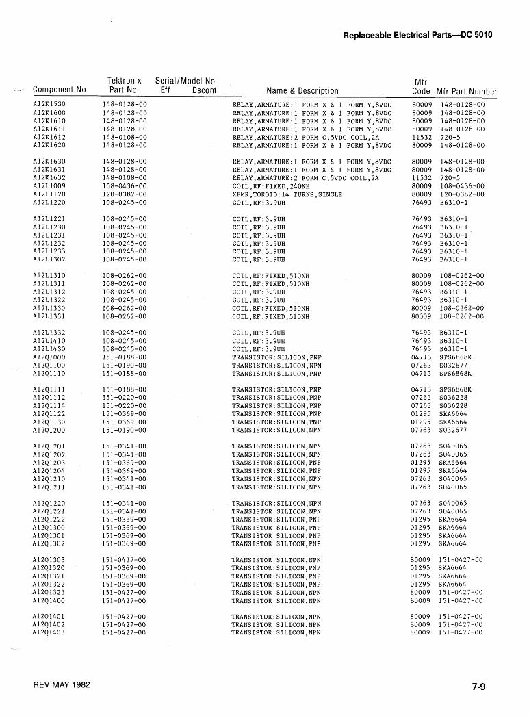
Replaceable Electrical Parts-DC 5810
Tektronix Serial /Model No. Mfr --- Component No. Part No. Eff Dscont Name & Description Code Mfr Part Number RELAY, ARMATURE : 1 FORM X & 1 FORM Y ,8VDC RELAY,ARMATURE:l FORM X & 1 FORM Y,8VDC RELAY,ARMATURE:l FORM X & 1 FORM Y,8VDC RELAY,ARMATURE:l FORM X & 1 FORM Y,8VDC RELAY,ARMATURE:2 FORM C,5VDC COIL,2A RELAY,ARMATURE:l FORM X & 1 FORM Y,8VDC
RELAY,ARMATURE:l FORM X & 1 FORM Y,8VDC RELAY,ARMATURE:l FORM X & 1 FORM Y,8VDC RELAY,ARMATURE:2 FORM C,5VDC COIL,2A COILyRF:FIXED,240NH XFMR,TOROID:14 TURNS,SINGLE COIL, RF : 3.9UH
COILYRF:3.9UH COIL,RF:3.9UH COILYRF:3.9UH CO1LyRF:3.9UH COILYRF:3.9UH COIL, RF : 3.9UH
REV MAY 1982
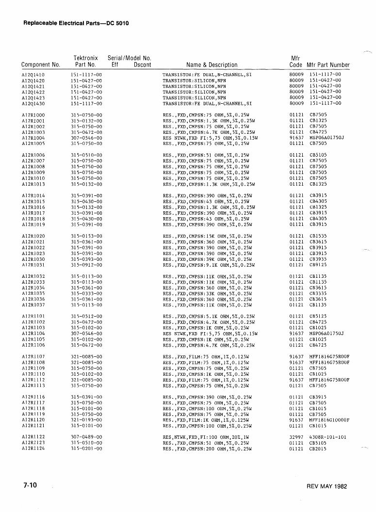
Replaceable Electrical Parts-DC 5010
Tektronix SerialIModel No. Mf r Component No. Part No. Eff Dscont Name & Description Code Mfr Part Number
RES.,FXD,CMPSN:75 OHMY5%,0.25W RES.,FXDYCMPSN:1.3K OHMY5%,0.25W RES.,FXD,CMPSN:75 OHM,5%,0.25W RES.,FXDYCMPSN:4.7K OHMY5%,0.25W RES NTWK,FXD FI:5,75 OHMY5%,0.15W RES.,FXD,CMPSN:75 OHMY5%,0.25W
RES.,FXDYCMPSN:5.1K OHMY5%,0.25W RES.,FXDYCMPSN:4.7K OHMY5%,0.25W RES.,FXD,CMPSN:lK OHMY5%,0.25W RES NTWK,FXD FI:5,75 OHMY5%,0.15W RES.,FXD,CMPSN:lK OHM,5%,0.25W RES.,FXDYCMPSN:4.7K OHMY5%,0.25W
REV MAY 1982
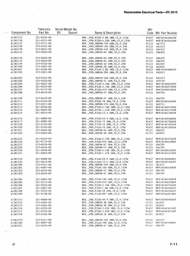
Replaceable Electrical Parts-DC 50 10
Tektronix SeriallModel No. Mf r --- Component No. Part No. Eff Dscont Name & Description Code Mfr Part Number
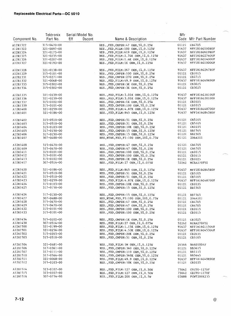
Replaceable Electrical Parts-DC 501 0
Tektronix SerialIModel No. Component No. Part No. Eff Dscont Name & Description
Mfr Code Mfr Part Number
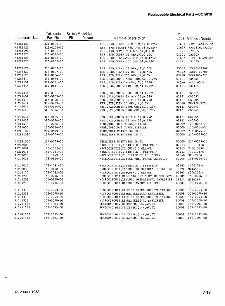
Replaceable Electrical Parts-DC 5010
Tektronix SerialIModel No. Mfr _, Component No. Part No. Eff Dscont Name & Description Code Mfr Part Number
TERM,TEST PO1NT:BRS CD PL MICROCIRCUIT,DI:TRIPLE D FLIPFLOP MICROCIRCUIT,DI:QUINT 2 ORINOR MICROCIRCUIT,DI:TRIPLE D FLIPFLOP MICROCIRCUIT,DI:DIVIDE BY 80 150MHZ MICROCIRCUIT,DI:SGL FREQ~PHASE DETECTOR
MICROCIRCUIT,DI:TRIPLE D FLIPFLOP MICROCIRCUIT,LI:DUAL OPERATIONAL AMPLIFIER MICROCIRCUIT,DI:QUINT 2 ORINOR MICROCIRCUIT,DI:8 STG SHE & STORE BUS RGTR MICROCIRCUIT,LI:DUAL OPERATIONAL AMPLIFIER MICROCIRCUIT,DI:HEX INVERTERIBUFFER
MICROCIRCUIT,LI:HIGH SPEED SCHMITT TRIGGER MICROCIRCUIT,LI:ML,VERTICAL AMPLIFIER MICROCIRCUIT,LI:HIGH SPEED SCHMITT TRIGGER MICROCIRCUIT,LI:ML,VERTICAL AMPLIFIER SEMICOND DEVICE:ZENERy0.4W,4V,5% SEMICOND DEVICE:ZENERy0.4W,4V,5%
SEMICOND DEVICE:ZENERY0.4W,4V,5% SEMICOND DEVICE:ZENERy0.4W,4V,5%
REV MAY 1982
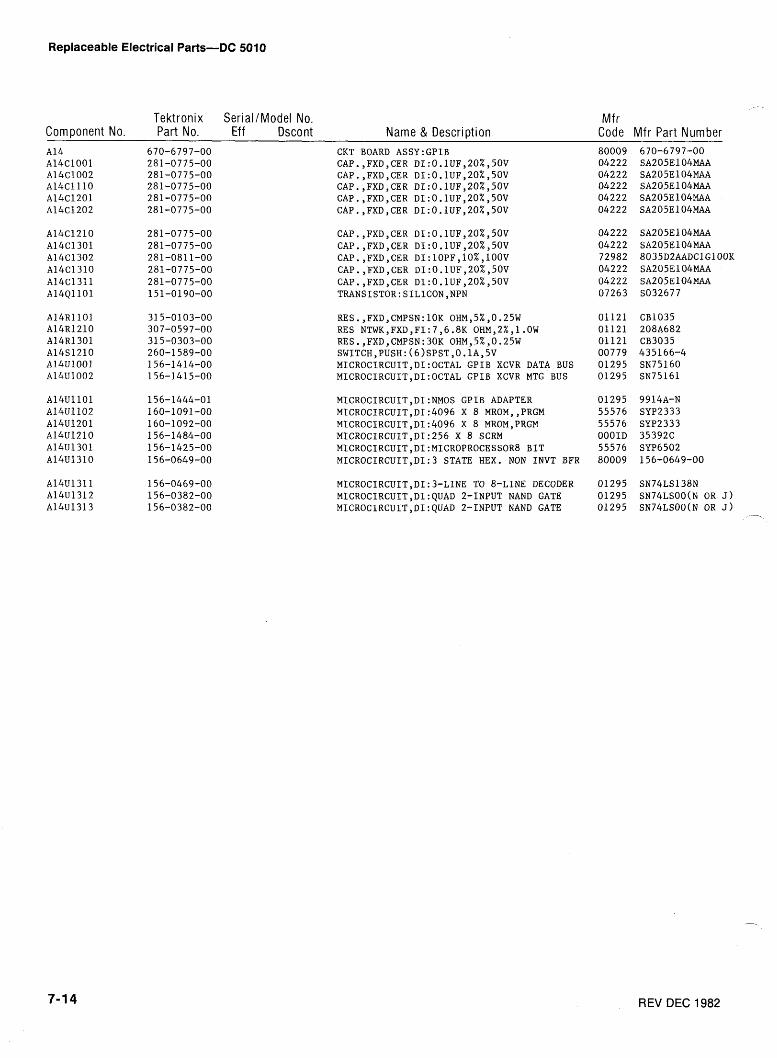
Replaceable Electrical Parts-DC 5010
Tektronix SerialIModel No. Mf r Component No. Part No. Eff Dscont Name & Description Code Mfr Part Number
CKT BOARD ASSY:GPIB CAP.,FXD,CER DI:O.lUF,20%,50V CAP.,FXD,CER DI:O.lUF,20%,50V CAP.,FXD,CER DI:O.lUF,20%,5OV CAP.,FXD,CER DI:0.1UFY20%,50V CAP.,FXD,CER DI:O.lUF,20%,50V
RES.,FXD,CMPSN:lOK OHM,5%,0.25W RES NTWK,FXD,FI:7,6.8K OHM,Z%,l.OW RES.,FXD,CMPSN:30K OHM,5%,0.25W SWITCH,PUSH:(~)SPST,O.~A,~V MICROCIRCUIT,DI:OCTAL GPIB XCVR DATA BUS MICROCIRCUIT,DI:OCTAL GPIB XCVR MTG BUS
MICROCIRCUIT,DI:NMOS GPIB ADAPTER MICROCIRCUIT,Dl:4096 X 8 MROM,,PRGM MICROCIRCUIT,DI:4096 X 8 MROM,PRGM MICROCIRCUlT,DI:256 X 8 SCRM MICROCIRCUIT,DI:MICROPROCESSOR8 BIT MICROCIRCUIT,DI:S STATE HEX. NON INVT BFR
MICROCIRCUIT,DI:3-LINE TO 8-LINE DECODER MICROCIRCUIT,DI:QUAD 2-INPUT NAND GATE MICROCIRCUIT,DI:QUAD 2-INPUT NAND GATE
80009 04222 04222 04222 04222 04222
04222 04222 72982 04222 04222 07263
01121 01121 01121 00779 01295 01295
01295 55576 55576 OOOID 55576 80009
01 295 01295 01295
REV DEC 1982
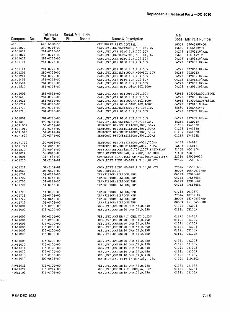
Replaceable Electrical Parts-DC 5010
Tektronix SerialIModel No. Mfr Component No. Part No. Eff Dscont Name & Description Code Mfr Part Number
CKT BOARD ASSY:DIGITAL CAP.,FXD,ELCTLT:22UF,+50-10%,10V CAP.,FXD,CER DI:O.lUF,20%,5OV CAP.,FXD,ELCTLT:47UF,+50-10%,16V CAP.,FXD,CER DI:O.lUF,20%,50V CAP.,FXD,CER DI:O.lUF,20%,50V
CAP.,FXD,CER DI:O.lUF,20%,50V CAP.,FXD,ELCTLT:22UF,+50-10%,25V SEMICOND DEVICE:SILICON,30V,150MA SEMICOND DEVICE:SILICON,30V,150MA SEMICOND DEVICE:SILICON,30V,150MA SEMICOND DEVICE:SILICON,30V,150MA
SEMICOND DEVICE:SILICONY400V,750MA SEMICOND DEVICE:SILICON,400VY750MA FUSE,CARTRIDGE:3AG,0.75Ay250VyFAST-BLOW FUSE,CARTRIDGE:3AG,3A,250V,0.65 SEC CONNECTOR,RCPT,:CKT CD MTGy20CONTACT,FEM CONN,RCPT,ELEC:HEADER,l X 36,Ol CTR
LG4O 16 LG4O 16 AGC 314 AGC 3 65001-025 65506-436
CONN,RCPT,ELEC:HEADER,l X 36,Ol CTR COIL ,RF: l5OUH TRANSISTOR:SILICON,PNP TRANSISTOR:SILICON,PNP TRANSISTOR:SILICON,PNP TRANSISTOR:SILICON,PNP
RES.,FXD,CMPSN:20 OHM,5%,0.25W RES.,FXD,CMPSN:lO OHM,5%,0.25W RES.,FXD,CMPSN:lO OHMY5%,0.25W RES.,FXD,CMPSN:lO OHMY5%,0.25W RES.,FXD,CMPSN:lO OHMY5%,0.25W RES NTWK,FXD F1:9,1K OHM,2%,1.25W
REV DEC 1982
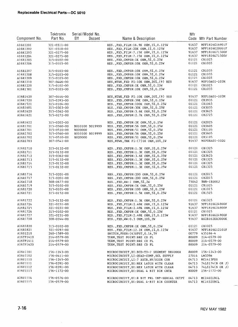
Replaceable Electrical Parts-DC 5010
Tektronix SerialIModel No. Mf r Component No. Part No. Eff Dscont Name & Description Code Mf r Part Number
RES.,FXD,CMPSN:lOK OHMY5%,0.25W RES.,FXD,CMPSN:lOK OHMY5%,0.25W RES.,FXD,CMPSN:lOK OHMY5%,0.25W RES,NTWK,FXD F1:lOK 0H~,20%,(9) RES RES.,FXD,CMPSN:lK OHMY5%,0.25W RES.,FXD,CMPSN:lOK OHMY5%,0.25W
RES,NTWK,FXD F1:lOK 0~~,20%,(9) RES RES.,FXDYCMPSN:39K OHMY5%,0.25W RES.,FXD,CMPSN:lOOK OHMY5%,0.25W RES.,FXDYCMPSN:30K OHMY5%,0.25W RES.,FXDYCMPSN:3.6K OHMY5%,0.25W RES.,FXDYCMPSN:2.7K OHMY5%,0.25W
RES.,FXD,CMPSN:2K OHMY5%,0.25W BOlOlOO B019999 RES.,FXD,CMPSN:56 OHMY5%,0.25W B020000 RES.,FXD,CMPSN:51 OHMY5%,0.25W BOlOlOO B019999 RES.,FXD,CMPSN:56 OHMY5%,0.25W B020000 RES.,FXD,CMPSN:51 OHMY5%,0.25W
RES,NTWK,THK FI:(7)1K OHM,lO%,lW
MICROCIRCUIT,DI:BCD-TO-7 SEGMENT DECODER MICROCIRCUIT,LI:QUAD-COMP,SGL SUPPLY MICROCIRCUIT,LI:7 XSTR,HV/HIGH CUR MICROCIRCUIT,DI:HEX LATCH WITH CLEAR MICROCIRCUIT,DI:HEX LATCH WITH CLEAR MICROCIRCUIT,DI:DUAL 4 BIT BIN CNTR
MICROCIRCUIT,DI:8 BIT PRL INP-SERIAL OUTPT MICROCIRCUIT,DI:DUAL 4-BIT BIN COUNTER
REV MAY 1982
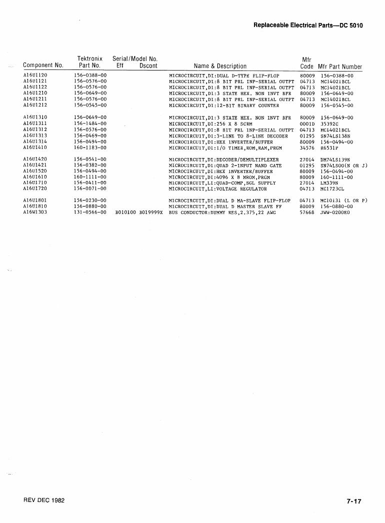
Replaceable Electrical Parts-DC 5010
Tektronix SeriallModel No. Mf r Component No. Part No. Eff Dscont Name & Description Code Mfr Part Number
MICROCIRCUIT,DI:DUAL D-TYPE FLIP-FLOP MICROCIRCUIT,DI:8 BIT PRL INP-SERIAL OUTPT MICROCIRCUIT,DI:8 BIT PRL INP-SERIAL OUTPT MICROCIRCUIT,DI:3 STATE HEX. NON INVT BFR MICROCIRCUIT,DI:8 BIT PRL INP-SERIAL OUTPT MICROCIRCUIT,DI:12-BIT BINARY COUNTER
MICROCIRCUIT,DI:3 STATE HEX. NON INVT BFR MICROCIRCUIT,DI:256 X 8 SCRM MICROCIRCUIT,DI:8 BIT PRL INP-SERIAL OUTPT MICROCIRCUIT,DI:3-LINE TO 8-LINE DECODER MICROCIRCUIT,DI:HEX INVERTERIBUFFER MICROCIRCUIT,DI:I/O TIMER,ROM,RAM,PRGM
MICROCIRCUIT,DI:DECODER/DEMULTIPLEXER MICROCIRCUIT,DI:QUAD 2-INPUT NAND GATE MICROCIRCUIT,DI:HEX INVERTERIBUFFER MICROCIRCUIT,DI:4096 X 8 MROM,PRGM MICROCIRCUIT,LI:QUAD-COMP,SGL SUPPLY MICROCIRCUIT,LI:VOLTAGE REGULATOR
MICROCIRCUIT,DI:DUAL D MA-SLAVE FLIP-FLOP MICROCIRCUIT,DI:DUAL D MASTER SLAVE FF
BOlOlOO B019999X BUS CONDUCT0R:DUMMY RES,2.375,22 AWG
80009 04713 04713 80009 04713 80009
80009 OOOID 04713 01295 80009 34576
27014 01295 80009 80009 27014 04713
04713 80009 57668
156-0649-00 35392C MCl402l BCL SN74LS138N 156-0494-00 R6531P
REV DEC 1982
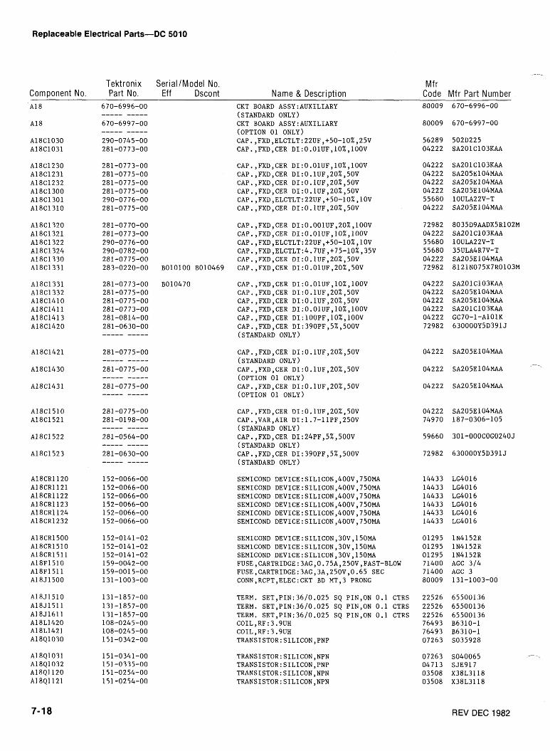
Replaceable Electrical Parts-DC 5010
Tektronix SeriallModel No. Component No. Part No. Eff Dscont Name & Descri~tion
Mfr Code Mfr Part Number
CKT BOARD ASSY:AUXILIARY (STANDARD ONLY) CKT BOARD ASSY:AUXILIARY (OPTION 01 ONLY) CAP.,FXD,ELCTLT:22UF,+50-10%,25V CAP.,FXD,CER DI:O.OIUFylO%,lOOV
CAP.,FXD,CER DI:O.O~UF,~O%,~OOV CAP.,FXD,CER DI:O.lUF,20%,50V CAP.,FXD,CER DI:O.lUF,20%,50V CAP.,FXD,CER DI:O.lUF,20%,50V CAP. ,FXDyELCTLT:22UF,+50-10%,10V CAP.,FXD,CER DI:O.lUF,20%,50V
CAP.,FXD,CER DI:0.001UF,20%,100V CAP.,FXD,CER DI:O.O1UF,10%,100V CAP.,FXD,ELCTLT:22UF,+50-10%,10V CAP.,FXD,ELCTLT:4,7UF,+75-10%,35V CAP.,FXD,CER DI:O.lUF,20%,50V
BOlOlOO B010469 CAP.,FXD,CER DI:O.OlUF,20%,50V
SEMICOND DEVICE:SILICON,400V,750MA SEMICOND DEVICE:SILICON,400V,750MA SEMICOND DEVICE:SILICON,400V,750MA SEMICOND DEVICE:SILICON,400V,750MA SEMICOND DEVICE:SILICON,400Vy750MA SEMICOND DEVICE:SILICON,400V,750MA
SEMICOND DEVICE:SILICON,30V,150MA SEMICOND DEVICE:SILICON,30Vy150MA SEMICOND DEVICE:SILICON,30V,150MA FUSE,CARTRIDGE:3AG,O.75A,250V,FAST-BLOW FUSE,CARTRIDGE:3AG,3A,250V,0.65 SEC CONN,RCPT,ELEC:CKT BD MT,3 PRONG
TERM. S~T,PI~:36/0.025 SQ PINYON 0.1 CTRS TERM. SET,PIN:36/0.025 SQ PINYON 0.1 CTRS TERM. SET,PIN:36/0.025 SQ PIN,ON 0.1 CTRS COIL,RF:3.9UH COIL,RF:3.9UH TRANSISTOR:SILICON,PNP
1N4152R 1N4152R 1N4152R AGC 314 AGC 3 131-1003-00
REV DEC 1982
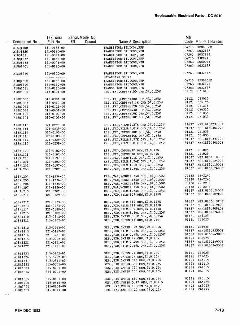
Replaceable Electrical Parts-DC 5010
Tektronix SerialIModel No. Mfr - - - Component No. Part No. Eff Dscont Name & Description Code Mfr Part Number
REV DEC 1982
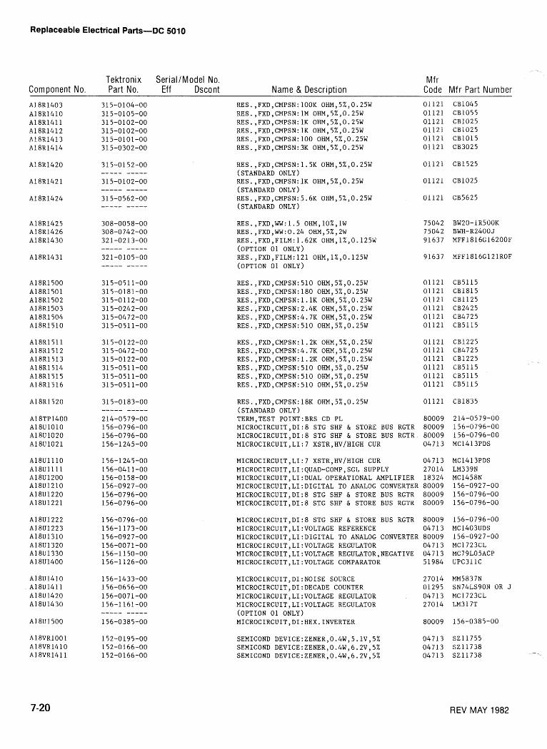
Replaceable Electrical Parts-DC 5010
Tektronix Serial /Model No. Mf r Component No. Part No. Eff Dscont Name & Description Code Mfr Part Number
RES.,FXDYCMPSN:18K OHMY5%,0.25W 01121 (STANDARD ONLY) TERM,TEST PO1NT:BRS CD PL 80009 MICROCIRCUIT,DI:8 STG SHF & STORE BUS RGTR 80009 MICROCIRCUIT,DI:8 STG SHF & STORE BUS RGTR 80009 MICROCIRCUIT,LI:7 XSTR,HV/HIGH CUR 04713
MICROCIRCUIT,LI:7 XSTR,HV/HIGH CUR 04 7 13 MICROCIRCUIT,LI:QUAD-COMP,SGL SUPPLY 27014 MICROCIRCUIT,LI:DUAL OPERATIONAL AMPLIFIER 18324 MICROCIRCUIT,LI:DIGITAL TO ANALOG CONVERTER 80009 MICROCIRCUIT,DI:8 STG SHF & STORE BUS RGTR 80009 MICROCIRCUIT,DI:8 STG SHF & STORE BUS RGTR 80009
MICROCIRCUIT,DI:8 STG SHF & STORE BUS RGTR 80009 MICROCIRCUIT,LI:VOLTAGE REFERENCE 04713 MICROCIRCUIT,LI:DIGITAL TO ANALOG CONVERTER 80009 MICROCIRCUIT,LI:VOLTAGE REGULATOR 04713 MICROCIRCUIT,LI:VOLTAGE REGULATOR,NEGATIVE 04713 MICROCIRCUIT,LI:VOLTAGE COMPARATOR 51984
MICROCIRCUIT,DI:NOISE SOURCE MICROCIRCUIT,DI:DECADE COUNTER MICROCIRCUIT,LI:VOLTAGE REGULATOR MICROCIRCUIT,LI:VOLTAGE REGULATOR (OPTION 01 ONLY) MICROCIRCUIT,DI:HEX.INVERTER
SEMICOND DEVICE:ZENERy0.4W,5.1V,5% 047 13 SEMICOND DEVICE:ZENERy0.4W,6.2V,5% 04713 SEMICOND DEVICE:ZENERy0.4W,6.2V,5% 04713
REV MAY 1982

Replaceable Electrical Parts-DC 501 0
Tekt ron ix Ser ia l /Mode l No. Mf r '-Component No. Part No. Eff Dscont Name & Descr ipt ion Code Mfr Part Number
A 1 8 Y 1 5 2 0 158-0129-00 XTAL UNIT,QTZ:lOMHZ,0.001~,PARALLEL 33096 PBllOY ----- ----- (STANDARD ONLY)
A18Y 1530 11 9-0894-0 1 OSCILLATOR,RF:lOMHZ,IbV 80009 1 1 9 - ~ 9 4 4 ~ 1 ----- ----- (OPTION 01 ONLY)

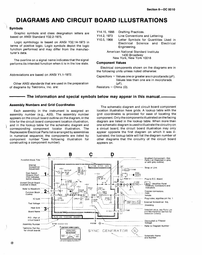
Section 8 D C 501 0
DIAGRAMS AND CIRCUIT BOARD ILLUSTRATIONS Symbols
Graphic symbols and class designation letters are based on ANSl Standard Y32.2-1975.
Logic symbology is based on ANSl Y32.14-1973 in terms of positive logic. Logic symbols depict the logic function performed and may differ from the manufac- turer's data.
The overline on a signal name indicates that the signal performs its intended function when it is in the low state.
Abbreviations are based on ANSl Y1 .l-1972.
Other ANSl standards that are used in the preparation of diagrams by Tektronix, Inc. are:
Y14.15, 1966 Drafting Practices. Y14.2, 1973 Line Conventions and Lettering. Y10.5, 1968 Letter Symbols for Quantities Used in
Electrical Science and Electrical Engineering.
American National Standard Institute 1430 Broadway
New York, New York 10018
Component Values Electrical components shown on the diagrams are in
the following units unless noted otherwise:
Capacitors = Values one or greater are in picof-arads (pF). Values less than one are in microfarads (/m.
Resistors = 0 hms (n).
The information and special symbols below may appear in this manual..
Assembly Numbers and Grid Coordinates
Each assembly in the instrument is assigned an assembly number (e.g., A20). The assembly number appears on the circuit board outline on the diagram, in the title for the circuit board component location illustration, and in the lookup table for the schematic diagram and corresponding component locator illustration. The Replaceable Electrical Parts list is arranged by assemblies in numerical sequence; the components are listed by component number *(see following illustration for
The schematic diagram and circuit board component location illustration have grids. A lookup table with the grid coordinates is provided for ease of locating the component. Only the components illustrated on the facing diagram are listed in the lookup table. When more than one schematic diagram is used to illustrate the circuitry on a circuit board, the circuit board illustration may only appear opposite the first diagram on which it was il- lustrated; the lookup table will list the diagram number of other diagrams that the circuitry of the circuit board
constructing a component number). appears on.
A B C D Funct~on Block T~t le
Internal Screwdriver --" -,, Adjustment
Cam Switch Closure Chart -- (Dot Indicates sw~tch closure)
Etched C~rcu~t Board 7, Outlined In Black
Refer to Waveform -
IC type - Test Voltage -
Heat Sink -
Board Name -
PIO-Part of crrcult board - *----
Assembly Num bbr - a-XXXX-xx -* - -- - a- --*
Tektron~x Part No r"# *COMPONENT NUMBER EXAMPLE
for clrcult boards S Y N C G E N E R A T O R @ -.,
%L -. -- ?L-..
Modified Component-See Parts List (Depicted in grey, or with grey outline)
Strap or Link
Plug to E.C. Board
Box - Identifies Panel on rols, Connectors and L J
l ndicators
Coaxial connectors: male female
Plug Index; signifies pin No. 1
External Screwdriver Adj.
Shielding
Selected value, see Parts List and Maintenance Section for Selection Criteria
Decoupled or Filtered Voltage
Refer to Diagram Number
Schematic Name and Number
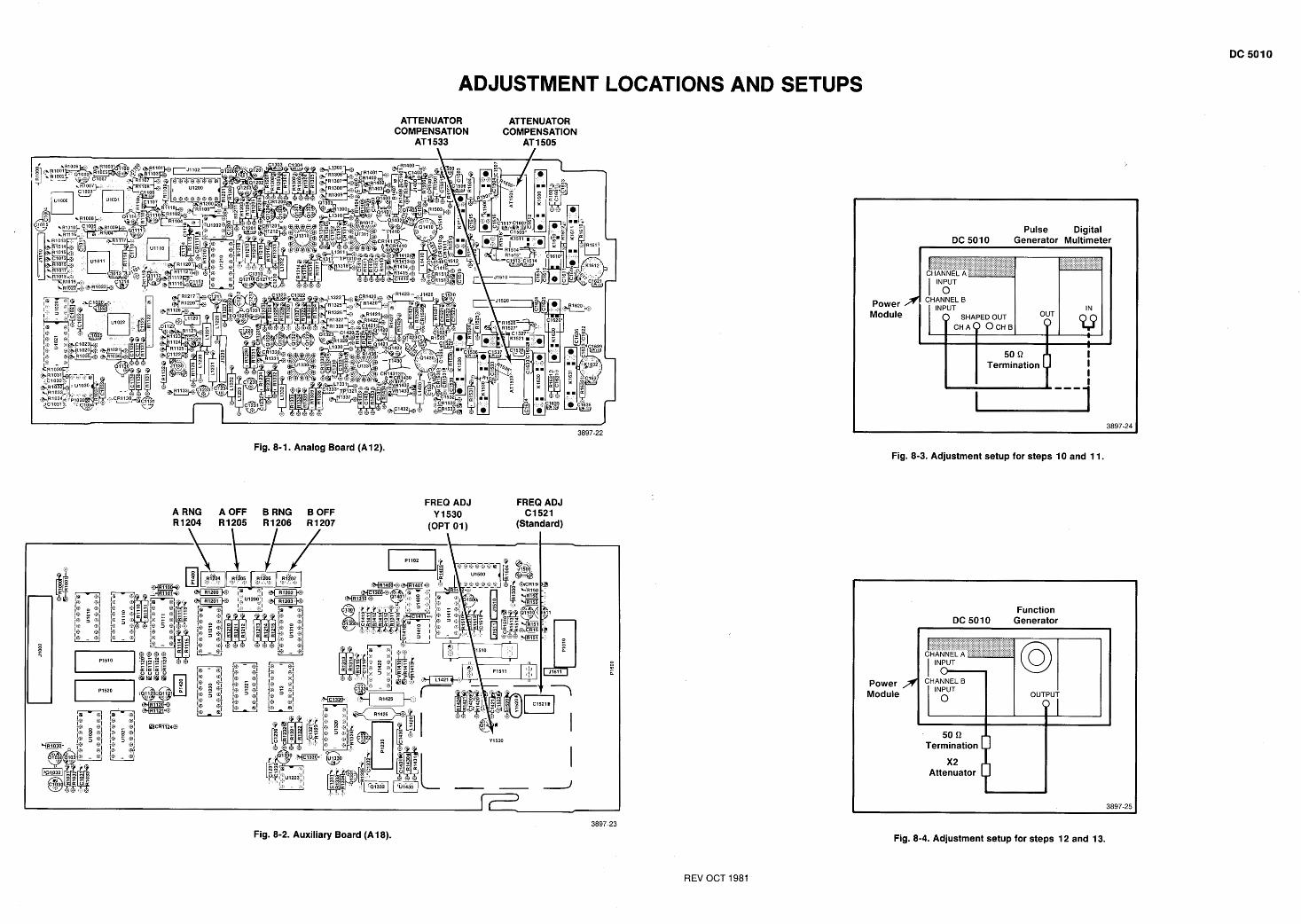
ADJUSTMENT LOCATIONS AND SETUPS
ATTENUATOR ATTENUATOR COMPENSATION COMPENSATION
AT1 533 AT 1 505
Pulse Digital DC 501 0 Generator Multimeter I
Power Module
CHANNEL B I I I INPUT
0 SHAPED OUT CHAO OCHB .
1
50 Q I Termination I
I I
3897-22
Fig. 8- 1. Analog Board (A 12). Fig. 8-3. Adjustment setup for steps 10 and 11.
A RNG AOFF B RNG B OFF R1204 R1205 R1206 R1207
\ I I /
FREQ ADJ FREQ ADJ Y 1530 C1521
(OPT 0 1 ) (Standard) I
Function DC SO 10 Generator
Power Module INPUT
OUTPUT
Attenuator
Fig. 8-4. Adjustment setup for steps 12 and 13.
3897-23
Fig. 8-2. Auxiliary Board (A1 8).
REV OCT 1981
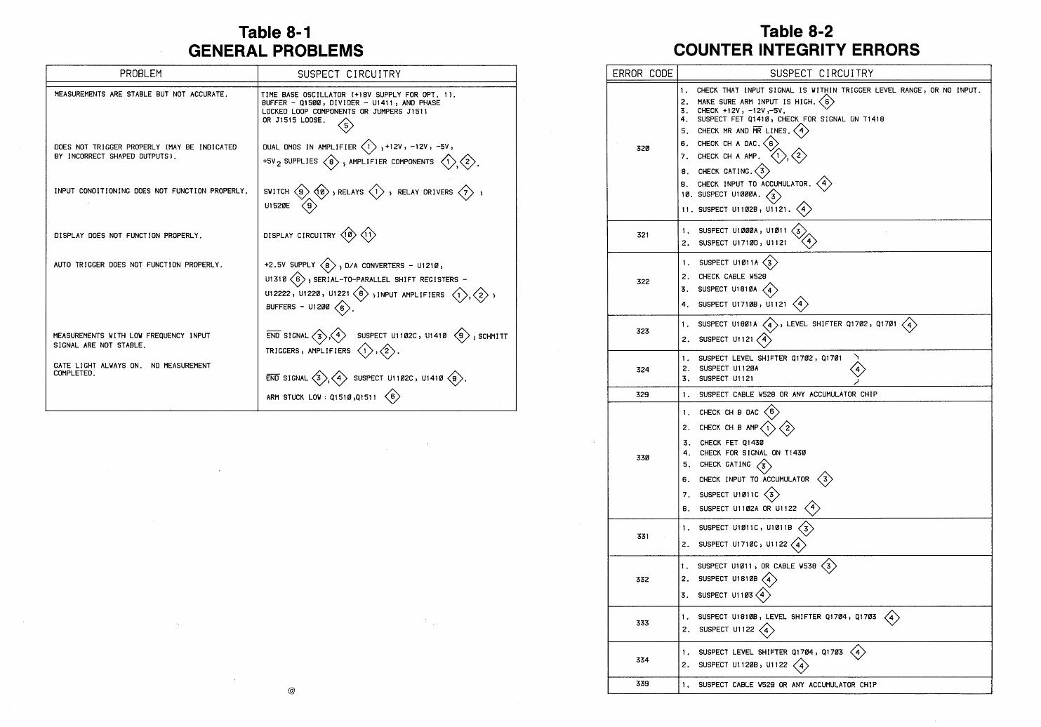
Table 8-1 GENERAL PROBLEMS
Table 8-2 COUNTER INTEGRITY ERRORS
PROBLEM
MEASUREMENTS ARE STABLE BUT NOT ACCURATE.
ERROR CODE SUSPECT CIRCUITRY SUSPECT CIRCUITRY I . CHECK THAT INPUT SIGNAL I S WITHIN TRIGGER LEVEL RANGE) OR NO INPUT.
2. MAKE SURE ARM INPUT I S HIGH. @ 3. CHECK +12V) -12V)-5V. 4. SUSPECT FET Q1410, CHECK FOR SIGNAL ON TI418
TIME BASE OSCILLATOR (+ I 8V SUPPLY FOR OPT. 1 1 . BUFFER - Q1500) DIVIDER - U1411) AND PHASE LOCKED LOOP COMPONENTS OR JUMPERS 51511 OR 51515 LOOSE.
5. CHECK MR AND ~ i i i LINES. @ 6 . CHECK CH A DAC.
7. CHECK CH A AMP.
8 . CHECK GATING.
9. CHECK INPUT TO ACCUMULATOR. @ 10. SUSPECT U1000A.
11. SUSPECT U11028, U1121.
DUAL DMOS I N AMPLIFIER @ ,+12V) -12V) -5V)
+5V SUPPLIES @ ) AMPLIFIER COMPONENTS
DOES NOT TRIGGER PROPERLY (MAY BE INDICATED BY INCORRECT SHAPED OUTPUTS).
SWITCH @ @,RELAYS @ , RELAY DRIVERS
U1520E @ INPUT CONDITIONING DOES NOT FUNCTION PROPERLY,
1, SUSPECT U1000A) U l 0 l l
2. SUSPECT U1710D) U1121 OISPLAY CIRCUITRY @ @ OISPLAY DOES NOT FUNCTION PROPERLY.
AUTO TRIGGER DOES NOT FUNCTION PROPERLY. 1. SUSPECT U l 0 l l A 3 0 2. CHECK CABLE W528
*2-5V SUPPLY 8 5 D/A CONVERTERS - U1210) 0 Ul318 @ , SERI AL-TO-PARALLEL SHI FT REG I STERS - U12222) U1220) U1221 ,INPUT AMPLIFIERS
BUFFERS - U1200
3. SUSPECT U1810A 4 0 4. SUSPECT U1710B) U1121 @
1 LEVEL SHIFTER 41702) Q1701
=SIGNAL@)@ SUSPECT U1102C) U1410 @,SCHMITT
TRIGGERS ) AMPLIFIERS 0 ) 0. MEASUREMENTS WITH LOW FREQUENCY INPUT SIGNAL ARE NOT STABLE.
-
1 . SUSPECT LEVEL SH I FTER Q 1 702 Q l70 l 'I
2. SUSPECT U 1 1 28A 3 . SUSPECT U1121 @ J
GATE LIGHT ALWAYS ON. NO MEASUREMENT COMPLETED. fi SIGNAL SUSPECT U1102C) U1410 @.
ARM STUCK LOW : Q1510)P1511 @ -- - - - - -
1. SUSPECT CABLE W528 OR ANY ACCUMULATOR CHIP
1. CHECK CH B DAC @ 2. CHECK CH B AMP 1 00 3. CHECK FET 91430 4. CHECK FOR SIGNAL ON T I430
5 . CHECK GATING 3 0 6. CHECK INPUT TO ACCUMULATOR @ 7. SUSPECT U1011C @ 8. SUSPECT U1102A OR "1122 6
-- - - - - -
1. SUSPECT U1011C) Ul011B
2. SUSPECT U1710C) U1122 4 0 1 . SUSPECT U1011 ) OR CABLE US38 3
2. SUSPECT U1810B 6 0 3. SUSPECT U1103 4 0 1. SUSPECT U1810B) LEVEL SHIFTER Q1704, 91703
2. SUSPECT U1122 4 0 1, SUSPECT LEVEL SHIFTER a17043 91703
2. SUSPECT U1120B) U1122
1. SUSPECT CABLE W529 OR ANY ACCUMULATOR CHIP
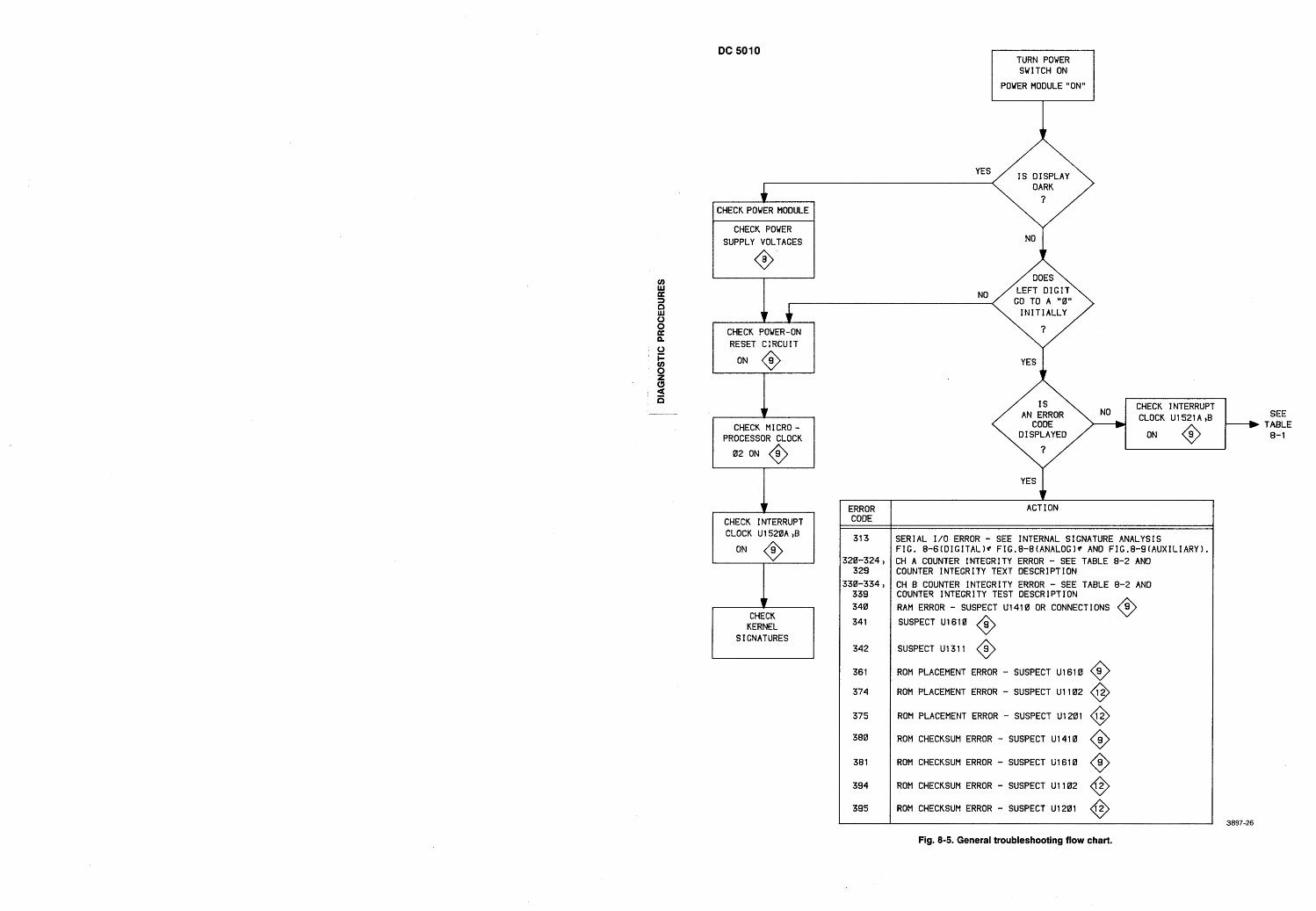
TURN POWER SWITCH ON
POWER MODULE "ON"
YES A I S DISPLAY
I CHECK POWER MODULE I I CHECK POWER I I SUPPLY VOLTAGES I No I
I RESET CIRCUIT I
I CHECK MICRO - PROCESSOR CLOCK
r 7 CHECK INTERRUPT CLOCK U1 S20A ,B
J
CHECK KERNEL
SIGNATURES , ERROR CODE
CHECK INTERRUPT CLOCK U lS2 l A )B
A
YES
ACT I ON
SERIAL 1/0 ERROR - SEE INTERNAL SIGNATURE ANALYSIS FIG. 8-6tDIGITALlt ' FIG.8-8(ANALOG)r AND FIG.8-9(AUXILIARYl, CH A COUNTER INTEGRITY ERROR - SEE TABLE 8-2 AND COUNTER INTEGRITY TEXT DESCRIPTION
CH B COUNTER INTEGRITY ERROR - SEE TABLE 8-2 AND COUNTER INTEGRITY TEST DESCRIPTION
RAM ERROR - SUSPECT U1410 OR CONNECTIONS @ SUSPECT U1610
SUSPECT U13 1 1 @ RON PLACEMENT ERROR - SUSPECT U1618 @ ROM PLACEMENT ERROR - SUSPECT U1102 12 0 ROM PLACEMENT ERROR - SUSPECT U1201 12 0 ROM CHECKSUM ERROR - SUSPECT U1410 @ ROM CHECKSUM ERROR - SUSPECT U1610 @ ROM CHECKSUM ERROR - SUSPECT U1102 0 ROM CHECKSUM ERROR - SUSPECT U1201 0
SEE TABLE 8- 1
Fig. 8-5. General troubleshooting flow chart.
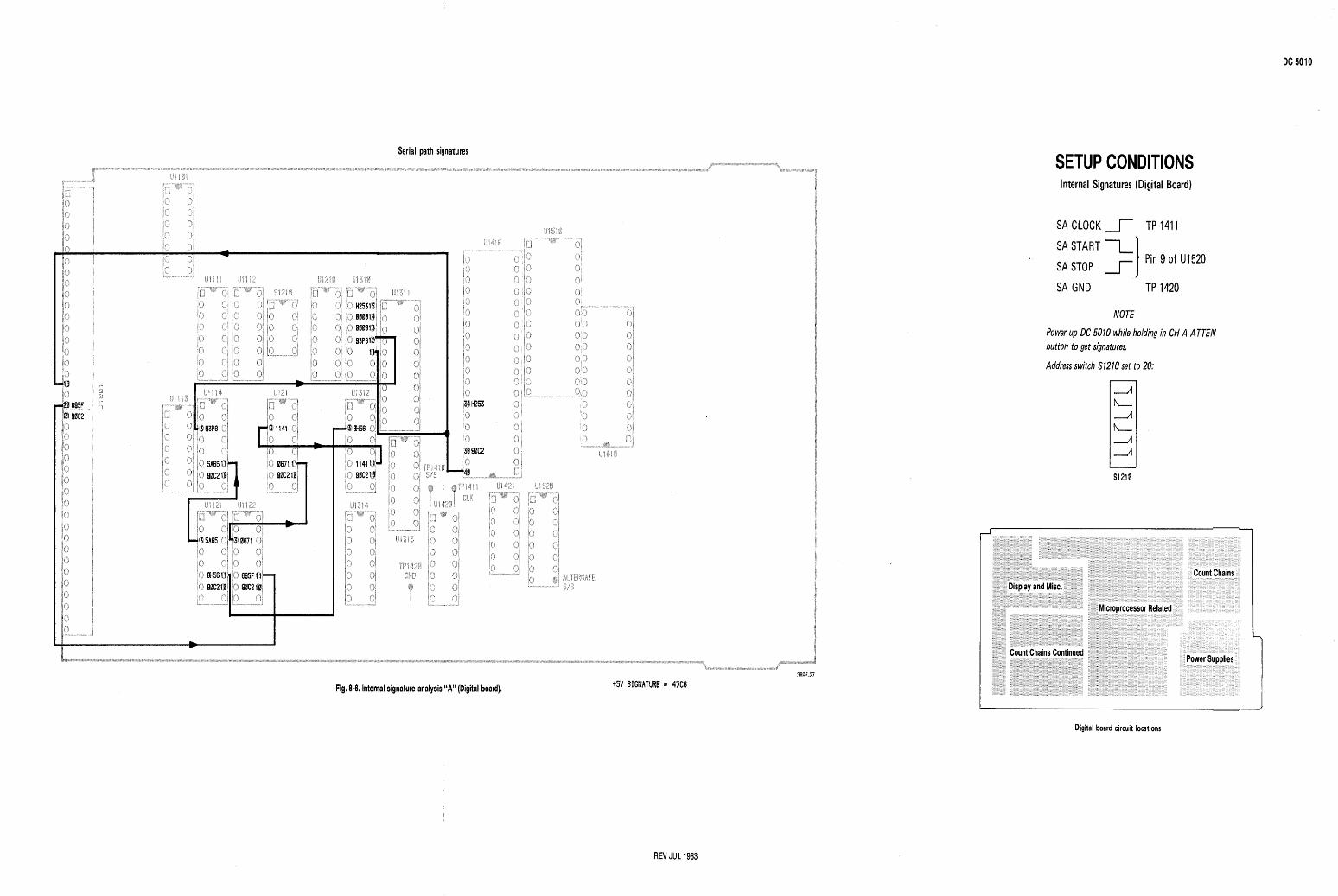
Serial path signatures SETUP CONDITIONS Internal Signatures (Digital Board)
SA CLOCK 1 TP 141 1
SA START 1 SA STOP 1 I Pin 9 of U1520
SA GND TP 1420
NOTE
Power up DC 5010 while holding in CH A ATTEN button to get signatures.
Address switch S1210 set to 20:
ffl,b95~ ger 90C2 ki) a ;( ' 1: 1
go I S 1
/("i f 8' ' g: 1
gc1 if-) L* gn to 10 ji?
!I %
0 " " *
3897-27 +SV SIGNATURE 9 47C6 Fig. 8-6, Internal signature analysis "A" (Digital board).
Digital board circuit locations
REV JUL 1983
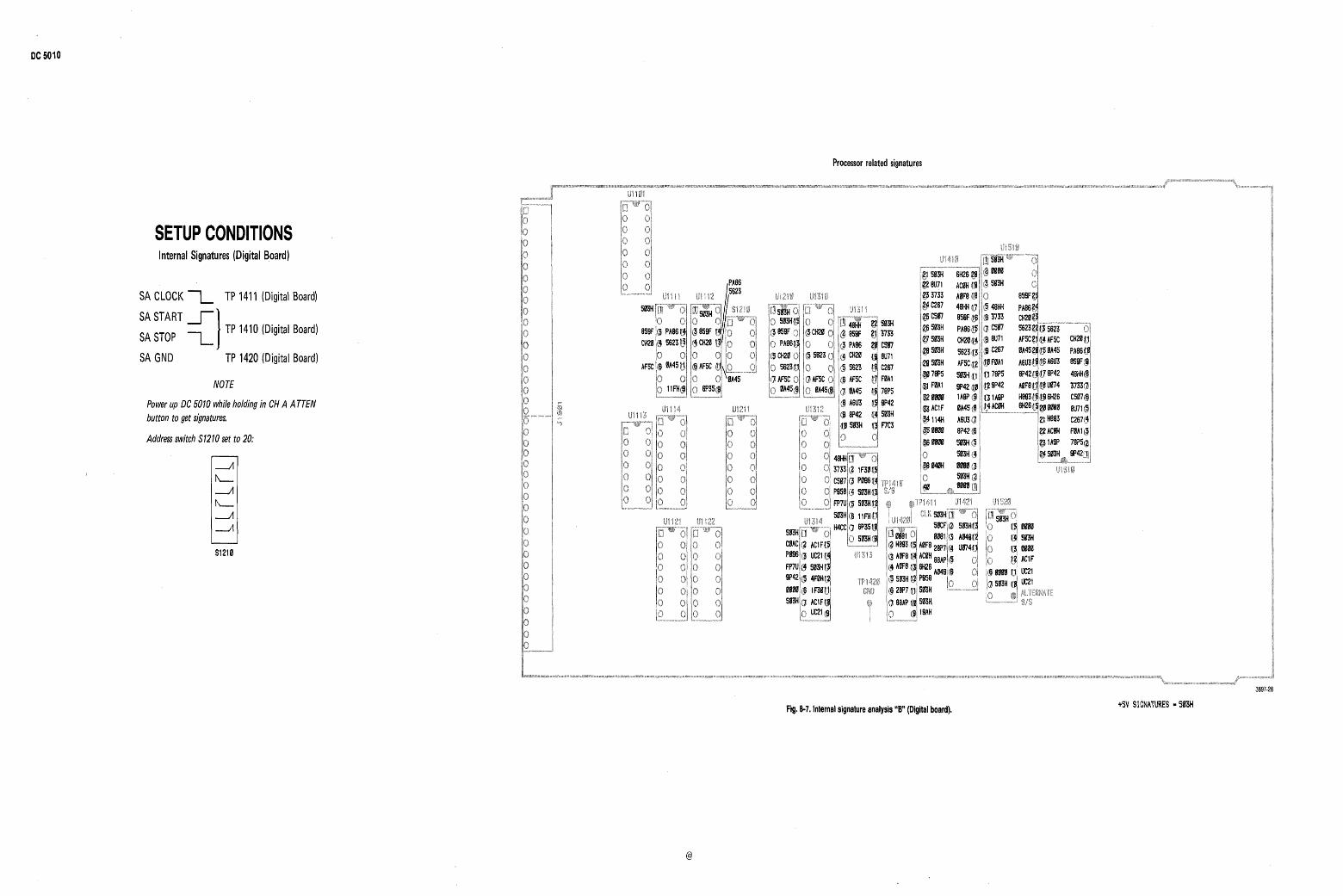
Processor related signatures
SETUP CONDITIONS Internal Signatures (Digital Board)
SA CLOCK 1 TP 1411 (Digital Board)
SASTART l-1 I
SA STOP 1 TP 1410 (Digital Board)
SA GND TP 1420 (Digital Board)
NOTE
Power up DC 50 10 while holding in CH A ATTEN button to get signatures.
Address switch S1210 set to 20:
Fig. 8-7. Internal signature analysis "B" (Digital board).
3897-28
+SV SIGNATURES m 503H
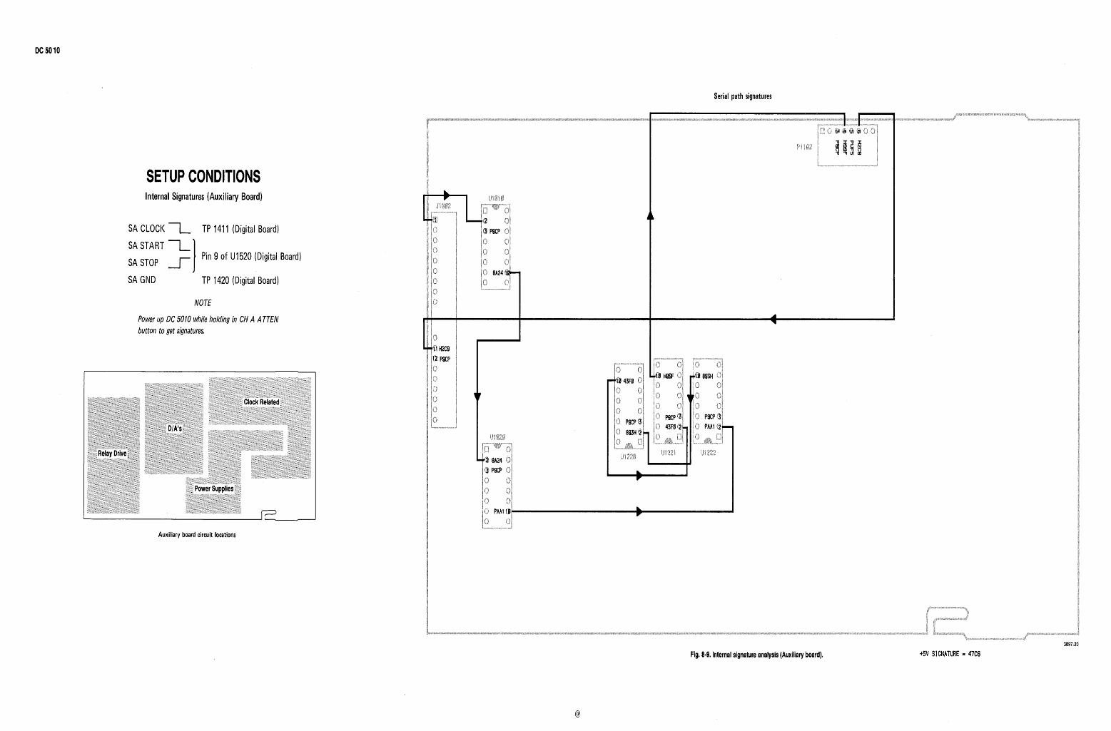
Serial path signatures
SETUP CONDITIONS lnternal Signatures (Auxiliary Board)
SA CLOCK 1 TP 1411 (Digital Board)
SA START -L SA STOP 1 I Pin 9 of U1520 (Digital Board)
SA GND TP 1420 (Digital Board)
NOTE
Power up DC 5010 while holding in CH A ATTEN button to get signatures,
Auxiliary board circuit locations
Fig, 8.9, Internal signature analysis (Auxiliary board).
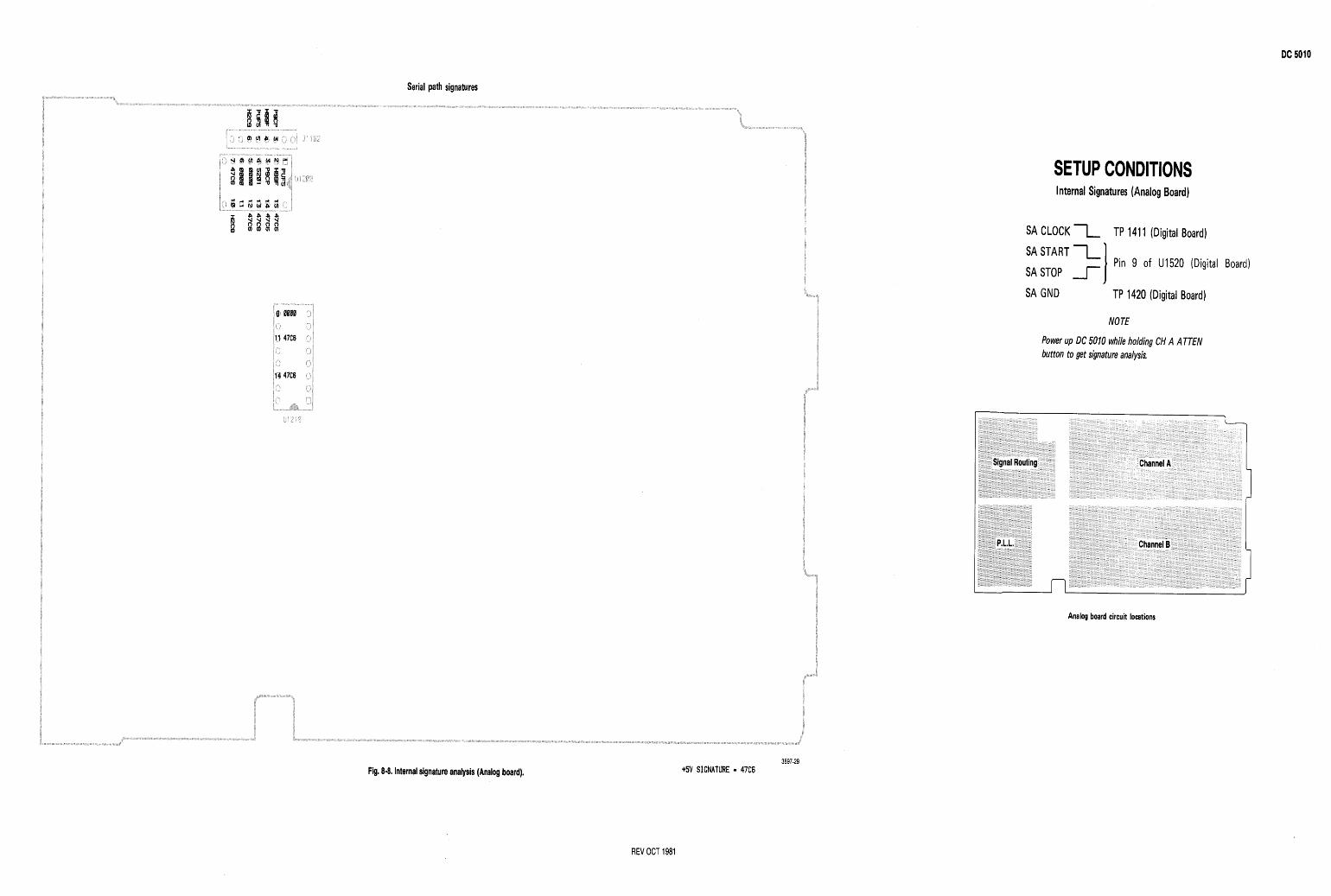
Serial path signatures
Fig. 8-8. Internal signature analysis (Analog board). 3897-29
+5V SIGNATURE - 47C6
SETUP CONDITIONS Internal Signatures (Analog Board)
SA CLOCK 1 TP 141 1 (Digital Board)
SA START 1 I Pin 9 of U1520 (Digital Board) SA STOP 1 SA GND TP 1420 (Digital Board)
NOTE
Power up DC 5010 while holding CH A ATTEN button to get signature analysis.
I I I
Analog board circuit locations
REV OCT 1981
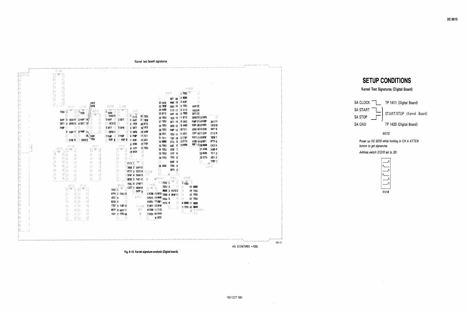
Kernel test board signatures
: 755 75s 000 C69
5H5 PCF
SETUP CONDITIONS Kernel Test Signatures (Digital Board)
SA CLOCK 1 TP 1411 (Digital Board)
SA START 1 I STARTISTOP (Kernel Board) SA STOP 1 SA GND TP 1420 (Digital Board)
NOTE
Power up DC 5010 while holding in CH A A TTEN button to get signatures.
Address switch S12 10 set to 20:
3897-31
+5V SIGNATURES - 755U
Fig. 8.10. Kernel signature analysis (Digital board).
REV OCT 1981
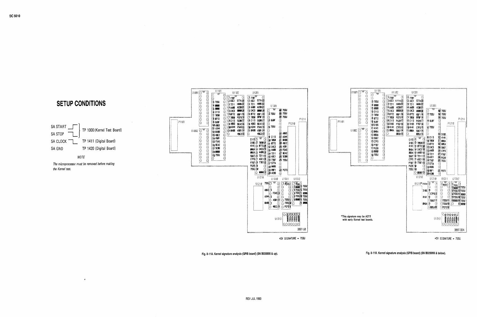
SETUP CONDITIONS
SA START 1 I TP 1000 (Kernel Test Board) SA STOP -L SA CLOCK 1 TP 1411 (Digital Board)
SA GND TP 1420 (Digital Board)
NOTE
The microprocessor must be removed before making the Kernel test,
t 5 V SIGNATURE - 7 5 5 U
*This signature may be A211 with early Kernel test boards.
t 5 V SIGNATURE - 7 5 5 U
Fig. 8-11A. Kernel signature analysis (GPIB board) (SN B030000 & up). Fig. 8-118. Kernel signature analysis (GPIB board) (SN 8029999 & below).
REV JUL 1983
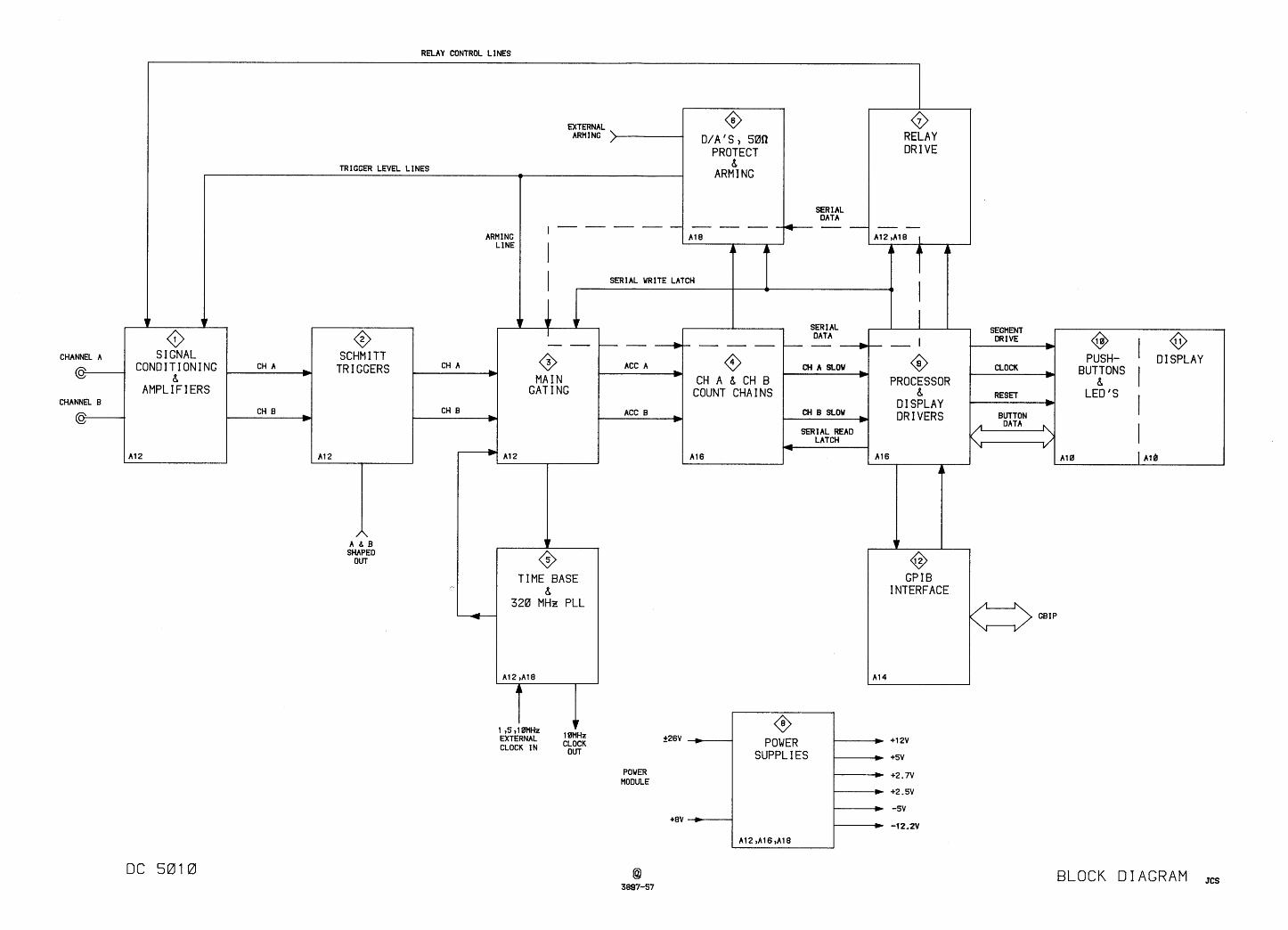
RELAY CONTROL LINES
0 RELAY DR I VE
v v 0
S I GNAL
TRIGGER LEVEL LINES I
EXTERNAL ARMING >
SER I AL DATA
D/A'S, 50R PROTECT
8 ARM 1 NG
ARMING LINE
SEGMENT DRIVE
b CHANNEL A
c- PUSH- ' DISPLAY ./ BlJTlONS I CONDITIONING CH A
8 b
AMPLIFIERS CHANNEL B
c- BUTTON ,, DATA 4
A b B SHAPED
OUT 0 GPIB
INTERFACE TIME BASE
8 320 MHz PLL
I t 15 9 1 0MHz EXTERNAL CLOCK IN
10MHz CLOCK
OUT
POWER MODULE
BLOCK DIAGRAM jcs
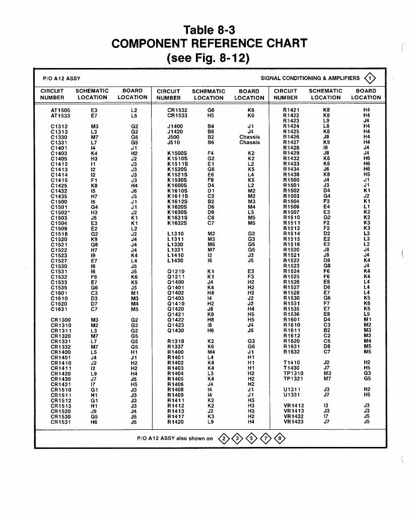
Table 8-3
PI0 A1 2 ASSY SIGNAL CONDITIONING & AMPLIFIERS 0 CIRCUIT SCHEMATIC BOARD NUMBER LOCATION LOCATION
CIRCUIT SCHEMATIC BOARD NUMBER LOCATION LOCATION
K6 K6
J 1 J4
Chassis Chassis
K2 K2 L2 K5 L4 K5 L2 M2 M2 M3 M4 L5 M5 M5
G2 G3 G5 G5 53 J 5
E3 F3 H2 H2 H2 J 2 92 H4 H5 H5 J4 55
G3 G6 J 1 H I H I H I H2 H2 H2 J 1 J 1 H3 H3 H3 H2 H4
CIRCUIT SCHEMATIC BOARD NUMBER LOCATION LOCATION
PI0 A12 ASSY also shown on @@@@@
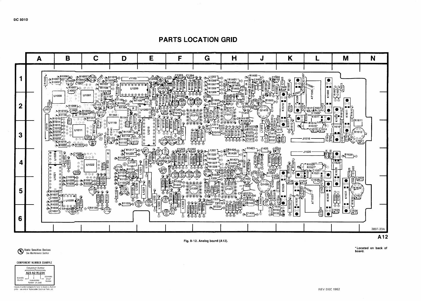
PARTS LOCATIO
Static Sensitive Devices See Maintenance Section
COMPONENT NUMBER EXAMPLE
Fig. 8-1 2. Analog board (A1 2).
*Located on back of board.
Chass~s-mounted components have no Assembly Numbel pref~x-see end of Replaceable Electr~cal Parts L~st. REV DEC 1982
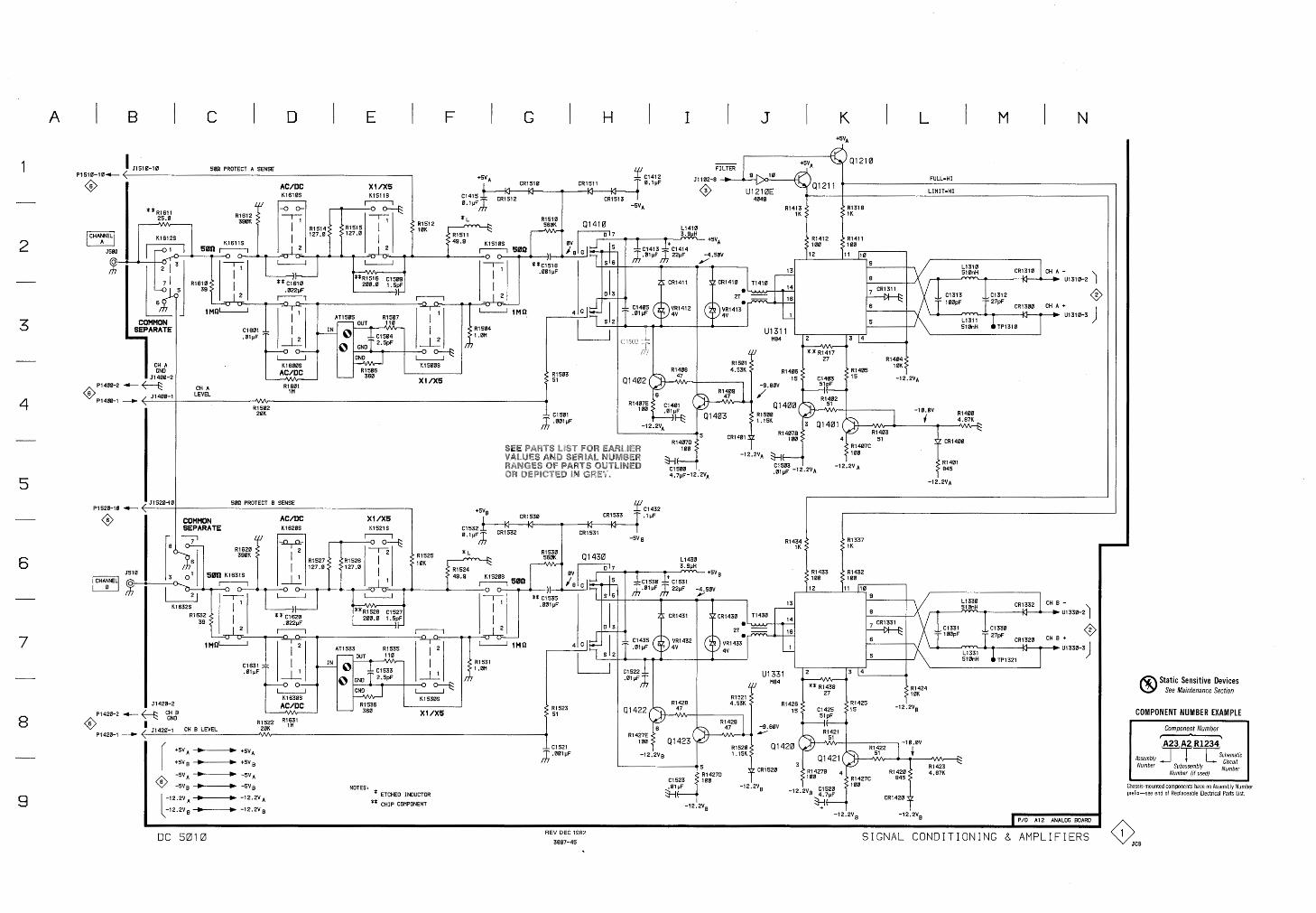
LEVEL 1H
Static Sensitive Devices See Maintenance Section
COMPONENT NUMBER EXAMPLE --
11420-1 CH B LEVEL 20K '" I Component Number - A23 A2 R1234
Assembly Number Subassembly r 1 ~ k h e m a t i c Circuit
Number ( I , used) Number I I
Chassis-mounted components have no Assembly Number preflx-see end of Replaceable Electr~cal Parts List.
NOTES, * ETCHED INDUCTOR
** CHIP COMPONENT
0 a I P/O A12 ANALOG BOARD
DC 5010 REV DEC 1982
3897-45 SIGNAL CONDITIONING 8 AMPLIFIERS
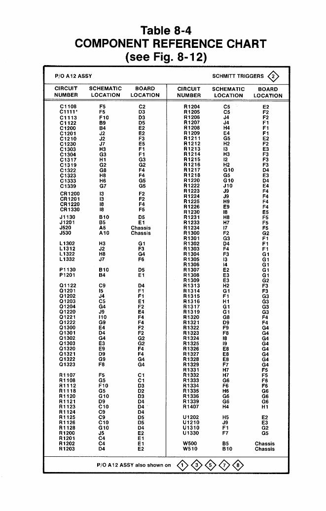
Table 8-4 COMPONENT REFERENCE CHART
(see Fig. 8- 12)
PI0 A1 2 ASSY SCHMITT TRIGGERS 2 0 CIRCUIT SCHEMATIC BOARD NUMBER LOCATION LOCATION
C2 D3 D3 D5 E2 E2 F3 E 5 F 1 F 1 G3 G2 F4 F4 G5 G5
F2 F2 F4 F5
D5 E 1
Chassis Chassis
G1 F3 G4 F6
D5 E 1
D4 F 1 F 1 E 1 F2 E4 F4 F4 F2 F2 G2 G2 F4 F4 G4 G4
C1 C1 D3 D2 D3 D4 D4 '
D4 D5 D5 D4 E2 E 1 E 1 E2
CIRCUIT SCHEMATIC BOARD NUMBER LOCATION LOCATION
E 2 F2 F2 F 1 F 1 F 1 E2 F2 E3 F3 F3 F3 D4 E 3 D4 E4 F4 F4 F4 F4 E 5 F5 F5 F5 G2 F 1 F 1 F 1 G I G1 G1 G I G1 G2 F3 F3 G3 G3 G3 G3 F4 F4 G4 G4 G4 G4 G4 G4 G4 G4 F5 F5 F6 F6 G6 G6 G6 H1
E 2 E3 G2 G5
Chassis Chassis
P I0 A1 2 ASSY also shown on OOOO@
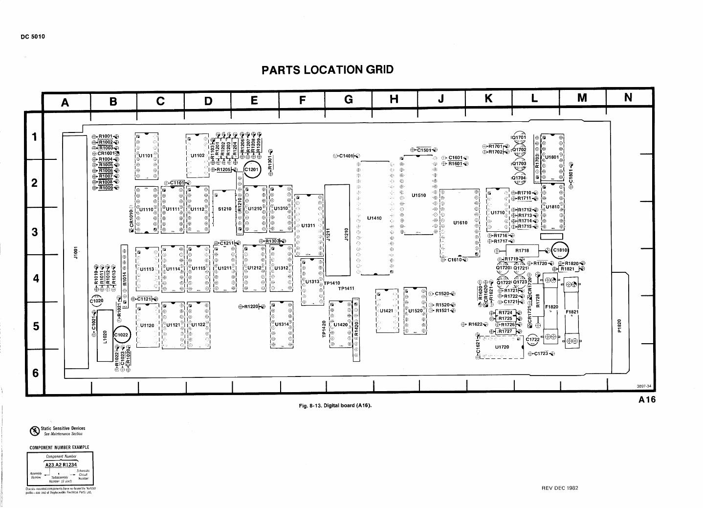
PARTS LOCATION GRID
Static Sensitive Devices See Maintenance Section
COMPONENT NUMBER EXAMPLE
Assembly
Chassls-mounted components have no Assembly Numbel pref~x-see end of Replaceable Electr~cal Parts List.
REV DEC I982
PARTS LOCATION GRID
Fig. 8- 1 3. Digital board (A 1 6). A16
Static Sensitive Devices See Maintenance Section
COMPONENT NUMBER EXAMPLE
Component Number - A23 A2 R1234
Assembly T r ' ~ L w n a t l c C ~ r c u ~ t Number Subassembly Number
Number (!fused) I I
Chassis-mounted components have no Assembly Number prefix-see end of Replaceable Electrical Parts List. REV DEC 1982
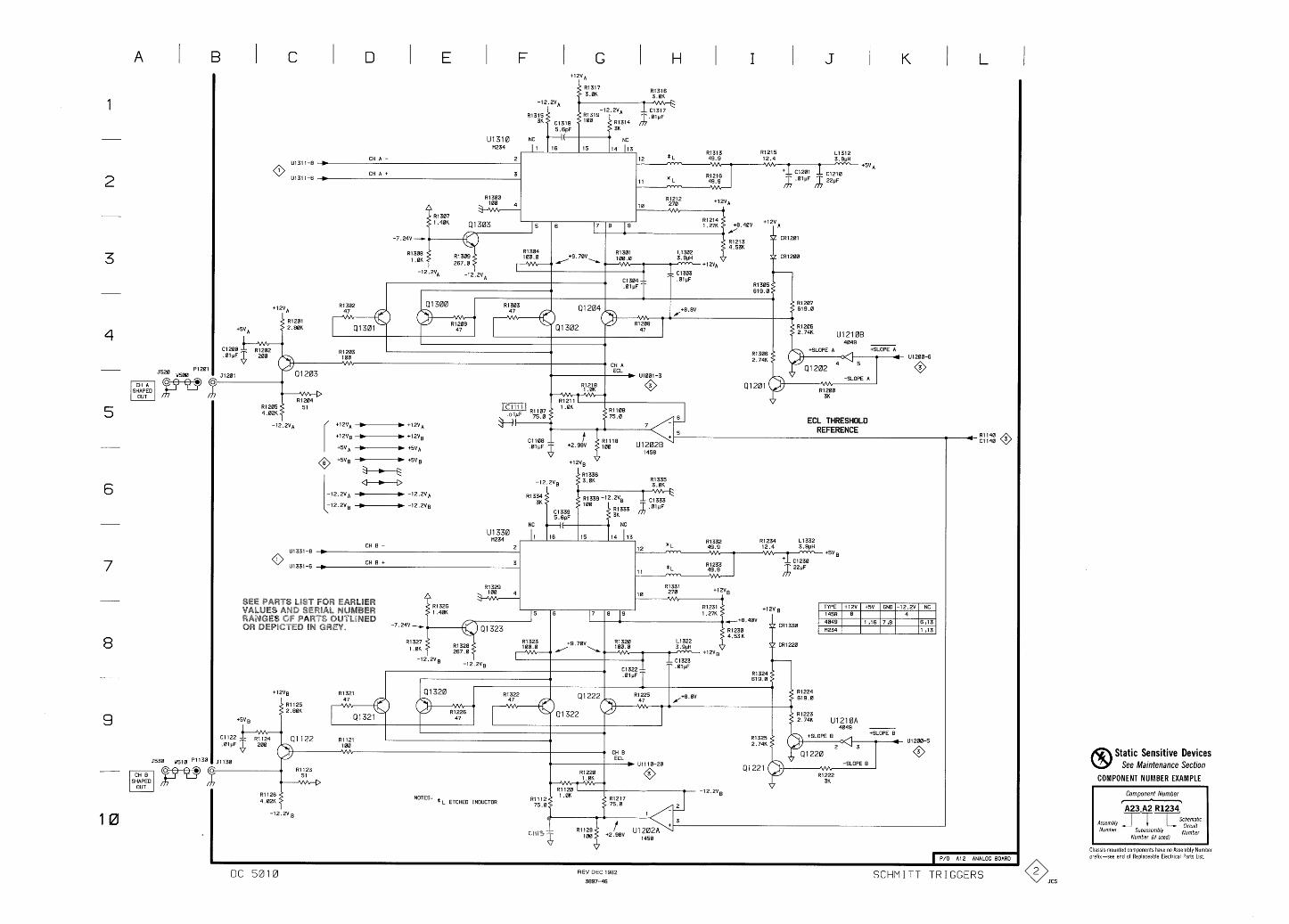
I E I I L I
I * ECL THRESHOLD
REFERENCE
. 1 2 V g
4 CRI 3 3 0
CRI 2 2 0
Static Sensitive Devices See Maintenance Section
COMPONENT NUMBER EXAMPLE
I Component Number - I NOTES: * L ETCHED INDUCTOR A23 A2 R1234
Assembly 2-T T S c k m a h c Number Subassembly C'rCU'f
Number (1, used) I I
Chassls-mounted components have no Assembly Number pref~x-see end of Replaceable Electrical Parts L~st . 1 P/O A12 ANALOG BOARD
DC 5010 REV DEC 1982
3 8 9 7 - 4 6 SCHMITT TRIGGERS
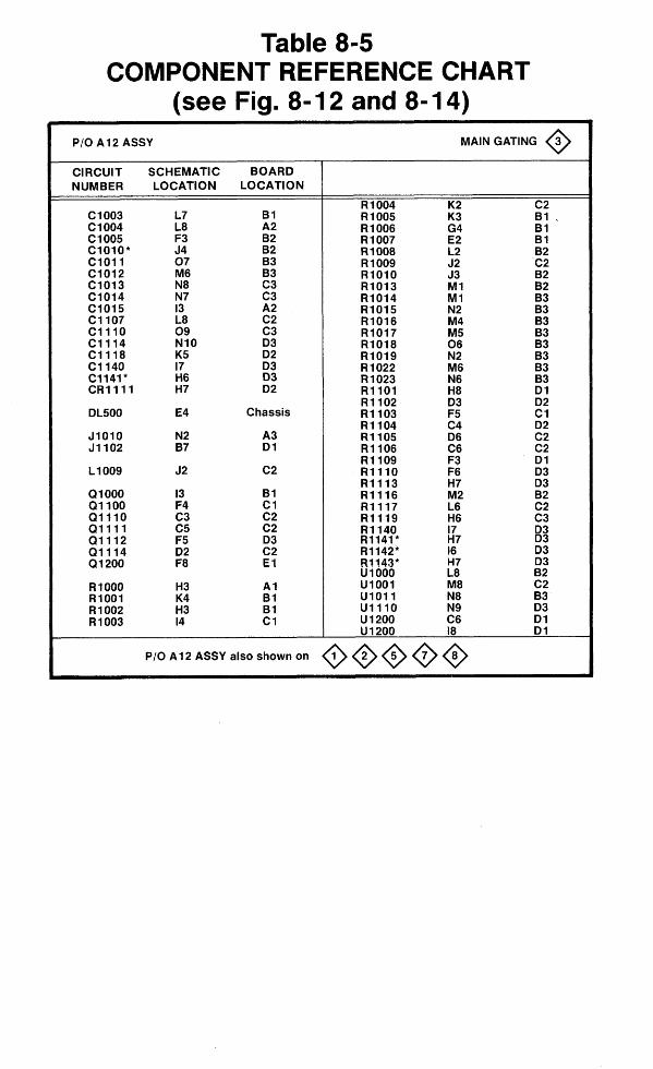
Table 8-5 COMPONENT REFERENCE CHART
(see Fig. 8- 12 and 8- 14) PI0 A 12 ASSY MAIN GATING 3 0 CIRCUIT SCHEMATIC BOARD NUMBER LOCATION LOCATION
B1 A2 82 B2 83 B3 C3 C3 A2 C2 C3 D3 D2 D3 D3 D2
Chassis
A3 D l
C2
B 1 C1 C2 C2 D 3 C2 E 1
A1 B1 B1 C1
PI0 A 12 ASSY also shown on @me@
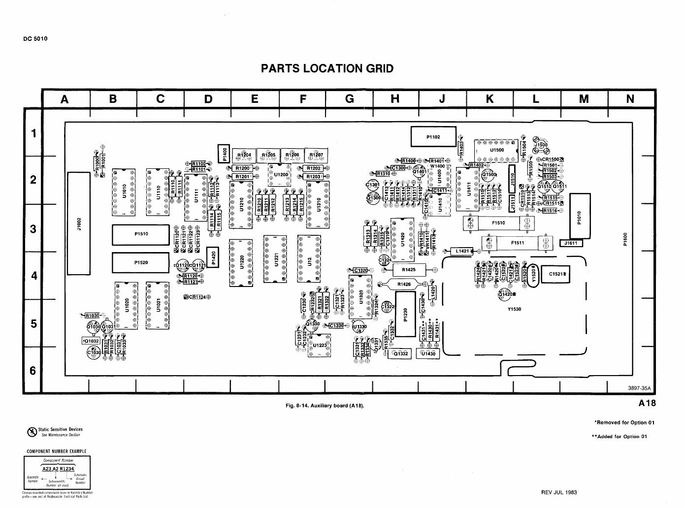
PARTS LOCATION GRID
Fig. 8-1 4. Auxiliary board (A1 8).
*Removed for Option 01
**Added for Option 01 Static Sensitive Devices
See Maintenance Section
COMPONENT NUMBER EXAMPLE
Component Number - A23 A2 R1234
Assembly T ' T ' T ~ c h e m a t , c C ~ r c u ~ t Number Subassembly
Number ( ~ f used)
REV JUL 1983 -- - --
Chassis-mounted components have no Assembly Numbel preflx-see end of Replaceable Electr~cal Parts Llst
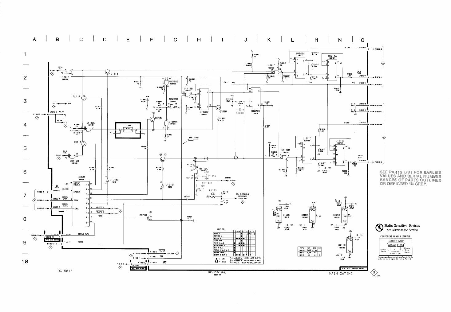
I L I M I N I O A LSB 51810-2
B LSB JIB1 0 -6
RUN STOP I
J
CH 8 FAST
51010-8 -
2 "l 4' ECL TWESHOLD REFERENCE
Static Sensitive Devices See Maintenance Section
COMPONENT NUMBER EXAMPLE
Component Number
- PI 102-8 - 51 102-8
- U1210-9 0
p l 1 0 2 1 - 1102-1 ARM
' = X A = (HIGH-NEC SLOPE1
= HIGH X 8 [HIGH -NEG SLOPE) X C -GATE (HIGH-STOP,LOY-w)
JCS

A LSB 51010-2
CH A
VT
--
A
--
--
--
-E*
P1018-9 C
REV DEC 1982 3897-47 MAIN GATING
CHA 51810-5
.;Jl
B LSB J1810-6
RUN STDP I
J U1011C
100131
V T E s 11 24 '--
R1017 396 i I 22 nR
; l c CH B
- 12 FAST
8 V T ~ R a ' - 51018-8
2 R1104A
75
ECL THRESHOLD CR1111 REFERENCE
Ul282-3,5
Stat ic Sensit ive Devices See Maintenance Section
COMPONENT NUMBER EXAMPLE
I Componen t Number, I A23A2R1234
A.embly T T T . h e - t f c Number Subassembly ,":::,
Number (11 usedl I TYPE +5V GND NC 100102 9 ~ 1 0 21 ~ 2 2 188131 9 ~ 1 0 21 40948 16 8 9 I I
Chass~s mounted components have no Assembly Number pref~x-see end of Replaceable Electr~cal Parts LIS!
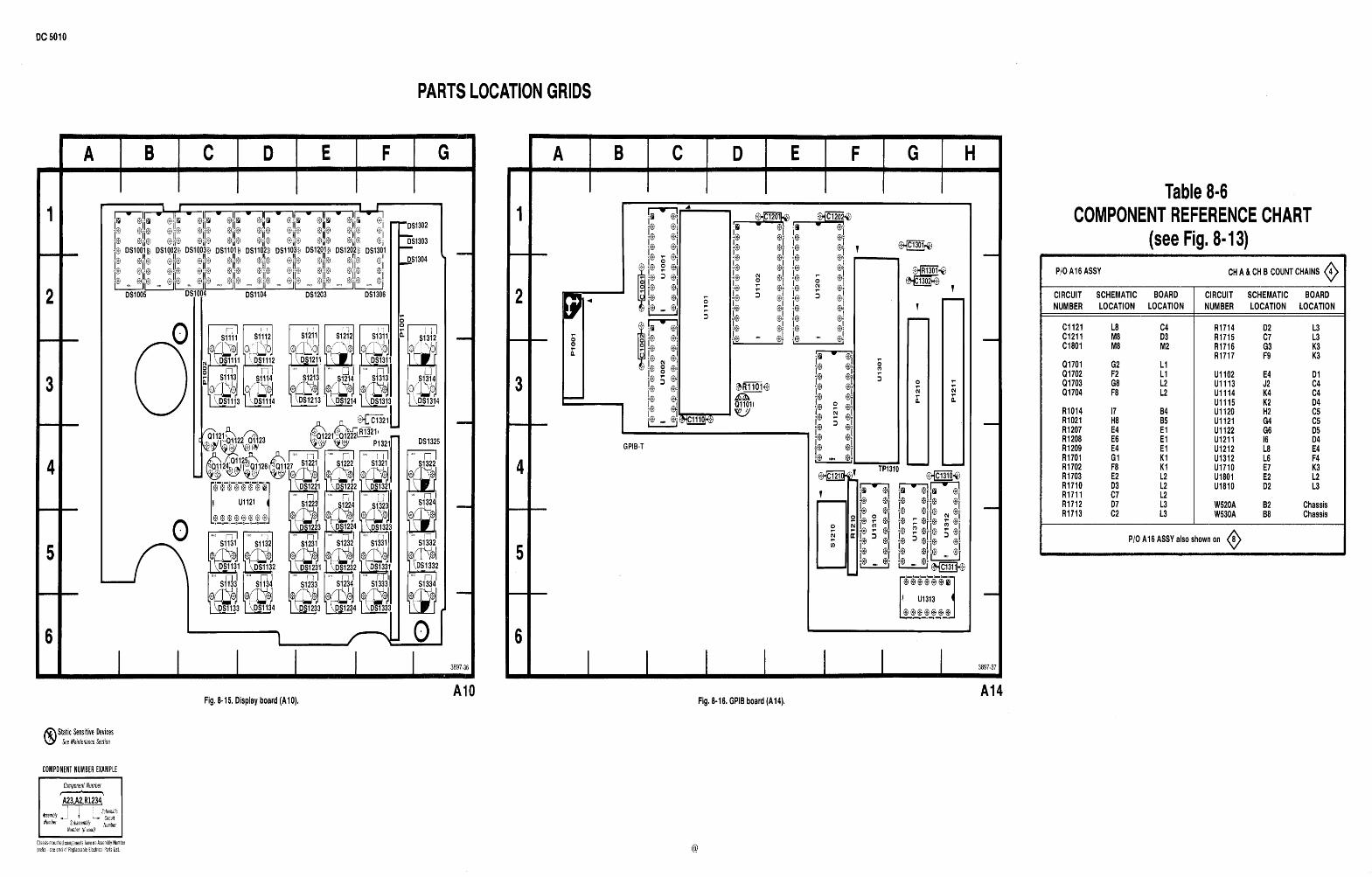
PARTS LOCATION GRIDS
Table 8.6 COMPONENT REFERENCE CHART
(see Fig. 8.13) CH A & CH B COUNT CHAINS 0 4 P/O A1 6 ASSY
CIRCUIT SCHEMATIC BOARD NUMBER LOCATION LOCATION
CIRCUIT SCHEMATIC BOARD NUMBER LOCATION LOCATION
L3 L3 K3 K3
D 1 C4 C4 D4 C5 C5 D5 D4 E4 F4 K3 L2 L3
Chassis Chassis
I
GPIB-T
P/O A16 ASSY also shown on 0
Fig. 8-16. GPlB board (A14). A14
Fig. 8.1 5. Display board (A1 0).
Static Sensitive Devices See Maintenance Section
COMPONENT NUMBER EXAMPLE
Component Number I. Assembly J 1 L Number Subassembly {i:ir
Number (I/ used)
Chassis-mountedcomponents haveno Assembly Number prei~x-see end 01 Replaceable Electr~cal Parts 11st
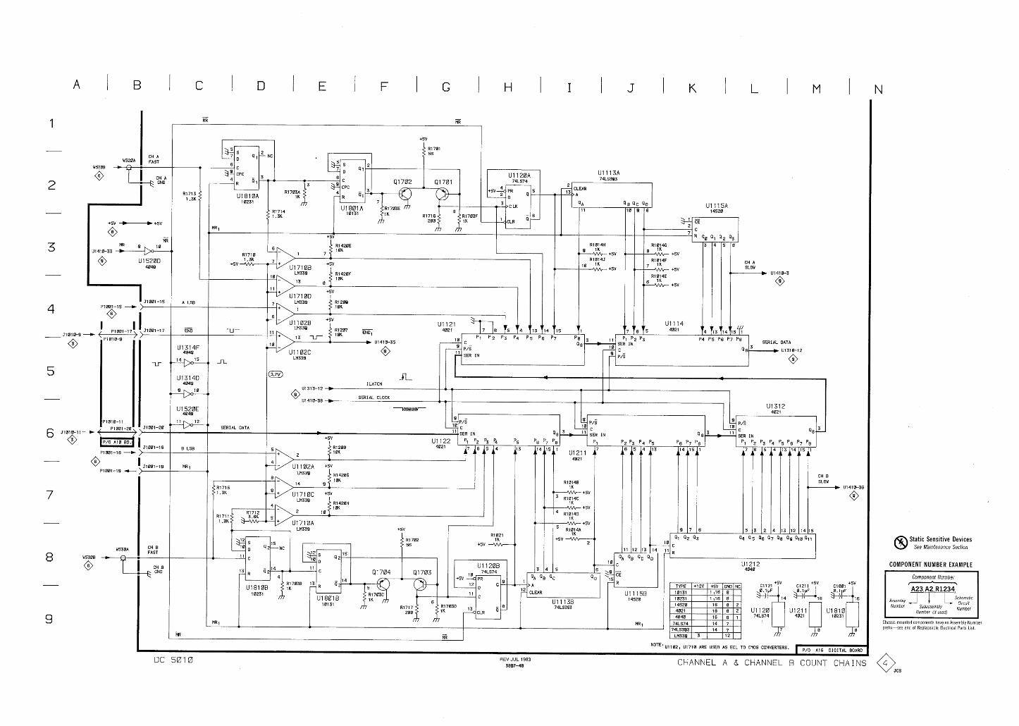
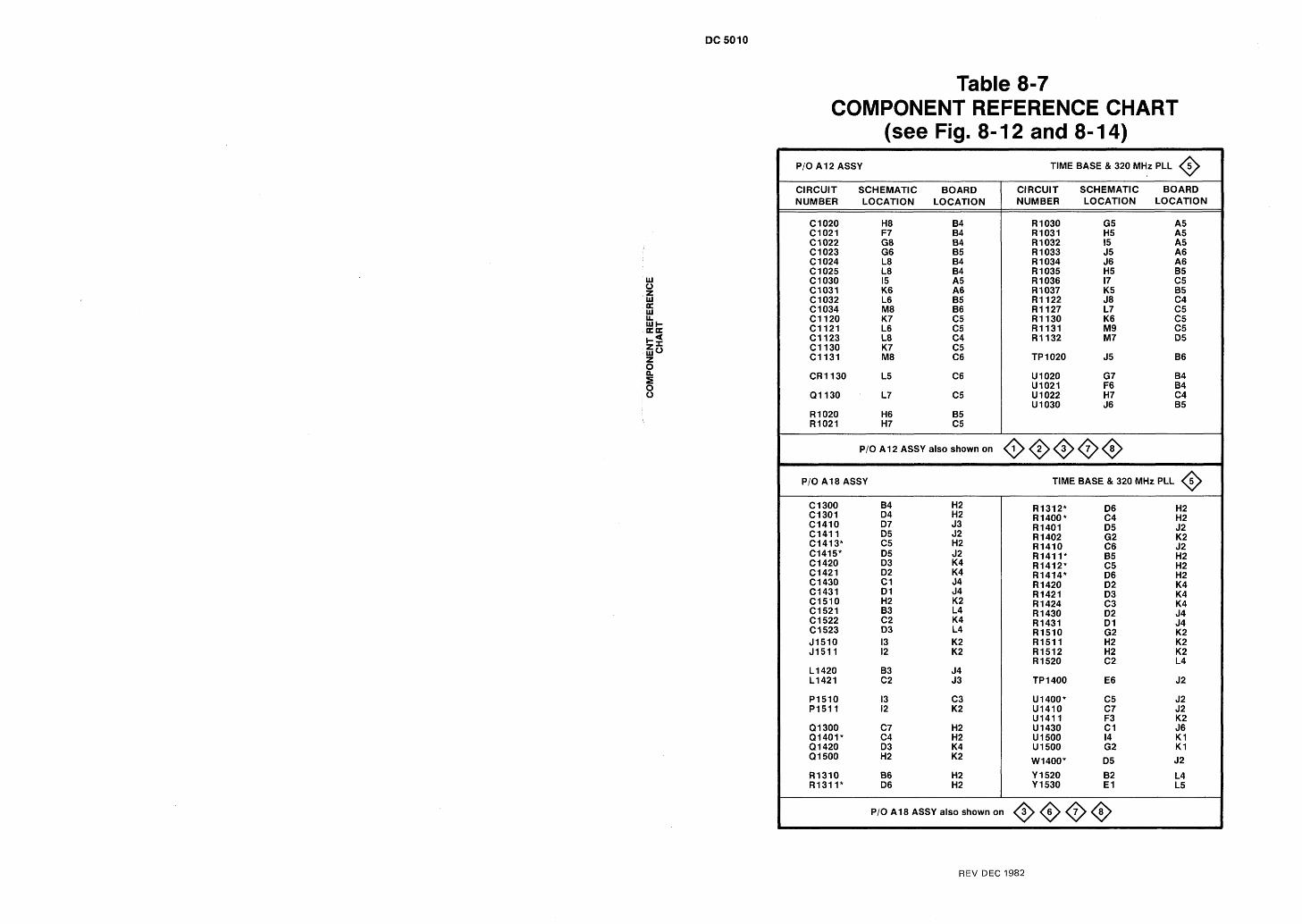
Table 8-7 COMPONENT REFERENCE CHART
(see Fig. 8- 12 and 8- 14) TlME BASE & 320 MHz PLL 0
CIRCUIT SCHEMATIC BOARD NUMBER LOCATION LOCATION
CIRCUIT SCHEMATIC BOARD NUMBER LOCATION LOCATION
P/O A1 2 ASSY also shown on o@@@@ PI0 A1 8 ASSY TlME BASE & 320 MHz PLL 0
PI0 A1 8 ASSY also shown on O@O@
REV DEC 1982
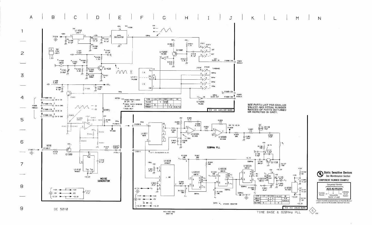
B I C
* *
I I I
+26V LM317
2 +18V 3 OVEN 1 OSCILLATOR -
1 7 . . .
TOP VIEW L1421 * C1421
LM317 3.9pH 0.1pF +12v- -
* ~ 1 4 2 0
* Y1520 1.5K
l0MHZ 18K 0
390pF 2-1 0pF
U1411
-1420 74LS90
POWER MODULE
+5v - - - T ) +5V,1
C1300 +
+ C1301
1 MHz - " .-$ -" l0MHz POWER
'1600-l6A t 400 1 1 i 0 CLOCK OUT PI 600-1 58 ' MODULE
-0 CH A IN NOTES * *THESE PARTS ADDED
I N OPT 01 74LS90 U 1 500E '1600-17A t 74LS04 - CH A GND
*THESE PARTS REMOVED ~ ~ 3 1 1 I N OPT. 01 MM5837 1 ,2 5 ,6,7,8
'1600-178 t t PADS ONLY -0 CH B IN P/O A18 AUXILIARY BOARD
POWER - MODULE
lMHz ,
320MHz PLL
1 MHz U1020 SP8627
C1021
R1122C 100131
100 . S ~ V T
4 n
c < - 12 - - " R 1 ~ T
11
6 160MHz MC1458 R1122D 100 320MHz
d U1110-17 VT
TYPE +12V +5V GND -12.2V NC V T @ 100131 9 2 5 ,6
4044 14 7 6,8,9,12
* L ETCHED INDUCTOR MC1458 8 4
Static Sensitive Devices See Maintenance Section
COMPONENT NUMBER EXAMPLE -12.2v
NO I SE GENERATOR
Component Number
Anemb,y J 1 L Number Subassembly arCUft
Number (1, used) Number
Chassis-mounted components haue no Assembly Number prel~x-see end of Replaceable Electr~cal Parts L~st
REV DEC 1982 3897-49
TIME BASE 8 320MHr PLL
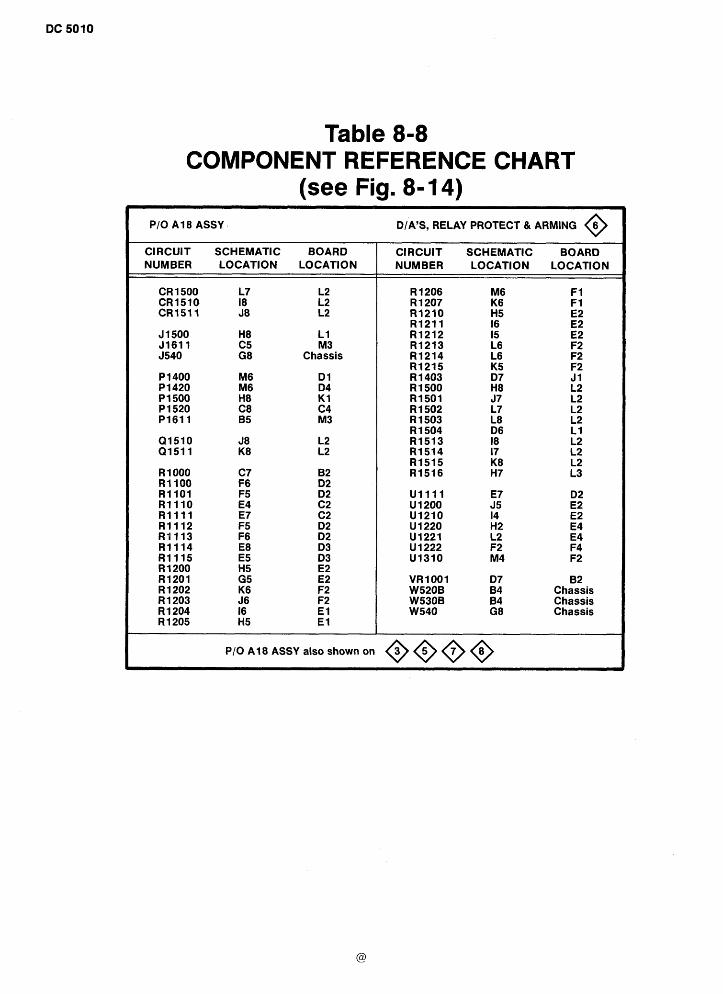
Table 8-8 COMPONENT REFERENCE CHART
(see Fig. 8- 14) PI0 A 18 ASSY DIA'S, RELAY PROTECT & ARMING 6 0
CIRCUIT SCHEMATIC BOARD NUMBER LOCATION LOCATION
J 1 500 H8 L 1 5161 1 C5 M3 J540 G8 Chassis
CIRCUIT SCHEMATIC BOARD NUMBER LOCATION LOCATION
VR1001 D7 82 W520B 64 Chassis W530B B4 Chassis W540 G8 Chassis
P I0 A18 ASSY also shown on OOOG
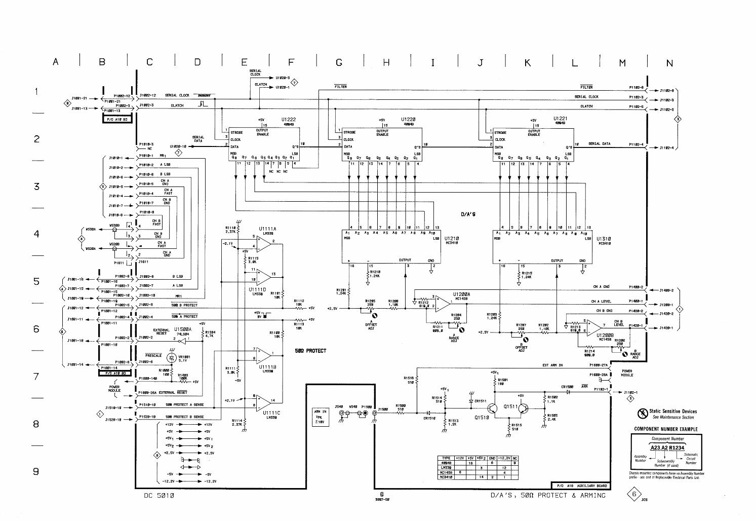
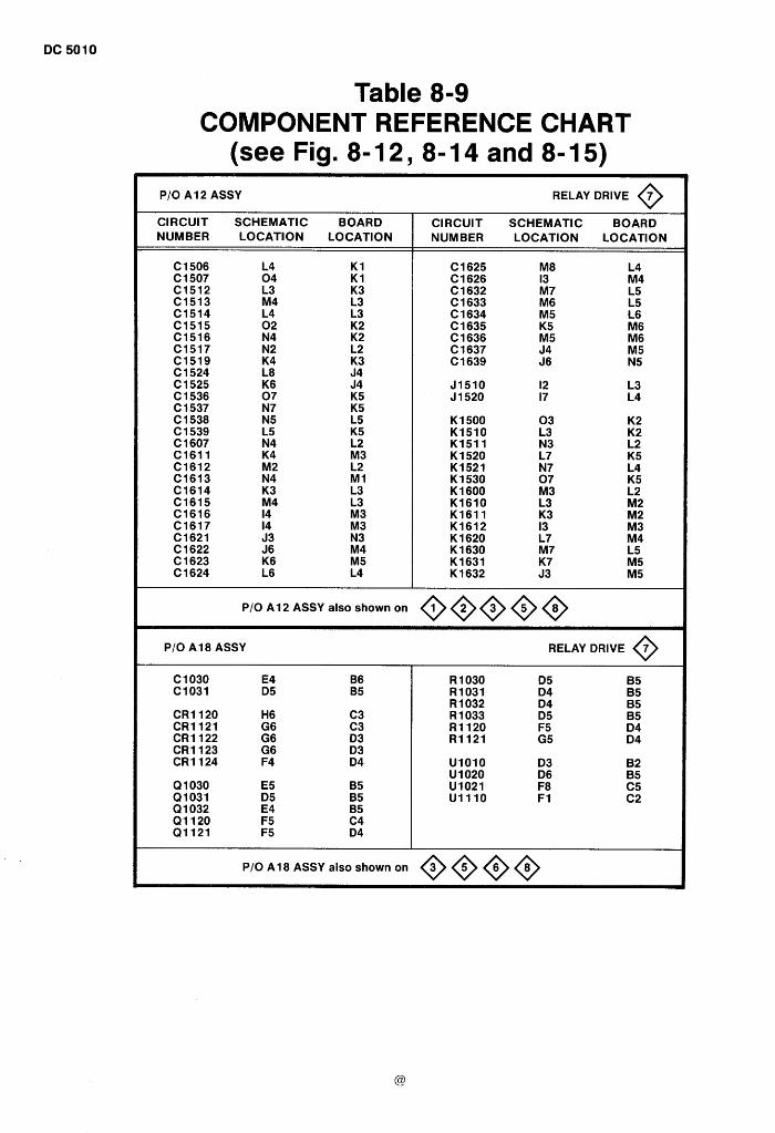
Table 8-9 COMPONENT REFERENCE CHART
(see Fig. 8-12, 8-14 and 8-15) P/O A12 ASSY RELAY DRIVE @ CIRCUIT SCHEMATIC BOARD NUMBER LOCATION LOCATION
CIRCUIT SCHEMATIC BOARD NUMBER LOCATION LOCATION
- -
P/O A1 2 ASSY also shown on
P/O A18 ASSY RELAY DRIVE 7 0
PI0 A18 ASSY also shown on OO@@
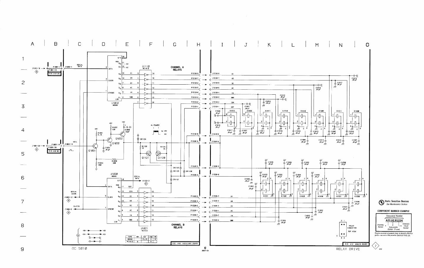
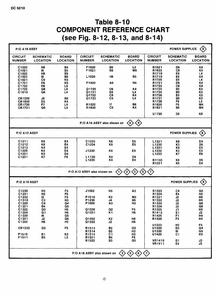
Table 8- 10 COMPONENT REFERENCE CHART
(see Fig. 8- 12, 8- 13, and 8- 14) PI0 A1 6 ASSY
CIRCUIT SCHEMATIC BOARD NUMBER LOCATION LOCATION
CIRCUIT SCHEMATIC BOARD NUMBER LOCATION LOCATION
PI0 A16 ASSY also shown on @@
POWER SUPPLIES @ CIRCUIT SCHEMATIC BOARD NUMBER LOCATION LOCATION
PI0 A12 ASSY POWER SUPPLIES 8 0
PI0 A1 2 ASSY also shown on 00000 PI0 A1 8 ASSY POWER SUPPLIES @
PI0 A18 ASSY also shown on OO@O
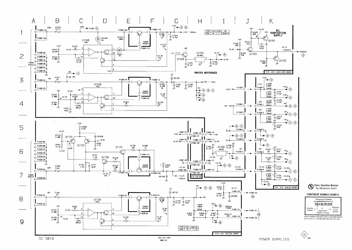
1 P1600-118
MODULE +12.2v
MODULE ?R $"""i P1600-4B L C 1 2 3 1 '7' Lc1232
A- O-lpF J O-lyF
MASTER REFERENCE P/O A18 AUXILIARY BOARO
PI 230-2 I.,'
v V
P/O A12 ANALOG BOARO Static Sensitive Devices
See Maintenance Section
C1023
b +5V
C1722 +5V 22pF
L1020 +SVg 1 50pH r @ OiiEkiY - - J1001-31
4- = + 9
C1022;; C1020 - C1021_; 47pF 22pFC- 0.1pF Dl SPLAY
GNO 51001-34 I
4 1
m I
COMPONENT NUMBER EXAMPLE
Component Number - I A23 A 2 R1234 '
Assembly l-'T T h e m a t , c
Number Subassembly C'rcu't Number (if used) Number
DC 5010 REV JUL 1983
3897-52 POWER SUPPLIES
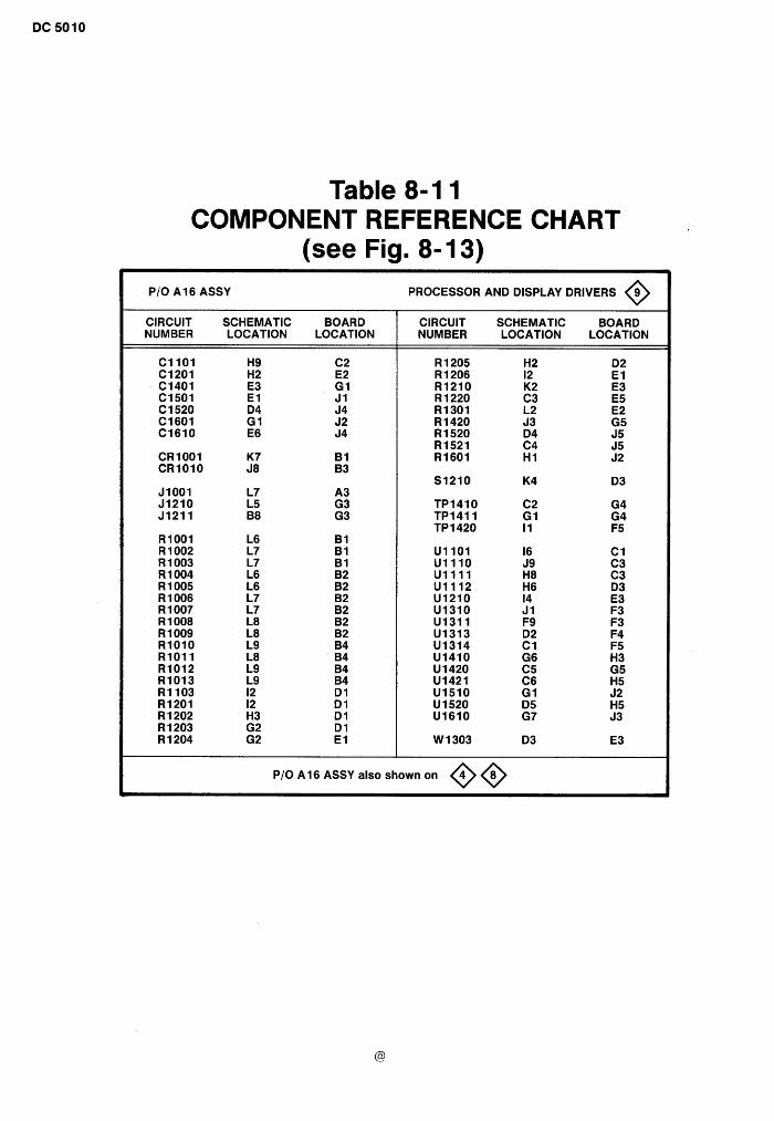
Table 8-1 1 COMPONENT REFERENCE CHART
(see Fig. 8- 13) P I 0 A1 6 ASSY PROCESSOR AND DISPLAY DRIVERS 9 0
--
CIRCUIT SCHEMATIC BOARD NUMBER LOCATION LOCATION
CIRCUIT SCHEMATIC BOARD NUMBER LOCATION LOCATION
P/O A1 6 ASSY also shown on @@
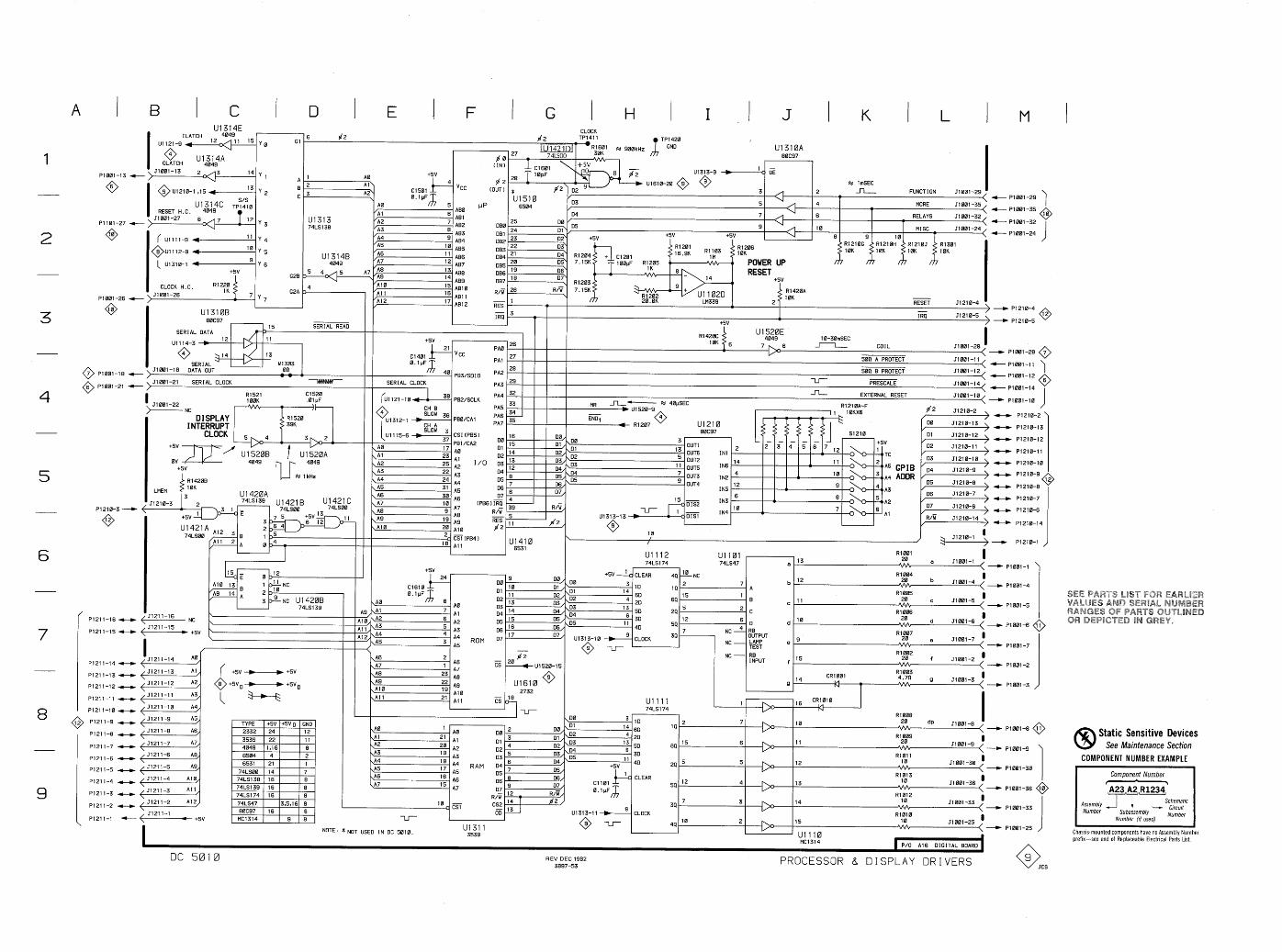
I C I G H CLOCK
8
C
RESET H.C.
( U l l l l - 9
@UI I 12-9
( Ul310-I
CLOCK H.C. R1220 31001-26
7
I U1310B 80C97
SERIAL DATA I 5 SERIAL READ
J l 001 -21 SERIAL CLOCK T
CLEAR
10
60 20
50 30
40
CLOCK
44 18 NC R1004 2 7 b ,,?,OA 51001-4
i 1 4
I 5 1 RIB05 64 -
c l1 A?OA c 51001-5 '
24 C R1006 12
0 d l0 Aon d 51081-6 I
54 7
34 NC 4 RE
OUTPUT Rl007
NC - LAMP e A:! e 51001-7 - TEST
NC - RE R1002 INPUT f f 51001-2 '
CRl00l R1003
Q l4 VI - g J1001-31
' I I\, I 16 CRl0l0
I I I VI I
I \DO - R1008 ID
19 \A0 7 I 0 dp 51001-8
l4 60
I A0
\A 1 Al 20 R1009 51211-7 \A2 02 50 64 6 11
!/" 20 51001-9
I \A3
20 A2 02 4 A3 D3 5 D3/- 30
\A4 R1011
;; iz RAM 04 04/-
+5v 40 29 5 1\, 12 10
51211-5 51001-3s I
\A5 05 05/ I/"
\A6 l6 A6 061 &-C CLEAR l2 4
R1013
\A7 06 07, Cl I01 59 I\, 13
I 0 A7 vn v v v
51001-36 51211-3 A l l 07 R/V, 0 . l p ~ A R1012 1 R/Y 7 I 0 - CS2
l4 p/2 / 3 I 4 34 I/-
10 c CSl
Jl00l-33
51211-1 = J -LT
UI 31 3-1 1 d CLOCK = +5v Rl0l0
I 44 - I 0
2 15 I 0 51001-25
* NOT USED IN DC 501 0. Ul3ll 3539 U1110
MCl314 P/O A16 DIGITAL BOARD
- - -
Static Sensitive Devices See Maintenance Section
COMPONENT NUMBER EXAMPLE
Component Number 1 ' A23 A2 ~ 1 2 3 4 '
Assembly ~ - ' T 1 ~ ~ c ~ e m a t 1 c Number Subassembly
Number (1, used) Number I I
Chaw-mounted components have no Assembly Number preflx-see end of Replaceable Electrical Parts L~st.
REV DEC 1982 3897-53
PROCESSOR 8 DISPLAY DRIVERS w cs
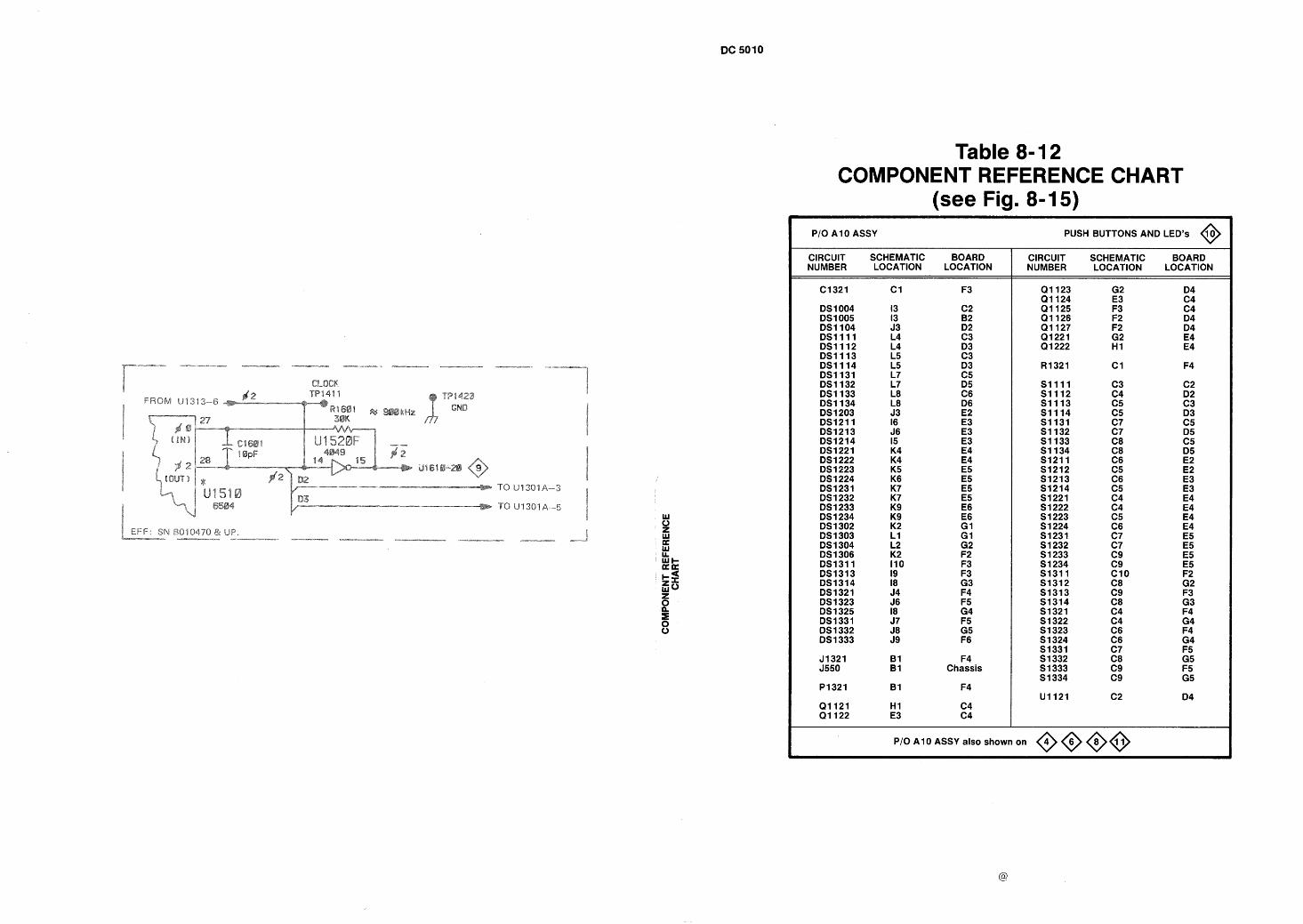
4 EFF: SN B010470 & UP. i - c - m v - I" .--PI-* - -r-m--r mxxx--m- ---- ..----- --
Table 8- 1 2 COMPONENT REFERENCE CHART
(see Fig. 8- 15) PI0 A10 ASSY PUSH BUTTONS AND LED'S @
CIRCUIT SCHEMATIC BOARD NUMBER LOCATION LOCATION
F3
C2 B2 D2 C3 D3 C3 D3 C5 D5 C6 D6 E2 E3 E3 E3 E4 E4 E5 E 5 E 5 E5 E6 E6 G I G I G2 F2 F3 F3 G3 F4 F5 G4 F5 G5 F6
F4 Chassis
F4
C4 C4
CIRCUIT SCHEMATIC BOARD NUMBER LOCATION LOCATION
P I0 A1 0 ASSY also shown on @@@@
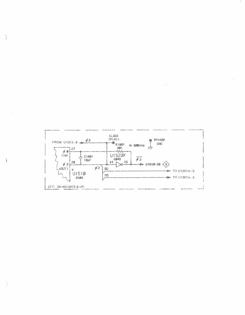
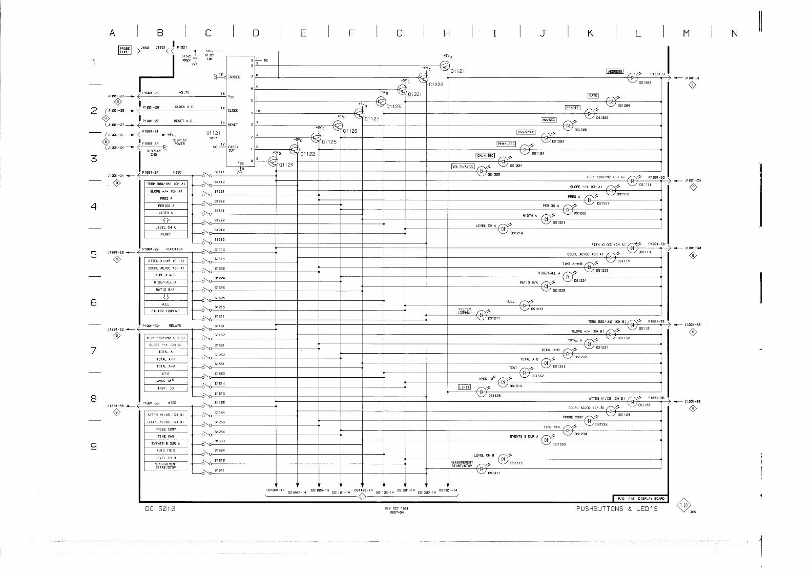
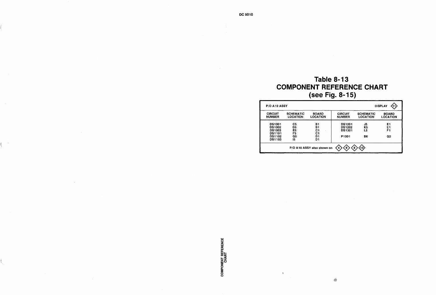
Table 8- 13 COMPONENT REFERENCE CHART
(see Fig. 8- 15) I PIOAlOASSY DISPLAY @
CIRCUIT SCHEMATIC BOARD CIRCUIT SCHEMATIC BOARD NUMBER LOCATION LOCATION NUMBER LOCATION LOCATION
DS1001 C5 B1 DS1201 J5 E l DS 1 002 D5 B1 DS 1 202 K5 E 1 DS 1 003 E5 C1 DS1301 L5 F 1 DS1101 F5 C1 DS1102 G5 D l P1001 B6 G2 DS1103 15 D l
P I 0 A1 0 ASSY also shown on @@@@
0 z W a W LA wt- =a
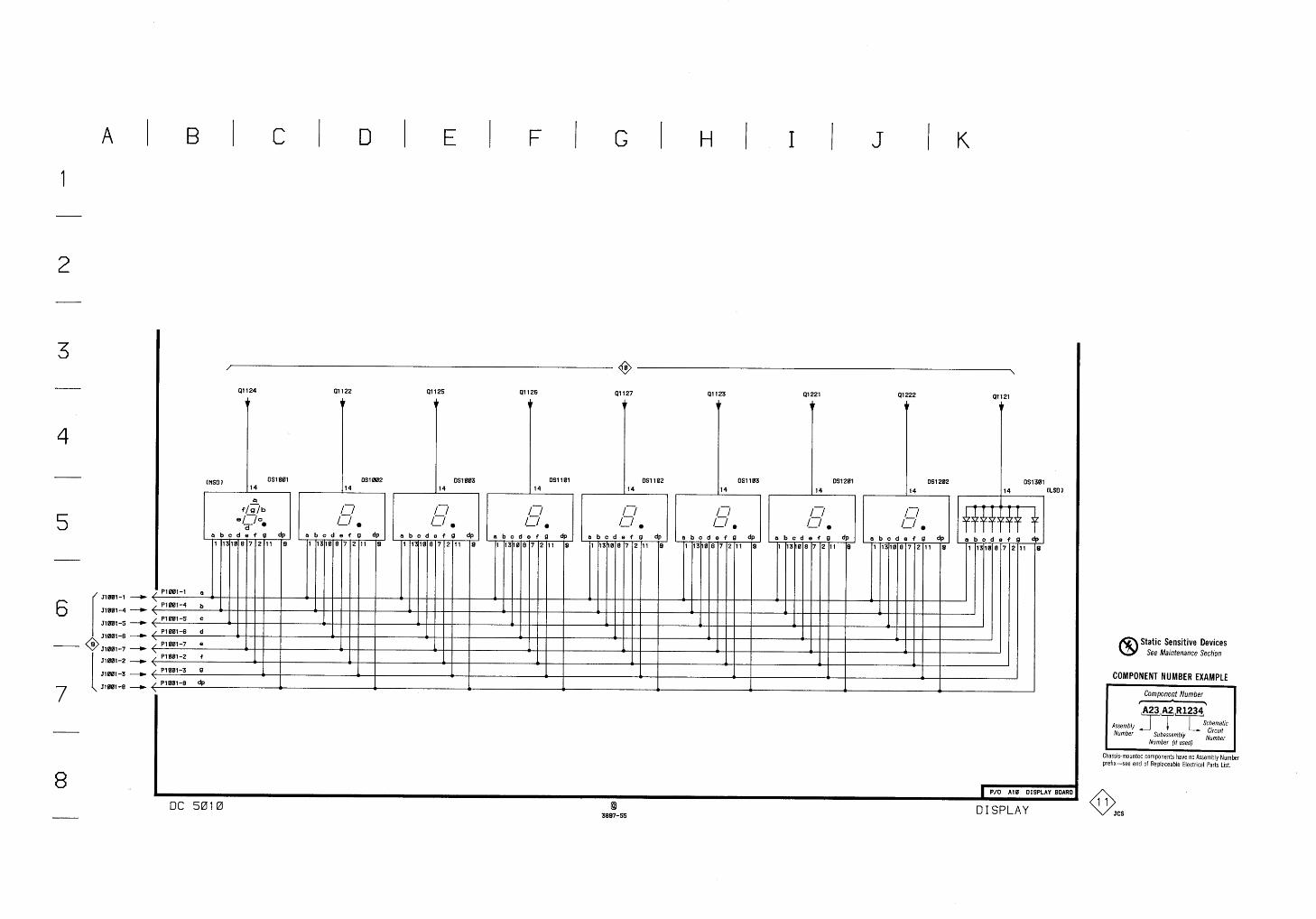
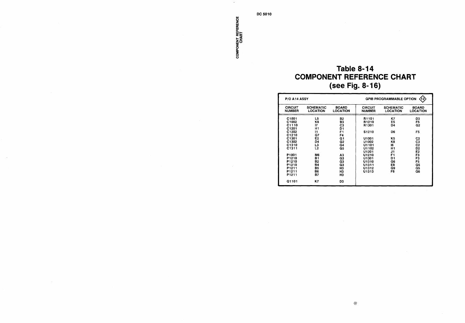
Table 8- 14 COMPONENT REFERENCE CHART
(see Fig. 8- 16)
I PI0 A14 ASSY
CIRCUIT SCHEMATIC NUMBER LOCATION
C1001 C 1 002 L5 K8
C1110 17 C1201 H I C1202 I1 C1210 G7 C1301 E2 C1302 04 C1310 C1311 L3
L2
- - -
BOARD LOCATION
GPlB PROGRAMMABLE OPTION 12 0 CIRCUIT SCHEMATIC BOARD NUMBER LOCATION LOCATION
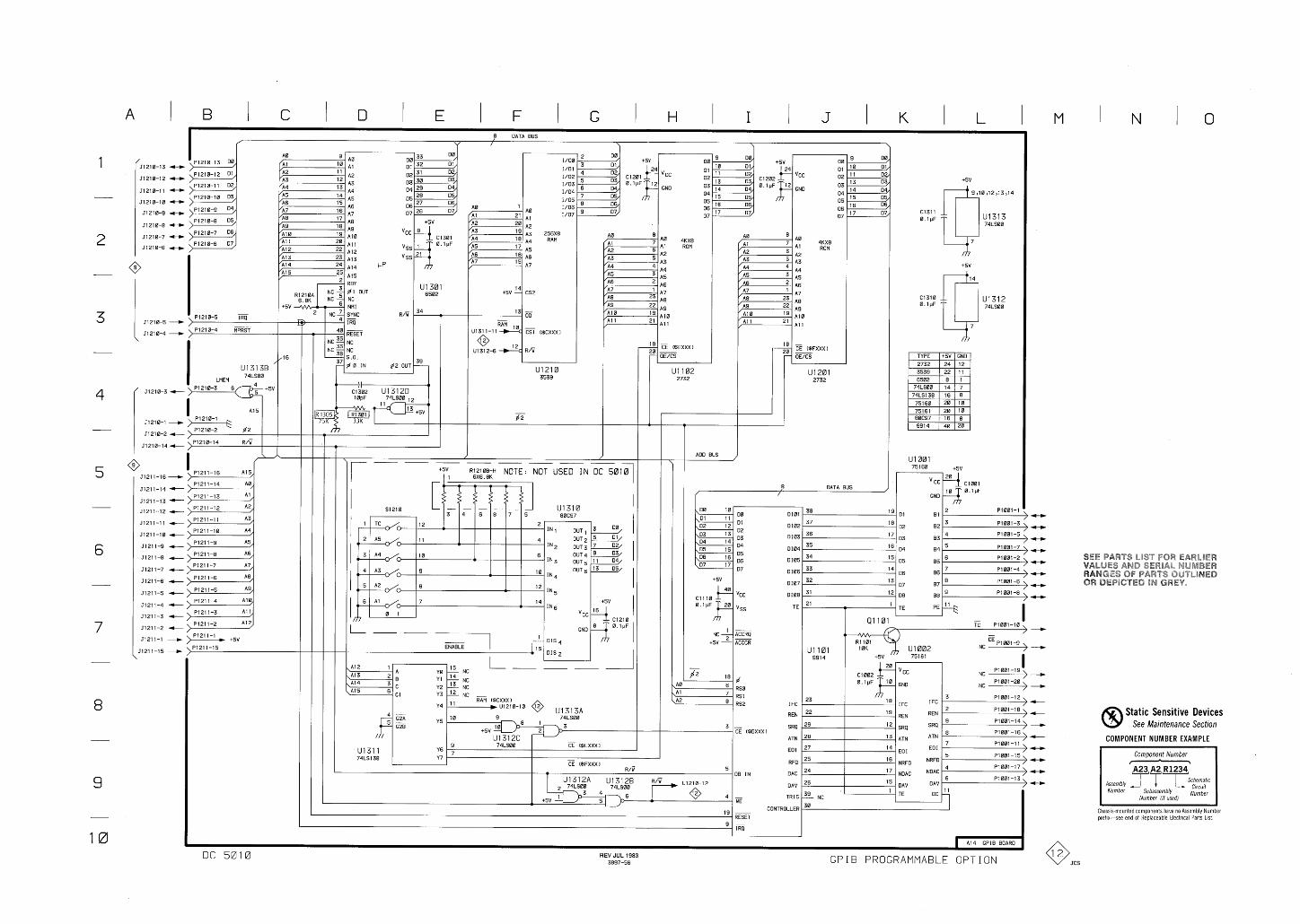
c 1 2 0 1 ~ ~ v c c 0.1pF l2 GND
I /Dt I /o;
256x8 RAM 4KX8
ROM
A4 A5 A6
A7
A1 0 A1 1
A10
A l l
4KX8 ROM
ADD BUS )
8 DATA BUS
f /
0101
Dl02
0103
Dl04
0105
Dl06
Dl07
0108
TE
I FC
REN
SRQ
ATN
EO I
RFO
DAC
DAV
rRlG
A12 A Ye '5 NC
A1 3 A14
8 Y1 l4
A15 c Y2 13 E GI '1'3 12 NC -
Y4 RAM ($CXXXI , u1210-10 @
313A 9
Y5 74LS00
+5v O8 -3 U l 3 l Z C
9 74LS00 -
Y6 CE ($EXXXI
U 1 3 1 1 74LS138 Y7 -
CE ($FXXXl D /G
I FC
REN
SRQ
ATN
EO I
NRFO
ND AC
DAV
DC
23
22
* IFC
Is- REN
29 l2 SRQ
28 l3 ATN
27 l4 EOI
25 l6 NRFO
24 l7 NDAC
26 DAV
TE
Static Sensitive Devices See Maintenance Section
COMPONENT NUMBER EXAMPLE
, ., " 08 IN
CONTROLLER
RESET
Component Number - A23 A2 R1234 'T T % h e m a t j c
Assembly -1 Number Subassembly i:;ubetr
Number ( I / used)
Chassls-mounted components have no Assembly Number prefix-see end of Replaceable Electrical Parts Ltst
I A14 GPIB BOARD
DC 5010 REV JUL 1983 3897-56 GPIB PROGRAMMABLE OPTION
Section 9-DC 501 0
REPLACEABLE MECHANICAL PARTS
PARTS ORDERING INFORMATION
Replacement parts are available from or through your local Tektronix, Inc. Field Office or representative.
Changes to Tektronix instruments are sometimes made to accommodate improved components as they become available, and to give you the benefit of the latest circuit improvements developed in our engineering department. It is therefore important, when ordering parts, to include the following information in your order: Part number, instrument type or number, serial number, and modification number if applicable.
If a part you have ordered has been replaced with a new or improved part, your local Tektronix, Inc. Field Office or representative will contact you concerning any change in part number.
Change information, if any, is located at the rear of this manual.
SPECIAL NOTES AND SYMBOLS
XOOO Part first added at this serial number
OOX Part removed after this serial number
FIGURE AND INDEX NUMBERS
Items in this section are referenced numbers to the illustrations.
# ACTR ADPTR ALIGN A L ASSEM ASSY ATTEN AWG BD BRKT BRS BRZ BSHG CAB CAP CER CHAS CKT COMP CONN cov CPLG CRT DEG DWR
INCH NUMBER SIZE ACTUATOR ADAPTER ALIGNMENT ALUMINUM ASSEMBLED ASSEMBLY ATTENUATOR AMERICAN WlRE GAGE BOARD BRACKET BRASS BRONZE BUSHING CABINET CAPACITOR CERAMIC CHASSIS CIRCUIT COMPOSITION CONNECTOR COVER COUPLING CATHODE RAY TUBE DEGREE DRAWER
ELCTRN ELEC ELCTLT ELEM EPL EQPT EXT FIL FLEX FLH FLTR FR FSTNR FT FXD GSKT HDL HEX HEX HD HEX SOC HLCPS HLEXT HV IC ID IDENT IMPLR
by figure and index
INDENTATION SYSTEM
This mechanical parts list is indented to indicate item relationships. Following is an example of the indentation system used in the description column.
1 2 3 4 5 Name & Description
Assembly andlor Component Attaching parts for Assembly andlor Component
- - - - - - Detail Part of Assembly andlor Component Attaching parts for Detail Part
* - - - - - -
Parts of Detail Part Attaching parts for Parts of Detail Part
- - - * - - -
Attaching Parts always appear in the same indentation as the item it mounts, while the detail parts are indented to the right. Indented items are part of, and included with, the next higher indentation. The separation symbol - - - * - - - indicates the end of attaching parts.
Attaching parts must be purchased separately, unless otherwise specified.
ITEM NAME
In the Parts List, an ltem Name is separated from the description by a colon (:). Because of space limitations, an ltem Name may sometimes appear as incomplete. For further ltem Name identification, the U.S. Federal Cataloging Handbook H6-1
can be utilized where possible.
ABBREVIATIONS
ELECTRON ELECTRICAL ELECTROLYTIC ELEMENT ELECTRICAL PARTS LIST EQUIPMENT EXTERNAL FlLLlSTER HEAD FLEXIBLE FLAT HEAD FILTER FRAME or FRONT FASTENER FOOT FIXED GASKET HANDLE HEXAGON HEXAGONAL HEAD HEXAGONAL SOCKET HELICAL COMPRESSION HELICAL EXTENSION HIGH VOLTAGE INTEGRATED CIRCUIT INSIDE DIAMETER IDENTIFICATION IMPELLER
IN INCAND INSUL INTL LPHLDR MACH MECH MTG NIP NON WlRE OBD 0 D OVH PH BRZ P L PLSTC PN PNH PWR RCPT RES RGD RLF RTNR SCH SCOPE SCR
INCH INCANDESCENT INSULATOR INTERNAL LAMPHOLDER MACHINE MECHANICAL MOUNTING NIPPLE NOT WlRE WOUND ORDER BY DESCRIPTION OUTSIDE DIAMETER OVAL HEAD PHOSPHOR BRONZE PLAIN or PLATE PLASTIC PART NUMBER PAN HEAD POWER RECEPTACLE RESISTOR RIGID RELIEF RETAINER SOCKET HEAD OSCILLOSCOPE SCREW
S E SINGLE END SECT SECTION SEMICOND SEMICONDUCTOR SHLD SHLDR SKT S L SLFLKG SLVG SPR S Q SST STL SW T TERM THD THK TNSN TPG TRH v VAR W / WSHR XFMR XSTR
SHIELD SHOULDERED SOCKET SLIDE SELF-LOCKING SLEEVING SPRING SQUARE STAINLESS STEEL STEEL SWITCH TUBE TERMINAL THREAD THICK TENSION TAPPING TRUSS HEAD VOLTAGE VARIABLE WITH WASHER TRANSFORMER TRANSISTOR
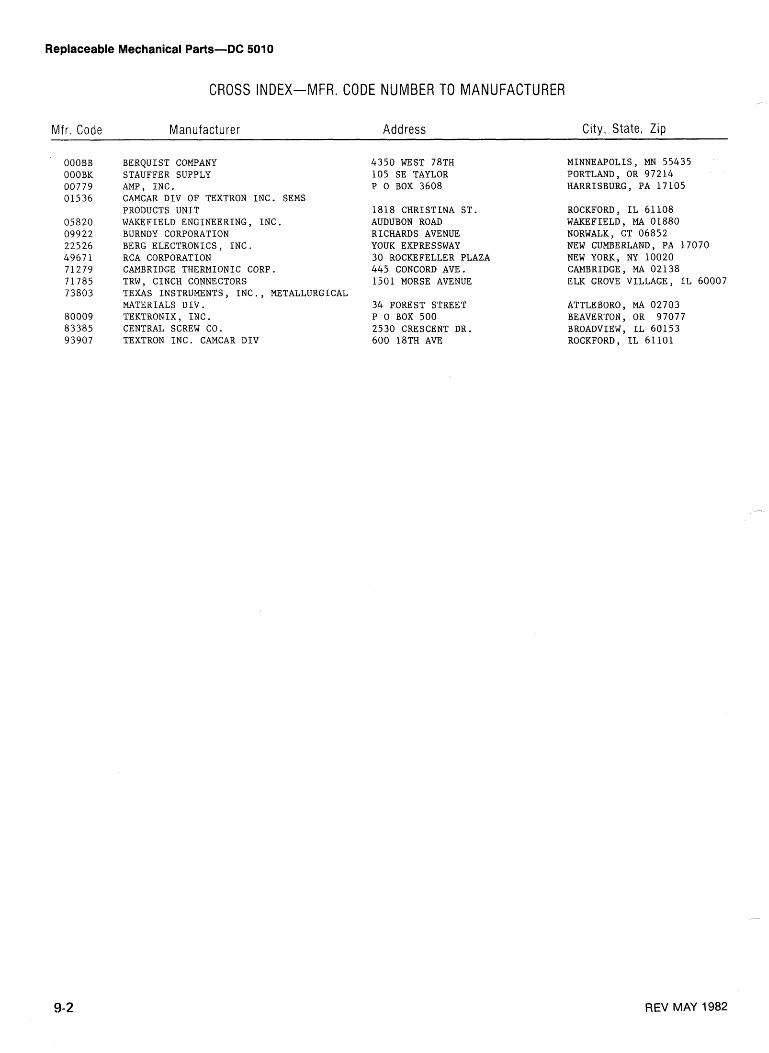
Replaceable Mechanical Parts-DC 5010
CROSS INDEX-MFR. CODE NUMBER TO MANUFACTURER
M f r . Code Manufacturer Address C i t y , S t a t e , Zip
OOOBB OOOBK 0 0 7 7 9 0 1 5 3 6
BERQUIST COMPANY STAUFFER SUPPLY AMP, I N C . CAMCAR D I V OF TEXTRON I N C . SEMS PRODUCTS U N I T WAKEFIELD ENGINEERING, I N C . BURNDY CORPORATION BERG ELECTRONICS, I N C . RCA CORPORATION CAMBRIDGE THERMIONIC CORP. TRW, CINCH CONNECTORS TEXAS INSTRUMENTS, I N C . , METALLURGICAL MATERIALS D I V . TEKTRONIX , I N C . CENTRAL SCREW CO. TEXTRON I N C . CAMCAR D I V
4 3 5 0 WEST 7 8 T H 1 0 5 S E TAYLOR P 0 BOX 3608
1818 C H R I S T I N A S T . AUDUBON ROAD RICHARDS AVENUE YOUK EXPRESSWAY 3 0 ROCKEFELLER PLAZA 445 CONCORD AVE. 1 5 0 1 MORSE AVENUE
34 FOREST STREET P 0 BOX 5 0 0 2 5 3 0 CRESCENT DR. 6 0 0 1 8 T H AVE
MINNEAPOLIS , MN 5 5 4 3 5 PORTLAND, OR 9 7 2 1 4 HARRISBURG, P A 1 7 1 0 5
ROCKFORD, I L 6 1 1 0 8 WAKEFIELD, MA 0 1 8 8 0 NORWALK, CT 0 6 8 5 2 NEW CUMBERLAND, P A 1 7 0 7 0 NEW YORK, NY 1 0 0 2 0 CAMBRIDGE, MA 0 2 1 3 8 ELK GROVE VILLAGE, I L 6 0 0 0 7
ATTLEBORO, MA 0 2 7 0 3 BEAVERTON, OR 9 7 0 7 7 BROADVIEW, I L 6 0 1 5 3 ROCKFORD, I L 6 1 1 0 1
REV MAY 1982
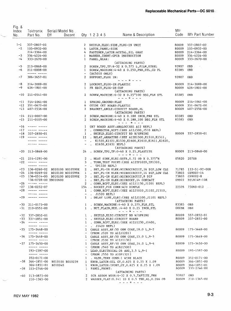
Replaceable Mechanical Parts-DC 5010
Fig. & Index Tektronix SerialIModel No. Mf r
- No. Part No. Eff Dscont Qty 1 2 3 4 5 Name & Description Code Mfr Part Number
-21 214-1291-00 -22 ----- -----
we--- ----- -23 136-0260-02 BOlOlOO B010599X -24 136-0269-02 BOlOlOO B010599X -25 136-0514-00 BOlOlOO B010599X
136-0728-00 XB010600 -26 ----- ----- -27 136-0252-07 -28 ----- -----
----- ----- -29 ----- -----
----- ----- -35 175-3448-00
----- ----- -36 175-3449-00
----- ----- -37 175-3450-00
----- ----- 195-1597-00 ----- ----- 352-0171-00
-38 366-1851-00 BOlOlOO B010239 366-1851-01 B010240
-39 333-2746-00
SHIELD, ELEC : SIDE, PLUG-IN UNIT LATCH,PANEL:SI.DE FASTENER,LATCH:ACETAL,SIL GRAY MARKER,IDENT:GPIB INSTRUCTION PANEL,REAR:
(ATTACHING PARTS) SCREW,TPG,TF:6-32 X 0.375 L,FILM,STEEL SCREW,MACHINE:4-40 X 0.250,PNH,STLYCD PL ( ~ ~ 5 0 1 0 ONLY) SUPPORT,PLUG IN:
- - - * - - - LOCKOUT,PLUG-1N:PLASTIC FR SECT, PLUG-IN : TOP
(ATTACHING PARTS) SCREW,MACHINE:6-32 X 0.25"100 DEG,FLH STL - - - * - - - SPRING,GROUND:FLAT GUIDE CKT B0ARD:PLASTIC BRACKET, ANGLE : CIRCUIT BOARD, AL
(ATTACHING PARTS) SCREW,MACHINE:4-40 X 0.188 INCH,PNH STL SCREW,MACHINE:4-40 X 0.188,100 DEG,FLH STL
- - - * - - - CKT BOARD ASSY:ANALOG(SEE A12 REPL) CONNECTOR,RCPT:(SEE A12J50OYJ510 REPL) SHIELD ,ELEC: CIRCUIT BD WISPRING RELAY,ARMATURE:(SEE A12K1500,K1510,K1511, K1520,K1521,K1530,K1600,K1610,K1611,K1620 K163OYK1631 REPL)
(ATTACHING PARTS) SCREW,TPG,TF:O-40 X 0.25,PLASTITE - - - * - - - HEAT SINK,ELEC:XSTR,0.72 OD X 0.375"H TERM,TEST POINT:(SEE A12TP1020,TP1310, TP1330 REPL) SKT,PL-IN ELEK:MICROCIRCUIT,16 DIP,LOW CLE SKT,PL-IN ELEK:MICROCIRCUIT,14 DIP,LOW CLE SKT,PL-IN ELEC:MICROCIRCUIT,8 DIP SKT,PL-IN ELEK:MICROCKT,14 CONTACT CONN,RCPT,ELEC:(SEE A12J1130,J1201 REPL) SOCKET,PIN CONN:W/O DIMPLE CONN,RCPT,ELEC:(SEE A12J1010,J1102,J1510, 51520 REPL) DELAY LINE,ELEC:(SEE A12J1100,J1101 REPL)
(ATTACHING PARTS) SCREW,MACHINE:4-40 X 0.375,FLHYSTL NUT,PLAIN,HEX.:4-40 X 0.25 INCH,STL
- - - t - - -
SHIELD,ELEC:CIRCUIT BD WISPRING SHIELD ,ELEC :CIRCUIT BOARD CONN,RCPT,ELEC:(SEE A12J1230,J1400, 51420 REPL)
CABLE ASSY,RF:50 OHM COAX,18.0 L,9-2 (FROM 5520 TO ~12~1201) CABLE ASSY,RF:50 OHM COAX,15.0 L,9-3 (FROM 5530 TO ~1251130) CABLE ASSY,RF:50 OHM COAX,14.0 L,9-4 (FROM 5540 TO A18J1500) LEAD,ELECTRICAL:26 AWG,3.5 L,9-1 (FROM 5550 TO A10~1321) . HLDR,TERM C0NN:l WIRE BLACK KNOB,LATCH:SIL GY,0.625 X 0.25 X 1.09 KNOB,LATCH:IVORY,GYy0.625 X 0.25 X 1.09 PANEL, FRONT :
(ATTACHING PARTS) SCR ASSEM WSHR: 6-32 X 0.5 ,TAPTITE ,PNH WASHER,FLAT:0.141 ID X 0.5 THK,AL,0.266 OD
- - - * - - -
93907 OBD ,
83385 OBD
OBD
214-3089-00 426-1801-00
OBD
214-1061-00 351-0672-00 407-2556-00
OBD OBD
83385 OBD OOOBK OBD
93907 OBD 80009 2 10- 1365-00
REV MAY 1982
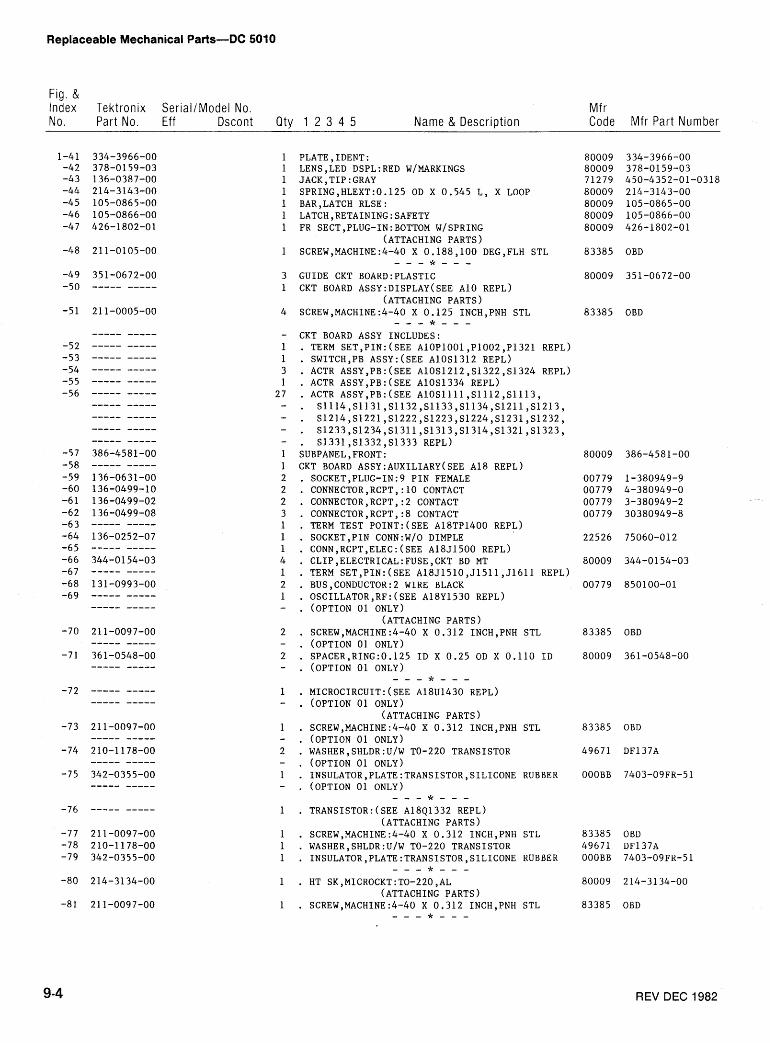
Replaceable Mechanical Parts-DC 5010
Fig. & Index Tektronix SeriallModel No. Mfr No. Part No. Eff Dscont Qty 1 2 3 4 5 Name & Description Code Mfr Part Number
PLATE, IDENT : LENSSLED DSPL:RED W~MARKINGS JACK,TIP:GRAY SPRING,HLEXT:0.125 OD X 0.545 L, X LOOP BAR, LATCH RLSE : LATCH,RETAINING:SAFETY FR SECT,PLUG-1N:BOTTOM WISPRING
(ATTACHING PARTS) SCREW,MACHINE:4-40 X 0.188,100 DEG,FLH STL - - - * - - - GUIDE CKT B0ARD:PLASTIC CKT BOARD ASSY:DISPLAY(SEE A10 REPL)
(ATTACHING PARTS) SCREW,MACHINE:4-40 X 0.125 INCH,PNH STL - - - * - - - CKT BOARD ASSY INCLUDES: . TERM SET,PIN:(SEE A10P1001,P1002,P1321 REPL) . SWITCH,PB AssY:(SEE A10S1312 REPL) . ACTR ASSY,PB:(SEE AlOS1212,S1322,S1324 REPL) . ACTR ASSY,PB:(SEE A10S1334 REPL) . ACTR ASSY,PB:(SEE A10Sllll,S1112,S1113, . S1114,S1131,S1132,S1133,S1134,S1211,S1213, . S1214,S1221,S1222,S1223,S1224,S1231,S1232, . S1233,S1234,S1311,S1313,S1314,S1321,S1323, . S1331,S1332,S1333 REPL) SUBPANEL,FRONT: CKT BOARD ASSY:AUXILIARY(SEE A18 REPL) SOCKET,PLUG-IN:9 PIN FEMALE CONNECTOR,RCPT,:lO CONTACT CONNECTOR,RCPT,:2 CONTACT CONNECTOR,RCPT,:8 CONTACT TERM TEST POINT:(SEE A18TP1400 REPL) SOCKET,PIN CONN:W/O DIMPLE CONN,RCPT,ELEC:(SEE A18J1500 REPL) CLIP,ELECTRICAL:FUSE,CKT BD MT TERM SET,PIN:(SEE A18J1510,J1511,J1611 REPL) BUS,CONDUCTOR:2 WIRE BLACK OSCILLATOR,RF:(SEE A18Y1530 REPL) (OPTION 01 ONLY)
(ATTACHING PARTS) SCREW,MACHINE:4-40 X 0.312 INCH,PNH STL (OPTION 01 ONLY) SPACER,RING:0.125 ID X 0.25 OD X 0.110 ID (OPTION 01 ONLY) - - - * - - - MICROCIRCUIT:(SEE ~ 1 8 ~ 1 4 3 0 REPL) (OPTION 01 ONLY)
(ATTACHING PARTS) SCREW,MACHINE:4-40 X 0.312 INCH,PNH STL (OPTION 01 ONLY) WASHER,SHLDR:U/W TO-220 TRANSISTOR (OPTION 01 ONLY) INSULATOR,PLATE:TRANSISTOR,SILICONE RUBBER (OPTION 01 ONLY) - - - * - - - TRANSISTOR:(SEE ~ 1 8 ~ 1 3 3 2 REPL)
(ATTACHING PARTS) SCREW,MACHINE:4-40 X 0.312 INCH,PNH STL WASHER,SHLDR:U/W TO-220 TRANSISTOR INSULATOR,PLATE:TRANSISTOR,SILICONE RUBBER
- - - * - - - HT SK,MICROCKT:TO-220,AL
(ATTACHING PARTS) SCREW,MACHINE:4-40 X 0.312 INCH,PNH STL - - - * - - -
83385 OBD
83385 OBD
83385 OBD
80009 361-0548-00
83385 OBD
49671 DF137A
OOOBB 7403-09FR-51
83385 OBD 49671 DF137A OOOBB 7403-09FR-51
80009 214-3134-00
83385 OBD
REV DEC 1982
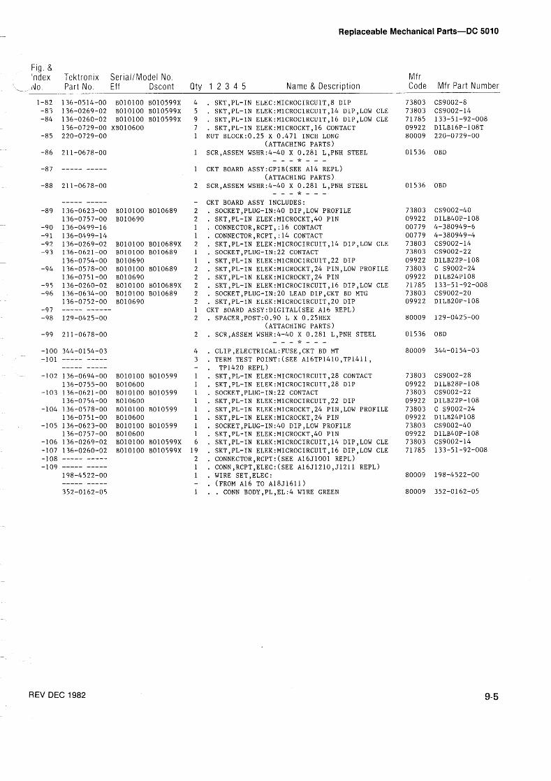
Replaceable Mechanical Parts-DC 5010
Fig. & 'ndex Tektron~x SerrallModel No. Mfr d o Part No. Eff Dscont Qty 1 2 3 4 5 Name & Description Code Mfr Part Number
BOlOlOO B010599X BOlOlOO B010599X BOlOlOO B010599X
XB010600
BOlOlOO B010689 8010690
BOlOlOO B010689X BOlOlOO B010689 B010690 BOlOlOO B010689 B010690 B010100 B010689X BOlOlOO B010689 8010690
-
BOlOlOO 8010599 B010600 BOlOlOO B010599 B010600 BOlOlOO B010599 B010600 BOlOlOO B010599 B010600 BOlOlOO B010599X BOlOlOO B010599X
. SKT,PL-IN ELEC:MICROCIRCUIT,8 DIP
. SKT,PL-IN ELEK:MICROCIRCUIT,14 DlP,LOW CLE
. SKT,PL-IN ELEK:MICROCIRCUIT,16 DlP,LOW CLE
. SKT,PL-IN ELEK:MICROCKT,16 CONTACT NUT BLOCK:0.25 X 0.471 INCH LONG
(ATTACHING PARTS) SCR,ASSEM WSHR:4-40 X 0.281 L,PNH STEEL - - - * - - - CKT BOARD ASSY:GPIB(SEE A14 REPL)
(ATTACHING PARTS) SCR,ASSEM WSHR:4-40 X 0.281 L,PNH STEEL - - - * - - - CKT BOARD ASSY INCLUDES: . SOCKET,PLUG-IN:4O DIP,LOW PROFILE . SKT,PL-IN ELEK:MICROCKT,40 PIN . CONNECTOR,RCPT,:16 CONTACT . CONNECTOR,RCPT,:14 CONTACT . SKT,PL-IN ELEK:MICROCIRCUIT,14 DIP,LOW CLE . SOCKET,PLUG-IN:22 CONTACT . SKT,PL-IN ELEK:MICROCIRCUlT,22 DIP . SKT,PL-IN ELEK:MICROCKT,24 PIN,LOW PROFILE . SKT,PL-IN ELEK:MICROCKT,24 PIN . SKT,PL-IN ELEK:MICROCIRCUIT,16 DIP,LOW CLE . SOCKET,PLUG-IN:20 LEAD DIP,CKT BD MTG . SKT,PL-IN ELEK:MICROCIRCUIT,20 DIP CKT BOARD ASSY:DIGITAL(SEE A16 REPL)
SPACER,POST:0.90 L X 0.25HEX (ATTACHING PARTS)
SCR,ASSEM WSHR:4-40 X 0.281 L,PNH STEEL - - - * - - - CLIP ,ELECTRICAL : FUSE, CKT BD MT TERM TEST POINT:(SEE A16TP1410,TP1411, TP1420 REPL) SKT,PL-IN ELEK:MICROCIRCUIT,28 CONTACT SKT,PL-IN ELEK:MICROCIRCUIT,28 DIP SOCKET,PLUG-IN:22 CONTACT SKT,PL-IN ELEK:MICROCIRCUIT,22 DIP SKT,PL-IN ELEK:MICROCKT,24 PIN,LOW PROFILE SKT,PL-IN ELEK:MICROCKT,24 PIN SOCKET,PLUG-IN:40 DIP,LOW PROFILE SKT,PL-IN ELEK:MICROCKT,40 PIN SKT,PL-IN ELEK:MICROCIRCUIT,14 DIP,LOW CLE SKT,PL-IN ELEK:MICROCIRCUIT,16 DIP,LOW CLE CONNECTOR,RCPT:(SEE A16J1001 REPL) CONN,RCPT,ELEC:(SEE A16J1210,J1211 REPL) WIRE SET,ELEC: (FROM A16 TO ~ 1 8 ~ 1 6 1 1 ) . CONN BODY,PL,EL:4 WIRE GREEN
01536 OBD
01536 OBD
OBD
REV DEC 1982

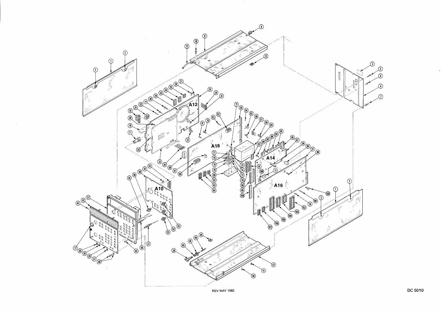
L /
REV MAY 1982
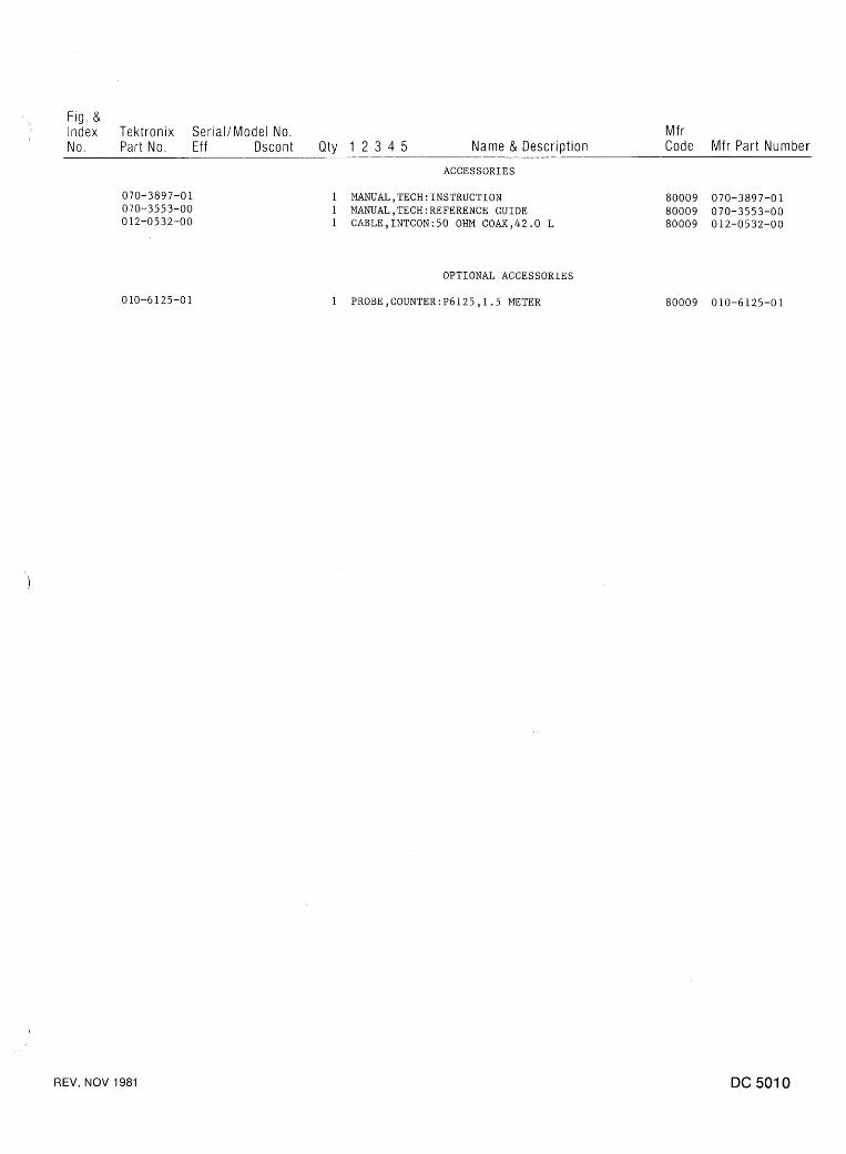
Fig. & Index Tektronix SeriallModel No. Mfr
I
No. Part No. Eff Dscont Qty 1 2 3 4 5 Name & Description Code Mfr Part Number ACCESSORIES
1 MANUAL,TECH:INSTRUCTION 1 MANUAL,TECH:REFERENCE GUIDE 1 CABLE,INTCON:50 OHM COAX,42.0 L
OPTIONAL ACCESSORIES
1 PROBE, COUNTER : P6 125 , 1 .5 METER
REV, NOV 1981
MANUAL CHANGE INFORMATION
At Tektronix, we continually strive to keep up with latest electronic developments by adding circuit and component improvements to our instruments as soon as they are developed and tested.
Sometimes, due to printing and shipping requirements, we can't get these changes immediately into printed manuals. Hence, your manual may contain new change information on following pages.
A single change may affect several sections. Since the change information sheets are carried in the manual until all changes are permanently entered, some duplication may occur. If no such change pages appear following this page, your manual is correct as printed.
Related Documents