Data & Knowledge Engineering 10 (1993) 229-257 229 North-Holland DATAK 172 Database design with user-definable modelling concepts* Peter C. Lockemann, Guido Moerkotte, Andrea Neufeld, Klaus Radermacher and Norbert Runge Fakultiit fiir lnforrnatik, Universitiit Karlsruhe, Postfach 6980, W-7500 Karlsruhe, Germany Received 7 August 1992 Accepted 18 January 1993 Abstract Lockemann, P.C., G. Moerkotte, A. Neufeld, K. Radermacher and N. Runge, Database design with user-definable modelling concepts, Data & Knowledge Engineering 10 (1993) 229-257. Modelling is an integral part of engineering processes. Consequently, database design for engineering applications should take into account the modelling concepts used by engineers. On the other hand, these applications exhibit a wide diversity of modelling concepts. Rather than consolidating these into one single semantic data model one should aim for correspondingly specialized semantic models. This paper takes a constructive approach to developing such specialized models by proposing an Extensible Semantic Model (ESM) as the basis for declaring specialized semantic data models. The paper introduces a computerized environment for database design based on an ESM, and discusses the consequences of the ESM for a number of design tools: the need for a formal definition of the notion of modelling concept in order to have reliable and precise foundation for the extensions, declarative techniques for quickly introducing graphical repre- sentations for new concepts and for using them during schema design, conceptual-level test data generation for a designer-oriented evaluation of designs, and optimization techniques to control the wide latitude in mapping a conceptual schema to a logical schema. First experiences seem to point to considerable productivity gains during database design. Keywords. Database design; logical design; database design environment; computer-aided engineering; data models; conceptual modelling; modelling concepts; deductive databases; database consistency; graphical modelling; rapid prototyping; test data generation; schema translation; data translation. 1. Introduction 1.1 Engineering: An unconventional database design world Databases should at all times be a faithful reflection of some predetermined reality, its so-called universe of discourse (or mini-world). Crudely speaking, database design is the process which, among others, must ensure that a database will satisfy this condition to the best of its abilities over its entire lifetime of possible decades under all conceivable updates to it. An important step towards this goal and, hence, an important phase of the design process Correspondence to:P.C, Lockemann, Fakult~t fiir Informatik, Universitiit Karlsruhe, Postfach 6980, W-7500 Karlsruhe, Germany. email: [email protected] * This work reported in this paper was supported by the Deutsche Forschungsgemeinschaft (German Research Council) under grant no. Lo 296/5. 0169-023X/93/$06.00 (~) 1993 - Elsevier Science Publishers B.V. All rights reserved

Welcome message from author
This document is posted to help you gain knowledge. Please leave a comment to let me know what you think about it! Share it to your friends and learn new things together.
Transcript
Data & Knowledge Engineering 10 (1993) 229-257 229 North-Holland
DATAK 172
Database design with user-definable modelling concepts*
Peter C. Lockemann, Guido Moerkotte, Andrea Neufeld, Klaus R a d e r m a c h e r and Norber t Runge Fakultiit fiir lnforrnatik, Universitiit Karlsruhe, Postfach 6980, W-7500 Karlsruhe, Germany
Received 7 August 1992 Accepted 18 January 1993
Abstract
Lockemann, P.C., G. Moerkotte, A. Neufeld, K. Radermacher and N. Runge, Database design with user-definable modelling concepts, Data & Knowledge Engineering 10 (1993) 229-257.
Modelling is an integral part of engineering processes. Consequently, database design for engineering applications should take into account the modelling concepts used by engineers. On the other hand, these applications exhibit a wide diversity of modelling concepts. Rather than consolidating these into one single semantic data model one should aim for correspondingly specialized semantic models. This paper takes a constructive approach to developing such specialized models by proposing an Extensible Semantic Model (ESM) as the basis for declaring specialized semantic data models. The paper introduces a computerized environment for database design based on an ESM, and discusses the consequences of the ESM for a number of design tools: the need for a formal definition of the notion of modelling concept in order to have reliable and precise foundation for the extensions, declarative techniques for quickly introducing graphical repre- sentations for new concepts and for using them during schema design, conceptual-level test data generation for a designer-oriented evaluation of designs, and optimization techniques to control the wide latitude in mapping a conceptual schema to a logical schema. First experiences seem to point to considerable productivity gains during database design.
Keywords. Database design; logical design; database design environment; computer-aided engineering; data models; conceptual modelling; modelling concepts; deductive databases; database consistency; graphical modelling; rapid prototyping; test data generation; schema translation; data translation.
1. Introduction
1.1 Engineering: An unconventional database design world
Databases should at all times be a faithful reflection of some predetermined reality, its so-called universe of discourse (or mini-world). Crudely speaking, database design is the process which, among others, must ensure that a database will satisfy this condition to the best of its abilities over its entire lifetime of possible decades under all conceivable updates to it.
An important step towards this goal and, hence, an important phase of the design process
Correspondence to:P.C, Lockemann, Fakult~t fiir Informatik, Universitiit Karlsruhe, Postfach 6980, W-7500 Karlsruhe, Germany. email: [email protected]
* This work reported in this paper was supported by the Deutsche Forschungsgemeinschaft (German Research Council) under grant no. Lo 296/5.
0169-023X/93/$06.00 (~) 1993 - Elsevier Science Publishers B.V. All rights reserved
23(I P.( ' . L o c k e m a n n et al.
is semantic modelling. The objective of semantic modelling is to register the features relevant to the universe of discourse, and the rules governing it, and to reflect these into a formalized framework. In turn, the framework is determined by the construction rules of a so-called semantic data model. Consequently, semantic modelling attempts to describe the features and rules of the universe of discourse to the best accuracy and naturalness possible within the constraints imposed by the construction rules of a given semantic data model.
Conventional database design, and hence, the prevailing design methodologies presume a designer who starts out with a more or less intuitive understanding of his/her subject matter, and that the semantic modelling process for the first time forces him/her to put down in formalized terms this understanding. Conventional database applications, due to their predominant roots in business and administration, could expect from their designers only very limited formal background. Consequently, conventional semantic models tend towards a very limited repertoire of construction rules. Such a situation left little space for more than a handful relatively simple, almost standardized semantic data models (with the ER model as a typical example).
In science and engineering we face an entirely different situation. In these areas we encounter experts who are well-versed and trained in translating their understanding of problems and solutions into precise and rigorous formulations. In doing so, they utilize a multitude of such traditional and well-proven presentation and construction rules as technical drawings of 3D artifacts, process flow diagrams for continuous process plants, diagrams for material and energy balances including the underlying computation rules, logic diagrams for electric machinery and electronic circuits, gate-level diagrams and layout masks for VLSI circuits, or volume partitioning for finite-element methods.
To summarize, database design for an engineering world starts from a situation that is markedly different from the conditions found in the business world that until now con- tributed the large majority of applications. This situation is characterized by well-formalized descriptions of situations, problems and solutions, and by potential users that are highly skilled in formal techniques. In such a situation, the role of database designer will change from system analyst to mediator between the subject-oriented formulations and the data- base-oriented formulations of a discourse world. The aim of the present paper is to study the consequences of this novel situation.
1.2 The case for extensible semantic data models
As stated before, semantic data models provide a set of rules for expressing the features relevant to some universe of discourse within a formalized framework. Hence, from a database system perspective one could very well interpret the presentation and construction rules of an engineering discipline as the equivalent to a semantic data model. Most of these models, though, have evolved over long times, and their objective has been to support numerical computations, to guide experiments and empirical studies, and to control en- gineering and manufacturing processes. Often they were in use long before computer suppor t -o r for that matter, database support-became available. Consequently, they exhibit a rich expressiveness of their formalisms geared towards coping with all the objectives of the engineering world. By contrast, the traditional semantic data models used in connection with databases exhibit a much poorer expressiveness, which is due not only to their origin in less challenging applications but also to their target, the logical data models as provided for by database management systems (DBMS).
Direct use of the engineering models would thus open up a gap so far uncommon to database design. Informatics usually fills such gaps by splitting them into two or more steps of reduced complexity. In effect, this would mean to introduce some intermediate semantic
Database design with user-definable modelling concepts 231
data model as a suitable compromise between the requirements of both the engineering and database worlds. Although one might be tempted to look for a single intermediate model, all experience indicates otherwise: Just notice the still large variety in data exchange standards across different engineering disciplines and even within a single one ( IGES and STEP in mechanical engineering, EDIF and V H D C in electronic circuit design [7, 39, 40, 43 D, or the large number of semantic data models that are tailored to specific applications [20]. This t rend can be expected to continue with the many technology leaps still to be expected. To gain a uniform intermediate model one would have to be willing to merge all the different models of the past into one, thus trading specificity and ease of handling for generality and unwieldiness.
To illustrate this point consider the notion of is_reachable which is common to several engineering disciplines, though always with a different semantics. In architecture, is_reach- able expresses a relation between the floors of a building and describes how floors can be accessed from one another via stairwells or elevators. In robotics, the same term refers to the reachability of a workpiece by a robot arm in terms of a set of points in a three-dimensional convex workspace. In traffic control two intersections within a city can be reached from one another if a connection between them can be found in the transitive closure of the connections between adjacent intersections.
To merge all these notions into a single data model seems entirely unattractive. A better alternative allows for a set of intermediate models which, by necessity, is open-ended in order to respond flexibly to new applications and technologies. Such an alternative should strictly be constructive: Introducing a new semantic data model including the facilities for schema definition and mapping should turn into a purely engineering task. The challenge, then, is to find a set of meta construction rules with which to define the construction rules for a new semantic data model. We refer to such an approach as an Extensible Semantic Model (ESM).
The approach seems particularly suited to define an 'open environment ' with a number of base mechanisms that can easily be extended by tools or interpretative means to reflect the construction rules of a specific data model.
1.3 Objectives of the paper
The central characteristic of the ESM is the free definability of construction r u l e s - referred to as 'modelling concepts' in the remainder. To deal with the rules in a constructive
and (at least partially) automated manner one must be able to completely and rigorously describe their semantics. Such a requirement bears a certain semblance to work in the areas of metal-modelling and metadata management [18, 19, 37]. Meta-modelling refers to the automated generation of a software system from a given specification. Metadata manage- ment is based on a data dictionary which supplies information on the data model and the database schema to both an information system and its users. And indeed, in a language called Telos both ideas have been combined to add extensibility to information systems, though only for the rather 'simple-minded' business applications [23]. As noted above, our objective is to go beyond these and to support the more ambitious modelling needs of engineers.
The need for extensible semantic data models in the narrower context of database design seems to have been mentioned for the first time in [10]. This is also the purpose of our work. The narrower scope gives rise to a set of more specific challenges: Rather than concentrating on just the technical support of the modelling process itself, we should also render help for the computer-assisted analysis and evaluation of the design results and to the largely automatic generation of a database schema from them - all this under the generic conditions of an open environment.
232 P.('. Lockemann et al.
Consequently, the objective of this paper is to examine the consequences of ESM for the database design process, for the architecture of a design environment, its softwarc infra- structure and its design mechanisms and tools. The next section briefly reviews traditional database design and then discusses the impact of an ESM on database design as well as the architectures of design environments. Section 3 introduces an example universe. Sections 4 through 7 deal with those design mechanisms that provide the necessary infrastructure. Section 4 deals with the notion of concept, formalizes it and presents a language for declaring concepts. Section 5 discusses the use of the declared concepts in a graphical environment for schema construction. Section 6 focuses on schema validation and Section 7 on schema translation to a target database system. Section 8 concludes the paper.
2. Database design with extensible semantic models
We turn our attention first to the question of how an ESM affects the design process. This is best done by comparing it to the classical design process in order to identify the necessary modifications and additions to the activities and their results. The analysis will provide us with a crude architecture of an ESM-based design environment.
2.1 Traditional database design
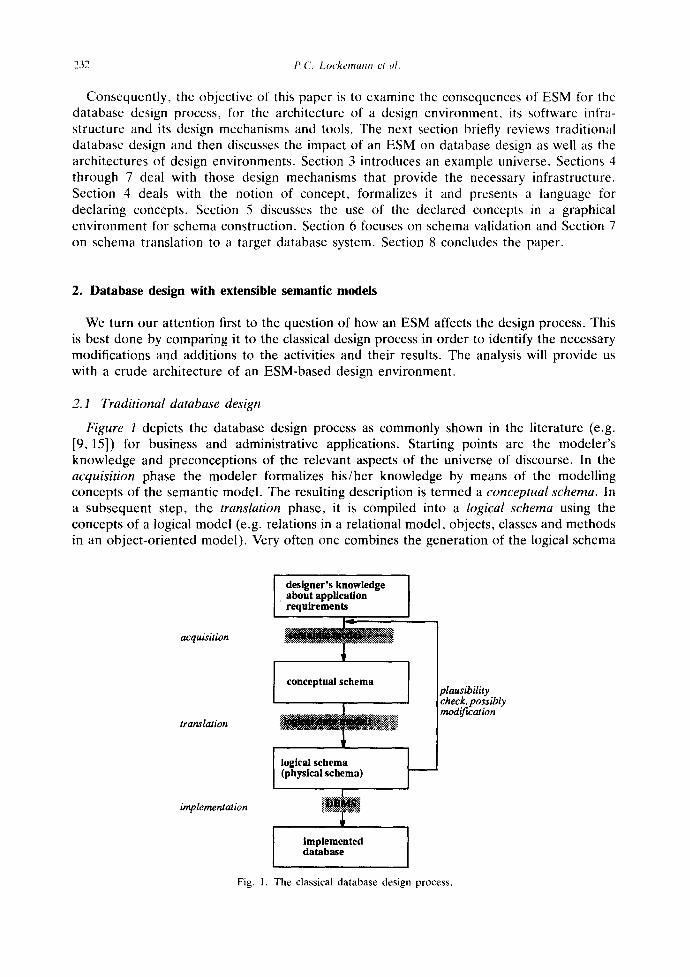
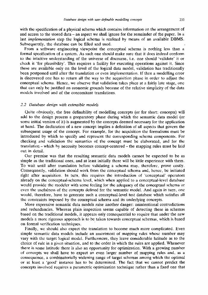
Figure 1 depicts the database design process as commonly shown in the literature (e.g. [9, 15]) for business and administrative applications. Starting points are the modeler's knowledge and preconceptions of the relevant aspects of the universe of discourse. In the acquisition phase the modeler formalizes his/her knowledge by means of the modelling concepts of the semantic model. The resulting description is termed a conceptual schema. In a subsequent step, the translation phase, it is compiled into a logical schema using the concepts of a logical model (e.g. relations in a relational model, objects, classes and methods in an object-oriented model). Very often one combines the generation of the logical schema
acquisition
translation
implementation
designer's knowledge [ about application
'requirements
conceptual schema
I logical schema ] (physical schema)
I Implemented database
Fig. 1. The classical database design process.
plausibility check, possibly mod~cation
Database design with user-definable modelling concepts 233
with the specification of a physical schema which contains information on the arrangement of and access to the stored data - an aspect we shall ignore for the remainder of the paper. In a last implementation step the logical schema is realized by means of an available DBMS. Subsequently, the database can be filled and used.
From a software engineering viewpoint the conceptual schema is nothing less than a formal specification of a system. As such one should make sure that it does indeed conform to the intuitive understanding of the universe of discourse, i.e. one should 'validate' it or check it 'for plausibility'. This requires a facility for executing operations against it. Since these are available only on the level of the logical data model, validation has traditionally been postponed until after the translation or even implementation. If then a modelling error is discovered one has to return all the way to the acquisition phase in order to adjust the conceptual schema. Hence, we observe that validation takes place at a fairly late stage, one that can only be justified on economic grounds because of the relative simplicity of the data models involved and of the concomitant translations.
2.2 Database design with extensible models
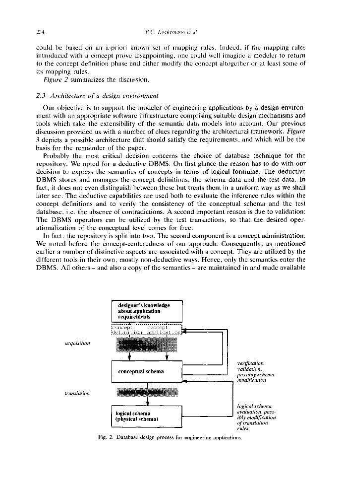
Quite obviously, the free definability of modelling concepts (or for short: concepts) will add to the design process a preparatory phase during which the semantic data model (or some initial version of it) is augmented by the concepts deemed necessary for the application at hand. The declaration of a new concept implies a definition of all aspects that govern the subsequent usage of the concept. For example, for the acquisition the formalisms must be introduced by which to specify and represent the corresponding schema components. For checking and validation the semantics of the concept must be elaborated, and for the translation- which by necessity becomes concept-centered- the mapping rules must be laid out in detail.
Our premise was that the resulting semantic data models cannot be expected to be as simple as the traditional ones, and at least initially there will be little experience with them. To wait until after translation before validating a schema may, therefore, prove costly. Consequently, validation should work from the conceptual schema and, hence, be initiated right after acquisition. In turn, this requires the introduction of 'conceptual' operators already on the conceptual-schema level, which when applied to a conceptual-level database would provide the modeler with some feeling for the adequacy of the conceptual schema or even the usefulness of the concepts defined for the semantic model. And again in turn, one would, therefore, have to generate such a conceptual-level test database which satisfies all the constraints imposed by the conceptual schema and its underlying concepts.
More expressive semantic data models raise another danger: unintentional contradictions and redundancies. Whereas plain inspection seems capable of detecting these in schemas based on the traditional models, it appears only consequential to require that under the new models a more rigorous approach is to be taken towards conceptual schemas, which is based on formal verification techniques.
Finally, we should also expect the translation to become much more complicated. Even simple semantic data models include an assortment of mapping rules whose number may vary with the target logical model. Furthermore, they leave considerable latitude as to the choice of rule in a given situation, and to the order in which the rules are applied. Whenever there is some latitude there is also an opportunity for optimization. With a growing number of concepts we shall have to expect an even larger number of mapping rules and, as a consequence, a combinatorially widening range of target schemas among which the optimal or at least a 'good' instance has to be determined. The fact that we cannot predict the concepts involved requires a parametric optimization technique rather than a fixed one that
234 P.('. Lockemann el al.
could be based on an a-priori known set of mapping rules. Indeed, if the mapping rules introduced with a concept prove disappointing, one could well imagine a modeler to return to the concept definition phase and either modify the concept altogether or at least some of its mapping rules.
Figure 2 summarizes the discussion.
2.3 Architecture of a design environment
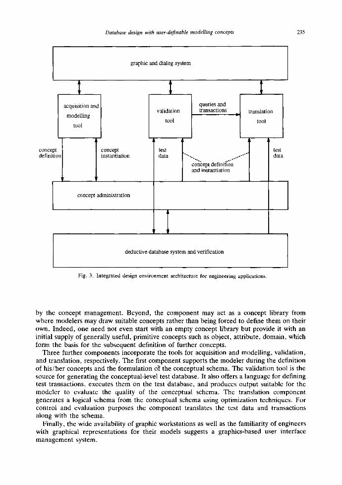
Our objective is to support the modeler of engineering applications by a design environ- ment with an appropriate software infrastructure comprising suitable design mechanisms and tools which take the extensibility of the semantic data models into account. Our previous discussion provided us with a number of clues regarding the architectural framework. Figure 3 depicts a possible architecture that should satisfy the requirements, and which will be the basis for the remainder of the paper.
Probably the most critical decision concerns the choice of database technique for the repository. We opted for a deductive DBMS. On first glance the reason has to do with our decision to express the semantics of concepts in terms of logical formulae. The deductive DBMS stores and manages the concept definitions, the schema data and the test data. In fact, it does not even distinguish between these but treats them in a uniform way as we shall later see. The deductive capabilities are used both to evaluate the inference rules within the concept definitions and to verify the consistency of the conceptual schema and the test database, i.e. the absence of contradictions. A second important reason is due to validation: The DBMS operators can be utilized by the test transactions, so that the desired oper- ationalization of the conceptual level comes for free.
In fact, the repository is split into two. The second component is a concept administration. We noted before the concept-centeredness of our approach. Consequently, as mentioned earlier a number of distinctive aspects are associated with a concept. They are utilized by the different tools in their own, mostly non-deductive ways. Hence, only the semantics enter the DBMS. All others - and also a copy of the semantics - are maintained in and made available
azrquisition
translation
designer's knowledge I about application requirements
. . . . . . . . . I . . . . . . . . . . . . . . . . . . J . . . . . . •
[7oncept concept ,_ ~e[inition .a~plica[ion~ '--.-..--.-..-- --:.--.-.-.-.~ .'..',':.--).'...'~.'.""
.,.4 • ~:~:
conceptual schema l_
logical schema (physical schema)
verification validation, possibly schema modification
logical schema evaluation, poss- ibly modif;cation of translation rules
Fig. 2. Database design process for engineering applications.
Database design with user-definable modelling concepts 235
graphic and dialog system
concept definil
acquisition and
modelling
tool
)O concept instantiation
concept administration
validation
tool
queries and transactions
test data
.... "'c'on~ept definii[on ......... and instantiation
I ,,
lxanslation
tool
deductive database system and verification
Fig. 3. Integrated design environment architecture for engineering applications.
by the concept management. Beyond, the component may act as a concept library from where modelers may draw suitable concepts rather than being forced to define them on their own. Indeed, one need not even start with an empty concept library but provide it with an initial supply of generally useful, primitive concepts such as object, attribute, domain, which form the basis for the subsequent definition of further concepts.
Three further components incorporate the tools for acquisition and modelling, validation, and translation, respectively. The first component supports the modeler during the definition of his/her concepts and the formulation o~ the conceptual schema. The validation tool is the source for generating the conceptual-level test database. It also offers a language for defining test transactions, executes them on the test database, and produces output suitable for the modeler to evaluate the quality of the conceptual schema. The translation component generates a logical schema from the conceptual schema using optimization techniques. For control and evaluation purposes the component translates the test data and transactions along with the schema.
Finally, the wide availability of graphic workstations as well as the familiarity of engineers with graphical representations for their models suggests a graphics-based user interface management system.
236 f ' .( ' . L o c k e m a n n et al.
3. An example universe
We shall illustrate our approach in the remainder of the paper by way of a scenario from traffic control. We select this scenario because a description of it by I. Walter in terms of a KL-ONE like knowledge representation formalism [41] has been available to us. Her objective was to develop a knowledge base that could be subjected to inference rules based on Augmented Transition Networks, in order to extract traffic episodes, i.e., semantically rich processes, from image sequences [42]. For our purposes, however, we may view her work as an attempt at developing a conceptual model for the traffic scenario. Because KL-ONE encompasses a considerable number of modelling concepts, redefining these concepts in terms of our approach promised to provide a realistic test of an ESM-based database design. Moreover, since I. Walter developed by hand several alternative mappings of her conceptual schema to a relational schema [14], her work also offers a good basis for judging the quality of the logical schemas obtained with our approach.
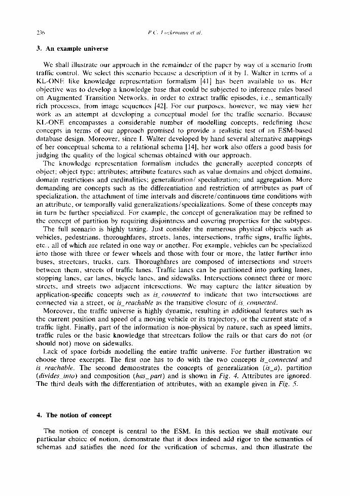
The knowledge representation formalism includes the generally accepted concepts of object; object type; attributes; attribute features such as value domains and object domains, domain restrictions and cardinalities; generalization/ specialization; and aggregation. More demanding are concepts such as the differentiation and restriction of attributes as part of specialization, the attachment of time intervals and discrete/continuous time conditions with an attribute, or temporally valid generalizations/specializations. Some of these concepts may in turn be further specialized. For example, the concept of generalization may be refined to the concept of partition by requiring disjointness and covering properties for the subtypes.
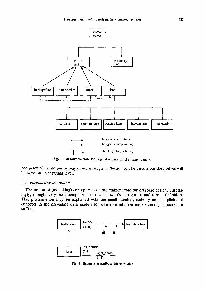
The full scenario is highly taxing. Just consider the numerous physical objects such as vehicles, pedestrians, thoroughfares, streets, lanes, intersections, traffic signs, traffic lights, etc., all of which are related in one way or another. For example, vehicles can be specialized into those with three or fewer wheels and those with four or more, the latter further into buses, streetcars, trucks, cars. Thoroughfares are composed of intersections and streets between them, streets of traffic lanes. Traffic lanes can be partitioned into parking lanes, stopping lanes, car lanes, bicycle lanes, and sidewalks. Intersections connect three or more streets, and streets two adjacent intersections. We may capture the latter situation by application-specific concepts such as &_connected to indicate that two intersections are connected via a street, or isreachable as the transitive closure of &_connected.
Moreover, the traffic universe is highly dynamic, resulting in additional features such as the current position and speed of a moving vehicle or its trajectory, or the current state of a traffic light. Finally, part of the information is non-physical by nature, such as speed limits, traffic rules or the basic knowledge that streetcars follow the rails or that cars do not (or should not) move on sidewalks.
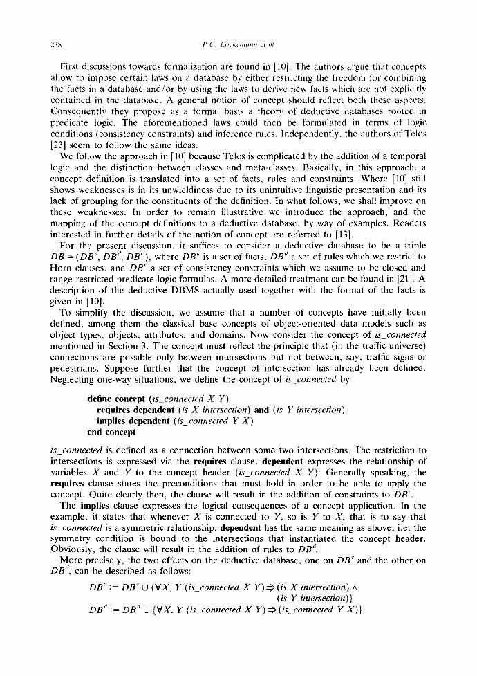
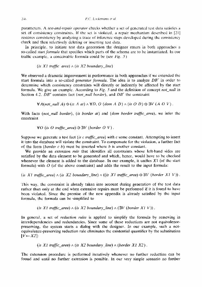
Lack of space forbids modelling the entire traffic universe. For further illustration we choose three excerpts. The first one has to do with the two concepts &_connected and &_reachable. The second demonstrates the concepts of generalization (/s_a), partition (divides_into) and composition (has_part) and is shown in Fig. 4. Attributes are ignored. The third deals with the differentiation of attributes, with an example given in Fig. ,5.
4. The notion of concept
The notion of concept is central to the ESM. In this section we shall motivate our particular choice of notion, demonstrate that it does indeed add rigor to the semantics of schemas and satisfies the need for the verification of schemas, and then illustrate the
Database design with user-definable modelling concepts 237
immobile object
I
I traffic area
i . . . . . . . . . . . . . . . . . . . . . o ¢ i . . . . . . . . . . . . . . 6
boundary line
1 car lane ilstop~,lO, i par~,loe II bicyc,,loe
1 = ls_a (generalization)
.......... ~ has_part (composition)
divides_into (partition)
Fig. 4. An example from the original schema for the traffic scenario.
adequacy of the notion by way of our example of Section 3. The discussions themselves will be kept on an informal level.
4.1 Formalizing the notion
The notion of (modelling) concept plays a pre-eminent role for database design. Surpris- ingly, though, very few attempts seem to exist towards its rigorous and formal definition. This phenomenon may be explained with the small number, stability and simplicity of concepts in the prevailing data models for which an intuitive understanding appeared to suffice.
traffic area
lane
J border
(1,)10 ~ l
j lefLborder (1,1) right_border
(1,1)
' I I boundary line
Fig. 5. Example of attribute differentiation.
238 P. (. l~ockemann et al.
First discussions towards formalization are found in [10]. The authors argue that concepts allow to impose certain laws on a database by either restricting the freedom for combining the facts in a database and /o r by using the laws to derive new facts which are not explicitly contained in the database. A general notion of concept should reflect both these aspects. Consequently they propose as a formal basis a theory of deductive databases rooted in predicate logic. The aforementioned laws could then be formulated in terms of logic conditions (consistency constraints) and inference rules. Independently, the authors of Telos [23] seem to follow the same ideas.
We follow the approach in [10] because Telos is complicated by the addition of a temporal logic and the distinction between classes and meta-classes. Basically, in this approach, a concept definition is translated into a set of facts, rules and constraints. Where [10] still shows weaknesses is in its unwieldiness due to its unintuitive linguistic presentation and its lack of grouping for the constituents of the definition. In what follows, we shall improve on these weaknesses. In order to remain illustrative we introduce the approach, and the mapping of the concept definitions to a deductive database, by way of examples. Readers interested in further details of the notion of concept are referred to [13].
For the present discussion, it suffices to consider a deductive database to be a triple DB = (DB ~', DB J, DB*), where DB" is a set of facts, DB ~ a set of rules which we restrict to Horn clauses, and DB' a set of consistency constraints which we assume to be closed and range-restricted predicate-logic formulas. A more detailed treatment can be found in [21]. A description of the deductive DBMS actually used together with the format of the facts is given in [10].
To simplify the discussion, we assume that a number of concepts have initially been defined, among them the classical base concepts of object-oriented data models such as object types, objects, attributes, and domains. Now consider the concept of is_connected mentioned in Section 3. The concept must reflect the principle that (in the traffic universe) connections are possible only between intersections but not between, say, traffic signs or pedestrians. Suppose further that the concept of intersection has already been defined. Neglecting one-way situations, we define the concept of is_connected by
define concept (is_connected X Y) requires dependent (is X intersection) and (is Y intersection) implies dependent (is_connected Y X )
end concept
is_connected is defined as a connection between some two intersections. The restriction to intersections is expressed via the requires clause, dependent expresses the relationship of variables X and Y to the concept header (is_connected X Y). Generally speaking, the requires clause states the preconditions that must hold in order to be able to apply the concept. Quite clearly then, the clause will result in the addition of constraints to DB'.
The implies clause expresses the logical consequences of a concept application. In the example, it states that whenever X is connected to Y, so is Y to X, that is to say that is_connected is a symmetric relationship, dependent has the same meaning as above, i.e. the symmetry condition is bound to the intersections that instantiated the concept header. Obviously, the clause will result in the addition of rules to DB ~.
More precisely, the two effects on the deductive database, one on DB" and the other on D B a, can be described as follows:
DB" := DB C U {VX, Y (is_connected X Y) ~ (is X intersection)/x (is Y intersection)}
DB d := DB d U {VX, Y (is_connected X Y) ~ (is_connected Y X)}
Database design with user-definable modelling concepts 239
Notice that the constituents of the concept definition become distributed across DB. The ties among them must separately be maintained. This is one of the purposes of the concept management component.
Since we are not just interested in direct connections but also in indirect ones across several intermediate intersections, we introduce the concept isreachable:
define derivable concept (is_reachable X Y) if (is_connected X Y); (isconnected X Z), (is_reachable Z Y)
end concept
Because information on reachability need not explicitly be entered into the database but can be deduced from the information on connections, we refer to is_reachable as a derivable concept. The form of inference is described by a set of rule bodies whereas the concept header serves as the rule header. In the example there are two rule bodies which correspond to the two rules that together make up the definition of transitive closure. Hence, if clauses result in additions to DB d. In the present case:
DB d := DB d U {VX, Y (is_connected X Y) ~ (is_reachable Y X ) , VX, Y, Z (is_connected X Z) A (is_reachable Z Y)
(is_reachable X Y)}
We observe that our notion of concept does not entirely agree with what we would expect from classical semantic modelling. There, one would view the notion of intersection -and hence, of is_connected and of is_reachable- as instantiations of construction rules 'entity type', that is as components of the conceptual schema. We conclude that for engineering applications a strict separation between data model (as a set of concepts) and schema (as a set of types instantiated from the concepts) would be somewhat artificial. Rather, due to the highly specific nature of the relationships observed in the universe of discourse, the semantic data model should itself already include a number of type specifications.
Of course, this does not preclude concept definitions that agree with the classical understanding of construction rule. Take the concept of transitive_closure which is of more general interest than just in the context of reachability:
define concept (transitive_closure P Q) implies dependent (P X Y) impl (Q X Y);
dependent (P X Y), (Q Y Z) impl (Q x z ) end concept
with the effects on the database:
DB a := DB a U {VP, Q, X, Y (transitive_closure P Q) A (P X Y ) ~ ( Q X Y ) , VP, Q, X, Y, Z (transitive_closure P Q) A (P X Y) A (Q Y Z)
~ ( Q S Z)}
Similarly, the concept of symmetric conforms to the classical understanding of the concept:
define concept (symmetric P) implies dependent (P X Y) impl (P Y X)
end concept

240 P.(', Lockemann et al.
Given the general concepts of transitive_closure and symmetric, the concepts of is_connected and is_reachable may now be defined in their terms, thus demonstrating how concepts may evolve in a stepwise fashion. Furthermore, since is_reachable is a derived concept that makes no sense without is_connected, we may embed the definition of the former within the definition of the latter:
define concept (is_connected X Y) features (symmetric is_connected) requires dependent (is X intersection) and (is Y intersection) follow ups
define derivable concept (is_reachable V W) features (transitive_closure is_connected is_reachable)
end concept end concept
This example includes a new clause, features. Here , its effect is the same as the one of the corresponding implies clauses in the above concept definitions. However , because the concept of symmetry is known by now and can more intuitively be understood in this definition as a property of the presently defined concept, we chose a different notation.
The last example nicely demonstrates the transition from what one would traditionally call a data model to what one would traditionally call a schema. In our case, both are treated according to exactly the same formalism. Thus, our formalism meets our previously stated objective: it does not force us to strictly differentiate between the two. This adds another justification for preferring the approach of [10] over the one in [23].
4.2 Applying the notion
While the concepts of is_connected and is_reachable served the purpose of introducing our notion of concept, we now proceed to demonstrate its application to the concepts underlying Figures 4 and 5. We assume the existence of a set of initial concepts object, object type (ot), attribute (at), and domain (dom) and range (ran) of attributes (see [13]).
We start with the generalization concept:
define concept (isa X Y) requires dependent (is X ot) and (is Y ot) implies dependent all 0 (is 0 X) impl (is 0 Y) followups
define derivable concept (isa_trans V W) features (transitive_closure isa isa_trans ) ; ( acyclic isa_tr ans)
end concept end concept
Notice that we made use of the further concept of acyclic which can be defined in a way similar to symmetric.
The partition concept relies on the notion of disjointness between two object types:
define concept (disjoint X Y) requires dependent (is X ot) and (is Y ot) ;
dependent not ex Z (is Z X) and (/s Z Y) end concept

Database design with user-definable modelling concepts 241
On the other hand, we elect to include the property of coverage directly in the partition concept:
define concept (divides_into X Y) requires dependent (is X ot) and (is Y ot) ;
dependent all W (/s W Y) impi (is W or) ; dependent all O (is 0 X) impl ex W (is W Y) and (is 0 W)
implies dependent all W (is W Y) impl(isa W X) ; dependent all V, W (/s V Y) and (is W Y) impl (dis]oint V W)
end concept
where the object type X is divided into a set of object types W~ being instances of Y. For every instance O of X there exists a W/of Y and O is instance of Wj.
The third concept in Fig. 4 was that of composition. Since there is no particular semantics that we can associate with the concept, we elect to treat has_part as a (multi-valued) attribute which has an object type for its range:
define concept (has_part 0 A P) requires dependent (is Pot);
dependent (is A at) ; dependent ( dom A O) ; dependent (ran A P)
end concept
The last concept to be considered is the diffs (differentiation) concept from Fig. 5:
define concepts (diffs AT1 AT2) requires dependent (is A T1 at) ;
dependent (is AT2 at) ; dependent ex OT1, OT2 (dora A T 1 0 T 1 ) and (dora A T 2 0 T 2 )
and (isa_trans O T 1 0 T 2 ) ; dependent all R1, R2 (ran AT1 RI ) and (ran AT2 R2) impl R1 = R2
implies dependent all O, V (AT1 0 V) impl (AT2 0 V) end concept
Now suppose that we construct Fig. 5 through the following sequence of steps: create object types traffic_area, boundary_line and lane; then add attribute border; subsequently add differentiations left_border and right_border; finally generalize lane to traffic area. This sequence cannot be completed beyond attribute border: the attempt to add left_border will fail because the constraint due to the third requires clause will cause the verification to fail and the deductive database to reject the update.
Figure 5 includes cardinalities. Minimum cardinality of 1 may be expressed by a concept not_null, and maximum cardinality of 1 by a concept single_valued. We give the definition of not_null:
define concept (not_null A) requires dependent (is A at) and
all D, 0 (dora A D), (is 0 D) impl ex V( A 0 V) end concept
242 P.(7 Lockemann et al.
5. Designing schemas with concepts
Semantic data models have been successful whenever their applications during the acquisition phase resulted in graphic representations for the conceptual schemas that were easy to draw and understand. Just take ER diagrams as an example. These considerations apply equally well to the engineering environment where engineers have been accustomed to diagrammatic presentations for a long time (take materials flow diagrams, mechanical drawings, floor plans). Although, judging from these diagrams, engineers seem to tolerate a much higher variety of concepts and, hence, of graphic symbols, extensibility still provides the means to limit the symbols to those that are relevant in a given application context.
In contrast to traditional tools with their fixed number of concepts and symbols, an ESM-based design tool must be able to accommodate the more or less spontaneous introduction of new symbols and the drawing of diagrams with hitherto unknown symbols. We take up these two issues in turn. Additional aspects of the design tool such as consistent layout and behavior during all design stages, response to error situations due to, e.g. mishandling or constraint violations, and abstraction mechanisms to master large diagrams through limited-size windows, are covered elsewhere [32,30,31,33].
5.1 Graphical representation of" defined concepts'
The principle underlying the functionality of our design tool is declarative programming. Consider the definition of the graphic representation of a newly introduced concept. The ultimate objective is to have this representation available whenever the concept is to be used during semantic modelling, or whenever a conceptual schema is to be retrieved from the database and to be displayed on the screen. In both cases a procedure must exist which generates the proper symbol. Defining a graphical representation for a concept corresponds, then, to the construction of such a procedure. Declarative programming intends to describe the desired result in terms of the immediate display effects while avoiding writing down the detailed procedure in terms of some programming language or sequence of function calls. Instead, such a procedure should be automatically derived from the sequence of declarative actions on the screen•
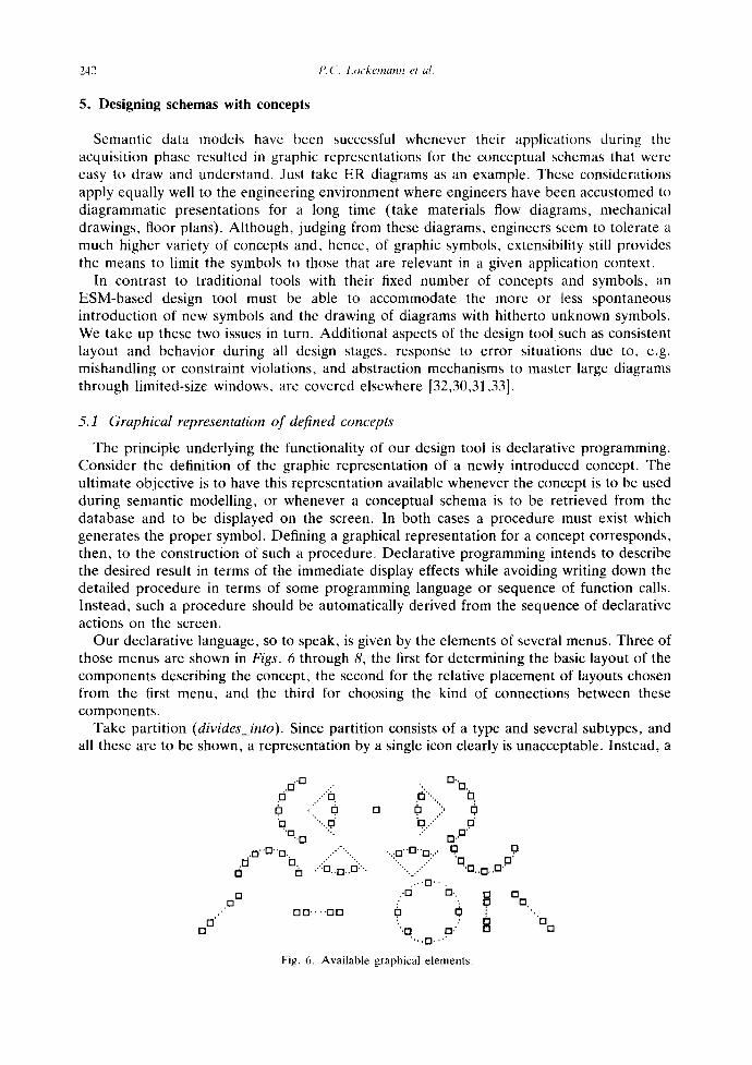
Our declarative language, so to speak, is given by the elements of several menus. Three of those menus are shown in Figs. 6 through 8, the first for determining the basic layout of the components describing the concept, the second for the relative placement of layouts chosen from the first menu, and the third for choosing the kind of connections between these components.
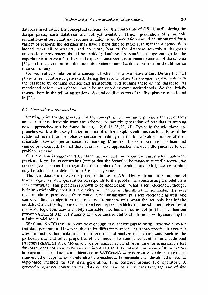
Take partition (divides_into). Since partition consists of a type and several subtypes, and all these are to be shown, a representation by a single icon clearly is unacceptable. Instead, a
n [ ]
.C] ' '0 .:- d / o
0 ,: o.' b "".. O"
• ,O .n '.:.
• O " ° " O - . , . ' " "'... .o 0" ..':o..o..o:'.. 0
[] .0
D O . . . . 017
• • " D . O •,. Cl
[] i, "O .."" O'
.:" CI..•" ...o..o..o.... o. .o
" ' . / 'D O" "..." " [ ] . .0 . .0 ' '
. . . .17. . . . .-C] 17.. [ ] [ ]
• : [ ] [ ]
""O O r " . . , n . . , "
Fig. 6. Available graphical elements .
"O []
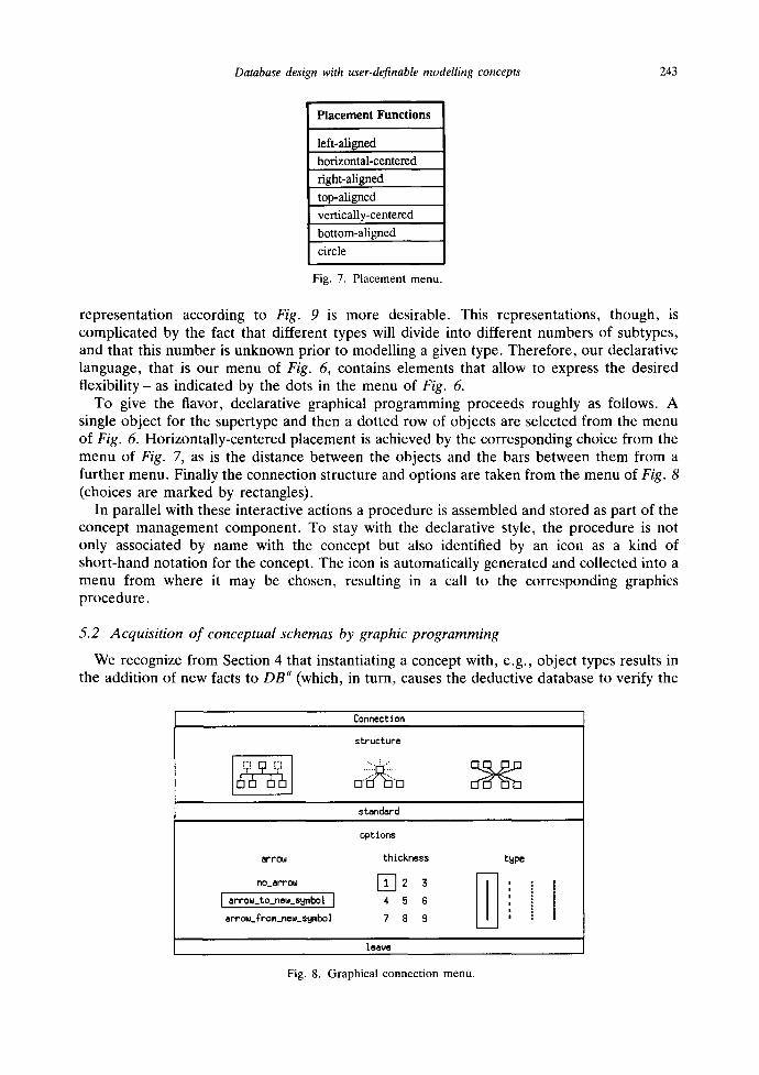
Database design with user-definable modelling concepts 243
P l a c e m e n t F u n c t i o n s
left-aligned horizontal-centered
right-aligned
top-aligned vertically-centered
bottom-aligned
circle
Fig. 7. Placement menu.
representation according to Fig. 9 is more desirable. This representations, though, is complicated by the fact that different types will divide into different numbers of subtypes, and that this number is unknown prior to modelling a given type. Therefore, our declarative language, that is our menu of Fig. 6, contains elements that allow to express the desired flexibility - as indicated by the dots in the menu of Fig. 6.
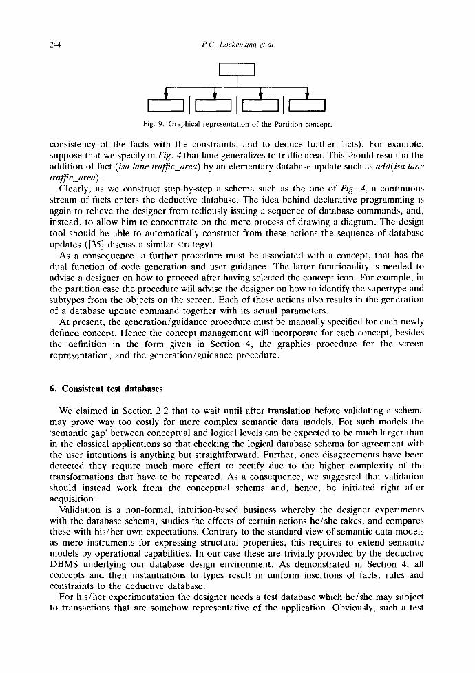
To give the flavor, declarative graphical programming proceeds roughly as follows. A single object for the supertype and then a dotted row of objects are selected from the menu of Fig. 6. Horizontally-centered placement is achieved by the corresponding choice from the menu of Fig. 7, as is the distance between the objects and the bars between them from a further menu. Finally the connection structure and options are taken from the menu of Fig. 8 (choices are marked by rectangles).
In parallel with these interactive actions a procedure is assembled and stored as part of the concept management component. To stay with the declarative style, the procedure is not only associated by name with the concept but also identified by an icon as a kind of short-hand notation for the concept. The icon is automatically generated and collected into a menu from where it may be chosen, resulting in a call to the corresponding graphics procedure.
5.2 Acquisition of conceptual schemas by graphic programming
We recognize from Section 4 that instantiating a concept with, e.g., object types results in the addition of new facts to DB a (which, in turn, causes the deductive database to verify the
Connection
structure
standard
options
arrow thickness
no_errow [] ~ 3
[ arrow_to_new_sumbol ] 4 5 6
arrow_From_new_~ymbol 7 B S
1 e ~ e
Fig. 8. Graphical connection menu.
type
244 P.C. Lockemann et al.
I I I
I I I I I ,I, ,I, ,ll i
Fig. 9. Graphical representation of the Partition concept.
consistency of the facts with the constraints, and to deduce further facts). For example, suppose that we specify in Fig. 4 that lane generalizes to traffic area. This should result in the addition of fact (isa lane traffic_area) by an elementary database update such as add(isa lane traffic_area).
Clearly, as we construct step-by-step a schema such as the one of Fig. 4, a continuous stream of facts enters the deductive database. The idea behind declarative programming is again to relieve the designer from tediously issuing a sequence of database commands, and, instead, to allow him to concentrate on the mere process of drawing a diagram. The design tool should be able to automatically construct from these actions the sequence of database updates ([35] discuss a similar strategy).
As a consequence, a further procedure must be associated with a concept, that has the dual function of code generation and user guidance. The latter functionality is needed to advise a designer on how to proceed after having selected the concept icon. For example, in the partition case the procedure will advise the designer on how to identify the supertype and subtypes from the objects on the screen. Each of these actions also results in the generation of a database update command together with its actual parameters.
At present, the generation/guidance procedure must be manually specified for each newly defined concept. Hence the concept management will incorporate for each concept, besides the definition in the form given in Section 4, the graphics procedure for the screen representation, and the generation/guidance procedure.
6. Consistent test databases
We claimed in Section 2.2 that to wait until after translation before validating a schema may prove way too costly for more complex semantic data models. For such models the 'semantic gap' between conceptual and logical levels can be expected to be much larger than in the classical applications so that checking the logical database schema for agreement with the user intentions is anything but straightforward. Further, once disagreements have been detected they require much more effort to rectify due to the higher complexity of the transformations that have to be repeated. As a consequence, we suggested that validation should instead work from the conceptual schema and, hence, be initiated right after acquisition.
Validation is a non-formal, intuition-based business whereby the designer experiments with the database schema, studies the effects of certain actions he/she takes, and compares these with his/her own expectations. Contrary to the standard view of semantic data models as mere instruments for expressing structural properties, this requires to extend semantic models by operational capabilities. In our case these are trivially provided by the deductive DBMS underlying our database design environment. As demonstrated in Section 4, all concepts and their instantiations to types result in uniform insertions of facts, rules and constraints to the deductive database.
For his/her experimentation the designer needs a test database which he/she may subject to transactions that are somehow representative of the application. Obviously, such a test
Database design with user-definable modelling concepts 245
database must satisfy the conceptual schema, i.e. the constraints of D B c. Usually during the design phase, such databases are not yet available. Hence, generation of a suitable semantic-level test database becomes a major issue. Generation should be automated for a variety of reasons: the designer may have a hard time to make sure that the database does indeed meet all constraints, and no more; bias of the database towards a designer's unconscious preferences should be avoided; database size should be large enough for the experiments to have a fair chance of exposing incorrectness or imcompleteness of the schema [24]; and re-generation of a database after schema modification or correction should not be time-consuming.
Consequently, validation of a conceptual schema is a two-phase affair. During the first phase a test database is generated, during the second phase the designer experiments with the database by defining queries and transactions and running these on the database. As mentioned before, both phases should be supported by computerized tools. We shall briefly discuss them in the following sections. A detailed discussions of the first phase can be found in [24].
6.1 Generat ing a test database
Starting point for the generation is the conceptual schema, more precisely the set of facts and constraints derivable from the schema. Automatic generation of test data is nothing new: approaches can be found in, e.g., [2, 8, 16, 25, 27, 34]. Typically though, these ap- proaches work with a very limited number of rather simple conditions (such as those of the relational model), and emphasize certain probability distribution of values because of their orientation towards performance bechmarking. Moreover, the set of conditions is fixed and cannot be extended. For all these reasons, these approaches provide little guidance to our problem at hand.
Our problem is aggravated by three factors: first, we allow for unrestricted first-order predicate formulae as constraints (except that the formulae be range-restricted); second, we do not give an upper limit regarding the number of constraints; and third, new constraints may be added to or deleted from D B c at any time.
The test database must satisfy the conditions of D B c. Hence, from the standpoint of formal logic, test data generation corresponds to the problem of constructing a model for a set of formulae. This problem is known to be undecidable. What is semi-decidable, though, is finite satisfiability, that is, there exists in principle an algorithm that terminates whenever the formula set possesses a finite model. Since unsatisfiability is semi-decidable as well, one can even find an algorithm that does not terminate only when the set only has infinite models. On that basis, approaches have been reported which examine whether a given set of predicate-logic formulae is finitely satisfiable, i.e. has a finite model [6, 11]. The theorem prover SATCHMO [5, 17] attempts to prove unsatisfiability of a formula set by searching for a finite model for it.
We found SATCHMO to come close enough to our intentions to be an attractive basis for test data generation. However, due to its different purpose- existence p roofs - i t does not care for factors that make it easier to control and analyze the experiments, such as the particular size and other properties of the model like naming conventions and additional structural characteristics. Moreover, performance, i.e. the effort in time for generating a test database, does not seem to be an issue in SATCHMO. To take at least some of these factors into account, considerable modifications to SATCHMO were necessary. Under such circum- stances, other approaches should also be considered. In particular, we developed a second, logic-based method for test data generation. It is centered around two operators. A generating operator constructs test data on the basis of a test data language and of size
246 17. C. L o c k e m a n n et al.
parameters. A test-and-repair operator checks whether a set of generated test data satisfies a set of consistency constraints. If the set is violated, a repair mechanism described in 1211 restores consistency by analyzing a trace of inference steps developed during the consistency check and then selectively deleting or inserting test data.
In principle, to initiate test data generation the designer enters in both approaches a so-called start formula that specifies which parts of the schema are to be instantiated. In our traffic example, a conceivable formula could be (see Fig. 5)
(is X1 traffic_area)/x (is X2 boundary_line)
We observed a dramatic improvement in performance in both approaches if we extended the start formula into a so-called generator formula. The idea is to analyze DB C in order to determine which consistency constraints will directly or indirectly be affected by the start formula. We give an example. According to Fig. 5 and the definition of concept not_null in Section 4.2, DB" contains fact (not_null border), and DB c the constraint
VA(not_null A) ~ ( i s A at)/x VD, O (dom A D)/x (is 0 D ) ~ 3 V (A 0 V) .
With facts (not_null border), (is border at) and (dom border traffic_area), we infer the constraint
VO (is 0 traffic_area)~ 3V (border 0 V) .
Suppose we generate a test fact (is c traffic_area) with c some constant. Attempting to insert it into the database will violate the constraint. To compensate for the violation, a further fact of the form (border c b) must be inserted where b is another constant.
We provide an extension rule that identifies all constraints whose left-hand sides are satisfied by the data element to be generated and which, hence, would have to be checked whenever the element is added to the database. In our example, it unifies X1 (of the start formula) with O (of the above constraint) and adds the result to the input formula:
(is X1 traffic_area)/x ( is)(2 boundary_line)/x ((is X1 traffic_area) ~ 3V (border X1 V)) .
This way, the constraint is already taken into account during generation of the test data rather than only at the end when extensive repairs must be performed if it is found to have been violated. Since the premise of the new appendix is already satisfied by the input formula, the formula can be simplified to
(is X1 traffic_area) ^ (is)(2 boundary_line) ^ (3V (border XI V)) .
In general, a set of reduction rules is applied to simplify the formula by removing in interdependencies and redundancies. Since some of these reductions are not equivalence- preserving, the system starts a dialog with the designer. In our example, such a not- equivalence-preserving reduction rule eliminates the existential quantifier by the substitution [V~--X2]:
(is X1 traffic_area) A (is X2 boundary_line) A (border X1 X 2 ) .
The extension procedure is performed iteratively whenever no further reduction can be found and until no further extension is possible. In our very simple scenario no further

Database design with user-definable modelling concepts 247
constraint is found to be affected, and the analysis procedure stops with the formula above as the resulting generator formula.
It is then translated into a sequence of generating operations followed at the end by a test-and-repair operation:
gen-op((is X1 traffic_area)), gen-op((is )[2 boundary_line)), gen-op((border X1 X2 )), test-and-repair( DB¢) .
The first operation generates substitutions for X1, e.g., t ra f f icarea_l , . . . , traffic_area_n where n is a size parameter specified by the user, as well as the corresponding facts (/s traffic_area_1 traffic_area), etc. Similarly, the second operation generates boundary lines. The third operation combines the already generated substitutions into border facts such as (border traffic_area_l boundary_line_l ). The test-and-repair operation is needed in order to check whether the generator formula remains valid for the current test database. This is always necessary in the presence of multiple constraints, or as in our case because of the application of a not-equivalence-preserving reduction rule. In general, in case of failure, a repair mechanism adds or removes test data such that the inconsistencies are resolved. However, the gen-op operations alone, by reflecting the interdependencies between facts and constraints, already avoid trivial conflicts that arise whenever insertion of a fact should trigger insertion or deletion of other facts.
If nl traffic areas and n2 boundary lines have been generated, there exist n l * n 2 possibilities for combining them into border facts. Leaving alone the constraints, any subset of the cross-products is a reasonable extension of border. We have added facilities that allow a designer to control the size of the fact base by specifying a rough quantity of instantiations per concept or data type and, equally important, to interactively control which combinations of facts are to be generated, by specifying whether injective, surjective etc. relations should be observed between the test data.
Finally, by running extensive benchmarks, we demonstrated that by interactively imposing certain strategies on the test-and-repair operations we could often improve dramatically the performance of test data generation where SATCHMO had to follow a fixed built-in strategy to recover from constraint violations [24].
6.2 Generating test transactions
A language is provided in which the modeler may express the start formula as well as the approximate quantity of test data and a pattern for meaningfully looking constants. Likewise, a language is needed to formulate the transactions which subject the test database to update and retrieval operations. The issue bears close relationship to research in dynamic modelling on the semantic level of data or systems. Among the published representation formalisms [1, 12, 22], we chose the ACM/PCM behavior specification language of [4] and [26] as our basis. It allows to declare transaction schemas which may subsequently be instantiated to transactions. A transaction schema consists of a name, the types of the objects involved (input parameters), a precondition, and the actions to be invoked in an order controlled by sequencing, case statements, and iteration.
Suppose our traffic scenario of Fig. 4 is complemented by mobile objects such as vehicles. Furthermore, assume that parking lanes are characterized by attributes occupied_by and parking_time_exhausted. Now, let us define a transaction for towing away all vehicles parked in parking lanes whose parking time has been exhausted (parking_time_exhausted is true).
248 P. ('. L o c k e m a n n et al.
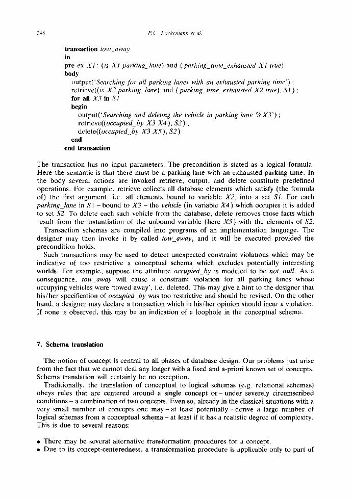
transaction low away in pre ex XI : (is X1 parking lane) and (parking_time_exhausted XI true) body
output('Searching for all parking lanes with an exhausted parking time') ; retrieve((is X2 parking_lane) and (parking_t ime_exhausted)(2 true), $1 ) ; for all X3 in $1 begin
output('Searching and deleting the vehicle in parking lane %X3') ; retrieve((occupied_by )(3 X4 ), $2 ) ; delete((occupied_by X3 X5) , $2 )
end end transaction
The transaction has no input parameters. The precondition is stated as a logical formula. Here the semantic is that there must be a parking lane with an exhausted parking time. In the body several actions are invoked retrieve, output, and delete constitute predefined operations. For example, retrieve collects all database elements which satisfy (the formula of) the first argument, i.e. all elements bound to variable X2, into a set $1. For each parking_lane in S1 - b o u n d to X3 - t h e vehicle (in variable X4 ) which occupies it is added to set $2. To delete each such vehicle from the database, delete removes those facts which result from the instantiation of the unbound variable (here X5) with the elements of $2.
Transaction schemas are compiled into programs of an implementation language. The designer may then invoke it by called tow_away, and it will be executed provided the precondit ion holds.
Such transactions may be used to detect unexpected constraint violations which may be indicative of too restrictive a conceptual schema which excludes potentially interesting worlds. For example, suppose the attribute occupied_by is modeled to be not_null. As a consequence, tow_away will cause a constraint violation for all parking lanes whose occupying vehicles were ' towed away', i.e. deleted. This may give a hint to the designer that h is /her specification of occupied_by was too restrictive and should be revised. On the other hand, a designer may declare a transaction which in his/her opinion should incur a violation. If none is observed, this may be an indication of a loophole in the conceptual schema.
7. Schema translation
The notion of concept is central to all phases of database design. Our problems just arise from the fact that we cannot deal any longer with a fixed and a-priori known set of concepts. Schema translation will certainly be no exception.
Traditionally, the translation of conceptual to logical schemas (e.g. relational schemas) obeys rules that are centered around a single concept o r - under severely circumscribed conditions - a combination of two concepts. Even so, already in the classical situations with a very small number of concepts one m a y - a t least po ten t i a l ly -de r ive a large number of logical schemas from a conceptual schema - at least if it has a realistic degree of complexity. This is due to several reasons:
• There may be several alternative transformation procedures for a concept. • Due to its concept-centeredness, a transformation procedure is applicable only to part of
Database design with user-definable modelling concepts 249
the conceptual schema. However, there usually are various possibilities for partitioning a conceptual schema such that a transformation may be applied to some part.
• Given such a partitioning, there usually are several schema sections which may be subjected to a transformation.
A complete translation, then, consists of a sequence of transformation steps. After each step a decision has to be made as to the next partitioning, the section and the transformation procedure to choose. Clearly, this leads to a large search space within which to locate a - suitably defined - optimal solution. In other words, schema translation is - also - a search and optimization problem. With the much larger number of concepts to be expected in our situation, the search space will in all likelihood become unmanageable if one follows the traditional ways of manual inspection and judgment.
Schema translation principles and methodologies published so far [3, 28, 38] have scarcely treated the translation as a formal optimization problem. Consequently, they seem to be lacking in (automated or at least computer-aided) selection of schema sections and trans- formation procedures. An additional complication in our case is that the set of concepts and, hence, of transformation procedures must be considered open-ended. Indeed, for each new concept that is to be introduced, new transformation procedures must be developed. By storing them with the concept management component they become accessible to the translation tool.
In the remainder of this section we briefly sketch our principles, formalisms and tech- niques for dealing with the stepwise and partial schema translation and for controlling the search process. We use the relational model as our target logical data model. The subject is covered in greater detail in [36].
For the development of the translation tool, its data structures and procedures, we adopted guidelines about the solutions of search and optimization problems published in the literature, e.g. [29]. The overall solution, then, consists of a problem-specific representation of the search space elements, of the procedures or rules for computing new elements of the search space, and of methods for the evaluation of the quality of logical schemas.
7.1 Encoding and analyzing the search space elements
At any time during the translation, the search space consists of a set of partially translated schemas (we call them search space elements). Initially, the space contains a single element, the original conceptual schema. From then on it consists of intermediate elements which include both, those parts of the schema that have already been transformed during earlier steps, and those that must still be subjected to transformations. The translation of a search space element terminates when the element in its entirety represents a logical schema. Additionally, every search space element includes a trace for determining which relations and relational attributes of the logical schema correspond to which object types and attributes of the conceptual schema (once'translated). This trace is used for the translation of a conceptual-level test database, and queries to it, to the corresponding database and queries on the logical schema.
We omit for a moment the trace. The formalism for the representation of partially transformed schemas meets the following conditions. Elements of the conceptual schema and elements of the already generated logical schema can be represented together, and still untransformed relationships between these two schemas can be preserved. The formalism is susceptible to automated transformations as well as selections and extractions of schema parts. Finally, it provides an open environment to accommodate newly defined concepts.
In this formalism every search space element is represented by a set of schema elements.
250 t:('. Lockemann et al.
Each element can be interpreted as a concept application (of either the semantic or the logical model), whose constituents can easily be determined from the concept definition as maintained in the concept management component. A schema element, then, has the following structure:
<concept_id> (<argument_l), <argument_list))
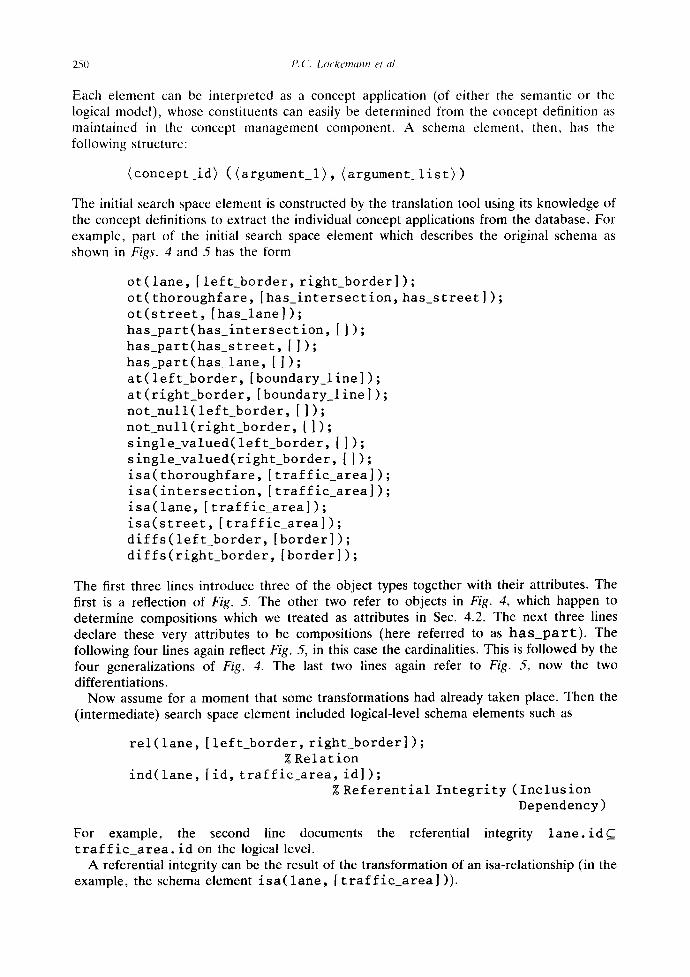
The initial search space element is constructed by the translation tool using its knowledge of the concept definitions to extract the individual concept applications from the database. For example, part of the initial search space element which describes the original schema as shown in Figs. 4 and 5 has the form
or(lane, [left_border, right_border]); ot(thoroughfare, [has_intersection, has_street]); ot(street, [has_lane]); has_part(has_intersection, []); has_part(has_street, ]]); has_part(has_lane, []); at(left_border, [boundary_line]); at(right border, [boundary_line]); not_null(left_border, []); notnull(right_border,[]); single_valued(leftborder,]]); single_valued(right_border, []); isa(thoroughfare, [traffic_area]); isa(intersection, [traffic_area]); isa(lane, [traffic_area]); isa(street, ]traffic_area]); diffs(left border, [border]); diffs(right_border, [border]);
The first three lines introduce three of the object types together with their attributes. The first is a reflection of Fig. 5. The other two refer to objects in Fig. 4, which happen to determine compositions which we treated as attributes in Sec. 4.2. The next three lines declare these very attributes to be compositions (here referred to as h a s _ p a r t ) . The following four lines again reflect Fig. 5, in this case the cardinalities. This is followed by the four generalizations of Fig. 4. The last two lines again refer to Fig. 5, now the two differentiations.
Now assume for a moment that some transformations had already taken place. Then the (intermediate) search space element included logical-level schema elements such as
rel(lane, [left_border, right border]); % Relation
ind(lane, [id, traffic_area, id]); % Referential Integrity (Inclusion
Dependency)
For example, the second line documents the referential integrity l a n e . i d C t r a f f i c a r e a , id on the logical level.
A referential integrity can be the result of the transformation of an isa-relationship (in the example, the schema element i s a ( l a n e , [ t r a f f i c _ a r e a l )).
Database design with user-definable modelling concepts 251
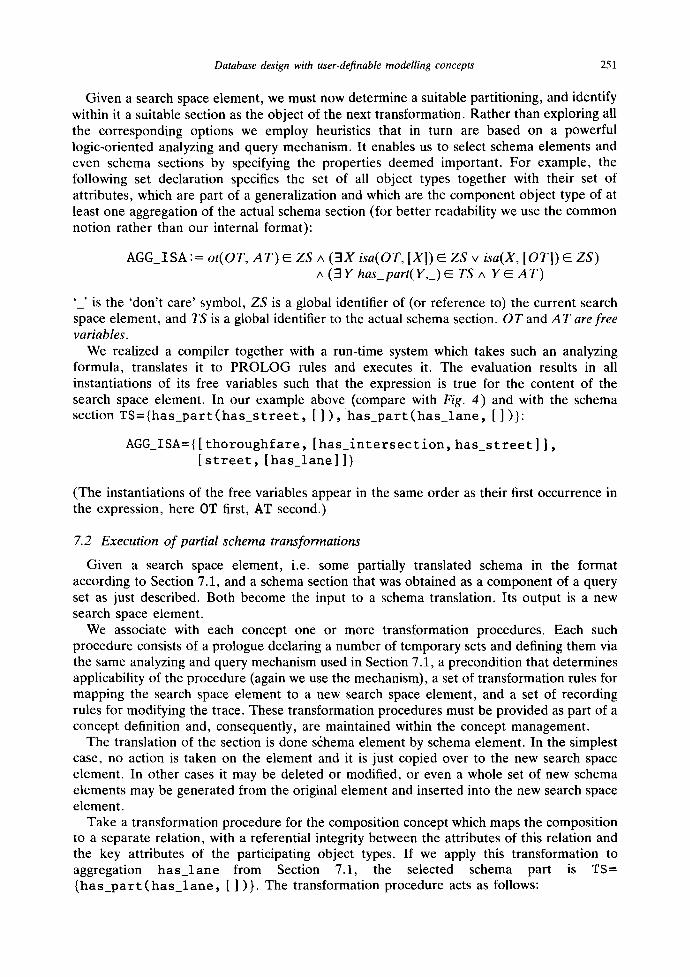
Given a search space element, we must now determine a suitable partitioning, and identify within it a suitable section as the object of the next transformation. Rather than exploring all the corresponding options we employ heuristics that in turn are based on a powerful logic-oriented analyzing and query mechanism. It enables us to select schema elements and even schema sections by specifying the properties deemed important. For example, the following set declaration specifies the set of all object types together with their set of attributes, which are part of a generalization and which are the component object type of at least one aggregation of the actual schema section (for better readability we use the common notion rather than our internal format):
AGG_ISA := ot(OT, AT) E ZS A (3X isa(OT, [X]) E ZS v isa(X, [OT]) ~ ZS) ^ (3Y has_part(Y,_) ~ TS ^ Y E AT)
'_' is the 'don't care' symbol, ZS is a global identifier of (or reference to) the current search space element, and TS is a global identifier to the actual schema section. OT and A T are free variables.
We realized a compiler together with a run-time system which takes such an analyzing formula, translates it to PROLOG rules and executes it. The evaluation results in all instantiations of its free variables such that the expression is true for the content of the search space element. In our example above (compare with Fig. 4) and with the schema section T S = { h a s _ p a r t ( h a s _ s t r e e t , [ ] ) , h a s _ p a r t ( h a s _ l a n e , [ ] )}:
AGG_ISA={[ t h o r o u g h f a r e , [ h a s _ i n t e r s e c t i o n , h a s _ s t r e e t ] ] , [ s t r e e t , [ h a s _ l a n e ] ]}
(The instantiations of the free variables appear in the same order as their first occurrence in the expression, here 0T first, AT second.)
7.2 Execution of partial schema transformations
Given a search space element, i.e. some partially translated schema in the format according to Section 7,1, and a schema section that was obtained as a component of a query set as just described. Both become the input to a schema translation. Its output is a new search space element.
We associate with each concept one or more transformation procedures. Each such procedure consists of a prologue declaring a number of temporary sets and defining them via the same analyzing and query mechanism used in Section 7.1, a precondition that determines applicability of the procedure (again we use the mechanism), a set of transformation rules for mapping the search space element to a new search space element, and a set of recording rules for modifying the trace. These transformation procedures must be provided as part of a concept definition and, consequently, are maintained within the concept management.
The translation of the section is done s6hema element by schema element. In the simplest case, no action is taken on the element and it is just copied over to the new search space element. In other cases it may be deleted or modified, or even a whole set of new schema elements may be generated from the original element and inserted into the new search space element.
Take a transformation procedure for the composition concept which maps the composition to a separate relation, with a referential integrity between the attributes of this relation and the key attributes of the participating object types. If we apply this transformation to aggregation h a s _ l a n e from Section 7.1, the selected schema part is TS= { h a s _ p a r t ( h a s _ l a n e , [ ])}. The transformation procedure acts as follows:
252 I'. (. Lockemann et al.
(1) Schema element h a s _ p a r t ( h a s _ l a n e , [ ] ) is recognized as element of section TS. and schema element o t ( s t r e e t , [ h a s _ l a n e ] ) as the composite object type of the aggregation (within the search space element). The following schema elements are generated and inserted into the new search space element:
rel(has_part_lane, [has_part, part_of]); %Relation
ind(has_part lane, [has part, street, id]); %Referential Integrity
ind(has_part_lane, [part_of, lane, id]); % Referential Integrity
(2) The element h a s _ p a r t ( h a s _ l a n e , [] ) is no longer an element in the new search space element. Hence, it is dropped.
(3) The schema element o t ( s t r e e t , [ h a s l a n e ] ) is modified to o t ( s t r e e t , [ ] ) because the aggregation due to h a s _ l a n e has now been taken care of.
(4) All other schema elements remain unchanged.
7.3 Record ing object types and attributes
The trace is maintained in a locality-Relation of the form
locality(OT, AT, [LI .... ,Ln])
with the semantic: the attribute values for the attribute AT of the instances of the object type OT will occur in the localities L a , . . o , L n. Initially the Li refer to object types, but in a completely translated search space element all the Li are names of relations, and the attribute AT belongs to all these relations.
We give an example. Consider a transformation procedure which maps a generalization hierarchy to relations for its leaves, with a consequent migration of the attributes of the super types to these relations. The input is the schema section
divides_into(pl, [[car_lane, stopping_lane, parking_lane, bicycle lane, sidewalk], lane]);
isa(car_lane, [lane]); isa(parking_lane, [lane]); ot(lane, [width]); or(car_lane, [max_speed]); ot(parking lane, [parking_time, occupied_by]);
and the part of the trace
locality(car_lane,width, [lane]); locality(parking_lane,width, [lane]);
The application of this transformation procedure results in:
divides_into(pl, [[stopping_lane, bicycle_lane, sidewalk], lane]);
ot(lane, [width]);

Database design with user-definable modelling concepts 253
rel(car_lane, [max speed, width]); rel(parking_lane, [parking_time,width]);
(Observe here that o t ( l a n e , [ w i d t h ] ) remains unchanged because lane is still in- volved in other generalizations (more precisely, partitions). On the other hand, there is no longer a generalization from c a r _ l a n e a n d p a r k i n g _ l a n e t o l a n e . )
The trace now has the modified elements
locality(ear_lane,width, [car_lane]); locality(parking_lane,width, [parking lane]);
For example, the value for the attribute width of an instance of the former object type c a r _ l a n e can now be found at the relation c a r _ l a n e instead of at l a n e (which is at that time still an object type, with need for further transformations).
The trace suffices to construct, after the translation phase has been completed, logical- level test database and queries from those on the conceptual level.
7.4 Search control and evaluation of logical schemas
Optimization of the translation process for the entire schema corresponds to determining the best sequence of transformations to the schema. This is known to be a computationally hard problem. Therefore, heuristics have to be employed to limit the search space. For our present example we apply the following simple heuristics (which must obviously be observed by the order in which we pose set queries to the partially transformed schemas): Generaliza- tions and aggregation relationships are transformed before the object types involved in them are mapped onto a relation each. Hence, the translation process progress in order opposite to schema acquisition. In the latter case, generalization or composition can only be applied to already existing object types.
Nonetheless, this still leaves some latitude as regards the choice of transformation. Just consider the three standard transformation procedures for generalization, or partition for that matter: a relation for each object type with local attributes only, versus relations for the leaves only with migration of attributes, versus a single relation with a discriminator attribute [281.
Thus the choice of transformation should be accompanied by a continuous evaluation of the quality of logical schemas. We do so by using the queries and transactions available from the validation phase under the assumption that these are representative of later database use. Of course, we need these now on the logical level rather than the conceptual level. This is the purpose behind the trace of Section 7.3 and the ensuing construction of logical-level test database and queries.
We illustrate the use of queries by an example. Remember the translation in the example in Section 7.3. This is an ideal translation for a query which requests the parking time and the width of a parking lane, because this information can be retrieved from a single relation ( p a r k i n g _ l a n e ) . If instead the query requested car lanes and parking lanes based on the values of the attribute width as selection criterion, it would have to access both relations. For the latter case, the first of the above mentioned three standard transformation procedures would be more suitable, although referential integrity constraints would have to be included in the result.
7.5 Designer interaction
Much of the evaluation of the translation results defies an automatic analysis. Instead, inspection of the partially transformed schemas and the correspondingly transformed queries

254 P. ('. l . o c k e m a n n et al.
and transactions, evaluation of their interrelationships or further study of their effects on a suitably transformed test database are actions that require human judgment and close interaction between designer and transformation tool. Consequently. this tool should provide suitable mechanisms for supporting the designer during his/her analysis. Among these are well-organized information displays (especially a graph editor with a problem specific configuration for the graphical presentation of a search space element), pre- evaluation of transformation alternatives and exclusion of those that the system deems uneconomical so that the designers may concentrate their attention on the more rewarding ones. Furthermore, we integrated a comfortable interface to the relational database system (ORACLE, in our case) with graphical features for ttle display of the relational database schema, the test database, and the results of the translated queries running on the test database.
8. Conclusions
The hypothesis underlying this paper is that the most flexible and domain-oriented- and hence most user-oriented-approach to database design in an environment with multiple data models, each with a large spectrum of modelling concepts, and with users skilled in formal techniques, could be provided by an extensible semantic data model. We studied the various ramifications of such an approach on the architecture of a design environment as well as on the numerous steps needed to incorporate new modelling concepts, and the challenges this poses to the various phases of the design process. It should have become clear that the approach makes it necessary to be much more precise and detailed as far as design methods, techniques and tools are concerned.
Because all these are parametric in nature, extensible semantic data models seem to add a price to database design. Whether the additional expense is justified by new benefits can ultimately be decided only on the basis of hard empirical evidence. We took first steps in this direction by modelling a medium-sized traffic application (Section 3). We succeeded in reproducing the KL-ONE model underlying a deductive database for the extraction of traffic episodes from image sequences [41] within less than 3 weeks even though we started from an empty concept base. At that time we had little experience with our own environment. We estimate that with the improvements we have added since, with the wider experience we have gained, and with an initial concept base containing widely used concepts, modelling of the traffic universe could be reduced to less than a week.
The procedure for test data generation underwent a large number of benchmark tests. We could demonstrate that the use of the generator formula yields impressive gains in generation speed, in particular if it is coupled with an interactive component which allows for close interaction and control by the designer [24].
The expense for schema translation depends on the required quality of the logical schema. The more elaborate the heuristics applied are the longer the translation will take because it will have to explore more alternatives. We were surprised to find that even with modest claims and, hence, simple heuristics were able to generate within about half an hour an ORACLE schema that was competitive with those developed as part of a master's thesis within the traffic project. Even exploring a large variety of alternatives in order to obtain superior results took us just about two weeks.
Those first empirical results indeed seem encouraging and highly supportive of our approach. Nonetheless, we feel that more experiments with a variety of divergent application worlds are needed before final judgment on the viability and applicability of extensible semantic data models is possible.
Database design with user-definable modelling concepts 255
References
[1] V. De Antonellis and B. Zonta, Modelling events in data base applications design, in: Proc. Inter- nat. Conf. on Very Large Data Bases (VLDB) Cannes (1981) 23-31.
[2] D. Bitton, D.J. DeWitt and C. Turbyfill, Bench- marking database systems-A systematic ap- proach, in: Proc. Internat. Conf. on Very Large Data Bases (VLDB) (1983) 8-19.
[3] Michael R. Blaha, William J. Premerlani and James E. Rumbaugh, Relational database design using an object-oriented methodology, Comm. ACM 31 (1988) 414-427.
[4] M.L. Brodie and D. Ridjanovic, On the design and specification of database transactions, in: M.L. Brodie, J. Mylopoulos and J.W. Schmidt, eds., On Conceptual Modelling. Perspectives from Artificial Intelligence, Databases, and Pro- gramming Languages (Springer, New York, 1984) 277-306.
[5] F. Bry, H. Decker and R. Manthey, A uniform approach to contraint satisfiability and Constraint satisfiability in deductive databases, in: Proc. In- ternat. Conf. on Extending Database Technology, LNCS 303 (Springer, Berlin, 1988) 488-505.
[6] F. Bry and R. Manthey, Checking consistency of database constraints: A logical basis, in: Proc. lnternat. Conf. on Very Large Data Bases (VLDB) (1986) 13-20.
[7] EDIF Steering Committee, EDIF Electronic De- sign Interchange Format Version 2.0.0, Elec- tronic Industries Association, 1987.
[8] D.J. DeWitt, Benchmarking database systems: Past efforts and future directions, IEEE Database Engrg., 8(1) (1985) 2-9.
[9] R. Elmasri and S.B. Navathe, Fundamentals of Database Systems (Benjamin/Cummings, Menlo Park, CA, 1989).
[10] S. Karl and P.C. Lockemann, Design of engineer- ing databases: A case for more varied semantic modelling concept, lnformat. Syst. 13(4) (Dec. 1988) 335-357.
[11] C.H. Kung, A tableaux approach for consistency checking, in: Sernadas, Bubenko, and Olive, eds., Proc. IF1P Work. Conf. on Theoretical and Formal Aspects of Information Systems (North- Holland, Amsterdam, 1985) 191-210.
[12] G. Lausen, Modelling and analysis of the be- havior of information systems, IEEE Trans. on Software Engrg. 14(11) (Nov. 1988) 1610-1620.
[13] P.C. Lockemann and G. Moerkotte, On the no- tion of concept, in: Proc. Internat. Conf. on the Entity-Relationship Approach (1991) 349-370.
[14] P.C. Lockemann, H.-N. Nagel and I.M. Waiter, Databases for knowledged bases: empirical study of a knowledge base management system for a semantic network, Data & Knowledge Engrg. 7(2) (1991) 115-154.
[15] L.A. Maciaszek, Database Design and Implemen- tation (Prentice Hall, Englewood Cliffs, NJ, 1990).
[16] H. Mannila and K.-J. R~iih~i, Automatic genera- tion of test data for relational queries, J. Comput. System Sci. 38(2) (1989) 240-258.
[17] R. Manthey and F. Bry, SATCHMO: A theorem prover implemented in Prolog, in: E. Lusk and R. Overbeck, eds., 9th lnternat. Conf. on Auto- mated Deduction, Argonne, IL (May 1988) LNCS 310 (Springer, Berlin) 415-434.
[18] L. Mark and N. Roussopoulos, Integration of data, schema and meta-schema in the context of self-documenting data models, in: E-R-Approach to Software Engineering (1983) 585-602.
[19] L. Mark and N. Roussopoulos, Metadata man- agement, 1EEE Comput. 19(12) (Dec. 1986) 26- 36.
[20] F. Maryanski, The data model compiler: A tool for generating object-oriented database systems, in: K.R. Dittrich and U. Dayal. eds., Proc. lnternat. Workshop on Object-Oriented Databases (IEEE Press, New York, 1986) 73-84.
[21] G. Moerkotte and P.C. Lockemann, Reactive consistency control in deductive databases, ACM Trans. Database S yst. 16(4) (1991) 670-702.
[22] J. Mylopoulos, P. Bernstein and H. Wong, A language facility for designing database-intensive applications, ACM Trans. Database Syst. 5(2) (1980) 185-207.
[23] J. Mylopoulos, A. Borgida, M. Jarke and M. Koubarakis, Telos: A language for representing knowledge about information systems, ACM Trans. Office Informat. Syst. 8(4) (1990).
[24] A. Neufeld, G. Moerkotte and P.C. Lockemann, Generating consistent test data: Restricting the search Space by a generator formula, to appear in VLDB J., 1993.
[25] L. Neugebauer and K. Neumann, Schemages- teuerte Testdatengenerierung fiir relationale Databanken, Informatik-Bericht 8502, TU Braunschweig, Institut fiir Informatik, Abtl. Datenbanken und Informationssysteme, 1985 (in German).
[26] A.H. Ngu, Conceptual transactions modelling, IEEE Trans. Knowledge and Data Engrg., 1(4) (1989) 508-518.
[27] H. Noble, The automatic generation of test data for a relational database, lnformat. Syst. 8(2) (1983) 79-86.
[28] F. Oertly and G. Schiller, Evolutionary database design, in: 5th lnternat. Conf. Data Engineering (1989) 618-624.
[29] J. Pearl, Heuristics (Addison-Wesley, Reading, MA, 1984).
[30] K. Radermacher, Graphikunterst/itzung fiir den Datenbankentwurf mit freidefinierten Model-
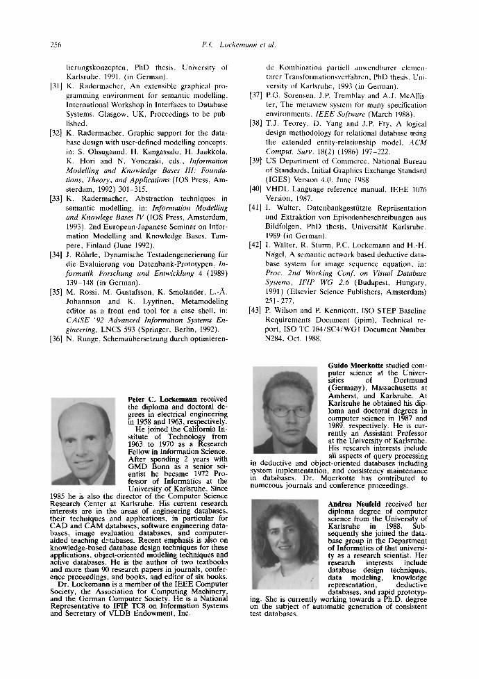
256 P.C. Lockemann et al.
lierungskonzepten, PhD thesis, University of Karlsruhe, 1991. (in German).
[31] K. Radermacher, An extensible graphical pro- gramming environment for semantic modelling, International Workshop in Interfaces to Database Systems, Glasgow, UK, Proceedings to be pub- lished.
[32] K. Radermacher, Graphic support for the data- base design with user-defined modelling concepts, in: S. Ohsugaand, H. Kangassalo, H. Jaakkola, K. Hori and N. Yonezaki, eds., Information Modelling and Knowledge Bases 1H: Founda- tions, Theory, and Applications ([OS Press, Am- sterdam, 1992) 301-315.
[33] K. Radermacher, Abstraction techniques in semantic modelling, in: Information Modelling and Knowlege Bases IV (lOS Press, Amsterdam, 1993). 2nd European-Japanese Seminar on Infor- mation Modelling and Knowledge Bases, Tam- pere, Finland (June 1992).
[34] J. R6hrle, Dynamische Testadengenerierung fiir die Evaluierung yon Datenbank-Prototypen, In- formatik Forschung und Entwicklung 4 (1989) 139-148 (in German).
[35] M. Rossi, M. Gustafsson, K. Smolander, L.-A. Johannson and K. Lyytinen, Metamodeling editor as a front end tool for a case shell, in: CAiSE "92 Advanced Information Systems En- gineering, LNCS 593 (Springer, Berlin, 1992).
[36] N. Runge, Schemaiibersetzung durch optimieren-
de Kombination partiell anwendbarer elemen- tarer Transformationsverfahren, PhD thesis. Uni- versity of Karlsruhe, 1993 (in German).
[37] P.G. Sorensen, J.E Tremblay and A.J. McAllis- ter, The metaview system for many specification environments, IEEE Software (March 1988).
[38] T.J. Teorey, D. Yang and J.P. Fry, A logical design methodology for relational database using the extended entity-relationship model, ACM Comput. Surv. 18(2) (1986) 197-222.
[39] US Department of Commerce, National Bureau of Standards, Initial Graphics Exchange Standard (IGES) Version 4.0, June 1988.
[40] VHDL Language reference manual, IEEE 1076 Version, 1987.
[41] I. Walter, Datenbankgestfitzte Reprfisentation und Extraktion von Episodenbeschreibungen aus Bildfolgen, PhD thesis, Universit~it Karlsruhe, 1989 (in German).
[42] I. Walter, R. Sturm, P.C. Lockemann and H.-H. Nagel, A semantic network based deductive data- base system for image sequence equation, in: Proc. 2nd Working Conf. on Visual Database Systems, 1F1P WG 2.6 (Budapest, Hungary, 1991) (Elsevier Science Publishers, Amsterdam) 251-277.
[43] P. Wilson and P. Kennicott, ISO STEP Baseline Requirements Document (ipim), Technical re- port, ISO TC 184/SC4/WG1 Document Number N284, Oct. 1988.
Peter C. L o c k e m a n n received the diploma and doctoral de- t~nrees m electrical engineering
1958 and 1963, respectively. He joined the California In-
stitute of Technology from 1963 to 1970 as a Research Fellow in Information Science. After s~ending 2 years with GMD t~onn as a senior sci- entist he became 1972 Pro- fessor of Informatics at the University of Karlsruhe. Since
1985 he is also the director of the Computer Science Research Center at Karlsruhe. His current research interests are in the areas of engineering databases, their techniques and applications, in particular for CAD and CAM databases, software engineering data- bases, image evaluation databases, and computer- aided teaching d.-tabases. Recent emphasis is also on knowledge-based database design techniques for these applications, object-oriented modeling techniques and active databases. He is the author of two textbooks and more than 90 research papers in journals, confer- ence proceedings, and books, and editor of six books.
Dr. Lockemann is a member of the IEEE Computer Society, the Association for Computing Machinery, and the German Computer Society. He is a National Representative to IFIP TC8 on Information Systems and Secretary of VLDB Endowment, Inc.
Guido Moerkot te studied com- puter science at the Univer- sities of Dortmund (Germany), Massachusetts at Amherst, and Karlsruhe. At Karlsruhe he obtained his dip- loma and doctoral degrees in computer science in 1987 and 1989, respectively. He is cur- rently an Assistant Professor at the University of Karlsruhe. His research interests include all aspects of query processing
m deductive and object-oriented databases including system implementation, and consistency maintenance in databases. Dr. Moerkotte has contributed to numerous journals and conference proceedings.
- - Andrea Neufeid received her diploma degree of computer science from the University of
~ , Karlsruhe in 1988. Sub- sequently she joined the data- base group in the Department of Informatics of that universi- ty as a research scientist. Her research interests include
I ' ~ database design techniques, , data modeling, knowledge " representation, deductive
databases, and rapid prototyp- ing. She is currently working towards a Ph.D. degree on the subject of automatic generation of consistent test databases.
Database design with user-definable modelling concepts 257
Klaus Radermacher studied computer science at the Uni- versities of Karlsruhe and Massachusetts at Boston. He received his diploma and doc- toral degrees from the Uni- versity of Karlsruhe in 1987 and 1991, respectively. From 1987 to 1992 he was with the database group at the Uni- versity of Karlsruhe, where his interests centered on database
~i~ design techniques and tools. He is the co-author of a textbook on databases and has published numerous papers in journals, confer- ence proceedings, and books. In 1992 he joined the FORUM Institute for Management, an institute for continued education, where he manages courses on data processing or other technical subjects.
Norbert Runge received his diploma degree in computer science from the Technische Hochschule Darmstadt in spring 1988. He then joined the database group at the Uni- versity of Karlsruhe. He is currently involved in a project for the development of a de- sign environment for engineer- ing databases. His research in- terests are database design methodologies, schema trans-
lation between diffel~nt data models, and object- oriented conceptual modelling.
Related Documents