Data Center Power Session TECDCT-3873 © 2009 Cisco Systems, Inc. All rights reserved. Cisco Public Presentation_ID 1 Agenda Infrastructure Design LAN Switching Analysis Recap on Current Trends New Layer 2 Technologies Fabric Extender Deep dive and Design with virtual Port Channeling Break Demos: vPC Designs with Server Virtualization 10 Gigabit Ethernet to the Server Break Demo: Nexus1kv © 2009 Cisco Systems, Inc. All rights reserved. Cisco Public TECDCT-3873_c2 2 Blade Servers Blade Switching LAN Blade Switching SAN Unified Compute System Break Demo: UCS SAN Switching Analysis

Data Center Design Power Session
Dec 01, 2014
Welcome message from author
This document is posted to help you gain knowledge. Please leave a comment to let me know what you think about it! Share it to your friends and learn new things together.
Transcript
Data Center Power Session
TECDCT-3873
© 2009 Cisco Systems, Inc. All rights reserved. Cisco PublicPresentation_ID 1
AgendaInfrastructure Design
LAN Switching Analysis Recap on Current Trends
New Layer 2 Technologies
Fabric Extender
Deep dive and Design with virtual Port Channeling
Break
Demos: vPC
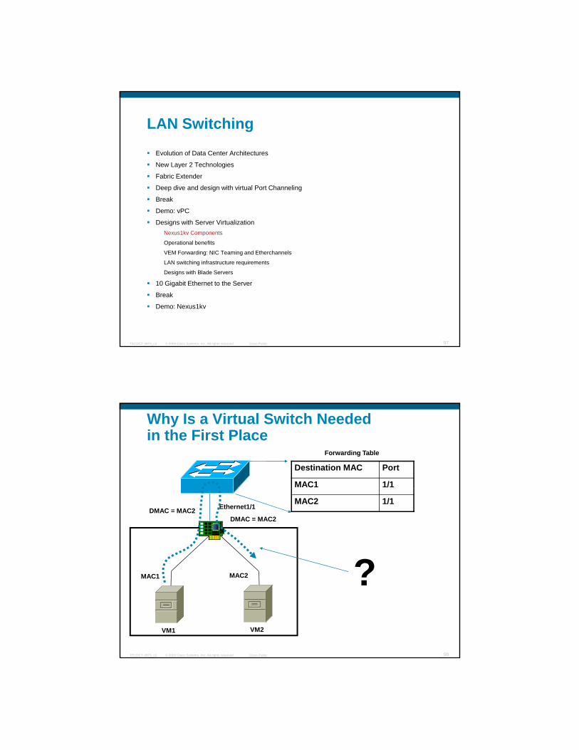
Designs with Server Virtualization
10 Gigabit Ethernet to the Server
Break
Demo: Nexus1kv
© 2009 Cisco Systems, Inc. All rights reserved. Cisco PublicTECDCT-3873_c2 2
Blade Servers Blade Switching LAN
Blade Switching SAN
Unified Compute System
Break
Demo: UCS
SAN Switching Analysis

Infrastructure Design
© 2009 Cisco Systems, Inc. All rights reserved. Cisco PublicPresentation_ID 3
Data Center LayoutBetter to move the Horizontal distribution closerto the servers to reduce the cable length
Main Distribution Area
Horizontal Distribution Area
© 2009 Cisco Systems, Inc. All rights reserved. Cisco PublicTECDCT-3873_c2 4
Equipment Distribution Area
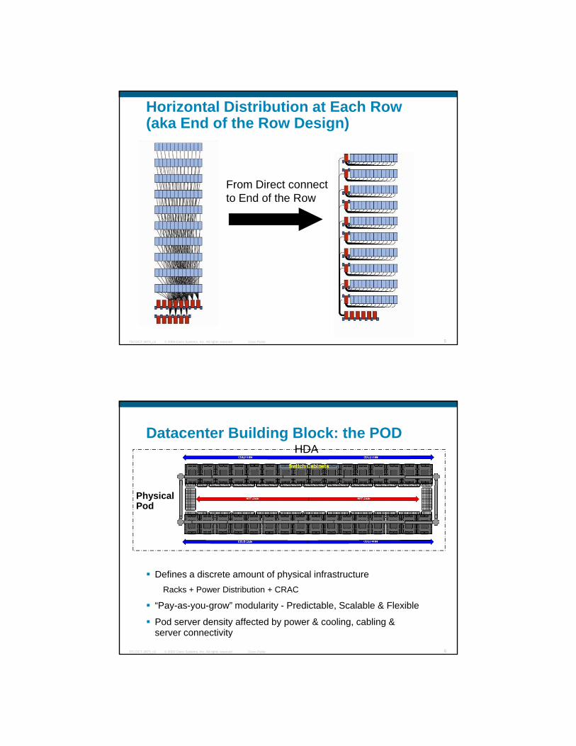
Horizontal Distribution at Each Row(aka End of the Row Design)
From Direct connectto End of the Row
© 2009 Cisco Systems, Inc. All rights reserved. Cisco PublicTECDCT-3873_c2 5
Datacenter Building Block: the PODHDA
PhysicalPod
© 2009 Cisco Systems, Inc. All rights reserved. Cisco PublicTECDCT-3873_c2 6
Defines a discrete amount of physical infrastructureRacks + Power Distribution + CRAC
“Pay-as-you-grow” modularity - Predictable, Scalable & Flexible
Pod server density affected by power & cooling, cabling & server connectivity

Overall DC Layout
HDA
MDA
© 2009 Cisco Systems, Inc. All rights reserved. Cisco PublicTECDCT-3873_c2 7
Mapping Between Physical Layout and Network Topology: HDA
Equipment Distribution
Single “POD”
Equipment Distribution Area (EDA)
Acc1 Acc2
HDA
© 2009 Cisco Systems, Inc. All rights reserved. Cisco PublicTECDCT-3873_c2 8
336 Servers

Mapping Between Physical Layout and Network Topology: MDA
Agg1 Agg2 Agg3 Agg4
Core 1 Core 2Additional Equipment:
Core Routing\Firewalls
LAN AppliancesAgg1 Agg2 Agg3 Agg4
SAN Directors
© 2009 Cisco Systems, Inc. All rights reserved. Cisco PublicTECDCT-3873_c2 9
10 Gigabit Ethernet for Server Connectivity
100Mb 1Gb 10Gb
UTP Cat 5 UTP Cat 5
10Mb
UTP Cat 3
Mid 1980’s Mid 1990’s Early 2000’s Late 2000’s
UTP Cat6a
CableTransceiverLatency (link)
Power(each side)Distance
Connector(Media)
Twinax ~ 0.1μs~ 0.1W<10mSFP+ CU*copper
UTP Cat 5MMF, SMF
UTP Cat 3 UTP Cat6aMMF, SMFTwinAx, CX4
Standard
SFF 8431**
10G Options
Twinax 15mX2 CX4copper IEEE 802.3ak4W ~ 0.1μs
In-rackX-rack
© 2009 Cisco Systems, Inc. All rights reserved. Cisco PublicTECDCT-3873_c2 10
MM OM2MM OM3 ~ 01W82m
300mSFP+ SRMMF,short reach
MM OM2MM OM3 ~ 01W10m
100mSFP+ USRMMF, ultra short reach
Cat6Cat6a/7Cat6a/7
2.5μs2.5μs1.5μs
~ 6W***~ 6W***~ 4W***
55m100m30m
RJ45 10GBASE-Tcopper
IEEE 802.3ae
none
IEEE 802.3an
*** As of 2008; expected to decrease over time* Terminated cable ** Draft 3.0, not final
Across racks
~50% power savings with
EEE
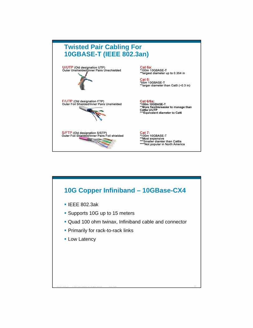
Twisted Pair Cabling For 10GBASE-T (IEEE 802.3an)
© 2009 Cisco Systems, Inc. All rights reserved. Cisco PublicTECDCT-3873_c2 11
10G Copper Infiniband – 10GBase-CX4
IEEE 802.3ak
Supports 10G up to 15 metersSupports 10G up to 15 meters
Quad 100 ohm twinax, Infiniband cable and connector
Primarily for rack-to-rack links
Low Latency
© 2009 Cisco Systems, Inc. All rights reserved. Cisco PublicTECDCT-3873_c2 12

10G SPF+ Cu
SFF 8431
Supports 10GE passive direct attached upSupports 10GE passive direct attached up to 10 meters
Active cable options to be available
Twinax with direct attached SFP+
Primarily for in rack and rack-to-rack links
© 2009 Cisco Systems, Inc. All rights reserved. Cisco PublicTECDCT-3873_c2 13
Low Latency, low cost, low power
10GBase-*X (IEEE 802.3ae) The 802.3ae 10GbE standard defines 3 MM and 1 SM fiber category based on the maximum transmission reach as shown below (ISO 11801 Standard defines the following MM and SM ( gfiber types):
SPEED
REACH
300m 500m 200m
100Mb/s OM1 OM1 OM1
1,000Mb/s OM1 OM2 OS1
10Gb/s OM3 OS1 OS1
© 2009 Cisco Systems, Inc. All rights reserved. Cisco PublicTECDCT-3873_c2 14
150M 300M 550M10Gig OM2 Plus OM3 OM3 Plus
Not all laser optimized 10Gig fiber cable is the same.
OM1 is equivalent to standard 62.5/125µm MM fiberOM2 is equivalent to standard 50/125µm fiber. OM3 is laser enhanced 50/125µm fiber – 10gigOS1 is equivalent to SM 8/125µm fiber.

Optics Positioning for Data Centers1000 BASE-LX
1G Optics Type
1000 BASE-SX
1000 BASE T
10GBASE-LR
10G Optics Type
10GBASE-SR
10GBASE-LRMRequire OM3 MMF
10GBASE-USR OM3 MMF Only
10GBASE-T 30M/100M
Max PMD Distance (m) 500 ~1000010 100
1000 BASE-T
10GBASE-CX4
© 2009 Cisco Systems, Inc. All rights reserved. Cisco PublicTECDCT-3873_c2 15
Mid to Endof
Rack
<100 M
Mid to Endof
Rack
<100 M
In RackX-rack
<10M
In RackX-rack
<10M
AcrossAisles
<300 M
AcrossAisles
<300 M
AcrossSites
<10 KM
AcrossSites
<10 KM
Max PMD Distance (m) 26-82 300220 ~1000010
10GBASE-CX1
100
Cost Effective 10G Server Connectivity Today
SFP+ USR – ‘Ultra Short Reach’O f O f
SFP+ Direct Attach 1 3 5 and 7M on Twinax
© 2009 Cisco Systems, Inc. All rights reserved. Cisco PublicTECDCT-3873_c2 16
100M on OM3 fiber, 30M on OM2 fiber
Support on all Cisco Catalyst and Nexus switches
Low Cost
Target FCS: Q1 CY09
1, 3, 5 and 7M on Twinax0.1W PowerSupport across all Nexus SwitchesLow Cost

Cabling Infrastructure Patch Panels for End of the Row or Middle of the RowCategory 6A (Blue) with OM3 MM (Orange) per Rack, terminating in patch rack at EoR Cable count varies based on design requirement
© 2009 Cisco Systems, Inc. All rights reserved. Cisco PublicTECDCT-3873_c2 17
Fiber for SAN or for TOR switches
Copper for EoR server connectivity
HDA Photos for End or Middle of the Row
cables on the back go to the TORpatch panels
© 2009 Cisco Systems, Inc. All rights reserved. Cisco PublicTECDCT-3873_c2 18
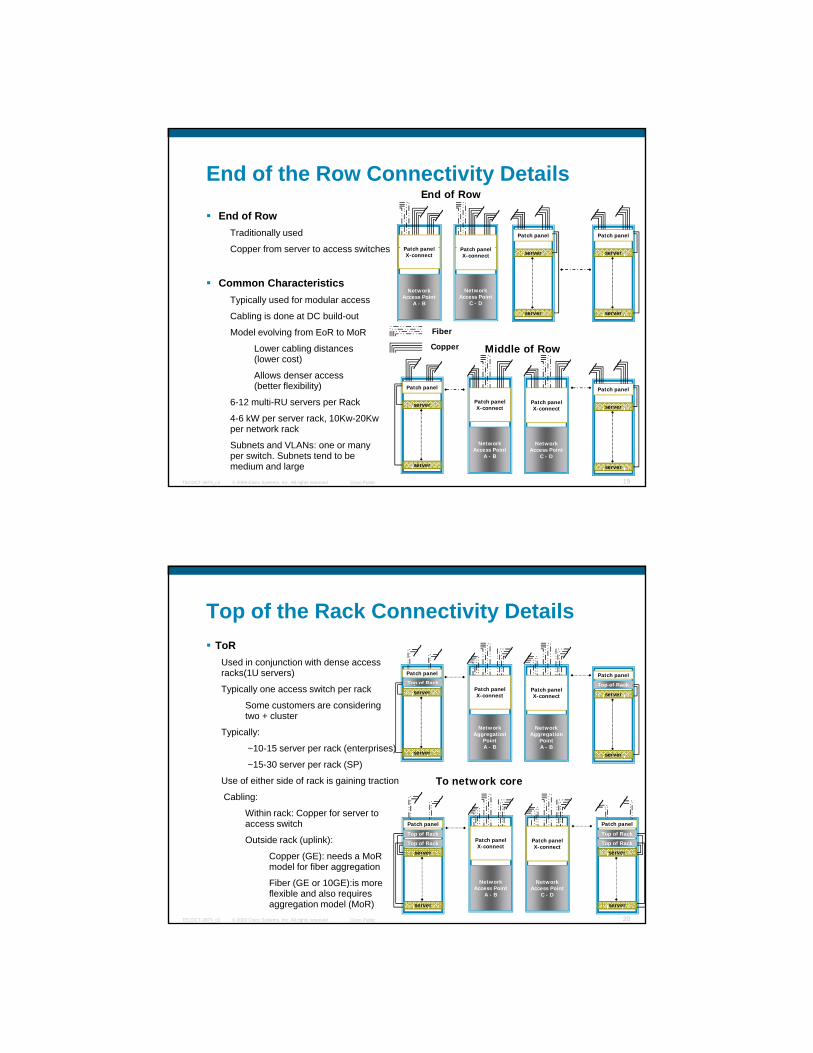
End of the Row Connectivity Details
End of RowTraditionally used
Copper from server to access switchesPatch panel Patch panel
End of Row
P t h l P t h lCopper from server to access switches
Common CharacteristicsTypically used for modular access
Cabling is done at DC build-out
Model evolving from EoR to MoR
Lower cabling distances (lower cost)
Network Access Point
A - B
server
server
server
server
Patch panelX-connect
Network Access Point
C - D
Patch panelX-connect
Fiber
Copper Middle of Row
© 2009 Cisco Systems, Inc. All rights reserved. Cisco PublicTECDCT-3873_c2 19
Allows denser access (better flexibility)
6-12 multi-RU servers per Rack
4-6 kW per server rack, 10Kw-20Kw per network rack
Subnets and VLANs: one or many per switch. Subnets tend to be medium and large
Patch panel
Network Access Point
A - B
server
server
server Patch panelX-connect
Network Access Point
C - D
Patch panelX-connect
Patch panel
server
Top of the Rack Connectivity DetailsToR
Used in conjunction with dense access racks(1U servers) Patch panelPatch panel
Top of Rack Top of RackTypically one access switch per rack
Some customers are considering two + cluster
Typically:
~10-15 server per rack (enterprises)
~15-30 server per rack (SP)
Use of either side of rack is gaining traction
Cabling:To network core
Network Aggregation
PointA - B
server
server
server Patch panelX-connect
Network Aggregation
PointA - B
Patch panelX-connect
server
p Top of Rack
© 2009 Cisco Systems, Inc. All rights reserved. Cisco PublicTECDCT-3873_c2 20
Within rack: Copper for server to access switch
Outside rack (uplink):
Copper (GE): needs a MoR model for fiber aggregation
Fiber (GE or 10GE):is more flexible and also requires aggregation model (MoR)
Top of Rack
server
server
Top of Rack
server
Network Access Point
A - B
Patch panelX-connect
Network Access Point
C - D
Patch panelX-connect
Top of Rack
server
Top of Rack
Patch panel Patch panel
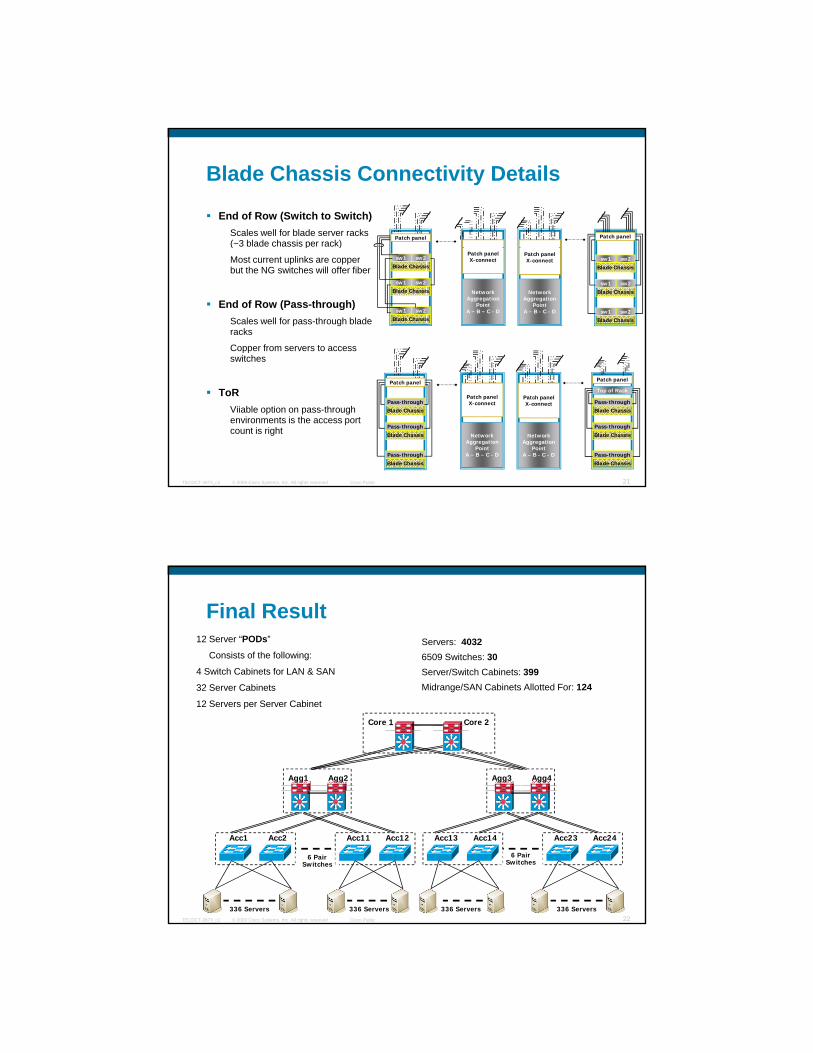
Blade Chassis Connectivity Details
End of Row (Switch to Switch)Scales well for blade server racks (~3 blade chassis per rack)
Patch panel Patch panel( p )
Most current uplinks are copper but the NG switches will offer fiber
End of Row (Pass-through)Scales well for pass-through blade racks
Copper from servers to access switches
Blade Chassissw1 sw2
Blade Chassissw1 sw2
Blade Chassis
sw1 sw2
Blade Chassissw1 sw2
Blade Chassissw1 sw2
Blade Chassissw1 sw2
Network Aggregation
PointA – B – C - D
Patch panelX-connect
Network Aggregation
PointA – B - C - D
Patch panelX-connect
© 2009 Cisco Systems, Inc. All rights reserved. Cisco PublicTECDCT-3873_c2 21
ToRViiable option on pass-through environments is the access port count is right
Blade Chassis
Pass-through
Blade ChassisPass-through
Blade ChassisPass-through
Network Aggregation
PointA – B – C - D
Patch panelX-connect
Network Aggregation
PointA – B - C - D
Patch panelX-connect
Top of Rack
Blade Chassis
Pass-through
Blade ChassisPass-through
Blade ChassisPass-through
Patch panelPatch panel
Final Result12 Server “PODs”
Consists of the following:
4 Switch Cabinets for LAN & SAN
32 S C bi t
Servers: 40326509 Switches: 30Server/Switch Cabinets: 399Mid /SAN C bi t All tt d F 12432 Server Cabinets
12 Servers per Server Cabinet
Midrange/SAN Cabinets Allotted For: 124
Agg1 Agg2 Agg3 Agg4
Core 1 Core 2
© 2009 Cisco Systems, Inc. All rights reserved. Cisco PublicTECDCT-3873_c2 22
Acc11 Acc12
336 Servers
Acc1 Acc2
336 Servers
Acc13 Acc14
336 Servers
Acc23 Acc24
336 Servers
6 Pair Switches
6 Pair Switches

LAN Switching in the Datacenter
© 2009 Cisco Systems, Inc. All rights reserved. Cisco PublicPresentation_ID 23
Icons and Associated Product
=
Catalyst 4948-10GE Catalyst 4900MNexus 5000Nexus 7000
=with Service Modules
© 2009 Cisco Systems, Inc. All rights reserved. Cisco PublicTECDCT-3873_c2 24
CBS 3100Blade Switches
Catalyst 6500 Nexus 2148T
with VSS =
Nexus 1000v
LAN Switching
Evolution of Data Center ArchitecturesNew Layer 2 TechnologiesNew Layer 2 TechnologiesFabric ExtenderDeep dive and Design with virtual Port ChannelingBreakDemo: vPC
© 2009 Cisco Systems, Inc. All rights reserved. Cisco PublicTECDCT-3873_c2 25
Designs with Server Virtualization10 Gigabit Ethernet to the ServerBreakDemo: Nexus1kv
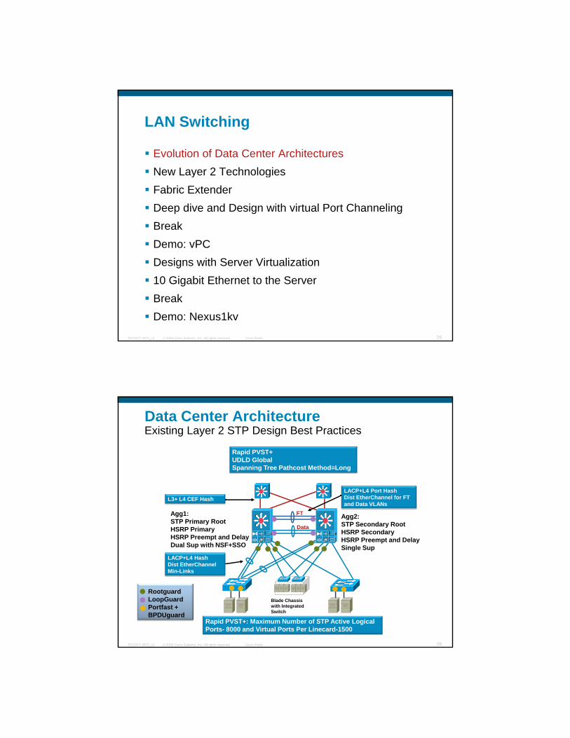
Data Center ArchitectureExisting Layer 2 STP Design Best Practices
Rapid PVST+ UDLD GlobalSpanning Tree Pathcost Method=Long
Agg1:STP Primary RootHSRP Primary HSRP Preempt and DelayDual Sup with NSF+SSO
Agg2:STP Secondary RootHSRP SecondaryHSRP Preempt and DelaySingle Sup
FT
LACP+L4 HashDist EtherChannel
L3+ L4 CEF Hash LACP+L4 Port HashDist EtherChannel for FT and Data VLANs
Data
© 2009 Cisco Systems, Inc. All rights reserved. Cisco PublicTECDCT-3873_c2 26
Rapid PVST+: Maximum Number of STP Active Logical Ports- 8000 and Virtual Ports Per Linecard-1500
Blade Chassis with Integrated Switch
RootguardLoopGuard Portfast +BPDUguard
Dist EtherChannelMin-Links

Migration from “Inline” Services
The Need:Higher performance/scalability required in aggregation and/or core
The Migration:Move Catalyst 6500 chassis with service modules to an “on-the-stick”
© 2009 Cisco Systems, Inc. All rights reserved. Cisco PublicTECDCT-3873_c2 27
configuration and re-use high speed links to connect to the aggregation Layer
VSS Allows a Migration to a L2 Topology Based on Etherchannels
10 Gig uplinks
IETF NSF
10 Gig uplinks
6500 with VSSIETF NSF-capable
STP Root
© 2009 Cisco Systems, Inc. All rights reserved. Cisco PublicTECDCT-3873_c2 28
10 Gig uplinks
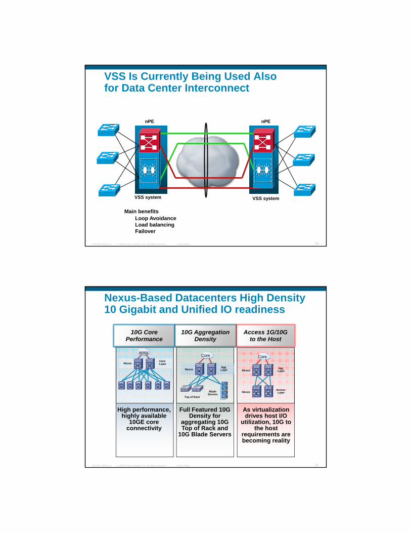
nPE nPE
VSS Is Currently Being Used Alsofor Data Center Interconnect
© 2009 Cisco Systems, Inc. All rights reserved. Cisco PublicTECDCT-3873_c2 29
VSS systemVSS system
Main benefitsLoop AvoidanceLoad balancingFailover
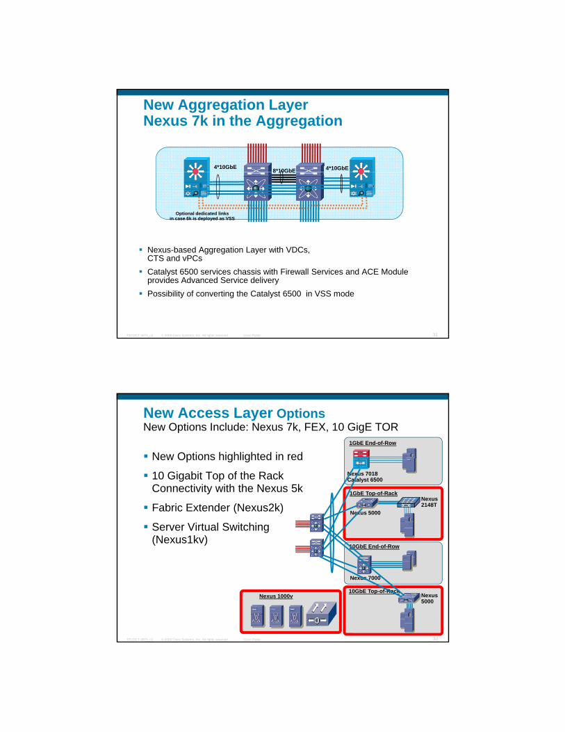
10G Core Performance
10G Aggregation Density
Nexus-Based Datacenters High Density 10 Gigabit and Unified IO readiness
Access 1G/10G to the Host
Hi h f F ll F d 10G
Agg LayerNexus
Top of Rack
BladeServers
CoreCore LayerNexus
WAN
A i li i
Access LayerNexus
Agg LayerNexus
Core
© 2009 Cisco Systems, Inc. All rights reserved. Cisco PublicTECDCT-3873_c2 30
High performance, highly available
10GE core connectivity
Full Featured 10G Density for
aggregating 10G Top of Rack and
10G Blade Servers
As virtualization drives host I/O
utilization, 10G to the host
requirements are becoming reality
New Aggregation LayerNexus 7k in the Aggregation
8*10GbE4*10GbE 4*10GbE
Nexus-based Aggregation Layer with VDCs, CTS d PC
8 10GbE
Optional dedicated linksin case 6k is deployed as VSS
© 2009 Cisco Systems, Inc. All rights reserved. Cisco PublicTECDCT-3873_c2 31
CTS and vPCsCatalyst 6500 services chassis with Firewall Services and ACE Module provides Advanced Service deliveryPossibility of converting the Catalyst 6500 in VSS mode
New Access Layer OptionsNew Options Include: Nexus 7k, FEX, 10 GigE TOR
New Options highlighted in red
10 Gigabit Top of the Rack
1GbE End-of-Row
Nexus 701810 Gigabit Top of the Rack Connectivity with the Nexus 5k
Fabric Extender (Nexus2k)
Server Virtual Switching (Nexus1kv)
10GbE End-of-Row
1GbE Top-of-RackNexus2148T
Catalyst 6500
Nexus 5000
© 2009 Cisco Systems, Inc. All rights reserved. Cisco PublicTECDCT-3873_c2 32
10GbE Top-of-RackNexus5000
Nexus 7000
Nexus 1000v
LAN Switching
Evolution of Data Center ArchitecturesNew Layer 2 TechnologiesNew Layer 2 TechnologiesFabric ExtenderDeep dive and Design with virtual Port ChannelingBreakDemo: vPC
© 2009 Cisco Systems, Inc. All rights reserved. Cisco PublicTECDCT-3873_c2 33
Designs with Server Virtualization10 Gigabit Ethernet to the ServerBreakDemo: Nexus1kv
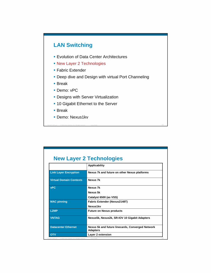
New Layer 2 TechnologiesApplicability
Link Layer Encryption Nexus 7k and future on other Nexus platforms
Virtual Domain Contexts Nexus 7k
vPC Nexus 7k
Nexus 5k
Catalyst 6500 (as VSS)MAC pinning Fabric Extender (Nexus2148T)
Nexus1kv
© 2009 Cisco Systems, Inc. All rights reserved. Cisco PublicTECDCT-3873_c2 34
L2MP Future on Nexus products
VNTAG Nexus5k, Nexus2k, SR-IOV 10 Gigabit Adapters
Datacenter Ethernet Nexus 5k and future linecards, Converged Network Adapters
OTV Layer 2 extension

Cisco TrustSec TrustSec Linksec (802.1ae) Frame Format
The encryption used by TrustSec follows IEEE Standards-based LinkSec (802.1ae) encryption, where the upper layers are unaware of the L2 header/encryption.
DMAC SMAC
CMDE_TYPE Version Length SGT Option
Length & TypeSGT
Value Variable
802.1ae Header .1Q CMD ETH TYPE P l d ICV CRC
© 2009 Cisco Systems, Inc. All rights reserved. Cisco PublicTECDCT-3873_c2 35
DMAC SMAC 802.1ae Header(16 Octets)
.1Q(4)
CMD(8 Octets) ETH_TYPE Payload ICV
(16 Octets) CRC
Authenticated
Encrypted
Nexus 7000 TrustSecSample Config – Manual 802.1AE Symmetric Configuration
DC2DC1 Encrypted Traffic
Nexus-7000-1(config)# interface ethernet 2/45Nexus-7000-1(config-if)# cts manualNexus-7000-1(config-if-cts-manual)# sap pmk 12344219Nexus-7000-1(config-if-cts-manual)# exit
Nexus-7000-2(config)# interface ethernet 2/3Nexus-7000-2(config-if)# cts manualNexus-7000-2(config-if-cts-manual)# sap pmk 12344219Nexus-7000-2(config-if-cts-manual)# exit
Public Soil
© 2009 Cisco Systems, Inc. All rights reserved. Cisco PublicTECDCT-3873_c2 36
Nexus-7000-1# show cts
CTS Global Configuration==============================CTS support : enabledCTS device identity : test1CTS caching support : disabledNumber of CTS interfaces in
DOT1X mode : 0Manual mode : 1
Nexus-7000-2# show cts
CTS Global Configuration==============================CTS support : enabledCTS device identity : test2CTS caching support : disabledNumber of CTS interfaces in
DOT1X mode : 0Manual mode : 1
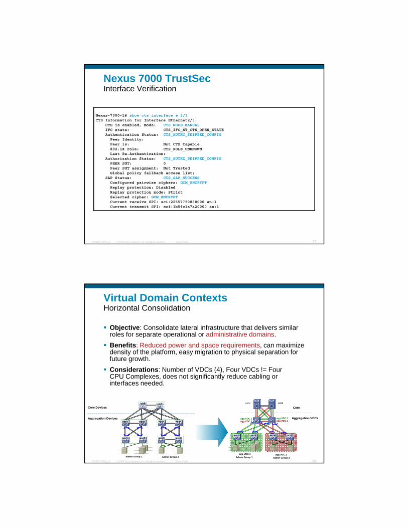
Nexus 7000 TrustSec Interface Verification
Nexus-7000-1# show cts interface e 2/3CTS Information for Interface Ethernet2/3:
CTS i bl d d CTS MODE MANUALCTS is enabled, mode: CTS_MODE_MANUALIFC state: CTS_IFC_ST_CTS_OPEN_STATEAuthentication Status: CTS_AUTHC_SKIPPED_CONFIGPeer Identity: Peer is: Not CTS Capable802.1X role: CTS_ROLE_UNKNOWNLast Re-Authentication:
Authorization Status: CTS_AUTHZ_SKIPPED_CONFIGPEER SGT: 0Peer SGT assignment: Not TrustedGlobal policy fallback access list:
SAP Status: CTS_SAP_SUCCESSConfigured pairwise ciphers: GCM ENCRYPT
© 2009 Cisco Systems, Inc. All rights reserved. Cisco PublicTECDCT-3873_c2 37
g p p _Replay protection: DisabledReplay protection mode: StrictSelected cipher: GCM_ENCRYPTCurrent receive SPI: sci:225577f0860000 an:1Current transmit SPI: sci:1b54c1a7a20000 an:1
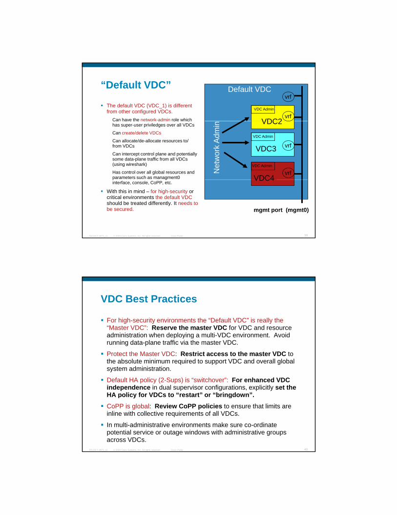
Virtual Domain ContextsHorizontal Consolidation
Objective: Consolidate lateral infrastructure that delivers similar roles for separate operational or administrative domains.B fit R d d d i t i iBenefits: Reduced power and space requirements, can maximize density of the platform, easy migration to physical separation for future growth.Considerations: Number of VDCs (4), Four VDCs != Four CPU Complexes, does not significantly reduce cabling or interfaces needed.
core core corecore
© 2009 Cisco Systems, Inc. All rights reserved. Cisco PublicTECDCT-3873_c2 38
core1
core2
agg2agg1
acc2acc1
agg4agg3
accYaccNacc2acc1 accYaccN
corecore
Core
Aggregation VDCs
Core Devices
Aggregation Devices agg VDC 1agg VDC 2
agg VDC 1agg VDC 2
agg VDC 1 agg VDC 2Admin Group 1 Admin Group 2 Admin Group 1 Admin Group 2
“Default VDC”
The default VDC (VDC_1) is different from other configured VDCs.
Can have the network-admin role which
Default VDC
VDC2
VDC Admin
vrf
vrf
Can have the network admin role which has super-user priviledges over all VDCs
Can create/delete VDCs
Can allocate/de-allocate resources to/from VDCs
Can intercept control plane and potentially some data-plane traffic from all VDCs (using wireshark)
Has control over all global resources and parameters such as managment0
VDC2
VDC3
VDC4
Net
wor
k A
dmin
VDC Admin
VDC Admin
vrf
vrf
© 2009 Cisco Systems, Inc. All rights reserved. Cisco PublicTECDCT-3873_c2 39
p ginterface, console, CoPP, etc.
With this in mind – for high-security or critical environments the default VDCshould be treated differently. It needs to be secured.
VDC4
mgmt port (mgmt0)
VDC Best Practices
For high-security environments the “Default VDC” is really the “Master VDC”: Reserve the master VDC for VDC and resource administration when deploying a multi VDC environment Avoidadministration when deploying a multi-VDC environment. Avoid running data-plane traffic via the master VDC.
Protect the Master VDC: Restrict access to the master VDC to the absolute minimum required to support VDC and overall global system administration.
Default HA policy (2-Sups) is “switchover”: For enhanced VDC independence in dual supervisor configurations, explicitly set the HA polic for VDCs to “restart” or “bringdo n”
© 2009 Cisco Systems, Inc. All rights reserved. Cisco PublicTECDCT-3873_c2 40
HA policy for VDCs to “restart” or “bringdown”.
CoPP is global: Review CoPP policies to ensure that limits are inline with collective requirements of all VDCs.
In multi-administrative environments make sure co-ordinate potential service or outage windows with administrative groups across VDCs.

Resource Scalability Limits
Some resource scalability is limited per system, others are per VDC16,000 maximum Logical Interfaces (RPVST+) TOTAL for all configured VDCs*
75,000 maximum Logical Interfaces (MST) TOTAL for all configured VDCs*
256 per configured VDC*
4096 VLANs per configured VDC*
FIB TCAM can be scaled by planning interface allocationsFIB is per I/O module and is only populated with entries for VDCs
© 2009 Cisco Systems, Inc. All rights reserved. Cisco PublicTECDCT-3873_c2 41
assigned on a module
You can optionally maximize this by using the following rule:
Assign 1 VDC per module (slot), with 2 modules minimum per VDC on a single system (to preserve redundancy)
* for 4.0(3)
VDC Granularity for Current 10 GigE Ports
VDCA
VDCCPorts are assigned on a per VDC basis
and cannot be shared across VDC’s
32 port10GE
module
and cannot be shared across VDC s
Once a port has been assigned to a VDC, ll b t fi ti i d f
© 2009 Cisco Systems, Inc. All rights reserved. Cisco PublicTECDCT-3873_c2 42
VDCB
VDCC
all subsequent configuration is done from within that VDC…
On 32-port 10GE module ports must be assigned to a VDC by 4-block groups.
http://www.cisco.com/en/US/docs/switches/datacenter/sw/4_1/nx-os/virtual_device_context/configuration/guide/vdc_overview.html#wp1073104
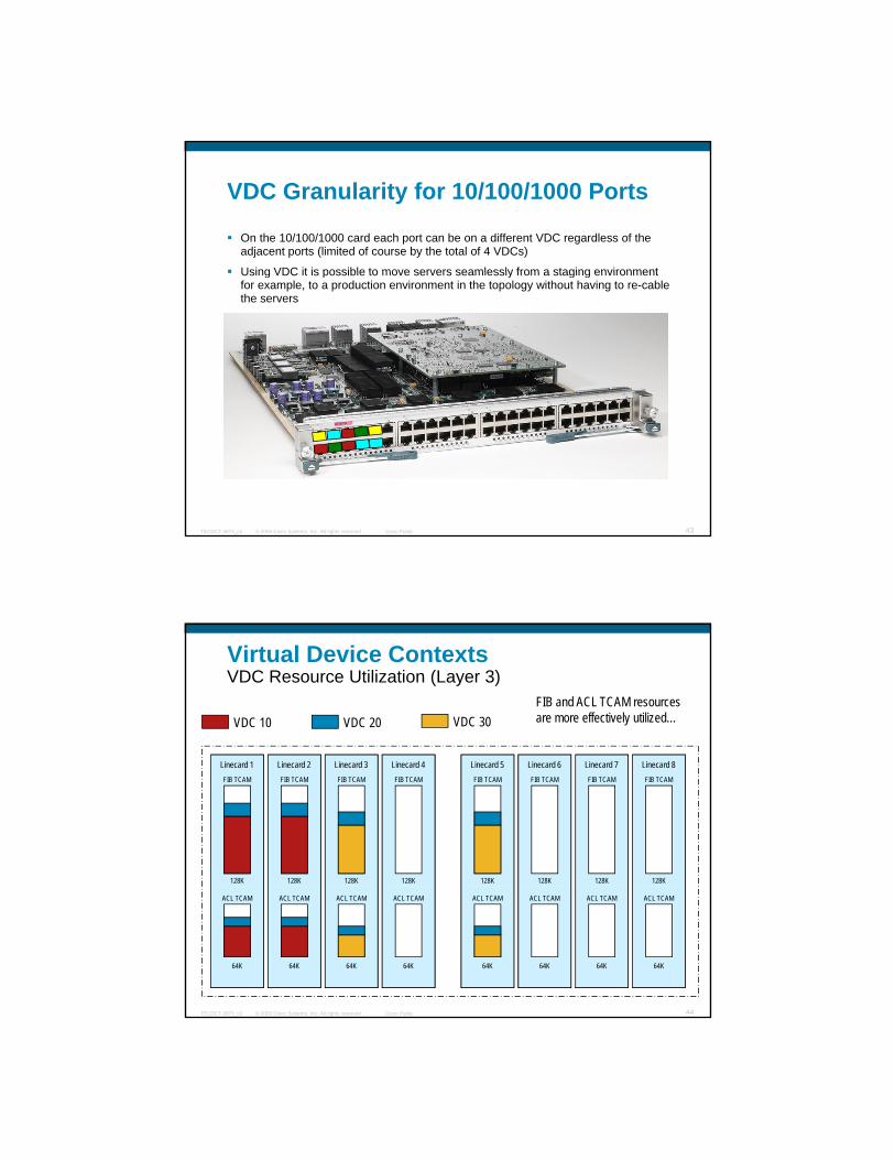
VDC Granularity for 10/100/1000 Ports
On the 10/100/1000 card each port can be on a different VDC regardless of the adjacent ports (limited of course by the total of 4 VDCs)
Using VDC it is possible to move servers seamlessly from a staging environmentUsing VDC it is possible to move servers seamlessly from a staging environment for example, to a production environment in the topology without having to re-cable the servers
© 2009 Cisco Systems, Inc. All rights reserved. Cisco PublicTECDCT-3873_c2 43
Virtual Device Contexts VDC Resource Utilization (Layer 3)
VDC 10 VDC 20 VDC 30FIB and ACL TCAM resources are more effectively utilized…
Linecard 1 Linecard 2 Linecard 3 Linecard 4 Linecard 5 Linecard 6 Linecard 7 Linecard 8
128K 128K 128K 128K 128K 128K 128K 128K
FIB TCAM FIB TCAM FIB TCAM FIB TCAM FIB TCAM FIB TCAM FIB TCAM FIB TCAM
© 2009 Cisco Systems, Inc. All rights reserved. Cisco PublicTECDCT-3873_c2 44
64K 64K 64K 64K 64K 64K 64K 64K
ACL TCAM ACL TCAM ACL TCAM ACL TCAM ACL TCAM ACL TCAM ACL TCAM ACL TCAM
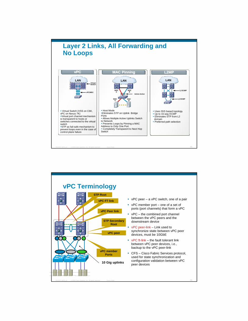
Layer 2 Links, All Forwarding and No Loops
MAC PinningMAC Pinning L2MPL2MPvPCvPC
LAN
Active-Active
MACB
MACA
MACA
MACB
Host Mode
LAN
L2 ECMP
L2 ECMP
Uses ISIS based topology
LAN
vPC/MEC
Virtual Switch (VSS on C6K,
VirtualSwitch
© 2009 Cisco Systems, Inc. All rights reserved. Cisco PublicTECDCT-3873_c2 45
Eliminates STP on Uplink Bridge Ports
Allows Multiple Active Uplinks Switch to Network
Prevents Loops by Pinning a MAC Address to Only One Port
Completely Transparent to Next Hop Switch
Uses ISIS based topologyUp to 16 way ECMPEliminates STP from L2domainPreferred path selection
( ,vPC on Nexus 7K)Virtual port channel mechanism
is transparent to hosts or switches connected to the virtual switchSTP as fail-safe mechanism to
prevent loops even in the case of control plane failure
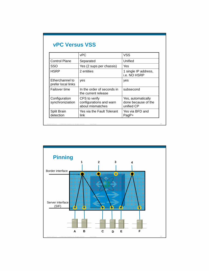
vPC Terminology
vPC peer – a vPC switch, one of a pair
vPC member port – one of a set of ports (port channels) that form a vPC
STP Root
vPC FT link
vPC peer
STP Secondary Root
ports (port channels) that form a vPC
vPC – the combined port channel between the vPC peers and the downstream device
vPC peer-link – Link used to synchronize state between vPC peer devices, must be 10GbE
vPC ft-link – the fault tolerant link between vPC peer devices, i.e.,
vPC Peer link
© 2009 Cisco Systems, Inc. All rights reserved. Cisco PublicTECDCT-3873_c2 46
p , ,backup to the vPC peer-link
CFS – Cisco Fabric Services protocol, used for state synchronization and configuration validation between vPC peer devices10 Gig uplinks
vPC member Ports

vPC “Layer 2” Processing (i.e. Etherchannel)
Etherchanneling modified to keep traffic local
Notice that the Peer-link is
almost unutilized
Downstream Switch runs LACP
LACP
hashing enhanced to keep traffic
local
© 2009 Cisco Systems, Inc. All rights reserved. Cisco PublicTECDCT-3873_c2 47
10 Gig uplinks
Unmodified Port-
channeling
vPC: Layer 3 Traffic ProcessingNotice that the
Peer-link is almost
unutilized
HSRP standby
HSRP active process communicates the active
MAC to its neighbor. Only the HSRP active process responds to
ARP requests
HSRP primary
HSRP MAC populated in the Layer 2
table with the “R” flag
© 2009 Cisco Systems, Inc. All rights reserved. Cisco PublicTECDCT-3873_c2 48
10 Gig uplinks
y
vPC Versus VSS
vPC VSS
Control Plane Separated UnifiedSSO Yes (2 sups per chassis) YesHSRP 2 entities 1 single IP address,
i.e. NO HSRPEtherchannel to prefer local links
yes yes
Failover time In the order of seconds in the current release
subsecond
© 2009 Cisco Systems, Inc. All rights reserved. Cisco PublicTECDCT-3873_c2 49
Configuration synchroniziation
CFS to verify configurations and warn about mismatches
Yes, automatically done because of the unified CP
Split Brain detection
Yes via the Fault Tolerant link
Yes via BFD and PagP+
Pinning
Border interface
1 2 3 4
Server interface(SIF)
© 2009 Cisco Systems, Inc. All rights reserved. Cisco PublicTECDCT-3873_c2 50
(SIF)
A B C D E F
1 2 3 4
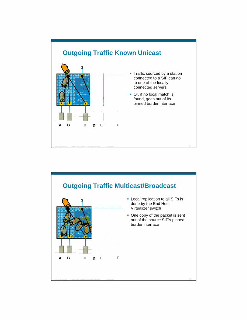
Outgoing Traffic Known Unicast
Traffic sourced by a station yconnected to a SIF can go to one of the locally connected servers
Or, if no local match is found, goes out of its pinned border interface
© 2009 Cisco Systems, Inc. All rights reserved. Cisco PublicTECDCT-3873_c2 51
A B C D E F
Outgoing Traffic Multicast/Broadcast
1 2 3 4 Local replication to all SIFs is done by the End Host Virtualizer switchVirtualizer switch
One copy of the packet is sent out of the source SIF’s pinned border interface
© 2009 Cisco Systems, Inc. All rights reserved. Cisco PublicTECDCT-3873_c2 52
A B C D E F
1 2 3 4
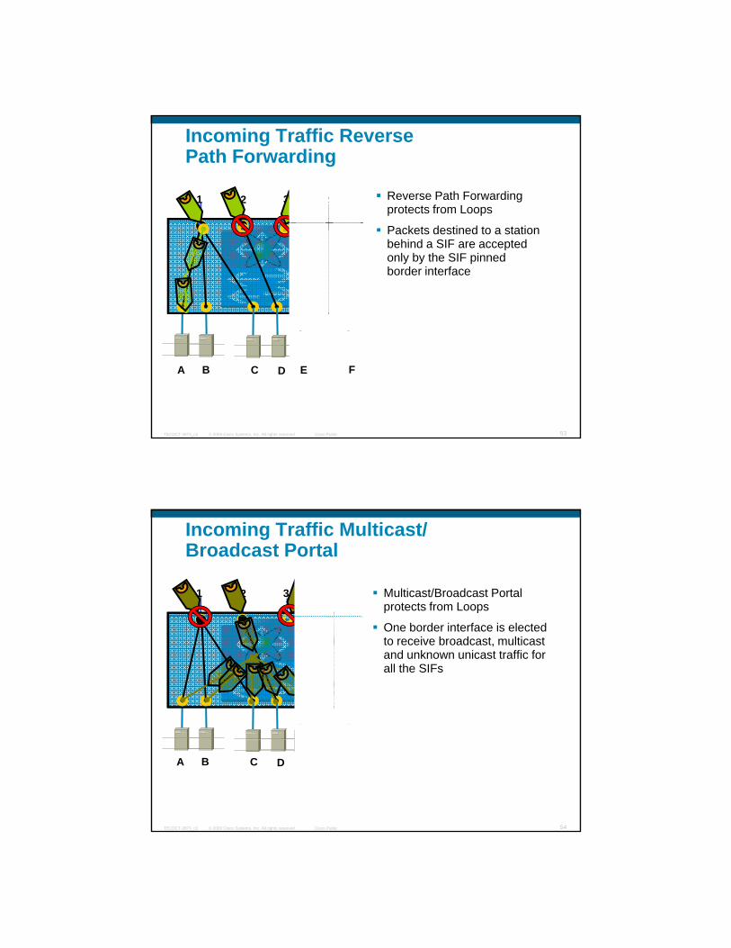
Incoming Traffic Reverse Path Forwarding
Reverse Path Forwarding protects from Loops
Packets destined to a station behind a SIF are accepted only by the SIF pinned border interface
© 2009 Cisco Systems, Inc. All rights reserved. Cisco PublicTECDCT-3873_c2 53
A B C D E F
1 2 3 4
Incoming Traffic Multicast/Broadcast Portal
Multicast/Broadcast Portal protects from Loops
One border interface is elected to receive broadcast, multicast and unknown unicast traffic for all the SIFs
© 2009 Cisco Systems, Inc. All rights reserved. Cisco PublicTECDCT-3873_c2 54
A B C D E F
1 2 3 4
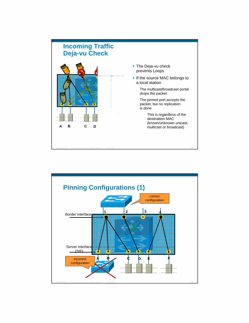
Incoming TrafficDeja-vu Check
The Deja-vu check prevents Loops
If the source MAC belongs to a local station
The multicast/broadcast portal drops the packet
The pinned port accepts the packet, but no replication is done
© 2009 Cisco Systems, Inc. All rights reserved. Cisco PublicTECDCT-3873_c2 55
A B C D E F
This is regardless of the destination MAC (known/unknown unicast, multicast or broadcast)
Pinning Configurations (1)
3
correct configuration
Border interface
Server interface
1 2 3 4
© 2009 Cisco Systems, Inc. All rights reserved. Cisco PublicTECDCT-3873_c2 56
Server interface(SIF)
A B C D E Fincorrect configuration

Pinning Configurations (2)all Border Interfaces of the same “subnet”
must be in the same L2 domain
Border interface1 2 3 4
© 2009 Cisco Systems, Inc. All rights reserved. Cisco PublicTECDCT-3873_c2 57
Server interface(SIF)
A B C D E FVirtual Switching can be connected to End
Host Virtualizer
Layer 2 MultipathingClos Networks
L2L2
L2
© 2009 Cisco Systems, Inc. All rights reserved. Cisco PublicTECDCT-3873_c2 58
Layer 2 MultiPathing enables designs that up until today were only possible with Infiniband

Layer 2 Multipathing
Edge switchesDetermine which Edge id can reach a given MAC address
Set the destination id
IS-IS computes shortest path to id
Core switchesForward from Edge switch to Edge switch based on destination id
IS-IS computes shortest path to id
Source MAC sends to Destination MAC
© 2009 Cisco Systems, Inc. All rights reserved. Cisco PublicTECDCT-3873_c2 59
Source MAC sends to Destination MAC
Edge switch does lookup for id attached to Destination MACIf found, forward based on id
If not found, flood on broadcast tree
Core Forwarding Table
Edge
CoreL2
L2
FORWARDING TABLE on 3
1 2
3 4 5Destination Link
Switch 1 L1
Switch 2 L2
l1 l2
© 2009 Cisco Systems, Inc. All rights reserved. Cisco PublicTECDCT-3873_c2 60
MAC
A B C D E F
Switch 3 N/A
Switch 4 L1,L2
Switch 5 L1,L2

Edge Forwarding Table
Edge
CoreL2
L2
FORWARDING TABLE on 1
1 2
3 4 5Destination Link
MAC
A, B, C
Directly
MAC Switch 2
l1l2
l3
© 2009 Cisco Systems, Inc. All rights reserved. Cisco PublicTECDCT-3873_c2 61
MAC
A B C D E F
MAC
D, E, F
Switch 2
Server Connectivity Evolution – Present
Shift towards server virtualization
Management ChallengesManagement Challenges
Multiple VMs inside each physical server, connected by virtual switches
Rapid proliferation of logical elements that need to be managed
Feature parity issues between virtual and physical elements
© 2009 Cisco Systems, Inc. All rights reserved. Cisco PublicTECDCT-3873_c2 62
Separate management of physical ( ) and logical ( ) elementsSeparate management of physical ( ) and logical ( ) elementsSeparate management of physical ( ) and logical ( ) elementsSeparate management of physical ( ) and logical ( ) elements
VMsvNICs
VSwitch
VMsvNICs
VSwitch
VMsvNICs
VSwitch
VMsvNICs
VSwitch

Server Connectivity Evolution – FutureFuture with Network Interface Virtualization and VNTAG: Consolidated Management
Virtual Interfaces within VMs are now visible to the switchvisible to the switch
Both network configuration and policy enforcement for these interfaces can now be driven from the switch
This allows consolidated management of physical and virtual elements
© 2009 Cisco Systems, Inc. All rights reserved. Cisco PublicTECDCT-3873_c2 63
Consolidated management of physical ( ) and logical elementsConsolidated management of physical ( ) and logical elementsConsolidated management of physical ( ) and logical elementsConsolidated management of physical ( ) and logical elements
VSwitch VSwitch
VMsvNICs
VSwitch
VMsvNICs
VSwitch
VMsvNICs
VMsvNICs
Interface Virtualizer (IV) Architecture
© 2009 Cisco Systems, Inc. All rights reserved. Cisco PublicTECDCT-3873_c2 64
VNTAG Ethertype
source virtual interface
destination virtual interfaced p
l
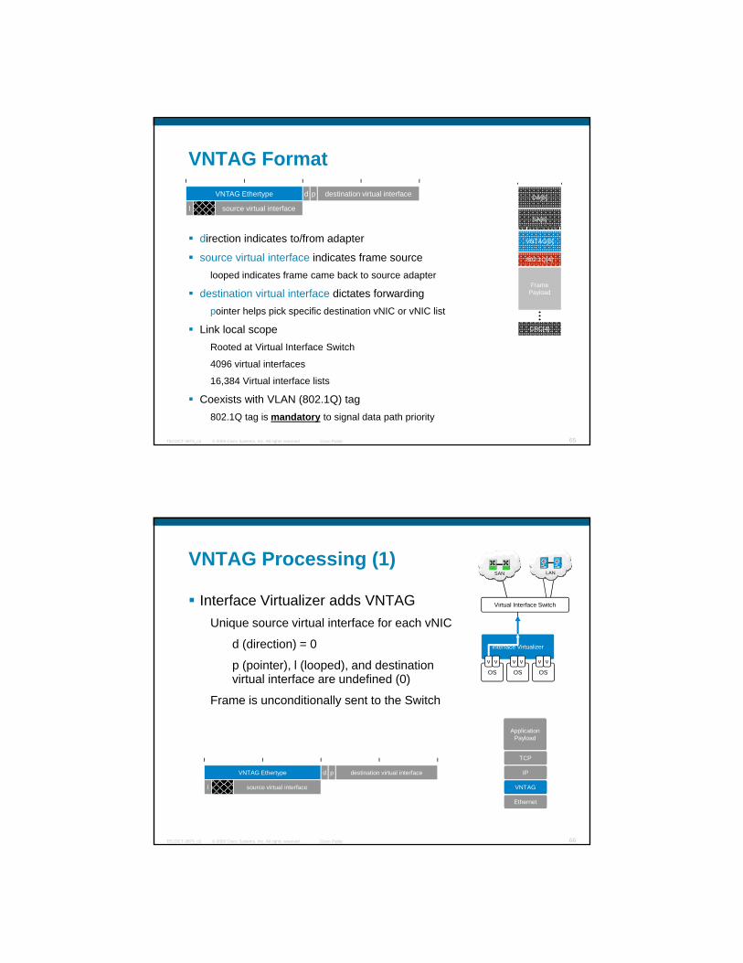
VNTAG FormatVNTAG
SA[6]
DA[6]
direction indicates to/from adapter
source virtual interface indicates frame sourcelooped indicates frame came back to source adapter
destination virtual interface dictates forwardingpointer helps pick specific destination vNIC or vNIC list
Link local scope
Frame Payload
CRC[4]
VNTAG[6]
802.1Q[4]
© 2009 Cisco Systems, Inc. All rights reserved. Cisco PublicTECDCT-3873_c2 65
Rooted at Virtual Interface Switch
4096 virtual interfaces
16,384 Virtual interface lists
Coexists with VLAN (802.1Q) tag802.1Q tag is mandatory to signal data path priority
VNTAG Processing (1)
Interface Virtualizer adds VNTAGUnique source virtual interface for each vNIC
LANSAN
Virtual Interface Switch
Unique source virtual interface for each vNIC
d (direction) = 0
p (pointer), l (looped), and destination virtual interface are undefined (0)
Frame is unconditionally sent to the Switch
Interface Virtualizer
OS
v
OS OS
v v v v v
ApplicationP l d
© 2009 Cisco Systems, Inc. All rights reserved. Cisco PublicTECDCT-3873_c2 66
Payload
TCP
IP
Ethernet
VNTAG
VNTAG Ethertype
source virtual interface
destination virtual interfaced p
l
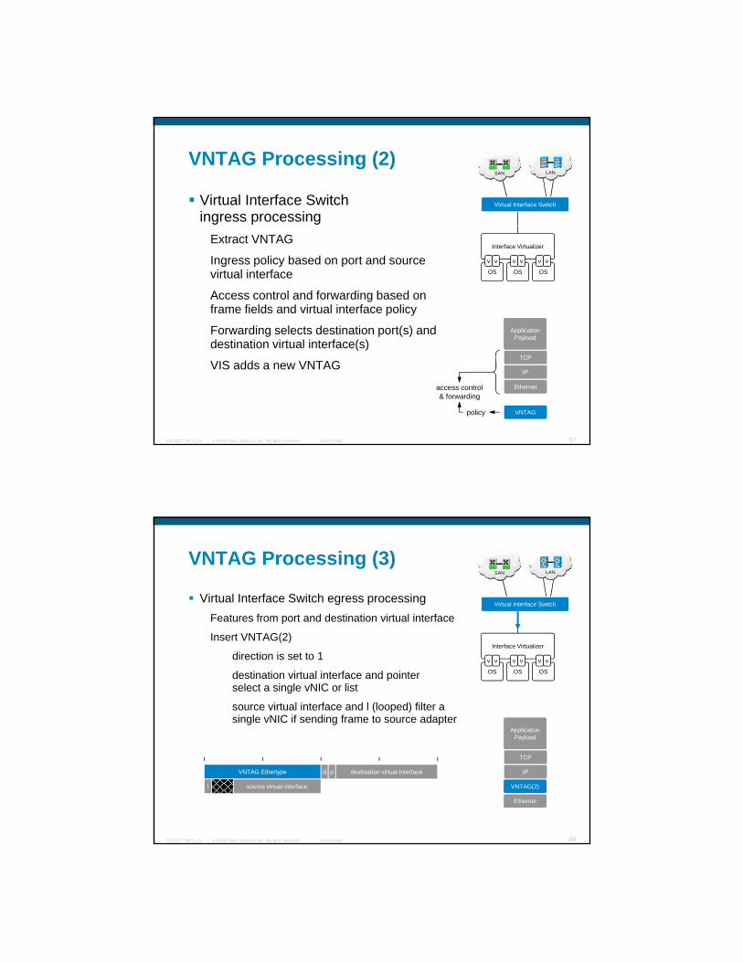
VNTAG Processing (2)
Virtual Interface Switch ingress processing
LANSAN
Virtual Interface Switch
Extract VNTAG
Ingress policy based on port and source virtual interface
Access control and forwarding based on frame fields and virtual interface policy
Forwarding selects destination port(s) and
Interface Virtualizer
OS
v
OS OS
v v v v v
ApplicationP l d
© 2009 Cisco Systems, Inc. All rights reserved. Cisco PublicTECDCT-3873_c2 67
g p ( )destination virtual interface(s)
VIS adds a new VNTAG
Payload
TCP
IP
Ethernet
VNTAGpolicy
access control& forwarding
VNTAG Processing (3)
Virtual Interface Switch egress processingFeatures from port and destination virtual interface
LANSAN
Virtual Interface Switch
Insert VNTAG(2)
direction is set to 1
destination virtual interface and pointer select a single vNIC or list
source virtual interface and l (looped) filter a single vNIC if sending frame to source adapter
Interface Virtualizer
OS
v
OS OS
v v v v v
ApplicationP l d
© 2009 Cisco Systems, Inc. All rights reserved. Cisco PublicTECDCT-3873_c2 68
Payload
TCP
IP
Ethernet
VNTAG(2)
VNTAG Ethertype
source virtual interface
destination virtual interfaced p
l

VNTAG Processing (4)
Interface Virtualizer (IV) forwards based on VNTAG
LANSAN
Virtual Interface Switch
Extract VNTAG
Upper layer protocol features from frame fields
destination virtual interface and pointer select vNIC(s)
source virtual interface and looped filter a single vNIC
if source and destination are same IV
Interface Virtualizer
OS
v
OS OS
v v v v v
ApplicationP l d
© 2009 Cisco Systems, Inc. All rights reserved. Cisco PublicTECDCT-3873_c2 69
Multicast (vNIC list)Unicast (single vNIC)
if source and destination are same IV Payload
TCP
IP
Ethernet
VNTAG(2)vNICforwarding
ULPfeatures
OS
v
OS OS
v v v v v
OS
v
OS OS
v v v v v
x x
VNTAG Processing (5)
OS stack formulates frames traditionally
Interface Virtualizer adds VNTAG
LANSAN
Virtual Interface Switch
Virtual Interface Switch ingress processing
Virtual Interface Switch egress processing
Interface Virtualizer forwards based on VNTAG
OS stack receives frame as if directly connected to Switch
Interface Virtualizer
OS OSOS
v v vv v
ApplicationP l d
© 2009 Cisco Systems, Inc. All rights reserved. Cisco PublicTECDCT-3873_c2 70
Payload
TCP
IP
Ethernet
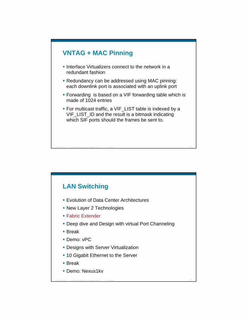
VNTAG + MAC Pinning
Interface Virtualizers connect to the network in a redundant fashion
Redundancy can be addressed using MAC pinning: each downlink port is associated with an uplink port
Forwarding is based on a VIF forwarding table which is made of 1024 entries
For multicast traffic, a VIF_LIST table is indexed by a
© 2009 Cisco Systems, Inc. All rights reserved. Cisco PublicTECDCT-3873_c2 71
VIF_LIST_ID and the result is a bitmask indicating which SIF ports should the frames be sent to.
LAN Switching
Evolution of Data Center Architectures New Layer 2 TechnologiesNew Layer 2 TechnologiesFabric ExtenderDeep dive and Design with virtual Port ChannelingBreakDemo: vPC
© 2009 Cisco Systems, Inc. All rights reserved. Cisco PublicTECDCT-3873_c2 72
Designs with Server Virtualization10 Gigabit Ethernet to the ServerBreakDemo: Nexus1kv
CoreLayer
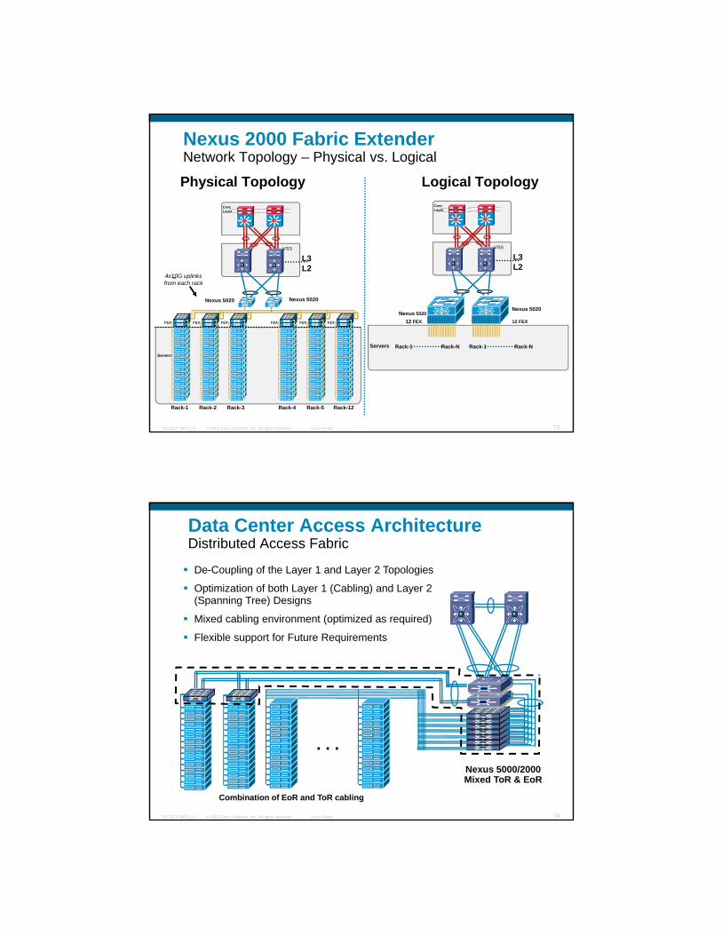
Nexus 2000 Fabric ExtenderNetwork Topology – Physical vs. Logical
Physical Topology Logical TopologyCoreLayer
FE4x10G uplinksfrom each rack
Nexus 5020
L3L2
VSS
FEX
Nexus 5020
FEX FEX FEX FEX FEX
Nexus 5020Nexus 5020
12 FEX12 FEX
L3L2
VSS
© 2009 Cisco Systems, Inc. All rights reserved. Cisco PublicTECDCT-3873_c2 73
Rack-1 Rack-2 Rack-3 Rack-4 Rack-12
Servers
Rack-5
Servers Rack-1 Rack-N Rack-1 Rack-N
Data Center Access ArchitectureDistributed Access Fabric
De-Coupling of the Layer 1 and Layer 2 Topologies
Optimization of both Layer 1 (Cabling) and Layer 2 (Spanning Tree) Designs
Mixed cabling environment (optimized as required)
Flexible support for Future Requirements
© 2009 Cisco Systems, Inc. All rights reserved. Cisco PublicTECDCT-3873_c2 74
Combination of EoR and ToR cabling
Nexus 5000/2000 Mixed ToR & EoR
. . .

Cabling Design for FEX Copper Connectivity
•Top of Rack Fabric Extenders provide 1G server connectivity•Nexus 5000 in Middle of Row connects to Fabric Extenders with CX1 copper 10G
•Top of Rack Fabric Extenders provide 1G server connectivity•Nexus 5000 in Middle of Row connects to Fabric Extenders with CX1 copper 10G
© 2009 Cisco Systems, Inc. All rights reserved. Cisco PublicTECDCT-3873_c2 75
ppbetween racks•Suitable for small server rows where each FEX is no longer than 5 meters from the 5Ks•CX1 copper between racks is not patched•Middle of Row Nexus 5000 can also provide 10G server connectivity within their rack
ppbetween racks•Suitable for small server rows where each FEX is no longer than 5 meters from the 5Ks•CX1 copper between racks is not patched•Middle of Row Nexus 5000 can also provide 10G server connectivity within their rack
FEX Inner FunctioningInband Management Model
Fabric extender is discovered by switch using an L2 Satellite Discover Protocol (SDP) that is run on the uplink port of fabric extender
NX5K checks software image compatibility, assign an IP address and upgrade the fabric extender if necessary
N5K pushes programming data to Fabric Extender
© 2009 Cisco Systems, Inc. All rights reserved. Cisco PublicTECDCT-3873_c2 76
Fabric Extender updates the N5K with its operational status and statistic.
Extension to existing CLI on N5K is used for Fabric Extender CLI information
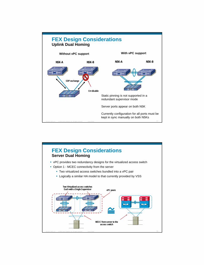
FEX Design ConsiderationsUplink Dual Homing
N5K-A N5K-B
Without vPC support With vPC support
N5K-A N5K-B
SDP exchange
Err-disable
N5K-A N5K-B N5K A N5K B
© 2009 Cisco Systems, Inc. All rights reserved. Cisco PublicTECDCT-3873_c2 77
Static pinning is not supported in a redundant supervisor mode
Server ports appear on both N5K
Currently configuration for all ports must be kept in sync manually on both N5Ks
FEX Design ConsiderationsServer Dual HomingvPC provides two redundancy designs for the virtualized access switchOption 1 - MCEC connectivity from the server
Two virtualized access switches bundled into a vPC pairTwo virtualized access switches bundled into a vPC pairLogically a similar HA model to that currently provided by VSS
vPC peersTwo Virtualized access switches Each with a Single Supervisor
© 2009 Cisco Systems, Inc. All rights reserved. Cisco PublicTECDCT-3873_c2 78
MCEC from server to the access switch

FEX Design ConsiderationsNIC Teaming with 802.3ad Across Two FEX Devices
N5KA N5KB
N5K
© 2009 Cisco Systems, Inc. All rights reserved. Cisco PublicTECDCT-3873_c2 79
By leveraging vPC it is possible to create 802.3ad configurations with dual-homed servers
FEX Design Considerations MAC Pinning on Fabric Extender (FEX)
Fabric Extender associates (pins) a server side (1GE) port with an uplink (10GE) port
Static Pinning
(10GE) port
Server ports are either individually pinned to specific uplinks (static pinning) or all interfaces pinned to a single logical port channel
Behavior on FEX uplink failure depends on the configuration
Static Pinning – Server ports pinned to Port Channel
NIC teaming required
© 2009 Cisco Systems, Inc. All rights reserved. Cisco PublicTECDCT-3873_c2 80
g p pthe specific uplink are brought down with the failure of the pinned uplink
Port Channel – Server traffic is shifted to remaining uplinks based on port channel hash
Server Interface stays active

FEX Design ConsiderationsN2K/N5K Spanning Tree Design Considerations
Root BridgeHSRP Active
Secondary Root Bridge
HSRP Standby
Bridge Assurance
BPDU Guard
y
Global BPDU Filter reduces the spanning
tree load (BPDUs generated on a Host
Port)
VMW S T k
© 2009 Cisco Systems, Inc. All rights reserved. Cisco PublicTECDCT-3873_c2 81
UDLD
VSwitch
VM #1
VM #4
VM #3
VM #2
VMWare Server Trunk Needs to Carry
Multiple VLANs which can increase the STP
load
FEX Design ConsiderationsvPC - Spanning Tree Design Considerations
Both vPC PeersAct as the default GW
Enabling vPC on the access to aggregation links improves layer 2 scalability
Single Logical Link to STP
Fabric Links(No
Spanning
y yRemoving physical loops out of the layer 2 topologyReducing the STP state on the access and aggregation layer
The use of vPC does result in a reduction of logical port count on the aggregation but does
vPC
© 2009 Cisco Systems, Inc. All rights reserved. Cisco PublicTECDCT-3873_c2 82
Server PortsBPDU Guard
p gTree)on the aggregation but does
involve CFS synchronization of state between the two aggregation nodes

LAN Switching
Evolution of Data Center Architectures New Layer 2 TechnologiesNew Layer 2 TechnologiesFabric ExtenderDeep dive and Design with virtual Port ChannelingBreakDemo: vPC
© 2009 Cisco Systems, Inc. All rights reserved. Cisco PublicTECDCT-3873_c2 83
Designs with Server Virtualization10 Gigabit Ethernet to the ServerBreakDemo: Nexus1kv
vPC Configuration Commands
Configure vPC, and start the ft-link on both peers:(config)# feature vpc(config)# feature vpc
(config)# vpc domain 1
(config-vpc-domain)# peer-keepalive destination x.x.x.x source x.x.x.y
(conifg)# int port-channel 10
(config-int)# vpc peer-link
© 2009 Cisco Systems, Inc. All rights reserved. Cisco PublicTECDCT-3873_c2 84
Move any port-channels into appropriate vPC groups(config)# int port-channel 20
(config-int)# vpc 20
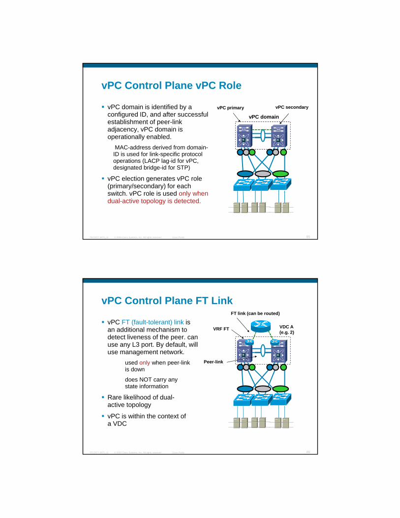
vPC Control Plane vPC Role
vPC domain is identified by a configured ID, and after successful establishment of peer link
vPC domain
vPC primary vPC secondary
establishment of peer-link adjacency, vPC domain is operationally enabled.
MAC-address derived from domain-ID is used for link-specific protocol operations (LACP lag-id for vPC, designated bridge-id for STP)
vPC election generates vPC role
© 2009 Cisco Systems, Inc. All rights reserved. Cisco PublicTECDCT-3873_c2 85
vPC election generates vPC role (primary/secondary) for each switch. vPC role is used only when dual-active topology is detected.
vPC Control Plane FT Link
vPC FT (fault-tolerant) link is an additional mechanism to detect liveness of the peer can
FT link (can be routed)
VDC A(e.g. 2)
VRF FT
detect liveness of the peer. can use any L3 port. By default, will use management network.
used only when peer-link is down
does NOT carry any state information
R lik lih d f d l
Peer-link
© 2009 Cisco Systems, Inc. All rights reserved. Cisco PublicTECDCT-3873_c2 86
Rare likelihood of dual-active topology
vPC is within the context of a VDC

vPC DeploymentRecommended ConfigurationsvPC is a Layer 2 feature
Port has to be in switchport mode before configuring vPC
vPC/vPC peer link support following port/
VDC A(e.g. 2)
VRF FT
vPC/vPC peer-link support following port/port-channel modes
Port Modes: Access or Trunk
Port-channel Modes: On mode or LACP (active/passive) mode
Recommended port mode Trunk
vPC peer-link should support multiple VLANs and should trunk the access VLANs
Recommended port-channel mode is Link Aggregation
Peer-link
LACP
© 2009 Cisco Systems, Inc. All rights reserved. Cisco PublicTECDCT-3873_c2 87
Control Protocol (LACP).
Dynamically react to runtime changes and failures
Lossless membership change
Detection of mis-configuration
Maximum 8 ports in a port-channel in on-mode and 16 ports with 8 operational ports in a LACPport-channel
l2fm
vpc-transport-api
igmp stp vpcm vpcm
vpc-transport-api
stp igmp l2fm{ opcode, payload}
vPC Control PlaneCFSoE
cfs
cfsoe
netstack
cfs
cfsoe
netstack
sw-1 sw-2
CFS (Cisco Fabric Service), over Ethernet (CFSoE), provides a reliable transport layer to all applications that need to co-operate with peer vPC switch. CFSoE
© 2009 Cisco Systems, Inc. All rights reserved. Cisco PublicTECDCT-3873_c2 88
CFSoE uses retransmissions & acknowledgements per segment transmitted. supports fragmentation and re-assembly for payloads more than MTUuses BPDU class address, and is treated with highest QoS/drop-thresholds.
Each component has (one or more) request-response handshakes (over CFSoE) with its peer. Protocols (STP/IGMP/FHRP) continue to exchange regular protocol BPDUs. In addition, they’ll use CFS for state synchronization

CFS Distribution
CFS only checks that the VLANs assigned to a vPC are the same on both devices that
(config)#cfs distribute enable
(config)#cfs ethernet the same on both devices that are on the same vPC
This warns the person on the other 7k that he has to make configuration changes to include the same exact VLANs
Distribution is automatically enabled b enabling PC
( g)distribute enable
tc-nexus7k01-vdc3# show cfs status
Distribution: Enabled
Distribution over IP: Disabled
IPv4 multicast address:
© 2009 Cisco Systems, Inc. All rights reserved. Cisco PublicTECDCT-3873_c2 89
enabled by enabling vPC IPv4 multicast address: 239.255.70.83
IPv6 multicast address: ff15::efff:4653
Distribution over Ethernet: Enabled
CFSoIP vs CFSoE vPC uses CFSoE, Roles Leverage CFSoIP
vPC domain (CFSoE) CFSoIP Cloud
Role Defintion
© 2009 Cisco Systems, Inc. All rights reserved. Cisco PublicTECDCT-3873_c2 90
The user creates new Role
User “commits” the changes
Role get automatically propagated to the other switches

Type-1 Compatibility Parameters
Port Channel is disabled if one of the following parameters is mismatched”
Port-channel Speed (’10M’, ‘100M’, ‘1000M’ or ‘10G’)
Port-channel Duplex (‘half’ or ‘full’)
Port Mode (‘access’ or ‘trunk’)
Port-channel MTU
Port-channel Native VLAN
© 2009 Cisco Systems, Inc. All rights reserved. Cisco PublicTECDCT-3873_c2 91
Port-channel mode (‘on’, ‘active’ or ‘passive’)
Detecting Mis-ConfigurationSw1 (config)# show vpc briefVPC domain id : 1Peer status : peer adjacency formed okVPC keep-alive status : DisabledConfiguration consistency status: success
VPC status---------------------------------------------------id Port Consistency Reason---- -------------- ----------- ----------------1 Po2 success success2 Po3 failed vpc port channel mis-config due to
vpc links in the 2 switches connected to different partners
© 2009 Cisco Systems, Inc. All rights reserved. Cisco PublicTECDCT-3873_c2 92
vpc links in the 2 switches connected to different partners
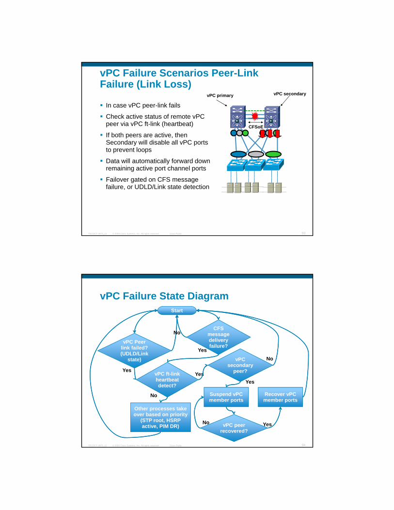
vPC Failure Scenarios Peer-Link Failure (Link Loss)
In case vPC peer-link fails
Check active status of remote vPC
vPC primary vPC secondary
peer via vPC ft-link (heartbeat)
If both peers are active, then Secondary will disable all vPC ports to prevent loops
Data will automatically forward down remaining active port channel ports
F il t d CFS
CFSoE
© 2009 Cisco Systems, Inc. All rights reserved. Cisco PublicTECDCT-3873_c2 93
Failover gated on CFS message failure, or UDLD/Link state detection
vPC Failure State DiagramStart
CFS No
vPC Peer vPC Peer link failed? (UDLD/Link
state)
message delivery failure?
vPC ft-link heartbeat detect?
vPC secondary
peer?
No
No
Yes
Yes
Yes
Yes
© 2009 Cisco Systems, Inc. All rights reserved. Cisco PublicTECDCT-3873_c2 94
Suspend vPC member ports
Other processes take over based on priority
(STP root, HSRP active, PIM DR)
No
vPC peer recovered?
YesNo
Recover vPC member ports

vPC Between Sites and Within Each DC
N7kC DC2
DC1 DC2
vPC between sites CFSoE Region 2CFSoE Region 1
Peer link Peer linkEth2/9 Eth2/25
Eth2/9 Eth2/25
Eth7/9 Eth7/25
Eth7/9 Eth7/25
N7kA-DC1
Eth2/3 Eth7/3 Eth8/5
Eth8/5
access Eth2/26
Eth8/40 Eth8/4Po60
Po50
N7kC-DC2
© 2009 Cisco Systems, Inc. All rights reserved. Cisco PublicTECDCT-3873_c2 95
N7kB-DC1
Eth2/3 Eth7/3Eth8/5
Eth2/26
Po30 N7kD-DC2
Links Protected by IEEE 802.1ae
FT link
Routing Designfor the Extended VLANs
150 120 120 150
Failovfor H
S
DC1 DC2gw 1.1.1.1 gw 1.1.1.2
HSRP Group 1 HSRP Group 2
150, 120
140 130 130 140
120, 150 er direction SR
P Group 2 (e.g. 1.1.1.2)
irect
ion
Gro
up 1
(e.g
. 1.1
.1.1
)
© 2009 Cisco Systems, Inc. All rights reserved. Cisco PublicTECDCT-3873_c2 96
140, 130 130, 140
Failo
ver d
ifo
r HSR
P G
G 60 0000.0c07.ac3c static << group that is active or standby* 60 0000.0c07.ac3d static << group that is listen mode
G 60 0000.0c07.ac3d static << group that is active or standby* 60 0000.0c07.ac3c static << group that is listen mode
LAN Switching
Evolution of Data Center Architectures
New Layer 2 Technologies
Fabric ExtenderFabric Extender
Deep dive and design with virtual Port Channeling
Break
Demo: vPC
Designs with Server VirtualizationNexus1kv Components
Operational benefits
VEM Forwarding: NIC Teaming and Etherchannels
LAN switching infrastructure requirements
© 2009 Cisco Systems, Inc. All rights reserved. Cisco PublicTECDCT-3873_c2 97
LAN switching infrastructure requirements
Designs with Blade Servers
10 Gigabit Ethernet to the Server
Break
Demo: Nexus1kv
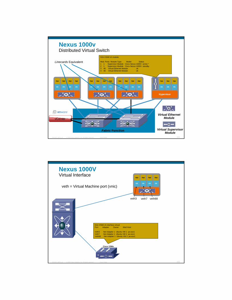
Destination MAC Port
MAC1 1/1
Forwarding Table
Why Is a Virtual Switch Needed in the First Place
Ethernet1/1
MAC2
MAC2 1/1
?
DMAC = MAC2DMAC = MAC2
© 2009 Cisco Systems, Inc. All rights reserved. Cisco PublicTECDCT-3873_c2 98
MAC1
VM1
MAC2
VM2
?

Destination MAC Port
MAC1 1/1
Forwarding Table
Virtual Switching Virtualized Servers Need “VN-link” Technology
MAC1 1/1
MAC2 1/1Ethernet1/1
vSwitch or Nexus 1000v
=
© 2009 Cisco Systems, Inc. All rights reserved. Cisco PublicTECDCT-3873_c2 99
VM1
MAC2
VM2
MAC1 Nexus1kv
ESX Server ComponentsVMware ESX is a “bare-metal” hypervisor that partitions physical servers in multiple virtual machines
vnics
Virtual Machine
Software virtual switch
OS
App
OS
App
OS
App
© 2009 Cisco Systems, Inc. All rights reserved. Cisco PublicTECDCT-3873_c2 100
vmnics
S
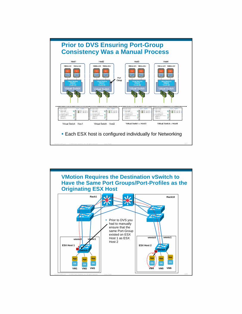
Nexus 1000v Distributed Virtual Switch
Linecards Equivalent
N1k-VSM# sh module
Mod Ports Module-Type Model Status1 1 Supervisor Module Cisco Nexus 1000V active *2 1 Supervisor Module Cisco Nexus 1000V standby3 48 Virtual Ethernet Module ok4 48 Virtual Ethernet Module ok
Hypervisor
OS
App
OS
App
OS
App
OS
App
Hypervisor
OS
App
OS
App
OS
App
OS
App
Hypervisor
OS
App
OS
App
OS
App
OS
App
Hypervisor
OS
App
OS
App
OS
App
OS
App
4 48 Virtual Ethernet Module ok
© 2009 Cisco Systems, Inc. All rights reserved. Cisco PublicTECDCT-3873_c2 101
Fabric Function
vCenterVirtual Ethernet
Module
Virtual SupervisorModule
Hypervisor
OS
App
OS
App
OS
App
OS
App
Nexus 1000VVirtual Interface
veth = Virtual Machine port (vnic)
veth7
N1k-VSM# sh interface virtual Port Adapter Owner Mod Host
veth3 veth68
© 2009 Cisco Systems, Inc. All rights reserved. Cisco PublicTECDCT-3873_c2 102
Veth3 Net Adapter 1 Ubuntu VM 1 pe-esx1Veth7 Net Adapter 1 Ubuntu VM 2 pe-esx1Veth68 Net Adapter 1 Ubuntu VM 3 pe-esx1
Cisco VSMs

Nexus 1000v Ethernet Interface
th3/1Eth = uplink port on the ESX ServerApp App App App
eth3/1
eth3/2
Eth uplink port on the ESX Server
WS-C6504E-VSS#sh cdp neighborsDevice ID Local Intrfce Platform Port ID
N1k-VSM Gig 1/1/1 Nexus1000 Eth 3/1N1k-VSM Gig 2/1/2 Nexus1000 Eth 3/2N1k-VSM Gig 1/8/1 Nexus1000 Eth 4/1N1k-VSM Gig 2/8/2 Nexus1000 Eth 4/2
Hypervisor
OS OS OS OS
© 2009 Cisco Systems, Inc. All rights reserved. Cisco PublicTECDCT-3873_c2 103
eth4/1
eth4/2Hypervisor
OS
App
OS
App
OS
App
OS
App
What Is a Port Profile?
n1000v# show port-profile name WebProfileport-profile WebProfileport profile WebProfiledescription:status: enabledcapability uplink: nosystem vlans:port-group: WebProfileconfig attributes:switchport mode accessswitchport access vlan 110no shutdown
evaluated config attributes:it h t d
Support Commands Include:
Port managementVLANPVLANPort-channelACLNetflow
Support Commands Include:
Port managementVLANPVLANPort-channelACLNetflow
© 2009 Cisco Systems, Inc. All rights reserved. Cisco PublicTECDCT-3873_c2 104
switchport mode accessswitchport access vlan 110no shutdown
assigned interfaces:Veth10
NetflowPort SecurityQoS
NetflowPort SecurityQoS

Port-Profile as Viewed from the Network Administrator and Server Administrator
Network Administrator view
N1k-VSM# sh port-profile name Ubuntu-VM
Server admin view
port-profile Ubuntu-VM
description:
status: enabled
capability uplink: no
capability l3control: no
system vlans: none
port-group: Ubuntu-VM
max-ports: 32
inherit:
© 2009 Cisco Systems, Inc. All rights reserved. Cisco PublicTECDCT-3873_c2 105
inherit:
config attributes:
switchport mode access
switchport access vlan 95
no shutdown
assigned interfaces:
Vethernet2
Vethernet4
What Makes the Virtual Switch “Distributed”?
ESX servers that are under the same Nexus 1kv VSM share the same Port-Profile ConfigurationProfile Configuration
When a new Port-Profile is defined it gets automatically propagated to all the ESX servers (VEMs) that are the VSM
In this example ESX1 and ESX2 are under VSM1 and share the green and red Port-Profile
3 41 2
VSM1 VSM2
Cisco VSMs Cisco VSMs
© 2009 Cisco Systems, Inc. All rights reserved. Cisco PublicTECDCT-3873_c2 106
ESX3 and ESX4 are under VSM2 and share the Blue and Yellow Port Profile
Port ProfilesPort Profiles Port ProfilesPort Profiles
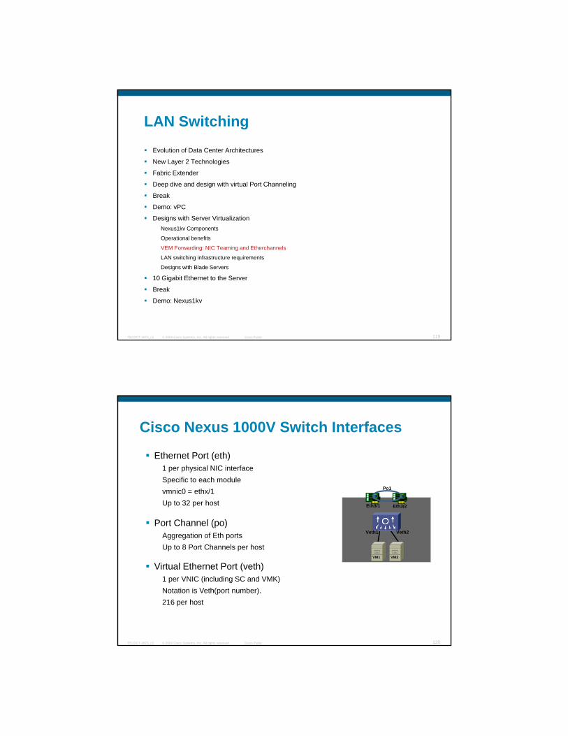
Prior to DVS Ensuring Port-Group Consistency Was a Manual Process
© 2009 Cisco Systems, Inc. All rights reserved. Cisco PublicTECDCT-3873_c2 107
Each ESX host is configured individually for Networking
VMotion Requires the Destination vSwitch to Have the Same Port Groups/Port-Profiles as the Originating ESX Host
Rack10Rack1
Prior to DVS you had to manually ensure that the same Port-Group existed on ESX Host 1 as ESX vmnic0 vmnic1
vmnic0 vmnic1
© 2009 Cisco Systems, Inc. All rights reserved. Cisco PublicTECDCT-3873_c2 108
Host 2
VM4 VM5
ESX Host 2
VM6VM1 VM2
ESX Host 1
VM3
vSwitchvSwitch
c0
OS
App
OS
App
OS
App
OS
App
OS
App
OS
App

“Distributed” Virtual Switching Facilitates VMotion Migration
Port Profiles
Server 2
VMW ESX
Server 1
VEM
VM #4
VM #3
VM #2
VM #1
VM #4
VM #3
VM #2
VM #1
VEM
© 2009 Cisco Systems, Inc. All rights reserved. Cisco PublicTECDCT-3873_c2 109
VMW ESXVMW ESX
VMs Need to MoveVMotionDRSSW Upgrade/PatchHardware Failure
LAN Switching
Evolution of Data Center Architectures
New Layer 2 Technologies
Fabric ExtenderFabric Extender
Deep dive and design with virtual Port Channeling
Break
Demo: vPC
Designs with Server VirtualizationNexus1kv Components
Operational benefits
VEM Forwarding: NIC Teaming and Etherchannels
LAN switching infrastructure requirements
© 2009 Cisco Systems, Inc. All rights reserved. Cisco PublicTECDCT-3873_c2 110
LAN switching infrastructure requirements
Designs with Blade Servers
10 Gigabit Ethernet to the Server
Break
Demo: Nexus1kv

Configuring Access-Lists, Port Security, SPAN, etc…Without Nexus1kv Is Complicated
Is VM#1 on Server 1? Or on which server, on which switch do I put the ACL?do I put the ACL?
ACL need to be specify the IP address of the VM else you risk to drop both VM1 and VM3 traffic
SPAN will get all traffic from VM1, VM2, VM3, VM4!! You need to filter that!!
VMW ESX
Server 1
VM #4
VM #3
VM #2
VM #1
vSwitch
© 2009 Cisco Systems, Inc. All rights reserved. Cisco PublicTECDCT-3873_c2 111
need to filter that!!
Port Security CAN’T be usedACLs (complicated)
SPAN (realistically can’t be used)
Port Security needs to be disabled
You Can Use Access-Lists, Port Security, SPAN, etc…WITH Nexus1kv
Is VM#1 on Server 1? It doesn’t matter ACL “follows” the VMServer 1
ACLs specific to a Port-Group
the VM
SPAN will get only the traffic from the virtual Ethernet Port
Port Security ensures that VMs won’t generate fake make addresses
VMW ESX VEM
VM #4
VM #3
VM #2
VM #1
Port Security
© 2009 Cisco Systems, Inc. All rights reserved. Cisco PublicTECDCT-3873_c2 112
SPAN on a virtual ethernet port

vNIC Security
VMs can be secured in multiple ways:
VM #4
VM #3
Server
VM #2
VM #1
i
Nexus 1000 DVSNexus 1000 DVS
VLANs
ACLs
Private VLANs
Port-Security
vnics
vmnic
IEEE 802.1q trunk
© 2009 Cisco Systems, Inc. All rights reserved. Cisco PublicTECDCT-3873_c2 113
PromiscuousPort
PromiscuousPortOnly One Subnet
Private VLANs Can Be Extended Across ESX Servers by Using the Nexus1kv
Promiscuous ports receive and transmit Only One Subnet
xx
and transmit to all hosts
Communities allow communications between groups
Isolated ports talk to promisc o s
xx
xx
© 2009 Cisco Systems, Inc. All rights reserved. Cisco PublicTECDCT-3873_c2 114
Community‘A’
Community‘B’
IsolatedPorts
Primary VLAN
Community VLAN
Community VLAN
Isolated VLAN
to promiscuous ports only
xx
.11 .12 .13 .14 .15 .16 .17 .18OS
App
OS
App
OS
App
OS
App
OS
App
OS
App
OS
App
OS
App

Tracing Virtual Ethernet Ports
show interface VEthernetVethernet2 is upHardware is Virtual, address is 0050.5675.26c5Hardware is Virtual, address is 0050.5675.26c5Owner is VMware VM1, adapter is vethernet1Active on module 8, host tc-esx05.cisco.comVMware DVS port 16777215Port-Profile is MyApplicationPort mode is accessRx444385 Input Packets 444384 Unicast Packets0 Multicast Packets 1 Broadcast Packets
© 2009 Cisco Systems, Inc. All rights reserved. Cisco PublicTECDCT-3873_c2 115
0 Multicast Packets 1 Broadcast Packets572675241 BytesTx687655 Output Packets 687654 Unicast Packets0 Multicast Packets 1 Broadcast Packets 1 Flood Packets592295257 Bytes0 Input Packet Drops 0 Output Packet Drops
SPAN Traffic to a Catalyst 6500 or a Nexus 7k Where You Have a Sniffer Attached
OS
App
OS
App
OS
App
OS
App
OS
App
OS
App
OS
App
OS
App
OS
App
OS
App
OS
App
OS
App
Capture here
Hypervisor
OS OS OS OS
Virtual Ethernet Module
Virtual Ethernet Module
Virtual Ethernet Module
Hypervisor
OS OS OS OS
Virtual Ethernet Module
Virtual Ethernet Module
Virtual Ethernet Module
Hypervisor
OS OS OS OS
Virtual Ethernet Module
Virtual Ethernet Module
Virtual Ethernet Module
© 2009 Cisco Systems, Inc. All rights reserved. Cisco PublicTECDCT-3873_c2 116

Ease of ProvisioningPlug-and-play designs with VBS
Virtual EthernetVirtual EthernetVirtual Ethernet
1 Add or replace a VBS Switch to the Cluster
2 Switch config and code automatically Virtual Ethernet ModuleVirtual Ethernet ModuleVirtual Ethernet Module
Virtual Ethernet ModuleVirtual Ethernet ModuleVirtual Ethernet Module
2 Switch config and code automatically propagated
3 Add a blade Server
© 2009 Cisco Systems, Inc. All rights reserved. Cisco PublicTECDCT-3873_c2 117
Virtual Ethernet ModuleVirtual Ethernet ModuleVirtual Ethernet Module
4 It’s always booted from the same LUN
Ease of ProvisioningMaking Blade Servers Deployment Faster
1 Physically Add a new blade (or replace an old one)
Virtual EthernetVirtual EthernetVirtual Ethernet2 Go to vCenter, add host to cluster
Virtual Ethernet ModuleVirtual Ethernet ModuleVirtual Ethernet Module
Nexus 1000vNexus 1000v
© 2009 Cisco Systems, Inc. All rights reserved. Cisco PublicTECDCT-3873_c2 118
Virtual Ethernet ModuleVirtual Ethernet ModuleVirtual Ethernet Module
Virtual Ethernet ModuleVirtual Ethernet ModuleVirtual Ethernet Module
3 Done:
the new blade is in production
All port-groups appear
LAN Switching
Evolution of Data Center Architectures
New Layer 2 Technologies
Fabric ExtenderFabric Extender
Deep dive and design with virtual Port Channeling
Break
Demo: vPC
Designs with Server VirtualizationNexus1kv Components
Operational benefits
VEM Forwarding: NIC Teaming and Etherchannels
LAN switching infrastructure requirements
© 2009 Cisco Systems, Inc. All rights reserved. Cisco PublicTECDCT-3873_c2 119
LAN switching infrastructure requirements
Designs with Blade Servers
10 Gigabit Ethernet to the Server
Break
Demo: Nexus1kv
Cisco Nexus 1000V Switch Interfaces
Ethernet Port (eth)1 per physical NIC interfaceSpecific to each moduleSpecific to each modulevmnic0 = ethx/1Up to 32 per host
Port Channel (po)Aggregation of Eth portsUp to 8 Port Channels per host
VM1 VM2
Eth3/1 Eth3/2
Po1
Veth2Veth1
© 2009 Cisco Systems, Inc. All rights reserved. Cisco PublicTECDCT-3873_c2 120
Virtual Ethernet Port (veth)1 per VNIC (including SC and VMK)Notation is Veth(port number). 216 per host
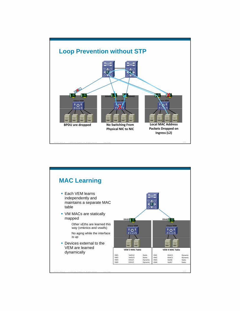
Loop Prevention without STP
Cisco VEM Cisco VEM Cisco VEM
Eth4/1 Eth4/2
X
X
© 2009 Cisco Systems, Inc. All rights reserved. Cisco PublicTECDCT-3873_c2 121
VM1 VM2 VM3 VM4 VM5 VM6 VM7 VM7 VM9 VM10 VM11 VM12
BPDU are dropped
X
No Switching From Physical NIC to NIC
Local MAC Address Packets Dropped on
Ingress (L2)
MAC Learning
Each VEM learns independently and maintains a separate MACmaintains a separate MAC table
VM MACs are statically mapped
Other vEths are learned this way (vmknics and vswifs)
No aging while the interface is up
Cisco VEM
Eth4/1
Cisco VEM
Eth3/1
© 2009 Cisco Systems, Inc. All rights reserved. Cisco PublicTECDCT-3873_c2 122
is up
Devices external to the VEM are learned dynamically
VM3 VM4VM1 VM2
VEM 3 MAC Table
VM1 Veth12 StaticVM2 Veth23 StaticVM3 Eth3/1 DynamicVM4 Eth3/1 Dynamic
VEM 4 MAC Table
VM1 Eth4/1 DynamicVM2 Eth4/1 DynamicVM3 Veth8 StaticVM4 Veth7 Static
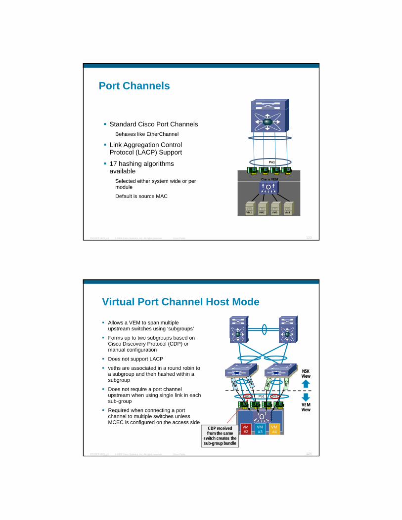
Port Channels
St d d Ci P t Ch lStandard Cisco Port ChannelsBehaves like EtherChannel
Link Aggregation Control Protocol (LACP) Support
17 hashing algorithms available
Selected either system wide or per Cisco VEM
Po1
© 2009 Cisco Systems, Inc. All rights reserved. Cisco PublicTECDCT-3873_c2 123
Selected either system wide or per module
Default is source MAC
VM1 VM2 VM3 VM4
Virtual Port Channel Host Mode
Allows a VEM to span multiple upstream switches using ‘subgroups’
Forms up to two subgroups based onForms up to two subgroups based on Cisco Discovery Protocol (CDP) or manual configuration
Does not support LACP
veths are associated in a round robin to a subgroup and then hashed within a subgroup
Does not require a port channel upstream when using single link in each SG1Po1SG0
N5KView
© 2009 Cisco Systems, Inc. All rights reserved. Cisco PublicTECDCT-3873_c2 124
p g gsub-group
Required when connecting a port channel to multiple switches unless MCEC is configured on the access side
VM #4
VM #3
VM #2
SG0
VEMView
CDP received from the same
switch creates the sub-group bundle
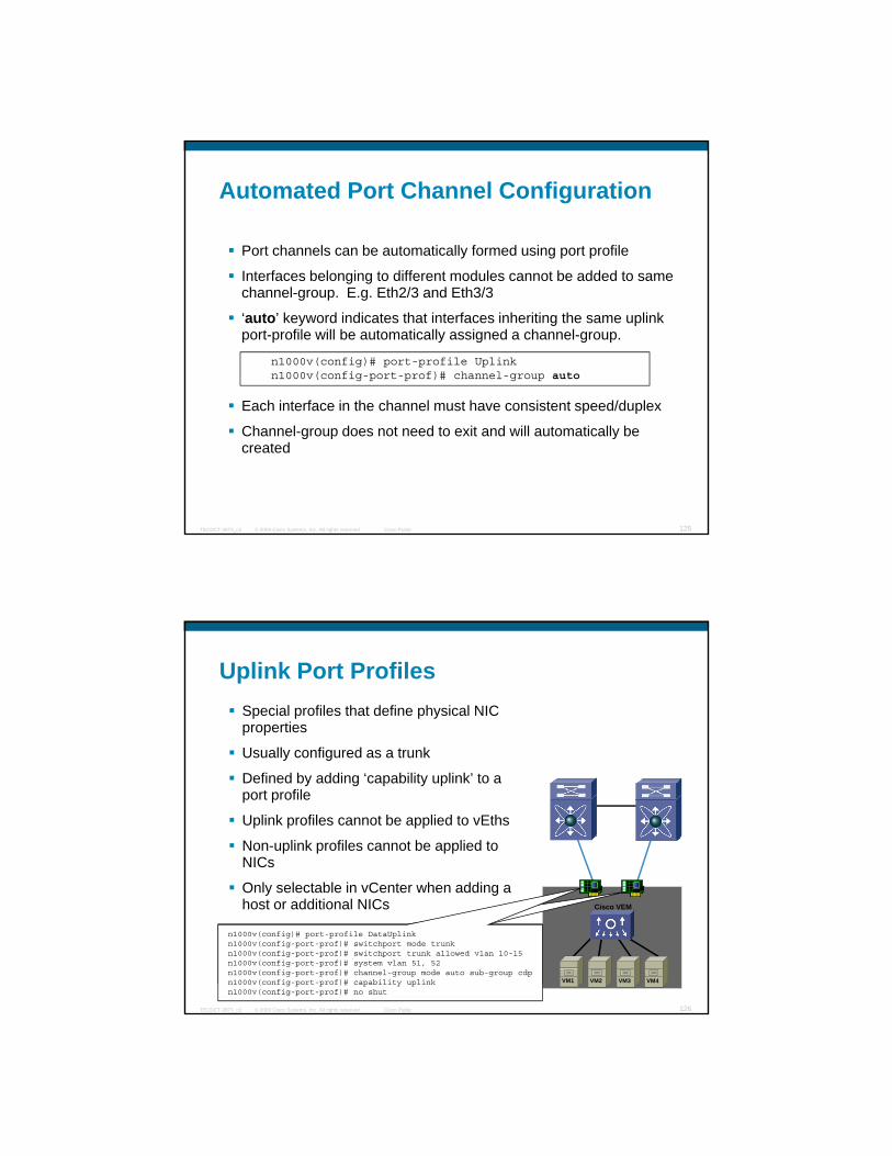
Automated Port Channel Configuration
Port channels can be automatically formed using port profile
I t f b l i t diff t d l t b dd d tInterfaces belonging to different modules cannot be added to same channel-group. E.g. Eth2/3 and Eth3/3
‘auto’ keyword indicates that interfaces inheriting the same uplink port-profile will be automatically assigned a channel-group.
Each interface in the channel must have consistent speed/duplex
n1000v(config)# port-profile Uplinkn1000v(config-port-prof)# channel-group auto
© 2009 Cisco Systems, Inc. All rights reserved. Cisco PublicTECDCT-3873_c2 125
Each interface in the channel must have consistent speed/duplex
Channel-group does not need to exit and will automatically be created
Uplink Port ProfilesSpecial profiles that define physical NIC properties
Usually configured as a trunkUsually configured as a trunk
Defined by adding ‘capability uplink’ to a port profile
Uplink profiles cannot be applied to vEths
Non-uplink profiles cannot be applied to NICs
O l l t bl i C t h ddi
© 2009 Cisco Systems, Inc. All rights reserved. Cisco PublicTECDCT-3873_c2 126
Cisco VEM
VM1 VM2 VM3 VM4
Only selectable in vCenter when adding a host or additional NICs
n1000v(config)# port-profile DataUplinkn1000v(config-port-prof)# switchport mode trunkn1000v(config-port-prof)# switchport trunk allowed vlan 10-15n1000v(config-port-prof)# system vlan 51, 52n1000v(config-port-prof)# channel-group mode auto sub-group cdpn1000v(config-port-prof)# capability uplinkn1000v(config-port-prof)# no shut
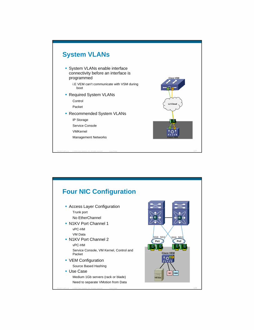
System VLANs
System VLANs enable interface connectivity before an interface is programmed Cisco VSMprogrammed
i.E VEM can’t communicate with VSM during boot
Required System VLANsControl
Packet
Recommended System VLANs
Cisco VSM
C P
L2 Cloud
© 2009 Cisco Systems, Inc. All rights reserved. Cisco PublicTECDCT-3873_c2 127
Cisco VEM
yIP Storage
Service Console
VMKernel
Management Networks
C P
Four NIC Configuration
Access Layer ConfigurationTrunk port
Ci VEM
Po2SG0 SG1
No EtherChannelN1KV Port Channel 1
vPC-HMVM Data
Po1SG0 SG1
N1KV Port Channel 2vPC-HMService Console, VM Kernel, Control and
© 2009 Cisco Systems, Inc. All rights reserved. Cisco PublicTECDCT-3873_c2 128
Cisco VEM
VM Data
C P
VMKSC
VEM ConfigurationSource Based Hashing
Use CaseMedium 1Gb servers (rack or blade)Need to separate VMotion from Data
Packet
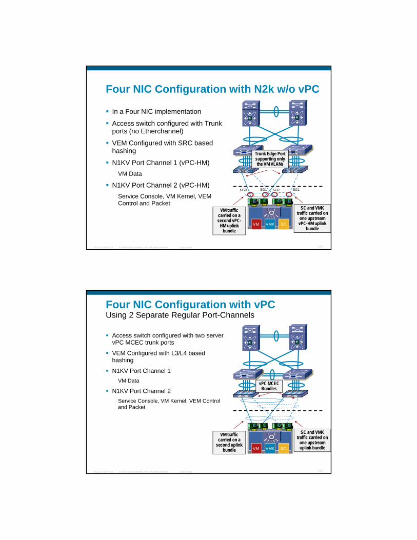
Four NIC Configuration with N2k w/o vPC
In a Four NIC implementation
Access switch configured with Trunk gports (no Etherchannel)
VEM Configured with SRC based hashing
N1KV Port Channel 1 (vPC-HM)VM Data
N1KV Port Channel 2 (vPC-HM)SG1
Trunk Edge Port supporting only the VM VLANs
SG1
© 2009 Cisco Systems, Inc. All rights reserved. Cisco PublicTECDCT-3873_c2 129
( )Service Console, VM Kernel, VEM Control and Packet
SCVMKVM
SG1SG0
SC and VMK traffic carried on
one upstream vPC-HM uplink
bundle
VM traffic carried on a second vPC-
HM uplink bundle
SG1SG0
Four NIC Configuration with vPCUsing 2 Separate Regular Port-Channels
Access switch configured with two server vPC MCEC trunk ports
VEM C fi d ith L3/L4 b dVEM Configured with L3/L4 based hashing
N1KV Port Channel 1VM Data
N1KV Port Channel 2Service Console, VM Kernel, VEM Control and Packet
vPC MCEC Bundles
© 2009 Cisco Systems, Inc. All rights reserved. Cisco PublicTECDCT-3873_c2 130
SCVMKVM
SC and VMK traffic carried on
one upstream uplink bundle
VM traffic carried on a
second uplink bundle
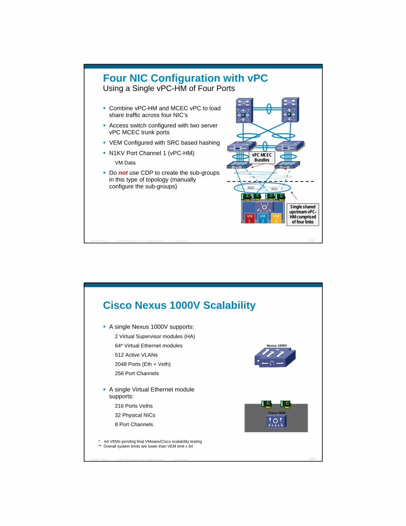
Four NIC Configuration with vPCUsing a Single vPC-HM of Four Ports
Combine vPC-HM and MCEC vPC to load share traffic across four NIC’s
A it h fi d ith tAccess switch configured with two server vPC MCEC trunk ports
VEM Configured with SRC based hashing
N1KV Port Channel 1 (vPC-HM)VM Data
Do not use CDP to create the sub-groups in this type of topology (manually
vPC MCEC Bundles
© 2009 Cisco Systems, Inc. All rights reserved. Cisco PublicTECDCT-3873_c2 131
configure the sub-groups)
VM3
VM 2
VM1
Single shared upstream vPC-HM comprised
of four links
SG1SG0
Cisco Nexus 1000V Scalability
A single Nexus 1000V supports:2 Virtual Supervisor modules (HA)
64* Virtual Ethernet modules
512 Active VLANs
2048 Ports (Eth + Veth)
256 Port Channels
A single Virtual Ethernet module supports:
Nexus 1000V
© 2009 Cisco Systems, Inc. All rights reserved. Cisco PublicTECDCT-3873_c2 132
216 Ports Veths
32 Physical NICs
8 Port Channels
Cisco VEM
* 64 VEMs pending final VMware/Cisco scalability testing** Overall system limits are lower than VEM limit x 64

LAN Switching
Evolution of Data Center Architectures
New Layer 2 Technologies
Fabric ExtenderFabric Extender
Deep dive and design with virtual Port Channeling
Break
Demo: vPC
Designs with Server VirtualizationNexus1kv Components
Operational benefits
VEM Forwarding: NIC Teaming and Etherchannels
LAN switching infrastructure requirements
© 2009 Cisco Systems, Inc. All rights reserved. Cisco PublicTECDCT-3873_c2 133
LAN switching infrastructure requirements
Designs with Blade Servers
10 Gigabit Ethernet to the Server
Break
Demo: Nexus1kv
Virtual Machine Considerations
Hardware MAC learning
Large HW-based MAC
Virtual Servers
Large HW-based MAC address Tables
Control plane policing
Layer 2 trace
Broadcast and Storm Control
© 2009 Cisco Systems, Inc. All rights reserved. Cisco PublicTECDCT-3873_c2 134
Private VLAN integration
Unified I/O ready
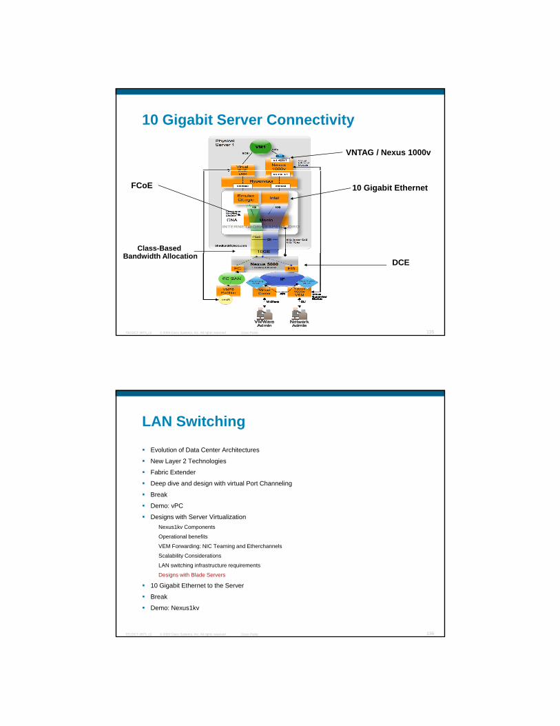
10 Gigabit Server Connectivity
VNTAG / Nexus 1000v
10 Gigabit EthernetFCoE
Class-Based
© 2009 Cisco Systems, Inc. All rights reserved. Cisco PublicTECDCT-3873_c2 135
DCEBandwidth Allocation
LAN Switching
Evolution of Data Center Architectures
New Layer 2 Technologies
Fabric ExtenderFabric Extender
Deep dive and design with virtual Port Channeling
Break
Demo: vPC
Designs with Server VirtualizationNexus1kv Components
Operational benefits
VEM Forwarding: NIC Teaming and Etherchannels
Scalability Considerations
© 2009 Cisco Systems, Inc. All rights reserved. Cisco PublicTECDCT-3873_c2 136
Scalability Considerations
LAN switching infrastructure requirements
Designs with Blade Servers
10 Gigabit Ethernet to the Server
Break
Demo: Nexus1kv

With Nexus1kv the Switch Just a Plug-and-Play “Fabric”
With the Nexus1kv the Profiles are defined on the Nexus1kv
The Mapping is performed on the Virtual Center pp g p
The Switch provides simply the Switching Fabric and trunks all necessary VLANs.
Nexus1kv
M i f “ ” t C t
© 2009 Cisco Systems, Inc. All rights reserved. Cisco PublicTECDCT-3873_c2 137
Mapping of “servers” to VLANs/Port Profiles
vCenter
Profile Definition Nexus1kv CLI
Switching Fabric With Virtualized Servers
You have Virtualized Servers on the Blades
You are better off using clustered Cisco VBS g
Cisco VBS
Network Management Model
Equivalent to a 3750 stackable: plug-and-play
Stacking Capability Up to 8 Blade Switches
© 2009 Cisco Systems, Inc. All rights reserved. Cisco PublicTECDCT-3873_c2 138
Stacking Capability Up to 8 Blade Switches, i.e. single config point
Etherchanneling Across switches in the stack
Server Identity Flexattach
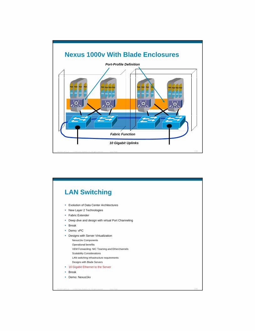
Nexus 1000v With Blade EnclosuresPort-Profile Definition
OS
App
OS
App
OS
App
OS
App
OS
App
OS
App
OS
App
OS
App
OS
App
OS
App
OS
App
OS
App
OS
App
OS
App
OS
App
OS
App
© 2009 Cisco Systems, Inc. All rights reserved. Cisco PublicTECDCT-3873_c2 139
Fabric Function
10 Gigabit Uplinks
LAN Switching
Evolution of Data Center Architectures
New Layer 2 Technologies
Fabric ExtenderFabric Extender
Deep dive and design with virtual Port Channeling
Break
Demo: vPC
Designs with Server VirtualizationNexus1kv Components
Operational benefits
VEM Forwarding: NIC Teaming and Etherchannels
Scalability Considerations
© 2009 Cisco Systems, Inc. All rights reserved. Cisco PublicTECDCT-3873_c2 140
Scalability Considerations
LAN switching infrastructure requirements
Designs with Blade Servers
10 Gigabit Ethernet to the Server
Break
Demo: Nexus1kv
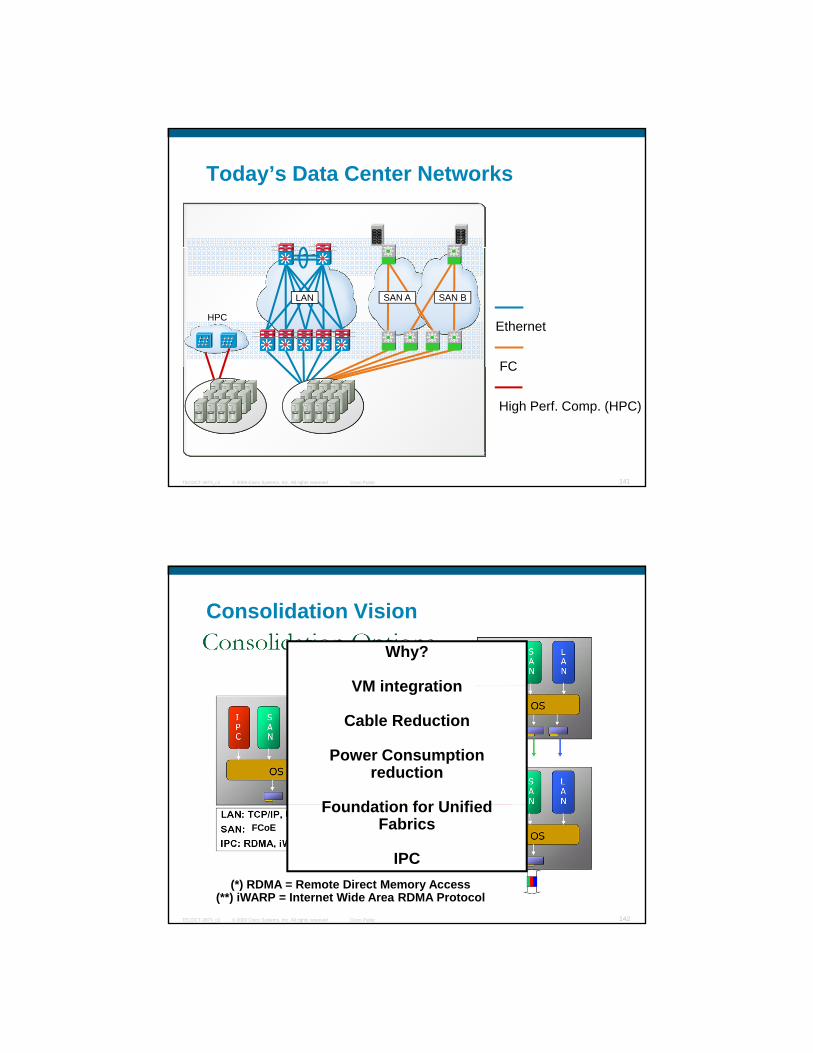
Today’s Data Center Networks
Ethernet
FC
HPC
LAN SAN A SAN B
© 2009 Cisco Systems, Inc. All rights reserved. Cisco PublicTECDCT-3873_c2 141
FC
High Perf. Comp. (HPC)
Consolidation Vision
Why?
VM integrationVM integration
Cable Reduction
Power Consumption reduction
Foundation for Unified
© 2009 Cisco Systems, Inc. All rights reserved. Cisco PublicTECDCT-3873_c2 142
FCoE
Foundation for Unified Fabrics
IPC(*) RDMA = Remote Direct Memory Access
(**) iWARP = Internet Wide Area RDMA Protocol
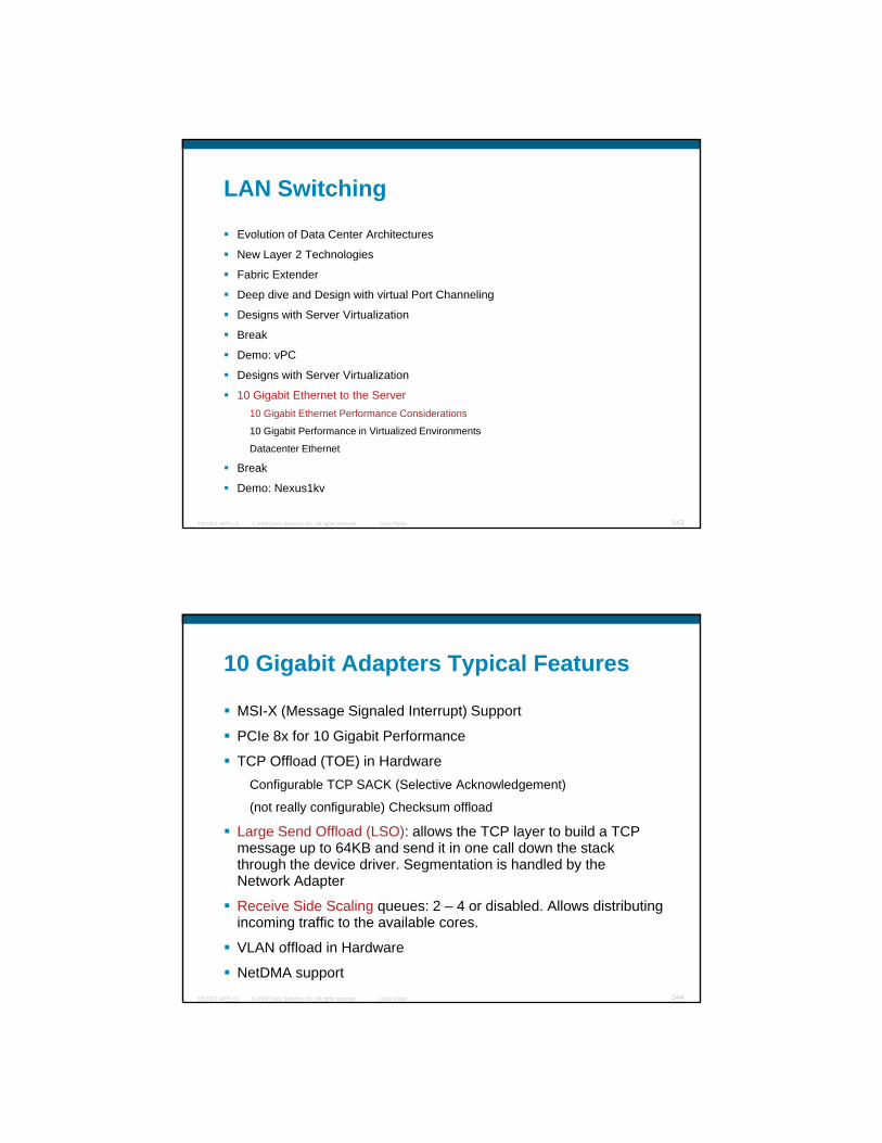
LAN Switching
Evolution of Data Center Architectures
New Layer 2 Technologies
Fabric Extender
Deep dive and Design with virtual Port Channeling
Designs with Server Virtualization
Break
Demo: vPC
Designs with Server Virtualization
10 Gigabit Ethernet to the Server
© 2009 Cisco Systems, Inc. All rights reserved. Cisco PublicTECDCT-3873_c2 143
10 Gigabit Ethernet to the Server10 Gigabit Ethernet Performance Considerations
10 Gigabit Performance in Virtualized Environments
Datacenter Ethernet
Break
Demo: Nexus1kv
10 Gigabit Adapters Typical Features
MSI-X (Message Signaled Interrupt) Support
PCIe 8x for 10 Gigabit Performanceg
TCP Offload (TOE) in HardwareConfigurable TCP SACK (Selective Acknowledgement)
(not really configurable) Checksum offload
Large Send Offload (LSO): allows the TCP layer to build a TCP message up to 64KB and send it in one call down the stack through the device driver. Segmentation is handled by the
© 2009 Cisco Systems, Inc. All rights reserved. Cisco PublicTECDCT-3873_c2 144
Network Adapter
Receive Side Scaling queues: 2 – 4 or disabled. Allows distributing incoming traffic to the available cores.
VLAN offload in Hardware
NetDMA support
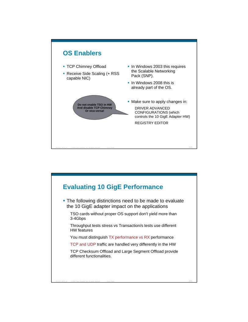
OS Enablers
TCP Chimney Offload
Receive Side Scaling (+ RSS
In Windows 2003 this requires the Scalable Networking Pack (SNP)g (
capable NIC) Pack (SNP).
In Windows 2008 this is already part of the OS.
Make sure to apply changes in:DRIVER ADVANCED CONFIGURATIONS (which
Do not enable TSO in HWAnd disable TCP Chimney
Or vice-versa!
© 2009 Cisco Systems, Inc. All rights reserved. Cisco PublicTECDCT-3873_c2 145
CONFIGURATIONS (which controls the 10 GigE Adapter HW)
REGISTRY EDITOR
Evaluating 10 GigE Performance
The following distinctions need to be made to evaluate the 10 GigE adapter impact on the applications
TSO cards without proper OS support don’t yield more than 3-4Gbps
Throughput tests stress vs Transaction/s tests use different HW features
You must distinguish TX performance vs RX performance
TCP and UDP traffic are handled very differently in the HW
© 2009 Cisco Systems, Inc. All rights reserved. Cisco PublicTECDCT-3873_c2 146
y y
TCP Checksum Offload and Large Segment Offload provide different functionalities.

Preliminary TestsMaximum Throughput Is ~3.2 Gbps
© 2009 Cisco Systems, Inc. All rights reserved. Cisco PublicTECDCT-3873_c2 147
Why?
Only 1 core is dealing with TCP/IP processing
Solution:Make sure that the OS uses
The OS doesn’t “know” that the Adapter is TOE capable so it doesn’t really use it
A lot of memory copiesbetween user space and kernel space
Is the card plugged in the
TCP offloading in Hardware
Enable Large Segment Offload
Enable TCP/IP distribution to all available cores
© 2009 Cisco Systems, Inc. All rights reserved. Cisco PublicTECDCT-3873_c2 148
p ggPCIe x8?
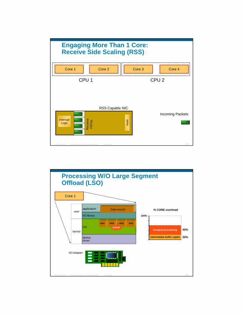
Engaging More Than 1 Core:Receive Side Scaling (RSS)
Core 1 Core 2 Core 3 Core 4
RSS Capable NIC
CPU 1 CPU 2
© 2009 Cisco Systems, Inc. All rights reserved. Cisco PublicTECDCT-3873_c2 149
p
Rec
eive
FI
FOsInterrupt
Logic
Incoming Packets
Has
h
Processing W/O Large Segment Offload (LSO)
Core 1
device driver
MSSMSSMSSMSSOS
Data record
application
I/O libraryuser
kernel
% CORE overhead
100%
transport processing 40%
Intermediate buffer copies 20%
Data record
MSS MSS MSS MSS
TCP/IP
© 2009 Cisco Systems, Inc. All rights reserved. Cisco PublicTECDCT-3873_c2 150
driver
I/O Adapter
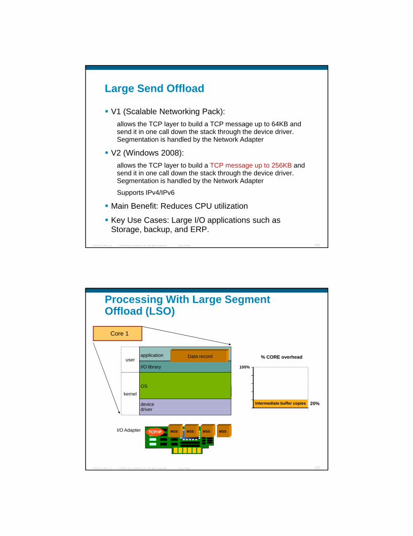
Large Send Offload
V1 (Scalable Networking Pack): allows the TCP layer to build a TCP message up to 64KB andallows the TCP layer to build a TCP message up to 64KB and send it in one call down the stack through the device driver. Segmentation is handled by the Network Adapter
V2 (Windows 2008): allows the TCP layer to build a TCP message up to 256KB and send it in one call down the stack through the device driver. Segmentation is handled by the Network Adapter
© 2009 Cisco Systems, Inc. All rights reserved. Cisco PublicTECDCT-3873_c2 151
Supports IPv4/IPv6
Main Benefit: Reduces CPU utilization
Key Use Cases: Large I/O applications such as Storage, backup, and ERP.
Processing With Large Segment Offload (LSO)
Core 1
device driver
MSSMSSMSSMSSOS
application
I/O libraryuser
kernel
% CORE overhead
100%
Intermediate buffer copies 20%
Data record
© 2009 Cisco Systems, Inc. All rights reserved. Cisco PublicTECDCT-3873_c2 152
driver
I/O Adapter TCP/IP MSS MSS MSS MSS

Registry Configuration (for Windows 2003)In Windows 2008 Just Use “netsh” cmd
Set to 1
© 2009 Cisco Systems, Inc. All rights reserved. Cisco PublicTECDCT-3873_c2 153
W/o LSO Checksum Offload Alone Doesn’t Do Much
© 2009 Cisco Systems, Inc. All rights reserved. Cisco PublicTECDCT-3873_c2 154
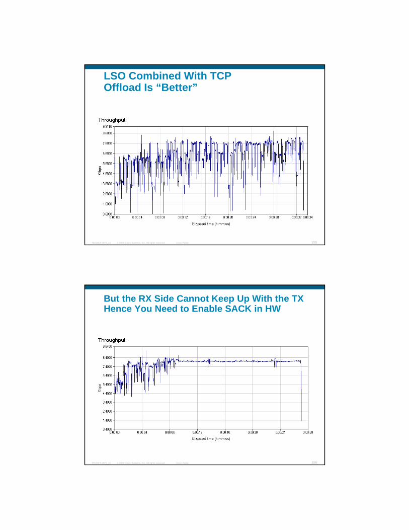
LSO Combined With TCP Offload Is “Better”
© 2009 Cisco Systems, Inc. All rights reserved. Cisco PublicTECDCT-3873_c2 155
But the RX Side Cannot Keep Up With the TX Hence You Need to Enable SACK in HW
© 2009 Cisco Systems, Inc. All rights reserved. Cisco PublicTECDCT-3873_c2 156
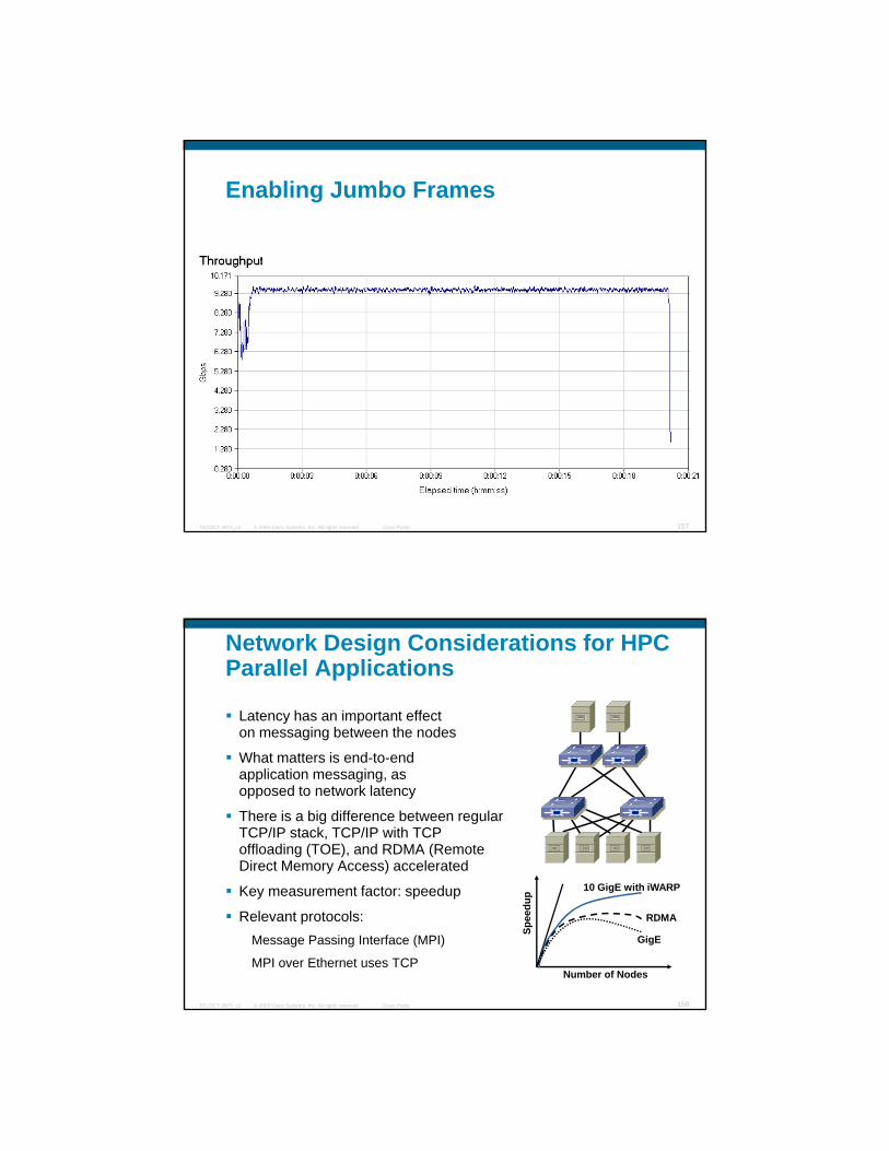
Enabling Jumbo Frames
© 2009 Cisco Systems, Inc. All rights reserved. Cisco PublicTECDCT-3873_c2 157
Network Design Considerations for HPC Parallel Applications
Latency has an important effecton messaging between the nodes
What matters is end-to-endapplication messaging, asopposed to network latency
There is a big difference between regular TCP/IP stack, TCP/IP with TCP offloading (TOE), and RDMA (Remote Direct Memory Access) accelerated
© 2009 Cisco Systems, Inc. All rights reserved. Cisco PublicTECDCT-3873_c2 158
Key measurement factor: speedup
Relevant protocols:Message Passing Interface (MPI)
MPI over Ethernet uses TCP
Spee
dup
Number of Nodes
10 GigE with iWARP
RDMA
GigE

Sources of Overhead in Datacenter Servers
CPU System40%Transport Processing
Sources of Overhead in Server Networking
CPU Overhead
Solutions for Overhead in Server Networking
Transport Offload Engine (TOE)Moves Transport processor cycles to the NICMoves TCP/IP protocol stack buffer copies
CPU SystemMemory
TCP Buffer Pool
App Buffer
TCP/IPKernel
User
Application Context Switches
Intermediate Buffer Copying
40%
20%
© 2009 Cisco Systems, Inc. All rights reserved. Cisco PublicTECDCT-3873_c2 159
o es C / p otoco stac bu e cop esfrom system memory to the NIC memory
RDMA Eliminates intermediate and application buffer copies (memory bandwidth consumption)
Kernel Bypass – direct user-level access tohardware Dramatically reduces application context switches
NICh/w
s/w
iWARP
The Internet Wide Area RDMA Protocol (iWARP) is an Internet Engineering Task Force (IETF) update of the RDMA Consortium's RDMA over TCP standard.
iWARP is a superset of the Virtual Interface Architecture that permits zero-copy transmission over legacy TCP. It may be thought of as the features of InfiniBand (IB) applied to Ethernet.
http://www openfabrics org/ runs on top of iWARP
© 2009 Cisco Systems, Inc. All rights reserved. Cisco PublicTECDCT-3873_c2 160
http://www.openfabrics.org/ runs on top of iWARP
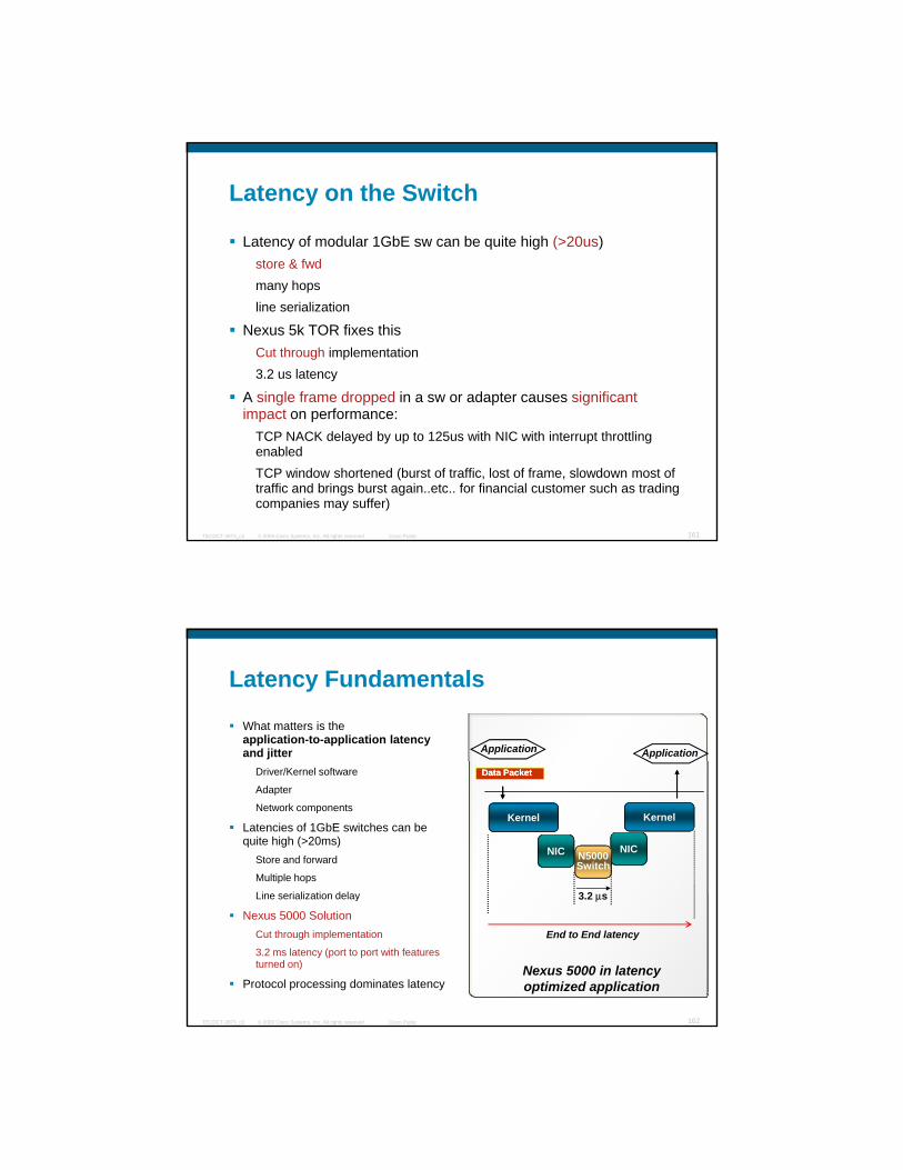
Latency on the Switch
Latency of modular 1GbE sw can be quite high (>20us)store & fwdmany hopsline serialization
Nexus 5k TOR fixes thisCut through implementation3.2 us latency
A single frame dropped in a sw or adapter causes significant
© 2009 Cisco Systems, Inc. All rights reserved. Cisco PublicTECDCT-3873_c2 161
impact on performance:TCP NACK delayed by up to 125us with NIC with interrupt throttling enabledTCP window shortened (burst of traffic, lost of frame, slowdown most of traffic and brings burst again..etc.. for financial customer such as trading companies may suffer)
Latency Fundamentals
What matters is the application-to-application latency and jitter Application Application
Driver/Kernel software
Adapter
Network components
Latencies of 1GbE switches can be quite high (>20ms)
Store and forward
Multiple hops
Line serialization delay 3 2 s
Kernel
NIC NICN5000Switch
Kernel
Data PacketData Packet
© 2009 Cisco Systems, Inc. All rights reserved. Cisco PublicTECDCT-3873_c2 162
Line serialization delay
Nexus 5000 SolutionCut through implementation
3.2 ms latency (port to port with features turned on)
Protocol processing dominates latency
3.2 μs
End to End latency
Nexus 5000 in latency optimized application

Latency
© 2009 Cisco Systems, Inc. All rights reserved. Cisco PublicTECDCT-3873_c2 163
What Helps WhereChecksum
Offload RSS LSO iWARP
TX
(4)
TX + +++
RX + +++
CPU % ++ + +
TCP workload
Transactions/s+ + +
© 2009 Cisco Systems, Inc. All rights reserved. Cisco PublicTECDCT-3873_c2 164
(1,2)TCP workload
Throughput+ ++ +++
UDP throughput ++
Latency + +++
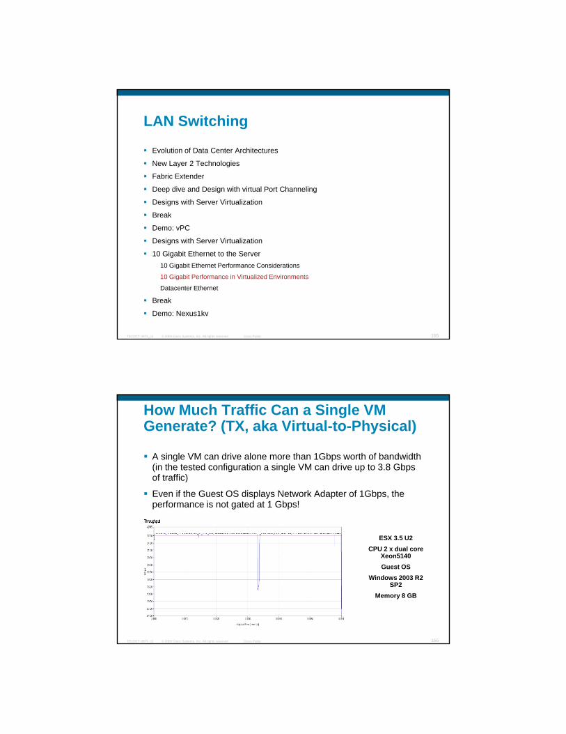
LAN Switching
Evolution of Data Center Architectures
New Layer 2 Technologies
Fabric Extender
Deep dive and Design with virtual Port Channeling
Designs with Server Virtualization
Break
Demo: vPC
Designs with Server Virtualization
10 Gigabit Ethernet to the Server
© 2009 Cisco Systems, Inc. All rights reserved. Cisco PublicTECDCT-3873_c2 165
10 Gigabit Ethernet to the Server10 Gigabit Ethernet Performance Considerations
10 Gigabit Performance in Virtualized Environments
Datacenter Ethernet
Break
Demo: Nexus1kv
How Much Traffic Can a Single VM Generate? (TX, aka Virtual-to-Physical)
A single VM can drive alone more than 1Gbps worth of bandwidth (in the tested configuration a single VM can drive up to 3.8 Gbps of traffic)of traffic)
Even if the Guest OS displays Network Adapter of 1Gbps, the performance is not gated at 1 Gbps!
ESX 3.5 U2CPU 2 x dual core
Xeon5140
© 2009 Cisco Systems, Inc. All rights reserved. Cisco PublicTECDCT-3873_c2 166
Guest OSWindows 2003 R2
SP2Memory 8 GB

Traffic Flow VM-to-Physical (V2P) With Quad-GigE Cards
C t l t 6500
ESX 1
vmnic0
vmnic1
vmnic2
vmnic3
vNIC
vNIC
vNIC
vNIC
client 1
client 2
1 GigE
1 GigE
1 GigE
1 GigE
10 GigE
10 GigE
Catalyst 6500
Gig
E 2/
13 -
16GigE 2/17 - 20
Te4/3
Te4/4
© 2009 Cisco Systems, Inc. All rights reserved. Cisco PublicTECDCT-3873_c2 167
ESX 2
vmnic0 vmnic1 vmnic2 vmnic3
vNIC vNIC vNIC vNIC
1 GigE 1 GigE1 GigE 1 GigE
Traffic Flow VM-to-Physical (V2P) With 10 GigE Cards
C t l t 6500
ESX 1
vmnic0
vmnic1
vmnic2
vmnic3
vNIC
vNIC
vNIC
vNIC
client 1
client 2
10 GigE 10 GigE
10 GigE
Catalyst 6500
GigE 2/17 - 20
Te4/3
Te4/4
© 2009 Cisco Systems, Inc. All rights reserved. Cisco PublicTECDCT-3873_c2 168
ESX 2
vmnic0 vmnic1 vmnic2 vmnic3
vNIC vNIC vNIC vNIC
1 GigE 1 GigE1 GigE 1 GigE

How Much Traffic Can 4 VMs Generate?(TX aka V2P)
A typical configuration made of 4 VMs could drive up to ~8-9 Gbps worth of traffic, which means that an ESX server equipped with a Quad-GigE adapter throttles the VMs performance of a typical ESX implementation
ESX 3.5 U2CPU 2 x dual core
Xeon5140
© 2009 Cisco Systems, Inc. All rights reserved. Cisco PublicTECDCT-3873_c2 169
Guest OSWindows 2003 R2
SP2Memory 8 GB
P2V (RX) vs V2P (RX) Throughput With 10 GigE NICs to 4 VMs
RX: ~4.3 Gbps
ESX 3.5 U2CPU 2 x dual core
Xeon5140Guest OS
Windows 2003 R2 SP2
TX: ~ 8Gbps
© 2009 Cisco Systems, Inc. All rights reserved. Cisco PublicTECDCT-3873_c2 170
SP2Memory 8 GB
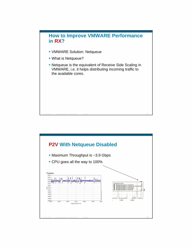
How to Improve VMWARE Performance in RX?
VMWARE Solution: Netqueue
What is Netqueue?What is Netqueue?
Netqueue is the equivalent of Receive Side Scaling in VMWARE, i.e. it helps distributing incoming traffic to the available cores.
© 2009 Cisco Systems, Inc. All rights reserved. Cisco PublicTECDCT-3873_c2 171
P2V With Netqueue Disabled
Maximum Throughput is ~3.9 Gbps
CPU goes all the way to 100%CPU goes all the way to 100%
© 2009 Cisco Systems, Inc. All rights reserved. Cisco PublicTECDCT-3873_c2 172
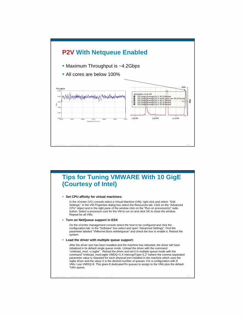
P2V With Netqueue Enabled
Maximum Throughput is ~4.2Gbps
All cores are below 100%All cores are below 100%
© 2009 Cisco Systems, Inc. All rights reserved. Cisco PublicTECDCT-3873_c2 173
Tips for Tuning VMWARE With 10 GigE(Courtesy of Intel)
Set CPU affinity for virtual machines:In the vCenter (VC) console select a Virtual Machine (VM), right click and select “Edit Settings”. In the VM Properties dialog box select the Resources tab. Click on the “Advanced g p gCPU” object and in the right pane of the window click on the “Run on processor(s)” radio button. Select a processor core for the VM to run on and click OK to close the window. Repeat for all VMs.
Turn on NetQueue support in ESXOn the vCenter management console select the host to be configured and click the configuration tab. In the “Software” box select and open “Advanced Settings”. Find the parameter labeled “VMkernel.Boot.netNetqueue” and check the box to enable it. Reboot the system.
Load the driver with multiple queue support:
© 2009 Cisco Systems, Inc. All rights reserved. Cisco PublicTECDCT-3873_c2 174
After the driver rpm has been installed and the machine has rebooted, the driver will have initialized in its default single queue mode. Unload the driver with the command “vmkload_mod –u ixgbe”. Reload the driver and set it in multiple queue mode with the command “vmkload_mod ixgbe VMDQ=X,X InterruptType=2,2” (where the comma separated parameter value is repeated for each physical port installed in the machine which uses the ixgbe driver and the value X is the desired number of queues. For a configuration with 8 VMs I use VMDQ=9. This gives 8 dedicated Rx queues to assign to the VMs plus the default TxRx queue.

LAN Switching
Evolution of Data Center Architectures
New Layer 2 Technologies
Fabric Extender
Deep dive and Design with virtual Port Channeling
Designs with Server Virtualization
Break
Demo: vPC
Designs with Server Virtualization
10 Gigabit Ethernet to the Server
© 2009 Cisco Systems, Inc. All rights reserved. Cisco PublicTECDCT-3873_c2 175
10 Gigabit Ethernet to the Server10 Gigabit Ethernet Performance Considerations
10 Gigabit Performance in Virtualized Environments
Datacenter Ethernet
Break
Demo: Nexus1kv
I/O Consolidation
I/O consolidation supports all three types of traffic onto a single network
Servers have a common interface adapter that supports all three types of traffic
© 2009 Cisco Systems, Inc. All rights reserved. Cisco PublicTECDCT-3873_c2 176
IPC: Inter Process Communication

Provides class of service flow control Ability to supportPriority-based Flow
BenefitFeature
Data Center Ethernet Summary
Auto-negotiation for Enhanced Ethernet capabilitiesData Center Bridging
End to End Congestion Management for L2 networkCongestion Notification (BCN/QCN)
Grouping classes of traffic into “Service Lanes”IEEE 802.1Qaz, CoS based Enhanced Transmission
CoS Based BW Management
Provides class of service flow control. Ability to support storage traffic
Priority-based Flow Control (PFC)
© 2009 Cisco Systems, Inc. All rights reserved. Cisco PublicTECDCT-3873_c2 177
Eliminate Spanning Tree for L2 topologies
Utilize full Bi-Sectional bandwidth with ECMPL2 Multi-path for Unicast & Multicast
Auto negotiation for Enhanced Ethernet capabilities DCBX (Switch to NIC)
g gExchange
SAN Switching
© 2009 Cisco Systems, Inc. All rights reserved. Cisco PublicPresentation_ID 178
Complete Your Online Session Evaluation
Give us your feedback and you could win fabulous prizes. Winners announced daily.Winners announced daily.
Receive 20 Passport points for each session evaluation you complete.
Complete your session evaluation online now (open a browser through our wireless network to access our portal) or visit one of the Internet stations throughout
© 2009 Cisco Systems, Inc. All rights reserved. Cisco PublicTECDCT-3873_c2 179
the Internet stations throughout the Convention Center. Don’t forget to activate your
Cisco Live Virtual account for access to all session material, communities, andon-demand and live activities throughout the year. Activate your account at the Cisco booth in the World of Solutions or visit www.ciscolive.com.
Recommended Readings
www.datacenteruniversity.com
© 2009 Cisco Systems, Inc. All rights reserved. Cisco PublicTECDCT-3873_c2 180

Recommended Readings
© 2009 Cisco Systems, Inc. All rights reserved. Cisco PublicTECDCT-3873_c2 181
© 2009 Cisco Systems, Inc. All rights reserved. Cisco PublicTECDCT-3873_c2 182

Data Center Power Session
TECDCT-3873
© 2009 Cisco Systems, Inc. All rights reserved. Cisco PublicPresentation_ID 1
AgendaInfrastructure Design (Mauricio Arregoces)
LAN Switching Analysis (Maurizio Portolani)Recap on Current Trends and Past Best Practices
New Layer 2 Technologies
Fabric Extender
Deep dive and Design with virtual Port Channeling
Break
Demos: vPC, OTV (Maurizio Portolani) Designs with Server Virtualization
10 Gigabit Ethernet to the Server
Break
Demo: Nexus1kv (Maurizio Portolani)
Blade Servers (Carlos Pereira)
© 2009 Cisco Systems, Inc. All rights reserved. Cisco PublicTECDCT-3873 2
Blade Servers (Carlos Pereira)Blade Switching LAN
Blade Switching SAN
Storage Networking with VMware ESX / vSphere
BreakUnified IO
Unified Compute System
Demo: UCS (Carlos Pereira)
Blade Switching - LAN
© 2009 Cisco Systems, Inc. All rights reserved. Cisco PublicTECDCT-3873 3
What Are Going to Talk About ?Cisco Catalyst Virtual Blade Switches (VBS)
Ci Bl d S it h Cisco Part OEM
CBS30x0
CBS31x0X
Cisco Blade Switch Cisco Part Number OEM
Entry Level GE
switch
GE VBS
© 2009 Cisco Systems, Inc. All rights reserved. Cisco PublicTECDCT-3873 4
CBS31x0G10G VBS
x = 1 for IBM, 2 for HP and 3 for Dell

Setting the Stage …
On this session of the Data Center techtorial the maximum number of enclosures per rack will be considered for the SAN design calculations.
Nevertheless, power and cooling constraints needs to be considered on a case by case basis when implementing blade servers.
© 2009 Cisco Systems, Inc. All rights reserved. Cisco PublicTECDCT-3873 5
Design with Pass-Thru Module and Modular Access Switch
Cable density
Rack example:
ModularAccessSwitches
Blade ServerRack
Four Enclosures Per Rack
Up to 16 servers per enclosure
32 1GE LOMs + 2 Management interfaces per enclosure.
136 available 1GE access ports
Requires structured cabling to support 136 1GE connections/rack
Pair of … Supports up to …
© 2009 Cisco Systems, Inc. All rights reserved. Cisco PublicTECDCT-3873 6
Gigabit Ethernet Connections
pp p
Cat 6513 28 enclosures (7 racks) 10 x 6748 cards per each switch
Nexus 701019 enclosures (5 racks)
7 x 48 1GE cards + 1 x 10GE card per each switch
Nexus 701842 enclosures (11 racks)
15 x 48 1GE cards + 1 x 10GE card per each switch

Design with Pass-Thru Module and Modular Access Switch
© 2009 Cisco Systems, Inc. All rights reserved. Cisco PublicTECDCT-3873 7
Does this look Manageable? How to you find and replace a bad cable?
Design with Pass-Thru Module and Top of the Rack (TOR) Switches
High Cable density within the rack
High capacity uplinks provide
Aggregation Layer
g p y p paggregation layer connectivity
Rack example:Up to Four blade enclosures/rack
Up to 128 cables for server traffic
Up to 8 cables for Server management
Up to four rack switches support local
10 GigEUplinks
© 2009 Cisco Systems, Inc. All rights reserved. Cisco PublicTECDCT-3873 8
p ppblade servers
Additional switch for server management
Requires up to 136 cables within the rack
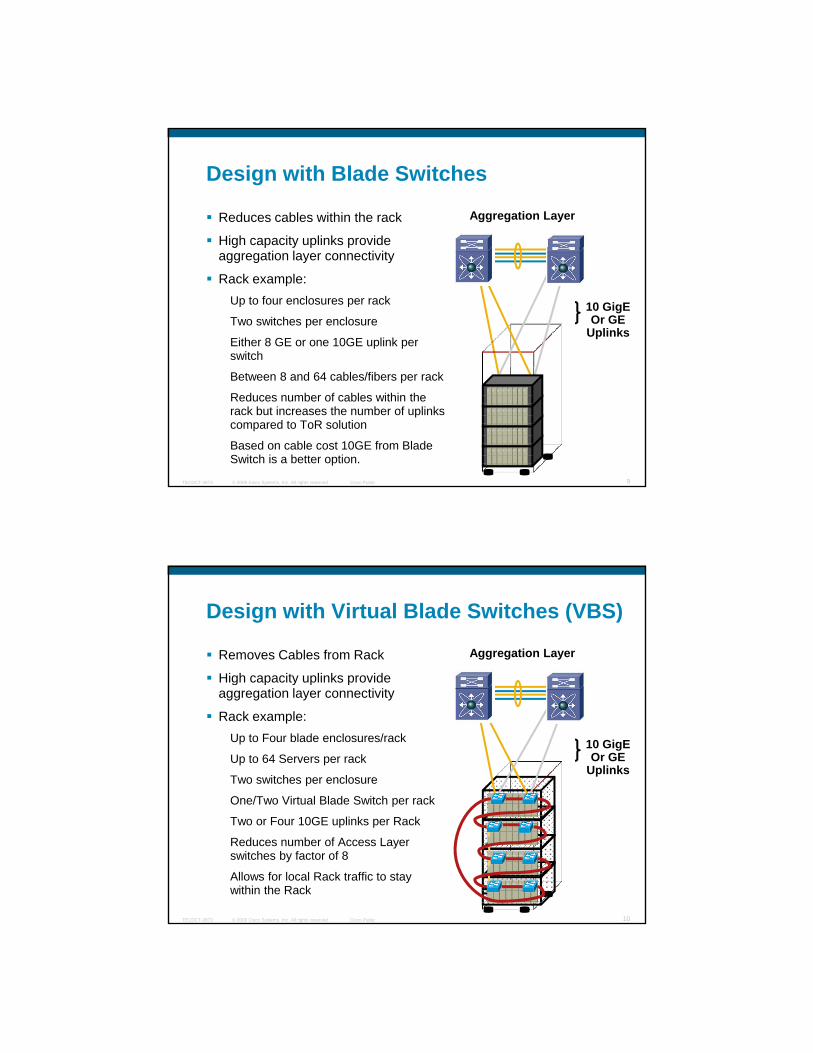
Design with Blade Switches
Reduces cables within the rack
High capacity uplinks provide
Aggregation Layer
g p y p paggregation layer connectivity
Rack example:Up to four enclosures per rack
Two switches per enclosure
Either 8 GE or one 10GE uplink per switch
10 GigEOr GE
Uplinks
© 2009 Cisco Systems, Inc. All rights reserved. Cisco PublicTECDCT-3873 9
Between 8 and 64 cables/fibers per rack
Reduces number of cables within the rack but increases the number of uplinks compared to ToR solution
Based on cable cost 10GE from Blade Switch is a better option.
Design with Virtual Blade Switches (VBS)
Removes Cables from Rack
High capacity uplinks provide
Aggregation Layer
g p y p paggregation layer connectivity
Rack example:Up to Four blade enclosures/rack
Up to 64 Servers per rack
Two switches per enclosure
One/Two Virtual Blade Switch per rack
10 GigEOr GE
Uplinks
© 2009 Cisco Systems, Inc. All rights reserved. Cisco PublicTECDCT-3873 10
p
Two or Four 10GE uplinks per Rack
Reduces number of Access Layer switches by factor of 8
Allows for local Rack traffic to stay within the Rack
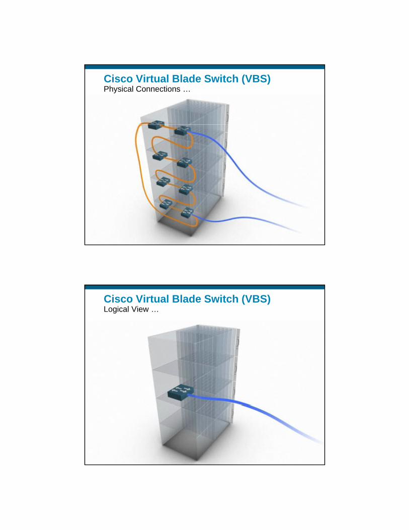
Cisco Virtual Blade Switch (VBS)Physical Connections …
© 2009 Cisco Systems, Inc. All rights reserved. Cisco PublicTECDCT-3873 11
Cisco Virtual Blade Switch (VBS)Logical View …
© 2009 Cisco Systems, Inc. All rights reserved. Cisco PublicTECDCT-3873 12

“Multiple Deployment Options for Customers” Caters to Different Customer Needs
BenefitsCommon ScenarioCommon ScenarioSingle Virtual Blade switch per rackEntire rack can be deployed with as little as two 10 GE uplinks or two GE Etherchannels Allows for Active/Active NIC teamsCreates a single router for entire rack if d l i L3 h d
© 2009 Cisco Systems, Inc. All rights reserved. Cisco PublicTECDCT-3873 13
if deploying L3 on the edgeKeeps Rack traffic in the Rack
Design ConsiderationsRing is limited to 64 GbpsMay cause Oversubscription
BenefitsSeparate VBS divide Left/Right switches
“Multiple Deployment Options for Customers” Caters to Different Customer Needs
Sepa ate S d de e t/ g t s tc esMore resilientProvides more Ring capacity since two rings per Rack
Design ConsiderationsRequires more Uplinks per RackServers can not form A/A NIC teams
© 2009 Cisco Systems, Inc. All rights reserved. Cisco PublicTECDCT-3873 14
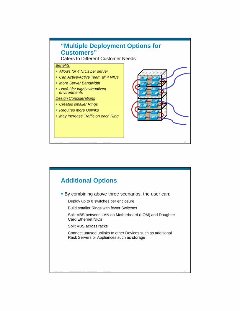
BenefitsAllows for 4 NICs per server
“Multiple Deployment Options for Customers” Caters to Different Customer Needs
pCan Active/Active Team all 4 NICsMore Server BandwidthUseful for highly virtualized environments
Design ConsiderationsCreates smaller Rings
© 2009 Cisco Systems, Inc. All rights reserved. Cisco PublicTECDCT-3873 15
Requires more UplinksMay Increase Traffic on each Ring
Additional Options
By combining above three scenarios, the user can:Deploy up to 8 switches per enclosureDeploy up to 8 switches per enclosure
Build smaller Rings with fewer Switches
Split VBS between LAN on Motherboard (LOM) and Daughter Card Ethernet NICs
Split VBS across racks
Connect unused uplinks to other Devices such as additional Rack Servers or Appliances such as storage
© 2009 Cisco Systems, Inc. All rights reserved. Cisco PublicTECDCT-3873 16
Rack Servers or Appliances such as storage

Plug-and-Play Designs with VBS and Nexus1000v
Virtual EthernetVirtual EthernetVirtual Ethernet
1 Add or replace a VBS Switch to the Cluster
2 Switch config and code automatically Virtual Ethernet ModuleVirtual Ethernet ModuleVirtual Ethernet Module
Virtual Ethernet ModuleVirtual Ethernet ModuleVirtual Ethernet Module
2 Switch config and code automatically propagated
3 Add a blade Server
© 2009 Cisco Systems, Inc. All rights reserved. Cisco PublicTECDCT-3873 17
Virtual Ethernet ModuleVirtual Ethernet ModuleVirtual Ethernet Module
4 It’s always booted from the same LUN
Cisco Virtual Blade Switch (VBS)Scalability
© 2009 Cisco Systems, Inc. All rights reserved. Cisco PublicTECDCT-3873 18
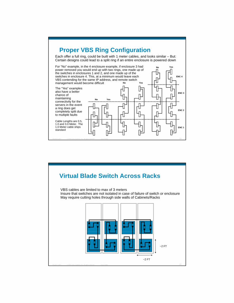
Proper VBS Ring ConfigurationEach offer a full ring, could be built with 1 meter cables, and looks similar – But:Certain designs could lead to a split ring if an entire enclosure is powered down
For “No” example, in the 4 enclosure example, if enclosure 3 had power removed you would end up with two rings, one made up of
No Yesp y p g , pthe switches in enclosures 1 and 2, and one made up of the switches in enclosure 4. This, at a minimum would leave each VBS contending for the same IP address, and remote switch management would become difficult
The “Yes” examples also have a better chance of maintaining connectivity for the servers in the event
No Yes
No Yes
ENC 3
ENC 4
© 2009 Cisco Systems, Inc. All rights reserved. Cisco PublicTECDCT-3873 19
servers in the event a ring does get completely split due to multiple faults
Cable Lengths are 0.5, 1.0 and 3.0 Meter. The 1.0 Meter cable ships standard
ENC 2
ENC 1
Virtual Blade Switch Across Racks
VBS cables are limited to max of 3 metersInsure that switches are not isolated in case of failure of switch or enclosureMay require cutting holes through side walls of Cabinets/RacksMay require cutting holes through side walls of Cabinets/Racks
© 2009 Cisco Systems, Inc. All rights reserved. Cisco PublicTECDCT-3873 20
~2 FT
~2 FT
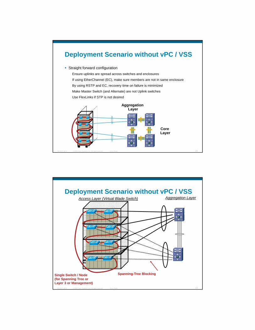
Deployment Scenario without vPC / VSS
Straight forward configurationEnsure uplinks are spread across switches and enclosures
If using EtherChannel (EC), make sure members are not in same enclosure
By using RSTP and EC, recovery time on failure is minimized
Make Master Switch (and Alternate) are not Uplink switches
Use FlexLinks if STP is not desired
Aggregation Layer
© 2009 Cisco Systems, Inc. All rights reserved. Cisco PublicTECDCT-3873 21
Core Layer
Aggregation LayerAccess Layer (Virtual Blade Switch)Deployment Scenario without vPC / VSS
© 2009 Cisco Systems, Inc. All rights reserved. Cisco PublicTECDCT-3873 22
Single Switch / Node (for Spanning Tree or Layer 3 or Management)
Spanning-Tree Blocking
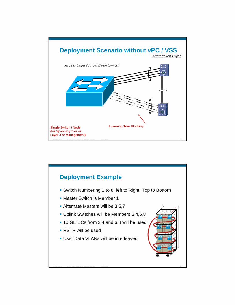
Aggregation Layer
Access Layer (Virtual Blade Switch)
Deployment Scenario without vPC / VSS
© 2009 Cisco Systems, Inc. All rights reserved. Cisco PublicTECDCT-3873 23
Single Switch / Node (for Spanning Tree or Layer 3 or Management)
Spanning-Tree Blocking
Deployment Example
Switch Numbering 1 to 8, left to Right, Top to Bottom
Master Switch is Member 1Master Switch is Member 1
Alternate Masters will be 3,5,7
Uplink Switches will be Members 2,4,6,8
10 GE ECs from 2,4 and 6,8 will be used
RSTP will be used
1
43
2
© 2009 Cisco Systems, Inc. All rights reserved. Cisco PublicTECDCT-3873 24
User Data VLANs will be interleaved 65
87

Configuration Commands
switch 1 priority 15 Sets Sw 1 to pri master
switch 3 priority 14 Sets Sw 3 to sec master
switch 5 priority 13 Sets Sw 5 to 3rd master
switch 7 priority 12 Sets Sw 7 to 4th Master
spanning-tree mode rapid-pvst Enables Rapid STP
vlan 1-10 Configures VLANs
state active
interface range gig1/0/1 – gig1/0/16
© 2009 Cisco Systems, Inc. All rights reserved. Cisco PublicTECDCT-3873 25
g g g g g
switchport access vlan xx Assign ports to VLANs
Configuration Commands
interface range ten2/0/1, ten4/0/1
switchport mode trunk
switchport trunk allowed vlans 1 10switchport trunk allowed vlans 1-10
channel group 1 mode active
interface range ten6/0/1, ten8/0/1
switchport mode trunk
switchport trunk allowed vlans 1-10
channel group 2 mode active
interface po1
i t l 1 3 5 7 9 t i it 0
© 2009 Cisco Systems, Inc. All rights reserved. Cisco PublicTECDCT-3873 26
spanning-tree vlan 1,3,5,7,9 port-priority 0
spanning-tree vlan 2,4,6,8,10 port-priority 16
interface po2
spanning-tree vlan 1,3,5,7,9 port-priority 16
spanning-tree vlan 2,4,6,8,10 port-priority 0
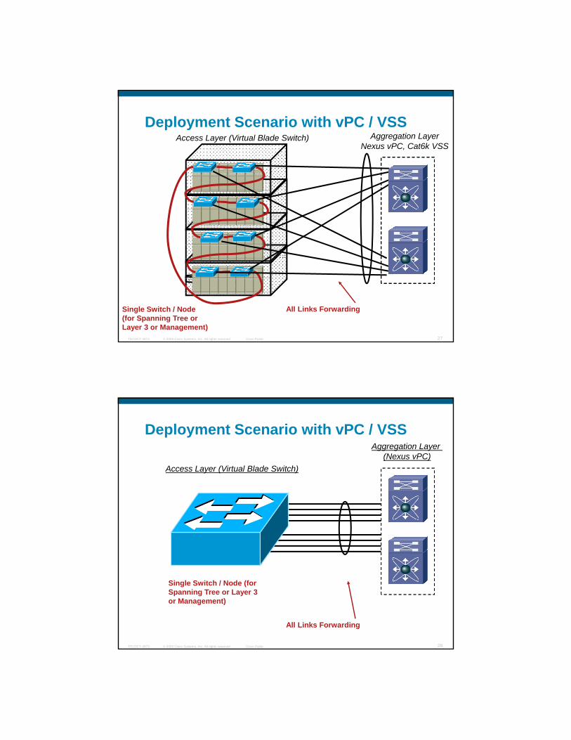
Aggregation LayerNexus vPC, Cat6k VSS
Access Layer (Virtual Blade Switch)Deployment Scenario with vPC / VSS
© 2009 Cisco Systems, Inc. All rights reserved. Cisco PublicTECDCT-3873 27
Single Switch / Node (for Spanning Tree or Layer 3 or Management)
All Links Forwarding
Aggregation Layer (Nexus vPC)
Access Layer (Virtual Blade Switch)
Deployment Scenario with vPC / VSS
© 2009 Cisco Systems, Inc. All rights reserved. Cisco PublicTECDCT-3873 28
Single Switch / Node (for Spanning Tree or Layer 3 or Management)
All Links Forwarding
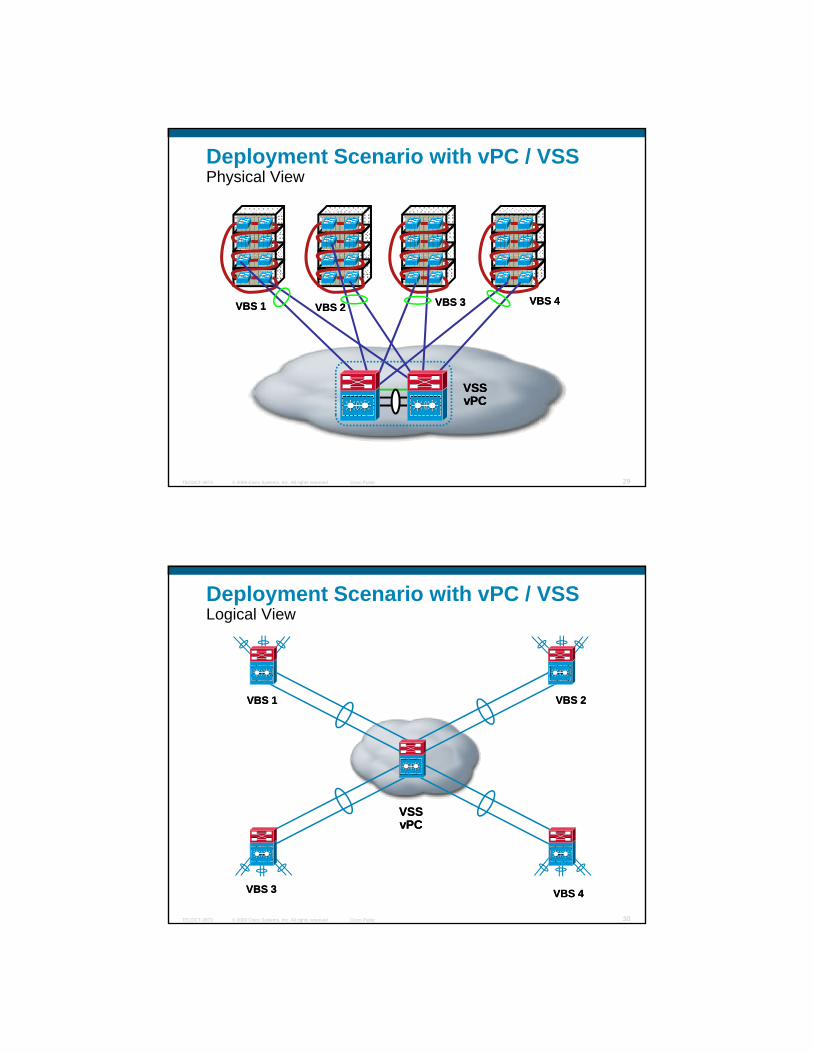
Deployment Scenario with vPC / VSS Physical View
VBS 1VBS 1 VBS 2VBS 2 VBS 4VBS 4VBS 3VBS 3
© 2009 Cisco Systems, Inc. All rights reserved. Cisco PublicTECDCT-3873 29
VSSVSSvPCvPC
Deployment Scenario with vPC / VSS Logical View
VBS 1VBS 1 VBS 2VBS 2
© 2009 Cisco Systems, Inc. All rights reserved. Cisco PublicTECDCT-3873 30
VBS 3VBS 3
VSSVSSvPCvPC
VBS 4VBS 4

“Rules” to Live by for EC / MCEC
1. Split links across line cards on Catalyst 6500 / Nexus 7000 side – prevents against Line Card Outage
2. Split across pair of Catalyst 6500 or across pair of Nexus 7000 -prevents against aggregation switch outage
3. Split links across members on blade side if using VBS - prevents against blade switch outage
4. Split links across Blade Enclosures if possible – prevents against enclosure outage
5 S lit VLAN f l d b l i t idl EC
© 2009 Cisco Systems, Inc. All rights reserved. Cisco PublicTECDCT-3873 31
5. Split VLANs across for load balancing – prevents idle ECs.
6. Chose appropriate EC load balancing algorithm – example: Blade servers generally have even number MAC addresses. Consider the hashing algorithms enhancements with MCEC
7. Last but Not least, monitor your ECs - Only way to know if you need more BW or Better MCEC load balance
Further Points to Consider on Layer 2:When is Layer 2 Adjacency Required?
Clustering: applications often execute on multiple servers clustered to appear as a
MS-Windows Advanced Serverclustered to appear as a
single device. Common for HA, Load Balancing and High Performance computing requirements.
NIC teaming software t picall req ires la er 2
Server Clustering
Linux Beowulf or proprietary clustering (HPC)
© 2009 Cisco Systems, Inc. All rights reserved. Cisco PublicTECDCT-3873 32
typically requires layer 2 adjacency
AFTSFTALB
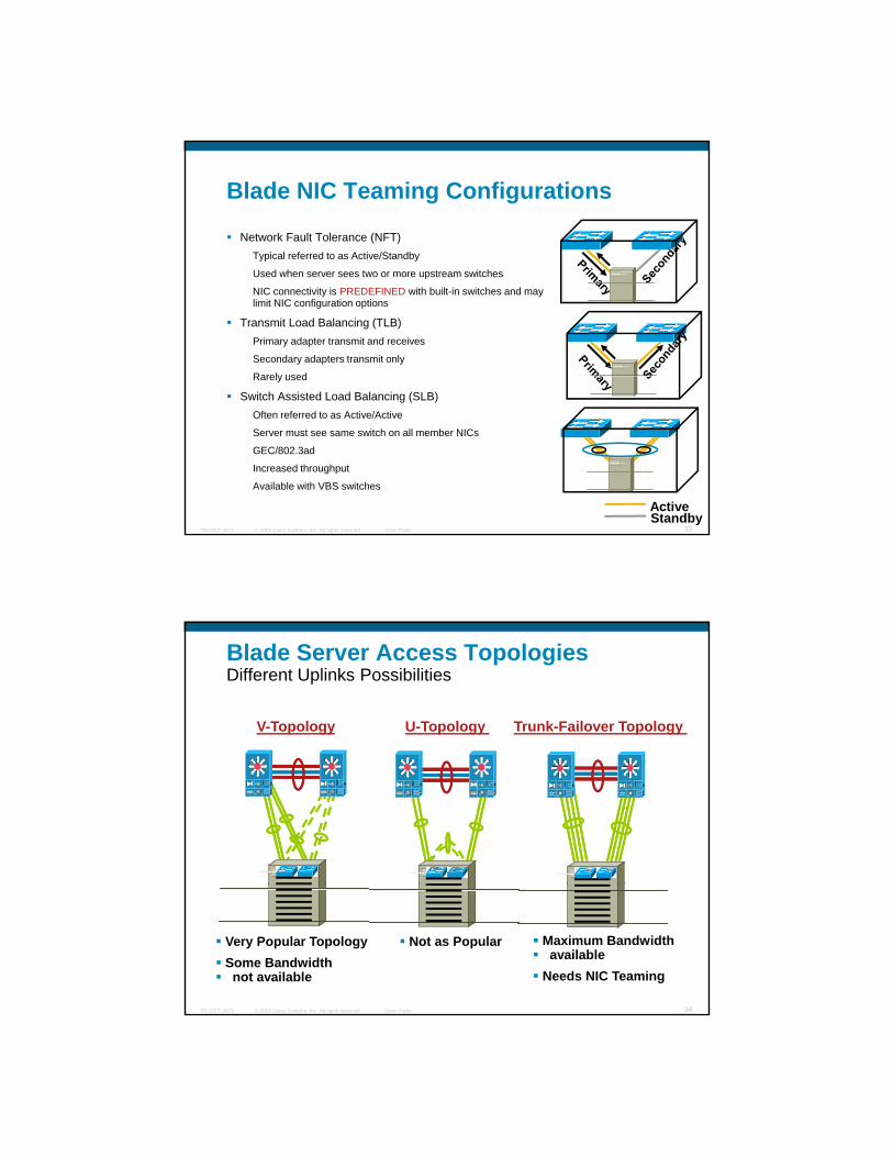
Blade NIC Teaming Configurations
Network Fault Tolerance (NFT)Typical referred to as Active/Standby
Used when server sees two or more upstream switchesUsed when server sees two or more upstream switches
NIC connectivity is PREDEFINED with built-in switches and may limit NIC configuration options
Transmit Load Balancing (TLB)Primary adapter transmit and receives
Secondary adapters transmit only
Rarely used
Switch Assisted Load Balancing (SLB)
© 2009 Cisco Systems, Inc. All rights reserved. Cisco PublicTECDCT-3873 33
Often referred to as Active/Active
Server must see same switch on all member NICs
GEC/802.3ad
Increased throughput
Available with VBS switches
ActiveStandby
Blade Server Access TopologiesDifferent Uplinks Possibilities
Trunk-Failover Topology V-Topology U-Topology
© 2009 Cisco Systems, Inc. All rights reserved. Cisco PublicTECDCT-3873 34
Very Popular TopologySome Bandwidthnot available
Maximum Bandwidth available
Needs NIC Teaming
Not as Popular

Layer 2 Trunk FailoverTypical Blade Network Topologies
L3 Switches
Cisco Blade Switches
Link State
Group 1
Link State
Group 1
© 2009 Cisco Systems, Inc. All rights reserved. Cisco PublicTECDCT-3873 35
Blade Server Chassis Blade Server ChassisFEATURE
• Map Uplink EtherChannel to downlink ports (Link State Group)
• If all uplinks fail, instantly shutdown downlink ports
• Server gets notified and starts using backup NIC/switch
CUSTOMER BENEFIT
• Higher Resiliency / Availability
• Reduce STP Complexity
Flexlink Overview
Achieve Layer 2 resiliency without using STP
Access switches have backup links to Aggregation switchesp gg g
Target of sub-100msec convergence upon forwarding link failover
Convergence time independent of #vlans and #mac-addresses
Interrupt based link-detection for Flexlink ports.
Link-Down detected at a 24msec poll.
No STP instance for Flexlink ports.
© 2009 Cisco Systems, Inc. All rights reserved. Cisco PublicTECDCT-3873 36
Forwarding on all vlans on the <up> flexlink port occurs with a single update operation – low cost.

(Mac address Move Notification) MMN Overview
Achieve near sub-100 msec downtime for the downstream traffic too, upon flexlink switchover.
Lightweight protocol : Send a MMN packet to [(Vlan1, Mac1, Mac2..) (Vlan2, Mac1, Mac2..) ..] distribution network.
Receiver parses the MMN packet and learns or moves the contained mac-addresses. Alternatively, it can flush the mac-address table for the vlans
© 2009 Cisco Systems, Inc. All rights reserved. Cisco PublicTECDCT-3873 37
the mac-address table for the vlans.
Receiver forwards packet to other switches.
Flexlink Preemption
Flexlink enhanced to :provide flexibility in choosing FWD link, optimizing available bandwidth utilization
U fi Fl li k i h i FWD li k b kUser can configure Flexlink pair when previous FWD link comes back up :Current FWD link continues
Preemption mode Off
Previous FWD link preempts the current and begins FWD instead
Preemption mode Forced
Higher bandwidth interface preempts the other and goes FWD
Preemption mode Bandwidth
Note: By default flexlink preemption mode is OFF
© 2009 Cisco Systems, Inc. All rights reserved. Cisco PublicTECDCT-3873 38
Note: By default, flexlink preemption mode is OFF
When configuring preemption delay:user can specify a preemption delay time (0 to 300 sec)
default preemption delay is 35 secs
Preemption Delay Time :Once the switch identifies a Flexlink preemption case, it waits an amount of <preemption delay> seconds before preempting the currently FWD Flexlink interface.
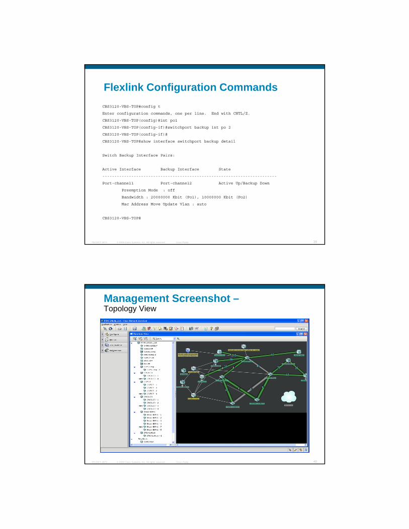
Flexlink Configuration CommandsCBS3120-VBS-TOP#config t
Enter configuration commands, one per line. End with CNTL/Z.
CBS3120-VBS-TOP(config)#int po1
CBS3120-VBS-TOP(config-if)#switchport backup int po 2
CBS3120-VBS-TOP(config-if)#
CBS3120-VBS-TOP#show interface switchport backup detail
Switch Backup Interface Pairs:
Active Interface Backup Interface State
------------------------------------------------------------------------
Port-channel1 Port-channel2 Active Up/Backup Down
© 2009 Cisco Systems, Inc. All rights reserved. Cisco PublicTECDCT-3873 39
p/ p
Preemption Mode : off
Bandwidth : 20000000 Kbit (Po1), 10000000 Kbit (Po2)
Mac Address Move Update Vlan : auto
CBS3120-VBS-TOP#
Management Screenshot –Topology View
© 2009 Cisco Systems, Inc. All rights reserved. Cisco PublicTECDCT-3873 40
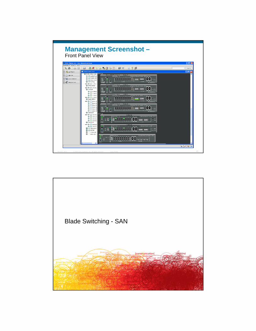
Management Screenshot –Front Panel View
© 2009 Cisco Systems, Inc. All rights reserved. Cisco PublicTECDCT-3873 41
Blade Switching - SAN
© 2009 Cisco Systems, Inc. All rights reserved. Cisco PublicTECDCT-3873 42
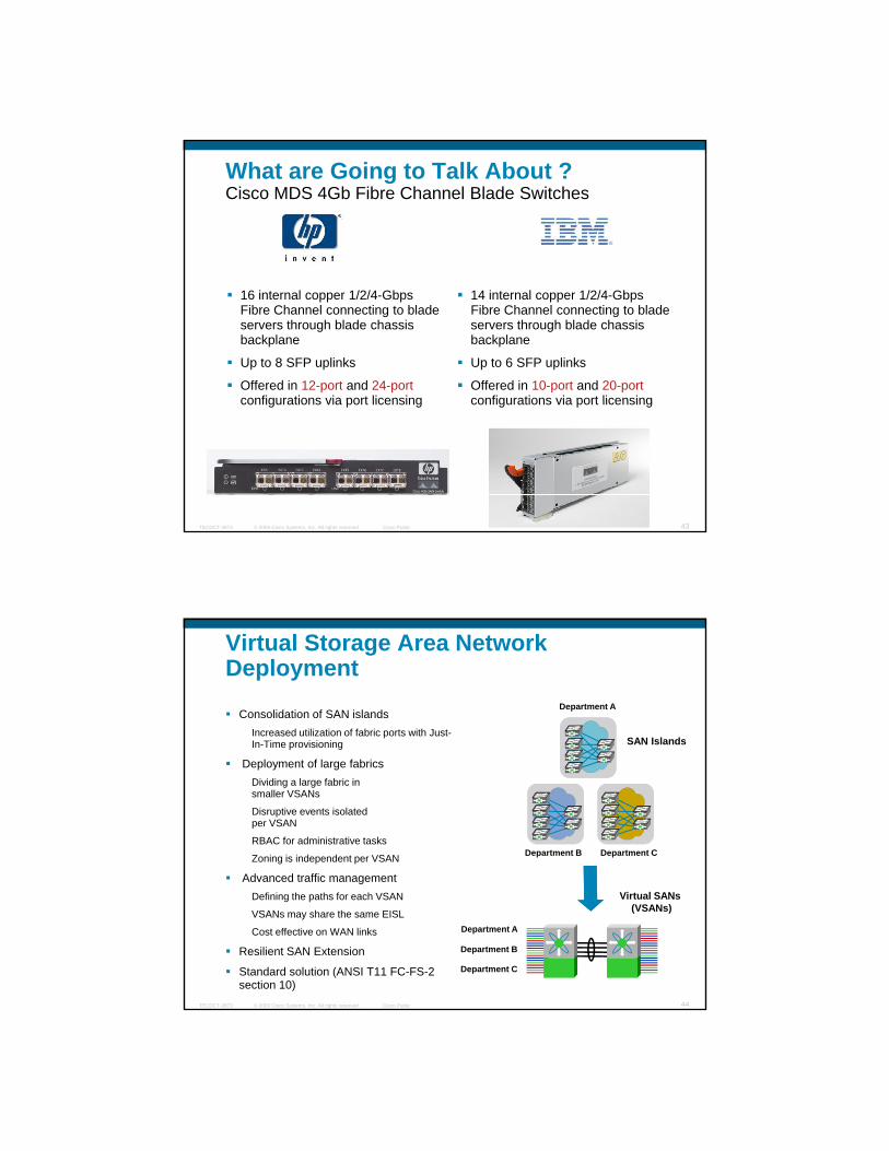
What are Going to Talk About ?Cisco MDS 4Gb Fibre Channel Blade Switches
16 internal copper 1/2/4-Gbps Fibre Channel connecting to blade servers through blade chassis backplane
Up to 8 SFP uplinks
Offered in 12-port and 24-port configurations via port licensing
14 internal copper 1/2/4-Gbps Fibre Channel connecting to blade servers through blade chassis backplane
Up to 6 SFP uplinks
Offered in 10-port and 20-portconfigurations via port licensing
© 2009 Cisco Systems, Inc. All rights reserved. Cisco PublicTECDCT-3873 43
configurations via port licensing configurations via port licensing
Virtual Storage Area Network Deployment
Consolidation of SAN islandsIncreased utilization of fabric ports with Just-In-Time provisioning SAN Islands
Department A
p g
Deployment of large fabricsDividing a large fabric in smaller VSANs
Disruptive events isolated per VSAN
RBAC for administrative tasks
Zoning is independent per VSAN
Advanced traffic management
Department B Department C
© 2009 Cisco Systems, Inc. All rights reserved. Cisco PublicTECDCT-3873 44
Advanced traffic managementDefining the paths for each VSAN
VSANs may share the same EISL
Cost effective on WAN links
Resilient SAN Extension
Standard solution (ANSI T11 FC-FS-2 section 10)
Virtual SANs (VSANs)
Department A
Department B
Department C
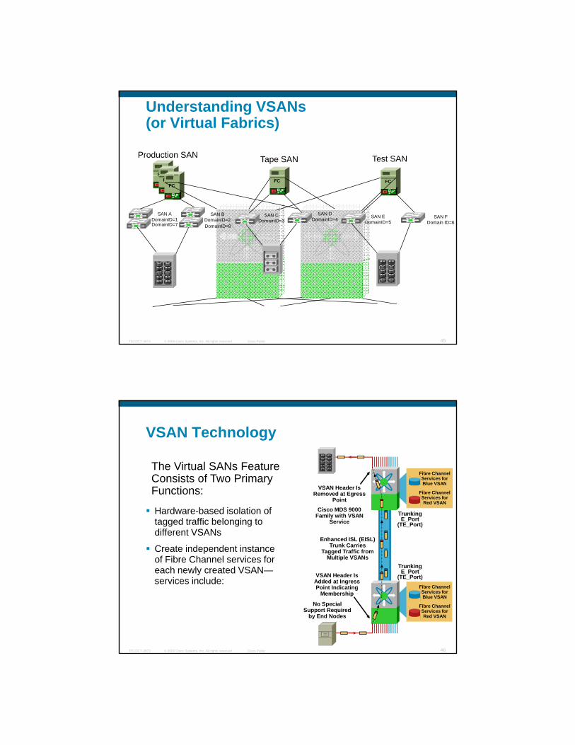
Understanding VSANs (or Virtual Fabrics)
Production SAN Tape SAN Test SAN
FCFC
FCFC
FC
FC
FC
SAN EDomainID=5
SAN FDomain ID=6
FC
FC
FC
FC
SAN ADomainID=1
SAN BDomainID=2
SAN CDomainID=3
SAN DDomainID=4
DomainID=8DomainID=7
© 2009 Cisco Systems, Inc. All rights reserved. Cisco PublicTECDCT-3873 45
VSAN Technology
Fibre ChannelServices for Blue VSAN
The Virtual SANs Feature Consists of Two Primary
Hardware-based isolation of tagged traffic belonging to different VSANs
Create independent instance of Fibre Channel services for each newly created VSAN
Blue VSAN
Fibre ChannelServices for Red VSAN
Cisco MDS 9000Family with VSAN
Service
Trunking
Trunking E_Port
(TE_Port)
Enhanced ISL (EISL) Trunk Carries
Tagged Traffic from Multiple VSANs
VSAN Header Is Removed at Egress
PointFunctions:
© 2009 Cisco Systems, Inc. All rights reserved. Cisco PublicTECDCT-3873 46
each newly created VSAN—services include:
Fibre ChannelServices for Blue VSAN
Fibre ChannelServices for Red VSAN
VSAN Header Is Added at Ingress Point Indicating
Membership
No Special Support Required
by End Nodes
E_Port(TE_Port)

Enhanced vs. Basic Zoning
Basic Zoning Enhanced Zoning Enhanced Advantages
Administrators can All fi ti hAdministrators can make simultaneous
configuration changes
All configuration changes are made within a single
session. Switch locks entire fabric to implement change
One configuration session for entire fabric to ensure consistency within fabric
If a zone is a member of multiple zonesets ,
an instance is created per zoneset.
References to the zone are used by the zonesets as
required once you define the zone.
Reduced payload size as the zone is referenced.
The size is more pronounced with bigger
database
© 2009 Cisco Systems, Inc. All rights reserved. Cisco PublicTECDCT-3873 47
created per zoneset. database
Default zone policy is defined per switch.
Enforces and exchanges default zone setting throughout the fabric
Fabric-wide policy enforcement reduces troubleshooting time.
Enhanced vs. Basic Zoning
Basic Zoning Enhanced Zoning Enhanced Advantages
Managing switch R t i th ti ti E h dManaging switch provides combined status about activation. Will not identify a failure switch.
Retrieves the activation results and the nature of the problem from each
remote switch.
Enhanced error reporting reduces troubleshooting
process.
To distribute zoneset must re-activate the
same zoneset.
Implements changes to the zoning database and distributes it without
activation.
This avoids hardware changes for hard
zoning in the switches.
D i MDS
© 2009 Cisco Systems, Inc. All rights reserved. Cisco PublicTECDCT-3873 48
During a merge MDS specific types can be
misunderstood by non-cisco switches.
Provides a vendor ID along with a vendor-specific type value to uniquely identify a
member type
Unique Vendor type
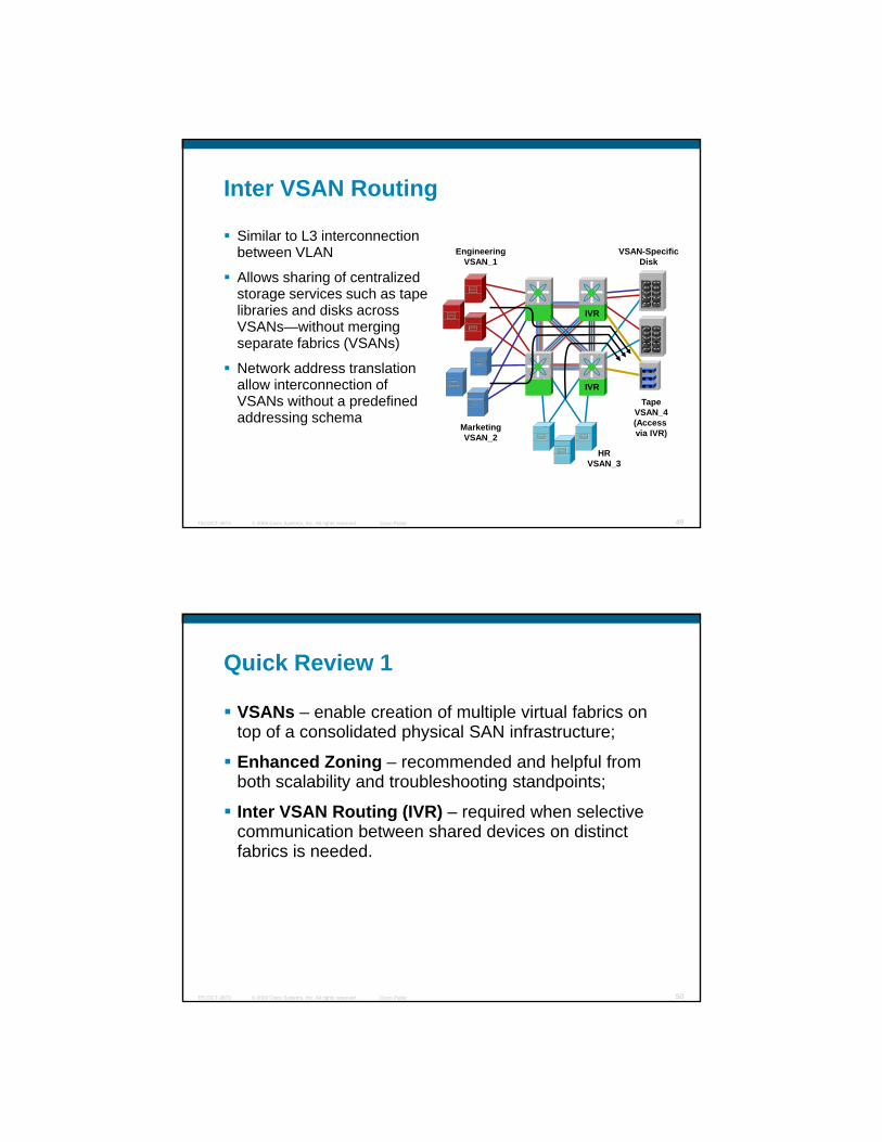
Inter VSAN Routing
Similar to L3 interconnection between VLAN VSAN-Specific
DiskEngineering
VSAN_1
Allows sharing of centralized storage services such as tape libraries and disks across VSANs—without merging separate fabrics (VSANs)
Network address translation allow interconnection of VSANs itho t a predefined
IVR
IVR
© 2009 Cisco Systems, Inc. All rights reserved. Cisco PublicTECDCT-3873 49
VSANs without a predefined addressing schema
TapeVSAN_4(Access via IVR)Marketing
VSAN_2
HRVSAN_3
Quick Review 1
VSANs – enable creation of multiple virtual fabrics on top of a consolidated physical SAN infrastructure;
Enhanced Zoning – recommended and helpful from both scalability and troubleshooting standpoints;
Inter VSAN Routing (IVR) – required when selective communication between shared devices on distinct fabrics is needed.
© 2009 Cisco Systems, Inc. All rights reserved. Cisco PublicTECDCT-3873 50
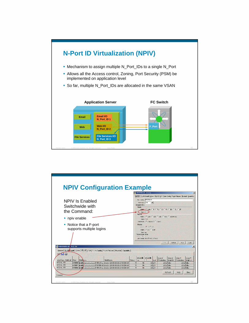
N-Port ID Virtualization (NPIV)
Mechanism to assign multiple N_Port_IDs to a single N_Port
Allows all the Access control, Zoning, Port Security (PSM) be g y ( )implemented on application level
So far, multiple N_Port_IDs are allocated in the same VSAN
Application Server FC Switch
© 2009 Cisco Systems, Inc. All rights reserved. Cisco PublicTECDCT-3873 51
Web
File Services
Email I/ON_Port_ID 1
Web I/ON_Port_ID 2
File Services I/ON_Port_ID 3
F_Port
NPIV Configuration Example
NPIV Is Enabled Switchwide with th C dthe Command:
npiv enable
Notice that a F-port supports multiple logins
© 2009 Cisco Systems, Inc. All rights reserved. Cisco PublicTECDCT-3873 52
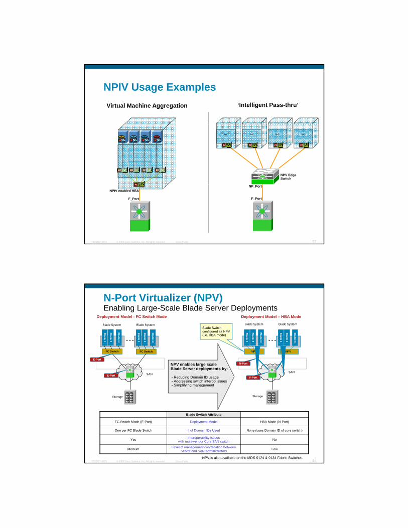
NPIV Usage Examples‘Intelligent Pass-thru’Virtual Machine Aggregation
FC FC FC FC
FC FC FC FC
FC
NPV Edge Switch
© 2009 Cisco Systems, Inc. All rights reserved. Cisco PublicTECDCT-3873 53
NP_Port
F_PortF_Port
FC
NPIV enabled HBA
N-Port Virtualizer (NPV)Enabling Large-Scale Blade Server Deployments
Blade 1
Blade 2
Blade N
Blade 1
Blade 2
Blade N…
Blade 1
Blade 2
Blade N
Blade 1
Blade 2
Blade N…
Blade System Blade System Blade System Blade SystemBlade Switch configured as NPV (i.e. HBA mode)
Deployment Model - FC Switch Mode Deployment Model – HBA Mode
FC Switch FC Switch NPV NPV
SAN
Storage
SAN
Storage
NPV enables large scaleBlade Server deployments by:
- Reducing Domain ID usage- Addressing switch interop issues- Simplifying management
E-Port
E-Port
N-Port
F-Port
© 2009 Cisco Systems, Inc. All rights reserved. Cisco PublicTECDCT-3873 54
Blade Switch Attribute
FC Switch Mode (E-Port) Deployment Model HBA Mode (N-Port)
One per FC Blade Switch # of Domain IDs Used None (uses Domain ID of core switch)
Yes Interoperability issues with multi-vendor Core SAN switch No
Medium Level of management coordination between Server and SAN Administrators Low
NPV is also available on the MDS 9124 & 9134 Fabric Switches

N-Port Virtualizater (NPV): An OverviewNPV-Core Switch (MDS or 3rd party switch with NPIV support)
Solves the domain-id l i bl
FC
20 2 110 1 1
FC
F-port
NP-port
explosion problem 20.2.1
Can have multipleuplinks, on differentVSANs (port channel and trunking in a later release)
MDS 9124MDS 9134
10.1.1
Up to 100NPV switches
© 2009 Cisco Systems, Inc. All rights reserved. Cisco PublicTECDCT-3873 55
Cisco MDS in a
Blade Chassis
NPV DeviceUses the same domain(s) as the NPV-core switch(es)
Blade Server 1Blade Server 2
Blade Server n
20.5.1
(no FL ports)
FC10.5.710.5.2
server port (F)
TargetInitiator
NPV FLOGI/FDISC Login Process
When NP port comes up on a NPV edge switch, it first FLOGI and PLOGI into the core to register into the FCName Server
NPV Core Switch
NP
F
P2
End Devices connected on NPV edge switch does FLOGI but NPV switch converts FLOGI to FDISC command, creating a virtual PWWN for the end device and allowing to login using the physical NP port.
All I/O of end device will always flow through same NP portNPV Edge Switch
NP
F
P1
FF
© 2009 Cisco Systems, Inc. All rights reserved. Cisco PublicTECDCT-3873 56
P5 = vP3P4 = vP2
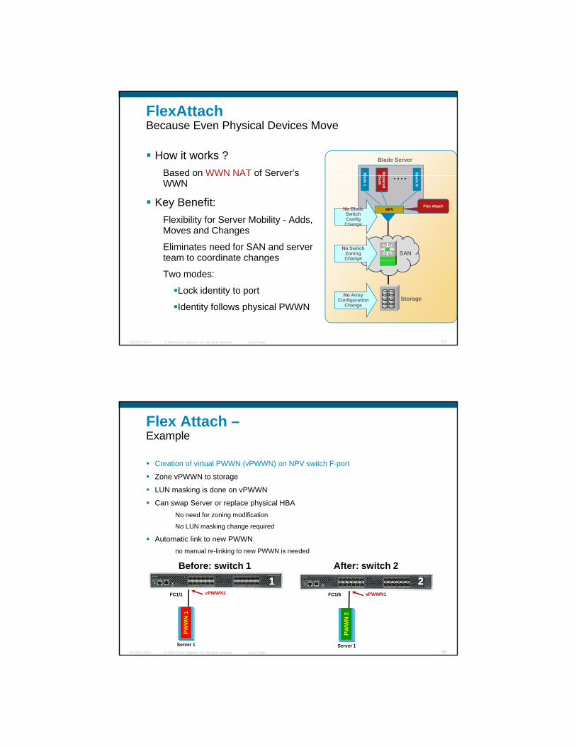
FlexAttachBecause Even Physical Devices Move
How it works ? Based on WWN NAT of Server’s B
l
Bl
Blade Server
ReBBased on WWN NAT of Server s
WWN
Key Benefit:Flexibility for Server Mobility - Adds, Moves and Changes
Eliminates need for SAN and server team to coordinate changes
lade 1NPV
lade N
eplaced B
lade
….
Flex AttachNo Blade Switch Config Change
No Switch Zoning Change
SAN
© 2009 Cisco Systems, Inc. All rights reserved. Cisco PublicTECDCT-3873 57
team to coordinate changes
Two modes:
Lock identity to port
Identity follows physical PWWNStorage
g
No Array Configuration
Change
Flex Attach –Example
Creation of virtual PWWN (vPWWN) on NPV switch F-port
Zone vPWWN to storage
LUN masking is done on vPWWN
Can swap Server or replace physical HBANo need for zoning modification
No LUN masking change required
Automatic link to new PWWN no manual re-linking to new PWWN is needed
Before: switch 1 After: switch 2
© 2009 Cisco Systems, Inc. All rights reserved. Cisco PublicTECDCT-3873 58
FC1/1
PWW
N 1
Server 1
vPWWN1 FC1/6
PWW
N 2
Server 1
vPWWN1
11 22
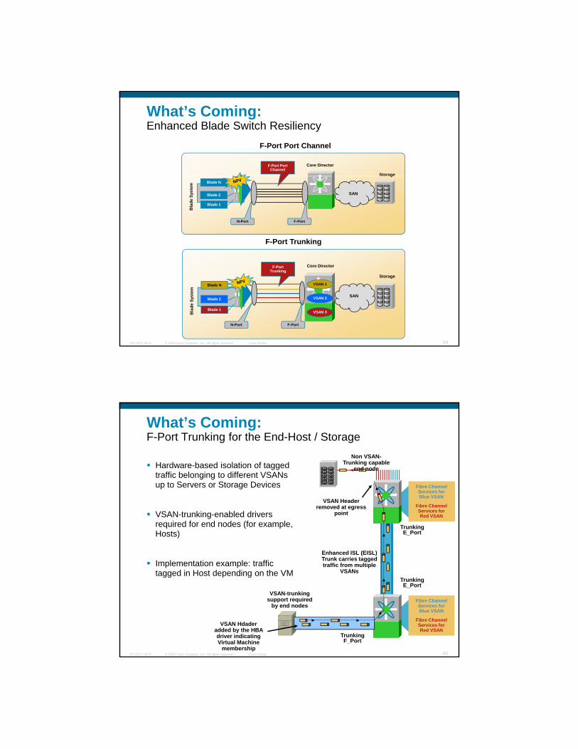
What’s Coming: Enhanced Blade Switch Resiliency
Storage
F-Port Port Channel
F-Port Port Channel
Core Director
g
Bla
deSy
stem
Blade 1
Blade 2
Blade N
F-PortN-Port
SAN
F-Port Trunking
© 2009 Cisco Systems, Inc. All rights reserved. Cisco PublicTECDCT-3873 59
Storage
Bla
de S
yste
m
Blade 1
Blade 2
Blade N
Core Director
VSAN 1
VSAN 2
VSAN 3
F-Port Trunking
F-PortN-Port
SAN
What’s Coming:F-Port Trunking for the End-Host / Storage
Hardware-based isolation of tagged traffic belonging to different VSANs up to Servers or Storage Devices Fibre Channel
Non VSAN-Trunking capable
end node
up to Servers or Storage Devices
VSAN-trunking-enabled drivers required for end nodes (for example, Hosts)
Implementation example: traffic tagged in Host depending on the VM
Fibre ChannelServices for Blue VSAN
Fibre ChannelServices for Red VSAN
Trunking E_Port
Enhanced ISL (EISL) Trunk carries tagged traffic from multiple
VSANs
VSAN Header removed at egress
point
© 2009 Cisco Systems, Inc. All rights reserved. Cisco PublicTECDCT-3873 60
tagged in Host depending on the VM
Fibre ChannelServices for Blue VSAN
Fibre ChannelServices for Red VSAN
VSAN Hdader added by the HBA driver indicating Virtual Machine
membership
VSAN-trunking support required
by end nodes
Trunking E_Port
VSANs
Trunking F_Port

Quick Review 2
NPIV – standard mechanism enabling F-port (switches and HBAs) virtualization
NPV – allows a FC switch to work on HBA mode. The switch behaves like a proxy of WWN and doesn’t consume a Domain ID, enhancing SAN scalability (mainly on blade environments)
Flex-Attach – adds flexibility to server mobility allowing the server FC identity to follow the physical pWWN (for blades and rack mount servers)
F-port port-channel – on NPV scenarios, the ability to bundle
© 2009 Cisco Systems, Inc. All rights reserved. Cisco PublicTECDCT-3873 61
p p , ymultiple physical ports in to 1 logical link
F-port trunking – extend VSAN tagging to the N_Port to F_Port connection. Works between switches together with NPV. For host, needs VSAN support on the HBA and allows per-VM VSAN allocation.
SAN Design: Initial Considerations
Requirements
F t i t- Fan-out maintenance- Dual physical fabrics
SANDesign
© 2009 Cisco Systems, Inc. All rights reserved. Cisco PublicTECDCT-3873 62
Parameters
- Number of end devices- Speed variation
Factors toConsider
- Topologies- Bandwidth reservation - Networking / gear capacity
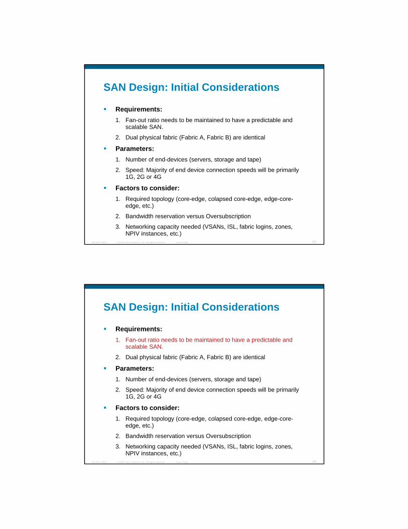
SAN Design: Initial Considerations
Requirements:1. Fan-out ratio needs to be maintained to have a predictable and
scalable SAN.
2. Dual physical fabric (Fabric A, Fabric B) are identical
Parameters:1. Number of end-devices (servers, storage and tape)
2. Speed: Majority of end device connection speeds will be primarily 1G, 2G or 4G
© 2009 Cisco Systems, Inc. All rights reserved. Cisco PublicTECDCT-3873 63
Factors to consider:1. Required topology (core-edge, colapsed core-edge, edge-core-
edge, etc.)
2. Bandwidth reservation versus Oversubscription
3. Networking capacity needed (VSANs, ISL, fabric logins, zones, NPIV instances, etc.)
SAN Design: Initial Considerations
Requirements:1. Fan-out ratio needs to be maintained to have a predictable and
scalable SAN.
2. Dual physical fabric (Fabric A, Fabric B) are identical
Parameters:1. Number of end-devices (servers, storage and tape)
2. Speed: Majority of end device connection speeds will be primarily 1G, 2G or 4G
© 2009 Cisco Systems, Inc. All rights reserved. Cisco PublicTECDCT-3873 64
Factors to consider:1. Required topology (core-edge, colapsed core-edge, edge-core-
edge, etc.)
2. Bandwidth reservation versus Oversubscription
3. Networking capacity needed (VSANs, ISL, fabric logins, zones, NPIV instances, etc.)
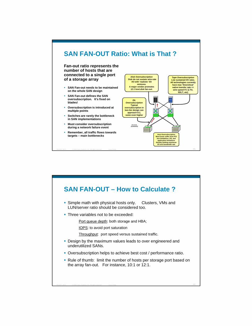
SAN FAN-OUT Ratio: What is That ?
Disk Oversubscription O
Fan-out ratio represents the number of hosts that are connected to a single port
SAN Fan-out needs to be maintained on the whole SAN design
SAN Fan-out defines the SAN oversubscription. It’s fixed on blades!
Oversubscription is introduced at multiple points
Disk OversubscriptionDisk do not sustain wire-rate
I/O with ‘realistic’ I/O mixtures.
A major vendor promotes 12:1 host:disk fan-out.
Tape OversubscriptionLow sustained I/O rates.
All technologies currently have max ‘theoretical’ native transfer rate << wire-speed FC (LTO,
SDLT, etc)
ISL Oversubscription
Typical oversubscription in two-tier design can
approach 8:1,
g pof a storage array
© 2009 Cisco Systems, Inc. All rights reserved. Cisco PublicTECDCT-3873 65
Switches are rarely the bottleneck in SAN implementations
Must consider oversubscription during a network failure event
Remember, all traffic flows towards targets – main bottlenecks
some even higher
Host OversubscriptionMost hosts suffer from PCI
bus limitations, OS, and application limitations
thereby limiting maximum I/O and bandwidth rate
8:1 O.S.(common)
SAN FAN-OUT – How to Calculate ?
Simple math with physical hosts only. Clusters, VMs and LUN/server ratio should be considered too.
Three variables not to be exceeded:Port queue depth: both storage and HBA;
IOPS: to avoid port saturation
Throughput: port speed versus sustained traffic.
Design by the maximum values leads to over engineered and underutilized SANs.
© 2009 Cisco Systems, Inc. All rights reserved. Cisco PublicTECDCT-3873 66
Oversubscription helps to achieve best cost / performance ratio.
Rule of thumb: limit the number of hosts per storage port based on the array fan-out. For instance, 10:1 or 12:1.
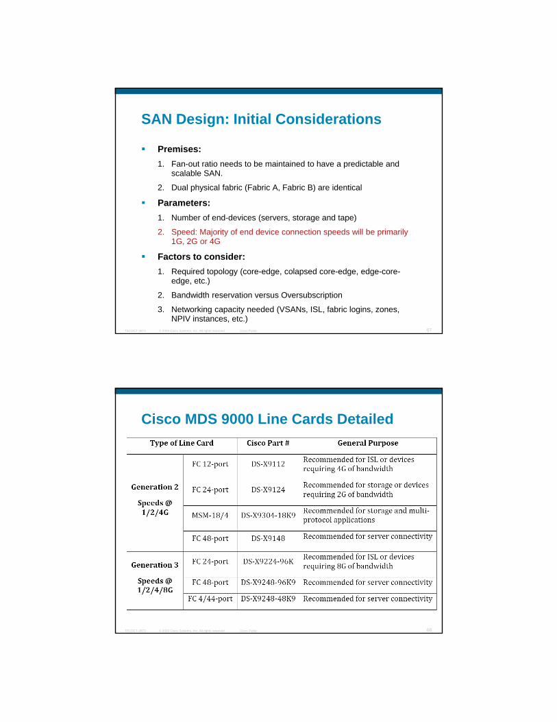
SAN Design: Initial Considerations
Premises:1. Fan-out ratio needs to be maintained to have a predictable and
scalable SAN.
2. Dual physical fabric (Fabric A, Fabric B) are identical
Parameters:1. Number of end-devices (servers, storage and tape)
2. Speed: Majority of end device connection speeds will be primarily 1G, 2G or 4G
© 2009 Cisco Systems, Inc. All rights reserved. Cisco PublicTECDCT-3873 67
Factors to consider:1. Required topology (core-edge, colapsed core-edge, edge-core-
edge, etc.)
2. Bandwidth reservation versus Oversubscription
3. Networking capacity needed (VSANs, ISL, fabric logins, zones, NPIV instances, etc.)
Cisco MDS 9000 Line Cards Detailed
© 2009 Cisco Systems, Inc. All rights reserved. Cisco PublicTECDCT-3873 68

SAN Design: Initial Considerations
Premises:1. Fan-out ratio needs to be maintained to have a predictable and
scalable SAN.
2. Dual physical fabric (Fabric A, Fabric B) are identical
Parameters:1. Number of end-devices (servers, storage and tape)
2. Speed: Majority of end device connection speeds will be primarily 1G, 2G or 4G
© 2009 Cisco Systems, Inc. All rights reserved. Cisco PublicTECDCT-3873 69
Factors to consider:1. Required topology (core-edge, colapsed core-edge, edge-core-
edge, etc.)
2. Bandwidth reservation versus Oversubscription
3. Networking capacity needed (VSANs, ISL, fabric logins, zones, NPIV instances, etc.)
Core-Edge
Traditional SAN design for growing SANs
Hi h d it di t iHigh density directors in core and, on the edge:
Unified IO (FCoE) switches [1];
Directors [2] ,
Fabric Switches [3] or
Blade switches [ 4 ]
P di bl f
A
BAA
B
B
© 2009 Cisco Systems, Inc. All rights reserved. Cisco PublicTECDCT-3873 70
Predictable performance
Scalable growth up to core and ISL capacity
A B
A B
[ 1 ] [ 2 ] [ 3 ] [ 4 ]
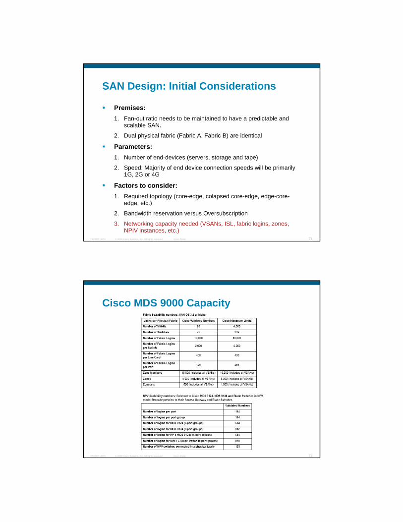
SAN Design: Initial Considerations
Premises:1. Fan-out ratio needs to be maintained to have a predictable and
scalable SAN.
2. Dual physical fabric (Fabric A, Fabric B) are identical
Parameters:1. Number of end-devices (servers, storage and tape)
2. Speed: Majority of end device connection speeds will be primarily 1G, 2G or 4G
© 2009 Cisco Systems, Inc. All rights reserved. Cisco PublicTECDCT-3873 71
Factors to consider:1. Required topology (core-edge, colapsed core-edge, edge-core-
edge, etc.)
2. Bandwidth reservation versus Oversubscription
3. Networking capacity needed (VSANs, ISL, fabric logins, zones, NPIV instances, etc.)
Cisco MDS 9000 Capacity
© 2009 Cisco Systems, Inc. All rights reserved. Cisco PublicTECDCT-3873 72

Blade Servers Fibre Channel Integration ChallengesDomain ID scalability limits the maximum number of FC switches to 239 devices per VSAN as per the Standardthe Standard.
Resellers today do not support more than ~40-75 devices
• EMC: 40 domains• HP: 40 domains
Being able to remove and reinsert a new blade without having to change Zoning Configurations
© 2009 Cisco Systems, Inc. All rights reserved. Cisco PublicTECDCT-3873 73
VMWare Integration (discussed later on this Techtorial)
Up to 8 FC switches per rack(4 Blade Servers x 2)
8 bits
Switch Topology Model
SwitchDomain Area Device
8 bits 8 bits
MDS as FC blade switch (1100+ usable ports per fabric,
all VSAN enabled)Bl d C t H D i i 2
IBM BladeCenter H Core-Edge Design:Fibre Channel with Cisco MDS FC Switch Module
Storage Array10:1 oversubscriptionBladeCenter H Design using 2 x
4G ISL per blade switch. Oversubscription can be reduced for individual blade centers by adding additional ISLs as needed. VSAN supported.
240
120
[A] 120 storage ports @ 2Gor [B] 60 storage ports @ 4G
72 ISL to edge @ 4G
[A] Storage Ports (2G dedicated):
or [B] Storage Ports (4G dedicated):
10:1 oversubscription (fan-out)
Cisco MDS 9513 as SAN
Aggregation DirectorsNPV +
Flex Attach
NPIV
© 2009 Cisco Systems, Inc. All rights reserved. Cisco PublicTECDCT-3873 74
Each Cisco MDS FC blade switch:2 ISL to core @ 4G14 host ports @ 4G
7.5:1 oversubscription
11527.5 : 110 : 18.4 : 1 9 racks
56 dual attached servers/rack
504 total servers1008 HBAs
Host Ports (4G HBAs):ISL Oversubscription (ports):
Disk Oversubscription (ports):Core-Edge Design Oversubscription:

MDS as FC blade switch (1200+ usable ports per fabric,
all VSAN enabled)
Bl d S D i i 2
Blade Server FC Attached Storage:Fibre Channel with Cisco MDS FC Switch Module – HP c-Class
Storage Array10:1 oversubscriptionBlade Server Design using 2
x 4G ISL per blade switch. Oversubscription can be reduced for individual blade centers by adding additional ISLs as needed.
240
120
[A] 120 storage ports @ 2Gor [B] 60 storage ports @ 4G
72 ISL to edge @ 4G
[A] Storage Ports (2G dedicated):
or [B] Storage Ports (4G dedicated):
10:1 oversubscription (fan-out)
Cisco MDS 9513 as SAN
Aggregation Directors
NPIV
NPV +Flex Attach
© 2009 Cisco Systems, Inc. All rights reserved. Cisco PublicTECDCT-3873 75
Each Cisco MDS FC blade switch (02 switches per HP c-Class enclosure):
2 ISL to core @ 4G16 host ports per HP c-Class enclosure @ 4G
8:1 oversubscription
11528 : 110 : 19.6 : 1 9 racks
64 dual attached servers/rack
576 total servers1152 HBAs
Host Ports (4G HBAs):ISL Oversubscription (ports):
Disk Oversubscription (ports):Core-Edge Design Oversubscription:
Storage Networking with VMWare ESX
© 2009 Cisco Systems, Inc. All rights reserved. Cisco PublicTECDCT-3873 76
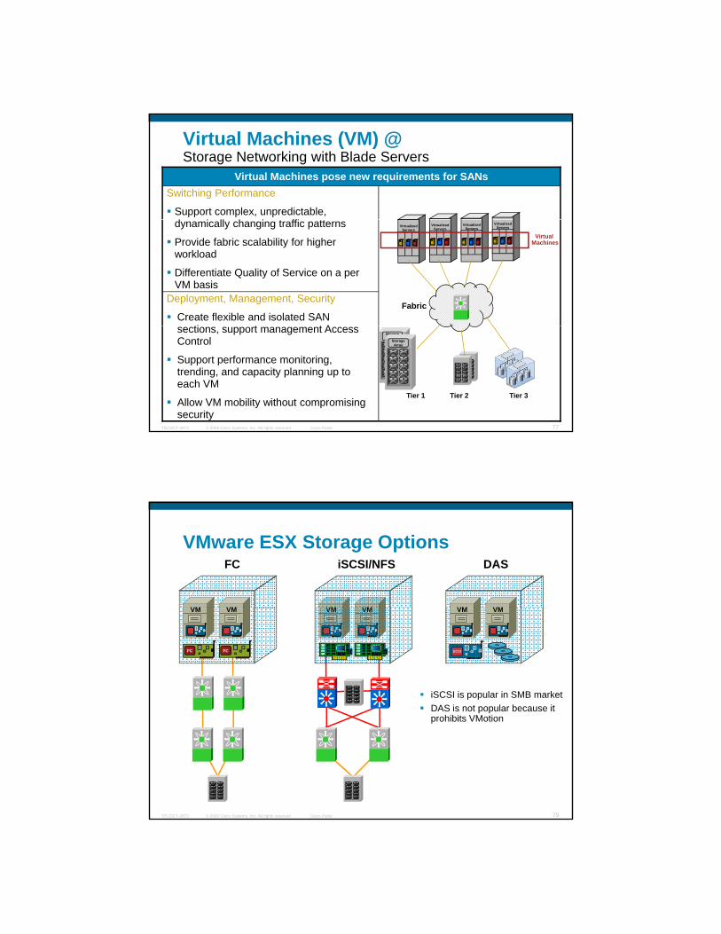
Virtual Machines (VM) @ Storage Networking with Blade Servers
Switching Performance
Support complex, unpredictable, d i ll h i ffi
Virtual Machines pose new requirements for SANs
dynamically changing traffic patterns
Provide fabric scalability for higher workload
Differentiate Quality of Service on a per VM basis
Deployment, Management, Security
Create flexible and isolated SAN ti t t A
VirtualizedServers
VirtualizedServers
VirtualizedServers
VirtualizedServers
Fabric
Virtual Machines
© 2009 Cisco Systems, Inc. All rights reserved. Cisco PublicTECDCT-3873 77
sections, support management Access Control
Support performance monitoring, trending, and capacity planning up to each VM
Allow VM mobility without compromising security
Tier 1 Tier 2 Tier 3
StorageArray
StorageArray
VMware ESX Storage Options
VM VM
iSCSI/NFS
VM VM
DAS
VM VM
FC
SCSIFC
VM VM
FC
VM VM VM VM
iSCSI is popular in SMB marketDAS is not popular because it
© 2009 Cisco Systems, Inc. All rights reserved. Cisco PublicTECDCT-3873 79
prohibits VMotion
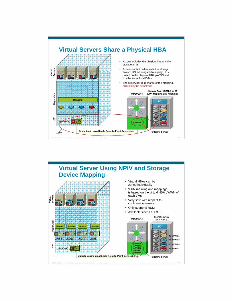
Virtual Servers Share a Physical HBA
A zone includes the physical hba and the storage array
Access control is demanded to storage al
ers
FC
Storage Array (SAN A or B)(LUN Mapping and Masking)MDS9124e
array “LUN masking and mapping”, it is based on the physical HBA pWWN and it is the same for all VMs
The hypervisor is in charge of the mapping, errors may be disastrous
Hyp
ervi
sor
Virt
uSe
rve
Mapping
© 2009 Cisco Systems, Inc. All rights reserved. Cisco PublicTECDCT-3873 80
Zone FC Name Server
pWWN-P
Single Login on a Single Point-to-Point Connection
HW
pWWN-P FC
s
Virtual Server Using NPIV and Storage Device Mapping
Virtual HBAs can be zoned individually“LUN masking and mapping” is based on the virtual HBA pWWN of each VMs
yper
viso
rVi
rtua
lSe
rver
s
Mapping Mapping Mapping Mapping FC
Storage Array(SAN A or B)MDS9124e
each VMsVery safe with respect to configuration errorsOnly supports RDMAvailable since ESX 3.5
© 2009 Cisco Systems, Inc. All rights reserved. Cisco PublicTECDCT-3873 81
HW
H
pWWN-P
FC FC FC FC
pWWN-PpWWN-1pWWN-2pWWN-3pWWN-4
Multiple Logins on a Single Point-to-Point Connection FC Name Server
pWWN-1 pWWN-2 pWWN-3 pWWN-4
To pWWN-1
To pWWN-2
To pWWN-3
To pWWN-4FC

QoS for Individual Virtual Machiness VM-2VM-1
Congested Link
Zone-Based QoS:VM-1 has Priority; VM-2 and any Additional Traffic has Lower Priority
VM-1 Reports Better Performances than VM-2
IVRHyp
ervi
sor
Virt
ual
Mac
hine
s
pWWN-V2Low Priority
VM-2VM-1Cisco MDS 9124e
Multilayer Fabric Switch
FC
QoS QoS
Storage Array
Cisco MDS 9000 Multilayer Fabric Switch
Storage Array(SAN A or B)
© 2009 Cisco Systems, Inc. All rights reserved. Cisco PublicTECDCT-3873 82
IVR
HW
H
FCpWWN-P
pWWN-V1High Priority
Low-Priority Traffic
Q
pWWN-T
FC
Routing Virtual Machines Across VSANs Using NPIV and IVR
s VM-2VM-1
Targets are in different VSANs
Inter VSAN Routing Zoning:IVR-Zone-P includes the physical devices pWWN-P and pWWN-TIVR-Zone-Vx includes the virtual machine ‘x’ and the physical target only
MDS9000FC
X H
yper
viso
rVi
rtua
l M
achi
nes
Raw DeviceMapping
Raw DeviceMapping
pWWN-V2
VM-2VM-1
MDS9124e VSAN-20
WWN T2
FC IVR-Zone-V2
p y g y
LUN Mapping and MaskingEach LUN ‘x’ is exposed to the physical initiator pWWN-P and to virtual machine ‘x’ pWWN-Vx only
© 2009 Cisco Systems, Inc. All rights reserved. Cisco PublicTECDCT-3873 83
FC
IVRHW
ESX
FCpWWN-P
pWWN-V1
VSAN-1 IVRVSAN-1
VSAN-10VSAN-20
VSAN-10
pWWN-T2
pWWN-T1
FCIVR-Zone-V1
IVR-Zone-P

VMotion LUN Migration without NPIV
VM1 VM2 VM3 VM2VM1 VM3 VM3VM1 VM2
Standard HBAs
All LUNs must be “exposed” to All configuration parameters
WWPN
STATU S
1 2 3 4 5 6 7 8 9 10 11 12 13 14 15 16
W S-X9016
1/2 Gbps FC Module
© 2009 Cisco Systems, Inc. All rights reserved. Cisco PublicTECDCT-3873 84
pevery server to ensure disk access during live migration
(single zone)
All configuration parameters are based on the World Wide
Port Name (WWPN) of the physical HBA FCFC
VMotion LUN Migration with NPIV
VM1 VM2 VM3
HBAs with NPIV
Centralized management of No need to reconfigure zoning
WWPN1WWPN2WWPN3
STATU S
1 2 3 4 5 6 7 8 9 10 11 12 13 14 15 16
W S-X9016
1/2 Gbps FC Module
© 2009 Cisco Systems, Inc. All rights reserved. Cisco PublicTECDCT-3873 85
VMs and resourcesRedeploy VMs and support
live migration
No need to reconfigure zoning or LUN masking
Dynamically reprovision VMs without impact to existing
infrastructureFCFC

VMotion: Switch Name Server - Before
© 2009 Cisco Systems, Inc. All rights reserved. Cisco PublicTECDCT-3873 86
VMotion: Switch Name Server - After
© 2009 Cisco Systems, Inc. All rights reserved. Cisco PublicTECDCT-3873 87

Virtualization Infrastructure and ManagementExample: Mapping vCenter ‘Data Centers’ to VSAN
StorageArray
VSAN 10
Data Center Red
StorageArray
StorageArray
Cisco MDS 9124e
Blade
VSAN-20
Frame Tagged on Trunk
VSAN-10
VSAN-30
VSAN-20
VSAN-10
VSAN-
Data CenterGreen
Cisco MDS 9000
Family
© 2009 Cisco Systems, Inc. All rights reserved. Cisco PublicTECDCT-3873 88
VSAN30
Data Center Yellow
Yellow
Green
Red
Admininistrative Team
Administrator Privileges
Storage Storage NetworkVirtual Machines
Array YellowVSAN-30Data Center Yellow
Array GreenVSAN-20Data Center Green
Array RedVSAN-10Data Center Red
In Summary: Blade Servers w/ Cisco LAN & SAN
© 2009 Cisco Systems, Inc. All rights reserved. Cisco PublicTECDCT-3873 89

Unified IO (FCoE)
© 2009 Cisco Systems, Inc. All rights reserved. Cisco PublicTECDCT-3873 90
What Is Data Center Ethernet (DCE)?
Data Center Ethernet is an architectural collection of Ethernet extensions designed to improve Ethernet networking and management in the Data Center.
© 2009 Cisco Systems, Inc. All rights reserved. Cisco PublicTECDCT-3873 91

What’s the Difference Between DCE, CEE and DCB ?
Nothing! All 03 acronyms describe the same thing, meaning the architectural collection of Ethernet extensions (based on open standards) Cisco has co-authored many of the standards associated and is focused on providing a standards-based solution for a Unified Fabric in the data center The IEEE has decided to use the term “DCB” (Data Center Bridging) to
© 2009 Cisco Systems, Inc. All rights reserved. Cisco PublicTECDCT-3873 92
The IEEE has decided to use the term DCB (Data Center Bridging) to describe these extensions to the industry. http://www.ieee802.org/1/pages/dcbridges.html
Provides class of service flow control. Ability to support Priority-based Flow
BenefitFeature
Data Center Ethernet Standards and FeaturesOverview
Auto-negotiation for Enhanced Ethernet capabilities DCBX
Data Center Bridging Capability Exchange
End to End Congestion Management for L2 networkCongestion Notification (BCN/QCN) - 802.1Qau802.1Qau
Grouping classes of traffic into “Service Lanes”IEEE 802.1Qaz, CoS based Enhanced Transmission
Enhanced Transmission Selection - 802.1Qaz802.1Qaz
storage trafficControl (PFC) - 802.1Qbb802.1Qbb
© 2009 Cisco Systems, Inc. All rights reserved. Cisco PublicTECDCT-3873 93
Provides ability to transport various traffic types (e.g. Storage, RDMA)
Lossless Service
Eliminate Spanning Tree for L2 topologies
Utilize full Bi-Sectional bandwidth with ECMPL2 Multi-path for Unicast & Multicast
DCBXp y g
Protocol - 802.1AB (LLDP)802.1AB (LLDP)
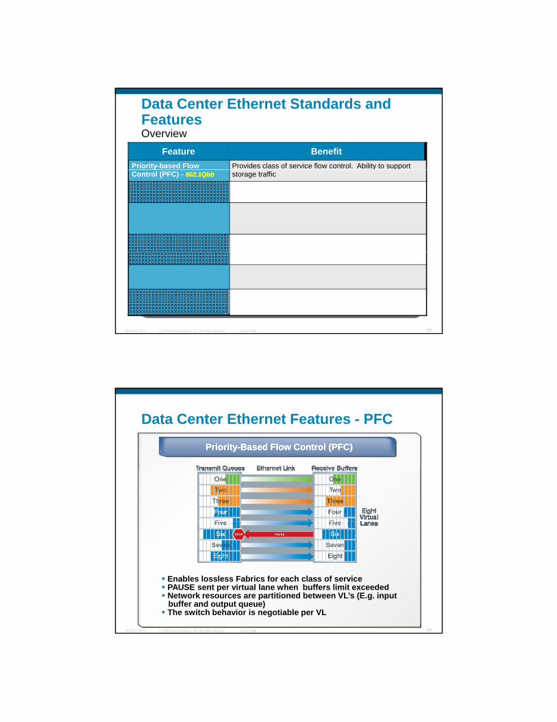
Provides class of service flow control. Ability to support Priority-based Flow
BenefitFeature
Data Center Ethernet Standards and FeaturesOverview
storage trafficControl (PFC) - 802.1Qbb802.1Qbb
© 2009 Cisco Systems, Inc. All rights reserved. Cisco PublicTECDCT-3873 94
Data Center Ethernet Features - PFC
Priority-Based Flow Control (PFC)Priority-Based Flow Control (PFC)
© 2009 Cisco Systems, Inc. All rights reserved. Cisco PublicTECDCT-3873 95
Enables lossless Fabrics for each class of servicePAUSE sent per virtual lane when buffers limit exceededNetwork resources are partitioned between VL’s (E.g. inputbuffer and output queue)The switch behavior is negotiable per VL
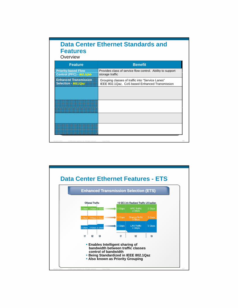
Provides class of service flow control. Ability to support Priority-based Flow
BenefitFeature
Data Center Ethernet Standards and FeaturesOverview
Grouping classes of traffic into “Service Lanes”IEEE 802.1Qaz, CoS based Enhanced Transmission
Enhanced Transmission Selection - 802.1Qaz802.1Qaz
storage trafficControl (PFC) - 802.1Qbb802.1Qbb
© 2009 Cisco Systems, Inc. All rights reserved. Cisco PublicTECDCT-3873 96
Data Center Ethernet Features - ETS
Enhanced Transmission Selection (ETS)Enhanced Transmission Selection (ETS)
© 2009 Cisco Systems, Inc. All rights reserved. Cisco PublicTECDCT-3873 97
Enables Intelligent sharing ofbandwidth between traffic classes control of bandwidthBeing Standardized in IEEE 802.1QazAlso known as Priority Grouping

Provides class of service flow control. Ability to support Priority-based Flow
BenefitFeature
Data Center Ethernet Standards and FeaturesOverview
End to End Congestion Management for L2 networkCongestion Notification (BCN/QCN) - 802.1Qau802.1Qau
Grouping classes of traffic into “Service Lanes”IEEE 802.1Qaz, CoS based Enhanced Transmission
Enhanced Transmission Selection - 802.1Qaz802.1Qaz
storage trafficControl (PFC) - 802.1Qbb802.1Qbb
© 2009 Cisco Systems, Inc. All rights reserved. Cisco PublicTECDCT-3873 98
Data Center Ethernet Features
Congestion ManagementCongestion Management
© 2009 Cisco Systems, Inc. All rights reserved. Cisco PublicTECDCT-3873 99
Moves congestion out of the core to avoid congestion spreadingAllows End-to-End congestion managementStandards track in 802.1Qau
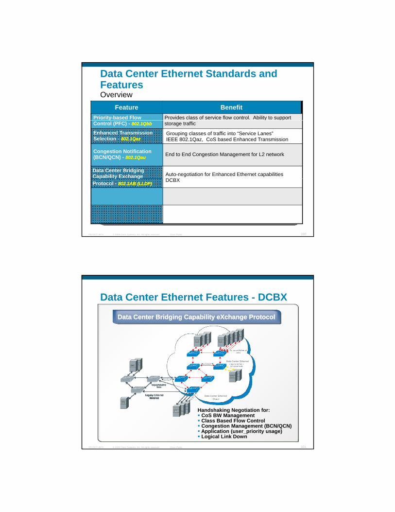
Provides class of service flow control. Ability to support Priority-based Flow
BenefitFeature
Data Center Ethernet Standards and FeaturesOverview
Auto-negotiation for Enhanced Ethernet capabilities DCBX
Data Center Bridging Capability Exchange
End to End Congestion Management for L2 networkCongestion Notification (BCN/QCN) - 802.1Qau802.1Qau
Grouping classes of traffic into “Service Lanes”IEEE 802.1Qaz, CoS based Enhanced Transmission
Enhanced Transmission Selection - 802.1Qaz802.1Qaz
storage trafficControl (PFC) - 802.1Qbb802.1Qbb
© 2009 Cisco Systems, Inc. All rights reserved. Cisco PublicTECDCT-3873 100
DCBXp y g
Protocol - 802.1AB (LLDP)802.1AB (LLDP)
Data Center Ethernet Features - DCBX
Data Center Bridging Capability eXchange ProtocolData Center Bridging Capability eXchange Protocol
Data Center Ethernet
© 2009 Cisco Systems, Inc. All rights reserved. Cisco PublicTECDCT-3873 101
Handshaking Negotiation for:CoS BW ManagementClass Based Flow ControlCongestion Management (BCN/QCN)Application (user_priority usage)Logical Link Down
Data Center Ethernet

Provides class of service flow control. Ability to support Priority-based Flow
BenefitFeature
Data Center Ethernet Standards and FeaturesOverview
Auto-negotiation for Enhanced Ethernet capabilities DCBX
Data Center Bridging Capability Exchange
End to End Congestion Management for L2 networkCongestion Notification (BCN/QCN) - 802.1Qau802.1Qau
Grouping classes of traffic into “Service Lanes”IEEE 802.1Qaz, CoS based Enhanced Transmission
Enhanced Transmission Selection - 802.1Qaz802.1Qaz
storage trafficControl (PFC) - 802.1Qbb802.1Qbb
© 2009 Cisco Systems, Inc. All rights reserved. Cisco PublicTECDCT-3873 102
Eliminate Spanning Tree for L2 topologies
Utilize full Bi-Sectional bandwidth with ECMPL2 Multi-path for Unicast & Multicast
DCBXp y g
Protocol - 802.1AB (LLDP)802.1AB (LLDP)
Data Center Ethernet Features – L2MPLayer 2 Multi-PathingLayer 2 Multi-Pathing
Phase 1Phase 1 Phase 2Phase 2 Phase 3Phase 3
LAN
Active-Active
MACB
MACA
MACA
MACB
LAN LAN
vPCL2 ECMP
L2 ECMP
Phase 1Phase 1 Phase 2Phase 2 Phase 3Phase 3
VirtualSwitch
We are here …
© 2009 Cisco Systems, Inc. All rights reserved. Cisco PublicTECDCT-3873 103
Eliminates STP on UplinkBridge PortsAllows Multiple ActiveUplinks Switch to NetworkPrevents Loops by Pinning aMAC Address to Only OnePortCompletely Transparent toNext Hop Switch
Virtual Switch retains physical switches independent control and data planesVirtual port channel mechanism is
transparent to hosts or switches connected to the virtual switchSTP as fail-safe mechanism to
prevent loops even in the case of control plane failure
Uses ISIS based topologyEliminates STP from L2domainPreferred path selectionTRILL is the work in
progress standard

Provides class of service flow control. Ability to support Priority-based Flow
BenefitFeature
Data Center Ethernet Standards and FeaturesOverview
Auto-negotiation for Enhanced Ethernet capabilities DCBX
Data Center Bridging Capability Exchange
End to End Congestion Management for L2 networkCongestion Notification (BCN/QCN) - 802.1Qau802.1Qau
Grouping classes of traffic into “Service Lanes”IEEE 802.1Qaz, CoS based Enhanced Transmission
Enhanced Transmission Selection - 802.1Qaz802.1Qaz
storage trafficControl (PFC) - 802.1Qbb802.1Qbb
© 2009 Cisco Systems, Inc. All rights reserved. Cisco PublicTECDCT-3873 104
Provides ability to transport various traffic types (e.g. Storage, RDMA)
Lossless Service
Eliminate Spanning Tree for L2 topologies
Utilize full Bi-Sectional bandwidth with ECMPL2 Multi-path for Unicast & Multicast
DCBXp y g
Protocol - 802.1AB (LLDP)802.1AB (LLDP)
Virtual LinksAn Example
VL1 LAN Service LAN/IPVL2 No Drop Service Storage
Up to 8 VL’s per physical linkAbility to support QoS queues within the lanes
VL1VL2VL3
LAN/IP Gateway
VL1 – LAN Service – LAN/IP
VL3 D l d D S i IPC
VL2 - No Drop Service - StorageDCECNA
DCECNA
DCECNA
Campus Core/Internet
© 2009 Cisco Systems, Inc. All rights reserved. Cisco PublicTECDCT-3873 105
Storage Gateway
VL3 – Delayed Drop Service - IPC
Storage AreaNetwork

Fibre Channel over Ethernet – How it Works
Direct mapping of Fibre Channel over EthernetFC-4 FC-4
C
Leverages standards-based extensions to Ethernet (DCE) to provide reliable I/O delivery
MACPHY
FCoE Mapping
FC-0
FC-1
FC-2
FC-3
FC-2
FC-3 FC Frame
Ethernet Header
Ethernet Payload
Ethernet FCS
SOF
EOF
CR
C
(a) Protocol Layers (b) Frame Encapsulation
© 2009 Cisco Systems, Inc. All rights reserved. Cisco PublicTECDCT-3873 106
Priority Flow Control (PFC)
Data Center Bridging Capability eXchange Protocol (DCBX)
10GE LosslessEthernet
Link(DCE)
FCoE Traffic
Other NetworkingTraffic
FCoE Enablers
10Gbps Ethernet
Lossless EthernetLossless EthernetMatches the lossless behavior guaranteed in FC by B2B credits
Ethernet jumbo framesMax FC frame payload = 2112 bytes
Normal ethernet frame, ethertype = FCoE
© 2009 Cisco Systems, Inc. All rights reserved. Cisco PublicTECDCT-3873 107
Ethe
rnet
Hea
der
FCoE
Hea
der
FCH
eade
r
FC Payload CR
C
EOF
FCS
Same as a physical FC frame
Control information: version, ordered sets (SOF, EOF)
o a et e et a e, et e type Co

Encapsulation Technologies
TCP
iSCSI SRP
TCP
FCIP
FCP
TCP
iFCP
FCP FCP FCP
SCSI Layer
Operating System / Applications
© 2009 Cisco Systems, Inc. All rights reserved. Cisco PublicTECDCT-3873 108
Ethernet
IP
IB
IP IP FCoE
FC
1, 2, 4, 8, 10 Gbps 1, 10 . . . Gbps 10, 20 Gbps
Encapsulation Technologies
FCP layer is untouched
Allows same management tools
FCP
SCSI Layer
OS / ApplicationsAllows same management toolsfor Fibre Channel
Allows same Fibre Channel drivers
Allows same Multipathingsoftware
Simplifies certifications ith
© 2009 Cisco Systems, Inc. All rights reserved. Cisco PublicTECDCT-3873 109
E. Ethernet
FCoE
1, 10 . . . Gbps
Simplifies certifications with OSMs
Evolution rather than Revolution

Unified I/O (FCoE) – Why ?
Fewer CNAs (Converged Network adapters) instead of NICs, HBAs and HCAs
FC TrafficFC HBAFC HBA
Limited number of interfaces for Blade Servers
All traffic goes over
10GE
CNACNAFC TrafficFC HBAFC HBA
NICNIC LAN Traffic
© 2009 Cisco Systems, Inc. All rights reserved. Cisco PublicTECDCT-3873 110
10GECNACNANICNIC LAN Traffic
NICNIC Mgmt Traffic
NICNIC Backup Traffic
IPC TrafficHCAHCA
SAN BSAN ALAN
Today:
Unified I/O: What Changes on the Network ?
Management Core switches
Access – Top of the Rack switches
FC HBA
FC HBA
NIC
NIC
© 2009 Cisco Systems, Inc. All rights reserved. Cisco PublicTECDCT-3873 111
EthernetFC
Rack switches
Servers

SAN BSAN ALAN
Today
Unified I/O: … Just the Access LayerUnified I/O Unified I/O
Reduction of server adaptersFewer Cables
Management
FCoE Switch
Fewer CablesSimplification of access layer & cablingGateway free implementation - fits in installed base of existing LAN and SANL2 Multipathing Access – DistributionLower TCOInvestment Protection (LANs and SANs)Consistent Operational ModelOne set of ToR Switches
© 2009 Cisco Systems, Inc. All rights reserved. Cisco PublicTECDCT-3873 112
FCoEEthernetFC
Converged Network Adapters (CNA)
© 2009 Cisco Systems, Inc. All rights reserved. Cisco PublicTECDCT-3873 113

CNA View on Host
10 GE/FCoE
FC10 GE
CiscoASIC
© 2009 Cisco Systems, Inc. All rights reserved. Cisco PublicTECDCT-3873 114
PCIe Bus
CNA View on VMware ESX – Fibre Channel
Emulex
© 2009 Cisco Systems, Inc. All rights reserved. Cisco PublicTECDCT-3873 115
Qlogic
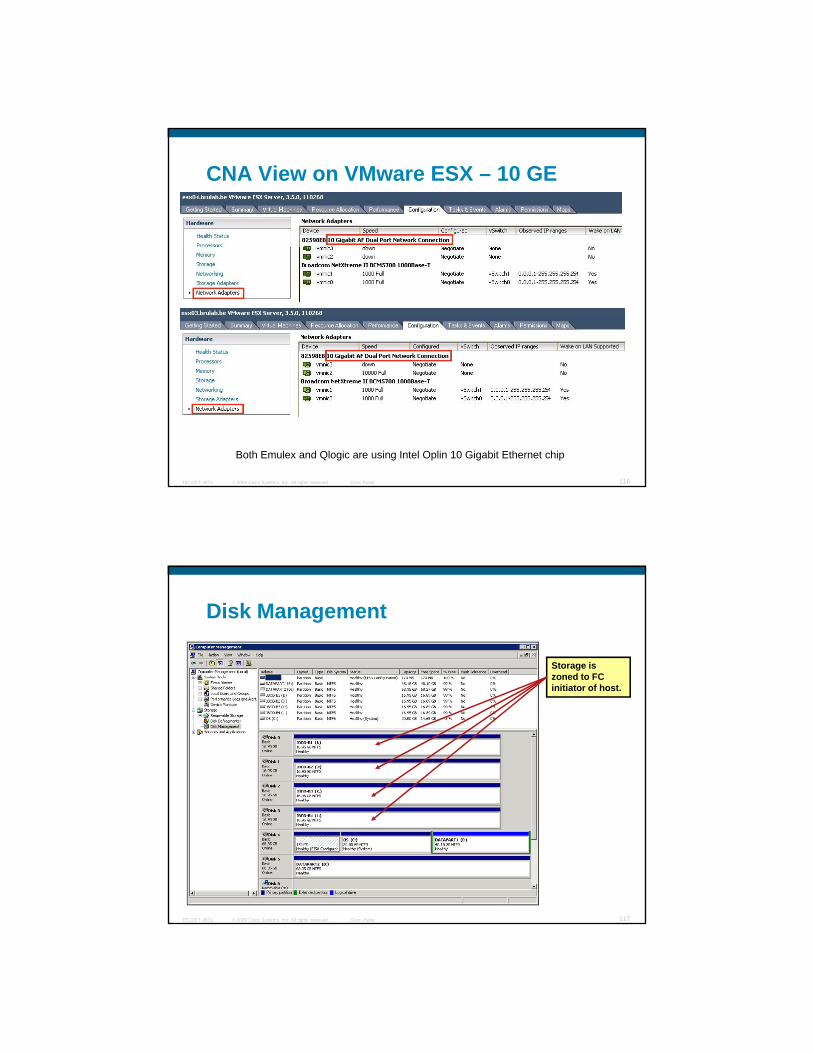
CNA View on VMware ESX – 10 GE
© 2009 Cisco Systems, Inc. All rights reserved. Cisco PublicTECDCT-3873 116
Both Emulex and Qlogic are using Intel Oplin 10 Gigabit Ethernet chip
Storage is zoned to FC i iti t f h t
Disk Management
initiator of host.
© 2009 Cisco Systems, Inc. All rights reserved. Cisco PublicTECDCT-3873 117
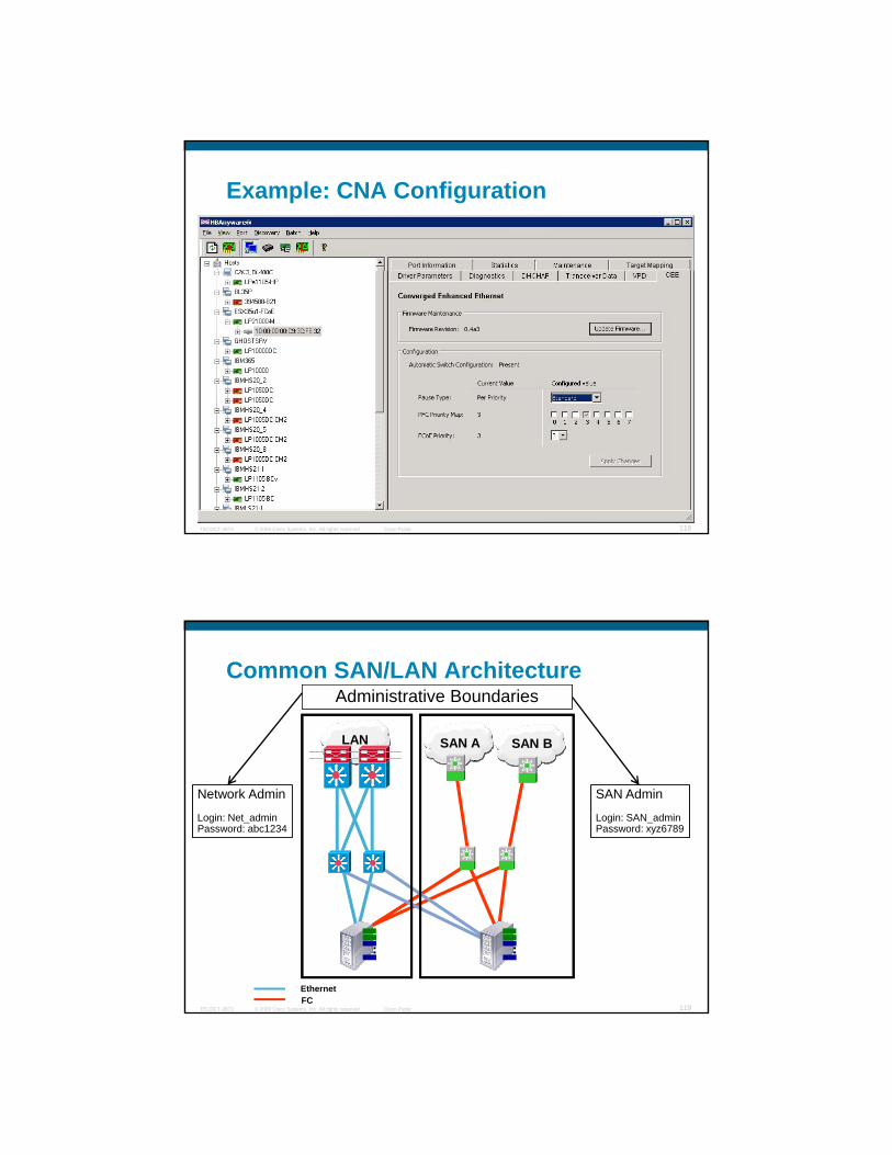
Example: CNA Configuration
© 2009 Cisco Systems, Inc. All rights reserved. Cisco PublicTECDCT-3873 118
Common SAN/LAN Architecture
SAN BSAN ALAN
Administrative Boundaries
Network Admin
Login: Net_adminPassword: abc1234
SAN Admin
Login: SAN_adminPassword: xyz6789
© 2009 Cisco Systems, Inc. All rights reserved. Cisco PublicTECDCT-3873 119
EthernetFC

Common SAN/LAN Architecture
SAN BSAN ALAN
Administrative Boundaries
NX5000
Network Admin
Login: Net_adminPassword: abc1234
SAN Admin
Login: SAN_adminPassword: xyz6789
© 2009 Cisco Systems, Inc. All rights reserved. Cisco PublicTECDCT-3873 120DataCenter Ethernet with FCoE
CNA
CNA
CNA
CNA
Ethernet FC
Unified IO Deployment - Unified IO
Fabric AFabric A Fabric BFabric B
SAN Fabric
L3
CoreCoreStorage Storage ArraysArrays
N7KN7K N7KN7K
L2L3
L2
AggregationAggregation
AccessAccess
EnetCNALAN Access
SAN EdgeB
SAN EdgeA
N5KN5K N5KN5K N5KN5K N5KN5K
N7KN7K N7KN7K
MDS9500MDS9500 MDS9500MDS9500 MDS9500MDS9500 MDS9500MDS9500
C6KC6K C6KC6K
© 2009 Cisco Systems, Inc. All rights reserved. Cisco PublicTECDCT-3873 121
A B ED
EnetFCFCoE
Unified IO Server Farm Pod EnvironmentConverged Edge Infrastructure: Unified/IO using ToR at the edge, and CNA at the hostsToR 10GE Unified/IO Server EnvironmentsLeverage Ethernet and Storage Clouds to reach traditional LAN/SAN services
VF_Ports
VN_Ports

Unified IO Farm - Phase 1: vPC @ Aggregation
Fabric AFabric A Fabric BFabric B
SAN Fabric
L3
CoreCoreStorage Storage ArraysArrays
N7KN7K N7KN7K
L2L3
L2
AggregationAggregation
AccessAccess
EnetCNALAN Access
SAN EdgeB
SAN EdgeA
N5KN5K N5KN5K N5KN5K N5KN5K
MDS9500MDS9500 MDS9500MDS9500 MDS9500MDS9500 MDS9500MDS9500
C6KC6K C6KC6K
4 4
4
N7KN7K
4 44
4
© 2009 Cisco Systems, Inc. All rights reserved. Cisco PublicTECDCT-3873 122
A B ED
EnetFCFCoE
Unified IO Server Farm using vPC at Aggregation LAN cloudAccess Switches remain as single logical instanceStorage connectivity is unchanged
Unified IO Farm - Phase 2: vPC @ Aggregation and Access
Fabric AFabric A Fabric BFabric B
SAN Fabric
L3
CoreCoreStorage Storage ArraysArrays
N7KN7K N7KN7K
L2L3
L2
AggregationAggregation
AccessAccess
EnetCNALAN Access
SAN EdgeB
SAN EdgeA
N5KsN5Ks N5KsN5Ks
MDS9500MDS9500 MDS9500MDS9500 MDS9500MDS9500 MDS9500MDS9500
C6KC6K C6KC6K
4 4
4
N7KsN7Ks
8 8
© 2009 Cisco Systems, Inc. All rights reserved. Cisco PublicTECDCT-3873 123
A B ED
EnetFCFCoE
Unified IO Server Farm using vPC at Aggregation LAN cloudAccess Switches provide vPC for LAN connectivityStorage connectivity is unchanged (different physical paths for SAN Fabric A and B)

Nexus 5000 on the Aggregation LayerVE Interfaces are NOT Supported so Far
© 2009 Cisco Systems, Inc. All rights reserved. Cisco PublicTECDCT-3873 124
Cisco Unified Computing System (UCS)
© 2009 Cisco Systems, Inc. All rights reserved. Cisco PublicTECDCT-3873 125

The Unified Computing Journey
Unified Fabric
• Wire once
Unified Computing
• Consolidated
Data Center 3.0
• Business service focused
• Resilient
Unified Virtual
Machines
• VN - Link
© 2009 Cisco Systems, Inc. All rights reserved. Cisco PublicTECDCT-3873 126
infrastructure• Low-latency
lossless• Virtualization
aware
Fabric & I/O• Stateless• Vn-tagging• Management
Resilient• Distributed • Standards-
based
• Application Mobility
Unified Computing Building BlocksUnified Fabric Introduced with the Cisco Nexus Series
PhysicalWire once infrastructureWire once infrastructure (Nexus 5000)Fewer switches, adapters, cables
Ethernet FibreChannel
© 2009 Cisco Systems, Inc. All rights reserved. Cisco PublicTECDCT-3873 127

Unified Computing Building BlocksUnified Fabric Introduced with the Cisco Nexus Series
PhysicalWire once infrastructure
VirtualWire once infrastructure (Nexus 5000)Fewer switches, adapters, cables
VirtualVN-Link (Nexus 1000v)Manage virtual the same as physical
Ethernet FibreChannel
© 2009 Cisco Systems, Inc. All rights reserved. Cisco PublicTECDCT-3873 128
physical
Physical
Unified Computing Building BlocksUnified Fabric Introduced with the Cisco Nexus Series
PhysicalWire once infrastructure
VirtualWire once infrastructure (Nexus 5000)Fewer switches, adapters, cables
VirtualVN-Link (Nexus 1000v)Manage virtual the same as physical
Ethernet FibreChannel
© 2009 Cisco Systems, Inc. All rights reserved. Cisco PublicTECDCT-3873 129
physical
ScaleFabric Extender (Nexus 2000)Scale without increasing points of management
Physical
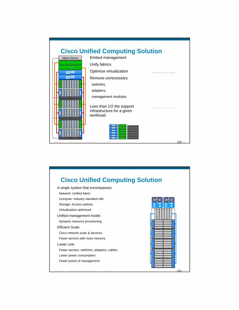
Mgmt Server Mgmt ServerEmbed management
Unify fabrics
Optimize virtualization
Mgmt Server
Cisco Unified Computing Solution
p
Remove unnecessary switches,
adapters,
management modules
Less than 1/2 the support
© 2009 Cisco Systems, Inc. All rights reserved. Cisco PublicTECDCT-3873 130130
ppinfrastructure for a given workload
Mgmt Server
Cisco Unified Computing SolutionA single system that encompasses:
Network: Unified fabric
Compute: Industry standard x86
Storage: Access options
Virtualization optimized
Unified management modelDynamic resource provisioning
Efficient ScaleCisco network scale & services
© 2009 Cisco Systems, Inc. All rights reserved. Cisco PublicTECDCT-3873 131131
Fewer servers with more memory
Lower costFewer servers, switches, adapters, cables
Lower power consumption
Fewer points of management
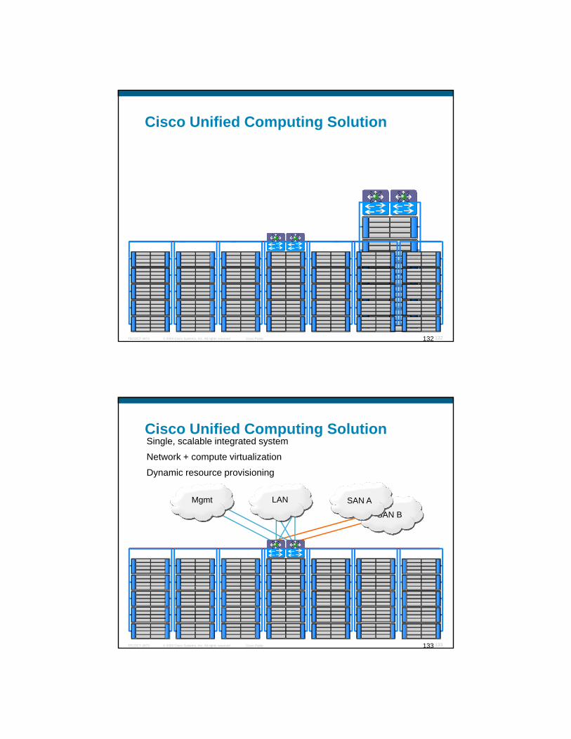
Cisco Unified Computing Solution
© 2009 Cisco Systems, Inc. All rights reserved. Cisco PublicTECDCT-3873 132132
Cisco Unified Computing SolutionSingle, scalable integrated system
Network + compute virtualization
Dynamic resource provisioning
SAN B
Mgmt SAN ALAN
© 2009 Cisco Systems, Inc. All rights reserved. Cisco PublicTECDCT-3873 133133
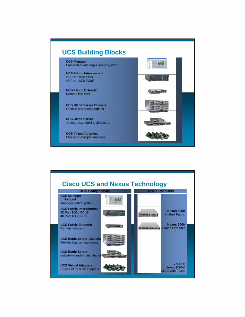
UCS ManagerEmbedded– manages entire system
UCS Fabric Interconnect
UCS Building Blocks
20 Port 10Gb FCoE40 Port 10Gb FCoE
UCS Fabric ExtenderRemote line card
UCS Blade Server ChassisFlexible bay configurations
© 2009 Cisco Systems, Inc. All rights reserved. Cisco PublicTECDCT-3873 134
UCS Blade ServerIndustry-standard architecture
UCS Virtual AdaptersChoice of multiple adapters
Cisco UCS and Nexus TechnologyUCS ManagerEmbeddedManages entire system
Nexus ProductsUCS Components
UCS Fabric Interconnect20 Port 10Gb FCoE40 Port 10Gb FCoE
UCS Fabric ExtenderRemote line card
UCS Blade Server ChassisFlexible bay configurations
Nexus 2000Fabric Extender
Nexus 5000Unified Fabric
© 2009 Cisco Systems, Inc. All rights reserved. Cisco PublicTECDCT-3873 135
Flexible bay configurations
UCS Blade ServerIndustry-standard architecture
UCS Virtual AdaptersChoice of multiple adapters
VN-LinkNexus 1000V
CNAs with FCoE

Cisco Unified Computing System (UCS) – Physical
© 2009 Cisco Systems, Inc. All rights reserved. Cisco PublicTECDCT-3873 136
Cisco Unified Computing System (UCS) – Physical
Top of Rack Interconnect(40 or 20 10GE ports) + (2 or 1 GEM uplink l t )
MGMT
SSG G
SAN
G G
SANLAN
slots)
ChassisUp to 8 half width blades or 4 full width blades
Fabric ExtenderHost to uplink traffic engineering
Blade EnclosureBlade Enclosure
II
x8x8x8x8
CC
A
G GG
R
A
GG
R
G
PM P
FabricInterconnect
FabricInterconnect
FabricInterconnect
FabricInterconnect
FabricExtender
FabricExtender
FabricExtender
FabricExtender
© 2009 Cisco Systems, Inc. All rights reserved. Cisco PublicTECDCT-3873 137
Up to 80Gb Flexible bandwidth allocation
Adapter – 3 optionsCisco Virtualized adapter
Compatibility CNAs (Emulex and QLogic) –Native FC + Intel Oplin
Intel Oplin - (10GE only)
Compute Blade
x86 Computer x86 Computer
X
BB
X X X X X
PM P
Compute Blade(Half slot)
Compute Blade(Half slot)
AdapterAdapter
Compute Blade(Full slot)
Compute Blade(Full slot)
AdapterAdapterAdapterAdapter
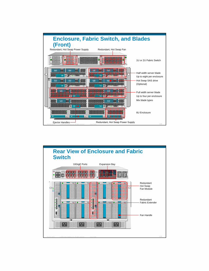
Enclosure, Fabric Switch, and Blades (Front)
1U or 2U Fabric Switch
Redundant, Hot Swap Power Supply Redundant, Hot Swap Fan
Up to eight per enclosure
(Optional)
Full width server blade
Half width server blade
Hot Swap SAS drive
© 2009 Cisco Systems, Inc. All rights reserved. Cisco PublicTECDCT-3873 138
6U Enclosure
Up to four per enclosure
Mix blade types
Ejector Handles Redundant, Hot Swap Power Supply
Rear View of Enclosure and Fabric Switch
10GigE Ports Expansion Bay
Redundant Fabric Extender
RedundantHot SwapFan Module
© 2009 Cisco Systems, Inc. All rights reserved. Cisco PublicTECDCT-3873 139
Fan Handle

UCS Adapters Options
Virtual Machine Aware: Existing Driver Stacks Proven 10GbE T h l
CostCostCompatibilityCompatibilityVirtualizationVirtualization
Virtualization and Consolidation
Technology
© 2009 Cisco Systems, Inc. All rights reserved. Cisco PublicTECDCT-3873 140
Converged network adapters (CNA)
Ability to mix and match adapter types within a system
Automatic discovery of component types
UCS Adapters: Interface Views
10 GigE Backplane interfaces to IOMsinterfaces to IOMsPhysical Interfaces
vHBAs & vNICs will be bound to these physical interface
© 2009 Cisco Systems, Inc. All rights reserved. Cisco PublicTECDCT-3873 141
Intel Oplin will not have HBA component. Could run FCoE software stack
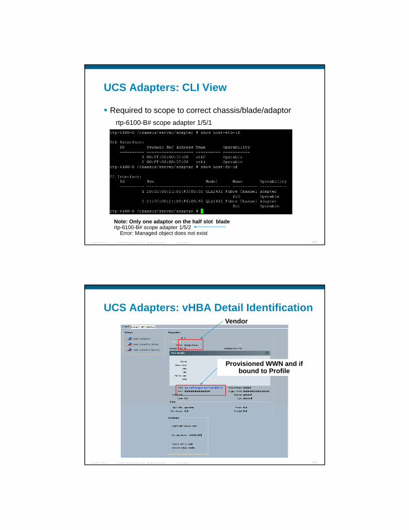
UCS Adapters: CLI View
Required to scope to correct chassis/blade/adaptor rtp-6100-B# scope adapter 1/5/1rtp 6100 B# scope adapter 1/5/1
© 2009 Cisco Systems, Inc. All rights reserved. Cisco PublicTECDCT-3873 142
Note: Only one adaptor on the half slot bladertp-6100-B# scope adapter 1/5/2
Error: Managed object does not exist
UCS Adapters: vHBA Detail IdentificationVendor
Provisioned WWN and if bound to Profile
© 2009 Cisco Systems, Inc. All rights reserved. Cisco PublicTECDCT-3873 143

UCS Adapters: Ethernet vNIC Details
Ethernet stats
© 2009 Cisco Systems, Inc. All rights reserved. Cisco PublicTECDCT-3873 144
Cisco Unified Computing System (UCS) – Logical
© 2009 Cisco Systems, Inc. All rights reserved. Cisco PublicTECDCT-3873 145

Unified Computing Key Value Propositions:Drivers for Use Cases
Hardware State Abstraction – Service Profiles
Unified Fabric - FCOE
Virtualized Adapter
© 2009 Cisco Systems, Inc. All rights reserved. Cisco PublicTECDCT-3873 146
Expanded Memory Server
Unified Management
Server Attributes / Configuration Points 1/3
ServerServerIdentity (UUID)
Adapters
Number
Type: FC, Ethernet
Identity
© 2009 Cisco Systems, Inc. All rights reserved. Cisco PublicTECDCT-3873 147
Characteristics
Firmware
Revisions
Configuration settings

Server Attributes / Configuration Points 2/3
NetworkNetworkUplinks
LAN settings
vLAN, QoS, etc…
SAN settings
vSAN
ServerServerIdentity (UUID)
Adapters
Number
Type: FC, Ethernet
Identity
© 2009 Cisco Systems, Inc. All rights reserved. Cisco PublicTECDCT-3873 148
Firmware
Revisions
Characteristics
Firmware
Revisions
Configuration settings
Server Attributes / Configuration Points 3/3
StorageStorageOptional Disk usageSAN settings
LUNsPersistent Binding
FirmwareRevisions
NetworkNetworkUplinks
LAN settings
vLAN, QoS, etc…
SAN settings
vSAN
ServerServerIdentity (UUID)
Adapters
Number
Type: FC, Ethernet
Identity
© 2009 Cisco Systems, Inc. All rights reserved. Cisco PublicTECDCT-3873 149
Firmware
Revisions
Characteristics
Firmware
Revisions
Configuration settings
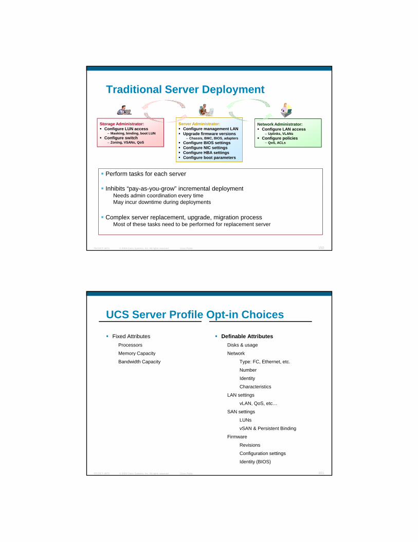
Traditional Server Deployment
Server Administrator:C fi t LAN
Storage Administrator:C fi LUN
Network Administrator:Configure management LANUpgrade firmware versions
– Chassis, BMC, BIOS, adaptersConfigure BIOS settingsConfigure NIC settingsConfigure HBA settingsConfigure boot parameters
Configure LUN access– Masking, binding, boot LUN
Configure switch– Zoning, VSANs, QoS
Configure LAN access– Uplinks, VLANs
Configure policies– QoS, ACLs
Perform tasks for each server
Inhibits “pay-as-you-grow” incremental deployment
© 2009 Cisco Systems, Inc. All rights reserved. Cisco PublicTECDCT-3873 150
Inhibits pay-as-you-grow incremental deploymentNeeds admin coordination every timeMay incur downtime during deployments
Complex server replacement, upgrade, migration processMost of these tasks need to be performed for replacement server
UCS Server Profile Opt-in Choices
Fixed AttributesProcessors
Memory Capacity
Definable Attributes Disks & usage
NetworkMemory Capacity
Bandwidth Capacity
Network
Type: FC, Ethernet, etc.
Number
Identity
Characteristics
LAN settings
vLAN, QoS, etc…
SAN settings
© 2009 Cisco Systems, Inc. All rights reserved. Cisco PublicTECDCT-3873 151
g
LUNs
vSAN & Persistent Binding
Firmware
Revisions
Configuration settings
Identity (BIOS)
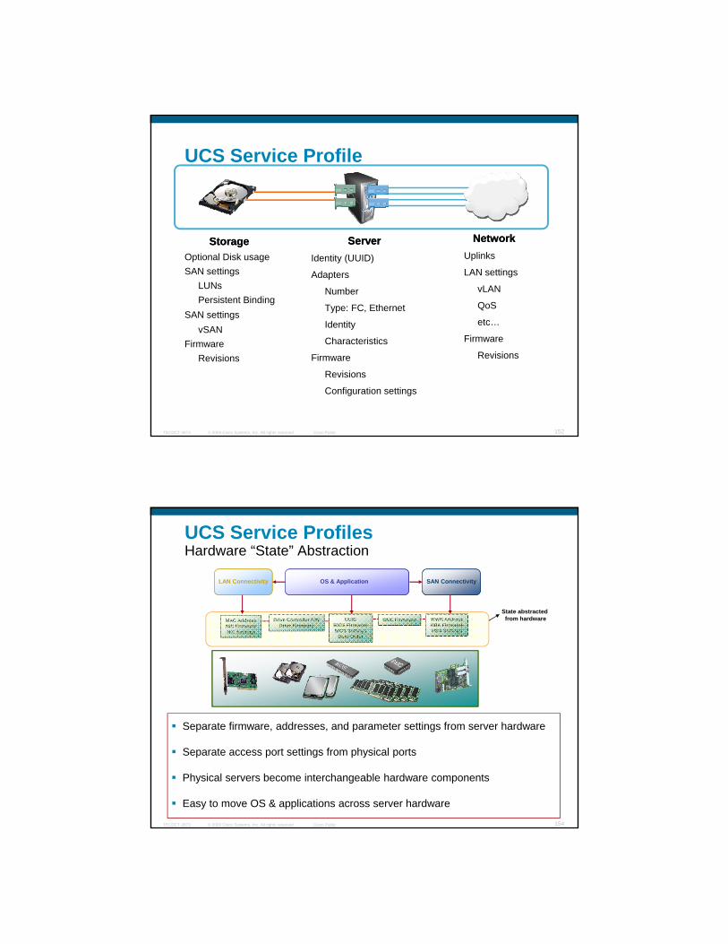
UCS Service Profile
NetworkNetworkUplinks
LAN settings
vLAN
QoS
etc…
StorageStorageOptional Disk usageSAN settings
LUNsPersistent Binding
SAN settingsvSAN
ServerServerIdentity (UUID)
Adapters
Number
Type: FC, Ethernet
Identity
© 2009 Cisco Systems, Inc. All rights reserved. Cisco PublicTECDCT-3873 152
Firmware
Revisions
vSANFirmware
Revisions
y
Characteristics
Firmware
Revisions
Configuration settings
UCS Service ProfilesHardware “State” Abstraction
State abstracted
LAN Connectivity SAN ConnectivityOS & Application
BMC FirmwareMAC AddressNIC FirmwareNIC Settings
Drive Controller F/WDrive Firmware
UUIDBIOS FirmwareBIOS Settings
Boot Order
WWN AddressHBA FirmwareHBA Settings
from hardware
© 2009 Cisco Systems, Inc. All rights reserved. Cisco PublicTECDCT-3873 154
Separate firmware, addresses, and parameter settings from server hardware
Separate access port settings from physical ports
Physical servers become interchangeable hardware components
Easy to move OS & applications across server hardware

Don’t I Get this Already from VMware?Hypervisors & Hardware State
Server Virtualization(VMware, Xen, HyperV, etc.)
Server Virtualization(VMware, Xen, HyperV, etc.)
Virtual Machine
Virtual Machine
Virtual Machine
Virtual Machine
Virtual Machine
Virtual Machine
Hardware State VirtualizationHardware State Virtualization
BMC FirmwareMAC AddressNIC FirmwareNIC Settings
Drive Controller F/WDrive Firmware
UUIDBIOS FirmwareBIOS Settings
Boot Order
WWN AddressHBA FirmwareHBA Settings
HYPERVISOR
© 2009 Cisco Systems, Inc. All rights reserved. Cisco PublicTECDCT-3873 155
Server virtualization & hardware state abstraction are independent of each other
Hypervisor (or OS) is unaware of underlying hardware state abstraction
UCS Service Profiles End to End Configure of Full UCS HW Stack
© 2009 Cisco Systems, Inc. All rights reserved. Cisco PublicTECDCT-3873 156
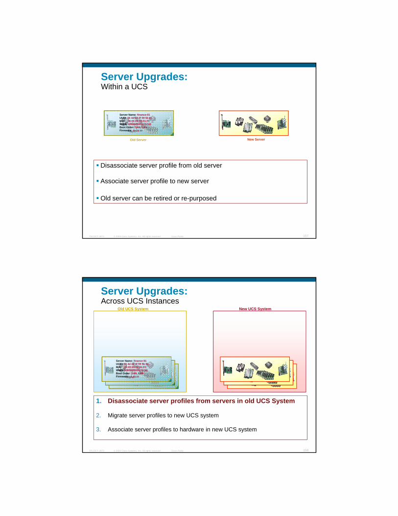
Server Upgrades: Within a UCS
Server Name: finance-01UUID: 56 4d cd 3f 59 5b 61…MAC : 08:00:69:02:01:FCMAC : 08:00:69:02:01:FCWWN: 5080020000075740Boot Order: SAN, LANFirmware: xx.yy.zz
Disassociate server profile from old server
Associate server profile to new server
Old Server New Server
© 2009 Cisco Systems, Inc. All rights reserved. Cisco PublicTECDCT-3873 157
Associate server profile to new server
Old server can be retired or re-purposed
Server Upgrades: Across UCS Instances
Old UCS System New UCS System
Server Name: finance-01UUID: 56 4d cd 3f 59 5b 61…MAC : 08:00:69:02:01:FCWWN: 5080020000075740Boot Order: SAN, LANFirmware: xx.yy.zz
Server Name: finance-01UUID: 56 4d cd 3f 59 5b 61…MAC : 08:00:69:02:01:FCWWN: 5080020000075740Boot Order: SAN, LANFirmware: xx.yy.zz
Server Name: finance-01UUID: 56 4d cd 3f 59 5b 61…MAC : 08:00:69:02:01:FCWWN: 5080020000075740Boot Order: SAN, LANFirmware: xx.yy.zz
© 2009 Cisco Systems, Inc. All rights reserved. Cisco PublicTECDCT-3873 158
1. Disassociate server profiles from servers in old UCS System
2. Migrate server profiles to new UCS system
3. Associate server profiles to hardware in new UCS system

Server Upgrades:Across UCS Instances
Server Name: finance-01UUID: 56 4d cd 3f 59 5b 61…MAC : 08:00:69:02:01:FCWWN: 5080020000075740
Server Name: finance-01UUID: 56 4d cd 3f 59 5b 61…MAC : 08:00:69:02:01:FCWWN: 5080020000075740
Server Name: finance-01UUID: 56 4d cd 3f 59 5b 61…MAC : 08:00:69:02:01:FCWWN: 5080020000075740Boot Order: SAN, LAN
Old System New System
Boot Order: SAN, LANFirmware: xx.yy.zz
WWN: 5080020000075740Boot Order: SAN, LANFirmware: xx.yy.zz
Firmware: xx.yy.zz
© 2009 Cisco Systems, Inc. All rights reserved. Cisco PublicTECDCT-3873 159
1. Disassociate server profiles from servers in old UCS system
2. Migrate server profiles to new UCS system
3. Associate server profiles to hardware in new UCS system
Server Upgrades:Across UCS Instances
Server Name: finance-01UUID: 56 4d cd 3f 59 5b 61…MAC : 08:00:69:02:01:FCWWN: 5080020000075740Boot Order: SAN LAN
Server Name: finance-01UUID: 56 4d cd 3f 59 5b 61…MAC : 08:00:69:02:01:FCWWN: 5080020000075740Boot Order: SAN, LANFirmware: xx.yy.zz
Server Name: finance-01UUID: 56 4d cd 3f 59 5b 61…MAC : 08:00:69:02:01:FCWWN: 5080020000075740Boot Order: SAN, LANFirmware: xx.yy.zz
Old System New System
Boot Order: SAN, LANFirmware: xx.yy.zz
Firmware: xx.yy.zz
© 2009 Cisco Systems, Inc. All rights reserved. Cisco PublicTECDCT-3873 160
1. Disassociate server profiles from servers in old UCS system
2. Migrate server profiles to new UCS system
3. Associate server profiles to hardware in new UCS system
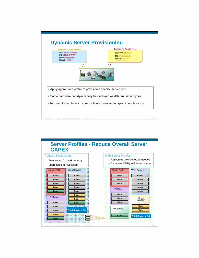
Dynamic Server ProvisioningServer Name: web-server-01UUID: 56 4d cd 3f 59 5b 61…MAC : 08:00:69:02:01:FCWWN: 5080020000075740Boot Order: SAN, LANFirmware: xx yy zz
Server Name: app-server-01UUID: 65 d4 cd f3 59 5b 16…MAC : 08:00:69:02:01:16WWN: 5080020000076789Boot Order: SAN, LANFirmware: xx.yy.zz
Profiles for Web Servers Profiles for App Servers
Firmware: xx.yy.zz yy
Apply appropriate profile to provision a specific server type
© 2009 Cisco Systems, Inc. All rights reserved. Cisco PublicTECDCT-3873 161
Apply appropriate profile to provision a specific server type
Same hardware can dynamically be deployed as different server types
No need to purchase custom configured servers for specific applications
Server Profiles - Reduce Overall Server CAPEX
Today’s Deployment:Provisioned for peak capacity
Spare node per workload
With Server Profiles:– Resources provisioned as needed– Same availability with fewer spares
Blade
Blade
Blade
Blade
Blade
Blade
Web Servers
Blade
Blade
Blade
Blade
Blade
Oracle RAC
VMware
Blade
Blade
Blade
Blade
Web Servers
Blade
Blade
Blade
Oracle RAC
Blade
VMware
Blade
© 2009 Cisco Systems, Inc. All rights reserved. Cisco PublicTECDCT-3873 162
Total Servers: 18
Blade
Blade
Blade
Blade
Blade
Blade
Blade
VMware Blade
Blade
HA Spare
BurstCapacity
Hot SpareBurst Capacity SpareNormal use Blade
Blade
Blade
Total Servers: 14

Unified Computing Key Value Propositions:Drivers for Use Cases
Hardware State Abstraction – Service Profiles
Unified Fabric - FCOE
Virtualized Adapter
© 2009 Cisco Systems, Inc. All rights reserved. Cisco PublicTECDCT-3873 165
Expanded Memory Server
Unified Management
LANIPC
Unified Fabric
SAN
Bla
de C
hass
is
10GE/FCoE
Unified FabricFewer switches
Fewer adapters
All I/O types available in each chassis
10GE & FCoE
Today’s ApproachAll fabric types have switches in each chassis
Repackaged switches
Complex to manage
Bl d h i fi ti
© 2009 Cisco Systems, Inc. All rights reserved. Cisco PublicTECDCT-3873 166
Bla
de
Bla
de
10GE & FCoE
LAN, SAN, IPC
Easier to manage
Blades can work with any chassis
Small network domain
Blade-chassis configuration dependency
Costly
Small network domain
Bla
de
Bla
de

High performance backplane• 2x 40G total bandwidth per half slot
- 8 lanes of 10G (half-slot)16 lanes of 10G (full slot)
Backplane and Fabric Extender
- 16 lanes of 10G (full-slot)• Redundant data and management paths• Support auto discover of all component
Compute blade
Compute blade
Compute blade
Backplane Fabric Extender
© 2009 Cisco Systems, Inc. All rights reserved. Cisco PublicTECDCT-3873 167
Fabric extender• Manage oversubscription
2:1 to 8:1• FCoE from blade to fabric switch• Customizable bandwidth
Compute blade
Compute blade
Compute blade
Compute blade
Compute blade
UCS: Overall System (Rear)
Uplinks
© 2009 Cisco Systems, Inc. All rights reserved. Cisco PublicTECDCT-3873 168
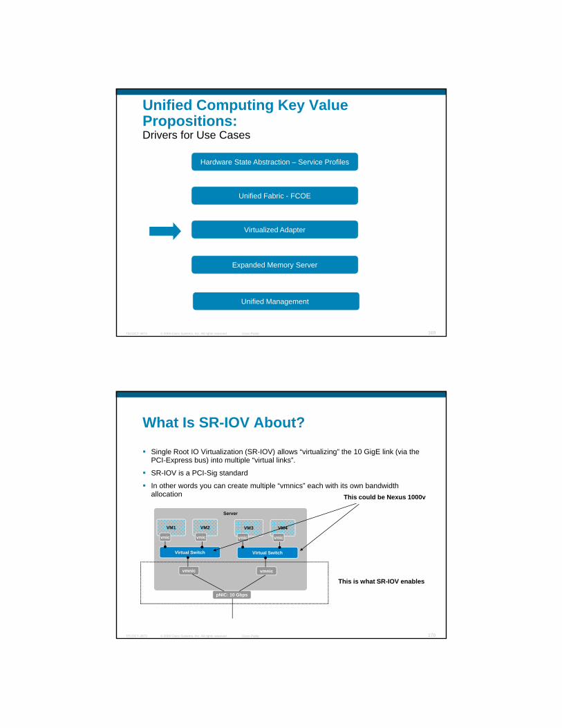
Unified Computing Key Value Propositions:Drivers for Use Cases
Hardware State Abstraction – Service Profiles
Unified Fabric - FCOE
Virtualized Adapter
© 2009 Cisco Systems, Inc. All rights reserved. Cisco PublicTECDCT-3873 169
Expanded Memory Server
Unified Management
What Is SR-IOV About?
Single Root IO Virtualization (SR-IOV) allows “virtualizing” the 10 GigE link (via the PCI-Express bus) into multiple “virtual links”.
SR-IOV is a PCI-Sig standardSR-IOV is a PCI-Sig standard
In other words you can create multiple “vmnics” each with its own bandwidth allocation
Server
VM1
vnic
VM2
vnic
Virtual Switch
VM3
vnic
VM4
vnic
Virtual Switch
This could be Nexus 1000v
© 2009 Cisco Systems, Inc. All rights reserved. Cisco PublicTECDCT-3873 170
vmnic vmnic
pNIC: 10 Gbps
This is what SR-IOV enables
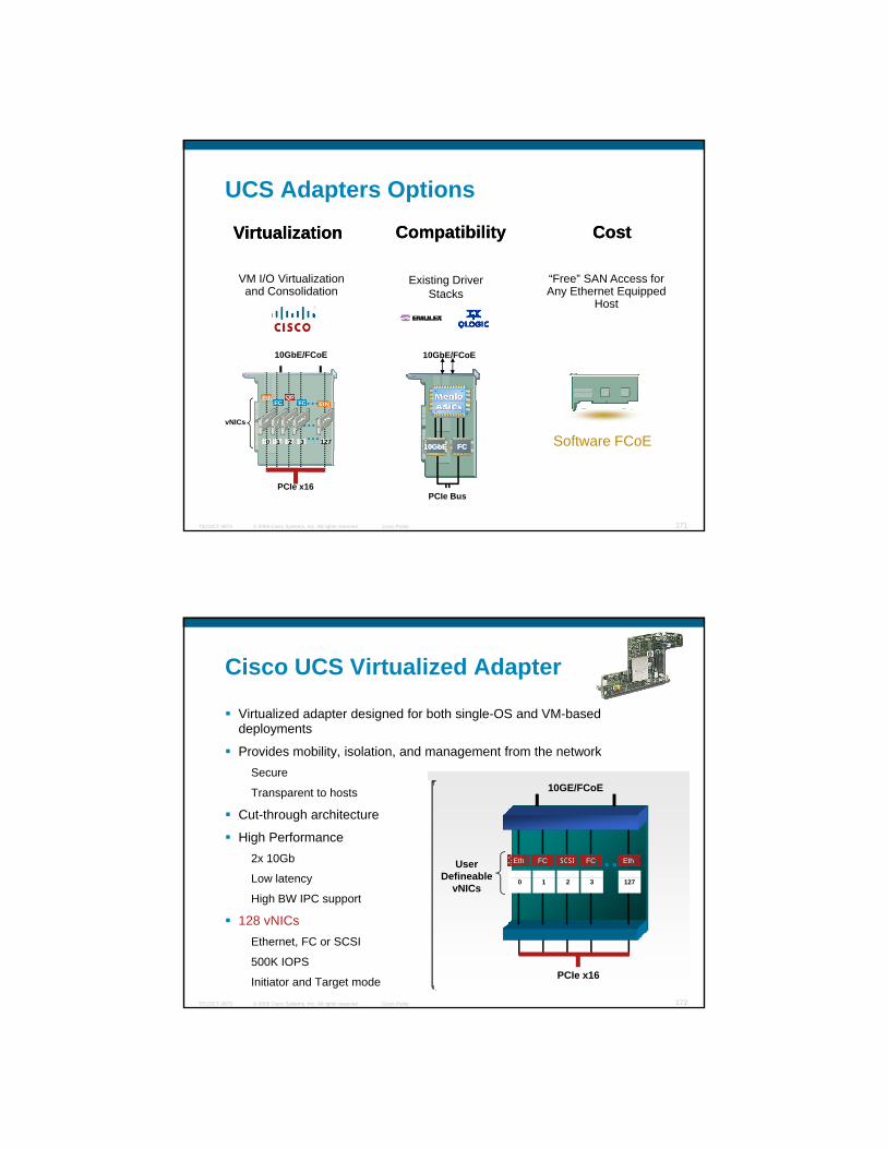
UCS Adapters Options
CostCostCompatibilityCompatibilityVirtualizationVirtualization
10GbE/FCoE
EthFC
QPC
10GbE/FCoE
“Free” SAN Access for Any Ethernet Equipped
Host
Existing Driver Stacks
VM I/O Virtualization and Consolidation
© 2009 Cisco Systems, Inc. All rights reserved. Cisco PublicTECDCT-3873 171
PCIe x16
vNICs
0
FC
1 2
FC
3
Eth
127
PCIe Bus
FCFC10GbE10GbE Software FCoE
Cisco UCS Virtualized Adapter
Virtualized adapter designed for both single-OS and VM-based deployments
P id bilit i l ti d t f th t kProvides mobility, isolation, and management from the networkSecure
Transparent to hosts
Cut-through architecture
High Performance2x 10Gb
Low latency
10GE/FCoE
MAC 0 MAC 1
Eth FC SCSI FC EthUser Defineable
© 2009 Cisco Systems, Inc. All rights reserved. Cisco PublicTECDCT-3873 172
Low latency
High BW IPC support
128 vNICsEthernet, FC or SCSI
500K IOPS
Initiator and Target mode PCIe x16
0 1 2 3 127Defineable
vNICs
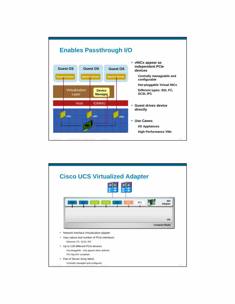
Enables Passthrough I/O
vNICs appear as independent PCIe devicesGuest OS Guest OS Guest OS devices
Centrally manageable and configurable
Hot-pluggable Virtual NICs
Different types: Eth, FC, SCSI, IPC
Guest drives deviceHost IOMMU
Device Driver Device Driver Device Driver
DeviceManager
Virtualization Layer
© 2009 Cisco Systems, Inc. All rights reserved. Cisco PublicTECDCT-3873 173
Guest drives device directly
Use Cases:I/O Appliances
High Performance VMs
vNIC vNIC vNIC
Cisco UCS Virtualized Adapter
Compute Blade
Network Interface Virtualization adapter
NIVAdapterFC FC Eth Eth Eth FC IPCSCSISCSIEthEth EthEth
OS
© 2009 Cisco Systems, Inc. All rights reserved. Cisco PublicTECDCT-3873 174
Network Interface Virtualization adapter
Vary nature and number of PCIe interfacesEthernet, FC, SCSI, IPC
Up to 128 different PCIe devicesHot-pluggable - only appear when defined
PCI-Sig IOV compliant
Part of Server Array fabricCentrally managed and configured
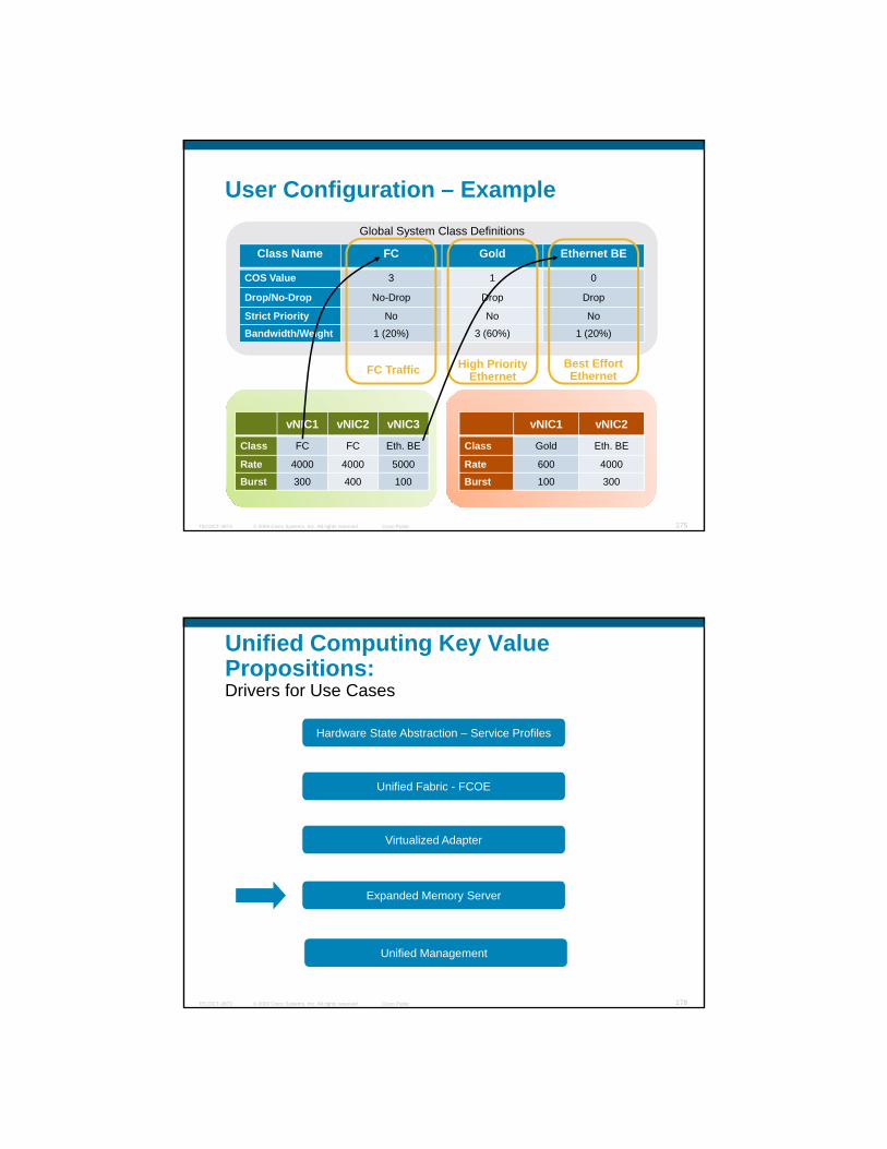
User Configuration – Example
Class Name FC Gold Ethernet BE
Global System Class Definitions
COS Value 3 1 0
Drop/No-Drop No-Drop Drop Drop
Strict Priority No No No
Bandwidth/Weight 1 (20%) 3 (60%) 1 (20%)
FC Traffic High PriorityEthernet
Best EffortEthernet
© 2009 Cisco Systems, Inc. All rights reserved. Cisco PublicTECDCT-3873 175
vNIC1 vNIC2 vNIC3
Class FC FC Eth. BE
Rate 4000 4000 5000
Burst 300 400 100
vNIC1 vNIC2
Class Gold Eth. BE
Rate 600 4000
Burst 100 300
Unified Computing Key Value Propositions:Drivers for Use Cases
Hardware State Abstraction – Service Profiles
Unified Fabric - FCOE
Virtualized Adapter
© 2009 Cisco Systems, Inc. All rights reserved. Cisco PublicTECDCT-3873 178
Expanded Memory Server
Unified Management
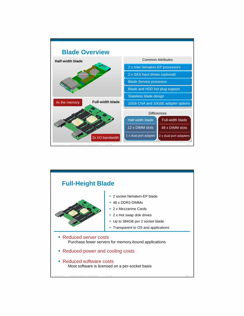
Blade OverviewCommon Attributes
2 x Intel Nehalem-EP processors
2 x SAS hard drives (optional)
Half-width blade
2 x SAS hard drives (optional)
Blade Service processor
Blade and HDD hot plug support
Stateless blade design
10Gb CNA and 10GbE adapter optionsFull-width blade4x the memory
© 2009 Cisco Systems, Inc. All rights reserved. Cisco PublicTECDCT-3873 179
Differences
Half-width blade Full-width blade
12 x DIMM slots 48 x DIMM slots
1 x dual port adapter 2 x dual port adapters
4x memory
2x I/O bandwidth
Full-Height Blade
2 socket Nehalem-EP blade
48 x DDR3 DIMMs
2 x Mezzanine Cards
2 x Hot swap disk drives
Up to 384GB per 2 socket blade
Transparent to OS and applications
Reduced server costsPurchase fewer servers for memory bound applications
© 2009 Cisco Systems, Inc. All rights reserved. Cisco PublicTECDCT-3873 180
Purchase fewer servers for memory-bound applications
Reduced power and cooling costs
Reduced software costsMost software is licensed on a per-socket basis

Expanded Memory Blade
Nehalem-EP Processor
Nehalem-EP Processor
Physical View
Logical View
8GB
8GB
8GB
8GB
8GB
8GB Slot 16
Slot 17
Slot 18
Slot 19
Slot 20
Slot 21
Channel 2(red) 8GB
8GB
Slot 22
Slot 23
8GB
8GB
8GB
Sl t 12
Slot 13Slot 14
Slot 15
Slot 16
Slot 17Slot 18
Slot 19
Slot 20
Slot 21
Channel 2(red)
Slot 22
Slot 23
Sl t 12
Slot 13Slot 14
Slot 15
32GB
32GB
32GB
View View
© 2009 Cisco Systems, Inc. All rights reserved. Cisco PublicTECDCT-3873 181
Channel 0(green)
Channel 1(blue)
8GB
8GB
8GB Slot 8
Slot 9Slot 10
Slot 11
Slot 12
8GB
8GB
8GB
8GB
8GB
8GB
8GB
8GB Slot 0
Slot 1Slot 2
Slot 3
Slot 4
Slot 5
8GB
8GB
Slot 6
Slot 7
Channel 0(green)
Channel 1(blue)
Slot 8
Slot 9Slot 10
Slot 11
Slot 12
Slot 0
Slot 1Slot 2
Slot 3
Slot 4
Slot 5Slot 6
Slot 7
32GB
32GB
32GB
Expanded Memory Architecture
Increases number of DIMMs the system can useMakes the system think it has high-capacity DIMMs when using larger number of lower capacity DIMMslower-capacity DIMMs
© 2009 Cisco Systems, Inc. All rights reserved. Cisco PublicTECDCT-3873 182
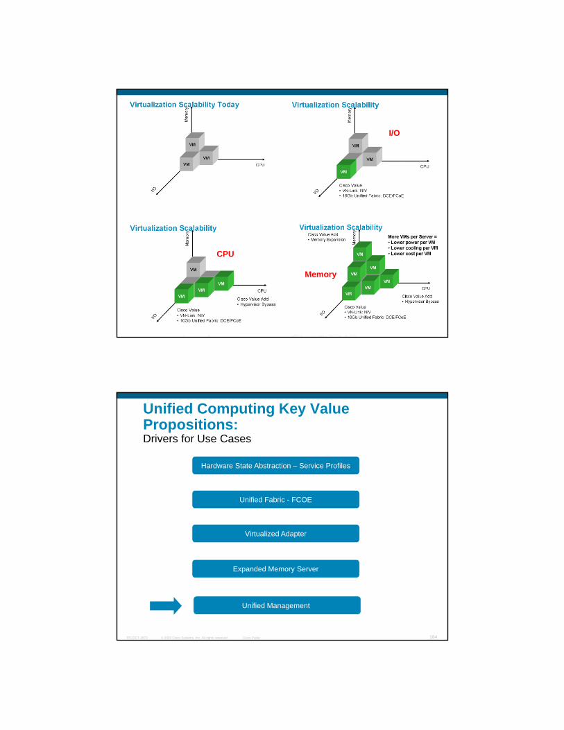
I/O
CPU
© 2009 Cisco Systems, Inc. All rights reserved. Cisco PublicTECDCT-3873 183
CPU
Memory
Unified Computing Key Value Propositions:Drivers for Use Cases
Hardware State Abstraction – Service Profiles
Unified Fabric - FCOE
Virtualized Adapter
© 2009 Cisco Systems, Inc. All rights reserved. Cisco PublicTECDCT-3873 184
Expanded Memory Server
Unified Management

LANSAN B
Unified Management (1/2)
SAN A
Two Failure DomainsSeparate fabrics
Central supervisor, forwarding logic
Distributed Fabric Extenders
Traffic isolation
Infrastructure Management Centralize chassis management
Intrinsic system management
Single management domain
Scalable architecture
© 2009 Cisco Systems, Inc. All rights reserved. Cisco PublicTECDCT-3873 185
Bla
de C
hass
is
Bla
de C
hass
is
Bla
de C
hass
is
Bla
de C
hass
is
Traffic isolation
Oversubscription10GE/FCoE10GE/FCoE
ChassisManagement
ChassisManagement
ChassisManagement
ChassisManagement
Unified Management (2/2)
Single point of device managementAdapters, blades, chassis, LAN & SAN connectivity
Embedded managerCustom Portal
View 1 View 2g
GUI & CLI
Standard APIs for systems managementXML, SMASH-CLP, WSMAN, IPMI, SNMP
SDK for commercial & custom implementations
Designed for multi-tenancyRBAC, organizations, pools & policies
UCS Manager
XML API
GUI
Custom Portal
Systems ManagementSoftware
Standard APIsCLI
© 2009 Cisco Systems, Inc. All rights reserved. Cisco PublicTECDCT-3873 186
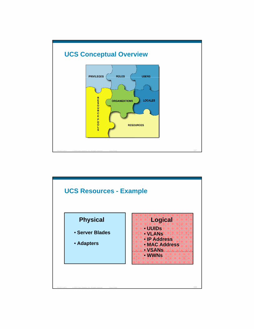
UCS Conceptual Overview
© 2009 Cisco Systems, Inc. All rights reserved. Cisco PublicTECDCT-3873 187
UCS Resources - Example
• Server Blades
• Adapters
Physical • UUIDs• VLANs• IP Address• MAC Address• VSANs
Logical
© 2009 Cisco Systems, Inc. All rights reserved. Cisco PublicTECDCT-3873 188
VSANs• WWNs

blade 3blade 2
Resource Pools - Example
Blade poolBlades
01:23:45:67:89:0d01:23:45:67:89:0c
01:23:45:67:89:0b
blade 1blade 0
01:23:45:67:89:0a
MAC poolMACs
WWN pool
© 2009 Cisco Systems, Inc. All rights reserved. Cisco PublicTECDCT-3873 189
05:00:1B:32:00:00:00:0405:00:1B:32:00:00:00:03
05:00:1B:32:00:00:00:0205:00:1B:32:00:00:00:01
WWNsWWN pool
How They Work Together
UCS ServerUCS Server
© 2009 Cisco Systems, Inc. All rights reserved. Cisco PublicTECDCT-3873 190

Profiles – Example
Servers
Virtual Machines
Ethernet Adapters
Fibre Channel Adapters
IPMI Profiles
© 2009 Cisco Systems, Inc. All rights reserved. Cisco PublicTECDCT-3873 191
Out-of-the-Box Protocol Support
SMASH CLPSNMP
Remote KVM UCS CLI and GUI
CIM XMLIPMI
© 2009 Cisco Systems, Inc. All rights reserved. Cisco PublicTECDCT-3873 192
UCS XML APISerial Over LAN
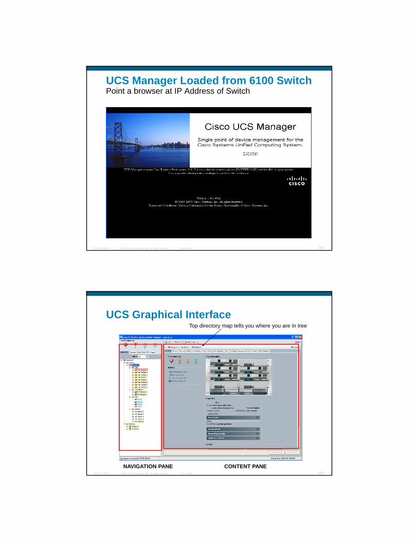
UCS Manager Loaded from 6100 SwitchPoint a browser at IP Address of Switch
© 2009 Cisco Systems, Inc. All rights reserved. Cisco PublicTECDCT-3873 193
UCS Graphical InterfaceTop directory map tells you where you are in tree
© 2009 Cisco Systems, Inc. All rights reserved. Cisco PublicTECDCT-3873 194
CONTENT PANENAVIGATION PANE
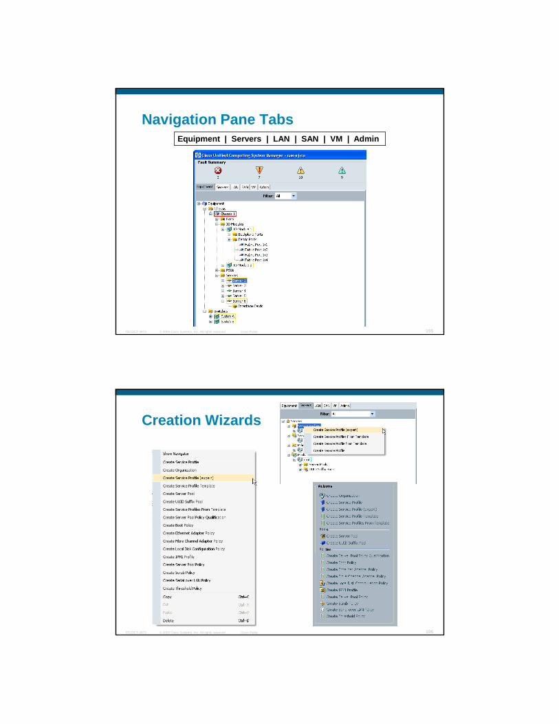
Navigation Pane TabsEquipment | Servers | LAN | SAN | VM | Admin
© 2009 Cisco Systems, Inc. All rights reserved. Cisco PublicTECDCT-3873 195
Creation Wizards
© 2009 Cisco Systems, Inc. All rights reserved. Cisco PublicTECDCT-3873 196
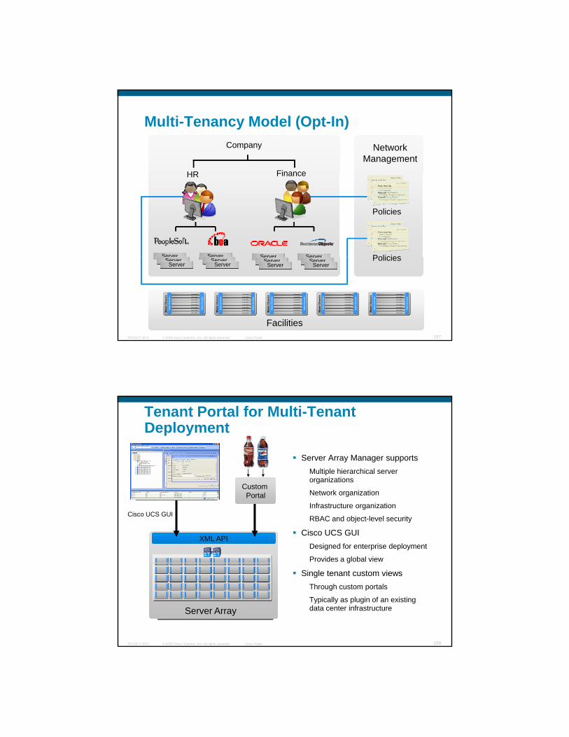
Multi-Tenancy Model (Opt-In)Network
ManagementCompany
HR FinanceHR Finance
Policies
PoliciesServer Server Server Server
© 2009 Cisco Systems, Inc. All rights reserved. Cisco PublicTECDCT-3873 197
Facilities
PoliciesServerServer
ServerServer
ServerServer
ServerServer
ServerServer
ServerServer
Bla
de C
hass
isFa
bric
Ext
ende
r
Fabr
ic E
xten
der
Compute Blade
Compute Blade
Compute Blade
Compute Blade
Compute Blade
Compute Blade
Compute Blade
Compute Blade Fabr
ic E
xten
der
Fabr
ic E
xten
der
Bla
de C
hass
isFa
bric
Ext
ende
r
Fabr
ic E
xten
der
Bla
de C
hass
isB
lade
Cha
ssis
Fabr
ic E
xten
der
Fabr
ic E
xten
der
Fabr
ic E
xten
der
Fabr
ic E
xten
der
Compute Blade
Compute Blade
Compute Blade
Compute Blade
Compute Blade
Compute Blade
Compute Blade
Compute Blade
Compute BladeCompute Blade
Compute BladeCompute Blade
Compute BladeCompute Blade
Compute BladeCompute Blade
Compute BladeCompute Blade
Compute BladeCompute Blade
Compute BladeCompute Blade
Compute BladeCompute Blade Fabr
ic E
xten
der
Fabr
ic E
xten
der
Bla
de C
hass
isFa
bric
Ext
ende
r
Fabr
ic E
xten
der
Compute Blade
Compute Blade
Compute Blade
Compute Blade
Compute Blade
Compute Blade
Compute Blade
Compute Blade Fabr
ic E
xten
der
Fabr
ic E
xten
der
Bla
de C
hass
isFa
bric
Ext
ende
r
Fabr
ic E
xten
der
Bla
de C
hass
isB
lade
Cha
ssis
Fabr
ic E
xten
der
Fabr
ic E
xten
der
Fabr
ic E
xten
der
Fabr
ic E
xten
der
Compute Blade
Compute Blade
Compute Blade
Compute Blade
Compute Blade
Compute Blade
Compute Blade
Compute Blade
Compute BladeCompute Blade
Compute BladeCompute Blade
Compute BladeCompute Blade
Compute BladeCompute Blade
Compute BladeCompute Blade
Compute BladeCompute Blade
Compute BladeCompute Blade
Compute BladeCompute Blade Fabr
ic E
xten
der
Fabr
ic E
xten
der
Tenant Portal for Multi-Tenant Deployment
Server Array Manager supportsMultiple hierarchical server organizationsorganizations
Network organization
Infrastructure organization
RBAC and object-level security
Cisco UCS GUIDesigned for enterprise deployment
Provides a global view
XML API
Custom Portal
Cisco UCS GUI
© 2009 Cisco Systems, Inc. All rights reserved. Cisco PublicTECDCT-3873 198
Single tenant custom viewsThrough custom portals
Typically as plugin of an existing data center infrastructureServer Array

Unified Compute Integration in the Data Center:Use Cases
Hardware State Abstraction – Service Profiles
Unified Fabric - FCOE
Virtualized Adapter
Expanded Memory Server
© 2009 Cisco Systems, Inc. All rights reserved. Cisco PublicTECDCT-3873 199
Unified Management
UCS IntegrationUCS Integration
UCS and Nexus in the Data CenterCore Layer
Nexus 7010
GigE
10GE
GigE
10GE
Distribution Layer
10GE
Access Layer
FEX
Nexus 5000
Nexus 7010
© 2009 Cisco Systems, Inc. All rights reserved. Cisco PublicTECDCT-3873 200
Rack 1
Row 1 / Domain 1 / POD 1Rack 1 ….....
Rack 1 Rack 121GE to Servers
10GE Servers
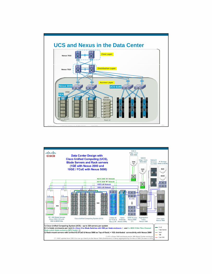
UCS and Nexus in the Data CenterCore Layer
Nexus 7010
GigE
10GE
GigE
10GE
Distribution Layer
10GE
Access Layer
FEX
Nexus 5000
Nexus 7010
UCS 6100
© 2009 Cisco Systems, Inc. All rights reserved. Cisco PublicTECDCT-3873 201
Rack 1
Row 1 / Domain 1 / POD 1Rack 1 ….....
Rack 1 Rack 121GE to Servers
10GE Servers slot 1slot 1
slot 2slot 2slot 3slot 3slot 4slot 4slot 5slot 5slot 6slot 6slot 7slot 7slot 8slot 8
blade1blade1blade2blade2blade3blade3blade4blade4blade5blade5blade6blade6blade7blade7blade8blade8
slot 1slot 1slot 2slot 2slot 3slot 3slot 4slot 4slot 5slot 5slot 6slot 6slot 7slot 7slot 8slot 8
blade1blade1blade2blade2blade3blade3blade4blade4blade5blade5blade6blade6blade7blade7blade8blade8
slot 1slot 1slot 2slot 2slot 3slot 3slot 4slot 4slot 5slot 5slot 6slot 6slot 7slot 7slot 8slot 8
blade1blade1blade2blade2blade3blade3blade4blade4blade5blade5blade6blade6blade7blade7blade8blade8
slot 1slot 2slot 3slot 4slot 5slot 6slot 7slot 8
blade1blade2blade3blade4blade5blade6blade7blade8
slot 1slot 2slot 3slot 4slot 5slot 6slot 7slot 8
blade1blade2blade3blade4blade5blade6blade7blade8
slot 1slot 2slot 3slot 4slot 5slot 6slot 7slot 8
blade1blade2blade3blade4blade5blade6blade7blade8
slot 1slot 1slot 2slot 2slot 3slot 3slot 4slot 4slot 5slot 5slot 6slot 6slot 7slot 7slot 8slot 8
blade1blade1blade2blade2blade3blade3blade4blade4blade5blade5blade6blade6blade7blade7blade8blade8
slot 1slot 1slot 2slot 2slot 3slot 3slot 4slot 4slot 5slot 5slot 6slot 6slot 7slot 7slot 8slot 8
blade1blade1blade2blade2blade3blade3blade4blade4blade5blade5blade6blade6blade7blade7blade8blade8
slot 1slot 1slot 2slot 2slot 3slot 3slot 4slot 4slot 5slot 5slot 6slot 6slot 7slot 7slot 8slot 8
blade1blade1blade2blade2blade3blade3blade4blade4blade5blade5blade6blade6blade7blade7blade8blade8
slot 1slot 2slot 3slot 4slot 5slot 6slot 7slot 8
blade1blade2blade3blade4blade5blade6blade7blade8
slot 1slot 2slot 3slot 4slot 5slot 6slot 7slot 8
blade1blade2blade3blade4blade5blade6blade7blade8
slot 1slot 2slot 3slot 4slot 5slot 6slot 7slot 8
blade1blade2blade3blade4blade5blade6blade7blade8
slot 1slot 1slot 2slot 2slot 3slot 3slot 4slot 4slot 5slot 5slot 6slot 6slot 7slot 7slot 8slot 8
blade1blade1blade2blade2blade3blade3blade4blade4blade5blade5blade6blade6blade7blade7blade8blade8
slot 1slot 1slot 2slot 2slot 3slot 3slot 4slot 4slot 5slot 5slot 6slot 6slot 7slot 7slot 8slot 8
blade1blade1blade2blade2blade3blade3blade4blade4blade5blade5blade6blade6blade7blade7blade8blade8
slot 1slot 1slot 2slot 2slot 3slot 3slot 4slot 4slot 5slot 5slot 6slot 6slot 7slot 7slot 8slot 8
blade1blade1blade2blade2blade3blade3blade4blade4blade5blade5blade6blade6blade7blade7blade8blade8
slot 1slot 2slot 3slot 4slot 5slot 6slot 7slot 8
blade1blade2blade3blade4blade5blade6blade7blade8
slot 1slot 2slot 3slot 4slot 5slot 6slot 7slot 8
blade1blade2blade3blade4blade5blade6blade7blade8
slot 1slot 2slot 3slot 4slot 5slot 6slot 7slot 8
blade1blade2blade3blade4blade5blade6blade7blade8
© 2009 Cisco Systems, Inc. All rights reserved. Cisco PublicTECDCT-3873 202

Interested in Data Center?
Discover the Data Center of the Future Cisco booth: #617
See a simulated data center and discover the benefits including investing to save, energy efficiency and innovation.
Data Center BoothCome by and see what’s happening in the world of Data Center –demos; social media activities; bloggers; author signings
Demos include:
© 2009 Cisco Systems, Inc. All rights reserved. Cisco PublicTECDCT-3873 203
Unified Computing Systems
Cisco on Cisco Data Center Interactive Tour
Unified Service Delivery for Service Providers
Advanced Services
Interested in Data Center?Data Center Super Session
Data Center Virtualization Architectures, Road to Cloud Computing (UCS)Wednesday, July 1, 2:30 – 3:30 pm, Hall Ded esday, Ju y , 30 3 30 p , aSpeakers: John McCool and Ed Bugnion
Panel: 10 Gig LOM Wednesday 08:00 AM Moscone S303
Panel: Next Generation Data Center
© 2009 Cisco Systems, Inc. All rights reserved. Cisco PublicTECDCT-3873 204
Panel: Next Generation Data CenterWednesday 04:00 PM Moscone S303
Panel: Mobility in the DC DataThursday 08:00 AM Moscone S303

Data Center and VirtualizationDC1 – Cisco Unified Computing System
Please Visit the Cisco Booth in theWorld of SolutionsSee the technology in action
p g y
DC2 – Data Center Switching: Cisco Nexus and Catalyst
DC3 – Unified Fabric Solutions
DC4 – Data Center Switching: Cisco Nexus and Catalyst
DC5 – Data Center 3.0: Accelerate Your Business, Optimize Your Future
© 2009 Cisco Systems, Inc. All rights reserved. Cisco PublicTECDCT-3873 205
Future
DC6 – Storage Area Networking: MDS
DC7 – Application Networking Systems: WAAS and ACE
Recommended Readings
© 2009 Cisco Systems, Inc. All rights reserved. Cisco PublicTECDCT-3873 206

Complete Your Online Session Evaluation
Give us your feedback and you could win fabulous prizes. Winners announced daily.Winners announced daily.
Receive 20 Passport points for each session evaluation you complete.
Complete your session evaluation online now (open a browser through our wireless network to access our portal) or visit one of the Internet stations throughout
© 2009 Cisco Systems, Inc. All rights reserved. Cisco PublicTECDCT-3873 207
the Internet stations throughout the Convention Center. Don’t forget to activate your
Cisco Live Virtual account for access to all session material, communities, andon-demand and live activities throughout the year. Activate your account at the Cisco booth in the World of Solutions or visit www.ciscolive.com.
© 2009 Cisco Systems, Inc. All rights reserved. Cisco PublicTECDCT-3873 208
Related Documents