For internal use only / Copyright © Siemens AG 2010. All rights reserved. Siemens Efficient turbocompressor technology for waste water treatment Short introduction

Welcome message from author
This document is posted to help you gain knowledge. Please leave a comment to let me know what you think about it! Share it to your friends and learn new things together.
Transcript

For i
nter
nal u
se o
nly
/ Cop
yrig
ht ©
Sie
men
s AG
201
0. A
ll rig
hts
rese
rved
.
Siemens
Efficient turbocompressor technology for
waste water treatment
Short introduction

Page 2
For i
nter
nal u
se o
nly
/ Cop
yrig
ht ©
Sie
men
s AG
201
0. A
ll rig
hts
rese
rved
.
© Siemens AG 2007. Alle Rechte vorbehalten.
Helsingør History
Siemens Turbomachinery Solutions (then HV-Turbo A/S) was acquired in beginning 2007 by Siemens together with the KK&K Group (Kuehnle, Kopp & Kausch).
The KK&K Group was renamed to “Pre-defined Compressors and Fans” (abbreviated to “PCF”) and integrated with the Oil & Gas Division of Siemens.
The HV-Turbo Group was renamed to “Municipal and Industrial Application” (abbreviated to “MIA”) and included in the PCF Group as E O C&S PCF MIA.
1882 1947 1954 1973 1978-81 2000 2007
Helsingør Ship Yard founded
First and only gas turbine is produced
A series of turbo-chargers
is launched
The first s-type aeration turbo compressor is
launched
The first WWTP installations in
Germany & USA
KK&K acquires HV-Turbo from NTR
Holding
KK&K group incl. HV-Turbo acquired
by Siemens AG
Closing of shipyard

Page 3
For i
nter
nal u
se o
nly
/ Cop
yrig
ht ©
Sie
men
s AG
201
0. A
ll rig
hts
rese
rved
.
© Siemens AG 2007. Alle Rechte vorbehalten.
Applications within Waste Water Aeration (Biochemical), Flue Gas Desulphurization, Sulphur Recovery, Fermentation and other industrial applications.Product Portfolio:
9 Basic compressor types with various customization possibilitiesNew product development: Direct Drive and Compact versions
Reference list of more than 7,500 units installedServices, e. g. spare parts, maintenance and repair, installations, modernization and upgrades
ACC Site InformationLocation: Helsingør
Business area and products
Units delivered in 2012: 210Office area: Approx. 2.500 sqmEmployees in 2013: 70 hereof 22 in Service
Numbers

Page 4
For i
nter
nal u
se o
nly
/ Cop
yrig
ht ©
Sie
men
s AG
201
0. A
ll rig
hts
rese
rved
.
© Siemens AG 2007. Alle Rechte vorbehalten.
Steam turbines used as generator drives for power generation up to 10 MW and as mechanical drives for e. g. pumps and compressorsSingle stage turbo compressors and blowers for industrial applications and processesServices, e. g. spare parts, maintenance and repair, installations, modernization and upgrades
Extended workbench for Power Fans
ACC is a Service Provider to Manufacturing Site Frankenthal
Business area and products
Volker Neumann (CEO)Dr. Klaus Jacoby (CEO)Frank Langner (CFO)
Management
600 (2011) Thereof approx. 300 in manufacturing
Employees

Page 5
For i
nter
nal u
se o
nly
/ Cop
yrig
ht ©
Sie
men
s AG
201
0. A
ll rig
hts
rese
rved
.
© Siemens AG 2007. Alle Rechte vorbehalten.
Aeration-ProcessesBiological Waste Water Treatment and floatation
Flue gas Desulphurization (FGD)
Fermentation (e.g. Enzymes for Bio fuel production, Yeast)
Marine applications
Siemens Turbomachinery SolutionsA suitable product portfolio to cover the main aeration applications
Siemens Applications
Siemens Solutions
Single stage centrifugal turbo compressorsFlow range 1.500 m3/h – 125.000 m3/h
Pressure range from 0.5 – 2.4 barg
Power range 50 KW – 3.300 KW
Air Supply Systems (automation)
Consultancy (energy optimization studies)
Service/ Upgrades and Revamps
Financing (energy saving motivated)

Page 6
For i
nter
nal u
se o
nly
/ Cop
yrig
ht ©
Sie
men
s AG
201
0. A
ll rig
hts
rese
rved
.
© Siemens AG 2007. Alle Rechte vorbehalten.
Siemens Turbomachinery SolutionsMarket leader in supply of aeration turbocompressors
1978 1983 1988 1993 1998 2003 20071978 1983 1988 1993 1998 2003 2007
1.000
3.500
1.300
500
Number of references Installed units status 2007
Market leader with < 7.000 referencesEstablished regional coverage (CN, US, EU) and constantly expandingOnly supplier which can offer all technologies (geared & direct driven)

Page 7
For i
nter
nal u
se o
nly
/ Cop
yrig
ht ©
Sie
men
s AG
201
0. A
ll rig
hts
rese
rved
.
© Siemens AG 2007. Alle Rechte vorbehalten.
Siemens Turbomachinery Equipment
Siemens Turbomachinery Solutions
Page 8
For i
nter
nal u
se o
nly
/ Cop
yrig
ht ©
Sie
men
s AG
201
0. A
ll rig
hts
rese
rved
.
© Siemens AG 2007. Alle Rechte vorbehalten.
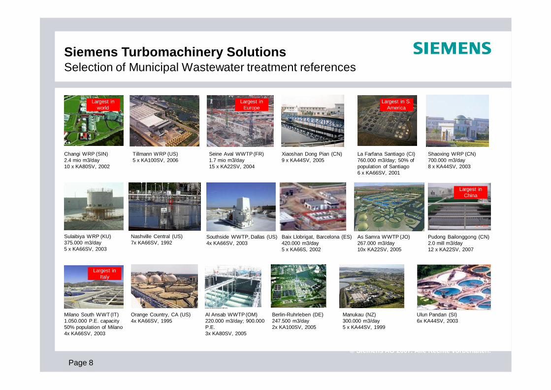
Siemens Turbomachinery SolutionsSelection of Municipal Wastewater treatment references
Changi WRP (SIN)2.4 mio m3/day10 x KA80SV, 2002
Tillmann WRP (US)5 x KA100SV, 2006
Seine Aval WWTP (FR)1.7 mio m3/day15 x KA22SV, 2004
Xiaoshan Dong Pian (CN)9 x KA44SV, 2005
La Farfana Santiago (CI)760.000 m3/day; 50% of population of Santiago6 x KA66SV, 2001
Shaoxing WRP (CN)700.000 m3/day8 x KA44SV, 2003
Sulaibiya WRP (KU)375.000 m3/day5 x KA66SV, 2003
Nashville Central (US)7x KA66SV, 1992
Southside WWTP, Dallas (US)4x KA66SV, 2003
Baix Llobrigat, Barcelona (ES)420.000 m3/day5 x KA66S, 2002
As Samra WWTP (JO)267.000 m3/day10x KA22SV, 2005
Pudong Bailonggong (CN)2.0 mill m3/day12 x KA22SV, 2007
Milano South WWT (IT)1.050.000 P.E. capacity50% population of Milano4x KA66SV, 2003
Orange Country, CA (US)4x KA66SV, 1995
Al Ansab WWTP (OM)220.000 m3/day; 900.000 P.E. 3x KA80SV, 2005
Berlin-Ruhrleben (DE)247.500 m3/day2x KA100SV, 2005
Manukau (NZ)300.000 m3/day5 x KA44SV, 1999
Ulun Pandan (SI)6x KA44SV, 2003
Largest in Europe
Largest in S. America
Largest in world
Largest in China
Largest in Italy

For i
nter
nal u
se o
nly
/ Cop
yrig
ht ©
Sie
men
s AG
201
0. A
ll rig
hts
rese
rved
.
Siemens Turbomachinery Solutions
Aeration Product Portfolio
Short introduction

Page 10
For i
nter
nal u
se o
nly
/ Cop
yrig
ht ©
Sie
men
s AG
201
0. A
ll rig
hts
rese
rved
.
© Siemens AG 2007. Alle Rechte vorbehalten.
Siemens Turbomachinery SolutionsA comprehensive product portfolio for your aeration needs
Air flow [m3/h]
Diff
eren
tial P
ress
ure
[bar
g]
0,25
0,75
1,25
1,75
2,25
1.000 10.000 100.000
3,0
GO
(2)
GO
(5)
GO
(10)
GO
(22)
GO
(44)
GO
(66)
GO
(80)
GO
(100
)
Integrally geared dual-one stage STC-GO
1,0
0,5
150 kW
200 kW
100 kW
50 kW30 KW
300 kW
400 kW
1.000 kW 2.000
kW20 kW
10 kW
kW figures are showing shaft power at 30 degC, 60% RH and 1,013 bar
Integrally geared, one stage
GO(2-c) GO(5-c) GO(10-c)
DO(1) DO(2) DO(5) DO(10)
Direct drive, one stage
Siemens Turbocompressors (STC) for Aeration

Page 11
For i
nter
nal u
se o
nly
/ Cop
yrig
ht ©
Sie
men
s AG
201
0. A
ll rig
hts
rese
rved
.
© Siemens AG 2007. Alle Rechte vorbehalten.
Siemens Turbomachinery SolutionsHow can Siemens Turbomachinery Solutions support your project?
Design
Construction
Operation
Design Support:
Mechanical, Civil, Electrical Plans, 3D Modeling, Technical Specifications, Design Solutions, On-time documentation
Civil Savings; Mechanical Savings; Electrical Savings:
Optimal number of aeration compressors/ High voltage motors; Correct sizing of pipes, valves
Energy Savings
By most efficient Dual-Point-Control and correct selection of compressor technology
Other operational savings:
Maintenance Savings. Extended lifetime
Your challenges Our answers

Page 12
For i
nter
nal u
se o
nly
/ Cop
yrig
ht ©
Sie
men
s AG
201
0. A
ll rig
hts
rese
rved
.
© Siemens AG 2007. Alle Rechte vorbehalten.
Siemens Turbomachinery SolutionsA comprehensive product portfolio for your aeration needs
Hard-ware
Siemens Turbocompressors (STC)
Integrally geared (STC-GO)
STC-GO(GK) STC-GO(GK-c)
STC-GO (GL/GB/GC)
Direct drive (STC-DO)
Base frame configuration
Console configuration
Full enclosure configuration
Sales & Execution concept
Fully customizablePre-engineered
Fully customizablePre-engineered
Appli-cations
Waste Water Oil & Gas & FGD
Fermentation
Waste Water Fermentation
Waste Water Fermentation
Frame size range
GO(2)-GO(100) Up to 2 bar diff.
GO(2)-GO(10) up to 1.0 bar diff.
DO(1)-DO(10) up to 0.9 bar diff.
Level of customizing
Air-foil-bearings

Page 13
For i
nter
nal u
se o
nly
/ Cop
yrig
ht ©
Sie
men
s AG
201
0. A
ll rig
hts
rese
rved
.
© Siemens AG 2007. Alle Rechte vorbehalten.
Siemens Turbomachinery SolutionsA comprehensive product portfolio for your aeration needs
Ambient temperature
Design
Package Assembly
Core
Drive System
Bearings/Lubrication
Impeller Design
Cooling
Capacity Control
Dual-Point Control
Controller
Lead Time
Instrumentation
Process Control
Motor/Voltage
Motor kW (Max)
Starter
Turndown (mass flow)
Enclosure Design
Optional Material
Ambient temperature
Design
Package Assembly
Core
Drive System
Bearings/Lubrication
Impeller Design
Cooling
Capacity Control
Dual-Point Control
Controller
Lead Time
Instrumentation
Process Control
Motor/Voltage
Motor kW (Max)
Starter
Turndown (mass flow)
Enclosure Design
Optional Material
IGV Inlet guide vanesVD Variable diffuserVFD Variable frequency driveMCP Master control panelSS Stainless steel
STC-GO(GL) STC-GO(GK) STC-DO
Not limited
Custom Engineered
Customizable
Air-end/gearbox
Geared
Sleeve, Forced Lube/Oil
Job Specific & Optimized
Water or Air
IGV or VD
Optional w/ VD & IGV
Specifiable (PLC)
30-40 weeks
Specifiable
MCP or DCS
Specifiable/Specifiable
3,000
SSRVS/VFD (stand alone)
45%
Optional & Specifiable
SS impeller & guide vanes
Air-end/gearbox
Geared
Ceramic Ball/Oil
Job Specific & Optimized
Inlet Guide Vanes IGV or VD
Optional w/ VD & IGV
MCP or DCS
Limited Selection/Low
315
45%
Optional Standard Upgrade
None
Air-end/gearbox
Geared
Ceramic Ball/Oil
Job Specific & Optimized
MCP or DCS
Limited Selection/Low
315
Optional VFD
45%
Optional Standard Upgrade
None
<45 degree C
Pre-Engineered w/options
Limited Customization
Air-end/motor
Direct-Drive w/VFD
Air foil/none
Standard
Closed Loop Coolant
Variable diffuser (VD)
Standard w/ VD & VFD
Limited Selection (PLC)
12-16 weeks
Limited Selection
MCP or DCS
Standard/Low
315
VFD included
35%
Standard
None
<45 degree C
Pre-Engineered w/options
Limited Customization
Air-end/motor
Direct-Drive w/VFD
Air foil/none
Standard; 13 types available
Closed Loop Coolant
Standard w/ VD & VFD
Limited Selection (PLC)
12-16 weeks
Limited Selection
MCP or DCS
Standard/Low
315
VFD included
35%
Standard
None
STC-GO(GK-c)
<45 degree C
Pre-Engineered w/options
Limited Customization
Air-end/gearbox
Geared
Ceramic Ball/Oil
Job Specific & Optimized
Air
Inlet Guide Vanes IGV or VD
Optional w/ VD & IGV
Limited Selection (PLC)
16-20 weeks
Limited Selection
MCP or DCS
Limited Selection/Low
315
45%
Optional Standard Upgrade
None
<45 degree C
Pre-Engineered w/options
Limited Customization
Air-end/gearbox
Geared
Ceramic Ball/Oil
Job Specific & Optimized
Air
Limited Selection (PLC)
16-20 weeks
Limited Selection
MCP or DCS
Limited Selection/Low
315
Optional VFD
45%
Optional Standard Upgrade
None
Custom Engineered
Customizable
Specifiable (PLC)
30-40 weeks30-40 weeks
Specifiable
Not limited
Water or Air

For i
nter
nal u
se o
nly
/ Cop
yrig
ht ©
Sie
men
s AG
201
0. A
ll rig
hts
rese
rved
.
Siemens Turbomachinery Solutions
Dual Point Control PhilosophyShort introduction

Page 15
For i
nter
nal u
se o
nly
/ Cop
yrig
ht ©
Sie
men
s AG
201
0. A
ll rig
hts
rese
rved
.
© Siemens AG 2007. Alle Rechte vorbehalten.
“Energy efficiency is not just low-hanging fruits – it is fruits that is lying on the ground” US Secretary of Energy, Steven Chu
How can we pick up this fruit in municipal sewage treatment?

Page 16
For i
nter
nal u
se o
nly
/ Cop
yrig
ht ©
Sie
men
s AG
201
0. A
ll rig
hts
rese
rved
.
© Siemens AG 2007. Alle Rechte vorbehalten.
Change process to reduce DO-set point to reducerequired air-volume
Exchange aeration equipment with higherefficiency equipment (dual point control)
More extensive process changeswith structural changes to plant
Upgrade and increase level of air distribution automation
Siemens Turbomachinery SolutionsPossibilities to reduce energy consumption in WWT process

Page 17
For i
nter
nal u
se o
nly
/ Cop
yrig
ht ©
Sie
men
s AG
201
0. A
ll rig
hts
rese
rved
.
© Siemens AG 2007. Alle Rechte vorbehalten.
Siemens Turbomachinery SolutionsFruits on the ground: Where is the biggest fruit to be pick up?
Electricity consumption for waste water treatment plant (activated sludge)
Source: Water Environment Federation Energy Conservation Task Force. Energy Conservation in Wastewater Treatment Facilities. 1997
Aeration54.3 %
Wastewater pumping14%
Screens, Grid1.4%
Clarifier3%
Lighting & Building8%
Return sludge pumping & Gravity
thickening1%
Anaerobic digesting
14 %
Belt Press4%
Chlorination0,3%
Aeration54.3 %
Wastewater pumping14%
Screens, Grid1.4%
Clarifier3%
Lighting & Building8%
Return sludge pumping & Gravity
thickening1%
Anaerobic digesting
14 %
Belt Press4%
Chlorination0,3%
In the secondary treatment phase waste water is treated by means of bacterial breakdown of the dissolved biological waste.
In order to foster this bacterial break-down, the oxygen level of the waterneeds to be increased. Aeration is the process by which the area of contact between water and air is increased, either by natural or mechanicalmeans, resulting in air being suspended in water.
Scope of evaluation without distribution pumping stations

Page 18
For i
nter
nal u
se o
nly
/ Cop
yrig
ht ©
Sie
men
s AG
201
0. A
ll rig
hts
rese
rved
.
© Siemens AG 2007. Alle Rechte vorbehalten.
Technology
Lagoon
Mechanical Aeration
Combination Systems
Diffused aeration
Type
Facultative
Aerobic
Aerated
Rotors
Low speed
High Speed
Turbine
Jet
Course
Fine
OTE kgO2/kW.hr
1,52 – 2,13
1,82 – 2,13
1,52 – 1,98
0,91 – 1,52
1,22 – 2,13
1,22 – 2,13
2,43 – 4,36
Retention time10,000 m3 water7-50 days
3-6 days
2-3 days
4-12 hours
4-12 hours
4-12 hours
4-12 hours
4-12 hours
4-12 hours
4-12 hours
Limitations
Space
Retention time
Water depthLife cycle costsPossibly inhomogeneous qualityMoving parts
Possibly inhomogeneous quality
Moving parts
Capital costs
Increasing maintenance of system
Generally more complex system
Siemens Turbomachinery SolutionsWhat sources of aeration are possible? And what is the efficiency?
Most efficient choice
Page 19
For i
nter
nal u
se o
nly
/ Cop
yrig
ht ©
Sie
men
s AG
201
0. A
ll rig
hts
rese
rved
.
© Siemens AG 2007. Alle Rechte vorbehalten.
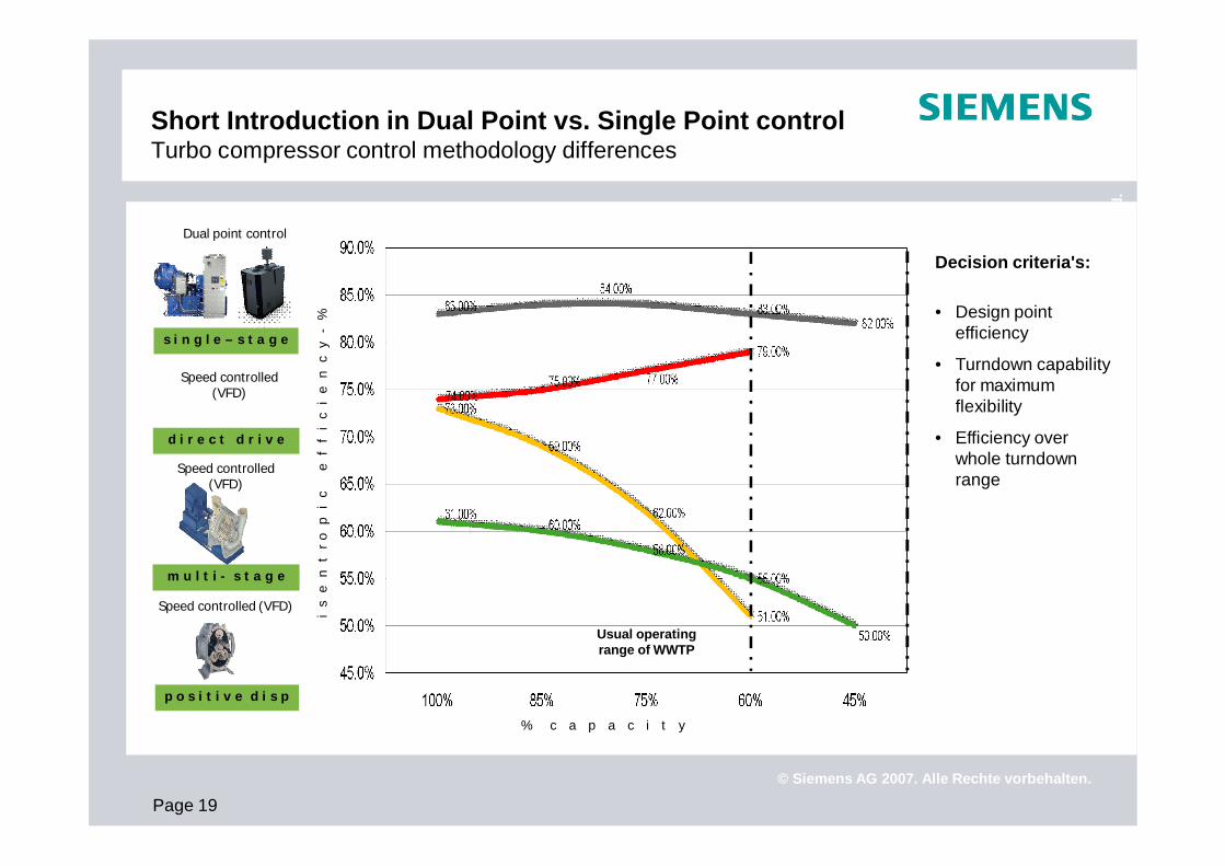
Short Introduction in Dual Point vs. Single Point controlTurbo compressor control methodology differences
s i n g l e – s t a g e
p o s i t i v e d i s p
m u l t i - s t a g e
d i r e c t d r i v e
Speed controlled (VFD)
i s
e
n t
r
o p
i
c
e
f
f i
c i
e
n c
y
-%
% c a p a c i t y
Dual point control
Speed controlled (VFD)
Speed controlled (VFD)
Usual operating range of WWTP
Decision criteria's:
• Design point efficiency
• Turndown capability for maximum flexibility
• Efficiency over whole turndown range

Page 20
For i
nter
nal u
se o
nly
/ Cop
yrig
ht ©
Sie
men
s AG
201
0. A
ll rig
hts
rese
rved
.
© Siemens AG 2007. Alle Rechte vorbehalten.
Siemens Turbomachinery SolutionsDual Point Control with STC-GO series
Air flow = f(n)Diff. pressure = f(n²)
Impeller speed = n
Single Point speed controllimits the turndown range as the pressure drops much faster than the flow by reduced speed. In order to reach a decent turndown, it is necessary to design the compressor for a much higher value with the result of overall lower efficiency.
Independent regulation of capacity and head:Capacity regulation via variable diffuser vanes: diffuser vanes are gradually closed, reducing the nozzle area, whereby a continuous turndown to 45% by keeping the maximum efficiency is achieved.
Head regulation: Inlet guide vanes (IGV) are adjusting the performance map acc. to fluctuations in temperature/ humidity and pressure changes
Dual Point control

Page 21
For i
nter
nal u
se o
nly
/ Cop
yrig
ht ©
Sie
men
s AG
201
0. A
ll rig
hts
rese
rved
.
© Siemens AG 2007. Alle Rechte vorbehalten.
Siemens Turbomachinery SolutionsIntegrally geared: Dual-Point vs. Single Point Control

Page 22
For i
nter
nal u
se o
nly
/ Cop
yrig
ht ©
Sie
men
s AG
201
0. A
ll rig
hts
rese
rved
.
© Siemens AG 2007. Alle Rechte vorbehalten.
Siemens Turbomachinery SolutionsDirect drive: Dual-Point vs. Single Point Control

Page 23
For i
nter
nal u
se o
nly
/ Cop
yrig
ht ©
Sie
men
s AG
201
0. A
ll rig
hts
rese
rved
.
© Siemens AG 2007. Alle Rechte vorbehalten.
A small 75 kW unit and a large 2000 kW unit during test run
Every compressor will go through an 8 - 16 hours full load performance test including measuring of vibrations and noise emission and a performance certificate will be issued for every compressor unit leaving the factory
Siemens Turbomachinery SolutionsQualified Performance test, based on ISO and ASME-PTC-10
Performance test Based on Performance Data Sheet (PDS)

For i
nter
nal u
se o
nly
/ Cop
yrig
ht ©
Sie
men
s AG
201
0. A
ll rig
hts
rese
rved
.
Siemens Turbomachinery Solutions
STC-GO series
Short introduction

Page 25
For i
nter
nal u
se o
nly
/ Cop
yrig
ht ©
Sie
men
s AG
201
0. A
ll rig
hts
rese
rved
.
© Siemens AG 2007. Alle Rechte vorbehalten.
Siemens Turbomachinery SolutionsThe fully customizable integrally geared STC-GO-series
Integrally geared STC-GO
Well proven design with over 7.000 installed references in over 2.300 WWT and Power plants
Fully customizable to fit the plants and project requirements
Each unit undergoes a performance test before delivery, in accordance to ISO and PTC-10
This series covers the full flow and pressure requirements
1.500 m3/hr to 125.000 m3/hr0.5 – 2.4 barg50 to 3.300 kW

Page 26
For i
nter
nal u
se o
nly
/ Cop
yrig
ht ©
Sie
men
s AG
201
0. A
ll rig
hts
rese
rved
.
© Siemens AG 2007. Alle Rechte vorbehalten.
Siemens Turbomachinery SolutionsThe fully customizable integrally geared STC-GO-series
Integrally geared STC-GO
Well proven design with over 7.000 installed references in over 2.300 WWT and Power plants
Fully customizable to fit the plants and project requirements
Each unit undergoes a performance test before delivery, in accordance to ISO and PTC-10
This series covers the full flow and pressure requirements
1.500 m3/hr to 125.000 m3/hr0.5 – 2.4 barg50 to 3.300 kW
Inlet filter and silencer
Compressor air end
Speed increasing gearbox
Cone diffuser
Base plate with
auxiliaries
Local control panel with Dual point
control
Silencer hood for noise reduction and several upgrade and customization options available depending on project and plant requirement

Page 27
For i
nter
nal u
se o
nly
/ Cop
yrig
ht ©
Sie
men
s AG
201
0. A
ll rig
hts
rese
rved
.
© Siemens AG 2007. Alle Rechte vorbehalten.
Siemens A/S Turbomachinery SolutionsPre-engineered geared compact units

For i
nter
nal u
se o
nly
/ Cop
yrig
ht ©
Sie
men
s AG
201
0. A
ll rig
hts
rese
rved
.
Siemens Turbomachinery Solutions
Air Bio Control (ABC)Automation solutionShort introduction

Page 29
For i
nter
nal u
se o
nly
/ Cop
yrig
ht ©
Sie
men
s AG
201
0. A
ll rig
hts
rese
rved
.
© Siemens AG 2007. Alle Rechte vorbehalten.
Siemens Turbomachinery SolutionsAir Bio Control (ABC): Automation solutions for WWTP

Page 30
For i
nter
nal u
se o
nly
/ Cop
yrig
ht ©
Sie
men
s AG
201
0. A
ll rig
hts
rese
rved
.
© Siemens AG 2007. Alle Rechte vorbehalten.
Siemens Turbomachinery SolutionsABC solution for two aeration lines with 12 zones

For i
nter
nal u
se o
nly
/ Cop
yrig
ht ©
Sie
men
s AG
201
0. A
ll rig
hts
rese
rved
.
Siemens Turbomachinery Solutions
Pay-as-you benefit Financial SolutionsShort introduction

Page 32
For i
nter
nal u
se o
nly
/ Cop
yrig
ht ©
Sie
men
s AG
201
0. A
ll rig
hts
rese
rved
.
© Siemens AG 2007. Alle Rechte vorbehalten.
Siemens Turbomachinery Solutions“Pay as you benefit” solution
“Pay as you benefit” shows our confidence in the achievable energy savings for your plant
With our partner Siemens Financial Services (SFS) we take over the initial investments in our products, allowing you to:
save liquidity in turbulent times
free investments for other purposes
put energy savings back into your facility
increase effluent quality & stability
save the environment w.o. putting pressure on your credit line
Payback via the agreed energy savings over the payback time

Page 33
For i
nter
nal u
se o
nly
/ Cop
yrig
ht ©
Sie
men
s AG
201
0. A
ll rig
hts
rese
rved
.
© Siemens AG 2007. Alle Rechte vorbehalten.
Siemens Turbomachinery SolutionsSiemens “Pay as you benefit” solution
Where is it possible with Siemens Financial Services

Page 34
For i
nter
nal u
se o
nly
/ Cop
yrig
ht ©
Sie
men
s AG
201
0. A
ll rig
hts
rese
rved
.
© Siemens AG 2007. Alle Rechte vorbehalten.
Siemens Turbomachinery SolutionsSiemens “Pay as you benefit” solution
The “Pay as you benefit” concept
Baseline
Ener
gy
& O
per
atio
nal
co
sts
Time (years)
Reduced operational costs after installation of Siemens blowers
Customer savings
Duration of program
Savings used for initial investment repay
Additional savings due to energy price increase

For i
nter
nal u
se o
nly
/ Cop
yrig
ht ©
Sie
men
s AG
201
0. A
ll rig
hts
rese
rved
.
Thank you for your attention
Thank You

Page 36
For i
nter
nal u
se o
nly
/ Cop
yrig
ht ©
Sie
men
s AG
201
0. A
ll rig
hts
rese
rved
.
© Siemens AG 2007. Alle Rechte vorbehalten.
m a n u a l a e r a t i o n c o n t r o l
Manual Control
Siemens Turbomachinery SolutionsEvolution of Automation Solutions for WWTP

Page 37
For i
nter
nal u
se o
nly
/ Cop
yrig
ht ©
Sie
men
s AG
201
0. A
ll rig
hts
rese
rved
.
© Siemens AG 2007. Alle Rechte vorbehalten.
f i x e d p r e s s u r e a e r a t i o n c o n t r o l
Constant Pressure Aeration Control
Siemens Turbomachinery SolutionsEvolution of Automation Solutions for WWTP

Page 38
For i
nter
nal u
se o
nly
/ Cop
yrig
ht ©
Sie
men
s AG
201
0. A
ll rig
hts
rese
rved
.
© Siemens AG 2007. Alle Rechte vorbehalten.
s e m i – a u t o m a t i c a e r a t i o n c o n t r o l
Semi-Automatic Aeration Control
Siemens Turbomachinery SolutionsEvolution of Automation Solutions for WWTP

Page 39
For i
nter
nal u
se o
nly
/ Cop
yrig
ht ©
Sie
men
s AG
201
0. A
ll rig
hts
rese
rved
.
© Siemens AG 2007. Alle Rechte vorbehalten.
f u l l y a u t o m a t i c a e r a t i o n c o n t r o l
Fully-Automatic Aeration Control
Siemens Turbomachinery SolutionsEvolution of Automation Solutions for WWTP
Page 40
For i
nter
nal u
se o
nly
/ Cop
yrig
ht ©
Sie
men
s AG
201
0. A
ll rig
hts
rese
rved
.
© Siemens AG 2007. Alle Rechte vorbehalten.
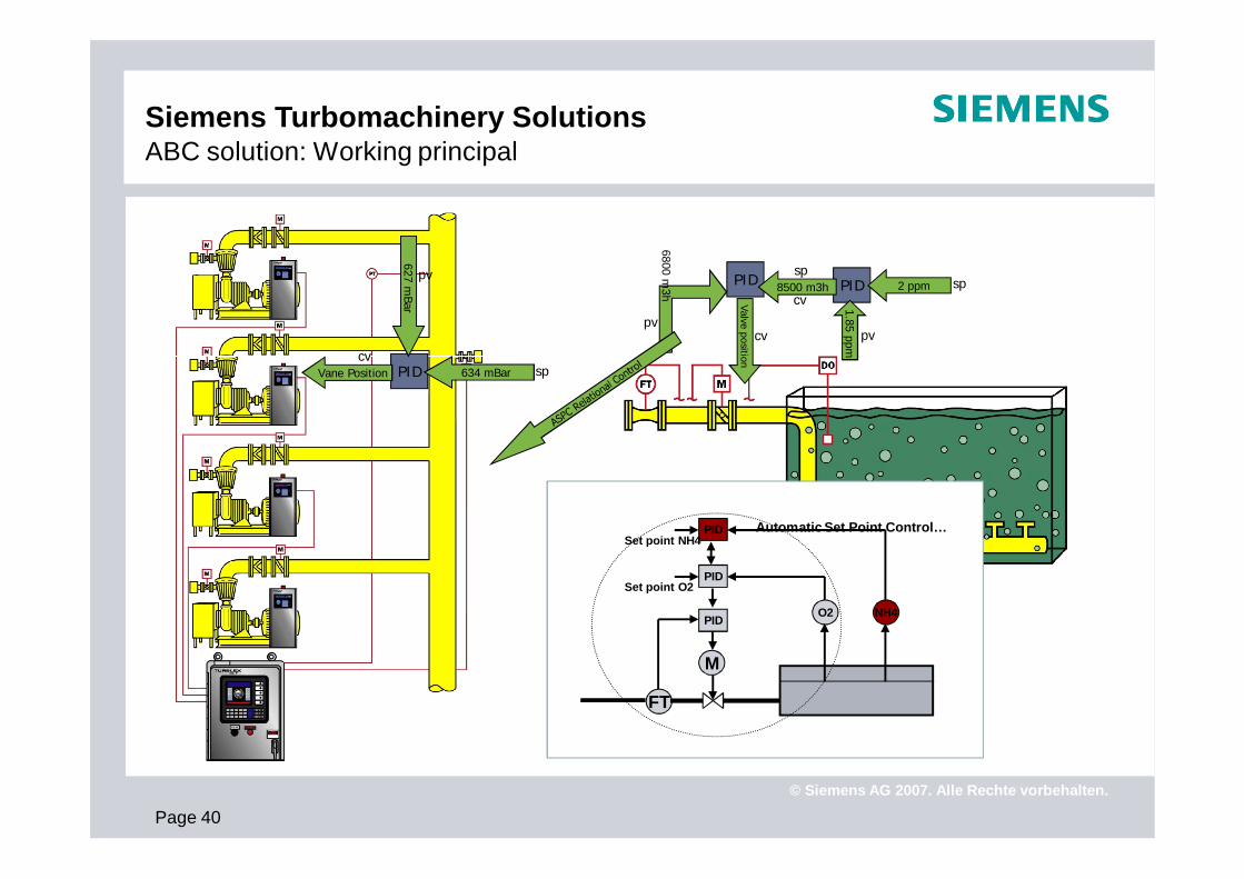
PIDPIDsp
cv8500 m3h 2 ppm sp
1.85 ppm
pv
Valve position
cv
6800 m3h
pv
PIDcv
Vane Position 634 mBar sp
627 mBar
pv
Siemens Turbomachinery SolutionsABC solution: Working principal
Automatic Set Point Control…
O2
PID
M
Set point O2
PID
FT
NH4
PIDSet point NH4

Page 41
For i
nter
nal u
se o
nly
/ Cop
yrig
ht ©
Sie
men
s AG
201
0. A
ll rig
hts
rese
rved
.
© Siemens AG 2007. Alle Rechte vorbehalten.
Siemens Turbomachinery SolutionsThe ABC solution
Related Documents