J FLOW CONTROLS · 4665 Interstate Dr. · Cincinnati, OH 45246 Tel : 1-513-731-2900 · Fax : 1-513-731-6939 http://www.jflowcontrols.com E-mail: [email protected] DM2500 and 2500 Series 2-Piece Flanged Ball Valve All information found on this brochure is subject to change at the discretion of J Flow Controls. For the most up to information, contact J Flow Controls. ©2014 J Flow ALL RIGHTS RESERVED * End connection: Flanged (ANSI 150 and 300) Note 1: The greases J Flow Controls uses include lubricants & anti-seize grease that are both SILICONE-FREE. Note 2: J Flow Controls strongly suggests increasing the torque at least 30%-40% for safety factor when mounting an actuator. FEATURES & BENEFITS OPTIONS * Spring return (dead-man) handle * Full automation capabilities * Manual valve with limit switch * V-ball for control valve in 15°, 30°, 45°, 60 °, 90°, slot, or custom * Hastalloy C, Super duplex, Alloy 20, and Monel * Comes standard in stainless steel and carbon steel * Investment cast body and end caps * Self adjusting stem packing * Blow-out proof stem design * 100% air tested under water at 100 psi * Temperature range of -40°F to +450°F * Working pressure: 1/4” - 2” at 1000 psi, 2-1/2” - 4” at 800 psi * ISO 5211 mounting pad (150# is direct mount, 300# requires bracket) Please visit www.jflowcontrols.com and use our “Configurator” for complete part numbers FLOW COEFFICIENT 110 980 16 240 1700 40 400 70 700 3” 4” 1-1/4” 3/8” 1-1/2” 1/2” 2” 1” 2-1/2” Cv FACTOR SIZE 7.5 1/4” * Working pressure to ANSI 150 or 300 * FIRE SAFE: API607-5th Edition Certified * Valve Design: ASME B16.34 * Steel Casting: MSS SP-55 * Face to face: ASME B16.10 * Pressure test: API 598 (ISO 5208) * Sulfide stress cranking: NACE MR-01-75 * Flange connection: ASME B16.50 BREAK-TORQUE VALUE for ANSI300 (in lb at 0 psi) 1/2" 3/4" 1" 2" SIZE GREASE NON-GREASE 3" 4" 1-1/2" 2-1/2" 75 90 115 240 300 635 750 1390 105 125 170 390 540 1265 1575 2910 BREAK-TORQUE VALUE for ASME150 (in lb at 0 psi) 1/2" 3/4" 1" 2" SIZE GREASE NON-GREASE 3" 4" 5" 10" 12" 1-1/4" 1-1/2" 2-1/2" 6" 8" 50 65 80 115 180 215 480 550 1100 2040 5755 10625 2215 4870 65 85 120 165 270 320 845 1170 2170 - - - - - TEMPERATURE (°F) 0 100 200 300 400 500 PRESSURE (P.S.I.) -20 1000 1200 800 600 400 200 0 PRESSURE/ TEMPERATURE ANSI150 TEMPERATURE (°F) 0 100 200 300 400 500 PRESSURE (P.S.I.) -20 1000 1200 800 600 400 200 0 PRESSURE/ TEMPERATURE ANSI300 RPTFE (PTFE+15% Glass) PTFE TFM (TFM1600) TFM4215

Welcome message from author
This document is posted to help you gain knowledge. Please leave a comment to let me know what you think about it! Share it to your friends and learn new things together.
Transcript
J FLOW CONTROLS · 4665 Interstate Dr. · Cincinnati, OH 45246
Tel : 1-513-731-2900 · Fax : 1-513-731-6939
http://www.jflowcontrols.com E-mail: [email protected]
D M2500 and 2500 Series
2-Piece Flanged Ball Valve
All information found on this brochureis subject to change at the discretionof J Flow Controls. For the most up to information, contact J Flow Controls.
©2014 J Flow ALL RIGHTS RESERVED
* End connection: Flanged (ANSI 150 and 300)
Note 1: The greases J Flow Controls uses include lubricants & anti-seize grease that are both SILICONE-FREE.
Note 2: J Flow Controls strongly suggests increasing the torque at least 30%-40% for safety factor when mounting an actuator.
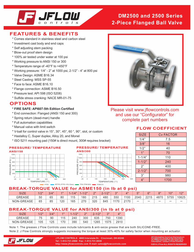
FEATURES & BENEFITS
OPTIONS
* Spring return (dead-man) handle
* Full automation capabilities
* Manual valve with limit switch
* V-ball for control valve in 15°, 30°, 45°, 60 °, 90°, slot, or custom
* Hastalloy C, Super duplex, Alloy 20, and Monel
* Comes standard in stainless steel and carbon steel
* Investment cast body and end caps
* Self adjusting stem packing
* Blow-out proof stem design
* 100% air tested under water at 100 psi
* Temperature range of -40°F to +450°F
* Working pressure: 1/4” - 2” at 1000 psi, 2-1/2” - 4” at 800 psi
* ISO 5211 mounting pad (150# is direct mount, 300# requires bracket)
Please visit www.jflowcontrols.comand use our “Configurator” for
complete part numbers
FLOW COEFFICIENT
110
980
16
240
1700
40
400
70
700
3”
4”
1-1/4”
3/8”
1-1/2”
1/2”
2”
1”
2-1/2”
Cv FACTORSIZE
7.51/4”
* Working pressure to ANSI 150 or 300
* FIRE SAFE: API607-5th Edition Certified
* Valve Design: ASME B16.34
* Steel Casting: MSS SP-55
* Face to face: ASME B16.10
* Pressure test: API 598 (ISO 5208)
* Sulfide stress cranking: NACE MR-01-75
* Flange connection: ASME B16.50
BREAK-TORQUE VALUE for ANSI300 (in lb at 0 psi)1/2" 3/4" 1" 2"SIZE
GREASE
NON-GREASE
3" 4"1-1/2" 2-1/2"
75 90 115 240 300 635 750 1390
105 125 170 390 540 1265 1575 2910
BREAK-TORQUE VALUE for ASME150 (in lb at 0 psi)1/2" 3/4" 1" 2"SIZE
GREASE
NON-GREASE
3" 4" 5" 10" 12"1-1/4" 1-1/2" 2-1/2" 6" 8"
50 65 80 115 180 215 480 550 1100 2040 5755 106252215 4870
65 85 120 165 270 320 845 1170 2170 - - - - -
TEMPERATURE (°F)
0 100 200 300 400 500
PR
ES
SU
RE
(P
.S.I
.)
-20
1000
1200
800
600
400
200
0
PRESSURE/ TEMPERATURE
ANSI150
TEMPERATURE (°F)
0 100 200 300 400 500
PR
ES
SU
RE
(P
.S.I
.)
-20
1000
1200
800
600
400
200
0
PRESSURE/ TEMPERATURE
ANSI300
RPTFE (PTFE+15% Glass)PTFE TFM (TFM1600) TFM4215
J FLOW CONTROLS · 4665 Interstate Dr. · Cincinnati, OH 45246
Tel : 1-513-731-2900 · Fax : 1-513-731-6939
http://www.jflowcontrols.com E-mail: [email protected]
All information found on this brochureis subject to change at the discretionof J Flow Controls. For the most up to information, contact J Flow Controls.
©2014 J Flow ALL RIGHTS RESERVED
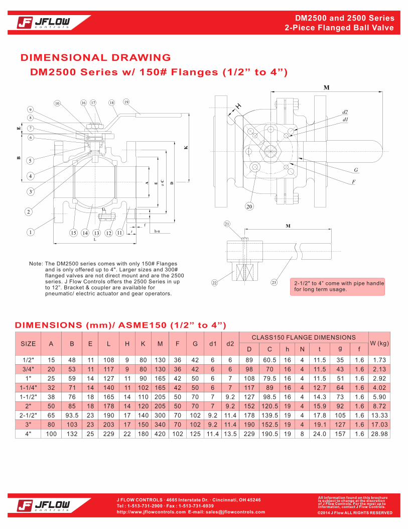
DIMENSIONAL DRAWING
Item 301F
DIMENSIONS (mm)/ ASME150 (1/2” to 4”)
N t g fD
CLASS150 FLANGE DIMENSIONS
hCFSIZE A EB L H K M
1/2"
3/4"
1-1/4"
1"
1-1/2"
2"
2-1/2"
3"
W (kg)d2G d1
4"
4
4
4
4
4
4
60.5
120.5
70
139.5
79.5
98.5
16
19
16
19
16
16
11.5
15.9
11.5
17.8
11.5
14.3
35
92
43
105
51
73
15
50
20
65
25
38
48
85
53
93.5
59
76
11
11
14
18
23
18
108
117
127
165
178
190
9
14
9
17
11
14
80
120
80
140
90
110
130
205
130
300
165
205
36 1.73
50 8.72
36 2.13
70 13.33
42 2.92
50 5.90
89
152
98
178
108
127
489 16 12.7 6432 71 14 140 11 102 165 42 4.02117
42
70
42
102
50
70
6
7
6
9.2
6
7
6
9.2
6
11.4
7
9.2
50 6 7
1.6
1.6
1.6
1.6
1.6
1.6
1.6
4
8
152.5
190.5 19
19.1
24.0
127
157
80
100
103
132
23
25
203
229
17
22
150
180
340
420
70 17.03
102 28.98
190
229
102
125
9.2
11.4
11.4
13.5
1.6
1.6
19
5
2
1
3
4
15 14 13 12 11
10
6
7
9
8
16 17 1918
K
øC
h-nt
f
gA D
L
BE
20
H
M
d1
d2
G
F
23
21
22
M
2-1/2" to 4” come with pipe handlefor long term usage.
Note: The DM2500 series comes with only 150# Flanges and is only offered up to 4". Larger sizes and 300# flanged valves are not direct mount and are the 2500 series. J Flow Controls offers the 2500 Series in up to 12”. Bracket & coupler are available for pneumatic/ electric actuator and gear operators.
D M2500 and 2500 Series2-Piece Flanged Ball Valve
D M2500 Series w/ 150# Flanges (1/2” to 4”)

J FLOW CONTROLS · 4665 Interstate Dr. · Cincinnati, OH 45246
Tel : 1-513-731-2900 · Fax : 1-513-731-6939
http://www.jflowcontrols.com E-mail: [email protected]
All information found on this brochureis subject to change at the discretionof J Flow Controls. For the most up to information, contact J Flow Controls.
©2014 J Flow ALL RIGHTS RESERVED
MATERIALS LIST
PARTS BLOWOUT VIEW
9060
3015
Straight Port 15 V-Port 30 V-Port 60 V-Port 90 V-Port
V-BALL OPTION FOR MODULATING CONTROL
45
45 V-Port
For Cv, please see our “J Flow V-Ball Cv” Literature
16
1
7
6
5
10
9
8
4
3
2
20-1
20
15
14
1413
11
19
18
17
23]
22
21
12
9
10
11
12
5
2
6
3
7
4
8
ITEM
1
13
14
15
16
17
18
19
20
21
22
23
PTFE/RPTFE
SS 316/ SS 304
CF8M/ WCB
SS 304
SS 304
RPTFE
SS 301
SS 304
CLASS150
CF8M/ WCB
SS 304
SS 304
PLASTIC
SS 304
CF8
SS 316/ SS 304
PTFE
STEEL PIPE
LEVER HEAD
STEM PACKING
BOLT
BODY
GLAND
BALL SEAT
STEM
DISK WASHER
THRUST WASHER
STEM NUT
PART NAME
FLANGED END
NUT STOP
HANDLE
HANDLE NUT
O-RING
WASHER
GASKET
BALL
STOPPER PLATE
SLEEVE
STOP PIN
SET BOLT
PIPE HANDLE
VITON
PTFE
SS 304
SS 304
SS 304
SS 304
MATERIAL
D M2500 and 2500 Series2-Piece Flanged Ball Valve
D M2500 Series w/ 150# Flanges (1/2” to 4”)

J FLOW CONTROLS · 4665 Interstate Dr. · Cincinnati, OH 45246
Tel : 1-513-731-2900 · Fax : 1-513-731-6939
http://www.jflowcontrols.com E-mail: [email protected]
All information found on this brochureis subject to change at the discretionof J Flow Controls. For the most up to information, contact J Flow Controls.
©2014 J Flow ALL RIGHTS RESERVED
DIMENSIONAL DRAWING
18
K
ø J
M
G
øC
H-N(N0. HOLES)f
A D
L
F
t
E
g
10
7
6
8
11
12
14
5 4 3 2 1
17
1615
9
13
E
20
19
DIMENSIONS (mm)/ ASME300 (1/2" to 4")
N t g BD
CLASS 300 FLANGE DIMENSIONS
HCJ
O fSIZE A EF L K M G
139.7
152.4
190.5
165.1
215.9
6.5
6.5
9.7
9.7
9.7
42
70
50
70
M5
M5
M8
M6
M8
10
10
18
14
18
95
117
156
124
165
42 35
43
73
51
92
66.5
89
114.5
127
82.5
241.3
282.7
12
12
102
102
M10
M10
20
20
190
210
105
127
149
168
16
19
22
19
20
22
22
4
4
4
4
8
8
8
1/2"
3/4"
1-1/2"
1"
2"
145
145
195
250
250
15
20
38
25
50
2-1/2"
3" 310
31065
80
14.5
16
17.5
21
22.5
25.5
29
1.6
1.6
1.6
1.6
1.6
1.6
1.6
304.8 15 102 M10 24 254 157200 22 84" 310100 32 1.6
13.9
24.9
14.2
23.9
21.6
22.9
21.9
29.7
10.7
18.0
10.9
19.6
16.8
16.3
16.3
24.4
76
80
88
114
123
142
152
182
2-1/2" to 4” come with pipe handlefor long term usage.
D M2500 and 2500 Series2-Piece Flanged Ball Valve
2500 Series w/ 300# Flanges (1/2” to 4”)

J FLOW CONTROLS · 4665 Interstate Dr. · Cincinnati, OH 45246
Tel : 1-513-731-2900 · Fax : 1-513-731-6939
http://www.jflowcontrols.com E-mail: [email protected]
All information found on this brochureis subject to change at the discretionof J Flow Controls. For the most up to information, contact J Flow Controls.
©2014 J Flow ALL RIGHTS RESERVED
D M2500 and 2500 Series2-Piece Flanged Ball Valve
6
18
7
10
9
3
8
5
3
16
13
14
12
17
15
11
20
4
2
1
19
2 1/2"-4"
1/2"-2
"
PTFE/RPTFE
SS 316/ SS 304
CF8M/ WCB
SS 304
PTFE
SS 304
RPTFE
SS 301
SS 304
BALL
STEM PACKING
BOLT
BODY
GLAND
BALL SEAT
STEM
DISK WASHER
GASKET
THRUST WASHER
STEM NUT
9
10
11
12
5
2
6
3
7
4
8
MATERIALSPART NAMEITEM
CF8M/ WCBFLANGED END1
SS 304NUT STOP13
SS 304STOPPER PLATE14
SS 304
SS 304
PLASTIC
SS 304
HANDLE
HANDLE NUT
SLEEVE
STOP PIN
15
16
17
18
CF8LEVER HEAD19
STEEL PIPEPIPE HANDLE20
SS 316/ SS 304
PTFE
PARTS BLOWOUT VIEW
2500 Series w/ 300# Flanges (1/2” to 4”)
Item 301F
MATERIALS LIST

J FLOW CONTROLS · 4665 Interstate Dr. · Cincinnati, OH 45246
Tel : 1-513-731-2900 · Fax : 1-513-731-6939
http://www.jflowcontrols.com E-mail: [email protected]
All information found on this brochureis subject to change at the discretionof J Flow Controls. For the most up to information, contact J Flow Controls.
©2014 J Flow ALL RIGHTS RESERVED
DIMENSIONAL DRAWING
D M2500 and 2500 Series2-Piece Flanged Ball Valve
2500 Series w/ 150# Flanges (5” to 12”)
216
241.5
298.5
C n h gK
CLASS 150 FLANGE DIMENSIONS
DSL
t fSIZE A EB F G H M
5"
6"
10"
8"
12"
DIMENSIONS (mm)/ ASME150 (5" to 12")
125
300
150
200
250
150
307
170
219
255
58
79
58
64
64
34
46
34
38
38
125
140
125
125
125
442
285
354
390
265 700
1500
850
1100
1200
356
610
394
457
533
M12
M16
M12
M12
M12
28
36
28
36
36
254
483
279
343
406
432
362
22
25
22
22
25
8
12
8
12
8
186
381
216
270
324
23.9
31.8
25.4
28.6
30.2
1.6
1.6
1.6
1.6
1.6
270
330.2
387.3
C n h gK
CLASS 300 FLANGE DIMENSIONS
DSL
t fSIZE A EB F G H M
6"
8"
10"
DIMENSIONS (mm)/ ASME300 (6" to 10")
150
200
250
174.5
219.5
255
53.5
64
64
31.5
38
38
125
125
125
343
379
288 850
1100
1200
403
502
568.5
M12
M12
M12
28
36
36
318
381
445
22
26
29
12
16
12
216
270
324
37
41.5
48
1.6
1.6
1.6
6
431 215
h-n
A g C D
7
M
f
t
BE
F
H
5
8
9 10 11 12 13 14
33
K
S
L 16
80.6
43.1
140
G
K
S
L 16
114
65.5
35.5
G 2500, 5"-6"
2500, 8"-12"
2500 Series w/ 300# Flanges (6” to 10”)
J FLOW CONTROLS · 4665 Interstate Dr. · Cincinnati, OH 45246
Tel : 1-513-731-2900 · Fax : 1-513-731-6939
http://www.jflowcontrols.com E-mail: [email protected]
All information found on this brochureis subject to change at the discretionof J Flow Controls. For the most up to information, contact J Flow Controls.
©2014 J Flow ALL RIGHTS RESERVED
D M2500 and 2500 Series2-Piece Flanged Ball Valve
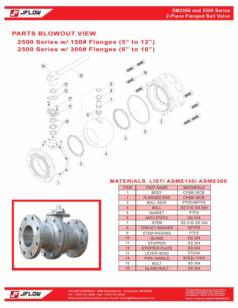
PARTS BLOWOUT VIEW
2500 Series w/ 150# Flanges (5” to 12”)
2500 Series w/ 300# Flanges (6” to 10”)
3
1
15
13
12
11
10
7
8
4
3
5
2
16
14
6
9
17
MATERIALS LIST/ ASME150/ ASME300
PTFE/RPTFE
SS 316/ SS 304
PTFE
RPTFE
SS 304
BALL
STEM PACKING
BODY
GLAND
BALL SEAT
STEM
GASKET
THRUST WASHER
STOPPER
9
10
11
12
5
2
6
3
7
4
8
MATERIALSPART NAMEITEM
CF8M/ WCB
FLANGED END
1
SS 304
13 FCD45
STOPPER PLATE
14 STEEL PIPE
SS 304
GLAND BOLT
15
16
LEVER HEAD
PIPE HANDLE
SS 316/ SS 304
ANTI-STATIC
BOLT
CF8M/ WCB
SS 316
PTFE
SS 304
SS 304
Related Documents