OD EXPERIMENTAL AND ANALYTICAL STUDY OF A STEAM VANE EXPANDER Gerald F. Robertson D D Technical Memorandum File No. TM 77-65 February 1, 1977 Contract No. N00017-73-C-1418 Copy No. The Pennsylvania State University Institute for Science and Engineering APPLIED RESEARCH LABORATORY Post Office Box 30 State College, PA 16801 APPROVED FOR PUL,:., ELEAS DISTRIDUTION Ur.lj;-E1 NAVY DEPARTMENT NAVAL SEA SYSTEMS COMMAND -JJ

Welcome message from author
This document is posted to help you gain knowledge. Please leave a comment to let me know what you think about it! Share it to your friends and learn new things together.
Transcript

OD
EXPERIMENTAL AND ANALYTICAL STUDY OFA STEAM VANE EXPANDER
Gerald F. Robertson
D DTechnical MemorandumFile No. TM 77-65February 1, 1977Contract No. N00017-73-C-1418
Copy No.
The Pennsylvania State UniversityInstitute for Science and EngineeringAPPLIED RESEARCH LABORATORYPost Office Box 30State College, PA 16801
APPROVED FOR PUL,:., ELEASDISTRIDUTION Ur.lj;-E1
NAVY DEPARTMENT
NAVAL SEA SYSTEMS COMMAND
-JJ

iEcuRITY CLASSIFICA.1TION OF THIS PAGE (60%on Data Entered)
REPOT DCUMNTATON AGEREAD INSTRUCTIONSREPOT DCUMNTATON AGEBEFORE COMPLETING FORM
1. REPORT NUMBER 2. GOVT ACCESSION No. 3. RECIPIENT'S CATALOG NUMBER
4 . TITL-E_(end Su11W ) - ---- 5. TYPE OF REPORT & PERIOD COVERED
b XERIMENTAL AND 3IAYIA SUYO TEAM PhD Thesis, Mech. Eng. -
- 6. PERF RMILQR2G. EPORT NUMBER
C TA T R TNMSER()
Gerad F.Robetson/ (/'c60017-73-C-1418
9. PERFORMING ORGANIZATION NAME AND ADDRESS 10. PROGRAM ELEMENT. PROJECT. TASK
The Pennsylvania State University AE OKUI UBR
Applied Research Laboratory .
P. 0. Box 30, S.~e.e-ee*e, PA 16801
It. CONTROLLING OFFICE NAME AND ADDRESS A~T......
Naval Sea Systems Command ,J/ FebWQZ77jDepartment of the Navy P . 1W~~ AGES
Washington, D. C. 20362 138 pages & figures14. MONITORING AGENC NA ADRE £flfDW (rent from Controlling Office) IS. SECURITY CLASS. (of this report)
- ' Unclassified, Unlimited
I5a. DECLASSIFICATION/ DOWNGRADINGSCHEDULE
IS. DISTRIBUTION STATEMENT (of this Report)
Approved for public release, distribution unlimited, per NSSC
(Naval Sea Systems Command) 4/4/77
17. DISTRIBUTION STATEMENT (of the abstract entered in Block 20, if different Iroat Repr
III. SUPPLEMENTARY NOTES -C
It. KEY WORDS (Continue on reverse side #f necessary an~d identify by block number)
Rotary Vanes Heat TransferSteam ExpanderLeakageFriction
20.\9STRACT (Continue on ,rerse, side it necessary and Identify by block number)
-~An experimental and analytical study of a rotary vane steam expander wasconducted to determine the effect of leakage, friction and heat transfer onthe expander performance. A commercially available rotary vane air motorwas modified to operate on steam utilizing little or no liquid lubricant.The indicated power output, shaft power output and frictional power loss of4the vane expander were experimentally determined as a function of speed,inlet timing and supply steam conditions. The steam mass flow rate and
DD I JAN 73 1473 EDITION OF I NOV 65 IS OBSOLETE UNCIASSIFIEDSECURITY CLASSIFICATION OF THIS PAGE (Whon Data Enteree~

UNCLASSIFIEDSECURITY CLASSIFICATION OF THIS PAGEO(M, Data ntored)
20. LABSTRACT (continued)
component temperatures were also measured. The data show that severe
internal leakage and frictional energy dissipation were major causesof efficiency reductions.
An analytical model of the expander thermodynamics, friction,leakage and heat transfer was developed from fundamental principles.The model predicts the expander leakage flow rate, frictional powerloss heat transfer rate and the effect of these losses on the poweroutput and efficiency. The analytically and experimentally determinedfrictional power losses were in agreement. The component temperatureprofiles were predicted with maximum errors of 10% - 15%. The
predicted leakage flow was approximately 16% below the experimentally
determined value. Errors in the leakage flow predictions resulted inthe predicted indicated power outputs being 20% - 40% below the
experimental values. This was condiered reasonably good in light of
the difficulty in identifying the steam leakage paths and componentclearances.
............
........................................ .....
cis .. .....
A IL
'= .
UNCLASSIFIED
SECURITY CLASSIFICATION OF THIS PAGE(rWh.n Dfre Entered)

III
ACKNOWLEDGMENTS
The author wishes to thank Professor Carl H. Wolgemuth for his
encouragement and guidance throughout this program.
The assistance of Messrs. Stanley Gulbernat, Rex Jacobs,
William Loessh and Doyle Walker in constructing the apparatus is also
appreciated.
The author wishes to acknowledge the support of this investigation
by the Applied Research Laboratory of The Pennsylvania State University
under contract with the Naval Sea Systems Command.
'-
TABLE OF CONTENTS
Page
ACKNOWLEDGMENTS................... . . ... . .. .. .. .. .. . ...
LIST OF TABLES. .................... ...... v
LIST OF FIGURES. ... ....................... vi
NOMENCLATURE .. .......................... ix
1. INTRODUCTION .. .........................
1.1 General Statement of the Problem. .. .......... 11.2 Previous Related Studies. .. .............. 21.3 Purpose .. ........................ 4
11. EXPERIMENTAL APPARATUS AND PROCEDURE .. ........... 7
2.1 Description of Expander ... .............. 72.2 Experimental Apparatus .. ................ 142.3 Experimental Procedure .. ................ 192.4 Error Analysis .. ..................... 21
2.4.1 Power Measurement .. ............... 212.4.2 Mass Flow Rate Measurement. ........... 232.4.3 Control Volume Pressure Measurement .. ...... 232.4.4 Steam Enthalpy Measurement. ........... 232.4.5 Temperature Measurement .. ............ 24
III. ANALYTICAL CONSIDERATIONS .. ................. 25
3.1 Thermodynamic Model. .................. 253.2 Friction Model .. ..................... 263.3 Leakage Model. ..................... .. 323.4 Heat Transfer Model. .................. 35
3.4.1 One-Dimensional Model .. ............. 353.4.2 Rotor, Three-Dimensional Model. ......... 363.4.3 Stator, Three-Dimensional Model .. ........ 39 r3.4.4 End Plate, Three-Dimensional Model. ....... 43
3.5 Numerical Procedure. .................. 45
3.5.1 Transient Analysis . .. .. .. .. .... 463.5.2 Steady State Analysis .. .............. 6

iv
TABLE OF CONTENTS (CONTINUED)
Page
IV. EXPERIMENTAL AND THEORETICAL RESULTS. .. .......... 47
4.1 Experimental Conditions. .. .............. 474.2 Experimental Results .. ................ 47
4.2.1 Paver. ............... ...... 474.2.2 Mass Flow Rate. .. ............... 554.2.3 Adiabatic Expansion Efficiency. .. ....... 614.2.4 Temperature Measurement Results .. ....... 644.2.5 Expander Heat Loss. .. ............. 70
4.3 Comparisons with Theoretical Results .. ....... 77
4.3.1 Mass Flow Rate. .. ............... 774.3.2 Power Output. .. ................ 804.3.3 Temperature Profiles and Heat Transfer
Coefficient .. ................. 83
V. SUMMARY AND CONCLUSIONS .. ................. 91
5.1 Summary .. .............. ......... 91
5.2 Conclusions .. ............... ...... 92
BIBLIOGRAPHY .. ............... ........... 95
APPENDIX A: EQUATIONS USED IN THERMODYNAMIC MODEL. .. ...... 97
APPENDIX B: DERIVATION OF EXPRESSIONS FOR TANGENTIAL ANDINORMAL ACCELERATIONS. ................ 108
APPENDIX C: DERIVATION OF FINITE DIFFERENCE EXPRESSIONS ill.. 1
APPENDIX D: DERIVATION OF FRICTIONAL HEAT FLUX EQUATIONS . 118

v
LIST OF TABLES
Table Page
1. Estimated Errors in the Power Measurements ... ........ .. 22
2. Expander Heat Loss Data ....... .................. .. 76
3. Definitions of Non-Dimensional Variables .... .......... .. 99
h

vi
LIST OF FIGURES
Figure Page
1. Schematic of Test Expander ........ ................ 8
2. Photograph of Test Expander ... .... .............. 9
3. Dimensionless Pressure Versus Dimensionless Volume,Ideal Expander (No Leakage, Heat Transfer, or Friction).. i1
4. Spring Force Variation ......... .................. 13
5. Schematic of Experimental Apparatus ... ........... ... 15
6. Bendersky Thermocouple Mounting .... ............. ... 20
7. Schematic Diagram of Vane Expander Model .. ......... ... 27
8. Vane Free Body Diagram ...... ................. .... 29
9. Leakage Paths for a Single Control Volume . ........ ... 33
10. Stator Model ........ ....................... .... 40
11. End Plate Model ... ..... ...................... .. 44
12. Pressure Versus Volume for 150 psia Supply Pressure22.5 ° Arc of Admission ......... .................. 48
13. Pressure Versus Volume for 150 psia Supply Pressure45* Arc of Admission .......... .................. 49
14. Power Versus Speed for 150 psia Supply Pressure ..... 51
15. Power Versus Speed for 115 psia Supply Pressure ..... . 52
16. Mechanical Efficiency Data 150 psia Supply Pressure . . . 54
17. Mechanical Efficiency Data 115 psia Supply Pressure . . . 56
18. Mass Flow Rate Data for 150 psia Supply Pressure22.5* Arc of Admission ...... .................. .. 57
a

vii
LIST OF FIGURES (CONTINUED)
Figure Page
19. Mass Flow Rate Data for 150 psia Supply Pressure450 Arc of Admission ....... ................... ... 58
20. Mass Flow Rate Data for 115 psia Supply Pressure22.50 Arc of Admission ....... .................. ... 59
21. Mass Flow Rate Data for 115 psia Supply Pressure450 Arc of Admission ....... ................... ... 60
22. Adiabatic Expansion Efficiency Data for 150 psiaSupply Pressure ........ ..................... ... 62
23. Adiabatic Expansion Efficiency Data for 115 psiaSupply Pressure ........ ..................... ... 65
24. Stator Temperature Profile Data for 150 psia SupplyPressure 22.5* Arc of Admission .... ............. ... 66
25. Stator Temperature Profile Data for 150 psia SupplyPressure 45* Arc of Admission .............. 67
26. Stator Temperature Profile Data for 115 psia SupplyPressure 22.5 ° Arc of Admission .... ............. ... 68
27. Stator Temperature Profile Data for 115 psia SupplyPressure 45* Arc of Admission .... .............. ... 69
28. End Plate Temperature Profile Data for 150 psia SupplyPressure 22.5 ° Arc of Admission .... ............. ... 71
29. End Plate Temperature Profile Data for 150 psia SupplyPressure 450 Arc of Admission .... .............. ... 72
30. End Plate Temperature Profile Data for 115 psia SupplyPressure 22.50 Arc of Admission .... ............. ... 73
31. End Plate Temperature Profile Data for 115 psia SupplyPressure 450 Arc of Admission .... .............. ... 74
32. Rotor Surface Temperature Data .... ................. 75
33a. Leakage Flow Rate Versus Speed .............. 79
33b. Horsepower Versus Speed ...... ................. ... 79
34. Frictional Power Loss Versus Speed.. . . .. .. . . . . . 82

viii
LIST OF FIGURES (CONTINUED)
Figure Page
35. Experimental and Analytical Stator Temperature Profiles22.50 Arc of Admission ...... .................. ... 84
36. Experimental and Analytical End Plate TemperatureProfiles ......... ......................... .... 85
37. Ratio of Rotor Surface Temperature to Steam SaturationTemperature Data ....... ..................... .... 88
38. Schematic Diagram Showing Control Volume .......... ... 98
39. Variation of Exhaust and Intake Area for Arc ofAdmission and Arc of Exhaust Greater than Arc ....... . 101
40. Variation of Intake Area for Arc of Admission Lessthan Arc .......... ......................... ... 102
41. Schematic of Vane Slot and Pressure Balancing orPressurization Port ....... ................... ... 104
42. Interior Finite Difference Node ...... ............. 112
43. Boundary Finite Difference Node ...... ............. 115
p.)

ix
NOMENCLATURE
Symbol Definition
A Exposed area of a vane
A CG/p/ n Normal acceleration of a vane relative to the rotor
A CG t Tangential acceleration of a vane center of gravity
A CORIOLIS Coriolis acceleration of a vane
AEVN Area of vane tip
A Maximum area for inlet or exhaust flowmax
A N Normal acceleration of a vane
AP Area of vane tip exposed to the inlet or exhaust port
A pnNormal acceleration of a point on a frame moving withp n the rotor at a radius corresponding with the vane
center of gravity
A ptTangential acceleration of a point on a frame movingwith the rotor at a radius corresponding with the vanecenter of gravity
A rsRotor surface area between adjacent vanes
ARC Angle between adjacent vanes
ARCAD Arc of admission
ARCEX Arc of exhaust
A tTangential acceleration of a vane
B Breathing number
b One-half the clearance between expander components
b' Parameter in Keenan and Keyes equation of state for
steam
c Specific heat of tank wall
in*II - ilI- - i lnx-
NOMENCLATURE (CONTINUED)
Symbol Definition
CD Discharge coefficient
e Eccentricity
FE End force on a vane
F Normal force on a vanen
F RB Rotor force on bottom side of a vane
FRT Rotor force on a vane at outside radius of rotor
Ft Tangential force on a vane
F3 Stator force on a vane
H Height of tank
h Specific enthalpy
hMean convective heat transfer coefficient
Aht Specific enthalpy change in nozzle
HR Length of vane extension above rotor
k Thermal conductivity
k Thermal conductivity of body 1 of two bodies in1 sliding contact
k 2 Thermal conductivity of body 2 of two bodies insliding contact
L Characteristic length for determining convective heattransfer coefficients
LE Characteristic length for determining the end plateheat transfer coefficient
L S Characteristic length for determining the stator heat
transfer coefficient
LV Vane height
M Rate of change of mass in the control volume
xi
NOMENCLATURE (CONTINUED)
Symbol Definition
MA Moment about vane base
mMass flow rate
mlDEAL Expander ideal mass flow rateIExpander
leakage mass flow rate
Expander total mass flow rate
mTB Mass of tank bottom
m Vane massV
mwf Mass of water in tank at end of test
i Mass of water in tank at start of test
Am Increase in mass of water in tank during test
Am Mass of condensed steamc
N Rotor speed (revolutions per minute)
Nu Local Nusselt Numberx
OP Width of groove at base of vane slot
OPD Depth of groove at base of vane slot
P Pressure
PA AEVN Pressure force on vane base
P f Pressure force on side of a vane
P LAG Pressure in control volume lagging a vane
PLEAD Pressure in a control volume leading a vane
Pr Prandtl number
P AP Supply pressure force on a vane tip (-0 when vane notexposed to inlet
AP Pressure drop along a leakage path

xii
NOMENCLATURE (CONTINUED)
Symbol Definition
q Frictional heat transfer rate per unit area into body 1of two bodies in sliding contact
q2 Frictional heat transfer rate per unit area into body 2of two bodies in sliding contact
q" gInstantaneous heat generation rate per unit area
q" Time averaged heat generation rate per unit areagen
qTt Total frictional heat generation rate
QHeat transfer rate
r Radial coordinate
Ar Incremental change in the radial coordinate
R Resistance of a leakage path
R' Ratio of rotor radius to stator radius
Ri Rotor radius
Ri- j Resistance of leakage path i-j
Re Local Reynolds Numberx
ReL Reynolds Number at L
R Stator radius0
R Tank radiust
s Laplace transform operator
SD Depth of vane slot
SPF Spring force on vane base
SW Width of vane slot
T Temperature
Tf Temperature of tank bottom at end of test
Ti Temperature of tank bottom at start of test
.1.$

NOMENCLATURE (CONTINUED)
Symbol Definition
~Laplace transform of temperature
T ROTOR Rotor surface temperature
TST Saturation temperature
TV Vane thickness
T Expander component wall temperaturew
T WALL Tank wall temperature
T0o(t) Instantaneous steam temperature
L Time averaged steam temperature
t Time
t' Tank wall thickness
At Incremental change in time
U Internal energy of the control volumecv
U wf Specific internal energy of the water in the tank atthe end of a test
U wi Specific internal energy of the water in the tank atthe start of a test
V CG/P Velocity of a vane center of gravity relative to a
vane slot
V Volume
v Specific volume
VH Volume of pressurization ports
V MEAN/S Fluid velocity over the stator surface,
V MEANIE. Fluid velocity over the end plate surface
VOP Volume of groove at base of vane
V SL Volume of vane slot, pressurization port, and grooveat base of vane slot

xiv
NOMENCLATURE (CONTINUED)
SyblDefinition
w Width of a leakage path
W Work
W Power
WVISCOUS Viscous power dissipation
W Normal component of vane weightn
W Tangential component of vane weightt
X Coordinate along leakage path
x Quality
xv Length along tank wall
XAD Angle inlet opens
XEX Angle exhaust opens
XV (LV-HR)
AX Distance along a leakage path
z Axial coordinate
Z' Rotor length
ZOR Width inlet and exhaust port
CLThermal diffusivity
CL I Thermal diffusivity of body I of two bodies in sliding. contact
a 2 Thermal diffusivity of body 2 of two bodies in sliding
contact
at ROTO R Angular acceleration of the rotor
6 Condensation liquid film thickness
C Clearance between rotor and end plate
rIADIABATIC Adiabatic expansion efficiency
EXPANSION

NOMENCLATURE (CONTINUED)
Symbol Definition
e Angular coordinate
Ae Incremental change in the angular coordinate
Viscosity
Coefficient of friction between vane and end plate
Coefficient of friction between vane and rotor
113 Coefficient of friction between vane and stator
IlIFE Frictional force between vane and end plate
P2FRB Frictional force between vane and rotor
12 FRT Frictional force between vane and rotor
P3F3 Frictional force between vane and stator
p Density
Pw Liquid water density
W Angular velocity (Radians per unit time)
Angular velocity vector
Subscripts
f Saturated liquid jg Saturated vapor
fg The change from saturated liquid to saturated vapor
0 Inlet condition
i-J Leakage path from source i to sink j
k Leakage source or sink

xvi
NOMENCIATURE (CONTINUED)
Superscripts Definition
* Dimensionless variable
NOTE: A dot over a variable (i) indicates either differentiation withrespect to time, or a rate as in the case of n(mass flow rate).

ABSTRACT
An experimental and analytical study of a rotary vane steam
expander was conducted to determine the effect of leakage, friction and
heat transfer on the expander performance. A commercially available
rotary vane air motor was modified to operate on steam utilizing little
or no liquid lubricant. The indicated power output, shaft power output
and frictional power loss of the vane expander were experimentally
determined as a function of speed, inlet timing and supply steam
conditions. The steam mass flow rate and component temperatures were
also measured. The data show that severe internal leakage and frictional
energy dissipation were major causes of efficiency reductions.
An analytical model of the expander thermodynamics, friction,
leakage and heat transfer was developed from fundamental principles.
The model predicts the expander leakage flow rate, frictional power loss
heat transfer rate and the effect of these losses on the power output and
efficiency. The analytically and experimentally determined frictional
power losses were in agreement. The component temperature profiles were
predicted with maximum errors of 10% - 15%. The predicted leakage flow
was approximately 16% below the experimentally determined value. Errors
in the leakage flow predictions resulted in the predicted indicated
power outputs being 20% - 40% below the experimental values. This was
considered reasonably good in light of the difficulty in identifying the
steam leakage paths and component clearances.

I I
CHAPTER I
INTRODUCTION
1.1 General Statement of the Problem
Interest in Rankine cycle power systems for applications
requiring power outputs in the 10-50 horsepower range, has led to the
consideration of many devices for the system prime mover. Several
positive displacement expanders such as the reciprocating, Wankel and
rotary vane type have been suggested. Turbines also have been used
extensively in Rankine cycle systems. However, the efficiency of
turbines is diminished at the low power levels, particularly at part
load, giving the positive displacement expanders a potential advantage
in size and efficiency.
Rotary vane expanders do not vibrate as much as reciprocating
expanders and due to their simplicity, they have possible weight
advantages. Ideally, the rotary vane expander operates with a high
efficiency. This has been analytically demonstrated for the idealized
expander by Wolgemuch and Olson [1]. However, there exist in the vane
expander losses due to leakage, friction and heat transfer which must
be considered to realistically assess the suitability of the vane
expander for use in low power dynamic thermal power systems.
Although vane expanders have been used extensively in industrial
applications as low expansion air motors in the 1/4 to 10 horsepower
I range, the investigation and development of vane expanders for use inL]

2
high temperature vapor cycles has been limited. To determine the
applicability of vane expanders in Rankine cycle applications and to
improve their performance, it is necessary to understand the various
losses which occur. Consequently, it is the object of this research to
determine the effects of friction, leakage, and heat transfer on the
performance of a rotary vane expander through a combined analytical and
experimental program.
1.2 Previous Related Studies
Wolgemuth and Olson [1 developed a thermodynamic model of the
rotary vane steam expander to study its general operating characteristics.
The analysis included the transient charging and discharging processes
of the expander to permit the breathing of these devices to be studied.
Although the model contained provisions for the inclusion of heat transfer,
and was adaptable to include the effects of leakage and friction, a
detailed analysis of these phenomena and their effect on the expander
performance was not performed. Their study shows that easy breathing in
vane expanders is readily achieved and that a vane expander operating in
the absence of heat transfer, leakage and friction can obtain a high
expansion efficiency.
The frictional forces existing between the vanes and the stator
of a rotary vane air cycle refrigeration machine (ROVAC) were analyzed
by Edwards and McDonald [2]. The model utilized mean values of the
geometric variables involved in the computation of the frictional forces.
In order to determine the pressure forces on the vanes, the analysis Pused a thermodynamic model which did not have the capability to predict
transient pressure effects.

3
Peterson and McGahan [3] developed a thermodynamic model of an
oil flooded sliding vane air compressor. The model analyzed the
frictional forces existing in the compressor and used a dynamic analysis
of the working fluid to compute the pressure forces on the vanes. The
model included the leakage occurring between the primary control volume
(volume between adjacent vanes) and the control volumes leading it and
lagging it as well as between the primary control volume and those
regions at inlet pressure. In computing the leakage flow, an empirically
determined discharge coefficient was employed to account for the blockage
of the flow area by oil. The heat transfer was modeled by assuming the
air transferred heat only with the oil in the chamber. Good agreement
was obtained between the experimental and computed power input require-
ments and air flow rates.
Eckard [4] graphically presented experimental data taken from a
high temperature vane expander being developed by General Electric.
Eckard pointed out that leakage and friction are two major problem areas
encountered in the development of a multi-vane vapor expander, with
practical solutions to leakage problems the most difficult to obtain.
In order to reduce leakage without large increases in friction, the
General Electric expander depends on the maintenance of small clearances.
Eckard noted, however, that considerable care must be taken to achieve
and maintain small clearances under the changing temperature conditions
encountered. Additional observations made by Eckard, based on the data
collected are:

1 4
1) Moderate shift in expander speed does not severely
reduce expander efficiency.
2) Breathing losses in a vane expander can essentially
be eliminated since dynamic valves are not required.
3) Low speed operation (1200-1800 RPM) is currently
essential for low frictional power losses.
Eckard concluded that additional material and design innovations are
necessary to further improve the expander performance and to increase
its applicability.
1.3 Purpose
The preceeding discussion indicates that vane expanders have a
potential for high efficiency in vapor cycle applications provided
degradation of expander performance due to friction, heat transfer and
leakage can be controlled.
Some experimental work has been done to develop an efficient
rotary vane expander. Additionally, friction and to a lesser extent
leakage, have been modeled in vane air compressors and in the Rovac
machine utilizing techniques applicable to a vane expander. However, a
physical description of the combined phenomena of heat transfer, leakage
and friction that occur within a multi-vane vapor expander has not been
formulated.
Since the amounts of leakage, heat transfer and a friction are
not independent of one another, and since it is difficult, at times,
to determine which of these phenomenon is associated with an observed
degradation of power or efficiency, an understanding and description of

the physical processes occurring in the expander is required to identify
the mechanisms of the various losses. Furthermore, the development of a
working model of the vane expander would permit a degree of optimization
of the expander design to be achieved prior to the construction of hard-
ware.
In view of the high efficiency potential of vane expanders, and
in view of the necessity to obtain a better understanding of the
phenomena occurring within them, the following are the specific
objectives of this thesis.
1. Analytical
The objective of the analytical study is to develop a working
model of multi-vane expanders to permit the computation of the following,
for various fluid conditions and expander geometry:
a. Frictional power loss.
b. Leakage flow rates and the associated effects on
power output and efficiency.
c. Heat transfer rates and their effects on power
output and efficiency.
d. Expander power and mass flow rate characteristics
in the ideal case and under the influence of
leakage, heat transfer and friction.
2. Experimental
The objectives of the experimental work are as follows:
a. Measure the mass flow rate, and power characteristics
of a multi-vane expander as a function of speed,
and arc of admission to compare with the predicted
values.S.

6
b. Determine the frictional power loss as a function
of speed, and arc of admission to obtain a better
understanding of the friction in vane expanders
and to test the validity of the friction analysis.
c. Determine the overall leakage flow rate in order
to verify the leakage analysis.
d. Measure the rotor and stator temperatures for
developing and verifying the heat transfer
analysis and to determine the approximate amount
of rotor and stator thermal expansion.

CHAPTER II
EXPERIMENTAL APPARATUS AND PROCEDURE
2.1 Description of Expander
The vane expander used to obtain the experimental data is
schematically illustrated in Figure 1. The configuration of the expander
was the result of extensive modification to a commercially available Gast
Corporation model 8AM air motor. The expander primarilly consisted of a
cylindrical rotor, containing eight sliding vanes, eccentrically mounted
in a cylindrical housing. Figure 2 is a photograph showing an exploded
view of the expander. To permit the expander to operate with little or
no liquid lubricant which might contaminate the working fluid, the vanes
and end plates, shown in Figure 2, were constructed of Pure Carbon P5N
and P9 carbon, respectively. To provide a hard rubbing surface for the
vanes, the expander housing contained a heat treated 416 stainless-steel
liner, located in the housing by two keys. The inlet and exhaust port
timing was controlled by the location of the ports in the liner. The
exhaust port was positioned so that exhaust began when the volume between
adjacent vanes (the control volume) was a maximum. A 1350 arc of exhaust
was employed so that the control volume exhausted from its maximum volume
to its minimum volume position. Ideally, this eliminated recompression
losses.

8
ROTOR DIAMETER: 2.974"ROTOR LENGTH- 2.502"STATOR INSIDE DIAMETER: 342" - 22.5t,
STATOR- | '
PRESSURE BALANCING ORPRESSURIZATION PORT
(TYPICAL)
VANE SLTS-
PRE-PRESSURIZATIONPORT (LOCATED IN ARC OF EXHAUSTBOTH END PLATES) 1350
ARC OF ADMISSION - -
22.50 MINIMUM 2450 MAXIMUM 45° EXHAUST
INLET
Figure 1. Schematic of Test Expander

i FIL
I I.
'C a
U we
Tp
Figure 2. Photograph of Test Expander

10
Admission of the steam was initiated when the volume between
adjacent vanes was a minimum (immediately after the exhaust port was
closed). Two arcs of admission, 22.5* and 45, were utilized in the
test program. Initially, a 22.50 arc of admission was employed since
it permitted a higher expansion ratio to be obtained than the 450 arc
of admission. The expansion ratio is defined as the ratio of the volume
at exhaust port opening to the volume at intake port closing. For a
22.50 arc of admission, Figure 3 shows that in the absence of friction,
leakage, and heat transfer, the expansion of the working fluid from the
supply pressure, of 150 psia, to the exhaust manifold pressure
(atmospheric pressure) is practically complete prior to the exhaust port
opening. Ideally, this results in a high adiabatic expansion efficiency.
The adiabatic expansion efficiency is defined as the ratio of the work
per pound of fluid to the isentropic enthalpy change from the inlet
manifold conditions to the exhaust manifold pressure. In the ideal case,
the 450 arc of admission results in an increase in the expander power
output, as indicated by the increase in area under the P* vs. V* diagram
shown in Figure 3. However, the increased arc of admission also results
in a decrease in the expansion ratio and hence a decrease in adiabatic
expansion efficiency.
To control leakage between the ends of the rotor and the end
plates, shims were installed between the carbon end plates and the
housing. The shims permitted the cold clearance between the rotor and
end plate to be adjusted to obtain a balance between leakage and end
plate-rotor friction.

iiI I 4 _ I 1. -1 I |
SUPPLY PRESSURE 150 PSIASPEED 1007 RPM
0 22.50 ARC OF ADMISSIONUjcc: 0 450 ARC OF ADMISSION
0-
Cn 0.8- %
-J-C,z
CL 0.2-
0.0 I 3 I0.0 0.05 0.10 0.15 0.20 0.25 0.30
V* (DIMENSIONLESS VOLUME)
Figure 3. Dimensionless Pressure Versus Dimensionless Volume,Ideal Expander (No Leakage, Heat Transfer, or Friction)

12
Contact between the vanes and the stator was maintained by a
combination of springs and steam pressure acting at the base of the
vanes. Steam was ported to the base of the vanes by two 1/8 inch and
one 3/16 inch diameter holes (pressure balancing ports or pressurization
ports) which extended from the control volume leading a vane to the vane
base, as shown schematically in Figure 1. The spring force on the vane
base was maintained by a combination of push pins and leaf springs. The
springs had a spring constant of approximately 729 lb /in. The variationf
in the force exerted by the spring on the vane is shown in Figure 4. A
high spring force was maintained on the vane when the vane was near the
inlet port. This was necessary to help prevent the high pressure steam
from pushing the vane into the vane slot. Lower spring forces were
exerted on the vane during portions of the closed expansion and the
exhaust processes (where the steam pressures were lower) to reduce
frictional energy dissipation. To develop a large pressure force on the
vane base as it moved from the exhaust side to the inlet side of the
expander, prepressurization ports were located in the end plates as
shown in Figure 1. The ports permitted the flow of high pressure steam
to the vane base while the vane tip was exposed to the low exhaust
pressure. This method of obtaining a vane-stator seal resulted from
testing the foll ing sealing configurations:
1) Spring force only acting on the vane base (Spring constant
of 17.1 lbf/in. and 729 lbf/in.). In both cases, the vane4
did not seal against the outer stator.
2) Steam pressure only, acting on the vane base utilizing
pressure balancing ports. Pressurization of the vane base

13
40
230
0EXHAUST ADMISSIONLL CLOSES
INLETz INLETCLOSES_ INE22.50 ARC OFOPENS ADMISSION,
0.00.0 2.0 4.0 6.0 8.0
VANE POSITION (RADIANS)
Figure 4. Spring Force Variation

!i I ~ |I-
14
at the time of inlet opening was not rapid enough to prevent
the vane from being pushed into the slot by high pressure
supply steam. This resulted In severe leakage.
3) Steam pressure only acting on the vane base utilizing pressure
balancing and prepressurization ports. The prepressuriza-
tion ports were not effective in rapidly pressurizing the
base of the vane. This also resulted in severe leakage since
the vane was pushed into the slot by the high pressure steam.
4) Combined spring force, with a spring constant of 729 lb f/in.,
and steam pressure utilizing pressure balancing and pre-
pressurization ports acting on the vane base.
2.2 Experimental Apparatus
A schematic diagram of the apparatus used to test the expander is
shown in Figure 5. The expander was coupled to a General-Electric D-C
cradled dynamometer model number 5B284B1010, to obtain torque and power
measurements. The dynamometer force-measuring device was a Toledo
balance with a 0-30 lb range in 0.01 lb subdivisions. The motor speedm m
was measured with a General-Electric model An5531-i tachometer generator
coupled to a Standard Electric Time Company type-SG6 RPM counter and a
clock.
A throttling valve in the steam supply line permitted the supply
steam to be throttled from 250 psia to 150 psia or less before entering
the expander. To ensure superheating of the supply steam, three
Cole-Palmer flexible heating tapes, capable of delivering 2.88 kW at
230 volts were wrapped around the steam supply line. Control of the
energy input into the heating tapes was obtained by use of a Variac.

15
IW-
w irUl w wol LJj C
a .z L W4L a:
0hi x J4
4 44
LL w
0 a
40.. 20 w3 4
L2 - 14a. 0.
W= I-
_j 0
9L 2aa
I-K

16
Omega Engineering Company chromel-alumel thermocouples were
mounted in the steam lines to measure the inlet and exhaust temperatures.
A mixing tank was installed in the inlet line to eliminate radial
temperature gradients in the flow prior to making the inlet temperature
measurements. This permitted a better determination of the inlet mixing
cup temperature. The inlet and exhaust temperatures were continuously
recorded on a Leeds and Northrup Type H potentiometric recorder.
The expander inlet and exhaust pressures were measured by
Ashcroft-Bourdon tube pressure gages, 0-200 psig and 0-100 psig,
respectively.
The steam mass flow rate was measured by condensing the steam in
a tank of water and measuring the increase in tank weight over a known
time interval. The combined weight of the tank and the water was
measured with a 0-1500 lb Toledo scale having 0.5 lb subdivisions.m m
(The tare weight of the tank was measured with the tank empty so that
the weight of the water could be obtained). A three way valve was
installed between the expander outlet and the tank inlet so that the
tank could be bypassed until the mass flow rate measurements were made.
Since the inlet steam was superheated, its state was determined
from the pressure and temperature measurements. However, since the
exhaust steam could be a two phase mixture, provisions were made for
determining the enthalpy of the exhausting steam by making an energy
balance on the condensing tank used to measure the mass flow rate. To
do this, the tank was heavily insulated. The tank water temperature was
measured using a thermistor (Yellow Springs Instrument Company No. 701)
with a digital readout (United Systems Corporation Model 581C). The

17
system accuracy was +0.55*C. Additionally, chromel-alumel thermocouples
were submerged in the water at different depths to provide a check on
temperature gradients in the water. The tank wall temperature was
measured with five (5) chromel-alumel thermocouples mounted at various
vertical positions on the tank wall. The output of the thermocouples
was measured with a Leeds and Northrup model 8686 potentiometer.
Measurement of the steam flow into the tank, water temperature rise, and
tank wall temperature rise permitted an energy balance to be performed
on the tank. The enthalpy of the two phase exhausting steam could then
be computed from the following expression:
h mTB c(Tf - Ti) + 27Rt * tw pc T WALL(x)dxwmB fxV'o lt+At
S+ mfuf - mu /Am . (2.1)
It was discovered during expander tests that leakage in the
expander was sufficiently high so that the exhausting steam was super-
heated. Therefore, its state was determined by the exhaust temperature
and pressure measurements.
Oil was pumped to the expander by a Mandel class XN force feed
lubricator. The lubricator was driven by a variable speed motor. The
oil flow rate was controlled by the speed of the motor and the stroke
length of the pump metering plunger. The pump was capable of delivering
oil flows of from0lb /min. to 0.13 lb /min. The oil employed was mixed
m m
using the raw materials and quantities given in Reference 5.

18
Measurement of the control volume pressure was accomplished with
three piezoelectric pressure transducers mounted in one end plate. The
positions of the transducers permitted measurement of the control volume
pressure during filling of the volume, during expansion and during the
initial phase of control volume blowdown. Two Kistler model 603 pressure
transducers coupled to Kistler model 504 charge amplifiers were used.
The third transducer was a Metrix model 5016 connected to a Metrix model
5080-3 charge amplifier. Provisions were made for simultaneously
monitoring the charge amplifier outputs with a Tektronix model 5103N
oscilloscope and a CEC (Consolidated Electrodynamics Corporation) model
5-124A oscillograph.
Since the pressure transducers were not designed to withstand the
high temperature steam environment and since their output was temperature
sensitive, the transducers were connected to water cooling adapters. The
adapters permitted the output of the transducers to remain stable.
Seven (7) chromel-alumel thermocouples (0.005 inches in diameter)
were mounted around the periphery of the stainless steel liner. The
thermocouples were positioned 0.050 inches from the inside surface of
the liner. The thermocouple leads were taken out of the expander
housing through conax glands.
Chromel-alumel thermocouples were also installed at eleven
circumferential positions in the carbon end plate. The thermocouples
were mounted 0.065 inches from the inner face of the end plate. The
liner and end plate thermocouples were connected through a switch and a
CEC Type 1-165 amplifier to the oscillograph.

19
The surface temperature of the rotor was measured by an iron-
Constantan, Bendersky [6] type thermocouple having a response time of
1 microsecond. The thermocouple is shown mounted in Figure 6. The
signal from the thermocouple was transferred from the rotor through a
mercury slip ring (Meridian Laboratory Incorporated, Mercotac I). The
signal was amplified by a CEC Type 1-165 high-gain amplifier and
recorded on the oscillograph. The Mercury slip ring was capable of
operating at a maximum temperature of 150*F. To ensure that the slip
ring temperature did not exceed this value, a cooling adapter cooled an
extension of the rotor shaft, ahead of the slip ring. This permitted
the slip ring to operate at room temperature.
2.3 Experimental Procedure
Prior to operating the expander, the steam line was heated by the
heating tapes. The steam flow was diverted, ahead of the expander, to
a drain line to remove any liquid condensate in the steam line (see
Figure 5). Once the condensate was removed, the solenoid valve upstream
of the expander was opened, causing the expander to rotate, and the
drain valve was closed. The force feed lubricator was started, and
cooling water flow to the pressure transducer and slip ring cooling
adapters was initiated. The supply pressure was adjusted to the desired
value, utilizing the throttling valve. The dynamometer load was adjusted
until the expander was rotating at the desired speed. The steam
exhausting from the expander bypassed the condensing tank via a three
way valve.
The expander was operated in this manner until the inlet steam
temperature and the expander component temperatures reached steady state

20
zw
0 ~ CcI.-
00
-1 0
U) u
0 I')
a-a
4-U WI.I ~ a 0
2.1
V oii:7,.4.Z~iJw
I--)

21
values. The expander was then shut down by closing the solenoid and the
throttling valves. The force feed lubricator was also stopped. The
initial mass of water in the condensing tank was recorded and the
pressure transducer outputs grounded. The solenoid valve was opened and
the throttling valve adjusted to provide the correct supply pressure.
The force feed lubricator was started and the revolution counter and
clock were activated. The expander exhaust steam was collected in the
condensing tank. The thermocouple and pressure transducer outputs were
recorded along with the supply and exhaust pressures. The dynamometer
load was also recorded. After approximately three to five minutes of
operation, the revolution counter and clock were stopped, the condensing
tank was bypassed, the force feed lubricator was stopped and the solenoid
and throttling valves were closed. The final mass of water in the
condensing tank was recorded along with the number of revolutions and
the operating time. Water flow to the cooling adapters was continued
until the next test or until the expander components had cooled to room
temperature.
2.4 Error Analysis
The errors associated with the various measurements have been
estimated by considering the parameters which affect the absolute
accuracy of the measurements.
2.4.1 Power Measurement. Errors in the power measurements
resulted from an uncertainty in the length of the torque arm, the motor
speed and the torque arm loading. The estimated errors associated with
the power measurements are tabulated in Table 1.
L '.'*

22
TABLE 1
Estimated Errors in the Power Measurements
PARAMETER ESTIMATED ERROR RESULTING ERRORIN THE PARAMETER IN THE POWER (hp)
Dynamometer +0.062 inches 3.40 x 10Torque ArmLength
Motor Speed +5 RPM 5.08 x 10- 3
Torque Arm +0.1 lbm 2.82 x 10- 3
Loading -

23
An overall estimate of the error in the power measurement was
made by taking the square root of the sum of the squares of the errors
given in Table 1. The resulting estimated error is approximately +0.01 hp.
2.4.2 Mass Flow Rate Measurement. Calibration of the Toledo
scale showed it to be accurate to within 0.5 lb . An error of 0.5 lbm m
in measuring the mass of water in the tank resulted in an error in the
mass flow rate measurement of approximately +0.1 lb m/min.
2.4.3 Control Volume Pressure Measurement. An estimate of the
error in the control volume pressure measurement is quite difficult.
The output of the piezoelectric transducers is affected by transducer
temperature and decay of the output signal. The control volume pressure,
measured by the pressure transducers during the portion of the cycle
when the inlet was open, was compared to the supply pressure gage
measurements. General agreement was within +4 psia. Similarly, agree-
ment between overlapping pressure transducers which simultaneously
measured the same control volume pressures during certain portions of
the cycle was within approximately +4 psia. Hence, a rough estimate of
the error associated with the pressure measurement is +4 psia.
2.4.4 Steam Enthalpy Measurement. The errors associated with
the measurement of the expander inlet and exhaust steam enthalpy result
from errors in the steam temperature and pressure measurements. Errors
also result from stratification of the flow. A mixing tank was installed
in the inlet steam line to minimize flow stratification. The superheated
exhaust steam was mixed during the control volume blowdown process. The
exhaust temperature and pressure measurements were made adjacent to the

24
expander exhaust port so that stratification of the flow in the steam
line would have a very short time to occur.
Errors in the pressure measurement of +2 psia and in the tempera-
ture measurement of +4*F result in errors in the steam enthalpy of +3.19
BTU/lb . This is approximately a +0.3% error. Therefore, in view ofm
the precautions taken to eliminate flow stratification, an error of
+1% in the enthalpy measurement can be expected with reasonable confidence.
2.4.5 Temperature Measurement. The manufacturer specified
deviation of the chromel-alumel thermocouples, output-vs-temperature
characteristics from the standard table values is +4*F. This was
verified through experimental tests.
Calibration tests of the iron-Constantan, Bendersky thermocouple
showed the deviation of its output-vs-temperature characteristics, from
the standard table values to be +40 F.
Precautions were taken to reduce thermocouple installation errors.
Particular care was taken to minimize the change in the rotor heat
transfer characteristics caused by the installation of the Bendersky
surface thermocouple. An iron-Constantan thermocouple was employed.
The thermocouple had an iron body so that it had thermal properties
similar to those of the iron rotor. Thin thermocouple wires were used
to minimize lead losses. The thermocouple was mounted so that the
pattern of the steam flow over the surface was disturbed as little as
possible by the thermocouple.
It is believed that the precautions taken in mounting the
Bendersky thermocouple reduced the thermocouple installation errors.

CHAPTER III
ANALYTICAL CONSIDERATIONS
3.1 Thermodynamic Model
The foundation of the vane expander analysis is the thermodynamic
model described by Wolgemuth and Olson [1]. The thermodynamic analysis
utilized the principles of conservation of energy and mass, as applied
to the volume between adjacent vanes (the control volume), in combination
with the geometric expressions for the volume, and the equation of state
in the form of steam tables. These relationships were used to obtain
differential equations for pressure, mass, volume and in the superheated
region, temperature of the working fluid as a function of rotor position.
The differential equations, in conjunction with the expression for the
indicated power output of the control volume, w = PV , were solved
numerically using Hamming's Predictor Corrector method [7].
In formulating the thermodynamic model, the first law of thermo-
dynamics was employed in the form
Q W + (mh) (mh) = Uc (3.1)
mhi out cv
Therefore, the model is capable of predicting the power output of the
expander in the ideal case, where mass transfer occurs only through the
inlet and the exhaust ports, and the control volume is adiabatic.
However, the thermodynamic model can also determine the effects of heat
" . . .... ..1 I . . . . . . . . . . . I ' . . . . . . . . . . . . . . I 1 Il l | .. . . . . . . . . . . i

26
transfer on the expander performance by computing the heat transfer rates
in separate heat transfer models and inputting the rates into the
thermodynamic model as Q . Similarly, the effect of leakage can be
determined by computing the leakage flow in a separate leakage model and
inputting the leakage flow rates into the thermodynamic model as min
or mOut * Hence, in the case of leakage, min or mout includes flow
through the inlet and exhaust ports as well as leakage.
The work term in Equation (3.1) is the indicated work of the
expander or the PdV work done by the working fluid. The effect of fric-
tion on the shaft power can be determined by computing the frictional
work loss by a separate friction model and subtracting it from the
indicated work.
To analytically determine the characteristics of the expander in
the presence of leakage, friction, and heat transfer, separate models
for these phenomena were developed which interact with the thermodynamic
model as described earlier and as schematically illustrated in Figure 7.
3.2 Friction Model
The analysis of the expander power loss due to friction assumes
that there is contact and hence, friction between the vanes and the
following components:
a. Stator
b. Rotor
c. End Plates.
There may also be friction between the rotor and the end plates
when rotor-end plate contact occurs. It was assumed that there was no
rotor-end plate contact in the experimental expander. This assumption LJ

27
L THERMODYNAMIC MODEL
HEAT LEAKAGE FRICTIONTRANSFER MODEL MODELMODEL
Figure 7. Schematic Diagram of Vane Expander Model
ii
28
was based on the observed freedom of rotor motion while the expander
was both hot and cold. Thus, it was not included in the analysis.
However, since a small amount of liquid lubricant was employed, an
analysis similar to that described in Reference 8 was used to determine
the power loss resulting from the viscous forces acting on the ends of
the rotor. By neglecting centrifugal effects and assuming the flow to
be steady, laminar and incompressible, the following expression for the
power loss due to these viscous forces was obtained:
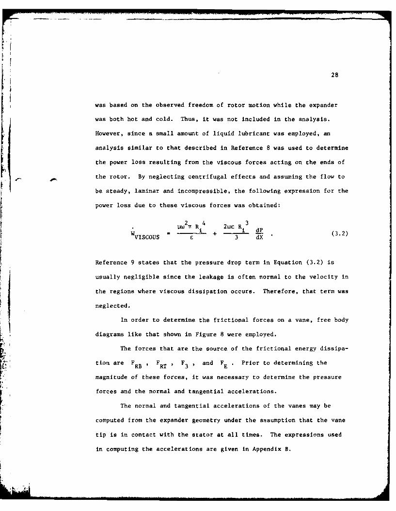
S2 R4 2 R3 d
WVISCOUS + 3 dX (3.2)
Reference 9 states that the pressure drop term in Equation (3.2) is
usually negligible since the leakage is often normal to the velocity in
the regions where viscous dissipation occurs. Therefore, that term was
neglected.
In order to determine the frictional forces on a vane, free body
diagrams like that shown in Figure 8 were employed.
The forces that are the source of the frictional energy dissipa-
tion are FRB , FRT , F3 , and FE. Prior to determining the
magnitude of these forces, it was necessary to determine the pressure
forces and the normal and tangential accelerations.
The normal and tangential accelerations of the vanes may be
computed from the expander geometry under the assumption that the vane
tip is in contact with the stator at all times. The expressions used
in computing the accelerations are given in Appendix B.

29
1PsAP
F3
KSTATOR 3F
N -l E "FrT~ H R
ROTOR N~ FnT
Fg Flts MYAN x VI
POINT "A" L&VANE SLOTP~iNT A PA EVN
I- +
T V
Figure 8. Vane Free Body Diagram

30
The net pressure force on the side of the vane, Pf , is computed
as follows:
Pf = (PLAG - LEAD) A (3.3)
where PLAG and PLEAD are the pressures in the control volumes lagging
and leading the vane and A is the exposed area of the vane. The
pressures used are those predicted by the thermodynamic model in the
presence of leakage but in the absence of friction. Due to the small
vane-rotor clearance in a cold expander, it was assumed that Pf acts
only on the vane in the space between the rotor and the stator and no
other pressure forces act on the side of the vane. In computing the
force at the base of the vane, it was assumed that the pressure under
the vane was the same as that in the leading control volume due to the
existence of the pressure balancing ports. The spring force exerted on
the vane is equal to the product of the spring constant and the spring
deflection.
Due to its larger coefficient of thermal expansion, the rotor was
assumed to be longer than the vanes. Therefore, the force exerted on
the vanes by the end plates was computed by assuming that the vane was
pushed against one end plate by the pressure in the control volume. The
end force on the vane was then equal to the product of the control volume
pressure and the area of the vane end.
Since the mass of the vanes is known, and since the friction
coefficient may be estimated, the only unknowns are FRT , FRB and F3
These are found by applying the three equations of dynamic equilibrium

31
IFTANGENTIAL - MvAt , and (3.5)
EMA - 0 , (3.6)
to the free body diagrams of the vane.
During one-half of the rotor revolution, the vane is pushed inward
(toward the center of the rotor) by the stator. During the other half,
the vane is pushed outward by the pressure and spring forces at its base.
Hence, at the end of one-half revolution, there is a reversal of the
direction of the friction forces between the vane and rotor. Addition-
ally, the net pressure force on the side of the vane may not always act
in the direction of rotation as shown in Figure 8. Therefore, four free
body diagrams have been used, resulting in four sets of equations. As
an example, the equations for Figure 8 in matrix form are
-1 F -P AAEVN-SPF+11 F -MvAN+WN+P A P
3 A 1 EMVN N+A
-PRB -P f+IFE-Wt+MVAt
TV TV VL RL-LVp 3 2-2 T-2XV F RT HR FM-2)if{3 2 2 _T"2 ~RT 2 1ET)+Vt( l
(3.7)
The remaining equations are similar and will not be presented.
The solution of the equations for F , F and F isF3 RB RT
accomplished by using the method of Gaussian elimination.

32
The values of F3 , F , FRT , and FE and hence, the
corresponding friction forces were determined as a function of 8 as the
rotor rotated in small increments Ae The incremental frictional work
loss was computed as the product of the frictional force times the radial
or tangential distance the vane traveled during the increment of rotation.
The sum of the incremental work losses over 3600 is the total frictional
work loss per revolution due to vane friction. The instantaneous fric-
tional power loss was computed at each vane position as the product of
the frictional force at the position and the velocity.
The power loss due to friction between the vanes and rotor, stator,
and end plate is equal to the product of the number of vanes, the
frictional work loss per revolution per vane and the speed. The net
frictional power loss is the sum of the power loss due to the vane
friction and the power loss due to viscous drag on the rotor ends.
It was assumed that all the energy dissipated by friction is
converted to heat which is transferred into either the rotor, lubricating
oil, stator, vane or end plate. A further discussion of the frictional
heat generation will be given in the description of the heat transfer
model.
3.3 Leakage Model
The leakage flow paths, assumed for this analysis, are shown for
a single control volume in Figure 9.
It was assumed that the leakage flow would be quasi-steady and, -
due to the small clearances maintained in a vane expander, laminar.
Considerable simplification was made by treating the steam as an
incompressible fluid. The relationship for parallel flow between flat

33
TYPICALPRESSURIZATIONPORT INLET
PORT
Figure 9. Leakage Paths for a Single Control Volume

34
plates was employed to obtain the following expression for the leakage
flow along each path:
2(P1 - P 2 )b 3 w
ML . 3AX
PAP where R = 3AXi (3.8)R 2b3w
The lengths of the leakage paths, AX in Equation (3.8) were
taken as the straight line distance from the source to the sink along
the leakage path. The widths of the leakage paths (w) were determined
by apportioning the total width of a leakage path at the source over the
total number of sinks the source leaked to along the leakage path. It
should be noted that Equation (3.8) neglects relative motion between the
moving and stationary parts.
Equation (3.8) was applied to all the leakage paths originating
from each control volume. As an example, for control volume 5 (see
Figure 9), the expression for the net leakage flow out is
I I5 = P5P5- F4 - + (P 5 R 1 + ( 1
L5- 4 5-14 5-3- 1 + - 1 + - 1
P2 I + (P5 _ I ) R 1 + (P 5 - P8 ) -8 + (P5 - P 7 )
+ (P5 - P5) 1 (P _I 8 5-7
+)PP E (P5 P1 15 6 5_6 + (P5 12 R5_1 2 5 - R 5-11
+(P 5 P 1 0 )1 + (P5 P9) + (P5 P6 ) + (P5 5)5-10 - 5-9 5-16
1 1 (3.9)R5_15 j

35
where Ri-j denotes the resistance of each leakage path and Pk denotes
the pressure of the leakage source or sink. The leakage flow is computed
for discrete rotor positions. A curve is then fit to the computed flow
rates to obtain the leakage as a continuous function of rotor position.
The pressures in Equation (3.9) were obtained as a function of
rotor position from the thermodynamic model. However, the pressure of a
control volume is dependent on the leakage flow rate. Hence, it was
necessary to iterate to obtain an accurate measure of the flow. This was
accomplished by initially inserting the control volume pressures, computed
in the absence of leakage, into the leakage expressions. Phe leakage
flow rate was computed and then input into the thermodynamic model to
recompute the control volume pressures. Based on these new pressures,
the leakage flow was recomputed. This process was repeated until the
control volume pressures varied only slightly from iteration to iteration.
3.4 Heat Transfer Model
3.4.1 One-Dimensional Model. A one-dimensional analysis of the
heat transfer between the working fluid and the stator as well as between
the working fluid and the end plates was performed to obtain as estima-
tion of the effect of heat transfer on the expander performance. The
fluid motion over the stator and end plates was modeled as flow over a
flat plate, and standard flat plate relationships were used to compute
the convective heat transfer coefficients. The electrical analogy to
heat transfer was employed and the heat transfer rate was obtained as a
function of the various thermal resistances (component material, boundary
layer, etc.) and the temperature difference between the working fluid ind

36
the surroundings. The working fluid temperature was obtained directly
from the thermodynamic model.
The simplified heat transfer analysis, while permitting a gross
determination of the heat transfer rates and their effect on the expander
performance relative to leakage and friction, does not permit an accurate
determination of the temperature profiles in the stator, rotor or end
plates (necessary for computations of thermal expansion). Furthermore,
the assumption of one-dimensional heat transfer allows only approximate
values of the heat transfer rates to be obtained.
To obtain a better representation of the heat transfer in the
expander, more sophisticated models of the rotor, stator and end plates
were required. The approach taken in modeling these components will be
discussed separately.
3.4.2 Rotor, Three-Dimensional Model. A finite difference
approach was used to approximate the heat conduction equation
1 DT a2T + . T 1 + T 2T (3.O)St3t ar 2 r Dr 2 2 2Drr 362 3z2
in the expander rotor. Appendix C illustrates the method used in forming
the finite difference equations.
Since the flow pattern in the control volume is not known, It is
difficult to determine the heat transfer coefficient between the steam
and the rotor. Therefore, an experimentally measured surface temperature
was specified as the boundary condition on the rotor surface. It was
assumed that for a given control volume, the rotor surface temperature
did not vary in the axial or tangential direction. This was an

37
approximation since frictional heat generation between the vane and rotor
would cause a higher surface temperature to be observed near the vane
slots.
Due to friction, heat is generated at the vane rotor interface.
Therefore, the boundary condition along the slot walls at points in
contact with a vane was a specified heat flux. The total amount of heat
generated was determined by the friction model descriLpd earlier. A
fraction of the heat generated is transferred into the rotor and the
remainder is transferred into the vane. To obtain an approximation of
the fractions of the heat generated going into the vane and rotor, an
exact solution to the temperature profiles in two semi-infinite solids
in frictional contact was obtained. The temperatures, at the surface of
contact, for the solids were equated resulting in the following expres-
sions for the amount of heat transferred into each solid (see Appendix
D):
""I kl 2i"qTOTAL I/
q"= L I j and
+k T.
2 1
qIo
", TOTAL (311)q2 = k1 , 1+ 2
An adiabatic boundary condition was assumed for that portion of
the vane slot not in contact with a vane.
The rotor is symmetric in the axial direction. Therefore, only
one-half of the axial length of the rotor was used in the analysis. The
rotor had an adiabatic boundary condition at the plane of symmetry.

38
The rotor model included provisions for using a specified heat
flux, resulting from friction, as the boundary condition for the rotor
end facing the end plate. However, based on the freedom of rotor motion
in the experimental expander, it was assumed that there was no rotor-end
plate contact and hence, no resulting frictional energy dissipation. It
was also assumed that the viscous energy dissipation between the oil and
rotor only resulted in the increase in the temperature of the oil.
Lack of end plate-rotor contact eliminated a major source of heat
generation. With this source of heat generation eliminated, the roor
end effects were neglected and the heat conduction equation solved for
two dimensions. Analysis of the computed rotor temperature profile
revealed that due to the rapid small amplitude fluctuations of the rot
surface temperature, the changing surface conditions did not greatly
effect the rotor temperature at points well below the surface. There-
fore, to permit the use of several nodes near the surface without
excessively increasing the computation time, modifications to the
analysis were made.
The mean rotor surface temperature was computed and that tempera-
ture used as a boundary condition at a depth of 0.050 inches below the
surface. Utilizing this boundary condition permritted considering only
that portion of the rotor contained between two vane slots. The
boundary condition at the vane slot and the rotor ends were not changed.
The heat transfer to the rotor was computed using the temperature
gradient near the surface. Since the rotor surface temperature did not
vary greatly, the mean rotor surface temperature was sufficiently good
for use in computing the rotor thermal expansion.

39
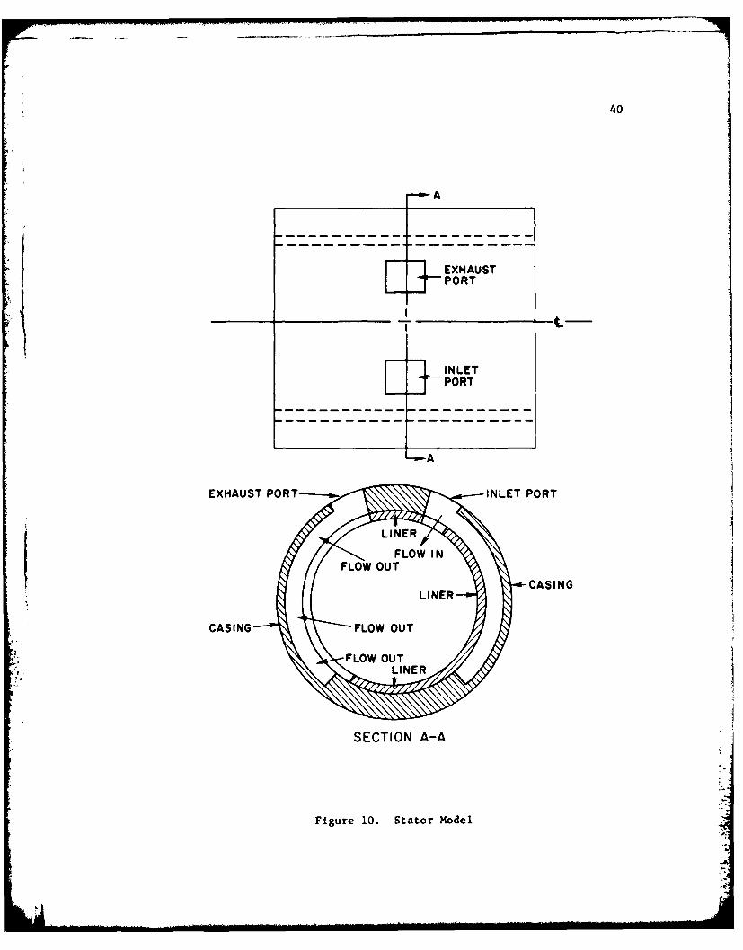
3.4.3 Stator, Three-Dimensional Model. To obtain the temperature
profiles and heat transfer rates, a three-dimensional analysis of the
stator was required due to the location of the inlet and exhaust ports
at the axial center of the stator. The ports act as heat sources or
sinks causing temperature gradients to exist between the ports and the
ends of the stator. The three-dimensional steady state heat conduction
equation
2 2T + 2T2T 1 T 1 2T 2T
T + r+ 3T = 0 (3.12)3r 2 r arr 2302 a2
was transformed into finite difference form for the stator geometry, as
shown in Figures 10. The method of forming the finite
difference expressions is illustrated in Appendix C.
At the inside surface, heat is transferred to the stator by
convection. Additionally, heat is generated at the inside surface due
to friction between the vanes and the stator. Therefore, the inside
surface boundary condition was
-k T= h(r - Tw ) + q" (3.13)r gen
The fluid temperature, To and heat generation rate seen by a
particular position on the stator surface are actually functions of time.
However, to permit a steady state analysis, the time averaged wall
temperature and heat generation rates were employed. For a given
position on the stator surface, the surface temperature was computed as:
40
A
EXHAUSTPORT
E-1
IN LETEl PORT
EXHAUST PORT-INLE.POR
LINE
SECTO A-A
Figur 10.UTaoMdeCASING

41
fT (t)dtT. = /dt (3.14)
and the heat generation rate was computed as:
A fqo dtSgen (3.15)
gen 'dt
The time dependent fluid temperatures and frictional heat
generation rates, used in Equations (3.14) and (3.15) were obtained from
the thermodynamic and friction models, respectively.
No iteration between the steam temperatures and heat transfer rates
was done as in the case of the steam pressures and the leakage flow rates
since the heat transfer did not appear to affect the component temperature
profiles, as a result of changing the steam temperature, to the same
degree as leakage affected the control volume pressure. The amount of
frictional heat entering the stator and the vane was computed using
Equation (3.11).
An estimate of the convective heat transfer coefficient was
obtained by modeling the flow over the stator as flow over a constant
temperature semi-infinite flat plate. The mean heat transfer coeffi-
cients from Reference 10 were for
LAMINAR FLOW:
Nu x 0.332 (Pr /3)(Re x /2 )
or
1k 0.332(Pr /3)(Re 1/2 ) and for (3.16)L L
42
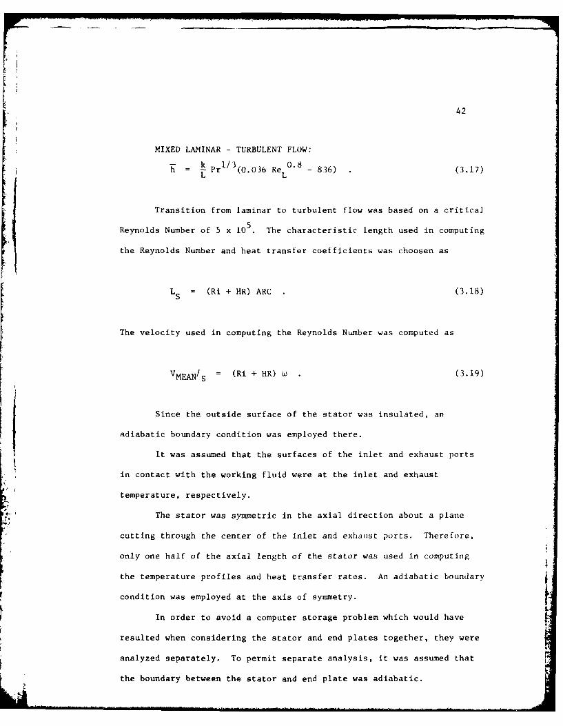
MIXED LAMINAR - TURBULENT FLOW:H = 1/3 0.8
h Pr 1 (0.036 Re 836) (3.17)L L
Transition from laminar to turbulent flow was based on a critical
Reynolds Number of 5 x 10 5. The characteristic length used in computing
the Reynolds Number and heat transfer coefficients was choosen as
LS = (Ri + HR) ARC (3.18)
The velocity used in computing the Reynolds Number was computed as
VMEAN/S = (Ri + HR) w (3.19)
Since the outside surface of the stator was insulated, an
adiabatic boundary condition was employed there.
It was assumed that the surfaces of the inlet and exhaust ports
in contact with the working fluid were at the inlet and exhaust
temperature, respectively.
The stator was symmetric in the axial direction about a plane
cutting through the center of the inlet and exhaust ports. Therefore,
only one half of the axial length of the stator was used in computing
the temperature profiles and heat transfer rates. An adiabatic boundary
condition was employed at the axis of symmetry.
In order to avoid a computer storage problem which would have
resulted when considering the stator and end plates together, they were
analyzed separately. To permit separate analysis, it was assumed that
the boundary between the stator and end plate was adiabatic.

43
3.4.4 End Plate, Three-Dimensional Model. To obtain the
temperature profiles and heat transfer rates for the end plate, Equation
(3.12) was transformed into finite difference form. The transformation
is illustrated in Appendix C. The end plate was modeled as shown in
Figures 11.
A combined convection and heat generation boundary condition was
employed at the end plate surfaces that contact the working fluid
(-k 2= h(T - T ) + q" )Dz w gen
Since the fluid temperature and heat generation rate varied with
time, Equations (3.14) and (3.15) were used to compute the time averaged
fluid temperature and heat generation rates for a particular point on
the end plate. The time dependent fluid temperatures and frictional
heat generation rates used in Equations (3.14) and (3.15) were obtained
from the thermodynamic and friction models, respectively. Like the
stator, no iteration between the steam temperature and heat transfer
rates was done. The fraction of the total frictional heat generated
between the vane and end plate that entered the end plate was computed
using Equation (3.11). The heat transfer coefficients for the end
plate were computed using Equations (3.16) and (3.17). The character-
istic length used in computation of the Reynolds Numbers and heat
transfer coefficients was chosen as:Ri+HRj ARC
r dr dO
RiLE = R +HR - (R1 + H) ARC (3.20)
dr
RT
The velocity used in computing the Reynolds Number was computed as: .

44
CARBO AAC
INSULATION
P9 CARBON CAST IRON
INSULATION
INSULATION
SECTION A-A
Figure 11. End Plate Model

45
iRi+HRW i r dr
i - . (R + HR W(.1VMEMIE = R +HR+- ) . (3.21)
II
Consistent with the stator analysis, the surface of the end plateiJ a T
which contacted the stator was assumed to be adiabatic (- = 0)
Since there was no contact between the rotor and end plate, there
was no heat generated on the end plate surface by rotor friction. How-
ever, there was leakage between the rotor and end plate. To model this
condition, a convective boundary condition was employed on those
surfaces of the end plate which were covered by the rotor but did notTb
contact a vane [-- L CT - T )A5z kw
The periphery of the hole in the end plate through which the
rotor shaft extended was also assumed to be an adiabatic surface (T 0)
The shaft did not contact the end plates at this point, so no frictional
heat was generated. Furthermore, since the rotor shaft was sealed at
both ends, it was assumed that steam leakage between the end plate hole
and rotor shaft would be small. It was possible that natural convection
might have existed, but it would have been small in comparison to the
other modes of heat transfer to the end plate.
Since the end plates were insulated, the outside surfaces of the
end plates were assumed adiabatic.
3.5 Numerical Procedure
A finite difference method was used to obtain solutions to the
expander heat transfer analysis.

46
3.5.1 Transient Analysis. The rapidly fluctuating surface
temperature, used as a rotor boundary condition, required the use of
small time steps to analytically synthesize the temperature fluctuations.
The stability requirements for the explicit method were determined using
the technique of Karplus [11,121. It was found that the time steps
required for stability were not prohibitive in view of the rapidly
changing rotor surface temperature. Therefore, the explicit method was
utilized in the rotor heat transfer analysis.
When employing the explicit method, the Laplacian (V 2T) was put
into finite difference form using the method of Taylor's Series
expansion [11,131. A forward difference approximation was used to
approximate the transient term (-L). This is illustrated in Appendix C.
3.5.2 Steady State Analysis. The method of Taylor's Series
expansion was used to obtain the finite difference approximation to the=2
Laplacian (V 2T). The set of algebraic equations that resulted from the
finite difference analysis were solved using the iterative method of
Gauss-Seidel with the incorporation of Young's over relaxation factor
parameter [7].

CHAPTER IV
EXPERIMENTAL AND THEORETICAL RESULTS
4.1 Experimental Conditions
The expander, described in Chapter 2, was tested with a 22.5' and
a 450 arc of admission. For each arc of admission, supply pressures of
150 psia and 115 psia were employed. The supply temperatures for the
150 psia and 115 psia supply pressures were 370°F + 10F and 360*F + 100 F,
respectively. The speed was varied from 840 to 1913 RPM.
Initial testing of the expander was conducted using no internal
lubrication. However, in an attempt to reduce component wear and to
decrease leakage by partially blocking the leakage paths with oil, all
the data included herein was collected using an oil flow rate of 0.05
lb /min. This compared with a steam flow rate on the order of 5 lb /min.m m
4.2 Experimental Results
4.2.1 Power. Figures 12 and 13 are representative pressure
versus volume diagrams constructed from the measured internal expander
pressures. The experimentally determined data points are indicated on
the curves. However, portions of the diagram were constructed by
assuming the pressures in the control volume at the inlet and the exhaust
ports were the supply and exhaust pressures, respectively. This is a
good assumption since the vane expander is an easy breathing device.
This has been verified analytically in Reference 1, and by the !M

48
SUPPLY PRESSURE 150 PSIA450 ARC OF ADMISSION1906 RPM
-- EXPERIMENTAL
W -0- ANALYTICAL (IDEAL)
C,)Cn 1.0 - - -w
(1)0.8
Cl)
z~0.6-
0.00.0 0.05 0.10 0.15 0.20 0.25 0.30
7, V *(DIMENSIONLESS VOLUME)
Figure 12. Pressure V~rsus Volume for 150 psia SupplyPressure 22.50 Arc of Admission

49
SUPPLY PRESSURE 150 PSIA22.50 ARC OF ADMISSION1820 RPM
-- 0- EXPERIMENTAL~ "--40--- ANALYTICAL (IDEAL)
Cnn13.03308-
wgn 0.6-
0O.4-",
S0.20
0.00.0 0.05 0.10 0.15 0.20 0.25 0.30
V* (DIMENSIONLESS VOLUME)
Figure 13. Pressure Versus Volume for 150 psia SupplyPressure 450 Arc of Admission
• "4z
0.0
01
....... ... * (D M E S I N L S V O L U M E)I. ... . . .. .. . .. . .. . .. 1 " = II .. . . ... . .. ... ...... .. ... . . .. . . .

50
experimental work discussed in Reference 4. Included in Figures 12 and
13 are the ideal P* -V* curves for the expander. The ideal curve is
based on the analysis of an expander with no friction, leakage or heat
transfer. During the expansion portion of the cycle, the measured control
volume pressures are higher than the ideal values. This is primarilly
due to leakage from the region exposed to the inlet port into the lower
pressure control volumes. The rapid decrease in control volume pressure
prior to opening the exhaust port is due to leakage out of the expanding
control volume to the low pressure region exposed to the exhaust port.
The increased area of the actual P* -V* diagram, compared to the
ideal diagram, illustrates that leakage increased the expander power
output.
The indicated work per revolution done by the expander was
numerically computed as
W = r PdV (4.1)e
using the measured pressures and the known volume variation. Figures 14
and 15 show the indicated power as a function of speed for the 22.50 and
450 arcs of admission and supply pressures of 150 psia and 115 psia. Due
to the larger arc of admission, higher indicated power outputs were
obtained for the 450 arc of admission. The difference in indicated
power, for the two arcs of admission, would have been greater had the
back pressure on the expander not increased, due to increased mass flow,
at the larger arc of admission. The shaft power, as measured by the
dynamometer, and the frictional power loss are also shown in Figures 14

51
150 PSIA SUPPLY PRESSUREi --O-- 22.50ARC OF ADMISSION
6.0- -C- 450 ARC OF ADMISSION
W SHAFT POWER
0.0-800100 00 20
SPE0RM
Figure ~~ 14FoeReru pe fr10pICTSuppLPesr
.00 PO

52
4.0 INDICATED -POWER/
0
~~3.0 S-0/
1r .0-
-- 0- 2.5 RC F AMISIO
.0
U)2.0-0
1.-
0.0- F25 RICTOALMSSO-0 P5 ACOE LOMSSIO
115~~ ~ ~ ~ PSASPLYPESR

53
and 15. The frictional power loss was determined as the difference
between the indicated power and the measured shaft power. Over the
entire speed range for 150 psia supply pressure and over the majority
of the speed range for 115 psia supply pressure, the 450 arc of
admission data showsa greater frictional power loss. This was due to
higher pressure forces being applied to the vane over a greater portion
of the cycle for the larger arc of admission. The larger pressure
forces produce an increase in vane friction. Figure 15 shows that for
a supply pressure of 115 psia, the frictional power loss for the 22.50
arc of admission exceeded the frictional power loss for the 450 arc of
admission at speeds above 1650 RPM. This was probably due to a
variation in the coefficient of sliding friction. However, since the
coefficient of friction is dependent on many factors such as load, and
the amount and location of lubricating oil and liquid water, it is
difficult to explain why the variation may have occurred.
Figure 14 shows that although the indicated and frictional power
increased linearly with speed, the shaft power curve begins to bend near
1500 RPM, for a supply pressure of 150 psia. This is due to a decreaseshaft horsepower
in the mechanical efficiency (mechanical efficiency = shat horsepowerindicated horsepower
at the higher speed. The decrease in mechanical efficiency is a result
of the frictional power loss becoming a larger percentage of the indicated
power. The variation of mechanical efficiency with speed for a supply
pressure of 150 psia is shown in Figure 16. [For a supply pressure of 115 psia, and a 22.50 arc of admission,
the shaft power curve begins to bend at approximately 1300 RPM. For this
supply pressure, the 450 arc of admission data show a continuous increase

54
100-
I- 150 PSIA SUPPLY PRESSUREzWj -- 0-- 22.50 ARC OF ADMISSION
U ~-0G-450 ARC OF ADMISSIONcr o-w
Z 60-w -
WLJ40-
20J
0.0-
800100 1500 2000
Figure 16. Mechanical Efficiency Data 150 psia Supply Pressure

pI
55
in shaft power with speed. Figure 17 shows that the mechanical
efficiency, for a 22.50 arc of admission and 115 psia supply pressure,
drops off quite rapidly. This decrease in mechanical efficiency, caused
by friction, results in the bending of the 22.5* arc of admission shaft-
power curve. The mechanical efficiency for the 450 arc of admission and
115 psia supply data, while varying with speed, shows no definite trend
downward at the higher speeds.
4.2.2 Mass Flow Rate. Figures 18, 19, 20 and 21 show the
measured mass flow rate, the ideal flow rate and the leakage flow rate
as a function of speed for 45° and 22.58 arcs of admission and 115 psia
and 150 psia supply pressures. In all cases, the flow rate of steam
increased with speed. Ideally, for an easy breathing expander, the
control volume contains the same mass of steam per revolution, independ-
ent of speed. Therefore, as the speed increases the mass flow rate
increases. The ideal mass flow rate was computed as the product of the
number of control volumes, the volume of a control volume at intake
closing, the density of the supply steam, and the speed in revolutions
per minute. The leakage flow was computed as the difference between the
measured flow rate and the ideal flow rate.
In all cases studied, the leakage flow remained approximately
constant with speed. The clearances in the expander do not change with
speed and for an easy breathing expander, the pressures in the control
volume do not vary greatly with speed. Since the leakage driving
potential and flow resistance do not vary with speed, it is consistent
that the leakage flow rate would not change greatly with speed. -.
. ... |T ll " . ... ... ... ., m . . . . . . .. . . . . . . . . . . . . ... . .. . ..... .. . . . . . . .. -- . .. . -- . . . . . .

56
100p" 115 PSIA SUPPLY PRESSUREZ -- 0-- 22.50 ARC OF ADMISSIONwo -- 0- 450 ARC OF ADMISSION
+ 12::80wa.
Z 60"w01
w 0W 40O
2J
XU
2o
w
0.0 -800 1000 1500 2000
SPEED (RPM)
Figure 17. Mechanical Efficiency Data 115 psia Supply Pressure

57
10.0
22.5* ARC OF ADMISSION150 PSIA SUPPLY PRESSURE
Ci .0
6.0-
~4.0-OVQ 11 1M0 MEASURED FLOW RATE
IL. LEAKAGE FLOW RATE(f)cn 2.0
- IDEAL FLOW RATE0. 1 I -
800 1000 1500 2000
SPEED (RPM)
Figure 18. Mass Flow Rate Data for 150 psia, Supply Pressure22.50 Arc of Admission

58
10.0
450 ARC OF ADMISSION150 PSIA SUPPLY PRESSURE
. 8.0EE
-U6.0 -O
.0.° 0 .1_ .__.]_
I-
. LEAKAGE FLOW RATE
2.0-
IDEAL FLOW RATE0.0 800 1 0 (RM
Soo 1000 1500 2000SPEED (RPM)
Figure 19. Mass Flow Rate Data for 150 psia Supply Pressure450 Arc of Admission

59
5.0
22.50 ARC OF ADMISSION115 PSIA SUPPLY PRESSURE
4.0-
E
3.0 - . - '' rEASURED FLOW RATE
~ 2.0LEAKAGE FLOW RATE0-
-
cncl) oo. -
41.0 ---
.- ~ IDEAL FLOW RATE
0.0PAB00 1000 1500 2000
SPEED (RPM)
Figure 20. Mass Flow Rate Data for 115 psia Supply Pressure22.5* Arc of Admission

60
6.0
450 ARC OF ADMISSION115 PSIA SUPPLY PRESSURE
5.0
.0MEASURED FLOW RATE
C 3 .0 -
0-0 LEAKAGE FLOW RATE
LL_
C,) 2.0-
1.0- o, IDEAL FLOW RATE
*2 - 0.0 I800 1000 1500 2000
SPEED (RPM)
Figure 21. Mass Flow Rate Data for 115 psia Supply Pressure458 Arc of Admission
,,.

61
Comparison of Figures 18 and 19 indicates that for the same
supply pressure, the leakage flow increases with arc of admission. The
same trend is observed by comparison of Figures 20 and 21. The
resistance to leakage flow, for a control volume at any specified
position, does not change with arc of admission; but the pressures in
the control volumes are maintained at higher values over a greater
portion of the cycle with the larger arc of admission. This greater
driving potential is apparently the cause for higher leakage at the
larger arc of admission.
Comparisons of Figures 18 and 20, and Figures 19 and 21, show
that for the same arc of admission, the leakage flow increases with
supply pressure. This would also appear to be due to the increased
driving potential.
4.2.3 Adiabatic Expansion Efficiency. Figure 22 shows the
adiabatic expansion efficiency for both arcs of admission at a supply
pressure of 150 psia. The adiabatic expansion efficiency is defined as
the ratio of the work per pound of steam, to the isentropic enthalpy
change from the supply conditions to the exhaust manifold pressure. The
low values of efficiency, shown in Figure 22, are primarilly the result
of leakage and friction.
Leakage has its greatest effect at low speeds. If all losses but
leakage are neglected, and it is assumed that leakage does not increase
the power output, the adiabatic expansion efficiency can be written as
DADIABATIC = 1 - (4.2)
EXPANSION mT

62
__25.0-
I.- 150 PSIA SUPPLY PRESSURE
zrwa. 20.0-
w0 1 5 0 -A o
L -
z0
10.0 Az
o -0- 22.50 ARC OF ADMISSIONI5.0 -A- 450 ARC OF ADMISSION
L4
0.0.080 1000 1500 2000
SPEED (RPM)
Figure 22. Adiabatic Expansion Efficiency Datafor 150 psia Supply Pressure
1w,

63
where mL is the leakage flow rate and m is the total flow rate
(1 = mIDEAL + ). Therefore, for a given ideal flow rate, as the
leakage flow increases, the efficiency decreases. The effect of leakage
on the adiabatic expansion efficiency is reduced somewhat since leakage
does increase the expander power output. Figures 18 through 21 showed
that the experimentally computed leakage flow rates did not vary greatly
with speed. However, the ideal flow rate is directly proportional to
speed. This implies that as the speed increases, the ratio of leakage
flow to total flow decreases resulting in a smaller adiabatic expansion
efficiency reduction due to leakage.
The effect of friction on the adiabatic expansion efficiency
increases with increased speed. For an easy breathing expander, the
frictional forces increase slightly with speed due to larger vane
accelerations. The distance per unit time over which the frictional
forces act also increases directly with speed. Therefore, as shown in
Figures 14 and 15, the frictional power loss increases with speed.
Under the influence of friction and leakage, a peak in the
adiabatic expansion efficiency versus speed will occur. Low
efficiencies at speeds less than the peak efficiency speed would be
primarilly due to leakage. The low efficiencies at speeds greater than
peak efficiency speed would be primarilly due to friction.
Figure 22 shows that at 150 psia supply pre 'ure and arcs of
admission of 22.50 and 450, the experimentally determined efficiency
continuously increased with speed. This was due to a decrease in the
ratio of leakage flow rate to total mass flow rate. For the conditions
shown in Figure 22, the peak adiabatic expansion efficiency was not
reached.

64
Figure 23 shows the same trend for the 450 arc of admission and
115 psia supply pressure. However, for the 22.50 arc of admission and
115 psia supply pressure, a peak in the experimental adiabatic expansion
efficiency was observed at approximately 1450 RPM. The decrease in
efficiency with speed above 1450 RPM was due to frictional power losses.
The severe effect of friction for a supply pressure of 115 psia and an
arc of admission of 22.50 was previously illustrated by the rapid drop
in mechanical efficiency shown in Figure 17.
4.2.4 Temperature Measurement Results. The liner and end plate
temperatures were measured for determining thermal expansions and for
comparison with the temperatures predicted by the heat transfer analysis.
The rotor surface temperature was measured so that it could be used as a
boundary condition in the heat transfer analysis. It also permitted
computation of the approximate rotor thermal expansion.
Figures 24 through 27 show the measured stator temperature
profiles (the points indicate the experimental data) for the 22.5' and
450 arcs nf admission and supply pressures of 150 psia and 115 psia.
The temperatures were measured 0.0625 inches from the expander end plate
and 0.050 inches from the inside surface of the stator. The temperatures
have been normalized by the supply temperature. Although the stator
temperature is higher on the inlet side of the expander, the temperature
profile is not severely distorted. Temperature differences between the
ivlet and exhaust side of the expander can result in distortion of the
expander stator. Distortion of the stator would make it more difficult
to maintain small clearances between the rotor and end plates without
producing large frictional losses.
IL.

65
25.0-
w 20.0
15. /
z 10015.0-4
zN
i- 5.04 115 PSIA SUPPLY PRESSURE
4 -0-22.50 ARC OF ADMISSIONO -A--450 ARC OF ADMISSION
4 0.0 - AAA
800 1000 1500 2000
SPEED (RPM)
Figure 23. Adiabatic Expansion Efficiency Datafor 115 psia supply Pressure

66
22.50 ARC OF ADMISSION150 PSIA SUPPLY PRESSURE
0.
315 1 45-
s.
V0.
270 EXHAUST 1_ .0- 9o"
Figure 24. Stator Temperature Profile Data for 150 psiaSupply Pressure 22.5* Arc of Admission

67
450 ARC OF ADMISSION150 PSIA SUPPLY PRESSURE
0•
EXHAUST
Figure 25. Stator Temperature Profile Data for 150 psiaSupply Pressure 450 Arc of Admission

68
22.50 ARC OF ADMISSION115 PSIA SUPPLY PRESSURE
00
EXHA UST._-. - 9o,
180
Figure 26. Stator Temperature Profile Data for 115 psia
Supply Pressure 22.58 Arc of Admission

69
450ARC OF ADMISSION115 PSIA SUPPLY PRESSURE
o*
27. EXHAUST -- o
~180
Figure 27. Stator Temperature Profile Data for 115 psia .!Supply Pressure 450 Arc of Admission
0.4
0.2

70
Comparison of Figures 24 through 27 shows that there is no
significant difference between the stator temperature profiles for the
22.50 and the 450 arc of admission cases. Also, the supply pressure
does not significantly affect the normalized temperature profile.
Figures 28 through 31 illustrate that there is no severe
distortion of the end plate temperature profile. The arc of admission
and supply pressure also does not greatly affect the end plate
normalized temperature profile.
Figure 32 shows representative curves of the normalized rotor
surface temperature as a function of rotor position. The data
indicates that the rotor surface temperature increases when the surface
is exposed to the high temperature supply steam. The surface tempera-
ture begins to decrease when the inlet port is closed and continues to
decrease until the inlet reopens.
The variation of the rotor surface temperature with rotor position
is not large. This is due to the small time during each revolution for
the transfer of heat between the rotor and the working fluid.
The rotor surface temperature at the point of the inlet opening
was below the saturation temperature of the supply steam. This would
indicate that some condensation of the steam occurred. Condensation
will be discussed in a later section.
4.2.5 Expander Heat Loss. The net heat loss from the expander
was determined by applying the first law of thermodynamics to the
expander. Table 2 summarizes the computed heat losses for the tests
conducted. The values predominantly range from 3000 to 7500 BTU/hr

71
22.50 ARC OF ADMISSION150 PSIA SUPPLY PRESSURE
0"
2700 EXHAUST -0. 900
225o 135'
Figure 28. End Plate Temperature Profile Data for 150
psia Supply Pressure 22.50 Arc of Admission

72
450 ARC OF ADMISSION150 PSIA SUPPLY PRESSURE
00
45.
7490
0.35
225" 135*
ISO,
Figure 29. End Plate Temperature Profile Data for 150
psia Supply Pressure 450 Arc of Admission

73
22.50 ARC OF ADMISSION115 PSIA SUPPLY PRESSURE
0
345*
1109
Figure 30. End Plate Temperature Profile Data for 115psia Supply Pressure 22.50 Arc of Admission

74
450 ARC OF ADMISSION115 PSIA SUPPLY PRESSURE
0"
S0.6 0
0.
270-EXHAUST_ 90"
22-5 135*
ISO,
Figure 31. End Plate Temperature Profile Data for 115psia Supply Pressure 450 Arc of Admission

75
1.0
0-
T/T o o.8 150 PSIA SUPPLY PRESSURE
-- 0-- 1138 RPM45* ARC OF ADMISSION
-- O--1007 RPM22.5* ARC OF ADMISSION
-- &--1820 RPM22.5* ARC OF ADMISSION
0.6
0 2.0 4.0 6.0E OIN C
INLET OPENS INLET CLOSES 45 ARC OF ADMISSION
INLET CLOSES 2250 ARC OF ADMISSION
ROTOR POSITION (RADIANS)
Figure 32. Rotor Surface Temperature Data
I

76
TABLE 2
Expander Heat Loss Data
Supply Pressure Arc of Admission Speed (RPM) Heat Loss <BTU)(psia) (Degrees) hr
150 22.5 1007 3639
150 22.5 1194 605
150 22.5 1488 3219
115 22.5 1083 4942
115 22.5 1109 3186
115 22.5 1350 4024
115 22.5 1693 4486
150 45 840 6661
150 45 1138 6619
150 45 1369 7188
150 45 1479 4581
150 45 1539 6072
150 45 1906 6359
115 45 895 7481
115 45 1285 4081
115 45 1296 2801
115 45 1477 6028

77
(1.18 to 2.95 horsepower). This indicates that the heat loss was of the
same order of magnitude as the power output. The variations observed in
the expander heat loss are believed to be primarilly due to the error
sustained in measuring the inlet and exhaust enthalpy. An error of 25
BTU/lb in determining the inlet and exhaust enthalpy difference resultsm
in an error in the heat loss of the order of 4500 BTU/hr. This enthalpy
difference of 25 BTU/lbm is approximately 2% of the inlet enthalpy.
Estimates of the magnitude of the heat loss to the slip ring and
pressure transducer cooling adapters were of the same order as the
experimentally determined heat losses. This source of energy loss would
be eliminated in an operational expander.
4.3 Comparisons with Theoretical Model
4.3.1 Mass Flow Rate. Computation of the mass flow rate depends
on the determination of the internal expander clearances. The rotor-end
plate and vane-end platc clearances were computed based on the initial
cold clearances and the relative thermal expansion of the components.
The cold clearances were determined from micrometer measurements
taken during assembly of the expander. The uncertainty in the determin-
ation of the cold clearances was estimated to be 0.001 inches.
The thermal expansions were computed using the measured component
temperatures. Although the thermal expansions of the components varied
with the supply and exhaust temperatures, the variations were small
relative to the accuracy of the cold clearance measurements. The rotor-
end plate clearance, under operating conditions, was calculated to be
0.003 inches. The vane-end plate clearance was calculated to be 0.005
inches. The larger clearance between the vanes and the end platas was

78
due to the small coefficient of the thermal expansion of the vanes
2.7 x 10- 6 in/in0 F, compared to 5.6 x 10⁻⁶ in/in*F for the rotor.
The computed rotor-end plate and vane-end plate clearances were
used in the leakage model to compute the leakage flow rate. The vane-end
plate clearance was adjusted from 0.005 inches to 0.006 inches due to
wear of the carbon vanes and end plates. It also permitted better
agreement to be obtained with the experimentally determined leakage flow
rates. Adjustment of the clearance by 0.001 inches was felt to be
justifiable since the change was within the limits of the cold clearance
measurements.
In computing the theoretical leakage flow rates, all leakage paths
except those between the end plate and the rotor and the end plate and
the vanes were neglected. Figure 33a shows a comparison between the
analytically and experimentally determined leakage flow rates for a 22.50
arc of admission and 150 psia supply pressure. The predicted leakage
flow rates were 16% below the measured values. It is believed the error
is due to the assumption that there was no leakage between the vane tip
and the stator. Clearances between the vane and the stator may have
occurred as a result of the vane being pushed into its slot by high
pressure supply steam. Clearances between the vane and stator may also
have occurred due to vane chatter resulting from the stator being rough,
or "out of round". It is possible that any vane-stator clearance would
result in more leakage from the regions exposed to supply pressure to
those control volumes in which the closed expansion process was occurring.
Since vane-stator clearances, resulting from vane chatter, are a
function of time and rotor position, a reasonable determination of the

79
4
-J
5 PSI SUPPLYIPRESSUR
0 ~
C(a)
22.50- ACOAD IDEALONO EKGFITO
100 1500 2000UPY RSSR
a.S
Fiue3bWospwrVru pe

80
vane stator clearance was not possible and no attempts were made to include
leakage between the vane and stator.
4.3.2 Power Output. The analytically determined leakage flow
rates were input into the thermodynamic model to determine the effect of
leakage on the expander power output.
Figure 33b shows the experimentally determined indicated power
output, the predicted power output with leakage affects included, and
the ideal power output. The ideal power output was computed assuming no
leakage, heat transfer or friction.
The analytical power output, computed considering only leakage
effects, is 7.7% below the measured indicated power at 1007 RPM. This
difference increases to 30.4% at 1820 RPM. The difference between the
predicted power output and the measured indicated power output is
apparently the result of the leakage model not predicting the correct
amotmt of leakage. As previously discussed, the leakage was computed
assuming a perfect seal between the vane and the stator. Leakage between
the vane and the stator would result in more leakage from those regions
at supply pressure to the control volumes undergoing the closed expansion
process. Leakage of this nature would result in increased expander power
output.
The effect of heat transfer on power was analytically computed by
using the theoretically determined heat transfer rates in the thermo-
dynamic model. The theoretical indicated power was computed in the
presence of both leakage and heat transfer for a 22.5* arc of admission
and 150 psba supply pressure. Heat transfer reduced the theoretical
power output by 14%, from 2.40 horsepower to 2.06 horsepower, at 1007 RPM.

81
At 1820 RPM, heat transfer reduced the power by 13.5%, from 3.25 to
2.81 horsepower.
Comparison between the analytical (leakage and heat transfer
included) and experimental indicated power outputs for a 22.5* arc of
admission and 150 psia supply pressure shows an error of 20.7% at 1007
RPM and 39% at 1820 RPM. It is felt that the error is predominately
the result of the inability to accurately determine the effects of
leakage on the expander power output.
Figure 34 shows a comparison between the analytical and experi-
mental frictional power loss for a supply pressure of 150 psia and an
arc of admission of 22.5*.
The theoretical and experimental curves are identical within the
accuracy of the plot. Good agreement was also obtained for the 450 arc
of admission and 150 psia supply steam. At 1479 RPM, and a 450 arc of
admission, the experimental frictional power loss was 1.69 horsepower
while the theoretical value was 1.71 horsepower. At 1913 RPM, and a
450 arc of admission, the experimental value was 2.26 horsepower and the
theoretical value 2.25 horsepower.
The coefficient of friction used in the model, for all surfaces,
was 0.075. This value was obtained by inputting the measured steam
pressures into the friction model and adjusting the coefficient of
friction until the predictions matched the experimental data. The
theoretical frictional power loss was computed using the coefficient of
friction of 0.075 and the steam pressures computed by the thermodynamic
model, with leakage effects included. A test of the validity of the
friction model was that a single coefficient of friction allowed accurate

82
~4.0Iw 22.50 ARC OF ADMISSION
3: 150 PSIA SUPPLY PRESSURE00.. --0- ANALYTICAL (COEFFICIENT
wl . OF FRICTION 0.075)Cr --0- EXPERIMENTAL0
002.0
0
-1 0.0
LL800 1000 1500 2000SPEED (RPM)
Figure 34. Frictional Power Lose Versus Speed

83
prediction of the frictional power loss at all speeds and supply condi-
tions except for the 115 psia supply pressure and 22.50 arc of admission
case. However, the trends in the power output and efficiency data for
this latter case appear to indicate an actual variation in the coeffi-
cient of friction.
4.3.3 Temperature Profiles and Heat Transfer Coefficient. A
comparison of the experimental and theoretical stator temperature
profiles is given in Figure 35. The maximum error is 13%. This error
was considered to be reasonably good due to the complex geometry and
lack of information regarding the heat transfer coefficient between the
steam and the stator.
The experimental and theoretical end plate temperature profiles
are compared in Figure 36. The maximum error is 8%.
The measured rotor surface temperature was used as a boundary
condition in computing the heat transfer to the rotor. The computed
rotor heat transfer was used in conjunction with the measured surface
temperature and inlet steam temperature to estimate the heat transfer
coefficient between the steam and the rotor. The values obtained are
only approximate since at any instant in time the steam temperature is
not accurately known. However, at the inlet the steam was assumed to be
at the supply temperature. Under this assumption, the computed heat
transfer coefficient, at a speed of 1007 RPM, ranged from 610 BTU/hrft2 F
when the rotor was initially exposed to the supply steam, to approximately
14,000 BTU/hrft 2F, just before the inlet was closed. The variation in
the heat transfer coefficient apparently resulted from the turbulence
and steam impingement on the rotor surface. The measured rotor surface

84
22.50 ARK OF ADMISSION150 PSIA SUPPLY PRESSURE
I~.4
2-ro--X-0-S EXPERIMENTA
225 -0- ANALYICENAL
Figure 35. Experimental and Analytical Stator TemperatureProf iles 22.5* Arc of Admission

85
22.50 ARC OF ADMISSION150 PSIA SUPPLY PRESSURE
-0.8
2?- EXHAUST 1 0
Fiur 3. xermeta ndAnlyialEn Pae emertrePrfie

86
temperatures used in computing the rotor heat transfer were obtained at
the circumferential center of the control volumes. When the rotor
surface of a particular control volume is first exposed to the inlet
port, the center of the control volume is restricted from seeing the
high temperature steam by the small rotor-stator clearance which exists
midway between the inlet and exhaust ports. Since the center of the
control volume would not be exposed to direct impingement by the supply
steam and the turbulence created by the filling process, the calculated
heat transfer coefficient would be expected to be low near inlet opening.
However, when the center of the control volume becomes exposed to the
incoming steam, impingement of the steam on the center of the rotor
coupled with turbulence created by the filling process, would cause the
heat transfer coefficient to be quite high.
The heat transfer coefficients at the exhaust ranged from
420 BTU/hr ft2 F when the exhaust opened to a maximum of 2800 BTU/hr ft2 F
as the exhaust closing was approached. The increase in the heat transfer
coefficient during the exhaust process was probably due to an increase in
the turbulence of the steam as it was forced out of the control volume by
the reduction in the volume of the control volume.
These heat transfer coefficients are only approximate values;
however they do provide a starting point for computation of the rotor
heat transfer without knowledge of the rotor surface temperature. It
should be pointed out that any computation of the instantaneous heat
transfer in the expander using the working fluid temperature and a heat 4
transfer coefficient is only a rough approximation. This is due, not
only to the uncertainty of the heat transfer coefficient but also to an
uncertainty in the knowledge of the instantaneous steam temperature.

............. r
87
Figure 37 illustrates the variation in the ratio of the rotor
surface temperature to the steam saturation temperature as a function of
rotor position. The data indicate that during a small portion of each
revolution, primarilly during the filling process, the rotor surface
temperature is below the steam saturation temperature. This condition
would permit condensation of some steam during filling of the control
volume.
An order of magnitude analysis of the degree of condensation can
be made by assuming that the amount of steam that could be condensed
during the filling process can be approximately written as
h ARs(sAT - T ROTOR)t (.Mc hfg (
where h is an average convective heat transfer coefficient and hfg is
the latent heat of vaporization of the steam. The convective heat
transfer coefficient for the condensation process is
h - k/6 , (4.2)
where k is the thermal conductivity of liquid water and 6 is the
thickness of the condensed liquid film.
From geometric considerations, the amount of liquid condensed
during the filling process can be approximately written as
AM p 6(RiAeZ) (4.3)
c WA

88
1.40
1.35 -0--"- -- 0- 1007 RPM 22.50 ARCOF ADMISSION
1.30 -- a- 1820 RPM 22.50 ARCOF ADMISSION
1.25-
1.200
TROTOR 1.15-TSAT I1.10 -
1.05 -
1.00 -/
0.95-
0.90- 11
0.850.0 1.0 2.0 3.0 4.0 5.0 6.0 7.0
INLET CLOSES
INLET OPEN
ROTOR POSITION (RADIANS)
Figure 37. Ratio of Rotor Surface Temperature toSteam Saturation Temperature Data -

89
where (R AOZ) is the rotor surface area of one control volume. Equating
Equations (4.1) and (4.3) and using Equation (4.2) gives
h(R i OZ)(TSAT - TROTOR)At P k
hfg T(RiAZ) .(4.4)
Solving Equation (4.4) for h and substitution of h into Equation (4.1)
permits an estimate of the amount of steam condensed in each control
volume during the filling process. The approximate mass flow rate of
condensed steam is
A (T -T )At 8 CONTROLRS SAT ROTOR VOLUMES N REVOLUTIONSm = X X
c hfg REVOLUTION MINUTE
(4.5)
Based on this calculation, condensation rates of 0.279 lb m/min at
1820 RPM and 0.207 lb /min at 1007 RPM have been calculated.
The heat transfer coefficients required to condense the steam are
25,789 BTU/hr ft 2F at 1820 RPM and 19,209 BTU/hr ft2,F at 1007 RPM.
Lower heat transfer coefficients would result in less condensation, at a
particular speed, due to insufficient time to condense the steam. The
rotor heat transfer coefficients computed from the rotor heat transfer
analysis, at 1007 RPM, have a minimum value at the inlet of 610 BTU/hr
ft2.F and a maximum of 14,000 BTU/hr ft2oF. Since these values are less
than that computed by Equation (4.4), the actual amount of steam con-
densed on the rotor would be less than the calculated values.
It is believed that condensation on the stator and the end plates
would be less than on the rotor since the surfaces of these components
do not see the relatively cold exhaust steam as long as the rotor surface

90
does. No stator or end plate surface temperatures were measured. The
measured end plate and stator temperatures at 0.065 inches below the
surface are slightly less than the supply temperature at the inlet.
However, the temperature at the surface of these components would be
higher due to convection from the supply steam and frictional heat
generation at the surface.
Since the predicted condensation rates are less than 10% of the
difference between the measured flow rate and the ideal flow rate, it
can be concluded that the difference was primarilly due to leakage. It
can also be concluded that the difference between the predicted power
output (computed with leakage affects only) and the experimentally
determined indicate' po-.er shown in Figure 33b is not due to condensation
and re-evaporation. The estimated condensation rate is not of sufficient
magnitude to cause the difference.
1,J
r&
. ... ... . ......I|I T If I .... .... ... ... .... ... J

CHAPTER V
SUMMARY AND CONCLUSIONS
5.1 Summary
A commercially available air expander modified to operate on
steam was tested using 150 psia and 115 psia supply steam. The speed
was varied from 840 to 1913 RPM. Under these operating conditions, the
power output ranged from 0.5 horsepower to 2.85 horsepower. Mechanical
efficiencies ranged from 65% to 40%. The experimentally determined
adiabatic expansion efficiencies varied from 9.5% at the low speeds to
20% at the high speeds. Leakage flow rates, ranging from 2.40 lb /minm
to 3.90 lb /min,were obtained. The leakage flow increased withm
increased arc of admission and supply pressure. The total mass flow of
the expander varied from 3.1 lb /min to 5.8 lb /min.m m
The expander was analytically modeled to permit the determination
of the expander performance and operating component temperatures.
The models predicted the frictional power loss very well. The
leakage flow rates were predicted with an error of 16%. The heat
transfer models predicted the stator and end plate temperature profiles
with an accuracy on the order of 10%. Indicated power predictions were
computed with errors ranging from 20.7% at the low speeds to 39% at the
high speeds.

92
5.2 Conclusions
1) The adiabatic expansion efficiency is severely reduced by
friction and leakage. Figures 16 and 17 show that friction reduced the
power output and hence, the efficiency of the expander by 40% - 50%.
Leakage reduced the efficiency on the order of 55% - 60%. Analytically,
it was determined that heat transfer reduced the efficiency approximately
10% - 20%.
2) Figures 18 through 21 show that the leakage flow varies only
slightly with speed but the ideal flow increases with speed. Therefore,
it can be seen from Equation (4.1) that the reduction in adiabatic
expansion efficiency due to leakage is decreased at higher speeds.
3) The frictional power loss is proportional to speed. As the
speed increases, friction tends to increasingly reduce the efficiency.
4) The frictional power loss can be predicted very well, as
shown in Figure 34. However, the predictions are dependent on a
knowledge of the coefficient of friction.
5) The magnitude of the leakage flow rates can be predicted
reasonably well by the model. However, prediction of the correct amount
of leakage depends on a knowledge of the leakage paths and the actual
operating clearances. This information is difficult to obtain in
practice.
6) The accuracy of the predicted power output is reduced by
severe amounts of leakage as a result of a lack of information regarding
the leakage paths.
The purpose of this study was not to develop an efficient vane
expander, but to obtain an understanding of the phenomena occurring
within the expander. However, the information gained provides a basis

93
for designing a vane expander with projected efficiencies 50% to 100%
greater than those measured in the experimental version.
The frictional power loss can be reduced by decreasing the normal
forces at the vane-rotor and vane-stator contact points. Supply of the
steam through a port in the end plate or through the rotor, at the vane
base, may prevent the vane from being pushed into the vane slot by
incoming steam. This would permit a decrease in the spring force at the
base of the vanes with a concomitant decrease in the vane-stator contact
force.
Frictional power losses can also be decreased by reducing the
friction coefficient. Injection of oil around the periphery of the
stator would increase the probability of obtaining a hydrodynamic film
between the vanes and the stator, resulting in a decrease in the
coefficient of friction. An increase in the oil flow rate may result
in a decrease of the friction coefficient, but it would also result in
more contamination of the steam. There may also be other material
combinations with lower coefficients of friction in the presence of
steam and oil.
Leakage in the expander could be reduced by matching the
coefficients of thermal expansion of the expander components. This
would result in lower operating clearances than were obtained in the
test expander. Elimination of the thin liner which is susceptible to
distortion could reduce leakage between the vane and the stator.
Heat transfer from the expander could be significantly reduced
by elimination of the pressure transducer and slip ring cooling adapters
installed in the test expander. Total heat losses could probably be

94
reduced from the same order of magnitude as the shaft power to 10% or
less of the shaft power.
k A.

95
BIBLIOGRAPHY
1. Wolgemuth, C. H. and Olson, D. R., "A Study of Breathing in VaneType Expanders," Proceedings of the Sixth IECEC, Boston, Massachusetts,August 3-5, 1971, published by SAE.
2. Edwards, T. C. and McDonald, A. T., "Analysis of Mechanical Frictionin Rotary Vane Machines," Purdue Compressor Technology ConferenceProceedings, July 25-27, 1972.
3. Peterson, C. R. and McGahan, W. A., "Thermodynamic and AerodynamicAnalysis Methods for Oil Flooded Sliding Vane Compressors," PurdueCompressor Technology Conference Proceedings, July 25-27, 1972.
4. Echard, J. E., "Multi-Vane Expander as Prime Mover in Low TemperatureSolar or Waste Heat Applications," Record of the Tenth IECEC, Newark,Delaware, August 18-22, 1975, published by IEEE.
5. Syniuta, W. D. and Palmer, R. M., "Design Features and InitialPerformance Data on an Automotive Steam Engine. Part II. Recipro-cating Steam Expander-Design Features and Performance," 1974 SAETransactions.
6. Bendersky, D., "A Special Thermocouple for Measuring TransientTemperatures," Mechanical Engineering, Vol. 75, 1953, p. 117.
7. Fox, L., Numerical Solution of Ordinary and Partial DifferentialEquations, Pergamon Press, New York, New York, 1962, p. 33-34, 289-291.
8. Bech, W. D., Stein, R. A. and Eibling, J. A., "Design for MinimumFriction in Rotary-Vane Refrigeration Compressors," ASHRAE Trans-actions, Vol. 72, Part 1, 1966, p. 190-197.
9. Blackburn, J. F., Reethof, G., Shearer, J. L., Fluid Power Control,The MIT Press, 1960, p. 102-103.
10. Holman, J. P., Heat Transfer, Second Edition, McGraw Hill BookCompany, New York, New York, 1968, p. 134-139.
11. Schmidt, F. W., Numerical Solutions in Heat Transfer and FluidMechanics, Copyright 1968 (unpublished), p. 5-7-5-12.
12. Karplus, W. J., "An Electric Circuit Theory Approach to FiniteDifference Stability," AIEE Transactions, 77, Part 1, 1958, p. 210.

96
13. Schneider, P. J., Conduction Heat Transfer, Addison Wesley PublishingCompany Incorporated, 1955, p. 153, 298.
14. Keenan, J. H. and Keyes, F. G., Thermodynamic Properties of Steam,John Wiley and Sons, 1967.
15. Schnachel, H. C., "Formulations for the Thermodynamic Properties ofSteam and Water," ASME Transactions, 80, 1958, p. 959-966.
16. Steltz, W. G. and Silvestri, G. J., "The Formation of SteamProperties for Digital Computer Application," ASNE Transactions, 80,1958, p. 967-973.
17. Selby, M. S. and Gerling, B., Standard Mathematical Tables, 14thEdition, The Chemical Rubber Company, 1965, p. 365.

APPENDIX A
EQUATIONS USED IN THERMODYNAMIC MODEL
The ordinary differential equations, used in the thermodynamic
model, for the pressure, mass and in the super-heated region, temperature
of the working fluid were the same as those given by Wolgemuth and Olson
in Reference 1. They will be listed here in dimensionless form.
Conservation of mass for the control volume shown in Figure 38
(volume between adjacent vanes plus the volume of the pressurization
ports and the volume of the trailing vane slot underneath the vane) shows
that
M* - m* - m* (A.1)1 2
where the subscript (1) indicates "in" and the subscript (2) indicates
"out". The superscript (*) indicates a dimensionless variable. The
dimensionless variables are defined in terms of the dimensional variables
in Table 3. For the inlet and exhaust ports
BA* (A.2)lor2 a (7/v h(.)
0 0
where B , the breathing number is defined as
60 CD AMA 223.8rh
2wNZ R 2 0 (A.3)
0

98
eO
L 1 1
FROTOR
Figure 38. Schematic Diagram Showing Control Volume

99
TABLE 3
Definitions of Non-Dimensional Variables
o=27rN
* V
(R 02Z)
P p0
T TT -T
0
* V _ V VoM - V (-_)
ZR 02 IV0 V ZR 02 V
60v
21tNZR0
R' RR0
A AA
MHAX
v 60
0 0
w w 2PZR2ih
0 0

100
andow ZPORT
A 0 OT(A. 3a)AMAX NUMBER OF VANES (
The variation of A with time is shown in Figure 39 for the exhaust
port, and for the inlet port when the arc of admission is greater than
the arc (angle between adjacent vanes). Figure 40 shows the variation
in A for the inlet port when the arc of admission is less than arc.
For the superheated region, the differential equation for the
dimensionless pressure is
h *E* h (AD *
1 2 h P D"* 0 0 0 P
Ph + h - VR 144X14.6959 roTIT p o 778 14.6959
where (A.4)
"* ** vv - M (C-)v
AD (A.5)0.0160185 M* 4.55504 + '()
v 0P I
and
4.55504T 3b'p2 aP
AB - (A.6)4.55504 + .p
Based on the Keenan and Keyes (14] equation of state for steam
v - 0.0160185(4.55504 T/P + b') , (A.7)
the dimensionless temperature in the superheated region is computed by
integrating
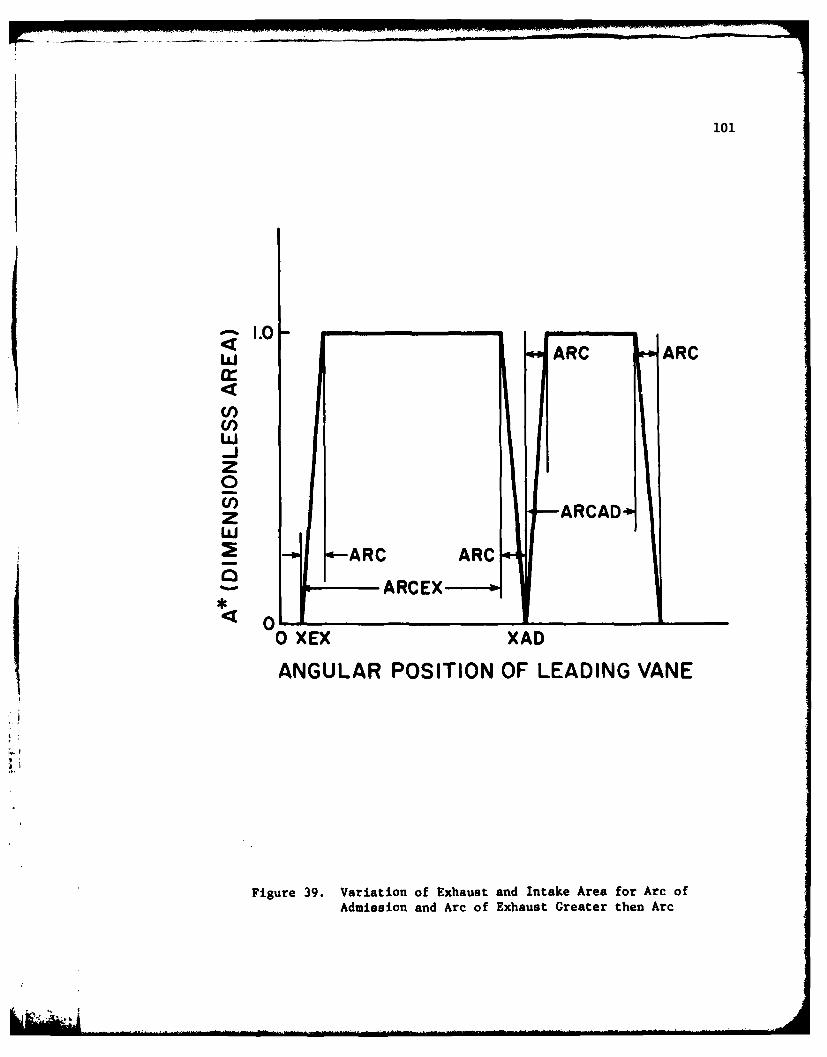
101
J-iz
S1.0
z ARCAD
w
0-~ARCEX------o-
0 XEX XAD
ANGULAR POSITION OF LEADING VANE
Figure 39. Variation of Exhaust and Intake Area for Arc ofAdmission and Arc of Exhaust Greater then Arc

102
I.0-
Cl)
-j RA ARCADZ ARCADin- ARC
z
XAD XAD4ARCAD XAD+ARC XAD+ARC+ARCAD
ANGULAR POSITION OF LEADING VANE
Figure 40. Variation of Intake Area for Arc ofAdmission less than Arc
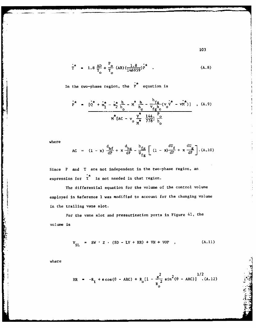
103
=1.8 M+ -0 (AB )P(1\ (A. 8)To T "149'
In the two-phase region, the P equation is
** * h h hRP Q+m -m - M . S(v V -vM) , (A.9)Q m m2hT h v h o
0 o fgo0* P
*V 144 oM [AC-v
M 0
whered d hfr dU dU
AC =hf X) +~( I .(.OACx j--+xdP U fg L x)-P dP (A10
Since P and T are not independent in the two-phase region, an
expression for T is not needed in that region.
The differential equation for the volume of the control volume
employed in Reference 1 was modified to account for the changing volume
in the trailing vane slot.
For the vane slot and pressurization ports in Figure 41, the
volume is
V SL =SW Z (SD - LV + HR) + VH + VOP ,(A.11)
where
21/HR =-Ri + ecos( - ARC) + R (I e sin 2 (e ARC)]J (.2
- (0 2(.2R
0

104
-
STATORVANE
I>
ROTOR
0~ PRESSURIZATIONP ORT
Figure 41. Schematic of Vane Slot and PressureBalancing or Pressurization Port

105
is the angular position of the leading vane, VH is the volume of
the pressurization ports and VOP is the volume of the groove at the
base of the vane slot. Since
VL V *S/ZR2 (A.13)
then
=dV dV dV SW dHRV SL -d T'o - d (A.14)
R0
or
We2 2V SL -1-2L[- sin(u ARC)- T sin(O ARV~~Cco5\(J RR) 2
Thrf s,1i 2 ( - ARC)]] / A.5
Theefoe, hedifferential equation for the dimensionless volume
becomes
V -R')Cos 6+ (1- R') cosO/- (lR) si - (1-R')
cos 2(0 ARC) -(1 - R') cos(e ARC)/' 1 (1l R') 2 since ( - ARC)
+ VSL '(A.16)
where R' - R /R
The dimensionless volume of the control volume at the position
when e - 0 (the initial volume) is

106
R 2 R R2 2 R 2o e 2
VI* 2 )ARC + sin(2 ARC) +-- e sin 2RC(I sin
0 0
ARC) R sin-l sin ARC + SW(SD - LV + R) 72 R + -e-
4
+ (OP)(OPD)] (A.17)
The differential equation for the dimensionless power is
W = P*V (A.18)
In the superheated region, Equations (A.1), (A.4), (A.8), (A.16)
and (A.18) where integrated on the digital computer using the IBM 360
Scientific Subroutine Package (360A-CM-03x) version III subroutine DHPCG.
Subroutine DHPCG uses the modified Hamming's Predictor Corrector method
[7].
In the two phase region, Equations (A.1), (A.9), (A.16), and (A.18)
were integrated on the digital computer using subroutine DHPCG.
The solution of the equations was started at 0 - 0 with initial
guesses for working fluid properties in the control volume and the
dimensionless work initialized at W = 0 . The equations were integrated
through one revolution and the final values of the properties used as
initial values for the next revolution. The process continued until the
initial and final property values were the same.
In the two phase region, the steam thermodynamic properties and
their derivatives were read into the computer as tabular data. The
properties and their derivatives were obtained from Reference 14. A

-I?
107
three point interpolation scheme gave good values of the properties and
their derivatives from the tabular data.
In the superheated region, the steam thermodynamic properties were
obtained from PSU IBM 360 computer subroutines based on References 14,
15, and 16. The partial derivatives of "b'" and the enthalpy which
appear in Equations (A.4) through (A.7) were evaluated from analytic
expressions resulting from differentiating the expressions for the
enthalpy and "b"' given in Reference 15 and 16.
4-
~-

i
APPENDIX B
DERIVATION OF EXPRESSIONS FOR TANGENTIAL AND NORMAL ACCELERATIONS
The tangential acceleration of the vane center of gravity may be
written as:
AC t= A +A +A(.I
CGt mAp t ACG/p t ACORIOLIS t (B.1)
The magnitude of the tangential acceleration of a point P(A t) on aPt
frame moving with the rotor at a radius coinciding with the radius of
the vane center of gravity is in general
A = r al ROTOR (B.2)
However, at steady state, the speed of the rotor is constant and the
angular acceleration ('OTO R ) is zero. It has been assumed that the
acceleration of the vane relative to the moving frame, in the tangential
direction, ACG/p t is zero. Therefore, Equation (B.1) reduces to
ACG t = ACORIOLIS t C 2 G X CO/P (B.3)
Figure 3.1 indicates that the distance HR describes the position of
the blade tip relative to the rotor. From Reference 1

109
HR -R + e cos + R (11/2 (B.4)
0
where Ri is the radius of the rotor, R is the radius of the stator
and e = R - Ri is the eccentricity. Therefore,
dHR dHR dO (B.5)VCG/P dt o- dt
or
22 2 -1/2VCG/p 2 ffN[-e sin 0 - - sin 8 cos (- sin e)
o Ro (B.6)
The velocity VCG/P is in the radial direction. Hence, the resulting
expression for the magnitude of the tangential acceleration of the vane
is:
ACG = 2(2TN)2[-e sin 0 -R-o sin 0 cos e(l - R sin
0 (B.7)
The direction of ACG t is found by rotating the vector VCG/P 900 in
the sense of rotation of the rotor.
The normal acceleration of the vane is
ACG n " Ap n + ACG/p n (B.8)
The magnitude of the normal acceleration (Ap n) of a point, on a frame
moving with the rotor, at a radius corresponding to the radius of the
vane center of gravity is

110
A r 2 (B.9)pn
This acceleration is always directed toward the center of the rotor.
The magnitude of the acceleration of the vane relative to the moving
frame (AcG/p n) is obtained by differentiating Equation (B.6) with
respect to time. Therefore,
2 e2 si2)-112AC/ (27rN)2[eco e e 2-/
A(2M) [-e cos 0 --- cos 26(1 - sin )o R
0
4 2 -3/21 e sin 2 20(1 - e_ sin 2) (B.1O)
R R0 0
Vector addition of the quantities in Equation (B.9) and (B.10) gives the
normal acceleration of the vane.
)I
#1.,

APPENDIX C
DERIVATION OF FINITE DIFFERENCE EXPRESSIONS
The transformation of the three dimensional Laplacian
2 2 22 rT 1 . 1 aT a T 2LV T =- -- +- -4.1
3r 2 r ar r 2 36e2 az 2
into finite difference form was accomplished by the method of Taylor's
Series expansion (11,131.
For interior nodes, as shown in Figure 42, the following Taylor's
Seriee expansions were written about the point bj.,k
al 0 2 T 2 3 a3TT1 j T -AT4 j A6 -i-i,j ,k ir ,k Ae +TF 2 3 +
ii~ j~k ae- i~j k3! ae li,j,k
(C.2)
L T= + aeij,k ae2 iJ,k 3D o i,j,k
(C.3)
T~+, iT~ Ar - + A2T-. 3A.~iI +T~~~ iT~ + arlij~k ar2 ij k3!ar3 i,j,k
22i (C.4)a-T -r Ar ar + Tj j Ar 34-...
i,J1I,k i,j,k r i,j,k + r2 i,j ,k3 ar' i,j,Vk
(C.5)
T T -zL 2 az 2 T1 A 3 a31T
(C.6)
T+ &Tz 2 2ji,j,k+l i,j,k + azi,j,k 21az 2 3!az 31i,j,k
(c.7)

112
Fu AZ
Figure 42. Interior Finite Difference Node

113
It is necessary to add Equations (C.2) through (C.7) in a way that
will permit the attainment of a finite difference approximation to
Equation (C.1). Therefore, Equations (C.2) through (C.7) were multiplied
by the coefficients A,B,C,D,E, and F , respectively. The following
constraints were applied to determine the coefficients:
E coefficients of 3 = 0ae
2T
E coefficients of 1 T
22
0 r
E coefficients of T
3r r
E coefficients of -- = 0az
2Z coefficients of T 1 . (C.8)z
The coefficients determined by application of those constraints are:
A C - 1/(rAO)2
2r + ArB-
2 rAr
2r - Ar
2rAr2
E F- 1/Az2 (C.9)
S.

114
Multiplication of Equations (C.2) through (C.7) by the constants A
through F , respectively, permits the attainment of the following
approximation for Equation (C.1):
V2T 1 T 2r + Ar T 1
(rAO)2 i-,j,k 2rAr2 i,j,k (rA6) 2 i+l,j,k
+ 2r -Ar T T + 1T
2rAr 2 Ti,j-l,k Az2 i,j,k+l Az2 i,j,k-1
2 + 2r + Ar + 2r - Ar +_2_.10
(rAS) 2 2rAr 2rAtr2 Az 2 ) i,j ,k (C.lO)
For grid points on a boundary as shown in Figure 43, where heat
generation and convection are present, Equation (C.1) was approximated
by using the fictitious node T i,jl,k . The boundary condition on the
kaTsurface was -- h(T - T ) + q" (C.11)ar w gen
The derivative on the left hand side of Equation (C.11) was
approximated using a central difference scheme. Therefore,
T T, hi 2-lk =+l.k - (T -T k +-gen (C.12)
2Ar -k k)~ +~~ k
orT2Arh(T ,, + q" !
Tj-Ik - k - Tjk) + i,j+l,k
substitution of Equation (C.12) into Equation (C.10) gives

115
% &
4-.-
F% gr 3 onayFnt ifrneNd%4
WOO FITITIOS NOD

116
2 = 1 + 2r + Ar1V(T 2 Ti-l,jk + r2 i,j+l,k 2 Ti+l,j,k
(rAO) 2rAr (rA6)
+ 1 1 + 2r - ArAz2 i,j,k-i Az2 Ti,j,k+l 2rA 2 Ti,j+l,k
2r - Ar h 2r - Ar ge+ " 2rAr - - + 2rAr k
2 +2r + Ar + 2r - Ar + _L2 + (2r - br) T(rA8) 2 2rAr 2 2rtr 2 Az2 rAr k Ti,j,k
(C.13)
The fictitious node technique as described above was applied to all the
boundaries.
In the steady state analysis, Equation (C.1) is equal to zero.
Therefore, the temperature at each node can be determined by using
Equations like (C.10) and (C.13). For example, using Equation (C.1O)
the expression for Ti,j, k is
T = + 2r + Ar T 1 Ti,j,k [ 2rA7)2 i-l,J, k 2rAr 2 i,j+l,k + 1 i jkL~A) rr(rAe) 2 T+, k
+ 2r - Ar Ti j-lk + 1T_i__l2rAr 2 Az2 i,j,k+l Az2 i,j,k-
S 2 + 2r + Ar + 2r - Ar + (C.14)
(rAO)2 2rAr 2 2rAr2 AZ2
Solving for Ti,j, k at each node, results in a set of algebraic
expressions for Ti,j, k which must be solved simultaneously. This was
accomplished using the Gauss-Seidel iterative method with the incorpora-
tion of Young's over relaxation factor [7].
LAIL,

117
For the transient analysis, the equation
V2T =1 3T (C.15)
ax at
was approximated by finite differences. For the explicit solution, a
finite difference expression for -L was obtained using a forwardat
difference. Therefore, the approximation was
_N+I NT N -1TN
3T _ i,j,k i,j,k (C.16)at At
The superscripts (N+l) and (N) refer to time (t + At) and time (t),
respectively.
The finite difference approximation of Equation (C.15), for an
interior node is:
N+l N
Ti,j,k Ti,j,k 1 T N 2r + Ar TN
aAt (rAe) 2 1 l,j,k + 2rAt2 ijk+l
+ 1 TN(rAO)2 i+l,j,k
2r - Ar TN 1 N 1 N2r T ~- +-T -
2A 2 ijk +Az 2 i,J,k+l Az2 i,j,k-i
(rAO)2 2rAr2 2rAr 2 - J k (C.17)
The approximations to Equation (C.15) for each node can be solved for
T l Since the values of TN are all known, iteration is notij , l,j,k
required to solve the set of algebraic equations.

APPENDIX D
DERIVATION OF FRICTIONAL HEAT FLUX EQUATIONS
The total rate of frictional heat generated at the interface of
two semi-infinite solids in sliding contact is
qTOTAL ql + q2 (D.1)
where q and q" are the heat transfered into body I and II, respectively.
The heat conduction equation for each body is
.2T 1 I T (D.2)
a 2 cat
The boundary conditions for each body are:
BODY I
3T 1Z 0-- q
z = o T 1 0 (D.3)
where T = t! t!
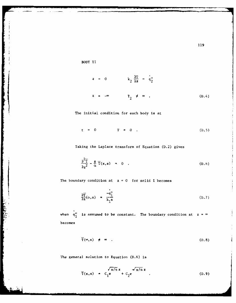
119
BODY II
aTz = o k2 -LT q'I2 az 2
Z = -00 T # . (D.4)2
The initial condition for each body is at
t = 0 T= 0 (D.5)
Taking the Laplace transform of Equation (D.2) gives
2-
2 sT(x,s) 0 (D.6)az2 OL
The boundary condition at z =0 for solid I becomes
3 -(o,=s) - I (D.7)-Z kls
.1
when q" is assumed to be constant. The boundary condition at z =1
becomes
T(-o,s) c DB
The general solution to Equation (D.6) is
rs/,,z -JgT zT(x,s) - C1e + C2e (D.9)

120
Applying boundary conditions (D.7) and (D.8) gives
/--, /z2/a 1T(z,s) 1 2 -3/2 (D.10)
k1
From Reference 17 the inverse transform of Equation (D.10) is
2 -( -zct)/4t z2 _
2. zi]
T(z) i e - )erfc 2t .(D.11)1L L 2/tj
Similarly for body II
V/2z2 z
)2 ( t )__ 1T(z,O) 2 2 - (- erfc- .(D.12)T( a 2V_
Assuming no contact resistance
T1 (0,t) = T2 (Ot) (D.13)
Therefore, by equating Equations (D.11) and (D.12), it is found that
q q 1 a2 (D.14)1 2 T 1
Combining Equations (D.1) and (D.14) gives
q21 q itT O T A( D .1 5 )
2 1
and
TOTAL 1 2
+ k a2 ' 2 L 1 D.16

DISTRIBUTION
Commander (NSEA 09G32)Naval Sea Systems CommandDepartment of the NavyWashington, D. C. 20362 Copies 1 and 2
Commander (NSEA 0342)Naval Sea Systems CommandDepartment of the NavyWashington, D. C. 20362 Copies 3 and 4
Defense Documentation Center5010 Duke StreetCameron StationAlexandria, VA 22314 Copies 5 through 16
* I
Related Documents