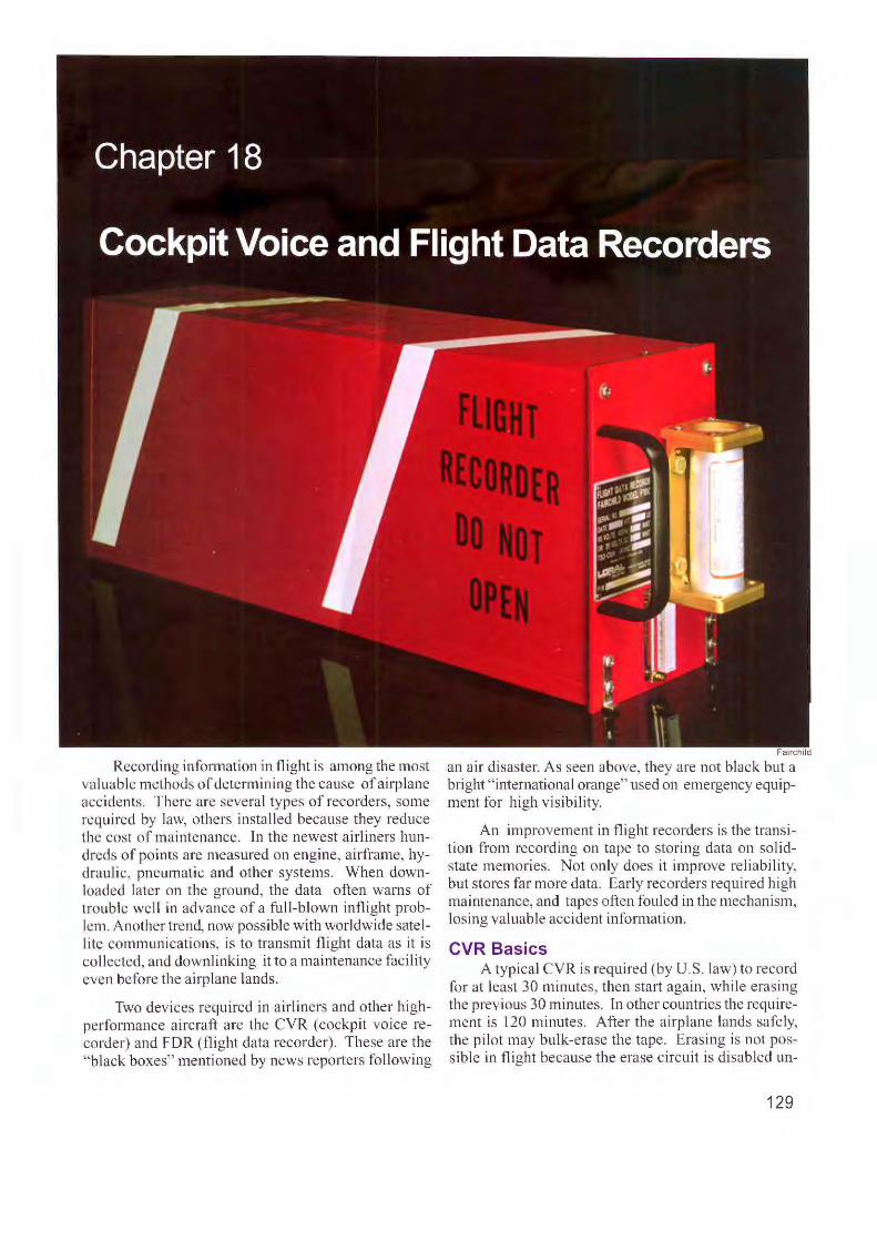
Reco rding info nnation in flight is among the most valuable methods of determining the cause of airplane acc ide nts. There are several typ es of reco rders, some req uired by law, others inst alled beca use th ey re duce the cost of maintenance. Jn the newest airliners hun- dred s of points are meas ured on engine, airframe, hy- drauli c, pneumatic and other systems. When down- loaded later on the ground, the data often warn s of trouble we ll in advance of a full-blown inflight prob- lem. Anot her trend, now possible with worldwide satel- 1 ite co mmunications, is to transmit flig ht data as it is co llected, and downlinking it to a maintenan ce facility eve n before the airplane lands. Two dev ices required in airliners and other hi gh- per fo rman ce aircra ft are the CVR (cockpit voice re- co rder) and FDR (flight data recorde r). The se are the "bl ack bo xes" menti oned by news re porters fo ll owi11g Fairchild an air di saster. As seen above, they are not black but a brig ht " i11ternational orange" used on emergency equip- ment for high visibility. An imp rovement in fli g ht recorders is the transi- ti on from reco rding on tape to stor ing data on so li d- state memories. No t only do es it improve re li ab il ity, but stores far more data. Early recorders req uired hi gh maintenance, and tapes often fouled in the mechanism, losing valuable accide nt informa tion. CVR Basics A typical CVR is re quired ( by U.S . l aw) to record for at least 30 minutes, then start aga in, whi le eras ing the prev ious 30 minutes. rn other countri es the require- ment is 1 20 minutes . After the air plane lands safe ly, the pilot may bulk- erase the tape. Erasing is not pos- sible in flight because the erase circuit is disabled un- 129

Welcome message from author
This document is posted to help you gain knowledge. Please leave a comment to let me know what you think about it! Share it to your friends and learn new things together.
Transcript
Recording infonnation in flight is among the most va luable methods of determining the cause of airplane accidents. There are several types of recorders, some required by law, others in stalled because they reduce the cost of maintenance. Jn the newest airliners hundreds of points are measured on engine, a irframe, hydraulic, pneumatic and other systems. When downloaded later on the ground, the data often warns of trouble well in advance of a full-blown inflight problem. Another trend, now possible w ith worldwide satel-1 ite communications, is to transmit flight data as it is collected, and downlinking it to a maintenance facility even before the airp lane lands .
Two devices required in a irliners and other highperformance aircraft are the CVR (cockpit voice recorder) and FDR (flight data recorder). These are the "black boxes" menti oned by news reporters fo ll owi11g
Fairchild
an air di saster. As seen above, they are not black but a bright " i11ternational orange" used on emergency equipment for high visibility.
An improvement in fli ght recorders is the transition from recording on tape to storing data on so lidstate memories. Not only does it improve re li abil ity, but stores far more data. Early recorders required high maintenance, and tapes often fouled in the mechanism, losing va luable accident information.
CVR Basics A typical CVR is required (by U.S . law) to record
for at least 30 minutes, then start again, whi le eras ing the previous 30 minutes. rn other countries the requirement is 120 minutes. After the a irplane lands safely, the pilot may bulk-erase the tape. Erasing is not possible in fli ght because the erase c ircuit is disabled un-
129
less the system senses the airplane is on the g round. Th is is usually done by a weight-on-wheels, or "squat switch."
The new CV R's are easier to down load than early models. Instant playback is possible with a portable device. Any place on the recording is quickly located by forward, reverse and stop commands.
The power source can be either 1 I 5 volts 400 Hz or 28 VDC. With so few moving parts, the solid-state CVR requires no period ic maintenance or scheduled overhau l.
Inertial Switch . If a CVR continues to receive aircraft power after a crash, the recorded audio is wiped clean and lost. This is prevented by an inerti al switch. lt responds to high G forces of a crash by intem1pting power to the voice recorder.
Audio Channels. The CVR provides four audio channels into the recorder:
Captain: Any microphone used by the captain, such as the norma l boom mike, as well as the mike in an oxygen mask or hand mike. This assures a recording of rad io commun ications.
Co-Pilot (First Officer) The same as for the captain.
Pu blic Address (PA) This channel picks up announcements by the crew to passengers in the cabin.
Cockpit Area Mike. This is designed to pick up crew member voices and other sounds in the cockpit. There have been problems with cockpit area mikes. After a crash, safety investigato rs often complain that
'
Fairchild
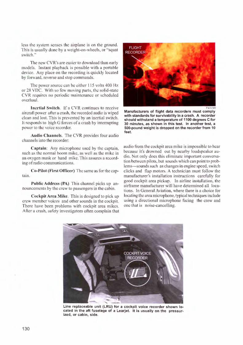
Manufacturers of flight data recorders must comply with standards for survivability in a crash. A recorder should withstand a temperature of 1100 degrees C for 30 minutes, as shown in this test. In another test, a 500-pound weight is dropped on the recorder from 10 feet.
audio from the cockpit area mike is impossible to hear because it 's drowned out by nearby loudspeaker audio. Not onl y does this eliminate important conversation between pilots, but sounds which can point to problems---sounds such as changes in engine speed, switch clicks and flap motors. A technician must follow the manufacturer's installation instructions careful ly for good cockpit area pickup. ln airli ne installation, the airframe manufactu rer will have determined all locations. ln General Aviation, where there is a choice for locating the area microphone, typical techniques include us ing a directiona l microphone fac ing the crew and one that is noise-cancel ling.
Line replaceable unit (LRU) for a cockpit voice recorder shown lo-cated in the aft fuselage of a Learjet. It is usually on the pressur-ized, or cabin, side.
130
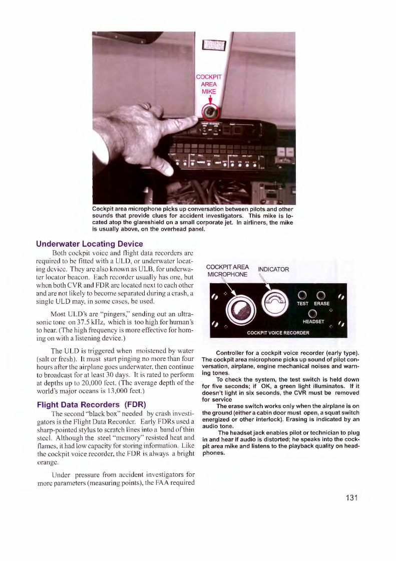
COCKPIT AREA MIKE
Cockpit area microphone picks up conversation between pilots and other sounds that provide clues for accident investigators. This mike is located atop the glareshield on a small corporate jet. In airliners, the mike is usually above, on the overhead panel.
Underwater Locating Device Both cockpit voice and flight data recorders are
required to be fitted with a ULD, or underwater locating device. They are also known as ULB, for underwater locator beacon. Each recorder usually has one, but when both CVR and FDR are located next to each other and are not likely to become separated during a crash, a sing le ULD may, in some cases, be used.
Most ULD 's are "pingers," sending out an ultrason ic tone on 37.5 kHz, which is too high for human 's to hear. (The high frequency is more effective for homing on with a li stening device.)
The ULD is triggered when moistened by water (sa lt or fresh). It must start pinging no more than four hours after the airplane goes underwater, then continue to broadcast for at least 30 days. Jt is rated to perfonn at depths up to 20,000 feet. (The average depth of the world 's major oceans is 13,000 feet.)
Flight Data Recorders (FDR) The second "black box" needed by crash investi
gators is the Flight Data Recorder. Early FD Rs used a sharp-pointed sty lus to scratch lines into a band of thin steel. Although the steel "memory" resisted heat and flames, it had low capacity for sto1ing information. Like the cockpit voice recorder, the FDR is always a bright orange.
Under p ressure from accident investigators for more parameters (measuring points), the FAA required
INDICATOR
Controller for a cockpit voice recorder (early type). The cockpit area microphone picks up sound of pilot conversation , airplane, engine mechanical noises and warning tones.
To check the system, the test switch is held down for five seconds; if OK, a green light illuminates. If it doesn't light in six seconds, the CVR must be removed for service
The erase switch works only when the airplane is on the ground (either a cabin door must open, a squat switch energized or other interlock). Erasing is indicated by an audio tone.
The headset jack enables pilot or technician to plug in and hear if audio is distorted; he speaks into the cockpit area mike and listens to the playback quality on headphones.
131
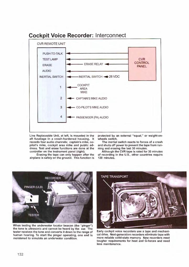
Cockpit Voice Recorder: Interconnect CVR REMOTE UNIT
PUSH-TO-TALK -TEST LAMP - CVR .. ERASE RELAY ~ CONTROL ERASE - PANEL
AUDIO --INERTIAL SWITCH .. INERTIAL SWITCH ... 28 voe
1 ~ COCKPIT
AREA MIKE
2 ,.,_ CAPTAIN'S MIKE AUDIO
3 ~ CO-PILOTS MIKE AUDIO
4 ~ PASSENGER (PA) AUDIO
Line Replaceable Unit, at left, is mounted in the aft fuselage in a crash-hardened housing. It records four audio channels ; captain's mike, copilot's mike, cockpit area mike and public address. Test and erase functions are done at the controller on the instrument panel (right).
Erasing the tape can only happen after the airplane is safely on the ground. This function is
protected by an external " squat," or weight-onwheels switch.
The inertial switch reacts to forces of a crash and shuts off power to prevent the tape from running and erasing the last 30 minutes.
Although the CVR tape is rated for 30 minutes of recording in the U.S., other countries require 120 minutes.
When testing the underwater locator beacon (the " pinger") the tone is ultrasonic and cannot be heard by the ear. The tester receives the tone and converts it down to the range of human hearing. To start the pinger operating, one end is moistened to simulate an underwater condition.
Early cockpit voice recorders use a tape and mechanical drive. Next-generation recorders eliminate tape with more reliable solid-state memory. New recorders meet tougher requirements for heat and G-forces and need less maintenance.
132
large aircraft be equipped with d igital flight data recorders of greater capacity and reliability. Depending on date of manufacture a ll such airplanes had to retrofit anywhere from 22 up to 57 parameters. Aircraft manufactured after 2002 require 88 parameters.
FDR's grew even more important with the arrival of e lectronic instruments. In airplanes with mechanical gauges, accident investigators could look at an a irspeed need le pinned in place by the crash and obtain valuable information (such as airspeed when the airplane struck the ground). They cou ld tell if warning lights were on or off at the time of impact by looking at condition of filaments in the bulbs. But as this information went from instruments, switches and lamps to e lectronic displays, it d isappeared when the screen went dark. T hus the urgency of storing data on a flight recorder.
Many in the aviation industry want to add to the present generation of flight data recorders. One idea is to equip large aircraft with two recording systems; forward and aft, to assure suffi cient data. There is also a move to equip the cockpit with a video camera. Video images stored in the FDR could yie ld valuable information about what happened just before the crash.
The d ig ital FDR (DFDR) takes analog sig nals (head ing, a ltitude, airspeed, etc.)--which usually va1y in a smooth, continuous fashion and converts them to digital format for storage in a solid-state memory. Some sig nals are "synchro," meaning signals from electromechanical instruments. Yet another type of input is from the aircraft databus, such as ARINC 429, whi ch is a stream of data from many aircraft systems.
Unlike the o ld, mechanical recorder, there is no scheduled overhaul and little maintenance fo r digita l models. Reliabi lity extends to 20,000 hours (on aver-
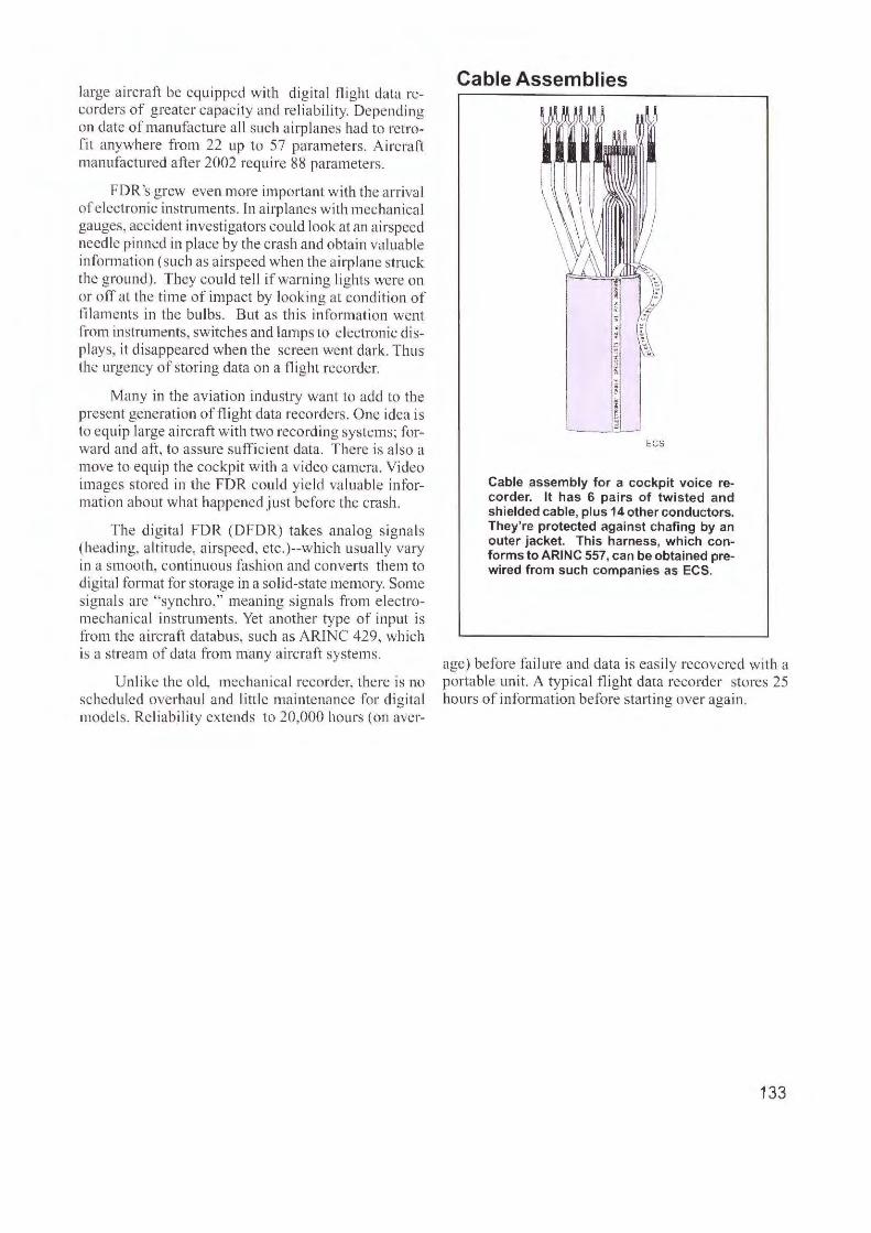
Cable Assemblies
ECS
Cable assembly for a cockpit voice recorder. It has 6 pairs of twisted and shielded cable, plus 14 other conductors. They're protected against chafing by an outer jacket. This harness, which conforms to ARING 557, can be obtained prewired from such companies as ECS.
age) before failu re and data is easil y recovered with a portable unit. A ty pical flight data recorder stores 25 hours of information before sta1ting over again.
133
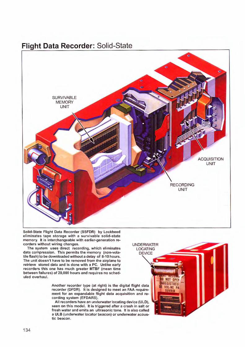
Flight Data Recorder: Solid-State
SURVIVABLE MEMORY
UNIT
Solid-State Flight Data Recorder (SSFDR) by Lockheed eliminates tape storage with a survivable solid-state memory. It is interchangeable with earlier-generation recorders without wiring changes.
The system uses direct recording, which eliminates data compression. This permits the memory (non-volatile flash)to be downloaded without a delay of 8-10 hours. The unit doesn 't have to be removed from the airplane to retrieve stored data and is done with a PC. Unlike early recorders this one has much greater MTBF (mean time between failures) of 20,000 hours and requires no scheduled overhaul.
UNDERWATER LOCATING
DEVICE
Another recorder type (at right) is the digital flight data recorder (DFDR). It is designed to meet an FAA requirement for an expandable flight data acquisition and recording system (EFDARS).
134
All recorders have an underwater locating device (ULD), seen on this model. It is triggered after a crash in salt or fresh water and emits an ultrasonic tone. It is also called a ULB (underwater locator beacon) or underwater acoustic beacon.
ACQUISITION UNIT
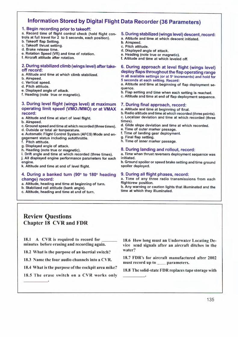
Information Stored by Digital Flight Data Recorder (36 Parameters) 1. Begin recording prior to takeoff: a. Record time of flight control check (hold flight controls at full travel for 2 to 5 seconds, each position). b. Takeoff flap Setting. c. Takeoff thrust setting. d. Brake release time. e. Rotation Speed (VR) and time of rotation. f. Aircraft attitude after rotation.
2. During stabilized climb (wings level) after takeoff record: a. Altitude and time at which climb stabilized. b. Airspeed. c. Vertical speed. d. Pitch attitude. e. Displayed angle of attack. f. Heading (note true or magnetic).
3. During level flight (wings level) at maximum operating limit speed (VMO./MMO) or at VMAX record: a. Altitude and time at start of level flight. b. Airspeed. c. Ground speed and time at which recorded (three times). d. Outside or total air temperature. e. Automatic Flight Control System (AFCS) Mode and engagement status including autothrottle. f. Pitch attitude. g. Displayed angle of attack. h. Heading (note true or magnetic). i. Drift angle and time at which recorded (three times). j. All displayed engine performance parameters for each engine. k. Altitude and time at end of level flight.
4. During a banked turn (90° to 180° heading change) record: a. Altitude, heading and time at beginning of turn. b. Stabilized roll attitude (bank angle). c. Altitude, heading and time at end of turn.
Review Questions Chapter 18 CVR and FDR
J.8.1 A CVR is required to record for __ _ minutes before erasing and recording again.
18.2 What is the purpose of an inertial switch?
18.3 Name the four audio channels into a CVR.
18.4 What is the purpose of the cockpit area mike?
18.5 The erase switch on a CVR works only
5. During stabilized {wings level) descent, record: a. Altitude and time at which descent initiated. b. Airspeed. c. Pitch attitude. d. Displayed angle of attack. e. Heading (note true or magnetic). f. Altitude and time at which leveled off.
6. During approach at level flight {wings level) deploy flaps throughout the flap operating range in all available settings (or at 5° increments) and hold for 5 seconds at each setting. Record: a. Altitude and time at beginning of flap deployment sequence. b. Flap setting and time when each setting is reached. c. Altitude and time at end of flap deployment sequence.
7. During final approach, record: a. Altitude and time at beginning of final. b. Radio altitude and time at which recorded (three points). c. Localizer deviation and time at which recorded (three times). d. Glide slope deviation and time at which recorded. e. Time of outer marker passage. f. Time of landing gear deployment. g. Final flap setting. h. Time of inner marker passage.
8. During landing and rollout, record: a. Time when thrust reversers deployment sequence was initiated. b. Ground spoiler or speed brake setting and time ground spoiler deployed.
9. During all fl ight phases, record: a. Time of any three radio transmissions from each flightcrew position. b. Any warning or caution lights that illuminated and the time at which they illuminated.
18.6 How long must an Underwater Locating Device send signals after an aircraft ditches in the water?
18.7 FDR's for aircraft manufactured after 2002 must record up to __ parameters.
18.8 The solid-state FDR replaces tape storage with
135
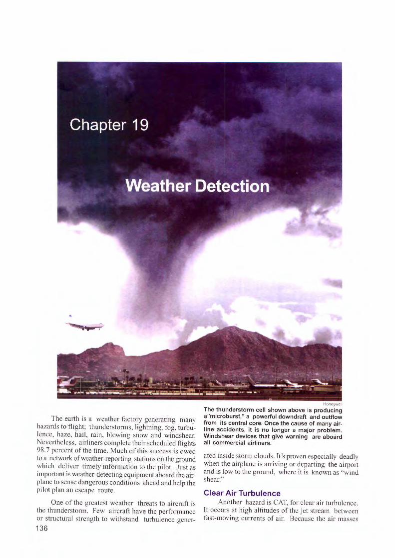
The ea1ih is a weather factory generating many hazards to fli ght; thunderstorms, lightning, fog, turbulence, haze, hail , rain, blowing snow and windshear. Nevertheless, airliners complete the ir scheduled fli ghts 98. 7 percent of the time. Much of thi s success is owed to a network of weather-reporting stations on the g round w hich de li ver timely info rmation to the pilot. Ju st as important is weather-detecting equipment aboard the airplane to sense dangerous conditions ahead and he lp the pil ot plan an escape route.
O ne of the g reatest weathe r threats to a ircraft is the thundersto rm. Few aircraft have the perfom1ance or structural strength to withsta nd turbul ence gener-
136
Honeywell
The thunderstorm cell shown above is producing a"microburst," a poweliul downdraft and outflow from its central core. Once the cause of many airline accidents, it is no longer a major problem. Windshear devices that give warning are aboard all commercial airliners.
atcd inside storm c louds . It's proven especia lly dead ly when the a irp lane is arriving or departing the airport and is low to the ground, where it is known as "wind shear."
Clear Air Turbulence Another hazard is CAT, for clear a ir turbulence.
It occurs at high a lti tudes of the jet stream between fas t-moving cur ren ts of a ir. Because the air masses
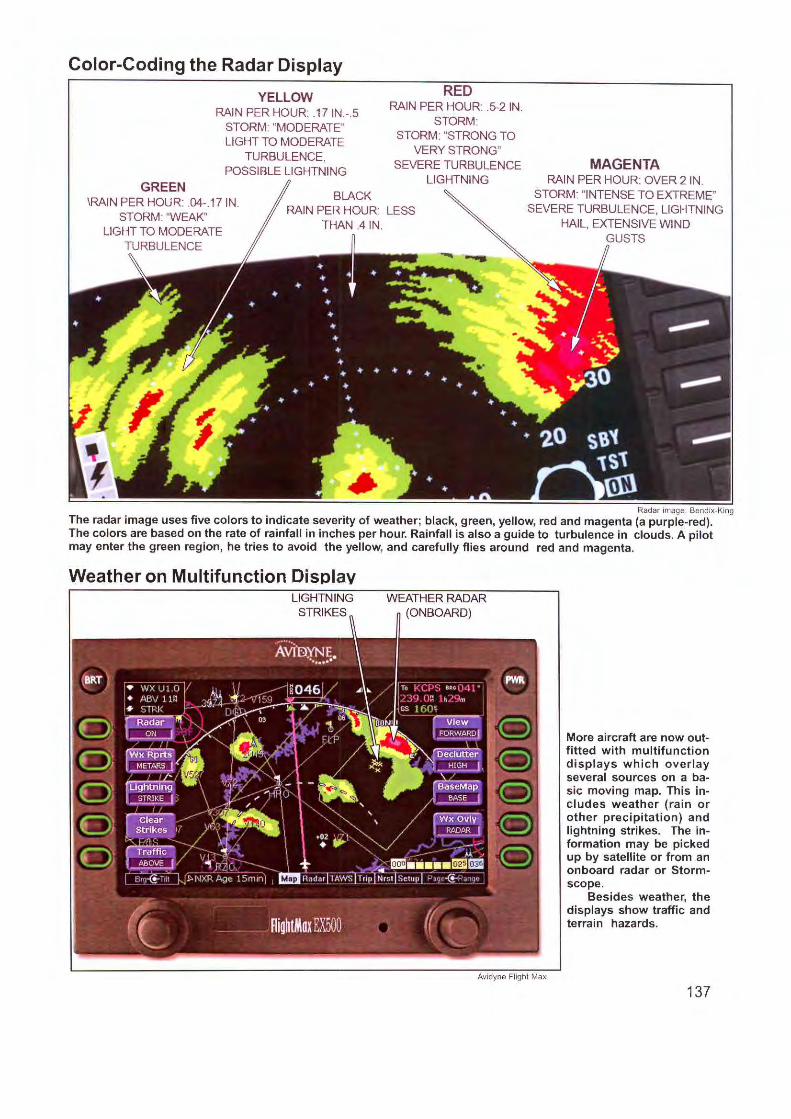
Color-Coding the Radar Display
GREEN
YELLOW RAIN PER HOUR; .17 IN.-.5
STORM: "MODERATE" LIGHT TO MODERATE
TURBULENCE, POSSIBLE LIGHTNING
BLACK
RED RAIN PER HOUR: .5-2 IN.
STORM: STORM: "STRONG TO
VERY STRONG" SEVERE TURBULENCE
LIGHTNING
\RAIN PER HOUR: .04-.17 IN. STORM: "WEAK"
LIGHT TO MODERATE
RAIN PER HOUR: LESS THAN .4 IN .
MAGENTA RAIN PER HOUR: OVER 2 IN.
STORM: "INTENSE TO EXTREME" SEVERE TURBU LENCE, LIGHTNING
HAIL, EXTENSIVE WIND GUSTS
Radar image. Bendix-King
The radar image uses five colors to indicate severity of weather; black, green, yellow, red and magenta (a purple-red). The colors are based on the rate of rainfall in inches per hour. Rainfall is also a guide to turbulence in clouds. A pilot may enter the green region, he tries to avoid the yellow, and carefully flies around red and magenta.
Weather on Multifunction Display WEATHER RADAR
(ON BOARD)
Avidyne Flight Max
More aircraft are now outfitted with multifunction displays which overlay several sources on a basic moving map. This includes weather (rain or other precipitation) and lightning strikes. The information may be picked up by satellite or from an onboard radar or Stormscope.
Besides weather, the displays show traffic and terrain hazards.
137
move in different directi ons, an airplane hits heavy turbulence when it enters the boundary between them. The damage is usually not to the airplane but to passengers. They arc tossed about and injured in the cabin (thus the request to keep the seat belt buckled.)
Thunderstorms Because thunderstorms arc accompan ied by light
ning, the earliest attempt at detecti on was the ADE or automat ic direction finder, already aboard many aircraft. Lightning is an electrical d iseharge that generates not only flashes of visible light but radio frequencies in the low- and medium-frequency bands. The A DF receiver, therefore, responds to thi s energy. With each lightning discharge, the ADF needle dips away from its rest position. According to the fo lklore of aviation (which many pilots believe) an ADF needle points toward the storm. Thi s is dangerous because the needle and its mechanism do try to point to the storm, but swing too slowly. As the lightning di scharges in different directions, the needle lags behind, becoming confused and erratic. But as we' II cc, lightni ng can prov ide valuable info rmation about storm locati on.
Types of Detection Weather Radar. The leading airborne weather
detecting device, first put aboa rd a DC-4 airliner in 1946, is weather radar. Adapted from military models of World War I l, it proved so effective it became required equipment aboard all commercial flights. The radar system operates on the principle of refl ectivity; a pulse emitted from the radar antenna strikes water droplets in a cloud and rcnects back as an echo. By plotting the strength and direction of the echoes, areas of heavy rain arc "painted" on a graphic display, and
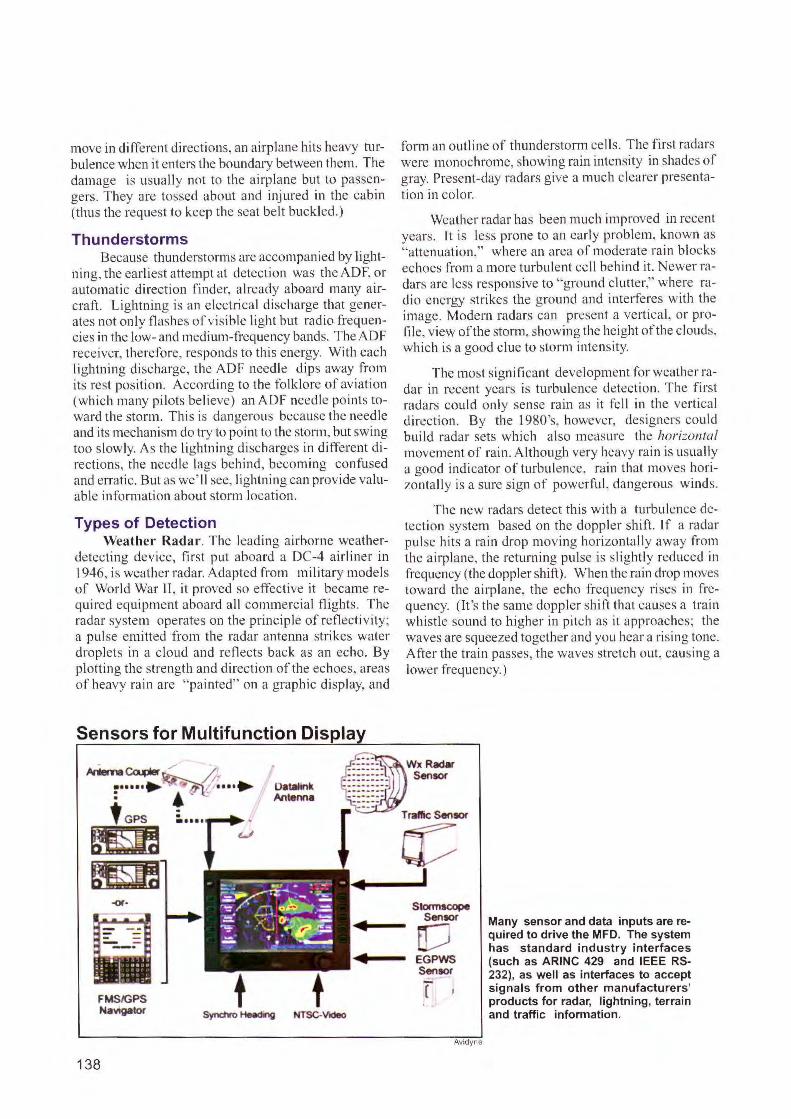
Sensors for Multifunction Displa
form an outline of thunderstorm cell s. The fi rst radars were monochrome, showing rain intensity in shades of gray. Present-day radars give a much clearer presentation in color.
Weather radar has been much improved in recent years. Lt is less prone to an early problem, known as "attenuation," where an area of moderate rain blocks echoes fro m a more turbulent cell behind it. Newer radars are less responsive to "ground clutter," where radio energy strikes the ground an d interferes with the image. Modem radars can present a vertical, or proti le, view of the storm, showing the height of the clouds, whi ch is a good clue to storm inte nsity.
The most signi ti cant development for weather radar in recent years is turbulence detection. The fi rst radars could onl y sense ra in as it fell in the vert ical direction. By the l 980's, however, designers could build radar sets which also measure the horizontal movement of rain . Although very heavy rain is usually a good indicator of turbulence, ra in that moves horizontally is a sure sign of powcrf~u1, dangerous wi nds.
The new radars detect th is wi th a turbulence detection system based on the doppler shift. If a radar pulse hits a rain drop moving horizonta ll y away fro m the airplane, the returning pulse is sl ightly reduced in frequency (the doppler shi ft). When the rain drop moves toward the airplane, the echo frequency rises in frequency. (I t's the same doppler shift that causes a train whistle sound to higher in pitch as it approaches; the waves are squeezed together and you hear a rising tone. A~er the train passes, the waves stretch out, causing a lower frequency.)
Datalink Antenna
~ WxRadar
~ Sen'°'
-«-
FMSIGPS Na111g11tor
138
t NTSC-Vldeo
Traffic Sensor
er: I
Stormscope Sensor
[J EGPWS Sensor
f
Avidyne
Many sensor and data inputs are required to drive the MFD. The system has standard industry interfaces (such as ARINC 429 and IEEE RS-232), as well as interfaces to accept signals from other manufacturers' products for radar, lightning, terrain and traffic information.
Weather Radar Transmitter-Receiver
ANTENNA
Antenna
ELEVATION
MOTOR
TILT
CONTROL
INERTIAL
REFERENCE
AZIMUTH
MOTOR
SCAN
MOTOR
ALTIMETER
SOURCE
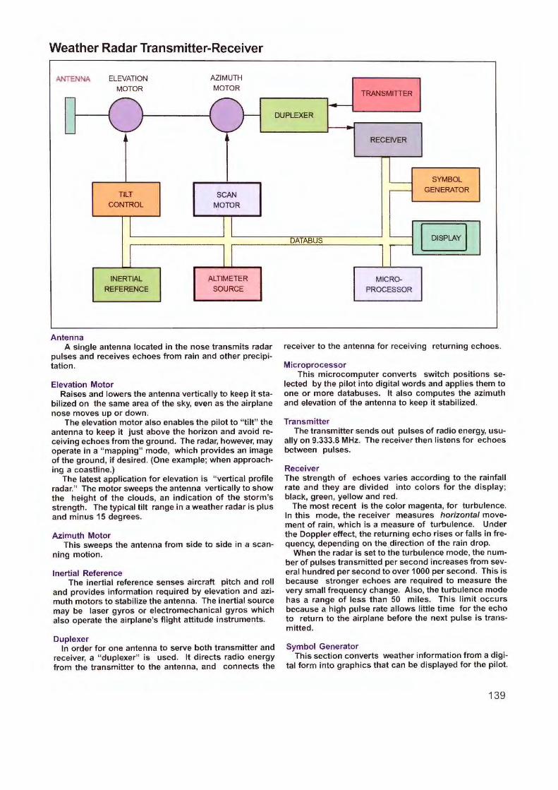
A single antenna located in the nose transmits radar pulses and receives echoes from rain and other precipitation.
Elevation Motor Raises and lowers the antenna vertically to keep it sta
bilized on the same area of the sky, even as the airplane nose moves up or down.
The elevation motor also enables the pilot to "tilt" the antenna to keep it just above the horizon and avoid receiving echoes from the ground. The radar, however, may operate in a "mapping" mode, which provides an image of the ground, if desired. (One example; when approaching a coastline.)
The latest application for elevation is "vertical profile radar." The motor sweeps the antenna vertically to show the height of the clouds, an indication of the storm's strength. The typical tilt range in a weather radar is plus and minus 15 degrees.
Azimuth Motor This sweeps the antenna from side to side in a scan
ning motion.
Inertial Reference The inertial reference senses aircraft pitch and roll
and provides information required by elevation and azimuth motors to stabilize the antenna. The inertial source may be laser gyros or electromechanical gyros which also operate the airplane's flight attitude instruments.
Duplexer In order for one antenna to serve both transmitter and
receiver, a " duplexer" is used. It directs radio energy from the transmitter to the antenna, and connects the
TRANSMITIER
DUPLEXER
RECEIVER
SYMBOL
GENERATOR
DATABUS I DISPLAY I MICRO-
PROCESSOR
receiver to the antenna for receiving returning echoes.
Microprocessor This microcomputer converts switch positions se
lected by the pilot into digital words and applies them to one or more databuses. It also computes the azimuth and elevation of the antenna to keep it stabilized.
Transmitter The transmitter sends out pulses of radio energy, usu
ally on 9.333.8 MHz. The receiver then listens for echoes between pulses.
Receiver The strength of echoes varies according to the rainfall rate and they are divided into colors for the display; black, green, yellow and red.
The most recent is the color magenta, for turbulence. In this mode, the receiver measures horizontal movement of rain, which is a measure of turbulence. Under the Doppler effect, the returning echo rises or falls in frequency, depending on the direction of the rain drop.
When the radar is set to the turbulence mode, the number of pulses transmitted per second increases from several hundred per second to over 1000 per second. This is because stronger echoes are required to measure the very small frequency change. Also, the turbulence mode has a range of less than 50 miles. This limit occurs because a high pulse rate allows little time for the echo to return to the airplane before the next pulse is transmitted.
Symbol Generator This section converts weather information from a digi
tal form into graphics that can be displayed for the pilot.
139

Early radar did not have circuits which could measure doppler shift. They were too unstable to measure small frequency changes. Today's radars use solidstate devices that generate precise frequencies and have the stability to measure frequency shifts in the returning echo. As seen in the illustration, turbulence is shown on the radar screen by the color magenta.
Single Engine Radar. Mounting radar in a light aircraft has been a problem because the antenna interferes with the propellor and engine. To avoid this area, the radar antenna is slung under a wing or built into the wing's lead ing edge. Small antenna size, however, limits operating range of these single-engine installations.
Lightning Detection Weather research shows that thunderstorms cre
ate lightning in strong up and down drafts. Particles of dust, ice crystals and water rub against each other and build static electricity. When voltage rises sufficiently, an electrical discharge jumps between clouds (most of the time), while some charges move from cloud to earth. As heavy electrical currents heat and expand the air,
they produce the sound of thunder---plus a wide spectrum of radio energy that travels hundreds of miles. You hear it as static on an AM radio during a storm. That energy is also an indicator of where turbulence is located.
Storrnscope appeared in the I 970's as the first practical lightning detection system fo r aircraft. It became successful in single-engine airplanes because it doesn 't need a radar antenna on the nose; just a smal I receiving antenna on the belly of the aiqJlane.
The Stormscope is tuned to a region where radio energy of lightning is concentrated; the very low frequency of 50 kHz. The display is electronic whi ch means there are no mechanically moving pa1ts to lag behind, as in the case ofanADF needle.
The display also maps the storm. When a lightning stroke is sensed, a dot is placed on the screen that shows the direction and distance of the stroke. The dot is held on the screen and joined by the next dot. Storing these signals, therefore, builds a graphic image of thunderstorm cells and places them in the proper position relative to the nose of the airplane.
Weather Radar Control Panel
140
GAIN CONTROL
UNCALIBRATED WEATHER
GAIN
!TEST! @ o UCAL
10 ~~~~-RI GHT MOOE~~~~- 10
!IDNT! © I TFR! !WX/T! ~ I MAP!
GROUND CLUTIER
SUPPRESSION
UP
ON
Both the captain and first officer operate the weather radar from the same control panel in this ARINC-type unit. Nearly all controls are duplicated; the captain's side is the white area, the copilot's is shown with a blue background. They are grouped as ""Left Mode" and "Right Mode" to indicate that the controls affect left and right sides of the instrument panel.
The panel, however, controls just one radar set and antenna. If captain and co-pilot choose different modes or ranges, they will see these selections on their displays. This is done by "time sharing" the radar scan. When the antenna swings from left to right, it obeys the captain's settings. When it scans from right to left, it reconfigures and responds to the co-pilot's switch settings. Thus, the two pilots may be viewing different weather situations on their displays---all from the same radar at nearly the same time.
Radar Antenna
TILT ~LEVATION)
RIVE MOTORS
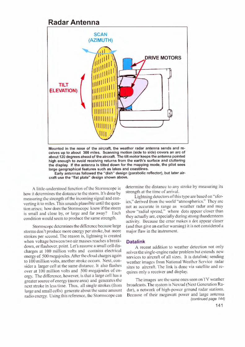
Mounted in the nose of the aircraft, the weather radar antenna sends and receives up to about 300 miles. Scanning motion (side to side) covers an arc of about 120 degrees ahead of the aircraft. The tilt motor keeps the antenna pointed high enough to avoid receiving returns from the earth's surface and cluttering the display. If the antenna is tilted down for the mapping mode, the pilot sees large geographical features such as lakes and coastlines.
Early antennas followed the "dish" design (parabolic reflector) , but later aircraft use the "flat plate" design shown above.
A litt le-understood function of the Storm scope is how it determines the distance to the storm. It 's done by measuring the strength of the incoming signal and converting it to miles. This sounds plausible unti I the question arises; how does the Stormscope know if the storm is small and c lose by, or large and far away? Each condition would seem to produce the same strength.
Stormscope determines the difference because large storms don 't produce more energy per stroke, but more strokes per second . The reason is, lightning is created when voltage between two air masses reaches a breakdown , or flashover, point. Let 's assume a small cell discharges at 100 milli on volts and contains e lectrica l energy of 500 megajoules. Afte r the c loud charges aga in to 100 milli on volts, another stroke occurs. Nex t, consider a larger cell at the same di stance. [t a lso flashes over at 100 mi llion volts and 500 megajoules of energy. The diffe re nce, however, is th at a large cell has a greater source of energy (more area) and generates the next stroke in less time . Thus, a ll single strokes (from large and small cells) generate about the same amount radio energy. Using this reference, the Stormscope can
determine the distance to any stroke by measuring its strength at the time of arrival.
Lightning detectors of this type are based on ''sferics," derived from the world "atmospherics." They are not as accurate in range as weather radar and may show "rad ial spread," where dots appear closer than they actually are, especially during strong thunderstorm activity. Because the error makes a dot appear closer (and thus give an earlier warning) it is not considered a major flaw in the instrument.
Datalink A recent addition to weather detection not only
solves the single-engine radar problem but extends new serv ices to aircraft of all s izes. It is datalink; sendi ng weather images from National Weather Serv ice radar sites to aircraft. The li nk is done v ia satellite and requires only a receiver and display.
The images are the same ones seen on TV weather broadcasts. The system is Nex.rad (Next Generation Radar), a network of high-power ground radar stations. Because of the ir megawatt power and large antenna
(continued page 144)
141
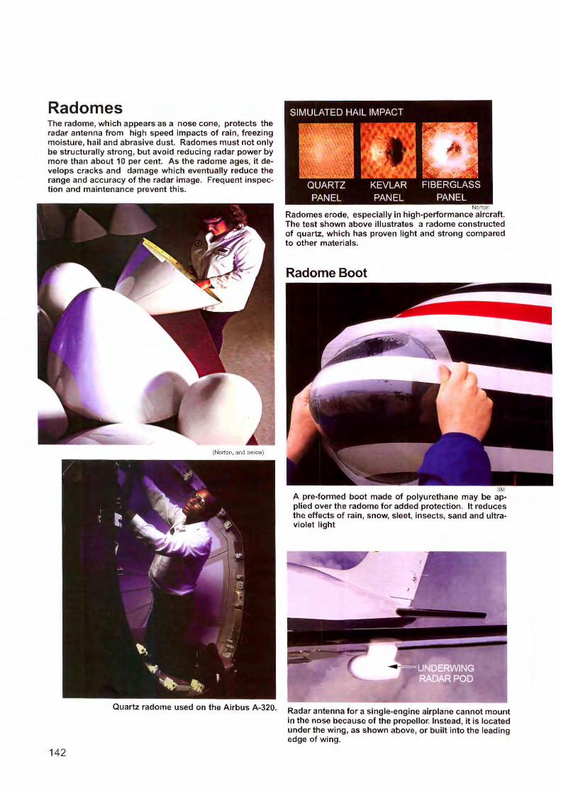
Radomes The radome, which appears as a nose cone, protects the radar antenna from high speed impacts of rain, freezing moisture, hail and abrasive dust. Radomes must not only be structurally strong, but avoid reducing radar power by more than about 10 per cent. As the radome ages, it develops cracks and damage which eventually reduce the range and accuracy of the radar image. Frequent inspection and maintenance prevent this.
(Norton, and below)
Quartz radome used on the Airbus A-320.
142
Norton
Radomes erode, especially in high-performance aircraft. The test shown above illustrates a radome constructed of quartz, which has proven light and strong compared to other materials.
Radome Boot
3M A pre-formed boot made of polyurethane may be applied over the radome for added protection. It reduces the effects of rain, snow, sleet, insects, sand and ultraviolet light
Radar antenna for a single-engine airplane cannot mount in the nose because of the propellor. Instead, it is located under the wing, as shown above, or built into the leading edge of wing.
Wind shear
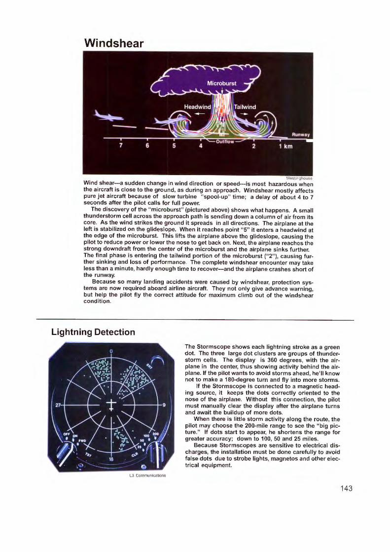
Westinghouse Wind shear---a sudden change in wind direction or speed---is most hazardous when the aircraft is close to the ground, as during an approach. Windshear mostly affects pure jet aircraft because of slow turbine "spool-up" time; a delay of about 4 to 7 seconds after the pilot calls for full power.
The discovery of the "microburst" (pictured above) shows what happens. A small thunderstorm cell across the approach path is sending down a column of air from its core. As the wind strikes the ground it spreads in all directions. The airplane at the left is stabilized on the glideslope. When it reaches point "5" it enters a headwind at the edge of the microburst. This lifts the airplane above the glideslope, causing the pilot to reduce power or lower the nose to get back on. Next, the airplane reaches the strong downdraft from the center of the microburst and the airplane sinks further. The final phase is entering the tailwind portion of the microburst (" 2" ), causing further sinking and loss of performance. The complete windshear encounter may take less than a minute, hardly enough time to recover---and the airplane crashes short of the runway.
Because so many landing accidents were caused by windshear, protection systems are now required aboard airline aircraft. They not only give advance warning, but help the pilot fly the correct attitude for maximum climb out of the windshear condition.
Lightning Detection
L3 Communications
The Stormscope shows each lightning stroke as a green dot. The three large dot clusters are groups of thunderstorm cells. The display is 360 degrees, with the airplane in the center, thus showing activity behind the airplane. If the pilot wants to avoid storms ahead, he'll know not to make a 180-degree turn and fly into more storms.
If the Stormscope is connected to a magnetic heading source, it keeps the dots correctly oriented to the nose of the airplane. Without this connection, the pilot must manually clear the display after the airplane turns and await the buildup of more dots.
When there is little storm activity along the route, the pilot may choose the 200-mile range to see the " big picture." If dots start to appear, he shortens the range for greater accuracy; down to 100, 50 and 25 miles.
Because Stormscopes are sensitive to electrical discharges, the installation must be done carefully to avoid false dots due to strobe lights, magnetos and other electrical equipment.
143
Windshear Computer r-- ------ ------,
1
1
,!-g~L (VERT t--L--- ~ - ·.,::11:-NOAM ACCEL
ACCEL) I ACCEL (NOAM COMPUTER I
(PITCH) ACCEL) ATTITUDE
REFERENCE SOURCE
(ROLL) (LONG I ACCEL)
VALID WINDSHEAR
I AURAL WARNING
"WINDSHEAR" P1TOT
STATIC SOURCE
PITOT STATIC SENSOflS
AIR (AIRSPEED) DETECTION ~ DATA
COMPUTER
AND
GUIDANCE
(ALPHA) COMPUTER
(FLAPS)
I I I I ATTITUDE DIRECTOR INDICATOR
PITCH/ROLL GUIDANCE
VALIDS
1 ALPHA I I DrnAOON
I I _ ____________ _ _ _ _J
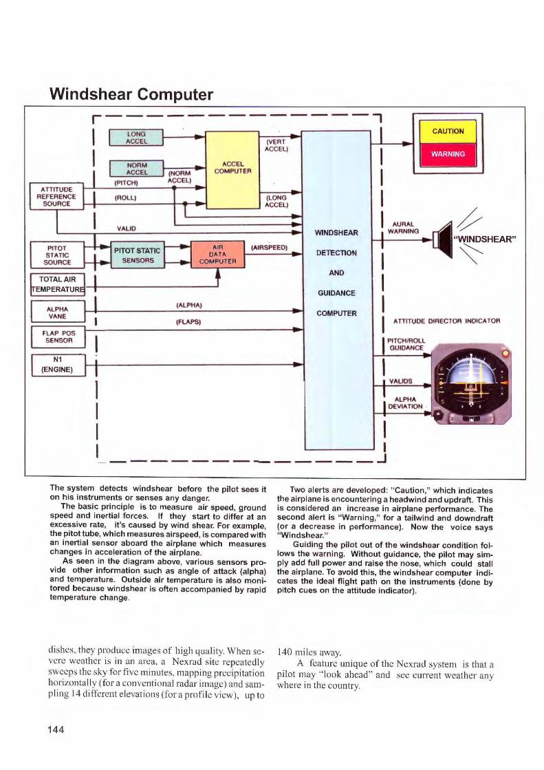
The system detects windshear before the pilot sees it on his instruments or senses any danger.
The basic principle is to measure air speed, ground speed and inertial forces. If they start to d iffer at an excessive rate, it's caused by wind shear. For example, the pitot tube, which measures airspeed, is compared with an inertial sensor aboard the airplane which measures changes in acceleration of the airplane.
As seen in the diagram above, various sensors provide other information such as angle of attack (alpha) and t emperature. Outside air temperature is also monitored because windshear is often accompanied by rapid temperature change.
dishes, they produce images of high quali ty. When severe weather is in an area, a Nexrad site repeatedly sweeps the sky for fi ve minutes, mapping precipi tat ion horizontally (for a con ventional radar image) and samp ling J 4 different e levations (for a profi le view), up to
144
Two alerts are developed: " Caution ," which indicates the airplane is encountering a headwind and updraft. This is considered an increase in airplane performance. The second alert is " Warning," for a tailwind and downdraft (or a decrease in performance). Now the voice says "Windshear."
Guiding the pilot out of the windshear condition follows the warning. Without guidance, the pilot may simply add full power and raise the nose, which could stall the airplane. To avoid th is, the windshear computer indicates the ideal flight path on the instruments (done by pitch cues on the attitude indicator).
140 mi les away. A feature un ique of the Nexrad system is that a
pi lot may " look ahead" and see current weather any where in the country.
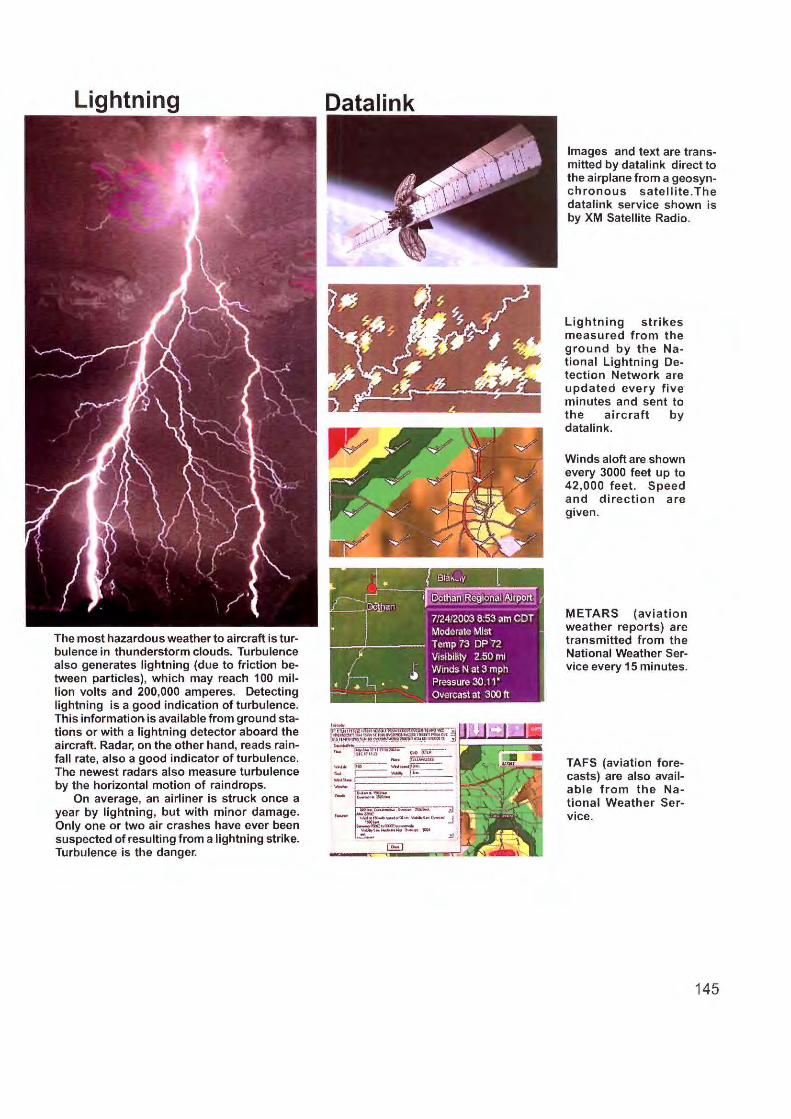
The most hazardous weather to aircraft is turbulence in thunderstorm clouds. Turbulence also generates lightning (due to friction between particles), which may reach 100 million volts and 200,000 amperes. Detecting lightning is a good indication of turbulence. This information, is available from ground stations or with a lightning detector aboard the aircraft. Radar, on the other hand, reads rainfall rate, also a good indicator of turbulence. The newest radars also measure turbulence by the horizontal motion of raindrops.
On average, an airliner is struck once a year by l ightning, but with minor damage. Only one or two air crashes have ever been suspected of resulting from a lightning strike. Turbulence is the danger.
Datalink
--I---------- ;..,,,,=~----I ... _.;,,, .. ~ ..........
-
Images and text are transmitted by datalink direct to the airplane from a geosynchronous satellite.The datalink service shown is by XM Satellite Radio.
Lightning strikes measured from the ground by the National Lightning Detection Network are updated every five minutes and sent to the aircraft by datalink.
Winds aloft are shown every 3000 feet up to 42 ,000 feet . Speed and direction are given.
METARS (aviation weather reports) are transmitted from the National Weather Service every 15 minutes.
TAFS (aviation forecasts) are also available from the National Weather Service.
145
Review Questions Chapter 19 Weather Detection
l 9.1 What is the greatest threat of a thunderstorm to an ai rcraft'?
19.2 On a weather radar display, what color indicates maximum hazard to an aircraft?
19.3 Weather radar detects storms by transmitting ____ of radio energy and measuring their echoes from water droplets.
19.4 Detecting turbulence in a storm is done by measuring echoes from the movement of water droplets.
19.5 What is the normal use of the tilt control?
19.6 What raises and lowers the radar antenna in a vertical direction for tilt control'?
l9.7What causes the radar antenna to scan left and right (horizontal motion)?
19.8 How is the radar antenna stabilized as the airplane maneuvers through pitch and roll?
146
19.9 What is a typical frequency for an airborne weather radar?
l 9.10 Lightning detection systems are usually tuned to a frequency of __ _
19.11 What is the most recent method for delivering weather images to the cockpit?
19. l 2 What is the purpose of a radome?
19.13. Radomes must reduce radar power by no more than about ___ _
19.14 W.ind shear is a sudden change in wind ____ and is most dangerous near the ___ _
19.15 A dangerous form of windshear, which oc-curs over a small area, is known as a ___ _
19.16 Windshear detection systems warn the pilot and also provide _ _ _ __ _
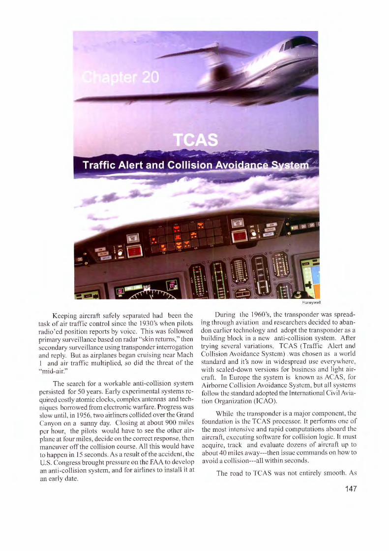
Keeping aircraft safely separated had been the task of ai r traffic control s ince the \ 930's when pi lots radio'ed pos ition reports by voice. Thi s was followed primary survei Ila nee based on radar "skin returns," then secondary surveillance using transponder inte rrogation and reply. But as airplanes began cruis ing near Mach J and air traffic multiplied, so did the threat of the "mid-air."
The search for a workable anti-collision system persisted fo r 50 years. Earl y experimental systems required costly atomic clocks, complex antennas and techniques borrowed from electronic warfare. Progress was slow until, in 1956, two airliners collided over the Grand Canyon on a sunny day. C losing at about 900 miles per hour, the pilots would have to see the other a irplane at four miles, decide on the correct response, then maneuver off the co llision course. A II this wou ld have to happen in 15 seconds. As a resul t of the acc ident, the U.S . Congress brought pressure on the FAA to develop an anti-colli sion system, and for airlines to install it at an early date.
Honeywell
During the I 960's, the transponder was spreading through av iation and researchers decided to abandon earlier technology and adopt the transponder as a building block in a new anti-collision system. After trying several variat ions, TCAS (Tra ffic Alert and Co llisio n Avo idance System) . was chosen as a wor ld standard and it 's now in w idespread use everywhere, with sca led-down vers ions for bus iness and li ght aircraft. Tn Europe the system is known as ACAS, for Airborne Collision Avo idance System, but al l systems follow the standard adopted the International Civ il Aviation Organizat ion (TCAO).
While the transponder is a major component, the foundation is the TCAS processor. Lt performs one of the most intensi ve and rapid computations aboard the a irc raft, executing software fo r coll is ion logic. It must acquire, track and evaluate dozens of a ircraft up to about 40 mi les away---then issue commands on how to avoid a colli sion---a ll within seconds.
The road to TCAS was not entirely smooth. As
147
TCAS Symbols on a Radar Display
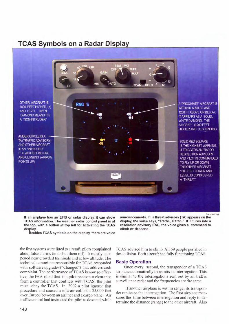
If an airplane has an EFIS or radar display, it can show TCAS information. The weather radar control panel is at the top, with a button at top left for activating the TCAS display.
Besides TCAS symbols on the display, there are voice
the fi rst ystems were fitted to aircraft, pi lots complained about fa lse alarms (and shut them off). Lt mostly happened near crowded terminals and at low altitude. The technical committee responsible fo r TCAS responded with soft ware upgrades ("Changes") that address each complaint. The performance of TCJ\S is now so efTective, the FAJ\ ruled that if a pi lot receives a clearance from a controller that conflicts with TCAS, the pi lot must obey the TCAS. In 2002 a pi lot ignored that procedure and caused a mid-air collision 35,000 feet over Europe between an airli ner and a cargo plane. Ai r traffic control had instructed the pilot to de cend, while
148
Bendix-King
announcements. If a threat advisory (TA) appears on the display, the voice says, "Traffic, Traffic." If it turns into a resolution advisory (RA), the voice gives a command to climb or descend.
TCAS advised him to climb. All 69 people perished in the collision. Both aircraft had fully functioni ng TCAS.
Basic Operation Once every second, the transponder of a TCAS
airplane automatically transmits an interrogation. This is simi lar to the interrogations sent out by air traffi c surve illance radar and the frequencies arc the same.
If another airplane is within range, its transponder replies to the interrogation. The first airplane measures the time between interrogation and reply to determine the distance (range) to the other aircraft. Also
received is the a ltitude of the other aircraft, which is encoded in the transponder reply (mode C). If the other aircraft has a Mode S transponder, its address is a lso sent. Directional antennas aboard the interrogating a irplane determine the bearing (direction) to the threat aircraft.
Because TCAS exchanges data between a irplanes, it does not require ground stations. Thus, it can operate where there is no radar coverage, such as ocea nic flight and over remote areas.
Once the TCAS processor acquires information about the other aircraft, it looks at the potentia l for a colli sion. A major factor is "range rate," which tells the rate at which distance is changing between the two aircraft. lfthat change is constant, the two aircraft are
on a colli s ion course. This is s imilar to what happens if a pilot looks out and sees another a irplane that appears stationary in the sky. lt means the two airplanes are converging. TCAS detects such threats long before they are visible to the pi lot.
Tau Airplanes differ g reatly in speed and performance
and TCAS must work with them all. This is done through a concept known as "tau" (the Greek letter) to adjust warnings to the actua l sit uation. By measuring distance and closing rate to the target, TCAS mi ght issue the first warning 40 seconds before a potential collision and a second one 25 seconds before. TCAS adjusts warning times according to a ircraft speeds.
Vertlcal Speed Indicator Adapted for TCAS
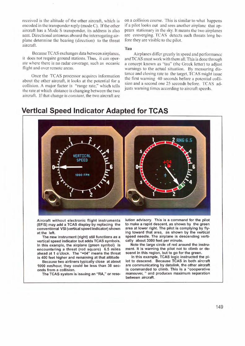
Aircraft without electronic flight instruments (EFIS) may add a TCAS display by replacing the conventional VSI (vertical speed indicator) shown at the left.
The new instrument (right) still functions as a vertical speed indicator but adds TCAS symbols. In this example, the airplane (green symbol) is encountering a threat (red square) 6.5 miles ahead at 1 o'clock. The "+04" means the threat is 400 feet higher and remaining at that altitude
Because two airliners typically close at about 1000 nm/hour, they could be less than 30 seconds from a collision.
The TCAS system is issuing an "RA," or reso-
lution advisory. This is a command for the pilot to make a rapid descent, as shown by the green area at lower right. The pilot is complying by flying toward that area, as shown by the vertical speed needle. The airplane is descending vertically about 3000 feet per minute.
Note the large circle of red around the instrument. It is warning the pilot not to climb or descend in this region, but to go for the green.
In this example, TCAS logic instructed the pilot to descend. Because TCAS in both aircraft are communicating by datalink, the other aircraft is commanded to climb. This is a " cooperative maneuver, " and produces maximum separation between aircraft.
149
TCAS System
CONTROL -PANEL
,
T p 0 E NNA ANT
r I TOP
DIRECTIONAL ANTENNA
TA/RA TAIRA DISPLAY DISPLAY
+ + r I MOOE S
- TCAS
I TRANSPONDER COMPUTER
/ ·------· - UNIT
OPTIONAL DUAL MOOE S TRANSPONDER
I
I I I
< I
)
OPTIONAL BOTTOM
DIRECTIONAL ATENNA
BOTTOM ANTENNA
BOTTOM OMNIDIRECTIONAL
ANTENNA
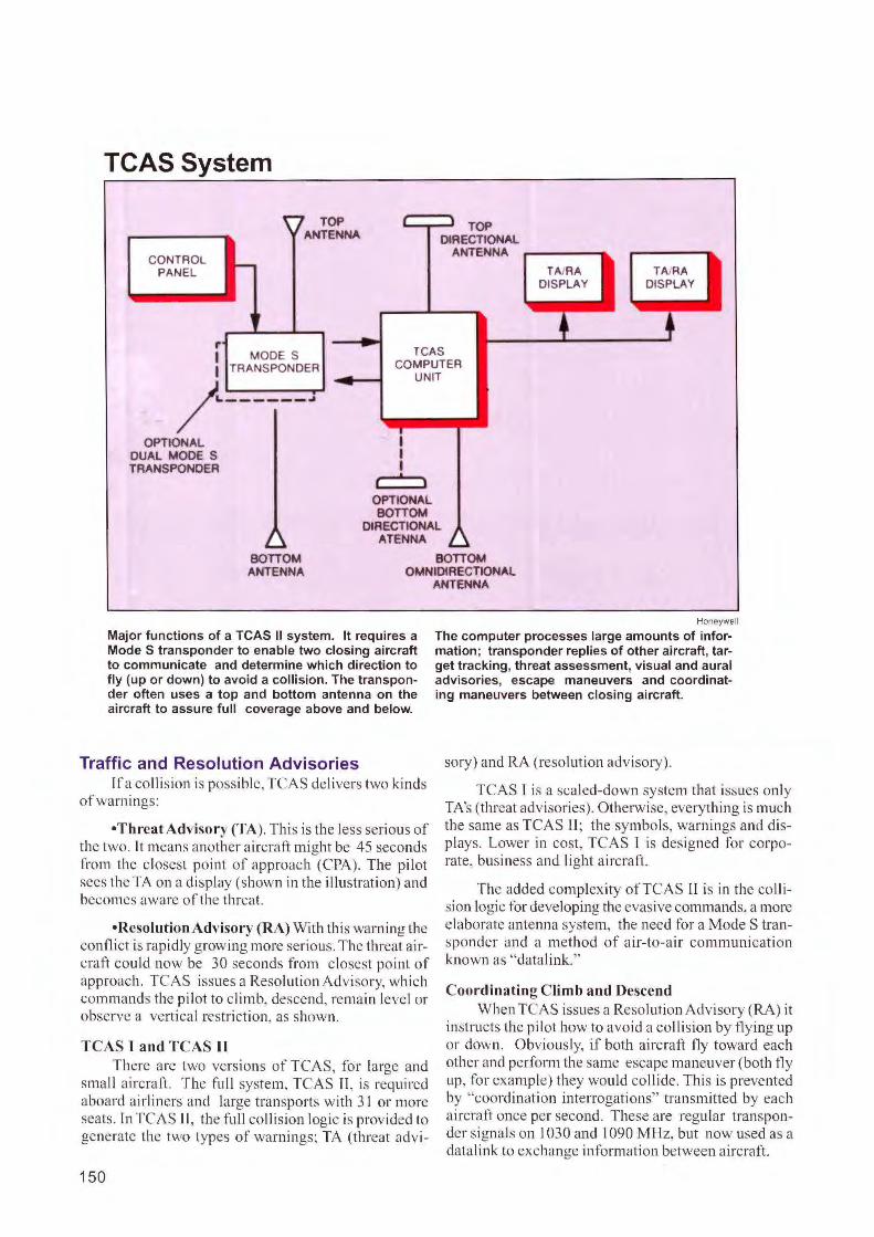
Major functions of a TCAS II system. It requires a Mode S transponder to enable two closing aircraft to communicate and determine which direction to fly (up or down) to avoid a collision. The transponder often uses a top and bottom antenna on the ai rcraft to assure full coverage above and below.
Traffic and Resolution Advisories If a coll is ion is possible, TCAS delivers two kinds
of warnings:
•Threat Advisory (TA). This is the less serious of the two. It means another aircraft might be 45 seconds from the c losest po int of approach (CPA ). The pilot sees the TA on a display (shown in the illustration) and becomes aware of the threat.
•Resolution Advisory (RA) With this warning the confl ict is rapidly growing more serious. The threat a ircraft could now be 30 seconds from closest point of approach. TCAS issues a Resolution Advisory, whic h commands the pilot to climb, descend , remai n level or observe a vert ica l restriction, as shown.
TCAS I and TCAS II There are two versions of TCAS, for large and
small a ircraft. The full system, TCAS fl, is required aboard ai rl iners and la rge transports with 3 1 or more seats. In TCAS Ir, the fu ll co llision logic is provided to generate the two types of warn ings; TA (threat advi-
150
Honeywell
The computer processes large amounts of information; transponder replies of other aircraft, target tracking, threat assessment, visual and aural advisories, escape maneuvers and coordinating maneuvers between closing aircraft.
sory) and RA (resolution advisory).
TCAS l is a sca led-down system that issues only TA's (threat advisories). Otherwise, everything is much the same as TCAS II ; the symbols, warn ings and displays. Lower in cost, TCAS I is designed for corporate, business and light a ircraft.
The added complexity ofTCAS 11 is in the collision logic for developing the evasive commands, a more e laborate antenna system, the need fo r a Mode S transponder and a method of a ir-to-air communication known as "datali nk."
Coordi nating Climb and Descend When TCAS issues a Resol ution Adv isory (RA) it
instructs the pil ot how to avo id a coll is ion by fly ing up or down. Obviously, if both a ircraft fly toward each other and perform the same escape maneuver (both fly up, fo r example) they would collide . This is prevented by "coordination interrogations" transmitted by each aircraft once per second. These are regular transponder signals on 1030 and I 090 M Hz, but now used as a data li nk to exchange informat ion between aircraft.
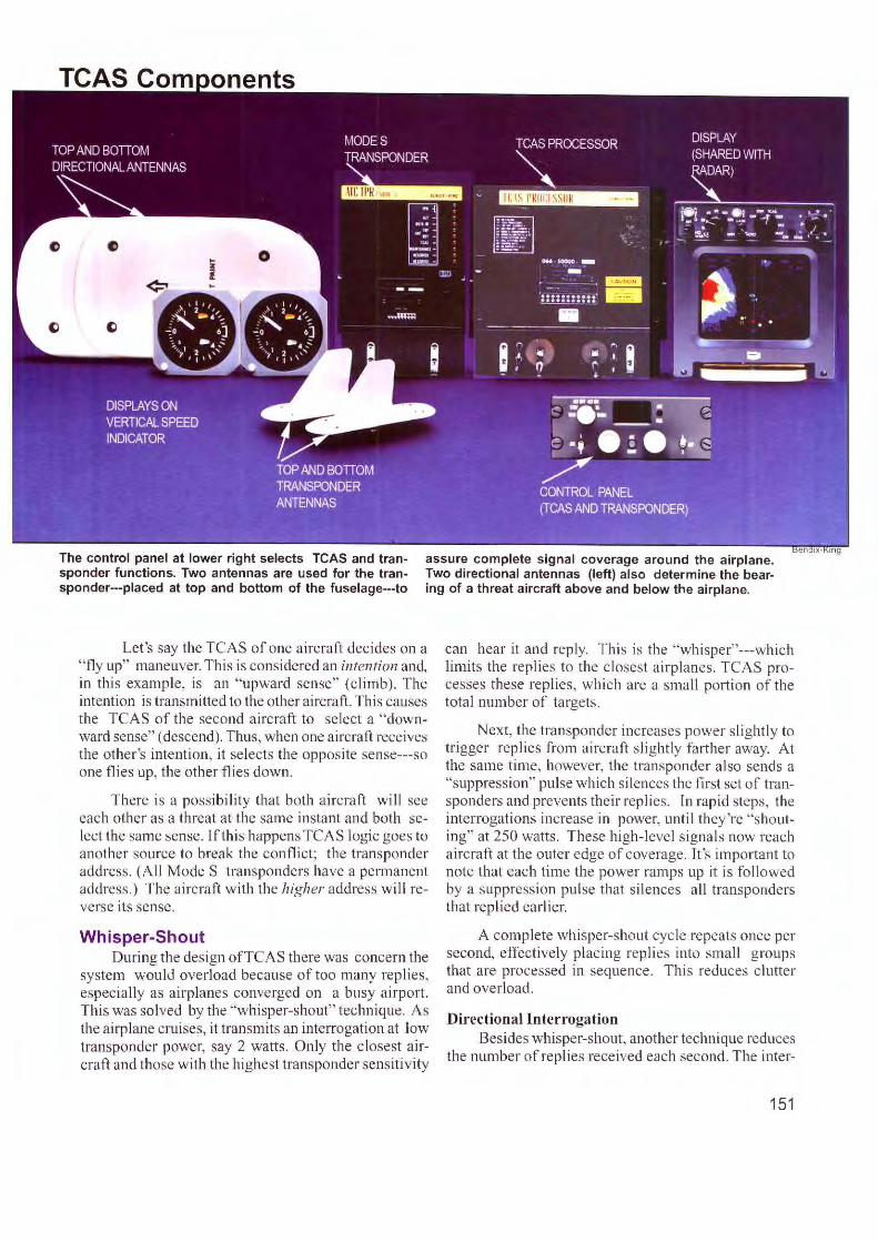
The control panel at lower right selects TCAS and transponder functions. Two antennas are used for the transponder---placed at top and bottom of the fuselage---to
assure complete signal coverage around the airplane. Two directional antennas (left) also determine the bearing of a threat aircraft above and below the airplane.
Let's say the TCAS of one aircraft decides on a "fly up" maneuver. This is considered an intention and, in this example, is an " upward sense" (cli mb). The intention is transmitted to the other aircraft. This causes the TCAS of the second aircraft to select a "downward sense" ( descend). Thus, when one aircraft receives the other 's intention, it selects the oppos ite sense---so one flies up, the other flies down.
There is a possibility that both aircraft will see each other as a threat at the same instant and both select the same sense. lf thi s happens TCAS logic goes to another source to break the conflict; the transponder address. (A ll Mode S transponders have a permanent address .) The aircraft w ith the higher address will reverse its sense.
Whisper-Shout During the design ofTCAS there was concern the
system would overload because of too many replies, especially as airplanes converged on a busy airport. This was solved by the "whisper-shout" technique. As the airplane cruises, it transmits an interrogation at low transponder power, say 2 watts. Only the c losest aircraft and those with the highest transponder sensiti vity
can hear it and reply. This is the "whi sper"---which limits the replies to the closest a irplanes. TCAS processes these replies, which are a small portion of the tota l number of targets.
Next, the tran sponder increases power s lightly to trigger rep li es from aircraft sli ghtly farther away. At the sa me time, however, the transponder a lso sends a "suppression" pul se which silences the fi rst set of transponders and prevents their replies. In rapid steps, the interrogati ons increase in power, until they're "shouting" at 250 watts. These high-level s ignals now reach aircraft at the outer edge of coverage. [t 's important to note that each time the power ramps up it is followed by a suppression pul se that silences a ll transponders that replied earlier.
A complete whisper-shout cycle repeats once per second, effect ively plac ing repli es into small groups that are processed in sequence. Thi s reduces clutter and overl oad .
Directional Interrogation Besides whisper-shout, another technique reduces
the number of replies received each second. The inter-
151
rogations arc transmitted through a directional anten11a which electronically rotates 90 degrees at a time. This covers a full circ le in four quadrants and limits replies to the active quadrant.
Non-TCAS Air·planes The system can a lso recognize aircraft that are not
ca rrying TCAS or Mode S transponders. Such aircraft typically have the earl ier ATCRBS transponder. A TCAS-equipped aircraft, however, interrogates these aircraft and computes information requi red to di splay a threat advisory (TA). There can be no cooperative maneuvering because thi s requires Mode S transponders on both aircraft, as well as a TCAS system.
TCAS IU TCAS 11 commands the pilot only in th e vertical
direction, wh ich is suffic ient to avoid a collision. The industry had started work on TCAS Ill , to add commands in the horizontal direction (fly left, fly right) but it never was completed . The problems of issuing both vertical and horizontal maneuvers proved extremely difficult. Maneuvering in two dimensions s imulta-
ncously multiplies the chances for aircraft to create new collision courses with second and third a irplanes as they avoid the first one. Before these problems were so lved, TCAS III was abandoned as new systems began to examine the coll ision threat.
A new global a ir traffic system is emerging wi th co llision avoidance based on GPS and sate llites. It is ADS-B---automatic dependent surveil lance-broadcast. As aircraft crui se they "squit ter" (automaticall y transmit) their position based on GPS. That information is picked up by nearby aircraft for co ll ision avoidance and also relayed via satell ite to air tra ffic con trol for managing traffic.
Yet another system began during 2004. Known as TIS, Traffic Information Service, it broadcasts the targets shown on all survei llance radars on the ground. The images are downlinked via satell ite to aircraft, which display traffic, as done with TCAS.
TCAS, however, will be operationa l for many generations. ft is stil l unequalled as the tactical coll ision avoidance system anywhere on earth.
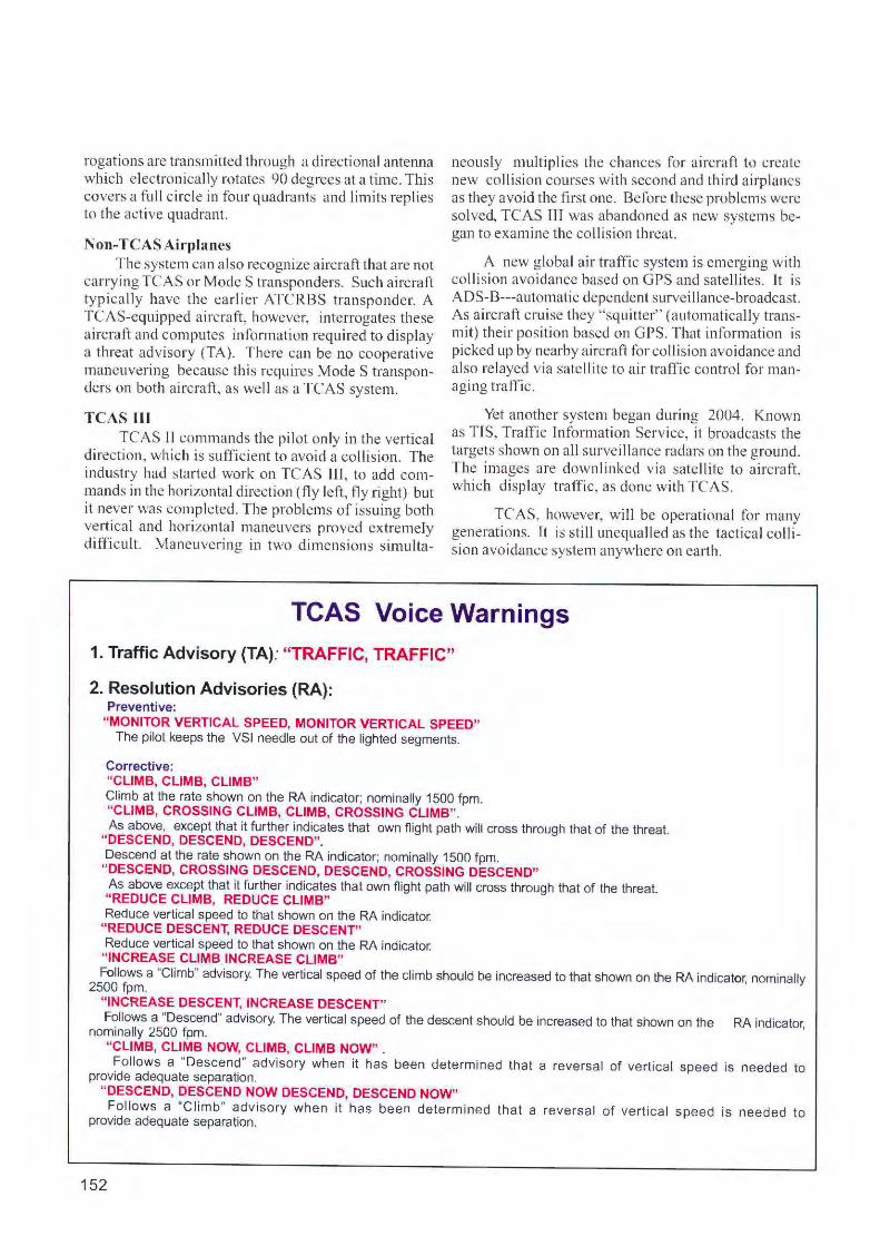
TCAS Voice Warnings 1. Traffic Advisory (TA): "TRAFFIC, TRAFFIC"
2. Resolution Advisories (RA): Preventive:
"MONITOR VERTICAL SPEED, MONITOR VERTICAL SPEED" The pilot keeps the VSI needle out of the lighted segments.
Corrective: "CLIMB, CLIMB, CLIMB" Climb at the rate shown on the RA indicator; nominally 1500 fpm. "CLIMB, CROSSING CLIMB, CLIMB, CROSSING CLIMB". As above, except that it fu rther indicates that own flight path will cross through that of the threat.
"DESCEND, DESCEND, DESCEND~ Descend at the rate shown on the RA indicator; nominally 1500 fpm.
"DESCEND, CROSSING DESCEND, DESCEND, CROSSING DESCEND" As above except that it further indicates that own flight path will cross through that of the threat. "REDUCE CLIMB, REDUCE CLIMB" Reduce vertical speed to that shown on the RA indicator.
"REDUCE DESCENT, REDUCE DESCENT" Reduce vertical speed to that shown on the RA indicator. "INCREASE CLIMB INCREASE CLIMB" Follows a "Climb" advisory. The vertical speed of the climb should be increased to that shown on the RA indicator; nominally
2500 fpm. "INCREASE DESCENT, INCREASE DESCENT" Follows a "Descend" advisory. The vertical speed of the descent should be increased to that shown on the RA indicator,
nominally 2500 fpm. "CLIMB, CLIMB NOW, CLIMB, CLIMB NOW" . Follows a "Descend" advisory when it has been determined that a reversal of vertical speed is needed to
provide adequate separation. "DESCEND, OESCEND NOW DESCEND, DESCEND NOW" Follows a "C li mb" advisory when it ha s been determined that a reversa l of vertica l speed is needed to
provide adequate separation .
152

Review Questions Chapter 20 TCAS (Traffic Alert and Collision Avoidance System)
20.1 A TCAS aircraft transmits an interrogation once per _ _ _
20.2 How does an intruder aircraft with an ATCRBS (early type) transponder reply to TCAS interrogations?
20.3 How does an intruder aircraft with a Mode S transponder reply to TCAS interrogation s?
20.4 How does TCAS determine the direction of a threat?
20.5 How does TCAS determine the distance of a threat?
20.6 How does TCAS determine whether the other aircraft is a threat?
20.7 What is the concept of "Tau".
20.8 Name the two kinds of warnings issued by TCAS.
20.9 Does a Threat Advisory (TA) command the pilot to maneuver out of the way?
20.10 What does an Resolution Authority (RA) do '?
20.11 If two TCAS aircraft are closing, what prevents them from climbing, and tlying into each other?
20.12 What is the technique of "whisper-shout"?
20.13 How does the directional antenna reduce the number of replies for each interrogation?
153

Chapter 21
Planning the Installation
Insta llat ions vary, from wiring a headset j ack to rebuilding an instrument panel. No matter how extensive, it must fo llow rules of "a irworthiness"---guidance by a c ivil aviation authority such the FAA in the US or a CAA in other countr ies.
Observe the TC. For major rebuilding of an instrument panel, there is an overriding rule about where you can place equipment. Cert({,ed airpl anes---those bu ilt in a factory and sold ready to tly---must obta in a TC, or Type Cert ificate . The TC shows a ll equipment delivered with the airp lane. Such equipment may not be moved to other locations on the panel without
FUEL QUANTITY
(FLOAT)
Instrument panel of the original Piper Cub, which received its Type Certificate in 1931. Today, the same instruments are still required for "day VFR" flying. More airplanes, however, show the same information on an electronic display, as seen on the next page.
154
violating the TC. They may be repl aced with equivalent units, but not sh ifted around . This does not prevent add ing new eq uipment to the panel, or minor re location of radios in a center stack, for example. These alte rati ons will be noted on fo rms subm itted fo r approval to the governmen t agency.
The pilot/owner handbook or flight manua l typically lists the equipment installed under the Type Certi ficate.
STC. When adding systems to a fac tory-b ui lt a irp lane, using equipment critical to tli ght, this is usua lly done under an STC, or Supplemental Type Certificate. Th e manufacturer of the new system proved its a irworthiness to obta in the STC. Examples include autopilots, displays and fuel management systems . For such insta llati on, you will work from drawings prepared by the STC-holdcr showing precisely where and how components mount.
STC's can be compared to a patent; they are owned exclusively by the des igner and protected by law. Often, the STC is offered for sa le to avion ics shops, along with the system and an installation k it. ln cases where a manufacturer is sell ing a maj or system, such as an autopilot, he often al lows the buyer to use the STC at no ext ra cost.
For large a ircraft, expect more support from the avionics manufacturer. Tf a flee t of 30 a ir transpo11s will be upgraded with a collis ion avoidance system, chances are a fie ld representative from the manufacture r will assis t in early insta llations .
Non-certified airplanes. There is a wide range of a ircraft operating in the "Experimental" category, which includes kit-b uil t, built- from-plans, antiques, warbirds
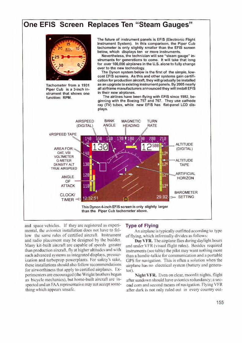
One EFIS Screen Replaces Ten "Steam Gauges"
Tachometer from a 1931 Piper Cub is a 3-inch instrument that shows one function: RPM.
AREA FOR:
AIRSPEED (DIGITAL)
OAT, VSI VOLTMETER
G-METER DENSITY ALT
TRUE AIRSPEED
The future of instrument panels is EFIS (Electronic Flight Instrument System). In this comparison, the Piper Cub tachometer is only slightly smaller than the EFIS screen below, which displays ten or more instruments.
Nevertheless, the technician will see " steam gauge" instruments for generations to come. It will take that long for over 100,000 airplanes in the U.S. alone to fully change over to the new technology.
The Dynon system below is the first of the simple, lowcost EFIS screens. As this and other systems gain certification for production aircraft, they will gradually be installed as an upgrade to existing instrument panels. By 2005 nearly all airframe manufacturers announced they will install EFIS in their new airplanes.
The airlines have been flying with EFIS since 1982, beginning with the Boeing 757 and 767. They use cathode ray (TV) tubes, while new EFIS has flat-panel LCD displays.
BANK ANGLE
MAGNETIC HEADING
TURN RATE
l--""11-= ALTITUDE (DIGITAL)
ALTITUDE TAPE
ARTIFICIAL HORIZON
BAROMETER SETIING
This Dynon 4-inch EFIS screen is only slightly larger than the Piper Cub tachometer above.
Type of Flying and space vehic les . If they a re registered as experimental, the avionics insta llation does not have to fo llow the same rules of certified aircraft. Instrument and radio placement may be designed by the builder. Many kit-bui lt a ircraft are capable of speeds greater than production a ircraft, fl y at higher a lt itudes and with s uch advanced systems as integrated displays, pressurization and turboprop powerplants. For safety's sake, these insta llations should also fo llow recommendations for a irworthiness that apply to certified a irplanes. Experimenters are encouraged (the Wright brothers began as bicycle mechanics), but home-built a irc raft are inspected and an FAA representative may not accept something which appears unsafe.
An airplane is typically outfitted according to type o fflying, which informally di vides as fo llows:
Day VFR. The a irplane flies during daylight hours and under VFR (visual fli ght rules). Besides required instruments (see table ) the pilot may want nothi ng more than a handie-ta lkie for communication and a portable GPS for navigation. This is often a solutio n when the airplane has no e lectrical system (battery and generator).
NightVFR. Even on c lear, moonlit nights, flight after sundown should have avionics redundancy; a second com and second means of navigation. Flying VFR after dark is not only ruled out in every country out-
155
side the U.S., but the accident rate is ten times higher on dark, moonless nights. The pilot should be able to call for help ifhe inadvertently flies into a cloud at night or is lost with 110 backup navigation.
Light IFR. Many pilots obtain a rating to fl y under TFR (instrument flight rules), but rarely use it. But it is a great timesavcr when the obstacle is a low cloud layer only in the vicinity of the airport. The fFR rating is used only to fly fo r the few minutes it takes to climb above, or descend through, thin layers.
Low IFR. This is for the serious pi lot who needs to get through widespread areas of low visibility, then shoot an instrument landing to a runway under a low cei ling. This aircraft needs reliable, redundant avionics. Safety will greatly improve with a terrain avoid-
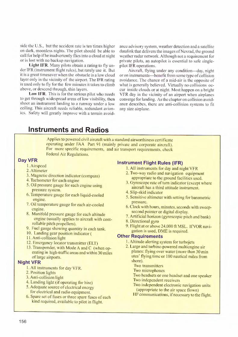
Instruments and Radios
ance advisory system, weather detection and a sate I li te datalink that delivers the images of Nexrad, the ground weather radar network. Although not a requirement for private pilots, an autopi lot is essential to safe s inglepilot IFR operations.
Aircraft, flying under any conditio11---day, nigh t or 011 instrume11ts---benefit from some type of co ll ision avo idance. The chance of a mid-air is the opposite of what is generally beli eved. Virtually no coll isions occur inside clouds or at night. Most happen on a bright VFR clay in the vicinity of an airport when airplanes converge for landing. As the chapter on collision avoidance describes, there are anti-coll is ion systems to fit any size airplane.
Applies to powered civil a ircraft with a standard airworthiness certificate operating under FAA Part 91 (ma inly private and corporate aircraft). For more specific requirements, and air transp011 requirements, check Federal Air Regulations.
Day VFR I. Ai rspeed 2. Altimeter 3. Magnetic direction indicator (compass) 4. Tachometer for each engine 5. Oil pressure gauge for each engine using
pressure system. 6. Temperature gauge for each liquid-cooled
engine. 7. Oil temperature gauge for each air-cooled
engine. 8. Manifold pressure gauge fo r each altitude
engine (usually applies to aircraft with cont-rollable pitch propellers).
9. fuel gauge showing quantity in each tank. I 0. Landing gear position indicator ( 11 . Anti-collision light 12. Emergency locator transmi tter (ELT) 13. Transponder, with Mode A and C (when op
erating in high-traffic areas and within 30 miles of large airports.
Night VFR I. All instruments for day VFR. 2. Position li ghts 3. Anti-collision light 4. Landing light (if operating for hire) 5. Adequate source of electri cal energy
for e lectri ca l and radio equipment.
156
6. Spare set of fuses or three spare fuses of each kind required, availab le to pilot in flight.
Instrument Flight Rules (IFR) 1. All instruments for day and night VFR 2. Two-way radio and navigation equipment
appropriate to the ground fac il it ies used. 3. Gyroscope rate of turn indicator (except where
aircraft has a third attitude instrument. 4. Slip-skid indicator 5. Sensitive altimeter with setting for barometric
pressure. 6. Clock with hours, minutes, seconds with sweep-
second pointer or digital display. 7. Artificial horizon (gyroscop ic pitch and bank) 8. Directional gyro 9. Flight at or above 24,000 ft MSL. lfVOR navi
gation is used, DME is required. Other Requirements
I . Altitude alerting system for turbojets 2. Large and turbine-powered multi engine air
planes: fl ying over water (more than 30 min utes' flying time or I 00 nautical miles from shore).
Two transmitters Two microphones Two headsets or one headset and one speaker Two independent receivers Two independent electronic navigation unjts
(appropriate to the air space flown) HF communications, if necessary to the flight.
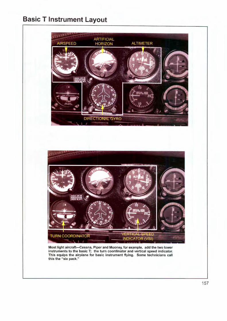
Basic T Instrument Layout
Most light aircraft---Cessna, Piper and Mooney, for example, add the two lower instruments to the basic T; the turn coordinator and vertical speed indicator. This equips the airplane for basic instrument flying. Some technicians call this the "six pack."
157
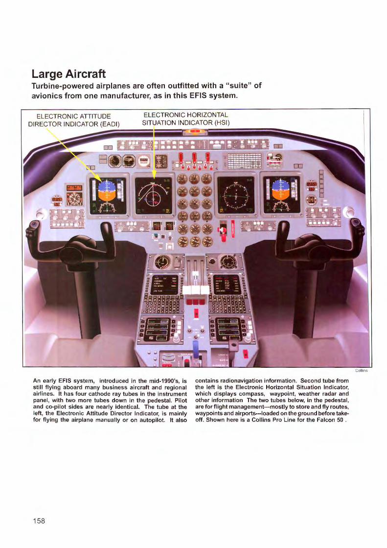
Large Ai re raft Turbine-powered airplanes are often outfitted with a "suite" of avionics from one manufacturer, as in this EFIS system.
ELECTRONIC ATTITUDE DIRECTOR INDICATOR (EADI)
ELECTRONIC HORIZONTAL SITUATION INDICATOR (HSI)
An early EFIS system, introduced in the mid-1990's, is still flying aboard many business aircraft and regional airlines. It has four cathode ray tubes in the instrument panel, with two more tubes down in the pedestal. Pilot and co-pilot sides are nearly identical. The tube at the left, the Electronic Attitude Director Indicator, is mainly for flying the airplane manually or on autopilot. It also
158
contains radionavigation information. Second tube from the left is the Electronic Horizontal Situation Indicator, which displays compass, waypoint, weather radar and other information The two tubes below, in the pedestal, are for flight management---mostly to store and fly routes, waypoints and airports-loaded on the ground before takeoff. Shown here is a Collins Pro Line for the Falcon 50 .
Collins
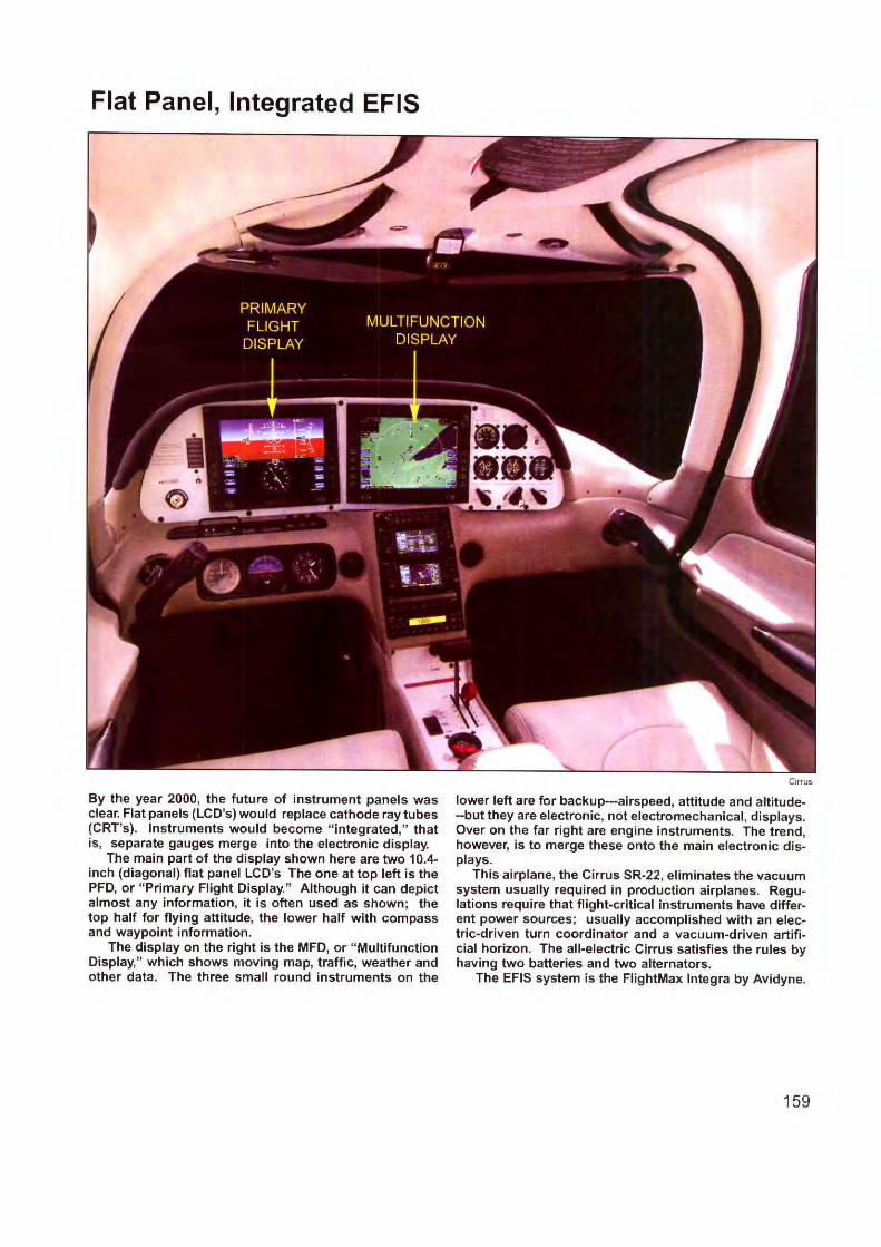
Flat Panel, Integrated EFIS
By the year 2000, the future of instrument panels was clear. Flat panels (LC D's) would replace cathode ray tubes (CRT's). Instruments would become " integrated," that is, separate gauges merge into the electronic display.
The main part of the display shown here are two 10.4-inch (diagonal) flat panel LCD's The one at top left is the PFD, or " Primary Flight Display." Although it can depict almost any information, it is often used as shown; the top half for flying attitude, the lower half with compass and waypoint information.
The display on the right is the MFD, or "Multifunction Display," which shows moving map, traffic, weather and other data. The three small round instruments on the
Ctrrus
lower left are for backup---airspeed, attitude and altitude··but they are electronic, not electromechanical, displays. Over on the far right are engine instruments. The trend, however, is to merge these onto the main electronic displays.
This airplane, the Cirrus SR-22, eliminates the vacuum system usually required in production airplanes. Regulations require that flight-critical instruments have different power sources; usually accomplished with an electric-driven turn coordinator and a vacuum-driven artificial horizon. The all-electric Cirrus satisfies the rules by having two batteries and two alternators.
The EFIS system is the FlightMax lntegra by Avidyne.
159

Typical Avionics Equippage
DAY VFR
BASIC IFR
IFR
The instrument and radio chart shown earlier covers only equipment required by law. Aircraft owners often add systems to reduce workload or improve safety.
COM PORTABLE OPS (or OPS/COM) TRA SPO DER ALTITUDE ENCODER I TERCOM
AUDIO PANEL, 3-LIGHT MB AND INTERCOM #I GPS/COM (VFR) #2 NAY/COM VOR/LOC INDICATOR TRANSPONDER ALTITUDE E CODER ADF
AUDIO PANEL, 3 LIGHT MB /\ND INTERCOM MOVING MAP/GPS (VFR) NAY/COM VOR/LOC/GLIDESLOPE I DICATOR GLI DESLOPE RECEIVER TRANSPON DER ALTITUDE ENCODER AUTOPILOT, I AX IS (RADIO TRACK. HEADNG) ENGINE MONITOR ADF
CORPORATE AIRCRAFT AUDIO PANEL. 3-LIGHT MB. INTERCOM MULTIFU CTIO DISPLAY / MOVI GMAP WEATH ER RADAR GPS (IFR) NAY/COM #I NAY/COM #2 HSI WITH SLAVED COMPASS SYSTEM VOR/LOC/GLIDESLOPE INDICATOR GLIDESLOPE RECEIVER TRANSPONDER # I TRANSPONDER #2 ALT ENCODER # I ALT E CODER #2 AUTOPILOT, 2 AXIS (TRCK, HEADING,
ALT HOLD) E GINE MO ITOR STORM SCOPE FLIGI IT TELEPHONE COLLISION AVOIDANCE TERRAi AVOIDA CE IN -FLIGHT ENTERTAINMENT ADF
T URBI NE AIRC RAFT AUDIO PANEL, 3-LIGHT MB. INTERCOM MULTI FU CTION DISPLAY / MOVING MAP RADAR INTERFACED TO MFD
FREQUENT !FR GPS (IFR) AUDIO PANEL 3-LIG HT MB. INTERCOM MULTIFUNCTION DISPLAY / MOVING MAP COM GPS (IFR) NAY/COM HSI WITH SLAVED COMPASS SYSTEM VOR/LOC/GLIDESLOPE INDICATOR GLIDESLOPE RECEIVER TRANSPONDER A LTITUDE ENCODER AUTOPILOT, 2 AXIS (TRK, HEADNG. ALT I IOLD) ENGINE MO ITOR STORMSCOPEAND/OR NEXRAD WX UPLINK FLIGHTTELEPHO E ENTER.TAI MENT SYSTEM ADF
NAY/COM #I NAY/COM #2 VOR/LOC/GLIDESLOPE INDICATOR GLIDESLOPE RECEIVER TRANSPO DER # 1. TRANSPONDER #2 ALTITUDE ENCODER # I and #2 HSI WITH COUPLED COMPASS SYSTEM FLIGHT DIRECTOR AUTOPILOT. 3 AX IS WITH YAW DAMPER ENGINE MONITOR STORM SCOPE INTERFACED TO MFD SATPHONE OR FLIGHT TELEPHONE COLLISION AVOIDANCE TAWS: TERRAIN AVOIDANCE IN-FLIGHT E TERTATNMENT SYSTEM EFIS OPTIO AL ADF I IF FOR TRANS-OCEA IC AIRCRAFT
Manuals and Diagrams The key to an in stallatio n is the manufacture r's
manual o n the specifi c model. Bes ides show ing where each wire connects, pictoria l drawings c lari fy difficult areas and g ive dimensions, power consumpti on and mounting hardware. There are schematic diagram s for troubl eshooting.
A manufacture r 's manual is also accepted by a government inspector (FAA, CAA) as "approved data." At some future time you may be questioned o n what you used for insta llati on guidance---and you can point to the manua l.
T here is no specia l format for manuals in General Aviation. In the a irlines, however, manuals are written according to an ATA (A ir Transport Association) "chapter." These documents include the "Component Maintenance M anual" and " lllustrated Paii s Cata log."
The section in the manual used much of the time is the " pin-out diagram," which shows how wires run among vario us connectors and units during an insta ll ation. Tt's also used for troubl eshooting late r on.
Obtaining Manuals There are several sources fo r insta llation manu
als . lf a maintenance shop is a dealer for an av ionics manufacturer, it 's usua lly required to have a library of
Installation Drawing
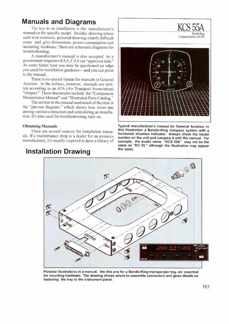
KCSSSA Bendix/King
Compass System with HSI
Typical manufacturer's manual for General Aviation, in this illustration a Bendix-King compass system with a horizontal situation indicator. Always check the model number on the unit and compare it with the manual. For example, the model name "KCS 55A" may not be the same as "KC 55," although the illustration may appear the same.
" " 1ui IPOR 1:n<lflOOJI a I $11.,,..-.. .. 1,1,f
Off
. - - - m .. , ..
Pictorial illustrations in a manual, like this one for a Bendix-King transponder tray, are essential for mounting hardware. The drawing shows where to assemble connectors and gives details on fastening the tray to the instrument panel.
161
manuals for the equipment it installs. These books a re purchased direct ly from the manufacturer.
Manuals are also available to members of " Resource One." This is an on-line service of the Aircraft E lectronics Associat io n (www.aea.net).
Manuals are sometimes avai lable from resellers who list them in av iation publications.
In some instances, manufacturers make their manuals avai lable on line at no charge.
Schematic (Circuit) Diagrams Manuals conta in schematics for troubleshooting
down to the circuit board level and are not often required for insta ll ation work. An installer follows pinout or interface diagrams like the examples shown on these pages. The schematic shows every resistor, capacitor, chip and other small component so ldered to printed circuits inside the radio enclosure. The schematic is more useful for troubleshooting on the shop bench with specia lized test equipment.
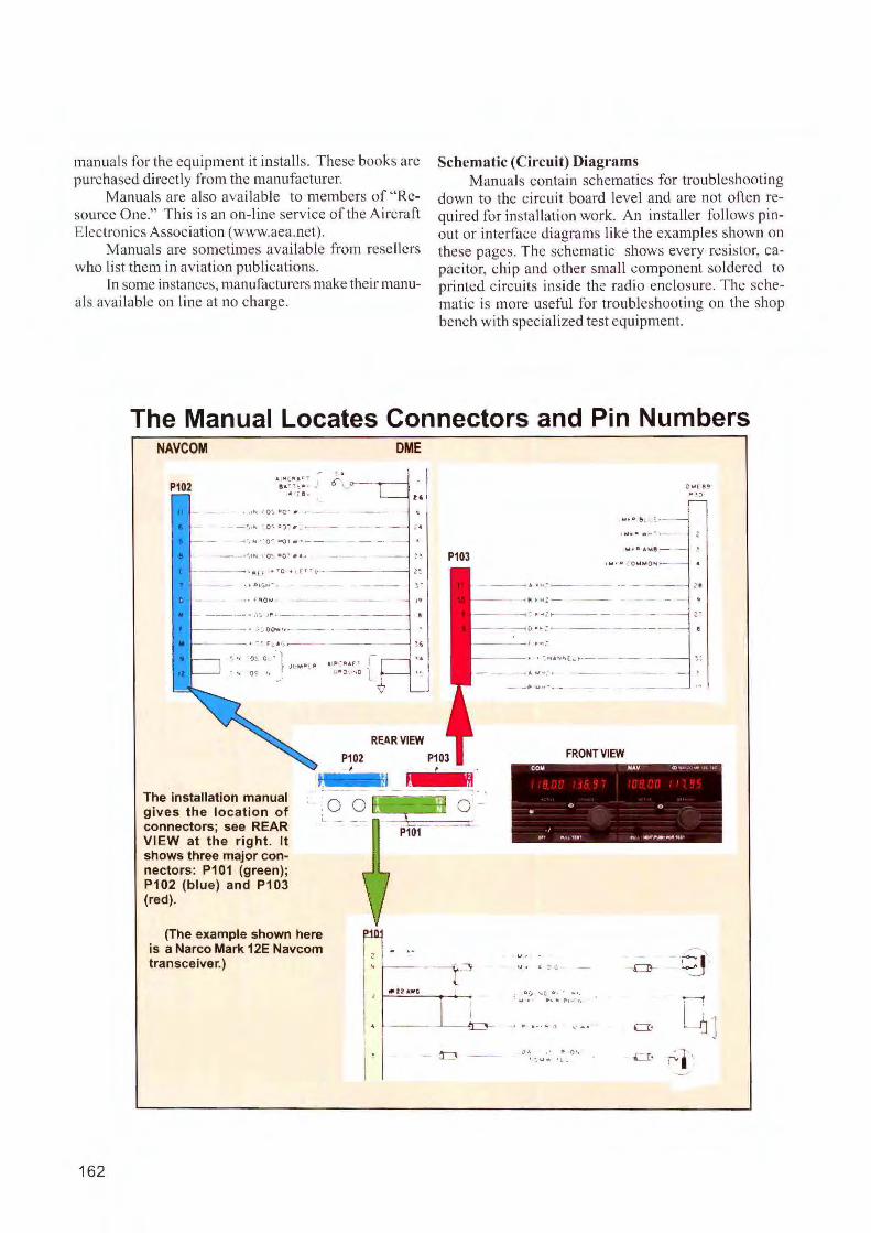
The Manual Locates Connectors and Pin Numbers
162
NAVCOM
P102
..
-• • jll a r .. u f · >: • · }
1• :-e .
.. o,<>---
':) .. o- , . - -
-•, .., O!:. •o- , · - -
DME
- ·'
a - ~ - ..... ,. o.:,.o· ~ .. .
, .o ., ... - --- .~., ~o ... -- -- ,.
,. ---~---- . - · .,. oo,,,,. •, -- - -- - .. -
... 0 ~ 0 - l, J1• ..i~1 " .t. lJl i* •d , _I-
.. o~ ·· ,•c. ,.o
RE.ARVIEW
P103
P102 P103 '
The installation manual gives the location of connectors; see REAR VIEW at the right. It shows three major connectors: P101 (green) ; P102 (blue) and P103 (red).
l - -
(The example shown here is a Narco Mark 12E Navcom transceiver. )
P101
t-----' ~
- •·1--:- - -
- .... Pl~ "':---<I( ~ ..... __ _
- · . -~ , ·j •, ( ~ -
......... -- ~ u ..... - -
FRONT VIEW
. . - .
COM NAV o .. , . ... JC •
C> .. . ~· ,v.,,... ... --00- fU
CD ~J g r., •, t • ._ .,
' r ... . .. \ \. A 4 CI· C1 ' J
CI· ..;,•
Pin Assi nments
0
01 140
02 150
03 160
04 170
0 5 180
06 190
0 7 200
08 2 1 0
0 9 22 0
010 23 0
011 240
012 250
013
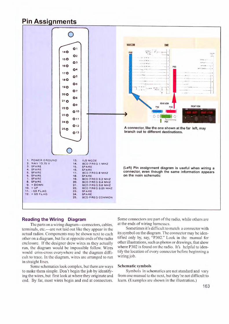
0 1 . PO W E R GFIOU N D 13 . ILS MODE 2 . N A V 13 .75 V 14, BC D F REQ 1 MH Z 3. SPA R E 15 . SPAR E 4 . SPA R E 1 6 . SPARE 5. SPAR E 17 . B C D FR EQ 8 MHZ 6 . SPAR E 18 . SPA RE 7 . SPARE 19 . BCD FREQ 0 .2 MHZ 8 . SPAR E 20. B CD FR EQ 0 .4 M H Z 9 . + DOW N 21. BCD FRE Q 0.8 M H Z
10. + UP 22. BCD FREQ 0.05 MHZ ,,. • GS FLAG 23. SF AR E 12. + G S FLAG 24 . SPA R E
25. BC D F RE Q C OMM ON
Reading the Wiring Diagram The part s on a wiring diagrarn---conncctors, cables,
terminals, etc.---are not laid out like they appear in the actual radios. Components may be shown next to each other on a diagram, but lie at opposite ends of the radio enclosure. lfthe designer drew w ires as they actually run, the diagram would be impossible follow. Wires would criss-cross everywhere and the d iagram difficult to trace. In the diagram, wires are arranged to run in stra ight lines.
Some schematics look complex, but there are ways to make them simple. Don't begin the job by identifying the wires, but fi rst look at where they originate and end . By fa r, most wires begin and end at connectors.
NAVCOM
P102
DME
P103
mRVlEW
PlOZ P103
~~·
00 ~ - .- P101 --~
FRONT VIEW (0",1 u , o , ~ •
• 0 •
A connector, like the one shown at the far left, may branch out to different destinations.
(Left) Pin assignment diagram is useful when wiring a connector, even though the same information appears on the main schematic
Some connectors are part of the radio, while others are at the ends of wiring ha rnesses.
Sometimes it's difficult to match a connector with its symbol on the d iagram. The connector may be identified only by, say, " P302." Look in the manua l for other illustrations, such as photos or drawings, that show where P302 is found on the radio. lt's helpfu l to identify the location o f every connector before beginning a wiring job.
Schematic symbols Symbo ls in schematics are not standard and vary
from one manual to the next, but they're not difficult to learn. (Examples are shown in the illustration.)
163
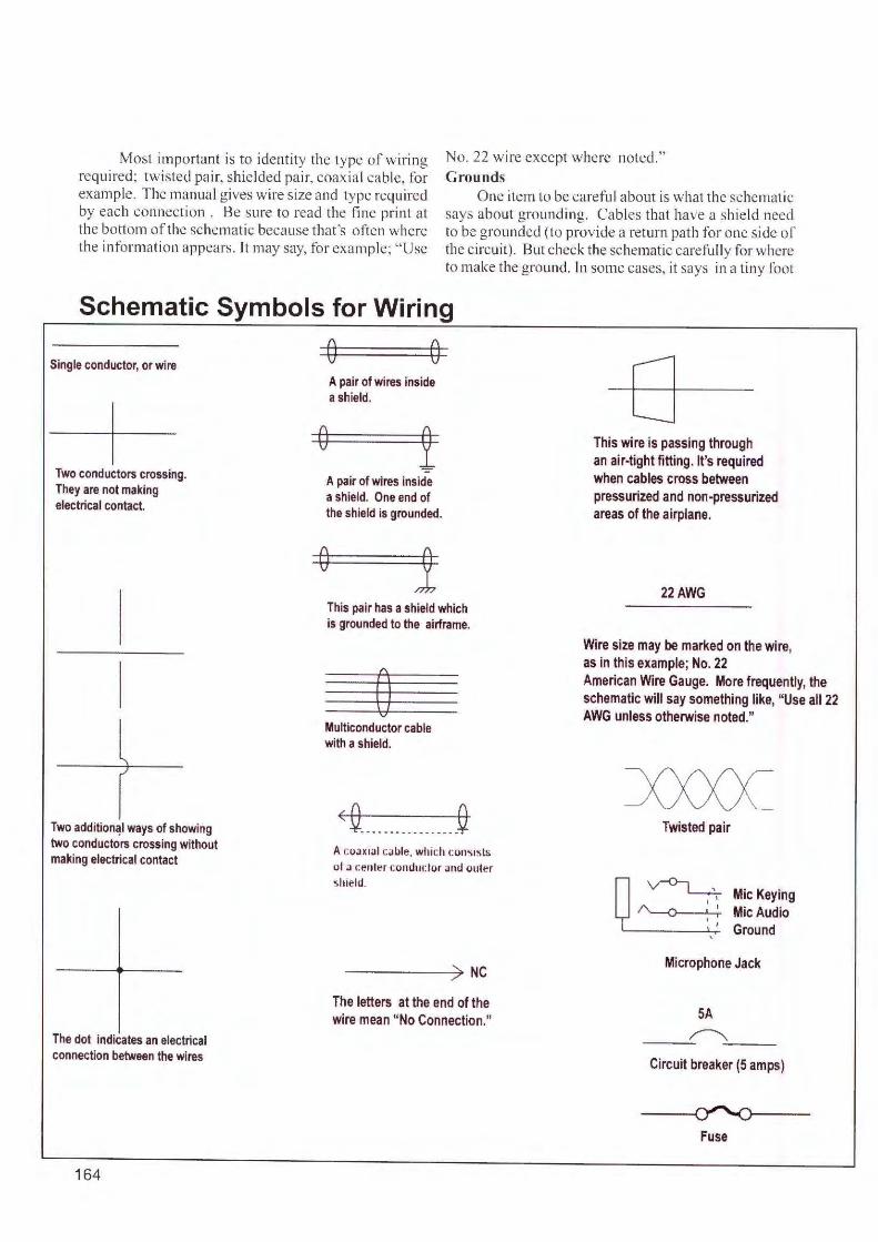
Most important is to identity the type of wiri ng requ ired; twisted pair, shielded pa ir, coaxial cable, for example. The manual gives wire size and type required by each connection . Be sure to read the fine prinL at the bottom of the schemati c because that's often where the information appears. l t may say, for example; "Use
No. 22 wi re except where noted." Grounds
One item to be carefu l about is what the schematic says about grounding. Cables that have a shie ld need to be grounded (to provide a retu rn path for one side of the circuit). But check the schematic carefully for where to make the ground. In some cases, it says in a tiny foot
Schematic Symbols for Wiring
Single conductor, or wire
Two conductors crossing. They are not making electrical contact.
l ./
Two addition<!I ways of showing two conductors crossing without making electrical contact
The dot indicates an electrical connection between the wires
164
0 0
0
A pair of wires inside a shield.
A pair of wires inside a shield. One end of the shield is grounded.
0 This pair has a shield which is grounded to the airframe.
0 Multiconductor cable with a shield .
<Q ...... ......... Q A coaxial cable, which consists of a cenler cond11clor and 011ler shield.
The letters at the end of the wire mean "No Connection."
0 This wire is passing through an air-tight fitting . It's required when cables cross between pressurized and non-pressurized areas of the airplane.
22AWG
Wire size may be marked on the wire, as in this example ; No. 22 American Wire Gauge. More frequently, the schematic will say something like, "Use all 22 AWG unless otherwise noted."
Twisted pair
~ MicKeying ~ MicAudio
, Ground
Microphone Jack
SA
---~-'--- -Circuit breaker (5 amps)
Fuse
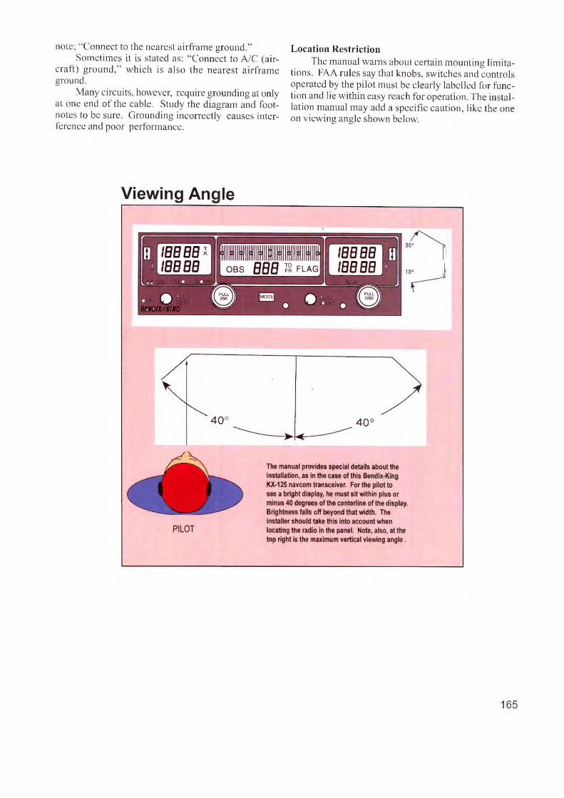
note; "Connect to the nearest airframe ground. " Location Restriction Sometimes it is stated as: "Connect to A/C (air
craft) g round," which is also the nearest ai rframe ground.
Many c ircuits, however, require grounding at only at one end of the cab le. Study the diagram and footnotes to be s ure. Grounding incorrectly causes interference and poor performance.
The manua l warns about certain moun ting limitations. FA A rules say that knobs, switches and contro ls operated by the pi lot must be c learly labelled for function and lie within easy reach for operation. The installatio n manual may add a specific caution, like the one on viewing angle shown below.
Viewing Angle
PILOT
"~ 10' ~ r-
/ 40°
The manual provides special details about the installation, as in the case of this Bendix-King KX-125 navcom transceiver. For the pilot to see a bright display, he must sit within plus or minus 40 degrees of the centerline of the display. Brightness falls off beyond that width. The installer should take this into account when locating the radio in the panel. Note, also, at the top right is the maximum vertical viewing angle .
165

Typical Navcom Connections
1. POWER INPUT 2. GROUND 3. MICROPHONE KEY LINE 4. MICROPHONE AUDIO 5. COM AUDIO 6. NAV AUDIO 7. SPEAKER OUTPUT
I. Power Supply The positive (+) s ide o f the 14- or 28-volt DC source
from the airp lane electrical system. Also called "A+" it comes from a fu se or c ircuit breaker designated " navcom."
2. Ground The re arc several types of grounds in an airplane.
Here, the ground is a path for DC power to return to the negati ve s ide of the aircraft e lectrical system. ln aluminum airpl anes, it is some times the metal structure (which is connected to the negative s ide of the battery). Some metal parts are insulated from g round by shock mounts made with rubber. To reach g round, mounts can be bypassed with short lengths of metal braid.
There will be many grounds required behind the instrument pane l and technic ians often prefer to run a separa te ground wire fro m each radi o, ins trume nt, etc., to a terminal block behind the pane l. A heavy common ground is then run fro m the block to the negative s ide of the aircraft battery.
The s tructure of a composite airp lane prevents the a irframe's use as a common ground because it will not conduct e lectric ity. Grounds are provided by running a " bus bar," a heavy copper st rip or wire from the negative s ide o f the battery to the device be ing grounded.
When you arc required to ground the shi eld o f a wire carrying audio, consult the manua l. In nearly all cases, a udi o lead s (for mi c ropho nes, for exa mp le ) mu st be grounded only at one end.
3. Microphone key line. This lead runs to the press-to-ta lk button on the mi
crophone. lt connects to the microphone j ack , specifically to the termina l that connects to the tip of the mike plug.
4. Microphone audio This ca rries a udio (vo ice) from the mi crophone jack
to the rad io. On the mike j ack, thi s is the center termina l.
5. Com Audio The voice signa l from the receiver. Fed to a head
phone j ack for I istening, it is called "headphone" or " low level" audio. In most a ircra ft . however, the voice is fed lo an audi o pane l so it can be amp Ii fied for a cabin speaker or used w ith an intercom.
166
8. AUXAUDO 9. INSTRUMENT LIGHTING 10. SWITCHED POWER 11. KEEP ALIVE LINE 12. DME 13. VOR/LOC
6. Nav Audio T his is audio from the VOR receiver, hea rd by the
pilot to identify the station by a Morse Code or voice identifier. VOR audio may also carry the voice ofa Flight Service Station. Most a ircraft feed nav audio to an audio panel for listening on headphones or cabin speaker.
7. Speaker Output Some navcoms have a buil t-in amplifi er for driving a
cabin loudspeaker. Otherwise, an a udio pane l must be added.
8. Aux (Auxiliary) Audio If the radio has a built-i n speaker ampl ifi er, it can
take low level audio from other radi os a nd boost it to speaker level. It 's u sua lly done in a irc raft without audio panels.
9. Instrument Lighting Also known as the "dimmer" line, it runs to an in
strument lighting contro ller. It e nables the pilot, with one knob, to dim radio lights along with other lights on the instrument pane l.
10. Switched Power Use this line when you need to turn on accessories
from the power switch on the radio. The VOR indicator, a separate in strument, is one example.
11. Keep Alive This line bypasses the power switch and goes d irectly
to a ircraft battery power. When the radio is tu rned off, the keep a live line continues powering rece iver memory that stores freque nc ies and other data .
12. DME (Distance Measuring Equipment) The DME is a separate rad io, but is tuned by the VOR
receiver. When the pilot selects a VOR, the DME is automatically "channeled" to the correct frequency.
13. VOR/ LOC Composite These arc the navigation signals (YOR and localizer)
processed by the rece iver. They are sent through thi s line to an indicator for display to the pilot.

Review Questions Chapter 21 Planning the Installation
21.1 Any major rebuilding of an instrument panel must conform to the airplane's ___ _
21.2 When installing new equipment critical to flight, the work must conform to a _____ _
21.3 In planning a major avionics installation, it is important know under what conditions the airplane will be flown. What are three general categories?
21.4 What instruments are in the "Basic T" layout?
21.5 Name two additional flight instruments for instrument flying?
21.6 Before beginning a wiring job, it's helpful to locate and identify every ___ _
21.7 Before wiring, determine the size and type of each wire by referring to the ___ ____ _
21.8Wire sizes are often described as "AWG". What does it mean?
21.9 Ts a ground wire always connected to the metal airframe?
21. 10 When selecting a location on the instrument panel, what is the consideration for viewing angle?
21.11 What is the purpose of " nav audio?"
21.12 What is a "keep alive" line?
167

Chapter 22
Electrical Systems
AC and DC Power Avionics and instruments require a variety of volt
ages and frequencies but they all begin with "primary" power. Most aircraft require low-voltage DC (direct current), which starts at the battery. A maj or difference is how primary power is distributed throughout the airplane. Tn light twins and smaller aircraft, power is di stributed as 12- or 28-volt DC. Most radios work direct ly from that source. But in large turbine a irc raft, DC is for s ta1ting engines and powering some devices. Most electrical power in these airplanes is taken directly from engine-driven generators which produce 115 volts AC. That hi gh voltage is not on ly distributed throughout the airplane, but is stepped down for recharging batteries. As we'll see, 115 VAC is an efficient method to power a large a irplane with hundreds of fee t of w ire.
A more recent system generates primary power at 270 volts DC. Designed fo r military ai rcraft, it looks ahead to th e "all -electric" a irplane, where e lectric motors replace today's heavy hydrauli c and pneumatic actuators for gear, flaps, fli ght controls and other mechanica l devices. The high voltage---270---carries electrical power with less loss from heating in the wi ring.
12 VDC. Adapted from the automobile industry, this system consists ma inly of an alternator and storage battery. It's called a 12-volt system, but has other names, as well . On some diagrams it 's a 14-volt
168
system---on others it 's 13.75 volts. But the system is usually called " 12 volts." When the alternator is recharging the battery voltage rises to over 13. On schematic dia&11·ams, you may see" 13. 75 volts" because the circuit designer wants you to use that voltage while operating the radio on a test bench. By adjusting to
12-volt Battery: Percent Charge • 12.70 volts 100%
• 12.50 volts 90%
• 12.42 volts 80%
• 12.32 volts 70%
• 12.20 volts 60% • 12.06 volts 50%
• 11.90 volts 40% • 11.75 volts 30% • 11.58 volts 20% • 11.31 volts 10% • 10.50 vo lts 0%
Voltages measured at the terminals of a storage battery drop with the state of charge. To measure the capacity of the battery, however, use a tester that puts a load on the battery.
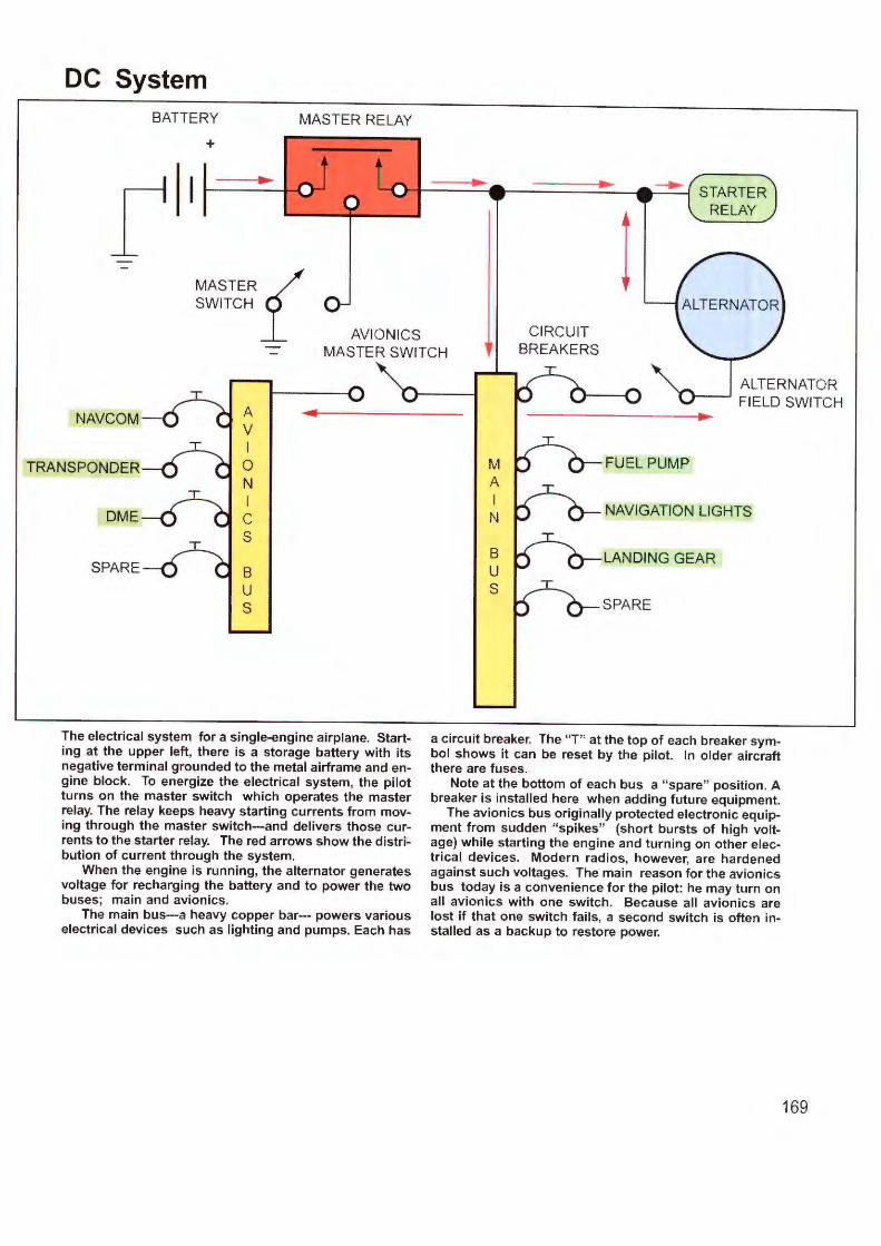
DC System BATTERY
+
r MASTER RELAY
... ... STARTER
RELAY
MASTER{ SWITCH
AVIONICS MASTER SWITCH
NAVCOM- A V I
TRANSPONDER 0 N I
DME C s
SPARE 8 u s
The electrical system for a single-engine airplane. Starting at the upper left, there is a storage battery with its negative terminal grounded to the metal airframe and engine block. To energize the electrical system, the pilot turns on the master switch which operates the master relay. The relay keeps heavy starting currents from moving through the master switch---and delivers those currents to the starter relay. The red arrows show the distribution of current through the system.
When the engine is running, the alternator generates voltage for recharging the battery and to power the two buses; main and avionics.
The main bus---a heavy copper bar--- powers various electrical devices such as lighting and pumps. Each has
ALTERNATOR FIELD SWITCH
M FUEL PUMP A I
NAVIGATION LIGHTS N
8 u s
a circuit breaker. The " T" at the top of each breaker symbol shows it can be reset by the pilot. In older aircraft there are fuses.
Note at the bottom of each bus a " spare" position . A breaker is installed here when adding future equipment.
The avionics bus originally protected electronic equipment from sudden " spikes" (short bursts of high voltage) while starting the engine and turning on other electrical devices. Modern radios, however, are hardened against such voltages. The main reason for the avionics bus today is a convenience for the pilot: he may turn on all avionics with one switch. Because all avionics are lost if that one switch fails, a second switch is often installed as a backup to restore power.
169
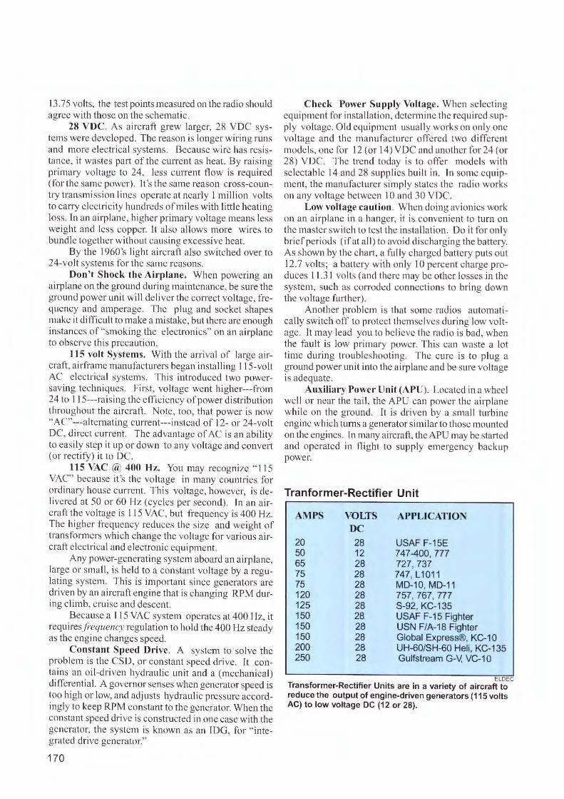
13. 75 volts, the test points measured on the radio should agree with those on the schematic.
28 VDC. As aircraft grew larger, 28 VDC systems were deve loped. The reason is longer wiring runs and more e lectrica l systems. B ecause wire has resistance, it wastes part of the current as heat . By rais ing primary voltage to 24, less current fl ow is required (for the same power). It 's the same reason cross-country transmission lines operate at nearly I million volts to carry e lectric ity hundreds of miles with little heating loss. ln an airplane, hig her primary voltage means less weight and less copper. It also a llows more w ires to bundle together without causing excessive heat.
By the I 960 's li ght a irc raft a lso switched over to 24-vo lt systems for the same reasons.
Don't Shock the Airplane. When powering an airplane on the ground during maintenance, be sure the ground power unit will de liver the correct voltage, frequency and amperage. The plug and socket shapes make it difficult to make a mistake, but there are enough instances of"srnoking the e lectronics" on an a irplane to observe this precaution.
l 15 volt Systems. With the arrival of large a ircraft, a irframe manufacturers began installing 11 5-volt AC e lectri cal systems. T his introduced two powersaving techniques . Firs t, voltage went higher---from 24 to 11 5---raising the effic iency of'power distribution throughout the a ircraft. Note, too, that power is now "AC"---alternat ing current---instead of 12- or 24-vo lt DC, direct current. The advantage of AC is an ability to easily s tep it up or down to any voltage and conve1i (o r rectify) it to DC.
115 VAC @ 400 Hz. You may recognize " 11 5 VAC" beca use it 's the voltage in many countries for ordina ry house current. This voltage, however, is deli vered at 50 or 60 Hz (cycles per second). ln an aircraft the voltage is I 15 VAC, but frequency is 400 Hz. The higher frequency reduces the size and we ight of transformers which change the voltage for various aircraft e lectrica l and e lectronic equipment.
Any power-generat ing system aboard an a irpl ane, large or small, is he ld to a constant voltage by a regula ting system. Thi s is important s ince generators are driven by an a ircraft eng ine that is chang ing RPM during c limb, cruise and descent.
Because a 11 5 VAC system operates at 400 Hz, it requires.fi·equency regulation to ho ld the 400 Hz steady as the eng ine changes speed .
Constant Speed Drive. A system to solve the problem is the CS D, or constant speed drive. It contains an o il-driven hydraulic uni t and a (mechani cal) differential. A governor senses when generator speed is too hig h or low, and adjusts hydraulic pressure according ly to keep RPM constant to the generator. When the constant speed drive is constructed in one case w ith the generator, the system is known as an TDG, for " integrated drive generator."
170
Check Power Supply Voltage. When selecting equipment for installation, determine the requi red su pply voltage. Old eq uipment usually works on only one voltage and the m anufacturer offered two different models, one for 12 ( or 14) V DC and another fo r 24 ( or 28) VDC. The trend today is to offer models with selectable 14 and 28 supplies bu il t in. l n some equipment, the man ufacturer s imply states the radio works on any voltage between IO and 30 VDC.
Low voltage caution . When doing avionics work on an a irplane in a hanger, it is conven ient to turn on the maste r switch to test the installation. Do it fo r only brief periods (if at all ) to avoid discharging the battery. As shown by the cha1i, a fu lly charged batte ry puts ou t 12.7 volts; a battery with only IO percent cha rge produces 11.3 1 volts (a nd there may be other losses in the system, such as corroded connections to bring down the vo ltage fu1i hcr).
Another problem is that some radios automatically switch off to protect them selves during low vol tage. It may lead you to be lieve the radio is bad, when the fault is low primary power. This can waste a lot time during troubleshooting. T he cure is to plug a ground power unit into the a irplane and be sure voltage is adequate .
Auxiliary Power Unit (APU). Located in a wheel well or near the ta il, the APU can power the a irplane while on the g round. It is d riven by a sm all turb ine eng ine which turns a generator s imilar to those moun ted on the eng ines. In many ai rcraft, theAPU may be started and operated in fl ight to supply emergency backup power.
Tranformer-Rectifier Unit
AMPS VOLTS APPLICATION DC
20 28 USAF F-15E 50 12 747-400, 777 65 28 727,737 75 28 747, L1 01 1 75 28 MD-10, MD-1 1 120 28 757, 767, 777 125 28 S-92, KC-135 150 28 USAF F-15 Fighter 150 28 USN F/A-18 Fighter 150 28 Global Express®, KC-10 200 28 UH-60/SH-60 Heli, KC-135 250 28 Gulfstream G-V, VC-10
ELDEC Transformer-Rectifier Units are in a variety of aircraft to reduce the output of engine-driven generators (115 volts AC) to low voltage DC (12 or 28).
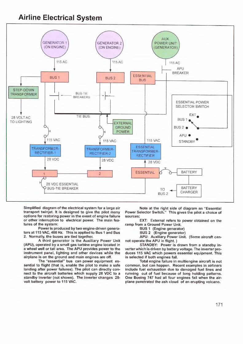
Airline Electrical System
STEP-DOWN TRANSFORMER
l
115AC
BUS 1
~ BUS-TIE . I ~ - BREAKERS
TIE BUS
GENERATOR 2 (ON ENGINE)
115AC
ESSENTIAL BUS
115AC
I APU ~BREAKER
ESSENTIAL POWER SELECTOR SWITCH
BUS 1 28 VOLT AC
TO LIGHTI NG EXTERNAL GROUND POWER
BUS 2 e
TRANSFORMERRECTIFIER-1
28 voe
28 voe ESSENTIAL BUS-TIE BREAKER
TRANSFORMERRECTIFIER-2
28 voe
2
Simplified diagram of the electrical system for a large air transport twinjet. It is designed to give the pilot many options for restoring power in the event of engine failure or other interruption to electrical power. The main features of the system:
Power is produced by two engine-driven generators at 115 VAC, 400 Hz. This is applied to Bus 1 and Bus 2. Normally, the buses are tied together.
A third generator is the Auxiliary Power Unit (APU), operated by a small gas turbine engine located in a wheel well or tail area. The APU provides power to the instrument panel, lighting and other devices while the airplane is on the ground and main engines are off.
The " essential" bus can power equipment essential to flight (that is, enable the pilot to make a safe landing after power failures) . The pilot can directly connect to the aircraft batteries which supply 28 VDC to a standby inverter (not shown). The inverter changes 28-volt battery power to 115 VAC.
115 VAC
ESSENTIAL TRANSFORMER
RECTIFIER
28 voe
ESSENTIAL
TO BUS 2
APU •
STANDBY •
BATIERY
BATIERY CHARGER
Note at the right side of diagram an "Essential Power Selector Switch." This gives the pilot a choice of sources:
EXT: External refers to power obtained on the ramp from a Ground Power Unit.
BUS 1 (Engine generator) BUS 2 (Engine generator) APU: Auxiliary Power Unit. (Some aircraft can
not operate the APU in flight. ) STANDBY: Power is drawn from a standby in
verter which is driven by battery voltage. The inverter produces 115 VAC which powers essential equipment. This is selected if both engines fail .
Total engine failure in multiengine aircraft is not common, but can happen. Recent examples in airliners include fuel exhaustion due to damaged fuel lines and running out of fuel because of long holding patterns. One Boeing 747 had all four engines fail when the airplane penetrated the ash cloud of an erupting volcano.
171
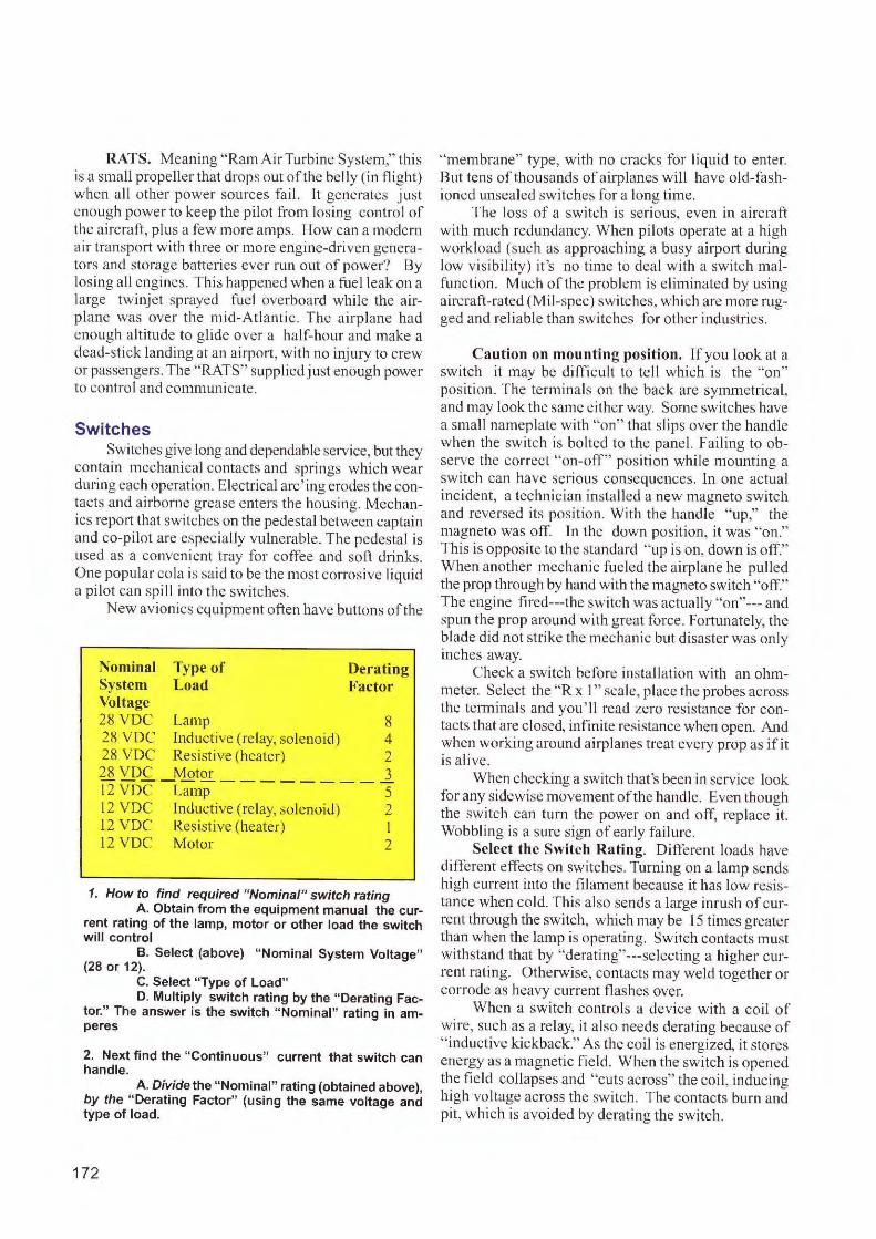
RATS. Meaning " Ram AirTurbine System," this is a small prope ller that drops out of the be lly ( in flight) when all other power sources fail. lt generates just enough power to keep the pi lot from los ing control of the aircraft , plus a few more amps. How can a modern ai r transpo1t w ith three or more engine-driven generators and storage batteries ever run o ut of power? By losing all engines. This happened when a fuel leak on a large twinjet sprayed fuel overboard while the a irpla ne was over the mid-Atlanti c. T he a irplane had eno ugh altitude to g lide over a half-ho ur and make a dead-stick la nding at an a irport, w ith no injury to crew or passengers. The "RATS" supplied just enough power to control and communicate.
Switches Switches g ive long and dependable service, but they
conta in mechanical contacts and springs which wear during each operation. E lectrical arc ' ing erodes the contacts and ai rborne grease enters the housing. Mechanics report that switches on the pedestal between captain and co-pi lot are especially vulnerable. The pedestal is used as a convenie nt tray for coffee and soft drinks. One popular cola is said to be the m ost corrosive liquid a pilot can spill into the switches.
New avionics equipment often have buttons of the
Nominal Type of System Load Voltage
Derating Factor
28 VDC Lamp 8 28 VDC Inductive (relay. so lenoid) 4 28 VDC Resistive (heater) 2 28 VDC Motor __ _ _____ 3 12 VDC Lamp 5 12 YDC Inductive (relay, so lenoid) 2 12 VDC Resistive (heater) I 12 VDC Motor 2
1. How to find required "Nominal" switch rating A. Obtain from the equipment manual the cur
rent rating of the lamp, motor or other load the switch will control
B. Select {above) "Nominal System Voltage" (28 or 12).
C. Select "Type of Load" D. Multiply switch rating by the "Derating Fac
tor." The answer is the switch "Nominal" rating in amperes
2. Next find the " Continuous" current that switch can handle.
A. Divide the "Nominal" rating (obtained above), by the "Derating Factor" (using the same voltage and type of load.
172
" membrane" type, with no cracks fo r liquid to enter. But tens of thousands of airplanes will have old-fashioned unsealed switches for a long t ime.
The loss of a switch is serious, even in aircraft with much redundancy. When pilots operate at a high workload (suc h as approaching a busy a irpo1t during low vis ibi lity) it's no time to deal w ith a switch malfunction. Much of the proble m is el iminated by us ing aircraft-rated (Mil-spec) switches, w hich are more rugged and reliable than switches for other industries.
Caution on mounting position. If you look at a switch it may be diffic ult to te ll which is the "on" pos ition. The terminals on the back are symmetrical, and may look the same e ither way. Some switches have a small nameplate with "on" that s lips over the handle w hen the sw itc h is bo lted to the pane l. Fai ling to observe the correct "on-off" position whi le mounti ng a sw itc h can have serious consequences. ln one actua l incident, a technic ian installed a new magneto switch and reversed its position. With the handle " up," the magneto was off. In the down position, it was "on." This is opposite to the sta ndard " up is on, down is off." Whe n another mechan ic fuel ed the airplane he pulled the prop through by hand wi th the magneto switch "off." The eng ine fi red---the switch was actually "on" --- and spun the prop around with great force. Fortunately, the blade did not stri ke the mechanic but disaster was onl y inches away.
C heck a switch before installation w ith an ohmmeter. Select the "Rx l " scale, p lace the probes across the te1n1ina ls and you 'll read zero resistance for contacts that are closed, infinite resistance when open. And w hen working around airplanes treat every prop as if it is a live.
When checkin g a switch that's been in service look for an y s idewise movement of the handle . Even though the sw itch can turn the power on and off, rep lace it. Wobbling is a sure sign of early fa ilure .
Select the Switch Rating. Different loads have different effects on switches. Turning on a lamp sends high current into the fi lament because it has low resistance when cold. T his also sends a large inrush of current through the switch, which may be 15 t imes greater than when the lamp is operating. Switch contacts must withstand that by " derating" ---se lecting a higher current rating. Otherwise, contacts may weld together or corrode as heavy current flashes over.
When a switch controls a device with a coil of w ire, su ch as a relay, it also needs derating because of " inductive k ickback." As the coil is energized, it stores e nergy as a magnetic fie ld. When the switch is opened the fie ld collapses and "cu ts across" the coi I, induc ing high vo ltage across the switch. The contacts burn and p it, w hi ch is avo ided by derating the switch.

Avionics Master. This switc h originated as a method for protecting early models of solid-state radios. Tt e nabled the pilot to keep all avionics off while cranking the engine to prevent damaging voltage spikes from reaching the radios. lt also protected radios against low voltage as the starter drew heavy current from the battery. These problems were common to the f irst generation of transistorized equipment; avionics today have bu ilt-in devices to protect against surge and low voltage protection.
But the avionics master is still widely used because it is a convenience for the pi lot. Instead of flippin g a half-dozen switches or more, he throws one switch to turn on a ll avionics.
This convenience, however, comes at a pri ce. It 's the single-point failure. If the avionics master switch fa il s, it disables all rad ios in the airplane. A solution in light aircraft is to wire a second switch across (in paralle l w ith ) the avion ics master. Using the back-up switch restores the lost power.
There are more advanced methods for keep ing ra-
Switch Types
1. Toggle Switch This switch has a "bat" handle (resembles a baseball
bat). Sometimes several are ganged together with their handles linked. It assures that all switches are thrown at once in same direction.
2. Pushbutton switch. Used when a circuit is operated for a short time,
such as the push-to-talk switch on a microphone. It has a spring-loaded button. Depending on the circuit, the switch may be push-to-make (contacts close) or pushto-break (contacts open).
3 Rocker switch The pilot pushes the top half of the rocker switch to energize the circuit, the bottom half to break the circuit.
5. Rotary switch Enables several circuits to be selected with one knob. It also is more resistant to being knocked off its position (which can happen in rocker and toggle switches).
6. Microswitches The name is from the few thousandths of an inch between contacts on the make and break . They have snap action. These switches are operated by the pilot, or located at different points on the airplane to sense a mechanical position. An example is a retractable landing
dios working in the event of failure of the master switch the master relay or fro m other interruptions to the pri~ mary power. Some tech nicians insta ll an "essential" bus, whi ch is a w ire directly from the battery. Multiengine aircraft have dual electrical systems to prevent the sing le-point fai lure.
CIRCUIT BREAKERS The purpose of a circuit breaker is to protect wir
ing, not the equipment. Most recent avionics already have overvoltage protection. The hazard is that a w ire carryi ng excessive current may heat and cause smoke or fire. By placing the breaker close to the power source, more of the wiring is protected.
The size of a circu it breaker---its rating in amperes (amps)---is selected so it opens before current exceeds the capacity of the w ire. The chart shows the size breaker or fuse for different levels of current in DC circuits.
gear; when the wheels are down and locked they operate microswitches that illuminate lights on the instrument panel.
7. Pressure switch. These are often used to warn when pressure in a
hydraulic or pneumatic system is too high or low. It's usually done through a flexible disk (diaphragm) which moves with pressure. It operates switch contacts and indicator lamps.
8. Thermal Switch Used to warn of overheating in a component (a generator, for example) and to sense and indicate an engine fire. It works on a bi-metal thermostat that curves with heat and makes an electrical contact.
9. Proximity Switch Are doors and hatches on the airplane closed and
locked before take-off? This is done with proximity switches. One half is a housing containing two strips of metal mounted parallel with each other. This may be fixed to the door frame. On the door is a permanent magnet. When the door is secured, the magnet pulls the metal strips together to operate a warning light in the cockpit.
173
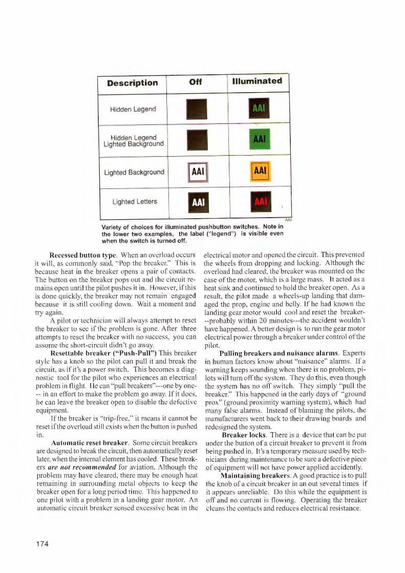
Description
Hidden Legend
Hidden Legend Lighted Background
Off Illuminated
Lighted Background AAI
Lighted Letters II AAI
Variety of choices for illuminated pushbutton switches. Note in the lower two examples, the label ("legend"} is visible even when the switch is turned off.
Recessed button type . When an overload occurs it will , as commonly said, "Pop the breaker." This is because heat in the breaker opens a pair of contacts . The button on the breaker pops out and the circuit remains open unti l the pilot pushes it in. However, if this is done quickly, the breaker may not remain engaged because it is stil l cooling down. Wait a mome nt and try agai n.
A p ilot or technician will always attempt to reset the breaker to see i r the problem is gone . After three attempts to reset the breaker with no success, you can assume the s hort-c ircuit d idn 't go away.
Resettable breaker ("Push-Pull") This breaker sty le has a knob so the pilot can pull it and break the c ircuit , as if it 's a power switch. This beco mes a diagnostic tool fo r the pi lot who experiences an e lectr ical problem in fl ight. He can "pull brcakers"---one by one-- in an effort to make the problem go away. lf it does, he can leave the breaker open to disable the defecti ve equipment.
If the breaker is " trip-free," it means it cannot be reset if the overload still ex ists when the button is pushed 111 .
Automatic reset breaker. Some circuit breakers arc designed to break the circuit, then automatically reset later, when the internal element has cooled. These breakers are not reco111111e11ded fo r aviation. Although the probl em may have cleared , there may be enough heat remaining in surrounding metal objects to keep the breaker open for a long period time. This happened to one pilot with a problem in a landing gear motor. An automatic c ircuit breaker sensed excessive heat in the
174
electrical motor and opened the c ircuit. This prevented the wheels from dropping and locki ng. A I though the overload had c leared, the breaker was mounted on the ca e of the motor, which is a large mass. It acted as a heat sink and continued to hold the breaker open. As a result, the pilot made a wheels-up landing that damaged the prop, eng ine and belly. l f he had known the landing gear motor would cool and reset the brcaker--probably w ith in 20 minutes---the accident wouldn 't have happened. A better design is to run the gear motor electrical power through a breaker under control of the pilot.
Pulling breakers and nuisance alarms. Experts in human factors know about "nuisance" a larms. lf a warn ing keeps sounding when there is no problem, p ilots will turn off the system. They do this, even though the system has no off switch. They simply "pull the breaker." This happened in the ea rly days of "ground prox" (ground proximity warning system), which had many fa lse alarm s. Instead of b laming the pilots, the manufacturers went back to their drawing boards and redesigned the system.
Breaker locks. There is a device that can be put under the button of a c ircuit breaker to prevent it from being pushed in. It 's a temporary measure used by technicians during maintenance to be sure a defective piece of equipment will not have power applied accidcntly.
Maintaining breakers. A good practice is to pull the knob of a c ircui t breaker in an out several times if it appears unre liable. Do th is whil e the equipment is off and no current is flowing. Opera ting the breaker c leans the contacts and reduces e lectrical res istance.
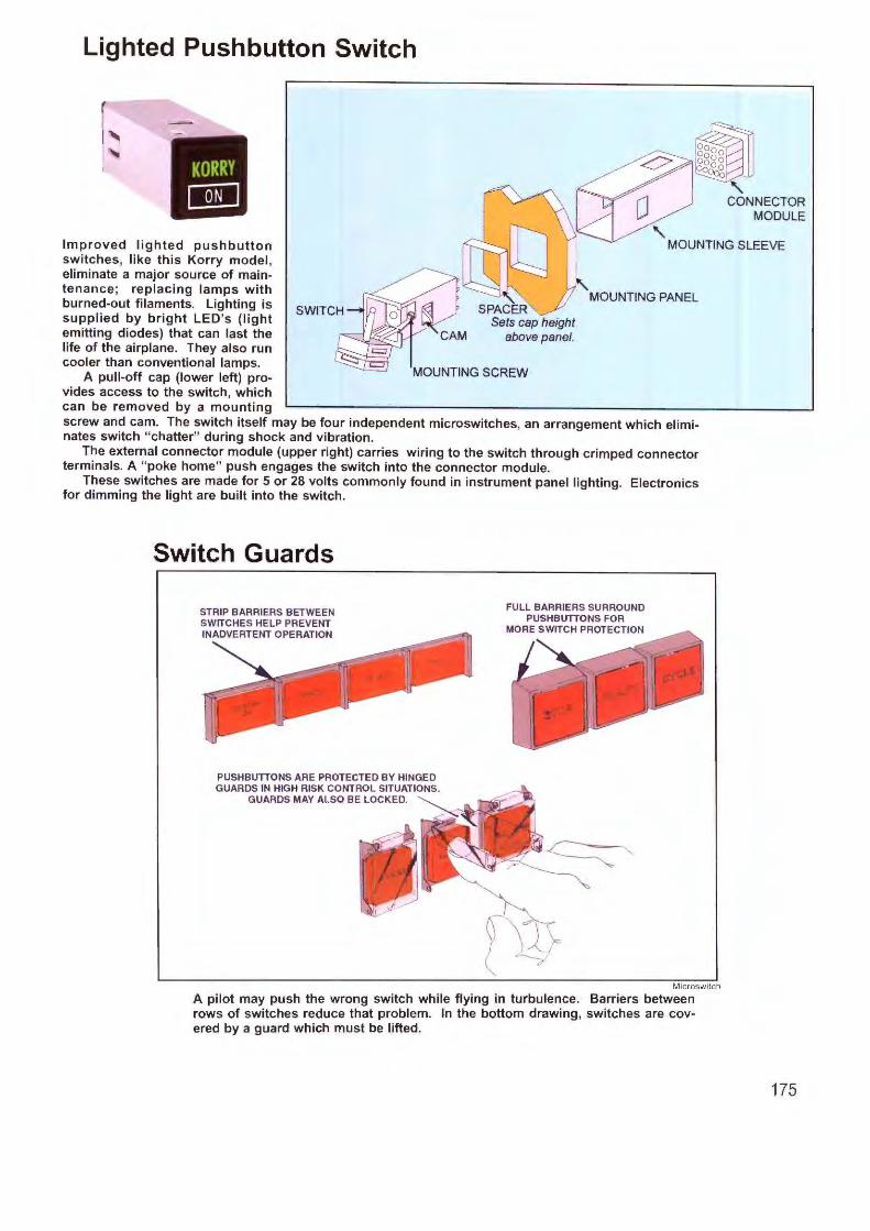
Lighted Pushbutton Switch
•-
MHI
' ' CONNECTOR
MODULE
Improved lighted pushbutton switches, like this Korry model , eliminate a major source of maintenance ; replacing lamps with burned-out filaments. Lighting is supplied by bright LED's (light emitting diodes) that can last the life of the airplane. They also run cooler than conventional lamps.
MOUNTING SLEEVE
A pull-off cap (lower left) provides access to the switch, which can be removed by a mounting
MOUNTING PANEL
MOUNTING SCREW
screw and cam. The switch itself may be four independent microswitches, an arrangement which eliminates switch "chatter" during shock and vibration.
The external connector module (upper right) carries wiring to the switch through crimped connector terminals. A " poke home" push engages the switch into the connector module.
These switches are made for 5 or 28 volts commonly found in instrument panel lighting. Electronics for dimming the light are built into the switch.
Switch Guards
STRIP BARRIERS BETWEEN SWITCHES HELP PREVENT INADVERTENT OPERATION
PUSHBUTIONS ARE PROTECT ED BY HINGED GUARDS IN HIGH RISK CONTROL SITUATIONS.
GUARDS MAY ALSO BE LOCKED. ~ - .
FULL BARRIERS SURROUND PUSHBUTIONS FOR
MORE SWITCH PROTECTION
Mlcroswitch
A pilot may push the wrong switch while flying in turbulence. Barriers between rows of switches reduce that problem. In the bottom drawing, switches are covered by a guard which must be lifted.
175
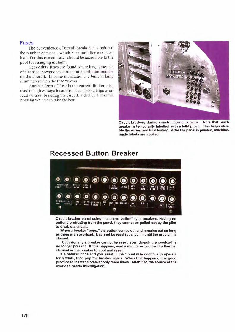
Fuses The convenience o f c ircuit breakers has reduced
the number o f fuses---which burn out a fter one overload. For this reason, fuses should be accessible to the pilot fo r chang ing in flight.
Heavy duty fuses are found where large amounts of electrical power concentrates at distribution centers o n the a irc raft. Jn some installatio ns, a built-in lamp illuminates when the fuse " blows."
Another form off use is the current limite r, al so used in high wattage locati ons . lt can pass a large overload without breaking the c ircuit, a ided by a ceramic ho us ing which can take the heat.
176
Circuit breakers during construction of a panel Note that each breaker is temporarily labelled with a felt-tip pen. This helps identify the wiring and final testing. After the panel is painted, machinemade labels are applied.
Recessed Button Breaker
Circuit breaker panel using "recessed button" type breakers. Having no buttons protruding from the panel, they cannot be pulled out by the pilot to disable a circuit.
When a breaker "pops," the button comes out and remains out so long as there is an overload. It cannot be reset (pushed in) until the problem is cleared.
Occasionally a breaker cannot be reset, even though the overload is no longer present. If this happens, wait a minute or two for the thermal element in the breaker to cool and reset.
If a breaker pops and you reset it, the circuit may continue to operate for a while, then pop the breaker again. When that happens, it is good practice to reset the breaker only three times. After that, the source of the overload needs investigation.

Review Questions Chapter 22 Electrical Systems
22.1 The primary electrical source in most airplanes is low voltage DC ( direct current). What are the two most common voltages?
22.2 In a light aircraft, connection to the battery is completed by the ____ _
22.3 A heavy copper bar that distributes power to most electrical systems aboard the airplane is called the _ ______ _
22.4 A heavy copper bar that distributes power only to radios and related equipment is called the
22.5 Large aircraft distribute power in the form of alternating current (AC) at volts. The fre-quency is _ __ _
22.6 What is the main purpose of an APU (auxiliary power unit) in a large aircraft?
22.7What is the meaning of RATS, and how does it work?
22.8 Why must switches have the ability to handle more current than required during normal operation?
22.9 What is the primary purpose of a fuse or circuit breaker?
177
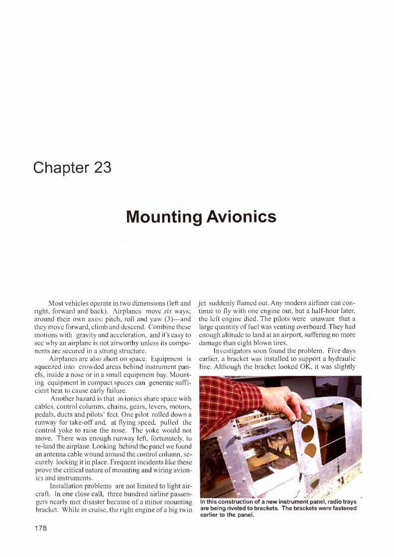
Chapter 23
Mounting Avionics
Most vehicles operate in two dimensions (left and right, forward and back). Airplanes move six ways; around their own axes; pitch, ro ll and yaw (3)---and they move forward, climb and descend. Combine these motions with gravity and acceleration, and it 's easy to see why an airplane is not airworthy unless its components are secured in a strong structure.
Airplanes are also short on space. Equi pment is squeezed into crowded areas behind instrument panels, inside a nose or in a small equipment bay. Mounting equipment in compact spaces can generate suffi cient heat to cause early fa ilure.
Another hazard is that avionics share space with cables, control co lumns, chains, gears, levers, motors, pedals, ducts and pilots' feet. One pilot rolled down a runway for take-ofT and, at flying speed, pulled the control yoke to raise the nose. The yoke would not move. There wa enough runway left , fortunately, to re-land the airplane. Looking behind the panel we found an antenna cable wound around the control column, securely locking it in place. Frequent incidents like these prove the critical nature of mounting and wiring avionics and instruments.
Installation problems are not limited to tight aircraft. ln one close call, three hundred airline passengers nearly met di saster becau e of a minor mounting bracket. While in cruise, the right engine of a big twin
178
jet suddenly named out. Any modern airliner can continue to fly with one engine out, but a half-hour later, the left engi ne died. The pilots were unaware that a large quanti ty of fi.1el was venting overboard. They had enough al ti tude to land at an airport, suffering no more damage than eight blown tires.
Investigators soon fo und the problem. Five days earlier, a bracket was insta lled to support a hydraulic line. Although the bracket looked OK, it was slightly
In this construction of a new instrument panel, radio trays are being riveted to brackets. The brackets were fastened earlier to the panel.

different in size from the correct one. This reduced clearance between hydraulic and fuel lines, causing contact between them. After five days of flyi ng, vibrati on and rubbing cut the fuel I ine, which spilled a large quantity out the trailing edge of the wing.
These cautionary ta les show how minor di screpanc ies lead to major problems. In an avionics in stallation or retrofit, it is not unusua l to mount a few hundred brackets, clamps, cable ties, supporting structures and other hardware.
New or Old Installation? There are various levels of installation. A pilot may
want to replace one old raclio---or need an upgrade where the panel is extensive ly refurbi shed. There is also the "tear it a l I out and start over again" job.
lf the airpl ane is a light aircraft, the radio shop often des igns the installation. When th e work affects structures and control systems, large shops depend on the skills of their A&P (a irframe and powerplant) mechanics to fabri cate brackets, she lves and other supports fo r the new radios .
Before tackling an installation, the technician runs a we ight-and-balance ca lculati on to see if remov ing and/or adding new equipment exceeds the a ircraft 's CG (center of gravity) or adds excessive weight.
Airplanes in fli ght a lso develop dynamic loads while maneuvering, especially in turbulence. lf there is any question whether add it ional suppot1 is required, the job should be reviewed by a DER (Des ignated Engineering Representative) with a specialty in structures. He can design a system that meets acceptable installation practices. A DER is required when cutting through a structural member (such a rib or bulkhead). Large shops often have a DER on staff, while sma ller facilities may hire an independent DER on a per-job basis.
STC's . Avionics equipment that is fli ght-critical is STC'd, meaning the manufacturer applied for a supplemental type certificate. The in stall ati on has been worked out in great deta il and a ki t of components may be supplied . Wherever an STC appli es, the install er fo llows the document carefull y for structural and wiring details.
Hostile Areas. Beyond the cockpit and passenger cab in, there is an unfriendly environment for e lectronic eq uipment. Engines generate heat and vibrati on, the airpl ane fli es through large temperature and humidity changes and low areas on the airfra me accumulate oil, hydraulic fluid and water. Many radios and instruments are fortified against these hazards with a TSO (technica l standard order), which cet1ifies they are built to meet environmental conditions encountered in aircraft.
The manufacturer's maintenance manua l is the most valuable source of installation info rmation. Not on ly does the company have the engineering resources to design the install ation, its manual is recognized as "approved data."
Selecting Metal Offer ing a good combinat io n of li ghtness,
strength, electri cal conductivity and workability, sheet aluminum is the common cho ice for panels. Aluminum angle and flat bar are selected fo r fab ri cating structures such as brackets and supports.
Look for the labe l "Ale lad," which refers to a thi n coating (on both sides) of 99 percent pure a luminum. The coating has high resistance to corrosion. Oxidation on aluminum does not have a distinctive color (like rust on iron) and may be difficult to see.
Consider various aluminum stock: 2024. This alloy is often se lected for sub-panels
that hold instruments, fo r example. It is not heavy enough for the overa ll instrument panel. 2024 has good resistance to metal fatigue and bends without cracking.
2024 aluminum can be polis hed to an a lmost clu·ome-1 ike finish.
3003. This grade ofaluminum is alloyed with manganese for strength . The material is still easi ly workable and resists cracks whi le bending. lt is also corrosion-resistant (without A lelad)
3003 is excellent for forming brackets, housings and structures that require a lot of bending and forming, especially where the higher strength of2024 is not required.
6061. This popular alloy is strong, corros ionresistant, workable and relatively low in cost. It is available in Alclad for added protection.
606 1 is useful in bu ilding structures which support the we ight of a stack of rad ios or instruments .
Thickness. Aluminum comes in many thicknesses, measured in thousandths of an inch, for di fferen t applications:
.040. This s ize is good for forming lightweight brackets for supporting cooling fans, switches and other lightweight equipment such as cover pl ates and g love box doors.
.063 makes sturdier brackets for supporti ng heavy equipment (a radio stack, for example), panels for headphone and mike jacks and equipment shelves.
.080 This heavy materi al is suitable fo r the overa ll , or mai n, in strument panel. In this thickness, however, you can make bends only over a large radius.
179
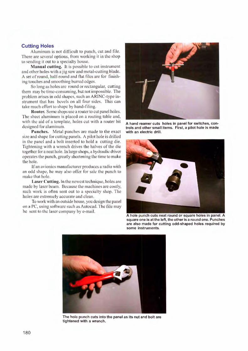
Cutting Holes Aluminum is not difficult to punch, cut and file.
There arc several options, from working it in the shop to sending it out to a spec ialty house.
Manual cutting. Jt is possible to cut instrument and other holes with a jig saw and metal-cutting blade. A set of round, half-round and flat fi les arc for fi ni shing touches and smoothing burred edges.
So long as holes are round or rectangu lar, cutting them may be time-consuming, but not impossible. The problem ari ses in odd shapes, such an ARINC-typc instrument that has bevels on all fou r sides. This can take much effort to shape by hand-fi ling.
Router. Some shops use a router to cut panel holes. The sheet aluminum is placed on a routing table and, with the aid of a template, holes cut with a router bit designed for al uminum.
Punches. Metal punches are made to the exact size and shape for cutting panels. A pilot hole is dri lled in the panel and a bolt inserted to hold a cutting die. Tightening with a wrench drives the halves of the die together for a neat hole. 1 n large shops, a hydraulic driver operates the punch, greatly shortening the time to make the hole.
If an av ionics manufacturer produces a radio with an odd shape, he may also offer for sale the punch to make that hole.
Laser Cutting. In the newest technique, holes are made by laser beam. Because the machi nes are costly, such work is often sent out to a specialty shop. The holes arc extremely accurate and clean.
To work with an outside house, you design the panel on a PC, using software such as Autocad. The file may be sent to the laser company by e-mail.
A hand reamer cuts holes in panel for switches, controls and other small items. First, a pilot hole is made with an electric drill.
,, •
A hole punch cuts neat round or square holes in panel. A square one is at the left, the other is a round one. Punches are also made for cutting odd-shaped holes required by some instruments.
The hole punch cuts into the panel as its nut and bolt are tightened with a wrench.
180
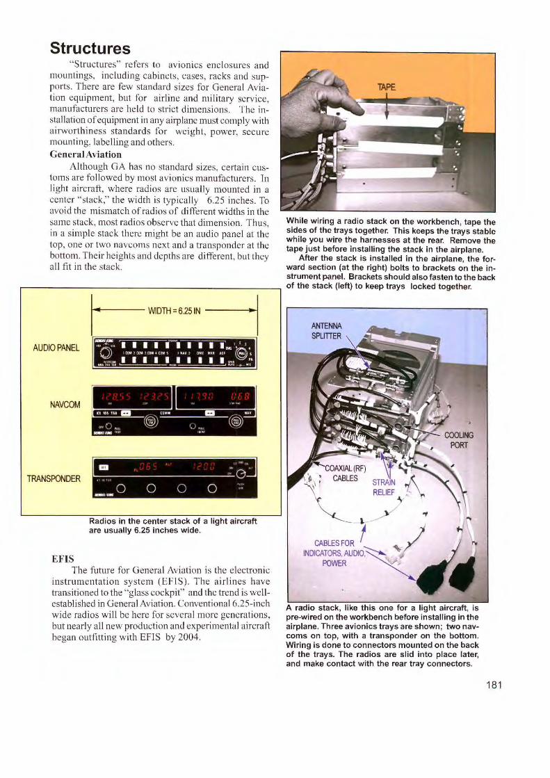
Structures "Structures" refers to av ioni cs enc losures and
mountings, inc luding cabinets, cases, racks and supports. There a re few standard sizes for General Aviation equipment, but for a irline and milita ry serv ice, manufacturers are held to strict dim ens io ns. The insta llation of equipment in any a iq) lanc must comply with a irworthiness standard s for we ight, power, secure mounting, labelling and others. General Aviation
Although GA has no standard sizes, certain customs are followed by most avioni cs manufacturers. Tn light a irc raft , where radi os arc usua lly mo unted in a cente r "stack," the width is typically 6.25 inches. To avo id the mi smatch o f radios of different widths in the same stack, most radios observe that dimension. Thus, in a simple stack there might be an audio panel at the top, one or two navcoms next and a transponder at the bottom. Their heights and depths are different, but they a ll fit in the stack.
AUDIO PANEL
NAVCOM
TRANSPONDER
EFTS
..... 0
0 0 0 0 ·
Radios in the center stack of a light aircraft are usually 6.25 inches wide.
The future fo r General Avia tion is the electronic instrumenta ti on system (EFlS). The a irlines have transitioned to the "glass cockpit" and the trend is wellestablished in General Aviation. Conventional 6.25-inch w ide radios will be here for several more generations, but nearly a ll new producti on and experimental a ircraft began outfitting with EFIS by 2004.
While wiring a radio stack on the workbench, tape the sides of the trays together. This keeps the trays stable while you wire the harnesses at the rear. Remove the tape just before installing the stack in the airplane.
After the stack is installed in the airplane, the forward section (at the right) bolts to brackets on the instrument panel. Brackets should also fasten to the back of the stack (left) to keep trays locked together.
ANTENNA SPLITTER
COAXIAL (RF) \ ~\ : CABLES
'\
~ 1
CABLES FOR t I INDICATORS, AUDIO~'-'":
POWER ~
A radio stack, like this one for a light aircraft, is pre-wired on the workbench before installing in the airplane. Three avionics trays are shown; two navcoms on top, with a transponder on the bottom. Wiring is done to connectors mounted on the back of the trays. The radios are slid into place later, and make contact with the rear tray connectors.
181
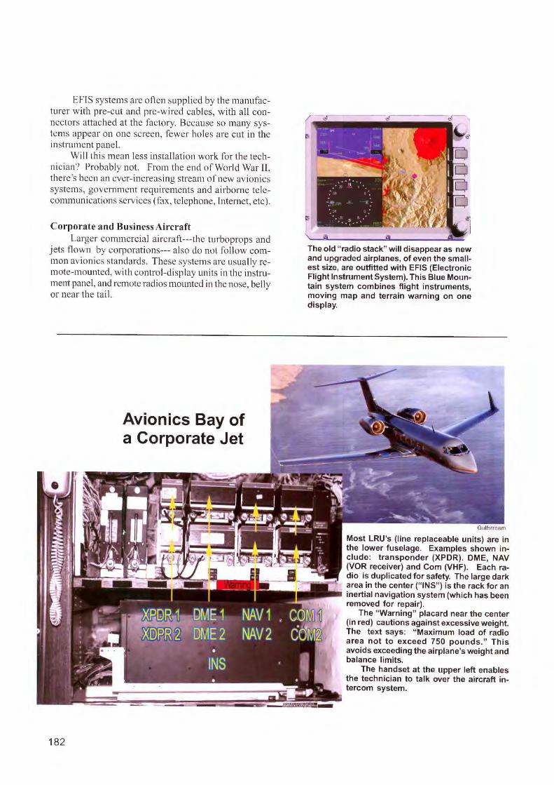
EFTS systems are often supplied by the manufacturer with pre-cut and pre-wired cables, w ith all connectors attached at the factory. Because so many systems appear on one screen, fewer ho les are cut in the instrument panel.
Will thi s mean less insta ll ation work for the technic ian? Probably not. From the end of World War II, there's been an ever-increasing stream of new avionics systems, government requirements and a irborne te lecommunications serv ices (fax, te lephone, Inte rnet, etc).
Corporate and Business Aircraft Larger commercial a irc raft---the turboprops and
jets flown by corporatio ns--- also do not fo llow common avio nics standards. These systems are usually remote-mounted, with control-display units in the instrument panel, and remote radi os mounted in the nose, be lly or near the ta il.
182
Avionics Bay of a Corporate Jet
-
The old "radio stack" will disappear as new and upgraded airplanes, of even the smallest size, are outfitted with EFIS (Electronic Flight Instrument System). This Blue Mountain system combines flight instruments, moving map and terrain warning on one display.
Most LRU's (line replaceable units) are in the lower fuselage. Examples shown include: transponder (XPDR). DME, NAV (VOR receiver) and Com (VHF). Each radio is duplicated for safety. The large dark area in the center ("INS") is the rack for an inertial navigation system (which has been removed for repair).
The "Warning" placard near the center (in red) cautions against excessive weight. The text says: "Maximum load of radio area not to exceed 750 pounds." This avoids exceeding the airplane's weight and balance limits.
The handset at the upper left enables the technician to talk over the aircraft intercom system.
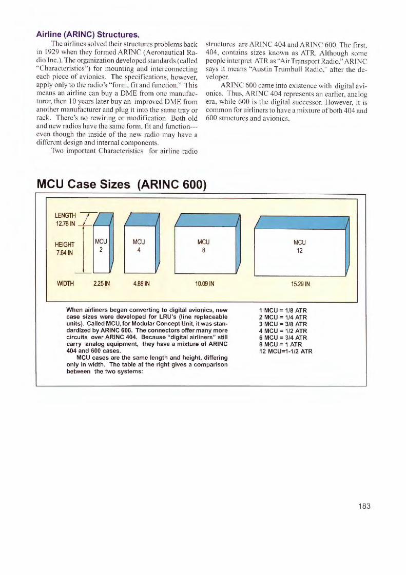
Airline (ARINC) Structures. The airlines solved their structures problems back
in 1929 when they formed A RINC (Aeronautical Radio Jnc.). The organization developed standards (called "Characteristics") for mounting and interconnecting each piece of avionics. The specifications, however, app ly only to the radio 's "form, fit and function." This means an airline can buy a DME from one manufacture r, then l O years later buy an improved DME from another manufacturer and plug it into the same tray or rack. There's no rewiring or modification Both old and new radios have th e same fo rm, fit and fun cti on--even though the inside of the new radio may have a different design and internal components.
structures are ARJNC 404 and ARINC 600. The first, 404, contains sizes known as ATR. Although some people interpret ATR as "Air Transport Radio," ARINC says it means "Austin Trumbull Radio," after the developer.
ARfNC 600 came into existence w ith digital avionics. Thus, ARINC 404 represents an earlier, analog era, while 600 is the digita l successor. However, it is common for airliners to have a mixture of both 404 and 600 structu res and avionics.
Two important Characteristics for a irline radio
MCU Case Sizes (ARINC 600)
Tn LENGTH ) )
12.76 IN
HEIGHT MCU MCU MCU MCU 7.641N 2 4 8 12
I J ---WIDTH 2.25 IN 4.88 IN 10.09 IN 15.29 IN
When airliners began converting to digital avionics, new 1 MCU = 1/8 ATR case sizes were developed for LRU 's (line replaceable 2 MCU = 1/4 ATR units). Called MCU, for Modular Concept Unit, it was stan- 3 MCU = 3/8 ATR dardized by ARINC 600. The connectors offer many more 4 MCU = 1/2 ATR circuits over ARINC 404. Because "digital airliners" still 6 MCU = 3/4 ATR carry analog equipment, they have a mixture of ARINC 8 MCU = 1 ATR 404 and 600 cases. 12 MCU=1-1/2 ATR
MCU cases are the same length and height, differing only in width. The table at the right gives a comparison between the two systems:
183
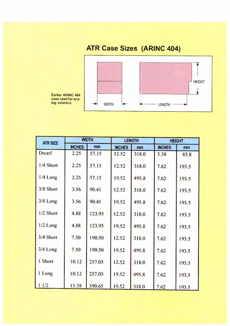
I
•
Earlier ARINC 404 case used for analog avionics.
.... .--------,-,.
_j WIDTH I._
1 - HEIGHT
'-----+'_j
.,..___~ LENGTH ~~
~
ATRSIZE WIDTH LENGTH H~GHT
INCHES mm INCHES ...mm ...... INCHES mm Dwarf 2.25 57. 15 12.52 318.0 3.38 85.8
1/4 Short 2.25 57.15 12.52 318.0 7.62 193.5
1/4 Long 2.25 57. 15 19.52 495.8 7.62 193 .5
3/8 Short 3.56 90.41 12.52 318.0 7.62 193.5
3/8 Long 3.56 90.41 19.52 495.8 7.62 193.5
1/2 Short 4.88 123.95 12.52 3 18.0 7.62 193.5
1/2 Long 4.88 123.95 19.52 495.8 7.62 193.5
3/4 Short 7.50 190.50 12.52 318.0 7.62 193.5
3/4 Long 7.50 190.50 19.52 495.8 7.62 193.5
1 Short 10. 12 257.05 12.52 3 18.0 7.62 193.5
1 Long 10.12 257.05 19.52 495.8 7.62 193.5
1 l/2 15.38 390.65 19.52 318.0 7.62 193.5 J -~
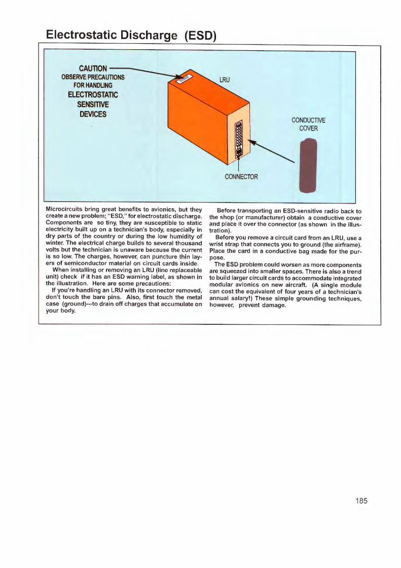
Electrostatic Discharge (ESD)
CAUTION--OBSERVEPRECAUTIONS
FOR HANDLING ELECTROSTATIC
SENSITIVE DEVICES
Microcircuits bring great benefits to avionics, but they create a new problem; "ESD," for electrostatic discharge. Components are so tiny, they are susceptible to static electricity built up on a technician's body, especially in dry parts of the country or during the low humidity of winter. The electrical charge builds to several thousand volts but the technician is unaware because the current is so low. The charges, however, can puncture thin layers of semiconductor material on circuit cards inside.
When installing or removing an LRU (line replaceable unit) check if it has an ESD warning label, as shown in the illustration. Here are some precautions:
If you're handling an LRU with its connector removed, don't touch the bare pins. Also, first touch the metal case (ground)---to drain off charges that accumulate on your body.
CONDUCTIVE COVER
CONNECTOR
Before transporting an ESD-sensitive radio back to the shop (or manufacturer) obtain a conductive cover and place it over the connector (as shown in the illustration).
Before you remove a circuit card from an LRU, use a wrist strap that connects you to ground (the airframe). Place the card in a conductive bag made for the purpose.
The ESD problem could worsen as more components are squeezed into smaller spaces. There is also a trend to build larger circuit cards to accommodate integrated modular avionics on new aircraft. (A single module can cost the equivalent of four years of a technician's annual salary!) These simple grounding techniques, however, prevent damage.
185
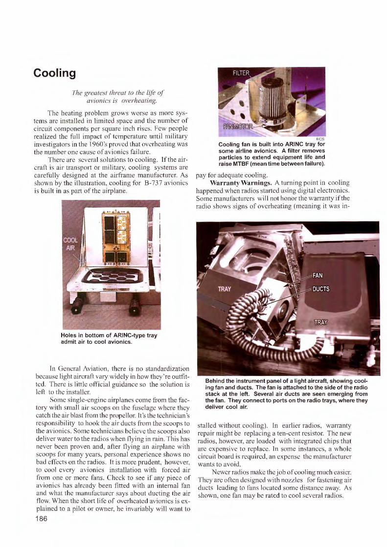
Cooling
The greatest threat to the /(le <~l avionics is overheating.
The heating problem grows worse as more systems arc installed in limited space and the number of circuit components per square inch rises. Few people realized the fu ll impact of temperature until military investigators in the l 960's proved that overheating was the number one cause of avionics fai lure.
There arc several solutions to cool ing. ff the aircraft is air transport or military, cool ing systems are carefully designed at the airframe manufacturer. As shown by the illustration, cooling for B-737 avionics is bu il t in as part of the airplane.
Holes in bottom of ARINC-type tray admit air to cool avionics.
Tn General Aviation, there is no standardi zation because light aircraft vary widely in how they' re outfitted. There is li ttle official guidance so the solution is left to the insta ller.
Some single-engine airplanes come from the factory with small air scoops on the fuselage where they catch the air blast from the propellor. It's the technician's responsibi lity to hook the air ducts from the scoops to the avionics. Some technicians be! icve the scoops also deliver water to the radio when fly ing in rain. This has never been proven and, after tlying an airplane with scoops for many years, personal experience shows no bad effects on the radios. ft is more prudent, however, to cool every avionics insta llation with forced air from one or more fans. Check to see if any piece of avionics has already been fitted with an internal fan and what the manufacturer says about ducting the air flow. When the short life of overheated avionics is explained to a pilot or owner, he invariably will want to
186
ECS Cooling fan is built into ARINC tray for some airline avionics. A filter removes particles to extend equipment life and raise MTBF (mean time between failure).
pay for adequate coo ling. Warranty Warnings. A turning point in cooling
happened when radios started using digital electronics. Some manufacturers wi ll not honor the warranty if the radio shows signs of overheating (meaning it was in-
Behind the instrument panel of a light aircraft, showing cooling fan and ducts. The fan is attached to the side of the radio stack at the left. Several air ducts are seen emerging from the fan. They connect to ports on the radio trays, where they deliver cool air.
stalled without cooling). In earlier radios, warranty repai r might be replacing a ten-cent resistor. The new rad ios, however, are loaded with integrated chips that arc expensive to replace. In some instances, a whole circuit board is required, an expense the manufacturer wants to avoid.
Newer radios make the job of cooling much easier. They are often designed with nozzles for fasten ing air ducts leading to fans located some distance away. As shown, one fan may be rated to coo l several radios.
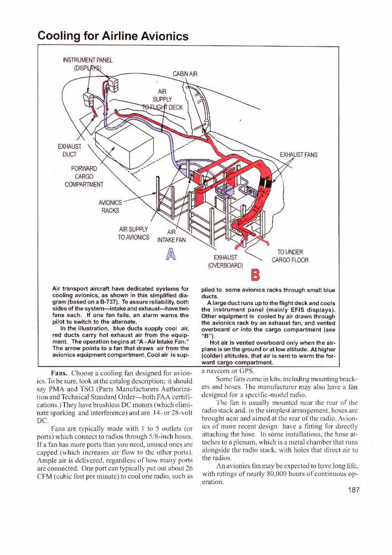
Cooling for Airline Avionics
FORWARD CARGO
COMPARTMENT
AVIONICS RACKS
AIR SUPPLY TO AVIONICS
Air transport aircraft have dedicated systems for cooling avionics, as shown in this simplified diagram {based on a B-737). To assure reliabil ity, both sides of the system---intake and exhaust---have two fans each. If one fan fails, an alarm warns the pilot to switch to the alternate.
In the illustration, blue duct s supply cool air, red ducts carry hot exhaust air from the equipment. The operation begins at "A - Air Intake Fan." The arrow points to a fan that draws air from the avionics equipment compartment. Cool air is sup-
Fans. Choose a coo ling fan designed fo r avionics. To be sure, look at the catalog description; it should say PMA and TSO (Parts Manufacturers Authorization and Technical Standard Order---both FAA certifications.) They have brush less DC motors (which eliminate sparking and interference) and are 14- or 28-voll DC.
Fans are typically made with I to 5 outlets (or ports) which connect to radi os through 5/8- inch hoses. l f a fan has more potts than you need, unused ones are capped (which increases a ir flow to the other ports). Ample air is de livered, regardless of how many ports are connected. One port can typ ica lly put out about 26 CFM (cubic feet per minute) to cool one radio, suc h as
EXHAUST (OVERBOARD)
B
TO UNDER CARGO FLOOR
plied to some avionics racks through small blue ducts.
A large duct runs up to the flight deck and cools the instrument panel {mainly EFIS displays). Other equipment is cooled by air drawn through the avionics rack by an exhaust fan, and vented overboard or into the cargo compartment {see "B").
Hot air is vented overboard only when the airplane is on the ground or at low altitude. At higher {colder) altitudes, that air is sent to warm the forward cargo compartment.
a navcom or GPS. Some fans come in kits, including mounti ng brack
ets and hoses. The manufacturer may also have a fan designed for a specifi c-model rad io.
The fa n is usually mounted near the rear of the radio stack and, in the si mplest arrangement, hoses are brought near and aimed at the rear of the radio. Avionics of more recent design have a fitti ng for directly attaching the hose. In some installations, the hose attaches lo a plenum, which is a metal chamber that runs alongs ide the rad io stack, wi th holes that direct a ir to the radios.
An avionics fan may be expected to have long life, w ith ratings of nearl y 80,000 hours of continuous operation.
187
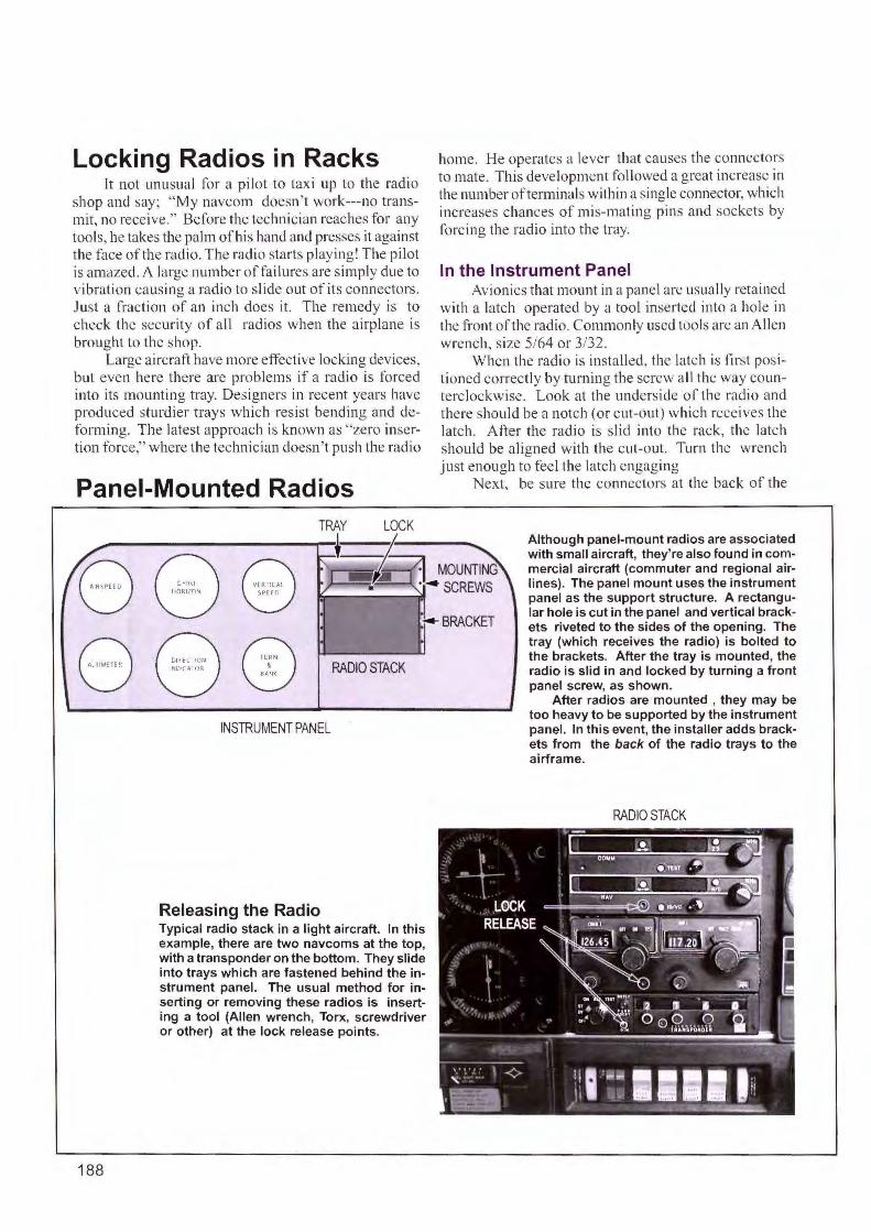
Locking Radios in Racks It not unusual for a pilot to taxi up to the radio
shop and say; "My navcom doesn't work---no transmit, no receive." Before the technician reaches for any tools, he takes the palm of his hand and presses it against the face of the radio. The radio starts playing! The pilot is amazed. A large number of failures arc simply due to vibration causing a radio to slide out of its connectors. Just a fraction of an inch does it. The remedy is to check the security of a ll radios when the airplane is brought to the shop.
Large aircraft have more effective locking devices, but even here there arc problems if a radio is forced into its mounting tray. Designers in recent years have produced sturdier trays which resist bending and deforming. The latest approach is known as "zero insertion force," where the technician doesn 't push the radio
Panel-Mounted Radios
8 8
188
RADIO STACK
INSTRUMENT PANEL
Releasing the Radio Typical radio stack in a light aircraft. In this example, there are two navcoms at the top, with a transponder on the bottom. They slide into trays which are fastened behind the instrument panel. The usual method for inserting or removing these radios is inserting a tool (Allen wrench, Tone, screwdriver or other) at the lock release points.
home. He operates a lever that causes the connectors to mate. This development followed a great increase in the number of terminals within a ingle connector, which increases chances of mis-mating pins and sockets by forcing the radio into the tray.
In the Instrument Panel Avionics that mount in a panel arc usually retained
with a latch operated by a tool inserted into a hole in the front of the radio. Commonly used tools are an Allen wrench, size 5/64 or 3/32.
When the rad io is installed, the latch is first positioned correctly by turning the screw all the way counterclockwise. Look at the underside of the radio and there should be a notch (or cut-out) which receives the latch. After the radio is slid into the rack, the latch should be aligned with the cut-out. Turn the wrench just enough to feel the latch engaging
Next, be sure the connectors at the back of the
Although panel-mount radios are associated with small aircraft, they're also found in commercial aircraft (commuter and regional airlines). The panel mount uses the instrument panel as the support structure. A rectangular hole is cut in the panel and vertical brackets riveted to the sides of the opening. The tray (which receives the radio) is bolted to the brackets. After the tray is mounted, the radio is slid in and locked by turning a front panel screw, as shown.
After radios are mounted , they may be too heavy to be supported by the instrument panel. In this event, the installer adds brackets from the back of the radio trays to the airframe.
RADIO STACK
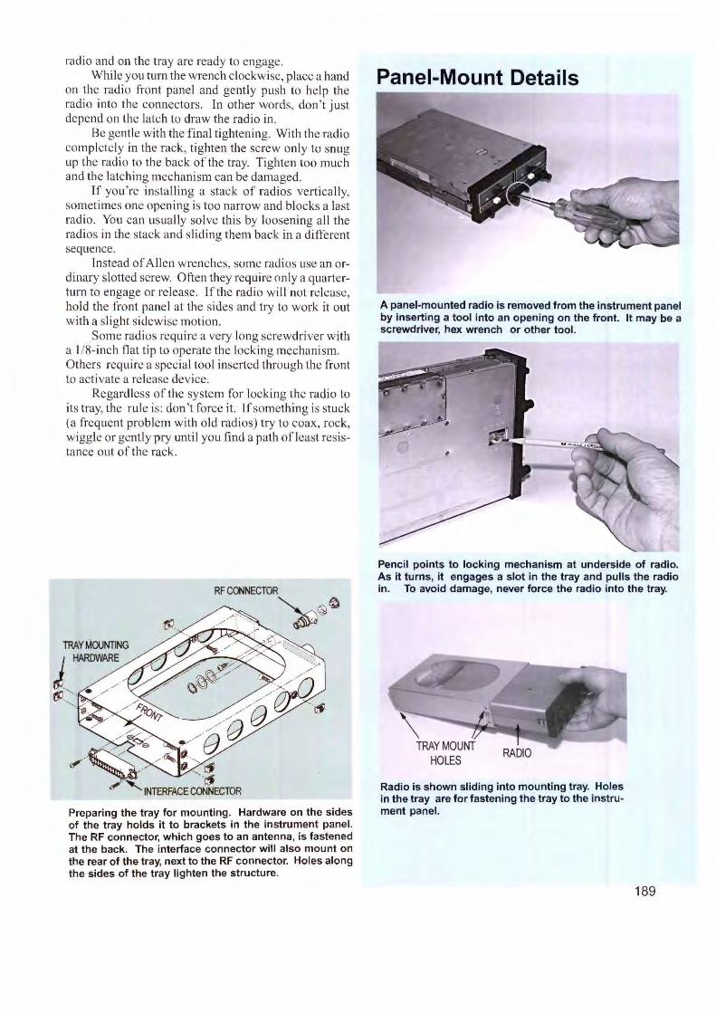
radio and on the tray are ready to engage. While you turn the wrench clockwise, p lace a hand
on the radio front pa nel and gently push to help th e radio into the connectors. ln other words, do n't just depend on the latch to draw the radio in.
Be gentle with the final tighten ing. With the radio completely in the rack, tighten the screw only to snug up the radio to the back of the tray. Tighten too much and the latchi ng mechanism can be damaged.
If you 're insta lling a stack of radios vertically, sometimes one opening is too narrow and blocks a last radio. You can usually solve th is by loosening a ll the radi os in the stack and sliding them back in a different sequence.
Instead of Al len wrenches, some radios use an ordinary slotted screw. Often they require only a quarte rturn to engage or release. lfthe radio wil l not release, hold the front panel at the sides and try to work it out w ith a slight sidewise motion.
Some radios require a very long screwdriver w ith a 1/8-inch flat tip to opera te the locking mechanism. Others require a spec ial tool inserted through the front to activate a re lease device.
Regard less of the system for locking the radio to its tray, the rule is: don 't force it. If somethi ng is stuck (a frequent problem w ith old radios) try to coax, rock, wiggle or gently pry unt il you fi nd a path ofl cast resistance o ut of the rack.
RF CONNECTOR
~@~
Preparing the tray for mounting. Hardware on the sides of the tray holds it to brackets in the instrument panel. The RF connector, which goes to an antenna, is fastened at the back. The interface connector will also mount on the rear of the tray, next to the RF connector. Holes along the sides of the tray lighten the structure.
Panel-Mount Details
A panel-mounted radio is removed from the instrument panel by inserting a tool into an opening on the front. It may be a screwdriver, hex wrench or other tool.
Pencil points to locking mechanism at underside of radio. As it turns, it engages a slot in the tray and pulls the radio in. To avoid damage, never force the radio into the tray.
Radio is shown sliding into mounting tray. Holes in the tray are for fastening the tray to the instrument panel.
189
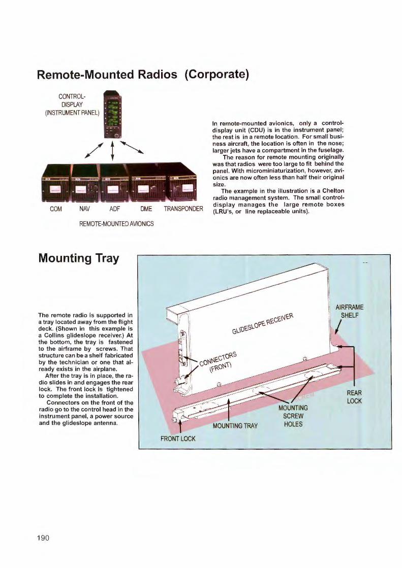
Remote-Mounted Radios (Corporate)
CONTROLDISPLAY
(INSTRUMENT PANEL}
, ~ ~~~
. l!!I . . l!!I · -. . • : . . • . - . . ,.- • . .. - - .. .. ... - - ..
COM NAV ADF DME
REMOTE-MOUNTED AVIONICS
Mounting Tray
The remote radio is supported in a tray located away from the flight deck. (Shown in this example is a Collins glideslope receiver.) At the bottom, the tray is fastened to the airframe by screws. That structure can be a shelf fabricated by the technician or one that already exists in the airplane.
After the tray is in place, the radio slides in and engages the rear lock. The front lock is tightened to complete the installation.
Connectors on the front of the radio go to the control head in the instrument panel, a power source and the glideslope antenna.
190
TRANSPONDER
FRONT LOCK
In remote-mounted avionics, only a control· display unit (CDU) is in the instrument panel ; the rest is in a remote location. For small business aircraft, the location is often in the nose; larger jets have a compartment in the fuselage.
The reason for remote mounting originally was that radios were too large to fit behind the panel. With microminiaturization, however, avionics are now often less than half their original size.
The example in the illustration is a Chelton radio management system. The small controldisplay manages the large remote boxes (LRU's, or line replaceable units).
AIRFRAME SHELF
I
MOUNTING TRAY
REAR LOCK
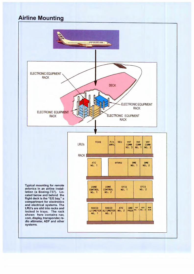
Airline Mounting
ELECTRONIC EQUIPMENT RACK
ELECTRONIC EQUIPMENT RACK
Typical mounting for remote avionics in an airline installation (a Boeing-737). Located below and behind the flight deck is the "E/E bay," a compartment for electronics and electrical systems. The LRU's are slid into racks and locked in trays. The rack shown here contains nav, com, display, transponder, radio altimeter, ADF and other systems.
LRU's
RACK
TCAS
ATC NO. ,
ZONE CONTROL
NO. 1
RADIO .. LTI"ETER
NO. 1
ELECTRONIC EQUIPMENT RACK
LECTRONIC EQUIPMENT RACK
P/A REU VHF VHF VHF .APIPL COM ca... COM
NO. 3 NO. 1 NO. 2
DFDAU ME DfllE NO . 1 NO. 2
ZONE EFIS EFIS CONTROL NO. 1 NO. 2
NO. 2
RADIO ATC GND ADF ADf l'ltJI
ALTINETER NO. 2 PROX MC). 1 IIO. 2 BCN
HO. 2
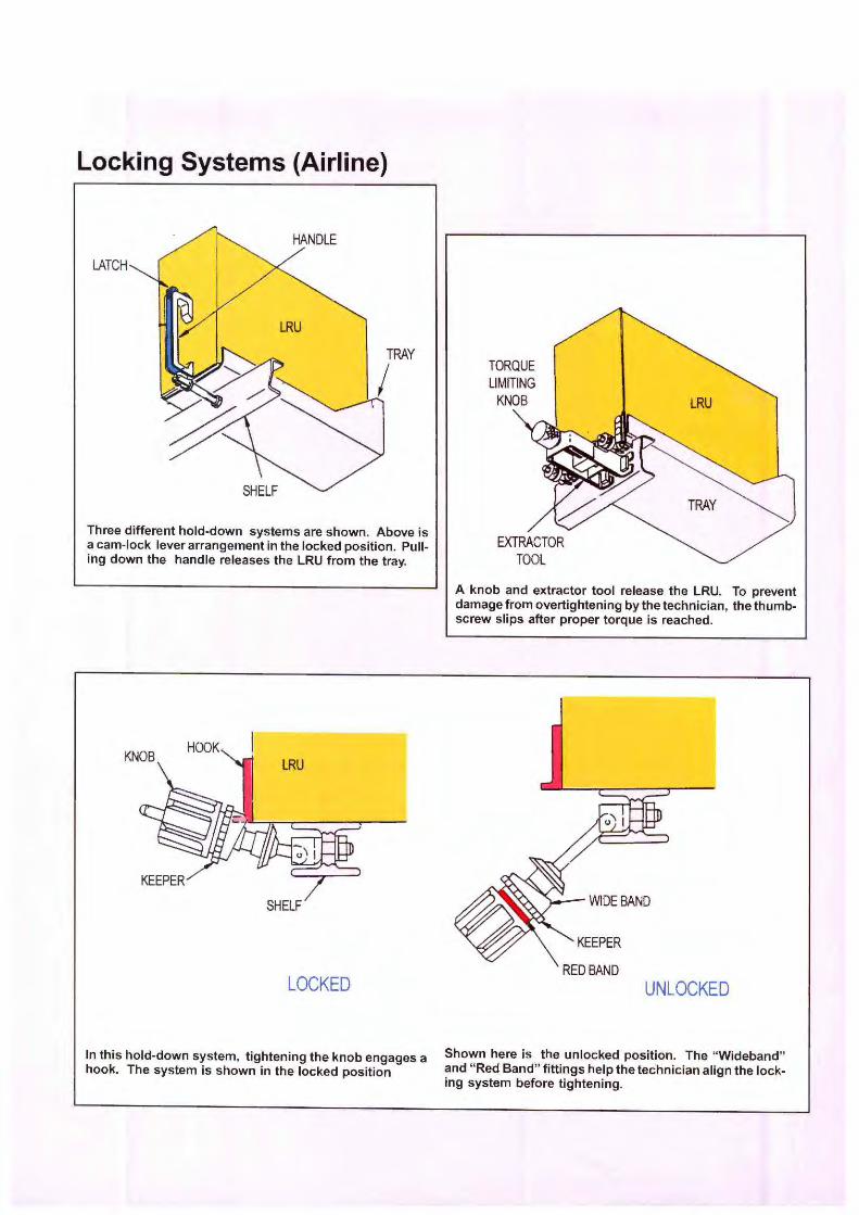
Locking Systems (Airline)
LATCH
Three different hold-down systems are shown. Above is a cam-lock lever arrangement in the locked position. Pulling down the handle releases the LRU from the tray.
LOCKED
In this hold-down system, tightening the knob engages a hook. The system is shown in the locked position
TORQUE LIMITING
KNOB
A knob and extractor tool release the LRU. To prevent damage from overtightening by the technician, the thumbscrew slips after proper torque is reached.
UNLOCKED
Shown here is the unlocked position. The "Wideband" and " Red Band" fittings help the technician align the locking system before tightening.
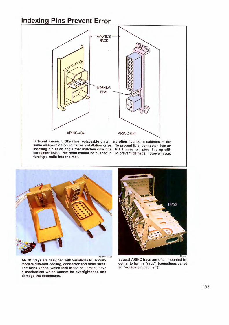
lndexin Pins Prevent Error
ARINC404
AVIONICS RACK
INDEXING PINS
ARINC600
Different avionic LRU 's (line replaceable units) are often housed in cabinets of the same size---which could cause installation error. To prevent it, a connector has an indexing pin at an angle that matches only one LRU. Unless all pins line up with connector holes, the radio cannot be pushed in. To prevent damage, however, avoid forcing a radio into the rack.
US Technical
ARINC trays are designed with variations to accommodate different cooling, connector and radio sizes. The black knobs, which lock in the equipment, have a mechanism which cannot be overtightened and damage the connectors.
arry
Several ARINC trays are often mounted together to form a " rack" (sometimes called an " equipment cabinet" ).
193
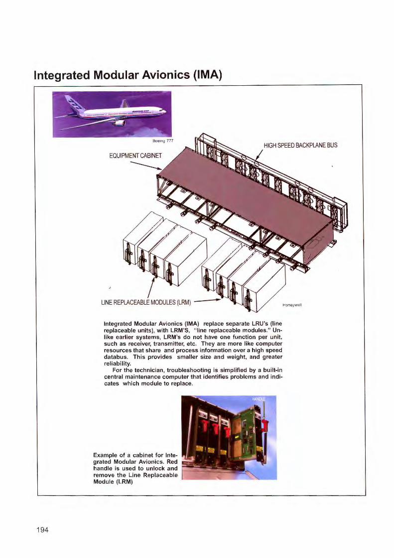
Integrated Modular Avionics (IMA)
Boeing 777 HIGH SPEED BACKPLANE BUS
194
EQUIPMENT CABINET
------
LINE REPLACEABLE MODULES (LRM) -
Integrated Modular Avionics (IMA) replace separate LRU's (line replaceable units), with LRM' S, "line replaceable modules." Unlike earlier systems, LRM's do not have one function per unit, such as receiver, transmitter, etc. They are more like computer resources that share and process information over a high speed databus. This provides smaller size and weight, and greater reliability.
For the technician, troubleshooting is simplified by a built-in central maintenance computer that identifies problems and indicates which module to replace.
Example of a cabinet for Integrated Modular Avionics. Red handle is used to unlock and remove the Line Replaceable Module (LRM)
Honeywell
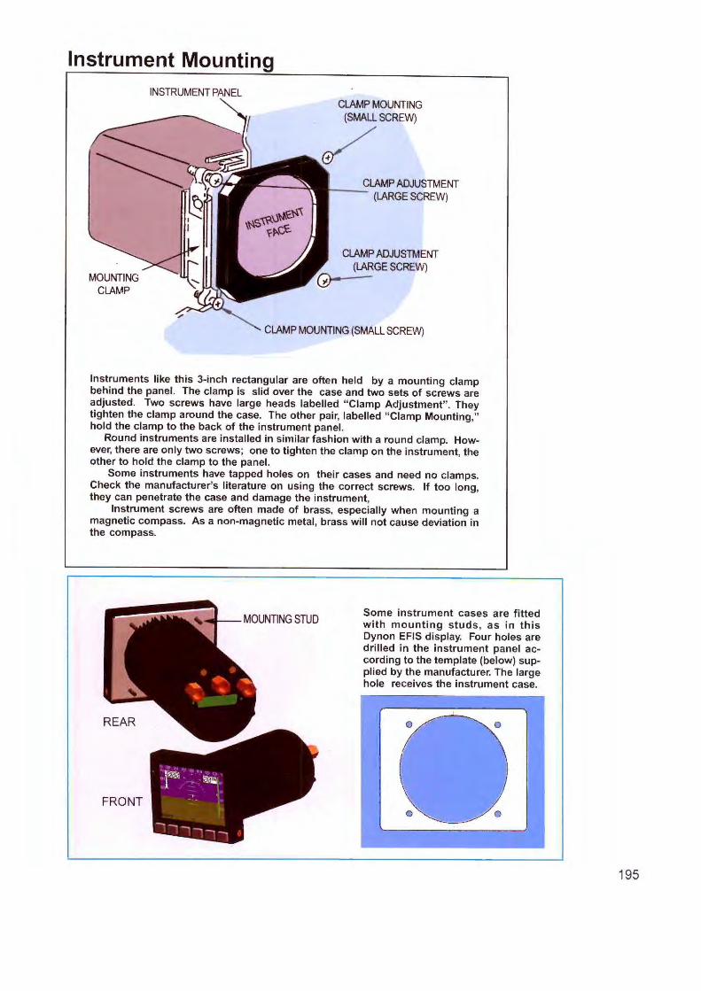
Instrument Mounting
MOUNTING CLAMP
INSTRUMENT PANEL CLAMP MOUNTING
(SMALL SCREW)
~ CLAMP ADJUSTMENT
:---- (LARGE SCREW)
CLAMP ADJUSTMENT (LARGE SCREW)
CLAMP MOUNTING (SMALL SCREW)
Instruments like this 3-inch rectangular are often held by a mounting clamp behind the panel. The clamp is slid over the case and two sets of screws are adjusted. Two screws have large heads labelled " Clamp Adjustment" . They tighten the clamp around the case. The other pair, labelled " Clamp Mounting," hold the clamp to the back of the instrument panel.
Round instruments are installed in similar fashion with a round clamp. However, there are only two screws; one to tighten the clamp on the instrument, the other to hold the clamp to the panel.
Some instruments have tapped holes on their cases and need no clamps. Check the manufacturer's literature on using the correct screws. If too long, they can penetrate the case and damage the instrument,
Instrument screws are often made of brass, especially when mounting a magnetic compass. As a non-magnetic metal, brass will not cause deviation in the compass.
REAR
Some instrument cases are fitted with mounting studs , as in this Dynon EFIS display. Four holes are drilled in the instrument panel according to the template (below) supplied by the manufacturer. The large hole receives the instrument case.
195
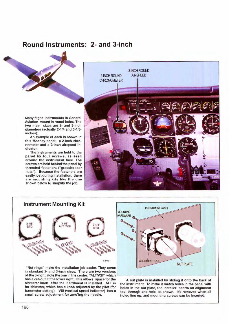
Round Instruments: 2- and 3-inch
Many flight instruments in General Aviation mount in round holes. The two main sizes are 2- and 3-inch diameters (actually 2-1 /4 and 3-1/8-inches).
An example of each is shown in this Mooney panel; a 2-inch chronometer and a 3-inch airspeed indicator.
The instruments are held to the panel by four screws, as seen around the instrument face. The screws are held behind the panel by threaded fasteners (" grasshopper nuts" ). Because the fasteners are easily lost during installation, there are mounting kits like the one shown below to simplify the job.
Instrument Mounting Kit
Edmo
" Nut rings" make the installation job easier. They come in standard 2- and 3-inch sizes. There are two versions
3-INCH ROUND AIRSPEED
MOUNTING HARDWARE
of the 3-inch; note the one in the center, "ALTNSI" which L----------------------~ has a cut-out at the lower right. This allows space for the altimeter knob after the instrument is installed. ALT is for altimeter, which has a knob adjusted by the pilot (for barometer setting). VSI (vertical speed indicator) has a small screw adjustment for zero' ing the needle.
196
A nut plate is installed by sl iding it onto the back of the instrument. To make it match holes in the panel with holes in the nut plate, the installer inserts an alignment tool through one hole, as shown. It's removed when all holes line up, and mounting screws can be inserted.
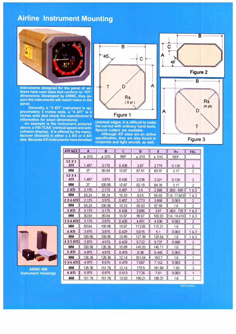
8 l C
45y ~~ A T
l Figure 2
( B--T D A
Rs ( 8 pl) Rs
(4 pl)
A D
T~ .,
Figure 3
I ATI SIZE II A I B C D E II Rs II FIG. I I II ± .010 I ± .010 II REF I ± .010 II ± .010 II REF. II I I 1!{i3 II 1.457 l~~~I 2.775 II 0.125 IGJ I MM II 37 I 80.84 II 10.87 I 67.81 II 69.97 II 3.17 2 I I 1!~4 l~~~~G;JI 0.125 GJ I MM II 37 100.96 10.87 82.19 II 84.35 II 3.17 2
I 2 ATI II 2.1 75 2.175 0.407 2.5 II 2.585 II .063, .695 1 &3
I MM I 55.24 55.24 10.33 63.5 II 65.65 lb .6.17.65311 1 &3 2 X4All 2.175 3.975 0.407 3.773 3.858 II 0.063 II 2
MM 55.24 100.96 10.33 95.83 97.99 II 1.6 II 2 3 All 3.175 3.175 0.428 3.885 3.97 11.063 .. 725 II 1 &3
MM 80.64 80.64 10.87 98.67 100.83 1.6, 18.415 1 &3 3 X4All 3.175 3.975 0.428 4.451 4.536 0.063 2
MM 80.64 100.96 II 10.87 11 3.05 115.21 1.6 2
I 4All 3.975 3.975 II 0.429 5.015 5.1 OJJ63 1 &3
I MM 100.96 100 .96 II 10.89 127.38 129.54 1.6 1 &3 14 X5All 3.975 4.975 II 0.429 5.722 5.737 0.068 2
I MM 100.96 126.36 II 10.89 145.33 145.71 1.6 2
I 5 All 4.975 4.975 II 0.478 6.36 6.445 0.063 2
I MM 126.36 126.36 12.14 161 .54 163.7 1.6 I 1 l5X6All 4.975 5.975 0.478 7.067 7.152 0.063 II 2
I MM 126.36 151 .76 12.14 179.5 II 181 .66 1.60 II 2
I 6 ATI 5.975 5.975 0.513 7.725 II 7.81 0.063 II I MM 151 .76 151.76 13.03 196.21 II 198.37 1.6 II

Review Questions Chapter 23 Mounting Avionics
23. 1 Who should be consulted if an avionics installation will affect structures in the airplane?
23.2 What designation assures that a piece of equipment has high resistance to heat, humidity and other environmental conditions of flight?
23.3 "Approved data" for an installation may be found in the ____ _ _
23.4 When selecting aluminum for making structures, what label indicates resistance to corrosion?
23.5 What are efficient methods for cutting oddshaped instrument holes in an aluminum panel?
23.6 When mounting new equipment in an instrument panel or in the avionics bay of a large aircraft, do not exceed the and limitations of the airplane.
198
23. 7 What is a major advantage of ARlNC cases in large aircraft?
23.8 What are the two basic types of ARI NC cases'?
23.9 What are two precautions when handUng avionics that are sensitive to electrostatic discharge (static electricity)?
23.10 What is the greatest threat to the life of avionics?
23.11 What techniques are used in large and small aircraft to prevent overheating?
23.12 When mounting a magnetic compass, always use screws to avoid in the compass.

Chapter 24
Connectors
Working wi th connectors often takes up more of an installation technician 's time than any other task. A light a ircraft has connectors in the dozens, while larger a irplanes count them in the hundreds. Without connectors, av ioni cs can't be removed for maintenance or modi ftcati ons.
There is a trend in avionics to reduce the amount of connectors and wiring . They add weight, take up space and cause troubl e when improperly installed. It is now possibl e to blend signals of many systems on a s ingle pair of wires or fiber optic cable and send them around the airplane. Applications increase with each generation of new aircraft but we wil l have to live with connectors fo r another 30 or 40 years.
Connectors look like simple mechanical devices--
--an outer shell, tenninals (pins or sockets) and insulating material. Neverthe less, connectors are a major cause of equipment fa ilure. Pins a re w ired incorrectly, bare w ires touch and sho1i-circui t or connector pins arc accidently bent. A ll can be avoided by careful wiring technique.
Technicians have different approaches to avo iding e rrors in w iring. Some fo ll ow the old carpenter's warning; "Measw-e twice, cut once." l n w iring, it means double-check ing for the correct pin, marking each pin on the diagram as it's done and making a fi na l check after a ll w iring to the connector is complete . Finding trouble after the insta llation is done takes far more time than c hecking for error as you bui ld up the w iring ha rness.
Reading pin connections. Some errors are due to the way pins are identified. Because of their high number and small s ize, markings on connectors arc not only tiny, but often the same color as the background. You may have to hold the connector up to a bri ght I ig ht to make the number legible.
(co11ti1111ed p. 202)
199
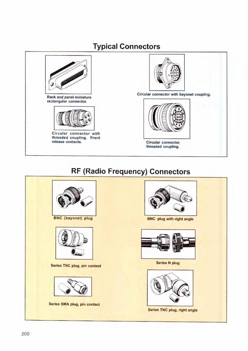
200
Typical Connectors
Rack and panel miniature rectangular connector.
Circular connector with threaded coupling. Front release contacts.
Circular connector with bayonet coupling.
Circular connector, threaded coupling.
RF {Radio Frequency) Connectors
BNC (bayonet) plug BNC plug with right angle
Series TNC plug, pin contact Series N plug
Series SMA plug, pin contact
Series TNC plug, right angle

How to Identify Connector Contacts
10 markers 1. The end of a circular connector, where contacts will be inserted. Some connectors identify every contact, but limited space may allow only starting and ending numbers like "1" and "14," shown above. Start at "1" and follow the guide line around to " 14," as shown by the arrows (which are not on the connector).
2. The same connector is shown; with red numbers added to clarify the numbering system. Note that " 10" is surrounded by two markers. They speed up your counting. You can jump to the first marker and know it's 10. When looking at the back of a connector (where the terminals are inserted or wired) counting is usually done in a counterclockwise direction.
Contacts are Selected to Fit the Application
Contacts
A circular connector, like this RMS bayonet receptacle, can be obtained with a variety of contacts (pins and sockets) to fit the application.
Shown below is an excerpt from an RMS specification sheet. By knowing maximum current rating and wire size, you can order the contact size for insertion into the connector. The contacts in this model are rear insertion and front release.
For use with Series R0715, R0716, R0717, R0718 and R0719
Max. Wire Current MS Part No.
Contact Size Rating Size AWG Amps. Pin socket
24 3.0 M39029/31-241 M39029/32-260 No. 20 22 5.0
20 7.5
No. 16 18 16 M39029/31-229 M39029/32-248 16 22
No.12 14 32 M39029/31-235 M39029/32-254 12 41
-
201
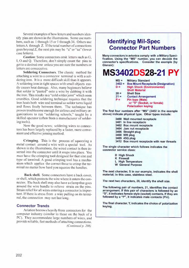
Several examples of how letters and numbers identify pins are shown in the illustrations. Some use numbers, such as l through 15 or I through 34. Others use letters A through Z. Tf the total number of connections goes beyond Z, the next pin may be "a" or "aa" (lower case lette rs).
C(lufio11: Some connectors omit letters such as G, I, 0 and Q. Therefore, don't si mply count the pins to get to a desired one unless you arc sure the numbers or lette rs are consecutive.
Sold ering Connectors. The classic method for attaching a wire to a connector te rminal is with a so ldering iron. It is a more difficult skill than it appears. A so ldering iron in tight spaces with small objects easily causes heat damage . Also, many beginners be lieve that solder is "pasted" onto a wire by dabbing it w ith the iron. This results in a "cold solderjo int" whi ch soon crumbles. Good so ldering technique requires tha t the iron heats both wire and terminal so solder turns liquid and n ows freely between them. The technique has proven troublesome enough for airlines and military organizatio ns to run "soldering schools," taught by a skilled operator ( often from a manufactmer of soldering too ls).
Now the good news; so ldering wires to connectors has been large ly replaced by a faste r, more convenient and effective j oining method.
Crimping. This is the process of squeezing a metal contact around a wire with a specia l tool. As shown in the il lustrations, the wired contact is then inserted into the connector unti I it snaps into place. Yo u must have the crimping tool des igned for that size and type of terminal. A good crimping tool has a mechanism which applies the correct force to c rimp the terminal no matte r how hard you squeeze the hand les.
Back shell. Some connectors have a back cover, or shell , which protects the w ire where it enters the connector. The back shell may a lso have a clamp that goes around the wire bundle to re lieve stra in on the p ins. Stra in re li ef for a l I wires entering a connector is important. lf thcre is stress from a wire pulling on its terminal, the connection may not last long.
Connector Trends Av iation borrows heavily fro m connectors for the
computer industry (similar to those on the back of a PC). They accommodate large numbers of wires, and provide reliable, fast methods of attaching connections .
(Continued p. 206)
202
Identifying Mil-Spec Connector Part Numbers
Many connectors in avionics comply with a Military Specification. Using the "MS" number, you can decode the connector's specifications. Consider the example (by Glenair):
MS3402DS28-21 PY MS= 3402 = O=
28 = 21 = P=
Military Standard Box Mount Receptacle (Designation) High Shock (Environmental) Shell Material Shell Size Contact Arrangement Pin type (Male)
or "S" (Socket, or female) Polarization keying
The first four numbers after "MS" (3402 in the example above) indicate physical type. Other types include:
3400 Wall mounted receptacle 3401 In line receptacle 3402 Box mount receptacle 3404 Jam nut receptacle 3406 Straight plug 3408 909 plug 3409 45Q plug 3412 Box mount receptacle with rear threads
The single character which follows indicates the connector service class:
D High Shock K Firewall L High Temperature W General Purpose
The next character, S in our example, indicates the shell material ; in this case, stainless steel.
The next two characters, 28, identify the shell size.
The following pair of numbers, 21, identifies the contact arrangement. If this pair of characters is followed by an "S" , it indicates female style (socket) contacts. If they are followed by a " P", it indicates male contacts (Pin).
The final character, Y, indicates the choice of polarization keying.
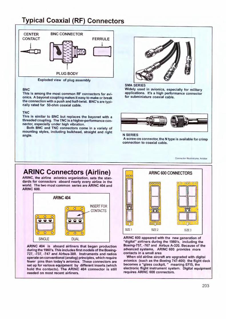
Typical Coaxial {RF) Connectors
CENTER CONTACT
CD
BNC CONNECTOR
PLUG BODY
FERRULE
D Exploded view of plug assembly
BNC This is among the most common RF connectors for avionics. A bayonet coupling makes it easy to make or break the connection with a push and half-twist. BNC's are typically rated for 50-ohm coaxial cable.
TNC This is similar to BNC but replaces the bayonet with a threaded coupling. The TNC is a higher-performance connector, especially under high vibration.
Both BNC and TNC connectors come in a variety of mounting styles, including bulkhead, straight and right angle.
ARINC Connectors {Airline) ARINC, the airline avionics organization, sets the standards for connectors aboard nearly every airline in the world. The two most common series are ARINC 404 and ARINC 600.
ARINC404
0 0 0 '/
~
[ 0 J ~~~
0 0 0
SINGLE
( 0
J 0 0
DUAL
1.-
INSERT FOR CONTACTS
ARINC 404 is aboard airliners that began production during the 1960's. This includes first models of the Boeing-727, -737, -747 and Airbus-300. Instruments and radios operate on conventional (analog) principles, which require fewer pins than today's avionics. These connectors are set up for various equipment by different inserts (which hold the contacts). The ARINC 404 connector is still needed on most recent airliners.
SMA SERIES Widely used in avionics, especially for military applications. It's a high performance connector for subminiature coaxial cable.
N SERIES A screw-on connector, the N type is available for crimp connection to coaxial cable.
000
D D
S1ZE1
Connector Illustrations: Anixter
ARINC 600 CONNECTORS
0 0 0 0 0 0 0
S1ZE2 S1ZE3
ARINC 600 appeared with the new generation of "digital" airliners during the 1980's, including the Boeing-757, -767 and Airbus A-320. Because of the advanced systems, ARINC 600 provides more contacts in a small area
When old airline aircraft are upgraded with digital avionics (such as the Boeing 747-400) the flight deck becomes a " glass cockpit," meaning EFIS, the electronic flight instrument system. Digital equipment requires ARINC 600 connectors.
203
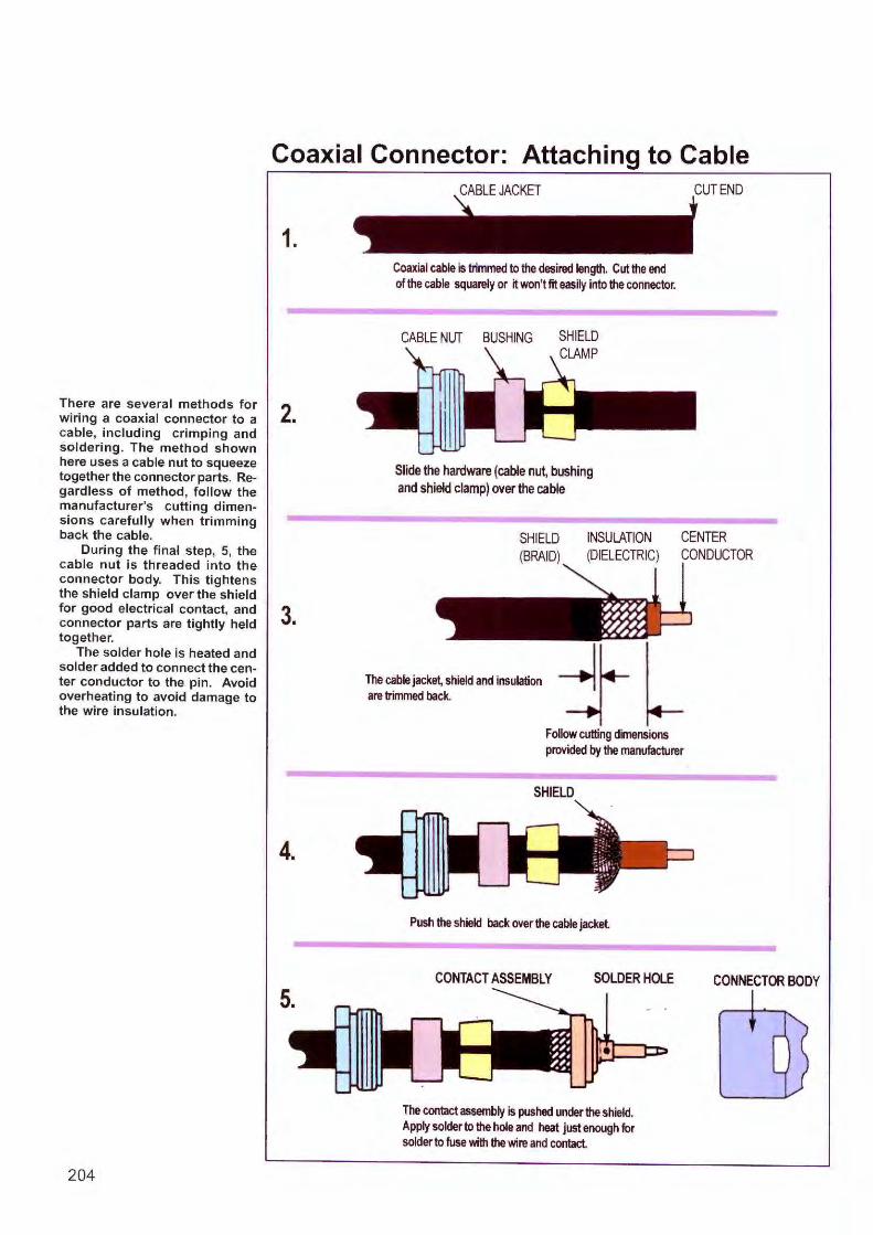
There are several methods for wiring a coaxial connector to a cable, including crimping and soldering. The method shown here uses a cable nut to squeeze together the connector parts. Regardless of method, follow the manufacturer's cutting dimensions carefully when trimming back the cable.
During the final step, 5, the cable nut is threaded into the connector body. This tightens the shield clamp over the shield for good electrical contact, and connector parts are tightly held together.
The solder hole is heated and solder added to connect the center conductor to the pin. Avoid overheating to avoid damage to the wire insulation.
204
Coaxial Connector: Attaching to Cable
1.
2.
3.
4.
Coaxial cable is trimmed to the desired length. Cut the end of the cable squarely or it won't fit easily into the connector.
CABLE NUT BUSHING
Slide the hardware (cable nu~ bushing and shield clamp) over the cable
CUT END
SHIELD (BRAID)
INSULATION (DIELECTRIC)
CENTER CONDUCTOR
The cab• jack'\ shold arnHasulation .. ~.. I are trimmed back. i.--
Follow cutting dimensions provided by the manufacturer
SHIELD
Push the shield back over the cable jacket
CONTACT ASSEMBLY SOLDER HOLE
The contact assembly is pushed under the shield. Apply solder to the hole and heat just enough for solder to fuse with the wire and contact
CONNECTOR BODY

Crimping: Attaching Wires to Connector Contacts
Connector contact (in red circle) is crimpled to the end of a wire with a crimping tool (type DMC AFB).
DMC Crimp tools are fitted with dies for making different crimp patterns. The most common for avionics work is the "Eight Indent" shown at the top.
~ NSULATION
WIRE\ \
SOCKET
Pin and socket contacts that will be inserted into the connector. The wire is crimped into tabs on the contact. Another set of tabs clamps the insulation to relieve strain. These terminals are used in a " Molex" connector.
CONTACT
INSPECTION HOLE (WIRE MUST BE VISI BLE)
"DI'-+- SPACE BETWEEN CONTACT AND INSULATION (1/64 TO 1/32-INCH)
WIRE {INSULATION)
In this type of contact, there is an inspection hole. Bare wire must be visible through the hole. There must also be a small space between the contact and the insulation.
This crimp tool has wide application among miniature and sub-miniature connector types. It delivers a standard 8-impression crimp. When the handles are squeezed, a ratchet controls maximum pressure. A selector knob sets the correct wire depth. The " go-no go" gauge checks the tool 's accuracy. The "positioner" holds the contact in the correct position. The model shown is the DMC AFM, also known as " Little Blue."
205
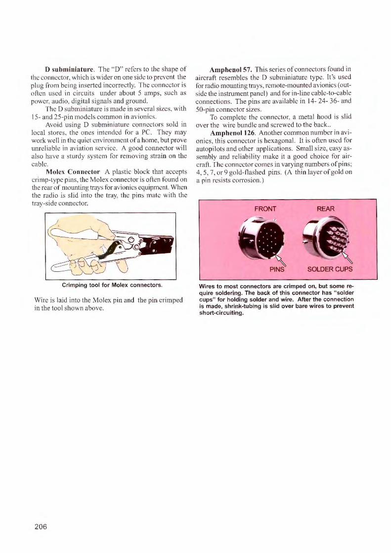
D subminiature. The " D" refers to the shape o f the connector, which is wider on one side to prevent the plug from being inserted incorrectly. The connector is often used in c ircuits under about 5 amps, such as power, audio, digital signals and ground.
The D subm in iature is made in several sizes, with 15- and 25-pin models common in avionics.
Avo id us ing D subrniniature connectors sold in local s tores, the ones intended for a PC. They may work we ll in the qu iet environment of a home, but prove unre liable in aviation service. J\ good connector will a lso have a sturdy system for removing strain on the cable.
Molex Connector A plasti c block that accepts crimp-type pins, the Molex connector is often found on the rear of mounting trays for avionics equipment. When the radio is slid into the tray, the pins mate with the tray-side connector.
Crimping tool for Molex connectors.
Wire is la id into the Molex pin and the pin crimped in the tool shown above.
206
Amphenol 57. This series o f connectors found in aircraft resembles the D subminiature type. It 's used for radio mounting trays, remote-mounted avionics ( outside the instrument panel) and for in- line cable-to-cable connections. The pins are available in 14- 24- 36- and 50-pi n connector sizes.
To complete the connecto r, a meta l hood is slid over the wire bund le and screwed to the back ..
Amphenol t 26. Anoth er commo n number in avionics, this connector is hexagonal. lt is often used fo r autopilots and other appl ications. Small size, easy assembly and re liability make it a good cho ice for airc raft. The connector comes in vary ing numbers of pins; 4 , 5, 7, or 9 go ld-flashed p ins. (A thin layer of gold on a pin resists corros ion .)
FRONT REAR
PINS SOLDER CUPS
Wires to most connectors are crimped on, but some require soldering. The back of this connector has "solder cups" for holding solder and wire. After the connection is made, shrink-tubing is slid over bare wires to prevent short-circuiting.

Releasing Connector Pins
DMC A variety of tools is available for installing and removing connector pins, either front or rear release. Although these tools may be offered in plastic, metal is preferred for durabillty.
~ ~ '=""'='===~=:z:;~~L.....-l_~I-..Jt--Y 3.TOOL PUSHES PIN OUT
To release pins (1) from a connector, the removal tool is inserted over the pin (2). When the tool seats, it spreads a spring which retains the pin. Now when the tool is pressed further, the pin is pushed (3) out. Shown here is a "front release" connector. Other connectors may be " rear release," but the principle is similar
Heat Gun for Shrink Tubing
A heat gun (also called a "hot air" gun) is essential for heatshrink tubing and so ldersleeving.
Effectiveness is greatly increased by adding nozzles , shown at right. They curve and concentrate hot air on the work, which creates equal and faster heating. Nozzles come in different sizes for work of various diameter. The nozzle at the top, however, should handle most avionics jobs. It has a 1-1/2-inch diameter.
A heat gun like this Steinel 1802 has selectable temperature from 120 F to 1100 F (50 C to 650 C). It consumes 1500 watts at 120 VAC.
207
DMC

Safety Wiring Connectors
Strain relief for cable is provided by clamp at back of connector. Screws are secured by safety wire applied by tool. (Illustrations: DMC)
1. Pre-twisted safety wire is inserted into fasteners. A ferrule has been crimped to one end (upper right).
2. The other end of the wire is inserted into the tool nose, which s tores fe rrules.
3. As the tool is squeezed 4. Completed job. It takes it crimps a ferrule on the a fraction of the time rewire and applies correct quired by manual safety tension . The wire is wiring and eliminates trimmed flush with ferrule. sharp ends.
Besides safety wiring connectors, as shown above, it is recommended in other areas. If the covers of junction boxes, panels, shields or switch housings cannot be accessed in flight, and they are not fastened by self-locking hardware, they should be safety wired.
208

Review Questions Chapter 24 Connectors
24.1 What is a major cause of failure when newlyinstalled equipment is first powered up?
24.2 What is one of the most common RF (radio frequency) connector types?
24.3 Soldering wires to connectors has mostly been replaced by ___ _ _
24.4 Pins are released from a connector with a tool.
24.5 Shrink-tubing is installed with a __ _
24.6 What is the purpose of a safety wire (also known as a "lock wire")?
209
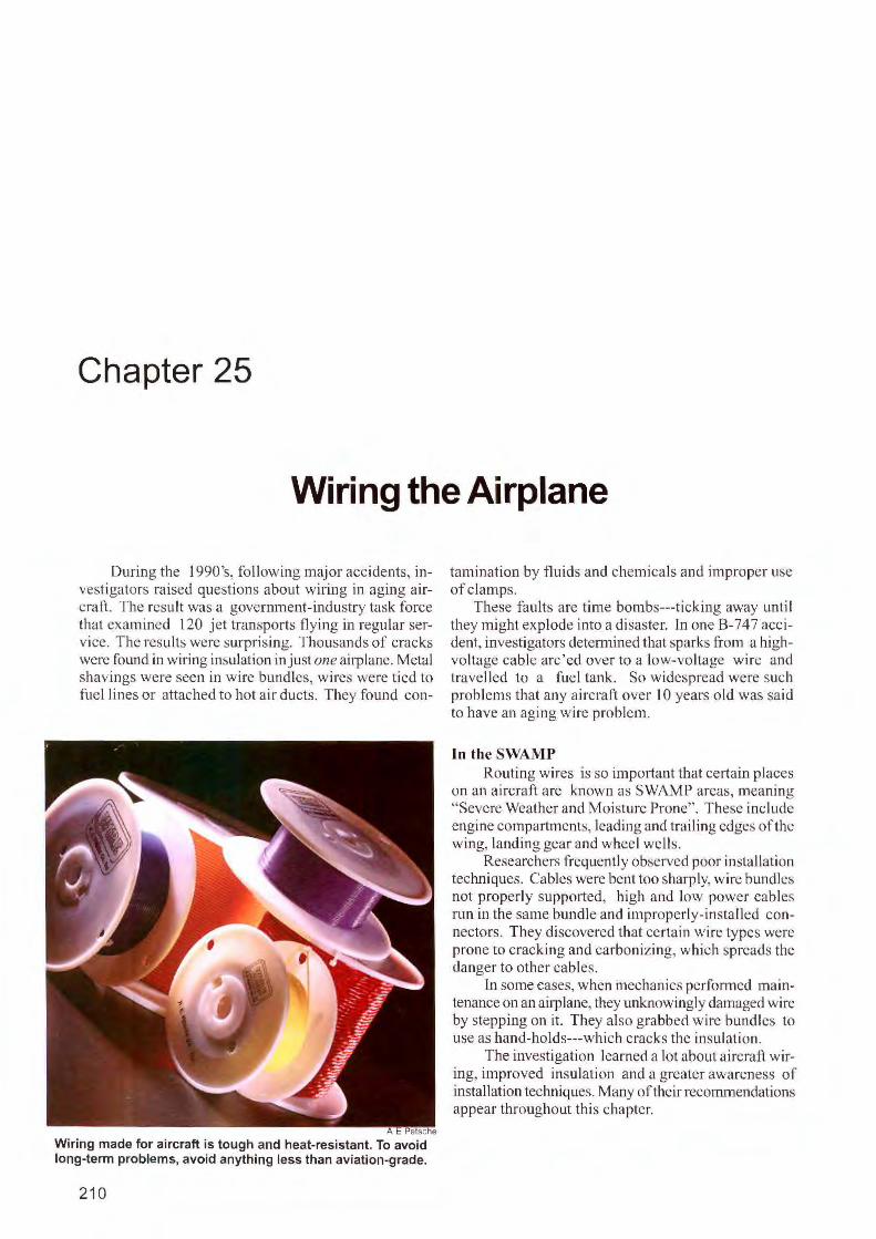
Chapter 25
Wiring the Airplane
During the l 990's, fo llow ing major accidents, investigators raised questions about wiring in aging a ircraft. The result was a government-industry task force that examined 120 jet transports flying in regular service. The results were surprising. Thousands of cracks were found in wiring insulation in just one airplane. Metal shavings were seen in w ire bundles, wires were tied to fue l lines or attached to hot air ducts. They found con-
e sc e
Wiring made for aircraft is tough and heat-resistant. To avoid long-term problems, avoid anything less than aviation-grade.
210
tamination by fluids and chemicals and improper use of clamps.
These faults a re time bombs---ticking away unti l they might explode into a disaster. In one B-747 accident, investigators detennined that sparks from a highvoltage cable arc'ed over to a low-vo ltage wire and travelled to a fuel tank. So widespread were such problems that any aircraft over 10 years o ld was said to have an aging wire problem.
In the SWAMP Routing wi res is so important that certain places
on an a ircraft a re known as SWAMP areas, meaning "Severe Weather and Moi sture Prone". These include engine compartments, leading and trailing edges of the wing, landing gear and wheel wel ls.
Researchers frequently observed poor instal lation techniques. Cables were bent too sharply, wi re bundles not properly supported, high and low power cables run in the same bundle and improperly-installed connectors. They discovered that certain wire types were prone to crack ing and carbonizing, which spreads the danger to other cables.
1n some cases, when mechanics performed maintenance on an airplane, they unknowingly damaged wire by stepping on it. They also grabbed w ire bu nd les to use as hand-ho lds---which cracks the insulation .
The investigation learned a lot about aircraft wiring, improved insulati on and a greater awareness of installation techniques. Many of their recommendations appear throughout this chapter.
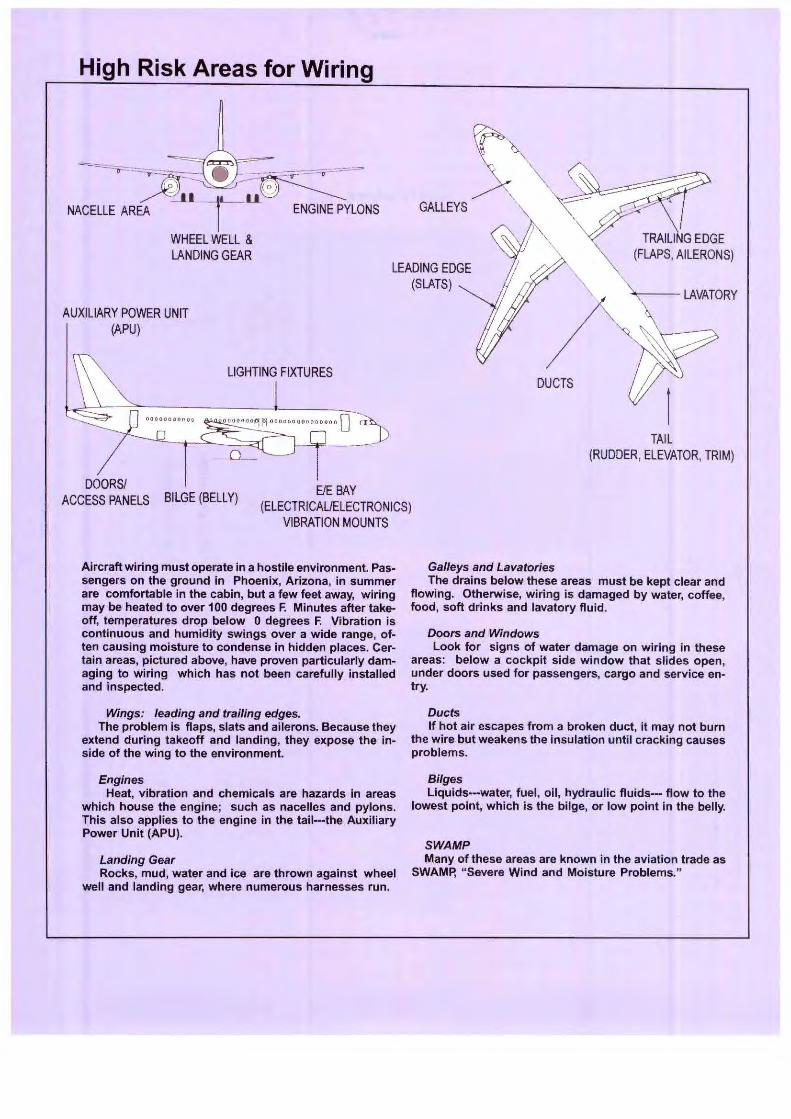
High Risk Areas for Wiring
AUXILIARY POWER UNIT {APU)
LIGHTING FIXTURES
GALLEYS
LEADING EDGE (SLATS)
DUCTS
TAIL (RUDDER, ELEVATOR, TRIM)
DOORS/ ACCESS PANELS BILGE {BELLY)
E/E BAY {ELECTRICAUELECTRONICS)
VIBRATION MOUNTS
Aircraft wiring must operate in a hostile environment. Passengers on the ground in Phoenix, Arizona, in summer are comfortable in the cabin, but a few feet away, wiring may be heated to over 100 degrees F. Minutes after takeoff, temperatures drop below O degrees F. Vibration is continuous and humidity swings over a wide range, often causing moisture to condense in hidden places. Certain areas, pictured above, have proven particularly damaging to wiring which has not been carefully installed and inspected.
Wings: leading and trailing edges. The problem is flaps, slats and ailerons. Because they
extend during takeoff and landing, they expose the inside of the wing to the environment.
Engines Heat, vibration and chemicals are hazards in areas
which house the engine; such as nacelles and pylons. This also applies to the engine in the tail---the Auxiliary Power Unit (APU).
Landing Gear Rocks, mud, water and ice are thrown against wheel
well and landing gear, where numerous harnesses run.
Galleys and Lavatories The drains below these areas must be kept clear and
flowing. Otherwise, wiring is damaged by water, coffee, food, soft drinks and lavatory fluid.
Doors and Windows Look for signs of water damage on wiring in these
areas: below a cockpit side window that slides open, under doors used for passengers, cargo and service entry.
Ducts If hot air escapes from a broken duct, it may not burn
the wire but weakens the insulation until cracking causes problems.
Bilges Liquids--water, fuel, oil, hydraulic fluids--- flow to the
lowest point, which is the bilge, or low point in the belly.
SWAMP Many of these areas are known in the aviation trade as
SWAMP, "Severe Wind and Moisture Problems."
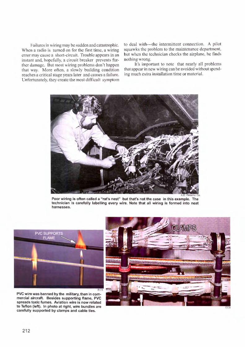
Failures in wiring may be sudden and catastroph ic. When a radio is turned on for the first time, a wiring error may cause a short-circui t. Trouble appears in an instant and, hopefully, a circuit breaker prevents fu rlher damage. But most wiring problems don't happen that way. More often, a slowly building condition reaches a critical stage years later and causes a fai lure. Unfortunately, they create the most difficult symptom
to deal wi th--- the interm ittent connection. A pilot squawks the problem to the maintenance department, but when the technician checks the airplane, he finds nothing wrong.
lt 's important to note that nearly all problems that appear in new wiring can be avoided without spending much extra installation time or materi al.
A. . Petsche Co.
Poor wiring is often called a "rat's nest" but that's not the case in this example. The technician is carefully labelling every wire. Note that all wiring is formed into neat harnesses.
ECS
PVC wire was banned by the military, then in commercial aircraft. Besides supporting flame, PVC spreads toxic fumes. Aviation wire is now related to Teflon (left). In photo at right, wire bundles are carefully supported by clamps and cable ties.
212
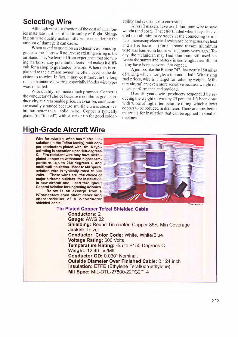
Selecting Wire Although w ire is a fraction of the cost of an avion
ics insta llation, it is critical to safety of fli ght. Sk imping on wire quality makes little sense considering the amount of damage it can cause.
When asked to quote on an exten sive avionics upgrade, some shops wi ll not re-use existing wiring in the airplane. They've learned from experience that old wiring harbors many potential defects and makes it difficult for a shop to guarantee its work. When this is explai ned to the a irplane owner, he often accepts the decision to re-wire. In fact, it may cost more, in the long run, to maintain old wiring, especially if o lder wire types were install ed.
Wire quality has made much progress. Copper is the conductor of choice because it combines good conductivity at a reasonable price. In aviation, conductors a re usually stranded because multiple wires absorb v ibration better than solid wire. Copper is typi cally plated (or " tinned") with silver or tin for good solder-
Hi h-Grade Aircraft Wire Wire for aviation often has "Tefzel" insulation (in the Teflon family), with copper conductors plated with tin. A typical rating is operation up to 150-degrees C. Fire-resistant wire may have nickelplated copper to withstand higher temperature---up to 260 degrees C and multi-wall insulation. Made to Mil Specs, aviation wire is typically rated to 600 volts. These wires are the choice of major airframe builders for installation in new aircraft and used throughout General Aviation for upgrading avionics. -~
Below is an excerpt from a _-""'_ Wiremasters spec sheet describing -characteristics of a 2-conductor shielded cable.
ability and resistance to corros ion. Aircraft makers have used alu minum wire to save
weight (and cost). That effort failed when they discovered that a luminum corrodes at the connecting te rm inals. Increasing electrical res istance here generates heat and a tire hazard. (For the same reason, aluminum wire was ba1rned in house wiring many years ago.) Today, the tec hnician may find aluminum st il l used between the starte r and battery in some light a ircraft, but many have been converted to copper.
A jumbo, li ke the Boeing 747, has nearly 150 miles of wiring which weighs a ton and a ha lf With ri sing fuel prices, wire is a target fo r reduc ing weight. Military aircraft are even more sensit ive because weight reduces perfo rmance and payload.
Over 50 years, w ire producers responded by reducing the weight of wire by 25 percent. It's been done with wires of higher temperature rating, which a llows copper to be reduced in diameter. There are now better materials for insulation that can be applied in smaller thickness.
Tin Plated Copper Tefzel Shielded Cable Conductors: 2 Gauge: AWG 22 . Shielding: Round Tin coated Copper 85% Min Coverage Jacket: Tefzel Conductor Color Code: White, White/Blue Voltage Rating: 600 Volts Temperature Rating: -55 to +150 Degrees C Weight: 12.40 lbs/Mft Conductor OD: 0.030" Nominal. Outside Diameter Over Finished Cable: 0.1 24 inch Insulation: ETFE (Ethylene Terafluoroethylene) Mil Spec: MIL-DTL-27500-22TG2T14
213
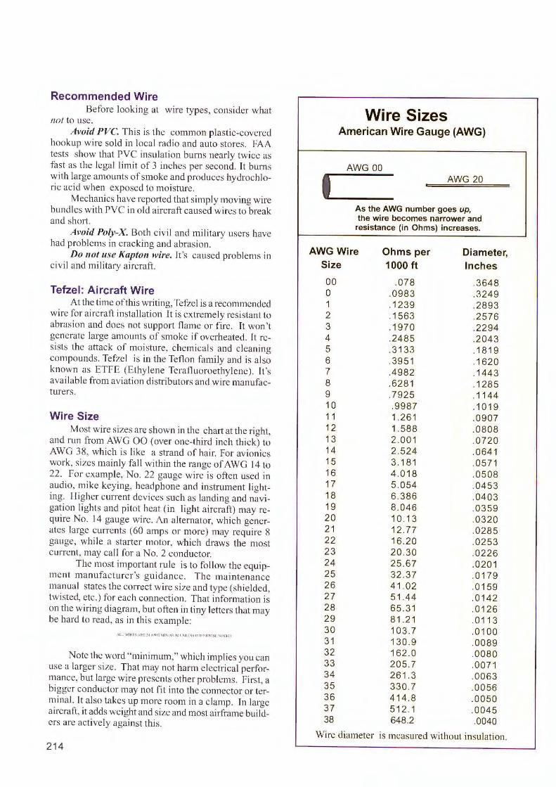
Recommended Wire Before looking at wire types, consider what
not to use. Avoid PVC. This is the common plastic-covered
hookup wire sold in local radio and auto stores. FAA tests show that PVC insulation burns nearly twice as fast as the legal limit of 3 inches per second. It burns with large amounts of smoke and produces hydrochloric acid when exposed to moi sture.
Mechanics have reported that simply moving wire bundles with PVC in o ld aircraft caused wires to break and short.
Avoid Po/y-X. Both civil and military users have had problems in cracking and abrasion.
Do not use Kapton wire. It 's caused problems in c iv il and military aircraft.
Tefzel: Aircraft Wire At the time of this writing, Tefzel is a recommended
wire for aircraft installation lt is extremely resistant to abrasion and does not support flame or fire. Tt won't generate large amounts of smoke if overheated. It resists the attack of moisture, chemicals and cleaning compounds. Tefzel is in the Teflon fami ly and is also known as ETFE (Ethylene Tcrafluoroethy lene). It 's available from aviation distributors and wire manufacturers.
Wire Size Most wire s izes are shown in the cha11 at the right,
and run from AWG 00 (over one-third inch thick) to AWG 38, which is like a strand of hair. For avionics work, sizes mainly fall within the range of AWG 14 to 22. For example, No. 22 gauge wire is often used in audio, mike keying, headphone and instrument lighting. Higher current devices such as landing and navigation lights and pitot heat (in light aircraft) may require No. 14 gauge wire. An alternator, which generates large currents (60 amps or more) may require 8 gauge, while a starter motor, which draws the most current, may call for a No. 2 conductor.
The most important rule is to follow the equipment ma nufacturer 's guidance. The maintenance manual states the correct wire size and type (shielded, twisted, etc.) for each connection. That information is o n the wiring diagram, but often in tiny lette rs that may be ha rd to read, as in this example:
\ l l W!H.f-.AkL !~ "W(i \ 1t ,1Ml'M I ' l [,~01111 In.\ 1Sl ",0[11)
Note the word "minimum," which implies you can use a larger size . That may not harm electri cal performance, but large wire presents other problems. First, a bigger conductor may not fit into the connector or terminal. It a lso takes up more room in a c lamp. Tn large aircraft, it adds weight and size and most ailframe builde rs are active ly against this.
214
I
Wire Sizes American Wire Gauge (AWG)
AWG 00 AWG 20
As the AWG number goes up, the wire becomes narrower and resistance (in Ohms) increases.
AWG Wire Ohms per Diameter, Size 1000 ft Inches
00 .078 .3648 0 .0983 .3249 1 .1239 .2893 2 .1563 .2576 3 .1970 .2294 4 .2485 .2043 5 .3 133 .1819 6 .3951 .1620 7 .4982 .1443 8 .6281 .1285 9 .7925 .1144 10 .9987 .1019 11 1.261 .0907 12 1.588 .0808 13 2.001 .0720 14 2.524 .0641 15 3.181 .0571 16 4 .018 .0508 17 5.054 .0453 18 6.386 .0403 19 8.046 .0359 20 10.13 .0320 21 12.77 .0285 22 16.20 .0253 23 20.30 .0226 24 25.67 .0201 25 32.37 .0 179 26 41.02 .0159 27 51.44 .0 142 28 65.31 .0126 29 81.21 .0113 30 103.7 .0 100 31 130.9 .0089 32 162.0 .0080 33 205.7 .007 1 34 26 1.3 .0063 35 330.7 .0056 36 414.8 .0050 37 5 12.1 .0045 38 648.2 .0040
Wire diameter is measured without insulati on.
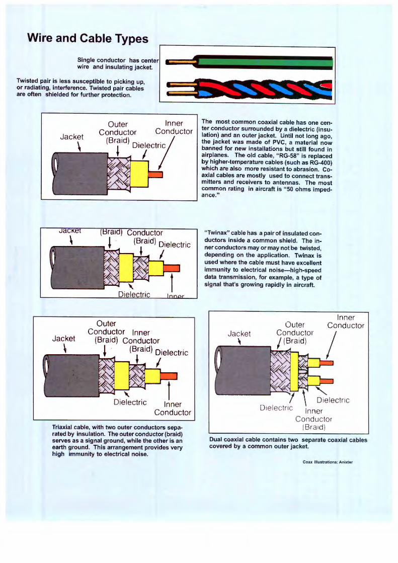
Wire and Cable Types
Single conductor has center wire and insulating jacket.
Twisted pair is less susceptible to picking up, or radiating, interference. Twisted pair cables are often shielded for further protection.
JaCK l
\
Jacket
\
Outer Inner Conductor Conductor
(Braid) D. I t·ic /
! '8/c/
Conductor (Braid) Dielectric
J I
Outer Conductor Inner
(Braid) Conductor J · (Braid) Dielectric
J I
Inner Conductor
Triaxial cable, with two outer conductors separated by insulation. The outer conductor (braid) serves as a signal ground, while the other is an earth ground. This arrangement provides very high immunity to electrical noise.
The most common coaxial cable has one center conductor surrounded by a dielectric (insulation) and an outer jacket. Until not long ago, the jacket was made of PVC, a material now banned for new installations but still found in airplanes. The old cable, "RG-58" is replaced by higher-temperature cables (such as RG-400) which are also more resistant to abrasion. Coaxial cables are mostly used to connect transmitters and receivers to antennas. The most common rating in aircraft is "50 ohms impedance."
"Twinax" cable has a pair of insulated conductors inside a common shield. The inner conductors may or may not be twisted, depending on the application. Twinax is used where the cable must have excellent immunity to electrical noise---high-speed data transmission, for example, a type of signal that's growing rapidly in aircraft.
Outer Conductor / (Braid)
Inner Conductor
I Dielectric
Dielectric Inner Conductor
(Braid)
Dual coaxial cable contains two separate coaxial cables covered by a common outer jacket.
Coax Illustrations: Anixter
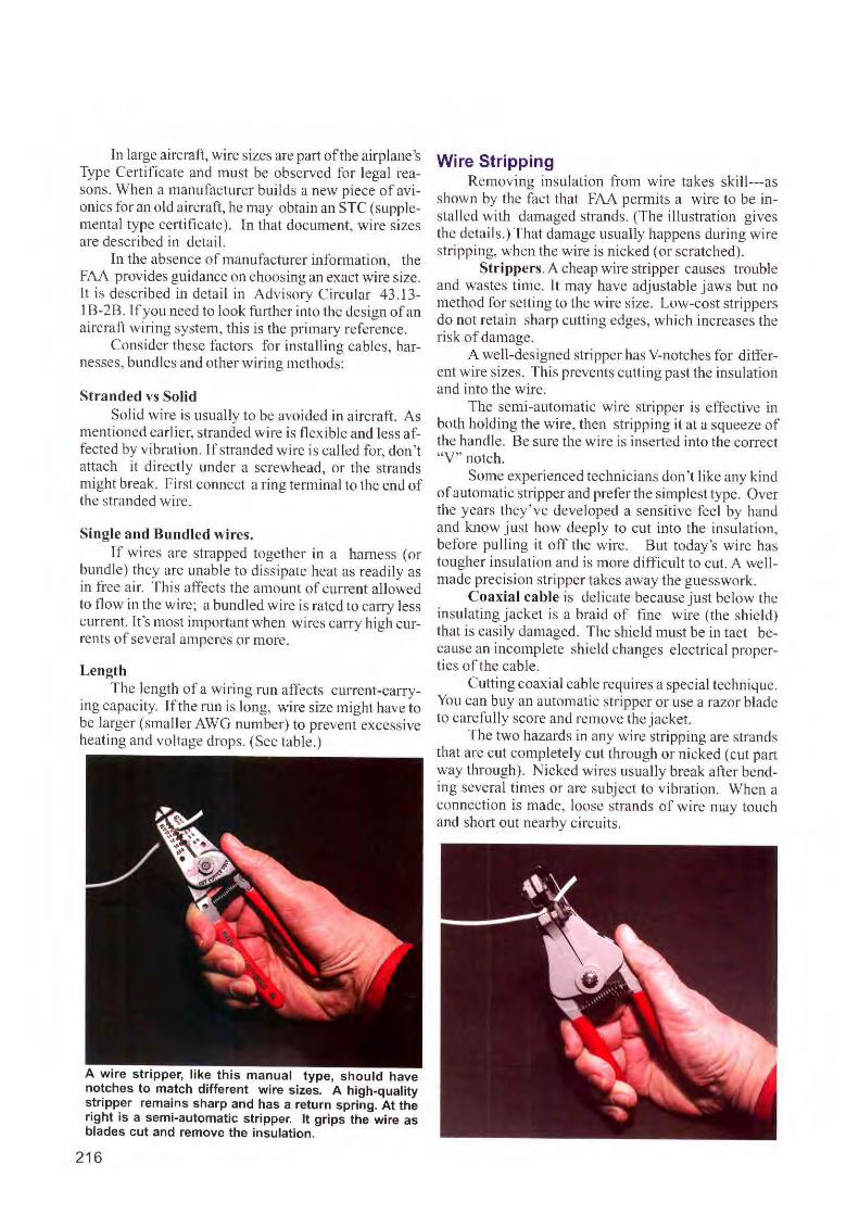
In large aircraft, wire sizes are part of the airplane 's Type Ce1tificate and must be observed for legal re~sons. When a manufacturer builds a new piece of avionics for an old aircraft, he may obtain an STC (supplemental type certificate). [n that document, wire sizes are described in detail.
In the absence of manufacturer information, the FAA provides guidance on choosing an exact wire size. It is described in detail in Advisory Circular 43.13-1B-2B. If you need to look further into the design of an aircraft wiring system, this is the primary reference.
Consider these factors fo r installing cables, harnesses, bundles and other wiring methods:
Stranded vs Solid Solid wire is usually to be avoided in aircraft. As
mentioned earlier, stranded wire is fl exible and less affected by vibration. If stranded wire is called for, don 't attach it directly under a screwhead, or the strands might break. First connect a ring tenninal to the end of the stranded wire.
Single and Bundled wires. If wires are strapped together in a harness (or
bundle) they are unable to dissipate heat as readily as in free air. This affects the amount of current allowed to flow in the wire; a bundled wire is rated to carry less current. It's most important when wires carry high currents of several amperes or more.
Length The length of a wiring run affects current-carry
ing capacity If the run is long, wire size might hav~ to be larger (smaller AWG nwnber) to prevent excessive heating and voltage drops. (See table.)
A wire stripper, like this manual type, should have notches to match different wire sizes. A high-quality stripper remains sharp and has a return spring. At the right is a semi-automatic stripper. It grips the wire as blades cut and remove the insulation.
216
Wire Stripping Removing insulation from wire tak~s ski ll--~as
shown by the fact that FAA permits a w1r~ to be installed with darnaoed strands. (The illustration gives
b . . the detai ls.) That damage usually happens dun ng wire stripping, when the wire is nicked (or scratched).
Strippers. A cheap wire stripper causes trouble and wastes time. Tt may have adjustab le jaws but no method fo r setting to the wire size. Low-cost strippers do not retain sharp cutting edges, which increases the risk of damage. .
A well-designed stripper has V-notches for drfferent wi re sizes. This prevents cutting past the insulation and into the wire.
The semi-automatic wire stripper is effective in both holding the wire, then stripping it at a squeeze of the handle. Be sure the wire is inserted into the correct "V" notch.
Some experienced technicians don 't like any kind of automatic stripper and prefer the simplest type. Over the years they've developed a sensitive fe~I by h~nd and know just how deeply to cut 111to the 111sulat1011, before pulling it off the wi re. But today's wire has touoher insulation and is more difficult to cut. A well-o made precision stripper takes away the guesswork.
Coaxial cable is delicate because just below the insulating jacket is a braid of fine wire (the shield) that is easily damaged. The shield must be in tact because an incomplete shie ld changes electrical properties of the cable.
Cutting coaxial cable requires a special tech nique. You can buy an automatic stripper or use a razor blade to carefu ll y score and remove the jacket.
The two hazards in any wire stripping are strands that are cut completely cut through or nicked (cut part way through). Nicked wires usually break after bending several times or are subject to vibration . When a connection is made, loose strands of wire may touch and short out nearby circuits.
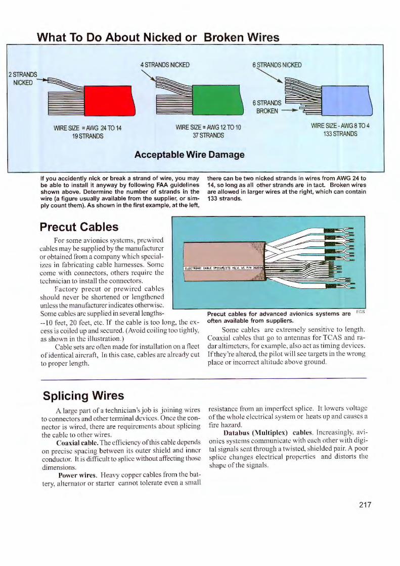
What To Do About Nicked or Broken Wires
4 STRANDS NICKED 6 STRANDS NICKED
~
ss=oo!t \ BROKEN -=----,.__ ____ __,
WIRE SIZE = AWG 24 TO 14 19 STRANDS
WIRE SIZE= AWG 12 TO 10 37STRANDS
WIRE SIZE -AWG 8 TO 4 133STRANDS
Acceptable Wire Damage
If you accidently nick or break a strand of wire, you may be able to install it anyway by following FAA guidelines shown above. Determine the number of strands in the wire (a figure usually available from the supplier, or simply count them). As shown in the first example, at the left,
Precut Cables For some avionics systems, prew ircd
cables may be supplied by the manufacturer or obta ined from a company w hich specializes in fabricating cable harnesses. Some come with connectors, others require the technic ian to insta ll the connectors.
Factory precut o r prewired cables sho uld never be shortened or lengthened unless the manufacturer indicates otherwise. Some cables are supplied in several lengths-- IO feet, 20 feet, etc. If the cable is too long, the excess is coiled up and secured. (Avoid coil ing too tightly, as shown in the illustration.)
Cable sets are often made for installation on a fleet of ident ica l aircraft, rn this case, cables are already cut to proper length .
Splicing Wires A large part of a technician's job is joining wires
to connectors and other terminal devices. Once the connector is wired, there a re requirements about spl ic ing the cable to other w ires.
Coaxial cable. The efficiency of this cable depends on precise spac ing between its outer shie ld and inner conductor. It is difficult to splice w ithout affecting those dimensions.
Power wires. Heavy copper cables from the batte ry, a lte rnator or starte r cannot to lerate even a small
there can be two nicked strands in wires from AWG 24 to 14, so long as all other strands are in tact. Broken wires are allowed in larger wires at the right, which can contain 133 strands.
Precut cables for advanced avionics systems are Ecs often available from suppliers.
Some cables are extremely sens itive to length. Coaxia l cables that go to antennas for TCAS and radar a ltimeters, for example, a lso act as timing devices. ff they're altered, the pilot will see targets in the wrong place or incorrect altitude above ground.
resistance from an imperfect splice. It lowers voltage of the w hole e lectTical system or heats up and causes a fire hazard .
Databus (Multiplex) cables. Increasingly, avionics systems communicate w ith each other with digita l s ignals sent through a twisted, shie lded pair. A poor splice changes e lectrical properties and di storts the shape of the signa ls.
217
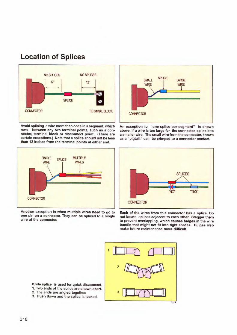
Location of Splices
NO SPLICES NO SPLICES
H CONNECTOR TERMINAL BLOCK
Avoid splicing a wire more than once in a segment, which runs between any two terminal points, such as a connector, terminal block or disconnect point. (There are certain exceptions.) Note that a splice should not be less than 12 inches from the terminal points at either end.
SINGLE WIRE
CONNECTOR
SPLICE MULTIPLE WIRES
Another exception is when multiple wires need to go to one pin on a connector. They can be spliced to a single wire at the connector.
Knife splice is used for quick disconnect. 1. Two ends of the splice are shown apart. 2. The ends are angled together. 3. Push down and the splice is locked.
218
2
SPLICE
CONNECTOR
LARGE WIRE
An exception to "one-splice-per-segment" is shown above. If a wire is too large for the connector, splice it to a smaller wire. The small wire from the connector, known as a "pigtail," can be crimped to a connector contact.
SPLICES
CONNECTOR
Each of the wires from this connector has a splice. Do not locate splices adjacent to each other. Stagger them to prevent overlapping, which causes bulges in the wire bundle that might not fit into tight spaces. Bulges also make future maintenance more difficult.
CJ
3 [llffil[]J AMP
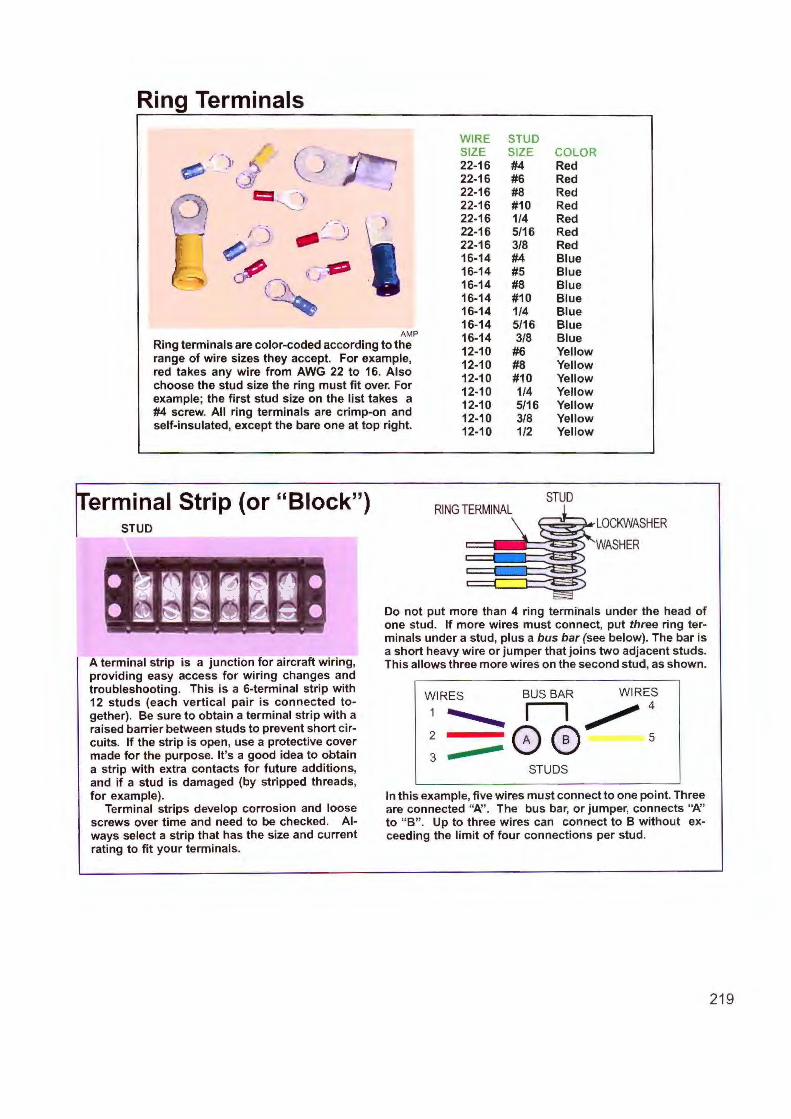
Ring Terminals
WIRE STUD
( ZE 12 LO
) 22-16 #4 Red 1.) 22-16 #6 Red = .) 22-16 #8 Red
'"--..;: 22-16 #10 Red ,
I 22-16 1/4 Red
I __ )
22-16 5/16 Red
~ 22-16 3/8 Red 16-14 #4 Blue
°"') l•J - 16-14 #5 Blue 16-14 #8 Blue
(. - 16-14 #10 Blue 16-14 1/4 Blue 16-14 5/16 Blue
AMP 16-14 3/8 Blue Ring terminals are color-coded according to the 12-10 #6 Yellow range of wire sizes they accept. For example, 12-10 #8 Yellow red takes any wire from AWG 22 to 16. Also 12-10 #10 Yellow choose the stud size the ring must fit over. For 12-10 1/4 Yellow example; the first stud size on the list takes a 12-10 5/16 Yellow #4 screw. All ring terminals are crimp-on and 12-10 3/8 Yellow self-insulated, except the bare one at top right. 12-10 1/2 Yellow
erminal Strip (or "Block") STUD
• ' ti ! ~~ , · ·~~~ i1 ~~· " . . . .. . .
A terminal strip is a junction for aircraft wiring, providing easy access for wiring changes and troubleshooting. This is a 6-terminal strip with 12 studs (each vertical pair is connected together). Be sure to obtain a terminal strip with a raised barrier between studs to prevent short circuits. If the strip is open, use a protective cover made for the purpose. It's a good idea to obtain a strip with extra contacts for future additions, and if a stud is damaged (by stripped threads, for example).
Terminal strips develop corrosion and loose screws over time and need to be checked. Always select a strip that has the size and current rating to fit your terminals.
STUD RING TERMINAL
LOCKWASHER
WASHER
Do not put more than 4 ring terminals under the head of one stud. If more wires must connect, put three ring terminals under a stud, plus a bus bar (see below). The bar is a short heavy wire or jumper that joins two adjacent studs. This allows three more wires on the second stud, as shown.
WIRES
2
3
BUS BAR
5
STUDS
In this example, five wires must connect to one point. Three are connected "N '. The bus bar, or jumper, connects "N' to "B" . Up to three wires can connect to B without exceeding the limit of four connections per stud.
21 9
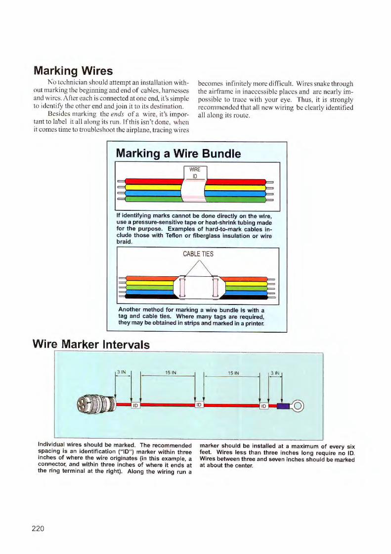
Marking Wires No technician should attempt an installation with
out markjng the beginning and end of cables, harnesses and wires. After each is connected at one end, it's simple to identify the other end and join it to its destination.
Besides marking the ends of a wire, it's important to label it all a long its run. ff this isn 't done, when it comes time to troubleshoot the ai rplane, traci ng wires
becomes infinitely more difficul t. Wires snake through the ai rframe in inaccessible places and are nearly impossible to trace with your eye. Thus, it is strongly recommended that all new w iring be clearly identified all along its route.
Marking a Wire Bundle WIRE
I ID
9 =·= E { r \ \
If identifying marks cannot be done directly on the wire, use a pressure-sensitive tape or heat-shrink tubing made for the purpose. Examples of hard-to-mark cables include those with Teflon or fiberglass insulation or wire braid.
CABLE TIES
IJ D Another method for marking a wire bundle is with a tag and cable ties. Where many tags are required, they may be obtained in strips and marked in a printer.
Wire Marker Intervals
Individual wires should be marked. The recommended spacing is an identification (" ID") marker within three inches of where the wire originates (in this example, a connector, and within three inches of where it ends at the ring terminal at the right). Along the wiring run a
220
marker should be installed at a maximum of every six feet. Wires less than three inches long require no ID. Wires between three and seven inches should be marked at about the center.
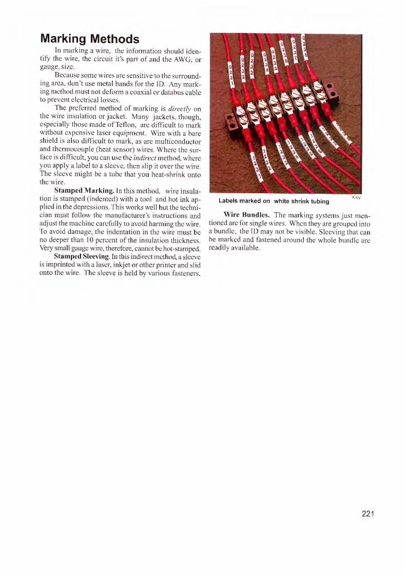
Marking Methods In marking a wire, the information should iden
tify the wire, the circuit it 's part of and the AWG, or gauge, size.
Because some wires are sensitive to the surrounding area, don 't use metal bands for the 10. Any marking method must not deform a coaxial or databus cable to prevent electrica l losses .
The preferred method of marking is directly on the wire insulation or jacket. Many jackets, though, especially those made of Tefl on, are difficult to mark without ex pensive laser equipment. Wire with a bare shield is al so difficult to mark, as are multiconductor and thermocouple (heat sensor) wires. Where the surface is difficult, you can usc the indirect method, where you apply a label to a sleeve, then slip it over the wire. The sleeve might be a tube that you heat-shrink onto the wire.
Stamped Marking. In this method, wire insulation is stamped (indented) with a tool and hot ink applied in the depressions. This works well but the technician must follow the manufacturer's instructions and adjust the machine carefully to avoid harming the wire. To avoid damage, the indentation in the wire must be no deeper than IO percent of the insulation thickness. Very small gauge wire, therefore, cannot be hot-stamped.
Stamped Sleeving. In this indirect method, a sleeve is imprinted with a laser, inkjet or other prin ter and slid onto the wire. The sleeve is held by various fasteners.
Labels marked on white shrink tubing Kray
Wire Bundles. The marking systems just mentioned are for single wires. When they are grouped into a bundle, the ID may not be visible. Sleev ing that can be marked and fastened around the whole bundle arc readily available.
221
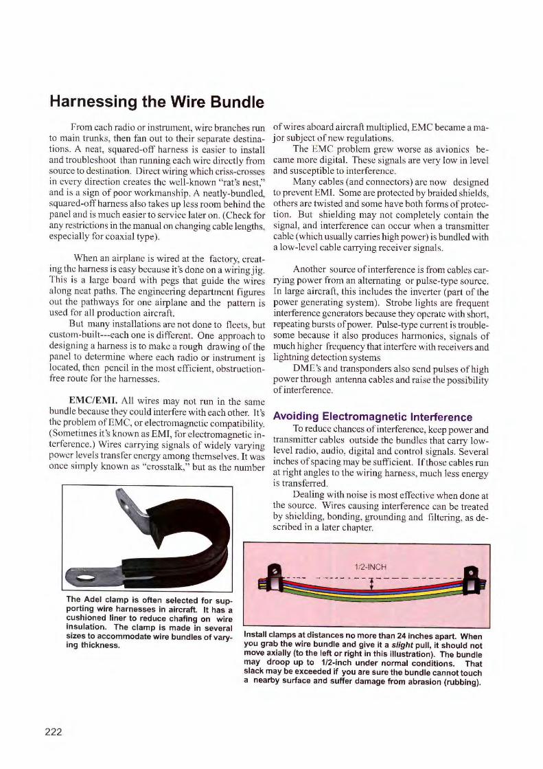
Harnessing the Wire Bundle
From each radio or instrument, wire branches run to main trunks, then fan out to their separate destinations. A neat, squared-off harness is easier to install and troubleshoot than running each wire directly from source to destination. Direct wiring which criss-crosses in every directi on creates the well-known "rat 's nest," and is a sign of poor workmanship. A neatly-bundled, squared-off harness also takes up less room behind the panel and is much easier to service later on . (Check for any restrictions in the manual on changing cable lengths, especially fo r coaxial type).
When an airplane is wired at the factory, creating the harness is easy because it's done on a wiringj ig. This is a large board with pegs that guide the wires along neat paths. The engineering department figures out the pathways for one airplane and the pattern is used for all product ion aircraft.
But many installations are not done to fl eets, but custom-built---each one is different. One approach to designing a harness is to make a rough drawing of the panel to determine where each radio or instrument is located, then pencil in the most efficient, obstructionfree route for the harnesses.
EMC/EMI. All wires may not run in the same bundle because they could interfere with each other. It's the problem of EMC, or electromagnetic compatibi lity. (Sometimes it 's known as EMJ, for electromagnetic interference.) Wires carrying signals of widely varying power levels transfer energy among themselves. It was once simply known as "crosstalk," but as the number
of wires aboard aircraft multiplied, EMC became a major subject of new regul ations.
The EMC problem grew worse as avion ics became more digital. These signals are very low in leve l and susceptible to interference.
Many cables (and connectors) are now designed to prevent EMI. Some are protected by braided shields, others are twisted and some have both forms of protection. But shielding may not completely conta in the signal , and interference can occur when a transmitter cable (which usually carries high power) is bundled with a low-level cable carrying receiver s ignals.
Another source of interference is from cables carrying power from an alternating or pu lse-type source. fn large aircraft, this includes the inverter (part of the power generating system). Strobe lights are frequent interference generators because they operate with short, repeating bursts of power. Pulse-type current is troublesome because it also produces harmonics, signals of much higher frequency that interfere with receivers and lightning detection systems
DME's and transponders also send pulses of high power through antenna cables and raise the possibility of interference .
Avoiding Electromagnetic Interference To reduce chances of interference, keep power and
transmitter cables outside the bundles that carry lowlevel radio, audio, digital and control signals. Several inches of spacing may be sufficient. If those cables run at tight angles to the wiring harness, much less energy is transferred.
Dealing with noise is most effective when done at the source. Wires causing interference can be treated by shi elding, bonding, grounding and fi ltering, as described in a later chapter.
1/2-INCH
The Adel clamp is often selected for supporting wire harnesses in aircraft. It has a cushioned liner to reduce chafing on wire insulation. The clamp is made in several sizes to accommodate wire bundles of varying thickness.
Install clamps at distances no more than 24 inches apart. When you grab the wire bundle and give it a slight pull, it should not move axially (to the left or right in this illustration). The bundle may droop up to 1/2-inch under normal conditions. That slack may be exceeded if you are sure the bundle cannot touch a nearby surface and suffer damage from abrasion (rubbing).
222
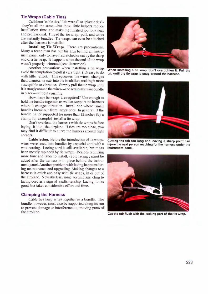
Tie Wraps (Cable Ties) Call them "cable ties," "tie wraps" or "plastic ties"
-they ' re all the same---but these little helpers reduce installation time and make the finished job look neat and professional. Thread the tie wrap, pull, and wires are instantly bundled. Tie wraps can even be attached after the harness is installed.
Installing Tie Wraps. There are precautions. Many a technician has put his arm behind an instrument panel, only to have it scratched or cut by the sharp end of a tie wrap. It happens when the end of tie wrap wasn't properly trimmed (see illustration).
Another precaution: when installing a tie wrap avoid the temptation to pull it very tight. (It 's easy to do with little effort.) This squeezes the wires, changes their diameter or cuts into the insulation, making it more susceptible to vibration. Simply pull the tie wrap until it is snugly around the wires---and retains the wire bundle in place---without crushing.
How many tie wraps are required? Use enough to hold the bundle together, as well as support the harness where it changes direction. Install one where small bundles break out from larger ones. In general, if the bundle is not supported for more than 12 inches (by a clamp, for example) install a tie wrap.
Don't overload the harness with tie wraps before laying it into the airplane. lf ties are too close, you may find it difficult to curve the harness around tight comers.
Cable lacing. Before the introduction of tie wraps, wires were laced into bundles by a special cord with a wax coating. Lacing cord is still available, but it has been mostly replaced by tie wraps. Besides requiring more time and labor to install , cable lacing cannot be added after the harness is in place behind the instrument panel. Another problem with lacing happens during maintenance and upgrading. Making changes to a harness is quick and easy with tie wraps, in or out of the airplane. Neve1t heless, some technicians cling to lacing cord as a sign of craftsmanship Lacing looks good, but takes considerable effort and time.
Clamping the Harness Cable ties keep wires together in a bundle. The
bundle, however, must also be supported along its run to prevent damage or interference to moving parts of the airplane.
When installing a tie wrap, don't overtighten it. Pull the tab until the tie wrap is snug around the harness.
Cutting the tab too long and leaving a sharp point can injure the next person reaching for the harness under the instrument panel.
Cut the tab flush with the locking part of the tie wrap.
223
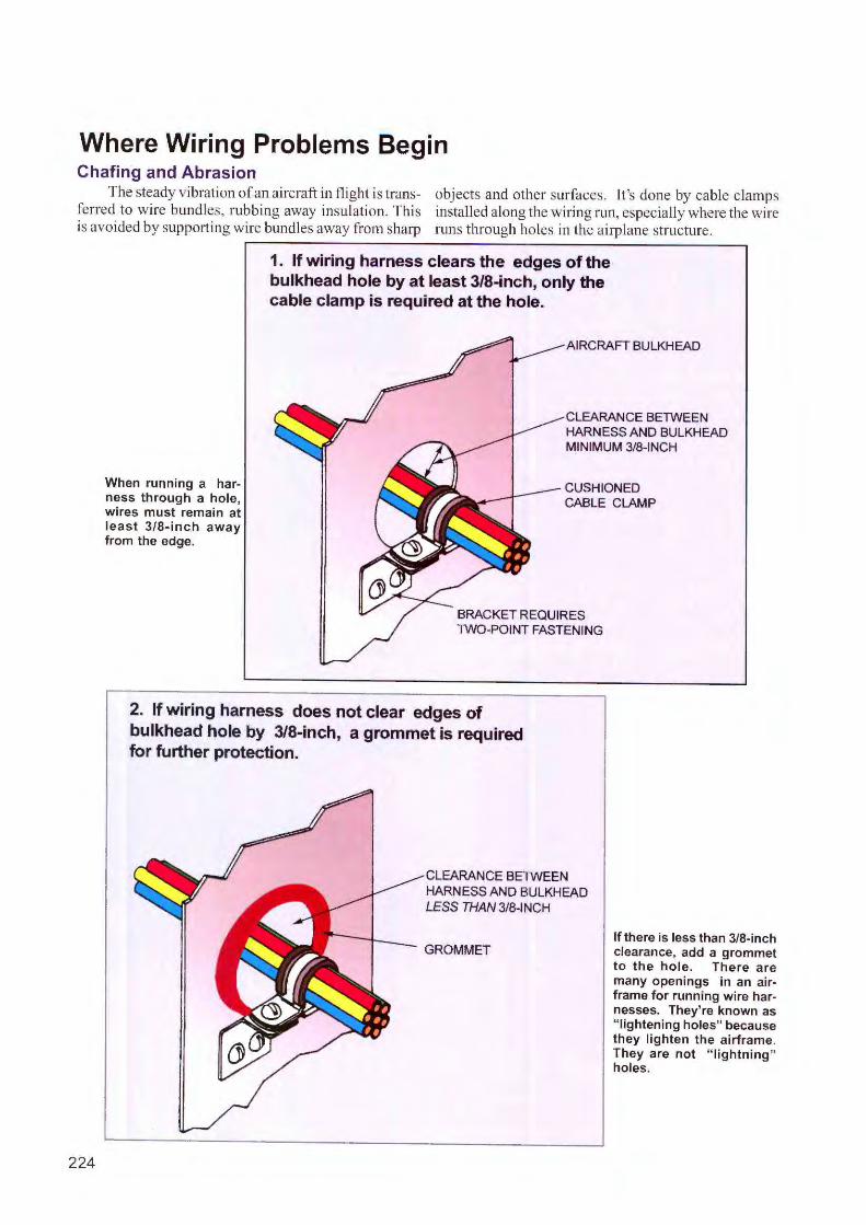
Where Wiring Problems Begin Chafing and Abrasion
The steady vibration of an aircraft in flight is trans- objects and other surfaces. It's done by cable c lamps ferred to wire bundles, rubbing away insulation. This iJ1Stalled a long the wiring run, especially where the wire is avoided by supporting wire bundles away from sharp nms through ho les in the airplane structure.
224
When running a harness through a hole, wires must remain at least 3/8- inch away from the edge.
1. If wiring harness clears the edges of the bulkhead hole by at least 3/8-inch, only the cable clamp is required at the hole.
AIRCRAFT BULKHEAD
CLEARANCEBEn'VEEN HARNESS AND BULKHEAD MINIMUM 3/8-INCH
CUSHIONED CABLE CLAMP
BRACKET REQUIRES n'\/0-POINT FASTENING
2. If wiring harness does not clear edges of bulkhead hole by 3/8-inch, a grommet is required for further protection.
CLEARANCE BEn'VEEN HARNESS AND BULKHEAD LESS THAN 3/8-INCH
GROMMET If there is less than 3/8-inch clearance, add a grommet to the hole. There are many openings in an airframe for running wire harnesses. They're known as " lightening holes" because they lighten the airframe. They are not " lightning" holes.
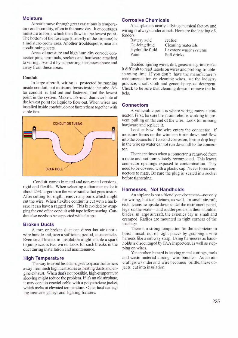
Moisture Aircraft move through great variations in tempera
ture and humidity, often in the same day. It encourages moisture to form , wh ich then flows to the lowest point. The bottom of the fuselage (the belly of the airplane) is a moisture-prone area. Another troublespot is near air conditioning ducts.
Areas of moisture and high humidity cotTode connector pins, terminals, sockets and hardware attached to wi ring. Avoid it by supporting harnesses above and away from these areas.
Conduit ln large a ircraft, wiring is protected by running
inside conduit, but moi sture forms ins ide the tube. After conduit is laid out and fastened, find the lowest point in the system. Make a 1/8-inch diameter hole at the lowest po int for liquid to flow out. When wires are installed inside conduit, do not fasten them together with cable tics.
CONDUIT OR TUBING
DRAIN HOLE
Conduit comes in metal and non-metal versions, rigid and fl exibl e. When selecting a diameter make it about 25% larger than the wire bundle that goes inside . After cutting to length, remove any burrs which might cut the w ire. When flexible conduit is cut with a hacksaw, it can have a ragged end . This is avoided by wrapping the end of the conduit with tape before sawing. Conduit also needs to be suppo1ied with clamps.
Broken Ducts A torn or broken duct can direct hot a ir onto a
wire bundle and, over a sufficient period, cause cracks. Even small breaks in insulation m.ight enable a spark to jump across two w ires. Look for such breaks in the duct during insta ll ation and maintenance.
High Temperature The way to avoid heat damage is to space the harness
away from such high heat zones as heating ducts and engine exhaust. When that's not possible, high-temperature sleeving might reduce the problem. Tf it 's an old airplane, it may contain coax ial cable with a polyethelene jacket, wh.ich melts at elevated temperature. Other heat-damaging areas are galleys and lighting fixtures.
Corrosive Chemicals An airplane is nearly a :flying chemi cal factory and
wiring is always under attack. Here are the leading offenders:
Battery acid De-icing fluid Hydraulic :fluid Paint
Jet fue l C leani ng materials Lavatory waste systems Soft drinks
Besides injuring wires, dirt, grease and grime make it difficult to read labels on wires and prolong troubleshooting time. lf you don't have the manufacture r 's recommendation on cleaning wires, use the industry practice; a soft c loth and genera l-purpose detergent. Check to be sure that c leaning doesn' t remove the labels.
Connectors A vu lnerable point is where wiring enters a con
nector. First, be sure the strain re lief is working to prevent pulling on the end of the wire. Look for m issing hardware and replace it.
Look at how the wi re enters the connector. lf moisture fom1s on the wire can it run down and flow into the connector? To avoid corrosion, form a drip loop in the wire so water cannot run downhill to the connector.
There are times when a connector is removed from a radio and not immed iately reconnected. This leaves connector openings exposed to contamination. They need to be covered with a plastic cap. Never fo rce connectors to mate . Be sure the plug is seated in a socket before tightening.
Harnesses, Not Handholds An airplane is not a friendly environment---not only
for wiring, but technic ians, as well. l n small a ircraft, technicians lie upside dow n under the instrument panel, legs on the seats--- and rudder pedal s in their shoulder blades. In large aircraft, the avionics bay is small and cramped. Radios are mounted in tight corners of the fuselage.
There is a strong temptation for the technician to ho ist him self out of tight places by grabbing a w ire harness like a subway strap. Using harnesses as handholds is discouraged by FAA inspectors, as well as step-. . p111g on wires.
Yet another hazard is leaving metal cuttings, tools and waste material among wire bundles. As an aircraft grows o lder and wire becomes brittle, these objects cut into insulation.
225
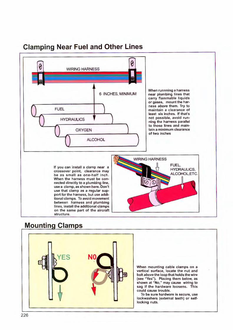
Clamping Near Fuel and Other Lines
Mountin
226
6 INCHES, MINIMUM
FUEL
HYDRAULICS
OXYGEN
ALCOHOL
If you can install a clamp near a crossover point, clearance may be as small as one-half inch. When the harness must be connected directly to a plumbing line, use a clamp, as shown here. Don't use that clamp as a regular support for the harness, but use additional clamps. To avoid movement between harness and plumbing lines, install the additional clamps on the same part of the aircraft structure.
Clam s
ES
When runnning a harness near plumbing lines that carry flammable liquids or gases, mount the harness above them. Try to maintain a clearance of least six inches. If that's not possible, avoid running the harness parallel to those lines and maintain a minimum clearance of two inches
FUEL. HYDRAULICS, ALCOHOL.ETC.
When mounting cable clamps on a vertical surface, locate the nut and bolt above the loop that holds the wire (see "Yes"). Placing them below, as shown at "No," may cause wiring to sag if the hardware loosens. This could cause trouble.
To be sure hardware is secure, use lockwashers (external teeth) or selflocking nuts.
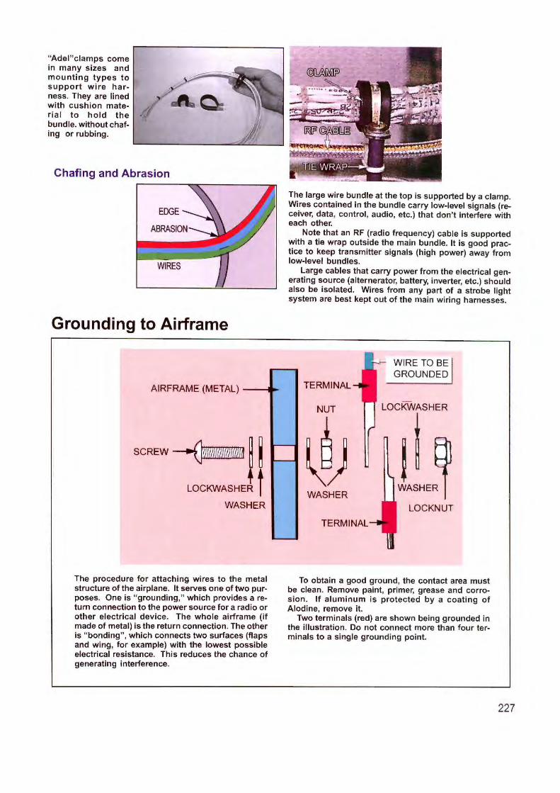
"Adel" clamps come in many sizes and mounting types to support wire harness. They are lined with cushion material to hold the bundle. without chafing or rubbing.
Chafing and Abrasion
Grounding to Airframe
AIRFRAME (METAL) ----11~
SCREW~~ .
LOCKWASHER
WASHER
The large wire bundle at the top is supported by a clamp. Wires contained in the bundle carry low-level signals (receiver, data, control , audio, etc.) that don't interfere with each other.
Note that an RF (radio frequency) cable is supported with a tie wrap outside the main bundle. It is good practice to keep transmitter signals (high power) away from low-level bundles.
Large cables that carry power from the electrical generating source (alternerator, battery, inverter, etc.) should also be isolated. Wires from any part of a strobe light system are best kept out of the main wiring harnesses.
TERMINAL
NUT
~) WASHER
TERMINAL
WIRE TO BE GROUNDED
LOCKWASHER
ti WASHER
LOCKNUT
-The procedure for attaching wires to the metal structure of the airplane. It serves one of two purposes. One is "grounding," which provides a return connection to the power source for a radio or other electrical device. The whole airframe (if made of metal) is the return connection. The other is "bonding" , which connects two surfaces (flaps and wing, for example) with the lowest possible electrical resistance. This reduces the chance of generating interference.
To obtain a good ground, the contact area must be clean. Remove paint, primer, grease and corrosion. If aluminum is protected by a coating of Alodine, remove it.
Two terminals (red) are shown being grounded in the illustration. Do not connect more than four terminals to a single grounding point.
227
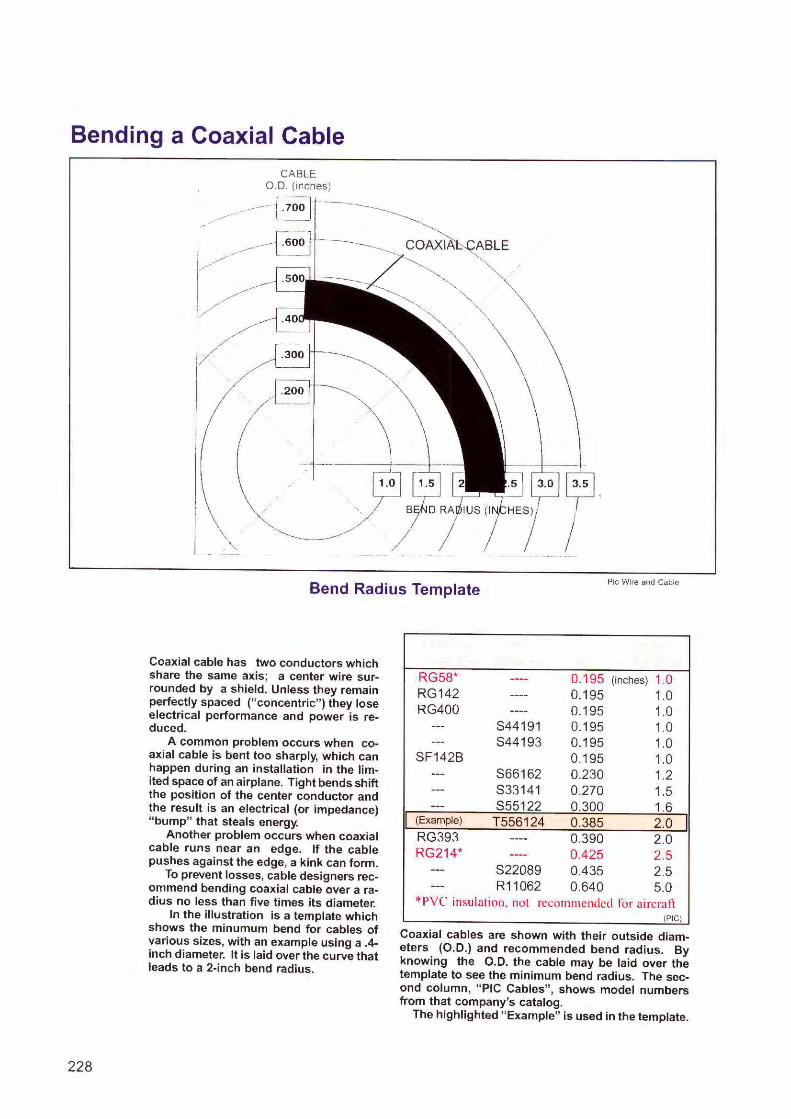
Bending a Coaxial Cable
\ '-----.
Bend Radius Template Pie Wire and Cable
228
Coaxial cable has two conductors which share the same axis; a center wire surrounded by a shield. Unless they remain perfectly spaced ("concentric" ) they lose electrical performance and power is reduced.
A common problem occurs when coaxial cable is bent too sharply, which can happen during an installation in the limited space of an airplane. Tight bends shift the position of the center conductor and the result is an electrical (or impedance) "bump" that steals energy.
Another problem occurs when coaxial cable runs near an edge. If the cable pushes against the edge, a kink can form.
To prevent losses, cable designers recommend bending coaxial cable over a radius no less than five times its diameter.
In the illustration is a template which shows the minumum bend for cables of various sizes, with an example using a .4-inch diameter. It is laid over the curve that leads to a 2-inch bend radius.
RG58* ---- 0.195 (inches) 1.0 RG1 42 ---- 0.195 1.0 RG400 ---- 0.195 1.0
--- S44191 0.195 1.0 --- S44193 0.195 1.0
SF142B 0.1 95 1.0 --- S66162 0.230 1.2 --- S33141 0.270 1.5 --- $55122 0.300 1.6
I (Example) T556124 0.385 2.0 I RG393 ---- 0.390 2.0 RG214* ---- 0.425 2.5
--- S22089 0.435 2.5 --- R11062 0.640 5.0
*PVC insulation, not recommended for aircraft (PIC)
Coaxial cables are shown with their outside diameters (O.D.) and recommended bend radius. By knowing the O.D. the cable may be laid over the template to see the minimum bend radius. The second column, "PIC Cables", shows model numbers from that company's catalog.
The highlighted "Example" is used in the template.
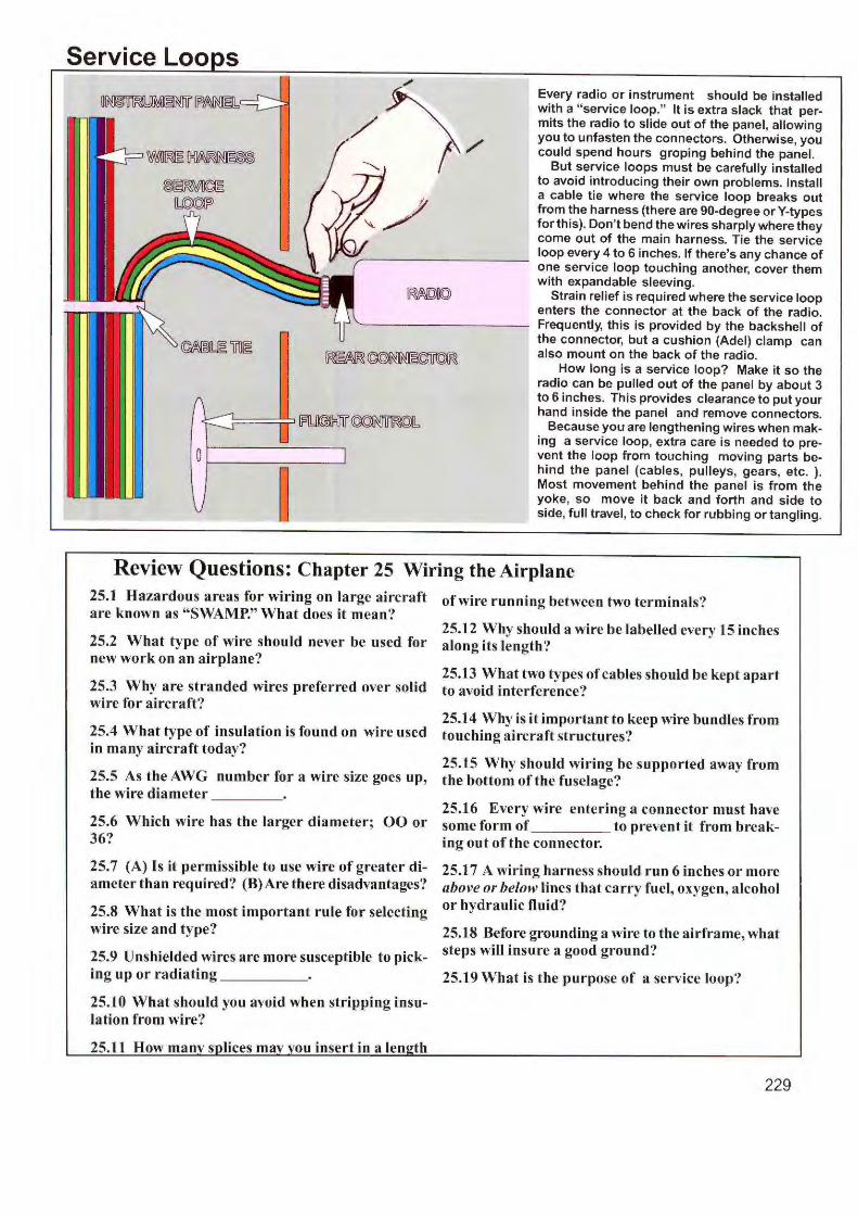
Service Loo s Every radio or instrument should be installed with a " service loop." It is extra slack that permits the radio to slide out of the panel, allowing you to unfasten the connectors. Otherwise, you could spend hours groping behind the panel.
But service loops must be carefully installed to avoid introducing their own problems. Install a cable tie where the service loop breaks out from the harness {there are 90-degree or Y-types for this). Don't bend the wires sharply where they come out of the main harness. Tie the service loop every 4 to 6 inches. If there's any chance of one service loop touching another, cover them with expandable sleeving.
Strain relief is required where the service loop enters the connector at the back of the radio. Frequently, this is provided by the backshell of the connector, but a cushion (Adel) clamp can also mount on the back of the radio.
How long is a service loop? Make it so the radio can be pulled out of the panel by about 3 to 6 inches. This provides clearance to put your hand inside the panel and remove connectors.
Because you are lengthening wires when making a service loop, extra care is needed to prevent the loop from touching moving parts behind the panel (cables, pulleys, gears, etc. ). Most movement behind the panel is from the yoke, so move it back and forth and side to side, full travel , to check for rubbing or tangling.
Review Questions: Chapter 25 Wiring the Airplane 25.1 Hazardous areas for wiring on large aircraft are known as "SWAMP." What does it mean?
of wire running between two terminals?
25.12 Why should a wire be labelled every 15 inches 25.2 What type of wire should never be used for along its length? new work on an airplane?
25.3 Why are stranded wires preferred over solid wire for aircraft?
25.4 What type of insulation is found on wire used in many aircraft today?
25.13 What two types of cables should be kept apart to avoid interference?
25.14 Why is it important to keep wire bundles from touching aircraft structures?
25.15 Why should wiring be supported away from 25.5 As the AWG number for a wire size goes up, the bottom of the fuselage? the wire diameter ___ _
25.6 Which wire has the larger diameter; 00 or 36?
25.7 (A) Is it permissible to use wire of greater diameter than required? (B)Are there disadvantages'?
25.8 What is the most important rule for selecting wire size and type?
25.9 Unshielded wires are more susceptible to pick-ing up or radiating ____ _
25.10 What should you avoid when stripping insulation from wire?
ou insert in a len th
25.16 Every wire entering a connector must have some form of to prevent it from breaking out of the connector.
25.17 A wiring harness should run 6 inches or more above or below lines that carry fuel, oxygen, alcohol or hydraulic fluid?
25.18 Before grounding a wire to the airframe, what steps will insure a good ground?
25.19 What is the purpose of a service loop?
229
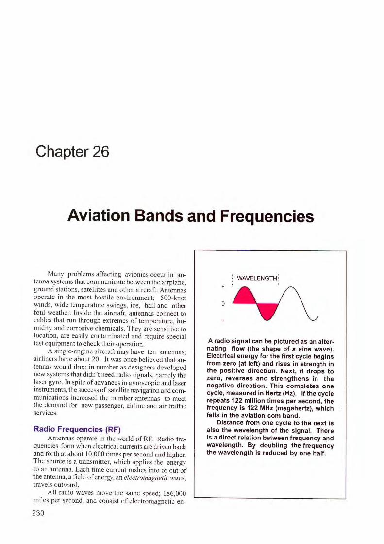
Chapter 26
Aviation Bands and Frequencies
Many problems affecting avionics occur in antenna systems that conununicate between the airplane, ground stations, satell ites and other aircraft. Antennas operate in the most hosti le environment; 500-knot winds, wide temperature swings, ice, hail and other foul weather. Inside the aircraft, antennas connect to cables that run through extremes of temperature, humidity and corrosive chemicals. They are sensitive to location, are easily contaminated and require special test equipment to check their operation.
A single-engine aircraft may have ten antennas; airl iners have about 20. It was once believed that antennas would drop in number as designers developed new systems that didn 't need radio signals, namely the laser gyro. In spite of advances in gyroscopic and laser instruments, the success of satellite navigation and communications increased the number antennas to meet the demand for new passenger, airl ine and air traffic services.
Radio Frequencies (RF) Antennas operate in the world of RF. Radio fre
quencies fonn when electrical currents are driven back and forth at about 10,000 times per second and higher. The source is a transmitter, which applies the energy to an antenna. Each time cun-ent rushes into or out of the antenna, a field of energy, an electromagnetic wave, travels outward.
All radio waves move the same speed; 186,000 miles per second, and consist of electromagnetic en-
230
:1 WAVELENGTH: ' '
+
0
A radio signal can be pictured as an alternating flow (the shape of a sine wave). Electrical energy for the first cycle begins from zero (at left) and rises in strength in the positive direction. Next, it drops to zero , reverses and strengthens in the negative direction. This completes one cycle, measured in Hertz (Hz). If the cycle repeats 122 million times per second, the frequency is 122 MHz (megahertz), which falls in the aviation com band.
Distance from one cycle to the next is also the wavelength of the signal. There is a direct relation between frequency and wavelength. By doubling the frequency the wavelength is reduced by one half.
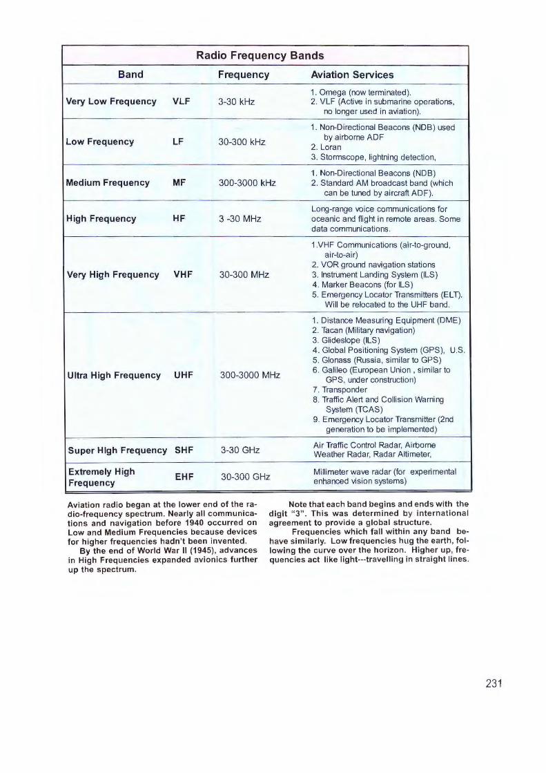
Radio Frequency Bands
Band Frequency Aviation Services
1. Omega (now terminated). Very Low Frequency VLF 3-30 kHz 2. VLF (Active in submarine operations,
no longer used in aviation).
1. Non-Directional Beacons (NOB) used
Low Frequency LF 30-300 kHz by airborne ADF
2. Loran 3. Stormscope, lightning detection,
1. Non-Directional Beacons (NOB) Medium Frequency MF 300-3000 kHz 2. Standard AM broadcast band (which
can be tuned by aircraft ADF).
Long-range voice communications for High Frequency HF 3 -30 MHz oceanic and flight in remote areas. Some
data communications.
1.VHF Communications (air-to-ground , air-to-air)
2. VOR ground navigation stations Very High Frequency VHF 30-300 MHz 3. Instrument Landing System (ILS)
4. Marker Beacons (for ILS) 5. Emergency Locator Transmitters (EL T).
Will be relocated to the UHF band.
1. Distance Measuring Equipment (OME) 2. Tacan (Military navigation) 3. Glideslope (ILS) 4. Global Positioning System (GPS), U.S. 5. Glonass (Russia, similar to GPS)
Ultra High Frequency UHF 300-3000 MHz 6. Galileo (European Union , similar to
GPS, under construction) 7. Transponder 8. Traffic Alert and Collision Warning
System (TCAS) 9. Emergency Locator Transmitter (2nd
generation to be implemented)
Super High Frequency SHF 3-30 GHz Air Traffic Control Radar, Airborne Weather Radar, Radar Altimeter,
Extremely High EHF 30-300 GHz Millimeter wave radar (for experimental
Frequency enhanced vision systems)
Aviation radio began at the lower end of the radio-frequency spectrum. Nearly all communications and navigation before 1940 occurred on Low and Medium Frequencies because devices for higher frequencies hadn't been invented.
By the end of World War II (1945), advances in High Frequencies expanded avionics further up the spectrum.
Note that each band begins and ends w ith the digit " 3". This was determ ined by internat ional agreement to provide a global structure.
Frequencies which fall w ithin any band behave similarly. Low frequencies hug the earth, following the curve over the horizon. Higher up, frequencies act like light---travelling in straight lines.
231
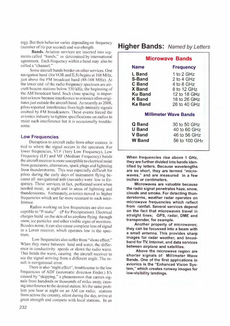
ergy. But the ir behavior varies depending on frequency (number of Hz per second) and wavelength.
Bands. Aviation serv ices arc inserted into segments ca 1 led "bands," as determined by international agreement. Each frequency within a band may a lso be called a "channe l."
Some a ircra ft bands border on other services. One navigation band (for VORand ILS) begins at 108 MHz, just above the F M broadcast band ( 88- 108 MH z). At the lower end of the radio frequency spectrum a re airc raft beacon stations below 530 kHz, the beginning of the AM broadcast band. Such close spacing is important to know because inte rference to avionics often orig inates just outside the aircraft band . As recently as 2008, pilots reported interference-from high-intens ity signals emitted by FM broadcasters. These events fo rced the avionics industry to tig hten specifi cations on radios to resist such interference but it is occasionally troublesome.
Low Frequencies Disruption to aircraft radio from othe r sources is
ti ed to where the s ig nal occurs in the spectrum. For lower frequencies, VLF (Very Low Frequency), Low Frequency (LF) and MF (Med ium Frequency) bands the a ircraft receiver is more susceptible to electrical noise fro m generators, alternators, spark plugs and I ightning fro m thunderstorms. T his was especia lly di fficult for pilots during the early days of instrument fly ing because all navigational aids (navaids) were low in frequency. These services, in fact, performed worst when needed most; at night and in areas of lightning and thunderstorms. Fortunately, avionics moved to hig her frequencies whi ch are far more res istant to such interference.
Radios working on low frequencies a re a lso suscepti ble to " P-static"-(P for Precipitation). Electr ical charges bui ld on the skin of an airplane flying through snow, ice pa rtic les and othe r visible s igns of moisture. Besides noise, it can also cause complete loss of signal in a Loran receiver, which operates low in the spectrum.
Low frequencies a lso suffer from "shore effect." When they move between land and water, the diffe rence in conductiv ity speeds or s lows the radio wave . Th is bends the wave, causing the a ircraft receiver to see the s ig nal a rriv ing fro m a d ifferent angle. T he res ul t is navigationa l er ror.
There is also "night effect", troublesome to the low frequencies of ADF (automatic direction f inder. ) It 's caused by "skipping," a phenomeno n that carries signals from hundreds or t housands of miles away, causing interference to the desired station. It's the same problem you hear at night on an AM car rad io; stations from across the country, s ilent during the day, arrive at great s trength and compete with local stations. In an
232
Higher Bands: Named by Letters
Microwave Bands
Name
L Band S-Band C Band X Band Ku Band K Band Ka Band
Frequency
1 to 2 GHz 2 to 4 GHz 4 to 8 GHz 8 to 12 GHz 12 to 18 GHz 18 to 26 GHz 26 to 40 GHz
Millimeter Wave Bands
Q Band U Band VBand WBand
30 to 50 GHz 40 to 60 GHz 46 to 56 GHz 56 to 100 GHz
When frequencies rise above 1 GHz, they are further divided into bands ident ified by letters. Because wavelengths are so short, they are termed "microwaves ," and are measured in a few inches or centimeters.
Microwaves are valuable because the radio signal penetrates haze, snow, clouds and smoke. For detecting thunderstorms, weather radar operates on microwave frequencies which reflect from rainfall. Several services depend on the fact that microwaves travel in stra ight lines; GPS, radar, DME and transponder, for example.
Another property of microwaves; they can be focussed into a beam with a small antenna. This provides sharp images for radar weather, and broadband for TV, Internet, and data services between airplane and satellites.
Above the microwave region are shorter signals of Millimeter Wave Bands. One of the first applications in avionics is the "Enhanced Vision System," which creates runway images for low-visibility landings.
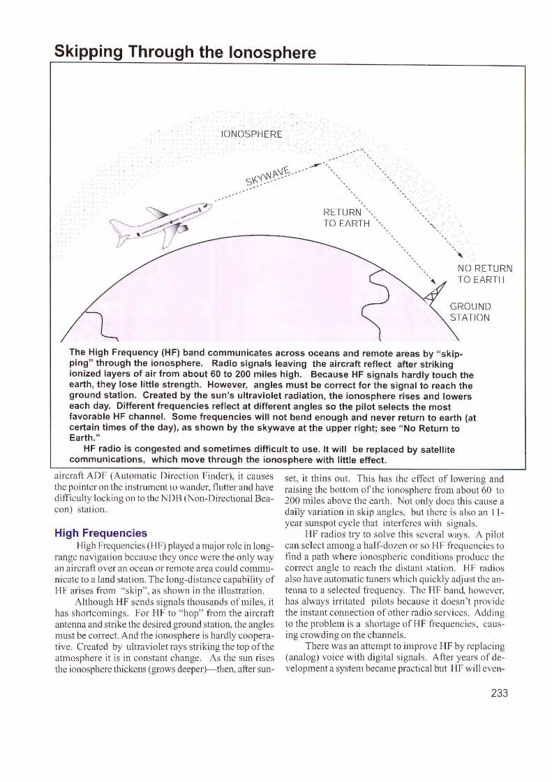
Skipping Through the Ionosphere
IONOSPHERE
-~ t. _..--,,
s~~~-~:!----- -- ,
RETU RN',,_ TO EARTH ',,,
"' NO RETURN TO EARTH
GROUND STATION
The High Frequency (HF) band communicates across oceans and remote areas by "skipping" through the ionosphere. Radio signals leaving the aircraft reflect after striking ionized layers of air from about 60 to 200 miles high. Because HF signals hardly touch the earth, they lose little strength. However, angles must be correct for the signal to reach the ground station. Created by the sun's ultraviolet radiation, the ionosphere rises and lowers each day. Different frequencies reflect at different angles so the pilot selects the most favorable HF channel. Some frequencies will not bend enough and never return to earth (at certain times of the day) , as shown by the skywave at the upper right; see "No Return to Earth."
HF radio is congested and sometimes difficult to use. It will be replaced by satellite communications, which move through the ionosphere with little effect.
aircraft ADF (Automatic Direction Finder), it causes the pointe r on the instrument to wander, flutter and have difficulty locking on to the NOB (Non-Directional Beacon) stati on.
High Frequencies High Frequencies (HF) played a major role in long
range nav igatio n because they once were the only way an a irc raft over an ocean or re mote area could communicate to a land station. The long-distance capability of HF arises from "skip", as shown in the ill ustratio n.
Al though HF sends s ignals thousands of mi les, it has sho,tcomings. For HF to "hop" from the aircraft antenna and strike the desired ground stati on, the angles must be correct. And the ionosphere is hardly cooperative. Created by ultraviolet rays striking the top of the atmosphere it is in constant change. As the sun rises the ionosphere thickens (grows deeper)-then, after sun-
set, it thins out. Thi s has the effect of lowering and ra ising the bottom of the ionosphere from about 60 to 200 miles above the ea1th. Not only docs thi s cause a dai ly variation in skip angles, but there is a lso an 11-year sunspot cyc le that interferes w ith signa ls.
HF radios try to solve this severa l ways. A pilot can select among a ha lf-doze n or so HF frequencies to find a path where ionospheric condi tions produce the correct angle to reach the di stant station . HF radi os also have automatic tuners which quickly adjust the antenna to a selected frequency. The HF band, however, has a lways ir ritated pi lots because it doesn't provide the instant connection of other radio services. Adding to the problem is a shortage of HF freq uencies, causing crowding on the channels .
There was an attempt to improve HF by replac ing (a nalog) voice w ith dig ital signals . After years of development a system became practical but HF wi II even-
233
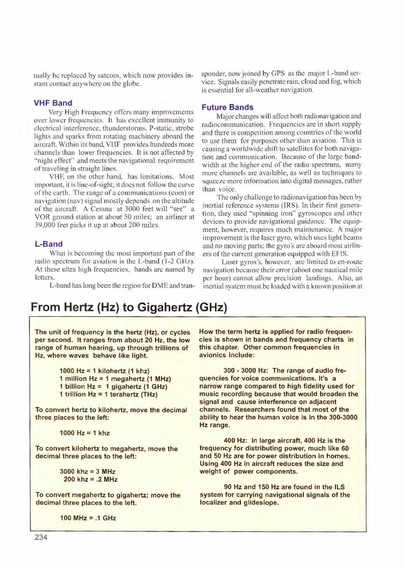
tuall y be replaced by satcom, which now provides intant contact anywhere on the globe.
VHF Band Very High Frequency offers many improvements
over lower frequencies. lt has excellent immunity to electrica l interference, thunderstorms, P-static, strobe lights and sparks from rotating machinery aboard the aircraft. Within its band, VHF provides hundreds more channels than lower frequencies. It is not affected by ''night effect" and meets the navigational requirement of traveling in straight lines.
VllF, on the other hand, has limitations. Most impo1tant, it is line-of-sight; it does not follow the curve of the ea rth. The range of a communications (com) or navigation (nav) signal mostly depends on the altitude of the aircraft. A Cessna at 3000 feet will "sec" a VOR ground stati on at about 50 miles; an airliner at 39,000 feet picks it up at about 200 mi les.
L-Band What is becoming the most important part of the
radio spectrum for aviation is the L-band ( 1-2 GHz). At these ultra hi gh frequencies, bands arc named by letters.
L-band has long been the region for OM E and tran-
sponder, now joined by GPS as the major L-band service. Signals easily penetrate rai n, cloud and fog, which is essential for all-weather navigation.
Future Bands Major changes will affect both radionavigation and
radiocommunication. Frequencies are in short suppl y and there is competition among countries of the world to use them for purposes other than aviation. This is causing a worldwide shift to satellites for both navigation and communication. Because of the large bandwidth at the higher end of the radio spectrum, many more channels arc available, as we ll as techniques to squeeze more information into digital messages, rather than voice.
The onl y cha llenge to radionavigation has been by inertial reference systems (I RS). In their first generation, they used "spinning iron" gyroscopes and other devices to provide navigational guidance. The equipment, however, req uires much maintenance. A major improvement is the laser gyro, which uses light beams and no moving parts; the gyro's are aboard most airliners of the current generation equipped with EFIS.
Laser gyros's, however, are limited to en-route navigation because their error (about one nautica l mil e per hour) cann ot a ll ow precision landings . Also, an inertial system must be loaded with a known position at
From Hertz {Hz} to Gigahertz {GHz}
The unit of frequency is the hertz (Hz), or cycles per second. It ranges from about 20 Hz, the low range of human hearing, up through trillions of Hz, where waves behave like light.
1000 Hz = 1 kilohertz (1 khz) 1 million Hz = 1 megahertz (1 MHz) 1 billion Hz = 1 gigahertz (1 GHz) 1 trillion Hz = 1 terahertz (THz)
To convert hertz to kilohertz, move the decimal three places to the left:
1000 Hz= 1 khz
To convert kilohertz to megahertz, move the decimal three places to the left:
3000 khz = 3 MHz 200 khz = .2 MHz
To convert megahertz to gigahertz; move the decimal three places to the left.
100 MHz= .1 GHz
234
How the term hertz is applied for radio frequencies is shown in bands and frequency charts in this chapter. Other common frequencies in avionics include:
300 - 3000 Hz: The range of audio frequencies for voice communications. It's a narrow range compared to high fidelity used for music recording because that would broaden the signal and cause interference on adjacent channels. Researchers found that most of the ability to hear the human voice is in the 300-3000 Hz range.
400 Hz: In large aircraft, 400 Hz is the frequency for distributing power, much like 60 and 50 Hz are for power distribution in homes. Using 400 Hz in aircraft reduces the size and weight of power components.
90 Hz and 150 Hz are found in the ILS system for carrying navigational signals of the localizer and glideslope.
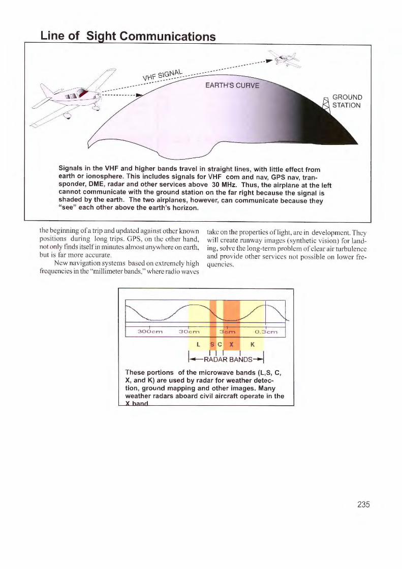
Line of Si ht Communications
\j r\f ~~~~~~- ----:..:..----------_------- EARTH'S CURVE
Signals in the VHF and higher bands travel in straight lines, with little effect from earth or ionosphere. This includes signals for VHF com and nav, GPS nav, transponder, DME, radar and other services above 30 MHz. Thus, the airplane at the left cannot communicate with the ground station on the far right because the signal is shaded by the earth. The two airplanes, however, can communicate because they "see" each other above the earth's horizon.
the beginning of a trip and updated aga inst other known positions duri ng long trips. GPS, on the other hand, not only finds itself in minutes a lmost anywhere on earth, but is far more accurate.
New navigati on systems based on extremely high frequencies in the ' "mill imeter bands," where radio waves
take on the properties ofl ight, are in development. T hey will create runway images (synt het ic vision) for landing, so lve the long-term problem of clear a ir turbulence and provide other serv ices not possible on lower frequencies.
L S C X K
I I I I I I ~RADAR BANDS--J
These portions of the microwave bands (L,S, C, X, and K) are used by radar for weather detection , ground mapping and other images. Many weather radars aboard civil aircraft operate in the
235
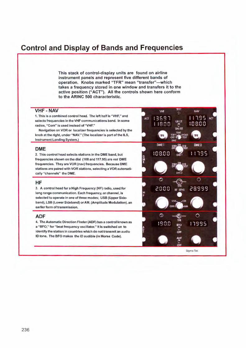
Control and Display of Bands and Frequencies
This stack of control-display units are found on airline instrument panels and represent five different bands of operation. Knobs marked "TFR" mean "transfer"---which takes a frequency stored in one window and transfers it to the active position ("ACT"). All the controls shown here conform to the ARINC 500 characteristic.
VHF-NAV 1. This is a combined control head. The left half is "VHF," and
selects frequencies in the VHF communications band. In some
radios, " Com" is used instead of "VHF. "
Navigation on VOR or localizer frequencies Is selected by the knob at the right, under "NAV." (The localizer is part of the llS,
Instrument landing S stem.
DME 2. This control head selects stations in the DME band, but
frequencies shown on the dial (108 and 117.95) are not DME
frequencies. They are VOR (nav) frequencies. Because DME stations are paired with VOR stations, selecting a VOR automatically "channels" the DME.
HF 3. A control head for a High Frequency (HF) radio, used for
long range communication. Each frequency, or channel, is
selected to operate in one of three modes; USS (Upper Side
band), lSB (lower Sideband) or AM, (Amplitude Modulation), an earlier form of transmission.
ADF 4. The Automatic Direction Finder (ADF) has a control known as a "BFO," for "beat frequency oscillator." It is switched on to
identify the station in countries which do not transmit an audio
ID tone. The BFO makes the ID audible (in Morse Code).
AC:l
0 M E
H F
A 0 F
VHF TtST
::i ,: ,:, i _, ,_1 _, ' : 8 c: 0 UP/LT ..,.
·, ON/RT • DMi
m!~ HOlO 011 TEST
DI~
DMEl mY OIi Oit Off TUI
::J8DO OI<\£ 1
4) 6W°" 0iA1 ..... , '
Q -@-2DOC:
TFR
RI SfNS • • U~8, 1 l58
Ofr..,a.AM
? ~-mt , ,-, n , , ' :, ,_, ,_, 8FO ,.,. OFP
• ANT .. .. OFF
NAV
I I ,-11-I I:, :;t
I Ii ,:1 i t oi I,_,·-· 1..1 1.,1
• DME2
I r ,· 1 i I I :1 :1
-}
,nnrin ,: C• :, :t :,
• ()
-: :: s ;4
• Sigma-Tek
236
ACT
•
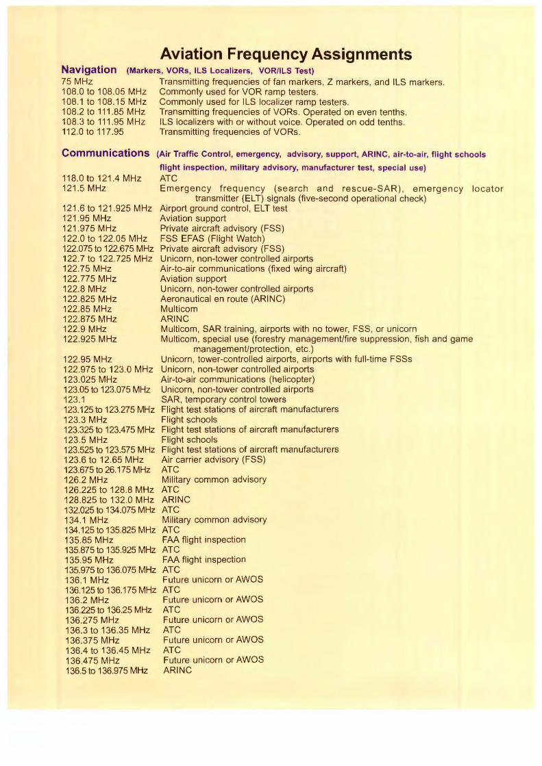
Aviation Frequency Assignments Navigation 75 MHz
(Markers, VORs, ILS Localizers, VOR/ILS Test)
108.0 to 108.05 MHz 108.1 to 108.15 MHz 108.2 to 111 .85 MHz 108.3 to 111.95 MHz 112.0 to 117.95
Transmitting frequencies of fan markers, Z markers, and ILS markers. Commonly used for VOR ramp testers. Commonly used for ILS localizer ramp testers. Transmitting frequencies of VORs. Operated on even tenths. ILS localizers with or without voice. Operated on odd tenths. Transmitting frequencies of VORs.
Communications (Air Traffic Control, emergency, advisory, support, ARINC, air-to-air, flight schools
118.0 to 121.4 MHz 121 .5 MHz
121.6 to 121.925 MHz 121.95 MHz 121.975 MHz 122.0 to 122.05 MHz 122.075 to 122.675 MHz 122.7 to 122.725 MHz 122.75 MHz 122.775 MHz 122.8 MHz 122.825 MHz 122.85 MHz 122.875 MHz 122.9 MHz
flight inspection, military advisory, manufacturer test, special use) ATC Emergency frequency (search and rescue-SAR) , emergen cy
transmitter (ELT) signals (five-second operational check) Airport ground control , ELT test Aviation support Private aircraft advisory (FSS) FSS EFAS (Flight Watch) Private aircraft advisory (FSS) Unicorn, non-tower controlled airports Air-to-air communications (fixed wing aircraft) Aviation support Unicorn, non-tower controlled airports Aeronautical en route (ARINC) Multicom ARINC Multicom, SAR training , airports with no tower, FSS, or unicorn
locator
122.925 MHz Multicom, special use (forestry management/fire suppression, fish and game management/protection , etc.)
122.95 MHz Unicorn, tower-controlled airports, airports with full-time FSSs 122.975 to 123.0 MHz Unicorn, non-tower controlled airports 123.025 MHz Air-to-air communications (helicopter) 123.05 to 123.075 MHz Unicorn, non-tower controlled airports 123.1 SAR, temporary control towers 123.125to 123.275 MHz Flight test stations of aircraft manufacturers 123.3 MHz Flight schools 123.325 to 123.475 MHz Flight test stations of aircraft manufacturers 123.5 MHz Flight schools 123.525 to 123.575 MHz Flight test stations of aircraft manufacturers 123.6 to 12.65 MHz Air carrier advisory (FSS) 123.675 to 26.175 MHz ATC 126.2 MHz Military common advisory 126.225 to 128.8 MHz ATC 128.825 to 132.0 MHz ARINC 132.025 to 134.075 MHz ATC 134.1 MHz Military common advisory 134.125 to 135.825 MHz ATC 135.85 MHz FAA flight inspection 135.875 to 135.925 MHz ATC 135.95 MHz FM flight inspection 135.975 to 136.075 MHz ATC 136.1 MHz Future unicorn or AWOS 136.125 to 136.175 MHz ATC 136.2 MHz Future unicorn or AWOS 136.225 to 136.25 MHz ATC 136.275 MHz Future unicorn or AWOS 136.3 to 136.35 MHz ATC 136.375 MHz Future unicorn or AWOS 136.4 to 136.45 MHz ATC 136.4 75 MHz Future unicorn or AWOS 136.5 to 136.975 MHz ARINC
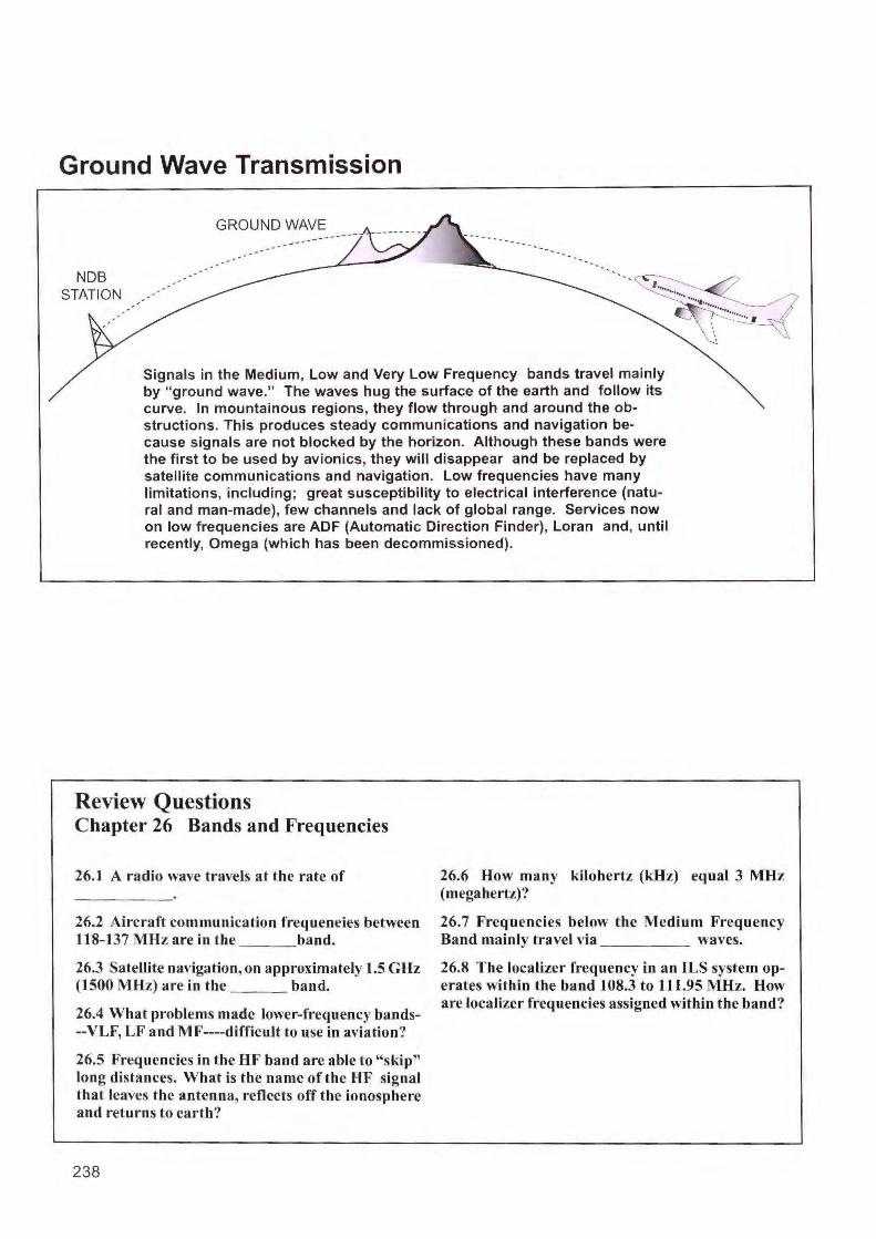
Ground Wave Transmission
NDB STATION
GROUND WAVE ---
Signals in the Medium, Low and Very Low Frequency bands travel mainly by "ground wave." The waves hug the surface of the earth and follow its curve. In mountainous regions, they flow through and around the ob-structions. This produces steady communications and navigation because signals are not blocked by the horizon. Although these bands were the first to be used by avionics, they will disappear and be replaced by satellite communications and navigation. Low frequencies have many limitations, including; great susceptibility to electrical interference (natural and man-made), few channels and lack of global range. Services now on low frequencies are ADF (Automatic Direction Finder), Loran and, until recently, Omega (which has been decommissioned).
Review Questions Chapter 26 Bands and Frequencies
26. I A radio wave travels at the rate of
26.2 Aircraft communication frequencies between 118-137 MHz are in the band.
26.3 Satellite navigation, on approximately 1.5 GHz (1500 MHz) are in the band.
26.4 What problems made lower-frequency bands--VLF, LF and MF----difficult to use in aviation?
26.5 Frequencies in the HF band are able to "skip" long distances. What is the name of the HF signal that leaves the antenna, reflects off the ionosphere and returns to earth?
238
26.6 How many kilohertz (kHz) equal 3 MHz (megahertz)?
26.7 Frequencies below the Medium Frequency Band mainly travel via waves.
26.8 The localizer frequency in an ILS system operates within the band l 08.3 to 111.95 MHz. How are localizer frequencies assigned within the band'?
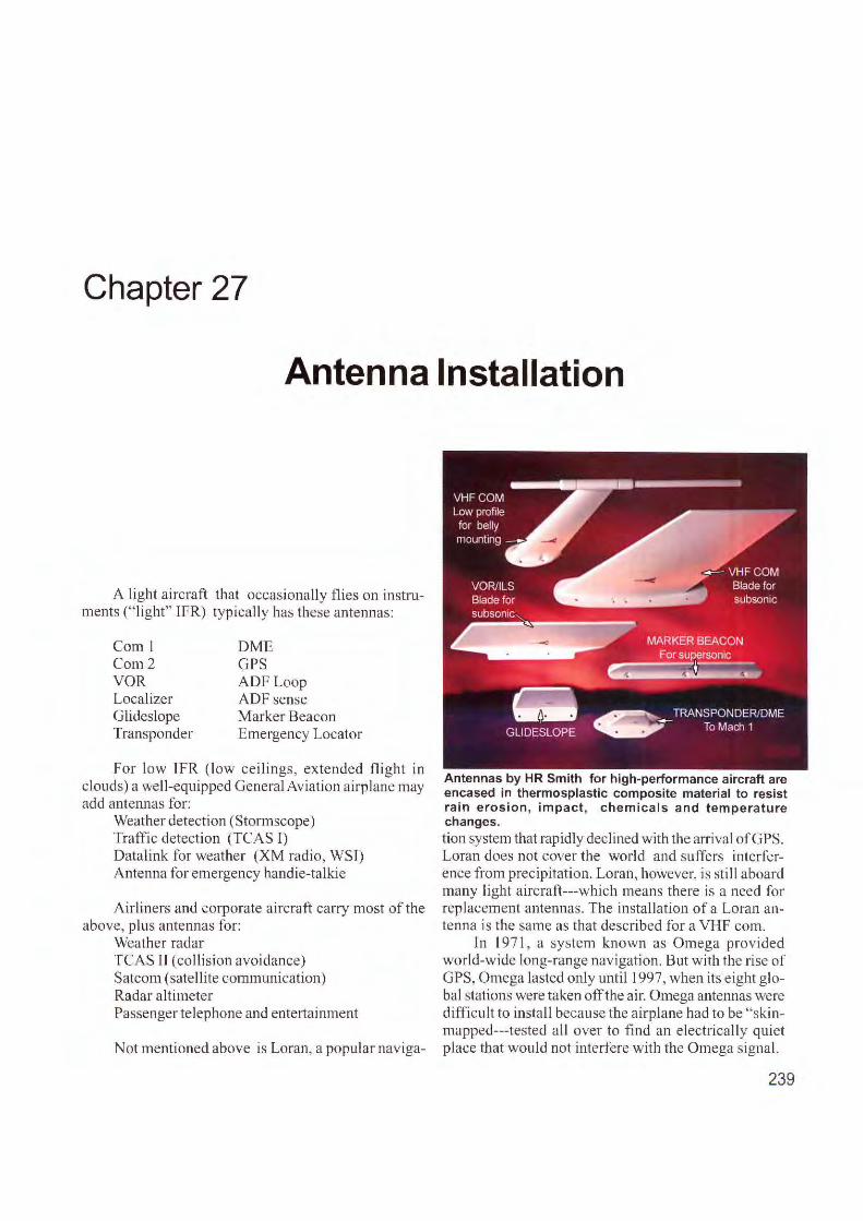
Chapter 27
Antenna Installation
A light aircraft that occas ionally flies o n instruments ("li ght" IFR) typica lly has these antennas:
Com l Com 2 VOR Localizer Glideslope Transponder
DME GPS ADFLoop ADF sense Marker Beacon Emergency Locator
For low lFR (low cei lings, extended fli ght in clouds) a well-equipped General Aviation a irplane may add antennas for:
Weather detection (Stormscope) Traffic detection (TCAS 1) Datalink for weather (XM radio, WST) Antenna for emergency handie-ta lkic
Airl iners and corporate a ircraft carry most of the above, plus antennas fo r:
Weather radar TCAS Tl (co llision avoidance) Satcom (satellite communication) Radar altimeter Passenger telephone and ente1tainment
Not mentioned above is Loran, a popular nav iga-
Antennas by HR Smith for high-performance aircraft are encased in thermosplastic composite material to resist rain erosion , impact, chemicals and temperature changes. ti.on system that rapidly declined with the arrival ofGPS. Loran does not cover the world and suffers interference from prec ipitation. Loran, however, is still aboard many light aircraft---which means there is a need for replacement antennas . The install ation of a Loran antenna is the same as that described fo r a VHF com.
In l 97 1, a system known as Omega provided world-wide long-range nav igation. But w ith the rise of GPS, Omega lasted only until I 997, when its eight globa l stations were taken off the air. Omega antennas were difficult to install because the a irplane had to be "skinmapped---tested all over to fin d an e lectrically quiet place that would not interfere with the Omega signa l.
239
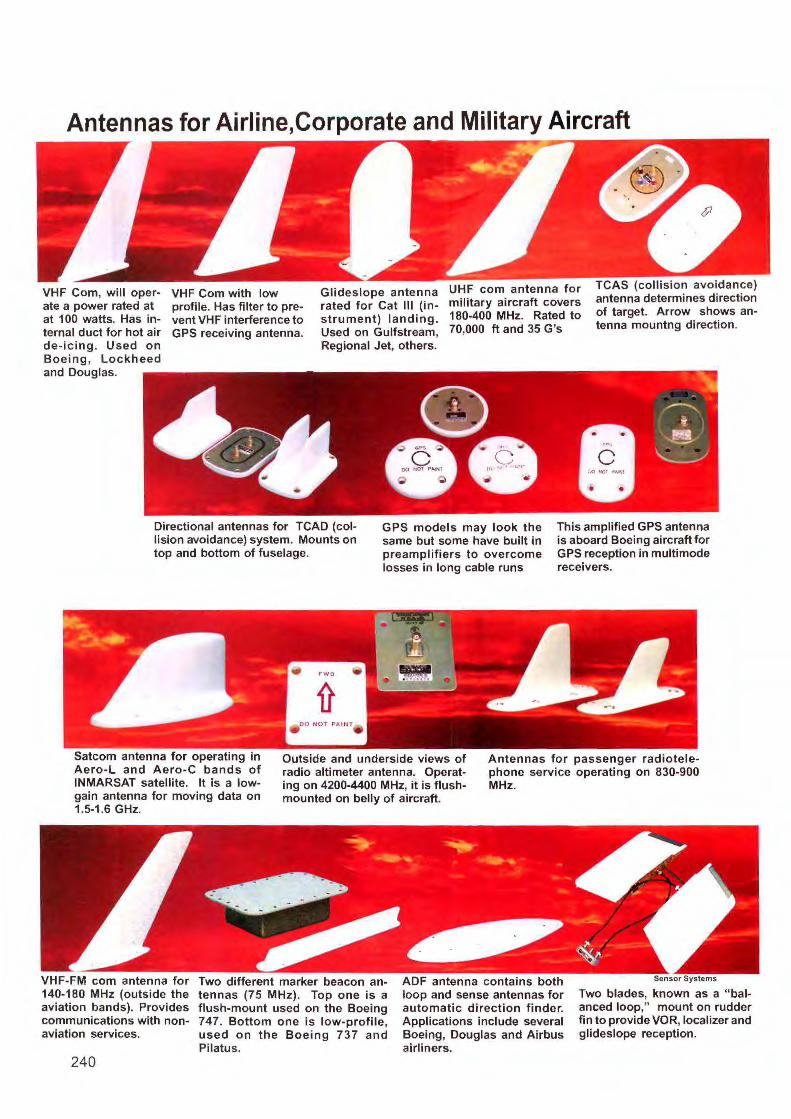
Antennas for Airline,Corporate and Military Aircraft
VHF Com, will operate a power rated at at 100 watts. Has internal duct for hot air de-icing. Used on Boeing, Lockheed
VHF Com with low profile. Has filter to prevent VHF interference to GPS receiving antenna.
Glideslope antenna rated for Cat Ill (instrument) landing. Used on Gulfstream, Regional Jet, others.
UHF com antenna for military aircraft covers 180-400 MHz. Rated to 70,000 ft and 35 G's
TCAS (collision avoidance} antenna determines direction of target. Arrow shows antenna mountng direction.
and Douglas.
Directional antennas for TCAD (collision avoidance} system. Mounts on top and bottom of fuselage.
GPS models may look the same but some have built in preamplifiers to overcome losses in long cable runs
This amplified GPS antenna is aboard Boeing aircraft for GPS reception in multimode receivers.
Satcom antenna for operating in Aero-L and Aero-C bands of INMARSAT satellite. It is a lowgain antenna for moving data on 1.5-1.6 GHz.
Outside and underside views of radio altimeter antenna. Operating on 4200-4400 MHz, it is flushmounted on belly of aircraft.
Antennas for passenger radiotelephone service operating on 830-900 MHz.
VHF-FM com antenna for 140-180 MHz (outside the aviation bands}. Provides communications with nonaviation services.
240
Two different marker beacon antennas (75 MHz}. Top one i s a flush-mount used on the Boeing 747. Bottom one is low-profile, used on the Boeing 737 and Pilatus.
ADF antenna contains both loop and sense antennas for automatic direction finder. Applications include several Boeing, Douglas and Airbus airliners.
Sensor Systems
Two blades, known as a "balanced loop," mount on rudder fin to provide VOR, localizer and glideslope reception.
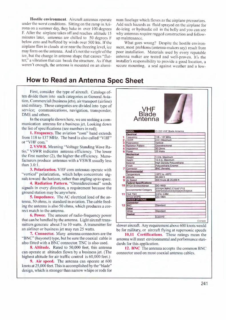
Hostile environment. Aircraft antennas operate under the worst conditions. Sitting on the ramp in Arizona on a summer day, they bake in over l 00 degrees F. After the ai rplane takes off and reaches a ltitude 15 minutes later, antennas are chi I led to 50 degrees F below zero and buffeted by winds over 500 kts . If the airplane flies in clouds at or near the freezing level, ice may form on the antenna. And it 's not the weight of the ice, but the change in antenna shape that causes "flutter," a vibration that can break the structure. As if that weren't enough, the a ntenna is mounted on an alumi-
num fuselage which flexes as the airplane pressurizes. Add such hazards as fluid sprayed on the airplane for de-icing or hydraulic o il in the belly and you ca n see why ante1rnas require rugged construction and followup mai ntenance.
What goes wrong? Despite the hostile environment, most problems (antenna-makers say) result from poor installation. Materi als used by every reputable anten na maker are tested and wel l-prove n. It 's the installer's responsibility to provide a good location, a secure mounting, a seal against weather and a low-
How to Read an Antenna Spec Sheet
First, consider the type of aircraft. Catalogs often divide them into such categories as General Aviation, Commercial (business j ets), air transpo1t (airline) and military. These categories are divided into type of service; communications, navigation, transponder, DME and others.
In the example shown here, we are seeking a communication antenna for a business jet. Looking down the list of specifications (see numbers in red);
I. Frequency. The aviation "com" band extends from 118 to 13 7 MHz. The band is also cal led "VHF" or "VHF com."
2. VSWR. Meaning "Voltage Standing Wave Ratio," YSWR indicates antenna efficiency. The lower the first number (2), the higher the efficiency. Manufacture rs produce antennas with a YSWR usually less than 3.0: I.
3. Polarization. VHF com antennas operate with "vertica l" polarization , which he lps concentrate signals toward the horizon, rather than angJjng up to space.
4. Radiation Pattern. "Omnidirectional" sends signals in every direction, a requirement because the ground station may be anywhere.
5. [mpedance. The AC electrical load of the antenna, 50 ohms, is standard in aviation. The cable feeding the antenna is also 50 ohms, which produces a correct match to the antenna.
6. Power. The amount of radio-frequency power that can be handled by the antenna. Light aircraft transmitters generate about 5 to 10 watts. A transmitter for an airliner or business jet may run 25 watts.
7. Connector. Many antenna connecto rs are the "BNC" (bayonet) type, but be sure the coaxial cable is a lso fitted w ith a BNC connector. TNC is also used.
8. Altitude. Rated to 50,000 feet, this antenna can operate at a ltitudes flown by a business jet. (The highest a ltitude fo r air traffic control is 60,000 feet.)
9. Air speed. The antenna can operate at 600 knots at 25 ,000 feet. This is accomplished by the "blade" design, which is stronger than narrow whips or rods for
1 2 3 4 5 6
7
8 9
10
11
12
VHF Blade
Antenna
....... Cl 223 VHF Blade An1enna Electrical Freouoncv 118• 137MHz VSWR 2.0:1 Maximum P01arlza1lon Venical Radialion Pallern Omnidireclional fmnA11ance 500hms Power 25 Walls Mechanical Weiqhl 1.5 lb. Maximum Hei(lhl 12.5 In. Maximum Malerial Hioh Oensttv POlvurelhane Finish POlvurelhane Enamel Conneclor BNCllemalel Envlronmentel T emoerature -55"C 10 +85oC Allilude 1so.ooo n Air Soeed 1600 Knols@ 25.000 fl Federel 5-,,111ca11ons RTCA Environmenlal 00-1600
Environmen1a1 Ca1ego,y [02XjACB[R(C.C1 )U(F .Fl )I (l XWFOXSXXXXX(XX]XIXXXX XAX
FAA TSO C37d C38d RTCAMOPS 00-186A ... ... • Connector BNC (Standard Color While Standard Guket
IC22310
Coman!
slower aircraft. Any requirement above 600 knots would be for military, or aircraft flying at supersonic speeds
10,11 Certifications . These ratings mean the antenna will meet environmental and pe1fo1mance standards for this application.
12. BNC The antenna accepts the common BNC connector used on most coaxial antenna cables.
241
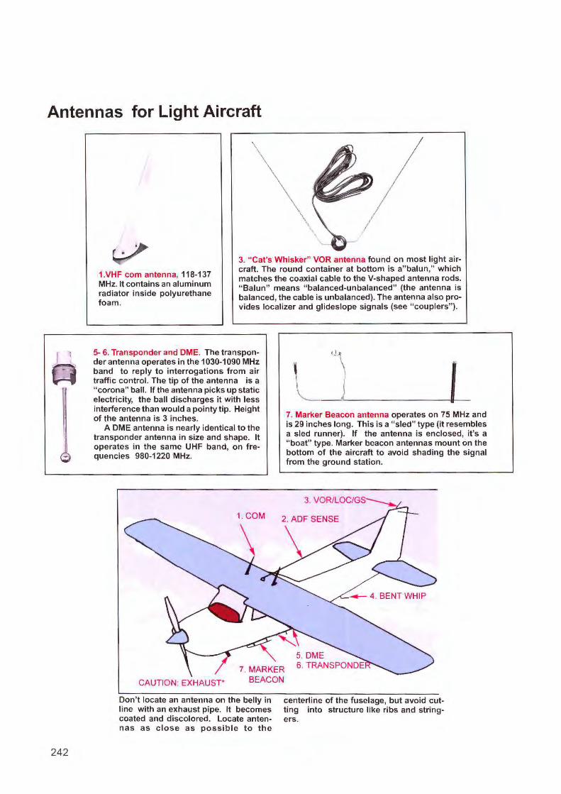
Antennas for Light Aircraft
242
1.VHF com antenna, 118-137 MHz. It contains an aluminum radiator inside polyurethane foam.
3. " Cat's Whisker" VOR antenna found on most light aircraft. The round container at bottom is a" balun," which matches the coaxial cable to the V-shaped antenna rods. " Balun" means " balanced-unbalanced" (the antenna is balanced, the cable is unbalanced). The antenna also provides localizer and glideslope signals (see " couplers" ).
5- 6. Transponder and CME. The transponder antenna operates in the 1030-1090 MHz band to reply to interrogations from air traffic control. The tip of the antenna is a "corona" ball. If the antenna picks up static electricity, the ball discharges it with less interference than would a pointy tip. Height of the antenna is 3 inches.
A CME antenna is nearly identical to the transponder antenna in size and shape. It operates in the same UHF band, on frequencies 980-1220 MHz.
CAUTION. EXHAUST*
Don't locate an antenna on the belly in line with an exhaust pipe. It becomes coated and discolored. Locate antennas as c lose as possible to the
I
7. Marker Beacon antenna operates on 75 MHz and is 29 inches long. This is a " sled" type (it resembles a sled runner). If the antenna is enclosed, it's a "boat" type. Marker beacon antennas mount on the bottom of the aircraft to avoid shading the signal from the ground station.
centerline of the fuselage, but avoid cutting into structure like ribs and stringers.
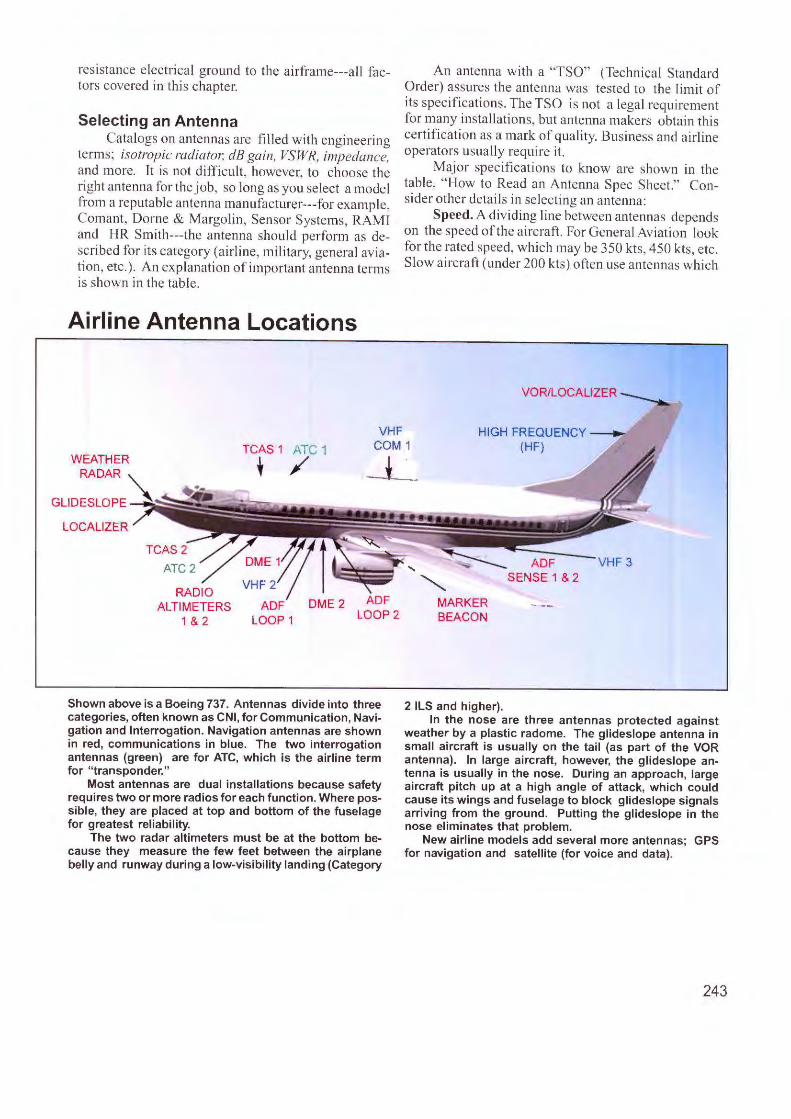
resistance e lectrical ground to the airframe---all factors covered in this chapter.
Selecting an Antenna Catalogs on antennas are filled with engineering
terms; isotropic radiat01: dB gain, VSWR, impedance, and more. It is not difficult, however, to choose the right antenna for the job, so long as you select a model from a reputable antenna manufacturer---for example, Comant, Dorne & Margolin, Sensor Systems, RAMT and HR Smith---the antenna s hould perform as described fo r its category (airline, military, genera l aviation, etc.). An explanation of important antenna terms is shown in the table.
Airline Antenna Locations
An antenna with a "TSO" (Technica l Standard Order) assures the antenna was tested to the limit of its specifications. The TSO is not a legal requirement for many insta llations, but antenna makers obtain this certification as a mark of qual ity. Business and airline operators usually requ.irc it.
Major spec ifications to know are shown in the table, "How to Read an Antenna Spec Sheet." Consider other details in selecting an antenna:
Speed. A dividing line between antennas depends on the speed of the a ircraft. For General Aviation look for the rated speed, which may be 350 k ts, 450 kts, etc. S low aircraft (under 200 kts) often use antennas which
VOR/LOCALIZER --...
TCAS 1 t Tt 1 VHF
COM 1 HIGH FREQUENCY ----...
(HF) WEATHER
RADAR
GLIDESLOPE ~ LOCALIZER
+ / _t __
ADF LOOP2
Shown above is a Boeing 737. Antennas divide into three categories, often known as CNI, for Communication, Navigation and Interrogation. Navigation antennas are shown in red, communications in blue. The two interrogation antennas (green) are for ATC, which is the airline term for "transponder."
Most antennas are dual installations because safety requires two or more radios for each function. Where possible, they are placed at top and bottom of the fuselage for greatest reliability.
The two radar altimeters must be at the bottom because they measure the few feet between the airplane belly and runway during a low-visibility landing (Category
MARKER BEACON
2 ILS and higher).
VHF 3
In the nose are three antennas protected against weather by a plastic radome. The glideslope antenna in small aircraft is usually on the tail (as part of the VOR antenna). In large aircraft, however, the glideslope antenna is usually in the nose. During an approach, large aircraft pitch up at a high angle of attack, which could cause its wings and fuselage to block glideslope signals arriving from the ground. Putting the glideslope in the nose eliminates that problem.
New airline models add several more antennas; GPS for navigation and satellite (for voice and data).
243
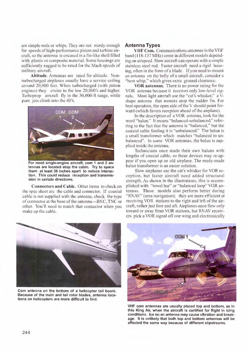
are simple rods or whips. They are not sturdy enough for speeds of high-performance pi ston and turbine a ircraft, so the antenna is encased in a fin-like shell filled with plastic or composite material. Some housings are sufficiently rugged to be rated for the Mach speeds of military aircraft.
Altitude. Antennas are rated fo r altitude. Nonturbocharged ai rplanes usua lly have a service ce iling around 20,000 feet. When turbocharged (with pi ton engines) they cruise in the low 20,000 's and higher. Turboprop aircraft fly in the 30,000-ft range, while pure jets climb into the 40's.
For most single-engine aircraft, com 1 and 2 antennas are located atop the cabin. Try to space them at least 36 inches apart to reduce interaction. This could reduce reception and transmission in certain directions.
Connectors and Cable. Other items to check on the spec s heet are the cable and connector. If coaxial cable is not supplied with the antenna, check the type of connector at the base of the antenna---BNC, TNC or other. You ' 11 need to match that connector when you make up the cable.
Com antenna on the bottom of a helicopter tail boom. Because of the main and tail rotor blades, antenna locations on helicopters are more difficult to find.
244
Antenna Types VHF Com. Communications antennas in the VHF
band ( 118- 137 MHz) come in different models depending on airspeed. Slow aircraft can operate wi th a simple sta inless steel rod. Faster aircraft need a rigid hou -ing, often in the form of a blade. If you need to mount an antenna on the belly of a smal l aircraft, cons ider a " bent whip," wh ich g ives extra ground c learance.
VOR antennas. There is no power rating for the VOR antenna because it receives on ly low-level signals. Most light aircraft use the "cat's whisker," a Vshapc antenna that mounts atop the rudder fin. For best operation, the open side of the V shou ld poi nt fo rward (whic h favors reception ahead of the airplane).
Tn the description of a VOR antenna, look for the word "balun." l t means "balanced-unbalanced," referring to the fact that the antenna is "ba lanced," but the coaxial cable feeding it is " unbalanced." The balun is a small transformer which matches " balanced to unbalanced". In some VOR anten nas, the balun is supplied inside the antenna.
Technicians once made their own baluns with lengths of coax ial cable, so these devices may re-appear if you open up an old a irplane. The ready-made balun transformer is an easier solution.
S low airplanes use the cat's whisker for VOR recept ion, but faste r aircraft need added structural strength. As shown in the illustrations, thi s is accomplis hed with "towel bar" or ' 'balanced loop" VOR antennas. These models also perform better during " RNAV" (area navigation); they are more efficient at receiving VOR stations to the right and left of the a ircraft, rather just fore and aft. A irplanes once flew only toward or away from VOR stations, but RNAV receivers pick a VOR signal off one wing and electronical ly
VHF com antennas are usually placed top and bottom, as in this King Air, when the aircraft is certified for flight in icing conditions. Ice on an antenna may cause vibration and breakage. It is unlikely that both top and bottom antennas will be affected the same way because of different slipstreams.
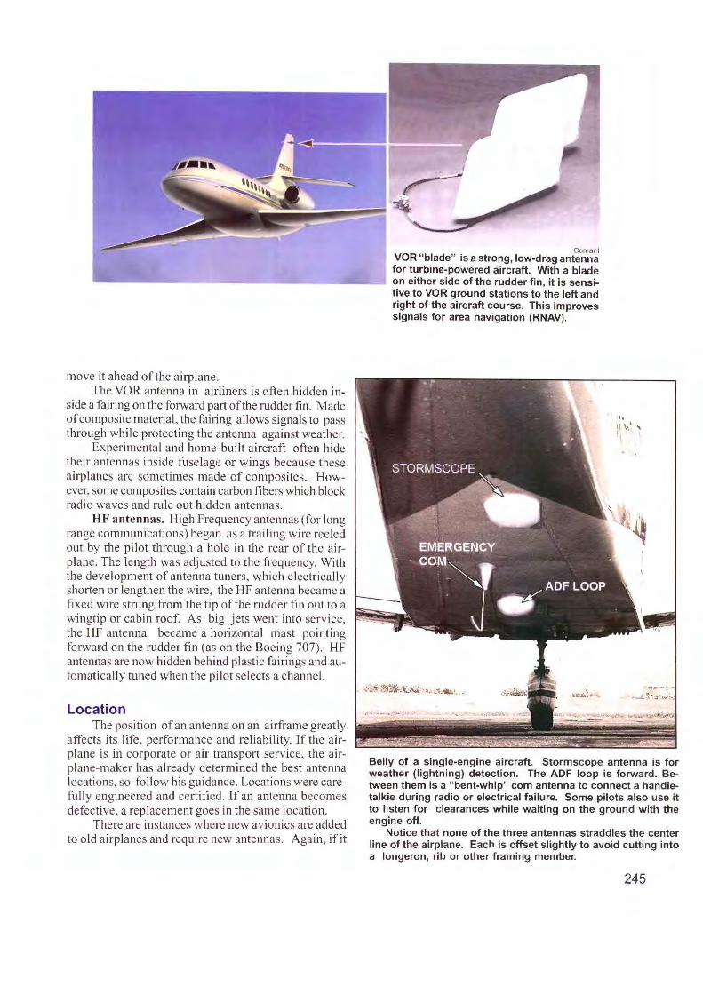
move it ahead of the airplane. The VOR ante nna in a irliners is often bidden in
side a fairing on the forward part of the rudder fin . Made of composite material, the fairing a llows signals to pass through while protecting the antenna against weather.
Experimental and home-built aircraft o ften hide their antennas inside fuselage or w ings because these a irplanes are sometimes made of compos ites. However, some composites contain carbon fibers which block radi o waves and rule out hidden antennas.
HF antennas. High Frequency ante1mas (for long range communications) began as a trailing wire reeled out by the pilot through a hole in the rear of the airplane. The length was adjusted to the frequency. With the development of antenna tuners, which e lectrically shorten or lengthen the wire, the HF antenna became a fi xed wire strung from the tip of the rudder fin out to a wingtip or cabin roof. As big j ets went into serv ice, the HF antenna became a horizontal mast pointing forward on the rudder fin (as on the Boeing 707). HF antennas are now hidden behind pl astic fairings and automatically tuned when the pilot selects a channel.
Location The position of an anten11a on an airframe greatly
affects its life, performance and re liability. If the airplane is in corporate or air transport service, the a irp lane-maker has already determined the best antenna locati ons, so fo llow his guidance. Locatio ns were carefully engineered and certified. If an antenna becomes defective, a replacement goes in the same location.
There are instances where new avionics are added to old a irplanes and require new antennas. Again, if it
Coman! VOR "blade" is a strong, low-drag antenna for turbine-powered aircraft. With a blade on either side of the rudder fin, it is sensitive to VOR ground stations to the left and right of the aircraft course. This improves signals for area navigation (RNAV).
.. I \1 ' '
Belly of a single-engine aircraft. Stormscope antenna is for weather (lightning) detection. The ADF loop is forward. Between them is a "bent-whip" com antenna to connect a handietalkie during radio or electrical failure. Some pilots also use it to listen for clearances while waiting on the ground with the engine off.
Notice that none of the three antennas straddles the center line of the airplane. Each is offset slightly to avoid cutting into a longeron, rib or other framing member.
245
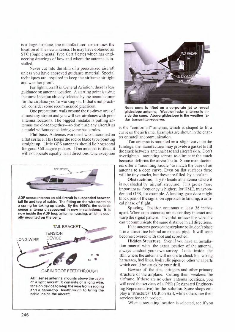
is a large ai rplane, the manufacturer determines the location of the new antenna. He may have obtained an STC (Supplemental Type Ce11ifi cate) which has engineering drawings of how and where the antenna is installed.
ever cut into the sk in of a pressurized aircraft unless you have approved guidance material. Special techniques are required to keep the airframe air tight and weather proof.
For light aircraft in General Aviation, there is less guidance on antenna location. A starting point is using the same location already selected by the manufacturer for the airplane you're working on. If that's not practica l, consider some recommended practices.
One precaution; walk around the tie-down area of almost any airport and you will sec airplanes with poor antenna locations. The biggest mi stake is putting antennas too close together---so don 't use any aircraft as a model without considering some basic rules.
Flat base. Antennas work best when mounted on a flat surface. This keeps the rod or blade type pointing straight up. Little GPS antennas should lie horizontal for good 360-degree pickup. J fan antenna is tilted, it will not operate equally in all directions. One exception
ADFSEN~--
~.--
ADF sense antenna on old aircraft is suspended between tail fin and top of cabin. The fitting on the wire contains a spring for taking up slack. By the 1990's, the outside sense antenna disappeared in new installations; it is now inside the ADF loop antenna housing, which is usually mounted on the belly.
TENSION ~WIRE?4 ~/
246
CABIN ROOF FEEDTHROUGH
ADF sense antenna mounts above the cabin of a light aircraft. It consists of a long wire, tension device to keep the wire from sagging and a cabin-top feedthrough to bring the cable inside the aircraft.
Nose cone is lifted on a corporate jet to reveal glideslope antenna. Weather radar antenna is inside the cone. Above glideslope is the weather radar transmitter-receiver.
is the "conforma l" antenna, which is shaped to fi t a curve on the ai1framc. Examples are shown in the chapter on satellite communication.
lfan antenna is mounted on a sl ight curve on the fuselage, the manufacturer may provide a gasket to fill the crack between antenna base and aircraft skin. Don't ove11ightcn mounting screws to elim inate the crack because deforms the ai rcraft skin. Some ma nufacturers offer a "mounting sadd le" to match the base of an antenna to a deep curve. Even on flat surfaces there will be tiny cracks, but these are filled by a sealant.
Obstructions. Try to locate an antenna where it is not shaded by aircraft structure. This grows more important as frequency is higher; for DME, tra nsponder and GPS, for example. A landing-gear door might block part of the signal on approach to landing, a crit ical phase oftlight.
Spacing. Position antennas at least 36 inches apa1i. When com antennas are closer they interact and warp the signal pattern. The pilot notices th is when he can't communicate the same di stance in a ll di rections.
If the antenna goes on the airplane belly, don't place it in a direct line behind an exhaust pipe. lt will soon become covered with soot and scorched.
Hidden Structure. Even if you have an installation manual with the exact location of the antenna, always conduct your own survey. Look inside the skin where the antenna will mount to check for wiring harnesses, fuel lines, hydrau lic pipes or other vi tal parts which could be struck by your dril l.
Beware of the ribs, stringers and other primary structure of the airplane. Cutting them weakens the airframe. If there arc no other antenna locations, you wi ll need the services of a DER (Designated Engineering Representative) for the solution. Some shops employ a "structures" DER on staff, while others hire thei r services for each project.
When a mounting location is selected, see if you
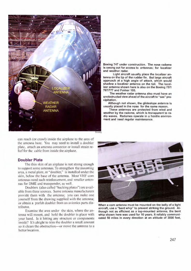
can reach (or crawl) inside the airplane to the area of the antenna base. You may need to install a doubler plate. attach an antenna connector or install strain relief for the cable from inside the airplane.
Doubler Plate The thin skin of an airplane is not strong enough
to support some antennas. To strengthen the mounting area, a metal plate, or "doubler," is installed under the skin, below the base of the antenna. Most VHF com antennas need such reinforcement, and smaller antennas for DME and transponder, as wel l.
Doublers (also called "backing plates") are availab le fro m tlu·ee sources. Some antemrn manufacturers provide them with the antenna; you can make one yourself from the drawing supplied with the antenna; or obtain a prefab doubler from an avionics parts distributor.
Examine the area under the skin , where the antenna will mount, and hold the doubler in place with your hand. ls it hitting any structure or componen ts inside? It's alright to trim the doubler a small amount so it clears the obstruction---or move the antenna to a better locati on.
Boeing 747 under construction. The nose radome is swung out for access to antennas; for localizer and weather radar.
Light aircraft usually place the localizer antenna on the tip of the rudder fin. But large aircraft approach at a high angle of attack, which would shadow a localizer antenna on the tail. The localizer antenna shown here is also on the Boeing 757/ 767/777 and Fokker 100.
The weather radar antenna also must have an unobstructed view ahead of the aircraft to "see" precipitation.
Although not shown, the glideslope antenna is usually placed in the nose for the same reason.
These antennas are protected from wind and weather by the radome, which is transparent to radio waves. Radomes operate in a hostile environment and need regular maintenance.
When a com antenna must be mounted on the belly of a light aircraft, use a "bent whip" to prevent striking the ground. Although not as efficient as a top-mounted antenna, the bent whip shown here was used for 10 years. It reliably communicated 50 miles in every direction at an altitude of 3000 feet,
247
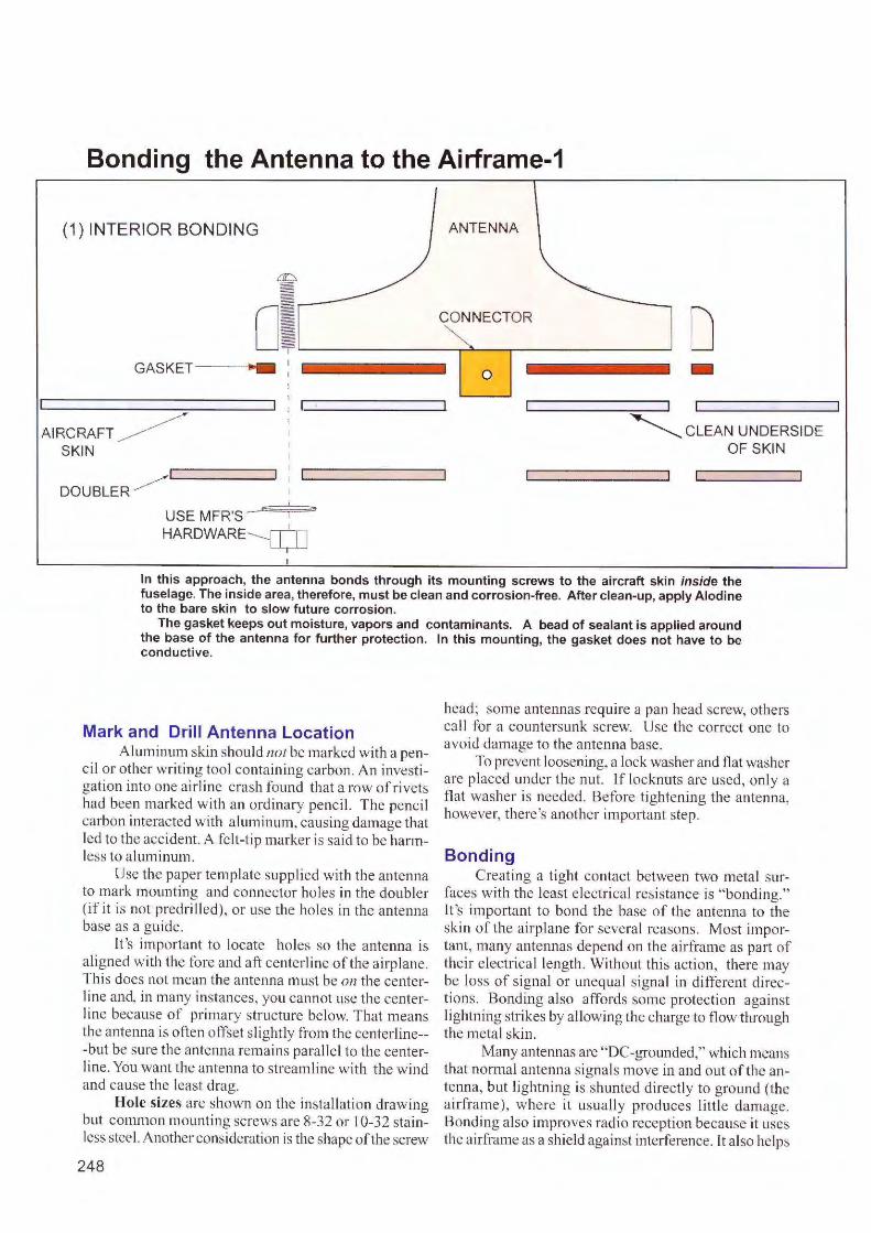
Bonding the Antenna to the Airframe-1
(1) INTERIOR BONDING ANTENNA
o;L._ _______ c_O~N~N- E_C_T .... O_R _______ _, D GASKET--- -
AIRCRAFT ~ SKIN
DOUBLER ~
USE MFR'S_E
HARDWARE-----~
0
--,
-~ CLEAN UNDERSIDE
OF SKIN
In this approach, the antenna bonds through its mounting screws to the aircraft skin inside the fuselage. The inside area, therefore, must be clean and corrosion-free. After clean-up, apply Alodine to the bare skin to slow future corrosion.
The gasket keeps out moisture, vapors and contaminants. A bead of sealant is applied around the base of the antenna for further protection. In this mounting, the gasket does not have to be conductive.
Mark and Drill Antenna Location A lum inum skin should not be marked with a pen
c il or othe r writing too l containing carbon. An investigation into one airline crash found that a row of rivets had been marked with an ordinary pencil. T he pencil carbon interacted w ith aluminum, causing damage that led to the acc ident. A fel t-tip marker is said to be harmless to aluminum.
Use the paper template supplied with the antenna to mark mounting and connector ho les in the double r (if it is not predrilled), or use the ho les in the antenna base as a guide.
It 's important to locate holes so the antenna is a ligned with the fore and aft centerline of the airp lane. This does not mean the antenna must be on the centerline and, in many instances, you cannot use the cente rI ine because of primary structure be low. That means the antenna is often offset s lig htly fro m the centerline--but be sure the antenna remains pa ralle l to the centerline. You want the antenna to s treamline with the wind and cause the least drag.
Hole sizes are shown on the installation drawing but conm1on mounting screws are 8-32 o r I 0-32 stainless steel. Another consideration is the shape of the screw
248
head; some ante1mas require a pan head screw, others call for a countersunk screw. Use the correct one to avoid damage to the antenna base.
To prevent loosening, a lock washer and flat washer are placed under the nut. If locknuts arc used, only a flat washer is needed. Before tightening the antenna, however, there's another important step.
Bonding Creating a tight contact between two metal sur
faces wi th the least e lectrical resistance is "bonding." It 's important to bond the base of the antenna to the skin of the a irplane for severa l reasons. Most important, many antennas depend on the a irframe as part of their e lectrica l length. Without this ac tion, there may be loss of s ignal or unequal s ignal in different directions. Bonding a lso affords some protectio n against lightning strikes by allowing the charge to fl ow tlu-ough the metal skin .
Many antennas are "DC-grounded," which means that normal antenna signals move in and out of the antenna, but lightning is shunted directly to ground (the airframe), where it usually produces l ittle damage. Bondi ng a lso improves radio reception because it uses the a irframe as a sh ie ld against interference. It also helps
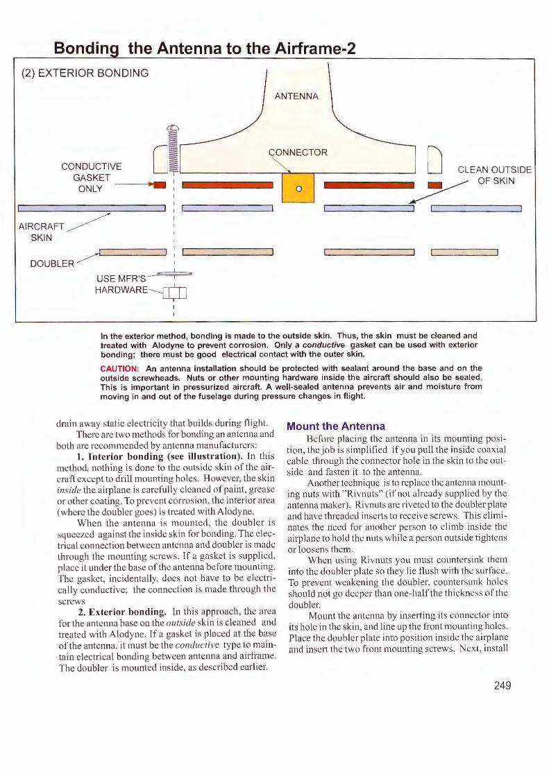
Bondin the Antenna to the Airframe-2 (2) EXTERIOR BONDING
ANTENNA
: CONDUCTIVE
GASKET c;L_ ______ c_o"T"N.l,,,N_E_c_TT""O_R ______ __, D CLEAN OUTSIDE
ONLY __ ___.., __
AIRCRAFT ~ SKIN
DOUBLER ~
USE MFR'S HARDWARE~
0 ~ OFSKIN
---------,
In the exterior method, bonding is made to the outside skin. Thus, the skin must be cl_eaned a~d treated with Alodyne to prevent corrosion. Only a conductive gasket can be used with exterior bonding; there must be good electrical contact with the outer skin.
CAUTION: An antenna installation should be protected with sealant around the base and on the outside screwheads. Nuts or other mounting hardware inside the aircraft s~ould also. be sealed. This is important in pressurized aircraft. A well-sealed ant_enn_a prevents air and moisture from moving in and out of the fuselage during pressure changes m flight.
drain away static electricity that builds during flight. There are two methods for bonding an antenna and
both are recommended by antenna manufacturers: I. Interior bonding (see illustration). ln this
method, nothing is done to the outside skin of the aircraft except to drill mounting holes. However, the skin inside the airplane is carefully cleaned of paint, grease or other coating. To prevent corrosion, the interior area (where the doubler goes) is treated with Alodyne. .
When the antenna is mounted, the doubler 1s squeezed against the inside skin for bonding. Tl.1e electrical connection between antenna and doubler ts made through the mounting screws. Tf a gasket is suppl!cd, place it under the base of the antenna before mount111g. The gasket, incidentally, docs not have to be electrically conductive; the connection is made through the screws
2. Exterior bonding. ln thi s approach, the area for the antenna base on the outside skin is cleaned and treated with Alodyne. If a gasket is placed at the base of the antenna, it must be the conductil1e type to maintain electrical bondino between antenna and airframe.
0 .
The doubler is mounted inside, as described earlier.
Mount the Antenna Before placing the antenna in its mounting posi
tion, the job is simplified if you pull the inside coaxial cable through the connector hole in the skin to the outside and fasten it to the antenna.
Another technique is to replace the antenna mounting nuts with " Rivnuts" (if not already supplied by the antenna maker). Rivnuts are riveted to the doubler plate and have threaded inserts to receive screws. This eliminates the need fo r another person to climb inside the airplane to hold the nuts while a person outside tightens or loosens them.
When using Ri vnuts yo u must countersink them into the doubler plate so they lie flush with the sur face. To prevent weakening the doubler, countersunk holes should not go deeper than one-half the thi ckness of the doubler.
Mount the antenna by inserting its connector into its hole in the skin, and line up the front mounting holes. Place the doubler plate into position inside the airplane and insert the two front mounting screws. Next, install
249
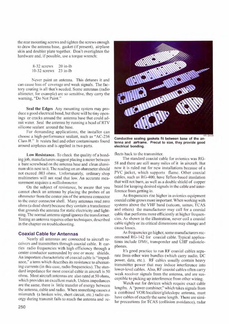
the rear mow1ting screws and tighten the screws enough to draw the antenna base, gasket (if present), airplane skin and doubler plate together. Don 't overtighten the hardware and, if possible, use a torque wrench:
8-32 screws I 0-32 screws
20 in-lb 23 in-lb
Never paint an antenna. This detunes it and can cause loss of coverage and weak signals. The factory coat ing is a ll that's needed. Some antc1rnas (radio alt imeter, fo r example) are so sensitive, they carry the warn ing, "Do Not Paint."
Seal the Edges Any mounting system may produce a good e lectrica l bond, but there wi ll be tiny openings or cracks around the antenna base that could admit water. Seal the antenna by running a bead of RTV silicone sealant around the base.
For demanding applications, the in staller can choose a high-performance sealant, such as "AC-236 C lass B." It resists fuel and other contaminants found around airplanes and is applied in two parts.
Low Resistance. To check the qua li ty ofa bonding job, manufacturers suggest placing a meter between a bare screwhead on the antenna base and c lean a ltm1inum skin next to it. The reading on an ohmmeter should not exceed .003 ohms. Unfortunately, ordinary shop mu ltimeters will not read that low. An accurate measurement requires a mil!iohmmeter.
On the subj ect of resistance, be aware that you caru1ot check an antern,a by placing the probes of an ohmmeter from the center pin of the antenna connector to the outer connector shell. Many ante1111as read zero ohms (a dead sho1i) because they contain a trans fom1c r tl~at grounds the antenna for static electri city and lightnmg. The normal antenna signal ignores the transformer. Testing an ante1111a requires other techniques, described in the chapter on troubleshooting.
Coaxial Cable for Antennas Nearly all antennas arc connected to a ircraft re
ceivers and transmitters through coaxial cable. It carries radio freq uencies with hi gh efficiency through a cente r cond uctor sun·ounded by one or more shields. An important characteri stic of coax ial cable is " impedance," a term whi ch describes its resistance to alternating currents (in th is case, radio frequencies ). The standard impedance fo r most coaxial cable in a ircraft is 50 ohms. Most a ircraft antennas are a lso rated at 50 ohms which provides an excellent match. U nless impedance; are the same, there is litt le transfer of energy between th~ antenna, cable and radio. When something causes a mismatch (a broken wire, short c ircui t, etc.) radio energy during transmit fai ls to reach the antenna and re-
250
HR Smith
Conductive sealing gaskets fit between base of the antenna and airframe. Precut to size, they provide good electrical bonding.
fleets back to the transmitter. The standard coaxial cable for avionics was RG-
58 and there are still many miles of it in ai rcraft. But now it is ruled out for new installations because of a PVC j acket, which supports flame. Other coaxia l cables, such as RG-400, have Teflon-based insulation that will not burn, as well as a double shield of copper braid for keeping desired signal s in the cable and interference from getting in .
As frequencies rise higher in avionics equipment coaxial cable grows more imp01tant. When working with systems above the VHF band (satcom, satnav, TCAS and others) the manufacturer may ca ll for a coaxial cable that performs more effic iently at hig her frequencies. As shown in the illustration , never coil a coaxial cable ti ghtly or its critical dimensions may change and cause losses.
As frequencies go higher, some manufacturers recommend RG-142 for coaxial cable. Typical applications include DME, transponder and UHF radiotelephones.
lt 's good practice to run RF coaxial cables separate from other wire bund les (which carry audio, DC power, data, etc .). RF cables usual ly contain heavy transmitter power that may induce interference into lower-level cables. A lso, RF coaxia l cables often carry weak receiver signals from the antenna, and are susceptible lo picking up interference from other wiring.
Watch o ut for devices whi ch require exact cable lengths. A "power combiner," wh ich takes signals from a combined VOR/localizer/glideslopc antenna, must have cables of exactly the same length. There are similar p recaution s fo r TCAS (collision avoidance), radar
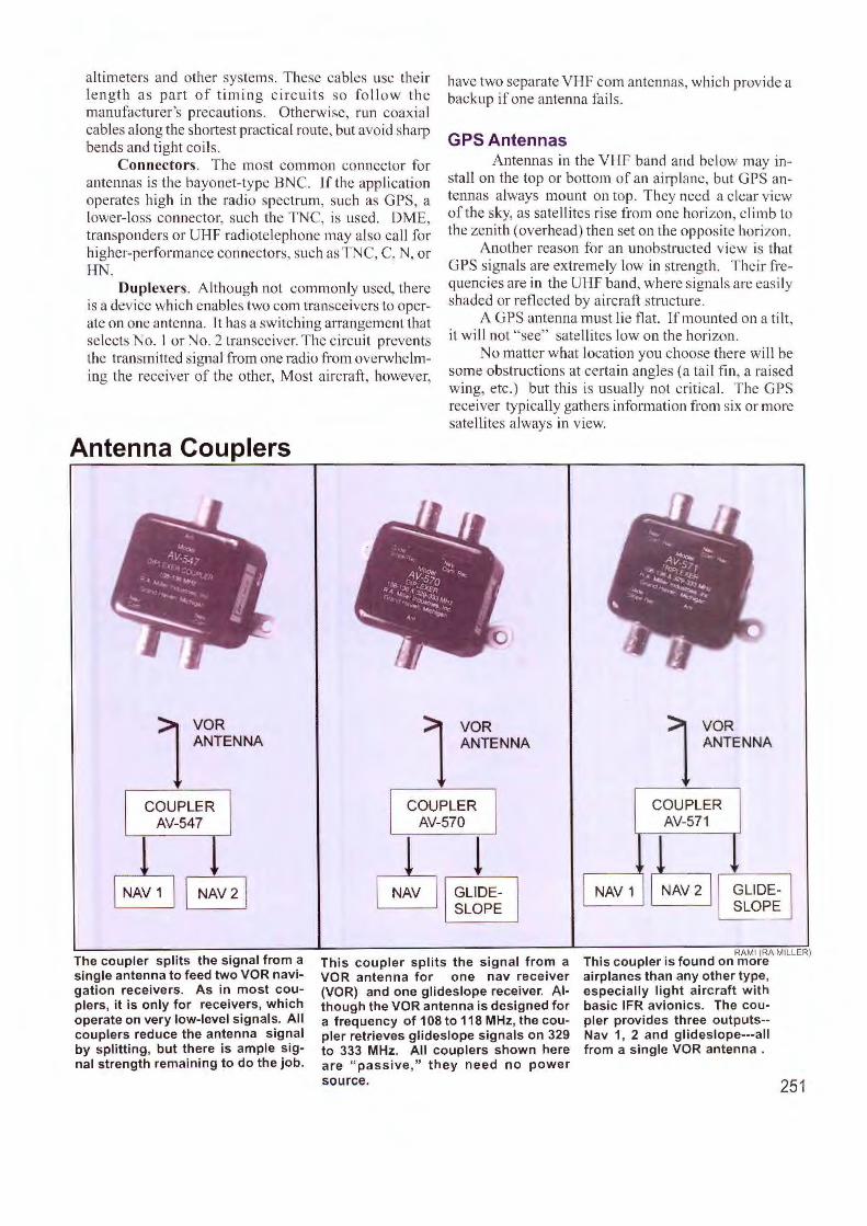
altimeter and other systems. These cables use their length as part of timing circuits so follow the manufacturer's precautions. Otherwise, run coaxial cables along the shortest practical route, but avoid sharp bends and tight coils.
Connectors. The most common connector for antennas is the bayonet-type BNC. l f the application operates high in the radio spectrum, such as GPS, a lower-loss connector, such the TNC, is used. DME, transponders or UHF radiotelephone may also call for higher-performance connectors, such as TNC, C, N, or HN.
Duplexers. Although not commonly used. there is a device which enables two corn transceivers to operate on one antenna. lt has a switching arrangement that selects No. I or No. 2 transceiver. The circuit prevents the transmitted sib111al from one radio from overwhelming the receiver of the other, Most aircraft, however,
Antenna Couplers
have two separate VHF com antennas, which provide a backup if one antenna fai ls.
GPS Antennas Antennas in the VHF band and below may in
stall on the top or bottom of an airp lane, but GPS antennas always mount on top. They need a clear view of the sky, as satell ites rise from one horizon, climb to the zenith ( overhead) then set on the opposite horizon.
Another reason for an unobstructed view is that GPS signals are extremely low in strength. Their frequencies are in the UHF band, where signals are easily shaded or reflected by aircraft structure .
A GPS antenna must lie flat. If mounted on a tilt, it will not "see" sate ll ites low on the horizon.
o matter what location you choose there will be some obstructions at certain angles (a tai l fin, a rai sed wing, etc.) but this is usually not critica l. The G PS receiver typically gathers infomrntion from six or more satellites always in view.
ANTENNA 1 VOR
ANTENNA 1 VOR ANTENNA 1 VOR
COUPLER AV-547
NAV 1 I NAv2 j
The coupler splits the signal from a single antenna to feed two VOR navigation receivers. As in most couplers, it is only for receivers, which operate on very low-level signals. All couplers reduce the antenna signal by splitting, but there is ample signal strength remaining to do the job.
COUPLER AV-570
NAV
! GLIDESLOPE
This coupler splits the signal from a VOR antenna for one nav receiver (VOR) and one glideslope receiver. Although the VOR antenna is designed for a frequency of 108 to 118 MHz, the coupler retrieves glideslope signals on 329 to 333 MHz. All couplers shown here are " passive," they need no power source.
NAY 1
COUPLER AV-571
RAMI (RA MILLER) This coupler is found on more airplanes than any other type, especially light aircraft with basic IFR avionics. The cou-pler provides three outputs--Nav 1, 2 and glideslope---all from a single VOR antenna .
251
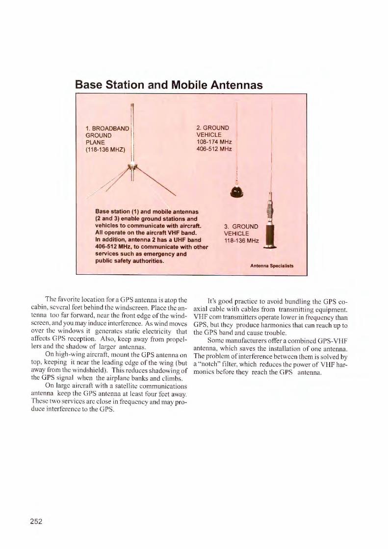
Base Station and Mobile Antennas
1. BROADBAND ~II
GROUND ii PLANE I (118-136 MHZ) I
/
2. GROUND VEHICLE 108-174 MHz 406-512 MHz
I
a Base station (1) and mobile antennas (2 and 3) enable ground stations and vehicles to communicate with aircraft. All operate on the aircraft VHF band.
3. GROUND VEHICLE 118-136 MHz In addition, antenna 2 has a UHF band
406-512 MHz, to communicate with other services such as emergency and public safety authorities.
The favorite location for a GPS antenna is atop the cabin, several feet behind the windscreen. Place the antenna too far forward, near the front edge of the windscreen, and you may induce inte1ference. As wind moves over the windows it generates static e lectricity that affects GPS reception. Also, keep away from propellers and the shadow of larger antennas.
On high-wi ng a ircraft, mount the GPS antenna on top, keeping it near the leading edge of the wing (but away from the windshield). This reduces shadowi ng of the GPS s ignal when the airplane banks and climbs.
On large aircraft wi th a satellite communications antenna keep the GPS antenna at least four feet away. These two services are close in frequency and may produce interference to the GPS.
252
Antenna Specialists
It 's good practice to avoid bundling the GPS coaxial cable with cabl es from transmitting equipment. VHF com transmitters operate lower in frequency than GPS, but they produce harmonics that can reach up to the GPS band and cause trouble.
Some manufacturers offer a combined GPS-VHF antenna, which saves the installation of one antern,a. The problem of inte1ference between them is solved by a "notch" filter, which reduces the power of VHF harmonics before they reach the GPS antern,a.
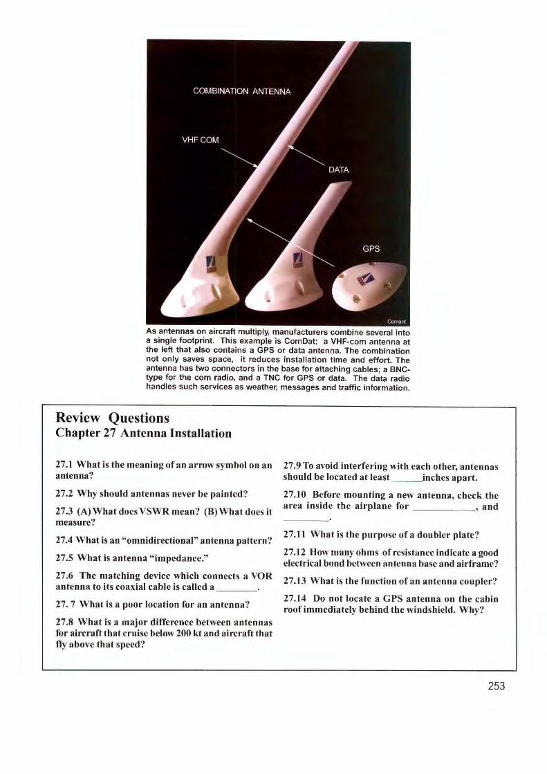
As antennas on aircraft multiply, manufacturers combine several into a single footprint. This example is ComDat; a VHF-com antenna at the left that also contains a GPS or data antenna. The combination not only saves space, it reduces installation time and effort. The antenna has two connectors in the base for attaching cables; a BNCtype for the com radio, and a TNC for GPS or data. The data radio handles such services as weather, messages and traffic information.
Review Questions Chapter 27 Antenna InstaUation
27.1 What is the meaning of an arrow symbol on an antenna?
27.2 Why should antennas never be painted?
27.3 (A) What does VSWR mean? (B) What does it measure?
27.4 What is an "omnidirectional" antenna pattern?
27.5 What is antenna " impedance."
27.6 The matching device which connects a VOR antenna to its coaxial cable is called a _ __ _
27. 7 What is a poor location for an antenna?
27.8 What is a major difference between antennas for aircraft that cruise below 200 kt and aircraft that fly above that speed?
27 .9 To avoid interfering with each other, antennas should be located at least inches apart.
27.10 Before mounting a new antenna, check the area inside the airplane for , and
27.11 What is the purpose of a doubler plate?
27 .12 How many ohms of resistance indicate a good electrical bond between antenna base and airframe?
27.13 What is the function of an a ntenna coupler?
27.14 Do not locate a GPS antenna on the cabin roof immediately behind the windshield. Why?
253
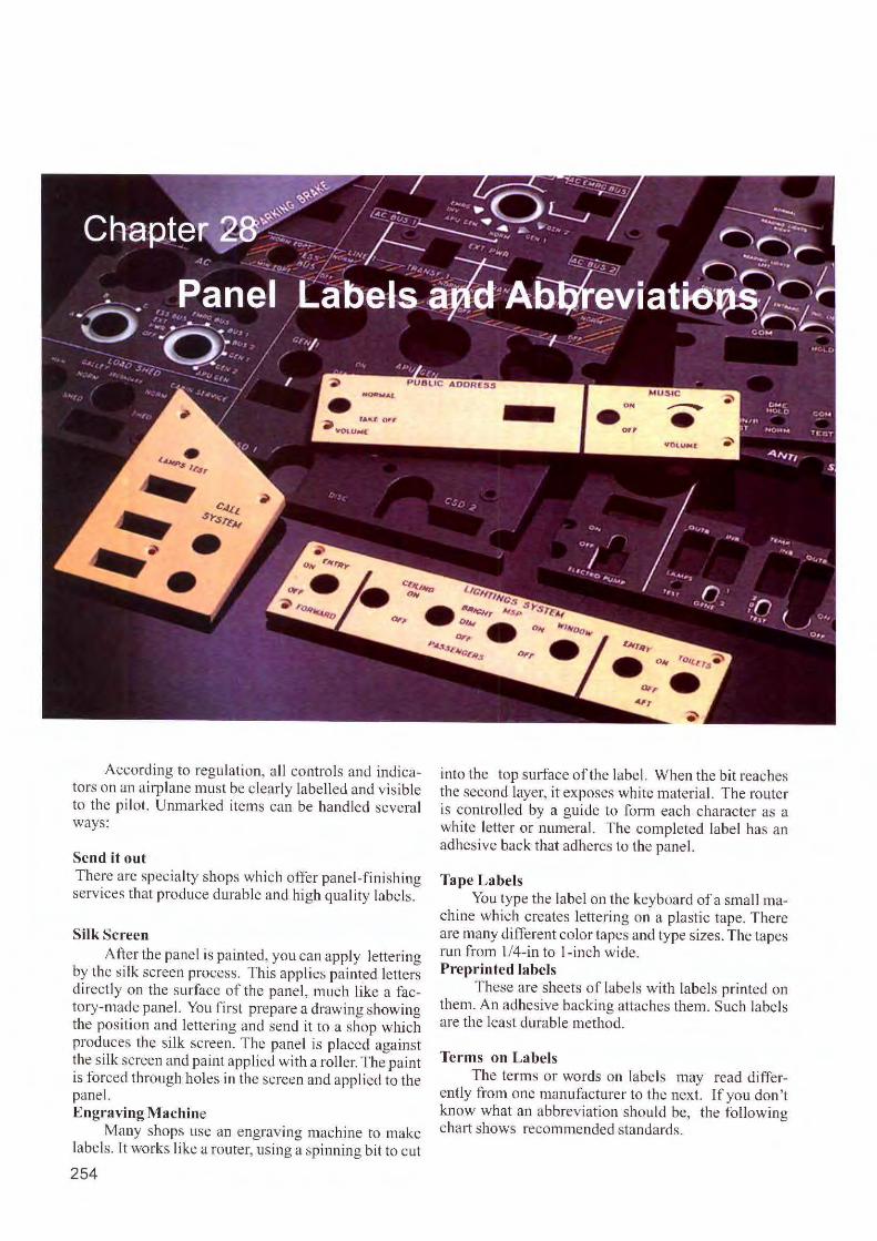
According to regulation, a ll controls and indicators on an airplane must be clearl y labe lled and visible to the pilot. Unmarked items can be handled several ways:
Send it out There are specia lty shops which offer panel-finishing services that produce durable and high quality labels.
Silk Screen After the panel is painted, you can apply lettering
by the silk screen process. This applies painted letters directly on the surface of the pane l, much like a factory-made pane l. You first prepare a drawing showing the position and lettering and send it to a shop which produces the silk screen. The panel is placed against the silk screen and paint applied with a roller. The paint is fo rced through holes in the screen and applied to the panel. Engraving Machine
Many shops use an engraving machine to make labels. It works like a router, using a spinning bit to cut
254
into the top surface of the label. When the bit reaches the second layer, it exposes white material. The router is controlled by a guide to form each character as a white lette r or numeral. The completed label has an adhesive back that adheres to the panel.
Tape Labels You type the label on the keyboard of a smal l ma
chine which creates lettering on a plastic tape. There are many different co lor tapes and type sizes. The tapes run from l /4-in to 1-inch wide. Preprinted labels
These are sheets of labels with labe ls printed on them. An adhesive backing attaches them. Such labels are the least durabl e method.
Terms on Labels The terms or words on labels may read differ
ently from one manufacturer to the next. If you don't know what an abbreviation should be, the fo llowing chart shows recom mended standards.

Panel Abbreviations
Abbrev iations for instrument panels on airline and mili tary aircraft are standardized. In General Aviation, corporate and many commercial a ircraft, the choice is o ften left to the insta lle r.
Industry o rganizations recommend the fo ll owing abbreviations, which may be used directly on the panel, the fa ces of electromechanical instruments, in symbols of an electronic display (EFlS), switches, buttons, placards, legends, controls and in diagrams.
Whe n us ing abbrevia ti o ns, the re a re severa l basic rules:
Do not use periods (.) in abbreviations; for example: the word DECREASE becomes DECR
An abbreviation mi ght loo k confu sing, as in
lSCTN (for INTERSECTION). In these instances, a hyphen is inserted: J-SCTN
A forward slash (/) means the term has a dual function. Example: OFF/RESET is OFF/R
There are a few exceptions. Some terms, such as GUDESLOPE have a lways been abbrev iated as G/S. Altho ugh it is one function, the forwa rd s lash is sti II used.
Over 1,300 tenns appear in the followi ng table. Besides serv ing as a gui de to marking instrument panels, they can also decipher abbreviations on existing equipment and in diagrams.
A ALERTING SYSTEM DISPLAY, AUTOMATIC LANDING ALAND ABEAM ABM
ALERTING DISPLAY ASD AUTOMATIC LANDING AL ABNORMAL ABNORM ALPHABET, IC ALPHA AUTOMATIC RUDDER CONTROL A-RUD ABOVE ABV ALIGNMENT ALN AUTOMATIC TEST EQUIPMENT ATE ABOVE GROUND LEVEL AGL ALTERNATE ALTN AUTOMATIC THRUST AT ABOVE MEAN SEA LEVEL AMSL ALTERNATING CURRENT AC AUTOMATIC POWER RESERVE APR ABSOLUTE ABS ALTIMETER ALTM AUTOPILOT AP ACCELERATION ACCEL ALTITUDE ALT AUTOPILOT AND FLIGHT DIRECTOR AFD ACCEPT ACPT ALL SPEED AILERON ASA AUTOPILOT/FLIGHT DIRECTOR AP/FD ACCUMULATOR ACCU ALL UP WEIGHT AUW AUTOSTABILIZER ASTAB ACKNOWLEDGE ACK AMBIENT AMB AUTOTHROTILE AT ACQUIRE ACQ AMMETER AMM AUXILIARY AUX ACTIVATE ACTV AMPERE AMP AUXILIARY DATA ACQUISITION UNIT ADAU ACTIVE ACT AMPERE HOUR AH AUXILIARY POWER UNIT APU ACTUAL GROSS WEIGHT AGW AMPLIFIER AMPL AVAILABLE AVAIL ACTUAL TIME OF ARRIVAL ATA AMPLITUDE MODULATION AM AVERAGE AV ACTUAL TIME OF DEPARTURE ATD ANALOG TO DIGITAL ND AVIONICS AVNCS ACTUAL TIME OVER ATO ANALYZER ANAL AZIMUTH AZ ADDRESS ADRS ANGLE OF ATIACK AOA ADJUST ADJ ANGULAR ANG B ADVANCE ADV ANNUNCIATOR ANN BACKBEAM BBM ADVISORY ADVY ANTENNA ANT BACK COURSE BCRS ADVISORY ROUTE ADR ANTI ICE AICE ANTI BACK LOCALIZER BLOC AERONAUTICAL INFORMATION SKID ASKID BAROMETRIC SETIING BARO SERVICE, PUBLICATION AIS,AIP APPROACH APPR BATIERY BAT AERONAUTICAL MOBILE SERVICE, APPROACH CONTROL APP BATIERY UNIT BU FIXED SERVICE AMS,AFS AREA CONTROL CENTER ACC BEACON BCN AILERON AIL AREA POSITIVE CONTROL APC BEARING BRG AIR CONDITIONING AIRCOND AREA NAVIGATION RNAV BEARING DEVIATION INDICATOR BDI
AIRCRAFT ACFT ARING COMMUNICATIONS, BEAT FREQUENCY OSCILLATOR BFO AIRCRAFT INTEGRATED DATA AID
ADDRESSING AND BELOW BLW AIRCRAFT NOSE DOWN ND REPORTING SYSTEM AGARS BETWEEN BTWN AIRCRAFT NOSE UP NU
ARRIVAL, ING ARR BEVERAGE BEV AIRCRAFT OPERATING MANUAL AOM ARTIFICIAL ARTF BLUE BLU
AIR CYCLE MACHINE ACM AS SOON AS POSSIBLE ASAP BODLE BTL
AIR DATA AD ASSEMBLY ASSY BOTIOM OF CLIMB BOC
AIR DRIVEN GENERATOR ADG ASSIGN ASSN BOTIOM OF DESCENT BOD
AIR DRIVEN PUMP ADP ASYMMETRIC ASYM BOUNDARY BNDRY
AIRPORT ARPT ATIENDANT ATIND BOUNDARY LAYER CONTROL BLC
AIRPORT BEACON ABN ATIENTION ATIN BRAKE BRK
AIRPORT REFERENCE POINT ARP ATIITUDE ATI BRAKING ACTION BA
AIRPORT TRAIFFIC ZONE ATZ ATIITUDE DIRECTOR INDICATOR ADI BREAKOFF HEIGHT BOH
AIRBORNE REPORT AIREP ATIITUDE- HEADING REFERENCE AHR BRIGHT, NESS BRT
AIRSPEED AS AUDIO AUD BROADCAST BCST
AIRSPEED INDICATOR ASI AUDIO SELECTOR PANEL ASP BUILT IN TEST EQUIPMENT BITE
AIR TO GROUND AG AUGMENT, ER, ATION AUG BUS TIE BREAKER BTB
AIR TURBINE MOTOR ATM AUTOMATIC AUTO BUS TIE RELAY BTR
AIR ROUTE TRAFFIC AUTOMATIC BRAKE AB BUS TRANSFER CONTACTOR BTC
CONTROL (CENTER) ARTC(C) AUTOMATIC DIRECTION FINDER ADF AIR TRAFFIC CONTROL ATC AUTOMATIC FLIGHT CONTROL AFC C
AIR TRAFFIC SERVICES ATS AUTOMATIC FLIGHT GUIDANCE AFG CABIN CAB
AIRWAY AWY AUTOMATIC FLIGHT AF CALIBRATION CAL
ALARM ALM AUTOMATIC FREQUENCY CONTROL AFC CALIBRATED AIRSPEED CAS
ALERT, ALERTING ALRT AUTOMATIC GAIN CONTROL AGC CALL SIGN cs CANCEL CNCL
255

Panel Abbreviations CAPACITY CAPTAIN CAPTURE CARBURETOR CARD READER CARGO CONTINUOUS WAVE CATEGORY CATHODE RAY TUBE CAUTION, ARY CAUTION AND WARNING CEILING CEILING AND VIS
UNRESTRICTED/OK CENTIGRADE CENTIMETER CENTER CENTER OF GRAVITY CENTERLINE CENTRAL AIR DATA CENTRAL PROCESSOR CHANGE CHANNEL CHARGE, CHARGER CHECK CHECKED CHECKLIST CHECK VALVE CHRONOMETER CIRCLE CIRCUIT CIRCUIT BREAKER CIRCUIT BREAKER MONITORING CIRCULATE, CIRCULATION CLEAR CLEAR AIR TURBULENCE CLEARANCE CLEARED CLEARWAY CLIMB
CPTY CAPT CAP
CARB CR
CRG cw CAT CRT
CAUT CAW CLNG
CAVU/CAVOK C
CM CTR CG Cll
CAD CP
CHG CHAN CHRG
CK CKD CL
CHKV CHR
CRCL CCT CB
CBM CIRC CLR CAT
CLNC CLRD CWY CLB
CLIMB SPEED MIN INITIAL CLIMB SPEED INITIAL CLOCK CLOCKWISE CLOSE, CLOSED
CLOUD COCKPIT COCKPIT VOICE RECORDER COLD COLD AIR UNIT COLLISION COLLISION AVOIDANCE COMBINED SPEED INDICATOR COMMAND COMMANDER COMMUNICATION COMPANY COMPARATOR COMPARTMENT COMPASS COMPLETE COMPRESSOR COMPUTE COMPUTER CONDITION CONFIGURATION CONSTRAINT
CONSTANT SPEED DRIVE CONTACTOR CONTINUE
CONTINUOUS REPETITIVE CHIME CONTINUOUS WAVE CONTROL CONTROL AREA CONTROL DISPLAY CONTROL SYSTEM ELECTRONIC CONTROL UNIT
There are machines for printing labels with adhesive backing.
256
V3 V4
CLK cw
CLS,CLSD
CLO CKPT CVR
C CAU
COLL CA CSI
CMD CMDR COM co
CMPRTR COMPT COMP CMPL
CPRSR CMPT
CMPTR COND
CONFIG CSTR
CSD CNTOR CONT
CRC cw CTL CTA CD
CSE cu
Kroy
CONTROL WHEEL STEERING CONTROL ZONE COOLER, ING COPILOT CORRECT COST INDEX COUNTER CLOCKWISE COUPLE COUPLER COURSE
COURSE DEVIATION INDICATOR COWLING CREW MEMBER CRITICALENGINE FAIL SPEED CRITICAL POINT CROSSCREW QUALIFICATION CROSSBAR CROSS FEED
CROSS LINE
CROSS TRACK DEVIATION CROSS TRACK ERROR CROSS VALVE CROSSWIND CRUISE CRUISING SPEED DESIGN CYLINDER
D DAMPER DANGER, -OUS DANGERAREA DATA ENTR, DISPLAY PANEL DATA LINK DATA MANAGEMENT DATE DEAD RECKONING DECELERATE, ION DECIBEL DECISION ALTITUDE DECISION HEIGHT DECISION SPEED DECK DECLINATION DECREASE DEFINITION DEFLECTION DEGREE DEICE DELAY DELAY MESSAGE DELAYED FLAP APPROACH DELETE DEPARTURE DEPARTURE MESSAGE DEPRESSURIZE, ATION DESCEND, DESCENT DESIGN EYE POSITION DESIGNATOR DESIRED TRACK DESTINATION DETECTED, TOR, TION DEVIATION DIFFERENCE, TIAL DIFFERENTIAL PRESSURE DIGITAL AIDS RECORDER DIGITAL AIR DATA (Equipment) DIGITAL DISTANCE AND RADIO MAGNETIC INDICATOR DIGITAL FLIGHT DATA
ACQUISITION UNIT DIGITAL FLIGHT DATA RECORDER DIGITAL TO ANALOG DILUTER, ION DIRECT, ION, DIRECT TO DIRECT CURRENT DIRECTIONAL GYRO DIRECTION FINDER DIRECT LIFT CONTROL DIRECT OPERATING COST DISARMED DISCHARGE DISCONNECT
cws CZ
COOL CP
CORR Cl
ccw CPL
CPLR CRS
COi COWL
CM V1 CP
CCQ XBAR XFD
XLN
XTK XTKE XVLV
XWND CRZ VC
CYL
DMPR DNGR
DA DEDP
DL OM DAT DR
DECEL DB DA DH V1 DK
DEC DECR DEF
DEFL DEG DICE DLA DEL DFA DEL DEP DEP DPR DES DEP DSIG DTK DEST DET DEV DIFF dP
DAR DAD
DDRMI
DFDAU DFDR
DIA OIL DIR DC DG OF
DLC DOC
DISRMD DISCH DISC

Panel Abbreviations DISENGAGED DISENG FLIGHT ENGINEER FE HIGH HI DISPLAY DSPL FLIGHT GUIDANCE FG HIGH FREQUENCY HF DISPLAY UNIT DU FLIGHT INFORMATION HIGH LEVEL HL DISTANCE DIST CENTER FIG HIGH PRESSURE HP DISTANCE MEASURING EQUIPMENT DME FLIGHT INFORMATION REGION FIR HIGH SPEED HSPO DISTANCE TO GO DTG FLIGHT INFORMATION DIVERSION DVRSN REGION BOUNDARY FIRS HOLD, ING, HOLDING PATIERN HLD DIVERT OVRT FLIGHT INFORMATION SERVICE FIS HORIZONTAL NAVIGATION HNAV DOPPLER DOPP FLIGHT LEVEL FL DOUBLE SIDE BAND DSB FLIGHT LEVEL CHANGE FLCH HORIZONTAL SITUATION INDICATOR HSI DOWN DN FLIGHT MANAGEMENT SYSTEM FM8 HOT H DRIFT DFT FLIGHT MODE ANNUNCIATOR FMA HOUR HR DRIFT ANGLE DA FLIGHT NAVIGATION FN HYDRAULIC HYD DRIFT DOWN DD FLIGHT PATH ANGLE FPA DRIVE DRV FLIGHT PATH TARGET FPT I DRY OPERATING WEIGHT DOW FLIGHT PATH VECTOR FPV ICING ICE
FLIGHT PLAN FPLN IDENTIFICATION BEACON IBN E FLIGHT WARNING FW IDENTIFY. !ER, !CATION ID EARTH ACCELERATION 9 FLIGHT (WEATHER) FORECAST FIFOR EAST E FLOW FLO IGNITION IGN ECONOMIC, MY ECON FLUORESCENT FLUOR IMMEDIATE !MM EFFECTIVE EFF FOOT, FEET FT ELAPSED TIME ET FORECAST FCST INBOARD INBD ELECTRIC, AL, ITY ELEC FOREIGN OBJECT DAMAGE FOD INBOUND INB ELECTROMAGNETIC INTERFERENCE EMI FORWARD FWD ELECTRONIC ELEX FREEZE FRZ INCHES IN(S) ELECTRONIC ADI EADI FREQUENCY FREQ INCLUDE, SIVE INC ELECTRONIC CENTRALIZED FREQUENCY MODULATION FM
AIRCRAFT MONITOR ECAM FROM FR INCREASE, ING INCR ELECTRONIC COOLING SYSTEM ECS FRONT FRT INDEX INDX ELECTRONIC ENGINE CONTROL EEC FUEL CONTROL UNIT FCU INDICATED AIRSPEED IAS ELECTRONIC FUEL CONTROL EFG FUEL FLOW FF INDICATOR, ION, ED IND ELECTRONIC FLIGHT INSTRUMENT EFI FUEL ON BOARD FOB INERTIAL I ELECTRONIC HSI EHSI FUEL OVER DESTINATION FOO INERTIAL NAVIGATION IN EXPAND, SION EXP FUEL QUANTITY FQ INERTIAL NAVIGATION SYSTEM INS EXPECTED APPROACH TIME EAT FUEL USED FU INERTIAL REFERENCE IR EXPEDITE XPED FUNCTION FCTN INERTIAL SENSOR IS EXTENO, -EO EXTD FUSELAGE FUS IN-FLIGHT ENTERTAINMENT IFE EXTENDED FUNCTION XFCN INFORMATION INFO EXTERNAL, EXTERIOR EXT G INHIBITION INHIB EXTERNAL POWER CONTACTOR EPC GALLEY GLY EXTINGUISH, -ER EXTING GALLON GAL INITIAL, ATION, IZATION INIT EXTRA FUNCTION XFCN GENERAL ENL INITIAL APPROACH INA EXTRACT EXTR GENERATOR GEN INITIAL APPROACH FIX IAF EXTRACT REFERENCE POSITION ERP GENERATOR CONTROL UNIT GCU INITIAL POINT IP
GENERATOR LINE CONTACTOR GLC INJECTION INJ F GENERATOR LINE RELAY GLR INLET (INTAKE) GUIDE VANES IGV FAHRENHEIT F GEOGRAPHICAL REFERENCE POINT GRP INNER INR FAILURE, FAILED FAIL GO AROUND GA INNER MARKER 1M FAN SPEED N1 GLARESHIELD GSHLD INOPERATIVE INOP FAST/SLOW FIS GLIDE SLOPE G/S FAULT ISOLATION MONITOR FIM GLIDE PATH GP INPUT/OUTPUT VO FAULT REPORTING MANUAL FRM GLOBAL POSITIONING SYSTEM GPS INSTRUMENT INST FEEL SIMULATION UNIT FSU GRAM G INSTRUMENT FLIGHT RULES IFR FEET, FOOT FT GRAVITY 9 INSTRUMENT LANDING SYSTEM ILS FEET PER MINUTE FPM GREEN GRN INSTRUMENT METEOROLOGICAL FIELD ELEVATION PRESSURE QFE GREENWICH MEAN TIME GMT CONDITIONS IMC FIGURE FIG GROSS WEIGHT GW INTAKE INTK FILAMENT FIL GROUND GND INTEGRATED DRIVE GENERATOR IDG FILTER FLTR GROUND CONTROLLED APPROACH GCA INTERCEPT INTCP FINAL TO SAFETY SPEED VFTO GROUND MOVEMENT CONTROL GMC INTERCEPT POINT IPT FINAL APPROACH FIX FAF GROUND MOVEMENT RADAR GMR FIRST OFFICER FO GROUND POWER UNIT GPU INTERCOM, INTERCOMMUNICATION 1/C FINAL APPROACH FNA GROUND PROXIMITY WARNING GPW INTERLOCK INTLK FLAP FLP GROUND REFERENCE POINT GRP INTERMEDIATE FIX IF FLAP EXTENDED SPEED MAX VFE GROUND ROLL GR INTERMEDIATE PRESSURE IPR FLAPOPERATINGSPEED MAX VFO GROUND SPEED GS INTERNATIONAL !NTL FLARE FLR GROUND TO AIR GA INTERNATIONAL STANDARD FLEXIBLE FLEX GUST SPEED DESIGN MAX VB ATMOSPHERE !SA FLIGHT AUGMENTATION COMPUTER FAG GYRO G INTERPHONE INPH FLIGHT FLT INTERRUPT, ED. ION INTRP FLIGHT CONTROL FC H INTERSECTION ISCTN FLIGHT CREW OPERATING MANUAL FCOM HANDLE HNDL INTER SYSTEM BUS ISB FLIGHTDATAACQUISITION UNIT FOAU HEAD HD INVERTER INV FLIGHT DATA ENTRY PANEL FDEP HEADING HOG ISOLATE, ED, ION ISOL FLIGHT DATA RECORDER FOR HEADING AND ATIITUDE HA FLIGHT DATA STORAGE UNIT FOSU HEADING SELECT HOGS J FLIGHT DECK FOK HEAD UP DISPLAY HUD JAMMED, -ING JAM FLIGHT DATA ENTRY PANEL FDEP HEADWIND HWND JET PIPE TEMPERATURE PT FLIGHT DATA RECORDER FDR HEAT HT JUNCTION JCT FLIGHT DATA STORAGE UNIT FDSU HEATER HTR FLIGHT DECK F-DK HEIGHT H K FLIGHT DIRECTOR FD HELICOPTER HEL KEYBOARD KYBD
HERTZ HZ KILO K
257

Panel Abbreviations KRUGER KRUG MASTER MSTR 0 KNOTS) KT(S) MASTER WARNING MW OBSERVED, -ATION OBSV
MAXIMUM MAX OBSERVER OBSR L MAXIMUM CONTINUOUS THRUST MCT OBSTACLE, OBSTRUCTION OBST LANDING LDG MAXIMUM CRUISE MCR OBSTACLE CLEARANCE LIMIT OCL LANDING DIRECTION INDICATION LDI MAXIMUM LANDING WEIGHT MLW OFF/RESET OFF/R LANDING GEAR LG MAXIMUM RAMP WEIGHT MRW OFFSET OFST LANDING GEAR EXTENDED MAXIMUM OPERATING SPEED MACH MMO OMEGA 0
SPEED MAX VLE MAXIMUM OPERATING SPEED AIRSPEED VMO OMEGA NAVIGATION ON LANDING GEAR OPERATING MAXIMUM TAXI WEIGHT MTXW OMNI BEARING SELECTOR OBS
SPEED MAX VLO MAXIMUM TAKEOFF GROSS WEIGHT MTOGW ON BOARD BALANCE SYSTEM OBBS LANDING REFERENCE SPEED VREF MAXIMUM TAKEOFF WEIGHT MTOW ON BOARD WEIGHING SYSTEM OBWS LANDING WEIGHT LW MAXIMUM ZERO FUEL WEIGHT MZFW ON BOARD WEIGHT AND LASER LSR MEAN AERODYNAMIC CHORD MAC BALANCE SYSTEM OBWBS LATERAL, LATITUDE LAT MEAN SEA LEVEL MSL OPEN 0 LATERAL NAVIGATION LNAV MEAN TIME BETWEEN FAILURE MTBF OPERATIONAL OP LATERAL REVISE LREV MECHANIC MECH OPERATIVE, ING OPER LATCH LTCH MEDIUM MED OPERATION OPS LATITUDE LAT MEDIUM FREQUENCY MF OPERATION, ING MANUAL OM LATITUDE/LONGITUDE LIL MEGA M OPPOSITE OPP LAVATORY LAV MEMORY/MEMORANDUM MEM OPTIMUM OPT LEADING EDGE LE MERCURY Hg OUTBOARD OUTBD LEAST SIGNIFICANT BIT LSB MESSAGE MSG OUTBOUND OUTS LEFT L METER M OUTER OUTR ' LEFT HAND (SIDE) LH METERING FIX MF OUTER MARKER OM LEFT LINE SELECT (KEY) LLS METEOROLOGICAL MET OUTLET OUTL LEFT WING DOWN LWD MICROPHONE MIC OUTPUT/INPUT 0~ LENGTH L MICROWAVE LANDING SYSTEM MLS OUTSIDE AIR TEMPERATURE OAT LEVEL LVL MIDDLE, MIDSHIP MID OVERBOARD OVBD LEVEL CHANGE CHG MIDDLE MARKER MM OVERFLOW OVFL LEVER LVR MILE M OVERHEAD OVHD LIGHT. LIGHTS LT MILES PER HOUR MPH OVERHEAT OVHT LIGHT EMITTING DIODE LED MILLIBAR(S) Ml OVERLOAD OVLD LIMIT LIM MINIMUM MIN OVER PRESSURE OVPR LIMITER LMTR MINIMUM APPROACH BREAKOFF HEIGHT MABH OVERRIDE OVRD LINEAR LIN MINIMUM CONTROL SPEED VMC OVERRUN OVRN LINE REPLACEABLE UNIT LRU MINIMUM DECISION/DESCENT ALTITUDEMDA OVERSPEED OVSPD LINE SELECT KEY LSK MINIMUM EN ROUTE ALTITUDE MEA OXYGEN OXY LIQUID OXYGEN LOX MINIMUM EQUIPMENT LIST MEL LITER L MINIMUM OPERATING SPEED VMIN p LOAD LD MINIMUM REQUIREMENTLIST MRL PACK PK LOAD CLASSIFICATION NUMBER LCN MINIMUM SAFE ALTITUDE MSA PAGE PG LOAD RELIEF SYSTEM LRS MINIMUM SECTOR FUEL MSF PANEL PNL LOAD SHEDDING RELAY LSR MINIMUM ZERO FUEL WEIGHT MZFW PARALLEL TRACK PTK LOCAL LCL MINUTE MN PARAVISUAL DIRECTOR PVD LOCAL MEAN TIME LMT MISCELLANEOUS MISC PARK PK LOCALIZER LOC MISSED MSD PASSENGERS PAX LOCALIZER INERTIAL SMOOTHING LIS MISSED APPROACH POINT MAP PASSENGER ADDRESS PA LOCALIZER TYPE DIRECTIONAL AID LOA MISSED APPROACH PROCEDURE MAPROC PASSENGER ENTERTAINMENT LOCATION LCTN MODERATE MOD SYSTEM PES LOCATOR LCTR MODE CONTROL MC PATTERN PAT LOCKED LKD MODE SELECT PANEL MSP PEDAL PEDL LONG RANGE CRUISE LRC MODIFY, MODIFICATION MOD PEDESTAL PED LONG RANGE NAVIGATION LORAN MODULAR CONCEPT UNIT MCU PERCENT % LONGITUDE, -INAL LONG MONITOR, ED MON PERFORMANCE PERF LOW LO MOTOR MOT PERFORMANCE MANAGEMENT PM LOWER LWR MOUNTING MTG PILOT PLT LOWER SIDE BAND LSB MULTIFUNCTION DISPLAY MFD PILOT FLYING PF LOW FREQUENCY LF MULTIPLEX MUX PILOT IN COMMAND PIC LOW LEVEL LL PILOT NOT FLYING PNF LOW PRESSURE LP N PITCH PTCH LOW SPEED LSPD NACELLE NAC PITCH AUGMENTATION COMPUTER PAC LOW SPEED AILERON LSA NAUTICAL MILES NM PLAN, (FLIGHT PLAN) PLN
NAUTICAL MILES PER HOUR (KNOTS) KTS PLAN POSITION INDICATOR PPI M NAVIGATION/COMMUNICATION NAVCOM PLANNED LANDING WEIGHT PLW MACH M NAVIGATION, NAVIGATOR NAV PLATFORM PLATF MACH/AIRSPEED INDICATOR MIAS! NAVIGATION AID NAVAID PNEUMATIC PNEU MAGNETIC MAG NAVIGATION DISPLAY ND POINT PT MAGNETIC INDICATOR Ml NAVIGATION REFERENCE POINT NRP POINT OF NO RETURN PNR MAIN LANDING GEAR MLG NEGATIVE NEG POSITION POS MAINTAIN, MAINTENANCE MAINT NEXT NXT POSITIVE POS MAINTENANCE CONTROL NEXT PAGE NP POSSIBLE PSBL AND DISPLAY PANEL MCDP NEUTRAL NEUT POTABLE WATER POTW MAINTENANCE TEST PANEL MTP NOISE ABATE, ABATEMENT NA POUND LB MALFUNCTION MALF NON DIRECTIONAL BEACON NOB POUNDS PER SQUARE INCH PSI MANDATORY OCCURRENCE REPORT MOR NON RETURN VALVE NRV POWER PWR MANIFOLD MANF NORMAL NORM POWER CONTROL UNIT PCU MANEUVER SPEED DESIGN VA NORTH N POWER TRANSFER UNIT PTU MANEUVER SPEED RECOMMENDED VMAN NOSE LAUDING GEAR NLG PRECISION APPROACH MANUAL MAN NOSE WHEEL NW PATH INDICATOR PAPI MARKER MKR NOTICE TO AIRMEN NOTAM PRECISION APPROACH RADAR PAR MARKER BEACON MB NUMBER # PREDICTED, TION PRED
PREDICTED WIND DATA PWD PREFERRED PREFD
258

Panel Abbreviations PREFLIGHT PREFLT REPORTING POINT RPT SPEED REFERENCE SYSTEM SRS PRESENT PRES REQUEST REQ SPOILER SPLR PRESENT POSITION POS REQUIRED REQD SQUELCH SQ PRESSURE PRESS REQUIRED TIME OF ARRIVAL RTA SQUIB SQB PRESSURIZATION PRESN RESERVE, ATION RSV STABILITY. IZER, IZATION STAB PREVIOUS PREV RESERVOIR RSVR STALL SPEED VS PRIMARY PRI RESET RST STANDARD STD PRIMARY FLIGHT DISPLAY PFD RESPONDER BEACON RSP STANDARD INSTRUMENT DEPARTURE SID PRINTER PRTR RESTRICTED, TION REST STANDARD OPERATING PROCEDURE SOP PROCEDURE PROC RETARD RETD STEADY STOY PROCEDURE TURN PROCT RETRACT: ED, ABLE RETR STEERING STRG PROFILE PROF RETURN RET STEP CLIMB STEPCLB PROGRAM PRGM REVERSE, REVISION, REVISE REV STEP DESCENT STEP DES PROGRESS PROG REVERSE CURRENT PROTECTION RCP STOPWAY SWY PROPELLOR PROP REVERSER RVSR STRAIGHT IN APPROACH STA PROTECTION PROT REVOLUTIONS PER MINUTE RPM SUBSTITUTE SUB PROXIMITY PROX RIGHT R SUPPLY SPLY PURSER PURS RIGHT HAND (SIDE} RH SURFACE SURF PUSH BUTION PB RIGHT LINE SELECT (KEY) RLS SURVEILLANCE RADAR SR PUSH (PRESS) TO ARM PTA RIGHT WING DOWN RWD SWITCH SW PUSH (PRESS) TO CANCEL PTC ROTARY RTRY SYMBOL GENERATOR UNIT SGU PUSH (PRESS) TO RESET PTR ROTATION SPEED VR SYMMETRICAL SYM PUSH (PRESS) TO SET PTS ROTOR RTR SYNCHRONIZE, ATION SYNC PUSH {PRESS) TO TALK/TRANSMIT PTI ROUGH AIR SPEED VRA SYSTEM SYS PUSH (PRESS) TO TEST PTT ROUTE RTE SYSTEM DATA ANALOG CONVERTER SDAC PUSH (PRESS) TO INHIBIT PTI ROUTE SURVEILLANCE RADAR RSR SYSTEM DISPLAY SD
RUDDER RUD Q RUNWAY RWY T QUADRANT QUAD RUNWAY HEADING QFU TACHOMETER TACH QUANTITY QTY RUNWAY VISUAL RANGE RVR TACTICAL TAC QUART QT TACTICAL AIR NAVIGATION ACAN QUICK ACCESS RECORDER OAR s TAILPLANE INCIDENCE TPI
SATELLITE SAT TAILWIND TWND R SCREEN SCRN TAKEOFF TO RADIO RAD SEA LEVEL SL TAKEOFF DISTANCE TOD RADAR RDR SEA LEVEL PRESSURE QNH TAKEOFF FINAL SAFETY SPEED VFTO RADAR HEIGHT/RADIO HEIGHT RHT SECONDS SEC TAKEOFF FUEL TOF RADIAL R SECOND, SECONDARY 2ND TAKEOFF/GO AROUND TO/GA RADIAUDISTANCE RID SECONDARY SURVEILLANCE RADAR SSR TAKEOFF GROSS WEIGHT TOGW RADIO AL Tl METER RA SECTION SECT TAKE OFF SAFETY SPEED V2 RADIO/INERTIAL R/1 SECTOR SCTR TAKEOFF WIGHT TOW RADIO DISTANCE MAGNETIC SEGMENT SEG TANK TNK
INDICATOR RDMI SELECT: ED, ION, OR SEL TARGET TRGT RADIO MAGNETIC INDICATOR RMI SELECTIVE CALL SELCAL TAXIWAY TWY RADIO MANAGEMENT RM SENSITIVITY SENS TELEPHONE TEL RADIO NAVIGATION INDICATOR RNI SEPARATE, TION SEP TELETYPEWRITER TT RADIO RANGE RNG SEQUENCE, TIAL SEQ TEMPERATURE TEMP RADIO TELETYPEWRITER RTT SERVICE SERV TERMINAL TML RADIO TELEPHONE RT SERVICING SVNG TERMINAL AREA SURVEILLANCE RAM AIR TEMPERATURE/TURBINE RAT SERVICEABLE SVBL RADAR TAR RANDOM (AREA) NAVIGATION RNAV SERVO ALTIMETER SVALT TERMINAL (MOVEMENT) AREA TMA RANGE RNG SERVO MOTOR SVMOT TERMINAL FORECAST TAF RATE OF CLIMB ROC SHAKER SHKR TERRAIN TERR RATE OF DESCENT ROD SHED,-DING SHED TEST TST READY ROY SHIELD.ING SHLD THRESHOLD SPEED TARGET VAT REAR(PART) AFT SHOP REPLACEABLE UNIT SRU THROTILE THROT RECALL RCL SHORT SHT THRUST THR RECEIVE RCV SHORT TAKE OFF AND LANDING STOL THRUST CONTROL TC RECEIVER RCVR SHORT TAKE OFF AND THRUST MANAGEMENT TM RECIRCULATION RECIRC VERTICAL LANDING STOVL THRUST RATING TR RECLEAR,ED RCLR SHUTIER SHTR THRUST REVERSER HRREV RECORDER RCDR SIGNAL SIG TIME THE RECTIFIER RECT SIMULATE, -TOR SIM TIMER TMR REDUCTION REON SIMULTANEOUS SIMUL TIME TOGO TIG REDUNDANT: -ANCY REDUND SINGLE SIDE BAND SSB TO BE DETERMINED TBD REFERENCE REF SINGLE CHIME SC TOP OF CLIMB TOC REFERENCE EYE POSITION REP SINGLE STROKE CHIME SSC TOP OF DESCENT TOD REFERENCE SPEED; THRESHOLD} VREF SITUATION SIT TOTAL AIR TEMPERATURE TAT
REFRIGERATION FRIG SKIP SKP TOUCH AND GO LANDING TGL REFUEL RFL SLAT SLT TOUCHDOWN TON REGULATOR REG SLOW s TOUCHDOWN POINT TOP REGULATED TAKEOFF WEIGHT RTOW SMOKE SMK TOUCHDOWN ZONE TDZ
REJECTED TAKEOFF RTO SMOKING SMKG TOWER TWR
RELAY RLY SOUTH s TRACK TRK
RELEASE REL SPACE SP TRACK ANGLE ERROR TKE
REMAIN RMN SPEAKER SPKR TRACK MADE GOOD TMG
REMOTE REM SPECIAL SPCL TRAFFIC TRFC
REMOTE CONTROLLED SPECIFIC, ATION SPEC TRAILING EDGE TE
CIRCUIT BREAKER RCCB SPECIFIC FUEL CONSUMPTION SFC TRANSCEIVER XCVR
REPEATING RPTG SPEED SPD TRANSFER XFER
REPELLENT RPLNT SPEED BRAKE SPBK TRANSFEROFCONTROLMESSAGE TFR
REPETITIVE CHIME RC SPEED CLIMB SPDCLB TRANSFORMER XFMR
REPETITIVE STROKE RS SPEED COMMAND SC TRANSFORMER RECTIFIER TR
REPORT REP SPEED DESCENT SPDDES TRANSITION TRANS
259

Panel Abbreviations TRANSITION LEVEL TRANSMITIER TRANSMITIER/RECEIVER TRANSPONDER TRAVEL TROPOPAUSE TRUE TRUE AIRSPEED TRUE TRACK TURBINE TURBINE GAS TEMPERATURE TURBINE INLET TEMPERATURE TURBINE VIBRATION INDICATOR TURBULENCE TURN AND SLIP TURN POINT TURN RADIUS
u ULTRAHIGH FREQUENCY ULTRAVIOLET UNABLE UNAVAILABLE UNCOUPLED, ING UNDERFLOOR UNLOCK.ED UNSERVICEABLE UPPER UPPER AIRWAY UPPER AREA CONTROL CENTER UPPERCONTROLAREA UPPER SIDEBAND UTILITY UPPER FLIGHT
INFORMATION REGION
V VACUUM VALVE VARIATION, VARIABLE VECTOR VELOCITY VENTILATION VERIFY VERTICAL VERTICAL BEARING VERTICAL DEVIATION VERTICAL GYRO VERTICAL NAVIGATION VERTICAL PROFILE VERTICAL REFERENCE UNIT VERTICAL REVISE VERTICAL SITUATION DISPLAY VERTICAUSHORT TAKEOFF
AND LANDING VERTICAL SPEED VERTICAL SPEED INDICATOR VERTICAL TAKEOFF AND LANDING VERTICAL TRACK VERTICAL TRACK ERROR VERY HIGH FREQUENCY
QNE XMTR
T/R XPDR TRVL
TROPO TRU TAS TIK TUR TGT TIT TVI
TURB TIS TPT
TRAD
UHF UV
UNABL UNAVAIL UNCPL
UFLOOR UNLK
UIS UPR UWY UAC UTA USB UTIL
UIR
VAC VLV VAR
VECT VEL
VENT VRFY VERT VBRG VDEV
VG VNAV
VPROF VRU VREV VSD
V/STOL VS VSI
VTOL VTK VTE
VERY HIGH FREQUENCY DF STATION VERY LOW FREQUENCY
VHF VDF VLF
VHF NAVIGATION VHF OMNIDIRECTIONAL RANGE VHF OMNITEST VIBRATION VISIBILITY VISUAL APPROACH
SLOPE INDICATOR VISUAL FLIGHT RULES VISUAL METEOROLOGICAL
CONDITIONS VLF/OMEGA VOLT VOLUME VOR/DME VOR/ILS VOR/LOC VOR TACTICAL AIR NAVIGATION
260
VHF/NAV VOR VOT VIB VIS
VASI VFR
VMC VLF/0
V VOL V/D Vil VIL
VORTAC
Paramount
Panels may be fabricated, finished and labelled by an outside shop specializing in this work.
w WIND DIRECTION
WARNING WARN WIND SPEED WARNING AND SYSTEM WIND VELOCITY
CONTROL PANEL WSCP WINDSHIELD WARNING DISPLAY WO WINDSHIELD GUIDANCE WARNING LIGHTS WL WING AND TAIL WARNING SYSTEM ws WINGTIP BRAKE WATER WTR WATI w y WAYPOINT WPT YAW DAMPER WEATHER wx YELLOW WEATHER RADAR WXR WEIGHT WT z WEIGHT, ALTITUDE, TEMPERATURE WAT ZERO FUEL WEIGHT WEST w ZONE WHEEL WHL WHEEL WELL WW
WDIR WSPD WN
WSHLD WG WT
WTB
YD YEL
ZFW ZN
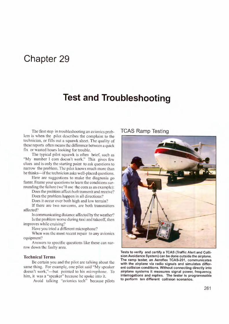
Chapter 29
Test and Troubleshooting
The first step in troubleshooting an avionics prob- TCAS Ramp Testing le rn is when the pilot describes the complaint to the r------------------............ -technician, or fill s out a squawk sheet. The quality of these repo1ts often means the difference between a quick fix or wasted hours looki ng for trouble .
The typical pilot squawk is often brief, such as "My number l com doesn 't work." This gives few clues and is on ly the starting point to ask questions to narrow the problem. The pilot knows much more than he thinks---ifthe techn ician asks well-placed questions.
Here are suggestions to make the diagnosis go faster. Frame your questions to learn the conditions surrounding the fa ilure (we' ll use the com as an example):
Does the problem affect both transm it and receive? Does the prob lem happen in all direction s? Does it occur over both high and low terrain? lf there are two navcoms, are both transm itters
affected? ls communicating distance affected by the weather? ls the problem worse during taxi and takeoff, then
improves while cru is ing? Have you tried a different microphone? When was the most recent repair to any avionics
equipment? Answers to specific questions like these can nar
row down the fa ulty area.
Technical Terms Be ce1tain you and the pilot are talking about the
same thing. For example, one pi lot said "My speaker doesn't work," ---but pointed to his microphone. To him, it was a "speaker" because he spoke into it.
Avoid talking "avionics tech" because pilots
Tests to verify and certify a TCAS (Traffic Alert and Collision Avoidance System) can be done outside the airplane. The ramp tester, an Aeroflex TCAS-201, communicates with the airplane via radio signals and simulates different collision conditions. Without connecting directly into airplane systems it measures signal power, frequency, interrogations and replies. The tester is programmable to perform ten different collision scenarios.
261
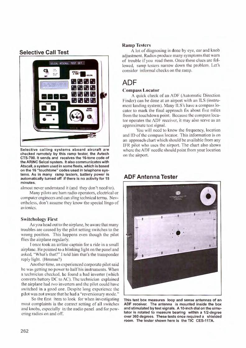
Selective Call Test
Selective calling systems aboard aircraft are checked remotely by this ramp tester, the Avtech CTS-700. It sends and receives the 16-tone code of the ARINC Selcal system. It also communicates with Atscall , a system used in some fleets, which is based on the 16 "touchtone" codes used in telephone systems. As in many ramp testers, battery power is automatically turned off if there is no activity for 15 minutes.
almost never understand it (and they don ' t need to). Many pilots are ham radio operators, electrical or
computer engineers and can sling technical terms. Nevertheless, don' t assume they know the special lingo of av10111cs.
Switchology First As you head out to the airplane, be aware that many
troubles are caused by the pi lot setting switches to the wrong position. This happens even though the pilot flies the airplane regularly.
I once took an airline captain for a ride in a small airplane. He pointed to a blinking light on the panel and asked, " What's that?" I to ld him that's the transponder reply light. (Hmmm?)
Another time, an experienced corporate pilot said he was getting no power to half his instruments. When a technician checked, he fo und a bad inverter (which converts battery DC to AC). The technician explained the airplane had two inverters and the pilot could have switched in a good one. Despite long experience the pilot was not aware that he had a " reversionary mode."
So the first item to look for when investigating most complaints is the correct setting of all switches and knobs, espec ially in the aud io panel and for powering radios on and off
262
Ramp Testers A lot of diagnosing is done by eye, ear and knob
adjustment. Radios produce many symptoms that warn of trouble if you read them. Once these clues are followed, ramp testers narrow down the problem. Let's consider informal checks on the ramp.
ADF Compass Locator
A quick check of an ADF (Automatic Direction Finder) can be done at an airport with an !LS (instrument landing system). Many I LS 's have a compass locator to mark the final approach fi x about fi ve miles from the touchdown point. Because the compass locator operates the ADF receiver, it may also serve as an approximate test signal.
You will need to know the frequency, location and 10 of the compass locator. This information is on an approach chatt which should be available from any lfR pilot who uses the airport. The chart also shows where the ADF needle should point from your location on the airport.
ADF Antenna Tester
This test box measures loop and sense antennas of an ADF receiver. The antenna is mounted inside the box and stimulated by test signals. A 10-inch dial on the simulator is rotated to measure bearing within a 1/2-degree over 360 degrees. These tests once required a shielded room. The tester shown here is the TIC CES-117A.
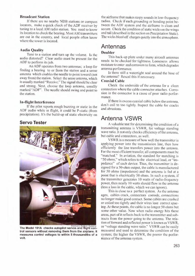
Broadcast Station If there are no nearby NDB stati ons or compass
locators, make a qui ck check of the ADF receiver by tuning to a local AM radio station. You need to know its location to check the bearing. Most AM transmitters are out in the country, and local people often know where the tower is located.
A udio Quali ty Tune to a station and turn up the volume. Is the
audio distorted? C lear audio must be present for the A DF to perfonn its job.
An ADF operates from two ante1rnas; a loop for finding a bearing to or from the station and a sense antenna which enables the needle to point toward (not away from) the station. Select the sense antenna, which is usually marked " Receive." The signal shou ld be clear and strong. Next, choose the loop antenna, usually marked "ADF". The needle should swing and point to the station.
In-flight Interference ff the pilot reports rough buzzing or static in the
ADF audio while in flight, it could be P-static ( from precipitation ). It 's the bu ild-up of stat ic e lectricity on
Servo Tester
ectronic v1a tt0n ystems The Model 101A checks autopilot servos and fl ight con-trol sensors without removing them from the airplane. It measures control voltages to within 5 thousandths of a volt.
the airfram e that makes raspy sounds in low-frequency radios. Check if each grounding or bonding poi nt between the ADF system and the a irframe is c lean and secure. Check the condition of static wicks on the wings and tail (described in the section on Precipitation Static). The wicks bleed off charges quietly into the atmosphere.
Antennas Doubler
This back-up plate under many aircraft antennas needs to be checked for tightness. Looseness a llows moisture to enter and corrosion to form, which degrades antenna performance.
l s there still a wate1t ight sea l around the base of the antenna? Reseal thi s if necessary. Coaxial Cable
Check the underside of the antenna for a clea n connection where the cable connector attaches. Corrosion in the connector is a ca use of poor radio performance.
If there is excess coaxia l cable below the anten na, don't coil to too tightly. Inspect the cable for cracks and abrasions.
Antenna VSWR A valuable test for determining the condition of a
transmitting antenna is VSWR, for voltage standing wave ratio. It not only checks effic iency of the anten na, but cable and co1rnectors, as wcl I.
VSWR is a measure of how well the transmitter is applying power into the transmi ssion line, then how efficiently the line transfers power into the antenna. For the most efficient transfer, al l components must be "matched." ln aviat ion, the standard for matching is "50 o lm1s," which refers to the electrica l load, or " impedance" of each device. Thus, the transm itter is designed for a 50-ohm output, the cable is manufactured for 50 ohms (impedance) and the antenna is fed at a point that is electrically 50 ohms. In such a system, if the transmitter generates 10 watts of radi o-frequency power, then nearly 10 watts should flow in the antenna ( less a loss in th e cab le, which we can ignore).
This is close to a perfect system. As the antenna ages, cables crack, connectors corrode, connections no longer make good contact. Some cables arc crushed or co iled too tightly and their wires lose correct spacing. At these points, the cable is no longer 50 ohms but some other va lue. Now when rad io energy hits these areas, part o f it reflects back to the transmitter and subtracts from the power go ing to the antenna. The relation of forward and reflected power is known as VSWR, or "voltage standing wave ratio." VSWR can be easily measured and used to determine the condition of the system; the higher the VSWR, the poorer the pe1fo rmance of the antenna system.
263
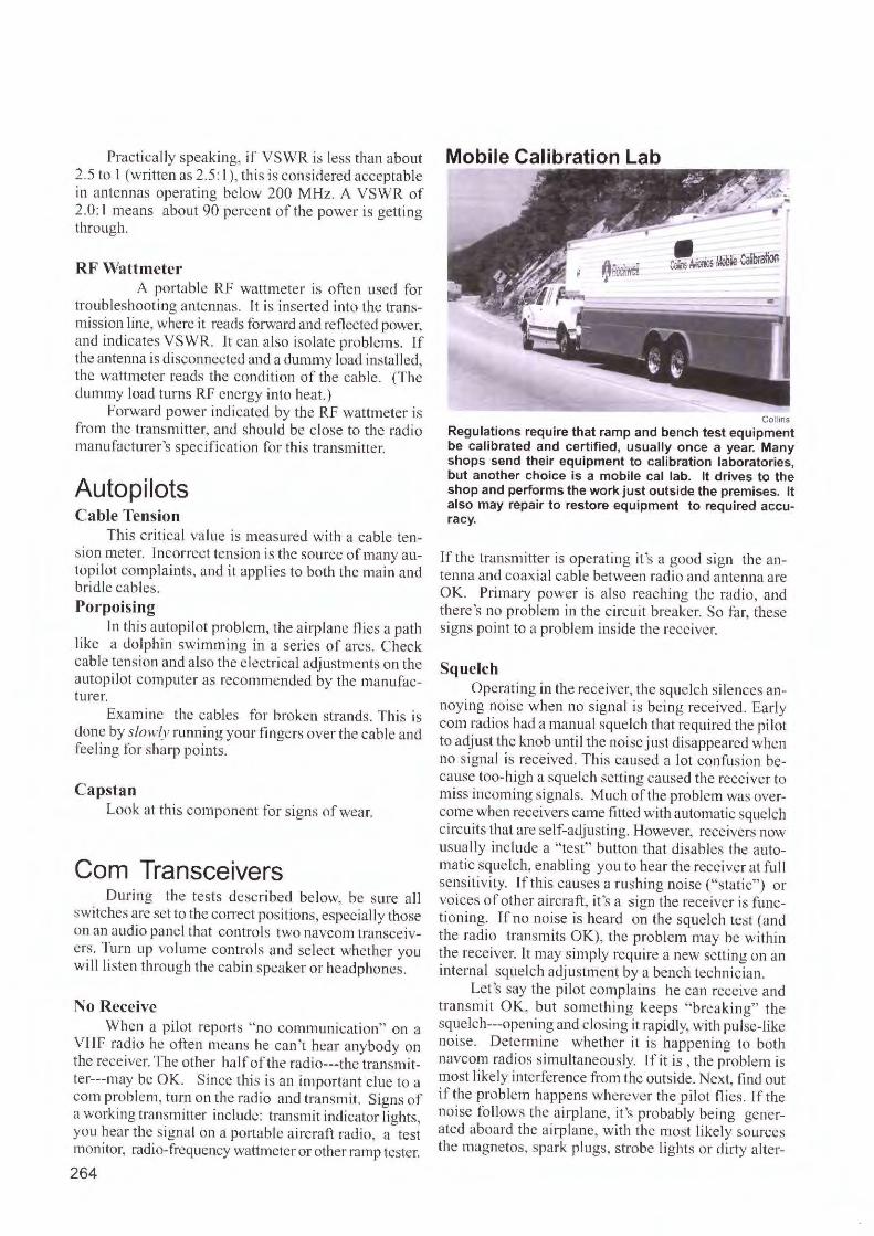
Practica lly speaki ng, if VSWR is less than about Mobile Calibration Lab 2.5 to 1 (written as 2.5: I), this is considered acceptable in antennas operating below 200 M Hz. A VSWR of 2.0 : 1 means about 90 percent of the power is getti ng through.
RF Wattmeter A portable RF wattmeter is often used fo r
trnub leshooting antennas. It is inserted into the transmission line, where it reads fo1ward and reflected power, and ind icates YSWR. Jt can a lso isolate problems. lf the antenna is d isconnected and a dtm1.my load installed , the wattmctcr reads the cond ition of the cable. (The dummy load turns Rf energy into heat.)
forwa rd power indicated by the RF wattmeter is from the transmitte r, and shoul d be c lose to the radio manufacturer 's specification for thi s transmitter.
Autopilots Cable Tension
This cri tical value is measured with a cable tension meter. Incorrect tension is the source of many autopi lot comp.laints, and it applies to both th e mai n and brid le cables. Porpoising
In this autopi lot problem, the a irplane flies a path like a dolphin swimmi ng in a series of arcs. Check cable tension and a lso the electrical adj ustments on the autopilot computer as recommended by the manufacture r.
Exam ine the cables for broken strands. Thi s is done by slowly running your fi ngers over the cable and fee ling for shaqJ points.
Capstan Look at this component for s igns of wear.
Com Transceivers Du ring the tests described be low, be sure all
switches are set to the correct positions, especially those on an audio panel that contro ls two navcom transceive rs. Turn up volume controls and select whether you will listen through the cabin speaker or headphones.
No Receive When a pi lot repo,is "no communication" on a
VHF radio he often means he can 't hear anybody on the receiver. The other halfof the radio---the transmitter---may be OK. Since this is an important c lue to a corn problem, turn on the radio and transmit. Signs of a working transmitter include: transmjt indicator lights, you hear the signal on a portable a ircraft radio, a test monitor, radio-frequency wattmeter or other ramp tester.
264
Collins
Regulations require that ramp and bench test equipment be calibrated and certified, usually once a year. Many shops send their equipment to calibration laboratories, but another choice is a mobile cal lab. It drives to the shop and performs the work just outside the premises. It also may repair to restore equipment to required accuracy.
If the transmitter is operati ng it 's a good sign the antenna and coaxial cable between radio and antenna are OK. P rimary power is also reaching the rad io, and there's no problem in the c ircuit breaker. So far, these signs point to a problem inside the receiver.
Squelch Operating in the receiver, the squelch silences an
noying noise when no signal is being received. Early com radios had a manual squelch that requi red the pilot to adjust the knob until the noise just disappeared when no signal is received. This caused a lot confusion because too-high a sque lch setting caused the rece iver to m iss incoming signals. Much of the problem was overcome when receivers came fitted with automatic squelch circuits that are self-adjusting. However, receivers now usually include a "test" button that d isables the automatic squelch, enabling you to hear the recei ver at fu ll sens itivity. If this causes a rushing noise ("static" ) or voices of other aircraft, it 's a sign the receiver is fun ctioning. Tf no noise is heard on the sque lch test (and the radio transmits OK), the problem may be within the rece iver. It may s imp ly req ui re a new sett ing on an internal squelch adjustment by a bench techni cian.
Let 's say the pilot comp la ins he can receive and transmit OK, but something keeps "breaking" the squclch---opening and closing it rapidly, with pulse-like noise. Determine whether it is happening to both navcom radios simultaneously. If it is , the problem is most I ikely interference from the outside. Next, find out if the problem happens wherever the pilot fli es. If the noise follows the airplane, it's probably be ing generated aboard the airplane, w ith the most likely sources the magnetos, spark plugs, strobe li ghts or dirty a lter-
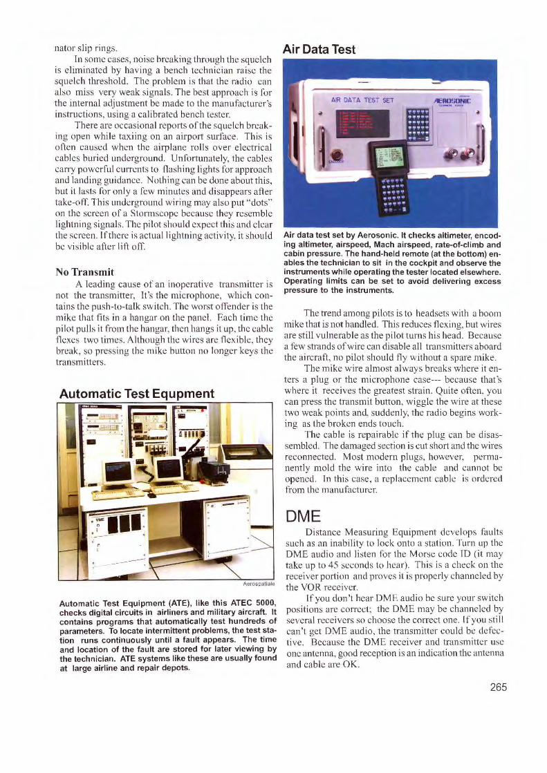
nator slip rings. In some cases, noi se breaking through the squelch
is eliminated by having a bench techn ician ra ise the squelch threshold . The problem is that the radio can also miss very weak signals. The best approach is for the internal adjustment be made to the manufacturer's instructions. using a calibrated bench tester.
There are occasional reports of the squelch breaking open while taxiing on an airport surface. This is often caused when the airplane rolls over electrical cables buried underground . Unfo11unately, the cables carry powerful currents to flashing lights for approach and landing gu idance. Nothing can be done about this, but it lasts for onl y a few minutes and disappears after take-off. This underground wiri ng may also put "dots" on the screen of a Stormscope because they resemble lightning signa ls. The pilot should expect this and clear the screen. lfthere is actual li ghtning activity, it should be visible after I ift off.
No Transmit A leading cause of an inoperative transmitter is
not the transmitter, It's the microphone, which contains the push-to-talk switch. The worst offender is the mike that fits in a hangar on the panel. Each time the pilot pulls it from the hangar, then hangs it up, the cable flexes two times. Although the wires are flexible, they break, so pressing the mike button no longer keys the transmitters.
. - ·-
Aerospatiale
Automatic Test Equipment (ATE), like this ATEC 5000, checks digital circuits in airliners and military aircraft. It contains programs that automatically test hundreds of parameters. To locate intermittent problems, the test station runs continuously until a fault appears. The time and location of the fault are stored for later viewing by the technician. ATE systems like these are usually found at large airline and repair depots.
Air Data Test
Air data test set by Aerosonic. It checks altimeter, encoding altimeter, airspeed, Mach airspeed, rate-of-climb and cabin pressure. The hand-held remote (at the bottom) enables the technician to sit in the cockpit and observe the instruments while operating the tester located elsewhere. Operating limits can be set to avoid delivering excess pressure to the instruments.
The trend among pilots is to headsets with a boom mike that is not handled. This reduces flexing, but wires are still vu lnerable as the pilot turns his head. Because a few strands of wire can disable a ll transmitters aboard the aircra ft , no pilot should fly without a spare mike.
The mike wire almost always breaks where it enters a plug or the microphone case--- because that's where it receives the greatest strain. Quite often, you can press the tra nsmit button, wiggle the wire at these two weak points and, suddenly, the radio begins working as the broken ends touch.
The cable is rcpairnble if the plug can be disassembled. The damaged section is cut short and the wires reconnected. Most modern plugs. however, permanently mold the wi re into the cable and cannot be opened. In thi s case, a replacement cable is ordered from the manufacturer.
DME Distance Measuring Equipment develops fau lts
such as an inability to lock onto a station. Turn up the DME audio and listen for the Morse code ID (it may take up to 45 seconds to hear). This is a check on the rece iver portion and proves it is properly channeled by the VOR receiver.
If you don't hear DME audio be sure your switch positions are correct; the DM E may be channeled by several receivers so choo e the correct one. lfyou still can't get DME audio, the transmitter could be defective. Because the DME receiver and transmitter use one antenna, good reception is an ind ication the antenna and cable are OK.
265
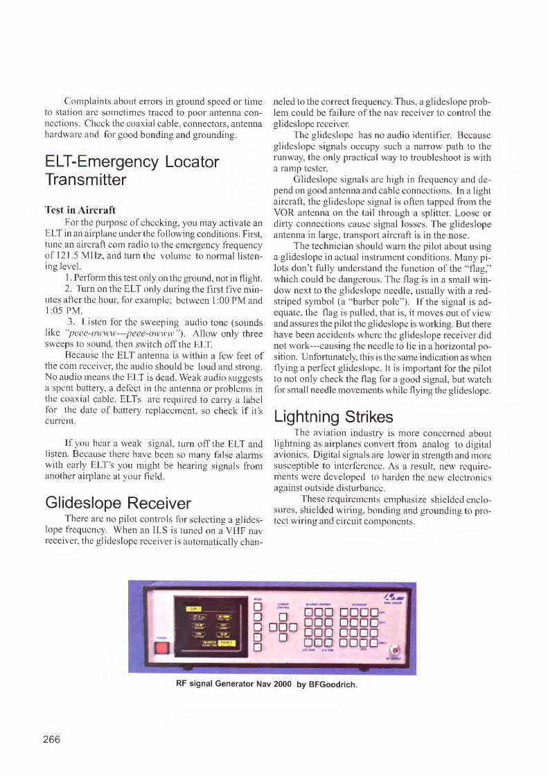
Complaints about errors in ground speed or time to station a re sometimes traced lo poor antenna connections. Check the coaxial cable, connectors, antenna hardware and for good bonding and grounding.
ELT-Emergency Locator Transmitter
Test in Aircraft For the purpose of checking, you may activate an
ELT in an airplane under the fo llowing conditions. First, tune an a ircraft com radio to the emergency frequency of 12 1.5 MHz, and turn the volume to normal listening level.
I. Perform this test only on the ground , not in flight. 2. Turn on the ELT only during the first five min
utes after the hour, for example; between 1 :00 PM and 1:05 PM.
3. Listen for the sweeping audio tone (sounds like ''peee-011·ww---peee-owwll' "). Allow only three sweeps to sound, then switch off the ELT.
Because the £LT antenna is within a few feet of the com receiver, the audio should be loud and strong. No a udio means the ELT is dead. Weak audio suggests a spent battery, a defect in the antenna or problems in the coaxial cable. E LTs are required to carry a label for the date of battery replacement, so check if it's current.
If you hear a weak s igna l, turn off the ELT and listen. Because there have been so many fa lse alarms wi th early ELT's you might be hearing s ignals from anothe r airplane at your field.
Glideslope Receiver T here are no pilot controls for selecting a g lides
lope frequency. When an ILS is tuned on a VHF nav receiver, the glideslope receiver is automatica lly chan-
ne led to the correct frequency. Thus, a g lides lope problem could be failure of the nav rece iver to control the glides lope receiver.
The glidcslopc has no aud io identifier. Because glides lope s ignals occupy suc h a narrow path to the runway, the only practical way to troubleshoot is with a ramp tester.
Glideslope signals are high in frequency and depend on good antenna and cable connections. In a light aircraft, the glideslope signa l is often tapped from the VOR antem1a on the tail through a splitter. Loose or dirty connection s cause s ignal losses. The g lideslope antenna in large, transport aircraft is in the nose.
The technic ian should warn the pi lot about using a g lideslope in actual instrument condit ions. M any pilots don't fully unde rstand the function of the "flag," which could be dangerous. The flag is in a small w indow next to the g lideslope needle, usua lly w ith a redstriped symbol (a "barber pole"). If the s ignal is adequate, the fl ag is pulled, that is, it moves out of view and assures the pilot the glideslope is working. But there have been accidents w here the g lideslope receiver d id not work---causing the needle to lie in a horizonta l posi tion. Unfortunately, this is the same indication as when flying a perfect glideslope . lt is important for the pilot to not onl y check the flag for a good signal, but watch for small need le movements wh ile flying the glides lope.
Lightning Strikes The aviation industry is more concerned about
I ightning as a irplanes conve,t from analog to digital avionics. Digita l signals are lower in strength and more susceptibl e to interference. As a result, new requirements were developed to harden the new e lectronics against outs ide di sturbance.
T hese requirements emphasize shielded enclosures, shie lded w iring, bond ing and groundi ng to protect w iring and circuit components.
D =. ODO DOD O ... · O D 000 DODD-· D ODO DOD DODD B O ,g_o_g oogo-
RF signal Generator Nav 2000 by BFGoodrich.
266
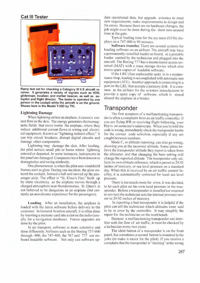
Cat Ill Tester
Ramp test set for checking a Category Ill ILS aircraft receiver. It generates a variety of signals such as VOR, glideslope, localizer, and marker beacon, as well as autopilot and flight director. The tester is operated by one person in the cockpit while the aircraft is on the ground. Shown here is the Model T-30D by TIC.
Lightning Damage When lightning strikes an airplane, it causes a cur
rent flow in the skin. The energy generates e lectromagnetic fi elds that move in side the airplane, where they induce additional current flows in wiring and electrical equ ipment. Known as " lightning indirect effect," it can trip c ircuit breakers, disrupt di gital circuits and damage other components.
Li ghtning may damage the skin. After landing, the pilot notices small pits or burns where lightning entered or depat1ed. In some instances, instruments in the panel are damaged. Compasses have been known to demagneti ze and swing a imlessly.
One phenomenon is when the pilot sees windshield frames start to g low. During one inc ident, the glow ente red the cockpit, fo rmed a ball and moved up the passenger a isle . The effect is "St. Elmo's Fire," built up by static electric ity as the a irplane moves through a charged atmosphere near thunderstorm s. St. Elmo 's is not be li eved to be dangerous in an airplane (but certainly an unwelcome experience for the passengers) .
Loading. After an insta llatio n, the a irplane is loaded w ith the latest software before de livery to the customer. In General Aviation a ircraft, it is often done by insert ing a memory card into a slot on the radio ( usually fo r a navigation database) . Future upgrades a re done by the pilot.
In air transpo11, software is more extensive and done differently. A irliners such as the Boeing 737-600 through -900, the 747-400, the 767 and 777 use onboard loadable software. Not only can software up-
date operati ona l data, but upgrade avionics to meet new requirements. make improvements in des ign and fi x errors. Because there are no hardware changes, the job might even be done during the short turn-around time at the gate.
Typical loading time for the six main (EFTS) displays on a 747-400 is 90 minutes.
Software transfer. There are several systems for loading software on an a irl iner. The ai rcraft may have a pennanently-insta lled loader on board , or a portable loader carri ed by the techn ician and plugged into the aircraft. The Boeing 777 has a maintenance access terminal (MAT) with a mass s torage device which also stores spare copies of loadab le software.
lf the LRU (line replaceable uni t) is in a mai nt enance shop, loading is accomplished with automatic test equipment (ATE). Another approach is connecting to a po11 on the LRU that accepts a memory disk. l t is common in the a irl ines for the avionics manufacture r to provide a spare copy of softwa re, which is stored aboard the a irplane in a b inder.
Transponder The first symptom of a malfunctioning transpon
der is often a compla int from an air traffic controller. If you are fl ying TFR or rece iving fligh t following, your blip is on someone's radarscope. When you 're told the code is wrong, immediate ly check the transponder knobs for the correct code selection, especially if any are caught between numbers.
Mode C, or al titude reporting, can also go wrong, show ing you at the incorrect a lti tude. Some pi lots believe the transponder a lt itude they repo,1 is taken fro m the a ltimeter, and that chang ing the baro setting will change the repo1ied a ltitude. The transponder only utilizes its own altitude reference, which is preset to 29.92 inches of mercury, or sea level pressure on a standard day. When this is rece ived by an a ir traffic control facili ty, it is automatically corrected for local sea leve l pressure.
There is too much room for e rror, it was dec ided, to let each pilot set his own local pressure in the transponder. Before a transponder is insta ll ed ( or returned to service) the technician sets the internal pressure sensor to 29.92 inches of mercury.
Tn reporting a bad transponder it is helpful if the pi lot can tell the technician which altitudes were said to be in e rror by the controller. It may simplify the repair for the technician on the workbench
Because a ma lfunctioning transponder can interfere with the flow of air traffic, it must be checked by a technician every two years.
The ident button of a transponder is on the front pane l, but sometimes a second button is mounted in the yoke (to make it easier for the pilot). If you receive a complaint that the transponder is " identing" at the wrong
267
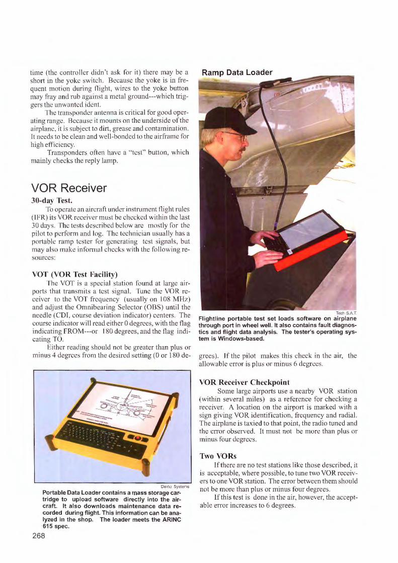
time (the control ler didn 't ask for it ) there may be a sho1t in the yoke sw itch. Because the yoke is in frequent motion during fli ght, wires to the yoke button may fray and rub against a metal ground---which triggers the unwanted ident.
The transponder antenna is critical for good operating range. Because it mounts on the unders ide of the a irplane , it is subject to dirt, grease and contamination. Jt needs to be clean and well-bonded to the a irframe for high effi ciency.
Transponders often have a " test" button, which mainly checks the reply lamp.
VOR Receiver 30-day Test.
To operate an a ircraft under instrument flight rules ( I FR) its VOR receiver must be checked w ithin the last 30 days. The tests described below are mostly for the pilot to perform and log. The technician usually has a portable ramp teste r for generating test signals, but may also make informal checks with the following resources:
VOT (VOR Test Facility) The YOT is a special s tation found at large a ir
ports that transmits a test signal. Tune the YOR receiver to the YOT frequency ( usua lly on I 08 MHz) and adj ust the Omnibearing Se lector (OBS) until the needle (CDT, course deviation indicator) centers. The course ind icator will read e ither O degrees, with the flag indicating FROM---or 180 degrees, and the flag indicating TO.
Either reading should not be greater than plus or minus 4 degrees from the desired setting (0 or 180 de-
Demo Systems
Portable Data Loader contains a mass storage cartridge to upload software directly into the aircraft. It also downloads maintenance data recorded during flight. This information can be analyzed in the shop. The loader meets the ARINC 615 spec.
268
Ramp Data Loader
Tech S.A.T
Flightline portable test set loads software on airplane through port in wheel well. It also contains fault diagnostics and flight data analysis. The tester's operating system is Windows-based.
g rees). If the pilot makes this check in the a ir, the allowable e rror is plus or mi nus 6 degrees.
VOR Receiver Checkpoint Some large a irports use a nearby YOR station
(within several miles) as a reference for checking a receiver. A locatio n on the airport is marked with a sign giving VOR identificati on, frequ ency and radia l. The airplane is taxied to that point, the radio tuned and the e rror observed. It must not be more than plus or minus fo ur degrees.
Two VORs If there are no test stat ions like those described, it
is acceptable, where poss ible, to tune two YOR receivers to one YOR station. The error between them should not be more than plus or min us four degrees.
lfthis test is done in the air, however, the acceptable e rror increases to 6 degrees.
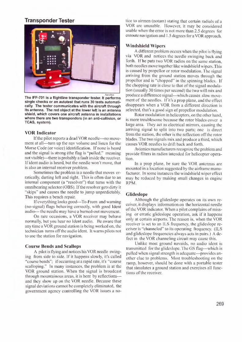
Transponder Tester
Aeroflex The IFF-701 is a flightline transponder tester. It performs single checks or an autotest that runs 30 tests automatically. The tester communicates with the aircraft through its antenna. The red object at the lower left is an antenna shield, which covers one aircraft antenna in installations where there are two transponders (in an anti-collision, or TCAS, system).
VOR Indicator lfthe pi lot reports a dead VOR ncedle--- no move
ment at all---turn up the nav volume and listen for the Morse Code (or voice) identification. l f none is heard and the signal is strong (the flag is " pulled," meaning not visible )---there is probably a fault inside the receiver. lf ident a udio is heard, but the needle won't move, that is a lso an inte rnal receiver problem.
Sometimes the problem is a needle that moves e rratica lly, darti11g left a nd right. T his is often due to an inte rnal component (a " resolver") that turns w ith the omnibearing selector (OBS). If the reso lver gets dirty it "skips" and causes the needle to jump unpredictably. Thi s requ ires a be nch repai r.
If everything looks good---To-From a nd warning (no-s igna l) flags behaving correctly, with good Jdent audio--- the need le may have a burned-out movement.
On rare occasions, a VOR rece iver may be have norma lly, but you hear no Tdent a udi o. Be aware that any time a VOR ground station is be ing worked on, the technic ian turns off the audio iclent. lt warns pil ots not to use the station for navigation.
Course Bends and Scallops A pilo t is flying and notices his VOR needle swing
ing from side to s ide. lf it happens s lowly, it's called "course bends"; if occurring at a rapid rate, it 's "course scalloping." J n many instances, the prob lem is at the VOR ground station . When the signal is broadcast through mountaino us areas, it is bent by re fl ections--and they show up on the VOR needle. Because these signal dev iat ions cannot be complete ly e lim inated, the government agency conh·o lling the VOR issues a no-
tice to a irmen (notam) stating that certain rad ials of a VOR are unusable. However, it may be cons idered usable whe n the error is not more than 2.5 degrees fo r enroute navigation and 1.5 degrees for a VOR approach.
Windshield Wipers A different problem occurs when the pilot is fly ing
via VOR and notices the need le swinging back and forth . If he puts two VOR radios on the same station, both needles move together like w indshield wipers. This is caused by propellor or rotor modulation. T he s igna l arriving from the ground station moves th rough the propel lor and is "chopped" in the spinning blades. If the c hopping rate is close to that of the signa l modul ation (usually 30 times per second) the two w il l mix a nd produce a difference signal---which causes s low movement of the needles. lf it's a prop pla ne, and the effect di sappears when a VOR from a different direction is se lected, that's a good s ign of prope l I or modulation.
Rotor modulation in helicopters, on the other hand, is more troublesome because the rotor blades cover a large area. They act as e lectri cal mirrors, causing the a rri ving signal to split in to two pa rts; one is direct from the stati on, the other is the reflection off the rotor blades. T he two signals mix and produce a third, which causes VOR needles to drift back and fo rth.
Avionics manufacturers recognize the problem and provide fi lters in rad ios intended for helicopter operati on.
ln a prop p lane, be sure the VOR ante nnas are mounted in a location suggested by the ai,frame manufacture r. In some instances the windshield w iper effect may be reduced by making small changes in engine RPM.
Glideslope A lthough the g l.ideslope operates on its own re
ceiver, it displays information on the horizonta l needle of the VOR indi cator. When a pi lot comp la ins of missing or erratic gl ideslope operation, ask if it happens only at certa in ai rports. T he reason is, when the VOR receiver is set to an lLS freq uency, the gl ideslope receiver is "channe led" to its operating frequency. (!LS and glideslope frequencies a lways acts in pairs.) A defect in the VOR channeling c ircuit may cause th is.
Unlike most g!:ound navaids, no audio ident is transmitted for the glideslope. The GS fl ag---which is pu lled when s ignal stre ngth is adequate---prov ides anothe r c lue to problems. Most troubleshooting on t he ramp, however, should be done w ith a portable tester that s imulates a ground station and exerc ises a ll functions of the receiver.
269
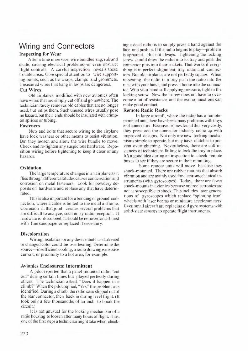
Wiring and Connectors Inspecting for Wear
After a time in service, wire bundles sag, rub and chafe, causing e lectrical problems--or even obstruct night controls. A ca reful inspection reveals these trouble areas. Give specia l attentio n to wire supporting points, such as tie-wraps, c lamps and grommets. Unsecured wires that hang in loops are dangerous. Cut Wires
O ld airplanes modified with new avion ics often have wires that arc simply cut ofJ and go nowhere. The technician rarely removes old cables that are no longer used, but sn ips them. Such unused wires usually pose no hazard, but their ends should be insulated with crimpon splices or tubing. Fasteners
uts and bolts that secure wiring to the airplane have lock washers or other means to resist vibration. But they loosen and a llow the wire bundle to move. Check and re-tighten any suspicious hardware. Reposi tion wiring before tightening to keep it c lear of any hazards.
Oxidation The large temperature changes in an ai rplane as it
nies through different altitudes causes condensation and corrosion on metal fasteners. Look for powdery deposits o n hardware and replace any that have de teriorated.
This is also important for a bonding or ground connection. where a cable is bo lted to the metal a irframe. Corrosion in that joint c reates several problems that are difficu lt to analyze, such noisy radio reception. If hardware is discolored, it should be removed and shined with fine sandpaper or replaced if necessary.
Discoloration Wiring insulation or any device that has darkened
or changed co lor could be overheating. Determine the source---insuffic ient cooling, a radio drawing excessive current, o r proximity to a hot area, for example.
Avionics Enclosures: Intermittent A pilot reported that a panel-mounted radio '·c ut
out" during certain times but played perfectly during others. The technician asked, " Does it happen in a c limb?" When the pilot repl ied, "Yes," the problem was identified. During a climb, the radio case slipped out of the rear connector, then back in during level flight. ( It took only a few thousandths of an inch to break the c ircuit.)
lt is not unusual for the locking mechanism of a radio housing to loosen after many hours of flight. Thus, one of the first steps a technician might take when check-
270
ing a dead radio is to simply press a hand against the face and push in. If the radio begins to play---prob lem is apparent. But not always. Tightening the locking screw sho uld draw the rad io into its tray and push the connector pins into their sockets. That works if everything is in perfect alignment; tray, radio and connectors. But old airp lanes are not perfectly square. When re-seating the radio in a tray push the radio into the rack with your hand, and press it home into the connector. With your hand still applying pressure, tighten the locking screw. Now the screw docs not have to overcome a lot of resistance and the rear connections can make good contact. Remote Radio Racks
In la rge a irc raft, where the rad io has a remotemounted unit, there have been many problems with trays and connectors. Because airlines found this very costly, they pressured the connector industry come up with improved designs. Not only are new locking mechanisms simple to operate, but may have c lutches to prevent overtightening. evcrtheless, there are still instances of technicians fa iling to lock the tray in place. 11 's a good idea during an inspection to check remote boxes to see if they are secure in their mounting.
Some remote uni ts will move because they shock-mo unted. There arc rubber mounts that absorb vibration and are mainly used for e lectromechanica l instruments (with gyroscopes). Today, there are fewer shock-mounts in avionics because microelectronics arc not as susceptible to shock. This inc ludes later generati ons of gyroscopes which replace "spinning iron" wheels with laser beams or miniature accelerometers. Even small a ircraft arc replacing o ld gyro systems with solid-state sensors to operate night instruments.
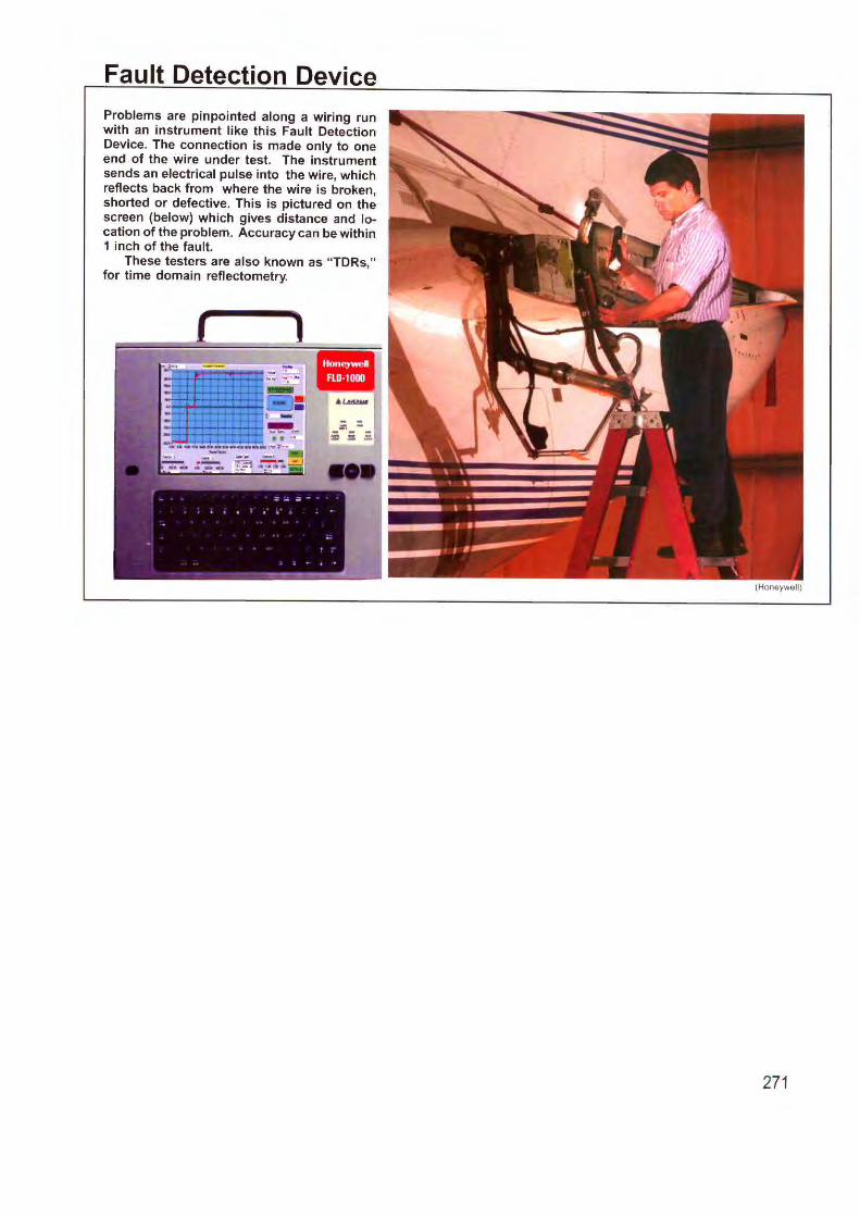
Fault Detection Device
Problems are pinpointed along a wiring run with an instrument like this Fault Detection Device. The connection is made only to one end of the wire under test. The instrument sends an electrical pulse into the wire, which reflects back from where the wire is broken, shorted or defective. This is pictured on the screen (below) which gives distance and location of the problem. Accuracy can be within 1 inch of the fault.
These testers are also known as "TDRs," for time domain reflectometry.
271
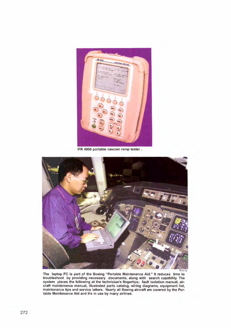
272
IFR 4000 portable navcom ramp tester .
Boeing
The laptop PC is part of the Boeing "Portable Maintenance Aid." It reduces time to troubleshoot by providing necessary documents, along with search capability. The system places the following at the technician's fingertips; fault isolation manual, aircraft maintenance manual, illustrated parts catalog, wiring diagrams, equipment list, maintenance tips and service letters. Nearly all Boeing aircraft are covered by the Portable Maintenance Aid and it's in use by many airlines.
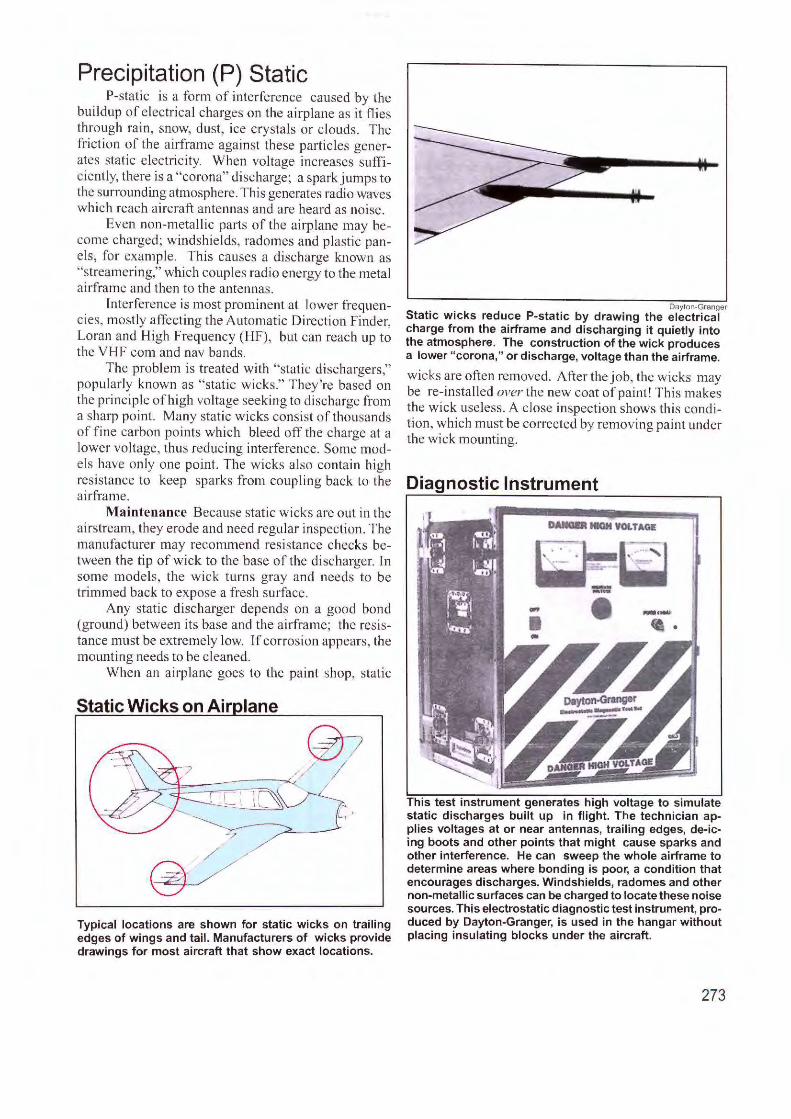
Precipitation (P) Static P-static is a form of interference caused by the
buildup of electrical charges on the ai rplane as it flies through rain, snow, dust, ice crystals or clouds. The friction of the airframe against these particles generates static e lectri city. When voltage increases sufficiently, there is a "corona" discharge; a spark jumps to the surrounding atmosphere. This generates radio waves which reach aircraft antennas and are heard as noise.
Even non-metallic pa11s of the airplane may become charged; windshields, radornes and plastic panels, for example. This causes a discharge known as "streamering," which couples radio energy to the metal ai rframe and then to the antennas.
Tnterference is most prominent at lower frequencies, mostly affecting the Automatic Direction Finder, Loran and High Frequency (HF), but can reach up to the VHF com and nav bands.
The problem is treated wi th "static dischargers," popularly known as "static wicks." They 're based on the principl e of high voltage seeking to discharge from a sharp point. Many static wicks consist of thousands of fine carbon points which bleed off the charge at a lower voltage, thus reducing interference. Some models have only one point. The wicks also contain high resistance to keep sparks from coupling back to the airframe.
Maintenance Because stati c wicks are out in the airstream, they erode and need regular in spection. The manufacturer may recommend resistance checks between the tip of wick to the base of the discharger. In some models, the wick turn s gray and needs to be trimmed back to expose a fresh surface.
Any static discharger depends on a good bond (ground) between its base and the airframe; the resistance must be extremely low. Tf corrosion appears, the mounting needs to be cleaned.
When an airpl ane goes to the paint shop, static
Static Wicks on Air lane
Typical locations are shown for static wicks on trailing edges of wings and tail. Manufacturers of wicks provide drawings for most aircraft that show exact locations.
Dayton-Granger Static wicks reduce P-static by drawing the electrical charge from the airframe and discharging it quietly into the atmosphere. The construction of the wick produces a lower "corona," or discharge, voltage than the airframe.
wicks are often removed. After the job, the wicks may be re-insta lled over the new coat of pa int! This makes the wick useless. A close inspection shows this condition, which must be corrected by removing paint under the wick mounting.
Diagnostic Instrument
DARGIR NIGH VOl.TAGf:
This test instrument generates high voltage to simulate static discharges built up in flight. The technician applies voltages at or near antennas, trailing edges, de-icing boots and other points that might cause sparks and other interference. He can sweep the whole airframe to determine areas where bonding is poor, a condition that encourages discharges. Windshields, radomes and other non-metallic surfaces can be charged to locate these noise sources. This electrostatic diagnostic test instrument, produced by Dayton-Granger, is used in the hangar without placing insulating blocks under the aircraft.
273
Avionics Checklist The more symptoms of trouble provided to the tech· nician, the quicker he can analyze problems. Here is a summary of items for both pilot and technician to help gather that information
Electrical Source •Are there signs of a failing charging system, such as
hard starting, dim lighting or changes in lamp brightness as engine rpm varies?
•Are there blown fuses or "popped" circuit breakers? •Do you hear a whining or musical tone that varies with
engine rpm? This could be alternator interference. •Is there repeating noise in the audio, or extra dots on a
Stormscope? This might caused by a strobe light or poorly shielded ignition wires.
•Is the negative terminal of the battery making a good connection with the airframe?
Com Radio •Is the correct radio selected on the audio panel? •Check if the volume control is at normal listening level. •Are plugs for mikes and headsets fully seated in their
jacks? •If there is no receive audio, check if the push-to-talk
switch on the mike is stuck on. •Are mike and headphone plugs clean and shiny? •Turn the receiver to 'Test" to hear background noise. *If there's no audio in the headphones, switch to the cabin
speaker. •When trying to contact another station, does the opera
tor say, "I can hear your carrier, but no modulation?" •Check the frequency the radio is tuned to. Is it in the
"Active" position? •Many radios provide "sidetone;" as you speak. You
should hear yourself in the headset. •Does the indicator lamp light up when the mike is
pressed? •Does the same problem affect two com radios? •Does the problem occur on more than one channel? •Is the audio distorted, noisy? • Are there audio tones behind your voice when trans
mitting? (This could be inverter or alternator interference.)
Transponder •When flying in a radar environment, does the reply light
blink? Check if the light is not set to the dim position. •Press the test button to check reply light. •Turn off the DME. If the transponder problem disap
pears, the DME is causing interference. ·Does air traffic control say it's not receiving Mode A
(identification) and/or Mode C (altitude)? •If air traffic control reports problems, try to communi
cate with another radar facility to confirm it. Sometimes the problem is the radar facility.
•Is the mode selector in the correct position, and not in standby?
•Does the transponder "recycle" correctly. Turn it to standby, then turn it on. There may be about a 30 second delay before it turns on again.
Flight Control/Autopilot •Does it follow the selected mode, such as wings level,
heading hold, and track the VOR or Localizer? •Does it track the vertical functions, such as altitude hold? •Is the autotrim responding correctly? •Is there "porpoising"---where the nose rises and falls. •Can trim be adjusted? ·Check the vacuum for the gyro instruments. •With the autopilot engaged, and the airplane on the
ground, can you overpower the system with the flight con-
trols? •Are control cables loose?
Weather Radar •Check the condition of the radome for cracks, water
entry, splitting of layers. . *Verify the setting of panel controls, such as brightness
and sensitivity. •Run the self-test routine •Are display graphics sharp and clear? •Does the radar stabilize as the aircraft maneuvers?
GPS •Is the database current? •If the GPS is relocated more than several hundred miles
with the power off, expect it to do a sky search of five or more minutes before navigating.
•Are there enough satellites for navigation? Three is the minimum, while four are required for instrument flight.
•When on the ground, is the GPS antenna shaded by hangars or other structures?
•Check the mapping of the satellites. Are there sufficient satellites widely dispersed for good geometry?
•Check for sufficient signal strength. •Have any warnings been issued (notices to airmen) that
affect satellite coverage. Are there forecasts of severe solar storms which might affect reception?
•Does the position shown on the GPS agree with the airplane's present location?
•Is the airplane in a hangar where GPS signals may not penetrate?
•Are error messages present?
Distance Measuring Equipment (DME) •Listen to DME audio for a Morse code identifier. •Is the brightness turned up for the display? •Be aware that ground speed and time-to-station func
tion only when the airplane is flying directly to or from the ground station.
•Is the DME station off for maintenance? Check another station.
Automatic Direction Finder (ADF) •Does interference disappear when the engine is off? •Does the ADF needle point when "ADF" is selected and
a station is tuned? •Is the bandswitch set to the correct band? •Do you hear audio when "Ant" is selected, a station is
tuned, and there is no ADF needle movement? •Is the bearing of the pointer accurate? •Is the ADF needle being deflected by thunderstorms
(which may be more than 100 miles away)? •Does the test function deflect the ADF needle an appro
priate number of degrees? •Did you check for ADF action on more than one sta
tion?
Nav (VOR/ILS} • Can you hear a Morse code and/or voice identifier? •Does the problem appear on more than one channel? •If reception is poor, is it true for all directions? •Are both VOR and Localizer functions affected the same
way? Can you receive one but not the other? •Is the problem the same in a second nav radio? •Does the VOR bearing appear to be in error? •Center the VOR needle, then rotate the bearing selec
tor 180 degrees. Is there an error between the two bearings (to and from)?
•Are flags indicating good signal strength? •Compare two nav receivers to determine if both have
the same problem.

Index
A ACARS 41
bands and frequencies 45 cockpit display 41 message format 43 messages 43 000 1 42 system 42
ADF (Automatic Direction Finder) 81 broadcast stations 85 coastal effect 86 compass card, fixed 81 control-display, airline 84 digital ADF receiver 85 display, EFJS 86 loop 82 NDB station 83 night effect 86 quadrantal error 86 receiver, airline LRU 84 receiver. analog 82 RMI (Radio Magneti c Indicator) 82 sense 82 system diagram 83
Aircraft earth station 35 Airways, lighted 11 altitude reporting: mode C I 00 Antenna Installation 239
ADF 246 airline antenna locations 243 altitude 244 antenna types 240, 244 antennas for light aircraft 242 base station, mobile 252 bonding 248
Lo airframe 249 coaxial cable 250 combination antenna 253 connectors 25 1 couplers 25 1 doubler plate 24 7 duplexers 25 1 gaskets 250 GPS antennas 25 1 HF (high frequency) 245 hidden structure 246 high-performance antennas 239 hostile environment 241 location 245 mark and dri II 248 mounting 249 selecting an antenna 243 spec sheet, how to read 24 1 typical antennas 239 VOR blade 245
AIUNC 183 structures 183
276
Aviation Bands and Frequencies 230 control and display 236 frequency assignments 237 future bands 234 ground wave transmission 238 hertz to gigahertz 234 high frequencies 233 Higher bands 232 L-band 234 I ine-of-sight 235 microwave 235 Radio frequencies (RF) 230 radio signal 230 skipping tlu·ough ionosphere 233 vhfband 234
Avionics definition of I
Avionics master switch 173
8 Barany chair 7 Beam steering unit (BSU) 35 Bell, Alexander Graham 9 Blind tlying
first fli ght 2
C Calibration 264 Cell Phones 33 Channels
spli tting 16 Clear air tu rbulence (CAT) 136 CNS: Communication, Navigation, Survei llance 4 Cockpit Voice and Fl ight Data Recorders 129
cable assembly 133 cockpit area mike 130, 13 1 CVR basics 129 CVR channels 130 Flight data recorder 133
parameters 135 solid state 134
flight data recorders 13 1 inertia l switch 130 interconnect, CVR 132 LRU: line replaceabl e unit 130 tape drive 132 temperature test 130 underwater locating device 13 1
tester J 32 Con nectors 199
Amphenol 206 application 20 I crimp tool 206 crimping 202 d-subminiature 206 heat gun 207 how to identify contacts 20 I Molex 206 radio frequency 200 reading pin connections 199 releasing pins 207
safety wi ring 208 solder cups 206 soldering 202 trends 202 typical 200
Cooling 186
D DME (Distance Measuring Equipment) 88
E
ai rborne system diagram 9 1 chanclling 88, 90 EFIS display 90 ground speed 88 ground station 9 1 jitter 89, 90 obtaining distance 89 pulse spacing 92 reply frequencies 92 scanning and agile 89 slant range 89 X and Y channels 92
EFIS: electronic night instrument system 120
Airbus A-320 127 archicteclure 124 electromechanical to EFIS 122 tlight deck 120 glass cockpit 120 MFD: multi fonct ion display 125 on B-747-400 126 pictorial display 121 replacing old instruments 121 three-screen 123
Electrical Systems 168 I 15 vol t system 170 28 volt DC 170 AC and DC power J 68 APU (Auxil iary Power Unit) 170 battery charge, percentage 168 circuit breakers 173
recessed button 176 DC system 169 fu ses 176 ram air turbine (RATS ) 172 switches 172
avionics master 173 llighted pushbutton 175 pushbutton 174 switch guards 175 types 173
Elect.-ostatic dischar·ge 185 ELT 50 ELT (Emergency Locator Transmitter
406 MHz ELT 5 1 406 system 53 components 52 controls and connections 54 Cospas-Sarsat satellites 51 , 55 direct ion of fllight 50 dongle 54
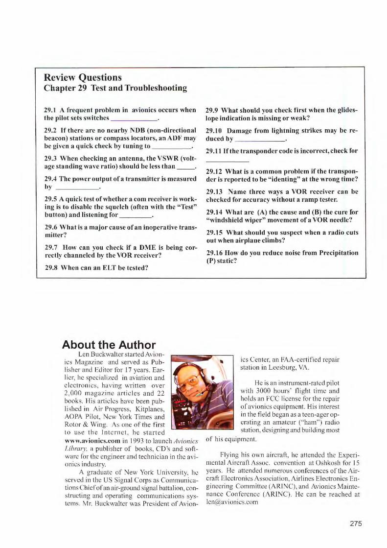
Review Questions Chapter 29 Test and Troubleshooting
29.1 A frequent problem in avionics occurs when the pilot sets switches ______ ,
29.2 If there are no nearby NDB (non-directional beacon) stations or compass locators, an ADF may be given a quick check by tuning to _ ___ _
29.3 When checking an antenna, the VSWR (voltage standing wave ratio) should be less than __ .
29.4 The power output of a transmitter is measured by ____ _
29.5 A quick test of whether a com receiver is working is to disable the squelch (often with the "Test" button) and listening for _ __ _
29.6 What is a major cause of an inoperative transmitter?
29.7 How can you check if a DME is being correctly channeled by the VOR receiver?
29.8 When can an ELT be tested?
About the Author Len Buckwalter sta rted Avion
ics Magazine and served as Publi sher and Editor for L 7 years . Earlier, he spec ialized in aviation and e lectroni cs, hav ing written over 2,000 magazine artic les a nd 22 books. His articles have been publi shed in Air Progress, Kitplanes, AOPA Pilot, New York Times and Rotor & Wing. As one of the first to use th e intern e t, he sta rte d www.avionics.com in 1993 to launch Avionics Library. a publisher of books, CD 's and software for the engineer and teclrnic ian in the avionics industry.
A graduate of New York University, he served in the US Signal Corps as Communications Chiefof an air-ground signal battalion, constructing and operating communications systems. Mr. Buckwalter was President of Avion-
29.9 What should you check first when the glideslope indication is missing or weak?
29.10 Damage from lightning strikes may be re-duced by _ ____ _
29.11 lf tbe transponder code is incorrect, check for
29.12 What is a common problem if the transponder is reported to be "identing" at the wrong time?
29.13 Name three ways a VOR receiver can be checked for accuracy without a ramp tester.
29.14 What are (A) the cause and (B) the cure for "windshield wiper" movement of a VOR needle?
29.15 What should you suspect when a radio cuts out when airplane climbs?
29.16 How do you reduce noise from Precipitation (P) static?
ics Center, an FAA-certified repair station in Leesburg, VA.
He is an instrument-rated pilot with 3000 hours' flight time and holds an FCC license fo r the repa ir of avion ics equipment. His inte rest in the fi eld began as a teen-ager operating an amateur (" ham") radio station, designing and building most
of hi s equipment.
Flying his own airc ra ft, he attended the Experimental A ircraft Assoc. convention at Oshkosh fo r 15 years. He attended numerous conferences of the Aircraft Electronics Association, Airlines Electron,ics Engineering Committee (ARrNC), and Avionics Maintenance Conference (ARJNC). He can be reached at [email protected]
275

fleet operation 54 ground stations 51 Leosars, Geosars 52 regist rat ion 53, 55
ELT (Emergency Locato r Transmitter) 266
test in aircraft 266
G Galileo 118 Glideslope 73 G PS/Satnav (Satellite Navigation) 108
clock 11 0 constellation 109 EGNOS 116 frequencies 110 Gali leo 11 8 GNSS 11 l LAAS: local area augmentation
system 11 6 ground station l l 7
launch vehicle I 09 LNAV-RNAV 11 6 LPV l 16 multimode receiver l 17 posi tion fi nding l 12 PPS: precise positioning service I 12 PRNcode 11 2 propagation corrections I l 2 RAI M: receiver autonomous in tegrity
moni toring 117 SA: selective availability 111 satellite signal I 13 satel lite, typical 108 SBAS l 16 second civil frequency I 16 segments I 14 space segment I 09 SPS: standard positioning service 112 WAAS: wide area augmentation
system 11 4 system 115
Gro und earth station 34
H Hertz, Heinrich 9 HF (High Frequency)
antenna coupler 27 antenna mounting 27 control panel 26 control-display 23 datal ink 25, 26 LRU (line replaceable unit) 25 SSB (single sideband ) 24 system diagram 24 transceiver 26
HSI (Horiz. Situation Indicator) 64
ILS (Instrument Landing System) 67 90 Hz, 150 Hz audio tones 7 1 approach lighting system 69 categori es 68
Category I 69 Category ll 69 Category l l I 69 compass locator 72 components 68 decision height 68 glidcslope 70 glideslope indications 72 glidcslope, pictorial 72 glideslope receiver 73 glides lope station 73 localizer 70 loca lizer an-ay 70 localizer indications 71 mmker beacon 72 marker beacon ground station 74 marker beacon receiver 74 RVR (Runway Visual Range) 68 system; pictorial view 68
Inmarsat Aero System 31 Instrument panel
first 2 interference 85
L Lightning detection 140 Lind bergh, Charles 2 Low frequencies 232
M Marconi, G 6 Marker beacon receiver 74 MLS: Mic rowave La nding System 76
azimuth beam. diagram 77 elevation antenna 78 elevation beam 78 multimode receiver 79 space shuttle 76 time reference scanning beam 79 transmi tt ing azimuth signal 77
Morse, Samuel 9 Mounting avionics l 78
airl ine mounting l 9 1 ARINC structures 183 ATR case sizes (ARJNC 404) 184 av ionics bay, corporate jet 182 Case sizes, MCU (A RlNC) 183 cooling 186
airline 187 fans l 87
cutting holes 180 electrostatic discharge 185 index ing pins 193 instruments 195 instruments, airl ine 197 integrated modu lar avionics (IMA)
194 locking radios in racks 188 lock ing systems, airline 192 new or old installation l 79 panel-mounted radios 188 rack, equipment cabinet 193 radio stack 181
re leasing radio 188 remote-mounti ing, corporate 190 round i instruments 196 structures 18 1 tray l 90 tray preparation 189
Multimodc receiver 11 7
N NDB (Non-Di rectional Beacon) 83
p Panel labe ls and abbreviations 254
abbreviations 256 engraving 254 preprinted 254 silk screen 254 tape 254 terms on labels 254
Planning the Installation 154 :''steam gauges" l 55 4-inch EFIS 155 basic T instrument layout 157 co1rnectors and pin numbers 162 EFI S, turbine ai rcra ft 158 flat panel 159 grounds l 64 installat ion drawings 16 1 instruments and radios 156 manuals and diagrams 16 l navcom connections, typical 166 non-certified airplanes 154 pin ass ignments 163 schematic symbols l 63 schematics 162 STC: Supplemental Type Certi ficate
R
154 TC: Type Certificate 154 type of fl ying 155 typical avionics equippagc 160 viewing angle l 65 wiri ng di agram, read ing l 63
Radar Altimeter 104 alti tude trips 107 antennas I 05 carrier wave I 06 components I 05 decision height I 05 display l 04 display, analog I 07 gear warning 107 operation 106
Radio management system 21 RA IM: receiver autonomous integrity monitoring 11 7 RMI (Radio Magnetic Indicator) 64, 82
s Satcom (Satellite Communications)
airc raft earth station 30, 35 antennas 30
277

conformal 3 1, 37 high gain 30. 31, 36 intermediate gain 33 low gain 30
beam steering unit (BSU) 35 data system 38 ground earth station 29, 34 lnmarsa t 29 lnmarsat Aero System 39 radio frequency unit 35 satellite data unit (SDU) 35 space segment 32
Selca I airborne system 48 codes 47, 48 controller 46 decoder 46 ground network 47
silk screen 254 Sperry, Elmer 7 SSB (single s ideband) 24 Swift64 33
T TCAS (Traffic Alert Collision Avoidance System 147
basic operation 148 components 151 coordinating climb and descent 150 directional interrogation 151 non-TCAS airplanes 152 RA: Resolution Advisory 150, 152 Symbols on radar display J 48 TA: Threat Advisory I 50, 152 tau 149 TCAS I, TCAS ll 150 TCAS Ill 152 voice warnings 152 wh isper-shout 15 1
Terminals 219 block 2 19 ri ng 219
Test and Troubleshooting 261 ADF antenna 262 air data test set 265 antennas 263
doubler 263 rf wattmeter 264
audio quality 263 automatic test station 265 autopilot 264
cable tension 264 porpoising 264
checkli st 274 coaxial cable 263 com transceiver 264
no receive 264 no transmit 265 squelch 264
enclosures 270 fau lt detection device 27 1 glidcslope 269 glideslope receiver 266
278
!LS (Cat Ill) tester 267 in-fl ight interference 263 lightning strike 266 loading software 267
dataloader 268 navcom ramp tester 272 P (precipi tation) static 273
static wicks 273 Portable maintenance aid 272 reporting trouble 26 1 RF signal generator 266 selective call 262 servo 263 switchology 262 TCAS ramp test 261 techn ical terms 26 1 transponder 267 VOR checkpoint 268 VOR receiver 268
course bends 269 VOR test faci li ty (VOT) 268 VSWR 263 wiring and connectors 270
Transponder 94 aircraft address 98 ATCRBS and Mode S 95 code selection IO I control-display 94 control-display (ai rline) 98 ID code IOI interrogator, ground 95 LRU (line replaceable unit) 98 mode A interrogation 99 mode C intetrngati on 99 mode S 96 mode S: all call 102 mode S: in terrogations and replies
102 mode S: selective address 102 panel-mounted 96 reserved codes I O I squawk 94 System diagram 97
Turn and Bank 8
V VDR: VHF Data Radio 16 VHF Com 16
acceptable radi os 17 basic connect ions 18 control panel 20 line replaceable unit 20 radio management system 21 splilling channels 21 system diagram 19
VOR 57 course indicator 63 coverage 58 HSI (Horizontal Situation Indicator)
64 Nav control-display 65 navigation 63 principles 59
receiver diagram 62 reference and variable phase 61 RM~ (Radio Magnetic Indicator) 64 scrvtce volume 58 signal components 59 signal structure 60 VOR-DME station 57
w Weather detection 136
clear air turbulence 136 datal ink 14 1, 145 I ightning detection 140 sensors 138 Stormscopc 14 1, 143 weather radar
color coding display 137 control panel 140 radomc 142 receiver-transmitter 139 system components 139 thunderstorms 138, 139
windshear 143 computer 144
Weather radar 137 antenna 14 1
Wind shear 143 Wiring the Airplane 210
Adel clamp 222 bending coaxial cable 228 chafing and abrasion 224 clampi ng 223, 226 conduit 225 co1Tosivc chemicals 225 ducts 225 electromagnetic interference 222 grounding 227 Harnessing 222 high grade wire 2 13 high risk area 2 1 I high temperature 225 intervals 220 lacing 223 length 216 marking 220 methods 221 moisture 225 nicked and broken wires 217 precut 217 PVC 212 selecting 2 13 service loops 229 splicing 217
knife 2 18 location of splices 218
stranded vs. sol id 216 stripping 216 SWAM P area 210 tie wraps (cable ties) 223 wire and cable types 215
Wright Brothers t, 6
Related Documents