© Si emens, 2008 All documents may only be used for rendering services on Siemens Healthcare Products. Any document in electronic form may be printed once. Copy and distribution of electronic docu- ments and hardcopies is prohibited. Offenders will be liable for damages. All other rights are re- served. Print No.: S i e m en s W o l f M an f r e d Definition / AS / Flash PHS Replacement of Parts CT 2008 CT00-000.841.03.17.02 Replaces: CT00-000.841.03.16.02 English Doc. Gen. Date: 08.11 n.a. H CXCS SD CR-CT Instructions for Replacing or Installing Parts © Siemens,2008 This document is valid for: SOMATOM Definition SOMATOM Definition AS SOMATOM Definition Flash 08097102 08097144 08098225 08616026 08616034

Welcome message from author
This document is posted to help you gain knowledge. Please leave a comment to let me know what you think about it! Share it to your friends and learn new things together.
Transcript

8/12/2019 CT00-000.841.03.17.02.pdf
http://slidepdf.com/reader/full/ct00-000841031702pdf 1/353
© Siemens, 2008All documents may only be used for renderingservices on Siemens Healthcare Products. Anydocument in electronic form may be printedonce. Copy and distribution of electronic docu-ments and hardcopies is prohibited. Offenderswill be liable for damages. All other rights are re-
served.
Print No.:
SiemensWolfManfred
Definition / AS / Flash
PHS
Replacement of Parts
CT
2008
CT00-000.841.03.17.02
Replaces: CT00-000.841.03.16.02
EnglishDoc. Gen. Date: 08.11
n.a.H CXCS SD CR-CT
Instructions for Replacing or Installing Parts
© Siemens,2008
This document is valid for:
SOMATOM Definition
SOMATOM Definition AS
SOMATOM Definition Flash
0809710208097144080982250861602608616034

8/12/2019 CT00-000.841.03.17.02.pdf
http://slidepdf.com/reader/full/ct00-000841031702pdf 2/353
2 Copyright / Version / Disclaimer
Definition / AS / Flash CT00-000.841.03.17.02 © Siemens, 200808.11 H CX CS SD CR-CT
Page 2 of 354
1Copyright/ Version/ Disclaimer
Copyright
“© Siemens, 2008“ refers to the copyright of a Siemens entity such as Siemens Aktienge-sellschaft - Germany, Siemens Shenzhen Magnetic Resonance Ltd. - China, SiemensShanghai Medical Equipment Ltd. - China, Siemens Medical Solutions USA Inc. - USA
and/or Siemens Healthcare Diagnostics Inc. - USA.
Document Version
Siemens reserves the right to change its products and services at any time.
In addition, manuals are subject to change without notice. The hardcopy documents corre-spond to the version at the time of system delivery and/or printout. Versions to hardcopydocumentation are not automatically distributed. Please contact your local Siemens officeto order current version or refer to our website http://www.healthcare.siemens.com.
DisclaimerSiemens provides this documentation “as is“ without the assumption of any liability underany theory of law.
The installation and service of equipment described herein requires superior understand-ing of our equipment and may only be performed by qualified personnel who are speciallytrained for such installation and/or service.

8/12/2019 CT00-000.841.03.17.02.pdf
http://slidepdf.com/reader/full/ct00-000841031702pdf 3/353
© Siemens, 2008 CT00-000.841.03.17.02 Definition / AS / Flash08.11 H CX CS SD CR-CT
Table of Contents 3
Page 3 of 354
0TableofContents
1 _______ General _______________________________________________________ 15
Introduction. . . . . . . . . . . . . . . . . . . . . . . . . . . . . . . . . . . . . . . . . . . . . . . . . . . . . . . . . . . 15
Safety information. . . . . . . . . . . . . . . . . . . . . . . . . . . . . . . . . . . . . . . . . . . . . . . . . . . . . . 17PHS-specific warnings . . . . . . . . . . . . . . . . . . . . . . . . . . . . . . . . . . . . . . . . . . . . . . . 17
Information for switching off the gantry power . . . . . . . . . . . . . . . . . . . . . . . . . . . . . . . . 18
Enabling service power to the patient table . . . . . . . . . . . . . . . . . . . . . . . . . . . . . . . . . . 19
Service movement of PHS . . . . . . . . . . . . . . . . . . . . . . . . . . . . . . . . . . . . . . . . . . . . . . . 21
Manual vertical movement of tabletop . . . . . . . . . . . . . . . . . . . . . . . . . . . . . . . . . . . . . . 22PHS-1B. . . . . . . . . . . . . . . . . . . . . . . . . . . . . . . . . . . . . . . . . . . . . . . . . . . . . . . . . . . 22PHS-2 / PHS-3 / PHS-4: . . . . . . . . . . . . . . . . . . . . . . . . . . . . . . . . . . . . . . . . . . . . . . 23MPT / MPT-2 (Multi-Purpose Table): . . . . . . . . . . . . . . . . . . . . . . . . . . . . . . . . . . . . . 23
Manual horizontal movement of tabletop . . . . . . . . . . . . . . . . . . . . . . . . . . . . . . . . . . . . 25
Tools . . . . . . . . . . . . . . . . . . . . . . . . . . . . . . . . . . . . . . . . . . . . . . . . . . . . . . . . . . . . . . . . 27
2 _______ PHS-2/-3/-4 Covers______________________________________________ 28
Overview. . . . . . . . . . . . . . . . . . . . . . . . . . . . . . . . . . . . . . . . . . . . . . . . . . . . . . . . . . . . . 28
Tabletop covers (front and rear) . . . . . . . . . . . . . . . . . . . . . . . . . . . . . . . . . . . . . . . . . . . 29Preliminary steps . . . . . . . . . . . . . . . . . . . . . . . . . . . . . . . . . . . . . . . . . . . . . . . . . . . 29Prerequisites. . . . . . . . . . . . . . . . . . . . . . . . . . . . . . . . . . . . . . . . . . . . . . . . . . . . . . . 29Removing . . . . . . . . . . . . . . . . . . . . . . . . . . . . . . . . . . . . . . . . . . . . . . . . . . . . . . . . . 30Installation. . . . . . . . . . . . . . . . . . . . . . . . . . . . . . . . . . . . . . . . . . . . . . . . . . . . . . . . . 31Startup . . . . . . . . . . . . . . . . . . . . . . . . . . . . . . . . . . . . . . . . . . . . . . . . . . . . . . . . . . . 31Final Steps . . . . . . . . . . . . . . . . . . . . . . . . . . . . . . . . . . . . . . . . . . . . . . . . . . . . . . . . 31
Tabletop lower rear cover . . . . . . . . . . . . . . . . . . . . . . . . . . . . . . . . . . . . . . . . . . . . . . . . 32Prerequisites. . . . . . . . . . . . . . . . . . . . . . . . . . . . . . . . . . . . . . . . . . . . . . . . . . . . . . . 32Preliminary steps . . . . . . . . . . . . . . . . . . . . . . . . . . . . . . . . . . . . . . . . . . . . . . . . . . . 32Removing . . . . . . . . . . . . . . . . . . . . . . . . . . . . . . . . . . . . . . . . . . . . . . . . . . . . . . . . . 33Installation. . . . . . . . . . . . . . . . . . . . . . . . . . . . . . . . . . . . . . . . . . . . . . . . . . . . . . . . . 33Startup . . . . . . . . . . . . . . . . . . . . . . . . . . . . . . . . . . . . . . . . . . . . . . . . . . . . . . . . . . . 33Final Steps . . . . . . . . . . . . . . . . . . . . . . . . . . . . . . . . . . . . . . . . . . . . . . . . . . . . . . . . 34
Side support (left/right). . . . . . . . . . . . . . . . . . . . . . . . . . . . . . . . . . . . . . . . . . . . . . . . . . 35Prerequisites. . . . . . . . . . . . . . . . . . . . . . . . . . . . . . . . . . . . . . . . . . . . . . . . . . . . . . . 35Preliminary steps . . . . . . . . . . . . . . . . . . . . . . . . . . . . . . . . . . . . . . . . . . . . . . . . . . . 35
Removing . . . . . . . . . . . . . . . . . . . . . . . . . . . . . . . . . . . . . . . . . . . . . . . . . . . . . . . . . 36Installation. . . . . . . . . . . . . . . . . . . . . . . . . . . . . . . . . . . . . . . . . . . . . . . . . . . . . . . . . 38Startup . . . . . . . . . . . . . . . . . . . . . . . . . . . . . . . . . . . . . . . . . . . . . . . . . . . . . . . . . . . 38Final Steps . . . . . . . . . . . . . . . . . . . . . . . . . . . . . . . . . . . . . . . . . . . . . . . . . . . . . . . . 39
Front and rear end covers / switchplate cover . . . . . . . . . . . . . . . . . . . . . . . . . . . . . . . . 40Prerequisites. . . . . . . . . . . . . . . . . . . . . . . . . . . . . . . . . . . . . . . . . . . . . . . . . . . . . . . 40Preliminary steps . . . . . . . . . . . . . . . . . . . . . . . . . . . . . . . . . . . . . . . . . . . . . . . . . . . 40Removing . . . . . . . . . . . . . . . . . . . . . . . . . . . . . . . . . . . . . . . . . . . . . . . . . . . . . . . . . 41Installation. . . . . . . . . . . . . . . . . . . . . . . . . . . . . . . . . . . . . . . . . . . . . . . . . . . . . . . . . 41Startup . . . . . . . . . . . . . . . . . . . . . . . . . . . . . . . . . . . . . . . . . . . . . . . . . . . . . . . . . . . 41Final Steps . . . . . . . . . . . . . . . . . . . . . . . . . . . . . . . . . . . . . . . . . . . . . . . . . . . . . . . . 42
Telescopic covers: Releasing . . . . . . . . . . . . . . . . . . . . . . . . . . . . . . . . . . . . . . . . . . . . . 43Prerequisites. . . . . . . . . . . . . . . . . . . . . . . . . . . . . . . . . . . . . . . . . . . . . . . . . . . . . . . 43

8/12/2019 CT00-000.841.03.17.02.pdf
http://slidepdf.com/reader/full/ct00-000841031702pdf 4/353
4 Table of Contents
Definition / AS / Flash CT00-000.841.03.17.02 © Siemens, 200808.11 H CX CS SD CR-CT
Page 4 of 354
Preliminary steps. . . . . . . . . . . . . . . . . . . . . . . . . . . . . . . . . . . . . . . . . . . . . . . . . . . . 43Removing . . . . . . . . . . . . . . . . . . . . . . . . . . . . . . . . . . . . . . . . . . . . . . . . . . . . . . . . . 44Installation . . . . . . . . . . . . . . . . . . . . . . . . . . . . . . . . . . . . . . . . . . . . . . . . . . . . . . . . . 46Startup. . . . . . . . . . . . . . . . . . . . . . . . . . . . . . . . . . . . . . . . . . . . . . . . . . . . . . . . . . . . 47Final Steps. . . . . . . . . . . . . . . . . . . . . . . . . . . . . . . . . . . . . . . . . . . . . . . . . . . . . . . . . 47
Telescopic covers: Raising with the help of the belt . . . . . . . . . . . . . . . . . . . . . . . . . . . . 48Prerequisites . . . . . . . . . . . . . . . . . . . . . . . . . . . . . . . . . . . . . . . . . . . . . . . . . . . . . . . 48Preliminary steps. . . . . . . . . . . . . . . . . . . . . . . . . . . . . . . . . . . . . . . . . . . . . . . . . . . . 48Removal. . . . . . . . . . . . . . . . . . . . . . . . . . . . . . . . . . . . . . . . . . . . . . . . . . . . . . . . . . . 49Installation . . . . . . . . . . . . . . . . . . . . . . . . . . . . . . . . . . . . . . . . . . . . . . . . . . . . . . . . . 50Startup. . . . . . . . . . . . . . . . . . . . . . . . . . . . . . . . . . . . . . . . . . . . . . . . . . . . . . . . . . . . 50Final steps . . . . . . . . . . . . . . . . . . . . . . . . . . . . . . . . . . . . . . . . . . . . . . . . . . . . . . . . . 51
Telescopic covers: Removing . . . . . . . . . . . . . . . . . . . . . . . . . . . . . . . . . . . . . . . . . . . . . 52Prerequisites . . . . . . . . . . . . . . . . . . . . . . . . . . . . . . . . . . . . . . . . . . . . . . . . . . . . . . . 52Preliminary steps. . . . . . . . . . . . . . . . . . . . . . . . . . . . . . . . . . . . . . . . . . . . . . . . . . . . 52Removing . . . . . . . . . . . . . . . . . . . . . . . . . . . . . . . . . . . . . . . . . . . . . . . . . . . . . . . . . 53Installation . . . . . . . . . . . . . . . . . . . . . . . . . . . . . . . . . . . . . . . . . . . . . . . . . . . . . . . . . 55Startup. . . . . . . . . . . . . . . . . . . . . . . . . . . . . . . . . . . . . . . . . . . . . . . . . . . . . . . . . . . . 55Final Steps. . . . . . . . . . . . . . . . . . . . . . . . . . . . . . . . . . . . . . . . . . . . . . . . . . . . . . . . . 56
Table electronics cover . . . . . . . . . . . . . . . . . . . . . . . . . . . . . . . . . . . . . . . . . . . . . . . . . . 57Prerequisites . . . . . . . . . . . . . . . . . . . . . . . . . . . . . . . . . . . . . . . . . . . . . . . . . . . . . . . 57Preliminary steps. . . . . . . . . . . . . . . . . . . . . . . . . . . . . . . . . . . . . . . . . . . . . . . . . . . . 57Removing . . . . . . . . . . . . . . . . . . . . . . . . . . . . . . . . . . . . . . . . . . . . . . . . . . . . . . . . . 58Installation . . . . . . . . . . . . . . . . . . . . . . . . . . . . . . . . . . . . . . . . . . . . . . . . . . . . . . . . . 59Startup. . . . . . . . . . . . . . . . . . . . . . . . . . . . . . . . . . . . . . . . . . . . . . . . . . . . . . . . . . . . 59Final Steps. . . . . . . . . . . . . . . . . . . . . . . . . . . . . . . . . . . . . . . . . . . . . . . . . . . . . . . . . 59
3 _______ PHS-2/-3/-4 Mechanical __________________________________________ 60
Overview . . . . . . . . . . . . . . . . . . . . . . . . . . . . . . . . . . . . . . . . . . . . . . . . . . . . . . . . . . . . . 60
Tabletop plate . . . . . . . . . . . . . . . . . . . . . . . . . . . . . . . . . . . . . . . . . . . . . . . . . . . . . . . . . 61Prerequisites . . . . . . . . . . . . . . . . . . . . . . . . . . . . . . . . . . . . . . . . . . . . . . . . . . . . . . . 61Preliminary steps. . . . . . . . . . . . . . . . . . . . . . . . . . . . . . . . . . . . . . . . . . . . . . . . . . . . 61Removing . . . . . . . . . . . . . . . . . . . . . . . . . . . . . . . . . . . . . . . . . . . . . . . . . . . . . . . . . 62Installation . . . . . . . . . . . . . . . . . . . . . . . . . . . . . . . . . . . . . . . . . . . . . . . . . . . . . . . . . 62Startup. . . . . . . . . . . . . . . . . . . . . . . . . . . . . . . . . . . . . . . . . . . . . . . . . . . . . . . . . . . . 63Final Steps. . . . . . . . . . . . . . . . . . . . . . . . . . . . . . . . . . . . . . . . . . . . . . . . . . . . . . . . . 63
Horizontal drive, tabletop. . . . . . . . . . . . . . . . . . . . . . . . . . . . . . . . . . . . . . . . . . . . . . . . . 64
Prerequisites . . . . . . . . . . . . . . . . . . . . . . . . . . . . . . . . . . . . . . . . . . . . . . . . . . . . . . . 64Preliminary steps. . . . . . . . . . . . . . . . . . . . . . . . . . . . . . . . . . . . . . . . . . . . . . . . . . . . 64Removing . . . . . . . . . . . . . . . . . . . . . . . . . . . . . . . . . . . . . . . . . . . . . . . . . . . . . . . . . 66Installation . . . . . . . . . . . . . . . . . . . . . . . . . . . . . . . . . . . . . . . . . . . . . . . . . . . . . . . . . 71Startup. . . . . . . . . . . . . . . . . . . . . . . . . . . . . . . . . . . . . . . . . . . . . . . . . . . . . . . . . . . . 72Final Steps. . . . . . . . . . . . . . . . . . . . . . . . . . . . . . . . . . . . . . . . . . . . . . . . . . . . . . . . . 73
Horizontal drive, top support (PHS-3 and PHS-4 only). . . . . . . . . . . . . . . . . . . . . . . . . . 74Prerequisites . . . . . . . . . . . . . . . . . . . . . . . . . . . . . . . . . . . . . . . . . . . . . . . . . . . . . . . 74Preliminary steps. . . . . . . . . . . . . . . . . . . . . . . . . . . . . . . . . . . . . . . . . . . . . . . . . . . . 74Removing . . . . . . . . . . . . . . . . . . . . . . . . . . . . . . . . . . . . . . . . . . . . . . . . . . . . . . . . . 75Installation . . . . . . . . . . . . . . . . . . . . . . . . . . . . . . . . . . . . . . . . . . . . . . . . . . . . . . . . . 77
Startup. . . . . . . . . . . . . . . . . . . . . . . . . . . . . . . . . . . . . . . . . . . . . . . . . . . . . . . . . . . . 77

8/12/2019 CT00-000.841.03.17.02.pdf
http://slidepdf.com/reader/full/ct00-000841031702pdf 5/353
© Siemens, 2008 CT00-000.841.03.17.02 Definition / AS / Flash08.11 H CX CS SD CR-CT
Table of Contents 5
Page 5 of 354
Final Steps . . . . . . . . . . . . . . . . . . . . . . . . . . . . . . . . . . . . . . . . . . . . . . . . . . . . . . . . 78
Vertical drive. . . . . . . . . . . . . . . . . . . . . . . . . . . . . . . . . . . . . . . . . . . . . . . . . . . . . . . . . . 79Prerequisites. . . . . . . . . . . . . . . . . . . . . . . . . . . . . . . . . . . . . . . . . . . . . . . . . . . . . . . 79Preliminary steps . . . . . . . . . . . . . . . . . . . . . . . . . . . . . . . . . . . . . . . . . . . . . . . . . . . 80Removing . . . . . . . . . . . . . . . . . . . . . . . . . . . . . . . . . . . . . . . . . . . . . . . . . . . . . . . . . 80Installation. . . . . . . . . . . . . . . . . . . . . . . . . . . . . . . . . . . . . . . . . . . . . . . . . . . . . . . . . 83Startup . . . . . . . . . . . . . . . . . . . . . . . . . . . . . . . . . . . . . . . . . . . . . . . . . . . . . . . . . . . 84Final Steps . . . . . . . . . . . . . . . . . . . . . . . . . . . . . . . . . . . . . . . . . . . . . . . . . . . . . . . . 84
Belt pulley (tabletop) . . . . . . . . . . . . . . . . . . . . . . . . . . . . . . . . . . . . . . . . . . . . . . . . . . . 85Prerequisites. . . . . . . . . . . . . . . . . . . . . . . . . . . . . . . . . . . . . . . . . . . . . . . . . . . . . . . 85Preliminary steps . . . . . . . . . . . . . . . . . . . . . . . . . . . . . . . . . . . . . . . . . . . . . . . . . . . 86Removal . . . . . . . . . . . . . . . . . . . . . . . . . . . . . . . . . . . . . . . . . . . . . . . . . . . . . . . . . . 86Installation. . . . . . . . . . . . . . . . . . . . . . . . . . . . . . . . . . . . . . . . . . . . . . . . . . . . . . . . . 88Adjustment . . . . . . . . . . . . . . . . . . . . . . . . . . . . . . . . . . . . . . . . . . . . . . . . . . . . . . . . 90Startup . . . . . . . . . . . . . . . . . . . . . . . . . . . . . . . . . . . . . . . . . . . . . . . . . . . . . . . . . . . 91Final steps. . . . . . . . . . . . . . . . . . . . . . . . . . . . . . . . . . . . . . . . . . . . . . . . . . . . . . . . . 92
Tabletop Drive Belt . . . . . . . . . . . . . . . . . . . . . . . . . . . . . . . . . . . . . . . . . . . . . . . . . . . . . 93Prerequisites. . . . . . . . . . . . . . . . . . . . . . . . . . . . . . . . . . . . . . . . . . . . . . . . . . . . . . . 93Preliminary steps . . . . . . . . . . . . . . . . . . . . . . . . . . . . . . . . . . . . . . . . . . . . . . . . . . . 93Removing . . . . . . . . . . . . . . . . . . . . . . . . . . . . . . . . . . . . . . . . . . . . . . . . . . . . . . . . . 94Installation. . . . . . . . . . . . . . . . . . . . . . . . . . . . . . . . . . . . . . . . . . . . . . . . . . . . . . . . . 95Startup . . . . . . . . . . . . . . . . . . . . . . . . . . . . . . . . . . . . . . . . . . . . . . . . . . . . . . . . . . . 97Final Steps . . . . . . . . . . . . . . . . . . . . . . . . . . . . . . . . . . . . . . . . . . . . . . . . . . . . . . . . 98
Top Support Drive Belt (PHS-3 and PHS-4 only) . . . . . . . . . . . . . . . . . . . . . . . . . . . . . . 99Prerequisites. . . . . . . . . . . . . . . . . . . . . . . . . . . . . . . . . . . . . . . . . . . . . . . . . . . . . . . 99Preliminary steps . . . . . . . . . . . . . . . . . . . . . . . . . . . . . . . . . . . . . . . . . . . . . . . . . . . 99
Removing . . . . . . . . . . . . . . . . . . . . . . . . . . . . . . . . . . . . . . . . . . . . . . . . . . . . . . . . 100Installation. . . . . . . . . . . . . . . . . . . . . . . . . . . . . . . . . . . . . . . . . . . . . . . . . . . . . . . . 100Startup . . . . . . . . . . . . . . . . . . . . . . . . . . . . . . . . . . . . . . . . . . . . . . . . . . . . . . . . . . 102Final Steps . . . . . . . . . . . . . . . . . . . . . . . . . . . . . . . . . . . . . . . . . . . . . . . . . . . . . . . 103
Tabletop Position Sensor . . . . . . . . . . . . . . . . . . . . . . . . . . . . . . . . . . . . . . . . . . . . . . . 104Prerequisites. . . . . . . . . . . . . . . . . . . . . . . . . . . . . . . . . . . . . . . . . . . . . . . . . . . . . . 104Preliminary steps . . . . . . . . . . . . . . . . . . . . . . . . . . . . . . . . . . . . . . . . . . . . . . . . . . 104Removing . . . . . . . . . . . . . . . . . . . . . . . . . . . . . . . . . . . . . . . . . . . . . . . . . . . . . . . . 105Installation. . . . . . . . . . . . . . . . . . . . . . . . . . . . . . . . . . . . . . . . . . . . . . . . . . . . . . . . 106Startup . . . . . . . . . . . . . . . . . . . . . . . . . . . . . . . . . . . . . . . . . . . . . . . . . . . . . . . . . . 106Final Steps . . . . . . . . . . . . . . . . . . . . . . . . . . . . . . . . . . . . . . . . . . . . . . . . . . . . . . . 107
Top Support Position Sensor and Band (PHS-3 and PHS-4 only) . . . . . . . . . . . . . . . . 108Prerequisites. . . . . . . . . . . . . . . . . . . . . . . . . . . . . . . . . . . . . . . . . . . . . . . . . . . . . . 108Preliminary steps . . . . . . . . . . . . . . . . . . . . . . . . . . . . . . . . . . . . . . . . . . . . . . . . . . 108Removing . . . . . . . . . . . . . . . . . . . . . . . . . . . . . . . . . . . . . . . . . . . . . . . . . . . . . . . . 109Installation. . . . . . . . . . . . . . . . . . . . . . . . . . . . . . . . . . . . . . . . . . . . . . . . . . . . . . . . 110Startup . . . . . . . . . . . . . . . . . . . . . . . . . . . . . . . . . . . . . . . . . . . . . . . . . . . . . . . . . . 110Final Steps . . . . . . . . . . . . . . . . . . . . . . . . . . . . . . . . . . . . . . . . . . . . . . . . . . . . . . . 110
Vertical position sensor . . . . . . . . . . . . . . . . . . . . . . . . . . . . . . . . . . . . . . . . . . . . . . . . 111Prerequisites. . . . . . . . . . . . . . . . . . . . . . . . . . . . . . . . . . . . . . . . . . . . . . . . . . . . . . 111Preliminary steps . . . . . . . . . . . . . . . . . . . . . . . . . . . . . . . . . . . . . . . . . . . . . . . . . . 111Removing . . . . . . . . . . . . . . . . . . . . . . . . . . . . . . . . . . . . . . . . . . . . . . . . . . . . . . . . 112
Installation. . . . . . . . . . . . . . . . . . . . . . . . . . . . . . . . . . . . . . . . . . . . . . . . . . . . . . . . 112Startup . . . . . . . . . . . . . . . . . . . . . . . . . . . . . . . . . . . . . . . . . . . . . . . . . . . . . . . . . . 112

8/12/2019 CT00-000.841.03.17.02.pdf
http://slidepdf.com/reader/full/ct00-000841031702pdf 6/353
6 Table of Contents
Definition / AS / Flash CT00-000.841.03.17.02 © Siemens, 200808.11 H CX CS SD CR-CT
Page 6 of 354
Final Steps. . . . . . . . . . . . . . . . . . . . . . . . . . . . . . . . . . . . . . . . . . . . . . . . . . . . . . . . 113
Vertical Microswitches. . . . . . . . . . . . . . . . . . . . . . . . . . . . . . . . . . . . . . . . . . . . . . . . . . 114Prerequisites . . . . . . . . . . . . . . . . . . . . . . . . . . . . . . . . . . . . . . . . . . . . . . . . . . . . . . 114Preliminary steps. . . . . . . . . . . . . . . . . . . . . . . . . . . . . . . . . . . . . . . . . . . . . . . . . . . 114Replacement . . . . . . . . . . . . . . . . . . . . . . . . . . . . . . . . . . . . . . . . . . . . . . . . . . . . . . 115Startup. . . . . . . . . . . . . . . . . . . . . . . . . . . . . . . . . . . . . . . . . . . . . . . . . . . . . . . . . . . 120Final Steps. . . . . . . . . . . . . . . . . . . . . . . . . . . . . . . . . . . . . . . . . . . . . . . . . . . . . . . . 120
4 _______ PHS-2/PHS-3/PHS-4 Electronics__________________________________ 121
Overview . . . . . . . . . . . . . . . . . . . . . . . . . . . . . . . . . . . . . . . . . . . . . . . . . . . . . . . . . . . . 121
Power Supplies . . . . . . . . . . . . . . . . . . . . . . . . . . . . . . . . . . . . . . . . . . . . . . . . . . . . . . . 123Prerequisites . . . . . . . . . . . . . . . . . . . . . . . . . . . . . . . . . . . . . . . . . . . . . . . . . . . . . . 123Preliminary steps. . . . . . . . . . . . . . . . . . . . . . . . . . . . . . . . . . . . . . . . . . . . . . . . . . . 123Removing . . . . . . . . . . . . . . . . . . . . . . . . . . . . . . . . . . . . . . . . . . . . . . . . . . . . . . . . 124Installation . . . . . . . . . . . . . . . . . . . . . . . . . . . . . . . . . . . . . . . . . . . . . . . . . . . . . . . . 124
Startup. . . . . . . . . . . . . . . . . . . . . . . . . . . . . . . . . . . . . . . . . . . . . . . . . . . . . . . . . . . 125Final Steps. . . . . . . . . . . . . . . . . . . . . . . . . . . . . . . . . . . . . . . . . . . . . . . . . . . . . . . . 125
Contactor, relays and diode . . . . . . . . . . . . . . . . . . . . . . . . . . . . . . . . . . . . . . . . . . . . . 126Prerequisites . . . . . . . . . . . . . . . . . . . . . . . . . . . . . . . . . . . . . . . . . . . . . . . . . . . . . . 126Preliminary steps. . . . . . . . . . . . . . . . . . . . . . . . . . . . . . . . . . . . . . . . . . . . . . . . . . . 126Removing . . . . . . . . . . . . . . . . . . . . . . . . . . . . . . . . . . . . . . . . . . . . . . . . . . . . . . . . 127Installation . . . . . . . . . . . . . . . . . . . . . . . . . . . . . . . . . . . . . . . . . . . . . . . . . . . . . . . . 127Startup. . . . . . . . . . . . . . . . . . . . . . . . . . . . . . . . . . . . . . . . . . . . . . . . . . . . . . . . . . . 127Final Steps. . . . . . . . . . . . . . . . . . . . . . . . . . . . . . . . . . . . . . . . . . . . . . . . . . . . . . . . 128
Fuses . . . . . . . . . . . . . . . . . . . . . . . . . . . . . . . . . . . . . . . . . . . . . . . . . . . . . . . . . . . . . . 129Prerequisites . . . . . . . . . . . . . . . . . . . . . . . . . . . . . . . . . . . . . . . . . . . . . . . . . . . . . . 129
Preliminary steps. . . . . . . . . . . . . . . . . . . . . . . . . . . . . . . . . . . . . . . . . . . . . . . . . . . 129Removing . . . . . . . . . . . . . . . . . . . . . . . . . . . . . . . . . . . . . . . . . . . . . . . . . . . . . . . . 130Installation . . . . . . . . . . . . . . . . . . . . . . . . . . . . . . . . . . . . . . . . . . . . . . . . . . . . . . . . 130Startup. . . . . . . . . . . . . . . . . . . . . . . . . . . . . . . . . . . . . . . . . . . . . . . . . . . . . . . . . . . 130Final Steps. . . . . . . . . . . . . . . . . . . . . . . . . . . . . . . . . . . . . . . . . . . . . . . . . . . . . . . . 131
Table Master Board (LMAS) > for PHS-3 with SW VA11 ONLY !! . . . . . . . . . . . . . . . . . 132Prerequisites . . . . . . . . . . . . . . . . . . . . . . . . . . . . . . . . . . . . . . . . . . . . . . . . . . . . . . 132Preliminary steps. . . . . . . . . . . . . . . . . . . . . . . . . . . . . . . . . . . . . . . . . . . . . . . . . . . 133Removing . . . . . . . . . . . . . . . . . . . . . . . . . . . . . . . . . . . . . . . . . . . . . . . . . . . . . . . . 134Installation . . . . . . . . . . . . . . . . . . . . . . . . . . . . . . . . . . . . . . . . . . . . . . . . . . . . . . . . 134Startup. . . . . . . . . . . . . . . . . . . . . . . . . . . . . . . . . . . . . . . . . . . . . . . . . . . . . . . . . . . 134
Final Steps. . . . . . . . . . . . . . . . . . . . . . . . . . . . . . . . . . . . . . . . . . . . . . . . . . . . . . . . 135
Table master board (LMAS-2 and LMAS-3) . . . . . . . . . . . . . . . . . . . . . . . . . . . . . . . . . 136Prerequisites . . . . . . . . . . . . . . . . . . . . . . . . . . . . . . . . . . . . . . . . . . . . . . . . . . . . . . 136Preliminary steps. . . . . . . . . . . . . . . . . . . . . . . . . . . . . . . . . . . . . . . . . . . . . . . . . . . 136Removing . . . . . . . . . . . . . . . . . . . . . . . . . . . . . . . . . . . . . . . . . . . . . . . . . . . . . . . . 137Installation . . . . . . . . . . . . . . . . . . . . . . . . . . . . . . . . . . . . . . . . . . . . . . . . . . . . . . . . 137Startup. . . . . . . . . . . . . . . . . . . . . . . . . . . . . . . . . . . . . . . . . . . . . . . . . . . . . . . . . . . 138Final Steps. . . . . . . . . . . . . . . . . . . . . . . . . . . . . . . . . . . . . . . . . . . . . . . . . . . . . . . . 138
Brake resistor . . . . . . . . . . . . . . . . . . . . . . . . . . . . . . . . . . . . . . . . . . . . . . . . . . . . . . . . 139Prerequisites . . . . . . . . . . . . . . . . . . . . . . . . . . . . . . . . . . . . . . . . . . . . . . . . . . . . . . 139Preliminary steps. . . . . . . . . . . . . . . . . . . . . . . . . . . . . . . . . . . . . . . . . . . . . . . . . . . 139
Removing . . . . . . . . . . . . . . . . . . . . . . . . . . . . . . . . . . . . . . . . . . . . . . . . . . . . . . . . 140

8/12/2019 CT00-000.841.03.17.02.pdf
http://slidepdf.com/reader/full/ct00-000841031702pdf 7/353
© Siemens, 2008 CT00-000.841.03.17.02 Definition / AS / Flash08.11 H CX CS SD CR-CT
Table of Contents 7
Page 7 of 354
Installation. . . . . . . . . . . . . . . . . . . . . . . . . . . . . . . . . . . . . . . . . . . . . . . . . . . . . . . . 140Startup . . . . . . . . . . . . . . . . . . . . . . . . . . . . . . . . . . . . . . . . . . . . . . . . . . . . . . . . . . 140Final Steps . . . . . . . . . . . . . . . . . . . . . . . . . . . . . . . . . . . . . . . . . . . . . . . . . . . . . . . 141
Vertical motor controller . . . . . . . . . . . . . . . . . . . . . . . . . . . . . . . . . . . . . . . . . . . . . . . . 142Prerequisites. . . . . . . . . . . . . . . . . . . . . . . . . . . . . . . . . . . . . . . . . . . . . . . . . . . . . . 142Preliminary steps . . . . . . . . . . . . . . . . . . . . . . . . . . . . . . . . . . . . . . . . . . . . . . . . . . 142Removing . . . . . . . . . . . . . . . . . . . . . . . . . . . . . . . . . . . . . . . . . . . . . . . . . . . . . . . . 143Installation. . . . . . . . . . . . . . . . . . . . . . . . . . . . . . . . . . . . . . . . . . . . . . . . . . . . . . . . 143Startup . . . . . . . . . . . . . . . . . . . . . . . . . . . . . . . . . . . . . . . . . . . . . . . . . . . . . . . . . . 143Final Steps . . . . . . . . . . . . . . . . . . . . . . . . . . . . . . . . . . . . . . . . . . . . . . . . . . . . . . . 144
Horizontal Motor Controller (Tabletop / Table Support) . . . . . . . . . . . . . . . . . . . . . . . . 145Prerequisites. . . . . . . . . . . . . . . . . . . . . . . . . . . . . . . . . . . . . . . . . . . . . . . . . . . . . . 145Preliminary steps . . . . . . . . . . . . . . . . . . . . . . . . . . . . . . . . . . . . . . . . . . . . . . . . . . 145Removing . . . . . . . . . . . . . . . . . . . . . . . . . . . . . . . . . . . . . . . . . . . . . . . . . . . . . . . . 146Installation. . . . . . . . . . . . . . . . . . . . . . . . . . . . . . . . . . . . . . . . . . . . . . . . . . . . . . . . 147Startup . . . . . . . . . . . . . . . . . . . . . . . . . . . . . . . . . . . . . . . . . . . . . . . . . . . . . . . . . . 147Final Steps . . . . . . . . . . . . . . . . . . . . . . . . . . . . . . . . . . . . . . . . . . . . . . . . . . . . . . . 147
Holding solenoid (PHS-4 only) . . . . . . . . . . . . . . . . . . . . . . . . . . . . . . . . . . . . . . . . . . . 148Prerequisites. . . . . . . . . . . . . . . . . . . . . . . . . . . . . . . . . . . . . . . . . . . . . . . . . . . . . . 148Preliminary steps . . . . . . . . . . . . . . . . . . . . . . . . . . . . . . . . . . . . . . . . . . . . . . . . . . 148Removal . . . . . . . . . . . . . . . . . . . . . . . . . . . . . . . . . . . . . . . . . . . . . . . . . . . . . . . . . 149Installation. . . . . . . . . . . . . . . . . . . . . . . . . . . . . . . . . . . . . . . . . . . . . . . . . . . . . . . . 150Startup . . . . . . . . . . . . . . . . . . . . . . . . . . . . . . . . . . . . . . . . . . . . . . . . . . . . . . . . . . 150
PMM Module . . . . . . . . . . . . . . . . . . . . . . . . . . . . . . . . . . . . . . . . . . . . . . . . . . . . . . . . 151Prerequisites. . . . . . . . . . . . . . . . . . . . . . . . . . . . . . . . . . . . . . . . . . . . . . . . . . . . . . 151Preliminary steps . . . . . . . . . . . . . . . . . . . . . . . . . . . . . . . . . . . . . . . . . . . . . . . . . . 151
Removing . . . . . . . . . . . . . . . . . . . . . . . . . . . . . . . . . . . . . . . . . . . . . . . . . . . . . . . . 152Installation. . . . . . . . . . . . . . . . . . . . . . . . . . . . . . . . . . . . . . . . . . . . . . . . . . . . . . . . 153Startup . . . . . . . . . . . . . . . . . . . . . . . . . . . . . . . . . . . . . . . . . . . . . . . . . . . . . . . . . . 153Final Steps . . . . . . . . . . . . . . . . . . . . . . . . . . . . . . . . . . . . . . . . . . . . . . . . . . . . . . . 153
PMM Cable (Top Support) . . . . . . . . . . . . . . . . . . . . . . . . . . . . . . . . . . . . . . . . . . . . . . 154Prerequisites. . . . . . . . . . . . . . . . . . . . . . . . . . . . . . . . . . . . . . . . . . . . . . . . . . . . . . 154Preliminary steps . . . . . . . . . . . . . . . . . . . . . . . . . . . . . . . . . . . . . . . . . . . . . . . . . . 154Removing . . . . . . . . . . . . . . . . . . . . . . . . . . . . . . . . . . . . . . . . . . . . . . . . . . . . . . . . 155Installation. . . . . . . . . . . . . . . . . . . . . . . . . . . . . . . . . . . . . . . . . . . . . . . . . . . . . . . . 156Startup . . . . . . . . . . . . . . . . . . . . . . . . . . . . . . . . . . . . . . . . . . . . . . . . . . . . . . . . . . 157Final Steps . . . . . . . . . . . . . . . . . . . . . . . . . . . . . . . . . . . . . . . . . . . . . . . . . . . . . . . 157
PMM cable (vertical lift) . . . . . . . . . . . . . . . . . . . . . . . . . . . . . . . . . . . . . . . . . . . . . . . . 158Prerequisites. . . . . . . . . . . . . . . . . . . . . . . . . . . . . . . . . . . . . . . . . . . . . . . . . . . . . . 158Preliminary steps . . . . . . . . . . . . . . . . . . . . . . . . . . . . . . . . . . . . . . . . . . . . . . . . . . 158Removing . . . . . . . . . . . . . . . . . . . . . . . . . . . . . . . . . . . . . . . . . . . . . . . . . . . . . . . . 159Installation. . . . . . . . . . . . . . . . . . . . . . . . . . . . . . . . . . . . . . . . . . . . . . . . . . . . . . . . 160Startup . . . . . . . . . . . . . . . . . . . . . . . . . . . . . . . . . . . . . . . . . . . . . . . . . . . . . . . . . . 161Final Steps . . . . . . . . . . . . . . . . . . . . . . . . . . . . . . . . . . . . . . . . . . . . . . . . . . . . . . . 161
PHS Cable Set . . . . . . . . . . . . . . . . . . . . . . . . . . . . . . . . . . . . . . . . . . . . . . . . . . . . . . 162Prerequisites. . . . . . . . . . . . . . . . . . . . . . . . . . . . . . . . . . . . . . . . . . . . . . . . . . . . . . 162Preliminary steps . . . . . . . . . . . . . . . . . . . . . . . . . . . . . . . . . . . . . . . . . . . . . . . . . . 162Removing . . . . . . . . . . . . . . . . . . . . . . . . . . . . . . . . . . . . . . . . . . . . . . . . . . . . . . . . 163
Installation. . . . . . . . . . . . . . . . . . . . . . . . . . . . . . . . . . . . . . . . . . . . . . . . . . . . . . . . 166Startup . . . . . . . . . . . . . . . . . . . . . . . . . . . . . . . . . . . . . . . . . . . . . . . . . . . . . . . . . . 167

8/12/2019 CT00-000.841.03.17.02.pdf
http://slidepdf.com/reader/full/ct00-000841031702pdf 8/353
8 Table of Contents
Definition / AS / Flash CT00-000.841.03.17.02 © Siemens, 200808.11 H CX CS SD CR-CT
Page 8 of 354
Final Steps. . . . . . . . . . . . . . . . . . . . . . . . . . . . . . . . . . . . . . . . . . . . . . . . . . . . . . . . 167
5 _______ PHS-1B Covers________________________________________________ 168
Overview . . . . . . . . . . . . . . . . . . . . . . . . . . . . . . . . . . . . . . . . . . . . . . . . . . . . . . . . . . . . 168
Tabletop. . . . . . . . . . . . . . . . . . . . . . . . . . . . . . . . . . . . . . . . . . . . . . . . . . . . . . . . . . . . . 170Prerequisites . . . . . . . . . . . . . . . . . . . . . . . . . . . . . . . . . . . . . . . . . . . . . . . . . . . . . . 170Preliminary Steps . . . . . . . . . . . . . . . . . . . . . . . . . . . . . . . . . . . . . . . . . . . . . . . . . . 170Removal. . . . . . . . . . . . . . . . . . . . . . . . . . . . . . . . . . . . . . . . . . . . . . . . . . . . . . . . . . 171Installation . . . . . . . . . . . . . . . . . . . . . . . . . . . . . . . . . . . . . . . . . . . . . . . . . . . . . . . . 171Startup. . . . . . . . . . . . . . . . . . . . . . . . . . . . . . . . . . . . . . . . . . . . . . . . . . . . . . . . . . . 171Final Steps. . . . . . . . . . . . . . . . . . . . . . . . . . . . . . . . . . . . . . . . . . . . . . . . . . . . . . . . 172
Back Basin, Center Cover, and Front Cover . . . . . . . . . . . . . . . . . . . . . . . . . . . . . . . . . 173Prerequisites . . . . . . . . . . . . . . . . . . . . . . . . . . . . . . . . . . . . . . . . . . . . . . . . . . . . . . 173Preliminary Steps . . . . . . . . . . . . . . . . . . . . . . . . . . . . . . . . . . . . . . . . . . . . . . . . . . 173Removal. . . . . . . . . . . . . . . . . . . . . . . . . . . . . . . . . . . . . . . . . . . . . . . . . . . . . . . . . . 173
Installation . . . . . . . . . . . . . . . . . . . . . . . . . . . . . . . . . . . . . . . . . . . . . . . . . . . . . . . . 174Startup. . . . . . . . . . . . . . . . . . . . . . . . . . . . . . . . . . . . . . . . . . . . . . . . . . . . . . . . . . . 174Final Steps. . . . . . . . . . . . . . . . . . . . . . . . . . . . . . . . . . . . . . . . . . . . . . . . . . . . . . . . 175
Base Cover, Electronics Cover . . . . . . . . . . . . . . . . . . . . . . . . . . . . . . . . . . . . . . . . . . . 176Prerequisites . . . . . . . . . . . . . . . . . . . . . . . . . . . . . . . . . . . . . . . . . . . . . . . . . . . . . . 176Preliminary Steps . . . . . . . . . . . . . . . . . . . . . . . . . . . . . . . . . . . . . . . . . . . . . . . . . . 176Removal. . . . . . . . . . . . . . . . . . . . . . . . . . . . . . . . . . . . . . . . . . . . . . . . . . . . . . . . . . 177Installation . . . . . . . . . . . . . . . . . . . . . . . . . . . . . . . . . . . . . . . . . . . . . . . . . . . . . . . . 178Startup. . . . . . . . . . . . . . . . . . . . . . . . . . . . . . . . . . . . . . . . . . . . . . . . . . . . . . . . . . . 178Final Steps. . . . . . . . . . . . . . . . . . . . . . . . . . . . . . . . . . . . . . . . . . . . . . . . . . . . . . . . 179
6 _______ PHS-1B Mechanical and Electronic _______________________________ 180
Overview . . . . . . . . . . . . . . . . . . . . . . . . . . . . . . . . . . . . . . . . . . . . . . . . . . . . . . . . . . . . 180
Boards within the Electronics Tray . . . . . . . . . . . . . . . . . . . . . . . . . . . . . . . . . . . . . . . . 182Prerequisites . . . . . . . . . . . . . . . . . . . . . . . . . . . . . . . . . . . . . . . . . . . . . . . . . . . . . . 182Preliminary Steps . . . . . . . . . . . . . . . . . . . . . . . . . . . . . . . . . . . . . . . . . . . . . . . . . . 182Removal. . . . . . . . . . . . . . . . . . . . . . . . . . . . . . . . . . . . . . . . . . . . . . . . . . . . . . . . . . 182Installation . . . . . . . . . . . . . . . . . . . . . . . . . . . . . . . . . . . . . . . . . . . . . . . . . . . . . . . . 183Startup. . . . . . . . . . . . . . . . . . . . . . . . . . . . . . . . . . . . . . . . . . . . . . . . . . . . . . . . . . . 183Final Steps. . . . . . . . . . . . . . . . . . . . . . . . . . . . . . . . . . . . . . . . . . . . . . . . . . . . . . . . 183
Horizontal Drive Assembly . . . . . . . . . . . . . . . . . . . . . . . . . . . . . . . . . . . . . . . . . . . . . . 184
Prerequisites . . . . . . . . . . . . . . . . . . . . . . . . . . . . . . . . . . . . . . . . . . . . . . . . . . . . . . 184Preliminary Steps . . . . . . . . . . . . . . . . . . . . . . . . . . . . . . . . . . . . . . . . . . . . . . . . . . 184Removal. . . . . . . . . . . . . . . . . . . . . . . . . . . . . . . . . . . . . . . . . . . . . . . . . . . . . . . . . . 184Installation . . . . . . . . . . . . . . . . . . . . . . . . . . . . . . . . . . . . . . . . . . . . . . . . . . . . . . . . 187Startup. . . . . . . . . . . . . . . . . . . . . . . . . . . . . . . . . . . . . . . . . . . . . . . . . . . . . . . . . . . 187Final Steps. . . . . . . . . . . . . . . . . . . . . . . . . . . . . . . . . . . . . . . . . . . . . . . . . . . . . . . . 187
Tabletop Drive Belt . . . . . . . . . . . . . . . . . . . . . . . . . . . . . . . . . . . . . . . . . . . . . . . . . . . . 188Prerequisites . . . . . . . . . . . . . . . . . . . . . . . . . . . . . . . . . . . . . . . . . . . . . . . . . . . . . . 188Preliminary Steps . . . . . . . . . . . . . . . . . . . . . . . . . . . . . . . . . . . . . . . . . . . . . . . . . . 188Removal. . . . . . . . . . . . . . . . . . . . . . . . . . . . . . . . . . . . . . . . . . . . . . . . . . . . . . . . . . 188Installation . . . . . . . . . . . . . . . . . . . . . . . . . . . . . . . . . . . . . . . . . . . . . . . . . . . . . . . . 190
Startup. . . . . . . . . . . . . . . . . . . . . . . . . . . . . . . . . . . . . . . . . . . . . . . . . . . . . . . . . . . 191Final Steps. . . . . . . . . . . . . . . . . . . . . . . . . . . . . . . . . . . . . . . . . . . . . . . . . . . . . . . . 191

8/12/2019 CT00-000.841.03.17.02.pdf
http://slidepdf.com/reader/full/ct00-000841031702pdf 9/353
© Siemens, 2008 CT00-000.841.03.17.02 Definition / AS / Flash08.11 H CX CS SD CR-CT
Table of Contents 9
Page 9 of 354
Tabletop Position Wire Sensor B732 . . . . . . . . . . . . . . . . . . . . . . . . . . . . . . . . . . . . . . 192Prerequisites. . . . . . . . . . . . . . . . . . . . . . . . . . . . . . . . . . . . . . . . . . . . . . . . . . . . . . 192Preliminary Steps . . . . . . . . . . . . . . . . . . . . . . . . . . . . . . . . . . . . . . . . . . . . . . . . . . 192Removal . . . . . . . . . . . . . . . . . . . . . . . . . . . . . . . . . . . . . . . . . . . . . . . . . . . . . . . . . 193Installation. . . . . . . . . . . . . . . . . . . . . . . . . . . . . . . . . . . . . . . . . . . . . . . . . . . . . . . . 193
Startup . . . . . . . . . . . . . . . . . . . . . . . . . . . . . . . . . . . . . . . . . . . . . . . . . . . . . . . . . . 194Final Steps . . . . . . . . . . . . . . . . . . . . . . . . . . . . . . . . . . . . . . . . . . . . . . . . . . . . . . . 194
Vertical Drive . . . . . . . . . . . . . . . . . . . . . . . . . . . . . . . . . . . . . . . . . . . . . . . . . . . . . . . . 195Prerequisites. . . . . . . . . . . . . . . . . . . . . . . . . . . . . . . . . . . . . . . . . . . . . . . . . . . . . . 195Preliminary Steps . . . . . . . . . . . . . . . . . . . . . . . . . . . . . . . . . . . . . . . . . . . . . . . . . . 195Removal . . . . . . . . . . . . . . . . . . . . . . . . . . . . . . . . . . . . . . . . . . . . . . . . . . . . . . . . . 196Installation. . . . . . . . . . . . . . . . . . . . . . . . . . . . . . . . . . . . . . . . . . . . . . . . . . . . . . . . 197Startup . . . . . . . . . . . . . . . . . . . . . . . . . . . . . . . . . . . . . . . . . . . . . . . . . . . . . . . . . . 197Final Steps . . . . . . . . . . . . . . . . . . . . . . . . . . . . . . . . . . . . . . . . . . . . . . . . . . . . . . . 198
Vertical Position Sensor B711 . . . . . . . . . . . . . . . . . . . . . . . . . . . . . . . . . . . . . . . . . . . 199Prerequisites. . . . . . . . . . . . . . . . . . . . . . . . . . . . . . . . . . . . . . . . . . . . . . . . . . . . . . 199Preliminary Steps . . . . . . . . . . . . . . . . . . . . . . . . . . . . . . . . . . . . . . . . . . . . . . . . . . 199Removal . . . . . . . . . . . . . . . . . . . . . . . . . . . . . . . . . . . . . . . . . . . . . . . . . . . . . . . . . 199Installation. . . . . . . . . . . . . . . . . . . . . . . . . . . . . . . . . . . . . . . . . . . . . . . . . . . . . . . . 200Startup . . . . . . . . . . . . . . . . . . . . . . . . . . . . . . . . . . . . . . . . . . . . . . . . . . . . . . . . . . 200Final Steps . . . . . . . . . . . . . . . . . . . . . . . . . . . . . . . . . . . . . . . . . . . . . . . . . . . . . . . 201
Vertical Microswitches . . . . . . . . . . . . . . . . . . . . . . . . . . . . . . . . . . . . . . . . . . . . . . . . . 202Prerequisites. . . . . . . . . . . . . . . . . . . . . . . . . . . . . . . . . . . . . . . . . . . . . . . . . . . . . . 202Preliminary Steps . . . . . . . . . . . . . . . . . . . . . . . . . . . . . . . . . . . . . . . . . . . . . . . . . . 202Removal . . . . . . . . . . . . . . . . . . . . . . . . . . . . . . . . . . . . . . . . . . . . . . . . . . . . . . . . . 202Installation. . . . . . . . . . . . . . . . . . . . . . . . . . . . . . . . . . . . . . . . . . . . . . . . . . . . . . . . 203Startup . . . . . . . . . . . . . . . . . . . . . . . . . . . . . . . . . . . . . . . . . . . . . . . . . . . . . . . . . . 203
Final Steps . . . . . . . . . . . . . . . . . . . . . . . . . . . . . . . . . . . . . . . . . . . . . . . . . . . . . . . 204
7 _______ MPT/MPT-2 covers _____________________________________________ 205
Overview. . . . . . . . . . . . . . . . . . . . . . . . . . . . . . . . . . . . . . . . . . . . . . . . . . . . . . . . . . . . 205
Important information for attachment of foot and top covers . . . . . . . . . . . . . . . . . . . . 207
Tabletop covers (front and rear) . . . . . . . . . . . . . . . . . . . . . . . . . . . . . . . . . . . . . . . . . . 209Prerequisites. . . . . . . . . . . . . . . . . . . . . . . . . . . . . . . . . . . . . . . . . . . . . . . . . . . . . . 209Preliminary steps . . . . . . . . . . . . . . . . . . . . . . . . . . . . . . . . . . . . . . . . . . . . . . . . . . 209Removing . . . . . . . . . . . . . . . . . . . . . . . . . . . . . . . . . . . . . . . . . . . . . . . . . . . . . . . . 210Installation. . . . . . . . . . . . . . . . . . . . . . . . . . . . . . . . . . . . . . . . . . . . . . . . . . . . . . . . 211
Startup . . . . . . . . . . . . . . . . . . . . . . . . . . . . . . . . . . . . . . . . . . . . . . . . . . . . . . . . . . 211Final Steps . . . . . . . . . . . . . . . . . . . . . . . . . . . . . . . . . . . . . . . . . . . . . . . . . . . . . . . 212
Switchplate cover . . . . . . . . . . . . . . . . . . . . . . . . . . . . . . . . . . . . . . . . . . . . . . . . . . . . . 213Prerequisites. . . . . . . . . . . . . . . . . . . . . . . . . . . . . . . . . . . . . . . . . . . . . . . . . . . . . . 213Preliminary steps . . . . . . . . . . . . . . . . . . . . . . . . . . . . . . . . . . . . . . . . . . . . . . . . . . 213Removing . . . . . . . . . . . . . . . . . . . . . . . . . . . . . . . . . . . . . . . . . . . . . . . . . . . . . . . . 214Installation. . . . . . . . . . . . . . . . . . . . . . . . . . . . . . . . . . . . . . . . . . . . . . . . . . . . . . . . 215Startup . . . . . . . . . . . . . . . . . . . . . . . . . . . . . . . . . . . . . . . . . . . . . . . . . . . . . . . . . . 215Final Steps . . . . . . . . . . . . . . . . . . . . . . . . . . . . . . . . . . . . . . . . . . . . . . . . . . . . . . . 216
Side support (left/right). . . . . . . . . . . . . . . . . . . . . . . . . . . . . . . . . . . . . . . . . . . . . . . . . 217Prerequisites. . . . . . . . . . . . . . . . . . . . . . . . . . . . . . . . . . . . . . . . . . . . . . . . . . . . . . 217
Preliminary steps . . . . . . . . . . . . . . . . . . . . . . . . . . . . . . . . . . . . . . . . . . . . . . . . . . 217

8/12/2019 CT00-000.841.03.17.02.pdf
http://slidepdf.com/reader/full/ct00-000841031702pdf 10/353
10 Table of Contents
Definition / AS / Flash CT00-000.841.03.17.02 © Siemens, 200808.11 H CX CS SD CR-CT
Page 10 of 354
Removing . . . . . . . . . . . . . . . . . . . . . . . . . . . . . . . . . . . . . . . . . . . . . . . . . . . . . . . . 218Installation . . . . . . . . . . . . . . . . . . . . . . . . . . . . . . . . . . . . . . . . . . . . . . . . . . . . . . . . 218Startup. . . . . . . . . . . . . . . . . . . . . . . . . . . . . . . . . . . . . . . . . . . . . . . . . . . . . . . . . . . 219Final Steps. . . . . . . . . . . . . . . . . . . . . . . . . . . . . . . . . . . . . . . . . . . . . . . . . . . . . . . . 219
Front and rear covers (left/right) . . . . . . . . . . . . . . . . . . . . . . . . . . . . . . . . . . . . . . . . . . 220Prerequisites . . . . . . . . . . . . . . . . . . . . . . . . . . . . . . . . . . . . . . . . . . . . . . . . . . . . . . 220Preliminary steps. . . . . . . . . . . . . . . . . . . . . . . . . . . . . . . . . . . . . . . . . . . . . . . . . . . 220Removing . . . . . . . . . . . . . . . . . . . . . . . . . . . . . . . . . . . . . . . . . . . . . . . . . . . . . . . . 221Installation . . . . . . . . . . . . . . . . . . . . . . . . . . . . . . . . . . . . . . . . . . . . . . . . . . . . . . . . 222Startup. . . . . . . . . . . . . . . . . . . . . . . . . . . . . . . . . . . . . . . . . . . . . . . . . . . . . . . . . . . 222Final Steps. . . . . . . . . . . . . . . . . . . . . . . . . . . . . . . . . . . . . . . . . . . . . . . . . . . . . . . . 223
Telescopic Covers: Releasing & Raising. . . . . . . . . . . . . . . . . . . . . . . . . . . . . . . . . . . . 224Prerequisites . . . . . . . . . . . . . . . . . . . . . . . . . . . . . . . . . . . . . . . . . . . . . . . . . . . . . . 224Preliminary steps. . . . . . . . . . . . . . . . . . . . . . . . . . . . . . . . . . . . . . . . . . . . . . . . . . . 224Removing . . . . . . . . . . . . . . . . . . . . . . . . . . . . . . . . . . . . . . . . . . . . . . . . . . . . . . . . 225Installation . . . . . . . . . . . . . . . . . . . . . . . . . . . . . . . . . . . . . . . . . . . . . . . . . . . . . . . . 227Startup. . . . . . . . . . . . . . . . . . . . . . . . . . . . . . . . . . . . . . . . . . . . . . . . . . . . . . . . . . . 227Final Steps. . . . . . . . . . . . . . . . . . . . . . . . . . . . . . . . . . . . . . . . . . . . . . . . . . . . . . . . 227
Telescopic Covers: Lowering & Removing . . . . . . . . . . . . . . . . . . . . . . . . . . . . . . . . . . 228Prerequisites . . . . . . . . . . . . . . . . . . . . . . . . . . . . . . . . . . . . . . . . . . . . . . . . . . . . . . 228Preliminary steps. . . . . . . . . . . . . . . . . . . . . . . . . . . . . . . . . . . . . . . . . . . . . . . . . . . 228Removing . . . . . . . . . . . . . . . . . . . . . . . . . . . . . . . . . . . . . . . . . . . . . . . . . . . . . . . . 229Installation . . . . . . . . . . . . . . . . . . . . . . . . . . . . . . . . . . . . . . . . . . . . . . . . . . . . . . . . 233Startup. . . . . . . . . . . . . . . . . . . . . . . . . . . . . . . . . . . . . . . . . . . . . . . . . . . . . . . . . . . 233Final Steps. . . . . . . . . . . . . . . . . . . . . . . . . . . . . . . . . . . . . . . . . . . . . . . . . . . . . . . . 234
8 _______ MPT/MPT-2 Mechanical _________________________________________ 235
Overview . . . . . . . . . . . . . . . . . . . . . . . . . . . . . . . . . . . . . . . . . . . . . . . . . . . . . . . . . . . . 235
Tabletop plate . . . . . . . . . . . . . . . . . . . . . . . . . . . . . . . . . . . . . . . . . . . . . . . . . . . . . . . . 238Prerequisites . . . . . . . . . . . . . . . . . . . . . . . . . . . . . . . . . . . . . . . . . . . . . . . . . . . . . . 239Preliminary steps. . . . . . . . . . . . . . . . . . . . . . . . . . . . . . . . . . . . . . . . . . . . . . . . . . . 239Removing . . . . . . . . . . . . . . . . . . . . . . . . . . . . . . . . . . . . . . . . . . . . . . . . . . . . . . . . 240Installation . . . . . . . . . . . . . . . . . . . . . . . . . . . . . . . . . . . . . . . . . . . . . . . . . . . . . . . . 241Startup. . . . . . . . . . . . . . . . . . . . . . . . . . . . . . . . . . . . . . . . . . . . . . . . . . . . . . . . . . . 241Final Steps. . . . . . . . . . . . . . . . . . . . . . . . . . . . . . . . . . . . . . . . . . . . . . . . . . . . . . . . 243
Vertical drive . . . . . . . . . . . . . . . . . . . . . . . . . . . . . . . . . . . . . . . . . . . . . . . . . . . . . . . . . 244Prerequisites . . . . . . . . . . . . . . . . . . . . . . . . . . . . . . . . . . . . . . . . . . . . . . . . . . . . . . 244
Preliminary steps. . . . . . . . . . . . . . . . . . . . . . . . . . . . . . . . . . . . . . . . . . . . . . . . . . . 244Removing . . . . . . . . . . . . . . . . . . . . . . . . . . . . . . . . . . . . . . . . . . . . . . . . . . . . . . . . 245Installation . . . . . . . . . . . . . . . . . . . . . . . . . . . . . . . . . . . . . . . . . . . . . . . . . . . . . . . . 250Startup. . . . . . . . . . . . . . . . . . . . . . . . . . . . . . . . . . . . . . . . . . . . . . . . . . . . . . . . . . . 251Final Steps. . . . . . . . . . . . . . . . . . . . . . . . . . . . . . . . . . . . . . . . . . . . . . . . . . . . . . . . 251
Horizontal drive, tabletop. . . . . . . . . . . . . . . . . . . . . . . . . . . . . . . . . . . . . . . . . . . . . . . . 252Prerequisites . . . . . . . . . . . . . . . . . . . . . . . . . . . . . . . . . . . . . . . . . . . . . . . . . . . . . . 252Preliminary steps. . . . . . . . . . . . . . . . . . . . . . . . . . . . . . . . . . . . . . . . . . . . . . . . . . . 252Removing . . . . . . . . . . . . . . . . . . . . . . . . . . . . . . . . . . . . . . . . . . . . . . . . . . . . . . . . 254Installation . . . . . . . . . . . . . . . . . . . . . . . . . . . . . . . . . . . . . . . . . . . . . . . . . . . . . . . . 258Startup. . . . . . . . . . . . . . . . . . . . . . . . . . . . . . . . . . . . . . . . . . . . . . . . . . . . . . . . . . . 259
Final Steps. . . . . . . . . . . . . . . . . . . . . . . . . . . . . . . . . . . . . . . . . . . . . . . . . . . . . . . . 259

8/12/2019 CT00-000.841.03.17.02.pdf
http://slidepdf.com/reader/full/ct00-000841031702pdf 11/353
© Siemens, 2008 CT00-000.841.03.17.02 Definition / AS / Flash08.11 H CX CS SD CR-CT
Table of Contents 11
Page 11 of 354
Horizontal drive, top support . . . . . . . . . . . . . . . . . . . . . . . . . . . . . . . . . . . . . . . . . . . . 260Prerequisites. . . . . . . . . . . . . . . . . . . . . . . . . . . . . . . . . . . . . . . . . . . . . . . . . . . . . . 260Preliminary steps . . . . . . . . . . . . . . . . . . . . . . . . . . . . . . . . . . . . . . . . . . . . . . . . . . 260Removing . . . . . . . . . . . . . . . . . . . . . . . . . . . . . . . . . . . . . . . . . . . . . . . . . . . . . . . . 261Installation. . . . . . . . . . . . . . . . . . . . . . . . . . . . . . . . . . . . . . . . . . . . . . . . . . . . . . . . 264
Startup . . . . . . . . . . . . . . . . . . . . . . . . . . . . . . . . . . . . . . . . . . . . . . . . . . . . . . . . . . 264Final Steps . . . . . . . . . . . . . . . . . . . . . . . . . . . . . . . . . . . . . . . . . . . . . . . . . . . . . . . 265
Belt pulley PHS_MPT (tabletop) . . . . . . . . . . . . . . . . . . . . . . . . . . . . . . . . . . . . . . . . . 266Prerequisites. . . . . . . . . . . . . . . . . . . . . . . . . . . . . . . . . . . . . . . . . . . . . . . . . . . . . . 266Preliminary steps . . . . . . . . . . . . . . . . . . . . . . . . . . . . . . . . . . . . . . . . . . . . . . . . . . 267Removal . . . . . . . . . . . . . . . . . . . . . . . . . . . . . . . . . . . . . . . . . . . . . . . . . . . . . . . . . 267Installation. . . . . . . . . . . . . . . . . . . . . . . . . . . . . . . . . . . . . . . . . . . . . . . . . . . . . . . . 269Adjustment . . . . . . . . . . . . . . . . . . . . . . . . . . . . . . . . . . . . . . . . . . . . . . . . . . . . . . . 271Startup . . . . . . . . . . . . . . . . . . . . . . . . . . . . . . . . . . . . . . . . . . . . . . . . . . . . . . . . . . 273Final steps. . . . . . . . . . . . . . . . . . . . . . . . . . . . . . . . . . . . . . . . . . . . . . . . . . . . . . . . 273
Tabletop Drive Belt . . . . . . . . . . . . . . . . . . . . . . . . . . . . . . . . . . . . . . . . . . . . . . . . . . . . 274Prerequisites. . . . . . . . . . . . . . . . . . . . . . . . . . . . . . . . . . . . . . . . . . . . . . . . . . . . . . 274Preliminary steps . . . . . . . . . . . . . . . . . . . . . . . . . . . . . . . . . . . . . . . . . . . . . . . . . . 274Removing . . . . . . . . . . . . . . . . . . . . . . . . . . . . . . . . . . . . . . . . . . . . . . . . . . . . . . . . 275Installation. . . . . . . . . . . . . . . . . . . . . . . . . . . . . . . . . . . . . . . . . . . . . . . . . . . . . . . . 277Startup . . . . . . . . . . . . . . . . . . . . . . . . . . . . . . . . . . . . . . . . . . . . . . . . . . . . . . . . . . 280Final Steps . . . . . . . . . . . . . . . . . . . . . . . . . . . . . . . . . . . . . . . . . . . . . . . . . . . . . . . 281
Top Support Drive Belt . . . . . . . . . . . . . . . . . . . . . . . . . . . . . . . . . . . . . . . . . . . . . . . . . 282Prerequisites. . . . . . . . . . . . . . . . . . . . . . . . . . . . . . . . . . . . . . . . . . . . . . . . . . . . . . 282Preliminary steps . . . . . . . . . . . . . . . . . . . . . . . . . . . . . . . . . . . . . . . . . . . . . . . . . . 282Removing . . . . . . . . . . . . . . . . . . . . . . . . . . . . . . . . . . . . . . . . . . . . . . . . . . . . . . . . 283Installation. . . . . . . . . . . . . . . . . . . . . . . . . . . . . . . . . . . . . . . . . . . . . . . . . . . . . . . . 284
Startup . . . . . . . . . . . . . . . . . . . . . . . . . . . . . . . . . . . . . . . . . . . . . . . . . . . . . . . . . . 286Final Steps . . . . . . . . . . . . . . . . . . . . . . . . . . . . . . . . . . . . . . . . . . . . . . . . . . . . . . . 287
Tabletop Position Wire Sensor B732 . . . . . . . . . . . . . . . . . . . . . . . . . . . . . . . . . . . . . . 288Prerequisites. . . . . . . . . . . . . . . . . . . . . . . . . . . . . . . . . . . . . . . . . . . . . . . . . . . . . . 288Preliminary steps . . . . . . . . . . . . . . . . . . . . . . . . . . . . . . . . . . . . . . . . . . . . . . . . . . 288Removing . . . . . . . . . . . . . . . . . . . . . . . . . . . . . . . . . . . . . . . . . . . . . . . . . . . . . . . . 289Installation. . . . . . . . . . . . . . . . . . . . . . . . . . . . . . . . . . . . . . . . . . . . . . . . . . . . . . . . 291Startup . . . . . . . . . . . . . . . . . . . . . . . . . . . . . . . . . . . . . . . . . . . . . . . . . . . . . . . . . . 291Final Steps . . . . . . . . . . . . . . . . . . . . . . . . . . . . . . . . . . . . . . . . . . . . . . . . . . . . . . . 292
Top Support Position Magnetic Sensor and Band . . . . . . . . . . . . . . . . . . . . . . . . . . . . 293Prerequisites. . . . . . . . . . . . . . . . . . . . . . . . . . . . . . . . . . . . . . . . . . . . . . . . . . . . . . 293Preliminary steps . . . . . . . . . . . . . . . . . . . . . . . . . . . . . . . . . . . . . . . . . . . . . . . . . . 293Removing . . . . . . . . . . . . . . . . . . . . . . . . . . . . . . . . . . . . . . . . . . . . . . . . . . . . . . . . 294Installation. . . . . . . . . . . . . . . . . . . . . . . . . . . . . . . . . . . . . . . . . . . . . . . . . . . . . . . . 295Startup . . . . . . . . . . . . . . . . . . . . . . . . . . . . . . . . . . . . . . . . . . . . . . . . . . . . . . . . . . 296Final Steps . . . . . . . . . . . . . . . . . . . . . . . . . . . . . . . . . . . . . . . . . . . . . . . . . . . . . . . 296
Vertical position sensor B711 . . . . . . . . . . . . . . . . . . . . . . . . . . . . . . . . . . . . . . . . . . . . 297Prerequisites. . . . . . . . . . . . . . . . . . . . . . . . . . . . . . . . . . . . . . . . . . . . . . . . . . . . . . 297Preliminary steps . . . . . . . . . . . . . . . . . . . . . . . . . . . . . . . . . . . . . . . . . . . . . . . . . . 297Removing . . . . . . . . . . . . . . . . . . . . . . . . . . . . . . . . . . . . . . . . . . . . . . . . . . . . . . . . 298Installation. . . . . . . . . . . . . . . . . . . . . . . . . . . . . . . . . . . . . . . . . . . . . . . . . . . . . . . . 298Startup . . . . . . . . . . . . . . . . . . . . . . . . . . . . . . . . . . . . . . . . . . . . . . . . . . . . . . . . . . 298
Final Steps . . . . . . . . . . . . . . . . . . . . . . . . . . . . . . . . . . . . . . . . . . . . . . . . . . . . . . . 299

8/12/2019 CT00-000.841.03.17.02.pdf
http://slidepdf.com/reader/full/ct00-000841031702pdf 12/353

8/12/2019 CT00-000.841.03.17.02.pdf
http://slidepdf.com/reader/full/ct00-000841031702pdf 13/353
© Siemens, 2008 CT00-000.841.03.17.02 Definition / AS / Flash08.11 H CX CS SD CR-CT
Table of Contents 13
Page 13 of 354
Installation. . . . . . . . . . . . . . . . . . . . . . . . . . . . . . . . . . . . . . . . . . . . . . . . . . . . . . . . 323Startup . . . . . . . . . . . . . . . . . . . . . . . . . . . . . . . . . . . . . . . . . . . . . . . . . . . . . . . . . . 323Final Steps . . . . . . . . . . . . . . . . . . . . . . . . . . . . . . . . . . . . . . . . . . . . . . . . . . . . . . . 324
Horizontal motor controller U731 (Tabletop) / U721 (Top Support) . . . . . . . . . . . . . . . 325Prerequisites. . . . . . . . . . . . . . . . . . . . . . . . . . . . . . . . . . . . . . . . . . . . . . . . . . . . . . 325Preliminary steps . . . . . . . . . . . . . . . . . . . . . . . . . . . . . . . . . . . . . . . . . . . . . . . . . . 325Removing . . . . . . . . . . . . . . . . . . . . . . . . . . . . . . . . . . . . . . . . . . . . . . . . . . . . . . . . 326Installation. . . . . . . . . . . . . . . . . . . . . . . . . . . . . . . . . . . . . . . . . . . . . . . . . . . . . . . . 327Startup . . . . . . . . . . . . . . . . . . . . . . . . . . . . . . . . . . . . . . . . . . . . . . . . . . . . . . . . . . 327Final Steps . . . . . . . . . . . . . . . . . . . . . . . . . . . . . . . . . . . . . . . . . . . . . . . . . . . . . . . 327
Holding solenoid (MPT-2 only) . . . . . . . . . . . . . . . . . . . . . . . . . . . . . . . . . . . . . . . . . . . 328Prerequisites. . . . . . . . . . . . . . . . . . . . . . . . . . . . . . . . . . . . . . . . . . . . . . . . . . . . . . 328Preliminary steps . . . . . . . . . . . . . . . . . . . . . . . . . . . . . . . . . . . . . . . . . . . . . . . . . . 328Removal . . . . . . . . . . . . . . . . . . . . . . . . . . . . . . . . . . . . . . . . . . . . . . . . . . . . . . . . . 329Installation. . . . . . . . . . . . . . . . . . . . . . . . . . . . . . . . . . . . . . . . . . . . . . . . . . . . . . . . 330Startup . . . . . . . . . . . . . . . . . . . . . . . . . . . . . . . . . . . . . . . . . . . . . . . . . . . . . . . . . . 330
PMM Box . . . . . . . . . . . . . . . . . . . . . . . . . . . . . . . . . . . . . . . . . . . . . . . . . . . . . . . . . . . 331Prerequisites. . . . . . . . . . . . . . . . . . . . . . . . . . . . . . . . . . . . . . . . . . . . . . . . . . . . . . 331Preliminary steps . . . . . . . . . . . . . . . . . . . . . . . . . . . . . . . . . . . . . . . . . . . . . . . . . . 331Removing . . . . . . . . . . . . . . . . . . . . . . . . . . . . . . . . . . . . . . . . . . . . . . . . . . . . . . . . 332Installation. . . . . . . . . . . . . . . . . . . . . . . . . . . . . . . . . . . . . . . . . . . . . . . . . . . . . . . . 333Startup . . . . . . . . . . . . . . . . . . . . . . . . . . . . . . . . . . . . . . . . . . . . . . . . . . . . . . . . . . 333Final Steps . . . . . . . . . . . . . . . . . . . . . . . . . . . . . . . . . . . . . . . . . . . . . . . . . . . . . . . 333
10 ______ Intervention Module (IVM)_______________________________________ 334
Overview. . . . . . . . . . . . . . . . . . . . . . . . . . . . . . . . . . . . . . . . . . . . . . . . . . . . . . . . . . . . 334
Intervention Panel (IVP) . . . . . . . . . . . . . . . . . . . . . . . . . . . . . . . . . . . . . . . . . . . . . . . . 335Prerequisites. . . . . . . . . . . . . . . . . . . . . . . . . . . . . . . . . . . . . . . . . . . . . . . . . . . . . . 335Preliminary steps . . . . . . . . . . . . . . . . . . . . . . . . . . . . . . . . . . . . . . . . . . . . . . . . . . 335Removing . . . . . . . . . . . . . . . . . . . . . . . . . . . . . . . . . . . . . . . . . . . . . . . . . . . . . . . . 336Installation (for wireless operation) . . . . . . . . . . . . . . . . . . . . . . . . . . . . . . . . . . . . . 337Installation (for wired operation) . . . . . . . . . . . . . . . . . . . . . . . . . . . . . . . . . . . . . . . 339Startup . . . . . . . . . . . . . . . . . . . . . . . . . . . . . . . . . . . . . . . . . . . . . . . . . . . . . . . . . . 340Final Steps . . . . . . . . . . . . . . . . . . . . . . . . . . . . . . . . . . . . . . . . . . . . . . . . . . . . . . . 342
Wireless Interface Gantry (WIG) . . . . . . . . . . . . . . . . . . . . . . . . . . . . . . . . . . . . . . . . . 343Prerequisites. . . . . . . . . . . . . . . . . . . . . . . . . . . . . . . . . . . . . . . . . . . . . . . . . . . . . . 343Preliminary steps . . . . . . . . . . . . . . . . . . . . . . . . . . . . . . . . . . . . . . . . . . . . . . . . . . 343
Removing . . . . . . . . . . . . . . . . . . . . . . . . . . . . . . . . . . . . . . . . . . . . . . . . . . . . . . . . 344Installation. . . . . . . . . . . . . . . . . . . . . . . . . . . . . . . . . . . . . . . . . . . . . . . . . . . . . . . . 345Startup . . . . . . . . . . . . . . . . . . . . . . . . . . . . . . . . . . . . . . . . . . . . . . . . . . . . . . . . . . 346Final Steps . . . . . . . . . . . . . . . . . . . . . . . . . . . . . . . . . . . . . . . . . . . . . . . . . . . . . . . 347
Rechargeable batteries of IVP . . . . . . . . . . . . . . . . . . . . . . . . . . . . . . . . . . . . . . . . . . . 348Prerequisites. . . . . . . . . . . . . . . . . . . . . . . . . . . . . . . . . . . . . . . . . . . . . . . . . . . . . . 348Preliminary steps . . . . . . . . . . . . . . . . . . . . . . . . . . . . . . . . . . . . . . . . . . . . . . . . . . 348Removing . . . . . . . . . . . . . . . . . . . . . . . . . . . . . . . . . . . . . . . . . . . . . . . . . . . . . . . . 349Installation. . . . . . . . . . . . . . . . . . . . . . . . . . . . . . . . . . . . . . . . . . . . . . . . . . . . . . . . 350Startup . . . . . . . . . . . . . . . . . . . . . . . . . . . . . . . . . . . . . . . . . . . . . . . . . . . . . . . . . . 350Final Steps . . . . . . . . . . . . . . . . . . . . . . . . . . . . . . . . . . . . . . . . . . . . . . . . . . . . . . . 351
11 ______ Changes to Previous Version____________________________________ 352

8/12/2019 CT00-000.841.03.17.02.pdf
http://slidepdf.com/reader/full/ct00-000841031702pdf 14/353
14 Table of Contents
Definition / AS / Flash CT00-000.841.03.17.02 © Siemens, 200808.11 H CX CS SD CR-CT
Page 14 of 354
12 ______ Index ________________________________________________________ 353

8/12/2019 CT00-000.841.03.17.02.pdf
http://slidepdf.com/reader/full/ct00-000841031702pdf 15/353
© Siemens, 2008 CT00-000.841.03.17.02 Definition / AS / Flash08.11 H CX CS SD CR-CT
General 15
Page 15 of 354
1- 1General
Introduction 0
This document describes the replacement of parts procedures for the following patienttable types:
Patient table type Component material number
PHS-4 80 97 144
PHS-3 86 16 034
PHS-2
(= PHS-3 without top support movement)
86 16 026
PHS-1B 106 43 655
MPT
(= Multi-Purpose Table)
80 98 225
MPT-2 80 97 102

8/12/2019 CT00-000.841.03.17.02.pdf
http://slidepdf.com/reader/full/ct00-000841031702pdf 16/353
16 General
Definition / AS / Flash CT00-000.841.03.17.02 © Siemens, 200808.11 H CX CS SD CR-CT
Page 16 of 354
Fig. 1: PHS-2 / PHS-3 type patient table
Fig. 2: Multi-purpose table (MPT)
Fig. 3: PHS-4 type patient table
Fig. 4: PHS-1B

8/12/2019 CT00-000.841.03.17.02.pdf
http://slidepdf.com/reader/full/ct00-000841031702pdf 17/353
© Siemens, 2008 CT00-000.841.03.17.02 Definition / AS / Flash08.11 H CX CS SD CR-CT
General 17
Page 17 of 354
Safety information 1.1
Only qualified and system-trained service staff are allowed to perform CT system installa-tion, service, maintenance, and quality assurance. Ensure that the most recent version ofthe technical documentation is available.
To avoid any risk of injury to persons and/or damage to the system, read and observe theGeneral Safety Notes (TD00-000.860.01.xx.xx). Please read and observe the Prod-uct-specific Safety Notes (C2-028.860.01.xx.xx) which include very importantsafety-related information as well as information about the handling of screws and nuts,application of Loctite, and instructions for torque wrenches. You will find the following infor-mation in the “Product-specific Safety Notes.”
• Safety information related to the method of risk management .
• General safety information such as handling of technical documentation, CT systemtraining request, radiation protection, electrical protection, service tools.
• General safety information about working in the gantry with the power off/on .
• Use of the patient table as lifting device for gantry part replacement .
• Laser products .
• Attachment of screws and nuts, application of Loctite, adjustment instructions for thetorque wrench.
PHS-specific warnings 0
WARNING [ hz_serdoc_F13G01U11M01 ]
Use of the service-enable switch (table) disables collisionprotection.
Risk of accident and injury!
Be careful when moving the table.

8/12/2019 CT00-000.841.03.17.02.pdf
http://slidepdf.com/reader/full/ct00-000841031702pdf 18/353
18 General
Definition / AS / Flash CT00-000.841.03.17.02 © Siemens, 200808.11 H CX CS SD CR-CT
Page 18 of 354
Information for switching off the gantry power 1.2
1. Switch system toCOMP/ON at the control box.
2. Switch OFF the gantry/PHS power using service push-button S1 in the PDC.
Secure the circuit breakers that S1 switched OFF against unintended switch-on(e.g. lock and tag).
NOTE Read and observe the safety information in the “Product-spe-cific safety notes” prior to performing service work on thepatient table. If the patient table power is switched off for ser-vice work, always secure it against accidental switch-on.

8/12/2019 CT00-000.841.03.17.02.pdf
http://slidepdf.com/reader/full/ct00-000841031702pdf 19/353
© Siemens, 2008 CT00-000.841.03.17.02 Definition / AS / Flash08.11 H CX CS SD CR-CT
General 19
Page 19 of 354
Enabling service power to the patient table 1.3
• Press the blue RESET button (arrow) on the PDC_XGS_Control assembly in the PDC.
Fig. 5: PDC XGS Control Reset pushbutton

8/12/2019 CT00-000.841.03.17.02.pdf
http://slidepdf.com/reader/full/ct00-000841031702pdf 20/353
20 General
Definition / AS / Flash CT00-000.841.03.17.02 © Siemens, 200808.11 H CX CS SD CR-CT
Page 20 of 354
• PDC-A: F7 is tripped using S1. To apply power to the PHS for service movement, resetF7 and wait two minutes for the table firmware to initialize.
Fig. 6: F7 in PDC-APos. 1 F7
Relay K7 uses normally closed contacts. When the system is powered OFF in thenormal way, the firmware energizes K7 to remove power. Only when S1 is used
will the relay de-energize to allow power from F7 to flow to the table for testing.
NOTE With software versions VA40 and higher, the PHS controlsrun on the UMAS.
Therefore, the UMAS has to be switched on with breaker F11in addition to F7.

8/12/2019 CT00-000.841.03.17.02.pdf
http://slidepdf.com/reader/full/ct00-000841031702pdf 21/353
© Siemens, 2008 CT00-000.841.03.17.02 Definition / AS / Flash08.11 H CX CS SD CR-CT
General 21
Page 21 of 354
Service movement of PHS 1.4
• Using the service panel
Fig. 7: Example of a PHS 3 service movement panel Pos. 1 power indicator
Pos. 2 standby indicator
Pos. 3 service on
Pos. 4 service unlock
• Ensure that the power indicator (LED) is ON (Item 1) and standby status hasbeen reached (LED ON at Item 2). This may take 2 minutes after power isswitched on.
• Push the service switch (item 3) to activate service mode.
LED will illuminate.
• Push and hold the unlock button (Item 4) and at the same time use the move-ment switches.
Service movement only works if all 4 foot switches are still connected orthe foot switch cables (X741a/b and X751a/b) are plugged into the serviceplugs.

8/12/2019 CT00-000.841.03.17.02.pdf
http://slidepdf.com/reader/full/ct00-000841031702pdf 22/353
22 General
Definition / AS / Flash CT00-000.841.03.17.02 © Siemens, 200808.11 H CX CS SD CR-CT
Page 22 of 354
Manual vertical movement of tabletop 1.5
In case of a malfunction of the vertical drive, manual vertical movement of the tabletop isstill possible via a mechanical interface at the vertical drive motor.
PHS-1B 0
Crank for manual vertical movement
The emergency crank for vertical movement is attached to the bottom cover in the back.
Fig. 8: Crank for vertical movement Pos. 1 Crank
• Observe the vertical move directions according to the label as shown.
Fig. 9: Access for crank Fig. 10: Use of crank

8/12/2019 CT00-000.841.03.17.02.pdf
http://slidepdf.com/reader/full/ct00-000841031702pdf 23/353
© Siemens, 2008 CT00-000.841.03.17.02 Definition / AS / Flash08.11 H CX CS SD CR-CT
General 23
Page 23 of 354
Fig. 11: Turning directions
PHS-2 / PHS-3 / PHS-4:0
The mechanical interface is located at the axle of the vertical drive.
MPT / MPT-2 (Multi-Purpose Table): 0
The mechanical interface is located at the axle of the vertical drive.
Fig. 12: PHS-2 / PHS-3 / PHS-4: Mechanical interface (vertical drive) Pos. 1 Mechanical interface (hex nut)
• Attach a hex nut to the drive axle (item 1) and move the tabletop mechanicallyby turning a wrench in clockwise direction (for raising) or counterclockwisedirection (for lowering).
8/12/2019 CT00-000.841.03.17.02.pdf
http://slidepdf.com/reader/full/ct00-000841031702pdf 24/353
24 General
Definition / AS / Flash CT00-000.841.03.17.02 © Siemens, 200808.11 H CX CS SD CR-CT
Page 24 of 354
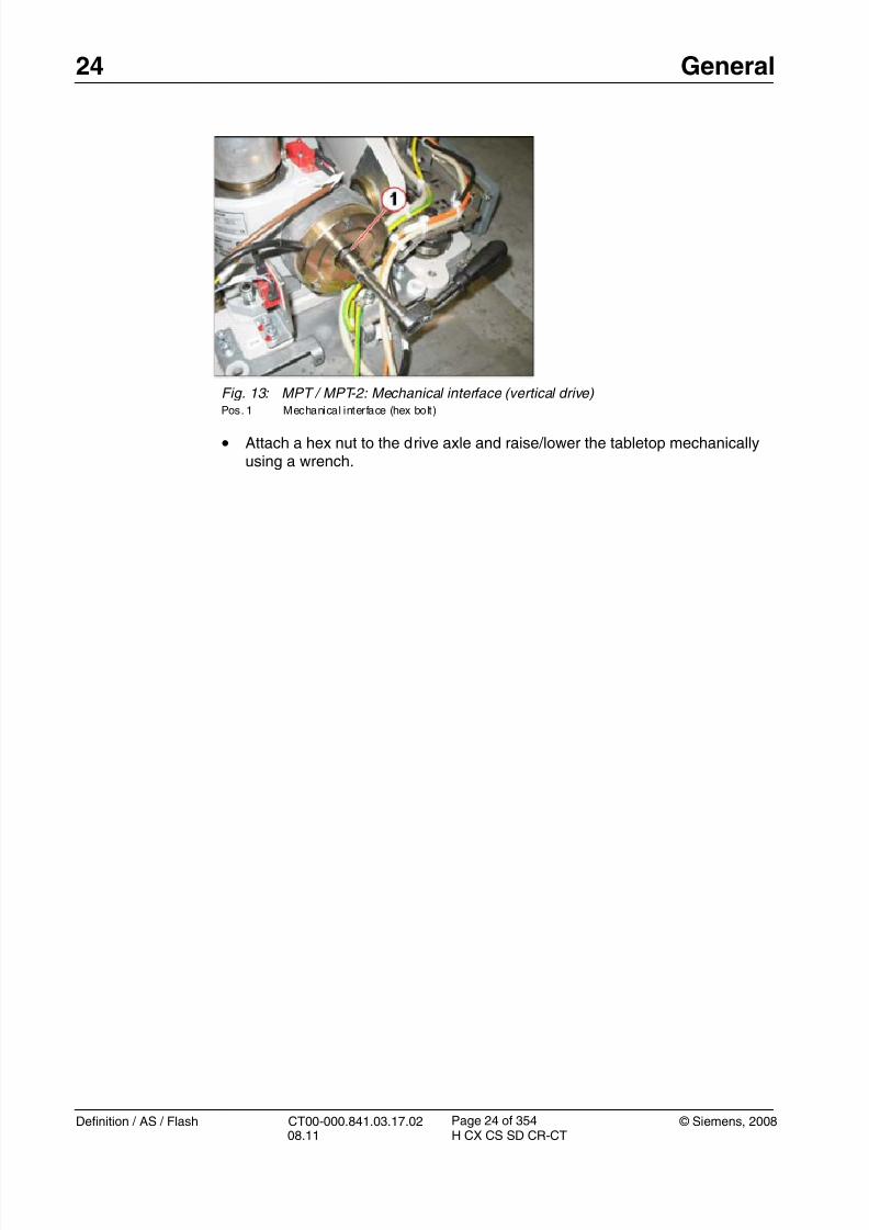
Fig. 13: MPT / MPT-2: Mechanical interface (vertical drive) Pos. 1 Mechanical interface (hex bolt)
• Attach a hex nut to the drive axle and raise/lower the tabletop mechanicallyusing a wrench.

8/12/2019 CT00-000.841.03.17.02.pdf
http://slidepdf.com/reader/full/ct00-000841031702pdf 25/353
© Siemens, 2008 CT00-000.841.03.17.02 Definition / AS / Flash08.11 H CX CS SD CR-CT
General 25
Page 25 of 354
Manual horizontal movement of tabletop 1.6
Manual horizontal movement of the tabletop is possible under the following conditions:
• Power to patient table or system has been switched OFF
• Stop button has been pushed• One of the release switches is pushed
- Left/right foot switch at electronics cover (PHS-2/PHS-3/PHS-4) or table base(MPT/MPT-2) or left/right/rear button on top cover (PHS-1B)
- Switch cover at lower rear tabletop (not PHS-1B)
Fig. 14: PHS-2/PHS-3/PHS-4: Safety/release switches (horizontal movement) Pos. 1 Switch cover bar
Pos. 2 Foot switch (left/ right) at electronics cover
Fig. 15: MPT/MPT-2: Safety/release switches (horizontal movement) Pos. 1 Switch cover
Pos. 2 Foot switch (left/r ight)

8/12/2019 CT00-000.841.03.17.02.pdf
http://slidepdf.com/reader/full/ct00-000841031702pdf 26/353
26 General
Definition / AS / Flash CT00-000.841.03.17.02 © Siemens, 200808.11 H CX CS SD CR-CT
Page 26 of 354
Fig. 16: PHS-1B: Release button right side Fig. 17: PHS-1B: Release button rear

8/12/2019 CT00-000.841.03.17.02.pdf
http://slidepdf.com/reader/full/ct00-000841031702pdf 27/353
© Siemens, 2008 CT00-000.841.03.17.02 Definition / AS / Flash08.11 H CX CS SD CR-CT
General 27
Page 27 of 354
Tools 1.7
Normally, a standard tool set is required for performing service as described in this docu-ment. If special tools are needed, they are described in the relevant replacement descrip-tion under the “Tools” item.
NOTE Torque wrenches must be checked for accuracy on a regularbasis.

8/12/2019 CT00-000.841.03.17.02.pdf
http://slidepdf.com/reader/full/ct00-000841031702pdf 28/353
28 PHS-2/-3/-4 Covers
Definition / AS / Flash CT00-000.841.03.17.02 © Siemens, 200808.11 H CX CS SD CR-CT
Page 28 of 354
2-2PHS-2/-3/-4 Covers
Overview 0
This chapter describes the removal and replacement of the PHS covers.
Fig. 18: Table covers, overview
Covers described in this document.
• Tabletop covers (front and rear). (Not shown) These are the covers below the table-
top plate covering the support. They are removed to gain access to the drive motors,tabletop belt, horizontal sensors, and horizontal controllers.
• Telescopic covers. (Item 1) These are released from the tabletop support and left atthe lowest position for most service operations, but are removed to gain access to thevertical drive components.
• Tabletop lower rear cover. (Item 2) This cover is underneath the support at the back ofthe table. It is removed to gain access to the support belt and for greater access to thesupport components.
• Front and back end covers. (Item 3) These are at each end of the side covers.
• Switchplate cover. (Item 4) These are at each end of the side covers.
• Side support (left/right). (Item 5) These are the aluminum covers on each side of thetabletop. They are normally only removed and replaced if damaged.
• Table electronics cover. (Item 6) This is removed to gain access to the components inthe electronics tray.

8/12/2019 CT00-000.841.03.17.02.pdf
http://slidepdf.com/reader/full/ct00-000841031702pdf 29/353
© Siemens, 2008 CT00-000.841.03.17.02 Definition / AS / Flash08.11 H CX CS SD CR-CT
PHS-2/-3/-4 Covers 29
Page 29 of 354
Tabletop covers (front and rear) 2.1
• The following instructions are applicable to:
- Tabletop cover (front)
- Tabletop cover (rear)
Preliminary steps 0
1. Raise the patient table to a height of 125.
2. Switch system to COMP/ON at the control box.
3. Switch OFF the gantry/PHS power using service push-button S1 in the PDC.
Secure the circuit breakers that S1 switched OFF against unintended switch-on(e.g. lock and tag).
NOTE Read and observe the safety information in the “Prod-uct-specific safety notes” prior to performing service work on the patient table. If the patient table power is switched offfor service work, always secure it against accidentalswitch-on.
4. Push table in to the end stop.
5. Remove the switchplate cover (Front and rear end covers / switchplate cover / p. 40).
Prerequisites 0
Safety
WARNING [ hz_serdoc_F13G01U12M03 ]
Avoid accident and injury or damage to parts.
Risk of accident and injury!
Read and observe the safety information contained inthe “General” section of this document and/or the
“Product specific safety notes”.
Time and Manpower
• 1 person
• Estimated total repair time: 15 min.
Tools and auxiliary equipment
• Standard service kit

8/12/2019 CT00-000.841.03.17.02.pdf
http://slidepdf.com/reader/full/ct00-000841031702pdf 30/353
30 PHS-2/-3/-4 Covers
Definition / AS / Flash CT00-000.841.03.17.02 © Siemens, 200808.11 H CX CS SD CR-CT
Page 30 of 354
Removing 0
1. Remove the rear tabletop cover:
2. Remove the front tabletop cover
Fig. 19: Top cover screws
• The rear cover is secured by 6 screws.
• Remove all 6 screws and lift the cover away while unplugging theground connector.
Fig. 20: Cover plate - old version Fig. 21: Cover plate - new version

8/12/2019 CT00-000.841.03.17.02.pdf
http://slidepdf.com/reader/full/ct00-000841031702pdf 31/353
© Siemens, 2008 CT00-000.841.03.17.02 Definition / AS / Flash08.11 H CX CS SD CR-CT
PHS-2/-3/-4 Covers 31
Page 31 of 354
- The front cover has another cover plate attached at the front.
- Remove the front-end covers (Front and rear end covers / switchplate cover / p. 40) and the cover plate securing screws (item 1) from underneath the tabletop plate, andslide the cover plate out in a forward motion.
NOTE Beginning with delivery in June 2009, the cover plate is fixedwith 5 screws instead of 3.
- Remove the 6 securing screws (similar to back top cover) and slide the top cover outtoward the back while unplugging the ground connector.
Installation 0
1. Replace the covers and ground connectors and install the screws.
Startup 0
Electrical
1. Switch on circuit breakers F2, F3, F5, F6, F7, and F11 in the PDC A and F2 in the PDCB (not for Definition AS).
First switch the F2, F3, F5, F6 circuit breakers to the “0” position and then to the“1” position.
2. Switch the system to the SYSTEM/ON status at the control box.
Software
n.a
Tune-up
n.a
Tests
1. Perform a test scan
Final Steps 0
1. Clean.

8/12/2019 CT00-000.841.03.17.02.pdf
http://slidepdf.com/reader/full/ct00-000841031702pdf 32/353
32 PHS-2/-3/-4 Covers
Definition / AS / Flash CT00-000.841.03.17.02 © Siemens, 200808.11 H CX CS SD CR-CT
Page 32 of 354
Tabletop lower rear cover 2.2
• The following instruction is applicable for:
- Lower cover, material number 86 14 690
Prerequisites 0
Safety
WARNING [ hz_serdoc_F13G01U12M03 ]
Avoid accident and injury or damage to parts.
Risk of accident and injury!
Read and observe the safety information contained in
the “General” section of this document and/or the“Product specific safety notes”.
Time and Manpower
• 1 person
• Estimated total repair time: 15 min.
Tools and auxiliary equipment
•
Standard service kit
Preliminary steps 0
1. Raise the patient table to height of 125.
2. Switch system toCOMP/ON at the control box.
3. Switch OFF the gantry/PHS power using service push-button S1 in the PDC.
Secure the circuit breakers that S1 switched OFF against unintended switch-on(e.g. lock and tag).
NOTE Read and observe the safety information in the “Prod-uct-specific safety notes” prior to performing service work on the patient table. If the patient table power is switched offfor service work, always secure it against accidentalswitch-on.

8/12/2019 CT00-000.841.03.17.02.pdf
http://slidepdf.com/reader/full/ct00-000841031702pdf 33/353
© Siemens, 2008 CT00-000.841.03.17.02 Definition / AS / Flash08.11 H CX CS SD CR-CT
PHS-2/-3/-4 Covers 33
Page 33 of 354
Removing 0
1. Remove the lower rear cover.
Installation 0
1. Replace cover and install screws.
Startup 0
Electrical
1. Switch on circuit breakers F2, F3, F5, F6, F7, and F11 in the PDC A and F2 in the PDCB (not for Definition AS).
First switch the F2, F3, F5, F6 circuit breakers to the “0” position and then to the“1” position.
2. Switch the system to the SYSTEM/ON status at the control box.
Fig. 22: Back bottom cover
• Pull the support fully out of gantry to gain access to the fasteners.
• The back lower cover is secured by 6 screws (Item 1), remove themand take the cover away.

8/12/2019 CT00-000.841.03.17.02.pdf
http://slidepdf.com/reader/full/ct00-000841031702pdf 34/353

8/12/2019 CT00-000.841.03.17.02.pdf
http://slidepdf.com/reader/full/ct00-000841031702pdf 35/353
© Siemens, 2008 CT00-000.841.03.17.02 Definition / AS / Flash08.11 H CX CS SD CR-CT
PHS-2/-3/-4 Covers 35
Page 35 of 354
Side support (left/right) 2.3
• The following instruction is applicable for:
- Side support (left/right), material number 86 14 542
Prerequisites 0
Safety
WARNING [ hz_serdoc_F13G01U12M03 ]
Avoid accident and injury or damage to parts.
Risk of accident and injury!
Read and observe the safety information contained in
the “General” section of this document and/or the“Product specific safety notes”.
Time and Manpower
• 1 person
• Estimated total repair time: 45 min.
Tools and auxiliary equipment
•
Standard service kit
Preliminary steps 0
1. Raise the patient table to height of 125.
2. Switch system to COMP/ON at the control box.
3. Switch OFF the gantry/PHS power using service push-button S1 in the PDC.
Secure the circuit breakers that S1 switched OFF against unintended switch-on(e.g. lock and tag).
NOTE Read and observe the safety information in the “Prod-uct-specific safety notes” prior to performing service work on the patient table. If the patient table power is switched offfor service work, always secure it against accidentalswitch-on.
4. Remove the front and back end covers and back switchplate (Front and rear end cov-ers / switchplate cover / p. 40)
.

8/12/2019 CT00-000.841.03.17.02.pdf
http://slidepdf.com/reader/full/ct00-000841031702pdf 36/353
36 PHS-2/-3/-4 Covers
Definition / AS / Flash CT00-000.841.03.17.02 © Siemens, 200808.11 H CX CS SD CR-CT
Page 36 of 354
Removing 0
1. Measure side support distance from frame.
2. Remove standoff and support.
Fig. 23: Distance measurement
• Check the distance from the frame to the side support at the back ofthe table. It should be approximately 18 mm (Item 1).
Fig. 24: Standoff
• At the front of the cover, remove the standoff (Item 1).

8/12/2019 CT00-000.841.03.17.02.pdf
http://slidepdf.com/reader/full/ct00-000841031702pdf 37/353
© Siemens, 2008 CT00-000.841.03.17.02 Definition / AS / Flash08.11 H CX CS SD CR-CT
PHS-2/-3/-4 Covers 37
Page 37 of 354
3. Remove the side support.
Fig. 25: Side cover securing screws • From inside the frame, remove the 6 screws (e.g. Item 1) securing the
side cover. The tabletop will have to be moved in and out to gainaccess to all screws.
• Start with the front screws followed by the back screws, leaving thecenter screws until last.
• After pushing the tabletop plate fully inward to its limit, hold the sidecover in place with your body while removing the last screw, and thenlift the cover away.

8/12/2019 CT00-000.841.03.17.02.pdf
http://slidepdf.com/reader/full/ct00-000841031702pdf 38/353

8/12/2019 CT00-000.841.03.17.02.pdf
http://slidepdf.com/reader/full/ct00-000841031702pdf 39/353
© Siemens, 2008 CT00-000.841.03.17.02 Definition / AS / Flash08.11 H CX CS SD CR-CT
PHS-2/-3/-4 Covers 39
Page 39 of 354
Software
n.a
Tune-up
n.a
Tests
1. Perform a test scan
Final Steps 0
1. Clean.

8/12/2019 CT00-000.841.03.17.02.pdf
http://slidepdf.com/reader/full/ct00-000841031702pdf 40/353
40 PHS-2/-3/-4 Covers
Definition / AS / Flash CT00-000.841.03.17.02 © Siemens, 200808.11 H CX CS SD CR-CT
Page 40 of 354
Front and rear end covers / switchplate cover 2.4
• The following instruction is applicable for:
- Front cover (left), material number 86 14 559
- Front cover (right), material number 86 14 567- Rear cover (left), material number 86 14 575
- Rear cover (right), material number 86 14 583
- Switchplate cover, material number 86 14 534
Prerequisites 0
Safety
WARNING [ hz_serdoc_F13G01U12M03 ] Avoid accident and injury or damage to parts.
Risk of accident and injury!
Read and observe the safety information contained inthe “General” section of this document and/or the“Product specific safety notes”.
Time and Manpower
• 1 person
• Estimated total repair time: 15 min.
Tools and auxiliary equipment
• Standard service kit
Preliminary steps 0
1. Raise the patient table to height of 125.
2. Switch system toCOMP/ON at the control box.3. Switch OFF the gantry/PHS power using service push-button S1 in the PDC.
Secure the circuit breakers that S1 switched OFF against unintended switch-on(e.g. lock and tag).
NOTE Read and observe the safety information in the “Prod-uct-specific safety notes” prior to performing service work on the patient table. If the patient table power is switched offfor service work, always secure it against accidentalswitch-on.
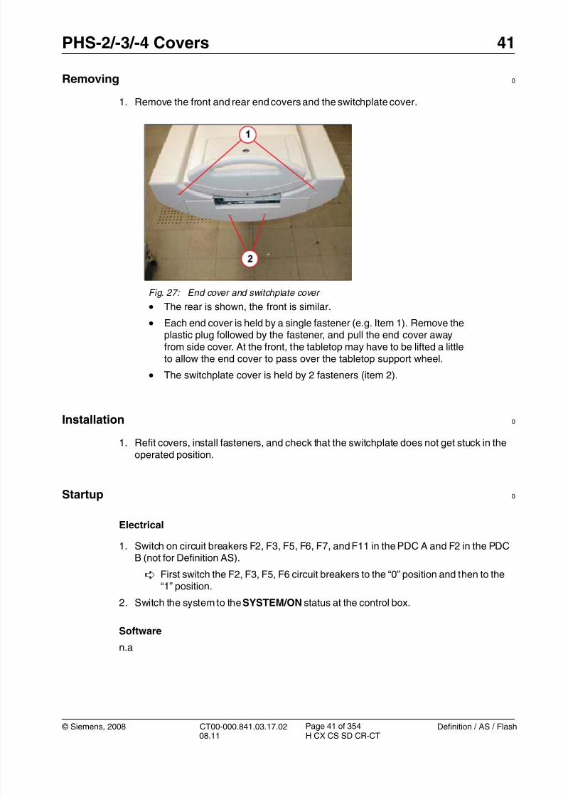
8/12/2019 CT00-000.841.03.17.02.pdf
http://slidepdf.com/reader/full/ct00-000841031702pdf 41/353
© Siemens, 2008 CT00-000.841.03.17.02 Definition / AS / Flash08.11 H CX CS SD CR-CT
PHS-2/-3/-4 Covers 41
Page 41 of 354
Removing 0
1. Remove the front and rear end covers and the switchplate cover.
Installation 0
1. Refit covers, install fasteners, and check that the switchplate does not get stuck in theoperated position.
Startup 0
Electrical
1. Switch on circuit breakers F2, F3, F5, F6, F7, and F11 in the PDC A and F2 in the PDCB (not for Definition AS).
First switch the F2, F3, F5, F6 circuit breakers to the “0” position and then to the“1” position.
2. Switch the system to the SYSTEM/ON status at the control box.
Software
n.a
Fig. 27: End cover and switchplate cover
• The rear is shown, the front is similar.
• Each end cover is held by a single fastener (e.g. Item 1). Remove theplastic plug followed by the fastener, and pull the end cover awayfrom side cover. At the front, the tabletop may have to be lifted a littleto allow the end cover to pass over the tabletop support wheel.
• The switchplate cover is held by 2 fasteners (item 2).

8/12/2019 CT00-000.841.03.17.02.pdf
http://slidepdf.com/reader/full/ct00-000841031702pdf 42/353
42 PHS-2/-3/-4 Covers
Definition / AS / Flash CT00-000.841.03.17.02 © Siemens, 200808.11 H CX CS SD CR-CT
Page 42 of 354
Tune-up
n.a
Tests
1. Perform a test scan
Final Steps 0
1. Clean.

8/12/2019 CT00-000.841.03.17.02.pdf
http://slidepdf.com/reader/full/ct00-000841031702pdf 43/353
© Siemens, 2008 CT00-000.841.03.17.02 Definition / AS / Flash08.11 H CX CS SD CR-CT
PHS-2/-3/-4 Covers 43
Page 43 of 354
Telescopic covers: Releasing 2.5
• The following instructions are applicable to:
- Top cover (left), material number 86 14 674
- Top cover (right), material number 86 14 682- Upper telescopic cover (left/right), material number 86 14 666
- Lower telescopic cover (left/right), material number 86 14 658
- PHS-2: Foot cover (left), material number 86 14 633
- PHS-2: Foot cover (right), material number 86 14 641
- PHS-3 and PHS-4: Foot cover (left), material number 86 14 617
- PHS-3 and PHS-4: Foot cover (right), material number 86 14 625
Prerequisites 0
Safety
WARNING [ hz_serdoc_F13G01U12M03 ]
Avoid accident and injury or damage to parts.
Risk of accident and injury!
Read and observe the safety information contained inthe “General” section of this document and/or the“Product specific safety notes”.
Time and Manpower
• 1 person
• Estimated total repair time: 15 min.
Tools and auxiliary equipment
• Standard service kit
Preliminary steps 0
1. Raise the patient table as it is difficult otherwise to disengage the pins from the slots.
2. Switch system to COMP/ON at the control box.
3. Switch OFF the gantry/PHS power using service push-button S1 in the PDC.
Secure the circuit breakers that S1 switched OFF against unintended switch-on(e.g. lock and tag).
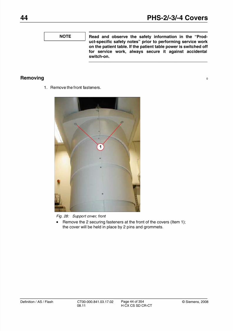
8/12/2019 CT00-000.841.03.17.02.pdf
http://slidepdf.com/reader/full/ct00-000841031702pdf 44/353
44 PHS-2/-3/-4 Covers
Definition / AS / Flash CT00-000.841.03.17.02 © Siemens, 200808.11 H CX CS SD CR-CT
Page 44 of 354
NOTE Read and observe the safety information in the “Prod-uct-specific safety notes” prior to performing service work on the patient table. If the patient table power is switched offfor service work, always secure it against accidental
switch-on.
Removing 0
1. Remove the front fasteners.
Fig. 28: Support cover, front
• Remove the 2 securing fasteners at the front of the covers (Item 1);
the cover will be held in place by 2 pins and grommets.

8/12/2019 CT00-000.841.03.17.02.pdf
http://slidepdf.com/reader/full/ct00-000841031702pdf 45/353
© Siemens, 2008 CT00-000.841.03.17.02 Definition / AS / Flash08.11 H CX CS SD CR-CT
PHS-2/-3/-4 Covers 45
Page 45 of 354
2. Remove the rear fasteners.
3. Release cover.
Fig. 29: Support cover, back
•Remove the 4 securing fasteners at the back of the covers (Item 1);the cover will be held in place by 2 pins and keyways.
Fig. 30: Pin and grommet
• Pull down the front to disengage front pins from grommet; supportweight of cover.

8/12/2019 CT00-000.841.03.17.02.pdf
http://slidepdf.com/reader/full/ct00-000841031702pdf 46/353
46 PHS-2/-3/-4 Covers
Definition / AS / Flash CT00-000.841.03.17.02 © Siemens, 200808.11 H CX CS SD CR-CT
Page 46 of 354
4. Release the pins from keyways.
Installation 0
1. Raise the table.
2. Position the back pins into the keyway slots and push the cover away from the gantryuntil the front pins are over the grommets. Push cover firmly upwards to position thepins in the grommets.
3. Install the fasteners.
Fig. 31: Top cover pins
Fig. 32: Keyway slots for top cover
• Push the cover towards the gantry to disengage the back pins fromthe keyway slots.
• Lower the cover to floor.

8/12/2019 CT00-000.841.03.17.02.pdf
http://slidepdf.com/reader/full/ct00-000841031702pdf 47/353
© Siemens, 2008 CT00-000.841.03.17.02 Definition / AS / Flash08.11 H CX CS SD CR-CT
PHS-2/-3/-4 Covers 47
Page 47 of 354
Startup 0
Electrical
1. Switch on circuit breakers F2, F3, F5, F6, F7, and F11 in the PDC A and F2 in the PDCB (not for Definition AS).
First switch the F2, F3, F5, F6 circuit breakers to the “0” position and then to the“1” position.
2. Switch the system to the SYSTEM/ON status at the control box.
Software
n.a
Tune-up
n.a
Tests
1. Raise and lower the table to check that covers are not rubbing against one another, per-form a test scan.
Final Steps 0
1. Clean.

8/12/2019 CT00-000.841.03.17.02.pdf
http://slidepdf.com/reader/full/ct00-000841031702pdf 48/353
48 PHS-2/-3/-4 Covers
Definition / AS / Flash CT00-000.841.03.17.02 © Siemens, 200808.11 H CX CS SD CR-CT
Page 48 of 354
Telescopic covers: Raising with the help of the belt 2.6
Prerequisites 0
Safety
WARNING [ hz_serdoc_F13G01U12M03 ]
Avoid accident and injury or damage to parts.
Risk of accident and injury!
Read and observe the safety information contained inthe “General” section of this document and/or the“Product specific safety notes”.
Time and manpower
• 1 person
• Estimated total repair time: 15 min.
Tools and auxiliary equipment
• Standard service kit
• Belt, material no. 7068521
Preliminary steps 0
1. Move the patient table to the lowest position.
2. Remove the electronics cover as described in (Table electronics cover / p. 57).

8/12/2019 CT00-000.841.03.17.02.pdf
http://slidepdf.com/reader/full/ct00-000841031702pdf 49/353
© Siemens, 2008 CT00-000.841.03.17.02 Definition / AS / Flash08.11 H CX CS SD CR-CT
PHS-2/-3/-4 Covers 49
Page 49 of 354
Removal 0
1. Remove the screws of the left and right foot cover.
2. Place the belt around the table as shown below.
Carefully lift up the table.
3. Switch the system to COMP/ON at the control box.
4. Switch OFF the gantry/PHS power using service push-button S1 in the PDC. Secure against unintended switch-on the circuit breakers that S1 switched OFF
(e.g. lock and tag).
NOTE Read and observe the safety guidelines in the “Product-spe-cific safety notes” prior to performing service work on thepatient table. If the patient table power is switched off for ser-vice work, always secure it against accidental switch-on.
Fig. 33: Foot cover, attachment screw Fig. 34: Foot cover, gantry side, attachmentscrew
Fig. 35: Lifting cover, side view Fig. 36: Lifting cover, front view

8/12/2019 CT00-000.841.03.17.02.pdf
http://slidepdf.com/reader/full/ct00-000841031702pdf 50/353
50 PHS-2/-3/-4 Covers
Definition / AS / Flash CT00-000.841.03.17.02 © Siemens, 200808.11 H CX CS SD CR-CT
Page 50 of 354
Installation 0
1. Lower the table.
2. Align the cover pins over grommets and push the cover until all four pins are in the
proper position.
Fig. 37: Pin and grommet
3. Secure the foot cover with the attachment screws.
4. Install the electronic cover.
Startup 0
Electrical
1. Switch on circuit breakers F2, F3, F5, F6, F7, and F11 in the PDC A and F2 in the PDCB (not for Definition AS).
First switch the F2, F3, F5, F6 circuit breakers to the “0” position and then to the“1” position.
2. Switch the system to the SYSTEM/ON status at the control box.
Software
n.a.
Tune-up
n.a.

8/12/2019 CT00-000.841.03.17.02.pdf
http://slidepdf.com/reader/full/ct00-000841031702pdf 51/353

8/12/2019 CT00-000.841.03.17.02.pdf
http://slidepdf.com/reader/full/ct00-000841031702pdf 52/353
52 PHS-2/-3/-4 Covers
Definition / AS / Flash CT00-000.841.03.17.02 © Siemens, 200808.11 H CX CS SD CR-CT
Page 52 of 354
Telescopic covers: Removing 2.7
• The following instructions are applicable to:
- Top cover (left), material number 86 14 674
- Top cover (right), material number 86 14 682- Upper telescopic cover (left/right), material number 86 14 666
- Lower telescopic cover (left/right), material number 86 14 658
- PHS-2: Foot cover (left), material number 86 14 633
- PHS-2: Foot cover (right), material number 86 14 641
- PHS-3 and PHS-4: Foot cover (left), material number 86 14 617
- PHS-3 and PHS-4: Foot cover (right), material number 86 14 625
Prerequisites 0
Safety
WARNING [ hz_serdoc_F13G01U12M03 ]
Avoid accident and injury or damage to parts.
Risk of accident and injury!
Read and observe the safety information contained inthe “General” section of this document and/or the“Product specific safety notes”.
Time and Manpower
• 1 person
• Estimated total repair time: 30 min.
Tools and auxiliary equipment
• Standard service kit
Preliminary steps 0
1. Raise the table to a height of 125.
2. Release the support covers (Telescopic covers: Releasing / p. 43).
3. Switch system toCOMP/ON at the control box.
4. Switch OFF the gantry/PHS power using service push-button S1 in the PDC.
Secure the circuit breakers that S1 switched OFF against unintended switch-on(e.g. lock and tag).

8/12/2019 CT00-000.841.03.17.02.pdf
http://slidepdf.com/reader/full/ct00-000841031702pdf 53/353
© Siemens, 2008 CT00-000.841.03.17.02 Definition / AS / Flash08.11 H CX CS SD CR-CT
PHS-2/-3/-4 Covers 53
Page 53 of 354
NOTE Read and observe the safety information in the “Prod-uct-specific safety notes” prior to performing service work on the patient table. If the patient table power is switched offfor service work, always secure it against accidental
switch-on.
Removing 0
1. Remove the electronics cover (Table electronics cover / p. 57), unplug X741a andX741b, then reinstall the cover temporarily to prevent any dropped cover screws fromentering the electronics tray.
2. Remove the top cover rear screw.
Fig. 38: Top cover, extra screw
• Remove the single screw holding the back part of the upper coverstogether (Item 1).

8/12/2019 CT00-000.841.03.17.02.pdf
http://slidepdf.com/reader/full/ct00-000841031702pdf 54/353
54 PHS-2/-3/-4 Covers
Definition / AS / Flash CT00-000.841.03.17.02 © Siemens, 200808.11 H CX CS SD CR-CT
Page 54 of 354
3. Remove the telescopic covers.
4. Remove the bottom cover.
Fig. 39: Segment fasteners • The upper cover, cover 1 and cover 2 segments are all held in place
by 2 fasteners at the front and 2 at the back (e.g. Item 1).
• Remove each pair of covers in turn, starting with the top pair.
• Then remove the second pair. Mark these segments “cover 2” toidentify them during reassembly.
• Do the same for the next pair of segments, but mark as “cover 1".
Fig. 40: Bottom cover - screws
• At the front, remove 1 of the 2 fasteners at the top (Item1) and thefastener at the bottom (Item 2).
• At the back, remove 1 of the 2 fasteners at the top (Item1).
• Lift the electronics cover and disconnect plugs X741a and X741b(lower cover vertical movement foot switches).
With these plugs disconnected, all table movement is inhibited.Install the service plugs if service movement is required.

8/12/2019 CT00-000.841.03.17.02.pdf
http://slidepdf.com/reader/full/ct00-000841031702pdf 55/353
© Siemens, 2008 CT00-000.841.03.17.02 Definition / AS / Flash08.11 H CX CS SD CR-CT
PHS-2/-3/-4 Covers 55
Page 55 of 354
5. Lift off the bottom cover.
Installation 0
1. Installation is the reverse of removal. Keep electronics cover in place to preventdropped screws from entering the electronics tray.
2. Telescopic covers 1 and 2 should be installed with the larger lip toward the top.
Startup 0
Electrical
1. Switch on circuit breakers F2, F3, F5, F6, F7, and F11 in the PDC A and F2 in the PDCB (not for Definition AS).
First switch the F2, F3, F5, F6 circuit breakers to the “0” position and then to the“1” position.
2. Switch the system to the SYSTEM/ON status at the control box.
Software
n.a
Tune-up
n.a
Fig. 41: Pin and grommet • The bottom cover is held by 4 pins and grommets, pull the covers
upwards and take away.

8/12/2019 CT00-000.841.03.17.02.pdf
http://slidepdf.com/reader/full/ct00-000841031702pdf 56/353
56 PHS-2/-3/-4 Covers
Definition / AS / Flash CT00-000.841.03.17.02 © Siemens, 200808.11 H CX CS SD CR-CT
Page 56 of 354
Tests
1. Raise and lower table to check for rubbing, perform a test scan.
Final Steps 0
1. Clean.

8/12/2019 CT00-000.841.03.17.02.pdf
http://slidepdf.com/reader/full/ct00-000841031702pdf 57/353
© Siemens, 2008 CT00-000.841.03.17.02 Definition / AS / Flash08.11 H CX CS SD CR-CT
PHS-2/-3/-4 Covers 57
Page 57 of 354
Table electronics cover 2.8
• The following instructions are applicable to:
- Electronics cover, material number 86 14 609
Prerequisites 0
Safety
WARNING [ hz_serdoc_F13G01U12M03 ]
Avoid accident and injury or damage to parts.
Risk of accident and injury!
Read and observe the safety information contained in
the “General” section of this document and/or the“Product specific safety notes”.
Time and Manpower
• 1 person
• Estimated total repair time: 10 min.
Tools and auxiliary equipment
•
Standard service kit
Preliminary steps 0
1. Raise the patient table to height of 125.
2. Switch system to COMP/ON at the control box.
3. Switch OFF the gantry/PHS power using service push-button S1 in the PDC.
Secure the circuit breakers that S1 switched OFF against unintended switch-on(e.g. lock and tag).
NOTE Read and observe the safety information in the “Prod-uct-specific safety notes” prior to performing service work on the patient table. If the patient table power is switched offfor service work, always secure it against accidentalswitch-on.

8/12/2019 CT00-000.841.03.17.02.pdf
http://slidepdf.com/reader/full/ct00-000841031702pdf 58/353
58 PHS-2/-3/-4 Covers
Definition / AS / Flash CT00-000.841.03.17.02 © Siemens, 200808.11 H CX CS SD CR-CT
Page 58 of 354
Removing 0
1. Remove the securing screws.
2. Remove the cover.
Fig. 42: Electronics cover
• Remove the 2 securing screws located on the sides of the cover (e.g.Item 1).
Fig. 43: Pin and grommet
• The cover is held by 4 pins and grommets; lift the cover to disengagepins.
• Unplug X751a and X751b before taking the cover away.
With these plugs disconnected, all table movement is inhibited.Install the service plugs if service movement is required.

8/12/2019 CT00-000.841.03.17.02.pdf
http://slidepdf.com/reader/full/ct00-000841031702pdf 59/353

8/12/2019 CT00-000.841.03.17.02.pdf
http://slidepdf.com/reader/full/ct00-000841031702pdf 60/353
60 PHS-2/-3/-4 Mechanical
Definition / AS / Flash CT00-000.841.03.17.02 © Siemens, 200808.11 H CX CS SD CR-CT
Page 60 of 354
3-3PHS-2/-3/-4 Mechanical
Overview 0
This chapter describes the removal and replacement of the PHS mechanical components.
Fig. 44: PHS mechanical overview Components described in this document:
• Tabletop plate (Item 2).
• Horizontal drive motors (Item 1) Both the tabletop plate and top support drive motorsare described.
• Vertical drive motor assembly (Item 3).
• Horizontal drive belts. Both tabletop plate and top support drive belts are described.
• Position sensors (Item 5) Tabletop wire sensor, support magnetic sensor, and verti-cal position sensor.
• Vertical microswitches (Item 6) Upper and lower limit switches and vertical connectare described. The safety nut switch is not a field replaceable item.

8/12/2019 CT00-000.841.03.17.02.pdf
http://slidepdf.com/reader/full/ct00-000841031702pdf 61/353
© Siemens, 2008 CT00-000.841.03.17.02 Definition / AS / Flash08.11 H CX CS SD CR-CT
PHS-2/-3/-4 Mechanical 61
Page 61 of 354
Tabletop plate 3.1
• The following instructions are applicable to:
- PHS tabletop plate, material number 86 14 302
Prerequisites 0
Safety
WARNING [ hz_serdoc_F13G01U12M03 ]
Avoid accident and injury or damage to parts.
Risk of accident and injury!
Read and observe the safety information contained in
the “General” section of this document and/or the“Product specific safety notes”.
Time and Manpower
• 1 person
• Estimated total repair time: 1 hr.
Tools and auxiliary equipment
•
Standard service kit• Loctite 243
Preliminary steps 0
1. Raise the patient table to height of 125.
2. Switch system to COMP/ON at the control box.
3. Switch OFF the gantry/PHS power using service push-button S1 in the PDC.
Secure the circuit breakers that S1 switched OFF against unintended switch-on
(e.g. lock and tag).
NOTE Read and observe the safety information in the “Prod-uct-specific safety notes” prior to performing service work on the patient table. If the patient table power is switched offfor service work, always secure it against accidentalswitch-on.
4. Remove the rear tabletop cover (Tabletop covers (front and rear) / p. 29).
5. Remove the lower rear tabletop cover (Tabletop lower rear cover / p. 32).
6. Remove the PMM module (PMM Module / p. 151) and release the cable from the table-top.

8/12/2019 CT00-000.841.03.17.02.pdf
http://slidepdf.com/reader/full/ct00-000841031702pdf 62/353
62 PHS-2/-3/-4 Mechanical
Definition / AS / Flash CT00-000.841.03.17.02 © Siemens, 200808.11 H CX CS SD CR-CT
Page 62 of 354
Removing 0
1. Remove the tabletop plate.
NOTE Due to different revision levels of the tabletop plate and thetable itself, it is possible that either the tabletop plate or thetable has ten fastener holes (instead of eight).
In this case, please leave the first pair of fastener holes onthe gantry side unused and install the tabletop plate witheight fasteners only (instead of ten).
Installation 0
1. Transfer the PMM box from old tabletop plate to the new one.
T 2. Installation is the reverse of removal. Install bolts applying Loctite 243 and check align-
ment of the tabletop plate with the frame before tightening to 6.8 Nm.
Fig. 45: Undertable view
• The tabletop plate is held by 4 pairs (older revisions: five pairs) of fas-teners which are accessible from below, in the area of the horizontal
drive motors. Five pairs are accessible at a time (see arrows).• Starting with the back pair, remove all eight fasteners (older revisions
ten fasteners), moving the tabletop plate back to gain access to eachpair in turn. <<earlier versions may have a problem with the fastenernear the sensor bracket>>
• Lift off the tabletop plate.

8/12/2019 CT00-000.841.03.17.02.pdf
http://slidepdf.com/reader/full/ct00-000841031702pdf 63/353
8/12/2019 CT00-000.841.03.17.02.pdf
http://slidepdf.com/reader/full/ct00-000841031702pdf 64/353
64 PHS-2/-3/-4 Mechanical
Definition / AS / Flash CT00-000.841.03.17.02 © Siemens, 200808.11 H CX CS SD CR-CT
Page 64 of 354
Horizontal drive, tabletop 3.2
• The following instructions are applicable to:
- PHS horizontal drive motor, material numbers 86 14 344 (PHS-2 and PHS-3) and 8618 386 (PHS-4)
NOTE The horizontal drive is delivered as a set with the drive pulleyand the jaw spanner. We recommend replacing the drive pul-ley together with the motor.
Prerequisites 0
Safety
WARNING [ hz_serdoc_F13G01U12M03 ]
Avoid accident and injury or damage to parts.
Risk of accident and injury!
Read and observe the safety information contained inthe “General” section of this document and/or the“Product specific safety notes”.
Time and Manpower
• 1 person
• Estimated total repair time: 1 hr.
Tools and auxiliary equipment
• Standard service kit
Preliminary steps 0
1. Raise table to height of 125.
2. Switch system toCOMP/ON at the control box.
3. Switch OFF the gantry/PHS power using service push-button S1 in the PDC.
Secure the circuit breakers that S1 switched OFF against unintended switch-on(e.g. lock and tag).

8/12/2019 CT00-000.841.03.17.02.pdf
http://slidepdf.com/reader/full/ct00-000841031702pdf 65/353
© Siemens, 2008 CT00-000.841.03.17.02 Definition / AS / Flash08.11 H CX CS SD CR-CT
PHS-2/-3/-4 Mechanical 65
Page 65 of 354
NOTE Read and observe the safety information in the “Prod-uct-specific safety notes” prior to performing service work on the patient table. If the patient table power is switched offfor service work, always secure it against accidental
switch-on.
4. Release the telescopic covers (Telescopic covers: Releasing / p. 43).
5. Remove the lower rear tabletop cover (Tabletop lower rear cover / p. 32).
6. Feed in the table and remove the tabletop covers (Tabletop covers (front andrear) / p. 29).

8/12/2019 CT00-000.841.03.17.02.pdf
http://slidepdf.com/reader/full/ct00-000841031702pdf 66/353
66 PHS-2/-3/-4 Mechanical
Definition / AS / Flash CT00-000.841.03.17.02 © Siemens, 200808.11 H CX CS SD CR-CT
Page 66 of 354
Removing 0
1. Release cables.

8/12/2019 CT00-000.841.03.17.02.pdf
http://slidepdf.com/reader/full/ct00-000841031702pdf 67/353
© Siemens, 2008 CT00-000.841.03.17.02 Definition / AS / Flash08.11 H CX CS SD CR-CT
PHS-2/-3/-4 Mechanical 67
Page 67 of 354

8/12/2019 CT00-000.841.03.17.02.pdf
http://slidepdf.com/reader/full/ct00-000841031702pdf 68/353
68 PHS-2/-3/-4 Mechanical
Definition / AS / Flash CT00-000.841.03.17.02 © Siemens, 200808.11 H CX CS SD CR-CT
Page 68 of 354
For PHS-2 and PHS-3 only:
Fig. 46: View of back
• At the back of the table, remove plug X3 of the tabletop motor con-
troller (Item1) by pulling the connector. Pull connector X2 from theother end of the controller and remove the 2 wires to the drive motorfrom pins 1 and 3.
• Disconnect plug X731/X732 (item 3).
• Cut all cable ties and remove cable clamps to release all cables to thedrive motor.
For PHS-4 only:
Fig. 47: PHS -4: View from below • Disconnect the cables on the horizontal drive

8/12/2019 CT00-000.841.03.17.02.pdf
http://slidepdf.com/reader/full/ct00-000841031702pdf 69/353
© Siemens, 2008 CT00-000.841.03.17.02 Definition / AS / Flash08.11 H CX CS SD CR-CT
PHS-2/-3/-4 Mechanical 69
Page 69 of 354
2. Remove back tabletop belt adjuster.
3. Form loop in belt.
Fig. 48: Tabletop belt adjuster • At the back of the table, release the adjuster screw (item 1) and
remove the 2 fasteners holding the adjuster (item 2); lift out theadjuster.
Fig. 49: Loop in drive belt
• From underneath, pull the drive belt down to form a loop that allows
access to the drive pulley.
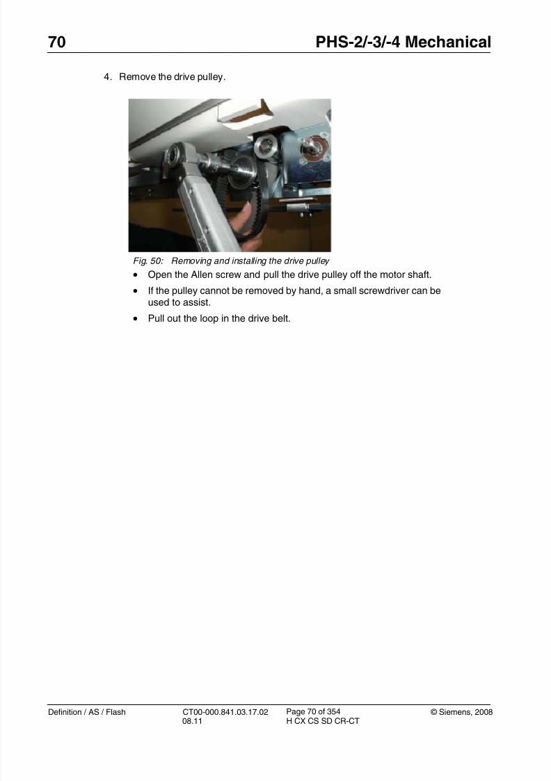
8/12/2019 CT00-000.841.03.17.02.pdf
http://slidepdf.com/reader/full/ct00-000841031702pdf 70/353
70 PHS-2/-3/-4 Mechanical
Definition / AS / Flash CT00-000.841.03.17.02 © Siemens, 200808.11 H CX CS SD CR-CT
Page 70 of 354
4. Remove the drive pulley.
Fig. 50: Removing and installing the drive pulley
• Open the Allen screw and pull the drive pulley off the motor shaft.
• If the pulley cannot be removed by hand, a small screwdriver can beused to assist.
• Pull out the loop in the drive belt.

8/12/2019 CT00-000.841.03.17.02.pdf
http://slidepdf.com/reader/full/ct00-000841031702pdf 71/353
© Siemens, 2008 CT00-000.841.03.17.02 Definition / AS / Flash08.11 H CX CS SD CR-CT
PHS-2/-3/-4 Mechanical 71
Page 71 of 354
5. Remove the drive.
Installation 0
1. Transfer connector X3 from the old drive to the new one. T 2. Install the motor and secure with 4 screws/nuts.
For PHS-2 and PHS-3: Tighten to 3 Nm.
For PHS-4: Tighten to 5 Nm.
3. Install all connectors, including pins 1 and 2 of X2.
Fig. 51: Drive motor securing screws - PHS-2, PHS-3
Fig. 52: Drive motor (table top) securing screws - PHS-4
• Remove the 4 nuts (Item 1) holding drive motor to frame, lift away thedrive motor.

8/12/2019 CT00-000.841.03.17.02.pdf
http://slidepdf.com/reader/full/ct00-000841031702pdf 72/353
72 PHS-2/-3/-4 Mechanical
Definition / AS / Flash CT00-000.841.03.17.02 © Siemens, 200808.11 H CX CS SD CR-CT
Page 72 of 354
4. Push the drive pulley onto the motor shaft together with the jaw spanner.
NOTE The jaw spanner will be used
1. as a spacer between the drive pulley and the motor box
2. as opposite support
T5. Fasten the drive pulley with the following torque:
PHS-2 and PHS-3: 35 Nm
PHS -4: 65 Nm
(Fig. 50 / p. 70).
6. Pull out the drive belt loop and reinstall the back adjuster, check that the drive belt islocated properly in the drive pulley.
7. Adjust the drive belt tension to 52 +2 Hz using the belt tension meter. The procedure isdescribed in (Installation / p. 95).
8. Install wires into X2 pins 1,3, then plug X2 and X3 into the controller and install plugX731/X732. Install clamps and cable ties.
9. Reinstall all covers.
Startup 0
Electrical
1. Switch on circuit breakers F2, F3, F5, F6, F7, and F11 in the PDC A and F2 in the PDCB (not for Definition AS).
First switch the F2, F3, F5, F6 circuit breakers to the “0” position and then to the
“1” position.
Fig. 53: Installing the drive pulley Pos. 1 Drive pulley for tabletop
Pos. 2 Jaw spanner
Pos. 3 Horizontal motor for top support

8/12/2019 CT00-000.841.03.17.02.pdf
http://slidepdf.com/reader/full/ct00-000841031702pdf 73/353
© Siemens, 2008 CT00-000.841.03.17.02 Definition / AS / Flash08.11 H CX CS SD CR-CT
PHS-2/-3/-4 Mechanical 73
Page 73 of 354
2. Switch the system to the SYSTEM/ON status at the control box.
Software
n.a
Tune-up
1. Perform PHS calibration for tabletop.
Tests
1. Perform a test scan
Final Steps 0
1. Clean.

8/12/2019 CT00-000.841.03.17.02.pdf
http://slidepdf.com/reader/full/ct00-000841031702pdf 74/353
74 PHS-2/-3/-4 Mechanical
Definition / AS / Flash CT00-000.841.03.17.02 © Siemens, 200808.11 H CX CS SD CR-CT
Page 74 of 354
Horizontal drive, top support (PHS-3 and PHS-4 only) 3.3
• The following instructions are applicable to:
- PHS horizontal drive motor, material number 86 18 394
NOTE The horizontal drive is delivered as a set with the drive pulleyand the jaw spanner. We recommend replacing the drive pul-ley together with the motor.
Prerequisites 0
Safety
WARNING [ hz_serdoc_F13G01U12M03 ]
Avoid accident and injury or damage to parts.
Risk of accident and injury!
Read and observe the safety information contained inthe “General” section of this document and/or the“Product specific safety notes”.
Time and Manpower
• 1 person
• Estimated total repair time: 45 min.
Tools and auxiliary equipment
• Standard service kit
Preliminary steps 0
1. Raise table to height of 125.
2. Switch system toCOMP/ON at the control box.
3. Switch OFF the gantry/PHS power using service push-button S1 in the PDC.
Secure the circuit breakers that S1 switched OFF against unintended switch-on(e.g. lock and tag).
NOTE Read and observe the safety information in the “Prod-uct-specific safety notes” prior to performing service work on the patient table. If the patient table power is switched offfor service work, always secure it against accidentalswitch-on.

8/12/2019 CT00-000.841.03.17.02.pdf
http://slidepdf.com/reader/full/ct00-000841031702pdf 75/353
© Siemens, 2008 CT00-000.841.03.17.02 Definition / AS / Flash08.11 H CX CS SD CR-CT
PHS-2/-3/-4 Mechanical 75
Page 75 of 354
4. Release the telescopic covers (Telescopic covers: Releasing / p. 43).
5. Remove the lower rear tabletop cover (Tabletop lower rear cover / p. 32).
6. Feed in the table and remove the tabletop covers (Tabletop covers (front andrear) / p. 29).
Removing 0
1. Release cables.
Fig. 54: View of back
• At the back of the table, remove plug X3 of the support motor control-ler (Item2) by pulling the connector. Pull connector X2 from the otherend of the controller and remove pins 1 and 3.
• Disconnect plug X731/X732 (item 4).
• Cut all cable ties and remove cable clamps to release cables to thedrive motor.

8/12/2019 CT00-000.841.03.17.02.pdf
http://slidepdf.com/reader/full/ct00-000841031702pdf 76/353
76 PHS-2/-3/-4 Mechanical
Definition / AS / Flash CT00-000.841.03.17.02 © Siemens, 200808.11 H CX CS SD CR-CT
Page 76 of 354
2. Remove the adjuster.
3. Remove the drive pulley.
Fig. 55: Support belt adjuster • Release locknut (item 1), loosen clamping bolt (Item 2), and unscrew
the adjuster to release tension on the belt.
• Continue unscrewing the adjuster until the bracket can be removedfrom the frame.
• The procedure to remove the drive pulley for the top support is iden-tical to the procedure for the drive pulley of the tabletop described in(Removing / p. 66)
Fig. 56: Drive pulley of top support Pos. 1 Drive pulley for top support
Pos. 2 Mounting screw
Pos. 3 Drive pulley for tabletop

8/12/2019 CT00-000.841.03.17.02.pdf
http://slidepdf.com/reader/full/ct00-000841031702pdf 77/353
© Siemens, 2008 CT00-000.841.03.17.02 Definition / AS / Flash08.11 H CX CS SD CR-CT
PHS-2/-3/-4 Mechanical 77
Page 77 of 354
4. Remove the drive motor.
Installation 0
1. Transfer connector X3 from the old drive to the new one.
T 2. Install motor and secure with 4 screws. Tighten to 3 Nm.
3. Install pulley on motor shaft. The procedure is the same as for the drive pulley of thetabletop described in (Installation / p. 71)
4. Reinstall and adjust the support drive belt to 70 +2 Hz using the belt tension meter. Theprocedure is described in (Installation / p. 100).
5. Install wires into X2 pins 1 and 3, then plug X2 and X3 into controller and install plugX731/X732. Install clamps and cable ties.
Startup 0
Electrical
1. Switch on circuit breakers F2, F3, F5, F6, F7, and F11 in the PDC A and F2 in the PDCB (not for Definition AS).
First switch the F2, F3, F5, F6 circuit breakers to the “0” position and then to the“1” position.
2. Switch the system to the SYSTEM/ON status at the control box.
Software
n.a
Fig. 57: Drive motor securing screws • Remove the 4 fasteners and take the drive motor away.

8/12/2019 CT00-000.841.03.17.02.pdf
http://slidepdf.com/reader/full/ct00-000841031702pdf 78/353
78 PHS-2/-3/-4 Mechanical
Definition / AS / Flash CT00-000.841.03.17.02 © Siemens, 200808.11 H CX CS SD CR-CT
Page 78 of 354
Tune-up
1. Perform the PHS calibration for top support.
Tests
1. Perform a test scan
Final Steps 0
1. Clean.

8/12/2019 CT00-000.841.03.17.02.pdf
http://slidepdf.com/reader/full/ct00-000841031702pdf 79/353
© Siemens, 2008 CT00-000.841.03.17.02 Definition / AS / Flash08.11 H CX CS SD CR-CT
PHS-2/-3/-4 Mechanical 79
Page 79 of 354
Vertical drive 3.4
• The following instructions are applicable to:
- PHS vertical drive, material number 86 14 427 (valid for software <VA20)
- PHS vertical drive, material number 86 14 294 (valid for software VA20 andonwards)
Prerequisites 0
Safety
WARNING [ hz_serdoc_F13G01U12M03 ]
Avoid accident and injury or damage to parts.
Risk of accident and injury!
Read and observe the safety information contained inthe “General” section of this document and/or the“Product specific safety notes”.
Time and Manpower
• 1 person
• Estimated total repair time: 1 1/2 hours.
Tools and auxiliary equipment
• Standard service kit
• Loctite 243
• 12 mm + 14mm hex key socket
• Mallet•
Fig. 58: A "mallet" is a type of hammer with a head made of softer material.

8/12/2019 CT00-000.841.03.17.02.pdf
http://slidepdf.com/reader/full/ct00-000841031702pdf 80/353
80 PHS-2/-3/-4 Mechanical
Definition / AS / Flash CT00-000.841.03.17.02 © Siemens, 200808.11 H CX CS SD CR-CT
Page 80 of 354
Preliminary steps 0
1. Raise table to height of 125.
2. Switch off the system (Click <SYSTEM> and select <Shutdown> in the user main
menu; this switches off the system automatically after shut down).3. Switch off the gantry power using service push-button S1 in PDC A. Secure against
unintended switch-on.
4. Release the telescopic covers (Telescopic covers: Releasing / p. 43).
5. Remove the telescopic covers (Telescopic covers: Removing / p. 52).
Removing 0
1. Remove the cables:-
- U711_X7 at the vertical motor controller.- U711_X3 at the vertical motor controller.
- U711_X1, wires U,V,W, and PE at the vertical motor controller.
- M700_X711 at electronics tray.
- Cut all cable ties to release motor cables.
2. Disconnect microswitches.
Fig. 59: Disconnect and safety nut switches
• Remove the bracket and “connect” microswitch (S718) (Item 3) andlay the switch and bracket aside.
• Remove connections S717SC, S717C at the safety nut microswitch(S717) (Item 2) mounted on the drive motor spindle.

8/12/2019 CT00-000.841.03.17.02.pdf
http://slidepdf.com/reader/full/ct00-000841031702pdf 81/353
© Siemens, 2008 CT00-000.841.03.17.02 Definition / AS / Flash08.11 H CX CS SD CR-CT
PHS-2/-3/-4 Mechanical 81
Page 81 of 354
3. Install the safety bolts.
4. Lower the table onto the safety bolts.
Fig. 60: Vertical safety bolts • Remove safety bolts from the storage position (Item 1) and install into
vertical lock position (Item 2) using the 14mm hex key.
Fig. 61: Vertical drive motor securing screws
• Using a 6 mm hex key, lower the table by turning the manual lift screw( Item 1 ) counterclockwise until the weight of the table is taken by thesafety bolts. Continue until the bottom of the drive rises 1-2 mm offthe base plate (Item 2).
• Remove the 3 securing bolts (Item 3). Note that the heads areapproximately 8 mm high to allow some freedom of vertical move-
ment for the drive.
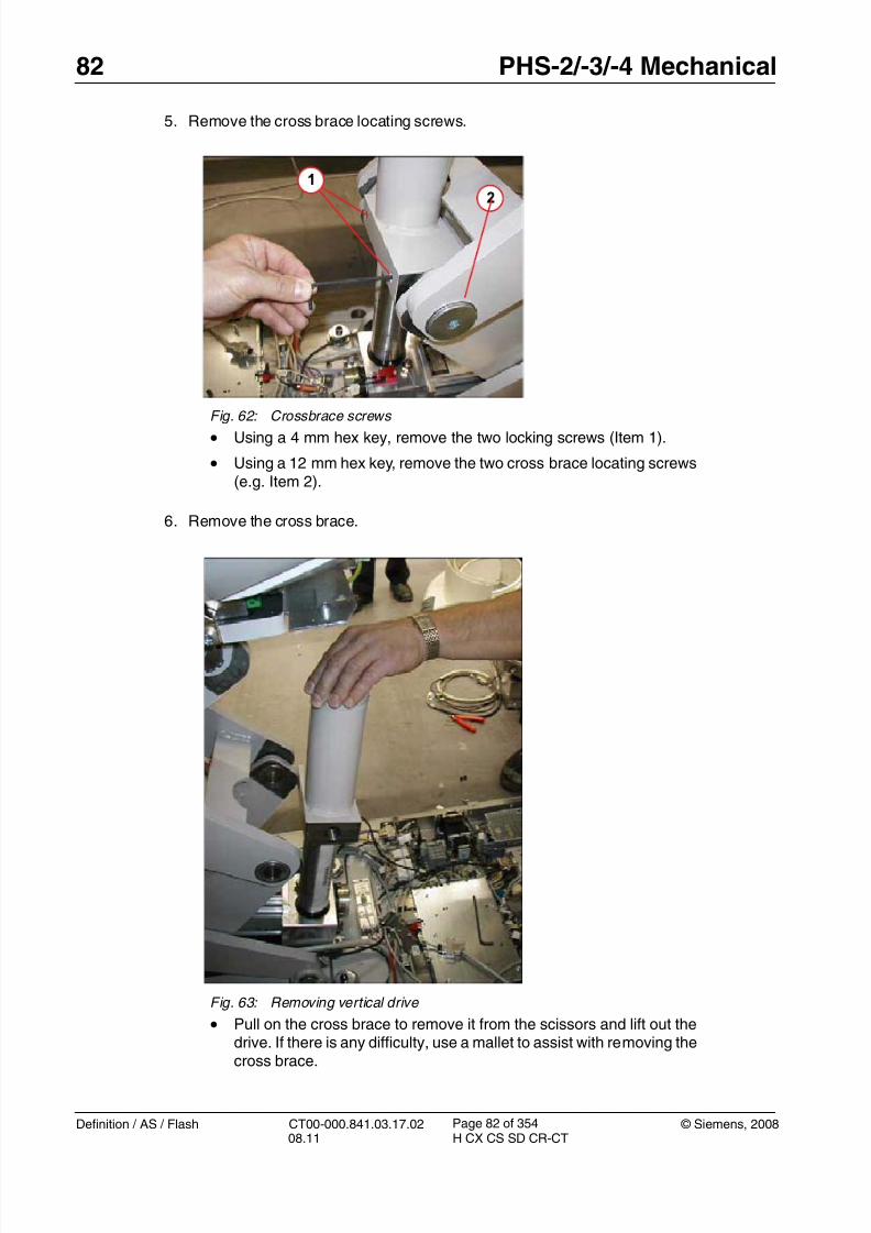
8/12/2019 CT00-000.841.03.17.02.pdf
http://slidepdf.com/reader/full/ct00-000841031702pdf 82/353
82 PHS-2/-3/-4 Mechanical
Definition / AS / Flash CT00-000.841.03.17.02 © Siemens, 200808.11 H CX CS SD CR-CT
Page 82 of 354
5. Remove the cross brace locating screws.
6. Remove the cross brace.
Fig. 62: Crossbrace screws • Using a 4 mm hex key, remove the two locking screws (Item 1).
• Using a 12 mm hex key, remove the two cross brace locating screws(e.g. Item 2).
Fig. 63: Removing vertical drive
• Pull on the cross brace to remove it from the scissors and lift out the
drive. If there is any difficulty, use a mallet to assist with removing thecross brace.

8/12/2019 CT00-000.841.03.17.02.pdf
http://slidepdf.com/reader/full/ct00-000841031702pdf 83/353
© Siemens, 2008 CT00-000.841.03.17.02 Definition / AS / Flash08.11 H CX CS SD CR-CT
PHS-2/-3/-4 Mechanical 83
Page 83 of 354
7. Remove the shaft pin.
Installation 0
1. Install the cross brace on to the new drive, insert the pin, and tighten the 2 lockingscrews. Rotate the cross brace to obtain the approximate height for reinstallation. Fineadjustments can be made with the manual lift screw.
Attention:Don´t move the spindle higher than the position for reinstallation. Otherwise, theball bearings from the spindle nut will fall out.
2. Place the drive in position and push the cross brace into place between the scissors;again, use a mallet if necessary.
T 3. Install the cross brace locating screws, tighten them to 130 Nm, and install the 2 lockingscrews with torque of 18.6 Nm.
4. Use the manual lift screw to lower the drive motor (clockwise) until it almost touches thebase plate and install the three locating screws applying Loctite 243, leaving 8 mmbetween the head and the drive motor flange.
5. Continue to turn clockwise to raise the table until the safety bolts can be removed. Rein-stall them in the storage positions.
6. Reinstall and adjust connect microswitch S718.
7. Reinstall all plugs and wires to original configuration, using cable ties as necessary.
8. Replace all covers.
Fig. 64: Shaft locking pin • Remove the 2 locking screws (item 1) and withdraw the pin (Item 2).
Lift off the cross brace.

8/12/2019 CT00-000.841.03.17.02.pdf
http://slidepdf.com/reader/full/ct00-000841031702pdf 84/353
84 PHS-2/-3/-4 Mechanical
Definition / AS / Flash CT00-000.841.03.17.02 © Siemens, 200808.11 H CX CS SD CR-CT
Page 84 of 354
Startup 0
Electrical
1. Switch on circuit breakers F2, F3, F5, F6, F7, and F11 in the PDC A and F2 in the PDCB (not for Definition AS).
First switch the F2, F3, F5, F6 circuit breakers to the “0” position and then to the“1” position.
2. Switch the system to the SYSTEM/ON status at the control box.
Software
n.a
Tune-up
1. Perform the PHS calibration for vertical positioning.
Tests
1. Perform a test scan
Final Steps 0
1. Clean.

8/12/2019 CT00-000.841.03.17.02.pdf
http://slidepdf.com/reader/full/ct00-000841031702pdf 85/353
© Siemens, 2008 CT00-000.841.03.17.02 Definition / AS / Flash08.11 H CX CS SD CR-CT
PHS-2/-3/-4 Mechanical 85
Page 85 of 354
Belt pulley (tabletop) 3.5
• The following instructions are applicable to:
The table below shows the usage of the two versions:
NOTE Replace the belt pulley with the same version that wasinstalled before.
The ’Belt pulley PHS_MPT’ does not fit into patient tablesdelivered with ’Belt pulley PHS’.
This instruction describes the example of replacement of the’Belt pulley PHS’. The mechanical work is identical when
replacing the ’Belt pulley PHS_MPT’.
Prerequisites 0
Time and manpower
• 1 person
• Estimated total repair time: 1.5 hours
Fig. 65: Belt pulley PHS (without drive shaftsupport), part no. 8615853 Fig. 66: Belt pulley PHS_MPT (with driveshaft support), part no. 8615861
Belt pulley PHS,
part no. 8615853
Belt pulley PHS_MPT,
part no. 8615861
Patient table version Serial no. range:
PHS-2, product no. 8616026 up to serial no. 1169 from serial no. 1170 onward
PHS-3, product no. 8616034 up to serial no. 1601 from serial no. 1602 onwardPHS-4, product no. 8097144 n.a. from serial no. 1001 onward

8/12/2019 CT00-000.841.03.17.02.pdf
http://slidepdf.com/reader/full/ct00-000841031702pdf 86/353
86 PHS-2/-3/-4 Mechanical
Definition / AS / Flash CT00-000.841.03.17.02 © Siemens, 200808.11 H CX CS SD CR-CT
Page 86 of 354
Tools and auxiliary equipment
• Standard service tools.
• Belt tension meter, part no. 8614203 or 7355642.
Preliminary steps 0
1. Raise the table to a height of 125.
2. Switch the system to COMP/ON on the control box.
3. Switch OFF the gantry/PHS power using the service push-button S1 in the PDC.
Secure the circuit breakers that S1 switched off against unintended switch-on(e.g. lock and tag).
NOTE Read and observe the safety information in the “Prod-
uct-specific safety notes” prior to performing service work on the patient table. If the patient table power is switched offfor service work, always secure it against accidentalswitch-on.
4. Remove the switchplate cover (Removing / p. 41).
5. Feed in the table and remove the tabletop covers (Tabletop covers (front andrear) / p. 29).
Fig. 67: Right front cover
• Remove the right front cover (1/ Fig. 67 / p. 86).
Removal 0
1. Move the tabletop approximately 50 cm (20 inches) into the gantry.
NOTE Do not slide the tabletop when the belt pulleys are removed.

8/12/2019 CT00-000.841.03.17.02.pdf
http://slidepdf.com/reader/full/ct00-000841031702pdf 87/353
© Siemens, 2008 CT00-000.841.03.17.02 Definition / AS / Flash08.11 H CX CS SD CR-CT
PHS-2/-3/-4 Mechanical 87
Page 87 of 354
2. Remove the rear belt pulley:
3. Remove the front belt pulley:
Fig. 68: Tabletop belt pulley (rear)
1. Release the belt tension adjustment screw (1).
2. Remove the two fastening screws (2).
3. Lift the belt pulley (3) out of the belt.
Fig. 69: Tabletop belt pulley (front)
1. Remove the belt (1).
2. Release the belt tension adjustment screw (2).
3. Remove the two fastening screws (3).
4. Remove the belt pulley.

8/12/2019 CT00-000.841.03.17.02.pdf
http://slidepdf.com/reader/full/ct00-000841031702pdf 88/353
88 PHS-2/-3/-4 Mechanical
Definition / AS / Flash CT00-000.841.03.17.02 © Siemens, 200808.11 H CX CS SD CR-CT
Page 88 of 354
Installation 0
1. Prepare the new belt pulleys:
Fig. 70: Preparing the new belt pulley assembly
The position of the alignment screw depends on the installation locationof the belt pulley:
• Front belt pulley: Insert the alignment screw into the lower thread(1).
• Rear belt pulley: Insert the alignment screw into the upper thread (2).
The alignment screw should protrude approx. 0.7 to 1.0 mm at the oppo-site side.

8/12/2019 CT00-000.841.03.17.02.pdf
http://slidepdf.com/reader/full/ct00-000841031702pdf 89/353
© Siemens, 2008 CT00-000.841.03.17.02 Definition / AS / Flash08.11 H CX CS SD CR-CT
PHS-2/-3/-4 Mechanical 89
Page 89 of 354
2. Install the front belt pulley.
3. Install the rear belt pulley.
Fig. 71: Installing the belt pulley (front) 1. Place the new belt pulley.
2. Insert the fastening screws:
- Insert the longer screw (1) closer to the rear side.
- Insert the shorter screw (2) closer to the front side.
3. Position the belt pulley:
- Insert the adjustment screw (3)
- Push the belt pulley to the PHS center
- Adjust a distance of 4 mm between the leading edge of the belt pul-ley and the front of the support frame (4).
4. Install the fastening screws (1, 2) but do not fully tighten them yet.
5. Put the belt (5) onto the front pulley.
Fig. 72: Installing the belt pulley (rear)
• Insert the new pulley into the belt (1).
• Install the fastening screws (2) but do not fully tighten them yet.
• Turn the adjustment screw (3) until the belt is pre-loaded.

8/12/2019 CT00-000.841.03.17.02.pdf
http://slidepdf.com/reader/full/ct00-000841031702pdf 90/353
90 PHS-2/-3/-4 Mechanical
Definition / AS / Flash CT00-000.841.03.17.02 © Siemens, 200808.11 H CX CS SD CR-CT
Page 90 of 354
Adjustment 0
1. Adjust the belt tension:
- Push the tabletop towards the gantry until a distance of 600 mm between the rear
pulley and the belt clamp is achieved.
- Place the sensor of the belt tension meter at the center of the trim length over the flatsize of the belt (300 mm) (1/ Fig. 74 / p. 90).
The distance between sensor and belt should be about 5 to 20 mm.
- Start belt vibration by hitting it with the head of a screwdriver.
- The resonance frequency must be 52 + 2 Hz for correct belt tension.
- Adjust the required frequency by turning the setscrew (2/ Fig. 74 / p. 90).
Fig. 73: Belt tabletop - distance 600 mm
Fig. 74: Belt tension measurement (with new
meter) Fig. 75: Belt tension measurement (with oldmeter)

8/12/2019 CT00-000.841.03.17.02.pdf
http://slidepdf.com/reader/full/ct00-000841031702pdf 91/353
© Siemens, 2008 CT00-000.841.03.17.02 Definition / AS / Flash08.11 H CX CS SD CR-CT
PHS-2/-3/-4 Mechanical 91
Page 91 of 354
2. Adjust the axial belt position:
- Manually move the tabletop in and out and check that the belt is centered properly onthe front and rear pulley (1).
- Turn the alignment screw (2) to adjust the correct (centered) belt position (1).
NOTE After axial adjustment the belt should not constantly touchthe pulley side.
When pushing or pulling the tabletop, a slight shift of the beltto the left or right side is acceptable.
3. Tighten the fastening screws of both belt pulleys with 11 Nm.
Startup 0
Electrical
1. Switch on circuit breakers F2, F3, F5, F6, F7, and F11 in the PDC A and F2 in the PDC
B (not for Definition AS).
First switch the F2, F3, F5, F6 circuit breakers to the “0” position and then to the“1” position.
2. Switch the system to SYSTEM/ON status on the control box.
Software
n.a.
Tune-up
n.a.
Fig. 76: Centered positioned belt Fig. 77: Adjusting the overturning

8/12/2019 CT00-000.841.03.17.02.pdf
http://slidepdf.com/reader/full/ct00-000841031702pdf 92/353
92 PHS-2/-3/-4 Mechanical
Definition / AS / Flash CT00-000.841.03.17.02 © Siemens, 200808.11 H CX CS SD CR-CT
Page 92 of 354
Tests
1. Move the tabletop (in and out) with gantry panel buttons.
2. Perform test scans (Topogram and Spiral).
Final steps 0
1. Install all PHS covers.
2. Clean the PHS.
8/12/2019 CT00-000.841.03.17.02.pdf
http://slidepdf.com/reader/full/ct00-000841031702pdf 93/353

8/12/2019 CT00-000.841.03.17.02.pdf
http://slidepdf.com/reader/full/ct00-000841031702pdf 94/353
94 PHS-2/-3/-4 Mechanical
Definition / AS / Flash CT00-000.841.03.17.02 © Siemens, 200808.11 H CX CS SD CR-CT
Page 94 of 354
Removing 0
1. Move tabletop plate to approximately 1.5 meters into the gantry so that the belt secur-ing point is accessible from underneath.
2. Release the rear adjuster.
3. Form a loop in the belt.
Fig. 78: Tabletop belt adjuster
• Unscrew adjustment screw (1).
• Remove the 2 holding screws (2) and lift the adjuster away.
Fig. 79: Loop in drive belt
• From underneath, pull the drive belt down to the form as shown in thefigure above.

8/12/2019 CT00-000.841.03.17.02.pdf
http://slidepdf.com/reader/full/ct00-000841031702pdf 95/353
© Siemens, 2008 CT00-000.841.03.17.02 Definition / AS / Flash08.11 H CX CS SD CR-CT
PHS-2/-3/-4 Mechanical 95
Page 95 of 354
4. Remove the belt.
Installation 0
1. Push table fully into gantry and feed the end of the belt through the front adjuster.
T2. Ensure that both ends of the belt are fully inserted into securing clamp and install the
two screws and tighten to 6 Nm.
3. Create a loop in the belt as shown above.
4. Reinstall the rear belt tensioner. There is also a front belt tensioner which does not nor-mally need to be adjusted; however, if difficulties are experienced it can also bereleased.
Remove the front right end cap (Front and rear end covers / switchplate cover / p. 40) togain access.
5. Check belt tension.
Fig. 80: Tabletop belt clamp • Pull out the loop in the drive belt.
• Remove the 2 holding screws on the belt clamp (item 1).
• Withdraw the belt.

8/12/2019 CT00-000.841.03.17.02.pdf
http://slidepdf.com/reader/full/ct00-000841031702pdf 96/353
96 PHS-2/-3/-4 Mechanical
Definition / AS / Flash CT00-000.841.03.17.02 © Siemens, 200808.11 H CX CS SD CR-CT
Page 96 of 354
- Procedure using the belt tension meter
- Push the tabletop plate towards the gantry until you achieve a distance of 600 mmbetween the rear pulley and the belt clamp.
- Place the sensor at the center of the trim length over the flat size of the belt (300mm). The distance between sensor and belt should be about 5 to 20 mm.
To learn how to use the tension meter, see the operating instructions delivered withthe meter.
- Start belt vibration by hitting it with the head of a screwdriver.
- Perform the measurement.
- The resonance frequency must be 58 +2 Hz for correct belt tension.
NOTE The value 58 +2 Hz is only valid for a new belt. For othercases, e.g. after replacement of the horizontal motor, the ten-
sion has to be adjusted to 52 +2 Hz.
Fig. 81: Belt tabletop - distance 600 mm
Fig. 82: Measuring with the belt tension meter
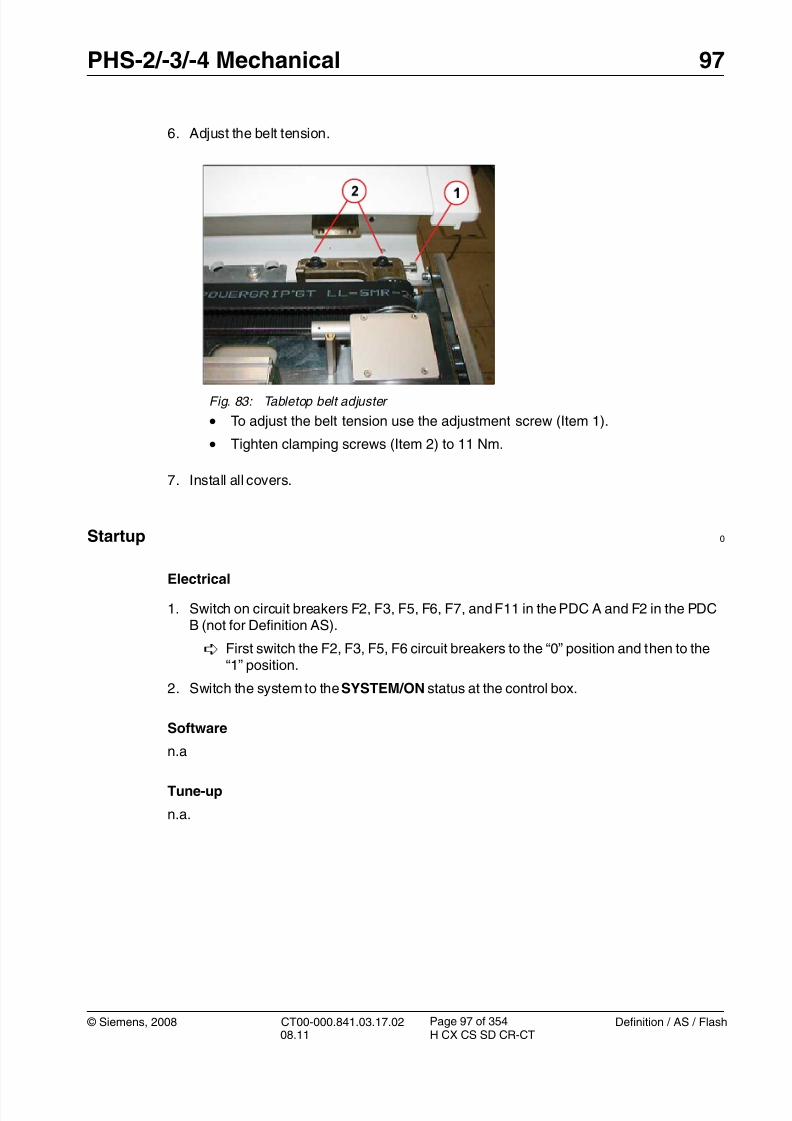
8/12/2019 CT00-000.841.03.17.02.pdf
http://slidepdf.com/reader/full/ct00-000841031702pdf 97/353
© Siemens, 2008 CT00-000.841.03.17.02 Definition / AS / Flash08.11 H CX CS SD CR-CT
PHS-2/-3/-4 Mechanical 97
Page 97 of 354
6. Adjust the belt tension.
7. Install all covers.
Startup 0
Electrical
1. Switch on circuit breakers F2, F3, F5, F6, F7, and F11 in the PDC A and F2 in the PDCB (not for Definition AS).
First switch the F2, F3, F5, F6 circuit breakers to the “0” position and then to the“1” position.
2. Switch the system to the SYSTEM/ON status at the control box.
Software
n.a
Tune-up
n.a.
Fig. 83: Tabletop belt adjuster
• To adjust the belt tension use the adjustment screw (Item 1).
• Tighten clamping screws (Item 2) to 11 Nm.

8/12/2019 CT00-000.841.03.17.02.pdf
http://slidepdf.com/reader/full/ct00-000841031702pdf 98/353
98 PHS-2/-3/-4 Mechanical
Definition / AS / Flash CT00-000.841.03.17.02 © Siemens, 200808.11 H CX CS SD CR-CT
Page 98 of 354
Tests
1. Perform a test scan
Final Steps 0
1. Clean.

8/12/2019 CT00-000.841.03.17.02.pdf
http://slidepdf.com/reader/full/ct00-000841031702pdf 99/353
© Siemens, 2008 CT00-000.841.03.17.02 Definition / AS / Flash08.11 H CX CS SD CR-CT
PHS-2/-3/-4 Mechanical 99
Page 99 of 354
Top Support Drive Belt (PHS-3 and PHS-4 only) 3.7
• The following instructions are applicable to:
- PHS top support drive belt, material number 86 14 369
Prerequisites 0
Safety
WARNING [ hz_serdoc_F13G01U12M03 ]
Avoid accident and injury or damage to parts.
Risk of accident and injury!
Read and observe the safety information contained in
the “General” section of this document and/or the“Product specific safety notes”.
Time and Manpower
• 1 person
• Estimated total repair time: 30 min.
Tools and auxiliary equipment
•
Standard service kit• Belt tension meter, for material number see the SPC.
Preliminary steps 0
1. Raise table to height of 125.
2. Switch system to COMP/ON at the control box.
3. Switch OFF the gantry/PHS power using service push-button S1 in the PDC.
Secure the circuit breakers that S1 switched OFF against unintended switch-on
(e.g. lock and tag).
NOTE Read and observe the safety information in the “Prod-uct-specific safety notes” prior to performing service work on the patient table. If the patient table power is switched offfor service work, always secure it against accidentalswitch-on.
4. Release the telescopic covers (Telescopic covers: Releasing / p. 43).
5. Remove the lower rear tabletop cover (Tabletop lower rear cover / p. 32).
6. Push table in approx. 1.5 meters.

8/12/2019 CT00-000.841.03.17.02.pdf
http://slidepdf.com/reader/full/ct00-000841031702pdf 100/353
100 PHS-2/-3/-4 Mechanical
Definition / AS / Flash CT00-000.841.03.17.02 © Siemens, 200808.11 H CX CS SD CR-CT
Page 100 of 354
Removing 0
1. Remove the adjuster.
2. Remove the belt.
Installation 0
T 1. Feed the new belt through the adjuster bracket and reinstall clamp. Tighten screws to 6Nm.
2. Route belt over motor pulley and reinstall the belt tensioner.
Fig. 84: Support belt adjuster
• Release lock nut (item 1), remove clamping bolt (Item 2), andunscrew adjuster (Item 3) to release belt tension.
• Continue unscrewing adjuster until the adjuster bracket can beremoved from the frame.
Fig. 85: Top support drive belt clamp
• Remove the two fasteners holding the belt clamp (Item 1) andremove the belt.

8/12/2019 CT00-000.841.03.17.02.pdf
http://slidepdf.com/reader/full/ct00-000841031702pdf 101/353
© Siemens, 2008 CT00-000.841.03.17.02 Definition / AS / Flash08.11 H CX CS SD CR-CT
PHS-2/-3/-4 Mechanical 101
Page 101 of 354
3. Check the belt tension.
- Procedure using the belt tension meter
- Pull the top support fully out, away from the gantry. You should achieve a distanceof 435 mm between the rear pulley and the belt clamp.
- Place the sensor at the center of the trim length over the flat size of the belt. The dis-tance between sensor and belt should be about 5 to 20 mm.
To learn how to use the tension meter, see the operating instructions delivered withthe meter.
- Start belt vibration by hitting it with the head of a screwdriver.
- Perform the measurement.
- The resonance frequency must be 75 +2 Hz for correct belt tension.
Fig. 86: Belt for top support
Fig. 87: Measuring tension of belt top support

8/12/2019 CT00-000.841.03.17.02.pdf
http://slidepdf.com/reader/full/ct00-000841031702pdf 102/353
102 PHS-2/-3/-4 Mechanical
Definition / AS / Flash CT00-000.841.03.17.02 © Siemens, 200808.11 H CX CS SD CR-CT
Page 102 of 354
NOTE The value 75 +2 Hz is only valid for a new belt. For othercases, e.g. after replacement of the horizontal motor, the ten-sion has to be adjusted to 70 +2 Hz.
4. Adjust the belt tension.
Startup 0
Electrical
1. Switch on circuit breakers F2, F3, F5, F6, F7, and F11 in the PDC A and F2 in the PDCB (not for Definition AS).
First switch the F2, F3, F5, F6 circuit breakers to the “0” position and then to the“1” position.
2. Switch the system to the SYSTEM/ON status at the control box.
Software
n.a
Tune-up
n.a.
Fig. 88: Support belt adjuster
• Use adjustment screw (Item 3) to set deflection of the belt to 20 - 22mm and tighten clamping screw (item 2) to 11 Nm.
• Tighten the locking nut (Item 1).

8/12/2019 CT00-000.841.03.17.02.pdf
http://slidepdf.com/reader/full/ct00-000841031702pdf 103/353
© Siemens, 2008 CT00-000.841.03.17.02 Definition / AS / Flash08.11 H CX CS SD CR-CT
PHS-2/-3/-4 Mechanical 103
Page 103 of 354
Tests
1. Perform a test scan
Final Steps 0
1. Clean.

8/12/2019 CT00-000.841.03.17.02.pdf
http://slidepdf.com/reader/full/ct00-000841031702pdf 104/353
104 PHS-2/-3/-4 Mechanical
Definition / AS / Flash CT00-000.841.03.17.02 © Siemens, 200808.11 H CX CS SD CR-CT
Page 104 of 354
Tabletop Position Sensor 3.8
• The following instructions are applicable to:
- PHS tabletop position sensor, material number 86 14 377
Prerequisites 0
Safety
WARNING [ hz_serdoc_F13G01U12M03 ]
Avoid accident and injury or damage to parts.
Risk of accident and injury!
Read and observe the safety information contained in
the “General” section of this document and/or the“Product specific safety notes”.
Time and Manpower
• 1 person
• Estimated total repair time: 1.5 hours
Tools and auxiliary equipment
•
Standard service kit
Preliminary steps 0
1. Raise table to height of 125.
2. Switch system toCOMP/ON at the control box.
3. Switch OFF the gantry/PHS power using service push-button S1 in the PDC.
Secure the circuit breakers that S1 switched OFF against unintended switch-on(e.g. lock and tag).
NOTE Read and observe the safety information in the “Prod-uct-specific safety notes” prior to performing service work on the patient table. If the patient table power is switched offfor service work, always secure it against accidentalswitch-on.
4. Release the telescopic covers (Telescopic covers: Releasing / p. 43).
5. Remove the lower rear tabletop cover (Tabletop lower rear cover / p. 32).
6. Feed in the table and remove the tabletop covers (Tabletop covers (front andrear) / p. 29).

8/12/2019 CT00-000.841.03.17.02.pdf
http://slidepdf.com/reader/full/ct00-000841031702pdf 105/353
© Siemens, 2008 CT00-000.841.03.17.02 Definition / AS / Flash08.11 H CX CS SD CR-CT
PHS-2/-3/-4 Mechanical 105
Page 105 of 354
Removing 0
1. Remove the sensor wire.
Fig. 89: Undertable view
• Push tabletop plate to a position approximately 1.5 meters into thegantry to access the sensor wire anchor point
• and release from underneath, but do not remove the nut securing thesensor wire.
• From above, hold the sensor wire with one hand to prevent suddenretraction and with other hand reach down underneath and removethe nut.
• Carefully allow wire to retract.

8/12/2019 CT00-000.841.03.17.02.pdf
http://slidepdf.com/reader/full/ct00-000841031702pdf 106/353
106 PHS-2/-3/-4 Mechanical
Definition / AS / Flash CT00-000.841.03.17.02 © Siemens, 200808.11 H CX CS SD CR-CT
Page 106 of 354
2. Remove the sensor.
Installation 0
T 1. Install sensor; tighten all 3 screws to 3 Nm.
2. Draw the sensor wire out and connect end into fixing point.
3. Reinstall all covers.
Startup 0
Electrical
1. Switch on circuit breakers F2, F3, F5, F6, F7, and F11 in the PDC A and F2 in the PDCB (not for Definition AS).
First switch the F2, F3, F5, F6 circuit breakers to the “0” position and then to the“1” position.
2. Switch the system to the SYSTEM/ON status at the control box.
Software
n.a
Fig. 90: Tabletop sensor • Remove the plug from the sensor.
• Remove the 3 screws holding the sensor.

8/12/2019 CT00-000.841.03.17.02.pdf
http://slidepdf.com/reader/full/ct00-000841031702pdf 107/353

8/12/2019 CT00-000.841.03.17.02.pdf
http://slidepdf.com/reader/full/ct00-000841031702pdf 108/353
108 PHS-2/-3/-4 Mechanical
Definition / AS / Flash CT00-000.841.03.17.02 © Siemens, 200808.11 H CX CS SD CR-CT
Page 108 of 354
Top Support Position Sensor and Band (PHS-3 and PHS-4 only) 3.9
• The following instructions are applicable to:
- PHS top support position sensor, material number 86 14 385
Prerequisites 0
Safety
WARNING [ hz_serdoc_F13G01U12M03 ]
Avoid accident and injury or damage to parts.
Risk of accident and injury!
Read and observe the safety information contained in
the “General” section of this document and/or the“Product specific safety notes”.
Time and Manpower
• 1 person
• Estimated total repair time: 1 hr.
Tools and auxiliary equipment
•
Standard service kit• Feeler gauges e.g., material number 80 38 259
Preliminary steps 0
1. Switch system toCOMP/ON at the control box.
2. Switch OFF the gantry/PHS power using service push-button S1 in the PDC.
Secure the circuit breakers that S1 switched OFF against unintended switch-on(e.g. lock and tag).
NOTE Read and observe the safety information in the “Prod-uct-specific safety notes” prior to performing service work on the patient table. If the patient table power is switched offfor service work, always secure it against accidentalswitch-on.
3. Switch off the gantry power using service push-button S1 in PDC A. Secure againstunintended switch-on.
4. Feed in the table and remove the tabletop covers (Tabletop covers (front andrear) / p. 29).
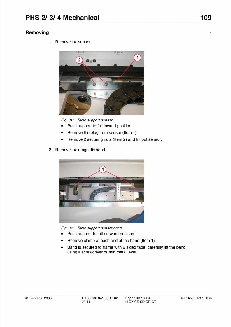
8/12/2019 CT00-000.841.03.17.02.pdf
http://slidepdf.com/reader/full/ct00-000841031702pdf 109/353
© Siemens, 2008 CT00-000.841.03.17.02 Definition / AS / Flash08.11 H CX CS SD CR-CT
PHS-2/-3/-4 Mechanical 109
Page 109 of 354
Removing 0
1. Remove the sensor.
2. Remove the magnetic band.
Fig. 91: Table support sensor
• Push support to full inward position.
• Remove the plug from sensor (Item 1).
• Remove 2 securing nuts (Item 2) and lift out sensor.
Fig. 92: Table support sensor band
• Push support to full outward position.
• Remove clamp at each end of the band (Item 1).
• Band is secured to frame with 2 sided tape; carefully lift the bandusing a screwdriver or thin metal lever.

8/12/2019 CT00-000.841.03.17.02.pdf
http://slidepdf.com/reader/full/ct00-000841031702pdf 110/353
110 PHS-2/-3/-4 Mechanical
Definition / AS / Flash CT00-000.841.03.17.02 © Siemens, 200808.11 H CX CS SD CR-CT
Page 110 of 354
Installation 0
1. Clean all tape residue from area of band.
2. Apply supplied 2-sided tape to back of new band and secure at correct position on
frame. T 3. Reinstall band end clamps. Tighten to 3 Nm.
4. Install the sensor. Use feeler gauge to set 0.5 mm clearance to magnetic band. Tightenthe nuts to 6 Nm.
5. Install the plug at the sensor.
Startup 0
Electrical
1. Switch on circuit breakers F2, F3, F5, F6, F7, and F11 in the PDC A and F2 in the PDCB (not for Definition AS).
First switch the F2, F3, F5, F6 circuit breakers to the “0” position and then to the“1” position.
2. Switch the system to the SYSTEM/ON status at the control box.
Software
n.a
Tune-up
1. Perform the PHS calibration for top support.
Tests
1. Perform a test scan
Final Steps 0
1. Clean.

8/12/2019 CT00-000.841.03.17.02.pdf
http://slidepdf.com/reader/full/ct00-000841031702pdf 111/353
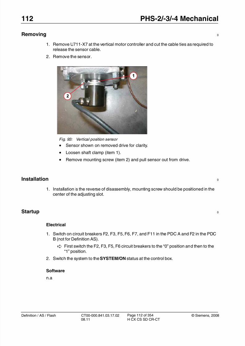
8/12/2019 CT00-000.841.03.17.02.pdf
http://slidepdf.com/reader/full/ct00-000841031702pdf 112/353
112 PHS-2/-3/-4 Mechanical
Definition / AS / Flash CT00-000.841.03.17.02 © Siemens, 200808.11 H CX CS SD CR-CT
Page 112 of 354
Removing 0
1. Remove U711-X7 at the vertical motor controller and cut the cable ties as required torelease the sensor cable.
2. Remove the sensor.
Installation 0
1. Installation is the reverse of disassembly, mounting screw should be positioned in thecenter of the adjusting slot.
Startup 0
Electrical
1. Switch on circuit breakers F2, F3, F5, F6, F7, and F11 in the PDC A and F2 in the PDCB (not for Definition AS).
First switch the F2, F3, F5, F6 circuit breakers to the “0” position and then to the“1” position.
2. Switch the system to the SYSTEM/ON status at the control box.
Software
n.a
Fig. 93: Vertical position sensor
• Sensor shown on removed drive for clarity.
• Loosen shaft clamp (item 1).
• Remove mounting screw (item 2) and pull sensor out from drive.

8/12/2019 CT00-000.841.03.17.02.pdf
http://slidepdf.com/reader/full/ct00-000841031702pdf 113/353
© Siemens, 2008 CT00-000.841.03.17.02 Definition / AS / Flash08.11 H CX CS SD CR-CT
PHS-2/-3/-4 Mechanical 113
Page 113 of 354
Tune-up
1. Perform the PHS calibration for vertical positioning.
Tests
1. Perform a test scan
Final Steps 0
1. Clean.

8/12/2019 CT00-000.841.03.17.02.pdf
http://slidepdf.com/reader/full/ct00-000841031702pdf 114/353

8/12/2019 CT00-000.841.03.17.02.pdf
http://slidepdf.com/reader/full/ct00-000841031702pdf 115/353
© Siemens, 2008 CT00-000.841.03.17.02 Definition / AS / Flash08.11 H CX CS SD CR-CT
PHS-2/-3/-4 Mechanical 115
Page 115 of 354
3. Switch OFF the gantry/PHS power using service push-button S1 in the PDC.
Secure the circuit breakers that S1 switched OFF against unintended switch-on(e.g. lock and tag).
NOTERead and observe the safety information in the “Prod-uct-specific safety notes” prior to performing service work on the patient table. If the patient table power is switched offfor service work, always secure it against accidentalswitch-on.
4. Release the telescopic covers (Telescopic covers: Releasing / p. 43).
Replacement 0
NOTE All replaceable switches are attached by two screws.
S717 screws are secured with Loctite.
Removal:
1. Disconnect the wires.
2. Remove the screws; avoid breaking off the screws or damaging the screw head.
3. Remove the switch and the insulating pad.
Installation:
1. Install the new switch and the insulating pad following the removal instructions inreverse order.
2. Tighten the screws with 0.8 Nm.
3. Reconnect the wires; observe the different pin assignments of old (Marquardt = red)and new (Cherry = white) microswitch type (1,2/ Fig. 94 / p. 114).

8/12/2019 CT00-000.841.03.17.02.pdf
http://slidepdf.com/reader/full/ct00-000841031702pdf 116/353
116 PHS-2/-3/-4 Mechanical
Definition / AS / Flash CT00-000.841.03.17.02 © Siemens, 200808.11 H CX CS SD CR-CT
Page 116 of 354
1. Upper safety limit switch (S711) and lower safety limit switch (S713):
Fig. 95: Safety limit switches (old version) Fig. 96: Safety limit switches (new version)
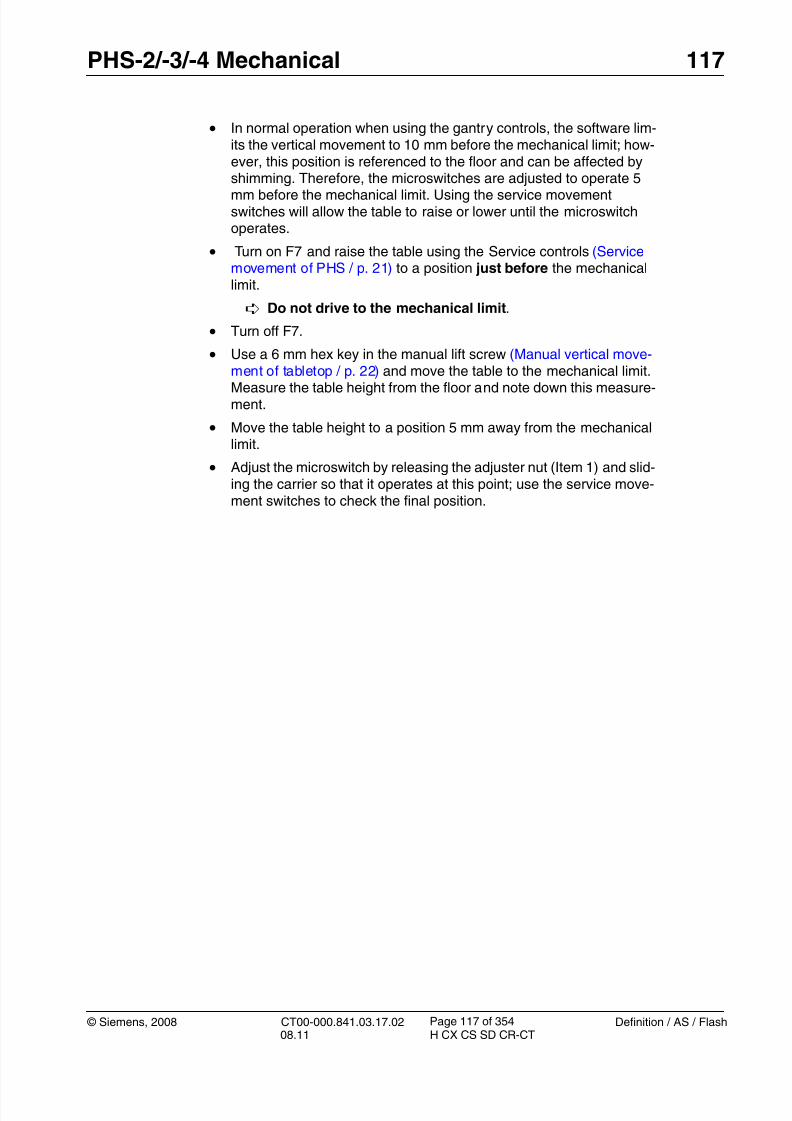
8/12/2019 CT00-000.841.03.17.02.pdf
http://slidepdf.com/reader/full/ct00-000841031702pdf 117/353
© Siemens, 2008 CT00-000.841.03.17.02 Definition / AS / Flash08.11 H CX CS SD CR-CT
PHS-2/-3/-4 Mechanical 117
Page 117 of 354
• In normal operation when using the gantry controls, the software lim-its the vertical movement to 10 mm before the mechanical limit; how-ever, this position is referenced to the floor and can be affected byshimming. Therefore, the microswitches are adjusted to operate 5
mm before the mechanical limit. Using the service movementswitches will allow the table to raise or lower until the microswitchoperates.
• Turn on F7 and raise the table using the Service controls (Servicemovement of PHS / p. 21) to a position just before the mechanicallimit.
Do not drive to the mechanical limit.
• Turn off F7.
• Use a 6 mm hex key in the manual lift screw (Manual vertical move-ment of tabletop / p. 22) and move the table to the mechanical limit.Measure the table height from the floor and note down this measure-ment.
• Move the table height to a position 5 mm away from the mechanicallimit.
• Adjust the microswitch by releasing the adjuster nut (Item 1) and slid-ing the carrier so that it operates at this point; use the service move-ment switches to check the final position.

8/12/2019 CT00-000.841.03.17.02.pdf
http://slidepdf.com/reader/full/ct00-000841031702pdf 118/353
118 PHS-2/-3/-4 Mechanical
Definition / AS / Flash CT00-000.841.03.17.02 © Siemens, 200808.11 H CX CS SD CR-CT
Page 118 of 354
2. Safety nut switch S717:
Fig. 97: Disconnect and safety nut switches
The safety nut switch (Item 2) is installed close to the spindle hous-ing. A shear nut inside the drive will break if too much strain isapplied. If it breaks, the outer bushing drops and S717 is pressed,causing an emergency stop.
If the machine groove is not visible, the complete vertical driveassembly should be replaced.

8/12/2019 CT00-000.841.03.17.02.pdf
http://slidepdf.com/reader/full/ct00-000841031702pdf 119/353
© Siemens, 2008 CT00-000.841.03.17.02 Definition / AS / Flash08.11 H CX CS SD CR-CT
PHS-2/-3/-4 Mechanical 119
Page 119 of 354
3. Disconnect safety switch S718 (3/ Fig. 97 / p. 118):
Install S717 following the removal instructions in reverse order:
Fig. 98: Safety nut switch S717 Pos. 1 1 mm distance
• Install the new switch with insulating pad, actuator and metal ball.
• Adjust a distance of 1.0 mm between spindle housing and actuator(1/ Fig. 98 / p. 119).
Fig. 99: S718 (old version) Fig. 100: S718 (new version)

8/12/2019 CT00-000.841.03.17.02.pdf
http://slidepdf.com/reader/full/ct00-000841031702pdf 120/353
120 PHS-2/-3/-4 Mechanical
Definition / AS / Flash CT00-000.841.03.17.02 © Siemens, 200808.11 H CX CS SD CR-CT
Page 120 of 354
- The disconnect safety switch is normally operated and will release if the drive motorlifts due to a blockage.
- Adjust the microswitch vertically using the switch screws (shown at [1]) and horizon-tally using the bracket fasteners (shown at [2]).
- The operation can be checked by installing the safety bolts and manually loweringthe table using a 6 mm hex key until the motor lifts (Manual vertical movement oftabletop / p. 22). Check to make sure that the microswitch releases.
Startup 0
Electrical
1. Switch on circuit breakers F2, F3, F5, F6, F7, and F11 in the PDC A and F2 in the PDCB (not for Definition AS).
First switch the F2, F3, F5, F6 circuit breakers to the “0” position and then to the“1” position.
2. Switch the system to the SYSTEM/ON status at the control box.
Software
n.a
Tune-up
n.a
Tests
1. Move the patient table to various vertical positions.
2. Perform test scans (Topo, spiral).
Final Steps 0
1. Install all PHS covers.
2. Clean the covers.
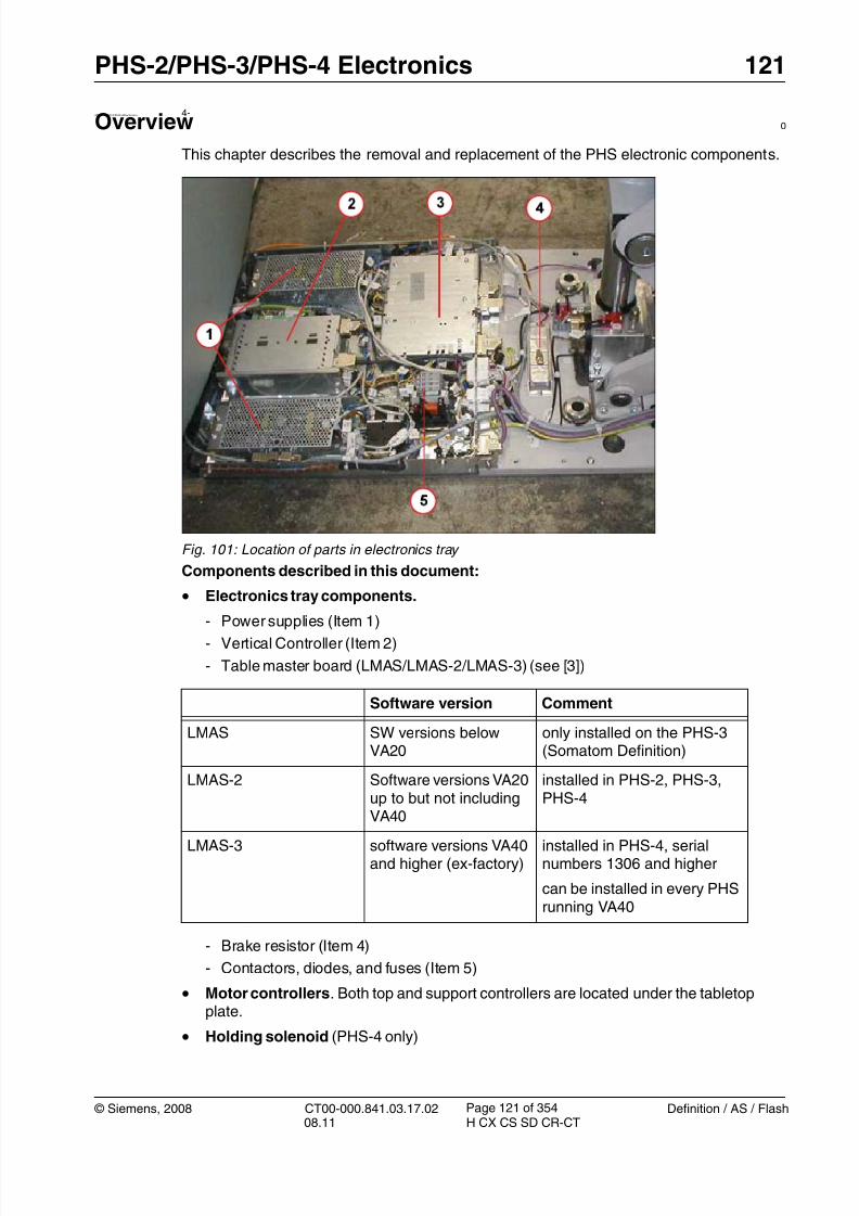
8/12/2019 CT00-000.841.03.17.02.pdf
http://slidepdf.com/reader/full/ct00-000841031702pdf 121/353
© Siemens, 2008 CT00-000.841.03.17.02 Definition / AS / Flash08.11 H CX CS SD CR-CT
PHS-2/PHS-3/PHS-4 Electronics 121
Page 121 of 354
4- 4PHS-2/PHS-3/PHS-4Electronics
Overview 0
This chapter describes the removal and replacement of the PHS electronic components.
Fig. 101: Location of parts in electronics tray
Components described in this document:
• Electronics tray components.
- Power supplies (Item 1)- Vertical Controller (Item 2)
- Table master board (LMAS/LMAS-2/LMAS-3) (see [3])
- Brake resistor (Item 4)
- Contactors, diodes, and fuses (Item 5)
• Motor controllers. Both top and support controllers are located under the tabletopplate.
• Holding solenoid (PHS-4 only)
Software version Comment
LMAS SW versions belowVA20
only installed on the PHS-3(Somatom Definition)
LMAS-2 Software versions VA20up to but not includingVA40
installed in PHS-2, PHS-3,PHS-4
LMAS-3 software versions VA40and higher (ex-factory)
installed in PHS-4, serialnumbers 1306 and higher
can be installed in every PHSrunning VA40

8/12/2019 CT00-000.841.03.17.02.pdf
http://slidepdf.com/reader/full/ct00-000841031702pdf 122/353
122 PHS-2/PHS-3/PHS-4 Electronics
Definition / AS / Flash CT00-000.841.03.17.02 © Siemens, 200808.11 H CX CS SD CR-CT
Page 122 of 354
• PMM Module. Mounted at the back of the tabletop plate.
• Cable sets. PHS cable set, PMM vertical, and horizontal cable sets.
8/12/2019 CT00-000.841.03.17.02.pdf
http://slidepdf.com/reader/full/ct00-000841031702pdf 123/353
© Siemens, 2008 CT00-000.841.03.17.02 Definition / AS / Flash08.11 H CX CS SD CR-CT
PHS-2/PHS-3/PHS-4 Electronics 123
Page 123 of 354
Power Supplies 4.1
• The following instructions are applicable to:
- PHS-2 and PHS-3 power supplies (G701, G702), material number 86 14 500
PHS-4 power supplies, material number 86 14 500 (G701) and material number 8618 113 (G702)
Prerequisites 0
Safety
WARNING [ hz_serdoc_F13G01U12M03 ]
Avoid accident and injury or damage to parts.
Risk of accident and injury!
Read and observe the safety information contained inthe “General” section of this document and/or the“Product specific safety notes”.
Time and manpower
• 1 person
• Estimated total repair time: 30 min.
Tools and Auxiliary Equipment
• Standard service kit
Preliminary steps 0
1. Raise the patient table to height of 125.
2. Switch system to COMP/ON at the control box.
3. Switch OFF the gantry/PHS power using service push-button S1 in the PDC.
Secure the circuit breakers that S1 switched OFF against unintended switch-on(e.g. lock and tag).
NOTE Read and observe the safety information in the “Prod-uct-specific safety notes” prior to performing service work on the patient table. If the patient table power is switched offfor service work, always secure it against accidentalswitch-on.
4. Remove the electronics cover (Table electronics cover / p. 57).

8/12/2019 CT00-000.841.03.17.02.pdf
http://slidepdf.com/reader/full/ct00-000841031702pdf 124/353
124 PHS-2/PHS-3/PHS-4 Electronics
Definition / AS / Flash CT00-000.841.03.17.02 © Siemens, 200808.11 H CX CS SD CR-CT
Page 124 of 354
Removing 0
1. Remove power supply cover.
2. Remove the power supply.
Installation 0
1. Install securing nut and standoffs.
2. Install the cover and connector.
3. Reinstall electronics cover.
Fig. 102: Power supply cover
• Remove the connector.
• Remove nuts securing cover (Item 1) and lift off cover.
Fig. 103: Power supply securing fasteners • Remove standoffs (Item 1) and nut (Item 2) and lift power supply
away.

8/12/2019 CT00-000.841.03.17.02.pdf
http://slidepdf.com/reader/full/ct00-000841031702pdf 125/353
© Siemens, 2008 CT00-000.841.03.17.02 Definition / AS / Flash08.11 H CX CS SD CR-CT
PHS-2/PHS-3/PHS-4 Electronics 125
Page 125 of 354
Startup 0
Electrical
1. Switch on circuit breakers F2, F3, F5, F6, F7, and F11 in the PDC A and F2 in the PDCB (not for Definition AS).
First switch the F2, F3, F5, F6 circuit breakers to the “0” position and then to the“1” position.
2. Switch the system to the SYSTEM/ON status at the control box.
Software
n.a.
Tune-up
n.a.
Tests
1. Perform a test scan
Final Steps 0
1. Clean.

8/12/2019 CT00-000.841.03.17.02.pdf
http://slidepdf.com/reader/full/ct00-000841031702pdf 126/353
126 PHS-2/PHS-3/PHS-4 Electronics
Definition / AS / Flash CT00-000.841.03.17.02 © Siemens, 200808.11 H CX CS SD CR-CT
Page 126 of 354
Contactor, relays and diode 4.2
• The following instructions are applicable to:
- PHS-2, material number 86 16 026
- PHS-3, material number 86 16 034- PHS-4, material number 80 97 144
Prerequisites 0
Safety
WARNING [ hz_serdoc_F13G01U12M03 ]
Avoid accident and injury or damage to parts.
Risk of accident and injury!
Read and observe the safety information contained inthe “General” section of this document and/or the“Product specific safety notes”.
Time and manpower
• 1 person
• Estimated total repair time: 30 min. per item.
Tools and Auxiliary Equipment
• Standard service kit
Preliminary steps 0
1. Raise the patient table to height of 125.
2. Switch system toCOMP/ON at the control box.
3. Switch OFF the gantry/PHS power using service push-button S1 in the PDC.
Secure the circuit breakers that S1 switched OFF against unintended switch-on(e.g. lock and tag).
NOTE Read and observe the safety information in the “Prod-uct-specific safety notes” prior to performing service work on the patient table. If the patient table power is switched offfor service work, always secure it against accidentalswitch-on.
4. Remove the electronics cover (Table electronics cover / p. 57).

8/12/2019 CT00-000.841.03.17.02.pdf
http://slidepdf.com/reader/full/ct00-000841031702pdf 127/353
© Siemens, 2008 CT00-000.841.03.17.02 Definition / AS / Flash08.11 H CX CS SD CR-CT
PHS-2/PHS-3/PHS-4 Electronics 127
Page 127 of 354
Removing 0
1. Removing parts
Installation 0
1. Installation is in the reverse order of removal.
Startup 0
Electrical
1. Switch on circuit breakers F2, F3, F5, F6, F7, and F11 in the PDC A and F2 in the PDCB (not for Definition AS).
First switch the F2, F3, F5, F6 circuit breakers to the “0” position and then to the
“1” position.
Fig. 104: Location of relays, contactor, and diode block
• Remove wires, check that the markings are clear and understand-able.
• K711 vertical brake relay (shown at [1]), K709 AC power sensingrelay (shown at [2]), and K701 safety contactor (shown at [3]) are allreleased by removing the clamp on the respective mounting rail (e.g.[5]).
• The rectifier diode V702 (shown at [4]) is secured by a single fas-tener.

8/12/2019 CT00-000.841.03.17.02.pdf
http://slidepdf.com/reader/full/ct00-000841031702pdf 128/353
128 PHS-2/PHS-3/PHS-4 Electronics
Definition / AS / Flash CT00-000.841.03.17.02 © Siemens, 200808.11 H CX CS SD CR-CT
Page 128 of 354
2. Switch the system to the SYSTEM/ON status at the control box.
Software
n.a.
Tune-up
n.a.
Tests
1. Perform a test scan
Final Steps 0
1. Clean.
8/12/2019 CT00-000.841.03.17.02.pdf
http://slidepdf.com/reader/full/ct00-000841031702pdf 129/353

8/12/2019 CT00-000.841.03.17.02.pdf
http://slidepdf.com/reader/full/ct00-000841031702pdf 130/353
130 PHS-2/PHS-3/PHS-4 Electronics
Definition / AS / Flash CT00-000.841.03.17.02 © Siemens, 200808.11 H CX CS SD CR-CT
Page 130 of 354
Removing 0
1. Remove the fuse.
Installation 0
1. Position fuse as shown in the figure and close cover; the cover will locate the fuse intothe contacts.
2. Rotate the fuse holder back to the original position.
Startup 0
Electrical
1. Switch on circuit breakers F2, F3, F5, F6, F7, and F11 in the PDC A and F2 in the PDCB (not for Definition AS).
First switch the F2, F3, F5, F6 circuit breakers to the “0” position and then to the“1” position.
2. Switch the system to the SYSTEM/ON status at the control box.
Software
n.a.
Fig. 105: Replacing fuses
• Rotate the fuse holder 90 degrees by lifting the tab located at thegantry end (Item 1).
• Pull the tab (Item 2) to open the cover; the fuse will be pushed out bya small pin to the position shown in the figure.
• Remove the fuse.

8/12/2019 CT00-000.841.03.17.02.pdf
http://slidepdf.com/reader/full/ct00-000841031702pdf 131/353

8/12/2019 CT00-000.841.03.17.02.pdf
http://slidepdf.com/reader/full/ct00-000841031702pdf 132/353
132 PHS-2/PHS-3/PHS-4 Electronics
Definition / AS / Flash CT00-000.841.03.17.02 © Siemens, 200808.11 H CX CS SD CR-CT
Page 132 of 354
Table Master Board (LMAS) > for PHS-3 with SW VA11 ONLY !! 4.4
NOTE The following instructions are only valid for LMAS boardsoperating in the PHS-3 patient table with software version
VA11.
• The following instructions are applicable to:
- PHS LMAS Assembly, material number 86 14 526
Prerequisites 0
Safety
WARNING [ hz_serdoc_F13G01U12M03 ]
Avoid accident and injury or damage to parts.
Risk of accident and injury!
Read and observe the safety information contained inthe “General” section of this document and/or the“Product specific safety notes”.
Time and manpower
•1 person
• Estimated total repair time: 45 min.
Tools and Auxiliary Equipment
• Standard service kit

8/12/2019 CT00-000.841.03.17.02.pdf
http://slidepdf.com/reader/full/ct00-000841031702pdf 133/353
© Siemens, 2008 CT00-000.841.03.17.02 Definition / AS / Flash08.11 H CX CS SD CR-CT
PHS-2/PHS-3/PHS-4 Electronics 133
Page 133 of 354
Storage of table T3C PHS - LMAS
NOTE PHS relevant parameters are stored in the configuration tableT3C. Table T3C is stored on the PHS-LMAS board - Source:Volatile. If the LMAS board is replaced the original T3C has to
be restored on the new LMAS; otherwise, the PHS may notfunction correctly.
There are two ways to save the original T3C table
1. Prior to removing the old LMAS board, perform function“Service > Control > table load/modify”. Select table T3C,set radio button “Volatile” and press <Go> to display thetable. Select radio button “Persistent” and press <Go> toback it up on the UMAS board.
2. The original T3C is already stored on the UMAS becausethis step is performed automatically with every PHS
adjustment (vertical or horizontal). You may check if aPHS adjustment was performed in the past.
Restoring the T3C table on the new LMAS board:
Use function “Service > Control > table load/modify”. Selecttable T3C, set radio button “Persistent” and press <GO> todisplay the table stored at the UMAS. Select radio button“Volatile” and press <Go> to download it onto the LMAS.
• Select Local_Service > TuneUp.
• Select FRU Replace.
• Select PHS - LMAS.
• Press <Go> to start the tour.
- Save table T3C prior to replacing the part and restore table T3C after replacement asdescribed in the above note.
The Guided Tour has been completed successfully if the TC3 is restored on thenew component.
Preliminary steps 0
1. Raise the patient table to maximum height for better access.
2. Switch system to COMP/ON at the control box.
3. Switch OFF the gantry/PHS power using service push-button S1 in the PDC.
Secure the circuit breakers that S1 switched OFF against unintended switch-on(e.g. lock and tag).

8/12/2019 CT00-000.841.03.17.02.pdf
http://slidepdf.com/reader/full/ct00-000841031702pdf 134/353

8/12/2019 CT00-000.841.03.17.02.pdf
http://slidepdf.com/reader/full/ct00-000841031702pdf 135/353
© Siemens, 2008 CT00-000.841.03.17.02 Definition / AS / Flash08.11 H CX CS SD CR-CT
PHS-2/PHS-3/PHS-4 Electronics 135
Page 135 of 354
2. Switch the system to the SYSTEM/ON status at the control box.
Software
The firmware will be automatically loaded at power on.
Tune-up
1. Execute and follow the Guided Tour for FRU replacement
2. Restart the application to verify the FW actualization.
3. Perform all PHS adjustments
Tests
1. Perform the image quality test (table feed).
Final Steps 0
1. Clean.

8/12/2019 CT00-000.841.03.17.02.pdf
http://slidepdf.com/reader/full/ct00-000841031702pdf 136/353
136 PHS-2/PHS-3/PHS-4 Electronics
Definition / AS / Flash CT00-000.841.03.17.02 © Siemens, 200808.11 H CX CS SD CR-CT
Page 136 of 354
Table master board (LMAS-2 and LMAS-3) 4.5
• The following instructions are applicable to:
- Table master board (LMAS-2), material number 86 12 413
- Table master board (LMAS-3), material number 106 43 790
NOTE Do not replace LMAS and motor controllers at the same time!
If you are uncertain which component is causing the prob-lem, finish replacing one part before you replace the next.
Prerequisites 0
Safety
WARNING [ hz_serdoc_F13G01U12M03 ]
Avoid accident and injury or damage to parts.
Risk of accident and injury!
Read and observe the safety information contained inthe “General” section of this document and/or the“Product specific safety notes”.
Time and manpower
• 1 person
• Estimated total repair time: 45 min.
Tools and Auxiliary Equipment
• Standard service kit
Preliminary steps 0
1. Raise the patient table to maximum height for better access.
2. Switch system toCOMP/ON at the control box.
3. Switch OFF the gantry/PHS power using service push-button S1 in the PDC.
Secure the circuit breakers that S1 switched OFF against unintended switch-on(e.g. lock and tag).

8/12/2019 CT00-000.841.03.17.02.pdf
http://slidepdf.com/reader/full/ct00-000841031702pdf 137/353
© Siemens, 2008 CT00-000.841.03.17.02 Definition / AS / Flash08.11 H CX CS SD CR-CT
PHS-2/PHS-3/PHS-4 Electronics 137
Page 137 of 354
NOTE Read and observe the safety information in the “Prod-uct-specific safety notes” prior to performing service work on the patient table. If the patient table power is switched offfor service work, always secure it against accidental
switch-on.
4. Remove the electronics cover (Table electronics cover / p. 57).
Removing 0
1. Remove LMAS-2/-3 board.
NOTE The figure below shows the LMAS-2 board as an example.
The attachment points of the LMAS-3 are identical.
Installation 0
T 1. Secure assembly to electronics tray with the 2 nuts and tighten to 3 Nm.
2. Reinstall all connectors.
Note: Make sure that cable X301 is plugged into X302. Cable X302 does not getplugged into LMAS-2 and LMAS-3.
3. Reinstall electronics cover.
Fig. 107: LMAS securing fasteners
• Remove all connectors from board.
• Remove the 2 nuts securing the board (Item 1).

8/12/2019 CT00-000.841.03.17.02.pdf
http://slidepdf.com/reader/full/ct00-000841031702pdf 138/353
138 PHS-2/PHS-3/PHS-4 Electronics
Definition / AS / Flash CT00-000.841.03.17.02 © Siemens, 200808.11 H CX CS SD CR-CT
Page 138 of 354
Startup 0
Electrical
1. Switch on circuit breakers F2, F3, F5, F6, F7, and F11 in the PDC A and F2 in the PDCB (not for Definition AS).
First switch the F2, F3, F5, F6 circuit breakers to the “0” position and then to the“1” position.
2. Switch the system to SYSTEM/ON status on the control box.
Software
The firmware will be automatically loaded at power on.
Tune-up
• Select: Local_Service > TuneUp
• Select: FRU Replace
• Select: PHS - LMAS
• Press <Go> to start the tour.
The Auto_Complete is started and checks which adjustments are required.
Follow the instructions of the Auto_Complete routine.
Tests
1. Check all table movements (horizontal/vertical) via the buttons at the gantry controlpanels.
2. Perform a test scan.
Final Steps 0
1. Clean.

8/12/2019 CT00-000.841.03.17.02.pdf
http://slidepdf.com/reader/full/ct00-000841031702pdf 139/353
© Siemens, 2008 CT00-000.841.03.17.02 Definition / AS / Flash08.11 H CX CS SD CR-CT
PHS-2/PHS-3/PHS-4 Electronics 139
Page 139 of 354
Brake resistor 4.6
• The following instructions are applicable to:
- PHS-2, material number 86 16 026
- PHS-3, material number 86 16 034- PHS-4, material number 80 97 144
Prerequisites 0
Safety
WARNING [ hz_serdoc_F13G01U12M03 ]
Avoid accident and injury or damage to parts.
Risk of accident and injury!
Read and observe the safety information contained inthe “General” section of this document and/or the“Product specific safety notes”.
Time and manpower
• 1 person
• Estimated total repair time: 1 hr.
Tools and Auxiliary Equipment
• Standard service kit
Preliminary steps 0
1. Raise table to height of 125.
2. Switch system to COMP/ON at the control box.
3. Switch OFF the gantry/PHS power using service push-button S1 in the PDC.
Secure the circuit breakers that S1 switched OFF against unintended switch-on(e.g. lock and tag).
NOTE Read and observe the safety information in the “Prod-uct-specific safety notes” prior to performing service work on the patient table. If the patient table power is switched offfor service work, always secure it against accidentalswitch-on.
4. Release the telescopic covers (Telescopic covers: Releasing / p. 43).
5. Remove the telescopic covers (Telescopic covers: Removing / p. 52).
6. Remove the electronics cover (Table electronics cover / p. 57).
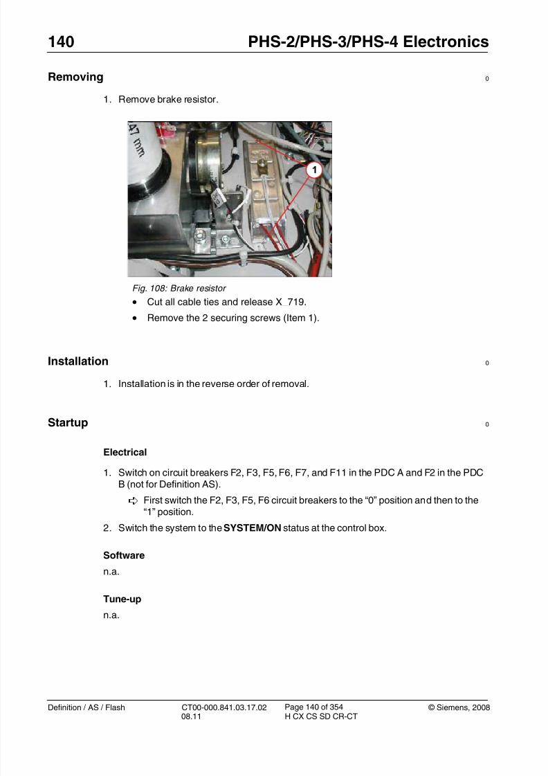
8/12/2019 CT00-000.841.03.17.02.pdf
http://slidepdf.com/reader/full/ct00-000841031702pdf 140/353
140 PHS-2/PHS-3/PHS-4 Electronics
Definition / AS / Flash CT00-000.841.03.17.02 © Siemens, 200808.11 H CX CS SD CR-CT
Page 140 of 354
Removing 0
1. Remove brake resistor.
Installation 0
1. Installation is in the reverse order of removal.
Startup 0
Electrical
1. Switch on circuit breakers F2, F3, F5, F6, F7, and F11 in the PDC A and F2 in the PDCB (not for Definition AS).
First switch the F2, F3, F5, F6 circuit breakers to the “0” position and then to the“1” position.
2. Switch the system to the SYSTEM/ON status at the control box.
Software
n.a.
Tune-up
n.a.
Fig. 108: Brake resistor
• Cut all cable ties and release X_719.
• Remove the 2 securing screws (Item 1).

8/12/2019 CT00-000.841.03.17.02.pdf
http://slidepdf.com/reader/full/ct00-000841031702pdf 141/353
8/12/2019 CT00-000.841.03.17.02.pdf
http://slidepdf.com/reader/full/ct00-000841031702pdf 142/353
142 PHS-2/PHS-3/PHS-4 Electronics
Definition / AS / Flash CT00-000.841.03.17.02 © Siemens, 200808.11 H CX CS SD CR-CT
Page 142 of 354
Vertical motor controller 4.7
• The following instructions are applicable to:
- PHS vertical motor controller LUST, material number 86 14 518
NOTE Do not replace LMAS and motor controllers at the same time!
If you are uncertain which component is causing the prob-lem, finish replacing one part before you replace the next.
Prerequisites 0
Safety
WARNING [ hz_serdoc_F13G01U12M03 ]
Avoid accident and injury or damage to parts.
Risk of accident and injury!
Read and observe the safety information contained inthe “General” section of this document and/or the“Product specific safety notes”.
Time and manpower
• 1 person
• Estimated total repair time: 45 min.
Tools and Auxiliary Equipment
• Standard service kit
Preliminary steps 0
1. Raise the patient table to height of 125.2. Switch system toCOMP/ON at the control box.
3. Switch OFF the gantry/PHS power using service push-button S1 in the PDC.
Secure the circuit breakers that S1 switched OFF against unintended switch-on(e.g. lock and tag).
NOTE Read and observe the safety information in the “Prod-uct-specific safety notes” prior to performing service work on the patient table. If the patient table power is switched offfor service work, always secure it against accidental
switch-on.

8/12/2019 CT00-000.841.03.17.02.pdf
http://slidepdf.com/reader/full/ct00-000841031702pdf 143/353
© Siemens, 2008 CT00-000.841.03.17.02 Definition / AS / Flash08.11 H CX CS SD CR-CT
PHS-2/PHS-3/PHS-4 Electronics 143
Page 143 of 354
4. Remove the electronics cover (Table electronics cover / p. 57).
Removing 0
1. Remove the vertical controller.
Installation 0
1. Check switch S3 on the inverter and set switch to Pos.1.
S3 must be in Pos.1
2. Transfer bracket from the old part to the new one.
T 3. Secure assembly to electronics tray, tighten nuts to 3 Nm, and reinstall all connectors.
4. Reinstall the covers.
Startup 0
Electrical
1. Switch on circuit breakers F2, F3, F5, F6, F7, and F11 in the PDC A and F2 in the PDCB (not for Definition AS).
First switch the F2, F3, F5, F6 circuit breakers to the “0” position and then to the“1” position.
2. Switch the system to the SYSTEM/ON status at the control box.
Software
n.a.
Fig. 109: Vertical motor controller
• Remove all connectors.
• Remove 2 brackets holding nuts (Item 1).

8/12/2019 CT00-000.841.03.17.02.pdf
http://slidepdf.com/reader/full/ct00-000841031702pdf 144/353
144 PHS-2/PHS-3/PHS-4 Electronics
Definition / AS / Flash CT00-000.841.03.17.02 © Siemens, 200808.11 H CX CS SD CR-CT
Page 144 of 354
Tune-up (for VA11 only)
1. Execute and follow the Guided Tour for FRU replacement.
2. Perform the vertical calibration.
Tune-up (beginning with VA20)
• Select: Local_Service > TuneUp
• Select: FRU Replace
• Select: PHS - Motor controller hor./vert.
• Press <Go> to start the tour.
The Auto_Complete is started and checks which adjustments are required.
Follow the instructions of the Auto_Complete routine.
Tests
1. Perform a test scan
Final Steps 0
1. Clean.

8/12/2019 CT00-000.841.03.17.02.pdf
http://slidepdf.com/reader/full/ct00-000841031702pdf 145/353
© Siemens, 2008 CT00-000.841.03.17.02 Definition / AS / Flash08.11 H CX CS SD CR-CT
PHS-2/PHS-3/PHS-4 Electronics 145
Page 145 of 354
Horizontal Motor Controller (Tabletop / Table Support) 4.8
• The following instructions are applicable to:
- PHS motor controller, material number 86 14 401
NOTE The PHS-2 patient table does not have top support move-ment, and therefore, no horizontal motor for the top support.
NOTE Do not replace LMAS and motor controllers at the same time!
If you are uncertain which component is causing the prob-lem, finish replacing one part before you replace the next.
Prerequisites 0
Safety
WARNING [ hz_serdoc_F13G01U12M03 ]
Avoid accident and injury or damage to parts.
Risk of accident and injury!
Read and observe the safety information contained inthe “General” section of this document and/or the“Product specific safety notes”.
Time and manpower
• 1 person
• Estimated total repair time: 45 min.
Tools and Auxiliary Equipment
• Standard service kit
Preliminary steps 0
1. Raise table to maximum table height.
2. Switch system to COMP/ON at the control box.
3. Switch OFF the gantry/PHS power using service push-button S1 in the PDC.
Secure the circuit breakers that S1 switched OFF against unintended switch-on(e.g. lock and tag).

8/12/2019 CT00-000.841.03.17.02.pdf
http://slidepdf.com/reader/full/ct00-000841031702pdf 146/353
146 PHS-2/PHS-3/PHS-4 Electronics
Definition / AS / Flash CT00-000.841.03.17.02 © Siemens, 200808.11 H CX CS SD CR-CT
Page 146 of 354
NOTE Read and observe the safety information in the “Prod-uct-specific safety notes” prior to performing service work on the patient table. If the patient table power is switched offfor service work, always secure it against accidental
switch-on.
4. Feed in the tabletop plate and remove the tabletop plate covers (Tabletop covers (frontand rear) / p. 29).
Removing 0
1. Remove motor controller.
Fig. 110: View of back
• Tabletop controller is at the back of the table (item 1), tabletop sup-port controller is at the front (item 2).
• Remove all connectors.
• Release the 2 holding screws.

8/12/2019 CT00-000.841.03.17.02.pdf
http://slidepdf.com/reader/full/ct00-000841031702pdf 147/353
© Siemens, 2008 CT00-000.841.03.17.02 Definition / AS / Flash08.11 H CX CS SD CR-CT
PHS-2/PHS-3/PHS-4 Electronics 147
Page 147 of 354
Installation 0
1. Check switch S1 on the inverter and set switch as follows:
Tabletop inverter (item 1): S1 must be in Pos.3
Top support inverter (item 2): S1 must be in Pos.22. Install mounting screws and connect all cables.
3. Reinstall all covers.
Startup 0
Electrical
1. Switch on circuit breakers F2, F3, F5, F6, F7, and F11 in the PDC A and F2 in the PDC
B (not for Definition AS).
First switch the F2, F3, F5, F6 circuit breakers to the “0” position and then to the“1” position.
2. Switch the system to the SYSTEM/ON status at the control box.
Software
n.a.
Tune-up (for VA11 only)
1. Execute and follow the Guided Tour for FRU replacement.
2. Perform the vertical calibration.
Tune-up (beginning with VA20)
• Select: Local_Service > TuneUp
• Select: FRU Replace
• Select: PHS - Motor controller hor./vert.
• Press <Go> to start the tour.
The Auto_Complete is started and checks which adjustments are required.
Follow the instructions of the Auto_Complete routine.
Tests
1. Perform a test scan
Final Steps 0
1. Clean.
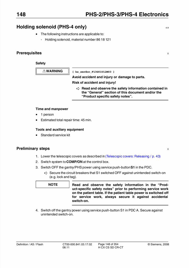
8/12/2019 CT00-000.841.03.17.02.pdf
http://slidepdf.com/reader/full/ct00-000841031702pdf 148/353
148 PHS-2/PHS-3/PHS-4 Electronics
Definition / AS / Flash CT00-000.841.03.17.02 © Siemens, 200808.11 H CX CS SD CR-CT
Page 148 of 354
Holding solenoid (PHS-4 only) 4.9
• The following instructions are applicable to:
- Holding solenoid, material number 86 18 121
Prerequisites 0
Safety
WARNING [ hz_serdoc_F13G01U12M03 ]
Avoid accident and injury or damage to parts.
Risk of accident and injury!
Read and observe the safety information contained in
the “General” section of this document and/or the“Product specific safety notes”.
Time and manpower
• 1 person
• Estimated total repair time: 45 min.
Tools and auxiliary equipment
•
Standard service kit
Preliminary steps 0
1. Lower the telescopic covers as described in (Telescopic covers: Releasing / p. 43)
2. Switch system toCOMP/ON at the control box.
3. Switch OFF the gantry/PHS power using service push-button S1 in the PDC.
Secure the circuit breakers that S1 switched OFF against unintended switch-on(e.g. lock and tag).
NOTE Read and observe the safety information in the “Prod-uct-specific safety notes” prior to performing service work on the patient table. If the patient table power is switched offfor service work, always secure it against accidentalswitch-on.
4. Switch off the gantry power using service push-button S1 in PDC A. Secure againstunintended switch-on.
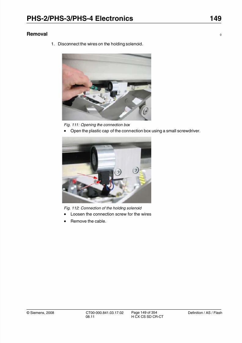
8/12/2019 CT00-000.841.03.17.02.pdf
http://slidepdf.com/reader/full/ct00-000841031702pdf 149/353
© Siemens, 2008 CT00-000.841.03.17.02 Definition / AS / Flash08.11 H CX CS SD CR-CT
PHS-2/PHS-3/PHS-4 Electronics 149
Page 149 of 354
Removal 0
1. Disconnect the wires on the holding solenoid.
Fig. 111: Opening the connection box
• Open the plastic cap of the connection box using a small screwdriver.
Fig. 112: Connection of the holding solenoid
• Loosen the connection screw for the wires
• Remove the cable.

8/12/2019 CT00-000.841.03.17.02.pdf
http://slidepdf.com/reader/full/ct00-000841031702pdf 150/353
150 PHS-2/PHS-3/PHS-4 Electronics
Definition / AS / Flash CT00-000.841.03.17.02 © Siemens, 200808.11 H CX CS SD CR-CT
Page 150 of 354
2. Remove the holding solenoid.
Installation 0
1. Installation is in the reverse order of removal.
2. Reinstall all covers.
Startup 0
Electrical
1. Switch on circuit breakers F2, F3, F5, F6, F7, and F11 in the PDC A and F2 in the PDCB (not for Definition AS).
First switch the F2, F3, F5, F6 circuit breakers to the “0” position and then to the“1” position.
2. Switch the system to the SYSTEM/ON status at the control box.
Software
n.a.
Tune-up
n.a.
Tests
1. Test the function of the system
Fig. 113: Attachment of the holding solenoid
• Open the screw using a 4-mm Allen key.
• Remove the holding solenoid.

8/12/2019 CT00-000.841.03.17.02.pdf
http://slidepdf.com/reader/full/ct00-000841031702pdf 151/353
© Siemens, 2008 CT00-000.841.03.17.02 Definition / AS / Flash08.11 H CX CS SD CR-CT
PHS-2/PHS-3/PHS-4 Electronics 151
Page 151 of 354
PMM Module 4.10
• The following instructions are applicable to:
- PMM Module, material number 19 78 451
Prerequisites 0
Safety
WARNING [ hz_serdoc_F13G01U12M03 ]
Avoid accident and injury or damage to parts.
Risk of accident and injury!
Read and observe the safety information contained in
the “General” section of this document and/or the“Product specific safety notes”.
Time and manpower
• 1 person
• Estimated total repair time: 20 min.
Tools and Auxiliary Equipment
•
Standard service kit
Preliminary steps 0
1. Raise the patient table to height of 125.
2. Shut down the system software (click <SYSTEM> and select <END> in the user mainmenu).
3. Click Shutdown System
4. Confirm with Yes in the dialog box displayed.
NOTE Read and observe the safety information in the “Prod-uct-specific safety notes” prior to performing service work on the patient table. If the patient table power is switched offfor service work, always secure it against accidentalswitch-on.

8/12/2019 CT00-000.841.03.17.02.pdf
http://slidepdf.com/reader/full/ct00-000841031702pdf 152/353
152 PHS-2/PHS-3/PHS-4 Electronics
Definition / AS / Flash CT00-000.841.03.17.02 © Siemens, 200808.11 H CX CS SD CR-CT
Page 152 of 354
Removing 0
1. Remove the PMM module.
2. Release the plug.
Fig. 114: PMM module securing screws
• Remove plastic caps and release 2 screws holding the PMM modulein the PMM box.
Fig. 115: PMM plug and terminator
• Lift out the module and disconnect plug X1 - see (1).
• Only for PMMs with revision level lower than 05: Remove externalCanOpen terminator X2 - see (2).

8/12/2019 CT00-000.841.03.17.02.pdf
http://slidepdf.com/reader/full/ct00-000841031702pdf 153/353
© Siemens, 2008 CT00-000.841.03.17.02 Definition / AS / Flash08.11 H CX CS SD CR-CT
PHS-2/PHS-3/PHS-4 Electronics 153
Page 153 of 354
Installation 0
1. Installation is in reverse order of removal.
NOTE On PMMs with revision level 05 and higher, the CanOpen ter-
minator is installed in the module. Therefore, the externalresistor in plug X2 is no longer required.
Do not install plug X2!
Startup 0
Electrical
1. Press the Sys On key on the control box. The whole system is ready for operation whenthe Sys On LED is lit and the operating elements on the control box are backlit.
Software
1. If the system shows a fatal firmware mismatch, the new firmware has to be installed:
Go to Local Service > Control > Firmware to load the current firmware version.
Tune-up
n.a.
Tests
1. Activate the ECG Monitor Demo mode.
- Select: Control > Configuration
- Select: Heartview
- Mark the checkbox “ECG Monitor Demo mode”
- Press <Apply>
An ECG pulse must be seen on the gantry display.
2. Deactivate the ECG Monitor Demo mode by deselecting the checkbox in the Heartview
window.
Final Steps 0
1. Clean.

8/12/2019 CT00-000.841.03.17.02.pdf
http://slidepdf.com/reader/full/ct00-000841031702pdf 154/353
154 PHS-2/PHS-3/PHS-4 Electronics
Definition / AS / Flash CT00-000.841.03.17.02 © Siemens, 200808.11 H CX CS SD CR-CT
Page 154 of 354
PMM Cable (Top Support) 4.11
• The following instructions are applicable to:
- PHS PMM cable top support, 86 14 757
Prerequisites 0
Safety
WARNING [ hz_serdoc_F13G01U12M03 ]
Avoid accident and injury or damage to parts.
Risk of accident and injury!
Read and observe the safety information contained in
the “General” section of this document and/or the“Product specific safety notes”.
Time and manpower
• 1 person
• Estimated total repair time: 45 min.
Tools and Auxiliary Equipment
•
Standard service kit
Preliminary steps 0
1. Raise table to height of 125.
2. Switch system toCOMP/ON at the control box.
3. Switch OFF the gantry/PHS power using service push-button S1 in the PDC.
Secure the circuit breakers that S1 switched OFF against unintended switch-on(e.g. lock and tag).
NOTE Read and observe the safety information in the “Prod-uct-specific safety notes” prior to performing service work on the patient table. If the patient table power is switched offfor service work, always secure it against accidentalswitch-on.
4. Feed in the tabletop plate and remove the tabletop covers (Tabletop covers (front andrear) / p. 29).

8/12/2019 CT00-000.841.03.17.02.pdf
http://slidepdf.com/reader/full/ct00-000841031702pdf 155/353
© Siemens, 2008 CT00-000.841.03.17.02 Definition / AS / Flash08.11 H CX CS SD CR-CT
PHS-2/PHS-3/PHS-4 Electronics 155
Page 155 of 354
Removing 0
1. Remove the PMM module (PMM Module / p. 151) and cut accessible cable ties.Remove the plug through the slot in the tabletop. Any ties that cannot be accessed atthe moment can be cut later.
2. Move the tabletop to the position shown in the figure below.
Fig. 116: Position for removing the bracket
3. Remove the bracket for the PMM cable.
- Loosen the attachment screw at the rear (2 /Fig. 117 / p. 155).
- Loosen the two screws on the bottom (1/ Fig. 118 / p. 155)
Fig. 117: Attaching bracket Pos. 1 Attaching bracket
Pos. 2 Attachment screw, rear
Fig. 118: View toward the bottom Pos. 1 Attachment screws
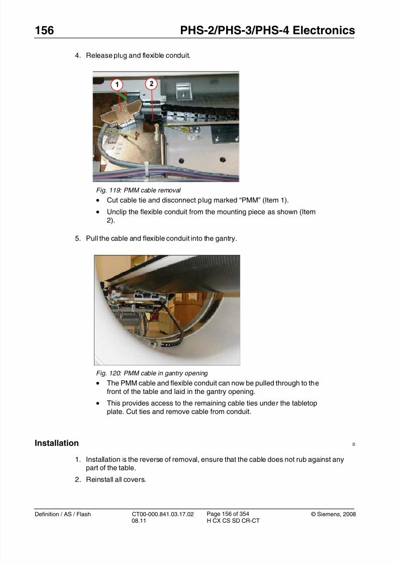
8/12/2019 CT00-000.841.03.17.02.pdf
http://slidepdf.com/reader/full/ct00-000841031702pdf 156/353
156 PHS-2/PHS-3/PHS-4 Electronics
Definition / AS / Flash CT00-000.841.03.17.02 © Siemens, 200808.11 H CX CS SD CR-CT
Page 156 of 354
4. Release plug and flexible conduit.
5. Pull the cable and flexible conduit into the gantry.
Installation 0
1. Installation is the reverse of removal, ensure that the cable does not rub against anypart of the table.
2. Reinstall all covers.
Fig. 119: PMM cable removal • Cut cable tie and disconnect plug marked “PMM” (Item 1).
• Unclip the flexible conduit from the mounting piece as shown (Item2).
Fig. 120: PMM cable in gantry opening
• The PMM cable and flexible conduit can now be pulled through to thefront of the table and laid in the gantry opening.
• This provides access to the remaining cable ties under the tabletopplate. Cut ties and remove cable from conduit.

8/12/2019 CT00-000.841.03.17.02.pdf
http://slidepdf.com/reader/full/ct00-000841031702pdf 157/353

8/12/2019 CT00-000.841.03.17.02.pdf
http://slidepdf.com/reader/full/ct00-000841031702pdf 158/353
158 PHS-2/PHS-3/PHS-4 Electronics
Definition / AS / Flash CT00-000.841.03.17.02 © Siemens, 200808.11 H CX CS SD CR-CT
Page 158 of 354
PMM cable (vertical lift) 4.12
• The following instructions are applicable to:
- PMM cable vertical lift, material number 86 14 740
Prerequisites 0
Safety
WARNING [ hz_serdoc_F13G01U12M03 ]
Avoid accident and injury or damage to parts.
Risk of accident and injury!
Read and observe the safety information contained in
the “General” section of this document and/or the“Product specific safety notes”.
Time and manpower
• 1 person
• Estimated total repair time: 1 hr.
Tools and Auxiliary Equipment
•
Standard service kit
Preliminary steps 0
1. Raise table to height of 125.
2. Switch system toCOMP/ON at the control box.
3. Switch OFF the gantry/PHS power using service push-button S1 in the PDC.
Secure the circuit breakers that S1 switched OFF against unintended switch-on(e.g. lock and tag).
NOTE Read and observe the safety information in the “Prod-uct-specific safety notes” prior to performing service work on the patient table. If the patient table power is switched offfor service work, always secure it against accidentalswitch-on.
4. Release the telescopic covers (Telescopic covers: Releasing / p. 43).
5. Remove the electronics cover (Table electronics cover / p. 57).
6. Remove the telescopic covers (Telescopic covers: Removing / p. 52).
7. Remove the lower rear tabletop cover (Tabletop lower rear cover / p. 32).

8/12/2019 CT00-000.841.03.17.02.pdf
http://slidepdf.com/reader/full/ct00-000841031702pdf 159/353
© Siemens, 2008 CT00-000.841.03.17.02 Definition / AS / Flash08.11 H CX CS SD CR-CT
PHS-2/PHS-3/PHS-4 Electronics 159
Page 159 of 354
8. Feed in the tabletop plate and remove the tabletop covers (Tabletop covers (front andrear) / p. 29).
Removing0
1. Release plug at electronics tray.
Fig. 121: PMM plug location
• Release plug marked “PMM” (item 1) and cut cable ties up to verticalflexible conduit.
• Cut cable ties holding cables between horizontal and vertical flexibleconduits.
• Pull the cable out of the vertical flexible conduit. Removal from thispoint may involve partial withdrawal of the PHS cable set; refer toinstructions on replacement of PHS cable set (PHS CableSet / p. 162)

8/12/2019 CT00-000.841.03.17.02.pdf
http://slidepdf.com/reader/full/ct00-000841031702pdf 160/353
160 PHS-2/PHS-3/PHS-4 Electronics
Definition / AS / Flash CT00-000.841.03.17.02 © Siemens, 200808.11 H CX CS SD CR-CT
Page 160 of 354
2. Release plug at support end.
Installation 0
1. Installation is in the reverse order of removal. Prior to installing the cable ties, refer to
installing the PHS cable set (PHS Cable Set / p. 162)and follow instructions regardingcable placement in the flexible conduit.
2. Reinstall all covers.
Fig. 122: PMM cable at support end
•Cut cable ties, release plug marked “PMM” (Item 1), and feed plugunder support bridge (Item 2) <<Later models have removable postin bridge>>.
• Cable can now be pulled out of the tabletop support flexible conduit,again refer to instructions on the replacement of PHS cable set (PHSCable Set / p. 162).

8/12/2019 CT00-000.841.03.17.02.pdf
http://slidepdf.com/reader/full/ct00-000841031702pdf 161/353
© Siemens, 2008 CT00-000.841.03.17.02 Definition / AS / Flash08.11 H CX CS SD CR-CT
PHS-2/PHS-3/PHS-4 Electronics 161
Page 161 of 354
Startup 0
Electrical
1. Switch on circuit breakers F2, F3, F5, F6, F7, and F11 in the PDC A and F2 in the PDCB (not for Definition AS).
First switch the F2, F3, F5, F6 circuit breakers to the “0” position and then to the“1” position.
2. Switch the system to the SYSTEM/ON status at the control box.
Software
n.a.
Tune-up
n.a.
Tests
1. Perform a test scan
Final Steps 0
1. Clean.
8/12/2019 CT00-000.841.03.17.02.pdf
http://slidepdf.com/reader/full/ct00-000841031702pdf 162/353
162 PHS-2/PHS-3/PHS-4 Electronics
Definition / AS / Flash CT00-000.841.03.17.02 © Siemens, 200808.11 H CX CS SD CR-CT
Page 162 of 354
PHS Cable Set 4.13
• The following instructions are applicable to:
- PHS cable set PHS3 and PHS-4, material number 86 14 724
Prerequisites 0
Safety
WARNING [ hz_serdoc_F13G01U12M03 ]
Avoid accident and injury or damage to parts.
Risk of accident and injury!
Read and observe the safety information contained in
the “General” section of this document and/or the“Product specific safety notes”.
Time and manpower
• 1 person
• Estimated total repair time: 1 1/2 hours.
Tools and Auxiliary Equipment
•
Standard service kit
Preliminary steps 0
1. Raise table to height of 125.
2. Switch system toCOMP/ON at the control box.
3. Switch OFF the gantry/PHS power using service push-button S1 in the PDC.
Secure the circuit breakers that S1 switched OFF against unintended switch-on(e.g. lock and tag).
NOTE Read and observe the safety information in the “Prod-uct-specific safety notes” prior to performing service work on the patient table. If the patient table power is switched offfor service work, always secure it against accidentalswitch-on.
4. Release the telescopic covers (Telescopic covers: Releasing / p. 43).
5. Remove the electronics cover (Table electronics cover / p. 57).
6. Remove the telescopic covers (Telescopic covers: Removing / p. 52).
7. Remove the lower rear tabletop cover (Tabletop lower rear cover / p. 32).
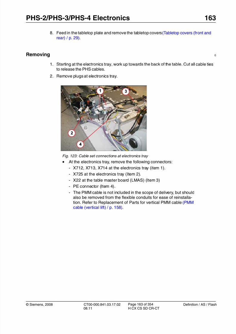
8/12/2019 CT00-000.841.03.17.02.pdf
http://slidepdf.com/reader/full/ct00-000841031702pdf 163/353
© Siemens, 2008 CT00-000.841.03.17.02 Definition / AS / Flash08.11 H CX CS SD CR-CT
PHS-2/PHS-3/PHS-4 Electronics 163
Page 163 of 354
8. Feed in the tabletop plate and remove the tabletop covers (Tabletop covers (front andrear) / p. 29).
Removing0
1. Starting at the electronics tray, work up towards the back of the table. Cut all cable tiesto release the PHS cables.
2. Remove plugs at electronics tray.
Fig. 123: Cable set connections at electronics tray
• At the electronics tray, remove the following connectors:
- X712, X713, X714 at the electronics tray (item 1).
- X725 at the electronics tray (Item 2).
- X22 at the table master board (LMAS) (Item 3)
- PE connector (Item 4).
- The PMM cable is not included in the scope of delivery, but shouldalso be removed from the flexible conduits for ease of reinstalla-tion. Refer to Replacement of Parts for vertical PMM cable (PMMcable (vertical lift) / p. 158).

8/12/2019 CT00-000.841.03.17.02.pdf
http://slidepdf.com/reader/full/ct00-000841031702pdf 164/353

8/12/2019 CT00-000.841.03.17.02.pdf
http://slidepdf.com/reader/full/ct00-000841031702pdf 165/353
© Siemens, 2008 CT00-000.841.03.17.02 Definition / AS / Flash08.11 H CX CS SD CR-CT
PHS-2/PHS-3/PHS-4 Electronics 165
Page 165 of 354
5. Remove cables from horizontal flexible conduit.
Fig. 126: Removing support post and ground connectors • PMM cable tray removed for clarity.
• Remove the support post (Item 1) (not included on early systems).
• Remove PE connections (Item 2).
• Pull cables from flexible conduit. At this point the PMM cable is alsopartially removed, but will be reinstalled with the new cable set.

8/12/2019 CT00-000.841.03.17.02.pdf
http://slidepdf.com/reader/full/ct00-000841031702pdf 166/353
166 PHS-2/PHS-3/PHS-4 Electronics
Definition / AS / Flash CT00-000.841.03.17.02 © Siemens, 200808.11 H CX CS SD CR-CT
Page 166 of 354
6. Remove plugs at the back of the table.
7. Cut all cable ties and remove all cable clamps; the cable set can now be removed.
Installation 0
1. Lay the new cable in place, include the PMM cable and service panel cable, and makesure the cables are parallel and not crossed. Then push them into the flexible conduitsuntil fully inserted and the plastic “leaves” have sprung back and are touching again.
2. Reconnect all plugs and ground connections, reinstall support post.
3. Replace cable ties. Ensure that cables in the flexible conduits are not to taught andhave sufficient freedom to flex fully. Check again that the cables in the flexible conduitare parallel and do not cross each other.
4. Reinstall all covers.
Fig. 127: View from back, PHS cable loom replacement
• At the back of the table, remove the following connectors:
- X5, X6 at one end of each motor controller.
- X1,X2 at the other end of each motor controller. At both controllersalso remove the 4 wires (to motor) from connector X2 pins 1, 3.
- X752 to back switchplate (Item 1).
- B721 and B731 to the horizontal motors (Item 2).
- PE connectors (item 3).
- Disconnect plug B722 to support sensor and B732 to top sensor.

8/12/2019 CT00-000.841.03.17.02.pdf
http://slidepdf.com/reader/full/ct00-000841031702pdf 167/353
© Siemens, 2008 CT00-000.841.03.17.02 Definition / AS / Flash08.11 H CX CS SD CR-CT
PHS-2/PHS-3/PHS-4 Electronics 167
Page 167 of 354
Startup 0
Electrical
1. Switch on circuit breakers F2, F3, F5, F6, F7, and F11 in the PDC A and F2 in the PDCB (not for Definition AS).
First switch the F2, F3, F5, F6 circuit breakers to the “0” position and then to the“1” position.
2. Switch the system to the SYSTEM/ON status at the control box.
Software
n.a.
Tune-up
n.a.
Tests
1. Perform a test scan
Final Steps 0
1. Clean.

8/12/2019 CT00-000.841.03.17.02.pdf
http://slidepdf.com/reader/full/ct00-000841031702pdf 168/353
168 PHS-1B Covers
Definition / AS / Flash CT00-000.841.03.17.02 © Siemens, 200808.11 H CX CS SD CR-CT
Page 168 of 354
5-5PHS-1BCovers
Overview 0
Fig. 128: PHS-1B: Covers, rear view Pos. 1 Tabletop
Pos. 2 Rubber bumper
Pos. 3 Back cover
Pos. 4 Back basin
Pos. 5 Bottom arc sheet
Pos. 6 Base cover
Pos. 7 Cover plates, right side (R1, R2, R3)
Pos. 8 Center cover
Pos. 9 Electronics cover

8/12/2019 CT00-000.841.03.17.02.pdf
http://slidepdf.com/reader/full/ct00-000841031702pdf 169/353
© Siemens, 2008 CT00-000.841.03.17.02 Definition / AS / Flash08.11 H CX CS SD CR-CT
PHS-1B Covers 169
Page 169 of 354
Fig. 129: PHS-1B: Covers, front view Pos. 1 Front cover
Pos. 2 Base cover
Covers described in this document:
• Tabletop
• Back cover
• Back basin
• Base cover
• Center cover
• Front cover

8/12/2019 CT00-000.841.03.17.02.pdf
http://slidepdf.com/reader/full/ct00-000841031702pdf 170/353
170 PHS-1B Covers
Definition / AS / Flash CT00-000.841.03.17.02 © Siemens, 200808.11 H CX CS SD CR-CT
Page 170 of 354
Tabletop 5.1
Prerequisites 0
Safety
WARNING [ hz_serdoc_F13G01U12M03 ]
Avoid accident and injury or damage to parts.
Risk of accident and injury!
Read and observe the safety information contained inthe “General” section of this document and/or the“Product specific safety notes”.
Time and manpower
• 1 person
• Estimated total repair time: 1 hour
Tools and auxiliary equipment
• Standard service kit
Preliminary Steps 0
1. Move the table into the uppermost position.
2. Move the tabletop into the gantry.
3. Switch system to the COMP/ON status at the control box.
4. Switch off the gantry/PHS power using the S1 service button in the PDC. Secureagainst unintended switch-on the breakers that S1 switched off (e.g. lock and tag).
5. Remove the back cover and the back basin cover.

8/12/2019 CT00-000.841.03.17.02.pdf
http://slidepdf.com/reader/full/ct00-000841031702pdf 171/353
© Siemens, 2008 CT00-000.841.03.17.02 Definition / AS / Flash08.11 H CX CS SD CR-CT
PHS-1B Covers 171
Page 171 of 354
Removal 0
1. Loosen the 16 screws (8 on each side) reachable from the bottom up.
Fig. 130: Attachment screws for tabletop (only one side shown) 2. Remove the tabletop from the carriage.
Installation 0
1. Install the tabletop in the reverse order.
NOTE Before tightening the attachment screws make sure that thetabletop is aligned correctly.
Startup 0
Mechanical
1. Install the back basin cover.
Electrical
1. Switch on breakers F2, F3, F5, F6, F7, and F11 in the PDC.
First switch the F2, F3, F5, F6 breakers to the “0” position and then to the “1” posi-tion.
2. Switch the system to the SYSTEM/ON status at the control box.
Software
n.a.
Tune-up
n.a.

8/12/2019 CT00-000.841.03.17.02.pdf
http://slidepdf.com/reader/full/ct00-000841031702pdf 172/353
172 PHS-1B Covers
Definition / AS / Flash CT00-000.841.03.17.02 © Siemens, 200808.11 H CX CS SD CR-CT
Page 172 of 354
Tests
1. First move the tabletop manually, then with the help of the service console.
2. Perform a test scan.
Final Steps 0
1. Clean.

8/12/2019 CT00-000.841.03.17.02.pdf
http://slidepdf.com/reader/full/ct00-000841031702pdf 173/353
© Siemens, 2008 CT00-000.841.03.17.02 Definition / AS / Flash08.11 H CX CS SD CR-CT
PHS-1B Covers 173
Page 173 of 354
Back Basin, Center Cover, and Front Cover 5.2
Prerequisites 0
Safety
WARNING [ hz_serdoc_F13G01U12M03 ]
Avoid accident and injury or damage to parts.
Risk of accident and injury!
Read and observe the safety information contained inthe “General” section of this document and/or the“Product specific safety notes”.
Time and manpower
• 1 person
• Estimated total repair time: 15 min.
Tools and auxiliary equipment
• Standard service kit
Preliminary Steps 0
1. Move the table into the uppermost position.
2. Switch system to the COMP/ON status at the control box.
3. Switch off the gantry/PHS power using the S1 service button in the PDC. Secureagainst unintended switch-on the breakers that S1 switched off (e.g. lock and tag).
Removal 0
Back basin
NOTE For easier removal of the back basin it is recommended toremove the back cover first.
1. Loosen the 4 attachment screws from below
2. Remove the back basin
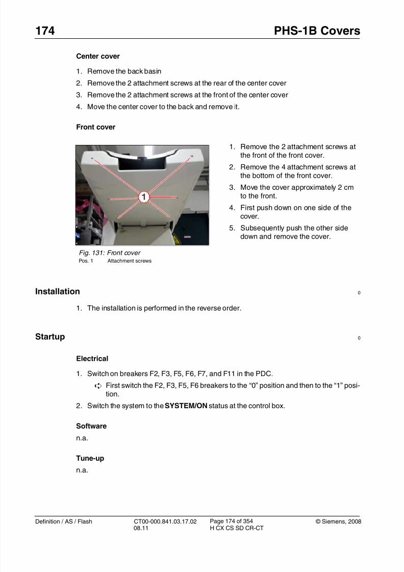
8/12/2019 CT00-000.841.03.17.02.pdf
http://slidepdf.com/reader/full/ct00-000841031702pdf 174/353
174 PHS-1B Covers
Definition / AS / Flash CT00-000.841.03.17.02 © Siemens, 200808.11 H CX CS SD CR-CT
Page 174 of 354
Center cover
1. Remove the back basin
2. Remove the 2 attachment screws at the rear of the center cover
3. Remove the 2 attachment screws at the front of the center cover4. Move the center cover to the back and remove it.
Front cover
Installation 0
1. The installation is performed in the reverse order.
Startup 0
Electrical
1. Switch on breakers F2, F3, F5, F6, F7, and F11 in the PDC.
First switch the F2, F3, F5, F6 breakers to the “0” position and then to the “1” posi-tion.
2. Switch the system to the SYSTEM/ON status at the control box.
Software
n.a.
Tune-up
n.a.
Fig. 131: Front cover Pos. 1 Attachment screws
1. Remove the 2 attachment screws atthe front of the front cover.
2. Remove the 4 attachment screws atthe bottom of the front cover.
3. Move the cover approximately 2 cm
to the front.
4. First push down on one side of thecover.
5. Subsequently push the other sidedown and remove the cover.

8/12/2019 CT00-000.841.03.17.02.pdf
http://slidepdf.com/reader/full/ct00-000841031702pdf 175/353
© Siemens, 2008 CT00-000.841.03.17.02 Definition / AS / Flash08.11 H CX CS SD CR-CT
PHS-1B Covers 175
Page 175 of 354
Tests
1. Check the movement of the table via the service keypad.
2. Perform a test scan.
Final Steps 0
1. Clean.

8/12/2019 CT00-000.841.03.17.02.pdf
http://slidepdf.com/reader/full/ct00-000841031702pdf 176/353
176 PHS-1B Covers
Definition / AS / Flash CT00-000.841.03.17.02 © Siemens, 200808.11 H CX CS SD CR-CT
Page 176 of 354
Base Cover, Electronics Cover 5.3
Prerequisites 0
Safety
WARNING [ hz_serdoc_F13G01U12M03 ]
Avoid accident and injury or damage to parts.
Risk of accident and injury!
Read and observe the safety information contained inthe “General” section of this document and/or the“Product specific safety notes”.
Time and manpower
• 1 person
• Estimated total repair time: 15 min.
Tools and auxiliary equipment
• Standard service kit
Preliminary Steps 0
1. Move the table into the uppermost position.
2. Switch system to the COMP/ON status at the control box.
3. Switch off the gantry/PHS power using the S1 service button in the PDC. Secureagainst unintended switch-on the breakers that S1 switched off (e.g. lock and tag).

8/12/2019 CT00-000.841.03.17.02.pdf
http://slidepdf.com/reader/full/ct00-000841031702pdf 177/353
© Siemens, 2008 CT00-000.841.03.17.02 Definition / AS / Flash08.11 H CX CS SD CR-CT
PHS-1B Covers 177
Page 177 of 354
Removal 0
Base cover (left and right side)
Fig. 132: Base cover Pos. 1 Attachment screws
• Loosen the 4 attachment screws onthe left and right side of the basecover.
Fig. 133: Base cover - front view Pos. 1 Attachment screws
Fig. 134: Base cover - rear view Pos. 1 Attachment screws
• Loosen the 2 attachment screws onthe front and back of the base cover.
• Remove both base covers.

8/12/2019 CT00-000.841.03.17.02.pdf
http://slidepdf.com/reader/full/ct00-000841031702pdf 178/353
178 PHS-1B Covers
Definition / AS / Flash CT00-000.841.03.17.02 © Siemens, 200808.11 H CX CS SD CR-CT
Page 178 of 354
Electronics cover
Installation 0
1. The installation is performed in the reverse order.
NOTE When installing the bottom covers, make sure that the cas-tors of the bottom arc sheet are on top of the bottom coverguides (see arrow).
Fig. 136: Bottom arc sheet
Startup 0
Electrical
1. Switch on breakers F2, F3, F5, F6, F7, and F11 in the PDC.
First switch the F2, F3, F5, F6 breakers to the “0” position and then to the “1” posi-tion.
2. Switch the system to the SYSTEM/ON status at the control box.
Fig. 135: Electronics cover - attachment screws,left side
1. Remove the left and right base cov-ers
2. Loosen the 2 attachment screws onboth sides of the electronics cover
3. Remove the electronics cover.

8/12/2019 CT00-000.841.03.17.02.pdf
http://slidepdf.com/reader/full/ct00-000841031702pdf 179/353
© Siemens, 2008 CT00-000.841.03.17.02 Definition / AS / Flash08.11 H CX CS SD CR-CT
PHS-1B Covers 179
Page 179 of 354
Software
n.a.
Tune-up
n.a.
Tests
1. Check the movement of the table via the service keypad.
2. Perform a test scan.
Final Steps 0
1. Clean.

8/12/2019 CT00-000.841.03.17.02.pdf
http://slidepdf.com/reader/full/ct00-000841031702pdf 180/353
180 PHS-1B Mechanical and Electronic
Definition / AS / Flash CT00-000.841.03.17.02 © Siemens, 200808.11 H CX CS SD CR-CT
Page 180 of 354
6-6PHS-1BMechanicaland Electronic
Overview 0
This chapter describes the removal and replacement of the following components:
• Boards within the electronics tray
• Horizontal drive assembly• Horizontal drive belt
• Vertical encoder
• Wire sensor
• Vertical drive
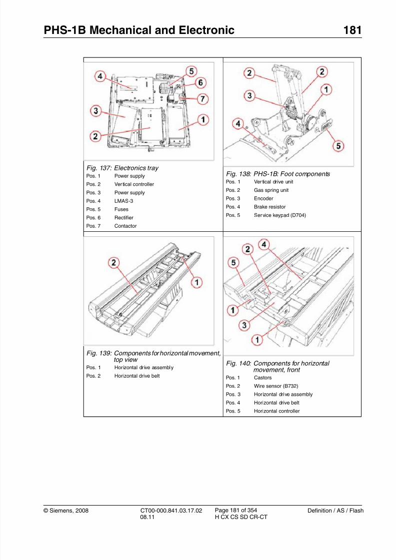
8/12/2019 CT00-000.841.03.17.02.pdf
http://slidepdf.com/reader/full/ct00-000841031702pdf 181/353
© Siemens, 2008 CT00-000.841.03.17.02 Definition / AS / Flash08.11 H CX CS SD CR-CT
PHS-1B Mechanical and Electronic 181
Page 181 of 354
Fig. 137: Electronics tray Pos. 1 Power supply
Pos. 2 Ver tical controller
Pos. 3 Power supply
Pos. 4 LMAS-3
Pos. 5 Fuses
Pos. 6 Rectifier
Pos. 7 Contactor
Fig. 138: PHS-1B: Foot components Pos. 1 Ver tical drive unit
Pos. 2 Gas spring unitPos. 3 Encoder
Pos. 4 Brake resistor
Pos. 5 Service keypad (D704)
Fig. 139: Components for horizontal movement,top view
Pos. 1 Horizontal dr ive assembly
Pos. 2 Horizontal drive belt
Fig. 140: Components for horizontalmovement, front
Pos. 1 Castors
Pos. 2 Wire sensor (B732)
Pos. 3 Horizontal drive assembly
Pos. 4 Horizontal drive belt
Pos. 5 Horizontal controller
8/12/2019 CT00-000.841.03.17.02.pdf
http://slidepdf.com/reader/full/ct00-000841031702pdf 182/353
182 PHS-1B Mechanical and Electronic
Definition / AS / Flash CT00-000.841.03.17.02 © Siemens, 200808.11 H CX CS SD CR-CT
Page 182 of 354
Boards within the Electronics Tray 6.1
Prerequisites 0
Safety
WARNING [ hz_serdoc_F13G01U12M03 ]
Avoid accident and injury or damage to parts.
Risk of accident and injury!
Read and observe the safety information contained inthe “General” section of this document and/or the“Product specific safety notes”.
Time and manpower
• 1 person
• Estimated total repair time: 1 hr.
Tools and auxiliary equipment
• Standard service kit
Preliminary Steps 0
1. Move the table into the uppermost position.
2. Move the tabletop into the gantry.
3. Switch system to the COMP/ON status at the control box.
4. Switch off the gantry/PHS power using the S1 service button in the PDC. Secureagainst unintended switch-on the breakers that S1 switched off (e.g. lock and tag).
5. Remove the cover of the electronics tray.
Removal 0
1. Remove all cable connections of the component which has to be replaced:
2. Loosen the attachment screws of the component which has to be replaced.
3. Take out the component.

8/12/2019 CT00-000.841.03.17.02.pdf
http://slidepdf.com/reader/full/ct00-000841031702pdf 183/353
© Siemens, 2008 CT00-000.841.03.17.02 Definition / AS / Flash08.11 H CX CS SD CR-CT
PHS-1B Mechanical and Electronic 183
Page 183 of 354
Installation 0
1. Install the new component in the reverse order.
Startup 0
Electrical
1. Switch on breakers F2, F3, F5, F6, F7, and F11 in the PDC.
First switch the F2, F3, F5, F6 breakers to the “0” position and then to the “1” posi-tion.
2. Switch the system to the SYSTEM/ON status at the control box.
Softwaren.a.
Tune-up
For LMAS-3 or motor controller only::
• Select: FRU Replacement
• Select: PHS - LMAS (for the LMAS-3)
or
• Select: PHS - Motor controller hor./vert. (for vertical motor controller).
• Press <Go> to start the tour.
The Auto_Complete is started and checks which adjustments are required.
Follow the instructions of the Auto_Complete routine.
Tests
1. Check the function of the table.
2. Perform a test scan
Final Steps 0
1. Clean.

8/12/2019 CT00-000.841.03.17.02.pdf
http://slidepdf.com/reader/full/ct00-000841031702pdf 184/353
184 PHS-1B Mechanical and Electronic
Definition / AS / Flash CT00-000.841.03.17.02 © Siemens, 200808.11 H CX CS SD CR-CT
Page 184 of 354
Horizontal Drive Assembly 6.2
Prerequisites 0
Safety
WARNING [ hz_serdoc_F13G01U12M03 ]
Avoid accident and injury or damage to parts.
Risk of accident and injury!
Read and observe the safety information contained inthe “General” section of this document and/or the“Product specific safety notes”.
Time and manpower
• 1 person
• Estimated total repair time: 1 hr.
Tools and auxiliary equipment
• Standard service kit
Preliminary Steps 0
1. Move the table into the uppermost position.
2. Switch system to the COMP/ON status at the control box.
3. Switch off the gantry/PHS power using the S1 service button in the PDC. Secureagainst unintended switch-on the breakers that S1 switched off (e.g. lock and tag).
4. Remove the back basin.
5. Remove the front cover
6. Move the tabletop manually into the gantry.
7. Remove the rear tabletop cover (this is required for the adjustment of the belt tension).
Removal 0
NOTE The horizontal drive assembly spare part is delivered as apreassembled component consisting of the motor, clutch,and pulley.
1. Cut the cable ties of the cables to the drive motor and the clutch.
2. Remove the cable connections of the horizontal drive on the motor controller.

8/12/2019 CT00-000.841.03.17.02.pdf
http://slidepdf.com/reader/full/ct00-000841031702pdf 185/353
© Siemens, 2008 CT00-000.841.03.17.02 Definition / AS / Flash08.11 H CX CS SD CR-CT
PHS-1B Mechanical and Electronic 185
Page 185 of 354
3. Disconnect the cable connection of the clutch.
Fig. 141: Clutch and wire sensor Pos. 1 Clutch
Pos. 2 Cable connection of clutch
Pos. 3 Wire sensor
Pos. 4 Cable connection of wire sensor
4. Disconnect the cable connection of the wire sensor.
5. Disconnect the wire of the wire sensor.
6. Release the tension of the toothed belt (Removal / p. 188).
a) Loosen the locknut.
b) Loosen the 2 attachment screws from below.
c) Release the belt tension by turning the adjustment screw counterclockwise.
Fig. 142: Wire of the wire sensor Pos. 1 Wire
Pos. 2 Locknut
Pos. 3 Fastening nut
• Loosen the locknut.
• Remove the fastening nut.
• Remove the wire from the attachmentbracket.
Note: Carefully hold the sensorwire with one hand when installingit at the brass assembly.
Do not let the sensor wire retract inan uncontrolled manner
Sudden retraction of the wire intothe sensor will destroy the sensor!
8/12/2019 CT00-000.841.03.17.02.pdf
http://slidepdf.com/reader/full/ct00-000841031702pdf 186/353
186 PHS-1B Mechanical and Electronic
Definition / AS / Flash CT00-000.841.03.17.02 © Siemens, 200808.11 H CX CS SD CR-CT
Page 186 of 354
7. Open the screws for the belt clamp and remove belt from the drive pulley.
Fig. 145: Belt clamp Pos. 1 Screws for belt clamp
8. Loosen the 4 attachment screws and remove the horizontal drive assembly
Fig. 146: Attachment screws of horizontal drive assembly
9. Remove the wire sensor from the old drive assembly (3 attachment screws)(Fig. 152 / p. 193).
Fig. 143: Belt tension adjuster - view from top Pos. 1 Locknut
Pos. 2 Adjustment screw
Fig. 144: Belt tension adjuster - view frombelow
Pos. 1 Attachment screws

8/12/2019 CT00-000.841.03.17.02.pdf
http://slidepdf.com/reader/full/ct00-000841031702pdf 187/353
© Siemens, 2008 CT00-000.841.03.17.02 Definition / AS / Flash08.11 H CX CS SD CR-CT
PHS-1B Mechanical and Electronic 187
Page 187 of 354
Installation 0
1. Install the wire sensor on the new drive assembly.
2. Install the horizontal drive assembly.
3. Install the belt and adjust the belt tension according to (Installation / p. 190).
NOTE The frequency measured with the belt tension meter has tobe 39 + 2 Hz.
4. Connect the cables for the motor, the wire sensor, and the clutch.
5. Secure the cables with the cable ties.
6. Install all covers.
Startup 0
Electrical
1. Switch on breakers F2, F3, F5, F6, F7, and F11 in the PDC.
First switch the F2, F3, F5, F6 breakers to the “0” position and then to the “1” posi-tion.
2. Switch the system to the SYSTEM/ON status at the control box.
Software
n.a.
Tune-up
n.a.
Tests
1. Check the horizontal movement of the tabletop via the buttons at the gantry control pan-els.
2. Perform a test scan
Final Steps 0
1. Clean.

8/12/2019 CT00-000.841.03.17.02.pdf
http://slidepdf.com/reader/full/ct00-000841031702pdf 188/353
188 PHS-1B Mechanical and Electronic
Definition / AS / Flash CT00-000.841.03.17.02 © Siemens, 200808.11 H CX CS SD CR-CT
Page 188 of 354
Tabletop Drive Belt 6.3
Prerequisites 0
Safety
WARNING [ hz_serdoc_F13G01U12M03 ]
Avoid accident and injury or damage to parts.
Risk of accident and injury!
Read and observe the safety information contained inthe “General” section of this document and/or the“Product specific safety notes”.
Time and manpower
• 1 person
• Estimated total repair time: 1.5 hours.
Tools and auxiliary equipment
• Standard service kit
• Belt tension meter, refer to SPC for the material number.
Preliminary Steps 0
1. Move the table into the uppermost position.
2. Move the tabletop into the gantry.
3. Switch system to the COMP/ON status at the control box.
4. Switch off the gantry/PHS power using the S1 service button in the PDC. Secureagainst unintended switch-on the breakers that S1 switched off (e.g. lock and tag).
5. Remove the front covers.
6. Remove the back cover.
7. Remove the rear tabletop cover.
Removal 0
1. Release the tension of the toothed belt
a) Loosen the locknut.
b) Loosen the 2 attachment screws from below.
c) Release the belt tension by turning the adjustment screw counterclockwise.

8/12/2019 CT00-000.841.03.17.02.pdf
http://slidepdf.com/reader/full/ct00-000841031702pdf 189/353
© Siemens, 2008 CT00-000.841.03.17.02 Definition / AS / Flash08.11 H CX CS SD CR-CT
PHS-1B Mechanical and Electronic 189
Page 189 of 354
2. Open the screws for the belt clamp and remove the belt.
Fig. 149: Belt clamp Pos. 1 Screws for belt clamp
Fig. 147: Belt tension adjuster - view from top Pos. 1 Locknut
Pos. 2 Adjustment screw
Fig. 148: Belt tension adjuster - view frombelow
Pos. 1 Attachment screws

8/12/2019 CT00-000.841.03.17.02.pdf
http://slidepdf.com/reader/full/ct00-000841031702pdf 190/353
190 PHS-1B Mechanical and Electronic
Definition / AS / Flash CT00-000.841.03.17.02 © Siemens, 200808.11 H CX CS SD CR-CT
Page 190 of 354
Installation 0
1. Perform the installation in the reverse order.
2. Measuring the belt tension using the belt tension meter:
The measurement has to be performed from above.Push the tabletop towards the gantry until you achieve a distance of 600 mm betweenthe center of the rear pulley and the belt clamp.
Place the sensor of the belt tension meter at the center of the trim length (= 300 mmfrom rear pulley) over the flat side of the belt. The distance between the sensor of thebelt tension meter and the belt should be about 5 to 20 mm.
Fig. 150: Measuring the belt tension Pos. 1 Rear pulley
Pos. 2 Belt clamp
Pos. 3 Measuring point
To learn how to use the tension meter, see the operating instructions delivered with themeter.
- Start belt vibration by hitting it with the head of a screwdriver.
- Perform the measurement.
- The resonance frequency must be 45 +2 Hz for correct belt tension.
NOTE The value 45 +2 Hz is only valid when the belt is replaced.When using the same belt, e.g. after replacement of the hori-zontal motor, the tension has to be adjusted to 39 +2 Hz.
3. Adjust the belt tension
- Adjust the belt tension with the adjusting screw
- Repeat measurement.
- Adjust until the required frequency is reached.
- Secure the attachment screws.
4. Install all covers.

8/12/2019 CT00-000.841.03.17.02.pdf
http://slidepdf.com/reader/full/ct00-000841031702pdf 191/353
© Siemens, 2008 CT00-000.841.03.17.02 Definition / AS / Flash08.11 H CX CS SD CR-CT
PHS-1B Mechanical and Electronic 191
Page 191 of 354
Startup 0
Electrical
1. Switch on breakers F2, F3, F5, F6, F7, and F11 in the PDC. First switch the F2, F3, F5, F6 breakers to the “0” position and then to the “1” posi-
tion.
2. Switch the system to the SYSTEM/ON status at the control box.
Software
n.a.
Tune-up
n.a.
Tests
1. Check the horizontal movement of the tabletop via the buttons at the gantry control pan-els.
2. Perform a test scan
Final Steps 0
1. Clean.

8/12/2019 CT00-000.841.03.17.02.pdf
http://slidepdf.com/reader/full/ct00-000841031702pdf 192/353
192 PHS-1B Mechanical and Electronic
Definition / AS / Flash CT00-000.841.03.17.02 © Siemens, 200808.11 H CX CS SD CR-CT
Page 192 of 354
Tabletop Position Wire Sensor B732 6.4
Prerequisites 0
Safety
WARNING [ hz_serdoc_F13G01U12M03 ]
Avoid accident and injury or damage to parts.
Risk of accident and injury!
Read and observe the safety information contained inthe “General” section of this document and/or the“Product specific safety notes”.
Time and manpower
• 1 person
• Estimated total repair time: 1 hour.
Tools and auxiliary equipment
• Standard service kit
Preliminary Steps 0
1. Move the table into the uppermost position.
2. Switch system to the COMP/ON status at the control box.
3. Switch off the gantry/PHS power using the S1 service button in the PDC. Secureagainst unintended switch-on the breakers that S1 switched off (e.g. lock and tag).
4. Remove the front cover
5. Move the tabletop manually into the gantry.

8/12/2019 CT00-000.841.03.17.02.pdf
http://slidepdf.com/reader/full/ct00-000841031702pdf 193/353
© Siemens, 2008 CT00-000.841.03.17.02 Definition / AS / Flash08.11 H CX CS SD CR-CT
PHS-1B Mechanical and Electronic 193
Page 193 of 354
Removal 0
1. Disconnect the connection cable of the wire sensor:
2. Remove the sensor wire.
3. Loosen the 3 attachment nuts and remove the sensor:
Fig. 152: Wire positioning sensor - attachment nuts and screws
Installation 0
NOTE Carefully hold the sensor wire with one hand when installingit at the brass assembly.
Do not let the sensor wire retract in an uncontrolled manner.
Sudden retraction of the wire into the sensor will destroy thesensor!
T 1. Install sensor with the 3 attachment nuts.
2. Draw the sensor wire out and attach the end to the bracket with the nut.
Fig. 151: Wire positioning sensor - removing thewire
Pos. 1 Locking nut
Pos. 2 Attachment nut
• Loosen the locking nut of the wire(No. 1).
• Remove the attachment nut (No. 2).
• Remove the wire from the holdingbracket
8/12/2019 CT00-000.841.03.17.02.pdf
http://slidepdf.com/reader/full/ct00-000841031702pdf 194/353
194 PHS-1B Mechanical and Electronic
Definition / AS / Flash CT00-000.841.03.17.02 © Siemens, 200808.11 H CX CS SD CR-CT
Page 194 of 354
3. Secure the sensor wire accordingly with the locking nut.
4. Reinstall all covers.
Startup 0
Electrical
1. Switch on breakers F2, F3, F5, F6, F7, and F11 in the PDC.
First switch the F2, F3, F5, F6 breakers to the “0” position and then to the “1” posi-tion.
2. Switch the system to the SYSTEM/ON status at the control box.
Software
n.a.
Tune-up
• Select: Local_Service > Tune-up
• Select: FRU Replacement
• Select: PHS - Encoder
• Press <Go> to start the tour.
The Auto_Complete is started and checks which adjustments are required.
Follow the instructions of the Auto_Complete routine.
Tests
1. Check the horizontal movement of the tabletop via the buttons at the gantry control pan-els.
2. Check the horizontal position display at the gantry display and/or control monitor.
3. Perform a test scan
Final Steps0
1. Clean.

8/12/2019 CT00-000.841.03.17.02.pdf
http://slidepdf.com/reader/full/ct00-000841031702pdf 195/353

8/12/2019 CT00-000.841.03.17.02.pdf
http://slidepdf.com/reader/full/ct00-000841031702pdf 196/353

8/12/2019 CT00-000.841.03.17.02.pdf
http://slidepdf.com/reader/full/ct00-000841031702pdf 197/353
© Siemens, 2008 CT00-000.841.03.17.02 Definition / AS / Flash08.11 H CX CS SD CR-CT
PHS-1B Mechanical and Electronic 197
Page 197 of 354
10. Using a punch and a hammer, remove the bolt from the spindle attachment.
11. Remove the old vertical drive.
12. Remove the encoder from the old vertical drive.
Installation 0
NOTE When installing the new vertical drive, use the new split pinsdelivered with the spare part.
1. Change the white plastic gear from the old vertical drive to the new one.
2. Install the encoder from the old drive to the new one.
3. Rotate the spindle shaft counterclockwise toward the mechanical end position and then
back again by 180 degrees.4. Place the new vertical drive on the lower spindle attachment and install the 14 mm bolt
from the left to the right side.
5. Secure the bolt with new split pins.
6. Install the 12 mm bolt. If necessary, adjust the spindle height by rotating the spindleshaft or by pushing the tabletop slightly upward.
7. Secure the bolt with new split pins.
8. Connect all cables and secure them with cable ties.
9. Remove the two stop bolts. If necessary, lift the table a little with the emergency crank.
Startup 0
Electrical
1. Switch on breakers F2, F3, F5, F6, F7, and F11 in the PDC.
First switch the F2, F3, F5, F6 breakers to the “0” position and then to the “1” posi-tion.
2. Switch the system to the SYSTEM/ON status at the control box.
Software
n.a.
Tune-up
• Select: Local_Service > TuneUp
• Select: FRU Replace
• Select: PHS - Encoder

8/12/2019 CT00-000.841.03.17.02.pdf
http://slidepdf.com/reader/full/ct00-000841031702pdf 198/353
198 PHS-1B Mechanical and Electronic
Definition / AS / Flash CT00-000.841.03.17.02 © Siemens, 200808.11 H CX CS SD CR-CT
Page 198 of 354
• Press <Go> to start the tour.
The Auto_Complete is started and checks which adjustments are required.
Follow the instructions of the Auto_Complete routine.
Tests
1. Perform a test scan
Final Steps 0
1. Clean.

8/12/2019 CT00-000.841.03.17.02.pdf
http://slidepdf.com/reader/full/ct00-000841031702pdf 199/353
8/12/2019 CT00-000.841.03.17.02.pdf
http://slidepdf.com/reader/full/ct00-000841031702pdf 200/353
200 PHS-1B Mechanical and Electronic
Definition / AS / Flash CT00-000.841.03.17.02 © Siemens, 200808.11 H CX CS SD CR-CT
Page 200 of 354
3. Removing the sensor:
Installation 0
1. Install the encoder in the reverse order.
Startup 0
Electrical
1. Switch on breakers F2, F3, F5, F6, F7, and F11 in the PDC.
First switch the F2, F3, F5, F6 breakers to the “0” position and then to the “1” posi-tion.
2. Switch the system to the SYSTEM/ON status at the control box.
Software
n.a.
Tune-up
• Select: Local_Service > Tune-up
• Select: FRU Replacement
• Select: PHS - Encoder
• Press <Go> to start the tour.
The Auto_Complete is started and checks which adjustments are required.
Follow the instructions of the Auto_Complete routine.
Fig. 156: Vertical encoder Pos. 1 Shaft clamp
Pos. 2 Attachment screw
• Loosen the screw on the shaft clamp.
• Remove the attachment screw.
• Pull the sensor out from the drive.

8/12/2019 CT00-000.841.03.17.02.pdf
http://slidepdf.com/reader/full/ct00-000841031702pdf 201/353

8/12/2019 CT00-000.841.03.17.02.pdf
http://slidepdf.com/reader/full/ct00-000841031702pdf 202/353

8/12/2019 CT00-000.841.03.17.02.pdf
http://slidepdf.com/reader/full/ct00-000841031702pdf 203/353

8/12/2019 CT00-000.841.03.17.02.pdf
http://slidepdf.com/reader/full/ct00-000841031702pdf 204/353
204 PHS-1B Mechanical and Electronic
Definition / AS / Flash CT00-000.841.03.17.02 © Siemens, 200808.11 H CX CS SD CR-CT
Page 204 of 354
Final Steps 0
1. Clean.

8/12/2019 CT00-000.841.03.17.02.pdf
http://slidepdf.com/reader/full/ct00-000841031702pdf 205/353
© Siemens, 2008 CT00-000.841.03.17.02 Definition / AS / Flash08.11 H CX CS SD CR-CT
MPT/MPT-2 covers 205
Page 205 of 354
7- 7MPT/MPT-2covers
Overview 0
This chapter describes the removal and replacement of the PHS covers.
The following instructions are applicable to:
• MPT, material number 8098225• MPT-2, material number 8097102
Fig. 158: MPT: Overview of covers Pos. 1 Telescopic covers (left/right)
Pos. 2 Switchplate cover
Pos. 3 Side support (left/r ight)
Pos. 4 Rear covers (lef t/r ight)
Pos. 5 Front covers (left/right)
Pos. 6 Handle / PMM box
Covers described in this document.• Tabletop covers (front and rear): (not shown) These are the covers underneath the
tabletop plate covering the support. They must be removed to gain access to the hori-zontal drive motors, tabletop belt, horizontal sensors, and horizontal controllers.
• Telescopic covers: (Item 1) The telescopic covers are divided into 4 segment pairs:
- Top cover (left/right) = top segment
- Upper telescopic cover (left/right) = upper middle segment
- Lower telescopic cover (left/right) = lower middle segment
- Foot cover (left/right) = base segment

8/12/2019 CT00-000.841.03.17.02.pdf
http://slidepdf.com/reader/full/ct00-000841031702pdf 206/353
206 MPT/MPT-2 covers
Definition / AS / Flash CT00-000.841.03.17.02 © Siemens, 200808.11 H CX CS SD CR-CT
Page 206 of 354
The whole cover assembly can be released at the tabletop and lowered to the tablebase for certain service operations at the tabletop and/or for complete removal.
For most service operations at the table base, the whole cover assembly can bereleased at the bottom (foot covers) and lifted with the help of a service tool (adjustable
strap with two hooks) to gain access to all components (e.g. electronics, vertical driveetc.) in the table base.
• Switchplate cover (Item 2) This cover must be removed to gain access to the switch-plate and the horizontal drive motors and belts.
• Side support. (Item 3) These are the aluminum covers on each side of the tabletopplate. They are normally only removed if damaged.
• Rear-end covers (Item 4) These are at each foot end of the side support covers.
NOTE: Both covers (left/right) are loosely mounted together in the middle. For removalboth covers must be removed.
• Front-end covers. (Item 5) These are at each front end (gantry side) of the side sup-
port covers.
• Handle / PMM box. (Item 6) This cover at the foot end of the tabletop sled incorporatesthe handle bar for manual tabletop movement. If the system has the PMM optioninstalled then this cover represents the PMM box (including the PMM electronics andterminals).
NOTE: For Replacement of Parts refer to section “MPT Electronics - PMM Box” (PMMBox / p. 331)

8/12/2019 CT00-000.841.03.17.02.pdf
http://slidepdf.com/reader/full/ct00-000841031702pdf 207/353

8/12/2019 CT00-000.841.03.17.02.pdf
http://slidepdf.com/reader/full/ct00-000841031702pdf 208/353
208 MPT/MPT-2 covers
Definition / AS / Flash CT00-000.841.03.17.02 © Siemens, 200808.11 H CX CS SD CR-CT
Page 208 of 354
Fig. 161: Grommet between the foot switches Fig. 162: Grommets for top covers (gantryside)
Fig. 163: Brass pin on cover Fig. 164: Example of a damaged grommet

8/12/2019 CT00-000.841.03.17.02.pdf
http://slidepdf.com/reader/full/ct00-000841031702pdf 209/353
© Siemens, 2008 CT00-000.841.03.17.02 Definition / AS / Flash08.11 H CX CS SD CR-CT
MPT/MPT-2 covers 209
Page 209 of 354
Tabletop covers (front and rear) 7.2
• The following instructions are applicable to:
- Front tabletop cover, material number 86 18 360
- Rear tabletop cover, material number 86 18 378
Prerequisites 0
Safety
WARNING [ hz_serdoc_F13G01U12M03 ]
Avoid accident and injury or damage to parts.
Risk of accident and injury!
Read and observe the safety information contained inthe “General” section of this document and/or the“Product specific safety notes”.
Time and Manpower
• 1 person
• Estimated total repair time: 10 min.
Tools and auxiliary equipment
• Standard service kit
Preliminary steps 0
1. Raise the patient table to maximum height (position 125) via the service buttons or, ifnot possible, via the mechanical lift.
2. Switch system to COMP/ON at the control box.
3. Switch OFF the gantry/PHS power using service push-button S1 in the PDC.
Secure the circuit breakers that S1 switched OFF against unintended switch-on(e.g. lock and tag).
NOTE Read and observe the safety information in the “Prod-uct-specific safety notes” prior to performing service work on the patient table. If the patient table power is switched offfor service work, always secure it against accidentalswitch-on.
For rear tabletop cover:
• Move the tabletop plate toward the gantry until all six mounting screws are accessible.

8/12/2019 CT00-000.841.03.17.02.pdf
http://slidepdf.com/reader/full/ct00-000841031702pdf 210/353
210 MPT/MPT-2 covers
Definition / AS / Flash CT00-000.841.03.17.02 © Siemens, 200808.11 H CX CS SD CR-CT
Page 210 of 354
• Remove the rear covers of the side support. (Front and rear covers (left/right) / p. 220)
For front tabletop cover:
• Move the tabletop plate all the way back toward the foot end of the table.
• Remove the tabletop plate. (Tabletop plate / p. 238)
• Remove the front covers of the side support. (Front and rear covers (left/right) / p. 220)
Removing 0
1. Removing the rear tabletop cover:
Fig. 165: MPT: Tabletop cover (rear)
Pos. 1 Mounting screws and plastic caps
• Remove the 6 plastic caps from the mounting holes (item 1).
• Remove the 6 mounting screws (item 1).
• Remove the cover by sliding it out to the rear.

8/12/2019 CT00-000.841.03.17.02.pdf
http://slidepdf.com/reader/full/ct00-000841031702pdf 211/353
© Siemens, 2008 CT00-000.841.03.17.02 Definition / AS / Flash08.11 H CX CS SD CR-CT
MPT/MPT-2 covers 211
Page 211 of 354
2. Removing the front tabletop cover:
Installation 0
1. Reinstall the covers and secure them with the mounting screws.
2. Install the plastic caps over the 6 mounting holes.
3. Reinstall the end covers of the side support.
Startup 0
Electrical
1. Switch on circuit breakers F2, F3, F5, F6, F7, and F11 in the PDC A and F2 in the PDCB (not for Definition AS).
First switch the F2, F3, F5, F6 circuit breakers to the “0” position and then to the“1” position.
2. Switch the system to the SYSTEM/ON status at the control box.
Software
n.a
Fig. 166: MPT: Tabletop cover (front) Pos. 1 Mounting screws and plastic caps
Pos. 2 Mounting screws (front)
• Remove the 6 plastic caps (item 1).
• Remove the 6 mounting screws (item 1).
• Remove the two cover screws at the front end of the cover (item 2).
• Remove the cover by sliding it out to the front.

8/12/2019 CT00-000.841.03.17.02.pdf
http://slidepdf.com/reader/full/ct00-000841031702pdf 212/353
212 MPT/MPT-2 covers
Definition / AS / Flash CT00-000.841.03.17.02 © Siemens, 200808.11 H CX CS SD CR-CT
Page 212 of 354
Tune-up
n.a
Tests
1. Check all patient table movements (horizontal and vertical).
2. Perform a test scan.
Final Steps 0
1. Clean.

8/12/2019 CT00-000.841.03.17.02.pdf
http://slidepdf.com/reader/full/ct00-000841031702pdf 213/353
© Siemens, 2008 CT00-000.841.03.17.02 Definition / AS / Flash08.11 H CX CS SD CR-CT
MPT/MPT-2 covers 213
Page 213 of 354
Switchplate cover 7.3
• The following instruction is applicable for:
- Switchplate cover, material number 86 18 238
Prerequisites 0
Safety
WARNING [ hz_serdoc_F13G01U12M03 ]
Avoid accident and injury or damage to parts.
Risk of accident and injury!
Read and observe the safety information contained in
the “General” section of this document and/or the“Product specific safety notes”.
Time and Manpower
• 1 person
• Estimated total repair time: 10 min.
Tools and auxiliary equipment
•
Standard service kit
Preliminary steps 0
1. Raise the patient table to maximum height (position 125) via the service buttons or, ifnot possible, via the mechanical lift.
2. Switch system to COMP/ON at the control box.
3. Switch OFF the gantry/PHS power using service push-button S1 in the PDC.
Secure the circuit breakers that S1 switched OFF against unintended switch-on
(e.g. lock and tag).
NOTE Read and observe the safety information in the “Prod-uct-specific safety notes” prior to performing service work on the patient table. If the patient table power is switched offfor service work, always secure it against accidentalswitch-on.

8/12/2019 CT00-000.841.03.17.02.pdf
http://slidepdf.com/reader/full/ct00-000841031702pdf 214/353
214 MPT/MPT-2 covers
Definition / AS / Flash CT00-000.841.03.17.02 © Siemens, 200808.11 H CX CS SD CR-CT
Page 214 of 354
Removing 0
1. Removing the switchplate cover.
Fig. 167: MPT: Switchplate cover Pos. 1 Mounting screws
• Remove the two cover mounting screws (item 1).
• Remove the cover by sliding it off toward the foot end of the table (seearrow).

8/12/2019 CT00-000.841.03.17.02.pdf
http://slidepdf.com/reader/full/ct00-000841031702pdf 215/353
© Siemens, 2008 CT00-000.841.03.17.02 Definition / AS / Flash08.11 H CX CS SD CR-CT
MPT/MPT-2 covers 215
Page 215 of 354
Installation 0
1. Installing/reinstalling the cover:
Startup 0
Electrical
1. Switch on circuit breakers F2, F3, F5, F6, F7, and F11 in the PDC A and F2 in the PDCB (not for Definition AS).
First switch the F2, F3, F5, F6 circuit breakers to the “0” position and then to the“1” position.
2. Switch the system to the SYSTEM/ON status at the control box.
Software
n.a.
Tune-up
n.a.
Fig. 168: MPT: Switchplate cover mounting Pos. 1 Holding pin (at cover)
Pos. 2 Guide rail (at tabletop)
• Slide the cover onto the tabletop plate until the two holding pins(item1) feed into the guide rail (item 2) at both sides of the tabletopplate.
• Hold the rear of the cover and install the two cover mounting screws.

8/12/2019 CT00-000.841.03.17.02.pdf
http://slidepdf.com/reader/full/ct00-000841031702pdf 216/353
216 MPT/MPT-2 covers
Definition / AS / Flash CT00-000.841.03.17.02 © Siemens, 200808.11 H CX CS SD CR-CT
Page 216 of 354
Tests
1. Check the proper function of the switchplate.
Pushing the cover must release manual tabletop movement.
Releasing the cover must block manual tabletop movement.2. Perform a test scan.
Final Steps 0
1. Clean.

8/12/2019 CT00-000.841.03.17.02.pdf
http://slidepdf.com/reader/full/ct00-000841031702pdf 217/353
© Siemens, 2008 CT00-000.841.03.17.02 Definition / AS / Flash08.11 H CX CS SD CR-CT
MPT/MPT-2 covers 217
Page 217 of 354
Side support (left/right) 7.4
• The following instruction is applicable for:
- Side support cover (left/right), material number 86 18 188
Prerequisites 0
Safety
WARNING [ hz_serdoc_F13G01U12M03 ]
Avoid accident and injury or damage to parts.
Risk of accident and injury!
Read and observe the safety information contained in
the “General” section of this document and/or the“Product specific safety notes”.
Time and Manpower
• 1 person
• Estimated total repair time: 30 min.
Tools and auxiliary equipment
•
Standard service kit
Preliminary steps 0
1. Raise the patient table to maximum height (position 125) via the service buttons or, ifnot possible, via the mechanical lift.
2. Switch system to COMP/ON at the control box.
3. Switch OFF the gantry/PHS power using service push-button S1 in the PDC.
Secure the circuit breakers that S1 switched OFF against unintended switch-on
(e.g. lock and tag).
NOTE Read and observe the safety information in the “Prod-uct-specific safety notes” prior to performing service work on the patient table. If the patient table power is switched offfor service work, always secure it against accidentalswitch-on.
4. Remove the rear covers of the side support. (Front and rear covers (left/right) / p. 220)
5. Remove the tabletop plate. (Tabletop plate / p. 238)
6. Remove the front covers of the side support. (Front and rear covers (left/right) / p. 220)
8/12/2019 CT00-000.841.03.17.02.pdf
http://slidepdf.com/reader/full/ct00-000841031702pdf 218/353
218 MPT/MPT-2 covers
Definition / AS / Flash CT00-000.841.03.17.02 © Siemens, 200808.11 H CX CS SD CR-CT
Page 218 of 354
Removing 0
1. Removing the side support covers:
Installation 0
1. Lift the new side support cover onto the tabletop and align it with the mounting holes.
2. Install all accessible mounting screws and tighten accordingly.
3. Move the tabletop sled accordingly to access the remaining mounting holes.
Fig. 169: MPT: Side support covers Pos. 1 Mounting screws (4 of 6)
Fig. 170: MPT: Side support cover Pos. 1 Mounting screws (remaining 2 of 6)
• Remove all accessible mounting screws (item 1).
• Move the tabletop sled in the other direction to access the remainingmounting screws.
• Remove the remaining mounting screws
• Carefully lift off the side support cover and remove it.

8/12/2019 CT00-000.841.03.17.02.pdf
http://slidepdf.com/reader/full/ct00-000841031702pdf 219/353
© Siemens, 2008 CT00-000.841.03.17.02 Definition / AS / Flash08.11 H CX CS SD CR-CT
MPT/MPT-2 covers 219
Page 219 of 354
4. Install the remaining mounting screws and tighten accordingly.
5. Reinstall the front covers of the side support.
6. Reinstall the rear covers of the side support.
7. Reinstall the tabletop plate.
Startup 0
Electrical
1. Switch on circuit breakers F2, F3, F5, F6, F7, and F11 in the PDC A and F2 in the PDCB (not for Definition AS).
First switch the F2, F3, F5, F6 circuit breakers to the “0” position and then to the“1” position.
2. Switch the system to the SYSTEM/ON status at the control box.
Software
n.a.
Tune-up
n.a.
Tests
1. Check all table movements (horizontal and vertical).
2. Perform a test scan.
Final Steps 0
1. Clean.

8/12/2019 CT00-000.841.03.17.02.pdf
http://slidepdf.com/reader/full/ct00-000841031702pdf 220/353
220 MPT/MPT-2 covers
Definition / AS / Flash CT00-000.841.03.17.02 © Siemens, 200808.11 H CX CS SD CR-CT
Page 220 of 354
Front and rear covers (left/right) 7.5
• The following instructions are applicable to:
- Front cover left, material number 86 18 204
- Front cover right, material number 86 18 196- Rear cover left, material number 86 18 220
- Rear cover right, material number 86 18 212
Prerequisites 0
Safety
WARNING [ hz_serdoc_F13G01U12M03 ]
Avoid accident and injury or damage to parts.
Risk of accident and injury!
Read and observe the safety information contained inthe “General” section of this document and/or the“Product specific safety notes”.
Time and Manpower
• 1 person
• Estimated total repair time: 15 min.
Tools and auxiliary equipment
• Standard service kit
Preliminary steps 0
1. Raise the patient table to maximum height (position 125) via the service buttons or, ifnot possible, via the mechanical lift.
2. Switch system toCOMP/ON at the control box.
3. Switch OFF the gantry/PHS power using service push-button S1 in the PDC.
Secure the circuit breakers that S1 switched OFF against unintended switch-on(e.g. lock and tag).
NOTE Read and observe the safety information in the “Prod-uct-specific safety notes” prior to performing service work on the patient table. If the patient table power is switched offfor service work, always secure it against accidentalswitch-on.

8/12/2019 CT00-000.841.03.17.02.pdf
http://slidepdf.com/reader/full/ct00-000841031702pdf 221/353

8/12/2019 CT00-000.841.03.17.02.pdf
http://slidepdf.com/reader/full/ct00-000841031702pdf 222/353
222 MPT/MPT-2 covers
Definition / AS / Flash CT00-000.841.03.17.02 © Siemens, 200808.11 H CX CS SD CR-CT
Page 222 of 354
2. Removing the front covers of the side support:
Installation 0
1. Refit covers and install the mounting screws and plastic caps accordingly.
Startup 0
Electrical
1. Switch on circuit breakers F2, F3, F5, F6, F7, and F11 in the PDC A and F2 in the PDCB (not for Definition AS).
First switch the F2, F3, F5, F6 circuit breakers to the “0” position and then to the“1” position.
2. Switch the system to the SYSTEM/ON status at the control box.
Software
n.a.
Tune-up
n.a.
Fig. 172: MPT: Front covers (side support) Pos. 1 Mounting screws and plastic caps
Pos. 2 Support wheels
• Remove the tabletop plate for easier removal of the covers.
• Remove the two plastic caps and mounting screws (item 1).
• Remove the cover by pulling it over the support wheel and off to thefront (see arrow).
NOTE: If the tabletop plate was not removed it must be lifted slightlyto enable the cover to be pulled over the support wheel (item 2).

8/12/2019 CT00-000.841.03.17.02.pdf
http://slidepdf.com/reader/full/ct00-000841031702pdf 223/353
© Siemens, 2008 CT00-000.841.03.17.02 Definition / AS / Flash08.11 H CX CS SD CR-CT
MPT/MPT-2 covers 223
Page 223 of 354
Tests
1. Check all table movements (horizontal and vertical).
2. Perform a test scan.
Final Steps 0
1. Clean.

8/12/2019 CT00-000.841.03.17.02.pdf
http://slidepdf.com/reader/full/ct00-000841031702pdf 224/353
224 MPT/MPT-2 covers
Definition / AS / Flash CT00-000.841.03.17.02 © Siemens, 200808.11 H CX CS SD CR-CT
Page 224 of 354
Telescopic Covers: Releasing & Raising 7.6
• The following instructions are applicable to:
- Top cover (left), material number 86 16 337
- Top cover (right), material number 86 18 329- Upper telescopic cover (left/right), material number 86 18 352
- Lower telescopic cover (left/right), material number 86 18 345
- Foot cover (left), material number 86 16 311
- Foot cover (right), material number 86 16 303
This procedure is relevant if access to the electronic components in the table base isrequired.
Prerequisites 0
Safety
WARNING [ hz_serdoc_F13G01U12M03 ]
Avoid accident and injury or damage to parts.
Risk of accident and injury!
Read and observe the safety information contained inthe “General” section of this document and/or the“Product specific safety notes”.
Time and Manpower
• 1 person
• Estimated total repair time: 15 min.
Tools and auxiliary equipment
• Standard service kit
Preliminary steps 0
1. If possible, lower the patient table to minimum height via the service buttons.
2. Switch system toCOMP/ON at the control box.
3. Switch OFF the gantry/PHS power using service push-button S1 in the PDC.
Secure the circuit breakers that S1 switched OFF against unintended switch-on(e.g. lock and tag).
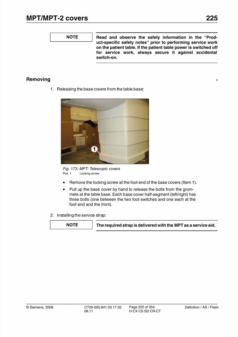
8/12/2019 CT00-000.841.03.17.02.pdf
http://slidepdf.com/reader/full/ct00-000841031702pdf 225/353
© Siemens, 2008 CT00-000.841.03.17.02 Definition / AS / Flash08.11 H CX CS SD CR-CT
MPT/MPT-2 covers 225
Page 225 of 354
NOTE Read and observe the safety information in the “Prod-uct-specific safety notes” prior to performing service work on the patient table. If the patient table power is switched offfor service work, always secure it against accidental
switch-on.
Removing 0
1. Releasing the base covers from the table base:
2. Installing the service strap:
NOTE The required strap is delivered with the MPT as a service aid.
Fig. 173: MPT: Telescopic covers Pos. 1 Locking screw
• Remove the locking screw at the foot end of the base covers (Item 1).
• Pull up the base cover by hand to release the bolts from the grom-mets at the table base. Each base cover half-segment (left/right) hasthree bolts (one between the two foot switches and one each at thefoot end and the front).

8/12/2019 CT00-000.841.03.17.02.pdf
http://slidepdf.com/reader/full/ct00-000841031702pdf 226/353
226 MPT/MPT-2 covers
Definition / AS / Flash CT00-000.841.03.17.02 © Siemens, 200808.11 H CX CS SD CR-CT
Page 226 of 354
3. Lifting the telescopic covers:
Fig. 174: MPT: Telescopic covers (lifting) Pos. 1 Strap (service aid delivered with MPT)
Pos. 2 Strap mounting location
Pos. 3 Fastener
• Loop the service strap around the cover bar between the two footswitches (Item 2) and across the tabletop to the other side.
• Feed the end of the strap into the fastener (item 3) and tighten thestrap.
Fig. 175: MPT: Telescopic covers (raised) Pos. 1 Service switches
• Raise the table via the service switches to maximum table position.
In this position full access to the electronic components at the tablebase is available.

8/12/2019 CT00-000.841.03.17.02.pdf
http://slidepdf.com/reader/full/ct00-000841031702pdf 227/353
© Siemens, 2008 CT00-000.841.03.17.02 Definition / AS / Flash08.11 H CX CS SD CR-CT
MPT/MPT-2 covers 227
Page 227 of 354
Installation 0
1. Lower the table to minimum position.
2. Release the strap and remove it.
3. Push the base covers down onto the table base by hand until the bolts are pushed intothe grommets.
4. Install the locking screw at the foot end of the base cover to secure the telescopic cov-ers.
Startup 0
Electrical
1. Switch on circuit breakers F2, F3, F5, F6, F7, and F11 in the PDC A and F2 in the PDCB (not for Definition AS).
First switch the F2, F3, F5, F6 circuit breakers to the “0” position and then to the“1” position.
2. Switch the system to the SYSTEM/ON status at the control box.
Software
n.a.
Tune-up
n.a.
Tests
1. Raise and lower table to check that covers are not rubbing against one another andcausing a squeaking noise.
2. Perform a test scan.
Final Steps 0
1. Clean.

8/12/2019 CT00-000.841.03.17.02.pdf
http://slidepdf.com/reader/full/ct00-000841031702pdf 228/353
228 MPT/MPT-2 covers
Definition / AS / Flash CT00-000.841.03.17.02 © Siemens, 200808.11 H CX CS SD CR-CT
Page 228 of 354
Telescopic Covers: Lowering & Removing 7.7
• The following instructions are applicable to:
- Top cover (left), material number 86 16 337
- Top cover (right), material number 86 18 329- Upper telescopic cover (left/right), material number 86 18 352
- Lower telescopic cover (left/right), material number 86 18 345
- Foot cover (left), material number 86 16 311
- Foot cover (right), material number 86 16 303
Prerequisites 0
Safety
WARNING [ hz_serdoc_F13G01U12M03 ]
Avoid accident and injury or damage to parts.
Risk of accident and injury!
Read and observe the safety information contained inthe “General” section of this document and/or the“Product specific safety notes”.
Time and Manpower
• 1 person
• Estimated total repair time: 30 min.
Tools and auxiliary equipment
• Standard service kit
Preliminary steps 0
1. If possible, lower the patient table to minimum height via the service buttons.2. Switch system toCOMP/ON at the control box.
3. Switch OFF the gantry/PHS power using service push-button S1 in the PDC.
Secure the circuit breakers that S1 switched OFF against unintended switch-on(e.g. lock and tag).
NOTE Read and observe the safety information in the “Prod-uct-specific safety notes” prior to performing service work on the patient table. If the patient table power is switched offfor service work, always secure it against accidentalswitch-on.

8/12/2019 CT00-000.841.03.17.02.pdf
http://slidepdf.com/reader/full/ct00-000841031702pdf 229/353
© Siemens, 2008 CT00-000.841.03.17.02 Definition / AS / Flash08.11 H CX CS SD CR-CT
MPT/MPT-2 covers 229
Page 229 of 354
Removing 0
1. Removing the cover screws:
Fig. 176: MPT: Top cover (gantry-side) Pos. 1 Cover screws
Pos. 2 Mounting screws
• Remove the two cover screws (item 1) at the gantry side of the topcover.
Fig. 177: MPT: Top cover (foot-end side) Pos. 1 Cover screws
Pos. 2 Mounting screws
• Remove the cover screws (item 1) at the foot-end side of the topcover.

8/12/2019 CT00-000.841.03.17.02.pdf
http://slidepdf.com/reader/full/ct00-000841031702pdf 230/353

8/12/2019 CT00-000.841.03.17.02.pdf
http://slidepdf.com/reader/full/ct00-000841031702pdf 231/353
© Siemens, 2008 CT00-000.841.03.17.02 Definition / AS / Flash08.11 H CX CS SD CR-CT
MPT/MPT-2 covers 231
Page 231 of 354
3. Removing the top cover from the tabletop:
Fig. 180: MPT: Top cover (gantry-side) Pos. 1 Top cover (right half-shell)
Pos. 2 Bolt & grommet locations
• Pull down the top cover at the gantry side until the two bolts arereleased from the grommets. (item 2 and arrow)
• Hold on to the cover and step to the right side of the table.
Fig. 181: MPT: Top cover (foot-end side) Pos. 1 Top cover (right half-shell)
Pos. 2 Pin and keyway locations
• Slightly lift the right half-shell of the top cover at the foot end of thetable to release the pin at the keyway (item 2) and pull it toward theside of the table to unhook and remove it. (see arrow)
• Remove the left half-shell of the top cover the same way from theother side of the table.
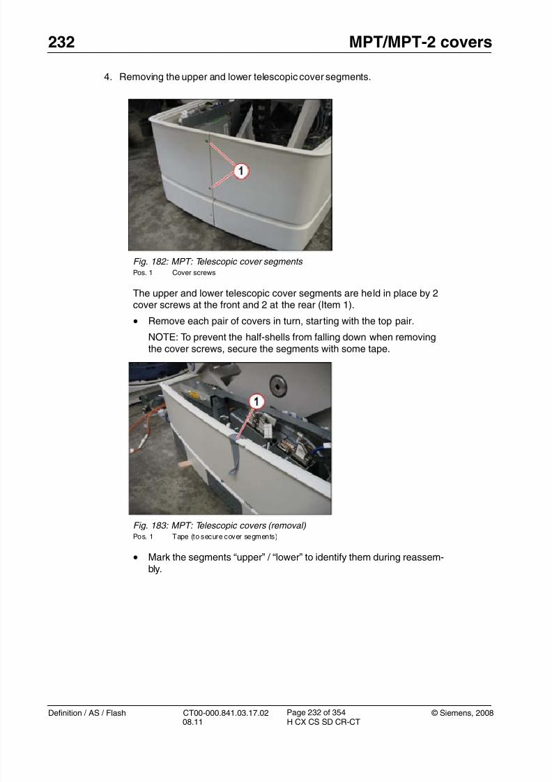
8/12/2019 CT00-000.841.03.17.02.pdf
http://slidepdf.com/reader/full/ct00-000841031702pdf 232/353
232 MPT/MPT-2 covers
Definition / AS / Flash CT00-000.841.03.17.02 © Siemens, 200808.11 H CX CS SD CR-CT
Page 232 of 354
4. Removing the upper and lower telescopic cover segments.
Fig. 182: MPT: Telescopic cover segments Pos. 1 Cover screws
The upper and lower telescopic cover segments are held in place by 2cover screws at the front and 2 at the rear (Item 1).
• Remove each pair of covers in turn, starting with the top pair.
NOTE: To prevent the half-shells from falling down when removingthe cover screws, secure the segments with some tape.
Fig. 183: MPT: Telescopic covers (removal) Pos. 1 Tape (to secure cover segments)
• Mark the segments “upper” / “lower” to identify them during reassem-bly.

8/12/2019 CT00-000.841.03.17.02.pdf
http://slidepdf.com/reader/full/ct00-000841031702pdf 233/353
© Siemens, 2008 CT00-000.841.03.17.02 Definition / AS / Flash08.11 H CX CS SD CR-CT
MPT/MPT-2 covers 233
Page 233 of 354
5. Removing the foot cover segment.
Installation 0
1. Installation is in the reverse order of removal.
2. Telescopic covers (lower and upper) must be installed with the larger lip toward the top.
Startup 0
Electrical
1. Switch on circuit breakers F2, F3, F5, F6, F7, and F11 in the PDC A and F2 in the PDCB (not for Definition AS).
First switch the F2, F3, F5, F6 circuit breakers to the “0” position and then to the“1” position.
2. Switch the system to the SYSTEM/ON status at the control box.
Software
n.a.
Fig. 184: MPT: Foot cover (right) Pos. 1 Locking screw
Pos. 2 Cover screws
Pos. 3 Bolts
• Remove the locking screw at the foot-end side of the foot covers(Item 1).
• Remove the two cover screws at the front and rear (item 2).
• Pull up each foot cover half-shell by hand to release the cover bolts(item 3) from the grommets at the table base. .
• Remove both foot cover segments.

8/12/2019 CT00-000.841.03.17.02.pdf
http://slidepdf.com/reader/full/ct00-000841031702pdf 234/353
234 MPT/MPT-2 covers
Definition / AS / Flash CT00-000.841.03.17.02 © Siemens, 200808.11 H CX CS SD CR-CT
Page 234 of 354
Tune-up
n.a.
Tests
1. Raise and lower table to check that covers are not rubbing against one another andcausing a squeaking noise.
2. Perform a test scan.
Final Steps 0
1. Clean.

8/12/2019 CT00-000.841.03.17.02.pdf
http://slidepdf.com/reader/full/ct00-000841031702pdf 235/353
© Siemens, 2008 CT00-000.841.03.17.02 Definition / AS / Flash08.11 H CX CS SD CR-CT
MPT/MPT-2 Mechanical 235
Page 235 of 354
8- 8MPT/MPT-2Mechanical
Overview 0
This chapter describes the removal and replacement of the following MPT mechanicalcomponents:
• Tabletop plates (Standard, RTP, and Bariatric type plates)
• Vertical drive unit
• Horizontal drive motors (tabletop and top support drive motor)
• Horizontal drive belts (tabletop and top support drive belt)
• Position sensors (tabletop wire sensor, top support magnetic sensor, and verticalposition sensor)
• Vertical safety and limit switches (upper and lower limit switches and vertical con-nect safety switch)
NOTE The safety nut switch on the vertical drive is NOT an FRU!
If the safety nut switch is activated the complete verticaldrive must be replaced!
NOTE The adjustment procedures for parts that require softwarecalibration will be covered by the “FRU Replacement” proce-dure under “Local Service” > “Tune-up”.

8/12/2019 CT00-000.841.03.17.02.pdf
http://slidepdf.com/reader/full/ct00-000841031702pdf 236/353
236 MPT/MPT-2 Mechanical
Definition / AS / Flash CT00-000.841.03.17.02 © Siemens, 200808.11 H CX CS SD CR-CT
Page 236 of 354
Fig. 185: MPT: Vertical drive and tabletop plate Pos. 1 Vertical drive
Pos. 2 Tabletop plate
Fig. 186: MPT: Horizontal motors and belts Pos. 1 Tabletop motor and belt
Pos. 2 Top support motor and belt
Fig. 187: MPT: Vertical position sensor Pos. 1 Ver tical drive (rear)
Pos. 2 Vertical position sensor
Fig. 188: MPT: Wire sensor (horizontalposition)
Pos. 1 Wire sensor
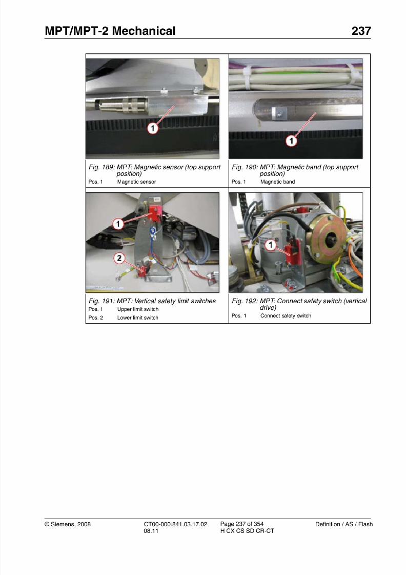
8/12/2019 CT00-000.841.03.17.02.pdf
http://slidepdf.com/reader/full/ct00-000841031702pdf 237/353
© Siemens, 2008 CT00-000.841.03.17.02 Definition / AS / Flash08.11 H CX CS SD CR-CT
MPT/MPT-2 Mechanical 237
Page 237 of 354
Fig. 189: MPT: Magnetic sensor (top supportposition)
Pos. 1 Magnetic sensor
Fig. 190: MPT: Magnetic band (top supportposition)
Pos. 1 Magnetic band
Fig. 191: MPT: Vertical safety limit switches Pos. 1 Upper limit switch
Pos. 2 Lower limit switch
Fig. 192: MPT: Connect safety switch (verticaldrive)
Pos. 1 Connect safety switch

8/12/2019 CT00-000.841.03.17.02.pdf
http://slidepdf.com/reader/full/ct00-000841031702pdf 238/353
238 MPT/MPT-2 Mechanical
Definition / AS / Flash CT00-000.841.03.17.02 © Siemens, 200808.11 H CX CS SD CR-CT
Page 238 of 354
Tabletop plate 8.1
• The following instructions are applicable to:
- MPT standard tabletop, material number 86 18 170
- MPT RTP tabletop, material number 86 18 162- MPT bariatric tabletop, material number 86 18 154
NOTE The Multi-Purpose Table (MPT) has removable tabletops.
Exchange/replacement does not require any tools.
The replacement procedure is identical for all tabletop platetypes.
NOTE The RTP and Bariatric tabletop plates are optional accesso-ries and therefore cannot be ordered via the Spare Parts Cat-
alog.
They have to be ordered through sales channels!
Fig. 193: MPT: Tabletop plate types Pos. 1 Standard type tabletop plate
Pos. 2 Bariatric / RPT type tabletop plate

8/12/2019 CT00-000.841.03.17.02.pdf
http://slidepdf.com/reader/full/ct00-000841031702pdf 239/353
© Siemens, 2008 CT00-000.841.03.17.02 Definition / AS / Flash08.11 H CX CS SD CR-CT
MPT/MPT-2 Mechanical 239
Page 239 of 354
Prerequisites 0
Safety
WARNING [ hz_serdoc_F13G01U12M03 ] Avoid accident and injury or damage to parts.
Risk of accident and injury!
Read and observe the safety information contained inthe “General” section of this document and/or the“Product specific safety notes”.
Time and Manpower
• 1 person
• Estimated total repair time: less than 2 minutes.
Tools and auxiliary equipment
• None
Preliminary steps 0
1. Raise the patient table to a convenient height (e.g. position 125).
2. Move the tabletop all the way back toward the foot end of the table.
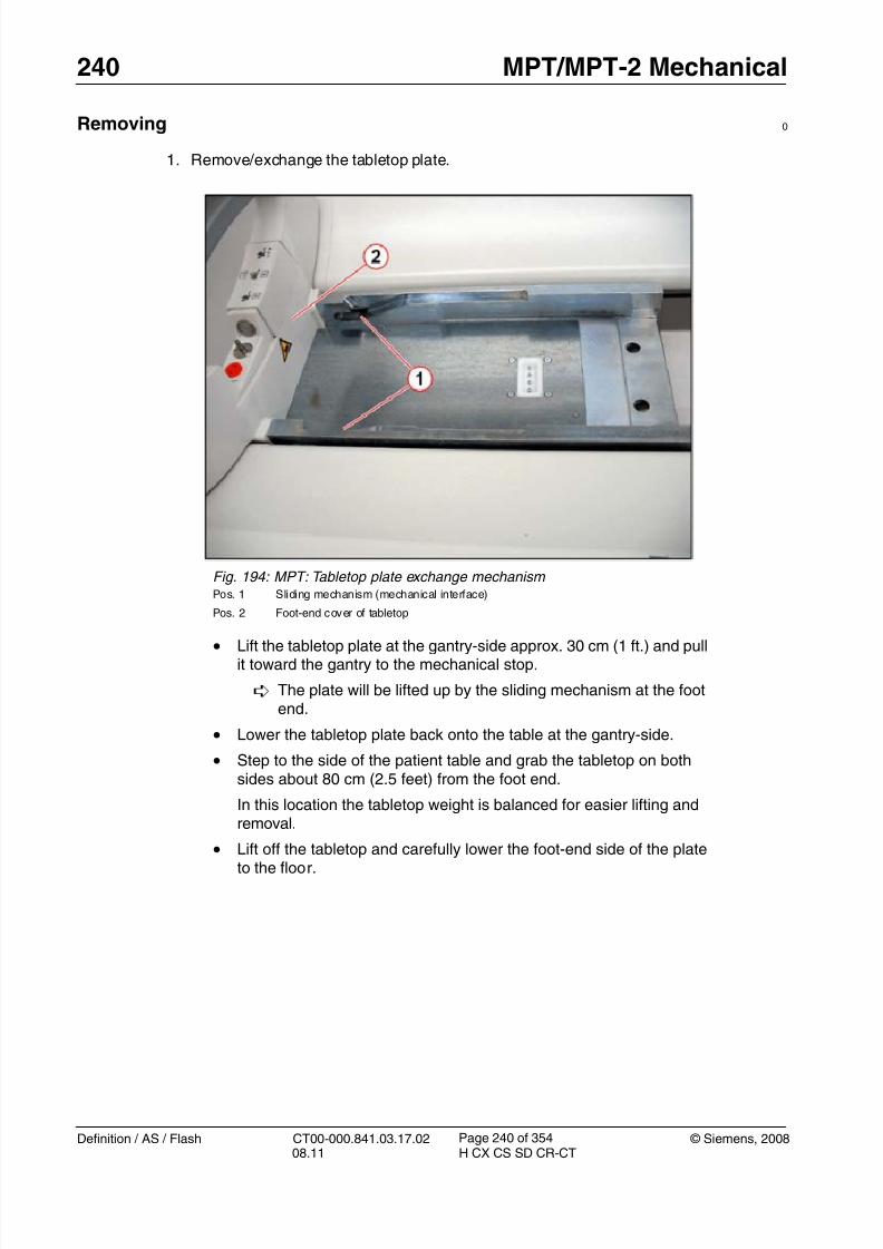
8/12/2019 CT00-000.841.03.17.02.pdf
http://slidepdf.com/reader/full/ct00-000841031702pdf 240/353

8/12/2019 CT00-000.841.03.17.02.pdf
http://slidepdf.com/reader/full/ct00-000841031702pdf 241/353
© Siemens, 2008 CT00-000.841.03.17.02 Definition / AS / Flash08.11 H CX CS SD CR-CT
MPT/MPT-2 Mechanical 241
Page 241 of 354
Installation 0
1. Check the coding screws at the new tabletop plate:
2. Lift the new tabletop onto the table and position it on the tabletop so that the aluminumblock of the tabletop plate sits on the sliding mechanism (mechanical interface) of thetabletop.
3. Lift the tabletop at the gantry side approx. 30 cm (1 ft.) and push it toward the foot end of
the table until it slides fully down the sliding mechanism and reaches a mechanical stop.4. Lower the tabletop plate at the gantry-side onto the tabletop.
The tabletop plate is automatically secured to the tabletop by the 2 locking pinsand the sliding mechanism.
Startup 0
Mechanical
n.a.
Fig. 195: MPT: Tabletop plate (mechanical interface) Pos. 1 Coding screws
Pos. 2 Locking pins
Pos. 3 Guide pins (for sliding mechanism)
• Check the coding screws at the mechanical interface (item 1) of theold tabletop plate and compare with the new plate.
• If necessary adjust the coding at the new plate by moving the codingscrew to the corresponding locations.

8/12/2019 CT00-000.841.03.17.02.pdf
http://slidepdf.com/reader/full/ct00-000841031702pdf 242/353
242 MPT/MPT-2 Mechanical
Definition / AS / Flash CT00-000.841.03.17.02 © Siemens, 200808.11 H CX CS SD CR-CT
Page 242 of 354
Software
n.a
NOTEThe tabletop plate and plate type will be recognized automat-ically by the software through the coding switches at thetabletop sled.
If incorrect or invalid coding (e.g. tabletop plate missing, cod-ing screws in incorrect location or not activating the switch)is recognized, the table will not go into standby and tablemovement will be blocked.
Tune-up
n.a
Tests
1. Check horizontal movements of the tabletop via the buttons at the gantry control panel.
2. Perform a test scan
Fig. 196: MPT: Coding switches at tabletop sled (for plate identification) Pos. 1 Tabletop sled
Pos. 2 Coding switches
Pos. 3 Holes for locking pins of tabletop plate

8/12/2019 CT00-000.841.03.17.02.pdf
http://slidepdf.com/reader/full/ct00-000841031702pdf 243/353

8/12/2019 CT00-000.841.03.17.02.pdf
http://slidepdf.com/reader/full/ct00-000841031702pdf 244/353
244 MPT/MPT-2 Mechanical
Definition / AS / Flash CT00-000.841.03.17.02 © Siemens, 200808.11 H CX CS SD CR-CT
Page 244 of 354
Vertical drive 8.2
• The following instructions are applicable to:
- PHS vertical drive, material number 86 14 294
Prerequisites 0
Safety
WARNING [ hz_serdoc_F13G01U12M03 ]
Avoid accident and injury or damage to parts.
Risk of accident and injury!
Read and observe the safety information contained in
the “General” section of this document and/or the“Product specific safety notes”.
Time and Manpower
• 1 person
• Estimated total repair time: 2 hr.
Tools and auxiliary equipment
•
Standard service kit• Loctite 243
• Size 10 hex nut socket (for manual lift)
• Mallet
Preliminary steps 0
1. Raise the patient table to maximum height (position 125) via the service buttons or, ifnot possible, via the mechanical lift.
2. Switch system toCOMP/ON at the control box.
3. Switch OFF the gantry/PHS power using service push-button S1 in the PDC.
Secure the circuit breakers that S1 switched OFF against unintended switch-on(e.g. lock and tag).
NOTE Read and observe the safety information in the “Prod-uct-specific safety notes” prior to performing service work on the patient table. If the patient table power is switched offfor service work, always secure it against accidentalswitch-on.
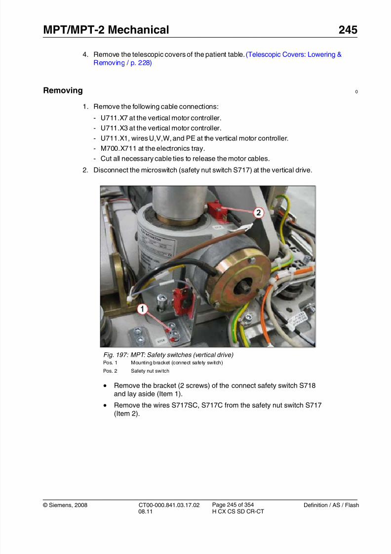
8/12/2019 CT00-000.841.03.17.02.pdf
http://slidepdf.com/reader/full/ct00-000841031702pdf 245/353
© Siemens, 2008 CT00-000.841.03.17.02 Definition / AS / Flash08.11 H CX CS SD CR-CT
MPT/MPT-2 Mechanical 245
Page 245 of 354
4. Remove the telescopic covers of the patient table. (Telescopic Covers: Lowering &Removing / p. 228)
Removing0
1. Remove the following cable connections:
- U711.X7 at the vertical motor controller.
- U711.X3 at the vertical motor controller.
- U711.X1, wires U,V,W, and PE at the vertical motor controller.
- M700.X711 at the electronics tray.
- Cut all necessary cable ties to release the motor cables.
2. Disconnect the microswitch (safety nut switch S717) at the vertical drive.
Fig. 197: MPT: Safety switches (vertical drive) Pos. 1 Mounting bracket (connect safety switch)
Pos. 2 Safety nut switch
• Remove the bracket (2 screws) of the connect safety switch S718and lay aside (Item 1).
• Remove the wires S717SC, S717C from the safety nut switch S717(Item 2).

8/12/2019 CT00-000.841.03.17.02.pdf
http://slidepdf.com/reader/full/ct00-000841031702pdf 246/353
246 MPT/MPT-2 Mechanical
Definition / AS / Flash CT00-000.841.03.17.02 © Siemens, 200808.11 H CX CS SD CR-CT
Page 246 of 354
3. Install the vertical safety bolts.
Fig. 198: MPT: Vertical safety bolts Pos. 1 Storage position
Pos. 2 Vertical lock position
• Remove the safety bolts from storage position (Item 1).
• Install the bolts at the vertical lock position (Item 2).

8/12/2019 CT00-000.841.03.17.02.pdf
http://slidepdf.com/reader/full/ct00-000841031702pdf 247/353

8/12/2019 CT00-000.841.03.17.02.pdf
http://slidepdf.com/reader/full/ct00-000841031702pdf 248/353
248 MPT/MPT-2 Mechanical
Definition / AS / Flash CT00-000.841.03.17.02 © Siemens, 200808.11 H CX CS SD CR-CT
Page 248 of 354
5. Remove the cross brace locating screws.
Fig. 200: MPT: Cross brace & shaft locking pin (vertical drive) Pos. 1 Locking screws (cross brace)
Pos. 2 Locating screws (cross brace)
Pos. 3 Locking screws (shaft pin)
Pos. 4 Shaft pin
• Remove the 2 locking screws (Item 1) at the cross brace.
( 4mm Allen key)
• Remove the 2 cross brace locating screws (Item 2).
( 12mm Allen key)
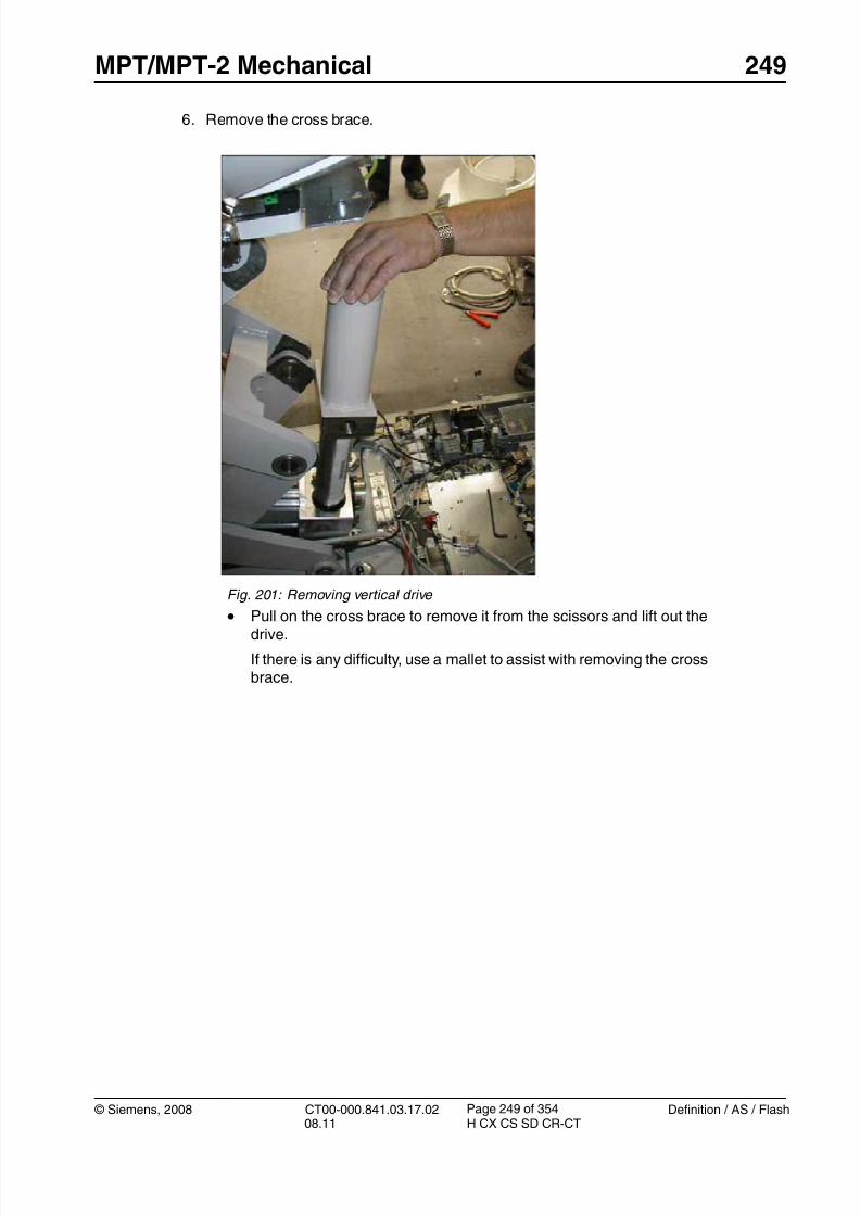
8/12/2019 CT00-000.841.03.17.02.pdf
http://slidepdf.com/reader/full/ct00-000841031702pdf 249/353
© Siemens, 2008 CT00-000.841.03.17.02 Definition / AS / Flash08.11 H CX CS SD CR-CT
MPT/MPT-2 Mechanical 249
Page 249 of 354
6. Remove the cross brace.
Fig. 201: Removing vertical drive
•Pull on the cross brace to remove it from the scissors and lift out thedrive.
If there is any difficulty, use a mallet to assist with removing the crossbrace.

8/12/2019 CT00-000.841.03.17.02.pdf
http://slidepdf.com/reader/full/ct00-000841031702pdf 250/353
250 MPT/MPT-2 Mechanical
Definition / AS / Flash CT00-000.841.03.17.02 © Siemens, 200808.11 H CX CS SD CR-CT
Page 250 of 354
7. Remove the shaft pin.
Installation 0
1. Install the cross brace onto the new drive, insert the shaft pin, and tighten the 2 lockingscrews of the shaft pin. Rotate the cross brace to obtain the approximate height for rein-stallation. Fine adjustments can be made with the manual lift screw.
2. Place the drive in position and push the cross brace into place between the scissors;again, use a mallet if necessary.
T 3. Install the cross brace locating screws, tighten them to 130 Nm, and install the 2 lockingscrews with torque of 18.6 Nm.
4. Use the manual lift screw to lower the drive motor (clockwise) until it almost touches thebase plate and install the 3 locating screws applying Loctite 243, leaving 8 mm betweenthe head and the drive motor flange.
5. Continue to turn clockwise to raise the table until the safety bolts can be removed. Rein-stall them in the storage positions.
6. Reinstall the bracket of the connect safety switch S718 to the table base and adjust the
switch to the switch flag on the new vertical drive.
Refer to adjustment instructions for the connect safety switch.
7. Reinstall all plugs and wires to original configuration. Use cable ties as necessary.
8. Reinstall the table covers.
Fig. 202: Shaft locking pin • Remove the 2 locking screws (item 1) and withdraw the pin (Item 2).
• Lift off the cross brace.

8/12/2019 CT00-000.841.03.17.02.pdf
http://slidepdf.com/reader/full/ct00-000841031702pdf 251/353
© Siemens, 2008 CT00-000.841.03.17.02 Definition / AS / Flash08.11 H CX CS SD CR-CT
MPT/MPT-2 Mechanical 251
Page 251 of 354
Startup 0
Electrical
1. Switch on circuit breakers F2, F3, F5, F6, F7, and F11 in the PDC A and F2 in the PDCB (not for Definition AS).
First switch the F2, F3, F5, F6 circuit breakers to the “0” position and then to the“1” position.
2. Switch the system to the SYSTEM/ON status at the control box.
Software
n.a.
Tune-up
• Select: Local_Service > Tune-up
• Select: FRU Replacement
• Select: PHS - Encoder
• Press <Go> to start the tour.
The Auto_Complete is started and checks which adjustments are required.
Follow the instructions of the Auto_Complete routine.
Tests
1. Check the vertical table movement via the buttons at the gantry control panels andcheck the vertical position at the gantry display.
2. Perform a test scan
Final Steps 0
1. Clean.

8/12/2019 CT00-000.841.03.17.02.pdf
http://slidepdf.com/reader/full/ct00-000841031702pdf 252/353

8/12/2019 CT00-000.841.03.17.02.pdf
http://slidepdf.com/reader/full/ct00-000841031702pdf 253/353
© Siemens, 2008 CT00-000.841.03.17.02 Definition / AS / Flash08.11 H CX CS SD CR-CT
MPT/MPT-2 Mechanical 253
Page 253 of 354
NOTE Read and observe the safety information in the “Prod-uct-specific safety notes” prior to performing service work on the patient table. If the patient table power is switched offfor service work, always secure it against accidental
switch-on.
4. Remove the tabletop plate. (Tabletop plate / p. 238)
5. Remove the left/right rear covers of the side support (one plastic cap and screw eachside).
6. Feed the tabletop sled towards the gantry to access all 6 mounting screws of the reartabletop cover.
7. Remove the rear tabletop cover (6 plastic caps and Allen screws). (Tabletop covers(front and rear) / p. 209)
8. Remove the switchplate cover at the foot end of the tabletop. (Switchplatecover / p. 213)

8/12/2019 CT00-000.841.03.17.02.pdf
http://slidepdf.com/reader/full/ct00-000841031702pdf 254/353

8/12/2019 CT00-000.841.03.17.02.pdf
http://slidepdf.com/reader/full/ct00-000841031702pdf 255/353
© Siemens, 2008 CT00-000.841.03.17.02 Definition / AS / Flash08.11 H CX CS SD CR-CT
MPT/MPT-2 Mechanical 255
Page 255 of 354

8/12/2019 CT00-000.841.03.17.02.pdf
http://slidepdf.com/reader/full/ct00-000841031702pdf 256/353
256 MPT/MPT-2 Mechanical
Definition / AS / Flash CT00-000.841.03.17.02 © Siemens, 200808.11 H CX CS SD CR-CT
Page 256 of 354
For MPT only:
Fig. 203: MPT: Horizontal motor controller (tabletop/top support) Pos. 1 Tabletop controller U731
Pos. 2 Top support control ler U721
Pos. 3 Connectors X731/X721 (to motor assembly)
• Remove the connector X3 from the motor controller U731 (item 1).
• Remove the connector X2 from the corresponding motor controllerand remove the 2 wires to the drive motor from pins 1 and 3 (= motorbrake connection).
• Disconnect the cable connection X731 (item3)
• Cut all cable ties and remove cable clamp (shielding of orange cable)to release all cables to the drive motor.
For MPT-2 only:
Fig. 204: MPT-2: View from below • Disconnect the cables on the horizontal drive.

8/12/2019 CT00-000.841.03.17.02.pdf
http://slidepdf.com/reader/full/ct00-000841031702pdf 257/353
© Siemens, 2008 CT00-000.841.03.17.02 Definition / AS / Flash08.11 H CX CS SD CR-CT
MPT/MPT-2 Mechanical 257
Page 257 of 354
2. Remove the tabletop belt adjuster (at the foot end of the tabletop):
3. Remove the drive pulley.
Fig. 205: MPT: Tabletop belt tension adjuster Pos. 1 Adjustment screw
Pos. 2 Mounting/Locking screws
• Release the belt tension adjustment screw (item 1).
• Remove the 2 locking screws holding the adjuster block (item 2).
• Remove the belt tension adjuster.
Fig. 206: MPT: Pulley mounting (tabletop drive) Pos. 1 Pulley mounting screw
Pos. 2 Pulley
• Open the pulley mounting screw (item 1)
• Feed the belt downwards from the pulley (see arrow) to form a loop.
• Remove the pulley (item 2) from the drive by pulling it off.
If the pulley cannot be removed by hand, a small screwdriver can beused to assist.

8/12/2019 CT00-000.841.03.17.02.pdf
http://slidepdf.com/reader/full/ct00-000841031702pdf 258/353
258 MPT/MPT-2 Mechanical
Definition / AS / Flash CT00-000.841.03.17.02 © Siemens, 200808.11 H CX CS SD CR-CT
Page 258 of 354
4. Remove the drive.
Installation 0
T 1. Install the drive motor and secure with 4 screws/nuts.
For MPT: Tighten to 3 Nm.
For MPT-2: Tighten to 5 Nm
2. Reconnect all cables in the reverse direction as described above.
3. Push the drive pulley onto the motor shaft together with the jaw spanner(Fig. 53 / p. 72).
Fig. 207: Drive motor securing screws - PHS-2, PHS-3, MPT
Fig. 208: Drive motor (table top) securing screws - PHS-4, MPT-2
• Remove the 4 drive mounting screws/nuts (Item 1).
Hold the drive when removing the screws to prevent dropping.
• Remove the drive motor.

8/12/2019 CT00-000.841.03.17.02.pdf
http://slidepdf.com/reader/full/ct00-000841031702pdf 259/353
© Siemens, 2008 CT00-000.841.03.17.02 Definition / AS / Flash08.11 H CX CS SD CR-CT
MPT/MPT-2 Mechanical 259
Page 259 of 354
NOTE The jaw spanner will be used
1. as a spacer between the drive pulley and the motor box
2. as opposite support
T 4. Fasten the drive pulley with the following torque:
MPT: 35 Nm
MPT-2: 65 Nm
(Fig. 50 / p. 70)
5. Reinstall the belt adjuster; check that the drive belt is located properly in both pulleys.
6. Adjust the drive belt tension to 52 +2 Hz using the belt tension meter. The procedure isdescribed in (Installation / p. 277).
7. Reinstall all covers.
Startup 0
Electrical
1. Switch on circuit breakers F2, F3, F5, F6, F7, and F11 in the PDC A and F2 in the PDCB (not for Definition AS).
First switch the F2, F3, F5, F6 circuit breakers to the “0” position and then to the“1” position.
2. Switch the system to the SYSTEM/ON status at the control box.
Software
n.a
Tune-up
n.a.
Tests
1. Check the horizontal movement of the tabletop via the buttons at the gantry control pan-els.
2. Perform a test scan
Final Steps 0
1. Clean.

8/12/2019 CT00-000.841.03.17.02.pdf
http://slidepdf.com/reader/full/ct00-000841031702pdf 260/353
260 MPT/MPT-2 Mechanical
Definition / AS / Flash CT00-000.841.03.17.02 © Siemens, 200808.11 H CX CS SD CR-CT
Page 260 of 354
Horizontal drive, top support 8.4
• The following instructions are applicable to:
- PHS horizontal drive motor, material number 86 18 394
NOTE The horizontal drive is delivered as a set with the drive pulleyand the jaw spanner. We recommend replacing the drive pul-ley together with the motor.
Prerequisites 0
Safety
WARNING [ hz_serdoc_F13G01U12M03 ]
Avoid accident and injury or damage to parts.
Risk of accident and injury!
Read and observe the safety information contained inthe “General” section of this document and/or the“Product specific safety notes”.
Time and Manpower
• 1 person
• Estimated total repair time: 45 min.
Tools and auxiliary equipment
• Standard service kit
• Loctite 243
Preliminary steps 0
1. Raise the patient table to maximum height (position 125).2. Switch system toCOMP/ON at the control box.
3. Switch OFF the gantry/PHS power using service push-button S1 in the PDC.
Secure the circuit breakers that S1 switched OFF against unintended switch-on(e.g. lock and tag).
NOTE Read and observe the safety information in the “Prod-uct-specific safety notes” prior to performing service work on the patient table. If the patient table power is switched offfor service work, always secure it against accidental
switch-on.

8/12/2019 CT00-000.841.03.17.02.pdf
http://slidepdf.com/reader/full/ct00-000841031702pdf 261/353
© Siemens, 2008 CT00-000.841.03.17.02 Definition / AS / Flash08.11 H CX CS SD CR-CT
MPT/MPT-2 Mechanical 261
Page 261 of 354
4. Remove the switchplate cover at the foot end of the tabletop. (Switchplatecover / p. 213)
5. Lower the telescopic covers of the table to the table base. (Telescopic Covers: Lower-ing & Removing / p. 228)
6. Move the tabletop towards the gantry.7. Remove the rear plastic cover under the tabletop. (Tabletop covers (front and
rear) / p. 209)
Removing 0
1. Remove the cable connections at the motor controller:
Fig. 209: MPT: Horizontal motor controller (tabletop/top support) Pos. 1 Tabletop control ler U731
Pos. 2 Top support controller U721
Pos. 3 Connectors X731/X721 (to motor assembly)
• Remove connector X3 from the motor controller U721 (item 2).
• Remove connector X2 from the corresponding motor controller andremove the 2 wires from X2.pin 1 and X2.pin 3 (= motor brake con-nection).
• Disconnect connector X732 (item 3).
• Cut all cable ties and remove cable clamp (shielding of orange cable)to release all cables to the drive motor.
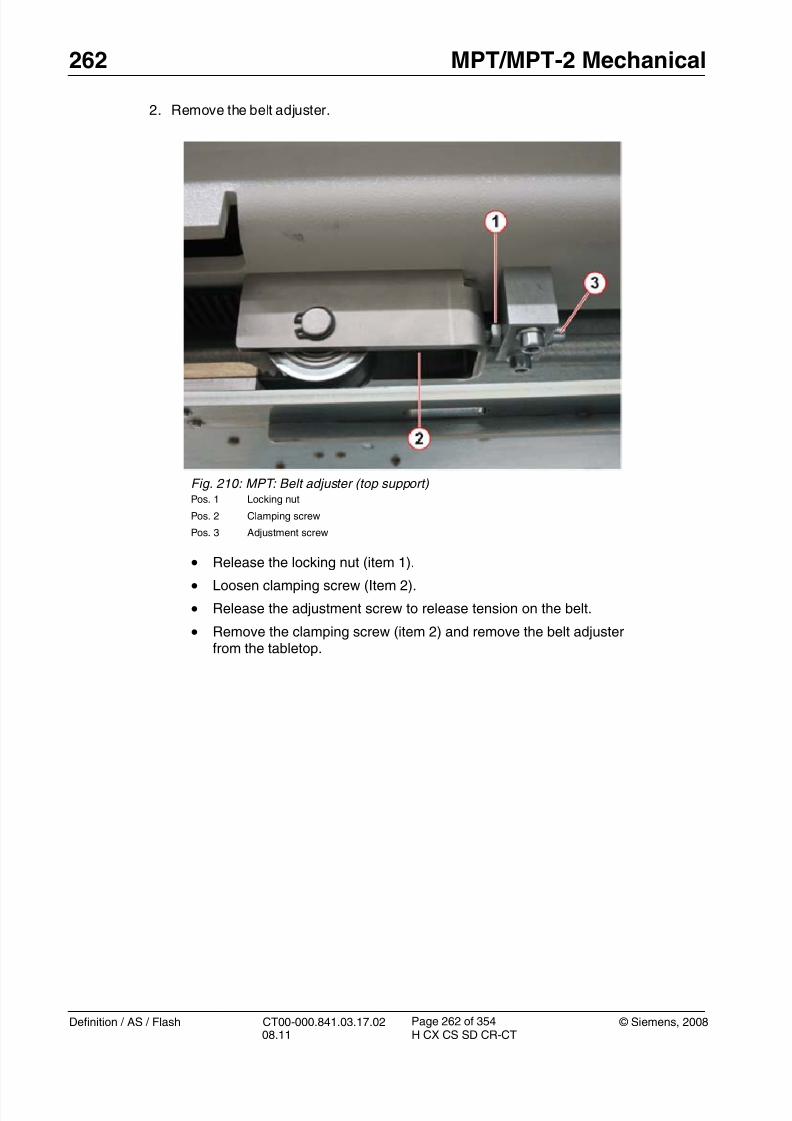
8/12/2019 CT00-000.841.03.17.02.pdf
http://slidepdf.com/reader/full/ct00-000841031702pdf 262/353
262 MPT/MPT-2 Mechanical
Definition / AS / Flash CT00-000.841.03.17.02 © Siemens, 200808.11 H CX CS SD CR-CT
Page 262 of 354
2. Remove the belt adjuster.
Fig. 210: MPT: Belt adjuster (top support) Pos. 1 Locking nut
Pos. 2 Clamping screw
Pos. 3 Adjustment screw
• Release the locking nut (item 1).
• Loosen clamping screw (Item 2).
• Release the adjustment screw to release tension on the belt.
• Remove the clamping screw (item 2) and remove the belt adjusterfrom the tabletop.

8/12/2019 CT00-000.841.03.17.02.pdf
http://slidepdf.com/reader/full/ct00-000841031702pdf 263/353
© Siemens, 2008 CT00-000.841.03.17.02 Definition / AS / Flash08.11 H CX CS SD CR-CT
MPT/MPT-2 Mechanical 263
Page 263 of 354
3. Remove the pulley from the drive.
4. Remove the drive motor.
Fig. 211: MPT: Pulley mounting (top support drive) Pos. 1 Pulley mounting screw
Pos. 2 Pulley
• Open the pulley mounting screw (item 1)
• Remove the belt from the pulley and pull the pulley (item 2) off thedrive shaft.
If the pulley cannot be removed by hand, a small screwdriver can beused to assist.
Fig. 212: Drive motor securing screws
• Remove the 4 drive mounting screws (Item 1).
Hold the drive when removing the screws to prevent dropping.
• Remove the drive motor.

8/12/2019 CT00-000.841.03.17.02.pdf
http://slidepdf.com/reader/full/ct00-000841031702pdf 264/353
264 MPT/MPT-2 Mechanical
Definition / AS / Flash CT00-000.841.03.17.02 © Siemens, 200808.11 H CX CS SD CR-CT
Page 264 of 354
Installation 0
T 1. Install the drive motor and secure with 4 screws. Tighten to 3 Nm.
2. Route the green and orange cables of the new drive to motor controller U721 accord-
ingly.3. Install the two wires from the orange cable into connector X2 (pins 1 and 3) and con-
nect X2 at the motor controller U721.
4. Connect X3 at motor controller U721 and secure the shielding of the orange cable withthe clamp.
5. Connect the green cable to connector X732 (located between the motor controllers)
6. Push the drive pulley onto the motor shaft together with the jaw spanner.
NOTE The jaw spanner will be used
1. as a spacer between the drive pulley and the motor box
2. as opposite support
7. Fasten the drive pulley with the torque of 35 Nm
8. Install the drive belt over the pulley.
9. Reinstall the belt adjuster; check that the drive belt is located properly in both pulleys.
10. Adjust the support drive belt to 70 +2 Hz using the belt tension meter. The procedure isdescribed in (Installation / p. 95).
11. Reinstall all table covers.
Startup 0
Electrical
1. Switch on circuit breakers F2, F3, F5, F6, F7, and F11 in the PDC A and F2 in the PDCB (not for Definition AS).
First switch the F2, F3, F5, F6 circuit breakers to the “0” position and then to the“1” position.
2. Switch the system to the SYSTEM/ON status at the control box.
Software
n.a
Tune-up
n.a.

8/12/2019 CT00-000.841.03.17.02.pdf
http://slidepdf.com/reader/full/ct00-000841031702pdf 265/353
© Siemens, 2008 CT00-000.841.03.17.02 Definition / AS / Flash08.11 H CX CS SD CR-CT
MPT/MPT-2 Mechanical 265
Page 265 of 354
Tests
1. Check the horizontal movement of the top support via the buttons at the gantry controlpanels.
2. Perform a test scan
Final Steps 0
1. Clean.

8/12/2019 CT00-000.841.03.17.02.pdf
http://slidepdf.com/reader/full/ct00-000841031702pdf 266/353
266 MPT/MPT-2 Mechanical
Definition / AS / Flash CT00-000.841.03.17.02 © Siemens, 200808.11 H CX CS SD CR-CT
Page 266 of 354
Belt pulley PHS_MPT (tabletop) 8.5
• The following instructions are applicable to:
Fig. 213: Belt pulley PHS_MPT, part no. 8615861
The list below shows the usage of the ’Belt pulley PHS_MPT’:
NOTE The ’Belt pulley PHS_MPT’ (part no. 8615861) does not fit intopatient tables delivered with ’Belt pulley PHS’ (part no.8615853).
Prerequisites 0
Time and manpower
• 1 person
• Estimated total repair time: 1.5 hours
Tools and auxiliary equipment
• Standard service tools.
• Belt tension meter, part no. 8614203 or 7355642.
Patient table version Serial no. range:
PHS-2, product no. 8616026 from serial no. 1170 onward
PHS-3, product no. 8616034 from serial no. 1602 onward
PHS-4, product no. 8097144 from serial no. 1001 onward
MPT, product no. 8098225 from serial no. 1001 onward
MPT-2, product no. 8097102 from serial no. 1001 onward

8/12/2019 CT00-000.841.03.17.02.pdf
http://slidepdf.com/reader/full/ct00-000841031702pdf 267/353
© Siemens, 2008 CT00-000.841.03.17.02 Definition / AS / Flash08.11 H CX CS SD CR-CT
MPT/MPT-2 Mechanical 267
Page 267 of 354
Preliminary steps 0
1. Raise the table to a height of 125.
2. Switch the system to COMP/ON on the control box.
3. Switch OFF the gantry/PHS power using the service push-buttonS1 in the PDC. Secure the circuit breakers that S1 switched off against unintended switch-on
(e.g. lock and tag).
NOTE Read and observe the safety information in the “Prod-uct-specific safety notes” prior to performing service work on the patient table. If the patient table power is switched offfor service work, always secure it against accidentalswitch-on.
4. Remove the switchplate cover (Removing / p. 41).
5. Feed in the table and remove the tabletop covers (Tabletop covers (front andrear) / p. 29).
6. Remove the front cover of the right side support.
Fig. 214: Right front cover
Removal 0
1. Move the tabletop approximately 50 cm (20 inches) into the gantry.
NOTE Do not slide the tabletop when the belt pulleys are removed.
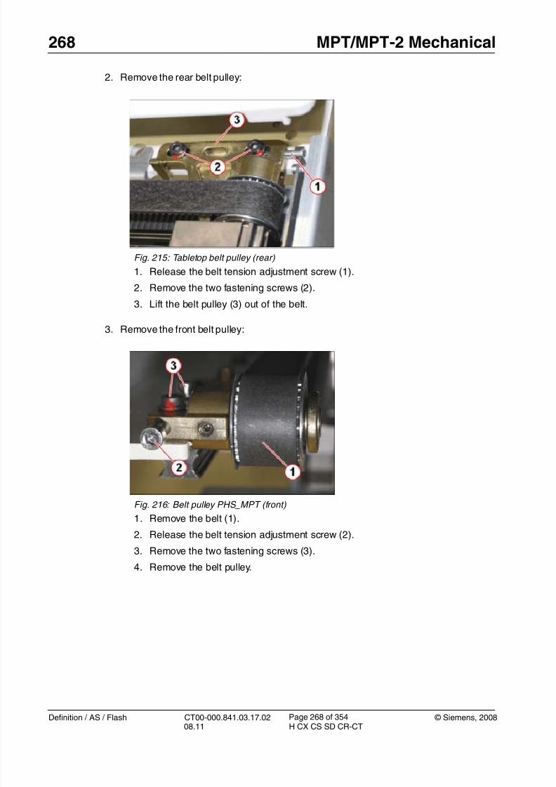
8/12/2019 CT00-000.841.03.17.02.pdf
http://slidepdf.com/reader/full/ct00-000841031702pdf 268/353
268 MPT/MPT-2 Mechanical
Definition / AS / Flash CT00-000.841.03.17.02 © Siemens, 200808.11 H CX CS SD CR-CT
Page 268 of 354
2. Remove the rear belt pulley:
3. Remove the front belt pulley:
Fig. 215: Tabletop belt pulley (rear)
1. Release the belt tension adjustment screw (1).
2. Remove the two fastening screws (2).
3. Lift the belt pulley (3) out of the belt.
Fig. 216: Belt pulley PHS_MPT (front)
1. Remove the belt (1).
2. Release the belt tension adjustment screw (2).3. Remove the two fastening screws (3).
4. Remove the belt pulley.

8/12/2019 CT00-000.841.03.17.02.pdf
http://slidepdf.com/reader/full/ct00-000841031702pdf 269/353
© Siemens, 2008 CT00-000.841.03.17.02 Definition / AS / Flash08.11 H CX CS SD CR-CT
MPT/MPT-2 Mechanical 269
Page 269 of 354
Installation 0
1. Prepare the new belt pulleys:
Fig. 217: Preparing the new belt pulley
The position of the alignment screw depends on the installation locationof the belt pulley:
• Front belt pulley: Insert the alignment screw into the lower thread(1).
• Rear belt pulley: Insert the alignment screw into the upper thread (2).
The alignment screw should protrude approx. 0.7 to 1.0 mm at the oppo-site side.

8/12/2019 CT00-000.841.03.17.02.pdf
http://slidepdf.com/reader/full/ct00-000841031702pdf 270/353
270 MPT/MPT-2 Mechanical
Definition / AS / Flash CT00-000.841.03.17.02 © Siemens, 200808.11 H CX CS SD CR-CT
Page 270 of 354
2. Install the front belt pulley.
Fig. 218: Belt pulley PHS_MPT (front)
1. Place the new belt pulley.
2. Install the fastening screws:
- Insert the longer screw (1) closer to the PHS rear.
- Insert the shorter screw (2) closer to the PHS front.
3. Position the belt pulley:
- Insert the adjustment screw (3)
- Push the belt pulley to the PHS rear.
- Adjust a distance of 4 mm between the leading edge of the belt pul-ley and the front of the support frame (4).
4. Install the fastening screws (1, 2) but do not fully tighten them yet.
5. Put the belt (5) onto the front pulley.

8/12/2019 CT00-000.841.03.17.02.pdf
http://slidepdf.com/reader/full/ct00-000841031702pdf 271/353
© Siemens, 2008 CT00-000.841.03.17.02 Definition / AS / Flash08.11 H CX CS SD CR-CT
MPT/MPT-2 Mechanical 271
Page 271 of 354
3. Install the rear belt pulley.
Adjustment 0
1. Adjust the belt tension:
- Push the tabletop towards the gantry until a distance of 600 mm between the rear
pulley and the belt clamp is achieved.
Fig. 220: Belt tabletop - distance 600 mm
- Place the sensor of the belt tension meter at the center of the trim length over the flatsize of the belt (300 mm) (1/ Fig. 221 / p. 272).
The distance between sensor and belt should be about 5 to 20 mm.
Fig. 219: Installing the new belt pulley (rear)
• Insert the new pulley into the belt (1).
• Install the fastening screws (2) but do not fully tighten them yet.
• Turn the adjustment screw (3) until the belt is pre-loaded.

8/12/2019 CT00-000.841.03.17.02.pdf
http://slidepdf.com/reader/full/ct00-000841031702pdf 272/353
272 MPT/MPT-2 Mechanical
Definition / AS / Flash CT00-000.841.03.17.02 © Siemens, 200808.11 H CX CS SD CR-CT
Page 272 of 354
- Start belt vibration by hitting it with the head of a screwdriver.
- The resonance frequency must be 52 + 2 Hz for correct belt tension.
- Adjust the required frequency by turning the setscrew (2 /Fig. 221 / p. 272).
2. Adjust the axial belt position:
- Manually move the tabletop in and out and check that the belt is centered properly onthe front and rear pulley (1).
- Turn the alignment screw (2) to adjust the correct (centered) belt position (1).
NOTE After axial adjustment the belt should not constantly touchthe pulley side.
When pushing or pulling the tabletop, a slight shift of the beltto the left or right side is acceptable.
3. Tighten the fastening screws (3) of the belt pulleys with 11 Nm.
Fig. 221: Belt tension measurement (with newmeter)
Fig. 222: Belt tension measurement (with oldmeter)
Fig. 223: Belt centering (front pulley) Fig. 224: Belt centering (rear pulley)

8/12/2019 CT00-000.841.03.17.02.pdf
http://slidepdf.com/reader/full/ct00-000841031702pdf 273/353
© Siemens, 2008 CT00-000.841.03.17.02 Definition / AS / Flash08.11 H CX CS SD CR-CT
MPT/MPT-2 Mechanical 273
Page 273 of 354
Startup 0
Electrical
1. Switch on circuit breakers F2, F3, F5, F6, F7, and F11 in the PDC A and F2 in the PDCB (not for Definition AS).
First switch the F2, F3, F5, F6 circuit breakers to the “0” position and then to the“1” position.
2. Switch the system to SYSTEM/ON status on the control box.
Software
n.a.
Tune-up
n.a.
Tests
1. Move the tabletop (in and out) with gantry panel buttons.
2. Perform test scans (Topogram and Spiral).
Final steps 0
1. Install all PHS covers.2. Clean the PHS.
8/12/2019 CT00-000.841.03.17.02.pdf
http://slidepdf.com/reader/full/ct00-000841031702pdf 274/353
274 MPT/MPT-2 Mechanical
Definition / AS / Flash CT00-000.841.03.17.02 © Siemens, 200808.11 H CX CS SD CR-CT
Page 274 of 354
Tabletop Drive Belt 8.6
• The following instructions are applicable to:
- PHS tabletop drive belt, part no 86 14 351
Prerequisites 0
Safety
WARNING [ hz_serdoc_F13G01U12M03 ]
Avoid accident and injury or damage to parts.
Risk of accident and injury!
Read and observe the safety information contained in
the “General” section of this document and/or the“Product specific safety notes”.
Time and Manpower
• 1 person
• Estimated total repair time: 45 min.
Tools and auxiliary equipment
•
Standard service kit• Loctite 243
• Belt tension meter, for material number see the SPC.
Preliminary steps 0
1. Raise the patient table to maximum height (position 125).
2. Switch system toCOMP/ON at the control box.
3. Switch OFF the gantry/PHS power using service push-button S1 in the PDC.
Secure the circuit breakers that S1 switched OFF against unintended switch-on(e.g. lock and tag).
NOTE Read and observe the safety information in the “Prod-uct-specific safety notes” prior to performing service work on the patient table. If the patient table power is switched offfor service work, always secure it against accidentalswitch-on.
4. Remove the tabletop plate. (Tabletop plate / p. 238)
5. Remove the front-end cover from the left and right side support.(Front and rear covers(left/right) / p. 220)

8/12/2019 CT00-000.841.03.17.02.pdf
http://slidepdf.com/reader/full/ct00-000841031702pdf 275/353
© Siemens, 2008 CT00-000.841.03.17.02 Definition / AS / Flash08.11 H CX CS SD CR-CT
MPT/MPT-2 Mechanical 275
Page 275 of 354
6. Remove the front tabletop cover (6 plastic caps and Allen screws). (Tabletop covers(front and rear) / p. 209)
7. Remove the left/right rear end covers of the side support (one plastic cap and screweach side).(Front and rear covers (left/right) / p. 220)
8. Feed the tabletop sled towards the gantry to get full access to the rear tabletop cover.9. Remove the rear tabletop cover (6 plastic caps and Allen screws). (Tabletop covers
(front and rear) / p. 209)
Removing 0
1. Move tabletop approx. 1.5 meters into the gantry so that the belt securing point isaccessible from underneath.
2. Release and remove the belt adjuster at the foot end of the tabletop.
Fig. 225: MPT: Tabletop belt tension adjuster Pos. 1 Adjustment screw
Pos. 2 Mounting/Locking screws
• Release the belt adjustment screw (item 1).
• Remove the 2 mounting screws (item 2) and remove the beltadjuster.

8/12/2019 CT00-000.841.03.17.02.pdf
http://slidepdf.com/reader/full/ct00-000841031702pdf 276/353
276 MPT/MPT-2 Mechanical
Definition / AS / Flash CT00-000.841.03.17.02 © Siemens, 200808.11 H CX CS SD CR-CT
Page 276 of 354
3. Remove the belt connection block from the tabletop sled.
Fig. 226: MPT: Brass assembly (under tabletop sled) Pos. 1 Access holes (at right tabletop side support)
Pos. 2 Mounting screw of brass assembly
• Move the top support all the way toward the foot end of the table toaccess the access holes (item 1) at the right side support.
• Move the tabletop sled towards the gantry until the first mountingscrew (item 2) of the brass assembly can be seen through the accessholes.
• Remove the first mounting screw with an Allen key (size 5).
• Move the tabletop sled approx. 7 cm (3 in.) further toward the gantry
to access the second mounting screw.
• Remove the second mounting screw.
The brass assembly is now disconnected from the sled and canbe accessed from the top by moving the tabletop sled away.

8/12/2019 CT00-000.841.03.17.02.pdf
http://slidepdf.com/reader/full/ct00-000841031702pdf 277/353
© Siemens, 2008 CT00-000.841.03.17.02 Definition / AS / Flash08.11 H CX CS SD CR-CT
MPT/MPT-2 Mechanical 277
Page 277 of 354
4. Removing the belt:
Installation 0
1. Push table fully into gantry and feed the end of the belt through the front adjuster.
T 2. Insert the two belt ends into the belt clamp and secure the clamp with the 2 mountingscrews. Tighten screws to 6 Nm.
Ensure that both ends of the belt are fully inserted into the securing clamp.
Fig. 227: MPT: Belt connection assembly (tabletop) Pos. 1 Mounting screws (tabletop belt)
Pos. 2 Assembly mounting holes (tabletop sled)
• Flip over the assembly 180 degrees to access the mounting screwsof the belt clamp.
• Remove the 2 mounting screws (item 1).
• Remove the belt.

8/12/2019 CT00-000.841.03.17.02.pdf
http://slidepdf.com/reader/full/ct00-000841031702pdf 278/353
278 MPT/MPT-2 Mechanical
Definition / AS / Flash CT00-000.841.03.17.02 © Siemens, 200808.11 H CX CS SD CR-CT
Page 278 of 354
3. Flip back the belt connection assembly and mount the brass assembly onto the table-top sled.
T 4. Form a belt loop over the drive pulley as before and reinstall the belt.
5. Reinstall the belt tension adjuster at the foot end of the table and secure accordingly.
NOTE There is also a belt tension adjuster at the front-end (gantryside) of the tabletop, which normally does not need to betouched.
However, if difficulties should be experienced in adjustingthe correct belt tension it can also be used for additionaladjustment.
6. Check the belt tension.
Fig. 228: MPT: Brass assembly (under tabletop sled) Pos. 1 Access holes (at right tabletop side support)
Pos. 2 Mounting screw of brass assembly
• Reposition the tabletop sled to align the mounting holes of the brassassembly.
• Insert the Allen key through the access holes (item 1), install the firstmounting screw (item 2), and tighten carefully.
• Move the tabletop sled approx. 7 cm (3 in.) to access the secondmounting point.
• Install the second mounting screw (item 2) and tighten carefully.

8/12/2019 CT00-000.841.03.17.02.pdf
http://slidepdf.com/reader/full/ct00-000841031702pdf 279/353
© Siemens, 2008 CT00-000.841.03.17.02 Definition / AS / Flash08.11 H CX CS SD CR-CT
MPT/MPT-2 Mechanical 279
Page 279 of 354
- Procedure using the belt tension meter
- Push the tabletop plate towards the gantry until you achieve a distance of 600 mmbetween the rear pulley and the belt clamp.
- Place the sensor at the center of the trim length over the flat size of the belt (300mm). The distance between sensor and belt should be about 5 to 20 mm.
To learn how to use the tension meter, see the operating instructions delivered withthe meter.
- Start belt vibration by hitting it with the head of a screwdriver.
- Perform the measurement.
- The resonance frequency must be 58 +2 Hz for correct belt tension.
NOTE The value 58 +2 Hz is only valid for a new belt. For othercases, e.g. after replacement of the horizontal motor, the ten-
sion has to be adjusted to 52 +2 Hz.
Fig. 229: Belt tabletop - distance 600 mm
Fig. 230: Measuring with the belt tension meter

8/12/2019 CT00-000.841.03.17.02.pdf
http://slidepdf.com/reader/full/ct00-000841031702pdf 280/353
280 MPT/MPT-2 Mechanical
Definition / AS / Flash CT00-000.841.03.17.02 © Siemens, 200808.11 H CX CS SD CR-CT
Page 280 of 354
7. Adjust the belt tension using the adjustment screw (item 1).
8. Reinstall all covers.
9. Reinstall the tabletop plate.
Startup 0
Electrical
1. Switch on circuit breakers F2, F3, F5, F6, F7, and F11 in the PDC A and F2 in the PDCB (not for Definition AS).
First switch the F2, F3, F5, F6 circuit breakers to the “0” position and then to the“1” position.
2. Switch the system to the SYSTEM/ON status at the control box.
Software
n.a
Tune-up
n.a.
Tests
1. Check the horizontal movement of the tabletop via the buttons at the gantry control pan-els.
2. Perform a test scan
Fig. 231: MPT: Tabletop belt tension adjuster Pos. 1 Adjustment screw
Pos. 2 Mounting/Locking screws
• Tighten clamping screws (Item 2) to 11 Nm.

8/12/2019 CT00-000.841.03.17.02.pdf
http://slidepdf.com/reader/full/ct00-000841031702pdf 281/353
© Siemens, 2008 CT00-000.841.03.17.02 Definition / AS / Flash08.11 H CX CS SD CR-CT
MPT/MPT-2 Mechanical 281
Page 281 of 354
Final Steps 0
1. Clean.

8/12/2019 CT00-000.841.03.17.02.pdf
http://slidepdf.com/reader/full/ct00-000841031702pdf 282/353
282 MPT/MPT-2 Mechanical
Definition / AS / Flash CT00-000.841.03.17.02 © Siemens, 200808.11 H CX CS SD CR-CT
Page 282 of 354
Top Support Drive Belt 8.7
• The following instructions are applicable to:
- PHS top support drive belt, material number 86 14 369
Prerequisites 0
Safety
WARNING [ hz_serdoc_F13G01U12M03 ]
Avoid accident and injury or damage to parts.
Risk of accident and injury!
Read and observe the safety information contained in
the “General” section of this document and/or the“Product specific safety notes”.
Time and Manpower
• 1 person
• Estimated total repair time: 45 min.
Tools and auxiliary equipment
•
Standard service kit• Belt tension meter, for material number see the SPC.
Preliminary steps 0
1. Raise the patient table to maximum height (position 125).
2. Switch system toCOMP/ON at the control box.
3. Switch OFF the gantry/PHS power using service push-button S1 in the PDC.
Secure the circuit breakers that S1 switched OFF against unintended switch-on
(e.g. lock and tag).
NOTE Read and observe the safety information in the “Prod-uct-specific safety notes” prior to performing service work on the patient table. If the patient table power is switched offfor service work, always secure it against accidentalswitch-on.
4. Remove the switchplate cover at the foot end of the tabletop. (Switchplatecover / p. 213)
5. Lower the telescopic covers of the table to the table base. (Telescopic Covers: Lower-
ing & Removing / p. 228)
8/12/2019 CT00-000.841.03.17.02.pdf
http://slidepdf.com/reader/full/ct00-000841031702pdf 283/353
© Siemens, 2008 CT00-000.841.03.17.02 Definition / AS / Flash08.11 H CX CS SD CR-CT
MPT/MPT-2 Mechanical 283
Page 283 of 354
6. Move the tabletop towards the gantry to get full access to all parts.
Removing 0
1. Removing the belt adjuster bracket.
Fig. 232: MPT: Belt adjuster (top support) Pos. 1 Locking nut
Pos. 2 Clamping screw
Pos. 3 Adjustment screw
• Release the lock nut (item 1).
• Release the clamping screw (Item 2) at the adjuster bracket.
Note: Access is realized through a cutout in the metal frame when thetop support is fully retracted (see figure).
• Release the belt tension by turning the adjuster screw (item 3) coun-terclockwise.
• Fully remove the clamping screw (item 2)
• Fully remove the adjustment screw from the adjuster bracket andremove the adjuster bracket.
8/12/2019 CT00-000.841.03.17.02.pdf
http://slidepdf.com/reader/full/ct00-000841031702pdf 284/353
284 MPT/MPT-2 Mechanical
Definition / AS / Flash CT00-000.841.03.17.02 © Siemens, 200808.11 H CX CS SD CR-CT
Page 284 of 354
2. Removing the belt:
Installation 0
1. Feed the new belt through the motor pulley first.
T 2. Feed the belt through the adjuster bracket and reinstall clamp. Tighten screws to 6 Nm.
3. Reinstall the belt tension adjuster.
4. Checking the belt tension:
Fig. 233: MPT: Belt clamp (top support) Pos. 1 Belt clamp screws
• Remove the 2 screws (Item 1) at the belt clamp and remove the beltends.
• Remove the belt from the belt adjuster by feeding it out.
Fig. 234: MPT: Belt on motor pulley (top support)
• Remove the belt by feeding it out of the motor pulley and the adjusterbracket.

8/12/2019 CT00-000.841.03.17.02.pdf
http://slidepdf.com/reader/full/ct00-000841031702pdf 285/353
© Siemens, 2008 CT00-000.841.03.17.02 Definition / AS / Flash08.11 H CX CS SD CR-CT
MPT/MPT-2 Mechanical 285
Page 285 of 354
- Procedure using the belt tension meter
- Pull the top support fully out, away from the gantry. You should achieve a distanceof 435 mm between the rear pulley and the belt clamp.
- The procedure is the same as described in (Installation / p. 100)
Place the sensor at the center of the trim length over the flat size of the belt (seearrow in the figure below). The distance between sensor and belt should be about 5to 20 mm.
To learn how to use the tension meter, see the operating instructions delivered withthe meter.
- Start belt vibration by hitting it with the head of a screwdriver.
- Perform the measurement.
- The resonance frequency must be 75 +2 Hz for correct belt tension.
NOTE The value 75 +2 Hz is only valid for a new belt. For othercases, e.g. after replacement of the horizontal motor, the ten-sion has to be adjusted to 70 +2 Hz.
Fig. 235: MPT: Belt for top support
Fig. 236: MPT: Measuring position

8/12/2019 CT00-000.841.03.17.02.pdf
http://slidepdf.com/reader/full/ct00-000841031702pdf 286/353
286 MPT/MPT-2 Mechanical
Definition / AS / Flash CT00-000.841.03.17.02 © Siemens, 200808.11 H CX CS SD CR-CT
Page 286 of 354
5. Adjusting the belt tension:
6. Reinstall all covers.
Startup 0
Electrical
1. Switch on circuit breakers F2, F3, F5, F6, F7, and F11 in the PDC A and F2 in the PDCB (not for Definition AS).
First switch the F2, F3, F5, F6 circuit breakers to the “0” position and then to the“1” position.
2. Switch the system to the SYSTEM/ON status at the control box.
Software
n.a
Fig. 237: MPT: Belt adjuster (top support) Pos. 1 Locking nut
Pos. 2 Clamping screw
Pos. 3 Adjustment screw
• Adjust the tension of the belt with the adjustment screw (Item 3) torequired belt deflection.
• Tighten the clamping screw (item 2) to 11 Nm.
• Tighten the locking nut (Item 1).

8/12/2019 CT00-000.841.03.17.02.pdf
http://slidepdf.com/reader/full/ct00-000841031702pdf 287/353
© Siemens, 2008 CT00-000.841.03.17.02 Definition / AS / Flash08.11 H CX CS SD CR-CT
MPT/MPT-2 Mechanical 287
Page 287 of 354
Tune-up
n.a.
Tests
1. Check the horizontal movement of the top support via the buttons at the gantry controlpanels.
2. Perform a test scan
Final Steps 0
1. Clean.

8/12/2019 CT00-000.841.03.17.02.pdf
http://slidepdf.com/reader/full/ct00-000841031702pdf 288/353

8/12/2019 CT00-000.841.03.17.02.pdf
http://slidepdf.com/reader/full/ct00-000841031702pdf 289/353
© Siemens, 2008 CT00-000.841.03.17.02 Definition / AS / Flash08.11 H CX CS SD CR-CT
MPT/MPT-2 Mechanical 289
Page 289 of 354
7. Remove the left/right rear end covers of the side support (1 plastic cap and screw eachside). (Front and rear covers (left/right) / p. 220)
8. Feed the tabletop sled towards the gantry to get full access to the rear tabletop cover.
9. Remove the rear tabletop cover (6 plastic caps and Allen screws). (Tabletop covers
(front and rear) / p. 209)10. Lower the telescopic covers of the table to the table base. (Telescopic Covers: Lower-
ing & Removing / p. 228)
Removing 0
1. Remove the brass assembly under the tabletop sled:
Fig. 238: MPT: Brass assembly (under tabletop sled) Pos. 1 Access holes (at right tabletop side support)
Pos. 2 Mounting screw of brass assembly
• Move the top support all the way toward the foot end of the tableaccess the access holes (item 1) at the right side support.
• Move the tabletop sled towards the gantry until the first mountingscrew (item 2) of the brass assembly can be seen through the accessholes.
• Remove the first mounting screw with an Allen key (size 5).
• Move the tabletop sled approx. 7 cm (3 in.) further toward the gantryto access the second mounting screw.
• Remove the second mounting screw.
The brass assembly is now removed from the sled and can beaccessed from the top by moving the sled away.

8/12/2019 CT00-000.841.03.17.02.pdf
http://slidepdf.com/reader/full/ct00-000841031702pdf 290/353
290 MPT/MPT-2 Mechanical
Definition / AS / Flash CT00-000.841.03.17.02 © Siemens, 200808.11 H CX CS SD CR-CT
Page 290 of 354
2. Removing and retracting the sensor wire:
3. Removing the sensor:
Fig. 239: MPT: Sensor wire fixation at brass assembly (tabletop sled) Pos. 1 Brass assembly mounting holes (tabletop sled)
Pos. 2 Sensor wire mounting nut
Pos. 3 Sensor lock nut
Pos. 4 Belt c lamp (tabletop belt)
• Release the sensor lock nut.
• Hold the sensor wire with one hand to prevent sudden retraction andremove the mounting nut of the sensor wire (item 2).
• Remove the sensor wire from the brass block and carefully let itretract into the sensor housing.
Fig. 240: MPT: Wire sensor (tabletop position) Pos. 1 Cable connection
Pos. 2 Mounting screws
Pos. 3 Sensor wire (outlet)
• Remove the cable connection from the sensor (item 1).
• Remove the 3 mounting screws of the sensor (item 2).

8/12/2019 CT00-000.841.03.17.02.pdf
http://slidepdf.com/reader/full/ct00-000841031702pdf 291/353
© Siemens, 2008 CT00-000.841.03.17.02 Definition / AS / Flash08.11 H CX CS SD CR-CT
MPT/MPT-2 Mechanical 291
Page 291 of 354
Installation 0
NOTE Carefully hold the sensor wire with one hand when installingit at the brass assembly.
Do not let the sensor wire retract in an uncontrolled manner.Sudden retraction of the wire into the sensor will destroy thesensor!
T 1. Install sensor; tighten all 3 screws to 3 Nm.
2. Draw the sensor wire out and mount the end to the brass assembly with the mountingnut.
3. Secure the sensor wire accordingly with the locking nut.
4. Reinstall the brass assembly to the tabletop sled accordingly (the reverse sequence as
that described under “Removing”).5. Reinstall all covers.
6. Reinstall the tabletop plate.
Startup 0
Electrical
1. Switch on circuit breakers F2, F3, F5, F6, F7, and F11 in the PDC A and F2 in the PDC
B (not for Definition AS). First switch the F2, F3, F5, F6 circuit breakers to the “0” position and then to the
“1” position.
2. Switch the system to the SYSTEM/ON status at the control box.
Software
n.a
Tune-up
NOTE The adjustment procedures for parts that require calibrationwill be covered by the “FRU Replacement” procedure under“Local Service” > “Tune-up”.
• Select: Local_Service > Tune-up
• Select: FRU Replacement
• Select: PHS - Encoder
• Press <Go> to start the tour.
The Auto_Complete is started and checks which adjustments are required.
Follow the instructions of the Auto_Complete routine.

8/12/2019 CT00-000.841.03.17.02.pdf
http://slidepdf.com/reader/full/ct00-000841031702pdf 292/353

8/12/2019 CT00-000.841.03.17.02.pdf
http://slidepdf.com/reader/full/ct00-000841031702pdf 293/353
© Siemens, 2008 CT00-000.841.03.17.02 Definition / AS / Flash08.11 H CX CS SD CR-CT
MPT/MPT-2 Mechanical 293
Page 293 of 354
Top Support Position Magnetic Sensor and Band 8.9
• The following instructions are applicable to:
- PHS top support position sensor, material number 86 14 385
Prerequisites 0
Safety
WARNING [ hz_serdoc_F13G01U12M03 ]
Avoid accident and injury or damage to parts.
Risk of accident and injury!
Read and observe the safety information contained in
the “General” section of this document and/or the“Product specific safety notes”.
Time and Manpower
• 1 person
• Estimated total repair time: 1 hour.
Tools and auxiliary equipment
•
Standard service kit• Feeler gauges e.g., material number 80 38 259
Preliminary steps 0
1. Raise the patient table to maximum height (position 125).
2. Switch system to COMP/ON at the control box.
3. Switch OFF the gantry/PHS power using service push-button S1 in the PDC.
Secure the circuit breakers that S1 switched OFF against unintended switch-on
(e.g. lock and tag).
NOTE Read and observe the safety information in the “Prod-uct-specific safety notes” prior to performing service work on the patient table. If the patient table power is switched offfor service work, always secure it against accidentalswitch-on.
4. Remove the tabletop plate. (Tabletop plate / p. 238)
5. Remove the front end cover from the left and right side support. (Front and rear covers(left/right) / p. 220)
8/12/2019 CT00-000.841.03.17.02.pdf
http://slidepdf.com/reader/full/ct00-000841031702pdf 294/353
294 MPT/MPT-2 Mechanical
Definition / AS / Flash CT00-000.841.03.17.02 © Siemens, 200808.11 H CX CS SD CR-CT
Page 294 of 354
6. Remove the front tabletop cover (6 plastic caps and Allen screws). (Tabletop covers(front and rear) / p. 209)
7. Remove the left/right rear end covers of the side support (one plastic cap and screweach side). (Front and rear covers (left/right) / p. 220)
8. Feed the tabletop sled towards the gantry to get full access to the rear tabletop cover.9. Remove the rear tabletop cover (6 plastic caps and Allen screws). (Tabletop covers
(front and rear) / p. 209)
Removing 0
1. Removing the magnetic sensor:
Fig. 241: MPT: Magnetic sensor (top support position) Pos. 1 Mounting screws
Pos. 2 Cable connection
Pos. 3 Magnetic sensor
• Push the top support all the way towards the gantry.
• Remove the connector from sensor (Item 2).
• Remove 2 mounting nuts (Item 1) and lift off the sensor.

8/12/2019 CT00-000.841.03.17.02.pdf
http://slidepdf.com/reader/full/ct00-000841031702pdf 295/353

8/12/2019 CT00-000.841.03.17.02.pdf
http://slidepdf.com/reader/full/ct00-000841031702pdf 296/353
296 MPT/MPT-2 Mechanical
Definition / AS / Flash CT00-000.841.03.17.02 © Siemens, 200808.11 H CX CS SD CR-CT
Page 296 of 354
Startup 0
Mechanical
1. Switch ON circuit breakers F2, F3, F5, F6, F7, and F11 in the PDC.
NOTE First switch the F2, F3, F5, and F6 circuit breakers to the “0”position and then to the “1” position.
2. Switch system to status SYSTEM/ON at the control box.
Software
n.a
Tune-up• Select: Local_Service > Tune-up
• Select: FRU Replacement
• Select: PHS - Encoder
• Press <Go> to start the tour.
The Auto_Complete is started and checks which adjustments are required.
Follow the instructions of the Auto_Complete routine.
Tests
1. Check the horizontal movement of the top support via the buttons at the gantry controlpanels.
2. Check the horizontal position display at the gantry display and/or control monitor.
3. Perform a test scan
Final Steps 0
1. Clean.

8/12/2019 CT00-000.841.03.17.02.pdf
http://slidepdf.com/reader/full/ct00-000841031702pdf 297/353
© Siemens, 2008 CT00-000.841.03.17.02 Definition / AS / Flash08.11 H CX CS SD CR-CT
MPT/MPT-2 Mechanical 297
Page 297 of 354
Vertical position sensor B711 8.10
• The following instructions are applicable to:
- PHS vertical sensor, material number 86 14 435
Prerequisites 0
Safety
WARNING [ hz_serdoc_F13G01U12M03 ]
Avoid accident and injury or damage to parts.
Risk of accident and injury!
Read and observe the safety information contained in
the “General” section of this document and/or the“Product specific safety notes”.
Time and Manpower
• 1 person
• Estimated total repair time: 1 hr.
Tools and auxiliary equipment
•
Standard service kit
Preliminary steps 0
1. Raise table to maximum vertical position (position 125).
2. Switch system to COMP/ON at the control box.
3. Switch OFF the gantry/PHS power using service push-button S1 in the PDC.
Secure the circuit breakers that S1 switched OFF against unintended switch-on(e.g. lock and tag).
NOTE Read and observe the safety information in the “Prod-uct-specific safety notes” prior to performing service work on the patient table. If the patient table power is switched offfor service work, always secure it against accidentalswitch-on.
4. Raise the telescopic table covers with the adjustable strip (service aid delivered with theMPT) to gain full access to the vertical drive assembly. (Telescopic Covers: Releasing &Raising / p. 224)
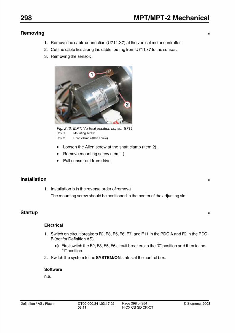
8/12/2019 CT00-000.841.03.17.02.pdf
http://slidepdf.com/reader/full/ct00-000841031702pdf 298/353
298 MPT/MPT-2 Mechanical
Definition / AS / Flash CT00-000.841.03.17.02 © Siemens, 200808.11 H CX CS SD CR-CT
Page 298 of 354
Removing 0
1. Remove the cable connection (U711.X7) at the vertical motor controller.
2. Cut the cable ties along the cable routing from U711.x7 to the sensor.
3. Removing the sensor:
Installation 0
1. Installation is in the reverse order of removal.
The mounting screw should be positioned in the center of the adjusting slot.
Startup 0
Electrical
1. Switch on circuit breakers F2, F3, F5, F6, F7, and F11 in the PDC A and F2 in the PDCB (not for Definition AS).
First switch the F2, F3, F5, F6 circuit breakers to the “0” position and then to the“1” position.
2. Switch the system to the SYSTEM/ON status at the control box.
Software
n.a.
Fig. 243: MPT: Vertical position sensor B711Pos. 1 Mounting screw
Pos. 2 Shaft clamp (Al len screw)
• Loosen the Allen screw at the shaft clamp (item 2).
• Remove mounting screw (item 1).
• Pull sensor out from drive.

8/12/2019 CT00-000.841.03.17.02.pdf
http://slidepdf.com/reader/full/ct00-000841031702pdf 299/353
© Siemens, 2008 CT00-000.841.03.17.02 Definition / AS / Flash08.11 H CX CS SD CR-CT
MPT/MPT-2 Mechanical 299
Page 299 of 354
Tune-up
• Select: Local_Service > Tune-up
• Select: FRU Replacement
• Select: PHS - Encoder
• Press <Go> to start the tour.
The Auto_Complete is started and checks which adjustments are required.
Follow the instructions of the Auto_Complete routine.
Tests
1. Check the vertical table movement via the buttons at the gantry control panels andcheck the display for the vertical position at the gantry display.
2. Perform a test scan
Final Steps 0
1. Clean.

8/12/2019 CT00-000.841.03.17.02.pdf
http://slidepdf.com/reader/full/ct00-000841031702pdf 300/353
300 MPT/MPT-2 Mechanical
Definition / AS / Flash CT00-000.841.03.17.02 © Siemens, 200808.11 H CX CS SD CR-CT
Page 300 of 354
Vertical Microswitches 8.11
• The following instructions are applicable to:
- PHS microswitches, material number 86 14 419
Prerequisites 0
Safety
WARNING [ hz_serdoc_F13G01U12M03 ]
Avoid accident and injury or damage to parts.
Risk of accident and injury!
Read and observe the safety information contained in
the “General” section of this document and/or the“Product specific safety notes”.
Time and Manpower
• 1 person
• Estimated total repair time: 1 hr.
Tools and auxiliary equipment
•
Standard service kit
Preliminary steps 0
1. Raise table to maximum vertical position (position 125).
2. Switch system toCOMP/ON at the control box.
3. Switch OFF the gantry/PHS power using service push-button S1 in the PDC.
Secure the circuit breakers that S1 switched OFF against unintended switch-on(e.g. lock and tag).
NOTE Read and observe the safety information in the “Prod-uct-specific safety notes” prior to performing service work on the patient table. If the patient table power is switched offfor service work, always secure it against accidentalswitch-on.
4. Raise the telescopic table covers with the adjustable strip (service aid delivered with theMPT) to gain full access to the vertical drive assembly. (Telescopic Covers: Releasing &Raising / p. 224)

8/12/2019 CT00-000.841.03.17.02.pdf
http://slidepdf.com/reader/full/ct00-000841031702pdf 301/353
© Siemens, 2008 CT00-000.841.03.17.02 Definition / AS / Flash08.11 H CX CS SD CR-CT
MPT/MPT-2 Mechanical 301
Page 301 of 354
Removing 0
1. Note regarding the safety nut switch:
2. All replaceable switches are mounted by 2 screws.
Release screws and remove the switch.
Fig. 244: MPT: Safety switches at vertical drive Pos. 1 Safety nut switch
Pos. 2 Machined groove
Pos. 3 Connect safety switch
• The safety nut switch (Item 2) monitors the internal safety nut. It is nota field replaceable unit. Should the nut fail, the machine groove (item1) will drop into the casing and the switch will operate.
If the machine groove is not visible, the complete vertical driveassembly should be replaced.

8/12/2019 CT00-000.841.03.17.02.pdf
http://slidepdf.com/reader/full/ct00-000841031702pdf 302/353
302 MPT/MPT-2 Mechanical
Definition / AS / Flash CT00-000.841.03.17.02 © Siemens, 200808.11 H CX CS SD CR-CT
Page 302 of 354
Installation 0
1. Installation is in the reverse order of removal.
2. Upper and lower safety limit switches
Fig. 245: MPT: Vertical limit switches Pos. 1 Upper limit switch
Pos. 2 Lower limit switch
• In normal operation when using the gantry controls, the software lim-its the vertical movement to 10 mm before the mechanical limit; how-ever, this position is referenced to the floor and can be affected byshimming. Therefore, the microswitches are adjusted to operate 5mm before the mechanical limit. Using the service movement
switches will allow the table to raise or lower until the microswitchoperates.
• Turn on F7 and raise the table using the Service controls (Servicemovement of PHS / p. 21) to a position just before the mechanicallimit.
Do not drive to the mechanical limit.
• Turn off F7.
• Use a 6 mm hex key in the manual lift screw (Vertical drive / p. 79) and move the table to the mechanical limit. Measure the table heightfrom the floor and note it.
• Move the table height to a position 5 mm away from the mechanicallimit.
• Adjust the microswitch by releasing the adjuster nut (Item 1) and slid-ing the carrier so that it operates at this point; use the service move-ment switches to check the final position.

8/12/2019 CT00-000.841.03.17.02.pdf
http://slidepdf.com/reader/full/ct00-000841031702pdf 303/353
© Siemens, 2008 CT00-000.841.03.17.02 Definition / AS / Flash08.11 H CX CS SD CR-CT
MPT/MPT-2 Mechanical 303
Page 303 of 354
3. Connect the safety switch
Startup 0
Electrical
1. Switch on circuit breakers F2, F3, F5, F6, F7, and F11 in the PDC A and F2 in the PDCB (not for Definition AS).
First switch the F2, F3, F5, F6 circuit breakers to the “0” position and then to the
“1” position.2. Switch the system to the SYSTEM/ON status at the control box.
Software
n.a
Tune-up
n.a
Fig. 246: MPT: Connect safety switch (vertical drive) Pos. 1 Mounting screws (switch bracket)
Pos. 2 Switch mounting screws
Pos. 3 Switching lever (on vert ical drive)
• The connect safety switch is normally activated and will release if thedrive motor lifts due to a blockage.
• Adjust the microswitch vertically using the switch screws (Item 1) andhorizontally using the bracket fasteners (Item 2).
• The operation can be checked by installing the safety bolts and man-ually lowering the table using a hex socket and wrench until the motor
lifts. Check that the microswitch releases.

8/12/2019 CT00-000.841.03.17.02.pdf
http://slidepdf.com/reader/full/ct00-000841031702pdf 304/353
304 MPT/MPT-2 Mechanical
Definition / AS / Flash CT00-000.841.03.17.02 © Siemens, 200808.11 H CX CS SD CR-CT
Page 304 of 354
Tests
1. Check the vertical table movement via the buttons at the gantry control panels.
2. Perform a test scan
Final Steps 0
1. Clean.

8/12/2019 CT00-000.841.03.17.02.pdf
http://slidepdf.com/reader/full/ct00-000841031702pdf 305/353
© Siemens, 2008 CT00-000.841.03.17.02 Definition / AS / Flash08.11 H CX CS SD CR-CT
MPT/MPT-2 Electronics 305
Page 305 of 354
9- 9MPT/MPT-2Electronics
Overview 0
This chapter describes the removal and replacement of the MPT electronic components.
Fig. 247: Overview: MPT electronics, left table base Pos. 1 Power supplies
Pos. 2 Table master board (LMAS-2 / LMAS-3)
Pos. 3 Ver tical controller
Pos. 4 Foot switch assembly
Pos. 5 Fuses and contactors
• Electronics components (at left table base)
- Power supplies (Item 1)
- LMAS-2 / LMAS-3 table master board (see [2])
Software version Comment
LMAS-2 software versions belowVA40
installed in MPT and MPT-2
LMAS-3 software versions VA40and higher (ex-factory)
installed in MPT-2, serialnumbers 1047 and higher
can be installed in every MPTrunning VA40

8/12/2019 CT00-000.841.03.17.02.pdf
http://slidepdf.com/reader/full/ct00-000841031702pdf 306/353
306 MPT/MPT-2 Electronics
Definition / AS / Flash CT00-000.841.03.17.02 © Siemens, 200808.11 H CX CS SD CR-CT
Page 306 of 354
- Vertical motor controller (Item 3)
- Foot switch assembly (Item 4)
- Contactors, diodes, and fuses (Item 5)
- Brake resistor
Fig. 248: Overview: MPT electronics at tabletop Pos. 1 PMM box
Pos. 2 Horizontal motor controller (tabletop)
Pos. 3 Horizontal motor controller (top support)
• Electronic components (at tabletop)
- Horizontal motor controllers (tabletop and top support)
- PMM box

8/12/2019 CT00-000.841.03.17.02.pdf
http://slidepdf.com/reader/full/ct00-000841031702pdf 307/353
© Siemens, 2008 CT00-000.841.03.17.02 Definition / AS / Flash08.11 H CX CS SD CR-CT
MPT/MPT-2 Electronics 307
Page 307 of 354
Power Supplies G701 / G702 9.1
• The following instructions are applicable to:
- PHS power supplies, material number 86 14 500 (for MPT and MPT-2) and 86 18113 (for MPT-2)
Prerequisites 0
Safety
WARNING [ hz_serdoc_F13G01U12M03 ]
Avoid accident and injury or damage to parts.
Risk of accident and injury!
Read and observe the safety information contained inthe “General” section of this document and/or the“Product specific safety notes”.
Time and manpower
• 1 person
• Estimated total repair time: 30 min
Tools and Auxiliary Equipment
• Standard service kit
Preliminary steps 0
1. If possible, raise the patient table to maximum height (position 125).
2. Switch system to COMP/ON at the control box.
3. Switch OFF the gantry/PHS power using service push-button S1 in the PDC.
Secure the circuit breakers that S1 switched OFF against unintended switch-on
(e.g. lock and tag).
NOTE Read and observe the safety information in the “Prod-uct-specific safety notes” prior to performing service work on the patient table. If the patient table power is switched offfor service work, always secure it against accidentalswitch-on.
4. Raise the telescopic segment covers with the adjustable strip (service aid deliveredwith MPT) to gain full access to the electronics assembly. (Telescopic Covers: Lower-ing & Removing / p. 228)
5. Remove the foot switch assembly at the left table base for better access (3 Allenscrews).

8/12/2019 CT00-000.841.03.17.02.pdf
http://slidepdf.com/reader/full/ct00-000841031702pdf 308/353
308 MPT/MPT-2 Electronics
Definition / AS / Flash CT00-000.841.03.17.02 © Siemens, 200808.11 H CX CS SD CR-CT
Page 308 of 354
Removing 0
1. Remove the power supply cover.
2. Remove the power supply.
Fig. 249: Power supply cover Pos. 1 Power supply cover
Pos. 2 Cover mounting nuts
Pos. 3 Footswitch assembly
Pos. 4 Lower bolt/stand-off
Pos. 5 Lower cable connection
• Remove the mounting nuts from the cover (Item 2).
• Remove the cover (item 1)
Fig. 250: PHS power supply (upper view) Pos. 1 Upper cable connection
Pos. 2 Upper mounting bolt/stand-off
• Remove the upper and lower bolt/stand-offs (Item 1).
• Disconnect the upper and lower cable.
• Remove the power supply.

8/12/2019 CT00-000.841.03.17.02.pdf
http://slidepdf.com/reader/full/ct00-000841031702pdf 309/353
© Siemens, 2008 CT00-000.841.03.17.02 Definition / AS / Flash08.11 H CX CS SD CR-CT
MPT/MPT-2 Electronics 309
Page 309 of 354
Installation 0
1. Position the power supply at the mounting position.
2. Connect the upper and lower cable to the power supply.
3. Secure the power supply with the upper and lower bolt/stand-off.4. Reinstall the power supply cover and secure with the 2 mounting nuts.
5. Reinstall the foot switch assembly and secure with 3 Allen screws.
6. Lower the telescopic segment covers of the table and secure with the locking screw.
Startup 0
Electrical
1. Switch on circuit breakers F2, F3, F5, F6, F7, and F11 in the PDC A and F2 in the PDCB (not for Definition AS).
First switch the F2, F3, F5, F6 circuit breakers to the “0” position and then to the“1” position.
2. Switch the system to the SYSTEM/ON status at the control box.
Software
n.a.
Tune-upn.a.
Tests
1. Check all table movements (horizontal/vertical) via the buttons at the gantry controlpanels.
2. Perform a test scan
Final Steps 0
1. Clean.

8/12/2019 CT00-000.841.03.17.02.pdf
http://slidepdf.com/reader/full/ct00-000841031702pdf 310/353
310 MPT/MPT-2 Electronics
Definition / AS / Flash CT00-000.841.03.17.02 © Siemens, 200808.11 H CX CS SD CR-CT
Page 310 of 354
Contactor Relays and Diode 9.2
• The following instructions are applicable to:
- Relay (K709), material number 86 14 484
- Relay (K711), material number 86 14 476- Contactor relay (K701), material number 86 14 468
- Rectifier (V702), material number 86 14 492
Prerequisites 0
Safety
WARNING [ hz_serdoc_F13G01U12M03 ]
Avoid accident and injury or damage to parts.
Risk of accident and injury!
Read and observe the safety information contained inthe “General” section of this document and/or the“Product specific safety notes”.
Time and manpower
• 1 person
• Estimated total repair time: 30 min. per item.
Tools and Auxiliary Equipment
• Standard service kit
Preliminary steps 0
1. If possible, raise the patient table to maximum height (position 125).
2. Switch system toCOMP/ON at the control box.
3. Switch OFF the gantry/PHS power using service push-button S1 in the PDC. Secure the circuit breakers that S1 switched OFF against unintended switch-on
(e.g. lock and tag).
NOTE Read and observe the safety information in the “Prod-uct-specific safety notes” prior to performing service work on the patient table. If the patient table power is switched offfor service work, always secure it against accidentalswitch-on.

8/12/2019 CT00-000.841.03.17.02.pdf
http://slidepdf.com/reader/full/ct00-000841031702pdf 311/353
© Siemens, 2008 CT00-000.841.03.17.02 Definition / AS / Flash08.11 H CX CS SD CR-CT
MPT/MPT-2 Electronics 311
Page 311 of 354
4. Raise the telescopic segment covers with the adjustable strip (service aid deliveredwith MPT) to gain full access to the electronics assembly. (Telescopic Covers: Releas-ing & Raising / p. 224)
Removing 0
1. Removing parts
Fig. 251: Location of relays, fuses, and rectifier Pos. 1 Contactor/safety relay K701
Pos. 2 Fuses F701/F711/F721/F731 (4 x 1AT)
Pos. 3 Relay K711 (vertical brake)
Pos. 4 Rectifier V702
Pos. 5 Mounting rail
Pos. 6 Rail clamp
Pos. 7 Relay K709 (location behind K701)
• Remove wires, check that the markings are clear and understand-
able.
• Safety relay K701 (Item 1), relay K709 (item 7) and K711 verticalbrake relay (item 3) are all released by removing the rail clamp (item6) on the respective mounting rail (item 5).
• The rectifier (Item 4) is secured by a a single central mounting screw.

8/12/2019 CT00-000.841.03.17.02.pdf
http://slidepdf.com/reader/full/ct00-000841031702pdf 312/353
312 MPT/MPT-2 Electronics
Definition / AS / Flash CT00-000.841.03.17.02 © Siemens, 200808.11 H CX CS SD CR-CT
Page 312 of 354
Installation 0
1. Installation is in the reverse order of removal.
Startup 0
Mechanical
1. Lower the telescopic segment covers of the table and secure with the locking screw.
2. Switch ON circuit breakers F2, F3, F5, F6, F7, and F11 in the PDC.
NOTE First switch the F2, F3, F5, and F6 circuit breakers to the “0”position and then to the “1” position.
3. Switch system to status SYSTEM/ON at the control box.
Software
n.a.
Tune-up
n.a.
Tests
1. Check all table movements (horizontal/vertical) via the buttons at the gantry controlpanels.
2. Perform a test scan
Final Steps 0
1. Clean.

8/12/2019 CT00-000.841.03.17.02.pdf
http://slidepdf.com/reader/full/ct00-000841031702pdf 313/353
© Siemens, 2008 CT00-000.841.03.17.02 Definition / AS / Flash08.11 H CX CS SD CR-CT
MPT/MPT-2 Electronics 313
Page 313 of 354
Fuses F701 / F711 / F721 / F731 9.3
• The following instructions are applicable to:
- Fuses (1AT), material number 86 14 450
Prerequisites 0
Safety
WARNING [ hz_serdoc_F13G01U12M03 ]
Avoid accident and injury or damage to parts.
Risk of accident and injury!
Read and observe the safety information contained in
the “General” section of this document and/or the“Product specific safety notes”.
Time and manpower
• 1 person
• Estimated total repair time: 20 min.
Tools and Auxiliary Equipment
•
Standard service kit
Preliminary steps 0
1. If possible, raise the patient table to maximum height (position 125).
2. Switch system to COMP/ON at the control box.
3. Switch OFF the gantry/PHS power using service push-button S1 in the PDC.
Secure the circuit breakers that S1 switched OFF against unintended switch-on(e.g. lock and tag).
NOTE Read and observe the safety information in the “Prod-uct-specific safety notes” prior to performing service work on the patient table. If the patient table power is switched offfor service work, always secure it against accidentalswitch-on.
4. Raise the telescopic segment covers with the adjustable strip (service aid deliveredwith MPT) to gain full access to the electronics assembly. (Telescopic Covers: Releas-ing & Raising / p. 224)

8/12/2019 CT00-000.841.03.17.02.pdf
http://slidepdf.com/reader/full/ct00-000841031702pdf 314/353
314 MPT/MPT-2 Electronics
Definition / AS / Flash CT00-000.841.03.17.02 © Siemens, 200808.11 H CX CS SD CR-CT
Page 314 of 354
Removing 0
1. Remove the fuse.
Installation 0
1. Insert the new fuse as shown in the figure and close cover.
The cover will guide the fuse into the contacts.
2. Rotate fuse housing back into its original position.
3. Lower the telescopic segment covers of the table and secure with the locking screw.
Startup 0
Electrical
1. Switch on circuit breakers F2, F3, F5, F6, F7, and F11 in the PDC A and F2 in the PDCB (not for Definition AS).
First switch the F2, F3, F5, F6 circuit breakers to the “0” position and then to the“1” position.
2. Switch the system to the SYSTEM/ON status at the control box.
Software
n.a.
Fig. 252: Replacing fuses
• Rotate the fuse holder 90 degrees by lifting the tab (Item 1).
• Pull the lid (Item 2) to open the fuse housing.
The fuse will be pushed out by a small pin to the position shownin the figure.
• Remove fuse.
8/12/2019 CT00-000.841.03.17.02.pdf
http://slidepdf.com/reader/full/ct00-000841031702pdf 315/353
© Siemens, 2008 CT00-000.841.03.17.02 Definition / AS / Flash08.11 H CX CS SD CR-CT
MPT/MPT-2 Electronics 315
Page 315 of 354
Tune-up
n.a.
Tests
1. Check all table movements (horizontal/vertical) via the buttons at the gantry controlpanels
2. Perform a test scan
Final Steps 0
1. Clean.

8/12/2019 CT00-000.841.03.17.02.pdf
http://slidepdf.com/reader/full/ct00-000841031702pdf 316/353
316 MPT/MPT-2 Electronics
Definition / AS / Flash CT00-000.841.03.17.02 © Siemens, 200808.11 H CX CS SD CR-CT
Page 316 of 354
Table master board (LMAS-2 and LMAS-3) 9.4
• The following instructions are applicable to:
- Table master board (LMAS-2), material number 86 12 413
- Table master board (LMAS-3), material number 106 43 790
NOTE Do not replace LMAS and motor controllers at the same time!
If you are uncertain which component is causing the prob-lem, finish replacing one part before you replace the next.
Prerequisites 0
Safety
WARNING [ hz_serdoc_F13G01U12M03 ]
Avoid accident and injury or damage to parts.
Risk of accident and injury!
Read and observe the safety information contained inthe “General” section of this document and/or the“Product specific safety notes”.
Time and manpower
• 1 person
• Estimated total repair time: 1 hr.
Tools and Auxiliary Equipment
• Standard service kit
Preliminary steps 0
1. If possible, raise the patient table to maximum height (position 125).
2. Switch system toCOMP/ON at the control box.
3. Switch OFF the gantry/PHS power using service push-button S1 in the PDC.
Secure the circuit breakers that S1 switched OFF against unintended switch-on(e.g. lock and tag).

8/12/2019 CT00-000.841.03.17.02.pdf
http://slidepdf.com/reader/full/ct00-000841031702pdf 317/353
© Siemens, 2008 CT00-000.841.03.17.02 Definition / AS / Flash08.11 H CX CS SD CR-CT
MPT/MPT-2 Electronics 317
Page 317 of 354
NOTE Read and observe the safety information in the “Prod-uct-specific safety notes” prior to performing service work on the patient table. If the patient table power is switched offfor service work, always secure it against accidental
switch-on.
4. Raise the telescopic segment covers with the adjustable strip (service aid deliveredwith MPT) to gain full access to the electronics assembly. (Telescopic Covers: Releas-ing & Raising / p. 224)
Removing 0
1. Remove the table master board (LMAS-2 or LMAS-3).
NOTE The figure below shows the LMAS-2 board as an example.
The attachment points of the LMAS-3 are identical.
Installation 0
1. Connect all lower cables to the new LMAS assembly.
T 2. Mount the LMAS assembly to the frame with the 2 nuts and tighten to 3 Nm.
3. Reestablish all other cable connections at the LMAS.
4. Lower the telescopic segment covers of the table and secure with the locking screw.
Fig. 253: Table master board (LMAS-2) Pos. 1 Mounting nut
• Remove all upper cable connections from the LMAS-2 or LMAS-3board.
• Remove the 2 mounting nuts securing the LMAS assembly (Item 1).
• Lift the LMAS assembly to remove the lower cable connections.

8/12/2019 CT00-000.841.03.17.02.pdf
http://slidepdf.com/reader/full/ct00-000841031702pdf 318/353
318 MPT/MPT-2 Electronics
Definition / AS / Flash CT00-000.841.03.17.02 © Siemens, 200808.11 H CX CS SD CR-CT
Page 318 of 354
Startup 0
Electrical
1. Switch on circuit breakers F2, F3, F5, F6, F7, and F11 in the PDC A and F2 in the PDCB (not for Definition AS).
First switch the F2, F3, F5, F6 circuit breakers to the “0” position and then to the“1” position.
2. Switch the system to the SYSTEM/ON status at the control box.
Software
n.a.
Tune-up
• Select: Local_Service > TuneUp
• Select: FRU Replace
• Select: PHS - LMAS
• Press <Go> to start the tour.
The Auto_Complete is started and checks which adjustments are required.
Follow the instructions of the Auto_Complete routine.
Tests
1. Check all table movements (horizontal/vertical) via the buttons at the gantry controlpanels
2. Perform a test scan
Final Steps 0
1. Clean.

8/12/2019 CT00-000.841.03.17.02.pdf
http://slidepdf.com/reader/full/ct00-000841031702pdf 319/353
© Siemens, 2008 CT00-000.841.03.17.02 Definition / AS / Flash08.11 H CX CS SD CR-CT
MPT/MPT-2 Electronics 319
Page 319 of 354
Brake resistor R719 9.5
• The following instructions are applicable to:
- Brake resistor R719, material number 86 14 443
Prerequisites 0
Safety
WARNING [ hz_serdoc_F13G01U12M03 ]
Avoid accident and injury or damage to parts.
Risk of accident and injury!
Read and observe the safety information contained in
the “General” section of this document and/or the“Product specific safety notes”.
Time and manpower
• 1 person
• Estimated total repair time: 30 min.
Tools and Auxiliary Equipment
•
Standard service kit
Preliminary steps 0
1. If possible, raise the patient table to maximum height (position 125).
2. Switch system to COMP/ON at the control box.
3. Switch OFF the gantry/PHS power using service push-button S1 in the PDC.
Secure the circuit breakers that S1 switched OFF against unintended switch-on(e.g. lock and tag).
NOTE Read and observe the safety information in the “Prod-uct-specific safety notes” prior to performing service work on the patient table. If the patient table power is switched offfor service work, always secure it against accidentalswitch-on.
4. Raise the telescopic segment covers with the adjustable strip (service aid deliveredwith MPT) to gain full access to the electronics assembly. (Telescopic Covers: Releas-ing & Raising / p. 224)
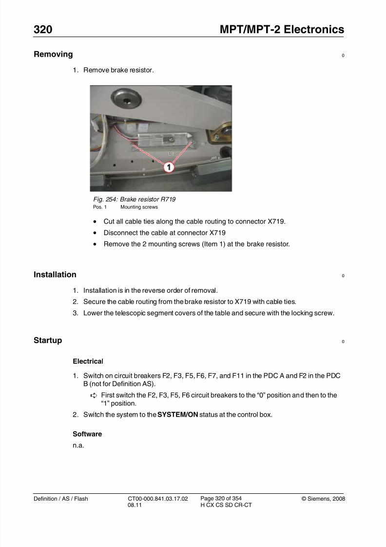
8/12/2019 CT00-000.841.03.17.02.pdf
http://slidepdf.com/reader/full/ct00-000841031702pdf 320/353
320 MPT/MPT-2 Electronics
Definition / AS / Flash CT00-000.841.03.17.02 © Siemens, 200808.11 H CX CS SD CR-CT
Page 320 of 354
Removing 0
1. Remove brake resistor.
Installation 0
1. Installation is in the reverse order of removal.
2. Secure the cable routing from the brake resistor to X719 with cable ties.
3. Lower the telescopic segment covers of the table and secure with the locking screw.
Startup 0
Electrical
1. Switch on circuit breakers F2, F3, F5, F6, F7, and F11 in the PDC A and F2 in the PDCB (not for Definition AS).
First switch the F2, F3, F5, F6 circuit breakers to the “0” position and then to the“1” position.
2. Switch the system to the SYSTEM/ON status at the control box.
Software
n.a.
Fig. 254: Brake resistor R719 Pos. 1 Mounting screws
• Cut all cable ties along the cable routing to connector X719.
• Disconnect the cable at connector X719
• Remove the 2 mounting screws (Item 1) at the brake resistor.

8/12/2019 CT00-000.841.03.17.02.pdf
http://slidepdf.com/reader/full/ct00-000841031702pdf 321/353
© Siemens, 2008 CT00-000.841.03.17.02 Definition / AS / Flash08.11 H CX CS SD CR-CT
MPT/MPT-2 Electronics 321
Page 321 of 354
Tune-up
n.a.
Tests
1. Check the vertical table movement via the buttons at the gantry control panels.
2. Perform a test scan
Final Steps 0
1. Clean.

8/12/2019 CT00-000.841.03.17.02.pdf
http://slidepdf.com/reader/full/ct00-000841031702pdf 322/353
322 MPT/MPT-2 Electronics
Definition / AS / Flash CT00-000.841.03.17.02 © Siemens, 200808.11 H CX CS SD CR-CT
Page 322 of 354
Vertical motor controller U711 9.6
• The following instructions are applicable to:
- Vertical motor controller LUST, material number 86 14 518
NOTE Do not replace LMAS and motor controllers at the same time!
If you are uncertain which component is causing the prob-lem, finish replacing one part before you replace the next.
Prerequisites 0
Safety
WARNING [ hz_serdoc_F13G01U12M03 ]
Avoid accident and injury or damage to parts.
Risk of accident and injury!
Read and observe the safety information contained inthe “General” section of this document and/or the“Product specific safety notes”.
Time and manpower
• 1 person
• Estimated total repair time: 45 min.
Tools and Auxiliary Equipment
• Standard service kit
Preliminary steps 0
1. If possible, raise the patient table to maximum height (position 125).2. Switch system toCOMP/ON at the control box.
3. Switch OFF the gantry/PHS power using service push-button S1 in the PDC.
Secure the circuit breakers that S1 switched OFF against unintended switch-on(e.g. lock and tag).
NOTE Read and observe the safety information in the “Prod-uct-specific safety notes” prior to performing service work on the patient table. If the patient table power is switched offfor service work, always secure it against accidental
switch-on.

8/12/2019 CT00-000.841.03.17.02.pdf
http://slidepdf.com/reader/full/ct00-000841031702pdf 323/353
© Siemens, 2008 CT00-000.841.03.17.02 Definition / AS / Flash08.11 H CX CS SD CR-CT
MPT/MPT-2 Electronics 323
Page 323 of 354
4. Raise the telescopic segment covers with the adjustable strip (service aid deliveredwith MPT) to gain full access to the electronics assembly. (Telescopic Covers: Releas-ing & Raising / p. 224)
Removing 0
1. Remove the vertical motor controller.
Installation 0
1. Check the switch S3 on the inverter and set switch to Pos.1.
S3 must be in Pos.1
2. Install the new motor controller and secure with the two mounting screws.
T Tighten screws to 3 Nm.
3. Connect all cables at the motor controller.
4. Reinstall the patient table segment covers.
Startup 0
Electrical
1. Switch on circuit breakers F2, F3, F5, F6, F7, and F11 in the PDC A and F2 in the PDCB (not for Definition AS).
First switch the F2, F3, F5, F6 circuit breakers to the “0” position and then to the“1” position.
Fig. 255: Vertical motor controller (LUST) Pos. 1 Mounting screws
• Remove all cable connections.
•
Remove the 2 mounting screws (Item 1).

8/12/2019 CT00-000.841.03.17.02.pdf
http://slidepdf.com/reader/full/ct00-000841031702pdf 324/353
324 MPT/MPT-2 Electronics
Definition / AS / Flash CT00-000.841.03.17.02 © Siemens, 200808.11 H CX CS SD CR-CT
Page 324 of 354
2. Switch the system to the SYSTEM/ON status at the control box.
Software
n.a.
Tune-up
Execute the guided tour for FRU replacement:
• Select: Local_Service > TuneUp
• Select: FRU Replace
• Select: PHS - Motor controller hor./vert.
• Press <Go> to start the tour.
The Auto_Complete is started and checks which adjustments are required.
Follow the instructions of the Auto_Complete routine.
Tests
1. Check the vertical table movement via the buttons at the gantry control panels.
2. Perform a test scan
Final Steps 0
1. Clean.

8/12/2019 CT00-000.841.03.17.02.pdf
http://slidepdf.com/reader/full/ct00-000841031702pdf 325/353
© Siemens, 2008 CT00-000.841.03.17.02 Definition / AS / Flash08.11 H CX CS SD CR-CT
MPT/MPT-2 Electronics 325
Page 325 of 354
Horizontal motor controller U731 (Tabletop) / U721 (Top Support)9.7
• The following instructions are applicable to:
- Horizontal motor controller, material number 86 14 401
NOTE Do not replace LMAS and motor controllers at the same time!
If you are uncertain which component is causing the prob-lem, finish replacing one part before you replace the next.
Prerequisites 0
Safety
WARNING [ hz_serdoc_F13G01U12M03 ]
Avoid accident and injury or damage to parts.
Risk of accident and injury!
Read and observe the safety information contained inthe “General” section of this document and/or the“Product specific safety notes”.
Time and manpower
• 1 person
• Estimated total repair time: 45 min.
Tools and Auxiliary Equipment
• Standard service kit
Preliminary steps 0
1. If possible, raise the patient table to maximum height (position 125).2. Switch system to COMP/ON at the control box.
3. Switch OFF the gantry/PHS power using service push-button S1 in the PDC.
Secure the circuit breakers that S1 switched OFF against unintended switch-on(e.g. lock and tag).
NOTE Read and observe the safety information in the “Prod-uct-specific safety notes” prior to performing service work on the patient table. If the patient table power is switched offfor service work, always secure it against accidental
switch-on.

8/12/2019 CT00-000.841.03.17.02.pdf
http://slidepdf.com/reader/full/ct00-000841031702pdf 326/353
326 MPT/MPT-2 Electronics
Definition / AS / Flash CT00-000.841.03.17.02 © Siemens, 200808.11 H CX CS SD CR-CT
Page 326 of 354
4. Remove the left/right rear end covers of the side support (1 plastic cap and screw eachside). (Front and rear covers (left/right) / p. 220)
5. Move the tabletop plate towards the gantry to get access to the rear tabletop cover.
6. Remove the rear plastic cover underneath the tabletop plate. (Tabletop covers (front
and rear) / p. 209)7. Remove the switch plate cover at the foot end of the tabletop plate. (Switchplate
cover / p. 213)
Removing 0
1. Remove the motor controller.
Fig. 256: MPT: Horizontal motor controller (tabletop/top support) Pos. 1 Tabletop controller U731
Pos. 2 Top support control ler U721
Pos. 3 Connectors X731/X721 (to motor assembly)
• Tabletop controller is at the foot end of the table (item 2), top supportcontroller is located closer to the gantry (Item 1).
• Remove all connectors.
• Remove the 2 mounting screws.

8/12/2019 CT00-000.841.03.17.02.pdf
http://slidepdf.com/reader/full/ct00-000841031702pdf 327/353
© Siemens, 2008 CT00-000.841.03.17.02 Definition / AS / Flash08.11 H CX CS SD CR-CT
MPT/MPT-2 Electronics 327
Page 327 of 354
Installation 0
1. Check the switch S1 on the inverter and set switch as follows:
Table top controller (item 1): S1 must be in Pos.3
Top support controller (item 2): S1 must be in Pos.22. Install the mounting screws and connect all cables.
3. Reinstall the tabletop covers.
Startup 0
Electrical
1. Switch on circuit breakers F2, F3, F5, F6, F7, and F11 in the PDC A and F2 in the PDC
B (not for Definition AS).
First switch the F2, F3, F5, F6 circuit breakers to the “0” position and then to the“1” position.
2. Switch the system to the SYSTEM/ON status at the control box.
Software
n.a.
Tune-up
Execute the guided tour for FRU replacement:• Select: Local_Service > TuneUp
• Select: FRU Replace
• Select: PHS - Motor controller hor./vert.
• Press <Go> to start the tour.
The Auto_Complete is started and checks which adjustments are required.
Follow the instructions of the Auto_Complete routine.
Tests
1. Check the horizontal table movement of the tabletop/top support via the buttons at thegantry control panels
2. Perform a test scan
Final Steps 0
1. Clean.

8/12/2019 CT00-000.841.03.17.02.pdf
http://slidepdf.com/reader/full/ct00-000841031702pdf 328/353
328 MPT/MPT-2 Electronics
Definition / AS / Flash CT00-000.841.03.17.02 © Siemens, 200808.11 H CX CS SD CR-CT
Page 328 of 354
Holding solenoid (MPT-2 only) 9.8
• The following instructions are applicable to:
- Holding solenoid, material number 86 18 121
Prerequisites 0
Safety
WARNING [ hz_serdoc_F13G01U12M03 ]
Avoid accident and injury or damage to parts.
Risk of accident and injury!
Read and observe the safety information contained in
the “General” section of this document and/or the“Product specific safety notes”.
Time and manpower
• 1 person
• Estimated total repair time: 45 min.
Tools and auxiliary equipment
•
Standard service kit
Preliminary steps 0
1. Lower the telescopic covers as described in (Side support (left/right) / p. 217)
2. Switch system toCOMP/ON at the control box.
3. Switch OFF the gantry/PHS power using service push-button S1 in the PDC.
Secure the circuit breakers that S1 switched OFF against unintended switch-on(e.g. lock and tag).
NOTE Read and observe the safety information in the “Prod-uct-specific safety notes” prior to performing service work on the patient table. If the patient table power is switched offfor service work, always secure it against accidentalswitch-on.

8/12/2019 CT00-000.841.03.17.02.pdf
http://slidepdf.com/reader/full/ct00-000841031702pdf 329/353
© Siemens, 2008 CT00-000.841.03.17.02 Definition / AS / Flash08.11 H CX CS SD CR-CT
MPT/MPT-2 Electronics 329
Page 329 of 354
Removal 0
1. Disconnect the wires on the holding solenoid.
Fig. 257: Opening the connection box
• Open the plastic cap of the connection box using a small screwdriver.
Fig. 258: Connection of the holding solenoid
• Loosen the connection screw for the wires
• Remove the cable.

8/12/2019 CT00-000.841.03.17.02.pdf
http://slidepdf.com/reader/full/ct00-000841031702pdf 330/353
330 MPT/MPT-2 Electronics
Definition / AS / Flash CT00-000.841.03.17.02 © Siemens, 200808.11 H CX CS SD CR-CT
Page 330 of 354
2. Remove the holding solenoid.
Installation 0
1. Installation is in the reverse order of removal.
2. Reinstall the covers.
Startup 0
Electrical
1. Switch on circuit breakers F2, F3, F5, F6, F7, and F11 in the PDC A and F2 in the PDCB (not for Definition AS).
First switch the F2, F3, F5, F6 circuit breakers to the “0” position and then to the“1” position.
2. Switch the system to the SYSTEM/ON status at the control box.
Software
n.a.
Tune-up
n.a.
Tests
1. Test the function of the system
Fig. 259: Attachment of the holding solenoid
• Open the screw using a 4-mm Allen key.
• Remove the holding solenoid.

8/12/2019 CT00-000.841.03.17.02.pdf
http://slidepdf.com/reader/full/ct00-000841031702pdf 331/353
© Siemens, 2008 CT00-000.841.03.17.02 Definition / AS / Flash08.11 H CX CS SD CR-CT
MPT/MPT-2 Electronics 331
Page 331 of 354
PMM Box 9.9
• The following instructions are applicable to:
- PMM Box, material number 86 18 444
NOTE The PMM box is fully integrated in the tabletop handleassembly.
Therefore the complete assembly must be replaced.
Prerequisites 0
Safety
WARNING [ hz_serdoc_F13G01U12M03 ]
Avoid accident and injury or damage to parts.
Risk of accident and injury!
Read and observe the safety information contained inthe “General” section of this document and/or the“Product specific safety notes”.
Time and manpower
• 1 person• Estimated total repair time: 15 min.
Tools and Auxiliary Equipment
• Standard service kit
Preliminary steps 0
1. Raise the patient table to height of 125.
2. Shut down the system software (click <SYSTEM> and select <END> in the user mainmenu).
3. Click Shutdown System
4. Confirm with Yes in the dialog box displayed.
NOTE Read and observe the safety information in the “Prod-uct-specific safety notes” prior to performing service work on the patient table. If the patient table power is switched offfor service work, always secure it against accidentalswitch-on.

8/12/2019 CT00-000.841.03.17.02.pdf
http://slidepdf.com/reader/full/ct00-000841031702pdf 332/353
332 MPT/MPT-2 Electronics
Definition / AS / Flash CT00-000.841.03.17.02 © Siemens, 200808.11 H CX CS SD CR-CT
Page 332 of 354
Removing 0
• Remove the PMM box.
Fig. 260: PMM assembly Pos. 1 Tabletop handle (incorporates PMM)
Pos. 2 Mounting screws
Fig. 261: PMM assembly and connection Pos. 1 Tabletop handle
Pos. 2 Cable connection X1
Pos. 3 PMM module
Pos. 4 External CanOpen terminator X2 (only version <02)
1. Remove plastic caps and release the 4 Allen screws holding thePMM assembly.
2. Slide out the assembly to the rear by pulling at the tabletop handle.
3. Disconnect connection X1 (item 2).
4. Only for PMMs with revision level lower than 02: Remove externalCanOpen terminator X2 (item 4).
5. Remove the assembly.

8/12/2019 CT00-000.841.03.17.02.pdf
http://slidepdf.com/reader/full/ct00-000841031702pdf 333/353
© Siemens, 2008 CT00-000.841.03.17.02 Definition / AS / Flash08.11 H CX CS SD CR-CT
MPT/MPT-2 Electronics 333
Page 333 of 354
Installation 0
1. Installation is in reverse order of removal.
NOTE On PMMs with revision level 02 and higher, the CanOpen ter-
minator is installed in the module. Therefore, the externalresistor in plug X2 is no longer required.
Do not install plug X2!
Startup 0
Electrical
1. Press the Sys On key on the control box. The whole system is ready for operation whenthe Sys On LED is lit and the operating elements on the control box are backlit.
Software
1. If the system shows a fatal firmware mismatch, the new firmware has to be installed:
Go to Local Service > Control > Firmware to load the current firmware version.
Tune-up
n.a.
Tests
1. Activate the ECG Monitor Demo mode
- Select: Control > Configuration
- Select: Heartview
- Mark checkbox “ECG Monitor Demo mode”
- Press <Apply>
An ECG pulse must be seen at the gantry display.
2. Deactivate the ECG Monitor Demo mode by deselecting the checkbox in the Heartview
window.
Final Steps 0
1. Clean.

8/12/2019 CT00-000.841.03.17.02.pdf
http://slidepdf.com/reader/full/ct00-000841031702pdf 334/353
334 Intervention Module (IVM)
Definition / AS / Flash CT00-000.841.03.17.02 © Siemens, 200808.11 H CX CS SD CR-CT
Page 334 of 354
10- 10Intervention Module(IVM)
Overview 0
This chapter describes the replacement of the following components of the InterventionModule (IVM).
• Intervention Panel (IVP) with accumulator pack
• Wireless Interface Gantry (WIG). This item is located in the right gantry stand.
• Rechargeable batteries of IVP (4 x AA type)
Fig. 262: Components of Intervention Module (IVM)
Pos. 1 Intervention Panel (IVP)
Pos. 2 Wireless Interface Gantry (WIG)
Pos. 3 IVP battery pack (4 x rechargeable AA type)
NOTE The replacement of cables that belong to the IVM option isnot described in this document. For further installation infor-mation, refer to the “Options - Installation and Startup -Patient Table/Intervention Options” document, print numberCT00-000.841.26.xx.02.
If the USB FOC cable needs replacing, follow the guidelinesfor optical cables, e.g. minimum bending radius is 60 mm(approx. 2.4 ").

8/12/2019 CT00-000.841.03.17.02.pdf
http://slidepdf.com/reader/full/ct00-000841031702pdf 335/353
© Siemens, 2008 CT00-000.841.03.17.02 Definition / AS / Flash08.11 H CX CS SD CR-CT
Intervention Module (IVM) 335
Page 335 of 354
Intervention Panel (IVP) 10.1
• The following instructions are applicable to:
- Intervention Panel, material number 101 61 670 (1/ Fig. 262 / p. 334)
Prerequisites 0
Safety
WARNING [ hz_serdoc_F13G01U12M03 ]
Avoid accident and injury or damage to parts.
Risk of accident and injury!
Read and observe the safety information contained in
the “General” section of this document and/or the“Product specific safety notes”.
Time and manpower
• 1 person
• Estimated total repair time: 30 min
Tools and Auxiliary Equipment
•
Standard service kit• Torx key (size: TX8)
Preliminary steps 0
1. Switch system to COMP/ON at the control box.
2. Switch OFF the gantry/PHS power using service push-button S1 in the PDC.
Secure the circuit breakers that S1 switched OFF against unintended switch-on(e.g. lock and tag).
NOTE Read and observe the safety information in the “Prod-uct-specific safety notes” prior to performing service work on the patient table. If the patient table power is switched offfor service work, always secure it against accidentalswitch-on.

8/12/2019 CT00-000.841.03.17.02.pdf
http://slidepdf.com/reader/full/ct00-000841031702pdf 336/353
336 Intervention Module (IVM)
Definition / AS / Flash CT00-000.841.03.17.02 © Siemens, 200808.11 H CX CS SD CR-CT
Page 336 of 354
Removing 0
1. Remove the IVP:
Fig. 263: IVP (rear) Pos. 1 Release button
Pos. 2 Cable connector
Pos. 3 Cover
Pos. 4 Rechargeable batteries (4 x AA type)
Pos. 5 Wire less operation switch
• Disconnect the cable from the IVP, if connected (Pos. 2)
Note: Normally, the cable is only connected in wired operation.
• Disconnect the external power supply from the IVP (if connected).
• If IVP is attached to a holder at the PHS or trolley, push the 2 releasebuttons at the IVP (pos.1) to remove it.

8/12/2019 CT00-000.841.03.17.02.pdf
http://slidepdf.com/reader/full/ct00-000841031702pdf 337/353
© Siemens, 2008 CT00-000.841.03.17.02 Definition / AS / Flash08.11 H CX CS SD CR-CT
Intervention Module (IVM) 337
Page 337 of 354
Installation (for wireless operation) 0
1. Install the new rechargeable batteries and set the “Wireless” switch at the new IVP.
2. Set the “Wireless mode”
- Set the “Wireless” switch (pos. 5) to Position “ON”
3. Reinstall the cover at the IVP (pos. 3)
4. Install the country-specific IVP approval label (2-6/ Fig. 266 / p. 339) at the IVP housingaccording to Figure: (4/ Fig. 265 / p. 338)
Fig. 264: IVP (rear) Pos. 1 Release button
Pos. 2 Cable connector
Pos. 3 Cover
Pos. 4 Rechargeable batteries (4 x AA type)
Pos. 5 Wireless operation switch
• Remove the cover (Pos.3) from the new IVP (5 Torx screws)
• Install the 4 batteries (pos.4), which are delivered with the new sparepart, according to the polarity symbols in the battery compartment.
Due to warranty reasons, use only the accumulator pack, whichis delivered with the spare part. Other batteries may change thewarranted standby time or will even damage the IVP.
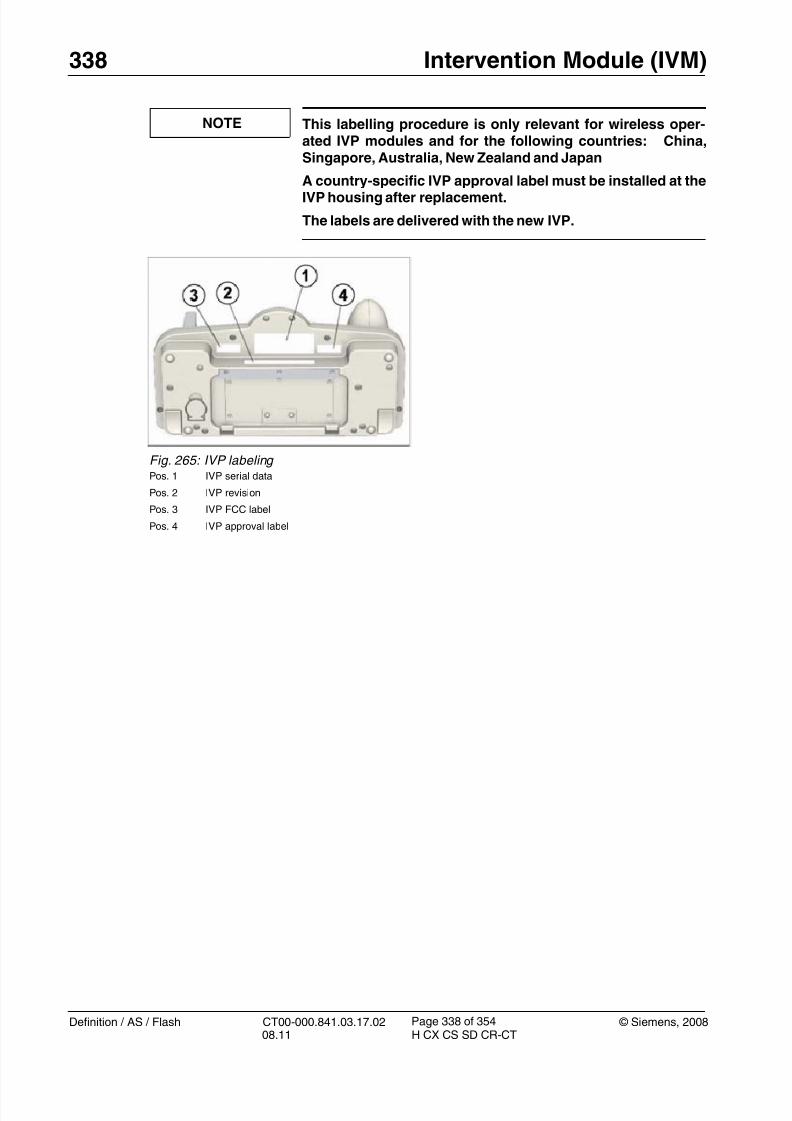
8/12/2019 CT00-000.841.03.17.02.pdf
http://slidepdf.com/reader/full/ct00-000841031702pdf 338/353
338 Intervention Module (IVM)
Definition / AS / Flash CT00-000.841.03.17.02 © Siemens, 200808.11 H CX CS SD CR-CT
Page 338 of 354
NOTE This labelling procedure is only relevant for wireless oper-ated IVP modules and for the following countries: China,Singapore, Australia, New Zealand and Japan
A country-specific IVP approval label must be installed at theIVP housing after replacement.
The labels are delivered with the new IVP.
Fig. 265: IVP labeling Pos. 1 IVP serial data
Pos. 2 IVP revision
Pos. 3 IVP FCC label
Pos. 4 IVP approval label

8/12/2019 CT00-000.841.03.17.02.pdf
http://slidepdf.com/reader/full/ct00-000841031702pdf 339/353
© Siemens, 2008 CT00-000.841.03.17.02 Definition / AS / Flash08.11 H CX CS SD CR-CT
Intervention Module (IVM) 339
Page 339 of 354
Fig. 266: IVM approval labels
Pos. 1 WIG approval labelPos. 2 IVP approval label: Singapore
Pos. 3 IVP approval label: New Zealand
Pos. 4 IVP approval label: Japan
Pos. 5 IVP approval label: Australia
Pos. 6 IVP approval label: China
Installation (for wired operation) 0
• Ex-factory, the spare part is already configured for wired operation.
Therefore only the cable connection has to be performed. Do not insert the accumulator pack.
The power supply for charging the batteries is also not used.

8/12/2019 CT00-000.841.03.17.02.pdf
http://slidepdf.com/reader/full/ct00-000841031702pdf 340/353
340 Intervention Module (IVM)
Definition / AS / Flash CT00-000.841.03.17.02 © Siemens, 200808.11 H CX CS SD CR-CT
Page 340 of 354
Startup 0
Electrical
1. Switch on circuit breakers F2, F3, F5, F6, F7, and F11 in the PDC A and F2 in the PDCB (not for Definition AS).
First switch the F2, F3, F5, F6 circuit breakers to the “0” position and then to the“1” position.
2. Switch the system to the SYSTEM/ON status at the control box.
Software
NOTE After replacement of the IVP, the firmware will be updatedautomatically without any interaction necessary.
During the FW update the LED at the Power-ON button will bepermanently RED.
Clearing the charge counter for the batteries
• For software versions less than VA30:
Go to Service Software
Select Utilities.
Within Source select Escape to OS
Within Command select NT Command Interpreter
Within Parameters type rsh 192.168.184.4 -l root -n “comon -ww 3.0x28.0x2006.40” ↵
• For software VA30 and higher versions:
Select Tune-Up > Expert Mode > IVM > Clear Charge Counter
NOTE For wireless operating Intervention Module ONLY!
After replacement of the component IVP and/or WIG, a“teaching” procedure for synchronizing the wireless commu-
nication is necessary.
This “teaching” procedure must be executed in servicemode.
The IVP and WIG have to be set to wireless mode AND thecable MUST be connected.
• Execute the teaching procedure to synchronize the wireless communication betweenthe components IVP and WIG.
Make sure for the wireless module the cable is connected and both switches are set to“wireless mode”, on WIP and on the IVP. The “wireless” switch for the IVP is located
behind the rear cover of the IVP, next to the batteries.

8/12/2019 CT00-000.841.03.17.02.pdf
http://slidepdf.com/reader/full/ct00-000841031702pdf 341/353
© Siemens, 2008 CT00-000.841.03.17.02 Definition / AS / Flash08.11 H CX CS SD CR-CT
Intervention Module (IVM) 341
Page 341 of 354
Charging the batteries (only for wireless operation)
The batteries are partially charged when delivered.
1. Connect IVP to the power supply
2. Switch on the IVP
Led indicates “yellow” > the batteries are charging
3. After completion of charging procedure, the IVP will be switched off automatically.
This charging procedure must be performed only after the first installa-
tion/replacement of the IVP.
Tune-up
n.a.
Tests
• Check the status LED at the power on button of the IVP:
LED must be permanently GREEN.
Fig. 267: Intervention Panel (IVP) Pos. 1 Power ON button
1. Switch ON the IVP (Pos.1)
2. Log into service mode: Option > Local Service
3. Select: Tune-Up > Expert Mode > IVM
For VA30 and higher versions: Select IVM Teaching
4. Press <GO>
Wait for messages in the status window:Function “Interventional Module Adjustment” completed
and
Status “OK” in the Test window

8/12/2019 CT00-000.841.03.17.02.pdf
http://slidepdf.com/reader/full/ct00-000841031702pdf 342/353
342 Intervention Module (IVM)
Definition / AS / Flash CT00-000.841.03.17.02 © Siemens, 200808.11 H CX CS SD CR-CT
Page 342 of 354
• Execute the IVP button test under service mode::
- Select: Option > Local Service
- Select: Test tools
- Select: Stat.Controller > GPC
Deselect all functions first.
- Select: Intervention Module Test
Follow the instructions in the status message window
- Press all buttons at the IVP except the Power ON button and the buttons at the joy-stick mouse.
Wait for the message “Intervention Module Test passed”
Final Steps 0
1. Attach the IVP to the holder at the PHS or trolley (as applicable).
8/12/2019 CT00-000.841.03.17.02.pdf
http://slidepdf.com/reader/full/ct00-000841031702pdf 343/353
© Siemens, 2008 CT00-000.841.03.17.02 Definition / AS / Flash08.11 H CX CS SD CR-CT
Intervention Module (IVM) 343
Page 343 of 354
Wireless Interface Gantry (WIG) 10.2
• The following instructions are applicable to:
- Wireless Interface Gantry, material number 101 61 671 (2/ Fig. 262 / p. 334)
• The WIG is located in the right gantry stand.
Prerequisites 0
Safety
WARNING [ hz_serdoc_F13G01U12M03 ]
Avoid accident and injury or damage to parts.
Risk of accident and injury!
Read and observe the safety information contained inthe “General” section of this document and/or the“Product specific safety notes”.
Time and manpower
• 1 person
• Estimated total repair time: 30 min
Tools and Auxiliary Equipment• Standard service kit
Preliminary steps 0
1. Switch system to COMP/ON at the control box.
2. Switch OFF the gantry/PHS power using service push-button S1 in the PDC.
Secure the circuit breakers that S1 switched OFF against unintended switch-on(e.g. lock and tag).
NOTE Read and observe the safety information in the “Prod-uct-specific safety notes” prior to performing service work on the patient table. If the patient table power is switched offfor service work, always secure it against accidentalswitch-on.
3. Remove the right side cover at the right gantry stand.
4. Remove the front right cover at the right gantry stand.

8/12/2019 CT00-000.841.03.17.02.pdf
http://slidepdf.com/reader/full/ct00-000841031702pdf 344/353
344 Intervention Module (IVM)
Definition / AS / Flash CT00-000.841.03.17.02 © Siemens, 200808.11 H CX CS SD CR-CT
Page 344 of 354
Removing 0
1. Remove the WIG:
Fig. 268: Wireless Interface Gantry (WIG) Pos. 1 Mounting screws (4 x)
Pos. 2 UMAS-WIG cable connection (X1)Pos. 3 WIG - ICS cable connection (X2, USB port)
Pos. 4 WIG status indicators (LEDs)
Pos. 5 Wireless On/Off switch
Pos. 6 Wireless antenna (X3)
• Disconnect the UMAS-WIG cable at X1 (Pos.2).
• Disconnect the ICS-WIG cable at X2 (Pos.3)
• Remove the 4 mounting screws (Pos.1).
• Remove the WIG assembly.

8/12/2019 CT00-000.841.03.17.02.pdf
http://slidepdf.com/reader/full/ct00-000841031702pdf 345/353
© Siemens, 2008 CT00-000.841.03.17.02 Definition / AS / Flash08.11 H CX CS SD CR-CT
Intervention Module (IVM) 345
Page 345 of 354
Installation 0
1. Install the new WIG.
Fig. 269: Wireless Interface Gantry (WIG) Pos. 1 Mounting screws (4 x)
Pos. 2 UMAS-WIG cable connection (X1)Pos. 3 WIG - ICS cable connection (X2, USB port)
Pos. 4 WIG status indicators (LEDs)
Pos. 5 Wireless On/Off switch
Pos. 6 Wireless antenna (X3)
• Set the “Wireless” switch at the new WIG accordingly (item 5):
Position “ON” for wireless operation
Position “OFF” for wired operation (= IVP connected to gantryvia cable)
• Install the WIG at the right gantry stand with 4 mounting screws (item1).
• Connect the UMAS cable to X1 (item 2).
• Connect the USB cable to X2 (item 3).
8/12/2019 CT00-000.841.03.17.02.pdf
http://slidepdf.com/reader/full/ct00-000841031702pdf 346/353
346 Intervention Module (IVM)
Definition / AS / Flash CT00-000.841.03.17.02 © Siemens, 200808.11 H CX CS SD CR-CT
Page 346 of 354
Startup 0
Electrical
1. Switch on circuit breakers F2, F3, F5, F6, F7, and F11 in the PDC A and F2 in the PDCB (not for Definition AS).
First switch the F2, F3, F5, F6 circuit breakers to the “0” position and then to the“1” position.
2. Switch the system to the SYSTEM/ON status at the control box.
Software
• Updating the firmware:
•Executing the teaching procedure:
NOTE For wireless operating Intervention Module ONLY!
After replacement of the component IVP and/or WIG, a“teaching” procedure for synchronizing the wireless com-munication is necessary.
This “teaching” procedure must be executed in servicemode.
The IVP and WIP have to be set to wire less mode AND thecable MUST be connected.
Fig. 270: Firmware check - successful
• Log into service mode: Option > Local service
• Select: Control > Firmware Update
The firmware check is started and the status of the FW check is dis-played.
If all firmware versions are OK and “Function FW check com-pleted” is displayed, the firmware was loaded successfully.
If firmware version status is not OK, press <GO> to start thefirmware update again.

8/12/2019 CT00-000.841.03.17.02.pdf
http://slidepdf.com/reader/full/ct00-000841031702pdf 347/353
© Siemens, 2008 CT00-000.841.03.17.02 Definition / AS / Flash08.11 H CX CS SD CR-CT
Intervention Module (IVM) 347
Page 347 of 354
Tune-up
n.a.
Tests
• Check the status of the LEDs at the WIG:
LED “Run” (Yellow) must be ON (a short flash every other second is normal)
LED “Power” (Green) must be ON
LED “Link” (Green) must be ON (if RF-Link to IVP exists)
Final Steps 0
1. Reinstall the front right cover at the right gantry stand.
2. Reinstall the cover at the right gantry stand.
3. Clean.
Fig. 271: Intervention Panel (IVP) Pos. 1 Power ON button
1. Switch ON the IVP (Pos.1)
2. Log into service mode: Option > Local Service
3. Select: Tuneup > Expert Mode > IVM
For VA30 and higher versions: Select IVM Teaching
4. Press <GO>
Wait for messages in the status window:Function “Interventional Module Adjustment” completed
and
Status “OK” in the Test window

8/12/2019 CT00-000.841.03.17.02.pdf
http://slidepdf.com/reader/full/ct00-000841031702pdf 348/353
348 Intervention Module (IVM)
Definition / AS / Flash CT00-000.841.03.17.02 © Siemens, 200808.11 H CX CS SD CR-CT
Page 348 of 354
Rechargeable batteries of IVP 10.3
• The following instructions are applicable to:
- Rechargeable batteries of IVP, material number 101 61 762 (contains a set of 4 bat-teries) (3/ Fig. 262 / p. 334)
NOTE Due to warranty reasons, use only the accumulator pack named above. Other batteries may change the warranty timeor will even damage the IVP.
Prerequisites 0
Safety
WARNING [ hz_serdoc_F13G01U12M03 ]
Avoid accident and injury or damage to parts.
Risk of accident and injury!
Read and observe the safety information contained inthe “General” section of this document and/or the“Product specific safety notes”.
Time and manpower
• 1 person
• Estimated total repair time: 15 min
Tools and Auxiliary Equipment
• Standard service kit
• Torx key (size: TX8)
Preliminary steps 0
1. Switch system toCOMP/ON at the control box.
2. Switch OFF the gantry/PHS power using service push-button S1 in the PDC.
Secure the circuit breakers that S1 switched OFF against unintended switch-on(e.g. lock and tag).
NOTE Read and observe the safety information in the “Prod-uct-specific safety notes” prior to performing service work on the patient table. If the patient table power is switched offfor service work, always secure it against accidentalswitch-on.

8/12/2019 CT00-000.841.03.17.02.pdf
http://slidepdf.com/reader/full/ct00-000841031702pdf 349/353
© Siemens, 2008 CT00-000.841.03.17.02 Definition / AS / Flash08.11 H CX CS SD CR-CT
Intervention Module (IVM) 349
Page 349 of 354
3. Remove the cover at the rear of the IVP (5 x Torx screws, TX8).
Removing 0
1. Remove the rechargeable batteries from the IVP.
Fig. 272: Intervention Panel (rear): Battery compartment Pos. 1 Rechargeable batteries (4 x AA type)
Pos. 2 Wireless operation switch
• Remove the rear cover of the IVP (5 x Torx screws, TX8)
• Remove the 4 batteries.

8/12/2019 CT00-000.841.03.17.02.pdf
http://slidepdf.com/reader/full/ct00-000841031702pdf 350/353
350 Intervention Module (IVM)
Definition / AS / Flash CT00-000.841.03.17.02 © Siemens, 200808.11 H CX CS SD CR-CT
Page 350 of 354
Installation 0
1. Install the new rechargeable batteries (4 x AA type).
2. Connect the cable to the IVP (only for wired IVP version).
Startup 0
Electrical
1. Switch on circuit breakers F2, F3, F5, F6, F7, and F11 in the PDC A and F2 in the PDCB (not for Definition AS).
First switch the F2, F3, F5, F6 circuit breakers to the “0” position and then to the
“1” position.2. Switch the system to the SYSTEM/ON status at the control box.
Fig. 273: IVP (rear) Pos. 1 Release button
Pos. 2 Cable connector
Pos. 3 Cover
Pos. 4 Rechargeable batteries (4 x AA type)
Pos. 5 Wire less operation switch
• Install the 4 batteries according to the polarity symbols in the batterycompartment.
• Reinstall the cover at the IVP (5 x TX8 screws).
8/12/2019 CT00-000.841.03.17.02.pdf
http://slidepdf.com/reader/full/ct00-000841031702pdf 351/353
© Siemens, 2008 CT00-000.841.03.17.02 Definition / AS / Flash08.11 H CX CS SD CR-CT
Intervention Module (IVM) 351
Page 351 of 354
Software
• For software versions less than VA30:
Go to Service Software
Select Utilities.
Within Source select Escape to OS
Within Command select NT Command Interpreter
Within Parameters type rsh 192.168.184.4 -l root -n “comon -ww 3.0x28.0x2006.40” ↵
• For VA30 and higher versions:
Within the Service Software, select Tune-Up > Expert Mode > IVM > Clear ChargeCounter
NOTE After replacement of the rechargeable batteries, the “teach-ing” procedure for synchronizing the wireless communica-tion is NOT necessary.
Tune-up
n.a.
Tests
• Check the status LED at the power ON button of the IVP:
LED must be permanently GREEN.
If LED is flashing YELLOW or flashing RED the batteries must be charged.
Connect the external power supply to the IVP to charge the batteries, if neces-sary.
Final Steps 0
1. Clean.

8/12/2019 CT00-000.841.03.17.02.pdf
http://slidepdf.com/reader/full/ct00-000841031702pdf 352/353
352 Changes to Previous Version
Definition / AS / Flash CT00-000.841.03.17.02 © Siemens, 200808.11 H CX CS SD CR-CT
Page 352 of 354
11- 11Changes to Previous Version
Chapter Change Reason
3 Belt pulley PHS added CR 110471
3 Microswitch replacement updated CR 110336
4Switch-on procedure after LMAS-2 replace-ment added
TD_11628
8 Belt pulley PHS_MPT added CR 110471

8/12/2019 CT00-000.841.03.17.02.pdf
http://slidepdf.com/reader/full/ct00-000841031702pdf 353/353
Index 353
12Index
H hz_serdoc_F13G01U11M01 . . . . . . . .17
hz_serdoc_F13G01U12M0329, 32, 35, 40, 43, 48, 52, 57, 61, 64, 74, 79, 93, 99, 104,108, 111, 114, 123, 126, 129, 132, 136, 139, 142, 145, 148, 151, 154, 158, 162, 170,173, 176, 182, 184, 188, 192, 195, 199, 202, 209, 213, 217, 220, 224, 228, 239, 244,252, 260, 274, 282, 288, 293, 297, 300, 307, 310, 313, 316, 319, 322, 325, 328, 331,335, . . . . . . . . . . . . . . . . . . . . . .343, 348
Related Documents


