Page 0 - 1 FLIGHT MANUAL DA 20/100 Category of Airworthiness : UTILITY Applicable Airworthiness Requirements : AWM Chapter 523-VLA Serial No. : Registration : Date of Issue : 19 June 2000 Document No. : DA202-100 This manual must be carried in the aircraft at all times! Scope and revision status can be found in the List of Effective Pages and in the Record of Revisions. The pages identified as "DOT-appr." in the List of Effective Pages are approved by: Signature William Jupp Chief, Flight Test For Director, Aircraft Certification Authority Transport Canada Date of approval 19 June 2000 This airplane is to be operated in compliance with the information and limitations contained herein.

DA20_100_AFM_inc_Rev5.pdf DA20_100_AFM_inc_Rev5.pdf DA20_100_AFM_inc_Rev5.pdf DA20_100_AFM_inc_Rev5.pdf DA20_100_AFM_inc_Rev5.pdf DA20_100_AFM_inc_Rev5.pdf DA20_100_AFM_inc_Rev5.pdf
Jan 01, 2016
DA20_100_AFM_inc_Rev5.pdf DA20_100_AFM_inc_Rev5.pdf DA20_100_AFM_inc_Rev5.pdf DA20_100_AFM_inc_Rev5.pdf DA20_100_AFM_inc_Rev5.pdf DA20_100_AFM_inc_Rev5.pdf DA20_100_AFM_inc_Rev5.pdf DA20_100_AFM_inc_Rev5.pdf DA20_100_AFM_inc_Rev5.pdf DA20_100_AFM_inc_Rev5.pdf DA20_100_AFM_inc_Rev5.pdf DA20_100_AFM_inc_Rev5.pdf DA20_100_AFM_inc_Rev5.pdf DA20_100_AFM_inc_Rev5.pdf DA20_100_AFM_inc_Rev5.pdf DA20_100_AFM_inc_Rev5.pdf
Welcome message from author
This document is posted to help you gain knowledge. Please leave a comment to let me know what you think about it! Share it to your friends and learn new things together.
Transcript

Page 0 - 1
FLIGHT MANUAL
DA 20/100
Category of Airworthiness : UTILITY
Applicable Airworthiness Requirements : AWM Chapter 523-VLA
Serial No. :
Registration :
Date of Issue : 19 June 2000
Document No. : DA202-100
This manual must be carried in the aircraft at all times! Scope and revision status can be found in the List
of Effective Pages and in the Record of Revisions.
The pages identified as "DOT-appr." in the List of Effective Pages are approved by:
Signature
William Jupp
Chief, Flight Test
For Director, Aircraft Certification
Authority Transport Canada
Date of approval 19 June 2000
This airplane is to be operated in compliance with the information and limitations contained herein.

DIAMOND AIRCRAFT DA 20/100 Flight Manual
Doc # DA202-100 June 19, 2000 Page Issue 1 0 - 2
PREFACE
Congratulations on your choice of the DA 20/100 KATANA.
Safe handling of an airplane increases and ensures your safety and provides you with many hours of
enjoyment. For this reason you should take the time to familiarize yourself with your KATANA airplane.
We ask that you carefully read this Flight Manual and pay special attention to the recommendations given.
A careful study of the manual will reward you with many hours of trouble-free flight operation of your
KATANA airplane.
All rights reserved. Reproduction of this manual or any portion
thereof by any means without the express written permission of
DIAMOND AIRCRAFT INDUSTRIES prohibited.
Copyright � by DIAMOND AIRCRAFT INDUSTRIES,
London, Ontario
Canada
DIAMOND AIRCRAFT DA 20/100 Flight Manual
Doc # DA202-100 June 19, 2000 Page Issue 1 0 - 3
TABLE OF CONTENTS
Chapter
GENERAL 1
OPERATING LIMITATIONS 2
EMERGENCY PROCEDURES 3
NORMAL OPERATING PROCEDURES 4
PERFORMANCE 5
WEIGHT AND BALANCE / EQUIPMENT LIST 6
DESCRIPTION OF THE AIRPLANE AND ITS SYSTEMS 7
HANDLING, PREVENTIVE AND CORRECTIVE MAINTENANCE 8
SUPPLEMENTS 9
DIAMOND AIRCRAFT DA 20/100 Flight Manual
Doc # DA202-100 22 August, 2006 Page Revision 5 0 - 4
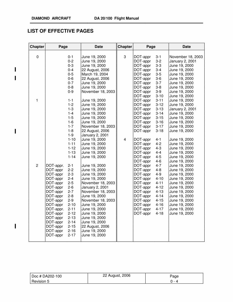
LIST OF EFFECTIVE PAGES
Chapter Page Date Chapter Page Date 0 0-1 June 19, 2000 3 DOT-appr 3-1 November 18, 2003 0-2 June 19, 2000 DOT-appr 3-2 January 2, 2001 0-3 June 19, 2000 DOT-appr 3-3 June 19, 2000 0-4 22 August, 2006 DOT-appr 3-4 June 19, 2000 0-5 March 19, 2004 DOT-appr 3-5 June 19, 2000 0-6 22 August, 2006 DOT-appr 3-6 June 19, 2000 0-7 June 19, 2000 DOT-appr 3-7 June 19, 2000 0-8 June 19, 2000 DOT-appr 3-8 June 19, 2000 0-9 November 18, 2003 DOT-appr 3-9 June 19, 2000 DOT-appr 3-10 June 19, 2000 1 1-1 June 19, 2000 DOT-appr 3-11 June 19, 2000 1-2 June 19, 2000 DOT-appr 3-12 June 19, 2000 1-3 June 19, 2000 DOT-appr 3-13 January 2, 2001 1-4 June 19, 2000 DOT-appr 3-14 June 19, 2000 1-5 June 19, 2000 DOT-appr 3-15 June 19, 2000 1-6 June 19, 2000 DOT-appr 3-16 June 19, 2000 1-7 November 18, 2003 DOT-appr 3-17 June 19, 2000 1-8 22 August, 2006 DOT-appr 3-18 June 19, 2000 1-9 January 2, 2001 1-10 June 19, 2000 4 DOT-appr 4-1 June 19, 2000 1-11 June 19, 2000 DOT-appr 4-2 June 19, 2000 1-12 June 19, 2000 DOT-appr 4-3 June 19, 2000 1-13 June 19, 2000 DOT-appr 4-4 June 19, 2000 1-14 June 19, 2000 DOT-appr 4-5 June 19, 2000 DOT-appr 4-6 June 19, 2000 2 DOT-appr. 2-1 June 19, 2000 DOT-appr 4-7 June 19, 2000 DOT-appr 2-2 June 19, 2000 DOT-appr 4-8 June 19, 2000 DOT-appr 2-3 June 19, 2000 DOT-appr 4-9 June 19, 2000 DOT-appr 2-4 June 19, 2000 DOT-appr 4-10 June 19, 2000 DOT-appr 2-5 November 18, 2003 DOT-appr 4-11 June 19, 2000 DOT-appr 2-6 January 2, 2001 DOT-appr 4-12 June 19, 2000 DOT-appr 2-7 November 18, 2003 DOT-appr 4-13 June 19, 2000 DOT-appr 2-8 June 19, 2000 DOT-appr 4-14 June 19, 2000 DOT-appr 2-9 November 18, 2003 DOT-appr 4-15 June 19, 2000 DOT-appr 2-10 June 19, 2000 DOT-appr 4-16 June 19, 2000 DOT-appr. 2-11 June 19, 2000 DOT-appr 4-17 June 19, 2000 DOT-appr 2-12 June 19, 2000 DOT-appr 4-18 June 19, 2000 DOT-appr 2-13 June 19, 2000 DOT-appr 2-14 June 19, 2000 DOT-appr 2-15 22 August, 2006 DOT-appr 2-16 June 19, 2000 DOT-appr 2-17 June 19, 2000
DIAMOND AIRCRAFT DA 20/100 Flight Manual
Doc # DA202-100 March 19, 2004 Page Revision 4 0 - 5
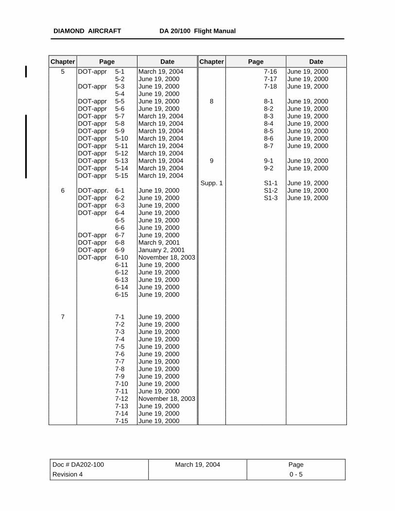
Chapter Page Date Chapter Page Date
5 DOT-appr 5-1 March 19, 2004 7-16 June 19, 2000 5-2 June 19, 2000 7-17 June 19, 2000 DOT-appr 5-3 June 19, 2000 7-18 June 19, 2000 5-4 June 19, 2000 DOT-appr 5-5 June 19, 2000 8 8-1 June 19, 2000 DOT-appr 5-6 June 19, 2000 8-2 June 19, 2000 DOT-appr 5-7 March 19, 2004 8-3 June 19, 2000 DOT-appr 5-8 March 19, 2004 8-4 June 19, 2000 DOT-appr 5-9 March 19, 2004 8-5 June 19, 2000 DOT-appr 5-10 March 19, 2004 8-6 June 19, 2000 DOT-appr 5-11 March 19, 2004 8-7 June 19, 2000 DOT-appr 5-12 March 19, 2004 DOT-appr 5-13 March 19, 2004 9 9-1 June 19, 2000 DOT-appr 5-14 March 19, 2004 9-2 June 19, 2000 DOT-appr 5-15 March 19, 2004 Supp. 1 S1-1 June 19, 2000
6 DOT-appr. 6-1 June 19, 2000 S1-2 June 19, 2000 DOT-appr 6-2 June 19, 2000 S1-3 June 19, 2000 DOT-appr 6-3 June 19, 2000 DOT-appr 6-4 June 19, 2000 6-5 June 19, 2000 6-6 June 19, 2000 DOT-appr 6-7 June 19, 2000 DOT-appr 6-8 March 9, 2001 DOT-appr 6-9 January 2, 2001 DOT-appr 6-10 November 18, 2003 6-11 June 19, 2000 6-12 June 19, 2000 6-13 June 19, 2000 6-14 June 19, 2000 6-15 June 19, 2000
7 7-1 June 19, 2000 7-2 June 19, 2000 7-3 June 19, 2000 7-4 June 19, 2000 7-5 June 19, 2000 7-6 June 19, 2000 7-7 June 19, 2000 7-8 June 19, 2000 7-9 June 19, 2000 7-10 June 19, 2000 7-11 June 19, 2000 7-12 November 18, 2003 7-13 June 19, 2000 7-14 June 19, 2000 7-15 June 19, 2000

DIAMOND AIRCRAFT DA 20/100 Flight Manual
Doc # DA202-100 June 19, 2000 Page Issue 1 0 - 7
[INTENTIONALLY LEFT BLANK]

DIAMOND AIRCRAFT DA 20/100 Flight Manual
Doc # DA202-100 June 19, 2000 Page Issue 1 0 - 8
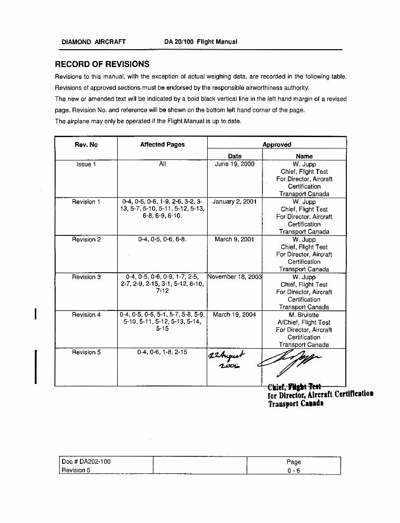
REVISION LOG
This log should be used for control of all revisions issued and installed in this manual. The affected pages
of any revision as well as the Record of Revisions must be inserted into the manual upon receipt. The
pages superseded by the revision must be removed and destroyed. The Revision Log should be updated
by hand. Changes are identified on those pages affected by a revision bar.
Rev. No. Date Issued: Inserted On: Inserted By:
Issue 1 June 19, 2000 June 19, 2000 Diamond Aircraft
DIAMOND AIRCRAFT DA 20/100 Flight Manual
Doc # DA202-100 November 18, 2003 Page Revision 3 0 - 9
SUBSCRIPTION SERVICE Diamond Aircraft Publications Revision Subscription Contacts
To ensure safe operation and maintenance of the DA20/100 Katana aircraft, it is recommended
that operators verify that their documentation is at the correct issue/revision levels. For revision and
subscription service please contact the following:
1. DA20/100 Katana related manuals and publications.
North America, Australia, South Africa: Europe, Other: Diamond Aircraft Industries Inc. Customer Support 1560 Crumlin Sideroad London, Ontario Canada N5V 1S2 www.diamondair.com
Diamond Aircraft Industries GmbH Customer Support N.A. Otto-Strasse 5 A-2700 Wiener Neustadt Austria www.diamond-air.at
Phone: Fax:
519-457-4041 519-457-4045
Phone: Fax:
011-43-2622-26700 011-43-2622-26780
2. Rotax 912 Engine related manuals and publications.
North America: Austria: Rotech Research Canada LTD. 6235 Okanagan Landing Road Vernon, British Columbia Canada V1H 1M5 www.rotec.com
HB- FLUGTECHNIK GES.M.B.H. Dr. Adolf Scharf Str. 44 A-4053HAID www.rotax.bombardier.com
Phone: Fax:
250-260-6299 250-260-6269
Phone: Fax:
07229 / 79104/79117 07229 / 79104 15
OR Contact your authorized Rotax Engine distributor as listed in the back of the 912 Operators Manual.
3. Hoffmann Propeller Model HO-V352 related manuals and publications.
North America, Australia, South Africa: Europe, Other: Diamond Aircraft Industries Inc. Customer Support 1560 Crumlin Sideroad London, Ontario Canada N5V 1S2 www.diamondair.com
Hoffmann Propeller GmbH. & Co. Customer Support Kupferlingstr. 9 D-83022 Rosenheim Germany
Phone: Fax:
519-457-4041 519-457-4045
Phone: Fax:
011-49-8031-1878-0 011-49-8031-1878-78
DIAMOND AIRCRAFT DA 20/100 Flight Manual General
Doc # DA202-100 January 2, 2001 Page Revision 1 1 - 1
CHAPTER 1
GENERAL
1.1. INTRODUCTION 1- 1 1.2. CERTIFICATION BASIS 1- 2 1.3. WARNINGS, CAUTIONS, AND NOTES 1- 2 1.4. THREE-VIEW-DRAWING OF AIRPLANE 1- 3 1.5. DIMENSIONS 1- 4 1.6. ENGINE 1- 5 1.7. PROPELLER 1- 5 1.8. FUEL 1- 6 1.9. LUBRICANT AND COOLANT 1- 7 1.10. WEIGHT 1- 9 1.11. LIST OF DEFINITIONS AND ABBREVIATIONS 1-10 1.12. CONVERSION FACTORS 1-14
1.1. INTRODUCTION
The Airplane Flight Manual has been prepared to provide pilots and instructors with information for the
safe and efficient operation of this airplane.
This Manual includes the material required by JAR-VLA and Transport Canada Airworthiness Manual
(AWM) Chapter 523-VLA. It also contains supplemental data supplied by the airplane manufacturer that
can be useful to the pilot.
The Flight Manual conforms to a standard equipped DA 20/100 KATANA. Any optional equipment
installed on request of the customer (COMM, NAV, etc.) is not considered.
For the operation of optional equipment the Operation Manual of the respective vendor must be used.
For permissible accessories refer to the equipment list, Section 6.5.

DIAMOND AIRCRAFT DA 20/100 Flight Manual General
Doc # DA202-100 January 2, 2001 Page Revision 1 1 - 2
1.2. CERTIFICATION BASIS
The DA 20/100 has been approved by Transport Canada in accordance with the Canadian Airworthiness
Manual (AWM) Chapter 523-VLA. The Type Certificate No. A-191, originally issued on July 29th, 1994,
has been revised to include the DA20/100.
Category of Airworthiness: UTILITY
Noise Certification Basis: a) Canadian Airworthiness Manual Chapter 516
b) FAA Part 36
1.3. WARNINGS, CAUTIONS, AND NOTES
The following definitions apply to warnings, cautions, and notes used in the Flight Manual:
WARNING
means that the non-observation of the corresponding procedure leads to an
immediate or important degradation of the flight safety.
CAUTION
means that the non-observation of the corresponding procedure leads to a
minor or to a more or less long term degradation of flight safety.
NOTE
draws the attention to any special item not directly related to safety but which
is important or unusual.

DIAMOND AIRCRAFT DA 20/100 Flight Manual General
Doc # DA202-100 January 2, 2001 Page Revision 1 1 - 3
1.4. THREE-VIEW-DRAWING OF AIRPLANE
DIAMOND AIRCRAFT DA 20/100 Flight Manual General
Doc # DA202-100 January 2, 2001 Page Revision 1 1 - 4
1.5. DIMENSIONS
1.5.1 Overall Dimensions
Span: 35 ft 7 in (10.84 m)
Length: 23 ft 6.0 in ( 7.17 m)
Height: 6 ft 11.0 in ( 2.10m)
1.5.2 Wing
Airfoil: Wortmann FX 63-137/20 HOAC
Wing Area: 125 sq.ft. (11.6 m2)
Mean Aerodynamic Chord (MAC):
3 ft 6.9 in ( 1.09 m)
Aspect Ratio: 10.0
Dihedral: +4° nominal
Sweep of Leading Edge: +1° nominal
1.5.3 Horizontal Stabilizer
Angle of Incidence : -2.5° ±0.5°
Span: 8 ft 8 in (2.65 m)
1.5.4 Landing Gear
Track: 6 ft 3 in (1.90 m)
Wheel Base: 5 ft 9 in (1.75 m)
Tire Size: Nose: 4.00-4 (TOST)
5.00-4 (GOODYEAR)
Main:� 15 x 6.00-5 (GOODYEAR) or
5.00 x 5, 6 Ply (TSO C62)
Tire Pressure: Nose: 26 psi (1.8 bar)
Main: 33 psi (2.3 bar)
� Main tires must be same brand, model and size.

DIAMOND AIRCRAFT DA 20/100 Flight Manual General
Doc # DA202-100 January 2, 2001 Page Revision 1 1 - 5
1.6. ENGINE Rotax 912S, 4 Cylinder, 4 Stroke-Engine, horizontally opposed, liquid cooled cylinder heads, air-cooled
cylinders.
Propeller drive via integrated reduction gear.
Reduction Ratio: 2.43 : 1
Displacement: 82.5 cu.in. (1.352 liters)
Output Power: 100 hp (73.5 kW)
at 2385 RPM
1.7. PROPELLER Two-bladed variable pitch propeller, manufactured by HOFFMANN,
Constant speed, hydraulic pitch control
model HO-V352F/170FQ OR
model HO-V352F/C170FQ
Range of Pitch Angle: 10° - 35°
Diameter: 5 ft 6.9 in (1.70 m)
DIAMOND AIRCRAFT DA 20/100 Flight Manual General
Doc # DA202-100 January 2, 2001 Page Revision 1 1 - 6
1.8. FUEL
Approved Fuel Grades: AVGAS 100LL
Automotive Gasoline, Unleaded, Minimum 95 RON or 91 AKI
RON = Research Octane Number
MON = Motor Octane Number
AKI = Anti Knock Index =
Total Fuel Capacity:
Specifications: Europe - EN 228
USA - ASTM D4814
Canada – CAN/CGSB-3.5-94
(or more current issue)
20.1 US gal. (76 liters)
Usable Fuel: 19.5 US gal. (74 liters)
Unusable Fuel: 0.6 US gal. ( 2 liters)
CAUTION
Use of automotive gasoline containing alcohol (e.g.: methanol or ethanol) other than specified in the above listed specifications, is not
permitted.
NOTE Petroleum suppliers provide automotive gasoline of varying volatilities, depending on the season and climatic zone. Fuels with higher volatility (“cold weather” grade fuels) are more susceptible to fuel vapour formation than fuels with lower volatility (“hot weather” grade fuels), at equal temperatures. Use of fuels dispensed in winter or in colder climatic zones, under high ambient temperature conditions, increases the risk of vapor formation and subsequent possible engine malfunction.
MON + RON 2

DIAMOND AIRCRAFT DA 20/100 Flight Manual General
Doc # DA202-100 November 18, 2003 Page Revision 3 1 - 7
1.9. LUBRICANT AND COOLANT
1.9.1. Lubricant Use only motor oil with API classification SF or SG or higher. Due to high stresses in the reduction gears, a 4 stroke motorcycle oil of a registered brand with gear
additives that meets API classification SF or SG are highly recommended. The viscosity should be selected according to the various climatic conditions using the following table.
CAUTION
Do not use aviation lubricant!
When operating with AVGAS100LL fuel do not use synthetic oil.
Oil Capacity: Minimum : 3.0 liters (3.2 US qt.)
Maximum : 3.4 liters (3.6 US qt.)
DIAMOND AIRCRAFT DA 20/100 Flight Manual General
Doc # DA202-100 August 22, 2006 Page Revision 5 1 - 8
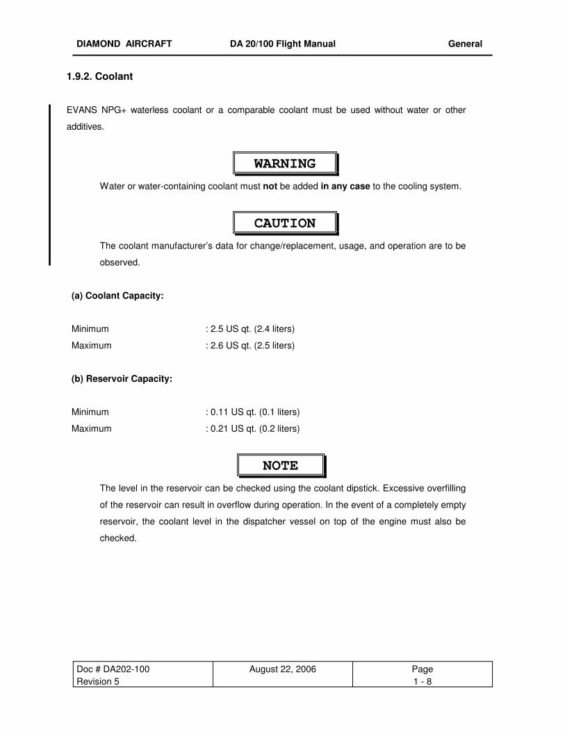
1.9.2. Coolant
EVANS NPG+ waterless coolant or a comparable coolant must be used without water or other
additives.
WARNING
Water or water-containing coolant must not be added in any case to the cooling system.
CAUTION
The coolant manufacturer’s data for change/replacement, usage, and operation are to be
observed.
(a) Coolant Capacity:
Minimum
: 2.5 US qt. (2.4 liters)
Maximum : 2.6 US qt. (2.5 liters)
(b) Reservoir Capacity:
Minimum
: 0.11 US qt. (0.1 liters)
Maximum : 0.21 US qt. (0.2 liters)
NOTE
The level in the reservoir can be checked using the coolant dipstick. Excessive overfilling
of the reservoir can result in overflow during operation. In the event of a completely empty
reservoir, the coolant level in the dispatcher vessel on top of the engine must also be
checked.

DIAMOND AIRCRAFT DA 20/100 Flight Manual General
Doc # DA202-100 January 2, 2001 Page Revision 1 1 - 9
1.10. WEIGHT
Maximum Take-off Weight : 1653 lbs (750 kg)
Maximum Landing Weight : 1653 lbs (750 kg)
Empty Weight : See Chapter 6
Maximum Weight in Baggage Compartment
: 44 lbs (20 kg)
only if restraining devices available
Wing Loading
At Maximum Take-off Weight : 13.23 lbs/sq.ft. (64.60 kg/m2)
Performance Load at Max. Take-off Weight : 16.78 lbs/hp (7.61 kg/hp)

DIAMOND AIRCRAFT DA 20/100 Flight Manual General
Doc # DA202-100 June 19, 2000 Page Issue 1 1 - 10
1.11. LIST OF DEFINITIONS AND ABBREVIATIONS
1.11.1. Speed
AGL: Above Ground Level
CAS: Calibrated airspeed; Indicated speed corrected for installation and instrument errors. CAS
is equal to TAS at standard atmospheric conditions at MSL.
KCAS: CAS in knots.
IAS: Indicated airspeed as shown on the airspeed indicator.
KIAS: IAS indicated in knots.
GS: Ground Speed. Speed of the airplane relative to the ground.
TAS: True airspeed. Speed of the airplane relative to air. TAS is CAS corrected for altitude and
temperature errors.
vA: Maneuvering speed. Maximum speed at which the airplane is not overstressed at full
deflection of control surfaces.
vFE: Maximum speed with flaps extended.
vNE: Speed which must never be exceeded in any operation.
vNO: Maximum structural cruising speed which should only be exceeded in calm air, and then
only with caution.
vS: The power-off stall speed with the airplane in its standard configuration.
vSO: The power-off stall speed with the airplane in landing configuration.
vX: Best angle-of-climb speed.
vY: Best rate-of-climb speed.
DIAMOND AIRCRAFT DA 20/100 Flight Manual General
Doc # DA202-100 June 19, 2000 Page Issue 1 1 - 11
1.11.2. Meteorological Terms
ISA: International Standard Atmosphere at which air is identified as a dry gas. The temperature at
mean sea level is 15° Celsius (59° F), the air pressure at sea level is 1013.25 mbar (29.92 inHg),
the temperature gradient up to the altitude at which the temperature reaches -56.5° C (-67.9° F) is
-0.0065° C/m (-0.0036° F/ft) and 0° C/m (0° F/ft) above.
OAT: Outside air temperature.
AGL: Above Ground Level
Indicated Pressure Altitude:
Altitude reading with altimeter set to 1013.25 mbar (29.92 inHg) air pressure.
Pressure Altitude:
Altitude measured at standard pressure at MSL (1013.25 mbar / 29.92 inHg) using a barometric
altimeter. Pressure altitude is the indicated altitude corrected for installation and instrument errors.
Within this manual the instrument errors are assumed to be zero.
Aerodrome/Airport Pressure:
Actual atmospheric pressure at the aerodrome/airport altitude.
Wind: The wind speeds used in the diagrams in this manual should be referred to as headwind or
tailwind components of the measured wind.
1.11.3. Powerplant
Take-off Power:
Maximum engine power for take-off.
Maximum Continuous Power:
Maximum permissible continuous engine output power during flight.
DIAMOND AIRCRAFT DA 20/100 Flight Manual General
Doc # DA202-100 June 19, 2000 Page Issue 1 1 - 12
1.11.4. Flight Performance and Flight Planning
Demonstrated Crosswind Component:
The maximum speed of the crosswind component at which the maneuvrability of the airplane
during take-off and landing has been demonstrated during type certification test flights.
Service Ceiling:
The altitude at which the maximum rate of climb is 0.5 m/s (100 ft/min.).
1.11.5. Weight and Balance
Reference Datum (RD):
An imaginary vertical plane from which all horizontal distances for the center of gravity calculations
are measured. It is the plane through the leading edge of the wing root rib, perpendicular to the
longitudinal axis of the airplane.
Station:
A defined point along the longitudinal axis which is generally presented as a specific distance from
the reference datum.
Lever Arm:
The horizontal distance from the reference datum to the center of gravity (of a component).
Moment:
The weight of a component multiplied by its lever arm.
Center of Gravity (CG):
Point of equilibrium for the airplane weight.
CG position:
Distance from the reference datum to the CG. It is determined by dividing the total moment (sum
of the individual moments) by the total weight.

DIAMOND AIRCRAFT DA 20/100 Flight Manual General
Doc # DA202-100 June 19, 2000 Page Issue 1 1 - 13
Center of Gravity Limits:
The CG range which an airplane with a given weight must be operated within.
Usable Fuel:
The amount of fuel available for the flight plan calculation.
Unusable Fuel:
The amount of fuel remaining in the tank, which cannot be safely used in flight.
Empty Weight:
Weight of the airplane including unusable fuel, all operating fluids and maximum oil amount.
Useful Load:
The difference between take-off weight and empty weight.
Maximum Take-off Weight:
Maximum weight permissible for take-off.
1.11.6. Equipment
ACL: Anti collision light
1.11.7 Miscellaneous
GFRP - Glass Fibre Reinforced Plastic
CFRP - Carbon Fibre Reinforced Plastic

DIAMOND AIRCRAFT DA 20/100 Flight Manual General
Doc # DA202-100 June 19, 2000 Page Issue 1 1 - 14
1.12. CONVERSION FACTORS
1.12.1. Length or Altitude
1 [ft.] = 0.3048 [m]
1 [in.] = 25.4 [mm]
1.12.2. Speed
1 [kts] = 1.852 [km/h]
1 [mph] = 1.609 [km/h]
1.12.3. Pressure
1 [hPa] = 100 [N/m2] = 1 [mbar]
1 [in. Hg] = 33.865 [hPa]
1 [psi] = 68.97 [mbar]
1.12.4 Weight
1 [lbs] = 0.454 [kg]
1.12.5 Volume
1 [US gallon] = 3.785 [liters]
1 [Imperial gallon] = 4.546 [liters]
DIAMOND AIRCRAFT DA 20/100 Flight Manual Limitations
Doc # 202-100 June 19, 2000 Page DOT Approved 2 - 1
CHAPTER 2
OPERATING LIMITATIONS
2.1 INTRODUCTION 2-1 2.2 AIRSPEED LIMITATIONS 2-2 2.3 AIRSPEED INDICATOR MARKINGS 2-2 2.4 POWERPLANT LIMITATIONS 2-3 2.5 POWERPLANT INSTRUMENT MARKINGS 2-5 2.6 MISCELLANEOUS INSTRUMENT MARKINGS 2-5 2.7 WEIGHT 2-6 2.8 CENTER OF GRAVITY 2-6 2.9 APPROVED MANEUVERS 2-7
2.10 MANEUVERING LOAD FACTORS 2-7 2.11 MAXIMUM PASSENGER SEATING 2-8 2.12 FLIGHT CREW 2-8 2.13 KINDS OF OPERATION 2-8 2.14 FUEL 2-9 2.15 PLACARDS 2-9 2.16 DEMONSTRATED CROSSWIND COMPONENT 2-17 2.17 TEMPERATURE LIMITS 2-17
2.1. INTRODUCTION
Chapter 2 of this Flight Manual comprises the operating limitations, instrument markings, airspeed
indicator markings, and the limitation placards which are necessary for the safe operation of the airplane,
its engine, and standard systems and equipment.
The operating limitations in this Chapter and Chapter 9 have been approved by the Department of
Transport (DOT), and must be complied with for all operations.
WARNING
These limitations must be complied with for all operations.

DIAMOND AIRCRAFT DA 20/100 Flight Manual Limitations
Doc # 202-100 June 19, 2000 Page DOT Approved 2 - 2
2.2. AIRSPEED LIMITATIONS
IAS
Speed kts mph km/h Remarks
vA
Maneuvering Speed
104 120 193 Do not make full or abrupt control movement above this speed, because under certain conditions the airplane may be overstressed by full control movement.
vFE
Maximum Flap Extended Speed
81 93 150 Do not exceed this speed with flaps extended
vNO
Maximum Structural Cruising Speed
118 135 218 Do not exceed this speed except in smooth air, and then only with caution
vNE
Never Exceed Speed
161 185 298 Do not exceed this speed in any operation
2.3. AIRSPEED INDICATOR MARKINGS
IAS
Marking kts mph km/h Explanation
White Arc 37-81 43-93 69-150 Operating range with extended flaps
Green Arc 41-118 47-135 76-218 Normal operating range
Yellow Arc 118-161 135-185 218-298 Maneuvers must be conducted with caution and only in smooth air.
Red Line 161 185 298 Maximum permissible speed for all operating modes
DIAMOND AIRCRAFT DA 20/100 Flight Manual Limitations
Doc # 202-100 June 19, 2000 Page DOT Approved 2 - 3
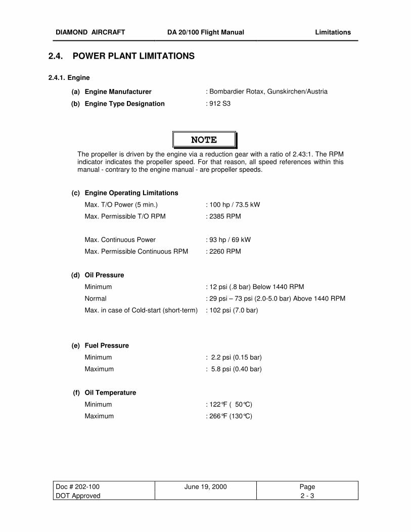
2.4. POWER PLANT LIMITATIONS 2.4.1. Engine
(a) Engine Manufacturer : Bombardier Rotax, Gunskirchen/Austria
(b) Engine Type Designation : 912 S3
NOTE The propeller is driven by the engine via a reduction gear with a ratio of 2.43:1. The RPM indicator indicates the propeller speed. For that reason, all speed references within this manual - contrary to the engine manual - are propeller speeds.
(c) Engine Operating Limitations
Max. T/O Power (5 min.) : 100 hp / 73.5 kW
Max. Permissible T/O RPM : 2385 RPM
Max. Continuous Power : 93 hp / 69 kW
Max. Permissible Continuous RPM : 2260 RPM
(d) Oil Pressure
Minimum
Normal
: 12 psi (.8 bar) Below 1440 RPM
: 29 psi – 73 psi (2.0-5.0 bar) Above 1440 RPM
Max. in case of Cold-start (short-term) : 102 psi (7.0 bar)
(e) Fuel Pressure
Minimum : 2.2 psi (0.15 bar)
Maximum : 5.8 psi (0.40 bar)
(f) Oil Temperature
Minimum : 122°F ( 50°C)
Maximum : 266°F (130°C)
DIAMOND AIRCRAFT DA 20/100 Flight Manual Limitations
Doc # 202-100 June 19, 2000 Page DOT Approved 2 - 4
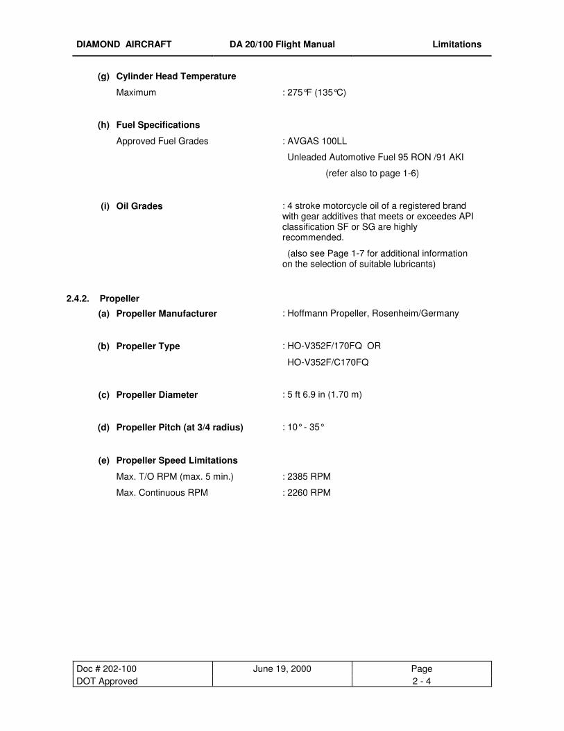
(g) Cylinder Head Temperature
Maximum : 275°F (135°C)
(h) Fuel Specifications
Approved Fuel Grades : AVGAS 100LL
Unleaded Automotive Fuel 95 RON /91 AKI
(refer also to page 1-6)
(i) Oil Grades : 4 stroke motorcycle oil of a registered brand with gear additives that meets or exceedes API classification SF or SG are highly recommended.
(also see Page 1-7 for additional information on the selection of suitable lubricants)
2.4.2. Propeller
(a) Propeller Manufacturer : Hoffmann Propeller, Rosenheim/Germany
(b) Propeller Type : HO-V352F/170FQ OR
HO-V352F/C170FQ
(c) Propeller Diameter : 5 ft 6.9 in (1.70 m)
(d) Propeller Pitch (at 3/4 radius) : 10° - 35°
(e) Propeller Speed Limitations
Max. T/O RPM (max. 5 min.) : 2385 RPM
Max. Continuous RPM : 2260 RPM
DIAMOND AIRCRAFT DA 20/100 Flight Manual Limitations
Doc # 202-100 November 18, 2003 Page Revision 3 2 - 5
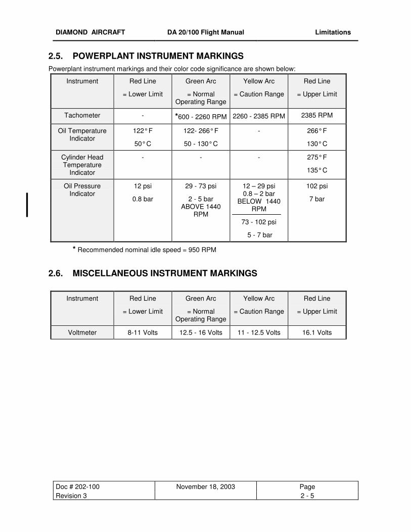
2.5. POWERPLANT INSTRUMENT MARKINGS Powerplant instrument markings and their color code significance are shown below:
Instrument Red Line
= Lower Limit
Green Arc
= Normal Operating Range
Yellow Arc
= Caution Range
Red Line
= Upper Limit
Tachometer - *600 - 2260 RPM 2260 - 2385 RPM 2385 RPM
Oil Temperature Indicator
122° F
50° C
122- 266° F
50 - 130° C
- 266° F
130° C
Cylinder Head Temperature
Indicator
- - - 275° F
135° C
Oil Pressure Indicator
12 psi
0.8 bar
29 - 73 psi
2 - 5 bar ABOVE 1440
RPM
12 – 29 psi 0.8 – 2 bar
BELOW 1440 RPM
73 - 102 psi
5 - 7 bar
102 psi
7 bar
* Recommended nominal idle speed = 950 RPM
2.6. MISCELLANEOUS INSTRUMENT MARKINGS
Instrument Red Line
= Lower Limit
Green Arc
= Normal Operating Range
Yellow Arc
= Caution Range
Red Line
= Upper Limit
Voltmeter 8-11 Volts 12.5 - 16 Volts 11 - 12.5 Volts 16.1 Volts

DIAMOND AIRCRAFT DA 20/100 Flight Manual Limitations
Doc # 202-100 January 2, 2001 Page DOT Approved 2 - 6
2.7. WEIGHT
Maximum permissible weight : 1653 lbs (750 kg)
Maximum permissible weight in the baggage compartment
: 44 lbs ( 20 kg) only permissible with baggage harness
WARNING
Exceeding the weight limitations may lead to overloading of the airplane, as well as
degrading of the handling characteristics and flight performance.
2.8. CENTER OF GRAVITY
The reference datum (RD) for the center of gravity (CG) calculation is tangent to the leading edge of the
wing at the root rib. This plane is vertical when the fuselage is horizontal. Procedures for horizontal
alignment, as well as particulars with regard to the empty weight center of gravity, refer to Chapter 6.
Most forward CG (all weights) : 9.84 in (250 mm) aft of RD
Most rearward CG (all weights) : 15.35 in (390 mm) aft of RD
WARNING
Exceeding the center of gravity limitations reduces the maneuverability and stability of the
airplane.
The procedure used to determine the center of gravity is described in Chapter 6.
DIAMOND AIRCRAFT DA 20/100 Flight Manual Limitations
Doc # 202-100 November 18, 2003 Page Revision 3 2 - 7
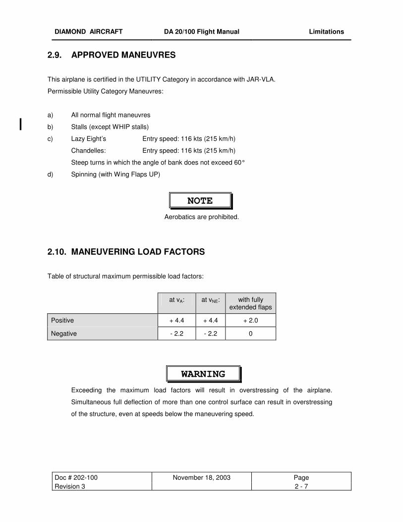
2.9. APPROVED MANEUVRES
This airplane is certified in the UTILITY Category in accordance with JAR-VLA.
Permissible Utility Category Maneuvres:
a) All normal flight maneuvres
b) Stalls (except WHIP stalls)
c) Lazy Eight’s Entry speed: 116 kts (215 km/h)
Chandelles: Entry speed: 116 kts (215 km/h)
Steep turns in which the angle of bank does not exceed 60°
d) Spinning (with Wing Flaps UP)
NOTE
Aerobatics are prohibited.
2.10. MANEUVERING LOAD FACTORS
Table of structural maximum permissible load factors:
at vA: at vNE: with fully extended flaps
Positive + 4.4 + 4.4 + 2.0
Negative - 2.2 - 2.2 0
WARNING
Exceeding the maximum load factors will result in overstressing of the airplane.
Simultaneous full deflection of more than one control surface can result in overstressing
of the structure, even at speeds below the maneuvering speed.

DIAMOND AIRCRAFT DA 20/100 Flight Manual Limitations
Doc # 202-100 June 19, 2000 Page DOT Approved 2 - 8
2.11. MAXIMUM PASSENGER SEATING Maximum Passenger Seating: one passenger.
2.12. FLIGHT CREW Minimum Flight Crew: one pilot,
aircraft to be flown solo from left seat only
2.13. KINDS OF OPERATION Flights are permissible in accordance with visual flight rules.
Minimum Equipment, Flight and Navigation Instruments:
Airspeed Indicator
Altimeter
Magnetic Compass
Turn and Bank Indicator (not mandatory for Day-VFR only)
Instrument Panel and Map Lighting (not mandatory for Day-VFR only)
Minimum Equipment, Powerplant Instruments:
Fuel Quantity Indicator
Oil Pressure Indicator
Oil Temperature Indicator
Manifold Pressure Indicator
Cylinder Head Temperature Indicator
Tachometer
Fuel Pressure Warning Light
Voltmeter
Ammeter
Generator Warning Light
Note: Additional equipment may be required for compliance with specific operational or specific national
requirements. It is the operators responsibility to ensure compliance with any such specific
equipment requirements.

DIAMOND AIRCRAFT DA 20/100 Flight Manual Limitations
Doc # 202-100 November 18, 2003 Page Revision 3 2 - 9
2.14. FUEL Fuel Capacity
Total Fuel Quantity: : 20.1 US gal. (76 liters)
Usable Fuel: : 19.5 US gal. (74 liters )
Unusable Fuel: : 0.53 US gal. ( 2 liters)
2.15. PLACARDS
The following placards must be installed:
1. On the instrument panel next to airspeed indicator
Note: Ensure correct applicability of placard, depending on national limitations.
OR
Effective for all aircaft operated strictly under JAR-VLA regulations
This airplane is classified as a very light airplane approved for day VFR only, in non-icing conditions. All aerobatic maneuvres, including intentional spinning, are prohibited. See Flight Manual for other limitations.
This airplane is classified as a very light airplane approved for VFR only, In non-icing conditions. All aerobatic manoeuvres, except for intentional spinning which is permitted with flaps UP only, are prohibited. See Flight Manual for other limitations.
This airplane is classified as a very light airplane approved for Visual Meterological Conditions only, In non-icing conditions. All aerobatic manoeuvres, except for intentional spinning which is permitted with flaps UP only, are prohibited. See Flight Manual for other limitations.

DIAMOND AIRCRAFT DA 20/100 Flight Manual Limitations
Doc # 202-100 June 19, 2000 Page DOT Approved 2 - 10
3. Next to the switches
4. On the flap control
2. On the instrument panel under the airspeed indicator
5. On the dimming switch for trim display, flap control and GPS (if installed)
6. Next to dimming potentiometer for cabin and fuel shut-off valve light

DIAMOND AIRCRAFT DA 20/100 Flight Manual Limitations
Doc # 202-100 June 19, 2000 Page DOT Approved 2 - 11
7. On the instrument panel next to the individual circuit breakers
� Depending on aircraft specific avionic equipment configuration.
OR� OR�
DIAMOND AIRCRAFT DA 20/100 Flight Manual Limitations
Doc # 202-100 June 19, 2000 Page DOT Approved 2 - 12
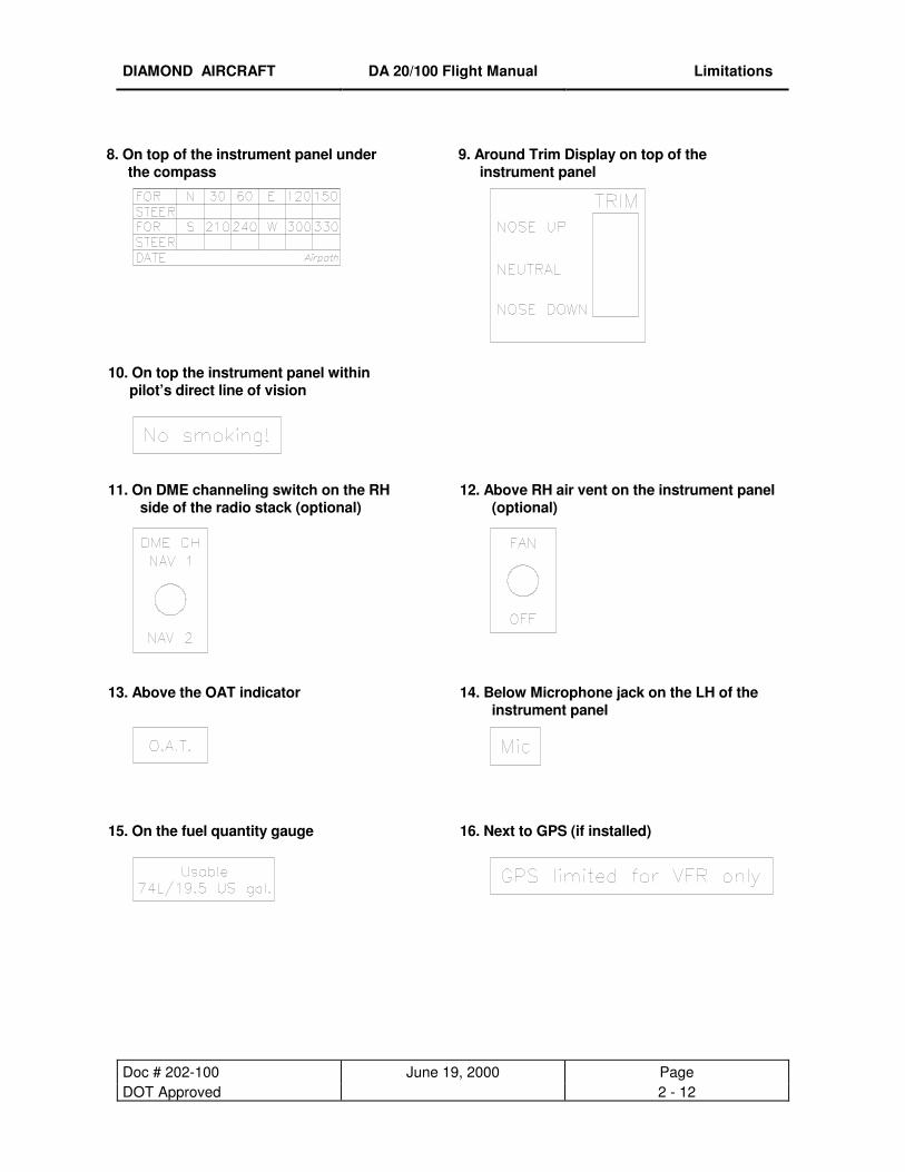
8. On top of the instrument panel under the compass
9. Around Trim Display on top of the instrument panel
15. On the fuel quantity gauge 16. Next to GPS (if installed)
10. On top the instrument panel within pilot’s direct line of vision
11. On DME channeling switch on the RH side of the radio stack (optional)
12. Above RH air vent on the instrument panel (optional)
13. Above the OAT indicator 14. Below Microphone jack on the LH of the instrument panel

DIAMOND AIRCRAFT DA 20/100 Flight Manual Limitations
Doc # 202-100 June 19, 2000 Page DOT Approved 2 - 13
17. Under the instrument panel next to the individual knobs
18. On the centre console between throttle and propeller levers
19. On the side of the throttle quadrant next to tension adjustment knob
20. Next to trim switch on the centre console
21. Next to instrument and map light switches on the centre console
22. Next to fuel shut-off valve in correct position

DIAMOND AIRCRAFT DA 20/100 Flight Manual Limitations
Doc # 202-100 June 19, 2000 Page DOT Approved 2 - 14
23. Next to canopy release handles
Inside Left (partially coloured red) Inside Right (partially coloured red)
Outside Left Outside Right
24. Next to ELT (if installed) to indicate switch position for EBC 102A ELT model for EBC 502 ELT model
25. Next to Headset Jacks on the Back Rest Pilot side (LH) Co-pilot side (RH)
DIAMOND AIRCRAFT DA 20/100 Flight Manual Limitations
Doc # 202-100 August 22, 2006 Page Revision 5 2 - 15
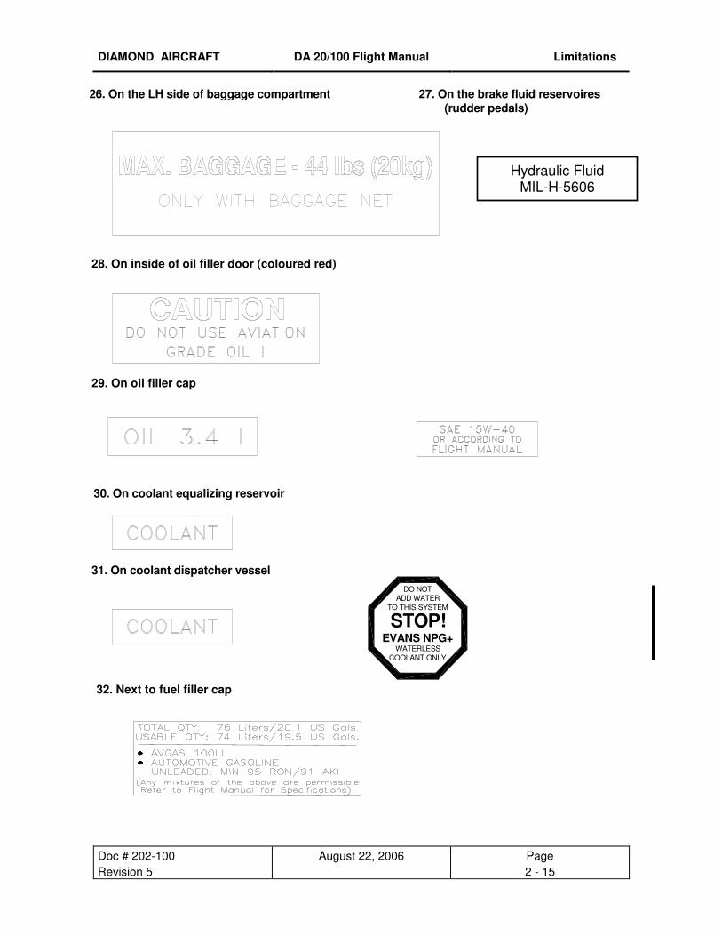
26. On the LH side of baggage compartment 27. On the brake fluid reservoires (rudder pedals)
30. On coolant equalizing reservoir
32. Next to fuel filler cap
28. On inside of oil filler door (coloured red)
29. On oil filler cap
31. On coolant dispatcher vessel
Hydraulic Fluid MIL-H-5606
DO NOTADD WATER
TO THIS SYSTEM
STOP!EVANS NPG+
WATERLESS COOLANT ONLY
DIAMOND AIRCRAFT DA 20/100 Flight Manual Limitations
Doc # 202-100 June 19, 2000 Page DOT Approved 2 - 16
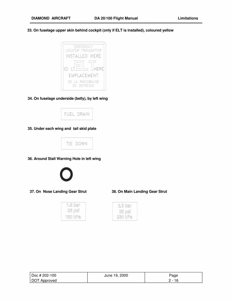
33. On fuselage upper skin behind cockpit (only if ELT is installed), coloured yellow
35. Under each wing and tail skid plate
36. Around Stall Warning Hole in left wing
37. On Nose Landing Gear Strut 38. On Main Landing Gear Strut
34. On fuselage underside (belly), by left wing
DIAMOND AIRCRAFT DA 20/100 Flight Manual Limitations
Doc # 202-100 June 19, 2000 Page DOT Approved 2 - 17
2.16. DEMONSTRATED CROSSWIND COMPONENT
The maximum demonstrated crosswind component is 15 kts. (27 km/h).
2.17. TEMPERATURE LIMITS Limits for outside air temperature and temperature of the structure for the operation of the airplane:
Maximum T/O Temperature : 131°F (55°C)
Structural Temperature limit
For Indicator see pg.4-3

DIAMOND AIRCRAFT DA 20/100 Flight Manual Emergency Procedures
Doc # 202-100 November 18, 2003 Page Revision 3 3 - 1
CHAPTER 3
EMERGENCY PROCEDURES
3.1. INTRODUCTION 3- 2 3.2. AIRSPEEDS DURING EMERGENCY PROCEDURES 3- 2 3.3. EMERGENCY PROCEDURES - CHECKLISTS 3.3.1. Engine Failures (a) Engine Failure during Take-off Run 3- 3 (b) Engine Failure after Take-off I. Insufficient Engine Power 3- 3 II. Engine Inoperative 3- 4 (c) Engine Failure during Flight I. Engine Running Roughly 3- 4 II. Loss of Oil Pressure 3- 4 III. Loss of Fuel Pressure 3- 4 IV. Restarting the Engine with Propeller Windmilling 3- 5 V. Restarting the Engine with Propeller at Full Stop 3- 6 3.3.2. Emergency Landing (a) Emergency Landing with Engine Off 3- 7 (b) Precautionary Landing with Engine Power Available 3- 7 3.3.3. Fire (a) Engine Fire during Start on the Ground 3- 9 (b) Engine Fire during Flight 3- 9 (c) Electrical Fire including Smoke during Flight 3- 9 (d) Electrical Fire including Smoke on the Ground 3-10 (e) Cabin Fire during Flight 3-10 3.3.4. Icing Unintentional Flight into Icing Area 3-11 3.3.5. Recovery from Unintentional Spin 3-11 3.3.6. Landing with Defective Tire on Main Landing Gear 3-12 3.3.7. [Intentionally left blank] 3-12 3.3.8. Gliding 3-13 3.3.9. Electrical Power Failure 3-13 3.3.10 Flap System Failure 3-15 3.3.11 Starter Failure 3-15 3.3.12. Avionics System Failure 3-16 3.3.13. Trim System Failure 3-17 3.3.14. Instrument Panel Lighting Failure 3-18 3.3.15. Tachometer failure 3-18

DIAMOND AIRCRAFT DA 20/100 Flight Manual Emergency Procedures
Doc # 202-100 January 2, 2001 Page DOT Approved 3 - 2
3.1. INTRODUCTION
The following chapter contains check-lists as well as descriptions of the recommended procedures in case
of an emergency. Since it is impossible to present in the Flight Manual all emergency situations which
may occur, knowledge of the airplane and experience of the pilot are essential in rectifying such problems.
3.2. AIRSPEEDS DURING EMERGENCY PROCEDURES
vIAS
kts mph km/h
Engine failure after take-off with flaps in T/O position 60 68 110
Manoeuvring Speed 104 120 193
Airspeed for best glide angle
Wing Flaps in T/O Position 1653 lbs (750 kg)
73
84
135
Wing Flaps in T/O-Position 1322 lbs (600 kg) 66 76 121
Precautionary Landing (with power and Wing Flaps in landing position) 57 66 106
Emergency landing with engine off (Wing Flaps in T/O or LDG position) 57 66 106
Emergency landing with engine off (Wing Flaps UP) 65 75 120
DIAMOND AIRCRAFT DA 20/100 Flight Manual Emergency Procedures
Doc # 202-100 June 19, 2000 Page DOT Approved 3 - 3
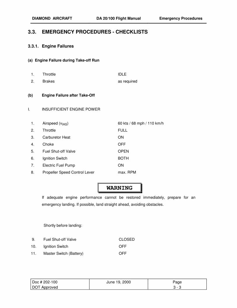
3.3. EMERGENCY PROCEDURES - CHECKLISTS
3.3.1. Engine Failures
(a) Engine Failure during Take-off Run
1. Throttle IDLE
2. Brakes as required
(b) Engine Failure after Take-Off
I. INSUFFICIENT ENGINE POWER
1. Airspeed (vIAS) 60 kts / 68 mph / 110 km/h
2. Throttle FULL
3. Carburetor Heat ON
4. Choke OFF
5. Fuel Shut-off Valve OPEN
6. Ignition Switch BOTH
7. Electric Fuel Pump ON
8. Propeller Speed Control Lever max. RPM
WARNING
If adequate engine performance cannot be restored immediately, prepare for an
emergency landing. If possible, land straight ahead, avoiding obstacles.
Shortly before landing:
9. Fuel Shut-off Valve CLOSED
10. Ignition Switch OFF
11. Master Switch (Battery) OFF
DIAMOND AIRCRAFT DA 20/100 Flight Manual Emergency Procedures
Doc # 202-100 June 19, 2000 Page DOT Approved 3 - 4
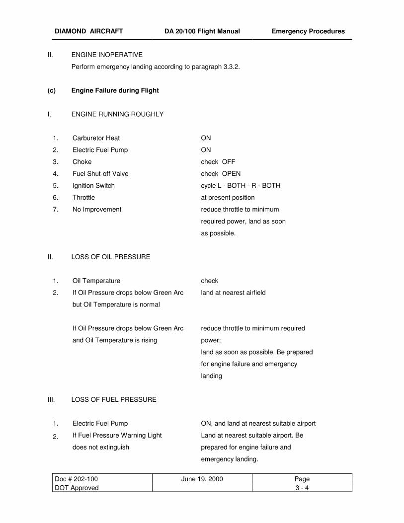
II. ENGINE INOPERATIVE
Perform emergency landing according to paragraph 3.3.2.
(c) Engine Failure during Flight
I. ENGINE RUNNING ROUGHLY
1. Carburetor Heat ON
2. Electric Fuel Pump ON
3. Choke check OFF
4. Fuel Shut-off Valve check OPEN
5. Ignition Switch cycle L - BOTH - R - BOTH
6. Throttle at present position
7. No Improvement reduce throttle to minimum
required power, land as soon
as possible.
II. LOSS OF OIL PRESSURE
1. Oil Temperature check
2. If Oil Pressure drops below Green Arc
but Oil Temperature is normal
land at nearest airfield
If Oil Pressure drops below Green Arc
and Oil Temperature is rising
reduce throttle to minimum required
power;
land as soon as possible. Be prepared
for engine failure and emergency
landing
III. LOSS OF FUEL PRESSURE
1. Electric Fuel Pump ON, and land at nearest suitable airport
2. If Fuel Pressure Warning Light
does not extinguish
Land at nearest suitable airport. Be
prepared for engine failure and
emergency landing.

DIAMOND AIRCRAFT DA 20/100 Flight Manual Emergency Procedures
Doc # 202-100 June 19, 2000 Page DOT Approved 3 - 5
IV. RESTARTING THE ENGINE WITH PROPELLER WINDMILLING
As long as the airspeed (vIAS) is at least 54 kts / 62 mph / 100 km/h, the propeller will
continue to windmill.
1. Airspeed (vIAS) 70 kts / 81 mph / 130 km/h
2. Wing Flaps T/O Position
3. Propeller Speed Control Lever max. RPM
4. Fuel Shut-off Valve OPEN
5. Ignition Switch BOTH
6. Electric Fuel Pump ON
7. Throttle 3/4 in (2 cm) forward
If the engine does not start within 10 seconds: Cold Start
8. Throttle IDLE
9. Choke ON (Pulled)
10. Ignition Switch START

DIAMOND AIRCRAFT DA 20/100 Flight Manual Emergency Procedures
Doc # 202-100 June 19, 2000 Page DOT Approved 3 - 6
V. RESTARTING THE ENGINE WITH PROPELLER AT FULL STOP
1. Electrically Powered Equipment OFF
2. Master Switch (Battery) ON
3. Propeller Speed Control Lever max. RPM
4. Fuel shut off valve OPEN
5. Electric Fuel Pump ON
6. Throttle Cold Start:
Warm Start:
IDLE
3/4 in (2 cm) forward
7. Choke Cold Start:
Warm Start:
ON (pulled)
OFF
8. Ignition Switch START
NOTE
The engine may also be re-started by increasing the airspeed by pushing the airplane into
a descent and accelerating to approx. (vIAS) 120 kts / 138 mph / 222 km/h. A loss of 1000
ft / 300 m altitude must be taken into account.
After successful re-start:
9. Oil Pressure check
10. Choke OFF
11. Electrically Powered Equipment ON if required
12. Oil Temperature check
DIAMOND AIRCRAFT DA 20/100 Flight Manual Emergency Procedures
Doc # 202-100 June 19, 2000 Page DOT Approved 3 - 7
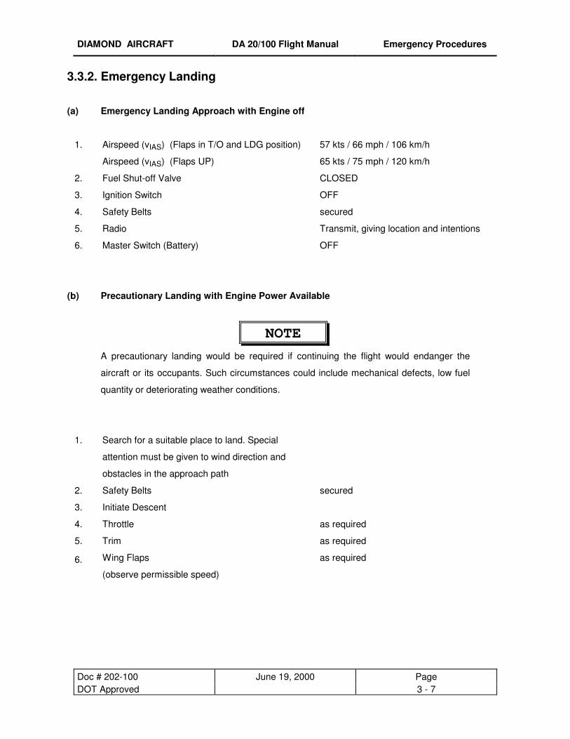
3.3.2. Emergency Landing
(a) Emergency Landing Approach with Engine off
1. Airspeed (vIAS) (Flaps in T/O and LDG position) 57 kts / 66 mph / 106 km/h
Airspeed (vIAS) (Flaps UP) 65 kts / 75 mph / 120 km/h
2. Fuel Shut-off Valve CLOSED
3. Ignition Switch OFF
4. Safety Belts secured
5. Radio Transmit, giving location and intentions
6. Master Switch (Battery) OFF
(b) Precautionary Landing with Engine Power Available
NOTE
A precautionary landing would be required if continuing the flight would endanger the
aircraft or its occupants. Such circumstances could include mechanical defects, low fuel
quantity or deteriorating weather conditions.
1. Search for a suitable place to land. Special
attention must be given to wind direction and
obstacles in the approach path
2. Safety Belts secured
3. Initiate Descent
4. Throttle as required
5. Trim as required
6. Wing Flaps
(observe permissible speed)
as required

DIAMOND AIRCRAFT DA 20/100 Flight Manual Emergency Procedures
Doc # 202-100 June 19, 2000 Page DOT Approved 3 - 8
7. Overfly selected landing area (not below 500 ft / 150 m above
ground) to confirm suitability and that approach route is free of
obstacles
8. Climb up to 1000 ft AGL (if possible)
9. Low pass over flight (around 100 feet) to observe any possible
obstacles, such as cables, fences, ditches
10. Climb up to 1000 ft AGL (if possible)
11. Radio Transmit, giving location and
intentions
12. Final Approach
Throttle as required
Propeller Speed Control Lever max. RPM
Carburetor Heat ON
Electric Fuel Pump ON
Wing Flaps LDG
Airspeed (vIAS) 57 kts / 66 mph / 106 km/h
13. Touch-down is to be made with minimum airspeed, nose wheel
should be kept above ground as long as possible
14. After Touch-down:
Brake as required
Fuel Shut-off Valve CLOSED
Ignition Switch OFF
Master Switch (Battery) OFF
NOTE
If no suitable level landing area can be found, an up-hill landing should be performed, if
possible.

DIAMOND AIRCRAFT DA 20/100 Flight Manual Emergency Procedures
Doc # 202-100 June 19, 2000 Page DOT Approved 3 - 9
3.3.3. Fire
(a) Engine Fire during Engine-Start-Up on the Ground
1. Fuel Shut-off Valve CLOSED
2. Throttle FULL
3. Master Switch (Battery) OFF
4. Ignition Switch OFF
5. Evacuate Airplane immediately
(b) Engine Fire during Flight
1. Fuel Shut-off Valve CLOSED
2. Airspeed (vIAS) 70 kts / 81 mph / 130 km/h
3. Flaps T/O
4. Throttle FULL
5. Electric Fuel Pump OFF
6. Cabin Heat CLOSED
7. Perform emergency landing with engine
off according to paragraph 3.3.2
(c) Electrical Fire including Smoke during Flight
1. Master Switch (Battery) OFF
2. Cabin Air OPEN
3. Fire Extinguisher use only if smoke development
continues.
CAUTION
If fire extinguisher is used, the cabin must be aerated.

DIAMOND AIRCRAFT DA 20/100 Flight Manual Emergency Procedures
Doc # 202-100 June 19, 2000 Page DOT Approved 3 - 10
In case the fire is extinguished and electric power is required for continuation of the flight:
4. Avionics Master Switch OFF
5. Electrically Powered Equipment OFF
6. Master Switch (Battery) ON
7. Avionics Master Switch ON
8. Radio ON
9. Land as soon as possible.
(d) Electrical Fire including Smoke on the Ground
1. Master Switch (Battery) OFF
If engine running:
2. Throttle IDLE
3. Fuel Shut-off Valve CLOSED
4. Ignition Switch OFF
5. Canopy open
6. Fire Extinguisher deploy as required
(e) Cabin Fire during Flight
1. Master Switch (Battery) OFF
2. Cabin Air OPEN
3. Cabin Heat CLOSED
4. Fire Extinguisher deploy as required
5. Land as soon as possible
CAUTION
If fire extinguisher is used, the cabin must be aerated.
DIAMOND AIRCRAFT DA 20/100 Flight Manual Emergency Procedures
Doc # 202-100 June 19, 2000 Page DOT Approved 3 - 11
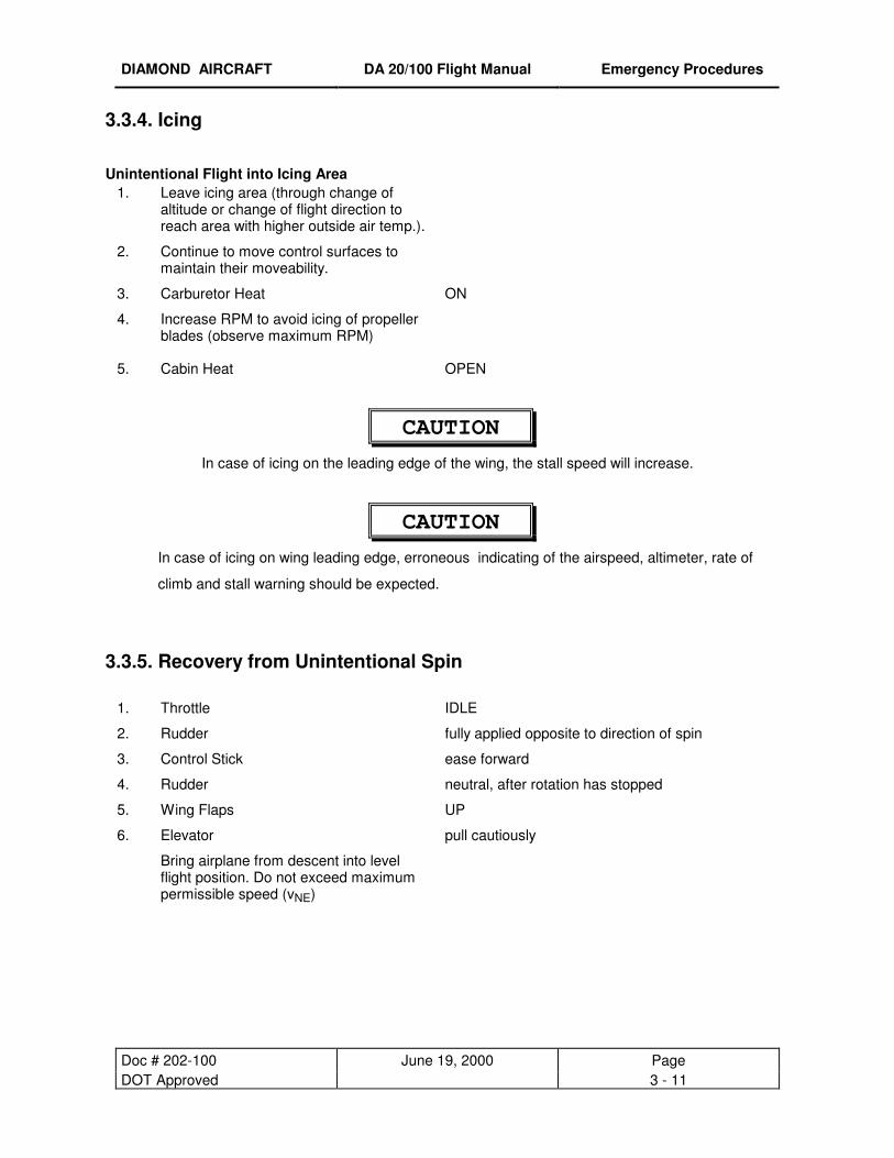
3.3.4. Icing
Unintentional Flight into Icing Area 1. Leave icing area (through change of
altitude or change of flight direction to reach area with higher outside air temp.).
2. Continue to move control surfaces to maintain their moveability.
3. Carburetor Heat ON
4. Increase RPM to avoid icing of propeller blades (observe maximum RPM)
5. Cabin Heat OPEN
CAUTION
In case of icing on the leading edge of the wing, the stall speed will increase.
CAUTION
In case of icing on wing leading edge, erroneous indicating of the airspeed, altimeter, rate of
climb and stall warning should be expected.
3.3.5. Recovery from Unintentional Spin
1. Throttle IDLE
2. Rudder fully applied opposite to direction of spin
3. Control Stick ease forward
4. Rudder neutral, after rotation has stopped
5. Wing Flaps UP
6. Elevator pull cautiously
Bring airplane from descent into level flight position. Do not exceed maximum permissible speed (vNE)
DIAMOND AIRCRAFT DA 20/100 Flight Manual Emergency Procedures
Doc # 202-100 June 19, 2000 Page DOT Approved 3 - 12
3.3.6. Landing with Defective Tire on Main Landing Gear
1. Final approach with wing flaps in landing position.
2. Land airplane on the side of runway opposite to the side with the defective tire to compensate for
change in direction which is to be expected during final rolling.
3. Land with wing slightly tipped in the direction of the non-defective tire. To increase the
maneuvrability during rolling, the nose-wheel should be brought to the ground as soon as possible
after touch-down.
4. To ease the load on the defective tire, the aileron should be fully applied in the direction of the
non-defective tire.
3.3.7. [Intentionally left blank]

DIAMOND AIRCRAFT DA 20/100 Flight Manual Emergency Procedures
Doc # 202-100 January 2, 2001 Page DOT Approved 3 - 13
3.3.8. Gliding
1. Wing Flaps T/O
2. Airspeed at 1653 lbs (750 kg) (vIAS) 73 kts / 84 mph / 135 km/h
3. Glide Ratio 14, which means at
1000 ft/305m above ground, and with no
wind the distance of glide is
2.3 NM (4.25 km)
NOTE
The glide distance from 1000 ft altitude increases for each 10 kts tail wind by 1968 ft (0.6 km).
The glide distance from 1000 ft altitude decreases for each 10 kts head wind by 2296 ft (0.7 km).
3.3.9. Electrical Power Failure
a) Total Electrical Power Failure
1. Battery Circuit Breaker If tripped, reset
2. Master Switch (Generator/Battery) check ON
3. If Unsuccessful Land at nearest suitable airport
b) Generator Failure
GEN. Annunciator Illuminated
1. Master Switch (Generator) Cycle Generator Master Switch OFF - ON
2. Generator Circuit Breaker If tripped, reset
3. Generator CONTROL Circuit Breaker If tripped, reset
4. If Generator can not be brought on-line Switch OFF all non-flight essential electrical
consumers. Monitor Ammeter and Voltmeter. Land at
nearest suitable airport.
NOTE
There are 30 minutes of battery life remaining at a discharge load of 20 amperes.
DIAMOND AIRCRAFT DA 20/100 Flight Manual Emergency Procedures
Doc # 202-100 January 2, 2001 Page DOT Approved 3 - 14
c) Low Voltage Indication (needle in yellow Arc)
I. LOW VOLTAGE INDICATION (NEEDLE IN YELLOW ARC) WHILE AIRPLANE ON
GROUND
1. Propeller RPM Increase RPM until needle is in the Green Arc.
This should occur before exceeding 1350 RPM.
2. Non-flight essential electrical consumers Switch OFF consumers until needle is in the
Green Arc.
3. If needle remains in the yellow arc and the
ammeter is indicating to the left of centre
(discharge)
Discontinue any planned flight activity
II. LOW VOLTAGE INDICATION (NEEDLE IN YELLOW ARC) DURING FLIGHT
1. All non-flight essential electrical
consumers
Switch OFF
2. If needle is remaining in the yellow arc and
the ammeter is indicating to the left of
centre (discharge):
Generator Failure: Refer to paragraph 3.3.9 (b)
III. LOW VOLTAGE INDICATION (NEEDLE IN YELLOW ARC) DURING LANDING:
1. After landing proceed in accordance with paragraph 3.3.9 (c).
WARNING
If at any time the Voltmeter needle indicates in the red arc, you should land at the nearest
suitable airfield and service the aircraft accordingly before continuing the flight.
DIAMOND AIRCRAFT DA 20/100 Flight Manual Emergency Procedures
Doc # 202-100 January 2, 2001 Page DOT Approved 3 - 15
3.3.10. Flap System Failure
Flap Position Indicator Failure
- visual check of the flap position
- select airspeed within the range of the white arc marked on the airspeed indicator
- check all positions of the flap toggle switch (flap stops are fail-safe)
- modify approach and landing as follows:
• only UP available: - raise approach speed by 5 kts
- throttle as required
- flat approach angle
• only T/O available: - normal approach speed
- throttle as required
- flat approach angle
• only LDG available: - normal landing
3.3.11. Starter Failure
Starter does not disengage after starting the engine (continuous whining sound audible).
1. Throttle IDLE
2. Ignition Switch OFF
discontinue any planned flight
DIAMOND AIRCRAFT DA 20/100 Flight Manual Emergency Procedures
Doc # 202-100 January 2, 2001 Page DOT Approved 3 - 16
3.3.12 Avionics System Failure
Total Avionic Failure:
1. Check Avionic Master Circuit Breaker If tripped, re-engage and monitor status, If it trips
again, land at nearest suitable airport
2. Check Avionic Master Switch Toggle avionic master switch, if avionic system
remains off-line, pull avionic master control circuit
breaker and land at nearest suitable airport
Radio System Operative, no reception:
1. Microphone Key check for stuck Microphone Key on transceiver display
2. Headphones check, deactivate SQUELCH for a few moments, if
SQUELCH not heard, check headset connection
Radio System Operative, transmitting not possible:
1. Selected Frequency check if correct
2. Microphone check, if available use different one (headset)
Problem cannot be resolved: switch transponder (if available) to "COMM FAILURE" code if required by
the situation and permitted by applicable national regulations.

DIAMOND AIRCRAFT DA 20/100 Flight Manual Emergency Procedures
Doc # 202-100 January 2, 2001 Page DOT Approved 3 - 17
3.3.13 Trim System Failure
Stuck Trim:
1. Circuit breaker check, reset if breaker is tripped
2. Rocker switch depress in both directions, wait
5 minutes, try again
NOTE
Full range of travel is available for elevator, but expect forces up to 20 lbs. on control stick.
3. Land at nearest suitable airport
Runaway of Trim:
1. Control Stick Grip stick and maintain control of airplane
2. Trim motor circuit breaker Pull circuit breaker
3. Rocker Switch Check if depressed
If reason for runaway condition is obvious and has been resolved, push in (engage) circuit breaker.
NOTE
Full travel of the elevator trim system will take approximately 10 seconds.

DIAMOND AIRCRAFT DA 20/100 Flight Manual Emergency Procedures
Doc # 202-100 January 2, 2001 Page DOT Approved 3 - 18
3.3.14 Instrument Panel Lighting Failure
1. Rocker Switch, map light ON
2. Rocker Switch, I-panel lighting Cycle Rocker Switch OFF - ON
3. Dimming Control Turn fully clockwise
4. Internal Lighting Circuit Breaker. If tripped, reset
5. If NOT Successful
Expect electrical power failure.
Use Flashlight
Ref. 3.3.9 3.3.15 Tachometer failure Operation at T/O (5 minute) power: 1. Airspeed Do not exceed 110 KIAS
Operation at maximum continuous power: 1. Propeller Speed Control Lever Ensure lever is at least ½ inch (10mm)
(measured at slot) aft of full forward position. Engine will now be operating at, or below, maximum continuous power.
NOTE With propeller speed control lever at least ½ inch (10mm) aft of full forward position, the Max. Permissible Continuous RPM (2260 RPM) cannot be exceeded at any throttle setting and airspeed. However, maximum engine power may not be available.

DIAMOND AIRCRAFT DA 20/100 Flight Manual Normal Operating Procedures
Doc # 202-100 June 19, 2000 Page DOT Approved 4 - 1
CHAPTER 4
NORMAL OPERATING PROCEDURES
4.1. INTRODUCTION 4- 2 4.2. AIRSPEEDS FOR NORMAL FLIGHT OPERATION 4- 2 4.3. STRUCTURAL TEMPERATURE INDICATOR 4- 3 4.4. NORMAL OPERATION CHECKLIST 4- 5 4.4.1. Preflight Inspection I. In-Cabin Check 4- 5 II. Walk-Around Check 4- 6 4.4.2. Before Starting Engine 4- 9 4.4.3. Starting Engine 4-10 4.4.4. Before Taxiing 4-11 4.4.5. Taxiing 4-11 4.4.6. Before Take-off (Engine Run-up) 4-12 4.4.7. Take-off 4-13 4.4.8. Climb 4-14 4.4.9. Cruise 4-14 4.4.10. Descent 4-15 4.4.11. Landing Approach 4-15 4.4.12. Balked Landing 4-16 4.4.13. After Landing 4-16 4.4.14. Engine Shut-down 4-16 4.4.15. Flight in Rain 4-17 4.4.16. Spinning 4-18
DIAMOND AIRCRAFT DA 20/100 Flight Manual Normal Operating Procedures
Doc # 202-100 June 19, 2000 Page DOT Approved 4 - 2
4.1. INTRODUCTION
Chapter 4 provides checklist and amplified procedures for the normal operation. For normal procedures
and supplementary information associated with optional systems refer to Chapter 9.
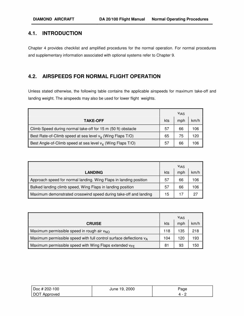
4.2. AIRSPEEDS FOR NORMAL FLIGHT OPERATION
Unless stated otherwise, the following table contains the applicable airspeeds for maximum take-off and
landing weight. The airspeeds may also be used for lower flight weights.
vIAS
TAKE-OFF kts mph km/h
Climb Speed during normal take-off for 15 m (50 ft) obstacle 57 66 106
Best Rate-of-Climb speed at sea level vy (Wing Flaps T/O) 65 75 120
Best Angle-of-Climb speed at sea level vx (Wing Flaps T/O) 57 66 106
vIAS
LANDING kts mph km/h
Approach speed for normal landing. Wing Flaps in landing position 57 66 106
Balked landing climb speed, Wing Flaps in landing position 57 66 106
Maximum demonstrated crosswind speed during take-off and landing 15 17 27
vIAS
CRUISE kts mph km/h
Maximum permissible speed in rough air vNO 118 135 218
Maximum permissible speed with full control surface deflections vA 104 120 193
Maximum permissible speed with Wing Flaps extended vFE 81 93 150

DIAMOND AIRCRAFT DA 20/100 Flight Manual Normal Operating Procedures
Doc # 202-100 June 19, 2000 Page DOT Approved 4 - 3
4.3 STRUCTURAL TEMPERATURE INDICATOR
A structural temperature indicator, installed on the spar bridge, indicates when the structural temperature
limitation is exceeded (ref. section 2.17). The indicator need only be checked if the OAT exceeds 38° C
(100° F).
The indicator is accessed by lifting the flap between the two seatback cushions. The indicator is visible
through the cut out in the seat shell backs (ref. fig. 2).
At temperatures below the 55° C (131° F) limit, the indicator appears all red with a faint indication of “55”
(° C). At temperatures exceeding the 55° C (131° F) limit, the indicator displays a clearly contrasting red
“55” (° C) on a black background (ref. fig.1).
NOTE At temperatures approaching the limit, the background will progressively darken
prior to turning black; this indicates acceptable temperatures.
Red “55” on black background indicates that structural temperature limit is exceeded. Flight is prohibited.
All red indicates that structural temperature is below limit. Flight is permitted.
Figure 1
Figure 2

DIAMOND AIRCRAFT DA 20/100 Flight Manual Normal Operating Procedures
Doc # 202-100 June 19, 2000 Page DOT Approved 4 - 4
[ INTENTIONALLY LEFT BLANK ]

DIAMOND AIRCRAFT DA 20/100 Flight Manual Normal Operating Procedures
Doc # 202-100 June 19, 2000 Page DOT Approved 4 - 5
4.4. NORMAL OPERATION CHECKLIST 4.4.1. Preflight Inspection
I. In-Cabin Check
1. Structural Temperature Indicator (if OAT exceeds 38°C (100° F))
check that Structural Temperature does not exceed 55° C (131° F)
2. Airplane Documents check 3. Flight Control Lock removed 4. Flight Controls check for proper direction of
movement
5. Ignition Key pulled out
6. Carburetor Heat free, OFF
7. Cabin Heat free
8. Choke free, self-resetting
9. Parking Brake free
10. Throttle free, IDLE
11. Propeller Speed Control Lever free, max. RPM
12. Master Switch (Battery) ON
13. Warning Lights (Gen., Fuel Press., and Canopy) illuminated
14. Fuel Quantity sufficient
15. Engine Gauges, Ammeter and Voltmeter check
16. Circuit Breakers pressed in
17. Map Light operational
18. Instrument Lights operational and dimmable
19. Trim NEUTRAL
20. Wing Flaps (Indicator- and Flap Actuation) check, extend and retract fully
21. Trim and Flap Indicator Lights operational and dimmable
22. Exterior Lights operational as required
23. Master Switch (Battery) OFF
24. Foreign Object Inspection done
25. Emergency Locator Transmitter (ELT):
EBC Model 502 - ARM
EBC Model 102A - OFF
26. Fire Extinguisher check
27. Baggage stowed, baggage net attached
28. Canopy clean, undamaged
DIAMOND AIRCRAFT DA 20/100 Flight Manual Normal Operating Procedures
Doc # 202-100 June 19, 2000 Page DOT Approved 4 - 6
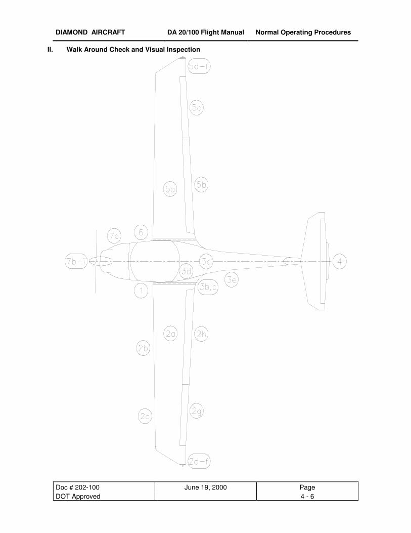
II. Walk Around Check and Visual Inspection

DIAMOND AIRCRAFT DA 20/100 Flight Manual Normal Operating Procedures
Doc # 202-100 June 19, 2000 Page DOT Approved 4 - 7
CAUTION
Visually inspect for the following conditions: Defects, contamination, cracks,
delaminations, excessive play, insecure or improper mounting and general condition.
Additionally, check the control surfaces for freedom of movement.
CAUTION
Set PARKING brake prior to removing wheel chocks
1. Left Main Landing Gear
a) Landing Gear Strut visual inspection
b) Wheel Fairing visual inspection
c) Tire Pressure (33 psi / 2.3 bar) check
d) Tire, Wheel, Brake visual inspection
e) Wheel Chocks remove
2. Left Wing
a) Entire Wing visual inspection
b) Stall Warning check (suck on opening)
c) Pitot-Static Probe clean, holes open
d) Tie down remove
e) Taxi and Landing Lights visual inspection
f) Wing Tip, Position Lights and Strobe visual inspection
g) Aileron Balancing Weight visual inspection
h) Aileron including Inspection Panel visual inspection
i) Wing Flap including Inspection Panel visual inspection
3. Fuselage
a) Skin visual inspection
b) Tank Vent check
c) Tank Drain drain water
d) Fuel Quantity visual inspection (use fuel pipette)
e) Antennas visual inspection
DIAMOND AIRCRAFT DA 20/100 Flight Manual Normal Operating Procedures
Doc # 202-100 June 19, 2000 Page DOT Approved 4 - 8
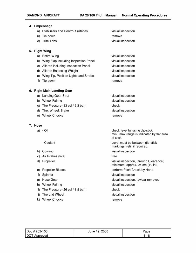
4. Empennage a) Stabilizers and Control Surfaces visual inspection
b) Tie down remove
c) Trim Tabs visual inspection
5. Right Wing a) Entire Wing visual inspection
b) Wing Flap including Inspection Panel visual inspection
c) Aileron including Inspection Panel visual inspection
d) Aileron Balancing Weight visual inspection
e) Wing Tip, Position Lights and Strobe visual inspection
f) Tie down remove
6. Right Main Landing Gear a) Landing Gear Strut visual inspection
b) Wheel Fairing visual inspection
c) Tire Pressure (33 psi / 2.3 bar) check
d) Tire, Wheel, Brake visual inspection
e) Wheel Chocks remove
7. Nose a) - Oil check level by using dip-stick.
min / max range is indicated by flat area of stick
- Coolant Level must be between dip-stick markings, refill if required.
b) Cowling visual inspection
c) Air Intakes (five) free
d) Propeller visual inspection, Ground Clearance; minimum: approx. 25 cm (10 in).
e) Propeller Blades perform Pitch Check by Hand
f) Spinner visual inspection
g) Nose Gear visual inspection, towbar removed
h) Wheel Fairing visual inspection
i) Tire Pressure (26 psi / 1.8 bar) check
j) Tire and Wheel visual inspection
k) Wheel Chocks remove
DIAMOND AIRCRAFT DA 20/100 Flight Manual Normal Operating Procedures
Doc # 202-100 June 19, 2000 Page DOT Approved 4 - 9
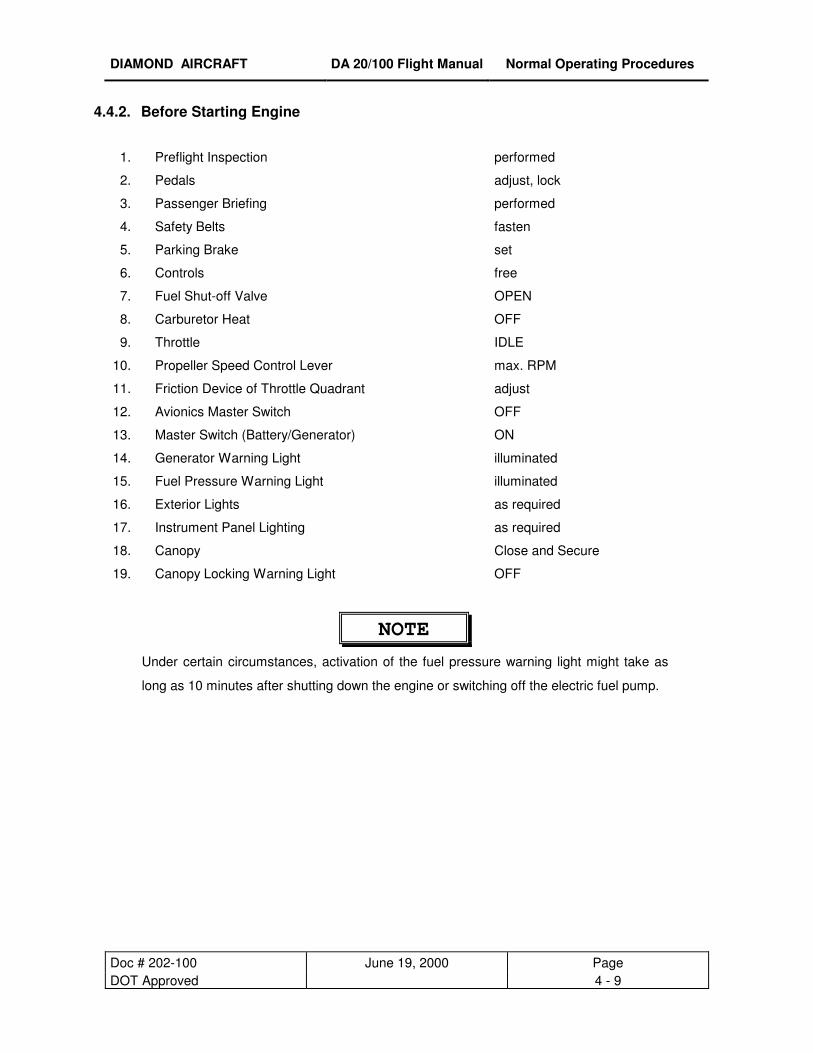
4.4.2. Before Starting Engine
1. Preflight Inspection performed
2. Pedals adjust, lock
3. Passenger Briefing performed
4. Safety Belts fasten
5. Parking Brake set
6. Controls free
7. Fuel Shut-off Valve OPEN
8. Carburetor Heat OFF
9. Throttle IDLE
10. Propeller Speed Control Lever max. RPM
11. Friction Device of Throttle Quadrant adjust
12. Avionics Master Switch OFF
13. Master Switch (Battery/Generator) ON
14. Generator Warning Light illuminated
15. Fuel Pressure Warning Light illuminated
16. Exterior Lights as required
17. Instrument Panel Lighting as required
18. Canopy Close and Secure
19. Canopy Locking Warning Light OFF
NOTE
Under certain circumstances, activation of the fuel pressure warning light might take as
long as 10 minutes after shutting down the engine or switching off the electric fuel pump.
DIAMOND AIRCRAFT DA 20/100 Flight Manual Normal Operating Procedures
Doc # 202-100 June 19, 2000 Page DOT Approved 4 - 10
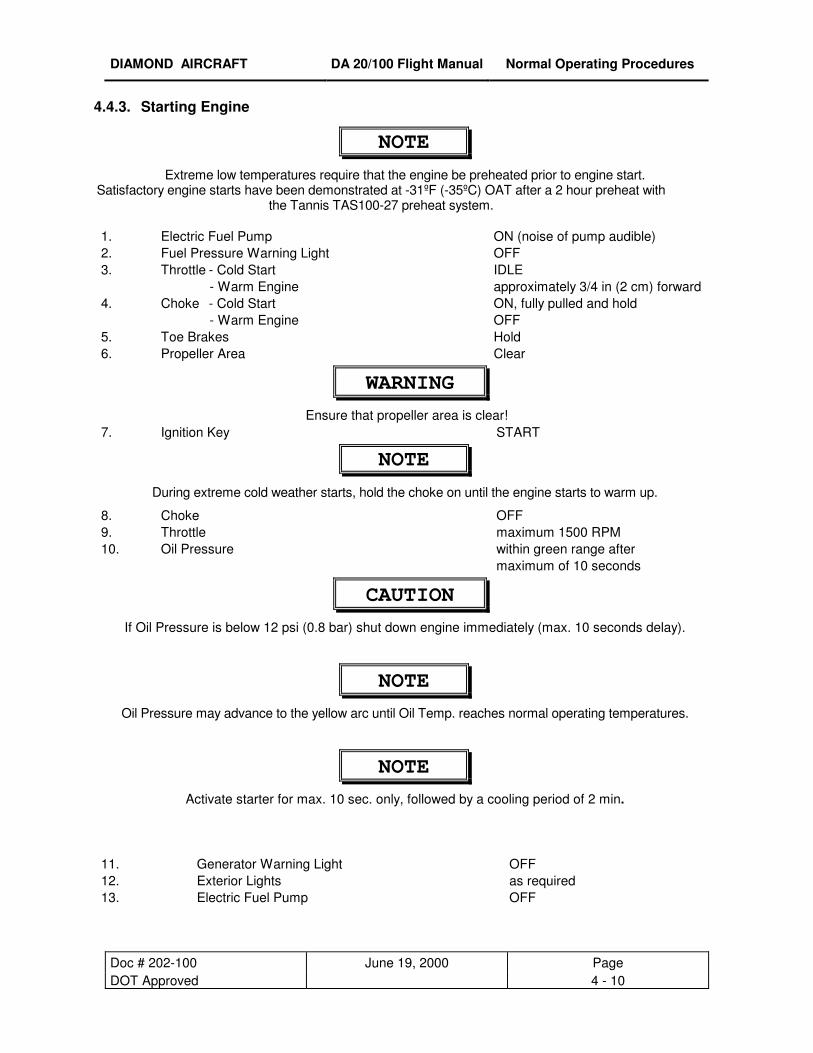
4.4.3. Starting Engine
NOTE
Extreme low temperatures require that the engine be preheated prior to engine start. Satisfactory engine starts have been demonstrated at -31ºF (-35ºC) OAT after a 2 hour preheat with
the Tannis TAS100-27 preheat system.
1. Electric Fuel Pump ON (noise of pump audible) 2. Fuel Pressure Warning Light OFF 3. Throttle - Cold Start
- Warm Engine IDLE approximately 3/4 in (2 cm) forward
4. Choke - Cold Start - Warm Engine
ON, fully pulled and hold OFF
5. Toe Brakes Hold 6. Propeller Area Clear
WARNING
Ensure that propeller area is clear! 7. Ignition Key START
NOTE
During extreme cold weather starts, hold the choke on until the engine starts to warm up.
8. Choke OFF 9. Throttle maximum 1500 RPM 10. Oil Pressure within green range after
maximum of 10 seconds
CAUTION
If Oil Pressure is below 12 psi (0.8 bar) shut down engine immediately (max. 10 seconds delay).
NOTE
Oil Pressure may advance to the yellow arc until Oil Temp. reaches normal operating temperatures.
NOTE
Activate starter for max. 10 sec. only, followed by a cooling period of 2 min.
11. Generator Warning Light OFF 12. Exterior Lights as required 13. Electric Fuel Pump OFF
DIAMOND AIRCRAFT DA 20/100 Flight Manual Normal Operating Procedures
Doc # 202-100 June 19, 2000 Page DOT Approved 4 - 11
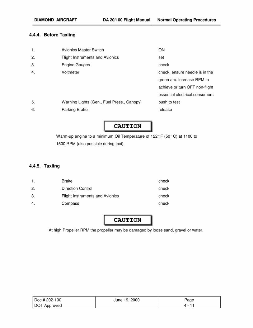
4.4.4. Before Taxiing
1. Avionics Master Switch ON
2. Flight Instruments and Avionics set
3. Engine Gauges check
4. Voltmeter check, ensure needle is in the
green arc. Increase RPM to
achieve or turn OFF non-flight
essential electrical consumers
5. Warning Lights (Gen., Fuel Press., Canopy) push to test
6. Parking Brake release
CAUTION
Warm-up engine to a minimum Oil Temperature of 122° F (50° C) at 1100 to
1500 RPM (also possible during taxi).
4.4.5. Taxiing
1. Brake check
2. Direction Control check
3. Flight Instruments and Avionics check
4. Compass check
CAUTION
At high Propeller RPM the propeller may be damaged by loose sand, gravel or water.

DIAMOND AIRCRAFT DA 20/100 Flight Manual Normal Operating Procedures
Doc # 202-100 June 19, 2000 Page DOT Approved 4 - 12
4.4.6. Before Take-off (Engine Run-up)
NOTE For OAT’s less than -5º F (-20º C) turn cabin heat on for at least 10 minutes prior to take-off.
1. Toe Brakes hold
2. Safety Belts fastened
3. Canopy closed and locked
4. Fuel Pressure Warning Light OFF (If light illuminates,
maintenance action is required and
flight should not be initiated )
5. Fuel Shut-off Valve check OPEN
6. Fuel Quantity Indicator check
7. Engine Gauges within green range
8. Trim NEUTRAL
9. Controls free
10. Throttle 1700-1800 RPM
11. Propeller Speed Control Lever Cycle 3 times
(RPM drop: 50 - 250 RPM)
12. Ignition Switch Cycle L - BOTH - R - BOTH
(Max. RPM drop: 150 RPM)
(Max. RPM difference (L/R): 50 RPM)
(Min. RPM difference (L/R): none, but
RPM drop must be noticeable)
13. Throttle 1500 RPM
14. Carburetor Heat ON
RPM drop: max. 50 RPM;
15. Throttle IDLE
16. Carburetor Heat OFF
17. Circuit Breakers check pressed IN
18. Electric Fuel Pump ON
19. Wing Flaps T/O
20. Parking Brake release
DIAMOND AIRCRAFT DA 20/100 Flight Manual Normal Operating Procedures
Doc # 202-100 June 19, 2000 Page DOT Approved 4 - 13
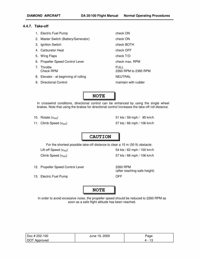
4.4.7. Take-off
1. Electric Fuel Pump check ON
2. Master Switch (Battery/Generator) check ON
3. Ignition Switch check BOTH
4. Carburetor Heat check OFF
5. Wing Flaps check T/O
6. Propeller Speed Control Lever check max. RPM
7. Throttle Check RPM
FULL 2260 RPM to 2385 RPM
8. Elevator - at beginning of rolling NEUTRAL
9. Directional Control maintain with rudder
NOTE In crosswind conditions, directional control can be enhanced by using the single wheel brakes. Note that using the brakes for directional control increases the take-off roll distance.
10. Rotate (vIAS) 51 kts / 59 mph / 95 km/h
11. Climb Speed (vIAS) 57 kts / 66 mph / 106 km/h
CAUTION
For the shortest possible take-off distance to clear a 15 m (50 ft) obstacle:
Lift-off Speed (vIAS) 54 kts / 62 mph / 100 km/h
Climb Speed (vIAS) 57 kts / 66 mph / 106 km/h
12. Propeller Speed Control Lever 2260 RPM (after reaching safe height)
13. Electric Fuel Pump OFF
NOTE
In order to avoid excessive noise, the propeller speed should be reduced to 2260 RPM as soon as a safe flight altitude has been reached.

DIAMOND AIRCRAFT DA 20/100 Flight Manual Normal Operating Procedures
Doc # 202-100 June 19, 2000 Page DOT Approved 4 - 14
4.4.8. Climb
1. Propeller Speed Control Lever 2260 RPM
2. Throttle FULL
3. Engine Gauges within green range
4. Wing Flaps T/O
5. Airspeed 65 kts / 75 mph / 120 km/h
6. Trim adjust
NOTE The best rate of climb speed decreases with increasing altitude.
NOTE Electric fuel pump ON above 13000 ft.
Speeds [ vIAS ]
Altitude flaps T/O flaps UP feet kts mph km/h kts mph km/h
0 - 4000 65 75 120 69 79 128
4000 - 7000 63 73 117 65 75 120
7000 -10000 62 71 115
above 10000 59 68 110
4.4.9. Cruise
1. Throttle as required
2. Propeller Speed Control Lever 1700 - 2260 RPM
NOTE
For favorable manifold pressure/RPM combinations refer to Chapter 5.
NOTE Electric fuel pump ON above 13000 ft.
3. Wing Flaps UP
4. Trim as required
5. Engine Gauges check
DIAMOND AIRCRAFT DA 20/100 Flight Manual Normal Operating Procedures
Doc # 202-100 June 19, 2000 Page DOT Approved 4 - 15
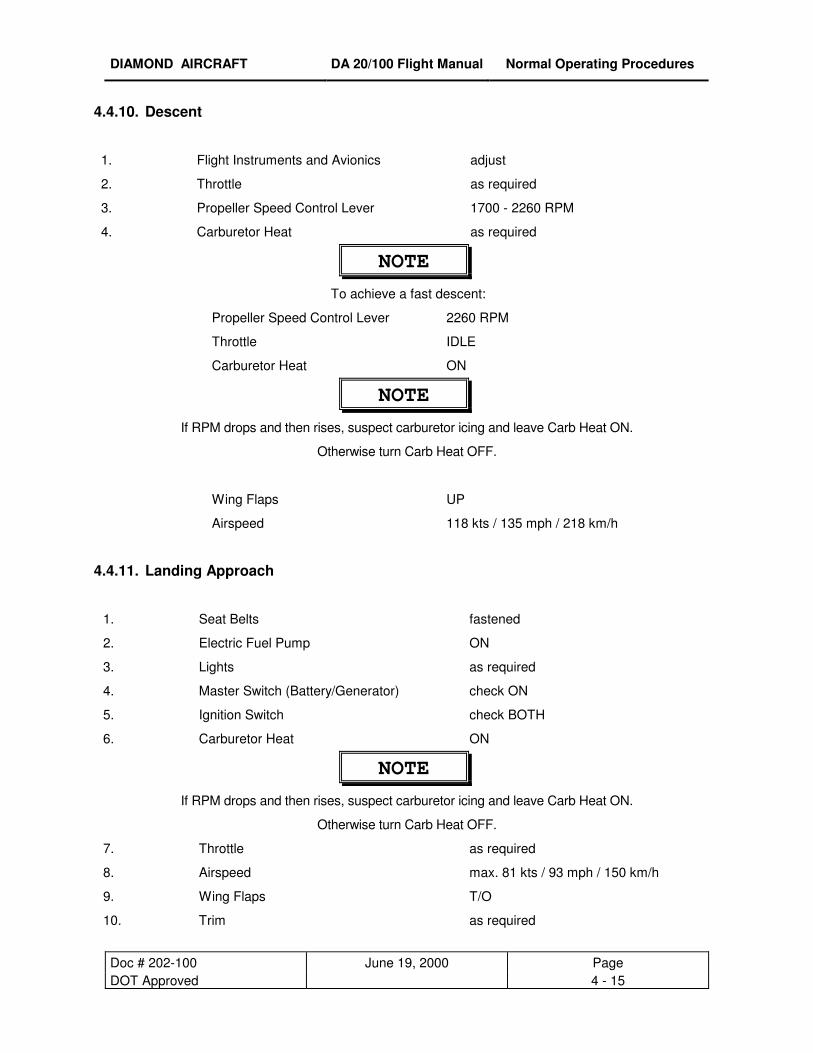
4.4.10. Descent
1. Flight Instruments and Avionics adjust
2. Throttle as required
3. Propeller Speed Control Lever 1700 - 2260 RPM
4. Carburetor Heat as required
NOTE
To achieve a fast descent:
Propeller Speed Control Lever 2260 RPM
Throttle IDLE
Carburetor Heat ON
NOTE
If RPM drops and then rises, suspect carburetor icing and leave Carb Heat ON.
Otherwise turn Carb Heat OFF.
Wing Flaps UP
Airspeed 118 kts / 135 mph / 218 km/h
4.4.11. Landing Approach
1. Seat Belts fastened
2. Electric Fuel Pump ON
3. Lights as required
4. Master Switch (Battery/Generator) check ON
5. Ignition Switch check BOTH
6. Carburetor Heat ON
NOTE
If RPM drops and then rises, suspect carburetor icing and leave Carb Heat ON.
Otherwise turn Carb Heat OFF.
7. Throttle as required
8. Airspeed max. 81 kts / 93 mph / 150 km/h
9. Wing Flaps T/O
10. Trim as required
DIAMOND AIRCRAFT DA 20/100 Flight Manual Normal Operating Procedures
Doc # 202-100 June 19, 2000 Page DOT Approved 4 - 16
11. Propeller Speed Control Lever max. RPM
12. Wing Flaps LDG
13. Approach Speed 57 kts / 66 mph / 106 km/h
CAUTION
For strong headwind, crosswind, danger of wind-shear or turbulence, a higher approach
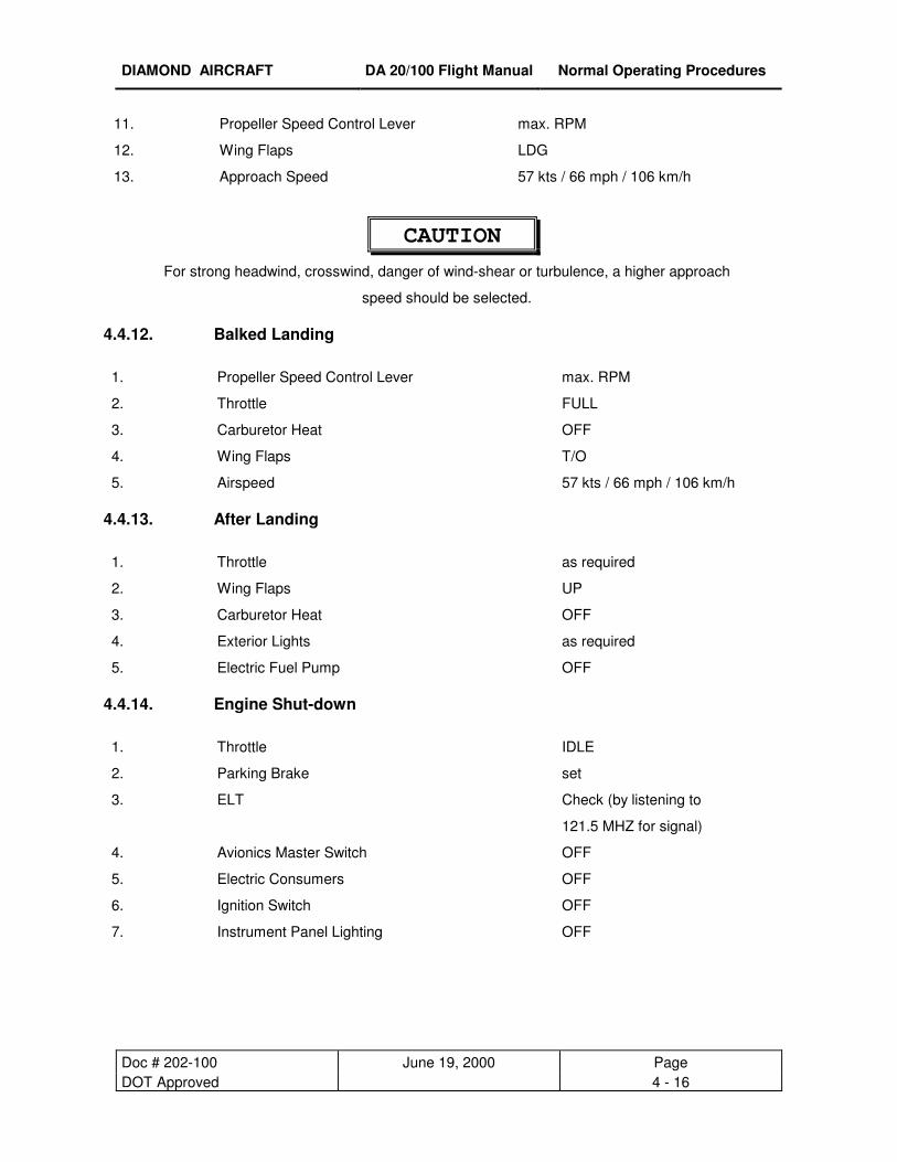
speed should be selected. 4.4.12. Balked Landing
1. Propeller Speed Control Lever max. RPM
2. Throttle FULL
3. Carburetor Heat OFF
4. Wing Flaps T/O
5. Airspeed 57 kts / 66 mph / 106 km/h 4.4.13. After Landing
1. Throttle as required
2. Wing Flaps UP
3. Carburetor Heat OFF
4. Exterior Lights as required
5. Electric Fuel Pump OFF 4.4.14. Engine Shut-down
1. Throttle IDLE
2. Parking Brake set
3. ELT Check (by listening to
121.5 MHZ for signal)
4. Avionics Master Switch OFF
5. Electric Consumers OFF
6. Ignition Switch OFF
7. Instrument Panel Lighting
OFF

DIAMOND AIRCRAFT DA 20/100 Flight Manual Normal Operating Procedures
Doc # 202-100 June 19, 2000 Page DOT Approved 4 - 17
8. Master Switch (Battery) OFF 9. Tie Downs and Wheel Chocks as required
NOTE
In case of post ignition due to hot weather conditions, the ignition should
be switched on, choke pulled and after approximately 3 seconds, ignition
should be turned off again.
4.4.15. Flight in Rain
NOTE
Flight performance might be reduced, especially for the T/O-distance and the
maximum horizontal air speed. The influence on flight characteristics of the airplane is
negligible. Flights through heavy rain should be avoided due to the reduced visibility.
DIAMOND AIRCRAFT DA 20/100 Flight Manual Normal Operating Procedures
Doc # 202-100 June 19, 2000 Page DOT Approved 4 - 18
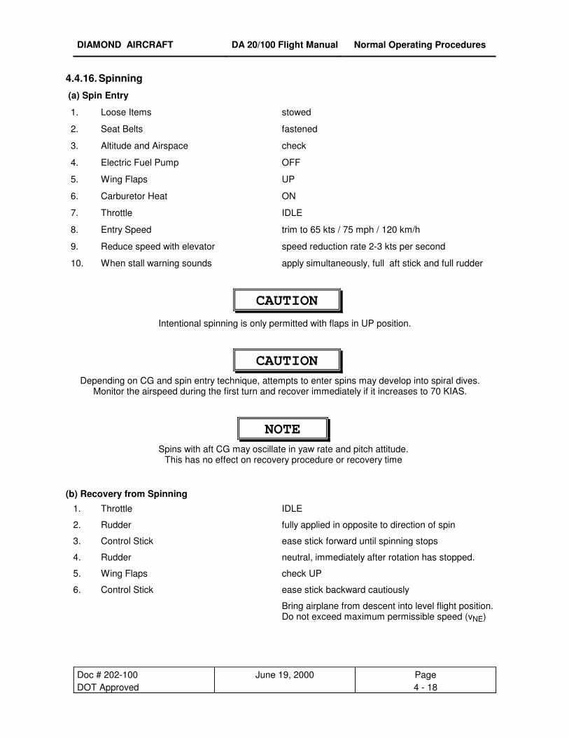
4.4.16. Spinning
(a) Spin Entry
1. Loose Items stowed
2. Seat Belts fastened
3. Altitude and Airspace check
4. Electric Fuel Pump OFF
5. Wing Flaps UP
6. Carburetor Heat ON
7. Throttle IDLE
8. Entry Speed trim to 65 kts / 75 mph / 120 km/h
9. Reduce speed with elevator speed reduction rate 2-3 kts per second
10. When stall warning sounds apply simultaneously, full aft stick and full rudder
CAUTION
Intentional spinning is only permitted with flaps in UP position.
CAUTION Depending on CG and spin entry technique, attempts to enter spins may develop into spiral dives.
Monitor the airspeed during the first turn and recover immediately if it increases to 70 KIAS.
NOTE Spins with aft CG may oscillate in yaw rate and pitch attitude.
This has no effect on recovery procedure or recovery time
(b) Recovery from Spinning
1. Throttle IDLE
2. Rudder fully applied in opposite to direction of spin
3. Control Stick ease stick forward until spinning stops
4. Rudder neutral, immediately after rotation has stopped.
5. Wing Flaps check UP
6. Control Stick ease stick backward cautiously
Bring airplane from descent into level flight position. Do not exceed maximum permissible speed (vNE)

DIAMOND AIRCRAFT DA 20/100 Flight Manual Performance
Doc # DA202-100 March 19, 2004 Page Revision 4 5 - 1
CHAPTER 5
PERFORMANCE
5.1 INTRODUCTION 5- 2
5.2 USE OF PERFORMANCE TABLES AND DIAGRAMS 5- 2
5.3 PERFORMANCE TABLES AND DIAGRAMS 5- 3
5.3.1 Figure 5.1: Airspeed Calibration 5- 3
5.3.2 Figure 5.2: Cruising Performance 5- 4
5.3.3 Figure 5.3: Stall Speeds 5- 5
5.3.4 Figure 5.4: Wind Data 5- 6
5.3.5 Figure 5.5: Take-Off Distances 5- 7
5.3.6 Figure 5.6: Climb Performance / Service Ceiling 5- 9
5.3.7 [INTENTIONALLY LEFT BLANK] 5-10
5.3.8 Figure 5.8: Cruising Speed (True Airspeed) 5-11
5.3.9 Figure 5.9: Maximum Flight Duration 5-12
5.3.10 Figure 5.10: Climb Performance during Balked Landing 5-13
5.3.11 Landing Distances 5-14
5.4 NOISE DATA 5-15
DIAMOND AIRCRAFT DA 20/100 Flight Manual Performance
Doc # 202-100 June 19, 2000 Page Issue 1 5 - 2
5.1. INTRODUCTION
The performance tables and diagrams on the following pages have been prepared to illustrate the
performance you may expect from your airplane as well as to assist you in precise flight planning. The
data presented in these tables and diagrams has been derived from test-flights using an airplane and
engine in good operating condition, and was corrected to standard atmospheric conditions (59° F (15° C)
and 29.92 in. Hg (1013.25 mbar) at sea level ).
The performance tables do not take into account the expertise of the pilot or the maintenance condition of
the airplane. The performance illustrated in the tables can be achieved if the indicated procedures are
followed and the airplane is in good maintenance condition.
Note that the flight duration data does not include a fuel reserve. The fuel consumption during cruise is
based on propeller RPM and manifold pressure settings. Some undefined variables such as the operating
condition of the engine, contamination of the aircrafts surface, or turbulence could have influences on
flight distance and flight duration. For this reason, it is of utmost importance that all available data is used
when calculating the required amount of fuel for a flight.
For flight operation without wheel fairings the resulting performance variations is given in %.
5.2. USE OF PERFORMANCE TABLES AND DIAGRAMS
The performance data is shown in the form of tables and diagrams to illustrate the influence of the
different variables. These tables contain sufficiently detailed information to plan any flight with the
necessary precision and safety on the conservative side.
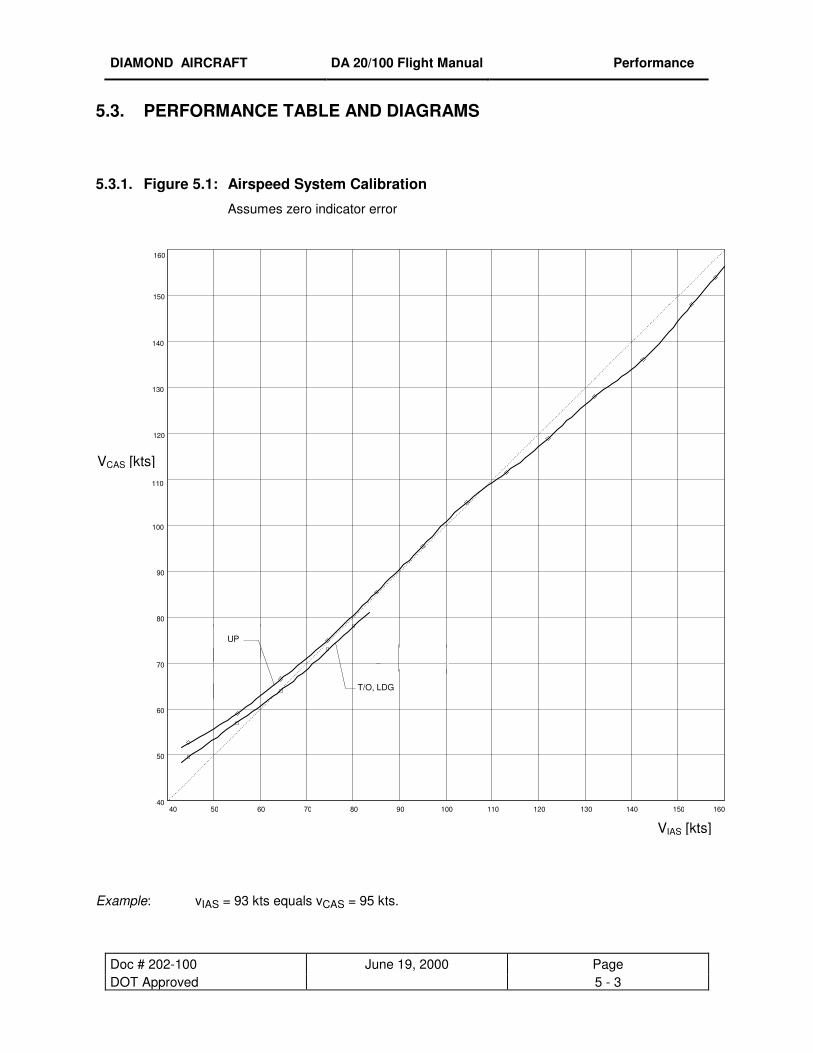
DIAMOND AIRCRAFT DA 20/100 Flight Manual Performance
Doc # 202-100 June 19, 2000 Page DOT Approved 5 - 3
5.3. PERFORMANCE TABLE AND DIAGRAMS
5.3.1. Figure 5.1: Airspeed System Calibration
Assumes zero indicator error
Example: vIAS = 93 kts equals vCAS = 95 kts.
160
110
40
50
60
70
80
90
100
120
130
140
150
40 50 60 70 80 90 100 110 120 130 140 150 160
T/O, LDG
UP
VIAS [kts]
VCAS [kts]
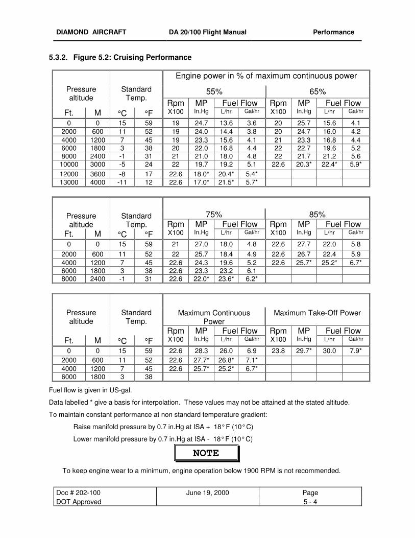
DIAMOND AIRCRAFT DA 20/100 Flight Manual Performance
Doc # 202-100 June 19, 2000 Page DOT Approved 5 - 4
5.3.2. Figure 5.2: Cruising Performance
Engine power in % of maximum continuous power
55% 65%
Pressure altitude
Standard Temp.
Fuel Flow Fuel Flow Ft. M °C °F
Rpm X100
MP In.Hg L/hr Gal/hr
Rpm X100
MP In.Hg L/hr Gal/hr
0 0 15 59 19 24.7 13.6 3.6 20 25.7 15.6 4.1 2000 600 11 52 19 24.0 14.4 3.8 20 24.7 16.0 4.2 4000 1200 7 45 19 23.3 15.6 4.1 21 23.3 16.8 4.4 6000 1800 3 38 20 22.0 16.8 4.4 22 22.7 19.6 5.2 8000 2400 -1 31 21 21.0 18.0 4.8 22 21.7 21.2 5.6 10000 3000 -5 24 22 19.7 19.2 5.1 22.6 20.3* 22.4* 5.9* 12000 3600 -8 17 22.6 18.0* 20.4* 5.4* 13000 4000 -11 12 22.6 17.0* 21.5* 5.7*
75% 85%
Pressure altitude
Standard Temp. Fuel Flow Fuel Flow
Ft. M °C °F Rpm X100
MP In.Hg L/hr Gal/hr
Rpm X100
MP In.Hg L/hr Gal/hr
0 0 15 59 21 27.0 18.0 4.8 22.6 27.7 22.0 5.8 2000 600 11 52 22 25.7 18.4 4.9 22.6 26.7 22.4 5.9 4000 1200 7 45 22.6 24.3 19.6 5.2 22.6 25.7* 25.2* 6.7* 6000 1800 3 38 22.6 23.3 23.2 6.1 8000 2400 -1 31 22.6 22.0* 23.6* 6.2*
Maximum Continuous Power
Maximum Take-Off Power
Pressure altitude
Standard Temp.
Fuel Flow Fuel Flow Ft. M °C °F
Rpm X100
MP In.Hg L/hr Gal/hr
Rpm X100
MP In.Hg L/hr Gal/hr
0 0 15 59 22.6 28.3 26.0 6.9 23.8 29.7* 30.0 7.9* 2000 600 11 52 22.6 27.7* 26.8* 7.1* 4000 1200 7 45 22.6 25.7* 25.2* 6.7* 6000 1800 3 38
Fuel flow is given in US-gal.
Data labelled * give a basis for interpolation. These values may not be attained at the stated altitude.
To maintain constant performance at non standard temperature gradient:
Raise manifold pressure by 0.7 in.Hg at ISA + 18° F (10° C)
Lower manifold pressure by 0.7 in.Hg at ISA - 18° F (10° C)
NOTE
To keep engine wear to a minimum, engine operation below 1900 RPM is not recommended.
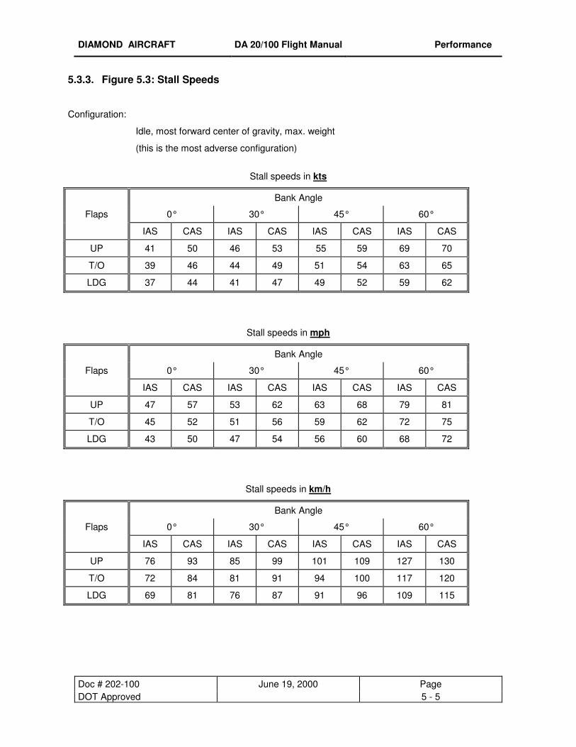
DIAMOND AIRCRAFT DA 20/100 Flight Manual Performance
Doc # 202-100 June 19, 2000 Page DOT Approved 5 - 5
5.3.3. Figure 5.3: Stall Speeds
Configuration:
Idle, most forward center of gravity, max. weight
(this is the most adverse configuration)
Stall speeds in kts
Bank Angle
Flaps 0° 30° 45° 60°
IAS CAS IAS CAS IAS CAS IAS CAS
UP 41 50 46 53 55 59 69 70
T/O 39 46 44 49 51 54 63 65
LDG 37 44 41 47 49 52 59 62
Stall speeds in mph
Bank Angle
Flaps 0° 30° 45° 60°
IAS CAS IAS CAS IAS CAS IAS CAS
UP 47 57 53 62 63 68 79 81
T/O 45 52 51 56 59 62 72 75
LDG 43 50 47 54 56 60 68 72
Stall speeds in km/h
Bank Angle
Flaps 0° 30° 45° 60°
IAS CAS IAS CAS IAS CAS IAS CAS
UP 76 93 85 99 101 109 127 130
T/O 72 84 81 91 94 100 117 120
LDG 69 81 76 87 91 96 109 115
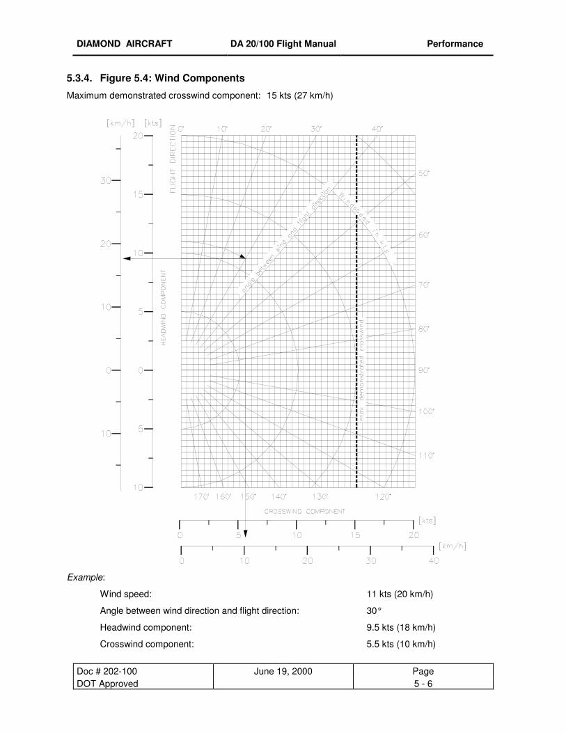
DIAMOND AIRCRAFT DA 20/100 Flight Manual Performance
Doc # 202-100 June 19, 2000 Page DOT Approved 5 - 6
5.3.4. Figure 5.4: Wind Components
Maximum demonstrated crosswind component: 15 kts (27 km/h)
Example:
Wind speed: 11 kts (20 km/h)
Angle between wind direction and flight direction: 30°
Headwind component: 9.5 kts (18 km/h)
Crosswind component: 5.5 kts (10 km/h)
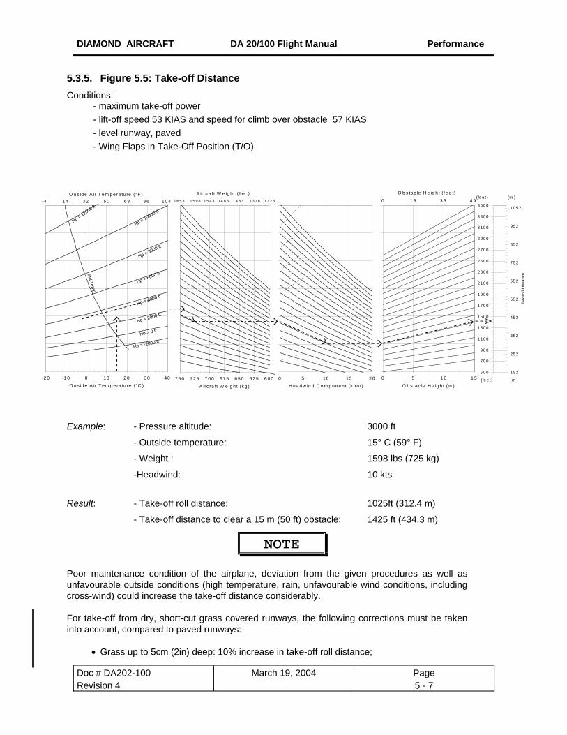
DIAMOND AIRCRAFT DA 20/100 Flight Manual Performance
Doc # DA202-100 March 19, 2004 Page Revision 4 5 - 7
5.3.5. Figure 5.5: Take-off Distance Conditions: - maximum take-off power - lift-off speed 53 KIAS and speed for climb over obstacle 57 KIAS - level runway, paved - Wing Flaps in Take-Off Position (T/O)
O u s id e A ir T e m p e ra tu re (°F )
Hp = -2000 ft
Hp = 0 ft
Hp = 2000 ft
Hp = 4000 ft
Hp = 6000 ft
Hp = 8000 ft
Hp = 10000 ft
Hp = 12000 ft
Std Temp
-2 0 -1 0 0 1 0 2 0 3 0 4 0
O u s id e A ir T e m p e ra tu re (°C )
-4 1 4 3 2 5 0 6 8 8 6 1 0 4
A irc ra ft W e ig h t ( lb s .)
6 0 06 2 56 5 06 7 57 0 07 2 57 5 0
A irc ra ft W e ig h t (k g )
1 6 5 3 1 5 9 8 1 5 4 3 1 4 8 8 1 4 3 3 1 3 7 8 1 3 2 3.
0 5 1 0 1 5 2 0
H e a d w in d C o m p o n e n t (k n o t)
O b s tac le H e ig h t (f e e t)
0 5 1 0 1 5
O b s tac le H e ig h t (m )
0 1 6 3 3 4 9
5 0 0
7 0 0
9 0 0
1 1 0 0
1 3 0 0
1 5 0 0
1 7 0 0
1 9 0 0
2 1 0 0
2 3 0 0
2 5 0 0
2 7 0 0
2 9 0 0
3 1 0 0
3 3 0 0
3 5 0 0
.
1 5 2
2 5 2
3 5 2
4 5 2
5 5 2
6 5 2
7 5 2
8 5 2
9 5 2
1 0 5 2
Take
off D
ista
nce
( fe e t )
(m )(fe e t )
(m )
Example: - Pressure altitude: 3000 ft
- Outside temperature: 15° C (59° F)
- Weight : 1598 lbs (725 kg)
-Headwind: 10 kts
Result: - Take-off roll distance: 1025ft (312.4 m)
- Take-off distance to clear a 15 m (50 ft) obstacle: 1425 ft (434.3 m)
NOTE Poor maintenance condition of the airplane, deviation from the given procedures as well as unfavourable outside conditions (high temperature, rain, unfavourable wind conditions, including cross-wind) could increase the take-off distance considerably. For take-off from dry, short-cut grass covered runways, the following corrections must be taken into account, compared to paved runways:
• Grass up to 5cm (2in) deep: 10% increase in take-off roll distance;
DIAMOND AIRCRAFT DA 20/100 Flight Manual Performance
Doc # DA202-100 March 19, 2004 Page Revision 4 5 - 8
• Grass 5 to 10cm (2 to 4in) deep: 15% increase in take-off roll distance; • Grass deeper than 10cm (4in): 25% increase in take-off roll distance.
On wet soft grass covered runways with grass deeper than 10cm (4in), the take-off roll distance might be increased by as much as 40%. This information is provided for guidance purposes only and has not been demonstrated. The dashed lines in the above diagram (wind component) represents tailwind.
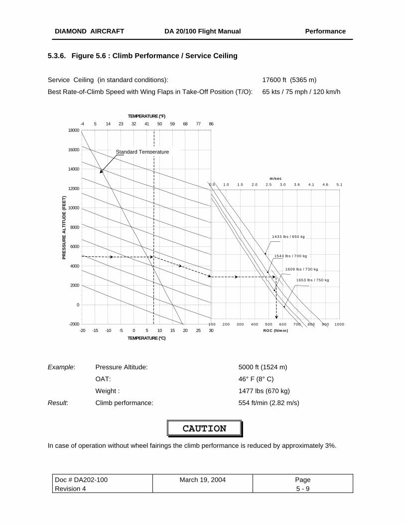
DIAMOND AIRCRAFT DA 20/100 Flight Manual Performance
Doc # DA202-100 Revision 4
5.3.6. Figure 5.6 : Climb Performance / Service Ceiling
Service Ceiling (in standard conditions): 17600 ft (5365 m)
Best Rate-of-Climb Speed with Wing Flaps in Take-Off Position (T/O): 65 kts / 75 mph / 120 km/h
-2000
0
2000
4000
6000
8000
10000
12000
14000
16000
18000
-20 -15 -10
PRES
SUR
E A
LTIT
UD
E (F
EET)
-4 5 14 23 32 41 50 59 68 77 86
TEMPERATURE (°F)
e
Example: Press
OAT:
Weigh
Result: Climb
In case of operation w
Standard Temperatur
March 19, 2004 Page 5 - 9
-5 0 5 10 15 20 25 30
TEMPERATURE (°C)
0
2000
4000
6000
8000
10000
12000
14000
16000
100 200 300 400 500 600 700 800 900 1000
ROC (ft/m in)
0.5 1.0 1.5 2.0 2.5 3.0 3.6 4.1 4.6 5.1m /sec
1433 lbs / 650 kg
1543 lbs / 700 kg
1609 lbs / 730 kg
1653 lbs / 750 kg
ure Altitude: 5000 ft (1524 m)
46° F (8° C)
t : 1477 lbs (670 kg)
performance: 554 ft/min (2.82 m/s)
CAUTION
ithout wheel fairings the climb performance is reduced by approximately 3%.

DIAMOND AIRCRAFT DA 20/100 Flight Manual Performance
Doc # DA202-100 March 19, 2004 Page Revision 4 5 - 10
5.3.7. [INTENTIONALLY LEFT BLANK]
[ INTENTIONALLY LEFT BLANK ]

DIAMOND AIRCRAFT DA 20/100 Flight Manual Performance
Doc # DA2Revision 4
5.3.8. Figure 5.8: Cruising Speed (True Airspeed) Diagram for true airspeed (TAS) calculation at selected power level.
Flight mass 1653 lbs (750 kg) and Flaps UP.
Temperature (°F)
Example:
Result:
In ca
appro
-4 +14 +32 +50 +68 +86
02-100 March 19, 2004 Page 5 - 11
Temperature (°C) True Airspeed (knots)
Pressure altitude: 9500 ft
Temperature: 57° F (14° C)
power setting: 55 %
True airspeed (TAS): 116 kts (215 km/h)
CAUTION
se of operation without wheel fairings the maximum cruising speed is reduced by
ximately 5%.

DIAMOND AIRCRAFT DA 20/100 Flight Manual Performance
Doc # DA202-100 March 19, 2004 Page Revision 4 5 - 12
5.3.9. Figure 5.9: Maximum Flight Duration
Diagram for calculation of the maximum flight duration depending on fuel availability.
600
m /
2000
ft.
600 m / 2
000 ft.
1200 m / 4
000 ft.
1800 m / 6
000 ft.
1800 m
/ 6000
ft.
1200 m / 4
000 ft.
600 m / 2
000 ft.
0
10
20
30
40
50
60
70
80
0 1 2 3 4 5 6
Flight Time (hour), no reserve
Fuel
Qua
ntity
(litr
es)
0
2
4
6
8
10
12
14
16
18
20
- 3/4 1/4 1 1/4 2 1/4 3 1/4 4 1/4 5 1/4
Flight Time (hour), 45 minute reserve
Fuel
Qua
ntity
(US
Gal
)
55 %75 %95 %
Example: Fuel quantity: 13.2 US gal (50 liters)
Pressure Altitude 6000 ft
Power Setting: 75%
Result: Possible flight time without reserve: 2:11 h:min
Possible flight time with reserve of 45 mins: 1:26 h:min

DIAMOND AIRCRAFT DA 20/100 Flight Manual Performance
Doc # DA202-100 March 19, 2004 Page Revision 4 5 - 13
5.3.10. Figure 5.10: Climb Performance during Balked Landing
Conditions: Speed = 57 kts / 66 mph / 106 km/h
Wing Flaps in Landing Position (LDG)
Weight 1653 lbs (750 kg)
most forward center of gravity
max take-off power
0
100
200
300
400
500
600
700
800
0 1000 2000 3000 4000 5000 6000 7000 8000 9000 10000
RO
C (f
t/min
)
0.00
0.51
1.02
1.52
2.03
2.54
3.05
3.56
4.06
RO
C (
m/s
ec)
Hp (ft) Hp (m)
Example: Pressure altitude: 2250 ft (685 m)
Outside temperature: 59° F (15° C)
Result: Climb performance during balked landing: 320 ft/min. (1.63 m/sec)
CAUTION
In case of operation without wheel fairings the climb performance is reduced by approximately 3%.
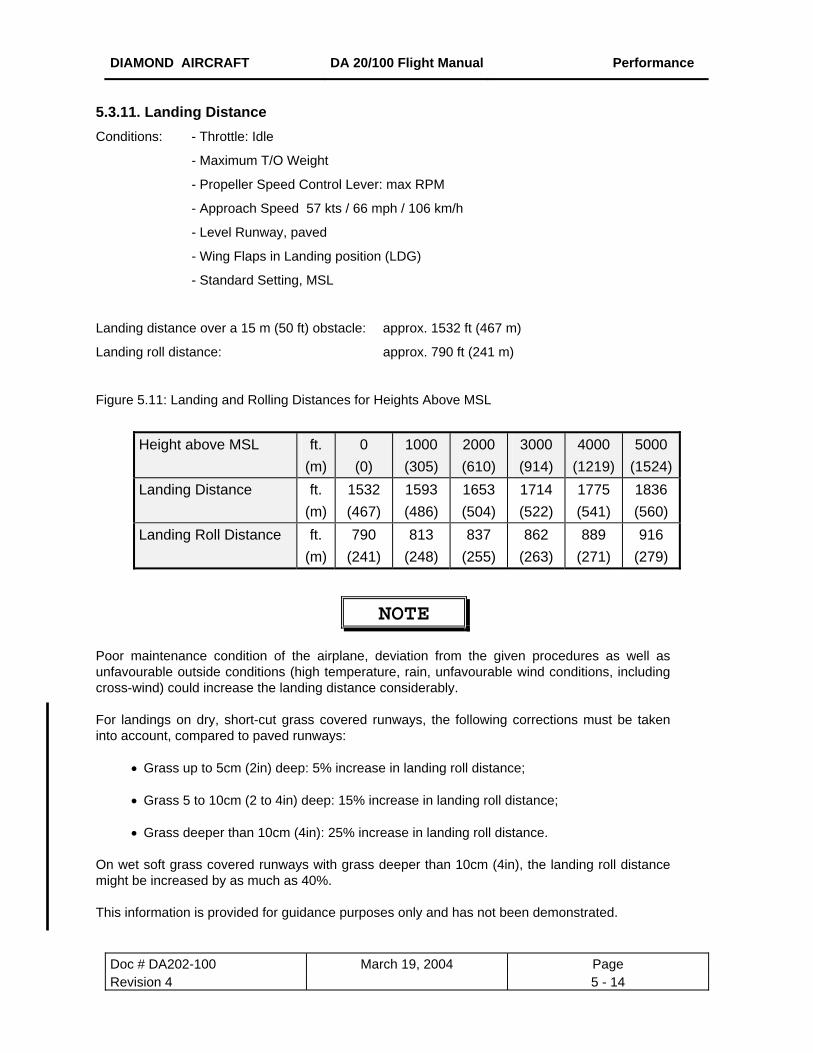
DIAMOND AIRCRAFT DA 20/100 Flight Manual Performance
Doc # DA202-100 March 19, 2004 Page Revision 4 5 - 14
5.3.11. Landing Distance Conditions: - Throttle: Idle
- Maximum T/O Weight
- Propeller Speed Control Lever: max RPM
- Approach Speed 57 kts / 66 mph / 106 km/h
- Level Runway, paved
- Wing Flaps in Landing position (LDG)
- Standard Setting, MSL
Landing distance over a 15 m (50 ft) obstacle: approx. 1532 ft (467 m)
Landing roll distance: approx. 790 ft (241 m)
Figure 5.11: Landing and Rolling Distances for Heights Above MSL
Height above MSL ft.
(m)0
(0) 1000 (305)
2000 (610)
3000 (914)
4000 (1219)
5000 (1524)
Landing Distance
ft. (m)
1532 (467)
1593 (486)
1653 (504)
1714 (522)
1775 (541)
1836 (560)
Landing Roll Distance ft. (m)
790 (241)
813 (248)
837 (255)
862 (263)
889 (271)
916 (279)
NOTE
Poor maintenance condition of the airplane, deviation from the given procedures as well as unfavourable outside conditions (high temperature, rain, unfavourable wind conditions, including cross-wind) could increase the landing distance considerably. For landings on dry, short-cut grass covered runways, the following corrections must be taken into account, compared to paved runways:
• Grass up to 5cm (2in) deep: 5% increase in landing roll distance; • Grass 5 to 10cm (2 to 4in) deep: 15% increase in landing roll distance; • Grass deeper than 10cm (4in): 25% increase in landing roll distance.
On wet soft grass covered runways with grass deeper than 10cm (4in), the landing roll distance might be increased by as much as 40%. This information is provided for guidance purposes only and has not been demonstrated.

DIAMOND AIRCRAFT DA 20/100 Flight Manual Performance
Doc # DA202-100 March 19, 2004 Page Revision 4 5 - 15
5.4 NOISE DATA
a) Noise limit according to FAR 36, Appendix G: 75.0 dB (A)
Noise value measured: 63.8 dB (A)
b) Noise limit according to ICAO Annex 16, Chapter 10: 79.1 dB (A)
Noise value measured: 71.7dB (A)
DIAMOND AIRCRAFT DA 20/100 Flight Manual Weight & Balance
Doc # 202-100 June 19, 2000 Page DOT-Approved 6 - 1
CHAPTER 6
WEIGHT AND BALANCE / EQUIPMENT LIST
6.1 INTRODUCTION 6-2 6.2 AIRPLANE WEIGHING 6-3
- Figure 6.1 Weighing Report 6-4 6.3 WEIGHT AND BALANCE REPORT 6-5
- Figure 6.2 Weight & Balance Report 6-6 6.4 FLIGHT-WEIGHT AND CENTER OF GRAVITY 6-7
- Figure 6.3 Weight & Balance Diagram 6-8 - Figure 6.4 Calculation of Loading Condition 6-9 - Figure 6.5 Permissible Center of Gravity Range and
permissible Flight Weight-Moment 6-10
6.5 EQUIPMENT LIST 6-11
AIRCRAFT SPECIFIC WEIGHT AND BALANCE DOCUMENTS (ENCLOSED AT THE END OF THIS CHAPTER)
DIAMOND AIRCRAFT DA 20/100 Flight Manual Weight & Balance
Doc # 202-100 June 19, 2000 Page DOT-Approved 6 - 2
1. INTRODUCTION
To obtain the performance, flight characteristics and safe operation described in this Flight Manual, the
airplane must be operated within the permissible weight and balance envelope as described in Chapter 2.
It is the pilot's responsibility to adhere to the weight and balance limitations and to take into consideration
the change of the CG position due to fuel consumption.
The procedure for weighing the airplane and calculating the empty weight CG position are given in this
Chapter.
The aircraft is weighed when new and should be reweighed in accordance with applicable air regulations.
Empty weight and the center of gravity are recorded in a Weighing Report and Weight and balance Report
as illustrated in the samples in figure 6.1 and 6.2. The actual report for the aircraft is at the end of this
chapter.
In case of equipment changes, the new weight and empty weight CG position must be determined by
calculation or by weighing and must be entered in the Weight & Balance Report. The following pages are
sample forms which can be used for airplane weighing, calculation of the empty weight CG position, and
for the determination of the useful load.
NOTE
After every repair, painting or change of equipment the new empty weight must be
determined as required by applicable air regulations. Weight, empty weight CG position
and useful load must be entered in the Weight & Balance Report by an authorized person.

DIAMOND AIRCRAFT DA 20/100 Flight Manual Weight & Balance
Doc # 202-100 June 19, 2000 Page DOT-Approved 6 - 3
6.2. AIRPLANE WEIGHING
Pre-weighing conditions:
- equipment must be in accordance with the airplane equipment list
- brake fluid, lubricant (3.17 US qt / 3 liters), coolant (2.64 US qt / 2,5 liters) and
unusable fuel (0.53 US gal./ 2 liters), included
To determine the empty weight and the empty weight CG position, the airplane is to be positioned in the
above mentioned pre-weighing condition, with the nose gear and each main gear on a scale. Ensure the
aircraft is level longitudinally as illustrated on the weighing report (see figure 6.1).
With the airplane correctly positioned, a plumb line is dropped from the leading edge of each wing at the
root rib to the floor, join these two points to determine the reference datum (RD). From this line use a
suspended plumb line aligned with each landing gear to measure the distances DN (nose gear), DL (left
main gear) and DR (right main gear).
The following formulas apply:
Empty Weight: WT = WN + WL + WR lbs [kg]
Empty Weight Moment: M = WN x DN + WL x DL + WR x DR in⋅lbs [m⋅kg]
Empty Weight CG position : = Empty Weight Moment
Empty WeightMWT
= in [m]
CAUTION
Items ahead of RD are considered to have a negative lever arm.
Items aft of RD are considered to have a positive lever arm.
Record the data in the Weighing Report included at the end of this chapter. The following
Sample Weighing Report figure 6.1 is for reference only.
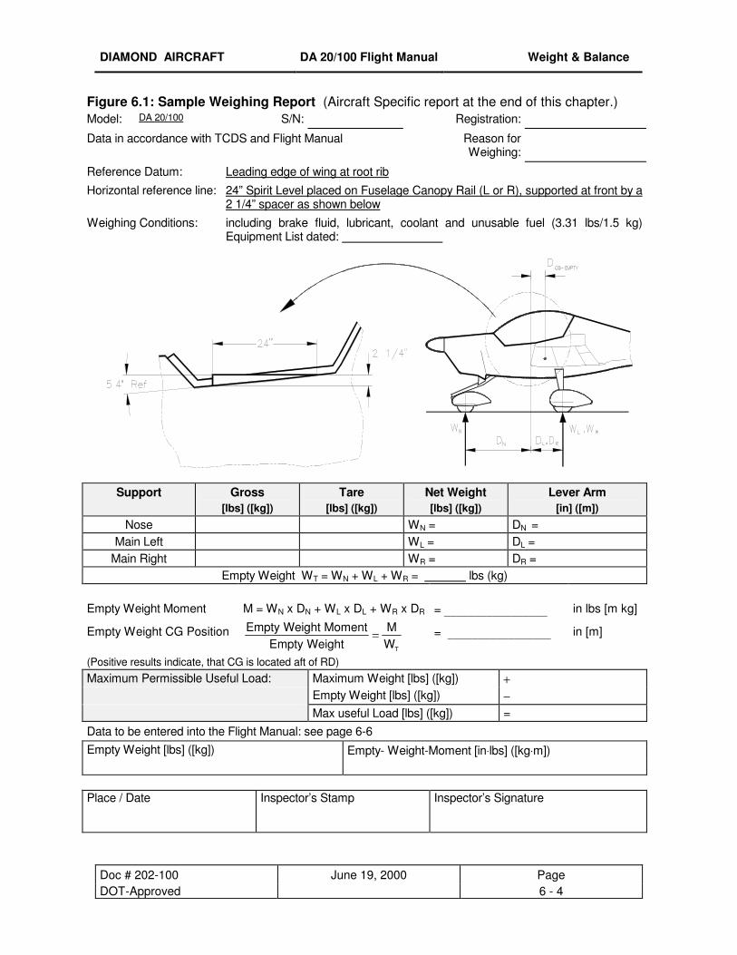
DIAMOND AIRCRAFT DA 20/100 Flight Manual Weight & Balance
Doc # 202-100 June 19, 2000 Page DOT-Approved 6 - 4
Figure 6.1: Sample Weighing Report (Aircraft Specific report at the end of this chapter.) Model: DA 20/100 S/N: Registration:
Data in accordance with TCDS and Flight Manual Reason for Weighing:
Reference Datum: Leading edge of wing at root rib
Horizontal reference line: 24” Spirit Level placed on Fuselage Canopy Rail (L or R), supported at front by a 2 1/4” spacer as shown below
Weighing Conditions: including brake fluid, lubricant, coolant and unusable fuel (3.31 lbs/1.5 kg) Equipment List dated:
Support Gross
[lbs] ([kg]) Tare
[lbs] ([kg]) Net Weight [lbs] ([kg])
Lever Arm [in] ([m])
Nose WN = DN = Main Left WL = DL =
Main Right WR = DR = Empty Weight WT = WN + WL + WR = lbs (kg)
Empty Weight Moment M = WN x DN + WL x DL + WR x DR = _________________ in lbs [m kg]
Empty Weight CG Position Empty Weight MomentEmpty Weight
MWT
= = _________________ in [m]
(Positive results indicate, that CG is located aft of RD) Maximum Permissible Useful Load: Maximum Weight [lbs] ([kg]) + Empty Weight [lbs] ([kg]) − Max useful Load [lbs] ([kg]) = Data to be entered into the Flight Manual: see page 6-6 Empty Weight [lbs] ([kg]) Empty- Weight-Moment [in⋅lbs] ([kg⋅m]) Place / Date
Inspector’s Stamp Inspector’s Signature
DIAMOND AIRCRAFT DA 20/100 Flight Manual Weight & Balance
Doc # 202-100 June 19, 2000 Page Issue 1 6 - 5
6.3. WEIGHT AND BALANCE REPORT
The empty weight and Empty Weight CG position data determined prior to delivery of the airplane is the
first entry in the Weight and Balance Report. Each change of the installed equipment as well as each
repair affecting the empty weight, the CG position of the empty weight or the empty weight moment must
be entered in the Weight and Balance Report at the end of this chapter. The following Sample Weight
and Balance Report figure 6.2. is for reference only.
Ensure that you are using the latest weight and balance information when performing a weight and
balance calculation
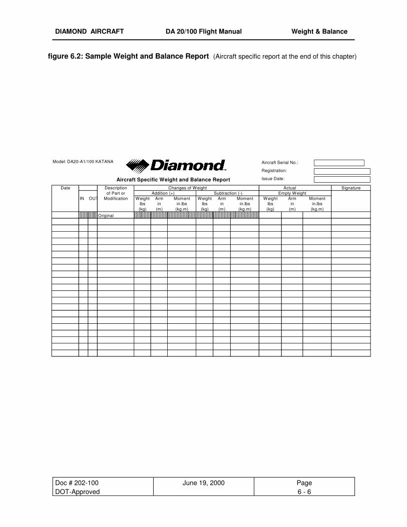
DIAMOND AIRCRAFT DA 20/100 Flight Manual Weight & Balance
Doc # 202-100 June 19, 2000 Page DOT-Approved 6 - 6
figure 6.2: Sample Weight and Balance Report (Aircraft specific report at the end of this chapter)
Date Description Changes of Weight Actual Signatureof Part or Addition (+) Subtraction (-) Empty Weight
IN OUT Modification Weight Arm Moment Weight Arm Moment Weight Arm Momentlbs in in.lbs lbs in in.lbs lbs in in.lbs(kg) (m) (kg.m) (kg) (m) (kg.m) (kg) (m) (kg.m)
Original
Issue Date:
Registration:
Aircraft Serial No.:Model: DA20-A1/100 KATANA
Aircraft Specific Weight and Balance Report
DIAMOND AIRCRAFT DA 20/100 Flight Manual Weight & Balance
Doc # 202-100 June 19, 2000 Page DOT-Approved 6 - 7
6.4. FLIGHT WEIGHT AND CENTER OF GRAVITY
The following data enables the pilot to operate the DA 20/100 within the required weight- and center of
gravity limitations.
The following diagrams,
Figure 6.3 Weight & Balance Diagram
Figure 6.4 Calculation of Loading Condition
Figure 6.5 Permissible Center of Gravity Range
and permissible Flight-Weight-Moment
are to be used for calculations of the flight-weight and the center of gravity as follows:
1. The empty weight and the empty-weight-moment of the airplane should be taken from the
weighing report or from the weight & balance report and entered into the form "Calculation of
Loading Condition" (figure 6.4) in the columns identified with "Your DA 20".
2. Using the Weight & Balance Diagram (see figure 6.3) determine the moment for each part to be
loaded, and enter it in the respective column in figure 6.4.
3. Add the weights and the moments of each column (point 4 and point 6 in figure 6.4) and enter the
sum in figure 6.5 "Permissible CG Range and Permissible Flight-Weight-Moment" to check if the
values are within the permissible limits of the loading range.
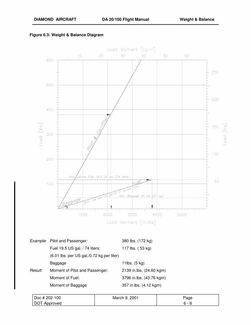
DIAMOND AIRCRAFT DA 20/100 Flight Manual Weight & Balance
Doc # 202-100 March 9, 2001 Page DOT-Approved 6 - 8
Figure 6.3: Weight & Balance Diagram
Example: Pilot and Passenger: 380 lbs. (172 kg)
Fuel 19.5 US gal. / 74 liters: 117 lbs. ( 53 kg)
(6.01 lbs. per US gal./0.72 kg per liter)
Baggage 11lbs. (5 kg)
Result: Moment of Pilot and Passenger: 2139 in.lbs. (24.60 kgm)
Moment of Fuel: 3796 in.lbs. (43.76 kgm)
Moment of Baggage 357 in.lbs. (4.12 kgm)
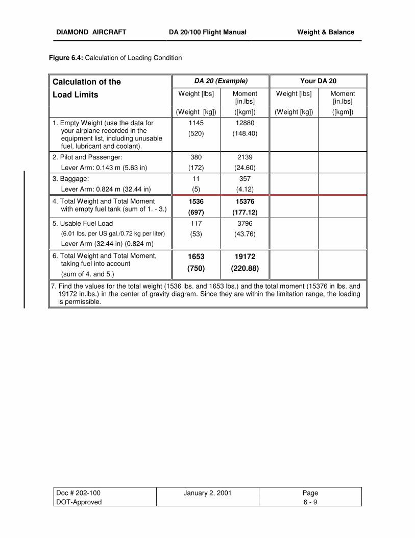
DIAMOND AIRCRAFT DA 20/100 Flight Manual Weight & Balance
Doc # 202-100 January 2, 2001 Page DOT-Approved 6 - 9
Figure 6.4: Calculation of Loading Condition
Calculation of the DA 20 (Example) Your DA 20
Load Limits Weight [lbs] Moment [in.lbs]
Weight [lbs] Moment [in.lbs]
(Weight [kg]) ([kgm]) (Weight [kg]) ([kgm])
1. Empty Weight (use the data for your airplane recorded in the equipment list, including unusable fuel, lubricant and coolant).
1145
(520)
12880
(148.40)
2. Pilot and Passenger:
Lever Arm: 0.143 m (5.63 in)
380
(172)
2139
(24.60)
3. Baggage:
Lever Arm: 0.824 m (32.44 in)
11
(5)
357
(4.12)
4. Total Weight and Total Moment with empty fuel tank (sum of 1. - 3.)
1536
(697)
15376
(177.12)
5. Usable Fuel Load (6.01 lbs. per US gal./0.72 kg per liter) Lever Arm (32.44 in) (0.824 m)
117
(53)
3796
(43.76)
6. Total Weight and Total Moment, taking fuel into account
(sum of 4. and 5.)
1653 (750)
19172 (220.88)
7. Find the values for the total weight (1536 lbs. and 1653 lbs.) and the total moment (15376 in lbs. and 19172 in.lbs.) in the center of gravity diagram. Since they are within the limitation range, the loading is permissible.
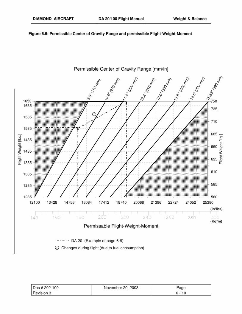
DIAMOND AIRCRAFT DA 20/100 Flight Manual Weight & Balance
Doc # 202-100 November 20, 2003 Page Revision 3 6 - 10
Figure 6.5: Permissible Center of Gravity Range and permissible Flight-Weight-Moment
Permissible Center of Gravity Range [mm/in]
Permissable Flight-Weight-Moment
DA 20 (Example of page 6-9)
Changes during flight (due to fuel consumption)
10.6
" (27
0 m
m)
11.4
" (2
90 m
m)
12.2
' (3
10 m
m)
13.0
" (33
0 m
m)
13.8
" (3
50 m
m)
14.5
" (37
0 m
m)
15.3
5" (3
90 m
m)
9.8"
(250
mm
)
1235
1285
1335
1385
1435
1485
1535
1585
1635
12100 13428 14756 16084 17412 18740 20068 21396 22724 24052 25380
Flig
ht W
eigh
t [lb
s.]
560
585
610
635
660
685
710
735
Flig
ht W
eigh
t [kg
.]
1653 -- --750
(in*lbs) (Kg*m)
1
1
DIAMOND AIRCRAFT DA 20/100 Flight Manual Weight & Balance
Doc # 202-100 June 19, 2000 Page Issue 1 6 - 11
6.5. EQUIPMENT LIST
The following table lists the equipment available for this airplane. An Equipment Record of items installed
in your specific airplane is included at the end of this chapter.
The equipment list comprises the following data:
• The item No. containing an alpha character for the equipment group and a sequential number.
• Abbreviations:
A Avionics
I Instruments
M Miscellaneous (any equipment other than avionics or instruments)
Weight and lever arm of the equipment items are shown in the columns "Weight" and "Arm".
NOTE
Additional installation of equipment must be carried out in compliance with the
specifications in the Maintenance Manual. The columns "Weight" and "Arm" show the
weight and the CG position of the equipment with respect to the reference datum. A
positive value shows the distance aft of the reference datum, a negative value shows the
distance forward of the reference datum.

DIAMOND AIRCRAFT DA 20/100 Flight Manual Weight & Balance
Doc # 202-100 June 19, 2000 Page Issue 1 6 - 12
Equipment List
Seq. No.: Part Description,
Manufacturer, Type
Weight
[lbs] (kg)
Arm
[in] (m) A 1 ADF
King KR87 3.20
(1.45) -20.5
(-0.521) A 2 Slaving Amplifier
Century 1D755 1.80
(0.82) +5.5
(+0.140) A 3 ADF ANTENNA
King KA44B 2.80
(1.27) +38.5
(+.978) A 4
GPS / Com King KLX135A
4.4 (1.98
-20.5 (-0.521)
A 5
DME Antenna King KA60
0.20 (0.09)
+18.0 (+0.457)
A 6
GPS Antenna Garmin GA56
0.25 (0.11)
+16.0 (+0.407)
A 7
GPS Antenna King KA91
0.6 (0.27)
+16.0 (+0.407)
A 8
Marker Beacon Antenna King KA26
0.50 (0.23)
+59.0 (+1.499)
A 9
Transponder Antenna Bendix/King, KA60
0.20 (0.09)
+18.0 (+0.457)
A 10
VHF-AM Antenna Comant CI122
0.50 (0.23)
+43.5 (+1.105)
A 11
Audio Panel King KMA24
1.7 (0.772)
-20.5 (-0.521)
A 12
Audio Panel Terra TMA350D
1.7 (0.772)
-20.5 (-0.521)
A 13
Diplexer Comant CI1125
0.25 (0.11)
-18.0 (-0.457)
A 14
Diplexer Comant CI505
0.20 (0.09)
-18.0 (-0.457)
A 15
DME King KN64
2.60 (1.18)
-20.5 (-0.521)
A 16 Encoder SSD120-20
0.80 (0.363)
-22.5 (-.571)
A 17 Flux Detector Century 1B495
0.40 (0.18)
+14.0 (+0.356)
A 18 GPS Garmin 155
2.14 (0.97)
-20.5 (-0.521)
A 19 GPS / Com King KLX135
4.4 (1.98)
-20.5 (-0.521)
A 20 ADF Indicator King KI227
0.70 (0.32)
-15.5 (-0.394)
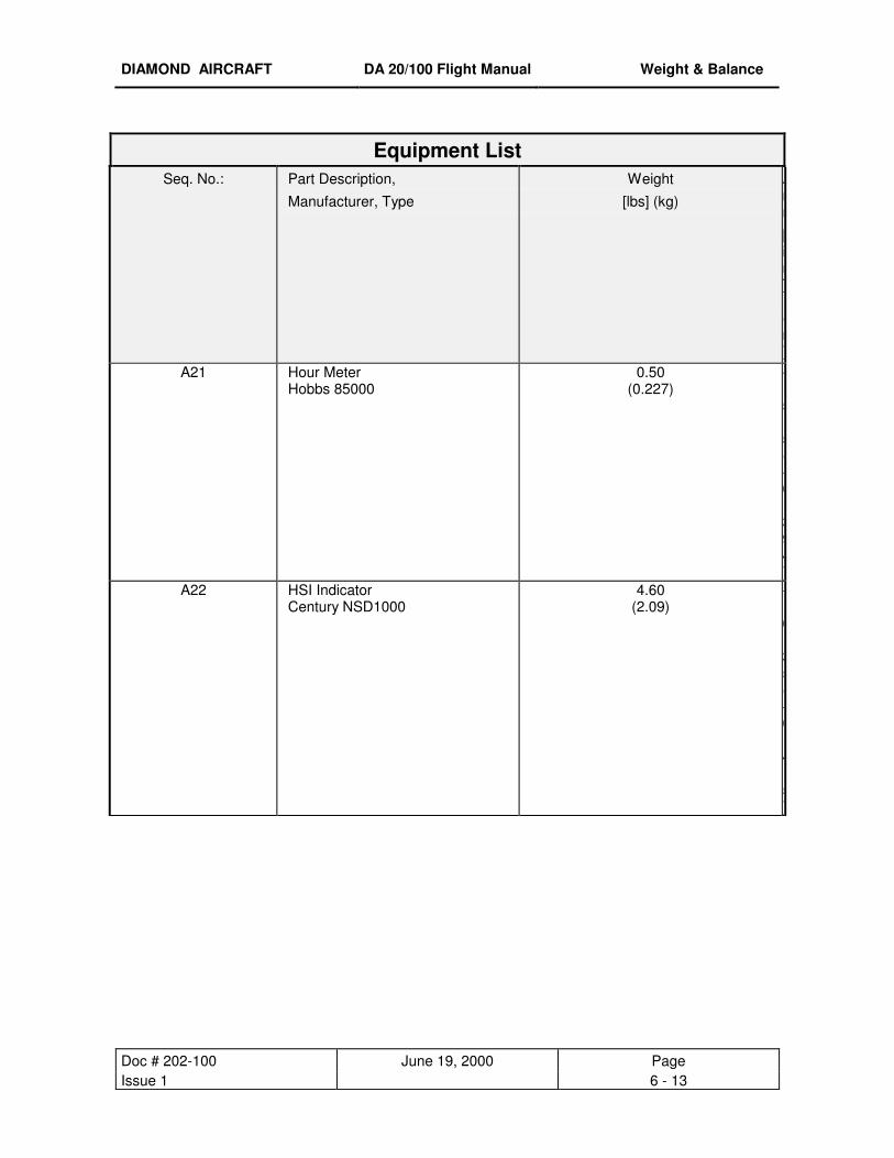
DIAMOND AIRCRAFT DA 20/100 Flight Manual Weight & Balance
Doc # 202-100 June 19, 2000 Page Issue 1 6 - 13
Equipment List
Seq. No.: Part Description,
Manufacturer, Type
Weight
[lbs] (kg)
Arm
[in] (m)
A21 Hour Meter Hobbs 85000
0.50 (0.227)
-15.5(-0.394)
A22 HSI Indicator Century NSD1000
4.60 (2.09)
-16.35(-0.415)

DIAMOND AIRCRAFT DA 20/100 Flight Manual Weight & Balance
Doc # 202-100 June 19, 2000 Page Issue 1 6 - 14
A23 Nav Indicator King KI208
1.10 (0.499)
-16.35(-0.415)
A24 Nav Indicator King KI209
1.10 (0.499)
-16.35(-0.415)
A25 Outside Air Temperature Indicator Davtron 301F
0.50 (0.227)
-15.5(-0.394)
A26 Intercom PS Engineering PM501
0.53 (0.240)
-15.5(-0.394)

DIAMOND AIRCRAFT DA 20/100 Flight Manual Weight & Balance
Doc # 202-100 June 19, 2000 Page Issue 1 6 - 15
A27 Nav / Com #1 King KX125
3.88 (1.76)
-20.5(-0.521)
A28 Nav / Com #2 King KX125
3.88 (1.76)
-20.5(-0.521)
A29 Nav / Com #1 King KX155
4.94 (2.24)
-20.5(-0.521)
A30 Nav / Com #2 King KX155
4.94 (2.24)
-20.5(-0.521)

DIAMOND AIRCRAFT DA 20/100 Flight Manual Weight & Balance
Doc # 202-100 June 19, 2000 Page Issue 1 6 - 16
A31 Remote Switch NAT RS16
0.44 (0.20)
-17.0(-0.432)
A32 Transponder Bendix/King, KT76A
3.00 (1.36)
-20.5(-0.521)
A33 GPS Garmin, GPS150
2.14 (0.97)
-20.5(-0.521)
A34 Chronometer Davtron M800B
0.24 (0.11)
-15.5(-0.394)
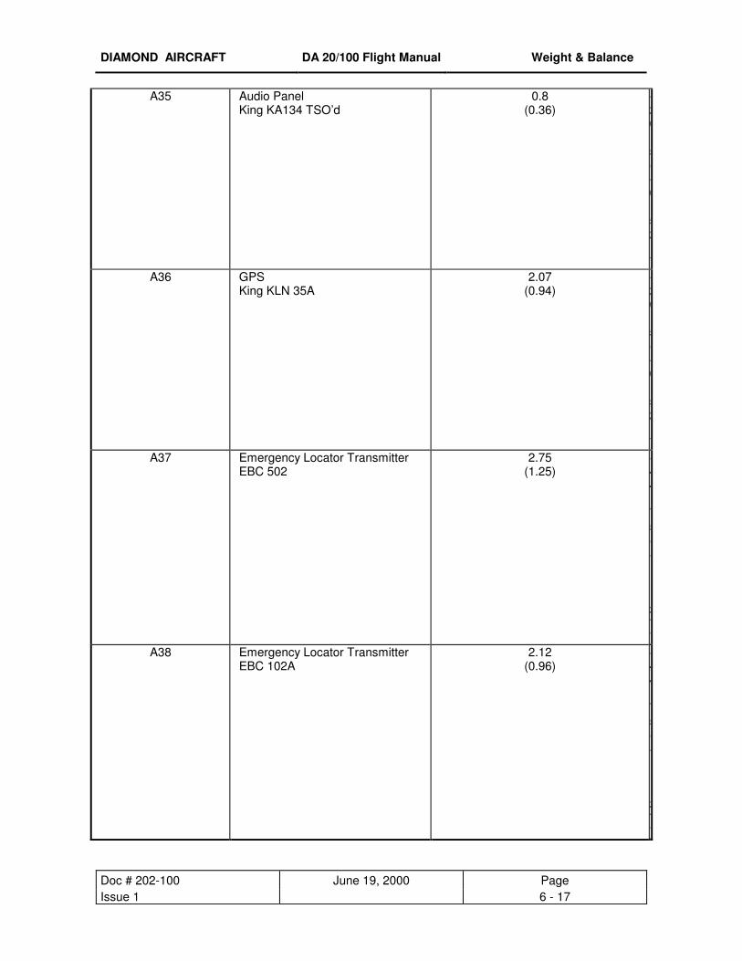
DIAMOND AIRCRAFT DA 20/100 Flight Manual Weight & Balance
Doc # 202-100 June 19, 2000 Page Issue 1 6 - 17
A35 Audio Panel King KA134 TSO’d
0.8 (0.36)
-20.5(-0.521)
A36 GPS King KLN 35A
2.07 (0.94)
-20.5(-0.521)
A37 Emergency Locator Transmitter EBC 502
2.75 (1.25)
+44.75(+1.137)
A38 Emergency Locator Transmitter EBC 102A
2.12 (0.96)
+44.75(+1.137)
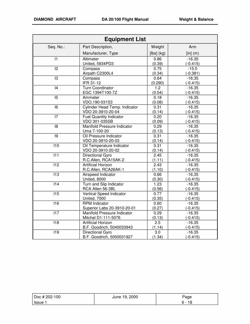
DIAMOND AIRCRAFT DA 20/100 Flight Manual Weight & Balance
Doc # 202-100 June 19, 2000 Page Issue 1 6 - 18
Equipment List
Seq. No.: Part Description,
Manufacturer, Type
Weight
[lbs] (kg)
Arm
[in] (m) I1 Altimeter
United, 5934PD3 0.86
(0.39) -16.35
(-0.415) I2 Compass
Airpath C2300L4 0.75
(0.34) -15.0
(-0.381) I3 Compass
IFR 31-12 0.64
(0.290) -16.35
(-0.415) I4 Turn Coordinator
EGC 1394T100-7Z 1.2
(0.54) -16.35
(-0.415) I5 Ammeter
VDO,190-031S3 0.18
(0.08) -16.35
(-0.415) I6 Cylinder Head Temp. Indicator
VDO 20-3910-20-04 0.31
(0.14) -16.35
(-0.415) I7 Fuel Quantity Indicator
VDO 301-035SB 0.20
(0.09) -16.35
(-0.415) I8 Manifold Pressure Indicator
Uma 7-100-20 0.29
(0.13) -16.35
(-0.415) I9 Oil Pressure Indicator
VDO 20-3910-20-03 0.31
(0.14) -16.35
(-0.415) I10 Oil Temperature Indicator
VDO 20-3910-20-02 0.31
(0.14) -16.35
(-0.415) I11 Directional Gyro
R.C.Allen, RCA15AK-2 2.45
(1.11) -16.35
(-0.415) I12 Artificial Horizon
R.C.Allen, RCA26AK-1 2.43
(1.10) -16.35
(-0.415) I13 Airspeed Indicator
United, 8000 0.66
(0.30) -16.35
(-0.415) I14 Turn and Slip Indicator
RCA Allen 56-3BL 1.23
(0.56) -16.35
(-0.415) I15 Vertical Speed Indicator
United, 7000 0.77
(0.35) -16.35
(-0.415) I16 RPM Indicator
Superior Labs 20-3910-20-01 0.60
(0.27) -16.35
(-0.415) I17 Manifold Pressure Indicator
Mitchel D1-111-5076 0.29
(0.13) -16.35
(-0.415) I18 Artificial Horizon
B.F. Goodrich, 5040033943 2.5
(1.14) -16.35
(-0.415) I19 Directional Gyro
B.F. Goodrich, 5050031927 3.0
(1.34) -16.35
(-0.415)

DIAMOND AIRCRAFT DA 20/100 Flight Manual Weight & Balance
Doc # 202-100 June 19, 2000 Page Issue 1 6 - 19
Equipment List
Seq. No.: Part Description,
Manufacturer, Type
Weight
[lbs] (kg)
Arm
[in] (m)
M1 Wheel Fairing, Main Gear DIAMOND left or right
2.65 (1.20)
+27.56(+0.700)
M2 Wheel Fairing, Nose Gear DIAMOND
2.65 (1.20)
-44.84(-1.139)

DIAMOND AIRCRAFT DA 20/100 Flight Manual Weight & Balance
Doc # 202-100 June 19, 2000 Page Issue 1 6 - 20
M3 Seat Cushion, standard DIAMOND, 2 pieces
4.50 (2.05)
+12.00(+0.305)
M4 Seat Cushion, leather DIAMOND, 2 pieces
5.63 (2.55)
+12.00(+0.305)
M5 Fire Extinguisher AMEREX A 620
2.25 (1.02)
+32.25(+0.895)
M6 Tire 5.00x5,6Ply,Main Gear(TSOC62) (including inner tube)
4.51 (2.05)
+22.45(+0.570)
DIAMOND AIRCRAFT DA 20/100 Flight Manual Weight & Balance
Doc # 202-100 June 19, 2000 Page Issue 1 6 - 21
M7 Tire 15 x 6.00-5,Main Gear(Goodyear) (including inner tube)
7.70 (3.49)
+22.45(+0.570)
Refer to the Aircraft Specific Equipment list at the end of this chapter.

DIAMOND AIRCRAFT DA 20/100 Flight Manual Description
Doc # 202-100 June 19, 2000 Page Issue 1 7 - 1
CHAPTER 7
DESCRIPTION OF THE AIRPLANE
AND ITS SYSTEMS
7.1. INTRODUCTION 7- 2 7.2. AIRFRAME 7- 2 7.3. FLIGHT CONTROLS 7- 3 7.4. INSTRUMENT PANEL 7- 5 7.5. LANDING GEAR SYSTEM 7- 7 7.6. SEATS AND SAFETY BELTS 7- 8 7.7. BAGGAGE COMPARTMENT 7- 8 7.8. CANOPY 7- 9 7.9. POWERPLANT 7-10 7.10. FUEL SYSTEM 7-13 7.11. ELECTRICAL SYSTEM 7-14 7.12. PITOT AND STATIC PRESSURE SYSTEMS 7-17 7.13. STALL WARNING 7-17 7.14. AVIONICS 7-18
DIAMOND AIRCRAFT DA 20/100 Flight Manual Description
Doc # 202-100 June 19, 2000 Page Issue 1 7 - 2
7.1. INTRODUCTION
This Chapter provides description and operation of the airplane and its systems. Refer to Chapter 9
(Supplements), for details of optional systems and equipment.
7.2. AIRFRAME
7.2.1. Fuselage
The GFRP-fuselage is of semi-monocoque construction. The fire protection cover on the fire wall is made
from a special fire retarding fleece, that is covered by a stainless steel plate on the engine side. The main
bulkhead is of CFRP/GFRP construction.
7.2.2. Wings
The GFRP-wings are of semi-monocoque sandwich construction, and contain a CFRP-spar. The ailerons
and flaps are made from CFRP and are attached to the wings using aluminum hinges.
The wing-fuselage connection is made with three bolts each. The so-called A- and B- bolts are fixed to the
fuselage's root rib. The A-bolt is placed in front of the spar tunnel, the B-bolt lies near the trailing edge. The
two main bolts are placed in the middle of the spar tunnel (main bulkhead). They are accessible between
the backrests and can be inserted from the front side. A spring loaded hook locks both bolt handles,
thereby securing them.
7.2.3. Empennage
The rudder and elevator units are of semi-monocoque sandwich construction. The vertical stabilizer
contains a dipole antenna for the number 1 com. radio, the horizontal stabilizer contains an antenna for the
NAV equipment (VOR).

DIAMOND AIRCRAFT DA 20/100 Flight Manual Description
Doc # 202-100 June 19, 2000 Page Issue 1 7 - 3
7.3. FLIGHT CONTROLS The ailerons and elevator are actuated via push rods, and the rudder is controlled using control cables.
The flaps have three positions (up [UP], take-off [T/O], and landing [LDG]) and are electrically operated.
The switch is located on the instrument panel. In addition the flap control circuit is provided with a
manually triggerable circuit breaker.
Elevator forces may be balanced using the electric trim system.
7.3.1. Trim System
The Rocker switch is located on center console behind engine control unit. The digital trim indicator is
located in the middle of the instrument panel.
The switch controls an electrical actuator beside the vertical push rod in the vertical stabilizer. The
actuator applies via compression springs a load on the elevator controls. Its circuit breaker is located in
the circuit breaker panel and can also be triggered manually.
switch forward = nose down
7.3.2. Flaps
The flaps are driven by an electric motor. The flaps are controlled by a three position flap operating switch
on the instrument panel. The three positions of the switch correspond to the position of the flaps, where
the top position of the switch is used during cruise flight. When the switch is moved to a different position,
the flaps move automatically until the selected position is reached. The up (fully retracted) and landing
(fully extended) positions are additionally equipped with a limit switch to prevent overtraveling.
The electric flap actuator is protected by an automatic circuit breaker (3.5 A), located in the circuit breaker
panel, which can also be triggered manually.
7.3.3. Flap Position Indicator
The current flap position is indicated by three control lights beside the flap operating switch.
Wing Flap Position Light Degree
CRUISE green 0°
T/O yellow 15°
LDG yellow 40°
When two lights are illuminated at the same time, the flaps are between these two positions. This is the
case while the flaps are in motion.
DIAMOND AIRCRAFT DA 20/100 Flight Manual Description
Doc # 202-100 June 19, 2000 Page Issue 1 7 - 4
7.3.4. Pedal Adjustment
NOTE
The pedals may only be adjusted on the ground.
The pedals for rudder and brakes are unlocked by pulling the T-grip located on the rudder pedal
sled aft pedestal.
Forward adjustment: Push both pedals forward with your feet while pulling the T-grip.
Backward adjustment: Pull pedals backward to desired position by pulling on T-grip.
NOTE
After the T-grip is released, push the pedals forward with your feet until they lock in place.
7.3.5. Flight Control Lock
A flight control lock, P/N 20-1000-01-00 , is provided with each aircraft and should be installed whenever
the aircraft is parked.
NOTE
Failure to install the flight control lock whenever the aircraft is parked may result in control system damage, due to gusts or turbulence.
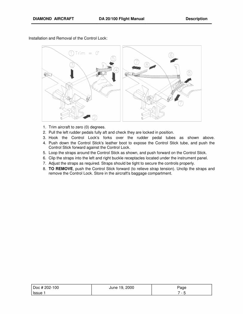
DIAMOND AIRCRAFT DA 20/100 Flight Manual Description
Doc # 202-100 June 19, 2000 Page Issue 1 7 - 5
Installation and Removal of the Control Lock:
1. Trim aircraft to zero (0) degrees. 2. Pull the left rudder pedals fully aft and check they are locked in position. 3. Hook the Control Lock's forks over the rudder pedal tubes as shown above.4. Push down the Control Stick's leather boot to expose the Control Stick tube, and push the
Control Stick forward against the Control Lock. 5. Loop the straps around the Control Stick as shown, and push forward on the Control Stick. 6. Clip the straps into the left and right buckle receptacles located under the instrument panel. 7. Adjust the straps as required. Straps should be tight to secure the controls properly. 8. TO REMOVE, push the Control Stick forward (to relieve strap tension). Unclip the straps and
remove the Control Lock. Store in the aircraft's baggage compartment.

DIAMOND AIRCRAFT DA 20/100 Flight Manual Description
Doc # 202-100 June 19, 2000 Page Issue 1 7 - 6
7.4. INSTRUMENT PANEL
Item Description Item Description Item Description Item Description
1. Outside Air Temp. Ind. 16. Landing Light Switch 31. Intercom 44. I-Panel Light Switch
2. Not Used 17. Taxi Light Switch 32. Manifold Pressure 45. Map Light Switch
3. Air Speed Indicator 18. Nav. Lights Switch 33. Tachometer 46. Trim Ind. Dimmer
4. Artificial Horizon Ind. 19. Avionics Master 34. Oil Pressure Ind. 47. Carb Heat Knob
5. Altimeter 20. Master Switch 35. Oil Temp. Ind. 48. Choke Knob
6. CDI 21. Ignition Switch 36. Voltmeter 49. Cabin Heat Knob
7. Stall Warning Horn 22. Flap Control 37. Cylinder Head Temp. 50. Parking Brake Knob
8. Turn and Bank Ind. 23. Compass Card Indicator 51. Power Lever
9. Directional Gyro 24. Trim Indicator 38. Ammeter 52. Propeller RPM Lever
10. Vertical Speed Ind. 25. Annunciator Lights 39. Fuel Indicator 53. Lever Tension Knob
11. Not Used 26. Hobbs Meter 40. Circuit Breakers 54. Trim Switch
12. Microphone Jack 27. Not Used 41. Compass 55. Microphone Switch
13. Air Vent 28. Radio 42. Canopy Locking 56. Fuel Shut-Off Valve
14. Fuel Pump Switch 29. Transponder Warning Light
15. Strobe Light Switch 30. Not Used 43. I-Panel Reostat

DIAMOND AIRCRAFT DA 20/100 Flight Manual Description
Doc # 202-100 June 19, 2000 Page Issue 1 7 - 7
7.4.1. Flight Instruments
The flight instruments are installed on the pilot's side of the instrument panel.
7.4.2. Cabin Heat
The cabin heat and defrost system, directs ram air through the coolant radiator and the heat shroud
(located around the muffler) into the heat valve. The warm air is then directed to both the window
defrosting vents and to the cabin floor.
The cabin heat knob, located in front of the center console, is used to regulate the flow of heated air.
knob pulled = cabin heat ON
7.4.3. Cabin Air
The cabin aeration is controlled by two adjustable air-vent nozzles. The two sliding windows in the canopy
can be opened for additional ventilation.
7.5. LANDING GEAR SYSTEM
The landing gear system consists of the two main landing gear wheels mounted to a self-spring steel strut
and a free castering nose wheel. The suspension of the nose wheel is handled by an elastomer package.
The landing gear wheel fairings are removable. During flight operations without wheel fairings, partially
reduced flight performance must be taken into account (see Chapter 5).
7.5.1. Wheel Brakes
Hydraulically operated disc brakes act on the wheels of the main landing gear. The wheel brakes are
operated individually using the toe-brake pedals either on the pilot's or on the co-pilot's side. If either the
left or right wheel brake system on the pilot’s side fail, the co-pilot’s brakes fail too. The same applies to a
failure on the co-pilot’s side, in this case, also the pilot’s brakes fail.
CAUTION When placing the feet on the brake pedals, care should be taken to not contact the
structure above the pedals, which could prevent effective application of the brake(s).

DIAMOND AIRCRAFT DA 20/100 Flight Manual Description
Doc # 202-100 June 19, 2000 Page Issue 1 7 - 8
7.5.2. Parking Brake
The knob is located on the center console in front of the throttle quadrant, and is pushed in when the
brakes are to be released. To set the parking brake, pull the knob to the stop. Repeated pushing of the
toe-brake pedals will build up the required brake pressure which will remain in effect until the parking brake
is released.
7.6. SEATS AND SAFETY BELTS
The seats are removable to facilitate the maintenance and inspection of the underlying controls. Covers on
the control sticks prevent loose objects to foul the controls.
The seats are equipped with removable cushions. Manually triggered seat-type parachutes may be used
instead of cushions. For automatically triggered parachutes it is possible to install suitable fastening loops
on the A-bolts (under the seats).
Every seat is equipped with four-point safety belt. The locking of the safety belt occurs by slipping the lap
belt through the shoulder belt-ends and inserting the lap belt-end into the belt lock. The belt is opened by
pulling the lock cover.
7.7. BAGGAGE COMPARTMENT
The baggage compartment is located behind the seat above the fuel tank. The baggage should be
distributed evenly in the baggage compartment. The baggage net must be secured.
CAUTION Ensure that baggage compartment limitations (44 lbs/20 kg max.) and aircraft weight and
balance limitations are not exceeded.
DIAMOND AIRCRAFT DA 20/100 Flight Manual Description
Doc # 202-100 June 19, 2000 Page Issue 1 7 - 9
7.8. CANOPY
Locking:
The canopy is closed by pulling down on the forward handles on the canopy frame. Locking the canopy is
accomplished by pushing forward on the two locking handles on the left and right side of the frame.
To lock: Push both LH and RH locking handles forward.
To unlock: Pull both LH and RH locking handles backwards.
A canopy locking warning light, located in the upper center section of the instrument panel, indicates the
status of the canopy’s locking mechanism. If the canopy locking warning light is illuminated, the canopy is
not locked properly.
In an emergency situation, the canopy can be opened from the outside LH side, by sliding the locking
handle backward and pulling the emergency release lever forward to a stop and lifting up.
CAUTION Before starting the engine, the canopy must be closed and locked.
NOTE The Master Switch must be ON for the Canopy Locking Warning Light to be operational.

DIAMOND AIRCRAFT DA 20/100 Flight Manual Description
Doc # 202-100 June 19, 2000 Page Issue 1 7 - 10
7.9. POWERPLANT
7.9.1. Engine
Rotax 912S3, 4 cylinder, 4 stroke engine, horizontally opposed, liquid cooled cylinder heads, air cooled
cylinders.
Propeller drive via integrated reduction gear (crankshaft RPM in parentheses).
Displacement: 82.5 cu.in. (1.352 liters)
Max. T/O Power (5 min.): 100 HP / 73.5 kW at 2385 RPM (5800 RPM)
Max. Continuous Power: 94 HP / 69 kW at 2260 RPM (5500 RPM)
Additional information can be found in the Engine Operating Manual.
The powerplant instruments are located on the instrument panel on the co-pilot's side. The ignition switch
is present in form of a key switch. The ignition is turned on by turning the key to position BOTH. The starter
is operated by further turning against spring load to the right (position START). The engine is shut off by
the ignition switch.
Due to the backlash in the reduction gear, the propeller can be easily turned approximately 30° by hand.
Sudden throttle movements should be avoided to prevent impact load in the gearbox.
7.9.2. Carburetor Heat, Throttle, Propeller Pitch Control Lever
The Throttle and Propeller Pitch Control levers are grouped together (throttle quadrant) on the center
console. The tension/friction on the throttle quadrant can be adjusted using the friction knob, located on the
right side of the center console. The carburetor heat knob is located in the front of the center console.
Carburetor Heat: square knob, in front of throttle in center console
knob pulled = ON
During normal operation the Carburetor heat is OFF (knob pushed IN)
Throttle: large lever with black conical knobs
lever full forward = FULL throttle
lever full rearward = IDLE

DIAMOND AIRCRAFT DA 20/100 Flight Manual Description
Doc # 202-100 June 19, 2000 Page Issue 1 7 - 11
Propeller Pitch Control Lever: lever with blue notched knob, right of throttle
lever forward = max. RPM (fine pitch)
lever rearward = min. RPM (coarse pitch)
(also see page 7-10).
7.9.3. Choke Small black knob below the center instrument panel (self-resetting)
knob pulled = choke ON
7.9.4. Propeller
The HO-V352F Hoffmann Propeller is used on the DA 20/100 KATANA. The infinitely variable pitch is
hydraulically controlled by a Woodward Governor. When the desired propeller RPM is preselected, the
governor automatically maintains this RPM, regardless of manifold pressure and airspeed.
7.9.5. Propeller Governor
Woodward A 210786
7.9.6. Propeller Pitch Adjustment
Propeller pitch adjustments are made with the propeller pitch control lever located on the center console
(throttle quadrant) to the right of the throttle. Pulling the lever backwards causes a reduction in RPM. The
governor keeps the selected RPM constant regardless of airspeed or throttle setting. If the engine power
level selected with the throttle is insufficient to keep the selected RPM constant, the propeller blades will
move to the smallest possible pitch.
The propeller governor is mounted on the engine. It is driven directly by the engine. The propeller governor
oil circuit is part of the engine oil circulation system. A defect in the governor or oil system will cause the
blades to run to the minimum pitch position.
The pitch of the blades can be rotated through its pitch angle by hand.

DIAMOND AIRCRAFT DA 20/100 Flight Manual Description
Doc # 202-100 November 18, 2003 Page Revision 3 7 - 12
7.9.7. Lubricating
The engine is equipped with a dry sump forced flow
lubrication system. If the engine is not operated for an
extended period of time, it is possible that some of the oil
may drain back into the engine, resulting in a false dip
stick reading. To check the oil level, remove the oil
tank cap and turn the propeller by hand in the
normal rotation of operation. This is to transfer all
the oil from the engine crankcase to the oil tank.
WARNING: DO NOT TURN THE PROPELLER IN
THE OPPOSITE DIRECTION OF NORMAL
ROTATION OF OPERATION. The process is
finished when crankcase air can be heard being
forced back to the oil tank. The sound will be
noticed as a gurgle coming from the oil tank with
the oil cap removed. The sound verifies that the
crankcase has been purged of residual oil. Remove
the oil dip stick, clean and reinsert. Let the oil dip
stick sit for a few seconds then remove verifying the
oil level is in the middle of the level marks.
CAUTION Never operate the engine with the oil filler cap removed.
Observe normal procedures and limitations while running engine.
The oil level must be between the min. and max. quantity as indicated by the flat area of the dip stick.
NOTE
Failure to recognize the above condition could result in overfilling of the oil Tank.
Flat Area
Maximum OilLevel
Minimum OilLevel
Flat Area
Maximum OilLevel
Minimum OilLevel

DIAMOND AIRCRAFT DA 20/100 Flight Manual Description
Doc # 202-100 June 19, 2000 Page Issue 1 7 - 13
7.10. FUEL SYSTEM
The tank, made from aluminum, is located behind the seats, below the baggage compartment. It holds 76
liters (20.1 US gal.), of which 74 liters (19.5 US gal.) are usable. The tank filler on the left side of the
fuselage behind the canopy is connected to the tank with a rubber hose. The tank vent line runs from the
filler connection piece through the fuselage bottom skin to the exterior of the airplane .
A finger filter is installed at the bottom of the tank. From there, the fuel is fed to the electric fuel pump, and
from there, through the middle tunnel to the fuel shut-off valve. From the fuel shut-off valve it is fed to the
firewall breach, and further to the mechanical fuel pump. From there, the fuel reaches the distribution
manifold and finally the float chambers of both carburetors. A return line runs from the distribution
manifold to the tank. Incorporated in the return line is an orifice.
A fuel pressure sensor is installed at the distribution manifold. As soon as the fuel pressure drops below
0.1 bar (1.5 psi), the fuel pressure warning light will illuminate.
Oriface

DIAMOND AIRCRAFT DA 20/100 Flight Manual Description
Doc # 202-100 June 19, 2000 Page Issue 1 7 - 14
7.10.1. Fuel Shut-off Valve
The fuel shut-off valve is located on the left hand side of the center console near the pilot's feet. In the
open position the tap is parallel to the direction of flight. The valve is protected against unintentional shut-
off by a locking detent.
WARNING The fuel shut-off valve should only be closed during engine fire or fuel system maintenance. After reopening, the locking detent should be checked to ensure it performs the proper safety function. Otherwise the danger of operating the airplane with the fuel shut-off valve closed (engine failure) is possible!
7.10.2. Tank Drain
To drain the tank sump, activate the spring loaded drain by pushing the brass tube in with a drain
container. The brass tube protrudes approx. 1 1/6 in (30 mm) from the fuselage contour and is located on
the left side of the fuselage, approximately at the same station as the fuel filler cap.
7.10.3. Fuel Pipette
A fuel pipette, P/N 20-1200-02-00, is supplied with all aircraft to permit direct measurement of fuel level
during the preflight check.
NOTE Electric fuel gauges may malfunction. Check fuel quantity with fuel pipette before each flight
To check the fuel level, insert the graduated end of the fuel dipstick into the fuel tank through the fuel filler
opening until it touches bottom, withdraw and read fuel quantity. The dipstick is calibrated in increments of
¼ of full tank capacity (76 liters/20.1 US gallons) .
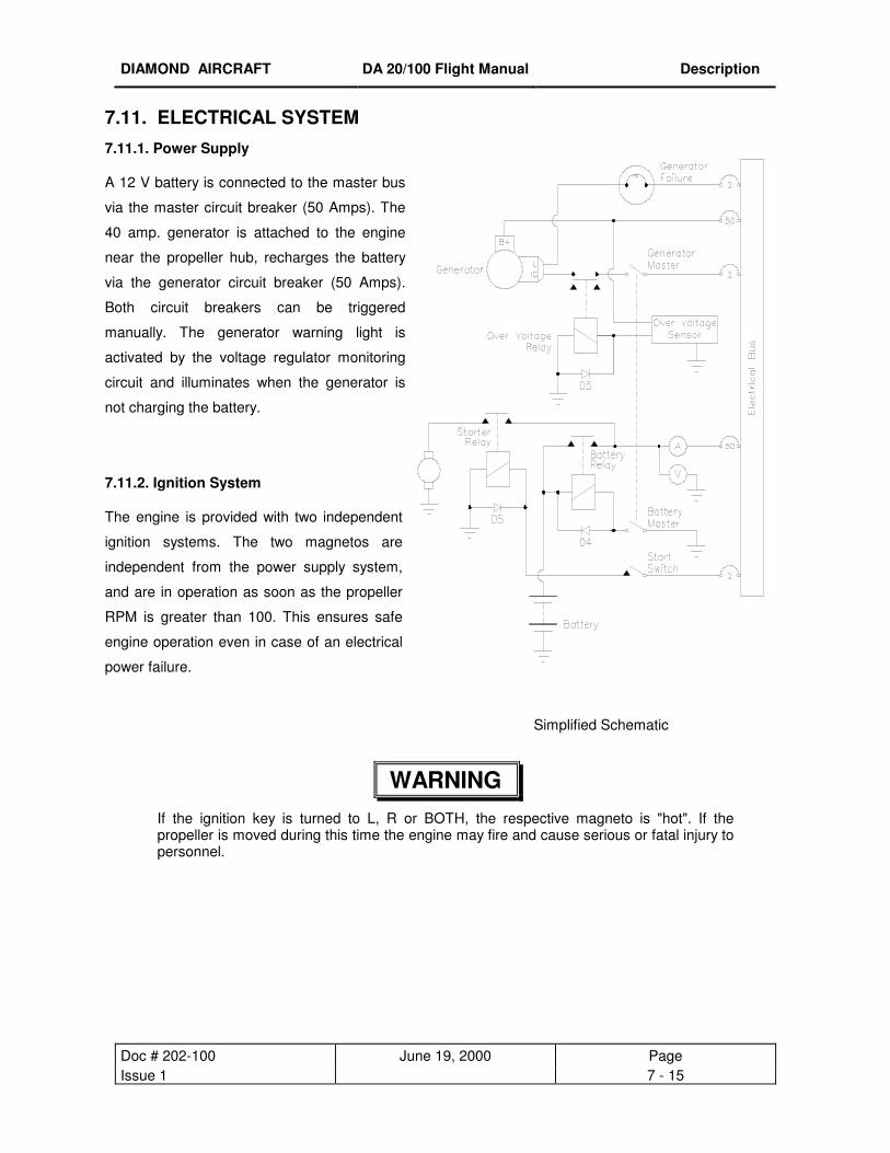
DIAMOND AIRCRAFT DA 20/100 Flight Manual Description
Doc # 202-100 June 19, 2000 Page Issue 1 7 - 15
7.11. ELECTRICAL SYSTEM 7.11.1. Power Supply
A 12 V battery is connected to the master bus
via the master circuit breaker (50 Amps). The
40 amp. generator is attached to the engine
near the propeller hub, recharges the battery
via the generator circuit breaker (50 Amps).
Both circuit breakers can be triggered
manually. The generator warning light is
activated by the voltage regulator monitoring
circuit and illuminates when the generator is
not charging the battery.
7.11.2. Ignition System
The engine is provided with two independent
ignition systems. The two magnetos are
independent from the power supply system,
and are in operation as soon as the propeller
RPM is greater than 100. This ensures safe
engine operation even in case of an electrical
power failure.
WARNING If the ignition key is turned to L, R or BOTH, the respective magneto is "hot". If the propeller is moved during this time the engine may fire and cause serious or fatal injury to personnel.
Simplified Schematic

DIAMOND AIRCRAFT DA 20/100 Flight Manual Description
Doc # 202-100 June 19, 2000 Page Issue 1 7 - 16
7.11.3. Electrical Powered Equipment
The individual consumers (e.g. Radio, Fuel Pump, Position Lights, etc.) are connected in series with
their respective circuit breakers. Equipment that does not have switches installed, and requires a
switch, is controlled by rocker switches in the lower left side of the instrument panel. Refer to Section
7.4 for a illustration of the instrument panel.
7.11.4 . Voltmeter
The voltmeter indicates the status of the electrical bus. It consists of a dial that is marked numerically
from 8 - 16 volts in divisions of 2.
The scale is divided into three colored arcs to indicate the seriousness of the bus condition. These
arcs are:
Red for 8.0 - 11.0 volts,
Yellow for 11.0 - 12.5 volts,
Green for 12.5 - 16.0 volts,
Redline at 16.1 volts.
7.11.5. Ammeter
The ammeter indicates the charging (+) and discharging (-) of the battery. It consists of a dial which is
marked numerically from -60 to 60 amps.
7.11.6. Generator Warning Light
The generator warning light (red) illuminates during:
- Generator failure, no output from the generator
The only remaining power source is the battery (20 amps. for 30 minutes)
7.11.7. Fuel Pressure Indicator
As soon as the fuel pressure drops below 1.45 psi (0.1 bar), the fuel pressure switch closes, and the fuel
pressure warning light illuminates.
DIAMOND AIRCRAFT DA 20/100 Flight Manual Description
Doc # 202-100 June 19, 2000 Page Issue 1 7 - 17
7.11.8. Instruments
The instruments for temperatures, oil pressure, and fuel quantity are connected in series with the
respective sensors. The electrical resistance of a sensor changes with the measurable variable, which
causes the power to the instrument and consequently the needle deflection to change. Oil pressure
indicator, cylinder head temperature indicator and fuel pressure warning light are supplied with power
through one circuit breaker. Oil temperature indicator and fuel quantity indicator are also protected
together by one circuit breaker.
7.11.9 Internal Lighting
The internal lighting of the DA 20/100 KATANA is provided by a lighting module located aft of the Pilot’s
head and on the center line of the aircraft. Included in this module are two panel illumination lights and
one map light. The switches for the lights are located on the center console aft of the Trim control switch.
There is a dimming control located on the left side of the instrument panel for adjusting the intensity of the
panel lighting. As well there is a toggle switch located on the top center of the instrument panel that
controls the intensity of the Wing Flap and Trim annunciator. A red LED mounted underneath the
instrument panel, on the pilot’s side, is used to illuminate the Fuel Shut Off Valve.

DIAMOND AIRCRAFT DA 20/100 Flight Manual Description
Doc # 202-100 June 19, 2000 Page Issue 1 7 - 18
7.12. PITOT AND STATIC PRESSURE SYSTEMS
The pitot pressure is measured on the leading edge of a calibrated probe below the left wing. The static
pressure is measured by the same probe using two holes in the lower edge and rear edge of the probe.
For protection against water and humidity, water sumps are installed within the line. These water sumps
are accessible beneath the left seat shell.
The error of the static pressure system is small enough to be neglected for the measuring of the altitude.
For the error of the airspeed indicating system refer to Chapter 5.
The pitot static pressure probe should be protected whenever the aircraft is parked to prevent
contamination and subsequent malfunction of the aircraft systems relying on its proper functioning.
NOTE Use only the factory supplied pitot static probe cover, P/N G-659-200 with the “Remove before Flight” flag attached.
7.13. STALL WARNING SYSTEM
When the airspeed drops below 1.1 times the stall speed, a horn sounds in the left instrument panel. The
horn grows louder as the speed approaches the stall speed. The horn is activated by suction on a hose
that leads from a hole in the leading edge of the left wing to the horn. The hole is marked by a red circle.
The stall warning hole should be plugged whenever the aircraft is parked to prevent contamination and
subsequent malfunction of the stall warning system.
NOTE Use only the factory supplied stall warning plug, P/N 20-1010-01-00 with the “Remove before Flight” flag attached.
7.14. AVIONICS
The center of the instrument panel contains the radio and navigation equipment. The microphone key for
the radio is installed in the control stick. There are two connectors for headsets on the backrest of the seat.
Operating instructions for individual avionics equipment should be taken from the manuals of the
respective manufacturers.

DIAMOND AIRCRAFT DA 20/100 Flight Manual Handling
Doc # 202-100 June 19, 2000 Page Issue 1 8 - 1
9 CHAPTER 8
HANDLING, PREVENTIVE
AND CORRECTIVE MAINTENANCE
8.1 INTRODUCTION 8-2
8.1 AIRPLANE INSPECTION PERIODS 8-2
8.1 AIRPLANE ALTERATIONS OR REPAIRS 8-2
8.1 GROUND HANDLING / ROAD TRANSPORT
8.1.1 Ground Handling 8-3
8.1.2 Parking 8-4
8.1.3 Mooring 8-4
8.1.4 Jacking 8-4
8.1.5 Road Transport 8-5
8.1 CLEANING AND CARE
8.1.1 Painted Exterior Surfaces 8-6
8.1.2 Canopy 8-6
8.1.3 Propeller 8-7
8.1.4 Engine 8-7
8.1.5 Interior Surfaces, Seats and Carpets 8-7

DIAMOND AIRCRAFT DA 20/100 Flight Manual Handling
Doc # 202-100 June 19, 2000 Page Issue 1 8 - 2
8.1. INTRODUCTION
This Chapter contains factory-recommended procedures for proper ground handling and servicing of the
airplane. It also identifies certain inspection and maintenance requirements which must be followed if the
airplane is to retain that new-plane performance and dependability. It is wise to follow a planned schedule
of lubrication and preventive maintenance based on climatic and flying conditions encountered.
8.2. AIRPLANE INSPECTION PERIOD
Inspection intervals are every 100 hrs, 200 hrs, 1000 hrs, and 6000 hrs. of flight time. The respective
maintenance procedure can be found in the Airplane Maintenance Manual.
8.3. AIRPLANE ALTERATIONS OR REPAIRS
It is essential that the responsible airworthiness authority be contacted prior to any alterations on the
airplane to ensure that airworthiness of the airplane is not affected. For repairs and painting refer to the
applicable Maintenance Manual Doc. No. DA201.
DIAMOND AIRCRAFT DA 20/100 Flight Manual Handling
Doc # 202-100 June 19, 2000 Page Issue 1 8 - 3
8.4. GROUND HANDLING / ROAD TRANSPORT
8.4.1. Ground Handling
I. Towing Forward
The airplane is most easily and safely maneuvered by hand with the tow-bar attached to the nose wheel. If
the aircraft is towed forward without using the tow-bar, the nose-wheel will follow the movement of the
airplane. It is recommended that the tow-bar be used to pull the aircraft forward. The DA 20/100 KATANA
may also be moved forward by pushing at the trailing edge of the wing tips.
II. Moving Backward
By following a simple procedure it is very easy to move the Katana backward around the ramp. This is
accomplished by pushing down with one hand on the aft section of the fuselage near the vertical stabilizer,
to lift the nose wheel, while pushing back on the leading edge of the horizontal stabilizer, close to its
center, with the other hand. Using this technique the DA 20/100 KATANA can easily be pushed from
side to side as well as backward. If additional assistance is required, a second person may push at the
leading edge of the wings.
CAUTION
Do not push or lift on Spinner!
CAUTION
Do not push on control surfaces!

DIAMOND AIRCRAFT DA 20/100 Flight Manual Handling
Doc # 202-100 June 19, 2000 Page Issue 1 8 - 4
8.4.2. Parking
For short time parking, the airplane must be orientated in headwind direction, the parking brake must be
engaged, the wing flaps must be in the retracted position and the wheels must be chocked.
For extended and unattended parking, as well as in unpredictable wind conditions, the airplane must be
anchored to the ground or placed in a hangar.
When parking the airplane, the flight controls lock, P/N 20-1000-01-00 must be installed and pitot static
probe cover and stall warning plug should be fitted (ref. Chapter 7, Aircraft Description).
Parking in a hangar is recommended.
8.4.3. Mooring
The tail fin of the airplane has a hole which can be used to tie-down the airplane to the ground. Tie-down
rings are also installed near the midpoint on each wing which should also be used as tie-down points.
8.4.4. Jacking
The DA 20/100 KATANA can be jacked at the two jackpoints located on the lower side of the fuselage's
root ribs and at the tail fin.
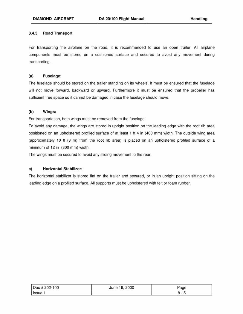
DIAMOND AIRCRAFT DA 20/100 Flight Manual Handling
Doc # 202-100 June 19, 2000 Page Issue 1 8 - 5
8.4.5. Road Transport
For transporting the airplane on the road, it is recommended to use an open trailer. All airplane
components must be stored on a cushioned surface and secured to avoid any movement during
transporting.
(a) Fuselage:
The fuselage should be stored on the trailer standing on its wheels. It must be ensured that the fuselage
will not move forward, backward or upward. Furthermore it must be ensured that the propeller has
sufficient free space so it cannot be damaged in case the fuselage should move.
(b) Wings:
For transportation, both wings must be removed from the fuselage.
To avoid any damage, the wings are stored in upright position on the leading edge with the root rib area
positioned on an upholstered profiled surface of at least 1 ft 4 in (400 mm) width. The outside wing area
(approximately 10 ft (3 m) from the root rib area) is placed on an upholstered profiled surface of a
minimum of 12 in (300 mm) width.
The wings must be secured to avoid any sliding movement to the rear.
c) Horizontal Stabilizer:
The horizontal stabilizer is stored flat on the trailer and secured, or in an upright position sitting on the
leading edge on a profiled surface. All supports must be upholstered with felt or foam rubber.

DIAMOND AIRCRAFT DA 20/100 Flight Manual Handling
Doc # 202-100 June 19, 2000 Page Issue 1 8 - 6
8.5. CLEANING AND CARE
CAUTION
Excessive dirt deteriorates the flight performance.
8.5.1. Painted Surfaces
To achieve the best flight characteristics for the DA20/100 KATANA, a clean external surface is most
important. For this reason it is highly recommended that the airplane, especially the leading edge of the wings
are kept clean at all times.
For best result, the cleaning is performed using a generous amount of water. If necessary, a mild cleaning
agent can be added. Excessive dirt such as insects etc. are best cleaned off immediately after flight, because
once dried they are difficult to remove.
Approximately once a year, the surface of the airplane should be treated and buffed using a silicon free
automotive polish.
CAUTION
DO NOT use any cleaning agents containing silicon based materials.
8.5.2. Canopy
The DA 20/100 KATANA offers excellent vision through a large plexiglass canopy. It is essential that care
will be taken while cleaning the canopy, as it is easily scratched. If scratched, the vision will be reduced.
In principal the same rules should be applied to clean the canopy as for the outside surface of the airplane.
To remove excessive dirt, plenty of water should be used; make sure to use only clean sponges and
chamois. Even the smallest dust particle can cause scratches.
In order to achieve clarity, plastic cleaners such as Permatex Part No. 403D or Mirror Glaze may be
used according to the manufacturer’s instructions. Do not wipe in circles, but only in one direction.
DIAMOND AIRCRAFT DA 20/100 Flight Manual Handling
Doc # 202-100 June 19, 2000 Page Issue 1 8 - 7
8.5.3. Propeller
See Hoffmann Propeller Instruction Manual E540 (HO-V352).
8.5.4. Engine
See Operator's Manual for the Rotax 912 aircraft engine.
8.5.5. Interior Surfaces, Seats and Carpets
The interior should be cleaned using a vacuum cleaner. All loose items (pens, bags etc.) should be
properly stored and secured. All instruments can be cleaned using a soft dry cloth, plastic surfaces should
be wiped clean using a damp cloth without any cleaning agents.
Doc # 202-100 June 19, 2000 Page DOT Approved 9-1
CHAPTER 9
SUPPLEMENTS
9.1 GENERAL 9-1
9.1 INDEX OF SUPPLEMENTS 9-2
9.1 GENERAL This Chapter contains information regarding optional equipment which may be installed in your airplane.
Individual supplements address each optional equipment installation.
It is only necessary to maintain those supplements which pertain to your specific airplane’s configuration.
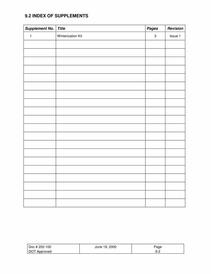
Doc # 202-100 June 19, 2000 Page DOT Approved 9-2
9.2 INDEX OF SUPPLEMENTS
Supplement No. Title Pages Revision
1 Winterization Kit 3 Issue 1
DIAMOND AIRCRAFT DA 20/100 Flight Manual Supplement 1
Doc # 202-100 June 19, 2000 Page DOT Approved S1-1
CHAPTER 9
SUPPLEMENT 1
WINTERIZATION KIT
1 GENERAL S1-1
2 OPERATING LIMITATIONS S1-2
3 EMERGENCY PROCEDURES S1-2
4 NORMAL PROCEDURES S1-2
5 PERFORMANCE S1-3
6 WEIGHT AND BALANCE S1-3

DIAMOND AIRCRAFT DA 20/100 Flight Manual Supplement 1
Doc # 202-100 June 19, 2000 Page DOT Approved S1-2
1. GENERAL
The Winterization kit should be installed for operations in temperatures consistently below 0°C (32°F).The
kit consists of permanently installed mounting hardware and caution placards with quickly detachable oil
cooler and radiator inlet baffles. The baffles partially restrict the airflow through the oil cooler and radiator
to maintain optimum oil and coolant temperatures.
2. OPERATING LIMITATIONS
Maximum T/O temperature with baffles installed is 10°C(50°F).
The following placard must be located in two places, one immediately forward of the oil cooler inlet the
other upon the radiator inlet baffle:
3. EMERGENCY PROCEDURES There is no change to the airplane emergency procedures when the winterization kit is installed.
4. NORMAL PROCEDURES Preflight Inspection:
[Insert after Item 7 (c) of the Walk-around inspection (ref. section 4.4.1 of the Airplane Flight Manual)]
• If OAT is below 0°C (32°F) install oil cooler and radiator inlet baffles (recommended),
• If OAT is above 10°C (50°F) remove oil cooler and radiator inlet baffles (mandatory !)
CAUTION

DIAMOND AIRCRAFT DA 20/100 Flight Manual Supplement 1
Doc # 202-100 June 19, 2000 Page DOT Approved S1-3
5. PERFORMANCE There is no change in airplane performance when the winterization kit is installed.
6. WEIGHT AND BALANCE The effect of the winterization kit on weight and balance is negligible

Related Documents


