1 New Product Terminal Relay G6D-F4PU/G3DZ-F4PU (Push-In Plus Technology) G6D-F4B/G3DZ-F4B (Screw Terminal) Model with Push-In Plus technology Added to Terminal Relays with Four-point Output Lineup • Realized 5 A rating by optimal designs for wide variety of applications (Push-In Plus technology). • Push-In Plus terminal enables work reduction and requires no retightening. • Short Bars (order separately) ensure easy common wiring and crossover wiring to adjacent terminal relays. • Double wire method enables branch wiring (Push-In Plus technology) • Each relay has independent coils and contacts for PLC output compatible (both NPN and PNP). • Mechanical Relay models and power MOS FET relay models (for high frequency contact ratings) are available. • LED operation indicator, diode for coil surge absorption, and tools for easy removal of relays are included as standard equipment. • UL and CSA certification for standard models. VDE certification for Screws terminal, TÜV certification for Push-In Plus terminal. IP20 protection code for Push-In Plus models. Features (G6D-F4PU/G3DZ-F4PU (Model with Push-In Plus technology)) For the most recent information on models that have been certified for safety standards, refer to your OMRON website. Refer to Safety Precautions on page 12. G6D-F4PU G3DZ-F4PU G6D-F4B G3DZ-F4B NEW Independent circuit for PLC output in both NPN and PNP Branch wiring with double wire method Short Bars enable common wiring LED operation indicator Tools for removal Easy common wiring with Short Bars * Connector terminal box, etc. Operating panel of each device, etc. Control box, etc. Wide Variety of Application G2RV-SR G6D-F4PU G2RV-SR G70V 1 point 4 point 8 point 16 point Applicable to Various Number of I/O Points Rated load: 3A Rated load: 5A Rated load: 5A Width: 31 mm Width: 31 mm Width: 43 mm G6D-F4B (Screw) G6D-F4PU (Push-In Plus technology) G6B-4BND (Screw) Slimmer Width Yet Larger Power Supply Capacity Pursuing High Usability Larger current capacity by approx. 67% Slimmer width by approx. 30% Short Hight for Installation in Narrow Spaces * Value Design for Panel Our shared concept “Value Design for Panel” for the specifications of products used in control panels (hereinafter called “Value Design”) will create new value to your control panels. Combining multiple products that share the Value Design concept will further increase the value provided to control panels.

Welcome message from author
This document is posted to help you gain knowledge. Please leave a comment to let me know what you think about it! Share it to your friends and learn new things together.
Transcript

1
New Product
Terminal RelayG6D-F4PU/G3DZ-F4PU (Push-In Plus Technology)G6D-F4B/G3DZ-F4B (Screw Terminal)
Model with Push-In Plus technology Added to Terminal Relays with Four-point Output Lineup• Realized 5 A rating by optimal designs for wide variety of applications
(Push-In Plus technology).• Push-In Plus terminal enables work reduction and requires no
retightening.• Short Bars (order separately) ensure easy common wiring and
crossover wiring to adjacent terminal relays.• Double wire method enables branch wiring (Push-In Plus technology)• Each relay has independent coils and contacts for PLC output
compatible (both NPN and PNP).• Mechanical Relay models and power MOS FET relay models
(for high frequency contact ratings) are available.• LED operation indicator, diode for coil surge absorption, and tools for
easy removal of relays are included as standard equipment.• UL and CSA certification for standard models.
VDE certification for Screws terminal, TÜV certification for Push-In Plus terminal.IP20 protection code for Push-In Plus models.
Features (G6D-F4PU/G3DZ-F4PU (Model with Push-In Plus technology))
For the most recent information on models that have been certified for safety standards, refer to your OMRON website.
Refer to Safety Precautions on page 12.
G6D-F4PUG3DZ-F4PU
G6D-F4BG3DZ-F4B
NEW
Independent circuit for PLC output in both NPN and PNP
Branch wiring with double wire method
Short Bars enable common wiring
LED operation indicator
Tools for removal
Easy common wiring with Short Bars
*
Connector terminal box, etc.
Operating panel of each device, etc.
Control box, etc.
Wide Variety of Application
G2RV-SR G6D-F4PU
G2RV-SR G70V
1 point 4 point
8 point 16 point
Applicable to Various Number of I/O Points
Rated load: 3A Rated load: 5A Rated load: 5A
Width: 31 mm Width: 31 mm Width: 43 mmG6D-F4B(Screw)
G6D-F4PU(Push-In Plus technology)
G6B-4BND(Screw)
Slimmer Width Yet Larger Power Supply CapacityPursuing High Usability
Largercurrent
capacity byapprox.
67%
Slimmerwidth byapprox.
30%
Short Hight for Installation in Narrow Spaces
* Value Design for PanelOur shared concept “Value Design for Panel” for the specifications of products used in control panels (hereinafter called “Value Design”) will create new value to your control panels. Combining multiple products that share the Value Design concept will further increase the value provided to control panels.
G6D-F4PU/G3DZ-F4PU/G6D-F4B/G3DZ-F4B
2
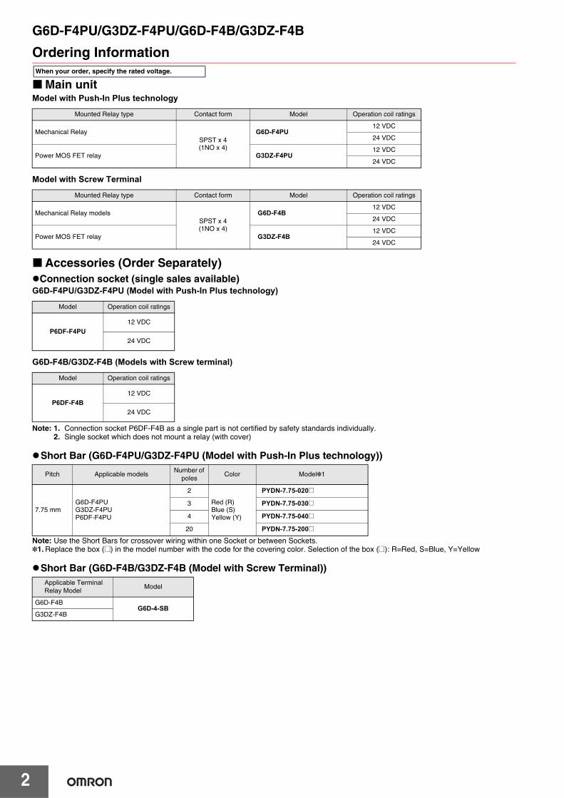
Ordering Information
Main unitModel with Push-In Plus technology
Model with Screw Terminal
Accessories (Order Separately)Connection socket (single sales available)
G6D-F4PU/G3DZ-F4PU (Model with Push-In Plus technology)
G6D-F4B/G3DZ-F4B (Models with Screw terminal)
Note: 1. Connection socket P6DF-F4B as a single part is not certified by safety standards individually.2. Single socket which does not mount a relay (with cover).
Short Bar (G6D-F4PU/G3DZ-F4PU (Model with Push-In Plus technology))
Note: Use the Short Bars for crossover wiring within one Socket or between Sockets.*1. Replace the box (@) in the model number with the code for the covering color. Selection of the box (@): R=Red, S=Blue, Y=Yellow
Short Bar (G6D-F4B/G3DZ-F4B (Model with Screw Terminal))
Mounted Relay type Contact form Model Operation coil ratings
Mechanical RelaySPST x 4(1NO x 4)
G6D-F4PU12 VDC
24 VDC
Power MOS FET relay G3DZ-F4PU12 VDC
24 VDC
Mounted Relay type Contact form Model Operation coil ratings
Mechanical Relay modelsSPST x 4(1NO x 4)
G6D-F4B12 VDC
24 VDC
Power MOS FET relay G3DZ-F4B12 VDC
24 VDC
Model Operation coil ratings
P6DF-F4PU
12 VDC
24 VDC
Model Operation coil ratings
P6DF-F4B
12 VDC
24 VDC
Pitch Applicable modelsNumber of
polesColor Model*1
7.75 mmG6D-F4PUG3DZ-F4PUP6DF-F4PU
2
Red (R)Blue (S)Yellow (Y)
PYDN-7.75-020@
3 PYDN-7.75-030@
4 PYDN-7.75-040@
20 PYDN-7.75-200@
Applicable Terminal Relay Model
Model
G6D-F4BG6D-4-SB
G3DZ-F4B
When your order, specify the rated voltage.

G6D-F4PU/G3DZ-F4PU/G6D-F4B/G3DZ-F4B
3
Replacement Relay (G6D-F4PU/G3DZ-F4PU (Model with Push-In Plus technology))
Parts for DIN Track Mounting
*1. When mounting support rail, please use End Plate (Model PFP-M).
Applicable Terminal Relay Model Model Operation coil ratings
G6D-F4PU/G6D-F4B G6D-1A-ASI12 VDC
24 VDC
G3DZ-F4PU/G3DZ-F4B G3DZ-2R6PL12 VDC
24 VDC
Appearance Type Model
DIN Tracks
1 m PFP-100N
0.5 m PFP-50N
End Plate *1 PFP-M
Spacer PFP-S
G6D-F4PU/G3DZ-F4PU/G6D-F4B/G3DZ-F4B
4
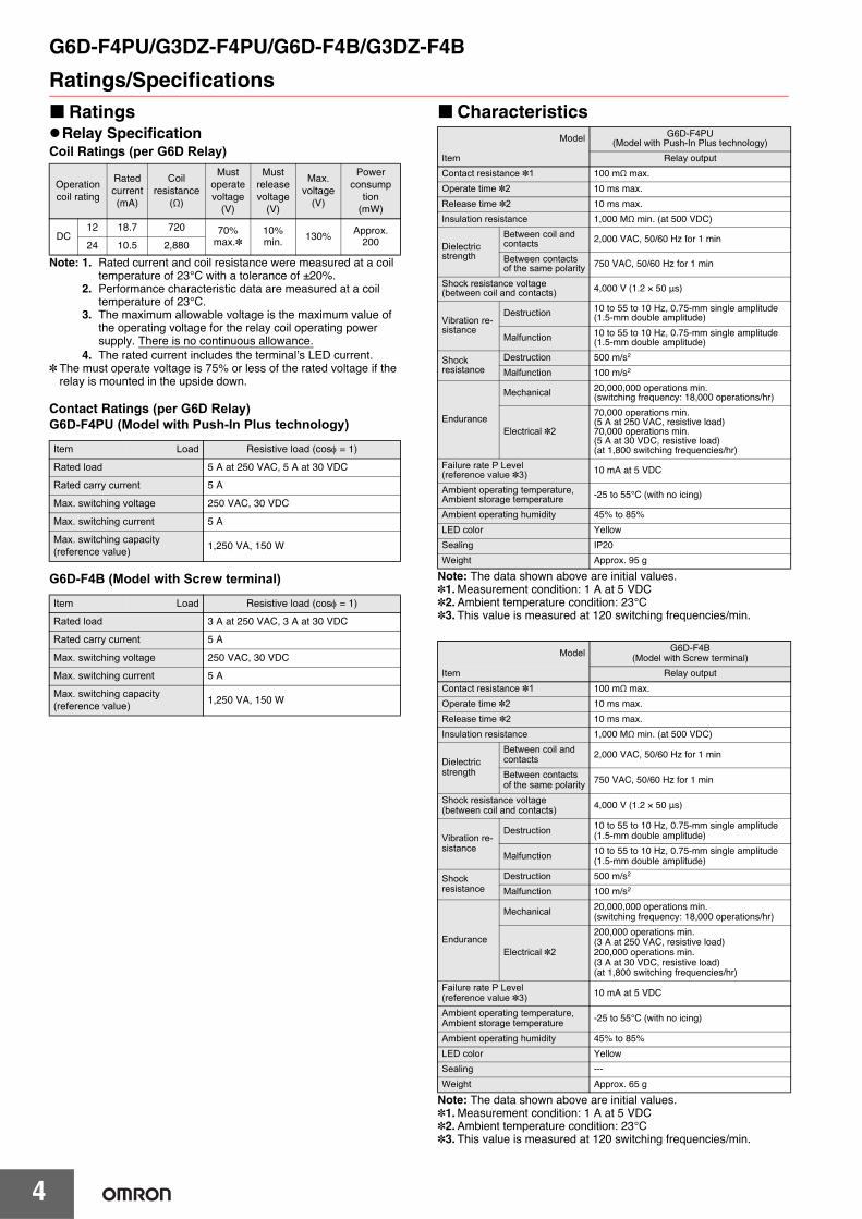
Ratings/SpecificationsRatings
Relay SpecificationCoil Ratings (per G6D Relay)
Note: 1. Rated current and coil resistance were measured at a coil temperature of 23°C with a tolerance of ±20%.
2. Performance characteristic data are measured at a coil temperature of 23°C.
3. The maximum allowable voltage is the maximum value of the operating voltage for the relay coil operating power supply. There is no continuous allowance.
4. The rated current includes the terminal’s LED current.* The must operate voltage is 75% or less of the rated voltage if the
relay is mounted in the upside down.
Contact Ratings (per G6D Relay)G6D-F4PU (Model with Push-In Plus technology)
G6D-F4B (Model with Screw terminal)
Characteristics
Note: The data shown above are initial values.*1. Measurement condition: 1 A at 5 VDC*2. Ambient temperature condition: 23°C*3. This value is measured at 120 switching frequencies/min.
Note: The data shown above are initial values.*1. Measurement condition: 1 A at 5 VDC*2. Ambient temperature condition: 23°C*3. This value is measured at 120 switching frequencies/min.
Operation coil rating
Rated current (mA)
Coil resistance
(Ω)
Must operate voltage
(V)
Must release voltage
(V)
Max.voltage
(V)
Power consump
tion(mW)
DC12 18.7 720 70%
max.*10% min.
130%Approx.
20024 10.5 2,880
Item Load Resistive load (cosφ = 1)
Rated load 5 A at 250 VAC, 5 A at 30 VDC
Rated carry current 5 A
Max. switching voltage 250 VAC, 30 VDC
Max. switching current 5 A
Max. switching capacity (reference value)
1,250 VA, 150 W
Item Load Resistive load (cosφ = 1)
Rated load 3 A at 250 VAC, 3 A at 30 VDC
Rated carry current 5 A
Max. switching voltage 250 VAC, 30 VDC
Max. switching current 5 A
Max. switching capacity (reference value)
1,250 VA, 150 W
Model G6D-F4PU (Model with Push-In Plus technology)
Item Relay output
Contact resistance *1 100 mΩ max.
Operate time *2 10 ms max.
Release time *2 10 ms max.
Insulation resistance 1,000 MΩ min. (at 500 VDC)
Dielectric strength
Between coil and contacts 2,000 VAC, 50/60 Hz for 1 min
Between contacts of the same polarity 750 VAC, 50/60 Hz for 1 min
Shock resistance voltage (between coil and contacts) 4,000 V (1.2 × 50 μs)
Vibration re-sistance
Destruction 10 to 55 to 10 Hz, 0.75-mm single amplitude (1.5-mm double amplitude)
Malfunction 10 to 55 to 10 Hz, 0.75-mm single amplitude (1.5-mm double amplitude)
Shock resistance
Destruction 500 m/s2
Malfunction 100 m/s2
Endurance
Mechanical 20,000,000 operations min. (switching frequency: 18,000 operations/hr)
Electrical *2
70,000 operations min. (5 A at 250 VAC, resistive load)70,000 operations min. (5 A at 30 VDC, resistive load)(at 1,800 switching frequencies/hr)
Failure rate P Level (reference value *3) 10 mA at 5 VDC
Ambient operating temperature, Ambient storage temperature -25 to 55°C (with no icing)
Ambient operating humidity 45% to 85%
LED color Yellow
Sealing IP20
Weight Approx. 95 g
Model G6D-F4B (Model with Screw terminal)
Item Relay output
Contact resistance *1 100 mΩ max.
Operate time *2 10 ms max.
Release time *2 10 ms max.
Insulation resistance 1,000 MΩ min. (at 500 VDC)
Dielectric strength
Between coil and contacts 2,000 VAC, 50/60 Hz for 1 min
Between contacts of the same polarity 750 VAC, 50/60 Hz for 1 min
Shock resistance voltage (between coil and contacts) 4,000 V (1.2 × 50 μs)
Vibration re-sistance
Destruction 10 to 55 to 10 Hz, 0.75-mm single amplitude (1.5-mm double amplitude)
Malfunction 10 to 55 to 10 Hz, 0.75-mm single amplitude (1.5-mm double amplitude)
Shock resistance
Destruction 500 m/s2
Malfunction 100 m/s2
Endurance
Mechanical 20,000,000 operations min. (switching frequency: 18,000 operations/hr)
Electrical *2
200,000 operations min. (3 A at 250 VAC, resistive load)200,000 operations min. (3 A at 30 VDC, resistive load)(at 1,800 switching frequencies/hr)
Failure rate P Level (reference value *3) 10 mA at 5 VDC
Ambient operating temperature, Ambient storage temperature -25 to 55°C (with no icing)
Ambient operating humidity 45% to 85%
LED color Yellow
Sealing ---
Weight Approx. 65 g

G6D-F4PU/G3DZ-F4PU/G6D-F4B/G3DZ-F4B
5
RatingsPower MOS FET Relay Specifications
Input (per G3DZ Power MOS FET Relay)
Note: The rated current includes the terminal’s LED current.
Output (per G3DZ Power MOS FET Relay)
Note: There is no output polarity for the G3DZ.
Characteristics
Rated voltage
Operating voltage
Must operate
voltage level
Must release
voltage level
Input impedance
Rated current
DC
129.6 to 14.4 VDC
9.6 VDC max.
1 VDC min.
2 kΩ ±20%8.0 mA ±20%
2419.2 to 28.8 VDC
19.2 VDC max.
4 kΩ ±20%8.2 mA ±20%
Rated operating voltage
Load voltage range
Load currentInrush current
resistance
5 to 240 VAC5 to 100 VDC
3 to 264 VAC3 to 125 VDC
100 μ to 0.3 A 6 A (10 ms)
ModelG3DZ-F4PU
(Model with Push-In Plus technology)
Item Power MOS FET relay output
Must operate time 10 ms max.
Release time 15 ms max.
Output ON-resistance 2.4 Ω max.
Leakage current at OFF state 10 μA max. (at 125 VDC)
Insulation resistance 100 MΩ min. (at 500 VDC)
Dielectric strength between I/O 2,000 VAC, 50/60 Hz for 1 min
Vibration resistance10 to 55 to 10 Hz, 0.75-mm single amplitude (1.5-mm double amplitude)
Shock resistance 500 m/s2
Ambient operating temperature, Ambient storage temperature
-25 to 55°C (with no icing)
Ambient operating humidity 45% to 85%
LED color Yellow
Sealing IP20
Weight Approx. 95 g
ModelG3DZ-F4B
(Model with Screw terminal)
Item Power MOS FET relay output
Must operate time 10 ms max.
Release time 15 ms max.
Output ON-resistance 2.4 Ω max.
Leakage current at OFF state 10 μA max. (at 125 VDC)
Insulation resistance 100 MΩ min. (at 500 VDC)
Dielectric strength between I/O 2,000 VAC, 50/60 Hz for 1 min
Vibration resistance10 to 55 to 10 Hz, 0.75-mm single amplitude (1.5-mm double amplitude)
Shock resistance 500 m/s2
Ambient operating temperature, Ambient storage temperature
-25 to 55°C (with no icing)
Ambient operating humidity 45% to 85%
LED color Yellow
Sealing ---
Weight Approx. 65 g
G6D-F4PU/G3DZ-F4PU/G6D-F4B/G3DZ-F4B
6
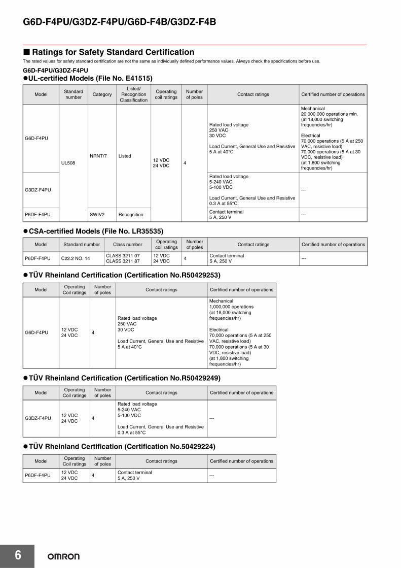
Ratings for Safety Standard CertificationThe rated values for safety standard certification are not the same as individually defined performance values. Always check the specifications before use.
G6D-F4PU/G3DZ-F4PUUL-certified Models (File No. E41515)
CSA-certified Models (File No. LR35535)
TÜV Rheinland Certification (Certification No.R50429253)
TÜV Rheinland Certification (Certification No.R50429249)
TÜV Rheinland Certification (Certification No.50429224)
ModelStandard number
CategoryListed/
RecognitionClassification
Operating coil ratings
Number of poles
Contact ratings Certified number of operations
G6D-F4PU
UL508
NRNT/7 Listed12 VDC24 VDC
4
Rated load voltage250 VAC30 VDC
Load Current, General Use and Resistive5 A at 40°C
Mechanical20,000,000 operations min.(at 18,000 switching frequencies/hr)
Electrical70,000 operations (5 A at 250 VAC, resistive load)70,000 operations (5 A at 30 VDC, resistive load)(at 1,800 switching frequencies/hr)
G3DZ-F4PU
Rated load voltage5-240 VAC5-100 VDC
Load Current, General Use and Resistive0.3 A at 55°C
---
P6DF-F4PU SWIV2 RecognitionContact terminal5 A, 250 V
---
Model Standard number Class numberOperating coil ratings
Number of poles
Contact ratings Certified number of operations
P6DF-F4PU C22.2 NO. 14CLASS 3211 07CLASS 3211 87
12 VDC24 VDC
4Contact terminal5 A, 250 V
---
ModelOperating
Coil ratingsNumber of poles
Contact ratings Certified number of operations
G6D-F4PU12 VDC24 VDC
4
Rated load voltage250 VAC30 VDC
Load Current, General Use and Resistive5 A at 40°C
Mechanical1,000,000 operations(at 18,000 switching frequencies/hr)
Electrical70,000 operations (5 A at 250 VAC, resistive load)70,000 operations (5 A at 30 VDC, resistive load)(at 1,800 switching frequencies/hr)
ModelOperating
Coil ratingsNumber of poles
Contact ratings Certified number of operations
G3DZ-F4PU12 VDC24 VDC
4
Rated load voltage5-240 VAC5-100 VDC
Load Current, General Use and Resistive0.3 A at 55°C
---
ModelOperating
Coil ratingsNumber of poles
Contact ratings Certified number of operations
P6DF-F4PU12 VDC24 VDC
4Contact terminal5 A, 250 V
---
G6D-F4PU/G3DZ-F4PU/G6D-F4B/G3DZ-F4B
7
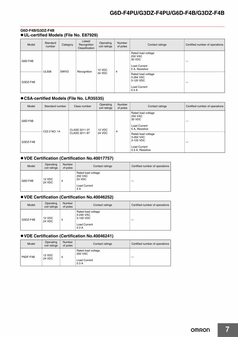
G6D-F4B/G3DZ-F4B UL-certified Models (File No. E87929)
CSA-certified Models (File No. LR35535)
VDE Certification (Certification No.40017757)
VDE Certification (Certification No.40046252)
VDE Certification (Certification No.40046241)
ModelStandard number
CategoryListed/
RecognitionClassification
Operating coil ratings
Number of poles
Contact ratings Certified number of operations
G6D-F4B
UL508 SWIV2 Recognition12 VDC24 VDC
4
Rated load voltage250 VAC30 VDC
Load Current5 A, Resistive
---
G3DZ-F4B
Rated load voltage3-264 VAC3-125 VDC
Load Current0.3 A
---
Model Standard number Class numberOperating coil ratings
Number of poles
Contact ratings Certified number of operations
G6D-F4B
C22.2 NO. 14CLASS 3211 07CLASS 3211 87
12 VDC24 VDC
4
Rated load voltage250 VAC30 VDC
Load Current5 A, Resistive
---
G3DZ-F4B
Rated load voltage3-264 VAC3-125 VDC
Load Current0.3 A, Resistive
---
ModelOperating coil ratings
Number of poles
Contact ratings Certified number of operations
G6D-F4B12 VDC24 VDC
4
Rated load voltage250 VAC24 VDC
Load Current3 A
---
ModelOperating coil ratings
Number of poles
Contact ratings Certified number of operations
G3DZ-F4B12 VDC24 VDC
4
Rated load voltage5-240 VAC5-100 VDC
Load Current0.3 A
---
ModelOperating coil ratings
Number of poles
Contact ratings Certified number of operations
P6DF-F4B12 VDC24 VDC
4
Rated load voltage250 VAC
Load Current0.3 A
---
G6D-F4PU/G3DZ-F4PU/G6D-F4B/G3DZ-F4B
8
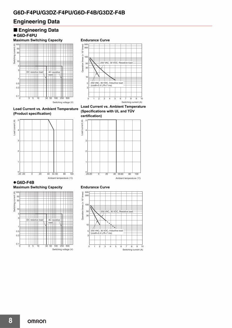
Engineering DataEngineering Data
G6D-F4PUMaximum Switching Capacity Endurance Curve
Load Current vs. Ambient Temperature (Product specification)
Load Current vs. Ambient Temperature (Specifications with UL and TÜV certification)
G6D-F4BMaximum Switching Capacity Endurance Curve
0 3 5 10 30 50 100 250 500
Switching voltage (V)
100
50
30
10
5
0.1
3
1
0.5
0.3
DC resistive load AC resistive load
Sw
itchi
ng c
urre
nt (
A)
250 VAC, 30 VDC, Inductive load (cosФ=0.4 L/R=7 ms)
0 1 2 3 4 5 6 7 8 9 10
Switching current (A)
500
300
100
30
50
10
3
5
250 VAC, 30 VDC, Resistive load
Ope
ratio
n tim
es (
× 1
04 tim
es)
-25 -20 0 20 40 55 60 80 100
Ambient temperature (˚C)
5
4
3
2
1
0
Load
cur
rent
(A
)
-25-20 0 20 40 55 60 80 100
Ambient temperature (˚C)
5
4
3
2
1
0
Load
cur
rent
(A
)
0 3 5 10 30 50 100 250 500
100
50
30
10
5
0.1
3
1
0.5
0.3
Switching voltage (V)
DC resistive load AC resistive load
Sw
itchi
ng c
urre
nt (
A)
0 1 2 3 4 5 6 7 8 9 10
500
300
100
30
50
10
3
5 250 VAC, 30 VDC, Inductive load (cosФ=0.4 L/R=7 ms)
Switching current (A)
250 VAC, 30 VDC, Resistive load
Ope
ratio
n tim
es (
× 1
04 tim
es)
G6D-F4PU/G3DZ-F4PU/G6D-F4B/G3DZ-F4B
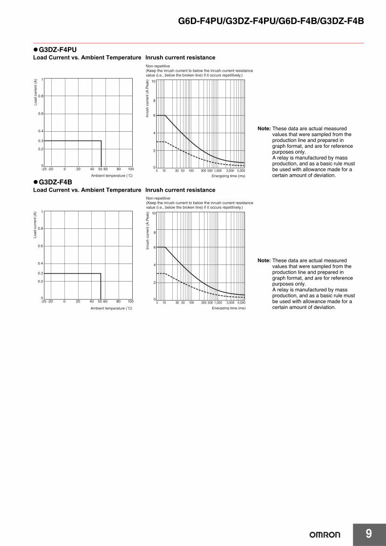
9
G3DZ-F4PULoad Current vs. Ambient Temperature Inrush current resistance
G3DZ-F4BLoad Current vs. Ambient Temperature Inrush current resistance
-25 -20 0 20 40 55 60 80 100
1
0.8
0.6
0.4
0.3
0.2
0
Ambient temperature (˚C)
Load
cur
rent
(A
)
10
8
6
4
2
0 5 10 30 50 100 300 500 1,000 3,000 5,000
Non-repetitive(Keep the inrush current to below the inrush current resistance value (i.e., below the broken line) if it occurs repetitively.)
Energizing time (ms)
Inru
sh c
urre
nt (
A.P
eak)
Note: These data are actual measured values that were sampled from the production line and prepared in graph format, and are for reference purposes only. A relay is manufactured by mass production, and as a basic rule must be used with allowance made for a certain amount of deviation.
-25 -20 0 20 40 55 60 80 100
1
0.8
0.6
0.4
0.3
0.2
0
Ambient temperature (˚C)
Load
cur
rent
(A
) 10
8
6
4
2
0 5 10 30 50 100 300 500 1,000 3,000 5,000
Non-repetitive(Keep the inrush current to below the inrush current resistance value (i.e., below the broken line) if it occurs repetitively.)
Energizing time (ms)
Inru
sh c
urre
nt (
A.P
eak)
Note: These data are actual measured values that were sampled from the production line and prepared in graph format, and are for reference purposes only. A relay is manufactured by mass production, and as a basic rule must be used with allowance made for a certain amount of deviation.
G6D-F4PU/G3DZ-F4PU/G6D-F4B/G3DZ-F4B
10
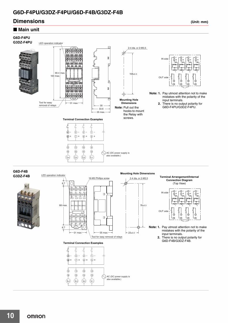
Dimensions (Unit: mm)
Main unit
12
16
L4
+
-
+
-
+
-
+
-4
8
4
8
3
7
2
6
1
5
11
15
L3
10
14
L2
9
13
L1
AC (DC power supply is also available.)
G6D-F4PUG3DZ-F4PU
31 max.
2-4 dia. or 2-M3.5
Tool for easy removal of relays
LED operation indicator
108±0.3
3033.6
35 max.
100 max.90.4 max.
12
1
16
11
15
10
14
9
13
2 3 4
IN side
OUT side
1
5 +-2
6 +-3
7 +-4
8 +-
Mounting Hole Dimensions
Terminal Connection Examples
Note: 1. Pay utmost attention not to make mistakes with the polarity of the input terminals.
2. There is no output polarity for G6D-F4PU/G3DZ-F4PU.Note: Pull out the
hooks to mount the Relay with screws.
G6D-F4BG3DZ-F4B
4 3 2 1
12 11 10 9
16 15 14 13
8
1
RY1 RY2 RY3 RY4
OUT
IN
7 6 5
2 3 4
68 max.
8.7
2-4 dia. or 2-M3.5
8.7
31 max. 35 max.
16-M3 Phillips screw
76±0.3
23±0.3
Tool for easy removal of relays
LED operation indicator
12
1
16
11
15
10
14
9
13
2 3 4
IN side
OUT side
1
5 +-2
6 +-3
7 +-4
8 +-
Mounting Hole DimensionsTerminal Arrangement/Internal
Connection Diagram(Top View)
Note: 1. Pay utmost attention not to make mistakes with the polarity of the input terminals.
2. There is no output polarity for G6D-F4B/G3DZ-F4B.
12
16
L4
+
-
+
-
+
-
+
-4
8
4
8
3
7
2
6
1
5
11
15
L3
10
14
L2
9
13
L1
AC (DC power supply is also available.)
Terminal Connection Examples
G6D-F4PU/G3DZ-F4PU/G6D-F4B/G3DZ-F4B
11
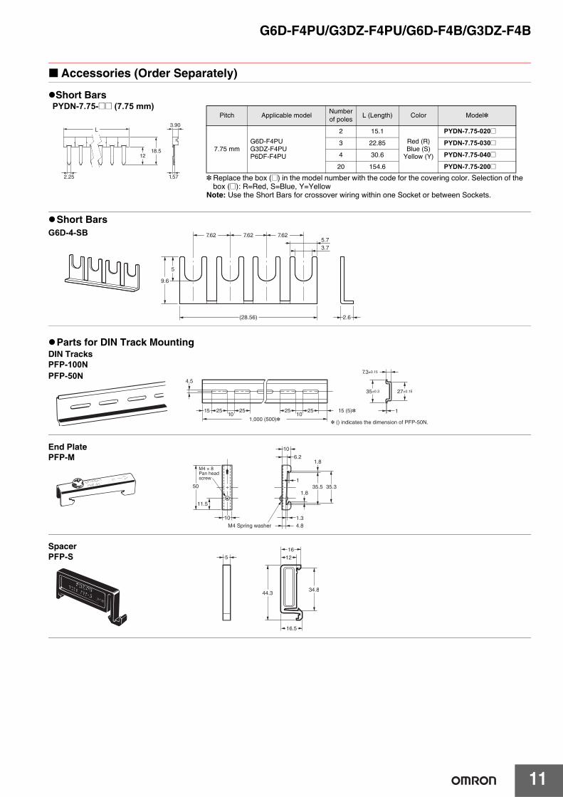
Accessories (Order Separately)
Short Bars
Short Bars
3.90L
1.572.25
1218.5
* Replace the box (@) in the model number with the code for the covering color. Selection of the box (@): R=Red, S=Blue, Y=Yellow
Note: Use the Short Bars for crossover wiring within one Socket or between Sockets.
Pitch Applicable modelNumber of poles
L (Length) Color Model*
7.75 mmG6D-F4PUG3DZ-F4PUP6DF-F4PU
2 15.1
Red (R)Blue (S)
Yellow (Y)
PYDN-7.75-020@
3 22.85 PYDN-7.75-030@
4 30.6 PYDN-7.75-040@
20 154.6 PYDN-7.75-200@
PYDN-7.75-@@ (7.75 mm)
7.62 7.62 7.62
(28.56) 2.6
5.73.7
5
9.6
G6D-4-SB
1
35±0.3
7.3±0.15
27±0.15
4.5
15 25 2510
15 (5)*10
25 25
* () indicates the dimension of PFP-50N.1,000 (500)*
Parts for DIN Track MountingDIN TracksPFP-100NPFP-50N
4.81.3
35.5 35.3
1.8
1
1.8
10
6.2
M4 Spring washer
50
11.5
M4 × 8Pan head screw
10
End PlatePFP-M
516
12
44.334.8
16.5
SpacerPFP-S

G6D-F4PU/G3DZ-F4PU/G6D-F4B/G3DZ-F4B
12
Safety PrecautionsBe sure to read the Common Precautions for All Relays in the website.
Warning Indications
Transport• Do not transport the I/O Relay Terminal under the following
locations. Doing so may occasionally result in damage,
malfunction, or deterioration of performance characteristics.
• Locations subject to water or oil• Locations subject to high temperature or high humidity
• Locations subject to condensation as the result of rapid changes
in temperature.• Do not transport a Socket when it is not packaged.
Damage or failure may occur.
Operating and Storage Environments• Do not use or store the I/O Relay Terminal in the following
locations. Doing so may result in damage, malfunction, or deterioration of performance characteristics.
• Locations subject to rainwater or water splashes.
• Locations subject to exposure to water, oil, or chemicals.• Locations subject to high temperature or high humidity.
• Storage at locations subject to ambient temperatures outside the
range -25 to 55°C• Usage at locations subject to ambient temperatures outside the
range -25 to 55°C
• Locations subject to relative humidity outside the range 45% to 85%
• Locations subject to condensation as the result of rapid changes
in temperature.
• Locations subject to corrosive or flammable gases.• Locations subject to dust, salts, or iron, or locations where there
is salt damage
• Locations subject to direct sunlight.• Locations subject to shock or vibration.
Installation and Mounting• Mount the I/O Relay Terminal in the specified direction. Otherwise
excessive heat generated by the I/O Relay Terminal may
occasionally cause burning.
• Mount the I/O Relay Terminal firmly to a DIN Track. Otherwise, the I/O Relay Terminal may fall off.
• Do not handle the I/O Relay Terminal with oily or dusty (especially
iron dust) hands.• Make sure that there is no excessive ambient temperature rise due
to the heat generation of the I/O Relay Terminal. If the I/O Relay
Terminal is mounted inside a panel, install a fan so that the interior of the panel is fully ventilated.
Installation and Wiring• Use wires that are suited to the load current and voltage.
Otherwise, excessive heat generated by the wires may cause burning or may cause the wire covering to melt, possibly leading to
electric shock.
• Do not use wires with a damaged outer covering. it may result in electric shock or ground leakage.it may result in electric shock or
ground leakage.
• Do not wire any wiring in the same duct or conduit as power or high-tension lines. Inductive noise may damage the I/O Relay
Terminal or cause it to malfunction.
• Do not apply a voltage or current that exceeds the rating to any terminal. Doing so may result in failure or burning.
• Do not use a deforming Short Bars. Doing so may result in
damage, malfunction, or deterioration of performance characteristics.
Push-In Plus Terminal• Do not wire anything to the release holes.• Do not tilt or twist the screwdriver while it is inserted into a release
hole on the terminal. The terminal may be damaged.
• Insert a flat-blade screwdriver into the release holes at an angle. The terminal may be damaged if you insert the screwdriver straight
in.
• Do not allow the flat-blade screwdriver to fall out while it is inserted into a release hole.
• Do not bend a wire past its natural bending radius or pull on it with
excessive force. Doing so may cause the wire disconnection.• Do not insert more than one wire into each terminal insertion hole.
• To prevent wire materials from smoking or ignition, confirm wire
ratings and use the wiring materials given in the following table.
Application• Select a load within the rated values. Not doing so may result in
malfunction, failure, or burning.
• The G6D may occasionally rupture if short-circuit current flows. As
protection against accidents due to short-circuiting, be sure to
install protective devices, such as fuses and no-fuse breakers, on the power supply side.
• Use a power supply within the rated frequencies. Otherwise,
malfunction, failure, or burning may occasionally occur.• Minor electrical shock may occasionally occur if you touch the
power charging area such as the terminal wiring area. Always turn
OFF the power supply before performing wiring.
Precautions for Safe Use
Supplementary comments on what to do or
avoid doing, to use the product safely.
Precautions for Correct
Use
Supplementary comments on what to do or
avoid doing, to prevent failure to operate, malfunction, or undesirable effects on product
performance.
Precautions for Safe Use
Mounting Directions
Recommended wiresStripping length
(Ferrules not used)
0.5 to 1.5 mm2/AWG20 to 16 8 mm

G6D-F4PU/G3DZ-F4PU/G6D-F4B/G3DZ-F4B
13
• Insert Short Bars so that the protrusion part of a Short Bar comes to the wire insertion side. If the Short Bar is inserted in the upside
down direction, the Short Bar may not be inserted securely.
Recommended Ferrules and Crimp ToolsRecommended ferrules
Note: 1. Make sure that the outer diameter of the wire coating is smaller than the inner diameter of the insulation sleeve of the recommended ferrule.
2. Make sure that the ferrule processing dimensions conform to the following figures.
3. Wires of AWG24 to AWG22/0.25 mm2 to 0.34 mm2 are not certified by UL standard.
4. Do not connect a ferrule for the applicable wires (AWG17 to AWG16/1.25 mm2 to 1.5 mm2) with an adjacent terminal insertion hole.
• Do not drop the Socket or subject it to abnormal vibration or shock during transportation or mounting. Doing so may result in
deterioration of performance, malfunction, or failure.
• Use a power supply with low noise.
G6D-F4PU/G3DZ-F4PU (Model with Push-In Plus technology)
1. Connecting Wires to the Push-In Plus TerminalPart Names of the Terminal
Connecting Wires with Ferrules and Solid WiresInsert the solid wire or ferrule straight into the terminal until the end
strikes the terminal.
• If a wire is difficult to connect because it is too thin, use a flat-blade
screwdriver in the same way as when connecting stranded wire.
Connecting Stranded WiresUse the following procedure to connect the wires to the terminal.
1. Hold a flat-blade screwdriver at an angle and insert it into the release hole. The angle should be between 10° and 15°. If the flat-blade screwdriver is inserted correctly, you will feel the spring in the release hole.
2. With the flat-blade screwdriver still inserted into the release hole, insert the wire into the terminal hole until it strikes the terminal.
3. Remove the flat-blade screwdriver from the release hole.
Checking Connections• After the insertion, pull gently on the wire to make sure that it will
not come off and the wire is securely fastened to the terminal.• To prevent short circuits, insert the stripped part of a stranded or
solid wire or the conductor part of a ferrule until it is hidden inside
the terminal insertion hole.• If you use recommended ferrules, part of the conductor may be
visible after the ferrule is inserted into the terminal, but the product
insulation distance will still be satisfied.
Applicable wire Ferrules
Conductor length (mm)
Stripping length [mm]
(Ferrules used)
Recommended ferrules
(mm2) (AWG)Manufactured
by Phoenix Contact
Manufactured by
Weidmuller
Manufactured by Wago
0.25 248 10 AI0,25-8 H0.25/12 FE-0.25-8N-YE
10 12 AI0,25-10 --- ---
0.34 228 10 AI0,34-8 H0.34/12 FE-0.34-8N-TQ
10 12 AI0,34-10 --- ---
0.5 208 10 AI0,5-8 H0.5/14 FE-0.5-8N-WH
10 12 AI0,5-10 H0.5/16 FE-0.5-10N-WH
0.75 188 10 AI0,75-8 H0.75/14 FE-0.75-8N-GY
10 12 AI0,75-10 H0.75/16 FE-0.75-10N-GY
1/1.25 18/178 10 AI1-8 H1.0/14 FE-1.0-8N-RD
10 12 AI1-10 H1.0/16 FE-1.0-10N-RD
1.25/1.5 17/168 10 AI1,5-8 H1.5/14 FE-1.5-8N-BK
10 12 AI1,5-10 H1.5/16 FE-1.5-10N-BK
Recommended crimp toolCRIMPFOX6CRIMPFOX6T-FCRIMPFOX10S
PZ6 roto Variocrimp4
NG OK
8 to 10 mm
1.9 mm max. 2.6 mm max.
Precautions for Correct Use
Release hole
Terminal (insertion) hole
Short bar insertion hole
Release hole
Terminal (insertion) hole
Ferrules or solid wires
(1)(3)
(2)
(2)
Flat-blade screwdriver
Stranded wires
10° to 15°
(1) (3)

G6D-F4PU/G3DZ-F4PU/G6D-F4B/G3DZ-F4B
14
2. Removing Wires from the Push-In Plus TerminalUse the following procedure to remove wires from the terminal.
The same method is used to remove stranded wires, solid wires, and ferrules.
1. Hold a flat-blade screwdriver at an angle and insert it into the release hole.
2. With the flat-blade screwdriver still inserted into the release hole, remove the wire from the terminal insertion hole.
3. Remove the flat-blade screwdriver from the release hole.
Recommended Flat-blade ScrewdriverUse a flat-blade screwdriver to connect and remove wires.
Use the following flat-blade screwdriver.
The following table shows manufacturers and models as of 2018/Dec.
* OMRON’s exclusive purchase model XW4Z-00B is available to order as SZF 0-0,4×2,5 (manufactured by Phoenix Contact).
Relay Replacement• Use the Relay Removal Tool provided with the Unit to dismount a
Terminal Relay.
• Always turn OFF the power supply before replacing Relays.• When mounting Relays, take care to vertically insert the sockets of
relays into the contact pins properly.
• Relays with other models or other voltages cannot be mounted together.
Removing the Terminal Cover (G6D-F4B)Hold the base side of the terminal cover as shown in the diagram, and remove the terminal cover by pulling it in upward.
Mountable RelaysRelays and SSRs cannot be mounted together.
Model Manufacturer
ESD 0,40×2,5 Wera
SZS 0,4×2,5SZF 0-0,4×2,5 * Phoenix Contact
0.4×2.5×75 302 Wiha
AEF.2,5×75 Facom
210-719 Wago
SDIS 0.4×2.5×75 Weidmuller
9900 (-2.5 × 75) Vessel
(1)(3)
(2)(2)
10° to 15°
Wire
Flat-blade screwdriver(1) (3)
Side
0.4 mm
2.5 mm dia.
2.5 mm
Front
Example: G6D-F4PU

Terms and Conditions AgreementRead and understand this catalog.
Please read and understand this catalog before purchasing the products. Please consult your OMRON representative if you have any questions or comments.
Warranties.(a) Exclusive Warranty. Omron’s exclusive warranty is that the Products will be free from defects in materials and workmanship
for a period of twelve months from the date of sale by Omron (or such other period expressed in writing by Omron). Omron disclaims all other warranties, express or implied.
(b) Limitations. OMRON MAKES NO WARRANTY OR REPRESENTATION, EXPRESS OR IMPLIED, ABOUT NON-INFRINGEMENT, MERCHANTABILITY OR FITNESS FOR A PARTICULAR PURPOSE OF THE PRODUCTS. BUYER ACKNOWLEDGES THAT IT ALONE HAS DETERMINED THAT THE PRODUCTS WILL SUITABLY MEET THE REQUIREMENTS OF THEIR INTENDED USE.
Omron further disclaims all warranties and responsibility of any type for claims or expenses based on infringement by the Products or otherwise of any intellectual property right. (c) Buyer Remedy. Omron’s sole obligation hereunder shall be, at Omron’s election, to (i) replace (in the form originally shipped with Buyer responsible for labor charges for removal or replacement thereof) the non-complying Product, (ii) repair the non-complying Product, or (iii) repay or credit Buyer an amount equal to the purchase price of the non-complying Product; provided that in no event shall Omron be responsible for warranty, repair, indemnity or any other claims or expenses regarding the Products unless Omron’s analysis confirms that the Products were properly handled, stored, installed and maintained and not subject to contamination, abuse, misuse or inappropriate modification. Return of any Products by Buyer must be approved in writing by Omron before shipment. Omron Companies shall not be liable for the suitability or unsuitability or the results from the use of Products in combination with any electrical or electronic components, circuits, system assemblies or any other materials or substances or environments. Any advice, recommendations or information given orally or in writing, are not to be construed as an amendment or addition to the above warranty.
See http://www.omron.com/global/ or contact your Omron representative for published information.
Limitation on Liability; Etc.OMRON COMPANIES SHALL NOT BE LIABLE FOR SPECIAL, INDIRECT, INCIDENTAL, OR CONSEQUENTIAL DAMAGES, LOSS OF PROFITS OR PRODUCTION OR COMMERCIAL LOSS IN ANY WAY CONNECTED WITH THE PRODUCTS, WHETHER SUCH CLAIM IS BASED IN CONTRACT, WARRANTY, NEGLIGENCE OR STRICT LIABILITY.
Further, in no event shall liability of Omron Companies exceed the individual price of the Product on which liability is asserted.
Suitability of Use.Omron Companies shall not be responsible for conformity with any standards, codes or regulations which apply to the combination of the Product in the Buyer’s application or use of the Product. At Buyer’s request, Omron will provide applicable third party certification documents identifying ratings and limitations of use which apply to the Product. This information by itself is not sufficient for a complete determination of the suitability of the Product in combination with the end product, machine, system, or other application or use. Buyer shall be solely responsible for determining appropriateness of the particular Product with respect to Buyer’s application, product or system. Buyer shall take application responsibility in all cases.
NEVER USE THE PRODUCT FOR AN APPLICATION INVOLVING SERIOUS RISK TO LIFE OR PROPERTY OR IN LARGE QUANTITIES WITHOUT ENSURING THAT THE SYSTEM AS A WHOLE HAS BEEN DESIGNED TO ADDRESS THE RISKS, AND THAT THE OMRON PRODUCT(S) IS PROPERLY RATED AND INSTALLED FOR THE INTENDED USE WITHIN THE OVERALL EQUIPMENT OR SYSTEM.
Programmable Products.Omron Companies shall not be responsible for the user’s programming of a programmable Product, or any consequence thereof.
Performance Data.Data presented in Omron Company websites, catalogs and other materials is provided as a guide for the user in determining suitability and does not constitute a warranty. It may represent the result of Omron’s test conditions, and the user must correlate it to actual application requirements. Actual performance is subject to the Omron’s Warranty and Limitations of Liability.
Change in Specifications.Product specifications and accessories may be changed at any time based on improvements and other reasons. It is our practice to change part numbers when published ratings or features are changed, or when significant construction changes are made. However, some specifications of the Product may be changed without any notice. When in doubt, special part numbers may be assigned to fix or establish key specifications for your application. Please consult with your Omron’s representative at any time to confirm actual specifications of purchased Product.
Errors and Omissions.Information presented by Omron Companies has been checked and is believed to be accurate; however, no responsibility is assumed for clerical, typographical or proofreading errors or omissions.

Authorized Distributor:
In the interest of product improvement, specifications are subject to change without notice.
Cat. No. J228-E1-01 0319(0319)
© OMRON Corporation 2019 All Rights Reserved.
OMRON Corporation Industrial Automation Company
OMRON ELECTRONICS LLC2895 Greenspoint Parkway, Suite 200 Hoffman Estates, IL 60169 U.S.A.Tel: (1) 847-843-7900/Fax: (1) 847-843-7787
Regional HeadquartersOMRON EUROPE B.V.Wegalaan 67-69, 2132 JD HoofddorpThe NetherlandsTel: (31)2356-81-300/Fax: (31)2356-81-388
Contact: www.ia.omron.comKyoto, JAPAN
OMRON ASIA PACIFIC PTE. LTD.No. 438A Alexandra Road # 05-05/08 (Lobby 2), Alexandra Technopark, Singapore 119967Tel: (65) 6835-3011/Fax: (65) 6835-2711
OMRON (CHINA) CO., LTD.Room 2211, Bank of China Tower, 200 Yin Cheng Zhong Road, PuDong New Area, Shanghai, 200120, China CSM_1_1_0319Tel: (86) 21-5037-2222/Fax: (86) 21-5037-2200
Related Documents


