Annex to ED Decision 2012/010/R European Aviation Safety Agency Certification Specifications for Aeroplane Flight Simulation Training Devices Initial issue 4 July 2012 ‘CS-FSTD(A)’

Welcome message from author
This document is posted to help you gain knowledge. Please leave a comment to let me know what you think about it! Share it to your friends and learn new things together.
Transcript

Annex to ED Decision 2012/010/R
European Aviation Safety Agency
Certification Specifications for Aeroplane Flight Simulation
Training Devices
Initial issue
4 July 2012
‘CS-FSTD(A)’

Annex to ED Decision 2012/010/R
Page 2 of 154
Table of contents
CS-FSTD(A) Book 1 - Certification Specifications ............................................... 3
SUBPART A - APPLICABILITY ................................................................................ 4
SUBPART B - TERMINOLOGY ................................................................................ 5
SUBPART C – AEROPLANE FLIGHT SIMULATION TRAINING DEVICES ........................ 7
APPENDICES ...................................................................................................... 8
Appendix 1 to CS FSTD(A).300 Flight Simulation Training Device Standards ......... 8
CS-FSTD(A) Book 2 - Acceptable Means of Compliance .................................... 26
SUBPART B – TERMINOLOGY ............................................................................. 27
AMC1 FSTD(A).200 Terminology and abbreviations .......................................... 27
SUBPART C – AEROPLANE FLIGHT SIMULATION TRAINING DEVICES ...................... 36
AMC1 FSTD(A).300 Qualification basis ............................................................ 36
Appendix 1 to AMC1 FSTD(A).300 Validation test tolerances ........................ 117
Appendix 2 to AMC1 FSTD(A).300 Validation data roadmap .......................... 119
Appendix 3 to AMC1 FSTD(A).300 Data requirements for alternate engines -
approval guidelines (applicable to full flight simulators only) .......................... 121
Appendix 4 to AMC1 FSTD(A).300 Data requirements for alternate avionics
(flight-related computers & controllers) – approval guidelines ........................ 123
Appendix 5 to AMC1 FSTD(A).300 Transport delay and latency testing methods
.............................................................................................................. 125
Appendix 6 to AMC1 FSTD(A).300 Recurrent evaluations - validation test data
presentation ............................................................................................. 129
Appendix 7 to AMC1 FSTD(A).300 Applicability of CS-FSTD amendments to FSTD
data packages for existing aeroplanes ......................................................... 130
Appendix 8 to AMC1 FSTD(A).300 General technical requirements for FSTD
qualification levels .................................................................................... 132
AMC2 FSTD(A).300 Guidance on design and qualification of level 'A' aeroplane full
flight simulators (FFSs) ................................................................................ 136
AMC3 FSTD(A).300 Guidance on design and qualification of flight and navigation
procedures trainers (FNPTs) .......................................................................... 138
AMC4 FSTD(A).300 Guidance on design and qualification of basic instrument
training devices (BITDs) ............................................................................... 143
AMC5 FSTD(A).300 Guidance on enhanced visual system (EVS) and qualification of
full flight simulators (FFSs) ........................................................................... 147
AMC6 FSTD(A).300 Guidance on old visual systems and new visual scenes for full
flight simulators (FFSs) ................................................................................ 150
AMC7 FSTD(A).300 Engineering simulator validation data ............................... 151
AMC8 FSTD(A).300 Engineering simulator validation data – approval guidelines 152

Annex to ED Decision 2012/010/R
Page 3 of 154
Certification Specifications
for
Aeroplane
Flight Simulation Training Devices
CS-FSTD(A)
Book 1

Annex to ED Decision 2012/010/R
Page 4 of 154
SUBPART A - APPLICABILITY
CS FSTD(A).001 Applicability
(a) CS-FSTD(A) as amended applies to approved training organisations operating a flight simulation training device (FSTD) or in the case of BITDs only, manufacturers seeking initial qualification of FSTDs.
(b) The version of the CS-FSTD(A) agreed by the competent authority and used for the issue of the initial qualification shall be applicable for future recurrent qualifications of the FSTD, unless recategorised.

Annex to ED Decision 2012/010/R
Page 5 of 154
SUBPART B - TERMINOLOGY
CS FSTD(A).200 Terminology
Because of the technical complexity of FSTD qualification, it is essential that standard terminology is used throughout. The following principal terms and abbreviations should be used in order to comply with CS–FSTD(A). Further terms and abbreviations are contained in AMC1 FSTD(A).200.
(a) ‘Flight simulation training device (FSTD)’ means a training device which is:
In the case of aeroplanes, a full flight simulator (FFS), a flight training device (FTD), a flight navigation procedures trainer (FNPT), or a basic instrument training device (BITD).
In the case of helicopters, a full flight simulator (FFS), a flight training device (FTD) or a flight navigation procedures trainer (FNPT).
(b) ‘Full flight simulator (FFS)’ means a full size replica of a specific type or make, model and series aircraft flight deck/cockpit, including the assemblage of all equipment and computer programmes necessary to represent the aeroplane in ground and flight operations, a visual system providing an out of the flight deck/cockpit view, and a force cueing motion system. It is in compliance with the minimum standards for FFS qualification.
(c) ‘Flight training device (FTD)’ means a full size replica of a specific aircraft type’s instruments, equipment, panels and controls in an open flight deck/cockpit area or an enclosed aircraft flight deck/cockpit, including the assemblage of equipment and computer software programmes necessary to represent the aircraft in ground and flight conditions to the extent of the systems installed in the device. It does not require a force cueing motion or visual system. It is in compliance with the minimum standards for a specific FTD level of qualification.
(d) ‘Flight and navigation procedures trainer (FNPT)’ means a training device which represents the flight deck/cockpit environment including the assemblage of equipment and computer programmes necessary to represent an aircraft or class of aeroplane in flight operations to the extent that the systems appear to function as in an aircraft. It is in compliance with the minimum standards for a specific FNPT level of qualification.
(e) ‘Basic instrument training device (BITD)’ means a ground-based training device which represents the student pilot’s station of a class of aeroplanes. It may use screen based instrument panels and spring loaded flight controls, providing a training platform for at least the procedural aspects of instrument flight.
(f) ‘Other training device (OTD)’ means a training aid other than an FSTD which provides for training where a complete flight deck/cockpit environment is not necessary.
(g) ‘Flight simulation training device user (FSTD user)’ means the organisation or person requesting training, checking or testing through the use of an FSTD.
(h) ‘Flight simulation training device qualification (FSTD qualification)’ means the level of technical ability of an FSTD as defined in the compliance document.
(i) ‘BITD manufacturer’ means that organisation or enterprise being directly responsible to the competent authority for requesting the initial BITD model qualification.
(j) ‘BITD model’ means a defined hardware and software combination, which has obtained a qualification. Each BITD will equate to a specific model and be a serial numbered unit.

Annex to ED Decision 2012/010/R
Page 6 of 154
(k) ‘Qualification test guide (QTG)’ means a document designed to demonstrate that the performance and handling qualities of an FSTD are within prescribed limits with those of the aircraft, class of aeroplane or type of helicopter and that all applicable requirements have been met. The QTG includes both the data of the aircraft, class of aeroplane or type of helicopter and FSTD data used to support the validation.
Annex to ED Decision 2012/010/R
Page 7 of 154
SUBPART C – AEROPLANE FLIGHT SIMULATION TRAINING DEVICES
CS FSTD(A).300 Qualification basis
(a) Any FSTD submitted for initial evaluation shall be evaluated against applicable CS–FSTD(A) criteria for the qualification levels applied for. Recurrent evaluations of an FSTD shall be based on the same version of CS-FSTD(A) that was applicable for its initial evaluation. An upgrade shall be based on the currently applicable version of CS-FSTD(A).
(b) An FSTD shall be assessed in those areas that are essential to completing the flight crew member training, testing and checking process as applicable.
(c) The FSTD shall be subjected to:
(1) validation tests; and
(2) functions and subjective tests.
(d) The QTG, including all data, supporting material and information should be submitted in a format to allow efficient review and evaluation before the FSTD can gain a qualification level. Where applicable, the QTG should be based on the aircraft validation data as defined by the operational suitability data (OSD) established in accordance with Part-21.

Annex to ED Decision 2012/010/R
Page 8 of 154
APPENDICES
Appendix 1 to CS FSTD(A).300 Flight Simulation Training Device Standards
This Appendix describes the minimum full flight simulator (FFS), flight training device (FTD), flight and navigation procedures trainer (FNPT) and basic instrument training devices (BITD) requirements for qualifying devices to the required qualification levels. Certain requirements included in this CS should be supported with a statement of compliance (SOC) and, in some designated cases, an objective test. The SOC shall describe how the requirement was met. The test results should show that the requirement has been attained. In the following tabular listing of FSTD standards, statements of compliance are indicated in the compliance column.
For FNPT use in multi-crew cooperation (MCC) training the general technical requirement are expressed in the MCC column with additional systems, instrumentation and indicators as required for MCC training and operation.
For MCC the minimum technical requirements are as for FNPT level II, with the following additions or amendments:
1 Turbo-jet or turbo-prop engines
2 Performance reserves, in the case of an engine failure, to be in accordance with CS-25. These may be simulated by a reduction in the aeroplane gross mass
3 Retractable landing gear
4 Pressurisation system
5 De-icing systems
6 Fire detection / suppression system
7 Dual controls
8 Autopilot with automatic approach mode
9 2 VHF transceivers including oxygen masks intercom system
10 2 VHF NAV receivers (VOR, ILS, DME)
11 1 ADF receiver
12 1 Marker receiver
13 1 transponder
The following indicators shall be located in the same positions on the instrument panels of both pilots:
1 Airspeed
2 Flight attitude with flight director
3 Altimeter
4 Flight director with ILS (HSI)
5 Vertical speed
6 ADF
7 VOR
8 Marker indication (as appropriate)
9 Stop watch (as appropriate)
Annex to ED Decision 2012/010/R
Page 9 of 154
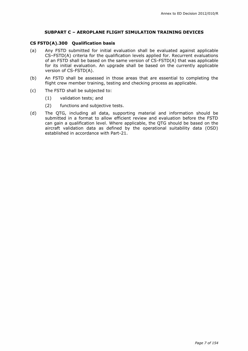
FLIGHT SIMULATION TRAINING DEVICE STANDARDS
FFS LEVEL FTD LEVEL
FNPT LEVEL BITD COMPLIANCE
A B C D 1 2 I II MCC
1. General
a.1 A fully enclosed flight deck.
a.2 A cockpit/flight deck sufficiently enclosed to exclude distraction, which will replicate that of the aeroplane or class of aeroplane simulated.
a.3 Flight deck, a full scale replica
of the aeroplane simulated.
Equipment for operation of the cockpit windows shall be included in the FSTD, but the actual windows need not be operable.
The flight deck, for FSTD purposes, consists of all that space forward of a cross section of the fuselage at the most extreme aft setting of the pilots’ seats. Additional required flight crew member duty stations and those required bulkheads aft of the pilot seats are also considered part of the flight deck and shall replicate the aeroplane.
Flight deck observer seats are not considered
to be additional flight crew member duty stations and may be omitted.
Bulkheads containing items such as switches, circuit breakers, supplementary radio panels, etc. to which the flight crew may require access during any event after preflight cockpit preparation is complete are considered essential and may not be omitted.
Bulkheads containing only items such as landing gear pin storage compartments, fire axes or extinguishers, spare light bulbs, aircraft document pouches etc. are not considered essential and may be omitted. Such items, or reasonable facsimile, shall still be available in the FSTD but may be relocated to a suitable location as near as practical to the original position. Fire axes and any similar purpose instruments need only be represented in silhouette.
a.4 Direction of movement of controls and switches identical to that in the aeroplane.
a.5 A full size panel of replicated system(s) which will have actuation of controls and switches that replicate those of the aeroplane simulated.
The use of electronically displayed images with physical overlay incorporating operable switches, knobs, buttons replicating aeroplane instruments panels may be acceptable to the competent authority.
Annex to ED Decision 2012/010/R
Page 10 of 154
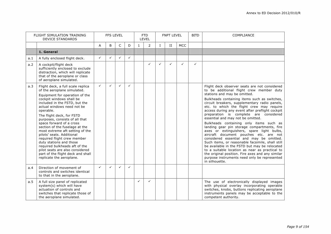
FLIGHT SIMULATION TRAINING DEVICE STANDARDS
FFS LEVEL FTD LEVEL
FNPT LEVEL BITD COMPLIANCE
A B C D 1 2 I II MCC
a.6 Cockpit/flight deck switches, instruments, equipment, panels, systems, primary and secondary flight controls sufficient for the training events to be accomplished shall be located in a spatially correct flight deck area and will operate as, and represent those in, that aeroplane or class of aeroplane.
For Multi-Crew Cooperation (MCC) qualification additional instrumentation and indicators may be required. See table at start of this Appendix.
For BITDs the switches and controls size and shape and their location in the cockpit shall be representative.
a.7 Crew members’ seats shall be provided with sufficient adjustment to allow the occupant to achieve the design eye reference position appropriate to the aeroplane or class of aeroplane and for the visual system to be installed to align with that eye position.
b.1 Circuit breakers that affect procedures and/or result in observable cockpit indications properly located and functionally accurate.
c.1 Flight dynamics model that accounts for various combinations of drag and thrust normally encountered in flight corresponding to actual flight conditions, including the effect of change in aeroplane attitude, sideslip, thrust, drag, altitude, temperature, gross weight, moments of inertia, centre of gravity location, and configuration.
For FTD levels 1 and 2 aerodynamic modelling sufficient to permit accurate systems operation and indication is acceptable.
For FNPTs and BITDs class-specific modelling is acceptable.
Annex to ED Decision 2012/010/R
Page 11 of 154
FLIGHT SIMULATION TRAINING DEVICE STANDARDS
FFS LEVEL FTD LEVEL
FNPT LEVEL BITD COMPLIANCE
A B C D 1 2 I II MCC
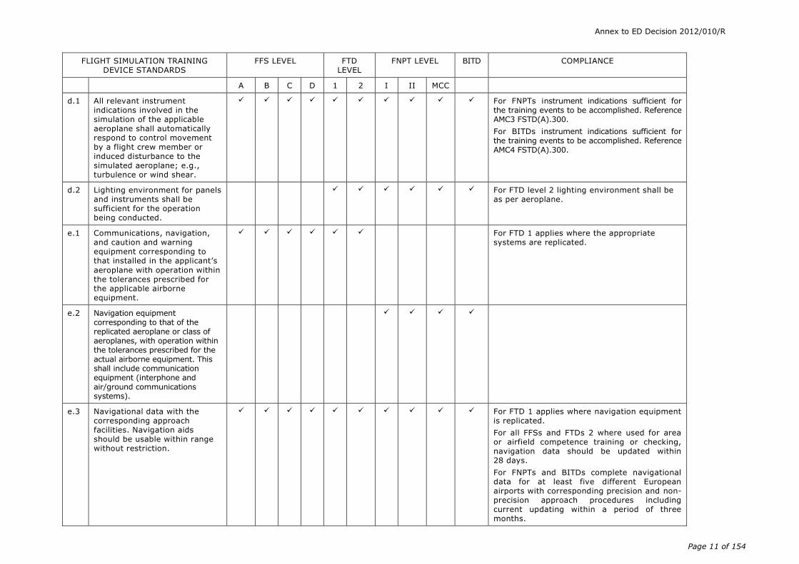
d.1 All relevant instrument indications involved in the simulation of the applicable aeroplane shall automatically respond to control movement by a flight crew member or induced disturbance to the simulated aeroplane; e.g., turbulence or wind shear.
For FNPTs instrument indications sufficient for the training events to be accomplished. Reference AMC3 FSTD(A).300.
For BITDs instrument indications sufficient for the training events to be accomplished. Reference AMC4 FSTD(A).300.
d.2 Lighting environment for panels and instruments shall be sufficient for the operation being conducted.
For FTD level 2 lighting environment shall be as per aeroplane.
e.1 Communications, navigation, and caution and warning equipment corresponding to that installed in the applicant’s
aeroplane with operation within the tolerances prescribed for the applicable airborne equipment.
For FTD 1 applies where the appropriate systems are replicated.
e.2 Navigation equipment corresponding to that of the replicated aeroplane or class of aeroplanes, with operation within the tolerances prescribed for the actual airborne equipment. This shall include communication equipment (interphone and air/ground communications systems).
e.3 Navigational data with the corresponding approach facilities. Navigation aids should be usable within range without restriction.
For FTD 1 applies where navigation equipment is replicated.
For all FFSs and FTDs 2 where used for area or airfield competence training or checking, navigation data should be updated within 28 days.
For FNPTs and BITDs complete navigational data for at least five different European airports with corresponding precision and non-precision approach procedures including current updating within a period of three months.
Annex to ED Decision 2012/010/R
Page 12 of 154
FLIGHT SIMULATION TRAINING DEVICE STANDARDS
FFS LEVEL FTD LEVEL
FNPT LEVEL BITD COMPLIANCE
A B C D 1 2 I II MCC
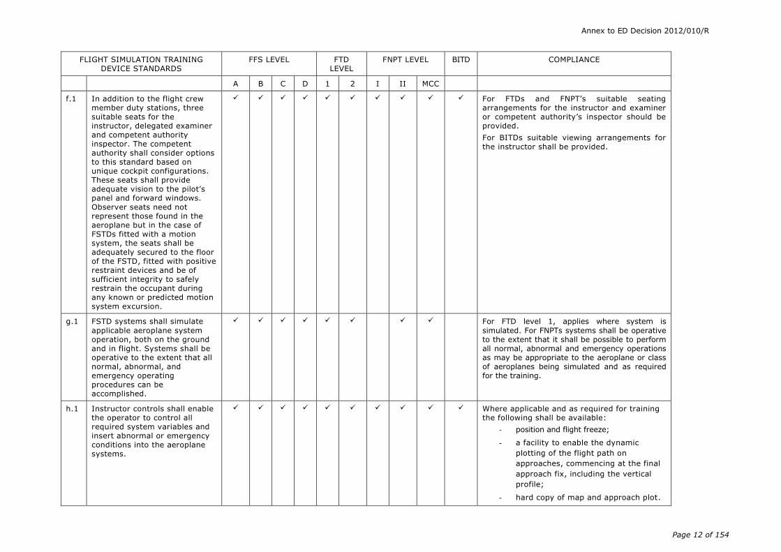
f.1 In addition to the flight crew member duty stations, three suitable seats for the instructor, delegated examiner and competent authority inspector. The competent authority shall consider options to this standard based on unique cockpit configurations. These seats shall provide adequate vision to the pilot’s panel and forward windows. Observer seats need not represent those found in the aeroplane but in the case of FSTDs fitted with a motion system, the seats shall be adequately secured to the floor of the FSTD, fitted with positive restraint devices and be of sufficient integrity to safely restrain the occupant during any known or predicted motion system excursion.
For FTDs and FNPT’s suitable seating arrangements for the instructor and examiner or competent authority’s inspector should be provided.
For BITDs suitable viewing arrangements for the instructor shall be provided.
g.1 FSTD systems shall simulate
applicable aeroplane system operation, both on the ground and in flight. Systems shall be operative to the extent that all normal, abnormal, and emergency operating procedures can be accomplished.
For FTD level 1, applies where system is
simulated. For FNPTs systems shall be operative to the extent that it shall be possible to perform all normal, abnormal and emergency operations as may be appropriate to the aeroplane or class of aeroplanes being simulated and as required for the training.
h.1 Instructor controls shall enable the operator to control all required system variables and insert abnormal or emergency conditions into the aeroplane systems.
Where applicable and as required for training the following shall be available:
- position and flight freeze;
- a facility to enable the dynamic
plotting of the flight path on
approaches, commencing at the final
approach fix, including the vertical
profile;
- hard copy of map and approach plot.
Annex to ED Decision 2012/010/R
Page 13 of 154
FLIGHT SIMULATION TRAINING DEVICE STANDARDS
FFS LEVEL FTD LEVEL
FNPT LEVEL BITD COMPLIANCE
A B C D 1 2 I II MCC
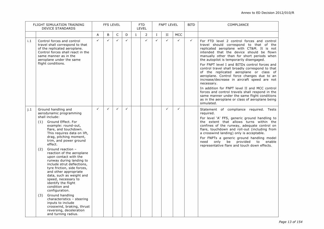
i.1 Control forces and control travel shall correspond to that of the replicated aeroplane. Control forces shall react in the same manner as in the aeroplane under the same flight conditions.
For FTD level 2 control forces and control travel should correspond to that of the replicated aeroplane with CT&M. It is not intended that the device should be flown manually other than for short periods when the autopilot is temporarily disengaged.
For FNPT level I and BITDs control forces and control travel shall broadly correspond to that of the replicated aeroplane or class of aeroplane. Control force changes due to an increase/decrease in aircraft speed are not necessary.
In addition for FNPT level II and MCC control forces and control travels shall respond in the same manner under the same flight conditions as in the aeroplane or class of aeroplane being simulated.
j.1 Ground handling and aerodynamic programming shall include:
(1) Ground Effect. For example: round-out, flare, and touchdown. This requires data on lift, drag, pitching moment,
trim, and power ground effect.
(2) Ground reaction – reaction of the aeroplane upon contact with the runway during landing to include strut deflections, tyre friction, side forces, and other appropriate data, such as weight and speed, necessary to identify the flight condition and configuration.
(3) Ground handling characteristics – steering inputs to include crosswind, braking, thrust reversing, deceleration and turning radius.
Statement of compliance required. Tests required.
For level ‘A’ FFS, generic ground handling to the extent that allows turns within the confines of the runway, adequate control on flare, touchdown and roll-out (including from a crosswind landing) only is acceptable.
For FNPTs a generic ground handling model
need only be provided to enable representative flare and touch down effects.

Annex to ED Decision 2012/010/R
Page 14 of 154
FLIGHT SIMULATION TRAINING DEVICE STANDARDS
FFS LEVEL FTD LEVEL
FNPT LEVEL BITD COMPLIANCE
A B C D 1 2 I II MCC
k.1
Wind shear models shall provide training in the specific skills required for recognition of wind shear phenomena and execution of recovery manoeuvres. Such models shall be representative of measured or accident derived winds, but may include simplifications which ensure repeatable encounters. For example, models may consist of independent variable winds in multiple simultaneous components. Wind models shall be available for the following critical phases of flight:
(1) Prior to take-off rotation
(2) At lift-off
(3) During initial climb
(4) Short final approach
Tests required.
See AMC1 FSTD(A).300, (b)(3) 2.g.
l.1 Instructor controls for environmental effects including wind speed and direction shall be provided.
For FTDs environment modelling sufficient to permit accurate systems operation and indication.
m.1 Stopping and directional control forces shall be representative for at least the following runway conditions based on aeroplane related data:
(1) Dry
(2) Wet
(3) Icy
(4) Patchy wet
(5) Patchy icy
(6) Wet on rubber residue in touchdown zone.
Statement of compliance required.
Objective tests required for (1), (2), (3); subjective check for (4), (5), (6).

Annex to ED Decision 2012/010/R
Page 15 of 154
FLIGHT SIMULATION TRAINING DEVICE STANDARDS
FFS LEVEL FTD LEVEL
FNPT LEVEL BITD COMPLIANCE
A B C D 1 2 I II MCC
n.1 Brake and tyre failure dynamics (including antiskid) and decreased brake efficiency due to brake temperatures shall be representative and based on aeroplane related data.
Statement of compliance required.
Subjective test is required for decreased braking efficiency due to brake temperature, if applicable.
o.1 A means for quickly and effectively conducting daily testing of FSTD programming and hardware shall be available.
Statement of compliance required.
p.1 Computer capacity, accuracy, resolution, and dynamic response shall be sufficient to fully support the overall fidelity, including its evaluation and testing.
Statement of compliance required.

Annex to ED Decision 2012/010/R
Page 16 of 154
FLIGHT SIMULATION TRAINING DEVICE STANDARDS
FFS LEVEL FTD LEVEL
FNPT LEVEL BITD COMPLIANCE
A B C D 1 2 I II MCC
q.1 Control feel dynamics shall replicate the aeroplane simulated.
Free response of the controls shall match that of the aeroplane within the tolerances specified. Initial and upgrade evaluations will include control free response (pitch, roll and yaw controller) measurements recorded at the controls. The measured responses shall correspond to those of the aeroplane in take-off, cruise, and landing configurations.
(1) For aeroplanes with irreversible control systems, measurements may be obtained on the ground if proper pitot static inputs are provided to represent conditions typical of those encountered in flight. Engineering validation or aeroplane manufacturer rationale will be submitted as justification to ground test or omit a configuration.
(2) For FSTDs requiring static and dynamic tests at the
controls, special test fixtures shall not be required during initial evaluation if the FSTD operator’s MQTG shows both text fixture results and alternate test method results such as computer data plots, which were obtained concurrently. Repetition of the alternate method during initial evaluation may then satisfy this requirement.
Tests required.

Annex to ED Decision 2012/010/R
Page 17 of 154
FLIGHT SIMULATION TRAINING DEVICE STANDARDS
FFS LEVEL FTD LEVEL
FNPT LEVEL BITD COMPLIANCE
A B C D 1 2 I II MCC
r.1 One of the following two methods is acceptable as a means to prove compliance:
(1) Transport Delay: A transport
delay test may be used to
demonstrate that the FSTD
system response does not
exceed 150 ms. This test
shall measure all the delay
encountered by a step signal
migrating from the pilot’s
control through the control
loading electronics and
interfacing through all the
simulation software modules
in the correct order, using a
handshaking protocol, finally
through the normal output
interfaces to the motion
system, to the visual system
and instrument displays.
(2) Latency: The visual system,
flight deck instruments and
initial motion system
response shall respond to
abrupt pitch, roll and yaw
inputs from the pilot’s
position within 150 ms of the
time, but not before the
time, when the aeroplane
would respond under the
same conditions.
Tests required.
For level ‘A’ & ‘B’ FFSs, and applicable systems for FTDs, FNPTs and BITDs the maximum permissible delay is 300 ms.

Annex to ED Decision 2012/010/R
Page 18 of 154
FLIGHT SIMULATION TRAINING DEVICE STANDARDS
FFS LEVEL FTD LEVEL
FNPT LEVEL BITD COMPLIANCE
A B C D 1 2 I II MCC
s.1 Aerodynamic modelling shall be provided. This shall include, for aeroplanes issued an original type certificate after June 1980, low altitude level flight ground effect, Mach effect at high altitude, normal and reverse dynamic thrust effect on control surfaces, aeroelastic representations, and representations of non-linearities due to sideslip based on aeroplane flight test data provided by the manufacturer.
Statement of compliance required. Mach effect, aeroelastic representations, and non-linearities due to sideslip are normally included in the FSTD aerodynamic model. The Statement of Compliance shall address each of these items. Separate tests for thrust effects and a Statement of compliance are required.
t.1 Modelling that includes the effects of airframe and engine icing.
Statement of compliance required.
SOC shall describe the effects that provide training in the specific skills required for recognition of icing phenomena and execution of recovery.
u.1 Aerodynamic and ground reaction modelling for the effects of reverse thrust on directional control shall be provided.
Statement of compliance required.
v.1 Realistic aeroplane mass
properties, including mass, centre of gravity and moments of inertia as a function of payload and fuel loading shall be implemented.
Statement of compliance required at initial
evaluation. SOC shall include a range of tabulated target values to enable a demonstration of the mass properties model to be conducted from the instructor’s station.
w.1 Self-testing for FSTD hardware and programming to determine compliance with the FSTD performance tests shall be provided. Evidence of testing shall include FSTD number, date, time, conditions, tolerances, and the appropriate dependent variables portrayed in comparison with the aeroplane standard.
Statement of compliance required. Tests required.
x.1 Timely and permanent update of hardware and programming subsequent to aeroplane modification sufficient for the qualification level sought.

Annex to ED Decision 2012/010/R
Page 19 of 154
FLIGHT SIMULATION TRAINING DEVICE STANDARDS
FFS LEVEL FTD LEVEL
FNPT LEVEL BITD COMPLIANCE
A B C D 1 2 I II MCC
y.1 Daily preflight documentation either in the daily log or in a location easily accessible for review is required.
2. Motion system
a.1 Motion cues as perceived by the pilot shall be representative of the aeroplane, e.g. touchdown cues shall be a function of the simulated rate of descent.
For FSTDs where motion systems are not specifically required, but have been added, they will be assessed to ensure that they do not adversely affect the qualification of the FSTD.
b.1 A motion system shall:
(1) provide sufficient cueing, which may be of a generic nature to accomplish the required tasks;
Statement of compliance required.
Tests required.
(2) have a minimum of 3 degrees of freedom (pitch, roll & heave); and
(3) produce cues at least equivalent to those of a six-degrees-of-freedom synergistic platform motion system.
c.1 A means of recording the motion response time as required.

Annex to ED Decision 2012/010/R
Page 20 of 154
FLIGHT SIMULATION TRAINING DEVICE STANDARDS
FFS LEVEL FTD LEVEL
FNPT LEVEL BITD COMPLIANCE
A B C D 1 2 I II MCC
d.1 Motion effects programming shall include:
(1) effects of runway rumble, oleo deflections, groundspeed, uneven runway, centreline lights and taxiway characteristics;
(2) buffets on the ground due to spoiler/speedbrake extension and thrust reversal;
(3) bumps associated with the landing gear;
(4) buffet during extension and retraction of landing gear;
(5) buffet in the air due to flap and spoiler/speedbrake extension;
(6) approach to stall buffet;
(7) touchdown cues for main and nose gear;
(8) nose wheel scuffing;
(9) thrust effect with brakes set;
(10) Mach and manoeuvre buffet;
(11) tyre failure dynamics;
(12) engine malfunction and engine damage; and
(13) tail and pod strike.
For level ‘A’ FFS: effects may be of a generic nature sufficient to accomplish the required tasks.

Annex to ED Decision 2012/010/R
Page 21 of 154
FLIGHT SIMULATION TRAINING DEVICE STANDARDS
FFS LEVEL FTD LEVEL
FNPT LEVEL BITD COMPLIANCE
A B C D 1 2 I II MCC
e.1 Motion vibrations: tests with recorded results that allow the comparison of relative amplitudes versus frequency are required.
Characteristic motion vibrations that result from operation of the aeroplane in so far as vibration marks an event or aeroplane state that can be sensed at the flight deck shall be present. The FSTD shall be programmed and instrumented in such a manner that the characteristic vibration modes can be measured and compared with aeroplane data.
Statement of compliance required.
Tests required.
3. Visual System
a.1 The visual system shall meet all the standards enumerated as applicable to the level of qualification requested by the applicant.
For FTDs, FNPT 1s and BITDs, when visual systems have been added by the FSTD operator even though not attracting specific credits, they will be assessed to ensure that they do not adversely affect the qualification of the FSTD.
For FTDs if the visual system is to be used for the training of manoeuvring by visual reference (such as route and airfield competence) then the visual system should at least comply with that required for level A FFS.
b.1 Continuous minimum collimated visual field-of-view of 45 degrees horizontal and 30 degrees vertical field of view simultaneously for each pilot.
SOC is acceptable in place of this test.

Annex to ED Decision 2012/010/R
Page 22 of 154
FLIGHT SIMULATION TRAINING DEVICE STANDARDS
FFS LEVEL FTD LEVEL
FNPT LEVEL BITD COMPLIANCE
A B C D 1 2 I II MCC
b.2 Continuous, cross-cockpit, minimum collimated visual field of view providing each pilot with 180 degrees horizontal and 40 degrees vertical field of view. Application of tolerances require the field of view to be not less than a total of 176 measured degrees horizontal field of view (including not less than 88 measured degrees
either side of the centre of the design eye point) and not less than a total of 36 measured degrees vertical field of view from the pilot’s and co-pilot’s eye points.
Consideration shall be given to optimising the vertical field of view for the respective aeroplane cut-off angle.
b.3 A visual system (night/dusk or day) capable of providing a field-of-view of a minimum of 45 degrees horizontally and 30 degrees vertically, unless restricted by the type of aeroplane, simultaneously for each pilot, including adjustable cloud base and visibility.
The visual system need not be collimated but shall be capable of meeting the standards laid down in Parts (b) and (c) (Validation, Functions and Subjective Tests - See AMC1 FSTD(A).300).
SOC is acceptable in place of this test.
c.1 A means of recording the visual response time for visual systems.
d.1 System geometry. The system fitted shall be free from optical discontinuities and artefacts that create non-realistic cues.
Test required. A statement of compliance is acceptable in place of this test.
e.1 Visual textural cues to assess sink rate and depth perception during take-off and landing shall be provided.
For level ‘A’ FFS visual cueing shall be sufficient to support changes in approach path by using runway perspective.
f.1 Horizon and attitude shall correlate to the simulated attitude indicator.
Statement of compliance required.
g.1 Occulting - a minimum of ten levels shall be available.
Occulting shall be demonstrated.
Statement of compliance required.
Annex to ED Decision 2012/010/R
Page 23 of 154
FLIGHT SIMULATION TRAINING DEVICE STANDARDS
FFS LEVEL FTD LEVEL
FNPT LEVEL BITD COMPLIANCE
A B C D 1 2 I II MCC
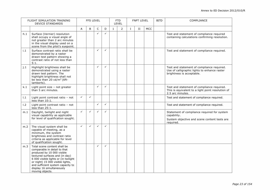
h.1 Surface (Vernier) resolution shall occupy a visual angle of not greater than 2 arc minutes in the visual display used on a scene from the pilot’s eyepoint.
Test and statement of compliance required containing calculations confirming resolution.
i.1 Surface contrast ratio shall be demonstrated by a raster drawn test pattern showing a contrast ratio of not less than 5:1.
Test and statement of compliance required.
j.1 Highlight brightness shall be demonstrated using a raster drawn test pattern. The highlight brightness shall not be less than 20 cd/m2 (6ft-lamberts).
Test and statement of compliance required. Use of calligraphic lights to enhance raster brightness is acceptable.
k.1 Light point size – not greater than 5 arc minutes.
Test and statement of compliance required. This is equivalent to a light point resolution of 2.5 arc minutes.
l.1 Light point contrast ratio – not less than 10:1.
Test and statement of compliance required.
l.2 Light point contrast ratio – not less than 25:1.
Test and statement of compliance required.
m.1 Daylight, twilight and night visual capability as applicable for level of qualification sought.
Statement of compliance required for system capability.
System objective and scene content tests are required.
m.2 The visual system shall be capable of meeting, as a minimum, the system brightness and contrast ratio criteria as applicable for level of qualification sought.
m.3 Total scene content shall be comparable in detail to that produced by 10 000 visible textured surfaces and (in day) 6 000 visible lights or (in twilight or night) 15 000 visible lights, and sufficient system capacity to display 16 simultaneously moving objects.

Annex to ED Decision 2012/010/R
Page 24 of 154
FLIGHT SIMULATION TRAINING DEVICE STANDARDS
FFS LEVEL FTD LEVEL
FNPT LEVEL BITD COMPLIANCE
A B C D 1 2 I II MCC
m.4 The system, when used in training, shall provide in daylight, full colour presentations and sufficient surfaces with appropriate textural cues to conduct a visual approach, landing and airport movement (taxi). Surface shading effects shall be consistent with simulated (static) sun position.
m.5 The system, when used in training, shall provide at twilight, as a minimum, full colour presentations of reduced ambient intensity, sufficient surfaces with appropriate textural cues that include self-illuminated objects such as road networks, ramp lighting and airport signage, to conduct a visual approach, landing and airport movement (taxi). Scenes shall include a definable horizon and typical terrain
characteristics such as fields, roads and bodies of water and surfaces illuminated by representative ownship lighting (e.g. landing lights). If provided, directional horizon lighting shall have correct orientation and be consistent with surface shading effects.
m.6 The system, when used in training, shall provide at night, as a minimum, all features applicable to the twilight scene, as defined above, with the exception of the need to portray reduced ambient intensity that removes ground cues that are not self-illuminating or illuminated by ownship lights (e.g. landing lights).

Annex to ED Decision 2012/010/R
Page 25 of 154
FLIGHT SIMULATION TRAINING DEVICE STANDARDS
FFS LEVEL FTD LEVEL
FNPT LEVEL BITD COMPLIANCE
A B C D 1 2 I II MCC
4. Sound System
a.1 Significant flight deck sounds which result from pilot actions corresponding to those of the aeroplane or class of aeroplane.
For FNPT level I and BITD engine sounds only need to be available.
b.1 Sound of precipitation, rain removal equipment and other significant aeroplane noises perceptible to the pilot during normal and abnormal operations and the sound of a crash when the FSTD is landed in excess of limitations.
Statement of compliance required.
c.1 Comparable amplitude and frequency of flight deck noises, including engine and airframe sounds. The sounds shall be coordinated with the required weather.
Tests required.
d.1 The volume control shall have an indication of sound level setting which meets all qualification requirements.

Annex to ED Decision 2012/010/R
Page 26 of 154
Acceptable Means of Compliance
Certification Specifications
for
Aeroplane
Flight Simulation Training Devices
CS-FSTD(A)
Book 2

Annex to ED Decision 2012/010/R
Page 27 of 154
A: Rule
SUBPART B – TERMINOLOGY
AMC1 FSTD(A).200 Terminology and abbreviations
(a) Terminology
In addition to the principal terms defined in the requirement itself, additional terms used in the context of CS–FSTD(A) and CS-FSTD(H) have the following meanings:
― ‘Acceptable change’ means a change to configuration, software etc., which qualifies as a potential candidate for alternative approach to validation.
― ‘Aircraft performance data’ are performance data published by the aircraft manufacturer in documents such as the aircraft flight manual (AFM), operations manual, performance engineering manual, or equivalent.
― ‘Airspeed’ means calibrated airspeed unless otherwise specified (knots).
― ‘Altitude’ means pressure altitude (m or ft) unless specified otherwise.
― ‘Audited engineering simulation’ means an aircraft manufacturer’s engineering simulation that has undergone a review by the appropriate competent authorities and been found to be an acceptable source of supplemental validation data.
― ‘Automatic testing’ means flight simulation training device (FSTD) testing wherein all stimuli are under computer control.
― ‘Bank’ means bank/roll angle (degrees).
― ‘Baseline’ means a fully flight test validated production aircraft simulation. It may represent a new aircraft type or a major derivative.
― ‘Breakout’ means the force required at the pilot’s primary controls to achieve initial movement of the control position.
― ‘Closed loop testing’ is a test method for which the input stimuli are generated by controllers which drive the FSTD to follow a pre-defined target response.
― ‘Computer controlled aircraft’ means an aircraft where the pilot inputs to the control surfaces are transferred and augmented via computers.
― ‘Control sweep’ means a movement of the appropriate pilot’s control from neutral to an extreme limit in one direction (forward, aft, right, or left), a continuous movement back through neutral to the opposite extreme position, and then a return to the neutral position.
― ‘Convertible FSTD’ means an FSTD in which hardware and software can be changed so that the FSTD becomes a replica of a different model or variant, usually of the same type aircraft. The same FSTD platform, cockpit shell, motion system, visual system, computers, and necessary peripheral equipment can thus be used in more than one simulation.
― ‘Critical engine parameter’ means the engine parameter that is the most appropriate measure of propulsive force.
― ‘Damping (critical)’: critical damping means that minimum damping of a second order system such that no overshoot occurs in reaching a steady state value after being displaced from a position of equilibrium and released. This corresponds to a relative damping ratio of 1:0.
― ‘Damping (over-damped)’:an over-damped response is that damping of a second order system such that it has more damping than is required for critical

Annex to ED Decision 2012/010/R
Page 28 of 154
damping, as described above. This corresponds to a relative damping ratio of more than 1:0.
― ‘Damping (under-damped)’: an under-damped response is that damping of a second order system such that a displacement from the equilibrium position and free release results in one or more overshoots or oscillations before reaching a steady state value. This corresponds to a relative damping ratio of less than 1:0.
― ‘Daylight visual’ means a visual system capable of meeting, as a minimum, system brightness, contrast ratio requirements and performance criteria appropriate for the level of qualification sought. The system, when used in training, should provide full colour presentations and sufficient surfaces with appropriate textural cues to successfully conduct a visual approach, landing and airport movement (taxi).
― ‘Deadband’ means the amount of movement of the input for a system for which there is no reaction in the output or state of the system observed.
― ‘Driven’ means a state where the input stimulus or variable is ‘driven’ or deposited by automatic means, generally a computer input. The input stimulus or variable may not necessarily be an exact match to the flight test comparison data – but simply driven to certain predetermined values.
― ‘Engineering simulation’ means an integrated set of mathematical models representing a specific aircraft configuration, which is typically used by the aircraft manufacturer for a wide range of engineering analysis tasks including engineering design, development and certification. It is also used to generate data for checkout, proof-of-match/validation and other training FSTD data documents.
― ‘Engineering simulator’ means the aircraft manufacturer’s simulator, which typically includes a full-scale representation of the simulated aircraft flight deck, operates in real-time and can be flown by a pilot to subjectively evaluate the simulation. It contains the engineering simulation models, which are also released by the aircraft manufacturer to the industry for FSTDs. The engineering simulator may or may not include actual on-board system hardware in lieu of software models.
― ‘Engineering simulator data’ means data generated by an engineering simulation or engineering simulator, depending on the aircraft manufacturer’s processes.
― ‘Engineering simulator validation data’ means validation data generated by an engineering simulation or engineering simulator.
― ‘Entry into service’ refers to the original state of the configuration and systems at the time a new or major derivative aircraft is first placed into commercial operation.
― ‘Essential match’ means a comparison of two sets of computer-generated results for which the differences should be negligible because essentially the same simulation models have been used. Also known as a virtual match.
― ‘FSTD data’ means the various types of data used by the FSTD manufacturer and the applicant to design, manufacture, test and maintain the FSTD.
― ‘FSTD evaluation’ means a detailed appraisal of an FSTD by the competent authority to ascertain whether or not the standard required for a specified qualification level is met.
― ‘FSTD operator’ means that organisation directly responsible to the competent authority for requesting and maintaining the qualification of a particular FSTD.

Annex to ED Decision 2012/010/R
Page 29 of 154
― ‘Flight test data’ means actual aircraft data obtained by the aircraft manufacturer (or other supplier of acceptable data) during an aircraft flight test programme.
― ‘Free response’ means the response of the aircraft after completion of a control input or disturbance.
― ‘Frozen/locked’ is a state where a variable is held constant with time.
― ‘Fuel used’ means the mass of fuel used (kilos or pounds).
― ‘Full sweep’ means the movement of the controller from neutral to a stop, usually the aft or right stop, to the opposite stop and then to the neutral position.
― ‘Functional performance’ means an operation or performance that can be verified by objective data or other suitable reference material that may not necessarily be flight test data.
― ‘Functions test’ means a quantitative and/or qualitative assessment of the operation and performance of an FSTD by a suitably qualified evaluator. The test can include verification of correct operation of controls, instruments, and systems of the simulated aircraft under normal and non-normal conditions. Functional performance is that operation or performance that can be verified by objective data or other suitable reference material which may not necessarily be flight test data.
― ‘Grandfather rights’ means the right of an FSTD operator to retain the qualification level granted under a previous regulation of an EASA Member State. It also means the right of an FSTD user to retain the training and testing/checking credits that were gained under a previous regulation of an EASA Member State.
― ‘Ground effect’ means the change in aerodynamic characteristics due to modification of the air flow past the aircraft caused by the presence of the ground.
― ‘Hands-off manoeuvre’ means a test manoeuvre conducted or completed without pilot control inputs.
― ‘Hands-on manoeuvre’ means a test manoeuvre conducted or completed with pilot control inputs as required.
― ‘Heavy’ means with operational mass at or near maximum for the specified flight condition.
― ‘Height’ means the height above ground/AGL (m or ft).
― ‘Highlight brightness’ means the maximum displayed brightness that satisfies the appropriate brightness test.
― ‘Icing accountability’ means a demonstration of minimum required performance whilst operating in maximum and intermittent maximum icing conditions of the applicable airworthiness requirement. Refers to changes from normal (as applicable to the individual aircraft design) in take-off, climb (en-route, approach, landing) or landing operating procedures or performance data, in accordance with the AFM, for flight in icing conditions or with ice accumulation on unprotected surfaces.
― ‘Integrated testing’ means testing of the FSTD such that all aircraft system models are active and contribute appropriately to the results. None of the aircraft system models should be substituted with models or other algorithms intended for testing only. This may be accomplished by using controller displacements as the input. These controllers should represent the displacement of the pilot’s controls and these controls should have been calibrated.

Annex to ED Decision 2012/010/R
Page 30 of 154
― ‘Irreversible control system’ means a control system in which movement of the control surface will not backdrive the pilot’s control on the flight deck.
― ‘Latency’ means the additional time, beyond that of the basic perceivable response time of the aircraft due to the response time of the FSTD.
― ‘Light’ means with operational mass at or near minimum for the specified flight condition.
― ‘Line oriented flight training (LOFT)’ refers to flight crew training which involves full mission simulation of situations which are representative of line operations, with special emphasis on situations which involve communications, management and leadership. It means ‘real-time’, full-mission training.
― ‘Manual testing’ means FSTD testing where the pilot conducts the test without computer inputs except for initial setup. All modules of the simulation should be active.
― ‘Master qualification test guide (MQTG)’ means the competent authority approved QTG which incorporates the results of tests witnessed by the competent authority. The MQTG serves as the reference for future evaluations.
― ‘Medium’ means the normal operational weight for flight segment.
― ‘Night visual’ means a visual system capable of meeting, as a minimum, the system brightness and contrast ratio requirements and performance criteria appropriate for the level of qualification sought. The system, when used in training, should provide, as a minimum, all features applicable to the twilight scene, as defined below, with the exception of the need to portray reduced ambient intensity that removes ground cues that are not self-illuminating or illuminated by own ship lights (e.g. landing lights).
― ‘Nominal’ means the normal operational weight, configuration, speed etc. for the flight segment specified.
― ‘Non-normal control’ is a term used in reference to computer controlled aircraft. Non-normal control is the state where one or more of the intended control, augmentation or protection functions are not fully available.
NOTE: Specific terms such as ALTERNATE, DIRECT, SECONDARY, BACKUP, etc., may be used to define an actual level of degradation.
― ‘Normal control’ is a term used in reference to computer controlled aircraft. Normal control is the state where the intended control, augmentation and protection functions are fully available.
― ‘Objective test (objective testing)’ means a quantitative assessment based on comparison with data.
― ‘One step’ refers to the degree of changes to an aircraft that would be allowed as an acceptable change, relative to a fully flight test validated simulation. The intention of the alternative approach is that changes would be limited to one, rather than a series, of steps away from the baseline configuration. It is understood, however, that those changes that support the primary change (e.g. weight, thrust rating and control system gain changes accompanying a body length change) are considered part of the ‘one step’.
― ‘Power lever angle’ means the angle of the pilot's primary engine control lever(s) on the flight deck. This may also be referred to as PLA, throttle, or power lever.
― ‘Predicted data’ means data derived from sources other than type-specific aircraft flight tests.
― ‘Primary reference document’ means any regulatory document which has been used by a competent authority to support the initial evaluation of an FSTD.

Annex to ED Decision 2012/010/R
Page 31 of 154
― ‘Proof-of-match (POM)’ means a document that shows agreement within defined tolerances between model responses and flight test cases at identical test and atmospheric conditions.
― ‘Protection functions’ means systems functions designed to protect an aircraft from exceeding its flight and manoeuvre limitations.
― ‘Pulse input’ means an abrupt input to a control followed by an immediate return to the initial position.
― ‘Reversible control system’ means a partially powered or unpowered control system in which movement of the control surface will backdrive the pilot’s control on the flight deck and/or affect its feel characteristics.
― ‘Robotic test’ means a basic performance check of a system’s hardware and software components. Exact test conditions are defined to allow for repeatability. The components are tested in their normal operational configuration and may be tested independently of other system components.
― ‘Snapshot’ means a presentation of one or more variables at a given instant of time.
― ‘Statement of compliance (SOC)’ means a declaration that specific requirements have been met.
― ‘Step input’ means an abrupt input held at a constant value.
― ‘Subjective test (subjective testing)’ means a qualitative assessment based on established standards as interpreted by a suitably qualified person.
― ‘Throttle lever angle (TLA)’ means the angle of the pilot’s primary engine control lever(s) on the flight deck.
― ‘Time history’ means a presentation of the change of a variable with respect to time.
― ‘Transport delay’ means the total FSTD system processing time required for an input signal from a pilot primary flight control until the motion system, visual system, or instrument response. It is the overall time delay incurred from signal input until output response. It does not include the characteristic delay of the aircraft simulated.
― ‘Twilight (dusk/dawn) visual’ means a visual system capable of meeting, as a minimum, the system brightness and contrast ratio requirements and performance criteria appropriate for the level of qualification sought. The system, when used in training, should provide, as a minimum, full colour presentations of reduced ambient intensity (as compared with a daylight visual system), sufficient to conduct a visual approach, landing and airport movement (taxi).
― ‘Update’ means the improvement or enhancement of an FSTD.
― ‘Upgrade’ means the improvement or enhancement of an FSTD for the purpose of achieving a higher qualification.
― ‘Validation data’ means data used to prove that the FSTD performance corresponds to that of the aircraft, class of aeroplane or type of helicopter.
― ‘Validation flight test data’ means performance, stability and control, and other necessary test parameters, electrically or electronically recorded in an aircraft using a calibrated data acquisition system of sufficient resolution and verified as accurate by the organisation performing the test, to establish a reference set of relevant parameters to which like FSTD parameters can be compared.
― ‘Validation test’ means a test by which FSTD parameters can be compared with the relevant validation data.

Annex to ED Decision 2012/010/R
Page 32 of 154
― ‘Visual ground segment test’ means a test designed to assess items impacting the accuracy of the visual scene presented to the pilot at a decision height (DH) on an instrument landing system (ILS) approach.
― ‘Visual system response time’ means the interval from an abrupt control input to the completion of the visual display scan of the first video field containing the resulting different information.
― ‘Well-understood effect’ means an incremental change to a configuration or system that can be accurately modelled using proven predictive methods based on known characteristics of the change.
(b) Abbreviations
A = aeroplane
AC = Advisory Circular
ACJ = Advisory Circular Joint
A/C = aircraft
Ad = total initial displacement of pilot controller (initial
displacement to final resting amplitude)
ADF = automatic direction finder
AFM = aircraft flight manual
AFCS = automatic flight control system
AGL = above ground level (m or ft)
An = sequential amplitude of overshoot after initial X axis crossing,
e.g. A1 = 1st overshoot.
AEO = all engines operating
AOA = angle of attack (degrees)
ATO = approved training organisation
BC = ILS localizer back course
CAT I/II/III = landing category operations
CCA = computer controlled aeroplane
cd/m2 = candela/metre2, 3.4263 candela/m2 = 1 ft-Lambert
CG = centre of gravity
cm(s) = centimetre, centimetres
CS = certification specifications
CT&M = correct trend and magnitude
daN = decaNewtons
dB = decibel
deg(s) = degree, degrees
DGPS = differential global positioning system
DH = decision height
DME = distance measuring equipment
DPATO = defined point after take-off
DPBL = defined point before landing
EGPWS = enhanced ground proximity warning system
EPR = engine pressure ratio
EW = empty weight
FAA = United States Federal Aviation Administration

Annex to ED Decision 2012/010/R
Page 33 of 154
FD = flight director
FOV = field Of view
FPM = feet per minute
ft = feet, 1 foot = 0.304801 metres
ft-Lambert = foot-Lambert, 1 ft-Lambert = 3.4263 candela/m2
g = acceleration due to gravity (m or ft/s2), 1g = 9.81 m/s2 or
32.2 ft/s2
G/S = glideslope
GPS = global positioning system
GPWS = ground proximity warning system
H = helicopter
HGS = head-up guidance system
HIS = horizontal situation indicator
IATA = International Air Transport Association
ICAO = International Civil Aviation Organisation
IGE = in ground effect
ILS = instrument landing system
IMC = instrument meteorological conditions
in = inches 1 in = 2.54 cm
IOS = instructor operating station
IPOM = integrated proof of match
IQTG = International Qualification Test Guide (RAeS Document)
JAA = Joint Aviation Authorities
JAWS = Joint Airport Weather Studies
JOEB = Joint Operations Evaluation Board (JAA)
km = kilometres 1 km = 0.62137 Statute Miles
kPa = kiloPascal (kilo Newton/metres2). 1 psi = 6.89476 kPa
kts = knots calibrated airspeed unless otherwise specified, 1 knot =
0.5148 m/s or 1.689 ft/s
lb = pounds
LOC = localiser
LOFT = line oriented flight training
LOS = line oriented simulation
LDP = landing decision point
m = metres, 1 metre = 3.28083 ft
MCC = multi-crew cooperation
MCTM = maximum certificated take-off mass (kilos/pounds)
MEH = multi-engine helicopter
min = minutes
MLG = main landing gear
mm = millimetres
MPa = megaPascals [1 psi = 6894.76 pascals]
MQTG = master qualification test guide
ms = millisecond(s)
MTOW = maximum take-off weight
n = sequential period of a full cycle of oscillation

Annex to ED Decision 2012/010/R
Page 34 of 154
N = normal control, used in reference to computer controlled
aircraft
N/A = not applicable
N1 = engine low pressure rotor revolutions per minute expressed
in per cent of maximum
N1/Ng = gas generator speed
N2 = engine high pressure rotor revolutions per minute expressed
in per cent of maximum
N2/Nf = free turbine speed
NDB = non-directional beacon
NM = nautical mile, 1 nautical mile = 6 080 ft = 1 852 m
NN = non-normal control a state referring to computer-controlled
aircraft
NR = main rotor speed
NWA = nosewheel angle (degrees)
OEB = Operations Evaluation Board
OEI = one engine inoperative
OGE = out of ground effect
OM-B = operations manual – part B (AFM)
OTD = other training device
P0 = time from pilot controller release until initial X axis crossing
(X axis defined by the resting amplitude)
P1 = first full cycle of oscillation after the initial X axis crossing
P2 = second full cycle of oscillation after the initial X axis crossing
PANS = procedure for air navigation services
PAPI = precision approach path indicator system
PAR = precision approach radar
Pf = impact or feel pressure
PLA = power lever angle
PLF = power for level flight
Pn = sequential period of oscillation
POM = proof-of-match
PSD = power spectral density
psi = pounds per square inch. (1 psi = 6·89476 kPa)
PTT = part-task trainer
QTG = qualification test guide
R/C = rate of climb (m/s or ft/min)
R/D = rate of descent (m/s or ft/min)
RAE = Royal Aerospace Establishment
RAeS = Royal Aeronautical Society
REIL = runway end identifier lights
RNAV = radio navigation
RVR = runway visual range (m or ft)
s = second(s)
sec(s) = second, seconds
sm = statute mile 1 statute mile = 5280 ft = 1609 m
SOC = statement of compliance

Annex to ED Decision 2012/010/R
Page 35 of 154
SUPPS = supplementary procedures referring to regional
supplementary procedures
TCAS = traffic alert and collision avoidance system
T(A) = tolerance applied to amplitude
T(p) = tolerance applied to period
T/O = take-off
Tf = total time of the flare manoeuvre duration
Ti = total time from initial throttle movement until a 10%
response of a critical engine parameter
TLA = throttle lever angle
TLOF = touchdown and lift off
TDP = take-off decision point
Tt = total time from Ti to a 90% increase or decrease in the power
level specified
VASI = visual approach slope indicator system
VDR = validation data roadmap
VFR = visual flight rules
VGS = visual ground segment
Vmca = minimum control speed (air)
Vmcg = minimum control speed (ground)
Vmcl = minimum control speed (landing)
VOR = VHF omni-directional range
Vr = rotate Speed
Vs = stall speed or minimum speed in the stall
V1 = critical decision speed
VTOSS = take-off safety speed
Vy = optimum climbing speed
Vw = wind velocity
WAT = weight, altitude, temperature
1st Segment = That portion of the take-off profile from lift-off to completion
of gear retraction (CS-25)
2nd Segment = That portion of the take-off profile from after gear retraction
to end of climb at V2 and initial flap/slat retraction (CS-25)
3rd Segment = That portion of the take-off profile after flap/slat retraction is
complete (CS-25)

Annex to ED Decision 2012/010/R
Page 36 of 154
SUBPART C – AEROPLANE FLIGHT SIMULATION TRAINING DEVICES
AMC1 FSTD(A).300 Qualification basis
(a) Introduction
(1) Purpose
This AMC establishes the criteria that define the performance and documentation requirements for the evaluation of FSTDs used for training, testing and checking of flight crew members. These test criteria and methods of compliance were derived from extensive experience of competent authorities and the industry.
(2) Background
(i) The availability of advanced technology has permitted greater use of FSTDs for training, testing and checking of flight crew members. The complexity, costs and operating environment of modern aircraft also encourage broader use of advanced simulation. FSTDs can provide more in-depth training than can be accomplished in aircraft and provide a safe and suitable learning environment. Fidelity of modern FSTDs is sufficient to permit pilot assessment with the assurance that the observed behaviour will transfer to the aircraft. Fuel conservation and reduction in adverse environmental effects are important by-products of FSTD use.
(ii) The methods, procedures, and testing criteria contained in this AMC are the result of the experience and expertise of competent authorities, operators, and aeroplane and FSTD manufacturers. From 1989 to 1992 a specially convened international working group under the sponsorship of the Royal Aeronautical Society (RAeS) held several meetings with the stated purpose of establishing common test criteria that would be recognised internationally. The final RAeS document, entitled International Standards for the Qualification of Airplane Flight Simulators, dated January 1992 (ISBN 0–903409–98–4), was the core document used to establish these criteria and also the ICAO Doc 9625 Manual of Criteria for the Qualification of Flight Simulators (1995 or as amended). An international review under the co-chair of FAA and JAA during 2001 was the basis for a major modification of the ICAO Manualand for this CS.
(iii) In showing compliance with CS–FSTD(A).300, the competent authority expects account to be taken of the IATA document entitled Flight Simulation Training Device Design & Performance Data Requirements, 7thedition, as appropriate to the qualification level sought. In any case early contact with the competent authority is advised at the initial stage of FSTD build to verify the acceptability of the data.
(3) Levels of FSTD qualification
Subparagraphs (b) and (c) of this AMC describe the minimum requirements for qualifying level A, B, C and D aeroplane FFS, level 1 and 2 aeroplane FTDs, FNPT types I, II and II MCC and BITDs.
See also Appendix 1 to CS FSTD(A).300.
(4) Terminology
Terminology and abbreviations of terms used in this AMC are contained in AMC1 FSTD(A).200.
(5) Testing for FSTD qualification

Annex to ED Decision 2012/010/R
Page 37 of 154
(i) The FSTD should be assessed in those areas that are essential to completing the flight crew member training, testing and checking process. This includes the FSTD’s longitudinal and lateral-directional responses; performance in take-off, climb, cruise, descent, approach, landing; specific operations; control checks; flight deck, flight engineer, and instructor station functions checks; and certain additional requirements depending on the complexity or qualification level of the FSTD. The motion and visual systems (where applicable) should be evaluated to ensure their proper operation. Tolerances listed for parameters in the validation tests (subparagraph (b)) of this AMC are the maximum acceptable for FSTD qualification and should not be confused with FSTD design tolerances.
(ii) For FFSs and FTDs the intent is to evaluate the FSTD as objectively as possible. Pilot acceptance, however, is also an important consideration. Therefore, the FSTD should be subjected to validation, and functions and subjective tests listed in (b) and (c) of this AMC.
Validation tests are used to compare objectively FFSs and FTDs with aircraft data to ensure that they agree within specified tolerances. Functions and subjective tests provide a basis for evaluating FSTD capability to perform over a typical training period and to verify correct operation of the FSTD.
(iii) For initial qualification of FFSs and FTDs aeroplane manufacturers’ validation flight test data is preferred. Data from other sources may be used, subject to the review and concurrence of the competent authority.
(iv) For FNPTs and BITDs generic data packages can be used; for an initial evaluation only correct trend and magnitude (CT&M) should be used. The tolerances listed in this AMC are applicable for recurrent evaluations and should be applied to ensure the device remains at the standard initially qualified.
For initial qualification testing of FNPTs and BITDs, validation data should be used. They may be derived from a specific aeroplane within the class of aeroplane the FNPT or BITD is representing or they may be based on information from several aeroplanes within the class. With the concurrence of the competent authority, it may be in the form of a manufacturer’s previously approved set of validation data for the applicable FNPT or BITD. Once the set of data for a specific FNPT or BITD has been accepted and approved by the competent authority, it will become the validation data that should be used as reference for subsequent recurrent evaluations with the application of the stated tolerances.
The substantiation of the set of data used to build the validation data should be in the form of an engineering report and should show that the proposed validation data are representative of the aeroplane or the class of aeroplane modelled. This report may include flight test data, manufacturer’s design data, information from the aircraft flight manual and maintenance manuals, results of approved or commonly accepted simulations or predictive models, recognised theoretical results, information from the public domain, subjective assessment of a qualified pilot or other sources as deemed necessary by the FSTD manufacturer to substantiate the proposed model.
(v) In the case of new aircraft programmes, the aircraft manufacturer’s data partially validated by flight test data may be used in the interim qualification of the FSTD. This is consistent with the possible interim

Annex to ED Decision 2012/010/R
Page 38 of 154
approval of operational suitability data (OSD) relative to FFSs in the type certification process under Part-21. However, the FSTD should be re-evaluated following the release of the manufacturer’s final data in accordance with the final definition of scope of the aircraft validation source data to support the objective qualification of the OSD as approved under Part-21. The schedule should be as agreed by the competent authority, FSTD operator, FSTD manufacturer, and aircraft manufacturer.
(vi) FSTD operators seeking initial or upgrade evaluation of an FSTD should be aware that performance and handling data for older aircraft may not be of sufficient quality to meet some of the test standards contained in this AMC. In this instance it may be necessary for an operator to acquire additional flight test data.
(vii) During FSTD evaluation, if a problem is encountered with a particular validation test, the test may be repeated to ascertain if the problem was caused by test equipment or FSTD operator error. Following this, if the test problem persists, an FSTD operator should be prepared to offer an alternative test.
(viii) Validation tests that do not meet the test criteria should be addressed to the satisfaction of the competent authority.
(6) Qualification test guide (QTG)
(i) The QTG is the primary reference document used for evaluating an FSTD. It contains test results, statements of compliance and other information for the evaluator to assess if the FSTD meets the test criteria described in this AMC.
(ii) The FSTD operator (in the case of a BITD the manufacturer) should submit a QTG which includes the following:
(A) A title page with FSTD operator (in the case of a BITD the manufacturer) and approval authority signature blocks.
(B) An FSTD information page (for each configuration in the case of convertible FSTDs) providing:
(a) FSTD operator’s FSTD identification number, for a BITD the model and serial number.
(b) aeroplane model and series being simulated- for FNPTs and BITDs aeroplane model or class being simulated.
(c) references to aerodynamic data or sources for aerodynamic model.
(d) references to engine data or sources for engine model.
(e) references to flight control data or sources for flight controls model.
(f) avionic equipment system identification where the revision level affects the training and checking capability of the FSTD.
(g) FSTD model and manufacturer.
(h) date of FSTD manufacture.
(i) FSTD computer identification.
(j) visual system type and manufacturer (if fitted); and
(k) motion system type and manufacturer (if fitted).

Annex to ED Decision 2012/010/R
Page 39 of 154
(C) Table of contents.
(D) List of effective pages and log of test revisions.
(E) Listing of all reference and source data.
(F) Glossary of terms and symbols used.
(G) Statements of compliance (SOC) with certain requirements. SOCs should refer to sources of information and show compliance rationale to explain how the referenced material is used, applicable mathematical equations and parameter values, and conclusions reached.
(H) Recording procedures and required equipment for the validation tests.
(I) The following items are required for each validation test:
(a) Test title: this should be short and definitive, based on the test title referred to in paragraph (b)(3) of this AMC;
(b) Test objective: this should be a brief summary of what the test is intended to demonstrate;
(c) Demonstration procedure: this is a brief description of how the objective is to be met;
(d) References: these are the aeroplane data source documents including both the document number and the page or condition number;
(e) Initial conditions: a full and comprehensive list of the test initial conditions is required;
(f) Manual test procedures: procedures should be sufficient to enable the test to be flown by a qualified pilot, using reference to flight deck instrumentation and without reference to other parts of the QTG or flight test data or other documents;
(g) Automatic test procedures (if applicable);
(h) Evaluation criteria: specify the main parameter(s) under scrutiny during the test;
(i) Expected result(s): the aeroplane result, including tolerances and, if necessary, a further definition of the point at which the information was extracted from the source data. For FNPTs and BITDs, the initial validation test result including tolerances is sufficient;
(j) Test result: dated FSTD validation test results obtained by the FSTD operator. Tests run on a computer that is independent of the FSTD are not acceptable. For a BITD the validation test results are normally obtained by the manufacturer;
(k) Source data: copy of the aeroplane source data (in the case of FFS/FTD) or other validation data (in the case of FNPT/BITD), clearly marked with the document, page number, issuing authority, and the test number and title as specified in (a)(6)(ii)(I) above. Computer-generated displays of flight test data (in the case of FFS/FTD) or other validation data (in the case of FNPT/BITD) overplotted with FSTD data are insufficient on their own

Annex to ED Decision 2012/010/R
Page 40 of 154
for this requirement. As applicable, the source data should be the data as defined by the operational suitability data (OSD) established in accordance with Part-21;
(l) Comparison of results: an acceptable means of easily comparing FSTD test results with the validation data;
(m) The preferred method is overplotting. The FSTD operator’s FSTD test results should be recorded on a multi-channel recorder, line printer, electronic capture and display or other appropriate recording media acceptable to the competent authority conducting the test. FSTD results should be labelled using terminology common to aeroplane parameters as opposed to computer software identifications. These results should be easily compared with the supporting data by employing cross plotting or other acceptable means. Aeroplane data documents included in the QTG may be photographically reduced only if such reduction will not alter the graphic scaling or cause difficulties in scale interpretation or resolution. Incremental scales on graphical presentations should provide resolution necessary for evaluation of the parameters shown in paragraph (b) below. The test guide will provide the documented proof of compliance with the FSTD validation tests in the tables in paragraph (b) below. For tests involving time histories, flight test data sheets, FSTD test results should be clearly marked with appropriate reference points to ensure an accurate comparison between the FSTD and aeroplane with respect to time. FSTD operators using line printers to record time histories should clearly mark that information taken from line printer data output for cross plotting on the aeroplane data. The cross plotting of the FSTD operator’s FSTD data to aeroplane data is essential to verify FSTD performance in each test. The evaluation serves to validate the FSTD operator’s FSTD test results.
(J) A copy of the version of the primary reference document as agreed with the competent authority and used in the initial evaluation should be included.
(iii) Use of an electronic qualification test guide (eQTG) can reduce costs, save time and improve timely communication, and is becoming a common practice. ARINC Report 436 defines an eQTG standard.
(7) Configuration control. A configuration control system should be established and maintained to ensure the continued integrity of the hardware and software as originally qualified.
(8) Procedures for initial FSTD qualification
(i) The request for evaluation should reference the QTG and also include a statement that the FSTD operator has thoroughly tested the FSTD and that it meets the criteria described in this CS, except as noted in the application form. The FSTD operator – for a BITD the manufacturer - should further certify that all the QTG checks for the requested qualification level have been achieved and that the FSTD is representative of the respective aeroplane or, for FNPTs and BITDs representative of the respective class of aeroplane.
(ii) A copy of the FSTD operator’s or BITD manufacturer’s QTG, marked with test results, should accompany the request. Any QTG

Annex to ED Decision 2012/010/R
Page 41 of 154
deficiencies raised by the competent authority should be addressed prior to the start of the on-site evaluation.
(iii) The FSTD operator may elect to accomplish the QTG validation tests while the FSTD is at the manufacturer’s facility. Tests at the manufacturer’s facility should be accomplished at the latest practical time prior to disassembly and shipment. The FSTD operator should then validate FSTD performance at the final location by repeating at least one-third of the validation tests in the QTG and submitting those tests to the competent authority. After reviewing these tests, the competent authority should schedule an initial evaluation. The QTG should be clearly annotated to indicate when and where each test was accomplished. This may not be applicable for BITDs that would normally undergo initial qualification at the manufacturer’s facility.
(9) FSTD recurrent qualification basis
(i) Following satisfactory completion of the initial evaluation and qualification tests, a periodic check system should be established to ensure that FSTDs continue to maintain their initially qualified performance, functions and other characteristics.
(ii) The FSTD operator should run the complete QTG, which includes validation, functions & subjective tests, between each annual evaluation by the competent authority. As a minimum, the QTG tests should be run progressively in at least four approximately equal three-monthly blocks on an annual cycle. Each block of QTG tests should be chosen to provide coverage of the different types of validation, functions & subjective tests. Results should be dated and retained in order to satisfy both the FSTD operator as well as the competent authority that the FSTD standards are being maintained. It is not acceptable that the complete QTG is run just prior to the annual evaluation.
(b) FSTD Validation Tests
(1) General
(i) FSTD performance and system operation should be objectively evaluated by comparing the results of tests conducted in the FSTD with aeroplane data unless specifically noted otherwise. To facilitate the validation of the FSTD, an appropriate recording device acceptable to the competent authority should be used to record each validation test result. These recordings should then be compared to the approved validation data.
(ii) Certain tests in this AMC are not necessarily based upon validation data with specific tolerances. However, these tests are included here for completeness, and the required criteria should be fulfilled instead of meeting a specific tolerance.
(iii) The FSTD MQTG should describe clearly and distinctly how the FSTD will be set up and operated for each test. Use of a driver programme designed to accomplish the tests automatically is encouraged. Overall integrated testing of the FSTD should be accomplished to assure that the total FSTD system meets the prescribed standards.
Historically, the tests provided in the QTG to support FSTD qualification have become increasingly fragmented. During the development of the ICAO Doc 9625 Manual of Criteria for the Qualification of Flight Simulators, 1993 by an RAeS Working Group, the following text was inserted:

Annex to ED Decision 2012/010/R
Page 42 of 154
“It is not the intent, nor is it acceptable, to test each Flight Simulator subsystem independently. Overall Integrated Testing of the Flight Simulator should be accomplished to assure that the total Flight Simulator system meets the prescribed standards.”
This text was developed to ensure that the overall testing philosophy within a QTG fulfilled the original intent of validating the FSTD as a whole whether the testing was carried out automatically or manually.
To ensure compliance with this intent, QTGs should contain explanatory material that clearly indicates how each test (or group of tests) is constructed and how the automatic test system is controlling the test e.g. which parameters are driven, free, locked and the use of closed and open loop drivers.
A test procedure with explicit and detailed steps for completion of each test must also be provided. Such information should greatly assist with the review of a QTG that involves an understanding of how each test was constructed in addition to the checking of the actual results.
A manual test procedure with explicit and detailed steps for completion of each test should also be provided.
(iv) Submittals for approval of data other than flight tests should include an explanation of validity with respect to available flight test information. Tests and tolerances in this paragraph should be included in the FSTD MQTG.
For FFS devices representing aeroplanes certificated after January 2002 the MQTG should be supported by a validation data roadmap (VDR) as described in Appendix 2 to AMC1 FSTD(A).300. Data providers are encouraged to supply a VDR for older aeroplanes.
For FFS devices representing aeroplanes certificated prior to January 1992, an operator may, after reasonable attempts have failed to obtain suitable flight test data, indicate in the MQTG where flight test data are unavailable or unsuitable for a specific test. For such a test, alternative data should be submitted to the competent authority for approval.
(v) The table of FSTD validation tests in this AMC indicates the required tests. Unless noted otherwise, FSTD tests should represent aeroplane performance and handling qualities at operating weights and centres of gravity (cg) positions typical of normal operation.
For FFS devices, if a test is supported by aeroplane data at one extreme weight or cg, another test supported by aeroplane data at mid-conditions or as close as possible to the other extreme should be included. Certain tests, which are relevant only at one extreme weight or cg condition, need not be repeated at the other extreme. Tests of handling qualities should include validation of augmentation devices.
Although FTDs are not designed for the purpose of training and testing of flight handling skills, it will be necessary, particularly for FTD level 2, to include tests which ensure stability and repeatability of the generic flight package. These tests are also indicated in the tables.
(vi) For the testing of computer controlled aeroplane (CCA) FSTDs, flight test data are required for both the normal (N) and non-normal (NN) control states, as applicable to the aeroplane simulated and, as

Annex to ED Decision 2012/010/R
Page 43 of 154
indicated in the validation requirements of this paragraph. Tests in the non-normal state should always include the least augmented state. Tests for other levels of control state degradation may be required as detailed by the competent authority at the time of definition of a set of specific aeroplane tests for FSTD data. Where applicable, flight test data should record:
(A) pilot controller deflections or electronically generated inputs including location of input; and
(B) flight control surface positions unless test results are not affected by, or are independent of, surface positions.
(vii) The recording requirements of (b)(1)(vi)(A) and (b)(1)(vi)(B) above apply to both normal and non-normal states. All tests in the table of validation tests require test results in the normal control state unless specifically noted otherwise in the comments section following the computer-controlled aeroplane designation (CCA). However, if the test results are independent of control state, non-normal control data may be substituted.
(viii) Where non-normal control states are required, test data should be provided for one or more non-normal control states including the least augmented state.
(ix) Where normal, non-normal or other degraded control states are not applicable to the aeroplane being simulated, appropriate rationales should be included in the aeroplane manufacturer’s validation data roadmap (VDR), which is described in Appendix 2 to AMC1 FSTD(A).300.
(2) Test requirements
(i) The ground and flight tests required for qualification are listed in the table of FSTD validation tests. Computer-generated FSTD test results should be provided for each test. The results should be produced on an appropriate recording device acceptable to the competent authority. Time histories are required unless otherwise indicated in the table of validation tests.
(ii) Approved validation data that exhibit rapid variations of the measured parameters may require engineering judgement when making assessments of FSTD validity. Such judgement should not be limited to a single parameter. All relevant parameters related to a given manoeuvre or flight condition should be provided to allow overall interpretation. When it is difficult or impossible to match FSTD to aeroplane data or approved validation data throughout a time history, differences should be justified by providing a comparison of other related variables for the condition being assessed.
(A) Parameters, tolerances, and flight conditions. The table of FSTD validation tests in paragraph (b)(3) below describes the parameters, tolerances, and flight conditions for FSTD validation. When two tolerance values are given for a parameter, the less restrictive may be used unless indicated otherwise.
Where tolerances are expressed as a percentage:
- for parameters that have units of per cent, or parameters normally displayed in the cockpit in units of per cent (e.g. N1, N2, engine torque or power), then a percentage tolerance should be interpreted as an absolute tolerance

Annex to ED Decision 2012/010/R
Page 44 of 154
unless otherwise specified (i.e. for an observation of 50% N1 and a tolerance of 5%, the acceptable range should be from 45% to 55%); and
- for parameters not displayed in units of per cent, a tolerance expressed only as a percentage should be interpreted as the percentage of the current reference value of that parameter during the test, except for parameters varying around a zero value for which a minimum absolute value should be agreed with the competent authority.
If a flight condition or operating condition is shown that does not apply to the qualification level sought, it should be disregarded. FSTD results should be labelled using the tolerances and units specified.
(B) Flight condition verification. When comparing the parameters listed to those of the aeroplane, sufficient data should also be provided to verify the correct flight condition. For example, to show the control force is within ± 2.2daN (5 lb) in a static stability test, data to show correct airspeed, power, thrust or torque, aeroplane configuration, altitude, and other appropriate datum identification parameters should also be given. If comparing short period dynamics on an FSTD, normal acceleration may be used to establish a match to the aeroplane, but airspeed, altitude, control input, aeroplane configuration, and other appropriate data should also be given. All airspeed values should be assumed to be calibrated unless annotated otherwise and like values used for comparison.
(C) Where the tolerances have been replaced by correct trend and magnitude (CT&M), the FSTD should be tested and assessed as representative of the aeroplane or class of aeroplane to the satisfaction of the competent authority. To facilitate future evaluations, sufficient parameters should be recorded to establish a reference. For the initial qualification of FNPTs and BITDs no tolerances are to be applied and the use of CT&M is to be assumed throughout.
(D) Flight conditions. The flight conditions are specified as follows:
(a) ground-on ground, independent of aeroplane configuration;
(b) take-off - gear down with flaps in any certified take-off position;
(c) second segment climb – gear up with flaps in any certified take off position;
(d) clean – flaps and gear up;
(e) cruise – clean configuration at cruise altitude and airspeed;
(f) approach – gear up or down with flaps at any normal approach positions as recommended by the aeroplane manufacturer; and
(g) landing – gear down with flaps in any certified landing position.
(3) Table of FSTD Validation Tests

Annex to ED Decision 2012/010/R
Page 45 of 154
(i) A number of tests within the QTG have had their requirements reduced to CT&M for initial evaluations thereby avoiding the need for specific flight test data. Where CT&M is used it is strongly recommended that an automatic recording system be used to ‘footprint’ the baseline results, thereby avoiding the effects of possible divergent subjective opinions on recurrent evaluation.
However, the use of CT&M is not to be taken as an indication that certain areas of simulation can be ignored. It is imperative that the specific characteristics are present, and incorrect effects would be unacceptable.
(ii) In all cases the tests are intended for use in recurrent evaluations at least to ensure repeatability.

Annex to ED Decision 2012/010/R
Page 46 of 154
Table of FSTD Validation Tests
TESTS TOLERANCE FLIGHT
CONDITIONS FSTD LEVEL COMMENTS
FFS FTD FNPT BITD
A B C D Init Rec I II MCC
For FNPT and BITD CT&M should be used for initial evaluations. The tolerances should be applied for recurrent evaluations (see AMC1 FSTD(A).300 (a)(5)(iv)).
It is accepted that tests and associated tolerances only apply to a level 1 FTD if that system or flight condition is simulated.
1. PERFORMANCE
a. TAXI
(1) Minimum radius turn.
± 0.9 m (3 ft) or ±
20% of aeroplane turn radius.
Ground C
T
&
M
Plot both main and nose gear-turning loci. Data for no brakes and the minimum thrust required to maintain a steady turn except for aeroplanes requiring asymmetric thrust or braking to turn.
(2) Rate of turn vs. nosewheel steering angle (NWA).
± 10% or ± 2º/s turn rate.
Ground C
T
&M
Tests for a minimum of two speeds, greater than minimum turning radius speed, with a spread of at least 5 kts groundspeed.
b. TAKE-OFF Note-All commonly used take-off flap settings should be demonstrated at least once either in minimum unstick speed 1.b(3), normal take-off 1.b(4), critical engine failure on take-off 1.b(5) or cross wind take-off 1.b(6).
(1) Ground acceleration time and distance.
± 5% or ±1.5 s time and
± 5% or ± 61 m (200 ft) distance
Take-off
C
T
&M
C T & M
Acceleration time and distance should be recorded for a minimum of 80% of the total time from brake release to VR.
May be combined with normal take-off 1.b(4) or rejected take-off 1.b(7). Plotted data should be shown using appropriate scales for each portion of the manoeuvre.
For FTDs test limited to time only.

Annex to ED Decision 2012/010/R
Page 47 of 154
TESTS TOLERANCE FLIGHT
CONDITIONS FSTD LEVEL COMMENTS
FFS FTD FNPT BITD
A B C D Init Rec I II MCC
(2) Minimum control speed, ground (VMCG) aerodynamic controls only per applicable airworthiness requirement or alternative engine inoperative test to demonstrate ground control characteristics.
± 25% of maximum aeroplane lateral deviation or
± 1.5 m (5 ft)
For aeroplanes with reversible flight control systems:
± 10% or ± 2·2 daN (5 lb) rudder pedal force
Take-off C
T &M
Engine failure speed should be within ± 1 kt of aeroplane engine failure speed. Engine thrust decay should be that resulting from the mathematical model for the engine variant applicable to the FFS under test. If the modelled engine variant is not the same as the aeroplane manufacturer’s flight test engine, then a further test may be run with the same initial conditions using the thrust from the flight test data as the driving parameter. If a VMCG test is not available an acceptable alternative is a flight test snap engine deceleration to idle at a speed between V1 and V1-10 kts, followed by control of heading using aerodynamic control only and recovery should be achieved with the main gear on the ground. To ensure only aerodynamic control, nose wheel steering should be disabled (i.e., castored) or the nosewheel
held slightly off the ground.
(3) Minimum unstick speed (VMU) or equivalent test to demonstrate early rotation take-off characteristics.
± 3 kts airspeed
± 1.5º pitch angle
Take-off C
T
&M
VMU is defined as the minimum speed at which the last main landing gear leaves the ground. Main landing gear strut compression or equivalent air/ground signal should be recorded.
If a VMU test is not available, alternative acceptable flight tests are a constant high-attitude take-off run through main gear lift-off, or an early rotation take-off. Record time history data from 10 kts before start of rotation until at least 5 s after the occurrence of main gear lift-off.

Annex to ED Decision 2012/010/R
Page 48 of 154
TESTS TOLERANCE FLIGHT
CONDITIONS FSTD LEVEL COMMENTS
FFS FTD FNPT BITD
A B C D Init Rec I II MCC
(4) Normal take-off.
± 3 kts airspeed
± 1.5º pitch angle
± 1.5º AOA ± 6 m (20 ft) height
For aeroplanes with reversible flight control systems:
± 10% or ± 2·2 daN (5 lb) column force
Take-off C
T
&M
Data required for near maximum certificated take-off weight at mid centre of gravity and light take-off weight at an aft centre of gravity.
If the aeroplane has more than one certificated take-off configuration, a different configuration should be used for each weight. Record take-off profile from brake release to at least 61 m (200 ft) AGL.
May be used for ground acceleration time and distance 1.b(1).
Plotted data should be shown using appropriate scales for each portion of the manoeuvre.
(5) Critical engine
failure on take-off.
± 3 kts airspeed
± 1.5º pitch angle
± 1.5º AOA
± 6 m (20 ft) height ± 2º bank and sideslip angle
± 3 heading angle
For aeroplanes with reversible flight control systems:
± 10% or ± 2·2 daN (5 lb) column force
± 10% or ± 1·3 daN (3 lb) wheel force
± 10% or ± 2·2 daN (5 lb) rudder pedal force.
Take-off C
T
&M
Record take-off profile to at least
61 m (200 ft) AGL. Engine failure speed should be within ± 3 kts of aeroplane data. Test at near maximum take-off weight.
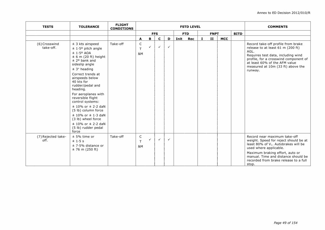
Annex to ED Decision 2012/010/R
Page 49 of 154
TESTS TOLERANCE FLIGHT
CONDITIONS FSTD LEVEL COMMENTS
FFS FTD FNPT BITD
A B C D Init Rec I II MCC
(6) Crosswind take-off.
± 3 kts airspeed
± 1.5º pitch angle
± 1.5º AOA ± 6 m (20 ft) height ± 2º bank and sideslip angle
± 3 heading
Correct trends at airspeeds below 40 kts for rudder/pedal and heading.
For aeroplanes with reversible flight control systems:
± 10% or ± 2·2 daN (5 lb) column force
± 10% or ± 1·3 daN (3 lb) wheel force
± 10% or ± 2·2 daN (5 lb) rudder pedal force
Take-off C
T
&M
Record take-off profile from brake release to at least 61 m (200 ft) AGL. Requires test data, including wind profile, for a crosswind component of at least 60% of the AFM value measured at 10m (33 ft) above the runway.
(7) Rejected take-off.
± 5% time or
± 1.5 s
± 7.5% distance or
± 76 m (250 ft)
Take-off C
T
&M
Record near maximum take-off weight. Speed for reject should be at least 80% of V1. Autobrakes will be used where applicable.
Maximum braking effort, auto or manual. Time and distance should be recorded from brake release to a full stop.
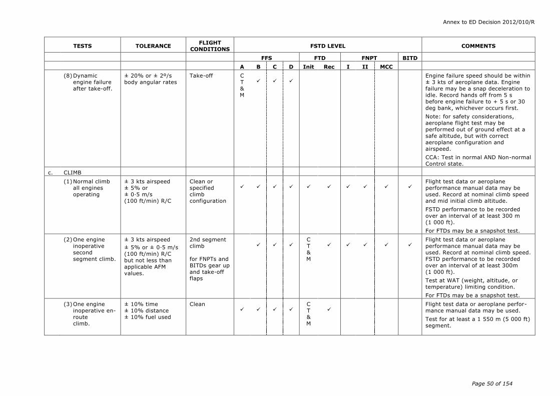
Annex to ED Decision 2012/010/R
Page 50 of 154
TESTS TOLERANCE FLIGHT
CONDITIONS FSTD LEVEL COMMENTS
FFS FTD FNPT BITD
A B C D Init Rec I II MCC
(8) Dynamic engine failure after take-off.
± 20% or ± 2º/s body angular rates
Take-off C T & M
Engine failure speed should be within ± 3 kts of aeroplane data. Engine failure may be a snap deceleration to idle. Record hands off from 5 s before engine failure to + 5 s or 30 deg bank, whichever occurs first.
Note: for safety considerations, aeroplane flight test may be performed out of ground effect at a safe altitude, but with correct aeroplane configuration and airspeed.
CCA: Test in normal AND Non-normal Control state.
c. CLIMB
(1) Normal climb all engines operating
± 3 kts airspeed ± 5% or ± 0·5 m/s (100 ft/min) R/C
Clean or specified climb configuration
Flight test data or aeroplane performance manual data may be used. Record at nominal climb speed and mid initial climb altitude.
FSTD performance to be recorded over an interval of at least 300 m (1 000 ft).
For FTDs may be a snapshot test.
(2) One engine inoperative second segment climb.
± 3 kts airspeed
± 5% or ± 0.5 m/s
(100 ft/min) R/C but not less than applicable AFM values.
2nd segment climb for FNPTs and BITDs gear up and take-off flaps
C T & M
Flight test data or aeroplane performance manual data may be used. Record at nominal climb speed. FSTD performance to be recorded over an interval of at least 300m (1 000 ft).
Test at WAT (weight, altitude, or temperature) limiting condition.
For FTDs may be a snapshot test.
(3) One engine inoperative en-route climb.
± 10% time ± 10% distance ± 10% fuel used
Clean
C T & M
Flight test data or aeroplane perfor-mance manual data may be used.
Test for at least a 1 550 m (5 000 ft) segment.
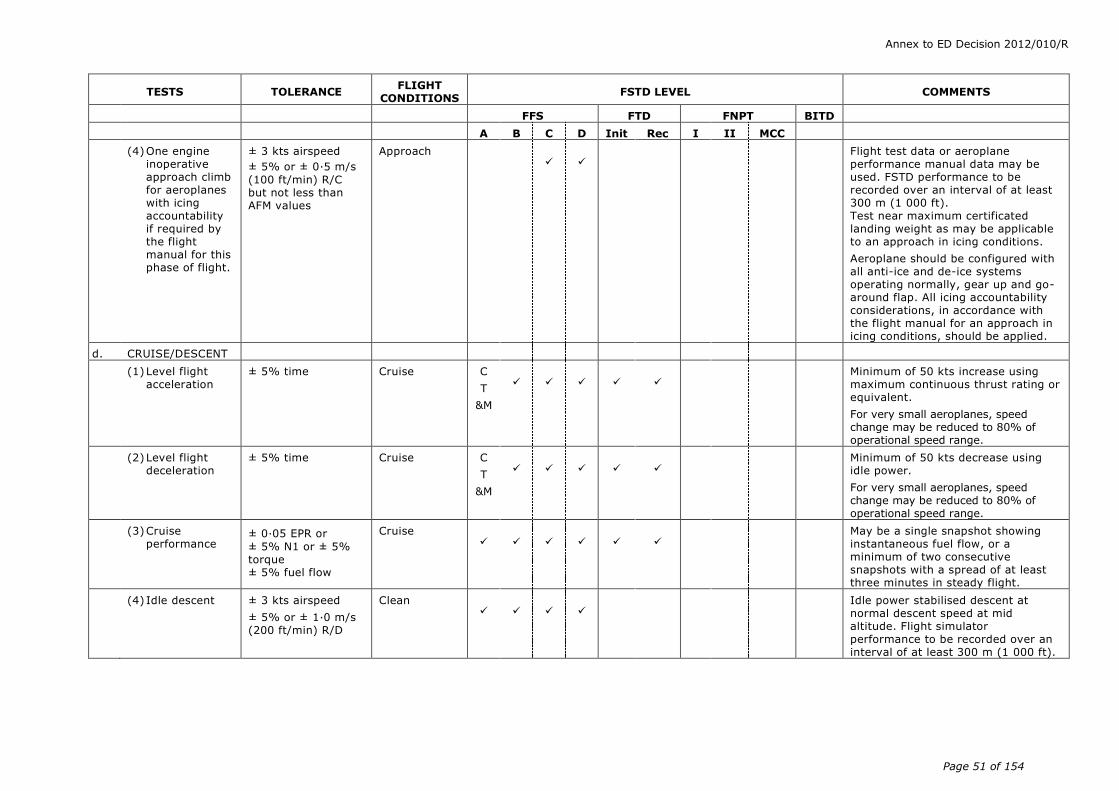
Annex to ED Decision 2012/010/R
Page 51 of 154
TESTS TOLERANCE FLIGHT
CONDITIONS FSTD LEVEL COMMENTS
FFS FTD FNPT BITD
A B C D Init Rec I II MCC
(4) One engine inoperative approach climb for aeroplanes with icing accountability if required by the flight manual for this phase of flight.
± 3 kts airspeed
± 5% or ± 0.5 m/s
(100 ft/min) R/C but not less than AFM values
Approach
Flight test data or aeroplane performance manual data may be used. FSTD performance to be recorded over an interval of at least 300 m (1 000 ft). Test near maximum certificated landing weight as may be applicable to an approach in icing conditions.
Aeroplane should be configured with all anti-ice and de-ice systems operating normally, gear up and go-around flap. All icing accountability considerations, in accordance with the flight manual for an approach in icing conditions, should be applied.
d. CRUISE/DESCENT
(1) Level flight acceleration
± 5% time Cruise C
T
&M
Minimum of 50 kts increase using maximum continuous thrust rating or equivalent.
For very small aeroplanes, speed change may be reduced to 80% of operational speed range.
(2) Level flight deceleration
± 5% time Cruise C
T
&M
Minimum of 50 kts decrease using idle power.
For very small aeroplanes, speed change may be reduced to 80% of operational speed range.
(3) Cruise performance
± 0.05 EPR or
± 5% N1 or ± 5% torque ± 5% fuel flow
Cruise
May be a single snapshot showing instantaneous fuel flow, or a minimum of two consecutive snapshots with a spread of at least three minutes in steady flight.
(4) Idle descent ± 3 kts airspeed
± 5% or ± 1·0 m/s (200 ft/min) R/D
Clean
Idle power stabilised descent at normal descent speed at mid altitude. Flight simulator performance to be recorded over an interval of at least 300 m (1 000 ft).
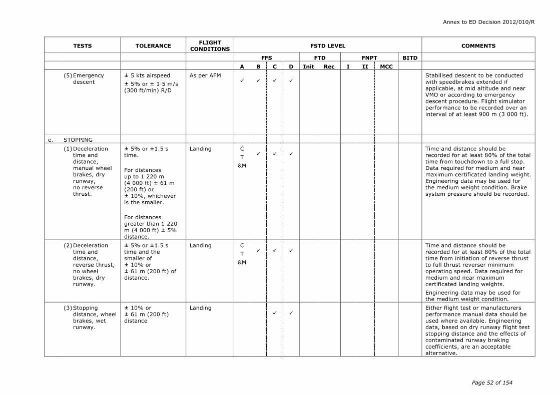
Annex to ED Decision 2012/010/R
Page 52 of 154
TESTS TOLERANCE FLIGHT
CONDITIONS FSTD LEVEL COMMENTS
FFS FTD FNPT BITD
A B C D Init Rec I II MCC
(5) Emergency descent
± 5 kts airspeed
± 5% or ± 1·5 m/s (300 ft/min) R/D
As per AFM
Stabilised descent to be conducted with speedbrakes extended if applicable, at mid altitude and near VMO or according to emergency descent procedure. Flight simulator performance to be recorded over an interval of at least 900 m (3 000 ft).
e. STOPPING
(1) Deceleration time and distance, manual wheel brakes, dry runway, no reverse thrust.
± 5% or ±1.5 s time.
For distances up to 1 220 m (4 000 ft) ± 61 m (200 ft) or ± 10%, whichever is the smaller.
For distances greater than 1 220 m (4 000 ft) ± 5% distance.
Landing C
T
&M
Time and distance should be recorded for at least 80% of the total time from touchdown to a full stop. Data required for medium and near maximum certificated landing weight. Engineering data may be used for the medium weight condition. Brake system pressure should be recorded.
(2) Deceleration time and distance, reverse thrust, no wheel brakes, dry runway.
± 5% or ±1.5 s time and the smaller of ± 10% or ± 61 m (200 ft) of distance.
Landing C
T
&M
Time and distance should be
recorded for at least 80% of the total time from initiation of reverse thrust to full thrust reverser minimum operating speed. Data required for medium and near maximum certificated landing weights.
Engineering data may be used for the medium weight condition.
(3) Stopping distance, wheel brakes, wet runway.
± 10% or ± 61 m (200 ft) distance
Landing
Either flight test or manufacturers performance manual data should be used where available. Engineering data, based on dry runway flight test stopping distance and the effects of contaminated runway braking
coefficients, are an acceptable alternative.
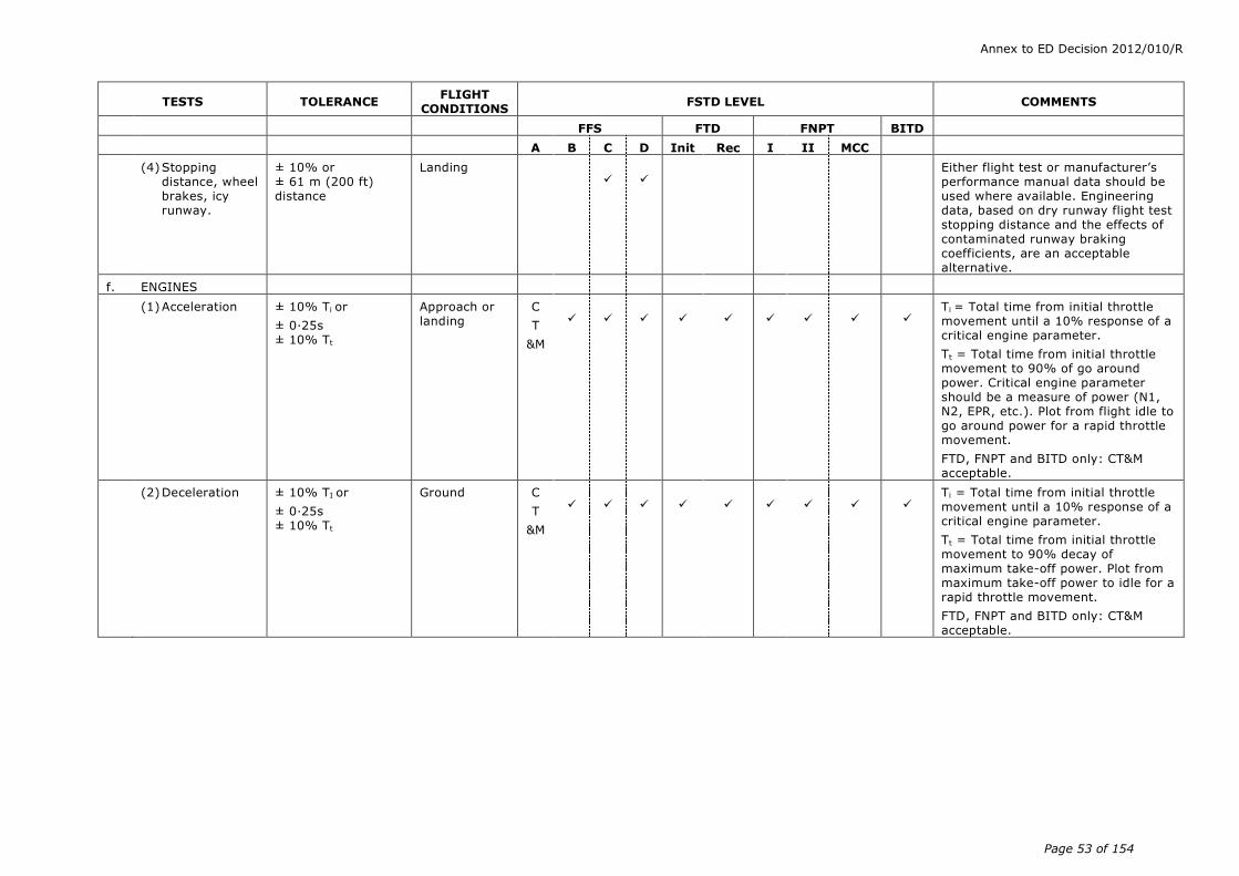
Annex to ED Decision 2012/010/R
Page 53 of 154
TESTS TOLERANCE FLIGHT
CONDITIONS FSTD LEVEL COMMENTS
FFS FTD FNPT BITD
A B C D Init Rec I II MCC
(4) Stopping distance, wheel brakes, icy runway.
± 10% or ± 61 m (200 ft) distance
Landing
Either flight test or manufacturer’s performance manual data should be used where available. Engineering data, based on dry runway flight test stopping distance and the effects of contaminated runway braking coefficients, are an acceptable alternative.
f. ENGINES
(1) Acceleration ± 10% Ti or
± 0·25s ± 10% Tt
Approach or landing
C
T
&M
Ti = Total time from initial throttle movement until a 10% response of a critical engine parameter.
Tt = Total time from initial throttle movement to 90% of go around power. Critical engine parameter should be a measure of power (N1, N2, EPR, etc.). Plot from flight idle to go around power for a rapid throttle movement.
FTD, FNPT and BITD only: CT&M acceptable.
(2) Deceleration ± 10% TI or
± 0·25s ± 10% Tt
Ground C
T
&M
Ti = Total time from initial throttle movement until a 10% response of a critical engine parameter.
Tt = Total time from initial throttle movement to 90% decay of maximum take-off power. Plot from maximum take-off power to idle for a rapid throttle movement.
FTD, FNPT and BITD only: CT&M acceptable.
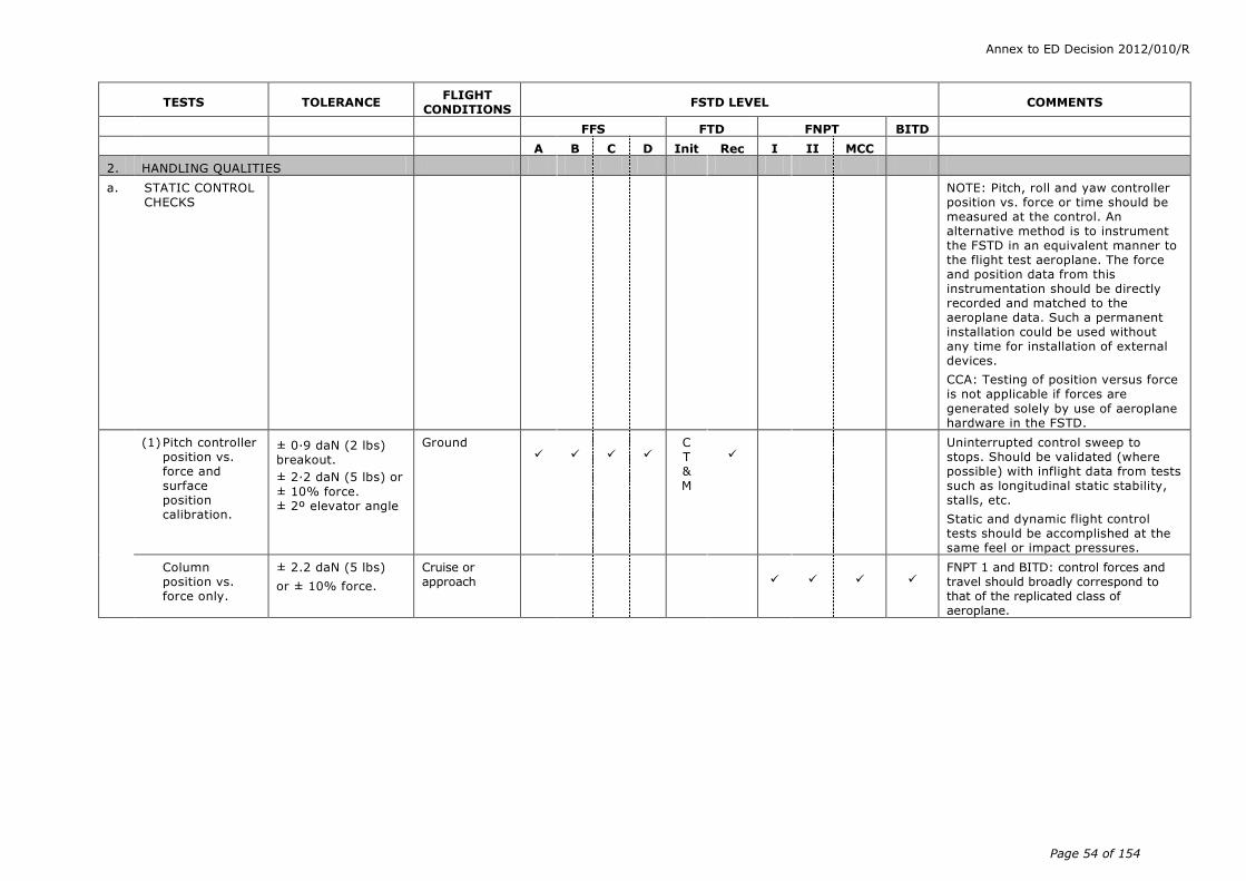
Annex to ED Decision 2012/010/R
Page 54 of 154
TESTS TOLERANCE FLIGHT
CONDITIONS FSTD LEVEL COMMENTS
FFS FTD FNPT BITD
A B C D Init Rec I II MCC
2. HANDLING QUALITIES
a. STATIC CONTROL CHECKS
NOTE: Pitch, roll and yaw controller position vs. force or time should be measured at the control. An alternative method is to instrument the FSTD in an equivalent manner to the flight test aeroplane. The force and position data from this instrumentation should be directly recorded and matched to the aeroplane data. Such a permanent installation could be used without any time for installation of external devices.
CCA: Testing of position versus force is not applicable if forces are
generated solely by use of aeroplane hardware in the FSTD.
(1) Pitch controller position vs. force and surface position calibration.
± 0.9 daN (2 lbs) breakout.
± 2.2 daN (5 lbs) or
± 10% force. ± 2º elevator angle
Ground
C T & M
Uninterrupted control sweep to stops. Should be validated (where possible) with inflight data from tests such as longitudinal static stability, stalls, etc.
Static and dynamic flight control tests should be accomplished at the same feel or impact pressures.
Column position vs. force only.
± 2.2 daN (5 lbs)
or ± 10% force.
Cruise or approach
FNPT 1 and BITD: control forces and travel should broadly correspond to that of the replicated class of aeroplane.

Annex to ED Decision 2012/010/R
Page 55 of 154
TESTS TOLERANCE FLIGHT
CONDITIONS FSTD LEVEL COMMENTS
FFS FTD FNPT BITD
A B C D Init Rec I II MCC
(2) Roll controller position vs. force and surface position calibration.
± 0.9 daN (2 lbs)
breakout
± 1.3 daN (3 lbs) or ± 10% force ± 2º aileron angle ± 3º spoiler angle
Ground
C T & M
Uninterrupted control sweep to stops. Should be validated with in-flight data from tests such as engine out trims, steady state sideslips, etc. Static and dynamic flight control tests should be accomplished at the same feel or impact pressures.
Wheel position vs. force only.
± 1.3 daN (3 lbs)
or ± 10% Force
Cruise or approach
FNPT 1 and BITD: Control forces and travel should broadly correspond to that of the replicated class of aeroplane
(3) Rudder pedal position vs. force and surface position calibration.
± 2.2 daN (5 lbs) breakout
± 2.2 daN (5 lbs)
or ± 10% force ± 2º rudder angle
Ground
C T & M
Uninterrupted control sweep to stops. Should be validated with in flight data from tests such as engine out trims, steady state sideslips, etc. Static and dynamic flight control tests should be accomplished at the same feel or impact pressures.
Pedal position vs. force only.
± 2.2 daN (5 lbs)
or ± 10% force.
Cruise or approach
FNPT 1 and BITD: Control forces and travel should broadly correspond to that of the replicated class of aeroplane.
(4) Nosewheel steering controller force and position calibration.
± 0.9 daN (2 lbs)
breakout
± 1.3 daN (3 lbs)
or ± 10% force ± 2º NWA
Ground C T
&M
Uninterrupted control sweep to stops.
(5) Rudder pedal steering calibration.
± 2º NWA
Ground C T
&M
Uninterrupted control sweep to stops.
(6) Pitch trim indicator vs. surface position calibration
± 0.5º trim angle.
Ground
Purpose of test is to compare flight simulator against design data or equivalent.
±1 of trim angle Ground
BITD: Only applicable if appropriate trim settings are available, e.g. data from the AFM.

Annex to ED Decision 2012/010/R
Page 56 of 154
TESTS TOLERANCE FLIGHT
CONDITIONS FSTD LEVEL COMMENTS
FFS FTD FNPT BITD
A B C D Init Rec I II MCC
(7) Pitch trim rate ± 10% or ± 0.5 deg/s trim rate ( /s)
Ground and approach
Trim rate to be checked at pilot primary induced trim rate (ground) and autopilot or pilot primary trim rate in flight at go-around flight conditions.
(8) Alignment of cockpit throttle lever vs. selected engine parameter.
± 5º of TLA
or ± 3% N1
or ± 0·03 EPR
or ± 3% torque
For propeller-driven aeroplanes, where the propeller levers do not have angular travel, a tolerance of ± 2 cm (± 0.8 in) applies.
Ground
Simultaneous recording for all engines. The tolerances apply against aeroplane data and between engines.
For aeroplanes with throttle detents, all detents to be presented.
In the case of propeller-driven aeroplanes, if an additional lever, usually referred to as the propeller lever, is present, it should also be checked.
Where these levers do not have angular travel a tolerance of ± 2 cm
(± 0.8 inches) applies.
May be a series of snapshot tests.
(9) Brake pedal position vs. force and brake system
pressure calibration.
± 2.2 daN (5 lbs) or
± 10% force.
± 1.0 MPa (150 psi)
or ± 10% brake system pressure.
Ground C T
&M
Flight simulator computer output results may be used to show compliance.
Relate the hydraulic system pressure
to pedal position in a ground static test.

Annex to ED Decision 2012/010/R
Page 57 of 154
TESTS TOLERANCE FLIGHT
CONDITIONS FSTD LEVEL COMMENTS
FFS FTD FNPT BITD
A B C D Init Rec I II MCC
b. DYNAMIC CONTROL CHECKS
Tests 2.b(1), 2.b(2), and 2.b(3) are not applicable if dynamic response is generated solely by use of aeroplane hardware in the flight simulator. Power setting may be that required for level flight unless otherwise specified.
(1) Pitch control. For underdamped systems:
± 10% of time from 90% of initial displacement (Ad) to first zero crossing and ± 10(n+1)% of period thereafter
± 10% amplitude of first overshoot applied to all overshoots greater than 5% of initial displacement (Ad).
± 1 overshoot (first significant overshoot should be matched)
For overdamped systems:
± 10% of time from 90% of initial displacement (Ad) to 10 % of initial displacement (0·1 Ad).
Take-off, cruise, and landing
Data should be for normal control displacements in both directions (approximately 25% to 50% full throw or approximately 25% to 50% of maximum allowable pitch controller deflection for flight conditions limited by the manoeuvring load envelope). Tolerances apply against the
absolute values of each period (considered independently).
n = The sequential period of a full oscillation.
Refer to AMC1 FSTD(A).300(b)(4)(i).

Annex to ED Decision 2012/010/R
Page 58 of 154
TESTS TOLERANCE FLIGHT
CONDITIONS FSTD LEVEL COMMENTS
FFS FTD FNPT BITD
A B C D Init Rec I II MCC
(2) Roll control. For underdamped systems:
± 10% of time from 90% of initial displacement (Ad) to first zero crossing and ± 10(n+1)% of period thereafter.
± 10% amplitude of first overshoot applied to all overshoots greater than 5% of initial displacement (Ad).
± 1 overshoot (first significant overshoot should be matched)
For overdamped systems:
± 10% of time from
90% of initial dis-placement (Ad) to 10 % of initial dis-placement (0·1 Ad).
Take-off, cruise, and landing
Data should be for normal control displacement (approximately 25% to 50% of full throw or approximately 25% to 50% of maximum allowable roll controller deflection for flight conditions limited by the manoeuvring load envelope).
Refer to AMC1 FSTD(A).300(b)(4)(i).
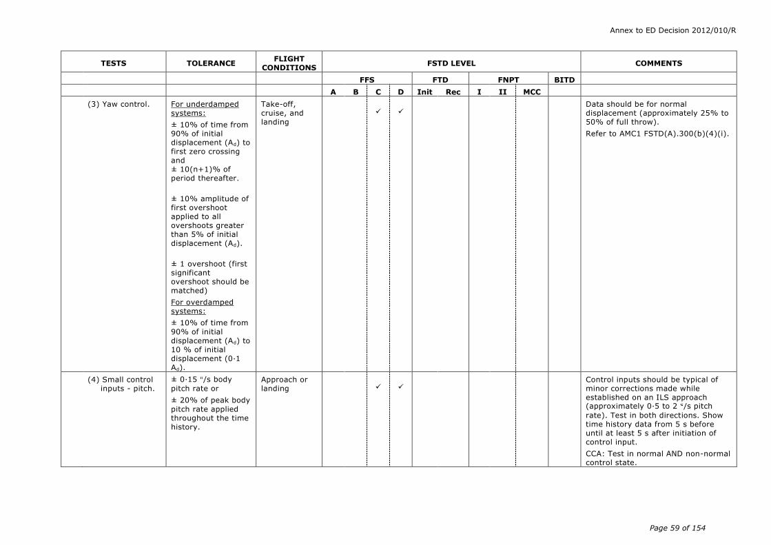
Annex to ED Decision 2012/010/R
Page 59 of 154
TESTS TOLERANCE FLIGHT
CONDITIONS FSTD LEVEL COMMENTS
FFS FTD FNPT BITD
A B C D Init Rec I II MCC
(3) Yaw control. For underdamped systems:
± 10% of time from 90% of initial displacement (Ad) to first zero crossing and ± 10(n+1)% of period thereafter.
± 10% amplitude of first overshoot applied to all overshoots greater than 5% of initial displacement (Ad).
± 1 overshoot (first significant overshoot should be matched)
For overdamped systems:
± 10% of time from
90% of initial displacement (Ad) to 10 % of initial displacement (0·1 Ad).
Take-off, cruise, and landing
Data should be for normal displacement (approximately 25% to 50% of full throw).
Refer to AMC1 FSTD(A).300(b)(4)(i).
(4) Small control inputs - pitch.
± 0·15 /s body
pitch rate or
± 20% of peak body
pitch rate applied throughout the time history.
Approach or landing
Control inputs should be typical of minor corrections made while established on an ILS approach (approximately 0·5 to 2 /s pitch
rate). Test in both directions. Show time history data from 5 s before until at least 5 s after initiation of control input.
CCA: Test in normal AND non-normal control state.
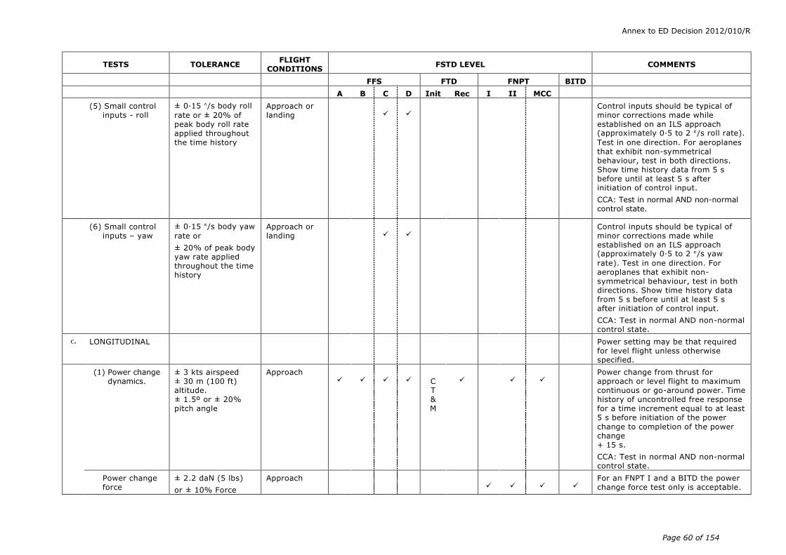
Annex to ED Decision 2012/010/R
Page 60 of 154
TESTS TOLERANCE FLIGHT
CONDITIONS FSTD LEVEL COMMENTS
FFS FTD FNPT BITD
A B C D Init Rec I II MCC
(5) Small control inputs - roll
± 0·15 /s body roll
rate or ± 20% of peak body roll rate applied throughout the time history
Approach or landing
Control inputs should be typical of minor corrections made while established on an ILS approach (approximately 0·5 to 2 /s roll rate).
Test in one direction. For aeroplanes that exhibit non-symmetrical behaviour, test in both directions. Show time history data from 5 s before until at least 5 s after initiation of control input.
CCA: Test in normal AND non-normal control state.
(6) Small control inputs – yaw
± 0·15 /s body yaw
rate or
± 20% of peak body yaw rate applied throughout the time history
Approach or landing
Control inputs should be typical of minor corrections made while established on an ILS approach (approximately 0·5 to 2 /s yaw
rate). Test in one direction. For aeroplanes that exhibit non-symmetrical behaviour, test in both directions. Show time history data from 5 s before until at least 5 s after initiation of control input.
CCA: Test in normal AND non-normal control state.
c. LONGITUDINAL Power setting may be that required for level flight unless otherwise specified.
(1) Power change dynamics.
± 3 kts airspeed ± 30 m (100 ft) altitude. ± 1.5º or ± 20% pitch angle
Approach
C T & M
Power change from thrust for approach or level flight to maximum continuous or go-around power. Time history of uncontrolled free response for a time increment equal to at least 5 s before initiation of the power
change to completion of the power change + 15 s.
CCA: Test in normal AND non-normal control state.
Power change force
± 2.2 daN (5 lbs)
or ± 10% Force
Approach
For an FNPT I and a BITD the power change force test only is acceptable.

Annex to ED Decision 2012/010/R
Page 61 of 154
TESTS TOLERANCE FLIGHT
CONDITIONS FSTD LEVEL COMMENTS
FFS FTD FNPT BITD
A B C D Init Rec I II MCC
(2) Flap change dynamics.
± 3 kts airspeed ± 30 m (100 ft) altitude. ± 1.5º or ± 20% pitch angle
Take-off through initial flap retraction and approach to landing
C T & M
Time history of uncontrolled free response for a time increment equal to at least 5 s before initiation of the reconfiguration change to completion of the reconfiguration change + 15 s.
CCA: Test in normal AND non-normal control state.
Flap change force
± 2.2 daN (5 lbs)
or ± 10% Force
For an FNPT I and a BITD the flap change force test only is acceptable.
(3) Spoiler / speedbrake change dynamics.
± 3 kts airspeed ± 30 m (100 ft) altitude. ± 1.5 º or ± 20% pitch angle
Cruise
C T & M
Time history of uncontrolled free response for a time increment equal to at least 5 s before initiation of the reconfiguration change to completion of the reconfiguration change + 15 s.
Results required for both extension and retraction.
CCA: Test in normal AND non-normal control state.
(4) Gear change dynamics.
± 3 kts airspeed ± 30 m (100 ft) altitude. ± 1.5º or ± 20% pitch angle
For FNPTs and BITDs, ± 2º or ± 20% pitch angle
Takeoff (retraction) and approach (extension)
C T & M
Time history of uncontrolled free response for a time increment equal to at least 5 s before initiation of the configuration change to completion of the reconfiguration change + 15 s.
CCA: Test in normal AND non-normal control state.
Gear change force
± 2.2 daN (5 lbs)
or ± 20% Force.
Take-off and approach
For an FNPT I and a BITD the gear change force test only is acceptable.
(5) Longitudinal trim.
± 1º elevator
± 0·5º stabilizer
± 1º pitch angle
± 5% net thrust or equivalent
Cruise, approach, and
landing
C
T & M
Steady-state wings level trim with thrust for level flight. May be a series
of snapshot tests.
CCA: Test in normal OR non-normal control state.
± 2 deg pitch control (elevator & stabilizer)
± 2 deg pitch
± 5% power or equivalent
Cruise, approach
May be a series of Snapshot tests.
FNPT I and BITD may use equivalent stick and trim controllers.
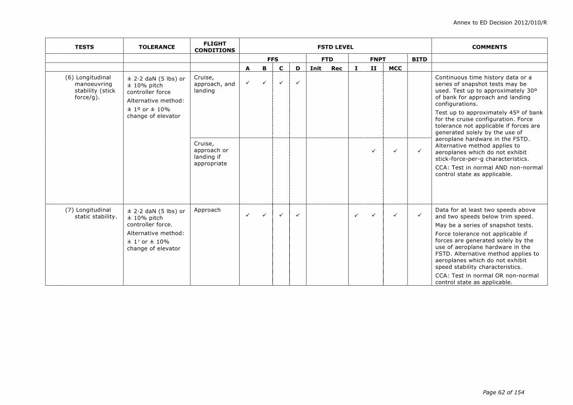
Annex to ED Decision 2012/010/R
Page 62 of 154
TESTS TOLERANCE FLIGHT
CONDITIONS FSTD LEVEL COMMENTS
FFS FTD FNPT BITD
A B C D Init Rec I II MCC
(6) Longitudinal manoeuvring stability (stick force/g).
± 2.2 daN (5 lbs) or
± 10% pitch controller force
Alternative method:
± 1º or ± 10% change of elevator
Cruise, approach, and landing
Continuous time history data or a series of snapshot tests may be used. Test up to approximately 30º of bank for approach and landing configurations.
Test up to approximately 45º of bank for the cruise configuration. Force tolerance not applicable if forces are generated solely by the use of aeroplane hardware in the FSTD. Alternative method applies to aeroplanes which do not exhibit stick-force-per-g characteristics.
CCA: Test in normal AND non-normal control state as applicable.
Cruise, approach or landing if appropriate
(7) Longitudinal static stability.
± 2.2 daN (5 lbs) or
± 10% pitch controller force.
Alternative method:
± 1 or ± 10%
change of elevator
Approach
Data for at least two speeds above and two speeds below trim speed.
May be a series of snapshot tests.
Force tolerance not applicable if forces are generated solely by the use of aeroplane hardware in the FSTD. Alternative method applies to aeroplanes which do not exhibit speed stability characteristics.
CCA: Test in normal OR non-normal control state as applicable.
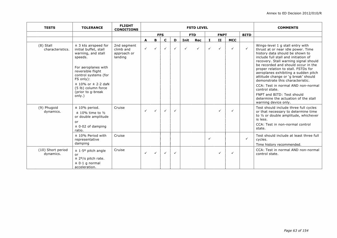
Annex to ED Decision 2012/010/R
Page 63 of 154
TESTS TOLERANCE FLIGHT
CONDITIONS FSTD LEVEL COMMENTS
FFS FTD FNPT BITD
A B C D Init Rec I II MCC
(8) Stall characteristics.
± 3 kts airspeed for initial buffet, stall warning, and stall speeds.
For aeroplanes with reversible flight control systems (for FS only):
± 10% or ± 2·2 daN (5 lb) column force (prior to g-break only.)
2nd segment climb and approach or landing
Wings-level 1 g stall entry with thrust at or near idle power. Time history data should be shown to include full stall and initiation of recovery. Stall warning signal should be recorded and should occur in the proper relation to stall. FSTDs for aeroplanes exhibiting a sudden pitch attitude change or ‘g break’ should demonstrate this characteristic.
CCA: Test in normal AND non-normal control state.
FNPT and BITD: Test should determine the actuation of the stall warning device only.
(9) Phugoid
dynamics.
± 10% period.
± 10% time to ½ or double amplitude
or
± 0.02 of damping ratio.
Cruise
Test should include three full cycles
or that necessary to determine time to ½ or double amplitude, whichever is less.
CCA: Test in non-normal control state.
± 10% Period with representative damping
Cruise
Test should include at least three full cycles.
Time history recommended.
(10) Short period dynamics.
± 1.5º pitch angle or ± 2º/s pitch rate.
± 0.1 g normal
acceleration.
Cruise
CCA: Test in normal AND non-normal control state.

Annex to ED Decision 2012/010/R
Page 64 of 154
TESTS TOLERANCE FLIGHT
CONDITIONS FSTD LEVEL COMMENTS
FFS FTD FNPT BITD
A B C D Init Rec I II MCC
d. LATERAL DIRECTIONAL
Power setting may be that required for level flight unless otherwise specified.
(1) Minimum control speed, air (VMCA or VMCL), per applicable airworthiness standard – or – Low speed engine inoper-ative handling characteristics in the air.
± 3 kts airspeed
Take-off or landing (whichever is most critical in the aeroplane)
C T
&M
C T & M
Minimum speed may be defined by a performance or control limit which prevents demonstration of VMCor VMCLin the conventional manner. Take-off thrust should be set on the operating engine(s). Time history or snapshot data may be used.
CCA: Test in normal OR non-normal control state.
FNPT and BITD: It is important that there exists a realistic speed relationship between Vmca and Vs for all configurations and in particular the
most critical full-power engine-out take-off configurations.
(2) Roll response (rate).
± 10% or ± 2º/s roll rate
FS only: For aeroplanes with reversible flight control systems: ± 10% or ± 1·3 daN (3 lb) roll controller force.
Cruise and approach or landing
C T & M
Test with normal roll control displacement (about 30% of maximum control wheel). May be combined with step input of flight deck roll controller test 2.d(3).
(3) Step input of cockpit roll controller (or roll overshoot).
± 10% or ± 2º bank angle
Approach or landing
With wings level, apply a step roll control input using approximately one-third of roll controller travel. At approximately 20 to 30 bank,
abruptly return the roll controller to neutral and allow at least 10 s of aeroplane free response. May be combined with roll response (rate) test 2.d(2).
CCA: Test in normal AND non-normal control state.
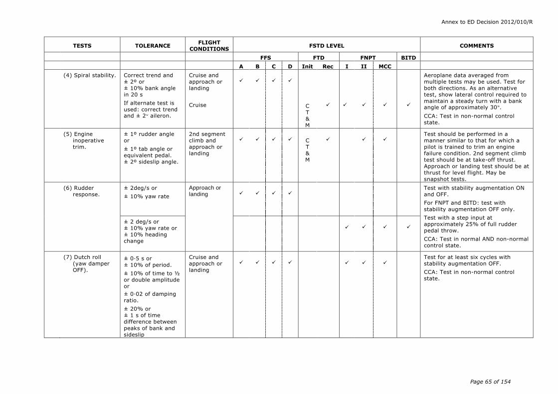
Annex to ED Decision 2012/010/R
Page 65 of 154
TESTS TOLERANCE FLIGHT
CONDITIONS FSTD LEVEL COMMENTS
FFS FTD FNPT BITD
A B C D Init Rec I II MCC
(4) Spiral stability. Correct trend and ± 2º or ± 10% bank angle in 20 s
If alternate test is used: correct trend and ± 2 aileron.
Cruise and approach or landing
Cruise
C T & M
Aeroplane data averaged from multiple tests may be used. Test for both directions. As an alternative test, show lateral control required to maintain a steady turn with a bank angle of approximately 30 .
CCA: Test in non-normal control state.
(5) Engine inoperative trim.
± 1º rudder angle or
± 1º tab angle or equivalent pedal. ± 2º sideslip angle.
2nd segment climb and approach or landing
C T & M
Test should be performed in a manner similar to that for which a pilot is trained to trim an engine failure condition. 2nd segment climb test should be at take-off thrust. Approach or landing test should be at thrust for level flight. May be snapshot tests.
(6) Rudder response.
± 2deg/s or
± 10% yaw rate
Approach or landing
Test with stability augmentation ON and OFF.
For FNPT and BITD: test with stability augmentation OFF only.
Test with a step input at approximately 25% of full rudder pedal throw.
CCA: Test in normal AND non-normal control state.
± 2 deg/s or ± 10% yaw rate or ± 10% heading change
(7) Dutch roll (yaw damper OFF).
± 0.5 s or
± 10% of period.
± 10% of time to ½ or double amplitude or
± 0.02 of damping ratio.
± 20% or ± 1 s of time difference between
peaks of bank and sideslip
Cruise and approach or landing
Test for at least six cycles with stability augmentation OFF.
CCA: Test in non-normal control state.

Annex to ED Decision 2012/010/R
Page 66 of 154
TESTS TOLERANCE FLIGHT
CONDITIONS FSTD LEVEL COMMENTS
FFS FTD FNPT BITD
A B C D Init Rec I II MCC
(8) Steady state sideslip.
For a given rudder position:
± 2º bank angle ± 1º sideslip angle ± 10% or ± 2º aileron ± 10% or ± 5º spoiler or equivalent roll controller position or force
For FFSs representing aircraft with reversible flight control systems:
±10% or ±1·3 daN (3 lb) wheel force
±10% or ±2·2 daN (5 lb) rudder pedal force.
Approach or landing
May be a series of snapshot tests using at least two rudder positions (in each direction for propeller driven aeroplanes) one of which should be near maximum allowable rudder.
For FNPT and BITD a roll controller position tolerance of ± 10% or ± 5º applies instead of the aileron tolerance.
For a BITD the force tolerance should be CT&M.
e. LANDINGS
(1) Normal landing ± 3 kts airspeed
± 1.5º pitch angle
± 1.5º AOA
± 3 m (10 ft) or ± 10% of height
For aeroplanes with reversible flight control systems:
± 10% or ± 2·2 daN (5 lb) column force
Landing C
T
&M
Test from a minimum of 61 m (200 ft) AGL to nosewheel touch- down.
Two tests should be shown, including two normal landing flaps (if applicable) one of which should be near maximum certificated landing weight, the other at light or medium weight.
CCA: Test in Normal AND Non-normal Control state if applicable.

Annex to ED Decision 2012/010/R
Page 67 of 154
TESTS TOLERANCE FLIGHT
CONDITIONS FSTD LEVEL COMMENTS
FFS FTD FNPT BITD
A B C D Init Rec I II MCC
(2) Minimum flap landing.
± 3 kts airspeed
± 1.5º pitch angle
± 1.5º AOA
± 3 m (10 ft) or ± 10% of height
For aeroplanes with reversible flight control systems:
± 10% or ± 2·2 daN
(5 lb) column force
Minimum certified landing flap configuration
Test from a minimum of 61 m (200 ft) AGL to nosewheel touchdown.
Test at near maximum landing weight.
(3) Crosswind landing.
± 3 kts airspeed
± 1.5º pitch angle
± 1.5º AOA
± 3 m (10 ft) or ± 10% height
± 2º bank angle
± 2º sideslip angle
± 3 heading angle
For aeroplanes with reversible flight control systems:
± 10% or ± 2·2 daN (5 lb) column force
± 10% or ± 1·3 daN (3 lb) wheel force
± 10% or ± 2·2 daN (5 lb) rudder pedal force.
Landing
Test from a minimum of 61 m (200 ft) AGL to a 50% decrease in main landing gear touchdown speed.
Requires test data, including wind profile, for a crosswind component of at least 60% of AFM value measured at 10 m (33 ft) above the runway.
(4) One engine inoperative landing.
± 3 kts airspeed
± 1.5º pitch angle
± 1.5º AOA
± 3 m (10 ft) or
± 10% height
± 2º bank angle
± 2º sideslip angle
± 3 heading angle
Landing
Test from a minimum of 61 m (200 ft) AGL to a 50% decrease in main landing gear touchdown speed.

Annex to ED Decision 2012/010/R
Page 68 of 154
TESTS TOLERANCE FLIGHT
CONDITIONS FSTD LEVEL COMMENTS
FFS FTD FNPT BITD
A B C D Init Rec I II MCC
(5) Autopilot landing (if applicable).
± 1.5 m (5 ft) flare
height.
± 0.5 s or ± 10%Tf.
± 0.7 m/s (140
ft/min) R/D at touchdown. ± 3 m (10 ft) lateral deviation during rollout.
Landing
If autopilot provides rollout guidance, record lateral deviation from touchdown to a 50% decrease in main landing gear touchdown speed. Time of autopilot flare mode engage and main gear touchdown should be noted. This test is not a substitute for the ground effects test requirement.
Tf = Duration of flare.
(6) All engine autopilot go around.
± 3 kts airspeed
± 1.5 pitch angle
± 1.5 AOA
As per AFM
Normal all engine autopilot go around should be demonstrated (if applicable) at medium weight.
CCA: Test in normal AND non-normal.
(7) One-engine-inoperative go-around
± 3 kts airspeed
±1·5 pitch angle
±1·5 AOA
± 2 bank angle
± 2 sideslip angle
As per AFM
Engine inoperative go-around required near maximum certificated landing weight with critical engine(s) inoperative. Provide one test with autopilot (if applicable) and one without autopilot.
CCA: Non-autopilot test to be conducted in non-normal mode.
(8) Directional control (rudder effectiveness) with reverse thrust symmetric).
± 5 kts airspeed
± 2 /s yaw rate
Landing
Apply rudder pedal input in both directions using full reverse thrust until reaching full thrust reverser minimum operating speed.
(9) Directional control (rudder effectiveness) with reverser thrust (asymmetric)
± 5 kts airspeed
± 3 heading angle
Landing
With full reverse thrust on the operating engine(s), maintain heading with rudder pedal input until maximum rudder pedal input or thrust reverser minimum operating speed is reached.

Annex to ED Decision 2012/010/R
Page 69 of 154
TESTS TOLERANCE FLIGHT
CONDITIONS FSTD LEVEL COMMENTS
FFS FTD FNPT BITD
A B C D Init Rec I II MCC
f. GROUND EFFECT
(1) A Test to demonstrate ground effect.
± 1º elevator
± 0·5º stabilizer angle.
± 5% net thrust or equivalent. ± 1º AOA
± 1.5 m (5 ft) or
± 10% height ± 3 kts airspeed
± 1º pitch angle
Landing
See AMC1 FSTD(A).300(b)(4)(ii). A rationale should be provided with justification of results.
CCA: Test in normal OR non-normal control state.

Annex to ED Decision 2012/010/R
Page 70 of 154
TESTS TOLERANCE FLIGHT
CONDITIONS FSTD LEVEL COMMENTS
FFS FTD FNPT BITD
A B C D Init Rec I II MCC
g. WIND SHEAR
(1) Four Tests, two take-off and two landing with one of each conducted in still air and the other with Wind Shear active to demonstrate wind shear models.
None Take-off and landing
Wind shear models are required which provide training in the specific skills required for recognition of wind shear phenomena and execution of recovery manoeuvres.
Wind shear models should be representative of measured or accident derived winds, but may be simplifications which ensure repeatable encounters. For example, models may consist of independent variable winds in multiple simultaneous components. Wind models should be available for the following critical phases of flight:
(1) prior to take-off rotation;
(2) at lift-off;
(3) during initial climb;
(4) short final approach.
The United States Federal Aviation Administration (FAA) Wind shear Training Aid, wind models from the Royal Aerospace Establishment (RAE), the United States JAWS Project or other recognised sources may be implemented and should be supported and properly referenced in the QTG. Wind models from alternate sources may also be used if supported by aeroplane-related data and such data are properly supported and referenced in the QTG. Use of alternate data should be coordinated with the competent authority prior to submittal of the QTG for approval.
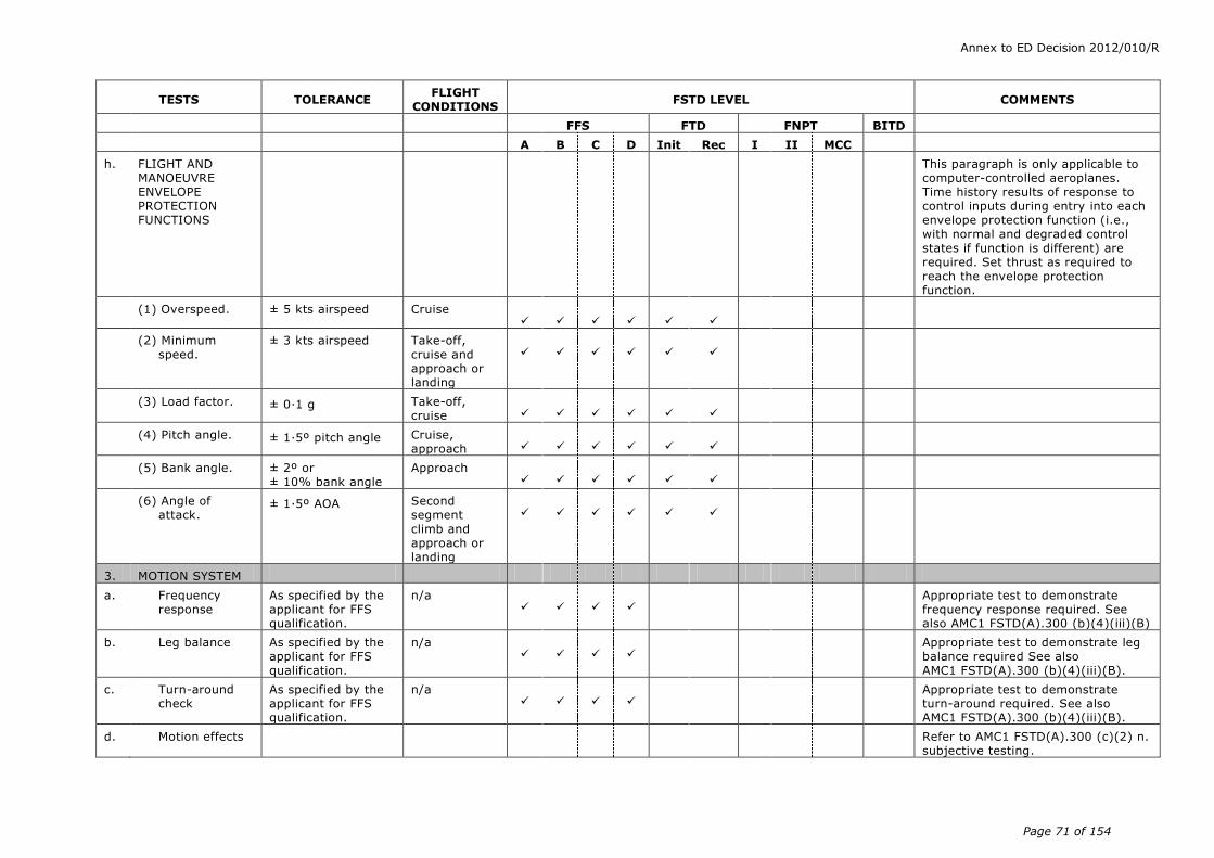
Annex to ED Decision 2012/010/R
Page 71 of 154
TESTS TOLERANCE FLIGHT
CONDITIONS FSTD LEVEL COMMENTS
FFS FTD FNPT BITD
A B C D Init Rec I II MCC
h. FLIGHT AND MANOEUVRE ENVELOPE PROTECTION FUNCTIONS
This paragraph is only applicable to computer-controlled aeroplanes. Time history results of response to control inputs during entry into each envelope protection function (i.e., with normal and degraded control states if function is different) are required. Set thrust as required to reach the envelope protection function.
(1) Overspeed. ± 5 kts airspeed Cruise
(2) Minimum speed.
± 3 kts airspeed Take-off, cruise and approach or landing
(3) Load factor. ± 0.1 g Take-off, cruise
(4) Pitch angle. ± 1.5º pitch angle Cruise, approach
(5) Bank angle. ± 2º or ± 10% bank angle
Approach
(6) Angle of attack.
± 1.5º AOA
Second segment climb and approach or landing
3. MOTION SYSTEM
a. Frequency response
As specified by the applicant for FFS qualification.
n/a
Appropriate test to demonstrate frequency response required. See also AMC1 FSTD(A).300 (b)(4)(iii)(B)
b. Leg balance As specified by the applicant for FFS qualification.
n/a
Appropriate test to demonstrate leg balance required See also AMC1 FSTD(A).300 (b)(4)(iii)(B).
c. Turn-around check
As specified by the applicant for FFS qualification.
n/a
Appropriate test to demonstrate
turn-around required. See also AMC1 FSTD(A).300 (b)(4)(iii)(B).
d. Motion effects Refer to AMC1 FSTD(A).300 (c)(2) n. subjective testing.
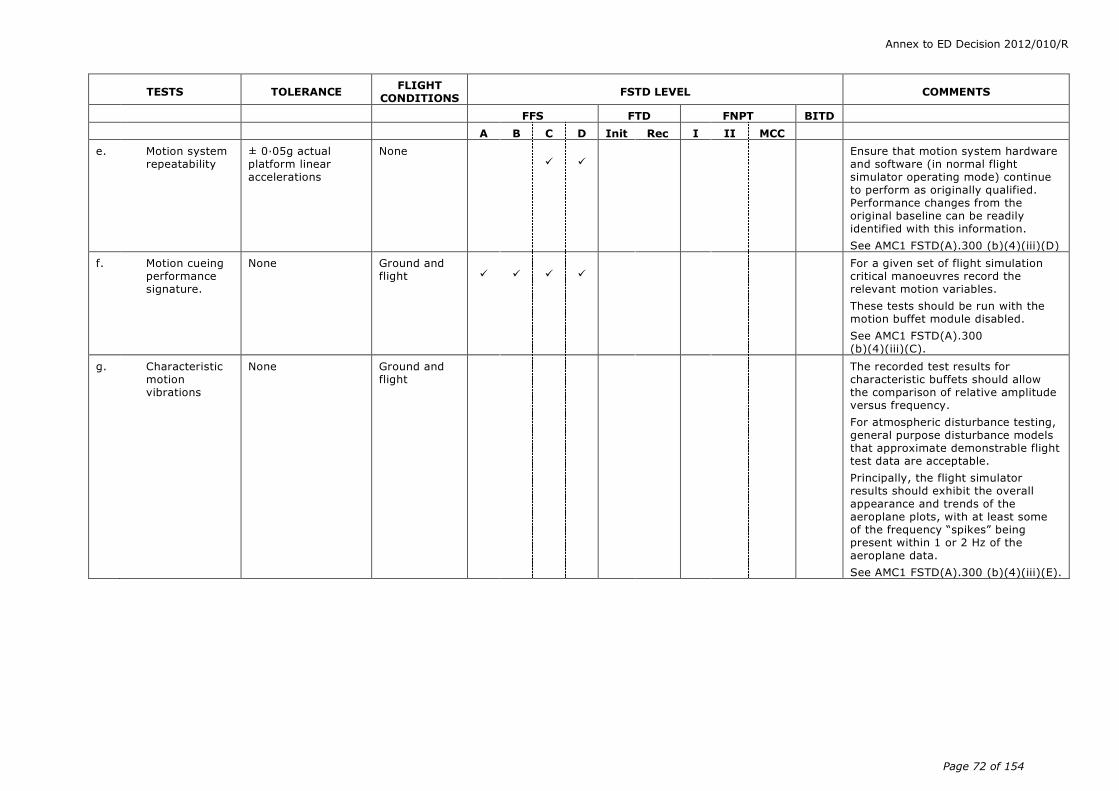
Annex to ED Decision 2012/010/R
Page 72 of 154
TESTS TOLERANCE FLIGHT
CONDITIONS FSTD LEVEL COMMENTS
FFS FTD FNPT BITD
A B C D Init Rec I II MCC
e. Motion system repeatability
± 0·05g actual platform linear accelerations
None
Ensure that motion system hardware and software (in normal flight simulator operating mode) continue to perform as originally qualified. Performance changes from the original baseline can be readily identified with this information.
See AMC1 FSTD(A).300 (b)(4)(iii)(D)
f. Motion cueing performance signature.
None Ground and flight
For a given set of flight simulation critical manoeuvres record the relevant motion variables.
These tests should be run with the motion buffet module disabled.
See AMC1 FSTD(A).300 (b)(4)(iii)(C).
g. Characteristic motion vibrations
None Ground and flight
The recorded test results for characteristic buffets should allow the comparison of relative amplitude versus frequency.
For atmospheric disturbance testing, general purpose disturbance models that approximate demonstrable flight test data are acceptable.
Principally, the flight simulator results should exhibit the overall appearance and trends of the aeroplane plots, with at least some of the frequency “spikes” being present within 1 or 2 Hz of the aeroplane data.
See AMC1 FSTD(A).300 (b)(4)(iii)(E).

Annex to ED Decision 2012/010/R
Page 73 of 154
TESTS TOLERANCE FLIGHT
CONDITIONS FSTD LEVEL COMMENTS
FFS FTD FNPT BITD
A B C D Init Rec I II MCC
The following tests with recorded results and an SOC are required for characteristic motion vibrations, which can be sensed at the flight deck where applicable by aeroplane type:
(1) Thrust effects with brakes set
n/a Ground
Test should be conducted at maximum possible thrust with brakes set.
(2) Landing gear extended buffet
n/a Flight
Test condition should be for a normal operational speed and not at the gear limiting speed.
(3) Flaps extended buffet
n/a Flight
Test condition should be for a normal operational speed and not at the flap limiting speed.
(4) Speedbrake deployed buffet
n/a Flight
(5) Approach-to-stall buffet
n/a Flight
Test condition should be approach-to-stall. Post-stall characteristics are not required.
(6) High speed or Mach buffet
n/a Flight
Test condition should be for high speed manoeuvre buffet/wind-up-turn or alternatively Mach buffet.
(7) In-flight vibrations
n/a Flight (clean configuration)
Test should be conducted to be representative of in-flight vibrations for propeller driven aeroplanes.
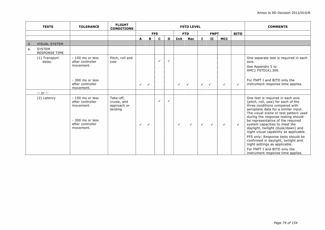
Annex to ED Decision 2012/010/R
Page 74 of 154
TESTS TOLERANCE FLIGHT
CONDITIONS FSTD LEVEL COMMENTS
FFS FTD FNPT BITD
A B C D Init Rec I II MCC
4. VISUAL SYSTEM
a. SYSTEM RESPONSE TIME
(1) Transport delay.
- 150 ms or less after controller movement.
- 300 ms or less
after controller movement.
Pitch, roll and yaw
One separate test is required in each axis.
See Appendix 5 to AMC1 FSTD(A).300.
For FNPT I and BITD only the
instrument response time applies.
-- or --
(2) Latency
- 150 ms or less after controller movement.
- 300 ms or less after controller movement.
Take-off, cruise, and approach or landing
One test is required in each axis (pitch, roll, yaw) for each of the three conditions compared with aeroplane data for a similar input. The visual scene or test pattern used during the response testing should be representative of the required system capacities to meet the daylight, twilight (dusk/dawn) and night visual capability as applicable.
FFS only: Response tests should be confirmed in daylight, twilight and night settings as applicable.
For FNPT I and BITD only the instrument response time applies.

Annex to ED Decision 2012/010/R
Page 75 of 154
TESTS TOLERANCE FLIGHT
CONDITIONS FSTD LEVEL COMMENTS
FFS FTD FNPT BITD
A B C D Init Rec I II MCC
b. DISPLAY SYSTEM TESTS
(1)
(a) Continuous collimated cross-cockpit visual field of view
Continuous, cross-cockpit, minimum collimated visual field of view providing each pilot with 180 degrees horizontal and 40 degrees vertical field of view.
Horizontal FOV: Not less than a total of 176 measured degrees (including not less than 88
measured degrees either side of the centre of the design eye point).
Vertical FOV: Not less than a total of 36 measured degrees from the pilot’s and co-pilot’s eye point.
n/a
Field of view should be measured using a visual test pattern filling the entire visual scene (all channels) consisting of a matrix of black and white 5 squares. Installed alignment
should be confirmed in a statement of compliance.
(b) Continuous collimated visual field of view
Continuous, minimum collimated visual field of view providing each pilot with 45 degrees horizontal and 30 degrees vertical field of view
n/a
30 degrees vertical field of view may be insufficient to meet AMC1 FSTD(A).300 Table (b)(3) 4.c. (visual ground segment).

Annex to ED Decision 2012/010/R
Page 76 of 154
TESTS TOLERANCE FLIGHT
CONDITIONS FSTD LEVEL COMMENTS
FFS FTD FNPT BITD
A B C D Init Rec I II MCC
(2) System geometry
5 even angular
spacing within 1
as measured from either pilot eye-point, and within 1·5 for adjacent
squares.
n/a
System geometry should be measured using a visual test pattern filling the entire visual scene (all channels) consisting of a matrix of black and white 5 squares with light
points at the intersections. The operator should demonstrate that the angular spacing of any chosen 5
square and the relative spacing of adjacent squares are within the
stated tolerances. The intent of this test is to demonstrate local linearity of the displayed image at either pilot eye-point.
(3) Surface contrast ratio
Not less than 5:1 n/a
Surface contrast ratio should be measured using a raster drawn test pattern filling the entire visual scene (all channels). The test pattern should consist of black and white squares, five per square with a white square in the centre of each channel.
Measurement should be made on the centre bright square for each channel using a 1 spot photometer. This
value should have a minimum brightness of 7 cd/m2 (2 foot-lamberts). Measure any adjacent dark squares. The contrast ratio is the bright square value divided by the dark square value.
Note. During contrast ratio testing, simulator aft-cab and flight deck ambient light levels should be zero.
(4) Highlight brightness
Not less than 20 cd/m2 (6 ft-lamberts) on the display
n/a
Highlight brightness should be measured by maintaining the full test pattern described in AMC1 FSTD(A).300 Table (b)(3) 4.b(3) above, superimposing a highlight on the centre white square of each channel and measuring the brightness using the 1 spot
photometer. Lightpoints are not acceptable. Use of calligraphic capabilities to enhance raster brightness is acceptable.

Annex to ED Decision 2012/010/R
Page 77 of 154
TESTS TOLERANCE FLIGHT
CONDITIONS FSTD LEVEL COMMENTS
FFS FTD FNPT BITD
A B C D Init Rec I II MCC
(5) Vernier resolution
Not greater than 2 arc minutes
n/a
Vernier resolution should be demonstrated by a test of objects shown to occupy the required visual angle in each visual display used on a scene from the pilot’s eye-point. The eye will subtend two arc minutes (arc tan (4/6 876)x60) when positioned on a 3 degree glideslope, 6 876 ft slant range from the centrally located threshold of a black runway surface painted with white threshold bars that are 16 ft wide with 4ft gaps in-between. This should be confirmed by calculations in a statement of compliance.
(6) Lightpoint size Not greater than 5
arc minutes.
n/a
Lightpoint size should be measured
using a test pattern consisting of a centrally located single row of lightpoints reduced in length until modulation is just discernible in each visual channel. A row of 48 lights will form a 4 angle or less.
(7) Lightpoint contrast ratio.
Not less than 10:1
Not less than 25:1
n/a
Lightpoint contrast ratio should be measured using a test pattern demonstrating a 1 area filled with
lightpoints (i.e. lightpoint modulation just discernible) and should be compared to the adjacent background.
Note. During contrast ratio testing, simulator aft-cab and flight deck ambient light levels should be zero.

Annex to ED Decision 2012/010/R
Page 78 of 154
TESTS TOLERANCE FLIGHT
CONDITIONS FSTD LEVEL COMMENTS
FFS FTD FNPT BITD
A B C D Init Rec I II MCC
c. VISUAL GROUND SEGMENT
Near end. The lights computed to be visible should be visible in the FSTD.
Far end: ± 20% of the computed VGS
Trimmed in the landing configuration at 30 m (100 ft) wheel height above touchdown zone elevation on glide slope at a RVR setting of 300 m (1 000 ft) or 350m (1 200ft)
Visual Ground Segment. This test is designed to assess items impacting the accuracy of the visual scene presented to a pilot at DH on an ILS approach. Those items include
- RVR, - glideslope (G/S) and localiser modelling accuracy (location and slope) for an ILS,- for a given weight, configuration and speed representative of a point within the aeroplane’s operational envelope for a normal approach and landing.
If non-homogenous fog is used, the vertical variation in horizontal visibility should be described and be included in the slant range visibility calculation used in the VGS computation.
FNPT: If a generic aeroplane is used as the basic model, a generic cut-off angle of 15 deg. is assumed as an ideal.
5. SOUND SYSTEMS
All tests in this section should be presented using an unweighted 1/3-octave band format from band 17 to 42 (50 Hz to 16 kHz). A minimum 20 s average should be taken at the location corresponding to the aeroplane data set. The aeroplane and flight simulator results should be produced using comparable data analysis techniques.
See AMC1 FSTD(A).300 (b)(4)(v).
a. TURBO-JET AEROPLANES
(1) Ready for engine start
5 dB per 1/3
octave band
Ground
Normal condition prior to engine start. The APU should be on if appropriate.
(2) All engines at idle
5 dB per 1/3
octave band Ground
Normal condition prior to take-off.

Annex to ED Decision 2012/010/R
Page 79 of 154
TESTS TOLERANCE FLIGHT
CONDITIONS FSTD LEVEL COMMENTS
FFS FTD FNPT BITD
A B C D Init Rec I II MCC
(3) All engines at maximum allowable thrust with brakes set
5 dB per 1/3
octave band
Ground
Normal condition prior to take-off.
(4) Climb 5 dB per 1/3
octave band
En-route climb
Medium altitude.
(5) Cruise 5 dB per 1/3
octave band
Cruise
Normal cruise configuration.
(6) Speedbrake/ spoilers extended (as appropriate)
5 dB per 1/3
octave band
Cruise
Normal and constant speedbrake deflection for descent at a constant airspeed and power setting.
(7) Initial approach
5 dB per 1/3
octave band
Approach
Constant airspeed, gear up, flaps/slats as appropriate.
(8) Final approach 5 dB per 1/3
octave band
Landing
Constant airspeed, gear down, full flaps.
b. PROPELLER AEROPLANES
(1) Ready for engine start
5 dB per 1/3
octave band
Ground
Normal condition prior to engine start. The APU should be on if appropriate.
(2) All propellers feathered
5 dB per 1/3
octave band
Ground
Normal condition prior to take-off.
(3) Ground idle or equivalent
5 dB per 1/3
octave band
Ground
Normal condition prior to take-off.
(4) Flight idle or equivalent
5 dB per 1/3
octave band
Ground
Normal condition prior to take-off.
(5) All engines at maximum allowable power with brakes set
5 dB per 1/3
octave band
Ground
Normal condition prior to take-off.
(6) Climb 5 dB per 1/3
octave band
En-route climb
Medium altitude.
(7) Cruise 5 dB per 1/3
octave band
Cruise
Normal cruise configuration.
(8) Initial approach
5 dB per 1/3
octave band
Approach
Constant airspeed, gear up, flaps extended as appropriate, RPM as per operations manual.

Annex to ED Decision 2012/010/R
Page 80 of 154
TESTS TOLERANCE FLIGHT
CONDITIONS FSTD LEVEL COMMENTS
FFS FTD FNPT BITD
A B C D Init Rec I II MCC
(9) Final approach 5 dB per 1/3
octave band
Landing
Constant airspeed, gear down, full flaps, RPM as per operations manual.
c. SPECIAL CASES 5 dB per 1/3
octave band
Special cases identified as particularly significant to the pilot, important in training, or unique to a specific aeroplane type or variant.
d. FFS BACKGROUND NOISE
Initial evaluation: not applicable.
Recurrent evaluation: 3dB
per 1/3 octave band compared to initial evaluation
Results of the background noise at initial qualification should be included in the QTG document and approved by the qualifying authority. The simulated sound will be evaluated to ensure that the background noise does not interfere with training. Refer to AMC1 FSTD(A).300 (b)(4)(v)(F). The measurements should be made with the simulation running, the sound muted and a dead cockpit.
e. FREQUENCY RESPONSE
Initial evaluation: not applicable.
Recurrent evaluation: cannot exceed 5 dB on
three consecutive bands when compared to initial evaluation and the average of the absolute differences between initial and recurrent evaluation results cannot exceed 2 dB.
Only required if the results are to be used during recurrent evaluations according to AMC1 FSTD(A).300 (b)(4)(v)(G). The results should be acknowledged by the competent authority at initial qualification.

Annex to ED Decision 2012/010/R
Page 81 of 154
(4) Information for validation tests
(i) Control dynamics
(A) General
The characteristics of an aircraft flight control system have a major effect on handling qualities. A significant consideration in pilot acceptability of an aircraft is the ‘feel’ provided through the flight controls. Considerable effort is expended on aircraft feel system design so that pilots will be comfortable and will consider the aircraft desirable to fly. In order for an FSTD to be representative, it too should present the pilot with the proper feel – that of the aircraft being simulated. Compliance with this requirement should be determined by comparing a recording of the control feel dynamics of the FSTD to actual aircraft measurements in the relevant configurations.
(a) Recordings such as free response to a pulse or step function are classically used to estimate the dynamic properties of electromechanical systems. In any case, the dynamic properties can only be estimated since the true inputs and responses are also only estimated. Therefore, it is imperative that the best possible data be collected since close matching of the FSTD control loading system to the aircraft systems is essential. The required dynamic control checks are indicated in (b)(3) – 2.b(1) to (3) of the table of FSTD validation tests.
(b) For initial and upgrade evaluations, control dynamics characteristics should be measured at and recorded directly from the flight controls. This procedure is usually accomplished by measuring the free response of the controls using a step input or pulse input to excite the system. The procedure should be accomplished in relevant flight conditions and configurations.
(c) For aeroplanes with irreversible control systems, measurements may be obtained on the ground if proper pitot-static inputs (if applicable) are provided to represent airspeeds typical of those encountered in flight. Likewise, it may be shown that for some aeroplanes, take-off, cruise, and landing configurations have like effects. Thus, one may suffice for another. If either or both considerations apply, engineering validation or aeroplane manufacturer rationale should be submitted as justification for ground tests or for eliminating a configuration. For FSTDs requiring static and dynamic tests at the controls, special test fixtures should not be required during initial and upgrade evaluations if the MQTG shows both test fixture results and the results of an alternate approach, such as computer plots which were produced concurrently and show satisfactory agreement. Repeat of the alternate method during the initial evaluation would then satisfy this test requirement.
(B) Control dynamics evaluation.
The dynamic properties of control systems are often stated in terms of frequency, damping, and a number of other classical measurements which can be found in texts on control systems. In order to establish a consistent means of validating test
Annex to ED Decision 2012/010/R
Page 82 of 154
results for FSTD control loading, criteria are needed that clearly define the interpretation of the measurements and the tolerances to be applied. Criteria are needed for underdamped, critically damped, and overdamped systems. In the case of an underdamped system with very light damping, the system may be quantified in terms of frequency and damping. In critically damped or overdamped systems, the frequency and damping are not readily measured from a response time history. Therefore, some other measurement should be used.
Tests to verify that control feel dynamics represent the aeroplane should show that the dynamic damping cycles (free response of the controls) match that of the aeroplane within specified tolerances. The method of evaluating the response and the tolerance to be applied is described in the underdamped and critically damped cases are as follows:
(a) Underdamped response.
(1) Two measurements are required for the period, the time to first zero crossing (in case a rate limit is present) and the subsequent frequency of oscillation. It is necessary to measure cycles on an individual basis in case there are non-uniform periods in the response. Each period should be independently compared with the respective period of the aeroplane control system and, consequently, should enjoy the full tolerance specified for that period.
(2) The damping tolerance should be applied to overshoots on an individual basis. Care should be taken when applying the tolerance to small overshoots since the significance of such overshoots becomes questionable. Only those overshoots larger than 5% of the total initial displacement should be considered. The residual band, labelled T(Ad) in Figure 1 is ± 5% of the initial displacement amplitude Ad from the steady state value of the oscillation. Only oscillations outside the residual band are considered significant. When comparing FSTD data to aeroplane data, the process should begin by overlaying or aligning the FSTD and aeroplane steady state values and then comparing amplitudes of oscillation peaks, the time of the first zero crossing, and individual periods of oscillation. The FSTD should show the same number of significant overshoots to within one when compared against the aeroplane data. This procedure for evaluating the response is illustrated in Figure 1 below.
(b) Critically damped and overdamped response. Due to the nature of critically damped and overdamped responses (no overshoots), the time to reach 90% of the steady state (neutral point) value should be the same as the aeroplane within ± 10%. Figure 2 illustrates the procedure.
(c) Special considerations. Control systems that exhibit characteristics other than classical overdamped or underdamped responses should meet specified tolerances. In addition, special consideration should be given to ensure that significant trends are maintained.

Annex to ED Decision 2012/010/R
Page 83 of 154
(C) Tolerances. The following table summarises the tolerances, T. See figures 1 and 2 for an illustration of the referenced measurements.
T(P0) ± 10% of P0
T(P1) ± 20% of P1
T(P2) ± 30% of P2
T(Pn) ± 10(n+1)% of Pn
T(An) ± 10% of A1
T(Ad) ± 5% of Ad = residual band
Significant overshoots first overshoot and ± 1 subsequent overshoots
Figure 1: Underdamped step response
Figure 2: Critically damped step response
(D) Alternate method for control dynamics evaluation
An alternate means for validating control dynamics for aircraft with hydraulically powered flight controls and artificial feel
Ad
P0
Displacement
vs
Time
0.9Ad
0.1 Ad
T(P0)
P = Period A = Amplitude T(P) = Tolerance applied to period (10% of P 0 , 10(n+1)% of P n ) T(A) = Tolerance applied to amplitude (0.1 A 1 )
T(
A d )
A d
A 1 T(
A )
P 0 P 1
T(P 0 ) T(P 1 )
Displacement vs
Time
Residual Band
0.9A d
P 2
T(A
)
T(
A )
T(P 2 )
T(A
)
Annex to ED Decision 2012/010/R
Page 84 of 154
systems is by the measurement of control force and rate of movement. For each axis of pitch, roll, and yaw, the control should be forced to its maximum extreme position for the following distinct rates. These tests should be conducted at typical flight and ground conditions.
(a) Static test: slowly move the control such that approximately 100 seconds are required to achieve a full sweep. A full sweep is defined as movement of the controller from neutral to the stop, usually aft or right stop, then to the opposite stop, then to the neutral position.
(b) Slow dynamic test: achieve a full sweep in approximately 10 s.
(c) Fast dynamic test: achieve a full sweep in approximately 4 s.
Note: dynamic sweeps may be limited to forces not exceeding 44.5 daN (100 lbs).
(E) Tolerances
(a) Static test: see (b)(3) – 2.a(1), (2), and (3) of table of FSTD validation tests.
(b) Dynamic test: ± 0.9 daN (2 lbs) or ± 10% on dynamic increment above static test.
The competent authority should consider alternative means such as the one described above. Such alternatives should, however, be justified and appropriate to the application. For example, the method described here may not apply to all manufacturers’ systems and certainly not to aeroplanes with reversible control systems. Hence, each case should be considered on its own merit on an ad hoc basis. Should the competent authority find that alternative methods do not result in satisfactory performance, then more conventionally accepted methods should be used.
(ii) Ground effect
(A) For an FSTD to be used for take-off and landing it should faithfully reproduce the aerodynamic changes which occur in ground effect. The parameters chosen for FSTD validation should be indicative of these changes.
A dedicated test should be provided to validate the aerodynamic ground effect characteristics.
The selection of the test method and procedures to validate ground effect is at the option of the organisation performing the flight tests; however, the flight test should be performed with enough duration near the ground to validate sufficiently the ground-effect model.
(B) Acceptable tests for validation of ground effect include the following:
(a) Level fly-bys: these should be conducted at a minimum of three altitudes within the ground effect, including one at no more than 10% of the wingspan above the ground, one each at approximately 30% and 50% of the wingspan where height refers to main gear tyre above the ground.
Annex to ED Decision 2012/010/R
Page 85 of 154
In addition, one level-flight trim condition should be conducted out of ground effect, e.g. at 150% of wingspan.
(b) Shallow approach landing: this should be performed at a glide slope of approximately one degree with negligible pilot activity until flare.
If other methods are proposed, a rationale should be provided to conclude that the tests performed validate the ground-effect model.
(C) The lateral-directional characteristics are also altered by ground effect. For example, because of changes in lift, roll damping is affected. The change in roll damping will affect other dynamic modes usually evaluated for FSTD validation. Dutch roll dynamics, spiral stability, and roll-rate for a given lateral control input are altered by ground effect. Steady heading sideslips will also be affected. These effects should be accounted for in the FSTD modelling. Several tests such as ‘crosswind landing’, ‘one engine inoperative landing’, and ‘engine failure on take-off’ serve to validate lateral-directional ground effect since portions of them are accomplished whilst transiting heights at which ground effect is an important factor.
(iii) Motion system
(A) General
(a) Pilots use continuous information signals to regulate the state of the aeroplane. In concert with the instruments and outside-world visual information, whole-body motion feedback is essential in assisting the pilot to control the aeroplane’s dynamics, particularly in the presence of external disturbances. The motion system should therefore meet basic objective performance criteria, as well as being subjectively tuned at the pilot's seat position to represent the linear and angular accelerations of the aeroplane during a prescribed minimum set of manoeuvres and conditions. Moreover, the response of the motion cueing system should be repeatable.
(b) The objective validation tests presented here in (b)(4)(iii) are intended to qualify the FSTD motion cueing system from a mechanical performance standpoint. Additionally, the list of motion effects provides a representative sample of dynamic conditions that should be present in the FSTD. A list of representative training-critical manoeuvres that should be recorded during initial qualification (but without tolerance) to indicate the FSTD motion cueing performance signature has been added to this document (see Table 1 and Table 2). These are intended to help to improve the overall standard of FSTD motion cueing.
(B) Motion system checks.
The intent of tests as described in the table of FSTD validation tests (b)(3), – points 3.a. frequency response, 3.b. leg balance, and 3.c. turn-around check is to demonstrate the performance of the motion system hardware, and to check the integrity of the motion set-up with regard to calibration and wear. These tests are independent of the motion cueing software and should be considered as robotic tests.

Annex to ED Decision 2012/010/R
Page 86 of 154
(C) Motion cueing performance signature
(a) Background. The intent of this test is to provide quantitative time history records of motion system response to a selected set of automated QTG manoeuvres during initial qualification. This is not intended to be a comparison of the motion platform accelerations against the flight test recorded accelerations (i.e. not to be compared against aeroplane cueing). This information describes a minimum set of manoeuvres and a guideline for determining the FSTD’s motion footprint. If over time there is a change to the initially certified motion software load or motion hardware then these baseline tests should be rerun.
(b) List of tests. Table 1 delineates those tests that are important to pilot motion cueing and are general tests applicable to all types of aeroplanes and thus the motion cueing performance signature should be run for initial qualification. These tests can be run at any time deemed acceptable to the competent authority prior to or during the initial qualification. The tests in table 2 are also significant to pilot motion cues but are provided for information only. These tests are not required to be run.
(c) Priority. A priority (X) is given to each of these manoeuvres, with the intent of placing greater importance on those manoeuvres that directly influence pilot perception and control of the aeroplane motions. For the manoeuvres designated with a priority in the tables below, the FSTD motion cueing system should have a high tilt co-ordination gain, high rotational gain, and high correlation with respect to the aeroplane simulation model.
(d) Data recording. The minimum list of parameters provided should allow for the determination of the FSTD’s motion cueing performance signature for the initial qualification. The following parameters are recommended as being acceptable to perform such a function:
(1) flight model acceleration and rotational rate commands at the pilot reference point;
(2) motion actuators position;
(3) actual platform position; and
(4) actual platform acceleration at pilot reference point.
(D) Motion system repeatability.
The intent of this test is to ensure that the motion system software and motion system hardware have not degraded or changed over time. This diagnostic test should be run during recurrent checks in lieu of the robotic tests. This test allows an improved ability to determine changes in the software or determine degradation in the hardware that have adversely affected the training value of the motion as was accepted during the initial qualification. The following information delineates the methodology that should be used for this test.
Annex to ED Decision 2012/010/R
Page 87 of 154
(a) Conditions:
(1) one test case on-ground: to be determined by the operator; and
(2) one test case in-flight: to be determined by the operator.
(b) Input: the inputs should be such that both rotational accelerations/rates and linear accelerations are inserted before the transfer from aeroplane centre of gravity to pilot reference point with a minimum amplitude of 5deg/s/s, 10deg/s and 0·3g respectively to provide adequate analysis of the output.
(c) Recommended output:
(1) actual platform linear accelerations: the output will comprise accelerations due to both the linear and rotational motion acceleration; and
(2) motion actuators position.

Annex to ED Decision 2012/010/R
Page 88 of 154
No. Associated validation test
Manoeuvre Priority Comments
1 1b4 Take-off rotation (Vr to V2) X Pitch attitude due to initial climb should dominate over cab tilt due to longitudinal acceleration
2 1b5 Engine failure between V1 and Vr
X
3 2e6 Pitch change during go-around
X
4 2c2 & 2c4 Configuration changes X
5 2c1 Power change dynamics X Resulting effects of power changes
6 2e1 Landing flare X
7 2e1 Touchdown bump
Table 1: Tests required for initial qualification
No. Associated validation test
Manoeuvre Priority Comments
8 1a2 Taxi (including acceleration, turns, braking), with presence of ground rumble
X
9 1b4 Brake release and initial acceleration
X
10 1b1 & 3g Ground rumble on runway, acceleration during take-off, scuffing, runway lights and surface discontinuities
X Scuffing and velocity cues are given priority
11 1b2 & 1b7 Engine failure prior to V1 (RTO)
X Lateral and directional cues are given priority
12 1c1 Steady-state climb X
13 1d1& 1d2 Level flight acceleration and deceleration
14 2c6 Turns X
15 1b8 Engine failures
16 2c8 Stall characteristics X
17 System failures X Priority depending on the type of system failure and aeroplane type (e.g. flight controls failures, rapid decompression, inadvertent thrust reverser deployment)
18 2g1 & 2e3 Wind shear/crosswind landing
X Influence on vibrations and on attitude control
19 1e1 Deceleration on runway Including contamination effects
Table 2: Tests that are significant but are not required to be run

Annex to ED Decision 2012/010/R
Page 89 of 154
(E) Motion vibrations
(a) Presentation of results. The characteristic motion vibrations are a means to verify that the FSTD can reproduce the frequency content of the aeroplane when flown in specific conditions. The test results should be presented as a power spectral density (PSD) plot with frequencies on the horizontal axis and amplitude on the vertical axis. The aeroplane data and FSTD data should be presented in the same format with the same scaling. The algorithms used for generating the FSTD data should be the same as those used for the aeroplane data. If they are not the same then the algorithms used for the FSTD data should be proven to be sufficiently comparable. As a minimum the results along the dominant axes should be presented and a rationale for not presenting the other axes should be provided.
(b) Interpretation of results. The overall trend of the PSD plot should be considered while focusing on the dominant frequencies. Less emphasis should be placed on the differences at the high frequency and low amplitude portions of the PSD plot. During the analysis it should be considered that certain structural components of the FSTD have resonant frequencies that are filtered and thus may not appear in the PSD plot. If such filtering is required the notch filter bandwidth should be limited to 1 Hz to ensure that the buffet feel is not adversely affected. In addition, a rationale should be provided to explain that the characteristic motion vibration is not being adversely affected by the filtering. The amplitude should match aeroplane data as per the description below. However, if for subjective reasons the PSD plot was altered a rationale should be provided to justify the change. If the plot is on a logarithmic scale it may be difficult to interpret the amplitude of the buffet in terms of acceleration. A 1x10⁻³ grms2/Hz would describe a heavy buffet. On the other hand, a 1x10⁻⁶ grms2/Hz buffet is barely perceivable but may represent a buffet at low speed. The previous two examples could differ in magnitude by 1 000. On a PSD plot this represents three decades (one decade is a change in order of magnitude of 10; two decades is a change in order of magnitude of 100, etc.).
(iv) Visual system
(A) Visual display system
(a) Contrast ratio (daylight systems). This should be demonstrated using a raster-drawn test pattern filling the entire visual scene (three or more channels) consisting of a matrix of black and white squares no larger than five degrees per square with a white square in the centre of each channel. Measurement should be made on the centre bright square for each channel using a one degree spot photometer. Measure any adjacent dark squares. The contrast ratio is the bright square value divided by the dark square value. Lightpoint contrast ratio is measured when lightpoint modulation is just discernable compared

Annex to ED Decision 2012/010/R
Page 90 of 154
to the adjacent background. See (b)(3) 4.b(3) and (b)(3) 4.b(7).
(b) Highlight brightness test (daylight systems). This should be demonstrated by maintaining the full test pattern described above, superimposing a highlight on the centre white square of each channel and measure the brightness using the one degree spot photometer. Lightpoints are not acceptable. Use of calligraphic capabilities to enhance raster brightness is acceptable. See (b)(3) 4.b(4).
(c) Resolution (daylight systems) should be demonstrated by a test of objects shown to occupy a visual angle of not greater than the specified value in arc minutes in the visual scene from the pilot’s eyepoint. This should be confirmed by calculations in the statement of compliance. See (b)(3) 4.b(5).
(d) Lightpoint size (daylight systems) should be measured in a test pattern consisting of a single row of lightpoints reduced in length until modulation is just discernible. See (b)(3) 4.b(6).
(e) Lightpoint size (twilight and night systems) should be of sufficient resolution so as to enable achievement of visual feature recognition tests according to (b)(3) 4.b(6).
(B) Visual ground segment
(a) Altitude and RVR for the assessment have been selected in order to produce a visual scene that can be readily assessed for accuracy (RVR calibration) and where spatial accuracy (centreline and G/S) of the simulated aeroplane can be readily determined using approach/runway lighting and flight deck instruments.
(b) The QTG should indicate the source of data, i.e. airport and runway used, ILS G/S antenna location (airport and aeroplane), pilot eye reference point, flight deck cut-off angle, etc., used to make accurate visual ground segment (VGS) scene content calculations.
(c) Automatic positioning of the simulated aeroplane on the ILS is encouraged. If such positioning is accomplished, diligent care should be taken to ensure the correct spatial position and aeroplane attitude is achieved. Flying the approach manually or with an installed autopilot should also produce acceptable results.
(v) Sound system
(A) General. The total sound environment in the aeroplane is very complex, and changes with atmospheric conditions, aeroplane configuration, airspeed, altitude, power settings, etc. Thus, flight deck sounds are an important component of the flight deck operational environment and as such provide valuable information to the flight crew. These aural cues can either assist the crew, as an indication of an abnormal situation, or hinder the crew, as a distraction or nuisance. For effective training, the FSTD should provide flight deck sounds that are perceptible to the pilot during normal and abnormal operations, and that are comparable to those of the aeroplane. Accordingly, the FSTD operator should carefully evaluate background noises in the

Annex to ED Decision 2012/010/R
Page 91 of 154
location being considered. To demonstrate compliance with the sound requirements, the objective or validation tests have been selected to provide a representative sample of normal static conditions typical of those experienced by a pilot.
(B) Alternate engine fits. For FSTDs with multiple propulsion configurations, any condition listed in the table of validation tests ((b)(3)) that is identified by the aeroplane manufacturer as significantly different due to a change in engine model, should be presented for evaluation as part of the QTG.
(C) Data and data collection system
(a) Information provided to the FSTD manufacturer should comply with the IATA document entitled Flight Simulation Training Device Design & Performance Data Requirements, 7th edition. This information should contain calibration and frequency response data.
(b) The system used to perform the tests listed in (b)(3) 5., within the table of FSTD validation tests, should comply with the following standards:
(1) ANSI S1.11 - 1986 - Specification for octave, half octave and third octave band filter sets; and
(2) IEC 1094-4 - 1995 - measurement microphones - type WS2 or better.
(D) Headsets. If headsets are used during normal operation of the aeroplane they should also be used during the FSTD evaluation.
(E) Playback equipment. Recordings of the QTG conditions according to (b)(3) in the table of FSTD validation tests, should be provided during initial evaluations.
(F) Background noise
(a) Background noise is the noise in the FSTD due to the FSTD's cooling and hydraulic systems that is not associated with the aeroplane, and the extraneous noise from other locations in the building. Background noise can seriously impact the correct simulation of aeroplane sounds, so the goal should be to keep the background noise below the aeroplane sounds. In some cases, the sound level of the simulation can be increased to compensate for the background noise. However, this approach is limited by the specified tolerances and by the subjective acceptability of the sound environment to the evaluation pilot.
(b) The acceptability of the background noise levels is dependent upon the normal sound levels in the aeroplane being represented. Background noise levels that fall below the lines defined by the following points, may be acceptable (refer to figure 3 below):
(1) 70 dB at 50 Hz;
(2) 55 dB at 1 000 Hz;
(3) 30 dB at 16 kHz.
These limits are for unweighted 1/3 octave band sound levels. Meeting these limits for background noise does not

Annex to ED Decision 2012/010/R
Page 92 of 154
ensure an acceptable FSTD. Aeroplane sounds, which fall below this limit require careful review and may require lower limits on the background noise.
(c) The background noise measurement may be rerun at the recurrent evaluation as stated in (b)(4)(v)(H). The tolerances to be applied are that recurrent 1/3 octave band amplitudes cannot exceed 3 dB when compared to the initial results.
(G) Frequency response. Frequency response plots for each channel should be provided at initial evaluation. These plots may be rerun at the recurrent evaluation as per (b)(4)(v)(H). The tolerances to be applied are as follows:
(a) recurrent 1/3 octave band amplitudes cannot exceed 5 dB for three consecutive bands when compared to initial results; and
(b) the average of the sum of the absolute differences between initial and recurrent results cannot exceed 2 dB (refer table 3 below).
(H) Initial and recurrent evaluations. If recurrent frequency response and FSTD background noise results are within tolerance, respective to initial evaluation results, and the operator can prove that no software or hardware changes have occurred that will affect the aeroplane cases, then it is not required to rerun those cases during recurrent evaluations.
If aeroplane cases are rerun during recurrent evaluations then the results may be compared against initial evaluation results rather than aeroplane master data.
(I) Validation testing. Deficiencies in aeroplane recordings should be considered when applying the specified tolerances to ensure that the simulation is representative of the aeroplane. Examples of typical deficiencies are:
(a) variation of data between tail numbers;
(b) frequency response of microphones;
(c) repeatability of the measurements; and
(d) extraneous sounds during recordings.

Annex to ED Decision 2012/010/R
Page 93 of 154
Fi
30 dB @ 16 kHz
55 dB @ 1 kHz
70 dB @ 50 Hz
0.0
10.0
20.0
30.0
40.0
50.0
60.0
70.0
80.0
50
63
80
100
125
160
200
250
315
400
500
630
800
1000
1250
1600
2000
2500
3150
4000
5000
6300
8000
100
00
125
00
160
00
Figure 3. 1/3 Octave Band Frequency (Hz)
dBSP
L
Figure 3: 1/3 octave band frequency (Hz)

Annex to ED Decision 2012/010/R
Page 94 of 154
Table 3: Example of recurrent frequency response test tolerance
Band
Centre
Freq.
Initial
Results
(dBSPL)
Recurrent
Results
(dBSPL)
Absolute
Difference
50 75.0 73.8 1.2
63 75.9 75.6 0.3
80 77.1 76.5 0.6
100 78.0 78.3 0.3
125 81.9 81.3 0.6
160 79.8 80.1 0.3
200 83.1 84.9 1.8
250 78.6 78.9 0.3
315 79.5 78.3 1.2
400 80.1 79.5 0.6
500 80.7 79.8 0.9
630 81.9 80.4 1.5
800 73.2 74.1 0.9
1000 79.2 80.1 0.9
1250 80.7 82.8 2.1
1600 81.6 78.6 3.0
2000 76.2 74.4 1.8
2500 79.5 80.7 1.2
3150 80.1 77.1 3.0
4000 78.9 78.6 0.3
5000 80.1 77.1 3.0
6300 80.7 80.4 0.3
8000 84.3 85.5 1.2
10000 81.3 79.8 1.5
12500 80.7 80.1 0.6
16000 71.1 71.1 0.0
Average 1.1

Annex to ED Decision 2012/010/R
Page 95 of 154
(c) Functions and subjective tests
(1) Discussion
(i) Accurate replication of aeroplane systems functions should be checked at each flight crew member position. This includes procedures using the operator’s approved manuals, aeroplane manufacturer’s approved manuals and checklists. A useful source of guidance for conducting the tests required to establish that the criteria set out in this CS are complied with by the FSTD under evaluation are published in the RAeS Aeroplane Flight Simulator Evaluation Handbook, 3rd edition, 2005. Handling qualities, performance, and FSTD systems operation should be subjectively assessed. In order to assure the functions tests are conducted in an efficient and timely manner, operators are encouraged to coordinate with the appropriate competent authority responsible for the evaluation so that any skills, experience or expertise needed by the competent authority in charge of the evaluation team are available.
(ii) The necessity of functions and subjective tests arises from the need to confirm that the simulation has produced a totally integrated and acceptable replication of the aeroplane. Unlike the objective tests listed in (b) above, the subjective testing should cover those areas of the flight envelope which may reasonably be reached by a trainee, even though the FSTD has not been approved for training in that area. Thus it is prudent to examine, for example, the normal and abnormal FSTD performance to ensure that the simulation is representative even though it may not be a requirement for the level of qualification being sought. (Any such subjective assessment of the simulation should include reference to (b) and (c) above in which the minimum objective standards acceptable for that qualification level are defined. In this way it is possible to determine whether simulation is an absolute requirement or just one where an approximation, if provided, has to be checked to confirm that it does not contribute to negative training.)
(iii) At the request of the competent authority, the FSTD may be assessed for a special aspect of an operator’s training programme during the functions and subjective portion of an evaluation. Such an assessment may include a portion of a line oriented flight training (LOFT) scenario or special emphasis items in the operator’s training programme. Unless directly related to a requirement for the current qualification level, the results of such an evaluation would not affect the FSTD’s current status.
(iv) Functions tests should be run in a logical flight sequence at the same time as performance and handling assessments. This also permits real time FSTD running for two to three hours, without repositioning or flight or position freeze, thereby permitting proof of reliability.
(2) Test requirements
(i) The ground and flight tests and other checks required for qualification are listed in table functions and subjective tests. The table includes manoeuvres and procedures to assure that the FSTD functions and performs appropriately for use in pilot training, testing and checking in the manoeuvres and procedures normally required of a training, testing and checking programme.
(ii) Manoeuvres and procedures are included to address some features of advanced technology aeroplanes and innovative training programmes. For example, ‘high angle of attack manoeuvring’ is

Annex to ED Decision 2012/010/R
Page 96 of 154
included to provide an alternative to ‘approach to stalls’. Such an alternative is necessary for aeroplanes employing flight envelope limiting technology.
(iii) All systems functions should be assessed for normal and, where appropriate, alternate operations. Normal, abnormal, and emergency procedures associated with a flight phase should be assessed during the evaluation of manoeuvres or events within that flight phase. Systems are listed separately under ‘any flight phase’ to assure appropriate attention to systems checks.
(iv) When evaluating functions and subjective tests, the fidelity of simulation required for the highest level of qualification should be very close to the aeroplane. However, for the lower levels of qualification the degree of fidelity may be reduced in accordance with the criteria contained in paragraph (b) above.
(v) Evaluation of the lower orders of FSTD should be tailored only to the systems and flight conditions which have been simulated. Similarly, many tests should be applicable for automatic flight. Where automatic flight is not possible and pilot manual handling is required, the FSTD should be at least controllable to permit the conduct of the flight.
(vi) Any additional capability provided in excess of the minimum required standards for a particular qualification level should be assessed to ensure the absence of any negative impact on the intended training and testing manoeuvres.

Annex to ED Decision 2012/010/R
Page 97 of 154
Functions and subjective tests
TABLE OF FUNCTIONS AND SUBJECTIVE TESTS FFS FTD FNPT BITD
A B C D 1 2 I II MCC
a PREPARATION FOR FLIGHT
(1) Preflight. Accomplish a functions check of all
switches, indicators, systems, and equipment at all crew members’ and instructors’ stations and determine that:
(a) the flight deck design and functions are identical to that of the aeroplane or class of aeroplane simulated
(b) design and functions represent those of the simulated class of aeroplane
b SURFACE OPERATIONS (PRE-TAKE-OFF)
(1) Engine start
(a) Normal start
(b) Alternate start procedures
(c) Abnormal starts and shutdowns (hot start, hung start, tail pipe fire, etc.)
(2) Pushback/Powerback
(1) (3) Taxi
(a) Thrust response
(b) Power lever friction
(c) Ground handling
(d) Nosewheel scuffing
(e) Brake operation (normal and alternate/emergency)
A. Brake fade (if applicable)
B. Other
c TAKE-OFF
(1) Normal (1)
(a) Aeroplane/engine parameter relationships
(b) Acceleration characteristics (motion)
(c) Acceleration characteristics (not associated with motion)
(d) Nosewheel and rudder steering
(e) Crosswind (maximum demonstrated)

Annex to ED Decision 2012/010/R
Page 98 of 154
TABLE OF FUNCTIONS AND SUBJECTIVE TESTS FFS FTD FNPT BITD
A B C D 1 2 I II MCC
(f) Special performance (e.g. reduced V1, max de-rate, short field operations)
(g) Low visibility take-off
(h) Landing gear, wing flap leading edge device operation
(i) Contaminated runway operation
(j) Other
(2) Abnormal/emergency
(a) Rejected
(b) Rejected special performance (e.g. reduced V1, max de-rate, short field
operations)
(c) With failure of most critical engine at most critical point, continued take-off
(d) With wind shear
(e) Flight control system failures, reconfiguration modes, manual reversion and associated handling
(f) Rejected, brake fade
(g) Rejected, contaminated runway
(h) Other
d CLIMB
(1) Normal
(2) One or more engines inoperative (2) (2)
(3) Other
e CRUISE
(1) Performance characteristics (speed vs. power)
(2) High altitude handling
(3) High Mach number handling (Mach tuck, Mach buffet) and recovery (trim change)
(3) (3)
(4) Overspeed warning (in excess of Vmo or Mmo)
(5) High IAS handling
f MANOEUVRES
(1) High angle of attack, approach to stalls, stall warning, buffet, and g-break (take-off, cruise, approach, and landing configuration)
(2) Flight envelope protection (high angle of attack, bank limit, overspeed, etc.)

Annex to ED Decision 2012/010/R
Page 99 of 154
TABLE OF FUNCTIONS AND SUBJECTIVE TESTS FFS FTD FNPT BITD
A B C D 1 2 I II MCC
(3) Turns with/without speedbrake/spoilers deployed
(4) Normal and standard rate turns
(5) Steep turns
(6) Performance turn
(7) In-flight engine shutdown and restart (assisted and windmill)
(8) Manoeuvring with one or more engines inoperative, as appropriate
(2) (2)
(9) Specific flight characteristics (e.g. direct lift control)
(10) Flight control system failures, reconfiguration modes, manual reversion and associated handling
(11) Other
g DESCENT
(1) Normal
(2) Maximum rate (clean and with speedbrake, etc.)
(3) With autopilot
(4) Flight control system failures, reconfiguration modes, manual reversion and associated handling
(5) Other
h INSTRUMENT APPROACHES AND LANDING
Only those instrument approach and landing tests relevant to the simulated aeroplane type or class should be selected from the following list, where tests should be made with limiting wind velocities, wind shear and with relevant system failures, including the use of flight director.
(1) Precision
(a) PAR
(b) CAT I/GBAS (ILS/MLS) published approaches
A. Manual approach with/without flight director including landing
B. Autopilot/autothrottle coupled approach and manual landing
C. Manual approach to DH and G/A all engines

Annex to ED Decision 2012/010/R
Page 100 of 154
TABLE OF FUNCTIONS AND SUBJECTIVE TESTS FFS FTD FNPT BITD
A B C D 1 2 I II MCC
D. Manual one engine out approach to DH and G/A
(2) (2)
E Manual approach controlled with and without flight director to 30 m (100 ft) below CAT I minima
(i) with crosswind (maximum demonstrated)
(ii) with wind shear
F. Autopilot/autothrottle coupled approach, one engine out to DH and G/A
G. Approach and landing with minimum/standby electrical power
(c) CAT II/GBAS (ILS/MLS) published approaches
A. Autopilot/autothrottle coupled approach to DH and landing
B. Autopilot/autothrottle coupled approach to DH and G/A
C. Autocoupled approach to DH and manual G/A
D. Autocoupled/autothrottle Category II published approach
(d) CAT III/GBAS (ILS/MLS) published approaches
A. Autopilot/autothrottle coupled approach to land and rollout
B. Autopilot/autothrottle coupled approach to DH/Alert Height and G/A
C. Autopilot/autothrottle coupled approach to land and rollout with one engine out
D. Autopilot/autothrottle coupled approach to DH/Alert Height and G/A with one engine out
E. Autopilot/autothrottle coupled approach (to land or to go around)
(i) with generator failure
(ii) with 10 kts tail wind
(iii) with 10 kts crosswind

Annex to ED Decision 2012/010/R
Page 101 of 154
TABLE OF FUNCTIONS AND SUBJECTIVE TESTS FFS FTD FNPT BITD
A B C D 1 2 I II MCC
(2) Non-precision
(a) NDB
(b) VOR, VOR/DME, VOR/TAC
(c) RNAV (GNSS)
(d) ILS LLZ (LOC), LLZ(LOC)/BC
(e) ILS offset localizer
(f) direction finding facility
(g) surveillance radar
NOTE: If Standard operating procedures are to use autopilot for non-precision approaches then these should be evaluated.
i VISUAL APPROACHES (SEGMENT) AND LANDINGS
(1) Manoeuvring, normal approach and landing all engines operating with and without visual approach aid guidance
(2) Approach and landing with one or more engines inoperative
(3) Operation of landing gear, flap/slats and speedbrakes (normal and abnormal)
(4) Approach and landing with crosswind (max. demonstrated for FFS)
(5) Approach to land with wind shear on approach
(6) Approach and landing with flight control system failures,(for FFS - reconfiguration modes, manual reversion and associated handling (most significant degradation which is probable))
(7) Approach and landing with trim malfunctions
(a) longitudinal trim malfunction
(b) lateral-directional trim malfunction
(8) Approach and landing with standby (minimum) electrical/hydraulic power
(9) Approach and landing from circling conditions (circling approach)
(10) Approach and landing from visual traffic pattern
(11) Approach and landing from non-precision approach
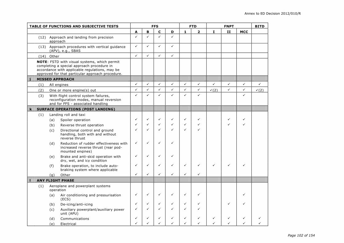
Annex to ED Decision 2012/010/R
Page 102 of 154
TABLE OF FUNCTIONS AND SUBJECTIVE TESTS FFS FTD FNPT BITD
A B C D 1 2 I II MCC
(12) Approach and landing from precision approach
(13) Approach procedures with vertical guidance (APV), e.g., SBAS
(14) Other
NOTE: FSTD with visual systems, which permit completing a special approach procedure in accordance with applicable regulations, may be approved for that particular approach procedure.
j MISSED APPROACH
(1) All engines
(2) One or more engine(s) out (2) (2)
(3) With flight control system failures, reconfiguration modes, manual reversion and for FFS - associated handling
k SURFACE OPERATIONS (POST LANDING)
(1) Landing roll and taxi
(a) Spoiler operation
(b) Reverse thrust operation
(c) Directional control and ground handling, both with and without reverse thrust
(d) Reduction of rudder effectiveness with increased reverse thrust (rear pod-mounted engines)
(e) Brake and anti-skid operation with dry, wet, and icy condition
(f) Brake operation, to include auto-braking system where applicable
(g) Other
l ANY FLIGHT PHASE
(1) Aeroplane and powerplant systems operation
(a) Air conditioning and pressurisation (ECS)
(b) De-icing/anti-icing
(c) Auxiliary powerplant/auxiliary power unit (APU)
(d) Communications
(e) Electrical

Annex to ED Decision 2012/010/R
Page 103 of 154
TABLE OF FUNCTIONS AND SUBJECTIVE TESTS FFS FTD FNPT BITD
A B C D 1 2 I II MCC
(f) Fire and smoke detection and suppression
(g) Flight controls (primary and secondary)
(h) Fuel and oil, hydraulic and pneumatic
(i) Landing gear
(j) Oxygen
(k) Powerplant
(l) Airborne radar
(m) Autopilot and flight director
(n) Collision avoidance systems (e.g.
GPWS, TCAS)
(o) Flight control computers including stability and control augmentation
(p) Flight display systems
(q) Flight management computers
(r) Head-up guidance, head-up displays
(s) Navigation systems
(t) Stall warning/avoidance
(u) Wind shear avoidance equipment
(v) Automatic landing aids
(2) Airborne procedures
(a) Holding
(b) Air hazard avoidance. (traffic, weather)
(c) Wind shear
(3) Engine shutdown and parking
(a) Engine and systems operation
(b) Parking brake operation
(4) Other as appropriate including effects of wind

Annex to ED Decision 2012/010/R
Page 104 of 154
TABLE OF FUNCTIONS AND SUBJECTIVE TESTS FFS FTD FNPT BITD
A B C D 1 2 I II MCC
m VISUAL SYSTEM
(1) Functional test content requirements (levels C and D)
NOTE: The following is the minimum airport model content requirement to satisfy visual capability tests, and provides suitable visual cues to allow completion of all functions and subjective tests described in this appendix. FSTD operators are encouraged to use the model content described below for the functions and subjective tests. If all of the elements cannot be found at a single real world airport, then additional real world
airports may be used. The intent of this visual scene content requirement description is to identify that content required to aid the pilot in making appropriate, timely decisions.
(a) two parallel runways and one crossing runway displayed simultaneously; at least two runways should be lit simultaneously
(b) runway threshold elevations and locations should be modelled to provide sufficient correlation with aeroplane systems (e.g., HGS, GPS, altimeter); slopes in runways, taxiways, and ramp areas should not cause distracting or unrealistic effects, including pilot eye-point height variation
(c) representative airport buildings, structures and lighting
(d) one useable gate, set at the appropriate height, for those aeroplanes that typically operate from terminal gates
(e) representative moving and static gate clutter (e.g., other aeroplanes, power carts, tugs, fuel trucks, additional gates)
(f) representative gate/apron markings (e.g., hazard markings, lead-in lines, gate numbering) and lighting
(g) representative runway markings, lighting, and signage, including a wind sock that gives appropriate wind cues
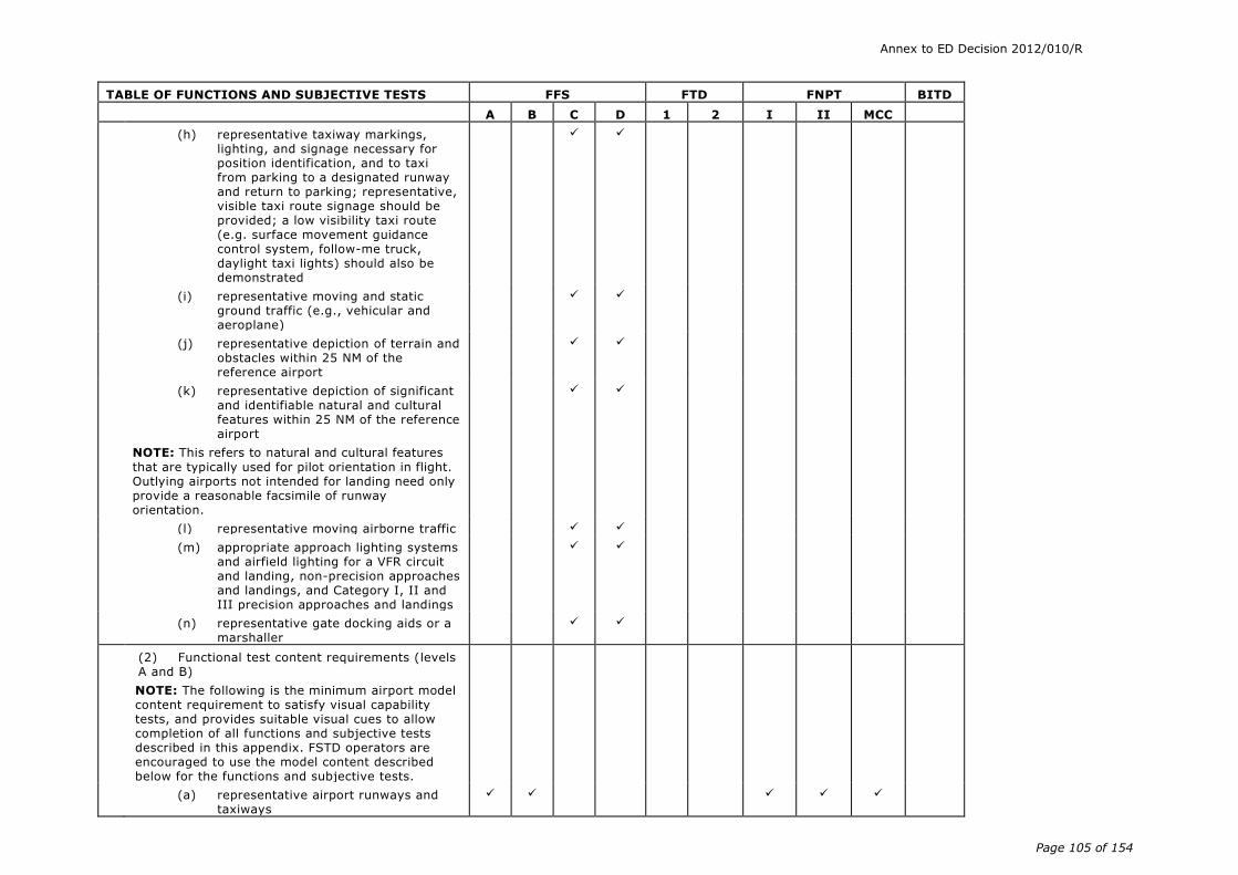
Annex to ED Decision 2012/010/R
Page 105 of 154
TABLE OF FUNCTIONS AND SUBJECTIVE TESTS FFS FTD FNPT BITD
A B C D 1 2 I II MCC
(h) representative taxiway markings, lighting, and signage necessary for position identification, and to taxi from parking to a designated runway and return to parking; representative, visible taxi route signage should be provided; a low visibility taxi route (e.g. surface movement guidance control system, follow-me truck, daylight taxi lights) should also be demonstrated
(i) representative moving and static ground traffic (e.g., vehicular and aeroplane)
(j) representative depiction of terrain and obstacles within 25 NM of the reference airport
(k) representative depiction of significant and identifiable natural and cultural features within 25 NM of the reference airport
NOTE: This refers to natural and cultural features
that are typically used for pilot orientation in flight. Outlying airports not intended for landing need only provide a reasonable facsimile of runway orientation.
(l) representative moving airborne traffic
(m) appropriate approach lighting systems and airfield lighting for a VFR circuit and landing, non-precision approaches and landings, and Category I, II and III precision approaches and landings
(n) representative gate docking aids or a marshaller
(2) Functional test content requirements (levels A and B)
NOTE: The following is the minimum airport model content requirement to satisfy visual capability tests, and provides suitable visual cues to allow completion of all functions and subjective tests described in this appendix. FSTD operators are encouraged to use the model content described below for the functions and subjective tests.
(a) representative airport runways and taxiways
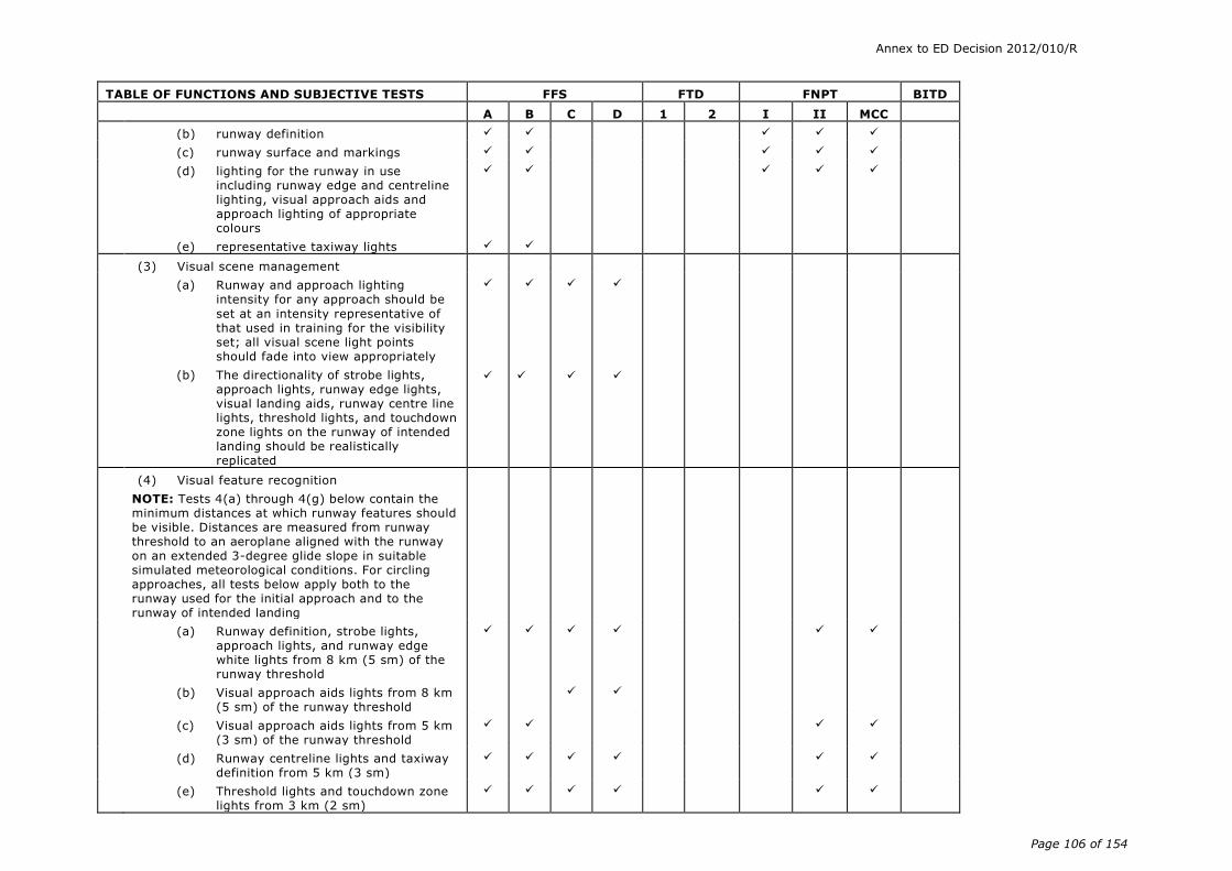
Annex to ED Decision 2012/010/R
Page 106 of 154
TABLE OF FUNCTIONS AND SUBJECTIVE TESTS FFS FTD FNPT BITD
A B C D 1 2 I II MCC
(b) runway definition
(c) runway surface and markings
(d) lighting for the runway in use including runway edge and centreline lighting, visual approach aids and approach lighting of appropriate colours
(e) representative taxiway lights
(3) Visual scene management
(a) Runway and approach lighting intensity for any approach should be
set at an intensity representative of that used in training for the visibility set; all visual scene light points should fade into view appropriately
(b) The directionality of strobe lights, approach lights, runway edge lights, visual landing aids, runway centre line lights, threshold lights, and touchdown zone lights on the runway of intended landing should be realistically replicated
(4) Visual feature recognition
NOTE: Tests 4(a) through 4(g) below contain the minimum distances at which runway features should be visible. Distances are measured from runway threshold to an aeroplane aligned with the runway on an extended 3-degree glide slope in suitable simulated meteorological conditions. For circling approaches, all tests below apply both to the runway used for the initial approach and to the runway of intended landing
(a) Runway definition, strobe lights, approach lights, and runway edge white lights from 8 km (5 sm) of the runway threshold
(b) Visual approach aids lights from 8 km (5 sm) of the runway threshold
(c) Visual approach aids lights from 5 km (3 sm) of the runway threshold
(d) Runway centreline lights and taxiway definition from 5 km (3 sm)
(e) Threshold lights and touchdown zone lights from 3 km (2 sm)

Annex to ED Decision 2012/010/R
Page 107 of 154
TABLE OF FUNCTIONS AND SUBJECTIVE TESTS FFS FTD FNPT BITD
A B C D 1 2 I II MCC
(f) Runway markings within range of landing lights for night scenes as required by the surface resolution test on day scenes
(g) For circling approaches, the runway of intended landing and associated lighting should fade into view in a non-distracting manner
(5) Airport model content
Minimum of three specific airport scenes as defined below;
(a) terminal approach area
A. accurate portrayal of airport features is to be consistent with published data used for aeroplane operations
B. all depicted lights should be checked for appropriate colours, directionality, behaviour and spacing (e.g., obstruction lights, edge lights, centre line, touchdown zone, VASI, PAPI, REIL and strobes)
C. depicted airport lighting should be selectable via controls at the instructor station as required for aeroplane operation
D. selectable airport visual scene capability at each model demonstrated for:
(i) night
(ii) twilight
(iii) day
E. (i) ramps and terminal buildings which correspond to an operator’s LOFT and LOS scenarios
(ii) terrain- appropriate terrain, geographic and cultural features

Annex to ED Decision 2012/010/R
Page 108 of 154
TABLE OF FUNCTIONS AND SUBJECTIVE TESTS FFS FTD FNPT BITD
A B C D 1 2 I II MCC
(iii) dynamic effects - the capability to present multiple ground and air hazards such as another aeroplane crossing the active runway or converging airborne traffic; hazards should be selectable via controls at the instructor station
(iv) illusions - operational visual scenes which portray representative physical relationships known to cause landing illusions, for example short runways, landing approaches over water, uphill or downhill runways, rising terrain on the approach path and unique topographic
features
NOTE: Illusions may be demonstrated at a generic airport or specific aerodrome.
(6) Correlation with aeroplane and associated equipment
(a) visual system compatibility with aerodynamic programming
(b) visual cues to assess sink rate and depth perception during landings. Visual cueing sufficient to support changes in approach path by using runway perspective. Changes in visual cues during take-off and approach should not distract the pilot
(c) accurate portrayal of environment relating to FSTD attitudes
(d) the visual scene should correlate with integrated aeroplane systems, where fitted (e.g. terrain, traffic and weather avoidance systems and head-up guidance system (HGS))
(e) representative visual effects for each visible, ownship, aeroplane external light

Annex to ED Decision 2012/010/R
Page 109 of 154
TABLE OF FUNCTIONS AND SUBJECTIVE TESTS FFS FTD FNPT BITD
A B C D 1 2 I II MCC
(f) the effect of rain removal devices should be provided
(7) Scene quality
(a) surfaces and textural cues should be free from apparent quantisation (aliasing)
(b) system capable of portraying full colour realistic textural cues
(c) the system light points should be free from distracting jitter, smearing or streaking
(d) demonstration of occulting through each channel of the system in an operational scene
(e) demonstration of a minimum of 10 levels of occulting through each channel of the system in an operational scene
(f) system capable of providing focus effects that simulate rain and light point perspective growth
(g) system capable of six discrete light step controls (0-5)
(8) Environmental effects
(a) the displayed scene should correspond to the appropriate surface contaminants and include runway lighting reflections for wet, partially obscured lights for snow, or suitable alternative effects
(b) Special weather representations which include the sound, motion and visual effects of light, medium and heavy precipitation near a thunderstorm on take-off, approach and landings at and below an altitude of 600 m (2 000 ft) above the aerodrome surface and within a radius of 16 km (10 sm) from the aerodrome
(c) in-cloud effects such as variable cloud density, speed cues and ambient changes should be provided

Annex to ED Decision 2012/010/R
Page 110 of 154
TABLE OF FUNCTIONS AND SUBJECTIVE TESTS FFS FTD FNPT BITD
A B C D 1 2 I II MCC
(d) the effect of multiple cloud layers representing few, scattered, broken and overcast conditions giving partial or complete obstruction of the ground scene
(e) gradual break-out to ambient visibility/RVR, defined as up to 10% of the respective cloud base or top, 20 ft ≤ transition layer ≤200 ft; cloud effects should be checked at and below a height of 600 m (2 000 ft) above the aerodrome and within a radius of 16 km (10 sm) from the airport
(f) visibility and RVR measured in terms of distance. Visibility/RVR should be checked at and below a height of 600 m (2 000 ft) above the aerodrome and within a radius of 16 km (10 sm) from the airport
(g) patchy fog giving the effect of variable RVR. Note – Patchy fog is sometimes
referred to as patchy RVR.
(h) effects of fog on aerodrome lighting such as halos and defocus
(i) effect of ownship lighting in reduced visibility, such as reflected glare, to include landing lights, strobes, and beacons
(j) wind cues to provide the effect of blowing snow or sand across a dry runway or taxiway should be selectable from the instructor station
(9) Instructor controls of:
(a) Environmental effects, e.g. cloud base, cloud effects, cloud density, visibility in kilometres/statute miles and RVR in metres or feet
(b) Airport/aerodrome selection
(c) Airport/aerodrome lighting including variable intensity where appropriate
(4) (4)
(d) Dynamic effects including ground and flight traffic
(10) Night visual scene capability
(11) Twilight visual scene capability

Annex to ED Decision 2012/010/R
Page 111 of 154
TABLE OF FUNCTIONS AND SUBJECTIVE TESTS FFS FTD FNPT BITD
A B C D 1 2 I II MCC
(12) Daylight visual scene capability
n MOTION EFFECTS
The following specific motion effects are required to indicate the threshold at which a flight crew member should recognise an event or situation. Where applicable below, FFS pitch, side loading and directional control characteristics should be representative of the aeroplane as a function of aeroplane type:
(1) Effects of runway rumble, oleo deflections, ground speed, uneven runway, runway centreline lights and taxiway characteristics
(a) After the aeroplane has been pre-set to the take-off position and then released, taxi at various speeds, first with a smooth runway, and note the general characteristics of the simulated runway rumble effects of oleo deflections. Next repeat the manoeuvre with a runway roughness of 50%, then finally with maximum roughness. The associated motion vibrations should be affected by ground speed and runway roughness. If time permits, different gross weights can also be selected as this may also affect the associated vibrations depending on aeroplane type. The associated motion effects for the above tests should also include an assessment of the effects of centreline lights, surface discontinuities of uneven runways, and various taxiway characteristics.
*
(2) Buffets on the ground due to spoiler/speedbrake extension and thrust
(a) Perform a normal landing and use ground spoilers and reverse thrust – either individually or in combination with each other – to decelerate the simulated aeroplane. Do not use wheel braking so that only the buffet due to the ground spoilers and thrust reversers is felt.
*

Annex to ED Decision 2012/010/R
Page 112 of 154
TABLE OF FUNCTIONS AND SUBJECTIVE TESTS FFS FTD FNPT BITD
A B C D 1 2 I II MCC
(3) Bumps associated with the landing gear
(a) Perform a normal take-off paying special attention to the bumps that could be perceptible due to maximum oleo extension after lift-off. When the landing gear is extended or retracted, motion bumps could be felt when the gear locks into position
*
(4) Buffet during extension and retraction of landing gear
(a) Operate the landing gear. Check that
the motion cues of the buffet experienced are reasonably representative of the actual aeroplane
*
(5) Buffet in the air due to flap and spoiler/speedbrake extension and approach to stall buffet
(a) First perform an approach and extend the flaps and slats, especially with airspeeds deliberately in excess of the normal approach speeds. In cruise configuration verify the buffets associated with the spoiler/speedbrake extension. The above effects could also be verified with different combinations of speedbrake/flap/gear settings to assess the interaction effects
*
(6) Approach to stall buffet
(a) Conduct an approach-to-stall with engines at idle and a deceleration of 1 kt/s. Check that the motion cues of the buffet, including the level of buffet
increase with decreasing speed, are reasonably representative of the actual aeroplane
*
(7) Touchdown cues for main and nose gear
(a) Fly several normal approaches with various rates of descent. Check that the motion cues of the touchdown bump for each descent rate are reasonably representative of the actual aeroplane
*

Annex to ED Decision 2012/010/R
Page 113 of 154
TABLE OF FUNCTIONS AND SUBJECTIVE TESTS FFS FTD FNPT BITD
A B C D 1 2 I II MCC
(8) Nose wheel scuffing
(a) Taxi the simulated aeroplane at various ground speeds and manipulate the nose wheel steering to cause yaw rates to develop which cause the nose wheel to vibrate against the ground (“scuffing”). Evaluate the speed/nose wheel combination needed to produce scuffing and check that the resultant vibrations are reasonably representative of the actual aeroplane
*
(9) Thrust effect with brakes set
(a) With the simulated aeroplane set with the brakes on at the take-off point, increase the engine power until buffet is experienced and evaluate its characteristics. This effect is most discernible with wing mounted engines. Confirm that the buffet increases appropriately with increasing engine thrust
*
(10) Mach and manoeuvre buffet
(a) With the simulated aeroplane trimmed in 1 g flight while at high altitude, increase the engine power such that the Mach number exceeds the documented value at which Mach buffet is experienced. Check that the buffet begins at the same Mach number as it does in the aeroplane (for the same configuration) and that buffet levels are a reasonable representation of the actual aeroplane. In the case of some aeroplanes, manoeuvre buffet could also be verified for the same effects. Manoeuvre buffet can occur during turning flight at conditions greater than 1 g, particularly at higher altitudes
*
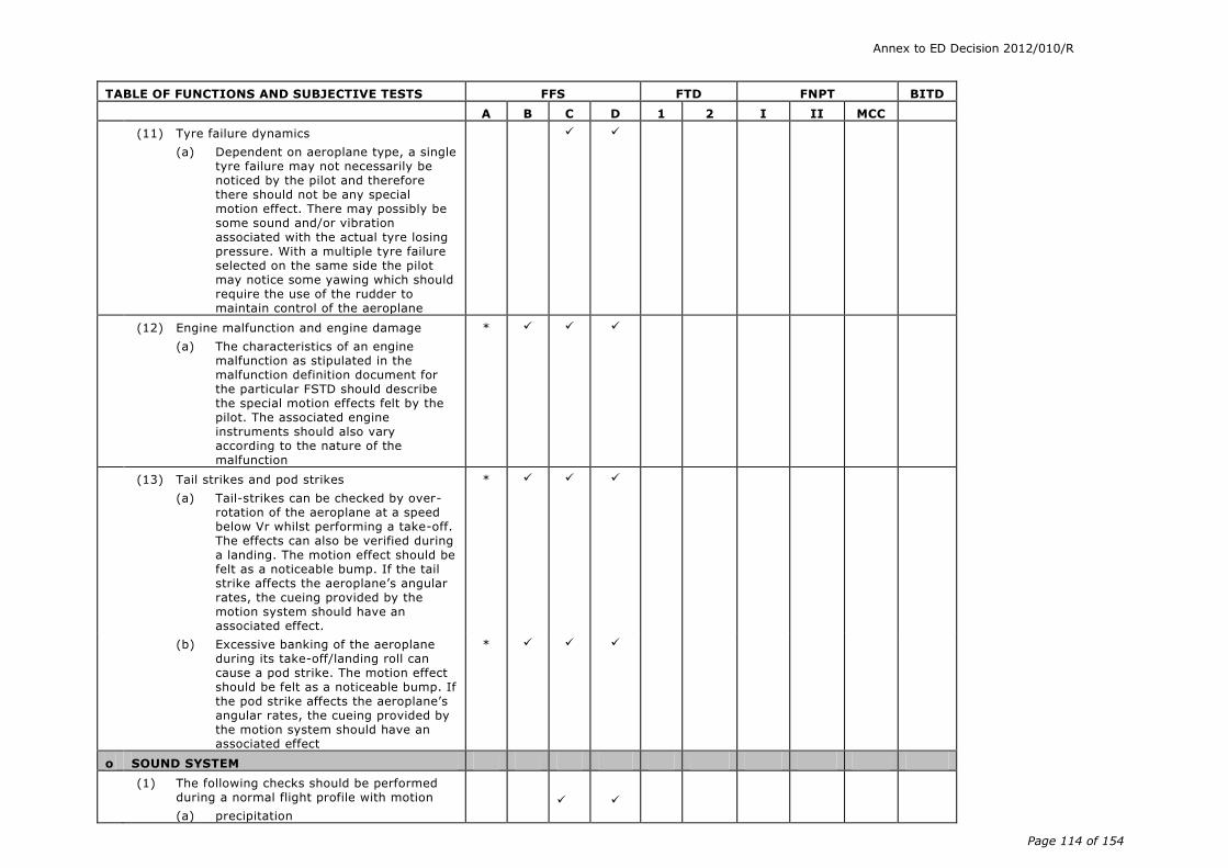
Annex to ED Decision 2012/010/R
Page 114 of 154
TABLE OF FUNCTIONS AND SUBJECTIVE TESTS FFS FTD FNPT BITD
A B C D 1 2 I II MCC
(11) Tyre failure dynamics
(a) Dependent on aeroplane type, a single tyre failure may not necessarily be noticed by the pilot and therefore there should not be any special motion effect. There may possibly be some sound and/or vibration associated with the actual tyre losing pressure. With a multiple tyre failure selected on the same side the pilot may notice some yawing which should require the use of the rudder to maintain control of the aeroplane
(12) Engine malfunction and engine damage
(a) The characteristics of an engine malfunction as stipulated in the malfunction definition document for the particular FSTD should describe the special motion effects felt by the pilot. The associated engine instruments should also vary according to the nature of the malfunction
*
(13) Tail strikes and pod strikes
(a) Tail-strikes can be checked by over-rotation of the aeroplane at a speed below Vr whilst performing a take-off. The effects can also be verified during a landing. The motion effect should be felt as a noticeable bump. If the tail strike affects the aeroplane’s angular rates, the cueing provided by the motion system should have an associated effect.
*
(b) Excessive banking of the aeroplane during its take-off/landing roll can cause a pod strike. The motion effect should be felt as a noticeable bump. If the pod strike affects the aeroplane’s angular rates, the cueing provided by the motion system should have an associated effect
*
o SOUND SYSTEM
(1) The following checks should be performed during a normal flight profile with motion
(a) precipitation

Annex to ED Decision 2012/010/R
Page 115 of 154
TABLE OF FUNCTIONS AND SUBJECTIVE TESTS FFS FTD FNPT BITD
A B C D 1 2 I II MCC
(b) rain removal equipment
(c) significant aeroplane noises perceptible to the pilot during normal operations, such as engine, flaps, gear, spoiler extension/retraction, thrust reverser to a comparable level of that found in the aeroplane
(d) abnormal operations for which there are associated sound cues including, but not limited to, engine malfunctions, landing gear/tire malfunctions, tail and engine pod strike and pressurisation malfunction
(e) sound of a crash when the FFS is landed in excess of limitations
(f) significant engine/propeller noise perceptible to pilot during normal operations
p SPECIAL EFFECTS
(1) Braking Dynamics
(a) representative brake failure dynamics (including antiskid) and decreased brake efficiency due to high brake temperatures based on aeroplane related data. These representations should be realistic enough to cause pilot identification of the problem and implementation of appropriate procedures. FSTD pitch, side-loading and directional control characteristics should be representative of the aeroplane
(2) Effects of Airframe and Engine Icing
(a) See Appendix 1 to CS FSTD(A).300 1.t.1.
NOTE: For level ‘A’, an asterisk (*) denotes that the appropriate effect is required to be present.
NOTE: It is accepted that tests will only apply to FTD level 1 if that system and flight condition is simulated. It is intended that the tests listed below should be conducted in automatic flight. Where automatic flight is not possible and pilot manual handling is required, the FTD should be at least controllable to permit the conduct of the flight.

Annex to ED Decision 2012/010/R
Page 116 of 154
NOTES:
General: motion and buffet cues will only be applicable to FSTD equipped with an appropriate motion system
(1) take-off characteristics sufficient to commence the airborne exercises;
(2) for FNPT 1 and BITD only if multi-engine;
(3) only trim change is required; and
(4) for FNPT, variable intensity airport lighting is not required.

Annex to ED Decision 2012/010/R
Page 117 of 154
Appendix 1 to AMC1 FSTD(A).300 Validation test tolerances
(a) Background
(1) The tolerances listed in AMC1 FSTD(A).300 are designed to be a measure of quality of match using flight test data as a reference.
(2) There are many reasons, however, why a particular test may not fully comply with the prescribed tolerances:
(i) flight test is subject to many sources of potential error, e.g. instrumentation errors and atmospheric disturbance during data collection;
(ii) data that exhibit rapid variation or noise may also be difficult to match; or
(iii) engineering simulator data and other calculated data may exhibit errors due to a variety of potential differences discussed below.
(3) When applying tolerances to any test, good engineering judgement should be applied. Where a test clearly falls outside the prescribed tolerance(s) for no apparent reason, then it should be judged to have failed.
(4) When engineering simulator data are used, the basis for their use is that the reference data are produced using the same simulation models as used in the equivalent FSTD; i.e., the two sets of results should be ‘essentially’ similar. The use of flight test-based tolerances may undermine the basis for using engineering simulator data, because an essential match is needed to demonstrate proper implementation of the data package.
(5) There are, of course, reasons why the results from the two sources can be expected to differ:
(i) hardware (avionics units and flight controls);
(ii) iteration rates;
(iii) execution order;
(iv) integration methods;
(v) processor architecture;
(vi) digital drift:
(A) interpolation methods;
(B) data handling differences; or
(C) auto-test trim tolerances, etc.
(6) Any differences should, however, be small and the reasons for any differences, other than those listed above, should be clearly explained.
(7) Historically, engineering simulation data were used only to demonstrate compliance with certain extra modelling features:
(i) flight test data could not reasonably be made available;
(ii) data from engineering simulations made up only a small portion of the overall validation data set; or
(iii) key areas were validated against flight test data.

Annex to ED Decision 2012/010/R
Page 118 of 154
(8) The current rapid increase in the use and projected use of engineering simulation data is an important issue because:
(i) flight test data are often not available due to sound technical reasons;
(ii) alternative technical solutions are being advanced; and
(iii) cost is an ever-present issue.
(9) Guidelines are therefore needed for the application of tolerances to engineering-simulator-generated validation data.
(b) Non-flight test tolerances
(1) Where engineering simulator data or other non-flight test data are used as an allowable form of reference validation data for the objective tests listed in the table of validation tests, the match obtained between the reference data and the FSTD results should be very close. It is not possible to define a precise set of tolerances as the reasons for other than an exact match will vary depending upon a number of factors discussed in paragraph (a) of this Appendix.
(2) As guidance, unless a rationale justifies a significant variation between the reference data and the FSTD results, 20% of the corresponding ‘flight test’ tolerances would be appropriate.
(3) For this guideline (20% of flight test tolerances) to be applicable, the data provider should supply a well-documented mathematical model and testing procedure that enables an exact replication of their engineering simulation results.

Annex to ED Decision 2012/010/R
Page 119 of 154
Appendix 2 to AMC1 FSTD(A).300 Validation data roadmap
(a) General
(1) Aeroplane manufacturers or other sources of data should supply a validation data roadmap (VDR) document as part of the data package. A VDR document contains guidance material from the aeroplane validation data supplier recommending the best possible sources of data to be used as validation data in the QTG. A VDR is of special value in the cases of requests for ‘interim’ qualification, requests for qualification of simulations of aeroplanes certificated prior to 1992, and for qualification of alternate engine or avionics fits (see Appendices 3 and 4 of this AMC). A VDR should be submitted to the competent authority as early as possible in the planning stages for any FSTD planned for qualification to the standards contained herein. The respective Member State’s civil aviation authority is the final authority to approve the data to be used as validation material for the QTG.
(2) The validation data roadmap should clearly identify (in matrix format) sources of data for all required tests. It should also provide guidance regarding the validity of these data for a specific engine type and thrust rating configuration and the revision levels of all avionics affecting aeroplane handling qualities and performance. The document should include rationale or explanation in cases where data or parameters are missing, engineering simulation data are to be used, flight test methods require explanation, etc., together with a brief narrative describing the cause/effect of any deviation from data requirements. Additionally, the document should make reference to other appropriate sources of validation data (e.g., sound and vibration data documents).
(3) Table 1 below depicts a generic roadmap matrix identifying sources of validation data for an abbreviated list of tests. A complete matrix should address all test conditions.
(4) Additionally, two examples of ‘rationale pages’ are presented in Appendix F of the IATA document Flight Simulation Training Device Design & Performance Data Requirements, 7th edition. These illustrate the type of aircraft and avionics configuration information and descriptive engineering rationale used to describe data anomalies, provide alternative data, or provide an acceptable basis to the competent authority for obtaining deviations from QTG validation requirements.

Annex to ED Decision 2012/010/R
Page 120 of 154
*1 CCA mode shall be described for each test condition. *2 If more than one aircraft type (e.g., derivative and baseline) are used as validation data more columns may be necessary.
Table 1: generic roadmap matrix

Annex to ED Decision 2012/010/R
Page 121 of 154
Appendix 3 to AMC1 FSTD(A).300 Data requirements for alternate engines -
approval guidelines (applicable to full flight simulators only)
(a) Background
(1) For a new aeroplane type, the majority of flight validation data are collected on the first aeroplane configuration with a ‘baseline’ engine type. These data are then used to validate all FFS representing that aeroplane type.
(2) In the case of FFS representing an aeroplane with engines of a different type than the baseline, or a different thrust rating than that of previously validated configurations, additional flight test validation data may be needed.
(3) When a FFS with additional and/or alternate engine fits is to be qualified, the QTG should contain tests against flight test validation data for selected cases where engine differences are expected to be significant.
(b) Approval Guidelines for validating alternate Engine Fits
(1) The following guidelines apply to FSTDs representing aeroplanes with an alternate engine fit or with more than one engine type or thrust rating.
(2) Validation tests should be segmented into those that are dependent on engine type or thrust rating, and those that are not.
(3) For tests that are independent of engine type or thrust rating, the QTG may be based on validation data from any engine fit. Tests in this category should be clearly identified.
(4) For tests which are affected by engine type, the QTG should contain selected engine-specific flight test data sufficient to validate that particular aeroplane-engine configuration. These effects may be due to engine dynamic characteristics, thrust levels and/or engine-related aeroplane configuration changes. This category is primarily characterised by differences between different engine manufacturers’ products, but also includes differences due to significant engine design changes from a previously flight-validated configuration within a single engine type. See Table 1 below for a list of acceptable tests.
(5) For those cases where the engine type is the same, but the thrust rating exceeds that of a previously flight-validated configuration by five per cent (5%) or more, or is significantly less than the lowest previously validated rating (a decrease of 15% or more), the QTG should contain selected engine-specific flight test data sufficient to validate the alternate thrust level. See Table 1 below for a list of acceptable tests. However, if an aeroplane manufacturer, qualified as a validation data supplier under the guidelines of AMC7 FSTD(A).300 and AMC8 FSTD(A).300, shows that a thrust increase greater than 5% will not significantly change the aeroplane’s flight characteristics, then flight validation data are not needed.
(6) No additional flight test data are required for thrust ratings which are not significantly different from that of the baseline or other applicable flight-validated engine-airframe configuration (i.e., less than 5% above or 15% below), except as noted in (b)(7) and (b)(8) below. As an example, for a configuration validated with 50000 pound-thrust-rated engines, no additional flight validation data are required for ratings between 42500 lbs and 52500 lbs. If multiple engine ratings are tested concurrently, only test data for the highest rating are needed.

Annex to ED Decision 2012/010/R
Page 122 of 154
(7) Throttle calibration data (i.e., commanded power setting parameter versus throttle position) should be provided to validate all alternate engine types, and engine thrust ratings that are higher or lower than a previously validated engine. Data from a test aeroplane or engineering test bench are acceptable, provided the correct engine controller (both hardware and software) is used.
(8) The validation data described in (b)(4) through (b)(7) above should be based on flight test data, except as noted there, or where other data are specifically allowed within AMC7 FSTD(A).300. However, if certification of the flight characteristics of the aeroplane with a new thrust rating (regardless of percentage change) does require certification flight testing with a comprehensive stability and control flight instrumentation package, then the conditions in table 1 below should be obtained from flight testing and presented in the QTG. Conversely, flight test data other than throttle calibration as described above are not required if the new thrust rating is certified on the aeroplane without need for a comprehensive stability and control flight instrumentation package.
(9) As a supplement to the engine-specific flight tests of table 1 below and baseline engine-independent tests, additional engine-specific engineering validation data should be provided in the QTG, as appropriate, to facilitate running the entire QTG with the alternate engine configuration. The specific validation tests to be supported by engineering simulation data should be agreed with the competent authority well in advance of FSTD evaluation.
(10) A matrix or roadmap should be provided with the QTG indicating the appropriate validation data source for each test (see Appendix 2 of this AMC).
The following flight test conditions (one per test number) are appropriate and should be
sufficient to validate implementation of alternate engine fits in an FSTD.
TEST NUMBER TEST DESCRIPTION ALTERNATE
ENGINE TYPE ALTERNATE THRUST RATING
2
1.b.1, 4 Normal take-off/ground acceleration time & distance
X X
1.b.2 Vmcg, if performed for aeroplane certification
X X
1.b.5 Engine-out take-off
Either test may be performed.
X 1.b.8
Dynamic engine failure after take-off
1.b.7 Rejected take-off if performed for aeroplane certification
X
1.d.3 Cruise performance X
1.f.1, 2 Engine acceleration and deceleration X X
2.a.8 Throttle calibration 1 X X
2.c.1 Power change dynamics (acceleration) X X
2.d.1 Vmca if performed for aeroplane certification
X X
2.d.5 Engine inoperative trim X X
2.e.1 Normal landing X
1 Should be provided for all changes in engine type or thrust rating (see (b)(7) above).
2 See (b)(5) through (b)(8) above for a definition of applicable thrust ratings.
Note: This table does not take into consideration additional configuration settings and control laws.
Table 1: Alternate engine validation flight tests
Annex to ED Decision 2012/010/R
Page 123 of 154
Appendix 4 to AMC1 FSTD(A).300 Data requirements for alternate avionics
(flight-related computers & controllers) – approval guidelines
(a) Background
(1) For a new aeroplane type, the majority of flight validation data is collected
on the first aeroplane configuration with a baseline flight-related avionics
ship-set (see (b)(2) below). These data are then used to validate all FSTDs
representing that aeroplane type.
(2) In the case of FSTDs representing an aeroplane with avionics of a different
hardware design than the baseline, or a different software revision than
that of previously validated configurations, additional validation data may
be required.
(3) When an FSTD with additional and/or alternate avionics configurations is to
be qualified, the qualification test guide (QTG) should contain tests against
validation data for selected cases where avionics differences are expected
to be significant.
(b) Approval guidelines for validating alternate avionics
(1) The following guidelines apply to FSTDs representing aeroplanes with a
revised, or more than one, avionics configuration.
(2) The aeroplane avionics should be segmented into those systems or
components that can significantly affect the QTG results and those that
cannot. The following avionics are examples of those for which hardware
design changes or software revision updates may lead to significant
differences relative to the baseline avionics configuration: flight control
computers and controllers for engines, autopilot, braking system, nose
wheel steering system, high lift system, and landing gear system. Related
avionics such as stall warning and augmentation systems should also be
considered. The aeroplane manufacturer should identify for each validation
test which avionics systems, if changed, could affect test results.
(3) The baseline validation data should be based on flight test data, except
where other data are specifically allowed (see AMC7 FSTD(A).300 and
AMC8 FSTD(A).300).
(4) For changes to an avionics system or component that cannot affect master
QTG (MQTG) validation test results, the QTG test can be based on
validation data from the previously validated avionics configuration.
(5) For changes to an avionics system or component that could affect a QTG
validation test, but where that test is not affected by this particular change
(e.g., the avionics change is a built-in test equipment (BITE) update or a
modification in a different flight phase), the QTG test can be based on
validation data from the previously-validated avionics configuration. The
aeroplane manufacturer should clearly state that this avionics change does
not affect the test.
(6) For an avionics change which affects some tests in the QTG, but where no
new functionality is added and the impact of the avionics change on
aeroplane response is a small, well-understood effect, the QTG may be
based on validation data from the previously validated avionics
configuration. This should be supplemented with avionics-specific validation
data from the aeroplane manufacturer’s engineering simulation, generated
with the revised avionics configuration. In such cases, the aeroplane
manufacturer should provide a rationale explaining the nature of the
change and its effect on the aeroplane response.

Annex to ED Decision 2012/010/R
Page 124 of 154
(7) For an avionics change that significantly affects some tests in the QTG,
especially where new functionality is added, the QTG should be based on
validation data from the previously validated avionics configuration and
supplemental avionics-specific flight test data sufficient to validate the
alternate avionics revision. However, additional flight validation data may
not be needed if the avionics changes were certified without need for
testing with a comprehensive flight instrumentation package. The
aeroplane manufacturer should coordinate FSTD data requirements in this
situation, in advance, with the competent authority.
(8) A matrix or roadmap should be provided with the QTG indicating the
appropriate validation data source for each test (see Appendix 2 to
AMC1 FSTD(A).300).

Annex to ED Decision 2012/010/R
Page 125 of 154
Appendix 5 to AMC1 FSTD(A).300 Transport delay and latency testing methods
(a) General
(1) The purpose of this appendix is to demonstrate how to determine the introduced transport delay through the FSTD system such that it does not exceed a specific time delay. That is, measure the transport delay from control inputs through the interface, through each of the host computer modules and back through the interface to motion, flight instrument and visual systems, and show that it is no more than the tolerances required in the validation test tables. (For latency testing methods see (b)).
(2) Four specific examples of transport delay are described as follows:
(i) simulation of classic non-computer-controlled aircraft;
(ii) simulation of computer-controlled aircraft using real aircraft equipment;
(iii) simulation of computer-controlled aircraft using software emulation of aircraft equipment; and
(iv) simulation using software avionics or rehosted instruments.
(3) Figure 1 illustrates the total transport delay for a non-computer-controlled aircraft, or the classic transport delay test.
(4) Since there are no aircraft-induced delays for this case, the total transport delay is equivalent to the introduced delay.
(5) Figure 2 illustrates the transport delay testing method employed on an FSTD that uses the real aircraft controller system.
(6) To obtain the induced transport delay for the motion, instrument and visual signal, the delay induced by the aircraft controller should be subtracted from the total transport delay. This difference represents the introduced delay.
(7) Introduced transport delay is measured from the cockpit control input to the reaction of the instruments, and motion and visual systems (See figure 1).
(8) Alternatively, the control input may be introduced after the aircraft controller system and the introduced transport delay measured directly from the control input to the reaction of the instruments, and FSTD motion and visual systems (see figure 2).
(9) Figure 3 illustrates the transport delay testing method employed on an FSTD that uses a software emulated aircraft controller system.
(10) By using the simulated aircraft controller system architecture for the pitch, roll and yaw axes, it is not possible to measure simply the introduced transport delay. Therefore, the signal should be measured directly from the pilot controller. Since in the real aircraft the controller system has an inherent delay as provided by the aircraft manufacturer, the FSTD manufacturer should measure the total transport delay and subtract the inherent delay of the actual aircraft components and ensure that the introduced delay does not exceed the tolerances required in the validation test tables.
(11) Special measurements for instrument signals for FSTDs using a real aircraft instrument display system, versus a simulated or rehosted display. For the case of the flight instrument systems, the total transport delay should be measured, and the inherent delay of the actual aircraft components

Annex to ED Decision 2012/010/R
Page 126 of 154
subtracted to ensure that the introduced delay does not exceed the tolerances required in the validation test tables.
(i) Figure 4A illustrates the transport delay procedure without the simulation of aircraft displays. The introduced delay consists of the delay between the control movement and the instrument change on the data bus.
(ii) Figure 4B illustrates the modified testing method required to correctly measure introduced delay due to software avionics or rehosted instruments. The total simulated instrument transport delay is measured and the aircraft delay should be subtracted from this total. This difference represents the introduced delay and should not exceed the tolerances required in the validation test tables. The inherent delay of the aircraft between the data bus and the displays is indicated as XX ms (see figure 4A). The display manufacturer should provide this delay time.
(12) Recorded signals. The signals recorded to conduct the transport delay calculations should be explained on a schematic block diagram. The FSTD manufacturer should also provide an explanation of why each signal was selected and how they relate to the above descriptions.
(13) Interpretation of results. It is normal that FSTD results vary over time from test to test. This can easily be explained by a simple factor called ‘sampling uncertainty’. All FSTDs run at a specific rate where all modules are executed sequentially in the host computer. The flight controls input can occur at any time in the iteration, but these data will not be processed before the start of the new iteration. For an FSTD running at 60 Hz a worst-case difference of 16·67 ms can be expected. Moreover, in some conditions, the host computer and the visual system do not run at the same iteration rate, therefore the output of the host computer to the visual will not always be synchronised.
(14) The transport delay test should account for daylight, twilight (dusk, dawn) and night modes (as applicable) of operation of the visual system. The tolerance is as required in the validation test tables and motion response should occur before the end of the first video scan containing new information.
Figure 1: Transport delay for simulation of classic non-computer-
controlled aircraft
Flight
controls
input
Simulator
flight control
interface
HOST
Ÿ Instruments
Ÿ Motion
Ÿ Visual
Ÿ Instruments
reaction
Ÿ Motion
reaction
Ÿ Visual
reaction
Simulator introduced transport delay
Total simulator transport delay

Annex to ED Decision 2012/010/R
Page 127 of 154
Figure 2: Transport delay for simulation of computer-controlled aircraft
using real aircraft equipment
Figure 3: Transport delay for simulation of computer-controlled aircraft using software emulation of aircraft equipment
Figure 4A and 4B: Transport delay for simulation of aircraft using real or rehosted
instrument drivers
Flight
controls
input
Aeroplane
controller
system
Simulator
flight
control
interface
Aircraft delay
HOST
Ÿ Instruments
Ÿ Motion
Ÿ Visual
Ÿ Instruments
reaction
Ÿ Motion reaction
Ÿ Visual reaction
Simulator introduced delay
Total simulator transport delay
Flight
controls
input
Simulator
flight
control
interface
Simulated
aeroplane
controller
system
HOST
Ÿ Instruments
Ÿ Motion
Ÿ Visual
Ÿ Instruments
reaction
Ÿ Motion
reaction
Ÿ Visual
reaction
Total simulator transport delay
Total transport delay (including aircraft delays)
Aircraft hardware
Display unit Software avionics
or
Re-hosted instrument Interface
Control,
Flight,
Instruments,
Software
Flight controls
signal
Host computer Flight control cabinet
B: FSTD using software avionics or re-hosted instruments
A: FSTD using real aircraft instruments
Flight control cabinet Host computer
Flight controls
signal
Control,
Flight,
Instruments,
Software
Interface
Delay less than "req’d value"
Data
bus
Aircraft hardware
Display unit
Aircraft delay = XX msec
EFIS symbol
generator

Annex to ED Decision 2012/010/R
Page 128 of 154
(b) Latency Test Methods
(1) The visual system, flight deck instruments and initial motion system response should respond to abrupt pitch, roll and yaw inputs from the pilot's position within the specified time, but not before the time, when the aeroplane would respond under the same conditions. The objective of the test is to compare the recorded response of the FSTD to that of the actual aeroplane data in the take-off, cruise and landing configuration for rapid control inputs in all three rotational axes. The intent is to verify that the FSTD system response does not exceed the specified time (this does not include aeroplane response time as per the manufacturer’s data) and that the motion and visual cues relate to actual aeroplane responses. For the aeroplane response, acceleration in the appropriate corresponding rotational axis is preferred.
(2) Interpretation of results. It is normal that FSTD results vary over time from test to test. This can easily be explained by a simple factor called ‘sampling uncertainty.’ All FSTDs run at a specific rate where all modules are executed sequentially in the host computer. The flight controls input can occur at any time in the iteration, but these data will not be processed before the start of the new iteration. For an FSTD running at 60 Hz a worst-case difference of 16·67 ms can be expected. Moreover, in some conditions, the host computer and the visual system do not run at the same iteration rate; therefore the output of the host computer to the visual will not always be synchronised.
Annex to ED Decision 2012/010/R
Page 129 of 154
Appendix 6 to AMC1 FSTD(A).300 Recurrent evaluations - validation test data
presentation
(a) Background
(1) During the initial evaluation of an FSTD the master qualification test guide (MQTG) is created. This is the master document, as amended, to which FSTD recurrent evaluation test results are compared.
(2) The currently accepted method of presenting recurrent evaluation test results is to provide FSTD results overplotted with reference data. Test results are carefully reviewed to determine if the test is within the specified tolerances. This can be a time consuming process, particularly when reference data exhibits rapid variations or an apparent anomaly requiring engineering judgement in the application of the tolerances. In these cases the solution is to compare the results to the MQTG. If the recurrent results are the same as those in the MQTG, the test is accepted. Both the FSTD operator and the competent authority are looking for any change in the FSTD performance since initial qualification.
(b) Recurrent evaluation test results presentation
(1) To promote a more efficient recurrent evaluation, FSTD operators are encouraged to overplot recurrent validation test results with MQTG FSTD results recorded during the initial evaluation and as amended. Any change in a validation test will be readily apparent. In addition to plotting recurrent validation test and MQTG results, operators may elect to plot reference data as well.
(2) For full flight simulators (FFSs) and flight training devices (FTDs: when tests are not based on CT&M) there are no suggested tolerances between the recurrent test results and the MQTG validation test results of the initial evaluation. Investigation of any discrepancy between the MQTG and recurrent FFS/FTD performance is left to the discretion of the FSTD operator and the competent authority.
For devices where CT&M is used for the initial evaluation, the test results for the recurrent evaluation should be acceptable if they are within the tolerances to the MQTG test results as given in AMC1 FSTD(A).300(b)(3).
(3) Differences between the two sets of results, other than minor variations attributable to repeatability issues (see Appendix 1 of this AMC), that cannot easily be explained, may require investigation.
(4) The FSTD should still retain the capability to overplot both automatic and manual validation test results with reference data.

Annex to ED Decision 2012/010/R
Page 130 of 154
Appendix 7 to AMC1 FSTD(A).300 Applicability of CS-FSTD amendments to
FSTD data packages for existing aeroplanes
Except where specifically indicated otherwise in AMC1 FSTD(A).300 (b)(3), validation data for qualification test guide (QTG) objective tests are expected to be derived from aeroplane flight testing.
Ideally, data packages for all new FSTDs should fully comply with the current standards for qualifying FSTDs.
For types of aeroplanes first entering into service after the publication of a new amendment of CS-FSTD(A), the provision of acceptable data to support the FSTD qualification process is a matter of planning and regulatory agreement.
For aeroplanes certificated prior to the release of the current amendment of CS-FSTD(A), it may not always be possible to provide the required data for any new or revised objective test cases compared to the previous amendments. After certification, manufacturers do not normally keep flight test aeroplanes available with the required instrumentation to gather additional data. In the case of flight test data gathered by independent data providers, it is most unlikely that the test aeroplane will still be available.
Notwithstanding the above discussion, except where other types of data are already acceptable (see, for example, AMC7 FSTD(A).300 and AMC8 FSTD(A).300), the preferred source of validation data is flight testing. It is expected that best endeavours will be made by data suppliers to provide the required flight test data. If any flight test data exist (flown during the certification or any other flight test campaigns) that address the requirement, these test data should be provided. If any possibility exists to do this flight test during the occasion of a new flight test campaign, this should be done and provided in the data package at the next issue. Where these flight test data are genuinely not available, alternative sources of data may be acceptable using the following hierarchy of preferences:
first: as defined in flight testing at an alternate but near equivalent condition/configuration.
second: data from an audited engineering simulation as defined in AMC1 FSTD(A).200(a) from an acceptable source (for example meets the guidelines laid out in AMC7 FSTD(A).300(b), or as used for aircraft certification.
third: aeroplane performance data as defined in AMC to CS FSTD(A).200 or other approved published sources (e.g., production flight test schedule) for the following tests:
i. 1.c(1) normal climb, all engines;
ii. 1.c(2) one engine inoperative 2nd segment climb;
iii. 1.c(3) one engine inoperative en-route climb;
iv. 1.c(4) one engine inoperative approach climb for aeroplanes with icing accountability;
v. 1.e(3) stopping distance, wheel brakes, wet runway, and test; and
vi. 1.e(4) stopping distance, wheel brakes, icy runway.
fourth: Where no other data are available, in exceptional circumstances only, the following sources may be acceptable subject to a case-by-case review with the competent authorities concerned taking into consideration the level of qualification sought for the FSTD:
i. unpublished but acceptable sources e.g., calculations, simulations, video or other simple means of flight test analysis or recording; or

Annex to ED Decision 2012/010/R
Page 131 of 154
ii. footprint test data from the actual training FSTD requiring qualification validated by subjective assessment by a pilot appointed by the competent authority.
In certain cases, it may make good engineering sense to provide more than one test to support a particular objective test requirement. An example is a minimum control speed (ground) test(Vmcg) test, where the flight test engine and thrust profile do not match the simulated engine. The VMCG test could be run twice, once with the flight test thrust profile as an input and a second time with a fully integrated response to a fuel cut on the simulated engine.
For aeroplanes certified prior to the date of issue of an amendment, an operator may, after reasonable attempts have failed to obtain suitable flight test data, indicate in the MQTG where flight test data are unavailable or unsuitable for a specific test. For each case, where the preferred data are not available, a rationale should be provided laying out the reasons for the non-compliance and justifying the alternate data and or test(s).
These rationales should be clearly recorded within the validation data roadmap (VDR) in accordance with and as defined in Appendix 2 to AMC1 FSTD(A).300.
It should be recognised that there may come a time when there are so little compatible flight test data available that new flight testing may be required.

Annex to ED Decision 2012/010/R
Page 132 of 154
Appendix 8 to AMC1 FSTD(A).300 General technical requirements for FSTD
qualification levels
This appendix summarises the general technical requirements for full flight simulators level A, B, C and D, flight training devices level 1 and 2, flight navigation procedures trainers level I, II and IIMCC, and basic instrument training devices.
Table 1:General technical requirements for level A, B, C and D full flight simulators(FFS)
Qualification Level
General technical requirements
A The lowest level of FFS technical complexity. An enclosed full-scale replica of the aeroplane cockpit/flight deck including simulation of all systems, instruments, navigational equipment, communications and caution and warning systems. An instructor’s station with seat should be provided. Seats for the flight crew
members and two seats for inspectors/observers should also be provided. Control forces and displacement characteristics should correspond to that of the replicated aeroplane and they should respond in the same manner as the aeroplane under the same flight conditions. The use of class specific data tailored to the specific aeroplane type with fidelity sufficient to meet the objective tests, functions and subjective tests is allowed. Generic ground effect and ground handling models are permitted.
Motion, visual and sound systems sufficient to support the training, testing and checking credits sought are required.
The visual system should provide at least 45 degrees horizontal and 30 degrees vertical field of view per pilot. The response to control inputs should not be greater than 300 ms more than that experienced on the aircraft.
B As for level A plus: Validation flight test data should be used as the basis for flight and performance and systems characteristics. Additionally ground handling and aerodynamics programming to include ground effect reaction and handling characteristics should be derived from validation flight test data.
C The second highest level of FFS fidelity. As for level B plus: A daylight/twilight/night visual system is required with a continuous, cross-cockpit, minimum collimated visual field of view providing each pilot with 180 degrees horizontal and 40 degrees vertical field of view.
A six-degrees-of-freedom motion system should be provided.
The sound simulation should include the sounds of precipitation and other significant aeroplane noises perceptible to the pilot and should be able to reproduce the sounds of a crash landing. The response to control inputs should not be greater than 150 ms more than that experienced on the airplane. Windshear simulation should be provided.
D The highest level of FFS fidelity. As for level C plus: Extended set of sound and motion buffet tests.
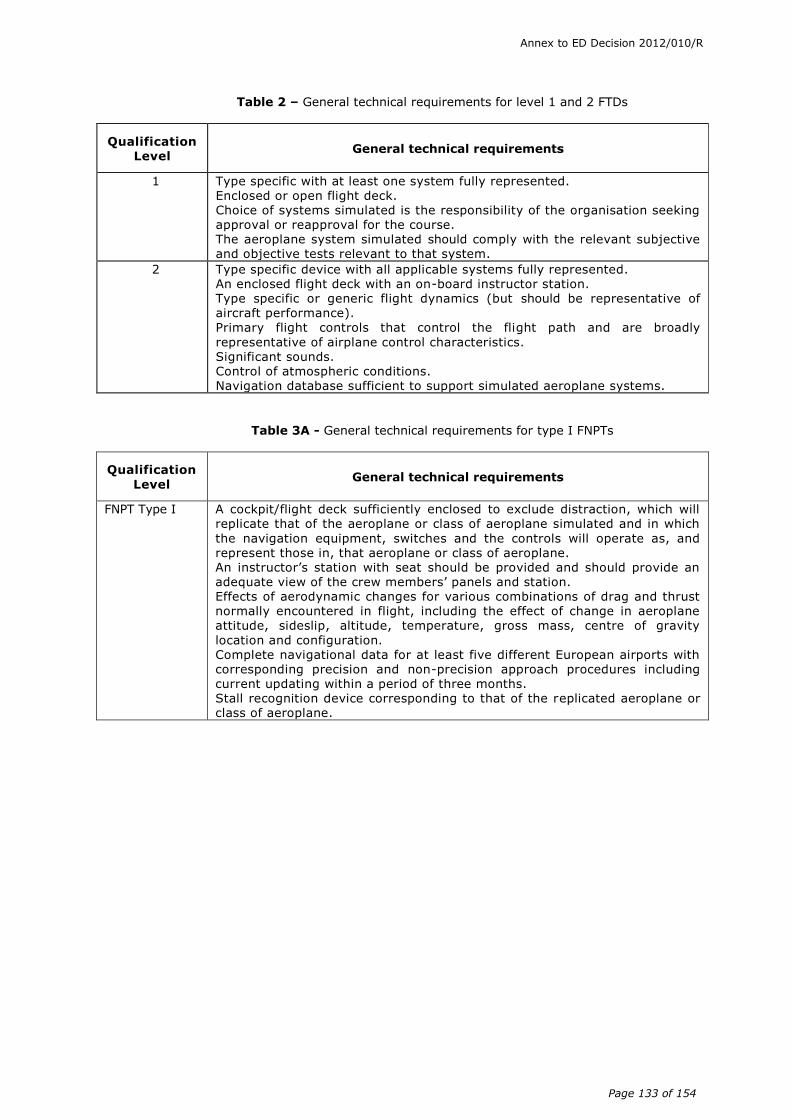
Annex to ED Decision 2012/010/R
Page 133 of 154
Table 2 – General technical requirements for level 1 and 2 FTDs
Qualification Level
General technical requirements
1 Type specific with at least one system fully represented. Enclosed or open flight deck. Choice of systems simulated is the responsibility of the organisation seeking approval or reapproval for the course. The aeroplane system simulated should comply with the relevant subjective and objective tests relevant to that system.
2 Type specific device with all applicable systems fully represented. An enclosed flight deck with an on-board instructor station. Type specific or generic flight dynamics (but should be representative of aircraft performance).
Primary flight controls that control the flight path and are broadly
representative of airplane control characteristics. Significant sounds. Control of atmospheric conditions. Navigation database sufficient to support simulated aeroplane systems.
Table 3A - General technical requirements for type I FNPTs
Qualification
Level General technical requirements
FNPT Type I A cockpit/flight deck sufficiently enclosed to exclude distraction, which will replicate that of the aeroplane or class of aeroplane simulated and in which
the navigation equipment, switches and the controls will operate as, and represent those in, that aeroplane or class of aeroplane. An instructor’s station with seat should be provided and should provide an adequate view of the crew members’ panels and station. Effects of aerodynamic changes for various combinations of drag and thrust normally encountered in flight, including the effect of change in aeroplane attitude, sideslip, altitude, temperature, gross mass, centre of gravity
location and configuration. Complete navigational data for at least five different European airports with corresponding precision and non-precision approach procedures including current updating within a period of three months. Stall recognition device corresponding to that of the replicated aeroplane or class of aeroplane.
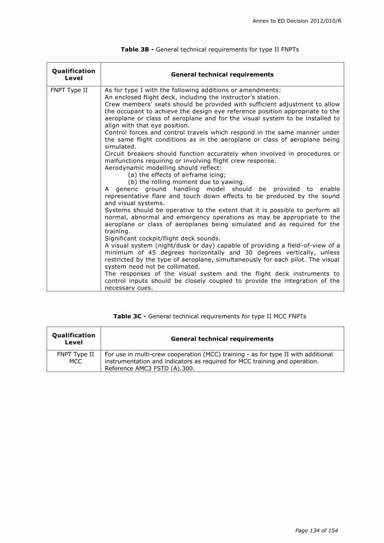
Annex to ED Decision 2012/010/R
Page 134 of 154
Table 3B - General technical requirements for type II FNPTs
Qualification Level
General technical requirements
FNPT Type II As for type I with the following additions or amendments:
An enclosed flight deck, including the instructor’s station. Crew members’ seats should be provided with sufficient adjustment to allow the occupant to achieve the design eye reference position appropriate to the aeroplane or class of aeroplane and for the visual system to be installed to align with that eye position. Control forces and control travels which respond in the same manner under
the same flight conditions as in the aeroplane or class of aeroplane being simulated. Circuit breakers should function accurately when involved in procedures or
malfunctions requiring or involving flight crew response. Aerodynamic modelling should reflect: (a) the effects of airframe icing; (b) the rolling moment due to yawing.
A generic ground handling model should be provided to enable representative flare and touch down effects to be produced by the sound and visual systems. Systems should be operative to the extent that it is possible to perform all normal, abnormal and emergency operations as may be appropriate to the aeroplane or class of aeroplanes being simulated and as required for the training.
Significant cockpit/flight deck sounds. A visual system (night/dusk or day) capable of providing a field-of-view of a minimum of 45 degrees horizontally and 30 degrees vertically, unless restricted by the type of aeroplane, simultaneously for each pilot. The visual
system need not be collimated. The responses of the visual system and the flight deck instruments to
control inputs should be closely coupled to provide the integration of the necessary cues.
Table 3C - General technical requirements for type II MCC FNPTs
Qualification Level
General technical requirements
FNPT Type II MCC
For use in multi-crew cooperation (MCC) training - as for type II with additional instrumentation and indicators as required for MCC training and operation.
Reference AMC3 FSTD (A).300.

Annex to ED Decision 2012/010/R
Page 135 of 154
Table 4 - General technical requirements for BITDs
Qualification Level
General technical requirements
BITD A student pilot’s station that represents a class of aeroplane sufficiently enclosed to exclude distraction. The switches and all the controls should be of a representative size, shape, location and should operate as and represent those as in the simulated class of aeroplane. In addition to the pilot’s seat, suitable viewing arrangements for the instructor should be provided allowing an adequate view of the pilot’s panels.
The control forces, control travel and aeroplane performance should be representative of the simulated class of aeroplane. Navigation equipment for flights under IFR with representative tolerances. This
should include communication equipment. Complete navigation database for at least three airports with corresponding precision and non-precision approach procedures including regular updates. Engine sound should be available.
Instructor controls of atmospheric conditions and to set and reset malfunctions relating to flight instruments, navigation aids, flight controls, engine out operations (for multi-engine aeroplanes only). Stall recognition device corresponding to that of the simulated class of aeroplane.
Annex to ED Decision 2012/010/R
Page 136 of 154
AMC2 FSTD(A).300 Guidance on design and qualification of level 'A' aeroplane
full flight simulators (FFSs)
(a) Background
(1) When determining the cost-effectiveness of any FSTD many factors should be taken into account such as:
(i) environmental
(ii) safety
(iii) accuracy
(iv) repeatability
(v) quality and depth of training
(vi) weather and crowded airspace
(2) The requirements as laid down by the various regulatory bodies for the lowest level of FFS do not appear to have been promoting the anticipated interest in the acquisition of lower cost FFS for the smaller aeroplanes used by the general aviation community.
(3) The significant cost drivers associated with the production of any FSTD are:
(i) type specific data package
(ii) QTG flight test data
(iii) motion system
(iv) visual system
(v) flight controls
(vi) aircraft parts
Note: To attempt to reduce the cost of ownership of a level A FFS, each element has been examined in turn and with a view to relaxing the requirements where possible whilst recognising the training, checking and testing credits allowed on such a device.
(b) Data package
(1) The cost of collecting specific flight test data sufficient to provide a complete model of the aerodynamics, engines and flight controls can be significant. The use of a class specific data package that could be tailored to represent a specific type of aeroplane (e.g. PA34 to PA31) is encouraged. This may enable a well-engineered light twin baseline data package to be carefully tuned to adequately represent any one of a range of similar aeroplanes. Such work including justification and the rationale for the changes should be carefully documented and made available for consideration by the Agency as part of the qualification process. Note that for this lower level of FFS, the use of generic ground handling and generic ground effect models is allowed.
(2) However, specific flight test data to meet the needs of each relevant test within the QTG should be required. Recognising the cost of gathering such data, the following points should be borne in mind:
(i) For this class of FFS, much of the flight test information could be gathered by simple means e.g. stopwatch, pencil and paper or video. However, comprehensive details of test methods and initial conditions should be presented.

Annex to ED Decision 2012/010/R
Page 137 of 154
(ii) A number of tests within the QTG have had their tolerances reduced to correct trend and magnitude (CT&M), thereby avoiding the need for specific flight test data.
(iii) The use of CT&M is not to be taken as an indication that certain areas of simulation can be ignored. Indeed in the class of aeroplane envisaged that might take advantage of level A, it is imperative that the specific characteristics are present, and incorrect effects would be unacceptable (e.g. if the aeroplane has a weak positive spiral stability, it would not be acceptable for the FFS to exhibit neutral or negative spiral stability).
(iv) Where CT&M is used, it is strongly recommended that an automatic recording system be used to footprint the baseline results, thereby avoiding the effects of possible divergent subjective opinions on recurrent evaluations.
(c) Motion
(1) For level A FFS, the requirements for both the primary cueing and buffet simulation have been not specified in detail. Traditionally, for primary cueing, emphasis has been laid on the numbers of axes available on the motion system. For this level of FFS, the FFS manufacturer should be allowed to decide on the complexity of the motion system. However, during the evaluation, the motion system should be assessed subjectively to ensure that it supports the piloting task, including engine failures, and never, provides negative cueing.
(2) Buffet simulation is important to add realism to the overall simulation; for level A, the effects can be simple but they should be appropriate, in harmony with the sound cues and never provide negative training.
(d) Visual
(1) Other than field of view (FOV), specific technical criteria for the visual systems are not specified. The emergence of lower cost ‘raster only’ daylight systems is recognised. The adequacy of the performance of the visual system should be determined by its ability to support the flying tasks, e.g. ‘visual cueing sufficient to support changes in approach path by using runway perspective’.
(2) The collimated visual optics may not always be needed. A single channel direct viewing system should be acceptable for an FFS of a single crew aeroplane. (The risk here is that, should the aeroplane be subsequently upgraded to multi-crew, the non-collimated visual system may be unacceptable.)
(3) The vertical FOV specified (30°) may be insufficient for certain tasks. Some smaller aeroplane have large downward viewing angles which cannot be accommodated by the +/–15° vertical FOV. This can lead to two limitations:
(i) at the CAT I all weather operations decision height, the appropriate visual ground segment may not be seen; and
(ii) during an approach, where the aeroplane goes below the ideal approach path, during the subsequent pitch-up to recover, adequate visual reference to make a landing on the runway may be lost.
(e) Flight controls
The specific requirements for flight controls remain unchanged. Because the handling qualities of smaller aeroplanes are inextricably intertwined with their flight controls, there is little scope for relaxation of the tests and tolerances. It
Annex to ED Decision 2012/010/R
Page 138 of 154
could be argued that with reversible control systems that the on the ground static sweep should in fact be replaced by more representative ‘in air’ testing. It is hoped that lower cost control loading systems would be adequate to fulfil the needs of this level of simulation (i.e. electric).
(f) Aeroplane parts
As with any level of FSTD, the components used within the flight deck need not be aeroplane parts; however, any parts used should be robust enough to endure the training tasks. Moreover, the level A FFS is type specific, thus all relevant switches, instruments, controls etc. within the simulated area should look and feel ‘as aeroplane’.
AMC3 FSTD(A).300 Guidance on design and qualification of flight and
navigation procedures trainers (FNPTs)
(a) Background
(1) Traditionally training devices used by the ab-initio professional pilot schools have been relatively simple instrument flight-only aids. These devices were loosely based on the particular school's aeroplane. The performance would be approximately correct in a small number of standard configurations, however the handling characteristics could range from rudimentary to loosely representative. The instrumentation and avionics fit varied between basic and very close to the target aeroplane. The approval to use such devices as part of a training course was based on a regular subjective evaluation of the equipment and its operator by an inspector of the competent authority.
(2) CS-FSTD(A) introduces two new devices: FNPT I & FNPT II. The FNPT I device is essentially a replacement for the traditional instrument flight ground training device taking advantage of recent technologies and having a more objective design basis. The FNPT II device is the more advanced of the two defined standards and fulfils the wider requirements of the various Part-FCL professional pilot training modules up to and including (optionally with additional features) multi-crew cooperation (MCC) training.
(3) The currently available technologies enable such new devices to have much greater fidelity and lower life-cycle costs than was previously possible. A more objective design basis encourages better understanding and therefore modelling of the aeroplane systems, handling and performance. These advances combined with the ever upwardly spiralling costs of flying and with the environmental pressures all point towards the need for revised standards.
(4) The FNPT II device essentially bridges the gap in design complexity between the traditional subjectively created device and the objectively based level A full flight simulator (FFS).
(5) These new standards are designed to replace the highly subjective design standards and qualification methods with new objective and subjective methods, which ensure that the devices fulfil their intended goals throughout their service lives.
(b) Design standards
Two sets of design standards are specified within CS-FSTD(A): FNPT I and FNPT II, the more demanding of which is FNPT II.
(1) Simulated aeroplane configuration
Unlike FFS devices, FNPT I and FNPT II devices are intended to be representative of a class of aeroplane (although they may in fact be type specific).

Annex to ED Decision 2012/010/R
Page 139 of 154
The configuration chosen should sensibly represent the aeroplane or aeroplanes likely to be used as part of the overall training package. Areas such as general layout, seating, instruments and avionics, control type, control force and position, performance and handling and powerplant configuration should be representative of the class of aeroplane or the aeroplane itself.
It is in the interest of all parties to engage in early discussions with the competent authority to broadly agree a suitable configuration (known as the designated aeroplane configuration). Ideally any such discussion should take place in time to avoid any hold-ups in the design/build/acceptance process thereby ensuring a smooth entry into service.
(2) The cockpit/flight deck
The cockpit/flight deck should be representative of the designated aeroplane configuration. For good training ambiance the cockpit/flight deck should be sufficiently enclosed for FNPT I to exclude any distractions. For an FNPT II the cockpit/flight deck should be fully enclosed. The controls, instruments and avionics controllers should be representative: touch, feel, layout, colour and lighting to create a positive learning environment and good transfer of training to the aeroplane.
(3) Cockpit/flight deck components
As with any training device, the components used within the cockpit/flight deck area do not need to be aircraft parts: however, any parts used should be representative of typical training aeroplanes and should be robust enough to endure the training tasks. With the current state of technology the use of simple cathode ray tube (CRT) monitor-based representations and touch screen controls would not be acceptable. The training tasks envisaged for these devices are such that appropriate layout and feel is very important: i.e. the altimeter sub-scale knob needs to be physically located where it is in the represented class of aeroplane either equipped with glass cockpit avionics or classic instruments. The use of CRTs with physical overlays incorporating operational switches/knobs/buttons replicating an aeroplane instrument panel may be acceptable to the competent authority.
(4) Data
The data used to model the aerodynamics flight controls and engines should be soundly based on the “designated aeroplane configuration”. It is not acceptable and would not give good training if the models merely represented a few key configurations bearing in mind the extent of the credits available.
Validation data may be derived from a specific aeroplane within a set of aeroplanes that the FNPT is intended to represent, or it may be based on information from several aeroplanes within a set/group/range (the designated aeroplane configuration). It is recommended that the intended validation data together with a substantiation report be submitted to the competent authority for evaluation and approval prior to the commencement of the manufacturing process.
(i) Data collection and model development
Recognising the cost of and complexity of flight simulation models, it should be possible to generate generic class typical models. Such models should be continuous and vary sensibly throughout the required training flight envelope. A basic requirement for any modelling is the integrity of the mathematical equations and models used to represent the flying qualities and performance of the class of
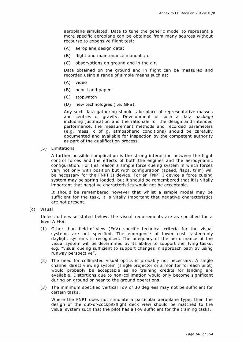
Annex to ED Decision 2012/010/R
Page 140 of 154
aeroplane simulated. Data to tune the generic model to represent a more specific aeroplane can be obtained from many sources without recourse to expensive flight test:
(A) aeroplane design data;
(B) flight and maintenance manuals; or
(C) observations on ground and in the air.
Data obtained on the ground and in flight can be measured and recorded using a range of simple means such as:
(A) video
(B) pencil and paper
(C) stopwatch
(D) new technologies (i.e. GPS).
Any such data gathering should take place at representative masses and centres of gravity. Development of such a data package including justification and the rationale for the design and intended performance, the measurement methods and recorded parameters (e.g. mass, c of g, atmospheric conditions) should be carefully documented and available for inspection by the competent authority as part of the qualification process.
(5) Limitations
A further possible complication is the strong interaction between the flight control forces and the effects of both the engines and the aerodynamic configuration. For this reason a simple force cueing system in which forces vary not only with position but with configuration (speed, flaps, trim) will be necessary for the FNPT II device. For an FNPT I device a force cueing system may be spring-loaded, but it should be remembered that it is vitally important that negative characteristics would not be acceptable.
It should be remembered however that whilst a simple model may be sufficient for the task, it is vitally important that negative characteristics are not present.
(c) Visual
Unless otherwise stated below, the visual requirements are as specified for a level A FFS.
(1) Other than field-of-view (FoV) specific technical criteria for the visual systems are not specified. The emergence of lower cost raster-only daylight systems is recognised. The adequacy of the performance of the visual system will be determined by its ability to support the flying tasks, e.g. “visual cueing sufficient to support changes in approach path by using runway perspective”.
(2) The need for collimated visual optics is probably not necessary. A single channel direct viewing system (single projector or a monitor for each pilot) would probably be acceptable as no training credits for landing are available. Distortions due to non-collimation would only become significant during on ground or near to the ground operations.
(3) The minimum specified vertical FoV of 30 degrees may not be sufficient for certain tasks.
Where the FNPT does not simulate a particular aeroplane type, then the design of the out-of-cockpit/flight deck view should be matched to the visual system such that the pilot has a FoV sufficient for the training tasks.

Annex to ED Decision 2012/010/R
Page 141 of 154
For example during an instrument approach the pilot should be able to see the appropriate visual segment at decision height. Additionally, where the aeroplane deviates from the permitted approach path, undue loss of visual reference should not occur during the subsequent correction in pitch.
(4) There are two methods of establishing latency, which is the relative response of the visual system, cockpit/flight deck instruments and initial motion system response. These should be coupled closely to provide integrated sensory cues.
For a generic FNPT, a transport delay test is the only suitable test that demonstrates that the FNPT system does not exceed the permissible delay. If the FNPT is based upon a particular aeroplane type, either Transport Delay or Latency tests are acceptable. Response time tests check response to abrupt pitch, roll, and yaw inputs at the pilot's position is within the permissible delay, but not before the time when the aeroplane would respond under the same conditions. Visual scene changes from steady state disturbance should occur within the system dynamic response limit but not before the resultant motion onset.
The test to determine compliance with these requirements should include simultaneously recording the analogue output from the pilot's control column, wheel, pedals, the output from the accelerometer attached to the motion system platform located at an acceptable location near the pilots’ seats, the output signal to the visual system display (including visual system analogue delays), and the output signal to the pilot's attitude indicator or an equivalent test approved by the competent authority. The test results in a comparison of a recording of the simulator’s response with actual aeroplane response data in the take-off, cruise, and landing configuration.
The intent is to verify that the FNPT system transport delays or time lags are less than the permissible delay and that the motion and visual cues relate to actual aeroplane responses. For the aeroplane response, acceleration in the appropriate rotational axis is preferred.
The transport delay test should measure all the delay encountered by a step signal migrating from the pilot's control through the control loading electronics and interfacing through all the simulation software modules in the correct order, using a handshaking protocol, finally through the normal output interfaces to the motion system, to the visual system and instrument displays. A recordable start time for the test should be provided by a pilot flight control input. The test mode should permit normal computation time to be consumed and should not alter the flow of information through the hardware/software system.
The transport delay of the system is therefore the time between control input and the individual hardware responses. It need only be measured once in each axis.
(5) Care should be taken when using the limited processing power of the lower cost visual systems to concentrate on the key areas which support the intended uses, thereby avoiding compromising the visual model by including unnecessary features e.g. moving ground traffic, marshallers. The capacity of the visual model should be directed towards:
(i) runway surface,
(ii) runway lighting systems,
(iii) PAPI/ VASI approach guidance aids,
(iv) approach lighting systems,

Annex to ED Decision 2012/010/R
Page 142 of 154
(v) simple taxiway,
(vi) simple large-scale ground features e.g. large bodies of water, big hills; and,
(vii) basic environmental lighting (night/dusk).
(d) Motion
Although motion is not a requirement for either an FNPT I or II, should the operator choose to have one fitted, it will be evaluated to ensure that its contribution to the overall fidelity of the device is positive. Unless otherwise stated in these certification specifications, the motion requirements are as specified for a level A FFS, see AMC2 FSTD(A).300.
(e) Testing/evaluation
To ensure that any device meets its design criteria initially and periodically throughout its life a system of objective and subjective testing will be used. The subjective testing may be similar to that in use in the recent past. The objective testing methodology is drawn from that used currently on FSTD.
The validation tests specified in AMC1 FSTD(A).300 (b)(3) should be “flown” by a suitably skilled person and the results recorded manually. Bearing in mind the cost implications, the use of automatic recording (and testing) is encouraged thereby increasing the repeatability of the achieved results.
The tolerances specified are designed to ensure that the device meets its original target criteria year after year. It is therefore important that such target data are carefully derived and values are agreed with the appropriate inspecting authority in advance of any formal qualification process. For initial qualification, it is highly desirable that the device should meet its design criteria within the listed tolerances. However, unlike the tolerances specified for FSTDs, the tolerances contained within these certification specifications are specifically intended to be used to ensure repeatability during the life of the device and in particular at each recurrent regulatory inspection.
A number of tests within the QTG have had their tolerances reduced to correct trend and magnitude (CT&M) thereby avoiding the need for specific validation data. The use of CT&M is not to be taken as an indication that certain areas of simulation can be ignored. For such tests, the performance of the device should be appropriate and representative of the simulated designated aeroplane and should never exhibit negative characteristics. Where CT&M is used, it is strongly recommended that an automatic recording system be used to footprint the baseline results, thereby avoiding the effects of possible divergent subjective opinions during recurrent evaluations.
The subjective tests listed under “Functions and Manoeuvres” (AMC1 FSTD(A).300(c) should be flown out by a suitably qualified and experienced pilot.
Subjective testing will review not only the interaction of all of the systems but the integration of the FNPT with the following:
(a) training environment
(b) freezes and repositions
(c) navaid environment
(d) communications
(e) weather and visual scene contents.
In parallel with this objective/subjective testing process, suitable maintenance arrangements as part of a compliance monitoring programme should be in
Annex to ED Decision 2012/010/R
Page 143 of 154
place. Such arrangements should cover routine maintenance, the provision of satisfactory spares holdings and personnel.
(f) FNPT type I
The design standards, testing and evaluation requirements for the FNPT Type I device are less demanding than those required for a FNPT Type II device. This difference in standard is in line with the reduced Part-FCL credits available for this type of device.
(g) Additional features
Any additional features in excess of the minimum design requirements added to an FNPT type I & II should be subject to evaluation and should meet the appropriate standards in CS-FSTD(A).
AMC4 FSTD(A).300 Guidance on design and qualification of basic instrument
training devices (BITDs)
(a) Background
(1) Traditionally, FSTDs used by the ab-initio pilot schools have been relatively simple instrument flight-only aids. These devices were loosely based on the particular school's aeroplane. The performance would be approximately correct in a small number of standard configurations. However, the handling characteristics could range from rudimentary to loosely representative. The instrumentation and avionics fit varied between basic and very close to the target aeroplane. The approval to use such devices as part of a training course was based on a regular subjective evaluation of the equipment and its operator by a competent authority inspector.
(2) CS-FSTD(A) introduces two new devices, flight and navigation procedures trainer (FNPT) type I and FNPT type II, where the FNPT I device is essentially a replacement for the traditional instrument flight ground training device taking advantage of recent technologies and having a more objective design basis.
(3) CS-FSTD(A) sets also the requirements and guidelines for the lowest level of FSTDs by introducing BITDs. It should be clearly understood that a BITD can never replace an FNPT I. The main purpose of a BITD is to replace an old instrument training device that cannot be longer approved either due to poor fidelity or system reliability.
(b) Design standards
(1) Unlike FFS devices, a BITD is intended to be representative of a class of aeroplane. The configuration chosen should broadly represent the aeroplane likely to be used as part of the overall training package. It would be in the interest of all parties to engage in early discussions with the competent authority to broadly agree a suitable configuration, known as the ‘designated aeroplane configuration’.
(2) The student pilot station should be broadly representative of the designated aeroplane configuration and should be sufficiently enclosed to exclude any distractions.
(3) The main instrument panel in a BITD may be displayed on a cathode ray tube (CRT). Touch screen or mouse and keyboard operation by the student pilot would not be acceptable for any instrument or system.
(4) The standards for BITDs were developed for low cost devices and therefore were kept as simple as possible. With advances in technology the higher standards defined for FFSs and FNPTs should be used where economically possible.
Annex to ED Decision 2012/010/R
Page 144 of 154
(c) Validation Data
(1) The data used to model the aerodynamics and engine(s) should be soundly based on the designated aeroplane configuration. It is not acceptable if the models merely represent a few key configurations.
(2) Recognising the cost and complexity of flight simulation models, it should be possible to generate a generic class typical model. Such models should be continuous and vary sensibly throughout the required training flight envelope. A basic principal for any modelling is the integrity of the mathematical equations and models used to represent the flying qualities and performance of the class of aeroplane simulated. Data to tune the generic model to represent a more specific aeroplane can be obtained from many sources without recourse to expensive flight test, including:
(i) aeroplane design date;
(ii) flight and maintenance manuals; and
(iii) observations on ground and during flight.
Data obtained on ground or in flight can be measured and recorded using a range of simple means such as:
(i) video;
(ii) pencil and paper;
(iii) stopwatch;
(iv) new technologies like GPS etc.
Any such data gathering should take place at representative masses and centres of gravity. Development of such a data package including justification and the rationale for the design and intended performance, the measurement methods and recorded parameters should be carefully documented and available for inspection by the competent authority as part of the qualification process.
(d) Limitations
A force cueing system may be spring-loaded. But it should be remembered that it is vitally important that negative characteristics are not acceptable.
(e) Testing and evaluation
To ensure that any device meets its design criteria initially and periodically throughout its life, a system of objective and subjective testing will be used. The subjective testing may be similar to that in use in the recent past. The objective testing methodology is drawn from that used currently on higher level training devices.
The validation tests specified in AMC1 FSTD(A).300(b)(3) should be flown by a suitably skilled person and the results recorded manually. However, a print-out of the parameters of interest is highly recommended, thereby increasing the repeatability of the achieved results.
The tolerances specified are designated to ensure that the device meets its original target criteria year after year. It is therefore important that such target data are carefully derived and values are agreed with the competent authority in advance of any formal qualification process. For initial qualification, it is highly desirable that the device meets its design criteria within the listed tolerances. However the tolerances contained in this CS are specifically intended to be used to ensure repeatability during the life of the device and in particular at each recurrent competent authority evaluation.

Annex to ED Decision 2012/010/R
Page 145 of 154
Most of the tests within the qualification test guide (QTG) had their tolerances reduced to correct trend and magnitude (CT&M). The use of CT&M is not to be taken as an indication that certain areas of simulation can be ignored. For such tests, the performance of the device should be approximate and representative of the simulated class of aeroplane and should under no circumstances exhibit negative characteristics. In all these cases it is strongly recommended to print out the baseline results during initial evaluation thereby avoiding the effects of possible divergent subjective opinions during recurrent evaluations.
The subjective tests listed under AMC1 FSTD(A).300(c), functions and manoeuvres, should be flown out by a suitably qualified and experienced pilot. Subjective testing should not only review the interaction of all the applicable systems but the integration of the BITD within a training syllabus, including:
(1) the training environment;
(2) freezes and repositions; and
(3) the navaid environment.
In parallel with this objective and subjective testing process, it is envisaged that suitable maintenance arrangements as part of a compliance monitoring programme are in place. Such arrangements should cover routine maintenance, the provision of satisfactory spares supply and personnel.

Annex to ED Decision 2012/010/R
Page 146 of 154
(f) Guidelines for an instrument panel displayed on a screen
a. a.
The basic flight instruments should be displayed and arranged in the usual "T-layout". Instruments should
be displayed very nearly full-size as in the simulated class of aeroplane. The following instruments should
be displayed so as to be representative for the simulated class of aeroplane:
1. An attitude indicator with at least 5° and 10° pitch markings, and bank angle markings for 10°, 20°,
30° and 60°.
2. Adjustable altimeter(s) with 20 ft markings. Controls to adjust the QNH should be located spatially
correct at the respective instrument.
3. An airspeed indicator with at least 5 kts markings within a representative speed range and colour
coding.
4. An HSI or heading indicator with incremental markings each of at least 5°, displayed on a 360° circle.
The heading figures should be radially aligned. Controls to adjust the course or heading bugs should be
located spatially correct at the respective instrument.
5. A vertical speed indicator with 100 fpm markings up to 1 000 fpm and 500 fpm thereafter within a
representative range.
6. A turn and bank indicator with incremental markings for a rate of 3° per second turn for left and right
turns. The 3° per second rate index should be inside of the maximum deflection of the indicator.
7. A slip indicator representative of the simulated class of aeroplane, where a coordinated flight condition
is indicated with the ball in centre position. A triangle slip indicator is acceptable if applicable for the
simulated class of aeroplane
8. A magnetic compass with incremental markings each 10°.
9. Engine instruments as applicable to the simulated class of aeroplane, with markings for normal ranges,
minimum and maximum limits.
10. A suction gauge or instrument pressure gauge, as applicable, with a display as applicable for the
simulated class of aeroplane.
11. A flap position indicator, which displays the current flap setting. This indicator should be representative
of the simulated class of aeroplane.
12. A pitch trim indicator with a display that shows zero trim and appropriate indices of aeroplane nose
down and nose up trim.
13. A stop watch or digital timer, which allows the readout of seconds and minutes.
b. A communication and navigation panel should be displayed such that the frequency in use is shown.
Controls to select the frequencies and other functions may be located on a central COM/NAV panel or on a
separate ergonomically located panel. The NAV equipment should include ADF, VOR, DME and ILS
indicators with the following incremental markings:
1. one-half dot or less for course and glide slope indications on the VOR and ILS display; and
2. 5° or less of bearing deviation for ADF and RMI, as applicable.
All NAV radios should be equipped with an aural identification feature. A marker beacon receiver should
also be installed with an optical and aural identification.
c. All instrument displays should be visible during all flight operation. The instrument system should be
designed to ensure jumping and stepping is not a distraction and to display all changes within the range
of the replicated instruments that are equal or greater than the values stated below:
1. attitude ½° pitch and 1° bank;
2. turn and bank of ¼ standard rate turn;
3. IAS 1 kts;

Annex to ED Decision 2012/010/R
Page 147 of 154
4. VSI 20 fpm;
5. altitude 3 ft;
6. heading on HSI ½°;
7. course and Heading on OBS and/or RMI 1°;
8. ILS ¼°;
9. RPM 25; and
10. MP ½ inch.
d. The update rate of all displays should be proofed by an SOC. The resolution should provide an image
of the instruments that:
1. does not appear out of focus;
2. does not appear to "jump" or "step" to a distracting degree during operation; and
3. does not appear with distracting jagged lines or edges.
(g) Additional Information
Unlike with other FSTDs the manufacturer of a BITD has the responsibility for the initial evaluation of a new BITD model. Because all serial numbers of such a model are automatically qualified, the ATO certificate containing the specification of the device and the extent to which it may be used at the operator’s site becomes more important before the course approval is granted.
AMC5 FSTD(A).300 Guidance on enhanced visual system (EVS) and
qualification of full flight simulators (FFSs)
(a) Applicability
(1) This process applies to all FFSs used to comply with EVS training and checking requirements as detailed in the relevant JOEB or EASA OEB reports for the particular aircraft type. This document represents one means of qualifying an FFS. Use of any other means requires prior approval by the competent authority.
(b) Compliance certificate
(1) A statement of compliance is required for those FFSs in which EVS hardware is not fitted as original equipment in the aircraft and has therefore been retrofitted to the aircraft and FFS. The statement of compliance should confirm that the added hardware and software have the same functionality as the aircraft equipment. A block diagram showing input and output signal flow as compared to the aircraft should be required.
(c) FFS Standards
(1) The minimum FFS requirements for qualifying an EVS system in an FFS are as follows:
(i) the FFS should be EASA qualified to level C with a daylight visual display or level D;
(ii) the EVS FFS hardware and software, including cockpit displays, should function the same or equivalent to that installed in the aircraft;
(iii) the instructor operating station (IOS) should include an EVS display of the representative EVS and HUD scene, as seen through the pilot's
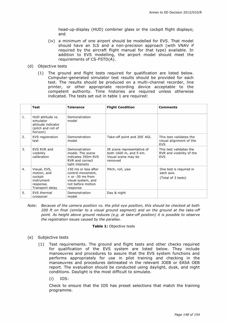
Annex to ED Decision 2012/010/R
Page 148 of 154
head-up-display (HUD) combiner glass or the cockpit flight displays; and
(iv) a minimum of one airport should be modelled for EVS. That model should have an ILS and a non-precision approach (with VNAV if required by the aircraft flight manual for that type) available. In addition to EVS modelling, the airport model should meet the requirements of CS-FSTD(A).
(d) Objective tests
(1) The ground and flight tests required for qualification are listed below. Computer-generated simulator test results should be provided for each test. The results should be produced on a multi-channel recorder, line printer, or other appropriate recording device acceptable to the competent authority. Time histories are required unless otherwise indicated. The tests set out in table 1 are required:
Note: Because of the camera position vs. the pilot eye position, this should be checked at both
200 ft on final (similar to a visual ground segment) and on the ground at the take-off
point. As height above ground reduces (e.g. at take-off position) it is possible to observe
the registration issues caused by the parallax.
Table 1: Objective tests
(e) Subjective tests
(1) Test requirements. The ground and flight tests and other checks required for qualification of the EVS system are listed below. They include manoeuvres and procedures to assure that the EVS system functions and performs appropriately for use in pilot training and checking in the manoeuvres and procedures delineated in the relevant JOEB or EASA OEB report. The evaluation should be conducted using daylight, dusk, and night conditions. Daylight is the most difficult to simulate.
(i) IOS:
Check to ensure that the IOS has preset selections that match the training programme.
Test
Tolerance Flight Condition Comments
1. HUD attitude vs. simulator attitude indicator (pitch and roll of horizon)
Demonstration model
2. EVS registration test
Demonstration model
Take-off point and 200' AGL This test validates the visual alignment of the EVS
3. EVS RVR and visibility calibration
Demonstration model. The scene indicates 350m EVS RVR and correct light intensity
IR scene representative of both 1600 m, and 5 km. Visual scene may be removed
This test validates the RVR and visibility of the EVS
4. Visual, EVS, motion, and cockpit instrument response. Transport delay
150 ms or less after control movement, + or -30 ms from visual system, and not before motion response
Pitch, roll, yaw One test is required in each axis.
(Total of 3 tests)
5. EVS thermal crossover
Demonstration model
Day & night

Annex to ED Decision 2012/010/R
Page 149 of 154
(ii) Pre-flight:
Carry out normal preflight procedures and checks, including warnings and annunciations.
(iii) Taxi:
(A) Observe parallax caused by camera position.
(B) Observe ground hazards especially other aircraft and nearby terrain.
(C) Signs may appear as a block (unreadable) due to no temperature variation between the letters and the background.
(iii) Take-off:
(A) Normal take-off in night VMC conditions. Observe the terrain and surrounding visual scene.
(B) Instrument take-off using visual RVR settings of 200m. The EVS RVR should be better than the visual RVR, i.e. 750m+.
(iv) In-flight operations:
(A) Adjust the scene to VMC and see if the image horizon is conformal with the visual horizon and the combiner horizon.
(B) Using a VMC night or dusk scene, select a thunderstorm at a distance of at least 20 nm and see if the imager detects the clouds.
(v) Approaches:
(A) Normal approach in night VMC conditions.
(B) ILS approach.
(a) Select the preset that allows the pilot to see the EVS image at approximately 500 ft. This should preset the EVS visibility to approximately 2300m, and the visual RVR to 750m.
(b) Fly or reposition the aircraft to 500 ft above ground level (AGL) on the ILS. Freeze position. The pilot flying (PF) should be able to see the image of the runway approach lights. The pilot not flying (PNF) should not be able to see any lights. (Some very slight bleed through of strobes is acceptable, but no steady lights).
(c) Continue the approach and freeze position at 200 ft AGL. The PF should be able to see approximately 1 nm down the runway, and the PNF should be able to visually acquire the approach lights and runway end identifier lights (REILs).
(d) Continue the approach and landing. Observe the blooming effect of the airport lights.
(C) Non-precision approach.
(D) Missed approach.
Note: Emphasis should be placed on the FFS’s capability to demonstrate that the EVS system is able to display the visual for the pilot to identify the required visual references to descend below the published decision altitude (DA) when conducting instrument approaches with vertical guidance. The EVS should continue to provide glide path and alignment information between DH and touchdown. During landing roll out, visual alignment information should be available to the pilot.

Annex to ED Decision 2012/010/R
Page 150 of 154
(vi) Visual segment and landing:
(A) Normal:
(a) From non-precision approach.
(b) From precision approach.
(vii) Abnormal procedures:
(A) EVS malfunctions on the ground.
(B) EVS malfunctions in the air.
(f) Qualification test guide (QTG)
(1) The ATO should develop the statement of compliance, accomplish the performance determination and recording, and forward the resulting information to the competent authority. The competent authority should return the package to the ATO with instructions to include the information in the QTG.
(2) The FFS should be scheduled for an evaluation in accordance with normal procedures. Use of recurrent evaluation schedules should be used to the maximum extent possible.
(3) During the on-site evaluation, the evaluator should ask the ATO to run the performance tests and record the results. The results of these on-site tests should be compared to those results previously approved and placed in the QTG.
(4) QTGs for new or upgraded FFSs should contain or reference the information described in 2 through 4 of this AMC as applicable for the FFS.
AMC6 FSTD(A).300 Guidance on old visual systems and new visual scenes for
full flight simulators (FFSs)
(a) Background.
CS-FSTD(A) FFS specifications for visual systems are three fully simulated airport scenes (so-called “real” scenes). Older visual systems are beginning to experience the limitations of these visual systems, as they cannot simulate the number of polygons and lightpoints necessary to fully simulate the current large airports expanding to sometimes five or more runways, complex taxi routings etc. Since these large airports do have real training value to airlines, airlines request that these large airports be modelled, so that the models can be used for flight training.
The ATO therefore models these scenes up to the limitations of the visual system, but they cannot fully comply with all CS-FSTD(A) FFS specifications for these scenes to qualify them as “real”.
Due to the advances in computer and display techniques, modern visual systems can simulate complex real airports in full detail. All available runways and lighting systems can be simulated including environmental lights in the airport vicinity. Older visual systems are less capable. They are limited in the number of lightpoints, polygons and texture they can display.
At the time of initial qualification certificates issued in the 1980s and 1990s these systems were compliant with the specifications of that time. The real scenes of those days were less complexly modelled due to system capabilities. These older, grandfathered, visual systems are not able to simulate the modern large airport scenes of today with sometimes five runways or more, complex taxi routings etc.
Users however, still want to use those simulators to perform their flight training and want to use these complex visual scenes because it happens to be their home base or major destination and request simulator operators to simulate these

Annex to ED Decision 2012/010/R
Page 151 of 154
scenes. The ATO therefore models these scenes up to the limitations of the system, but is unable to fully comply with the current CS-FSTD(A) specifications for visual scenes to qualify them as “real”.
(b) Practical solution.
(1) The typical limitation of these previously described older systems is the number of runways that can be simulated and the level of detail. Alternatively, smaller airports can be fully simulated but are sometimes less valuable for training purposes. The ATO can then decide:
(i) To simulate all airport content (runways) but in less detail, by (drastically) reducing the number of light points, textures and polygons used. This can result in a lower number of taxiways, no environmental lights etc.
(ii) To simulate only part of the airport, but in full detail. This could result in simulating fewer runways with their associated taxiways and light points.
(iii) To simulate only less complex visual scenes that fulfil the CS-FSTD(A) specifications, but are hardly ever used by the FFS users, because they do not simulate their operational destinations.
(2) Whatever decision is made, either the resulting requested simulated visual scene will not be fully matching reality and so the requirement for three fully simulated airports will not be met according to the modern standards, or these complex scenes will not be modelled at all.
(3) In order to prevent the ATO from designing and maintaining airports it does not need for the FFS users, but only to satisfy the competent authorities when they (re-)qualify the FFS, it should be allowed to use models which satisfy the requirements in parts of their model and lack them in other areas.
(4) For example, when an airport has five runways it should be acceptable to simulate only four of them. The ATO should, when agreed by the competent authority, state this limitation in a rationale, which will form part of the approved MQTG of the FFS. The FFS user should also be aware of this limitation and agree to this in writing and it should also be stated in the ATO certificate or operations manual (OM).
(5) Previously mentioned older visual systems or other visual systems manufactured before 1994 should therefore be allowed to display only part of the CS-FSTD(A) specified visual details for the scenes offered for evaluation by the competent authority. The detail to be provided should be correct within reasonable limits, up to the decision of the competent authority.
(6) For these specific scenes, the specifications to have at least one dedicated taxi route from the gate to a specific runway (single designated route) that can be followed using the appropriate airfield charts, taxi lights and taxi signs (also under low visibility conditions) remain valid. Also, the prevention of runway incursions (safety) is paramount. Therefore stop bars should be correctly modelled and switchable on/off. If no switchable feature exists, then they should be modelled “on” where the instructor will grant clearance to cross.
AMC7 FSTD(A).300 Engineering simulator validation data

Annex to ED Decision 2012/010/R
Page 152 of 154
(a) When a fully flight test validation simulation is modified as a result of changes to the simulated aircraft configuration, a qualified aircraft manufacturer may choose, with the prior agreement of the competent authority, to supply validation data from an “audited” engineering simulator/simulation to selectively supplement flight test data.
This arrangement is confined to changes that are incremental in nature and that are both easily understood and well defined.
(b) To be qualified to supply engineering simulator validation data, an aircraft manufacturer should:
(1) have a proven track record of developing successful data packages;
(2) have demonstrated high quality prediction methods through comparisons of predicted and flight test validated data;
(3) have an engineering simulator that:
(i) has models that run in an integrated manner;
(ii) uses the same models as released to the training community (which are also used to produce stand-alone proof-of-match and checkout documents); and
(iii) is used to support aircraft development and certification;
(4) use the engineering simulation to produce a representative set of integrated proof-of-match cases; and
(5) have an acceptable configuration control system in place covering the engineering simulator and all other relevant engineering simulations.
(c) Aircraft manufacturers seeking to take advantage of this alternative arrangement should contact the competent authority at the earliest opportunity.
(d) For the initial application, each applicant should demonstrate his/her ability to qualify to the satisfaction of the Agency, in accordance with the criteria in this AMC and in AMC8 FSTD(A).300.
AMC8 FSTD(A).300 Engineering simulator validation data – approval
guidelines
(a) Background
(1) In the case of fully flight test validated simulation models of a new or major derivative aircraft, it is likely that these models will become progressively unrepresentative as the aircraft configuration is revised.
(2) Traditionally, as the aircraft configuration has been revised, the simulation models have been revised to reflect changes. In the case of aerodynamic, engine, flight control and ground handling models, this revision process normally results in the collection of additional flight test data and the subsequent release of new models and validation data.
(3) The quality of the prediction of simulation models has advanced to the point where differences between the predicted and the flight test validation models are often quite small.
(4) Major aircraft manufacturers utilise the same simulation models in their engineering simulations as released to the training community. These simulations vary from physical engineering simulators with and without aircraft hardware to non-real-time workstation-based simulations.
(b) Approval guidelines – for using engineering simulator validation data

Annex to ED Decision 2012/010/R
Page 153 of 154
(1) The current system of requiring flight test data as a reference for validating training simulators should continue.
(2) When a fully flight test-validated simulation is modified as a result of changes to the simulated aircraft configuration, a qualified aircraft manufacturer may choose, with prior agreement of the competent authority, to supply validation data from an engineering simulator/simulation to selectively supplement flight test data.
(3) In cases where data from an engineering simulator is used, the engineering simulation process should be audited by the competent authority.
(4) In all cases a data package verified to current standards against flight testing should be developed for the aircraft entry-into-service configuration of the baseline aircraft.
(5) Where engineering simulator data is used as part of a qualification test guide (QTG), an essential match is expected as described in Appendix 1 to CS FSTD(A).300.
(6) In cases where the use of engineering simulator data is envisaged, a complete proposal should be presented to the appropriate regulatory body(ies). Such a proposal should contain evidence of the aircraft manufacturer’s past achievements in high fidelity modelling.
(7) The process should be applicable to one step away from a fully flight-validated simulation.
(8) A configuration management process should be maintained, including an audit trail which clearly defines the simulation model changes step by step away from a fully flight-validated simulation, so that it would be possible to remove the changes and return to the baseline (flight validated) version.
(9) The competent authorities should conduct technical reviews of the proposed plan and the subsequent validation data to establish acceptability of the proposal.
(10) The procedure should be considered complete when an approval statement is issued. This statement should identify acceptable validation data sources.
(11) To be admissible as an alternative source of validation data an engineering simulator should:
(i) have to exist as a physical entity, complete with a flight deck representative of the affected class of aircraft, with controls sufficient for manual flight;
(ii) have a visual system and preferably also a motion system;
(iii) where appropriate, have actual avionics boxes interchangeable with the equivalent software simulations, to support validation of released software;
(iv) have a rigorous configuration control system covering hardware and software; and
(v) have been found to be a high fidelity representation of the aircraft by the pilots of the manufacturers, operators and the competent authority.
(12) The precise procedure followed to gain acceptance of engineering simulator data will vary from case-to-case between aircraft manufacturers

Annex to ED Decision 2012/010/R
Page 154 of 154
and type of change. Irrespective of the solution proposed, engineering simulations/simulators should conform to the following criteria:
(i) the original (baseline) simulation models should have been fully flight test validated;
(ii) the models as released by the aircraft manufacturer to the industry for use in training FSTDs should be essentially identical to those used by the aircraft manufacturer in their engineering simulations/simulators; and
(iii) these engineering simulation/simulators should have been used as part of the aircraft design, development and certification process.
(13) Training FSTDs utilising these baseline simulation models should be currently qualified to at least internationally recognised standards such as contained in the ICAO Document 9625 Manual of Criteria for the Qualification of Flight Simulators (1995 or as amended).
(14) The type of modifications covered by this alternative procedure will be restricted to those with well-understood effects:
(i) software (e.g., flight control computer, autopilot, etc.);
(ii) simple (in aerodynamic terms) geometric revisions (e.g., body length);
(iii) engines – limited to non-propeller-driven aircraft;
(iv) control system gearing/rigging/deflection limits; and
(v) brake, tyre and steering revisions.
(15) The manufacturer who wishes to take advantage of this alternative procedure, is expected to demonstrate a sound engineering basis for his/her proposed approach. Such analysis should show that the predicted effects of the change(s) were incremental in nature and both easily understood and well defined, confirming that additional flight test data were not required. In the event that the predicted effects are not deemed to be sufficiently accurate, it might be necessary to collect a limited set of flight test data to validate the predicted increments.
(16) Any applications for this procedure should be reviewed by the Agency.
Related Documents