Chapter 2 Data Manipulation © 2007 Pearson Addison-Wesley. All rights reserved

Welcome message from author
This document is posted to help you gain knowledge. Please leave a comment to let me know what you think about it! Share it to your friends and learn new things together.
Transcript

Chapter 2
Data Manipulation
© 2007 Pearson Addison-Wesley.All rights reserved
© 2007 Pearson Addison-Wesley. All rights reserved 0-2
Chapter 2: Data Manipulation
• 2.1 Computer Architecture
• 2.2 Machine Language
• 2.3 Program Execution

© 2007 Pearson Addison-Wesley. All rights reserved 0-3
Computer Architecture - Von Neumann architecture
• The von Neumann architecture is a computer design model specifying sequential architectures.
- Use a single storage structure to hold both instructions and data.
- Run any arbitrary (but well-formed) sequence of instructions;
- Have inputs and outputs;
© 2007 Pearson Addison-Wesley. All rights reserved 0-4
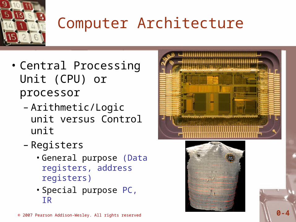
Computer Architecture
• Central Processing Unit (CPU) or processor– Arithmetic/Logic unit
versus Control unit– Registers
• General purpose (Data registers, address registers)
• Special purpose PC, IR

© 2007 Pearson Addison-Wesley. All rights reserved 0-5
BUS
• Control lines These allow the CPU to control which operations the devices attached should perform, I.E. read or write.
• Address lines Allows the CPU to reference certain (Memory) locations within the device.
• Data lines The meaningful data which is to be sent or retrieved from a device is placed on to these lines.

© 2007 Pearson Addison-Wesley. All rights reserved 0-6
Figure 2.1 CPU and main memory connected via a bus
© 2007 Pearson Addison-Wesley. All rights reserved 0-7
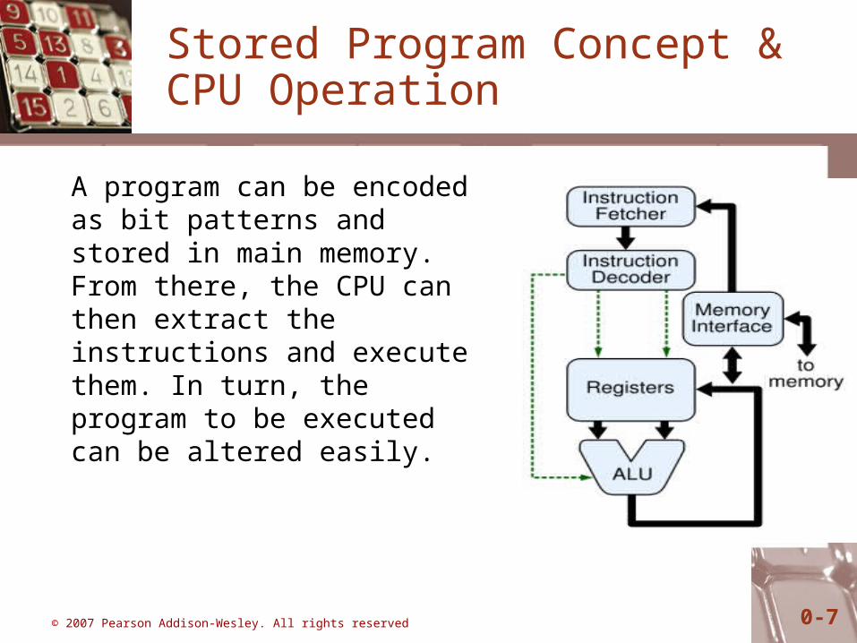
Stored Program Concept & CPU Operation
A program can be encoded as bit patterns and stored in main memory. From there, the CPU can then extract the instructions and execute them. In turn, the program to be executed can be altered easily.

© 2007 Pearson Addison-Wesley. All rights reserved 0-8
Terminology
• Machine instruction: An instruction (or command) encoded as a bit pattern recognizable by the CPU
• Machine language: The set of all instructions recognized by a machine
© 2007 Pearson Addison-Wesley. All rights reserved 0-9
Machine Language Philosophies
• Reduced Instruction Set Computing (RISC)– Few, simple, efficient, and fast instructions– Example: PowerPC from Apple/IBM/Motorola
• Complex Instruction Set Computing (CISC)– Many, convenient, and powerful instructions– Example: Pentium from Intel
© 2007 Pearson Addison-Wesley. All rights reserved 0-10
Machine Instruction Types
• Data Transfer: copy data from one location to another
• Arithmetic/Logic: use existing bit patterns to compute a new bit patterns
• Control: direct the execution of the program
© 2007 Pearson Addison-Wesley. All rights reserved 0-11
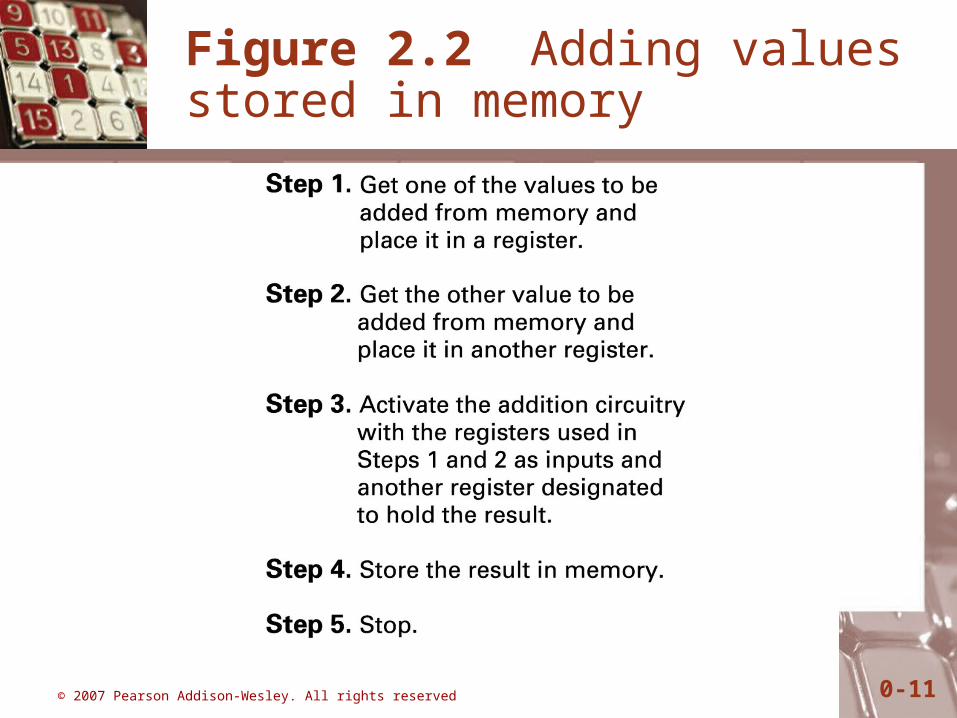
Figure 2.2 Adding values stored in memory
© 2007 Pearson Addison-Wesley. All rights reserved 0-12
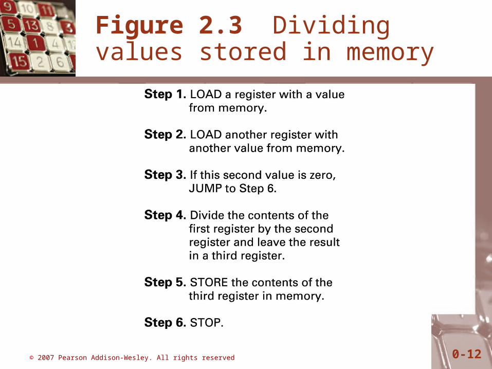
Figure 2.3 Dividing values stored in memory
© 2007 Pearson Addison-Wesley. All rights reserved 0-13
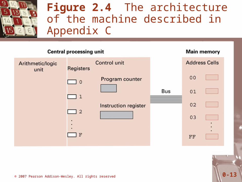
Figure 2.4 The architecture of the machine described in Appendix C
© 2007 Pearson Addison-Wesley. All rights reserved 0-14
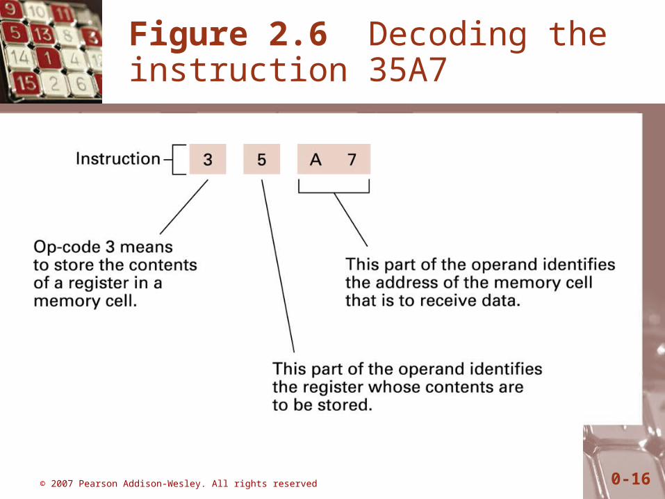
Parts of a Machine Instruction
• Op-code: Specifies which operation to execute
• Operand: Gives more detailed information about the operation– Interpretation of operand varies depending on op-
code

© 2007 Pearson Addison-Wesley. All rights reserved 0-15
Figure 2.5 The composition of an instruction for the machine in Appendix C
© 2007 Pearson Addison-Wesley. All rights reserved 0-16
Figure 2.6 Decoding the instruction 35A7

© 2007 Pearson Addison-Wesley. All rights reserved 0-17
Figure 2.7 An encoded version of the instructions in Figure 2.2

© 2007 Pearson Addison-Wesley. All rights reserved 0-18
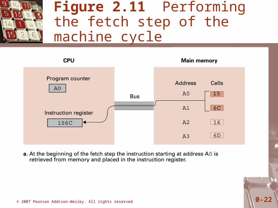
Program Execution
• Controlled by two special-purpose registers– Program counter: address of next instruction– Instruction register: current instruction
• Machine Cycle– Fetch– Decode– Execute

© 2007 Pearson Addison-Wesley. All rights reserved 0-19
Figure 2.8 The machine cycle

© 2007 Pearson Addison-Wesley. All rights reserved 0-20
Figure 2.9 Decoding the instruction B258

© 2007 Pearson Addison-Wesley. All rights reserved 0-21
Figure 2.10 The program from Figure 2.7 stored in main memory ready for execution
© 2007 Pearson Addison-Wesley. All rights reserved 0-22
Figure 2.11 Performing the fetch step of the machine cycle

© 2007 Pearson Addison-Wesley. All rights reserved 0-23
Figure 2.12 Rotating the bit pattern A3 one bit to the right

© 2007 Pearson Addison-Wesley. All rights reserved 0-24
Figure 2.11 Performing the fetch step of the machine cycle (cont’d)

© 2007 Pearson Addison-Wesley. All rights reserved 0-25
Review
• Concept of instruction
• Basics of computer architecture
- Von Newmann architecture model
- Roles of memory, CPU(control unit, ALU, Registers), Bus, I/O
- Decoding of instructions
- Machine cycle (Control unit performs its job)

© 2007 Pearson Addison-Wesley. All rights reserved 0-26
Review : Von Neumann architecture model
Related Documents