Thank you for purchasing an Oriental Motor product. This Manual describes product handling procedures and safety precautions. • Please read it thoroughly to ensure safe operation. • Always keep the manual where it is readily available. HM-40112-9 5-phase stepping motor and driver package CRK Series Built-in Controller Type USER MANUAL R-REM-OMC-108 Introduction Installation and connection Operation type and setting Method of control via I/O Method of control via Modbus RTU (RS-485 communication) Method of control via industrial network Inspection, troubleshooting and remedial actions Appendix

Welcome message from author
This document is posted to help you gain knowledge. Please leave a comment to let me know what you think about it! Share it to your friends and learn new things together.
Transcript
Thank you for purchasing an Oriental Motor product.
This Manual describes product handling procedures and safety precautions.
• Please read it thoroughly to ensure safe operation.
•Always keep the manual where it is readily available.
HM-40112-9
5-phase stepping motor and driver package
CRK Series Built-in Controller Type
USER MANUAL R-REM-OMC-108
Introduction
Installation andconnection
Operation type and setting
Method of control via I/O
Method of control via Modbus RTU (RS-485 communication)
Method of control via industrial network
Inspection, troubleshooting and remedial actions
Appendix
2
1 Introduction
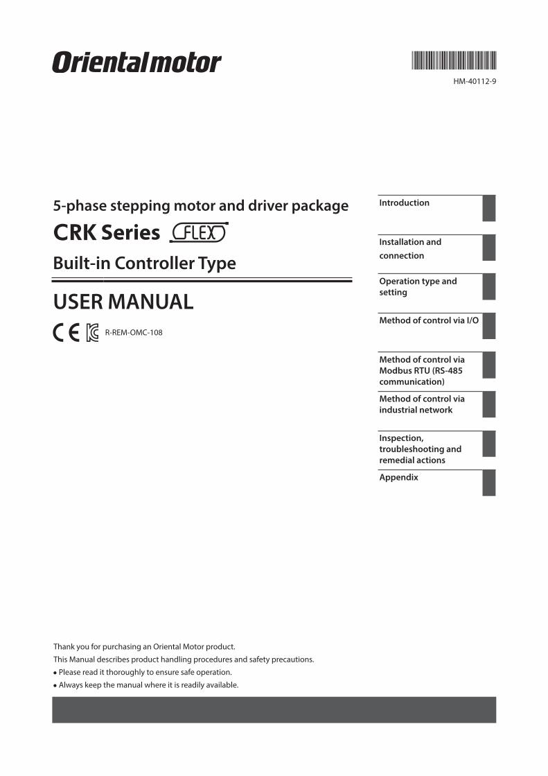
1 Introduction .................................................................................................................................................................. 8
2 Overview of the product ............................................................................................................................................. 9
3 System configuration ................................................................................................................................................11
4 Safety precautions .....................................................................................................................................................12
5 Precautions for use ....................................................................................................................................................14
6 General specifications ...............................................................................................................................................16
7 Regulations and standards .......................................................................................................................................17
7-1 EU Directive ............................................................................................................................................................................................. 17
7-2 Republic of Korea, Radio Waves Act ............................................................................................................................................... 17
7-3 RoHS Directive ....................................................................................................................................................................................... 17
8 Preparation ..................................................................................................................................................................18
8-1 Checking the product ......................................................................................................................................................................... 18
8-2 Combinations of motors and drivers ............................................................................................................................................. 19
8-3 Names and functions of parts .......................................................................................................................................................... 21
2 Installation and connection
1 Installation ...................................................................................................................................................................24
1-1 Location for installation ...................................................................................................................................................................... 24
1-2 Installing the motor ............................................................................................................................................................................. 24
1-3 Installing a load ..................................................................................................................................................................................... 26
1-4 Permissible radial load and permissible axial load ................................................................................................................... 27
1-5 Installing the driver .............................................................................................................................................................................. 30
1-6 Installing and wiring in compliance with EMC Directive ........................................................................................................ 31
2 Connection ..................................................................................................................................................................33
2-1 Connecting the motor ........................................................................................................................................................................ 33
2-2 Connecting the connector-type motor ........................................................................................................................................ 34
2-3 Connecting the electromagnetic brake ....................................................................................................................................... 36
2-4 Connecting the power supply and grounding the driver ...................................................................................................... 37
2-5 Connecting the I/O signals ................................................................................................................................................................ 38
2-6 Connecting the data setter ............................................................................................................................................................... 41
2-7 Connecting the encoder .................................................................................................................................................................... 41
2-8 Connecting the RS-485 communication cable .......................................................................................................................... 44
3 Explanation of I/O signals .........................................................................................................................................45
3-1 Input signals ........................................................................................................................................................................................... 45
3-2 Output signals ........................................................................................................................................................................................ 51
3
3 Operation type and setting
1 Adjustment and setting ............................................................................................................................................58
1-1 Step angle ................................................................................................................................................................................................ 58
1-2 Operating current ................................................................................................................................................................................. 58
1-3 Standstill current ................................................................................................................................................................................... 59
1-4 Acceleration/deceleration rate ........................................................................................................................................................ 59
2 Operation .....................................................................................................................................................................60
2-1 Positioning operation.......................................................................................................................................................................... 61
2-2 Return-to-home operation ................................................................................................................................................................ 70
2-3 Continuous operation ......................................................................................................................................................................... 75
2-4 Other operation ..................................................................................................................................................................................... 77
3 Operation data ............................................................................................................................................................79
4 Parameter ....................................................................................................................................................................80
4-1 Parameter list.......................................................................................................................................................................................... 80
4-2 I/O parameter ......................................................................................................................................................................................... 81
4-3 Motor parameter ................................................................................................................................................................................... 82
4-4 Speed parameter .................................................................................................................................................................................. 82
4-5 Return-to-home parameter .............................................................................................................................................................. 83
4-6 Alarm/warning parameter ................................................................................................................................................................. 83
4-7 Common parameter ............................................................................................................................................................................ 84
4-8 Operation setting parameter............................................................................................................................................................ 84
4-9 Communication parameter ............................................................................................................................................................... 85
5 Related functions .......................................................................................................................................................86
5-1 Position control ..................................................................................................................................................................................... 86
5-2 Encoder input ......................................................................................................................................................................................... 86
5-3 Misstep detection function ............................................................................................................................................................... 87
4 Method of control via I/O
1 Guidance ......................................................................................................................................................................92
2 Operation data ............................................................................................................................................................95
3 Parameter ....................................................................................................................................................................96
3-1 Parameter list.......................................................................................................................................................................................... 96
3-2 I/O parameter ......................................................................................................................................................................................... 97
3-3 Motor parameter ................................................................................................................................................................................... 98
3-4 Speed parameter .................................................................................................................................................................................. 98
3-5 Return-to-home parameter .............................................................................................................................................................. 98
3-6 Alarm/warning parameter ................................................................................................................................................................. 99
3-7 Common parameter ............................................................................................................................................................................ 99
3-8 Communication parameter ............................................................................................................................................................... 99
3-9 Operation setting parameter..........................................................................................................................................................100
4 Timing charts ............................................................................................................................................................101
4
5 Method of control via Modbus RTU (RS-485 communication)
1 Guidance ....................................................................................................................................................................104
2 Communication specifications ..............................................................................................................................106
3 Setting the switches ................................................................................................................................................107
4 Setting the RS-485 communication ......................................................................................................................109
5 Communication mode and communication timing ..........................................................................................110
5-1 Communication mode ......................................................................................................................................................................110
5-2 Communication timing ....................................................................................................................................................................110
6 Message .....................................................................................................................................................................111
6-1 Query .......................................................................................................................................................................................................111
6-2 Response ................................................................................................................................................................................................113
7 Function code ...........................................................................................................................................................115
7-1 Reading from a holding register(s) ...............................................................................................................................................115
7-2 Writing to a holding register ...........................................................................................................................................................116
7-3 Diagnosis ...............................................................................................................................................................................................116
7-4 Writing to multiple holding registers ..........................................................................................................................................117
7-5 Control method selection ................................................................................................................................................................118
8 Register address list .................................................................................................................................................119
8-1 Register address types ......................................................................................................................................................................119
8-2 Operation area .....................................................................................................................................................................................120
8-3 Maintenance area ...............................................................................................................................................................................123
8-4 Monitor area .........................................................................................................................................................................................124
8-5 Parameter area .....................................................................................................................................................................................126
8-6 Operation data area ...........................................................................................................................................................................129
9 Group send ................................................................................................................................................................131
10 Detection of communication errors ....................................................................................................................133
10-1 Communication errors .....................................................................................................................................................................133
10-2 Alarms and warnings ........................................................................................................................................................................133
11 Timing charts ............................................................................................................................................................134
12 Example of communication setting .....................................................................................................................136
12-1 Positioning operation.......................................................................................................................................................................136
12-2 Continuous operation ......................................................................................................................................................................138
12-3 Return-to-home operation .............................................................................................................................................................139
6 Method of control via industrial network
1 Method of control via CC-Link communication..................................................................................................142
1-1 Guidance ................................................................................................................................................................................................142
1-2 Setting the switches ..........................................................................................................................................................................145
1-3 Remote register list ............................................................................................................................................................................146
1-4 Assignment for remote I/O of 6 axes connection mode ......................................................................................................146
1-5 Assignment for remote I/O of 12 axes connection mode ....................................................................................................149
5
2 Method of control via MECHATROLINK communication ..................................................................................154
2-1 Guidance ................................................................................................................................................................................................154
2-2 Setting the switches ..........................................................................................................................................................................157
2-3 I/O field map for the NETC01-M2 ..............................................................................................................................................158
2-4 I/O field map for the NETC01-M3 ..............................................................................................................................................159
2-5 Communication format ....................................................................................................................................................................160
3 Details of remote I/O ...............................................................................................................................................162
3-1 Input signals to the driver ................................................................................................................................................................162
3-2 Output signals from the driver ......................................................................................................................................................162
4 Command code list ..................................................................................................................................................164
4-1 Group function ....................................................................................................................................................................................164
4-2 Maintenance command ...................................................................................................................................................................165
4-3 Monitor command .............................................................................................................................................................................166
4-4 Operation data .....................................................................................................................................................................................168
4-5 Application parameter ......................................................................................................................................................................168
4-6 System parameter...............................................................................................................................................................................170
4-7 Operation command .........................................................................................................................................................................171
7 Inspection, troubleshooting and remedial actions
1 Inspection ..................................................................................................................................................................174
2 Alarms and warnings ...............................................................................................................................................175
2-1 Alarms .....................................................................................................................................................................................................175
2-2 Warnings ................................................................................................................................................................................................178
3 Troubleshooting and remedial actions ................................................................................................................179
8 Appendix
1 Accessories ................................................................................................................................................................182
2 Method of control via GW protocol Version 1 .....................................................................................................183
2-1 Guidance ................................................................................................................................................................................................183
2-2 Communication specifications ......................................................................................................................................................186
2-3 Setting the switches ..........................................................................................................................................................................187
2-4 Communication mode ......................................................................................................................................................................188
2-5 Communication timing ....................................................................................................................................................................189
2-6 Frame structures .................................................................................................................................................................................189
2-7 Control method selection ................................................................................................................................................................192
2-8 Example of communication setting .............................................................................................................................................193
2-9 Command list .......................................................................................................................................................................................196
2-10 Command types .................................................................................................................................................................................199
2-11 Command details...............................................................................................................................................................................200
2-12 Simultaneous send ............................................................................................................................................................................220
2-13 Group send...........................................................................................................................................................................................220
2-14 Detection of communication errors ...........................................................................................................................................222
2-15 Timing charts .......................................................................................................................................................................................223

6
1 Introduction
This part explains the composition of the operating manuals, the product overview, specifications and safety standards as well as the name and function of each part and others.
Table of contents
1 Introduction ............................................. 8
2 Overview of the product ........................ 9
3 System configuration ............................ 11
4 Safety precautions ................................ 12
5 Precautions for use ................................ 14
6 General specifications .......................... 16
7 Regulations and standards .................. 177-1 EU Directive ...................................................... 17
7-2 Republic of Korea, Radio Waves Act ......... 17
7-3 RoHS Directive ................................................. 17
8 Preparation ............................................. 188-1 Checking the product ................................... 18
8-2 Combinations of motors and drivers ....... 19
8-3 Names and functions of parts .................... 21
Introduction
8
1 Introduction
1 Introduction
Before useOnly qualified personnel of electrical and mechanical engineering should work with the product.Use the product correctly after thoroughly reading the section “4 Safety precautions” on p.12. In addition, be sure to observe the contents described in warning, caution, and note in this manual.The product described in this manual has been designed and manufactured to be incorporated in general industrial equipment. Do not use for any other purpose. For the driver’s power supply, use a DC power supply with reinforced insulation on its primary and secondary sides. Oriental Motor Co., Ltd. is not responsible for any damage caused through failure to observe this warning.
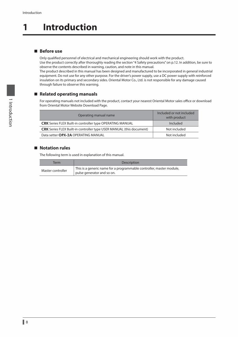
Related operating manualsFor operating manuals not included with the product, contact your nearest Oriental Motor sales office or download from Oriental Motor Website Download Page.
Operating manual nameIncluded or not included
with product
CRK Series FLEX Built-in controller type OPERATING MANUAL Included
CRK Series FLEX Built-in controller type USER MANUAL (this document) Not included
Data setter OPX-2A OPERATING MANUAL Not included
Notation rulesThe following term is used in explanation of this manual.
Term Description
Master controllerThis is a generic name for a programmable controller, master module, pulse generator and so on.
Overview of the product
9
1 Introduction
2 Overview of the product
This product is a motor and driver package product consisting of a 5-phase stepping motor designed for high torque and low vibration, and a driver with built-in controller function. The driver is compatible with I/O control, Modbus RTU control (RS-485 communication), and FA network control via the network converter.The operation data and parameters can be set using a support software MEXE02, an accessory data setter OPX-2A, or via RS-485 communication.
Main features
z Three operating patternsYou can perform positioning operation, return-to-home operation and continuous operation.Up to 63 operation data points can be set, and multi-point positioning is also possible.
z Low vibration, low noiseThe micro-step driver with smooth drive function achieves low vibration and low noise.
z Supporting Modbus RTU (RS-485 communication)You can set operation data and parameters or issue operation start/stop commands from the master station.Up to 31 drivers can be connected to one master controller.
z Detection of misstepIf the deviation between the encoder counter value and driver command position reaches or exceeds the set value, a STEPOUT output signal will be output.
z Alarm and warning functionsThe driver provides alarms that are designed to protect the driver from overheating, poor connection, misoperation, etc. (protective functions), as well as warnings that are output before the corresponding alarms generate (warning functions).
AccessoriesThe operation data and parameters can be set using a MEXE02, accessory OPX-2A or via RS-485 communication. Provide the MEXE02 or OPX-2A as necessary.
• MEXE02 .....The MEXE02 can be downloaded from Oriental Motor Website Download Page.When the MEXE02 is used, a communication cable for support software CC05IF-USB (accessory) is needed to connect a PC and driver. Be sure to purchase it.
• OPX-2A ......This product can be purchased separately.
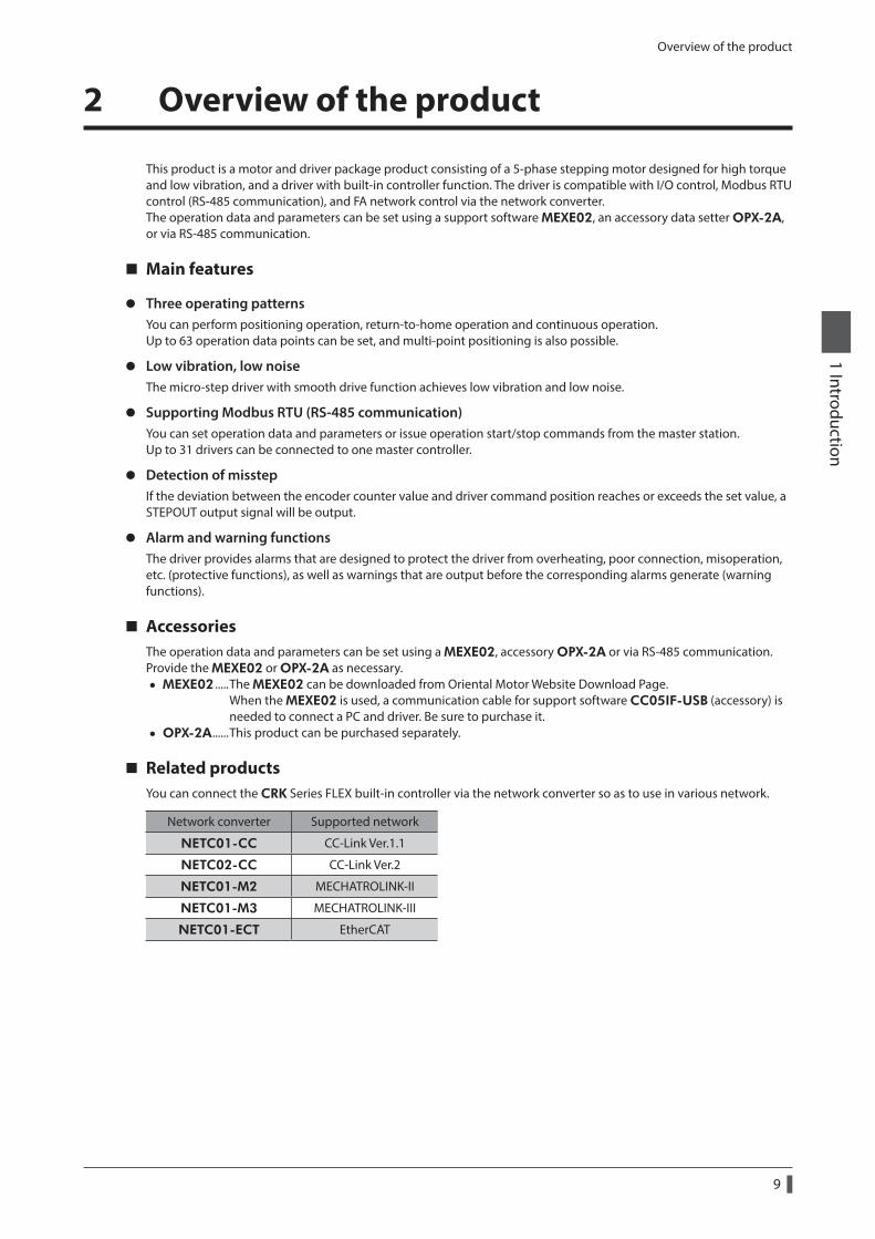
Related productsYou can connect the CRK Series FLEX built-in controller via the network converter so as to use in various network.
Network converter Supported network
NETC01-CC CC-Link Ver.1.1
NETC02-CC CC-Link Ver.2
NETC01-M2 MECHATROLINK-II
NETC01-M3 MECHATROLINK-III
NETC01-ECT EtherCAT
Overview of the product
10
1 Introduction
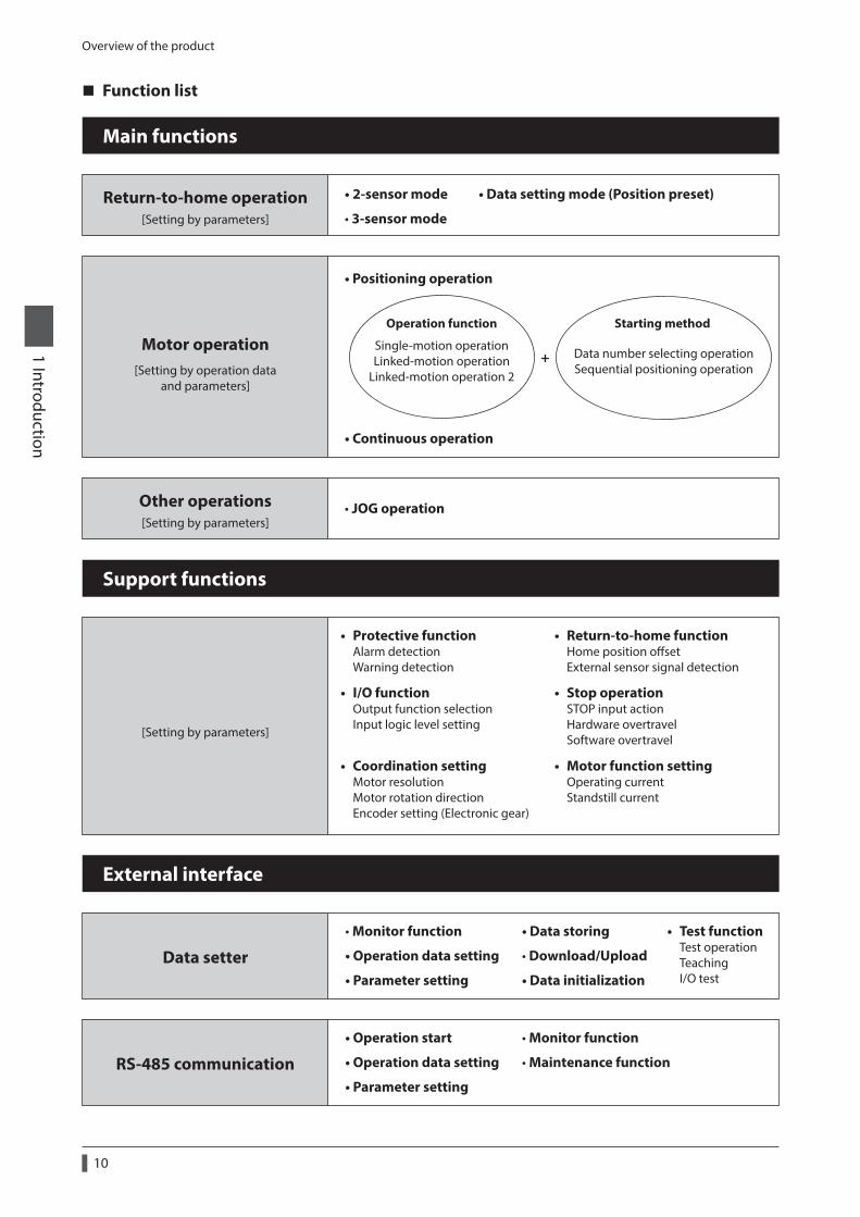
Function list
Return-to-home operation • 2-sensor mode
• 3-sensor mode
• Monitor function
• Operation data setting
• Parameter setting
Other operations • JOG operation
• Positioning operation
• Continuous operation
Single-motion operationLinked-motion operation
Linked-motion operation 2
Operation function
Data number selecting operationSequential positioning operation
Starting method
+
Main functions
[Setting by parameters]
Motor operation[Setting by operation data
and parameters]
[Setting by parameters]
• Return-to-home function Home position oset External sensor signal detection
• Motor function setting Operating current Standstill current
• Stop operation STOP input action Hardware overtravel Software overtravel
• I/O function Output function selection Input logic level setting
• Coordination setting Motor resolution Motor rotation direction Encoder setting (Electronic gear)
• Protective function Alarm detection Warning detection
Support functions
[Setting by parameters]
• Data storing
• Download/Upload
• Data initialization
External interface
Data setter
• Operation start
• Operation data setting
• Parameter setting
• Monitor function
• Maintenance functionRS-485 communication
• Data setting mode (Position preset)
• Test function Test operation Teaching I/O test
System configuration
11
1 Introduction
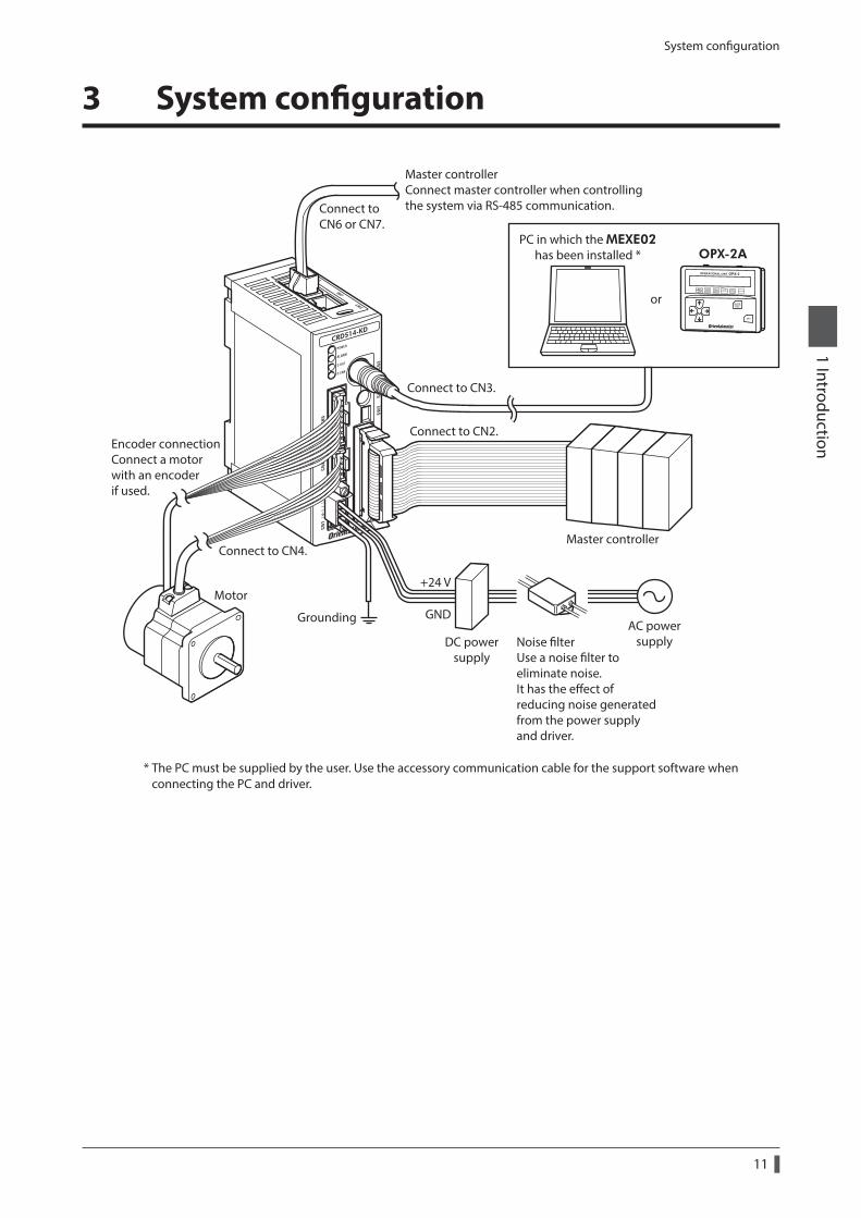
3 System configuration
Master controller
Encoder connection Connect a motor with an encoderif used.
Motor
Connect to CN6 or CN7.
Connect to CN3.
Connect to CN2.
Connect to CN4.
DC powersupply
Noise lterUse a noise lter toeliminate noise.It has the eect of reducing noise generated from the power supply and driver.
AC powersupply
Master controller Connect master controller when controlling the system via RS-485 communication.
Grounding
+24 V
GND
OPX-2APC in which the MEXE02
has been installed *
or
* The PC must be supplied by the user. Use the accessory communication cable for the support software when connecting the PC and driver.
Safety precautions
12
1 Introduction
4 Safety precautions
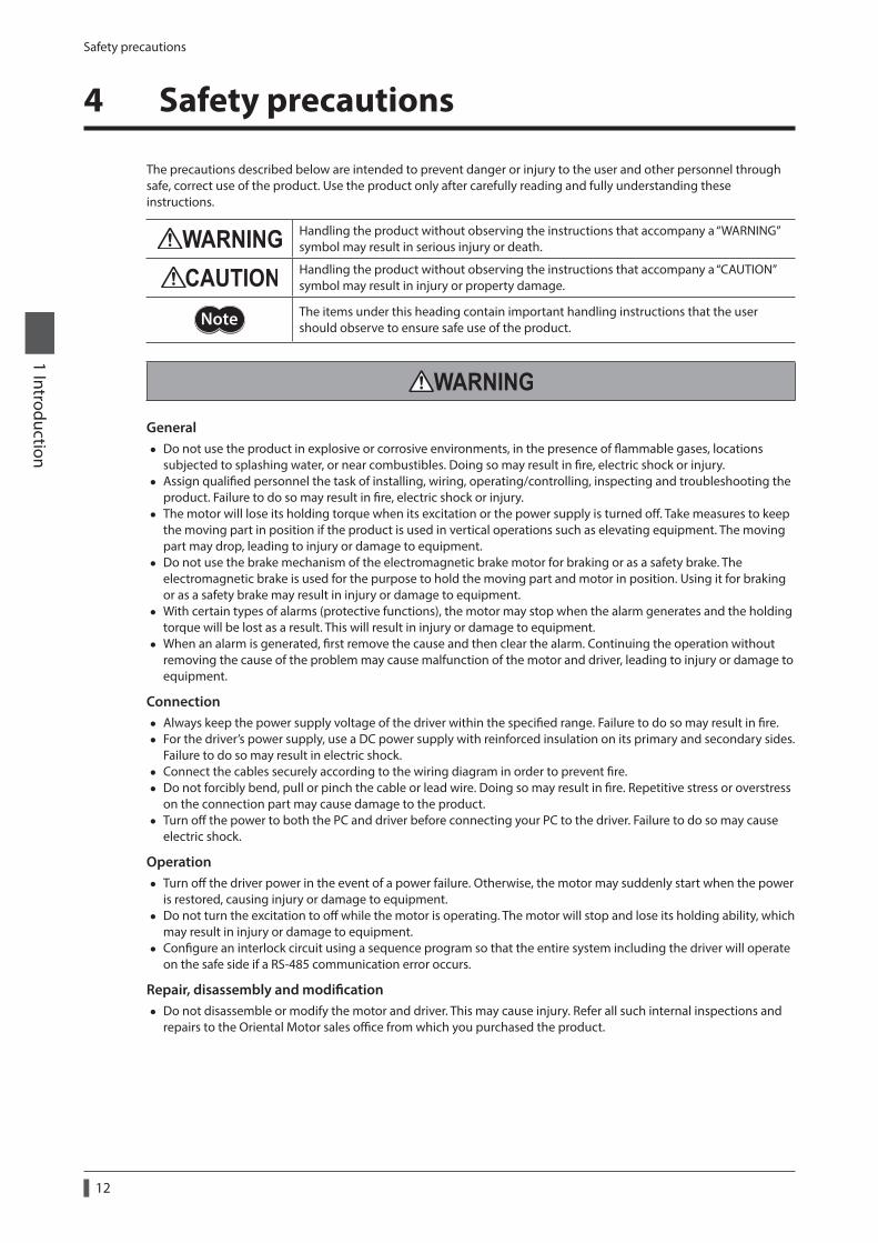
The precautions described below are intended to prevent danger or injury to the user and other personnel through safe, correct use of the product. Use the product only after carefully reading and fully understanding these instructions.
Handling the product without observing the instructions that accompany a “WARNING” symbol may result in serious injury or death.
Handling the product without observing the instructions that accompany a “CAUTION” symbol may result in injury or property damage.
The items under this heading contain important handling instructions that the user should observe to ensure safe use of the product.
General • Do not use the product in explosive or corrosive environments, in the presence of flammable gases, locations
subjected to splashing water, or near combustibles. Doing so may result in fire, electric shock or injury. • Assign qualified personnel the task of installing, wiring, operating/controlling, inspecting and troubleshooting the
product. Failure to do so may result in fire, electric shock or injury. • The motor will lose its holding torque when its excitation or the power supply is turned off. Take measures to keep
the moving part in position if the product is used in vertical operations such as elevating equipment. The moving part may drop, leading to injury or damage to equipment.
• Do not use the brake mechanism of the electromagnetic brake motor for braking or as a safety brake. The electromagnetic brake is used for the purpose to hold the moving part and motor in position. Using it for braking or as a safety brake may result in injury or damage to equipment.
• With certain types of alarms (protective functions), the motor may stop when the alarm generates and the holding torque will be lost as a result. This will result in injury or damage to equipment.
• When an alarm is generated, first remove the cause and then clear the alarm. Continuing the operation without removing the cause of the problem may cause malfunction of the motor and driver, leading to injury or damage to equipment.
Connection • Always keep the power supply voltage of the driver within the specified range. Failure to do so may result in fire. • For the driver’s power supply, use a DC power supply with reinforced insulation on its primary and secondary sides.
Failure to do so may result in electric shock. • Connect the cables securely according to the wiring diagram in order to prevent fire. • Do not forcibly bend, pull or pinch the cable or lead wire. Doing so may result in fire. Repetitive stress or overstress
on the connection part may cause damage to the product. • Turn off the power to both the PC and driver before connecting your PC to the driver. Failure to do so may cause
electric shock.
Operation • Turn off the driver power in the event of a power failure. Otherwise, the motor may suddenly start when the power
is restored, causing injury or damage to equipment. • Do not turn the excitation to off while the motor is operating. The motor will stop and lose its holding ability, which
may result in injury or damage to equipment. • Configure an interlock circuit using a sequence program so that the entire system including the driver will operate
on the safe side if a RS-485 communication error occurs.
Repair, disassembly and modification • Do not disassemble or modify the motor and driver. This may cause injury. Refer all such internal inspections and
repairs to the Oriental Motor sales office from which you purchased the product.
Safety precautions
13
1 Introduction
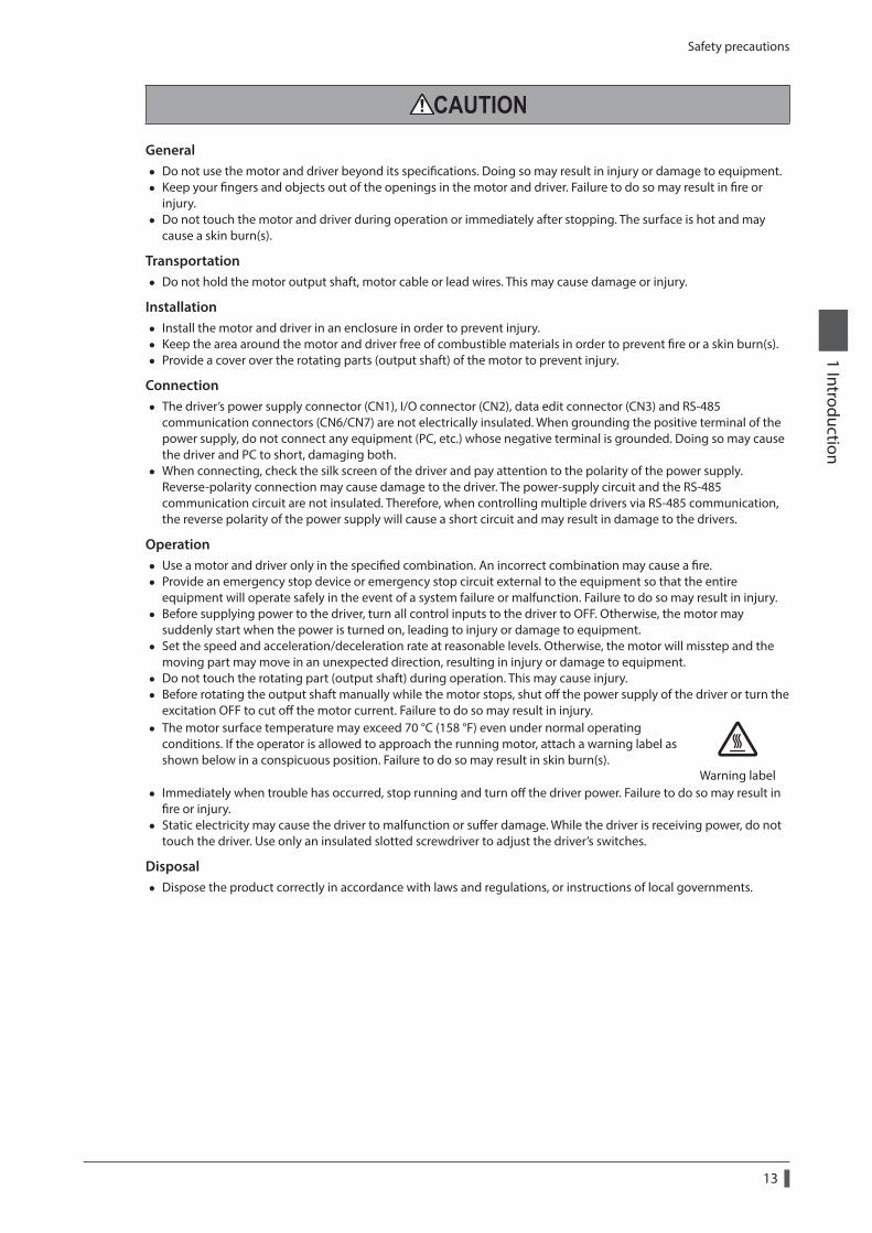
General • Do not use the motor and driver beyond its specifications. Doing so may result in injury or damage to equipment. • Keep your fingers and objects out of the openings in the motor and driver. Failure to do so may result in fire or
injury. • Do not touch the motor and driver during operation or immediately after stopping. The surface is hot and may
cause a skin burn(s).
Transportation • Do not hold the motor output shaft, motor cable or lead wires. This may cause damage or injury.
Installation • Install the motor and driver in an enclosure in order to prevent injury. • Keep the area around the motor and driver free of combustible materials in order to prevent fire or a skin burn(s). • Provide a cover over the rotating parts (output shaft) of the motor to prevent injury.
Connection • The driver’s power supply connector (CN1), I/O connector (CN2), data edit connector (CN3) and RS-485
communication connectors (CN6/CN7) are not electrically insulated. When grounding the positive terminal of the power supply, do not connect any equipment (PC, etc.) whose negative terminal is grounded. Doing so may cause the driver and PC to short, damaging both.
• When connecting, check the silk screen of the driver and pay attention to the polarity of the power supply. Reverse-polarity connection may cause damage to the driver. The power-supply circuit and the RS-485 communication circuit are not insulated. Therefore, when controlling multiple drivers via RS-485 communication, the reverse polarity of the power supply will cause a short circuit and may result in damage to the drivers.
Operation • Use a motor and driver only in the specified combination. An incorrect combination may cause a fire. • Provide an emergency stop device or emergency stop circuit external to the equipment so that the entire
equipment will operate safely in the event of a system failure or malfunction. Failure to do so may result in injury. • Before supplying power to the driver, turn all control inputs to the driver to OFF. Otherwise, the motor may
suddenly start when the power is turned on, leading to injury or damage to equipment. • Set the speed and acceleration/deceleration rate at reasonable levels. Otherwise, the motor will misstep and the
moving part may move in an unexpected direction, resulting in injury or damage to equipment. • Do not touch the rotating part (output shaft) during operation. This may cause injury. • Before rotating the output shaft manually while the motor stops, shut off the power supply of the driver or turn the
excitation OFF to cut off the motor current. Failure to do so may result in injury. • The motor surface temperature may exceed 70 °C (158 °F) even under normal operating
conditions. If the operator is allowed to approach the running motor, attach a warning label as shown below in a conspicuous position. Failure to do so may result in skin burn(s).
Warning label • Immediately when trouble has occurred, stop running and turn off the driver power. Failure to do so may result in
fire or injury. • Static electricity may cause the driver to malfunction or suffer damage. While the driver is receiving power, do not
touch the driver. Use only an insulated slotted screwdriver to adjust the driver’s switches.
Disposal • Dispose the product correctly in accordance with laws and regulations, or instructions of local governments.
Precautions for use
14
1 Introduction
5 Precautions for use
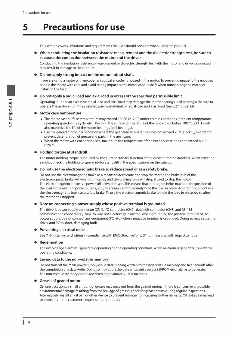
This section covers limitations and requirements the user should consider when using the product.
z When conducting the insulation resistance measurement and the dielectric strength test, be sure to separate the connection between the motor and the driver.Conducting the insulation resistance measurement or dielectric strength test with the motor and driver connected may result in damage to the product.
z Do not apply strong impact on the motor output shaft.If you are using a motor with encoder, an optical encoder is housed in the motor. To prevent damage to the encoder, handle the motor with care and avoid strong impact to the motor output shaft when transporting the motor or installing the load.
z Do not apply a radial load and axial load in excess of the specified permissible limitOperating it under an excessive radial load and axial load may damage the motor bearings (ball bearings). Be sure to operate the motor within the specified permissible limit of radial load and axial load. See p.27 for details.
z Motor case temperature • The motor case surface temperature may exceed 100 °C (212 °F) under certain conditions (ambient temperature,
operating speed, duty cycle, etc.). Keeping the surface temperature of the motor case below 100 °C (212 °F) will also maximize the life of the motor bearings (ball bearings).
• Use the geared motor in a condition where the gear case temperature does not exceed 70 °C (158 °F), in order to prevent deterioration of grease and parts in the gear case.
• When the motor with encoder is used, make sure the temperature of the encoder case does not exceed 80 °C (176 °F).
z Holding torque at standstillThe motor holding torque is reduced by the current cutback function of the driver at motor standstill. When selecting a motor, check the holding torque at motor standstill in the specifications on the catalog.
z Do not use the electromagnetic brake to reduce speed or as a safety brake.Do not use the electromagnetic brake as a means to decelerate and stop the motor. The brake hub of the electromagnetic brake will wear significantly and the braking force will drop if used to stop the motor.The electromagnetic brake is a power-off activated type. This means that although it helps maintain the position of the load in the event of power outage, etc., this brake cannot securely hold the load in place. Accordingly, do not use the electromagnetic brake as a safety brake. To use the electromagnetic brake to hold the load in place, do so after the motor has stopped.
z Note on connecting a power supply whose positive terminal is groundedThe driver’s power supply connector (CN1), I/O connector (CN2), data edit connector (CN3) and RS-485 communication connectors (CN6/CN7) are not electrically insulated. When grounding the positive terminal of the power supply, do not connect any equipment (PC, etc.) whose negative terminal is grounded. Doing so may cause the driver and PC to short, damaging both.
z Preventing electrical noiseSee “1-6 Installing and wiring in compliance with EMC Directive” on p.31 for measures with regard to noise.
z RegenerationThe overvoltage alarm will generate depending on the operating condition. When an alarm is generated, review the operating conditions.
z Saving data to the non-volatile memoryDo not turn off the main power supply while data is being written to the non-volatile memory and five seconds after the completion of a data write. Doing so may abort the data write and cause a EEPROM error alarm to generate.The non-volatile memory can be rewritten approximately 100,000 times.
z Grease of geared motorOn rare occasions, a small amount of grease may ooze out from the geared motor. If there is concern over possible environmental damage resulting from the leakage of grease, check for grease stains during regular inspections. Alternatively, install an oil pan or other device to prevent leakage from causing further damage. Oil leakage may lead to problems in the customer’s equipment or products.

Precautions for use
15
1 Introduction
z Rotating direction of the gear output shaftThe relationship between the rotating direction of the motor shaft and that of the gear output shaft changes as follows, depending on the gear type and gear ratio.
Type of gear Gear ratio
Rotating direction (relative to the motor rotating direction)
Frame size [mm (in.)]
20 (0.79) ø22 (0.87)
28 (1.10) 30 (1.18) 42 (1.65) 60 (2.36)
TH geared3.6, 7.2, 10 − Opposite direction Same direction
20, 30 − Same direction Opposite direction
PS geared PN geared
All gear ratio Same direction
Harmonic geared All gear ratio Opposite direction
General specifications
16
1 Introduction
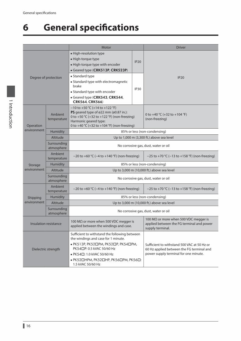
6 General specifications
Motor Driver
Degree of protection
•High-resolution type
•High-torque type
•High-torque type with encoder
•Geared type (CRK513P, CRK523P)
IP20
IP20 • Standard type
• Standard type with electromagnetic brake
• Standard type with encoder
•Geared type (CRK543, CRK544, CRK564, CRK566)
IP30
Operation environment
Ambient temperature
−10 to +50 °C (+14 to +122 °F) PS geared type of ø22 mm (ø0.87 in.): 0 to +50 °C (+32 to +122 °F) (non-freezing) Harmonic geared type: 0 to +40 °C (+32 to +104 °F) (non-freezing)
0 to +40 °C (+32 to +104 °F) (non-freezing)
Humidity 85% or less (non-condensing)
Altitude Up to 1,000 m (3,300 ft.) above sea level
Surrounding atmosphere
No corrosive gas, dust, water or oil
Storage environment
Ambient temperature
−20 to +60 °C (−4 to +140 °F) (non-freezing) −25 to +70 °C (−13 to +158 °F) (non-freezing)
Humidity 85% or less (non-condensing)
Altitude Up to 3,000 m (10,000 ft.) above sea level
Surrounding atmosphere
No corrosive gas, dust, water or oil
Shipping environment
Ambient temperature
−20 to +60 °C (−4 to +140 °F) (non-freezing) −25 to +70 °C (−13 to +158 °F) (non-freezing)
Humidity 85% or less (non-condensing)
Altitude Up to 3,000 m (10,000 ft.) above sea level
Surrounding atmosphere
No corrosive gas, dust, water or oil
Insulation resistance100 MΩ or more when 500 VDC megger is applied between the windings and case.
100 MΩ or more when 500 VDC megger is applied between the FG terminal and power supply terminal.
Dielectric strength
Sufficient to withstand the following between the windings and case for 1 minute.
• PK513P, PK52PM, PK52P, PK54PM, PK54P: 0.5 kVAC 50/60 Hz
• PK54: 1.0 kVAC 50/60 Hz
• PK52HPM, PK52HP, PK56PM, PK56: 1.5 kVAC 50/60 Hz
Sufficient to withstand 500 VAC at 50 Hz or 60 Hz applied between the FG terminal and power supply terminal for one minute.
Regulations and standards
17
1 Introduction
7 Regulations and standards
7-1 EU Directive
CE Marking
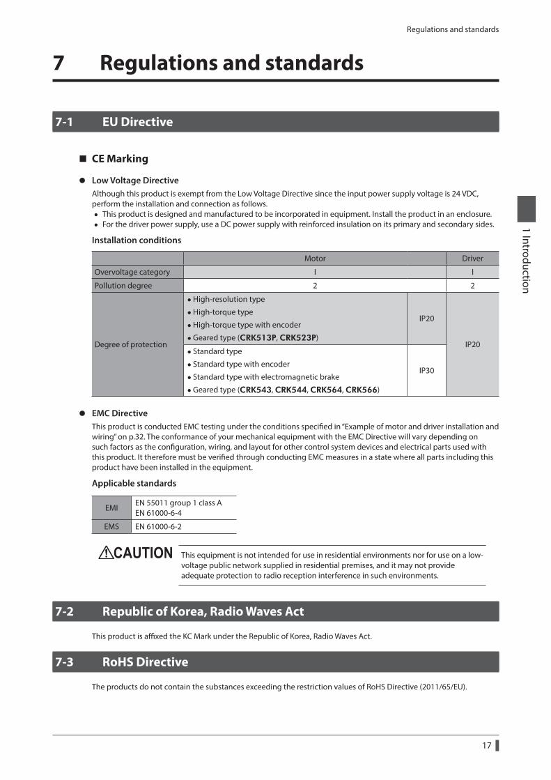
z Low Voltage DirectiveAlthough this product is exempt from the Low Voltage Directive since the input power supply voltage is 24 VDC, perform the installation and connection as follows.
• This product is designed and manufactured to be incorporated in equipment. Install the product in an enclosure. • For the driver power supply, use a DC power supply with reinforced insulation on its primary and secondary sides.
Installation conditions
Motor Driver
Overvoltage category I I
Pollution degree 2 2
Degree of protection
•High-resolution type
•High-torque type
•High-torque type with encoder
•Geared type (CRK513P, CRK523P)
IP20
IP20 • Standard type
• Standard type with encoder
• Standard type with electromagnetic brake
•Geared type (CRK543, CRK544, CRK564, CRK566)
IP30
z EMC DirectiveThis product is conducted EMC testing under the conditions specified in “Example of motor and driver installation and wiring” on p.32. The conformance of your mechanical equipment with the EMC Directive will vary depending on such factors as the configuration, wiring, and layout for other control system devices and electrical parts used with this product. It therefore must be verified through conducting EMC measures in a state where all parts including this product have been installed in the equipment.
Applicable standards
EMIEN 55011 group 1 class A EN 61000-6-4
EMS EN 61000-6-2
This equipment is not intended for use in residential environments nor for use on a low-voltage public network supplied in residential premises, and it may not provide adequate protection to radio reception interference in such environments.
7-2 Republic of Korea, Radio Waves Act
This product is affixed the KC Mark under the Republic of Korea, Radio Waves Act.
7-3 RoHS Directive
The products do not contain the substances exceeding the restriction values of RoHS Directive (2011/65/EU).
Preparation
18
1 Introduction
8 Preparation
This chapter explains the items you should check, as well as the name and function of each part.
8-1 Checking the product
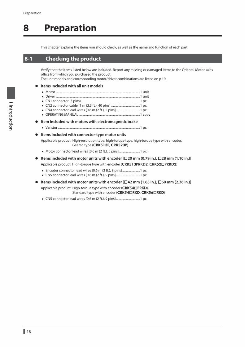
Verify that the items listed below are included. Report any missing or damaged items to the Oriental Motor sales office from which you purchased the product.The unit models and corresponding motor/driver combinations are listed on p.19.
z Items included with all unit models • Motor ..............................................................................................................1 unit • Driver ..............................................................................................................1 unit • CN1 connector (3 pins) .............................................................................1 pc. • CN2 connector cable [1 m (3.3 ft.), 40 pins] ......................................1 pc. • CN4 connector lead wires [0.6 m (2 ft.), 5 pins] ...............................1 pc. • OPERATING MANUAL ................................................................................1 copy
z Item included with motors with electromagnetic brake • Varistor ...........................................................................................................1 pc.
z Items included with connector-type motor unitsApplicable product: High-resolution type, high-torque type, high-torque type with encoder, Geared type (CRK513P, CRK523P)
• Motor connector lead wires [0.6 m (2 ft.), 5 pins] ...........................1 pc.
z Items included with motor units with encoder [20 mm (0.79 in.), 28 mm (1.10 in.)]Applicable product: High-torque type with encoder (CRK513PRKD2, CRK52PRKD2)
• Encoder connector lead wires [0.6 m (2 ft.), 8 pins] .......................1 pc. • CN5 connector lead wires [0.6 m (2 ft.), 9 pins] ...............................1 pc.
z Items included with motor units with encoder [42 mm (1.65 in.), 60 mm (2.36 in.)]Applicable product: High-torque type with encoder (CRK54PRKD), Standard type with encoder (CRK54RKD, CRK56RKD)
• CN5 connector lead wires [0.6 m (2 ft.), 9 pins] ...............................1 pc.
Preparation
19
1 Introduction
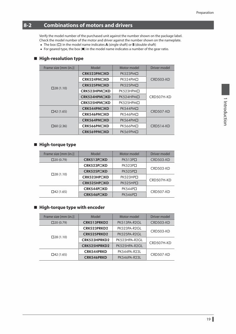
8-2 Combinations of motors and drivers
Verify the model number of the purchased unit against the number shown on the package label.Check the model number of the motor and driver against the number shown on the nameplate.
• The box () in the model name indicates A (single shaft) or B (double shaft) • For geared type, the box () in the model name indicates a number of the gear ratio.
High-resolution type
Frame size [mm (in.)] Model Motor model Driver model
28 (1.10)
CRK523PMKD PK523PM
CRD503-KDCRK524PMKD PK524PM
CRK525PMKD PK525PM
CRK523HPMKD PK523HPM
CRD507H-KDCRK524HPMKD PK524HPM
CRK525HPMKD PK525HPM
42 (1.65)CRK544PMKD PK544PM
CRD507-KDCRK546PMKD PK546PM
60 (2.36)
CRK564PMKD PK564PM
CRD514-KDCRK566PMKD PK566PM
CRK569PMKD PK569PM
High-torque type
Frame size [mm (in.)] Model Motor model Driver model
20 (0.79) CRK513PKD PK513P CRD503-KD
28 (1.10)
CRK523PKD PK523PCRD503-KD
CRK525PKD PK525P
CRK523HPKD PK523HPCRD507H-KD
CRK525HPKD PK525HP
42 (1.65)CRK544PKD PK544P
CRD507-KDCRK546PKD PK546P
High-torque type with encoder
Frame size [mm (in.)] Model Motor model Driver model
20 (0.79) CRK513PRKD2 PK513PA-R2GL CRD503-KD
28 (1.10)
CRK523PRKD2 PK523PA-R2GLCRD503-KD
CRK525PRKD2 PK525PA-R2GL
CRK523HPRKD2 PK523HPA-R2GLCRD507H-KD
CRK525HPRKD2 PK525HPA-R2GL
42 (1.65)CRK544PRKD PK544PA-R23L
CRD507-KDCRK546PRKD PK546PA-R23L
Preparation
20
1 Introduction
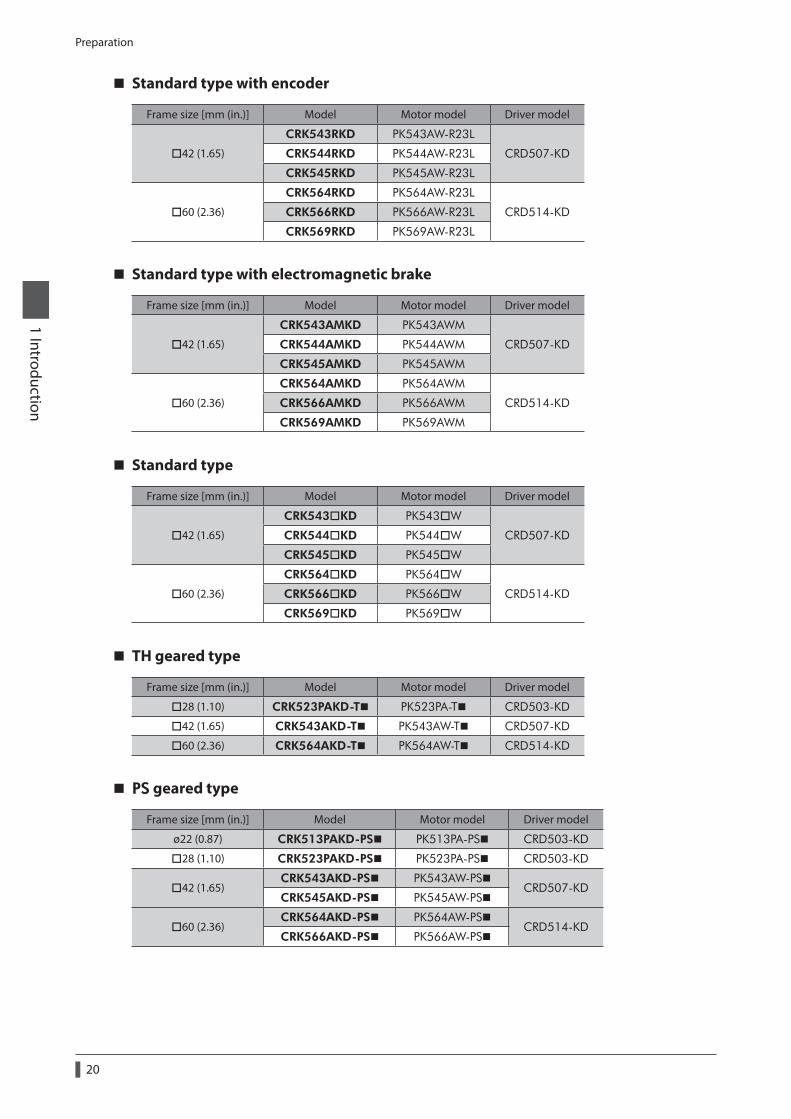
Standard type with encoder
Frame size [mm (in.)] Model Motor model Driver model
42 (1.65)
CRK543RKD PK543AW-R23L
CRD507-KDCRK544RKD PK544AW-R23L
CRK545RKD PK545AW-R23L
60 (2.36)
CRK564RKD PK564AW-R23L
CRD514-KDCRK566RKD PK566AW-R23L
CRK569RKD PK569AW-R23L
Standard type with electromagnetic brake
Frame size [mm (in.)] Model Motor model Driver model
42 (1.65)
CRK543AMKD PK543AWM
CRD507-KDCRK544AMKD PK544AWM
CRK545AMKD PK545AWM
60 (2.36)
CRK564AMKD PK564AWM
CRD514-KDCRK566AMKD PK566AWM
CRK569AMKD PK569AWM
Standard type
Frame size [mm (in.)] Model Motor model Driver model
42 (1.65)
CRK543KD PK543W
CRD507-KDCRK544KD PK544W
CRK545KD PK545W
60 (2.36)
CRK564KD PK564W
CRD514-KDCRK566KD PK566W
CRK569KD PK569W
TH geared type
Frame size [mm (in.)] Model Motor model Driver model
28 (1.10) CRK523PAKD-T PK523PA-T CRD503-KD
42 (1.65) CRK543AKD-T PK543AW-T CRD507-KD
60 (2.36) CRK564AKD-T PK564AW-T CRD514-KD
PS geared type
Frame size [mm (in.)] Model Motor model Driver model
ø22 (0.87) CRK513PAKD-PS PK513PA-PS CRD503-KD
28 (1.10) CRK523PAKD-PS PK523PA-PS CRD503-KD
42 (1.65)CRK543AKD-PS PK543AW-PS
CRD507-KDCRK545AKD-PS PK545AW-PS
60 (2.36)CRK564AKD-PS PK564AW-PS
CRD514-KDCRK566AKD-PS PK566AW-PS
Preparation
21
1 Introduction
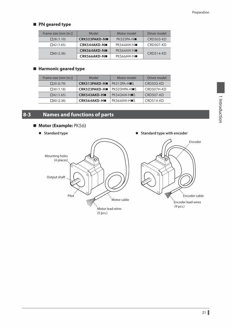
PN geared type
Frame size [mm (in.)] Model Motor model Driver model
28 (1.10) CRK523PAKD-N PK523PA-N CRD503-KD
42 (1.65) CRK544AKD-N PK544AW-N CRD507-KD
60 (2.36)CRK564AKD-N PK564AW-N
CRD514-KDCRK566AKD-N PK566AW-N
Harmonic geared type
Frame size [mm (in.)] Model Motor model Driver model
20 (0.79) CRK513PAKD-H PK513PA-HS CRD503-KD
30 (1.18) CRK523PAKD-H PK523HPA-HS CRD507H-KD
42 (1.65) CRK543AKD-H PK543AW-HS CRD507-KD
60 (2.36) CRK564AKD-H PK564AW-HS CRD514-KD
8-3 Names and functions of parts
Motor (Example: PK56)
z Standard type z Standard type with encoder
Motor cable
Mounting holes(4 places)
Output shaft
Pilot
Motor lead wires (5 pcs.)
Encoder cable
Encoder
Encoder lead wires (9 pcs.)
Preparation
22
1 Introduction
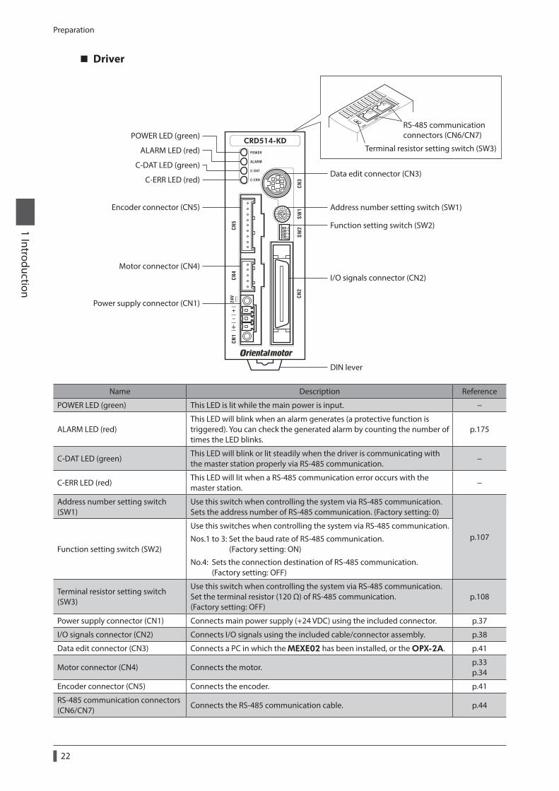
Driver
Terminal resistor setting switch (SW3)
POWER LED (green)
Encoder connector (CN5)
Motor connector (CN4)
Power supply connector (CN1)
C-ERR LED (red)
C-DAT LED (green)
ALARM LED (red)
Data edit connector (CN3)
Address number setting switch (SW1)
Function setting switch (SW2)
I/O signals connector (CN2)
DIN lever
RS-485 communicationconnectors (CN6/CN7)
Name Description Reference
POWER LED (green) This LED is lit while the main power is input. −
ALARM LED (red)This LED will blink when an alarm generates (a protective function is triggered). You can check the generated alarm by counting the number of times the LED blinks.
p.175
C-DAT LED (green)This LED will blink or lit steadily when the driver is communicating with the master station properly via RS-485 communication.
−
C-ERR LED (red)This LED will lit when a RS-485 communication error occurs with the master station.
−
Address number setting switch (SW1)
Use this switch when controlling the system via RS-485 communication. Sets the address number of RS-485 communication. (Factory setting: 0)
p.107Function setting switch (SW2)
Use this switches when controlling the system via RS-485 communication.
Nos.1 to 3: Set the baud rate of RS-485 communication. (Factory setting: ON)
No.4: Sets the connection destination of RS-485 communication. (Factory setting: OFF)
Terminal resistor setting switch (SW3)
Use this switch when controlling the system via RS-485 communication. Set the terminal resistor (120 Ω) of RS-485 communication. (Factory setting: OFF)
p.108
Power supply connector (CN1) Connects main power supply (+24 VDC) using the included connector. p.37
I/O signals connector (CN2) Connects I/O signals using the included cable/connector assembly. p.38
Data edit connector (CN3) Connects a PC in which the MEXE02 has been installed, or the OPX-2A. p.41
Motor connector (CN4) Connects the motor.p.33 p.34
Encoder connector (CN5) Connects the encoder. p.41
RS-485 communication connectors (CN6/CN7)
Connects the RS-485 communication cable. p.44
2 Installation and connection
This part explains the installation method of the product, the mounting method of a load and the connection method as well as I/O signals.
Table of contents
1 Installation .............................................. 241-1 Location for installation ................................ 24
1-2 Installing the motor ....................................... 24
1-3 Installing a load ............................................... 26
1-4 Permissible radial load and permissible axial load .................................... 27
1-5 Installing the driver ........................................ 30
1-6 Installing and wiring in compliance with EMC Directive ................................................... 31
2 Connection ............................................. 332-1 Connecting the motor .................................. 33
2-2 Connecting the connector-type motor .. 34
2-3 Connecting the electromagnetic brake .................................................................... 36
2-4 Connecting the power supply and grounding the driver ..................................... 37
2-5 Connecting the I/O signals .......................... 38
2-6 Connecting the data setter ......................... 41
2-7 Connecting the encoder .............................. 41
2-8 Connecting the RS-485 communication cable .................................................................... 44
3 Explanation of I/O signals .................... 453-1 Input signals ..................................................... 45
3-2 Output signals ................................................. 51
Installation
24
2 Installation and connection
1 Installation
This chapter explains the installation location and installation method of the motor and driver, and installing a load. Also covered in this section are the installation and wiring methods that are in compliance with the relevant EMC Directives.
1-1 Location for installation
The driver is designed and manufactured for installation in equipment.Install it in a well-ventilated location that provides easy access for inspection. The location must also satisfy the following conditions:
• Inside an enclosure that is installed indoors (provide vent holes) • Operating ambient temperature
Motor: −10 to +50 °C (+14 to +122 °F) (non-freezing) PS geared type of ø22 mm (ø0.87 in.): 0 to +50 °C (+32 to +122 °F) (non-freezing) Harmonic geared type: 0 to +40 °C (+32 to +104 °F) (non-freezing) Driver: 0 to +40 °C (+32 to +104 °F) (non-freezing)
• Operating ambient humidity 85% or less (non-condensing) • Area that is free of explosive atmosphere or toxic gas (such as sulfuric gas) or liquid • Area not exposed to direct sun • Area free of excessive amount of dust, iron particles or the like • Area not subject to splashing water (rain, water droplets), oil (oil droplets) or other liquids • Area free of excessive salt • Area not subject to continuous vibration or excessive shocks • Area free of excessive electromagnetic noise (from welders, power machinery, etc.) • Area free of radioactive materials, magnetic fields or vacuum • Up to 1,000 m (3,300 ft.) above sea level
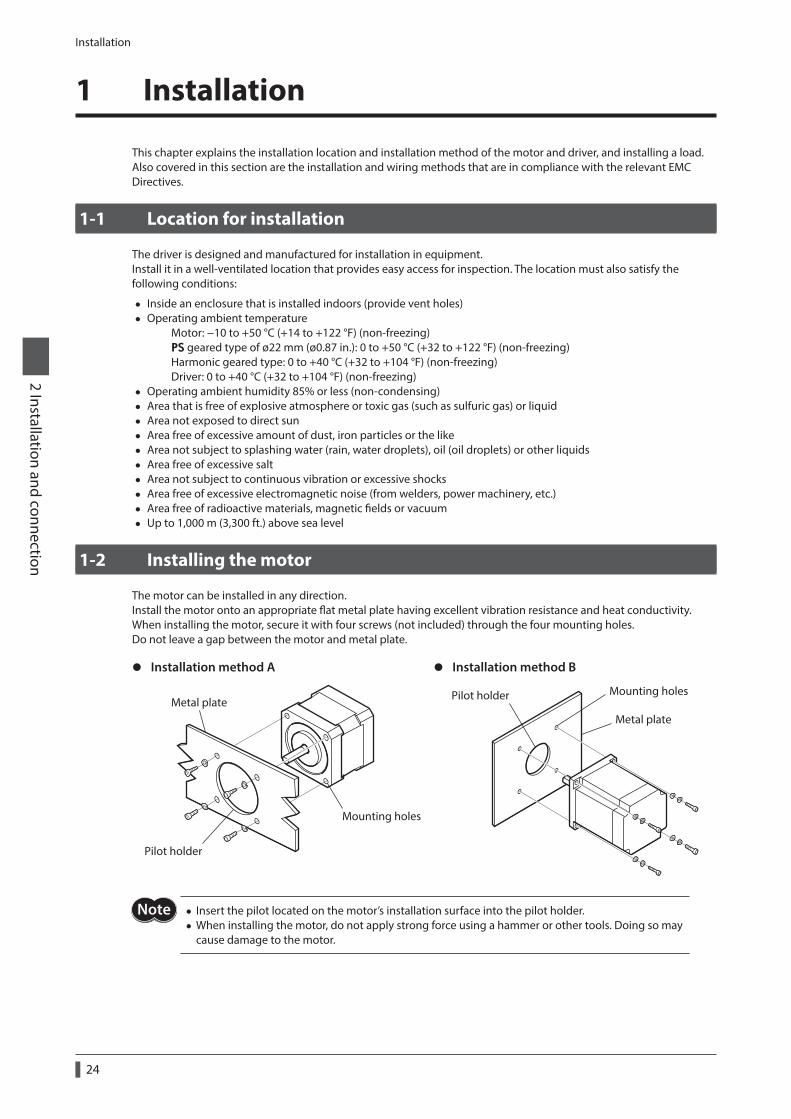
1-2 Installing the motor
The motor can be installed in any direction.Install the motor onto an appropriate flat metal plate having excellent vibration resistance and heat conductivity.When installing the motor, secure it with four screws (not included) through the four mounting holes.Do not leave a gap between the motor and metal plate.
z Installation method A z Installation method B
Pilot holder
Metal plate
Mounting holes
Metal plate
Pilot holder Mounting holes
Not • Insert the pilot located on the motor’s installation surface into the pilot holder. • When installing the motor, do not apply strong force using a hammer or other tools. Doing so may cause damage to the motor.
Installation
25
2 Installation and connection
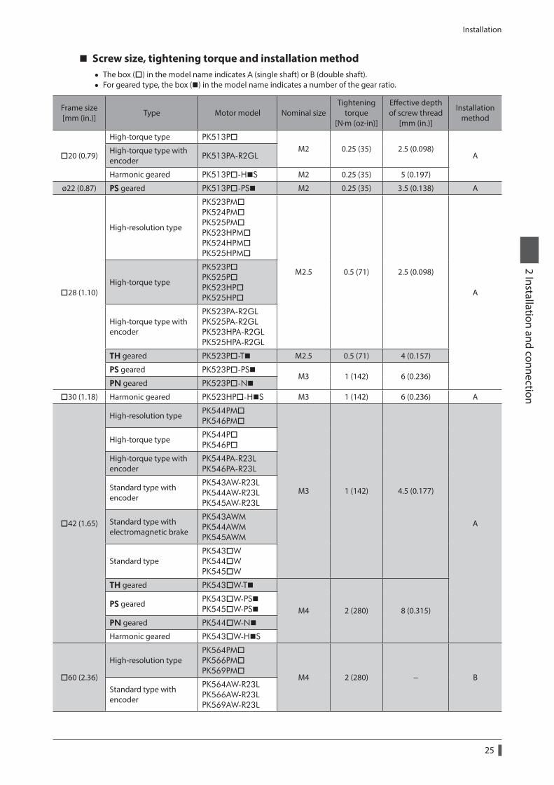
Screw size, tightening torque and installation method • The box () in the model name indicates A (single shaft) or B (double shaft). • For geared type, the box () in the model name indicates a number of the gear ratio.
Frame size [mm (in.)]
Type Motor model Nominal sizeTightening
torque [N·m (oz-in)]
Effective depth of screw thread
[mm (in.)]
Installation method
20 (0.79)
High-torque type PK513PM2 0.25 (35) 2.5 (0.098)
AHigh-torque type with encoder PK513PA-R2GL
Harmonic geared PK513P-HS M2 0.25 (35) 5 (0.197)
ø22 (0.87) PS geared PK513P-PS M2 0.25 (35) 3.5 (0.138) A
28 (1.10)
High-resolution type
PK523PM PK524PM PK525PM PK523HPM PK524HPM PK525HPM
M2.5 0.5 (71) 2.5 (0.098)
AHigh-torque type
PK523P PK525P PK523HP PK525HP
High-torque type with encoder
PK523PA-R2GL PK525PA-R2GL PK523HPA-R2GL PK525HPA-R2GL
TH geared PK523P-T M2.5 0.5 (71) 4 (0.157)
PS geared PK523P-PSM3 1 (142) 6 (0.236)
PN geared PK523P-N
30 (1.18) Harmonic geared PK523HP-HS M3 1 (142) 6 (0.236) A
42 (1.65)
High-resolution type PK544PM PK546PM
M3 1 (142) 4.5 (0.177)
A
High-torque type PK544P PK546P
High-torque type with encoder
PK544PA-R23L PK546PA-R23L
Standard type with encoder
PK543AW-R23L PK544AW-R23L PK545AW-R23L
Standard type with electromagnetic brake
PK543AWM PK544AWM PK545AWM
Standard typePK543W PK544W PK545W
TH geared PK543W-T
M4 2 (280) 8 (0.315)PS geared PK543W-PS
PK545W-PS
PN geared PK544W-N
Harmonic geared PK543W-HS
60 (2.36)
High-resolution typePK564PM PK566PM PK569PM
M4 2 (280) − BStandard type with encoder
PK564AW-R23L PK566AW-R23L PK569AW-R23L
Installation
26
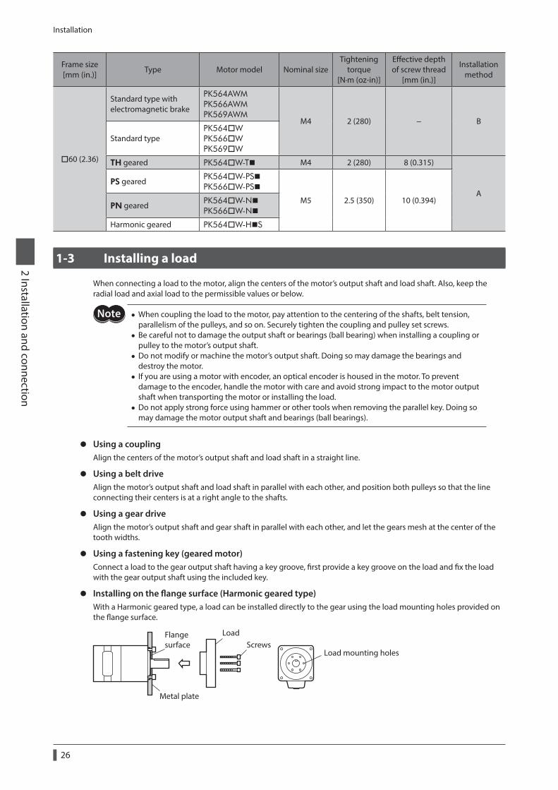
2 Installation and connection
Frame size [mm (in.)]
Type Motor model Nominal sizeTightening
torque [N·m (oz-in)]
Effective depth of screw thread
[mm (in.)]
Installation method
60 (2.36)
Standard type with electromagnetic brake
PK564AWM PK566AWM PK569AWM
M4 2 (280) − B
Standard typePK564W PK566W PK569W
TH geared PK564W-T M4 2 (280) 8 (0.315)
APS geared PK564W-PS
PK566W-PS
M5 2.5 (350) 10 (0.394)PN geared PK564W-N
PK566W-N
Harmonic geared PK564W-HS
1-3 Installing a load
When connecting a load to the motor, align the centers of the motor’s output shaft and load shaft. Also, keep the radial load and axial load to the permissible values or below.
• When coupling the load to the motor, pay attention to the centering of the shafts, belt tension, parallelism of the pulleys, and so on. Securely tighten the coupling and pulley set screws.
• Be careful not to damage the output shaft or bearings (ball bearing) when installing a coupling or pulley to the motor’s output shaft.
• Do not modify or machine the motor’s output shaft. Doing so may damage the bearings and destroy the motor.
• If you are using a motor with encoder, an optical encoder is housed in the motor. To prevent damage to the encoder, handle the motor with care and avoid strong impact to the motor output shaft when transporting the motor or installing the load.
• Do not apply strong force using hammer or other tools when removing the parallel key. Doing so may damage the motor output shaft and bearings (ball bearings).
z Using a couplingAlign the centers of the motor’s output shaft and load shaft in a straight line.
z Using a belt driveAlign the motor’s output shaft and load shaft in parallel with each other, and position both pulleys so that the line connecting their centers is at a right angle to the shafts.
z Using a gear driveAlign the motor’s output shaft and gear shaft in parallel with each other, and let the gears mesh at the center of the tooth widths.
z Using a fastening key (geared motor)Connect a load to the gear output shaft having a key groove, first provide a key groove on the load and fix the load with the gear output shaft using the included key.
z Installing on the flange surface (Harmonic geared type)With a Harmonic geared type, a load can be installed directly to the gear using the load mounting holes provided on the flange surface.
Metal plate
Flange surface Screws
Load
Load mounting holes
Installation
27
2 Installation and connection
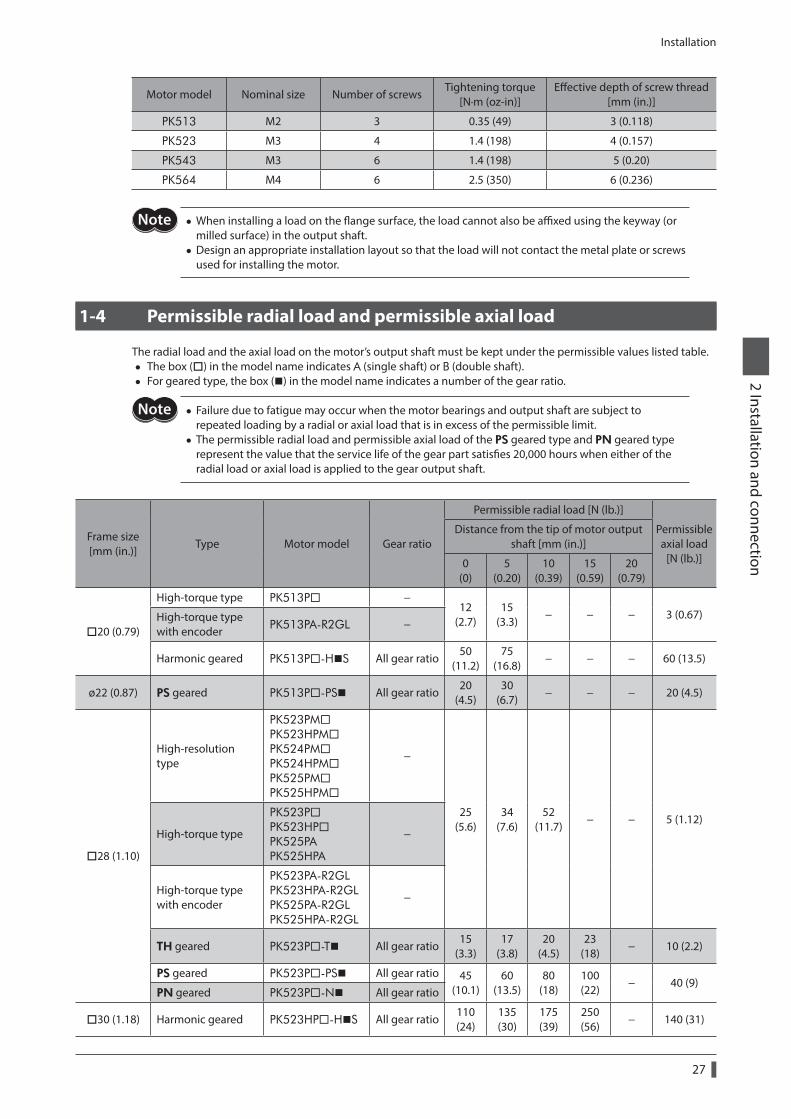
Motor model Nominal size Number of screwsTightening torque
[N·m (oz-in)]Effective depth of screw thread
[mm (in.)]
PK513 M2 3 0.35 (49) 3 (0.118)
PK523 M3 4 1.4 (198) 4 (0.157)
PK543 M3 6 1.4 (198) 5 (0.20)
PK564 M4 6 2.5 (350) 6 (0.236)
• When installing a load on the flange surface, the load cannot also be affixed using the keyway (or milled surface) in the output shaft.
• Design an appropriate installation layout so that the load will not contact the metal plate or screws used for installing the motor.
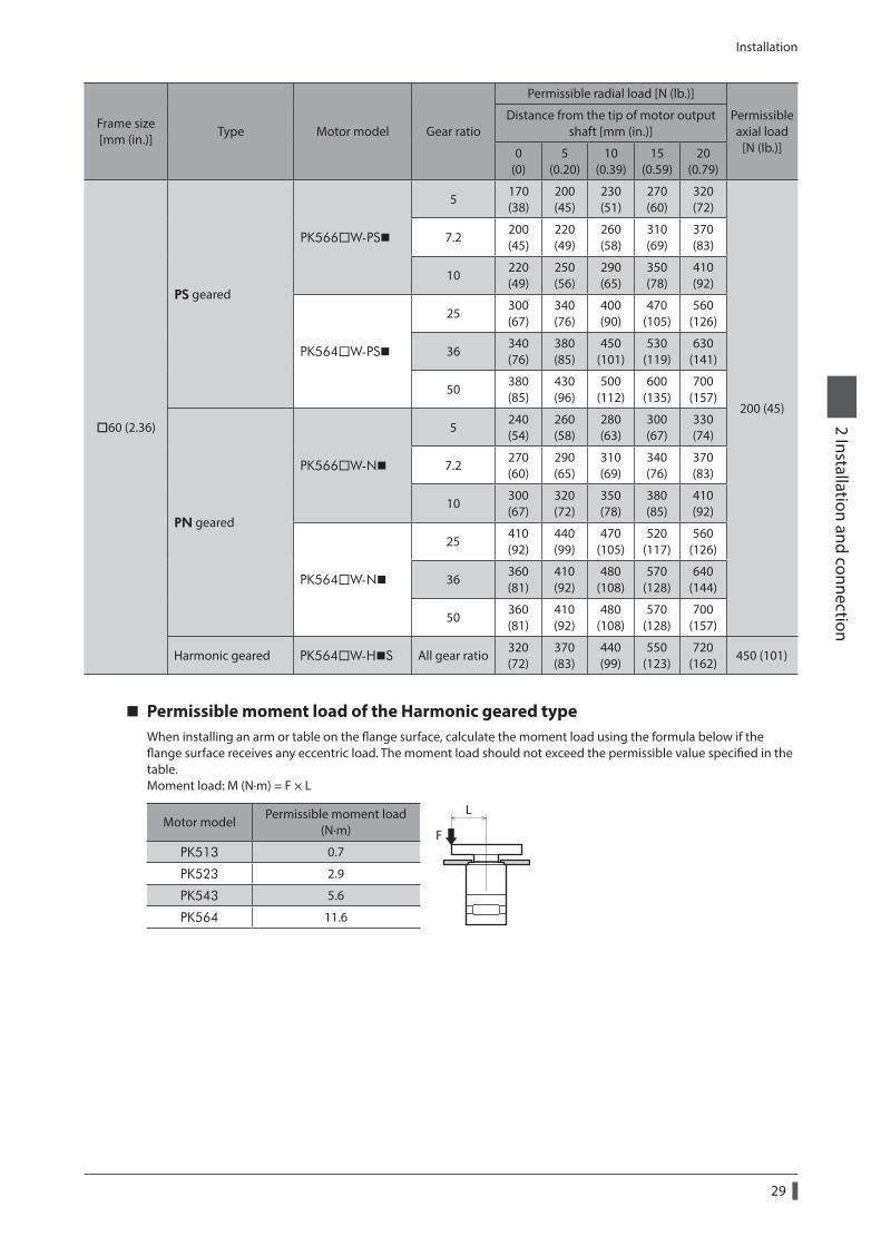
1-4 Permissible radial load and permissible axial load
The radial load and the axial load on the motor’s output shaft must be kept under the permissible values listed table. • The box () in the model name indicates A (single shaft) or B (double shaft). • For geared type, the box () in the model name indicates a number of the gear ratio.
• Failure due to fatigue may occur when the motor bearings and output shaft are subject to repeated loading by a radial or axial load that is in excess of the permissible limit.
• The permissible radial load and permissible axial load of the PS geared type and PN geared type represent the value that the service life of the gear part satisfies 20,000 hours when either of the radial load or axial load is applied to the gear output shaft.
Frame size [mm (in.)]
Type Motor model Gear ratio
Permissible radial load [N (lb.)]
Permissible axial load
[N (lb.)]
Distance from the tip of motor output shaft [mm (in.)]
0 (0)
5 (0.20)
10 (0.39)
15 (0.59)
20 (0.79)
20 (0.79)
High-torque type PK513P −12
(2.7)15
(3.3)− − − 3 (0.67)High-torque type
with encoder PK513PA-R2GL −
Harmonic geared PK513P-HS All gear ratio50
(11.2)75
(16.8)− − − 60 (13.5)
ø22 (0.87) PS geared PK513P-PS All gear ratio20
(4.5)30
(6.7)− − − 20 (4.5)
28 (1.10)
High-resolution type
PK523PM PK523HPMPK524PM PK524HPMPK525PM PK525HPM
−
25 (5.6)
34 (7.6)
52 (11.7)
− − 5 (1.12)High-torque type
PK523P PK523HPPK525PA PK525HPA
−
High-torque type with encoder
PK523PA-R2GL PK523HPA-R2GL PK525PA-R2GL PK525HPA-R2GL
−
TH geared PK523P-T All gear ratio15
(3.3)17
(3.8)20
(4.5)23
(18)− 10 (2.2)
PS geared PK523P-PS All gear ratio 45 (10.1)
60 (13.5)
80 (18)
100 (22)
− 40 (9)PN geared PK523P-N All gear ratio
30 (1.18) Harmonic geared PK523HP-HS All gear ratio110 (24)
135 (30)
175 (39)
250 (56)
− 140 (31)
Installation
28
2 Installation and connection
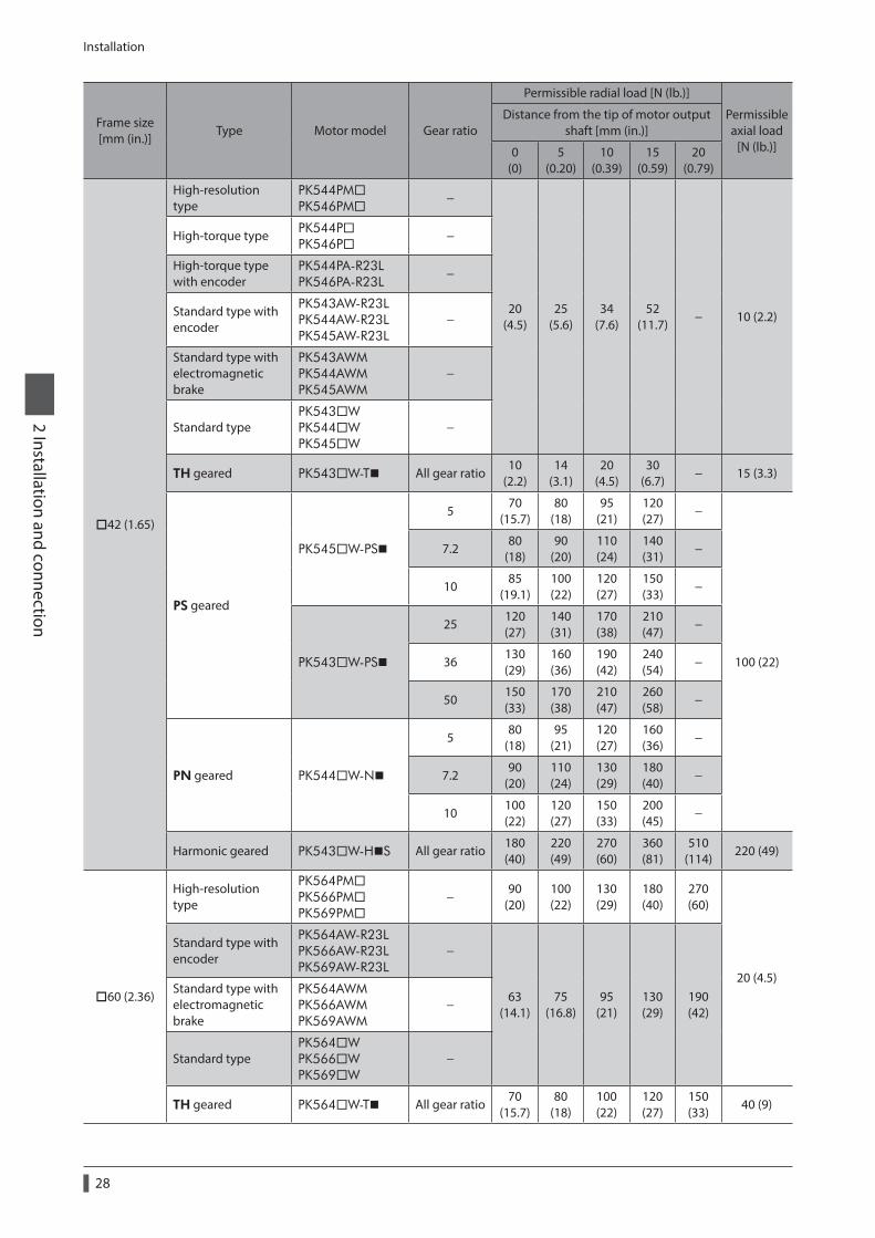
Frame size [mm (in.)]
Type Motor model Gear ratio
Permissible radial load [N (lb.)]
Permissible axial load
[N (lb.)]
Distance from the tip of motor output shaft [mm (in.)]
0 (0)
5 (0.20)
10 (0.39)
15 (0.59)
20 (0.79)
42 (1.65)
High-resolution type
PK544PMPK546PM
−
20 (4.5)
25 (5.6)
34 (7.6)
52 (11.7)
− 10 (2.2)
High-torque type PK544PPK546P
−
High-torque type with encoder
PK544PA-R23L PK546PA-R23L
−
Standard type with encoder
PK543AW-R23L PK544AW-R23L PK545AW-R23L
−
Standard type with electromagnetic brake
PK543AWM PK544AWM PK545AWM
−
Standard typePK543W PK544W PK545W
−
TH geared PK543W-T All gear ratio10
(2.2)14
(3.1)20
(4.5)30
(6.7)− 15 (3.3)
PS geared
PK545W-PS
570
(15.7)80
(18)95
(21)120 (27)
−
100 (22)
7.280
(18)90
(20)110 (24)
140 (31)
−
1085
(19.1)100 (22)
120 (27)
150 (33)
−
PK543W-PS
25120 (27)
140 (31)
170 (38)
210 (47)
−
36130 (29)
160 (36)
190 (42)
240 (54)
−
50150 (33)
170 (38)
210 (47)
260 (58)
−
PN geared PK544W-N
580
(18)95
(21)120 (27)
160 (36)
−
7.290
(20)110 (24)
130 (29)
180 (40)
−
10100 (22)
120 (27)
150 (33)
200 (45)
−
Harmonic geared PK543W-HS All gear ratio180 (40)
220 (49)
270 (60)
360 (81)
510 (114)
220 (49)
60 (2.36)
High-resolution type
PK564PMPK566PMPK569PM
−90
(20)100 (22)
130 (29)
180 (40)
270 (60)
20 (4.5)
Standard type with encoder
PK564AW-R23L PK566AW-R23L PK569AW-R23L
−
63 (14.1)
75 (16.8)
95 (21)
130 (29)
190 (42)
Standard type with electromagnetic brake
PK564AWM PK566AWM PK569AWM
−
Standard typePK564W PK566W PK569W
−
TH geared PK564W-T All gear ratio70
(15.7)80
(18)100 (22)
120 (27)
150 (33)
40 (9)
Installation
29
2 Installation and connection
Frame size [mm (in.)]
Type Motor model Gear ratio
Permissible radial load [N (lb.)]
Permissible axial load
[N (lb.)]
Distance from the tip of motor output shaft [mm (in.)]
0 (0)
5 (0.20)
10 (0.39)
15 (0.59)
20 (0.79)
60 (2.36)
PS geared
PK566W-PS
5170 (38)
200 (45)
230 (51)
270 (60)
320 (72)
200 (45)
7.2200 (45)
220 (49)
260 (58)
310 (69)
370 (83)
10220 (49)
250 (56)
290 (65)
350 (78)
410 (92)
PK564W-PS
25300 (67)
340 (76)
400 (90)
470 (105)
560 (126)
36340 (76)
380 (85)
450 (101)
530 (119)
630 (141)
50380 (85)
430 (96)
500 (112)
600 (135)
700 (157)
PN geared
PK566W-N
5240 (54)
260 (58)
280 (63)
300 (67)
330 (74)
7.2270 (60)
290 (65)
310 (69)
340 (76)
370 (83)
10300 (67)
320 (72)
350 (78)
380 (85)
410 (92)
PK564W-N
25410 (92)
440 (99)
470 (105)
520 (117)
560 (126)
36360 (81)
410 (92)
480 (108)
570 (128)
640 (144)
50360 (81)
410 (92)
480 (108)
570 (128)
700 (157)
Harmonic geared PK564W-HS All gear ratio320 (72)
370 (83)
440 (99)
550 (123)
720 (162)
450 (101)
Permissible moment load of the Harmonic geared typeWhen installing an arm or table on the flange surface, calculate the moment load using the formula below if the flange surface receives any eccentric load. The moment load should not exceed the permissible value specified in the table.Moment load: M (N·m) = F × L
Motor modelPermissible moment load
(N·m)
L
FPK513 0.7
PK523 2.9
PK543 5.6
PK564 11.6
Installation
30
2 Installation and connection
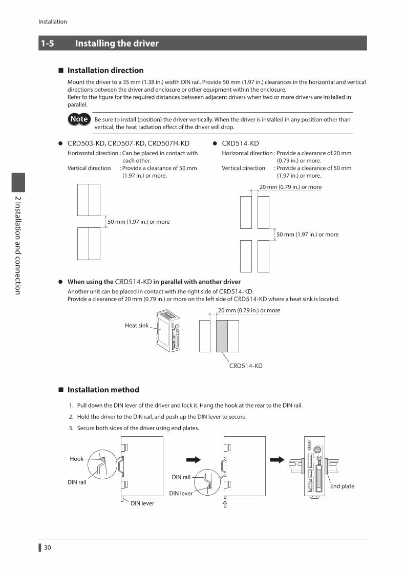
1-5 Installing the driver
Installation directionMount the driver to a 35 mm (1.38 in.) width DIN rail. Provide 50 mm (1.97 in.) clearances in the horizontal and vertical directions between the driver and enclosure or other equipment within the enclosure.Refer to the figure for the required distances between adjacent drivers when two or more drivers are installed in parallel.
Be sure to install (position) the driver vertically. When the driver is installed in any position other than vertical, the heat radiation effect of the driver will drop.
z CRD503-KD, CRD507-KD, CRD507H-KDHorizontal direction : Can be placed in contact with each other. Vertical direction : Provide a clearance of 50 mm (1.97 in.) or more.
50 mm (1.97 in.) or more
z CRD514-KDHorizontal direction : Provide a clearance of 20 mm (0.79 in.) or more. Vertical direction : Provide a clearance of 50 mm (1.97 in.) or more.
50 mm (1.97 in.) or more
20 mm (0.79 in.) or more
z When using the CRD514-KD in parallel with another driverAnother unit can be placed in contact with the right side of CRD514-KD.Provide a clearance of 20 mm (0.79 in.) or more on the left side of CRD514-KD where a heat sink is located.
Heat sink
20 mm (0.79 in.) or more
CRD514-KD
Installation method
1. Pull down the DIN lever of the driver and lock it. Hang the hook at the rear to the DIN rail.
2. Hold the driver to the DIN rail, and push up the DIN lever to secure.
3. Secure both sides of the driver using end plates.
Hook
DIN railDIN rail
DIN lever
DIN leverEnd plate
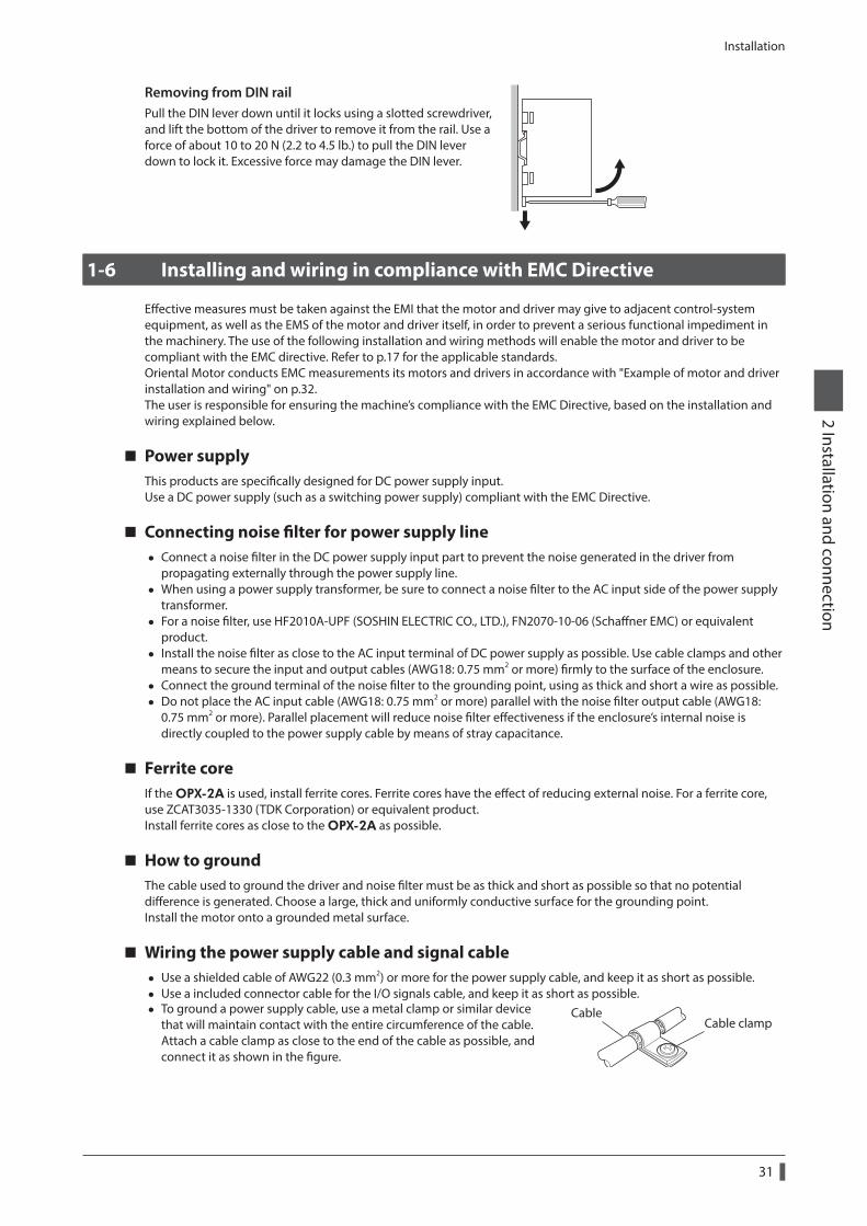
Installation
31
2 Installation and connection
Removing from DIN railPull the DIN lever down until it locks using a slotted screwdriver, and lift the bottom of the driver to remove it from the rail. Use a force of about 10 to 20 N (2.2 to 4.5 lb.) to pull the DIN lever down to lock it. Excessive force may damage the DIN lever.
1-6 Installing and wiring in compliance with EMC Directive
Effective measures must be taken against the EMI that the motor and driver may give to adjacent control-system equipment, as well as the EMS of the motor and driver itself, in order to prevent a serious functional impediment in the machinery. The use of the following installation and wiring methods will enable the motor and driver to be compliant with the EMC directive. Refer to p.17 for the applicable standards.Oriental Motor conducts EMC measurements its motors and drivers in accordance with "Example of motor and driver installation and wiring" on p.32.The user is responsible for ensuring the machine’s compliance with the EMC Directive, based on the installation and wiring explained below.
Power supplyThis products are specifically designed for DC power supply input.Use a DC power supply (such as a switching power supply) compliant with the EMC Directive.
Connecting noise filter for power supply line • Connect a noise filter in the DC power supply input part to prevent the noise generated in the driver from
propagating externally through the power supply line. • When using a power supply transformer, be sure to connect a noise filter to the AC input side of the power supply
transformer. • For a noise filter, use HF2010A-UPF (SOSHIN ELECTRIC CO., LTD.), FN2070-10-06 (Schaffner EMC) or equivalent
product. • Install the noise filter as close to the AC input terminal of DC power supply as possible. Use cable clamps and other
means to secure the input and output cables (AWG18: 0.75 mm2 or more) firmly to the surface of the enclosure. • Connect the ground terminal of the noise filter to the grounding point, using as thick and short a wire as possible. • Do not place the AC input cable (AWG18: 0.75 mm2 or more) parallel with the noise filter output cable (AWG18:
0.75 mm2 or more). Parallel placement will reduce noise filter effectiveness if the enclosure’s internal noise is directly coupled to the power supply cable by means of stray capacitance.
Ferrite coreIf the OPX-2A is used, install ferrite cores. Ferrite cores have the effect of reducing external noise. For a ferrite core, use ZCAT3035-1330 (TDK Corporation) or equivalent product.Install ferrite cores as close to the OPX-2A as possible.
How to groundThe cable used to ground the driver and noise filter must be as thick and short as possible so that no potential difference is generated. Choose a large, thick and uniformly conductive surface for the grounding point.Install the motor onto a grounded metal surface.
Wiring the power supply cable and signal cable • Use a shielded cable of AWG22 (0.3 mm2) or more for the power supply cable, and keep it as short as possible. • Use a included connector cable for the I/O signals cable, and keep it as short as possible. • To ground a power supply cable, use a metal clamp or similar device
that will maintain contact with the entire circumference of the cable. Attach a cable clamp as close to the end of the cable as possible, and connect it as shown in the figure.
Cable clampCable
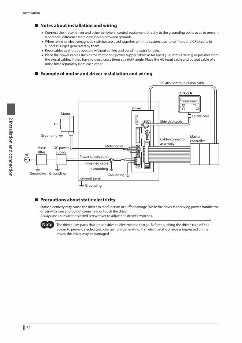
Installation
32
2 Installation and connection
Notes about installation and wiring • Connect the motor, driver and other peripheral control equipment directly to the grounding point so as to prevent
a potential difference from developing between grounds. • When relays or electromagnetic switches are used together with the system, use noise filters and CR circuits to
suppress surges generated by them. • Keep cables as short as possible without coiling and bundling extra lengths. • Place the power cables such as the motor and power supply cables as far apart [100 mm (3.94 in.)] as possible from
the signal cables. If they have to cross, cross them at a right angle. Place the AC input cable and output cable of a noise filter separately from each other.
Example of motor and driver installation and wiring
Motor
Mastercontroller
Driver
Shielded cable
RS-485 communication cable
Motor cable
Power supply cable
(shielded cable)
Cable/connector assembly
Ground panel
OPX-2A
Noiselter
DC powersupply
AC
Grounding
Grounding Grounding
GroundingGrounding
Grounding
Ferrite core
Precautions about static electricityStatic electricity may cause the driver to malfunction or suffer damage. While the driver is receiving power, handle the driver with care and do not come near or touch the driver.Always use an insulated slotted screwdriver to adjust the driver’s switches.
The driver uses parts that are sensitive to electrostatic charge. Before touching the driver, turn off the power to prevent electrostatic charge from generating. If an electrostatic charge is impressed on the driver, the driver may be damaged.
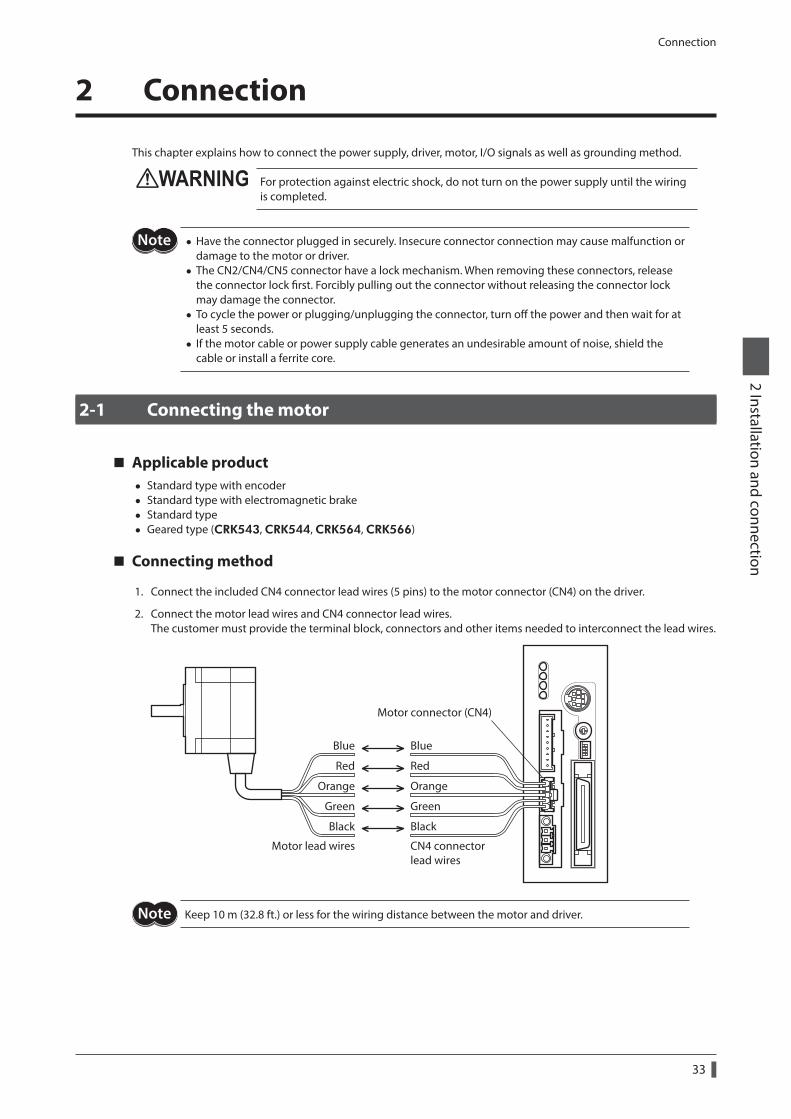
Connection
33
2 Installation and connection
2 Connection
This chapter explains how to connect the power supply, driver, motor, I/O signals as well as grounding method.
For protection against electric shock, do not turn on the power supply until the wiring is completed.
• Have the connector plugged in securely. Insecure connector connection may cause malfunction or damage to the motor or driver.
• The CN2/CN4/CN5 connector have a lock mechanism. When removing these connectors, release the connector lock first. Forcibly pulling out the connector without releasing the connector lock may damage the connector.
• To cycle the power or plugging/unplugging the connector, turn off the power and then wait for at least 5 seconds.
• If the motor cable or power supply cable generates an undesirable amount of noise, shield the cable or install a ferrite core.
2-1 Connecting the motor
Applicable product • Standard type with encoder • Standard type with electromagnetic brake • Standard type • Geared type (CRK543, CRK544, CRK564, CRK566)
Connecting method
1. Connect the included CN4 connector lead wires (5 pins) to the motor connector (CN4) on the driver.
2. Connect the motor lead wires and CN4 connector lead wires.The customer must provide the terminal block, connectors and other items needed to interconnect the lead wires.
Motor lead wires CN4 connector lead wires
Motor connector (CN4)
Blue
Red
Orange
Green
Black
Blue
Red
Orange
Green
Black
Keep 10 m (32.8 ft.) or less for the wiring distance between the motor and driver.
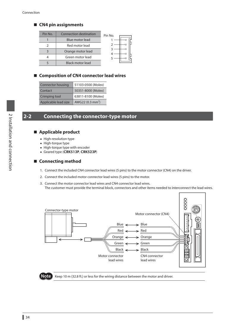
Connection
34
2 Installation and connection
CN4 pin assignments
Pin No. Connection destination
12345
Pin No.1 Blue motor lead
2 Red motor lead
3 Orange motor lead
4 Green motor lead
5 Black motor lead
Composition of CN4 connector lead wires
Connector housing 51103-0500 (Molex)
Contact 50351-8000 (Molex)
Crimping tool 63811-8100 (Molex)
Applicable lead size AWG22 (0.3 mm2)
2-2 Connecting the connector-type motor
Applicable product • High-resolution type • High-torque type • High-torque type with encoder • Geared type (CRK513P, CRK523P)
Connecting method
1. Connect the included CN4 connector lead wires (5 pins) to the motor connector (CN4) on the driver.
2. Connect the included motor connector lead wires (5 pins) to the motor.
3. Connect the motor connector lead wires and CN4 connector lead wires.The customer must provide the terminal block, connectors and other items needed to interconnect the lead wires.
Connector-type motor
Motor connector lead wires
CN4 connector lead wires
Motor connector (CN4)
Blue
Red
Orange
Green
Black
Blue
Red
Orange
Green
Black
Keep 10 m (32.8 ft.) or less for the wiring distance between the motor and driver.
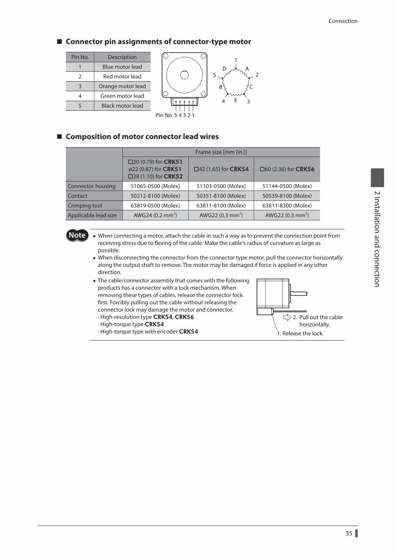
Connection
35
2 Installation and connection
Connector pin assignments of connector-type motor
Pin No. Description
4 3 2 1
1
2
34
5A
B
D
C
E
Pin No. 5
1 Blue motor lead
2 Red motor lead
3 Orange motor lead
4 Green motor lead
5 Black motor lead
Composition of motor connector lead wires
Frame size [mm (in.)]
20 (0.79) for CRK51 ø22 (0.87) for CRK51 28 (1.10) for CRK52
42 (1.65) for CRK54 60 (2.36) for CRK56
Connector housing 51065-0500 (Molex) 51103-0500 (Molex) 51144-0500 (Molex)
Contact 50212-8100 (Molex) 50351-8100 (Molex) 50539-8100 (Molex)
Crimping tool 63819-0500 (Molex) 63811-8100 (Molex) 63811-8300 (Molex)
Applicable lead size AWG24 (0.2 mm2) AWG22 (0.3 mm2) AWG22 (0.3 mm2)
• When connecting a motor, attach the cable in such a way as to prevent the connection point from receiving stress due to flexing of the cable. Make the cable's radius of curvature as large as possible.
• When disconnecting the connector from the connector type motor, pull the connector horizontally along the output shaft to remove. The motor may be damaged if force is applied in any other direction.
• The cable/connector assembly that comes with the following products has a connector with a lock mechanism. When removing these types of cables, release the connector lock first. Forcibly pulling out the cable without releasing the connector lock may damage the motor and connector. · High-resolution type CRK54, CRK56 · High-torque type CRK54 · High-torque type with encoder CRK54
2. Pull out the cable horizontally.
1. Release the lock.
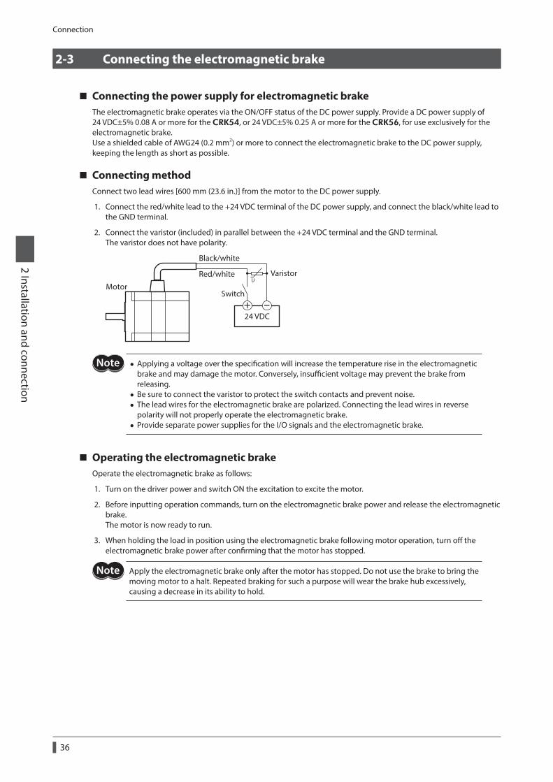
Connection
36
2 Installation and connection
2-3 Connecting the electromagnetic brake
Connecting the power supply for electromagnetic brakeThe electromagnetic brake operates via the ON/OFF status of the DC power supply. Provide a DC power supply of 24 VDC±5% 0.08 A or more for the CRK54, or 24 VDC±5% 0.25 A or more for the CRK56, for use exclusively for the electromagnetic brake.Use a shielded cable of AWG24 (0.2 mm2) or more to connect the electromagnetic brake to the DC power supply, keeping the length as short as possible.
Connecting methodConnect two lead wires [600 mm (23.6 in.)] from the motor to the DC power supply.
1. Connect the red/white lead to the +24 VDC terminal of the DC power supply, and connect the black/white lead to the GND terminal.
2. Connect the varistor (included) in parallel between the +24 VDC terminal and the GND terminal.The varistor does not have polarity.
Varistor
Switch
Black/white
Red/white
Motor
24 VDC
• Applying a voltage over the specification will increase the temperature rise in the electromagnetic brake and may damage the motor. Conversely, insufficient voltage may prevent the brake from releasing.
• Be sure to connect the varistor to protect the switch contacts and prevent noise. • The lead wires for the electromagnetic brake are polarized. Connecting the lead wires in reverse polarity will not properly operate the electromagnetic brake.
• Provide separate power supplies for the I/O signals and the electromagnetic brake.
Operating the electromagnetic brakeOperate the electromagnetic brake as follows:
1. Turn on the driver power and switch ON the excitation to excite the motor.
2. Before inputting operation commands, turn on the electromagnetic brake power and release the electromagnetic brake.The motor is now ready to run.
3. When holding the load in position using the electromagnetic brake following motor operation, turn off the electromagnetic brake power after confirming that the motor has stopped.
Apply the electromagnetic brake only after the motor has stopped. Do not use the brake to bring the moving motor to a halt. Repeated braking for such a purpose will wear the brake hub excessively, causing a decrease in its ability to hold.
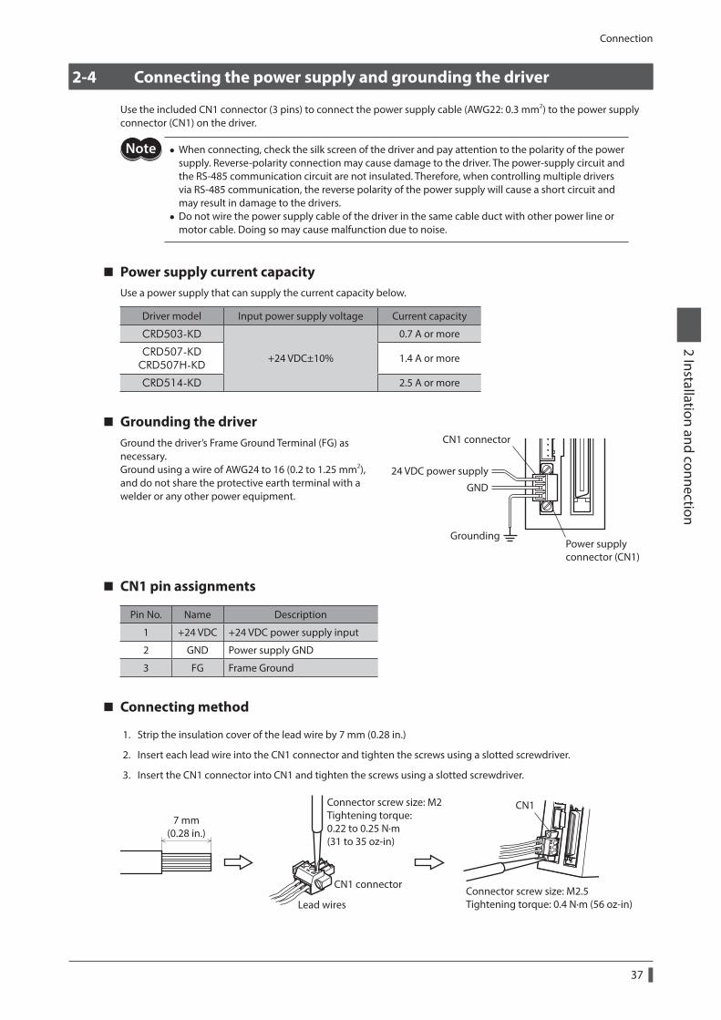
Connection
37
2 Installation and connection
2-4 Connecting the power supply and grounding the driver
Use the included CN1 connector (3 pins) to connect the power supply cable (AWG22: 0.3 mm2) to the power supply connector (CN1) on the driver.
• When connecting, check the silk screen of the driver and pay attention to the polarity of the power supply. Reverse-polarity connection may cause damage to the driver. The power-supply circuit and the RS-485 communication circuit are not insulated. Therefore, when controlling multiple drivers via RS-485 communication, the reverse polarity of the power supply will cause a short circuit and may result in damage to the drivers.
• Do not wire the power supply cable of the driver in the same cable duct with other power line or motor cable. Doing so may cause malfunction due to noise.
Power supply current capacityUse a power supply that can supply the current capacity below.
Driver model Input power supply voltage Current capacity
CRD503-KD
+24 VDC±10%
0.7 A or more
CRD507-KD CRD507H-KD
1.4 A or more
CRD514-KD 2.5 A or more
Grounding the driverGround the driver’s Frame Ground Terminal (FG) as necessary.Ground using a wire of AWG24 to 16 (0.2 to 1.25 mm2), and do not share the protective earth terminal with a welder or any other power equipment.
24 VDC power supply
CN1 connector
Power supplyconnector (CN1)
GND
Grounding
CN1 pin assignments
Pin No. Name Description
1 +24 VDC +24 VDC power supply input
2 GND Power supply GND
3 FG Frame Ground
Connecting method
1. Strip the insulation cover of the lead wire by 7 mm (0.28 in.)
2. Insert each lead wire into the CN1 connector and tighten the screws using a slotted screwdriver.
3. Insert the CN1 connector into CN1 and tighten the screws using a slotted screwdriver.
Lead wires
CN1 connector
7 mm(0.28 in.)
Connector screw size: M2Tightening torque: 0.22 to 0.25 N·m(31 to 35 oz-in)
Connector screw size: M2.5Tightening torque: 0.4 N·m (56 oz-in)
CN1
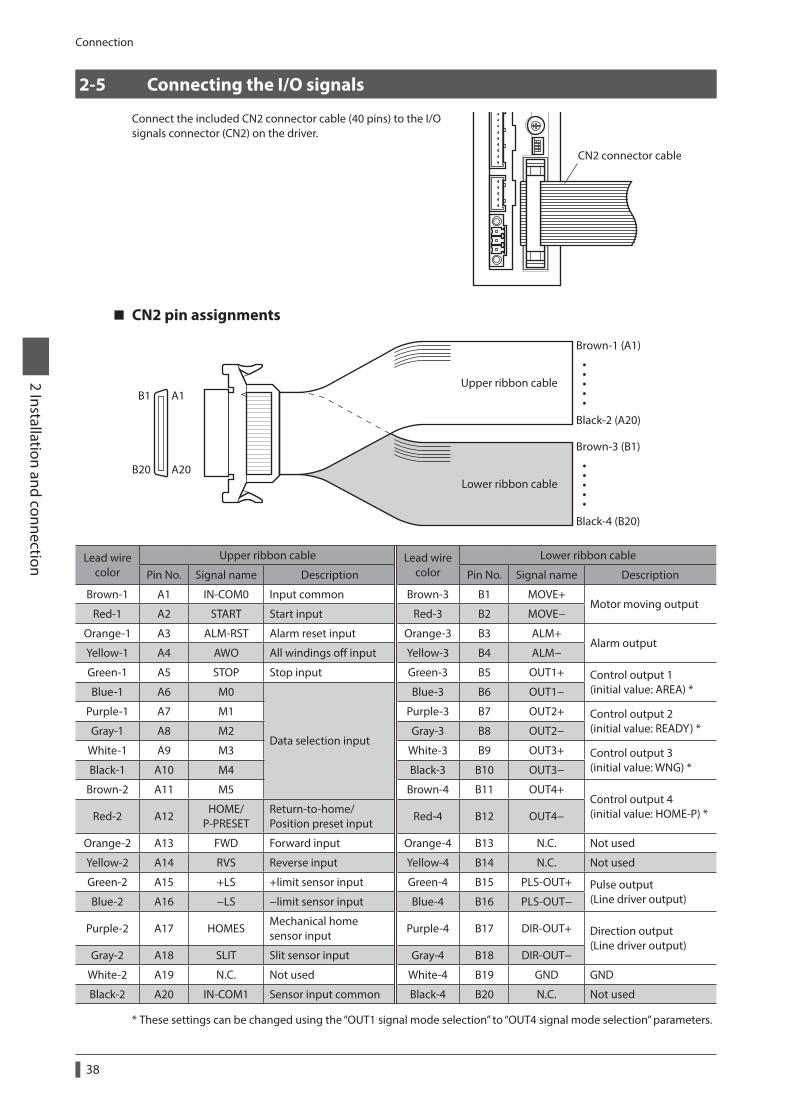
Connection
38
2 Installation and connection
2-5 Connecting the I/O signals
Connect the included CN2 connector cable (40 pins) to the I/O signals connector (CN2) on the driver.
CN2 connector cable
CN2 pin assignments
A1
A20
B1
B20
Brown-1 (A1)
Black-2 (A20)
•••••
Brown-3 (B1)
Black-4 (B20)
•••••
Upper ribbon cable
Lower ribbon cable
Lead wire color
Upper ribbon cable Lead wire color
Lower ribbon cable
Pin No. Signal name Description Pin No. Signal name Description
Brown-1 A1 IN-COM0 Input common Brown-3 B1 MOVE+Motor moving output
Red-1 A2 START Start input Red-3 B2 MOVE−
Orange-1 A3 ALM-RST Alarm reset input Orange-3 B3 ALM+Alarm output
Yellow-1 A4 AWO All windings off input Yellow-3 B4 ALM−
Green-1 A5 STOP Stop input Green-3 B5 OUT1+ Control output 1 (initial value: AREA) *Blue-1 A6 M0
Data selection input
Blue-3 B6 OUT1−
Purple-1 A7 M1 Purple-3 B7 OUT2+ Control output 2 (initial value: READY) *Gray-1 A8 M2 Gray-3 B8 OUT2−
White-1 A9 M3 White-3 B9 OUT3+ Control output 3 (initial value: WNG) *Black-1 A10 M4 Black-3 B10 OUT3−
Brown-2 A11 M5 Brown-4 B11 OUT4+Control output 4 (initial value: HOME-P) *Red-2 A12
HOME/ P-PRESET
Return-to-home/ Position preset input
Red-4 B12 OUT4−
Orange-2 A13 FWD Forward input Orange-4 B13 N.C. Not used
Yellow-2 A14 RVS Reverse input Yellow-4 B14 N.C. Not used
Green-2 A15 +LS +limit sensor input Green-4 B15 PLS-OUT+ Pulse output (Line driver output)Blue-2 A16 −LS −limit sensor input Blue-4 B16 PLS-OUT−
Purple-2 A17 HOMESMechanical home sensor input
Purple-4 B17 DIR-OUT+ Direction output (Line driver output)
Gray-2 A18 SLIT Slit sensor input Gray-4 B18 DIR-OUT−
White-2 A19 N.C. Not used White-4 B19 GND GND
Black-2 A20 IN-COM1 Sensor input common Black-4 B20 N.C. Not used
* These settings can be changed using the “OUT1 signal mode selection” to “OUT4 signal mode selection” parameters.
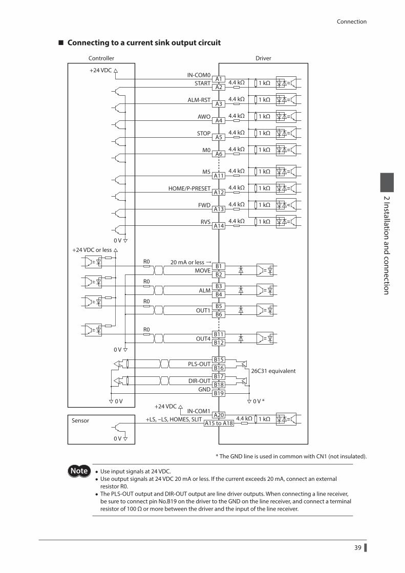
Connection
39
2 Installation and connection
Connecting to a current sink output circuit
A14
B1B2
B3B4
B5B6
B11B12
A13
A12
A6
A11
A5
A15 to A18A20
A4
A3
A2A1
B15B16B17B18B19
4.4 kΩ 1 kΩ
4.4 kΩ 1 kΩ
4.4 kΩ 1 kΩ
4.4 kΩ 1 kΩ
4.4 kΩ 1 kΩ
4.4 kΩ 1 kΩ
4.4 kΩ 1 kΩ
4.4 kΩ 1 kΩ
4.4 kΩ 1 kΩ
0 V
0 V
DriverController
Sensor
+24 VDCIN-COM0
IN-COM1
START
ALM-RST
AWO
STOP
4.4 kΩ 1 kΩ+LS, -LS, HOMES, SLIT
M0
M5
HOME/P-PRESET
FWD
RVS
MOVE
ALM
OUT1
OUT4
+24 VDC or less
R0
R0
R0
R0
0 V
+24 VDC0 V 0 V *
PLS-OUT
DIR-OUTGND
20 mA or less
26C31 equivalent
* The GND line is used in common with CN1 (not insulated).
• Use input signals at 24 VDC. • Use output signals at 24 VDC 20 mA or less. If the current exceeds 20 mA, connect an external resistor R0.
• The PLS-OUT output and DIR-OUT output are line driver outputs. When connecting a line receiver, be sure to connect pin No.B19 on the driver to the GND on the line receiver, and connect a terminal resistor of 100 Ω or more between the driver and the input of the line receiver.
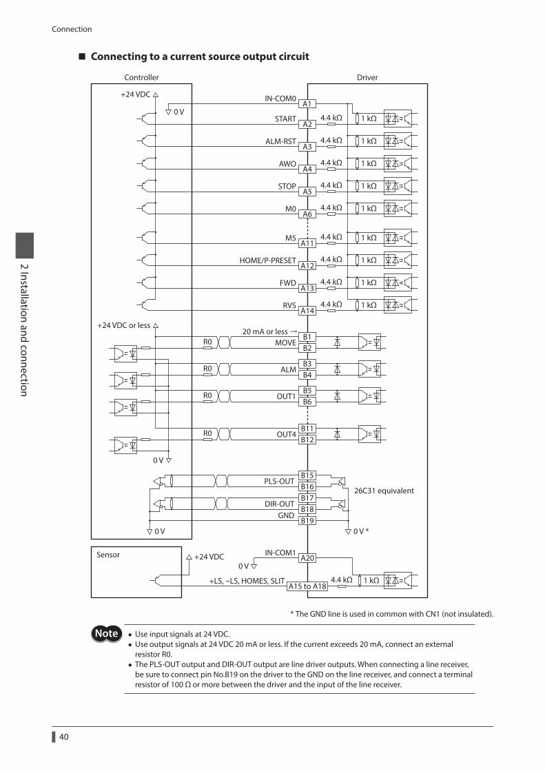
Connection
40
2 Installation and connection
Connecting to a current source output circuit
A14
B1B2
B3B4
B5B6
B11B12
A13
A12
A6
A11
A5
A15 to A18
A20
A4
A3
A2
A1
B15B16B17B18B19
4.4 kΩ 1 kΩ
4.4 kΩ 1 kΩ
4.4 kΩ 1 kΩ
4.4 kΩ 1 kΩ
4.4 kΩ 1 kΩ
4.4 kΩ 1 kΩ
4.4 kΩ 1 kΩ
4.4 kΩ 1 kΩ
4.4 kΩ 1 kΩ
0 V
0 V
DriverController
Sensor
+24 VDC IN-COM0
IN-COM1
START
ALM-RST
AWO
STOP
4.4 kΩ 1 kΩ+LS, -LS, HOMES, SLIT
M0
M5
HOME/P-PRESET
FWD
RVS
MOVE
ALM
OUT1
OUT4
+24 VDC or less
0 V
+24 VDC
R0
R0
R0
R0
0 V 0 V *
PLS-OUT
DIR-OUTGND
26C31 equivalent
20 mA or less
* The GND line is used in common with CN1 (not insulated).
• Use input signals at 24 VDC. • Use output signals at 24 VDC 20 mA or less. If the current exceeds 20 mA, connect an external resistor R0.
• The PLS-OUT output and DIR-OUT output are line driver outputs. When connecting a line receiver, be sure to connect pin No.B19 on the driver to the GND on the line receiver, and connect a terminal resistor of 100 Ω or more between the driver and the input of the line receiver.
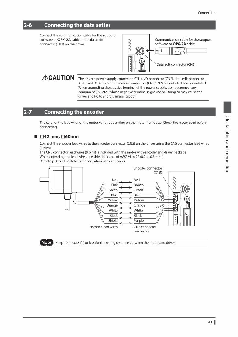
Connection
41
2 Installation and connection
2-6 Connecting the data setter
Connect the communication cable for the support software or OPX-2A cable to the data edit connector (CN3) on the driver.
Data edit connector (CN3)
Communication cable for the support software or OPX-2A cable
The driver's power supply connector (CN1), I/O connector (CN2), data edit connector (CN3) and RS-485 communication connectors (CN6/CN7) are not electrically insulated. When grounding the positive terminal of the power supply, do not connect any equipment (PC, etc.) whose negative terminal is grounded. Doing so may cause the driver and PC to short, damaging both.
2-7 Connecting the encoder
The color of the lead wire for the motor varies depending on the motor frame size. Check the motor used before connecting.
42 mm, 60mmConnect the encoder lead wires to the encoder connector (CN5) on the driver using the CN5 connector lead wires (9 pins).The CN5 connector lead wires (9 pins) is included with the motor with encoder and driver package.When extending the lead wires, use shielded cable of AWG24 to 22 (0.2 to 0.3 mm2).Refer to p.86 for the detailed specification of this encoder.
Encoder connector(CN5)
RedBrownGreenBlueYellowOrangeWhiteBlackPurple
RedPink
GreenBlue
YellowOrange
WhiteBlack
Shield
CN5 connector lead wires
Encoder lead wires
Keep 10 m (32.8 ft.) or less for the wiring distance between the motor and driver.
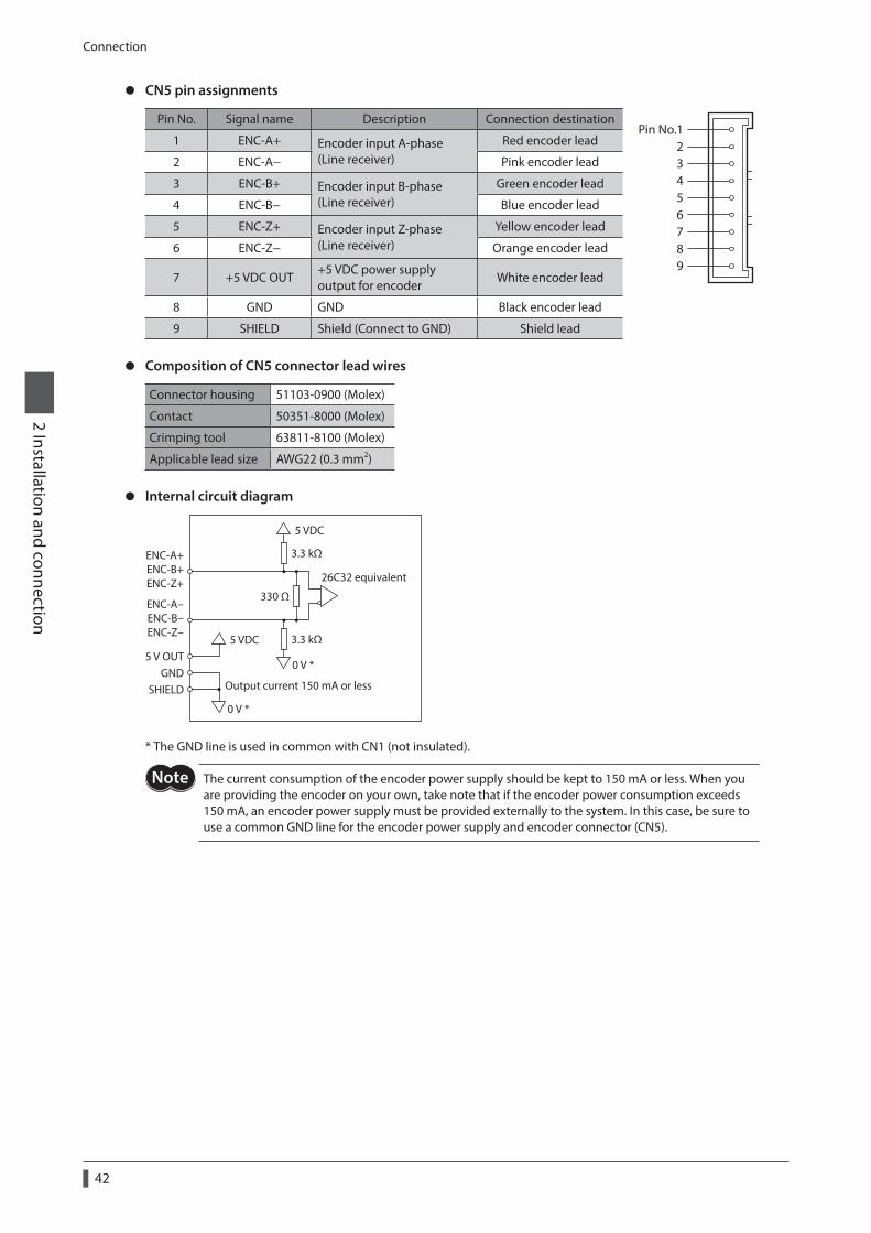
Connection
42
2 Installation and connection
z CN5 pin assignments
Pin No. Signal name Description Connection destinationPin No.1
23456789
1 ENC-A+ Encoder input A-phase (Line receiver)
Red encoder lead
2 ENC-A− Pink encoder lead
3 ENC-B+ Encoder input B-phase (Line receiver)
Green encoder lead
4 ENC-B− Blue encoder lead
5 ENC-Z+ Encoder input Z-phase (Line receiver)
Yellow encoder lead
6 ENC-Z− Orange encoder lead
7 +5 VDC OUT+5 VDC power supply output for encoder
White encoder lead
8 GND GND Black encoder lead
9 SHIELD Shield (Connect to GND) Shield lead
z Composition of CN5 connector lead wires
Connector housing 51103-0900 (Molex)
Contact 50351-8000 (Molex)
Crimping tool 63811-8100 (Molex)
Applicable lead size AWG22 (0.3 mm2)
z Internal circuit diagram
ENC-A+ENC-B+ENC-Z+
ENC-A-ENC-B-ENC-Z-
5 V OUTGND
330 Ω
3.3 kΩ
3.3 kΩ
0 V *
0 V *
5 VDC
5 VDC
26C32 equivalent
Output current 150 mA or lessSHIELD
* The GND line is used in common with CN1 (not insulated).
The current consumption of the encoder power supply should be kept to 150 mA or less. When you are providing the encoder on your own, take note that if the encoder power consumption exceeds 150 mA, an encoder power supply must be provided externally to the system. In this case, be sure to use a common GND line for the encoder power supply and encoder connector (CN5).
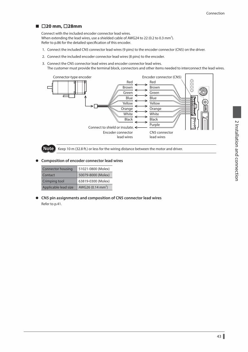
Connection
43
2 Installation and connection
20 mm, 28mmConnect with the included encoder connector lead wires.When extending the lead wires, use a shielded cable of AWG24 to 22 (0.2 to 0.3 mm2).Refer to p.86 for the detailed specification of this encoder.
1. Connect the included CN5 connector lead wires (9 pins) to the encoder connector (CN5) on the driver.
2. Connect the included encoder connector lead wires (8 pins) to the encoder.
3. Connect the CN5 connector lead wires and encoder connector lead wires.The customer must provide the terminal block, connectors and other items needed to interconnect the lead wires.
CN5 connector lead wires
Encoder connector (CN5)
Purple
RedBrownGreen
BlueYellow
OrangeWhiteBlack
RedBrownGreenBlueYellowOrangeWhiteBlack
Encoder connector lead wires
Connect to shield or insulate.
Connector-type encoder
Keep 10 m (32.8 ft.) or less for the wiring distance between the motor and driver.
z Composition of encoder connector lead wires
Connector housing 51021-0800 (Molex)
Contact 50079-8000 (Molex)
Crimping tool 63819-0300 (Molex)
Applicable lead size AWG26 (0.14 mm2)
z CN5 pin assignments and composition of CN5 connector lead wiresRefer to p.41.
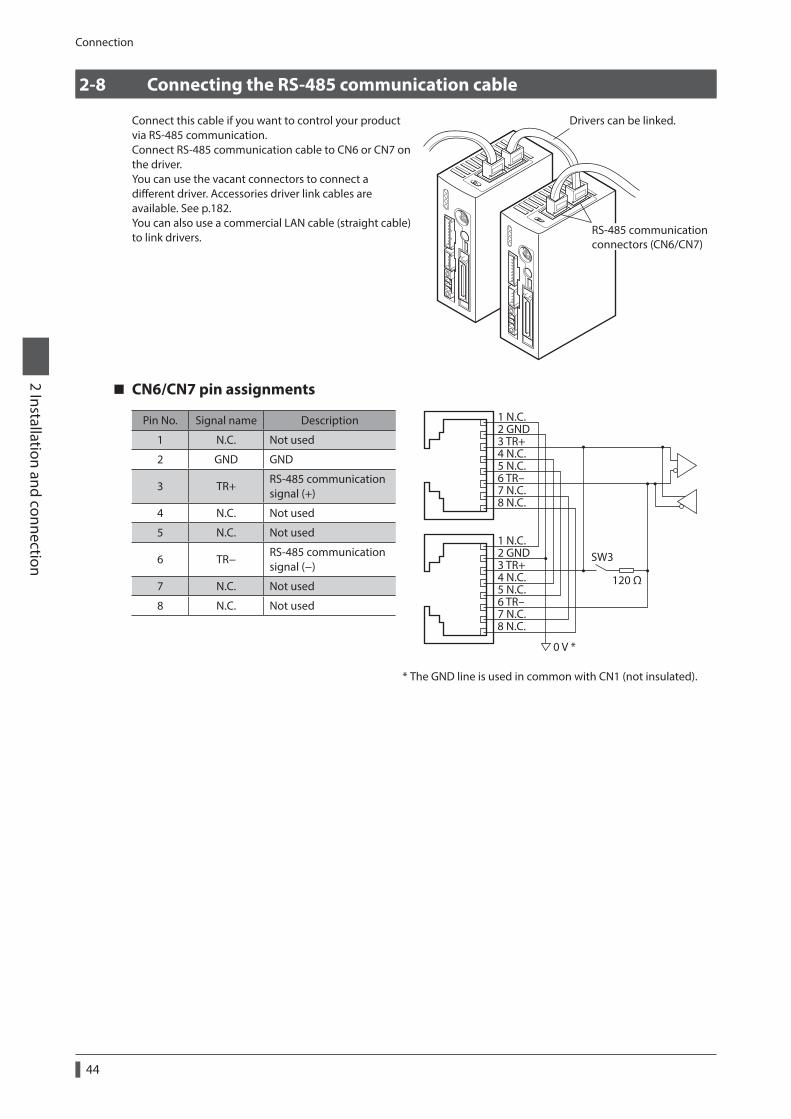
Connection
44
2 Installation and connection
2-8 Connecting the RS-485 communication cable
Connect this cable if you want to control your product via RS-485 communication.Connect RS-485 communication cable to CN6 or CN7 on the driver.You can use the vacant connectors to connect a different driver. Accessories driver link cables are available. See p.182.You can also use a commercial LAN cable (straight cable) to link drivers.
RS-485 communicationconnectors (CN6/CN7)
Drivers can be linked.
CN6/CN7 pin assignments
Pin No. Signal name Description 1 N.C.2 GND3 TR+4 N.C.5 N.C.6 TR-7 N.C.8 N.C.
1 N.C.2 GND3 TR+4 N.C.5 N.C.6 TR-7 N.C.8 N.C.
120 Ω
0 V *
SW3
* The GND line is used in common with CN1 (not insulated).
1 N.C. Not used
2 GND GND
3 TR+RS-485 communication signal (+)
4 N.C. Not used
5 N.C. Not used
6 TR−RS-485 communication signal (−)
7 N.C. Not used
8 N.C. Not used
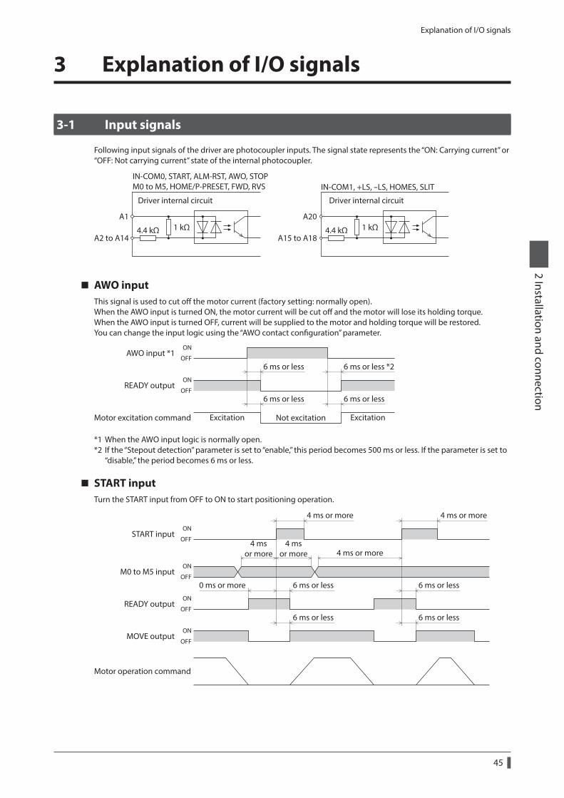
Explanation of I/O signals
45
2 Installation and connection
3 Explanation of I/O signals
3-1 Input signals
Following input signals of the driver are photocoupler inputs. The signal state represents the “ON: Carrying current” or “OFF: Not carrying current” state of the internal photocoupler.
1 kΩ4.4 kΩ
Driver internal circuit
IN-COM0, START, ALM-RST, AWO, STOPM0 to M5, HOME/P-PRESET, FWD, RVS
A1
A2 to A14
A20
A15 to A18
IN-COM1, +LS, -LS, HOMES, SLIT
1 kΩ4.4 kΩ
Driver internal circuit
AWO inputThis signal is used to cut off the motor current (factory setting: normally open).When the AWO input is turned ON, the motor current will be cut off and the motor will lose its holding torque.When the AWO input is turned OFF, current will be supplied to the motor and holding torque will be restored.You can change the input logic using the “AWO contact configuration” parameter.
Excitation Excitation
AWO input *1
Not excitationMotor excitation command
READY output
6 ms or less
6 ms or less
6 ms or less *2
ON
OFF
ON
OFF6 ms or less
*1 When the AWO input logic is normally open.*2 If the “Stepout detection” parameter is set to “enable,” this period becomes 500 ms or less. If the parameter is set to
“disable,” the period becomes 6 ms or less.
START inputTurn the START input from OFF to ON to start positioning operation.
START input
MOVE output
M0 to M5 input
4 msor more
4 msor more
6 ms or less 6 ms or less
6 ms or less
READY output
0 ms or more 6 ms or less
4 ms or more4 ms or more
4 ms or more
ON
OFF
ON
OFF
ON
OFF
ON
OFF
Motor operation command
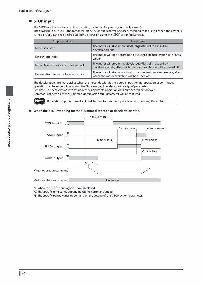
Explanation of I/O signals
46
2 Installation and connection
STOP inputThe STOP input is used to stop the operating motor (factory setting: normally closed).The STOP input turns OFF, the motor will stop. This input is normally closed, meaning that it is OFF when the power is turned on. You can set a desired stopping operation using the “STOP action” parameter.
Stop operation Description
Immediate stopThe motor will stop immediately regardless of the specified deceleration rate.
Deceleration stopThe motor will stop according to the specified deceleration rate (initial value).
Immediate stop + motor is not excitedThe motor will stop immediately regardless of the specified deceleration rate, after which the motor excitation will be turned off.
Deceleration stop + motor is not excitedThe motor will stop according to the specified deceleration rate, after which the motor excitation will be turned off.
The deceleration rate that applies when the motor decelerates to a stop in positioning operation or continuous operation can be set as follows using the “Acceleration (deceleration) rate type” parameter:Separate: The deceleration rate set under the applicable operation data number will be followed.Common: The setting of the “Common deceleration rate” parameter will be followed.
If the STOP input is normally closed, be sure to turn this input ON when operating the motor.
z When the STOP stopping method is immediate stop or deceleration stop.
MOVE output
6 ms or less
4 ms or more
STOP input *1
START input
READY output
*2 *3
6 ms or less
4 ms or more0 ms or more
6 ms or less
Excitation
ON
OFF
ON
OFF
ON
OFF
ON
OFF
Motor excitation command
Motor operation command
*1 When the STOP input logic is normally closed.*2 The specific time varies depending on the command speed.*3 The specific period varies depending on the setting of the “STOP action” parameter.
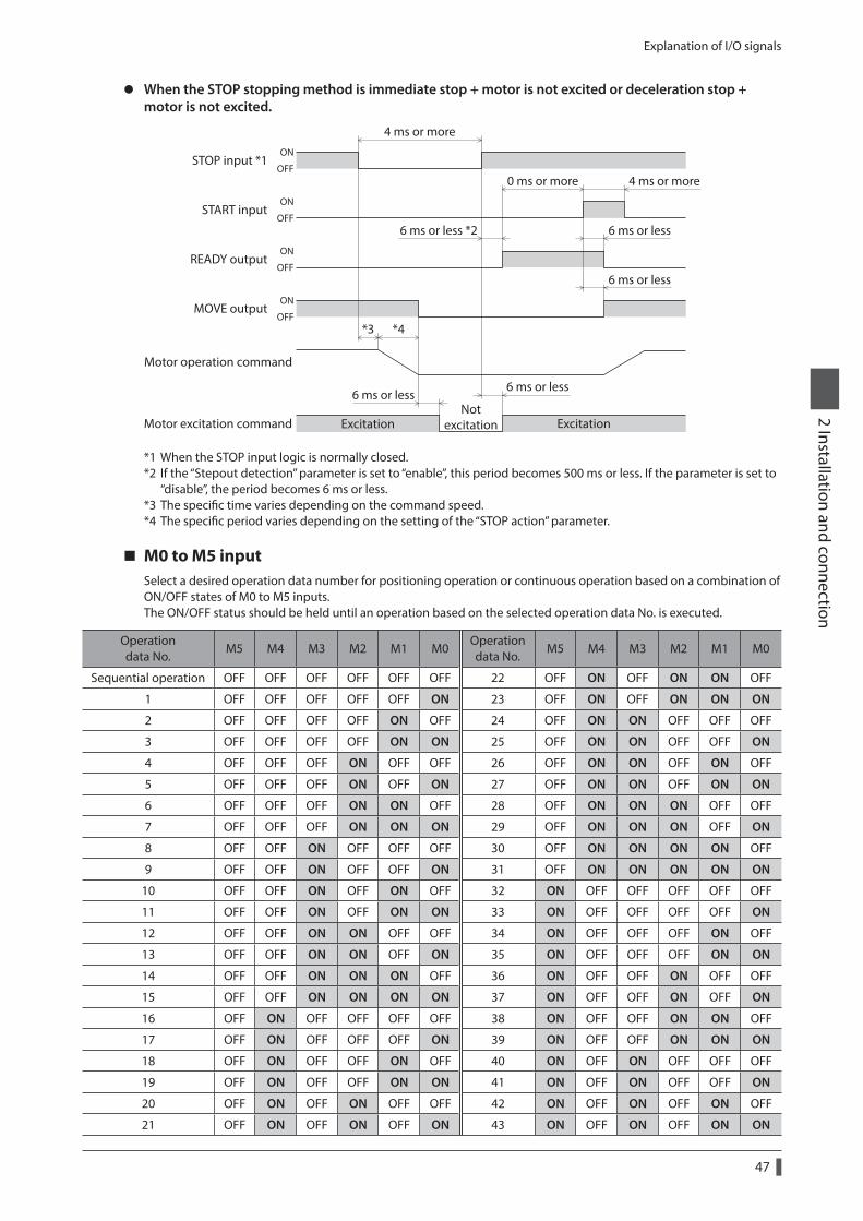
Explanation of I/O signals
47
2 Installation and connection
z When the STOP stopping method is immediate stop + motor is not excited or deceleration stop + motor is not excited.
MOVE output
6 ms or less
6 ms or less
4 ms or more
STOP input *1
START input
READY output
6 ms or less
*3 *4
6 ms or less
4 ms or more0 ms or more
6 ms or less *2
ExcitationNot
excitation Excitation
ON
OFF
ON
OFF
ON
OFF
ON
OFF
Motor excitation command
Motor operation command
*1 When the STOP input logic is normally closed.*2 If the “Stepout detection” parameter is set to “enable”, this period becomes 500 ms or less. If the parameter is set to
“disable”, the period becomes 6 ms or less.*3 The specific time varies depending on the command speed.*4 The specific period varies depending on the setting of the “STOP action” parameter.
M0 to M5 inputSelect a desired operation data number for positioning operation or continuous operation based on a combination of ON/OFF states of M0 to M5 inputs.The ON/OFF status should be held until an operation based on the selected operation data No. is executed.
Operation data No.
M5 M4 M3 M2 M1 M0Operation data No.
M5 M4 M3 M2 M1 M0
Sequential operation OFF OFF OFF OFF OFF OFF 22 OFF ON OFF ON ON OFF
1 OFF OFF OFF OFF OFF ON 23 OFF ON OFF ON ON ON
2 OFF OFF OFF OFF ON OFF 24 OFF ON ON OFF OFF OFF
3 OFF OFF OFF OFF ON ON 25 OFF ON ON OFF OFF ON
4 OFF OFF OFF ON OFF OFF 26 OFF ON ON OFF ON OFF
5 OFF OFF OFF ON OFF ON 27 OFF ON ON OFF ON ON
6 OFF OFF OFF ON ON OFF 28 OFF ON ON ON OFF OFF
7 OFF OFF OFF ON ON ON 29 OFF ON ON ON OFF ON
8 OFF OFF ON OFF OFF OFF 30 OFF ON ON ON ON OFF
9 OFF OFF ON OFF OFF ON 31 OFF ON ON ON ON ON
10 OFF OFF ON OFF ON OFF 32 ON OFF OFF OFF OFF OFF
11 OFF OFF ON OFF ON ON 33 ON OFF OFF OFF OFF ON
12 OFF OFF ON ON OFF OFF 34 ON OFF OFF OFF ON OFF
13 OFF OFF ON ON OFF ON 35 ON OFF OFF OFF ON ON
14 OFF OFF ON ON ON OFF 36 ON OFF OFF ON OFF OFF
15 OFF OFF ON ON ON ON 37 ON OFF OFF ON OFF ON
16 OFF ON OFF OFF OFF OFF 38 ON OFF OFF ON ON OFF
17 OFF ON OFF OFF OFF ON 39 ON OFF OFF ON ON ON
18 OFF ON OFF OFF ON OFF 40 ON OFF ON OFF OFF OFF
19 OFF ON OFF OFF ON ON 41 ON OFF ON OFF OFF ON
20 OFF ON OFF ON OFF OFF 42 ON OFF ON OFF ON OFF
21 OFF ON OFF ON OFF ON 43 ON OFF ON OFF ON ON
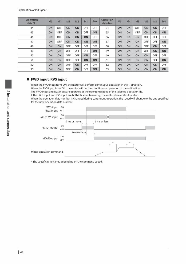
Explanation of I/O signals
48
2 Installation and connection
Operation data No.
M5 M4 M3 M2 M1 M0Operation data No.
M5 M4 M3 M2 M1 M0
44 ON OFF ON ON OFF OFF 54 ON ON OFF ON ON OFF
45 ON OFF ON ON OFF ON 55 ON ON OFF ON ON ON
46 ON OFF ON ON ON OFF 56 ON ON ON OFF OFF OFF
47 ON OFF ON ON ON ON 57 ON ON ON OFF OFF ON
48 ON ON OFF OFF OFF OFF 58 ON ON ON OFF ON OFF
49 ON ON OFF OFF OFF ON 59 ON ON ON OFF ON ON
50 ON ON OFF OFF ON OFF 60 ON ON ON ON OFF OFF
51 ON ON OFF OFF ON ON 61 ON ON ON ON OFF ON
52 ON ON OFF ON OFF OFF 62 ON ON ON ON ON OFF
53 ON ON OFF ON OFF ON 63 ON ON ON ON ON ON
FWD input, RVS inputWhen the FWD input turns ON, the motor will perform continuous operation in the + direction.When the RVS input turns ON, the motor will perform continuous operation in the − direction.The FWD input and RVS input are operated at the operating speed of the selected operation No.If the FWD input and RVS input are both ON simultaneously, the motor decelerates to a stop.When the operation data number is changed during continuous operation, the speed will change to the one specified for the new operation data number.
FWD input(RVS input)
M0 to M5 input
MOVE output
READY output
ON
OFF
ON
OFF
ON
OFF
ON
OFF
6 ms or less
6 ms or less
**
0 ms or more
Motor operation command
* The specific time varies depending on the command speed.
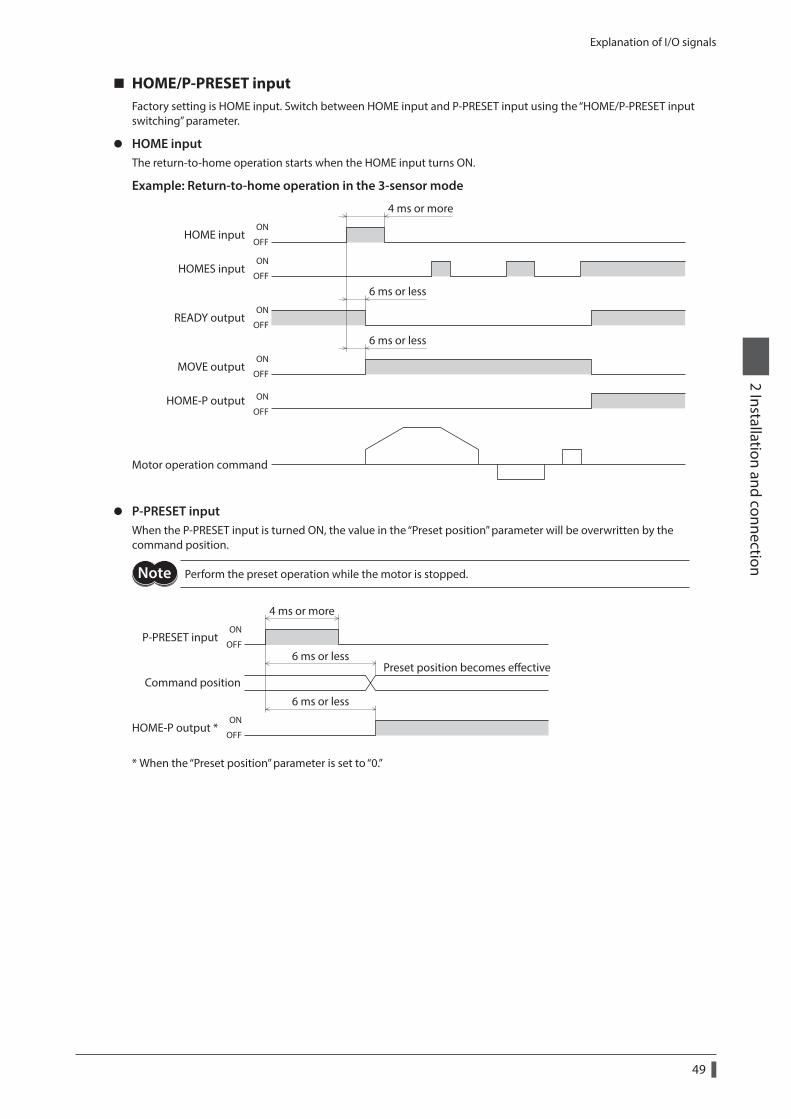
Explanation of I/O signals
49
2 Installation and connection
HOME/P-PRESET inputFactory setting is HOME input. Switch between HOME input and P-PRESET input using the “HOME/P-PRESET input switching” parameter.
z HOME inputThe return-to-home operation starts when the HOME input turns ON.
Example: Return-to-home operation in the 3-sensor mode
HOME inputON
OFF
HOMES inputON
OFF
READY outputON
OFF
MOVE outputON
OFF
HOME-P output ON
OFF
6 ms or less
6 ms or less
4 ms or more
Motor operation command
z P-PRESET inputWhen the P-PRESET input is turned ON, the value in the “Preset position” parameter will be overwritten by the command position.
Perform the preset operation while the motor is stopped.
P-PRESET input
Command position
ON
OFF
ON
OFFHOME-P output *
4 ms or more
6 ms or lessPreset position becomes eective
6 ms or less
* When the “Preset position” parameter is set to “0.”
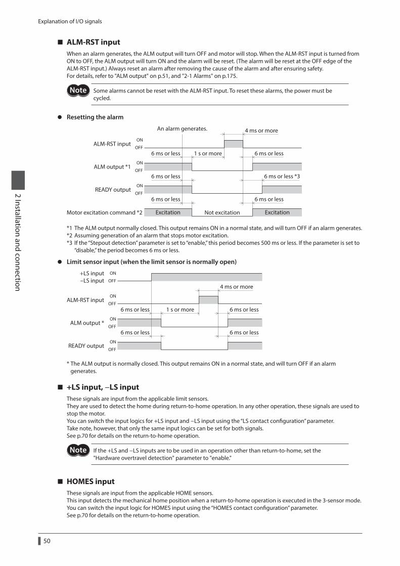
Explanation of I/O signals
50
2 Installation and connection
ALM-RST inputWhen an alarm generates, the ALM output will turn OFF and motor will stop. When the ALM-RST input is turned from ON to OFF, the ALM output will turn ON and the alarm will be reset. (The alarm will be reset at the OFF edge of the ALM-RST input.) Always reset an alarm after removing the cause of the alarm and after ensuring safety.For details, refer to "ALM output" on p.51, and "2-1 Alarms" on p.175.
Some alarms cannot be reset with the ALM-RST input. To reset these alarms, the power must be cycled.
z Resetting the alarm
An alarm generates.
6 ms or less
6 ms or less
4 ms or more
6 ms or less1 s or more
ALM-RST input
ALM output *1
READY output
6 ms or less *3
ON
OFF
ON
OFF
ON
OFF
Excitation ExcitationMotor excitation command *2
6 ms or less
Not excitation
6 ms or less
*1 The ALM output normally closed. This output remains ON in a normal state, and will turn OFF if an alarm generates.*2 Assuming generation of an alarm that stops motor excitation.*3 If the “Stepout detection” parameter is set to “enable,” this period becomes 500 ms or less. If the parameter is set to
“disable,” the period becomes 6 ms or less.
z Limit sensor input (when the limit sensor is normally open)
ALM-RST input
ALM output *
+LS input-LS input
6 ms or less
4 ms or more
6 ms or less1 s or more
READY output
6 ms or less6 ms or less
ON
OFF
ON
OFF
ON
OFF
ON
OFF
* The ALM output is normally closed. This output remains ON in a normal state, and will turn OFF if an alarm generates.
+LS input, −LS inputThese signals are input from the applicable limit sensors.They are used to detect the home during return-to-home operation. In any other operation, these signals are used to stop the motor.You can switch the input logics for +LS input and −LS input using the “LS contact configuration” parameter.Take note, however, that only the same input logics can be set for both signals.See p.70 for details on the return-to-home operation.
If the +LS and −LS inputs are to be used in an operation other than return-to-home, set the "Hardware overtravel detection" parameter to "enable."
HOMES inputThese signals are input from the applicable HOME sensors.This input detects the mechanical home position when a return-to-home operation is executed in the 3-sensor mode. You can switch the input logic for HOMES input using the “HOMES contact configuration” parameter.See p.70 for details on the return-to-home operation.
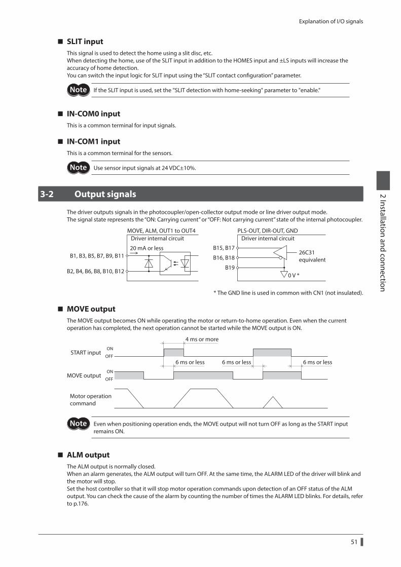
Explanation of I/O signals
51
2 Installation and connection
SLIT inputThis signal is used to detect the home using a slit disc, etc.When detecting the home, use of the SLIT input in addition to the HOMES input and ±LS inputs will increase the accuracy of home detection.You can switch the input logic for SLIT input using the “SLIT contact configuration” parameter.
If the SLIT input is used, set the "SLIT detection with home-seeking" parameter to "enable."
IN-COM0 inputThis is a common terminal for input signals.
IN-COM1 inputThis is a common terminal for the sensors.
Use sensor input signals at 24 VDC±10%.
3-2 Output signals
The driver outputs signals in the photocoupler/open-collector output mode or line driver output mode.The signal state represents the “ON: Carrying current” or “OFF: Not carrying current” state of the internal photocoupler.
20 mA or less
MOVE, ALM, OUT1 to OUT4
B15, B17B1, B3, B5, B7, B9, B11
B2, B4, B6, B8, B10, B12
B16, B18
B190 V *
PLS-OUT, DIR-OUT, GND
26C31equivalent
Driver internal circuit Driver internal circuit
* The GND line is used in common with CN1 (not insulated).
MOVE outputThe MOVE output becomes ON while operating the motor or return-to-home operation. Even when the current operation has completed, the next operation cannot be started while the MOVE output is ON.
START input
MOVE output
4 ms or more
6 ms or less
ON
OFF
ON
OFF
6 ms or less6 ms or less
Motor operationcommand
Even when positioning operation ends, the MOVE output will not turn OFF as long as the START input remains ON.
ALM outputThe ALM output is normally closed.When an alarm generates, the ALM output will turn OFF. At the same time, the ALARM LED of the driver will blink and the motor will stop.Set the host controller so that it will stop motor operation commands upon detection of an OFF status of the ALM output. You can check the cause of the alarm by counting the number of times the ALARM LED blinks. For details, refer to p.176.
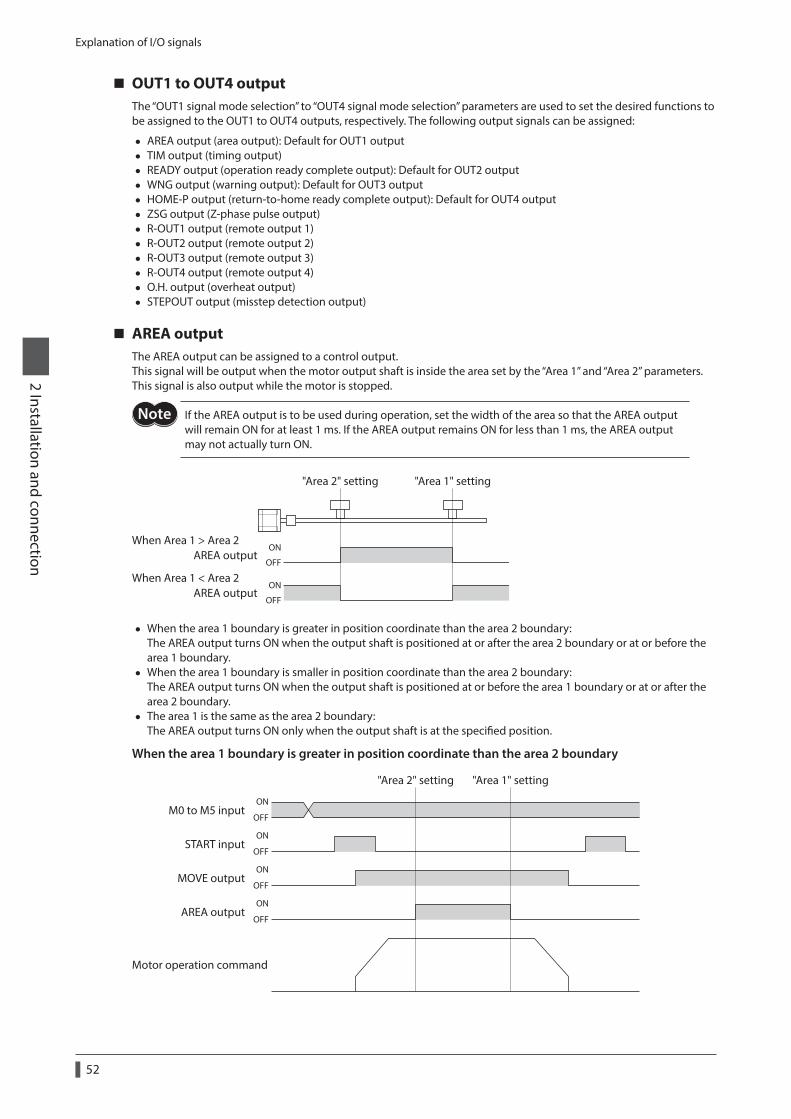
Explanation of I/O signals
52
2 Installation and connection
OUT1 to OUT4 outputThe “OUT1 signal mode selection” to “OUT4 signal mode selection” parameters are used to set the desired functions to be assigned to the OUT1 to OUT4 outputs, respectively. The following output signals can be assigned:
• AREA output (area output): Default for OUT1 output • TIM output (timing output) • READY output (operation ready complete output): Default for OUT2 output • WNG output (warning output): Default for OUT3 output • HOME-P output (return-to-home ready complete output): Default for OUT4 output • ZSG output (Z-phase pulse output) • R-OUT1 output (remote output 1) • R-OUT2 output (remote output 2) • R-OUT3 output (remote output 3) • R-OUT4 output (remote output 4) • O.H. output (overheat output) • STEPOUT output (misstep detection output)
AREA outputThe AREA output can be assigned to a control output.This signal will be output when the motor output shaft is inside the area set by the “Area 1” and “Area 2” parameters.This signal is also output while the motor is stopped.
If the AREA output is to be used during operation, set the width of the area so that the AREA output will remain ON for at least 1 ms. If the AREA output remains ON for less than 1 ms, the AREA output may not actually turn ON.
ON
OFF
ON
OFF
When Area 1 > Area 2
When Area 1 < Area 2
"Area 2" setting "Area 1" setting
AREA output
AREA output
• When the area 1 boundary is greater in position coordinate than the area 2 boundary: The AREA output turns ON when the output shaft is positioned at or after the area 2 boundary or at or before the area 1 boundary.
• When the area 1 boundary is smaller in position coordinate than the area 2 boundary: The AREA output turns ON when the output shaft is positioned at or before the area 1 boundary or at or after the area 2 boundary.
• The area 1 is the same as the area 2 boundary: The AREA output turns ON only when the output shaft is at the specified position.
When the area 1 boundary is greater in position coordinate than the area 2 boundary
M0 to M5 input
"Area 2" setting
START input
AREA output
Motor operation command
ON
OFF
ON
OFF
ON
OFF
ON
OFF
MOVE output
"Area 1" setting
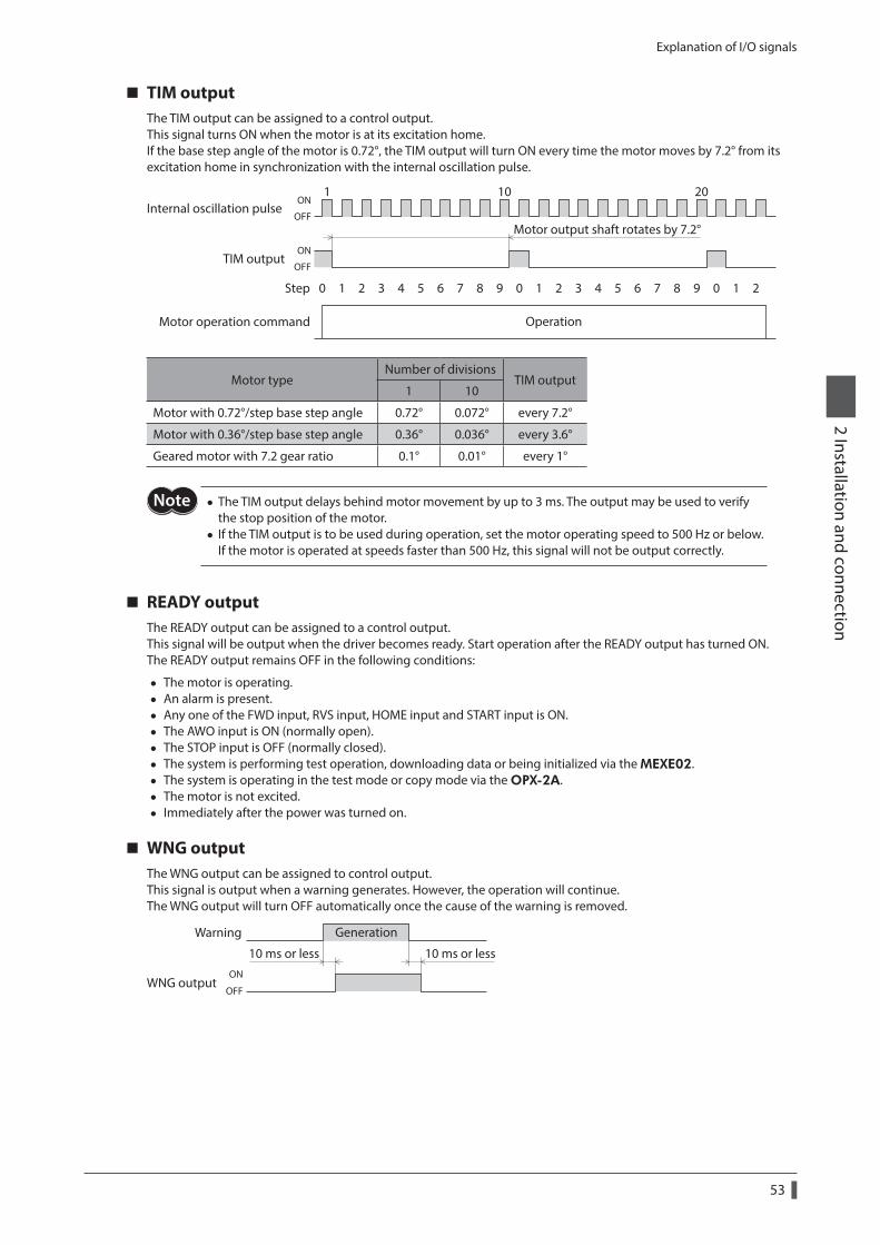
Explanation of I/O signals
53
2 Installation and connection
TIM outputThe TIM output can be assigned to a control output.This signal turns ON when the motor is at its excitation home.If the base step angle of the motor is 0.72°, the TIM output will turn ON every time the motor moves by 7.2° from its excitation home in synchronization with the internal oscillation pulse.
TIM output
Motor operation command
Internal oscillation pulse ON
OFF
ON
OFF
Motor output shaft rotates by 7.2°
1 10 20
Operation
0Step 1 2 3 4 5 6 7 8 9 0 1 2 3 4 5 6 7 8 9 0 1 2
Motor typeNumber of divisions
TIM output1 10
Motor with 0.72°/step base step angle 0.72° 0.072° every 7.2°
Motor with 0.36°/step base step angle 0.36° 0.036° every 3.6°
Geared motor with 7.2 gear ratio 0.1° 0.01° every 1°
• The TIM output delays behind motor movement by up to 3 ms. The output may be used to verify the stop position of the motor.
• If the TIM output is to be used during operation, set the motor operating speed to 500 Hz or below. If the motor is operated at speeds faster than 500 Hz, this signal will not be output correctly.
READY outputThe READY output can be assigned to a control output.This signal will be output when the driver becomes ready. Start operation after the READY output has turned ON.The READY output remains OFF in the following conditions:
• The motor is operating. • An alarm is present. • Any one of the FWD input, RVS input, HOME input and START input is ON. • The AWO input is ON (normally open). • The STOP input is OFF (normally closed). • The system is performing test operation, downloading data or being initialized via the MEXE02. • The system is operating in the test mode or copy mode via the OPX-2A. • The motor is not excited. • Immediately after the power was turned on.
WNG outputThe WNG output can be assigned to control output.This signal is output when a warning generates. However, the operation will continue.The WNG output will turn OFF automatically once the cause of the warning is removed.
GenerationWarning
WNG output
10 ms or less 10 ms or lessON
OFF
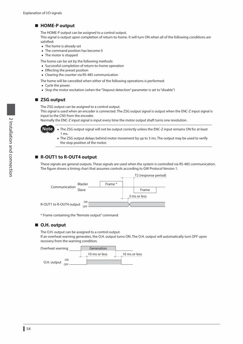
Explanation of I/O signals
54
2 Installation and connection
HOME-P outputThe HOME-P output can be assigned to a control output.This signal is output upon completion of return-to-home. It will turn ON when all of the following conditions are satisfied:
• The home is already set • The command position has become 0 • The motor is stopped
The home can be set by the following methods: • Successful completion of return-to-home operation • Effecting the preset position • Clearing the counter via RS-485 communication
The home will be cancelled when either of the following operations is performed: • Cycle the power. • Stop the motor excitation (when the “Stepout detection” parameter is set to “disable”)
ZSG outputThe ZSG output can be assigned to a control output.This signal is used when an encoder is connected. The ZSG output signal is output when the ENC-Z input signal is input to the CN5 from the encoder.Normally the ENC-Z input signal is input every time the motor output shaft turns one revolution.
• The ZSG output signal will not be output correctly unless the ENC-Z input remains ON for at least 1 ms.
• The ZSG output delays behind motor movement by up to 3 ms. The output may be used to verify the stop position of the motor.
R-OUT1 to R-OUT4 outputThese signals are general outputs. These signals are used when the system is controlled via RS-485 communication.The figure shows a timing chart that assumes controls according to GW Protocol Version 1.
Frame *
Frame
Master
SlaveCommunication
3 ms or less
T2 (response period)
R-OUT1 to R-OUT4 outputON
OFF
* Frame containing the “Remote output” command
O.H. outputThe O.H. output can be assigned to a control output.If an overheat warning generates, the O.H. output turns ON. The O.H. output will automatically turn OFF upon recovery from the warning condition.
Overheat warning Generation
O.H. output
10 ms or less 10 ms or lessON
OFF
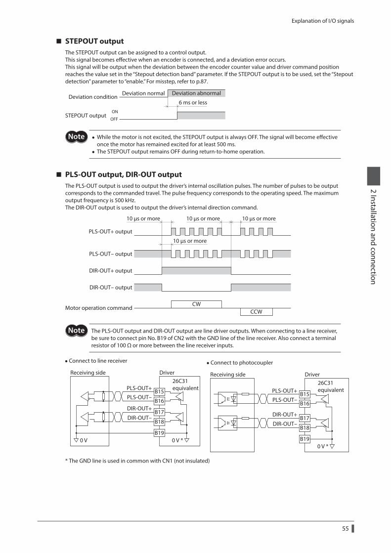
Explanation of I/O signals
55
2 Installation and connection
STEPOUT outputThe STEPOUT output can be assigned to a control output.This signal becomes effective when an encoder is connected, and a deviation error occurs.This signal will be output when the deviation between the encoder counter value and driver command position reaches the value set in the “Stepout detection band” parameter. If the STEPOUT output is to be used, set the “Stepout detection” parameter to “enable.” For misstep, refer to p.87.
6 ms or lessON
OFFSTEPOUT output
Deviation conditionDeviation normal Deviation abnormal
• While the motor is not excited, the STEPOUT output is always OFF. The signal will become effective once the motor has remained excited for at least 500 ms.
• The STEPOUT output remains OFF during return-to-home operation.
PLS-OUT output, DIR-OUT outputThe PLS-OUT output is used to output the driver’s internal oscillation pulses. The number of pulses to be output corresponds to the commanded travel. The pulse frequency corresponds to the operating speed. The maximum output frequency is 500 kHz.The DIR-OUT output is used to output the driver’s internal direction command.
PLS-OUT+ output
PLS-OUT- output
DIR-OUT+ output
DIR-OUT- output
CWCCW
10 µs or more
10 µs or more
10 µs or more10 µs or more
Motor operation command
The PLS-OUT output and DIR-OUT output are line driver outputs. When connecting to a line receiver, be sure to connect pin No. B19 of CN2 with the GND line of the line receiver. Also connect a terminal resistor of 100 Ω or more between the line receiver inputs.
•Connect to line receiver
B15
B16
B17
B18
B19
26C31equivalent
DriverReceiving side
0 V 0 V *
PLS-OUT+
PLS-OUT-
DIR-OUT+
DIR-OUT-
•Connect to photocoupler
B15
B16
B17
B18
B190 V *
26C31equivalentPLS-OUT+
PLS-OUT-
DIR-OUT+
DIR-OUT-
DriverReceiving side
* The GND line is used in common with CN1 (not insulated)

56
2 Installation and connection
3 Operation type and setting
This part explains the operation functions and the details of parameters.
Table of contents
1 Adjustment and setting ....................... 581-1 Step angle ......................................................... 58
1-2 Operating current ........................................... 58
1-3 Standstill current ............................................. 59
1-4 Acceleration/deceleration rate .................. 59
2 Operation ................................................ 602-1 Positioning operation ................................... 61
2-2 Return-to-home operation ......................... 70
2-3 Continuous operation ................................... 75
2-4 Other operation .............................................. 77
3 Operation data ....................................... 79
4 Parameter ................................................ 804-1 Parameter list ................................................... 80
4-2 I/O parameter ................................................... 81
4-3 Motor parameter............................................. 82
4-4 Speed parameter ............................................ 82
4-5 Return-to-home parameter ........................ 83
4-6 Alarm/warning parameter........................... 83
4-7 Common parameter ...................................... 84
4-8 Operation setting parameter ..................... 84
4-9 Communication parameter ........................ 85
5 Related functions .................................. 865-1 Position control ............................................... 86
5-2 Encoder input .................................................. 86
5-3 Misstep detection function ......................... 87
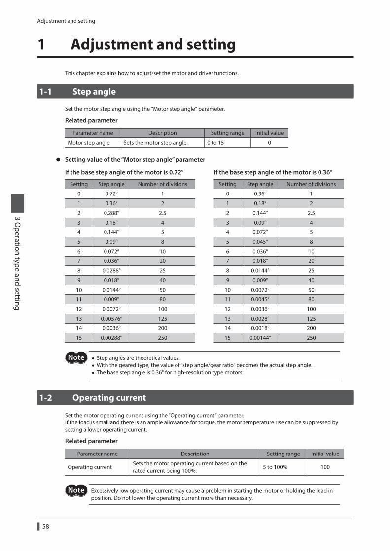
Adjustment and setting
58
3 Operation type and setting
1 Adjustment and setting
This chapter explains how to adjust/set the motor and driver functions.
1-1 Step angle
Set the motor step angle using the "Motor step angle" parameter.
Related parameter
Parameter name Description Setting range Initial value
Motor step angle Sets the motor step angle. 0 to 15 0
z Setting value of the “Motor step angle” parameter
If the base step angle of the motor is 0.72° If the base step angle of the motor is 0.36°
Setting Step angle Number of divisions Setting Step angle Number of divisions
0 0.72° 1 0 0.36° 1
1 0.36° 2 1 0.18° 2
2 0.288° 2.5 2 0.144° 2.5
3 0.18° 4 3 0.09° 4
4 0.144° 5 4 0.072° 5
5 0.09° 8 5 0.045° 8
6 0.072° 10 6 0.036° 10
7 0.036° 20 7 0.018° 20
8 0.0288° 25 8 0.0144° 25
9 0.018° 40 9 0.009° 40
10 0.0144° 50 10 0.0072° 50
11 0.009° 80 11 0.0045° 80
12 0.0072° 100 12 0.0036° 100
13 0.00576° 125 13 0.0028° 125
14 0.0036° 200 14 0.0018° 200
15 0.00288° 250 15 0.00144° 250
• Step angles are theoretical values. • With the geared type, the value of “step angle/gear ratio” becomes the actual step angle. • The base step angle is 0.36° for high-resolution type motors.
1-2 Operating current
Set the motor operating current using the “Operating current” parameter.If the load is small and there is an ample allowance for torque, the motor temperature rise can be suppressed by setting a lower operating current.
Related parameter
Parameter name Description Setting range Initial value
Operating currentSets the motor operating current based on the rated current being 100%.
5 to 100% 100
Excessively low operating current may cause a problem in starting the motor or holding the load in position. Do not lower the operating current more than necessary.
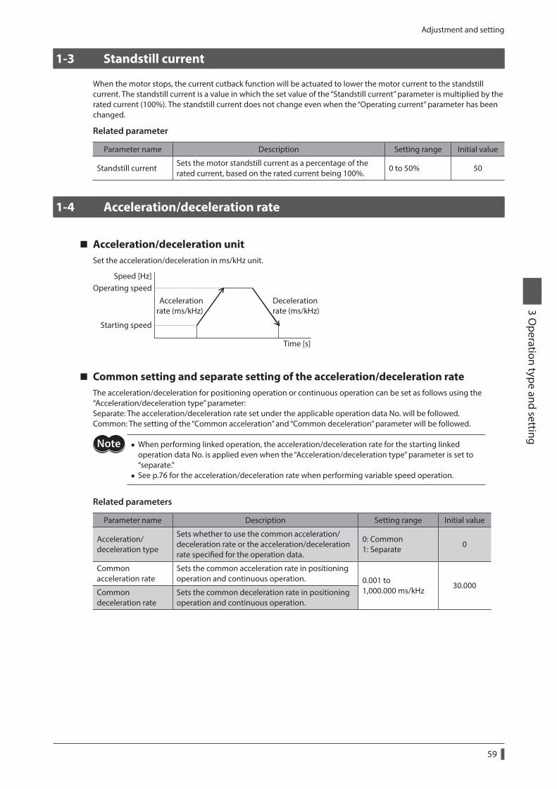
Adjustment and setting
59
3 Operation type and setting
1-3 Standstill current
When the motor stops, the current cutback function will be actuated to lower the motor current to the standstill current. The standstill current is a value in which the set value of the “Standstill current” parameter is multiplied by the rated current (100%). The standstill current does not change even when the “Operating current” parameter has been changed.
Related parameter
Parameter name Description Setting range Initial value
Standstill currentSets the motor standstill current as a percentage of the rated current, based on the rated current being 100%.
0 to 50% 50
1-4 Acceleration/deceleration rate
Acceleration/deceleration unitSet the acceleration/deceleration in ms/kHz unit.
Speed [Hz]
Time [s]
Operating speed
Starting speed
Accelerationrate (ms/kHz)
Decelerationrate (ms/kHz)
Common setting and separate setting of the acceleration/deceleration rateThe acceleration/deceleration for positioning operation or continuous operation can be set as follows using the “Acceleration/deceleration type” parameter:Separate: The acceleration/deceleration rate set under the applicable operation data No. will be followed.Common: The setting of the “Common acceleration” and “Common deceleration” parameter will be followed.
• When performing linked operation, the acceleration/deceleration rate for the starting linked operation data No. is applied even when the “Acceleration/deceleration type” parameter is set to “separate.”
• See p.76 for the acceleration/deceleration rate when performing variable speed operation.
Related parameters
Parameter name Description Setting range Initial value
Acceleration/deceleration type
Sets whether to use the common acceleration/deceleration rate or the acceleration/deceleration rate specified for the operation data.
0: Common 1: Separate
0
Common acceleration rate
Sets the common acceleration rate in positioning operation and continuous operation. 0.001 to
1,000.000 ms/kHz30.000
Common deceleration rate
Sets the common deceleration rate in positioning operation and continuous operation.
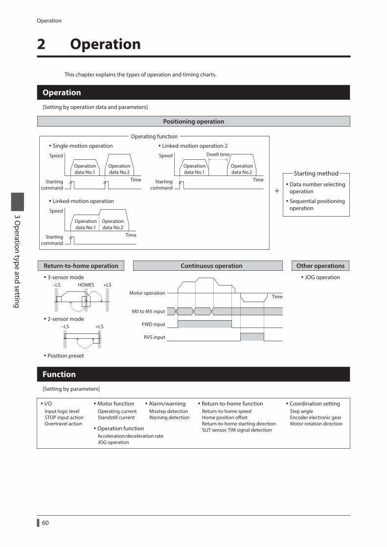
Operation
60
3 Operation type and setting
2 Operation
This chapter explains the types of operation and timing charts.
Return-to-home operation Continuous operation
Positioning operation
Speed
Time
Operating function
Data number selecting operation
Sequential positioning operation
Starting method
+
Operation
[Setting by operation data and parameters]
Function
[Setting by parameters]
I/OInput logic levelSTOP input actionOvertravel action
Coordination settingStep angleEncoder electronic gearMotor rotation direction
Motor functionOperating currentStandstill current
Operation functionAcceleration/deceleration rateJOG operation
Return-to-home functionReturn-to-home speedHome position osetReturn-to-home starting directionSLIT sensor, TIM signal detection
Alarm/warningMisstep detection Warning detection
Startingcommand
Single-motion operation
Speed
Time
Operationdata No.1
Operationdata No.2
Startingcommand
Linked-motion operation
Speed
Time
Dwell time
Operationdata No.1
Operationdata No.2
Operationdata No.1
Operationdata No.2
Startingcommand
Linked-motion operation 2
3-sensor mode-LS +LSHOMES
2-sensor mode-LS +LS
Position preset
Motor operationTime
FWD input
RVS input
M0 to M5 input
Other operations
JOG operation
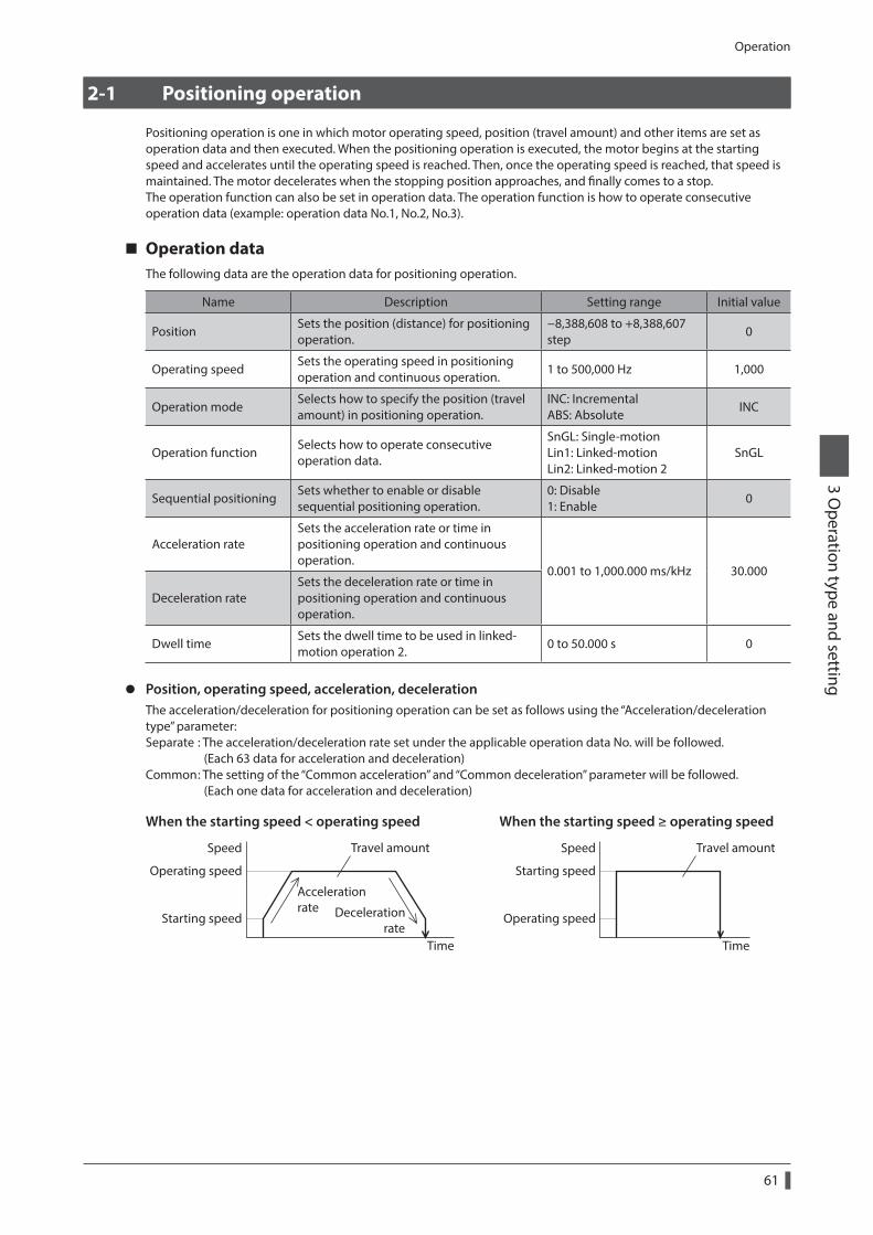
Operation
61
3 Operation type and setting
2-1 Positioning operation
Positioning operation is one in which motor operating speed, position (travel amount) and other items are set as operation data and then executed. When the positioning operation is executed, the motor begins at the starting speed and accelerates until the operating speed is reached. Then, once the operating speed is reached, that speed is maintained. The motor decelerates when the stopping position approaches, and finally comes to a stop.The operation function can also be set in operation data. The operation function is how to operate consecutive operation data (example: operation data No.1, No.2, No.3).
Operation dataThe following data are the operation data for positioning operation.
Name Description Setting range Initial value
PositionSets the position (distance) for positioning operation.
−8,388,608 to +8,388,607 step
0
Operating speedSets the operating speed in positioning operation and continuous operation.
1 to 500,000 Hz 1,000
Operation modeSelects how to specify the position (travel amount) in positioning operation.
INC: Incremental ABS: Absolute
INC
Operation functionSelects how to operate consecutive operation data.
SnGL: Single-motion Lin1: Linked-motion Lin2: Linked-motion 2
SnGL
Sequential positioningSets whether to enable or disable sequential positioning operation.
0: Disable 1: Enable
0
Acceleration rateSets the acceleration rate or time in positioning operation and continuous operation.
0.001 to 1,000.000 ms/kHz 30.000
Deceleration rateSets the deceleration rate or time in positioning operation and continuous operation.
Dwell timeSets the dwell time to be used in linked-motion operation 2.
0 to 50.000 s 0
z Position, operating speed, acceleration, decelerationThe acceleration/deceleration for positioning operation can be set as follows using the “Acceleration/deceleration type” parameter:Separate : The acceleration/deceleration rate set under the applicable operation data No. will be followed. (Each 63 data for acceleration and deceleration)Common : The setting of the “Common acceleration” and “Common deceleration” parameter will be followed. (Each one data for acceleration and deceleration)
When the starting speed < operating speed When the starting speed ≥ operating speed
Speed
Operating speed
Starting speed
Time
Accelerationrate Deceleration
rate
Travel amount Speed
Starting speed
Operating speed
Time
Travel amount
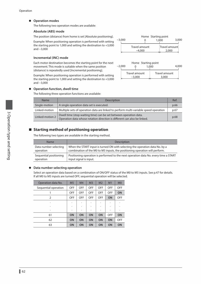
Operation
62
3 Operation type and setting
z Operation modesThe following two operation modes are available:
Absolute (ABS) modeThe position (distance) from home is set [Absolute positioning].
Example: When positioning operation is performed with setting the starting point to 1,000 and setting the destination to +3,000 and −3,000
3,000Starting point
1,000
Travel amount2,000
Travel amount-4,000
Home0-3,000
Incremental (INC) modeEach motor destination becomes the starting point for the next movement. This mode is suitable when the same position (distance) is repeatedly used [Incremental positioning].
Example: When positioning operation is performed with setting the starting point to 1,000 and setting the destination to +3,000 and −3,000
4,000-2,000Starting point
1,000
Travel amount3,000
Travel amount-3,000
Home0
z Operation function, dwell timeThe following three operation functions are available:
Name Description Ref.
Single-motion A single operation data set is executed. p.66
Linked-motion Multiple sets of operation data are linked to perform multi-variable speed operation p.67
Linked-motion 2Dwell time (stop waiting time) can be set between operation data. Operation data whose rotation direction is different can also be linked.
p.68
Starting method of positioning operationThe following two types are available in the starting method.
Name Description
Data number selecting operation
When the START input is turned ON with selecting the operation data No. by a combination of the M0 to M5 inputs, the positioning operation will perform.
Sequential positioning operation
Positioning operation is performed to the next operation data No. every time a START input signal is input.
z Data number selecting operationSelect an operation data based on a combination of ON/OFF status of the M0 to M5 inputs. See p.47 for details.If all M0 to M5 inputs are turned OFF, sequential operation will be selected.
Operation data No. M5 M4 M3 M2 M1 M0
Sequential operation OFF OFF OFF OFF OFF OFF
1 OFF OFF OFF OFF OFF ON
2 OFF OFF OFF OFF ON OFF
· · ·
· · ·
· · ·
· · ·
· · ·
· · ·
· · ·
61 ON ON ON ON OFF ON
62 ON ON ON ON ON OFF
63 ON ON ON ON ON ON
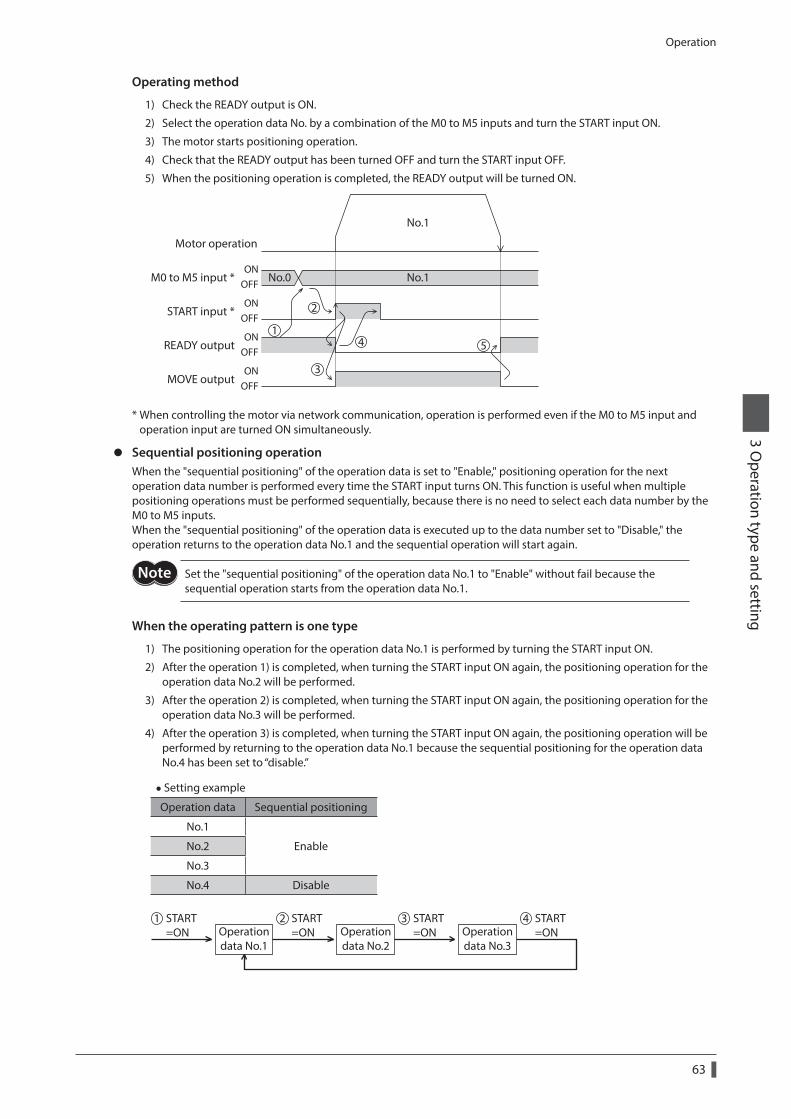
Operation
63
3 Operation type and setting
Operating method
1) Check the READY output is ON.
2) Select the operation data No. by a combination of the M0 to M5 inputs and turn the START input ON.
3) The motor starts positioning operation.
4) Check that the READY output has been turned OFF and turn the START input OFF.
5) When the positioning operation is completed, the READY output will be turned ON.
START input *
MOVE output
READY output
Motor operation
M0 to M5 input * No.0 No.1
No.1
ONOFF
ONOFF
ONOFF
ONOFF
1
2
3
4 5
* When controlling the motor via network communication, operation is performed even if the M0 to M5 input and operation input are turned ON simultaneously.
z Sequential positioning operationWhen the "sequential positioning" of the operation data is set to "Enable," positioning operation for the next operation data number is performed every time the START input turns ON. This function is useful when multiple positioning operations must be performed sequentially, because there is no need to select each data number by the M0 to M5 inputs.When the "sequential positioning" of the operation data is executed up to the data number set to "Disable," the operation returns to the operation data No.1 and the sequential operation will start again.
Set the "sequential positioning" of the operation data No.1 to "Enable" without fail because the sequential operation starts from the operation data No.1.
When the operating pattern is one type
1) The positioning operation for the operation data No.1 is performed by turning the START input ON.
2) After the operation 1) is completed, when turning the START input ON again, the positioning operation for the operation data No.2 will be performed.
3) After the operation 2) is completed, when turning the START input ON again, the positioning operation for the operation data No.3 will be performed.
4) After the operation 3) is completed, when turning the START input ON again, the positioning operation will be performed by returning to the operation data No.1 because the sequential positioning for the operation data No.4 has been set to “disable.”
• Setting example
Operation data Sequential positioning
No.1
EnableNo.2
No.3
No.4 Disable
Operationdata No.1
Operationdata No.2
Operationdata No.3
START=ON
1 START=ON
2 START=ON
3 START=ON
4
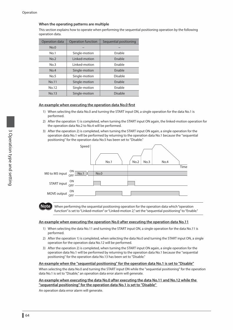
Operation
64
3 Operation type and setting
When the operating patterns are multipleThis section explains how to operate when performing the sequential positioning operation by the following operation data.
Operation data Operation function Sequential positioning
No.0 − −
No.1 Single-motion Enable
No.2 Linked-motion Enable
No.3 Linked-motion Enable
No.4 Single-motion Enable
No.5 Single-motion Disable
No.11 Single-motion Enable
No.12 Single-motion Enable
No.13 Single-motion Disable
An example when executing the operation data No.0 first
1) When selecting the data No.0 and turning the START input ON, a single operation for the data No.1 is performed.
2) After the operation 1) is completed, when turning the START input ON again, the linked-motion operation for the operation data No.2 to No.4 will be performed.
3) After the operation 2) is completed, when turning the START input ON again, a single operation for the operation data No.1 will be performed by returning to the operation data No.1 because the "sequential positioning" for the operation data No.5 has been set to "Disable."
Speed
No.2 No.3 No.4Time
No.1
START input
MOVE output
M0 to M5 input
OFFON
OFFON
OFFON
No.0No.1
When performing the sequential positioning operation for the operation data which “operation function” is set to “Linked-motion” or “Linked-motion 2,” set the “sequential positioning” to “Enable.”
An example when executing the operation No.0 after executing the operation data No.11
1) When selecting the data No.11 and turning the START input ON, a single operation for the data No.11 is performed.
2) After the operation 1) is completed, when selecting the data No.0 and turning the START input ON, a single operation for the operation data No.12 will be performed.
3) After the operation 2) is completed, when turning the START input ON again, a single operation for the operation data No.1 will be performed by returning to the operation data No.1 because the "sequential positioning" for the operation data No.13 has been set to "Disable."
An example when the "sequential positioning" for the operation data No.1 is set to "Disable"When selecting the data No.0 and turning the START input ON while the "sequential positioning" for the operation data No.1 is set to "Disable," an operation data error alarm will generate.
An example when executing the data No.0 after executing the data No.11 and No.12 while the "sequential positioning" for the operation data No.1 is set to "Disable" An operation data error alarm will generate.
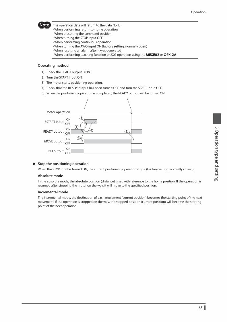
Operation
65
3 Operation type and setting
The operation data will return to the data No.1. · When performing return-to-home operation · When presetting the command position · When turning the STOP input OFF · When performing continuous operation · When turning the AWO input ON (factory setting: normally open) · When resetting an alarm after it was generated · When performing teaching function or JOG operation using the MEXE02 or OPX-2A
Operating method
1) Check the READY output is ON.
2) Turn the START input ON.
3) The motor starts positioning operation.
4) Check that the READY output has been turned OFF and turn the START input OFF.
5) When the positioning operation is completed, the READY output will be turned ON.
MOVE output
END output
READY output
Motor operation
SSTART inputON
OFF
ONOFF
ONOFF
ONOFF
1
2
3
4 5
z Stop the positioning operationWhen the STOP input is turned ON, the current positioning operation stops. (Factory setting: normally closed)
Absolute modeIn the absolute mode, the absolute position (distance) is set with reference to the home position. If the operation is resumed after stopping the motor on the way, it will move to the specified position.
Incremental modeThe incremental mode, the destination of each movement (current position) becomes the starting point of the next movement. If the operation is stopped on the way, the stopped position (current position) will become the starting point of the next operation.
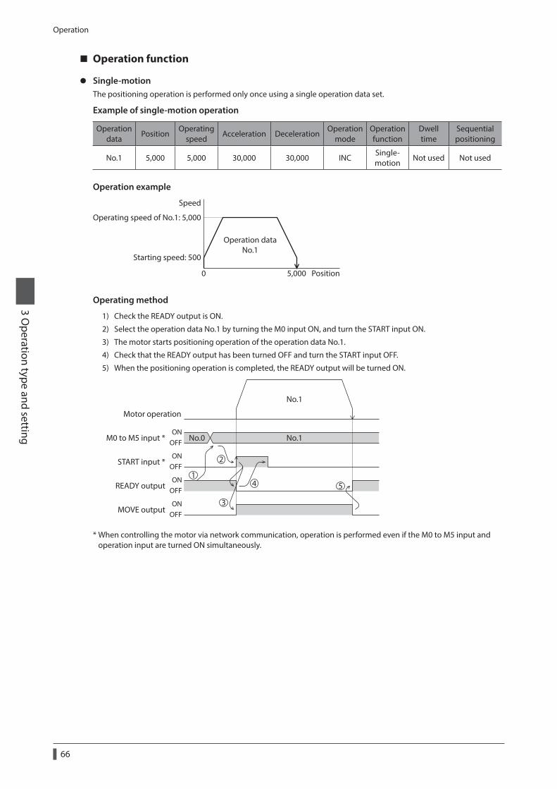
Operation
66
3 Operation type and setting
Operation function
z Single-motionThe positioning operation is performed only once using a single operation data set.
Example of single-motion operation
Operation data
PositionOperating
speedAcceleration Deceleration
Operation mode
Operation function
Dwell time
Sequential positioning
No.1 5,000 5,000 30,000 30,000 INCSingle-motion
Not used Not used
Operation example
Speed
Operating speed of No.1: 5,000
Starting speed: 500
Position5,0000
Operation dataNo.1
Operating method
1) Check the READY output is ON.
2) Select the operation data No.1 by turning the M0 input ON, and turn the START input ON.
3) The motor starts positioning operation of the operation data No.1.
4) Check that the READY output has been turned OFF and turn the START input OFF.
5) When the positioning operation is completed, the READY output will be turned ON.
START input *
MOVE output
READY output
Motor operation
M0 to M5 input * No.0 No.1
No.1
ONOFF
ONOFF
ONOFF
ONOFF
1
2
3
4 5
* When controlling the motor via network communication, operation is performed even if the M0 to M5 input and operation input are turned ON simultaneously.
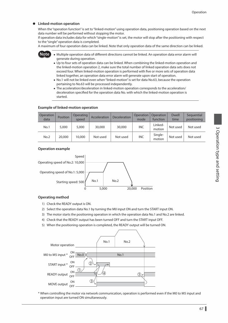
Operation
67
3 Operation type and setting
z Linked-motion operationWhen the “operation function” is set to “linked-motion” using operation data, positioning operation based on the next data number will be performed without stopping the motor.If operation data includes data for which “single-motion” is set, the motor will stop after the positioning with respect to the “single” operation data is completed.A maximum of four operation data can be linked. Note that only operation data of the same direction can be linked.
• Multiple operation data of different directions cannot be linked. An operation data error alarm will generate during operation.
• Up to four sets of operation data can be linked. When combining the linked-motion operation and the linked-motion operation 2, make sure the total number of linked operation data sets does not exceed four. When linked-motion operation is performed with five or more sets of operation data linked together, an operation data error alarm will generate upon start of operation.
• No.1 will not be linked even when “linked-motion” is set for data No.63, because the operation pertaining to No.63 will be processed independently.
• The acceleration/deceleration in linked-motion operation corresponds to the acceleration/deceleration specified for the operation data No. with which the linked-motion operation is started.
Example of linked-motion operation
Operation data
PositionOperating
speedAcceleration Deceleration
Operation mode
Operation function
Dwell time
Sequential positioning
No.1 5,000 5,000 30,000 30,000 INCLinked-motion
Not used Not used
No.2 20,000 10,000 Not used Not used INCSingle-motion
Not used Not used
Operation example
Speed
Operating speed of No.2: 10,000
Operating speed of No.1: 5,000
Starting speed: 500
Position5,000 20,0000
No.1 No.2
Operating method
1) Check the READY output is ON.
2) Select the operation data No.1 by turning the M0 input ON and turn the START input ON.
3) The motor starts the positioning operation in which the operation data No.1 and No.2 are linked.
4) Check that the READY output has been turned OFF and turn the START input OFF.
5) When the positioning operation is completed, the READY output will be turned ON.
START input *
MOVE output
READY output
Motor operation
M0 to M5 input * No.0 No.1ON
OFF
ONOFF
ONOFF
ONOFF
No.1 No.2
1
2
3
4 5
* When controlling the motor via network communication, operation is performed even if the M0 to M5 input and operation input are turned ON simultaneously.
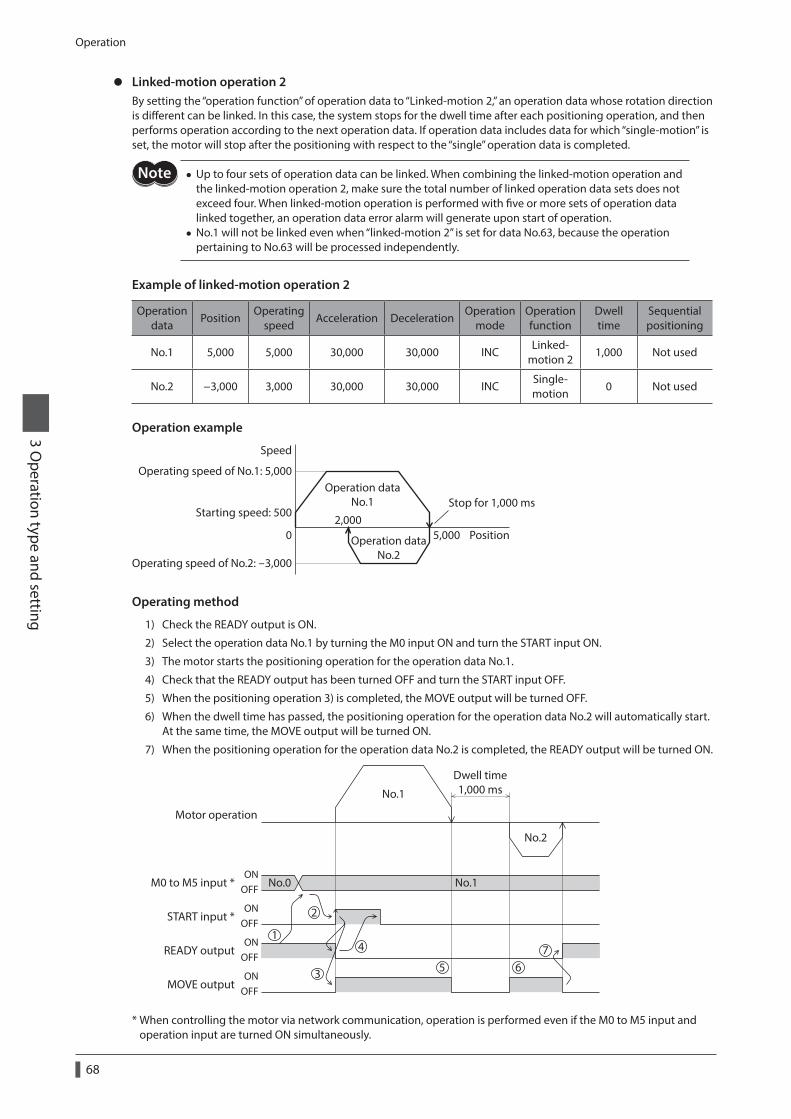
Operation
68
3 Operation type and setting
z Linked-motion operation 2By setting the “operation function” of operation data to “Linked-motion 2,” an operation data whose rotation direction is different can be linked. In this case, the system stops for the dwell time after each positioning operation, and then performs operation according to the next operation data. If operation data includes data for which “single-motion” is set, the motor will stop after the positioning with respect to the “single” operation data is completed.
• Up to four sets of operation data can be linked. When combining the linked-motion operation and the linked-motion operation 2, make sure the total number of linked operation data sets does not exceed four. When linked-motion operation is performed with five or more sets of operation data linked together, an operation data error alarm will generate upon start of operation.
• No.1 will not be linked even when “linked-motion 2” is set for data No.63, because the operation pertaining to No.63 will be processed independently.
Example of linked-motion operation 2
Operation data
PositionOperating
speedAcceleration Deceleration
Operation mode
Operation function
Dwell time
Sequential positioning
No.1 5,000 5,000 30,000 30,000 INCLinked-
motion 21,000 Not used
No.2 −3,000 3,000 30,000 30,000 INCSingle-motion
0 Not used
Operation example
Speed
Operating speed of No.1: 5,000
Operating speed of No.2: -3,000
Starting speed: 500
Position5,0002,000
0
Operation dataNo.1
Operation dataNo.2
Stop for 1,000 ms
Operating method
1) Check the READY output is ON.
2) Select the operation data No.1 by turning the M0 input ON and turn the START input ON.
3) The motor starts the positioning operation for the operation data No.1.
4) Check that the READY output has been turned OFF and turn the START input OFF.
5) When the positioning operation 3) is completed, the MOVE output will be turned OFF.
6) When the dwell time has passed, the positioning operation for the operation data No.2 will automatically start. At the same time, the MOVE output will be turned ON.
7) When the positioning operation for the operation data No.2 is completed, the READY output will be turned ON.
START input *
MOVE output
READY output
Motor operation
Dwell time1,000 ms
M0 to M5 input * No.0 No.1ON
OFF
ONOFF
ONOFF
ONOFF
No.1
No.2
1
2
3
4
5 67
* When controlling the motor via network communication, operation is performed even if the M0 to M5 input and operation input are turned ON simultaneously.
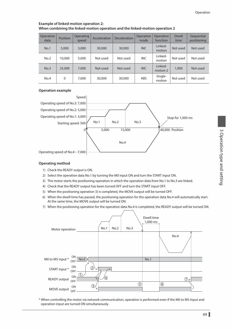
Operation
69
3 Operation type and setting
Example of linked-motion operation 2: When combining the linked-motion operation and the linked-motion operation 2
Operation data
PositionOperating
speedAcceleration Deceleration
Operation mode
Operation function
Dwell time
Sequential positioning
No.1 5,000 3,000 30,000 30,000 INCLinked-motion
Not used Not used
No.2 10,000 5,000 Not used Not used INCLinked-motion
Not used Not used
No.3 25,000 7,000 Not used Not used INCLinked-
motion 21,000 Not used
No.4 0 7,000 30,000 30,000 ABSSingle-motion
Not used Not used
Operation example
Speed
Operating speed of No.3: 7,000
Operating speed of No.4: -7,000
Operating speed of No.1: 3,000
Operating speed of No.2: 5,000
Starting speed: 500
Position5,000 40,00015,0000
No.1 No.2 No.3
No.4
Stop for 1,000 ms
Operating method
1) Check the READY output is ON.
2) Select the operation data No.1 by turning the M0 input ON and turn the START input ON.
3) The motor starts the positioning operation in which the operation data from No.1 to No.3 are linked.
4) Check that the READY output has been turned OFF and turn the START input OFF.
5) When the positioning operation 3) is completed, the MOVE output will be turned OFF.
6) When the dwell time has passed, the positioning operation for the operation data No.4 will automatically start. At the same time, the MOVE output will be turned ON.
7) When the positioning operation for the operation data No.4 is completed, the READY output will be turned ON.
START input *
MOVE output
READY output
Motor operation
Dwell time1,000 ms
M0 to M5 input * No.0 No.1ON
OFF
ONOFF
ONOFF
ONOFF
No.1 No.2 No.3
No.4
1
2
3
4
5 67
* When controlling the motor via network communication, operation is performed even if the M0 to M5 input and operation input are turned ON simultaneously.
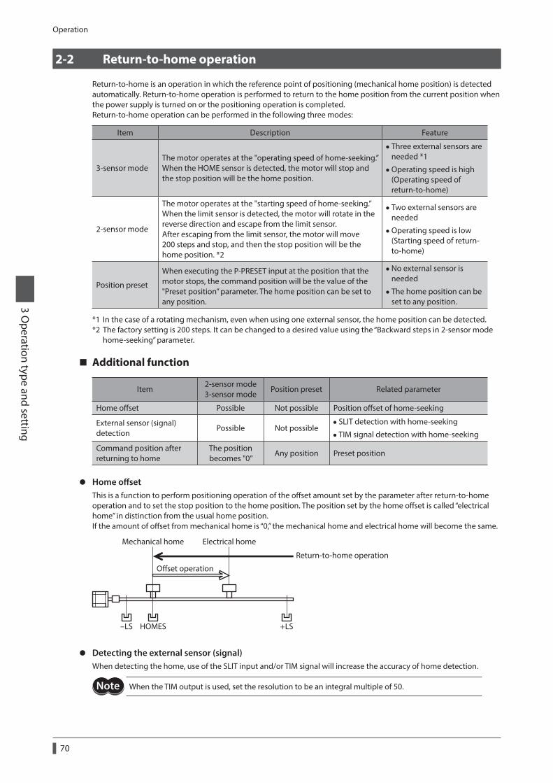
Operation
70
3 Operation type and setting
2-2 Return-to-home operation
Return-to-home is an operation in which the reference point of positioning (mechanical home position) is detected automatically. Return-to-home operation is performed to return to the home position from the current position when the power supply is turned on or the positioning operation is completed.Return-to-home operation can be performed in the following three modes:
Item Description Feature
3-sensor modeThe motor operates at the "operating speed of home-seeking.” When the HOME sensor is detected, the motor will stop and the stop position will be the home position.
• Three external sensors are needed *1
•Operating speed is high (Operating speed of return-to-home)
2-sensor mode
The motor operates at the "starting speed of home-seeking.” When the limit sensor is detected, the motor will rotate in the reverse direction and escape from the limit sensor. After escaping from the limit sensor, the motor will move 200 steps and stop, and then the stop position will be the home position. *2
• Two external sensors are needed
•Operating speed is low (Starting speed of return-to-home)
Position preset
When executing the P-PRESET input at the position that the motor stops, the command position will be the value of the "Preset position” parameter. The home position can be set to any position.
•No external sensor is needed
• The home position can be set to any position.
*1 In the case of a rotating mechanism, even when using one external sensor, the home position can be detected.*2 The factory setting is 200 steps. It can be changed to a desired value using the “Backward steps in 2-sensor mode
home-seeking” parameter.
Additional function
Item2-sensor mode 3-sensor mode
Position preset Related parameter
Home offset Possible Not possible Position offset of home-seeking
External sensor (signal) detection
Possible Not possible • SLIT detection with home-seeking
• TIM signal detection with home-seeking
Command position after returning to home
The position becomes "0”
Any position Preset position
z Home offsetThis is a function to perform positioning operation of the offset amount set by the parameter after return-to-home operation and to set the stop position to the home position. The position set by the home offset is called “electrical home” in distinction from the usual home position.If the amount of offset from mechanical home is “0,” the mechanical home and electrical home will become the same.
Mechanical home
-LS HOMES +LS
Electrical home
Oset operation
Return-to-home operation
z Detecting the external sensor (signal)When detecting the home, use of the SLIT input and/or TIM signal will increase the accuracy of home detection.
When the TIM output is used, set the resolution to be an integral multiple of 50.
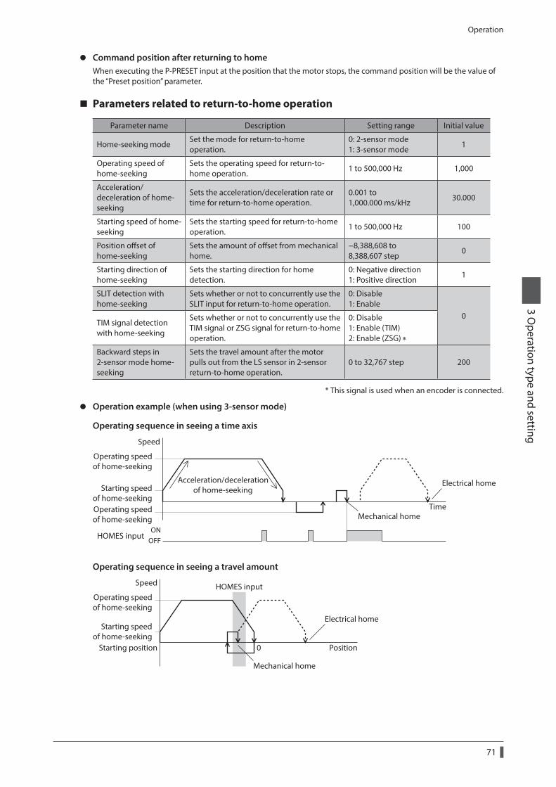
Operation
71
3 Operation type and setting
z Command position after returning to homeWhen executing the P-PRESET input at the position that the motor stops, the command position will be the value of the “Preset position” parameter.
Parameters related to return-to-home operation
Parameter name Description Setting range Initial value
Home-seeking modeSet the mode for return-to-home operation.
0: 2-sensor mode 1: 3-sensor mode
1
Operating speed of home-seeking
Sets the operating speed for return-to-home operation.
1 to 500,000 Hz 1,000
Acceleration/deceleration of home-seeking
Sets the acceleration/deceleration rate or time for return-to-home operation.
0.001 to 1,000.000 ms/kHz
30.000
Starting speed of home-seeking
Sets the starting speed for return-to-home operation.
1 to 500,000 Hz 100
Position offset of home-seeking
Sets the amount of offset from mechanical home.
−8,388,608 to 8,388,607 step
0
Starting direction of home-seeking
Sets the starting direction for home detection.
0: Negative direction 1: Positive direction
1
SLIT detection with home-seeking
Sets whether or not to concurrently use the SLIT input for return-to-home operation.
0: Disable 1: Enable
0TIM signal detection with home-seeking
Sets whether or not to concurrently use the TIM signal or ZSG signal for return-to-home operation.
0: Disable 1: Enable (TIM) 2: Enable (ZSG) ∗
Backward steps in 2-sensor mode home-seeking
Sets the travel amount after the motor pulls out from the LS sensor in 2-sensor return-to-home operation.
0 to 32,767 step 200
* This signal is used when an encoder is connected.
z Operation example (when using 3-sensor mode)
Operating sequence in seeing a time axis
Speed
Operating speedof home-seeking
Starting speedof home-seekingOperating speedof home-seeking
Time
Electrical home
Mechanical home
Acceleration/decelerationof home-seeking
HOMES inputON
OFF
Operating sequence in seeing a travel amount
Speed HOMES input
Position0Starting position
Operating speedof home-seeking
Starting speedof home-seeking
Electrical home
Mechanical home
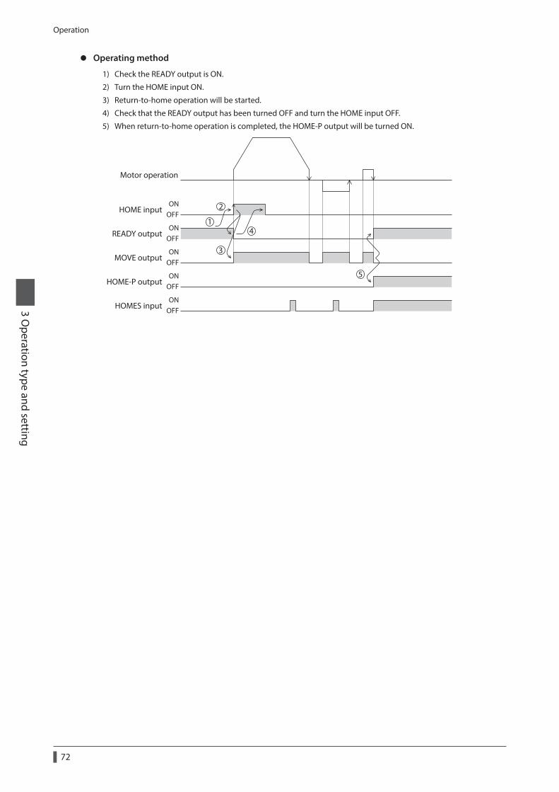
Operation
72
3 Operation type and setting
z Operating method
1) Check the READY output is ON.
2) Turn the HOME input ON.
3) Return-to-home operation will be started.
4) Check that the READY output has been turned OFF and turn the HOME input OFF.
5) When return-to-home operation is completed, the HOME-P output will be turned ON.
HOME input
MOVE output
READY output
Motor operation
ONOFF
ONOFF
ONOFF
HOME-P outputON
OFF
HOMES inputON
OFF
1
2
3
4
5
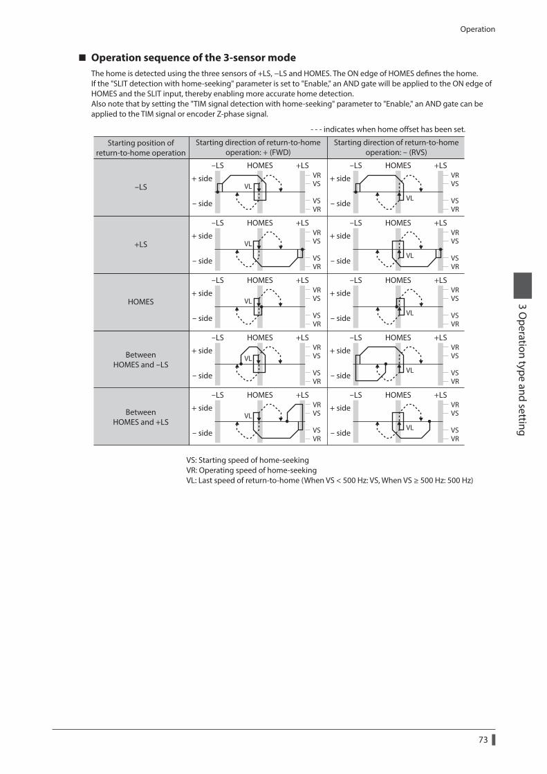
Operation
73
3 Operation type and setting
Operation sequence of the 3-sensor modeThe home is detected using the three sensors of +LS, −LS and HOMES. The ON edge of HOMES defines the home.If the "SLIT detection with home-seeking" parameter is set to "Enable," an AND gate will be applied to the ON edge of HOMES and the SLIT input, thereby enabling more accurate home detection.Also note that by setting the "TIM signal detection with home-seeking" parameter to "Enable," an AND gate can be applied to the TIM signal or encoder Z-phase signal.
BetweenHOMES and -LS
BetweenHOMES and +LS
HOMES
-LS
+LS
Starting position ofreturn-to-home operation
Starting direction of return-to-homeoperation: + (FWD)
Starting direction of return-to-homeoperation: - (RVS)
+ side
- side
+ side
- side
+ side
- side
+ side
- side
+ side
- side
-LS +LSHOMES
+ side
- side
+ side
- side
+ side
- side
+ side
- side
+ side
- side
-LS +LSHOMES
-LS +LSHOMES -LS +LSHOMES
-LS +LSHOMES -LS +LSHOMES
-LS +LSHOMES -LS +LSHOMES
-LS +LSHOMES -LS +LSHOMES
- - - indicates when home oset has been set.
VR
VR
VS
VS
VR
VR
VS
VS
VR
VR
VS
VS
VR
VR
VS
VS
VR
VR
VS
VS
VR
VR
VS
VS
VR
VR
VS
VS
VR
VR
VS
VS
VR
VR
VS
VS
VR
VR
VS
VS
VL
VL
VL
VL
VL
VL
VL
VL
VL
VL
VS: Starting speed of home-seeking VR: Operating speed of home-seeking VL: Last speed of return-to-home (When VS < 500 Hz: VS, When VS ≥ 500 Hz: 500 Hz)
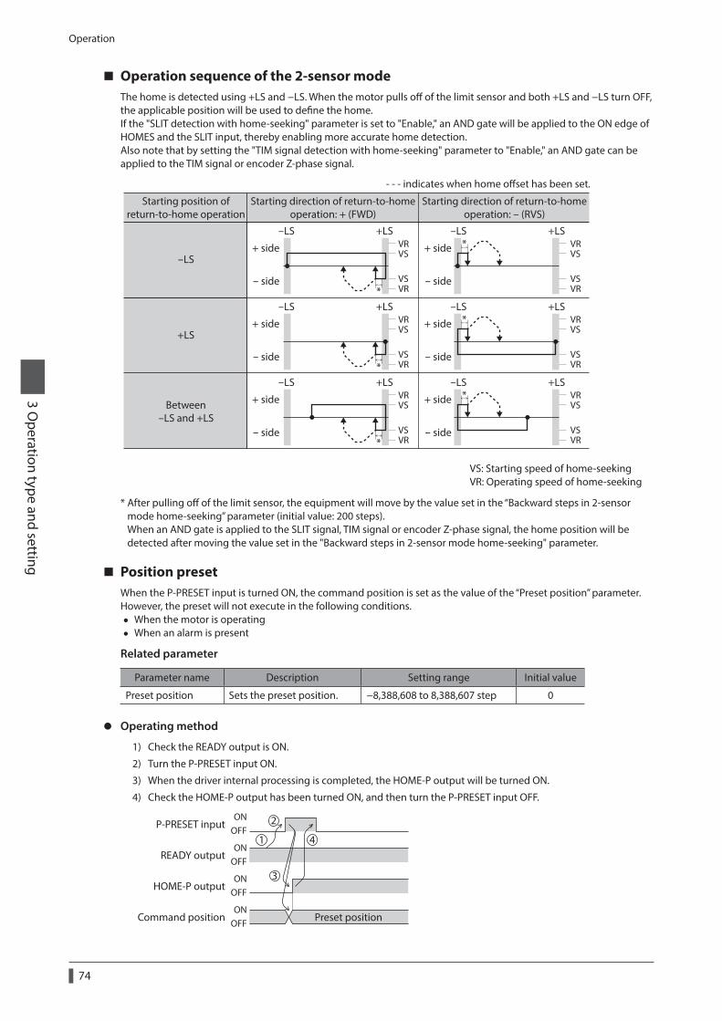
Operation
74
3 Operation type and setting
Operation sequence of the 2-sensor modeThe home is detected using +LS and −LS. When the motor pulls off of the limit sensor and both +LS and −LS turn OFF, the applicable position will be used to define the home.If the "SLIT detection with home-seeking" parameter is set to "Enable," an AND gate will be applied to the ON edge of HOMES and the SLIT input, thereby enabling more accurate home detection.Also note that by setting the "TIM signal detection with home-seeking" parameter to "Enable," an AND gate can be applied to the TIM signal or encoder Z-phase signal.
*
*
*
*
*
*Between
-LS and +LS
-LS
+LS
+ side
- side
+ side
- side
+ side
- side
-LS +LS
+ side
- side
+ side
- side
+ side
- side
-LS +LS
-LS +LS -LS +LS
-LS +LS -LS +LS
Starting position ofreturn-to-home operation
Starting direction of return-to-homeoperation: + (FWD)
Starting direction of return-to-homeoperation: - (RVS)
- - - indicates when home oset has been set.
VR
VR
VS
VS
VR
VR
VS
VS
VR
VR
VS
VS
VR
VR
VS
VS
VR
VR
VS
VS
VR
VR
VS
VS
VS: Starting speed of home-seeking VR: Operating speed of home-seeking
* After pulling off of the limit sensor, the equipment will move by the value set in the “Backward steps in 2-sensor mode home-seeking” parameter (initial value: 200 steps). When an AND gate is applied to the SLIT signal, TIM signal or encoder Z-phase signal, the home position will be detected after moving the value set in the "Backward steps in 2-sensor mode home-seeking" parameter.
Position presetWhen the P-PRESET input is turned ON, the command position is set as the value of the “Preset position” parameter.However, the preset will not execute in the following conditions.
• When the motor is operating • When an alarm is present
Related parameter
Parameter name Description Setting range Initial value
Preset position Sets the preset position. −8,388,608 to 8,388,607 step 0
z Operating method
1) Check the READY output is ON.
2) Turn the P-PRESET input ON.
3) When the driver internal processing is completed, the HOME-P output will be turned ON.
4) Check the HOME-P output has been turned ON, and then turn the P-PRESET input OFF.
P-PRESET input
HOME-P output
READY output
Command position Preset positionON
OFF
ONOFF
ONOFF
ONOFF
1
2
3
4
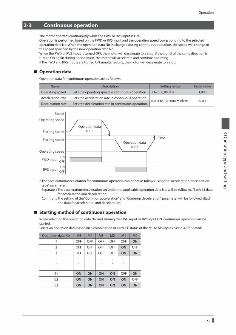
Operation
75
3 Operation type and setting
2-3 Continuous operation
The motor operates continuously while the FWD or RVS input is ON.Operation is performed based on the FWD or RVS input and the operating speed corresponding to the selected operation data No. When the operation data No. is changed during continuous operation, the speed will change to the speed specified by the new operation data No.When the FWD or RVS input is turned OFF, the motor will decelerate to a stop. If the signal of the same direction is turned ON again during deceleration, the motor will accelerate and continue operating.If the FWD and RVS inputs are turned ON simultaneously, the motor will decelerate to a stop.
Operation dataOperation data for continuous operation are as follows.
Name Description Setting range Initial value
Operating speed Sets the operating speed in continuous operation. 1 to 500,000 Hz 1,000
Acceleration rate Sets the acceleration rate in continuous operation.0.001 to 100.000 ms/kHz 30.000
Deceleration rate Sets the deceleration rate in continuous operation.
Speed
Operating speed
Operating speed
FWD inputOFFON
RVS inputOFFON
Starting speed
Starting speed Time
Operation dataNo.1
Operation dataNo.2
* The acceleration/deceleration for continuous operation can be set as follows using the “Acceleration/deceleration type” parameter: Separate : The acceleration/deceleration set under the applicable operation data No. will be followed. (Each 63 data for acceleration and deceleration) Common : The setting of the “Common acceleration” and “Common deceleration” parameter will be followed. (Each one data for acceleration and deceleration)
Starting method of continuous operationWhen selecting the operation data No. and turning the FWD input or RVS input ON, continuous operation will be started.Select an operation data based on a combination of ON/OFF status of the M0 to M5 inputs. See p.47 for details.
Operation data No. M5 M4 M3 M2 M1 M0
1 OFF OFF OFF OFF OFF ON
2 OFF OFF OFF OFF ON OFF
3 OFF OFF OFF OFF ON ON
· · ·
· · ·
· · ·
· · ·
· · ·
· · ·
· · ·
61 ON ON ON ON OFF ON
62 ON ON ON ON ON OFF
63 ON ON ON ON ON ON
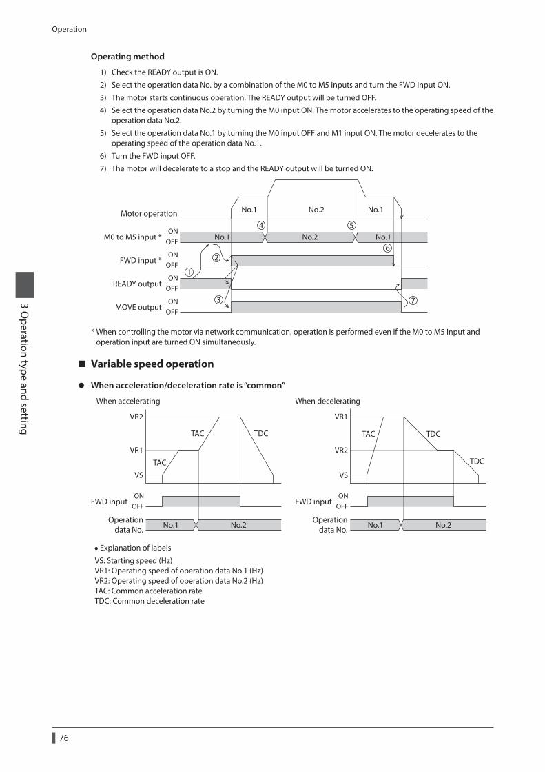
Operation
76
3 Operation type and setting
Operating method
1) Check the READY output is ON.
2) Select the operation data No. by a combination of the M0 to M5 inputs and turn the FWD input ON.
3) The motor starts continuous operation. The READY output will be turned OFF.
4) Select the operation data No.2 by turning the M0 input ON. The motor accelerates to the operating speed of the operation data No.2.
5) Select the operation data No.1 by turning the M0 input OFF and M1 input ON. The motor decelerates to the operating speed of the operation data No.1.
6) Turn the FWD input OFF.
7) The motor will decelerate to a stop and the READY output will be turned ON.
FWD input *
MOVE output
READY output
Motor operation
M0 to M5 input * No.1 No.1No.2
No.2No.1 No.1
ONOFF
ONOFF
ONOFF
ONOFF
4
1
2
3
5
6
7
* When controlling the motor via network communication, operation is performed even if the M0 to M5 input and operation input are turned ON simultaneously.
Variable speed operation
z When acceleration/deceleration rate is “common”
VR2
VR1
VS
TAC
No.1
OFFON
No.2
FWD input
Operationdata No.
FWD input
Operationdata No. No.1
OFFON
No.2
When accelerating When decelerating
TAC TDC
VR2
VR1
VS
TAC TDC
TDC
• Explanation of labels
VS: Starting speed (Hz) VR1: Operating speed of operation data No.1 (Hz) VR2: Operating speed of operation data No.2 (Hz) TAC: Common acceleration rate TDC: Common deceleration rate
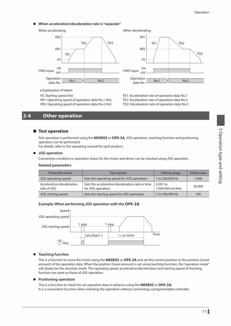
Operation
77
3 Operation type and setting
z When acceleration/deceleration rate is “separate”
VR2
VR1
VS
TA1
No.1
OFFON
No.2 No.1
OFFON
No.2
TA2 TD2
VR2
VR1
VS
TA1 TD2
TD2
FWD input
Operationdata No.
FWD input
Operationdata No.
When accelerating When decelerating
• Explanation of labels
VS: Starting speed (Hz) VR1: Operating speed of operation data No.1 (Hz) VR2: Operating speed of operation data No.2 (Hz)
TA1: Acceleration rate of operation data No.1 TA2: Acceleration rate of operation data No.2 TD2: Deceleration rate of operation data No.2
2-4 Other operation
Test operationTest operation is performed using the MEXE02 or OPX-2A. JOG operation, teaching function and positioning operation can be performed.For details, refer to the operating manual for each product.
z JOG operationConnection condition or operation status for the motor and driver can be checked using JOG operation.
Related parameters
Parameter name Description Setting range Initial value
JOG operating speed Sets the operating speed for JOG operation. 1 to 500,000 Hz 1,000
Acceleration/deceleration rate of JOG
Sets the acceleration/deceleration rate or time for JOG operation.
0.001 to 1,000.000 ms/kHz
30.000
JOG starting speed Sets the starting speed for JOG operation. 1 to 500,000 Hz 100
Example: When performing JOG operation with the OPX-2A
Less than1 s 1 s or more
JOG starting speed
Speed
Time
JOG operating speed
1 step 1 step
Key
z Teaching functionThis is a function to move the motor using the MEXE02 or OPX-2A and set the current position as the position (travel amount) of the operation data. When the position (travel amount) is set using teaching function, the “operation mode” will always be the absolute mode. The operating speed, acceleration/deceleration and starting speed of teaching function are same as those of JOG operation.
z Positioning operationThis is a function to check the set operation data in advance using the MEXE02 or OPX-2A.It is a convenient function when checking the operation without connecting a programmable controller.
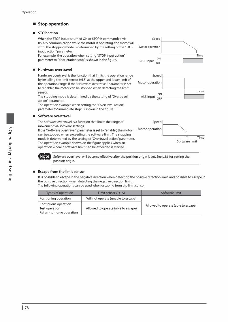
Operation
78
3 Operation type and setting
Stop operation
z STOP actionWhen the STOP input is turned ON or STOP is commanded via RS-485 communication while the motor is operating, the motor will stop. The stopping mode is determined by the setting of the “STOP input action” parameter.For example, the operation when setting "STOP input action" parameter to "deceleration stop" is shown in the figure.
Speed
TimeON
OFFSTOP input
Motor operation
z Hardware overtravelHardware overtravel is the function that limits the operation range by installing the limit sensor (±LS) at the upper and lower limit of the operation range. If the "Hardware overtravel" parameter is set to "enable", the motor can be stopped when detecting the limit sensor. The stopping mode is determined by the setting of “Overtravel action” parameter.The operation example when setting the "Overtravel action" parameter to “immediate stop” is shown in the figure.
ONOFF
±LS input
Speed
Time
Motor operation
z Software overtravelThe software overtravel is a function that limits the range of movement via software settings.If the "Software overtravel" parameter is set to "enable", the motor can be stopped when exceeding the software limit. The stopping mode is determined by the setting of “Overtravel action” parameter.The operation example shown on the figure applies when an operation where a software limit is to be exceeded is started.
Speed
TimeSpftware limit
Motor operation
Software overtravel will become effective after the position origin is set. See p.86 for setting the position origin.
z Escape from the limit sensorIt is possible to escape in the negative direction when detecting the positive direction limit, and possible to escape in the positive direction when detecting the negative direction limit.The following operations can be used when escaping from the limit sensor.
Types of operation Limit sensors (±LS) Software limit
Positioning operation Will not operate (unable to escape)
Allowed to operate (able to escape)Continuous operation Test operation Return-to-home operation
Allowed to operate (able to escape)
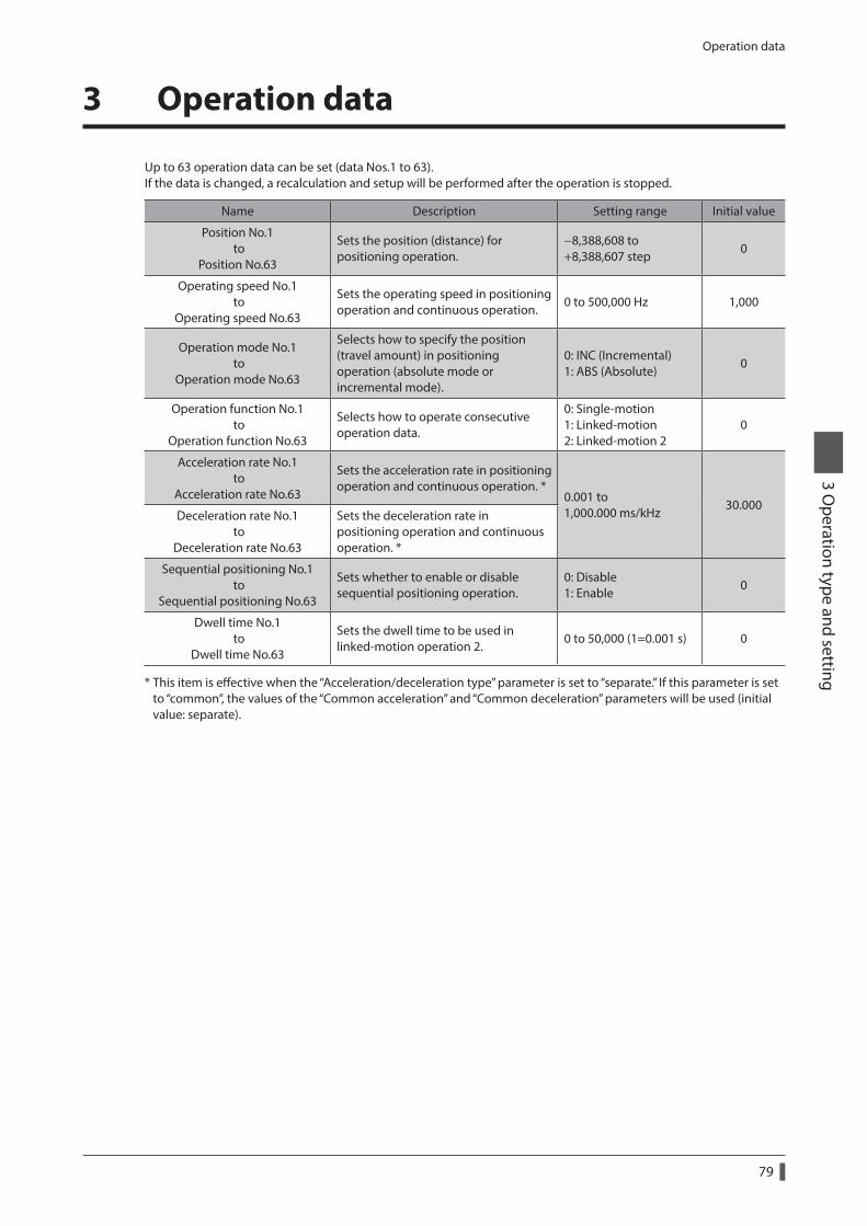
Operation data
79
3 Operation type and setting
3 Operation data
Up to 63 operation data can be set (data Nos.1 to 63).If the data is changed, a recalculation and setup will be performed after the operation is stopped.
Name Description Setting range Initial value
Position No.1 to
Position No.63
Sets the position (distance) for positioning operation.
−8,388,608 to +8,388,607 step
0
Operating speed No.1 to
Operating speed No.63
Sets the operating speed in positioning operation and continuous operation.
0 to 500,000 Hz 1,000
Operation mode No.1 to
Operation mode No.63
Selects how to specify the position (travel amount) in positioning operation (absolute mode or incremental mode).
0: INC (Incremental) 1: ABS (Absolute)
0
Operation function No.1 to
Operation function No.63
Selects how to operate consecutive operation data.
0: Single-motion 1: Linked-motion 2: Linked-motion 2
0
Acceleration rate No.1 to
Acceleration rate No.63
Sets the acceleration rate in positioning operation and continuous operation. *
0.001 to 1,000.000 ms/kHz
30.000Deceleration rate No.1
to Deceleration rate No.63
Sets the deceleration rate in positioning operation and continuous operation. *
Sequential positioning No.1 to
Sequential positioning No.63
Sets whether to enable or disable sequential positioning operation.
0: Disable 1: Enable
0
Dwell time No.1 to
Dwell time No.63
Sets the dwell time to be used in linked-motion operation 2.
0 to 50,000 (1=0.001 s) 0
* This item is effective when the “Acceleration/deceleration type” parameter is set to “separate.” If this parameter is set to “common”, the values of the “Common acceleration” and “Common deceleration” parameters will be used (initial value: separate).
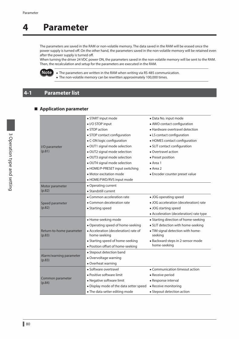
Parameter
80
3 Operation type and setting
4 Parameter
The parameters are saved in the RAM or non-volatile memory. The data saved in the RAM will be erased once the power supply is turned off. On the other hand, the parameters saved in the non-volatile memory will be retained even after the power supply is turned off.When turning the driver 24 VDC power ON, the parameters saved in the non-volatile memory will be sent to the RAM. Then, the recalculation and setup for the parameters are executed in the RAM.
• The parameters are written in the RAM when writing via RS-485 communication. • The non-volatile memory can be rewritten approximately 100,000 times.
4-1 Parameter list
Application parameter
I/O parameter (p.81)
• START input mode
• I/O STOP input
• STOP action
• STOP contact configuration
•C-ON logic configuration
•OUT1 signal mode selection
•OUT2 signal mode selection
•OUT3 signal mode selection
•OUT4 signal mode selection
•HOME/P-PRESET input switching
•Motor excitation mode
•HOME/FWD/RVS input mode
•Data No. input mode
•AWO contact configuration
•Hardware overtravel detection
• LS contact configuration
•HOMES contact configuration
• SLIT contact configuration
•Overtravel action
• Preset position
•Area 1
•Area 2
• Encoder counter preset value
Motor parameter (p.82)
•Operating current
• Standstill current
Speed parameter (p.82)
•Common acceleration rate
•Common deceleration rate
• Starting speed
• JOG operating speed
• JOG acceleration (deceleration) rate
• JOG starting speed
•Acceleration (deceleration) rate type
Return-to-home parameter (p.83)
•Home-seeking mode
•Operating speed of home-seeking
•Acceleration (deceleration) rate of home-seeking
• Starting speed of home-seeking
• Position offset of home-seeking
• Starting direction of home-seeking
• SLIT detection with home-seeking
• TIM signal detection with home-seeking
• Backward steps in 2-sensor mode home-seeking
Alarm/warning parameter (p.83)
• Stepout detection band
•Overvoltage warning
•Overheat warning
Common parameter (p.84)
• Software overtravel
• Positive software limit
•Negative software limit
•Display mode of the data setter speed
• The data setter editing mode
•Communication timeout action
• Receive period
• Response interval
• Receive monitoring
• Stepout detection action
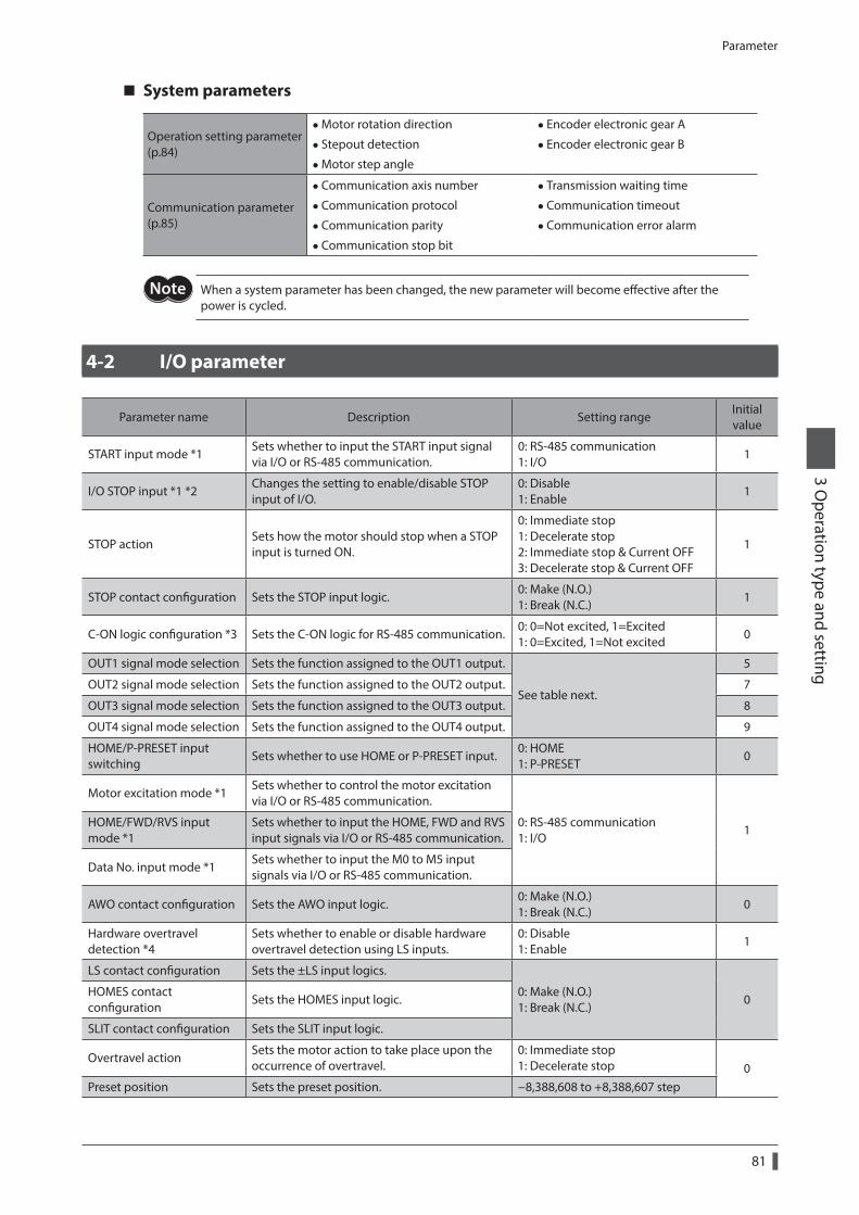
Parameter
81
3 Operation type and setting
System parameters
Operation setting parameter (p.84)
•Motor rotation direction
• Stepout detection
•Motor step angle
• Encoder electronic gear A
• Encoder electronic gear B
Communication parameter (p.85)
•Communication axis number
•Communication protocol
•Communication parity
•Communication stop bit
• Transmission waiting time
•Communication timeout
•Communication error alarm
When a system parameter has been changed, the new parameter will become effective after the power is cycled.
4-2 I/O parameter
Parameter name Description Setting rangeInitial value
START input mode *1Sets whether to input the START input signal via I/O or RS-485 communication.
0: RS-485 communication 1: I/O
1
I/O STOP input *1 *2Changes the setting to enable/disable STOP input of I/O.
0: Disable 1: Enable
1
STOP actionSets how the motor should stop when a STOP input is turned ON.
0: Immediate stop 1: Decelerate stop 2: Immediate stop & Current OFF 3: Decelerate stop & Current OFF
1
STOP contact configuration Sets the STOP input logic.0: Make (N.O.) 1: Break (N.C.)
1
C-ON logic configuration *3 Sets the C-ON logic for RS-485 communication.0: 0=Not excited, 1=Excited 1: 0=Excited, 1=Not excited
0
OUT1 signal mode selection Sets the function assigned to the OUT1 output.
See table next.
5
OUT2 signal mode selection Sets the function assigned to the OUT2 output. 7
OUT3 signal mode selection Sets the function assigned to the OUT3 output. 8
OUT4 signal mode selection Sets the function assigned to the OUT4 output. 9
HOME/P-PRESET input switching
Sets whether to use HOME or P-PRESET input.0: HOME 1: P-PRESET
0
Motor excitation mode *1Sets whether to control the motor excitation via I/O or RS-485 communication.
0: RS-485 communication 1: I/O
1HOME/FWD/RVS input mode *1
Sets whether to input the HOME, FWD and RVS input signals via I/O or RS-485 communication.
Data No. input mode *1Sets whether to input the M0 to M5 input signals via I/O or RS-485 communication.
AWO contact configuration Sets the AWO input logic.0: Make (N.O.) 1: Break (N.C.)
0
Hardware overtravel detection *4
Sets whether to enable or disable hardware overtravel detection using LS inputs.
0: Disable 1: Enable
1
LS contact configuration Sets the ±LS input logics.
0: Make (N.O.) 1: Break (N.C.)
0HOMES contact configuration
Sets the HOMES input logic.
SLIT contact configuration Sets the SLIT input logic.
Overtravel actionSets the motor action to take place upon the occurrence of overtravel.
0: Immediate stop 1: Decelerate stop 0
Preset position Sets the preset position. −8,388,608 to +8,388,607 step
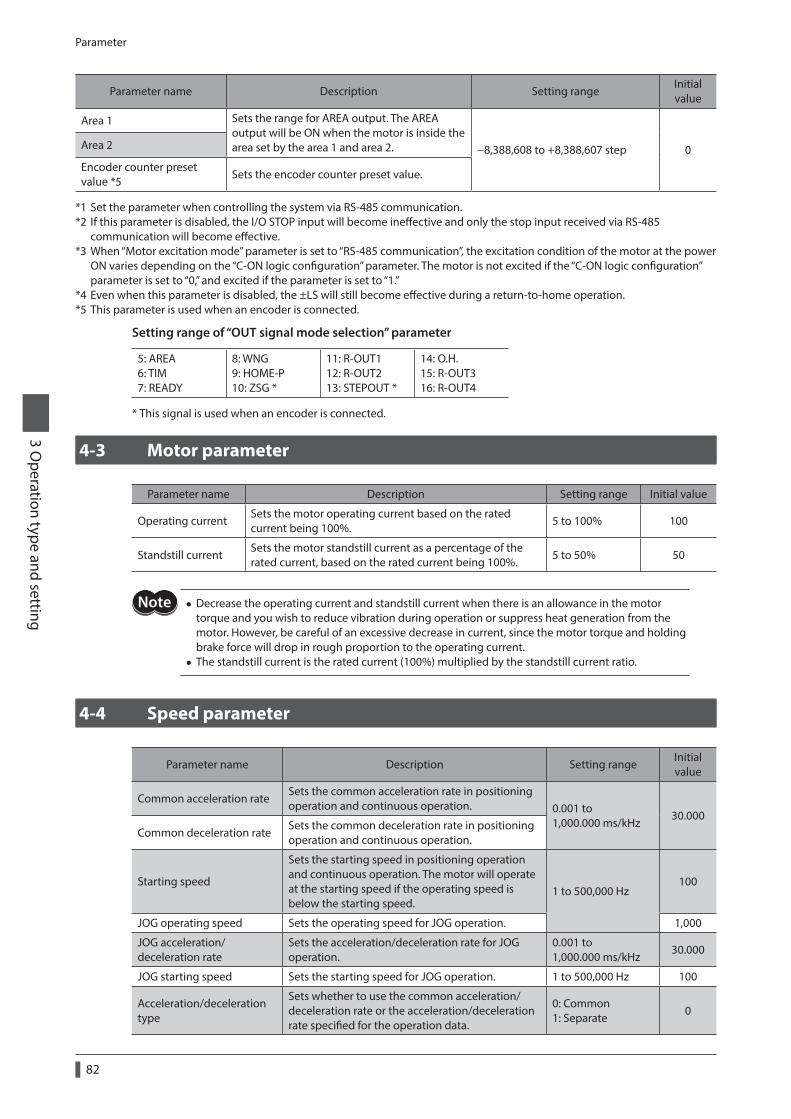
Parameter
82
3 Operation type and setting
Parameter name Description Setting rangeInitial value
Area 1 Sets the range for AREA output. The AREA output will be ON when the motor is inside the area set by the area 1 and area 2. −8,388,608 to +8,388,607 step 0Area 2
Encoder counter preset value *5
Sets the encoder counter preset value.
*1 Set the parameter when controlling the system via RS-485 communication.*2 If this parameter is disabled, the I/O STOP input will become ineffective and only the stop input received via RS-485
communication will become effective.*3 When “Motor excitation mode” parameter is set to “RS-485 communication”, the excitation condition of the motor at the power
ON varies depending on the “C-ON logic configuration” parameter. The motor is not excited if the “C-ON logic configuration” parameter is set to “0,” and excited if the parameter is set to “1.”
*4 Even when this parameter is disabled, the ±LS will still become effective during a return-to-home operation.*5 This parameter is used when an encoder is connected.
Setting range of “OUT signal mode selection” parameter
5: AREA 6: TIM 7: READY
8: WNG 9: HOME-P 10: ZSG *
11: R-OUT1 12: R-OUT2 13: STEPOUT *
14: O.H. 15: R-OUT3 16: R-OUT4
* This signal is used when an encoder is connected.
4-3 Motor parameter
Parameter name Description Setting range Initial value
Operating currentSets the motor operating current based on the rated current being 100%.
5 to 100% 100
Standstill currentSets the motor standstill current as a percentage of the rated current, based on the rated current being 100%.
5 to 50% 50
• Decrease the operating current and standstill current when there is an allowance in the motor torque and you wish to reduce vibration during operation or suppress heat generation from the motor. However, be careful of an excessive decrease in current, since the motor torque and holding brake force will drop in rough proportion to the operating current.
• The standstill current is the rated current (100%) multiplied by the standstill current ratio.
4-4 Speed parameter
Parameter name Description Setting rangeInitial value
Common acceleration rateSets the common acceleration rate in positioning operation and continuous operation. 0.001 to
1,000.000 ms/kHz30.000
Common deceleration rateSets the common deceleration rate in positioning operation and continuous operation.
Starting speed
Sets the starting speed in positioning operation and continuous operation. The motor will operate at the starting speed if the operating speed is below the starting speed.
1 to 500,000 Hz100
JOG operating speed Sets the operating speed for JOG operation. 1,000
JOG acceleration/deceleration rate
Sets the acceleration/deceleration rate for JOG operation.
0.001 to 1,000.000 ms/kHz
30.000
JOG starting speed Sets the starting speed for JOG operation. 1 to 500,000 Hz 100
Acceleration/deceleration type
Sets whether to use the common acceleration/deceleration rate or the acceleration/deceleration rate specified for the operation data.
0: Common 1: Separate
0
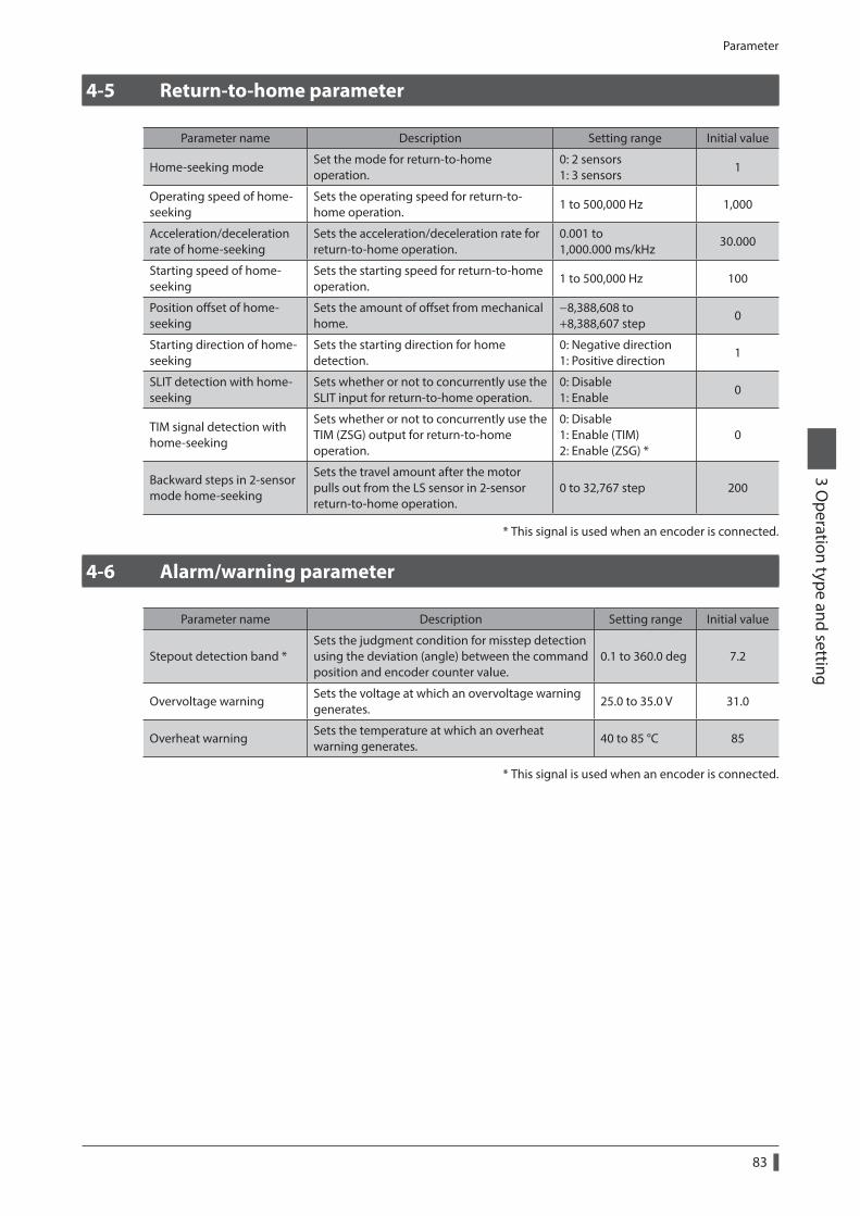
Parameter
83
3 Operation type and setting
4-5 Return-to-home parameter
Parameter name Description Setting range Initial value
Home-seeking modeSet the mode for return-to-home operation.
0: 2 sensors 1: 3 sensors
1
Operating speed of home-seeking
Sets the operating speed for return-to-home operation.
1 to 500,000 Hz 1,000
Acceleration/deceleration rate of home-seeking
Sets the acceleration/deceleration rate for return-to-home operation.
0.001 to 1,000.000 ms/kHz
30.000
Starting speed of home-seeking
Sets the starting speed for return-to-home operation.
1 to 500,000 Hz 100
Position offset of home-seeking
Sets the amount of offset from mechanical home.
−8,388,608 to +8,388,607 step
0
Starting direction of home-seeking
Sets the starting direction for home detection.
0: Negative direction 1: Positive direction
1
SLIT detection with home-seeking
Sets whether or not to concurrently use the SLIT input for return-to-home operation.
0: Disable 1: Enable
0
TIM signal detection with home-seeking
Sets whether or not to concurrently use the TIM (ZSG) output for return-to-home operation.
0: Disable 1: Enable (TIM) 2: Enable (ZSG) *
0
Backward steps in 2-sensor mode home-seeking
Sets the travel amount after the motor pulls out from the LS sensor in 2-sensor return-to-home operation.
0 to 32,767 step 200
* This signal is used when an encoder is connected.
4-6 Alarm/warning parameter
Parameter name Description Setting range Initial value
Stepout detection band *Sets the judgment condition for misstep detection using the deviation (angle) between the command position and encoder counter value.
0.1 to 360.0 deg 7.2
Overvoltage warningSets the voltage at which an overvoltage warning generates.
25.0 to 35.0 V 31.0
Overheat warningSets the temperature at which an overheat warning generates.
40 to 85 °C 85
* This signal is used when an encoder is connected.
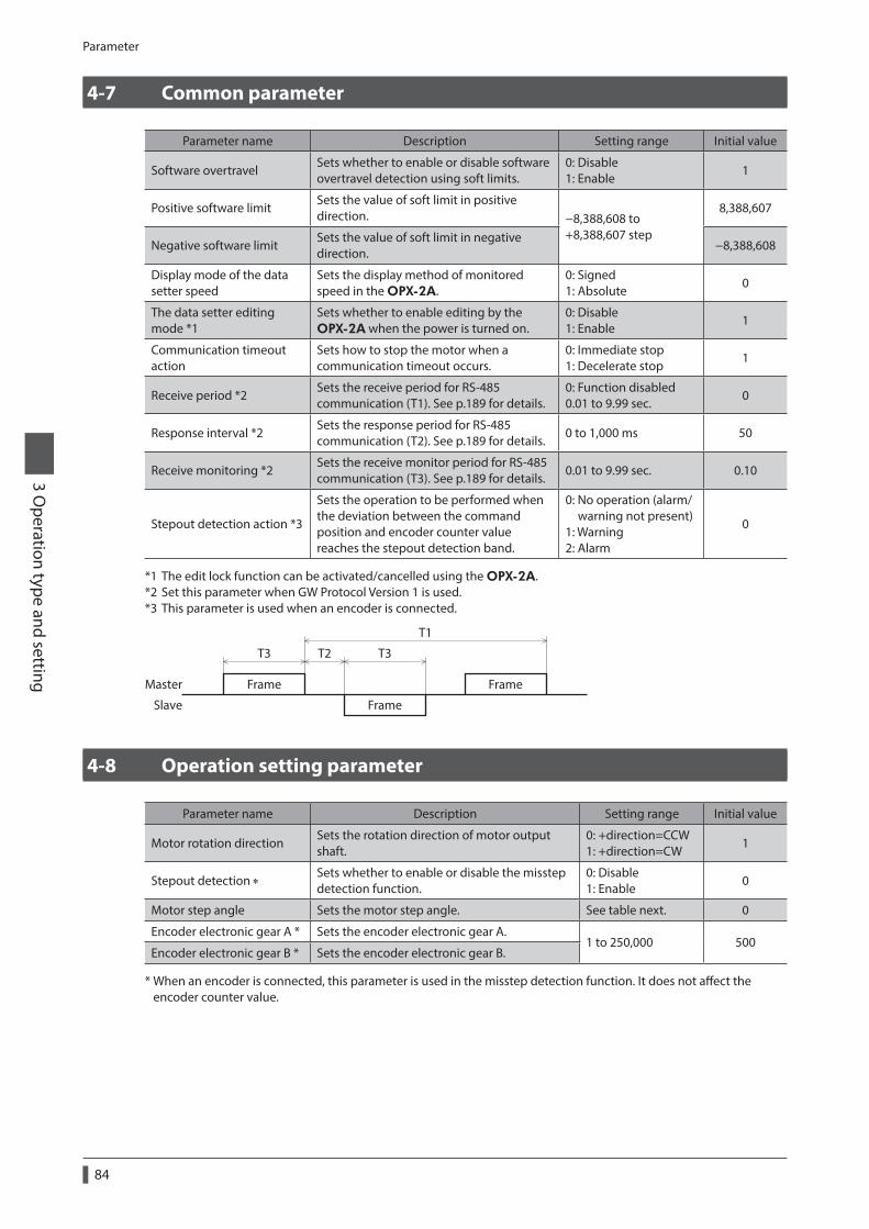
Parameter
84
3 Operation type and setting
4-7 Common parameter
Parameter name Description Setting range Initial value
Software overtravelSets whether to enable or disable software overtravel detection using soft limits.
0: Disable 1: Enable
1
Positive software limitSets the value of soft limit in positive direction. −8,388,608 to
+8,388,607 step
8,388,607
Negative software limitSets the value of soft limit in negative direction.
−8,388,608
Display mode of the data setter speed
Sets the display method of monitored speed in the OPX-2A.
0: Signed 1: Absolute
0
The data setter editing mode *1
Sets whether to enable editing by the OPX-2A when the power is turned on.
0: Disable 1: Enable
1
Communication timeout action
Sets how to stop the motor when a communication timeout occurs.
0: Immediate stop 1: Decelerate stop
1
Receive period *2Sets the receive period for RS-485 communication (T1). See p.189 for details.
0: Function disabled 0.01 to 9.99 sec.
0
Response interval *2Sets the response period for RS-485 communication (T2). See p.189 for details.
0 to 1,000 ms 50
Receive monitoring *2Sets the receive monitor period for RS-485 communication (T3). See p.189 for details.
0.01 to 9.99 sec. 0.10
Stepout detection action *3
Sets the operation to be performed when the deviation between the command position and encoder counter value reaches the stepout detection band.
0: No operation (alarm/ warning not present) 1: Warning 2: Alarm
0
*1 The edit lock function can be activated/cancelled using the OPX-2A.*2 Set this parameter when GW Protocol Version 1 is used.*3 This parameter is used when an encoder is connected.
Frame
T3 T2 T3
T1
Frame
Frame
Master
Slave
4-8 Operation setting parameter
Parameter name Description Setting range Initial value
Motor rotation directionSets the rotation direction of motor output shaft.
0: +direction=CCW 1: +direction=CW
1
Stepout detection ∗Sets whether to enable or disable the misstep detection function.
0: Disable 1: Enable
0
Motor step angle Sets the motor step angle. See table next. 0
Encoder electronic gear A * Sets the encoder electronic gear A.1 to 250,000 500
Encoder electronic gear B * Sets the encoder electronic gear B.
* When an encoder is connected, this parameter is used in the misstep detection function. It does not affect the encoder counter value.
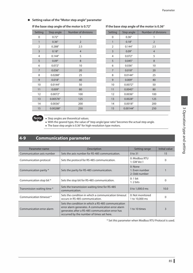
Parameter
85
3 Operation type and setting
z Setting value of the “Motor step angle” parameter
If the base step angle of the motor is 0.72° If the base step angle of the motor is 0.36°
Setting Step angle Number of divisions Setting Step angle Number of divisions
0 0.72° 1 0 0.36° 1
1 0.36° 2 1 0.18° 2
2 0.288° 2.5 2 0.144° 2.5
3 0.18° 4 3 0.09° 4
4 0.144° 5 4 0.072° 5
5 0.09° 8 5 0.045° 8
6 0.072° 10 6 0.036° 10
7 0.036° 20 7 0.018° 20
8 0.0288° 25 8 0.0144° 25
9 0.018° 40 9 0.009° 40
10 0.0144° 50 10 0.0072° 50
11 0.009° 80 11 0.0045° 80
12 0.0072° 100 12 0.0036° 100
13 0.00576° 125 13 0.0028° 125
14 0.0036° 200 14 0.0018° 200
15 0.00288° 250 15 0.00144° 250
• Step angles are theoretical values. • With the geared type, the value of “step angle/gear ratio” becomes the actual step angle. • The base step angle is 0.36° for high-resolution type motors.
4-9 Communication parameter
Parameter name Description Setting range Initial value
Communication axis number Sets the axis number for RS-485 communication. 0 to 31 15
Communication protocol Sets the protocol for RS-485 communication.0: Modbus RTU 1: GW Ver.1
0
Communication parity * Sets the parity for RS-485 communication.0: None 1: Even number 2: Odd number
1
Communication stop bit * Sets the stop bit for RS-485 communication.0: 1 bit 1: 2 bits
0
Transmission waiting time *Sets the transmission waiting time for RS-485 communication.
0 to 1,000.0 ms 10.0
Communication timeout *Sets the condition in which a communication timeout occurs in RS-485 communication.
0: Not monitored 1 to 10,000 ms
0
Communication error alarm
Sets the condition in which a RS-485 communication error alarm generates. A communication error alarm generates after a RS-485 communication error has occurred by the number of times set here.
1 to 10 times 3
* Set this parameter when Modbus RTU Protocol is used.
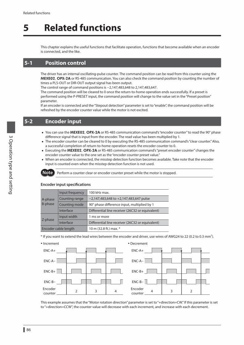
Related functions
86
3 Operation type and setting
5 Related functions
This chapter explains the useful functions that facilitate operation, functions that become available when an encoder is connected, and the like.
5-1 Position control
The driver has an internal oscillating-pulse counter. The command position can be read from this counter using the MEXE02, OPX-2A or RS-485 communication. You can also check the command position by counting the number of times a PLS-OUT or DIR-OUT output signal has been output.The control range of command positions is −2,147,483,648 to 2,147,483,647.The command position will be cleared to 0 once the return-to-home operation ends successfully. If a preset is performed using the P-PRESET input, the command position will change to the value set in the “Preset position” parameter.If an encoder is connected and the “Stepout detection” parameter is set to “enable”, the command position will be refreshed by the encoder counter value while the motor is not excited.
5-2 Encoder input
• You can use the MEXE02, OPX-2A or RS-485 communication command’s “encoder counter” to read the 90° phase difference signal that is input from the encoder. The read value has been multiplied by 1.
• The encoder counter can be cleared to 0 by executing the RS-485 communication command’s “clear counter.” Also, a successful completion of return-to-home operation resets the encoder counter to 0.
• Executing the MEXE02, OPX-2A or RS-485 communication command’s “preset encoder counter” changes the encoder counter value to the one set as the “encoder counter preset value.”
• When an encoder is connected, the misstep detection function becomes available. Take note that the encoder input is counted even when the misstep detection function is not used.
Perform a counter clear or encoder counter preset while the motor is stopped.
Encoder input specifications
A-phase B-phase
Input frequency 100 kHz max.
Counting range −2,147,483,648 to +2,147,483,647 pulse
Counting mode 90° phase difference input, multiplied by 1
Interface Differential line receiver (26C32 or equivalent)
Z-phaseInput width 1 ms or more
Interface Differential line receiver (26C32 or equivalent)
Encoder cable length 10 m (32.8 ft.) max. *
* If you want to extend the lead wires between the encoder and driver, use wires of AWG24 to 22 (0.2 to 0.3 mm2).
Increment Decrement
ENC-A+
ENC-A-
ENC-B+
ENC-B-
4 3 22 3 4Encodercounter
ENC-A+
ENC-A-
ENC-B+
ENC-B-
Encodercounter
This example assumes that the “Motor rotation direction” parameter is set to “+direction=CW.” If this parameter is set to “+direction=CCW”, the counter value will decrease with each increment, and increase with each decrement.
Related functions
87
3 Operation type and setting
5-3 Misstep detection function
This function becomes effective when an encoder is connected. Specifically, the deviation between the command position and encoder counter is monitored.The sub-functions specified below become available when the “Stepout detection” parameter is set to “enable.”
z Deviation error detectionWhen the deviation reaches the value set in the “Stepout detection band” parameter (initial value: 7.2°), a deviation error will be recognized.If the base step angle of the motor is 0.72°, set the value of the “Stepout detection band” parameter to 7.2°.If the base step angle of the motor is 0.36°, set the value of the “Stepout detection band” parameter to 3.6°.Deviation error detection will start after the motor has remained excited for 500 ms. This function is disabled during return to mechanical home operation.
z STEPOUT outputThis signal notifies a deviation error. Assign the STEPOUT output to one of the OUT0 to OUT4 outputs.
z Alarm/warningYou can cause an alarm or warning to be generated upon detection of a deviation error.
• Generate an excessive position deviation alarm: Set the “Stepout detection action” parameter to “alarm.” • Generate an excessive position deviation warning: Set the “Stepout detection action” parameter to “warning.” • Do not generate an alarm or warning: Set the “Stepout detection action” parameter to “no operation.”
z Command position updateThe command position is corrected by the encoder counter while the motor is not excited. The command position will still be refreshed even when the motor output shaft is turned by an external force while the motor excitation is stopped.
How to recover from deviation errorPerform one of the following operations to recover from the deviation error:
• Stop the motor excitation. • Perform return to mechanical home. • Clear the counter.
When the “Stepout detection action” parameter is set to “alarm”When a deviation error is detected, an excessive position deviation alarm will generate. In this case, reset the alarm by following the procedure below:
1. Stop the motor excitation or clear the counter to recover from the deviation error.
2. Turn the ALM-RST input ON to reset the alarm.
3. Perform return-to-home operation, if necessary.
If an excessive position deviation alarm generates, turning the ALM-RST input ON alone will not reset the alarm. Be sure to recover from the deviation error first, and then reset the alarm.
Encoder electronic gear settingsEven when the motor resolution is different from the encoder resolution, you can still detect a deviation error by setting the encoder electronic gears. The encoder electronic gears are used to determine a deviation error and will not affect the encoder counter value.
Parameter Description
Encoder electronic gear ASet the encoder resolution. Set to 500 if the encoder pulse count per motor revolution is 500 P/R. Note that the resolution is 500 P/R for motors with encoder.
Encoder electronic gear BSet the motor resolution. Set to 1,000 if the pulse count required for one motor revolution is 1,000 P/R.
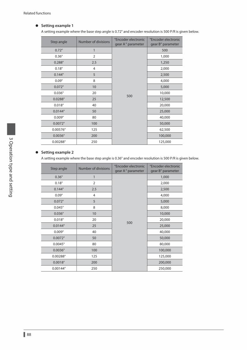
Related functions
88
3 Operation type and setting
z Setting example 1A setting example where the base step angle is 0.72° and encoder resolution is 500 P/R is given below.
Step angle Number of divisions“Encoder electronic gear A “ parameter
“Encoder electronic gear B“ parameter
0.72° 1
500
500
0.36° 2 1,000
0.288° 2.5 1,250
0.18° 4 2,000
0.144° 5 2,500
0.09° 8 4,000
0.072° 10 5,000
0.036° 20 10,000
0.0288° 25 12,500
0.018° 40 20,000
0.0144° 50 25,000
0.009° 80 40,000
0.0072° 100 50,000
0.00576° 125 62,500
0.0036° 200 100,000
0.00288° 250 125,000
z Setting example 2A setting example where the base step angle is 0.36° and encoder resolution is 500 P/R is given below.
Step angle Number of divisions“Encoder electronic gear A “ parameter
“Encoder electronic gear B“ parameter
0.36° 1
500
1,000
0.18° 2 2,000
0.144° 2.5 2,500
0.09° 4 4,000
0.072° 5 5,000
0.045° 8 8,000
0.036° 10 10,000
0.018° 20 20,000
0.0144° 25 25,000
0.009° 40 40,000
0.0072° 50 50,000
0.0045° 80 80,000
0.0036° 100 100,000
0.00288° 125 125,000
0.0018° 200 200,000
0.00144° 250 250,000

Related functions
89
3 Operation type and setting
• The accuracy of deviation varies depending on the operating speed and load. Be sure to check the deviation on the actual system.
• If you are providing the encoder on your own and installing it to the motor, take note that the accuracy of deviation error detection is also affected by the encoder resolution and assembly accuracy. Be sure to check the deviation on the actual system.
• If misstep occurs, the home position on the equipment side deviates from the home position recognized by the driver. If the operation is continued in this condition, the equipment may be damaged. Accordingly, take prompt actions if misstep is detected.
• If the step angle has been changed, be sure to change the value of the “Encoder electronic gear B” parameter accordingly. Similarly if the encoder resolution has changed, be sure to change the value of the “Encoder electronic gear A” parameter accordingly. If the gears are not set properly, the command position will not be updated correctly and a deviation error will be detected.
ResolutionIf the misstep function is used, use of an encoder with a resolution of 500 P/R.
If you are providing the encoder on your own, use the one that meets the specifications on p.86.

90
3 Operation type and setting
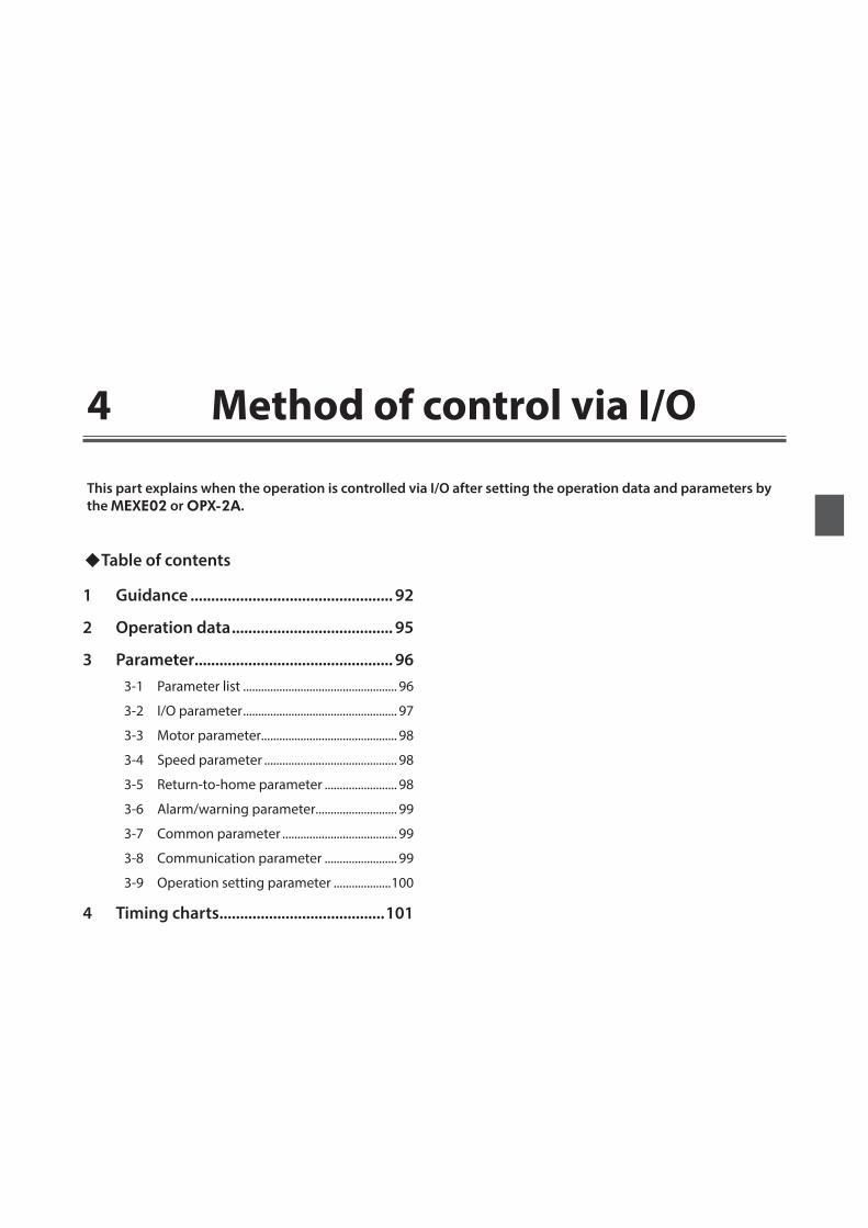
4 Method of control via I/O
This part explains when the operation is controlled via I/O after setting the operation data and parameters by the MEXE02 or OPX-2A.
Table of contents
1 Guidance ................................................. 92
2 Operation data ....................................... 95
3 Parameter ................................................ 963-1 Parameter list ................................................... 96
3-2 I/O parameter ................................................... 97
3-3 Motor parameter............................................. 98
3-4 Speed parameter ............................................ 98
3-5 Return-to-home parameter ........................ 98
3-6 Alarm/warning parameter........................... 99
3-7 Common parameter ...................................... 99
3-8 Communication parameter ........................ 99
3-9 Operation setting parameter ...................100
4 Timing charts ........................................101
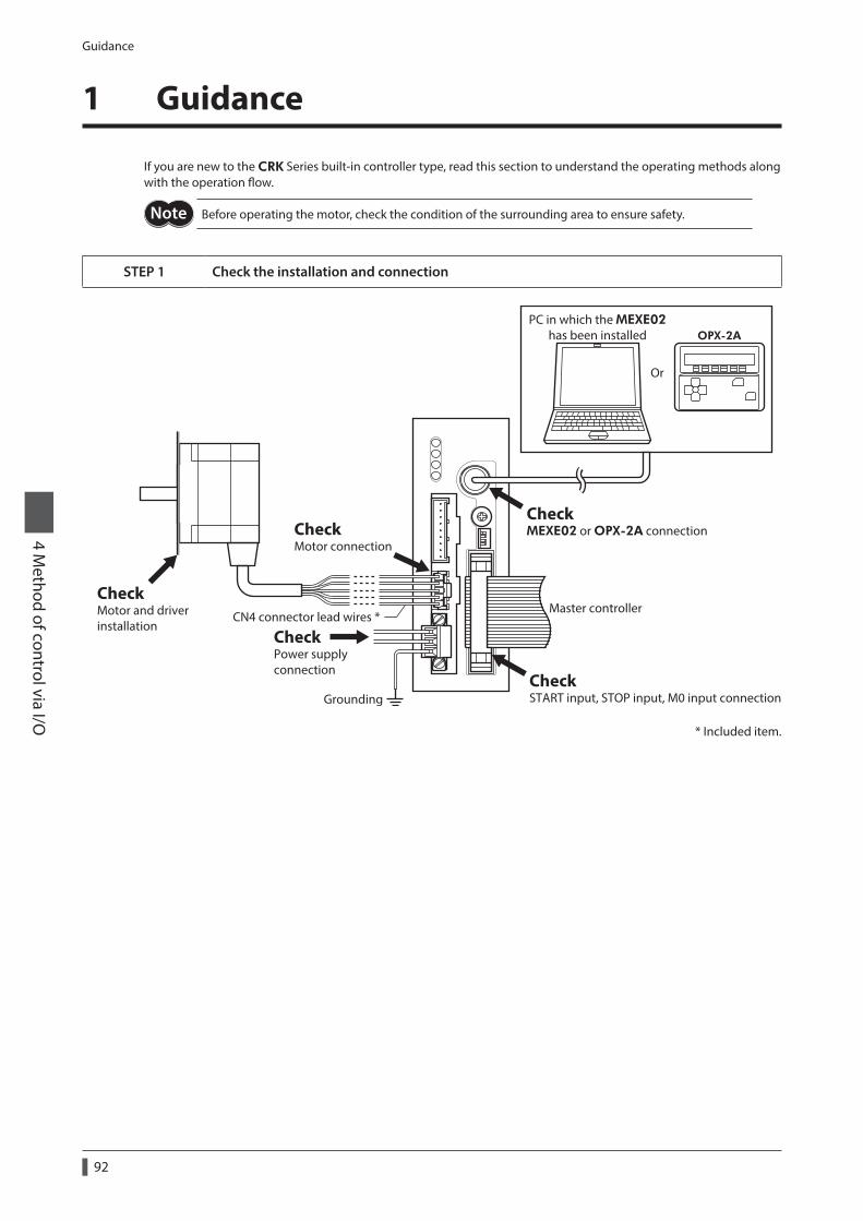
Guidance
92
4 Method of control via I/O
1 Guidance
If you are new to the CRK Series built-in controller type, read this section to understand the operating methods along with the operation flow.
Before operating the motor, check the condition of the surrounding area to ensure safety.
STEP 1 Check the installation and connection
CheckMotor and driver installation
Master controller
CheckMotor connection
CheckMEXE02 or OPX-2A connection
CheckSTART input, STOP input, M0 input connection
CheckPower supplyconnection
Grounding
Or
OPX-2APC in which the MEXE02
has been installed
CN4 connector lead wires *
* Included item.
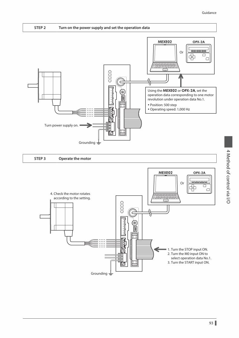
Guidance
93
4 Method of control via I/O
STEP 2 Turn on the power supply and set the operation data
Using the MEXE02 or OPX-2A, set the operation data corresponding to one motor revolution under operation data No.1.
Position: 500 step Operating speed: 1,000 Hz
Grounding
Turn power supply on.
Or
OPX-2AMEXE02
STEP 3 Operate the motor
1. Turn the STOP input ON.2. Turn the M0 input ON to select operation data No.1.3. Turn the START input ON.
4. Check the motor rotates according to the setting.
Grounding
Or
OPX-2AMEXE02

Guidance
94
4 Method of control via I/O
STEP 4 Were you able to operate the motor properly?
How did it go? Were you able to operate the motor properly?If the motor does not function, check the following points:
• Is the STOP input ON? (factory setting: normally closed) • Is any alarm present? • Are the power supply and motor connected securely?
For more detailed settings and functions, refer to “3 Parameter” on p.96.
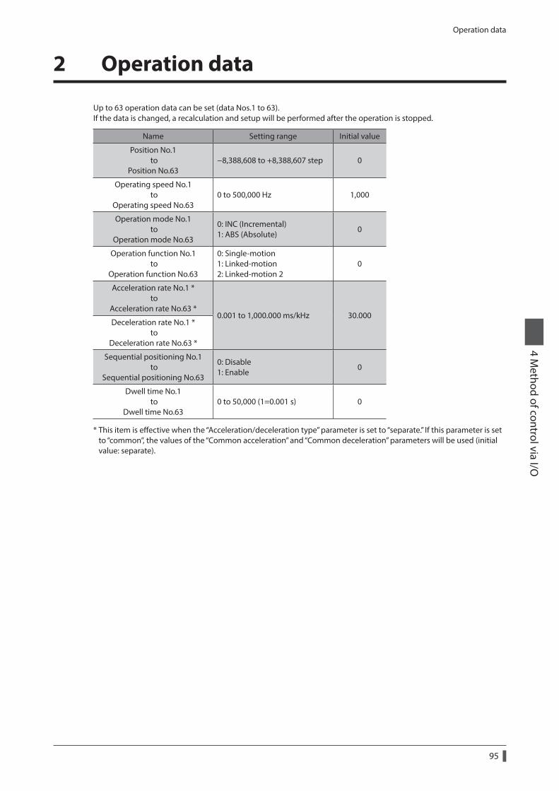
Operation data
95
4 Method of control via I/O
2 Operation data
Up to 63 operation data can be set (data Nos.1 to 63).If the data is changed, a recalculation and setup will be performed after the operation is stopped.
Name Setting range Initial value
Position No.1 to
Position No.63−8,388,608 to +8,388,607 step 0
Operating speed No.1 to
Operating speed No.630 to 500,000 Hz 1,000
Operation mode No.1 to
Operation mode No.63
0: INC (Incremental) 1: ABS (Absolute)
0
Operation function No.1 to
Operation function No.63
0: Single-motion 1: Linked-motion 2: Linked-motion 2
0
Acceleration rate No.1 * to
Acceleration rate No.63 *0.001 to 1,000.000 ms/kHz 30.000
Deceleration rate No.1 * to
Deceleration rate No.63 *
Sequential positioning No.1 to
Sequential positioning No.63
0: Disable 1: Enable
0
Dwell time No.1 to
Dwell time No.630 to 50,000 (1=0.001 s) 0
* This item is effective when the “Acceleration/deceleration type” parameter is set to “separate.” If this parameter is set to “common”, the values of the “Common acceleration” and “Common deceleration” parameters will be used (initial value: separate).
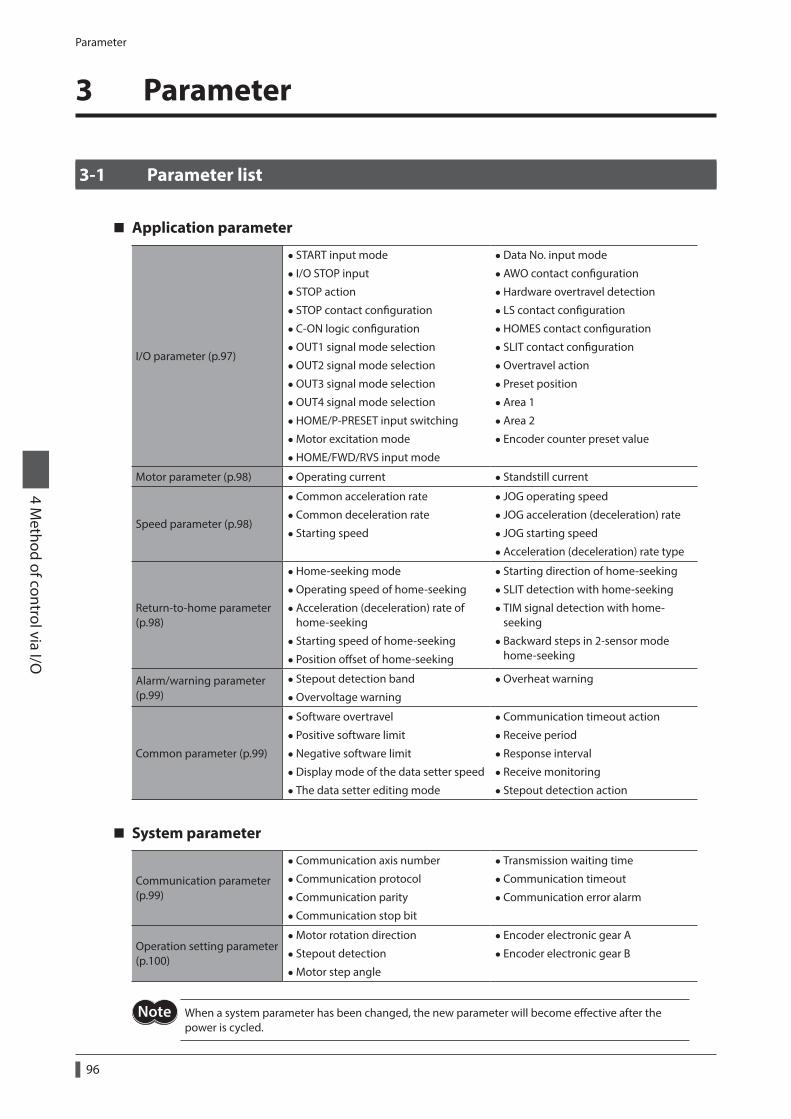
Parameter
96
4 Method of control via I/O
3 Parameter
3-1 Parameter list
Application parameter
I/O parameter (p.97)
• START input mode
• I/O STOP input
• STOP action
• STOP contact configuration
•C-ON logic configuration
•OUT1 signal mode selection
•OUT2 signal mode selection
•OUT3 signal mode selection
•OUT4 signal mode selection
•HOME/P-PRESET input switching
•Motor excitation mode
•HOME/FWD/RVS input mode
•Data No. input mode
•AWO contact configuration
•Hardware overtravel detection
• LS contact configuration
•HOMES contact configuration
• SLIT contact configuration
•Overtravel action
• Preset position
•Area 1
•Area 2
• Encoder counter preset value
Motor parameter (p.98) •Operating current • Standstill current
Speed parameter (p.98)
•Common acceleration rate
•Common deceleration rate
• Starting speed
• JOG operating speed
• JOG acceleration (deceleration) rate
• JOG starting speed
•Acceleration (deceleration) rate type
Return-to-home parameter (p.98)
•Home-seeking mode
•Operating speed of home-seeking
•Acceleration (deceleration) rate of home-seeking
• Starting speed of home-seeking
• Position offset of home-seeking
• Starting direction of home-seeking
• SLIT detection with home-seeking
• TIM signal detection with home-seeking
• Backward steps in 2-sensor mode home-seeking
Alarm/warning parameter (p.99)
• Stepout detection band
•Overvoltage warning
•Overheat warning
Common parameter (p.99)
• Software overtravel
• Positive software limit
•Negative software limit
•Display mode of the data setter speed
• The data setter editing mode
•Communication timeout action
• Receive period
• Response interval
• Receive monitoring
• Stepout detection action
System parameter
Communication parameter (p.99)
•Communication axis number
•Communication protocol
•Communication parity
•Communication stop bit
• Transmission waiting time
•Communication timeout
•Communication error alarm
Operation setting parameter (p.100)
•Motor rotation direction
• Stepout detection
•Motor step angle
• Encoder electronic gear A
• Encoder electronic gear B
When a system parameter has been changed, the new parameter will become effective after the power is cycled.
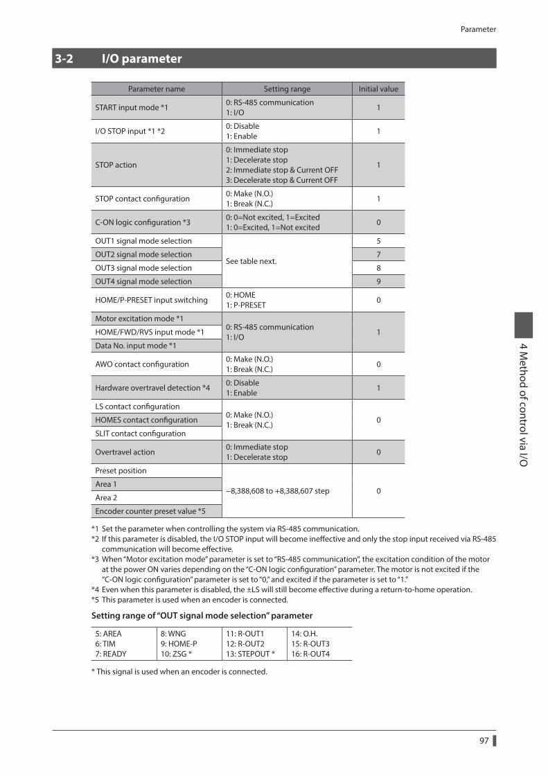
Parameter
97
4 Method of control via I/O
3-2 I/O parameter
Parameter name Setting range Initial value
START input mode *10: RS-485 communication 1: I/O
1
I/O STOP input *1 *20: Disable 1: Enable
1
STOP action
0: Immediate stop 1: Decelerate stop 2: Immediate stop & Current OFF 3: Decelerate stop & Current OFF
1
STOP contact configuration0: Make (N.O.) 1: Break (N.C.)
1
C-ON logic configuration *30: 0=Not excited, 1=Excited 1: 0=Excited, 1=Not excited
0
OUT1 signal mode selection
See table next.
5
OUT2 signal mode selection 7
OUT3 signal mode selection 8
OUT4 signal mode selection 9
HOME/P-PRESET input switching0: HOME 1: P-PRESET
0
Motor excitation mode *10: RS-485 communication 1: I/O
1HOME/FWD/RVS input mode *1
Data No. input mode *1
AWO contact configuration0: Make (N.O.) 1: Break (N.C.)
0
Hardware overtravel detection *40: Disable 1: Enable
1
LS contact configuration0: Make (N.O.) 1: Break (N.C.)
0HOMES contact configuration
SLIT contact configuration
Overtravel action0: Immediate stop 1: Decelerate stop
0
Preset position
−8,388,608 to +8,388,607 step 0Area 1
Area 2
Encoder counter preset value *5
*1 Set the parameter when controlling the system via RS-485 communication.*2 If this parameter is disabled, the I/O STOP input will become ineffective and only the stop input received via RS-485
communication will become effective.*3 When “Motor excitation mode” parameter is set to “RS-485 communication”, the excitation condition of the motor
at the power ON varies depending on the “C-ON logic configuration” parameter. The motor is not excited if the “C-ON logic configuration” parameter is set to “0,” and excited if the parameter is set to “1.”
*4 Even when this parameter is disabled, the ±LS will still become effective during a return-to-home operation.*5 This parameter is used when an encoder is connected.
Setting range of “OUT signal mode selection” parameter
5: AREA 6: TIM 7: READY
8: WNG 9: HOME-P 10: ZSG *
11: R-OUT1 12: R-OUT2 13: STEPOUT *
14: O.H. 15: R-OUT3 16: R-OUT4
* This signal is used when an encoder is connected.
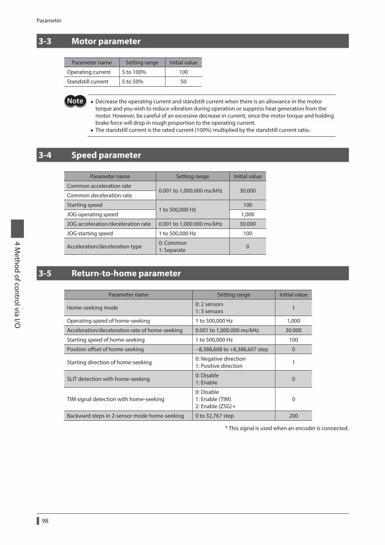
Parameter
98
4 Method of control via I/O
3-3 Motor parameter
Parameter name Setting range Initial value
Operating current 5 to 100% 100
Standstill current 5 to 50% 50
• Decrease the operating current and standstill current when there is an allowance in the motor torque and you wish to reduce vibration during operation or suppress heat generation from the motor. However, be careful of an excessive decrease in current, since the motor torque and holding brake force will drop in rough proportion to the operating current.
• The standstill current is the rated current (100%) multiplied by the standstill current ratio.
3-4 Speed parameter
Parameter name Setting range Initial value
Common acceleration rate0.001 to 1,000.000 ms/kHz 30.000
Common deceleration rate
Starting speed1 to 500,000 Hz
100
JOG operating speed 1,000
JOG acceleration/deceleration rate 0.001 to 1,000.000 ms/kHz 30.000
JOG starting speed 1 to 500,000 Hz 100
Acceleration/deceleration type0: Common 1: Separate
0
3-5 Return-to-home parameter
Parameter name Setting range Initial value
Home-seeking mode0: 2 sensors 1: 3 sensors
1
Operating speed of home-seeking 1 to 500,000 Hz 1,000
Acceleration/deceleration rate of home-seeking 0.001 to 1,000.000 ms/kHz 30.000
Starting speed of home-seeking 1 to 500,000 Hz 100
Position offset of home-seeking −8,388,608 to +8,388,607 step 0
Starting direction of home-seeking0: Negative direction 1: Positive direction
1
SLIT detection with home-seeking0: Disable 1: Enable
0
TIM signal detection with home-seeking0: Disable 1: Enable (TIM) 2: Enable (ZSG) ∗
0
Backward steps in 2-sensor mode home-seeking 0 to 32,767 step 200
* This signal is used when an encoder is connected.
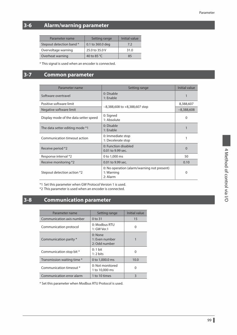
Parameter
99
4 Method of control via I/O
3-6 Alarm/warning parameter
Parameter name Setting range Initial value
Stepout detection band * 0.1 to 360.0 deg 7.2
Overvoltage warning 25.0 to 35.0 V 31.0
Overheat warning 40 to 85 °C 85
* This signal is used when an encoder is connected.
3-7 Common parameter
Parameter name Setting range Initial value
Software overtravel0: Disable 1: Enable
1
Positive software limit−8,388,608 to +8,388,607 step
8,388,607
Negative software limit −8,388,608
Display mode of the data setter speed0: Signed 1: Absolute
0
The data setter editing mode *10: Disable 1: Enable
1
Communication timeout action0: Immediate stop 1: Decelerate stop
1
Receive period *20: Function disabled 0.01 to 9.99 sec.
0
Response interval *2 0 to 1,000 ms 50
Receive monitoring *2 0.01 to 9.99 sec. 0.10
Stepout detection action *20: No operation (alarm/warning not present) 1: Warning 2: Alarm
0
*1 Set this parameter when GW Protocol Version 1 is used.*2 This parameter is used when an encoder is connected.
3-8 Communication parameter
Parameter name Setting range Initial value
Communication axis number 0 to 31 15
Communication protocol0: Modbus RTU 1: GW Ver.1
0
Communication parity *0: None 1: Even number 2: Odd number
1
Communication stop bit *0: 1 bit 1: 2 bits
0
Transmission waiting time * 0 to 1,000.0 ms 10.0
Communication timeout *0: Not monitored 1 to 10,000 ms
0
Communication error alarm 1 to 10 times 3
* Set this parameter when Modbus RTU Protocol is used.
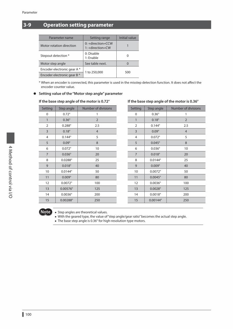
Parameter
100
4 Method of control via I/O
3-9 Operation setting parameter
Parameter name Setting range Initial value
Motor rotation direction0: +direction=CCW 1: +direction=CW
1
Stepout detection *0: Disable 1: Enable
0
Motor step angle See table next. 0
Encoder electronic gear A *1 to 250,000 500
Encoder electronic gear B *
* When an encoder is connected, this parameter is used in the misstep detection function. It does not affect the encoder counter value.
z Setting value of the “Motor step angle” parameter
If the base step angle of the motor is 0.72° If the base step angle of the motor is 0.36°
Setting Step angle Number of divisions Setting Step angle Number of divisions
0 0.72° 1 0 0.36° 1
1 0.36° 2 1 0.18° 2
2 0.288° 2.5 2 0.144° 2.5
3 0.18° 4 3 0.09° 4
4 0.144° 5 4 0.072° 5
5 0.09° 8 5 0.045° 8
6 0.072° 10 6 0.036° 10
7 0.036° 20 7 0.018° 20
8 0.0288° 25 8 0.0144° 25
9 0.018° 40 9 0.009° 40
10 0.0144° 50 10 0.0072° 50
11 0.009° 80 11 0.0045° 80
12 0.0072° 100 12 0.0036° 100
13 0.00576° 125 13 0.0028° 125
14 0.0036° 200 14 0.0018° 200
15 0.00288° 250 15 0.00144° 250
• Step angles are theoretical values. • With the geared type, the value of “step angle/gear ratio” becomes the actual step angle. • The base step angle is 0.36° for high-resolution type motors.
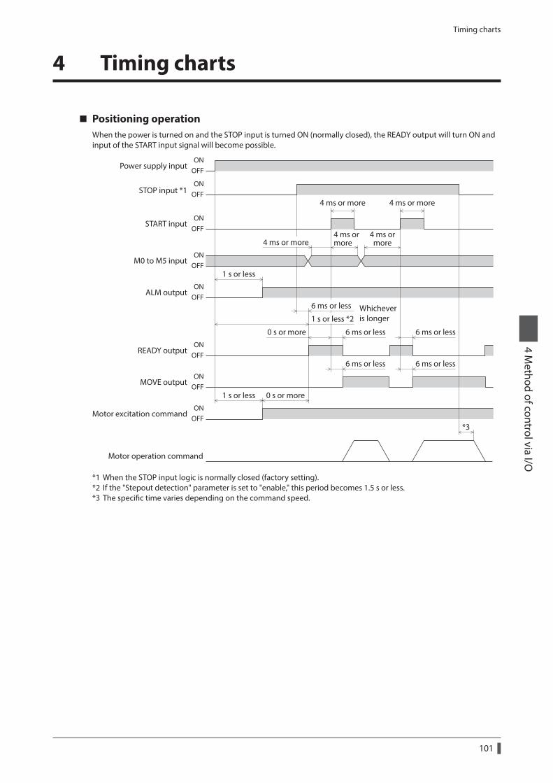
Timing charts
101
4 Method of control via I/O
4 Timing charts
Positioning operationWhen the power is turned on and the STOP input is turned ON (normally closed), the READY output will turn ON and input of the START input signal will become possible.
ONOFF
ONOFF
ONOFF
ONOFF
ONOFF
ONOFF
ONOFF
ONOFF
Power supply input
STOP input *1
START input
M0 to M5 input
Motor operation command
ALM output
READY output
MOVE output
Motor excitation command
1 s or less
*3
1 s or less
6 ms or less 6 ms or less
6 ms or less 6 ms or less
4 ms or more 4 ms or more
4 ms ormore
4 ms ormore
0 s or more
0 s or more
Whicheveris longer
6 ms or less
1 s or less *2
4 ms or more
*1 When the STOP input logic is normally closed (factory setting).*2 If the "Stepout detection" parameter is set to "enable," this period becomes 1.5 s or less.*3 The specific time varies depending on the command speed.
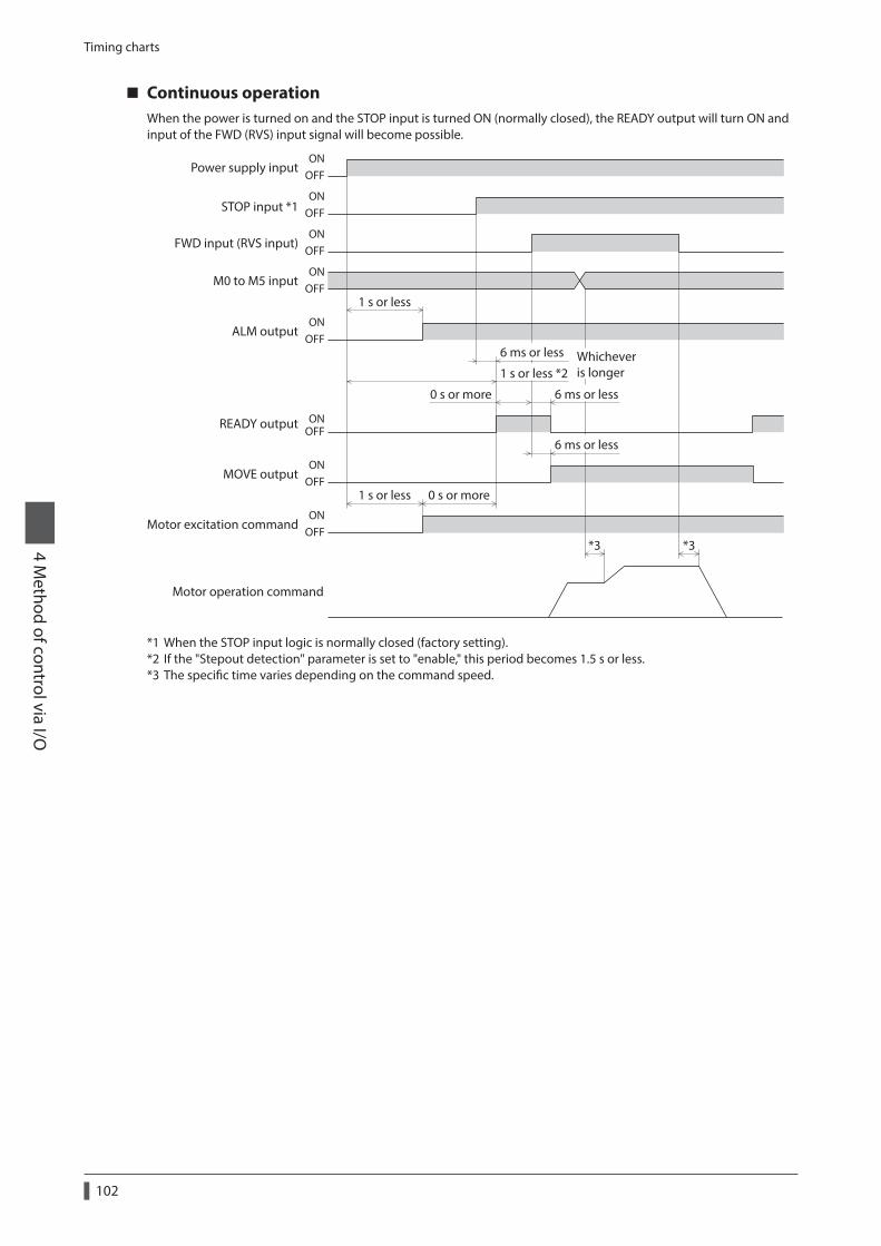
Timing charts
102
4 Method of control via I/O
Continuous operationWhen the power is turned on and the STOP input is turned ON (normally closed), the READY output will turn ON and input of the FWD (RVS) input signal will become possible.
ONOFF
ONOFF
ONOFF
ONOFF
ONOFF
ONOFF
ONOFF
ONOFF
Power supply input
STOP input *1
M0 to M5 input
ALM output
READY output
MOVE output
1 s or less
1 s or less
6 ms or less
*3 *3
0 s or more
0 s or more
6 ms or less
1 s or less *2
FWD input (RVS input)
6 ms or less
Whicheveris longer
Motor operation command
Motor excitation command
*1 When the STOP input logic is normally closed (factory setting).*2 If the "Stepout detection" parameter is set to "enable," this period becomes 1.5 s or less.*3 The specific time varies depending on the command speed.
5 Method of control via Modbus RTU (RS-485 communication)
This part explains how to control from the master controller via RS-485 communication. The protocol for the RS-485 communication is the Modbus protocol.
Table of contents
1 Guidance ...............................................104
2 Communication specifications .........106
3 Setting the switches ............................107
4 Setting the RS-485 communication ....................................109
5 Communication mode and communication timing .......................110
5-1 Communication mode ................................110
5-2 Communication timing ..............................110
6 Message.................................................1116-1 Query ................................................................111
6-2 Response..........................................................113
7 Function code .......................................1157-1 Reading from a holding register(s) .........115
7-2 Writing to a holding register ....................116
7-3 Diagnosis .........................................................116
7-4 Writing to multiple holding registers ....117
7-5 Control method selection ..........................118
8 Register address list ............................1198-1 Register address types ................................119
8-2 Operation area ...............................................120
8-3 Maintenance area .........................................123
8-4 Monitor area ...................................................124
8-5 Parameter area ...............................................126
8-6 Operation data area .....................................129
9 Group send ...........................................131
10 Detection of communication errors ......................................................133
10-1 Communication errors ...............................133
10-2 Alarms and warnings ..................................133
11 Timing charts .......................................134
12 Example of communication setting ....................................................136
12-1 Positioning operation ................................136
12-2 Continuous operation ................................138
12-3 Return-to-home operation ......................139
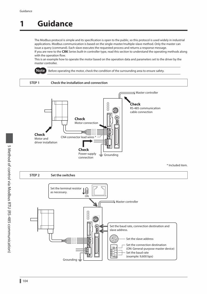
Guidance
104
5 Method of control via M
odbus RTU (RS-485 com
munication)
1 Guidance
The Modbus protocol is simple and its specification is open to the public, so this protocol is used widely in industrial applications. Modbus communication is based on the single-master/multiple-slave method. Only the master can issue a query (command). Each slave executes the requested process and returns a response message.If you are new to the CRK Series built-in controller type, read this section to understand the operating methods along with the operation flow.This is an example how to operate the motor based on the operation data and parameters set to the driver by the master controller.
Before operating the motor, check the condition of the surrounding area to ensure safety.
STEP 1 Check the installation and connection
CheckRS-485 communication cable connection
Master controller
CheckMotor connection
CheckMotor and driver installation
CheckPower supplyconnection
Grounding
CN4 connector lead wires *
* Included item.
STEP 2 Set the switches
Set the slave address
Set the connection destination(ON: General-purpose master device)Set the baud rate(example: 9,600 bps)
ON
Set the terminal resistoras necessary.
Master controller
Grounding
Set the baud rate, connection destination and slave address.
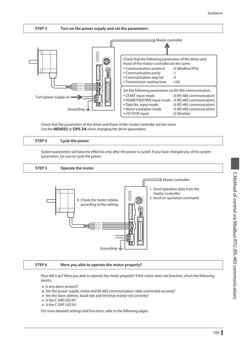
Guidance
105
5 Method of control via M
odbus RTU (RS-485 com
munication)
STEP 3 Turn on the power supply and set the parameters
Communication protocol : 0 (Modbus RTU) Communication parity : 1 Communication stop bit : 0 Transmission waiting time : 100
START input mode : 0 (RS-485 communication) HOME/FWD/RVS input mode : 0 (RS-485 communication) Data No. input mode : 0 (RS-485 communication) Motor excitation mode : 0 (RS-485 communication) I/O STOP input : 0 (Disable)
Set the following parameters via RS-485 communication.
Turn power supply on
Grounding
Master controller
Check that the following parameters of the driver and those of the master controller are the same.
Check that the parameters of the driver and those of the master controller are the same.Use the MEXE02 or OPX-2A when changing the driver parameters.
STEP 4 Cycle the power
System parameters will become effective only after the power is cycled. If you have changed any of the system parameters, be sure to cycle the power.
STEP 5 Operate the motor
1. Send operation data from the master controller.2. Send an operation command.3. Check the motor rotates
according to the setting.
Master controller
Grounding
STEP 6 Were you able to operate the motor properly?
How did it go? Were you able to operate the motor properly? If the motor does not function, check the following points:
• Is any alarm present? • Are the power supply, motor and RS-485 communication cable connected securely? • Are the slave address, baud rate and terminal resistor set correctly? • Is the C-ERR LED lit? • Is the C-DAT LED lit?
For more detailed settings and functions, refer to the following pages.
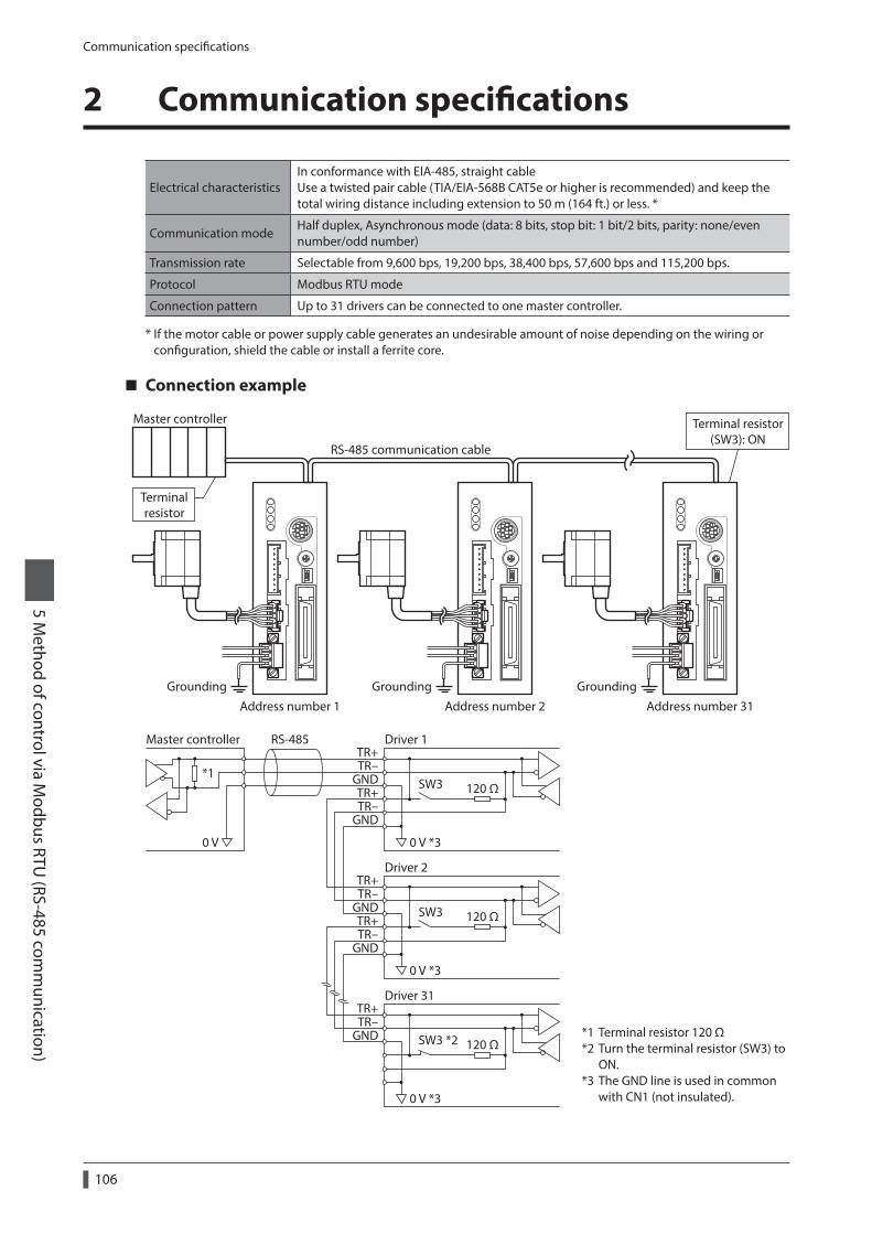
Communication specifications
106
5 Method of control via M
odbus RTU (RS-485 com
munication)
2 Communication specifications
Electrical characteristicsIn conformance with EIA-485, straight cable Use a twisted pair cable (TIA/EIA-568B CAT5e or higher is recommended) and keep the total wiring distance including extension to 50 m (164 ft.) or less. *
Communication modeHalf duplex, Asynchronous mode (data: 8 bits, stop bit: 1 bit/2 bits, parity: none/even number/odd number)
Transmission rate Selectable from 9,600 bps, 19,200 bps, 38,400 bps, 57,600 bps and 115,200 bps.
Protocol Modbus RTU mode
Connection pattern Up to 31 drivers can be connected to one master controller.
* If the motor cable or power supply cable generates an undesirable amount of noise depending on the wiring or configuration, shield the cable or install a ferrite core.
Connection example
RS-485 communication cable
Address number 1Grounding Grounding Grounding
Terminalresistor
Terminal resistor(SW3): ON
Address number 2 Address number 31
Master controller
TR+TR-
GNDTR+TR-
GND
TR+TR-
GND
TR+TR-
GND
TR+TR-
GND
120 Ω
0 V *30 V
SW3
Driver 1Master controller RS-485
*1
120 Ω
0 V *3
SW3
Driver 2
120 Ω
0 V *3
SW3 *2
Driver 31
*1 Terminal resistor 120 Ω*2 Turn the terminal resistor (SW3) to
ON.*3 The GND line is used in common
with CN1 (not insulated).
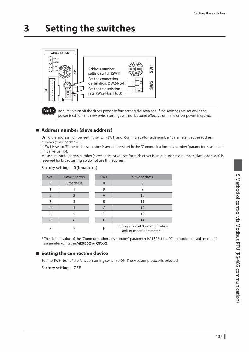
Setting the switches
107
5 Method of control via M
odbus RTU (RS-485 com
munication)
3 Setting the switches
Address numbersetting switch (SW1)
Set the transmissionrate. (SW2-Nos.1 to 3)
Set the connectiondestination. (SW2-No.4)
Be sure to turn off the driver power before setting the switches. If the switches are set while the power is still on, the new switch settings will not become effective until the driver power is cycled.
Address number (slave address)Using the address number setting switch (SW1) and “Communication axis number” parameter, set the address number (slave address).If SW1 is set to “F,” the address number (slave address) set in the “Communication axis number” parameter is selected (initial value: 15).Make sure each address number (slave address) you set for each driver is unique. Address number (slave address) 0 is reserved for broadcasting, so do not use this address.
Factory setting 0 (broadcast)
SW1 Slave address SW1 Slave address
0 Broadcast 8 8
1 1 9 9
2 2 A 10
3 3 B 11
4 4 C 12
5 5 D 13
6 6 E 14
7 7 FSetting value of “Communication
axis number” parameter ∗
* The default value of the “Communication axis number” parameter is “15.” Set the “Communication axis number” parameter using the MEXE02 or OPX-2.
Setting the connection deviceSet the SW2-No.4 of the function setting switch to ON. The Modbus protocol is selected.
Factory setting OFF
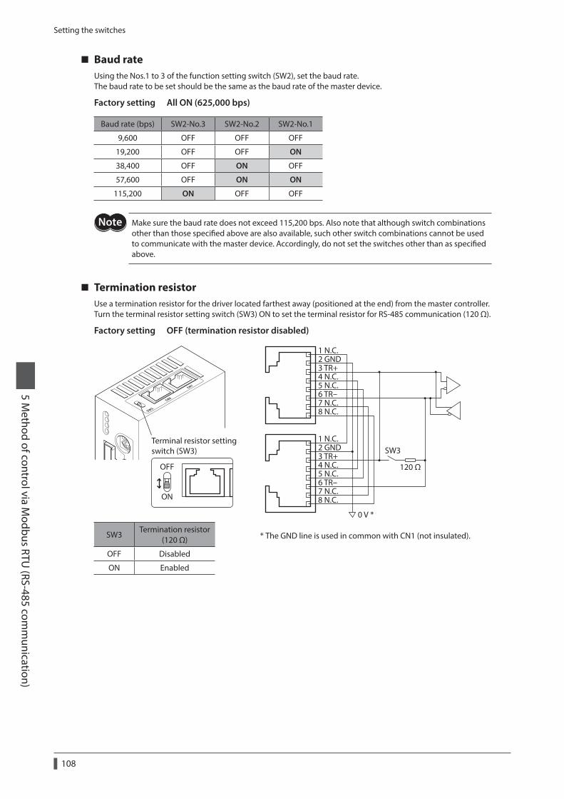
Setting the switches
108
5 Method of control via M
odbus RTU (RS-485 com
munication)
Baud rateUsing the Nos.1 to 3 of the function setting switch (SW2), set the baud rate.The baud rate to be set should be the same as the baud rate of the master device.
Factory setting All ON (625,000 bps)
Baud rate (bps) SW2-No.3 SW2-No.2 SW2-No.1
9,600 OFF OFF OFF
19,200 OFF OFF ON
38,400 OFF ON OFF
57,600 OFF ON ON
115,200 ON OFF OFF
Make sure the baud rate does not exceed 115,200 bps. Also note that although switch combinations other than those specified above are also available, such other switch combinations cannot be used to communicate with the master device. Accordingly, do not set the switches other than as specified above.
Termination resistorUse a termination resistor for the driver located farthest away (positioned at the end) from the master controller.Turn the terminal resistor setting switch (SW3) ON to set the terminal resistor for RS-485 communication (120 Ω).
Factory setting OFF (termination resistor disabled)
Terminal resistor settingswitch (SW3)
ON
OFF
1 N.C.2 GND3 TR+4 N.C.5 N.C.6 TR-7 N.C.8 N.C.
1 N.C.2 GND3 TR+4 N.C.5 N.C.6 TR-7 N.C.8 N.C.
120 Ω
0 V *
SW3
* The GND line is used in common with CN1 (not insulated).SW3Termination resistor
(120 Ω)
OFF Disabled
ON Enabled
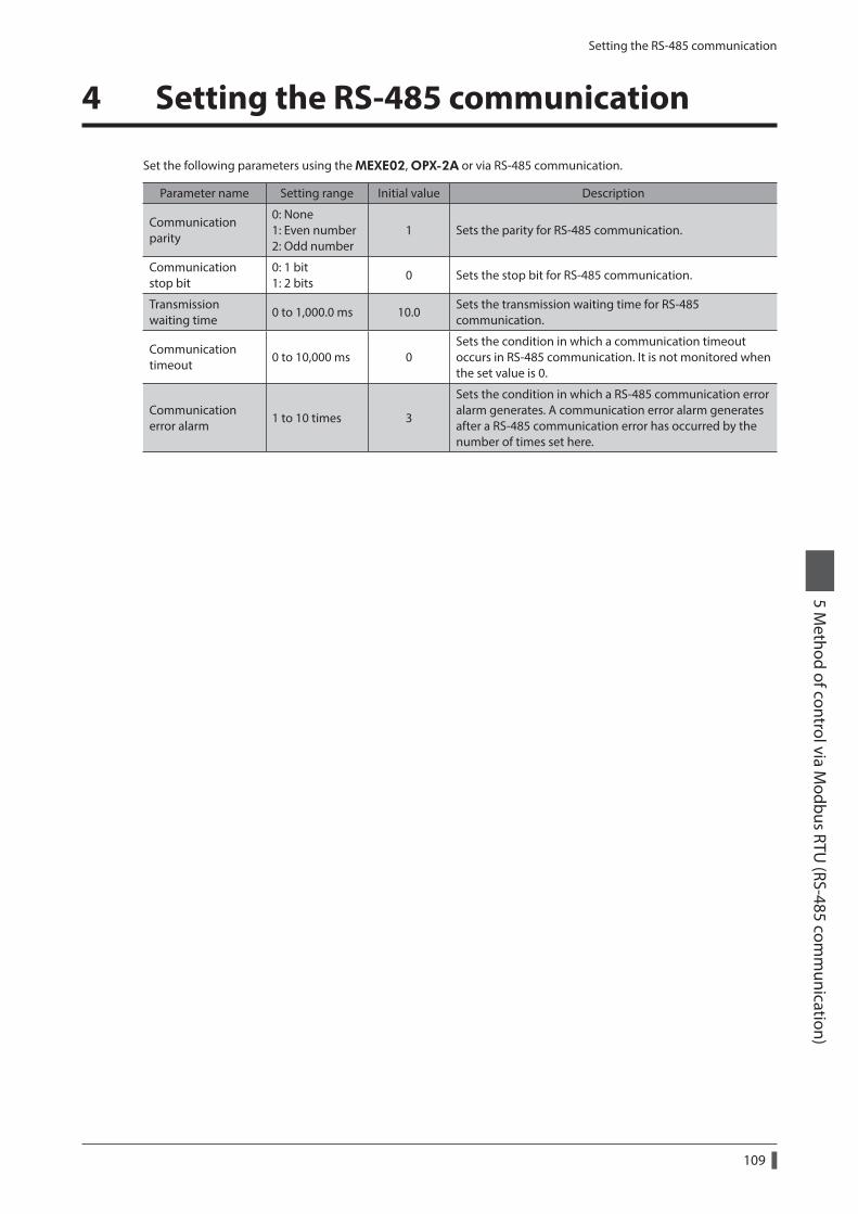
Setting the RS-485 communication
109
5 Method of control via M
odbus RTU (RS-485 com
munication)
4 Setting the RS-485 communication
Set the following parameters using the MEXE02, OPX-2A or via RS-485 communication.
Parameter name Setting range Initial value Description
Communication parity
0: None 1: Even number 2: Odd number
1 Sets the parity for RS-485 communication.
Communication stop bit
0: 1 bit 1: 2 bits
0 Sets the stop bit for RS-485 communication.
Transmission waiting time
0 to 1,000.0 ms 10.0Sets the transmission waiting time for RS-485 communication.
Communication timeout
0 to 10,000 ms 0Sets the condition in which a communication timeout occurs in RS-485 communication. It is not monitored when the set value is 0.
Communication error alarm
1 to 10 times 3
Sets the condition in which a RS-485 communication error alarm generates. A communication error alarm generates after a RS-485 communication error has occurred by the number of times set here.
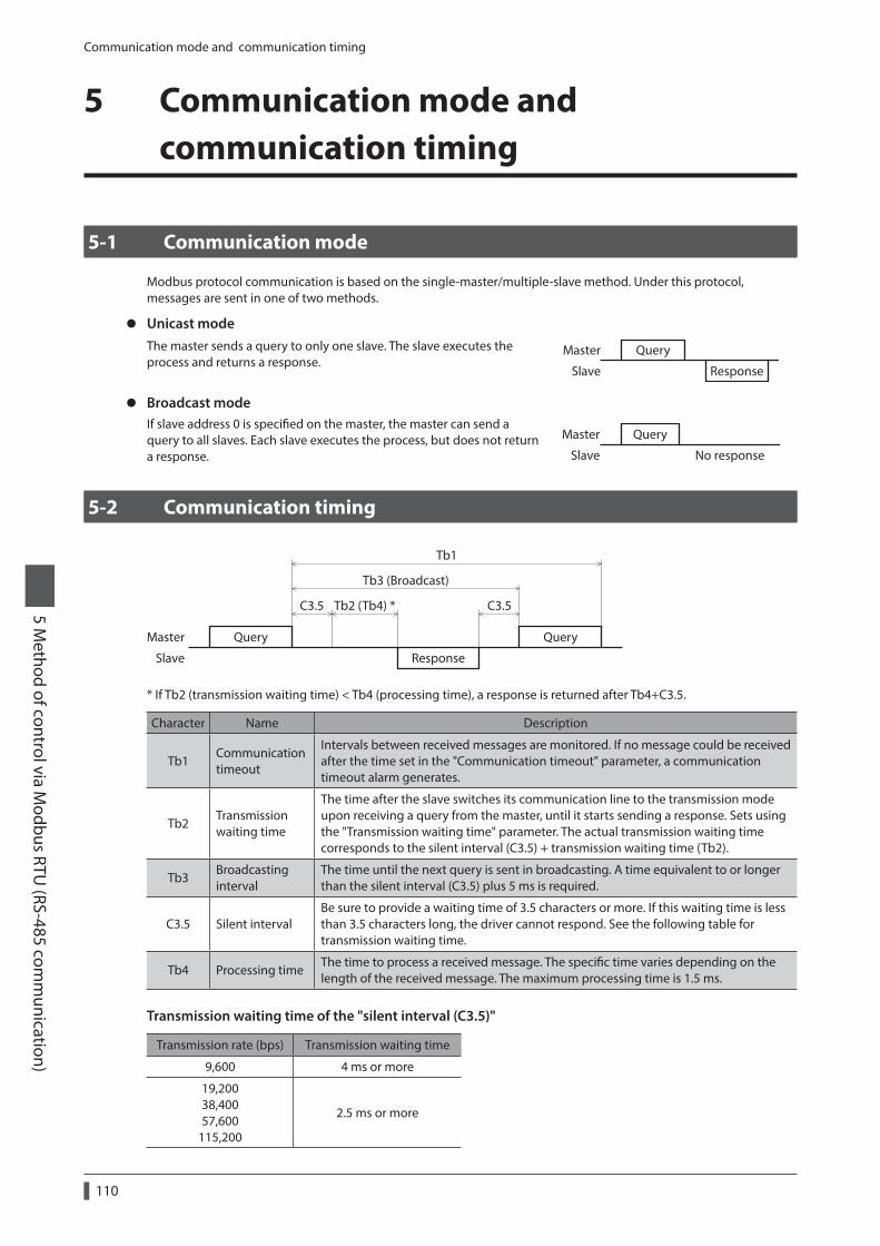
Communication mode and communication timing
110
5 Method of control via M
odbus RTU (RS-485 com
munication)
5 Communication mode and communication timing
5-1 Communication mode
Modbus protocol communication is based on the single-master/multiple-slave method. Under this protocol, messages are sent in one of two methods.
z Unicast modeThe master sends a query to only one slave. The slave executes the process and returns a response.
Query
Response
Master
Slave
z Broadcast modeIf slave address 0 is specified on the master, the master can send a query to all slaves. Each slave executes the process, but does not return a response. No response
QueryMaster
Slave
5-2 Communication timing
Query
Tb2 (Tb4) * C3.5C3.5
Tb3 (Broadcast)
Tb1
Query
Response
Master
Slave
* If Tb2 (transmission waiting time) < Tb4 (processing time), a response is returned after Tb4+C3.5.
Character Name Description
Tb1Communication timeout
Intervals between received messages are monitored. If no message could be received after the time set in the "Communication timeout" parameter, a communication timeout alarm generates.
Tb2Transmission waiting time
The time after the slave switches its communication line to the transmission mode upon receiving a query from the master, until it starts sending a response. Sets using the "Transmission waiting time" parameter. The actual transmission waiting time corresponds to the silent interval (C3.5) + transmission waiting time (Tb2).
Tb3Broadcasting interval
The time until the next query is sent in broadcasting. A time equivalent to or longer than the silent interval (C3.5) plus 5 ms is required.
C3.5 Silent intervalBe sure to provide a waiting time of 3.5 characters or more. If this waiting time is less than 3.5 characters long, the driver cannot respond. See the following table for transmission waiting time.
Tb4 Processing timeThe time to process a received message. The specific time varies depending on the length of the received message. The maximum processing time is 1.5 ms.
Transmission waiting time of the "silent interval (C3.5)"
Transmission rate (bps) Transmission waiting time
9,600 4 ms or more
19,200 38,400 57,600
115,200
2.5 ms or more
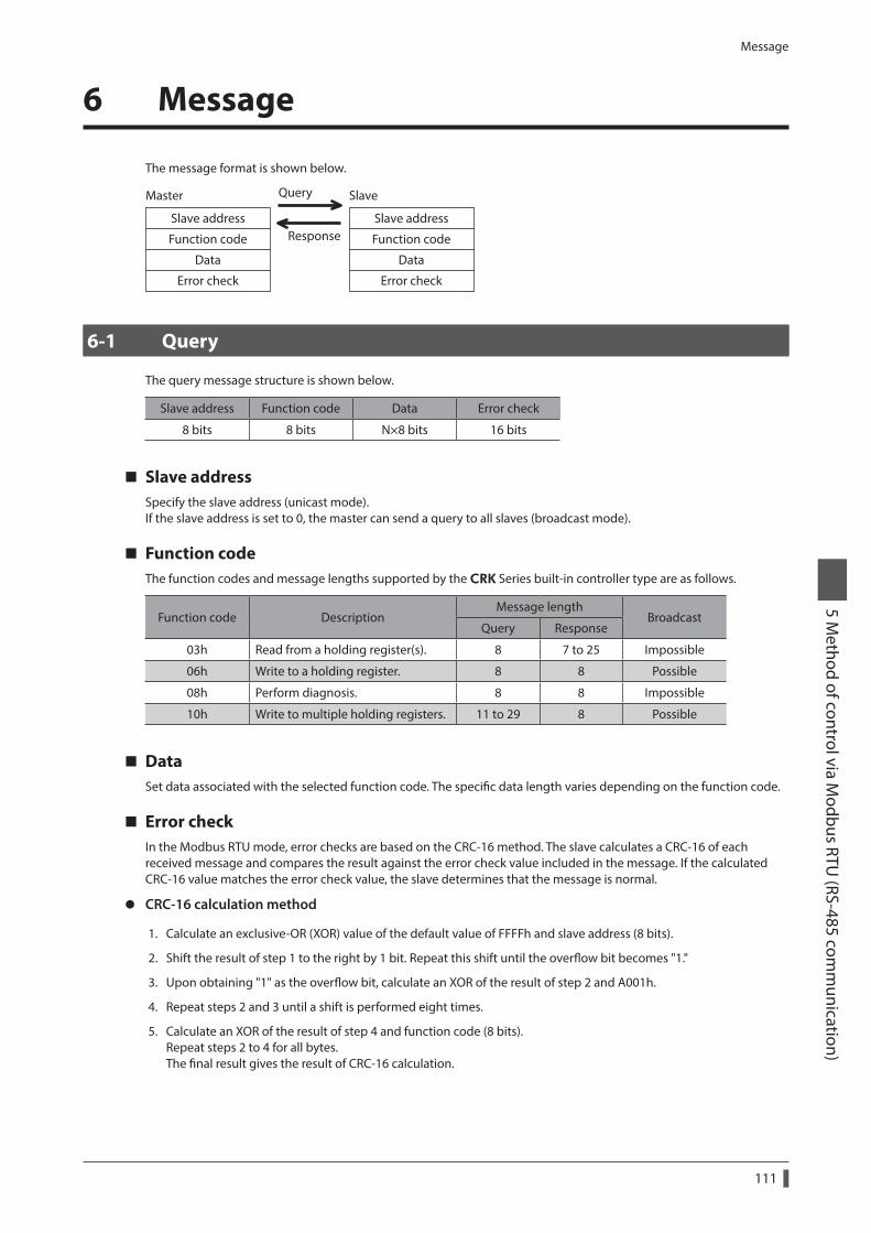
Message
111
5 Method of control via M
odbus RTU (RS-485 com
munication)
6 Message
The message format is shown below.
Slave address
Function code
Data
Error check
Slave address
Function code
Data
Error check
Master Query
Response
Slave
6-1 Query
The query message structure is shown below.
Slave address Function code Data Error check
8 bits 8 bits N×8 bits 16 bits
Slave addressSpecify the slave address (unicast mode).If the slave address is set to 0, the master can send a query to all slaves (broadcast mode).
Function codeThe function codes and message lengths supported by the CRK Series built-in controller type are as follows.
Function code DescriptionMessage length
BroadcastQuery Response
03h Read from a holding register(s). 8 7 to 25 Impossible
06h Write to a holding register. 8 8 Possible
08h Perform diagnosis. 8 8 Impossible
10h Write to multiple holding registers. 11 to 29 8 Possible
DataSet data associated with the selected function code. The specific data length varies depending on the function code.
Error checkIn the Modbus RTU mode, error checks are based on the CRC-16 method. The slave calculates a CRC-16 of each received message and compares the result against the error check value included in the message. If the calculated CRC-16 value matches the error check value, the slave determines that the message is normal.
z CRC-16 calculation method
1. Calculate an exclusive-OR (XOR) value of the default value of FFFFh and slave address (8 bits).
2. Shift the result of step 1 to the right by 1 bit. Repeat this shift until the overflow bit becomes "1."
3. Upon obtaining "1" as the overflow bit, calculate an XOR of the result of step 2 and A001h.
4. Repeat steps 2 and 3 until a shift is performed eight times.
5. Calculate an XOR of the result of step 4 and function code (8 bits).Repeat steps 2 to 4 for all bytes.The final result gives the result of CRC-16 calculation.
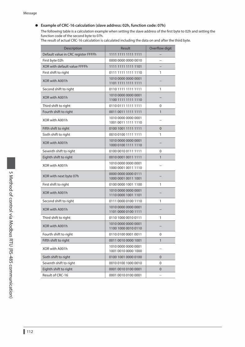
Message
112
5 Method of control via M
odbus RTU (RS-485 com
munication)
z Example of CRC-16 calculation (slave address: 02h, function code: 07h)The following table is a calculation example when setting the slave address of the first byte to 02h and setting the function code of the second byte to 07h.The result of actual CRC-16 calculation is calculated including the data on and after the third byte.
Description Result Overflow digit
Default value in CRC register FFFFh 1111 1111 1111 1111 −
First byte 02h 0000 0000 0000 0010 −
XOR with default value FFFFh 1111 1111 1111 1101 −
First shift to right 0111 1111 1111 1110 1
XOR with A001h1010 0000 0000 0001 1101 1111 1111 1111
−
Second shift to right 0110 1111 1111 1111 1
XOR with A001h1010 0000 0000 0001 1100 1111 1111 1110
−
Third shift to right 0110 0111 1111 1111 0
Fourth shift to right 0011 0011 1111 1111 1
XOR with A001h1010 0000 0000 0001 1001 0011 1111 1110
−
Fifth shift to right 0100 1001 1111 1111 0
Sixth shift to right 0010 0100 1111 1111 1
XOR with A001h1010 0000 0000 0001 1000 0100 1111 1110
−
Seventh shift to right 0100 0010 0111 1111 0
Eighth shift to right 0010 0001 0011 1111 1
XOR with A001h1010 0000 0000 0001 1000 0001 0011 1110
−
XOR with next byte 07h0000 0000 0000 0111 1000 0001 0011 1001
−
First shift to right 0100 0000 1001 1100 1
XOR with A001h1010 0000 0000 0001 1110 0000 1001 1101
−
Second shift to right 0111 0000 0100 1110 1
XOR with A001h1010 0000 0000 0001 1101 0000 0100 1111
−
Third shift to right 0110 1000 0010 0111 1
XOR with A001h1010 0000 0000 0001 1100 1000 0010 0110
−
Fourth shift to right 0110 0100 0001 0011 0
Fifth shift to right 0011 0010 0000 1001 1
XOR with A001h1010 0000 0000 0001 1001 0010 0000 1000
−
Sixth shift to right 0100 1001 0000 0100 0
Seventh shift to right 0010 0100 1000 0010 0
Eighth shift to right 0001 0010 0100 0001 0
Result of CRC-16 0001 0010 0100 0001 −
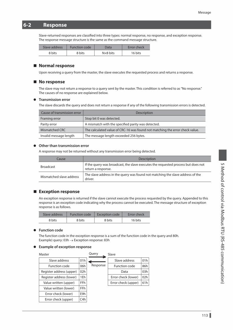
Message
113
5 Method of control via M
odbus RTU (RS-485 com
munication)
6-2 Response
Slave-returned responses are classified into three types: normal response, no response, and exception response.The response message structure is the same as the command message structure.
Slave address Function code Data Error check
8 bits 8 bits N×8 bits 16 bits
Normal responseUpon receiving a query from the master, the slave executes the requested process and returns a response.
No responseThe slave may not return a response to a query sent by the master. This condition is referred to as "No response."The causes of no response are explained below.
z Transmission errorThe slave discards the query and does not return a response if any of the following transmission errors is detected.
Cause of transmission error Description
Framing error Stop bit 0 was detected.
Parity error A mismatch with the specified parity was detected.
Mismatched CRC The calculated value of CRC-16 was found not matching the error check value.
Invalid message length The message length exceeded 256 bytes.
z Other than transmission errorA response may not be returned without any transmission error being detected.
Cause Description
BroadcastIf the query was broadcast, the slave executes the requested process but does not return a response.
Mismatched slave addressThe slave address in the query was found not matching the slave address of the driver.
Exception responseAn exception response is returned if the slave cannot execute the process requested by the query. Appended to this response is an exception code indicating why the process cannot be executed. The message structure of exception response is as follows.
Slave address Function code Exception code Error check
8 bits 8 bits 8 bits 16 bits
z Function codeThe function code in the exception response is a sum of the function code in the query and 80h.Example) query: 03h → Exception response: 83h
z Example of exception response
01h
06h
Register address (upper) 02h
E9h
C4h
01h
86h
03h
Register address (lower) 1Eh
Value written (upper) FFh
Value written (lower) FFh
02h
Error check (upper) 61h
Query
ResponseSlave address
Function code
Slave address
Function code
Data
Error check (lower)
Error check (lower)
Master Slave
Error check (upper)
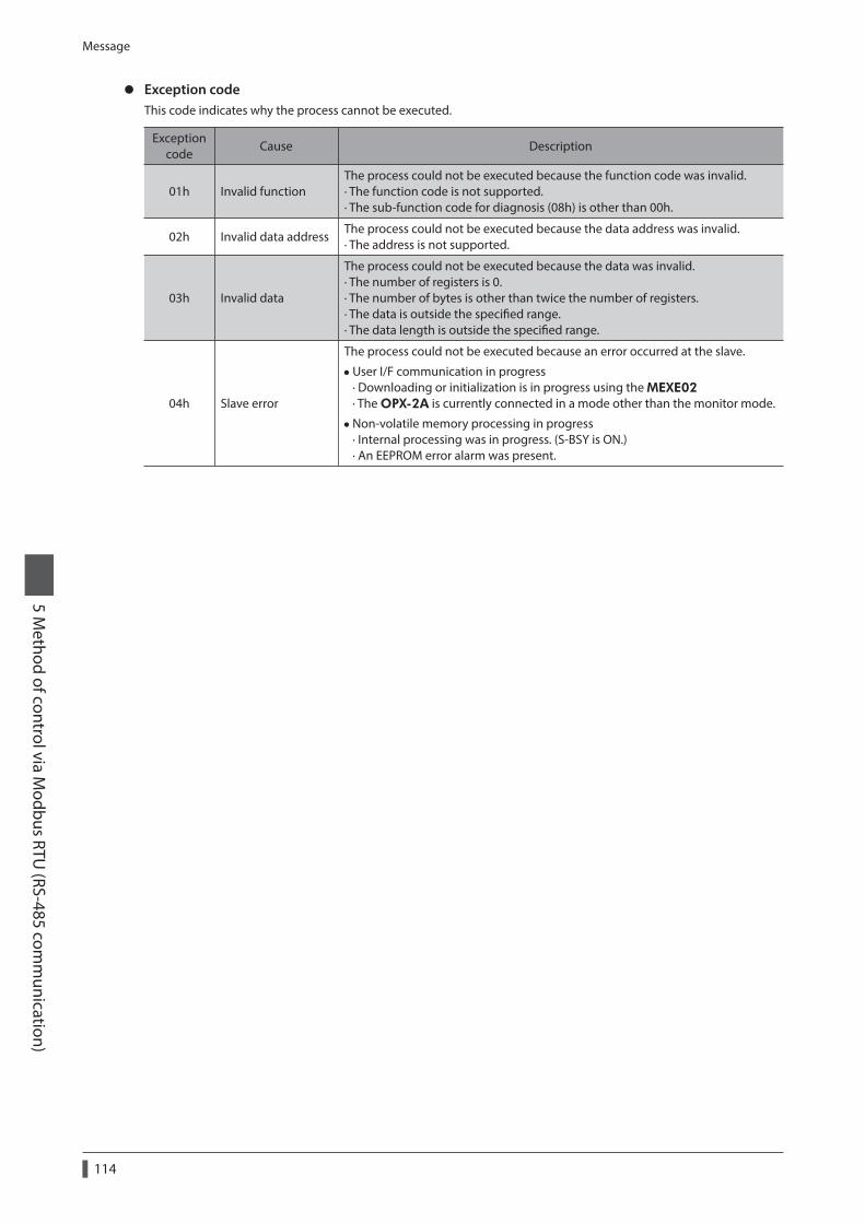
Message
114
5 Method of control via M
odbus RTU (RS-485 com
munication)
z Exception codeThis code indicates why the process cannot be executed.
Exception code
Cause Description
01h Invalid functionThe process could not be executed because the function code was invalid. · The function code is not supported. · The sub-function code for diagnosis (08h) is other than 00h.
02h Invalid data addressThe process could not be executed because the data address was invalid. · The address is not supported.
03h Invalid data
The process could not be executed because the data was invalid. · The number of registers is 0. · The number of bytes is other than twice the number of registers. · The data is outside the specified range. · The data length is outside the specified range.
04h Slave error
The process could not be executed because an error occurred at the slave.
•User I/F communication in progress · Downloading or initialization is in progress using the MEXE02 · The OPX-2A is currently connected in a mode other than the monitor mode.
•Non-volatile memory processing in progress · Internal processing was in progress. (S-BSY is ON.) · An EEPROM error alarm was present.
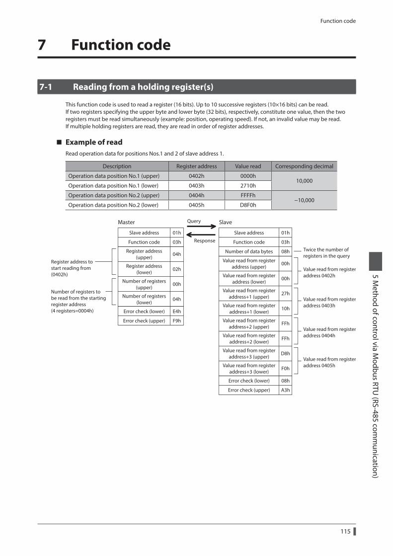
Function code
115
5 Method of control via M
odbus RTU (RS-485 com
munication)
7 Function code
7-1 Reading from a holding register(s)
This function code is used to read a register (16 bits). Up to 10 successive registers (10×16 bits) can be read.If two registers specifying the upper byte and lower byte (32 bits), respectively, constitute one value, then the two registers must be read simultaneously (example: position, operating speed). If not, an invalid value may be read.If multiple holding registers are read, they are read in order of register addresses.
Example of readRead operation data for positions Nos.1 and 2 of slave address 1.
Description Register address Value read Corresponding decimal
Operation data position No.1 (upper) 0402h 0000h10,000
Operation data position No.1 (lower) 0403h 2710h
Operation data position No.2 (upper) 0404h FFFFh−10,000
Operation data position No.2 (lower) 0405h D8F0h
Register address to start reading from (0402h)
Value read from registeraddress 0402h
Twice the number of registers in the query
Number of registers to be read from the starting register address (4 registers=0004h)
Query
Response
Value read from registeraddress 0403h
Value read from registeraddress 0404h
Value read from registeraddress 0405h
01h
03h
01h
03h
Number of data bytes 08h
E4h
F9h
08h
A3h
Value read from registeraddress (upper)
00h
Value read from registeraddress (lower)
00h
Value read from registeraddress+1 (upper)
27h
Value read from registeraddress+1 (lower)
10h
Value read from registeraddress+2 (upper)
FFh
Value read from registeraddress+2 (lower)
FFh
Value read from registeraddress+3 (upper)
D8h
Value read from registeraddress+3 (lower)
F0h
04h
02h
Number of registers(upper)
00h
Number of registers(lower)
04h
Register address(upper)
Register address(lower)
Error check (upper)
Slave address
Function code
Slave address
Function code
Error check (lower)
Error check (lower)
Master Slave
Error check (upper)
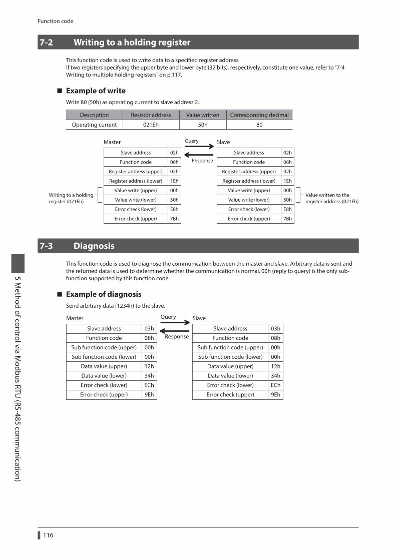
Function code
116
5 Method of control via M
odbus RTU (RS-485 com
munication)
7-2 Writing to a holding register
This function code is used to write data to a specified register address.If two registers specifying the upper byte and lower byte (32 bits), respectively, constitute one value, refer to “7-4 Writing to multiple holding registers” on p.117.
Example of writeWrite 80 (50h) as operating current to slave address 2.
Description Resistor address Value written Corresponding decimal
Operating current 021Eh 50h 80
02h
06h
02h
E8h
7Bh
02h
06h
1Eh
Value write (upper) 00h
Value write (lower)
Value write (upper)
Value write (lower)50h
Register address (upper) 02h
Register address (lower) 1Eh
00h
50h
E8h
7Bh
Query
Response
Register address (upper)
Register address (lower)
Slave address
Function code
Slave address
Function code
Error check (lower)
Master Slave
Error check (upper)
Error check (lower)
Error check (upper)
Writing to a holding register (021Eh)
Value written to the register address (021Eh)
7-3 Diagnosis
This function code is used to diagnose the communication between the master and slave. Arbitrary data is sent and the returned data is used to determine whether the communication is normal. 00h (reply to query) is the only sub-function supported by this function code.
Example of diagnosisSend arbitrary data (1234h) to the slave.
03h
08h
00h
ECh
9Eh
00h
12h
34h
03h
08h
00h
ECh
9Eh
00h
12h
34h
Sub function code (upper)
Sub function code (lower)
Error check (upper)
Query
ResponseSlave address
Function code
Slave address
Function code
Sub function code (upper)
Sub function code (lower)
Data value (upper)
Data value (lower)
Data value (upper)
Data value (lower)
Error check (lower)Error check (lower)
Master Slave
Error check (upper)
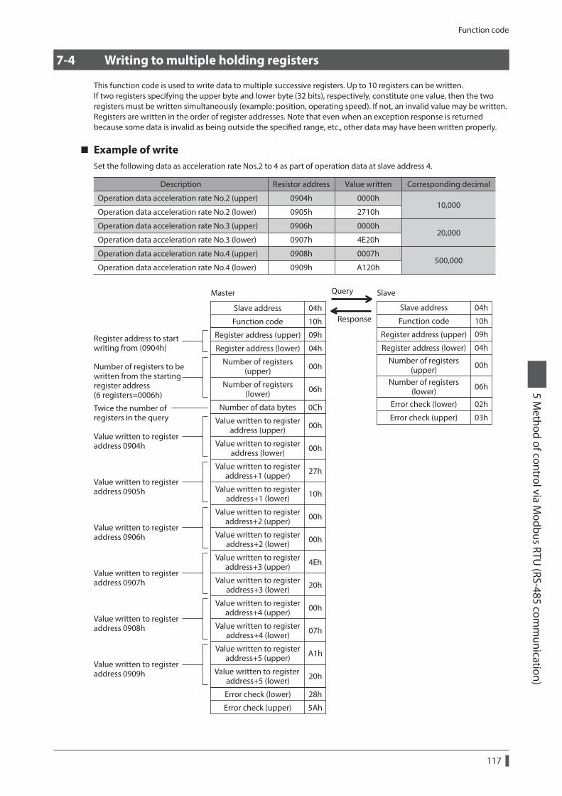
Function code
117
5 Method of control via M
odbus RTU (RS-485 com
munication)
7-4 Writing to multiple holding registers
This function code is used to write data to multiple successive registers. Up to 10 registers can be written.If two registers specifying the upper byte and lower byte (32 bits), respectively, constitute one value, then the two registers must be written simultaneously (example: position, operating speed). If not, an invalid value may be written.Registers are written in the order of register addresses. Note that even when an exception response is returned because some data is invalid as being outside the specified range, etc., other data may have been written properly.
Example of writeSet the following data as acceleration rate Nos.2 to 4 as part of operation data at slave address 4.
Description Resistor address Value written Corresponding decimal
Operation data acceleration rate No.2 (upper) 0904h 0000h10,000
Operation data acceleration rate No.2 (lower) 0905h 2710h
Operation data acceleration rate No.3 (upper) 0906h 0000h20,000
Operation data acceleration rate No.3 (lower) 0907h 4E20h
Operation data acceleration rate No.4 (upper) 0908h 0007h500,000
Operation data acceleration rate No.4 (lower) 0909h A120h
Register address to start writing from (0904h)
Value written to register address 0904h
Master Query
Response
Slave
Value written to register address 0905h
Value written to register address 0906h
Value written to register address 0907h
Value written to register address 0908h
Value written to register address 0909h
04hSlave address 04h
Function code 10h
Number of data bytes 0Ch
Error check (lower) 28h
Error check (upper)
Error check (lower)
Error check (upper)
5Ah
02h
03hValue written to registeraddress (upper) 00h
Value written to registeraddress (lower) 00h
Value written to registeraddress+1 (upper) 27h
Value written to registeraddress+1 (lower) 10h
Value written to registeraddress+2 (upper) 00h
Value written to registeraddress+2 (lower) 00h
Value written to registeraddress+3 (upper) 4Eh
Value written to registeraddress+3 (lower) 20h
Value written to registeraddress+4 (upper) 00h
Value written to registeraddress+4 (lower) 07h
Value written to registeraddress+5 (upper) A1h
Value written to register address+5 (lower) 20h
Register address (upper) 09h
Register address (lower)
Slave address
Function code
Register address (upper)
Register address (lower)04h
Number of registers(upper) 00h
Number of registers(lower) 06h
10h
09h
04h
Number of registers(upper) 00h
Number of registers(lower) 06h
Twice the number of registers in the query
Number of registers to be written from the starting register address (6 registers=0006h)
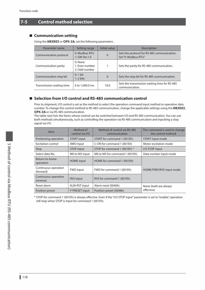
Function code
118
5 Method of control via M
odbus RTU (RS-485 com
munication)
7-5 Control method selection
Communication settingUsing the MEXE02 or OPX-2A, set the following parameters .
Parameter name Setting range Initial value Description
Communication protocol0: Modbus RTU 1: GW Ver.1.0
0Sets the protocol for RS-485 communication. Set “0: Modbus RTU.”
Communication parity0: None 1: Even number 2: Odd number
1 Sets the parity for RS-485 communication.
Communication stop bit0: 1 bit 1: 2 bits
0 Sets the stop bit for RS-485 communication.
Transmission waiting time 0 to 1,000.0 ms 10.0Sets the transmission waiting time for RS-485 communication.
Selection from I/O control and RS-485 communication controlPrior to shipment, I/O control is set as the method to select the operation command input method or operation data number. To change this control method to RS-485 communication, change the applicable settings using the MEXE02, OPX-2A or via RS-485 communication.The table next lists the items whose control can be switched between I/O and RS-485 communication. You can use both methods simultaneously, such as controlling the operation via RS-485 communication and inputting a stop signal via I/O.
ItemMethod of
control via I/OMethod of control via RS-485
communicationThis command is used to change
the control method.
Positioning operation START input START for command 1 (001Eh) START input mode
Excitation control AWO input C-ON for command 1 (001Eh) Motor excitation mode
Stop STOP input STOP for command 1 (001Eh) * I/O STOP input
Select data No. M0 to M5 input M0 to M5 for command 1 (001Eh) Data number input mode
Return-to-home operation
HOME input HOME for command 1 (001Eh)
HOME/FWD/RVS input modeContinuous operation (forward)
FWD input FWD for command 1 (001Eh)
Continuous operation (reverse)
RVS input RVS for command 1 (001Eh)
Reset alarm ALM-RST input Alarm reset (0040h) None (both are always effective)Position preset P-PRESET input Position preset (0048h)
* STOP for command 1 (001Eh) is always effective. Even if the “I/O STOP input” parameter is set to “enable,” operation still stop when STOP is input for command 1 (001Eh).
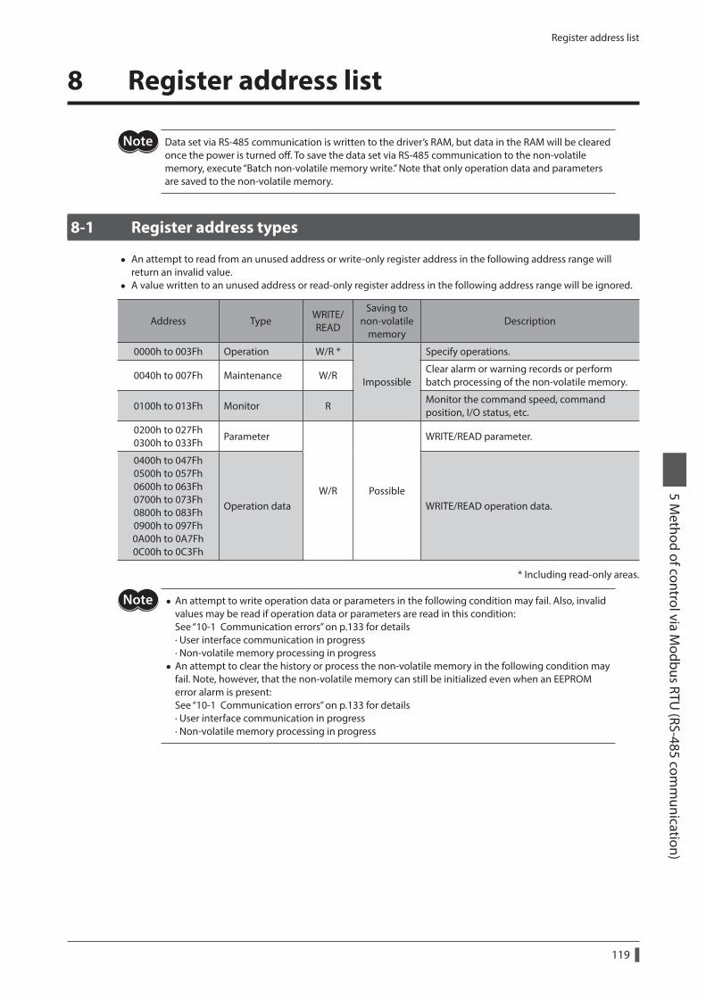
Register address list
119
5 Method of control via M
odbus RTU (RS-485 com
munication)
8 Register address list
Data set via RS-485 communication is written to the driver’s RAM, but data in the RAM will be cleared once the power is turned off. To save the data set via RS-485 communication to the non-volatile memory, execute “Batch non-volatile memory write.” Note that only operation data and parameters are saved to the non-volatile memory.
8-1 Register address types
• An attempt to read from an unused address or write-only register address in the following address range will return an invalid value.
• A value written to an unused address or read-only register address in the following address range will be ignored.
Address TypeWRITE/READ
Saving to non-volatile
memoryDescription
0000h to 003Fh Operation W/R *
Impossible
Specify operations.
0040h to 007Fh Maintenance W/RClear alarm or warning records or perform batch processing of the non-volatile memory.
0100h to 013Fh Monitor RMonitor the command speed, command position, I/O status, etc.
0200h to 027Fh 0300h to 033Fh
Parameter
W/R Possible
WRITE/READ parameter.
0400h to 047Fh 0500h to 057Fh 0600h to 063Fh 0700h to 073Fh 0800h to 083Fh 0900h to 097Fh 0A00h to 0A7Fh 0C00h to 0C3Fh
Operation data WRITE/READ operation data.
* Including read-only areas.
• An attempt to write operation data or parameters in the following condition may fail. Also, invalid values may be read if operation data or parameters are read in this condition: See “10-1 Communication errors” on p.133 for details · User interface communication in progress · Non-volatile memory processing in progress
• An attempt to clear the history or process the non-volatile memory in the following condition may fail. Note, however, that the non-volatile memory can still be initialized even when an EEPROM error alarm is present: See “10-1 Communication errors” on p.133 for details · User interface communication in progress · Non-volatile memory processing in progress
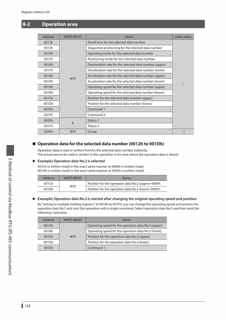
Register address list
120
5 Method of control via M
odbus RTU (RS-485 com
munication)
8-2 Operation area
Address WRITE/READ Name Initial value
0012h
W/R
Dwell time for the selected data number
−
0013h Sequential positioning for the selected data number
0014h Operating mode for the selected data number
0015h Positioning mode for the selected data number
0016h Deceleration rate for the selected data number (upper)
0017h Deceleration rate for the selected data number (lower)
0018h Acceleration rate for the selected data number (upper)
0019h Acceleration rate for the selected data number (lower)
001Ah Operating speed for the selected data number (upper)
001Bh Operating speed for the selected data number (lower)
001Ch Position for the selected data number (upper)
001Dh Position for the selected data number (lower)
001Eh Command 1
001Fh Command 2
0020hR
Status 1
0021h Status 2
0030h W/R Group −1
Operation data for the selected data number (0012h to 001Dh)Operation data is read or written from/to the selected data number indirectly.The actual area to be read or written in this operation is the area where the operation data is stored.
z Example) Operation data No.2 is selected001Ch is written (read) in the exact same manner as 0404h is written (read).001Dh is written (read) in the exact same manner as 0405h is written (read).
Address WRITE/READ Name
001ChW/R
Position for the operation data No.2 (upper)=0404h
001Dh Position for the operation data No.2 (lower)=0405h
z Example) Operation data No.3 is started after changing the original operating speed and positionBy “writing to multiple holding registers” at 001Ah to 001Fh, you can change the operating speed and position for operation data No.3 and start the operation with a single command. Select operation data No.3 and then send the following command.
Address WRITE/READ Name
001Ah
W/R
Operating speed for the operation data No.3 (upper)
001Bh Operating speed for the operation data No.3 (lower)
001Ch Position for the operation data No.3 (upper)
001Dh Position for the operation data No.3 (lower)
001Eh Command 1
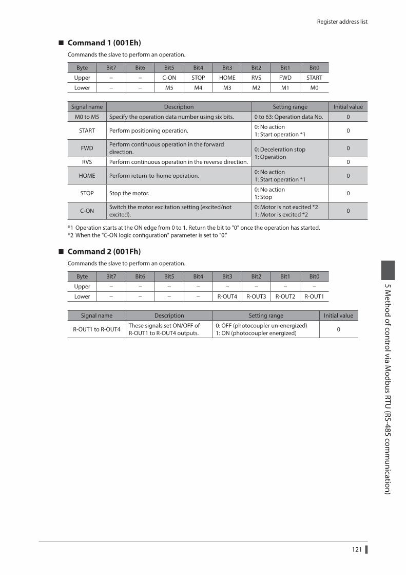
Register address list
121
5 Method of control via M
odbus RTU (RS-485 com
munication)
Command 1 (001Eh)Commands the slave to perform an operation.
Byte Bit7 Bit6 Bit5 Bit4 Bit3 Bit2 Bit1 Bit0
Upper − − C-ON STOP HOME RVS FWD START
Lower − − M5 M4 M3 M2 M1 M0
Signal name Description Setting range Initial value
M0 to M5 Specify the operation data number using six bits. 0 to 63: Operation data No. 0
START Perform positioning operation.0: No action 1: Start operation *1
0
FWDPerform continuous operation in the forward direction. 0: Deceleration stop
1: Operation0
RVS Perform continuous operation in the reverse direction. 0
HOME Perform return-to-home operation.0: No action 1: Start operation *1
0
STOP Stop the motor.0: No action 1: Stop
0
C-ONSwitch the motor excitation setting (excited/not excited).
0: Motor is not excited *2 1: Motor is excited *2
0
*1 Operation starts at the ON edge from 0 to 1. Return the bit to "0" once the operation has started.*2 When the "C-ON logic configuration" parameter is set to "0."
Command 2 (001Fh)Commands the slave to perform an operation.
Byte Bit7 Bit6 Bit5 Bit4 Bit3 Bit2 Bit1 Bit0
Upper − − − − − − − −
Lower − − − − R-OUT4 R-OUT3 R-OUT2 R-OUT1
Signal name Description Setting range Initial value
R-OUT1 to R-OUT4These signals set ON/OFF of R-OUT1 to R-OUT4 outputs.
0: OFF (photocoupler un-energized) 1: ON (photocoupler energized)
0
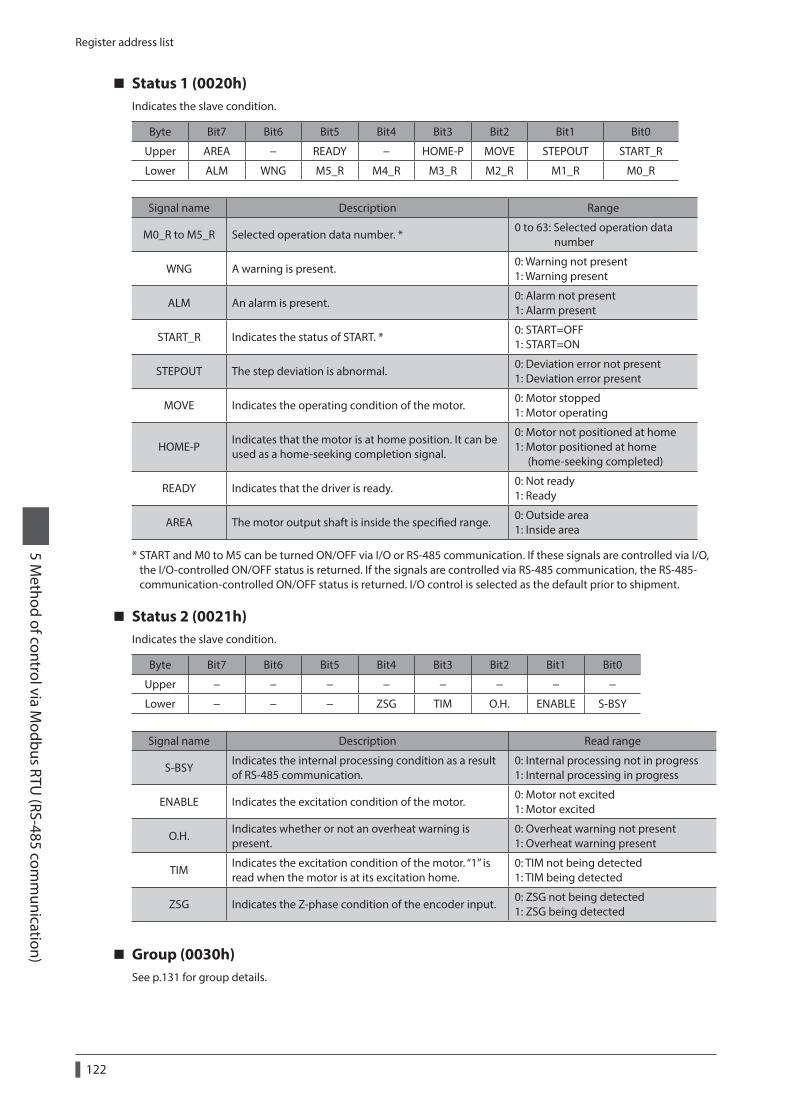
Register address list
122
5 Method of control via M
odbus RTU (RS-485 com
munication)
Status 1 (0020h)Indicates the slave condition.
Byte Bit7 Bit6 Bit5 Bit4 Bit3 Bit2 Bit1 Bit0
Upper AREA − READY − HOME-P MOVE STEPOUT START_R
Lower ALM WNG M5_R M4_R M3_R M2_R M1_R M0_R
Signal name Description Range
M0_R to M5_R Selected operation data number. *0 to 63: Selected operation data number
WNG A warning is present.0: Warning not present 1: Warning present
ALM An alarm is present.0: Alarm not present 1: Alarm present
START_R Indicates the status of START. *0: START=OFF 1: START=ON
STEPOUT The step deviation is abnormal.0: Deviation error not present 1: Deviation error present
MOVE Indicates the operating condition of the motor.0: Motor stopped 1: Motor operating
HOME-PIndicates that the motor is at home position. It can be used as a home-seeking completion signal.
0: Motor not positioned at home 1: Motor positioned at home (home-seeking completed)
READY Indicates that the driver is ready.0: Not ready 1: Ready
AREA The motor output shaft is inside the specified range.0: Outside area 1: Inside area
* START and M0 to M5 can be turned ON/OFF via I/O or RS-485 communication. If these signals are controlled via I/O, the I/O-controlled ON/OFF status is returned. If the signals are controlled via RS-485 communication, the RS-485-communication-controlled ON/OFF status is returned. I/O control is selected as the default prior to shipment.
Status 2 (0021h)Indicates the slave condition.
Byte Bit7 Bit6 Bit5 Bit4 Bit3 Bit2 Bit1 Bit0
Upper − − − − − − − −
Lower − − − ZSG TIM O.H. ENABLE S-BSY
Signal name Description Read range
S-BSYIndicates the internal processing condition as a result of RS-485 communication.
0: Internal processing not in progress 1: Internal processing in progress
ENABLE Indicates the excitation condition of the motor.0: Motor not excited 1: Motor excited
O.H.Indicates whether or not an overheat warning is present.
0: Overheat warning not present 1: Overheat warning present
TIMIndicates the excitation condition of the motor. “1” is read when the motor is at its excitation home.
0: TIM not being detected 1: TIM being detected
ZSG Indicates the Z-phase condition of the encoder input.0: ZSG not being detected 1: ZSG being detected
Group (0030h)See p.131 for group details.
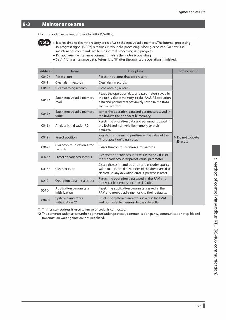
Register address list
123
5 Method of control via M
odbus RTU (RS-485 com
munication)
8-3 Maintenance area
All commands can be read and written (READ/WRITE).
• It takes time to clear the history or read/write the non-volatile memory. The internal processing in-progress signal (S-BSY) remains ON while the processing is being executed. Do not issue maintenance commands while the internal processing is in progress.
• Do not issue maintenance commands while the motor is operating. • Set “1” for maintenance data. Return it to “0” after the applicable operation is finished.
Address Name Description Setting range
0040h Reset alarm Resets the alarms that are present.
0: Do not execute 1: Execute
0041h Clear alarm records Clear alarm records.
0042h Clear warning records Clear warning records.
0044hBatch non-volatile memory read
Reads the operation data and parameters saved in the non-volatile memory, to the RAM. All operation data and parameters previously saved in the RAM are overwritten.
0045hBatch non-volatile memory write
Writes the operation data and parameters saved in the RAM to the non-volatile memory.
0046h All data initialization *2Resets the operation data and parameters saved in the RAM and non-volatile memory, to their defaults.
0048h Preset positionPresets the command position as the value of the “Preset position” parameter.
0049hClear communication error records
Clears the communication error records.
004Ah Preset encoder counter *1Presets the encoder counter value as the value of the “Encoder counter preset value” parameter.
004Bh Clear counterClears the command position and encoder counter value to 0. Internal deviations of the driver are also cleared, so any deviation error, if present, is reset.
004Ch Operation data initializationResets the operation data saved in the RAM and non-volatile memory, to their defaults.
004DhApplication parameters initialization
Resets the application parameters saved in the RAM and non-volatile memory, to their defaults.
004EhSystem parameters initialization *2
Resets the system parameters saved in the RAM and non-volatile memory, to their defaults
*1 This resistor address is used when an encoder is connected.*2 The communication axis number, communication protocol, communication parity, communication stop bit and
transmission waiting time are not initialized.
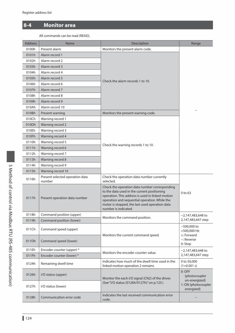
Register address list
124
5 Method of control via M
odbus RTU (RS-485 com
munication)
8-4 Monitor area
All commands can be read (READ).
Address Name Description Range
0100h Present alarm Monitors the present alarm code.
−
0101h Alarm record 1
Check the alarm records 1 to 10.
0102h Alarm record 2
0103h Alarm record 3
0104h Alarm record 4
0105h Alarm record 5
0106h Alarm record 6
0107h Alarm record 7
0108h Alarm record 8
0109h Alarm record 9
010Ah Alarm record 10
010Bh Present warning Monitors the present warning code.
010Ch Warning record 1
Check the warning records 1 to 10.
010Dh Warning record 2
010Eh Warning record 3
010Fh Warning record 4
0110h Warning record 5
0111h Warning record 6
0112h Warning record 7
0113h Warning record 8
0114h Warning record 9
0115h Warning record 10
0116hPresent selected operation data number
Check the operation data number currently selected.
0 to 630117h Present operation data number
Check the operation data number corresponding to the data used in the current positioning operation. This address is used in linked-motion operation and sequential operation. While the motor is stopped, the last used operation data number is indicated.
0118h Command position (upper)Monitors the command position.
−2,147,483,648 to 2,147,483,647 step0119h Command position (lower)
011Ch Command speed (upper)
Monitors the current command speed.
−500,000 to +500,000 Hz +: Forward −: Reverse 0: Stop
011Dh Command speed (lower)
011Eh Encoder counter (upper) *Monitors the encoder counter value.
−2,147,483,648 to 2,147,483,647 step011Fh Encoder counter (lower) *
0124h Remaining dwell timeIndicates how much of the dwell time used in the linked-motion operation 2 remains.
0 to 50,000 (1=0.001 s)
0126h I/O status (upper)Monitor the each I/O signal (CN2) of the driver. (See “I/O status (0126h/0127h)” on p.125.)
0: OFF (photocoupler un-energized) 1: ON (photocoupler energized)
0127h I/O status (lower)
0128h Communication error codeIndicates the last received communication error code.
−
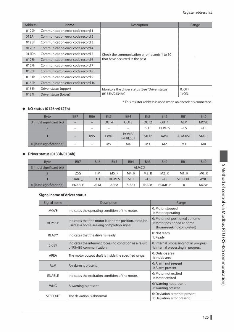
Register address list
125
5 Method of control via M
odbus RTU (RS-485 com
munication)
Address Name Description Range
0129h Communication error code record 1
Check the communication error records 1 to 10 that have occurred in the past.
−
012Ah Communication error code record 2
012Bh Communication error code record 3
012Ch Communication error code record 4
012Dh Communication error code record 5
012Eh Communication error code record 6
012Fh Communication error code record 7
0130h Communication error code record 8
0131h Communication error code record 9
0132h Communication error code record 10
0133h Driver status (upper) Monitors the driver status (See “Driver status (0133h/0134h).”
0: OFF 1: ON0134h Driver status (lower)
* This resistor address is used when an encoder is connected.
z I/O status (0126h/0127h)
Byte Bit7 Bit6 Bit5 Bit4 Bit3 Bit2 Bit1 Bit0
3 (most significant bit) − − OUT4 OUT3 OUT2 OUT1 ALM MOVE
2 − − − − SLIT HOMES −LS +LS
1 − RVS FWDHOME/
P-PRESETSTOP AWO ALM-RST START
0 (least significant bit) − − M5 M4 M3 M2 M1 M0
z Driver status (0133h/0134h)
Byte Bit7 Bit6 Bit5 Bit4 Bit3 Bit2 Bit1 Bit0
3 (most significant bit) ALMCD
2 ZSG TIM M5_R M4_R M3_R M2_R M1_R M0_R
1 START_R O.H. HOMES SLIT −LS +LS STEPOUT WNG
0 (least significant bit) ENABLE ALM AREA S-BSY READY HOME-P 0 MOVE
Signal name of driver status
Signal name Description Range
MOVE Indicates the operating condition of the motor.0: Motor stopped 1: Motor operating
HOME-PIndicates that the motor is at home position. It can be used as a home-seeking completion signal.
0: Motor not positioned at home 1: Motor positioned at home (home-seeking completed)
READY Indicates that the driver is ready.0: Not ready 1: Ready
S-BSYIndicates the internal processing condition as a result of RS-485 communication.
0: Internal processing not in progress 1: Internal processing in progress
AREA The motor output shaft is inside the specified range.0: Outside area 1: Inside area
ALM An alarm is present.0: Alarm not present 1: Alarm present
ENABLE Indicates the excitation condition of the motor.0: Motor not excited 1: Motor excited
WNG A warning is present.0: Warning not present 1: Warning present
STEPOUT The deviation is abnormal.0: Deviation error not present 1: Deviation error present
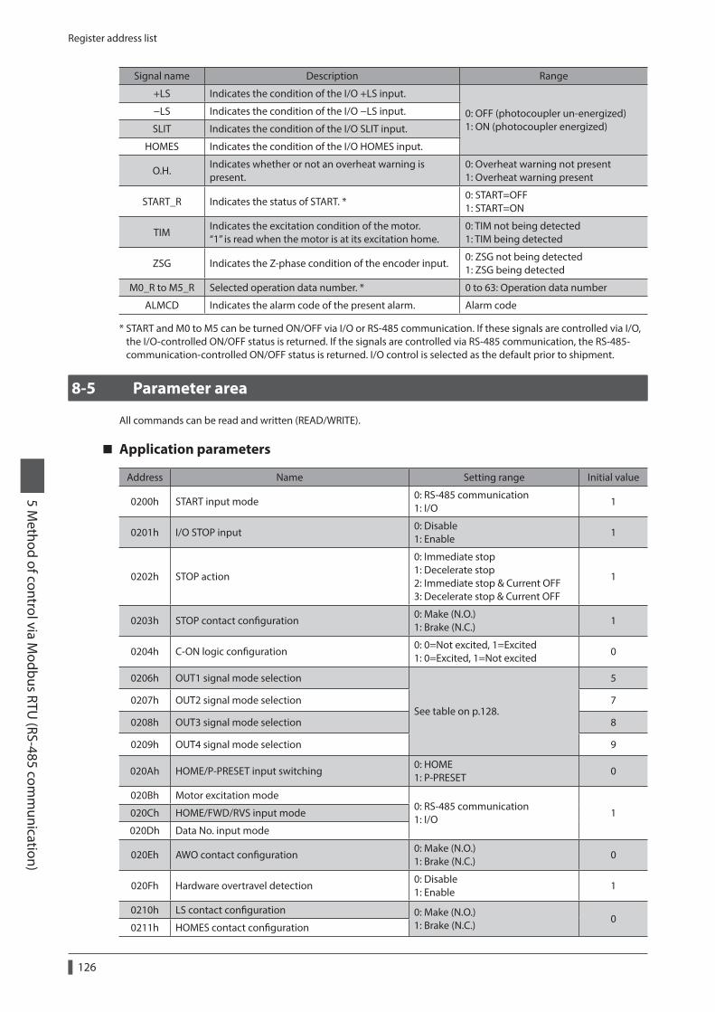
Register address list
126
5 Method of control via M
odbus RTU (RS-485 com
munication)
Signal name Description Range
+LS Indicates the condition of the I/O +LS input.
0: OFF (photocoupler un-energized) 1: ON (photocoupler energized)
−LS Indicates the condition of the I/O −LS input.
SLIT Indicates the condition of the I/O SLIT input.
HOMES Indicates the condition of the I/O HOMES input.
O.H.Indicates whether or not an overheat warning is present.
0: Overheat warning not present 1: Overheat warning present
START_R Indicates the status of START. *0: START=OFF 1: START=ON
TIMIndicates the excitation condition of the motor. “1” is read when the motor is at its excitation home.
0: TIM not being detected 1: TIM being detected
ZSG Indicates the Z-phase condition of the encoder input.0: ZSG not being detected 1: ZSG being detected
M0_R to M5_R Selected operation data number. * 0 to 63: Operation data number
ALMCD Indicates the alarm code of the present alarm. Alarm code
* START and M0 to M5 can be turned ON/OFF via I/O or RS-485 communication. If these signals are controlled via I/O, the I/O-controlled ON/OFF status is returned. If the signals are controlled via RS-485 communication, the RS-485-communication-controlled ON/OFF status is returned. I/O control is selected as the default prior to shipment.
8-5 Parameter area
All commands can be read and written (READ/WRITE).
Application parameters
Address Name Setting range Initial value
0200h START input mode0: RS-485 communication 1: I/O
1
0201h I/O STOP input0: Disable 1: Enable
1
0202h STOP action
0: Immediate stop 1: Decelerate stop 2: Immediate stop & Current OFF 3: Decelerate stop & Current OFF
1
0203h STOP contact configuration0: Make (N.O.) 1: Brake (N.C.)
1
0204h C-ON logic configuration0: 0=Not excited, 1=Excited 1: 0=Excited, 1=Not excited
0
0206h OUT1 signal mode selection
See table on p.128.
5
0207h OUT2 signal mode selection 7
0208h OUT3 signal mode selection 8
0209h OUT4 signal mode selection 9
020Ah HOME/P-PRESET input switching0: HOME 1: P-PRESET
0
020Bh Motor excitation mode0: RS-485 communication 1: I/O
1020Ch HOME/FWD/RVS input mode
020Dh Data No. input mode
020Eh AWO contact configuration0: Make (N.O.) 1: Brake (N.C.)
0
020Fh Hardware overtravel detection0: Disable 1: Enable
1
0210h LS contact configuration 0: Make (N.O.) 1: Brake (N.C.)
00211h HOMES contact configuration
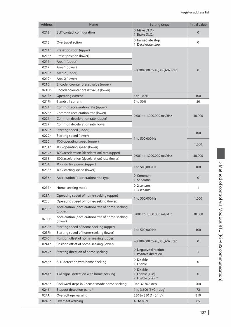
Register address list
127
5 Method of control via M
odbus RTU (RS-485 com
munication)
Address Name Setting range Initial value
0212h SLIT contact configuration0: Make (N.O.) 1: Brake (N.C.)
0
0213h Overtravel action0: Immediate stop 1: Decelerate stop
0
0214h Preset position (upper)
−8,388,608 to +8,388,607 step 0
0215h Preset position (lower)
0216h Area 1 (upper)
0217h Area 1 (lower)
0218h Area 2 (upper)
0219h Area 2 (lower)
021Ch Encoder counter preset value (upper)
021Dh Encoder counter preset value (lower)
021Eh Operating current 5 to 100% 100
021Fh Standstill current 5 to 50% 50
0224h Common acceleration rate (upper)
0.001 to 1,000.000 ms/kHz 30.0000225h Common acceleration rate (lower)
0226h Common deceleration rate (upper)
0227h Common deceleration rate (lower)
0228h Starting speed (upper)
1 to 500,000 Hz
1000229h Starting speed (lower)
0230h JOG operating speed (upper)1,000
0231h JOG operating speed (lower)
0232h JOG acceleration (deceleration) rate (upper)0.001 to 1,000.000 ms/kHz 30.000
0233h JOG acceleration (deceleration) rate (lower)
0234h JOG starting speed (upper)1 to 500,000 Hz 100
0235h JOG starting speed (lower)
0236h Acceleration (deceleration) rate type0: Common 1: Separate
0
0237h Home-seeking mode0: 2 sensors 1: 3 sensors
1
023Ah Operating speed of home-seeking (upper)1 to 500,000 Hz 1,000
023Bh Operating speed of home-seeking (lower)
023ChAcceleration (deceleration) rate of home-seeking (upper)
0.001 to 1,000.000 ms/kHz 30.000023Dh
Acceleration (deceleration) rate of home-seeking (lower)
023Eh Starting speed of home-seeking (upper)1 to 500,000 Hz 100
023Fh Starting speed of home-seeking (lower)
0240h Position offset of home-seeking (upper)−8,388,608 to +8,388,607 step 0
0241h Position offset of home-seeking (lower)
0242h Starting direction of home-seeking0: Negative direction 1: Positive direction
1
0243h SLIT detection with home-seeking0: Disable 1: Enable
0
0244h TIM signal detection with home-seeking0: Disable 1: Enable (TIM) 2: Enable (ZSG) *
0
0245h Backward steps in 2 sensor mode home-seeking 0 to 32,767 step 200
0246h Stepout detection band * 1 to 3,600 (1=0.1 deg) 72
024Ah Overvoltage warning 250 to 350 (1=0.1 V) 310
024Ch Overheat warning 40 to 85 °C 85
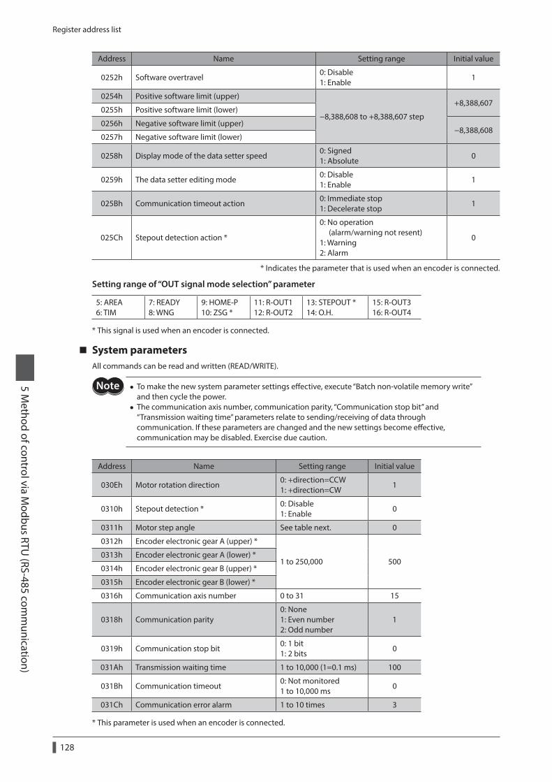
Register address list
128
5 Method of control via M
odbus RTU (RS-485 com
munication)
Address Name Setting range Initial value
0252h Software overtravel0: Disable 1: Enable
1
0254h Positive software limit (upper)
−8,388,608 to +8,388,607 step
+8,388,6070255h Positive software limit (lower)
0256h Negative software limit (upper)−8,388,608
0257h Negative software limit (lower)
0258h Display mode of the data setter speed0: Signed 1: Absolute
0
0259h The data setter editing mode0: Disable 1: Enable
1
025Bh Communication timeout action0: Immediate stop 1: Decelerate stop
1
025Ch Stepout detection action *
0: No operation (alarm/warning not resent) 1: Warning 2: Alarm
0
* Indicates the parameter that is used when an encoder is connected.
Setting range of “OUT signal mode selection” parameter
5: AREA 6: TIM
7: READY 8: WNG
9: HOME-P 10: ZSG *
11: R-OUT1 12: R-OUT2
13: STEPOUT * 14: O.H.
15: R-OUT3 16: R-OUT4
* This signal is used when an encoder is connected.
System parametersAll commands can be read and written (READ/WRITE).
• To make the new system parameter settings effective, execute “Batch non-volatile memory write” and then cycle the power.
• The communication axis number, communication parity, “Communication stop bit” and “Transmission waiting time” parameters relate to sending/receiving of data through communication. If these parameters are changed and the new settings become effective, communication may be disabled. Exercise due caution.
Address Name Setting range Initial value
030Eh Motor rotation direction0: +direction=CCW 1: +direction=CW
1
0310h Stepout detection *0: Disable 1: Enable
0
0311h Motor step angle See table next. 0
0312h Encoder electronic gear A (upper) *
1 to 250,000 5000313h Encoder electronic gear A (lower) *
0314h Encoder electronic gear B (upper) *
0315h Encoder electronic gear B (lower) *
0316h Communication axis number 0 to 31 15
0318h Communication parity0: None 1: Even number 2: Odd number
1
0319h Communication stop bit0: 1 bit 1: 2 bits
0
031Ah Transmission waiting time 1 to 10,000 (1=0.1 ms) 100
031Bh Communication timeout0: Not monitored 1 to 10,000 ms
0
031Ch Communication error alarm 1 to 10 times 3
* This parameter is used when an encoder is connected.
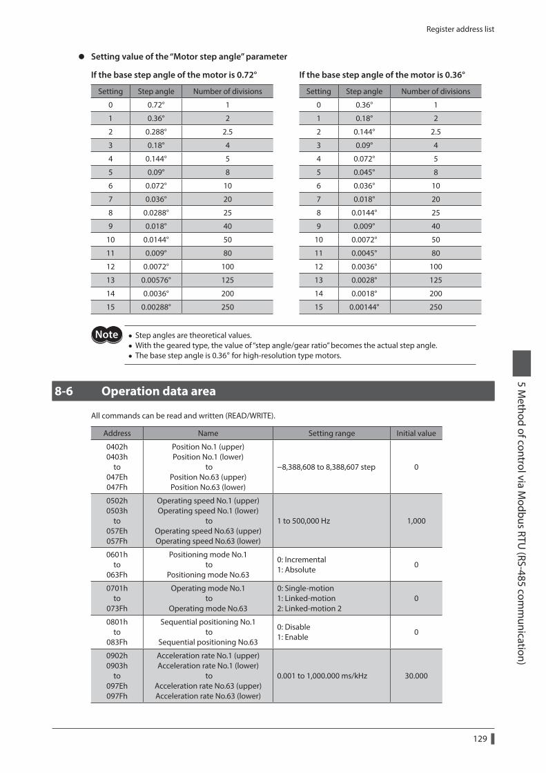
Register address list
129
5 Method of control via M
odbus RTU (RS-485 com
munication)
z Setting value of the “Motor step angle” parameter
If the base step angle of the motor is 0.72° If the base step angle of the motor is 0.36°
Setting Step angle Number of divisions Setting Step angle Number of divisions
0 0.72° 1 0 0.36° 1
1 0.36° 2 1 0.18° 2
2 0.288° 2.5 2 0.144° 2.5
3 0.18° 4 3 0.09° 4
4 0.144° 5 4 0.072° 5
5 0.09° 8 5 0.045° 8
6 0.072° 10 6 0.036° 10
7 0.036° 20 7 0.018° 20
8 0.0288° 25 8 0.0144° 25
9 0.018° 40 9 0.009° 40
10 0.0144° 50 10 0.0072° 50
11 0.009° 80 11 0.0045° 80
12 0.0072° 100 12 0.0036° 100
13 0.00576° 125 13 0.0028° 125
14 0.0036° 200 14 0.0018° 200
15 0.00288° 250 15 0.00144° 250
• Step angles are theoretical values. • With the geared type, the value of “step angle/gear ratio” becomes the actual step angle. • The base step angle is 0.36° for high-resolution type motors.
8-6 Operation data area
All commands can be read and written (READ/WRITE).
Address Name Setting range Initial value
0402h 0403h
to 047Eh 047Fh
Position No.1 (upper) Position No.1 (lower)
to Position No.63 (upper) Position No.63 (lower)
−8,388,608 to 8,388,607 step 0
0502h 0503h
to 057Eh 057Fh
Operating speed No.1 (upper) Operating speed No.1 (lower)
to Operating speed No.63 (upper) Operating speed No.63 (lower)
1 to 500,000 Hz 1,000
0601h to
063Fh
Positioning mode No.1 to
Positioning mode No.63
0: Incremental 1: Absolute
0
0701h to
073Fh
Operating mode No.1 to
Operating mode No.63
0: Single-motion 1: Linked-motion 2: Linked-motion 2
0
0801h to
083Fh
Sequential positioning No.1 to
Sequential positioning No.63
0: Disable 1: Enable
0
0902h 0903h
to 097Eh 097Fh
Acceleration rate No.1 (upper) Acceleration rate No.1 (lower)
to Acceleration rate No.63 (upper) Acceleration rate No.63 (lower)
0.001 to 1,000.000 ms/kHz 30.000

Register address list
130
5 Method of control via M
odbus RTU (RS-485 com
munication)
Address Name Setting range Initial value
0A02h 0A03h
to 0A7Eh 0A7Fh
Deceleration rate No.1 (upper) Deceleration rate No.1 (lower)
to Deceleration rate No.63 (upper) Deceleration rate No.63 (lower)
0.001 to 1,000.000 ms/kHz 30.000
0C01h to
0C3Fh
Dwell time No.1 to
Dwell time No.630 to 50,000 (1=0.001 s) 0
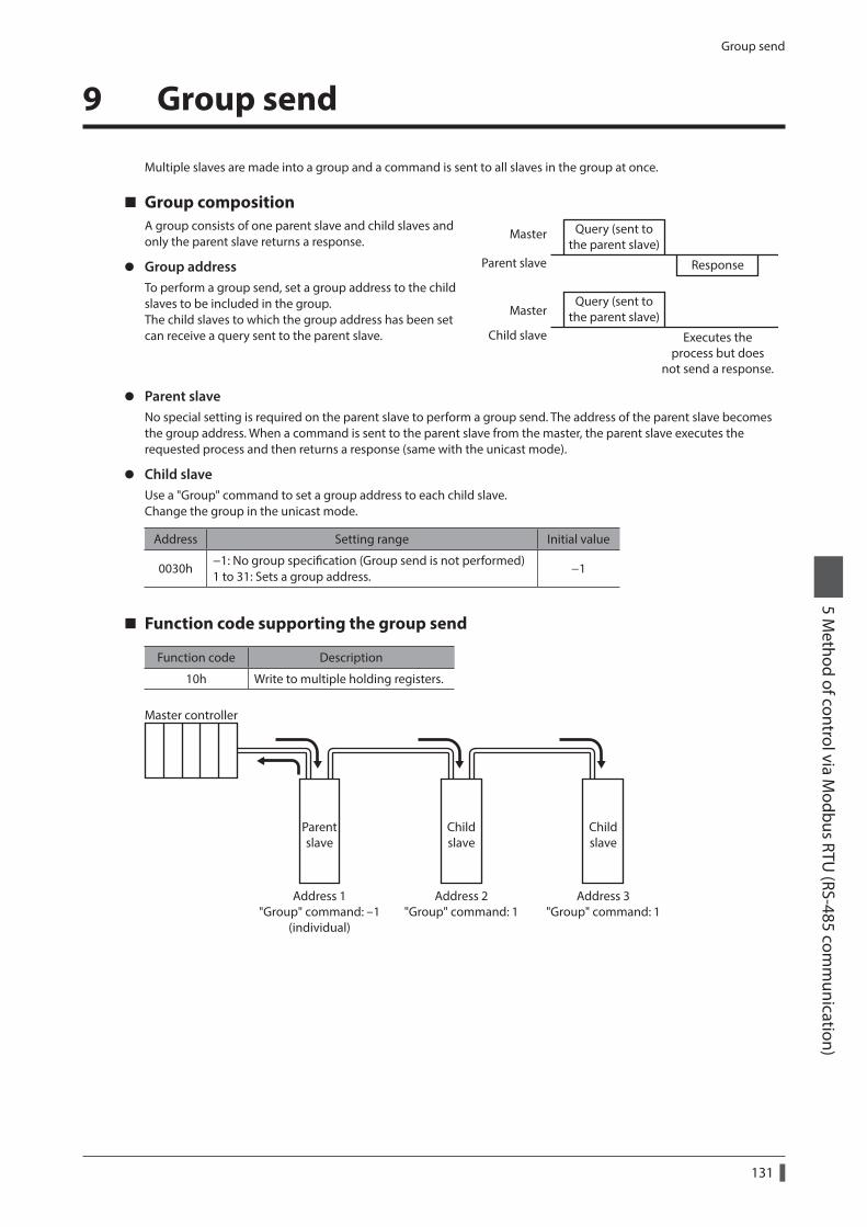
Group send
131
5 Method of control via M
odbus RTU (RS-485 com
munication)
9 Group send
Multiple slaves are made into a group and a command is sent to all slaves in the group at once.
Group compositionA group consists of one parent slave and child slaves and only the parent slave returns a response.
z Group addressTo perform a group send, set a group address to the child slaves to be included in the group.The child slaves to which the group address has been set can receive a query sent to the parent slave.
Query (sent tothe parent slave)
Query (sent tothe parent slave)
Response
Master
Master
Child slave Executes theprocess but does
not send a response.
Parent slave
z Parent slaveNo special setting is required on the parent slave to perform a group send. The address of the parent slave becomes the group address. When a command is sent to the parent slave from the master, the parent slave executes the requested process and then returns a response (same with the unicast mode).
z Child slaveUse a "Group" command to set a group address to each child slave.Change the group in the unicast mode.
Address Setting range Initial value
0030h−1: No group specification (Group send is not performed) 1 to 31: Sets a group address.
−1
Function code supporting the group send
Function code Description
10h Write to multiple holding registers.
Parentslave
Childslave
Childslave
Address 1"Group" command: -1
(individual)
Address 2"Group" command: 1
Address 3"Group" command: 1
Master controller
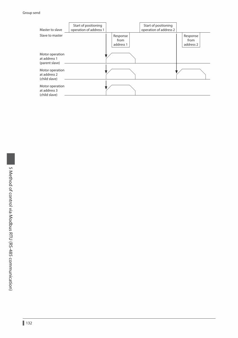
Group send
132
5 Method of control via M
odbus RTU (RS-485 com
munication)
Master to slave
Slave to master
Start of positioningoperation of address 1
Start of positioningoperation of address 2
Responsefrom
address 1
Responsefrom
address 2
Motor operationat address 1(parent slave)
Motor operationat address 2(child slave)
Motor operationat address 3(child slave)
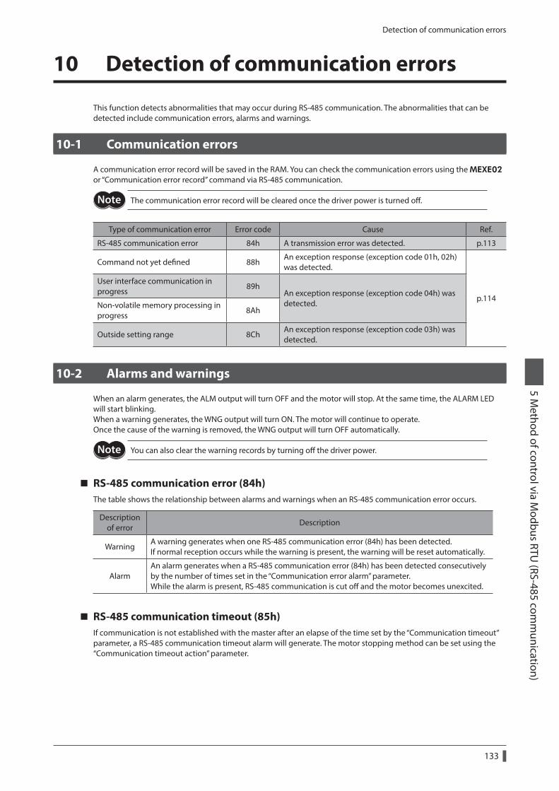
Detection of communication errors
133
5 Method of control via M
odbus RTU (RS-485 com
munication)
10 Detection of communication errors
This function detects abnormalities that may occur during RS-485 communication. The abnormalities that can be detected include communication errors, alarms and warnings.
10-1 Communication errors
A communication error record will be saved in the RAM. You can check the communication errors using the MEXE02 or “Communication error record” command via RS-485 communication.
The communication error record will be cleared once the driver power is turned off.
Type of communication error Error code Cause Ref.
RS-485 communication error 84h A transmission error was detected. p.113
Command not yet defined 88hAn exception response (exception code 01h, 02h) was detected.
p.114
User interface communication in progress
89hAn exception response (exception code 04h) was detected.Non-volatile memory processing in
progress8Ah
Outside setting range 8ChAn exception response (exception code 03h) was detected.
10-2 Alarms and warnings
When an alarm generates, the ALM output will turn OFF and the motor will stop. At the same time, the ALARM LED will start blinking.When a warning generates, the WNG output will turn ON. The motor will continue to operate.Once the cause of the warning is removed, the WNG output will turn OFF automatically.
You can also clear the warning records by turning off the driver power.
RS-485 communication error (84h)The table shows the relationship between alarms and warnings when an RS-485 communication error occurs.
Description of error
Description
WarningA warning generates when one RS-485 communication error (84h) has been detected. If normal reception occurs while the warning is present, the warning will be reset automatically.
AlarmAn alarm generates when a RS-485 communication error (84h) has been detected consecutively by the number of times set in the “Communication error alarm” parameter. While the alarm is present, RS-485 communication is cut off and the motor becomes unexcited.
RS-485 communication timeout (85h)If communication is not established with the master after an elapse of the time set by the “Communication timeout” parameter, a RS-485 communication timeout alarm will generate. The motor stopping method can be set using the “Communication timeout action” parameter.
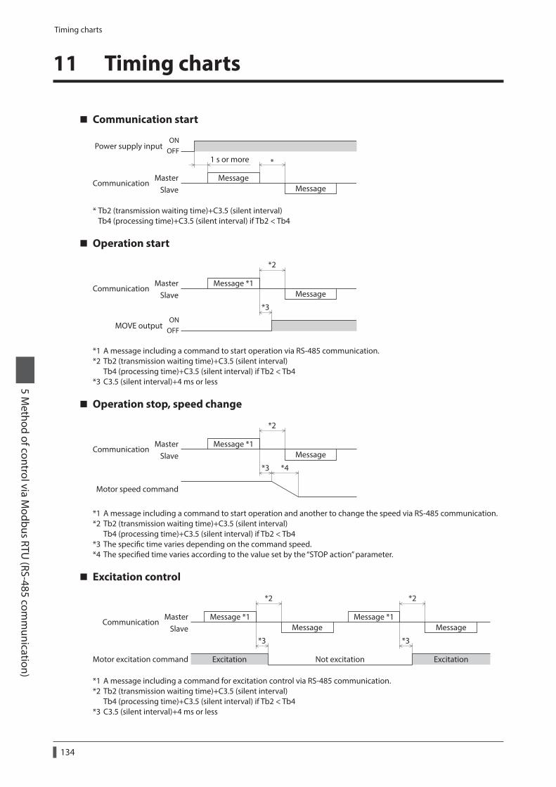
Timing charts
134
5 Method of control via M
odbus RTU (RS-485 com
munication)
11 Timing charts
Communication start
Message
Message
ONOFF
1 s or more *
MasterSlave
Communication
Power supply input
* Tb2 (transmission waiting time)+C3.5 (silent interval) Tb4 (processing time)+C3.5 (silent interval) if Tb2 < Tb4
Operation start
Message *1Message
ONOFF
*2
*3
MasterSlave
MOVE output
Communication
*1 A message including a command to start operation via RS-485 communication.*2 Tb2 (transmission waiting time)+C3.5 (silent interval)
Tb4 (processing time)+C3.5 (silent interval) if Tb2 < Tb4*3 C3.5 (silent interval)+4 ms or less
Operation stop, speed change
Message *1Message
*4
*2
*3
Motor speed command
MasterSlave
Communication
*1 A message including a command to start operation and another to change the speed via RS-485 communication.*2 Tb2 (transmission waiting time)+C3.5 (silent interval)
Tb4 (processing time)+C3.5 (silent interval) if Tb2 < Tb4*3 The specific time varies depending on the command speed.*4 The specified time varies according to the value set by the “STOP action” parameter.
Excitation control
Message
Excitation ExcitationNot excitation
*2
*3 *3
*2
Message *1Message
Message *1MasterSlave
Communication
Motor excitation command
*1 A message including a command for excitation control via RS-485 communication.*2 Tb2 (transmission waiting time)+C3.5 (silent interval)
Tb4 (processing time)+C3.5 (silent interval) if Tb2 < Tb4*3 C3.5 (silent interval)+4 ms or less

Timing charts
135
5 Method of control via M
odbus RTU (RS-485 com
munication)
Remote output
Message *1Message
*2
*3
R-OUT1 outputR-OUT2 output
ONOFF
MasterSlave
Communication
*1 A message including a command for remote output via RS-485 communication.*2 Tb2 (transmission waiting time)+C3.5 (silent interval)
Tb4 (processing time)+C3.5 (silent interval) if Tb2 < Tb4*3 C3.5 (silent interval)+4 ms or less

Example of communication setting
136
5 Method of control via M
odbus RTU (RS-485 com
munication)
12 Example of communication setting
The data required for each operation is set using the MEXE02, OPX-2A or via RS-485 communication.
12-1 Positioning operation
See p.61 for details on the positioning operation. How to perform the following positioning operation is explained as an example.
• Slave address: 1 • Position (distance): 1,000 step • Operating speed: 5,000 Hz
1. Send the following query to turn ON the motor excitation.
Field name Data Description
Slave address 01h Slave address 1
Function code 06h Write to a holding register
Register address (upper) 00hCommand 1=001Eh
Register address (lower) 1Eh
Value written (upper) 20hTurn ON C-ON=2000h
Value written (lower) 00h
Error check (lower) F0hResult of CRC-16=0CF0h
Error check (upper) 0Ch
2. Send the following query to set the position (travel amount) for operation data No.1 to 1,000 steps.
Field name Data Description
Slave address 01h Slave address 1
Function code 10h Write to multiple holding registers.
Register address (upper) 04hPosition No.1=0402h
Register address (lower) 02h
Number of registers (upper) 00hNumber of successive registers=2
Number of registers (lower) 02h
Number of data bytes 04h Total number of data bytes=4
Value written to register address (upper) 00h
1,000 step=0000 03E8hValue written to register address (lower) 00h
Value written to register address+1 (upper) 03h
Value written to register address+1 (lower) E8h
Error check (lower) 40hResult of CRC-16=0840h
Error check (upper) 08h
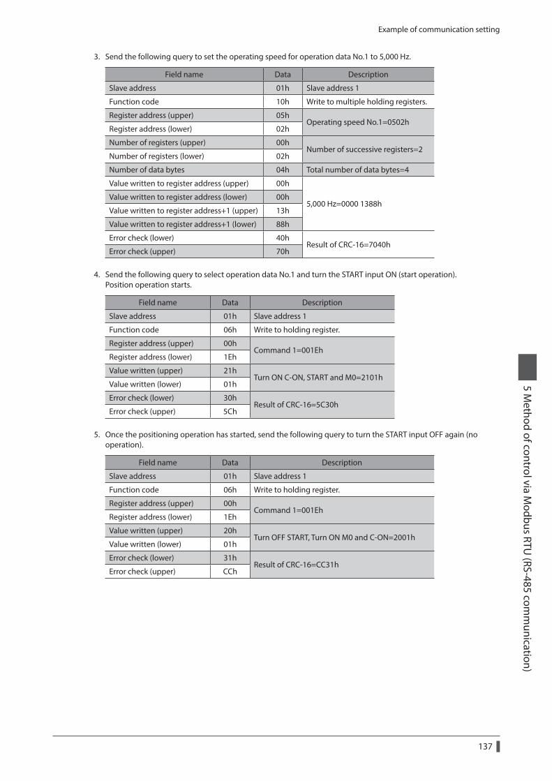
Example of communication setting
137
5 Method of control via M
odbus RTU (RS-485 com
munication)
3. Send the following query to set the operating speed for operation data No.1 to 5,000 Hz.
Field name Data Description
Slave address 01h Slave address 1
Function code 10h Write to multiple holding registers.
Register address (upper) 05hOperating speed No.1=0502h
Register address (lower) 02h
Number of registers (upper) 00hNumber of successive registers=2
Number of registers (lower) 02h
Number of data bytes 04h Total number of data bytes=4
Value written to register address (upper) 00h
5,000 Hz=0000 1388hValue written to register address (lower) 00h
Value written to register address+1 (upper) 13h
Value written to register address+1 (lower) 88h
Error check (lower) 40hResult of CRC-16=7040h
Error check (upper) 70h
4. Send the following query to select operation data No.1 and turn the START input ON (start operation).Position operation starts.
Field name Data Description
Slave address 01h Slave address 1
Function code 06h Write to holding register.
Register address (upper) 00hCommand 1=001Eh
Register address (lower) 1Eh
Value written (upper) 21hTurn ON C-ON, START and M0=2101h
Value written (lower) 01h
Error check (lower) 30hResult of CRC-16=5C30h
Error check (upper) 5Ch
5. Once the positioning operation has started, send the following query to turn the START input OFF again (no operation).
Field name Data Description
Slave address 01h Slave address 1
Function code 06h Write to holding register.
Register address (upper) 00hCommand 1=001Eh
Register address (lower) 1Eh
Value written (upper) 20hTurn OFF START, Turn ON M0 and C-ON=2001h
Value written (lower) 01h
Error check (lower) 31hResult of CRC-16=CC31h
Error check (upper) CCh
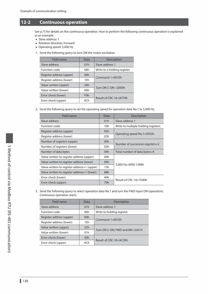
Example of communication setting
138
5 Method of control via M
odbus RTU (RS-485 com
munication)
12-2 Continuous operation
See p.75 for details on the continuous operation. How to perform the following continuous operation is explained as an example.
• Slave address: 1 • Rotation direction: Forward • Operating speed: 5,000 Hz
1. Send the following query to turn ON the motor excitation.
Field name Data Description
Slave address 01h Slave address 1
Function code 06h Write to a holding register
Register address (upper) 00hCommand 1=001Eh
Register address (lower) 1Eh
Value written (upper) 20hTurn ON C-ON =2000h
Value written (lower) 00h
Error check (lower) F0hResult of CRC-16=0CF0h
Error check (upper) 0Ch
2. Send the following query to set the operating speed for operation data No.1 to 5,000 Hz.
Field name Data Description
Slave address 01h Slave address 1
Function code 10h Write to multiple holding registers.
Register address (upper) 05hOperating speed No.1=0502h
Register address (lower) 02h
Number of registers (upper) 00hNumber of successive registers=2
Number of registers (lower) 02h
Number of data bytes 04h Total number of data bytes=4
Value written to register address (upper) 00h
5,000 Hz=0000 1388hValue written to register address (lower) 00h
Value written to register address+1 (upper) 13h
Value written to register address+1 (lower) 88h
Error check (lower) 40hResult of CRC-16=7040h
Error check (upper) 70h
3. Send the following query to select operation data No.1 and turn the FWD input ON (operation).Continuous operation starts.
Field name Data Description
Slave address 01h Slave address 1
Function code 06h Write to holding register.
Register address (upper) 00hCommand 1=001Eh
Register address (lower) 1Eh
Value written (upper) 22hTurn ON C-ON, FWD and M0=2201h
Value written (lower) 01h
Error check (lower) 30hResult of CRC-16=AC30h
Error check (upper) ACh
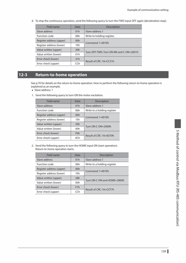
Example of communication setting
139
5 Method of control via M
odbus RTU (RS-485 com
munication)
4. To stop the continuous operation, send the following query to turn the FWD input OFF again (deceleration stop).
Field name Data Description
Slave address 01h Slave address 1
Function code 06h Write to holding register.
Register address (upper) 00hCommand 1=001Eh
Register address (lower) 1Eh
Value written (upper) 20hTurn OFF FWD, Turn ON M0 and C-ON=2001h
Value written (lower) 01h
Error check (lower) 31hResult of CRC-16=CC31h
Error check (upper) CCh
12-3 Return-to-home operation
See p.70 for details on the return-to-home operation. How to perform the following return-to-home operation is explained as an example.
• Slave address: 1
1. Send the following query to turn ON the motor excitation.
Field name Data Description
Slave address 01h Slave address 1
Function code 06h Write to a holding register
Register address (upper) 00hCommand 1=001Eh
Register address (lower) 1Eh
Value written (upper) 20hTurn ON C-ON=2000h
Value written (lower) 00h
Error check (lower) F0hResult of CRC-16=0CF0h
Error check (upper) 0Ch
2. Send the following query to turn the HOME input ON (start operation).Return-to-home operation starts.
Field name Data Description
Slave address 01h Slave address 1
Function code 06h Write to a holding register
Register address (upper) 00hCommand 1=001Eh
Register address (lower) 1Eh
Value written (upper) 28hTurn ON C-ON and HOME=2800h
Value written (lower) 00h
Error check (lower) F7hResult of CRC-16=CCF7h
Error check (upper) CCh

Example of communication setting
140
5 Method of control via M
odbus RTU (RS-485 com
munication)
3. Once the return-to-home operation has started, send the following query to turn the HOME input OFF again (no operation).
Field name Data Description
Slave address 01h Slave address 1
Function code 06h Write to holding register.
Register address (upper) 00hCommand 1=001Eh
Register address (lower) 1Eh
Value written (upper) 20hTurn OFF HOME, Turn ON C-ON=2000h
Value written (lower) 00h
Error check (lower) F0hResult of CRC-16=0CF0h
Error check (upper) 0Ch
6 Method of control via industrial network
This part explains how to control via industrial network. This product can be controlled via CC-Link communication or MECHATROLINK communication in combination with a network converter.
Table of contents
1 Method of control via CC-Link communication ....................................142
1-1 Guidance ..........................................................142
1-2 Setting the switches ....................................145
1-3 Remote register list ......................................146
1-4 Assignment for remote I/O of 6 axes connection mode .........................................146
1-5 Assignment for remote I/O of 12 axes connection mode .........................................149
2 Method of control via MECHATROLINK communication ....................................154
2-1 Guidance ..........................................................154
2-2 Setting the switches ....................................157
2-3 I/O field map for the NETC01-M2 .......158
2-4 I/O field map for the NETC01-M3 .......159
2-5 Communication format ..............................160
3 Details of remote I/O ...........................1623-1 Input signals to the driver .........................162
3-2 Output signals from the driver ................162
4 Command code list .............................1644-1 Group function ..............................................164
4-2 Maintenance command .............................165
4-3 Monitor command .......................................166
4-4 Operation data ..............................................168
4-5 Application parameter ................................168
4-6 System parameter ........................................170
4-7 Operation command ...................................171
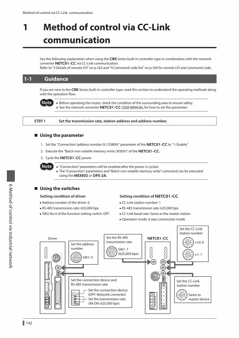
Method of control via CC-Link communication
142
6 Method of control via industrial netw
ork
1 Method of control via CC-Link communication
See the following explanation when using the CRK Series built-in controller type in combination with the network converter NETC01-CC via CC-Link communication.Refer to "3 Details of remote I/O" on p.162 and "4 Command code list" on p.164 for remote I/O and command code.
1-1 Guidance
If you are new to the CRK Series built-in controller type, read this section to understand the operating methods along with the operation flow.
• Before operating the motor, check the condition of the surrounding area to ensure safety. • See the network converter NETC01-CC USER MANUAL for how to set the parameter.
STEP 1 Set the transmission rate, station address and address number.
Using the parameter
1. Set the "Connection (address number 0) (1D80h)" parameter of the NETC01-CC to "1: Enable."
2. Execute the "Batch non-volatile memory write (3E85h)" of the NETC01-CC.
3. Cycle the NETC01-CC power.
• “Connection” parameters will be enabled after the power is cycled. • The “Connection” parameters and “Batch non-volatile memory write” command can be executed using the MEXE02 or OPX-2A.
Using the switches
Setting condition of driver
•Address number of the driver: 0
• RS-485 transmission rate: 625,000 bps
• SW2-No.4 of the function setting switch: OFF
Setting condition of NETC01-CC
•CC-Link station number: 1
• RS-485 transmission rate: 625,000 bps
•CC-Link baud rate: Same as the master station
•Operation mode: 6 axes connection mode
Set the address number
×10: 0
×1: 1
NETC01-CCDriver
Set the transmission rate.(All ON: 625,000 bps)
Set the CC-Linkstation number
Set the CC-Linkstation number
Set the RS-485transmission rate
SW1: 7(625,000 bps)
SW1: 0
Same as master device
Set the connection device.(OFF: Network converter)
Set the connection device andRS-485 transmission rate
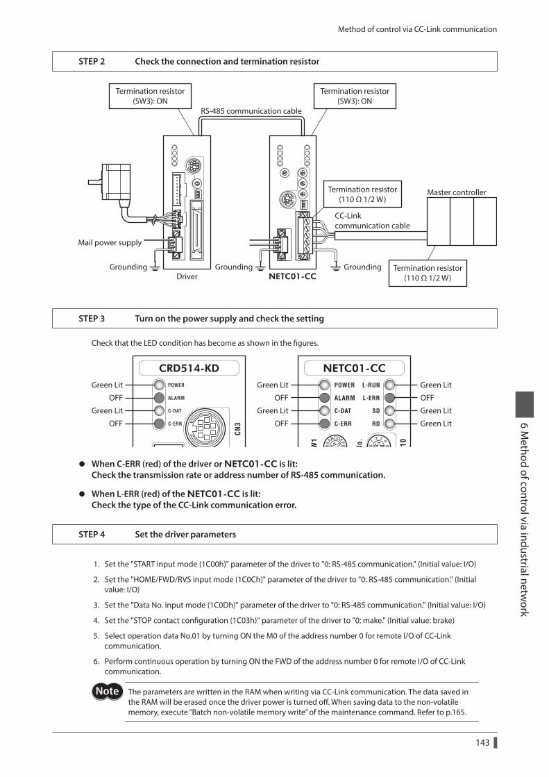
Method of control via CC-Link communication
143
6 Method of control via industrial netw
ork
STEP 2 Check the connection and termination resistor
Master controller
RS-485 communication cable
CC-Linkcommunication cable
Mail power supply
Driver
Termination resistor(110 Ω 1/2 W)
Termination resistor(110 Ω 1/2 W)
Termination resistor(SW3): ON
Termination resistor(SW3): ON
NETC01-CCGrounding Grounding Grounding
STEP 3 Turn on the power supply and check the setting
Check that the LED condition has become as shown in the figures.
Green LitGreen Lit
OFFOFF
Green Lit
OFF
Green Lit
OFF
Green Lit
OFF
Green Lit
Green Lit
z When C-ERR (red) of the driver or NETC01-CC is lit: Check the transmission rate or address number of RS-485 communication.
z When L-ERR (red) of the NETC01-CC is lit: Check the type of the CC-Link communication error.
STEP 4 Set the driver parameters
1. Set the "START input mode (1C00h)" parameter of the driver to "0: RS-485 communication." (Initial value: I/O)
2. Set the "HOME/FWD/RVS input mode (1C0Ch)" parameter of the driver to "0: RS-485 communication." (Initial value: I/O)
3. Set the "Data No. input mode (1C0Dh)" parameter of the driver to "0: RS-485 communication." (Initial value: I/O)
4. Set the "STOP contact configuration (1C03h)" parameter of the driver to "0: make." (Initial value: brake)
5. Select operation data No.01 by turning ON the M0 of the address number 0 for remote I/O of CC-Link communication.
6. Perform continuous operation by turning ON the FWD of the address number 0 for remote I/O of CC-Link communication.
The parameters are written in the RAM when writing via CC-Link communication. The data saved in the RAM will be erased once the driver power is turned off. When saving data to the non-volatile memory, execute “Batch non-volatile memory write” of the maintenance command. Refer to p.165.
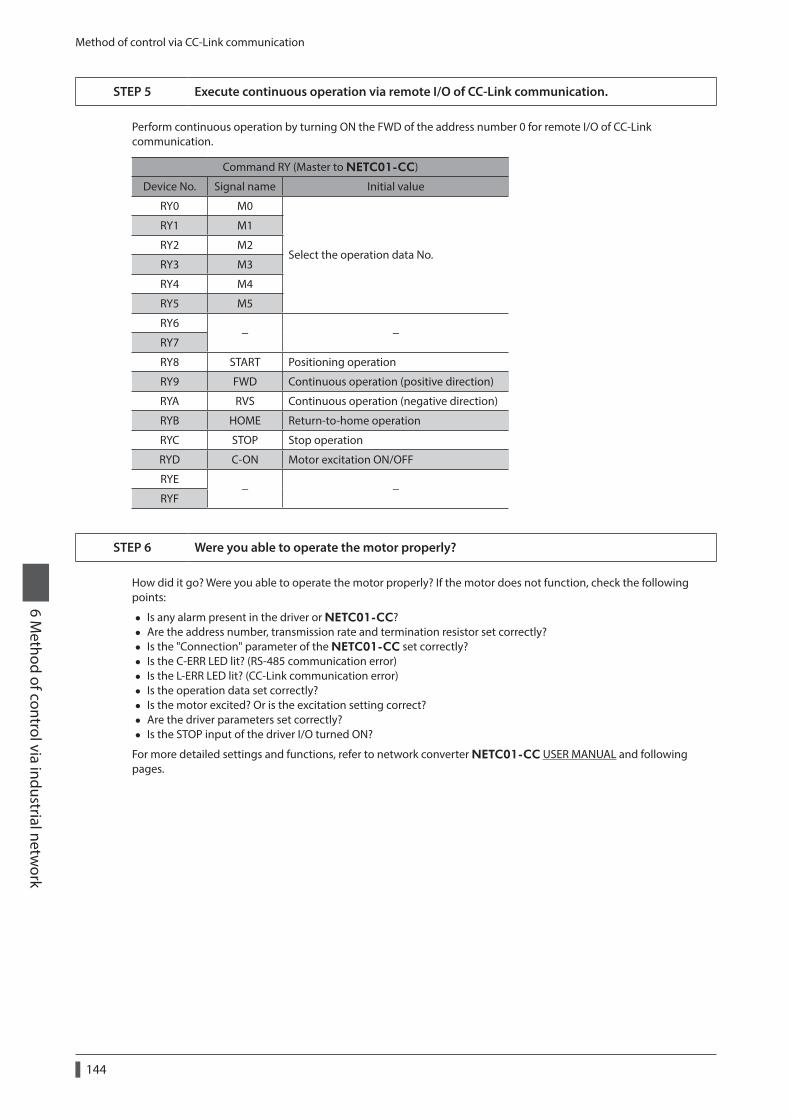
Method of control via CC-Link communication
144
6 Method of control via industrial netw
ork
STEP 5 Execute continuous operation via remote I/O of CC-Link communication.
Perform continuous operation by turning ON the FWD of the address number 0 for remote I/O of CC-Link communication.
Command RY (Master to NETC01-CC)
Device No. Signal name Initial value
RY0 M0
Select the operation data No.
RY1 M1
RY2 M2
RY3 M3
RY4 M4
RY5 M5
RY6− −
RY7
RY8 START Positioning operation
RY9 FWD Continuous operation (positive direction)
RYA RVS Continuous operation (negative direction)
RYB HOME Return-to-home operation
RYC STOP Stop operation
RYD C-ON Motor excitation ON/OFF
RYE− −
RYF
STEP 6 Were you able to operate the motor properly?
How did it go? Were you able to operate the motor properly? If the motor does not function, check the following points:
• Is any alarm present in the driver or NETC01-CC? • Are the address number, transmission rate and termination resistor set correctly? • Is the "Connection" parameter of the NETC01-CC set correctly? • Is the C-ERR LED lit? (RS-485 communication error) • Is the L-ERR LED lit? (CC-Link communication error) • Is the operation data set correctly? • Is the motor excited? Or is the excitation setting correct? • Are the driver parameters set correctly? • Is the STOP input of the driver I/O turned ON?
For more detailed settings and functions, refer to network converter NETC01-CC USER MANUAL and following pages.
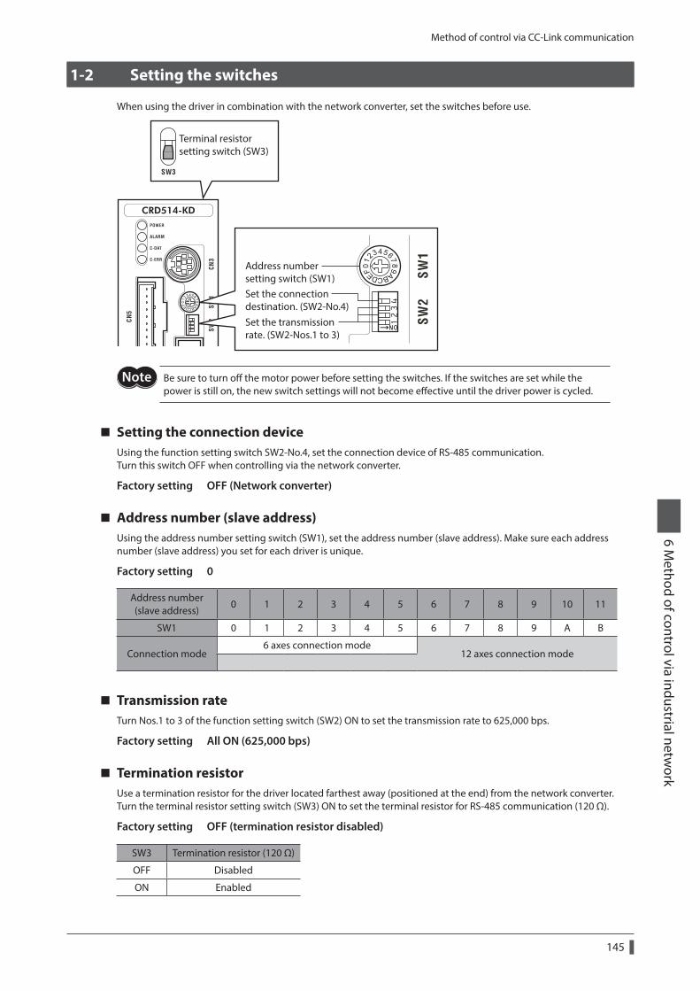
Method of control via CC-Link communication
145
6 Method of control via industrial netw
ork
1-2 Setting the switches
When using the driver in combination with the network converter, set the switches before use.
Address numbersetting switch (SW1)
Set the transmissionrate. (SW2-Nos.1 to 3)
Set the connectiondestination. (SW2-No.4)
Terminal resistor setting switch (SW3)
Be sure to turn off the motor power before setting the switches. If the switches are set while the power is still on, the new switch settings will not become effective until the driver power is cycled.
Setting the connection deviceUsing the function setting switch SW2-No.4, set the connection device of RS-485 communication.Turn this switch OFF when controlling via the network converter.
Factory setting OFF (Network converter)
Address number (slave address)Using the address number setting switch (SW1), set the address number (slave address). Make sure each address number (slave address) you set for each driver is unique.
Factory setting 0
Address number (slave address)
0 1 2 3 4 5 6 7 8 9 10 11
SW1 0 1 2 3 4 5 6 7 8 9 A B
Connection mode6 axes connection mode
12 axes connection mode
Transmission rateTurn Nos.1 to 3 of the function setting switch (SW2) ON to set the transmission rate to 625,000 bps.
Factory setting All ON (625,000 bps)
Termination resistorUse a termination resistor for the driver located farthest away (positioned at the end) from the network converter. Turn the terminal resistor setting switch (SW3) ON to set the terminal resistor for RS-485 communication (120 Ω).
Factory setting OFF (termination resistor disabled)
SW3 Termination resistor (120 Ω)
OFF Disabled
ON Enabled
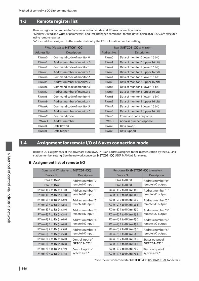
Method of control via CC-Link communication
146
6 Method of control via industrial netw
ork
1-3 Remote register list
Remote register is common to 6-axes connection mode and 12-axes connection mode."Monitor", "read and write of parameters" and "maintenance command" for the driver or NETC01-CC are executed using remote register."n" is an address assigned to the master station by the CC-Link station number setting.
RWw (Master to NETC01-CC) RWr (NETC01-CC to master)
Address No. Description Address No. Description
RWwn0 Command code of monitor 0 RWrn0 Data of monitor 0 (lower 16 bit)
RWwn1 Address number of monitor 0 RWrn1 Data of monitor 0 (upper 16 bit)
RWwn2 Command code of monitor 1 RWrn2 Data of monitor 1 (lower 16 bit)
RWwn3 Address number of monitor 1 RWrn3 Data of monitor 1 (upper 16 bit)
RWwn4 Command code of monitor 2 RWrn4 Data of monitor 2 (lower 16 bit)
RWwn5 Address number of monitor 2 RWrn5 Data of monitor 2 (upper 16 bit)
RWwn6 Command code of monitor 3 RWrn6 Data of monitor 3 (lower 16 bit)
RWwn7 Address number of monitor 3 RWrn7 Data of monitor 3 (upper 16 bit)
RWwn8 Command code of monitor 4 RWrn8 Data of monitor 4 (lower 16 bit)
RWwn9 Address number of monitor 4 RWrn9 Data of monitor 4 (upper 16 bit)
RWwnA Command code of monitor 5 RWrnA Data of monitor 5 (lower 16 bit)
RWwnB Address number of monitor 5 RWrnB Data of monitor 5 (upper 16 bit)
RWwnC Command code RWrnC Command code response
RWwnD Address number RWrnD Address number response
RWwnE Data (lower) RWrnE Data (lower)
RWwnF Data (upper) RWrnF Data (upper)
1-4 Assignment for remote I/O of 6 axes connection mode
Remote I/O assignments of the driver are as follows. "n" is an address assigned to the master station by the CC-Link station number setting. See the network converter NETC01-CC USER MANUAL for 6-axes.
Assignment list of remote I/O
Command RY (Master to NETC01-CC) Response RX (NETC01-CC to master)
Device No. Description Device No. Description
RYn7 to RYn0 Address number "0" remote I/O input
RXn7 to RXn0 Address number "0" remote I/O outputRYnF to RYn8 RXnF to RXn8
RY (n+1) 7 to RY (n+1) 0 Address number "1" remote I/O input
RX (n+1) 7 to RX (n+1) 0 Address number "1" remote I/O outputRY (n+1) F to RY (n+1) 8 RX (n+1) F to RX (n+1) 8
RY (n+2) 7 to RY (n+2) 0 Address number "2" remote I/O input
RX (n+2) 7 to RX (n+2) 0 Address number "2" remote I/O outputRY (n+2) F to RY (n+2) 8 RX (n+2) F to RX (n+2) 8
RY (n+3) 7 to RY (n+3) 0 Address number "3" remote I/O input
RX (n+3) 7 to RX (n+3) 0 Address number "3" remote I/O outputRY (n+3) F to RY (n+3) 8 RX (n+3) F to RX (n+3) 8
RY (n+4) 7 to RY (n+4) 0 Address number "4" remote I/O input
RX (n+4) 7 to RX (n+4) 0 Address number "4" remote I/O outputRY (n+4) F to RY (n+4) 8 RX (n+4) F to RX (n+4) 8
RY (n+5) 7 to RY (n+5) 0 Address number "5" remote I/O input
RX (n+5) 7 to RX (n+5) 0 Address number "5" remote I/O outputRY (n+5) F to RY (n+5) 8 RX (n+5) F to RX (n+5) 8
RY (n+6) 7 to RY (n+6) 0 Control input of NETC01-CC *
RX (n+6) 7 to RX (n+6) 0 Status output of NETC01-CC *RY (n+6) F to RY (n+6) 8 RX (n+6) F to RX (n+6) 8
RY (n+7) 7 to RY (n+7) 0 Control input of system area *
RX (n+7) 7 to RX (n+7) 0 Status output of system area *RY (n+7) F to RY (n+7) 8 RX (n+7) F to RX (n+7) 8
* See the network converter NETC01-CC USER MANUAL for details.
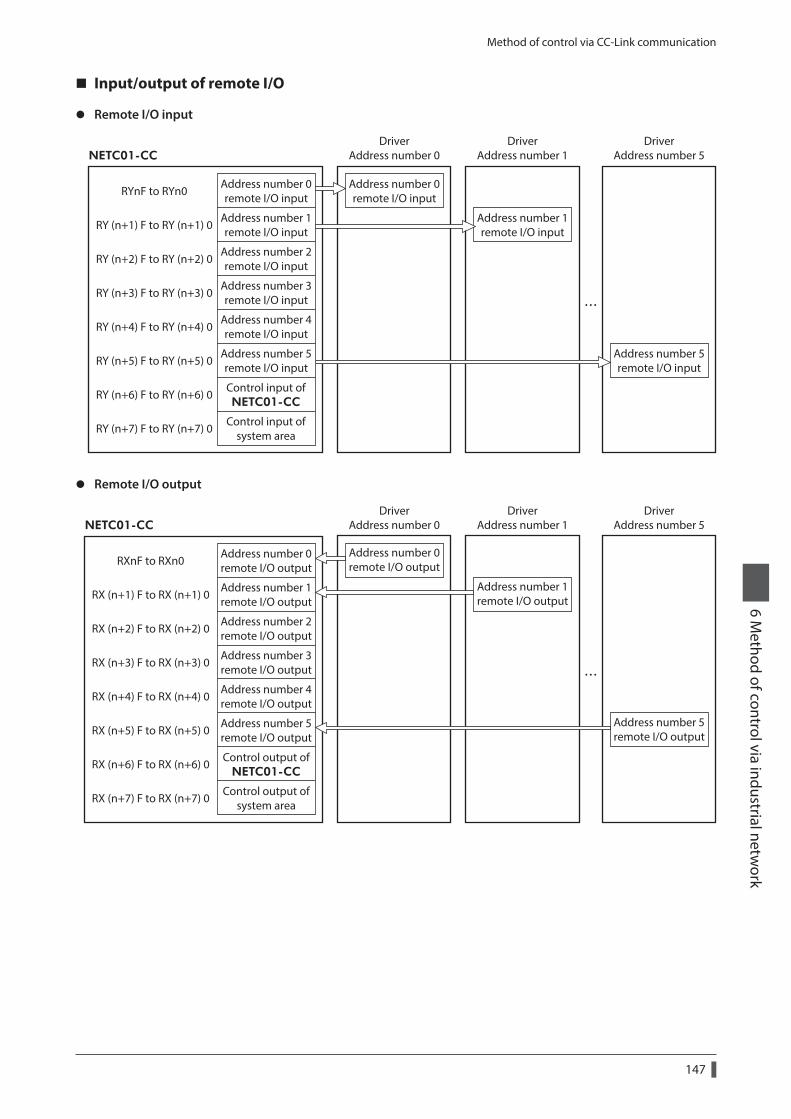
Method of control via CC-Link communication
147
6 Method of control via industrial netw
ork
Input/output of remote I/O
z Remote I/O input
Address number 0remote I/O input
Address number 1remote I/O input
Address number 2remote I/O input
Address number 3remote I/O input
Address number 4remote I/O input
Address number 5remote I/O input
Address number 0remote I/O input
Address number 1remote I/O input
RYnF to RYn0
RY (n+1) F to RY (n+1) 0
RY (n+2) F to RY (n+2) 0
RY (n+3) F to RY (n+3) 0
RY (n+4) F to RY (n+4) 0
RY (n+5) F to RY (n+5) 0
Control input ofNETC01-CC
RY (n+6) F to RY (n+6) 0
Control input ofsystem areaRY (n+7) F to RY (n+7) 0
NETC01-CC
DriverAddress number 0
DriverAddress number 1
Address number 5remote I/O input
DriverAddress number 5
z Remote I/O output
Address number 0remote I/O output
Address number 1remote I/O output
Address number 2remote I/O output
Address number 3remote I/O output
Address number 4remote I/O output
Address number 5remote I/O output
Address number 0remote I/O output
Address number 1remote I/O output
RXnF to RXn0
RX (n+1) F to RX (n+1) 0
RX (n+2) F to RX (n+2) 0
RX (n+3) F to RX (n+3) 0
RX (n+4) F to RX (n+4) 0
RX (n+5) F to RX (n+5) 0
Control output ofNETC01-CC
RX (n+6) F to RX (n+6) 0
Control output ofsystem areaRX (n+7) F to RX (n+7) 0
NETC01-CC
DriverAddress number 0
DriverAddress number 1
Address number 5remote I/O output
DriverAddress number 5
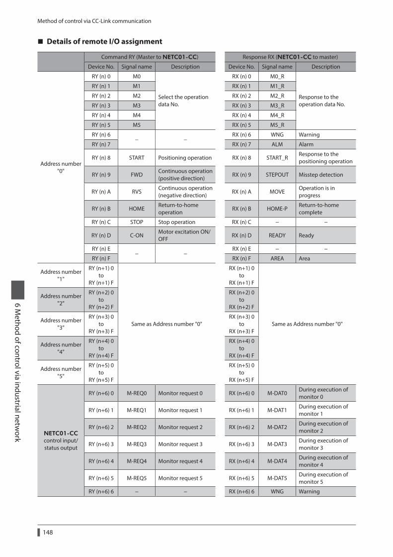
Method of control via CC-Link communication
148
6 Method of control via industrial netw
ork
Details of remote I/O assignment
Command RY (Master to NETC01-CC) Response RX (NETC01-CC to master)
Device No. Signal name Description Device No. Signal name Description
Address number "0"
RY (n) 0 M0
Select the operation data No.
RX (n) 0 M0_R
Response to the operation data No.
RY (n) 1 M1 RX (n) 1 M1_R
RY (n) 2 M2 RX (n) 2 M2_R
RY (n) 3 M3 RX (n) 3 M3_R
RY (n) 4 M4 RX (n) 4 M4_R
RY (n) 5 M5 RX (n) 5 M5_R
RY (n) 6− −
RX (n) 6 WNG Warning
RY (n) 7 RX (n) 7 ALM Alarm
RY (n) 8 START Positioning operation RX (n) 8 START_RResponse to the positioning operation
RY (n) 9 FWDContinuous operation (positive direction)
RX (n) 9 STEPOUT Misstep detection
RY (n) A RVSContinuous operation (negative direction)
RX (n) A MOVEOperation is in progress
RY (n) B HOMEReturn-to-home operation
RX (n) B HOME-PReturn-to-home complete
RY (n) C STOP Stop operation RX (n) C − −
RY (n) D C-ONMotor excitation ON/OFF
RX (n) D READY Ready
RY (n) E− −
RX (n) E − −
RY (n) F RX (n) F AREA Area
Address number "1"
RY (n+1) 0 to
RY (n+1) F
Same as Address number "0"
RX (n+1) 0 to
RX (n+1) F
Same as Address number "0"
Address number "2"
RY (n+2) 0 to
RY (n+2) F
RX (n+2) 0 to
RX (n+2) F
Address number "3"
RY (n+3) 0 to
RY (n+3) F
RX (n+3) 0 to
RX (n+3) F
Address number "4"
RY (n+4) 0 to
RY (n+4) F
RX (n+4) 0 to
RX (n+4) F
Address number "5"
RY (n+5) 0 to
RY (n+5) F
RX (n+5) 0 to
RX (n+5) F
NETC01-CC control input/ status output
RY (n+6) 0 M-REQ0 Monitor request 0 RX (n+6) 0 M-DAT0During execution of monitor 0
RY (n+6) 1 M-REQ1 Monitor request 1 RX (n+6) 1 M-DAT1During execution of monitor 1
RY (n+6) 2 M-REQ2 Monitor request 2 RX (n+6) 2 M-DAT2During execution of monitor 2
RY (n+6) 3 M-REQ3 Monitor request 3 RX (n+6) 3 M-DAT3During execution of monitor 3
RY (n+6) 4 M-REQ4 Monitor request 4 RX (n+6) 4 M-DAT4During execution of monitor 4
RY (n+6) 5 M-REQ5 Monitor request 5 RX (n+6) 5 M-DAT5During execution of monitor 5
RY (n+6) 6 − − RX (n+6) 6 WNG Warning
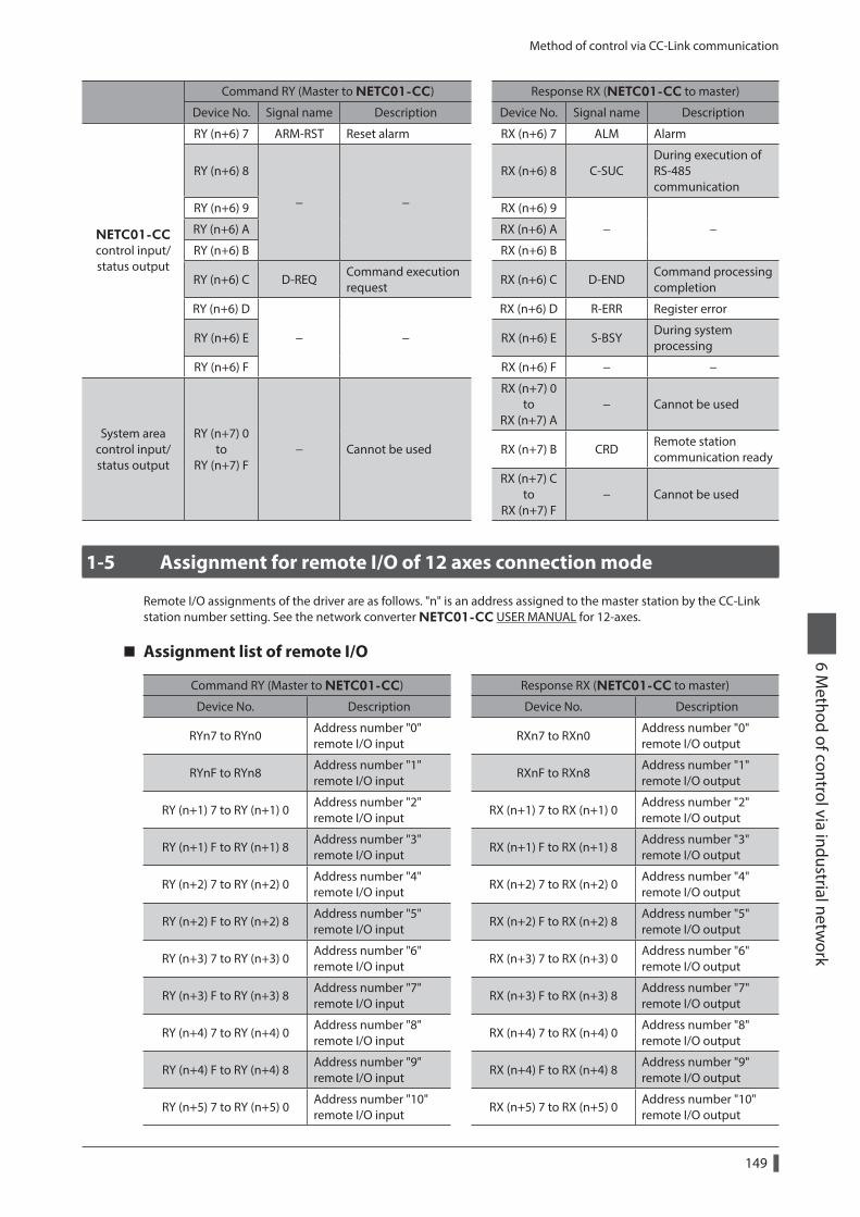
Method of control via CC-Link communication
149
6 Method of control via industrial netw
ork
Command RY (Master to NETC01-CC) Response RX (NETC01-CC to master)
Device No. Signal name Description Device No. Signal name Description
NETC01-CC control input/ status output
RY (n+6) 7 ARM-RST Reset alarm RX (n+6) 7 ALM Alarm
RY (n+6) 8
− −
RX (n+6) 8 C-SUCDuring execution of RS-485 communication
RY (n+6) 9 RX (n+6) 9
− −RY (n+6) A RX (n+6) A
RY (n+6) B RX (n+6) B
RY (n+6) C D-REQCommand execution request
RX (n+6) C D-ENDCommand processing completion
RY (n+6) D
− −
RX (n+6) D R-ERR Register error
RY (n+6) E RX (n+6) E S-BSYDuring system processing
RY (n+6) F RX (n+6) F − −
System area control input/ status output
RY (n+7) 0 to
RY (n+7) F− Cannot be used
RX (n+7) 0 to
RX (n+7) A− Cannot be used
RX (n+7) B CRDRemote station communication ready
RX (n+7) C to
RX (n+7) F− Cannot be used
1-5 Assignment for remote I/O of 12 axes connection mode
Remote I/O assignments of the driver are as follows. "n" is an address assigned to the master station by the CC-Link station number setting. See the network converter NETC01-CC USER MANUAL for 12-axes.
Assignment list of remote I/O
Command RY (Master to NETC01-CC) Response RX (NETC01-CC to master)
Device No. Description Device No. Description
RYn7 to RYn0Address number "0" remote I/O input
RXn7 to RXn0Address number "0" remote I/O output
RYnF to RYn8Address number "1" remote I/O input
RXnF to RXn8Address number "1" remote I/O output
RY (n+1) 7 to RY (n+1) 0Address number "2" remote I/O input
RX (n+1) 7 to RX (n+1) 0Address number "2" remote I/O output
RY (n+1) F to RY (n+1) 8Address number "3" remote I/O input
RX (n+1) F to RX (n+1) 8Address number "3" remote I/O output
RY (n+2) 7 to RY (n+2) 0Address number "4" remote I/O input
RX (n+2) 7 to RX (n+2) 0Address number "4" remote I/O output
RY (n+2) F to RY (n+2) 8Address number "5" remote I/O input
RX (n+2) F to RX (n+2) 8Address number "5" remote I/O output
RY (n+3) 7 to RY (n+3) 0Address number "6" remote I/O input
RX (n+3) 7 to RX (n+3) 0Address number "6" remote I/O output
RY (n+3) F to RY (n+3) 8Address number "7" remote I/O input
RX (n+3) F to RX (n+3) 8Address number "7" remote I/O output
RY (n+4) 7 to RY (n+4) 0Address number "8" remote I/O input
RX (n+4) 7 to RX (n+4) 0Address number "8" remote I/O output
RY (n+4) F to RY (n+4) 8Address number "9" remote I/O input
RX (n+4) F to RX (n+4) 8Address number "9" remote I/O output
RY (n+5) 7 to RY (n+5) 0Address number "10" remote I/O input
RX (n+5) 7 to RX (n+5) 0Address number "10" remote I/O output
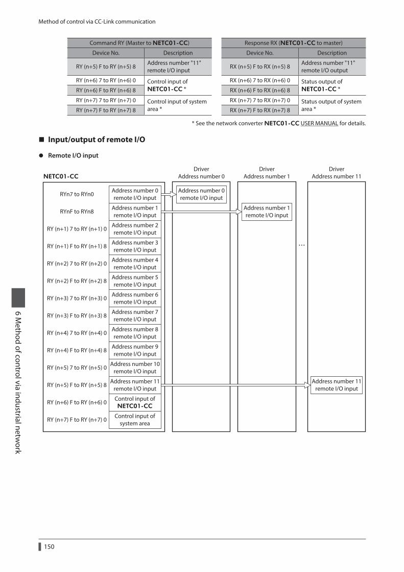
Method of control via CC-Link communication
150
6 Method of control via industrial netw
ork
Command RY (Master to NETC01-CC) Response RX (NETC01-CC to master)
Device No. Description Device No. Description
RY (n+5) F to RY (n+5) 8Address number "11" remote I/O input
RX (n+5) F to RX (n+5) 8Address number "11" remote I/O output
RY (n+6) 7 to RY (n+6) 0 Control input of NETC01-CC *
RX (n+6) 7 to RX (n+6) 0 Status output of NETC01-CC *RY (n+6) F to RY (n+6) 8 RX (n+6) F to RX (n+6) 8
RY (n+7) 7 to RY (n+7) 0 Control input of system area *
RX (n+7) 7 to RX (n+7) 0 Status output of system area *RY (n+7) F to RY (n+7) 8 RX (n+7) F to RX (n+7) 8
* See the network converter NETC01-CC USER MANUAL for details.
Input/output of remote I/O
z Remote I/O input
RYn7 to RYn0
RYnF to RYn8
RY (n+1) 7 to RY (n+1) 0
RY (n+1) F to RY (n+1) 8
RY (n+2) 7 to RY (n+2) 0
RY (n+2) F to RY (n+2) 8
RY (n+3) 7 to RY (n+3) 0
RY (n+3) F to RY (n+3) 8
RY (n+4) 7 to RY (n+4) 0
RY (n+4) F to RY (n+4) 8
RY (n+5) 7 to RY (n+5) 0
RY (n+5) F to RY (n+5) 8
RY (n+6) F to RY (n+6) 0
RY (n+7) F to RY (n+7) 0
Address number 0remote I/O input
Address number 1remote I/O input
Address number 2remote I/O input
Address number 3remote I/O input
Address number 4remote I/O input
Address number 5remote I/O input
Address number 6remote I/O input
Address number 7remote I/O input
Address number 8remote I/O input
Address number 9remote I/O input
Address number 10remote I/O input
Address number 11remote I/O input
Address number 0remote I/O input
Address number 1remote I/O input
Control input ofNETC01-CC
Control input ofsystem area
NETC01-CC
DriverAddress number 0
DriverAddress number 1
Address number 11remote I/O input
DriverAddress number 11
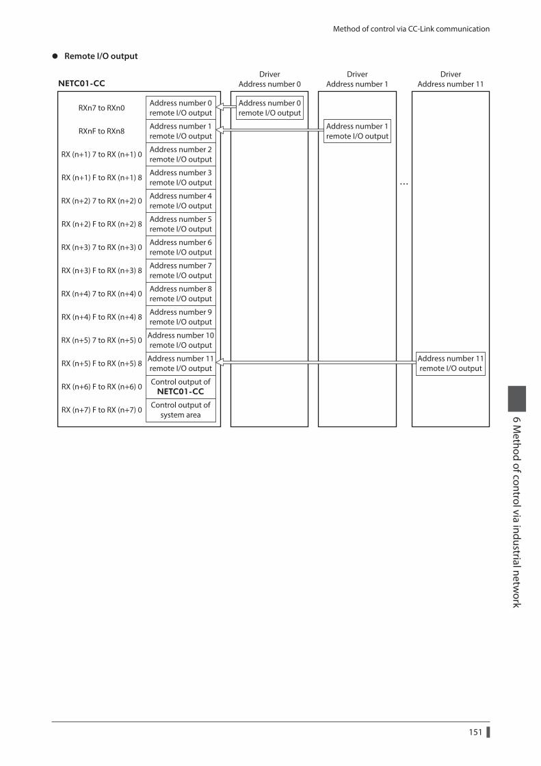
Method of control via CC-Link communication
151
6 Method of control via industrial netw
ork
z Remote I/O output
RXn7 to RXn0
RXnF to RXn8
RX (n+1) 7 to RX (n+1) 0
RX (n+1) F to RX (n+1) 8
RX (n+2) 7 to RX (n+2) 0
RX (n+2) F to RX (n+2) 8
RX (n+3) 7 to RX (n+3) 0
RX (n+3) F to RX (n+3) 8
RX (n+4) 7 to RX (n+4) 0
RX (n+4) F to RX (n+4) 8
RX (n+5) 7 to RX (n+5) 0
RX (n+5) F to RX (n+5) 8
RX (n+6) F to RX (n+6) 0
RX (n+7) F to RX (n+7) 0
Address number 0remote I/O output
Address number 1remote I/O output
Address number 2remote I/O output
Address number 3remote I/O output
Address number 4remote I/O output
Address number 5remote I/O output
Address number 6remote I/O output
Address number 7remote I/O output
Address number 8remote I/O output
Address number 9remote I/O output
Address number 10remote I/O output
Address number 11remote I/O output
Address number 0remote I/O output
Address number 1remote I/O output
Control output ofNETC01-CC
Control output ofsystem area
NETC01-CC
DriverAddress number 0
DriverAddress number 1
Address number 11remote I/O output
DriverAddress number 11
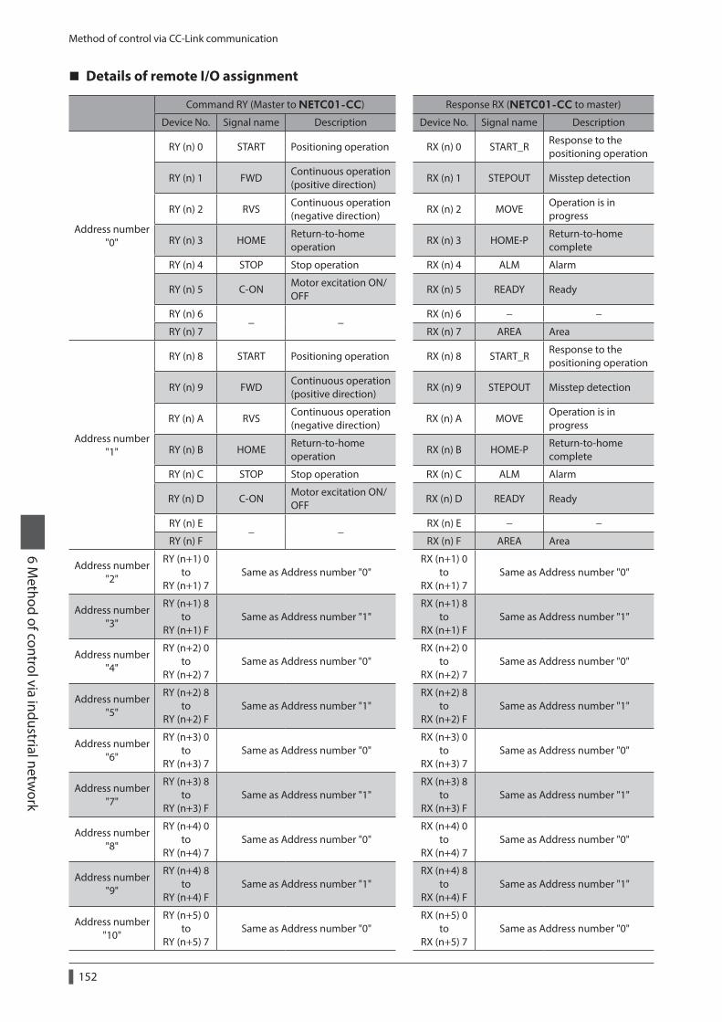
Method of control via CC-Link communication
152
6 Method of control via industrial netw
ork
Details of remote I/O assignment
Command RY (Master to NETC01-CC) Response RX (NETC01-CC to master)
Device No. Signal name Description Device No. Signal name Description
Address number "0"
RY (n) 0 START Positioning operation RX (n) 0 START_RResponse to the positioning operation
RY (n) 1 FWDContinuous operation (positive direction)
RX (n) 1 STEPOUT Misstep detection
RY (n) 2 RVSContinuous operation (negative direction)
RX (n) 2 MOVEOperation is in progress
RY (n) 3 HOMEReturn-to-home operation
RX (n) 3 HOME-PReturn-to-home complete
RY (n) 4 STOP Stop operation RX (n) 4 ALM Alarm
RY (n) 5 C-ONMotor excitation ON/OFF
RX (n) 5 READY Ready
RY (n) 6− −
RX (n) 6 − −
RY (n) 7 RX (n) 7 AREA Area
Address number "1"
RY (n) 8 START Positioning operation RX (n) 8 START_RResponse to the positioning operation
RY (n) 9 FWDContinuous operation (positive direction)
RX (n) 9 STEPOUT Misstep detection
RY (n) A RVSContinuous operation (negative direction)
RX (n) A MOVEOperation is in progress
RY (n) B HOMEReturn-to-home operation
RX (n) B HOME-PReturn-to-home complete
RY (n) C STOP Stop operation RX (n) C ALM Alarm
RY (n) D C-ONMotor excitation ON/OFF
RX (n) D READY Ready
RY (n) E− −
RX (n) E − −
RY (n) F RX (n) F AREA Area
Address number "2"
RY (n+1) 0 to
RY (n+1) 7Same as Address number "0"
RX (n+1) 0 to
RX (n+1) 7Same as Address number "0"
Address number "3"
RY (n+1) 8 to
RY (n+1) FSame as Address number "1"
RX (n+1) 8 to
RX (n+1) FSame as Address number "1"
Address number "4"
RY (n+2) 0 to
RY (n+2) 7Same as Address number "0"
RX (n+2) 0 to
RX (n+2) 7Same as Address number "0"
Address number "5"
RY (n+2) 8 to
RY (n+2) FSame as Address number "1"
RX (n+2) 8 to
RX (n+2) FSame as Address number "1"
Address number "6"
RY (n+3) 0 to
RY (n+3) 7Same as Address number "0"
RX (n+3) 0 to
RX (n+3) 7Same as Address number "0"
Address number "7"
RY (n+3) 8 to
RY (n+3) FSame as Address number "1"
RX (n+3) 8 to
RX (n+3) FSame as Address number "1"
Address number "8"
RY (n+4) 0 to
RY (n+4) 7Same as Address number "0"
RX (n+4) 0 to
RX (n+4) 7Same as Address number "0"
Address number "9"
RY (n+4) 8 to
RY (n+4) FSame as Address number "1"
RX (n+4) 8 to
RX (n+4) FSame as Address number "1"
Address number "10"
RY (n+5) 0 to
RY (n+5) 7Same as Address number "0"
RX (n+5) 0 to
RX (n+5) 7Same as Address number "0"
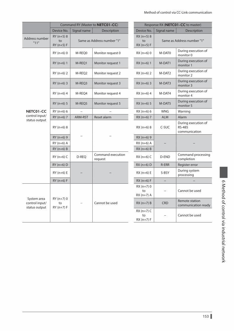
Method of control via CC-Link communication
153
6 Method of control via industrial netw
ork
Command RY (Master to NETC01-CC) Response RX (NETC01-CC to master)
Device No. Signal name Description Device No. Signal name Description
Address number "11"
RY (n+5) 8 to
RY (n+5) FSame as Address number "1"
RX (n+5) 8 to
RX (n+5) FSame as Address number "1"
NETC01-CC control input/ status output
RY (n+6) 0 M-REQ0 Monitor request 0 RX (n+6) 0 M-DAT0During execution of monitor 0
RY (n+6) 1 M-REQ1 Monitor request 1 RX (n+6) 1 M-DAT1During execution of monitor 1
RY (n+6) 2 M-REQ2 Monitor request 2 RX (n+6) 2 M-DAT2During execution of monitor 2
RY (n+6) 3 M-REQ3 Monitor request 3 RX (n+6) 3 M-DAT3During execution of monitor 3
RY (n+6) 4 M-REQ4 Monitor request 4 RX (n+6) 4 M-DAT4During execution of monitor 4
RY (n+6) 5 M-REQ5 Monitor request 5 RX (n+6) 5 M-DAT5During execution of monitor 5
RY (n+6) 6 − − RX (n+6) 6 WNG Warning
RY (n+6) 7 ARM-RST Reset alarm RX (n+6) 7 ALM Alarm
RY (n+6) 8
− −
RX (n+6) 8 C-SUCDuring execution of RS-485 communication
RY (n+6) 9 RX (n+6) 9
− −RY (n+6) A RX (n+6) A
RY (n+6) B RX (n+6) B
RY (n+6) C D-REQCommand execution request
RX (n+6) C D-ENDCommand processing completion
RY (n+6) D
− −
RX (n+6) D R-ERR Register error
RY (n+6) E RX (n+6) E S-BSYDuring system processing
RY (n+6) F RX (n+6) F − −
System area control input/ status output
RY (n+7) 0 to
RY (n+7) F− Cannot be used
RX (n+7) 0 to
RX (n+7) A− Cannot be used
RX (n+7) B CRDRemote station communication ready
RX (n+7) C to
RX (n+7) F− Cannot be used
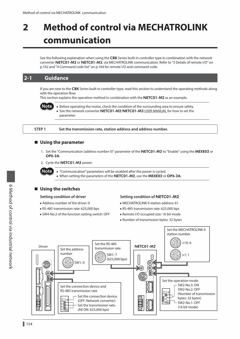
Method of control via MECHATROLINK communication
154
6 Method of control via industrial netw
ork
2 Method of control via MECHATROLINK communication
See the following explanation when using the CRK Series built-in controller type in combination with the network converter NETC01-M2 or NETC01-M3, via MECHATROLINK communication. Refer to "3 Details of remote I/O" on p.162 and "4 Command code list" on p.164 for remote I/O and command code.
2-1 Guidance
If you are new to the CRK Series built-in controller type, read this section to understand the operating methods along with the operation flow.This section explains the operation method in combination with the NETC01-M2 as an example.
• Before operating the motor, check the condition of the surrounding area to ensure safety. • See the network converter NETC01-M2/NETC01-M3 USER MANUAL for how to set the parameter.
STEP 1 Set the transmission rate, station address and address number.
Using the parameter
1. Set the "Communication (address number 0)" parameter of the NETC01-M2 to "Enable" using the MEXE02 or OPX-2A.
2. Cycle the NETC01-M2 power.
• “Communication” parameters will be enabled after the power is cycled. • When setting the parameters of the NETC01-M2, use the MEXE02 or OPX-2A.
Using the switches
Setting condition of driver
•Address number of the driver: 0
• RS-485 transmission rate: 625,000 bps
• SW4-No.2 of the function setting switch: OFF
Setting condition of NETC01-M2
•MECHATROLINK-II station address: 61
• RS-485 transmission rate: 625,000 bps
• Remote I/O occupied size: 16 bit mode
•Number of transmission bytes: 32 bytes
Set the address number
×10: 6
×1: 1
NETC01-M2Driver
Set the transmission rate.(All ON: 625,000 bps)
Set the operation mode
Set the MECHATROLINK-IIstation number
Set the RS-485transmission rate
SW1: 7(625,000 bps)
SW1: 0
SW2-No.3: ONSW2-No.2: OFF(Number of transmission bytes: 32 bytes)Set the connection device.
(OFF: Network converter)
Set the connection device andRS-485 transmission rate
SW2-No.1: OFF(16 bit mode)
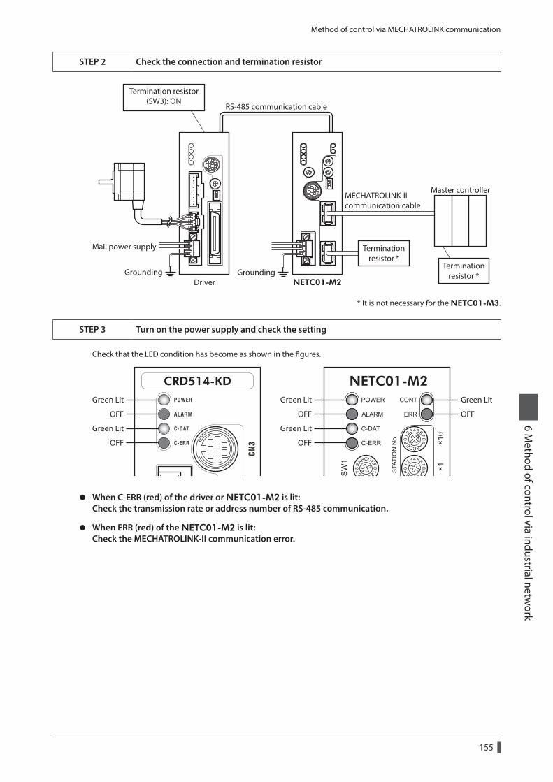
Method of control via MECHATROLINK communication
155
6 Method of control via industrial netw
ork
STEP 2 Check the connection and termination resistor
RS-485 communication cable
MECHATROLINK-IIcommunication cable
Mail power supply
NETC01-M2
Termination resistor(SW3): ON
DriverGroundingGrounding
Master controller
Terminationresistor *
Terminationresistor *
* It is not necessary for the NETC01-M3.
STEP 3 Turn on the power supply and check the setting
Check that the LED condition has become as shown in the figures.
Green LitGreen Lit
OFFOFF
Green Lit
OFF
Green Lit
OFF
Green Lit
OFF
z When C-ERR (red) of the driver or NETC01-M2 is lit: Check the transmission rate or address number of RS-485 communication.
z When ERR (red) of the NETC01-M2 is lit: Check the MECHATROLINK-II communication error.
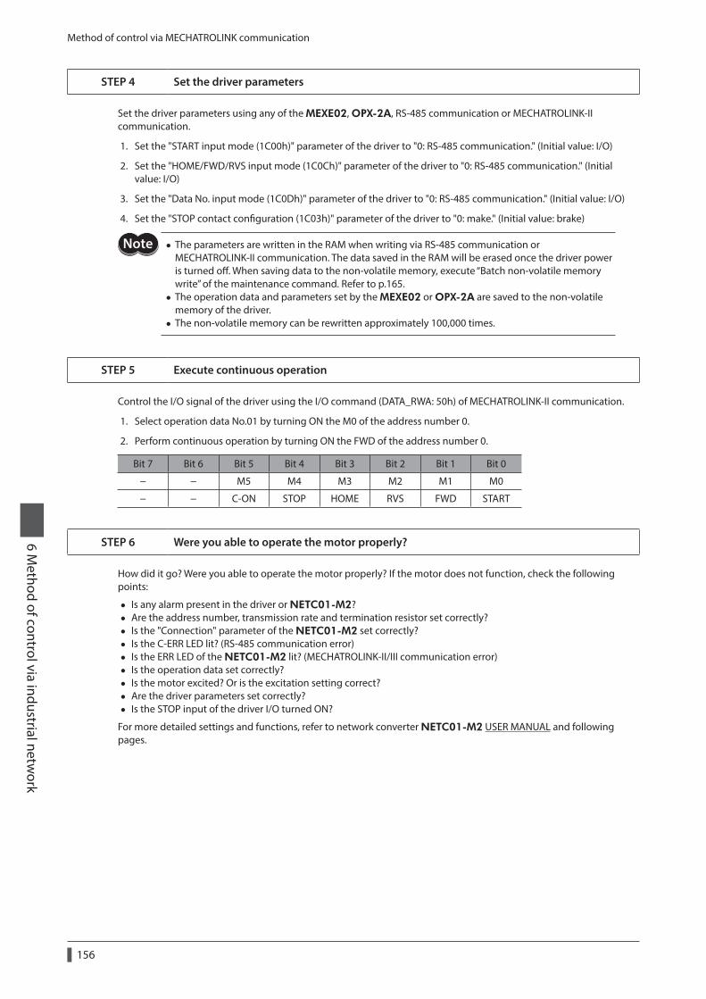
Method of control via MECHATROLINK communication
156
6 Method of control via industrial netw
ork
STEP 4 Set the driver parameters
Set the driver parameters using any of the MEXE02, OPX-2A, RS-485 communication or MECHATROLINK-II communication.
1. Set the "START input mode (1C00h)" parameter of the driver to "0: RS-485 communication." (Initial value: I/O)
2. Set the "HOME/FWD/RVS input mode (1C0Ch)" parameter of the driver to "0: RS-485 communication." (Initial value: I/O)
3. Set the "Data No. input mode (1C0Dh)" parameter of the driver to "0: RS-485 communication." (Initial value: I/O)
4. Set the "STOP contact configuration (1C03h)" parameter of the driver to "0: make." (Initial value: brake)
• The parameters are written in the RAM when writing via RS-485 communication or MECHATROLINK-II communication. The data saved in the RAM will be erased once the driver power is turned off. When saving data to the non-volatile memory, execute “Batch non-volatile memory write” of the maintenance command. Refer to p.165.
• The operation data and parameters set by the MEXE02 or OPX-2A are saved to the non-volatile memory of the driver.
• The non-volatile memory can be rewritten approximately 100,000 times.
STEP 5 Execute continuous operation
Control the I/O signal of the driver using the I/O command (DATA_RWA: 50h) of MECHATROLINK-II communication.
1. Select operation data No.01 by turning ON the M0 of the address number 0.
2. Perform continuous operation by turning ON the FWD of the address number 0.
Bit 7 Bit 6 Bit 5 Bit 4 Bit 3 Bit 2 Bit 1 Bit 0
− − M5 M4 M3 M2 M1 M0
− − C-ON STOP HOME RVS FWD START
STEP 6 Were you able to operate the motor properly?
How did it go? Were you able to operate the motor properly? If the motor does not function, check the following points:
• Is any alarm present in the driver or NETC01-M2? • Are the address number, transmission rate and termination resistor set correctly? • Is the "Connection" parameter of the NETC01-M2 set correctly? • Is the C-ERR LED lit? (RS-485 communication error) • Is the ERR LED of the NETC01-M2 lit? (MECHATROLINK-II/III communication error) • Is the operation data set correctly? • Is the motor excited? Or is the excitation setting correct? • Are the driver parameters set correctly? • Is the STOP input of the driver I/O turned ON?
For more detailed settings and functions, refer to network converter NETC01-M2 USER MANUAL and following pages.
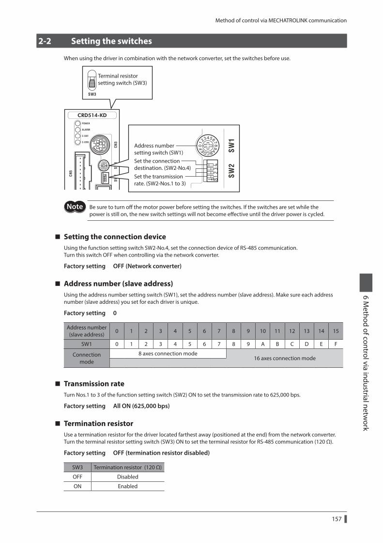
Method of control via MECHATROLINK communication
157
6 Method of control via industrial netw
ork
2-2 Setting the switches
When using the driver in combination with the network converter, set the switches before use.
Address numbersetting switch (SW1)
Set the transmissionrate. (SW2-Nos.1 to 3)
Set the connectiondestination. (SW2-No.4)
Terminal resistor setting switch (SW3)
Be sure to turn off the motor power before setting the switches. If the switches are set while the power is still on, the new switch settings will not become effective until the driver power is cycled.
Setting the connection deviceUsing the function setting switch SW2-No.4, set the connection device of RS-485 communication.Turn this switch OFF when controlling via the network converter.
Factory setting OFF (Network converter)
Address number (slave address)Using the address number setting switch (SW1), set the address number (slave address). Make sure each address number (slave address) you set for each driver is unique.
Factory setting 0
Address number (slave address)
0 1 2 3 4 5 6 7 8 9 10 11 12 13 14 15
SW1 0 1 2 3 4 5 6 7 8 9 A B C D E F
Connection mode
8 axes connection mode16 axes connection mode
Transmission rateTurn Nos.1 to 3 of the function setting switch (SW2) ON to set the transmission rate to 625,000 bps.
Factory setting All ON (625,000 bps)
Termination resistorUse a termination resistor for the driver located farthest away (positioned at the end) from the network converter. Turn the terminal resistor setting switch (SW3) ON to set the terminal resistor for RS-485 communication (120 Ω).
Factory setting OFF (termination resistor disabled)
SW3 Termination resistor (120 Ω)
OFF Disabled
ON Enabled
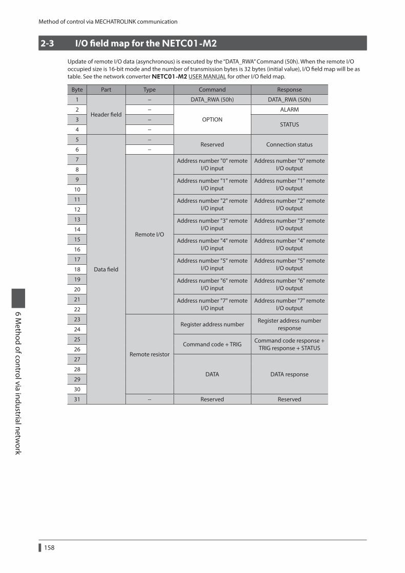
Method of control via MECHATROLINK communication
158
6 Method of control via industrial netw
ork
2-3 I/O field map for the NETC01-M2
Update of remote I/O data (asynchronous) is executed by the “DATA_RWA” Command (50h). When the remote I/O occupied size is 16-bit mode and the number of transmission bytes is 32 bytes (initial value), I/O field map will be as table. See the network converter NETC01-M2 USER MANUAL for other I/O field map.
Byte Part Type Command Response
1
Header field
− DATA_RWA (50h) DATA_RWA (50h)
2 −
OPTION
ALARM
3 −STATUS
4 −
5
Data field
−Reserved Connection status
6 −
7
Remote I/O
Address number "0" remote I/O input
Address number "0" remote I/O output8
9 Address number "1" remote I/O input
Address number "1" remote I/O output10
11 Address number "2" remote I/O input
Address number "2" remote I/O output12
13 Address number "3" remote I/O input
Address number "3" remote I/O output14
15 Address number "4" remote I/O input
Address number "4" remote I/O output16
17 Address number "5" remote I/O input
Address number "5" remote I/O output18
19 Address number "6" remote I/O input
Address number "6" remote I/O output20
21 Address number "7" remote I/O input
Address number "7" remote I/O output22
23
Remote resistor
Register address numberRegister address number
response24
25Command code + TRIG
Command code response + TRIG response + STATUS26
27
DATA DATA response28
29
30
31 − Reserved Reserved
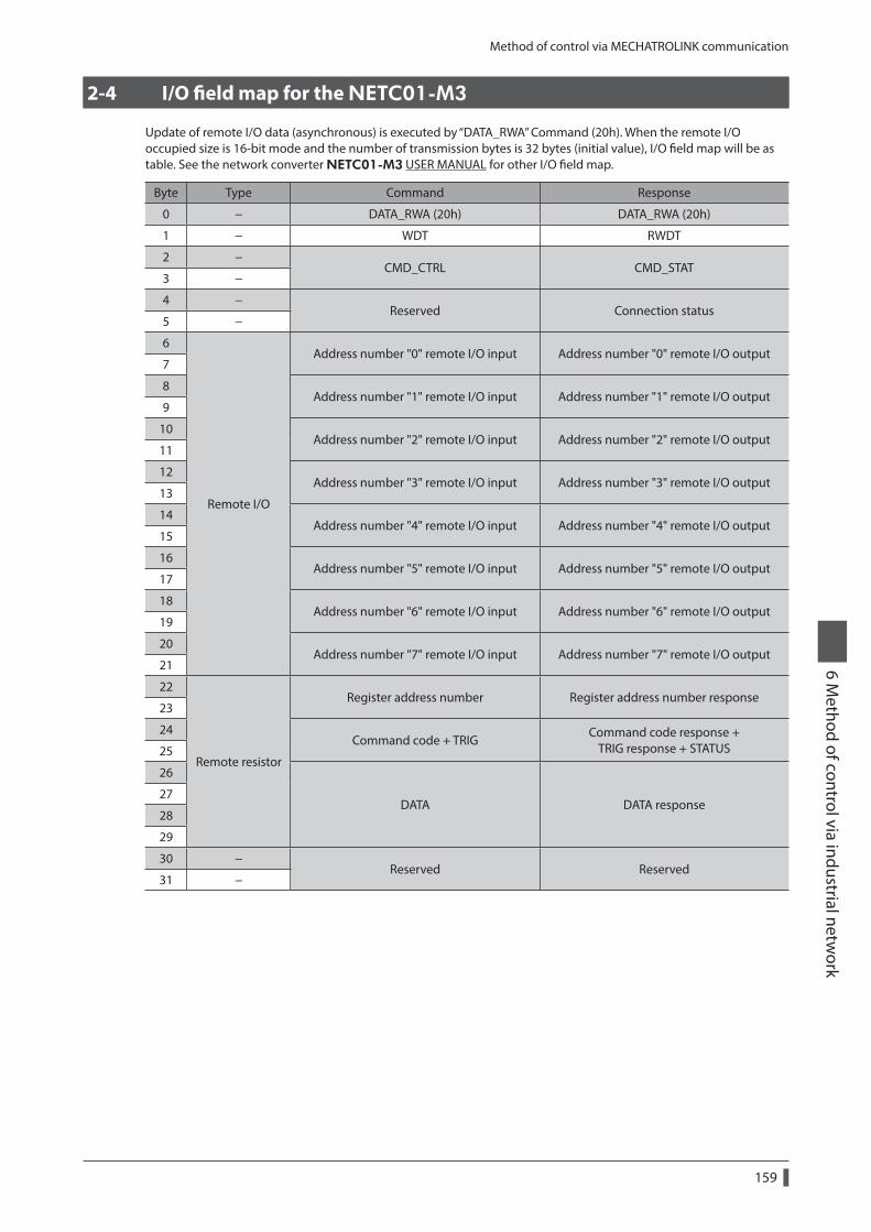
Method of control via MECHATROLINK communication
159
6 Method of control via industrial netw
ork
2-4 I/O field map for the NETC01-M3
Update of remote I/O data (asynchronous) is executed by “DATA_RWA” Command (20h). When the remote I/O occupied size is 16-bit mode and the number of transmission bytes is 32 bytes (initial value), I/O field map will be as table. See the network converter NETC01-M3 USER MANUAL for other I/O field map.
Byte Type Command Response
0 − DATA_RWA (20h) DATA_RWA (20h)
1 − WDT RWDT
2 −CMD_CTRL CMD_STAT
3 −
4 −Reserved Connection status
5 −
6
Remote I/O
Address number "0" remote I/O input Address number "0" remote I/O output7
8Address number "1" remote I/O input Address number "1" remote I/O output
9
10Address number "2" remote I/O input Address number "2" remote I/O output
11
12Address number "3" remote I/O input Address number "3" remote I/O output
13
14Address number "4" remote I/O input Address number "4" remote I/O output
15
16Address number "5" remote I/O input Address number "5" remote I/O output
17
18Address number "6" remote I/O input Address number "6" remote I/O output
19
20Address number "7" remote I/O input Address number "7" remote I/O output
21
22
Remote resistor
Register address number Register address number response23
24Command code + TRIG
Command code response + TRIG response + STATUS25
26
DATA DATA response27
28
29
30 −Reserved Reserved
31 −
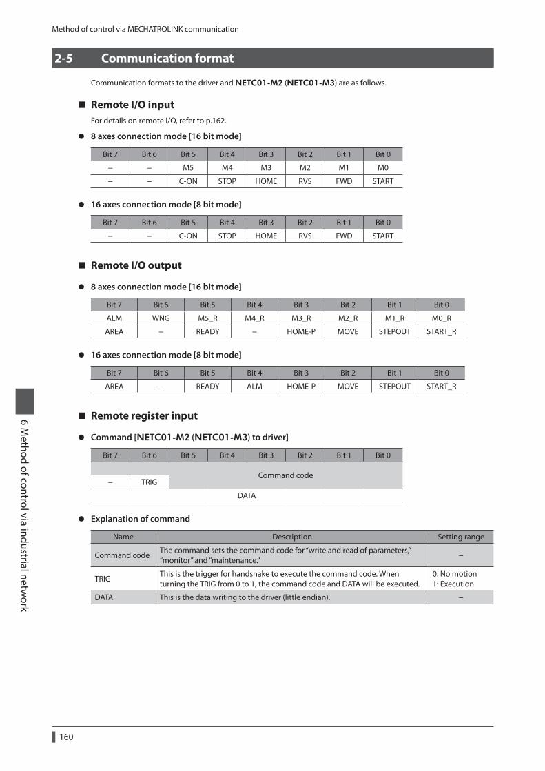
Method of control via MECHATROLINK communication
160
6 Method of control via industrial netw
ork
2-5 Communication format
Communication formats to the driver and NETC01-M2 (NETC01-M3) are as follows.
Remote I/O inputFor details on remote I/O, refer to p.162.
z 8 axes connection mode [16 bit mode]
Bit 7 Bit 6 Bit 5 Bit 4 Bit 3 Bit 2 Bit 1 Bit 0
− − M5 M4 M3 M2 M1 M0
− − C-ON STOP HOME RVS FWD START
z 16 axes connection mode [8 bit mode]
Bit 7 Bit 6 Bit 5 Bit 4 Bit 3 Bit 2 Bit 1 Bit 0
− − C-ON STOP HOME RVS FWD START
Remote I/O output
z 8 axes connection mode [16 bit mode]
Bit 7 Bit 6 Bit 5 Bit 4 Bit 3 Bit 2 Bit 1 Bit 0
ALM WNG M5_R M4_R M3_R M2_R M1_R M0_R
AREA − READY − HOME-P MOVE STEPOUT START_R
z 16 axes connection mode [8 bit mode]
Bit 7 Bit 6 Bit 5 Bit 4 Bit 3 Bit 2 Bit 1 Bit 0
AREA − READY ALM HOME-P MOVE STEPOUT START_R
Remote register input
z Command [NETC01-M2 (NETC01-M3) to driver]
Bit 7 Bit 6 Bit 5 Bit 4 Bit 3 Bit 2 Bit 1 Bit 0
Command code− TRIG
DATA
z Explanation of command
Name Description Setting range
Command codeThe command sets the command code for “write and read of parameters,” “monitor” and “maintenance."
−
TRIGThis is the trigger for handshake to execute the command code. When turning the TRIG from 0 to 1, the command code and DATA will be executed.
0: No motion 1: Execution
DATA This is the data writing to the driver (little endian). −
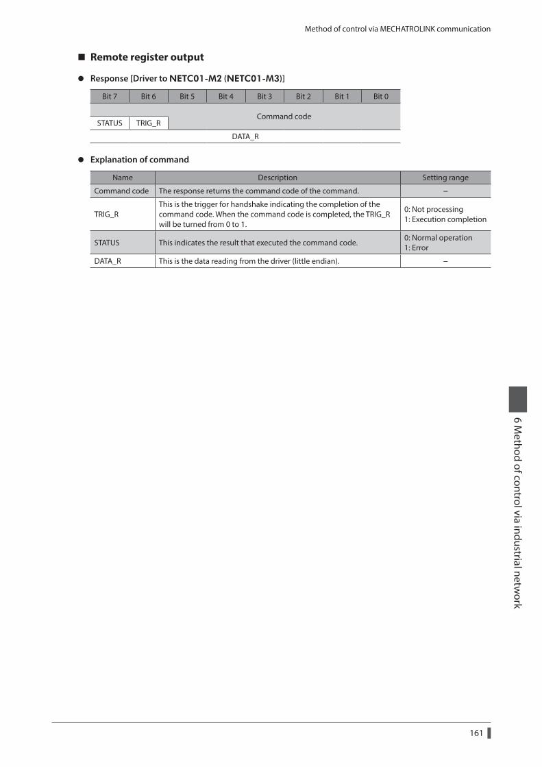
Method of control via MECHATROLINK communication
161
6 Method of control via industrial netw
ork
Remote register output
z Response [Driver to NETC01-M2 (NETC01-M3)]
Bit 7 Bit 6 Bit 5 Bit 4 Bit 3 Bit 2 Bit 1 Bit 0
Command codeSTATUS TRIG_R
DATA_R
z Explanation of command
Name Description Setting range
Command code The response returns the command code of the command. −
TRIG_RThis is the trigger for handshake indicating the completion of the command code. When the command code is completed, the TRIG_R will be turned from 0 to 1.
0: Not processing 1: Execution completion
STATUS This indicates the result that executed the command code.0: Normal operation 1: Error
DATA_R This is the data reading from the driver (little endian). −
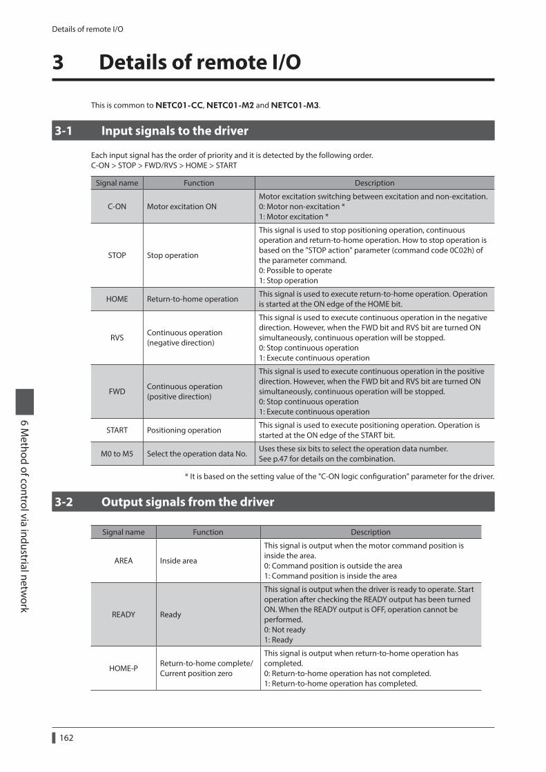
Details of remote I/O
162
6 Method of control via industrial netw
ork
3 Details of remote I/O
This is common to NETC01-CC, NETC01-M2 and NETC01-M3.
3-1 Input signals to the driver
Each input signal has the order of priority and it is detected by the following order.C-ON > STOP > FWD/RVS > HOME > START
Signal name Function Description
C-ON Motor excitation ONMotor excitation switching between excitation and non-excitation. 0: Motor non-excitation * 1: Motor excitation *
STOP Stop operation
This signal is used to stop positioning operation, continuous operation and return-to-home operation. How to stop operation is based on the "STOP action" parameter (command code 0C02h) of the parameter command. 0: Possible to operate 1: Stop operation
HOME Return-to-home operationThis signal is used to execute return-to-home operation. Operation is started at the ON edge of the HOME bit.
RVSContinuous operation (negative direction)
This signal is used to execute continuous operation in the negative direction. However, when the FWD bit and RVS bit are turned ON simultaneously, continuous operation will be stopped. 0: Stop continuous operation 1: Execute continuous operation
FWDContinuous operation (positive direction)
This signal is used to execute continuous operation in the positive direction. However, when the FWD bit and RVS bit are turned ON simultaneously, continuous operation will be stopped. 0: Stop continuous operation 1: Execute continuous operation
START Positioning operationThis signal is used to execute positioning operation. Operation is started at the ON edge of the START bit.
M0 to M5 Select the operation data No.Uses these six bits to select the operation data number. See p.47 for details on the combination.
* It is based on the setting value of the "C-ON logic configuration" parameter for the driver.
3-2 Output signals from the driver
Signal name Function Description
AREA Inside area
This signal is output when the motor command position is inside the area. 0: Command position is outside the area 1: Command position is inside the area
READY Ready
This signal is output when the driver is ready to operate. Start operation after checking the READY output has been turned ON. When the READY output is OFF, operation cannot be performed. 0: Not ready 1: Ready
HOME-PReturn-to-home complete/Current position zero
This signal is output when return-to-home operation has completed. 0: Return-to-home operation has not completed. 1: Return-to-home operation has completed.
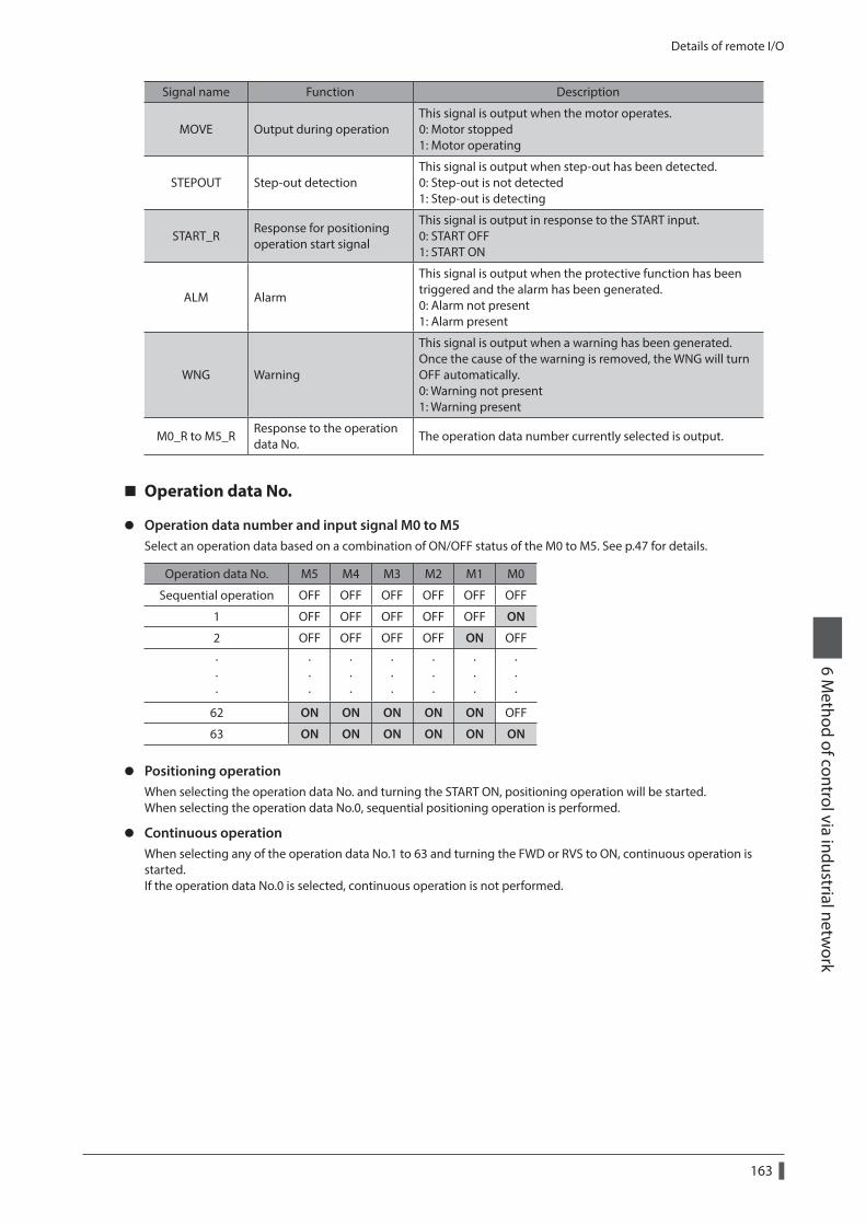
Details of remote I/O
163
6 Method of control via industrial netw
ork
Signal name Function Description
MOVE Output during operationThis signal is output when the motor operates. 0: Motor stopped 1: Motor operating
STEPOUT Step-out detectionThis signal is output when step-out has been detected. 0: Step-out is not detected 1: Step-out is detecting
START_RResponse for positioning operation start signal
This signal is output in response to the START input. 0: START OFF 1: START ON
ALM Alarm
This signal is output when the protective function has been triggered and the alarm has been generated. 0: Alarm not present 1: Alarm present
WNG Warning
This signal is output when a warning has been generated. Once the cause of the warning is removed, the WNG will turn OFF automatically. 0: Warning not present 1: Warning present
M0_R to M5_RResponse to the operation data No.
The operation data number currently selected is output.
Operation data No.
z Operation data number and input signal M0 to M5Select an operation data based on a combination of ON/OFF status of the M0 to M5. See p.47 for details.
Operation data No. M5 M4 M3 M2 M1 M0
Sequential operation OFF OFF OFF OFF OFF OFF
1 OFF OFF OFF OFF OFF ON
2 OFF OFF OFF OFF ON OFF
· · ·
· · ·
· · ·
· · ·
· · ·
· · ·
· · ·
62 ON ON ON ON ON OFF
63 ON ON ON ON ON ON
z Positioning operationWhen selecting the operation data No. and turning the START ON, positioning operation will be started.When selecting the operation data No.0, sequential positioning operation is performed.
z Continuous operationWhen selecting any of the operation data No.1 to 63 and turning the FWD or RVS to ON, continuous operation is started.If the operation data No.0 is selected, continuous operation is not performed.
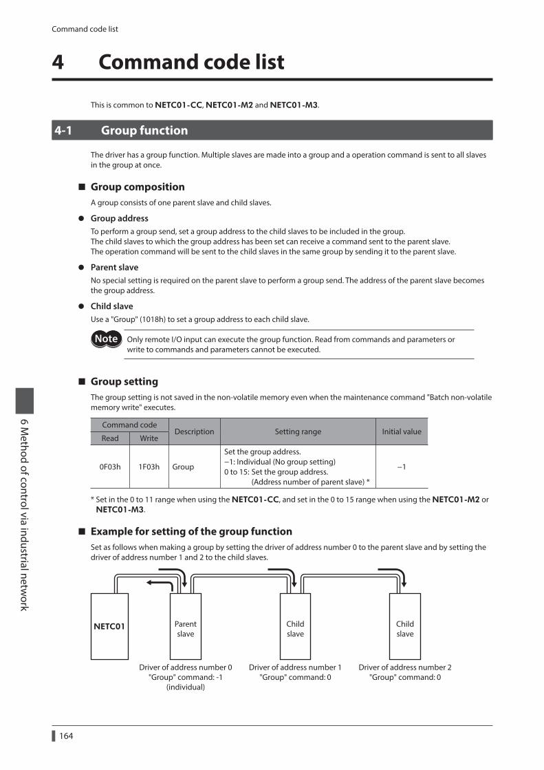
Command code list
164
6 Method of control via industrial netw
ork
4 Command code list
This is common to NETC01-CC, NETC01-M2 and NETC01-M3.
4-1 Group function
The driver has a group function. Multiple slaves are made into a group and a operation command is sent to all slaves in the group at once.
Group compositionA group consists of one parent slave and child slaves.
z Group addressTo perform a group send, set a group address to the child slaves to be included in the group.The child slaves to which the group address has been set can receive a command sent to the parent slave.The operation command will be sent to the child slaves in the same group by sending it to the parent slave.
z Parent slaveNo special setting is required on the parent slave to perform a group send. The address of the parent slave becomes the group address.
z Child slaveUse a "Group" (1018h) to set a group address to each child slave.
Only remote I/O input can execute the group function. Read from commands and parameters or write to commands and parameters cannot be executed.
Group settingThe group setting is not saved in the non-volatile memory even when the maintenance command "Batch non-volatile memory write" executes.
Command codeDescription Setting range Initial value
Read Write
0F03h 1F03h Group
Set the group address. −1: Individual (No group setting) 0 to 15: Set the group address. (Address number of parent slave) *
−1
* Set in the 0 to 11 range when using the NETC01-CC, and set in the 0 to 15 range when using the NETC01-M2 or NETC01-M3.
Example for setting of the group functionSet as follows when making a group by setting the driver of address number 0 to the parent slave and by setting the driver of address number 1 and 2 to the child slaves.
NETC01
Driver of address number 0"Group" command: -1
(individual)
Driver of address number 1"Group" command: 0
Driver of address number 2"Group" command: 0
Parentslave
Childslave
Childslave
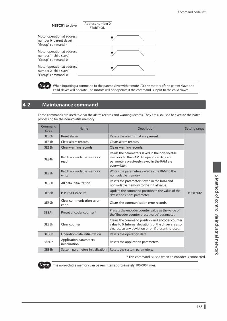
Command code list
165
6 Method of control via industrial netw
ork
Address number 0START=ON
Motor operation at addressnumber 0 (parent slave)"Group" command: -1
Motor operation at addressnumber 1 (child slave)"Group" command: 0
Motor operation at addressnumber 2 (child slave)"Group" command: 0
NETC01 to slave
When inputting a command to the parent slave with remote I/O, the motors of the parent slave and child slaves will operate. The motors will not operate if the command is input to the child slaves.
4-2 Maintenance command
These commands are used to clear the alarm records and warning records. They are also used to execute the batch processing for the non-volatile memory.
Command code
Name Description Setting range
3E80h Reset alarm Resets the alarms that are present.
1: Execute
3E81h Clear alarm records Clears alarm records.
3E82h Clear warning records Clears warning records.
3E84hBatch non-volatile memory read
Reads the parameters saved in the non-volatile memory, to the RAM. All operation data and parameters previously saved in the RAM are overwritten.
3E85hBatch non-volatile memory write
Writes the parameters saved in the RAM to the non-volatile memory.
3E86h All data initializationResets the parameters saved in the RAM and non-volatile memory to the initial value.
3E88h P-PRESET executeUpdate the command position to the value of the "Preset position" parameter.
3E89hClear communication error code
Clears the communication error records.
3E8Ah Preset encoder counter *Presets the encoder counter value as the value of the “Encoder counter preset value” parameter.
3E8Bh Clear counterClears the command position and encoder counter value to 0. Internal deviations of the driver are also cleared, so any deviation error, if present, is reset.
3E8Ch Operation data initialization Resets the operation data.
3E8DhApplication parameters initialization
Resets the application parameters.
3E8Eh System parameters initialization Resets the system parameters.
* This command is used when an encoder is connected.
The non-volatile memory can be rewritten approximately 100,000 times.
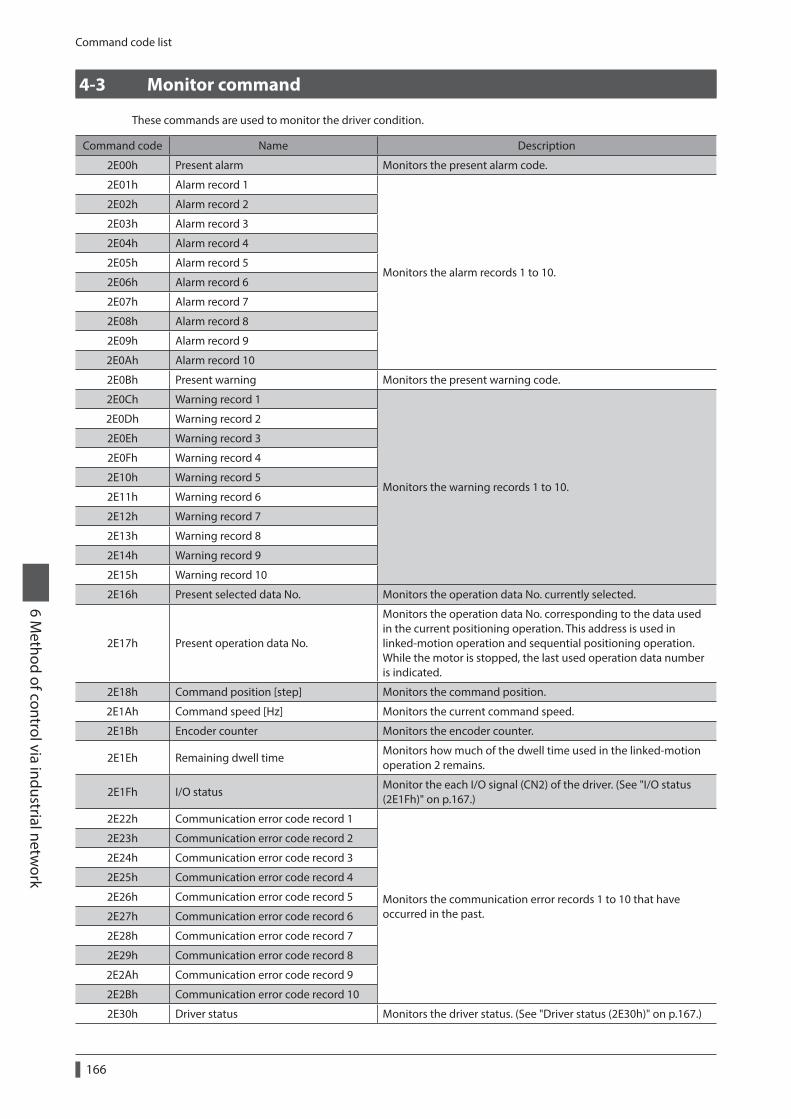
Command code list
166
6 Method of control via industrial netw
ork
4-3 Monitor command
These commands are used to monitor the driver condition.
Command code Name Description
2E00h Present alarm Monitors the present alarm code.
2E01h Alarm record 1
Monitors the alarm records 1 to 10.
2E02h Alarm record 2
2E03h Alarm record 3
2E04h Alarm record 4
2E05h Alarm record 5
2E06h Alarm record 6
2E07h Alarm record 7
2E08h Alarm record 8
2E09h Alarm record 9
2E0Ah Alarm record 10
2E0Bh Present warning Monitors the present warning code.
2E0Ch Warning record 1
Monitors the warning records 1 to 10.
2E0Dh Warning record 2
2E0Eh Warning record 3
2E0Fh Warning record 4
2E10h Warning record 5
2E11h Warning record 6
2E12h Warning record 7
2E13h Warning record 8
2E14h Warning record 9
2E15h Warning record 10
2E16h Present selected data No. Monitors the operation data No. currently selected.
2E17h Present operation data No.
Monitors the operation data No. corresponding to the data used in the current positioning operation. This address is used in linked-motion operation and sequential positioning operation. While the motor is stopped, the last used operation data number is indicated.
2E18h Command position [step] Monitors the command position.
2E1Ah Command speed [Hz] Monitors the current command speed.
2E1Bh Encoder counter Monitors the encoder counter.
2E1Eh Remaining dwell timeMonitors how much of the dwell time used in the linked-motion operation 2 remains.
2E1Fh I/O statusMonitor the each I/O signal (CN2) of the driver. (See "I/O status (2E1Fh)" on p.167.)
2E22h Communication error code record 1
Monitors the communication error records 1 to 10 that have occurred in the past.
2E23h Communication error code record 2
2E24h Communication error code record 3
2E25h Communication error code record 4
2E26h Communication error code record 5
2E27h Communication error code record 6
2E28h Communication error code record 7
2E29h Communication error code record 8
2E2Ah Communication error code record 9
2E2Bh Communication error code record 10
2E30h Driver status Monitors the driver status. (See "Driver status (2E30h)" on p.167.)
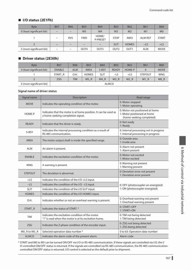
Command code list
167
6 Method of control via industrial netw
ork
I/O status (2E1Fh)
Byte Bit7 Bit6 Bit5 Bit4 Bit3 Bit2 Bit1 Bit0
0 (least significant bit) − − M5 M4 M3 M2 M1 M0
1 − RVS FWDHOME/
P-PRESETSTOP AWO ALM-RST START
2 − − − − SLIT HOMES −LS +LS
3 (most significant bit) − − OUT4 OUT3 OUT2 OUT1 ALM MOVE
Driver status (2E30h)
Byte Bit7 Bit6 Bit5 Bit4 Bit3 Bit2 Bit1 Bit0
0 (least significant bit) ENABLE ALM AREA S-BSY READY HOME-P 0 MOVE
1 START_R O.H. HOMES SLIT −LS +LS STEPOUT WNG
2 ZSG TIM M5_R M4_R M3_R M2_R M1_R M0_R
3 (most significant bit) ALMCD
Signal name of driver status
Signal name Description Read range
MOVE Indicates the operating condition of the motor.0: Motor stopped 1: Motor operating
HOME-PIndicates that the motor is at home position. It can be used as a home-seeking completion signal.
0: Motor not positioned at home 1: Motor positioned at home (home-seeking completed)
READY Indicates that the driver is ready.0: Not ready 1: Ready
S-BSYIndicates the internal processing condition as a result of RS-485 communication.
0: Internal processing not in progress 1: Internal processing in progress
AREA The motor output shaft is inside the specified range.0: Outside area 1: Inside area
ALM An alarm is present.0: Alarm not present 1: Alarm present
ENABLE Indicates the excitation condition of the motor.0: Motor not excited 1: Motor excited
WNG A warning is present.0: Warning not present 1: Warning present
STEPOUT The deviation is abnormal.0: Deviation error not present 1: Deviation error present
+LS Indicates the condition of the I/O +LS input.
0: OFF (photocoupler un-energized) 1: ON (photocoupler energized)
−LS Indicates the condition of the I/O −LS input.
SLIT Indicates the condition of the I/O SLIT input.
HOMES Indicates the condition of the I/O HOMES input.
O.H. Indicates whether or not an overheat warning is present.0: Overheat warning not present 1: Overheat warning present
START_R Indicates the status of START. *0: START=OFF 1: START=ON
TIMIndicates the excitation condition of the motor. “1” is read when the motor is at its excitation home.
0: TIM not being detected 1: TIM being detected
ZSG Indicates the Z-phase condition of the encoder input.0: ZSG not being detected 1: ZSG being detected
M0_R to M5_R Selected operation data number * 0 to 63: Operation data number
ALMCD Indicates the alarm code of the present alarm. Alarm code
* START and M0 to M5 can be turned ON/OFF via I/O or RS-485 communication. If these signals are controlled via I/O, the I/O-controlled ON/OFF status is returned. If the signals are controlled via RS-485 communication, the RS-485-communication-controlled ON/OFF status is returned. I/O control is selected as the default prior to shipment.
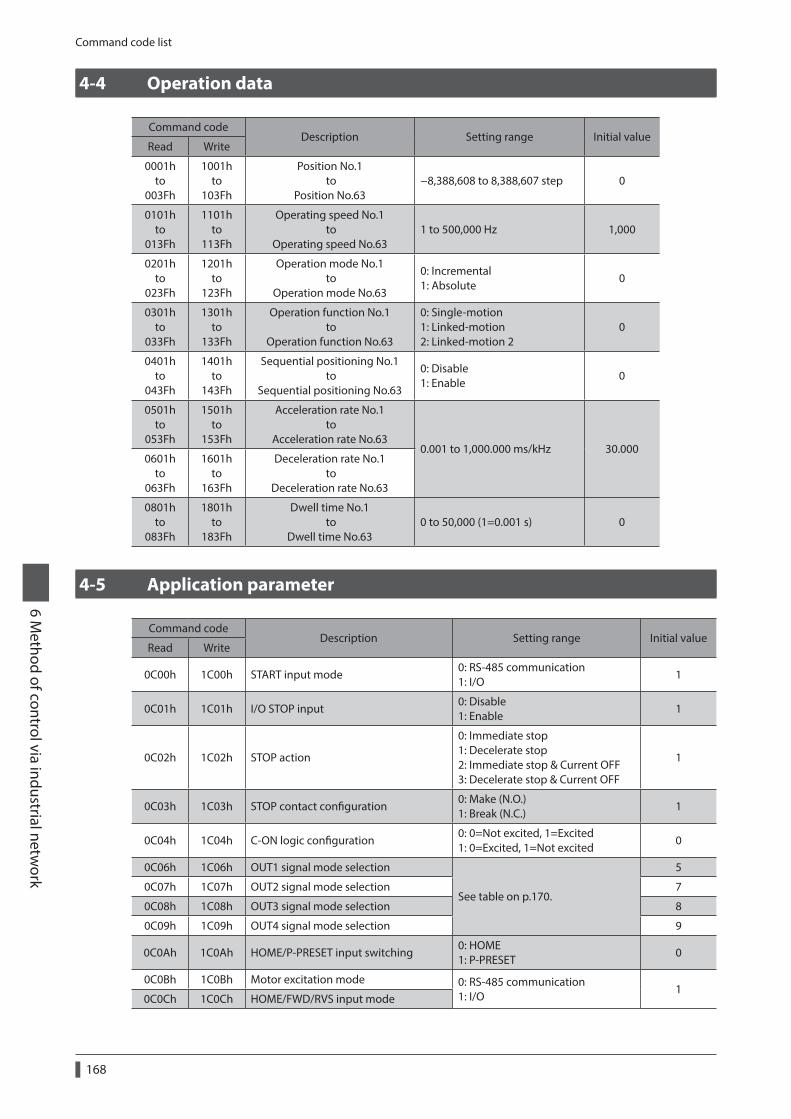
Command code list
168
6 Method of control via industrial netw
ork
4-4 Operation data
Command codeDescription Setting range Initial value
Read Write
0001h to
003Fh
1001h to
103Fh
Position No.1 to
Position No.63−8,388,608 to 8,388,607 step 0
0101h to
013Fh
1101h to
113Fh
Operating speed No.1 to
Operating speed No.631 to 500,000 Hz 1,000
0201h to
023Fh
1201h to
123Fh
Operation mode No.1 to
Operation mode No.63
0: Incremental 1: Absolute
0
0301h to
033Fh
1301h to
133Fh
Operation function No.1 to
Operation function No.63
0: Single-motion 1: Linked-motion 2: Linked-motion 2
0
0401h to
043Fh
1401h to
143Fh
Sequential positioning No.1 to
Sequential positioning No.63
0: Disable 1: Enable
0
0501h to
053Fh
1501h to
153Fh
Acceleration rate No.1 to
Acceleration rate No.630.001 to 1,000.000 ms/kHz 30.000
0601h to
063Fh
1601h to
163Fh
Deceleration rate No.1 to
Deceleration rate No.63
0801h to
083Fh
1801h to
183Fh
Dwell time No.1 to
Dwell time No.630 to 50,000 (1=0.001 s) 0
4-5 Application parameter
Command codeDescription Setting range Initial value
Read Write
0C00h 1C00h START input mode0: RS-485 communication 1: I/O
1
0C01h 1C01h I/O STOP input0: Disable 1: Enable
1
0C02h 1C02h STOP action
0: Immediate stop 1: Decelerate stop 2: Immediate stop & Current OFF 3: Decelerate stop & Current OFF
1
0C03h 1C03h STOP contact configuration0: Make (N.O.) 1: Break (N.C.)
1
0C04h 1C04h C-ON logic configuration0: 0=Not excited, 1=Excited 1: 0=Excited, 1=Not excited
0
0C06h 1C06h OUT1 signal mode selection
See table on p.170.
5
0C07h 1C07h OUT2 signal mode selection 7
0C08h 1C08h OUT3 signal mode selection 8
0C09h 1C09h OUT4 signal mode selection 9
0C0Ah 1C0Ah HOME/P-PRESET input switching0: HOME 1: P-PRESET
0
0C0Bh 1C0Bh Motor excitation mode 0: RS-485 communication 1: I/O
10C0Ch 1C0Ch HOME/FWD/RVS input mode
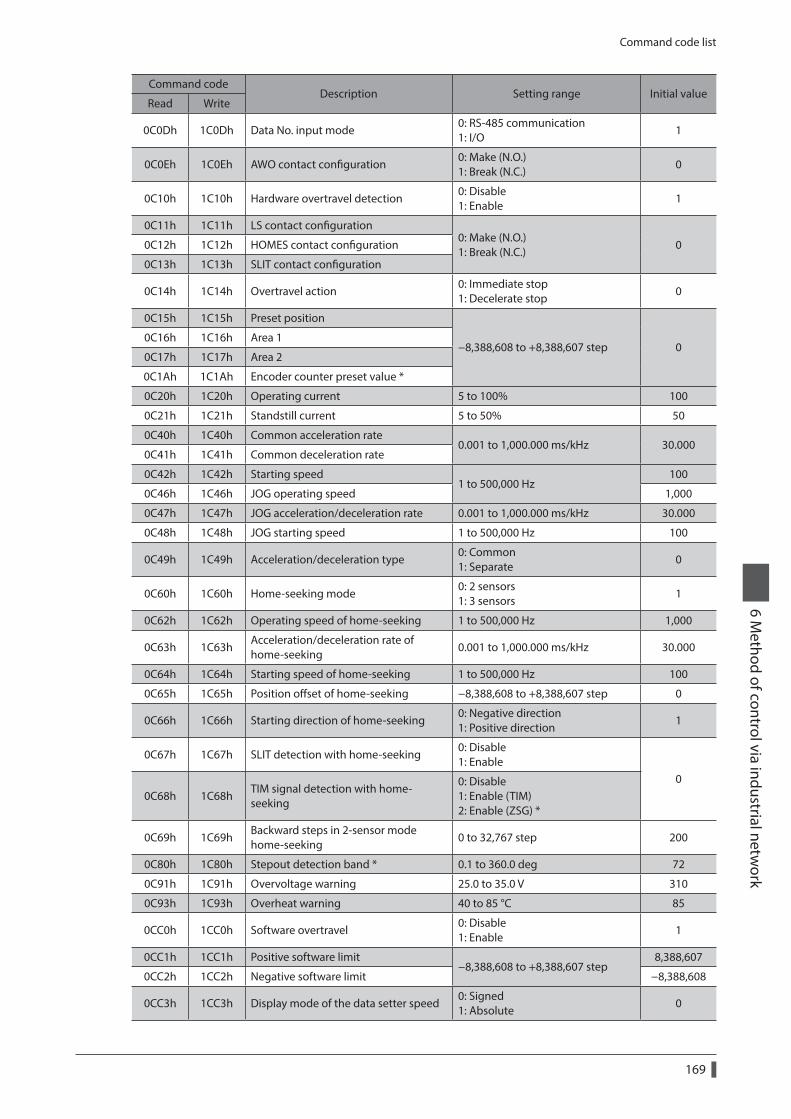
Command code list
169
6 Method of control via industrial netw
ork
Command codeDescription Setting range Initial value
Read Write
0C0Dh 1C0Dh Data No. input mode0: RS-485 communication 1: I/O
1
0C0Eh 1C0Eh AWO contact configuration0: Make (N.O.) 1: Break (N.C.)
0
0C10h 1C10h Hardware overtravel detection0: Disable 1: Enable
1
0C11h 1C11h LS contact configuration0: Make (N.O.) 1: Break (N.C.)
00C12h 1C12h HOMES contact configuration
0C13h 1C13h SLIT contact configuration
0C14h 1C14h Overtravel action0: Immediate stop 1: Decelerate stop
0
0C15h 1C15h Preset position
−8,388,608 to +8,388,607 step 00C16h 1C16h Area 1
0C17h 1C17h Area 2
0C1Ah 1C1Ah Encoder counter preset value *
0C20h 1C20h Operating current 5 to 100% 100
0C21h 1C21h Standstill current 5 to 50% 50
0C40h 1C40h Common acceleration rate0.001 to 1,000.000 ms/kHz 30.000
0C41h 1C41h Common deceleration rate
0C42h 1C42h Starting speed1 to 500,000 Hz
100
0C46h 1C46h JOG operating speed 1,000
0C47h 1C47h JOG acceleration/deceleration rate 0.001 to 1,000.000 ms/kHz 30.000
0C48h 1C48h JOG starting speed 1 to 500,000 Hz 100
0C49h 1C49h Acceleration/deceleration type0: Common 1: Separate
0
0C60h 1C60h Home-seeking mode0: 2 sensors 1: 3 sensors
1
0C62h 1C62h Operating speed of home-seeking 1 to 500,000 Hz 1,000
0C63h 1C63hAcceleration/deceleration rate of home-seeking
0.001 to 1,000.000 ms/kHz 30.000
0C64h 1C64h Starting speed of home-seeking 1 to 500,000 Hz 100
0C65h 1C65h Position offset of home-seeking −8,388,608 to +8,388,607 step 0
0C66h 1C66h Starting direction of home-seeking0: Negative direction 1: Positive direction
1
0C67h 1C67h SLIT detection with home-seeking0: Disable 1: Enable
00C68h 1C68h
TIM signal detection with home-seeking
0: Disable 1: Enable (TIM) 2: Enable (ZSG) *
0C69h 1C69hBackward steps in 2-sensor mode home-seeking
0 to 32,767 step 200
0C80h 1C80h Stepout detection band * 0.1 to 360.0 deg 72
0C91h 1C91h Overvoltage warning 25.0 to 35.0 V 310
0C93h 1C93h Overheat warning 40 to 85 °C 85
0CC0h 1CC0h Software overtravel0: Disable 1: Enable
1
0CC1h 1CC1h Positive software limit−8,388,608 to +8,388,607 step
8,388,607
0CC2h 1CC2h Negative software limit −8,388,608
0CC3h 1CC3h Display mode of the data setter speed0: Signed 1: Absolute
0
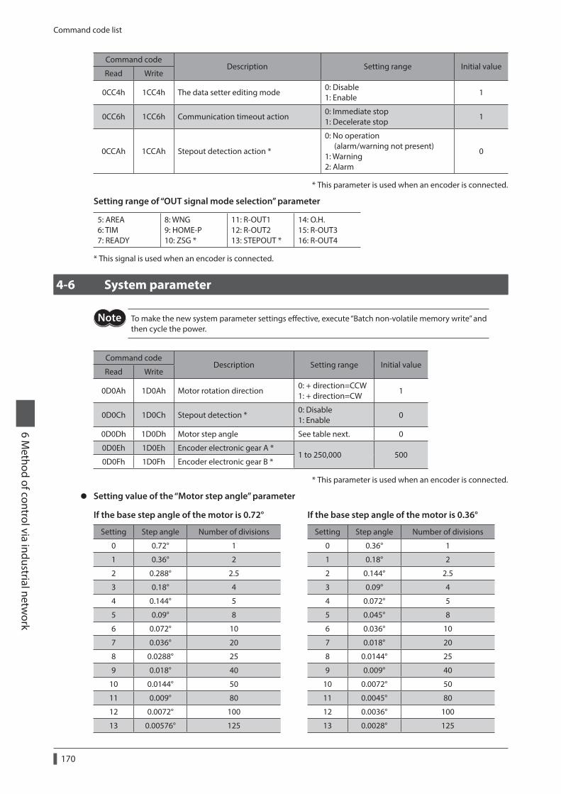
Command code list
170
6 Method of control via industrial netw
ork
Command codeDescription Setting range Initial value
Read Write
0CC4h 1CC4h The data setter editing mode0: Disable 1: Enable
1
0CC6h 1CC6h Communication timeout action0: Immediate stop 1: Decelerate stop
1
0CCAh 1CCAh Stepout detection action *
0: No operation (alarm/warning not present) 1: Warning 2: Alarm
0
* This parameter is used when an encoder is connected.
Setting range of “OUT signal mode selection” parameter
5: AREA 6: TIM 7: READY
8: WNG 9: HOME-P 10: ZSG *
11: R-OUT1 12: R-OUT2 13: STEPOUT *
14: O.H. 15: R-OUT3 16: R-OUT4
* This signal is used when an encoder is connected.
4-6 System parameter
To make the new system parameter settings effective, execute “Batch non-volatile memory write” and then cycle the power.
Command codeDescription Setting range Initial value
Read Write
0D0Ah 1D0Ah Motor rotation direction0: + direction=CCW 1: + direction=CW
1
0D0Ch 1D0Ch Stepout detection *0: Disable 1: Enable
0
0D0Dh 1D0Dh Motor step angle See table next. 0
0D0Eh 1D0Eh Encoder electronic gear A *1 to 250,000 500
0D0Fh 1D0Fh Encoder electronic gear B *
* This parameter is used when an encoder is connected.
z Setting value of the “Motor step angle” parameter
If the base step angle of the motor is 0.72° If the base step angle of the motor is 0.36°
Setting Step angle Number of divisions Setting Step angle Number of divisions
0 0.72° 1 0 0.36° 1
1 0.36° 2 1 0.18° 2
2 0.288° 2.5 2 0.144° 2.5
3 0.18° 4 3 0.09° 4
4 0.144° 5 4 0.072° 5
5 0.09° 8 5 0.045° 8
6 0.072° 10 6 0.036° 10
7 0.036° 20 7 0.018° 20
8 0.0288° 25 8 0.0144° 25
9 0.018° 40 9 0.009° 40
10 0.0144° 50 10 0.0072° 50
11 0.009° 80 11 0.0045° 80
12 0.0072° 100 12 0.0036° 100
13 0.00576° 125 13 0.0028° 125
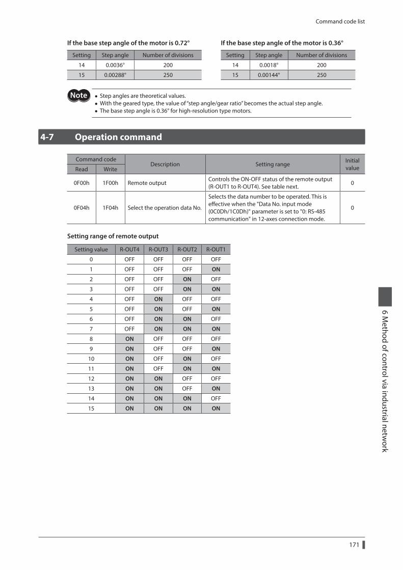
Command code list
171
6 Method of control via industrial netw
ork
If the base step angle of the motor is 0.72° If the base step angle of the motor is 0.36°
Setting Step angle Number of divisions Setting Step angle Number of divisions
14 0.0036° 200 14 0.0018° 200
15 0.00288° 250 15 0.00144° 250
• Step angles are theoretical values. • With the geared type, the value of “step angle/gear ratio” becomes the actual step angle. • The base step angle is 0.36° for high-resolution type motors.
4-7 Operation command
Command codeDescription Setting range
Initial valueRead Write
0F00h 1F00h Remote outputControls the ON-OFF status of the remote output (R-OUT1 to R-OUT4). See table next.
0
0F04h 1F04h Select the operation data No.
Selects the data number to be operated. This is effective when the "Data No. input mode (0C0Dh/1C0Dh)" parameter is set to "0: RS-485 communication" in 12-axes connection mode.
0
Setting range of remote output
Setting value R-OUT4 R-OUT3 R-OUT2 R-OUT1
0 OFF OFF OFF OFF
1 OFF OFF OFF ON
2 OFF OFF ON OFF
3 OFF OFF ON ON
4 OFF ON OFF OFF
5 OFF ON OFF ON
6 OFF ON ON OFF
7 OFF ON ON ON
8 ON OFF OFF OFF
9 ON OFF OFF ON
10 ON OFF ON OFF
11 ON OFF ON ON
12 ON ON OFF OFF
13 ON ON OFF ON
14 ON ON ON OFF
15 ON ON ON ON

172
6 Method of control via industrial netw
ork
7 Inspection, troubleshooting and remedial actions
This part explains the periodical inspection methods as well as confirmation items and remedial actions when problems have happened.
Table of contents
1 Inspection .............................................174
2 Alarms and warnings ..........................1752-1 Alarms ...............................................................175
2-2 Warnings ..........................................................178
3 Troubleshooting and remedial actions ...................................................179
Inspection
174
7 Inspection, troubleshooting and remedial actions
1 Inspection
It is recommended that periodic inspections for the items listed below are conducted after each operation of the motor. If an abnormal condition is noted, discontinue any use and contact your nearest Oriental Motor sales office.
During inspection • Are any of the motor mounting screws loose? • Check for any unusual noises in the motor bearings (ball bearings) or other moving parts. • Are there any scratches, signs of stress or loose driver connections in the motor cable? • Are the motor output shaft and load shaft out of alignment? • Are any of the driver DIN rail mounting parts loose? • Are there any loose driver connectors? • Is there attachment of dust, etc., on the driver? • Are there any strange smells or appearances within the driver?
The driver uses semiconductor elements. Handle the driver with care since static electricity may damage semiconductor elements. Static electricity may damage the driver.
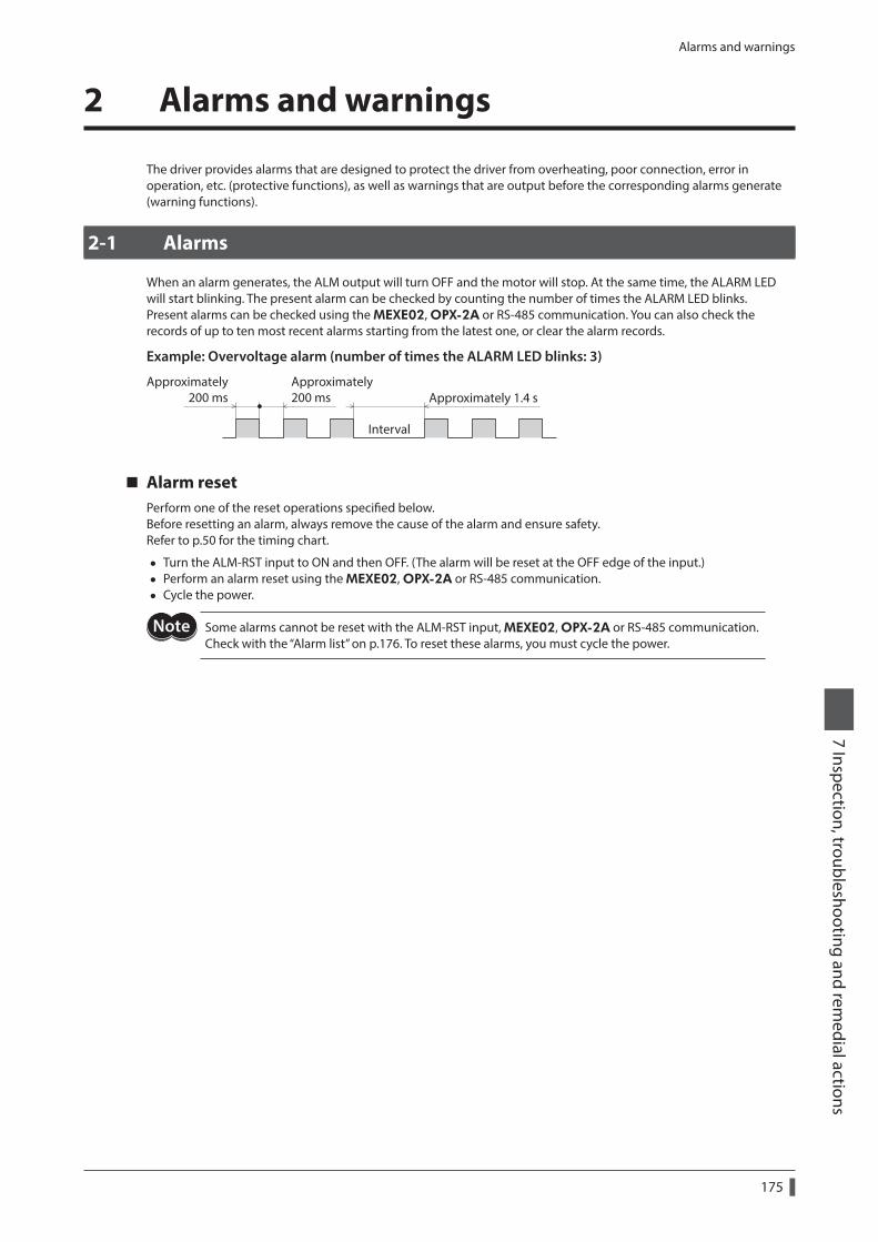
Alarms and warnings
175
7 Inspection, troubleshooting and remedial actions
2 Alarms and warnings
The driver provides alarms that are designed to protect the driver from overheating, poor connection, error in operation, etc. (protective functions), as well as warnings that are output before the corresponding alarms generate (warning functions).
2-1 Alarms
When an alarm generates, the ALM output will turn OFF and the motor will stop. At the same time, the ALARM LED will start blinking. The present alarm can be checked by counting the number of times the ALARM LED blinks.Present alarms can be checked using the MEXE02, OPX-2A or RS-485 communication. You can also check the records of up to ten most recent alarms starting from the latest one, or clear the alarm records.
Example: Overvoltage alarm (number of times the ALARM LED blinks: 3)
Approximately200 ms Approximately 1.4 s
Approximately200 ms
Interval
Alarm resetPerform one of the reset operations specified below.Before resetting an alarm, always remove the cause of the alarm and ensure safety.Refer to p.50 for the timing chart.
• Turn the ALM-RST input to ON and then OFF. (The alarm will be reset at the OFF edge of the input.) • Perform an alarm reset using the MEXE02, OPX-2A or RS-485 communication. • Cycle the power.
Some alarms cannot be reset with the ALM-RST input, MEXE02, OPX-2A or RS-485 communication. Check with the “Alarm list” on p.176. To reset these alarms, you must cycle the power.
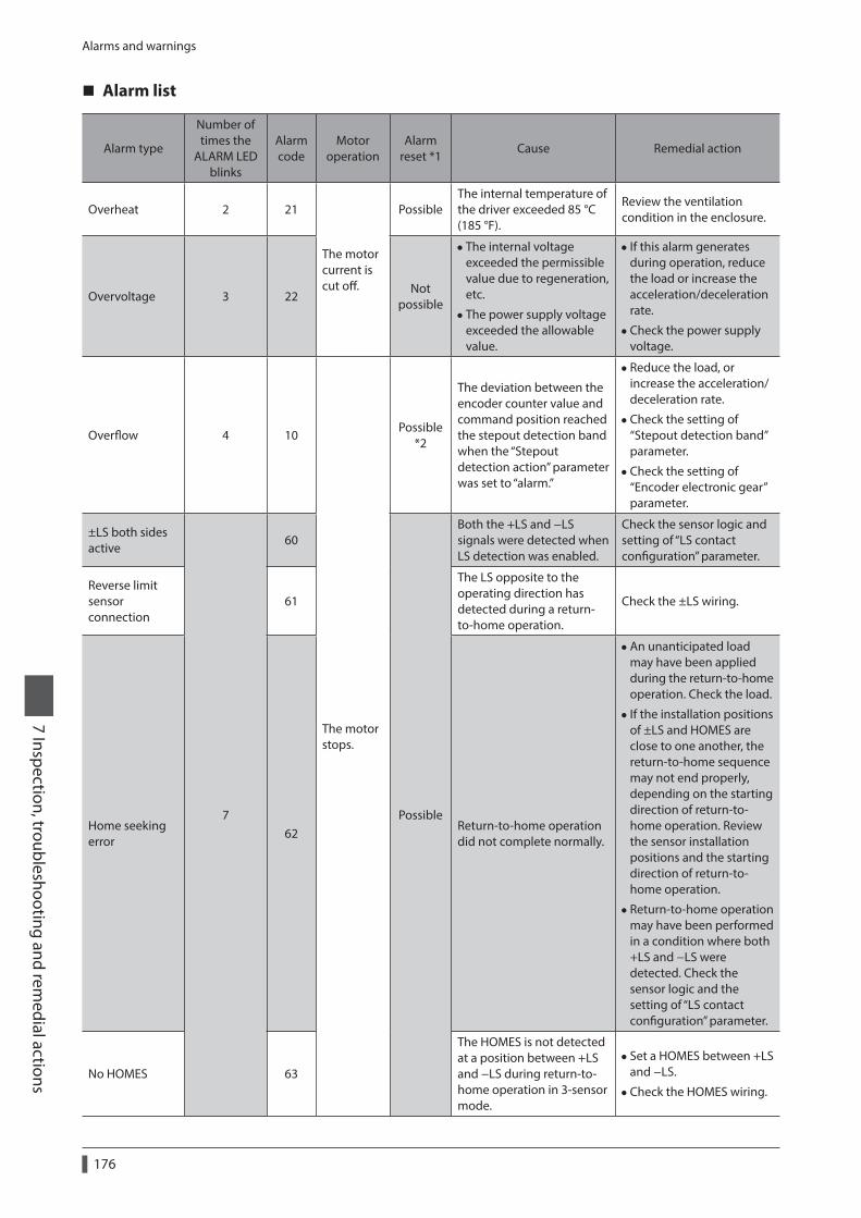
Alarms and warnings
176
7 Inspection, troubleshooting and remedial actions
Alarm list
Alarm type
Number of times the
ALARM LED blinks
Alarm code
Motor operation
Alarm reset *1
Cause Remedial action
Overheat 2 21
The motor current is cut off.
PossibleThe internal temperature of the driver exceeded 85 °C (185 °F).
Review the ventilation condition in the enclosure.
Overvoltage 3 22Not
possible
• The internal voltage exceeded the permissible value due to regeneration, etc.
• The power supply voltage exceeded the allowable value.
• If this alarm generates during operation, reduce the load or increase the acceleration/deceleration rate.
•Check the power supply voltage.
Overflow 4 10
The motor stops.
Possible *2
The deviation between the encoder counter value and command position reached the stepout detection band when the “Stepout detection action” parameter was set to “alarm.”
• Reduce the load, or increase the acceleration/ deceleration rate.
•Check the setting of “Stepout detection band” parameter.
•Check the setting of “Encoder electronic gear” parameter.
±LS both sides active
7
60
Possible
Both the +LS and −LS signals were detected when LS detection was enabled.
Check the sensor logic and setting of “LS contact configuration” parameter.
Reverse limit sensor connection
61
The LS opposite to the operating direction has detected during a return-to-home operation.
Check the ±LS wiring.
Home seeking error
62Return-to-home operation did not complete normally.
•An unanticipated load may have been applied during the return-to-home operation. Check the load.
• If the installation positions of ±LS and HOMES are close to one another, the return-to-home sequence may not end properly, depending on the starting direction of return-to-home operation. Review the sensor installation positions and the starting direction of return-to-home operation.
• Return-to-home operation may have been performed in a condition where both +LS and −LS were detected. Check the sensor logic and the setting of “LS contact configuration” parameter.
No HOMES 63
The HOMES is not detected at a position between +LS and −LS during return-to-home operation in 3-sensor mode.
• Set a HOMES between +LS and −LS.
•Check the HOMES wiring.
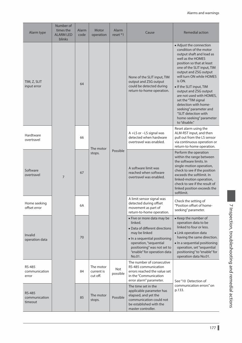
Alarms and warnings
177
7 Inspection, troubleshooting and remedial actions
Alarm type
Number of times the
ALARM LED blinks
Alarm code
Motor operation
Alarm reset *1
Cause Remedial action
TIM, Z, SLIT input error
7
64
The motor stops.
Possible
None of the SLIT input, TIM output and ZSG output could be detected during return-to-home operation.
•Adjust the connection condition of the motor output shaft and load as well as the HOMES position so that at least one of the SLIT input, TIM output and ZSG output will turn ON while HOMES is ON.
• If the SLIT input, TIM output and ZSG output are not used with HOMES, set the “TIM signal detection with home-seeking” parameter and “SLIT detection with home-seeking” parameter to “disable.”
Hardtware overtravel
66A +LS or −LS signal was detected when hardware overtravel was enabled.
Reset alarm using the ALM-RST input, and then pull out from the LS sensor via continuous operation or return-to-home operation.
Software overtravel
67A software limit was reached when software overtravel was enabled.
Perform the operation within the range between the software limits. In single-motion operation, check to see if the position exceeds the softlimit. In linked-motion operation, check to see if the result of linked position exceeds the softlimit.
Home seeking offset error
6A
A limit sensor signal was detected during offset movement as part of return-to-home operation.
Check the setting of “Position offset of home-seeking” parameter.
Invalid operation data
70
• Five or more data may be linked.
•Data of different directions may be linked
• In a sequential positioning operation, “sequential positioning” was not set to “enable” for operation data No.01.
• Keep the number of operation data to be linked to four or less.
• Link operation data having the same direction.
• In a sequential positioning operation, set “sequential positioning” to “enable” for operation data No.01.
RS-485 communication error
84The motor current is cut off.
Not possible
The number of consecutive RS-485 communication errors reached the value set in the “Communication error alarm” parameter. See “10 Detection of
communication errors” on p.133.
RS-485 communication timeout
85The motor stops.
Possible
The time set in the applicable parameter has elapsed, and yet the communication could not be established with the master controller.
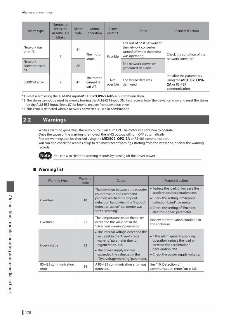
Alarms and warnings
178
7 Inspection, troubleshooting and remedial actions
Alarm type
Number of times the
ALARM LED blinks
Alarm code
Motor operation
Alarm reset *1
Cause Remedial action
Network bus error *3
7
81The motor stops.
Possible
The bus of host network of the network converter turned off while the motor was operating. Check the condition of the
network converter.Network converter error *3
8EThe network converter generated an alarm.
EEPROM error 9 41The motor current is cut off.
Not possible
The stored data was damaged.
Initialize the parameters using the MEXE02, OPX-2A or RS-485 communication.
*1 Reset alarm using the ALM-RST input/MEXE02/OPX-2A/RS-485 communication.*2 The alarm cannot be reset by merely turning the ALM-RST input ON. First recover from the deviation error and reset the alarm
by the ALM-RST input. See p.87 for how to recover from deviation error.*3 This error is detected when a network converter is used in combination.
2-2 Warnings
When a warning generates, the WNG output will turn ON. The motor will continue to operate.Once the cause of the warning is removed, the WNG output will turn OFF automatically.Present warnings can be checked using the MEXE02, OPX-2A or RS-485 communication.You can also check the records of up to ten most recent warnings starting from the latest one, or clear the warning records.
You can also clear the warning records by turning off the driver power.
Warning list
Warning typeWarning
codeCause Remedial action
Overflow 10
The deviation between the encoder counter value and command position reached the stepout detection band when the “Stepout detection action” parameter was set to “warning.”
• Reduce the load, or increase the acceleration/deceleration rate.
•Check the setting of “Stepout detection band” parameter.
•Check the setting of “Encoder electronic gear” parameter.
Overheat 21The temperature inside the driver exceeded the value set in the “Overheat warning” parameter.
Review the ventilation condition in the enclosure.
Overvoltage 22
• The internal voltage exceeded the value set in the “Overvoltage warning” parameter due to regeneration, etc.
• The power supply voltage exceeded the value set in the “Overvoltage warning” parameter.
• If this alarm generates during operation, reduce the load or increase the acceleration/deceleration rate.
•Check the power supply voltage.
RS-485 communication error
84A RS-485 communication error was detected.
See “10 Detection of communication errors” on p.133.
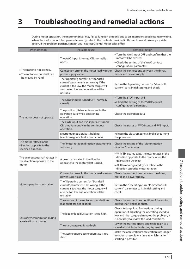
Troubleshooting and remedial actions
179
7 Inspection, troubleshooting and remedial actions
3 Troubleshooting and remedial actions
During motor operation, the motor or driver may fail to function properly due to an improper speed setting or wiring. When the motor cannot be operated correctly, refer to the contents provided in this section and take appropriate action. If the problem persists, contact your nearest Oriental Motor sales office.
Phenomenon Possible cause Remedial action
• The motor is not excited.
• The motor output shaft can be moved by hand.
The AWO input is turned ON (normally open).
• Turn the AWO input OFF and confirm that the motor will be excited.
•Check the setting of the “AWO contact configuration” parameter.
Connection error in the motor lead wires or power supply cable.
Check the connections between the driver, motor and power supply.
The “Operating current” or “Standstill current” parameter is set wrong. If the current is too low, the motor torque will also be too low and operation will be unstable.
Return the “operating current” or “standstill current” to its initial setting and check.
The motor does not operate.
The STOP input is turned OFF (normally closed).
• Turn the STOP input ON.
•Check the setting of the “STOP contact configuration” parameter.
The position (distance) is not set in the operation data while positioning operation.
Check the operation data.
The FWD input and RVS input are turned ON simultaneously in the continuous operation.
Check the status of FWD input and RVS input.
Electromagnetic brake is holding (electromagnetic brake motor only).
Release the electromagnetic brake by turning the power on.
The motor rotates in the direction opposite to the specified direction.
The “Motor rotation direction” parameter is set wrong.
Check the setting of the “Motor rotation direction” parameter.
The gear output shaft rotates in the direction opposite to the motor.
A gear that rotates in the direction opposite to the motor shaft is used.
•With TH geared type, the gear rotates in the direction opposite to the motor when the gear ratio is 20 or 30.
•All Harmonic geared types rotate in the direction opposite motor rotation.
Motor operation is unstable.
Connection error in the motor lead wires or power supply cable.
Check the connections between the driver, motor and power supply.
The “Operating current” or “Standstill current” parameter is set wrong. If the current is too low, the motor torque will also be too low and operation will be unstable.
Return the “Operating current” or “Standstill current” parameter to its initial setting and check.
Loss of synchronization during acceleration or running.
The centers of the motor output shaft and load shaft are not aligned.
Check the connection condition of the motor output shaft and load shaft.
The load or load fluctuation is too high.
Check for large load fluctuations during operation. If adjusting the operating speed to low and high torque eliminates the problem, it is necessary to review the load conditions.
The starting speed is too high.Lower the starting speed and set it again to a speed at which stable starting is possible.
The acceleration/deceleration rate is too short.
Make the acceleration/deceleration rate longer in order to reset it to a time at which stable starting is possible.

Troubleshooting and remedial actions
180
7 Inspection, troubleshooting and remedial actions
Phenomenon Possible cause Remedial action
With the electromagnetic brake type, the electromagnetic brake does not hold the load.
DC power is supplied to the electromagnetic brake.
To hold the load with the electromagnetic brake while motor is stopped, turn OFF the power supply for electromagnetic brake.
Motor does not move the set amount.
Wrong motor step angle settings. Check the “Motor step angle” parameter.
I/O signals can be monitored using the MEXE02, OPX-2A or RS-485 communication. Use these accessories to check the wiring conditions of I/O signals.
8 Appendix
This part explains accessories that are used in combination with the products and method of control via GW protocol Version 1.
Table of contents
1 Accessories............................................182
2 Method of control via GW protocol Version 1 ................................................183
2-1 Guidance ..........................................................183
2-2 Communication specifications ................186
2-3 Setting the switches ....................................187
2-4 Communication mode ................................188
2-5 Communication timing ..............................189
2-6 Frame structures ...........................................189
2-7 Control method selection ..........................192
2-8 Example of communication setting .......193
2-9 Command list .................................................196
2-10 Command types ...........................................199
2-11 Command details ........................................200
2-12 Simultaneous send......................................220
2-13 Group send ....................................................220
2-14 Detection of communication errors .....222
2-15 Timing charts .................................................223
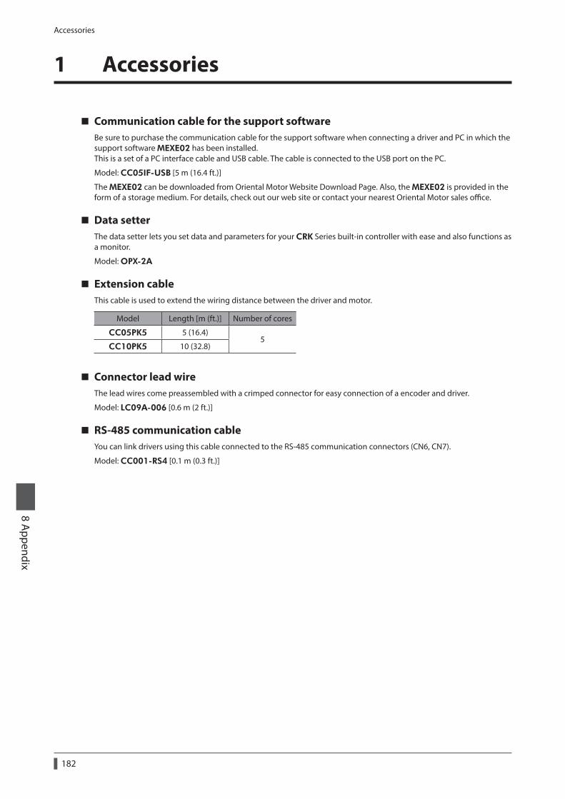
Accessories
182
8 Appendix
1 Accessories
Communication cable for the support softwareBe sure to purchase the communication cable for the support software when connecting a driver and PC in which the support software MEXE02 has been installed.This is a set of a PC interface cable and USB cable. The cable is connected to the USB port on the PC.
Model: CC05IF-USB [5 m (16.4 ft.)]
The MEXE02 can be downloaded from Oriental Motor Website Download Page. Also, the MEXE02 is provided in the form of a storage medium. For details, check out our web site or contact your nearest Oriental Motor sales office.
Data setterThe data setter lets you set data and parameters for your CRK Series built-in controller with ease and also functions as a monitor.
Model: OPX-2A
Extension cableThis cable is used to extend the wiring distance between the driver and motor.
Model Length [m (ft.)] Number of cores
CC05PK5 5 (16.4)5
CC10PK5 10 (32.8)
Connector lead wireThe lead wires come preassembled with a crimped connector for easy connection of a encoder and driver.
Model: LC09A-006 [0.6 m (2 ft.)]
RS-485 communication cableYou can link drivers using this cable connected to the RS-485 communication connectors (CN6, CN7).
Model: CC001-RS4 [0.1 m (0.3 ft.)]
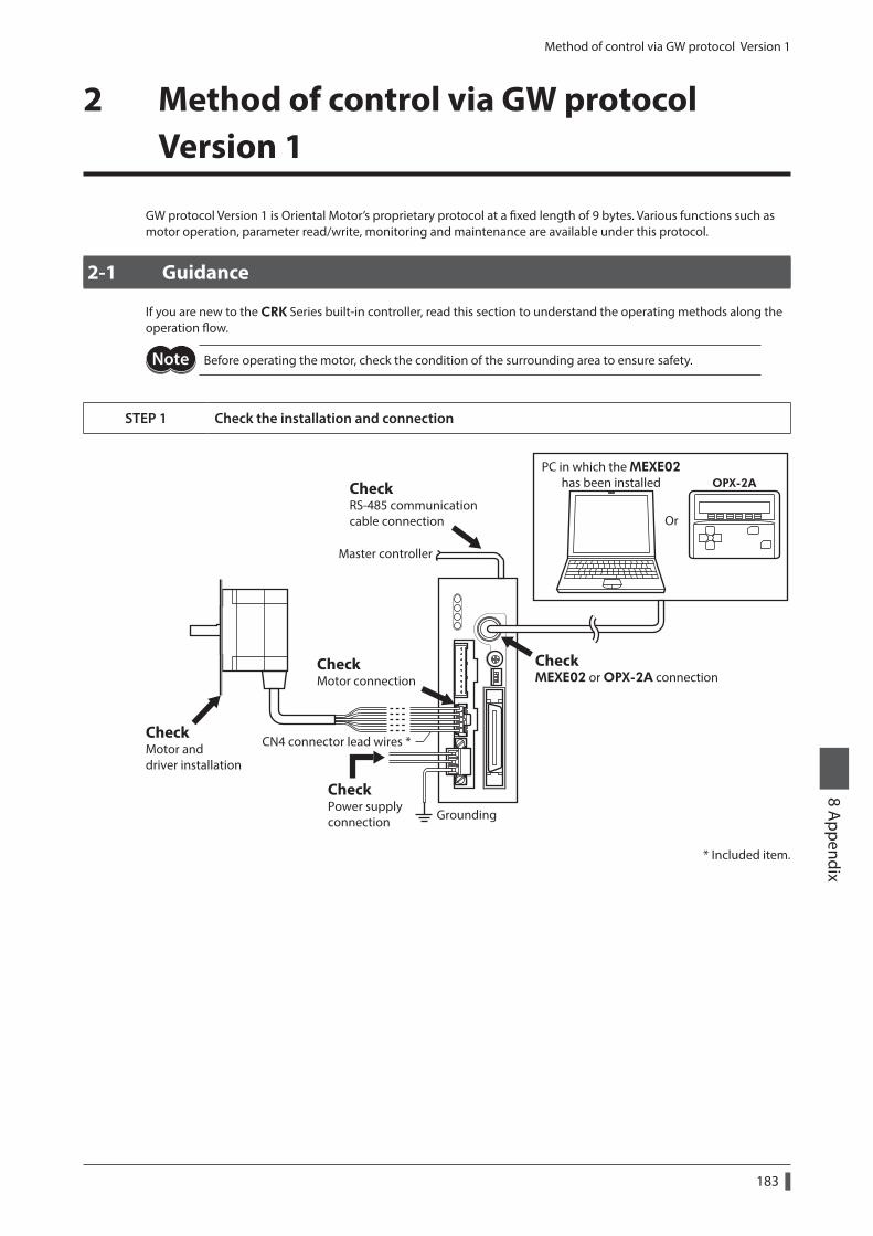
Method of control via GW protocol Version 1
183
8 Appendix
2 Method of control via GW protocol Version 1
GW protocol Version 1 is Oriental Motor’s proprietary protocol at a fixed length of 9 bytes. Various functions such as motor operation, parameter read/write, monitoring and maintenance are available under this protocol.
2-1 Guidance
If you are new to the CRK Series built-in controller, read this section to understand the operating methods along the operation flow.
Before operating the motor, check the condition of the surrounding area to ensure safety.
STEP 1 Check the installation and connection
CheckRS-485 communicationcable connection
Master controller
CheckMEXE02 or OPX-2A connection
CheckMotor connection
CheckMotor and driver installation
CheckPower supplyconnection Grounding
Or
OPX-2APC in which the MEXE02
has been installed
CN4 connector lead wires *
* Included item.
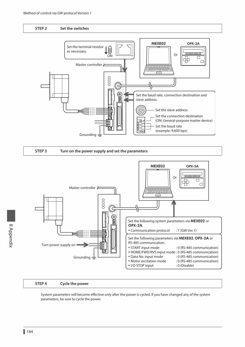
Method of control via GW protocol Version 1
184
8 Appendix
STEP 2 Set the switches
Grounding
ON
Set the terminal resistoras necessary.
Set the slave address
Set the connection destination(ON: General-purpose master device)
Set the baud rate(example: 9,600 bps)
Set the baud rate, connection destination and slave address.
Master controller
Or
OPX-2AMEXE02
STEP 3 Turn on the power supply and set the parameters
Communication protocol : 1 (GW Ver.1)
START input mode : 0 (RS-485 communication) HOME/FWD/RVS input mode : 0 (RS-485 communication) Data No. input mode : 0 (RS-485 communication) Motor excitation mode : 0 (RS-485 communication) I/O STOP input : 0 (Disable)
Set the following parameters via MEXE02, OPX-2A or RS-485 communication.
Set the following system parameters via MEXE02 or OPX-2A.
Turn power supply on
Master controller
Or
OPX-2AMEXE02
Grounding
STEP 4 Cycle the power
System parameters will become effective only after the power is cycled. If you have changed any of the system parameters, be sure to cycle the power.
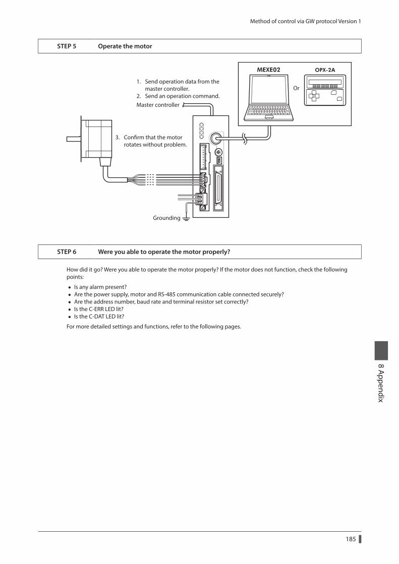
Method of control via GW protocol Version 1
185
8 Appendix
STEP 5 Operate the motor
1. Send operation data from the master controller.2. Send an operation command.
3. Conrm that the motor rotates without problem.
Master controller
Grounding
Or
OPX-2AMEXE02
STEP 6 Were you able to operate the motor properly?
How did it go? Were you able to operate the motor properly? If the motor does not function, check the following points:
• Is any alarm present? • Are the power supply, motor and RS-485 communication cable connected securely? • Are the address number, baud rate and terminal resistor set correctly? • Is the C-ERR LED lit? • Is the C-DAT LED lit?
For more detailed settings and functions, refer to the following pages.
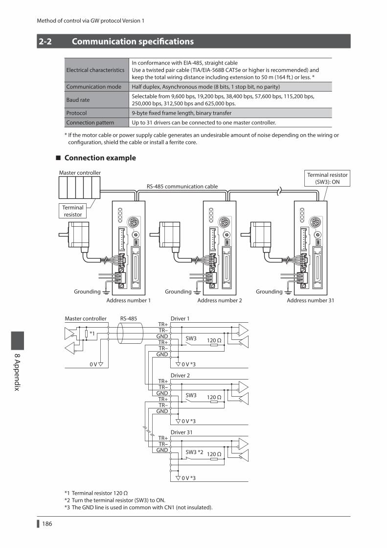
Method of control via GW protocol Version 1
186
8 Appendix
2-2 Communication specifications
Electrical characteristicsIn conformance with EIA-485, straight cable Use a twisted pair cable (TIA/EIA-568B CAT5e or higher is recommended) and keep the total wiring distance including extension to 50 m (164 ft.) or less. *
Communication mode Half duplex, Asynchronous mode (8 bits, 1 stop bit, no parity)
Baud rateSelectable from 9,600 bps, 19,200 bps, 38,400 bps, 57,600 bps, 115,200 bps, 250,000 bps, 312,500 bps and 625,000 bps.
Protocol 9-byte fixed frame length, binary transfer
Connection pattern Up to 31 drivers can be connected to one master controller.
* If the motor cable or power supply cable generates an undesirable amount of noise depending on the wiring or configuration, shield the cable or install a ferrite core.
Connection example
RS-485 communication cable
Address number 1Grounding Grounding Grounding
Terminalresistor
Terminal resistor(SW3): ON
Address number 2 Address number 31
Master controller
TR+TR-
GNDTR+TR-
GND
TR+TR-
GND
TR+TR-
GND
TR+TR-
GND
120 Ω
0 V *30 V
SW3
Driver 1Master controller RS-485
*1
120 Ω
0 V *3
SW3
Driver 2
120 Ω
0 V *3
SW3 *2
Driver 31
*1 Terminal resistor 120 Ω*2 Turn the terminal resistor (SW3) to ON.*3 The GND line is used in common with CN1 (not insulated).
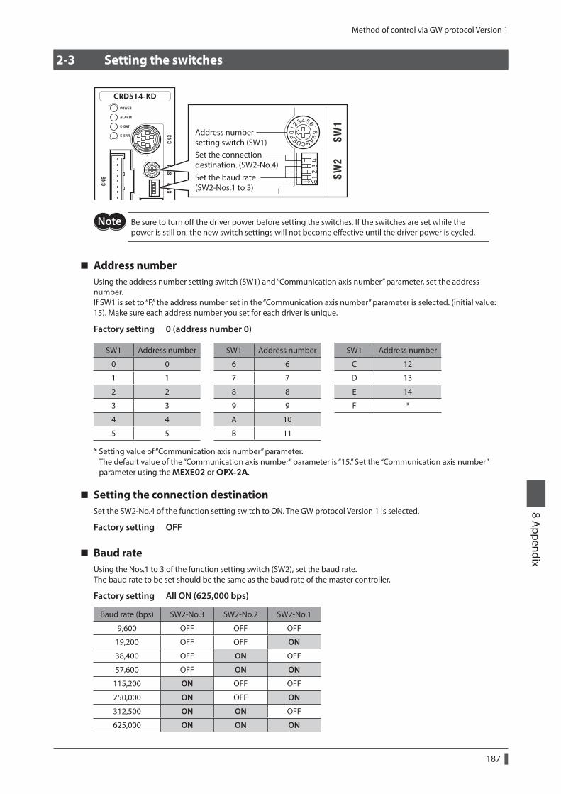
Method of control via GW protocol Version 1
187
8 Appendix
2-3 Setting the switches
Address numbersetting switch (SW1)
Set the baud rate.(SW2-Nos.1 to 3)
Set the connectiondestination. (SW2-No.4)
Be sure to turn off the driver power before setting the switches. If the switches are set while the power is still on, the new switch settings will not become effective until the driver power is cycled.
Address numberUsing the address number setting switch (SW1) and “Communication axis number” parameter, set the address number.If SW1 is set to “F,” the address number set in the “Communication axis number” parameter is selected. (initial value: 15). Make sure each address number you set for each driver is unique.
Factory setting 0 (address number 0)
SW1 Address number SW1 Address number SW1 Address number
0 0 6 6 C 12
1 1 7 7 D 13
2 2 8 8 E 14
3 3 9 9 F *
4 4 A 10
5 5 B 11
* Setting value of “Communication axis number” parameter. The default value of the “Communication axis number” parameter is “15.” Set the “Communication axis number” parameter using the MEXE02 or OPX-2A.
Setting the connection destinationSet the SW2-No.4 of the function setting switch to ON. The GW protocol Version 1 is selected.
Factory setting OFF
Baud rateUsing the Nos.1 to 3 of the function setting switch (SW2), set the baud rate.The baud rate to be set should be the same as the baud rate of the master controller.
Factory setting All ON (625,000 bps)
Baud rate (bps) SW2-No.3 SW2-No.2 SW2-No.1
9,600 OFF OFF OFF
19,200 OFF OFF ON
38,400 OFF ON OFF
57,600 OFF ON ON
115,200 ON OFF OFF
250,000 ON OFF ON
312,500 ON ON OFF
625,000 ON ON ON
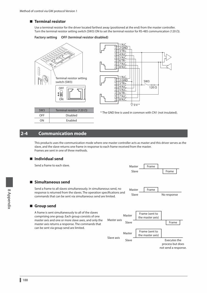
Method of control via GW protocol Version 1
188
8 Appendix
Terminal resistorUse a terminal resistor for the driver located farthest away (positioned at the end) from the master controller.Turn the terminal resistor setting switch (SW3) ON to set the terminal resistor for RS-485 communication (120 Ω).
Factory setting OFF (terminal resistor disabled)
Terminal resistor settingswitch (SW3)
ON
OFF
1 N.C.2 GND3 TR+4 N.C.5 N.C.6 TR-7 N.C.8 N.C.
1 N.C.2 GND3 TR+4 N.C.5 N.C.6 TR-7 N.C.8 N.C.
120 Ω
0 V *
SW3
* The GND line is used in common with CN1 (not insulated).SW3 Terminal resistor (120 Ω)
OFF Disabled
ON Enabled
2-4 Communication mode
This products uses the communication mode where one master controller acts as master and this driver serves as the slave, and the slave returns one frame in response to each frame received from the master.Frames are sent in one of three methods.
Individual sendSend a frame to each slave. Frame
Frame
Master
Slave
Simultaneous sendSend a frame to all slaves simultaneously. In simultaneous send, no response is returned from the slaves. The operation specifications and commands that can be sent via simultaneous send are limited.
FrameMaster
Slave No response
Group sendA frame is sent simultaneously to all of the slaves comprising one group. Each group consists of one master axis and one or more slave axes, and only the master axis returns a response. The commands that can be sent via group send are limited.
Frame (sent tothe master axis)
Frame (sent tothe master axis)
Slave axis
Master axisFrame
Master
Master
Slave
Slave Executes theprocess but does
not send a response.
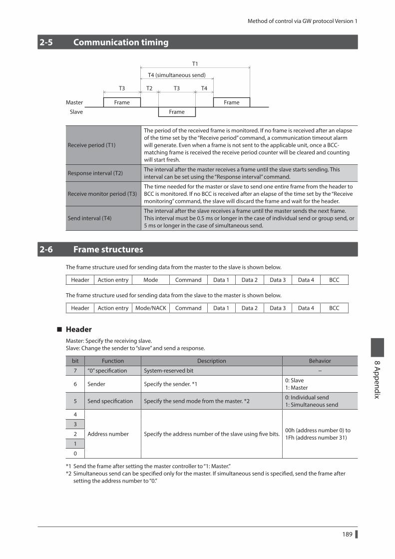
Method of control via GW protocol Version 1
189
8 Appendix
2-5 Communication timing
Frame
T3 T2 T3 T4
T4 (simultaneous send)
T1
Frame
Frame
Master
Slave
Receive period (T1)
The period of the received frame is monitored. If no frame is received after an elapse of the time set by the “Receive period” command, a communication timeout alarm will generate. Even when a frame is not sent to the applicable unit, once a BCC-matching frame is received the receive period counter will be cleared and counting will start fresh.
Response interval (T2)The interval after the master receives a frame until the slave starts sending. This interval can be set using the “Response interval” command.
Receive monitor period (T3)The time needed for the master or slave to send one entire frame from the header to BCC is monitored. If no BCC is received after an elapse of the time set by the “Receive monitoring” command, the slave will discard the frame and wait for the header.
Send interval (T4)The interval after the slave receives a frame until the master sends the next frame. This interval must be 0.5 ms or longer in the case of individual send or group send, or 5 ms or longer in the case of simultaneous send.
2-6 Frame structures
The frame structure used for sending data from the master to the slave is shown below.
Header Action entry Mode Command Data 1 Data 2 Data 3 Data 4 BCC
The frame structure used for sending data from the slave to the master is shown below.
Header Action entry Mode/NACK Command Data 1 Data 2 Data 3 Data 4 BCC
HeaderMaster: Specify the receiving slave.Slave: Change the sender to “slave” and send a response.
bit Function Description Behavior
7 “0” specification System-reserved bit −
6 Sender Specify the sender. *10: Slave 1: Master
5 Send specification Specify the send mode from the master. *20: Individual send 1: Simultaneous send
4
Address number Specify the address number of the slave using five bits.00h (address number 0) to 1Fh (address number 31)
3
2
1
0
*1 Send the frame after setting the master controller to “1: Master.”*2 Simultaneous send can be specified only for the master. If simultaneous send is specified, send the frame after
setting the address number to “0.”
Method of control via GW protocol Version 1
190
8 Appendix
Action entryMaster: Specify the operation to be performed by the slave.Slave: Sends directly the action entry data received from the master.
bit Function Description Behavior
7 “0” specification System-reserved bit *1 −
6 WRITE/READ Write or read data. *20: WRITE 1: READ
5 STOP Stop the motor. *3*40: No action 1: Stop
4 Not used − −
3 HOME Perform return-to-home operation. *4 *50: No action 1: Start operation
2 RVSPerform continuous operation in the reverse direction. *4 *6 *7 0: Deceleration stop
1: Operation1 FWD
Perform continuous operation in the forward direction. *4 *6 *7
0 START Perform positioning operation. *4 *5 *70: No action 1: Start operation
*1 When “1” is specified, a reception failure will be recognized. Accordingly, the frame will be discarded and NACK will be returned.
*2 Specify whether it is a WRITE or READ command. Other operation command bits are executed regardless of the WRITE/READ specification.
*3 The stopping method can be set using the “STOP action (13h)” command.*4 The operation command bits have priorities. Specifically, “1” is detected in the order of STOP > FWD/RVS > HOME >
START.*5 Operation is started at the ON edge of this bit (when the bit changes from 0 to 1). Once the operation has started,
return this bit to “0.”*6 Operation continues while this bit remains “1.” Returning it to “0” will cause the motor to decelerate to a stop.*7 Select the operation data number using the “Data number selection” command and specify it using the mode
command.
Commands (WRITE/READ) and operation commands (STOP, HOME, RVS, FWD, START) can be sent simultaneously. Since the operation is started after writing, data setting and operation can be performed simultaneously.
ModeMaster: Specify the data number. If any out-of-range mode is specified, a reception failure will be recognized. Accordingly, the frame will be discarded and NACK will be returned.
Mode Description
00h to 3FhIf the command requires a data number, specify an applicable data number. If the command does not require any data number, specify “00h.”
Slave: If the communication is performed successfully, the master mode will be returned directly.
Mode Description
00h to 3Fh The master mode will be returned directly (successful reception).
FFh This indicates a reception failure (NACK).
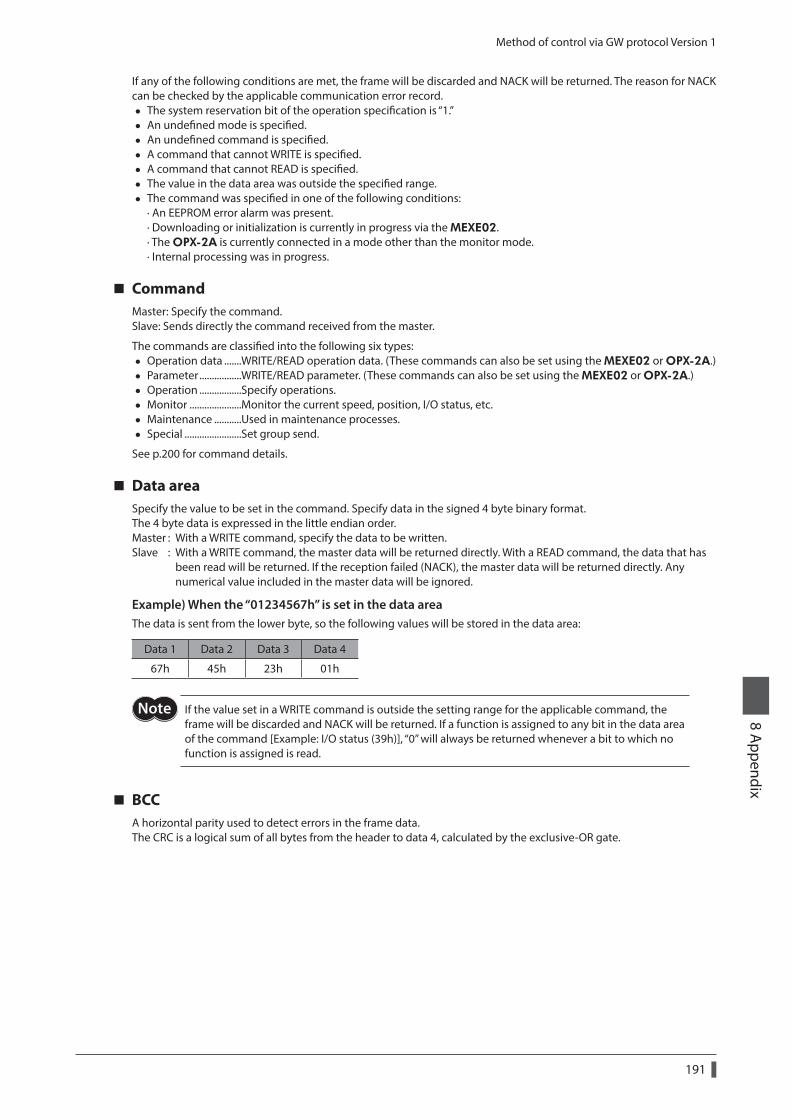
Method of control via GW protocol Version 1
191
8 Appendix
If any of the following conditions are met, the frame will be discarded and NACK will be returned. The reason for NACK can be checked by the applicable communication error record.
• The system reservation bit of the operation specification is “1.” • An undefined mode is specified. • An undefined command is specified. • A command that cannot WRITE is specified. • A command that cannot READ is specified. • The value in the data area was outside the specified range. • The command was specified in one of the following conditions:
· An EEPROM error alarm was present. · Downloading or initialization is currently in progress via the MEXE02. · The OPX-2A is currently connected in a mode other than the monitor mode. · Internal processing was in progress.
CommandMaster: Specify the command.Slave: Sends directly the command received from the master.
The commands are classified into the following six types: • Operation data .......WRITE/READ operation data. (These commands can also be set using the MEXE02 or OPX-2A.) • Parameter .................WRITE/READ parameter. (These commands can also be set using the MEXE02 or OPX-2A.) • Operation .................Specify operations. • Monitor .....................Monitor the current speed, position, I/O status, etc. • Maintenance ...........Used in maintenance processes. • Special .......................Set group send.
See p.200 for command details.
Data areaSpecify the value to be set in the command. Specify data in the signed 4 byte binary format.The 4 byte data is expressed in the little endian order.Master : With a WRITE command, specify the data to be written.Slave : With a WRITE command, the master data will be returned directly. With a READ command, the data that has been read will be returned. If the reception failed (NACK), the master data will be returned directly. Any numerical value included in the master data will be ignored.
Example) When the “01234567h” is set in the data areaThe data is sent from the lower byte, so the following values will be stored in the data area:
Data 1 Data 2 Data 3 Data 4
67h 45h 23h 01h
If the value set in a WRITE command is outside the setting range for the applicable command, the frame will be discarded and NACK will be returned. If a function is assigned to any bit in the data area of the command [Example: I/O status (39h)], “0” will always be returned whenever a bit to which no function is assigned is read.
BCCA horizontal parity used to detect errors in the frame data.The CRC is a logical sum of all bytes from the header to data 4, calculated by the exclusive-OR gate.
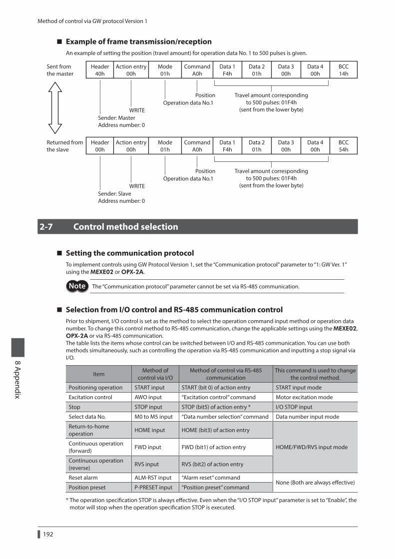
Method of control via GW protocol Version 1
192
8 Appendix
Example of frame transmission/receptionAn example of setting the position (travel amount) for operation data No. 1 to 500 pulses is given.
Header40h
Sent fromthe master
Action entry00h
Mode01h
CommandA0h
Data 1F4h
Data 201h
Data 300h
Data 400h
Travel amount correspondingto 500 pulses: 01F4h
(sent from the lower byte)
PositionOperation data No.1
WRITESender: MasterAddress number: 0
BCC14h
Header00h
Returned fromthe slave
Action entry00h
Mode01h
CommandA0h
Data 1F4h
Data 201h
Data 300h
Data 400h
Travel amount correspondingto 500 pulses: 01F4h
(sent from the lower byte)
PositionOperation data No.1
WRITESender: SlaveAddress number: 0
BCC54h
2-7 Control method selection
Setting the communication protocolTo implement controls using GW Protocol Version 1, set the “Communication protocol” parameter to “1: GW Ver. 1” using the MEXE02 or OPX-2A.
The “Communication protocol” parameter cannot be set via RS-485 communication.
Selection from I/O control and RS-485 communication controlPrior to shipment, I/O control is set as the method to select the operation command input method or operation data number. To change this control method to RS-485 communication, change the applicable settings using the MEXE02, OPX-2A or via RS-485 communication.The table lists the items whose control can be switched between I/O and RS-485 communication. You can use both methods simultaneously, such as controlling the operation via RS-485 communication and inputting a stop signal via I/O.
ItemMethod of
control via I/OMethod of control via RS-485
communicationThis command is used to change
the control method.
Positioning operation START input START (bit 0) of action entry START input mode
Excitation control AWO input “Excitation control” command Motor excitation mode
Stop STOP input STOP (bit5) of action entry * I/O STOP input
Select data No. M0 to M5 input “Data number selection” command Data number input mode
Return-to-home operation
HOME input HOME (bit3) of action entry
HOME/FWD/RVS input modeContinuous operation (forward)
FWD input FWD (bit1) of action entry
Continuous operation (reverse)
RVS input RVS (bit2) of action entry
Reset alarm ALM-RST input “Alarm reset” commandNone (Both are always effective)
Position preset P-PRESET input “Position preset” command
* The operation specification STOP is always effective. Even when the “I/O STOP input” parameter is set to “Enable”, the motor will stop when the operation specification STOP is executed.
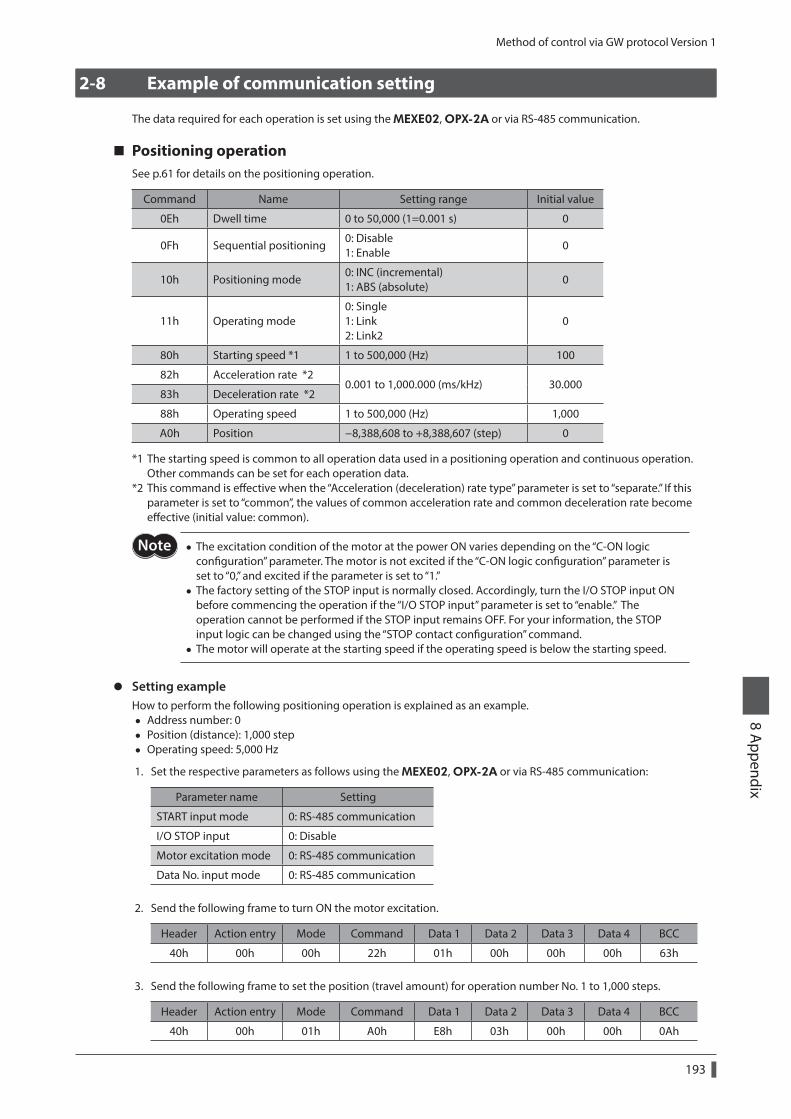
Method of control via GW protocol Version 1
193
8 Appendix
2-8 Example of communication setting
The data required for each operation is set using the MEXE02, OPX-2A or via RS-485 communication.
Positioning operationSee p.61 for details on the positioning operation.
Command Name Setting range Initial value
0Eh Dwell time 0 to 50,000 (1=0.001 s) 0
0Fh Sequential positioning0: Disable 1: Enable
0
10h Positioning mode0: INC (incremental) 1: ABS (absolute)
0
11h Operating mode0: Single 1: Link 2: Link2
0
80h Starting speed *1 1 to 500,000 (Hz) 100
82h Acceleration rate *20.001 to 1,000.000 (ms/kHz) 30.000
83h Deceleration rate *2
88h Operating speed 1 to 500,000 (Hz) 1,000
A0h Position −8,388,608 to +8,388,607 (step) 0
*1 The starting speed is common to all operation data used in a positioning operation and continuous operation. Other commands can be set for each operation data.
*2 This command is effective when the “Acceleration (deceleration) rate type” parameter is set to “separate.” If this parameter is set to “common”, the values of common acceleration rate and common deceleration rate become effective (initial value: common).
• The excitation condition of the motor at the power ON varies depending on the “C-ON logic configuration” parameter. The motor is not excited if the “C-ON logic configuration” parameter is set to “0,” and excited if the parameter is set to “1.”
• The factory setting of the STOP input is normally closed. Accordingly, turn the I/O STOP input ON before commencing the operation if the “I/O STOP input” parameter is set to “enable.” The operation cannot be performed if the STOP input remains OFF. For your information, the STOP input logic can be changed using the “STOP contact configuration” command.
• The motor will operate at the starting speed if the operating speed is below the starting speed.
z Setting exampleHow to perform the following positioning operation is explained as an example.
• Address number: 0 • Position (distance): 1,000 step • Operating speed: 5,000 Hz
1. Set the respective parameters as follows using the MEXE02, OPX-2A or via RS-485 communication:
Parameter name Setting
START input mode 0: RS-485 communication
I/O STOP input 0: Disable
Motor excitation mode 0: RS-485 communication
Data No. input mode 0: RS-485 communication
2. Send the following frame to turn ON the motor excitation.
Header Action entry Mode Command Data 1 Data 2 Data 3 Data 4 BCC
40h 00h 00h 22h 01h 00h 00h 00h 63h
3. Send the following frame to set the position (travel amount) for operation number No. 1 to 1,000 steps.
Header Action entry Mode Command Data 1 Data 2 Data 3 Data 4 BCC
40h 00h 01h A0h E8h 03h 00h 00h 0Ah
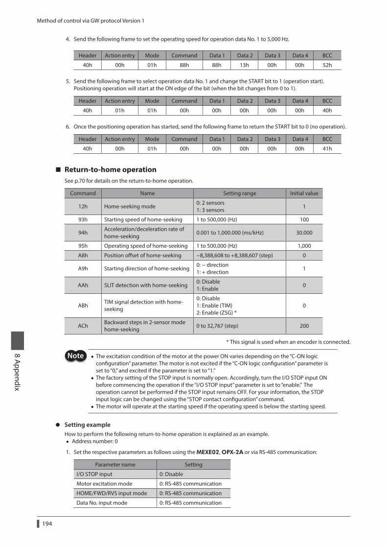
Method of control via GW protocol Version 1
194
8 Appendix
4. Send the following frame to set the operating speed for operation data No. 1 to 5,000 Hz.
Header Action entry Mode Command Data 1 Data 2 Data 3 Data 4 BCC
40h 00h 01h 88h 88h 13h 00h 00h 52h
5. Send the following frame to select operation data No. 1 and change the START bit to 1 (operation start).Positioning operation will start at the ON edge of the bit (when the bit changes from 0 to 1).
Header Action entry Mode Command Data 1 Data 2 Data 3 Data 4 BCC
40h 01h 01h 00h 00h 00h 00h 00h 40h
6. Once the positioning operation has started, send the following frame to return the START bit to 0 (no operation).
Header Action entry Mode Command Data 1 Data 2 Data 3 Data 4 BCC
40h 00h 01h 00h 00h 00h 00h 00h 41h
Return-to-home operationSee p.70 for details on the return-to-home operation.
Command Name Setting range Initial value
12h Home-seeking mode0: 2 sensors 1: 3 sensors
1
93h Starting speed of home-seeking 1 to 500,000 (Hz) 100
94hAcceleration/deceleration rate of home-seeking
0.001 to 1,000.000 (ms/kHz) 30.000
95h Operating speed of home-seeking 1 to 500,000 (Hz) 1,000
A8h Position offset of home-seeking −8,388,608 to +8,388,607 (step) 0
A9h Starting direction of home-seeking0: − direction 1: + direction
1
AAh SLIT detection with home-seeking0: Disable 1: Enable
0
ABhTIM signal detection with home-seeking
0: Disable 1: Enable (TIM) 2: Enable (ZSG) *
0
AChBackward steps in 2-sensor mode home-seeking
0 to 32,767 (step) 200
* This signal is used when an encoder is connected.
• The excitation condition of the motor at the power ON varies depending on the “C-ON logic configuration” parameter. The motor is not excited if the “C-ON logic configuration” parameter is set to “0,” and excited if the parameter is set to “1.”
• The factory setting of the STOP input is normally open. Accordingly, turn the I/O STOP input ON before commencing the operation if the “I/O STOP input” parameter is set to “enable.” The operation cannot be performed if the STOP input remains OFF. For your information, the STOP input logic can be changed using the “STOP contact configuration” command.
• The motor will operate at the starting speed if the operating speed is below the starting speed.
z Setting exampleHow to perform the following return-to-home operation is explained as an example.
• Address number: 0
1. Set the respective parameters as follows using the MEXE02, OPX-2A or via RS-485 communication:
Parameter name Setting
I/O STOP input 0: Disable
Motor excitation mode 0: RS-485 communication
HOME/FWD/RVS input mode 0: RS-485 communication
Data No. input mode 0: RS-485 communication
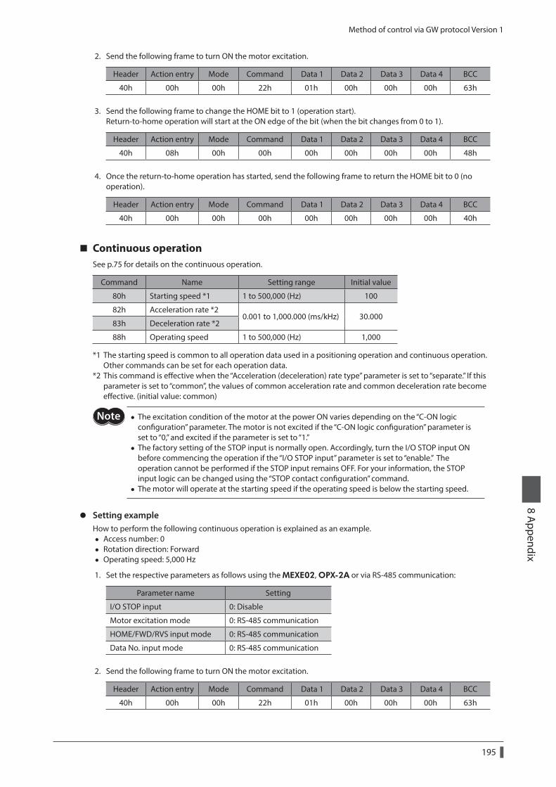
Method of control via GW protocol Version 1
195
8 Appendix
2. Send the following frame to turn ON the motor excitation.
Header Action entry Mode Command Data 1 Data 2 Data 3 Data 4 BCC
40h 00h 00h 22h 01h 00h 00h 00h 63h
3. Send the following frame to change the HOME bit to 1 (operation start).Return-to-home operation will start at the ON edge of the bit (when the bit changes from 0 to 1).
Header Action entry Mode Command Data 1 Data 2 Data 3 Data 4 BCC
40h 08h 00h 00h 00h 00h 00h 00h 48h
4. Once the return-to-home operation has started, send the following frame to return the HOME bit to 0 (no operation).
Header Action entry Mode Command Data 1 Data 2 Data 3 Data 4 BCC
40h 00h 00h 00h 00h 00h 00h 00h 40h
Continuous operationSee p.75 for details on the continuous operation.
Command Name Setting range Initial value
80h Starting speed *1 1 to 500,000 (Hz) 100
82h Acceleration rate *20.001 to 1,000.000 (ms/kHz) 30.000
83h Deceleration rate *2
88h Operating speed 1 to 500,000 (Hz) 1,000
*1 The starting speed is common to all operation data used in a positioning operation and continuous operation. Other commands can be set for each operation data.
*2 This command is effective when the “Acceleration (deceleration) rate type” parameter is set to “separate.” If this parameter is set to “common”, the values of common acceleration rate and common deceleration rate become effective. (initial value: common)
• The excitation condition of the motor at the power ON varies depending on the “C-ON logic configuration” parameter. The motor is not excited if the “C-ON logic configuration” parameter is set to “0,” and excited if the parameter is set to “1.”
• The factory setting of the STOP input is normally open. Accordingly, turn the I/O STOP input ON before commencing the operation if the “I/O STOP input” parameter is set to “enable.” The operation cannot be performed if the STOP input remains OFF. For your information, the STOP input logic can be changed using the “STOP contact configuration” command.
• The motor will operate at the starting speed if the operating speed is below the starting speed.
z Setting exampleHow to perform the following continuous operation is explained as an example.
• Access number: 0 • Rotation direction: Forward • Operating speed: 5,000 Hz
1. Set the respective parameters as follows using the MEXE02, OPX-2A or via RS-485 communication:
Parameter name Setting
I/O STOP input 0: Disable
Motor excitation mode 0: RS-485 communication
HOME/FWD/RVS input mode 0: RS-485 communication
Data No. input mode 0: RS-485 communication
2. Send the following frame to turn ON the motor excitation.
Header Action entry Mode Command Data 1 Data 2 Data 3 Data 4 BCC
40h 00h 00h 22h 01h 00h 00h 00h 63h
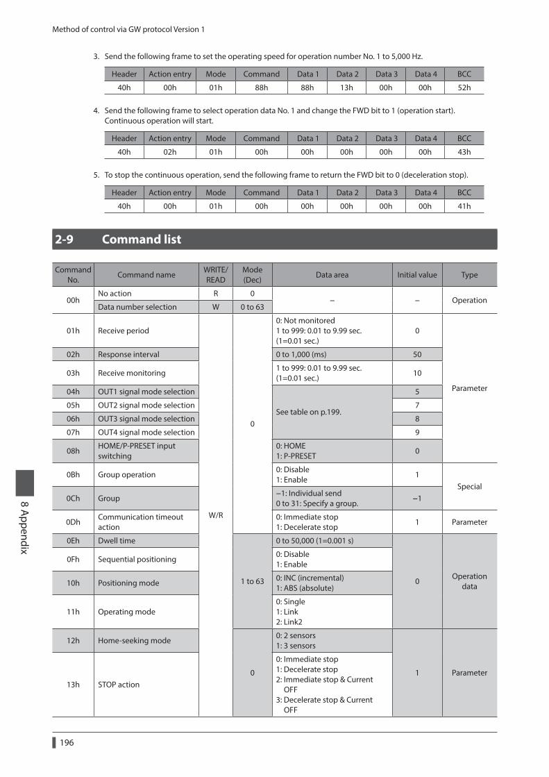
Method of control via GW protocol Version 1
196
8 Appendix
3. Send the following frame to set the operating speed for operation number No. 1 to 5,000 Hz.
Header Action entry Mode Command Data 1 Data 2 Data 3 Data 4 BCC
40h 00h 01h 88h 88h 13h 00h 00h 52h
4. Send the following frame to select operation data No. 1 and change the FWD bit to 1 (operation start).Continuous operation will start.
Header Action entry Mode Command Data 1 Data 2 Data 3 Data 4 BCC
40h 02h 01h 00h 00h 00h 00h 00h 43h
5. To stop the continuous operation, send the following frame to return the FWD bit to 0 (deceleration stop).
Header Action entry Mode Command Data 1 Data 2 Data 3 Data 4 BCC
40h 00h 01h 00h 00h 00h 00h 00h 41h
2-9 Command list
Command No.
Command nameWRITE/READ
Mode (Dec)
Data area Initial value Type
00hNo action R 0
− − OperationData number selection W 0 to 63
01h Receive period
W/R
0
0: Not monitored 1 to 999: 0.01 to 9.99 sec. (1=0.01 sec.)
0
Parameter
02h Response interval 0 to 1,000 (ms) 50
03h Receive monitoring1 to 999: 0.01 to 9.99 sec. (1=0.01 sec.)
10
04h OUT1 signal mode selection
See table on p.199.
5
05h OUT2 signal mode selection 7
06h OUT3 signal mode selection 8
07h OUT4 signal mode selection 9
08hHOME/P-PRESET input switching
0: HOME 1: P-PRESET
0
0Bh Group operation0: Disable 1: Enable
1Special
0Ch Group−1: Individual send 0 to 31: Specify a group.
−1
0DhCommunication timeout action
0: Immediate stop 1: Decelerate stop
1 Parameter
0Eh Dwell time
1 to 63
0 to 50,000 (1=0.001 s)
0Operation
data
0Fh Sequential positioning0: Disable 1: Enable
10h Positioning mode0: INC (incremental) 1: ABS (absolute)
11h Operating mode0: Single 1: Link 2: Link2
12h Home-seeking mode
0
0: 2 sensors 1: 3 sensors
1 Parameter13h STOP action
0: Immediate stop 1: Decelerate stop 2: Immediate stop & Current OFF 3: Decelerate stop & Current OFF
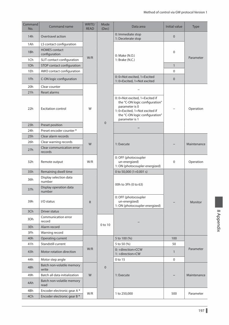
Method of control via GW protocol Version 1
197
8 Appendix
Command No.
Command nameWRITE/READ
Mode (Dec)
Data area Initial value Type
14h Overtravel action
W/R
0
0: Immediate stop 1: Decelerate stop
0
Parameter
1Ah LS contact configuration
0: Make (N.O.) 1: Brake (N.C.)
01BhHOMES contact configuration
1Ch SLIT contact configuration
1Dh STOP contact configuration 1
1Eh AWO contact configuration 0
1Fh C-ON logic configuration0: 0=Not excited, 1=Excited 1: 0=Excited, 1=Not excited
0
20h Clear counter
W
−
− Operation
21h Reset alarms
22h Excitation control
0: 0=Not excited, 1=Excited if the "C-ON logic configuration" parameter is 0 1: 0=Excited, 1=Not excited if the "C-ON logic configuration" parameter is 1
23h Preset position−
24h Preset encoder counter *
25h Clear alarm records
W 1: Execute − Maintenance26h Clear warning records
27hClear communication error records
32h Remote output W/R0: OFF (photocoupler un-energized) 1: ON (photocoupler energized)
0 Operation
35h Remaining dwell time
R
0 to 50,000 (1=0.001 s)
− Monitor
36hDisplay selection data number
00h to 3Fh (0 to 63)37h
Display operation data number
39h I/O status0: OFF (photocoupler un-energized) 1: ON (photocoupler energized)
3Ch Driver status
−3Dh
Communication error record
0 to 103Eh Alarm record
3Fh Warning record
40h Operating current
W/R
0
5 to 100 (%) 100
Parameter41h Standstill current 5 to 50 (%) 50
43h Motor rotation direction0: +direction=CCW 1: +direction=CW
1
44h Motor step angle 0 to 15 0
48hBatch non-volatile memory write
W 1: Execute − Maintenance49h Batch all data initialization
4AhBatch non-volatile memory read
4Bh Encoder electronic gear A *W/R 1 to 250,000 500 Parameter
4Ch Encoder electronic gear B *
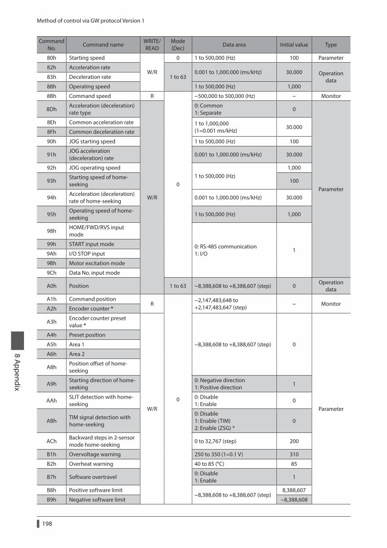
Method of control via GW protocol Version 1
198
8 Appendix
Command No.
Command nameWRITE/READ
Mode (Dec)
Data area Initial value Type
80h Starting speed
W/R
0 1 to 500,000 (Hz) 100 Parameter
82h Acceleration rate
1 to 630.001 to 1,000.000 (ms/kHz) 30.000 Operation
data83h Deceleration rate
88h Operating speed 1 to 500,000 (Hz) 1,000
8Bh Command speed R
0
−500,000 to 500,000 (Hz) − Monitor
8DhAcceleration (deceleration) rate type
W/R
0: Common 1: Separate
0
Parameter
8Eh Common acceleration rate 1 to 1,000,000 (1=0.001 ms/kHz)
30.0008Fh Common deceleration rate
90h JOG starting speed 1 to 500,000 (Hz) 100
91hJOG acceleration (deceleration) rate
0.001 to 1,000.000 (ms/kHz) 30.000
92h JOG operating speed1 to 500,000 (Hz)
1,000
93hStarting speed of home-seeking
100
94hAcceleration (deceleration) rate of home-seeking
0.001 to 1,000.000 (ms/kHz) 30.000
95hOperating speed of home-seeking
1 to 500,000 (Hz) 1,000
98hHOME/FWD/RVS input mode
0: RS-485 communication 1: I/O
199h START input mode
9Ah I/O STOP input
9Bh Motor excitation mode
9Ch Data No. input mode
A0h Position 1 to 63 −8,388,608 to +8,388,607 (step) 0Operation
data
A1h Command positionR
0
−2,147,483,648 to +2,147,483,647 (step)
− MonitorA2h Encoder counter *
A3hEncoder counter preset value *
W/R
−8,388,608 to +8,388,607 (step) 0
Parameter
A4h Preset position
A5h Area 1
A6h Area 2
A8hPosition offset of home-seeking
A9hStarting direction of home-seeking
0: Negative direction 1: Positive direction
1
AAhSLIT detection with home-seeking
0: Disable 1: Enable
0
ABhTIM signal detection with home-seeking
0: Disable 1: Enable (TIM) 2: Enable (ZSG) *
0
AChBackward steps in 2-sensor mode home-seeking
0 to 32,767 (step) 200
B1h Overvoltage warning 250 to 350 (1=0.1 V) 310
B2h Overheat warning 40 to 85 (°C) 85
B7h Software overtravel0: Disable 1: Enable
1
B8h Positive software limit−8,388,608 to +8,388,607 (step)
8,388,607
B9h Negative software limit −8,388,608
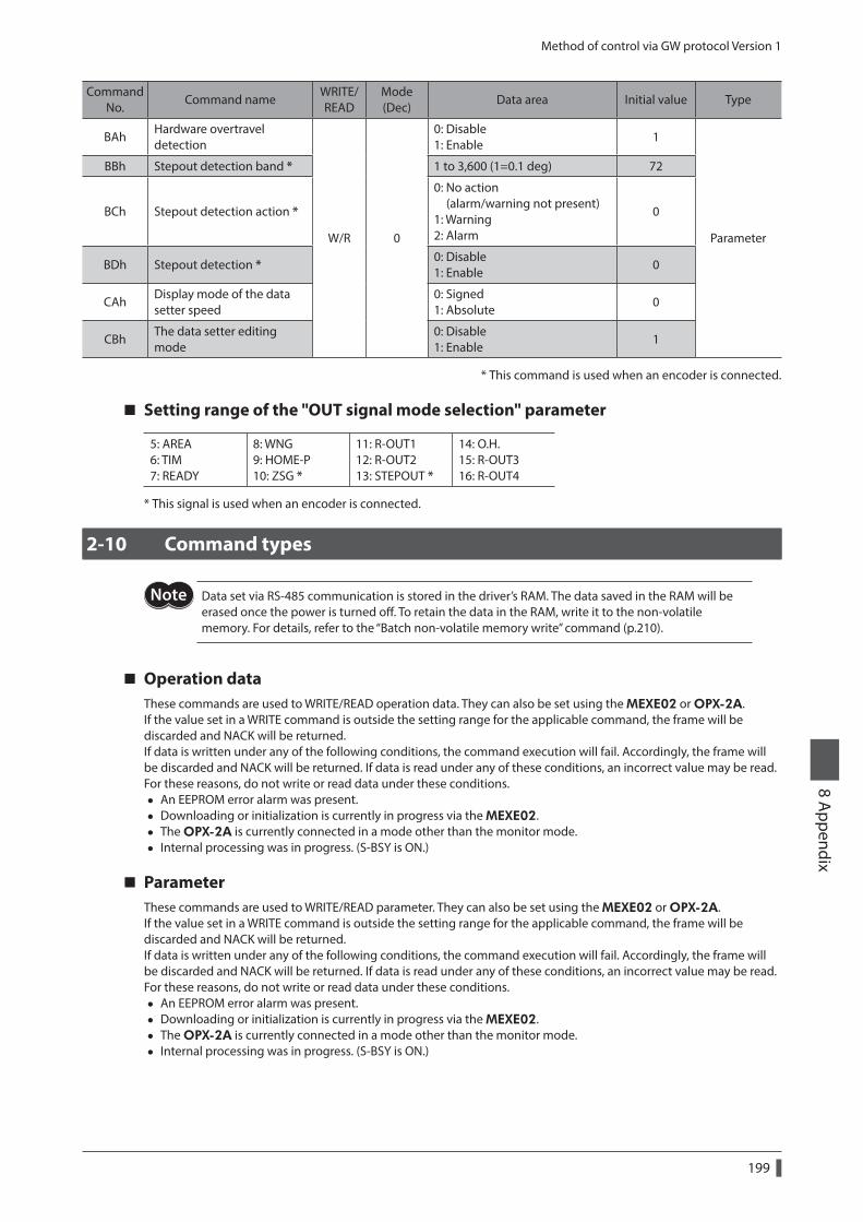
Method of control via GW protocol Version 1
199
8 Appendix
Command No.
Command nameWRITE/READ
Mode (Dec)
Data area Initial value Type
BAhHardware overtravel detection
W/R 0
0: Disable 1: Enable
1
Parameter
BBh Stepout detection band * 1 to 3,600 (1=0.1 deg) 72
BCh Stepout detection action *
0: No action (alarm/warning not present) 1: Warning 2: Alarm
0
BDh Stepout detection *0: Disable 1: Enable
0
CAhDisplay mode of the data setter speed
0: Signed 1: Absolute
0
CBhThe data setter editing mode
0: Disable 1: Enable
1
* This command is used when an encoder is connected.
Setting range of the "OUT signal mode selection" parameter
5: AREA 6: TIM 7: READY
8: WNG 9: HOME-P 10: ZSG *
11: R-OUT1 12: R-OUT2 13: STEPOUT *
14: O.H. 15: R-OUT3 16: R-OUT4
* This signal is used when an encoder is connected.
2-10 Command types
Data set via RS-485 communication is stored in the driver’s RAM. The data saved in the RAM will be erased once the power is turned off. To retain the data in the RAM, write it to the non-volatile memory. For details, refer to the “Batch non-volatile memory write” command (p.210).
Operation dataThese commands are used to WRITE/READ operation data. They can also be set using the MEXE02 or OPX-2A.If the value set in a WRITE command is outside the setting range for the applicable command, the frame will be discarded and NACK will be returned.If data is written under any of the following conditions, the command execution will fail. Accordingly, the frame will be discarded and NACK will be returned. If data is read under any of these conditions, an incorrect value may be read. For these reasons, do not write or read data under these conditions.
• An EEPROM error alarm was present. • Downloading or initialization is currently in progress via the MEXE02. • The OPX-2A is currently connected in a mode other than the monitor mode. • Internal processing was in progress. (S-BSY is ON.)
ParameterThese commands are used to WRITE/READ parameter. They can also be set using the MEXE02 or OPX-2A.If the value set in a WRITE command is outside the setting range for the applicable command, the frame will be discarded and NACK will be returned.If data is written under any of the following conditions, the command execution will fail. Accordingly, the frame will be discarded and NACK will be returned. If data is read under any of these conditions, an incorrect value may be read. For these reasons, do not write or read data under these conditions.
• An EEPROM error alarm was present. • Downloading or initialization is currently in progress via the MEXE02. • The OPX-2A is currently connected in a mode other than the monitor mode. • Internal processing was in progress. (S-BSY is ON.)
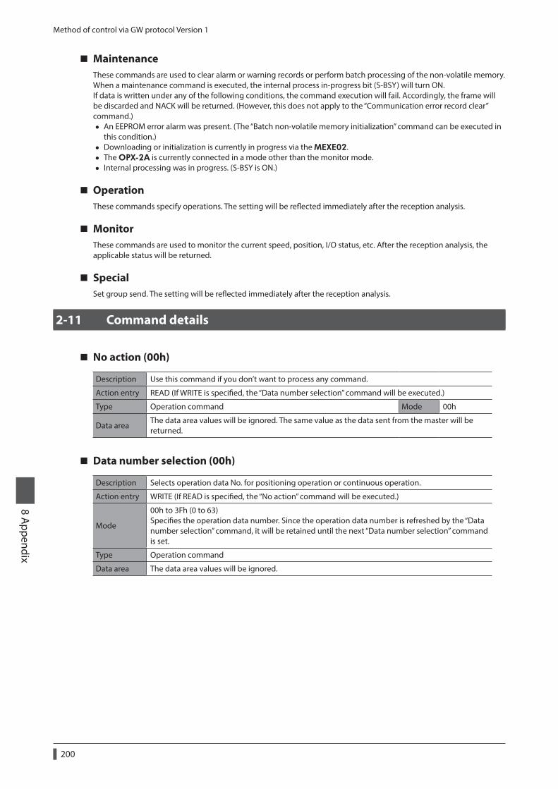
Method of control via GW protocol Version 1
200
8 Appendix
MaintenanceThese commands are used to clear alarm or warning records or perform batch processing of the non-volatile memory. When a maintenance command is executed, the internal process in-progress bit (S-BSY) will turn ON.If data is written under any of the following conditions, the command execution will fail. Accordingly, the frame will be discarded and NACK will be returned. (However, this does not apply to the “Communication error record clear” command.)
• An EEPROM error alarm was present. (The “Batch non-volatile memory initialization” command can be executed in this condition.)
• Downloading or initialization is currently in progress via the MEXE02. • The OPX-2A is currently connected in a mode other than the monitor mode. • Internal processing was in progress. (S-BSY is ON.)
OperationThese commands specify operations. The setting will be reflected immediately after the reception analysis.
MonitorThese commands are used to monitor the current speed, position, I/O status, etc. After the reception analysis, the applicable status will be returned.
SpecialSet group send. The setting will be reflected immediately after the reception analysis.
2-11 Command details
No action (00h)
Description Use this command if you don’t want to process any command.
Action entry READ (If WRITE is specified, the “Data number selection” command will be executed.)
Type Operation command Mode 00h
Data areaThe data area values will be ignored. The same value as the data sent from the master will be returned.
Data number selection (00h)
Description Selects operation data No. for positioning operation or continuous operation.
Action entry WRITE (If READ is specified, the “No action” command will be executed.)
Mode
00h to 3Fh (0 to 63) Specifies the operation data number. Since the operation data number is refreshed by the “Data number selection” command, it will be retained until the next “Data number selection” command is set.
Type Operation command
Data area The data area values will be ignored.
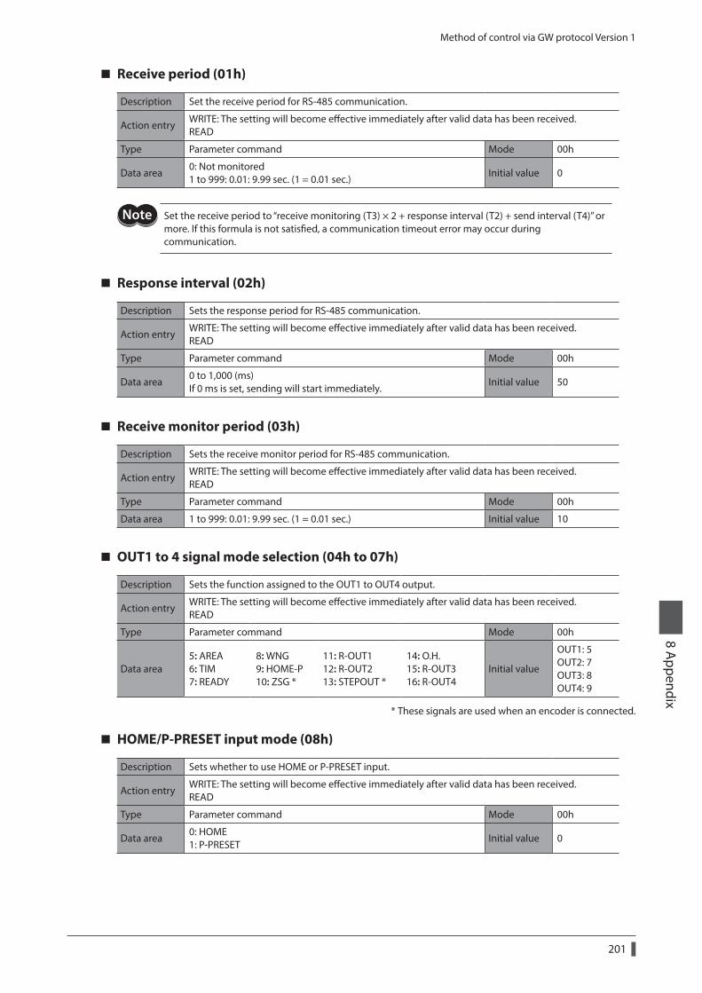
Method of control via GW protocol Version 1
201
8 Appendix
Receive period (01h)
Description Set the receive period for RS-485 communication.
Action entryWRITE: The setting will become effective immediately after valid data has been received. READ
Type Parameter command Mode 00h
Data area0: Not monitored 1 to 999: 0.01: 9.99 sec. (1 = 0.01 sec.)
Initial value 0
Set the receive period to “receive monitoring (T3) × 2 + response interval (T2) + send interval (T4)” or more. If this formula is not satisfied, a communication timeout error may occur during communication.
Response interval (02h)
Description Sets the response period for RS-485 communication.
Action entryWRITE: The setting will become effective immediately after valid data has been received. READ
Type Parameter command Mode 00h
Data area0 to 1,000 (ms) If 0 ms is set, sending will start immediately.
Initial value 50
Receive monitor period (03h)
Description Sets the receive monitor period for RS-485 communication.
Action entryWRITE: The setting will become effective immediately after valid data has been received. READ
Type Parameter command Mode 00h
Data area 1 to 999: 0.01: 9.99 sec. (1 = 0.01 sec.) Initial value 10
OUT1 to 4 signal mode selection (04h to 07h)
Description Sets the function assigned to the OUT1 to OUT4 output.
Action entryWRITE: The setting will become effective immediately after valid data has been received. READ
Type Parameter command Mode 00h
Data area5: AREA 6: TIM 7: READY
8: WNG 9: HOME-P 10: ZSG *
11: R-OUT1 12: R-OUT2 13: STEPOUT *
14: O.H. 15: R-OUT3 16: R-OUT4
Initial value
OUT1: 5 OUT2: 7 OUT3: 8 OUT4: 9
* These signals are used when an encoder is connected.
HOME/P-PRESET input mode (08h)
Description Sets whether to use HOME or P-PRESET input.
Action entryWRITE: The setting will become effective immediately after valid data has been received. READ
Type Parameter command Mode 00h
Data area0: HOME 1: P-PRESET
Initial value 0
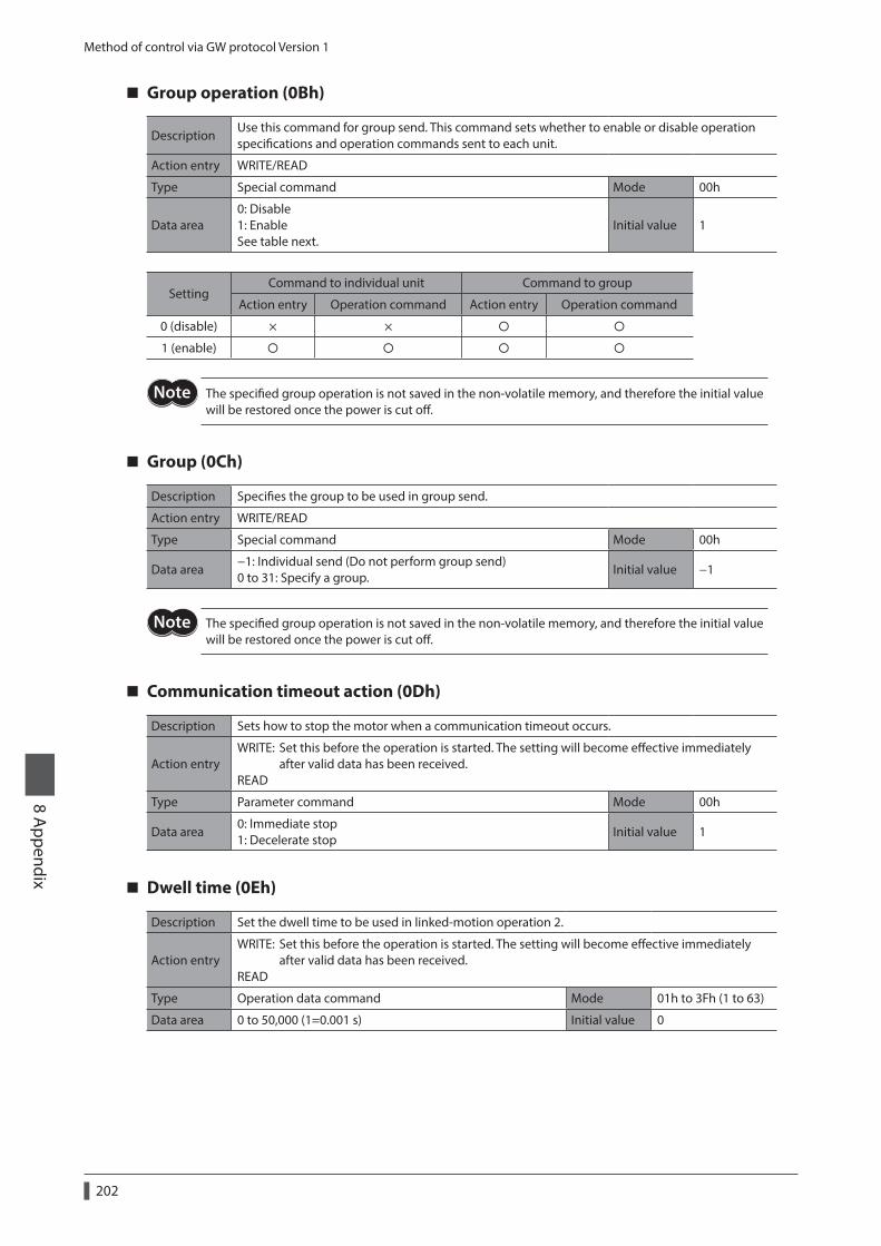
Method of control via GW protocol Version 1
202
8 Appendix
Group operation (0Bh)
DescriptionUse this command for group send. This command sets whether to enable or disable operation specifications and operation commands sent to each unit.
Action entry WRITE/READ
Type Special command Mode 00h
Data area0: Disable 1: Enable See table next.
Initial value 1
SettingCommand to individual unit Command to group
Action entry Operation command Action entry Operation command
0 (disable) × ×
1 (enable)
The specified group operation is not saved in the non-volatile memory, and therefore the initial value will be restored once the power is cut off.
Group (0Ch)
Description Specifies the group to be used in group send.
Action entry WRITE/READ
Type Special command Mode 00h
Data area−1: Individual send (Do not perform group send) 0 to 31: Specify a group.
Initial value −1
The specified group operation is not saved in the non-volatile memory, and therefore the initial value will be restored once the power is cut off.
Communication timeout action (0Dh)
Description Sets how to stop the motor when a communication timeout occurs.
Action entryWRITE: Set this before the operation is started. The setting will become effective immediately after valid data has been received. READ
Type Parameter command Mode 00h
Data area0: Immediate stop 1: Decelerate stop
Initial value 1
Dwell time (0Eh)
Description Set the dwell time to be used in linked-motion operation 2.
Action entryWRITE: Set this before the operation is started. The setting will become effective immediately after valid data has been received. READ
Type Operation data command Mode 01h to 3Fh (1 to 63)
Data area 0 to 50,000 (1=0.001 s) Initial value 0
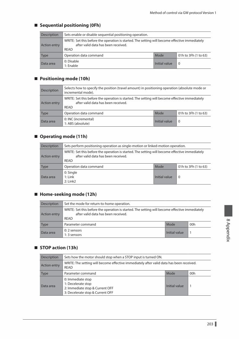
Method of control via GW protocol Version 1
203
8 Appendix
Sequential positioning (0Fh)
Description Sets enable or disable sequential positioning operation.
Action entryWRITE: Set this before the operation is started. The setting will become effective immediately after valid data has been received. READ
Type Operation data command Mode 01h to 3Fh (1 to 63)
Data area0: Disable 1: Enable
Initial value 0
Positioning mode (10h)
DescriptionSelects how to specify the position (travel amount) in positioning operation (absolute mode or incremental mode).
Action entryWRITE: Set this before the operation is started. The setting will become effective immediately after valid data has been received. READ
Type Operation data command Mode 01h to 3Fh (1 to 63)
Data area0: INC (incremental) 1: ABS (absolute)
Initial value 0
Operating mode (11h)
Description Sets perform positioning operation as single-motion or linked-motion operation.
Action entryWRITE: Set this before the operation is started. The setting will become effective immediately after valid data has been received. READ
Type Operation data command Mode 01h to 3Fh (1 to 63)
Data area0: Single 1: Link 2: Link2
Initial value 0
Home-seeking mode (12h)
Description Set the mode for return-to-home operation.
Action entryWRITE: Set this before the operation is started. The setting will become effective immediately after valid data has been received. READ
Type Parameter command Mode 00h
Data area0: 2 sensors 1: 3 sensors
Initial value 1
STOP action (13h)
Description Sets how the motor should stop when a STOP input is turned ON.
Action entryWRITE: The setting will become effective immediately after valid data has been received. READ
Type Parameter command Mode 00h
Data area
0: Immediate stop 1: Decelerate stop 2: Immediate stop & Current OFF 3: Decelerate stop & Current OFF
Initial value 1
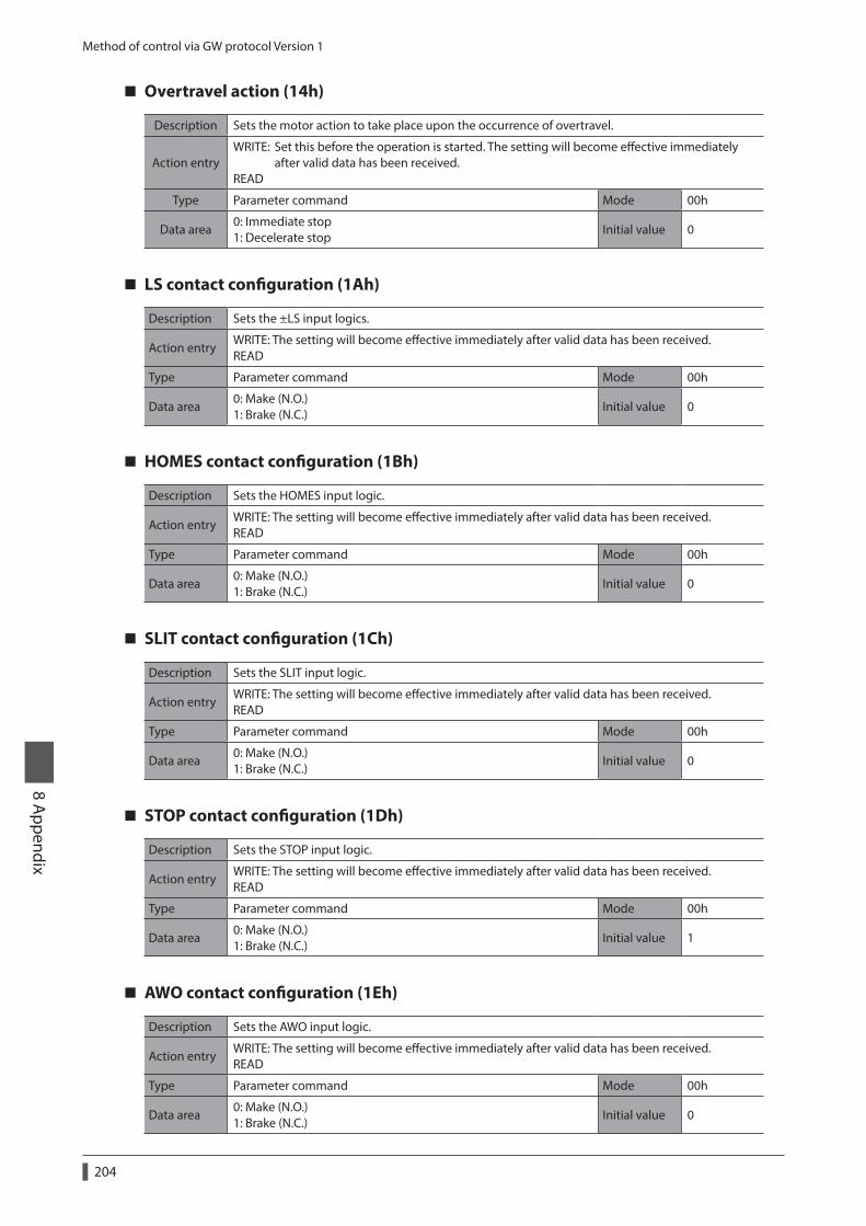
Method of control via GW protocol Version 1
204
8 Appendix
Overtravel action (14h)
Description Sets the motor action to take place upon the occurrence of overtravel.
Action entryWRITE: Set this before the operation is started. The setting will become effective immediately after valid data has been received. READ
Type Parameter command Mode 00h
Data area0: Immediate stop 1: Decelerate stop
Initial value 0
LS contact configuration (1Ah)
Description Sets the ±LS input logics.
Action entryWRITE: The setting will become effective immediately after valid data has been received. READ
Type Parameter command Mode 00h
Data area0: Make (N.O.) 1: Brake (N.C.)
Initial value 0
HOMES contact configuration (1Bh)
Description Sets the HOMES input logic.
Action entryWRITE: The setting will become effective immediately after valid data has been received. READ
Type Parameter command Mode 00h
Data area0: Make (N.O.) 1: Brake (N.C.)
Initial value 0
SLIT contact configuration (1Ch)
Description Sets the SLIT input logic.
Action entryWRITE: The setting will become effective immediately after valid data has been received. READ
Type Parameter command Mode 00h
Data area0: Make (N.O.) 1: Brake (N.C.)
Initial value 0
STOP contact configuration (1Dh)
Description Sets the STOP input logic.
Action entryWRITE: The setting will become effective immediately after valid data has been received. READ
Type Parameter command Mode 00h
Data area0: Make (N.O.) 1: Brake (N.C.)
Initial value 1
AWO contact configuration (1Eh)
Description Sets the AWO input logic.
Action entryWRITE: The setting will become effective immediately after valid data has been received. READ
Type Parameter command Mode 00h
Data area0: Make (N.O.) 1: Brake (N.C.)
Initial value 0
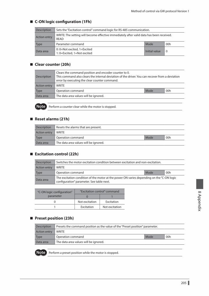
Method of control via GW protocol Version 1
205
8 Appendix
C-ON logic configuration (1Fh)
Description Sets the “Excitation control” command logic for RS-485 communication.
Action entryWRITE: The setting will become effective immediately after valid data has been received. READ
Type Parameter command Mode 00h
Data area0: 0=Not excited, 1=Excited 1: 0=Excited, 1=Not excited
Initial value 0
Clear counter (20h)
DescriptionClears the command position and encoder counter to 0. This command also clears the internal deviation of the driver. You can recover from a deviation error by executing the clear counter command.
Action entry WRITE
Type Operation command Mode 00h
Data area The data area values will be ignored.
Perform a counter clear while the motor is stopped.
Reset alarms (21h)
Description Resets the alarms that are present.
Action entry WRITE
Type Operation command Mode 00h
Data area The data area values will be ignored.
Excitation control (22h)
Description Switches the motor excitation condition between excitation and non-excitation.
Action entry WRITE
Type Operation command Mode 00h
Data areaThe excitation condition of the motor at the power ON varies depending on the “C-ON logic configuration” parameter. See table next.
“C-ON logic configuration” parameter
“Excitation control” command
0 1
0 Not excitation Excitation
1 Excitation Not excitation
Preset position (23h)
Description Presets the command position as the value of the “Preset position” parameter.
Action entry WRITE
Type Operation command Mode 00h
Data area The data area values will be ignored.
Perform a preset position while the motor is stopped.
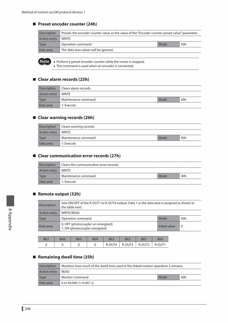
Method of control via GW protocol Version 1
206
8 Appendix
Preset encoder counter (24h)
Description Presets the encoder counter value as the value of the “Encoder counter preset value” parameter.
Action entry WRITE
Type Operation command Mode 00h
Data area The data area values will be ignored.
• Perform a preset encoder counter while the motor is stopped. • This command is used when an encoder is connected.
Clear alarm records (25h)
Description Clears alarm records.
Action entry WRITE
Type Maintenance command Mode 00h
Data area 1: Execute
Clear warning records (26h)
Description Clears warning records.
Action entry WRITE
Type Maintenance command Mode 00h
Data area 1: Execute
Clear communication error records (27h)
Description Clears the communication error records.
Action entry WRITE
Type Maintenance command Mode 00h
Data area 1: Execute
Remote output (32h)
DescriptionSets ON/OFF of the R-OUT1 to R-OUT4 output. Data 1 in the data area is assigned as shown in the table next.
Action entry WRITE/READ
Type Operation command Mode 00h
Data area0: OFF (photocoupler un-energized) 1: ON (photocoupler energized)
Initial value 0
Bit7 Bit6 Bit5 Bit4 Bit3 Bit2 Bit1 Bit0
0 0 0 0 R-OUT4 R-OUT3 R-OUT2 R-OUT1
Remaining dwell time (35h)
Description Monitors how much of the dwell time used in the linked-motion operation 2 remains.
Action entry READ
Type Monitor command Mode 00h
Data area 0 to 50,000 (1=0.001 s)
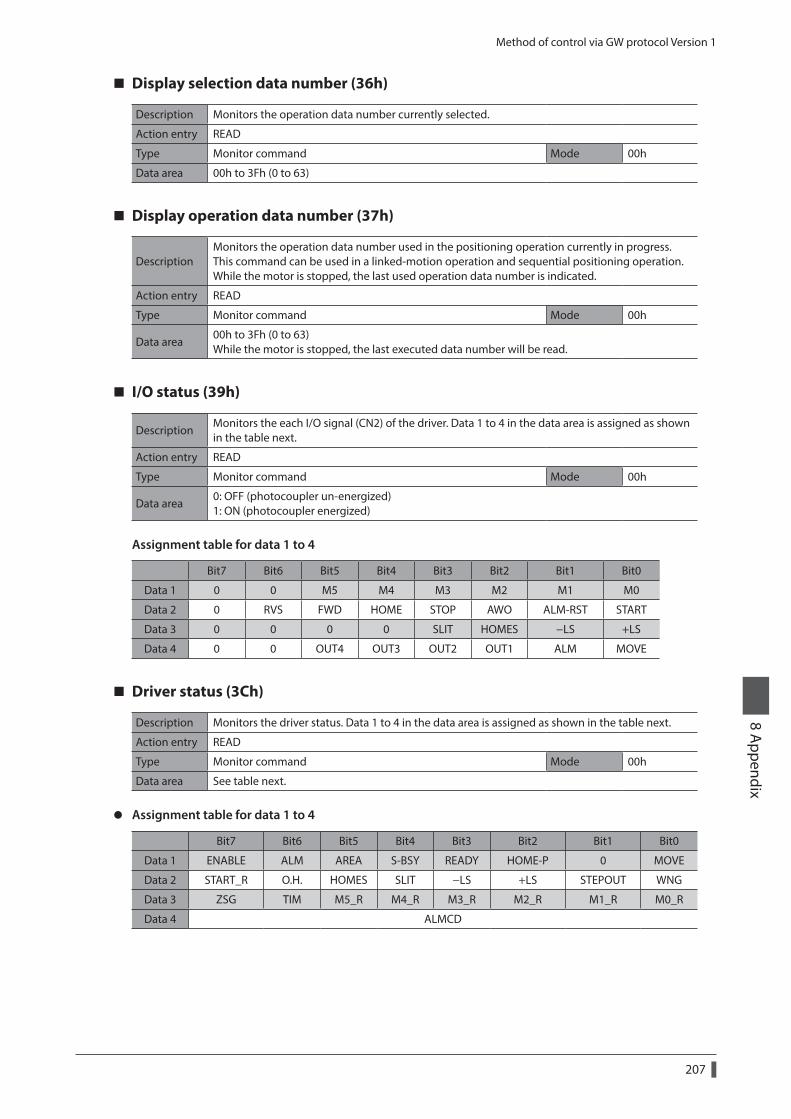
Method of control via GW protocol Version 1
207
8 Appendix
Display selection data number (36h)
Description Monitors the operation data number currently selected.
Action entry READ
Type Monitor command Mode 00h
Data area 00h to 3Fh (0 to 63)
Display operation data number (37h)
DescriptionMonitors the operation data number used in the positioning operation currently in progress. This command can be used in a linked-motion operation and sequential positioning operation. While the motor is stopped, the last used operation data number is indicated.
Action entry READ
Type Monitor command Mode 00h
Data area00h to 3Fh (0 to 63) While the motor is stopped, the last executed data number will be read.
I/O status (39h)
DescriptionMonitors the each I/O signal (CN2) of the driver. Data 1 to 4 in the data area is assigned as shown in the table next.
Action entry READ
Type Monitor command Mode 00h
Data area0: OFF (photocoupler un-energized) 1: ON (photocoupler energized)
Assignment table for data 1 to 4
Bit7 Bit6 Bit5 Bit4 Bit3 Bit2 Bit1 Bit0
Data 1 0 0 M5 M4 M3 M2 M1 M0
Data 2 0 RVS FWD HOME STOP AWO ALM-RST START
Data 3 0 0 0 0 SLIT HOMES −LS +LS
Data 4 0 0 OUT4 OUT3 OUT2 OUT1 ALM MOVE
Driver status (3Ch)
Description Monitors the driver status. Data 1 to 4 in the data area is assigned as shown in the table next.
Action entry READ
Type Monitor command Mode 00h
Data area See table next.
z Assignment table for data 1 to 4
Bit7 Bit6 Bit5 Bit4 Bit3 Bit2 Bit1 Bit0
Data 1 ENABLE ALM AREA S-BSY READY HOME-P 0 MOVE
Data 2 START_R O.H. HOMES SLIT −LS +LS STEPOUT WNG
Data 3 ZSG TIM M5_R M4_R M3_R M2_R M1_R M0_R
Data 4 ALMCD
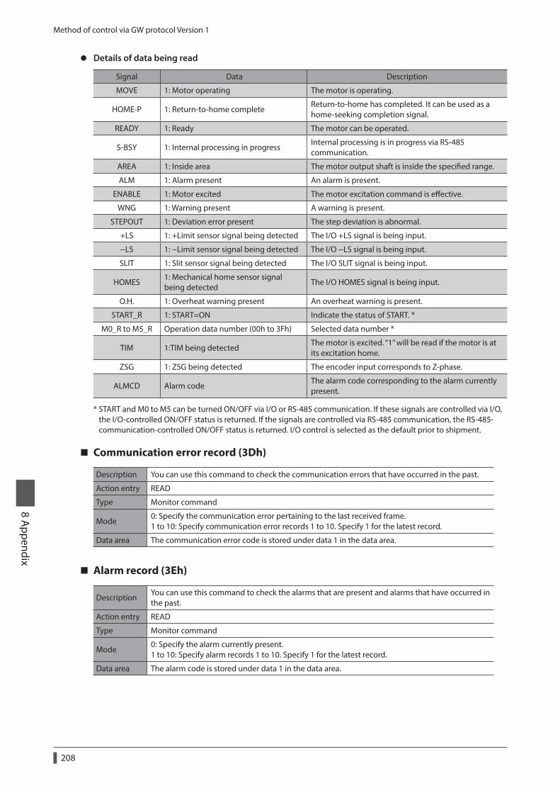
Method of control via GW protocol Version 1
208
8 Appendix
z Details of data being read
Signal Data Description
MOVE 1: Motor operating The motor is operating.
HOME-P 1: Return-to-home completeReturn-to-home has completed. It can be used as a home-seeking completion signal.
READY 1: Ready The motor can be operated.
S-BSY 1: Internal processing in progressInternal processing is in progress via RS-485 communication.
AREA 1: Inside area The motor output shaft is inside the specified range.
ALM 1: Alarm present An alarm is present.
ENABLE 1: Motor excited The motor excitation command is effective.
WNG 1: Warning present A warning is present.
STEPOUT 1: Deviation error present The step deviation is abnormal.
+LS 1: +Limit sensor signal being detected The I/O +LS signal is being input.
−LS 1: −Limit sensor signal being detected The I/O −LS signal is being input.
SLIT 1: Slit sensor signal being detected The I/O SLIT signal is being input.
HOMES1: Mechanical home sensor signal being detected
The I/O HOMES signal is being input.
O.H. 1: Overheat warning present An overheat warning is present.
START_R 1: START=ON Indicate the status of START. *
M0_R to M5_R Operation data number (00h to 3Fh) Selected data number *
TIM 1:TIM being detectedThe motor is excited. “1” will be read if the motor is at its excitation home.
ZSG 1: ZSG being detected The encoder input corresponds to Z-phase.
ALMCD Alarm codeThe alarm code corresponding to the alarm currently present.
* START and M0 to M5 can be turned ON/OFF via I/O or RS-485 communication. If these signals are controlled via I/O, the I/O-controlled ON/OFF status is returned. If the signals are controlled via RS-485 communication, the RS-485-communication-controlled ON/OFF status is returned. I/O control is selected as the default prior to shipment.
Communication error record (3Dh)
Description You can use this command to check the communication errors that have occurred in the past.
Action entry READ
Type Monitor command
Mode0: Specify the communication error pertaining to the last received frame. 1 to 10: Specify communication error records 1 to 10. Specify 1 for the latest record.
Data area The communication error code is stored under data 1 in the data area.
Alarm record (3Eh)
DescriptionYou can use this command to check the alarms that are present and alarms that have occurred in the past.
Action entry READ
Type Monitor command
Mode0: Specify the alarm currently present. 1 to 10: Specify alarm records 1 to 10. Specify 1 for the latest record.
Data area The alarm code is stored under data 1 in the data area.
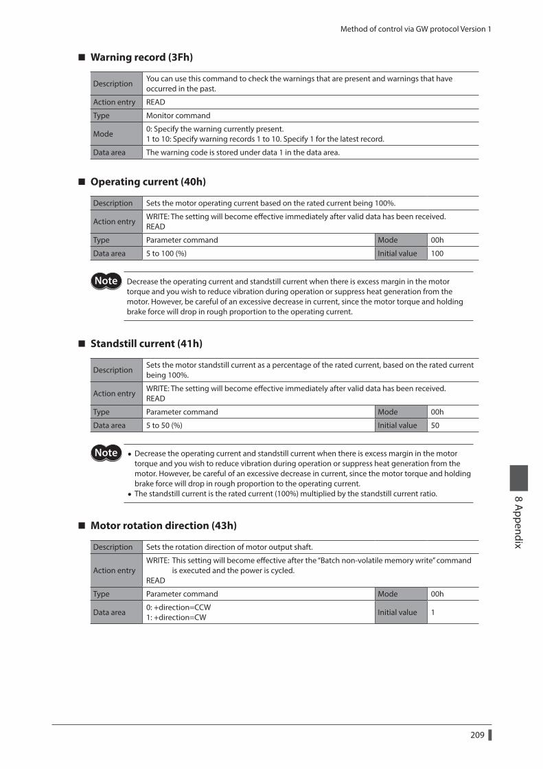
Method of control via GW protocol Version 1
209
8 Appendix
Warning record (3Fh)
DescriptionYou can use this command to check the warnings that are present and warnings that have occurred in the past.
Action entry READ
Type Monitor command
Mode0: Specify the warning currently present. 1 to 10: Specify warning records 1 to 10. Specify 1 for the latest record.
Data area The warning code is stored under data 1 in the data area.
Operating current (40h)
Description Sets the motor operating current based on the rated current being 100%.
Action entryWRITE: The setting will become effective immediately after valid data has been received. READ
Type Parameter command Mode 00h
Data area 5 to 100 (%) Initial value 100
Decrease the operating current and standstill current when there is excess margin in the motor torque and you wish to reduce vibration during operation or suppress heat generation from the motor. However, be careful of an excessive decrease in current, since the motor torque and holding brake force will drop in rough proportion to the operating current.
Standstill current (41h)
DescriptionSets the motor standstill current as a percentage of the rated current, based on the rated current being 100%.
Action entryWRITE: The setting will become effective immediately after valid data has been received. READ
Type Parameter command Mode 00h
Data area 5 to 50 (%) Initial value 50
• Decrease the operating current and standstill current when there is excess margin in the motor torque and you wish to reduce vibration during operation or suppress heat generation from the motor. However, be careful of an excessive decrease in current, since the motor torque and holding brake force will drop in rough proportion to the operating current.
• The standstill current is the rated current (100%) multiplied by the standstill current ratio.
Motor rotation direction (43h)
Description Sets the rotation direction of motor output shaft.
Action entryWRITE: This setting will become effective after the “Batch non-volatile memory write” command is executed and the power is cycled. READ
Type Parameter command Mode 00h
Data area0: +direction=CCW 1: +direction=CW
Initial value 1
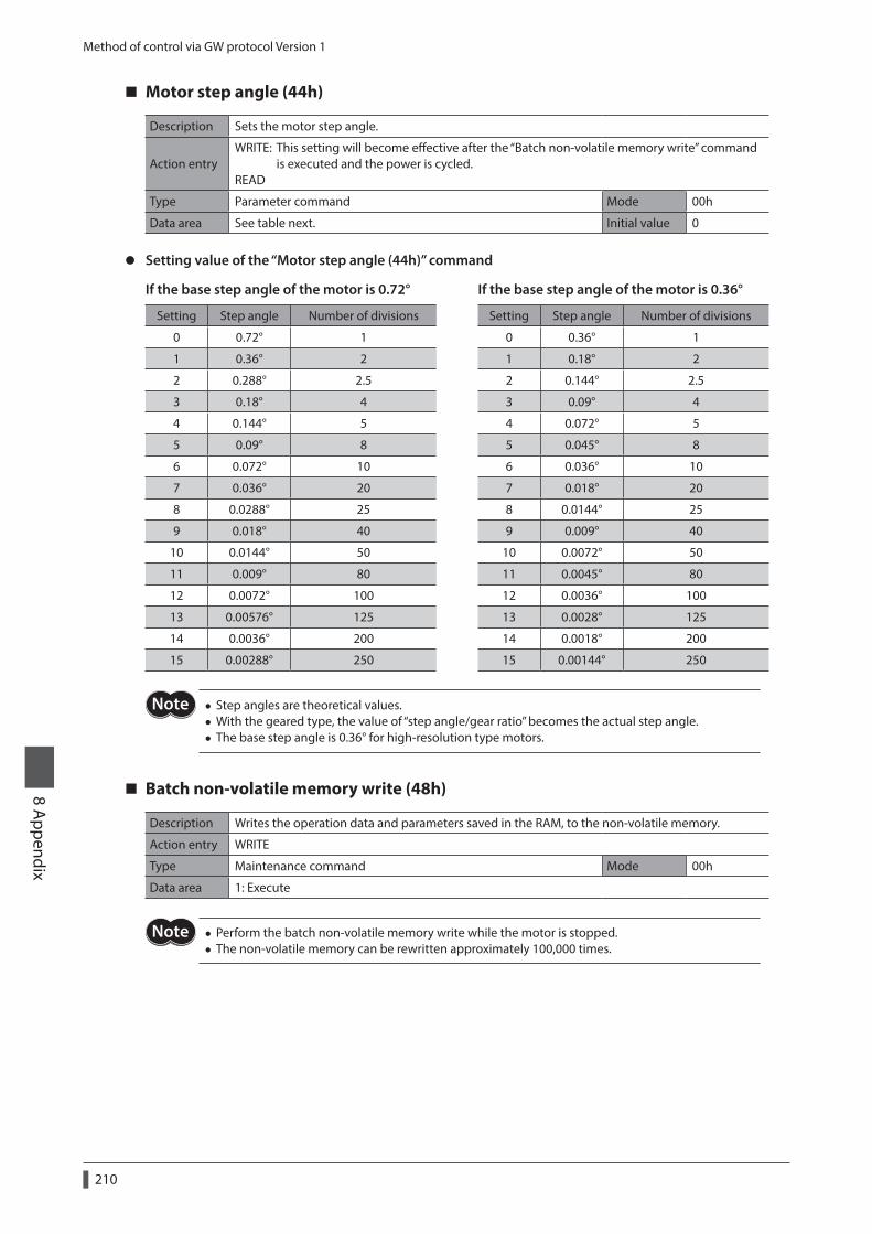
Method of control via GW protocol Version 1
210
8 Appendix
Motor step angle (44h)
Description Sets the motor step angle.
Action entryWRITE: This setting will become effective after the “Batch non-volatile memory write” command is executed and the power is cycled. READ
Type Parameter command Mode 00h
Data area See table next. Initial value 0
z Setting value of the “Motor step angle (44h)” command
If the base step angle of the motor is 0.72° If the base step angle of the motor is 0.36°
Setting Step angle Number of divisions Setting Step angle Number of divisions
0 0.72° 1 0 0.36° 1
1 0.36° 2 1 0.18° 2
2 0.288° 2.5 2 0.144° 2.5
3 0.18° 4 3 0.09° 4
4 0.144° 5 4 0.072° 5
5 0.09° 8 5 0.045° 8
6 0.072° 10 6 0.036° 10
7 0.036° 20 7 0.018° 20
8 0.0288° 25 8 0.0144° 25
9 0.018° 40 9 0.009° 40
10 0.0144° 50 10 0.0072° 50
11 0.009° 80 11 0.0045° 80
12 0.0072° 100 12 0.0036° 100
13 0.00576° 125 13 0.0028° 125
14 0.0036° 200 14 0.0018° 200
15 0.00288° 250 15 0.00144° 250
• Step angles are theoretical values. • With the geared type, the value of “step angle/gear ratio” becomes the actual step angle. • The base step angle is 0.36° for high-resolution type motors.
Batch non-volatile memory write (48h)
Description Writes the operation data and parameters saved in the RAM, to the non-volatile memory.
Action entry WRITE
Type Maintenance command Mode 00h
Data area 1: Execute
• Perform the batch non-volatile memory write while the motor is stopped. • The non-volatile memory can be rewritten approximately 100,000 times.
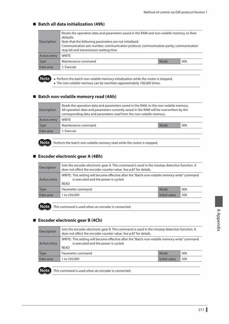
Method of control via GW protocol Version 1
211
8 Appendix
Batch all data initialization (49h)
Description
Resets the operation data and parameters saved in the RAM and non-volatile memory, to their defaults. Note that the following parameters are not initialized; Communication axis number, communication protocol, communication parity, communication stop bit and transmission waiting time
Action entry WRITE
Type Maintenance command Mode 00h
Data area 1: Execute
• Perform the batch non-volatile memory initialization while the motor is stopped. • The non-volatile memory can be rewritten approximately 100,000 times.
Batch non-volatile memory read (4Ah)
DescriptionReads the operation data and parameters saved in the RAM, to the non-volatile memory. All operation data and parameters currently saved in the RAM will be overwritten by the corresponding data and parameters read from the non-volatile memory.
Action entry WRITE
Type Maintenance command Mode 00h
Data area 1: Execute
Perform the batch non-volatile memory read while the motor is stopped.
Encoder electronic gear A (4Bh)
DescriptionSets the encoder electronic gear A. This command is used in the misstep detection function. It does not affect the encoder counter value. See p.87 for details.
Action entryWRITE: This setting will become effective after the “Batch non-volatile memory write” command is executed and the power is cycled. READ
Type Parameter command Mode 00h
Data area 1 to 250,000 Initial value 500
This command is used when an encoder is connected.
Encoder electronic gear B (4Ch)
DescriptionSets the encoder electronic gear B. This command is used in the misstep detection function. It does not affect the encoder counter value. See p.87 for details.
Action entryWRITE: This setting will become effective after the “Batch non-volatile memory write” command is executed and the power is cycled. READ
Type Parameter command Mode 00h
Data area 1 to 250,000 Initial value 500
This command is used when an encoder is connected.
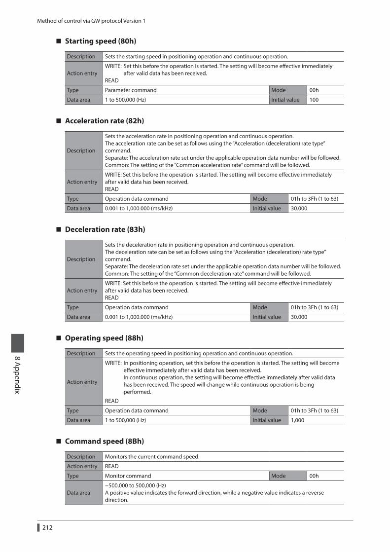
Method of control via GW protocol Version 1
212
8 Appendix
Starting speed (80h)
Description Sets the starting speed in positioning operation and continuous operation.
Action entryWRITE: Set this before the operation is started. The setting will become effective immediately after valid data has been received. READ
Type Parameter command Mode 00h
Data area 1 to 500,000 (Hz) Initial value 100
Acceleration rate (82h)
Description
Sets the acceleration rate in positioning operation and continuous operation. The acceleration rate can be set as follows using the “Acceleration (deceleration) rate type” command. Separate: The acceleration rate set under the applicable operation data number will be followed. Common: The setting of the “Common acceleration rate” command will be followed.
Action entryWRITE: Set this before the operation is started. The setting will become effective immediately after valid data has been received. READ
Type Operation data command Mode 01h to 3Fh (1 to 63)
Data area 0.001 to 1,000.000 (ms/kHz) Initial value 30.000
Deceleration rate (83h)
Description
Sets the deceleration rate in positioning operation and continuous operation. The deceleration rate can be set as follows using the “Acceleration (deceleration) rate type” command. Separate: The deceleration rate set under the applicable operation data number will be followed. Common: The setting of the “Common deceleration rate” command will be followed.
Action entryWRITE: Set this before the operation is started. The setting will become effective immediately after valid data has been received. READ
Type Operation data command Mode 01h to 3Fh (1 to 63)
Data area 0.001 to 1,000.000 (ms/kHz) Initial value 30.000
Operating speed (88h)
Description Sets the operating speed in positioning operation and continuous operation.
Action entry
WRITE: In positioning operation, set this before the operation is started. The setting will become effective immediately after valid data has been received. In continuous operation, the setting will become effective immediately after valid data has been received. The speed will change while continuous operation is being performed.
READ
Type Operation data command Mode 01h to 3Fh (1 to 63)
Data area 1 to 500,000 (Hz) Initial value 1,000
Command speed (8Bh)
Description Monitors the current command speed.
Action entry READ
Type Monitor command Mode 00h
Data area−500,000 to 500,000 (Hz) A positive value indicates the forward direction, while a negative value indicates a reverse direction.
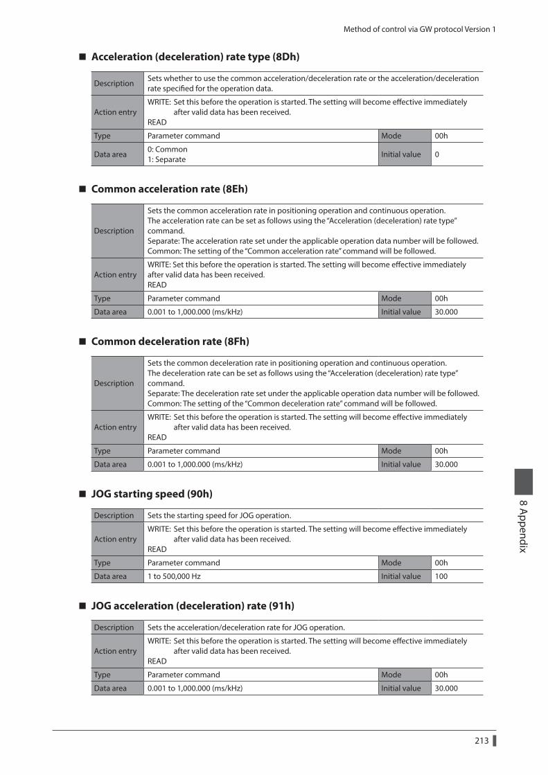
Method of control via GW protocol Version 1
213
8 Appendix
Acceleration (deceleration) rate type (8Dh)
DescriptionSets whether to use the common acceleration/deceleration rate or the acceleration/deceleration rate specified for the operation data.
Action entryWRITE: Set this before the operation is started. The setting will become effective immediately after valid data has been received. READ
Type Parameter command Mode 00h
Data area0: Common 1: Separate
Initial value 0
Common acceleration rate (8Eh)
Description
Sets the common acceleration rate in positioning operation and continuous operation. The acceleration rate can be set as follows using the “Acceleration (deceleration) rate type” command. Separate: The acceleration rate set under the applicable operation data number will be followed. Common: The setting of the “Common acceleration rate” command will be followed.
Action entryWRITE: Set this before the operation is started. The setting will become effective immediately after valid data has been received. READ
Type Parameter command Mode 00h
Data area 0.001 to 1,000.000 (ms/kHz) Initial value 30.000
Common deceleration rate (8Fh)
Description
Sets the common deceleration rate in positioning operation and continuous operation. The deceleration rate can be set as follows using the “Acceleration (deceleration) rate type” command. Separate: The deceleration rate set under the applicable operation data number will be followed. Common: The setting of the “Common deceleration rate” command will be followed.
Action entryWRITE: Set this before the operation is started. The setting will become effective immediately after valid data has been received. READ
Type Parameter command Mode 00h
Data area 0.001 to 1,000.000 (ms/kHz) Initial value 30.000
JOG starting speed (90h)
Description Sets the starting speed for JOG operation.
Action entryWRITE: Set this before the operation is started. The setting will become effective immediately after valid data has been received. READ
Type Parameter command Mode 00h
Data area 1 to 500,000 Hz Initial value 100
JOG acceleration (deceleration) rate (91h)
Description Sets the acceleration/deceleration rate for JOG operation.
Action entryWRITE: Set this before the operation is started. The setting will become effective immediately after valid data has been received. READ
Type Parameter command Mode 00h
Data area 0.001 to 1,000.000 (ms/kHz) Initial value 30.000
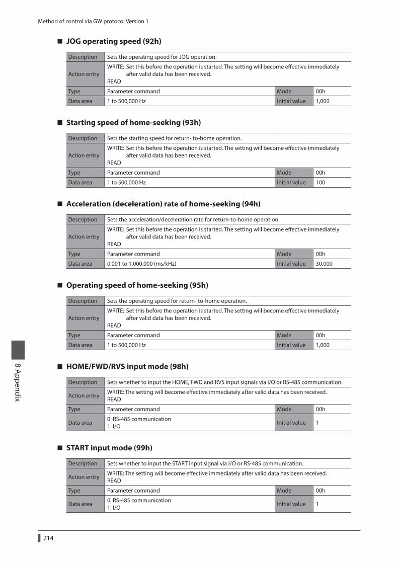
Method of control via GW protocol Version 1
214
8 Appendix
JOG operating speed (92h)
Description Sets the operating speed for JOG operation.
Action entryWRITE: Set this before the operation is started. The setting will become effective immediately after valid data has been received. READ
Type Parameter command Mode 00h
Data area 1 to 500,000 Hz Initial value 1,000
Starting speed of home-seeking (93h)
Description Sets the starting speed for return- to-home operation.
Action entryWRITE: Set this before the operation is started. The setting will become effective immediately after valid data has been received. READ
Type Parameter command Mode 00h
Data area 1 to 500,000 Hz Initial value 100
Acceleration (deceleration) rate of home-seeking (94h)
Description Sets the acceleration/deceleration rate for return-to-home operation.
Action entryWRITE: Set this before the operation is started. The setting will become effective immediately after valid data has been received. READ
Type Parameter command Mode 00h
Data area 0.001 to 1,000.000 (ms/kHz) Initial value 30.000
Operating speed of home-seeking (95h)
Description Sets the operating speed for return- to-home operation.
Action entryWRITE: Set this before the operation is started. The setting will become effective immediately after valid data has been received. READ
Type Parameter command Mode 00h
Data area 1 to 500,000 Hz Initial value 1,000
HOME/FWD/RVS input mode (98h)
Description Sets whether to input the HOME, FWD and RVS input signals via I/O or RS-485 communication.
Action entryWRITE: The setting will become effective immediately after valid data has been received. READ
Type Parameter command Mode 00h
Data area0: RS-485 communication 1: I/O
Initial value 1
START input mode (99h)
Description Sets whether to input the START input signal via I/O or RS-485 communication.
Action entryWRITE: The setting will become effective immediately after valid data has been received. READ
Type Parameter command Mode 00h
Data area0: RS-485 communication 1: I/O
Initial value 1
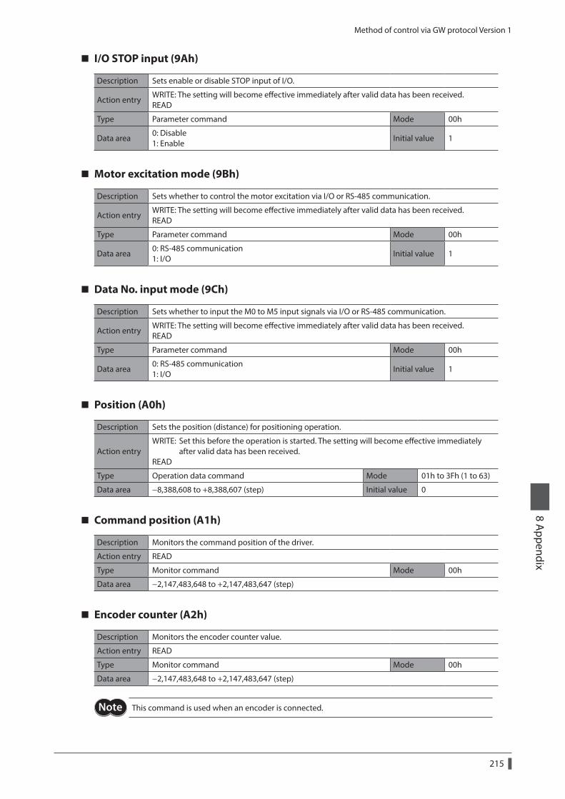
Method of control via GW protocol Version 1
215
8 Appendix
I/O STOP input (9Ah)
Description Sets enable or disable STOP input of I/O.
Action entryWRITE: The setting will become effective immediately after valid data has been received. READ
Type Parameter command Mode 00h
Data area0: Disable 1: Enable
Initial value 1
Motor excitation mode (9Bh)
Description Sets whether to control the motor excitation via I/O or RS-485 communication.
Action entryWRITE: The setting will become effective immediately after valid data has been received. READ
Type Parameter command Mode 00h
Data area0: RS-485 communication 1: I/O
Initial value 1
Data No. input mode (9Ch)
Description Sets whether to input the M0 to M5 input signals via I/O or RS-485 communication.
Action entryWRITE: The setting will become effective immediately after valid data has been received. READ
Type Parameter command Mode 00h
Data area0: RS-485 communication 1: I/O
Initial value 1
Position (A0h)
Description Sets the position (distance) for positioning operation.
Action entryWRITE: Set this before the operation is started. The setting will become effective immediately after valid data has been received. READ
Type Operation data command Mode 01h to 3Fh (1 to 63)
Data area −8,388,608 to +8,388,607 (step) Initial value 0
Command position (A1h)
Description Monitors the command position of the driver.
Action entry READ
Type Monitor command Mode 00h
Data area −2,147,483,648 to +2,147,483,647 (step)
Encoder counter (A2h)
Description Monitors the encoder counter value.
Action entry READ
Type Monitor command Mode 00h
Data area −2,147,483,648 to +2,147,483,647 (step)
This command is used when an encoder is connected.
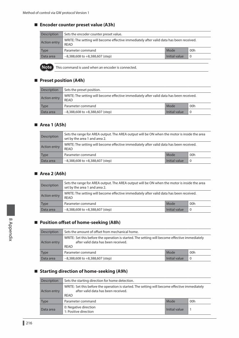
Method of control via GW protocol Version 1
216
8 Appendix
Encoder counter preset value (A3h)
Description Sets the encoder counter preset value.
Action entryWRITE: The setting will become effective immediately after valid data has been received. READ
Type Parameter command Mode 00h
Data area −8,388,608 to +8,388,607 (step) Initial value 0
This command is used when an encoder is connected.
Preset position (A4h)
Description Sets the preset position.
Action entryWRITE: The setting will become effective immediately after valid data has been received. READ
Type Parameter command Mode 00h
Data area −8,388,608 to +8,388,607 (step) Initial value 0
Area 1 (A5h)
DescriptionSets the range for AREA output. The AREA output will be ON when the motor is inside the area set by the area 1 and area 2.
Action entryWRITE: The setting will become effective immediately after valid data has been received. READ
Type Parameter command Mode 00h
Data area −8,388,608 to +8,388,607 (step) Initial value 0
Area 2 (A6h)
DescriptionSets the range for AREA output. The AREA output will be ON when the motor is inside the area set by the area 1 and area 2.
Action entryWRITE: The setting will become effective immediately after valid data has been received. READ
Type Parameter command Mode 00h
Data area −8,388,608 to +8,388,607 (step) Initial value 0
Position offset of home-seeking (A8h)
Description Sets the amount of offset from mechanical home.
Action entryWRITE: Set this before the operation is started. The setting will become effective immediately after valid data has been received. READ
Type Parameter command Mode 00h
Data area −8,388,608 to +8,388,607 (step) Initial value 0
Starting direction of home-seeking (A9h)
Description Sets the starting direction for home detection.
Action entryWRITE: Set this before the operation is started. The setting will become effective immediately after valid data has been received. READ
Type Parameter command Mode 00h
Data area0: Negative direction 1: Positive direction
Initial value 1
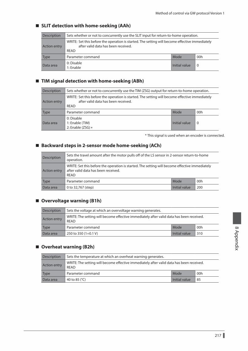
Method of control via GW protocol Version 1
217
8 Appendix
SLIT detection with home-seeking (AAh)
Description Sets whether or not to concurrently use the SLIT input for return-to-home operation.
Action entryWRITE: Set this before the operation is started. The setting will become effective immediately after valid data has been received. READ
Type Parameter command Mode 00h
Data area0: Disable 1: Enable
Initial value 0
TIM signal detection with home-seeking (ABh)
Description Sets whether or not to concurrently use the TIM (ZSG) output for return-to-home operation.
Action entryWRITE: Set this before the operation is started. The setting will become effective immediately after valid data has been received. READ
Type Parameter command Mode 00h
Data area0: Disable 1: Enable (TIM) 2: Enable (ZSG) ∗
Initial value 0
* This signal is used when an encoder is connected.
Backward steps in 2-sensor mode home-seeking (ACh)
DescriptionSets the travel amount after the motor pulls off of the LS sensor in 2-sensor return-to-home operation.
Action entryWRITE: Set this before the operation is started. The setting will become effective immediately after valid data has been received. READ
Type Parameter command Mode 00h
Data area 0 to 32,767 (step) Initial value 200
Overvoltage warning (B1h)
Description Sets the voltage at which an overvoltage warning generates.
Action entryWRITE: The setting will become effective immediately after valid data has been received. READ
Type Parameter command Mode 00h
Data area 250 to 350 (1=0.1 V) Initial value 310
Overheat warning (B2h)
Description Sets the temperature at which an overheat warning generates.
Action entryWRITE: The setting will become effective immediately after valid data has been received. READ
Type Parameter command Mode 00h
Data area 40 to 85 (°C) Initial value 85
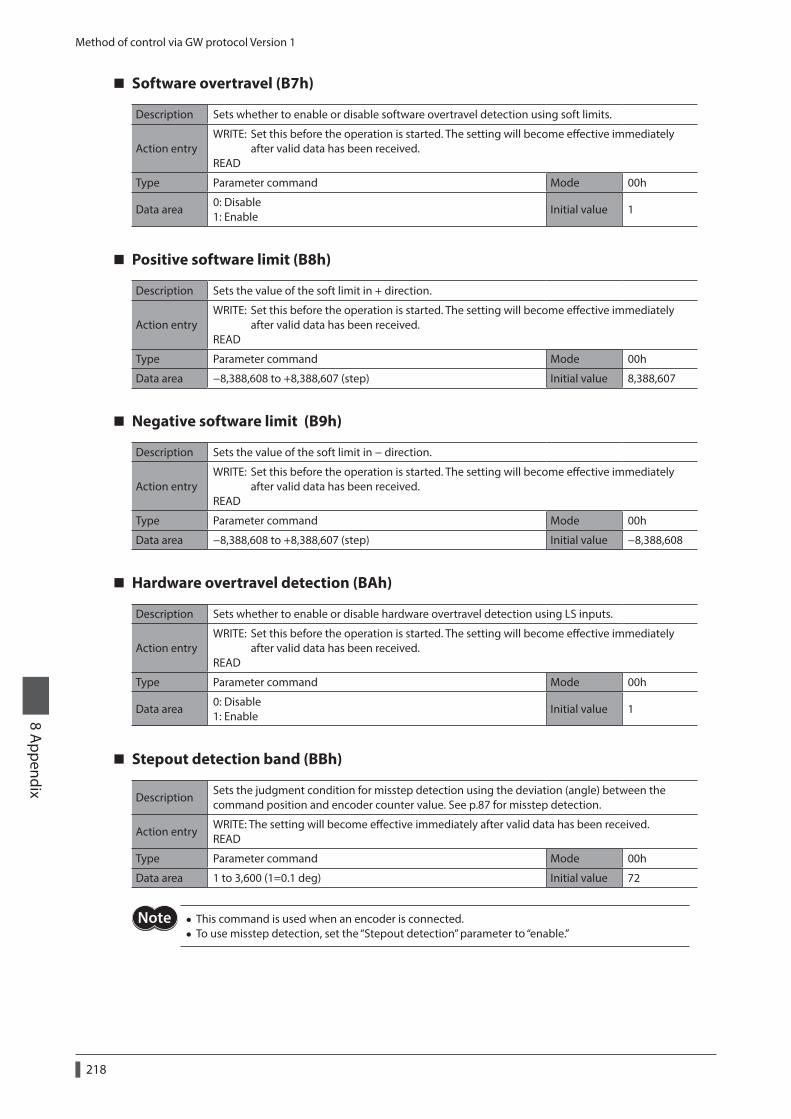
Method of control via GW protocol Version 1
218
8 Appendix
Software overtravel (B7h)
Description Sets whether to enable or disable software overtravel detection using soft limits.
Action entryWRITE: Set this before the operation is started. The setting will become effective immediately after valid data has been received. READ
Type Parameter command Mode 00h
Data area0: Disable 1: Enable
Initial value 1
Positive software limit (B8h)
Description Sets the value of the soft limit in + direction.
Action entryWRITE: Set this before the operation is started. The setting will become effective immediately after valid data has been received. READ
Type Parameter command Mode 00h
Data area −8,388,608 to +8,388,607 (step) Initial value 8,388,607
Negative software limit (B9h)
Description Sets the value of the soft limit in − direction.
Action entryWRITE: Set this before the operation is started. The setting will become effective immediately after valid data has been received. READ
Type Parameter command Mode 00h
Data area −8,388,608 to +8,388,607 (step) Initial value −8,388,608
Hardware overtravel detection (BAh)
Description Sets whether to enable or disable hardware overtravel detection using LS inputs.
Action entryWRITE: Set this before the operation is started. The setting will become effective immediately after valid data has been received. READ
Type Parameter command Mode 00h
Data area0: Disable 1: Enable
Initial value 1
Stepout detection band (BBh)
DescriptionSets the judgment condition for misstep detection using the deviation (angle) between the command position and encoder counter value. See p.87 for misstep detection.
Action entryWRITE: The setting will become effective immediately after valid data has been received. READ
Type Parameter command Mode 00h
Data area 1 to 3,600 (1=0.1 deg) Initial value 72
• This command is used when an encoder is connected. • To use misstep detection, set the “Stepout detection” parameter to “enable.”
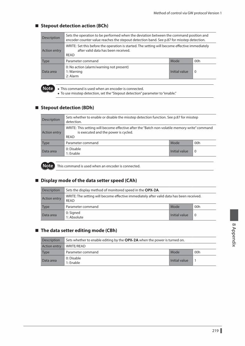
Method of control via GW protocol Version 1
219
8 Appendix
Stepout detection action (BCh)
DescriptionSets the operation to be performed when the deviation between the command position and encoder counter value reaches the stepout detection band. See p.87 for misstep detection.
Action entryWRITE: Set this before the operation is started. The setting will become effective immediately after valid data has been received. READ
Type Parameter command Mode 00h
Data area0: No action (alarm/warning not present) 1: Warning 2: Alarm
Initial value 0
• This command is used when an encoder is connected. • To use misstep detection, set the “Stepout detection” parameter to “enable.”
Stepout detection (BDh)
DescriptionSets whether to enable or disable the misstep detection function. See p.87 for misstep detection.
Action entryWRITE: This setting will become effective after the “Batch non-volatile memory write” command is executed and the power is cycled. READ
Type Parameter command Mode 00h
Data area0: Disable 1: Enable
Initial value 0
This command is used when an encoder is connected.
Display mode of the data setter speed (CAh)
Description Sets the display method of monitored speed in the OPX-2A.
Action entryWRITE: The setting will become effective immediately after valid data has been received. READ
Type Parameter command Mode 00h
Data area0: Signed 1: Absolute
Initial value 0
The data setter editing mode (CBh)
Description Sets whether to enable editing by the OPX-2A when the power is turned on.
Action entry WRITE/READ
Type Parameter command Mode 00h
Data area0: Disable 1: Enable
Initial value 1
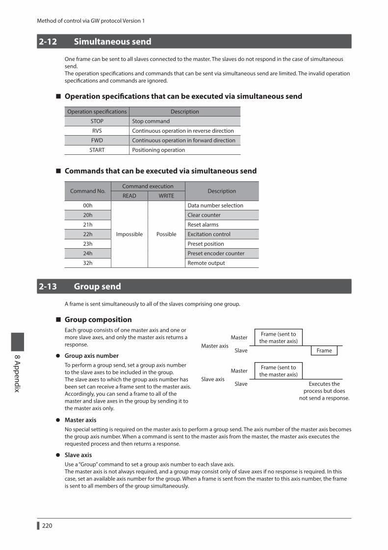
Method of control via GW protocol Version 1
220
8 Appendix
2-12 Simultaneous send
One frame can be sent to all slaves connected to the master. The slaves do not respond in the case of simultaneous send.The operation specifications and commands that can be sent via simultaneous send are limited. The invalid operation specifications and commands are ignored.
Operation specifications that can be executed via simultaneous send
Operation specifications Description
STOP Stop command
RVS Continuous operation in reverse direction
FWD Continuous operation in forward direction
START Positioning operation
Commands that can be executed via simultaneous send
Command No.Command execution
DescriptionREAD WRITE
00h
Impossible Possible
Data number selection
20h Clear counter
21h Reset alarms
22h Excitation control
23h Preset position
24h Preset encoder counter
32h Remote output
2-13 Group send
A frame is sent simultaneously to all of the slaves comprising one group.
Group compositionEach group consists of one master axis and one or more slave axes, and only the master axis returns a response.
z Group axis numberTo perform a group send, set a group axis number to the slave axes to be included in the group.The slave axes to which the group axis number has been set can receive a frame sent to the master axis. Accordingly, you can send a frame to all of the master and slave axes in the group by sending it to the master axis only.
Frame (sent tothe master axis)
Frame (sent tothe master axis)
Slave axis
Master axisFrame
Master
Master
Slave
Slave Executes theprocess but does
not send a response.
z Master axisNo special setting is required on the master axis to perform a group send. The axis number of the master axis becomes the group axis number. When a command is sent to the master axis from the master, the master axis executes the requested process and then returns a response.
z Slave axisUse a “Group” command to set a group axis number to each slave axis.The master axis is not always required, and a group may consist only of slave axes if no response is required. In this case, set an available axis number for the group. When a frame is sent from the master to this axis number, the frame is sent to all members of the group simultaneously.
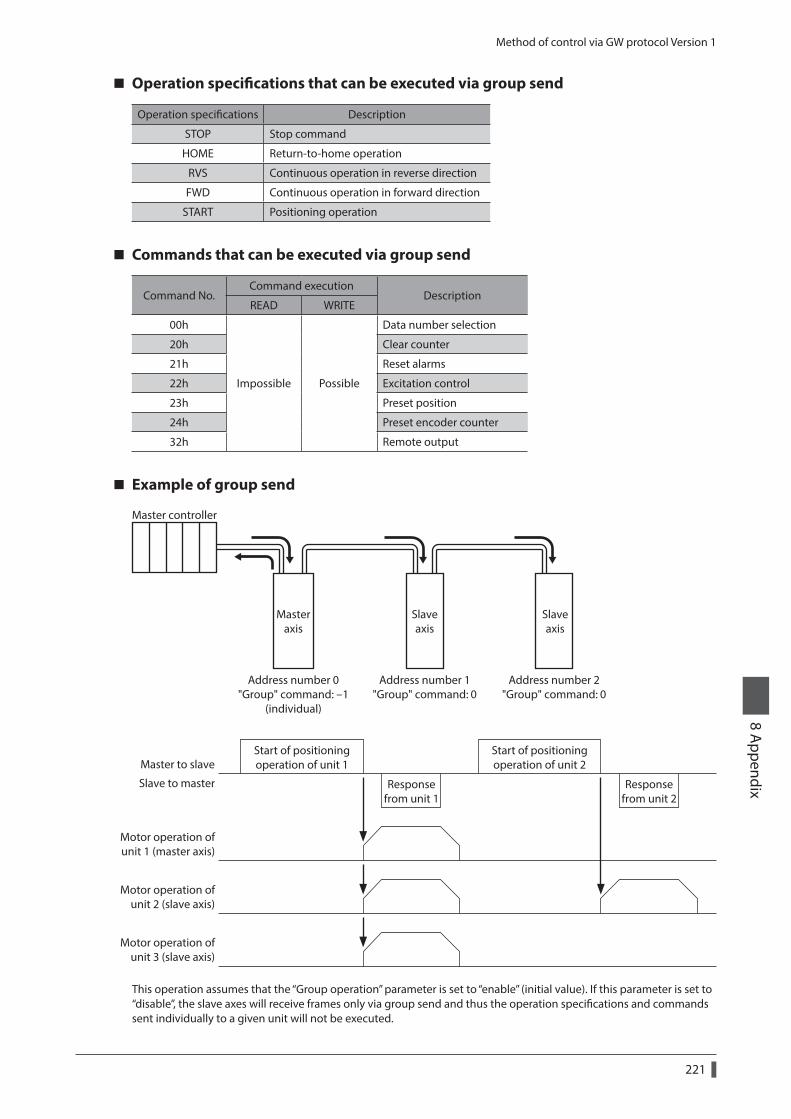
Method of control via GW protocol Version 1
221
8 Appendix
Operation specifications that can be executed via group send
Operation specifications Description
STOP Stop command
HOME Return-to-home operation
RVS Continuous operation in reverse direction
FWD Continuous operation in forward direction
START Positioning operation
Commands that can be executed via group send
Command No.Command execution
DescriptionREAD WRITE
00h
Impossible Possible
Data number selection
20h Clear counter
21h Reset alarms
22h Excitation control
23h Preset position
24h Preset encoder counter
32h Remote output
Example of group send
Address number 0"Group" command: -1
(individual)
Address number 1"Group" command: 0
Address number 2"Group" command: 0
Master controller
Masteraxis
Slaveaxis
Slaveaxis
Master to slave
Slave to master
Start of positioningoperation of unit 1
Start of positioningoperation of unit 2
Responsefrom unit 2
Responsefrom unit 1
Motor operation ofunit 1 (master axis)
Motor operation ofunit 2 (slave axis)
Motor operation ofunit 3 (slave axis)
This operation assumes that the “Group operation” parameter is set to “enable” (initial value). If this parameter is set to “disable”, the slave axes will receive frames only via group send and thus the operation specifications and commands sent individually to a given unit will not be executed.
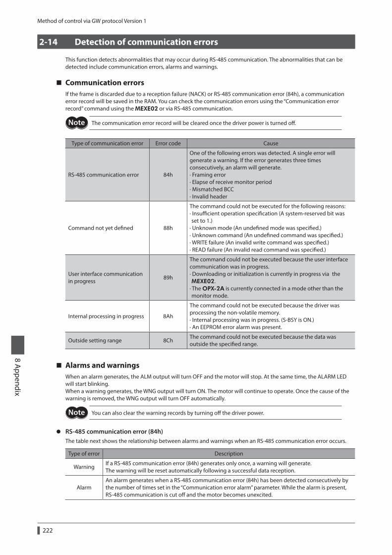
Method of control via GW protocol Version 1
222
8 Appendix
2-14 Detection of communication errors
This function detects abnormalities that may occur during RS-485 communication. The abnormalities that can be detected include communication errors, alarms and warnings.
Communication errorsIf the frame is discarded due to a reception failure (NACK) or RS-485 communication error (84h), a communication error record will be saved in the RAM. You can check the communication errors using the “Communication error record” command using the MEXE02 or via RS-485 communication.
The communication error record will be cleared once the driver power is turned off.
Type of communication error Error code Cause
RS-485 communication error 84h
One of the following errors was detected. A single error will generate a warning. If the error generates three times consecutively, an alarm will generate. · Framing error · Elapse of receive monitor period · Mismatched BCC · Invalid header
Command not yet defined 88h
The command could not be executed for the following reasons: · Insufficient operation specification (A system-reserved bit was set to 1.) · Unknown mode (An undefined mode was specified.) · Unknown command (An undefined command was specified.) · WRITE failure (An invalid write command was specified.) · READ failure (An invalid read command was specified.)
User interface communication in progress
89h
The command could not be executed because the user interface communication was in progress. · Downloading or initialization is currently in progress via the MEXE02. · The OPX-2A is currently connected in a mode other than the monitor mode.
Internal processing in progress 8Ah
The command could not be executed because the driver was processing the non-volatile memory. · Internal processing was in progress. (S-BSY is ON.) · An EEPROM error alarm was present.
Outside setting range 8ChThe command could not be executed because the data was outside the specified range.
Alarms and warningsWhen an alarm generates, the ALM output will turn OFF and the motor will stop. At the same time, the ALARM LED will start blinking.When a warning generates, the WNG output will turn ON. The motor will continue to operate. Once the cause of the warning is removed, the WNG output will turn OFF automatically.
You can also clear the warning records by turning off the driver power.
z RS-485 communication error (84h)The table next shows the relationship between alarms and warnings when an RS-485 communication error occurs.
Type of error Description
WarningIf a RS-485 communication error (84h) generates only once, a warning will generate. The warning will be reset automatically following a successful data reception.
AlarmAn alarm generates when a RS-485 communication error (84h) has been detected consecutively by the number of times set in the “Communication error alarm” parameter. While the alarm is present, RS-485 communication is cut off and the motor becomes unexcited.
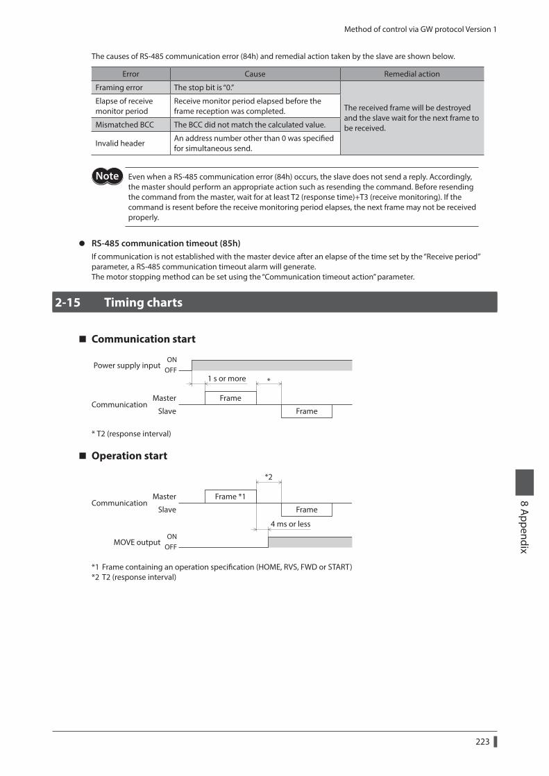
Method of control via GW protocol Version 1
223
8 Appendix
The causes of RS-485 communication error (84h) and remedial action taken by the slave are shown below.
Error Cause Remedial action
Framing error The stop bit is “0.”
The received frame will be destroyed and the slave wait for the next frame to be received.
Elapse of receive monitor period
Receive monitor period elapsed before the frame reception was completed.
Mismatched BCC The BCC did not match the calculated value.
Invalid headerAn address number other than 0 was specified for simultaneous send.
Even when a RS-485 communication error (84h) occurs, the slave does not send a reply. Accordingly, the master should perform an appropriate action such as resending the command. Before resending the command from the master, wait for at least T2 (response time)+T3 (receive monitoring). If the command is resent before the receive monitoring period elapses, the next frame may not be received properly.
z RS-485 communication timeout (85h)If communication is not established with the master device after an elapse of the time set by the “Receive period” parameter, a RS-485 communication timeout alarm will generate.The motor stopping method can be set using the “Communication timeout action” parameter.
2-15 Timing charts
Communication start
Frame
Frame
Master
Slave
Power supply input
Communication
ONOFF
1 s or more *
* T2 (response interval)
Operation start
Frame *1
Frame
Master
Slave
MOVE output
Communication
ONOFF
4 ms or less
*2
*1 Frame containing an operation specification (HOME, RVS, FWD or START)*2 T2 (response interval)
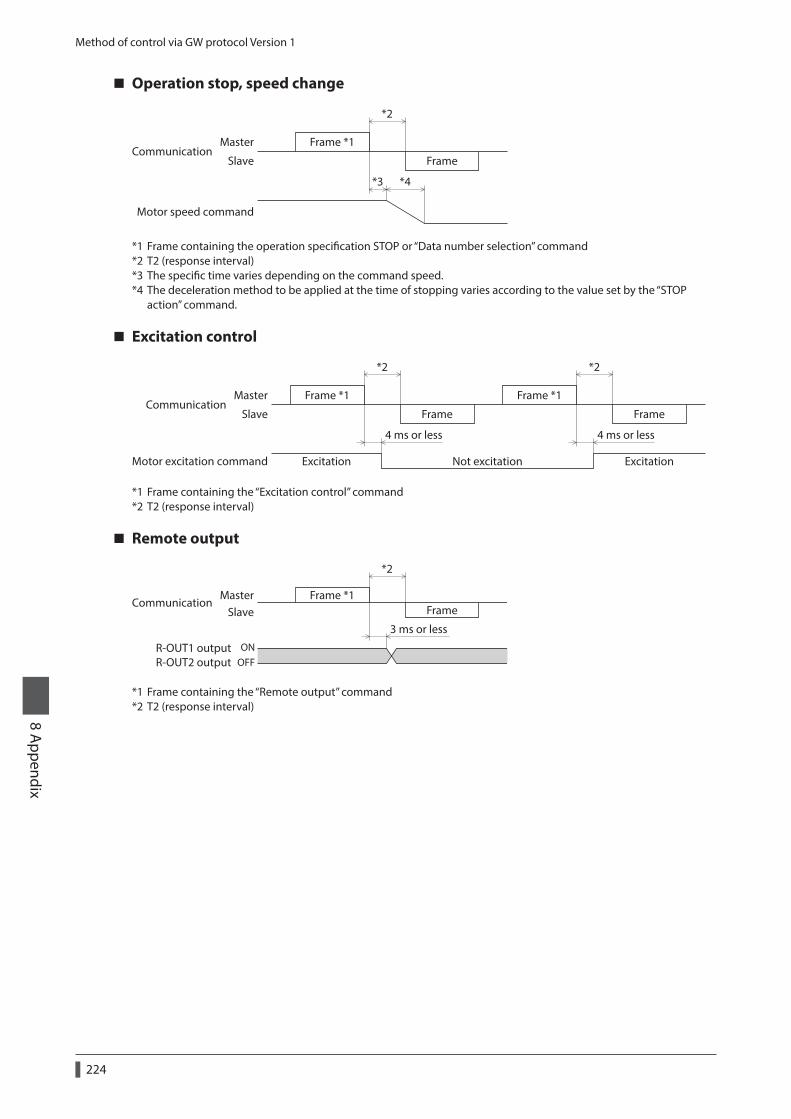
Method of control via GW protocol Version 1
224
8 Appendix
Operation stop, speed change
Frame *1
Frame
Motor speed command
*4*3
*2
Master
SlaveCommunication
*1 Frame containing the operation specification STOP or “Data number selection” command*2 T2 (response interval)*3 The specific time varies depending on the command speed.*4 The deceleration method to be applied at the time of stopping varies according to the value set by the “STOP
action” command.
Excitation control
Frame
Master
Slave
Excitation ExcitationNot excitation
Communication
4 ms or less
Frame *1
Frame
4 ms or less
Frame *1
Motor excitation command
*2 *2
*1 Frame containing the “Excitation control” command*2 T2 (response interval)
Remote output
Frame *1Frame
3 ms or less
*2
ONOFF
R-OUT1 outputR-OUT2 output
MasterSlave
Communication
*1 Frame containing the “Remote output” command*2 T2 (response interval)

225
8 Appendix
• Please contact your nearest Oriental Motor oce for further information.
Technical Support Tel:(800)468-39828:30 A.M. to 5:00 P.M., P.S.T. (M-F)7:30 A.M. to 5:00 P.M., C.S.T. (M-F)www.orientalmotor.com
Schiessstraße 44, 40549 Düsseldorf, GermanyTechnical Support Tel:00 800/22 55 66 22www.orientalmotor.de
Tel:01256-347090www.oriental-motor.co.uk
Tel:01 47 86 97 50www.orientalmotor.fr
Tel:02-93906346www.orientalmotor.it
Tel:0800-060708www.orientalmotor.com.tw
SingaporeTel:1800-8420280www.orientalmotor.com.sg
Tel:1800-806161www.orientalmotor.com.my
KoreaTel:080-777-2042www.inaom.co.kr
4-8-1 Higashiueno, Taito-ku, Tokyo 110-8536 JapanTel:03-6744-0361www.orientalmotor.co.jp
Tel:1800-888-881www.orientalmotor.co.th
Tel:400-820-6516www.orientalmotor.com.cn
Tel:+55-11-3266-6018www.orientalmotor.com.br
Tel:+91-80-41125586www.orientalmotor.co.in
Hong Kong BranchTel:+852-2427-9800
• Unauthorized reproduction or copying of all or part of this Manual is prohibited. If a new copy is required to replace an original manual that has been damaged or lost, please contact your nearest Oriental Motor sales office.
• Oriental Motor shall not be liable whatsoever for any problems relating to industrial property rights arising from use of any information, circuit, equipment or device provided or referenced in this manual.
• Characteristics, specifications and dimensions are subject to change without notice. • While we make every effort to offer accurate information in the manual, we welcome your input. Should you find unclear
descriptions, errors or omissions, please contact your nearest Oriental Motor sales office. • and are registered trademarks or trademarks of Oriental Motor Co., Ltd., in Japan and other countries.
Modbus is a registered trademark of the Schneider Automation Inc. CC-Link is a registered trademark of the CC-Link Partner Association. MECHATROLINK is a registered trademark of the MECHATROLINK Members Association. EtherCAT® is registered trademark and patented technology, licensed by Beckhoff Automation GmbH, Germany. Other product names and company names mentioned in this manual may be registered trademarks or trademarks of their respective companies and are hereby acknowledged. The third-party products mentioned in this manual are recommended products, and references to their names shall not be construed as any form of performance guarantee. Oriental Motor is not liable whatsoever for the performance of these third-party products.
© Copyright ORIENTAL MOTOR CO., LTD. 2010Published in September 2018
Related Documents