Thank you for purchasing an Oriental Motor product. This Manual describes product handling procedures and safety precautions. • Please read it thoroughly to ensure safe operation. • Always keep the manual where it is readily available. HM-60085-5 5-Phase Stepping Motor and Driver Package RKⅡ Series/ Motorized actuator equipped the RKⅡ Series Built-in Controller Type USER MANUAL KCC-REM-OMC-066 KCC-REM-OMC-067 Introduction Installation and connection Operation type and setting Method of control via I/O Method of control via Modbus RTU (RS-485 communication) Method of control via industrial network Operation using the OPX-2A Inspection, troubleshooting and remedial actions Appendix

Welcome message from author
This document is posted to help you gain knowledge. Please leave a comment to let me know what you think about it! Share it to your friends and learn new things together.
Transcript
Thank you for purchasing an Oriental Motor product.
This Manual describes product handling procedures and safety precautions.
• Please read it thoroughly to ensure safe operation.
• Always keep the manual where it is readily available.
HM-60085-5
5-Phase Stepping Motor and Driver Package
RKⅡSeries/Motorized actuator equipped the RKⅡSeries
Built-in Controller Type
USER MANUAL
KCC-REM-OMC-066 KCC-REM-OMC-067
Introduction
Installation and connection
Operation type and setting
Method of control via I/O
Method of control via Modbus RTU (RS-485 communication)
Method of control via industrial network
Operation using the OPX-2A
Inspection, troubleshooting and remedial actions
Appendix
2
1 Introduction
1 Introduction .................................................................................................................................................................. 8
2 Overview of the product ...........................................................................................................................................10
3 System configuration ................................................................................................................................................13
4 Safety precautions .....................................................................................................................................................14
5 Precautions for use ....................................................................................................................................................17
6 General specifications ...............................................................................................................................................19
7 Regulations and standards .......................................................................................................................................20
7-1 EU Directive ............................................................................................................................................................................................. 20
7-2 Republic of Korea, Radio Waves Act ............................................................................................................................................... 21
7-3 RoHS Directive ....................................................................................................................................................................................... 21
8 Preparation ..................................................................................................................................................................22
8-1 Checking the product ......................................................................................................................................................................... 22
8-2 How to identify the product model ............................................................................................................................................... 22
8-3 Combinations of motors and drivers ............................................................................................................................................. 23
8-4 Names and functions of parts .......................................................................................................................................................... 28
2 Installation and connection
1 Installation ...................................................................................................................................................................32
1-1 Location for installation ...................................................................................................................................................................... 32
1-2 Installing the motor ............................................................................................................................................................................. 32
1-3 Installing a load ..................................................................................................................................................................................... 33
1-4 Permissible radial load and permissible axial load ................................................................................................................... 34
1-5 Installing the driver .............................................................................................................................................................................. 36
2 Connection ..................................................................................................................................................................37
2-1 Connection example ........................................................................................................................................................................... 37
2-2 Grounding the motor and driver .................................................................................................................................................... 42
2-3 Connecting the 24 VDC power supply .......................................................................................................................................... 42
2-4 Connecting the data setter ............................................................................................................................................................... 42
2-5 Connecting the RS-485 communication cable .......................................................................................................................... 43
2-6 Noise measures ..................................................................................................................................................................................... 43
2-7 Conformity to the EMC Directive .................................................................................................................................................... 45
3 Explanation of I/O signals .........................................................................................................................................47
3-1 Assignment of direct I/O .................................................................................................................................................................... 47
3-2 Assignment of network I/O ............................................................................................................................................................... 51
3-3 Input signals ........................................................................................................................................................................................... 55
3-4 Output signals ........................................................................................................................................................................................ 60
3-5 Sensor input............................................................................................................................................................................................ 65
3-6 General signals (R0 to R15) ................................................................................................................................................................ 66
3
3 Operation type and setting
1 Guidance ......................................................................................................................................................................68
2 Adjustment and setting ............................................................................................................................................71
2-1 Resolution ................................................................................................................................................................................................ 71
2-2 Operating current ................................................................................................................................................................................. 72
2-3 Standstill current ................................................................................................................................................................................... 72
2-4 Acceleration/deceleration rate and acceleration/deceleration time ................................................................................. 72
2-5 Speed filter .............................................................................................................................................................................................. 73
2-6 Moving average filter .......................................................................................................................................................................... 74
2-7 When a motor with an encoder is used ........................................................................................................................................ 74
3 Operation type and function list .............................................................................................................................78
4 Positioning operation ................................................................................................................................................79
4-1 Operation data ....................................................................................................................................................................................... 79
4-2 Starting method of positioning operation .................................................................................................................................. 80
4-3 Operation function............................................................................................................................................................................... 84
5 Return-to-home operation .......................................................................................................................................88
5-1 About description of return-to-home operation ...................................................................................................................... 88
5-2 Operation sequence ............................................................................................................................................................................ 91
5-3 Position preset ....................................................................................................................................................................................... 94
6 Continuous operation ...............................................................................................................................................95
6-1 Operation data ....................................................................................................................................................................................... 95
6-2 Starting method of continuous operation .................................................................................................................................. 96
6-3 Variable speed operation ................................................................................................................................................................... 98
7 Other operation ........................................................................................................................................................100
7-1 JOG operation ......................................................................................................................................................................................100
7-2 Test operation ......................................................................................................................................................................................101
7-3 Stop operation .....................................................................................................................................................................................101
8 Coordinate management .......................................................................................................................................104
8-1 Position coordinate management ................................................................................................................................................104
8-2 Wrap function ......................................................................................................................................................................................104
9 Operation data ..........................................................................................................................................................106
10 Parameter ..................................................................................................................................................................107
10-1 Parameter list........................................................................................................................................................................................108
10-2 I/O parameter .......................................................................................................................................................................................109
10-3 Motor parameter .................................................................................................................................................................................110
10-4 Operation parameter .........................................................................................................................................................................110
10-5 Home operation parameter ............................................................................................................................................................111
10-6 Alarm parameter .................................................................................................................................................................................111
10-7 Warning parameter ............................................................................................................................................................................111
10-8 Coordinates parameter .....................................................................................................................................................................112
10-9 Common parameter ..........................................................................................................................................................................112
10-10 I/O function [Input] parameter ......................................................................................................................................................113
10-11 I/O function [Output] parameter ..................................................................................................................................................113
4
10-12 I/O function [RS-485] parameter ...................................................................................................................................................114
10-13 Communication parameter .............................................................................................................................................................115
4 Method of control via I/O
1 Guidance ....................................................................................................................................................................118
2 Operation data ..........................................................................................................................................................120
3 Parameter ..................................................................................................................................................................121
3-1 Parameter list........................................................................................................................................................................................122
3-2 I/O parameter .......................................................................................................................................................................................123
3-3 Motor parameter .................................................................................................................................................................................123
3-4 Operation parameter .........................................................................................................................................................................124
3-5 Home operation parameter ............................................................................................................................................................124
3-6 Alarm parameter .................................................................................................................................................................................125
3-7 Warning parameter ............................................................................................................................................................................125
3-8 Coordinates parameter .....................................................................................................................................................................125
3-9 Common parameter ..........................................................................................................................................................................125
3-10 I/O function [Input] parameter ......................................................................................................................................................126
3-11 I/O function [Output] parameter ..................................................................................................................................................126
3-12 I/O function [RS-485] parameter ...................................................................................................................................................127
3-13 Communication parameter............................................................................................................................................................128
4 Timing charts ............................................................................................................................................................129
5 Method of control via Modbus RTU (RS-485 communication)
1 Guidance ....................................................................................................................................................................138
2 Communication specifications ..............................................................................................................................143
3 Setting the switches ................................................................................................................................................145
4 Setting the RS-485 communication ......................................................................................................................148
5 Communication mode and communication timing ..........................................................................................149
5-1 Communication mode ......................................................................................................................................................................149
5-2 Communication timing ....................................................................................................................................................................149
6 Message .....................................................................................................................................................................150
6-1 Query .......................................................................................................................................................................................................150
6-2 Response ................................................................................................................................................................................................152
7 Function code ...........................................................................................................................................................154
7-1 Reading from a holding register(s) [03h] ...................................................................................................................................154
7-2 Writing to a holding register [06h] ...............................................................................................................................................155
7-3 Diagnosis [08h] ....................................................................................................................................................................................156
7-4 Writing to multiple holding registers [10h] ...............................................................................................................................157
8 Register address list .................................................................................................................................................159
8-1 Operation commands .......................................................................................................................................................................159
8-2 Maintenance commands .................................................................................................................................................................161
8-3 Monitor commands ...........................................................................................................................................................................162
5
8-4 Parameter R/W commands .............................................................................................................................................................165
9 Group send ................................................................................................................................................................174
10 Example for setting of the operation ...................................................................................................................176
10-1 Positioning operation........................................................................................................................................................................176
10-2 Continuous operation .......................................................................................................................................................................179
10-3 Return-to-home operation ..............................................................................................................................................................181
11 Detection of communication errors .....................................................................................................................183
11-1 Communication errors .....................................................................................................................................................................183
11-2 Alarms and warnings ........................................................................................................................................................................183
12 Timing charts ............................................................................................................................................................184
6 Method of control via industrial network
1 Setting the switches ................................................................................................................................................188
1-1 Protocol ..................................................................................................................................................................................................188
1-2 Address number (slave address) ...................................................................................................................................................188
1-3 Transmission rate ................................................................................................................................................................................189
1-4 Termination resistor ...........................................................................................................................................................................189
2 Method of control via CC-Link communication..................................................................................................190
2-1 Guidance ................................................................................................................................................................................................190
2-2 Basic operation procedure ..............................................................................................................................................................195
2-3 Remote register list of NETC01-CC ..........................................................................................................................................199
2-4 Assignment for remote I/O of 6-axes connection mode ......................................................................................................199
2-5 Assignment for remote I/O of 12-axes connection mode ....................................................................................................202
3 Method of control via MECHATROLINK communication ..................................................................................207
3-1 Guidance ................................................................................................................................................................................................207
3-2 Basic operation procedure ..............................................................................................................................................................212
3-3 I/O field map for the NETC01-M2 ..............................................................................................................................................215
3-4 I/O field map for the NETC01-M3 ..............................................................................................................................................216
3-5 Communication format ....................................................................................................................................................................217
4 Details of remote I/O ...............................................................................................................................................219
4-1 Input signals to the driver ................................................................................................................................................................219
4-2 Output signals from the driver ......................................................................................................................................................220
5 Command code list ..................................................................................................................................................222
5-1 Group function ....................................................................................................................................................................................222
5-2 Maintenance command ...................................................................................................................................................................223
5-3 Monitor command .............................................................................................................................................................................224
5-4 Operation data .....................................................................................................................................................................................226
5-5 User parameters ..................................................................................................................................................................................227
6
7 Operation using the OPX-2A
1 Overview of the OPX-2A ........................................................................................................................................236
1-1 Names and functions of parts ........................................................................................................................................................237
1-2 How to read the display ...................................................................................................................................................................237
1-3 OPX-2A error display .......................................................................................................................................................................238
2 Screen transitions.....................................................................................................................................................240
3 Monitor mode ...........................................................................................................................................................246
3-1 Overview of the monitor mode .....................................................................................................................................................246
3-2 Monitor items .......................................................................................................................................................................................246
4 Data mode .................................................................................................................................................................248
4-1 Setting items ........................................................................................................................................................................................248
4-2 Setting example ..................................................................................................................................................................................250
4-3 Initialization of the selected operation data .............................................................................................................................251
4-4 Initialization of all operation data .................................................................................................................................................251
5 Parameter mode .......................................................................................................................................................252
5-1 Setting example ..................................................................................................................................................................................253
5-2 Parameter list........................................................................................................................................................................................254
5-3 Initializing parameters ......................................................................................................................................................................259
6 Test mode ..................................................................................................................................................................260
6-1 Overview of the test mode ..............................................................................................................................................................260
6-2 Direct I/O test .......................................................................................................................................................................................261
6-3 JOG operation ......................................................................................................................................................................................261
6-4 Data select operation ........................................................................................................................................................................261
6-5 Return-to-home operation ..............................................................................................................................................................262
6-6 Presetting the position .....................................................................................................................................................................262
6-7 Presetting the encoder counter ....................................................................................................................................................262
6-8 Teaching .................................................................................................................................................................................................262
7 Copy mode ................................................................................................................................................................263
7-1 Overview of the copy mode ...........................................................................................................................................................263
7-2 Error of the copy mode .....................................................................................................................................................................263
8 Inspection, troubleshooting and remedial actions
1 Inspection ..................................................................................................................................................................266
2 Alarms and warnings ...............................................................................................................................................267
2-1 Alarms .....................................................................................................................................................................................................267
2-2 Warnings ................................................................................................................................................................................................272
2-3 Communication errors ......................................................................................................................................................................273
3 Troubleshooting and remedial actions ................................................................................................................274
9 Appendix
1 Accessories ................................................................................................................................................................276
1 Introduction ........................................................8
2 Overview of the product ..................................10
3 System configuration .......................................13
4 Safety precautions ............................................14
5 Precautions for use ...........................................17
6 General specifications ......................................19
7 Regulations and standards ..............................207-1 EU Directive ....................................................................... 20
7-2 Republic of Korea, Radio Waves Act ......................... 21
7-3 RoHS Directive .................................................................. 21
8 Preparation .......................................................228-1 Checking the product .................................................... 22
8-2 How to identify the product model .......................... 22
8-3 Combinations of motors and drivers........................ 23
8-4 Names and functions of parts ..................................... 28
1 Introduction
This part explains the composition of the operating manuals, the product overview, specifications and safety standards as well as the name and function of each part and others.
Table of contents
Introduction
8
1 Introduction
1 Introduction
Before useOnly qualified personnel should work with the product.Use the product correctly after thoroughly reading the section "4 Safety precautions" on p.14.The product described in this manual has been designed and manufactured for use in general industrial equipment.Do not use for any other purpose. Oriental Motor Co., Ltd. is not responsible for any damage caused through failure to observe this warning.
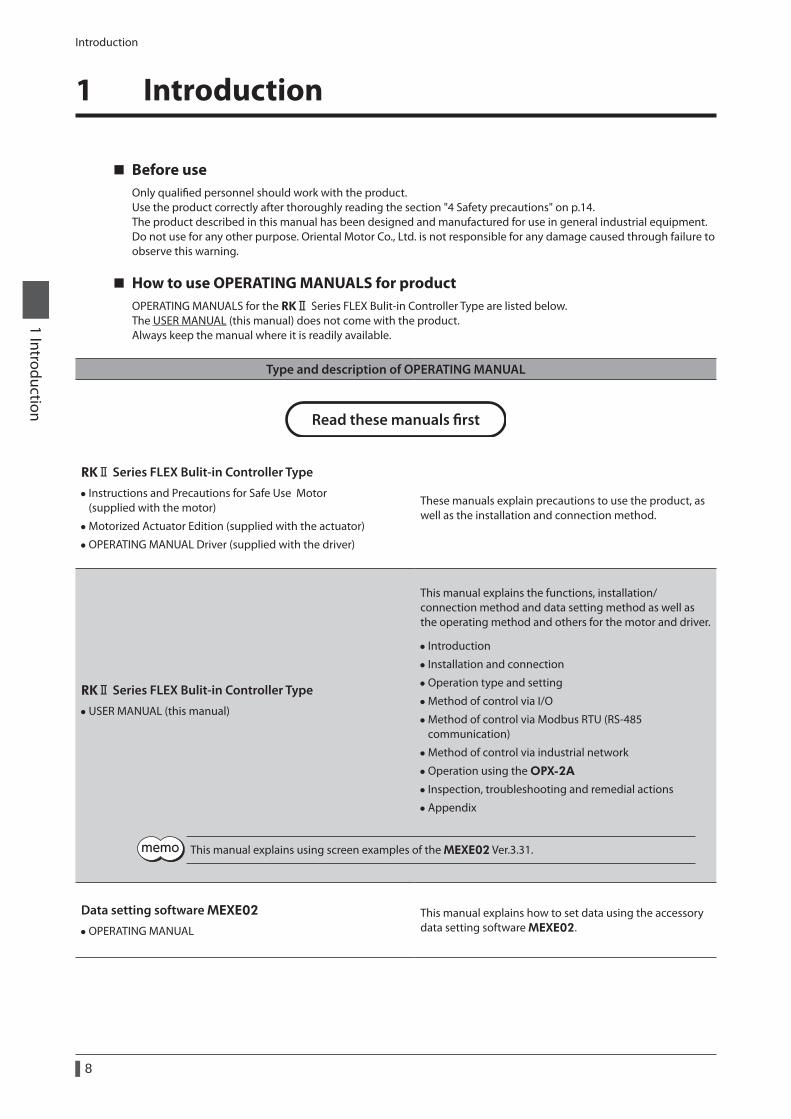
How to use OPERATING MANUALS for productOPERATING MANUALS for the RKⅡ Series FLEX Bulit-in Controller Type are listed below. The USER MANUAL (this manual) does not come with the product. Always keep the manual where it is readily available.
Type and description of OPERATING MANUAL
Read these manuals rst
RKⅡ Series FLEX Bulit-in Controller Type
• Instructions and Precautions for Safe Use Motor (supplied with the motor)
• Motorized Actuator Edition (supplied with the actuator)
• OPERATING MANUAL Driver (supplied with the driver)
These manuals explain precautions to use the product, as well as the installation and connection method.
RKⅡ Series FLEX Bulit-in Controller Type
• USER MANUAL (this manual)
This manual explains the functions, installation/connection method and data setting method as well as the operating method and others for the motor and driver.
• Introduction
• Installation and connection
• Operation type and setting
• Method of control via I/O
• Method of control via Modbus RTU (RS-485 communication)
• Method of control via industrial network
• Operation using the OPX-2A
• Inspection, troubleshooting and remedial actions
• Appendix
This manual explains using screen examples of the MEXE02 Ver.3.31.
Data setting software MEXE02
• OPERATING MANUAL
This manual explains how to set data using the accessory data setting software MEXE02.
Introduction
9
1 Introduction
Type and description of OPERATING MANUAL
Network converter
• CC-Link compatible NETC01-CC USER MANUAL
• CC-Link Ver.2 compatible NETC02-CC USER MANUAL
• MECHATROLINK-Ⅱ compatible NETC01-M2 USER MANUAL
• MECHATROLINK-Ⅲ compatible NETC01-M3 USER MANUAL
• EtherCAT compatible NETC01-ECT USER MANUAL
This manual explains the functions and installation/connection method as well as the operating method for the network converter.
RKⅡ Series UL APPENDIX
• APPENDIX UL Standards and CSA Standards for RKⅡ Series (supplied with the product)
This appendix includes information required for certification of the UL Standards and CSA standards.
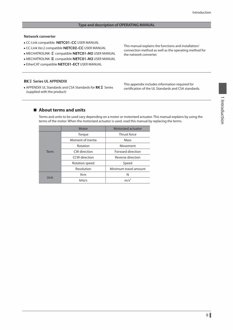
About terms and unitsTerms and units to be used vary depending on a motor or motorized actuator. This manual explains by using the terms of the motor. When the motorized actuator is used, read this manual by replacing the terms.
Motor Motorized actuator
Term
Torque Thrust force
Moment of inertia Mass
Rotation Movement
CW direction Forward direction
CCW direction Reverse direction
Rotation speed Speed
Resolution Minimum travel amount
UnitN·m N
kHz/s m/s2
Overview of the product
10
1 Introduction
2 Overview of the product
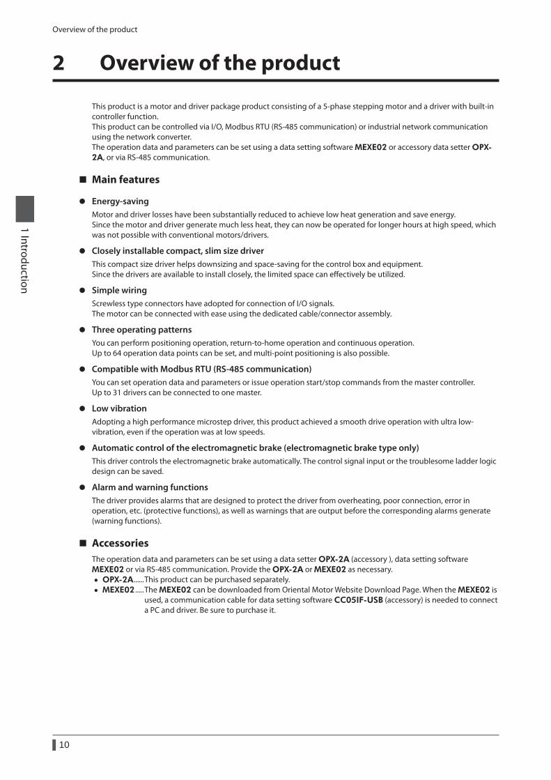
This product is a motor and driver package product consisting of a 5-phase stepping motor and a driver with built-in controller function.This product can be controlled via I/O, Modbus RTU (RS-485 communication) or industrial network communication using the network converter.The operation data and parameters can be set using a data setting software MEXE02 or accessory data setter OPX-2A, or via RS-485 communication.
Main features
z Energy-savingMotor and driver losses have been substantially reduced to achieve low heat generation and save energy.Since the motor and driver generate much less heat, they can now be operated for longer hours at high speed, which was not possible with conventional motors/drivers.
z Closely installable compact, slim size driverThis compact size driver helps downsizing and space-saving for the control box and equipment.Since the drivers are available to install closely, the limited space can effectively be utilized.
z Simple wiringScrewless type connectors have adopted for connection of I/O signals.The motor can be connected with ease using the dedicated cable/connector assembly.
z Three operating patternsYou can perform positioning operation, return-to-home operation and continuous operation.Up to 64 operation data points can be set, and multi-point positioning is also possible.
z Compatible with Modbus RTU (RS-485 communication)You can set operation data and parameters or issue operation start/stop commands from the master controller.Up to 31 drivers can be connected to one master.
z Low vibrationAdopting a high performance microstep driver, this product achieved a smooth drive operation with ultra low-vibration, even if the operation was at low speeds.
z Automatic control of the electromagnetic brake (electromagnetic brake type only)This driver controls the electromagnetic brake automatically. The control signal input or the troublesome ladder logic design can be saved.
z Alarm and warning functionsThe driver provides alarms that are designed to protect the driver from overheating, poor connection, error in operation, etc. (protective functions), as well as warnings that are output before the corresponding alarms generate (warning functions).
AccessoriesThe operation data and parameters can be set using a data setter OPX-2A (accessory ), data setting software MEXE02 or via RS-485 communication. Provide the OPX-2A or MEXE02 as necessary.
• OPX-2A ......This product can be purchased separately. • MEXE02 .....The MEXE02 can be downloaded from Oriental Motor Website Download Page. When the MEXE02 is
used, a communication cable for data setting software CC05IF-USB (accessory) is needed to connect a PC and driver. Be sure to purchase it.

Overview of the product
11
1 Introduction
Related productsThe RKⅡ Series FLEX built-in controller type can be used via various network when connecting to a network converter.
Network converter Supported network
NETC01-CC CC-Link Ver.1.10
NETC02-CC CC-Link Ver.2.00
NETC01-M2 MECHATROLINK-IINETC01-M3 MECHATROLINK-IIINETC01-ECT EtherCAT
Overview of the product
12
1 Introduction
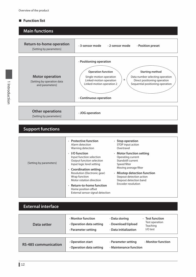
Function list
· Monitor function
· Operation data setting
· Parameter setting
Main functions
· Return-to-home function Home position oset External sensor signal detection
· I/O function Input function selection Output function selection Input logic level setting
· Coordination setting Resolution (Electronic gear) Wrap function Motor rotation direction
· Protective function Alarm detection Warning detection
Support functions
[Setting by parameters]
· Data storing
· Download/Upload
· Data initialization
External interface
Data setter
RS-485 communication
· Test function Test operation Teaching I/O test
· Motor function setting Operating current Standstill current Speed lter Moving average lter
· Stop operation STOP input action Overtravel
· Misstep detection function Stepout detection action Stepout detection band Encoder resolution
· Operation start
· Operation data setting
· Monitor function· Parameter setting
· Maintenance function
Return-to-home operation · 2-sensor mode
Other operations · JOG operation
· Positioning operation
· Continuous operation
Single-motion operationLinked-motion operation
Linked-motion operation 2
Operation function
Data number selecting operationDirect positioning operation
Sequential positioning operation
Starting method
+
[Setting by parameters]
Motor operation[Setting by operation data
and parameters]
[Setting by parameters]
· Position preset· 3-sensor mode
System configuration
13
1 Introduction
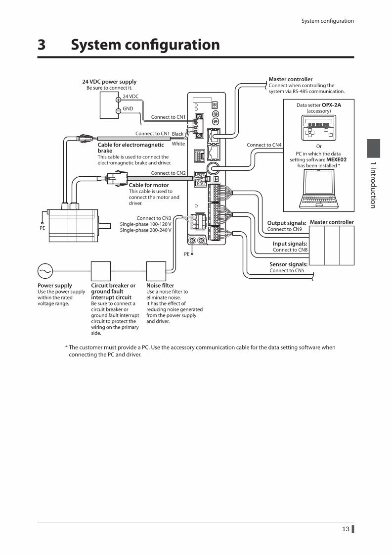
3 System configuration
Connect to CN2
Connect to CN1 Black
WhiteCable for electromagnetic brakeThis cable is used to connect the electromagnetic brake and driver.
Connect to CN3Single-phase 100-120 VSingle-phase 200-240 V
PE
Noise lterUse a noise lter toeliminate noise.It has the eect ofreducing noise generatedfrom the power supplyand driver.
Power supplyUse the power supplywithin the rated voltage range.
Circuit breaker orground fault interrupt circuit Be sure to connect a circuit breaker or ground fault interrupt circuit to protect the wiring on the primary side.
Cable for motorThis cable is used to connect the motor and driver.
Connect to CN1
24 VDC power supplyBe sure to connect it.
GND
24 VDC
Data setter OPX-2A(accessory)
OrPC in which the data
setting software MEXE02 has been installed *
PE
Connect to CN4
Sensor signals:Connect to CN5
Master controllerOutput signals: Connect to CN9
Input signals:Connect to CN8
Master controllerConnect when controlling the system via RS-485 communication.
* The customer must provide a PC. Use the accessory communication cable for the data setting software when connecting the PC and driver.
Safety precautions
14
1 Introduction
4 Safety precautions
The precautions described below are intended to prevent danger or injury to the user and other personnel through safe, correct use of the product. Use the product only after carefully reading and fully understanding these instructions.
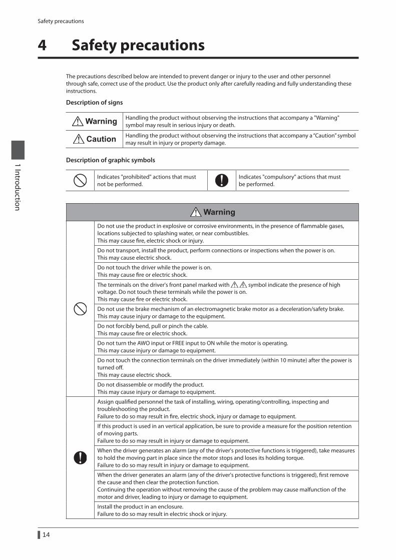
Description of signs
Handling the product without observing the instructions that accompany a "Warning" symbol may result in serious injury or death.
Handling the product without observing the instructions that accompany a “Caution” symbol may result in injury or property damage.
Description of graphic symbols
Indicates "prohibited" actions that must not be performed.
Indicates "compulsory" actions that must be performed.
Do not use the product in explosive or corrosive environments, in the presence of flammable gases, locations subjected to splashing water, or near combustibles. This may cause fire, electric shock or injury.
Do not transport, install the product, perform connections or inspections when the power is on. This may cause electric shock.
Do not touch the driver while the power is on. This may cause fire or electric shock.
The terminals on the driver's front panel marked with symbol indicate the presence of high voltage. Do not touch these terminals while the power is on. This may cause fire or electric shock.
Do not use the brake mechanism of an electromagnetic brake motor as a deceleration/safety brake. This may cause injury or damage to the equipment.
Do not forcibly bend, pull or pinch the cable. This may cause fire or electric shock.
Do not turn the AWO input or FREE input to ON while the motor is operating. This may cause injury or damage to equipment.
Do not touch the connection terminals on the driver immediately (within 10 minute) after the power is turned off. This may cause electric shock.
Do not disassemble or modify the product. This may cause injury or damage to equipment.
Assign qualified personnel the task of installing, wiring, operating/controlling, inspecting and troubleshooting the product. Failure to do so may result in fire, electric shock, injury or damage to equipment.
If this product is used in an vertical application, be sure to provide a measure for the position retention of moving parts. Failure to do so may result in injury or damage to equipment.
When the driver generates an alarm (any of the driver's protective functions is triggered), take measures to hold the moving part in place since the motor stops and loses its holding torque. Failure to do so may result in injury or damage to equipment.
When the driver generates an alarm (any of the driver's protective functions is triggered), first remove the cause and then clear the protection function. Continuing the operation without removing the cause of the problem may cause malfunction of the motor and driver, leading to injury or damage to equipment.
Install the product in an enclosure. Failure to do so may result in electric shock or injury.
Safety precautions
15
1 Introduction
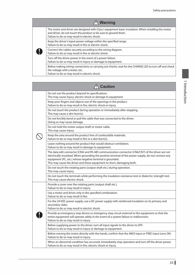
The motor and driver are designed with Class I equipment basic insulation. When installing the motor and driver, do not touch the product or be sure to ground them. Failure to do so may result in electric shock.
Keep the driver’s input-power voltage within the specified range. Failure to do so may result in fire or electric shock.
Connect the cables securely according to the wiring diagram. Failure to do so may result in fire or electric shock.
Turn off the driver power in the event of a power failure. Failure to do so may result in injury or damage to equipment.
Before making wiring connections or carrying out checks, wait for the CHARGE LED to turn off and check the voltage with a tester, etc. Failure to do so may result in electric shock.
Do not use the product beyond its specifications. This may cause injury, electric shock or damage to equipment.
Keep your fingers and objects out of the openings in the product. Failure to do so may result in fire, electric shock or injury.
Do not touch the product during operation or immediately after stopping. This may cause a skin burn(s).
Do not forcibly bend or pull the cable that was connected to the driver. Doing so may cause damage.
Do not hold the motor output shaft or motor cable. This may cause injury.
Keep the area around the product free of combustible materials. Failure to do so may result in fire or a skin burn(s).
Leave nothing around the product that would obstruct ventilation. Failure to do so may result in damage to equipment.
The data edit connector (CN4) and RS-485 communication connector (CN6/CN7) of the driver are not electrically insulated. When grounding the positive terminal of the power supply, do not connect any equipment (PC, etc.) whose negative terminal is grounded. This may cause the driver and these equipment to short, damaging both.
Do not touch the rotating parts (output shaft etc.) during operation. This may cause injury.
Do not touch the terminals while performing the insulation resistance test or dielectric strength test. This may cause electric shock.
Provide a cover over the rotating parts (output shaft etc.). Failure to do so may result in injury.
Use a motor and driver only in the specified combination. Failure to do so may result in fire.
For the 24 VDC power supply, use a DC power supply with reinforced insulation on its primary and secondary sides. Failure to do so may result in electric shock.
Provide an emergency stop device or emergency stop circuit external to the equipment so that the entire equipment will operate safely in the event of a system failure or malfunction. Failure to do so may result in injury.
Before supplying power to the driver, turn all input signals to the driver to OFF. Failure to do so may result in injury or damage to equipment.
Before moving the motor directly with the hands, confirm that the AWO input or FREE input turns ON. Failure to do so may result in injury.
When an abnormal condition has occurred, immediately stop operation and turn off the driver power. Failure to do so may result in fire, electric shock or injury.
Safety precautions
16
1 Introduction
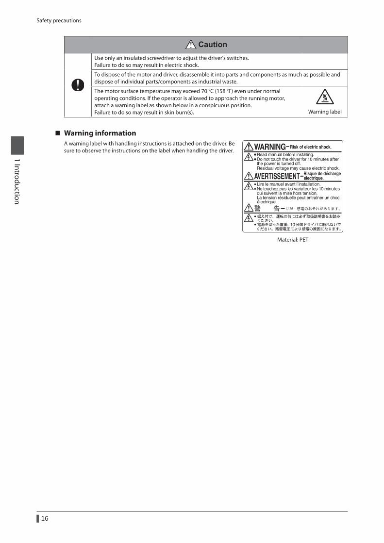
Use only an insulated screwdriver to adjust the driver's switches. Failure to do so may result in electric shock.
To dispose of the motor and driver, disassemble it into parts and components as much as possible and dispose of individual parts/components as industrial waste.
The motor surface temperature may exceed 70 °C (158 °F) even under normal operating conditions. If the operator is allowed to approach the running motor, attach a warning label as shown below in a conspicuous position. Failure to do so may result in skin burn(s). Warning label
Warning informationA warning label with handling instructions is attached on the driver. Be sure to observe the instructions on the label when handling the driver.
Material: PET
Precautions for use
17
1 Introduction
5 Precautions for use
This section covers limitations and requirements the user should consider when using the product.
z Always use the cable (supplied or accessory) to connect the motor and driver.Be sure to use the cable (supplied or accessory) to connect the motor and driver.If a cable other than the supplied cable or accessory cable is used, the driver may generate a large amount of heat.In the following condition, an appropriate accessory cable must be purchased separately. Refer to p.276 for details.
• If a flexible cable is to be used. • If a cable of 3 m (9.8 ft.) or longer is to be used. • If a motor and driver package without a cable was purchased.
z Perform the insulation resistance test or dielectric strength test separately on the motor and the driver.Performing the insulation resistance test or dielectric strength test with the motor and driver connected may result in damage to the product.
z Do not apply strong impact on the motor output shaft.If you are using a motor with encoder, an optical encoder is housed in the motor. To prevent damage to the encoder, handle the motor with care and avoid strong impact to the motor output shaft when transporting the motor or installing the load.
z Do not apply a radial load and axial load in excess of the specified permissible limitOperating the motor under an excessive radial load or axial load may damage the motor bearings (ball bearings). Be sure to operate the motor within the specified permissible limit of radial load and axial load. Refer to p.34 for details.
z Motor case temperature • The driver has an overheat protection function, but the motor has no such feature. The motor surface temperature
may exceed 100 °C (212 °F) under certain conditions (ambient temperature, operating speed, duty cycle, etc.). To prevent the motor bearings (ball bearings) from reaching its usable life quickly, use the motor in conditions where the surface temperature will not exceed 100 °C (212 °F).
• Use the geared type motor in a condition where the gear case temperature does not exceed 70 °C (158 °F), in order to prevent deterioration of grease and parts in the gear case.
• In the case of a motor with an encoder, use it in a condition where the motor surface temperature will not exceed 85 °C (185 °F) in order to protect the encoder.
z Holding torque at standstillThe motor holding torque is reduced by the current cutback function of the driver at motor standstill. When selecting a motor, check the holding torque at motor standstill in the specifications on the catalog.
z Do not use the electromagnetic brake to reduce speed or as a safety brake.Do not use the electromagnetic brake as a means to decelerate and stop the motor. The brake hub of the electromagnetic brake will wear significantly and the braking force will drop if used to stop the motor.The electromagnetic brake is a power-off activated type. This means that although it helps maintain the position of the load in the event of power outage, etc., this brake cannot securely hold the load in place. Accordingly, do not use the electromagnetic brake as a safety brake. To use the electromagnetic brake to hold the load in place, do so after the motor has stopped.
z Preventing leakage currentStray capacitance exists between the driver’s current-carrying line and other current-carrying lines, the earth and the motor, respectively. A high-frequency current may leak out through such capacitance, having a detrimental effect on the surrounding equipment. The actual leakage current depends on the driver’s switching frequency, the length of wiring between the driver and motor, and so on.When connecting an earth leakage breaker, use one of the following products offering resistance against high frequency current:Mitsubishi Electric Corporation: NV seriesFuji Electric FA Components & Systems Co., Ltd.: EG and SG series
z Preventing electrical noiseSee "2-6 Noise measures" on p.43 for measures with regard to noise.
Precautions for use
18
1 Introduction
z Saving data to the non-volatile memoryDo not turn off the power supply while writing the data to the non-volatile memory and 5 seconds after the completion of writing the data. Doing so may abort writing the data and cause an EEPROM error alarm to generate.The non-volatile memory can be rewritten approximately 100,000 times.
z Motor excitation at power ONThe motor is excited when the 24 VDC power and main power is on. If the motor is required to be in non-excitation status when turning on the power, assign the AWO input to the direct I/O or network I/O.
z Note on connecting a power supply whose positive terminal is groundedThe data edit connector (CN4) and RS-485 communication connector (CN6/CN7) of the driver are not electrically insulated. When grounding the positive terminal of the power supply, do not connect any equipment (PC, etc.) whose negative terminal is grounded. Doing so may cause the driver and these equipment to short, damaging both. Use the data setter OPX-2A to set data, etc.
z Grease of geared type motorOn rare occasions, a small amount of grease may ooze out from the geared type motor. If there is concern over possible environmental damage resulting from the leakage of grease, check for grease stains during regular inspections. Alternatively, install an oil pan or other device to prevent leakage from causing further damage. Oil leakage may lead to problems in the customer’s equipment or products.
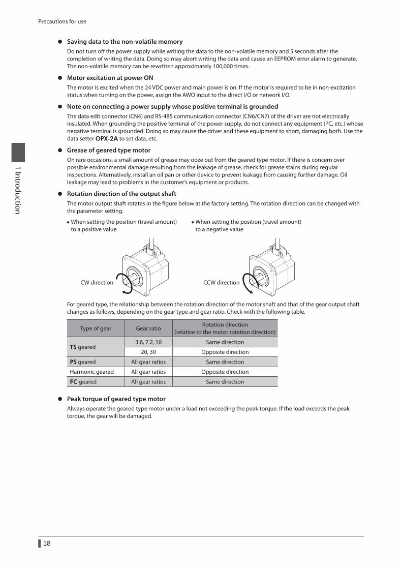
z Rotation direction of the output shaftThe motor output shaft rotates in the figure below at the factory setting. The rotation direction can be changed with the parameter setting.
• When setting the position (travel amount) to a positive value
CW direction
• When setting the position (travel amount) to a negative value
CCW direction
For geared type, the relationship between the rotation direction of the motor shaft and that of the gear output shaft changes as follows, depending on the gear type and gear ratio. Check with the following table.
Type of gear Gear ratioRotation direction
(relative to the motor rotation direction)
TS geared3.6, 7.2, 10 Same direction
20, 30 Opposite direction
PS geared All gear ratios Same direction
Harmonic geared All gear ratios Opposite direction
FC geared All gear ratios Same direction
z Peak torque of geared type motorAlways operate the geared type motor under a load not exceeding the peak torque. If the load exceeds the peak torque, the gear will be damaged.
General specifications
19
1 Introduction
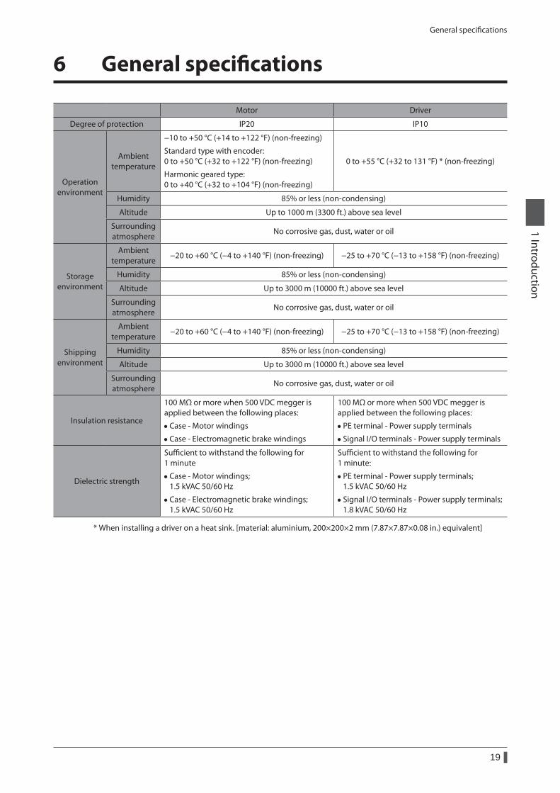
6 General specifications
Motor Driver
Degree of protection IP20 IP10
Operation environment
Ambient temperature
−10 to +50 °C (+14 to +122 °F) (non-freezing)
Standard type with encoder: 0 to +50 °C (+32 to +122 °F) (non-freezing)
Harmonic geared type: 0 to +40 °C (+32 to +104 °F) (non-freezing)
0 to +55 °C (+32 to 131 °F) * (non-freezing)
Humidity 85% or less (non-condensing)
Altitude Up to 1000 m (3300 ft.) above sea level
Surrounding atmosphere
No corrosive gas, dust, water or oil
Storage environment
Ambient temperature
−20 to +60 °C (−4 to +140 °F) (non-freezing) −25 to +70 °C (−13 to +158 °F) (non-freezing)
Humidity 85% or less (non-condensing)
Altitude Up to 3000 m (10000 ft.) above sea level
Surrounding atmosphere
No corrosive gas, dust, water or oil
Shipping environment
Ambient temperature
−20 to +60 °C (−4 to +140 °F) (non-freezing) −25 to +70 °C (−13 to +158 °F) (non-freezing)
Humidity 85% or less (non-condensing)
Altitude Up to 3000 m (10000 ft.) above sea level
Surrounding atmosphere
No corrosive gas, dust, water or oil
Insulation resistance
100 MΩ or more when 500 VDC megger is applied between the following places:
• Case - Motor windings
• Case - Electromagnetic brake windings
100 MΩ or more when 500 VDC megger is applied between the following places:
• PE terminal - Power supply terminals
• Signal I/O terminals - Power supply terminals
Dielectric strength
Sufficient to withstand the following for 1 minute
• Case - Motor windings; 1.5 kVAC 50/60 Hz
• Case - Electromagnetic brake windings; 1.5 kVAC 50/60 Hz
Sufficient to withstand the following for 1 minute:
• PE terminal - Power supply terminals; 1.5 kVAC 50/60 Hz
• Signal I/O terminals - Power supply terminals; 1.8 kVAC 50/60 Hz
* When installing a driver on a heat sink. [material: aluminium, 200×200×2 mm (7.87×7.87×0.08 in.) equivalent]
Regulations and standards
20
1 Introduction
7 Regulations and standards
7-1 EU Directive
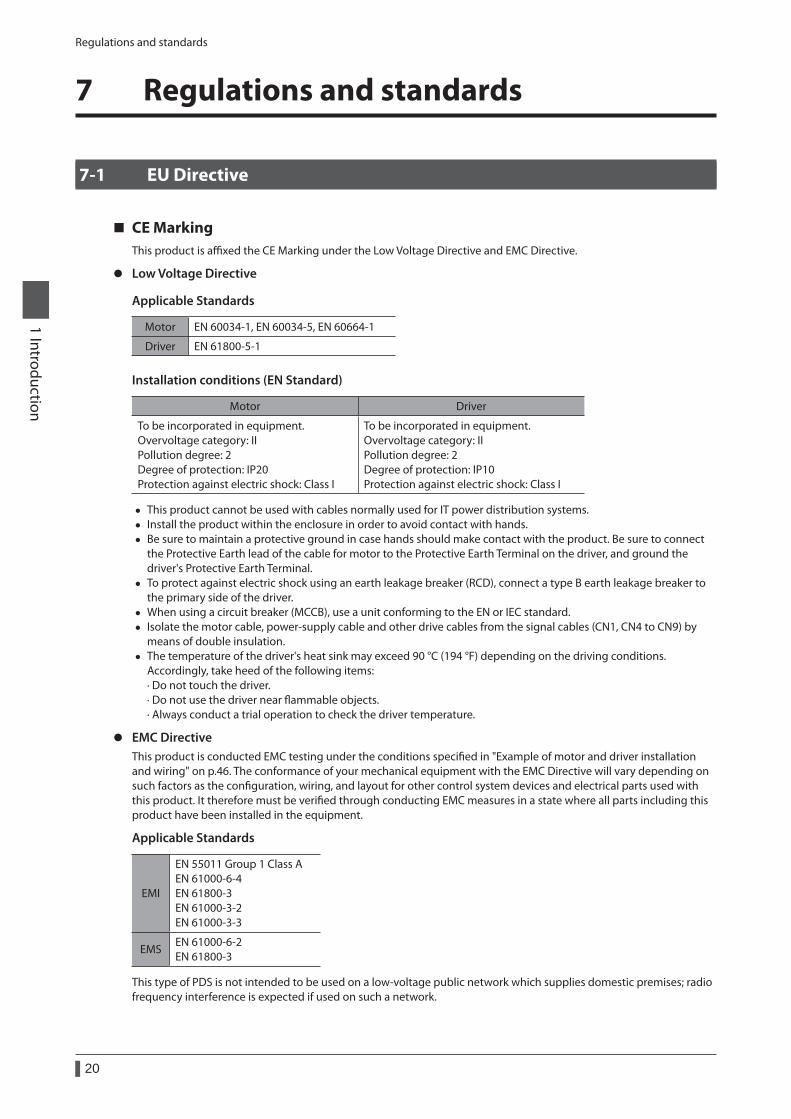
CE MarkingThis product is affixed the CE Marking under the Low Voltage Directive and EMC Directive.
z Low Voltage Directive
Applicable Standards
Motor EN 60034-1, EN 60034-5, EN 60664-1
Driver EN 61800-5-1
Installation conditions (EN Standard)
Motor Driver
To be incorporated in equipment. Overvoltage category: II Pollution degree: 2 Degree of protection: IP20 Protection against electric shock: Class I
To be incorporated in equipment. Overvoltage category: II Pollution degree: 2 Degree of protection: IP10 Protection against electric shock: Class I
• This product cannot be used with cables normally used for IT power distribution systems. • Install the product within the enclosure in order to avoid contact with hands. • Be sure to maintain a protective ground in case hands should make contact with the product. Be sure to connect
the Protective Earth lead of the cable for motor to the Protective Earth Terminal on the driver, and ground the driver's Protective Earth Terminal.
• To protect against electric shock using an earth leakage breaker (RCD), connect a type B earth leakage breaker to the primary side of the driver.
• When using a circuit breaker (MCCB), use a unit conforming to the EN or IEC standard. • Isolate the motor cable, power-supply cable and other drive cables from the signal cables (CN1, CN4 to CN9) by
means of double insulation. • The temperature of the driver's heat sink may exceed 90 °C (194 °F) depending on the driving conditions.
Accordingly, take heed of the following items: · Do not touch the driver. · Do not use the driver near flammable objects. · Always conduct a trial operation to check the driver temperature.
z EMC DirectiveThis product is conducted EMC testing under the conditions specified in "Example of motor and driver installation and wiring" on p.46. The conformance of your mechanical equipment with the EMC Directive will vary depending on such factors as the configuration, wiring, and layout for other control system devices and electrical parts used with this product. It therefore must be verified through conducting EMC measures in a state where all parts including this product have been installed in the equipment.
Applicable Standards
EMI
EN 55011 Group 1 Class A EN 61000-6-4 EN 61800-3 EN 61000-3-2 EN 61000-3-3
EMSEN 61000-6-2 EN 61800-3
This type of PDS is not intended to be used on a low-voltage public network which supplies domestic premises; radio frequency interference is expected if used on such a network.

Regulations and standards
21
1 Introduction
7-2 Republic of Korea, Radio Waves Act
Seller and user shall be noticed that this equipment is suitable for electromagnetic equipments for office work (Class A) and it can be used outside home.이 기기는 업무용 (A급 ) 전자파적합기기로서 판매자 또는 사용자는 이 점을 주의하시기 바라며 , 가정외의 지역에서 사용하는 것을 목적으로 합니다 .
7-3 RoHS Directive
The products do not contain the substances exceeding the restriction values of RoHS Directive (2011/65/EU).
Preparation
22
1 Introduction
8 Preparation
This chapter explains the items you should check, as well as the name and function of each part.
8-1 Checking the product
Verify that the items listed below are included. Report any missing or damaged items to the branch or sales office from which you purchased the product.Verify the model number of the purchased product against the number shown on the package label.Check the model number of the motor and driver against the number shown on the nameplate. Model names for motor and driver combinations are shown on p.23.
• Motor ...............................................................................................1 unit • Driver ...............................................................................................1 unit • Cable for motor ............................................................................1 pc.
(When the product is supplied with a connection cable) • Cable for electromagnetic brake ...........................................1 pc.
(When the product is a motor with an electromagnetic brake supplied with a connection cable) • Cable for encoder ........................................................................1 pc.
(When the product is a motor with an encoder supplied with a connection cable) • CN1 connector (4 pins) ..............................................................1 pc. • CN3 connector (3 pins) ..............................................................1 pc. • CN5 connector (5 pins) ..............................................................1 pc. • CN8 connector (9 pins) ..............................................................1 pc. • CN9 connector (7 pins) ..............................................................1 pc. • Parallel key .....................................................................................1 pc.
(Supplied with geared types; except for the RKS543-TS) • Motor mounting screw (M4) ...................................................4 pcs. (Supplied with RKS564-TS) • Motor mounting screw (M8) ...................................................4 pcs. (Supplied with RKS596-TS) • Instructions and Precautions for Safe Use Motor ............1 copy • OPERATING MANUAL Driver ....................................................1 copy
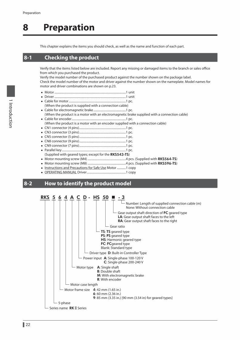
8-2 How to identify the product model
RKS 5 6 4 A C D - HS 50 - 3
Power input A: Single-phase 100-120 V C: Single-phase 200-240 V
Number: Length of supplied connection cable (m)None: Without connection cable
5-phase
Gear ratio
Gear output shaft direction of FC geared typeLA: Gear output shaft faces to the leftRA: Gear output shaft faces to the right
Driver type D: Built-in Controller Type
TS: TS geared typePS: PS geared typeHS: Harmonic geared typeFC: FCgeared typeBlank: Standard type
Motor type A: Single shaft B: Double shaft M: With electromagnetic brake R: With encoder
Motor case lengthMotor frame size 4: 42 mm (1.65 in.) 6: 60 mm (2.36 in.) 9: 85 mm (3.35 in.) [90 mm (3.54 in) for geared types]
Series name RK Series
Preparation
23
1 Introduction
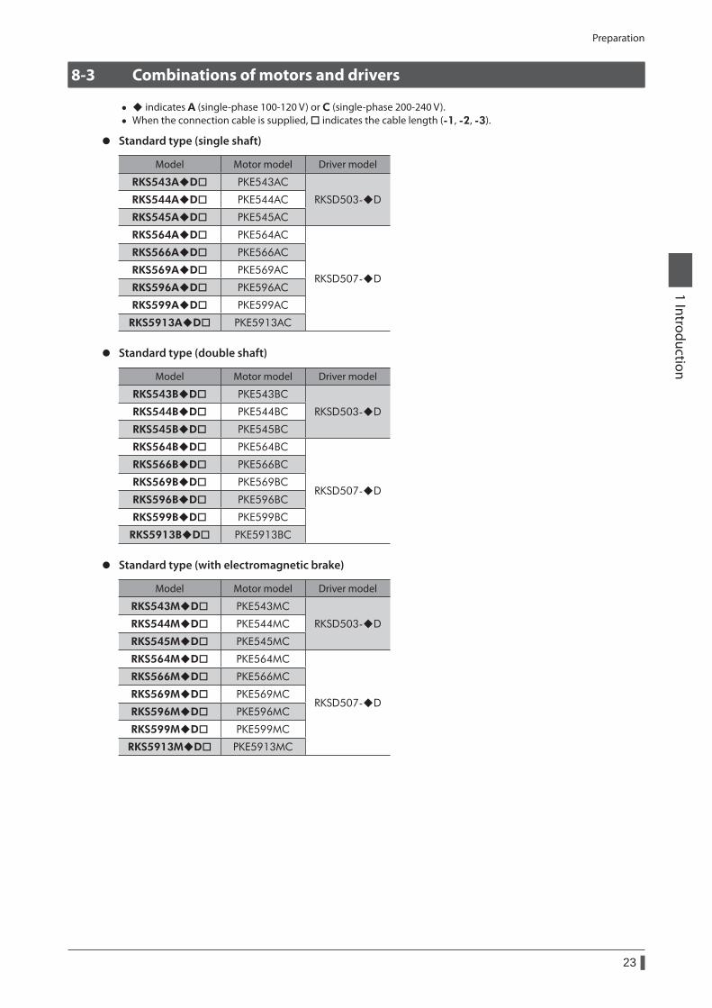
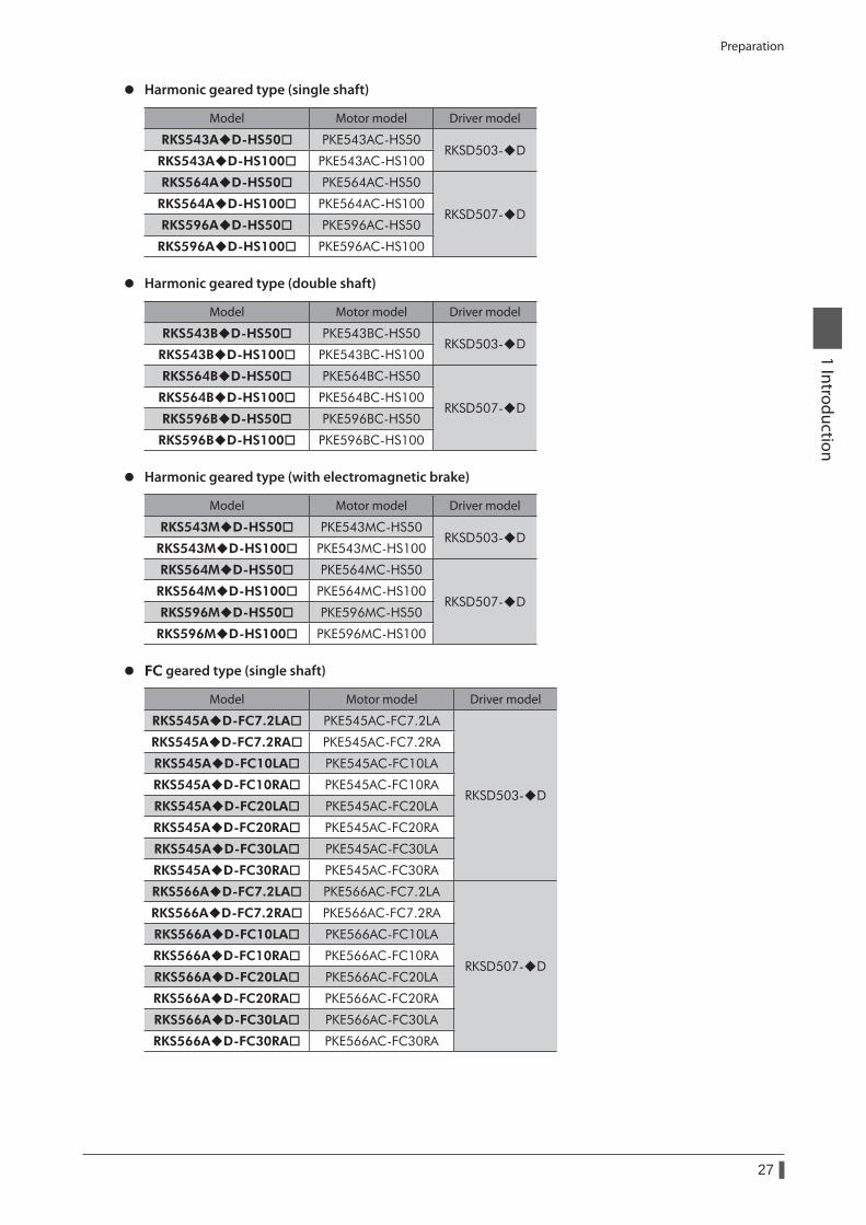
8-3 Combinations of motors and drivers
• indicates A (single-phase 100-120 V) or C (single-phase 200-240 V). • When the connection cable is supplied, indicates the cable length (-1, -2, -3).
z Standard type (single shaft)
Model Motor model Driver model
RKS543AD PKE543AC
RKSD503-DRKS544AD PKE544AC
RKS545AD PKE545AC
RKS564AD PKE564AC
RKSD507-D
RKS566AD PKE566AC
RKS569AD PKE569AC
RKS596AD PKE596AC
RKS599AD PKE599AC
RKS5913AD PKE5913AC
z Standard type (double shaft)
Model Motor model Driver model
RKS543BD PKE543BC
RKSD503-DRKS544BD PKE544BC
RKS545BD PKE545BC
RKS564BD PKE564BC
RKSD507-D
RKS566BD PKE566BC
RKS569BD PKE569BC
RKS596BD PKE596BC
RKS599BD PKE599BC
RKS5913BD PKE5913BC
z Standard type (with electromagnetic brake)
Model Motor model Driver model
RKS543MD PKE543MC
RKSD503-DRKS544MD PKE544MC
RKS545MD PKE545MC
RKS564MD PKE564MC
RKSD507-D
RKS566MD PKE566MC
RKS569MD PKE569MC
RKS596MD PKE596MC
RKS599MD PKE599MC
RKS5913MD PKE5913MC
Preparation
24
1 Introduction
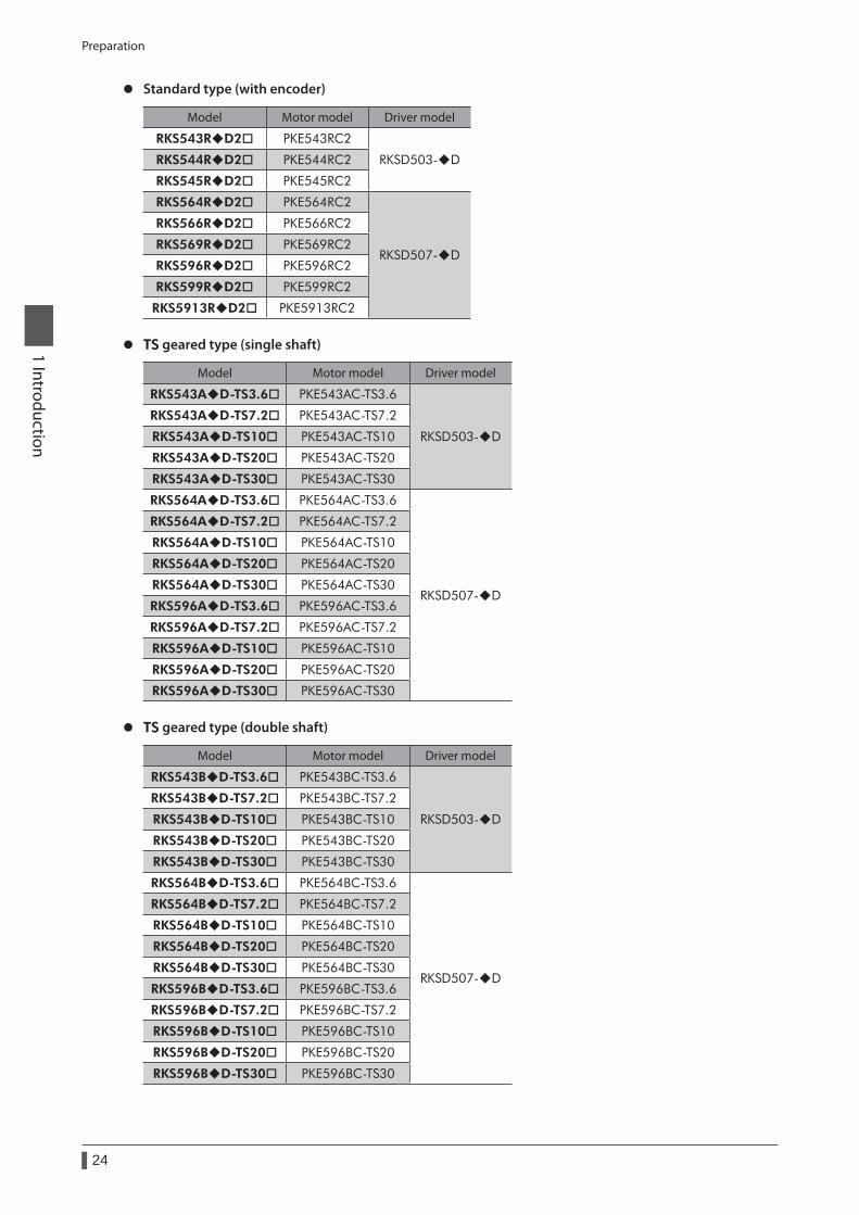
z Standard type (with encoder)
Model Motor model Driver model
RKS543RD2 PKE543RC2
RKSD503-DRKS544RD2 PKE544RC2
RKS545RD2 PKE545RC2
RKS564RD2 PKE564RC2
RKSD507-D
RKS566RD2 PKE566RC2
RKS569RD2 PKE569RC2
RKS596RD2 PKE596RC2
RKS599RD2 PKE599RC2
RKS5913RD2 PKE5913RC2
z TS geared type (single shaft)
Model Motor model Driver model
RKS543AD-TS3.6 PKE543AC-TS3.6
RKSD503-D
RKS543AD-TS7.2 PKE543AC-TS7.2
RKS543AD-TS10 PKE543AC-TS10
RKS543AD-TS20 PKE543AC-TS20
RKS543AD-TS30 PKE543AC-TS30
RKS564AD-TS3.6 PKE564AC-TS3.6
RKSD507-D
RKS564AD-TS7.2 PKE564AC-TS7.2
RKS564AD-TS10 PKE564AC-TS10
RKS564AD-TS20 PKE564AC-TS20
RKS564AD-TS30 PKE564AC-TS30
RKS596AD-TS3.6 PKE596AC-TS3.6
RKS596AD-TS7.2 PKE596AC-TS7.2
RKS596AD-TS10 PKE596AC-TS10
RKS596AD-TS20 PKE596AC-TS20
RKS596AD-TS30 PKE596AC-TS30
z TS geared type (double shaft)
Model Motor model Driver model
RKS543BD-TS3.6 PKE543BC-TS3.6
RKSD503-D
RKS543BD-TS7.2 PKE543BC-TS7.2
RKS543BD-TS10 PKE543BC-TS10
RKS543BD-TS20 PKE543BC-TS20
RKS543BD-TS30 PKE543BC-TS30
RKS564BD-TS3.6 PKE564BC-TS3.6
RKSD507-D
RKS564BD-TS7.2 PKE564BC-TS7.2
RKS564BD-TS10 PKE564BC-TS10
RKS564BD-TS20 PKE564BC-TS20
RKS564BD-TS30 PKE564BC-TS30
RKS596BD-TS3.6 PKE596BC-TS3.6
RKS596BD-TS7.2 PKE596BC-TS7.2
RKS596BD-TS10 PKE596BC-TS10
RKS596BD-TS20 PKE596BC-TS20
RKS596BD-TS30 PKE596BC-TS30
Preparation
25
1 Introduction
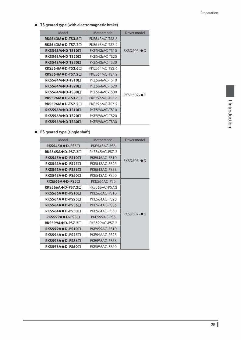
z TS geared type (with electromagnetic brake)
Model Motor model Driver model
RKS543MD-TS3.6 PKE543MC-TS3.6
RKSD503-D
RKS543MD-TS7.2 PKE543MC-TS7.2
RKS543MD-TS10 PKE543MC-TS10
RKS543MD-TS20 PKE543MC-TS20
RKS543MD-TS30 PKE543MC-TS30
RKS564MD-TS3.6 PKE564MC-TS3.6
RKSD507-D
RKS564MD-TS7.2 PKE564MC-TS7.2
RKS564MD-TS10 PKE564MC-TS10
RKS564MD-TS20 PKE564MC-TS20
RKS564MD-TS30 PKE564MC-TS30
RKS596MD-TS3.6 PKE596MC-TS3.6
RKS596MD-TS7.2 PKE596MC-TS7.2
RKS596MD-TS10 PKE596MC-TS10
RKS596MD-TS20 PKE596MC-TS20
RKS596MD-TS30 PKE596MC-TS30
z PS geared type (single shaft)
Model Motor model Driver model
RKS545AD-PS5 PKE545AC-PS5
RKSD503-D
RKS545AD-PS7.2 PKE545AC-PS7.2
RKS545AD-PS10 PKE545AC-PS10
RKS543AD-PS25 PKE543AC-PS25
RKS543AD-PS36 PKE543AC-PS36
RKS543AD-PS50 PKE543AC-PS50
RKS566AD-PS5 PKE566AC-PS5
RKSD507-D
RKS566AD-PS7.2 PKE566AC-PS7.2
RKS566AD-PS10 PKE566AC-PS10
RKS564AD-PS25 PKE564AC-PS25
RKS564AD-PS36 PKE564AC-PS36
RKS564AD-PS50 PKE564AC-PS50
RKS599AD-PS5 PKE599AC-PS5
RKS599AD-PS7.2 PKE599AC-PS7.2
RKS599AD-PS10 PKE599AC-PS10
RKS596AD-PS25 PKE596AC-PS25
RKS596AD-PS36 PKE596AC-PS36
RKS596AD-PS50 PKE596AC-PS50
Preparation
26
1 Introduction
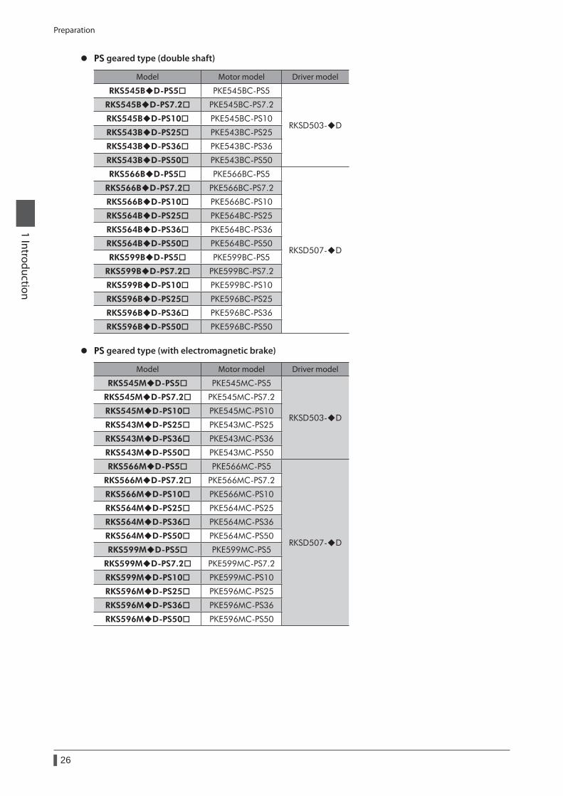
z PS geared type (double shaft)
Model Motor model Driver model
RKS545BD-PS5 PKE545BC-PS5
RKSD503-D
RKS545BD-PS7.2 PKE545BC-PS7.2
RKS545BD-PS10 PKE545BC-PS10
RKS543BD-PS25 PKE543BC-PS25
RKS543BD-PS36 PKE543BC-PS36
RKS543BD-PS50 PKE543BC-PS50
RKS566BD-PS5 PKE566BC-PS5
RKSD507-D
RKS566BD-PS7.2 PKE566BC-PS7.2
RKS566BD-PS10 PKE566BC-PS10
RKS564BD-PS25 PKE564BC-PS25
RKS564BD-PS36 PKE564BC-PS36
RKS564BD-PS50 PKE564BC-PS50
RKS599BD-PS5 PKE599BC-PS5
RKS599BD-PS7.2 PKE599BC-PS7.2
RKS599BD-PS10 PKE599BC-PS10
RKS596BD-PS25 PKE596BC-PS25
RKS596BD-PS36 PKE596BC-PS36
RKS596BD-PS50 PKE596BC-PS50
z PS geared type (with electromagnetic brake)
Model Motor model Driver model
RKS545MD-PS5 PKE545MC-PS5
RKSD503-D
RKS545MD-PS7.2 PKE545MC-PS7.2
RKS545MD-PS10 PKE545MC-PS10
RKS543MD-PS25 PKE543MC-PS25
RKS543MD-PS36 PKE543MC-PS36
RKS543MD-PS50 PKE543MC-PS50
RKS566MD-PS5 PKE566MC-PS5
RKSD507-D
RKS566MD-PS7.2 PKE566MC-PS7.2
RKS566MD-PS10 PKE566MC-PS10
RKS564MD-PS25 PKE564MC-PS25
RKS564MD-PS36 PKE564MC-PS36
RKS564MD-PS50 PKE564MC-PS50
RKS599MD-PS5 PKE599MC-PS5
RKS599MD-PS7.2 PKE599MC-PS7.2
RKS599MD-PS10 PKE599MC-PS10
RKS596MD-PS25 PKE596MC-PS25
RKS596MD-PS36 PKE596MC-PS36
RKS596MD-PS50 PKE596MC-PS50
Preparation
27
1 Introduction
z Harmonic geared type (single shaft)
Model Motor model Driver model
RKS543AD-HS50 PKE543AC-HS50RKSD503-D
RKS543AD-HS100 PKE543AC-HS100
RKS564AD-HS50 PKE564AC-HS50
RKSD507-DRKS564AD-HS100 PKE564AC-HS100
RKS596AD-HS50 PKE596AC-HS50
RKS596AD-HS100 PKE596AC-HS100
z Harmonic geared type (double shaft)
Model Motor model Driver model
RKS543BD-HS50 PKE543BC-HS50RKSD503-D
RKS543BD-HS100 PKE543BC-HS100
RKS564BD-HS50 PKE564BC-HS50
RKSD507-DRKS564BD-HS100 PKE564BC-HS100
RKS596BD-HS50 PKE596BC-HS50
RKS596BD-HS100 PKE596BC-HS100
z Harmonic geared type (with electromagnetic brake)
Model Motor model Driver model
RKS543MD-HS50 PKE543MC-HS50RKSD503-D
RKS543MD-HS100 PKE543MC-HS100
RKS564MD-HS50 PKE564MC-HS50
RKSD507-DRKS564MD-HS100 PKE564MC-HS100
RKS596MD-HS50 PKE596MC-HS50
RKS596MD-HS100 PKE596MC-HS100
z FC geared type (single shaft)
Model Motor model Driver model
RKS545AD-FC7.2LA PKE545AC-FC7.2LA
RKSD503-D
RKS545AD-FC7.2RA PKE545AC-FC7.2RA
RKS545AD-FC10LA PKE545AC-FC10LA
RKS545AD-FC10RA PKE545AC-FC10RA
RKS545AD-FC20LA PKE545AC-FC20LA
RKS545AD-FC20RA PKE545AC-FC20RA
RKS545AD-FC30LA PKE545AC-FC30LA
RKS545AD-FC30RA PKE545AC-FC30RA
RKS566AD-FC7.2LA PKE566AC-FC7.2LA
RKSD507-D
RKS566AD-FC7.2RA PKE566AC-FC7.2RA
RKS566AD-FC10LA PKE566AC-FC10LA
RKS566AD-FC10RA PKE566AC-FC10RA
RKS566AD-FC20LA PKE566AC-FC20LA
RKS566AD-FC20RA PKE566AC-FC20RA
RKS566AD-FC30LA PKE566AC-FC30LA
RKS566AD-FC30RA PKE566AC-FC30RA
Preparation
28
1 Introduction
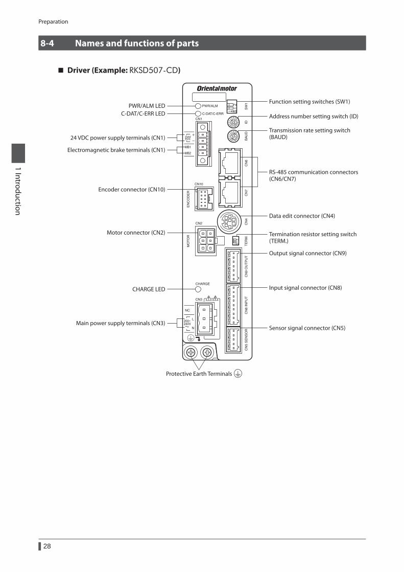
8-4 Names and functions of parts
Driver (Example: RKSD507-CD)
PWR/ALM LEDC-DAT/C-ERR LED
CHARGE LED
Protective Earth Terminals
Termination resistor setting switch(TERM.)
Transmission rate setting switch(BAUD)
Address number setting switch (ID)
Data edit connector (CN4)
Motor connector (CN2)
Encoder connector (CN10)
Output signal connector (CN9)
Input signal connector (CN8)
Sensor signal connector (CN5)Main power supply terminals (CN3)
24 VDC power supply terminals (CN1)
Electromagnetic brake terminals (CN1)
Function setting switches (SW1)
RS-485 communication connectors(CN6/CN7)
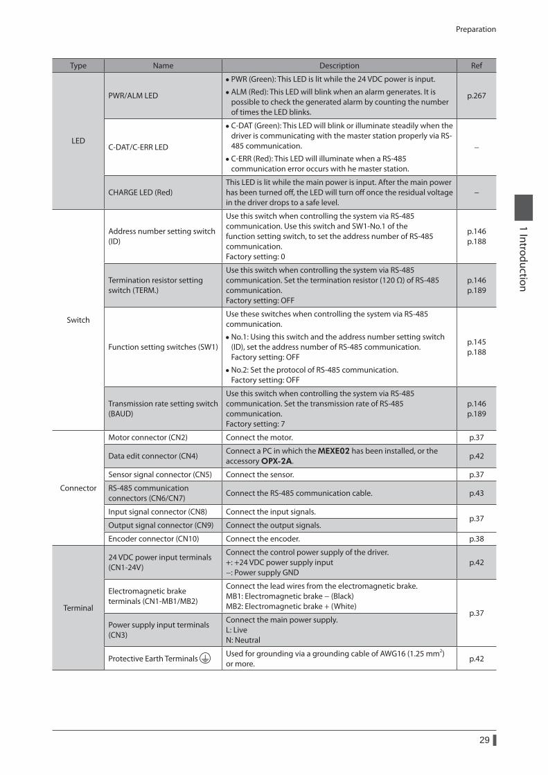
Preparation
29
1 Introduction
Type Name Description Ref
LED
PWR/ALM LED
• PWR (Green): This LED is lit while the 24 VDC power is input.
• ALM (Red): This LED will blink when an alarm generates. It is possible to check the generated alarm by counting the number of times the LED blinks.
p.267
C-DAT/C-ERR LED
• C-DAT (Green): This LED will blink or illuminate steadily when the driver is communicating with the master station properly via RS-485 communication.
• C-ERR (Red): This LED will illuminate when a RS-485 communication error occurs with he master station.
−
CHARGE LED (Red)This LED is lit while the main power is input. After the main power has been turned off, the LED will turn off once the residual voltage in the driver drops to a safe level.
−
Switch
Address number setting switch (ID)
Use this switch when controlling the system via RS-485 communication. Use this switch and SW1-No.1 of the function setting switch, to set the address number of RS-485 communication. Factory setting: 0
p.146 p.188
Termination resistor setting switch (TERM.)
Use this switch when controlling the system via RS-485 communication. Set the termination resistor (120 Ω) of RS-485 communication. Factory setting: OFF
p.146 p.189
Function setting switches (SW1)
Use these switches when controlling the system via RS-485 communication.
• No.1: Using this switch and the address number setting switch (ID), set the address number of RS-485 communication. Factory setting: OFF
• No.2: Set the protocol of RS-485 communication. Factory setting: OFF
p.145 p.188
Transmission rate setting switch (BAUD)
Use this switch when controlling the system via RS-485 communication. Set the transmission rate of RS-485 communication. Factory setting: 7
p.146 p.189
Connector
Motor connector (CN2) Connect the motor. p.37
Data edit connector (CN4)Connect a PC in which the MEXE02 has been installed, or the accessory OPX-2A.
p.42
Sensor signal connector (CN5) Connect the sensor. p.37
RS-485 communication connectors (CN6/CN7)
Connect the RS-485 communication cable. p.43
Input signal connector (CN8) Connect the input signals.p.37
Output signal connector (CN9) Connect the output signals.
Encoder connector (CN10) Connect the encoder. p.38
Terminal
24 VDC power input terminals (CN1-24V)
Connect the control power supply of the driver. +: +24 VDC power supply input −: Power supply GND
p.42
Electromagnetic brake terminals (CN1-MB1/MB2)
Connect the lead wires from the electromagnetic brake. MB1: Electromagnetic brake − (Black) MB2: Electromagnetic brake + (White)
p.37Power supply input terminals (CN3)
Connect the main power supply. L: Live N: Neutral
Protective Earth Terminals Used for grounding via a grounding cable of AWG16 (1.25 mm2) or more.
p.42
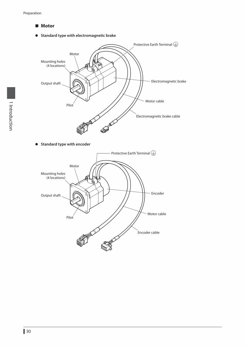
Preparation
30
1 Introduction
Motor
z Standard type with electromagnetic brake
Output shaft
PilotMotor cable
Motor
Electromagnetic brake cable
Electromagnetic brake
Protective Earth Terminal
Mounting holes(4 locations)
z Standard type with encoder
Output shaft
PilotMotor cable
Motor
Encoder cable
Encoder
Protective Earth Terminal
Mounting holes(4 locations)
1 Installation ........................................................321-1 Location for installation ................................................ 32
1-2 Installing the motor ........................................................ 32
1-3 Installing a load ................................................................ 33
1-4 Permissible radial load and permissible axial load .................................................... 34
1-5 Installing the driver ......................................................... 36
2 Connection ........................................................372-1 Connection example ...................................................... 37
2-2 Grounding the motor and driver ............................... 42
2-3 Connecting the 24 VDC power supply..................... 42
2-4 Connecting the data setter .......................................... 42
2-5 Connecting the RS-485 communication cable ..... 43
2-6 Noise measures ................................................................ 43
2-7 Conformity to the EMC Directive ............................... 45
3 Explanation of I/O signals ................................473-1 Assignment of direct I/O ............................................... 47
3-2 Assignment of network I/O .......................................... 51
3-3 Input signals ...................................................................... 55
3-4 Output signals .................................................................. 60
3-5 Sensor input ...................................................................... 65
3-6 General signals (R0 to R15) ........................................... 66
2 Installation and connection
This part explains the installation method of the product, the mounting method of a load and the connection method as well as I/O signals.
Table of contents
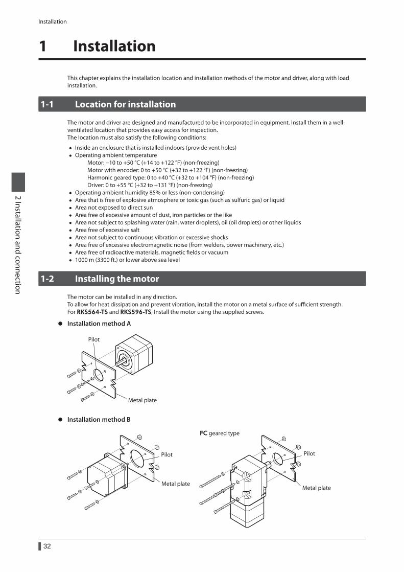
Installation
32
2 Installation and connection
1 Installation
This chapter explains the installation location and installation methods of the motor and driver, along with load installation.
1-1 Location for installation
The motor and driver are designed and manufactured to be incorporated in equipment. Install them in a well-ventilated location that provides easy access for inspection.The location must also satisfy the following conditions:
• Inside an enclosure that is installed indoors (provide vent holes) • Operating ambient temperature
Motor: −10 to +50 °C (+14 to +122 °F) (non-freezing) Motor with encoder: 0 to +50 °C (+32 to +122 °F) (non-freezing) Harmonic geared type: 0 to +40 °C (+32 to +104 °F) (non-freezing) Driver: 0 to +55 °C (+32 to +131 °F) (non-freezing)
• Operating ambient humidity 85% or less (non-condensing) • Area that is free of explosive atmosphere or toxic gas (such as sulfuric gas) or liquid • Area not exposed to direct sun • Area free of excessive amount of dust, iron particles or the like • Area not subject to splashing water (rain, water droplets), oil (oil droplets) or other liquids • Area free of excessive salt • Area not subject to continuous vibration or excessive shocks • Area free of excessive electromagnetic noise (from welders, power machinery, etc.) • Area free of radioactive materials, magnetic fields or vacuum • 1000 m (3300 ft.) or lower above sea level
1-2 Installing the motor
The motor can be installed in any direction.To allow for heat dissipation and prevent vibration, install the motor on a metal surface of sufficient strength.For RKS564-TS and RKS596-TS, Install the motor using the supplied screws.
z Installation method A
Metal plate
Pilot
z Installation method B
Metal plate
Pilot
Metal plate
FC geared type
Pilot
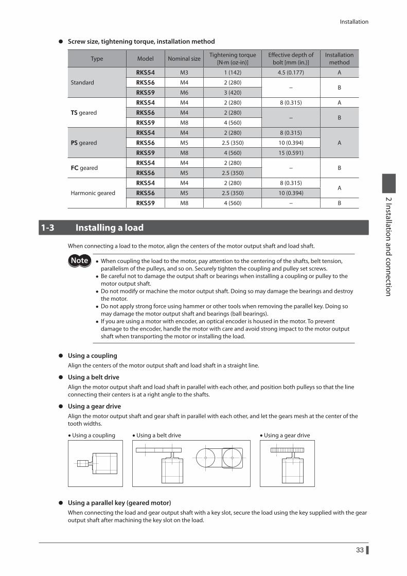
Installation
33
2 Installation and connection
z Screw size, tightening torque, installation method
Type Model Nominal sizeTightening torque
[N·m (oz-in)]Effective depth of
bolt [mm (in.)]Installation
method
Standard
RKS54 M3 1 (142) 4.5 (0.177) A
RKS56 M4 2 (280)− B
RKS59 M6 3 (420)
TS geared
RKS54 M4 2 (280) 8 (0.315) A
RKS56 M4 2 (280)− B
RKS59 M8 4 (560)
PS geared
RKS54 M4 2 (280) 8 (0.315)
ARKS56 M5 2.5 (350) 10 (0.394)
RKS59 M8 4 (560) 15 (0.591)
FC gearedRKS54 M4 2 (280)
− BRKS56 M5 2.5 (350)
Harmonic geared
RKS54 M4 2 (280) 8 (0.315)A
RKS56 M5 2.5 (350) 10 (0.394)
RKS59 M8 4 (560) − B
1-3 Installing a load
When connecting a load to the motor, align the centers of the motor output shaft and load shaft.
• When coupling the load to the motor, pay attention to the centering of the shafts, belt tension, parallelism of the pulleys, and so on. Securely tighten the coupling and pulley set screws.
• Be careful not to damage the output shaft or bearings when installing a coupling or pulley to the motor output shaft.
• Do not modify or machine the motor output shaft. Doing so may damage the bearings and destroy the motor.
• Do not apply strong force using hammer or other tools when removing the parallel key. Doing so may damage the motor output shaft and bearings (ball bearings).
• If you are using a motor with encoder, an optical encoder is housed in the motor. To prevent damage to the encoder, handle the motor with care and avoid strong impact to the motor output shaft when transporting the motor or installing the load.
z Using a couplingAlign the centers of the motor output shaft and load shaft in a straight line.
z Using a belt driveAlign the motor output shaft and load shaft in parallel with each other, and position both pulleys so that the line connecting their centers is at a right angle to the shafts.
z Using a gear driveAlign the motor output shaft and gear shaft in parallel with each other, and let the gears mesh at the center of the tooth widths.
• Using a coupling • Using a belt drive • Using a gear drive
z Using a parallel key (geared motor)When connecting the load and gear output shaft with a key slot, secure the load using the key supplied with the gear output shaft after machining the key slot on the load.
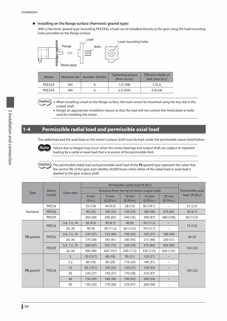
Installation
34
2 Installation and connection
z Installing on the flange surface (Harmonic geared type)With a Harmonic geared type (excluding PKE596), a load can be installed directly to the gear using the load mounting holes provided on the flange surface.
Metal plate
Flange Bolts
LoadLoad mounting holes
Model Nominal size Number of boltsTightening torque
[N·m (oz-in)]Effective depth of
bolt [mm (in.)]
PKE543 M3 6 1.4 (198) 5 (0.2)
PKE564 M4 6 2.5 (350) 6 (0.24)
• When installing a load on the flange surface, the load cannot be mounted using the key slot in the output shaft.
• Design an appropriate installation layout so that the load will not contact the metal plate or bolts used for installing the motor.
1-4 Permissible radial load and permissible axial load
The radial load and the axial load on the motor's output shaft must be kept under the permissible values listed below.
Failure due to fatigue may occur when the motor bearings and output shaft are subject to repeated loading by a radial or axial load that is in excess of the permissible limit.
The permissible radial load and permissible axial load of the PS geared type represent the value that the service life of the gear part satisfies 20,000 hours when either of the radial load or axial load is applied to the gear output shaft.
TypeMotor model
Gear ratio
Permissible radial load [N (lb.)]
Permissible axial load [N (lb.)]
Distance from the tip of motor output shaft
0 mm (0 in.)
5 mm (0.20 in.)
10 mm (0.39 in.)
15 mm (0.59 in.)
20 mm (0.79 in.)
Standard
PKE54
−
35 (7.8) 44 (9.9) 58 (13) 85 (19.1) − 15 (3.3)
PKE56 90 (20) 100 (22) 130 (29) 180 (40) 270 (60) 30 (6.7)
PKE59 260 (58) 290 (65) 340 (76) 390 (87) 480 (108) 60 (13.5)
TS geared
PKE543.6, 7.2, 10 20 (4.5) 30 (6.7) 40 (9) 50 (11.2) −
15 (3.3)20, 30 40 (9) 50 (11.2) 60 (13.5) 70 (15.7) −
PKE563.6, 7.2, 10 120 (27) 135 (30) 150 (33) 165 (37) 180 (40)
40 (9)20, 30 170 (38) 185 (41) 200 (45) 215 (48) 230 (51)
PKE593.6, 7.2, 10 300 (67) 325 (73) 350 (78) 375 (84) 400 (90)
150 (33)20, 30 400 (90) 450 (101) 500 (112) 550 (123) 600 (135)
PS geared PKE54
5 70 (15.7) 80 (18) 95 (21) 120 (27) −
100 (22)
7.2 80 (18) 90 (20) 110 (24) 140 (31) −
10 85 (19.1) 100 (22) 120 (27) 150 (33) −
25 120 (27) 140 (31) 170 (38) 210 (47) −
36 130 (29) 160 (36) 190 (42) 240 (54) −
50 150 (33) 170 (38) 210 (47) 260 (58) −
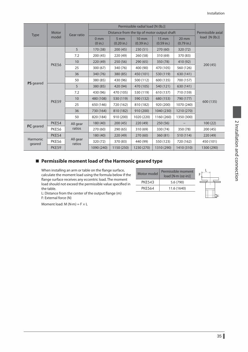
Installation
35
2 Installation and connection
TypeMotor model
Gear ratio
Permissible radial load [N (lb.)]
Permissible axial load [N (lb.)]
Distance from the tip of motor output shaft
0 mm (0 in.)
5 mm (0.20 in.)
10 mm (0.39 in.)
15 mm (0.59 in.)
20 mm (0.79 in.)
PS geared
PKE56
5 170 (38) 200 (45) 230 (51) 270 (60) 320 (72)
200 (45)
7.2 200 (45) 220 (49) 260 (58) 310 (69) 370 (83)
10 220 (49) 250 (56) 290 (65) 350 (78) 410 (92)
25 300 (67) 340 (76) 400 (90) 470 (105) 560 (126)
36 340 (76) 380 (85) 450 (101) 530 (119) 630 (141)
50 380 (85) 430 (96) 500 (112) 600 (135) 700 (157)
PKE59
5 380 (85) 420 (94) 470 (105) 540 (121) 630 (141)
600 (135)
7.2 430 (96) 470 (105) 530 (119) 610 (137) 710 (159)
10 480 (108) 530 (119) 590 (132) 680 (153) 790 (177)
25 650 (146) 720 (162) 810 (182) 920 (200) 1070 (240)
36 730 (164) 810 (182) 910 (200) 1040 (230) 1210 (270)
50 820 (184) 910 (200) 1020 (220) 1160 (260) 1350 (300)
FC gearedPKE54 All gear
ratios180 (40) 200 (45) 220 (49) 250 (56) − 100 (22)
PKE56 270 (60) 290 (65) 310 (69) 330 (74) 350 (78) 200 (45)
Harmonic geared
PKE54All gear
ratios
180 (40) 220 (49) 270 (60) 360 (81) 510 (114) 220 (49)
PKE56 320 (72) 370 (83) 440 (99) 550 (123) 720 (162) 450 (101)
PKE59 1090 (240) 1150 (250) 1230 (270) 1310 (290) 1410 (310) 1300 (290)
Permissible moment load of the Harmonic geared type
When installing an arm or table on the flange surface, calculate the moment load using the formula below if the flange surface receives any eccentric load. The moment load should not exceed the permissible value specified in the table.L: Distance from the center of the output flange (m)F: External force (N)
Moment load: M (N·m) = F × L
Motor modelPermissible moment
load [N·m (oz-in)]
LF
PKE543 5.6 (790)
PKE564 11.6 (1640)
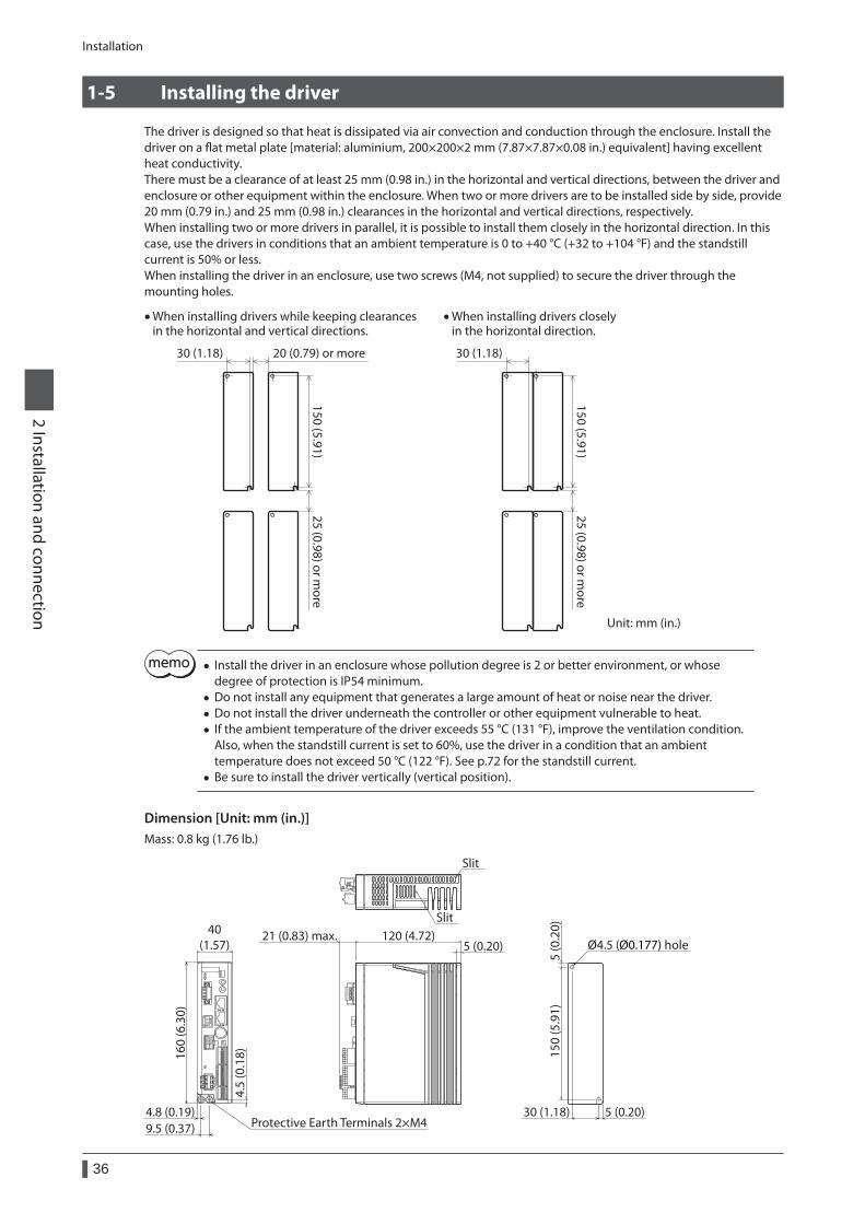
Installation
36
2 Installation and connection
1-5 Installing the driver
The driver is designed so that heat is dissipated via air convection and conduction through the enclosure. Install the driver on a flat metal plate [material: aluminium, 200×200×2 mm (7.87×7.87×0.08 in.) equivalent] having excellent heat conductivity.There must be a clearance of at least 25 mm (0.98 in.) in the horizontal and vertical directions, between the driver and enclosure or other equipment within the enclosure. When two or more drivers are to be installed side by side, provide 20 mm (0.79 in.) and 25 mm (0.98 in.) clearances in the horizontal and vertical directions, respectively.When installing two or more drivers in parallel, it is possible to install them closely in the horizontal direction. In this case, use the drivers in conditions that an ambient temperature is 0 to +40 °C (+32 to +104 °F) and the standstill current is 50% or less.When installing the driver in an enclosure, use two screws (M4, not supplied) to secure the driver through the mounting holes.
20 (0.79) or more
Unit: mm (in.)
150 (5.91)25 (0.98) or m
ore
30 (1.18)
25 (0.98) or more
• When installing drivers while keeping clearances in the horizontal and vertical directions.
150 (5.91)
30 (1.18)
• When installing drivers closely in the horizontal direction.
• Install the driver in an enclosure whose pollution degree is 2 or better environment, or whose degree of protection is IP54 minimum.
• Do not install any equipment that generates a large amount of heat or noise near the driver. • Do not install the driver underneath the controller or other equipment vulnerable to heat. • If the ambient temperature of the driver exceeds 55 °C (131 °F), improve the ventilation condition. Also, when the standstill current is set to 60%, use the driver in a condition that an ambient temperature does not exceed 50 °C (122 °F). See p.72 for the standstill current.
• Be sure to install the driver vertically (vertical position).
Dimension [Unit: mm (in.)]Mass: 0.8 kg (1.76 lb.)
40(1.57)
160
(6.3
0)
4.8 (0.19)9.5 (0.37)
4.5
(0.1
8)
21 (0.83) max. 120 (4.72)5 (0.20)
5 (0
.20)
5 (0.20)30 (1.18)
150
(5.9
1)
Protective Earth Terminals 2×M4
Slit
Ø4.5 (Ø0.177) hole
Slit
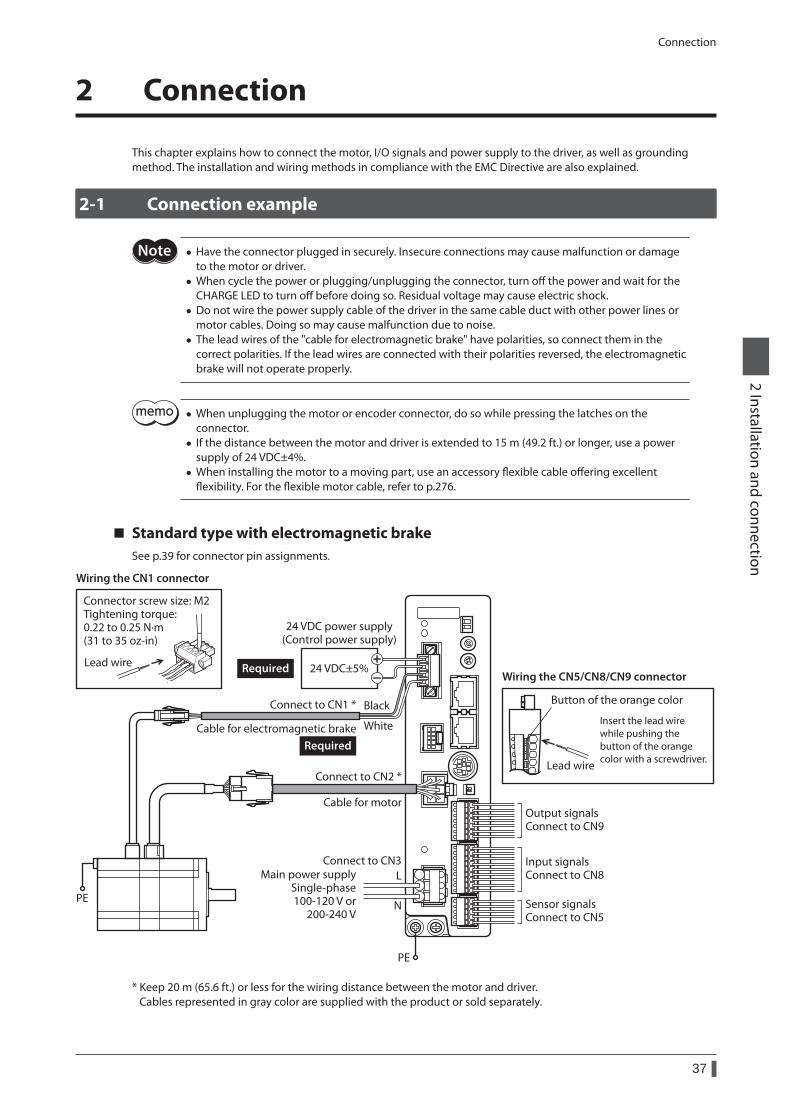
Connection
37
2 Installation and connection
2 Connection
This chapter explains how to connect the motor, I/O signals and power supply to the driver, as well as grounding method. The installation and wiring methods in compliance with the EMC Directive are also explained.
2-1 Connection example
• Have the connector plugged in securely. Insecure connections may cause malfunction or damage to the motor or driver.
• When cycle the power or plugging/unplugging the connector, turn off the power and wait for the CHARGE LED to turn off before doing so. Residual voltage may cause electric shock.
• Do not wire the power supply cable of the driver in the same cable duct with other power lines or motor cables. Doing so may cause malfunction due to noise.
• The lead wires of the "cable for electromagnetic brake" have polarities, so connect them in the correct polarities. If the lead wires are connected with their polarities reversed, the electromagnetic brake will not operate properly.
• When unplugging the motor or encoder connector, do so while pressing the latches on the connector.
• If the distance between the motor and driver is extended to 15 m (49.2 ft.) or longer, use a power supply of 24 VDC±4%.
• When installing the motor to a moving part, use an accessory flexible cable offering excellent flexibility. For the flexible motor cable, refer to p.276.
Standard type with electromagnetic brakeSee p.39 for connector pin assignments.
Black
White
L
N
PE
PE
Connect to CN3Main power supply
Single-phase100-120 V or
200-240 V
24 VDC±5%
24 VDC power supply(Control power supply)
Connect to CN2 *
Connect to CN1 *
Cable for electromagnetic brake
Cable for motorOutput signalsConnect to CN9
Input signalsConnect to CN8
Sensor signalsConnect to CN5
Wiring the CN1 connector
Lead wireWiring the CN5/CN8/CN9 connector
Button of the orange color
Lead wire
Insert the lead wire while pushing the button of the orange color with a screwdriver.
Connector screw size: M2Tightening torque:0.22 to 0.25 N·m(31 to 35 oz-in)
Required
Required
* Keep 20 m (65.6 ft.) or less for the wiring distance between the motor and driver. Cables represented in gray color are supplied with the product or sold separately.
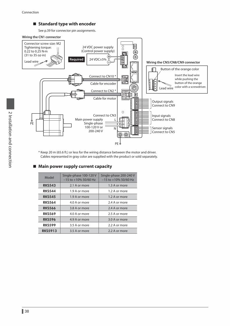
Connection
38
2 Installation and connection
Standard type with encoderSee p.39 for connector pin assignments.
L
N
Connect to CN3Main power supply
Single-phase100-120 V or
200-240 V
PE
PE
Connect to CN2 *
Connect to CN10 *
Cable for encoder
Cable for motorOutput signalsConnect to CN9
Input signalsConnect to CN8
Sensor signalsConnect to CN5
Wiring the CN1 connector
Lead wire Wiring the CN5/CN8/CN9 connector
Button of the orange color
Lead wire
Insert the lead wire while pushing the button of the orange color with a screwdriver.
Connector screw size: M2Tightening torque:0.22 to 0.25 N·m(31 to 35 oz-in)
24 VDC±5%
24 VDC power supply(Control power supply)
Required
* Keep 20 m (65.6 ft.) or less for the wiring distance between the motor and driver. Cables represented in gray color are supplied with the product or sold separately.
Main power supply current capacity
ModelSingle-phase 100-120 V −15 to +10% 50/60 Hz
Single-phase 200-240 V −15 to +10% 50/60 Hz
RKS543 2.1 A or more 1.3 A or more
RKS544 1.9 A or more 1.2 A or more
RKS545 1.9 A or more 1.2 A or more
RKS564 4.0 A or more 2.4 A or more
RKS566 3.8 A or more 2.4 A or more
RKS569 4.0 A or more 2.5 A or more
RKS596 4.9 A or more 3.0 A or more
RKS599 3.5 A or more 2.2 A or more
RKS5913 3.5 A or more 2.2 A or more
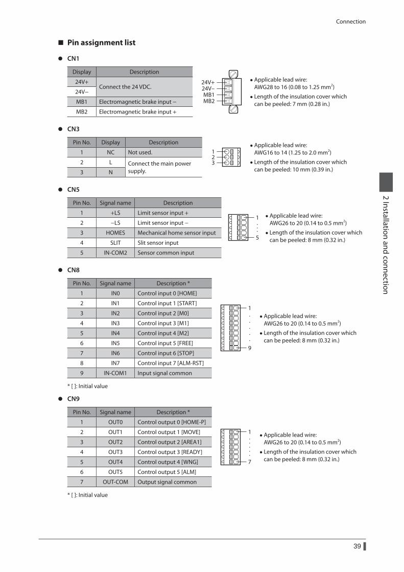
Connection
39
2 Installation and connection
Pin assignment list
z CN1
Display Description
24V+24V-MB1MB2
• Applicable lead wire: AWG28 to 16 (0.08 to 1.25 mm2)
• Length of the insulation cover which can be peeled: 7 mm (0.28 in.)
24V+Connect the 24 VDC.
24V−
MB1 Electromagnetic brake input −
MB2 Electromagnetic brake input +
z CN3
Pin No. Display Description
123
• Applicable lead wire: AWG16 to 14 (1.25 to 2.0 mm2)
• Length of the insulation cover which can be peeled: 10 mm (0.39 in.)
1 NC Not used.
2 L Connect the main power supply.3 N
z CN5
Pin No. Signal name Description
1
5
···
• Applicable lead wire: AWG26 to 20 (0.14 to 0.5 mm2)
• Length of the insulation cover which can be peeled: 8 mm (0.32 in.)
1 +LS Limit sensor input +
2 −LS Limit sensor input −
3 HOMES Mechanical home sensor input
4 SLIT Slit sensor input
5 IN-COM2 Sensor common input
z CN8
Pin No. Signal name Description *
1
9
·····
• Applicable lead wire: AWG26 to 20 (0.14 to 0.5 mm2)
• Length of the insulation cover which can be peeled: 8 mm (0.32 in.)
1 IN0 Control input 0 [HOME]
2 IN1 Control input 1 [START]
3 IN2 Control input 2 [M0]
4 IN3 Control input 3 [M1]
5 IN4 Control input 4 [M2]
6 IN5 Control input 5 [FREE]
7 IN6 Control input 6 [STOP]
8 IN7 Control input 7 [ALM-RST]
9 IN-COM1 Input signal common
* [ ]: Initial value
z CN9
Pin No. Signal name Description *
1
7
·····
• Applicable lead wire: AWG26 to 20 (0.14 to 0.5 mm2)
• Length of the insulation cover which can be peeled: 8 mm (0.32 in.)
1 OUT0 Control output 0 [HOME-P]
2 OUT1 Control output 1 [MOVE]
3 OUT2 Control output 2 [AREA1]
4 OUT3 Control output 3 [READY]
5 OUT4 Control output 4 [WNG]
6 OUT5 Control output 5 [ALM]
7 OUT-COM Output signal common
* [ ]: Initial value
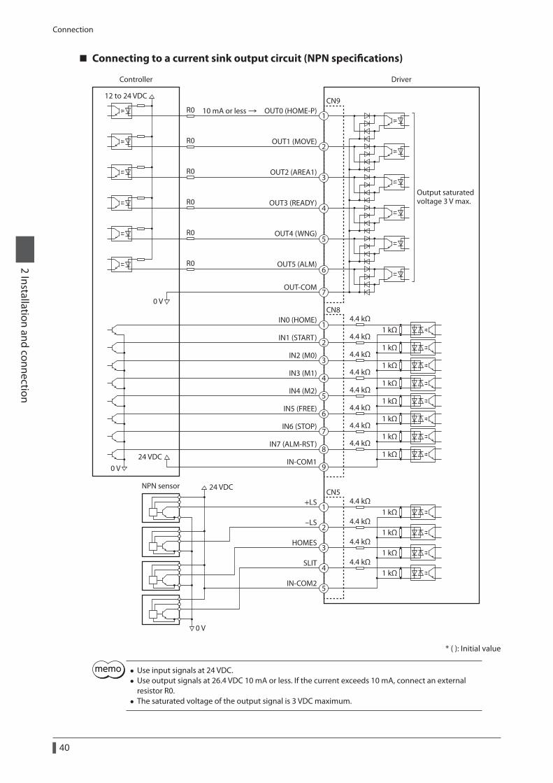
Connection
40
2 Installation and connection
Connecting to a current sink output circuit (NPN specifications)
DriverController
24 VDC
12 to 24 VDC
Output saturatedvoltage 3 V max.
OUT0 (HOME-P)CN9
1
2
3
4
5
6
7
1
2
3
4
5
6
7
8
9
1
2
3
4
5
IN0 (HOME)
IN1 (START)
IN2 (M0)
IN3 (M1)
IN4 (M2)
IN-COM1
IN7 (ALM-RST)
IN6 (STOP)
IN5 (FREE)
CN8
+LS
-LS
HOMES
SLIT
IN-COM2
CN5
OUT1 (MOVE)
OUT2 (AREA1)
OUT3 (READY)
OUT4 (WNG)
OUT5 (ALM)
OUT-COM
4.4 kΩ
4.4 kΩ1 kΩ
1 kΩ
1 kΩ
1 kΩ
1 kΩ
1 kΩ
1 kΩ
1 kΩ
4.4 kΩ
4.4 kΩ
4.4 kΩ
4.4 kΩ
4.4 kΩ
4.4 kΩ
1 kΩ
1 kΩ
1 kΩ
1 kΩ
4.4 kΩ
4.4 kΩ
4.4 kΩ
4.4 kΩ
R0
R0
R0
R0
R0
R0
24 VDC
0 V
0 V
0 V
NPN sensor
10 mA or less
* ( ): Initial value
• Use input signals at 24 VDC. • Use output signals at 26.4 VDC 10 mA or less. If the current exceeds 10 mA, connect an external resistor R0.
• The saturated voltage of the output signal is 3 VDC maximum.
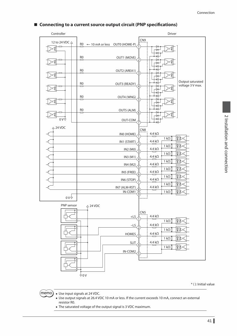
Connection
41
2 Installation and connection
Connecting to a current source output circuit (PNP specifications)
DriverController
24 VDC
12 to 24 VDC
Output saturatedvoltage 3 V max.
OUT0 (HOME-P)CN9
IN0 (HOME)
IN1 (START)
IN2 (M0)
IN3 (M1)
IN4 (M2)
IN-COM1IN7 (ALM-RST)
IN6 (STOP)
IN5 (FREE)
CN8
+LS
-LS
HOMES
SLIT
IN-COM2
CN5
OUT1 (MOVE)
OUT2 (AREA1)
OUT3 (READY)
OUT4 (WNG)
OUT5 (ALM)
OUT-COM
4.4 kΩ
4.4 kΩ1 kΩ
1 kΩ
1 kΩ
1 kΩ
1 kΩ
1 kΩ
1 kΩ
1 kΩ
4.4 kΩ
4.4 kΩ
4.4 kΩ
4.4 kΩ
4.4 kΩ
4.4 kΩ
1 kΩ
1 kΩ
1 kΩ
1 kΩ
4.4 kΩ
4.4 kΩ
4.4 kΩ
4.4 kΩ
R0
R0
R0
R0
R0
R0
24 VDC
0 V
0 V
0 V
PNP sensor
10 mA or less1
2
3
4
5
6
7
1
2
3
4
5
6
7
89
1
2
3
4
5
* ( ): Initial value
• Use input signals at 24 VDC. • Use output signals at 26.4 VDC 10 mA or less. If the current exceeds 10 mA, connect an external resistor R0.
• The saturated voltage of the output signal is 3 VDC maximum.
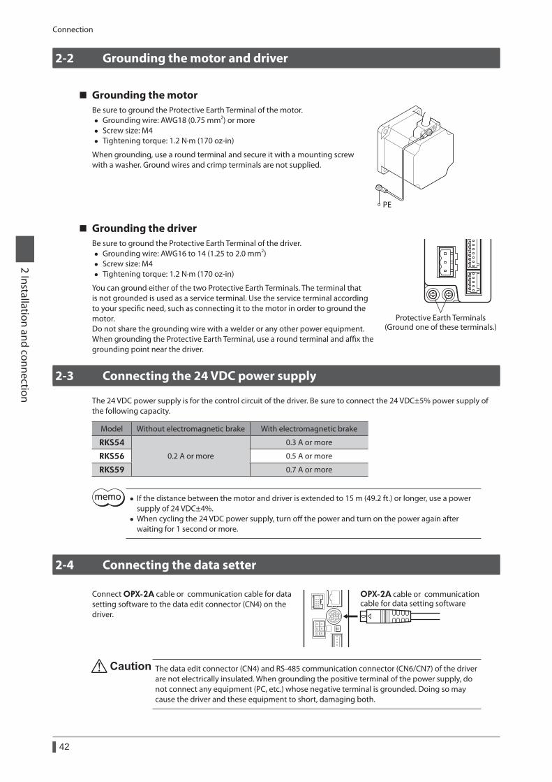
Connection
42
2 Installation and connection
2-2 Grounding the motor and driver
Grounding the motorBe sure to ground the Protective Earth Terminal of the motor.
• Grounding wire: AWG18 (0.75 mm2) or more • Screw size: M4 • Tightening torque: 1.2 N·m (170 oz-in)
When grounding, use a round terminal and secure it with a mounting screw with a washer. Ground wires and crimp terminals are not supplied.
PE
Grounding the driverBe sure to ground the Protective Earth Terminal of the driver.
• Grounding wire: AWG16 to 14 (1.25 to 2.0 mm2) • Screw size: M4 • Tightening torque: 1.2 N·m (170 oz-in)
You can ground either of the two Protective Earth Terminals. The terminal that is not grounded is used as a service terminal. Use the service terminal according to your specific need, such as connecting it to the motor in order to ground the motor. Do not share the grounding wire with a welder or any other power equipment. When grounding the Protective Earth Terminal, use a round terminal and affix the grounding point near the driver.
Protective Earth Terminals(Ground one of these terminals.)
2-3 Connecting the 24 VDC power supply
The 24 VDC power supply is for the control circuit of the driver. Be sure to connect the 24 VDC±5% power supply of the following capacity.
Model Without electromagnetic brake With electromagnetic brake
RKS54
0.2 A or more
0.3 A or more
RKS56 0.5 A or more
RKS59 0.7 A or more
• If the distance between the motor and driver is extended to 15 m (49.2 ft.) or longer, use a power supply of 24 VDC±4%.
• When cycling the 24 VDC power supply, turn off the power and turn on the power again after waiting for 1 second or more.
2-4 Connecting the data setter
Connect OPX-2A cable or communication cable for data setting software to the data edit connector (CN4) on the driver.
OPX-2A cable or communication cable for data setting software
The data edit connector (CN4) and RS-485 communication connector (CN6/CN7) of the driver are not electrically insulated. When grounding the positive terminal of the power supply, do not connect any equipment (PC, etc.) whose negative terminal is grounded. Doing so may cause the driver and these equipment to short, damaging both.
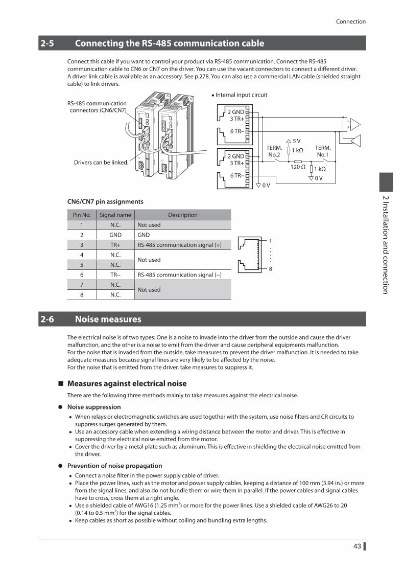
Connection
43
2 Installation and connection
2-5 Connecting the RS-485 communication cable
Connect this cable if you want to control your product via RS-485 communication. Connect the RS-485 communication cable to CN6 or CN7 on the driver. You can use the vacant connectors to connect a different driver. A driver link cable is available as an accessory. See p.278. You can also use a commercial LAN cable (shielded straight cable) to link drivers.
RS-485 communicationconnectors (CN6/CN7)
Drivers can be linked.
• Internal input circuit
2 GND3 TR+
6 TR-
2 GND3 TR+
6 TR-120 Ω
1 kΩ
1 kΩ
5 V
0 V0 V
TERM.No.2
TERM.No.1
CN6/CN7 pin assignments
Pin No. Signal name Description
1
8
·····
1 N.C. Not used
2 GND GND
3 TR+ RS-485 communication signal (+)
4 N.C.Not used
5 N.C.
6 TR− RS-485 communication signal (−)
7 N.C.Not used
8 N.C.
2-6 Noise measures
The electrical noise is of two types: One is a noise to invade into the driver from the outside and cause the driver malfunction, and the other is a noise to emit from the driver and cause peripheral equipments malfunction.For the noise that is invaded from the outside, take measures to prevent the driver malfunction. It is needed to take adequate measures because signal lines are very likely to be affected by the noise.For the noise that is emitted from the driver, take measures to suppress it.
Measures against electrical noiseThere are the following three methods mainly to take measures against the electrical noise.
z Noise suppression • When relays or electromagnetic switches are used together with the system, use noise filters and CR circuits to
suppress surges generated by them. • Use an accessory cable when extending a wiring distance between the motor and driver. This is effective in
suppressing the electrical noise emitted from the motor. • Cover the driver by a metal plate such as aluminum. This is effective in shielding the electrical noise emitted from
the driver.
z Prevention of noise propagation • Connect a noise filter in the power supply cable of driver. • Place the power lines, such as the motor and power supply cables, keeping a distance of 100 mm (3.94 in.) or more
from the signal lines, and also do not bundle them or wire them in parallel. If the power cables and signal cables have to cross, cross them at a right angle.
• Use a shielded cable of AWG16 (1.25 mm2) or more for the power lines. Use a shielded cable of AWG26 to 20 (0.14 to 0.5 mm2) for the signal cables.
• Keep cables as short as possible without coiling and bundling extra lengths.
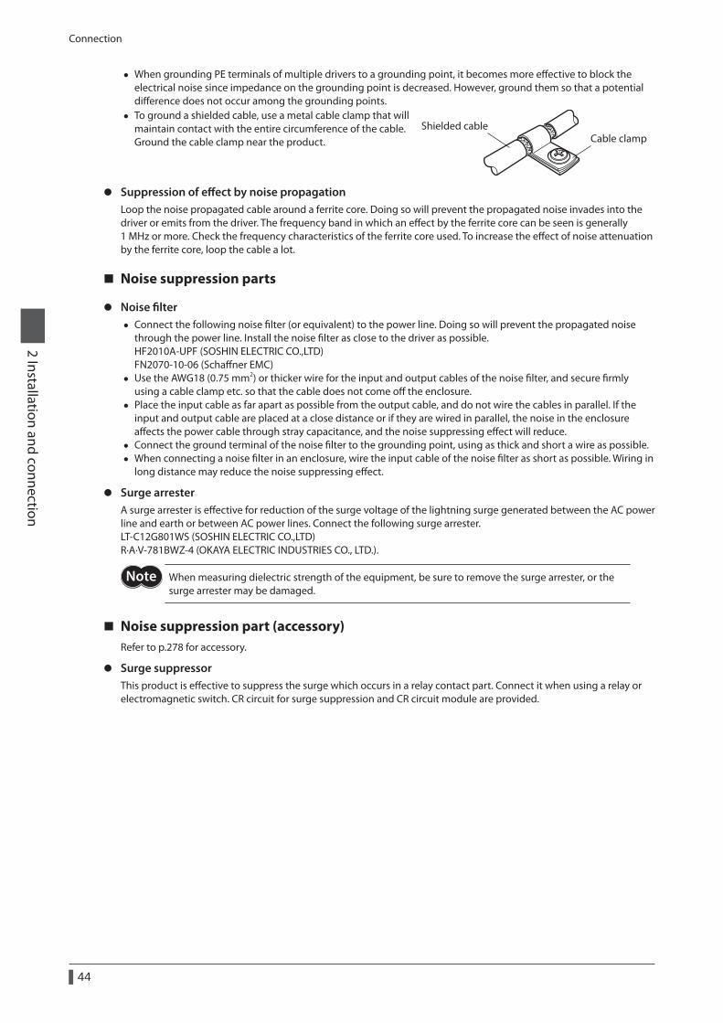
Connection
44
2 Installation and connection
• When grounding PE terminals of multiple drivers to a grounding point, it becomes more effective to block the electrical noise since impedance on the grounding point is decreased. However, ground them so that a potential difference does not occur among the grounding points.
• To ground a shielded cable, use a metal cable clamp that will maintain contact with the entire circumference of the cable. Ground the cable clamp near the product. Cable clamp
Shielded cable
z Suppression of effect by noise propagationLoop the noise propagated cable around a ferrite core. Doing so will prevent the propagated noise invades into the driver or emits from the driver. The frequency band in which an effect by the ferrite core can be seen is generally 1 MHz or more. Check the frequency characteristics of the ferrite core used. To increase the effect of noise attenuation by the ferrite core, loop the cable a lot.
Noise suppression parts
z Noise filter • Connect the following noise filter (or equivalent) to the power line. Doing so will prevent the propagated noise
through the power line. Install the noise filter as close to the driver as possible. HF2010A-UPF (SOSHIN ELECTRIC CO.,LTD) FN2070-10-06 (Schaffner EMC)
• Use the AWG18 (0.75 mm2) or thicker wire for the input and output cables of the noise filter, and secure firmly using a cable clamp etc. so that the cable does not come off the enclosure.
• Place the input cable as far apart as possible from the output cable, and do not wire the cables in parallel. If the input and output cable are placed at a close distance or if they are wired in parallel, the noise in the enclosure affects the power cable through stray capacitance, and the noise suppressing effect will reduce.
• Connect the ground terminal of the noise filter to the grounding point, using as thick and short a wire as possible. • When connecting a noise filter in an enclosure, wire the input cable of the noise filter as short as possible. Wiring in
long distance may reduce the noise suppressing effect.
z Surge arresterA surge arrester is effective for reduction of the surge voltage of the lightning surge generated between the AC power line and earth or between AC power lines. Connect the following surge arrester.LT-C12G801WS (SOSHIN ELECTRIC CO.,LTD)R·A·V-781BWZ-4 (OKAYA ELECTRIC INDUSTRIES CO., LTD.).
When measuring dielectric strength of the equipment, be sure to remove the surge arrester, or the surge arrester may be damaged.
Noise suppression part (accessory)Refer to p.278 for accessory.
z Surge suppressorThis product is effective to suppress the surge which occurs in a relay contact part. Connect it when using a relay or electromagnetic switch. CR circuit for surge suppression and CR circuit module are provided.
Connection
45
2 Installation and connection
2-7 Conformity to the EMC Directive
Effective measures must be taken against the EMI that the motor and driver may give to adjacent control-system equipment, as well as the EMS of the motor and driver itself, in order to prevent a serious functional impediment in the machinery. The use of the following installation and wiring methods will enable the motor and driver to be compliant with the EMC directive. Refer to p.20 for the applicable standards.Oriental Motor conducts EMC measurements on its motors and drivers in accordance with "Example of motor and driver installation and wiring". The user is responsible for ensuring the machine's compliance with the EMC Directive, based on the installation and wiring explained below.
Connecting noise filterIn large electrically noisy environments, connect a noise filter. Refer to p.44 for details.
Connecting surge arresterRefer to p.44.
Connecting the AC power line reactorWhen inputting single-phase 240 V, insert a reactor (5 A, 5 mH) in the AC power line to ensure compliance with EN 61000-3-2.
Connecting the 24 VDC power supplyUse a DC power supply compliant with the EMC Directive. Use a shielded cable for wiring. Refer to "Prevention of noise propagation" on p.43 for wire the shielded cable.
Connecting the motor cableUse an accessory cable when extending the wiring distance between the motor and driver
Connecting the signal cableRefer to "Prevention of noise propagation" on p.43.
How to ground • The cable used to ground the motor, driver and noise filter must be as thick and short as possible so that no
potential difference is generated. • Choose a large, thick and uniformly conductive surface for the grounding point. • Be sure to ground the Protective Earth Terminal of the motor and driver. Refer to p.42 for grounding method.
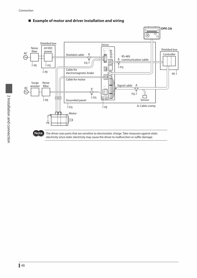
Connection
46
2 Installation and connection
Example of motor and driver installation and wiring
Sensor
Motor
Driver
Cable for motor
Cable for electromagnetic brake
Shielded box
Grounded panel
FG PE
PE
Shielded cable
Noiselter
24 VDCpower
Shielded boxAC
FGFGPE
PE PE
A
FG
A
Controller
A: Cable cramp
RS-485 communication cable
OPX-2A
Surgearrester
Noiselter
AC
FG
FG
PE
A
A
Signal cable
The driver uses parts that are sensitive to electrostatic charge. Take measures against static electricity since static electricity may cause the driver to malfunction or suffer damage.
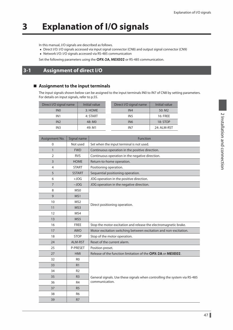
Explanation of I/O signals
47
2 Installation and connection
3 Explanation of I/O signals
In this manual, I/O signals are described as follows. • Direct I/O: I/O signals accessed via input signal connector (CN8) and output signal connector (CN9) • Network I/O: I/O signals accessed via RS-485 communication
Set the following parameters using the OPX-2A, MEXE02 or RS-485 communication.
3-1 Assignment of direct I/O
Assignment to the input terminalsThe input signals shown below can be assigned to the input terminals IN0 to IN7 of CN8 by setting parameters.For details on input signals, refer to p.55.
Direct I/O signal name Initial value Direct I/O signal name Initial value
IN0 3: HOME IN4 50: M2
IN1 4: START IN5 16: FREE
IN2 48: M0 IN6 18: STOP
IN3 49: M1 IN7 24: ALM-RST
Assignment No. Signal name Function
0 Not used Set when the input terminal is not used.
1 FWD Continuous operation in the positive direction.
2 RVS Continuous operation in the negative direction.
3 HOME Return-to-home operation.
4 START Positioning operation.
5 SSTART Sequential positioning operation.
6 +JOG JOG operation in the positive direction.
7 −JOG JOG operation in the negative direction.
8 MS0
Direct positioning operation.
9 MS1
10 MS2
11 MS3
12 MS4
13 MS5
16 FREE Stop the motor excitation and release the electromagnetic brake.
17 AWO Motor excitation switching between excitation and non-excitation.
18 STOP Stop of the motor operation.
24 ALM-RST Reset of the current alarm.
25 P-PRESET Position preset.
27 HMI Release of the function limitation of the OPX-2A or MEXE02.
32 R0
General signals. Use these signals when controlling the system via RS-485 communication.
33 R1
34 R2
35 R3
36 R4
37 R5
38 R6
39 R7
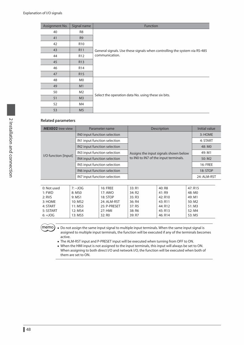
Explanation of I/O signals
48
2 Installation and connection
Assignment No. Signal name Function
40 R8
General signals. Use these signals when controlling the system via RS-485 communication.
41 R9
42 R10
43 R11
44 R12
45 R13
46 R14
47 R15
48 M0
Select the operation data No. using these six bits.
49 M1
50 M2
51 M3
52 M4
53 M5
Related parameters
MEXE02 tree view Parameter name Description Initial value
I/O function [Input]
IN0 input function selection
Assigns the input signals shown below to IN0 to IN7 of the input terminals.
3: HOME
IN1 input function selection 4: START
IN2 input function selection 48: M0
IN3 input function selection 49: M1
IN4 input function selection 50: M2
IN5 input function selection 16: FREE
IN6 input function selection 18: STOP
IN7 input function selection 24: ALM-RST
0: Not used 1: FWD 2: RVS 3: HOME 4: START 5: SSTART 6: +JOG
7: −JOG 8: MS0 9: MS1 10: MS2 11: MS3 12: MS4 13: MS5
16: FREE 17: AWO 18: STOP 24: ALM-RST 25: P-PRESET 27: HMI 32: R0
33: R1 34: R2 35: R3 36: R4 37: R5 38: R6 39: R7
40: R8 41: R9 42: R10 43: R11 44: R12 45: R13 46: R14
47: R15 48: M0 49: M1 50: M2 51: M3 52: M4 53: M5
• Do not assign the same input signal to multiple input terminals. When the same input signal is assigned to multiple input terminals, the function will be executed if any of the terminals becomes active.
• The ALM-RST input and P-PRESET input will be executed when turning from OFF to ON. • When the HMI input is not assigned to the input terminals, this input will always be set to ON. When assigning to both direct I/O and network I/O, the function will be executed when both of them are set to ON.
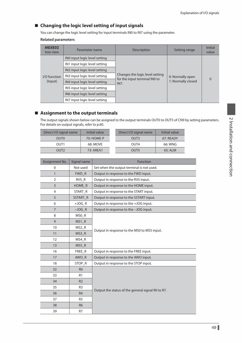
Explanation of I/O signals
49
2 Installation and connection
Changing the logic level setting of input signalsYou can change the logic level setting for input terminals IN0 to IN7 using the parameter.
Related parameters
MEXE02 tree view
Parameter name Description Setting rangeInitial value
I/O function [Input]
IN0 input logic level setting
Changes the logic level setting for the input terminal IN0 to IN7.
0: Normally open 1: Normally closed
0
IN1 input logic level setting
IN2 input logic level setting
IN3 input logic level setting
IN4 input logic level setting
IN5 input logic level setting
IN6 input logic level setting
IN7 input logic level setting
Assignment to the output terminalsThe output signals shown below can be assigned to the output terminals OUT0 to OUT5 of CN9 by setting parameters. For details on output signals, refer to p.60.
Direct I/O signal name Initial value Direct I/O signal name Initial value
OUT0 70: HOME-P OUT3 67: READY
OUT1 68: MOVE OUT4 66: WNG
OUT2 73: AREA1 OUT5 65: ALM
Assignment No. Signal name Function
0 Not used Set when the output terminal is not used.
1 FWD_R Output in response to the FWD input.
2 RVS_R Output in response to the RVS input.
3 HOME_R Output in response to the HOME input.
4 START_R Output in response to the START input.
5 SSTART_R Output in response to the SSTART input.
6 +JOG_R Output in response to the +JOG input.
7 −JOG_R Output in response to the −JOG input.
8 MS0_R
Output in response to the MS0 to MS5 input.
9 MS1_R
10 MS2_R
11 MS3_R
12 MS4_R
13 MS5_R
16 FREE_R Output in response to the FREE input.
17 AWO_R Output in response to the AWO input.
18 STOP_R Output in response to the STOP input.
32 R0
Output the status of the general signal R0 to R7.
33 R1
34 R2
35 R3
36 R4
37 R5
38 R6
39 R7
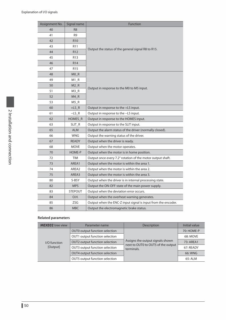
Explanation of I/O signals
50
2 Installation and connection
Assignment No. Signal name Function
40 R8
Output the status of the general signal R8 to R15.
41 R9
42 R10
43 R11
44 R12
45 R13
46 R14
47 R15
48 M0_R
Output in response to the M0 to M5 input.
49 M1_R
50 M2_R
51 M3_R
52 M4_R
53 M5_R
60 +LS_R Output in response to the +LS input.
61 −LS_R Output in response to the −LS input.
62 HOMES_R Output in response to the HOMES input.
63 SLIT_R Output in response to the SLIT input.
65 ALM Output the alarm status of the driver (normally closed).
66 WNG Output the warning status of the driver.
67 READY Output when the driver is ready.
68 MOVE Output when the motor operates.
70 HOME-P Output when the motor is in home position.
72 TIM Output once every 7.2° rotation of the motor output shaft.
73 AREA1 Output when the motor is within the area 1.
74 AREA2 Output when the motor is within the area 2.
75 AREA3 Output when the motor is within the area 3.
80 S-BSY Output when the driver is in internal processing state.
82 MPS Output the ON-OFF state of the main power supply.
83 STEPOUT Output when the deviation error occurs.
84 O.H. Output when the overheat warning generates.
85 ZSG Output when the ENC-Z input signal is input from the encoder.
86 MBC Output the electromagnetic brake status.
Related parameters
MEXE02 tree view Parameter name Description Initial value
I/O function [Output]
OUT0 output function selection
Assigns the output signals shown next to OUT0 to OUT5 of the output terminals.
70: HOME-P
OUT1 output function selection 68: MOVE
OUT2 output function selection 73: AREA1
OUT3 output function selection 67: READY
OUT4 output function selection 66: WNG
OUT5 output function selection 65: ALM
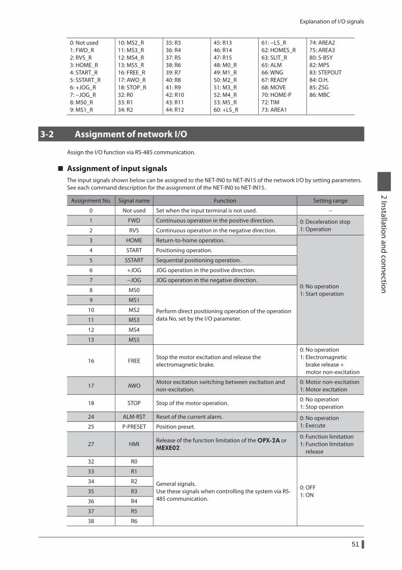
Explanation of I/O signals
51
2 Installation and connection
0: Not used 1: FWD_R 2: RVS_R 3: HOME_R 4: START_R 5: SSTART_R 6: +JOG_R 7: −JOG_R 8: MS0_R 9: MS1_R
10: MS2_R 11: MS3_R 12: MS4_R 13: MS5_R 16: FREE_R 17: AWO_R 18: STOP_R 32: R0 33: R1 34: R2
35: R3 36: R4 37: R5 38: R6 39: R7 40: R8 41: R9 42: R10 43: R11 44: R12
45: R13 46: R14 47: R15 48: M0_R 49: M1_R 50: M2_R 51: M3_R 52: M4_R 53: M5_R 60: +LS_R
61: −LS_R 62: HOMES_R 63: SLIT_R 65: ALM 66: WNG 67: READY 68: MOVE 70: HOME-P 72: TIM 73: AREA1
74: AREA2 75: AREA3 80: S-BSY 82: MPS 83: STEPOUT 84: O.H. 85: ZSG 86: MBC
3-2 Assignment of network I/O
Assign the I/O function via RS-485 communication.
Assignment of input signalsThe input signals shown below can be assigned to the NET-IN0 to NET-IN15 of the network I/O by setting parameters. See each command description for the assignment of the NET-IN0 to NET-IN15.
Assignment No. Signal name Function Setting range
0 Not used Set when the input terminal is not used. −
1 FWD Continuous operation in the positive direction. 0: Deceleration stop 1: Operation2 RVS Continuous operation in the negative direction.
3 HOME Return-to-home operation.
0: No operation 1: Start operation
4 START Positioning operation.
5 SSTART Sequential positioning operation.
6 +JOG JOG operation in the positive direction.
7 −JOG JOG operation in the negative direction.
8 MS0
Perform direct positioning operation of the operation data No. set by the I/O parameter.
9 MS1
10 MS2
11 MS3
12 MS4
13 MS5
16 FREEStop the motor excitation and release the electromagnetic brake.
0: No operation 1: Electromagnetic brake release + motor non-excitation
17 AWOMotor excitation switching between excitation and non-excitation.
0: Motor non-excitation 1: Motor excitation
18 STOP Stop of the motor operation.0: No operation 1: Stop operation
24 ALM-RST Reset of the current alarm. 0: No operation 1: Execute25 P-PRESET Position preset.
27 HMIRelease of the function limitation of the OPX-2A or MEXE02.
0: Function limitation 1: Function limitation release
32 R0
General signals. Use these signals when controlling the system via RS-485 communication.
0: OFF 1: ON
33 R1
34 R2
35 R3
36 R4
37 R5
38 R6
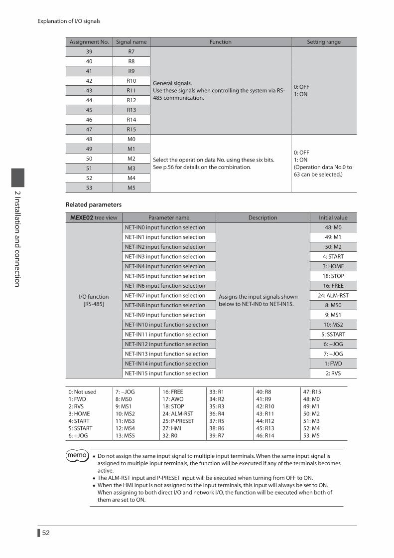
Explanation of I/O signals
52
2 Installation and connection
Assignment No. Signal name Function Setting range
39 R7
General signals. Use these signals when controlling the system via RS-485 communication.
0: OFF 1: ON
40 R8
41 R9
42 R10
43 R11
44 R12
45 R13
46 R14
47 R15
48 M0
Select the operation data No. using these six bits. See p.56 for details on the combination.
0: OFF 1: ON (Operation data No.0 to 63 can be selected.)
49 M1
50 M2
51 M3
52 M4
53 M5
Related parameters
MEXE02 tree view Parameter name Description Initial value
I/O function [RS-485]
NET-IN0 input function selection
Assigns the input signals shown below to NET-IN0 to NET-IN15.
48: M0
NET-IN1 input function selection 49: M1
NET-IN2 input function selection 50: M2
NET-IN3 input function selection 4: START
NET-IN4 input function selection 3: HOME
NET-IN5 input function selection 18: STOP
NET-IN6 input function selection 16: FREE
NET-IN7 input function selection 24: ALM-RST
NET-IN8 input function selection 8: MS0
NET-IN9 input function selection 9: MS1
NET-IN10 input function selection 10: MS2
NET-IN11 input function selection 5: SSTART
NET-IN12 input function selection 6: +JOG
NET-IN13 input function selection 7: −JOG
NET-IN14 input function selection 1: FWD
NET-IN15 input function selection 2: RVS
0: Not used 1: FWD 2: RVS 3: HOME 4: START 5: SSTART 6: +JOG
7: −JOG 8: MS0 9: MS1 10: MS2 11: MS3 12: MS4 13: MS5
16: FREE 17: AWO 18: STOP 24: ALM-RST 25: P-PRESET 27: HMI 32: R0
33: R1 34: R2 35: R3 36: R4 37: R5 38: R6 39: R7
40: R8 41: R9 42: R10 43: R11 44: R12 45: R13 46: R14
47: R15 48: M0 49: M1 50: M2 51: M3 52: M4 53: M5
• Do not assign the same input signal to multiple input terminals. When the same input signal is assigned to multiple input terminals, the function will be executed if any of the terminals becomes active.
• The ALM-RST input and P-PRESET input will be executed when turning from OFF to ON. • When the HMI input is not assigned to the input terminals, this input will always be set to ON. When assigning to both direct I/O and network I/O, the function will be executed when both of them are set to ON.
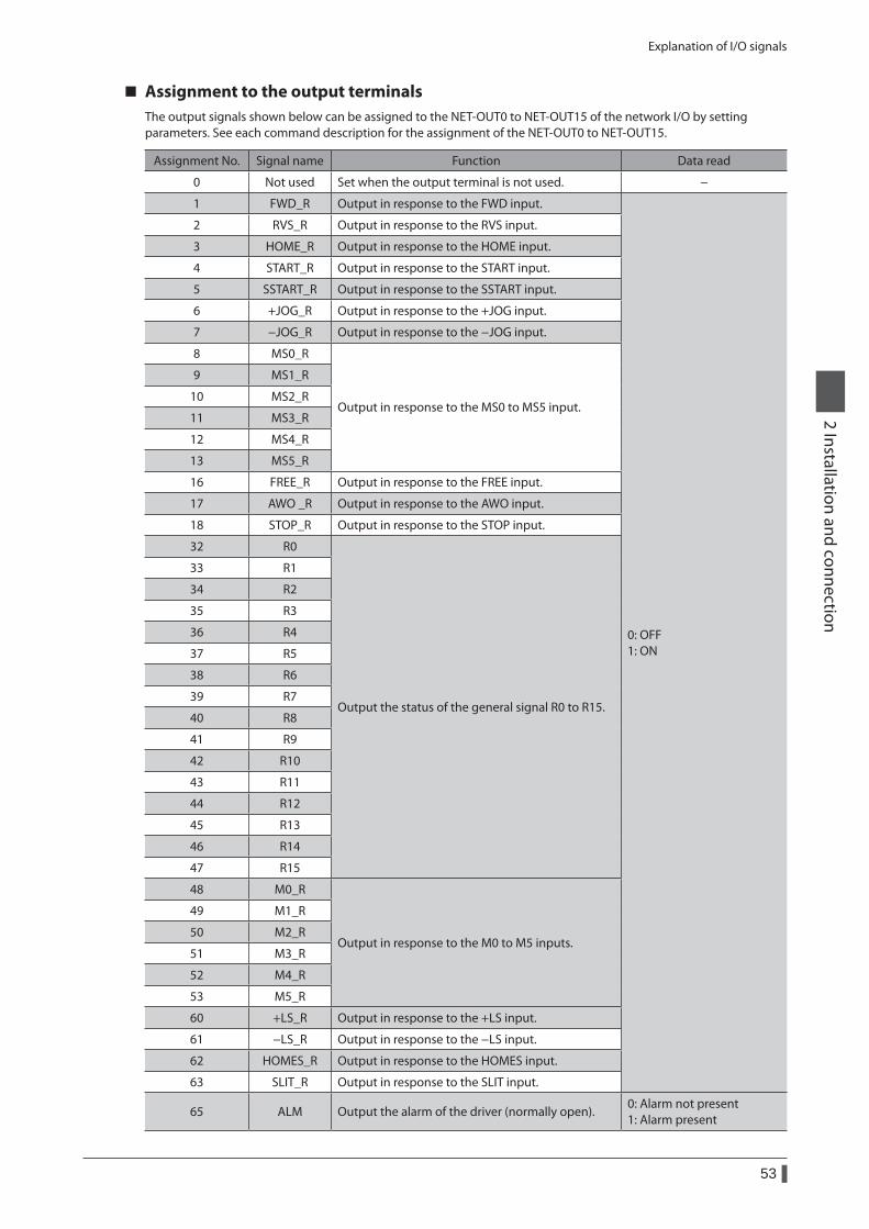
Explanation of I/O signals
53
2 Installation and connection
Assignment to the output terminalsThe output signals shown below can be assigned to the NET-OUT0 to NET-OUT15 of the network I/O by setting parameters. See each command description for the assignment of the NET-OUT0 to NET-OUT15.
Assignment No. Signal name Function Data read
0 Not used Set when the output terminal is not used. −
1 FWD_R Output in response to the FWD input.
0: OFF 1: ON
2 RVS_R Output in response to the RVS input.
3 HOME_R Output in response to the HOME input.
4 START_R Output in response to the START input.
5 SSTART_R Output in response to the SSTART input.
6 +JOG_R Output in response to the +JOG input.
7 −JOG_R Output in response to the −JOG input.
8 MS0_R
Output in response to the MS0 to MS5 input.
9 MS1_R
10 MS2_R
11 MS3_R
12 MS4_R
13 MS5_R
16 FREE_R Output in response to the FREE input.
17 AWO _R Output in response to the AWO input.
18 STOP_R Output in response to the STOP input.
32 R0
Output the status of the general signal R0 to R15.
33 R1
34 R2
35 R3
36 R4
37 R5
38 R6
39 R7
40 R8
41 R9
42 R10
43 R11
44 R12
45 R13
46 R14
47 R15
48 M0_R
Output in response to the M0 to M5 inputs.
49 M1_R
50 M2_R
51 M3_R
52 M4_R
53 M5_R
60 +LS_R Output in response to the +LS input.
61 −LS_R Output in response to the −LS input.
62 HOMES_R Output in response to the HOMES input.
63 SLIT_R Output in response to the SLIT input.
65 ALM Output the alarm of the driver (normally open).0: Alarm not present 1: Alarm present
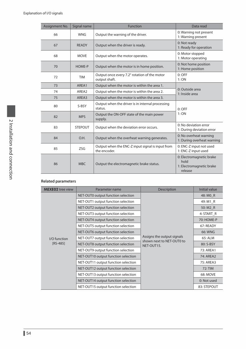
Explanation of I/O signals
54
2 Installation and connection
Assignment No. Signal name Function Data read
66 WNG Output the warning of the driver.0: Warning not present 1: Warning present
67 READY Output when the driver is ready.0: Not ready 1: Ready for operation
68 MOVE Output when the motor operates.0: Motor stopped 1: Motor operating
70 HOME-P Output when the motor is in home position.0: Not home position 1: Home position
72 TIMOutput once every 7.2° rotation of the motor output shaft.
0: OFF 1: ON
73 AREA1 Output when the motor is within the area 1.0: Outside area 1: Inside area
74 AREA2 Output when the motor is within the area 2.
75 AREA3 Output when the motor is within the area 3.
80 S-BSYOutput when the driver is in internal processing status. 0: OFF
1: ON82 MPS
Output the ON-OFF state of the main power supply.
83 STEPOUT Output when the deviation error occurs.0: No deviation error 1: During deviation error
84 O.H. Output when the overheat warning generates.0: No overheat warning 1: During overheat warning
85 ZSGOutput when the ENC-Z input signal is input from the encoder.
0: ENC-Z input not used 1: ENC-Z input used
86 MBC Output the electromagnetic brake status.
0: Electromagnetic brake hold 1: Electromagnetic brake release
Related parameters
MEXE02 tree view Parameter name Description Initial value
I/O function [RS-485]
NET-OUT0 output function selection
Assigns the output signals shown next to NET-OUT0 to NET-OUT15.
48: M0_R
NET-OUT1 output function selection 49: M1_R
NET-OUT2 output function selection 50: M2_R
NET-OUT3 output function selection 4: START_R
NET-OUT4 output function selection 70: HOME-P
NET-OUT5 output function selection 67: READY
NET-OUT6 output function selection 66: WNG
NET-OUT7 output function selection 65: ALM
NET-OUT8 output function selection 80: S-BSY
NET-OUT9 output function selection 73: AREA1
NET-OUT10 output function selection 74: AREA2
NET-OUT11 output function selection 75: AREA3
NET-OUT12 output function selection 72: TIM
NET-OUT13 output function selection 68: MOVE
NET-OUT14 output function selection 0: Not used
NET-OUT15 output function selection 83: STEPOUT
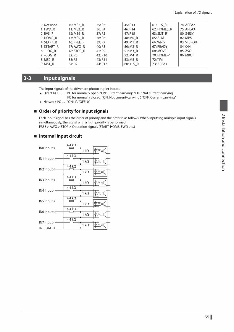
Explanation of I/O signals
55
2 Installation and connection
0: Not used 1: FWD_R 2: RVS_R 3: HOME_R 4: START_R 5: SSTART_R 6: +JOG_R 7: −JOG_R 8: MS0_R 9: MS1_R
10: MS2_R 11: MS3_R 12: MS4_R 13: MS5_R 16: FREE_R 17: AWO_R 18: STOP_R 32: R0 33: R1 34: R2
35: R3 36: R4 37: R5 38: R6 39: R7 40: R8 41: R9 42: R10 43: R11 44: R12
45: R13 46: R14 47: R15 48: M0_R 49: M1_R 50: M2_R 51: M3_R 52: M4_R 53: M5_R 60: +LS_R
61: −LS_R 62: HOMES_R 63: SLIT_R 65: ALM 66: WNG 67: READY 68: MOVE 70: HOME-P 72: TIM 73: AREA1
74: AREA2 75: AREA3 80: S-BSY 82: MPS 83: STEPOUT 84: O.H. 85: ZSG 86: MBC
3-3 Input signals
The input signals of the driver are photocoupler inputs. • Direct I/O ........... I/O for normally open: "ON: Current-carrying", "OFF: Not current-carrying"
I/O for normally closed: "ON: Not current-carrying", "OFF: Current-carrying" • Network I/O ...... "ON: 1", "OFF: 0"
Order of priority for input signalsEach input signal has the order of priority and the order is as follows. When inputting multiple input signals simultaneously, the signal with a high priority is performed.FREE > AWO > STOP > Operation signals (START, HOME, FWD etc.)
Internal input circuit
IN0 input
IN-COM1
4.4 kΩ
1 kΩ
IN1 input4.4 kΩ
1 kΩ
IN2 input4.4 kΩ
1 kΩ
IN3 input4.4 kΩ
1 kΩ
IN4 input4.4 kΩ
1 kΩ
IN5 input4.4 kΩ
1 kΩ
IN6 input4.4 kΩ
1 kΩ
IN7 input4.4 kΩ
1 kΩ
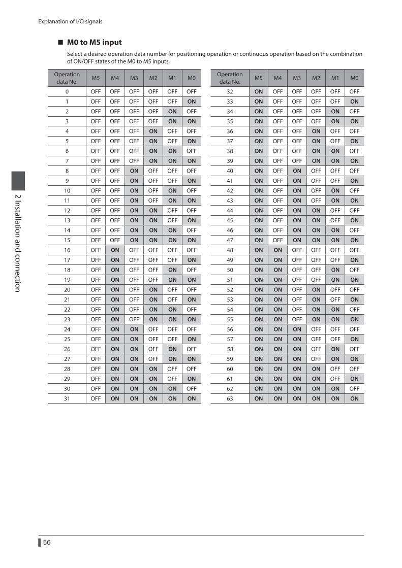
Explanation of I/O signals
56
2 Installation and connection
M0 to M5 inputSelect a desired operation data number for positioning operation or continuous operation based on the combination of ON/OFF states of the M0 to M5 inputs.
Operation data No.
M5 M4 M3 M2 M1 M0Operation data No.
M5 M4 M3 M2 M1 M0
0 OFF OFF OFF OFF OFF OFF 32 ON OFF OFF OFF OFF OFF
1 OFF OFF OFF OFF OFF ON 33 ON OFF OFF OFF OFF ON
2 OFF OFF OFF OFF ON OFF 34 ON OFF OFF OFF ON OFF
3 OFF OFF OFF OFF ON ON 35 ON OFF OFF OFF ON ON
4 OFF OFF OFF ON OFF OFF 36 ON OFF OFF ON OFF OFF
5 OFF OFF OFF ON OFF ON 37 ON OFF OFF ON OFF ON
6 OFF OFF OFF ON ON OFF 38 ON OFF OFF ON ON OFF
7 OFF OFF OFF ON ON ON 39 ON OFF OFF ON ON ON
8 OFF OFF ON OFF OFF OFF 40 ON OFF ON OFF OFF OFF
9 OFF OFF ON OFF OFF ON 41 ON OFF ON OFF OFF ON
10 OFF OFF ON OFF ON OFF 42 ON OFF ON OFF ON OFF
11 OFF OFF ON OFF ON ON 43 ON OFF ON OFF ON ON
12 OFF OFF ON ON OFF OFF 44 ON OFF ON ON OFF OFF
13 OFF OFF ON ON OFF ON 45 ON OFF ON ON OFF ON
14 OFF OFF ON ON ON OFF 46 ON OFF ON ON ON OFF
15 OFF OFF ON ON ON ON 47 ON OFF ON ON ON ON
16 OFF ON OFF OFF OFF OFF 48 ON ON OFF OFF OFF OFF
17 OFF ON OFF OFF OFF ON 49 ON ON OFF OFF OFF ON
18 OFF ON OFF OFF ON OFF 50 ON ON OFF OFF ON OFF
19 OFF ON OFF OFF ON ON 51 ON ON OFF OFF ON ON
20 OFF ON OFF ON OFF OFF 52 ON ON OFF ON OFF OFF
21 OFF ON OFF ON OFF ON 53 ON ON OFF ON OFF ON
22 OFF ON OFF ON ON OFF 54 ON ON OFF ON ON OFF
23 OFF ON OFF ON ON ON 55 ON ON OFF ON ON ON
24 OFF ON ON OFF OFF OFF 56 ON ON ON OFF OFF OFF
25 OFF ON ON OFF OFF ON 57 ON ON ON OFF OFF ON
26 OFF ON ON OFF ON OFF 58 ON ON ON OFF ON OFF
27 OFF ON ON OFF ON ON 59 ON ON ON OFF ON ON
28 OFF ON ON ON OFF OFF 60 ON ON ON ON OFF OFF
29 OFF ON ON ON OFF ON 61 ON ON ON ON OFF ON
30 OFF ON ON ON ON OFF 62 ON ON ON ON ON OFF
31 OFF ON ON ON ON ON 63 ON ON ON ON ON ON
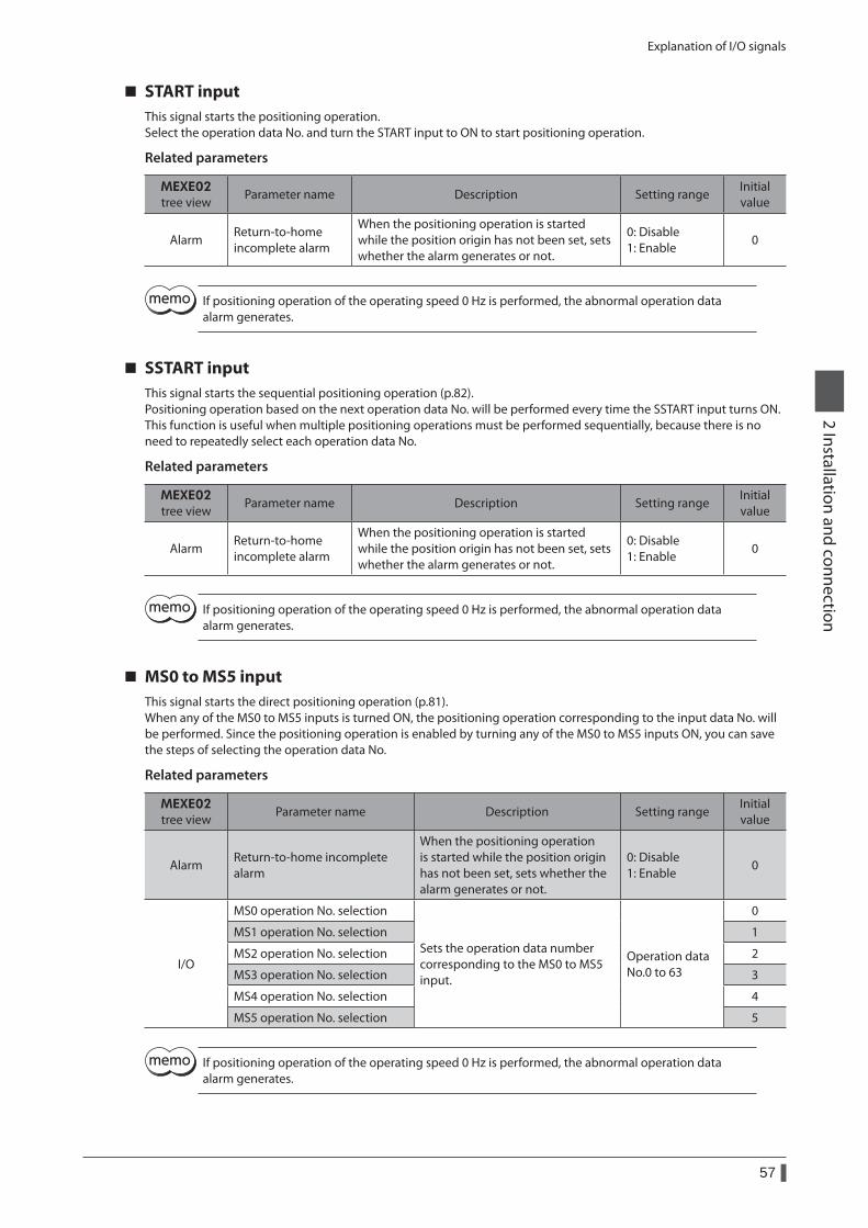
Explanation of I/O signals
57
2 Installation and connection
START inputThis signal starts the positioning operation.Select the operation data No. and turn the START input to ON to start positioning operation.
Related parameters
MEXE02 tree view
Parameter name Description Setting rangeInitial value
AlarmReturn-to-home incomplete alarm
When the positioning operation is started while the position origin has not been set, sets whether the alarm generates or not.
0: Disable 1: Enable
0
If positioning operation of the operating speed 0 Hz is performed, the abnormal operation data alarm generates.
SSTART inputThis signal starts the sequential positioning operation (p.82).Positioning operation based on the next operation data No. will be performed every time the SSTART input turns ON.This function is useful when multiple positioning operations must be performed sequentially, because there is no need to repeatedly select each operation data No.
Related parameters
MEXE02 tree view
Parameter name Description Setting rangeInitial value
AlarmReturn-to-home incomplete alarm
When the positioning operation is started while the position origin has not been set, sets whether the alarm generates or not.
0: Disable 1: Enable
0
If positioning operation of the operating speed 0 Hz is performed, the abnormal operation data alarm generates.
MS0 to MS5 inputThis signal starts the direct positioning operation (p.81).When any of the MS0 to MS5 inputs is turned ON, the positioning operation corresponding to the input data No. will be performed. Since the positioning operation is enabled by turning any of the MS0 to MS5 inputs ON, you can save the steps of selecting the operation data No.
Related parameters
MEXE02 tree view
Parameter name Description Setting rangeInitial value
AlarmReturn-to-home incomplete alarm
When the positioning operation is started while the position origin has not been set, sets whether the alarm generates or not.
0: Disable 1: Enable
0
I/O
MS0 operation No. selection
Sets the operation data number corresponding to the MS0 to MS5 input.
Operation data No.0 to 63
0
MS1 operation No. selection 1
MS2 operation No. selection 2
MS3 operation No. selection 3
MS4 operation No. selection 4
MS5 operation No. selection 5
If positioning operation of the operating speed 0 Hz is performed, the abnormal operation data alarm generates.
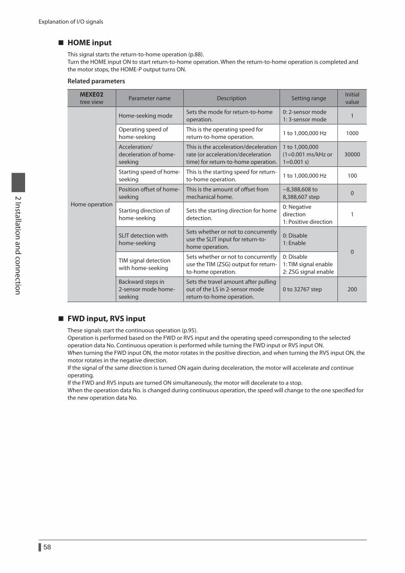
Explanation of I/O signals
58
2 Installation and connection
HOME inputThis signal starts the return-to-home operation (p.88).Turn the HOME input ON to start return-to-home operation. When the return-to-home operation is completed and the motor stops, the HOME-P output turns ON.
Related parameters
MEXE02 tree view
Parameter name Description Setting rangeInitial value
Home operation
Home-seeking modeSets the mode for return-to-home operation.
0: 2-sensor mode 1: 3-sensor mode
1
Operating speed of home-seeking
This is the operating speed for return-to-home operation.
1 to 1,000,000 Hz 1000
Acceleration/deceleration of home-seeking
This is the acceleration/deceleration rate (or acceleration/deceleration time) for return-to-home operation.
1 to 1,000,000 (1=0.001 ms/kHz or 1=0.001 s)
30000
Starting speed of home-seeking
This is the starting speed for return-to-home operation.
1 to 1,000,000 Hz 100
Position offset of home-seeking
This is the amount of offset from mechanical home.
−8,388,608 to 8,388,607 step
0
Starting direction of home-seeking
Sets the starting direction for home detection.
0: Negative direction 1: Positive direction
1
SLIT detection with home-seeking
Sets whether or not to concurrently use the SLIT input for return-to-home operation.
0: Disable 1: Enable
0TIM signal detection with home-seeking
Sets whether or not to concurrently use the TIM (ZSG) output for return-to-home operation.
0: Disable 1: TIM signal enable 2: ZSG signal enable
Backward steps in 2-sensor mode home-seeking
Sets the travel amount after pulling out of the LS in 2-sensor mode return-to-home operation.
0 to 32767 step 200
FWD input, RVS inputThese signals start the continuous operation (p.95).Operation is performed based on the FWD or RVS input and the operating speed corresponding to the selected operation data No. Continuous operation is performed while turning the FWD input or RVS input ON.When turning the FWD input ON, the motor rotates in the positive direction, and when turning the RVS input ON, the motor rotates in the negative direction.If the signal of the same direction is turned ON again during deceleration, the motor will accelerate and continue operating.If the FWD and RVS inputs are turned ON simultaneously, the motor will decelerate to a stop.When the operation data No. is changed during continuous operation, the speed will change to the one specified for the new operation data No.
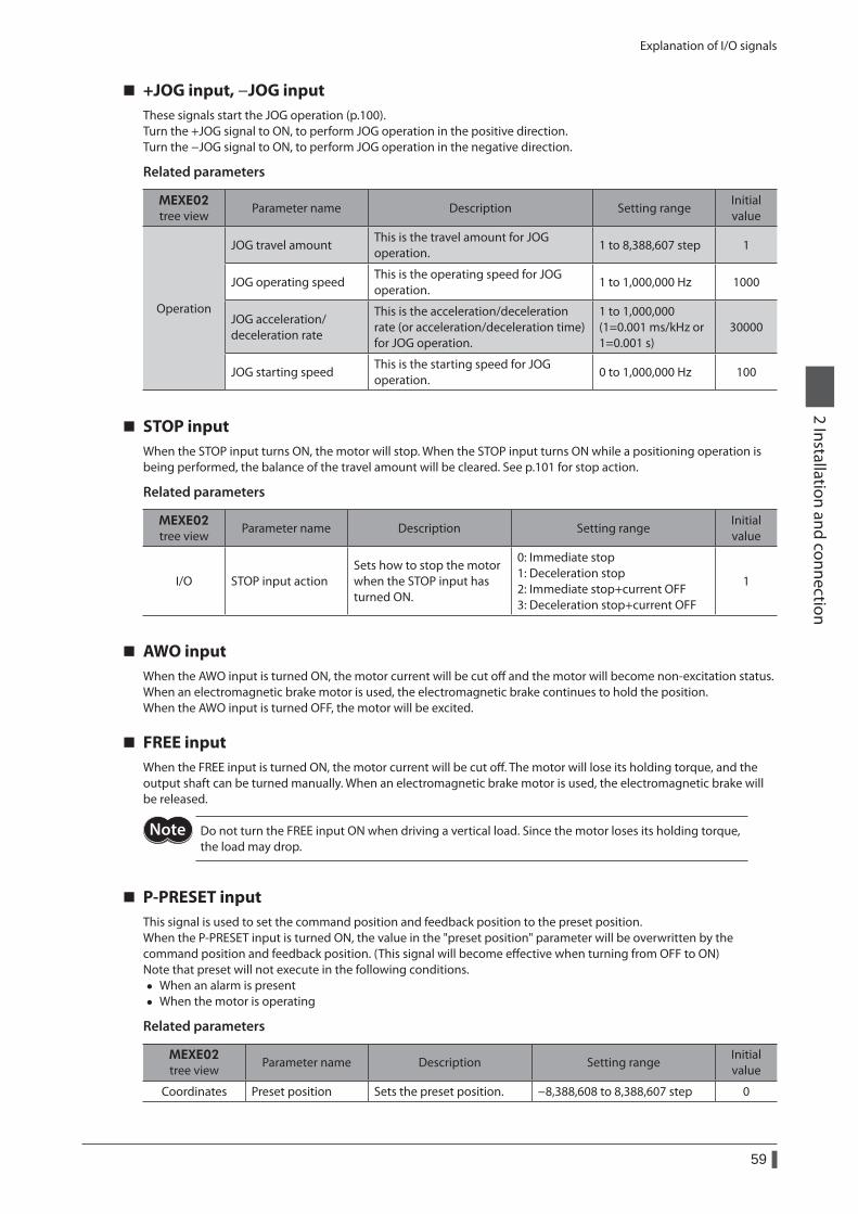
Explanation of I/O signals
59
2 Installation and connection
+JOG input, −JOG inputThese signals start the JOG operation (p.100).Turn the +JOG signal to ON, to perform JOG operation in the positive direction.Turn the −JOG signal to ON, to perform JOG operation in the negative direction.
Related parameters
MEXE02 tree view
Parameter name Description Setting rangeInitial value
Operation
JOG travel amountThis is the travel amount for JOG operation.
1 to 8,388,607 step 1
JOG operating speedThis is the operating speed for JOG operation.
1 to 1,000,000 Hz 1000
JOG acceleration/ deceleration rate
This is the acceleration/deceleration rate (or acceleration/deceleration time) for JOG operation.
1 to 1,000,000 (1=0.001 ms/kHz or 1=0.001 s)
30000
JOG starting speedThis is the starting speed for JOG operation.
0 to 1,000,000 Hz 100
STOP inputWhen the STOP input turns ON, the motor will stop. When the STOP input turns ON while a positioning operation is being performed, the balance of the travel amount will be cleared. See p.101 for stop action.
Related parameters
MEXE02 tree view
Parameter name Description Setting rangeInitial value
I/O STOP input actionSets how to stop the motor when the STOP input has turned ON.
0: Immediate stop 1: Deceleration stop 2: Immediate stop+current OFF 3: Deceleration stop+current OFF
1
AWO inputWhen the AWO input is turned ON, the motor current will be cut off and the motor will become non-excitation status.When an electromagnetic brake motor is used, the electromagnetic brake continues to hold the position.When the AWO input is turned OFF, the motor will be excited.
FREE inputWhen the FREE input is turned ON, the motor current will be cut off. The motor will lose its holding torque, and the output shaft can be turned manually. When an electromagnetic brake motor is used, the electromagnetic brake will be released.
Do not turn the FREE input ON when driving a vertical load. Since the motor loses its holding torque, the load may drop.
P-PRESET inputThis signal is used to set the command position and feedback position to the preset position.When the P-PRESET input is turned ON, the value in the "preset position" parameter will be overwritten by the command position and feedback position. (This signal will become effective when turning from OFF to ON)Note that preset will not execute in the following conditions.
• When an alarm is present • When the motor is operating
Related parameters
MEXE02 tree view
Parameter name Description Setting rangeInitial value
Coordinates Preset position Sets the preset position. −8,388,608 to 8,388,607 step 0
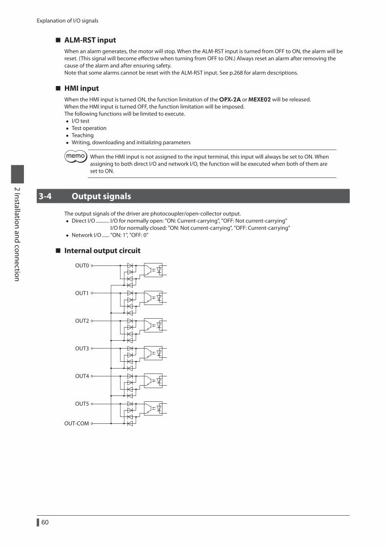
Explanation of I/O signals
60
2 Installation and connection
ALM-RST inputWhen an alarm generates, the motor will stop. When the ALM-RST input is turned from OFF to ON, the alarm will be reset. (This signal will become effective when turning from OFF to ON.) Always reset an alarm after removing the cause of the alarm and after ensuring safety.Note that some alarms cannot be reset with the ALM-RST input. See p.268 for alarm descriptions.
HMI inputWhen the HMI input is turned ON, the function limitation of the OPX-2A or MEXE02 will be released.When the HMI input is turned OFF, the function limitation will be imposed.The following functions will be limited to execute.
• I/O test • Test operation • Teaching • Writing, downloading and initializing parameters
When the HMI input is not assigned to the input terminal, this input will always be set to ON. When assigning to both direct I/O and network I/O, the function will be executed when both of them are set to ON.
3-4 Output signals
The output signals of the driver are photocoupler/open-collector output. • Direct I/O ........... I/O for normally open: "ON: Current-carrying", "OFF: Not current-carrying"
I/O for normally closed: "ON: Not current-carrying", "OFF: Current-carrying" • Network I/O ...... "ON: 1", "OFF: 0"
Internal output circuit
OUT0
OUT1
OUT2
OUT3
OUT4
OUT5
OUT-COM
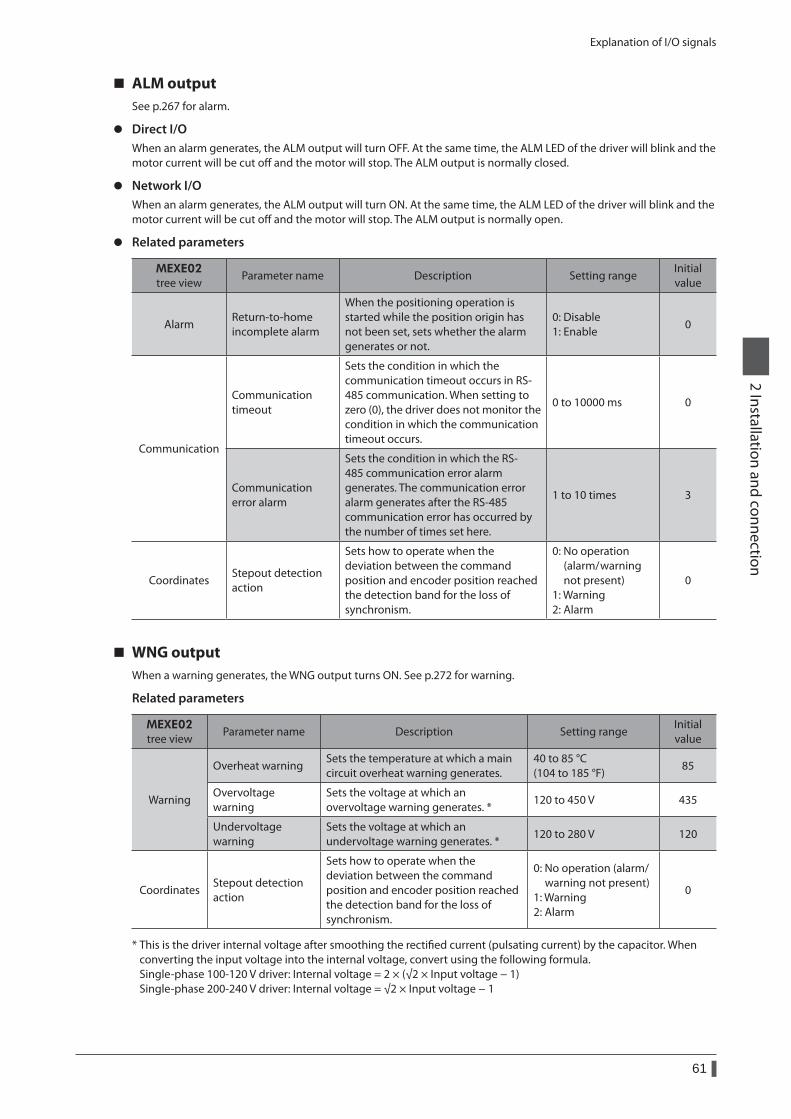
Explanation of I/O signals
61
2 Installation and connection
ALM outputSee p.267 for alarm.
z Direct I/OWhen an alarm generates, the ALM output will turn OFF. At the same time, the ALM LED of the driver will blink and the motor current will be cut off and the motor will stop. The ALM output is normally closed.
z Network I/OWhen an alarm generates, the ALM output will turn ON. At the same time, the ALM LED of the driver will blink and the motor current will be cut off and the motor will stop. The ALM output is normally open.
z Related parameters
MEXE02 tree view
Parameter name Description Setting rangeInitial value
AlarmReturn-to-home incomplete alarm
When the positioning operation is started while the position origin has not been set, sets whether the alarm generates or not.
0: Disable 1: Enable
0
Communication
Communication timeout
Sets the condition in which the communication timeout occurs in RS-485 communication. When setting to zero (0), the driver does not monitor the condition in which the communication timeout occurs.
0 to 10000 ms 0
Communication error alarm
Sets the condition in which the RS-485 communication error alarm generates. The communication error alarm generates after the RS-485 communication error has occurred by the number of times set here.
1 to 10 times 3
CoordinatesStepout detection action
Sets how to operate when the deviation between the command position and encoder position reached the detection band for the loss of synchronism.
0: No operation (alarm/ warning not present) 1: Warning 2: Alarm
0
WNG outputWhen a warning generates, the WNG output turns ON. See p.272 for warning.
Related parameters
MEXE02 tree view
Parameter name Description Setting rangeInitial value
Warning
Overheat warningSets the temperature at which a main circuit overheat warning generates.
40 to 85 °C (104 to 185 °F)
85
Overvoltage warning
Sets the voltage at which an overvoltage warning generates. *
120 to 450 V 435
Undervoltage warning
Sets the voltage at which an undervoltage warning generates. *
120 to 280 V 120
CoordinatesStepout detection action
Sets how to operate when the deviation between the command position and encoder position reached the detection band for the loss of synchronism.
0: No operation (alarm/ warning not present) 1: Warning 2: Alarm
0
* This is the driver internal voltage after smoothing the rectified current (pulsating current) by the capacitor. When converting the input voltage into the internal voltage, convert using the following formula. Single-phase 100-120 V driver: Internal voltage = 2 × (√2 × Input voltage − 1) Single-phase 200-240 V driver: Internal voltage = √2 × Input voltage − 1
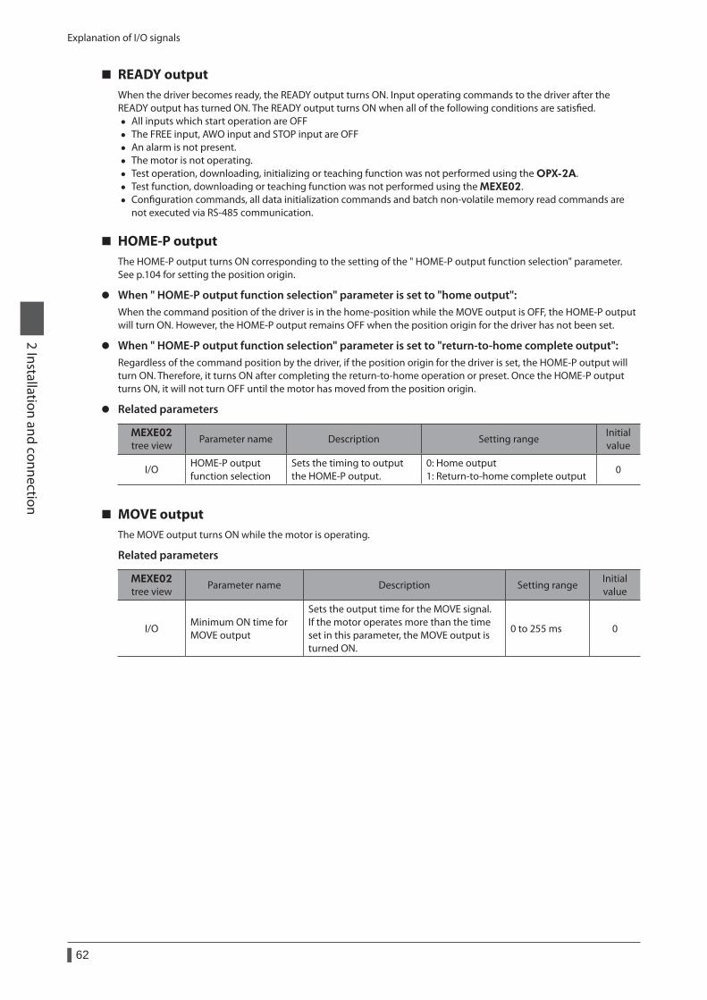
Explanation of I/O signals
62
2 Installation and connection
READY outputWhen the driver becomes ready, the READY output turns ON. Input operating commands to the driver after the READY output has turned ON. The READY output turns ON when all of the following conditions are satisfied.
• All inputs which start operation are OFF • The FREE input, AWO input and STOP input are OFF • An alarm is not present. • The motor is not operating. • Test operation, downloading, initializing or teaching function was not performed using the OPX-2A. • Test function, downloading or teaching function was not performed using the MEXE02. • Configuration commands, all data initialization commands and batch non-volatile memory read commands are
not executed via RS-485 communication.
HOME-P outputThe HOME-P output turns ON corresponding to the setting of the " HOME-P output function selection" parameter.See p.104 for setting the position origin.
z When " HOME-P output function selection" parameter is set to "home output":When the command position of the driver is in the home-position while the MOVE output is OFF, the HOME-P output will turn ON. However, the HOME-P output remains OFF when the position origin for the driver has not been set.
z When " HOME-P output function selection" parameter is set to "return-to-home complete output":Regardless of the command position by the driver, if the position origin for the driver is set, the HOME-P output will turn ON. Therefore, it turns ON after completing the return-to-home operation or preset. Once the HOME-P output turns ON, it will not turn OFF until the motor has moved from the position origin.
z Related parameters
MEXE02 tree view
Parameter name Description Setting rangeInitial value
I/OHOME-P output function selection
Sets the timing to output the HOME-P output.
0: Home output 1: Return-to-home complete output
0
MOVE outputThe MOVE output turns ON while the motor is operating.
Related parameters
MEXE02 tree view
Parameter name Description Setting rangeInitial value
I/OMinimum ON time for MOVE output
Sets the output time for the MOVE signal. If the motor operates more than the time set in this parameter, the MOVE output is turned ON.
0 to 255 ms 0
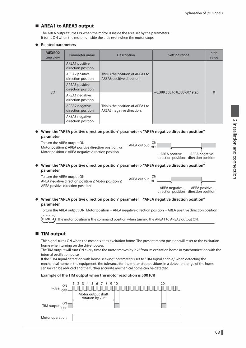
Explanation of I/O signals
63
2 Installation and connection
AREA1 to AREA3 outputThe AREA output turns ON when the motor is inside the area set by the parameters.It turns ON when the motor is inside the area even when the motor stops.
z Related parameters
MEXE02 tree view
Parameter name Description Setting rangeInitial value
I/O
AREA1 positive direction position
This is the position of AREA1 to AREA3 positive direction.
−8,388,608 to 8,388,607 step 0
AREA2 positive direction position
AREA3 positive direction position
AREA1 negative direction position
This is the position of AREA1 to AREA3 negative direction.
AREA2 negative direction position
AREA3 negative direction position
z When the "AREA positive direction position" parameter < "AREA negative direction position" parameterTo turn the AREA output ON: Motor position ≤ AREA positive direction position, or Motor position ≥ AREA negative direction position AREA positive
direction position
AREA output
AREA negativedirection position
ONOFF
z When the "AREA positive direction position" parameter > "AREA negative direction position" parameterTo turn the AREA output ON: AREA negative direction position ≤ Motor position ≤ AREA positive direction position AREA positive
direction position
AREA output
AREA negativedirection position
ONOFF
z When the "AREA positive direction position" parameter = "AREA negative direction position" parameterTo turn the AREA output ON: Motor position = AREA negative direction position = AREA positive direction position
The motor position is the command position when turning the AREA1 to AREA3 output ON.
TIM outputThis signal turns ON when the motor is at its excitation home. The present motor position will reset to the excitation home when turning on the driver power.The TIM output will turn ON every time the motor moves by 7.2° from its excitation home in synchronization with the internal oscillation pulse.If the "TIM signal detection with home-seeking" parameter is set to "TIM signal enable," when detecting the mechanical home in the equipment, the tolerance for the motor stop positions in a detection range of the home sensor can be reduced and the further accurate mechanical home can be detected.
Example of the TIM output when the motor resolution is 500 P/R
1 2 3 4 5 6 7 8 9 10 20
OFFON
OFFON
TIM output
Motor operation
Pulse
Motor output shaftrotation by 7.2°
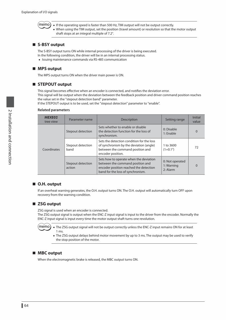
Explanation of I/O signals
64
2 Installation and connection
• If the operating speed is faster than 500 Hz, TIM output will not be output correctly. • When using the TIM output, set the position (travel amount) or resolution so that the motor output shaft stops at an integral multiple of 7.2°.
S-BSY outputThe S-BSY output turns ON while internal processing of the driver is being executed.In the following condition, the driver will be in an internal processing status.
• Issuing maintenance commands via RS-485 communication
MPS outputThe MPS output turns ON when the driver main power is ON.
STEPOUT outputThis signal becomes effective when an encoder is connected, and notifies the deviation error.This signal will be output when the deviation between the feedback position and driver command position reaches the value set in the "stepout detection band" parameter.If the STEPOUT output is to be used, set the "stepout detection" parameter to "enable".
Related parameters
MEXE02 tree view
Parameter name Description Setting rangeInitial value
Coordinates
Stepout detectionSets whether to enable or disable the detection function for the loss of synchronism.
0: Disable 1: Enable
0
Stepout detection band
Sets the detection condition for the loss of synchronism by the deviation (angle) between the command position and encoder position.
1 to 3600 (1=0.1°)
72
Stepout detection action
Sets how to operate when the deviation between the command position and encoder position reached the detection band for the loss of synchronism.
0: Not operated 1: Warning 2: Alarm
0
O.H. outputIf an overheat warning generates, the O.H. output turns ON. The O.H. output will automatically turn OFF upon recovery from the warning condition.
ZSG outputZSG signal is used when an encoder is connected. The ZSG output signal is output when the ENC-Z input signal is input to the driver from the encoder. Normally the ENC-Z input signal is input every time the motor output shaft turns one revolution.
• The ZSG output signal will not be output correctly unless the ENC-Z input remains ON for at least 1 ms.
• The ZSG output delays behind motor movement by up to 3 ms. The output may be used to verify the stop position of the motor.
MBC outputWhen the electromagnetic brake is released, the MBC output turns ON.
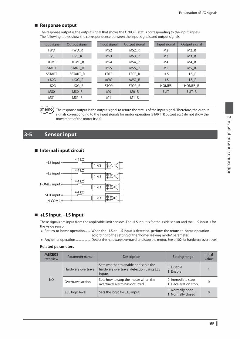
Explanation of I/O signals
65
2 Installation and connection
Response outputThe response output is the output signal that shows the ON/OFF status corresponding to the input signals.The following tables show the correspondence between the input signals and output signals.
Input signal Output signal Input signal Output signal Input signal Output signal
FWD FWD_R MS2 MS2_R M2 M2_R
RVS RVS_R MS3 MS3_R M3 M3_R
HOME HOME_R MS4 MS4_R M4 M4_R
START START_R MS5 MS5_R M5 M5_R
SSTART SSTART_R FREE FREE_R +LS +LS_R
+JOG +JOG_R AWO AWO_R −LS −LS_R
−JOG −JOG_R STOP STOP_R HOMES HOMES_R
MS0 MS0_R M0 M0_R SLIT SLIT_R
MS1 MS1_R M1 M1_R
The response output is the output signal to return the status of the input signal. Therefore, the output signals corresponding to the input signals for motor operation (START_R output etc.) do not show the movement of the motor itself.
3-5 Sensor input
Internal input circuit
+LS input
IN-COM2
4.4 kΩ
1 kΩ
-LS input4.4 kΩ
1 kΩ
HOMES input4.4 kΩ
1 kΩ
SLIT input4.4 kΩ
1 kΩ
+LS input, −LS inputThese signals are input from the applicable limit sensors. The +LS input is for the +side sensor and the −LS input is for the −side sensor.
• Return-to-home operation ........When the +LS or −LS input is detected, perform the return-to-home operation according to the setting of the "home-seeking mode" parameter.
• Any other operation .....................Detect the hardware overtravel and stop the motor. See p.102 for hardware overtravel.
Related parameters
MEXE02 tree view
Parameter name Description Setting rangeInitial value
I/O
Hardware overtravelSets whether to enable or disable the hardware overtravel detection using ±LS inputs.
0: Disable 1: Enable
1
Overtravel actionSets how to stop the motor when the overtravel alarm has occurred.
0: Immediate stop 1: Deceleration stop
0
±LS logic level Sets the logic for ±LS input.0: Normally open 1: Normally closed
0
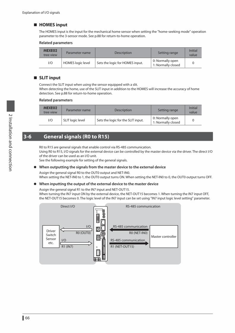
Explanation of I/O signals
66
2 Installation and connection
HOMES inputThe HOMES input is the input for the mechanical home sensor when setting the "home-seeking mode" operation parameter to the 3-sensor mode. See p.88 for return-to-home operation.
Related parameters
MEXE02 tree view
Parameter name Description Setting rangeInitial value
I/O HOMES logic level Sets the logic for HOMES input.0: Normally open 1: Normally closed
0
SLIT inputConnect the SLIT input when using the sensor equipped with a slit.When detecting the home, use of the SLIT input in addition to the HOMES will increase the accuracy of home detection. See p.88 for return-to-home operation.
Related parameters
MEXE02 tree view
Parameter name Description Setting rangeInitial value
I/O SLIT logic level Sets the logic for the SLIT input.0: Normally open 1: Normally closed
0
3-6 General signals (R0 to R15)
R0 to R15 are general signals that enable control via RS-485 communication.Using R0 to R15, I/O signals for the external device can be controlled by the master device via the driver. The direct I/O of the driver can be used as an I/O unit.See the following example for setting of the general signals.
z When outputting the signals from the master device to the external deviceAssign the general signal R0 to the OUT0 output and NET-IN0.When setting the NET-IN0 to 1, the OUT0 output turns ON. When setting the NET-IN0 to 0, the OUT0 output turns OFF.
z When inputting the output of the external device to the master deviceAssign the general signal R1 to the IN7 input and NET-OUT15.When turning the IN7 input ON by the external device, the NET-OUT15 becomes 1. When turning the IN7 input OFF, the NET-OUT15 becomes 0. The logic level of the IN7 input can be set using "IN7 input logic level setting" parameter.
I/O
I/OMaster controller
DriverSwitchSensor
etc.
RS-485 communicationDirect I/O
RS-485 communication
RS-485 communication
R0 (NET-IN0)
R1 (NET-OUT15)
R0 (OUT0)
R1 (IN7)
1 Guidance ............................................................68
2 Adjustment and setting ...................................712-1 Resolution .......................................................................... 71
2-2 Operating current ............................................................ 72
2-3 Standstill current ............................................................. 72
2-4 Acceleration/deceleration rate and acceleration/deceleration time .................................. 72
2-5 Speed filter ......................................................................... 73
2-6 Moving average filter ..................................................... 74
2-7 When a motor with an encoder is used................... 74
3 Operation type and function list .....................78
4 Positioning operation .......................................794-1 Operation data ................................................................. 79
4-2 Starting method of positioning operation ............. 80
4-3 Operation function ......................................................... 84
5 Return-to-home operation ..............................885-1 About description of return-to-home
operation ............................................................................ 88
5-2 Operation sequence ....................................................... 91
5-3 Position preset .................................................................. 94
6 Continuous operation ......................................956-1 Operation data ................................................................. 95
6-2 Starting method of continuous operation ............. 96
6-3 Variable speed operation ............................................. 98
7 Other operation ..............................................1007-1 JOG operation .................................................................100
7-2 Test operation .................................................................101
7-3 Stop operation ................................................................101
8 Coordinate management ...............................1048-1 Position coordinate management ..........................104
8-2 Wrap function .................................................................104
9 Operation data ................................................106
10 Parameter ........................................................10710-1 Parameter list ..................................................................108
10-2 I/O parameter ..................................................................109
10-3 Motor parameter ...........................................................110
10-4 Operation parameter ...................................................110
10-5 Home operation parameter .......................................111
10-6 Alarm parameter ............................................................111
10-7 Warning parameter .......................................................111
10-8 Coordinates parameter ...............................................112
10-9 Common parameter .....................................................112
10-10 I/O function [Input] parameter .................................113
10-11 I/O function [Output] parameter .............................113
10-12 I/O function [RS-485] parameter ..............................114
10-13 Communication parameter .......................................115
3 Operation type and setting
This part explains the operation functions and the details of parameters.
Table of contents
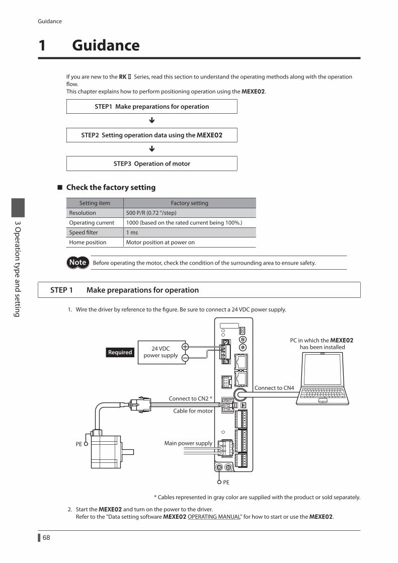
Guidance
68
3 Operation type and setting
1 Guidance
If you are new to the RKⅡ Series, read this section to understand the operating methods along with the operation flow.This chapter explains how to perform positioning operation using the MEXE02.
STEP1 Make preparations for operation
STEP2 Setting operation data using the MEXE02
STEP3 Operation of motor
Check the factory setting
Setting item Factory setting
Resolution 500 P/R (0.72 °/step)
Operating current 1000 (based on the rated current being 100%.)
Speed filter 1 ms
Home position Motor position at power on
Before operating the motor, check the condition of the surrounding area to ensure safety.
STEP 1 Make preparations for operation
1. Wire the driver by reference to the figure. Be sure to connect a 24 VDC power supply.
Main power supply
PE
Connect to CN4
24 VDCpower supply
PC in which the MEXE02 has been installed
Connect to CN2 *
Cable for motor
PE
Required
* Cables represented in gray color are supplied with the product or sold separately.
2. Start the MEXE02 and turn on the power to the driver.Refer to the "Data setting software MEXE02 OPERATING MANUAL" for how to start or use the MEXE02.
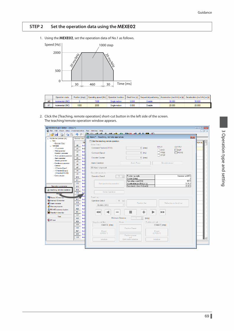
Guidance
69
3 Operation type and setting
STEP 2 Set the operation data using the MEXE02
1. Using the MEXE02, set the operation data of No.1 as follows.
Speed [Hz]
0
500
2000
Time [ms]30 30460
1000 step
20 m
s/kH
z 20 ms/kHz
2. Click the [Teaching, remote operation] short-cut button in the left side of the screen.The teaching/remote operation window appears.
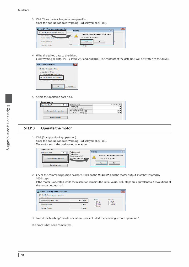
Guidance
70
3 Operation type and setting
3. Click "Start the teaching remote operation.Since the pop-up window (Warning) is displayed, click [Yes].
4. Write the edited data to the driver.Click "Writing all data. (PC −> Product)," and click [OK]. The contents of the data No.1 will be written to the driver.
5. Select the operation data No.1.
STEP 3 Operate the motor
1. Click [Start positioning operation].Since the pop-up window (Warning) is displayed, click [Yes].The motor starts the positioning operation.
2. Check the command position has been 1000 on the MEXE02, and the motor output shaft has rotated by 1000 steps.If the motor is operated while the resolution remains the initial value, 1000 steps are equivalent to 2 revolutions of the motor output shaft.
3. To end the teaching/remote operation, unselect "Start the teaching remote operation."
The process has been completed.
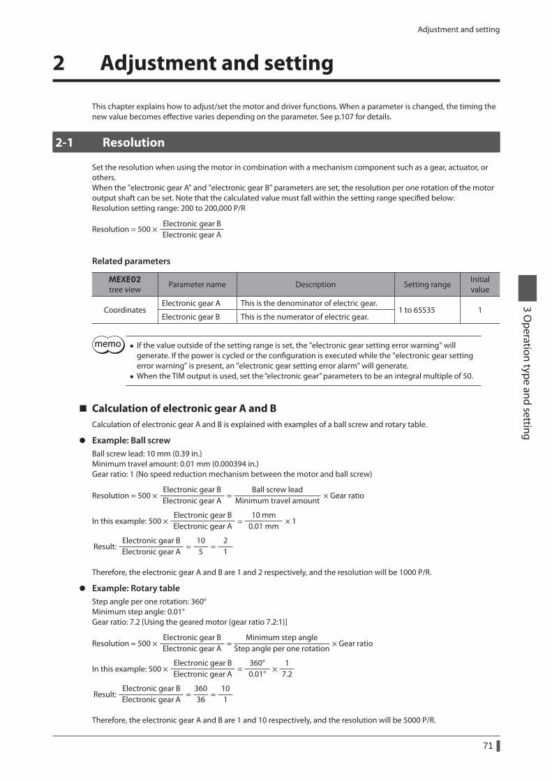
Adjustment and setting
71
3 Operation type and setting
2 Adjustment and setting
This chapter explains how to adjust/set the motor and driver functions. When a parameter is changed, the timing the new value becomes effective varies depending on the parameter. See p.107 for details.
2-1 Resolution
Set the resolution when using the motor in combination with a mechanism component such as a gear, actuator, or others.When the "electronic gear A" and "electronic gear B" parameters are set, the resolution per one rotation of the motor output shaft can be set. Note that the calculated value must fall within the setting range specified below:Resolution setting range: 200 to 200,000 P/R
Resolution = 500 ×Electronic gear BElectronic gear A
Related parameters
MEXE02 tree view
Parameter name Description Setting rangeInitial value
CoordinatesElectronic gear A This is the denominator of electric gear.
1 to 65535 1Electronic gear B This is the numerator of electric gear.
• If the value outside of the setting range is set, the "electronic gear setting error warning" will generate. If the power is cycled or the configuration is executed while the "electronic gear setting error warning" is present, an "electronic gear setting error alarm" will generate.
• When the TIM output is used, set the “electronic gear” parameters to be an integral multiple of 50.
Calculation of electronic gear A and BCalculation of electronic gear A and B is explained with examples of a ball screw and rotary table.
z Example: Ball screwBall screw lead: 10 mm (0.39 in.)Minimum travel amount: 0.01 mm (0.000394 in.)Gear ratio: 1 (No speed reduction mechanism between the motor and ball screw)
Resolution = 500 ×Electronic gear BElectronic gear A
=Ball screw lead
Minimum travel amount× Gear ratio
In this example: 500 ×Electronic gear BElectronic gear A
=10 mm
0.01 mm× 1
Electronic gear BElectronic gear A
=105
=21
Result:
Therefore, the electronic gear A and B are 1 and 2 respectively, and the resolution will be 1000 P/R.
z Example: Rotary tableStep angle per one rotation: 360°Minimum step angle: 0.01°Gear ratio: 7.2 [Using the geared motor (gear ratio 7.2:1)]
Resolution = 500 ×Electronic gear BElectronic gear A
=Minimum step angle
Step angle per one rotation× Gear ratio
360°0.01°
17.2
×In this example: 500 ×Electronic gear BElectronic gear A
=
Electronic gear BElectronic gear A
=36036
=101
Result:
Therefore, the electronic gear A and B are 1 and 10 respectively, and the resolution will be 5000 P/R.
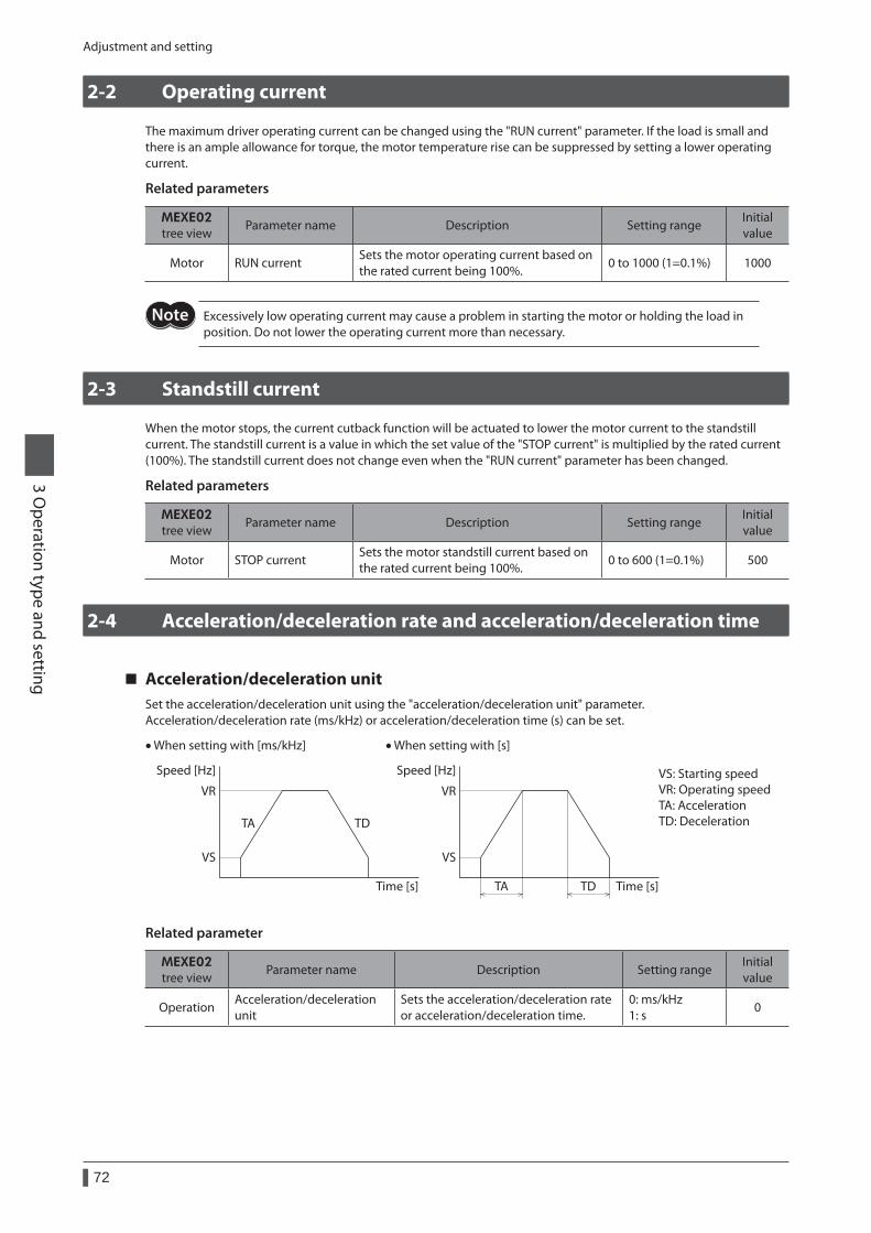
Adjustment and setting
72
3 Operation type and setting
2-2 Operating current
The maximum driver operating current can be changed using the "RUN current" parameter. If the load is small and there is an ample allowance for torque, the motor temperature rise can be suppressed by setting a lower operating current.
Related parameters
MEXE02 tree view
Parameter name Description Setting rangeInitial value
Motor RUN currentSets the motor operating current based on the rated current being 100%.
0 to 1000 (1=0.1%) 1000
Excessively low operating current may cause a problem in starting the motor or holding the load in position. Do not lower the operating current more than necessary.
2-3 Standstill current
When the motor stops, the current cutback function will be actuated to lower the motor current to the standstill current. The standstill current is a value in which the set value of the "STOP current" is multiplied by the rated current (100%). The standstill current does not change even when the "RUN current" parameter has been changed.
Related parameters
MEXE02 tree view
Parameter name Description Setting rangeInitial value
Motor STOP currentSets the motor standstill current based on the rated current being 100%.
0 to 600 (1=0.1%) 500
2-4 Acceleration/deceleration rate and acceleration/deceleration time
Acceleration/deceleration unitSet the acceleration/deceleration unit using the "acceleration/deceleration unit" parameter.Acceleration/deceleration rate (ms/kHz) or acceleration/deceleration time (s) can be set.
Speed [Hz] Speed [Hz]
Time [s] Time [s]
VR
VS
VR
VS
TA TD
TA TD
• When setting with [ms/kHz] • When setting with [s]
VS: Starting speedVR: Operating speedTA: AccelerationTD: Deceleration
Related parameter
MEXE02 tree view
Parameter name Description Setting rangeInitial value
OperationAcceleration/deceleration unit
Sets the acceleration/deceleration rate or acceleration/deceleration time.
0: ms/kHz 1: s
0
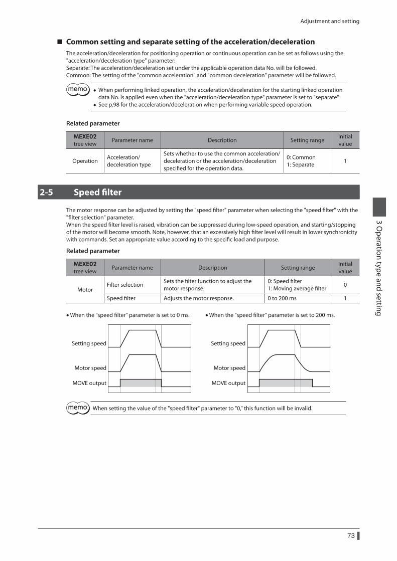
Adjustment and setting
73
3 Operation type and setting
Common setting and separate setting of the acceleration/decelerationThe acceleration/deceleration for positioning operation or continuous operation can be set as follows using the "acceleration/deceleration type" parameter:Separate: The acceleration/deceleration set under the applicable operation data No. will be followed.Common: The setting of the "common acceleration" and "common deceleration" parameter will be followed.
• When performing linked operation, the acceleration/deceleration for the starting linked operation data No. is applied even when the "acceleration/deceleration type" parameter is set to "separate".
• See p.98 for the acceleration/deceleration when performing variable speed operation.
Related parameter
MEXE02 tree view
Parameter name Description Setting rangeInitial value
OperationAcceleration/ deceleration type
Sets whether to use the common acceleration/ deceleration or the acceleration/deceleration specified for the operation data.
0: Common 1: Separate
1
2-5 Speed filter
The motor response can be adjusted by setting the "speed filter" parameter when selecting the "speed filter" with the "filter selection" parameter.When the speed filter level is raised, vibration can be suppressed during low-speed operation, and starting/stopping of the motor will become smooth. Note, however, that an excessively high filter level will result in lower synchronicity with commands. Set an appropriate value according to the specific load and purpose.
Related parameter
MEXE02 tree view
Parameter name Description Setting rangeInitial value
MotorFilter selection
Sets the filter function to adjust the motor response.
0: Speed filter 1: Moving average filter
0
Speed filter Adjusts the motor response. 0 to 200 ms 1
Setting speed
Motor speed
MOVE output
Setting speed
Motor speed
MOVE output
• When the "speed lter" parameter is set to 0 ms. • When the "speed lter" parameter is set to 200 ms.
When setting the value of the "speed filter" parameter to "0," this function will be invalid.
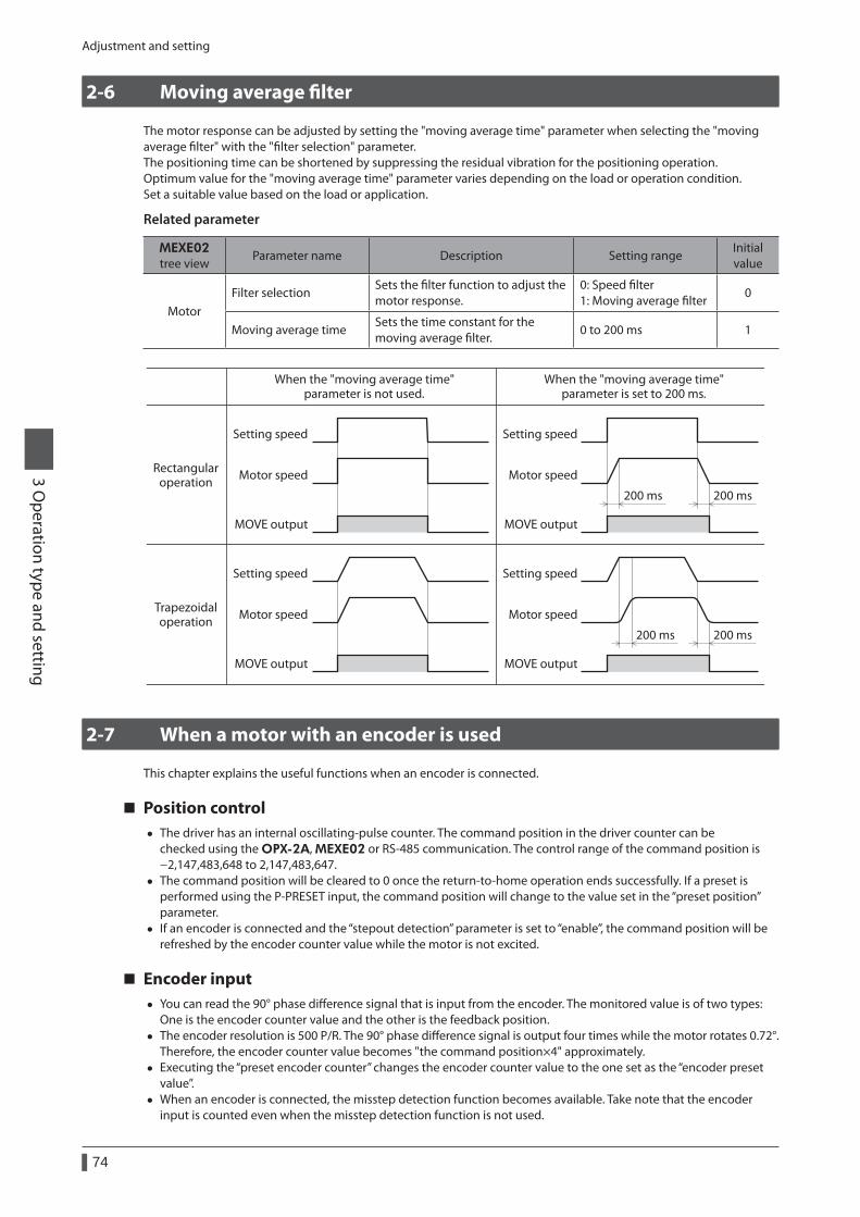
Adjustment and setting
74
3 Operation type and setting
2-6 Moving average filter
The motor response can be adjusted by setting the "moving average time" parameter when selecting the "moving average filter" with the "filter selection" parameter.The positioning time can be shortened by suppressing the residual vibration for the positioning operation.Optimum value for the "moving average time" parameter varies depending on the load or operation condition.Set a suitable value based on the load or application.
Related parameter
MEXE02 tree view
Parameter name Description Setting rangeInitial value
MotorFilter selection
Sets the filter function to adjust the motor response.
0: Speed filter 1: Moving average filter
0
Moving average timeSets the time constant for the moving average filter.
0 to 200 ms 1
Setting speed
Motor speed
MOVE output
Setting speed
Motor speed
MOVE output
Setting speed
Motor speed
MOVE output
Setting speed
Motor speed
MOVE output
200 ms
200 ms200 ms
200 ms
When the "moving average time"parameter is not used.
Rectangularoperation
Trapezoidaloperation
When the "moving average time"parameter is set to 200 ms.
2-7 When a motor with an encoder is used
This chapter explains the useful functions when an encoder is connected.
Position control • The driver has an internal oscillating-pulse counter. The command position in the driver counter can be
checked using the OPX-2A, MEXE02 or RS-485 communication. The control range of the command position is −2,147,483,648 to 2,147,483,647.
• The command position will be cleared to 0 once the return-to-home operation ends successfully. If a preset is performed using the P-PRESET input, the command position will change to the value set in the “preset position” parameter.
• If an encoder is connected and the “stepout detection” parameter is set to “enable”, the command position will be refreshed by the encoder counter value while the motor is not excited.
Encoder input • You can read the 90° phase difference signal that is input from the encoder. The monitored value is of two types:
One is the encoder counter value and the other is the feedback position. • The encoder resolution is 500 P/R. The 90° phase difference signal is output four times while the motor rotates 0.72°.
Therefore, the encoder counter value becomes "the command position×4" approximately. • Executing the “preset encoder counter” changes the encoder counter value to the one set as the “encoder preset
value”. • When an encoder is connected, the misstep detection function becomes available. Take note that the encoder
input is counted even when the misstep detection function is not used.
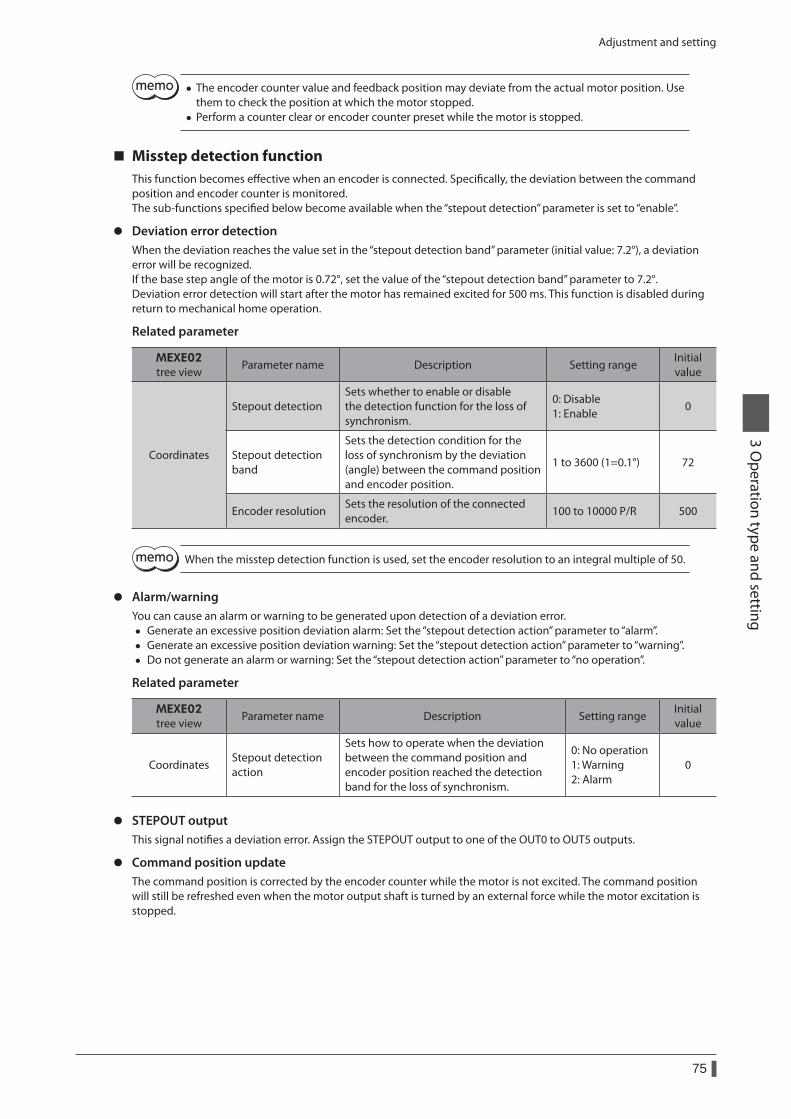
Adjustment and setting
75
3 Operation type and setting
• The encoder counter value and feedback position may deviate from the actual motor position. Use them to check the position at which the motor stopped.
• Perform a counter clear or encoder counter preset while the motor is stopped.
Misstep detection functionThis function becomes effective when an encoder is connected. Specifically, the deviation between the command position and encoder counter is monitored.The sub-functions specified below become available when the “stepout detection” parameter is set to “enable”.
z Deviation error detectionWhen the deviation reaches the value set in the “stepout detection band” parameter (initial value: 7.2°), a deviation error will be recognized.If the base step angle of the motor is 0.72°, set the value of the “stepout detection band” parameter to 7.2°.Deviation error detection will start after the motor has remained excited for 500 ms. This function is disabled during return to mechanical home operation.
Related parameter
MEXE02 tree view
Parameter name Description Setting rangeInitial value
Coordinates
Stepout detectionSets whether to enable or disable the detection function for the loss of synchronism.
0: Disable 1: Enable
0
Stepout detection band
Sets the detection condition for the loss of synchronism by the deviation (angle) between the command position and encoder position.
1 to 3600 (1=0.1°) 72
Encoder resolutionSets the resolution of the connected encoder.
100 to 10000 P/R 500
When the misstep detection function is used, set the encoder resolution to an integral multiple of 50.
z Alarm/warningYou can cause an alarm or warning to be generated upon detection of a deviation error.
• Generate an excessive position deviation alarm: Set the “stepout detection action” parameter to “alarm”. • Generate an excessive position deviation warning: Set the “stepout detection action” parameter to “warning”. • Do not generate an alarm or warning: Set the “stepout detection action” parameter to “no operation”.
Related parameter
MEXE02 tree view
Parameter name Description Setting rangeInitial value
CoordinatesStepout detection action
Sets how to operate when the deviation between the command position and encoder position reached the detection band for the loss of synchronism.
0: No operation 1: Warning 2: Alarm
0
z STEPOUT outputThis signal notifies a deviation error. Assign the STEPOUT output to one of the OUT0 to OUT5 outputs.
z Command position updateThe command position is corrected by the encoder counter while the motor is not excited. The command position will still be refreshed even when the motor output shaft is turned by an external force while the motor excitation is stopped.
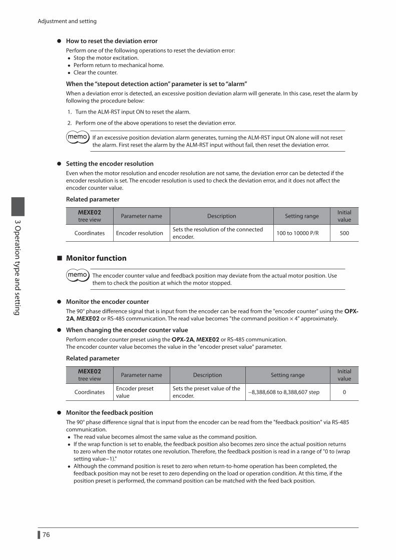
Adjustment and setting
76
3 Operation type and setting
z How to reset the deviation errorPerform one of the following operations to reset the deviation error:
• Stop the motor excitation. • Perform return to mechanical home. • Clear the counter.
When the “stepout detection action” parameter is set to “alarm”When a deviation error is detected, an excessive position deviation alarm will generate. In this case, reset the alarm by following the procedure below:
1. Turn the ALM-RST input ON to reset the alarm.
2. Perform one of the above operations to reset the deviation error.
If an excessive position deviation alarm generates, turning the ALM-RST input ON alone will not reset the alarm. First reset the alarm by the ALM-RST input without fail, then reset the deviation error.
z Setting the encoder resolutionEven when the motor resolution and encoder resolution are not same, the deviation error can be detected if the encoder resolution is set. The encoder resolution is used to check the deviation error, and it does not affect the encoder counter value.
Related parameter
MEXE02tree view
Parameter name Description Setting rangeInitial value
Coordinates Encoder resolutionSets the resolution of the connected encoder.
100 to 10000 P/R 500
Monitor function
The encoder counter value and feedback position may deviate from the actual motor position. Use them to check the position at which the motor stopped.
z Monitor the encoder counterThe 90° phase difference signal that is input from the encoder can be read from the "encoder counter" using the OPX-2A, MEXE02 or RS-485 communication. The read value becomes "the command position × 4" approximately.
z When changing the encoder counter valuePerform encoder counter preset using the OPX-2A, MEXE02 or RS-485 communication.The encoder counter value becomes the value in the "encoder preset value" parameter.
Related parameter
MEXE02tree view
Parameter name Description Setting rangeInitial value
CoordinatesEncoder preset value
Sets the preset value of the encoder.
−8,388,608 to 8,388,607 step 0
z Monitor the feedback positionThe 90° phase difference signal that is input from the encoder can be read from the "feedback position" via RS-485 communication.
• The read value becomes almost the same value as the command position. • If the wrap function is set to enable, the feedback position also becomes zero since the actual position returns
to zero when the motor rotates one revolution. Therefore, the feedback position is read in a range of "0 to (wrap setting value−1)."
• Although the command position is reset to zero when return-to-home operation has been completed, the feedback position may not be reset to zero depending on the load or operation condition. At this time, if the position preset is performed, the command position can be matched with the feed back position.
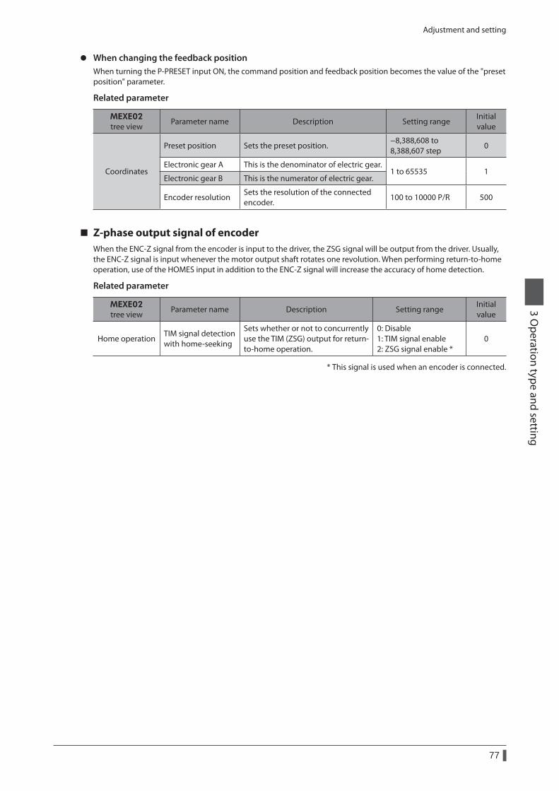
Adjustment and setting
77
3 Operation type and setting
z When changing the feedback positionWhen turning the P-PRESET input ON, the command position and feedback position becomes the value of the "preset position" parameter.
Related parameter
MEXE02tree view
Parameter name Description Setting rangeInitial value
Coordinates
Preset position Sets the preset position.−8,388,608 to 8,388,607 step
0
Electronic gear A This is the denominator of electric gear.1 to 65535 1
Electronic gear B This is the numerator of electric gear.
Encoder resolutionSets the resolution of the connected encoder.
100 to 10000 P/R 500
Z-phase output signal of encoderWhen the ENC-Z signal from the encoder is input to the driver, the ZSG signal will be output from the driver. Usually, the ENC-Z signal is input whenever the motor output shaft rotates one revolution. When performing return-to-home operation, use of the HOMES input in addition to the ENC-Z signal will increase the accuracy of home detection.
Related parameter
MEXE02tree view
Parameter name Description Setting rangeInitial value
Home operationTIM signal detection with home-seeking
Sets whether or not to concurrently use the TIM (ZSG) output for return-to-home operation.
0: Disable 1: TIM signal enable 2: ZSG signal enable *
0
* This signal is used when an encoder is connected.
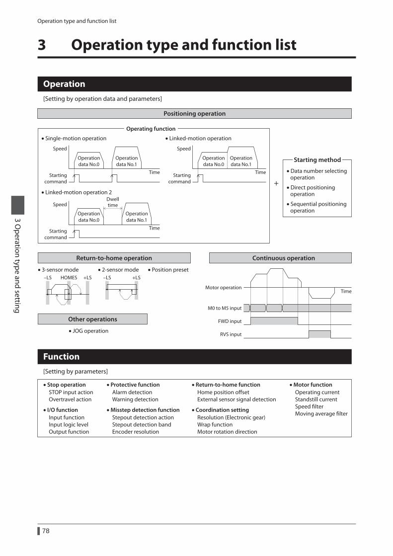
Operation type and function list
78
3 Operation type and setting
3 Operation type and function list
Other operations
• JOG operation
Positioning operation
Speed
Time
Speed
Time
Speed
Time
Operating function
• Data number selecting operation
• Direct positioning operation
• Sequential positioning operation
Starting method
+
Operation[Setting by operation data and parameters]
Function[Setting by parameters]
• Stop operationSTOP input actionOvertravel action
• Coordination settingResolution (Electronic gear)Wrap functionMotor rotation direction
• Motor functionOperating currentStandstill currentSpeed lterMoving average lter
• Misstep detection functionStepout detection actionStepout detection bandEncoder resolution
• I/O functionInput functionInput logic levelOutput function
• Return-to-home functionHome position osetExternal sensor signal detection
• Protective functionAlarm detectionWarning detection
Starting command
• Single-motion operation
Operationdata No.0
Operationdata No.1
Starting command
• Linked-motion operation
Dwelltime
Operationdata No.0
Operationdata No.1
Operationdata No.0
Operationdata No.1
Starting command
• Linked-motion operation 2
Return-to-home operation Continuous operation
• 3-sensor mode-LS +LSHOMES
• 2-sensor mode-LS +LS
• Position preset
Motor operationTime
FWD input
RVS input
M0 to M5 input
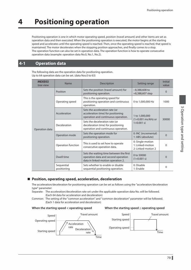
Positioning operation
79
3 Operation type and setting
4 Positioning operation
Positioning operation is one in which motor operating speed, position (travel amount) and other items are set as operation data and then executed. When the positioning operation is executed, the motor begins at the starting speed and accelerates until the operating speed is reached. Then, once the operating speed is reached, that speed is maintained. The motor decelerates when the stopping position approaches, and finally comes to a stop.The operation function can also be set in operation data. The operation function is how to operate consecutive operation data (example: operation data No.0, No.1, No.2).
4-1 Operation data
The following data are the operation data for positioning operation. Up to 64 operation data can be set. (data Nos.0 to 63)
MEXE02tree view
Name Description Setting rangeInitial value
Operation data
PositionSets the position (travel amount) for positioning operation.
−8,388,608 to +8,388,607 step
0
Operating speedThis is the operating speed for positioning operation and continuous operation.
0 to 1,000,000 Hz 1000
AccelerationSets the acceleration rate (or acceleration time) for positioning operation and continuous operation. 1 to 1,000,000
(1=0.001 ms/kHz or 1=0.001 s)
30000
DecelerationSets the deceleration rate (or deceleration time) for positioning operation and continuous operation.
Operation modeSets the operation mode for positioning operation.
0: INC (incremental) 1: ABS (absolute)
0
Operation functionThis is used to set how to operate consecutive operation data.
0: Single-motion 1: Linked-motion 2: Linked-motion 2
0
Dwell timeSets the waiting time between the first operation data and second operation data in linked-motion operation 2.
0 to 50000 (1=0.001 s)
0
Sequential positioning
Sets whether to enable or disable sequential positioning operation.
0: Disable 1: Enable
0
Position, operating speed, acceleration, decelerationThe acceleration/deceleration for positioning operation can be set as follows using the "acceleration/deceleration type" parameter:Separate: The acceleration/deceleration rate set under the applicable operation data No. will be followed. (Each 64 data for acceleration and deceleration)Common: The setting of the "common acceleration" and "common deceleration" parameter will be followed. (Each 1 data for acceleration and deceleration)
When the starting speed < operating speed
Speed
Operating speed
Starting speed
Time
Accelerationrate
Decelerationrate
Travel amount
When the starting speed ≥ operating speed
Speed
Starting speed
Operating speed
Time
Travel amount
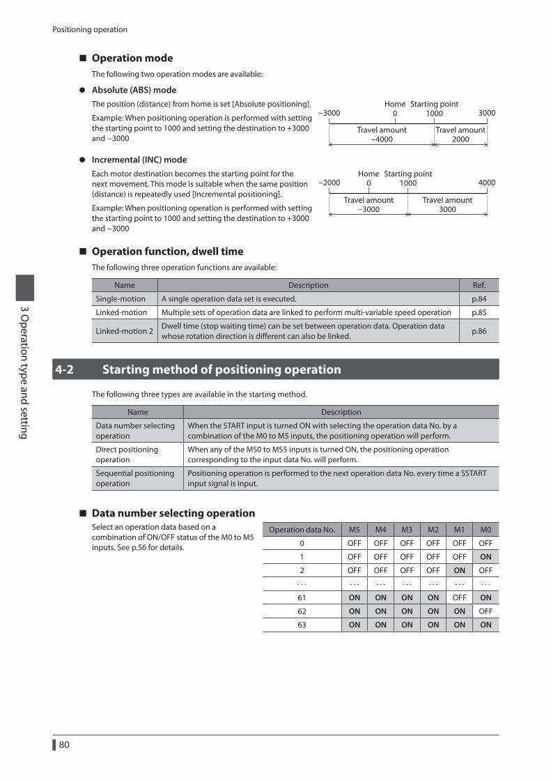
Positioning operation
80
3 Operation type and setting
Operation modeThe following two operation modes are available:
z Absolute (ABS) modeThe position (distance) from home is set [Absolute positioning].
Example: When positioning operation is performed with setting the starting point to 1000 and setting the destination to +3000 and −3000
3000Starting point
1000
Travel amount2000
Travel amount-4000
Home0-3000
z Incremental (INC) modeEach motor destination becomes the starting point for the next movement. This mode is suitable when the same position (distance) is repeatedly used [Incremental positioning].
Example: When positioning operation is performed with setting the starting point to 1000 and setting the destination to +3000 and −3000
4000-2000Starting point
1000
Travel amount3000
Travel amount-3000
Home0
Operation function, dwell timeThe following three operation functions are available:
Name Description Ref.
Single-motion A single operation data set is executed. p.84
Linked-motion Multiple sets of operation data are linked to perform multi-variable speed operation p.85
Linked-motion 2Dwell time (stop waiting time) can be set between operation data. Operation data whose rotation direction is different can also be linked.
p.86
4-2 Starting method of positioning operation
The following three types are available in the starting method.
Name Description
Data number selecting operation
When the START input is turned ON with selecting the operation data No. by a combination of the M0 to M5 inputs, the positioning operation will perform.
Direct positioning operation
When any of the MS0 to MS5 inputs is turned ON, the positioning operation corresponding to the input data No. will perform.
Sequential positioning operation
Positioning operation is performed to the next operation data No. every time a SSTART input signal is input.
Data number selecting operationSelect an operation data based on a combination of ON/OFF status of the M0 to M5 inputs. See p.56 for details.
Operation data No. M5 M4 M3 M2 M1 M0
0 OFF OFF OFF OFF OFF OFF
1 OFF OFF OFF OFF OFF ON
2 OFF OFF OFF OFF ON OFF
· · · · · · · · · · · · · · · · · · · · ·
61 ON ON ON ON OFF ON
62 ON ON ON ON ON OFF
63 ON ON ON ON ON ON
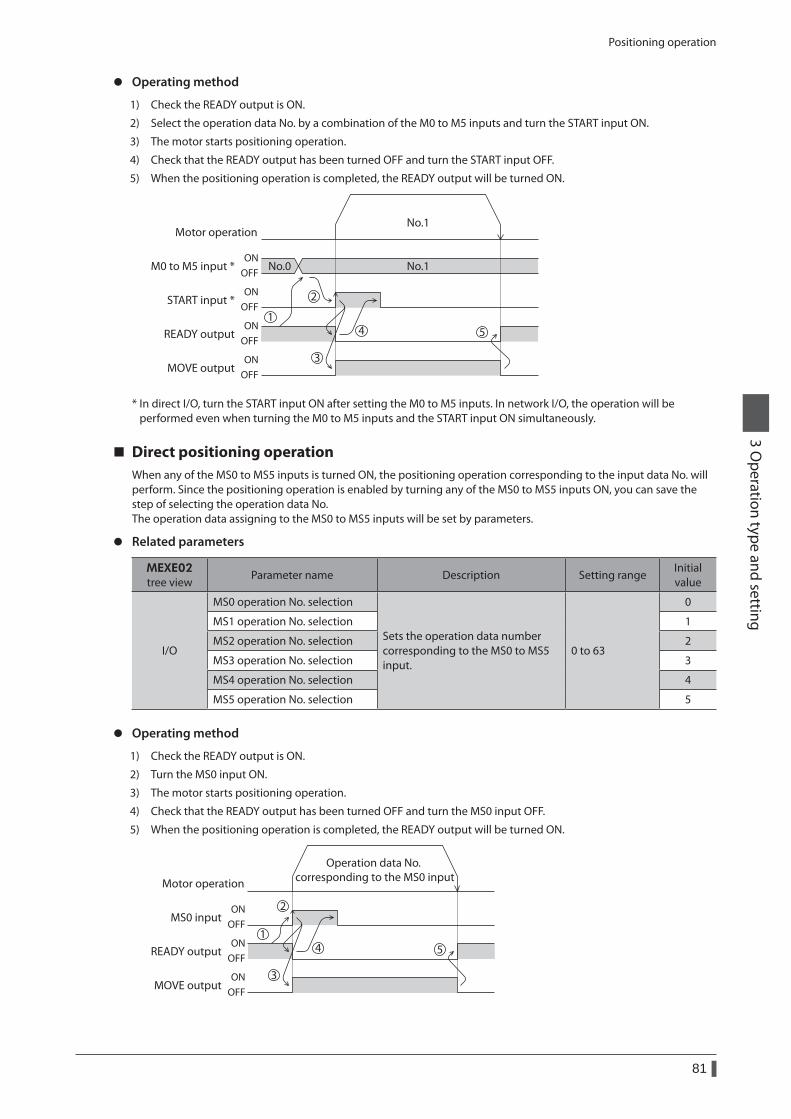
Positioning operation
81
3 Operation type and setting
z Operating method
1) Check the READY output is ON.
2) Select the operation data No. by a combination of the M0 to M5 inputs and turn the START input ON.
3) The motor starts positioning operation.
4) Check that the READY output has been turned OFF and turn the START input OFF.
5) When the positioning operation is completed, the READY output will be turned ON.
START input *
MOVE output
READY output
Motor operation
M0 to M5 input * No.0 No.1
No.1
ONOFF
ONOFF
ONOFF
ONOFF
1
2
3
4 5
* In direct I/O, turn the START input ON after setting the M0 to M5 inputs. In network I/O, the operation will be performed even when turning the M0 to M5 inputs and the START input ON simultaneously.
Direct positioning operationWhen any of the MS0 to MS5 inputs is turned ON, the positioning operation corresponding to the input data No. will perform. Since the positioning operation is enabled by turning any of the MS0 to MS5 inputs ON, you can save the step of selecting the operation data No.The operation data assigning to the MS0 to MS5 inputs will be set by parameters.
z Related parameters
MEXE02tree view
Parameter name Description Setting rangeInitial value
I/O
MS0 operation No. selection
Sets the operation data number corresponding to the MS0 to MS5 input.
0 to 63
0
MS1 operation No. selection 1
MS2 operation No. selection 2
MS3 operation No. selection 3
MS4 operation No. selection 4
MS5 operation No. selection 5
z Operating method
1) Check the READY output is ON.
2) Turn the MS0 input ON.
3) The motor starts positioning operation.
4) Check that the READY output has been turned OFF and turn the MS0 input OFF.
5) When the positioning operation is completed, the READY output will be turned ON.
MOVE output
READY output
Motor operation
MS0 inputON
OFF
ONOFF
ONOFF
1
2
3
4 5
Operation data No. corresponding to the MS0 input
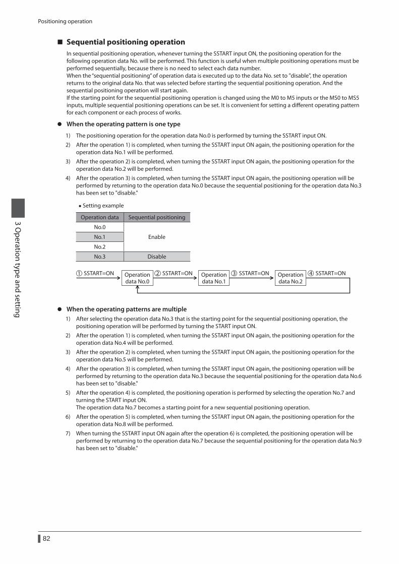
Positioning operation
82
3 Operation type and setting
Sequential positioning operationIn sequential positioning operation, whenever turning the SSTART input ON, the positioning operation for the following operation data No. will be performed. This function is useful when multiple positioning operations must be performed sequentially, because there is no need to select each data number.When the “sequential positioning” of operation data is executed up to the data No. set to "disable", the operation returns to the original data No. that was selected before starting the sequential positioning operation. And the sequential positioning operation will start again.If the starting point for the sequential positioning operation is changed using the M0 to M5 inputs or the MS0 to MS5 inputs, multiple sequential positioning operations can be set. It is convenient for setting a different operating pattern for each component or each process of works.
z When the operating pattern is one type
1) The positioning operation for the operation data No.0 is performed by turning the SSTART input ON.
2) After the operation 1) is completed, when turning the SSTART input ON again, the positioning operation for the operation data No.1 will be performed.
3) After the operation 2) is completed, when turning the SSTART input ON again, the positioning operation for the operation data No.2 will be performed.
4) After the operation 3) is completed, when turning the SSTART input ON again, the positioning operation will be performed by returning to the operation data No.0 because the sequential positioning for the operation data No.3 has been set to "disable."
• Setting example
Operation data Sequential positioning
No.0
EnableNo.1
No.2
No.3 Disable
Operationdata No.0
Operationdata No.1
Operationdata No.2
SSTART=ON1 SSTART=ON2 SSTART=ON3 SSTART=ON4
z When the operating patterns are multiple1) After selecting the operation data No.3 that is the starting point for the sequential positioning operation, the
positioning operation will be performed by turning the START input ON.
2) After the operation 1) is completed, when turning the SSTART input ON again, the positioning operation for the operation data No.4 will be performed.
3) After the operation 2) is completed, when turning the SSTART input ON again, the positioning operation for the operation data No.5 will be performed.
4) After the operation 3) is completed, when turning the SSTART input ON again, the positioning operation will be performed by returning to the operation data No.3 because the sequential positioning for the operation data No.6 has been set to "disable."
5) After the operation 4) is completed, the positioning operation is performed by selecting the operation No.7 and turning the START input ON.The operation data No.7 becomes a starting point for a new sequential positioning operation.
6) After the operation 5) is completed, when turning the SSTART input ON again, the positioning operation for the operation data No.8 will be performed.
7) When turning the SSTART input ON again after the operation 6) is completed, the positioning operation will be performed by returning to the operation data No.7 because the sequential positioning for the operation data No.9 has been set to "disable."
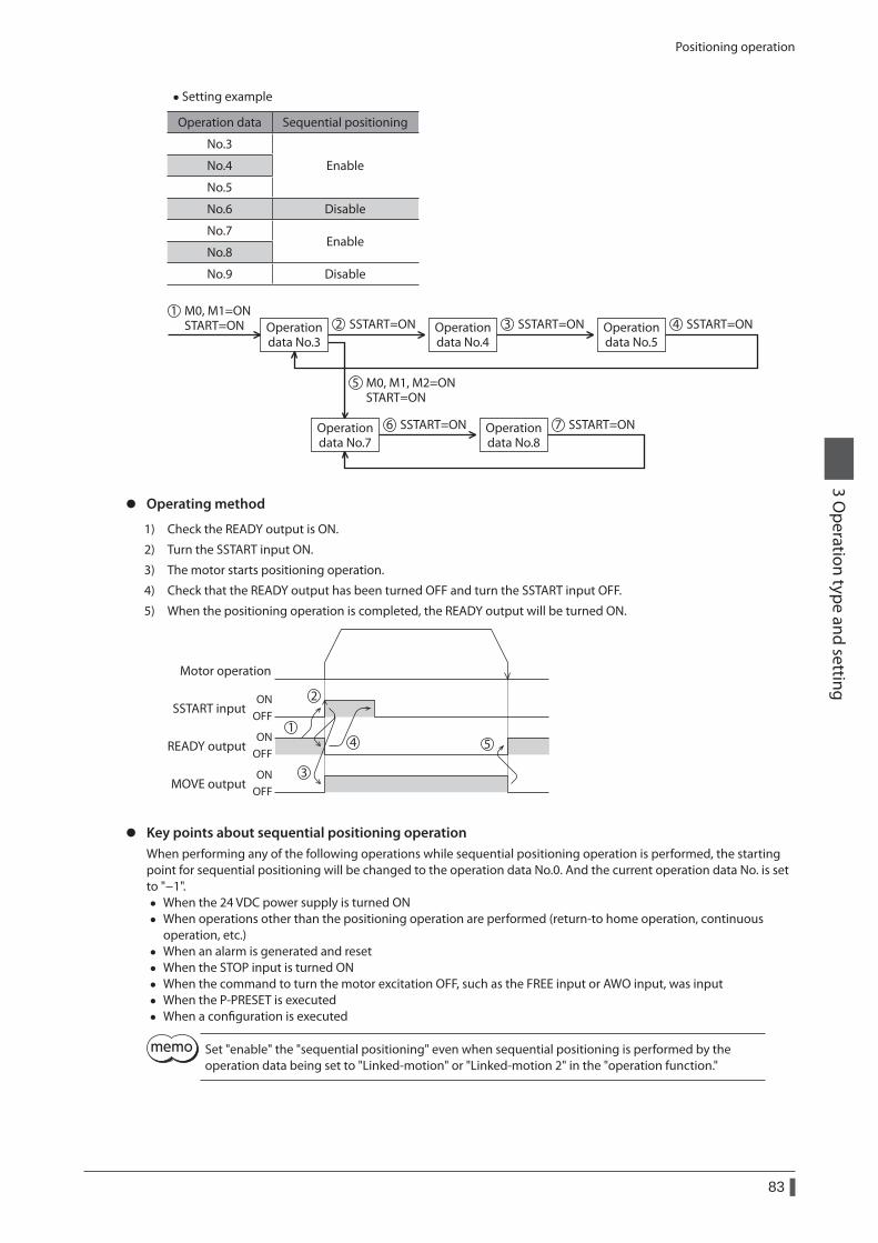
Positioning operation
83
3 Operation type and setting
• Setting example
Operation data Sequential positioning
No.3
EnableNo.4
No.5
No.6 Disable
No.7Enable
No.8
No.9 Disable
Operationdata No.3
Operationdata No.4
Operationdata No.5
Operationdata No.7
Operationdata No.8
SSTART=ON2M0, M1=ONSTART=ON
1
M0, M1, M2=ONSTART=ON
5
SSTART=ON6 SSTART=ON7
SSTART=ON3 SSTART=ON4
z Operating method
1) Check the READY output is ON.
2) Turn the SSTART input ON.
3) The motor starts positioning operation.
4) Check that the READY output has been turned OFF and turn the SSTART input OFF.
5) When the positioning operation is completed, the READY output will be turned ON.
MOVE output
READY output
Motor operation
SSTART inputON
OFF
ONOFF
ONOFF
1
2
3
4 5
z Key points about sequential positioning operationWhen performing any of the following operations while sequential positioning operation is performed, the starting point for sequential positioning will be changed to the operation data No.0. And the current operation data No. is set to "−1".
• When the 24 VDC power supply is turned ON • When operations other than the positioning operation are performed (return-to home operation, continuous
operation, etc.) • When an alarm is generated and reset • When the STOP input is turned ON • When the command to turn the motor excitation OFF, such as the FREE input or AWO input, was input • When the P-PRESET is executed • When a configuration is executed
Set "enable" the "sequential positioning" even when sequential positioning is performed by the operation data being set to "Linked-motion" or "Linked-motion 2" in the "operation function."
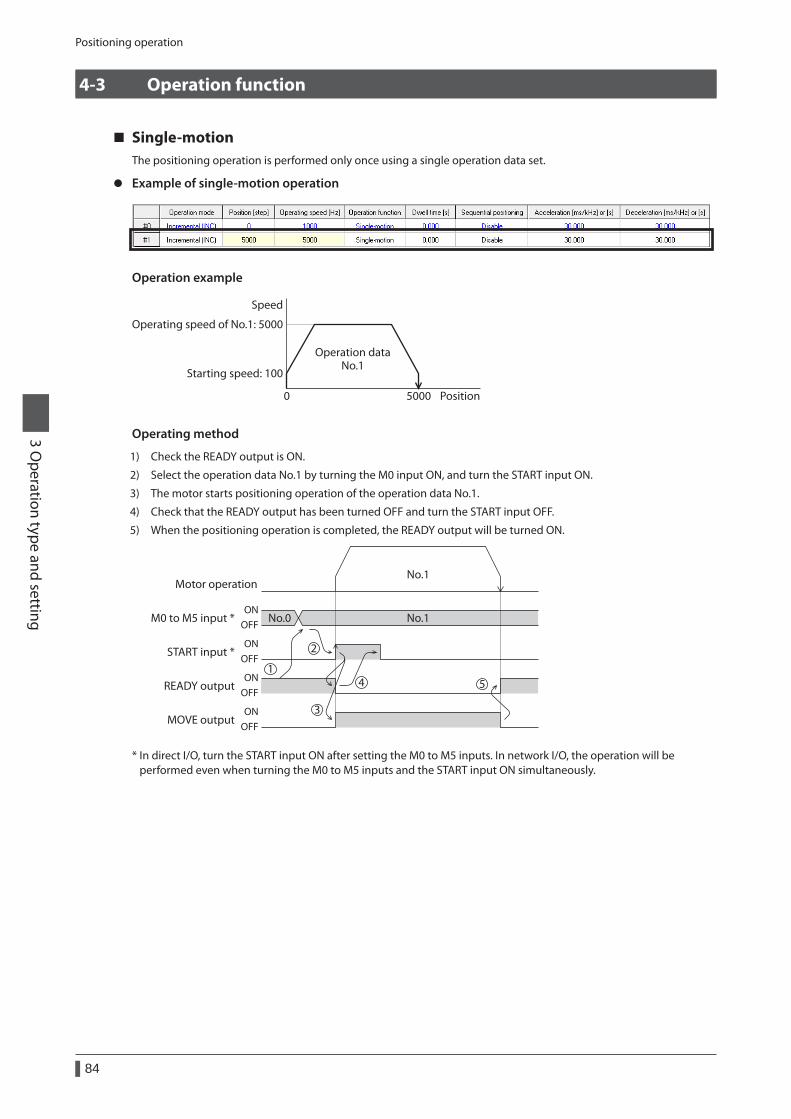
Positioning operation
84
3 Operation type and setting
4-3 Operation function
Single-motionThe positioning operation is performed only once using a single operation data set.
z Example of single-motion operation
Operation example
Speed
Operating speed of No.1: 5000
Starting speed: 100
Position50000
Operation dataNo.1
Operating method
1) Check the READY output is ON.
2) Select the operation data No.1 by turning the M0 input ON, and turn the START input ON.
3) The motor starts positioning operation of the operation data No.1.
4) Check that the READY output has been turned OFF and turn the START input OFF.
5) When the positioning operation is completed, the READY output will be turned ON.
START input *
MOVE output
READY output
Motor operation
M0 to M5 input * No.0 No.1
No.1
ONOFF
ONOFF
ONOFF
ONOFF
1
2
3
4 5
* In direct I/O, turn the START input ON after setting the M0 to M5 inputs. In network I/O, the operation will be performed even when turning the M0 to M5 inputs and the START input ON simultaneously.
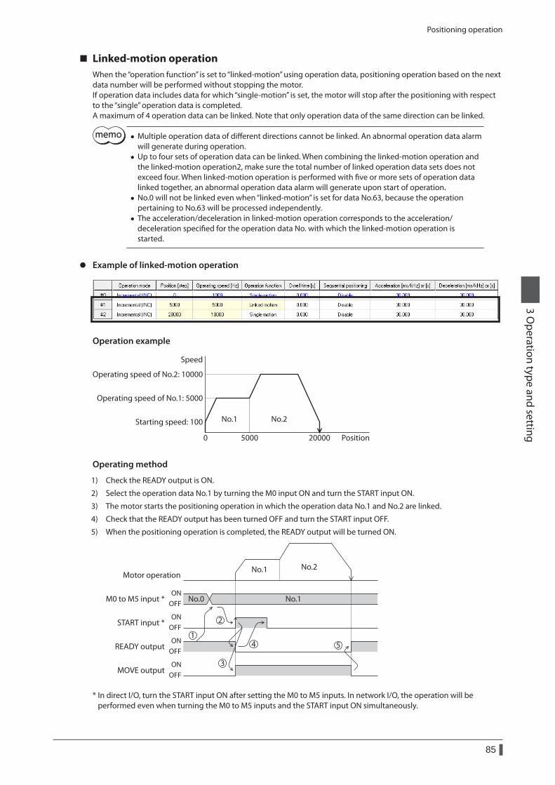
Positioning operation
85
3 Operation type and setting
Linked-motion operationWhen the “operation function” is set to “linked-motion” using operation data, positioning operation based on the next data number will be performed without stopping the motor.If operation data includes data for which “single-motion” is set, the motor will stop after the positioning with respect to the “single” operation data is completed.A maximum of 4 operation data can be linked. Note that only operation data of the same direction can be linked.
• Multiple operation data of different directions cannot be linked. An abnormal operation data alarm will generate during operation.
• Up to four sets of operation data can be linked. When combining the linked-motion operation and the linked-motion operation2, make sure the total number of linked operation data sets does not exceed four. When linked-motion operation is performed with five or more sets of operation data linked together, an abnormal operation data alarm will generate upon start of operation.
• No.0 will not be linked even when “linked-motion” is set for data No.63, because the operation pertaining to No.63 will be processed independently.
• The acceleration/deceleration in linked-motion operation corresponds to the acceleration/ deceleration specified for the operation data No. with which the linked-motion operation is started.
z Example of linked-motion operation
Operation example
Speed
Operating speed of No.2: 10000
Operating speed of No.1: 5000
Starting speed: 100
Position5000 200000
No.1 No.2
Operating method
1) Check the READY output is ON.
2) Select the operation data No.1 by turning the M0 input ON and turn the START input ON.
3) The motor starts the positioning operation in which the operation data No.1 and No.2 are linked.
4) Check that the READY output has been turned OFF and turn the START input OFF.
5) When the positioning operation is completed, the READY output will be turned ON.
START input *
MOVE output
READY output
Motor operation
M0 to M5 input * No.0 No.1ON
OFF
ONOFF
ONOFF
ONOFF
No.1 No.2
1
2
3
4 5
* In direct I/O, turn the START input ON after setting the M0 to M5 inputs. In network I/O, the operation will be performed even when turning the M0 to M5 inputs and the START input ON simultaneously.
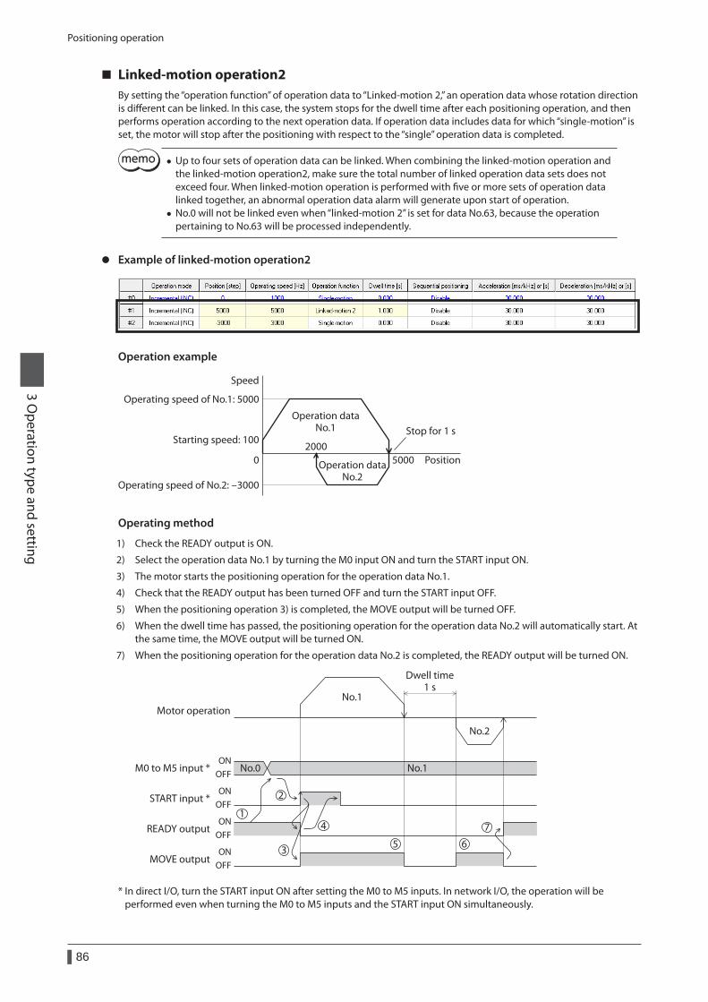
Positioning operation
86
3 Operation type and setting
Linked-motion operation2By setting the “operation function” of operation data to “Linked-motion 2,” an operation data whose rotation direction is different can be linked. In this case, the system stops for the dwell time after each positioning operation, and then performs operation according to the next operation data. If operation data includes data for which “single-motion” is set, the motor will stop after the positioning with respect to the “single” operation data is completed.
• Up to four sets of operation data can be linked. When combining the linked-motion operation and the linked-motion operation2, make sure the total number of linked operation data sets does not exceed four. When linked-motion operation is performed with five or more sets of operation data linked together, an abnormal operation data alarm will generate upon start of operation.
• No.0 will not be linked even when “linked-motion 2” is set for data No.63, because the operation pertaining to No.63 will be processed independently.
z Example of linked-motion operation2
Operation example
Speed
Operating speed of No.1: 5000
Operating speed of No.2: -3000
Starting speed: 100
Position50002000
0
Operation dataNo.1
Operation dataNo.2
Stop for 1 s
Operating method
1) Check the READY output is ON.
2) Select the operation data No.1 by turning the M0 input ON and turn the START input ON.
3) The motor starts the positioning operation for the operation data No.1.
4) Check that the READY output has been turned OFF and turn the START input OFF.
5) When the positioning operation 3) is completed, the MOVE output will be turned OFF.
6) When the dwell time has passed, the positioning operation for the operation data No.2 will automatically start. At the same time, the MOVE output will be turned ON.
7) When the positioning operation for the operation data No.2 is completed, the READY output will be turned ON.
START input *
MOVE output
READY output
Motor operation
Dwell time1 s
M0 to M5 input * No.0 No.1ON
OFF
ONOFF
ONOFF
ONOFF
No.1
No.2
1
2
3
4
5 6
7
* In direct I/O, turn the START input ON after setting the M0 to M5 inputs. In network I/O, the operation will be performed even when turning the M0 to M5 inputs and the START input ON simultaneously.
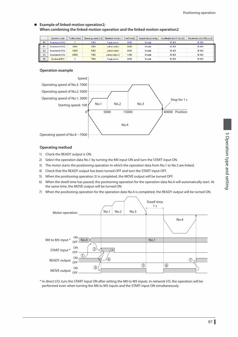
Positioning operation
87
3 Operation type and setting
z Example of linked-motion operation2; When combining the linked-motion operation and the linked-motion operation2
Operation example
Speed
Operating speed of No.3: 7000
Operating speed of No.4: -7000
Operating speed of No.1: 3000
Operating speed of No.2: 5000
Starting speed: 100
Position5000 40000150000
No.1 No.2 No.3
No.4
Stop for 1 s
Operating method
1) Check the READY output is ON.
2) Select the operation data No.1 by turning the M0 input ON and turn the START input ON.
3) The motor starts the positioning operation in which the operation data from No.1 to No.3 are linked.
4) Check that the READY output has been turned OFF and turn the START input OFF.
5) When the positioning operation 3) is completed, the MOVE output will be turned OFF.
6) When the dwell time has passed, the positioning operation for the operation data No.4 will automatically start. At the same time, the MOVE output will be turned ON.
7) When the positioning operation for the operation data No.4 is completed, the READY output will be turned ON.
START input *
MOVE output
READY output
Motor operation
Dwell time1 s
M0 to M5 input * No.0 No.1ON
OFF
ONOFF
ONOFF
ONOFF
No.1 No.2 No.3
No.4
1
2
3 5 6
74
* In direct I/O, turn the START input ON after setting the M0 to M5 inputs. In network I/O, the operation will be performed even when turning the M0 to M5 inputs and the START input ON simultaneously.
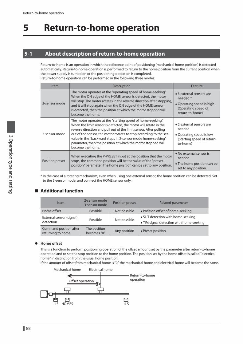
Return-to-home operation
88
3 Operation type and setting
5 Return-to-home operation
5-1 About description of return-to-home operation
Return-to-home is an operation in which the reference point of positioning (mechanical home position) is detected automatically. Return-to-home operation is performed to return to the home position from the current position when the power supply is turned on or the positioning operation is completed.Return-to-home operation can be performed in the following three modes:
Item Description Feature
3-sensor mode
The motor operates at the "operating speed of home-seeking." When the ON edge of the HOME sensor is detected, the motor will stop. The motor rotates in the reverse direction after stopping, and it will stop again when the ON edge of the HOME sensor is detected, then the position at which the motor stopped will become the home.
• 3 external sensors are needed *
• Operating speed is high (Operating speed of return-to-home)
2-sensor mode
The motor operates at the "starting speed of home-seeking." When the limit sensor is detected, the motor will rotate in the reverse direction and pull out of the limit sensor. After pulling out of the sensor, the motor rotates to stop according to the set value in the "backward steps in 2-sensor mode home-seeking" parameter, then the position at which the motor stopped will become the home.
• 2 external sensors are needed
• Operating speed is low (Starting speed of return-to-home)
Position presetWhen executing the P-PRESET input at the position that the motor stops, the command position will be the value of the "preset position" parameter. The home position can be set to any position.
• No external sensor is needed
• The home position can be set to any position.
* In the case of a rotating mechanism, even when using one external sensor, the home position can be detected. Set to the 3-sensor mode, and connect the HOME sensor only.
Additional function
Item2-sensor mode 3-sensor mode
Position preset Related parameter
Home offset Possible Not possible • Position offset of home-seeking
External sensor (signal) detection
Possible Not possible • SLIT detection with home-seeking
• TIM signal detection with home-seeking
Command position after returning to home
The position becomes "0"
Any position • Preset position
z Home offsetThis is a function to perform positioning operation of the offset amount set by the parameter after return-to-home operation and to set the stop position to the home position. The position set by the home offset is called "electrical home" in distinction from the usual home position.If the amount of offset from mechanical home is “0,” the mechanical home and electrical home will become the same.
Mechanical home
-LS HOMES +LS
Electrical home
Oset operation
Return-to-homeoperation
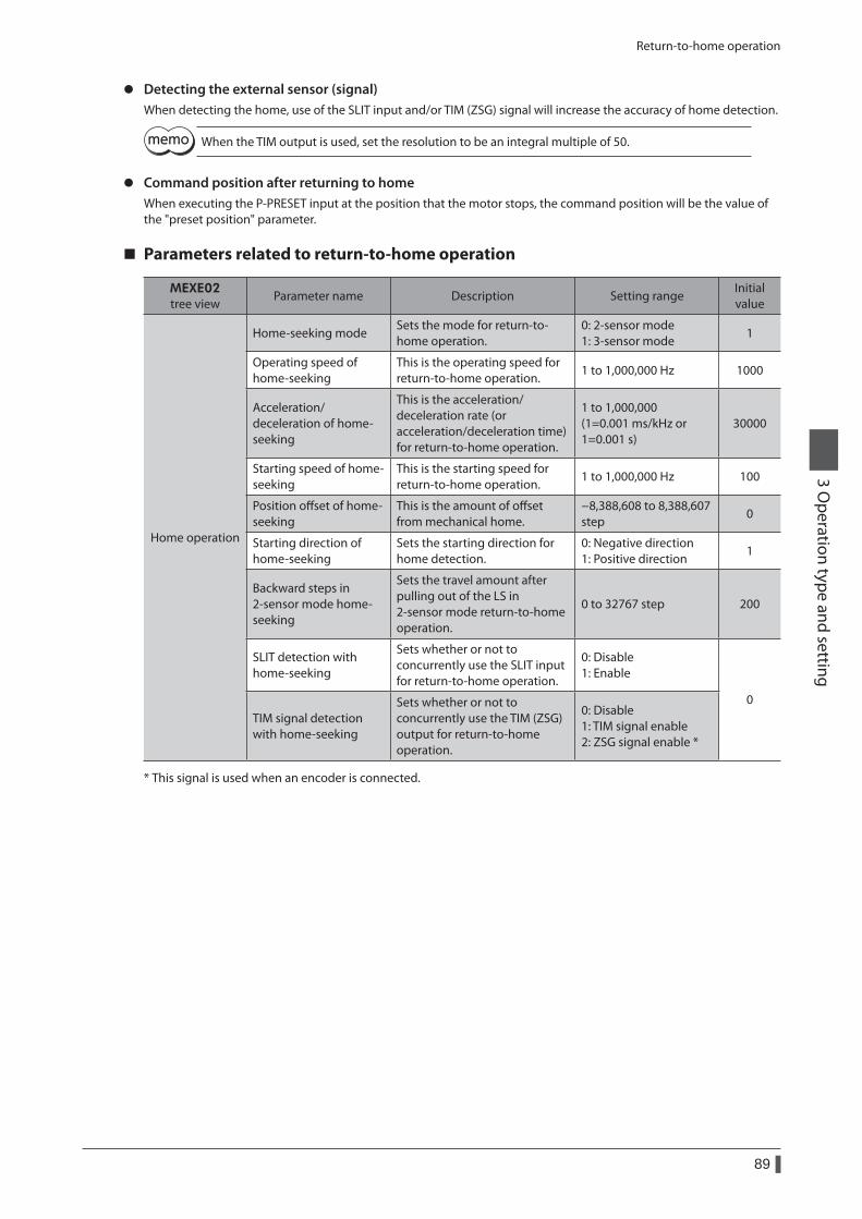
Return-to-home operation
89
3 Operation type and setting
z Detecting the external sensor (signal)When detecting the home, use of the SLIT input and/or TIM (ZSG) signal will increase the accuracy of home detection.
When the TIM output is used, set the resolution to be an integral multiple of 50.
z Command position after returning to homeWhen executing the P-PRESET input at the position that the motor stops, the command position will be the value of the "preset position" parameter.
Parameters related to return-to-home operation
MEXE02tree view
Parameter name Description Setting rangeInitial value
Home operation
Home-seeking modeSets the mode for return-to-home operation.
0: 2-sensor mode 1: 3-sensor mode
1
Operating speed of home-seeking
This is the operating speed for return-to-home operation.
1 to 1,000,000 Hz 1000
Acceleration/deceleration of home-seeking
This is the acceleration/deceleration rate (or acceleration/deceleration time) for return-to-home operation.
1 to 1,000,000 (1=0.001 ms/kHz or 1=0.001 s)
30000
Starting speed of home-seeking
This is the starting speed for return-to-home operation.
1 to 1,000,000 Hz 100
Position offset of home-seeking
This is the amount of offset from mechanical home.
−8,388,608 to 8,388,607 step
0
Starting direction of home-seeking
Sets the starting direction for home detection.
0: Negative direction 1: Positive direction
1
Backward steps in 2-sensor mode home-seeking
Sets the travel amount after pulling out of the LS in 2-sensor mode return-to-home operation.
0 to 32767 step 200
SLIT detection with home-seeking
Sets whether or not to concurrently use the SLIT input for return-to-home operation.
0: Disable 1: Enable
0TIM signal detection with home-seeking
Sets whether or not to concurrently use the TIM (ZSG) output for return-to-home operation.
0: Disable 1: TIM signal enable 2: ZSG signal enable *
* This signal is used when an encoder is connected.
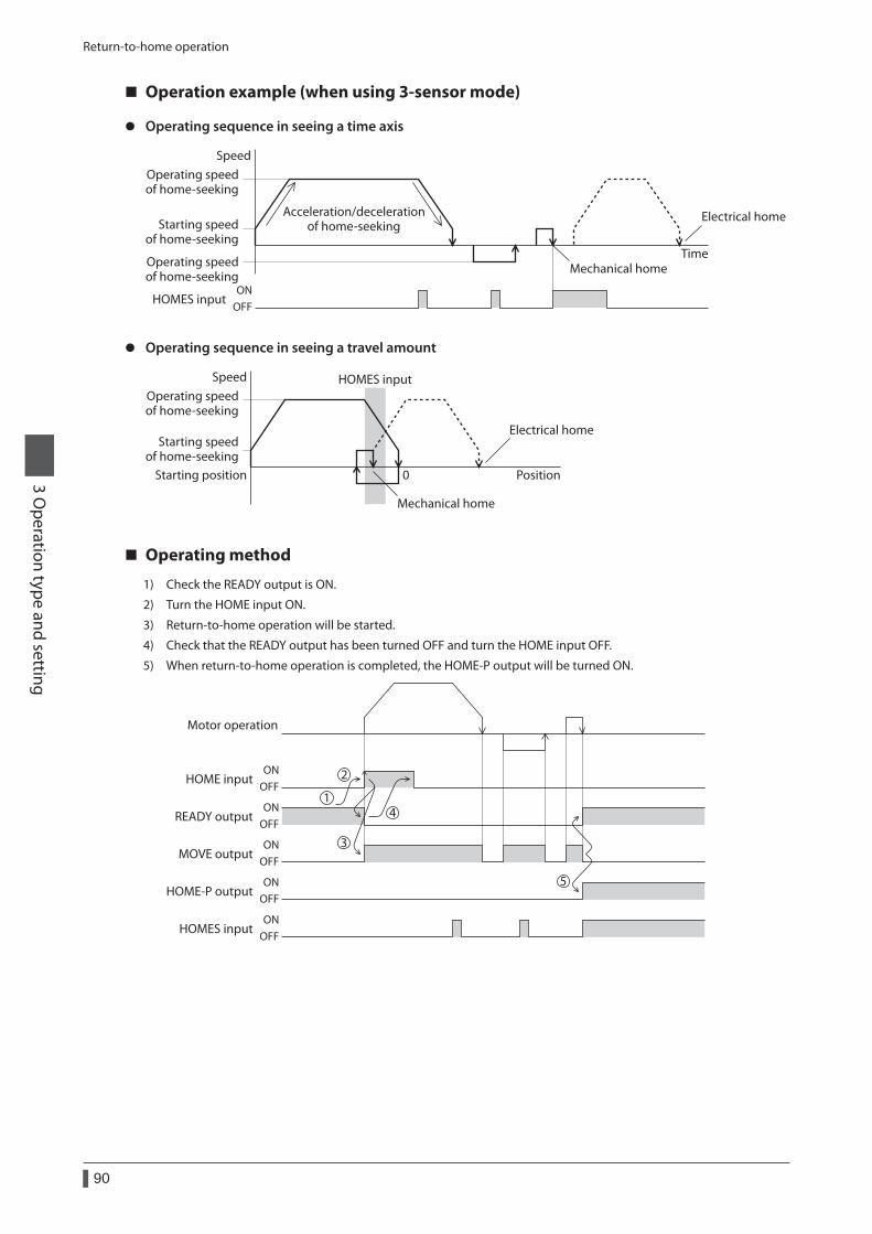
Return-to-home operation
90
3 Operation type and setting
Operation example (when using 3-sensor mode)
z Operating sequence in seeing a time axis
SpeedOperating speedof home-seeking
Starting speedof home-seeking
Operating speedof home-seeking
Time
Electrical home
Mechanical home
Acceleration/decelerationof home-seeking
HOMES inputON
OFF
z Operating sequence in seeing a travel amount
Speed HOMES input
Position0Starting position
Operating speedof home-seeking
Starting speedof home-seeking
Electrical home
Mechanical home
Operating method
1) Check the READY output is ON.
2) Turn the HOME input ON.
3) Return-to-home operation will be started.
4) Check that the READY output has been turned OFF and turn the HOME input OFF.
5) When return-to-home operation is completed, the HOME-P output will be turned ON.
ONOFF
ONOFF
ONOFF
ONOFF
ONOFF
HOME input
MOVE output
READY output
Motor operation
HOME-P output
HOMES input
1
2
3
4
5
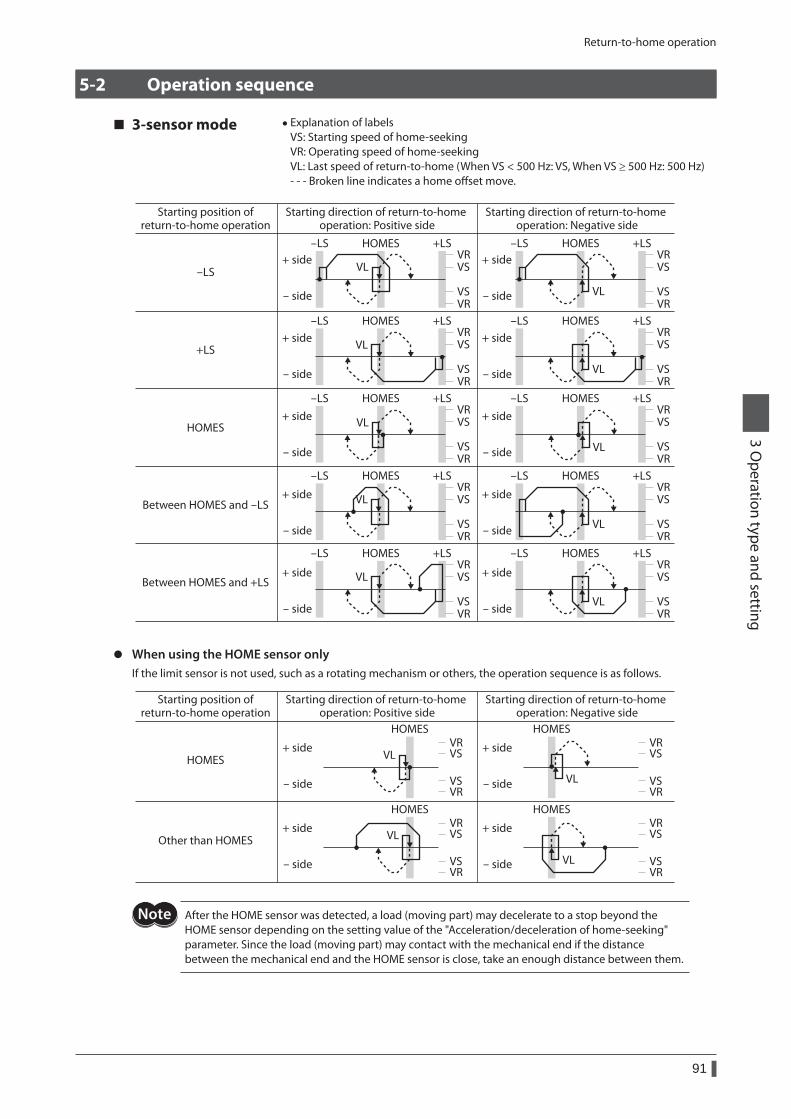
Return-to-home operation
91
3 Operation type and setting
5-2 Operation sequence
3-sensor mode • Explanation of labels VS: Starting speed of home-seeking VR: Operating speed of home-seeking VL: Last speed of return-to-home (When VS < 500 Hz: VS, When VS ≥ 500 Hz: 500 Hz)- - - Broken line indicates a home offset move.
Between HOMES and -LS
Between HOMES and +LS
HOMES
-LS
+LS
-LS +LS
VLVR
VR
VS
VL VS
VR
VR
VS
VS
VR
VR
VS
VS
VR
VR
VS
VS
VR
VR
VS
VS
VR
VR
VS
VS
VR
VR
VS
VS
VR
VR
VS
VS
VR
VR
VS
VS
VR
VR
VS
VS
VL
VL
VL
VL
VL
VL
VL
VL
HOMES -LS +LSHOMES
-LS +LSHOMES -LS +LSHOMES
-LS +LSHOMES -LS +LSHOMES
-LS +LSHOMES -LS +LSHOMES
-LS +LSHOMES -LS +LSHOMES
Starting position ofreturn-to-home operation
Starting direction of return-to-home operation: Positive side
Starting direction of return-to-home operation: Negative side
+ side
- side
+ side
- side
+ side
- side
+ side
- side
+ side
- side
+ side
- side
+ side
- side
+ side
- side
+ side
- side
+ side
- side
z When using the HOME sensor onlyIf the limit sensor is not used, such as a rotating mechanism or others, the operation sequence is as follows.
HOMES
Other than HOMES
Starting position ofreturn-to-home operation
Starting direction of return-to-home operation: Positive side
Starting direction of return-to-home operation: Negative side
+ side
- side
HOMES
+ side
- side
HOMES
+ side
- side
HOMES
+ side
- side
VR
VR
VS
VS
VR
VR
VS
VS
VR
VR
VS
VS
VR
VR
VS
VS
VL
VL
VL
VL
HOMES
After the HOME sensor was detected, a load (moving part) may decelerate to a stop beyond the HOME sensor depending on the setting value of the "Acceleration/deceleration of home-seeking" parameter. Since the load (moving part) may contact with the mechanical end if the distance between the mechanical end and the HOME sensor is close, take an enough distance between them.
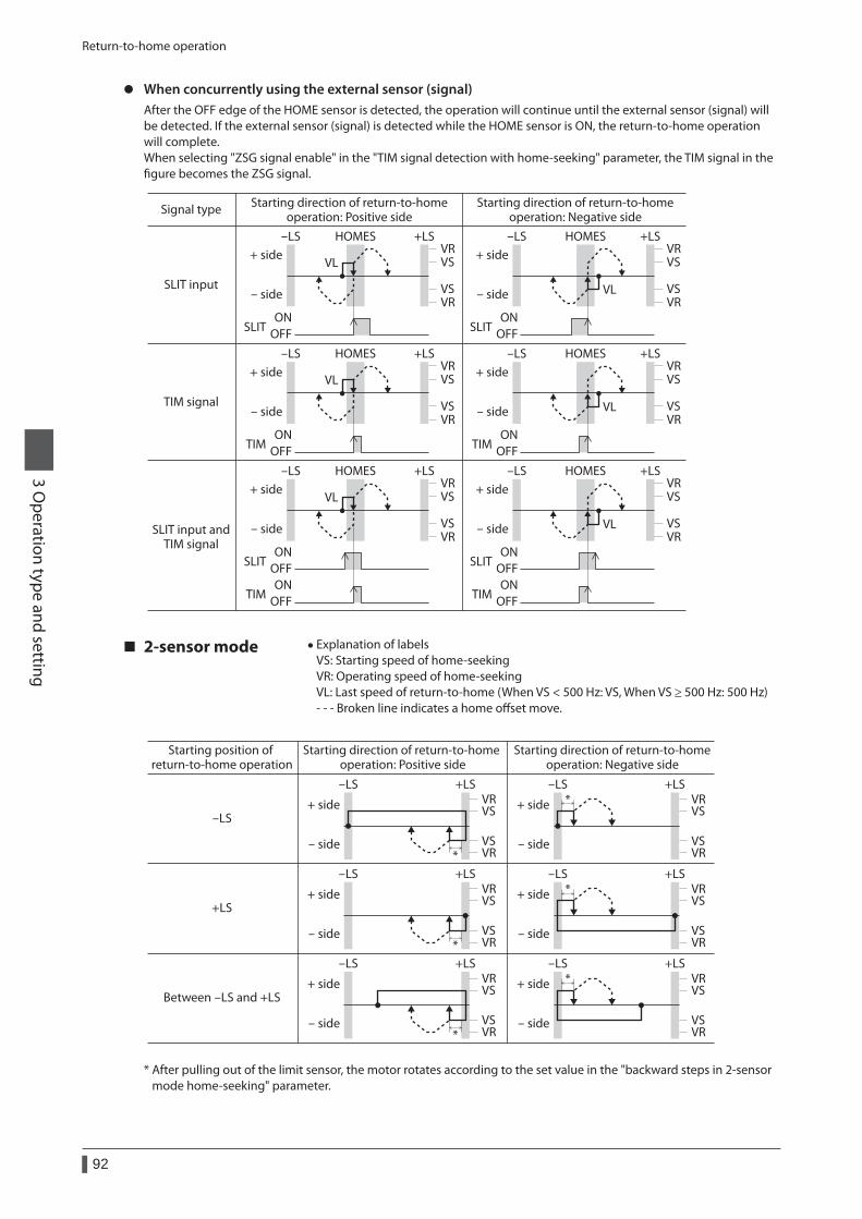
Return-to-home operation
92
3 Operation type and setting
z When concurrently using the external sensor (signal)After the OFF edge of the HOME sensor is detected, the operation will continue until the external sensor (signal) will be detected. If the external sensor (signal) is detected while the HOME sensor is ON, the return-to-home operation will complete.When selecting "ZSG signal enable" in the "TIM signal detection with home-seeking" parameter, the TIM signal in the figure becomes the ZSG signal.
VR
VR
VS
VS
VR
VR
VS
VS VL
VL
-LS +LSHOMES
SLIT OFFON
SLIT OFFON
-LS +LSHOMES
VR
VR
VS
VS
VR
VR
VS
VS VL
VL
-LS +LSHOMES
TIM OFFON
TIM OFFON
-LS +LSHOMES
SLIT input
TIM signal
SLIT input andTIM signal
VR
VR
VS
VS
VR
VR
VS
VS VL
VL
-LS +LSHOMES
TIM OFFON
TIM OFFON
SLIT OFFON
SLIT OFFON
-LS +LSHOMES
Signal type Starting direction of return-to-homeoperation: Positive side
Starting direction of return-to-homeoperation: Negative side
+ side
- side
+ side
- side
+ side
- side
+ side
- side
+ side
- side
+ side
- side
2-sensor mode • Explanation of labels VS: Starting speed of home-seeking VR: Operating speed of home-seeking VL: Last speed of return-to-home (When VS < 500 Hz: VS, When VS ≥ 500 Hz: 500 Hz)- - - Broken line indicates a home offset move.
Between -LS and +LS
-LS
+LS
Starting position of return-to-home operation
Starting direction of return-to-home operation: Positive side
Starting direction of return-to-homeoperation: Negative side
+ side
- side
+ side
- side
+ side
- side
+ side
- side
+ side
- side
+ side
- side
-LS +LS -LS +LS
-LS +LS -LS +LS
-LS +LS -LS +LS
VR
VR
VS
VS
VR
VR
VS
VS
VR
VR
VS
VS
VR
VR
VS
VS
VR
VR
VS
VS
VR
VR
VS
VS
*
*
*
*
*
*
* After pulling out of the limit sensor, the motor rotates according to the set value in the "backward steps in 2-sensor mode home-seeking" parameter.
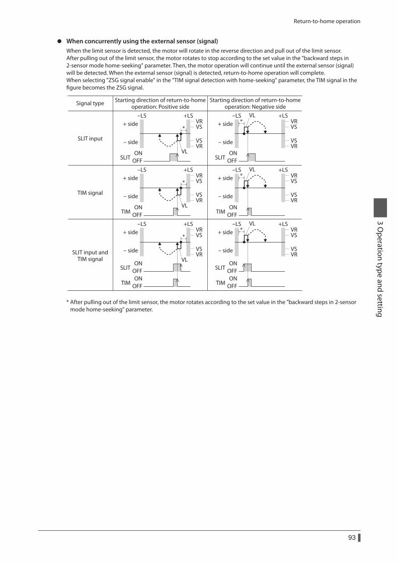
Return-to-home operation
93
3 Operation type and setting
z When concurrently using the external sensor (signal)When the limit sensor is detected, the motor will rotate in the reverse direction and pull out of the limit sensor.After pulling out of the limit sensor, the motor rotates to stop according to the set value in the "backward steps in 2-sensor mode home-seeking" parameter. Then, the motor operation will continue until the external sensor (signal) will be detected. When the external sensor (signal) is detected, return-to-home operation will complete.When selecting "ZSG signal enable" in the "TIM signal detection with home-seeking" parameter, the TIM signal in the figure becomes the ZSG signal.
Signal type
SLIT input
TIM signal
SLIT input andTIM signal
-LS +LS -LS +LSVR
VR
VS
VS
VR
VR
VS
VS
SLIT OFFON
SLIT OFFON
-LS +LS -LS +LSVR
VR
VS
VS
VR
VR
VS
VS
SLIT OFFON
SLIT OFFON
-LS +LS -LS +LSVR
VR
VS
VS
VR
VR
VS
VS
TIM OFFON
TIM OFFON
TIM OFFON
TIM OFFON
VL
VL
VL
VL
VL
VL
Starting direction of return-to-homeoperation: Positive side
Starting direction of return-to-homeoperation: Negative side
+ side
- side
+ side
- side
+ side
- side
+ side
- side
+ side
- side
+ side
- side
*
*
**
*
*
* After pulling out of the limit sensor, the motor rotates according to the set value in the "backward steps in 2-sensor mode home-seeking" parameter.
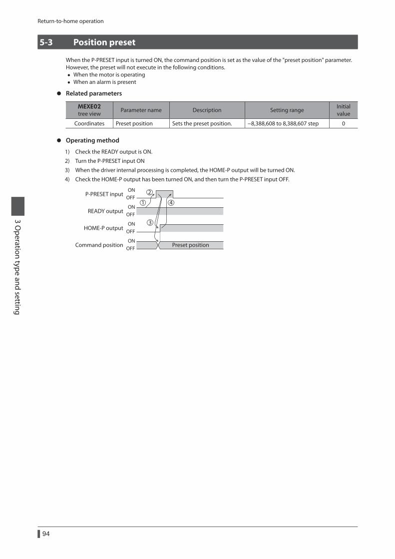
Return-to-home operation
94
3 Operation type and setting
5-3 Position preset
When the P-PRESET input is turned ON, the command position is set as the value of the "preset position" parameter.However, the preset will not execute in the following conditions.
• When the motor is operating • When an alarm is present
z Related parameters
MEXE02tree view
Parameter name Description Setting rangeInitial value
Coordinates Preset position Sets the preset position. −8,388,608 to 8,388,607 step 0
z Operating method
1) Check the READY output is ON.
2) Turn the P-PRESET input ON
3) When the driver internal processing is completed, the HOME-P output will be turned ON.
4) Check the HOME-P output has been turned ON, and then turn the P-PRESET input OFF.
P-PRESET input
HOME-P output
READY output
Command position Preset positionON
OFF
ONOFF
ONOFF
ONOFF
1
2
3
4
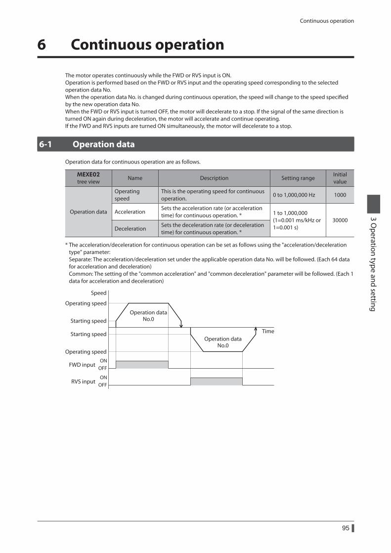
Continuous operation
95
3 Operation type and setting
6 Continuous operation
The motor operates continuously while the FWD or RVS input is ON.Operation is performed based on the FWD or RVS input and the operating speed corresponding to the selected operation data No.When the operation data No. is changed during continuous operation, the speed will change to the speed specified by the new operation data No.When the FWD or RVS input is turned OFF, the motor will decelerate to a stop. If the signal of the same direction is turned ON again during deceleration, the motor will accelerate and continue operating.If the FWD and RVS inputs are turned ON simultaneously, the motor will decelerate to a stop.
6-1 Operation data
Operation data for continuous operation are as follows.
MEXE02tree view
Name Description Setting rangeInitial value
Operation data
Operating speed
This is the operating speed for continuous operation.
0 to 1,000,000 Hz 1000
AccelerationSets the acceleration rate (or acceleration time) for continuous operation. * 1 to 1,000,000
(1=0.001 ms/kHz or 1=0.001 s)
30000Deceleration
Sets the deceleration rate (or deceleration time) for continuous operation. *
* The acceleration/deceleration for continuous operation can be set as follows using the "acceleration/deceleration type" parameter: Separate: The acceleration/deceleration set under the applicable operation data No. will be followed. (Each 64 data for acceleration and deceleration) Common: The setting of the "common acceleration" and "common deceleration" parameter will be followed. (Each 1 data for acceleration and deceleration)
Speed
Operating speed
Operating speed
FWD inputOFFON
RVS inputOFFON
Starting speed
Starting speed Time
Operation dataNo.0
Operation dataNo.0
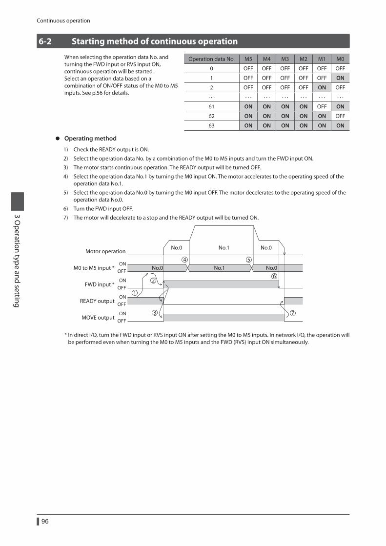
Continuous operation
96
3 Operation type and setting
6-2 Starting method of continuous operation
When selecting the operation data No. and turning the FWD input or RVS input ON, continuous operation will be started.Select an operation data based on a combination of ON/OFF status of the M0 to M5 inputs. See p.56 for details.
Operation data No. M5 M4 M3 M2 M1 M0
0 OFF OFF OFF OFF OFF OFF
1 OFF OFF OFF OFF OFF ON
2 OFF OFF OFF OFF ON OFF
· · · · · · · · · · · · · · · · · · · · ·
61 ON ON ON ON OFF ON
62 ON ON ON ON ON OFF
63 ON ON ON ON ON ON
z Operating method
1) Check the READY output is ON.
2) Select the operation data No. by a combination of the M0 to M5 inputs and turn the FWD input ON.
3) The motor starts continuous operation. The READY output will be turned OFF.
4) Select the operation data No.1 by turning the M0 input ON. The motor accelerates to the operating speed of the operation data No.1.
5) Select the operation data No.0 by turning the M0 input OFF. The motor decelerates to the operating speed of the operation data No.0.
6) Turn the FWD input OFF.
7) The motor will decelerate to a stop and the READY output will be turned ON.
FWD input *
MOVE output
READY output
M0 to M5 input * No.0 No.0No.1
No.1No.0 No.0
ONOFF
ONOFF
ONOFF
ONOFF
Motor operation
2
1
3
4 5
6
7
* In direct I/O, turn the FWD input or RVS input ON after setting the M0 to M5 inputs. In network I/O, the operation will be performed even when turning the M0 to M5 inputs and the FWD (RVS) input ON simultaneously.
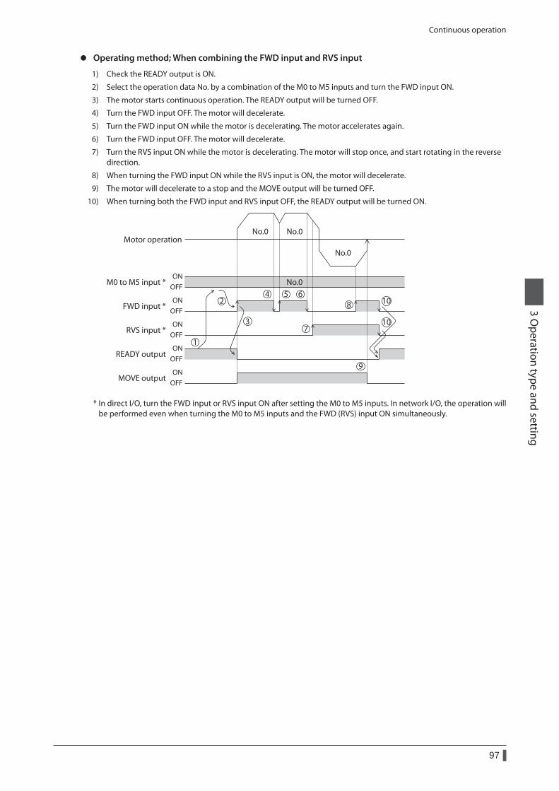
Continuous operation
97
3 Operation type and setting
z Operating method; When combining the FWD input and RVS input
1) Check the READY output is ON.
2) Select the operation data No. by a combination of the M0 to M5 inputs and turn the FWD input ON.
3) The motor starts continuous operation. The READY output will be turned OFF.
4) Turn the FWD input OFF. The motor will decelerate.
5) Turn the FWD input ON while the motor is decelerating. The motor accelerates again.
6) Turn the FWD input OFF. The motor will decelerate.
7) Turn the RVS input ON while the motor is decelerating. The motor will stop once, and start rotating in the reverse direction.
8) When turning the FWD input ON while the RVS input is ON, the motor will decelerate.
9) The motor will decelerate to a stop and the MOVE output will be turned OFF.
10) When turning both the FWD input and RVS input OFF, the READY output will be turned ON.
FWD input *
MOVE output
READY output
M0 to M5 input * No.0
No.0
No.0 No.0
ONOFF
ONOFF
RVS input *ON
OFF
ONOFF
ONOFF
Motor operation
1
24 5 6
7
9
8
3
10
10
* In direct I/O, turn the FWD input or RVS input ON after setting the M0 to M5 inputs. In network I/O, the operation will be performed even when turning the M0 to M5 inputs and the FWD (RVS) input ON simultaneously.
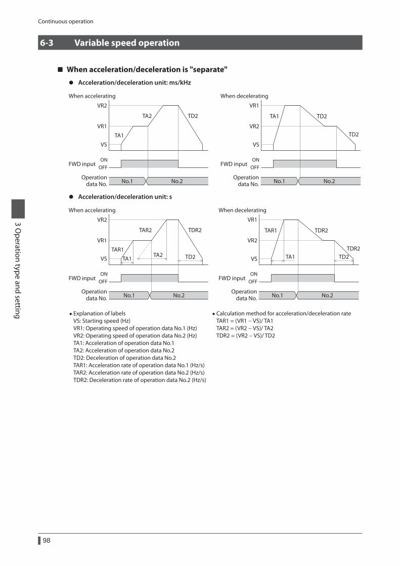
Continuous operation
98
3 Operation type and setting
6-3 Variable speed operation
When acceleration/deceleration is "separate"
z Acceleration/deceleration unit: ms/kHz
VR2
VR1
VS
TA1
No.1
OFFON
No.2 No.1
OFFON
No.2
TA2 TD2
VR2
VR1
VS
TA1 TD2
TD2
FWD input
Operationdata No.
FWD input
Operationdata No.
When accelerating When decelerating
z Acceleration/deceleration unit: s
VR2
VR1
VS
TAR1
TA1TA2 TD2 TA1 TD2
No.1
OFFON
No.2 No.1
OFFON
No.2
TAR2 TDR2
VR2
VR1
VS
TAR1 TDR2
TDR2
FWD input
Operationdata No.
FWD input
Operationdata No.
When accelerating When decelerating
• Explanation of labels VS: Starting speed (Hz) VR1: Operating speed of operation data No.1 (Hz) VR2: Operating speed of operation data No.2 (Hz) TA1: Acceleration of operation data No.1 TA2: Acceleration of operation data No.2 TD2: Deceleration of operation data No.2 TAR1: Acceleration rate of operation data No.1 (Hz/s) TAR2: Acceleration rate of operation data No.2 (Hz/s) TDR2: Deceleration rate of operation data No.2 (Hz/s)
• Calculation method for acceleration/deceleration rate TAR1 = (VR1 − VS)/ TA1 TAR2 = (VR2 − VS)/ TA2 TDR2 = (VR2 − VS)/ TD2
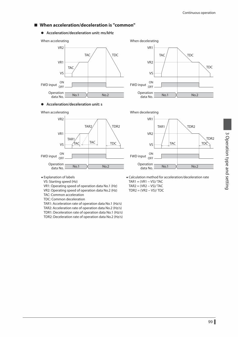
Continuous operation
99
3 Operation type and setting
When acceleration/deceleration is "common"
z Acceleration/deceleration unit: ms/kHz
VR2
VR1
VS
TAC
No.1
OFFON
No.2
FWD input
Operationdata No.
FWD input
Operationdata No. No.1
OFFON
No.2
When accelerating When decelerating
TAC TDC
VR2
VR1
VS
TAC TDC
TDC
z Acceleration/deceleration unit: s
VR2
VR1
VS
TAR1TAC TACTAC TDC TDC
No.1
OFFON
No.2 No.1
OFFON
No.2
TAR2 TDR2
VR2
VR1
VS
TAR1 TDR2
TDR2
FWD input
Operationdata No.
FWD input
Operationdata No.
When accelerating When decelerating
• Explanation of labels VS: Starting speed (Hz) VR1: Operating speed of operation data No.1 (Hz) VR2: Operating speed of operation data No.2 (Hz) TAC: Common acceleration TDC: Common deceleration TAR1: Acceleration rate of operation data No.1 (Hz/s) TAR2: Acceleration rate of operation data No.2 (Hz/s) TDR1: Deceleration rate of operation data No.1 (Hz/s) TDR2: Deceleration rate of operation data No.2 (Hz/s)
• Calculation method for acceleration/deceleration rate TAR1 = (VR1 − VS)/ TAC TAR2 = (VR2 − VS)/ TAC TDR2 = (VR2 − VS)/ TDC
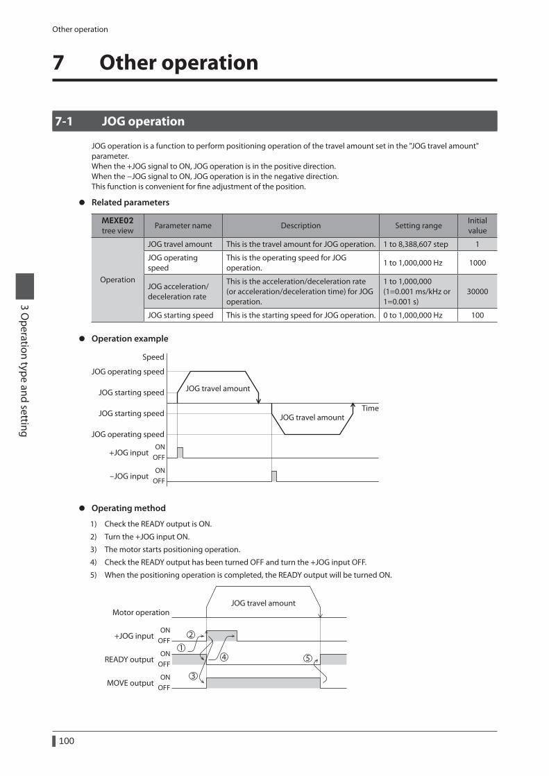
Other operation
100
3 Operation type and setting
7 Other operation
7-1 JOG operation
JOG operation is a function to perform positioning operation of the travel amount set in the "JOG travel amount" parameter.When the +JOG signal to ON, JOG operation is in the positive direction.When the −JOG signal to ON, JOG operation is in the negative direction.This function is convenient for fine adjustment of the position.
z Related parameters
MEXE02tree view
Parameter name Description Setting rangeInitial value
Operation
JOG travel amount This is the travel amount for JOG operation. 1 to 8,388,607 step 1
JOG operating speed
This is the operating speed for JOG operation.
1 to 1,000,000 Hz 1000
JOG acceleration/ deceleration rate
This is the acceleration/deceleration rate (or acceleration/deceleration time) for JOG operation.
1 to 1,000,000 (1=0.001 ms/kHz or 1=0.001 s)
30000
JOG starting speed This is the starting speed for JOG operation. 0 to 1,000,000 Hz 100
z Operation example
Speed
JOG operating speed
JOG operating speed
+JOG inputOFFON
-JOG inputOFFON
JOG starting speed
JOG starting speedTime
JOG travel amount
JOG travel amount
z Operating method
1) Check the READY output is ON.
2) Turn the +JOG input ON.
3) The motor starts positioning operation.
4) Check the READY output has been turned OFF and turn the +JOG input OFF.
5) When the positioning operation is completed, the READY output will be turned ON.
MOVE output
READY output
Motor operationJOG travel amount
+JOG inputON
OFF
ONOFF
ONOFF
1
2
3
4 5
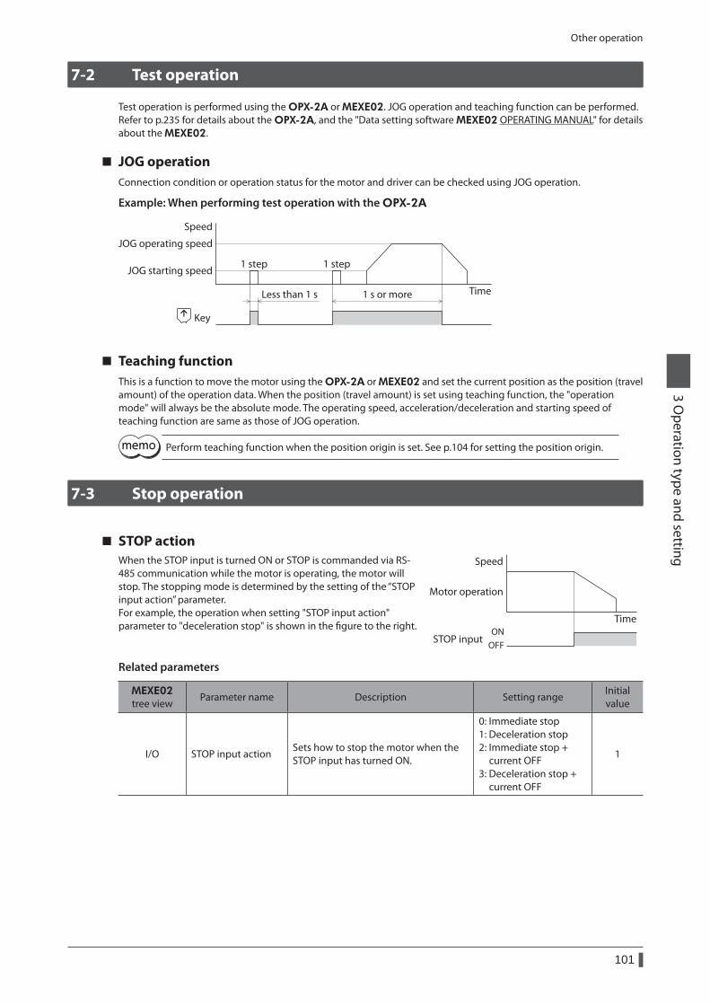
Other operation
101
3 Operation type and setting
7-2 Test operation
Test operation is performed using the OPX-2A or MEXE02. JOG operation and teaching function can be performed.Refer to p.235 for details about the OPX-2A, and the "Data setting software MEXE02 OPERATING MANUAL" for details about the MEXE02.
JOG operationConnection condition or operation status for the motor and driver can be checked using JOG operation.
Example: When performing test operation with the OPX-2A
Less than 1 s 1 s or more
JOG starting speed
Speed
Time
JOG operating speed
1 step 1 step
Key
Teaching functionThis is a function to move the motor using the OPX-2A or MEXE02 and set the current position as the position (travel amount) of the operation data. When the position (travel amount) is set using teaching function, the "operation mode" will always be the absolute mode. The operating speed, acceleration/deceleration and starting speed of teaching function are same as those of JOG operation.
Perform teaching function when the position origin is set. See p.104 for setting the position origin.
7-3 Stop operation
STOP actionWhen the STOP input is turned ON or STOP is commanded via RS-485 communication while the motor is operating, the motor will stop. The stopping mode is determined by the setting of the “STOP input action” parameter.For example, the operation when setting "STOP input action" parameter to "deceleration stop" is shown in the figure to the right.
Speed
TimeON
OFFSTOP input
Motor operation
Related parameters
MEXE02tree view
Parameter name Description Setting rangeInitial value
I/O STOP input actionSets how to stop the motor when the STOP input has turned ON.
0: Immediate stop 1: Deceleration stop 2: Immediate stop + current OFF 3: Deceleration stop + current OFF
1
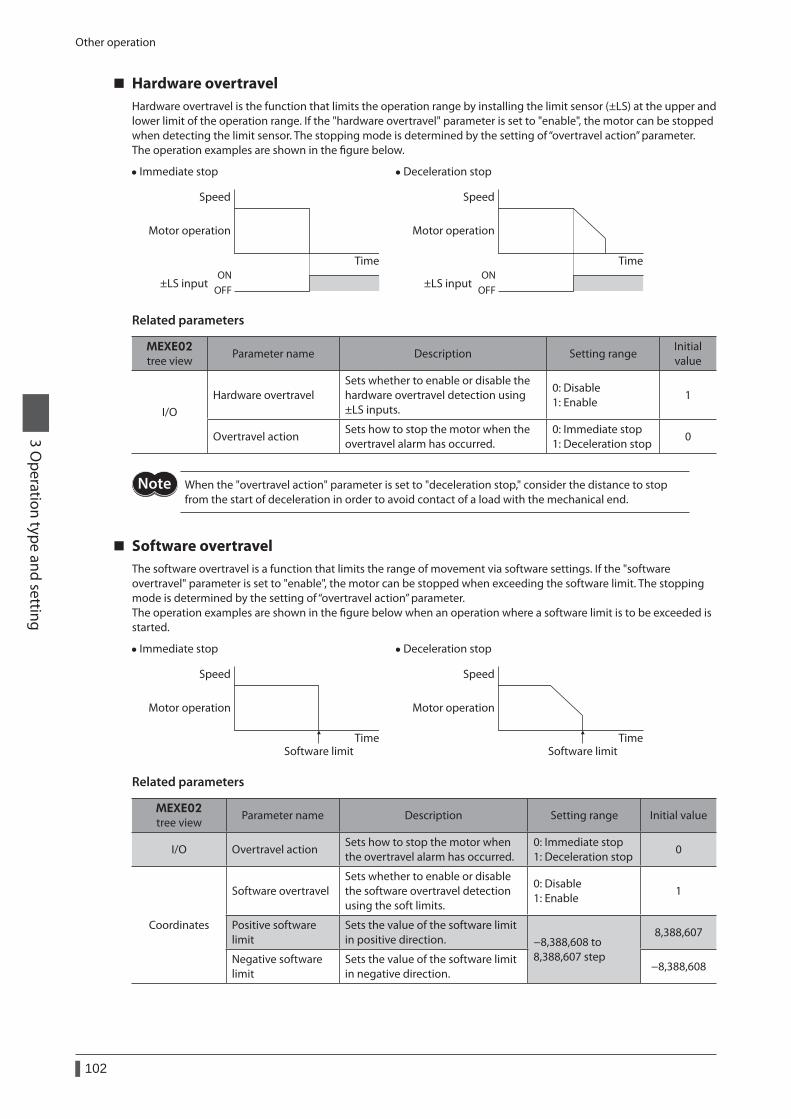
Other operation
102
3 Operation type and setting
Hardware overtravelHardware overtravel is the function that limits the operation range by installing the limit sensor (±LS) at the upper and lower limit of the operation range. If the "hardware overtravel" parameter is set to "enable", the motor can be stopped when detecting the limit sensor. The stopping mode is determined by the setting of “overtravel action” parameter.The operation examples are shown in the figure below.
• Immediate stop
ONOFF
Speed
Time
±LS input
Motor operation
• Deceleration stop
Speed
TimeON
OFF±LS input
Motor operation
Related parameters
MEXE02tree view
Parameter name Description Setting rangeInitial value
I/OHardware overtravel
Sets whether to enable or disable the hardware overtravel detection using ±LS inputs.
0: Disable 1: Enable
1
Overtravel actionSets how to stop the motor when the overtravel alarm has occurred.
0: Immediate stop 1: Deceleration stop
0
When the "overtravel action" parameter is set to "deceleration stop," consider the distance to stop from the start of deceleration in order to avoid contact of a load with the mechanical end.
Software overtravelThe software overtravel is a function that limits the range of movement via software settings. If the "software overtravel" parameter is set to "enable", the motor can be stopped when exceeding the software limit. The stopping mode is determined by the setting of “overtravel action” parameter.The operation examples are shown in the figure below when an operation where a software limit is to be exceeded is started.
• Immediate stop
Speed
TimeSoftware limit
Motor operation
• Deceleration stop
Software limit
Speed
Time
Motor operation
Related parameters
MEXE02tree view
Parameter name Description Setting range Initial value
I/O Overtravel actionSets how to stop the motor when the overtravel alarm has occurred.
0: Immediate stop 1: Deceleration stop
0
Coordinates
Software overtravelSets whether to enable or disable the software overtravel detection using the soft limits.
0: Disable 1: Enable
1
Positive software limit
Sets the value of the software limit in positive direction. −8,388,608 to
8,388,607 step
8,388,607
Negative software limit
Sets the value of the software limit in negative direction.
−8,388,608

Other operation
103
3 Operation type and setting
• Software overtravel will become effective after the position origin is set. See p.104 for setting the position origin.
• When the value of the software limit is changed while the motor is operating, the motor will stop according to the setting of the “overtravel action” parameter.
Escape from the limit sensorIt is possible to escape in the negative direction when detecting the positive direction limit, and possible to escape in the positive direction when detecting the negative direction limit.The following operations can be used when escaping from the limit sensor.
Types of operation Limit sensors (±LS) Software limit
Positioning operation Will not operate (unable to escape)
Allowed to operate (able to escape)Continuous operation Test operation Return-to-home operation
Allowed to operate (able to escape)
Coordinate management
104
3 Operation type and setting
8 Coordinate management
8-1 Position coordinate management
The driver manages the motor position information.
The position origin will be set whenever one of the following operations is executed: • Return-to-home operation • P-PRESET input is turned ON
The position origin will not be set whenever one of the following operations is executed: • When the 24 VDC power supply is turned ON • When the motor becomes in non-excitation state while the "stepout detection" parameter is set to "disable." • When a configuration is executed
If the "return-to-home incomplete alarm" parameter is set to "enable", positioning operations can be prohibited while the position origin has not been set.The return-to-home incomplete alarm will generate if the START input, SSTART input or the MS0 to MS5 inputs are turned ON while the position origin has not been set. See p.267 for alarm.
Related parameters
MEXE02tree view
Parameter name Description Setting rangeInitial value
AlarmReturn-to-home incomplete alarm
When the positioning operation is started while the position origin has not been set, sets whether the alarm generates or not.
0: Disable 1: Enable
0
8-2 Wrap function
The wrap function is a function that resets the command position or multi-rotation data to 0 whenever the command position exceeds the set value by the “wrap setting range” parameter. The command position varies in a range of "0 to (wrap setting value−1)."
Related parameters
MEXE02tree view
Parameter name Description Setting rangeInitial value
CoordinatesWrap setting
Sets whether to enable or disable the wrap function.
0: Disable 1: Enable
0
Wrap setting range Wrap setting range. 1 to 8,388,607 step 500
When setting the "wrap setting" parameter to "enable", the software overtravel will be disabled. (It is disabled even when setting the "software overtravel" parameter to "enable".)
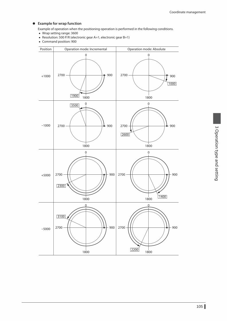
Coordinate management
105
3 Operation type and setting
z Example for wrap functionExample of operation when the positioning operation is performed in the following conditions.
• Wrap setting range: 3600 • Resolution: 500 P/R (electronic gear A=1, electronic gear B=1) • Command position: 900
Operation mode: Incremental Operation mode: AbsolutePosition
0
+1000 900
1800
2700
1900
0
900
1800
2700
1000
0
-1000 900
1800
2700
3500 0
900
1800
2700
2600
+5000
0
900
1800
2700
2300
0
900
1800
2700
1400
0
900
1800
2700
3100
0
900
1800
2700
2200
-5000
Operation data
106
3 Operation type and setting
9 Operation data
Up to 64 operation data can be set (data Nos.0 to 63).If the data is changed, a recalculation and setup will be performed after the operation is stopped.
Name Description Setting range Initial value
Position No.0 to
Position No.63
Sets the position (travel amount) for positioning operation.
−8,388,608 to +8,388,607 step
0
Operating speed No.0 to
Operating speed No.63
This is the operating speed for positioning operation and continuous operation.
0 to 1,000,000 Hz 1000
Operation mode No.0 to
Operation mode No.63
Sets the operation mode for positioning operation.
0: Incremental (INC) 1: Absolute (ABS)
0
Operation function No.0 to
Operation function No.63
This is used to set how to operate consecutive operation data.
0: Single-motion 1: Linked-motion 2: Linked-motion 2
0
Acceleration No.0 to
Acceleration No.63
Sets the acceleration rate (or acceleration time) for positioning operation and continuous operation. *1
1 to 1,000,000 (1=0.001 ms/kHz or 1=0.001 s) *2
30000
Deceleration No.0 to
Deceleration No.63
Sets the deceleration rate (or deceleration time) for positioning operation and continuous operation. *1
1 to 1,000,000 (1=0.001 ms/kHz or 1=0.001 s) *2
30000
Sequential positioning No.0 to
Sequential positioning No.63
Sets whether to enable or disable sequential positioning operation.
0: Disable 1: Enable
0
Dwell time No.0 to
Dwell time No.63
Sets the waiting time between the first operation data and second operation data in linked-motion operation 2.
0 to 50000 (1=0.001 s) 0
*1 This item is effective when the “acceleration/deceleration type” parameter is set to “separate”. If this parameter is set to “common”, the values of the “common acceleration” and “common deceleration” parameters will be used (initial value: separate).
*2 Acceleration/deceleration rate (ms/kHz) or acceleration/deceleration time (s) can be selected using "acceleration/deceleration unit" parameter. (initial value: acceleration/deceleration rate).
Parameter
107
3 Operation type and setting
10 Parameter
The parameters are saved in the RAM or non-volatile memory. The data saved in the RAM will be erased once the 24 VDC power supply is turned off. On the other hand, the parameters saved in the non-volatile memory will be retained even after the 24 VDC power supply is turned off.When turning the 24 VDC power supply on, the parameters saved in the non-volatile memory will be sent to the RAM. Then, the recalculation and setup for the parameters are executed in the RAM.
The parameters are written in the RAM area when writing via the RS-485 communication or industrial network.When the parameters stored in the RAM is saved in the non-volatile memory, execute the "Batch NV memory write" command of the maintenance command.The parameters having set in the MEXE02 is saved in the non-volatile memory when the data writing is performed.
When a parameter is changed, the timing to reflect the new value varies depending on the parameter. See the following four types.
Update timing Description
A Effective immediately Executes the recalculation and setup as soon as the parameter is written.
BEffective after stopping the operation
Executes the recalculation and setup after stopping the operation.
CEffective after executing the configuration or cycling the power
Executes the recalculation and setup after executing the configuration, or effective after cycling the 24 VDC power supply.
D Effective after cycling the powerExecutes the recalculation and setup after cycling the 24 VDC power supply again.
In this document, each update timing is represented in an alphabetical character.
• The parameters are written in the RAM area when writing via the RS-485 communication or industrial network. Be sure to save in the non-volatile memory before turning off the power supply when changing the parameter that is required turning on the power again to update.
• The non-volatile memory can be rewritten approximately 100,000 times.
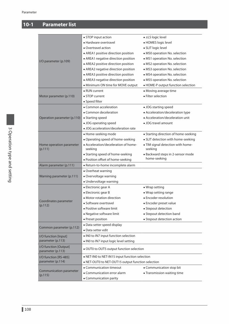
Parameter
108
3 Operation type and setting
10-1 Parameter list
I/O parameter (p.109)
• STOP input action
• Hardware overtravel
• Overtravel action
• AREA1 positive direction position
• AREA1 negative direction position
• AREA2 positive direction position
• AREA2 negative direction position
• AREA3 positive direction position
• AREA3 negative direction position
• Minimum ON time for MOVE output
• ±LS logic level
• HOMES logic level
• SLIT logic level
• MS0 operation No. selection
• MS1 operation No. selection
• MS2 operation No. selection
• MS3 operation No. selection
• MS4 operation No. selection
• MS5 operation No. selection
• HOME-P output function selection
Motor parameter (p.110)
• RUN current
• STOP current
• Speed filter
• Moving average time
• Filter selection
Operation parameter (p.110)
• Common acceleration
• Common deceleration
• Starting speed
• JOG operating speed
• JOG acceleration/deceleration rate
• JOG starting speed
• Acceleration/deceleration type
• Acceleration/deceleration unit
• JOG travel amount
Home operation parameter (p.111)
• Home-seeking mode
• Operating speed of home-seeking
• Acceleration/deceleration of home-seeking
• Starting speed of home-seeking
• Position offset of home-seeking
• Starting direction of home-seeking
• SLIT detection with home-seeking
• TIM signal detection with home-seeking
• Backward steps in 2-sensor mode home-seeking
Alarm parameter (p.111) • Return-to-home incomplete alarm
Warning parameter (p.111)
• Overheat warning
• Overvoltage warning
• Undervoltage warning
Coordinates parameter (p.112)
• Electronic gear A
• Electronic gear B
• Motor rotation direction
• Software overtravel
• Positive software limit
• Negative software limit
• Preset position
• Wrap setting
• Wrap setting range
• Encoder resolution
• Encoder preset value
• Stepout detection
• Stepout detection band
• Stepout detection action
Common parameter (p.112) • Data setter speed display
• Data setter edit
I/O function [Input] parameter (p.113)
• IN0 to IN7 input function selection
• IN0 to IN7 input logic level setting
I/O function [Output] parameter (p.113)
• OUT0 to OUT5 output function selection
I/O function [RS-485] parameter (p.114)
• NET-IN0 to NET-IN15 input function selection
• NET-OUT0 to NET-OUT15 output function selection
Communication parameter (p.115)
• Communication timeout
• Communication error alarm
• Communication parity
• Communication stop bit
• Transmission waiting time
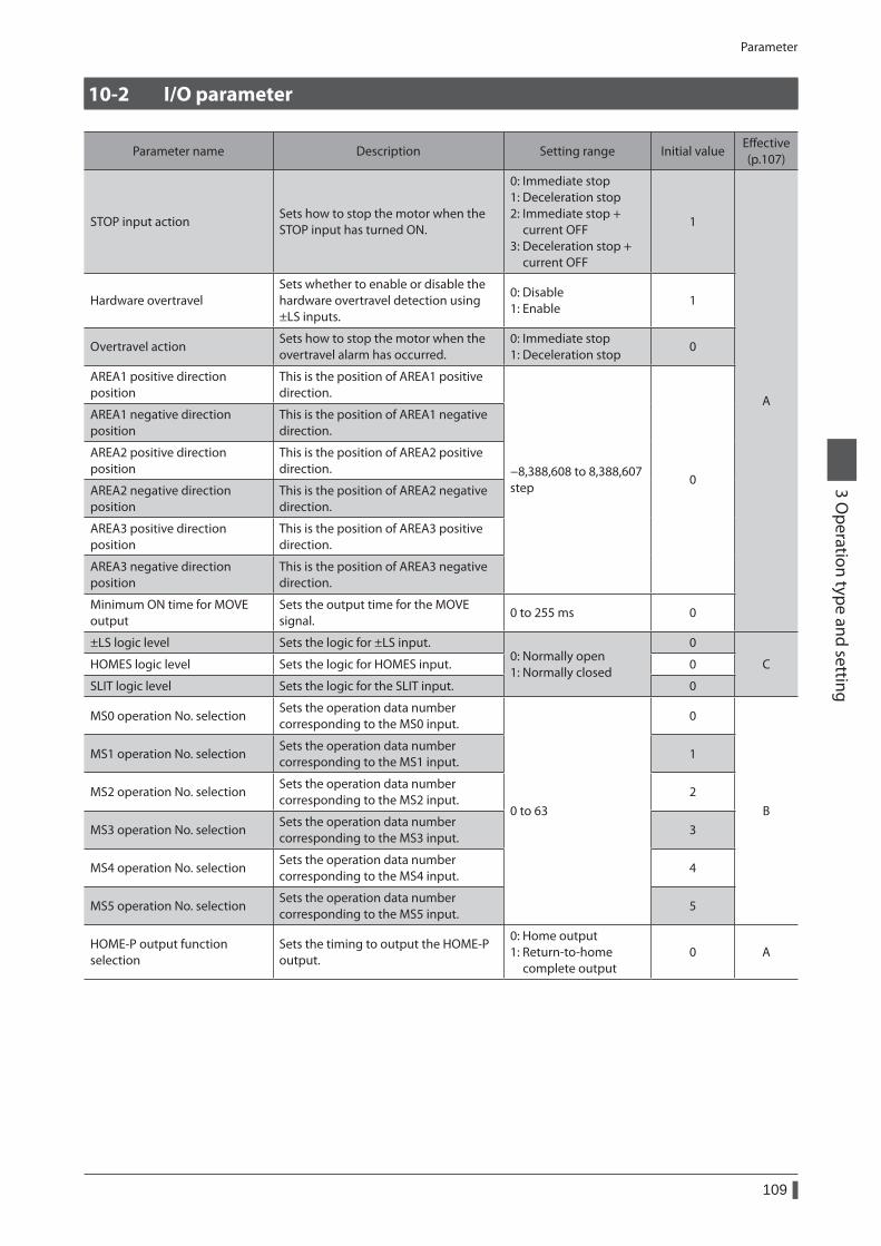
Parameter
109
3 Operation type and setting
10-2 I/O parameter
Parameter name Description Setting range Initial valueEffective (p.107)
STOP input actionSets how to stop the motor when the STOP input has turned ON.
0: Immediate stop 1: Deceleration stop 2: Immediate stop + current OFF 3: Deceleration stop + current OFF
1
A
Hardware overtravelSets whether to enable or disable the hardware overtravel detection using ±LS inputs.
0: Disable 1: Enable
1
Overtravel actionSets how to stop the motor when the overtravel alarm has occurred.
0: Immediate stop 1: Deceleration stop
0
AREA1 positive direction position
This is the position of AREA1 positive direction.
−8,388,608 to 8,388,607 step
0
AREA1 negative direction position
This is the position of AREA1 negative direction.
AREA2 positive direction position
This is the position of AREA2 positive direction.
AREA2 negative direction position
This is the position of AREA2 negative direction.
AREA3 positive direction position
This is the position of AREA3 positive direction.
AREA3 negative direction position
This is the position of AREA3 negative direction.
Minimum ON time for MOVE output
Sets the output time for the MOVE signal.
0 to 255 ms 0
±LS logic level Sets the logic for ±LS input.0: Normally open 1: Normally closed
0
CHOMES logic level Sets the logic for HOMES input. 0
SLIT logic level Sets the logic for the SLIT input. 0
MS0 operation No. selectionSets the operation data number corresponding to the MS0 input.
0 to 63
0
B
MS1 operation No. selectionSets the operation data number corresponding to the MS1 input.
1
MS2 operation No. selectionSets the operation data number corresponding to the MS2 input.
2
MS3 operation No. selectionSets the operation data number corresponding to the MS3 input.
3
MS4 operation No. selectionSets the operation data number corresponding to the MS4 input.
4
MS5 operation No. selectionSets the operation data number corresponding to the MS5 input.
5
HOME-P output function selection
Sets the timing to output the HOME-P output.
0: Home output 1: Return-to-home complete output
0 A
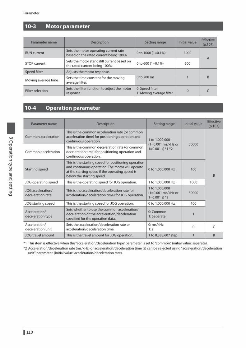
Parameter
110
3 Operation type and setting
10-3 Motor parameter
Parameter name Description Setting range Initial valueEffective (p.107)
RUN currentSets the motor operating current rate based on the rated current being 100%.
0 to 1000 (1=0.1%) 1000A
STOP currentSets the motor standstill current based on the rated current being 100%.
0 to 600 (1=0.1%) 500
Speed filter Adjusts the motor response.0 to 200 ms 1 B
Moving average timeSets the time constant for the moving average filter.
Filter selectionSets the filter function to adjust the motor response.
0: Speed filter 1: Moving average filter
0 C
10-4 Operation parameter
Parameter name Description Setting range Initial valueEffective (p.107)
Common accelerationThis is the common acceleration rate (or common acceleration time) for positioning operation and continuous operation. 1 to 1,000,000
(1=0.001 ms/kHz or 1=0.001 s) *1 *2
30000
B
Common decelerationThis is the common deceleration rate (or common deceleration time) for positioning operation and continuous operation.
Starting speed
This is the starting speed for positioning operation and continuous operation. The motor will operate at the starting speed if the operating speed is below the starting speed.
0 to 1,000,000 Hz 100
JOG operating speed This is the operating speed for JOG operation. 1 to 1,000,000 Hz 1000
JOG acceleration/ deceleration rate
This is the acceleration/deceleration rate (or acceleration/deceleration time) for JOG operation.
1 to 1,000,000 (1=0.001 ms/kHz or 1=0.001 s) *2
30000
JOG starting speed This is the starting speed for JOG operation. 0 to 1,000,000 Hz 100
Acceleration/deceleration type
Sets whether to use the common acceleration/deceleration or the acceleration/deceleration specified for the operation data.
0: Common 1: Separate
1
Acceleration/ deceleration unit
Sets the acceleration/deceleration rate or acceleration/deceleration time.
0: ms/kHz 1: s
0 C
JOG travel amount This is the travel amount for JOG operation. 1 to 8,388,607 step 1 B
*1 This item is effective when the “acceleration/deceleration type” parameter is set to “common.” (initial value: separate).*2 Acceleration/deceleration rate (ms/kHz) or acceleration/deceleration time (s) can be selected using "acceleration/deceleration
unit" parameter. (initial value: acceleration/deceleration rate).
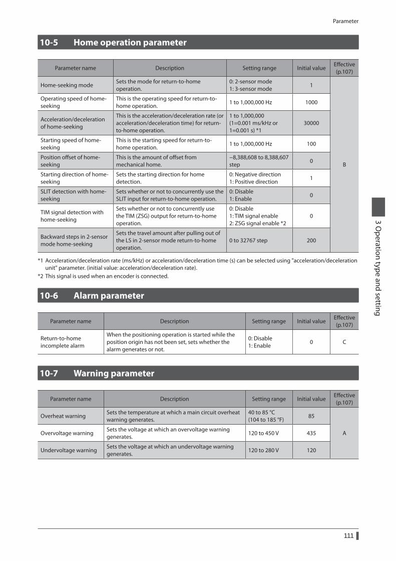
Parameter
111
3 Operation type and setting
10-5 Home operation parameter
Parameter name Description Setting range Initial valueEffective (p.107)
Home-seeking modeSets the mode for return-to-home operation.
0: 2-sensor mode 1: 3-sensor mode
1
B
Operating speed of home-seeking
This is the operating speed for return-to-home operation.
1 to 1,000,000 Hz 1000
Acceleration/deceleration of home-seeking
This is the acceleration/deceleration rate (or acceleration/deceleration time) for return-to-home operation.
1 to 1,000,000 (1=0.001 ms/kHz or 1=0.001 s) *1
30000
Starting speed of home-seeking
This is the starting speed for return-to-home operation.
1 to 1,000,000 Hz 100
Position offset of home-seeking
This is the amount of offset from mechanical home.
−8,388,608 to 8,388,607 step
0
Starting direction of home-seeking
Sets the starting direction for home detection.
0: Negative direction 1: Positive direction
1
SLIT detection with home-seeking
Sets whether or not to concurrently use the SLIT input for return-to-home operation.
0: Disable 1: Enable
0
TIM signal detection with home-seeking
Sets whether or not to concurrently use the TIM (ZSG) output for return-to-home operation.
0: Disable 1: TIM signal enable 2: ZSG signal enable *2
0
Backward steps in 2-sensor mode home-seeking
Sets the travel amount after pulling out of the LS in 2-sensor mode return-to-home operation.
0 to 32767 step 200
*1 Acceleration/deceleration rate (ms/kHz) or acceleration/deceleration time (s) can be selected using "acceleration/deceleration unit" parameter. (initial value: acceleration/deceleration rate).
*2 This signal is used when an encoder is connected.
10-6 Alarm parameter
Parameter name Description Setting range Initial valueEffective (p.107)
Return-to-home incomplete alarm
When the positioning operation is started while the position origin has not been set, sets whether the alarm generates or not.
0: Disable 1: Enable
0 C
10-7 Warning parameter
Parameter name Description Setting range Initial valueEffective (p.107)
Overheat warningSets the temperature at which a main circuit overheat warning generates.
40 to 85 °C (104 to 185 °F)
85
AOvervoltage warningSets the voltage at which an overvoltage warning generates.
120 to 450 V 435
Undervoltage warningSets the voltage at which an undervoltage warning generates.
120 to 280 V 120
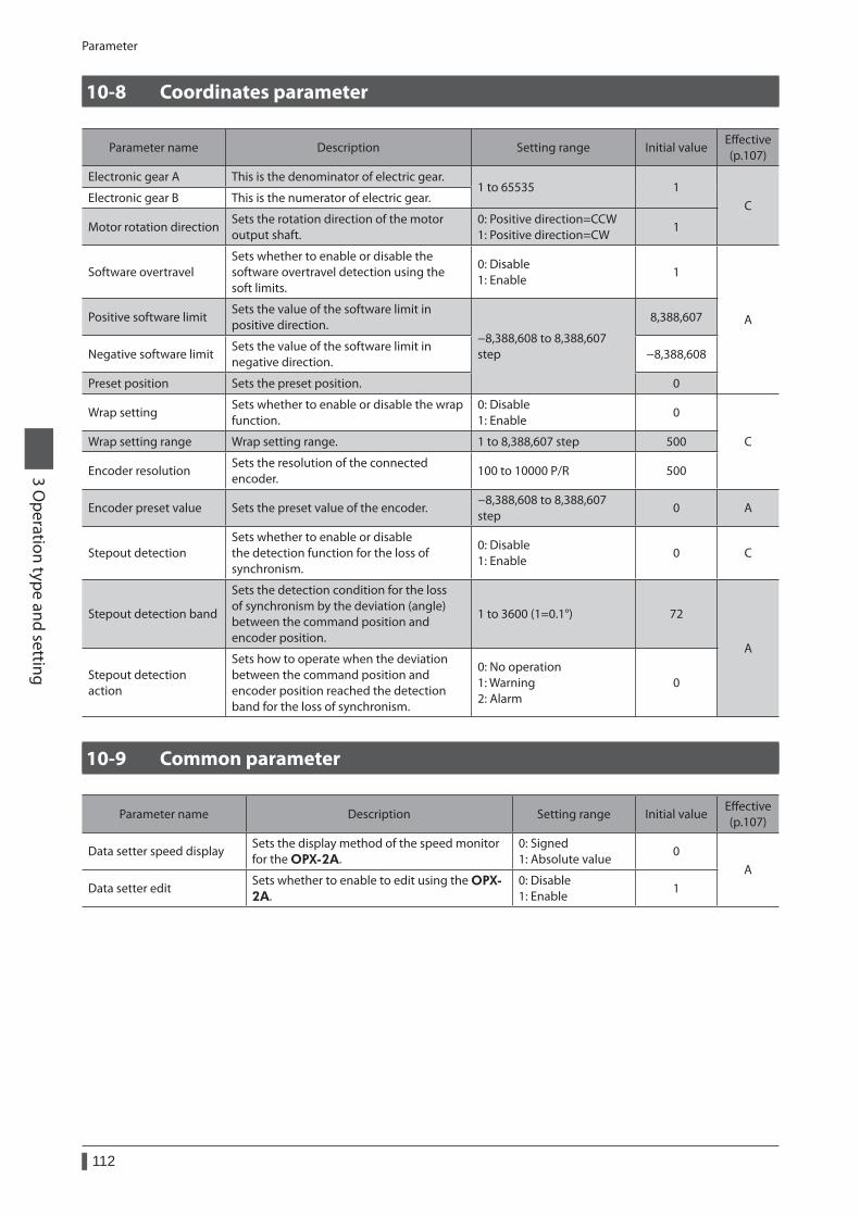
Parameter
112
3 Operation type and setting
10-8 Coordinates parameter
Parameter name Description Setting range Initial valueEffective (p.107)
Electronic gear A This is the denominator of electric gear.1 to 65535 1
CElectronic gear B This is the numerator of electric gear.
Motor rotation directionSets the rotation direction of the motor output shaft.
0: Positive direction=CCW 1: Positive direction=CW
1
Software overtravelSets whether to enable or disable the software overtravel detection using the soft limits.
0: Disable 1: Enable
1
APositive software limitSets the value of the software limit in positive direction.
−8,388,608 to 8,388,607 step
8,388,607
Negative software limitSets the value of the software limit in negative direction.
−8,388,608
Preset position Sets the preset position. 0
Wrap settingSets whether to enable or disable the wrap function.
0: Disable 1: Enable
0
CWrap setting range Wrap setting range. 1 to 8,388,607 step 500
Encoder resolutionSets the resolution of the connected encoder.
100 to 10000 P/R 500
Encoder preset value Sets the preset value of the encoder.−8,388,608 to 8,388,607 step
0 A
Stepout detectionSets whether to enable or disable the detection function for the loss of synchronism.
0: Disable 1: Enable
0 C
Stepout detection band
Sets the detection condition for the loss of synchronism by the deviation (angle) between the command position and encoder position.
1 to 3600 (1=0.1°) 72
A
Stepout detection action
Sets how to operate when the deviation between the command position and encoder position reached the detection band for the loss of synchronism.
0: No operation 1: Warning 2: Alarm
0
10-9 Common parameter
Parameter name Description Setting range Initial valueEffective (p.107)
Data setter speed displaySets the display method of the speed monitor for the OPX-2A.
0: Signed 1: Absolute value
0A
Data setter editSets whether to enable to edit using the OPX-2A.
0: Disable 1: Enable
1
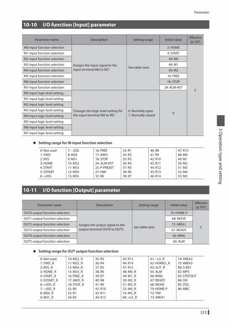
Parameter
113
3 Operation type and setting
10-10 I/O function [Input] parameter
Parameter name Description Setting range Initial valueEffective (p.107)
IN0 input function selection
Assigns the input signal to the input terminal IN0 to IN7.
See table next.
3: HOME
C
IN1 input function selection 4: START
IN2 input function selection 48: M0
IN3 input function selection 49: M1
IN4 input function selection 50: M2
IN5 input function selection 16: FREE
IN6 input function selection 18: STOP
IN7 input function selection 24: ALM-RST
IN0 input logic level setting
Changes the logic level setting for the input terminal IN0 to IN7.
0: Normally open 1: Normally closed
0
IN1 input logic level setting
IN2 input logic level setting
IN3 input logic level setting
IN4 input logic level setting
IN5 input logic level setting
IN6 input logic level setting
IN7 input logic level setting
z Setting range for IN input function selection
0: Not used 1: FWD 2: RVS 3: HOME 4: START 5: SSTART 6: +JOG
7: −JOG 8: MS0 9: MS1 10: MS2 11: MS3 12: MS4 13: MS5
16: FREE 17: AWO 18: STOP 24: ALM-RST 25: P-PRESET 27: HMI 32: R0
33: R1 34: R2 35: R3 36: R4 37: R5 38: R6 39: R7
40: R8 41: R9 42: R10 43: R11 44: R12 45: R13 46: R14
47: R15 48: M0 49: M1 50: M2 51: M3 52: M4 53: M5
10-11 I/O function [Output] parameter
Parameter name Description Setting range Initial valueEffective (p.107)
OUT0 output function selection
Assigns the output signal to the output terminal OUT0 to OUT5.
See table next.
70: HOME-P
C
OUT1 output function selection 68: MOVE
OUT2 output function selection 73: AREA1
OUT3 output function selection 67: READY
OUT4 output function selection 66: WNG
OUT5 output function selection 65: ALM
z Setting range for OUT output function selection
0: Not used 1: FWD_R 2: RVS_R 3: HOME_R 4: START_R 5: SSTART_R 6: +JOG_R 7: −JOG_R 8: MS0_R 9: MS1_R
10: MS2_R 11: MS3_R 12: MS4_R 13: MS5_R 16: FREE_R 17: AWO_R 18: STOP_R 32: R0 33: R1 34: R2
35: R3 36: R4 37: R5 38: R6 39: R7 40: R8 41: R9 42: R10 43: R11 44: R12
45: R13 46: R14 47: R15 48: M0_R 49: M1_R 50: M2_R 51: M3_R 52: M4_R 53: M5_R 60: +LS_R
61: −LS_R 62: HOMES_R 63: SLIT_R 65: ALM 66: WNG 67: READY 68: MOVE 70: HOME-P 72: TIM 73: AREA1
74: AREA2 75: AREA3 80: S-BSY 82: MPS 83: STEPOUT 84: OH 85: ZSG 86: MBC
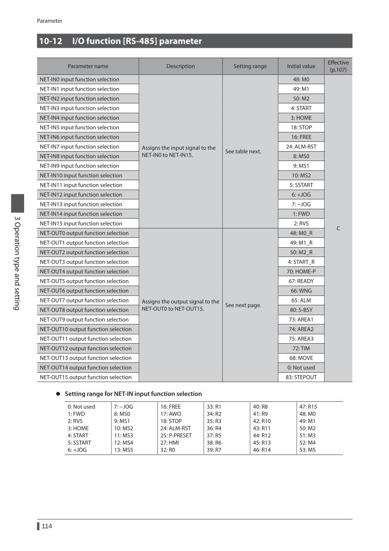
Parameter
114
3 Operation type and setting
10-12 I/O function [RS-485] parameter
Parameter name Description Setting range Initial valueEffective (p.107)
NET-IN0 input function selection
Assigns the input signal to the NET-IN0 to NET-IN15.
See table next.
48: M0
C
NET-IN1 input function selection 49: M1
NET-IN2 input function selection 50: M2
NET-IN3 input function selection 4: START
NET-IN4 input function selection 3: HOME
NET-IN5 input function selection 18: STOP
NET-IN6 input function selection 16: FREE
NET-IN7 input function selection 24: ALM-RST
NET-IN8 input function selection 8: MS0
NET-IN9 input function selection 9: MS1
NET-IN10 input function selection 10: MS2
NET-IN11 input function selection 5: SSTART
NET-IN12 input function selection 6: +JOG
NET-IN13 input function selection 7: −JOG
NET-IN14 input function selection 1: FWD
NET-IN15 input function selection 2: RVS
NET-OUT0 output function selection
Assigns the output signal to the NET-OUT0 to NET-OUT15.
See next page.
48: M0_R
NET-OUT1 output function selection 49: M1_R
NET-OUT2 output function selection 50: M2_R
NET-OUT3 output function selection 4: START_R
NET-OUT4 output function selection 70: HOME-P
NET-OUT5 output function selection 67: READY
NET-OUT6 output function selection 66: WNG
NET-OUT7 output function selection 65: ALM
NET-OUT8 output function selection 80: S-BSY
NET-OUT9 output function selection 73: AREA1
NET-OUT10 output function selection 74: AREA2
NET-OUT11 output function selection 75: AREA3
NET-OUT12 output function selection 72: TIM
NET-OUT13 output function selection 68: MOVE
NET-OUT14 output function selection 0: Not used
NET-OUT15 output function selection 83: STEPOUT
z Setting range for NET-IN input function selection
0: Not used 1: FWD 2: RVS 3: HOME 4: START 5: SSTART 6: +JOG
7: −JOG 8: MS0 9: MS1 10: MS2 11: MS3 12: MS4 13: MS5
16: FREE 17: AWO 18: STOP 24: ALM-RST 25: P-PRESET 27: HMI 32: R0
33: R1 34: R2 35: R3 36: R4 37: R5 38: R6 39: R7
40: R8 41: R9 42: R10 43: R11 44: R12 45: R13 46: R14
47: R15 48: M0 49: M1 50: M2 51: M3 52: M4 53: M5
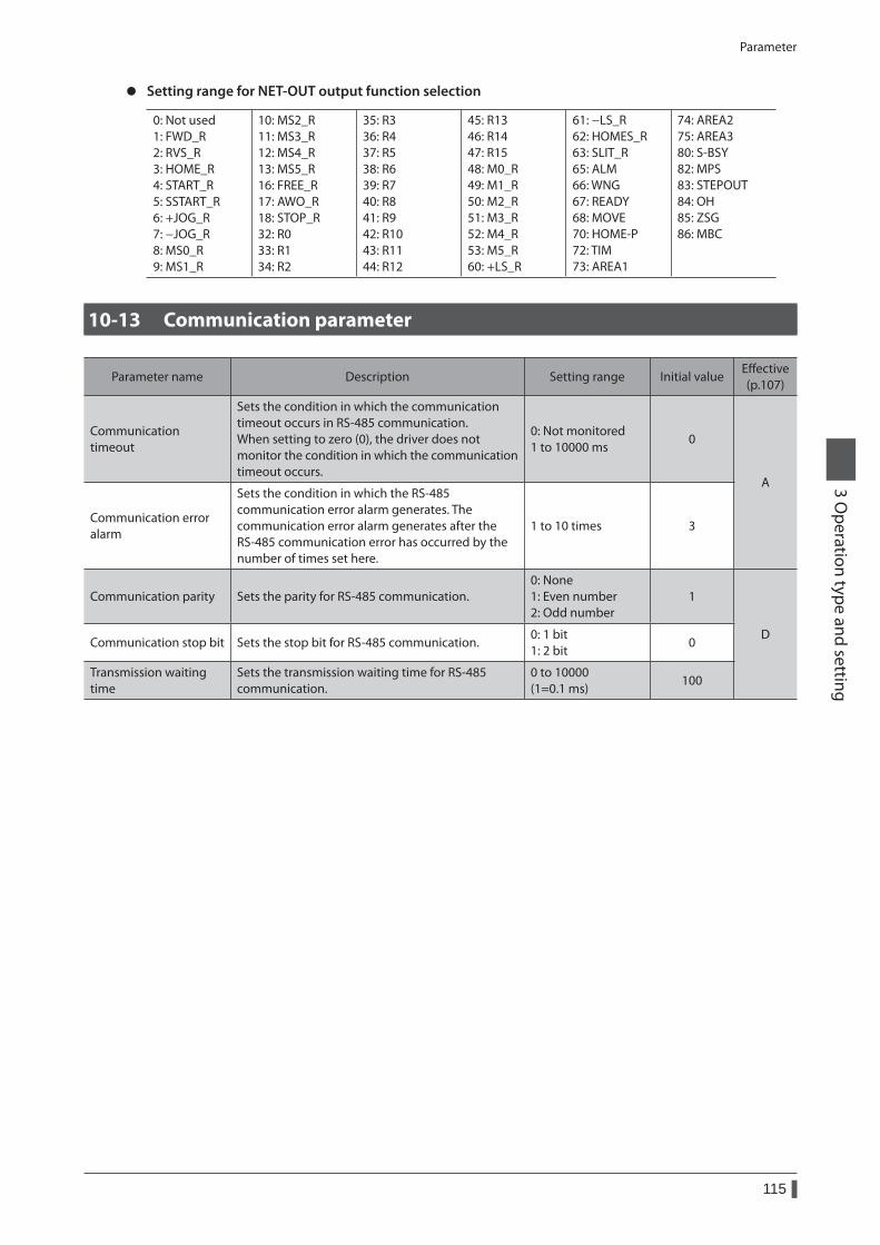
Parameter
115
3 Operation type and setting
z Setting range for NET-OUT output function selection
0: Not used 1: FWD_R 2: RVS_R 3: HOME_R 4: START_R 5: SSTART_R 6: +JOG_R 7: −JOG_R 8: MS0_R 9: MS1_R
10: MS2_R 11: MS3_R 12: MS4_R 13: MS5_R 16: FREE_R 17: AWO_R 18: STOP_R 32: R0 33: R1 34: R2
35: R3 36: R4 37: R5 38: R6 39: R7 40: R8 41: R9 42: R10 43: R11 44: R12
45: R13 46: R14 47: R15 48: M0_R 49: M1_R 50: M2_R 51: M3_R 52: M4_R 53: M5_R 60: +LS_R
61: −LS_R 62: HOMES_R 63: SLIT_R 65: ALM 66: WNG 67: READY 68: MOVE 70: HOME-P 72: TIM 73: AREA1
74: AREA2 75: AREA3 80: S-BSY 82: MPS 83: STEPOUT 84: OH 85: ZSG 86: MBC
10-13 Communication parameter
Parameter name Description Setting range Initial valueEffective (p.107)
Communication timeout
Sets the condition in which the communication timeout occurs in RS-485 communication. When setting to zero (0), the driver does not monitor the condition in which the communication timeout occurs.
0: Not monitored 1 to 10000 ms
0
A
Communication error alarm
Sets the condition in which the RS-485 communication error alarm generates. The communication error alarm generates after the RS-485 communication error has occurred by the number of times set here.
1 to 10 times 3
Communication parity Sets the parity for RS-485 communication.0: None 1: Even number 2: Odd number
1
DCommunication stop bit Sets the stop bit for RS-485 communication.
0: 1 bit 1: 2 bit
0
Transmission waiting time
Sets the transmission waiting time for RS-485 communication.
0 to 10000 (1=0.1 ms)
100

Parameter
116
3 Operation type and setting
1 Guidance ..........................................................118
2 Operation data ................................................120
3 Parameter ........................................................1213-1 Parameter list ..................................................................122
3-2 I/O parameter ..................................................................123
3-3 Motor parameter ...........................................................123
3-4 Operation parameter ...................................................124
3-5 Home operation parameter .......................................124
3-6 Alarm parameter ............................................................125
3-7 Warning parameter .......................................................125
3-8 Coordinates parameter ...............................................125
3-9 Common parameter .....................................................125
3-10 I/O function [Input] parameter .................................126
3-11 I/O function [Output] parameter .............................126
3-12 I/O function [RS-485] parameter ..............................127
3-13 Communication parameter ......................................128
4 Timing charts ..................................................129
4 Method of control via I/O
This part explains when the operation is controlled via I/O after setting the operation data and parameters by the OPX-2A or MEXE02.
Table of contents
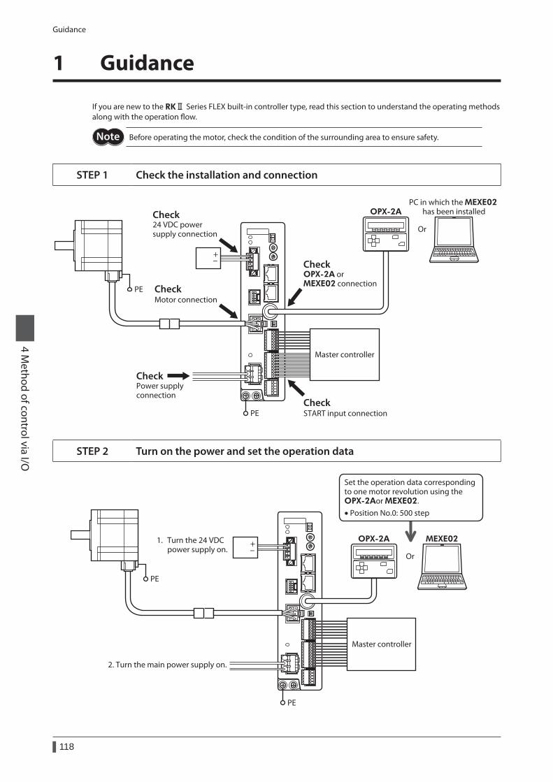
Guidance
118
4 Method of control via I/O
1 Guidance
If you are new to the RKⅡ Series FLEX built-in controller type, read this section to understand the operating methods along with the operation flow.
Before operating the motor, check the condition of the surrounding area to ensure safety.
STEP 1 Check the installation and connection
CheckOPX-2A or MEXE02 connection
CheckSTART input connection
CheckMotor connection
Check24 VDC powersupply connection
CheckPower supplyconnection
PE
PE
+-
Or
OPX-2APC in which the MEXE02
has been installed
Master controller
STEP 2 Turn on the power and set the operation data
2. Turn the main power supply on.
1. Turn the 24 VDC power supply on.
PE
PE
+-
Or
OPX-2A MEXE02
Master controller
Set the operation data corresponding to one motor revolution using the OPX-2Aor MEXE02.• Position No.0: 500 step
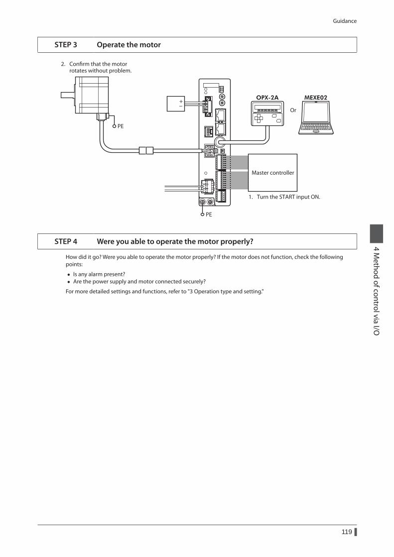
Guidance
119
4 Method of control via I/O
STEP 3 Operate the motor
2. Conrm that the motor rotates without problem.
1. Turn the START input ON.
PE
PE
+-
Or
OPX-2A MEXE02
Master controller
STEP 4 Were you able to operate the motor properly?
How did it go? Were you able to operate the motor properly? If the motor does not function, check the following points:
• Is any alarm present? • Are the power supply and motor connected securely?
For more detailed settings and functions, refer to "3 Operation type and setting."
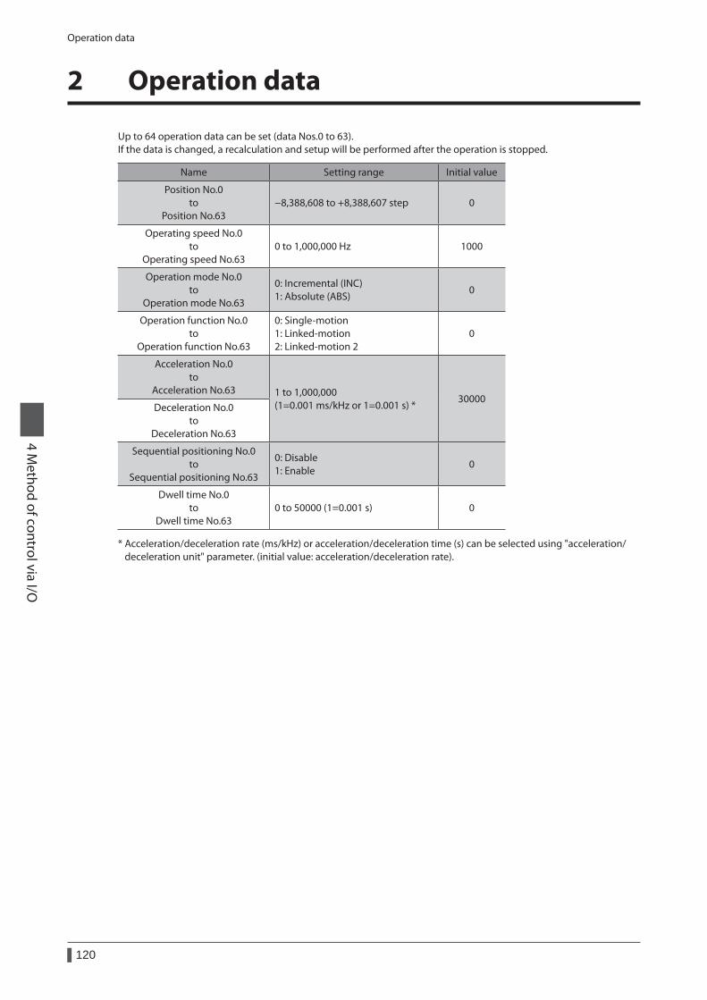
Operation data
120
4 Method of control via I/O
2 Operation data
Up to 64 operation data can be set (data Nos.0 to 63).If the data is changed, a recalculation and setup will be performed after the operation is stopped.
Name Setting range Initial value
Position No.0 to
Position No.63−8,388,608 to +8,388,607 step 0
Operating speed No.0 to
Operating speed No.630 to 1,000,000 Hz 1000
Operation mode No.0 to
Operation mode No.63
0: Incremental (INC) 1: Absolute (ABS)
0
Operation function No.0 to
Operation function No.63
0: Single-motion 1: Linked-motion 2: Linked-motion 2
0
Acceleration No.0 to
Acceleration No.63 1 to 1,000,000 (1=0.001 ms/kHz or 1=0.001 s) *
30000Deceleration No.0
to Deceleration No.63
Sequential positioning No.0 to
Sequential positioning No.63
0: Disable 1: Enable
0
Dwell time No.0 to
Dwell time No.630 to 50000 (1=0.001 s) 0
* Acceleration/deceleration rate (ms/kHz) or acceleration/deceleration time (s) can be selected using "acceleration/deceleration unit" parameter. (initial value: acceleration/deceleration rate).
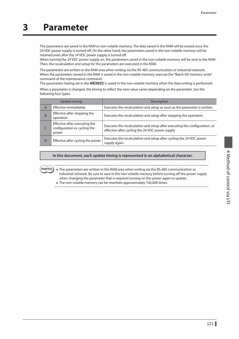
Parameter
121
4 Method of control via I/O
3 Parameter
The parameters are saved in the RAM or non-volatile memory. The data saved in the RAM will be erased once the 24 VDC power supply is turned off. On the other hand, the parameters saved in the non-volatile memory will be retained even after the 24 VDC power supply is turned off.When turning the 24 VDC power supply on, the parameters saved in the non-volatile memory will be sent to the RAM. Then, the recalculation and setup for the parameters are executed in the RAM.
The parameters are written in the RAM area when writing via the RS-485 communication or industrial network.When the parameters stored in the RAM is saved in the non-volatile memory, execute the "Batch NV memory write" command of the maintenance command.The parameters having set in the MEXE02 is saved in the non-volatile memory when the data writing is performed.
When a parameter is changed, the timing to reflect the new value varies depending on the parameter. See the following four types.
Update timing Description
A Effective immediately Executes the recalculation and setup as soon as the parameter is written.
BEffective after stopping the operation
Executes the recalculation and setup after stopping the operation.
CEffective after executing the configuration or cycling the power
Executes the recalculation and setup after executing the configuration, or effective after cycling the 24 VDC power supply
D Effective after cycling the powerExecutes the recalculation and setup after cycling the 24 VDC power supply again.
In this document, each update timing is represented in an alphabetical character.
• The parameters are written in the RAM area when writing via the RS-485 communication or industrial network. Be sure to save in the non-volatile memory before turning off the power supply when changing the parameter that is required turning on the power again to update.
• The non-volatile memory can be rewritten approximately 100,000 times.
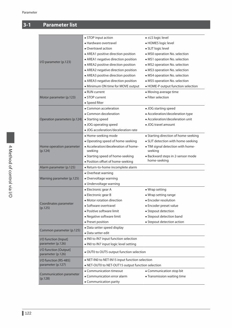
Parameter
122
4 Method of control via I/O
3-1 Parameter list
I/O parameter (p.123)
• STOP input action
• Hardware overtravel
• Overtravel action
• AREA1 positive direction position
• AREA1 negative direction position
• AREA2 positive direction position
• AREA2 negative direction position
• AREA3 positive direction position
• AREA3 negative direction position
• Minimum ON time for MOVE output
• ±LS logic level
• HOMES logic level
• SLIT logic level
• MS0 operation No. selection
• MS1 operation No. selection
• MS2 operation No. selection
• MS3 operation No. selection
• MS4 operation No. selection
• MS5 operation No. selection
• HOME-P output function selection
Motor parameter (p.123)
• RUN current
• STOP current
• Speed filter
• Moving average time
• Filter selection
Operation parameters (p.124)
• Common acceleration
• Common deceleration
• Starting speed
• JOG operating speed
• JOG acceleration/deceleration rate
• JOG starting speed
• Acceleration/deceleration type
• Acceleration/deceleration unit
• JOG travel amount
Home operation parameter (p.124)
• Home-seeking mode
• Operating speed of home-seeking
• Acceleration/deceleration of home-seeking
• Starting speed of home-seeking
• Position offset of home-seeking
• Starting direction of home-seeking
• SLIT detection with home-seeking
• TIM signal detection with home-seeking
• Backward steps in 2-sensor mode home-seeking
Alarm parameter (p.125) • Return-to-home incomplete alarm
Warning parameter (p.125)
• Overheat warning
• Overvoltage warning
• Undervoltage warning
Coordinates parameter (p.125)
• Electronic gear A
• Electronic gear B
• Motor rotation direction
• Software overtravel
• Positive software limit
• Negative software limit
• Preset position
• Wrap setting
• Wrap setting range
• Encoder resolution
• Encoder preset value
• Stepout detection
• Stepout detection band
• Stepout detection action
Common parameter (p.125) • Data setter speed display
• Data setter edit
I/O function [Input]parameter (p.126)
• IN0 to IN7 input function selection
• IN0 to IN7 input logic level setting
I/O function [Output]parameter (p.126)
• OUT0 to OUT5 output function selection
I/O function [RS-485] parameter (p.127)
• NET-IN0 to NET-IN15 input function selection
• NET-OUT0 to NET-OUT15 output function selection
Communication parameter (p.128)
• Communication timeout
• Communication error alarm
• Communication parity
• Communication stop bit
• Transmission waiting time
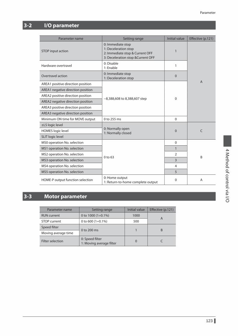
Parameter
123
4 Method of control via I/O
3-2 I/O parameter
Parameter name Setting range Initial value Effective (p.121)
STOP input action
0: Immediate stop 1: Deceleration stop 2: Immediate stop & Current OFF 3: Deceleration stop &Current OFF
1
A
Hardware overtravel0: Disable 1: Enable
1
Overtravel action0: Immediate stop 1: Deceleration stop
0
AREA1 positive direction position
−8,388,608 to 8,388,607 step 0
AREA1 negative direction position
AREA2 positive direction position
AREA2 negative direction position
AREA3 positive direction position
AREA3 negative direction position
Minimum ON time for MOVE output 0 to 255 ms 0
±LS logic level0: Normally open 1: Normally closed
0 CHOMES logic level
SLIT logic level
MS0 operation No. selection
0 to 63
0
B
MS1 operation No. selection 1
MS2 operation No. selection 2
MS3 operation No. selection 3
MS4 operation No. selection 4
MS5 operation No. selection 5
HOME-P output function selection0: Home output 1: Return-to-home complete output
0 A
3-3 Motor parameter
Parameter name Setting range Initial value Effective (p.121)
RUN current 0 to 1000 (1=0.1%) 1000A
STOP current 0 to 600 (1=0.1%) 500
Speed filter0 to 200 ms 1 B
Moving average time
Filter selection0: Speed filter 1: Moving average filter
0 C
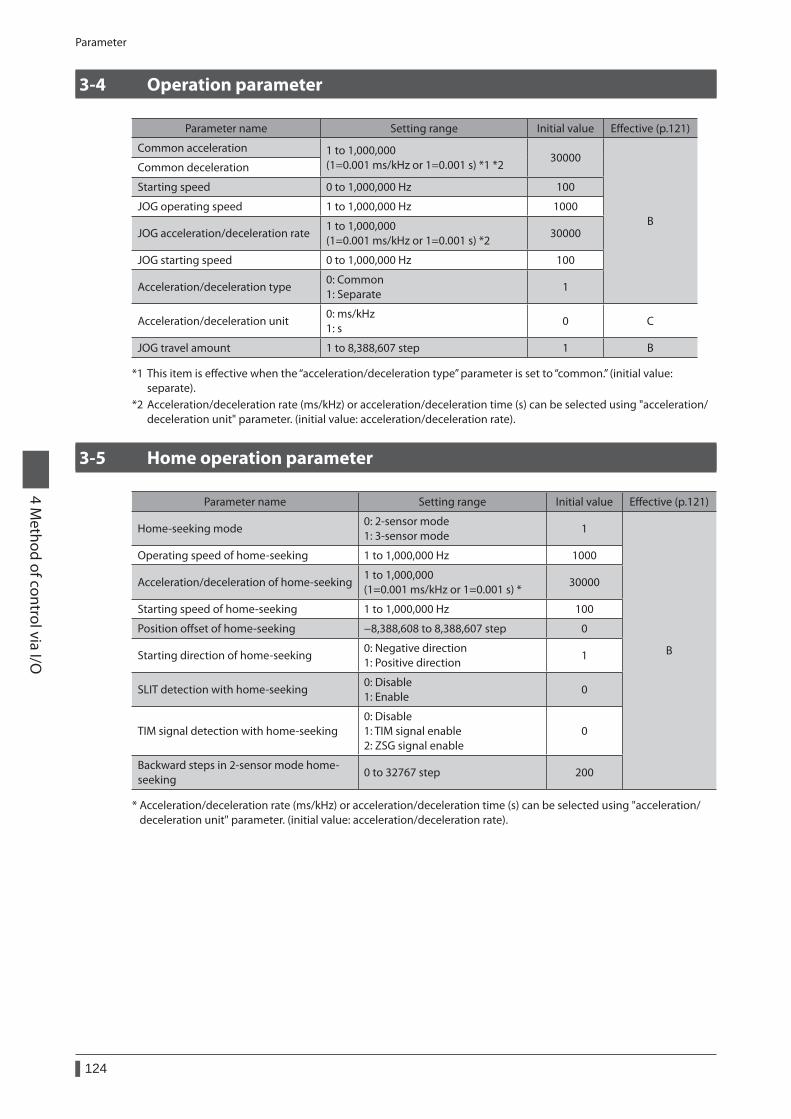
Parameter
124
4 Method of control via I/O
3-4 Operation parameter
Parameter name Setting range Initial value Effective (p.121)
Common acceleration 1 to 1,000,000 (1=0.001 ms/kHz or 1=0.001 s) *1 *2
30000
B
Common deceleration
Starting speed 0 to 1,000,000 Hz 100
JOG operating speed 1 to 1,000,000 Hz 1000
JOG acceleration/deceleration rate1 to 1,000,000 (1=0.001 ms/kHz or 1=0.001 s) *2
30000
JOG starting speed 0 to 1,000,000 Hz 100
Acceleration/deceleration type0: Common 1: Separate
1
Acceleration/deceleration unit0: ms/kHz 1: s
0 C
JOG travel amount 1 to 8,388,607 step 1 B
*1 This item is effective when the “acceleration/deceleration type” parameter is set to “common.” (initial value: separate).
*2 Acceleration/deceleration rate (ms/kHz) or acceleration/deceleration time (s) can be selected using "acceleration/deceleration unit" parameter. (initial value: acceleration/deceleration rate).
3-5 Home operation parameter
Parameter name Setting range Initial value Effective (p.121)
Home-seeking mode0: 2-sensor mode 1: 3-sensor mode
1
B
Operating speed of home-seeking 1 to 1,000,000 Hz 1000
Acceleration/deceleration of home-seeking1 to 1,000,000 (1=0.001 ms/kHz or 1=0.001 s) *
30000
Starting speed of home-seeking 1 to 1,000,000 Hz 100
Position offset of home-seeking −8,388,608 to 8,388,607 step 0
Starting direction of home-seeking0: Negative direction 1: Positive direction
1
SLIT detection with home-seeking0: Disable 1: Enable
0
TIM signal detection with home-seeking0: Disable 1: TIM signal enable 2: ZSG signal enable
0
Backward steps in 2-sensor mode home-seeking
0 to 32767 step 200
* Acceleration/deceleration rate (ms/kHz) or acceleration/deceleration time (s) can be selected using "acceleration/deceleration unit" parameter. (initial value: acceleration/deceleration rate).
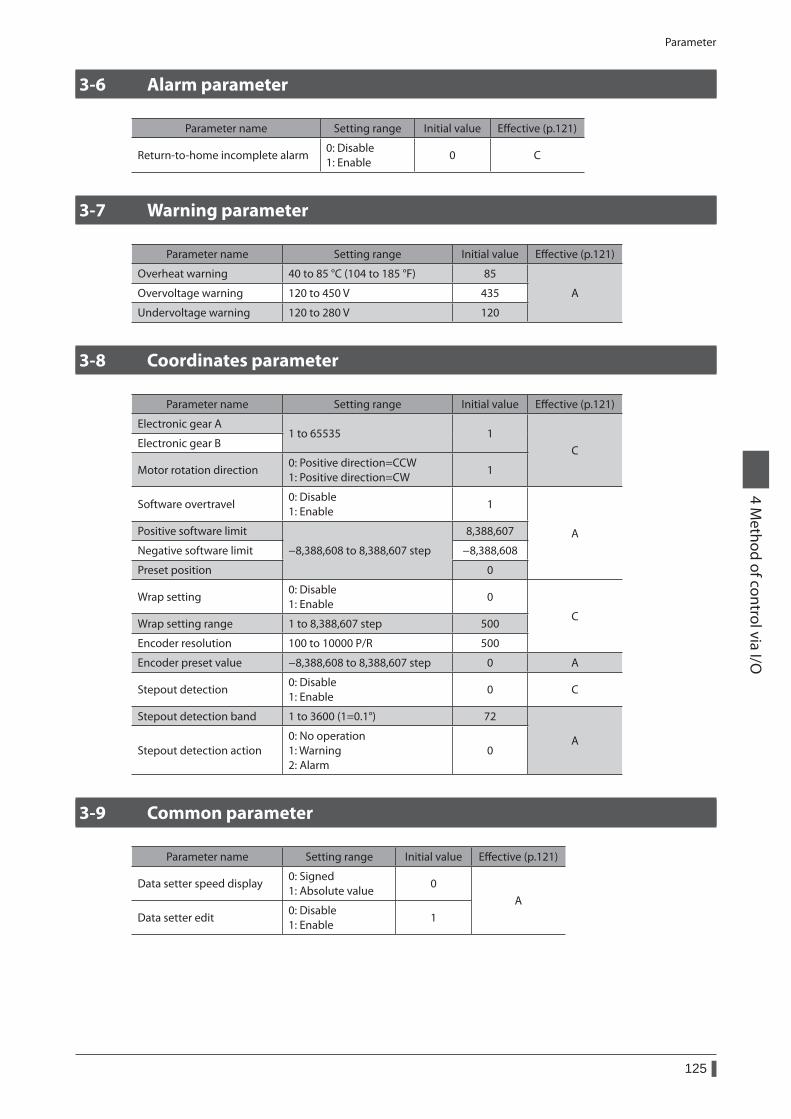
Parameter
125
4 Method of control via I/O
3-6 Alarm parameter
Parameter name Setting range Initial value Effective (p.121)
Return-to-home incomplete alarm0: Disable 1: Enable
0 C
3-7 Warning parameter
Parameter name Setting range Initial value Effective (p.121)
Overheat warning 40 to 85 °C (104 to 185 °F) 85
AOvervoltage warning 120 to 450 V 435
Undervoltage warning 120 to 280 V 120
3-8 Coordinates parameter
Parameter name Setting range Initial value Effective (p.121)
Electronic gear A1 to 65535 1
CElectronic gear B
Motor rotation direction0: Positive direction=CCW 1: Positive direction=CW
1
Software overtravel0: Disable 1: Enable
1
APositive software limit
−8,388,608 to 8,388,607 step
8,388,607
Negative software limit −8,388,608
Preset position 0
Wrap setting0: Disable 1: Enable
0
CWrap setting range 1 to 8,388,607 step 500
Encoder resolution 100 to 10000 P/R 500
Encoder preset value −8,388,608 to 8,388,607 step 0 A
Stepout detection0: Disable 1: Enable
0 C
Stepout detection band 1 to 3600 (1=0.1°) 72
AStepout detection action
0: No operation 1: Warning 2: Alarm
0
3-9 Common parameter
Parameter name Setting range Initial value Effective (p.121)
Data setter speed display0: Signed 1: Absolute value
0A
Data setter edit0: Disable 1: Enable
1
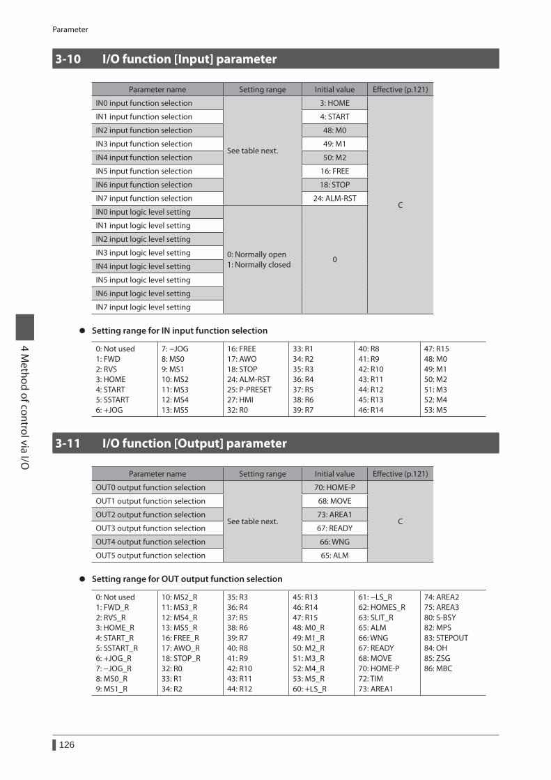
Parameter
126
4 Method of control via I/O
3-10 I/O function [Input] parameter
Parameter name Setting range Initial value Effective (p.121)
IN0 input function selection
See table next.
3: HOME
C
IN1 input function selection 4: START
IN2 input function selection 48: M0
IN3 input function selection 49: M1
IN4 input function selection 50: M2
IN5 input function selection 16: FREE
IN6 input function selection 18: STOP
IN7 input function selection 24: ALM-RST
IN0 input logic level setting
0: Normally open 1: Normally closed
0
IN1 input logic level setting
IN2 input logic level setting
IN3 input logic level setting
IN4 input logic level setting
IN5 input logic level setting
IN6 input logic level setting
IN7 input logic level setting
z Setting range for IN input function selection
0: Not used 1: FWD 2: RVS 3: HOME 4: START 5: SSTART 6: +JOG
7: −JOG 8: MS0 9: MS1 10: MS2 11: MS3 12: MS4 13: MS5
16: FREE 17: AWO 18: STOP 24: ALM-RST 25: P-PRESET 27: HMI 32: R0
33: R1 34: R2 35: R3 36: R4 37: R5 38: R6 39: R7
40: R8 41: R9 42: R10 43: R11 44: R12 45: R13 46: R14
47: R15 48: M0 49: M1 50: M2 51: M3 52: M4 53: M5
3-11 I/O function [Output] parameter
Parameter name Setting range Initial value Effective (p.121)
OUT0 output function selection
See table next.
70: HOME-P
C
OUT1 output function selection 68: MOVE
OUT2 output function selection 73: AREA1
OUT3 output function selection 67: READY
OUT4 output function selection 66: WNG
OUT5 output function selection 65: ALM
z Setting range for OUT output function selection
0: Not used 1: FWD_R 2: RVS_R 3: HOME_R 4: START_R 5: SSTART_R 6: +JOG_R 7: −JOG_R 8: MS0_R 9: MS1_R
10: MS2_R 11: MS3_R 12: MS4_R 13: MS5_R 16: FREE_R 17: AWO_R 18: STOP_R 32: R0 33: R1 34: R2
35: R3 36: R4 37: R5 38: R6 39: R7 40: R8 41: R9 42: R10 43: R11 44: R12
45: R13 46: R14 47: R15 48: M0_R 49: M1_R 50: M2_R 51: M3_R 52: M4_R 53: M5_R 60: +LS_R
61: −LS_R 62: HOMES_R 63: SLIT_R 65: ALM 66: WNG 67: READY 68: MOVE 70: HOME-P 72: TIM 73: AREA1
74: AREA2 75: AREA3 80: S-BSY 82: MPS 83: STEPOUT 84: OH 85: ZSG 86: MBC
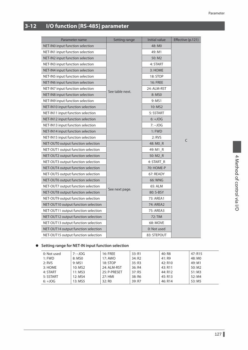
Parameter
127
4 Method of control via I/O
3-12 I/O function [RS-485] parameter
Parameter name Setting range Initial value Effective (p.121)
NET-IN0 input function selection
See table next.
48: M0
C
NET-IN1 input function selection 49: M1
NET-IN2 input function selection 50: M2
NET-IN3 input function selection 4: START
NET-IN4 input function selection 3: HOME
NET-IN5 input function selection 18: STOP
NET-IN6 input function selection 16: FREE
NET-IN7 input function selection 24: ALM-RST
NET-IN8 input function selection 8: MS0
NET-IN9 input function selection 9: MS1
NET-IN10 input function selection 10: MS2
NET-IN11 input function selection 5: SSTART
NET-IN12 input function selection 6: +JOG
NET-IN13 input function selection 7: −JOG
NET-IN14 input function selection 1: FWD
NET-IN15 input function selection 2: RVS
NET-OUT0 output function selection
See next page.
48: M0_R
NET-OUT1 output function selection 49: M1_R
NET-OUT2 output function selection 50: M2_R
NET-OUT3 output function selection 4: START_R
NET-OUT4 output function selection 70: HOME-P
NET-OUT5 output function selection 67: READY
NET-OUT6 output function selection 66: WNG
NET-OUT7 output function selection 65: ALM
NET-OUT8 output function selection 80: S-BSY
NET-OUT9 output function selection 73: AREA1
NET-OUT10 output function selection 74: AREA2
NET-OUT11 output function selection 75: AREA3
NET-OUT12 output function selection 72: TIM
NET-OUT13 output function selection 68: MOVE
NET-OUT14 output function selection 0: Not used
NET-OUT15 output function selection 83: STEPOUT
z Setting range for NET-IN input function selection
0: Not used 1: FWD 2: RVS 3: HOME 4: START 5: SSTART 6: +JOG
7: −JOG 8: MS0 9: MS1 10: MS2 11: MS3 12: MS4 13: MS5
16: FREE 17: AWO 18: STOP 24: ALM-RST 25: P-PRESET 27: HMI 32: R0
33: R1 34: R2 35: R3 36: R4 37: R5 38: R6 39: R7
40: R8 41: R9 42: R10 43: R11 44: R12 45: R13 46: R14
47: R15 48: M0 49: M1 50: M2 51: M3 52: M4 53: M5
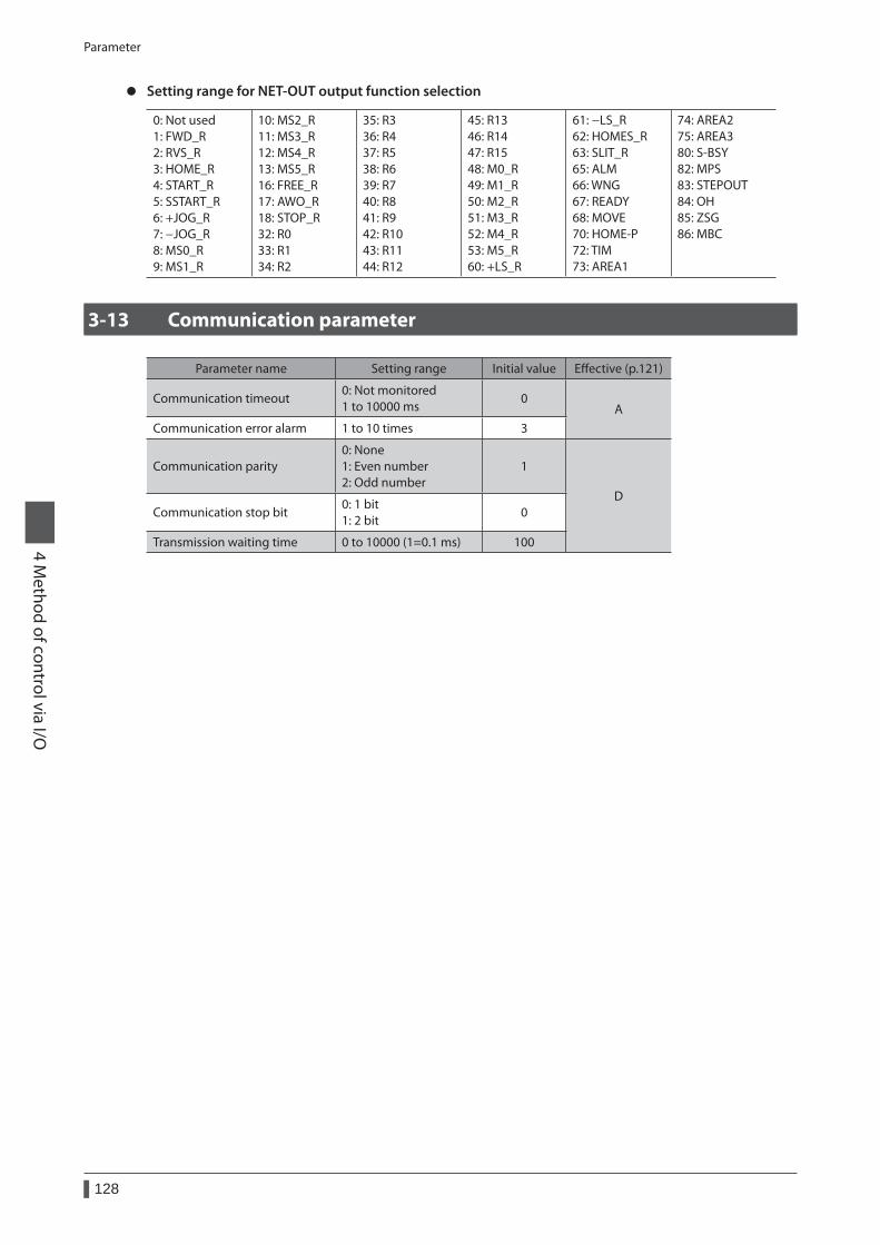
Parameter
128
4 Method of control via I/O
z Setting range for NET-OUT output function selection
0: Not used 1: FWD_R 2: RVS_R 3: HOME_R 4: START_R 5: SSTART_R 6: +JOG_R 7: −JOG_R 8: MS0_R 9: MS1_R
10: MS2_R 11: MS3_R 12: MS4_R 13: MS5_R 16: FREE_R 17: AWO_R 18: STOP_R 32: R0 33: R1 34: R2
35: R3 36: R4 37: R5 38: R6 39: R7 40: R8 41: R9 42: R10 43: R11 44: R12
45: R13 46: R14 47: R15 48: M0_R 49: M1_R 50: M2_R 51: M3_R 52: M4_R 53: M5_R 60: +LS_R
61: −LS_R 62: HOMES_R 63: SLIT_R 65: ALM 66: WNG 67: READY 68: MOVE 70: HOME-P 72: TIM 73: AREA1
74: AREA2 75: AREA3 80: S-BSY 82: MPS 83: STEPOUT 84: OH 85: ZSG 86: MBC
3-13 Communication parameter
Parameter name Setting range Initial value Effective (p.121)
Communication timeout0: Not monitored 1 to 10000 ms
0A
Communication error alarm 1 to 10 times 3
Communication parity0: None 1: Even number 2: Odd number
1
DCommunication stop bit
0: 1 bit 1: 2 bit
0
Transmission waiting time 0 to 10000 (1=0.1 ms) 100
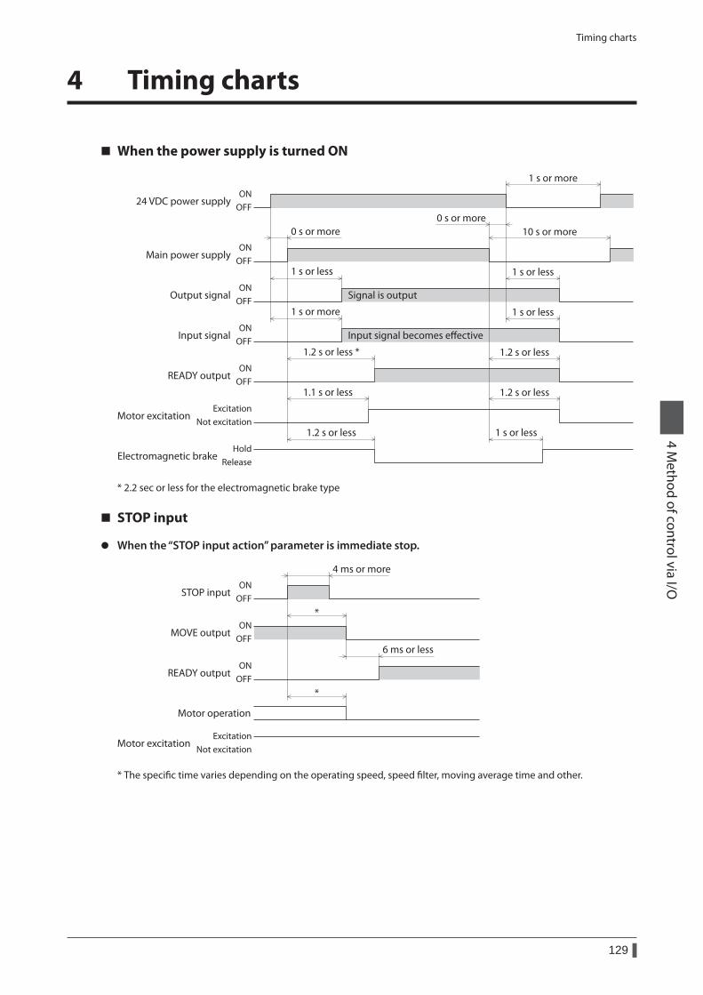
Timing charts
129
4 Method of control via I/O
4 Timing charts
When the power supply is turned ON
Input signal becomes eective
Signal is output
Main power supplyON
OFF
24 VDC power supplyON
OFF
ONOFF
ONOFF
ONOFF
1 s or less
1 s or more
1 s or less
1 s or less
10 s or more
1 s or more
0 s or more0 s or more
1.1 s or less 1.2 s or less
1.2 s or less 1 s or less
1.2 s or less1.2 s or less *
Output signal
Input signal
Motor excitation
Electromagnetic brake
READY output
ExcitationNot excitation
HoldRelease
* 2.2 sec or less for the electromagnetic brake type
STOP input
z When the “STOP input action” parameter is immediate stop.
Motor excitation
ONOFF
ONOFF
ONOFF
STOP input
MOVE output
READY output
*
*
6 ms or less
Motor operation
4 ms or more
ExcitationNot excitation
* The specific time varies depending on the operating speed, speed filter, moving average time and other.
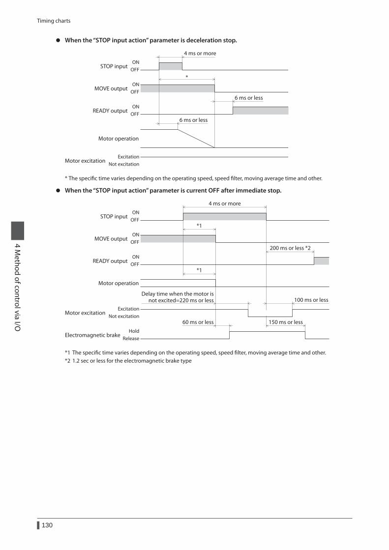
Timing charts
130
4 Method of control via I/O
z When the “STOP input action” parameter is deceleration stop.
*
6 ms or less
4 ms or more
6 ms or less
ONOFF
ONOFF
ONOFF
STOP input
MOVE output
READY output
Motor operation
Motor excitationExcitation
Not excitation
* The specific time varies depending on the operating speed, speed filter, moving average time and other.
z When the “STOP input action” parameter is current OFF after immediate stop.
*1
*1
200 ms or less *2
4 ms or more
60 ms or less 150 ms or less
100 ms or less
ONOFF
ONOFF
ONOFF
Motor excitation
STOP input
MOVE output
READY output
Motor operation
ExcitationNot excitation
Electromagnetic brakeHold
Release
Delay time when the motor isnot excited=220 ms or less
*1 The specific time varies depending on the operating speed, speed filter, moving average time and other.*2 1.2 sec or less for the electromagnetic brake type
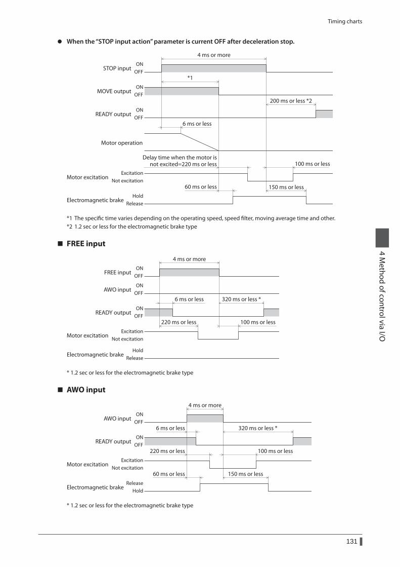
Timing charts
131
4 Method of control via I/O
z When the “STOP input action” parameter is current OFF after deceleration stop.
*1
4 ms or more
6 ms or less
100 ms or less
150 ms or less60 ms or less
200 ms or less *2ON
OFF
ONOFF
ONOFF
Motor excitation
STOP input
MOVE output
READY output
Motor operation
ExcitationNot excitation
Electromagnetic brakeRelease
Hold
Delay time when the motor isnot excited=220 ms or less
*1 The specific time varies depending on the operating speed, speed filter, moving average time and other.*2 1.2 sec or less for the electromagnetic brake type
FREE input
6 ms or less 320 ms or less *
100 ms or less220 ms or less
ONOFF
ONOFF
ONOFF
4 ms or more
FREE input
AWO input
READY output
Electromagnetic brakeRelease
Hold
Motor excitationExcitation
Not excitation
* 1.2 sec or less for the electromagnetic brake type
AWO input
6 ms or less
60 ms or less
320 ms or less *
150 ms or less
4 ms or more
220 ms or less 100 ms or less
ONOFF
ONOFF
AWO input
READY output
Electromagnetic brakeRelease
Hold
Motor excitationExcitation
Not excitation
* 1.2 sec or less for the electromagnetic brake type
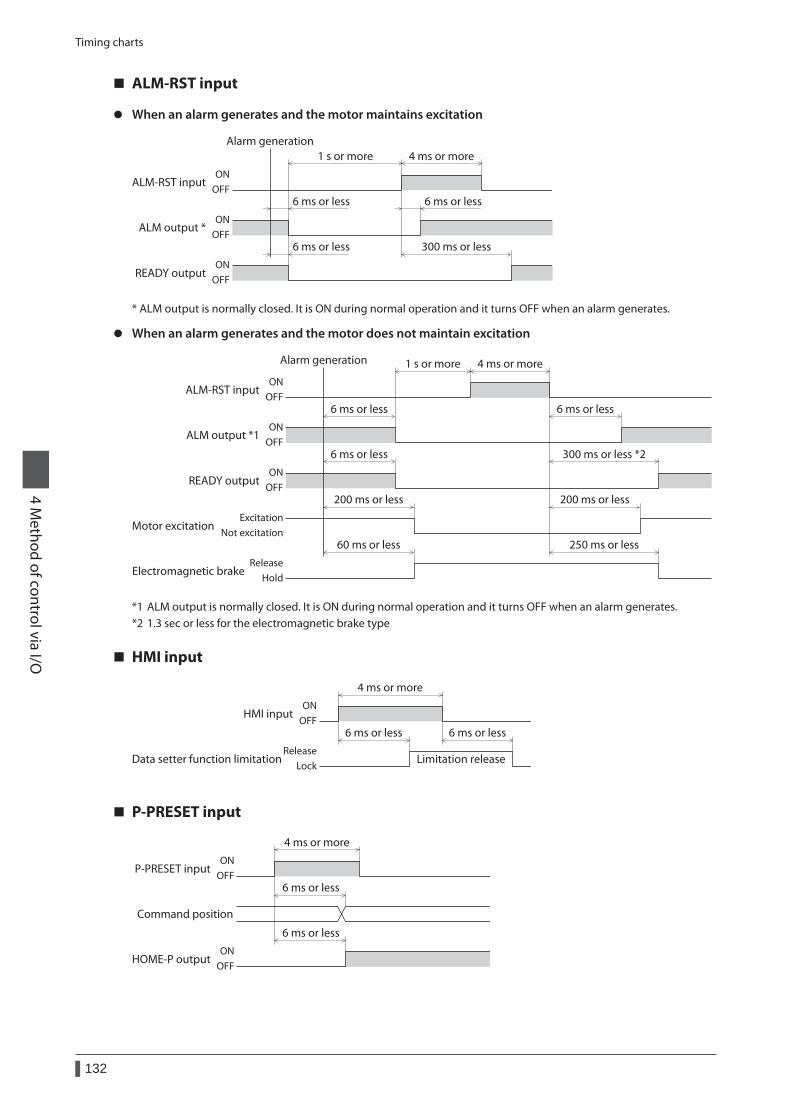
Timing charts
132
4 Method of control via I/O
ALM-RST input
z When an alarm generates and the motor maintains excitation
300 ms or less
6 ms or less6 ms or less
6 ms or less
1 s or more 4 ms or moreON
OFF
ONOFF
ONOFF
Alarm generation
ALM-RST input
ALM output *
READY output
* ALM output is normally closed. It is ON during normal operation and it turns OFF when an alarm generates.
z When an alarm generates and the motor does not maintain excitation
Alarm generation
6 ms or less
60 ms or less
200 ms or less
6 ms or less
300 ms or less *2
250 ms or less
200 ms or less
6 ms or less
1 s or more 4 ms or more
ALM-RST input
ALM output *1
READY output
ONOFF
ONOFF
ONOFF
Electromagnetic brakeRelease
Hold
Motor excitationExcitation
Not excitation
*1 ALM output is normally closed. It is ON during normal operation and it turns OFF when an alarm generates.*2 1.3 sec or less for the electromagnetic brake type
HMI input
Limitation release
HMI inputON
OFF
4 ms or more
6 ms or less
Data setter function limitationLock
Release
6 ms or less
P-PRESET input
P-PRESET inputON
OFF
Command position
HOME-P outputON
OFF
4 ms or more
6 ms or less
6 ms or less
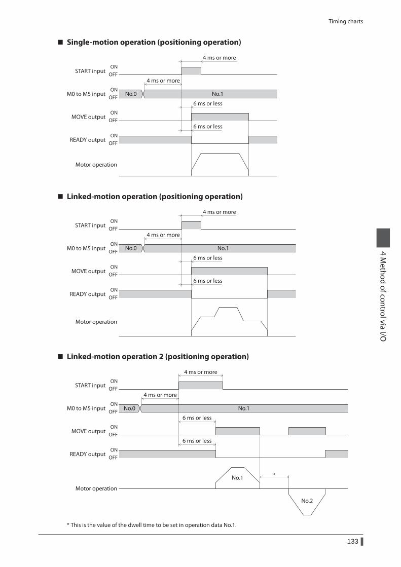
Timing charts
133
4 Method of control via I/O
Single-motion operation (positioning operation)
6 ms or less
No.0 No.1
6 ms or less
4 ms or more
4 ms or more
ONOFF
ONOFF
ONOFF
ONOFF
START input
M0 to M5 input
MOVE output
READY output
Motor operation
Linked-motion operation (positioning operation)
6 ms or less
No.0 No.1
6 ms or less
4 ms or more
4 ms or more
ONOFF
ONOFF
ONOFF
ONOFF
START input
M0 to M5 input
MOVE output
READY output
Motor operation
Linked-motion operation 2 (positioning operation)
No.0 No.1
START inputON
OFF
ONOFF
ONOFF
ONOFF
4 ms or more
6 ms or less
6 ms or less
*
MOVE output
READY output
Motor operation
No.1
No.2
M0 to M5 input
4 ms or more
* This is the value of the dwell time to be set in operation data No.1.
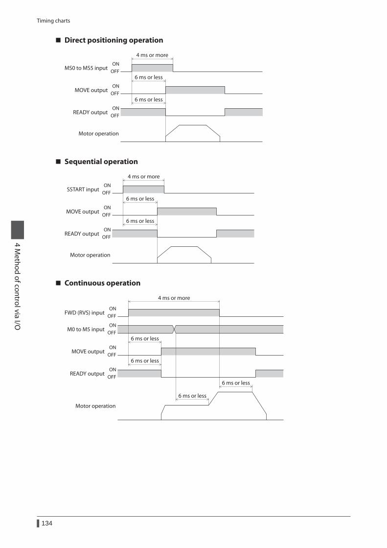
Timing charts
134
4 Method of control via I/O
Direct positioning operation
MS0 to MS5 inputON
OFF
ONOFF
ONOFF
4 ms or more
6 ms or less
6 ms or less
MOVE output
READY output
Motor operation
Sequential operation
SSTART inputON
OFF
ONOFF
ONOFF
4 ms or more
6 ms or less
6 ms or less
MOVE output
READY output
Motor operation
Continuous operation
6 ms or less
4 ms or more
6 ms or less
6 ms or less
6 ms or less
ONOFF
ONOFF
ONOFF
ONOFF
FWD (RVS) input
M0 to M5 input
MOVE output
READY output
Motor operation
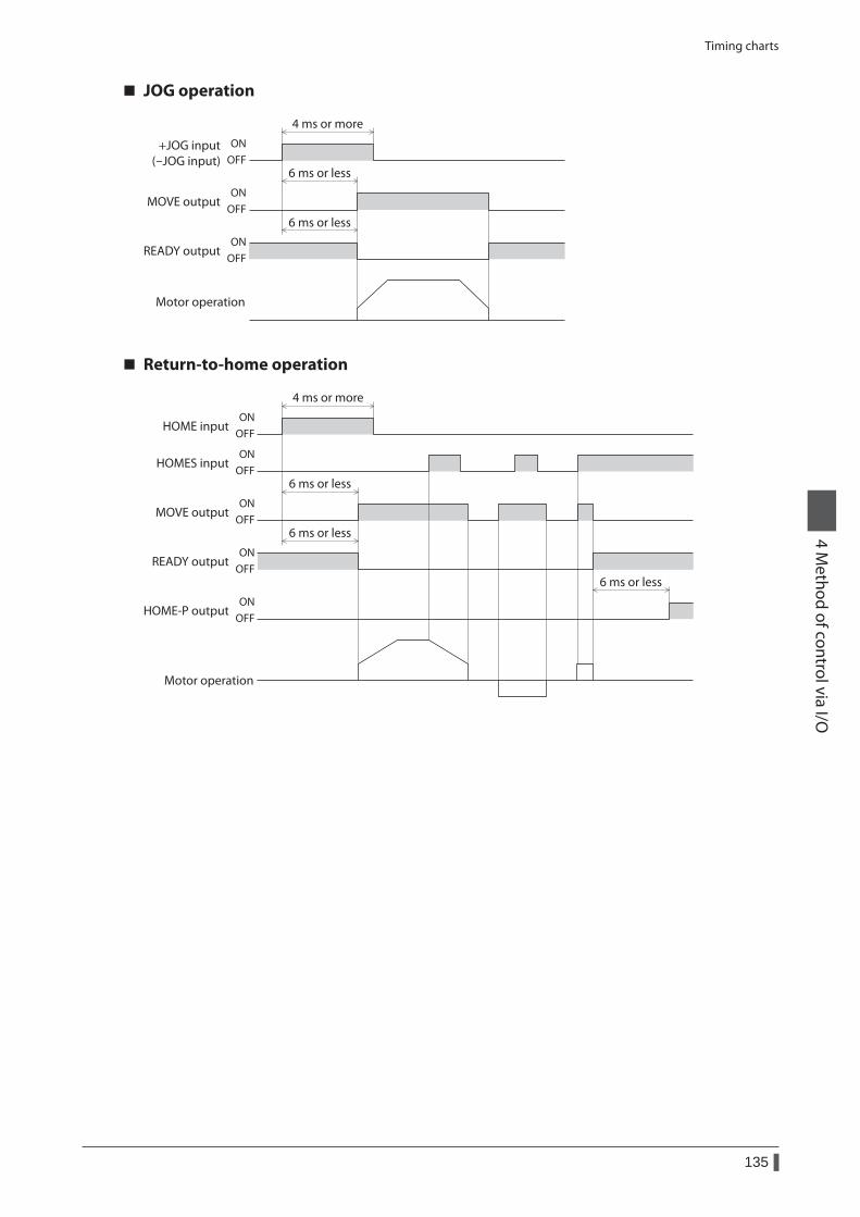
Timing charts
135
4 Method of control via I/O
JOG operation
+JOG input(-JOG input)
ONOFF
ONOFF
ONOFF
4 ms or more
6 ms or less
6 ms or less
MOVE output
READY output
Motor operation
Return-to-home operation
HOME inputON
OFF
ONOFF
ONOFF
ONOFF
ONOFF
4 ms or more
6 ms or less
6 ms or less
6 ms or less
HOMES input
MOVE output
READY output
HOME-P output
Motor operation

136
4 Method of control via I/O
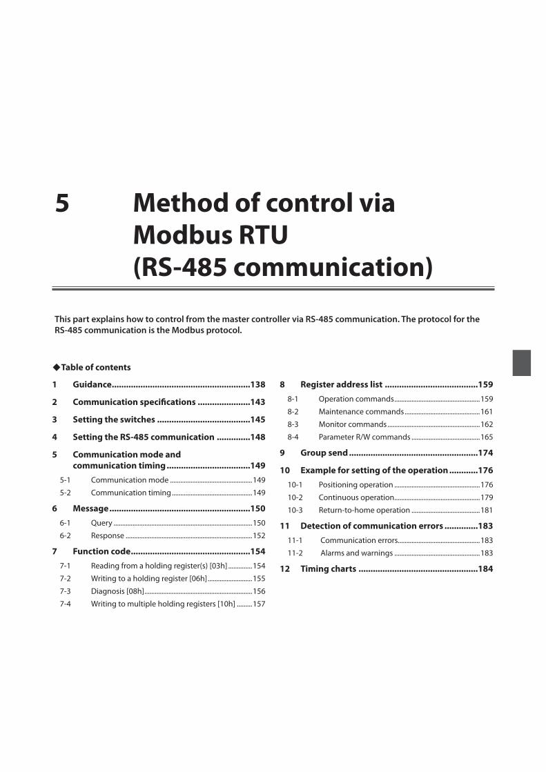
1 Guidance ..........................................................138
2 Communication specifications ......................143
3 Setting the switches .......................................145
4 Setting the RS-485 communication ..............148
5 Communication mode and communication timing ...................................149
5-1 Communication mode ................................................149
5-2 Communication timing ...............................................149
6 Message ...........................................................1506-1 Query .................................................................................150
6-2 Response ..........................................................................152
7 Function code ..................................................1547-1 Reading from a holding register(s) [03h] ..............154
7-2 Writing to a holding register [06h] ..........................155
7-3 Diagnosis [08h] ...............................................................156
7-4 Writing to multiple holding registers [10h] .........157
8 Register address list .......................................1598-1 Operation commands ..................................................159
8-2 Maintenance commands ............................................161
8-3 Monitor commands ......................................................162
8-4 Parameter R/W commands ........................................165
9 Group send ......................................................174
10 Example for setting of the operation ............17610-1 Positioning operation ..................................................176
10-2 Continuous operation ..................................................179
10-3 Return-to-home operation ........................................181
11 Detection of communication errors ..............18311-1 Communication errors................................................183
11-2 Alarms and warnings ..................................................183
12 Timing charts ..................................................184
5 Method of control via Modbus RTU (RS-485 communication)
This part explains how to control from the master controller via RS-485 communication. The protocol for the RS-485 communication is the Modbus protocol.
Table of contents
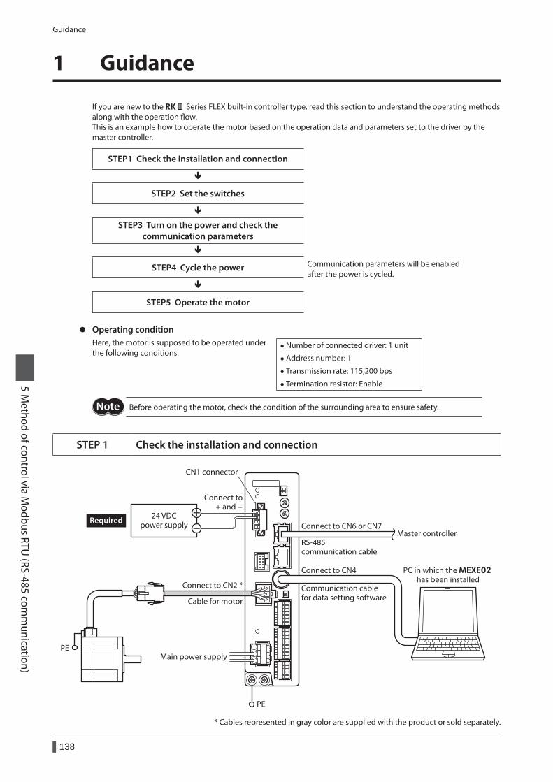
Guidance
138
5 Method of control via M
odbus RTU (RS-485 com
munication)
1 Guidance
If you are new to the RKⅡ Series FLEX built-in controller type, read this section to understand the operating methods along with the operation flow.This is an example how to operate the motor based on the operation data and parameters set to the driver by the master controller.
STEP1 Check the installation and connection
STEP2 Set the switches
STEP3 Turn on the power and check the communication parameters
STEP4 Cycle the power Communication parameters will be enabled after the power is cycled.
STEP5 Operate the motor
z Operating conditionHere, the motor is supposed to be operated under the following conditions.
• Number of connected driver: 1 unit
• Address number: 1
• Transmission rate: 115,200 bps
• Termination resistor: Enable
Before operating the motor, check the condition of the surrounding area to ensure safety.
STEP 1 Check the installation and connection
Main power supply
PE
Connect to CN4
24 VDCpower supplyRequired
PC in which the MEXE02 has been installed
Connect to CN2 *
Cable for motor
PE
Master controllerRS-485 communication cable
Connect to CN6 or CN7
Connect to + and -
CN1 connector
Communication cable for data setting software
* Cables represented in gray color are supplied with the product or sold separately.
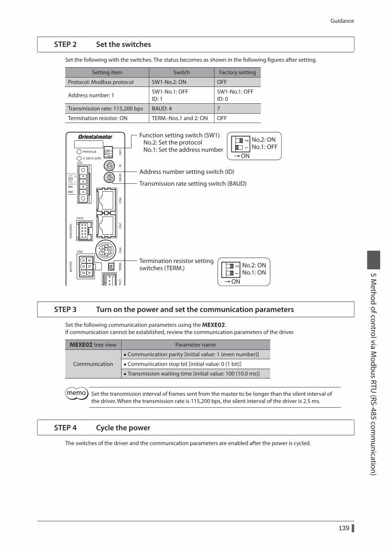
Guidance
139
5 Method of control via M
odbus RTU (RS-485 com
munication)
STEP 2 Set the switches
Set the following with the switches. The status becomes as shown in the following figures after setting.
Setting item Switch Factory setting
Protocol: Modbus protocol SW1-No.2: ON OFF
Address number: 1SW1-No.1: OFF ID: 1
SW1-No.1: OFF ID: 0
Transmission rate: 115,200 bps BAUD: 4 7
Termination resistor: ON TERM.-Nos.1 and 2: ON OFF
ON
ON
Address number setting switch (ID)
Termination resistor settingswitches (TERM.)
Transmission rate setting switch (BAUD)
Function setting switch (SW1) No.2: Set the protocol No.1: Set the address number
No.2: ONNo.1: OFF
No.2: ONNo.1: ON
STEP 3 Turn on the power and set the communication parameters
Set the following communication parameters using the MEXE02.If communication cannot be established, review the communication parameters of the driver.
MEXE02 tree view Parameter name
Communication
• Communication parity [initial value: 1 (even number)]
• Communication stop bit [initial value: 0 (1 bit)]
• Transmission waiting time [initial value: 100 (10.0 ms)]
Set the transmission interval of frames sent from the master to be longer than the silent interval of the driver. When the transmission rate is 115,200 bps, the silent interval of the driver is 2.5 ms.
STEP 4 Cycle the power
The switches of the driver and the communication parameters are enabled after the power is cycled.
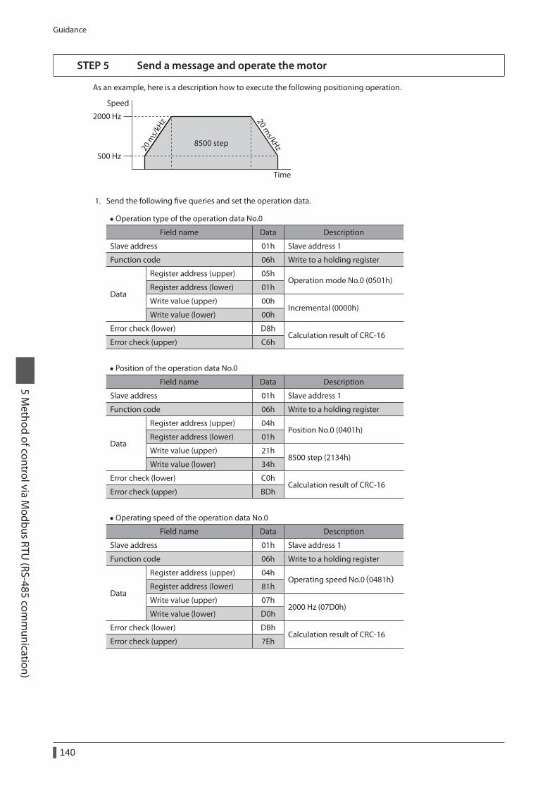
Guidance
140
5 Method of control via M
odbus RTU (RS-485 com
munication)
STEP 5 Send a message and operate the motor
As an example, here is a description how to execute the following positioning operation.
8500 step
2000 Hz
500 Hz
Speed
Time
20 m
s/kH
z 20 ms/kHz
1. Send the following five queries and set the operation data.
• Operation type of the operation data No.0
Field name Data Description
Slave address 01h Slave address 1
Function code 06h Write to a holding register
Data
Register address (upper) 05hOperation mode No.0 (0501h)
Register address (lower) 01h
Write value (upper) 00hIncremental (0000h)
Write value (lower) 00h
Error check (lower) D8hCalculation result of CRC-16
Error check (upper) C6h
• Position of the operation data No.0
Field name Data Description
Slave address 01h Slave address 1
Function code 06h Write to a holding register
Data
Register address (upper) 04hPosition No.0 (0401h)
Register address (lower) 01h
Write value (upper) 21h8500 step (2134h)
Write value (lower) 34h
Error check (lower) C0hCalculation result of CRC-16
Error check (upper) BDh
• Operating speed of the operation data No.0
Field name Data Description
Slave address 01h Slave address 1
Function code 06h Write to a holding register
Data
Register address (upper) 04hOperating speed No.0(0481h)
Register address (lower) 81h
Write value (upper) 07h2000 Hz (07D0h)
Write value (lower) D0h
Error check (lower) DBhCalculation result of CRC-16
Error check (upper) 7Eh
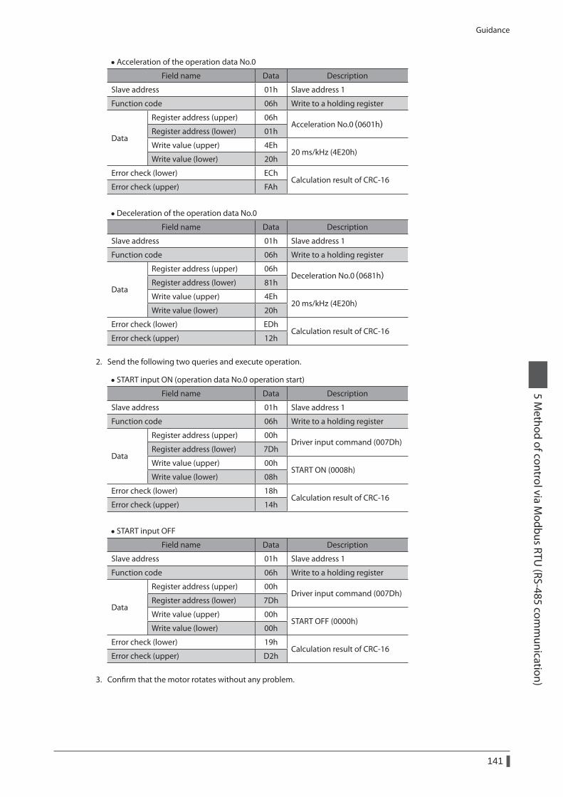
Guidance
141
5 Method of control via M
odbus RTU (RS-485 com
munication)
• Acceleration of the operation data No.0
Field name Data Description
Slave address 01h Slave address 1
Function code 06h Write to a holding register
Data
Register address (upper) 06hAcceleration No.0(0601h)
Register address (lower) 01h
Write value (upper) 4Eh20 ms/kHz (4E20h)
Write value (lower) 20h
Error check (lower) EChCalculation result of CRC-16
Error check (upper) FAh
• Deceleration of the operation data No.0
Field name Data Description
Slave address 01h Slave address 1
Function code 06h Write to a holding register
Data
Register address (upper) 06hDeceleration No.0(0681h)
Register address (lower) 81h
Write value (upper) 4Eh20 ms/kHz (4E20h)
Write value (lower) 20h
Error check (lower) EDhCalculation result of CRC-16
Error check (upper) 12h
2. Send the following two queries and execute operation.
• START input ON (operation data No.0 operation start)
Field name Data Description
Slave address 01h Slave address 1
Function code 06h Write to a holding register
Data
Register address (upper) 00hDriver input command (007Dh)
Register address (lower) 7Dh
Write value (upper) 00hSTART ON (0008h)
Write value (lower) 08h
Error check (lower) 18hCalculation result of CRC-16
Error check (upper) 14h
• START input OFF
Field name Data Description
Slave address 01h Slave address 1
Function code 06h Write to a holding register
Data
Register address (upper) 00hDriver input command (007Dh)
Register address (lower) 7Dh
Write value (upper) 00hSTART OFF (0000h)
Write value (lower) 00h
Error check (lower) 19hCalculation result of CRC-16
Error check (upper) D2h
3. Confirm that the motor rotates without any problem.

Guidance
142
5 Method of control via M
odbus RTU (RS-485 com
munication)
STEP 6 Were you able to operate the motor properly?
How did it go? Were you able to operate the motor properly? If the motor does not function, check the following points:
• Is any alarm present? • Are the power supply, motor and RS-485 communication cable connected securely? • Are the slave address, transmission rate and termination resistor set correctly? • Is the C-DAT/C-ERR LED turned off? Or is it lit in red? (A communication error has occurred)
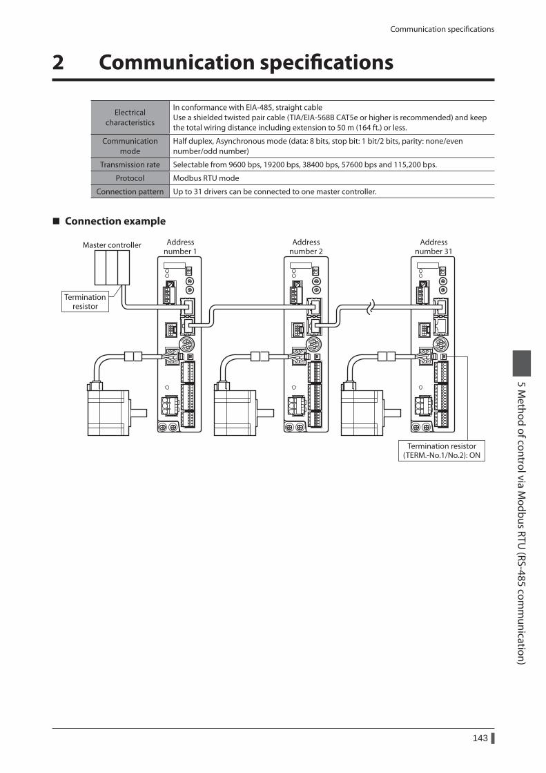
Communication specifications
143
5 Method of control via M
odbus RTU (RS-485 com
munication)
2 Communication specifications
Electrical characteristics
In conformance with EIA-485, straight cable Use a shielded twisted pair cable (TIA/EIA-568B CAT5e or higher is recommended) and keep the total wiring distance including extension to 50 m (164 ft.) or less.
Communication mode
Half duplex, Asynchronous mode (data: 8 bits, stop bit: 1 bit/2 bits, parity: none/even number/odd number)
Transmission rate Selectable from 9600 bps, 19200 bps, 38400 bps, 57600 bps and 115,200 bps.
Protocol Modbus RTU mode
Connection pattern Up to 31 drivers can be connected to one master controller.
Connection example
Master controller Addressnumber 1
Terminationresistor
Termination resistor(TERM.-No.1/No.2): ON
Addressnumber 2
Addressnumber 31
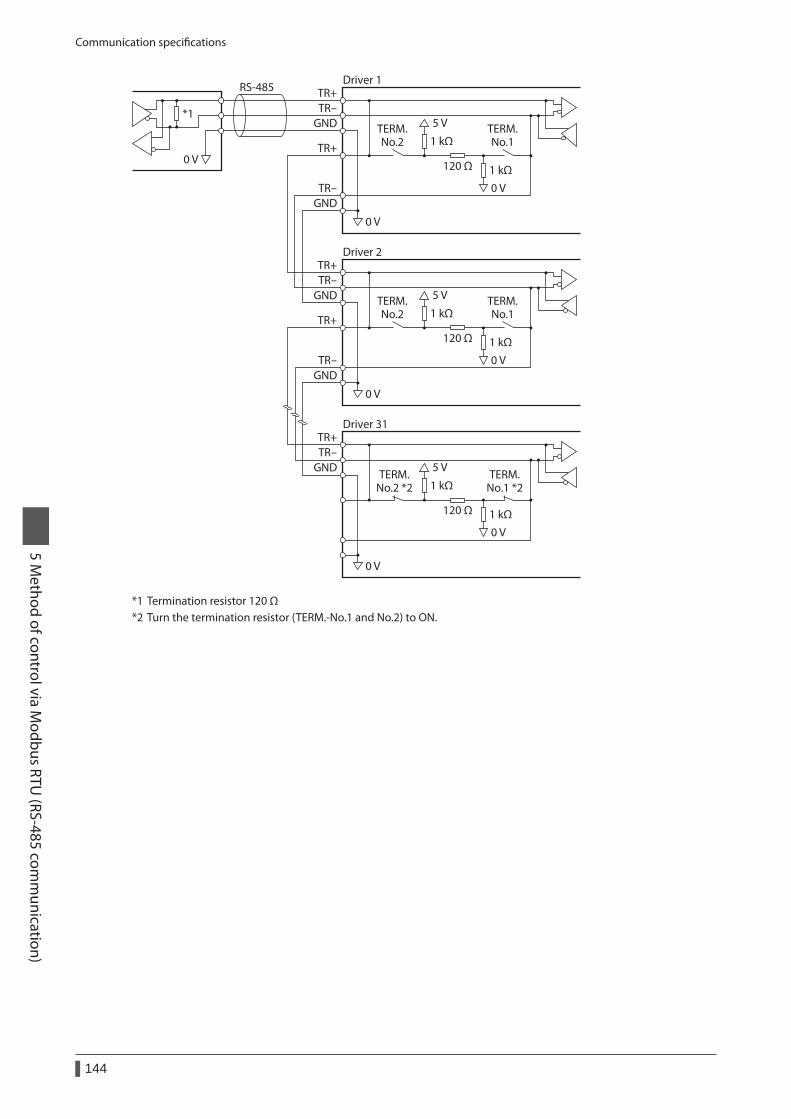
Communication specifications
144
5 Method of control via M
odbus RTU (RS-485 com
munication)
Driver 1
0 V
RS-485
*1GND
TR+TR-
GND
TR+
TR-
120 Ω
1 kΩ
1 kΩ
5 V
0 V
0 V
TERM.No.2
TERM.No.1
Driver 2
GND
TR+TR-
GND
TR+
TR-
120 Ω
1 kΩ
1 kΩ
5 V
0 V
0 V
TERM.No.2
TERM.No.1
Driver 31
GND
TR+TR-
120 Ω
1 kΩ
1 kΩ
5 V
0 V
0 V
TERM.No.2 *2
TERM.No.1 *2
*1 Termination resistor 120 Ω*2 Turn the termination resistor (TERM.-No.1 and No.2) to ON.
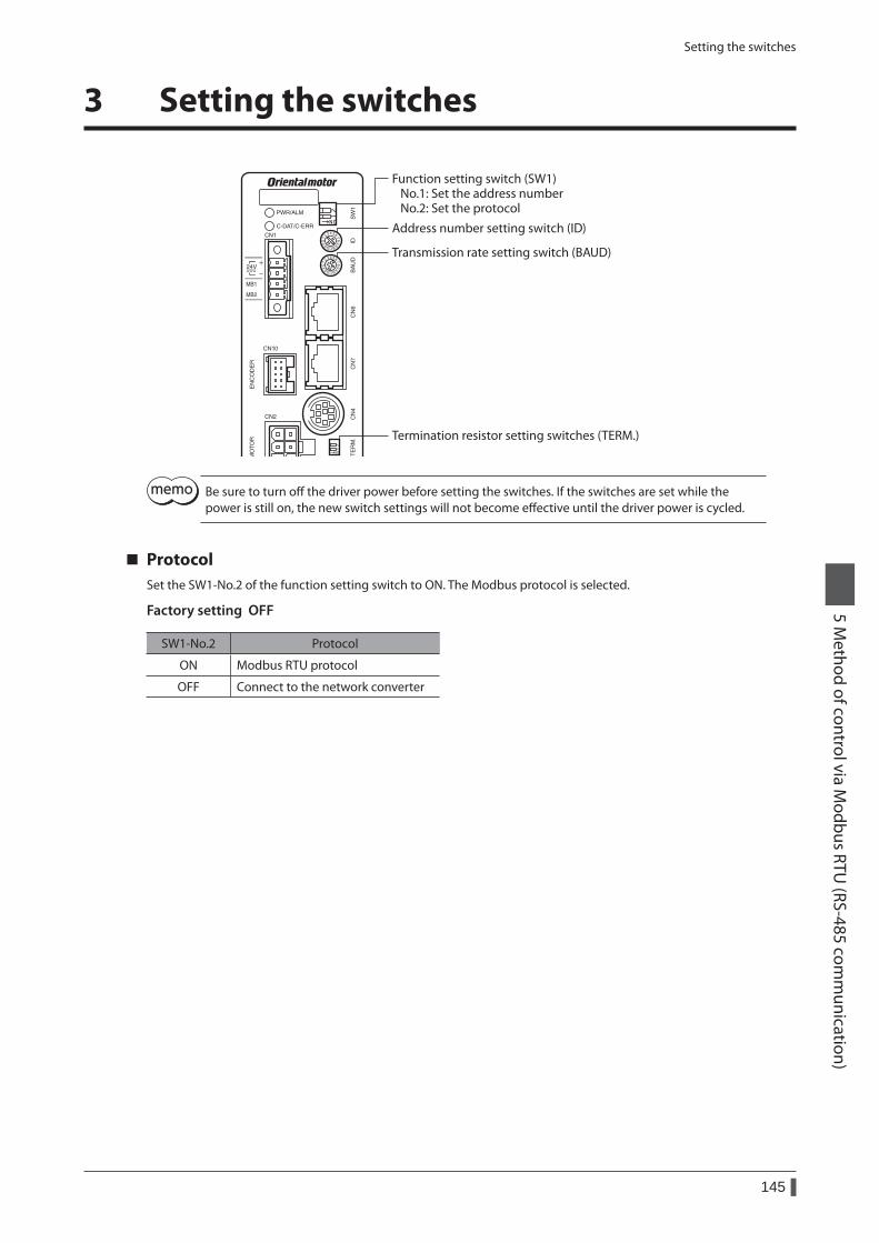
Setting the switches
145
5 Method of control via M
odbus RTU (RS-485 com
munication)
3 Setting the switches
Function setting switch (SW1) No.1: Set the address number No.2: Set the protocol
Transmission rate setting switch (BAUD)
Address number setting switch (ID)
Termination resistor setting switches (TERM.)
Be sure to turn off the driver power before setting the switches. If the switches are set while the power is still on, the new switch settings will not become effective until the driver power is cycled.
ProtocolSet the SW1-No.2 of the function setting switch to ON. The Modbus protocol is selected.
Factory setting OFF
SW1-No.2 Protocol
ON Modbus RTU protocol
OFF Connect to the network converter
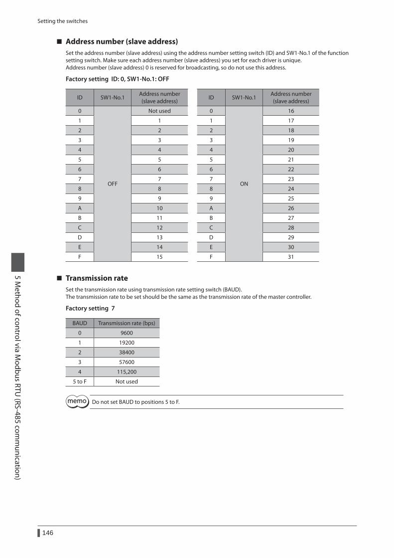
Setting the switches
146
5 Method of control via M
odbus RTU (RS-485 com
munication)
Address number (slave address)Set the address number (slave address) using the address number setting switch (ID) and SW1-No.1 of the function setting switch. Make sure each address number (slave address) you set for each driver is unique.Address number (slave address) 0 is reserved for broadcasting, so do not use this address.
Factory setting ID: 0, SW1-No.1: OFF
ID SW1-No.1Address number (slave address)
ID SW1-No.1Address number (slave address)
0
OFF
Not used 0
ON
16
1 1 1 17
2 2 2 18
3 3 3 19
4 4 4 20
5 5 5 21
6 6 6 22
7 7 7 23
8 8 8 24
9 9 9 25
A 10 A 26
B 11 B 27
C 12 C 28
D 13 D 29
E 14 E 30
F 15 F 31
Transmission rateSet the transmission rate using transmission rate setting switch (BAUD).The transmission rate to be set should be the same as the transmission rate of the master controller.
Factory setting 7
BAUD Transmission rate (bps)
0 9600
1 19200
2 38400
3 57600
4 115,200
5 to F Not used
Do not set BAUD to positions 5 to F.
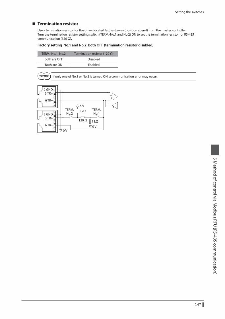
Setting the switches
147
5 Method of control via M
odbus RTU (RS-485 com
munication)
Termination resistorUse a termination resistor for the driver located farthest away (position at end) from the master controller.Turn the termination resistor setting switch (TERM.-No.1 and No.2) ON to set the termination resistor for RS-485 communication (120 Ω).
Factory setting No.1 and No.2: Both OFF (termination resistor disabled)
TERM.-No.1, No.2 Termination resistor (120 Ω)
Both are OFF Disabled
Both are ON Enabled
If only one of No.1 or No.2 is turned ON, a communication error may occur.
2 GND3 TR+
6 TR-
2 GND3 TR+
6 TR-120 Ω
1 kΩ
1 kΩ
5 V
0 V0 V
TERM.No.2
TERM.No.1
Setting the RS-485 communication
148
5 Method of control via M
odbus RTU (RS-485 com
munication)
4 Setting the RS-485 communication
Set parameters required to use via RS-485 communication beforehand.When a parameter is changed, the timing to reflect the new value varies depending on the parameter. Refer to p.165 for the update timing of each parameter.
Parameters set with the OPX-2A or MEXE02Set the following parameters using the OPX-2A or MEXE02 since they cannot be set via RS-485 communication.
MEXE02 tree view
Parameter name Description Setting rangeInitial value
Communication
Communication parity
Sets the parity for RS-485 communication.0: None 1: Even number 2: Odd number
1
Communication stop bit
Sets the stop bit for RS-485 communication.0: 1 bit 1: 2 bit
0
Transmission waiting time
Sets the transmission waiting time for RS-485 communication.
0 to 10000 (1=0.1 ms)
100
Parameters set with the OPX-2A, MEXE02 or via RS-485 communicationSet the following parameters using the OPX-2A, MEXE02 or via RS-485 communication.
MEXE02 tree view
Parameter name Description Setting rangeInitial value
Communication
Communication timeout
Sets the condition in which the communication timeout occurs in RS-485 communication. When setting to zero (0), the driver does not monitor the condition in which the communication timeout occurs.
0 to 10000 ms 0
Communication error alarm
Sets the condition in which the RS-485 communication error alarm generates. The communication error alarm generates after the RS-485 communication error has occurred by the number of times set here.
1 to 10 3
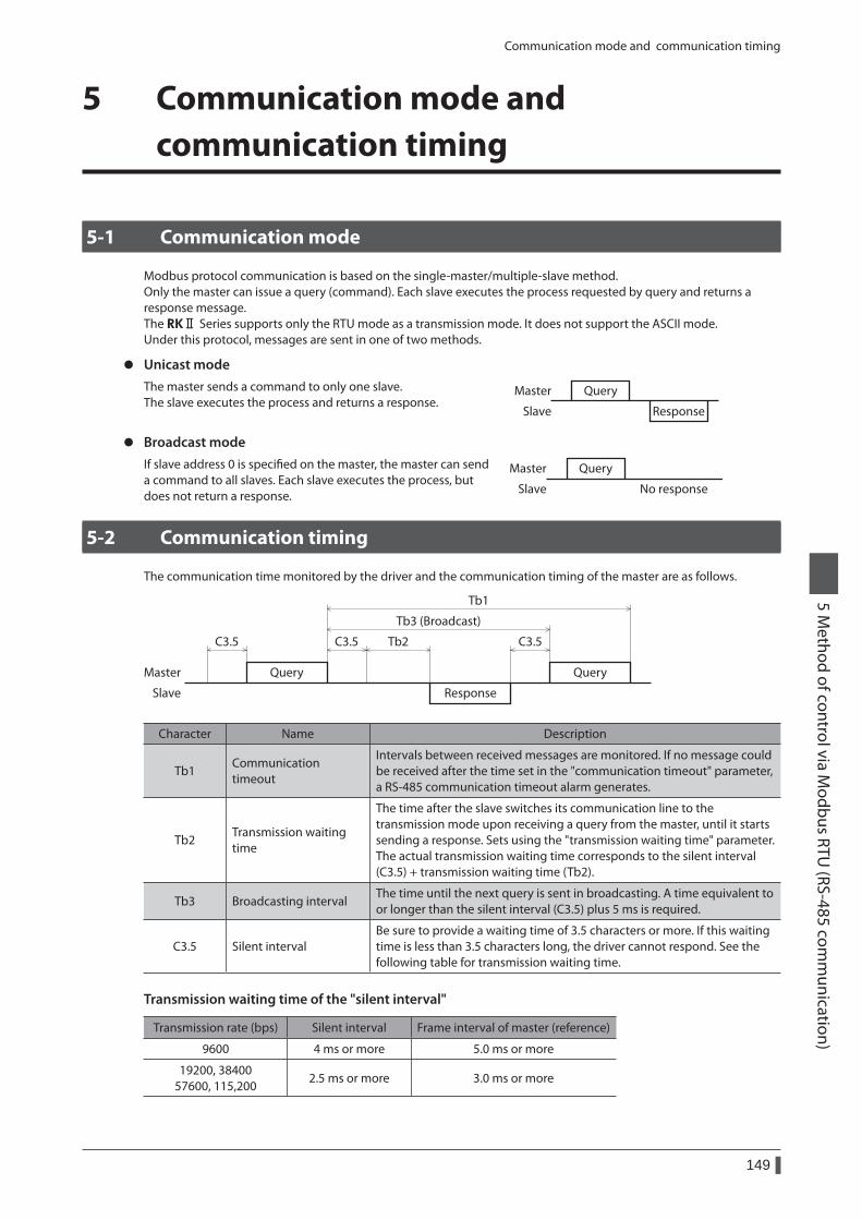
Communication mode and communication timing
149
5 Method of control via M
odbus RTU (RS-485 com
munication)
5 Communication mode and communication timing
5-1 Communication mode
Modbus protocol communication is based on the single-master/multiple-slave method. Only the master can issue a query (command). Each slave executes the process requested by query and returns a response message.The RKⅡ Series supports only the RTU mode as a transmission mode. It does not support the ASCII mode.Under this protocol, messages are sent in one of two methods.
z Unicast modeThe master sends a command to only one slave. The slave executes the process and returns a response.
Query
Response
Master
Slave
z Broadcast modeIf slave address 0 is specified on the master, the master can send a command to all slaves. Each slave executes the process, but does not return a response.
Master
Slave No response
Query
5-2 Communication timing
The communication time monitored by the driver and the communication timing of the master are as follows.
Query
Tb2 C3.5C3.5C3.5
Tb3 (Broadcast)
Tb1
Query
Response
Master
Slave
Character Name Description
Tb1Communication timeout
Intervals between received messages are monitored. If no message could be received after the time set in the "communication timeout" parameter, a RS-485 communication timeout alarm generates.
Tb2Transmission waiting time
The time after the slave switches its communication line to the transmission mode upon receiving a query from the master, until it starts sending a response. Sets using the "transmission waiting time" parameter. The actual transmission waiting time corresponds to the silent interval (C3.5) + transmission waiting time (Tb2).
Tb3 Broadcasting intervalThe time until the next query is sent in broadcasting. A time equivalent to or longer than the silent interval (C3.5) plus 5 ms is required.
C3.5 Silent intervalBe sure to provide a waiting time of 3.5 characters or more. If this waiting time is less than 3.5 characters long, the driver cannot respond. See the following table for transmission waiting time.
Transmission waiting time of the "silent interval"
Transmission rate (bps) Silent interval Frame interval of master (reference)
9600 4 ms or more 5.0 ms or more
19200, 38400 57600, 115,200
2.5 ms or more 3.0 ms or more
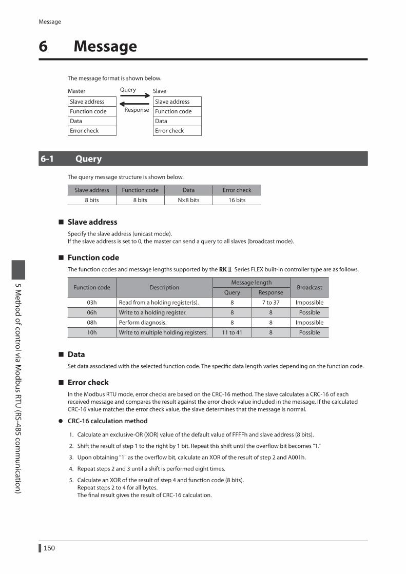
Message
150
5 Method of control via M
odbus RTU (RS-485 com
munication)
6 Message
The message format is shown below.
Slave address
Function code
Data
Error check
Slave address
Function code
Data
Error check
Master Query
Response
Slave
6-1 Query
The query message structure is shown below.
Slave address Function code Data Error check
8 bits 8 bits N×8 bits 16 bits
Slave addressSpecify the slave address (unicast mode).If the slave address is set to 0, the master can send a query to all slaves (broadcast mode).
Function codeThe function codes and message lengths supported by the RKⅡ Series FLEX built-in controller type are as follows.
Function code DescriptionMessage length
BroadcastQuery Response
03h Read from a holding register(s). 8 7 to 37 Impossible
06h Write to a holding register. 8 8 Possible
08h Perform diagnosis. 8 8 Impossible
10h Write to multiple holding registers. 11 to 41 8 Possible
DataSet data associated with the selected function code. The specific data length varies depending on the function code.
Error checkIn the Modbus RTU mode, error checks are based on the CRC-16 method. The slave calculates a CRC-16 of each received message and compares the result against the error check value included in the message. If the calculated CRC-16 value matches the error check value, the slave determines that the message is normal.
z CRC-16 calculation method
1. Calculate an exclusive-OR (XOR) value of the default value of FFFFh and slave address (8 bits).
2. Shift the result of step 1 to the right by 1 bit. Repeat this shift until the overflow bit becomes "1."
3. Upon obtaining "1" as the overflow bit, calculate an XOR of the result of step 2 and A001h.
4. Repeat steps 2 and 3 until a shift is performed eight times.
5. Calculate an XOR of the result of step 4 and function code (8 bits).Repeat steps 2 to 4 for all bytes.The final result gives the result of CRC-16 calculation.
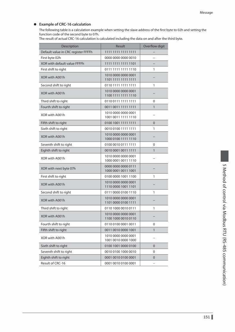
Message
151
5 Method of control via M
odbus RTU (RS-485 com
munication)
z Example of CRC-16 calculationThe following table is a calculation example when setting the slave address of the first byte to 02h and setting the function code of the second byte to 07h.The result of actual CRC-16 calculation is calculated including the data on and after the third byte.
Description Result Overflow digit
Default value in CRC register FFFFh 1111 1111 1111 1111 −
First byte 02h 0000 0000 0000 0010 −
XOR with default value FFFFh 1111 1111 1111 1101 −
First shift to right 0111 1111 1111 1110 1
XOR with A001h1010 0000 0000 0001 1101 1111 1111 1111
−
Second shift to right 0110 1111 1111 1111 1
XOR with A001h1010 0000 0000 0001 1100 1111 1111 1110
−
Third shift to right 0110 0111 1111 1111 0
Fourth shift to right 0011 0011 1111 1111 1
XOR with A001h1010 0000 0000 0001 1001 0011 1111 1110
−
Fifth shift to right 0100 1001 1111 1111 0
Sixth shift to right 0010 0100 1111 1111 1
XOR with A001h1010 0000 0000 0001 1000 0100 1111 1110
−
Seventh shift to right 0100 0010 0111 1111 0
Eighth shift to right 0010 0001 0011 1111 1
XOR with A001h1010 0000 0000 0001 1000 0001 0011 1110
−
XOR with next byte 07h0000 0000 0000 0111 1000 0001 0011 1001
−
First shift to right 0100 0000 1001 1100 1
XOR with A001h1010 0000 0000 0001 1110 0000 1001 1101
−
Second shift to right 0111 0000 0100 1110 1
XOR with A001h1010 0000 0000 0001 1101 0000 0100 1111
−
Third shift to right 0110 1000 0010 0111 1
XOR with A001h1010 0000 0000 0001 1100 1000 0010 0110
−
Fourth shift to right 0110 0100 0001 0011 0
Fifth shift to right 0011 0010 0000 1001 1
XOR with A001h1010 0000 0000 0001 1001 0010 0000 1000
−
Sixth shift to right 0100 1001 0000 0100 0
Seventh shift to right 0010 0100 1000 0010 0
Eighth shift to right 0001 0010 0100 0001 0
Result of CRC-16 0001 0010 0100 0001 −
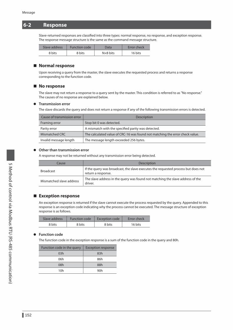
Message
152
5 Method of control via M
odbus RTU (RS-485 com
munication)
6-2 Response
Slave-returned responses are classified into three types: normal response, no response, and exception response.The response message structure is the same as the command message structure.
Slave address Function code Data Error check
8 bits 8 bits N×8 bits 16 bits
Normal responseUpon receiving a query from the master, the slave executes the requested process and returns a response corresponding to the function code.
No responseThe slave may not return a response to a query sent by the master. This condition is referred to as "No response."The causes of no response are explained below.
z Transmission errorThe slave discards the query and does not return a response if any of the following transmission errors is detected.
Cause of transmission error Description
Framing error Stop bit 0 was detected.
Parity error A mismatch with the specified parity was detected.
Mismatched CRC The calculated value of CRC-16 was found not matching the error check value.
Invalid message length The message length exceeded 256 bytes.
z Other than transmission errorA response may not be returned without any transmission error being detected.
Cause Description
BroadcastIf the query was broadcast, the slave executes the requested process but does not return a response.
Mismatched slave addressThe slave address in the query was found not matching the slave address of the driver.
Exception responseAn exception response is returned if the slave cannot execute the process requested by the query. Appended to this response is an exception code indicating why the process cannot be executed. The message structure of exception response is as follows.
Slave address Function code Exception code Error check
8 bits 8 bits 8 bits 16 bits
z Function codeThe function code in the exception response is a sum of the function code in the query and 80h.
Function code in the query Exception response
03h 83h
06h 86h
08h 88h
10h 90h
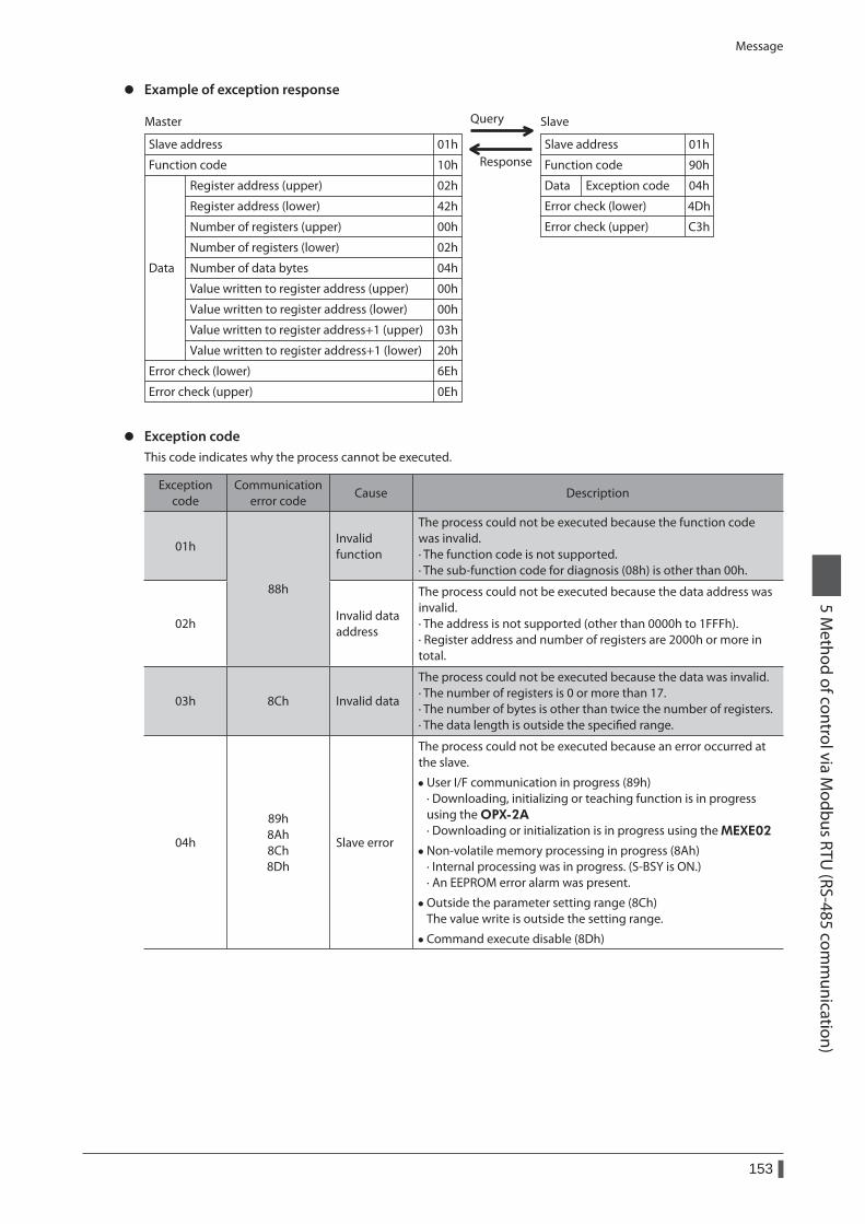
Message
153
5 Method of control via M
odbus RTU (RS-485 com
munication)
z Example of exception response
Value written to register address+1 (upper)
Value written to register address+1 (lower)
Value written to register address (upper)
Value written to register address (lower)
Master Query
Response
Slave
Slave address
Function code
Register address (upper)
Data
Error check (lower)
Error check (upper)
Slave address
Function code
Data Exception code
Register address (lower) Error check (lower)
Error check (upper)
01h
10h
02h
6Eh
0Eh
01h
90h
04h
42h
00h
02h
04h
03h
20h
00h
00h
4Dh
C3h
Number of data bytes
Number of registers (upper)
Number of registers (lower)
z Exception codeThis code indicates why the process cannot be executed.
Exception code
Communication error code
Cause Description
01h
88h
Invalid function
The process could not be executed because the function code was invalid. · The function code is not supported. · The sub-function code for diagnosis (08h) is other than 00h.
02hInvalid data address
The process could not be executed because the data address was invalid. · The address is not supported (other than 0000h to 1FFFh). · Register address and number of registers are 2000h or more in total.
03h 8Ch Invalid data
The process could not be executed because the data was invalid. · The number of registers is 0 or more than 17. · The number of bytes is other than twice the number of registers. · The data length is outside the specified range.
04h
89h 8Ah 8Ch 8Dh
Slave error
The process could not be executed because an error occurred at the slave.
• User I/F communication in progress (89h) · Downloading, initializing or teaching function is in progress using the OPX-2A· Downloading or initialization is in progress using the MEXE02
• Non-volatile memory processing in progress (8Ah) · Internal processing was in progress. (S-BSY is ON.) · An EEPROM error alarm was present.
• Outside the parameter setting range (8Ch) The value write is outside the setting range.
• Command execute disable (8Dh)
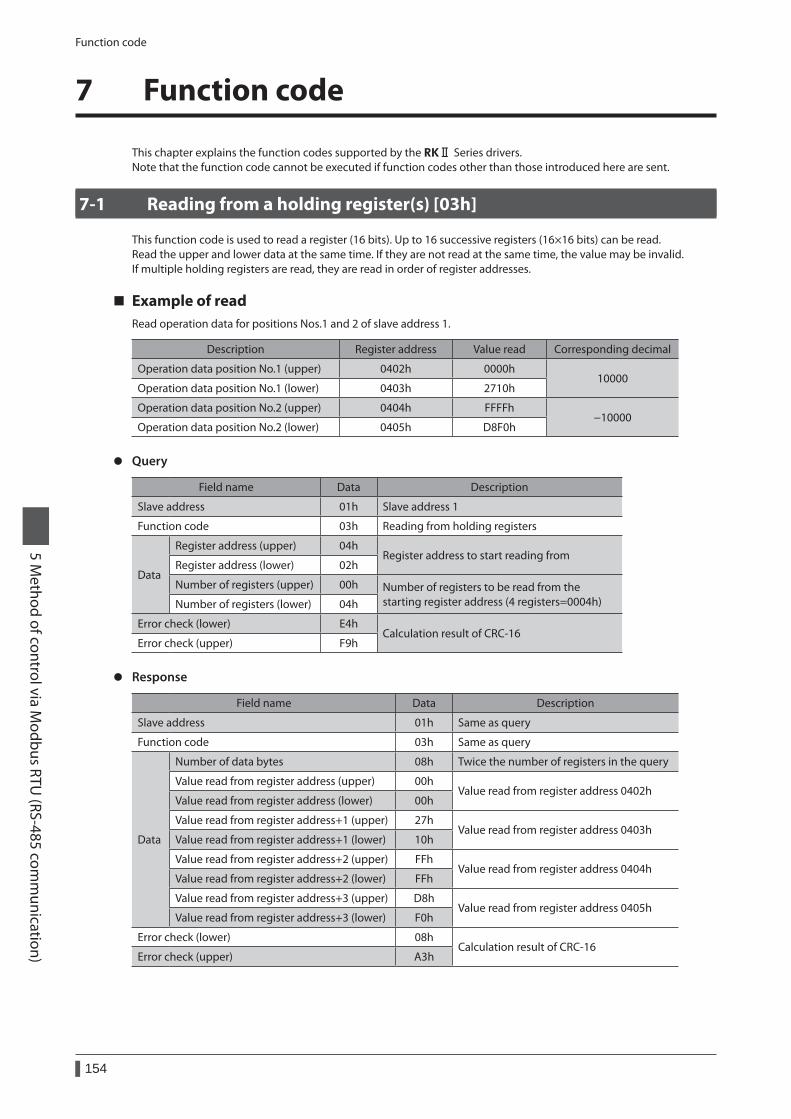
Function code
154
5 Method of control via M
odbus RTU (RS-485 com
munication)
7 Function code
This chapter explains the function codes supported by the RKⅡ Series drivers.Note that the function code cannot be executed if function codes other than those introduced here are sent.
7-1 Reading from a holding register(s) [03h]
This function code is used to read a register (16 bits). Up to 16 successive registers (16×16 bits) can be read.Read the upper and lower data at the same time. If they are not read at the same time, the value may be invalid.If multiple holding registers are read, they are read in order of register addresses.
Example of readRead operation data for positions Nos.1 and 2 of slave address 1.
Description Register address Value read Corresponding decimal
Operation data position No.1 (upper) 0402h 0000h10000
Operation data position No.1 (lower) 0403h 2710h
Operation data position No.2 (upper) 0404h FFFFh−10000
Operation data position No.2 (lower) 0405h D8F0h
z Query
Field name Data Description
Slave address 01h Slave address 1
Function code 03h Reading from holding registers
Data
Register address (upper) 04hRegister address to start reading from
Register address (lower) 02h
Number of registers (upper) 00h Number of registers to be read from the starting register address (4 registers=0004h)Number of registers (lower) 04h
Error check (lower) E4hCalculation result of CRC-16
Error check (upper) F9h
z Response
Field name Data Description
Slave address 01h Same as query
Function code 03h Same as query
Data
Number of data bytes 08h Twice the number of registers in the query
Value read from register address (upper) 00hValue read from register address 0402h
Value read from register address (lower) 00h
Value read from register address+1 (upper) 27hValue read from register address 0403h
Value read from register address+1 (lower) 10h
Value read from register address+2 (upper) FFhValue read from register address 0404h
Value read from register address+2 (lower) FFh
Value read from register address+3 (upper) D8hValue read from register address 0405h
Value read from register address+3 (lower) F0h
Error check (lower) 08hCalculation result of CRC-16
Error check (upper) A3h
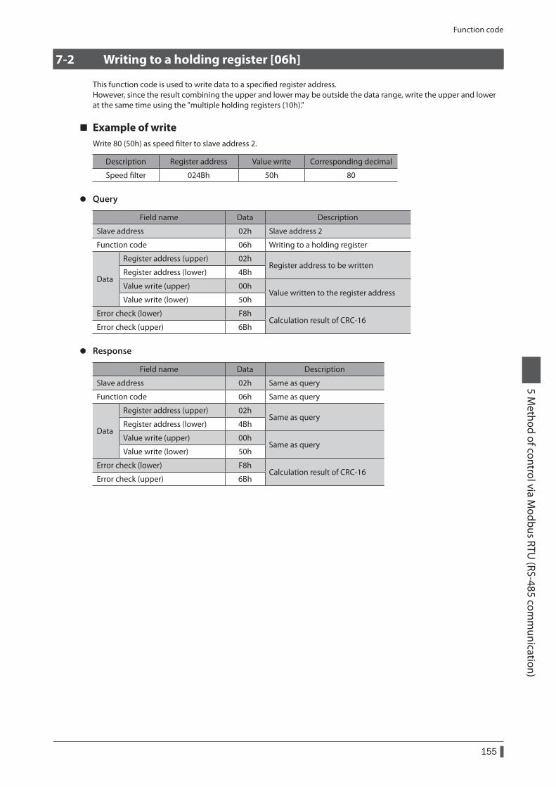
Function code
155
5 Method of control via M
odbus RTU (RS-485 com
munication)
7-2 Writing to a holding register [06h]
This function code is used to write data to a specified register address.However, since the result combining the upper and lower may be outside the data range, write the upper and lower at the same time using the "multiple holding registers (10h)."
Example of writeWrite 80 (50h) as speed filter to slave address 2.
Description Register address Value write Corresponding decimal
Speed filter 024Bh 50h 80
z Query
Field name Data Description
Slave address 02h Slave address 2
Function code 06h Writing to a holding register
Data
Register address (upper) 02hRegister address to be written
Register address (lower) 4Bh
Value write (upper) 00hValue written to the register address
Value write (lower) 50h
Error check (lower) F8hCalculation result of CRC-16
Error check (upper) 6Bh
z Response
Field name Data Description
Slave address 02h Same as query
Function code 06h Same as query
Data
Register address (upper) 02hSame as query
Register address (lower) 4Bh
Value write (upper) 00hSame as query
Value write (lower) 50h
Error check (lower) F8hCalculation result of CRC-16
Error check (upper) 6Bh
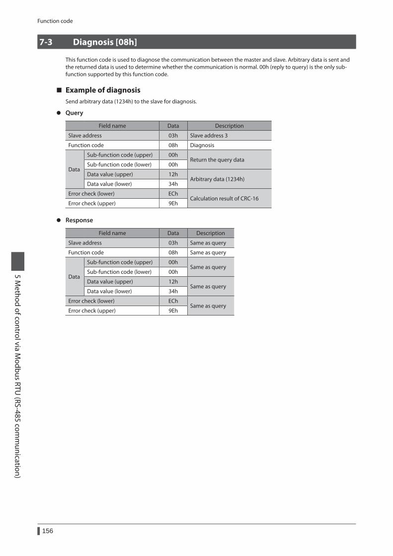
Function code
156
5 Method of control via M
odbus RTU (RS-485 com
munication)
7-3 Diagnosis [08h]
This function code is used to diagnose the communication between the master and slave. Arbitrary data is sent and the returned data is used to determine whether the communication is normal. 00h (reply to query) is the only sub-function supported by this function code.
Example of diagnosisSend arbitrary data (1234h) to the slave for diagnosis.
z Query
Field name Data Description
Slave address 03h Slave address 3
Function code 08h Diagnosis
Data
Sub-function code (upper) 00hReturn the query data
Sub-function code (lower) 00h
Data value (upper) 12hArbitrary data (1234h)
Data value (lower) 34h
Error check (lower) EChCalculation result of CRC-16
Error check (upper) 9Eh
z Response
Field name Data Description
Slave address 03h Same as query
Function code 08h Same as query
Data
Sub-function code (upper) 00hSame as query
Sub-function code (lower) 00h
Data value (upper) 12hSame as query
Data value (lower) 34h
Error check (lower) EChSame as query
Error check (upper) 9Eh
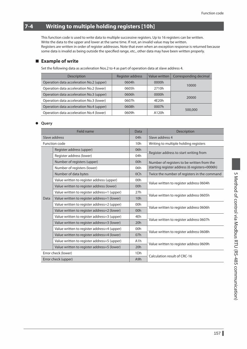
Function code
157
5 Method of control via M
odbus RTU (RS-485 com
munication)
7-4 Writing to multiple holding registers [10h]
This function code is used to write data to multiple successive registers. Up to 16 registers can be written.Write the data to the upper and lower at the same time. If not, an invalid value may be written.Registers are written in order of register addresses. Note that even when an exception response is returned because some data is invalid as being outside the specified range, etc., other data may have been written properly.
Example of writeSet the following data as acceleration Nos.2 to 4 as part of operation data at slave address 4.
Description Register address Value written Corresponding decimal
Operation data acceleration No.2 (upper) 0604h 0000h10000
Operation data acceleration No.2 (lower) 0605h 2710h
Operation data acceleration No.3 (upper) 0606h 0000h20000
Operation data acceleration No.3 (lower) 0607h 4E20h
Operation data acceleration No.4 (upper) 0608h 0007h500,000
Operation data acceleration No.4 (lower) 0609h A120h
z Query
Field name Data Description
Slave address 04h Slave address 4
Function code 10h Writing to multiple holding registers
Data
Register address (upper) 06hRegister address to start writing from
Register address (lower) 04h
Number of registers (upper) 00h Number of registers to be written from the starting register address (6 registers=0006h)Number of registers (lower) 06h
Number of data bytes 0Ch Twice the number of registers in the command
Value written to register address (upper) 00hValue written to register address 0604h
Value written to register address (lower) 00h
Value written to register address+1 (upper) 27hValue written to register address 0605h
Value written to register address+1 (lower) 10h
Value written to register address+2 (upper) 00hValue written to register address 0606h
Value written to register address+2 (lower) 00h
Value written to register address+3 (upper) 4EhValue written to register address 0607h
Value written to register address+3 (lower) 20h
Value written to register address+4 (upper) 00hValue written to register address 0608h
Value written to register address+4 (lower) 07h
Value written to register address+5 (upper) A1hValue written to register address 0609h
Value written to register address+5 (lower) 20h
Error check (lower) 1DhCalculation result of CRC-16
Error check (upper) A9h

Function code
158
5 Method of control via M
odbus RTU (RS-485 com
munication)
z Response
Field name Data Description
Slave address 04h Same as query
Function code 10h Same as query
Data
Register address (upper) 06hSame as query
Register address (lower) 04h
Number of registers (upper) 00hSame as query
Number of registers (lower) 06h
Error check (lower) 01hCalculation result of CRC-16
Error check (upper) 17h
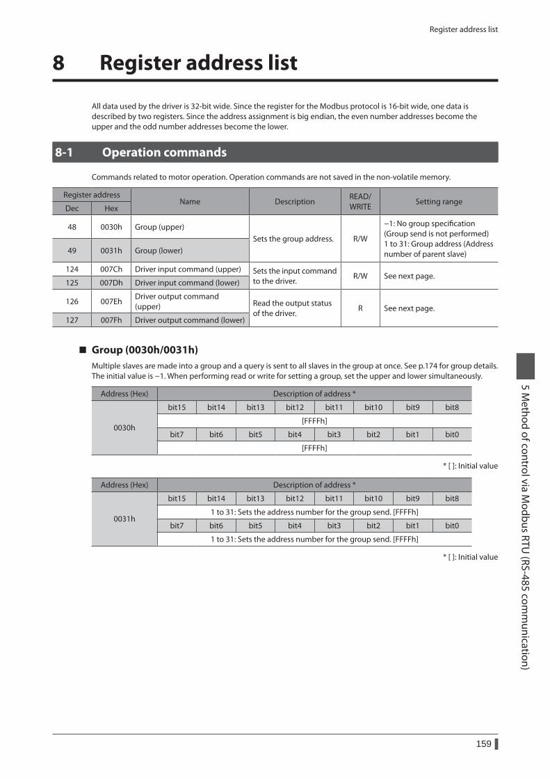
Register address list
159
5 Method of control via M
odbus RTU (RS-485 com
munication)
8 Register address list
All data used by the driver is 32-bit wide. Since the register for the Modbus protocol is 16-bit wide, one data is described by two registers. Since the address assignment is big endian, the even number addresses become the upper and the odd number addresses become the lower.
8-1 Operation commands
Commands related to motor operation. Operation commands are not saved in the non-volatile memory.
Register addressName Description
READ/ WRITE
Setting rangeDec Hex
48 0030h Group (upper)Sets the group address. R/W
−1: No group specification (Group send is not performed) 1 to 31: Group address (Address number of parent slave)49 0031h Group (lower)
124 007Ch Driver input command (upper) Sets the input command to the driver.
R/W See next page.125 007Dh Driver input command (lower)
126 007EhDriver output command (upper) Read the output status
of the driver.R See next page.
127 007Fh Driver output command (lower)
Group (0030h/0031h)Multiple slaves are made into a group and a query is sent to all slaves in the group at once. See p.174 for group details.The initial value is −1. When performing read or write for setting a group, set the upper and lower simultaneously.
Address (Hex) Description of address *
0030h
bit15 bit14 bit13 bit12 bit11 bit10 bit9 bit8
[FFFFh]
bit7 bit6 bit5 bit4 bit3 bit2 bit1 bit0
[FFFFh]
* [ ]: Initial value
Address (Hex) Description of address *
0031h
bit15 bit14 bit13 bit12 bit11 bit10 bit9 bit8
1 to 31: Sets the address number for the group send. [FFFFh]
bit7 bit6 bit5 bit4 bit3 bit2 bit1 bit0
1 to 31: Sets the address number for the group send. [FFFFh]
* [ ]: Initial value
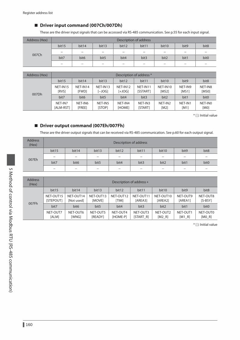
Register address list
160
5 Method of control via M
odbus RTU (RS-485 com
munication)
Driver input command (007Ch/007Dh)These are the driver input signals that can be accessed via RS-485 communication. See p.55 for each input signal.
Address (Hex) Description of address
007Ch
bit15 bit14 bit13 bit12 bit11 bit10 bit9 bit8
− − − − − − − −
bit7 bit6 bit5 bit4 bit3 bit2 bit1 bit0
− − − − − − − −
Address (Hex) Description of address *
007Dh
bit15 bit14 bit13 bit12 bit11 bit10 bit9 bit8
NET-IN15 [RVS]
NET-IN14 [FWD]
NET-IN13 [−JOG]
NET-IN12 [+JOG]
NET-IN11 [SSTART]
NET-IN10 [MS2]
NET-IN9 [MS1]
NET-IN8 [MS0]
bit7 bit6 bit5 bit4 bit3 bit2 bit1 bit0
NET-IN7 [ALM-RST]
NET-IN6 [FREE]
NET-IN5 [STOP]
NET-IN4 [HOME]
NET-IN3 [START]
NET-IN2 [M2]
NET-IN1 [M1]
NET-IN0 [M0]
* [ ]: Initial value
Driver output command (007Eh/007Fh)These are the driver output signals that can be received via RS-485 communication. See p.60 for each output signal.
Address (Hex)
Description of address
007Eh
bit15 bit14 bit13 bit12 bit11 bit10 bit9 bit8
− − − − − − − −
bit7 bit6 bit5 bit4 bit3 bit2 bit1 bit0
− − − − − − − −
Address (Hex)
Description of address ∗
007Fh
bit15 bit14 bit13 bit12 bit11 bit10 bit9 bit8
NET-OUT15 [STEPOUT]
NET-OUT14 [Not used]
NET-OUT13 [MOVE]
NET-OUT12 [TIM]
NET-OUT11 [AREA3]
NET-OUT10 [AREA2]
NET-OUT9 [AREA1]
NET-OUT8 [S-BSY]
bit7 bit6 bit5 bit4 bit3 bit2 bit1 bit0
NET-OUT7 [ALM]
NET-OUT6 [WNG]
NET-OUT5 [READY]
NET-OUT4 [HOME-P]
NET-OUT3 [START_R]
NET-OUT2 [M2_R]
NET-OUT1 [M1_R]
NET-OUT0 [M0_R]
* [ ]: Initial value
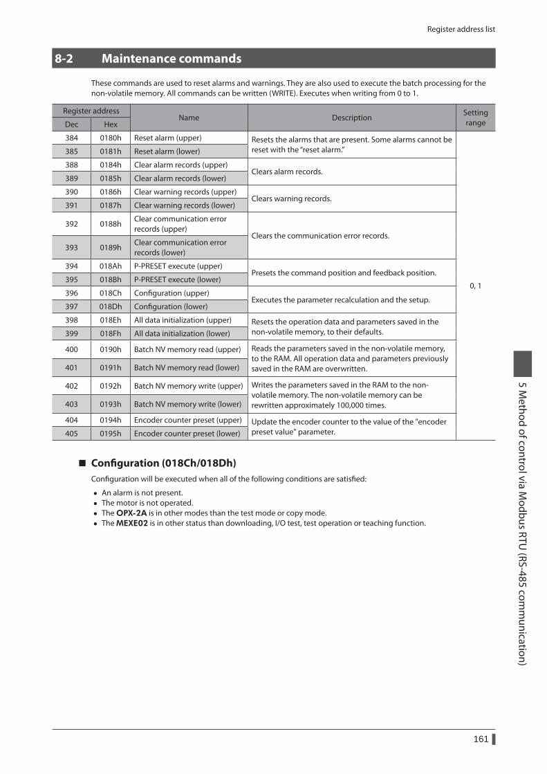
Register address list
161
5 Method of control via M
odbus RTU (RS-485 com
munication)
8-2 Maintenance commands
These commands are used to reset alarms and warnings. They are also used to execute the batch processing for the non-volatile memory. All commands can be written (WRITE). Executes when writing from 0 to 1.
Register addressName Description
Setting rangeDec Hex
384 0180h Reset alarm (upper) Resets the alarms that are present. Some alarms cannot be reset with the “reset alarm.”
0, 1
385 0181h Reset alarm (lower)
388 0184h Clear alarm records (upper)Clears alarm records.
389 0185h Clear alarm records (lower)
390 0186h Clear warning records (upper)Clears warning records.
391 0187h Clear warning records (lower)
392 0188hClear communication error records (upper)
Clears the communication error records.393 0189h
Clear communication error records (lower)
394 018Ah P-PRESET execute (upper)Presets the command position and feedback position.
395 018Bh P-PRESET execute (lower)
396 018Ch Configuration (upper)Executes the parameter recalculation and the setup.
397 018Dh Configuration (lower)
398 018Eh All data initialization (upper) Resets the operation data and parameters saved in the non-volatile memory, to their defaults.399 018Fh All data initialization (lower)
400 0190h Batch NV memory read (upper) Reads the parameters saved in the non-volatile memory, to the RAM. All operation data and parameters previously saved in the RAM are overwritten.401 0191h Batch NV memory read (lower)
402 0192h Batch NV memory write (upper) Writes the parameters saved in the RAM to the non-volatile memory. The non-volatile memory can be rewritten approximately 100,000 times.403 0193h Batch NV memory write (lower)
404 0194h Encoder counter preset (upper) Update the encoder counter to the value of the "encoder preset value" parameter.405 0195h Encoder counter preset (lower)
Configuration (018Ch/018Dh)Configuration will be executed when all of the following conditions are satisfied:
• An alarm is not present. • The motor is not operated. • The OPX-2A is in other modes than the test mode or copy mode. • The MEXE02 is in other status than downloading, I/O test, test operation or teaching function.
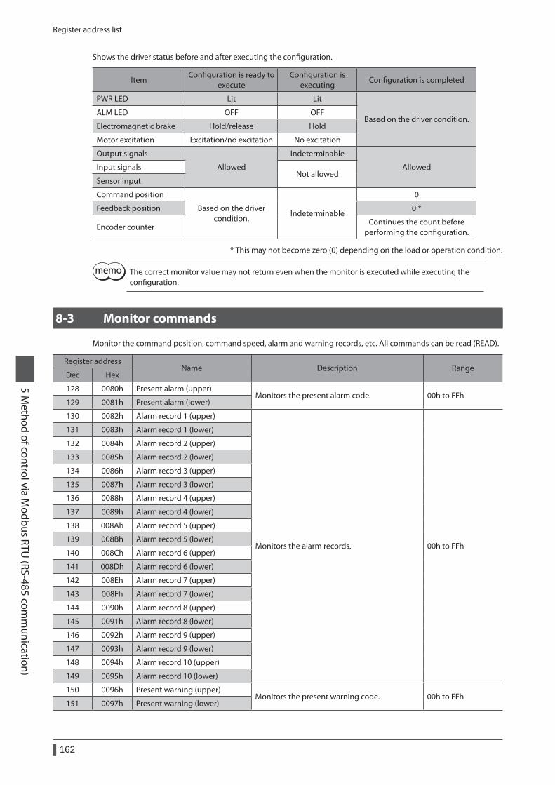
Register address list
162
5 Method of control via M
odbus RTU (RS-485 com
munication)
Shows the driver status before and after executing the configuration.
ItemConfiguration is ready to
executeConfiguration is
executingConfiguration is completed
PWR LED Lit Lit
Based on the driver condition.ALM LED OFF OFF
Electromagnetic brake Hold/release Hold
Motor excitation Excitation/no excitation No excitation
Output signals
Allowed
Indeterminable
AllowedInput signalsNot allowed
Sensor input
Command position
Based on the driver condition.
Indeterminable
0
Feedback position 0 *
Encoder counterContinues the count before
performing the configuration.
* This may not become zero (0) depending on the load or operation condition.
The correct monitor value may not return even when the monitor is executed while executing the configuration.
8-3 Monitor commands
Monitor the command position, command speed, alarm and warning records, etc. All commands can be read (READ).
Register addressName Description Range
Dec Hex
128 0080h Present alarm (upper)Monitors the present alarm code. 00h to FFh
129 0081h Present alarm (lower)
130 0082h Alarm record 1 (upper)
Monitors the alarm records. 00h to FFh
131 0083h Alarm record 1 (lower)
132 0084h Alarm record 2 (upper)
133 0085h Alarm record 2 (lower)
134 0086h Alarm record 3 (upper)
135 0087h Alarm record 3 (lower)
136 0088h Alarm record 4 (upper)
137 0089h Alarm record 4 (lower)
138 008Ah Alarm record 5 (upper)
139 008Bh Alarm record 5 (lower)
140 008Ch Alarm record 6 (upper)
141 008Dh Alarm record 6 (lower)
142 008Eh Alarm record 7 (upper)
143 008Fh Alarm record 7 (lower)
144 0090h Alarm record 8 (upper)
145 0091h Alarm record 8 (lower)
146 0092h Alarm record 9 (upper)
147 0093h Alarm record 9 (lower)
148 0094h Alarm record 10 (upper)
149 0095h Alarm record 10 (lower)
150 0096h Present warning (upper)Monitors the present warning code. 00h to FFh
151 0097h Present warning (lower)
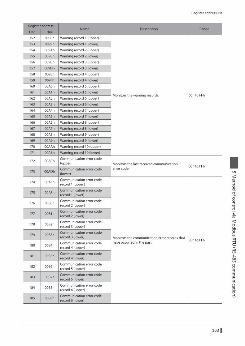
Register address list
163
5 Method of control via M
odbus RTU (RS-485 com
munication)
Register addressName Description Range
Dec Hex
152 0098h Warning record 1 (upper)
Monitors the warning records. 00h to FFh
153 0099h Warning record 1 (lower)
154 009Ah Warning record 2 (upper)
155 009Bh Warning record 2 (lower)
156 009Ch Warning record 3 (upper)
157 009Dh Warning record 3 (lower)
158 009Eh Warning record 4 (upper)
159 009Fh Warning record 4 (lower)
160 00A0h Warning record 5 (upper)
161 00A1h Warning record 5 (lower)
162 00A2h Warning record 6 (upper)
163 00A3h Warning record 6 (lower)
164 00A4h Warning record 7 (upper)
165 00A5h Warning record 7 (lower)
166 00A6h Warning record 8 (upper)
167 00A7h Warning record 8 (lower)
168 00A8h Warning record 9 (upper)
169 00A9h Warning record 9 (lower)
170 00AAh Warning record 10 (upper)
171 00ABh Warning record 10 (lower)
172 00AChCommunication error code (upper) Monitors the last received communication
error code.00h to FFh
173 00ADhCommunication error code (lower)
174 00AEhCommunication error code record 1 (upper)
Monitors the communication error records that have occurred in the past.
00h to FFh
175 00AFhCommunication error code record 1 (lower)
176 00B0hCommunication error code record 2 (upper)
177 00B1hCommunication error code record 2 (lower)
178 00B2hCommunication error code record 3 (upper)
179 00B3hCommunication error code record 3 (lower)
180 00B4hCommunication error code record 4 (upper)
181 00B5hCommunication error code record 4 (lower)
182 00B6hCommunication error code record 5 (upper)
183 00B7hCommunication error code record 5 (lower)
184 00B8hCommunication error code record 6 (upper)
185 00B9hCommunication error code record 6 (lower)
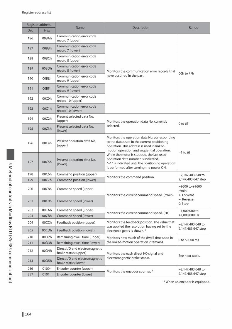
Register address list
164
5 Method of control via M
odbus RTU (RS-485 com
munication)
Register addressName Description Range
Dec Hex
186 00BAhCommunication error code record 7 (upper)
Monitors the communication error records that have occurred in the past.
00h to FFh
187 00BBhCommunication error code record 7 (lower)
188 00BChCommunication error code record 8 (upper)
189 00BDhCommunication error code record 8 (lower)
190 00BEhCommunication error code record 9 (upper)
191 00BFhCommunication error code record 9 (lower)
192 00C0hCommunication error code record 10 (upper)
193 00C1hCommunication error code record 10 (lower)
194 00C2hPresent selected data No. (upper) Monitors the operation data No. currently
selected.0 to 63
195 00C3hPresent selected data No. (lower)
196 00C4hPresent operation data No. (upper)
Monitors the operation data No. corresponding to the data used in the current positioning operation. This address is used in linked-motion operation and sequential operation. While the motor is stopped, the last used operation data number is indicated. "−1" is indicated until the positioning operation is performed after turning the power ON.
−1 to 63
197 00C5hPresent operation data No. (lower)
198 00C6h Command position (upper)Monitors the command position.
−2,147,483,648 to 2,147,483,647 step199 00C7h Command position (lower)
200 00C8h Command speed (upper)
Monitors the current command speed. (r/min)
−9600 to +9600 r/min +: Forward −: Reverse 0: Stop
201 00C9h Command speed (lower)
202 00CAh Command speed (upper)Monitors the current command speed. (Hz)
−1,000,000 to +1,000,000 Hz203 00CBh Command speed (lower)
204 00CCh Feedback position (upper) Monitors the feedback position. The value that was applied the resolution having set by the electronic gears is shown. *
−2,147,483,648 to 2,147,483,647 step205 00CDh Feedback position (lower)
210 00D2h Remaining dwell time (upper) Monitors how much of the dwell time used in the linked-motion operation 2 remains.
0 to 50000 ms211 00D3h Remaining dwell time (lower)
212 00D4hDirect I/O and electromagnetic brake status (upper) Monitors the each direct I/O signal and
electromagnetic brake status.See next table.
213 00D5hDirect I/O and electromagnetic brake status (lower)
256 0100h Encoder counter (upper)Monitors the encoder counter. *
−2,147,483,648 to 2,147,483,647 step257 0101h Encoder counter (lower)
* When an encoder is equipped.
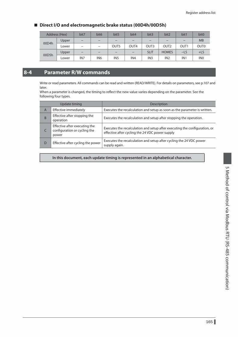
Register address list
165
5 Method of control via M
odbus RTU (RS-485 com
munication)
Direct I/O and electromagnetic brake status (00D4h/00D5h)
Address (Hex) bit7 bit6 bit5 bit4 bit3 bit2 bit1 bit0
00D4hUpper − − − − − − − MB
Lower − − OUT5 OUT4 OUT3 OUT2 OUT1 OUT0
00D5hUpper − − − − SLIT HOMES −LS +LS
Lower IN7 IN6 IN5 IN4 IN3 IN2 IN1 IN0
8-4 Parameter R/W commands
Write or read parameters. All commands can be read and written (READ/WRITE). For details on parameters, see p.107 and later.When a parameter is changed, the timing to reflect the new value varies depending on the parameter. See the following four types.
Update timing Description
A Effective immediately Executes the recalculation and setup as soon as the parameter is written.
BEffective after stopping the operation
Executes the recalculation and setup after stopping the operation.
CEffective after executing the configuration or cycling the power
Executes the recalculation and setup after executing the configuration, or effective after cycling the 24 VDC power supply
D Effective after cycling the powerExecutes the recalculation and setup after cycling the 24 VDC power supply again.
In this document, each update timing is represented in an alphabetical character.
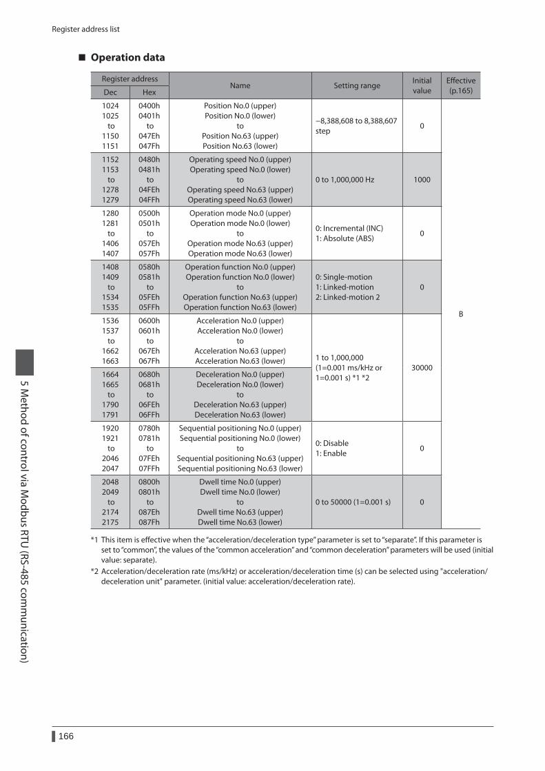
Register address list
166
5 Method of control via M
odbus RTU (RS-485 com
munication)
Operation data
Register addressName Setting range
Initial value
Effective (p.165)Dec Hex
1024 1025
to 1150 1151
0400h 0401h
to 047Eh 047Fh
Position No.0 (upper) Position No.0 (lower)
to Position No.63 (upper) Position No.63 (lower)
−8,388,608 to 8,388,607 step
0
B
1152 1153
to 1278 1279
0480h 0481h
to 04FEh 04FFh
Operating speed No.0 (upper) Operating speed No.0 (lower)
to Operating speed No.63 (upper) Operating speed No.63 (lower)
0 to 1,000,000 Hz 1000
1280 1281
to 1406 1407
0500h 0501h
to 057Eh 057Fh
Operation mode No.0 (upper) Operation mode No.0 (lower)
to Operation mode No.63 (upper) Operation mode No.63 (lower)
0: Incremental (INC) 1: Absolute (ABS)
0
1408 1409
to 1534 1535
0580h 0581h
to 05FEh 05FFh
Operation function No.0 (upper) Operation function No.0 (lower)
to Operation function No.63 (upper) Operation function No.63 (lower)
0: Single-motion 1: Linked-motion 2: Linked-motion 2
0
1536 1537
to 1662 1663
0600h 0601h
to 067Eh 067Fh
Acceleration No.0 (upper) Acceleration No.0 (lower)
to Acceleration No.63 (upper) Acceleration No.63 (lower) 1 to 1,000,000
(1=0.001 ms/kHz or 1=0.001 s) *1 *2
300001664 1665
to 1790 1791
0680h 0681h
to 06FEh 06FFh
Deceleration No.0 (upper) Deceleration No.0 (lower)
to Deceleration No.63 (upper) Deceleration No.63 (lower)
1920 1921
to 2046 2047
0780h 0781h
to 07FEh 07FFh
Sequential positioning No.0 (upper) Sequential positioning No.0 (lower)
to Sequential positioning No.63 (upper) Sequential positioning No.63 (lower)
0: Disable 1: Enable
0
2048 2049
to 2174 2175
0800h 0801h
to 087Eh 087Fh
Dwell time No.0 (upper) Dwell time No.0 (lower)
to Dwell time No.63 (upper) Dwell time No.63 (lower)
0 to 50000 (1=0.001 s) 0
*1 This item is effective when the “acceleration/deceleration type” parameter is set to “separate”. If this parameter is set to “common”, the values of the “common acceleration” and “common deceleration” parameters will be used (initial value: separate).
*2 Acceleration/deceleration rate (ms/kHz) or acceleration/deceleration time (s) can be selected using "acceleration/deceleration unit" parameter. (initial value: acceleration/deceleration rate).
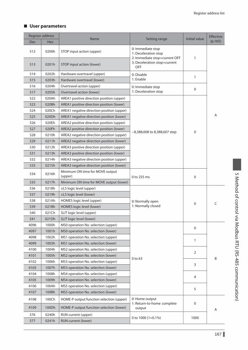
Register address list
167
5 Method of control via M
odbus RTU (RS-485 com
munication)
User parameters
Register addressName Setting range Initial value
Effective (p.165)Dec Hex
512 0200h STOP input action (upper)0: Immediate stop 1: Deceleration stop 2: Immediate stop+current OFF 3: Deceleration stop+current OFF
1
A
513 0201h STOP input action (lower)
514 0202h Hardware overtravel (upper) 0: Disable 1: Enable
1515 0203h Hardware overtravel (lower)
516 0204h Overtravel action (upper) 0: Immediate stop 1: Deceleration stop
0517 0205h Overtravel action (lower)
522 020Ah AREA1 positive direction position (upper)
−8,388,608 to 8,388,607 step 0
523 020Bh AREA1 positive direction position (lower)
524 020Ch AREA1 negative direction position (upper)
525 020Dh AREA1 negative direction position (lower)
526 020Eh AREA2 positive direction position (upper)
527 020Fh AREA2 positive direction position (lower)
528 0210h AREA2 negative direction position (upper)
529 0211h AREA2 negative direction position (lower)
530 0212h AREA3 positive direction position (upper)
531 0213h AREA3 positive direction position (lower)
532 0214h AREA3 negative direction position (upper)
533 0215h AREA3 negative direction position (lower)
534 0216hMinimum ON time for MOVE output (upper) 0 to 255 ms 0
535 0217h Minimum ON time for MOVE output (lower)
536 0218h ±LS logic level (upper)
0: Normally open 1: Normally closed
0 C
537 0219h ±LS logic level (lower)
538 021Ah HOMES logic level (upper)
539 021Bh HOMES logic level (lower)
540 021Ch SLIT logic level (upper)
541 021Dh SLIT logic level (lower)
4096 1000h MS0 operation No. selection (upper)
0 to 63
0
B
4097 1001h MS0 operation No. selection (lower)
4098 1002h MS1 operation No. selection (upper)1
4099 1003h MS1 operation No. selection (lower)
4100 1004h MS2 operation No. selection (upper)2
4101 1005h MS2 operation No. selection (lower)
4102 1006h MS3 operation No. selection (upper)3
4103 1007h MS3 operation No. selection (lower)
4104 1008h MS4 operation No. selection (upper)4
4105 1009h MS4 operation No. selection (lower)
4106 100Ah MS5 operation No. selection (upper)5
4107 100Bh MS5 operation No. selection (lower)
4108 100Ch HOME-P output function selection (upper) 0: Home output 1: Return-to-home complete output
0
A4109 100Dh HOME-P output function selection (lower)
576 0240h RUN current (upper)0 to 1000 (1=0.1%) 1000
577 0241h RUN current (lower)
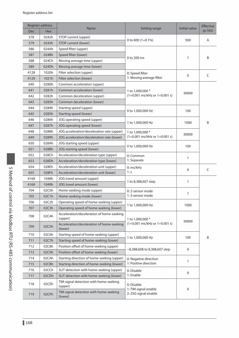
Register address list
168
5 Method of control via M
odbus RTU (RS-485 com
munication)
Register addressName Setting range Initial value
Effective (p.165)Dec Hex
578 0242h STOP current (upper)0 to 600 (1=0.1%) 500 A
579 0243h STOP current (lower)
586 024Ah Speed filter (upper)
0 to 200 ms 1 B587 024Bh Speed filter (lower)
588 024Ch Moving average time (upper)
589 024Dh Moving average time (lower)
4128 1020h Filter selection (upper) 0: Speed filter 1: Moving average filter
0 C4129 1021h Filter selection (lower)
640 0280h Common acceleration (upper)
1 to 1,000,000 * (1=0.001 ms/kHz or 1=0.001 s)
30000
B
641 0281h Common acceleration (lower)
642 0282h Common deceleration (upper)
643 0283h Common deceleration (lower)
644 0284h Starting speed (upper)0 to 1,000,000 Hz 100
645 0285h Starting speed (lower)
646 0286h JOG operating speed (upper)1 to 1,000,000 Hz 1000
647 0287h JOG operating speed (lower)
648 0288h JOG acceleration/deceleration rate (upper) 1 to 1,000,000 * (1=0.001 ms/kHz or 1=0.001 s)
30000649 0289h JOG acceleration/deceleration rate (lower)
650 028Ah JOG starting speed (upper)0 to 1,000,000 Hz 100
651 028Bh JOG starting speed (lower)
652 028Ch Acceleration/deceleration type (upper) 0: Common 1: Separate
1653 028Dh Acceleration/deceleration type (lower)
654 028Eh Acceleration/deceleration unit (upper) 0: ms/kHz 1: s
0 C655 028Fh Acceleration/deceleration unit (lower)
4168 1048h JOG travel amount (upper)1 to 8,388,607 step 1
B
4169 1049h JOG travel amount (lower)
704 02C0h Home-seeking mode (upper) 0: 2-sensor mode 1: 3-sensor mode
1705 02C1h Home-seeking mode (lower)
706 02C2h Operating speed of home-seeking (upper)1 to 1,000,000 Hz 1000
707 02C3h Operating speed of home-seeking (lower)
708 02C4hAcceleration/deceleration of home-seeking (upper) 1 to 1,000,000 *
(1=0.001 ms/kHz or 1=0.001 s)30000
709 02C5hAcceleration/deceleration of home-seeking (lower)
710 02C6h Starting speed of home-seeking (upper)1 to 1,000,000 Hz 100
711 02C7h Starting speed of home-seeking (lower)
712 02C8h Position offset of home-seeking (upper)−8,388,608 to 8,388,607 step 0
713 02C9h Position offset of home-seeking (lower)
714 02CAh Starting direction of home-seeking (upper) 0: Negative direction 1: Positive direction
1715 02CBh Starting direction of home-seeking (lower)
716 02CCh SLIT detection with home-seeking (upper) 0: Disable 1: Enable
0717 02CDh SLIT detection with home-seeking (lower)
718 02CEhTIM signal detection with home-seeking (upper) 0: Disable
1: TIM signal enable 2: ZSG signal enable
0719 02CFh
TIM signal detection with home-seeking (lower)
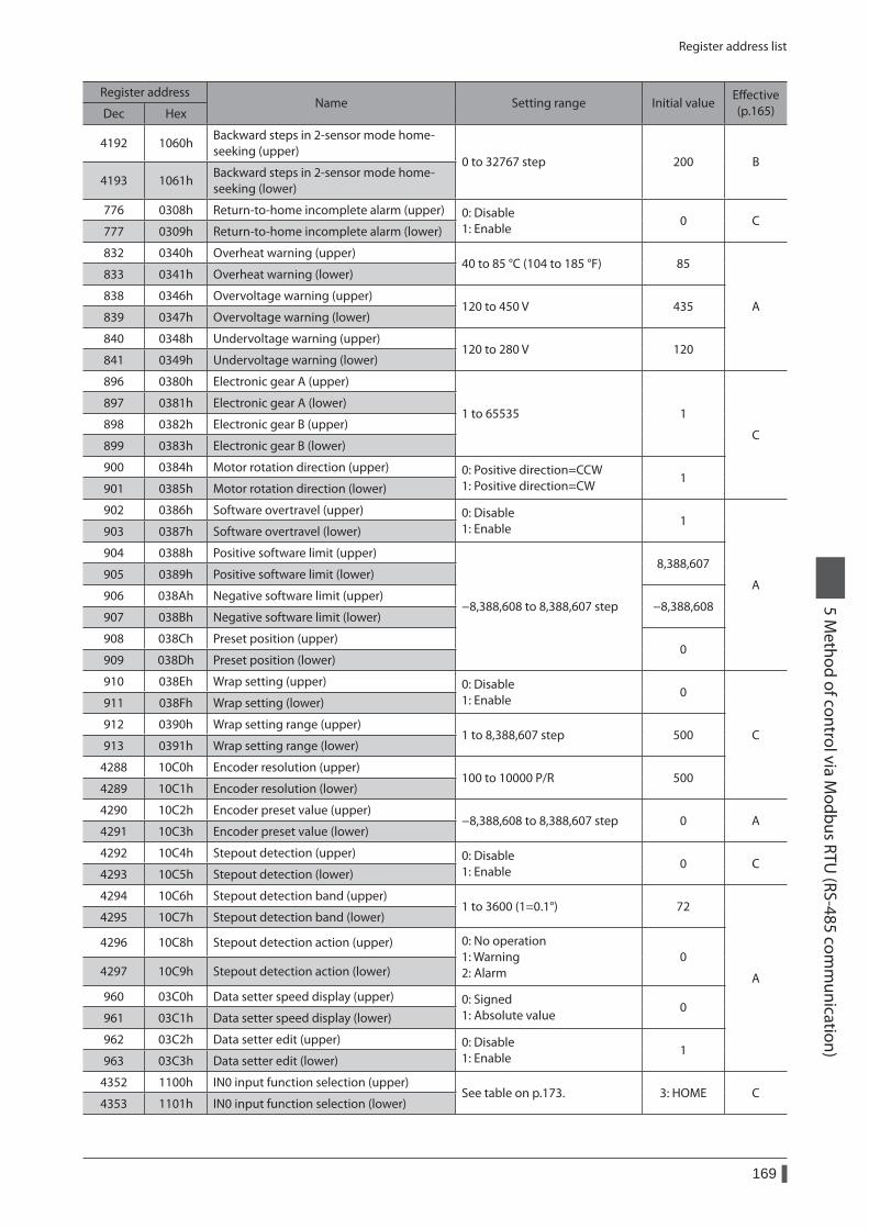
Register address list
169
5 Method of control via M
odbus RTU (RS-485 com
munication)
Register addressName Setting range Initial value
Effective (p.165)Dec Hex
4192 1060hBackward steps in 2-sensor mode home-seeking (upper)
0 to 32767 step 200 B4193 1061h
Backward steps in 2-sensor mode home-seeking (lower)
776 0308h Return-to-home incomplete alarm (upper) 0: Disable 1: Enable
0 C777 0309h Return-to-home incomplete alarm (lower)
832 0340h Overheat warning (upper)40 to 85 °C (104 to 185 °F) 85
A
833 0341h Overheat warning (lower)
838 0346h Overvoltage warning (upper)120 to 450 V 435
839 0347h Overvoltage warning (lower)
840 0348h Undervoltage warning (upper)120 to 280 V 120
841 0349h Undervoltage warning (lower)
896 0380h Electronic gear A (upper)
1 to 65535 1
C
897 0381h Electronic gear A (lower)
898 0382h Electronic gear B (upper)
899 0383h Electronic gear B (lower)
900 0384h Motor rotation direction (upper) 0: Positive direction=CCW 1: Positive direction=CW
1901 0385h Motor rotation direction (lower)
902 0386h Software overtravel (upper) 0: Disable 1: Enable
1
A
903 0387h Software overtravel (lower)
904 0388h Positive software limit (upper)
−8,388,608 to 8,388,607 step
8,388,607905 0389h Positive software limit (lower)
906 038Ah Negative software limit (upper)−8,388,608
907 038Bh Negative software limit (lower)
908 038Ch Preset position (upper)0
909 038Dh Preset position (lower)
910 038Eh Wrap setting (upper) 0: Disable 1: Enable
0
C
911 038Fh Wrap setting (lower)
912 0390h Wrap setting range (upper)1 to 8,388,607 step 500
913 0391h Wrap setting range (lower)
4288 10C0h Encoder resolution (upper)100 to 10000 P/R 500
4289 10C1h Encoder resolution (lower)
4290 10C2h Encoder preset value (upper)−8,388,608 to 8,388,607 step 0 A
4291 10C3h Encoder preset value (lower)
4292 10C4h Stepout detection (upper) 0: Disable 1: Enable
0 C4293 10C5h Stepout detection (lower)
4294 10C6h Stepout detection band (upper)1 to 3600 (1=0.1°) 72
A
4295 10C7h Stepout detection band (lower)
4296 10C8h Stepout detection action (upper) 0: No operation 1: Warning 2: Alarm
04297 10C9h Stepout detection action (lower)
960 03C0h Data setter speed display (upper) 0: Signed 1: Absolute value
0961 03C1h Data setter speed display (lower)
962 03C2h Data setter edit (upper) 0: Disable 1: Enable
1963 03C3h Data setter edit (lower)
4352 1100h IN0 input function selection (upper)See table on p.173. 3: HOME C
4353 1101h IN0 input function selection (lower)
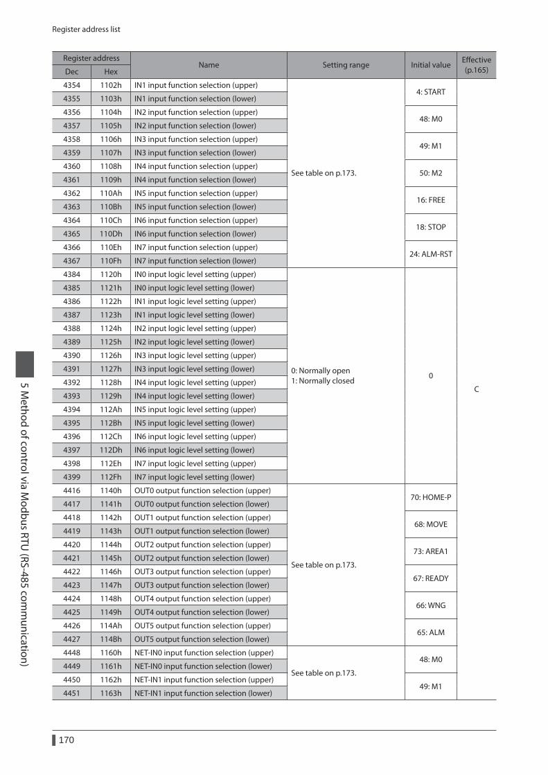
Register address list
170
5 Method of control via M
odbus RTU (RS-485 com
munication)
Register addressName Setting range Initial value
Effective (p.165)Dec Hex
4354 1102h IN1 input function selection (upper)
See table on p.173.
4: START
C
4355 1103h IN1 input function selection (lower)
4356 1104h IN2 input function selection (upper)48: M0
4357 1105h IN2 input function selection (lower)
4358 1106h IN3 input function selection (upper)49: M1
4359 1107h IN3 input function selection (lower)
4360 1108h IN4 input function selection (upper)50: M2
4361 1109h IN4 input function selection (lower)
4362 110Ah IN5 input function selection (upper)16: FREE
4363 110Bh IN5 input function selection (lower)
4364 110Ch IN6 input function selection (upper)18: STOP
4365 110Dh IN6 input function selection (lower)
4366 110Eh IN7 input function selection (upper)24: ALM-RST
4367 110Fh IN7 input function selection (lower)
4384 1120h IN0 input logic level setting (upper)
0: Normally open 1: Normally closed
0
4385 1121h IN0 input logic level setting (lower)
4386 1122h IN1 input logic level setting (upper)
4387 1123h IN1 input logic level setting (lower)
4388 1124h IN2 input logic level setting (upper)
4389 1125h IN2 input logic level setting (lower)
4390 1126h IN3 input logic level setting (upper)
4391 1127h IN3 input logic level setting (lower)
4392 1128h IN4 input logic level setting (upper)
4393 1129h IN4 input logic level setting (lower)
4394 112Ah IN5 input logic level setting (upper)
4395 112Bh IN5 input logic level setting (lower)
4396 112Ch IN6 input logic level setting (upper)
4397 112Dh IN6 input logic level setting (lower)
4398 112Eh IN7 input logic level setting (upper)
4399 112Fh IN7 input logic level setting (lower)
4416 1140h OUT0 output function selection (upper)
See table on p.173.
70: HOME-P4417 1141h OUT0 output function selection (lower)
4418 1142h OUT1 output function selection (upper)68: MOVE
4419 1143h OUT1 output function selection (lower)
4420 1144h OUT2 output function selection (upper)73: AREA1
4421 1145h OUT2 output function selection (lower)
4422 1146h OUT3 output function selection (upper)67: READY
4423 1147h OUT3 output function selection (lower)
4424 1148h OUT4 output function selection (upper)66: WNG
4425 1149h OUT4 output function selection (lower)
4426 114Ah OUT5 output function selection (upper)65: ALM
4427 114Bh OUT5 output function selection (lower)
4448 1160h NET-IN0 input function selection (upper)
See table on p.173.
48: M04449 1161h NET-IN0 input function selection (lower)
4450 1162h NET-IN1 input function selection (upper)49: M1
4451 1163h NET-IN1 input function selection (lower)
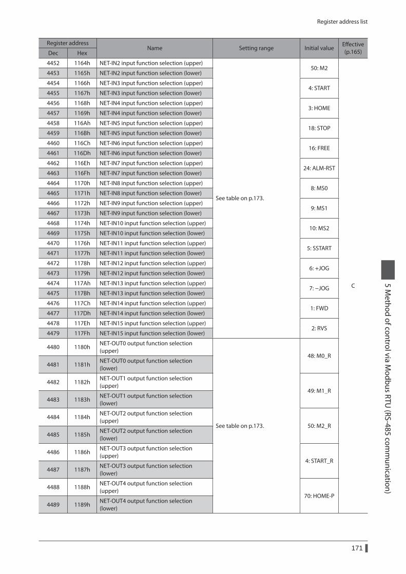
Register address list
171
5 Method of control via M
odbus RTU (RS-485 com
munication)
Register addressName Setting range Initial value
Effective (p.165)Dec Hex
4452 1164h NET-IN2 input function selection (upper)
See table on p.173.
50: M2
C
4453 1165h NET-IN2 input function selection (lower)
4454 1166h NET-IN3 input function selection (upper)4: START
4455 1167h NET-IN3 input function selection (lower)
4456 1168h NET-IN4 input function selection (upper)3: HOME
4457 1169h NET-IN4 input function selection (lower)
4458 116Ah NET-IN5 input function selection (upper)18: STOP
4459 116Bh NET-IN5 input function selection (lower)
4460 116Ch NET-IN6 input function selection (upper)16: FREE
4461 116Dh NET-IN6 input function selection (lower)
4462 116Eh NET-IN7 input function selection (upper)24: ALM-RST
4463 116Fh NET-IN7 input function selection (lower)
4464 1170h NET-IN8 input function selection (upper)8: MS0
4465 1171h NET-IN8 input function selection (lower)
4466 1172h NET-IN9 input function selection (upper)9: MS1
4467 1173h NET-IN9 input function selection (lower)
4468 1174h NET-IN10 input function selection (upper)10: MS2
4469 1175h NET-IN10 input function selection (lower)
4470 1176h NET-IN11 input function selection (upper)5: SSTART
4471 1177h NET-IN11 input function selection (lower)
4472 1178h NET-IN12 input function selection (upper)6: +JOG
4473 1179h NET-IN12 input function selection (lower)
4474 117Ah NET-IN13 input function selection (upper)7: −JOG
4475 117Bh NET-IN13 input function selection (lower)
4476 117Ch NET-IN14 input function selection (upper)1: FWD
4477 117Dh NET-IN14 input function selection (lower)
4478 117Eh NET-IN15 input function selection (upper)2: RVS
4479 117Fh NET-IN15 input function selection (lower)
4480 1180hNET-OUT0 output function selection (upper)
See table on p.173.
48: M0_R4481 1181h
NET-OUT0 output function selection (lower)
4482 1182hNET-OUT1 output function selection (upper)
49: M1_R4483 1183h
NET-OUT1 output function selection (lower)
4484 1184hNET-OUT2 output function selection (upper)
50: M2_R4485 1185h
NET-OUT2 output function selection (lower)
4486 1186hNET-OUT3 output function selection (upper)
4: START_R4487 1187h
NET-OUT3 output function selection (lower)
4488 1188hNET-OUT4 output function selection (upper)
70: HOME-P4489 1189h
NET-OUT4 output function selection (lower)
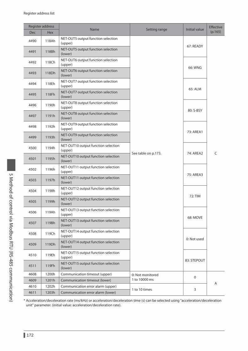
Register address list
172
5 Method of control via M
odbus RTU (RS-485 com
munication)
Register addressName Setting range Initial value
Effective (p.165)Dec Hex
4490 118AhNET-OUT5 output function selection (upper)
See table on p.173.
67: READY
C
4491 118BhNET-OUT5 output function selection (lower)
4492 118ChNET-OUT6 output function selection (upper)
66: WNG4493 118Dh
NET-OUT6 output function selection (lower)
4494 118EhNET-OUT7 output function selection (upper)
65: ALM4495 118Fh
NET-OUT7 output function selection (lower)
4496 1190hNET-OUT8 output function selection (upper)
80: S-BSY4497 1191h
NET-OUT8 output function selection (lower)
4498 1192hNET-OUT9 output function selection (upper)
73: AREA14499 1193h
NET-OUT9 output function selection (lower)
4500 1194hNET-OUT10 output function selection (upper)
74: AREA24501 1195h
NET-OUT10 output function selection (lower)
4502 1196hNET-OUT11 output function selection (upper)
75: AREA34503 1197h
NET-OUT11 output function selection (lower)
4504 1198hNET-OUT12 output function selection (upper)
72: TIM4505 1199h
NET-OUT12 output function selection (lower)
4506 119AhNET-OUT13 output function selection (upper)
68: MOVE4507 119Bh
NET-OUT13 output function selection (lower)
4508 119ChNET-OUT14 output function selection (upper)
0: Not used4509 119Dh
NET-OUT14 output function selection (lower)
4510 119EhNET-OUT15 output function selection (upper)
83: STEPOUT4511 119Fh
NET-OUT15 output function selection (lower)
4608 1200h Communication timeout (upper) 0: Not monitored 1 to 10000 ms
0
A4609 1201h Communication timeout (lower)
4610 1202h Communication error alarm (upper)1 to 10 times 3
4611 1203h Communication error alarm (lower)
* Acceleration/deceleration rate (ms/kHz) or acceleration/deceleration time (s) can be selected using "acceleration/deceleration unit" parameter. (initial value: acceleration/deceleration rate).
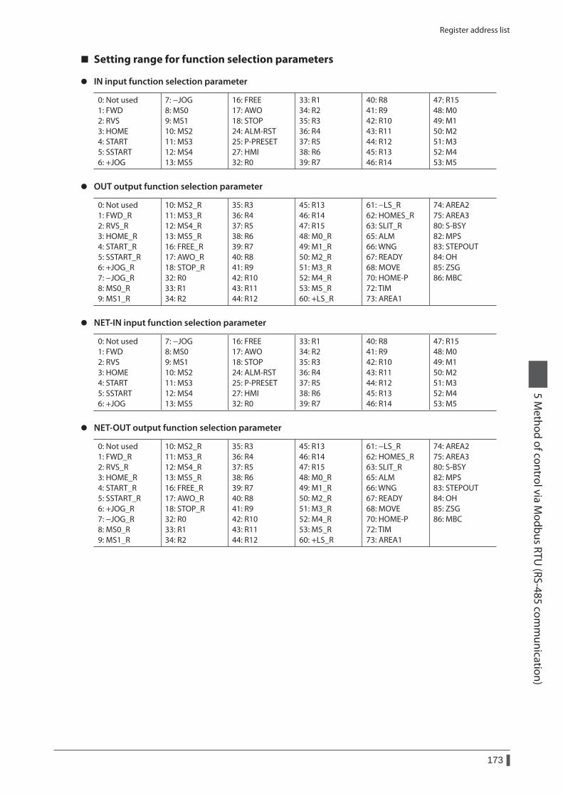
Register address list
173
5 Method of control via M
odbus RTU (RS-485 com
munication)
Setting range for function selection parameters
z IN input function selection parameter
0: Not used 1: FWD 2: RVS 3: HOME 4: START 5: SSTART 6: +JOG
7: −JOG 8: MS0 9: MS1 10: MS2 11: MS3 12: MS4 13: MS5
16: FREE 17: AWO 18: STOP 24: ALM-RST 25: P-PRESET 27: HMI 32: R0
33: R1 34: R2 35: R3 36: R4 37: R5 38: R6 39: R7
40: R8 41: R9 42: R10 43: R11 44: R12 45: R13 46: R14
47: R15 48: M0 49: M1 50: M2 51: M3 52: M4 53: M5
z OUT output function selection parameter
0: Not used 1: FWD_R 2: RVS_R 3: HOME_R 4: START_R 5: SSTART_R 6: +JOG_R 7: −JOG_R 8: MS0_R 9: MS1_R
10: MS2_R 11: MS3_R 12: MS4_R 13: MS5_R 16: FREE_R 17: AWO_R 18: STOP_R 32: R0 33: R1 34: R2
35: R3 36: R4 37: R5 38: R6 39: R7 40: R8 41: R9 42: R10 43: R11 44: R12
45: R13 46: R14 47: R15 48: M0_R 49: M1_R 50: M2_R 51: M3_R 52: M4_R 53: M5_R 60: +LS_R
61: −LS_R 62: HOMES_R 63: SLIT_R 65: ALM 66: WNG 67: READY 68: MOVE 70: HOME-P 72: TIM 73: AREA1
74: AREA2 75: AREA3 80: S-BSY 82: MPS 83: STEPOUT 84: OH 85: ZSG 86: MBC
z NET-IN input function selection parameter
0: Not used 1: FWD 2: RVS 3: HOME 4: START 5: SSTART 6: +JOG
7: −JOG 8: MS0 9: MS1 10: MS2 11: MS3 12: MS4 13: MS5
16: FREE 17: AWO 18: STOP 24: ALM-RST 25: P-PRESET 27: HMI 32: R0
33: R1 34: R2 35: R3 36: R4 37: R5 38: R6 39: R7
40: R8 41: R9 42: R10 43: R11 44: R12 45: R13 46: R14
47: R15 48: M0 49: M1 50: M2 51: M3 52: M4 53: M5
z NET-OUT output function selection parameter
0: Not used 1: FWD_R 2: RVS_R 3: HOME_R 4: START_R 5: SSTART_R 6: +JOG_R 7: −JOG_R 8: MS0_R 9: MS1_R
10: MS2_R 11: MS3_R 12: MS4_R 13: MS5_R 16: FREE_R 17: AWO_R 18: STOP_R 32: R0 33: R1 34: R2
35: R3 36: R4 37: R5 38: R6 39: R7 40: R8 41: R9 42: R10 43: R11 44: R12
45: R13 46: R14 47: R15 48: M0_R 49: M1_R 50: M2_R 51: M3_R 52: M4_R 53: M5_R 60: +LS_R
61: −LS_R 62: HOMES_R 63: SLIT_R 65: ALM 66: WNG 67: READY 68: MOVE 70: HOME-P 72: TIM 73: AREA1
74: AREA2 75: AREA3 80: S-BSY 82: MPS 83: STEPOUT 84: OH 85: ZSG 86: MBC
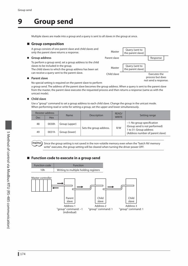
Group send
174
5 Method of control via M
odbus RTU (RS-485 com
munication)
9 Group send
Multiple slaves are made into a group and a query is sent to all slaves in the group at once.
Group compositionA group consists of one parent slave and child slaves and only the parent slave returns a response.
z Group addressTo perform a group send, set a group address to the child slaves to be included in the group.The child slaves to which the group address has been set can receive a query sent to the parent slave.
z Parent slaveNo special setting is required on the parent slave to perform
Query (sent tothe parent slave)
Query (sent tothe parent slave)
Response
Master
Master
Parent slave
Child slave Executes theprocess but does
not send a response.
a group send. The address of the parent slave becomes the group address. When a query is sent to the parent slave from the master, the parent slave executes the requested process and then returns a response (same as with the unicast mode).
z Child slaveUse a "group" command to set a group address to each child slave. Change the group in the unicast mode.When performing read or write for setting a group, set the upper and lower simultaneously.
Resister addressName Description
READ/ WRITE
Setting rangeDec Hex
48 0030h Group (upper)Sets the group address. R/W
−1: No group specification (Group send is not performed) 1 to 31: Group address (Address number of parent slave)49 0031h Group (lower)
Since the group setting is not saved in the non-volatile memory even when the "batch NV memory write" executes, the group setting will be cleared when turning the driver power OFF.
Function code to execute in a group send
Function code Function
10h Writing to multiple holding registers
Master controller
Address 1"group" command: -1
(individual)
Address 2"group" command: 1
Address 3"group" command: 1
Parentslave
Childslave
Childslave
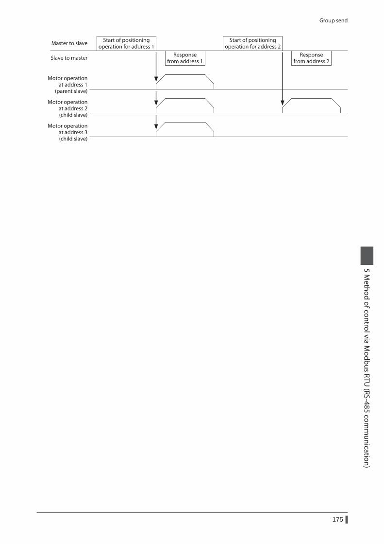
Group send
175
5 Method of control via M
odbus RTU (RS-485 com
munication)
Start of positioningoperation for address 1
Responsefrom address 1
Motor operationat address 1
(parent slave)
Motor operationat address 2(child slave)
Motor operationat address 3(child slave)
Start of positioningoperation for address 2
Responsefrom address 2
Master to slave
Slave to master
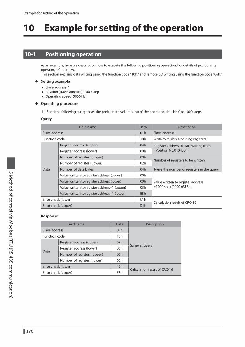
Example for setting of the operation
176
5 Method of control via M
odbus RTU (RS-485 com
munication)
10 Example for setting of the operation
10-1 Positioning operation
As an example, here is a description how to execute the following positioning operation. For details of positioning operatin, refer to p.79.This section explains data writing using the function code "10h," and remote I/O writing using the function code "06h."
z Setting example • Slave address: 1 • Position (travel amount): 1000 step • Operating speed: 5000 Hz
z Operating procedure
1. Send the following query to set the position (travel amount) of the operation data No.0 to 1000 steps
Query
Field name Data Description
Slave address 01h Slave address
Function code 10h Write to multiple holding registers
Data
Register address (upper) 04h Register address to start writing from =Position No.0 (0400h)Register address (lower) 00h
Number of registers (upper) 00hNumber of registers to be written
Number of registers (lower) 02h
Number of data bytes 04h Twice the number of registers in the query
Value written to register address (upper) 00h
Value written to register address =1000 step (0000 03E8h)
Value written to register address (lower) 00h
Value written to register address+1 (upper) 03h
Value written to register address+1 (lower) E8h
Error check (lower) C1hCalculation result of CRC-16
Error check (upper) D1h
Response
Field name Data Description
Slave address 01h
Same as query
Function code 10h
Data
Register address (upper) 04h
Register address (lower) 00h
Number of registers (upper) 00h
Number of registers (lower) 02h
Error check (lower) 40hCalculation result of CRC-16
Error check (upper) F8h
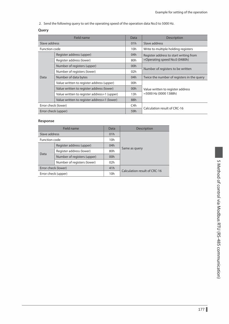
Example for setting of the operation
177
5 Method of control via M
odbus RTU (RS-485 com
munication)
2. Send the following query to set the operating speed of the operation data No.0 to 5000 Hz.
Query
Field name Data Description
Slave address 01h Slave address
Function code 10h Write to multiple holding registers
Data
Register address (upper) 04h Register address to start writing from =Operating speed No.0 (0480h)Register address (lower) 80h
Number of registers (upper) 00hNumber of registers to be written
Number of registers (lower) 02h
Number of data bytes 04h Twice the number of registers in the query
Value written to register address (upper) 00h
Value written to register address =5000 Hz (0000 1388h)
Value written to register address (lower) 00h
Value written to register address+1 (upper) 13h
Value written to register address+1 (lower) 88h
Error check (lower) C4hCalculation result of CRC-16
Error check (upper) 59h
Response
Field name Data Description
Slave address 01h
Same as query
Function code 10h
Data
Register address (upper) 04h
Register address (lower) 80h
Number of registers (upper) 00h
Number of registers (lower) 02h
Error check (lower) 41hCalculation result of CRC-16
Error check (upper) 10h
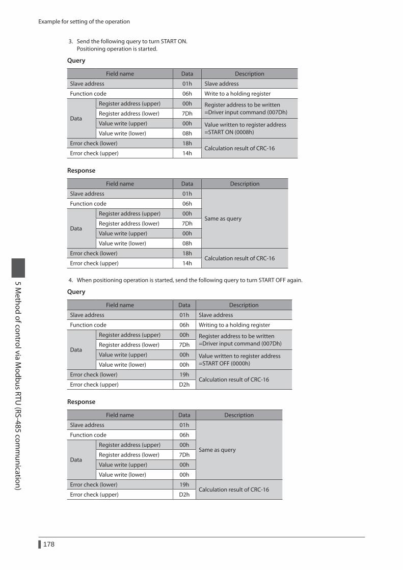
Example for setting of the operation
178
5 Method of control via M
odbus RTU (RS-485 com
munication)
3. Send the following query to turn START ON. Positioning operation is started.
Query
Field name Data Description
Slave address 01h Slave address
Function code 06h Write to a holding register
Data
Register address (upper) 00h Register address to be written =Driver input command (007Dh)Register address (lower) 7Dh
Value write (upper) 00h Value written to register address =START ON (0008h)Value write (lower) 08h
Error check (lower) 18hCalculation result of CRC-16
Error check (upper) 14h
Response
Field name Data Description
Slave address 01h
Same as query
Function code 06h
Data
Register address (upper) 00h
Register address (lower) 7Dh
Value write (upper) 00h
Value write (lower) 08h
Error check (lower) 18hCalculation result of CRC-16
Error check (upper) 14h
4. When positioning operation is started, send the following query to turn START OFF again.
Query
Field name Data Description
Slave address 01h Slave address
Function code 06h Writing to a holding register
Data
Register address (upper) 00h Register address to be written =Driver input command (007Dh)Register address (lower) 7Dh
Value write (upper) 00h Value written to register address =START OFF (0000h)Value write (lower) 00h
Error check (lower) 19hCalculation result of CRC-16
Error check (upper) D2h
Response
Field name Data Description
Slave address 01h
Same as query
Function code 06h
Data
Register address (upper) 00h
Register address (lower) 7Dh
Value write (upper) 00h
Value write (lower) 00h
Error check (lower) 19hCalculation result of CRC-16
Error check (upper) D2h
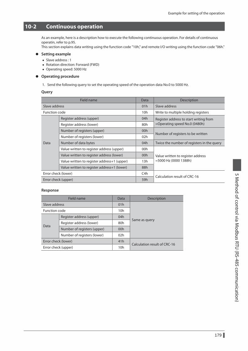
Example for setting of the operation
179
5 Method of control via M
odbus RTU (RS-485 com
munication)
10-2 Continuous operation
As an example, here is a description how to execute the following continuous operation. For details of continuous operatin, refer to p.95.This section explains data writing using the function code "10h," and remote I/O writing using the function code "06h."
z Setting example • Slave address : 1 • Rotation direction: Forward (FWD) • Operating speed: 5000 Hz
z Operating procedure
1. Send the following query to set the operating speed of the operation data No.0 to 5000 Hz.
Query
Field name Data Description
Slave address 01h Slave address
Function code 10h Write to multiple holding registers
Data
Register address (upper) 04h Register address to start writing from =Operating speed No.0 (0480h)Register address (lower) 80h
Number of registers (upper) 00hNumber of registers to be written
Number of registers (lower) 02h
Number of data bytes 04h Twice the number of registers in the query
Value written to register address (upper) 00h
Value written to register address =5000 Hz (0000 1388h)
Value written to register address (lower) 00h
Value written to register address+1 (upper) 13h
Value written to register address+1 (lower) 88h
Error check (lower) C4hCalculation result of CRC-16
Error check (upper) 59h
Response
Field name Data Description
Slave address 01h
Same as query
Function code 10h
Data
Register address (upper) 04h
Register address (lower) 80h
Number of registers (upper) 00h
Number of registers (lower) 02h
Error check (lower) 41hCalculation result of CRC-16
Error check (upper) 10h
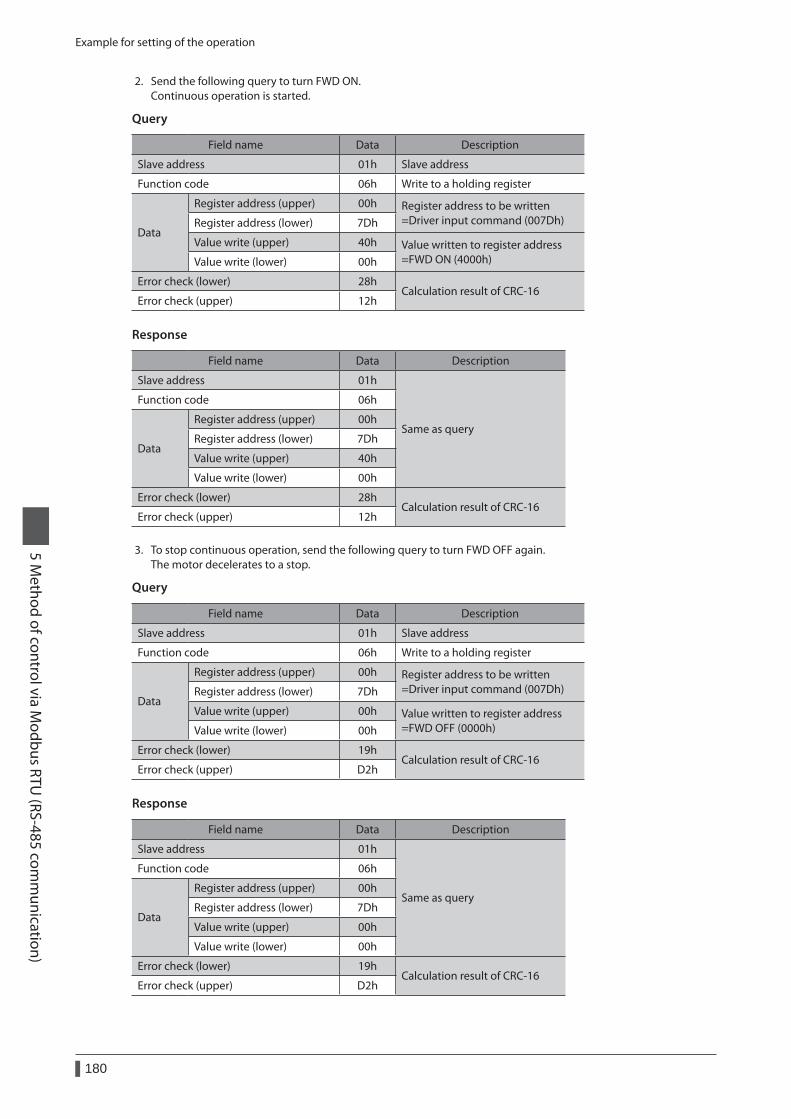
Example for setting of the operation
180
5 Method of control via M
odbus RTU (RS-485 com
munication)
2. Send the following query to turn FWD ON.Continuous operation is started.
Query
Field name Data Description
Slave address 01h Slave address
Function code 06h Write to a holding register
Data
Register address (upper) 00h Register address to be written =Driver input command (007Dh)Register address (lower) 7Dh
Value write (upper) 40h Value written to register address =FWD ON (4000h)Value write (lower) 00h
Error check (lower) 28hCalculation result of CRC-16
Error check (upper) 12h
Response
Field name Data Description
Slave address 01h
Same as query
Function code 06h
Data
Register address (upper) 00h
Register address (lower) 7Dh
Value write (upper) 40h
Value write (lower) 00h
Error check (lower) 28hCalculation result of CRC-16
Error check (upper) 12h
3. To stop continuous operation, send the following query to turn FWD OFF again.The motor decelerates to a stop.
Query
Field name Data Description
Slave address 01h Slave address
Function code 06h Write to a holding register
Data
Register address (upper) 00h Register address to be written =Driver input command (007Dh)Register address (lower) 7Dh
Value write (upper) 00h Value written to register address =FWD OFF (0000h)Value write (lower) 00h
Error check (lower) 19hCalculation result of CRC-16
Error check (upper) D2h
Response
Field name Data Description
Slave address 01h
Same as query
Function code 06h
Data
Register address (upper) 00h
Register address (lower) 7Dh
Value write (upper) 00h
Value write (lower) 00h
Error check (lower) 19hCalculation result of CRC-16
Error check (upper) D2h
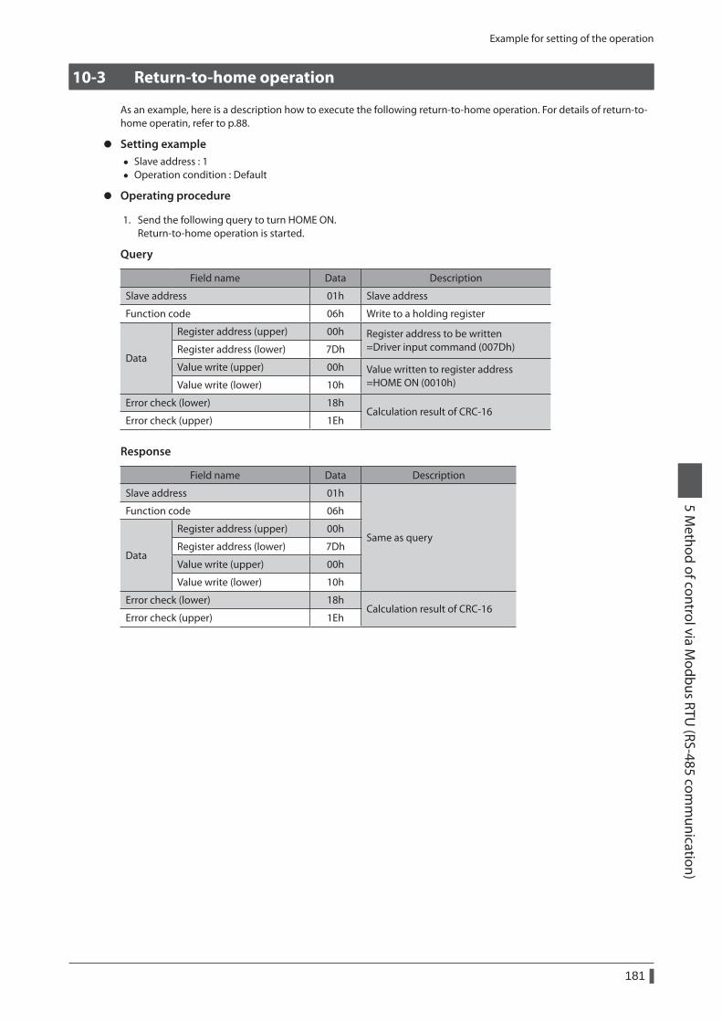
Example for setting of the operation
181
5 Method of control via M
odbus RTU (RS-485 com
munication)
10-3 Return-to-home operation
As an example, here is a description how to execute the following return-to-home operation. For details of return-to-home operatin, refer to p.88.
z Setting example • Slave address : 1 • Operation condition : Default
z Operating procedure
1. Send the following query to turn HOME ON.Return-to-home operation is started.
Query
Field name Data Description
Slave address 01h Slave address
Function code 06h Write to a holding register
Data
Register address (upper) 00h Register address to be written =Driver input command (007Dh)Register address (lower) 7Dh
Value write (upper) 00h Value written to register address =HOME ON (0010h)Value write (lower) 10h
Error check (lower) 18hCalculation result of CRC-16
Error check (upper) 1Eh
Response
Field name Data Description
Slave address 01h
Same as query
Function code 06h
Data
Register address (upper) 00h
Register address (lower) 7Dh
Value write (upper) 00h
Value write (lower) 10h
Error check (lower) 18hCalculation result of CRC-16
Error check (upper) 1Eh
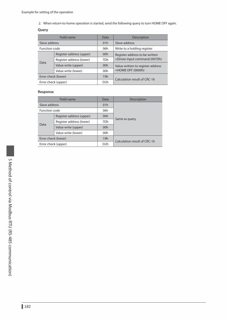
Example for setting of the operation
182
5 Method of control via M
odbus RTU (RS-485 com
munication)
2. When return-to-home operation is started, send the following query to turn HOME OFF again.
Query
Field name Data Description
Slave address 01h Slave address
Function code 06h Write to a holding register
Data
Register address (upper) 00h Register address to be written =Driver input command (007Dh)Register address (lower) 7Dh
Value write (upper) 00h Value written to register address =HOME OFF (0000h)Value write (lower) 00h
Error check (lower) 19hCalculation result of CRC-16
Error check (upper) D2h
Response
Field name Data Description
Slave address 01h
Same as query
Function code 06h
Data
Register address (upper) 00h
Register address (lower) 7Dh
Value write (upper) 00h
Value write (lower) 00h
Error check (lower) 19hCalculation result of CRC-16
Error check (upper) D2h
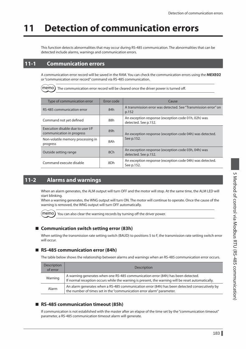
Detection of communication errors
183
5 Method of control via M
odbus RTU (RS-485 com
munication)
11 Detection of communication errors
This function detects abnormalities that may occur during RS-485 communication. The abnormalities that can be detected include alarms, warnings and communication errors.
11-1 Communication errors
A communication error record will be saved in the RAM. You can check the communication errors using the MEXE02 or “communication error record” command via RS-485 communication.
The communication error record will be cleared once the driver power is turned off.
Type of communication error Error code Cause
RS-485 communication error 84hA transmission error was detected. See “Transmission error” on p.152
Command not yet defined 88hAn exception response (exception code 01h, 02h) was detected. See p.152.
Execution disable due to user I/F communication in progress
89hAn exception response (exception code 04h) was detected. See p.152.Non-volatile memory processing in
progress8Ah
Outside setting range 8ChAn exception response (exception code 03h, 04h) was detected. See p.152.
Command execute disable 8DhAn exception response (exception code 04h) was detected. See p.152.
11-2 Alarms and warnings
When an alarm generates, the ALM output will turn OFF and the motor will stop. At the same time, the ALM LED will start blinking.When a warning generates, the WNG output will turn ON. The motor will continue to operate. Once the cause of the warning is removed, the WNG output will turn OFF automatically.
You can also clear the warning records by turning off the driver power.
Communication switch setting error (83h)When setting the transmission rate setting switch (BAUD) to positions 5 to F, the transmission rate setting switch error will occur.
RS-485 communication error (84h)The table below shows the relationship between alarms and warnings when an RS-485 communication error occurs.
Description of error
Description
WarningA warning generates when one RS-485 communication error (84h) has been detected. If normal reception occurs while the warning is present, the warning will be reset automatically.
AlarmAn alarm generates when a RS-485 communication error (84h) has been detected consecutively by the number of times set in the “communication error alarm” parameter.
RS-485 communication timeout (85h)If communication is not established with the master after an elapse of the time set by the “communication timeout” parameter, a RS-485 communication timeout alarm will generate.
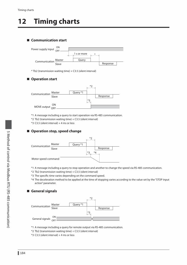
Timing charts
184
5 Method of control via M
odbus RTU (RS-485 com
munication)
12 Timing charts
Communication start
Query
ResponseMasterSlave
Power supply input
Communication
ONOFF
1 s or more *
* Tb2 (transmission waiting time) + C3.5 (silent interval)
Operation start
Query *1Response
MasterSlave
MOVE output
Communication
ONOFF
*2
*3
*1 A message including a query to start operation via RS-485 communication.*2 Tb2 (transmission waiting time) + C3.5 (silent interval)*3 C3.5 (silent interval) + 4 ms or less
Operation stop, speed change
Query *1Response
Master
Slave
Motor speed command
Communication
*4
*2
*3
*1 A message including a query to stop operation and another to change the speed via RS-485 communication.*2 Tb2 (transmission waiting time) + C3.5 (silent interval)*3 The specific time varies depending on the command speed.*4 The deceleration method to be applied at the time of stopping varies according to the value set by the “STOP input
action” parameter.
General signals
Query *1Response
MasterSlave
Communication
*2
*3
General signalsON
OFF
*1 A message including a query for remote output via RS-485 communication.*2 Tb2 (transmission waiting time) + C3.5 (silent interval)*3 C3.5 (silent interval) + 4 ms or less
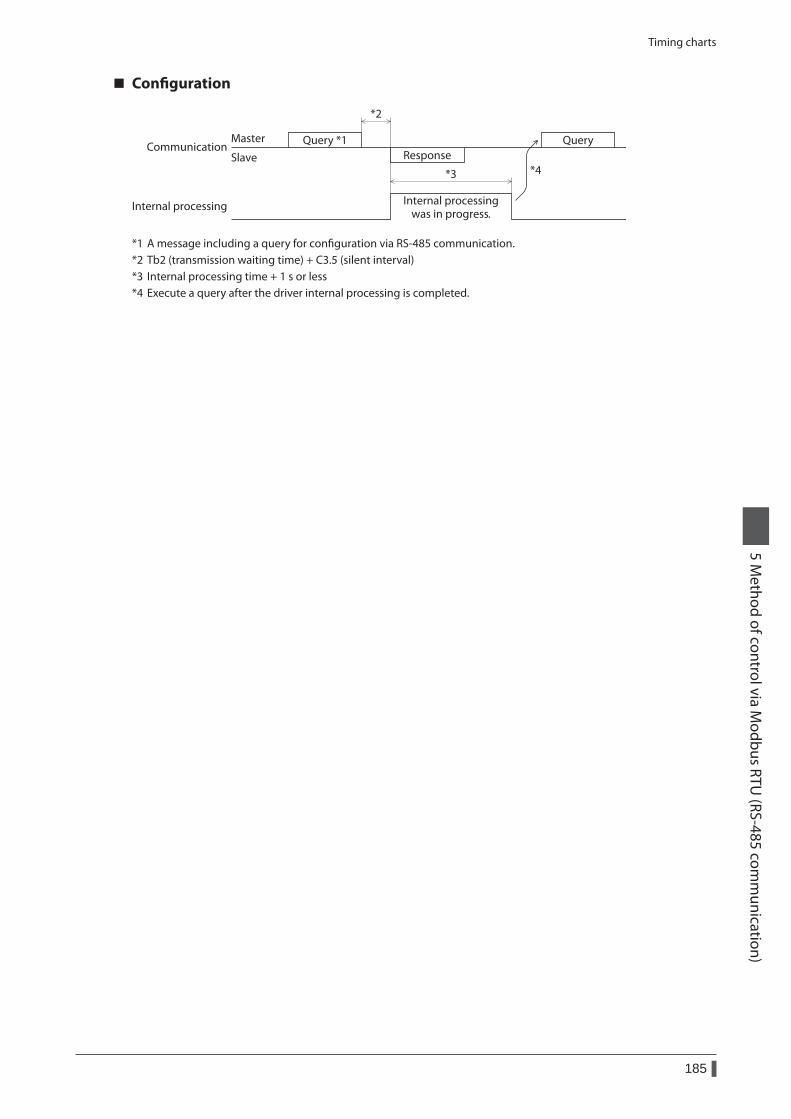
Timing charts
185
5 Method of control via M
odbus RTU (RS-485 com
munication)
Configuration
Master
Slave
Internal processing Internal processingwas in progress.
CommunicationResponse
*2
*3
Query *1 Query
*4
*1 A message including a query for configuration via RS-485 communication.*2 Tb2 (transmission waiting time) + C3.5 (silent interval)*3 Internal processing time + 1 s or less*4 Execute a query after the driver internal processing is completed.

186
5 Method of control via M
odbus RTU (RS-485 com
munication)
1 Setting the switches .......................................1881-1 Protocol .............................................................................188
1-2 Address number (slave address) ..............................188
1-3 Transmission rate ...........................................................189
1-4 Termination resistor ......................................................189
2 Method of control via CC-Link communication ...............................................190
2-1 Guidance...........................................................................190
2-2 Basic operation procedure .........................................195
2-3 Remote register list of NETC01-CC .....................199
2-4 Assignment for remote I/O of 6-axes connection mode ..........................................................199
2-5 Assignment for remote I/O of 12-axes connection mode ..........................................................202
3 Method of control via MECHATROLINK communication ...............................................207
3-1 Guidance...........................................................................207
3-2 Basic operation procedure .........................................212
3-3 I/O field map for the NETC01-M2 ........................215
3-4 I/O field map for the NETC01-M3 ........................216
3-5 Communication format ...............................................217
4 Details of remote I/O ......................................2194-1 Input signals to the driver ..........................................219
4-2 Output signals from the driver .................................220
5 Command code list .........................................2225-1 Group function ...............................................................222
5-2 Maintenance command ..............................................223
5-3 Monitor command ........................................................224
5-4 Operation data ...............................................................226
5-5 User parameters .............................................................227
6 Method of control via industrial network
This part explains how to control via industrial network using the network converter (sold separately).
Table of contents
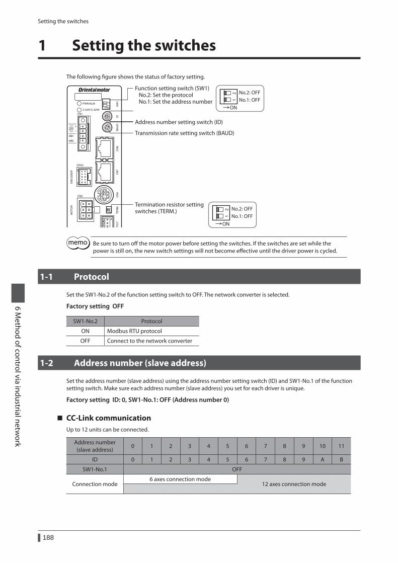
Setting the switches
188
6 Method of control via industrial netw
ork
1 Setting the switches
The following figure shows the status of factory setting.
Address number setting switch (ID)
Termination resistor setting switches (TERM.)
Transmission rate setting switch (BAUD)
Function setting switch (SW1) No.2: Set the protocol No.1: Set the address number
No.2: OFFNo.1: OFF
No.2: OFFNo.1: OFF
ON
ON
Be sure to turn off the motor power before setting the switches. If the switches are set while the power is still on, the new switch settings will not become effective until the driver power is cycled.
1-1 Protocol
Set the SW1-No.2 of the function setting switch to OFF. The network converter is selected.
Factory setting OFF
SW1-No.2 Protocol
ON Modbus RTU protocol
OFF Connect to the network converter
1-2 Address number (slave address)
Set the address number (slave address) using the address number setting switch (ID) and SW1-No.1 of the function setting switch. Make sure each address number (slave address) you set for each driver is unique.
Factory setting ID: 0, SW1-No.1: OFF (Address number 0)
CC-Link communicationUp to 12 units can be connected.
Address number (slave address)
0 1 2 3 4 5 6 7 8 9 10 11
ID 0 1 2 3 4 5 6 7 8 9 A B
SW1-No.1 OFF
Connection mode6 axes connection mode
12 axes connection mode
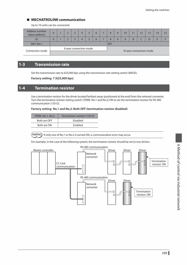
Setting the switches
189
6 Method of control via industrial netw
ork
MECHATROLINK communicationUp to 16 units can be connected.
Address number (slave address)
0 1 2 3 4 5 6 7 8 9 10 11 12 13 14 15
ID 0 1 2 3 4 5 6 7 8 9 A B C D E F
SW1-No.1 OFF
Connection mode8 axes connection mode
16 axes connection mode
1-3 Transmission rate
Set the transmission rate to 625,000 bps using the transmission rate setting switch (BAUD).
Factory setting 7 (625,000 bps)
1-4 Termination resistor
Use a termination resistor for the driver located farthest away (positioned at the end) from the network converter. Turn the termination resistor setting switch (TERM.-No.1 and No.2) ON to set the termination resistor for RS-485 communication (120 Ω).
Factory setting No.1 and No.2: Both OFF (termination resistor disabled)
TERM.-No.1, No.2 Termination resistor (120 Ω)
Both are OFF Disabled
Both are ON Enabled
If only one of No.1 or No.2 is turned ON, a communication error may occur.
For example, in the case of the following system, the termination resistor should be set to two drivers.
DriverNetworkconverter
Driver DriverRS-485 communication
Master controller
DriverNetworkconverter
DriverRS-485 communication
CC-Link communication
Termination resistor: ON
Termination resistor: ON
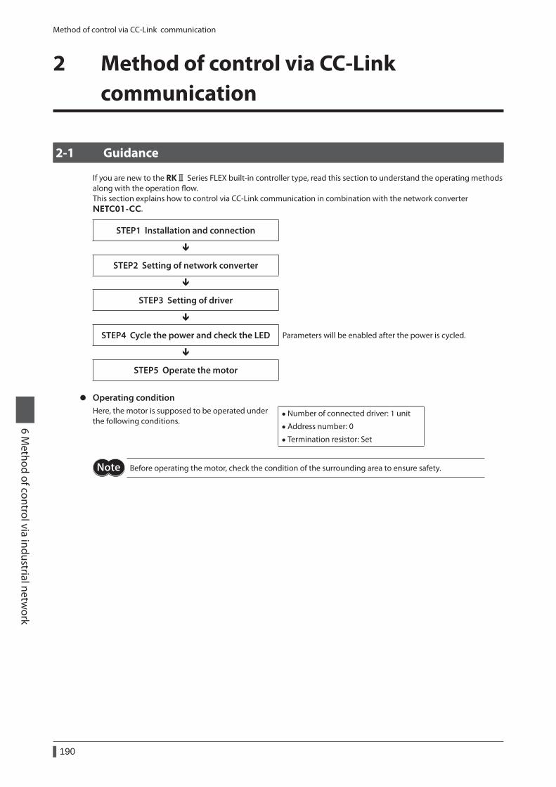
Method of control via CC-Link communication
190
6 Method of control via industrial netw
ork
2 Method of control via CC-Link communication
2-1 Guidance
If you are new to the RKⅡ Series FLEX built-in controller type, read this section to understand the operating methods along with the operation flow.This section explains how to control via CC-Link communication in combination with the network converter NETC01-CC.
STEP1 Installation and connection
STEP2 Setting of network converter
STEP3 Setting of driver
STEP4 Cycle the power and check the LED Parameters will be enabled after the power is cycled.
STEP5 Operate the motor
z Operating conditionHere, the motor is supposed to be operated under the following conditions.
• Number of connected driver: 1 unit
• Address number: 0
• Termination resistor: Set
Before operating the motor, check the condition of the surrounding area to ensure safety.
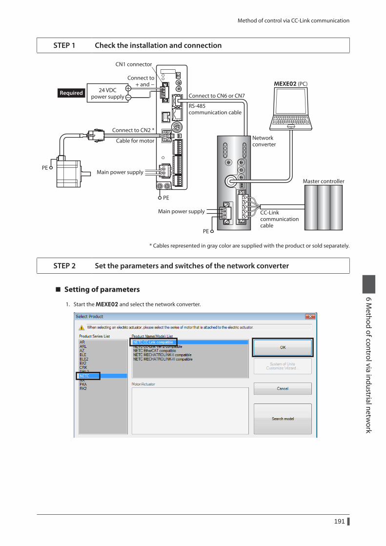
Method of control via CC-Link communication
191
6 Method of control via industrial netw
ork
STEP 1 Check the installation and connection
Main power supply
RS-485 communication cable
CC-Linkcommunicationcable
Networkconverter
MEXE02 (PC)
Connect to CN6 or CN7
Master controller
PE
Main power supply
PE
24 VDCpower supply
Required
Connect to CN2 *
PE
Connect to + and -
CN1 connector
Cable for motor
* Cables represented in gray color are supplied with the product or sold separately.
STEP 2 Set the parameters and switches of the network converter
Setting of parameters
1. Start the MEXE02 and select the network converter.
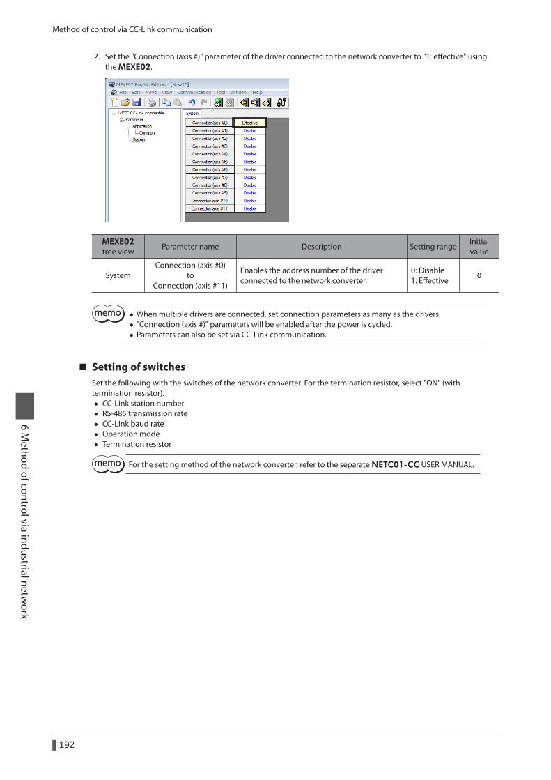
Method of control via CC-Link communication
192
6 Method of control via industrial netw
ork
2. Set the "Connection (axis #)" parameter of the driver connected to the network converter to "1: effective" using the MEXE02.
MEXE02 tree view
Parameter name Description Setting rangeInitial value
SystemConnection (axis #0)
to Connection (axis #11)
Enables the address number of the driver connected to the network converter.
0: Disable 1: Effective
0
• When multiple drivers are connected, set connection parameters as many as the drivers. • "Connection (axis #)" parameters will be enabled after the power is cycled. • Parameters can also be set via CC-Link communication.
Setting of switchesSet the following with the switches of the network converter. For the termination resistor, select "ON" (with termination resistor).
• CC-Link station number • RS-485 transmission rate • CC-Link baud rate • Operation mode • Termination resistor
For the setting method of the network converter, refer to the separate NETC01-CC USER MANUAL.
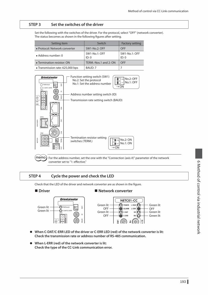
Method of control via CC-Link communication
193
6 Method of control via industrial netw
ork
STEP 3 Set the switches of the driver
Set the following with the switches of the driver. For the protocol, select "OFF" (network converter).The status becomes as shown in the following figures after setting.
Setting item Switch Factory setting
• Protocol: Network converter SW1-No.2: OFF OFF
• Address number: 0SW1-No.1: OFF ID: 0
SW1-No.1: OFF ID: 0
• Termination resistor: ON TERM.-Nos.1 and 2: ON OFF
• Transmission rate: 625,000 bps BAUD: 7 7
ON
ON
Address number setting switch (ID)
Termination resistor settingswitches (TERM.)
Transmission rate setting switch (BAUD)
Function setting switch (SW1) No.2: Set the protocol No.1: Set the address number
No.2: OFFNo.1: OFF
No.2: ONNo.1: ON
For the address number, set the one with the "Connection (axis #)" parameter of the network converter set to "1: effective."
STEP 4 Cycle the power and check the LED
Check that the LED of the driver and network converter are as shown in the figure.
Driver Network converter
Green litGreen litOFFOFF
Green litOFF
Green litGreen lit
Green litGreen lit
z When C-DAT/C-ERR LED of the driver or C-ERR LED (red) of the network converter is lit: Check the transmission rate or address number of RS-485 communication.
z When L-ERR (red) of the network converter is lit: Check the type of the CC-Link communication error.
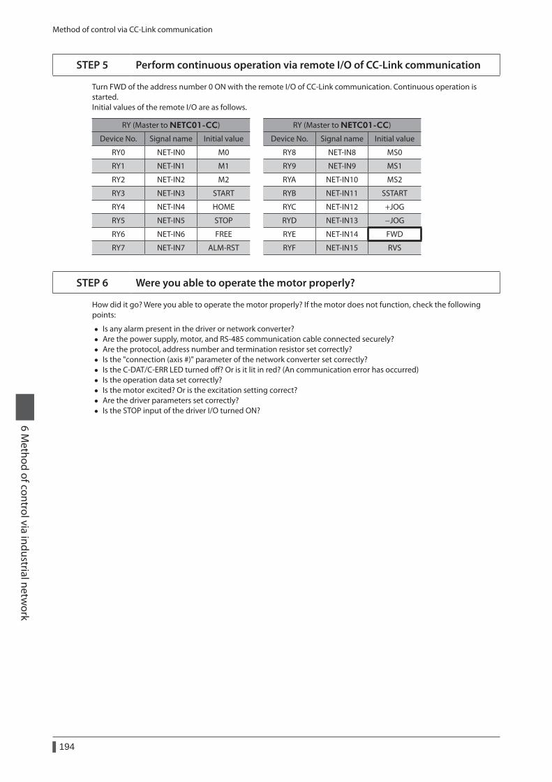
Method of control via CC-Link communication
194
6 Method of control via industrial netw
ork
STEP 5 Perform continuous operation via remote I/O of CC-Link communication
Turn FWD of the address number 0 ON with the remote I/O of CC-Link communication. Continuous operation is started.Initial values of the remote I/O are as follows.
RY (Master to NETC01-CC) RY (Master to NETC01-CC)
Device No. Signal name Initial value Device No. Signal name Initial value
RY0 NET-IN0 M0 RY8 NET-IN8 MS0
RY1 NET-IN1 M1 RY9 NET-IN9 MS1
RY2 NET-IN2 M2 RYA NET-IN10 MS2
RY3 NET-IN3 START RYB NET-IN11 SSTART
RY4 NET-IN4 HOME RYC NET-IN12 +JOG
RY5 NET-IN5 STOP RYD NET-IN13 −JOG
RY6 NET-IN6 FREE RYE NET-IN14 FWD
RY7 NET-IN7 ALM-RST RYF NET-IN15 RVS
STEP 6 Were you able to operate the motor properly?
How did it go? Were you able to operate the motor properly? If the motor does not function, check the following points:
• Is any alarm present in the driver or network converter? • Are the power supply, motor, and RS-485 communication cable connected securely? • Are the protocol, address number and termination resistor set correctly? • Is the "connection (axis #)" parameter of the network converter set correctly? • Is the C-DAT/C-ERR LED turned off? Or is it lit in red? (An communication error has occurred) • Is the operation data set correctly? • Is the motor excited? Or is the excitation setting correct? • Are the driver parameters set correctly? • Is the STOP input of the driver I/O turned ON?
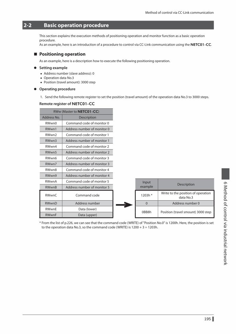
Method of control via CC-Link communication
195
6 Method of control via industrial netw
ork
2-2 Basic operation procedure
This section explains the execution methods of positioning operation and monitor function as a basic operation procedure.As an example, here is an introduction of a procedure to control via CC-Link communication using the NETC01-CC.
Positioning operationAs an example, here is a description how to execute the following positioning operation.
z Setting example • Address number (slave address): 0 • Operation data No.3 • Position (travel amount): 3000 step
z Operating procedure
1. Send the following remote register to set the position (travel amount) of the operation data No.3 to 3000 steps.
Remote register of NETC01-CC
RWw (Master to NETC01-CC)
Address No. Description
RWwn0 Command code of monitor 0
RWwn1 Address number of monitor 0
RWwn2 Command code of monitor 1
RWwn3 Address number of monitor 1
RWwn4 Command code of monitor 2
RWwn5 Address number of monitor 2
RWwn6 Command code of monitor 3
RWwn7 Address number of monitor 3
RWwn8 Command code of monitor 4
RWwn9 Address number of monitor 4
RWwnA Command code of monitor 5 Input example
DescriptionRWwnB Address number of monitor 5
RWwnC Command code 1203h *Write to the position of operation
data No.3
RWwnD Address number 0 Address number 0
RWwnE Data (lower)0BB8h Position (travel smount) 3000 step
RWwnF Data (upper)
* From the list of p.226, we can see that the command code (WRITE) of "Position No.0" is 1200h. Here, the position is set to the operation data No.3, so the command code (WRITE) is 1200 + 3 = 1203h.
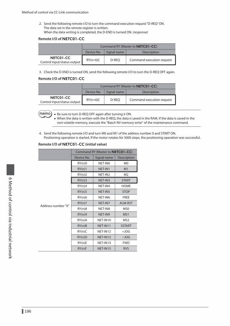
Method of control via CC-Link communication
196
6 Method of control via industrial netw
ork
2. Send the following remote I/O to turn the command execution request “D-REQ” ON.The data set in the remote register is written.When the data writing is completed, the D-END is turned ON. (response)
Remote I/O of NETC01-CC
Command RY (Master to NETC01-CC)
Device No. Signal name Description
NETC01-CCControl input/status output
RY(n+6)C D-REQ Command execution request
3. Check the D-END is turned ON, send the following remote I/O to turn the D-REQ OFF again.
Remote I/O of NETC01-CC
Command RY (Master to NETC01-CC)
Device No. Signal name Description
NETC01-CCControl input/status output
RY(n+6)C D-REQ Command execution request
• Be sure to turn D-REQ OFF again after turning it ON. • When the data is written with the D-REQ, the data is saved in the RAM. If the data is saved in the non-volatile memory, execute the "Batch NV memory write" of the maintenance command.
4. Send the following remote I/O and turn M0 and M1 of the address number 0 and START ON.Positioning operation is started. If the motor rotates for 3000 steps, the positioning operation was successful.
Remote I/O of NETC01-CC (initial value)
Command RY (Master to NETC01-CC)
Device No. Signal name Description
Address number "0"
RY(n)0 NET-IN0 M0
RY(n)1 NET-IN1 M1
RY(n)2 NET-IN2 M2
RY(n)3 NET-IN3 START
RY(n)4 NET-IN4 HOME
RY(n)5 NET-IN5 STOP
RY(n)6 NET-IN6 FREE
RY(n)7 NET-IN7 ALM-RST
RY(n)8 NET-IN8 MS0
RY(n)9 NET-IN9 MS1
RY(n)A NET-IN10 MS2
RY(n)B NET-IN11 SSTART
RY(n)C NET-IN12 +JOG
RY(n)D NET-IN13 −JOG
RY(n)E NET-IN14 FWD
RY(n)F NET-IN15 RVS
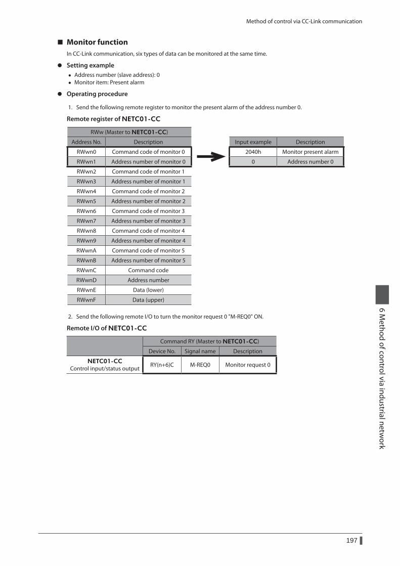
Method of control via CC-Link communication
197
6 Method of control via industrial netw
ork
Monitor functionIn CC-Link communication, six types of data can be monitored at the same time.
z Setting example • Address number (slave address): 0 • Monitor item: Present alarm
z Operating procedure
1. Send the following remote register to monitor the present alarm of the address number 0.
Remote register of NETC01-CC
RWw (Master to NETC01-CC)
Address No. Description Input example Description
RWwn0 Command code of monitor 0 2040h Monitor present alarm
RWwn1 Address number of monitor 0 0 Address number 0
RWwn2 Command code of monitor 1
RWwn3 Address number of monitor 1
RWwn4 Command code of monitor 2
RWwn5 Address number of monitor 2
RWwn6 Command code of monitor 3
RWwn7 Address number of monitor 3
RWwn8 Command code of monitor 4
RWwn9 Address number of monitor 4
RWwnA Command code of monitor 5
RWwnB Address number of monitor 5
RWwnC Command code
RWwnD Address number
RWwnE Data (lower)
RWwnF Data (upper)
2. Send the following remote I/O to turn the monitor request 0 "M-REQ0" ON.
Remote I/O of NETC01-CC
Command RY (Master to NETC01-CC)
Device No. Signal name Description
NETC01-CCControl input/status output
RY(n+6)C M-REQ0 Monitor request 0
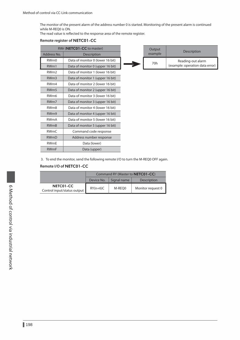
Method of control via CC-Link communication
198
6 Method of control via industrial netw
ork
The monitor of the present alarm of the address number 0 is started. Monitoring of the present alarm is continued while M-REQ0 is ON.The read value is reflected to the response area of the remote register.
Remote register of NETC01-CC
RWr (NETC01-CC to master) Output example
DescriptionAddress No. Description
RWrn0 Data of monitor 0 (lower 16 bit)70h
Reading-out alarm (example: operation data error)RWrn1 Data of monitor 0 (upper 16 bit)
RWrn2 Data of monitor 1 (lower 16 bit)
RWrn3 Data of monitor 1 (upper 16 bit)
RWrn4 Data of monitor 2 (lower 16 bit)
RWrn5 Data of monitor 2 (upper 16 bit)
RWrn6 Data of monitor 3 (lower 16 bit)
RWrn7 Data of monitor 3 (upper 16 bit)
RWrn8 Data of monitor 4 (lower 16 bit)
RWrn9 Data of monitor 4 (upper 16 bit)
RWrnA Data of monitor 5 (lower 16 bit)
RWrnB Data of monitor 5 (upper 16 bit)
RWrnC Command code response
RWrnD Address number response
RWrnE Data (lower)
RWrnF Data (upper)
3. To end the monitor, send the following remote I/O to turn the M-REQ0 OFF again.
Remote I/O of NETC01-CC
Command RY (Master to NETC01-CC)
Device No. Signal name Description
NETC01-CCControl input/status output
RY(n+6)C M-REQ0 Monitor request 0
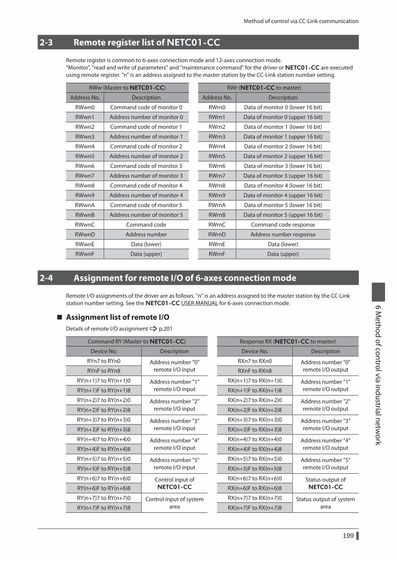
Method of control via CC-Link communication
199
6 Method of control via industrial netw
ork
2-3 Remote register list of NETC01-CC
Remote register is common to 6-axes connection mode and 12-axes connection mode."Monitor", "read and write of parameters" and "maintenance command" for the driver or NETC01-CC are executed using remote register. "n" is an address assigned to the master station by the CC-Link station number setting.
RWw (Master to NETC01-CC) RWr (NETC01-CC to master)
Address No. Description Address No. Description
RWwn0 Command code of monitor 0 RWrn0 Data of monitor 0 (lower 16 bit)
RWwn1 Address number of monitor 0 RWrn1 Data of monitor 0 (upper 16 bit)
RWwn2 Command code of monitor 1 RWrn2 Data of monitor 1 (lower 16 bit)
RWwn3 Address number of monitor 1 RWrn3 Data of monitor 1 (upper 16 bit)
RWwn4 Command code of monitor 2 RWrn4 Data of monitor 2 (lower 16 bit)
RWwn5 Address number of monitor 2 RWrn5 Data of monitor 2 (upper 16 bit)
RWwn6 Command code of monitor 3 RWrn6 Data of monitor 3 (lower 16 bit)
RWwn7 Address number of monitor 3 RWrn7 Data of monitor 3 (upper 16 bit)
RWwn8 Command code of monitor 4 RWrn8 Data of monitor 4 (lower 16 bit)
RWwn9 Address number of monitor 4 RWrn9 Data of monitor 4 (upper 16 bit)
RWwnA Command code of monitor 5 RWrnA Data of monitor 5 (lower 16 bit)
RWwnB Address number of monitor 5 RWrnB Data of monitor 5 (upper 16 bit)
RWwnC Command code RWrnC Command code response
RWwnD Address number RWrnD Address number response
RWwnE Data (lower) RWrnE Data (lower)
RWwnF Data (upper) RWrnF Data (upper)
2-4 Assignment for remote I/O of 6-axes connection mode
Remote I/O assignments of the driver are as follows. "n" is an address assigned to the master station by the CC-Link station number setting. See the NETC01-CC USER MANUAL for 6-axes connection mode.
Assignment list of remote I/ODetails of remote I/O assignment _ p.201
Command RY (Master to NETC01-CC) Response RX (NETC01-CC to master)
Device No. Description Device No. Description
RYn7 to RYn0 Address number "0" remote I/O input
RXn7 to RXn0 Address number "0" remote I/O outputRYnF to RYn8 RXnF to RXn8
RY(n+1)7 to RY(n+1)0 Address number "1" remote I/O input
RX(n+1)7 to RX(n+1)0 Address number "1" remote I/O outputRY(n+1)F to RY(n+1)8 RX(n+1)F to RX(n+1)8
RY(n+2)7 to RY(n+2)0 Address number "2" remote I/O input
RX(n+2)7 to RX(n+2)0 Address number "2" remote I/O outputRY(n+2)F to RY(n+2)8 RX(n+2)F to RX(n+2)8
RY(n+3)7 to RY(n+3)0 Address number "3" remote I/O input
RX(n+3)7 to RX(n+3)0 Address number "3" remote I/O outputRY(n+3)F to RY(n+3)8 RX(n+3)F to RX(n+3)8
RY(n+4)7 to RY(n+4)0 Address number "4" remote I/O input
RX(n+4)7 to RX(n+4)0 Address number "4" remote I/O outputRY(n+4)F to RY(n+4)8 RX(n+4)F to RX(n+4)8
RY(n+5)7 to RY(n+5)0 Address number "5" remote I/O input
RX(n+5)7 to RX(n+5)0 Address number "5" remote I/O outputRY(n+5)F to RY(n+5)8 RX(n+5)F to RX(n+5)8
RY(n+6)7 to RY(n+6)0 Control input of NETC01-CC
RX(n+6)7 to RX(n+6)0 Status output of NETC01-CCRY(n+6)F to RY(n+6)8 RX(n+6)F to RX(n+6)8
RY(n+7)7 to RY(n+7)0 Control input of system area
RX(n+7)7 to RX(n+7)0 Status output of system areaRY(n+7)F to RY(n+7)8 RX(n+7)F to RX(n+7)8
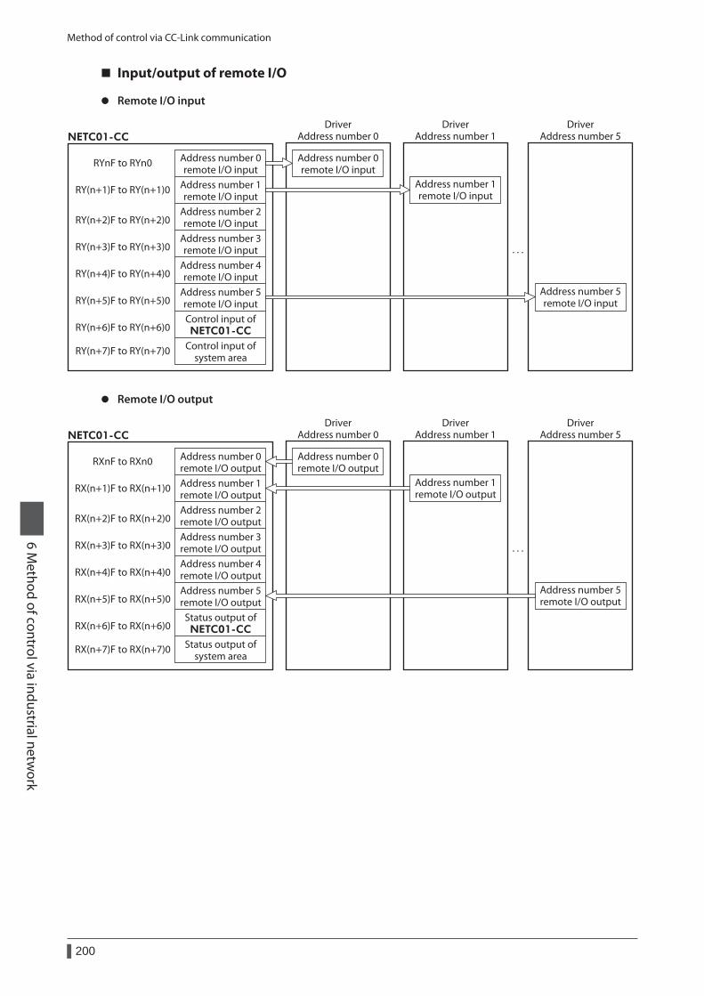
Method of control via CC-Link communication
200
6 Method of control via industrial netw
ork
Input/output of remote I/O
z Remote I/O input
Address number 0remote I/O input
Address number 1remote I/O input
Address number 2remote I/O input
Address number 3remote I/O input
Address number 4remote I/O input
Address number 5remote I/O input
Address number 0remote I/O input
Address number 1remote I/O input
RYnF to RYn0
RY(n+1)F to RY(n+1)0
RY(n+2)F to RY(n+2)0
RY(n+3)F to RY(n+3)0
RY(n+4)F to RY(n+4)0
RY(n+5)F to RY(n+5)0
Control input ofNETC01-CCRY(n+6)F to RY(n+6)0
Control input ofsystem area
RY(n+7)F to RY(n+7)0
NETC01-CC
· · ·
DriverAddress number 0
DriverAddress number 1
Address number 5remote I/O input
DriverAddress number 5
z Remote I/O output
Address number 0remote I/O outputAddress number 1remote I/O outputAddress number 2remote I/O outputAddress number 3remote I/O outputAddress number 4remote I/O outputAddress number 5remote I/O output
Address number 0remote I/O output
Address number 1remote I/O output
RXnF to RXn0
RX(n+1)F to RX(n+1)0
RX(n+2)F to RX(n+2)0
RX(n+3)F to RX(n+3)0
RX(n+4)F to RX(n+4)0
RX(n+5)F to RX(n+5)0
Status output ofNETC01-CCRX(n+6)F to RX(n+6)0
Status output ofsystem area
RX(n+7)F to RX(n+7)0
NETC01-CC
· · ·
DriverAddress number 0
DriverAddress number 1
Address number 5remote I/O output
DriverAddress number 5
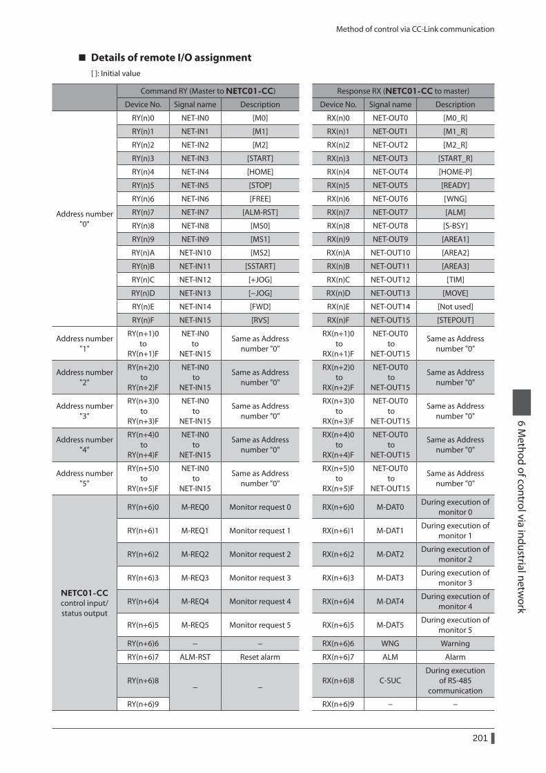
Method of control via CC-Link communication
201
6 Method of control via industrial netw
ork
Details of remote I/O assignment[ ]: Initial value
Command RY (Master to NETC01-CC) Response RX (NETC01-CC to master)
Device No. Signal name Description Device No. Signal name Description
Address number "0"
RY(n)0 NET-IN0 [M0] RX(n)0 NET-OUT0 [M0_R]
RY(n)1 NET-IN1 [M1] RX(n)1 NET-OUT1 [M1_R]
RY(n)2 NET-IN2 [M2] RX(n)2 NET-OUT2 [M2_R]
RY(n)3 NET-IN3 [START] RX(n)3 NET-OUT3 [START_R]
RY(n)4 NET-IN4 [HOME] RX(n)4 NET-OUT4 [HOME-P]
RY(n)5 NET-IN5 [STOP] RX(n)5 NET-OUT5 [READY]
RY(n)6 NET-IN6 [FREE] RX(n)6 NET-OUT6 [WNG]
RY(n)7 NET-IN7 [ALM-RST] RX(n)7 NET-OUT7 [ALM]
RY(n)8 NET-IN8 [MS0] RX(n)8 NET-OUT8 [S-BSY]
RY(n)9 NET-IN9 [MS1] RX(n)9 NET-OUT9 [AREA1]
RY(n)A NET-IN10 [MS2] RX(n)A NET-OUT10 [AREA2]
RY(n)B NET-IN11 [SSTART] RX(n)B NET-OUT11 [AREA3]
RY(n)C NET-IN12 [+JOG] RX(n)C NET-OUT12 [TIM]
RY(n)D NET-IN13 [−JOG] RX(n)D NET-OUT13 [MOVE]
RY(n)E NET-IN14 [FWD] RX(n)E NET-OUT14 [Not used]
RY(n)F NET-IN15 [RVS] RX(n)F NET-OUT15 [STEPOUT]
Address number "1"
RY(n+1)0 to
RY(n+1)F
NET-IN0 to
NET-IN15
Same as Address number "0"
RX(n+1)0 to
RX(n+1)F
NET-OUT0 to
NET-OUT15
Same as Address number "0"
Address number "2"
RY(n+2)0 to
RY(n+2)F
NET-IN0 to
NET-IN15
Same as Address number "0"
RX(n+2)0 to
RX(n+2)F
NET-OUT0 to
NET-OUT15
Same as Address number "0"
Address number "3"
RY(n+3)0 to
RY(n+3)F
NET-IN0 to
NET-IN15
Same as Address number "0"
RX(n+3)0 to
RX(n+3)F
NET-OUT0 to
NET-OUT15
Same as Address number "0"
Address number "4"
RY(n+4)0 to
RY(n+4)F
NET-IN0 to
NET-IN15
Same as Address number "0"
RX(n+4)0 to
RX(n+4)F
NET-OUT0 to
NET-OUT15
Same as Address number "0"
Address number "5"
RY(n+5)0 to
RY(n+5)F
NET-IN0 to
NET-IN15
Same as Address number "0"
RX(n+5)0 to
RX(n+5)F
NET-OUT0 to
NET-OUT15
Same as Address number "0"
NETC01-CCcontrol input/ status output
RY(n+6)0 M-REQ0 Monitor request 0 RX(n+6)0 M-DAT0During execution of
monitor 0
RY(n+6)1 M-REQ1 Monitor request 1 RX(n+6)1 M-DAT1During execution of
monitor 1
RY(n+6)2 M-REQ2 Monitor request 2 RX(n+6)2 M-DAT2During execution of
monitor 2
RY(n+6)3 M-REQ3 Monitor request 3 RX(n+6)3 M-DAT3During execution of
monitor 3
RY(n+6)4 M-REQ4 Monitor request 4 RX(n+6)4 M-DAT4During execution of
monitor 4
RY(n+6)5 M-REQ5 Monitor request 5 RX(n+6)5 M-DAT5During execution of
monitor 5
RY(n+6)6 − − RX(n+6)6 WNG Warning
RY(n+6)7 ALM-RST Reset alarm RX(n+6)7 ALM Alarm
RY(n+6)8− −
RX(n+6)8 C-SUCDuring execution
of RS-485 communication
RY(n+6)9 RX(n+6)9 − −
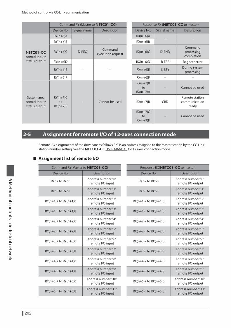
Method of control via CC-Link communication
202
6 Method of control via industrial netw
ork
Command RY (Master to NETC01-CC) Response RX (NETC01-CC to master)
Device No. Signal name Description Device No. Signal name Description
NETC01-CCcontrol input/ status output
RY(n+6)A− −
RX(n+6)A− −
RY(n+6)B RX(n+6)B
RY(n+6)C D-REQCommand
execution requestRX(n+6)C D-END
Command processing completion
RY(n+6)D
− −
RX(n+6)D R-ERR Register error
RY(n+6)E RX(n+6)E S-BSYDuring system
processing
RY(n+6)F RX(n+6)F − −
System area control input/ status output
RY(n+7)0 to
RY(n+7)F− Cannot be used
RX(n+7)0 to
RX(n+7)A− Cannot be used
RX(n+7)B CRDRemote station communication
ready
RX(n+7)C to
RX(n+7)F− Cannot be used
2-5 Assignment for remote I/O of 12-axes connection mode
Remote I/O assignments of the driver are as follows. "n" is an address assigned to the master station by the CC-Link station number setting. See the NETC01-CC USER MANUAL for 12 axes connection mode.
Assignment list of remote I/O
Command RY(Master to NETC01-CC) Response RX(NETC01-CC to master)
Device No. Description Device No. Description
RYn7 to RYn0Address number "0"
remote I/O inputRXn7 to RXn0
Address number "0" remote I/O output
RYnF to RYn8Address number "1"
remote I/O inputRXnF to RXn8
Address number "1" remote I/O output
RY(n+1)7 to RY(n+1)0Address number "2"
remote I/O inputRX(n+1)7 to RX(n+1)0
Address number "2" remote I/O output
RY(n+1)F to RY(n+1)8Address number "3"
remote I/O inputRX(n+1)F to RX(n+1)8
Address number "3" remote I/O output
RY(n+2)7 to RY(n+2)0Address number "4"
remote I/O inputRX(n+2)7 to RX(n+2)0
Address number "4" remote I/O output
RY(n+2)F to RY(n+2)8Address number "5"
remote I/O inputRX(n+2)F to RX(n+2)8
Address number "5" remote I/O output
RY(n+3)7 to RY(n+3)0Address number "6"
remote I/O inputRX(n+3)7 to RX(n+3)0
Address number "6" remote I/O output
RY(n+3)F to RY(n+3)8Address number "7"
remote I/O inputRX(n+3)F to RX(n+3)8
Address number "7" remote I/O output
RY(n+4)7 to RY(n+4)0Address number "8"
remote I/O inputRX(n+4)7 to RX(n+4)0
Address number "8" remote I/O output
RY(n+4)F to RY(n+4)8Address number "9"
remote I/O inputRX(n+4)F to RX(n+4)8
Address number "9" remote I/O output
RY(n+5)7 to RY(n+5)0Address number "10"
remote I/O inputRX(n+5)7 to RX(n+5)0
Address number "10" remote I/O output
RY(n+5)F to RY(n+5)8Address number "11"
remote I/O inputRX(n+5)F to RX(n+5)8
Address number "11" remote I/O output
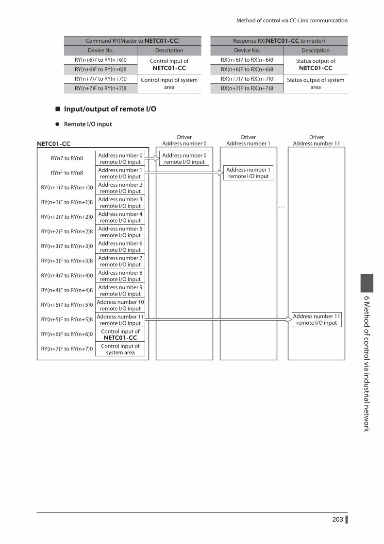
Method of control via CC-Link communication
203
6 Method of control via industrial netw
ork
Command RY(Master to NETC01-CC) Response RX(NETC01-CC to master)
Device No. Description Device No. Description
RY(n+6)7 to RY(n+6)0 Control input of NETC01-CC
RX(n+6)7 to RX(n+6)0 Status output of NETC01-CCRY(n+6)F to RY(n+6)8 RX(n+6)F to RX(n+6)8
RY(n+7)7 to RY(n+7)0 Control input of system area
RX(n+7)7 to RX(n+7)0 Status output of system areaRY(n+7)F to RY(n+7)8 RX(n+7)F to RX(n+7)8
Input/output of remote I/O
z Remote I/O input
RYn7 to RYn0
RYnF to RYn8
RY(n+1)7 to RY(n+1)0
RY(n+1)F to RY(n+1)8
RY(n+2)7 to RY(n+2)0
RY(n+2)F to RY(n+2)8
RY(n+3)7 to RY(n+3)0
RY(n+3)F to RY(n+3)8
RY(n+4)7 to RY(n+4)0
RY(n+4)F to RY(n+4)8
RY(n+5)7 to RY(n+5)0
RY(n+5)F to RY(n+5)8
RY(n+6)F to RY(n+6)0
RY(n+7)F to RY(n+7)0
Address number 0remote I/O input
Address number 1remote I/O input
Address number 2remote I/O input
Address number 3remote I/O input
Address number 4remote I/O input
Address number 5remote I/O input
Address number 6remote I/O input
Address number 7remote I/O input
Address number 8remote I/O input
Address number 9remote I/O input
Address number 10remote I/O input
Address number 11remote I/O input
Address number 0remote I/O input
Address number 1remote I/O input
Control input ofNETC01-CC
Control input ofsystem area
NETC01-CC
· · ·
DriverAddress number 0
DriverAddress number 1
Address number 11remote I/O input
DriverAddress number 11
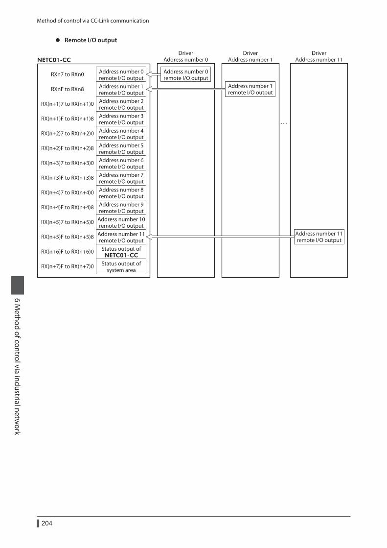
Method of control via CC-Link communication
204
6 Method of control via industrial netw
ork
z Remote I/O output
RXn7 to RXn0
RXnF to RXn8
RX(n+1)7 to RX(n+1)0
RX(n+1)F to RX(n+1)8
RX(n+2)7 to RX(n+2)0
RX(n+2)F to RX(n+2)8
RX(n+3)7 to RX(n+3)0
RX(n+3)F to RX(n+3)8
RX(n+4)7 to RX(n+4)0
RX(n+4)F to RX(n+4)8
RX(n+5)7 to RX(n+5)0
RX(n+5)F to RX(n+5)8
RX(n+6)F to RX(n+6)0
RX(n+7)F to RX(n+7)0
Address number 0remote I/O outputAddress number 1remote I/O outputAddress number 2remote I/O outputAddress number 3remote I/O outputAddress number 4remote I/O outputAddress number 5remote I/O outputAddress number 6remote I/O outputAddress number 7remote I/O outputAddress number 8remote I/O outputAddress number 9remote I/O output
Address number 10remote I/O output
Address number 11remote I/O output
Address number 0remote I/O output
Address number 1remote I/O output
Status output ofNETC01-CC
Status output ofsystem area
NETC01-CC
· · ·
DriverAddress number 0
DriverAddress number 1
Address number 11remote I/O output
DriverAddress number 11
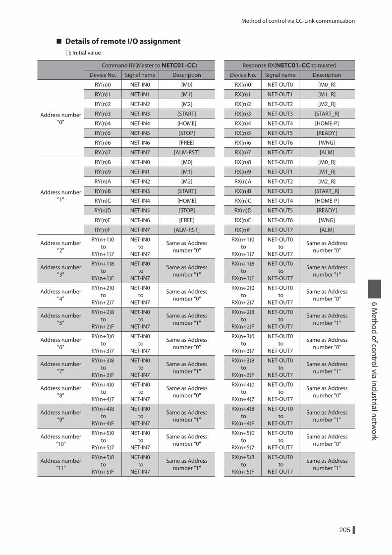
Method of control via CC-Link communication
205
6 Method of control via industrial netw
ork
Details of remote I/O assignment[ ]: Initial value
Command RY(Master to NETC01-CC) Response RX(NETC01-CC to master)
Device No. Signal name Description Device No. Signal name Description
Address number "0"
RY(n)0 NET-IN0 [M0] RX(n)0 NET-OUT0 [M0_R]
RY(n)1 NET-IN1 [M1] RX(n)1 NET-OUT1 [M1_R]
RY(n)2 NET-IN2 [M2] RX(n)2 NET-OUT2 [M2_R]
RY(n)3 NET-IN3 [START] RX(n)3 NET-OUT3 [START_R]
RY(n)4 NET-IN4 [HOME] RX(n)4 NET-OUT4 [HOME-P]
RY(n)5 NET-IN5 [STOP] RX(n)5 NET-OUT5 [READY]
RY(n)6 NET-IN6 [FREE] RX(n)6 NET-OUT6 [WNG]
RY(n)7 NET-IN7 [ALM-RST] RX(n)7 NET-OUT7 [ALM]
Address number "1"
RY(n)8 NET-IN0 [M0] RX(n)8 NET-OUT0 [M0_R]
RY(n)9 NET-IN1 [M1] RX(n)9 NET-OUT1 [M1_R]
RY(n)A NET-IN2 [M2] RX(n)A NET-OUT2 [M2_R]
RY(n)B NET-IN3 [START] RX(n)B NET-OUT3 [START_R]
RY(n)C NET-IN4 [HOME] RX(n)C NET-OUT4 [HOME-P]
RY(n)D NET-IN5 [STOP] RX(n)D NET-OUT5 [READY]
RY(n)E NET-IN6 [FREE] RX(n)E NET-OUT6 [WNG]
RY(n)F NET-IN7 [ALM-RST] RX(n)F NET-OUT7 [ALM]
Address number "2"
RY(n+1)0 to
RY(n+1)7
NET-IN0 to
NET-IN7
Same as Address number "0"
RX(n+1)0 to
RX(n+1)7
NET-OUT0 to
NET-OUT7
Same as Address number "0"
Address number "3"
RY(n+1)8 to
RY(n+1)F
NET-IN0 to
NET-IN7
Same as Address number "1"
RX(n+1)8 to
RX(n+1)F
NET-OUT0 to
NET-OUT7
Same as Address number "1"
Address number "4"
RY(n+2)0 to
RY(n+2)7
NET-IN0 to
NET-IN7
Same as Address number "0"
RX(n+2)0 to
RX(n+2)7
NET-OUT0 to
NET-OUT7
Same as Address number "0"
Address number "5"
RY(n+2)8 to
RY(n+2)F
NET-IN0 to
NET-IN7
Same as Address number "1"
RX(n+2)8 to
RX(n+2)F
NET-OUT0 to
NET-OUT7
Same as Address number "1"
Address number "6"
RY(n+3)0 to
RY(n+3)7
NET-IN0 to
NET-IN7
Same as Address number "0"
RX(n+3)0 to
RX(n+3)7
NET-OUT0 to
NET-OUT7
Same as Address number "0"
Address number "7"
RY(n+3)8 to
RY(n+3)F
NET-IN0 to
NET-IN7
Same as Address number "1"
RX(n+3)8 to
RX(n+3)F
NET-OUT0 to
NET-OUT7
Same as Address number "1"
Address number "8"
RY(n+4)0 to
RY(n+4)7
NET-IN0 to
NET-IN7
Same as Address number "0"
RX(n+4)0 to
RX(n+4)7
NET-OUT0 to
NET-OUT7
Same as Address number "0"
Address number "9"
RY(n+4)8 to
RY(n+4)F
NET-IN0 to
NET-IN7
Same as Address number "1"
RX(n+4)8 to
RX(n+4)F
NET-OUT0 to
NET-OUT7
Same as Address number "1"
Address number "10"
RY(n+5)0 to
RY(n+5)7
NET-IN0 to
NET-IN7
Same as Address number "0"
RX(n+5)0 to
RX(n+5)7
NET-OUT0 to
NET-OUT7
Same as Address number "0"
Address number "11"
RY(n+5)8 to
RY(n+5)F
NET-IN0 to
NET-IN7
Same as Address number "1"
RX(n+5)8 to
RX(n+5)F
NET-OUT0 to
NET-OUT7
Same as Address number "1"
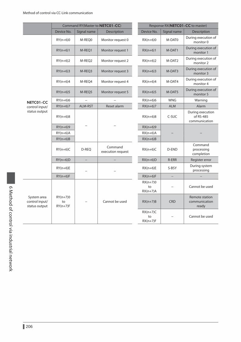
Method of control via CC-Link communication
206
6 Method of control via industrial netw
ork
Command RY(Master to NETC01-CC) Response RX(NETC01-CC to master)
Device No. Signal name Description Device No. Signal name Description
NETC01-CCcontrol input/ status output
RY(n+6)0 M-REQ0 Monitor request 0 RX(n+6)0 M-DAT0During execution of
monitor 0
RY(n+6)1 M-REQ1 Monitor request 1 RX(n+6)1 M-DAT1During execution of
monitor 1
RY(n+6)2 M-REQ2 Monitor request 2 RX(n+6)2 M-DAT2During execution of
monitor 2
RY(n+6)3 M-REQ3 Monitor request 3 RX(n+6)3 M-DAT3During execution of
monitor 3
RY(n+6)4 M-REQ4 Monitor request 4 RX(n+6)4 M-DAT4During execution of
monitor 4
RY(n+6)5 M-REQ5 Monitor request 5 RX(n+6)5 M-DAT5During execution of
monitor 5
RY(n+6)6 − − RX(n+6)6 WNG Warning
RY(n+6)7 ALM-RST Reset alarm RX(n+6)7 ALM Alarm
RY(n+6)8
− −
RX(n+6)8 C-SUCDuring execution
of RS-485 communication
RY(n+6)9 RX(n+6)9
− −RY(n+6)A RX(n+6)A
RY(n+6)B RX(n+6)B
RY(n+6)C D-REQCommand
execution requestRX(n+6)C D-END
Command processing completion
RY(n+6)D − − RX(n+6)D R-ERR Register error
RY(n+6)E− −
RX(n+6)E S-BSYDuring system
processing
RY(n+6)F RX(n+6)F − −
System area control input/ status output
RY(n+7)0 to
RY(n+7)F− Cannot be used
RX(n+7)0 to
RX(n+7)A− Cannot be used
RX(n+7)B CRDRemote station communication
ready
RX(n+7)C to
RX(n+7)F− Cannot be used
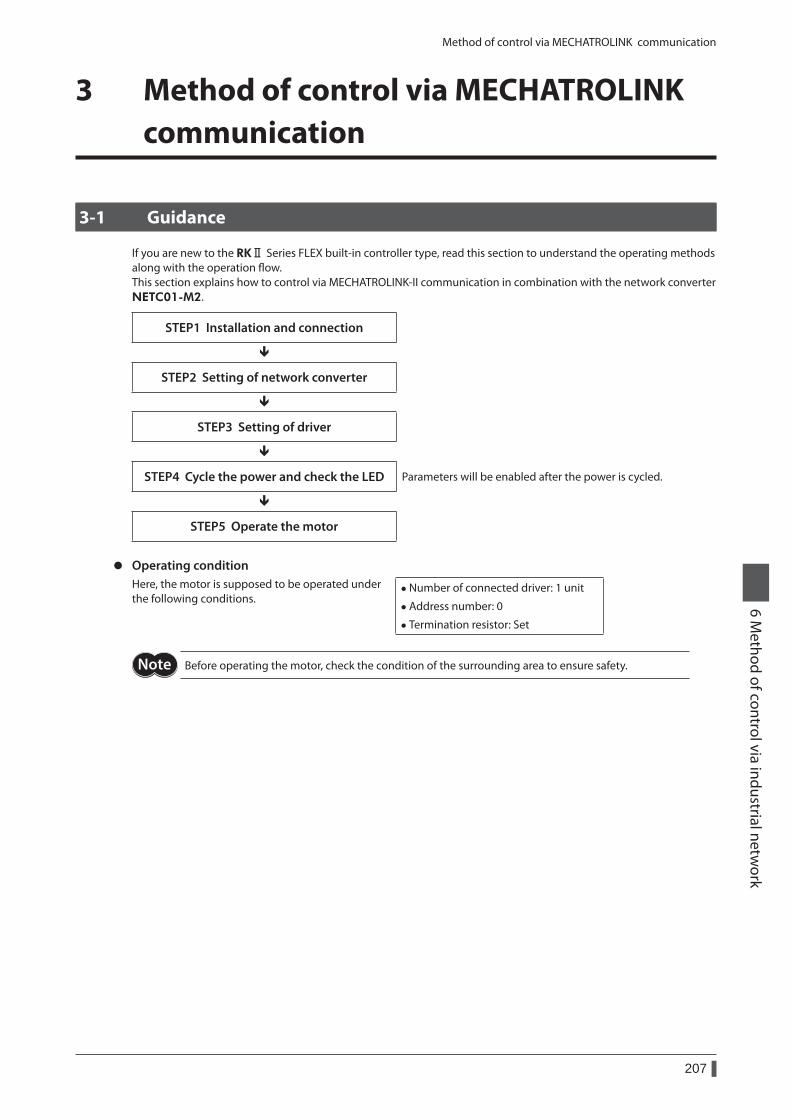
Method of control via MECHATROLINK communication
207
6 Method of control via industrial netw
ork
3 Method of control via MECHATROLINK communication
3-1 Guidance
If you are new to the RKⅡ Series FLEX built-in controller type, read this section to understand the operating methods along with the operation flow.This section explains how to control via MECHATROLINK-II communication in combination with the network converter NETC01-M2.
STEP1 Installation and connection
STEP2 Setting of network converter
STEP3 Setting of driver
STEP4 Cycle the power and check the LED Parameters will be enabled after the power is cycled.
STEP5 Operate the motor
z Operating conditionHere, the motor is supposed to be operated under the following conditions.
• Number of connected driver: 1 unit
• Address number: 0
• Termination resistor: Set
Before operating the motor, check the condition of the surrounding area to ensure safety.
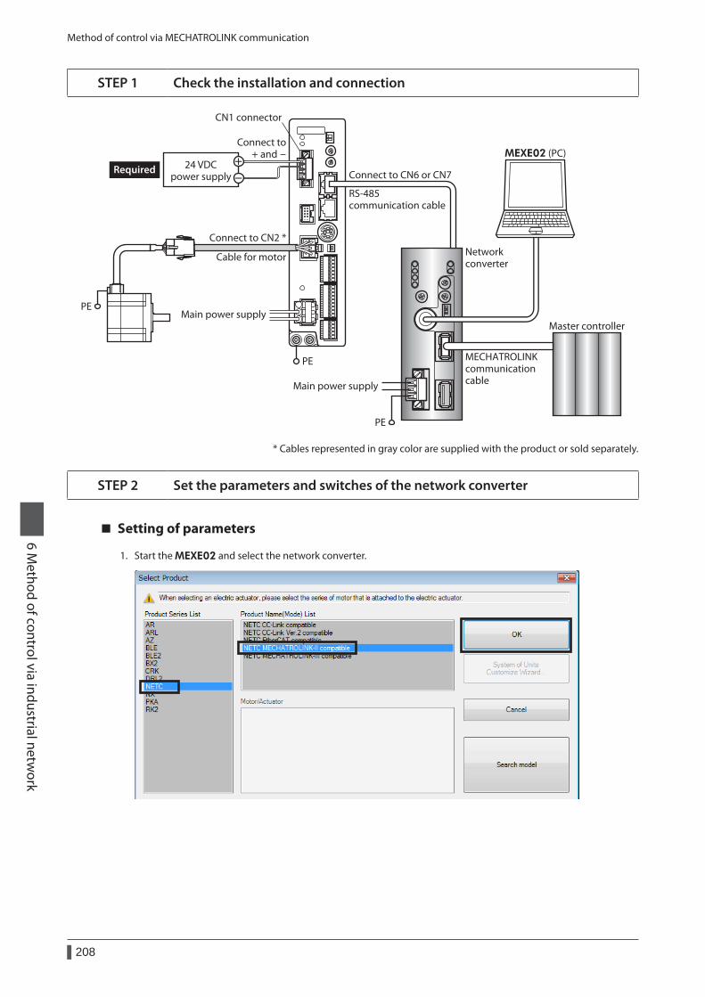
Method of control via MECHATROLINK communication
208
6 Method of control via industrial netw
ork
STEP 1 Check the installation and connection
Main power supply
RS-485 communication cable
Networkconverter
MEXE02 (PC)
Connect to CN6 or CN7
PE
Main power supply
PE
24 VDCpower supply
Required
Connect to CN2 *
PE
Connect to + and -
CN1 connector
Cable for motor
MECHATROLINKcommunicationcable
Master controller
* Cables represented in gray color are supplied with the product or sold separately.
STEP 2 Set the parameters and switches of the network converter
Setting of parameters
1. Start the MEXE02 and select the network converter.
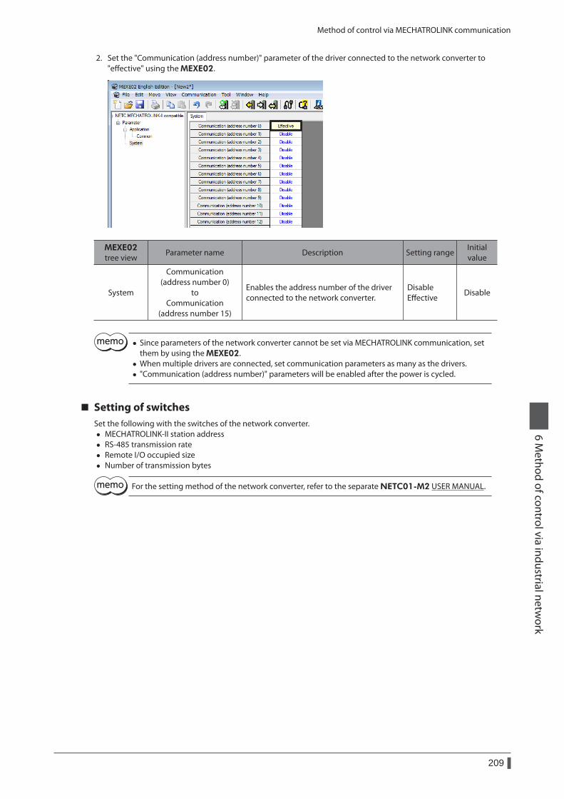
Method of control via MECHATROLINK communication
209
6 Method of control via industrial netw
ork
2. Set the "Communication (address number)" parameter of the driver connected to the network converter to "effective" using the MEXE02.
MEXE02 tree view
Parameter name Description Setting rangeInitial value
System
Communication (address number 0)
to Communication
(address number 15)
Enables the address number of the driver connected to the network converter.
Disable Effective
Disable
• Since parameters of the network converter cannot be set via MECHATROLINK communication, set them by using the MEXE02.
• When multiple drivers are connected, set communication parameters as many as the drivers. • "Communication (address number)" parameters will be enabled after the power is cycled.
Setting of switchesSet the following with the switches of the network converter.
• MECHATROLINK-II station address • RS-485 transmission rate • Remote I/O occupied size • Number of transmission bytes
For the setting method of the network converter, refer to the separate NETC01-M2 USER MANUAL.
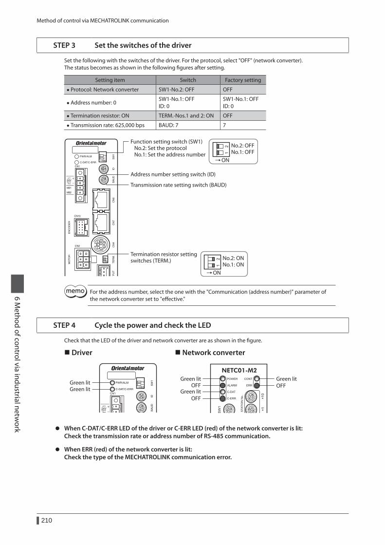
Method of control via MECHATROLINK communication
210
6 Method of control via industrial netw
ork
STEP 3 Set the switches of the driver
Set the following with the switches of the driver. For the protocol, select "OFF" (network converter).The status becomes as shown in the following figures after setting.
Setting item Switch Factory setting
• Protocol: Network converter SW1-No.2: OFF OFF
• Address number: 0SW1-No.1: OFF ID: 0
SW1-No.1: OFF ID: 0
• Termination resistor: ON TERM.-Nos.1 and 2: ON OFF
• Transmission rate: 625,000 bps BAUD: 7 7
ON
ON
Address number setting switch (ID)
Termination resistor settingswitches (TERM.)
Transmission rate setting switch (BAUD)
Function setting switch (SW1) No.2: Set the protocol No.1: Set the address number
No.2: OFFNo.1: OFF
No.2: ONNo.1: ON
For the address number, select the one with the "Communication (address number)" parameter of the network converter set to "effective."
STEP 4 Cycle the power and check the LED
Check that the LED of the driver and network converter are as shown in the figure.
Driver Network converter
Green litGreen litOFFOFF
Green litOFF
Green litGreen lit
z When C-DAT/C-ERR LED of the driver or C-ERR LED (red) of the network converter is lit: Check the transmission rate or address number of RS-485 communication.
z When ERR (red) of the network converter is lit: Check the type of the MECHATROLINK communication error.
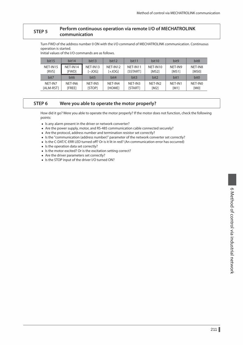
Method of control via MECHATROLINK communication
211
6 Method of control via industrial netw
ork
STEP 5 Perform continuous operation via remote I/O of MECHATROLINK communication
Turn FWD of the address number 0 ON with the I/O command of MECHATROLINK communication. Continuous operation is started.Initial values of the I/O commands are as follows.
bit15 bit14 bit13 bit12 bit11 bit10 bit9 bit8
NET-IN15 [RVS]
NET-IN14 [FWD]
NET-IN13 [−JOG]
NET-IN12 [+JOG]
NET-IN11 [SSTART]
NET-IN10 [MS2]
NET-IN9 [MS1]
NET-IN8 [MS0]
bit7 bit6 bit5 bit4 bit3 bit2 bit1 bit0
NET-IN7 [ALM-RST]
NET-IN6 [FREE]
NET-IN5 [STOP]
NET-IN4 [HOME]
NET-IN3 [START]
NET-IN2 [M2]
NET-IN1 [M1]
NET-IN0 [M0]
STEP 6 Were you able to operate the motor properly?
How did it go? Were you able to operate the motor properly? If the motor does not function, check the following points:
• Is any alarm present in the driver or network converter? • Are the power supply, motor, and RS-485 communication cable connected securely? • Are the protocol, address number and termination resistor set correctly? • Is the "communication (address number)" parameter of the network converter set correctly? • Is the C-DAT/C-ERR LED turned off? Or is it lit in red? (An communication error has occurred) • Is the operation data set correctly? • Is the motor excited? Or is the excitation setting correct? • Are the driver parameters set correctly? • Is the STOP input of the driver I/O turned ON?
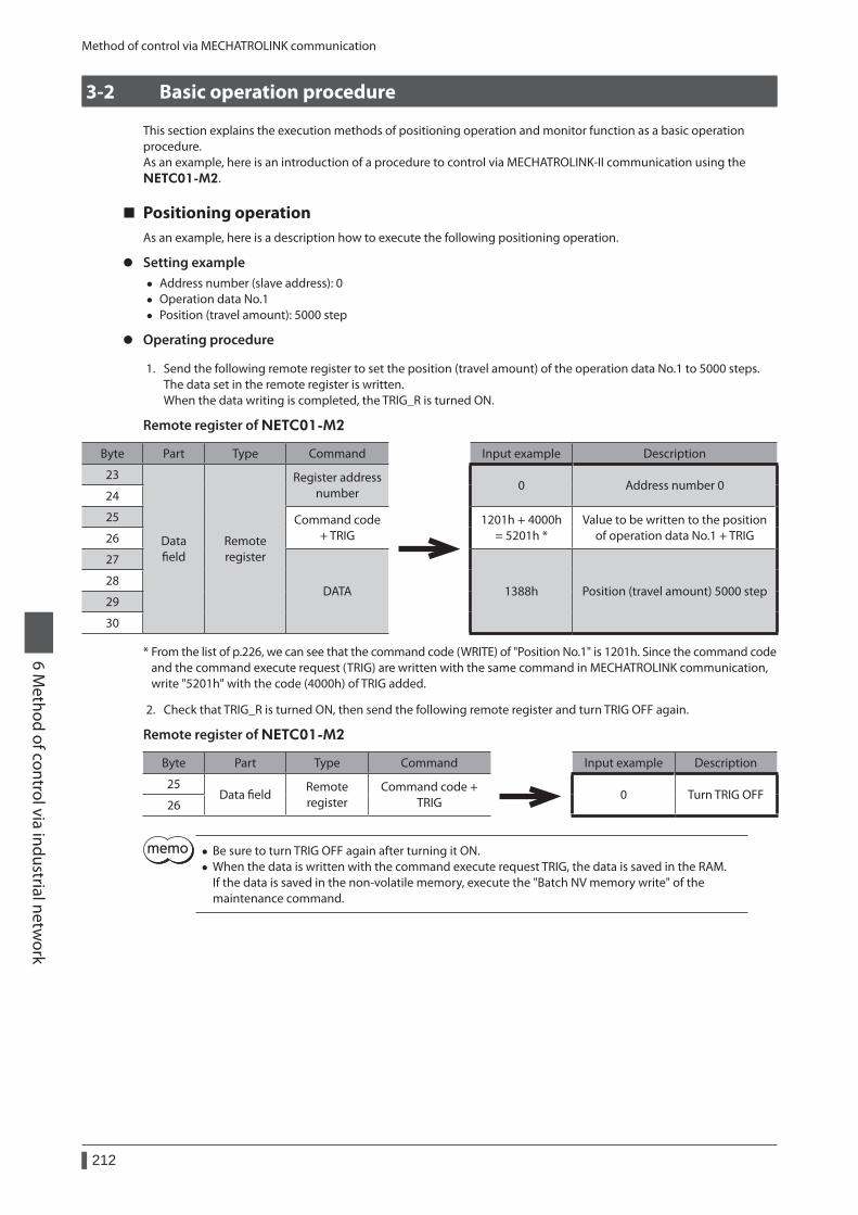
Method of control via MECHATROLINK communication
212
6 Method of control via industrial netw
ork
3-2 Basic operation procedure
This section explains the execution methods of positioning operation and monitor function as a basic operation procedure.As an example, here is an introduction of a procedure to control via MECHATROLINK-II communication using the NETC01-M2.
Positioning operationAs an example, here is a description how to execute the following positioning operation.
z Setting example • Address number (slave address): 0 • Operation data No.1 • Position (travel amount): 5000 step
z Operating procedure
1. Send the following remote register to set the position (travel amount) of the operation data No.1 to 5000 steps.The data set in the remote register is written.When the data writing is completed, the TRIG_R is turned ON.
Remote register of NETC01-M2
Byte Part Type Command Input example Description
23
Data field
Remote register
Register address number
0 Address number 024
25 Command code + TRIG
1201h + 4000h = 5201h *
Value to be written to the position of operation data No.1 + TRIG26
27
DATA 1388h Position (travel amount) 5000 step28
29
30
* From the list of p.226, we can see that the command code (WRITE) of "Position No.1" is 1201h. Since the command code and the command execute request (TRIG) are written with the same command in MECHATROLINK communication, write "5201h" with the code (4000h) of TRIG added.
2. Check that TRIG_R is turned ON, then send the following remote register and turn TRIG OFF again.
Remote register of NETC01-M2
Byte Part Type Command Input example Description
25Data field
Remote register
Command code + TRIG
0 Turn TRIG OFF26
• Be sure to turn TRIG OFF again after turning it ON. • When the data is written with the command execute request TRIG, the data is saved in the RAM. If the data is saved in the non-volatile memory, execute the "Batch NV memory write" of the maintenance command.
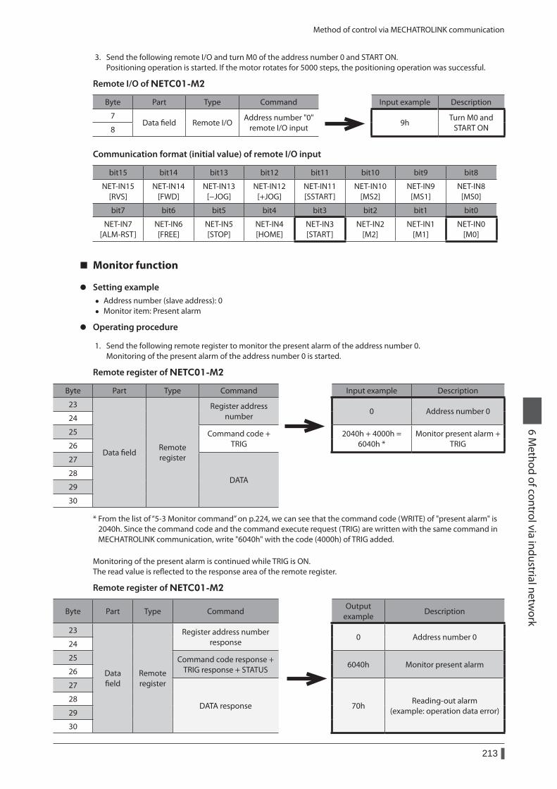
Method of control via MECHATROLINK communication
213
6 Method of control via industrial netw
ork
3. Send the following remote I/O and turn M0 of the address number 0 and START ON.Positioning operation is started. If the motor rotates for 5000 steps, the positioning operation was successful.
Remote I/O of NETC01-M2
Byte Part Type Command Input example Description
7Data field Remote I/O
Address number "0" remote I/O input
9hTurn M0 and
START ON8
Communication format (initial value) of remote I/O input
bit15 bit14 bit13 bit12 bit11 bit10 bit9 bit8
NET-IN15 [RVS]
NET-IN14 [FWD]
NET-IN13 [−JOG]
NET-IN12 [+JOG]
NET-IN11 [SSTART]
NET-IN10 [MS2]
NET-IN9 [MS1]
NET-IN8 [MS0]
bit7 bit6 bit5 bit4 bit3 bit2 bit1 bit0
NET-IN7 [ALM-RST]
NET-IN6 [FREE]
NET-IN5 [STOP]
NET-IN4 [HOME]
NET-IN3 [START]
NET-IN2 [M2]
NET-IN1 [M1]
NET-IN0 [M0]
Monitor function
z Setting example • Address number (slave address): 0 • Monitor item: Present alarm
z Operating procedure
1. Send the following remote register to monitor the present alarm of the address number 0.Monitoring of the present alarm of the address number 0 is started.
Remote register of NETC01-M2
Byte Part Type Command Input example Description
23
Data fieldRemote register
Register address number
0 Address number 024
25 Command code + TRIG
2040h + 4000h = 6040h *
Monitor present alarm + TRIG26
27
DATA28
29
30
* From the list of “5-3 Monitor command” on p.224, we can see that the command code (WRITE) of "present alarm" is 2040h. Since the command code and the command execute request (TRIG) are written with the same command in MECHATROLINK communication, write "6040h" with the code (4000h) of TRIG added.
Monitoring of the present alarm is continued while TRIG is ON.The read value is reflected to the response area of the remote register.
Remote register of NETC01-M2
Byte Part Type CommandOutput
exampleDescription
23
Data field
Remote register
Register address number response
0 Address number 024
25 Command code response + TRIG response + STATUS
6040h Monitor present alarm26
27
DATA response 70hReading-out alarm
(example: operation data error)28
29
30

Method of control via MECHATROLINK communication
214
6 Method of control via industrial netw
ork
2. To end the monitor, send the following remote I/O to turn the TRIG OFF again.
Remote register of NETC01-M2
Byte Part Type Command Input example Description
25Data field
Remote register
Command code + TRIG
0 Turn TRIG OFF26
In MECHATROLINK-II communication, only one type of data can be monitored for one driver because of the performance of the network converter. To monitor drivers with multiple axes, change the address number before executing monitoring.
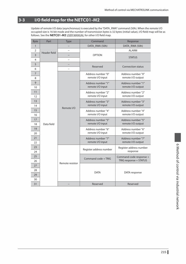
Method of control via MECHATROLINK communication
215
6 Method of control via industrial netw
ork
3-3 I/O field map for the NETC01-M2
Update of remote I/O data (asynchronous) is executed by the “DATA_RWA” command (50h). When the remote I/O occupied size is 16-bit mode and the number of transmission bytes is 32 bytes (initial value), I/O field map will be as follows. See the NETC01-M2 USER MANUAL for other I/O field map.
Byte Part Type Command Response
1
Header field
− DATA_RWA (50h) DATA_RWA (50h)
2 −
OPTION
ALARM
3 −STATUS
4 −
5
Data field
−Reserved Connection status
6 −
7
Remote I/O
Address number "0" remote I/O input
Address number "0" remote I/O output8
9 Address number "1" remote I/O input
Address number "1" remote I/O output10
11 Address number "2" remote I/O input
Address number "2" remote I/O output12
13 Address number "3" remote I/O input
Address number "3" remote I/O output14
15 Address number "4" remote I/O input
Address number "4" remote I/O output16
17 Address number "5" remote I/O input
Address number "5" remote I/O output18
19 Address number "6" remote I/O input
Address number "6" remote I/O output20
21 Address number "7" remote I/O input
Address number "7" remote I/O output22
23
Remote resistor
Register address numberRegister address number
response24
25Command code + TRIG
Command code response + TRIG response + STATUS26
27
DATA DATA response28
29
30
31 − Reserved Reserved
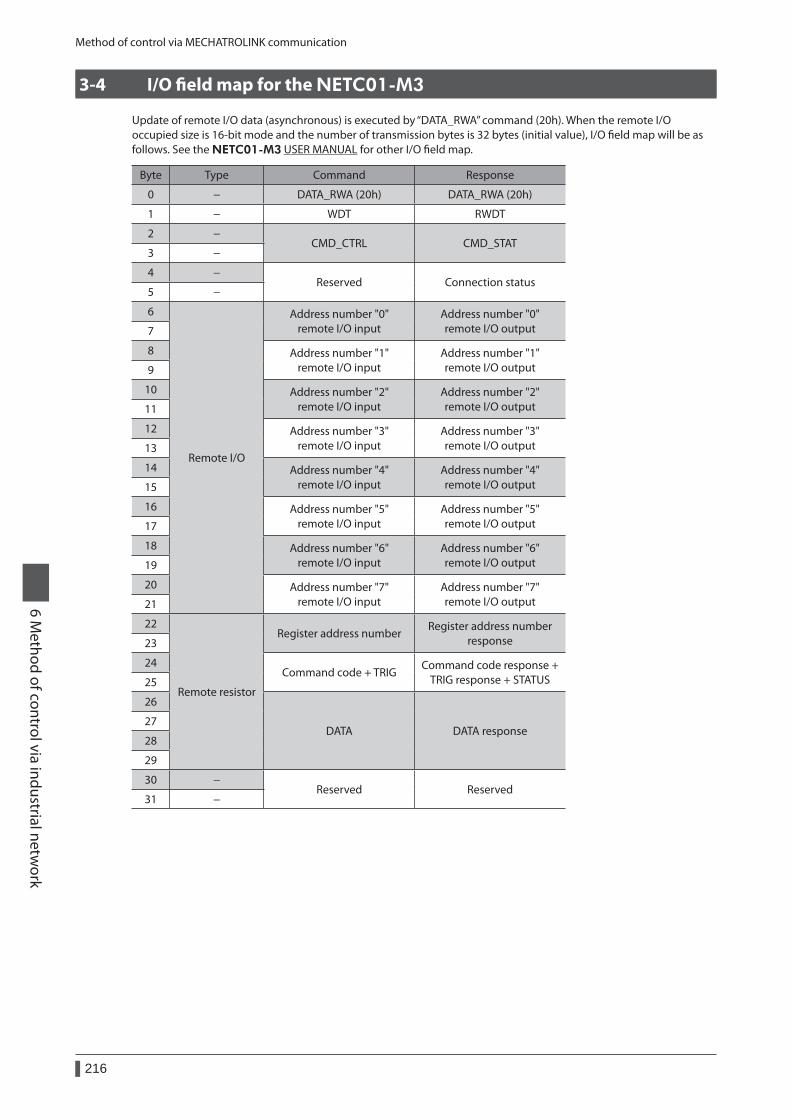
Method of control via MECHATROLINK communication
216
6 Method of control via industrial netw
ork
3-4 I/O field map for the NETC01-M3
Update of remote I/O data (asynchronous) is executed by “DATA_RWA” command (20h). When the remote I/O occupied size is 16-bit mode and the number of transmission bytes is 32 bytes (initial value), I/O field map will be as follows. See the NETC01-M3 USER MANUAL for other I/O field map.
Byte Type Command Response
0 − DATA_RWA (20h) DATA_RWA (20h)
1 − WDT RWDT
2 −CMD_CTRL CMD_STAT
3 −
4 −Reserved Connection status
5 −
6
Remote I/O
Address number "0" remote I/O input
Address number "0" remote I/O output7
8 Address number "1" remote I/O input
Address number "1" remote I/O output9
10 Address number "2" remote I/O input
Address number "2" remote I/O output11
12 Address number "3" remote I/O input
Address number "3" remote I/O output13
14 Address number "4" remote I/O input
Address number "4" remote I/O output15
16 Address number "5" remote I/O input
Address number "5" remote I/O output17
18 Address number "6" remote I/O input
Address number "6" remote I/O output19
20 Address number "7" remote I/O input
Address number "7" remote I/O output21
22
Remote resistor
Register address numberRegister address number
response23
24Command code + TRIG
Command code response + TRIG response + STATUS25
26
DATA DATA response27
28
29
30 −Reserved Reserved
31 −
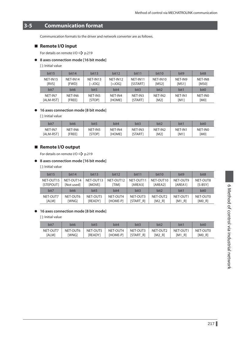
Method of control via MECHATROLINK communication
217
6 Method of control via industrial netw
ork
3-5 Communication format
Communication formats to the driver and network converter are as follows.
Remote I/O inputFor details on remote I/O _ p.219
z 8 axes connection mode [16 bit mode][ ]: Initial value
bit15 bit14 bit13 bit12 bit11 bit10 bit9 bit8
NET-IN15 [RVS]
NET-IN14 [FWD]
NET-IN13 [−JOG]
NET-IN12 [+JOG]
NET-IN11 [SSTART]
NET-IN10 [MS2]
NET-IN9 [MS1]
NET-IN8 [MS0]
bit7 bit6 bit5 bit4 bit3 bit2 bit1 bit0
NET-IN7 [ALM-RST]
NET-IN6 [FREE]
NET-IN5 [STOP]
NET-IN4 [HOME]
NET-IN3 [START]
NET-IN2 [M2]
NET-IN1 [M1]
NET-IN0 [M0]
z 16 axes connection mode [8 bit mode][ ]: Initial value
bit7 bit6 bit5 bit4 bit3 bit2 bit1 bit0
NET-IN7 [ALM-RST]
NET-IN6 [FREE]
NET-IN5 [STOP]
NET-IN4 [HOME]
NET-IN3 [START]
NET-IN2 [M2]
NET-IN1 [M1]
NET-IN0 [M0]
Remote I/O outputFor details on remote I/O _ p.219
z 8 axes connection mode [16 bit mode][ ]: Initial value
bit15 bit14 bit13 bit12 bit11 bit10 bit9 bit8
NET-OUT15 [STEPOUT]
NET-OUT14 [Not used]
NET-OUT13 [MOVE]
NET-OUT12 [TIM]
NET-OUT11 [AREA3]
NET-OUT10 [AREA2]
NET-OUT9 [AREA1]
NET-OUT8 [S-BSY]
bit7 bit6 bit5 bit4 bit3 bit2 bit1 bit0
NET-OUT7 [ALM]
NET-OUT6 [WNG]
NET-OUT5 [READY]
NET-OUT4 [HOME-P]
NET-OUT3 [START_R]
NET-OUT2 [M2_R]
NET-OUT1 [M1_R]
NET-OUT0 [M0_R]
z 16 axes connection mode [8 bit mode][ ]: Initial value
bit7 bit6 bit5 bit4 bit3 bit2 bit1 bit0
NET-OUT7 [ALM]
NET-OUT6 [WNG]
NET-OUT5 [READY]
NET-OUT4 [HOME-P]
NET-OUT3 [START_R]
NET-OUT2 [M2_R]
NET-OUT1 [M1_R]
NET-OUT0 [M0_R]
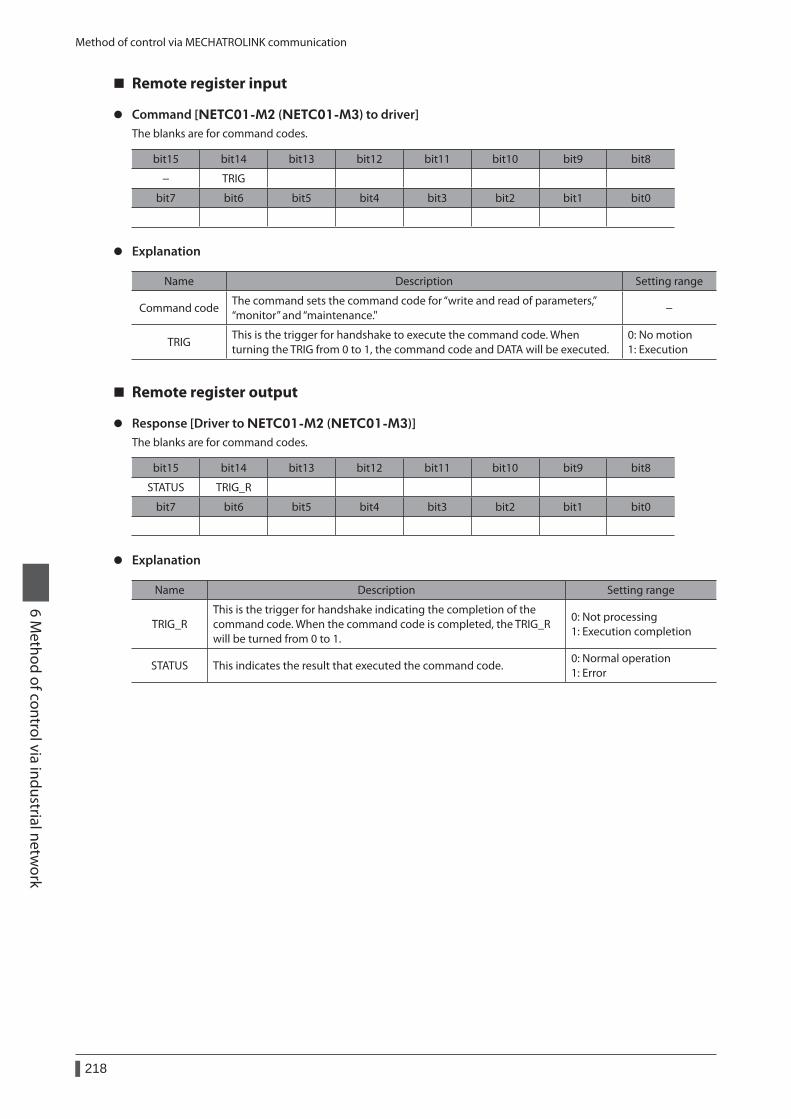
Method of control via MECHATROLINK communication
218
6 Method of control via industrial netw
ork
Remote register input
z Command [NETC01-M2 (NETC01-M3) to driver]The blanks are for command codes.
bit15 bit14 bit13 bit12 bit11 bit10 bit9 bit8
− TRIG
bit7 bit6 bit5 bit4 bit3 bit2 bit1 bit0
z Explanation
Name Description Setting range
Command codeThe command sets the command code for “write and read of parameters,” “monitor” and “maintenance."
−
TRIGThis is the trigger for handshake to execute the command code. When turning the TRIG from 0 to 1, the command code and DATA will be executed.
0: No motion 1: Execution
Remote register output
z Response [Driver to NETC01-M2 (NETC01-M3)]The blanks are for command codes.
bit15 bit14 bit13 bit12 bit11 bit10 bit9 bit8
STATUS TRIG_R
bit7 bit6 bit5 bit4 bit3 bit2 bit1 bit0
z Explanation
Name Description Setting range
TRIG_RThis is the trigger for handshake indicating the completion of the command code. When the command code is completed, the TRIG_R will be turned from 0 to 1.
0: Not processing 1: Execution completion
STATUS This indicates the result that executed the command code.0: Normal operation 1: Error
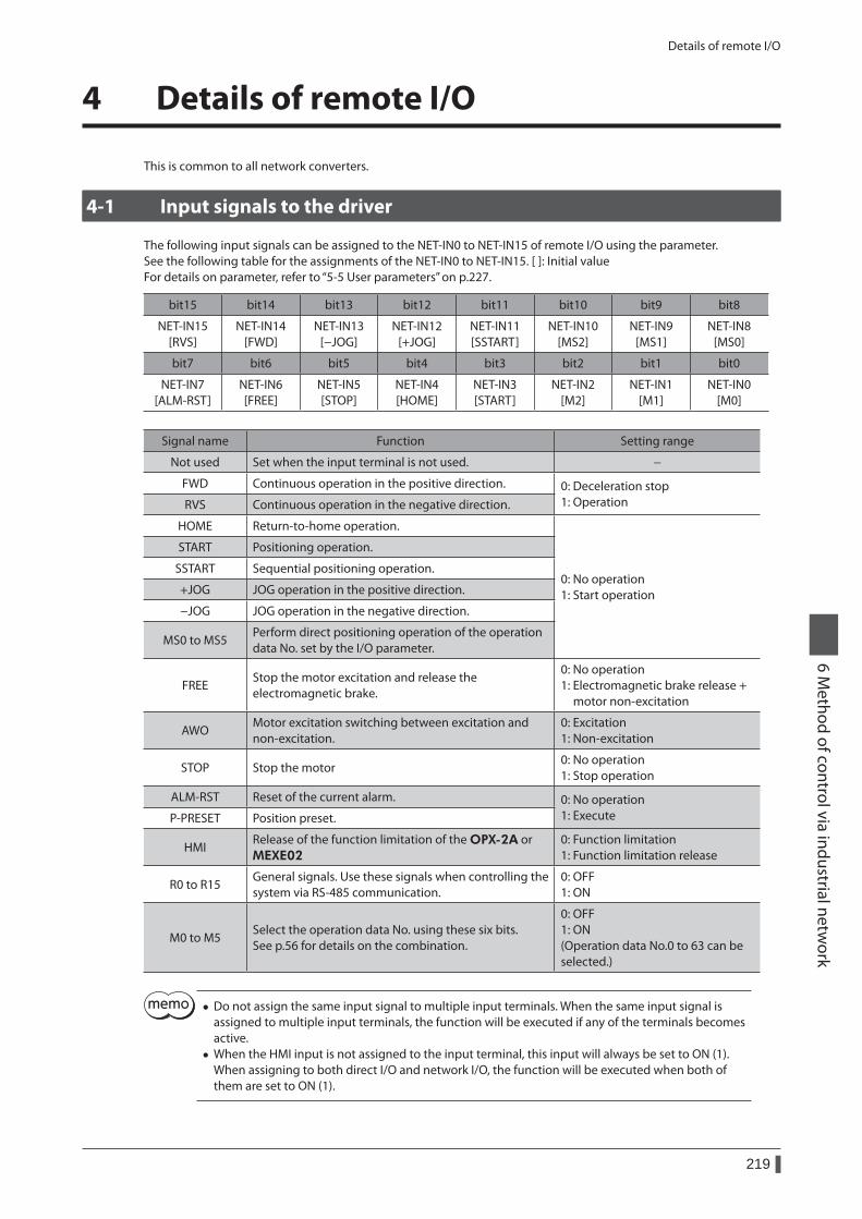
Details of remote I/O
219
6 Method of control via industrial netw
ork
4 Details of remote I/O
This is common to all network converters.
4-1 Input signals to the driver
The following input signals can be assigned to the NET-IN0 to NET-IN15 of remote I/O using the parameter.See the following table for the assignments of the NET-IN0 to NET-IN15. [ ]: Initial valueFor details on parameter, refer to “5-5 User parameters” on p.227.
bit15 bit14 bit13 bit12 bit11 bit10 bit9 bit8
NET-IN15 [RVS]
NET-IN14 [FWD]
NET-IN13 [−JOG]
NET-IN12 [+JOG]
NET-IN11 [SSTART]
NET-IN10 [MS2]
NET-IN9 [MS1]
NET-IN8 [MS0]
bit7 bit6 bit5 bit4 bit3 bit2 bit1 bit0
NET-IN7 [ALM-RST]
NET-IN6 [FREE]
NET-IN5 [STOP]
NET-IN4 [HOME]
NET-IN3 [START]
NET-IN2 [M2]
NET-IN1 [M1]
NET-IN0 [M0]
Signal name Function Setting range
Not used Set when the input terminal is not used. −
FWD Continuous operation in the positive direction. 0: Deceleration stop 1: OperationRVS Continuous operation in the negative direction.
HOME Return-to-home operation.
0: No operation 1: Start operation
START Positioning operation.
SSTART Sequential positioning operation.
+JOG JOG operation in the positive direction.
−JOG JOG operation in the negative direction.
MS0 to MS5Perform direct positioning operation of the operation data No. set by the I/O parameter.
FREEStop the motor excitation and release the electromagnetic brake.
0: No operation 1: Electromagnetic brake release + motor non-excitation
AWOMotor excitation switching between excitation and non-excitation.
0: Excitation 1: Non-excitation
STOP Stop the motor0: No operation 1: Stop operation
ALM-RST Reset of the current alarm. 0: No operation 1: ExecuteP-PRESET Position preset.
HMIRelease of the function limitation of the OPX-2A or MEXE02
0: Function limitation 1: Function limitation release
R0 to R15General signals. Use these signals when controlling the system via RS-485 communication.
0: OFF 1: ON
M0 to M5Select the operation data No. using these six bits. See p.56 for details on the combination.
0: OFF 1: ON (Operation data No.0 to 63 can be selected.)
• Do not assign the same input signal to multiple input terminals. When the same input signal is assigned to multiple input terminals, the function will be executed if any of the terminals becomes active.
• When the HMI input is not assigned to the input terminal, this input will always be set to ON (1). When assigning to both direct I/O and network I/O, the function will be executed when both of them are set to ON (1).
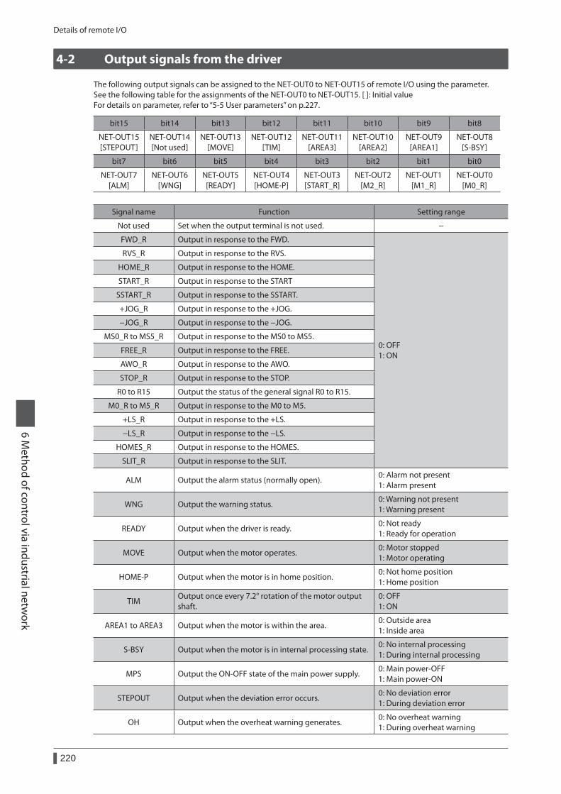
Details of remote I/O
220
6 Method of control via industrial netw
ork
4-2 Output signals from the driver
The following output signals can be assigned to the NET-OUT0 to NET-OUT15 of remote I/O using the parameter.See the following table for the assignments of the NET-OUT0 to NET-OUT15. [ ]: Initial valueFor details on parameter, refer to “5-5 User parameters” on p.227.
bit15 bit14 bit13 bit12 bit11 bit10 bit9 bit8
NET-OUT15 [STEPOUT]
NET-OUT14 [Not used]
NET-OUT13 [MOVE]
NET-OUT12 [TIM]
NET-OUT11 [AREA3]
NET-OUT10 [AREA2]
NET-OUT9 [AREA1]
NET-OUT8 [S-BSY]
bit7 bit6 bit5 bit4 bit3 bit2 bit1 bit0
NET-OUT7 [ALM]
NET-OUT6 [WNG]
NET-OUT5 [READY]
NET-OUT4 [HOME-P]
NET-OUT3 [START_R]
NET-OUT2 [M2_R]
NET-OUT1 [M1_R]
NET-OUT0 [M0_R]
Signal name Function Setting range
Not used Set when the output terminal is not used. −
FWD_R Output in response to the FWD.
0: OFF 1: ON
RVS_R Output in response to the RVS.
HOME_R Output in response to the HOME.
START_R Output in response to the START
SSTART_R Output in response to the SSTART.
+JOG_R Output in response to the +JOG.
−JOG_R Output in response to the −JOG.
MS0_R to MS5_R Output in response to the MS0 to MS5.
FREE_R Output in response to the FREE.
AWO_R Output in response to the AWO.
STOP_R Output in response to the STOP.
R0 to R15 Output the status of the general signal R0 to R15.
M0_R to M5_R Output in response to the M0 to M5.
+LS_R Output in response to the +LS.
−LS_R Output in response to the −LS.
HOMES_R Output in response to the HOMES.
SLIT_R Output in response to the SLIT.
ALM Output the alarm status (normally open).0: Alarm not present 1: Alarm present
WNG Output the warning status.0: Warning not present 1: Warning present
READY Output when the driver is ready.0: Not ready 1: Ready for operation
MOVE Output when the motor operates.0: Motor stopped 1: Motor operating
HOME-P Output when the motor is in home position.0: Not home position 1: Home position
TIMOutput once every 7.2° rotation of the motor output shaft.
0: OFF 1: ON
AREA1 to AREA3 Output when the motor is within the area.0: Outside area 1: Inside area
S-BSY Output when the motor is in internal processing state.0: No internal processing 1: During internal processing
MPS Output the ON-OFF state of the main power supply.0: Main power-OFF 1: Main power-ON
STEPOUT Output when the deviation error occurs.0: No deviation error 1: During deviation error
OH Output when the overheat warning generates.0: No overheat warning 1: During overheat warning

Details of remote I/O
221
6 Method of control via industrial netw
ork
Signal name Function Setting range
ZSGOutput when the ENC-Z input signal is input from the encoder.
0: ENC-Z input not used 1: ENC-Z input used
MBC Output the electromagnetic brake status.0: Electromagnetic brake hold 1: Electromagnetic brake release
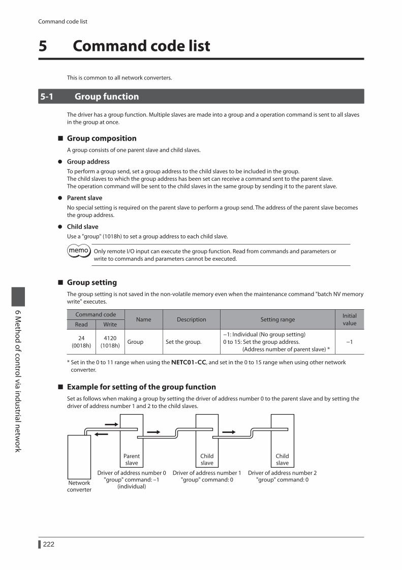
Command code list
222
6 Method of control via industrial netw
ork
5 Command code list
This is common to all network converters.
5-1 Group function
The driver has a group function. Multiple slaves are made into a group and a operation command is sent to all slaves in the group at once.
Group compositionA group consists of one parent slave and child slaves.
z Group addressTo perform a group send, set a group address to the child slaves to be included in the group.The child slaves to which the group address has been set can receive a command sent to the parent slave.The operation command will be sent to the child slaves in the same group by sending it to the parent slave.
z Parent slaveNo special setting is required on the parent slave to perform a group send. The address of the parent slave becomes the group address.
z Child slaveUse a "group" (1018h) to set a group address to each child slave.
Only remote I/O input can execute the group function. Read from commands and parameters or write to commands and parameters cannot be executed.
Group settingThe group setting is not saved in the non-volatile memory even when the maintenance command "batch NV memory write" executes.
Command codeName Description Setting range
Initial valueRead Write
24 (0018h)
4120 (1018h)
Group Set the group.−1: Individual (No group setting) 0 to 15: Set the group address. (Address number of parent slave) *
−1
* Set in the 0 to 11 range when using the NETC01-CC, and set in the 0 to 15 range when using other network converter.
Example for setting of the group functionSet as follows when making a group by setting the driver of address number 0 to the parent slave and by setting the driver of address number 1 and 2 to the child slaves.
Networkconverter
Driver of address number 0"group" command: -1
(individual)
Driver of address number 1"group" command: 0
Driver of address number 2"group" command: 0
Parentslave
Childslave
Childslave
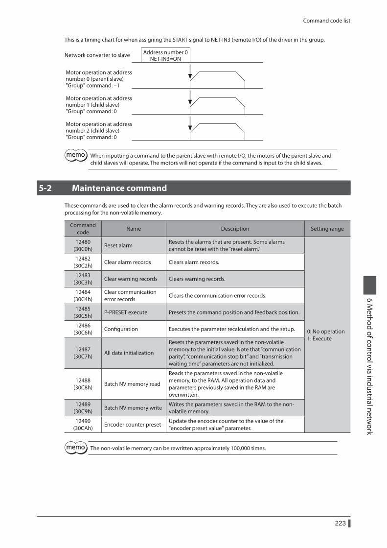
Command code list
223
6 Method of control via industrial netw
ork
This is a timing chart for when assigning the START signal to NET-IN3 (remote I/O) of the driver in the group.
Address number 0NET-IN3=ON
Motor operation at addressnumber 0 (parent slave)"Group" command: -1
Motor operation at addressnumber 1 (child slave)"Group" command: 0
Motor operation at addressnumber 2 (child slave)"Group" command: 0
Network converter to slave
When inputting a command to the parent slave with remote I/O, the motors of the parent slave and child slaves will operate. The motors will not operate if the command is input to the child slaves.
5-2 Maintenance command
These commands are used to clear the alarm records and warning records. They are also used to execute the batch processing for the non-volatile memory.
Command code
Name Description Setting range
12480 (30C0h)
Reset alarmResets the alarms that are present. Some alarms cannot be reset with the “reset alarm.”
0: No operation 1: Execute
12482 (30C2h)
Clear alarm records Clears alarm records.
12483 (30C3h)
Clear warning records Clears warning records.
12484 (30C4h)
Clear communication error records
Clears the communication error records.
12485 (30C5h)
P-PRESET execute Presets the command position and feedback position.
12486 (30C6h)
Configuration Executes the parameter recalculation and the setup.
12487 (30C7h)
All data initialization
Resets the parameters saved in the non-volatile memory to the initial value. Note that “communication parity”, “communication stop bit” and “transmission waiting time” parameters are not initialized.
12488 (30C8h)
Batch NV memory read
Reads the parameters saved in the non-volatile memory, to the RAM. All operation data and parameters previously saved in the RAM are overwritten.
12489 (30C9h)
Batch NV memory writeWrites the parameters saved in the RAM to the non-volatile memory.
12490 (30CAh)
Encoder counter presetUpdate the encoder counter to the value of the "encoder preset value" parameter.
The non-volatile memory can be rewritten approximately 100,000 times.
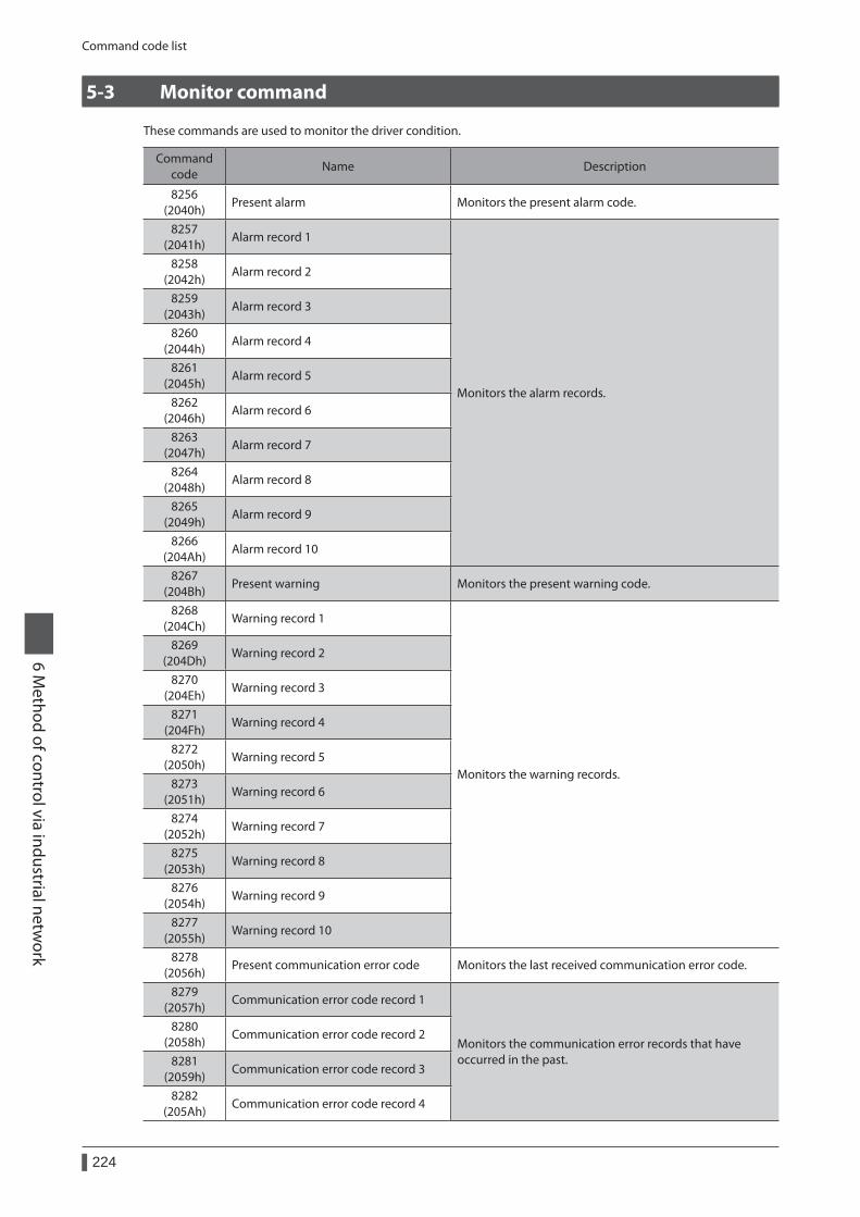
Command code list
224
6 Method of control via industrial netw
ork
5-3 Monitor command
These commands are used to monitor the driver condition.
Command code
Name Description
8256 (2040h)
Present alarm Monitors the present alarm code.
8257 (2041h)
Alarm record 1
Monitors the alarm records.
8258 (2042h)
Alarm record 2
8259 (2043h)
Alarm record 3
8260 (2044h)
Alarm record 4
8261 (2045h)
Alarm record 5
8262 (2046h)
Alarm record 6
8263 (2047h)
Alarm record 7
8264 (2048h)
Alarm record 8
8265 (2049h)
Alarm record 9
8266 (204Ah)
Alarm record 10
8267 (204Bh)
Present warning Monitors the present warning code.
8268 (204Ch)
Warning record 1
Monitors the warning records.
8269 (204Dh)
Warning record 2
8270 (204Eh)
Warning record 3
8271 (204Fh)
Warning record 4
8272 (2050h)
Warning record 5
8273 (2051h)
Warning record 6
8274 (2052h)
Warning record 7
8275 (2053h)
Warning record 8
8276 (2054h)
Warning record 9
8277 (2055h)
Warning record 10
8278 (2056h)
Present communication error code Monitors the last received communication error code.
8279 (2057h)
Communication error code record 1
Monitors the communication error records that have occurred in the past.
8280 (2058h)
Communication error code record 2
8281 (2059h)
Communication error code record 3
8282 (205Ah)
Communication error code record 4
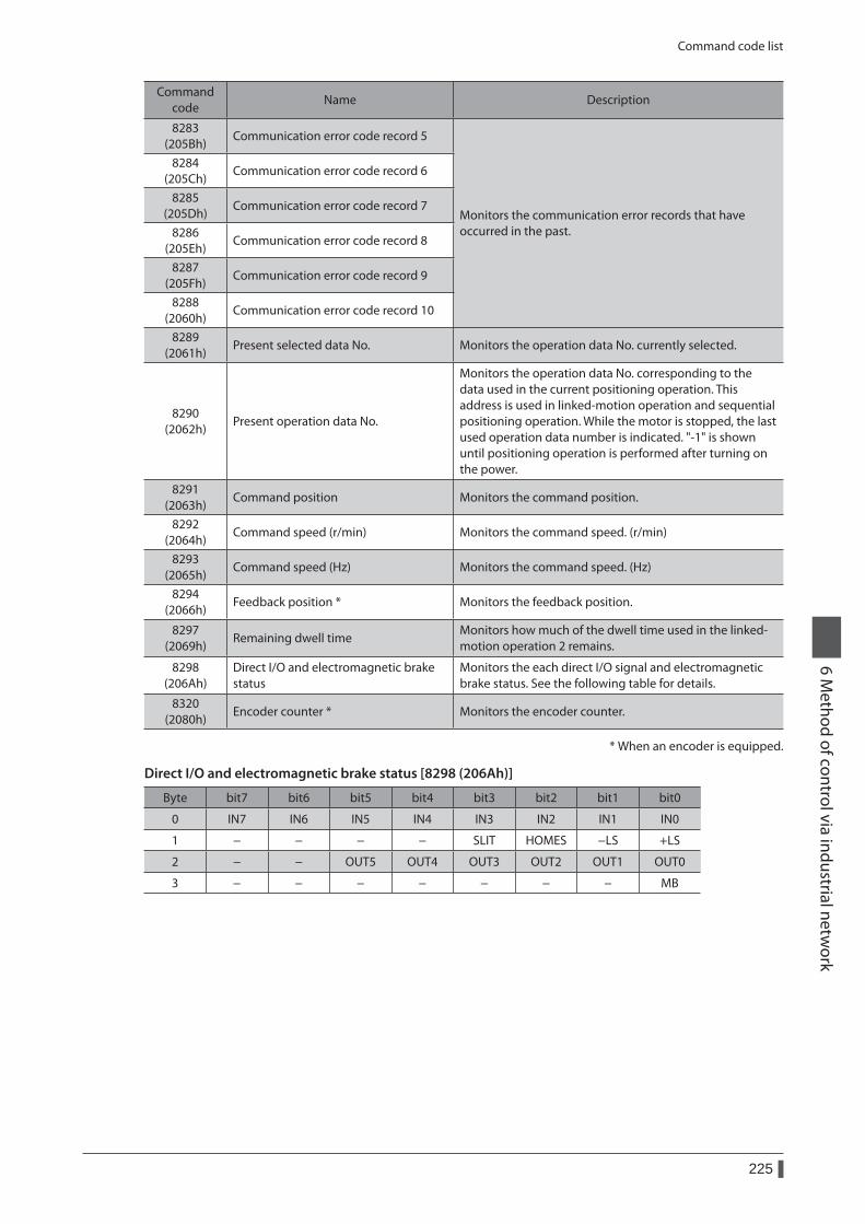
Command code list
225
6 Method of control via industrial netw
ork
Command code
Name Description
8283 (205Bh)
Communication error code record 5
Monitors the communication error records that have occurred in the past.
8284 (205Ch)
Communication error code record 6
8285 (205Dh)
Communication error code record 7
8286 (205Eh)
Communication error code record 8
8287 (205Fh)
Communication error code record 9
8288 (2060h)
Communication error code record 10
8289 (2061h)
Present selected data No. Monitors the operation data No. currently selected.
8290 (2062h)
Present operation data No.
Monitors the operation data No. corresponding to the data used in the current positioning operation. This address is used in linked-motion operation and sequential positioning operation. While the motor is stopped, the last used operation data number is indicated. "-1" is shown until positioning operation is performed after turning on the power.
8291 (2063h)
Command position Monitors the command position.
8292 (2064h)
Command speed (r/min) Monitors the command speed. (r/min)
8293 (2065h)
Command speed (Hz) Monitors the command speed. (Hz)
8294 (2066h)
Feedback position * Monitors the feedback position.
8297 (2069h)
Remaining dwell timeMonitors how much of the dwell time used in the linked-motion operation 2 remains.
8298 (206Ah)
Direct I/O and electromagnetic brake status
Monitors the each direct I/O signal and electromagnetic brake status. See the following table for details.
8320 (2080h)
Encoder counter * Monitors the encoder counter.
* When an encoder is equipped.
Direct I/O and electromagnetic brake status [8298 (206Ah)]
Byte bit7 bit6 bit5 bit4 bit3 bit2 bit1 bit0
0 IN7 IN6 IN5 IN4 IN3 IN2 IN1 IN0
1 − − − − SLIT HOMES −LS +LS
2 − − OUT5 OUT4 OUT3 OUT2 OUT1 OUT0
3 − − − − − − − MB
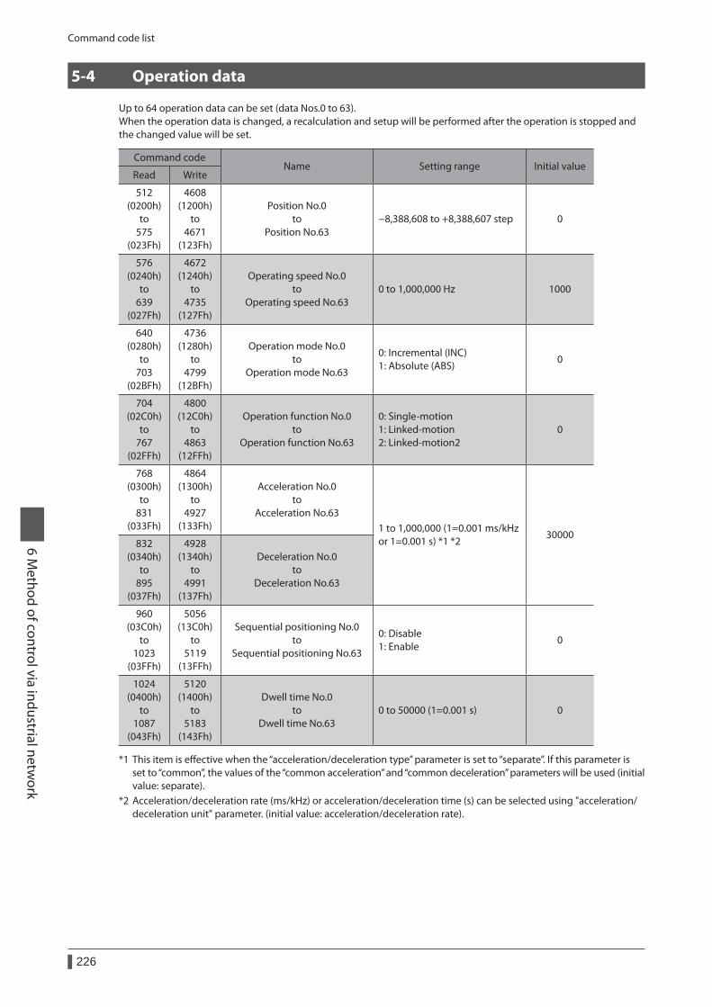
Command code list
226
6 Method of control via industrial netw
ork
5-4 Operation data
Up to 64 operation data can be set (data Nos.0 to 63).When the operation data is changed, a recalculation and setup will be performed after the operation is stopped and the changed value will be set.
Command codeName Setting range Initial value
Read Write
512 (0200h)
to 575
(023Fh)
4608 (1200h)
to 4671
(123Fh)
Position No.0 to
Position No.63−8,388,608 to +8,388,607 step 0
576 (0240h)
to 639
(027Fh)
4672 (1240h)
to 4735
(127Fh)
Operating speed No.0 to
Operating speed No.630 to 1,000,000 Hz 1000
640 (0280h)
to 703
(02BFh)
4736 (1280h)
to 4799
(12BFh)
Operation mode No.0 to
Operation mode No.63
0: Incremental (INC) 1: Absolute (ABS)
0
704 (02C0h)
to 767
(02FFh)
4800 (12C0h)
to 4863
(12FFh)
Operation function No.0 to
Operation function No.63
0: Single-motion 1: Linked-motion 2: Linked-motion2
0
768 (0300h)
to 831
(033Fh)
4864 (1300h)
to 4927
(133Fh)
Acceleration No.0 to
Acceleration No.631 to 1,000,000 (1=0.001 ms/kHz or 1=0.001 s) *1 *2
30000832
(0340h) to
895 (037Fh)
4928 (1340h)
to 4991
(137Fh)
Deceleration No.0 to
Deceleration No.63
960 (03C0h)
to 1023
(03FFh)
5056 (13C0h)
to 5119
(13FFh)
Sequential positioning No.0 to
Sequential positioning No.63
0: Disable 1: Enable
0
1024 (0400h)
to 1087
(043Fh)
5120 (1400h)
to 5183
(143Fh)
Dwell time No.0 to
Dwell time No.630 to 50000 (1=0.001 s) 0
*1 This item is effective when the “acceleration/deceleration type” parameter is set to “separate”. If this parameter is set to “common”, the values of the “common acceleration” and “common deceleration” parameters will be used (initial value: separate).
*2 Acceleration/deceleration rate (ms/kHz) or acceleration/deceleration time (s) can be selected using "acceleration/deceleration unit" parameter. (initial value: acceleration/deceleration rate).
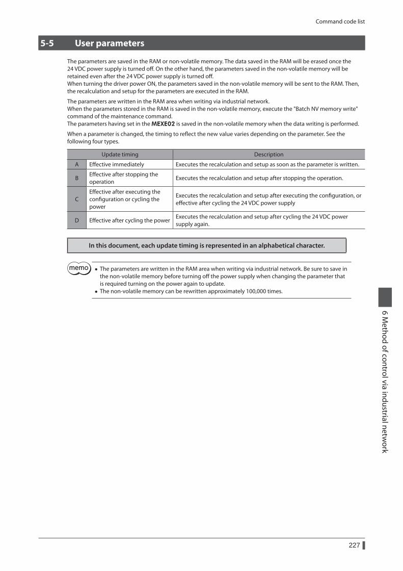
Command code list
227
6 Method of control via industrial netw
ork
5-5 User parameters
The parameters are saved in the RAM or non-volatile memory. The data saved in the RAM will be erased once the 24 VDC power supply is turned off. On the other hand, the parameters saved in the non-volatile memory will be retained even after the 24 VDC power supply is turned off.When turning the driver power ON, the parameters saved in the non-volatile memory will be sent to the RAM. Then, the recalculation and setup for the parameters are executed in the RAM.
The parameters are written in the RAM area when writing via industrial network.When the parameters stored in the RAM is saved in the non-volatile memory, execute the "Batch NV memory write" command of the maintenance command.The parameters having set in the MEXE02 is saved in the non-volatile memory when the data writing is performed.
When a parameter is changed, the timing to reflect the new value varies depending on the parameter. See the following four types.
Update timing Description
A Effective immediately Executes the recalculation and setup as soon as the parameter is written.
BEffective after stopping the operation
Executes the recalculation and setup after stopping the operation.
CEffective after executing the configuration or cycling the power
Executes the recalculation and setup after executing the configuration, or effective after cycling the 24 VDC power supply
D Effective after cycling the powerExecutes the recalculation and setup after cycling the 24 VDC power supply again.
In this document, each update timing is represented in an alphabetical character.
• The parameters are written in the RAM area when writing via industrial network. Be sure to save in the non-volatile memory before turning off the power supply when changing the parameter that is required turning on the power again to update.
• The non-volatile memory can be rewritten approximately 100,000 times.
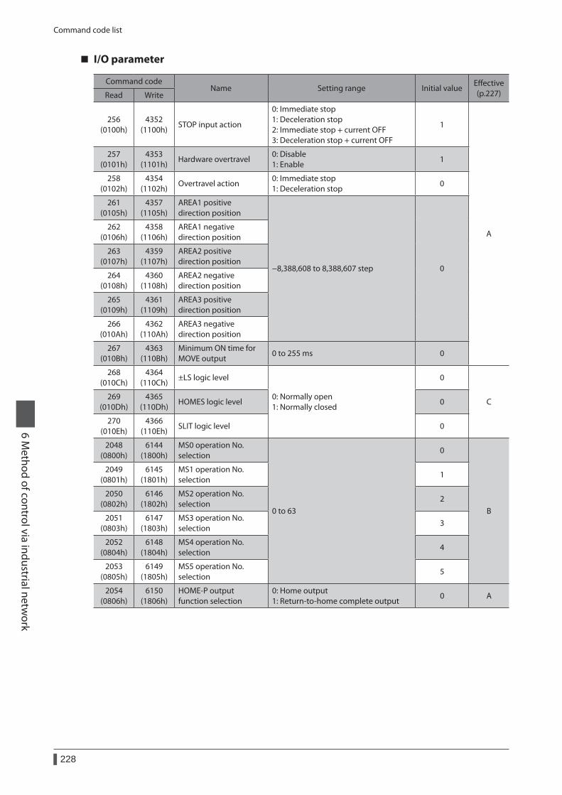
Command code list
228
6 Method of control via industrial netw
ork
I/O parameter
Command codeName Setting range Initial value
Effective (p.227)Read Write
256 (0100h)
4352 (1100h)
STOP input action
0: Immediate stop 1: Deceleration stop 2: Immediate stop + current OFF 3: Deceleration stop + current OFF
1
A
257 (0101h)
4353 (1101h)
Hardware overtravel0: Disable 1: Enable
1
258 (0102h)
4354 (1102h)
Overtravel action0: Immediate stop 1: Deceleration stop
0
261 (0105h)
4357 (1105h)
AREA1 positive direction position
−8,388,608 to 8,388,607 step 0
262 (0106h)
4358 (1106h)
AREA1 negative direction position
263 (0107h)
4359 (1107h)
AREA2 positive direction position
264 (0108h)
4360 (1108h)
AREA2 negative direction position
265 (0109h)
4361 (1109h)
AREA3 positive direction position
266 (010Ah)
4362 (110Ah)
AREA3 negative direction position
267 (010Bh)
4363 (110Bh)
Minimum ON time for MOVE output
0 to 255 ms 0
268 (010Ch)
4364 (110Ch)
±LS logic level
0: Normally open 1: Normally closed
0
C269
(010Dh)4365
(110Dh)HOMES logic level 0
270 (010Eh)
4366 (110Eh)
SLIT logic level 0
2048 (0800h)
6144 (1800h)
MS0 operation No. selection
0 to 63
0
B
2049 (0801h)
6145 (1801h)
MS1 operation No. selection
1
2050 (0802h)
6146 (1802h)
MS2 operation No. selection
2
2051 (0803h)
6147 (1803h)
MS3 operation No. selection
3
2052 (0804h)
6148 (1804h)
MS4 operation No. selection
4
2053 (0805h)
6149 (1805h)
MS5 operation No. selection
5
2054 (0806h)
6150 (1806h)
HOME-P output function selection
0: Home output 1: Return-to-home complete output
0 A
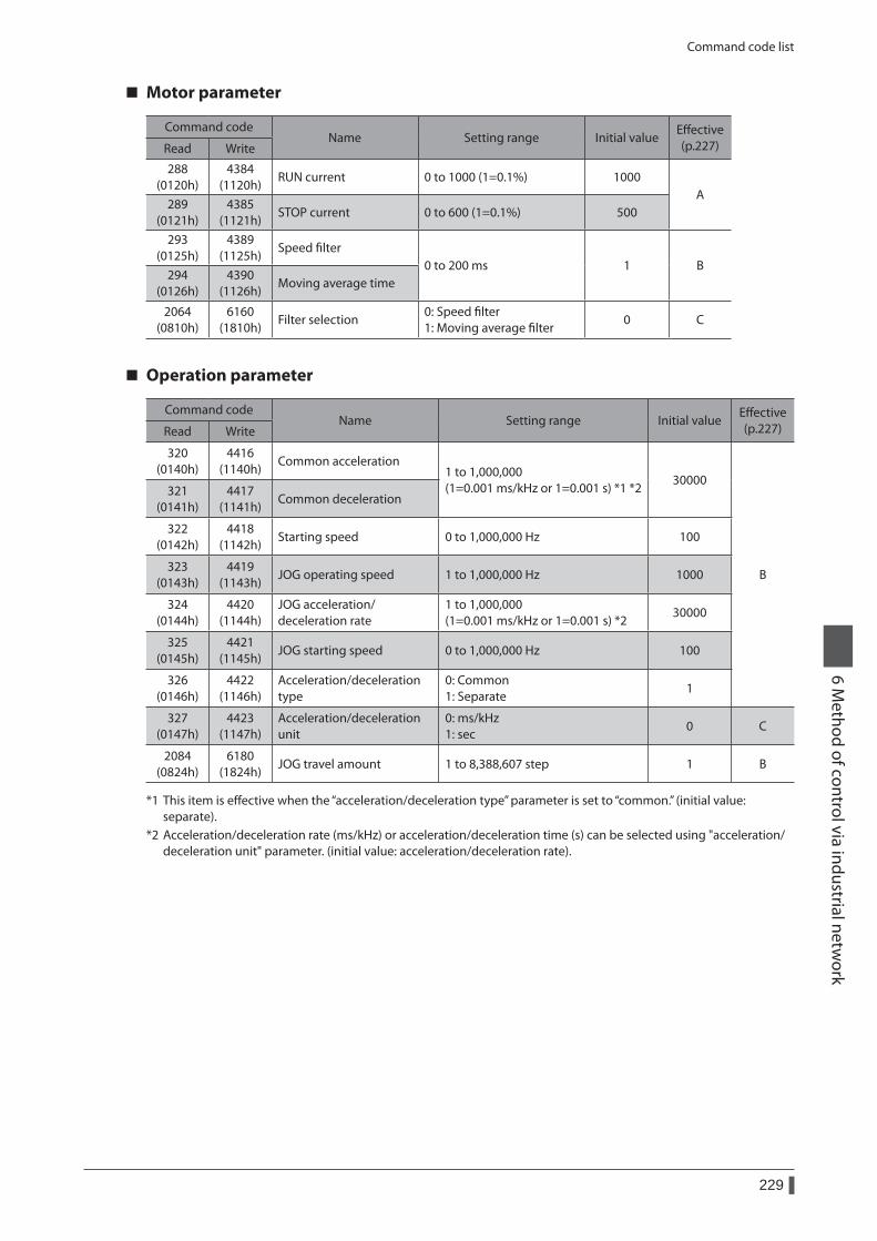
Command code list
229
6 Method of control via industrial netw
ork
Motor parameter
Command codeName Setting range Initial value
Effective (p.227)Read Write
288 (0120h)
4384 (1120h)
RUN current 0 to 1000 (1=0.1%) 1000A
289 (0121h)
4385 (1121h)
STOP current 0 to 600 (1=0.1%) 500
293 (0125h)
4389 (1125h)
Speed filter0 to 200 ms 1 B
294 (0126h)
4390 (1126h)
Moving average time
2064 (0810h)
6160 (1810h)
Filter selection0: Speed filter 1: Moving average filter
0 C
Operation parameter
Command codeName Setting range Initial value
Effective (p.227)Read Write
320 (0140h)
4416 (1140h)
Common acceleration1 to 1,000,000 (1=0.001 ms/kHz or 1=0.001 s) *1 *2
30000
B
321 (0141h)
4417 (1141h)
Common deceleration
322 (0142h)
4418 (1142h)
Starting speed 0 to 1,000,000 Hz 100
323 (0143h)
4419 (1143h)
JOG operating speed 1 to 1,000,000 Hz 1000
324 (0144h)
4420 (1144h)
JOG acceleration/deceleration rate
1 to 1,000,000 (1=0.001 ms/kHz or 1=0.001 s) *2
30000
325 (0145h)
4421 (1145h)
JOG starting speed 0 to 1,000,000 Hz 100
326 (0146h)
4422 (1146h)
Acceleration/deceleration type
0: Common 1: Separate
1
327 (0147h)
4423 (1147h)
Acceleration/deceleration unit
0: ms/kHz 1: sec
0 C
2084 (0824h)
6180 (1824h)
JOG travel amount 1 to 8,388,607 step 1 B
*1 This item is effective when the “acceleration/deceleration type” parameter is set to “common.” (initial value: separate).
*2 Acceleration/deceleration rate (ms/kHz) or acceleration/deceleration time (s) can be selected using "acceleration/deceleration unit" parameter. (initial value: acceleration/deceleration rate).
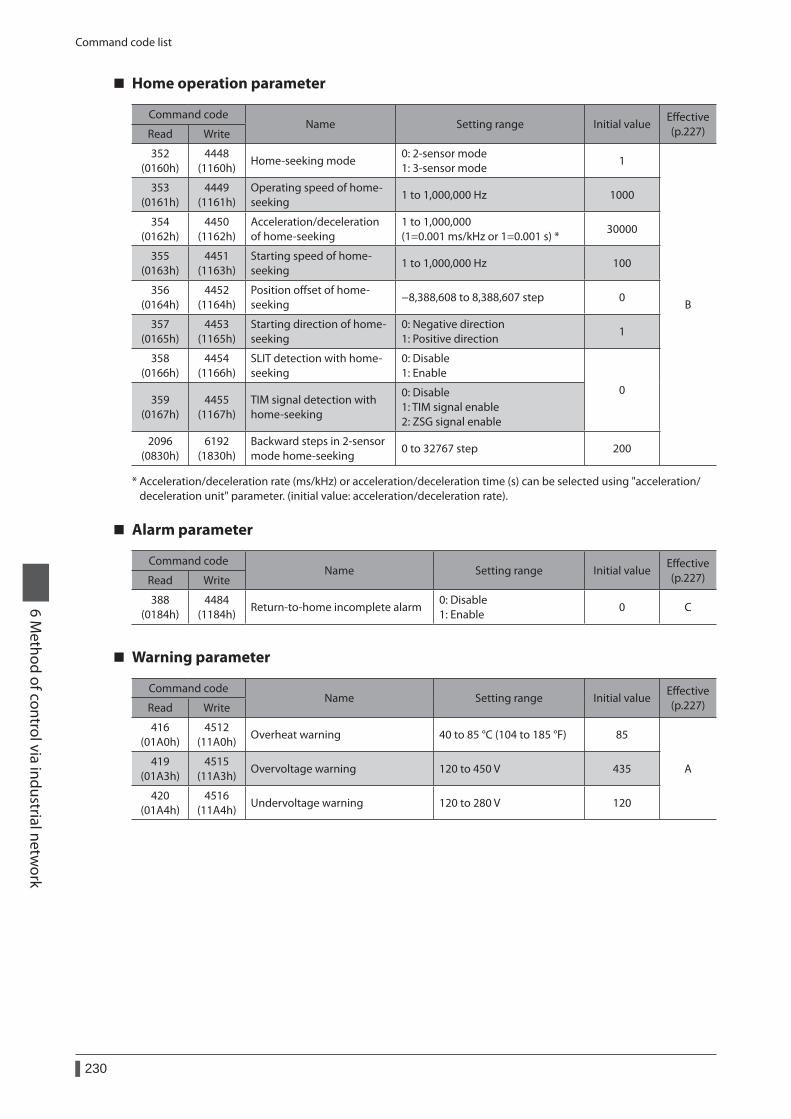
Command code list
230
6 Method of control via industrial netw
ork
Home operation parameter
Command codeName Setting range Initial value
Effective (p.227)Read Write
352 (0160h)
4448 (1160h)
Home-seeking mode0: 2-sensor mode 1: 3-sensor mode
1
B
353 (0161h)
4449 (1161h)
Operating speed of home-seeking
1 to 1,000,000 Hz 1000
354 (0162h)
4450 (1162h)
Acceleration/deceleration of home-seeking
1 to 1,000,000 (1=0.001 ms/kHz or 1=0.001 s) *
30000
355 (0163h)
4451 (1163h)
Starting speed of home-seeking
1 to 1,000,000 Hz 100
356 (0164h)
4452 (1164h)
Position offset of home-seeking
−8,388,608 to 8,388,607 step 0
357 (0165h)
4453 (1165h)
Starting direction of home-seeking
0: Negative direction 1: Positive direction
1
358 (0166h)
4454 (1166h)
SLIT detection with home-seeking
0: Disable 1: Enable
0359
(0167h)4455
(1167h)TIM signal detection with home-seeking
0: Disable 1: TIM signal enable 2: ZSG signal enable
2096 (0830h)
6192 (1830h)
Backward steps in 2-sensor mode home-seeking
0 to 32767 step 200
* Acceleration/deceleration rate (ms/kHz) or acceleration/deceleration time (s) can be selected using "acceleration/deceleration unit" parameter. (initial value: acceleration/deceleration rate).
Alarm parameter
Command codeName Setting range Initial value
Effective (p.227)Read Write
388 (0184h)
4484 (1184h)
Return-to-home incomplete alarm0: Disable 1: Enable
0 C
Warning parameter
Command codeName Setting range Initial value
Effective (p.227)Read Write
416 (01A0h)
4512 (11A0h)
Overheat warning 40 to 85 °C (104 to 185 °F) 85
A419
(01A3h)4515
(11A3h)Overvoltage warning 120 to 450 V 435
420 (01A4h)
4516 (11A4h)
Undervoltage warning 120 to 280 V 120
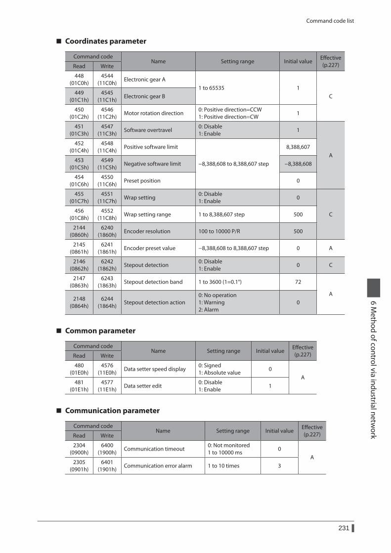
Command code list
231
6 Method of control via industrial netw
ork
Coordinates parameter
Command codeName Setting range Initial value
Effective (p.227)Read Write
448 (01C0h)
4544 (11C0h)
Electronic gear A1 to 65535 1
C449
(01C1h)4545
(11C1h)Electronic gear B
450 (01C2h)
4546 (11C2h)
Motor rotation direction0: Positive direction=CCW 1: Positive direction=CW
1
451 (01C3h)
4547 (11C3h)
Software overtravel0: Disable 1: Enable
1
A
452 (01C4h)
4548 (11C4h)
Positive software limit
−8,388,608 to 8,388,607 step
8,388,607
453 (01C5h)
4549 (11C5h)
Negative software limit −8,388,608
454 (01C6h)
4550 (11C6h)
Preset position 0
455 (01C7h)
4551 (11C7h)
Wrap setting0: Disable 1: Enable
0
C456
(01C8h)4552
(11C8h)Wrap setting range 1 to 8,388,607 step 500
2144 (0860h)
6240 (1860h)
Encoder resolution 100 to 10000 P/R 500
2145 (0861h)
6241 (1861h)
Encoder preset value −8,388,608 to 8,388,607 step 0 A
2146 (0862h)
6242 (1862h)
Stepout detection0: Disable 1: Enable
0 C
2147 (0863h)
6243 (1863h)
Stepout detection band 1 to 3600 (1=0.1°) 72
A2148
(0864h)6244
(1864h)Stepout detection action
0: No operation 1: Warning 2: Alarm
0
Common parameter
Command codeName Setting range Initial value
Effective (p.227)Read Write
480 (01E0h)
4576 (11E0h)
Data setter speed display0: Signed 1: Absolute value
0A
481 (01E1h)
4577 (11E1h)
Data setter edit0: Disable 1: Enable
1
Communication parameter
Command codeName Setting range Initial value
Effective (p.227)Read Write
2304 (0900h)
6400 (1900h)
Communication timeout0: Not monitored 1 to 10000 ms
0A
2305 (0901h)
6401 (1901h)
Communication error alarm 1 to 10 times 3
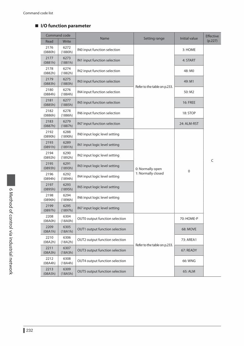
Command code list
232
6 Method of control via industrial netw
ork
I/O function parameter
Command codeName Setting range Initial value
Effective (p.227)Read Write
2176 (0880h)
6272 (1880h)
IN0 input function selection
Refer to the table on p.233.
3: HOME
C
2177 (0881h)
6273 (1881h)
IN1 input function selection 4: START
2178 (0882h)
6274 (1882h)
IN2 input function selection 48: M0
2179 (0883h)
6275 (1883h)
IN3 input function selection 49: M1
2180 (0884h)
6276 (1884h)
IN4 input function selection 50: M2
2181 (0885h)
6277 (1885h)
IN5 input function selection 16: FREE
2182 (0886h)
6278 (1886h)
IN6 input function selection 18: STOP
2183 (0887h)
6279 (1887h)
IN7 input function selection 24: ALM-RST
2192 (0890h)
6288 (1890h)
IN0 input logic level setting
0: Normally open 1: Normally closed
0
2193 (0891h)
6289 (1891h)
IN1 input logic level setting
2194 (0892h)
6290 (1892h)
IN2 input logic level setting
2195 (0893h)
6291 (1893h)
IN3 input logic level setting
2196 (0894h)
6292 (1894h)
IN4 input logic level setting
2197 (0895h)
6293 (1895h)
IN5 input logic level setting
2198 (0896h)
6294 (1896h)
IN6 input logic level setting
2199 (0897h)
6295 (1897h)
IN7 input logic level setting
2208 (08A0h)
6304 (18A0h)
OUT0 output function selection
Refer to the table on p.233.
70: HOME-P
2209 (08A1h)
6305 (18A1h)
OUT1 output function selection 68: MOVE
2210 (08A2h)
6306 (18A2h)
OUT2 output function selection 73: AREA1
2211 (08A3h)
6307 (18A3h)
OUT3 output function selection 67: READY
2212 (08A4h)
6308 (18A4h)
OUT4 output function selection 66: WNG
2213 (08A5h)
6309 (18A5h)
OUT5 output function selection 65: ALM
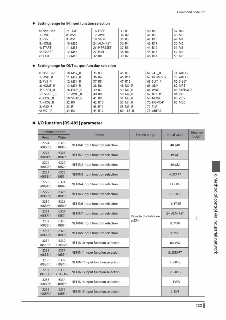
Command code list
233
6 Method of control via industrial netw
ork
z Setting range for IN input function selection
0: Not used 1: FWD 2: RVS 3: HOME 4: START 5: SSTART 6: +JOG
7: −JOG 8: MS0 9: MS1 10: MS2 11: MS3 12: MS4 13: MS5
16: FREE 17: AWO 18: STOP 24: ALM-RST 25: P-PRESET 27: HMI 32: R0
33: R1 34: R2 35: R3 36: R4 37: R5 38: R6 39: R7
40: R8 41: R9 42: R10 43: R11 44: R12 45: R13 46: R14
47: R15 48: M0 49: M1 50: M2 51: M3 52: M4 53: M5
z Setting range for OUT output function selection
0: Not used 1: FWD_R 2: RVS_R 3: HOME_R 4: START_R 5: SSTART_R 6: +JOG_R 7: −JOG_R 8: MS0_R 9: MS1_R
10: MS2_R 11: MS3_R 12: MS4_R 13: MS5_R 16: FREE_R 17: AWO_R 18: STOP_R 32: R0 33: R1 34: R2
35: R3 36: R4 37: R5 38: R6 39: R7 40: R8 41: R9 42: R10 43: R11 44: R12
45: R13 46: R14 47: R15 48: M0_R 49: M1_R 50: M2_R 51: M3_R 52: M4_R 53: M5_R 60: +LS_R
61: −LS_R 62: HOMES_R 63: SLIT_R 65: ALM 66: WNG 67: READY 68: MOVE 70: HOME-P 72: TIM 73: AREA1
74: AREA2 75: AREA3 80: S-BSY 82: MPS 83: STEPOUT 84: OH 85: ZSG 86: MBC
I/O function [RS-485] parameter
Command codeName Setting range Initial value
Effective (p.227)Read Write
2224 (08B0h)
6320 (18B0h)
NET-IN0 input function selection
Refer to the table on p.234.
48: M0
C
2225 (08B1h)
6321 (18B1h)
NET-IN1 input function selection 49: M1
2226 (08B2h)
6322 (18B2h)
NET-IN2 input function selection 50: M2
2227 (08B3h)
6323 (18B3h)
NET-IN3 input function selection 4: START
2228 (08B4h)
6324 (18B4h)
NET-IN4 input function selection 3: HOME
2229 (08B5h)
6325 (18B5h)
NET-IN5 input function selection 18: STOP
2230 (08B6h)
6326 (18B6h)
NET-IN6 input function selection 16: FREE
2231 (08B7h)
6327 (18B7h)
NET-IN7 input function selection 24: ALM-RST
2232 (08B8h)
6328 (18B8h)
NET-IN8 input function selection 8: MS0
2233 (08B9h)
6329 (18B9h)
NET-IN9 input function selection 9: MS1
2234 (08BAh)
6330 (18BAh)
NET-IN10 input function selection 10: MS2
2235 (08BBh)
6331 (18BBh)
NET-IN11 input function selection 5: SSTART
2236 (08BCh)
6332 (18BCh)
NET-IN12 input function selection 6: +JOG
2237 (08BDh)
6333 (18BDh)
NET-IN13 input function selection 7: −JOG
2238 (08BEh)
6334 (18BEh)
NET-IN14 input function selection 1: FWD
2239 (08BFh)
6335 (18BFh)
NET-IN15 input function selection 2: RVS
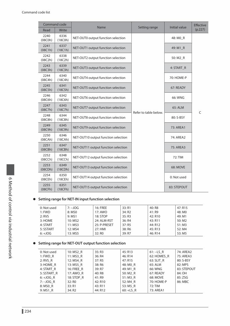
Command code list
234
6 Method of control via industrial netw
ork
Command codeName Setting range Initial value
Effective (p.227)Read Write
2240 (08C0h)
6336 (18C0h)
NET-OUT0 output function selection
Refer to table below.
48: M0_R
C
2241 (08C1h)
6337 (18C1h)
NET-OUT1 output function selection 49: M1_R
2242 (08C2h)
6338 (18C2h)
NET-OUT2 output function selection 50: M2_R
2243 (08C3h)
6339 (18C3h)
NET-OUT3 output function selection 4: START_R
2244 (08C4h)
6340 (18C4h)
NET-OUT4 output function selection 70: HOME-P
2245 (08C5h)
6341 (18C5h)
NET-OUT5 output function selection 67: READY
2246 (08C6h)
6342 (18C6h)
NET-OUT6 output function selection 66: WNG
2247 (08C7h)
6343 (18C7h)
NET-OUT7 output function selection 65: ALM
2248 (08C8h)
6344 (18C8h)
NET-OUT8 output function selection 80: S-BSY
2249 (08C9h)
6345 (18C9h)
NET-OUT9 output function selection 73: AREA1
2250 (08CAh)
6346 (18CAh)
NET-OUT10 output function selection 74: AREA2
2251 (08CBh)
6347 (18CBh)
NET-OUT11 output function selection 75: AREA3
2252 (08CCh)
6348 (18CCh)
NET-OUT12 output function selection 72: TIM
2253 (08CDh)
6349 (18CDh)
NET-OUT13 output function selection 68: MOVE
2254 (08CEh)
6350 (18CEh)
NET-OUT14 output function selection 0: Not used
2255 (08CFh)
6351 (18CFh)
NET-OUT15 output function selection 83: STEPOUT
z Setting range for NET-IN input function selection
0: Not used 1: FWD 2: RVS 3: HOME 4: START 5: SSTART 6: +JOG
7: −JOG 8: MS0 9: MS1 10: MS2 11: MS3 12: MS4 13: MS5
16: FREE 17: AWO 18: STOP 24: ALM-RST 25: P-PRESET 27: HMI 32: R0
33: R1 34: R2 35: R3 36: R4 37: R5 38: R6 39: R7
40: R8 41: R9 42: R10 43: R11 44: R12 45: R13 46: R14
47: R15 48: M0 49: M1 50: M2 51: M3 52: M4 53: M5
z Setting range for NET-OUT output function selection
0: Not used 1: FWD_R 2: RVS_R 3: HOME_R 4: START_R 5: SSTART_R 6: +JOG_R 7: −JOG_R 8: MS0_R 9: MS1_R
10: MS2_R 11: MS3_R 12: MS4_R 13: MS5_R 16: FREE_R 17: AWO_R 18: STOP_R 32: R0 33: R1 34: R2
35: R3 36: R4 37: R5 38: R6 39: R7 40: R8 41: R9 42: R10 43: R11 44: R12
45: R13 46: R14 47: R15 48: M0_R 49: M1_R 50: M2_R 51: M3_R 52: M4_R 53: M5_R 60: +LS_R
61: −LS_R 62: HOMES_R 63: SLIT_R 65: ALM 66: WNG 67: READY 68: MOVE 70: HOME-P 72: TIM 73: AREA1
74: AREA2 75: AREA3 80: S-BSY 82: MPS 83: STEPOUT 84: OH 85: ZSG 86: MBC
1 Overview of the OPX-2A ................................2361-1 Names and functions of parts ...................................237
1-2 How to read the display ..............................................237
1-3 OPX-2A error display ..................................................238
2 Screen transitions ...........................................240
3 Monitor mode .................................................2463-1 Overview of the monitor mode................................246
3-2 Monitor items .................................................................246
4 Data mode .......................................................2484-1 Setting items ...................................................................248
4-2 Setting example .............................................................250
4-3 Initialization of the selected operation data........251
4-4 Initialization of all operation data ...........................251
5 Parameter mode .............................................2525-1 Setting example .............................................................253
5-2 Parameter list ..................................................................254
5-3 Initializing parameters .................................................259
6 Test mode ........................................................2606-1 Overview of the test mode ........................................260
6-2 Direct I/O test ..................................................................261
6-3 JOG operation .................................................................261
6-4 Data select operation ...................................................261
6-5 Return-to-home operation ........................................262
6-6 Presetting the position ................................................262
6-7 Presetting the encoder counter ...............................262
6-8 Teaching ............................................................................262
7 Copy mode ......................................................2637-1 Overview of the copy mode ......................................263
7-2 Error of the copy mode................................................263
7 Operation using the OPX-2A
This chapter explains the overview and operation using the OPX-2A.
Table of contents
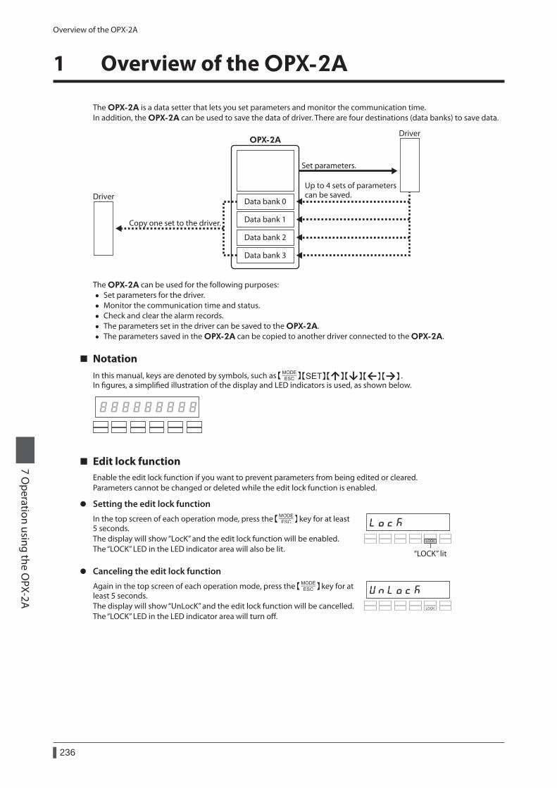
Overview of the OPX-2A
236
7 Operation using the O
PX-2A
1 Overview of the OPX-2A
The OPX-2A is a data setter that lets you set parameters and monitor the communication time.In addition, the OPX-2A can be used to save the data of driver. There are four destinations (data banks) to save data.
OPX-2A
Data bank 1
Data bank 0
Data bank 2
Data bank 3
Driver
Driver
Set parameters.
Up to 4 sets of parameters can be saved.
Copy one set to the driver.
The OPX-2A can be used for the following purposes: • Set parameters for the driver. • Monitor the communication time and status. • Check and clear the alarm records. • The parameters set in the driver can be saved to the OPX-2A. • The parameters saved in the OPX-2A can be copied to another driver connected to the OPX-2A.
NotationIn this manual, keys are denoted by symbols, such as .In figures, a simplified illustration of the display and LED indicators is used, as shown below.
Edit lock functionEnable the edit lock function if you want to prevent parameters from being edited or cleared.Parameters cannot be changed or deleted while the edit lock function is enabled.
z Setting the edit lock function
In the top screen of each operation mode, press the key for at least 5 seconds.The display will show “LocK” and the edit lock function will be enabled.The “LOCK” LED in the LED indicator area will also be lit. “LOCK” lit
z Canceling the edit lock function
Again in the top screen of each operation mode, press the key for at least 5 seconds.The display will show “UnLocK” and the edit lock function will be cancelled.The “LOCK” LED in the LED indicator area will turn off.
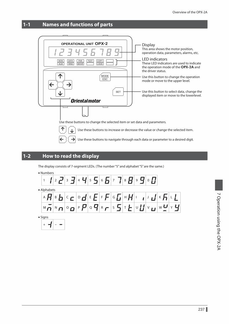
Overview of the OPX-2A
237
7 Operation using the O
PX-2A
1-1 Names and functions of parts
DisplayThis area shows the motor position, operation data, parameters, alarms, etc.
LED indicatorsThese LED indicators are used to indicate the operation mode of the OPX-2A and the driver status.
Use this button to select data, change the displayed item or move to the lowerlevel.
Use this button to change the operation mode or move to the upper level.
Use these buttons to change the selected item or set data and parameters.
Use these buttons to increase or decrease the value or change the selected item.
Use these buttons to navigate through each data or parameter to a desired digit.
1-2 How to read the display
The display consists of 7-segment LEDs. (The number “5” and alphabet “S” are the same.)
1 2 3 4 5 6 7 8 9 0
A
• Numbers
+ -
• Signs
• Alphabets
B C D E F G H I J K L
M N O P Q R S T U V W Y
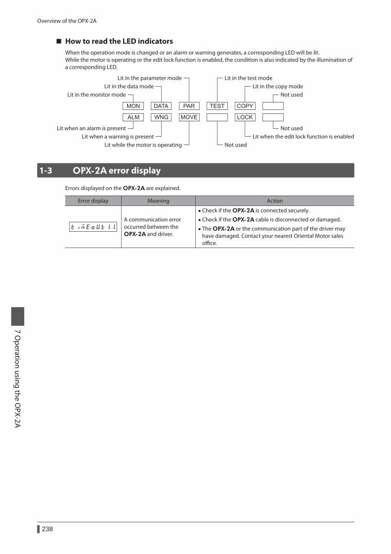
Overview of the OPX-2A
238
7 Operation using the O
PX-2A
How to read the LED indicatorsWhen the operation mode is changed or an alarm or warning generates, a corresponding LED will be lit.While the motor is operating or the edit lock function is enabled, the condition is also indicated by the illumination of a corresponding LED.
Lit in the copy modeLit in the test modeLit in the parameter mode
Lit in the data modeLit in the monitor mode
Lit when an alarm is presentLit when a warning is present
Lit while the motor is operating Not usedLit when the edit lock function is enabled
Not used
Not used
1-3 OPX-2A error display
Errors displayed on the OPX-2A are explained.
Error display Meaning Action
A communication error occurred between the OPX-2A and driver.
• Check if the OPX-2A is connected securely.
• Check if the OPX-2A cable is disconnected or damaged.
• The OPX-2A or the communication part of the driver may have damaged. Contact your nearest Oriental Motor sales office.

Overview of the OPX-2A
239
7 Operation using the O
PX-2A
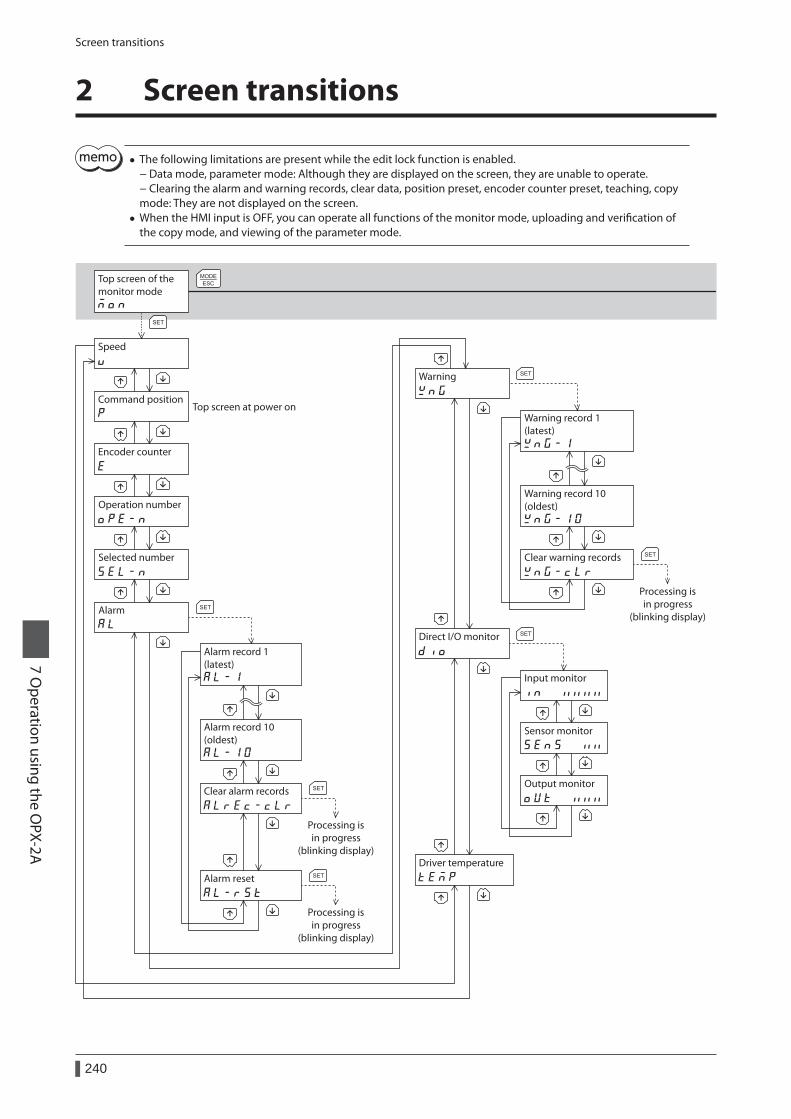
Screen transitions
240
7 Operation using the O
PX-2A
2 Screen transitions
• The following limitations are present while the edit lock function is enabled. − Data mode, parameter mode: Although they are displayed on the screen, they are unable to operate. − Clearing the alarm and warning records, clear data, position preset, encoder counter preset, teaching, copy mode: They are not displayed on the screen.
• When the HMI input is OFF, you can operate all functions of the monitor mode, uploading and verification of the copy mode, and viewing of the parameter mode.
Operation number
Selected number
Warning
Direct I/O monitor
Driver temperature
Speed
Command position
Encoder counter
Input monitor
Sensor monitor
Output monitor
Warning record 1(latest)
Warning record 10(oldest)
Clear warning records
Alarm
Alarm record 1 (latest)
Alarm record 10 (oldest)
Alarm reset
Clear alarm records
Processing isin progress
(blinking display)
Processing isin progress
(blinking display)
Processing isin progress
(blinking display)
Top screen of themonitor mode
Top screen at power on
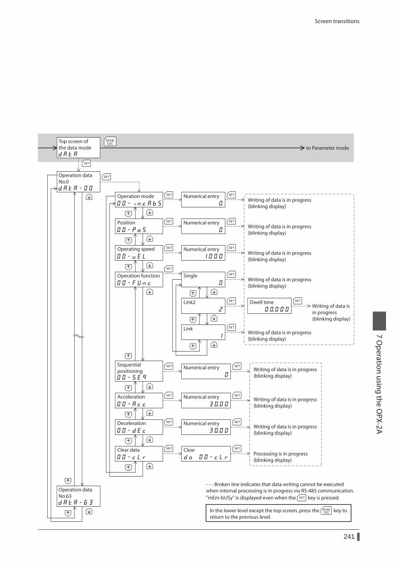
Screen transitions
241
7 Operation using the O
PX-2A
Operation dataNo.0
Operation dataNo.63
Top screen of the data mode to Parameter mode
Operation mode
Position
Operating speed
Operation function
Dwell time
Sequential positioning
Acceleration
Deceleration
Clear data Clear
Single
Link2
Link
Processing is in progress(blinking display)
Writing of data is in progress(blinking display)
Numerical entry
Writing of data is in progress(blinking display)
Numerical entry
Writing of data is in progress(blinking display)
Writing of data is in progress(blinking display)
Writing of data is in progress(blinking display)
Writing of data isin progress(blinking display)
Numerical entry
Writing of data is in progress(blinking display)
Numerical entry
Writing of data is in progress(blinking display)
Numerical entry
Writing of data is in progress(blinking display)
Numerical entry
In the lower level except the top screen, press thereturn to the previous level.
key to
- - - Broken line indicates that data writing cannot be executed when internal processing is in progress via RS-485 communication.
key is pressed."mEm-bUSy" is displayed even when the
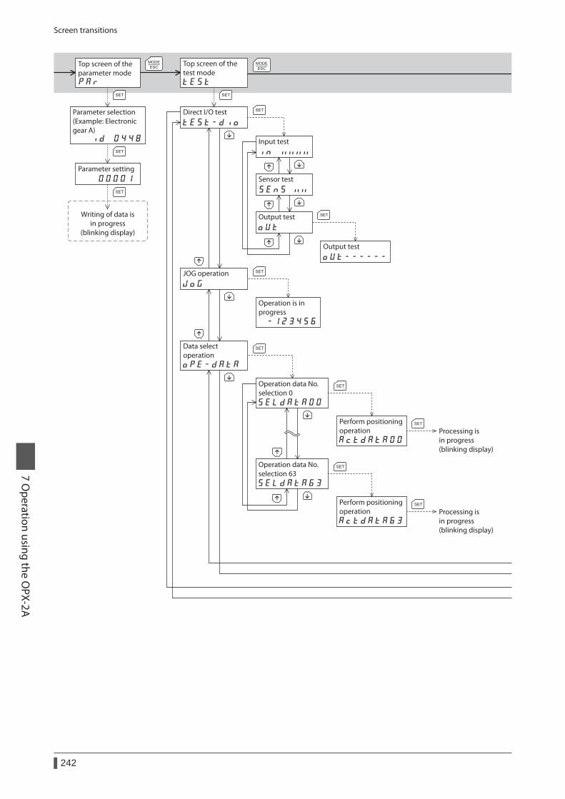
Screen transitions
242
7 Operation using the O
PX-2A
Top screen of theparameter mode
Top screen of thetest mode
Direct I/O test
JOG operation
Data select operation
Input test
Sensor test
Output test
Output test
Operation is in progress
Operation data No.selection 0
Operation data No.selection 63
Perform positioning operation Processing is
in progress(blinking display)
Processing isin progress(blinking display)
Perform positioning operation
Writing of data isin progress
(blinking display)
Parameter selection(Example: Electronicgear A)
Parameter setting
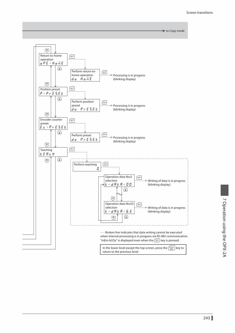
Screen transitions
243
7 Operation using the O
PX-2A
to Copy mode
Return-to-home operation
Operation data No.0selection
Operation data No.63selection
Position preset
Teaching
Perform position preset
Perform teaching
Processing is in progress(blinking display)
Processing is in progress(blinking display)
Processing is in progress(blinking display)
Writing of data is in progress(blinking display)
Writing of data is in progress(blinking display)
Encoder counter preset
Perform preset
Perform return-to-home operation
In the lower level except the top screen, press thereturn to the previous level.
key to
- - - Broken line indicates that data writing cannot be executed when internal processing is in progress via RS-485 communication.
key is pressed."mEm-bUSy" is displayed even when the
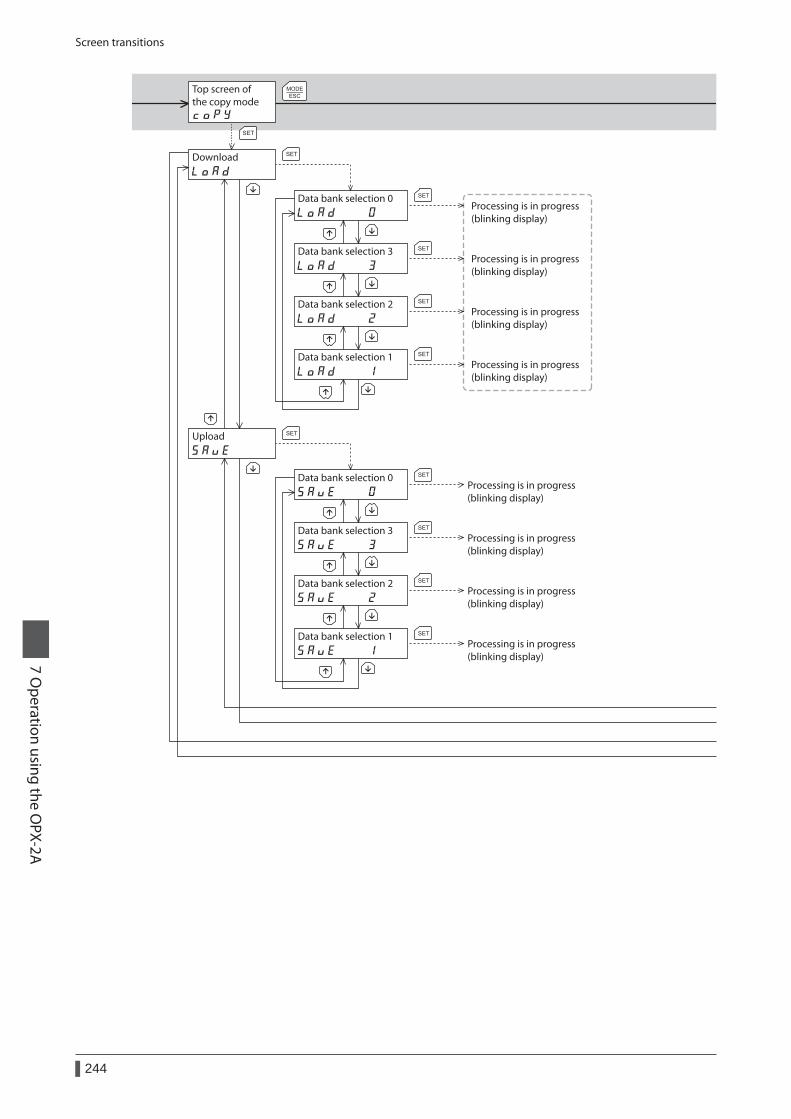
Screen transitions
244
7 Operation using the O
PX-2A
Top screen of the copy mode
Download
Data bank selection 0
Upload
Processing is in progress(blinking display)
Data bank selection 3Processing is in progress(blinking display)
Data bank selection 2Processing is in progress(blinking display)
Data bank selection 1Processing is in progress(blinking display)
Data bank selection 0Processing is in progress(blinking display)
Data bank selection 3Processing is in progress(blinking display)
Data bank selection 2Processing is in progress(blinking display)
Data bank selection 1Processing is in progress(blinking display)
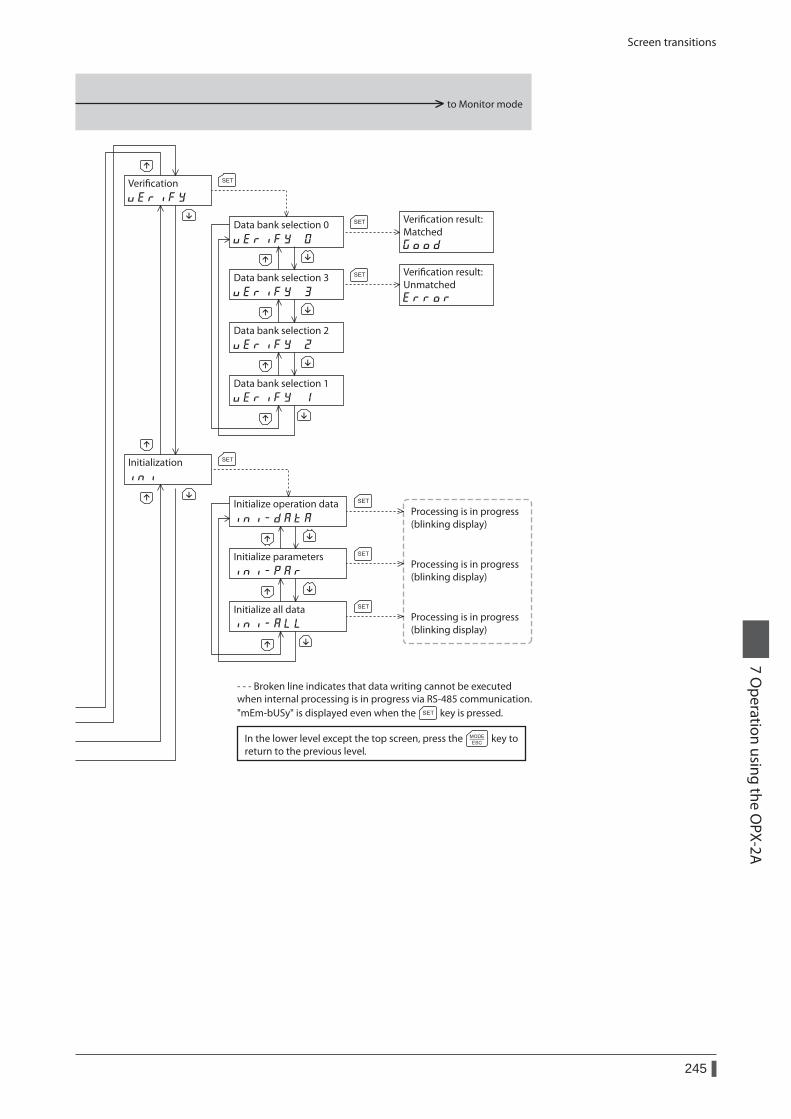
Screen transitions
245
7 Operation using the O
PX-2A
to Monitor mode
Verication
Initialization
Data bank selection 0
Data bank selection 3
Data bank selection 2
Data bank selection 1
Processing is in progress(blinking display)
Processing is in progress(blinking display)
Processing is in progress(blinking display)
Initialize operation data
Initialize all data
Initialize parameters
Verication result: Matched
Verication result: Unmatched
In the lower level except the top screen, press thereturn to the previous level.
key to
- - - Broken line indicates that data writing cannot be executed when internal processing is in progress via RS-485 communication.
key is pressed."mEm-bUSy" is displayed even when the
Monitor mode
246
7 Operation using the O
PX-2A
3 Monitor mode
3-1 Overview of the monitor mode
z Monitoring the operating statusYou can monitor the motor speed, command position, encoder counter, operation data number corresponding to the current operation, operation data number currently selected, and internal temperature of the driver in real time.
z Checking the alarms/warnings, clearing alarm/warning records, and resetting alarms • If an alarm or warning generates, a corresponding alarm code or warning code will be displayed. You can check the
code to identify the details of the alarm/warning. • Up to ten most recent alarms/warnings can be displayed, starting from the latest one. You can also clear alarm/
warning records. • You can reset the alarms currently present.
z Checking the I/O signalsYou can check the ON/OFF status of each I/O signal of the driver.
3-2 Monitor items
Motor speedYou can check the motor speed (unit: Hz).While the motor is rotating in the CCW direction, “−” is shown in front of the displayed value. If the speed is indicated by an absolute value, no sign is shown to indicate the rotating direction. You can select the value display format using the “data setter speed display” parameter.
Command positionYou can check the command position of the motor with reference to the home position.If a resolution is set, an appropriate value based on the resolution is shown as steps.
Encoder countWhen an encoder is equipped, you can check the encoder counter value.
Operation numberYou can check the operation data number corresponding to the data used in the current positioning operation.
Selected numberYou can check the operation data number currently selected.
AlarmWhen an alarm generates, a corresponding alarm code will be displayed. You can also reset alarms or check and clear alarm records. For details of alarm, refer to p.267.
Do not turn off the driver power while an alarm is being reset or alarm records are being cleared (=while the display is blinking). Doing so may damage the data.
Some alarms cannot be reset on the OPX-2A. Check with the "Alarm list" on p.268. To reset these alarms, you must cycle the driver power.
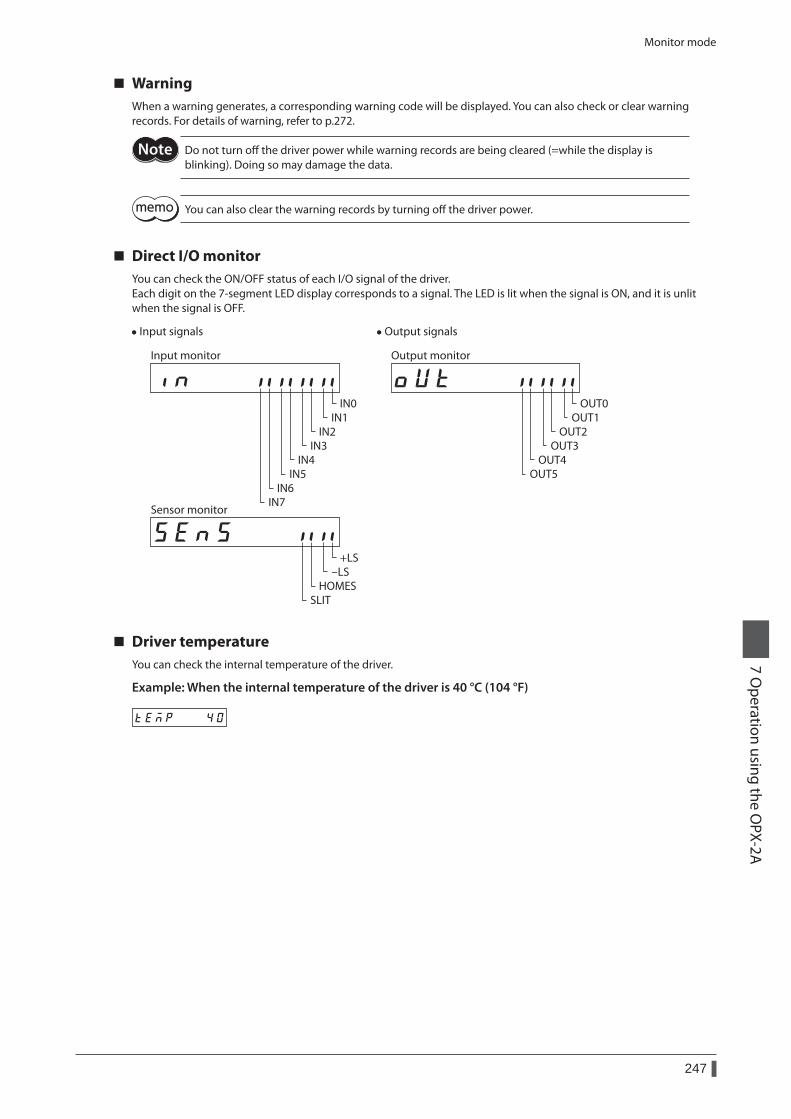
Monitor mode
247
7 Operation using the O
PX-2A
WarningWhen a warning generates, a corresponding warning code will be displayed. You can also check or clear warning records. For details of warning, refer to p.272.
Do not turn off the driver power while warning records are being cleared (=while the display is blinking). Doing so may damage the data.
You can also clear the warning records by turning off the driver power.
Direct I/O monitorYou can check the ON/OFF status of each I/O signal of the driver.Each digit on the 7-segment LED display corresponds to a signal. The LED is lit when the signal is ON, and it is unlit when the signal is OFF.
• Input signals
IN0IN1
IN2IN3
IN4IN5
IN6IN7
Input monitor
+LS-LS
HOMESSLIT
Sensor monitor
• Output signals
OUT0OUT1
OUT2OUT3
OUT4OUT5
Output monitor
Driver temperatureYou can check the internal temperature of the driver.
Example: When the internal temperature of the driver is 40 °C (104 °F)
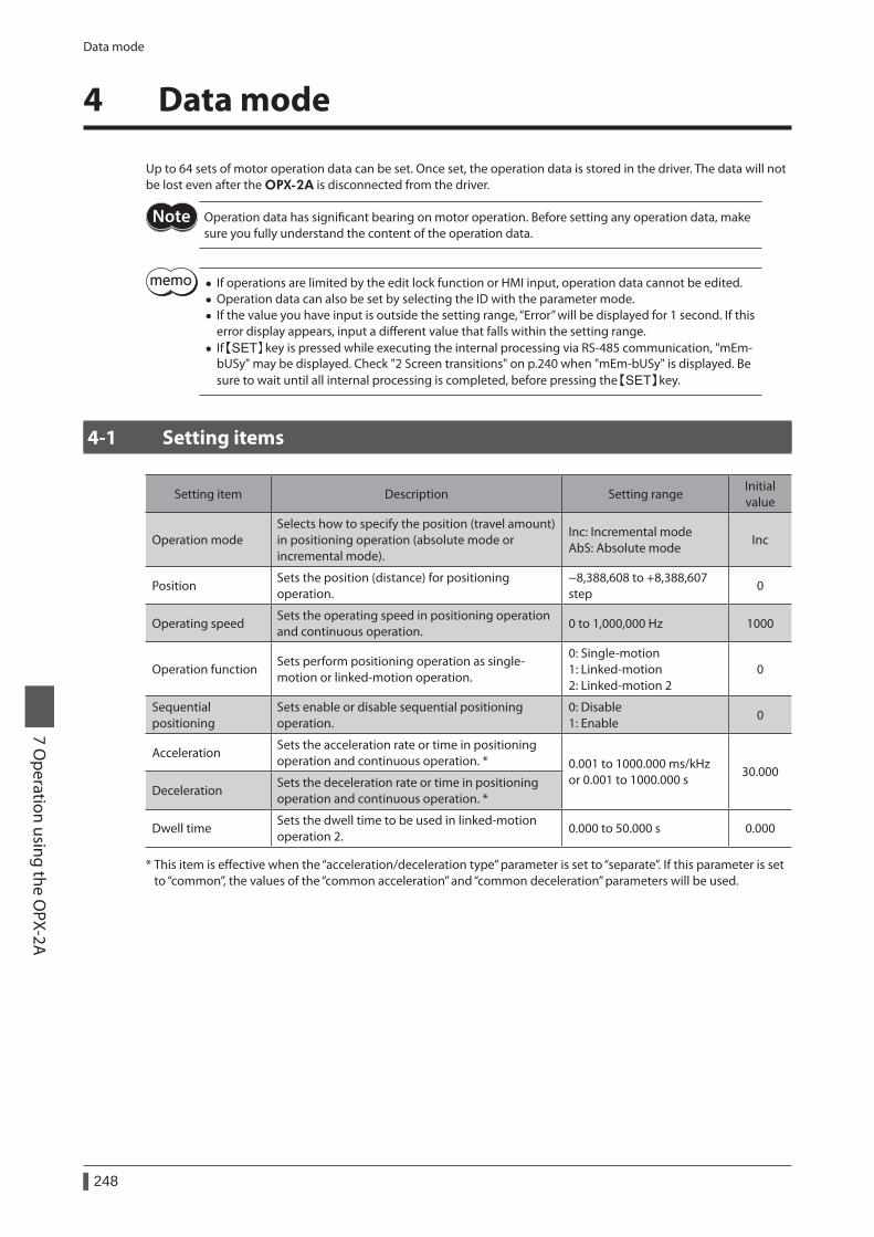
Data mode
248
7 Operation using the O
PX-2A
4 Data mode
Up to 64 sets of motor operation data can be set. Once set, the operation data is stored in the driver. The data will not be lost even after the OPX-2A is disconnected from the driver.
Operation data has significant bearing on motor operation. Before setting any operation data, make sure you fully understand the content of the operation data.
• If operations are limited by the edit lock function or HMI input, operation data cannot be edited. • Operation data can also be set by selecting the ID with the parameter mode. • If the value you have input is outside the setting range, “Error” will be displayed for 1 second. If this error display appears, input a different value that falls within the setting range.
• If key is pressed while executing the internal processing via RS-485 communication, "mEm-bUSy" may be displayed. Check "2 Screen transitions" on p.240 when "mEm-bUSy" is displayed. Be sure to wait until all internal processing is completed, before pressing the key.
4-1 Setting items
Setting item Description Setting rangeInitial value
Operation modeSelects how to specify the position (travel amount) in positioning operation (absolute mode or incremental mode).
Inc: Incremental mode AbS: Absolute mode
Inc
PositionSets the position (distance) for positioning operation.
−8,388,608 to +8,388,607 step
0
Operating speedSets the operating speed in positioning operation and continuous operation.
0 to 1,000,000 Hz 1000
Operation functionSets perform positioning operation as single-motion or linked-motion operation.
0: Single-motion 1: Linked-motion 2: Linked-motion 2
0
Sequential positioning
Sets enable or disable sequential positioning operation.
0: Disable 1: Enable
0
AccelerationSets the acceleration rate or time in positioning operation and continuous operation. * 0.001 to 1000.000 ms/kHz
or 0.001 to 1000.000 s30.000
DecelerationSets the deceleration rate or time in positioning operation and continuous operation. *
Dwell timeSets the dwell time to be used in linked-motion operation 2.
0.000 to 50.000 s 0.000
* This item is effective when the “acceleration/deceleration type” parameter is set to “separate”. If this parameter is set to “common”, the values of the “common acceleration” and “common deceleration” parameters will be used.

Data mode
249
7 Operation using the O
PX-2A
How to set the dwell timeWhen displaying the "2: linked-motion 2" on the "operation function" and pressing the key, the screen to set the dwell time is displayed. Input the dwell time using the keys and press the key.
Dwell timeProcessing is in progress(blinking display)
Single-motion
Linked-motion
Linked-motion 2
Operation function
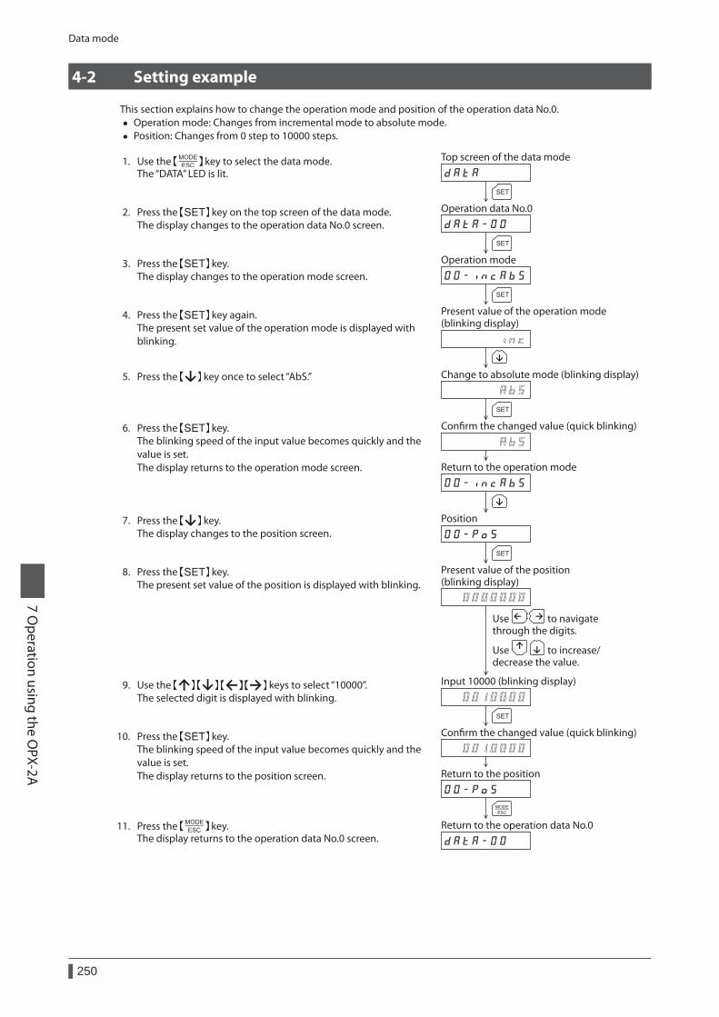
Data mode
250
7 Operation using the O
PX-2A
4-2 Setting example
This section explains how to change the operation mode and position of the operation data No.0. • Operation mode: Changes from incremental mode to absolute mode. • Position: Changes from 0 step to 10000 steps.
1. Use the key to select the data mode.The “DATA” LED is lit.
to increase/decrease the value.Use
to navigatethrough the digits.Use
Operation mode
Input 10000 (blinking display)
Conrm the changed value (quick blinking)
Present value of the operation mode (blinking display)
Change to absolute mode (blinking display)
Conrm the changed value (quick blinking)
Return to the operation mode
Position
Return to the position
Present value of the position (blinking display)
Operation data No.0
Return to the operation data No.0
Top screen of the data mode
2. Press the key on the top screen of the data mode.The display changes to the operation data No.0 screen.
3. Press the key.The display changes to the operation mode screen.
4. Press the key again.The present set value of the operation mode is displayed with blinking.
5. Press the key once to select “AbS.”
6. Press the key.The blinking speed of the input value becomes quickly and the value is set.The display returns to the operation mode screen.
7. Press the key.The display changes to the position screen.
8. Press the key.The present set value of the position is displayed with blinking.
9. Use the keys to select “10000”.The selected digit is displayed with blinking.
10. Press the key.The blinking speed of the input value becomes quickly and the value is set.The display returns to the position screen.
11. Press the key.The display returns to the operation data No.0 screen.

Data mode
251
7 Operation using the O
PX-2A
4-3 Initialization of the selected operation data
All of the set value for the selected operation data number can be reverted to the initial values. Perform "clear data" of the data mode. For the operation, check the screen transitions of the data mode on p.241.
4-4 Initialization of all operation data
All of the operation data saved in the driver can be reverted to the initial values. Perform "Initialize operation data" of the copy mode. For the operation, check the screen transitions of the copy mode on p.244.
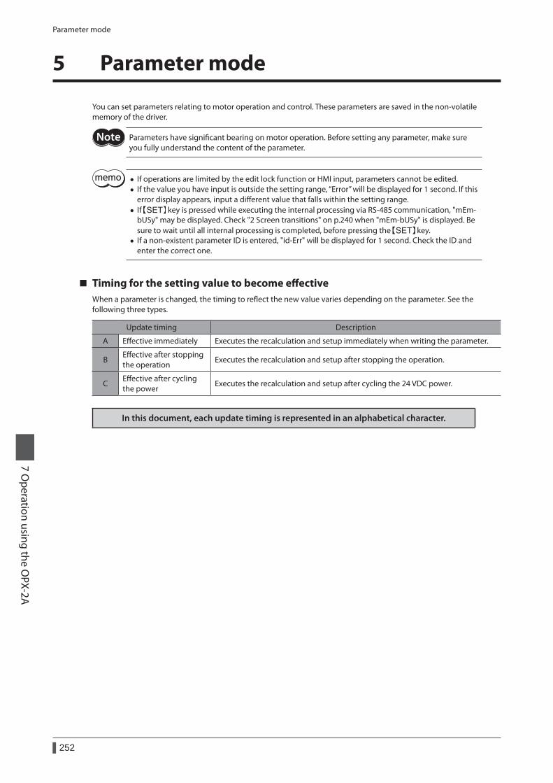
Parameter mode
252
7 Operation using the O
PX-2A
5 Parameter mode
You can set parameters relating to motor operation and control. These parameters are saved in the non-volatile memory of the driver.
Parameters have significant bearing on motor operation. Before setting any parameter, make sure you fully understand the content of the parameter.
• If operations are limited by the edit lock function or HMI input, parameters cannot be edited. • If the value you have input is outside the setting range, “Error” will be displayed for 1 second. If this error display appears, input a different value that falls within the setting range.
• If key is pressed while executing the internal processing via RS-485 communication, "mEm-bUSy" may be displayed. Check "2 Screen transitions" on p.240 when "mEm-bUSy" is displayed. Be sure to wait until all internal processing is completed, before pressing the key.
• If a non-existent parameter ID is entered, "id-Err" will be displayed for 1 second. Check the ID and enter the correct one.
Timing for the setting value to become effectiveWhen a parameter is changed, the timing to reflect the new value varies depending on the parameter. See the following three types.
Update timing Description
A Effective immediately Executes the recalculation and setup immediately when writing the parameter.
BEffective after stopping the operation
Executes the recalculation and setup after stopping the operation.
CEffective after cycling the power
Executes the recalculation and setup after cycling the 24 VDC power.
In this document, each update timing is represented in an alphabetical character.
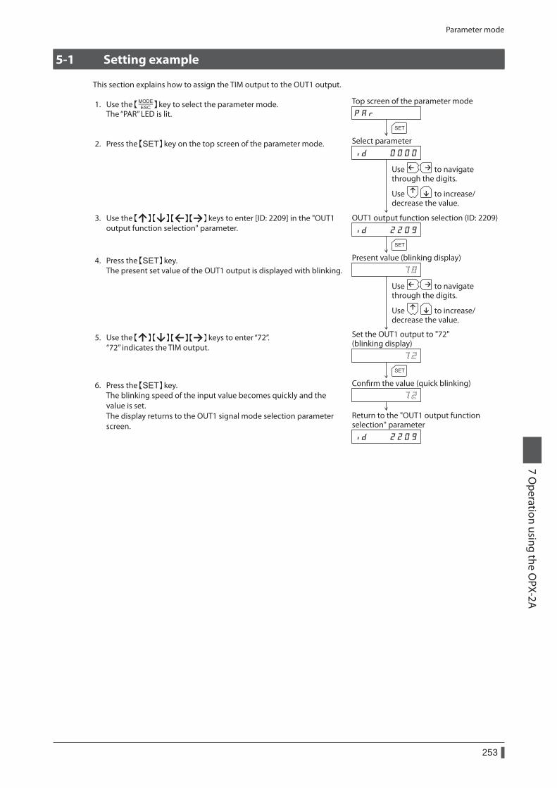
Parameter mode
253
7 Operation using the O
PX-2A
5-1 Setting example
This section explains how to assign the TIM output to the OUT1 output.
1. Use the key to select the parameter mode.The “PAR” LED is lit.
to increase/decrease the value.Use
to navigatethrough the digits.Use
to increase/decrease the value.Use
to navigatethrough the digits.Use
Return to the "OUT1 output function selection" parameter
Present value (blinking display)
Set the OUT1 output to "72"(blinking display)
Conrm the value (quick blinking)
Select parameter
OUT1 output function selection (ID: 2209)
Top screen of the parameter mode
2. Press the key on the top screen of the parameter mode.
3. Use the keys to enter [ID: 2209] in the "OUT1 output function selection" parameter.
4. Press the key.The present set value of the OUT1 output is displayed with blinking.
5. Use the keys to enter “72”.“72” indicates the TIM output.
6. Press the key.The blinking speed of the input value becomes quickly and the value is set.The display returns to the OUT1 signal mode selection parameter screen.
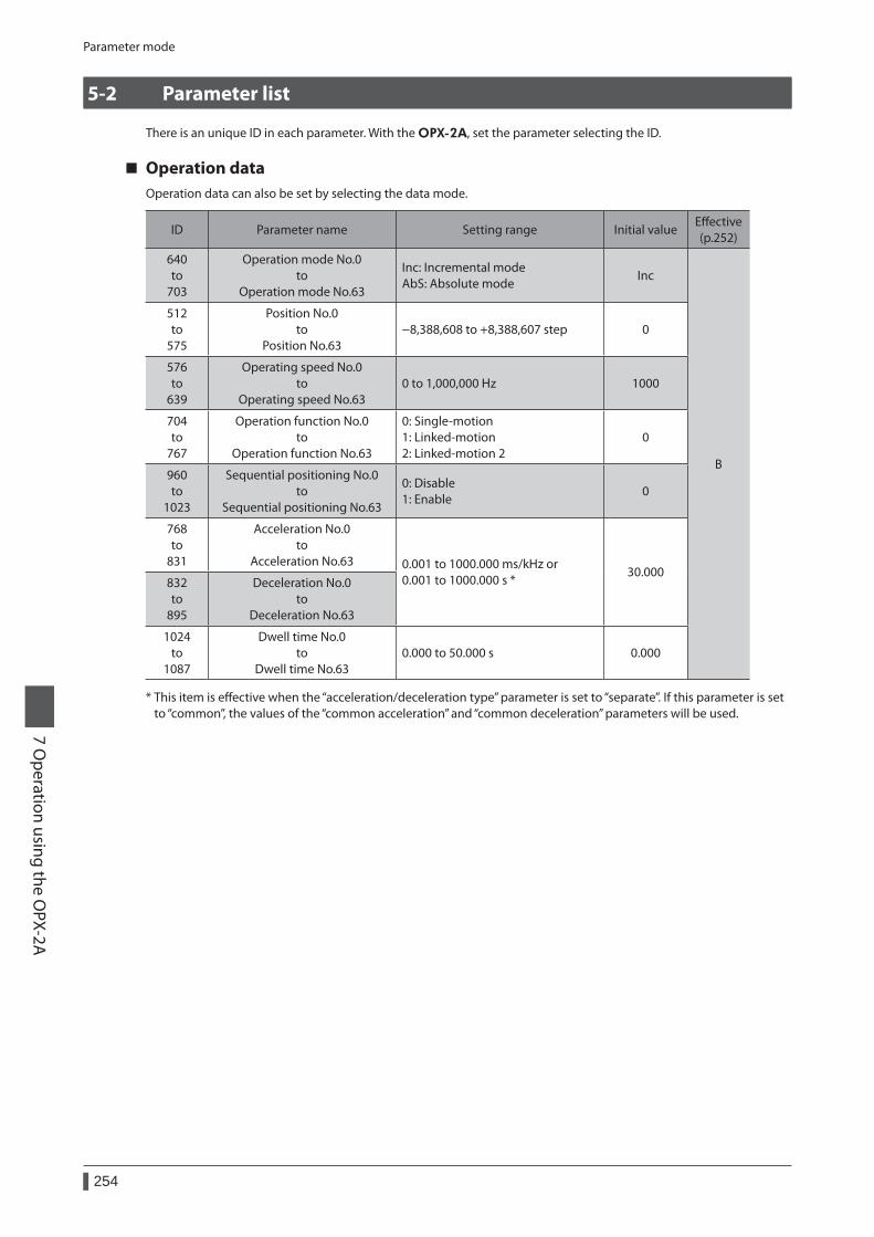
Parameter mode
254
7 Operation using the O
PX-2A
5-2 Parameter list
There is an unique ID in each parameter. With the OPX-2A, set the parameter selecting the ID.
Operation dataOperation data can also be set by selecting the data mode.
ID Parameter name Setting range Initial valueEffective (p.252)
640 to
703
Operation mode No.0 to
Operation mode No.63
Inc: Incremental mode AbS: Absolute mode
Inc
B
512 to
575
Position No.0 to
Position No.63−8,388,608 to +8,388,607 step 0
576 to
639
Operating speed No.0 to
Operating speed No.630 to 1,000,000 Hz 1000
704 to
767
Operation function No.0 to
Operation function No.63
0: Single-motion 1: Linked-motion 2: Linked-motion 2
0
960 to
1023
Sequential positioning No.0 to
Sequential positioning No.63
0: Disable 1: Enable
0
768 to
831
Acceleration No.0 to
Acceleration No.63 0.001 to 1000.000 ms/kHz or 0.001 to 1000.000 s *
30.000832 to
895
Deceleration No.0 to
Deceleration No.63
1024 to
1087
Dwell time No.0 to
Dwell time No.630.000 to 50.000 s 0.000
* This item is effective when the “acceleration/deceleration type” parameter is set to “separate”. If this parameter is set to “common”, the values of the “common acceleration” and “common deceleration” parameters will be used.
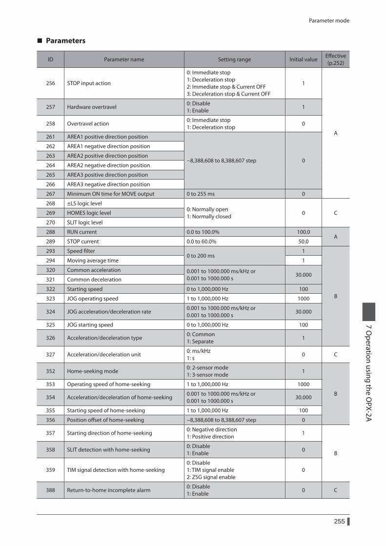
Parameter mode
255
7 Operation using the O
PX-2A
Parameters
ID Parameter name Setting range Initial valueEffective (p.252)
256 STOP input action
0: Immediate stop 1: Deceleration stop 2: Immediate stop & Current OFF 3: Deceleration stop & Current OFF
1
A
257 Hardware overtravel0: Disable 1: Enable
1
258 Overtravel action0: Immediate stop 1: Deceleration stop
0
261 AREA1 positive direction position
−8,388,608 to 8,388,607 step 0
262 AREA1 negative direction position
263 AREA2 positive direction position
264 AREA2 negative direction position
265 AREA3 positive direction position
266 AREA3 negative direction position
267 Minimum ON time for MOVE output 0 to 255 ms 0
268 ±LS logic level0: Normally open 1: Normally closed
0 C269 HOMES logic level
270 SLIT logic level
288 RUN current 0.0 to 100.0% 100.0A
289 STOP current 0.0 to 60.0% 50.0
293 Speed filter0 to 200 ms
1
B
294 Moving average time 1
320 Common acceleration 0.001 to 1000.000 ms/kHz or 0.001 to 1000.000 s
30.000321 Common deceleration
322 Starting speed 0 to 1,000,000 Hz 100
323 JOG operating speed 1 to 1,000,000 Hz 1000
324 JOG acceleration/deceleration rate0.001 to 1000.000 ms/kHz or 0.001 to 1000.000 s
30.000
325 JOG starting speed 0 to 1,000,000 Hz 100
326 Acceleration/deceleration type0: Common 1: Separate
1
327 Acceleration/deceleration unit0: ms/kHz 1: s
0 C
352 Home-seeking mode0: 2-sensor mode 1: 3-sensor mode
1
B
353 Operating speed of home-seeking 1 to 1,000,000 Hz 1000
354 Acceleration/deceleration of home-seeking0.001 to 1000.000 ms/kHz or 0.001 to 1000.000 s
30.000
355 Starting speed of home-seeking 1 to 1,000,000 Hz 100
356 Position offset of home-seeking −8,388,608 to 8,388,607 step 0
357 Starting direction of home-seeking0: Negative direction 1: Positive direction
1
B358 SLIT detection with home-seeking
0: Disable 1: Enable
0
359 TIM signal detection with home-seeking0: Disable 1: TIM signal enable 2: ZSG signal enable
0
388 Return-to-home incomplete alarm0: Disable 1: Enable
0 C
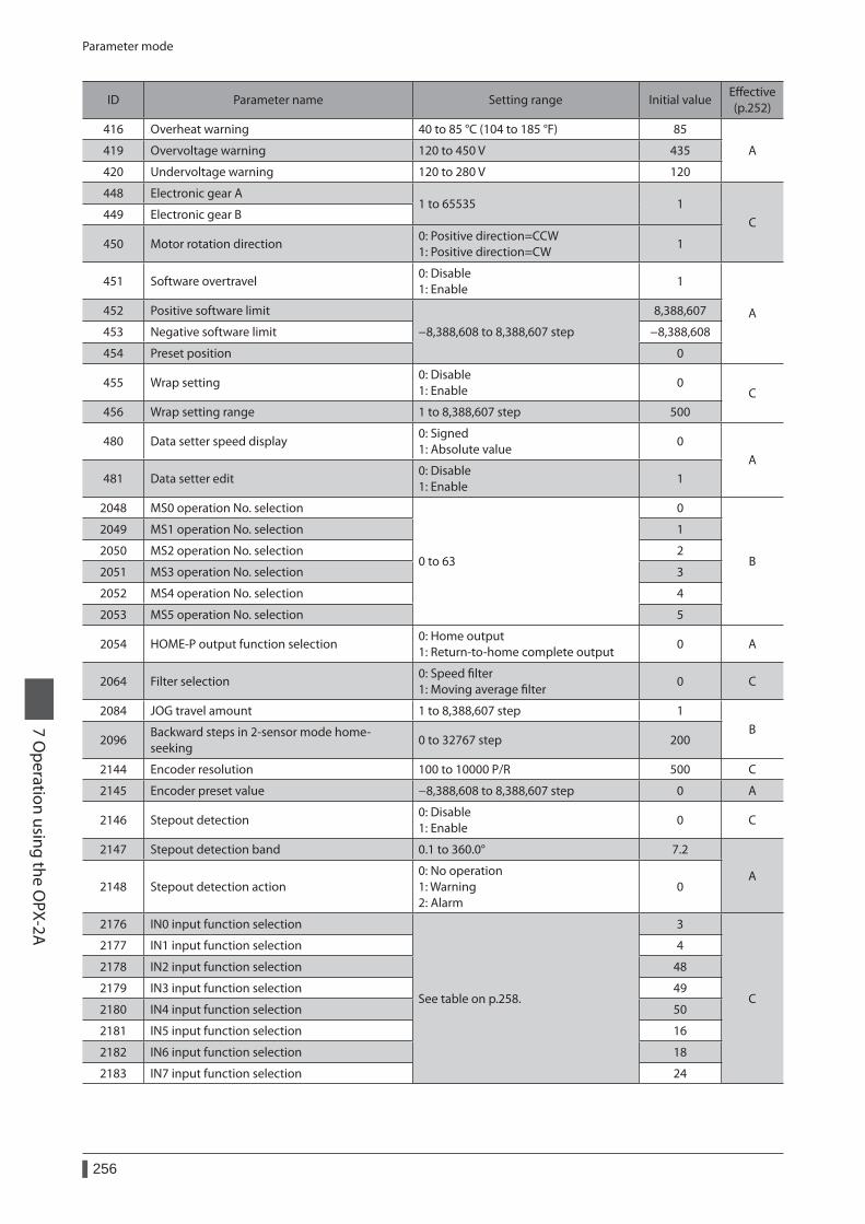
Parameter mode
256
7 Operation using the O
PX-2A
ID Parameter name Setting range Initial valueEffective (p.252)
416 Overheat warning 40 to 85 °C (104 to 185 °F) 85
A419 Overvoltage warning 120 to 450 V 435
420 Undervoltage warning 120 to 280 V 120
448 Electronic gear A1 to 65535 1
C449 Electronic gear B
450 Motor rotation direction0: Positive direction=CCW 1: Positive direction=CW
1
451 Software overtravel0: Disable 1: Enable
1
A452 Positive software limit
−8,388,608 to 8,388,607 step
8,388,607
453 Negative software limit −8,388,608
454 Preset position 0
455 Wrap setting0: Disable 1: Enable
0C
456 Wrap setting range 1 to 8,388,607 step 500
480 Data setter speed display0: Signed 1: Absolute value
0A
481 Data setter edit0: Disable 1: Enable
1
2048 MS0 operation No. selection
0 to 63
0
B
2049 MS1 operation No. selection 1
2050 MS2 operation No. selection 2
2051 MS3 operation No. selection 3
2052 MS4 operation No. selection 4
2053 MS5 operation No. selection 5
2054 HOME-P output function selection0: Home output 1: Return-to-home complete output
0 A
2064 Filter selection0: Speed filter 1: Moving average filter
0 C
2084 JOG travel amount 1 to 8,388,607 step 1B
2096Backward steps in 2-sensor mode home-seeking
0 to 32767 step 200
2144 Encoder resolution 100 to 10000 P/R 500 C
2145 Encoder preset value −8,388,608 to 8,388,607 step 0 A
2146 Stepout detection0: Disable 1: Enable
0 C
2147 Stepout detection band 0.1 to 360.0° 7.2
A2148 Stepout detection action
0: No operation 1: Warning 2: Alarm
0
2176 IN0 input function selection
See table on p.258.
3
C
2177 IN1 input function selection 4
2178 IN2 input function selection 48
2179 IN3 input function selection 49
2180 IN4 input function selection 50
2181 IN5 input function selection 16
2182 IN6 input function selection 18
2183 IN7 input function selection 24
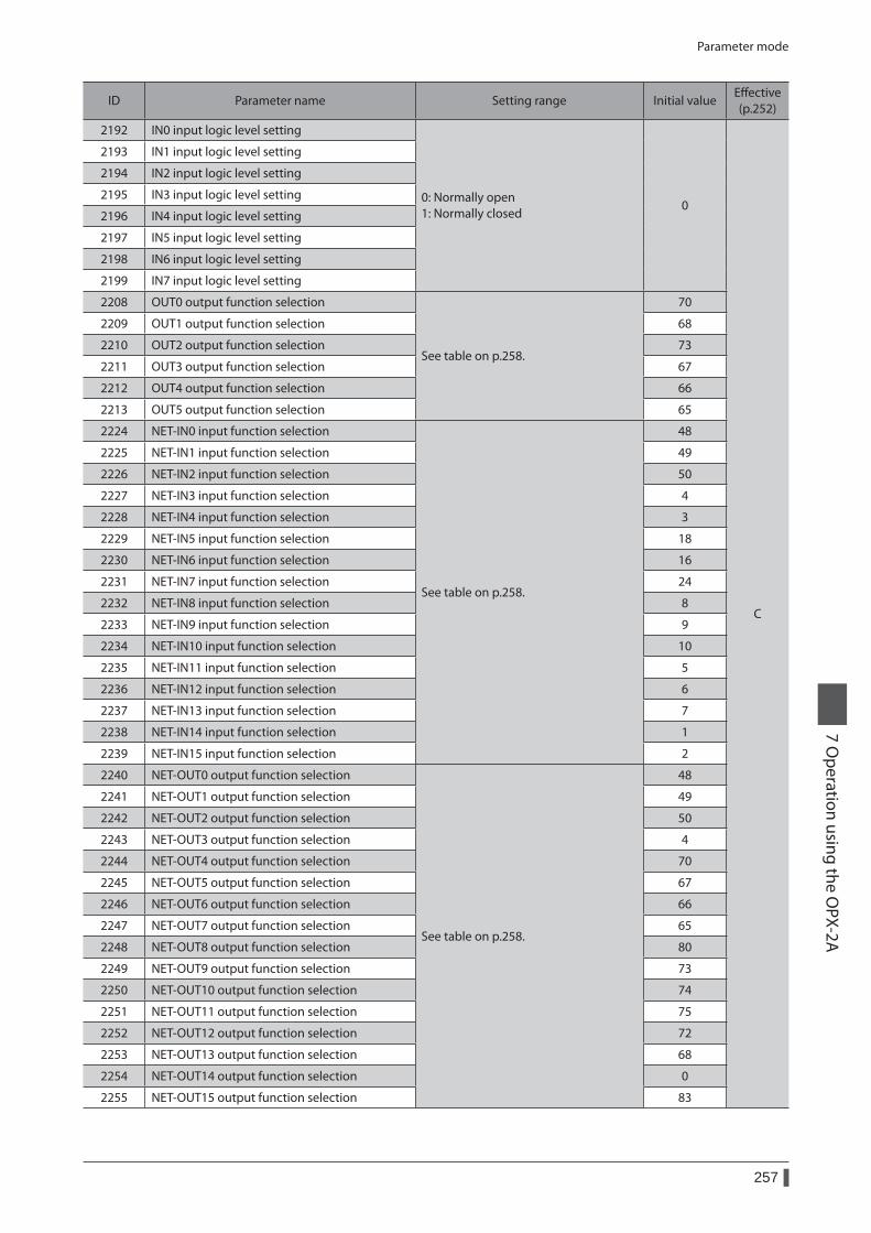
Parameter mode
257
7 Operation using the O
PX-2A
ID Parameter name Setting range Initial valueEffective (p.252)
2192 IN0 input logic level setting
0: Normally open 1: Normally closed
0
C
2193 IN1 input logic level setting
2194 IN2 input logic level setting
2195 IN3 input logic level setting
2196 IN4 input logic level setting
2197 IN5 input logic level setting
2198 IN6 input logic level setting
2199 IN7 input logic level setting
2208 OUT0 output function selection
See table on p.258.
70
2209 OUT1 output function selection 68
2210 OUT2 output function selection 73
2211 OUT3 output function selection 67
2212 OUT4 output function selection 66
2213 OUT5 output function selection 65
2224 NET-IN0 input function selection
See table on p.258.
48
2225 NET-IN1 input function selection 49
2226 NET-IN2 input function selection 50
2227 NET-IN3 input function selection 4
2228 NET-IN4 input function selection 3
2229 NET-IN5 input function selection 18
2230 NET-IN6 input function selection 16
2231 NET-IN7 input function selection 24
2232 NET-IN8 input function selection 8
2233 NET-IN9 input function selection 9
2234 NET-IN10 input function selection 10
2235 NET-IN11 input function selection 5
2236 NET-IN12 input function selection 6
2237 NET-IN13 input function selection 7
2238 NET-IN14 input function selection 1
2239 NET-IN15 input function selection 2
2240 NET-OUT0 output function selection
See table on p.258.
48
2241 NET-OUT1 output function selection 49
2242 NET-OUT2 output function selection 50
2243 NET-OUT3 output function selection 4
2244 NET-OUT4 output function selection 70
2245 NET-OUT5 output function selection 67
2246 NET-OUT6 output function selection 66
2247 NET-OUT7 output function selection 65
2248 NET-OUT8 output function selection 80
2249 NET-OUT9 output function selection 73
2250 NET-OUT10 output function selection 74
2251 NET-OUT11 output function selection 75
2252 NET-OUT12 output function selection 72
2253 NET-OUT13 output function selection 68
2254 NET-OUT14 output function selection 0
2255 NET-OUT15 output function selection 83
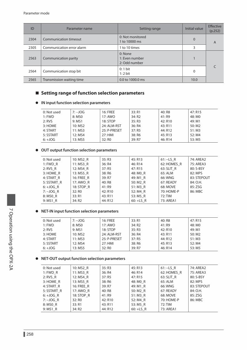
Parameter mode
258
7 Operation using the O
PX-2A
ID Parameter name Setting range Initial valueEffective (p.252)
2304 Communication timeout0: Not monitored 1 to 10000 ms
0A
2305 Communication error alarm 1 to 10 times 3
2563 Communication parity0: None 1: Even number 2: Odd number
1
C2564 Communication stop bit
0: 1 bit 1: 2 bit
0
2565 Transmission waiting time 0.0 to 1000.0 ms 10.0
Setting range of function selection parameters
z IN input function selection parameters
0: Not used 1: FWD 2: RVS 3: HOME 4: START 5: SSTART 6: +JOG
7: −JOG 8: MS0 9: MS1 10: MS2 11: MS3 12: MS4 13: MS5
16: FREE 17: AWO 18: STOP 24: ALM-RST 25: P-PRESET 27: HMI 32: R0
33: R1 34: R2 35: R3 36: R4 37: R5 38: R6 39: R7
40: R8 41: R9 42: R10 43: R11 44: R12 45: R13 46: R14
47: R15 48: M0 49: M1 50: M2 51: M3 52: M4 53: M5
z OUT output function selection parameters
0: Not used 1: FWD_R 2: RVS_R 3: HOME_R 4: START_R 5: SSTART_R 6: +JOG_R 7: −JOG_R 8: MS0_R 9: MS1_R
10: MS2_R 11: MS3_R 12: MS4_R 13: MS5_R 16: FREE_R 17: AWO_R 18: STOP_R 32: R0 33: R1 34: R2
35: R3 36: R4 37: R5 38: R6 39: R7 40: R8 41: R9 42: R10 43: R11 44: R12
45: R13 46: R14 47: R15 48: M0_R 49: M1_R 50: M2_R 51: M3_R 52: M4_R 53: M5_R 60: +LS_R
61: −LS_R 62: HOMES_R 63: SLIT_R 65: ALM 66: WNG 67: READY 68: MOVE 70: HOME-P 72: TIM 73: AREA1
74: AREA2 75: AREA3 80: S-BSY 82: MPS 83: STEPOUT 84: O.H. 85: ZSG 86: MBC
z NET-IN input function selection parameters
0: Not used 1: FWD 2: RVS 3: HOME 4: START 5: SSTART 6: +JOG
7: −JOG 8: MS0 9: MS1 10: MS2 11: MS3 12: MS4 13: MS5
16: FREE 17: AWO 18: STOP 24: ALM-RST 25: P-PRESET 27: HMI 32: R0
33: R1 34: R2 35: R3 36: R4 37: R5 38: R6 39: R7
40: R8 41: R9 42: R10 43: R11 44: R12 45: R13 46: R14
47: R15 48: M0 49: M1 50: M2 51: M3 52: M4 53: M5
z NET-OUT output function selection parameters
0: Not used 1: FWD_R 2: RVS_R 3: HOME_R 4: START_R 5: SSTART_R 6: +JOG_R 7: −JOG_R 8: MS0_R 9: MS1_R
10: MS2_R 11: MS3_R 12: MS4_R 13: MS5_R 16: FREE_R 17: AWO_R 18: STOP_R 32: R0 33: R1 34: R2
35: R3 36: R4 37: R5 38: R6 39: R7 40: R8 41: R9 42: R10 43: R11 44: R12
45: R13 46: R14 47: R15 48: M0_R 49: M1_R 50: M2_R 51: M3_R 52: M4_R 53: M5_R 60: +LS_R
61: −LS_R 62: HOMES_R 63: SLIT_R 65: ALM 66: WNG 67: READY 68: MOVE 70: HOME-P 72: TIM 73: AREA1
74: AREA2 75: AREA3 80: S-BSY 82: MPS 83: STEPOUT 84: O.H. 85: ZSG 86: MBC

Parameter mode
259
7 Operation using the O
PX-2A
5-3 Initializing parameters
You can revert parameters saved in the driver to their initial values. Perform "Initialize operation data" of the copy mode. For the operation, check the screen transitions of the copy mode on p.244.
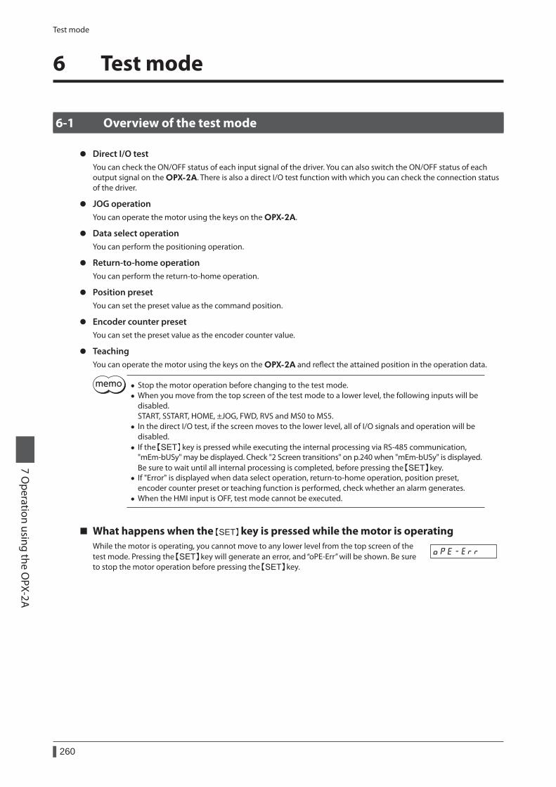
Test mode
260
7 Operation using the O
PX-2A
6 Test mode
6-1 Overview of the test mode
z Direct I/O testYou can check the ON/OFF status of each input signal of the driver. You can also switch the ON/OFF status of each output signal on the OPX-2A. There is also a direct I/O test function with which you can check the connection status of the driver.
z JOG operationYou can operate the motor using the keys on the OPX-2A.
z Data select operationYou can perform the positioning operation.
z Return-to-home operationYou can perform the return-to-home operation.
z Position presetYou can set the preset value as the command position.
z Encoder counter presetYou can set the preset value as the encoder counter value.
z TeachingYou can operate the motor using the keys on the OPX-2A and reflect the attained position in the operation data.
• Stop the motor operation before changing to the test mode. • When you move from the top screen of the test mode to a lower level, the following inputs will be disabled. START, SSTART, HOME, ±JOG, FWD, RVS and MS0 to MS5.
• In the direct I/O test, if the screen moves to the lower level, all of I/O signals and operation will be disabled.
• If the key is pressed while executing the internal processing via RS-485 communication, "mEm-bUSy" may be displayed. Check "2 Screen transitions" on p.240 when "mEm-bUSy" is displayed. Be sure to wait until all internal processing is completed, before pressing the key.
• If "Error" is displayed when data select operation, return-to-home operation, position preset, encoder counter preset or teaching function is performed, check whether an alarm generates.
• When the HMI input is OFF, test mode cannot be executed.
What happens when the key is pressed while the motor is operatingWhile the motor is operating, you cannot move to any lower level from the top screen of the test mode. Pressing the key will generate an error, and “oPE-Err” will be shown. Be sure to stop the motor operation before pressing the key.
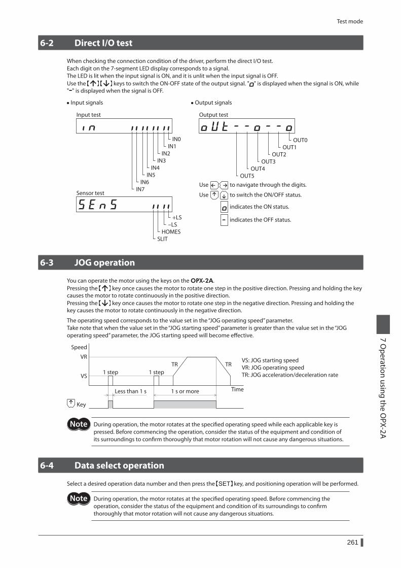
Test mode
261
7 Operation using the O
PX-2A
6-2 Direct I/O test
When checking the connection condition of the driver, perform the direct I/O test.Each digit on the 7-segment LED display corresponds to a signal. The LED is lit when the input signal is ON, and it is unlit when the input signal is OFF.Use the keys to switch the ON-OFF state of the output signal. " " is displayed when the signal is ON, while " " is displayed when the signal is OFF.
• Input signals
IN0IN1
IN2IN3
IN4IN5
IN6IN7
Input test
+LS-LS
HOMESSLIT
Sensor test
• Output signals
OUT0OUT1
OUT3OUT2
OUT5OUT4
to switch the ON/OFF status.Use
to navigate through the digits.Use
indicates the OFF status.
indicates the ON status.
Output test
6-3 JOG operation
You can operate the motor using the keys on the OPX-2A.Pressing the key once causes the motor to rotate one step in the positive direction. Pressing and holding the key causes the motor to rotate continuously in the positive direction.Pressing the key once causes the motor to rotate one step in the negative direction. Pressing and holding the key causes the motor to rotate continuously in the negative direction.
The operating speed corresponds to the value set in the “JOG operating speed” parameter.Take note that when the value set in the “JOG starting speed” parameter is greater than the value set in the “JOG operating speed” parameter, the JOG starting speed will become effective.
Less than 1 s 1 s or more
VS
Speed
Time
VRTR TR
1 step 1 step
Key
VS: JOG starting speedVR: JOG operating speedTR: JOG acceleration/deceleration rate
During operation, the motor rotates at the specified operating speed while each applicable key is pressed. Before commencing the operation, consider the status of the equipment and condition of its surroundings to confirm thoroughly that motor rotation will not cause any dangerous situations.
6-4 Data select operation
Select a desired operation data number and then press the key, and positioning operation will be performed.
During operation, the motor rotates at the specified operating speed. Before commencing the operation, consider the status of the equipment and condition of its surroundings to confirm thoroughly that motor rotation will not cause any dangerous situations.
Test mode
262
7 Operation using the O
PX-2A
6-5 Return-to-home operation
You can perform a return-to-home operation.The operating speed corresponds to the value set in the “operating speed of home-seeking” parameter.
During operation, the motor rotates at the specified operating speed. Before commencing the operation, consider the status of the equipment and condition of its surroundings to confirm thoroughly that motor rotation will not cause any dangerous situations.
6-6 Presetting the position
In this operation, the command position is preset by rewriting the value in the “preset position” parameter.
If operations are limited by the edit lock function, the preset function cannot be performed.
6-7 Presetting the encoder counter
In this operation, the encoder counter is preset by rewriting the value in the “encoder preset value” parameter.
If operations are limited by the edit lock function, the preset function cannot be performed.
6-8 Teaching
You can operate the motor using the keys on the OPX-2A and reflect the attained position in the operation data.The absolute mode will be automatically selected as the operation mode of any position data set by teaching.The operating speed, acceleration/deceleration rate and starting speed of teaching are the same as the corresponding settings applicable to JOG operation.
During operation, the motor rotates at the specified operating speed. Before commencing the operation, consider the status of the equipment and condition of its surroundings to confirm thoroughly that motor rotation will not cause any dangerous situations.
If operations are limited by the edit lock function, the teaching cannot be performed.
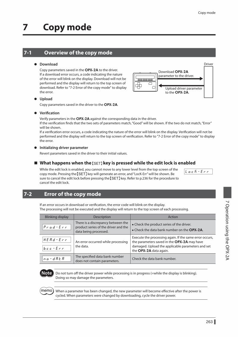
Copy mode
263
7 Operation using the O
PX-2A
7 Copy mode
7-1 Overview of the copy mode
z DownloadCopy parameters saved in the OPX-2A to the driver.If a download error occurs, a code indicating the nature of the error will blink on the display. Download will not be performed and the display will return to the top screen of download. Refer to "7-2 Error of the copy mode" to display the error.
z UploadCopy parameters saved in the driver to the OPX-2A.
Driver
Upload driver parameter to the OPX-2A.
Download OPX-2A parameter to the driver.
z VerificationVerify parameters in the OPX-2A against the corresponding data in the driver.If the verification finds that the two sets of parameters match, “Good” will be shown. If the two do not match, “Error” will be shown.If a verification error occurs, a code indicating the nature of the error will blink on the display. Verification will not be performed and the display will return to the top screen of verification. Refer to "7-2 Error of the copy mode" to display the error.
z Initializing driver parameterRevert parameters saved in the driver to their initial values.
What happens when the key is pressed while the edit lock is enabledWhile the edit lock is enabled, you cannot move to any lower level from the top screen of the copy mode. Pressing the key will generate an error, and “LocK-Err” will be shown. Be sure to cancel the edit lock before pressing the key. Refer to p.236 for the procedure to cancel the edit lock.
7-2 Error of the copy mode
If an error occurs in download or verification, the error code will blink on the display.The processing will not be executed and the display will return to the top screen of each processing.
Blinking display Description Action
There is a discrepancy between the product series of the driver and the data being processed.
• Check the product series of the driver.
• Check the data bank number on the OPX-2A.
An error occurred while processing the data.
Execute the processing again. If the same error occurs, the parameters saved in the OPX-2A may have damaged. Upload the applicable parameters and set the OPX-2A data again.
The specified data bank number does not contain parameters.
Check the data bank number.
Do not turn off the driver power while processing is in progress (=while the display is blinking). Doing so may damage the parameters.
When a parameter has been changed, the new parameter will become effective after the power is cycled. When parameters were changed by downloading, cycle the driver power.

264
7 Operation using the O
PX-2A
1 Inspection ........................................................266
2 Alarms and warnings ......................................2672-1 Alarms ................................................................................267
2-2 Warnings ...........................................................................272
2-3 Communication errors.................................................273
3 Troubleshooting and remedial actions .........274
8 Inspection, troubleshooting and remedial actions
This part explains the periodical inspection methods as well as confirmation items and remedial actions when problems have happened.
Table of contents
Inspection
266
8 Inspection, troubleshooting and remedial actions
1 Inspection
It is recommended that periodic inspections for the items listed below are conducted after each operation of the motor. If an abnormal condition is noted, discontinue any use and contact your nearest Oriental Motor sales office.
During inspection • Are any of the motor mounting screws loose? • Check for any unusual noises in the motor bearings (ball bearings) or other moving parts. • Are there any scratches, signs of stress or loose driver connections in the motor cable? • Are the motor output shaft and load shaft out of alignment? • Are the openings in the driver blocked? • Are any of the mounting screws or connection parts of the driver loose? • Is there attachment of dust, etc., on the driver? • Are there any strange smells or appearances within the driver?
The driver uses semiconductor elements. Handle the driver with care since static electricity may damage semiconductor elements. Static electricity may damage the driver.
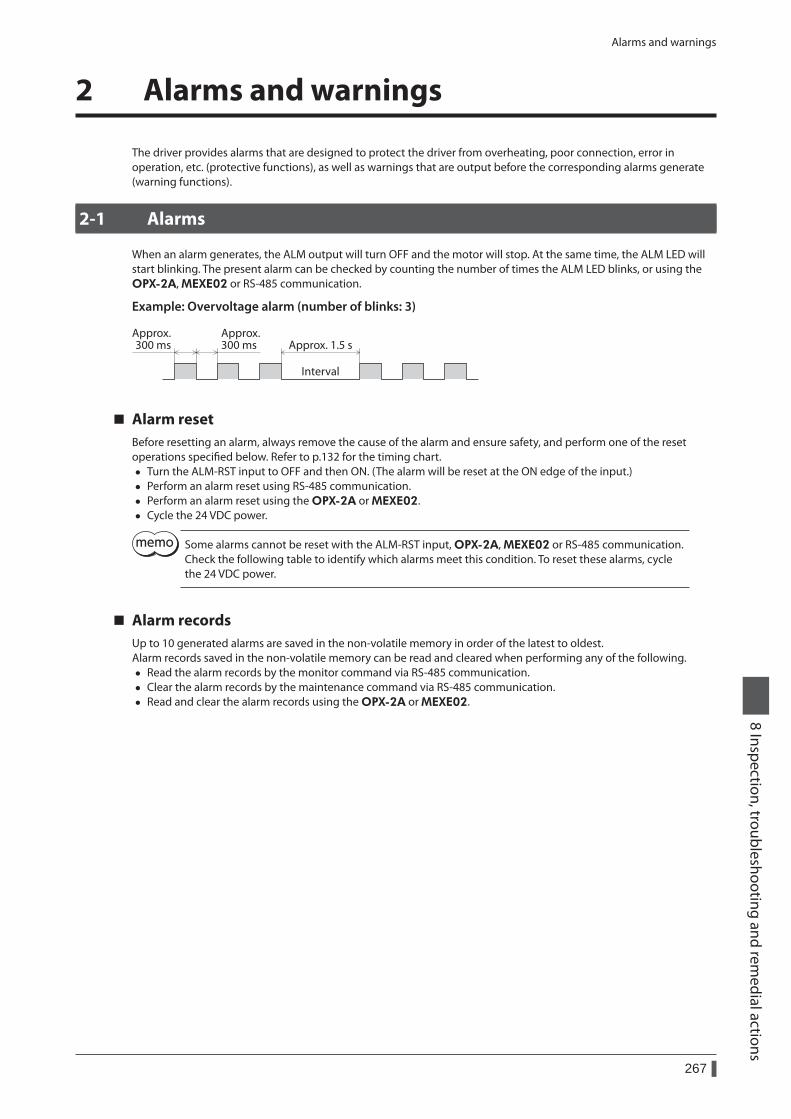
Alarms and warnings
267
8 Inspection, troubleshooting and remedial actions
2 Alarms and warnings
The driver provides alarms that are designed to protect the driver from overheating, poor connection, error in operation, etc. (protective functions), as well as warnings that are output before the corresponding alarms generate (warning functions).
2-1 Alarms
When an alarm generates, the ALM output will turn OFF and the motor will stop. At the same time, the ALM LED will start blinking. The present alarm can be checked by counting the number of times the ALM LED blinks, or using the OPX-2A, MEXE02 or RS-485 communication.
Example: Overvoltage alarm (number of blinks: 3)
Approx. 300 ms Approx. 1.5 s
Approx. 300 ms
Interval
Alarm resetBefore resetting an alarm, always remove the cause of the alarm and ensure safety, and perform one of the reset operations specified below. Refer to p.132 for the timing chart.
• Turn the ALM-RST input to OFF and then ON. (The alarm will be reset at the ON edge of the input.) • Perform an alarm reset using RS-485 communication. • Perform an alarm reset using the OPX-2A or MEXE02. • Cycle the 24 VDC power.
Some alarms cannot be reset with the ALM-RST input, OPX-2A, MEXE02 or RS-485 communication. Check the following table to identify which alarms meet this condition. To reset these alarms, cycle the 24 VDC power.
Alarm recordsUp to 10 generated alarms are saved in the non-volatile memory in order of the latest to oldest.Alarm records saved in the non-volatile memory can be read and cleared when performing any of the following.
• Read the alarm records by the monitor command via RS-485 communication. • Clear the alarm records by the maintenance command via RS-485 communication. • Read and clear the alarm records using the OPX-2A or MEXE02.
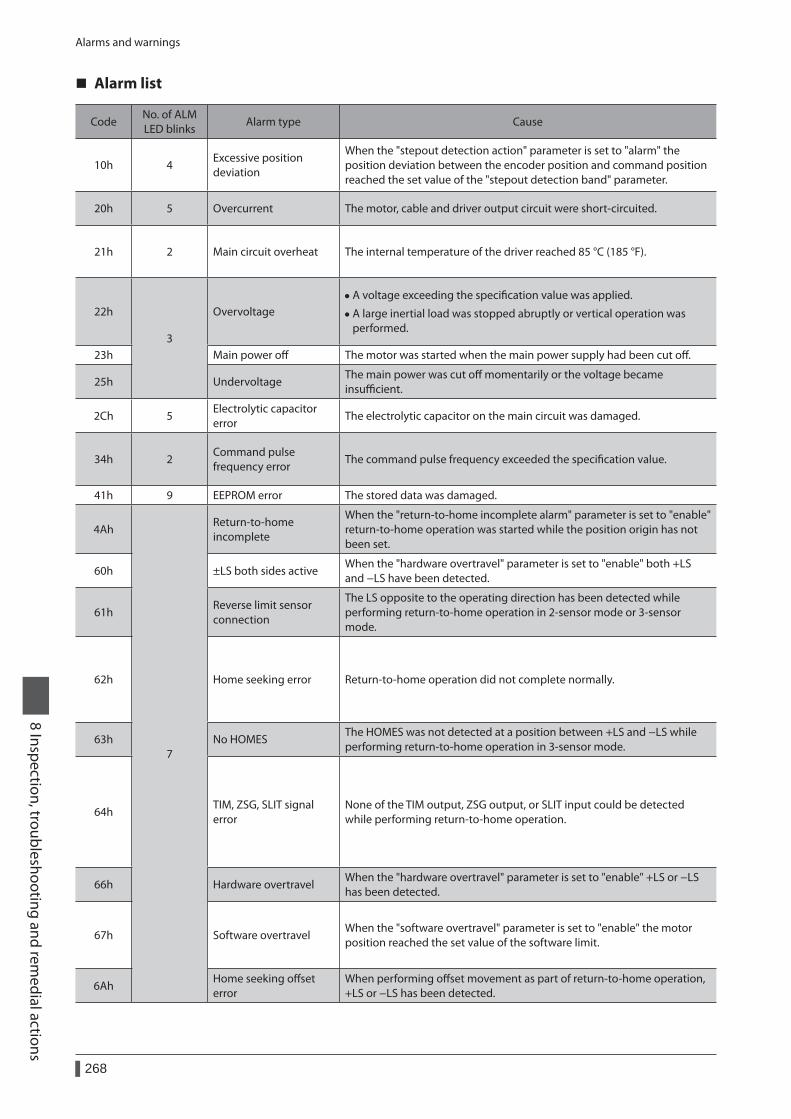
Alarms and warnings
268
8 Inspection, troubleshooting and remedial actions
Alarm list
CodeNo. of ALM LED blinks
Alarm type Cause Remedial action Reset operationsMotor
excitation *1
10h 4Excessive position deviation
When the "stepout detection action" parameter is set to "alarm" the position deviation between the encoder position and command position reached the set value of the "stepout detection band" parameter.
• Reduce the load or increase the acceleration/deceleration.
• Check the setting of the "stepout detection band" parameter.
• Turn the ALM-RST input from OFF (0) to ON (1).
• Perform an alarm reset. *2
Excitation ON
20h 5 Overcurrent The motor, cable and driver output circuit were short-circuited.Turn off the power and turn on the power again after checking that the motor, cable and driver output circuit are not short-circuited.
Cycle the power.
Excitation OFF
21h 2 Main circuit overheat The internal temperature of the driver reached 85 °C (185 °F). Review the ventilation condition in the enclosure. • Turn the ALM-RST input from OFF (0) to ON (1).
• Perform an alarm reset.
22h
3
Overvoltage • A voltage exceeding the specification value was applied.
• A large inertial load was stopped abruptly or vertical operation was performed.
• Check whether the power supply voltage is within the allowable range of the specification.
• If the alarm is generated while operating, reduce the load or increase the acceleration/deceleration.
Cycle the power.
23h Main power off The motor was started when the main power supply had been cut off. Check if the main power supply has been input normally. • Turn the ALM-RST input from OFF (0) to ON (1).
• Perform an alarm reset.25h UndervoltageThe main power was cut off momentarily or the voltage became insufficient.
Check whether the power supply voltage is within the allowable range of the specification.
2Ch 5Electrolytic capacitor error
The electrolytic capacitor on the main circuit was damaged. Contact your nearest Oriental Motor sales office. Cycle the power.
34h 2Command pulse frequency error
The command pulse frequency exceeded the specification value. Check the command pulse frequency. • Turn the ALM-RST input from OFF (0) to ON (1).
• Perform an alarm reset.
41h 9 EEPROM error The stored data was damaged. Initialize all parameters. Cycle the power.
4Ah
7
Return-to-home incomplete
When the "return-to-home incomplete alarm" parameter is set to "enable" return-to-home operation was started while the position origin has not been set.
Perform the position preset or return-to-home operation.
• Turn the ALM-RST input from OFF (0) to ON (1).
• Perform an alarm reset.
Excitation ON
60h ±LS both sides activeWhen the "hardware overtravel" parameter is set to "enable" both +LS and −LS have been detected.
Check the sensor logic and the setting of the "±LS logic level" parameter.
61hReverse limit sensor connection
The LS opposite to the operating direction has been detected while performing return-to-home operation in 2-sensor mode or 3-sensor mode.
Check the connection of ±LS.
62h Home seeking error Return-to-home operation did not complete normally.
• Check the load.
• Review the sensor installation positions and the starting direction of motor operation.
• Check the sensor logic and the setting of the "±LS logic level" parameter.
63h No HOMESThe HOMES was not detected at a position between +LS and −LS while performing return-to-home operation in 3-sensor mode.
Install a HOME sensor in the position between +side sensor and −side sensor.
64hTIM, ZSG, SLIT signal error
None of the TIM output, ZSG output, or SLIT input could be detected while performing return-to-home operation.
• When each signal is used with the HOMES, adjust the connection condition of the motor output shaft and load as well as the HOME sensor position so that the each signal will turn ON while the HOMES is ON.
• When each signal is not used with the HOMES, set the “TIM signal detection with home-seeking" parameter or "SLIT detection with home-seeking" parameter to "disable."
66h Hardware overtravelWhen the "hardware overtravel" parameter is set to "enable" +LS or −LS has been detected.
Escape from the limit sensor by performing continuous operation or return-to-home operation.
67h Software overtravelWhen the "software overtravel" parameter is set to "enable" the motor position reached the set value of the software limit.
• In single-motion operation, check to see if the position data of the motor exceeds the softlimit value.
• In linked-motion operation, check to see if the position data of the motor after linked-motion operation exceeds the softlimit value.
6AhHome seeking offset error
When performing offset movement as part of return-to-home operation, +LS or −LS has been detected.
Check the offset value.
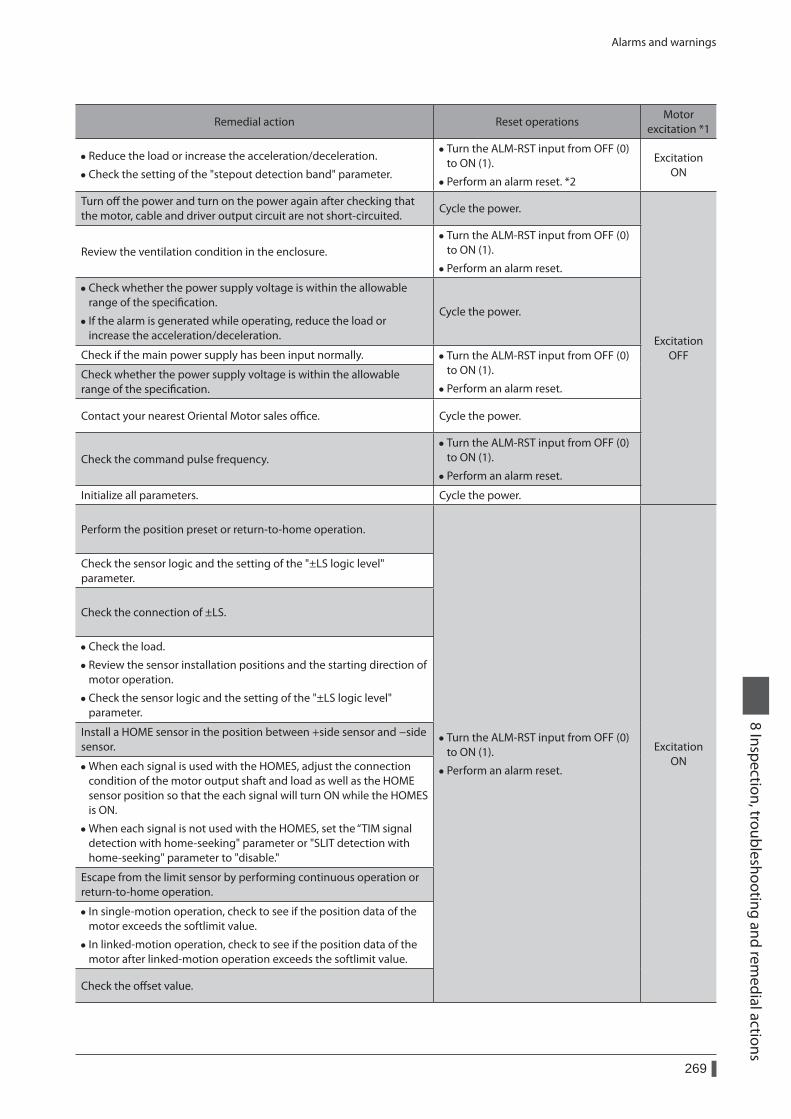
Alarms and warnings
269
8 Inspection, troubleshooting and remedial actions
Alarm list
CodeNo. of ALM LED blinks
Alarm type Cause Remedial action Reset operationsMotor
excitation *1
10h 4Excessive position deviation
When the "stepout detection action" parameter is set to "alarm" the position deviation between the encoder position and command position reached the set value of the "stepout detection band" parameter.
• Reduce the load or increase the acceleration/deceleration.
• Check the setting of the "stepout detection band" parameter.
• Turn the ALM-RST input from OFF (0) to ON (1).
• Perform an alarm reset. *2
Excitation ON
20h 5 Overcurrent The motor, cable and driver output circuit were short-circuited.Turn off the power and turn on the power again after checking that the motor, cable and driver output circuit are not short-circuited.
Cycle the power.
Excitation OFF
21h 2 Main circuit overheat The internal temperature of the driver reached 85 °C (185 °F). Review the ventilation condition in the enclosure. • Turn the ALM-RST input from OFF (0) to ON (1).
• Perform an alarm reset.
22h
3
Overvoltage • A voltage exceeding the specification value was applied.
• A large inertial load was stopped abruptly or vertical operation was performed.
• Check whether the power supply voltage is within the allowable range of the specification.
• If the alarm is generated while operating, reduce the load or increase the acceleration/deceleration.
Cycle the power.
23h Main power off The motor was started when the main power supply had been cut off. Check if the main power supply has been input normally. • Turn the ALM-RST input from OFF (0) to ON (1).
• Perform an alarm reset.25h UndervoltageThe main power was cut off momentarily or the voltage became insufficient.
Check whether the power supply voltage is within the allowable range of the specification.
2Ch 5Electrolytic capacitor error
The electrolytic capacitor on the main circuit was damaged. Contact your nearest Oriental Motor sales office. Cycle the power.
34h 2Command pulse frequency error
The command pulse frequency exceeded the specification value. Check the command pulse frequency. • Turn the ALM-RST input from OFF (0) to ON (1).
• Perform an alarm reset.
41h 9 EEPROM error The stored data was damaged. Initialize all parameters. Cycle the power.
4Ah
7
Return-to-home incomplete
When the "return-to-home incomplete alarm" parameter is set to "enable" return-to-home operation was started while the position origin has not been set.
Perform the position preset or return-to-home operation.
• Turn the ALM-RST input from OFF (0) to ON (1).
• Perform an alarm reset.
Excitation ON
60h ±LS both sides activeWhen the "hardware overtravel" parameter is set to "enable" both +LS and −LS have been detected.
Check the sensor logic and the setting of the "±LS logic level" parameter.
61hReverse limit sensor connection
The LS opposite to the operating direction has been detected while performing return-to-home operation in 2-sensor mode or 3-sensor mode.
Check the connection of ±LS.
62h Home seeking error Return-to-home operation did not complete normally.
• Check the load.
• Review the sensor installation positions and the starting direction of motor operation.
• Check the sensor logic and the setting of the "±LS logic level" parameter.
63h No HOMESThe HOMES was not detected at a position between +LS and −LS while performing return-to-home operation in 3-sensor mode.
Install a HOME sensor in the position between +side sensor and −side sensor.
64hTIM, ZSG, SLIT signal error
None of the TIM output, ZSG output, or SLIT input could be detected while performing return-to-home operation.
• When each signal is used with the HOMES, adjust the connection condition of the motor output shaft and load as well as the HOME sensor position so that the each signal will turn ON while the HOMES is ON.
• When each signal is not used with the HOMES, set the “TIM signal detection with home-seeking" parameter or "SLIT detection with home-seeking" parameter to "disable."
66h Hardware overtravelWhen the "hardware overtravel" parameter is set to "enable" +LS or −LS has been detected.
Escape from the limit sensor by performing continuous operation or return-to-home operation.
67h Software overtravelWhen the "software overtravel" parameter is set to "enable" the motor position reached the set value of the software limit.
• In single-motion operation, check to see if the position data of the motor exceeds the softlimit value.
• In linked-motion operation, check to see if the position data of the motor after linked-motion operation exceeds the softlimit value.
6AhHome seeking offset error
When performing offset movement as part of return-to-home operation, +LS or −LS has been detected.
Check the offset value.
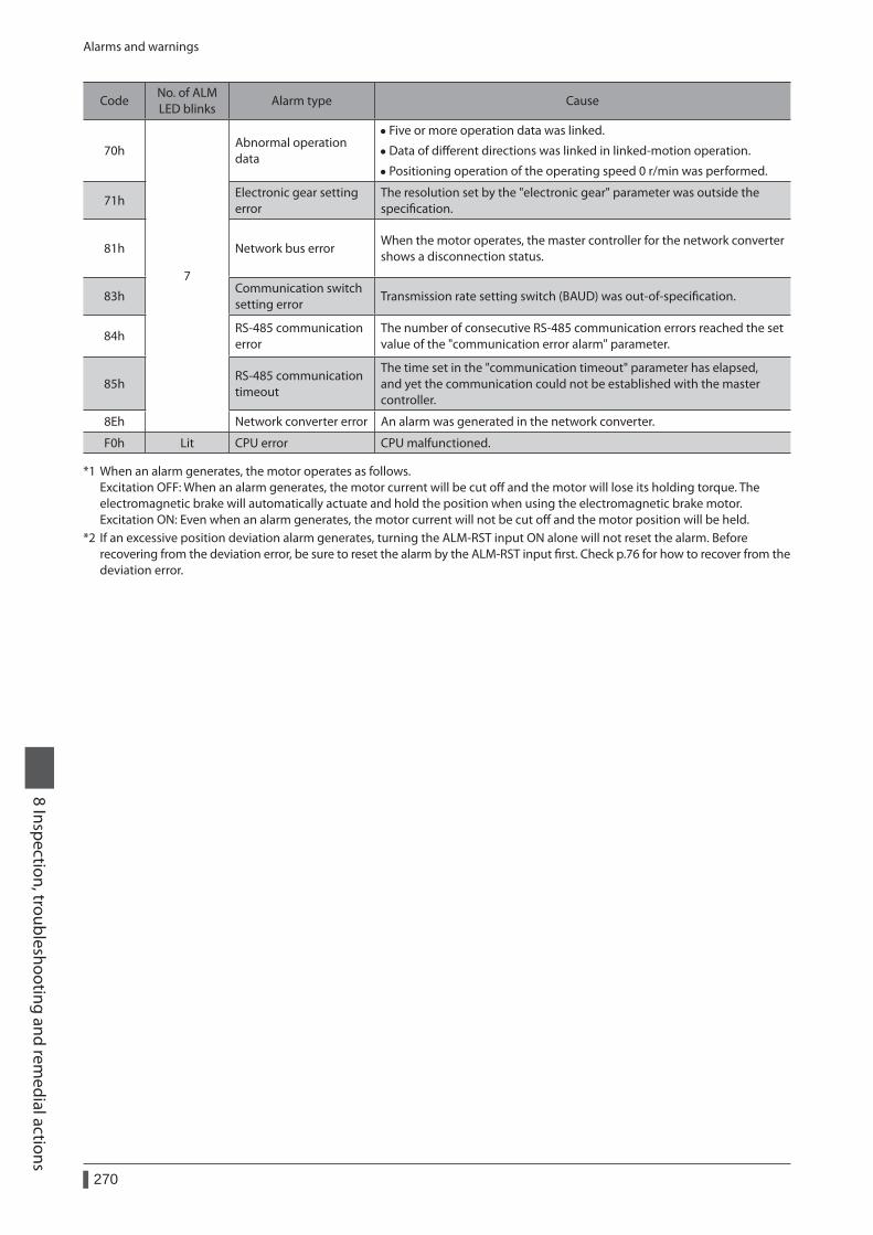
Alarms and warnings
270
8 Inspection, troubleshooting and remedial actions
CodeNo. of ALM LED blinks
Alarm type Cause Remedial action Reset operationsMotor
excitation *1
70h
7
Abnormal operation data
• Five or more operation data was linked.
• Data of different directions was linked in linked-motion operation.
• Positioning operation of the operating speed 0 r/min was performed.
Check the operation data. • Turn the ALM-RST input from OFF (0) to ON (1).
• Perform an alarm reset.
Excitation ON
71hElectronic gear setting error
The resolution set by the "electronic gear" parameter was outside the specification.
Set the electronic gear correctly, and then cycle the power. Cycle the power.Excitation
OFF
81h Network bus errorWhen the motor operates, the master controller for the network converter shows a disconnection status.
Check the connector or cable of the master controller. • Turn the ALM-RST input from OFF (0) to ON (1).
• Perform an alarm reset.
Excitation ON
83hCommunication switch setting error
Transmission rate setting switch (BAUD) was out-of-specification. Check the transmission rate setting switch (BAUD). Cycle the power.Excitation
OFF
84hRS-485 communication error
The number of consecutive RS-485 communication errors reached the set value of the "communication error alarm" parameter.
• Check the connection between the master controller and driver.
• Check the setting of RS-485 communication. • Turn the ALM-RST input from OFF (0) to ON (1).
• Perform an alarm reset.
Excitation ON85h
RS-485 communication timeout
The time set in the "communication timeout" parameter has elapsed, and yet the communication could not be established with the master controller.
Check the connection between the master controller and driver.
8Eh Network converter error An alarm was generated in the network converter. Check the alarm code of the network converter.
F0h Lit CPU error CPU malfunctioned. Cycle the power. − −
*1 When an alarm generates, the motor operates as follows. Excitation OFF: When an alarm generates, the motor current will be cut off and the motor will lose its holding torque. The electromagnetic brake will automatically actuate and hold the position when using the electromagnetic brake motor. Excitation ON: Even when an alarm generates, the motor current will not be cut off and the motor position will be held.
*2 If an excessive position deviation alarm generates, turning the ALM-RST input ON alone will not reset the alarm. Before recovering from the deviation error, be sure to reset the alarm by the ALM-RST input first. Check p.76 for how to recover from the deviation error.
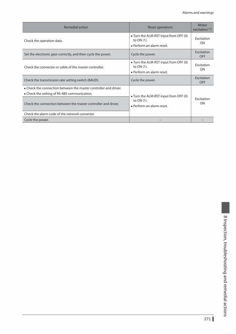
Alarms and warnings
271
8 Inspection, troubleshooting and remedial actions
CodeNo. of ALM LED blinks
Alarm type Cause Remedial action Reset operationsMotor
excitation *1
70h
7
Abnormal operation data
• Five or more operation data was linked.
• Data of different directions was linked in linked-motion operation.
• Positioning operation of the operating speed 0 r/min was performed.
Check the operation data. • Turn the ALM-RST input from OFF (0) to ON (1).
• Perform an alarm reset.
Excitation ON
71hElectronic gear setting error
The resolution set by the "electronic gear" parameter was outside the specification.
Set the electronic gear correctly, and then cycle the power. Cycle the power.Excitation
OFF
81h Network bus errorWhen the motor operates, the master controller for the network converter shows a disconnection status.
Check the connector or cable of the master controller. • Turn the ALM-RST input from OFF (0) to ON (1).
• Perform an alarm reset.
Excitation ON
83hCommunication switch setting error
Transmission rate setting switch (BAUD) was out-of-specification. Check the transmission rate setting switch (BAUD). Cycle the power.Excitation
OFF
84hRS-485 communication error
The number of consecutive RS-485 communication errors reached the set value of the "communication error alarm" parameter.
• Check the connection between the master controller and driver.
• Check the setting of RS-485 communication. • Turn the ALM-RST input from OFF (0) to ON (1).
• Perform an alarm reset.
Excitation ON85h
RS-485 communication timeout
The time set in the "communication timeout" parameter has elapsed, and yet the communication could not be established with the master controller.
Check the connection between the master controller and driver.
8Eh Network converter error An alarm was generated in the network converter. Check the alarm code of the network converter.
F0h Lit CPU error CPU malfunctioned. Cycle the power. − −
*1 When an alarm generates, the motor operates as follows. Excitation OFF: When an alarm generates, the motor current will be cut off and the motor will lose its holding torque. The electromagnetic brake will automatically actuate and hold the position when using the electromagnetic brake motor. Excitation ON: Even when an alarm generates, the motor current will not be cut off and the motor position will be held.
*2 If an excessive position deviation alarm generates, turning the ALM-RST input ON alone will not reset the alarm. Before recovering from the deviation error, be sure to reset the alarm by the ALM-RST input first. Check p.76 for how to recover from the deviation error.
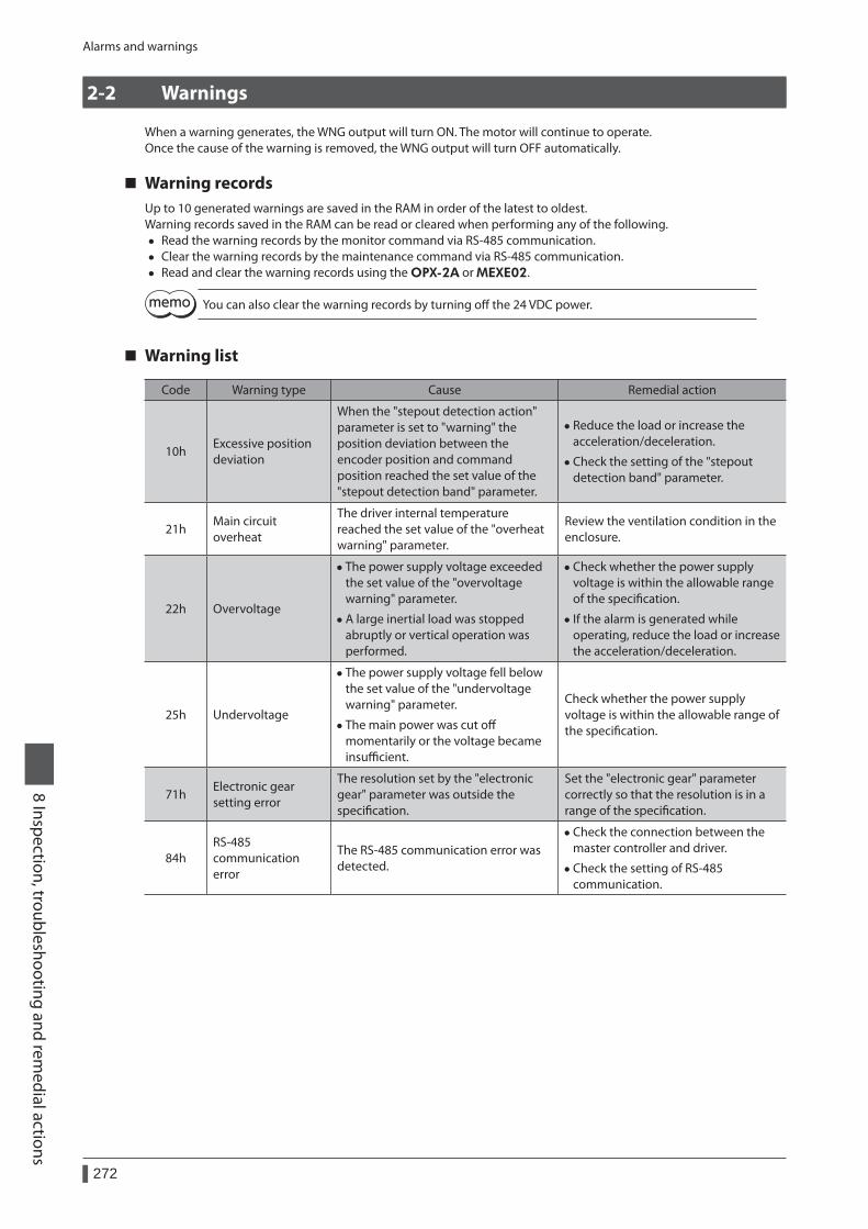
Alarms and warnings
272
8 Inspection, troubleshooting and remedial actions
2-2 Warnings
When a warning generates, the WNG output will turn ON. The motor will continue to operate.Once the cause of the warning is removed, the WNG output will turn OFF automatically.
Warning recordsUp to 10 generated warnings are saved in the RAM in order of the latest to oldest.Warning records saved in the RAM can be read or cleared when performing any of the following.
• Read the warning records by the monitor command via RS-485 communication. • Clear the warning records by the maintenance command via RS-485 communication. • Read and clear the warning records using the OPX-2A or MEXE02.
You can also clear the warning records by turning off the 24 VDC power.
Warning list
Code Warning type Cause Remedial action
10hExcessive position deviation
When the "stepout detection action" parameter is set to "warning" the position deviation between the encoder position and command position reached the set value of the "stepout detection band" parameter.
• Reduce the load or increase the acceleration/deceleration.
• Check the setting of the "stepout detection band" parameter.
21hMain circuit overheat
The driver internal temperature reached the set value of the "overheat warning" parameter.
Review the ventilation condition in the enclosure.
22h Overvoltage
• The power supply voltage exceeded the set value of the "overvoltage warning" parameter.
• A large inertial load was stopped abruptly or vertical operation was performed.
• Check whether the power supply voltage is within the allowable range of the specification.
• If the alarm is generated while operating, reduce the load or increase the acceleration/deceleration.
25h Undervoltage
• The power supply voltage fell below the set value of the "undervoltage warning" parameter.
• The main power was cut off momentarily or the voltage became insufficient.
Check whether the power supply voltage is within the allowable range of the specification.
71hElectronic gear setting error
The resolution set by the "electronic gear" parameter was outside the specification.
Set the "electronic gear" parameter correctly so that the resolution is in a range of the specification.
84hRS-485 communication error
The RS-485 communication error was detected.
• Check the connection between the master controller and driver.
• Check the setting of RS-485 communication.
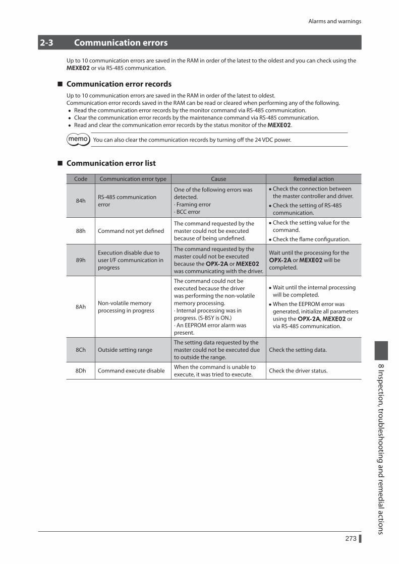
Alarms and warnings
273
8 Inspection, troubleshooting and remedial actions
2-3 Communication errors
Up to 10 communication errors are saved in the RAM in order of the latest to the oldest and you can check using the MEXE02 or via RS-485 communication.
Communication error recordsUp to 10 communication errors are saved in the RAM in order of the latest to oldest.Communication error records saved in the RAM can be read or cleared when performing any of the following.
• Read the communication error records by the monitor command via RS-485 communication. • Clear the communication error records by the maintenance command via RS-485 communication. • Read and clear the communication error records by the status monitor of the MEXE02.
You can also clear the communication records by turning off the 24 VDC power.
Communication error list
Code Communication error type Cause Remedial action
84hRS-485 communication error
One of the following errors was detected. · Framing error · BCC error
• Check the connection between the master controller and driver.
• Check the setting of RS-485 communication.
88h Command not yet definedThe command requested by the master could not be executed because of being undefined.
• Check the setting value for the command.
• Check the flame configuration.
89hExecution disable due to user I/F communication in progress
The command requested by the master could not be executed because the OPX-2A or MEXE02 was communicating with the driver.
Wait until the processing for the OPX-2A or MEXE02 will be completed.
8AhNon-volatile memory processing in progress
The command could not be executed because the driver was performing the non-volatile memory processing. · Internal processing was in progress. (S-BSY is ON.) · An EEPROM error alarm was present.
• Wait until the internal processing will be completed.
• When the EEPROM error was generated, initialize all parameters using the OPX-2A, MEXE02 or via RS-485 communication.
8Ch Outside setting rangeThe setting data requested by the master could not be executed due to outside the range.
Check the setting data.
8Dh Command execute disableWhen the command is unable to execute, it was tried to execute.
Check the driver status.
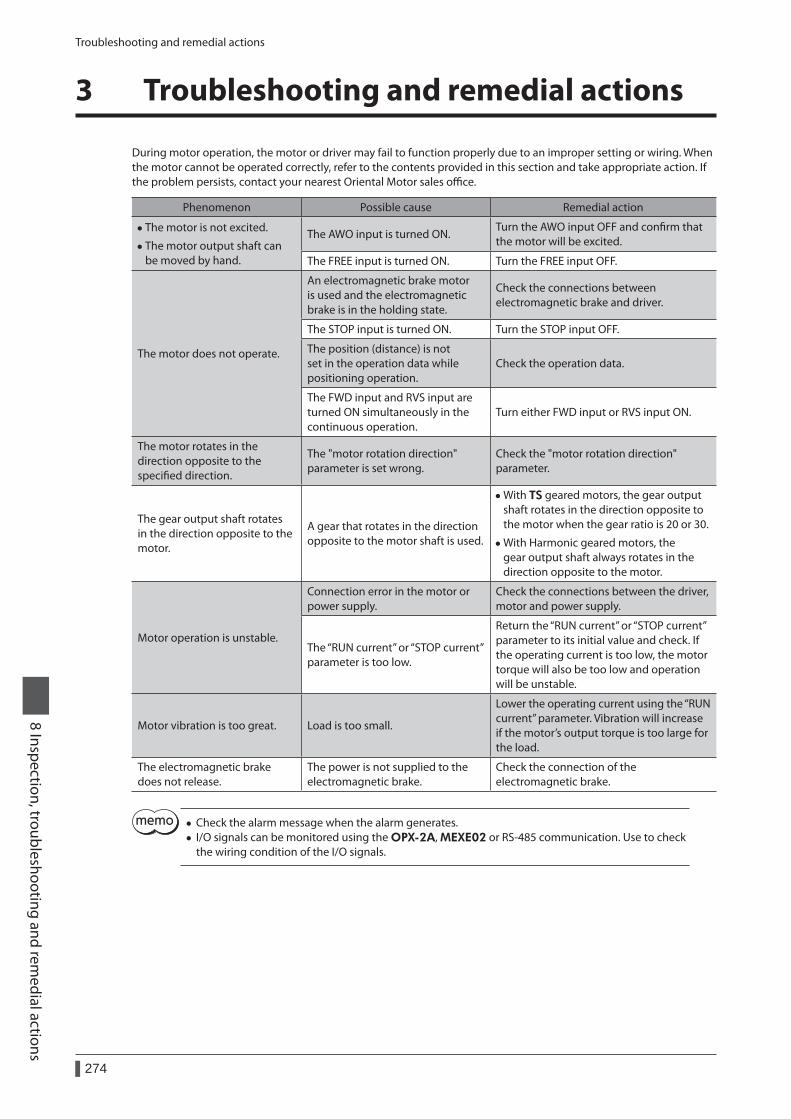
Troubleshooting and remedial actions
274
8 Inspection, troubleshooting and remedial actions
3 Troubleshooting and remedial actions
During motor operation, the motor or driver may fail to function properly due to an improper setting or wiring. When the motor cannot be operated correctly, refer to the contents provided in this section and take appropriate action. If the problem persists, contact your nearest Oriental Motor sales office.
Phenomenon Possible cause Remedial action
• The motor is not excited.
• The motor output shaft can be moved by hand.
The AWO input is turned ON.Turn the AWO input OFF and confirm that the motor will be excited.
The FREE input is turned ON. Turn the FREE input OFF.
The motor does not operate.
An electromagnetic brake motor is used and the electromagnetic brake is in the holding state.
Check the connections between electromagnetic brake and driver.
The STOP input is turned ON. Turn the STOP input OFF.
The position (distance) is not set in the operation data while positioning operation.
Check the operation data.
The FWD input and RVS input are turned ON simultaneously in the continuous operation.
Turn either FWD input or RVS input ON.
The motor rotates in the direction opposite to the specified direction.
The "motor rotation direction" parameter is set wrong.
Check the "motor rotation direction" parameter.
The gear output shaft rotates in the direction opposite to the motor.
A gear that rotates in the direction opposite to the motor shaft is used.
• With TS geared motors, the gear output shaft rotates in the direction opposite to the motor when the gear ratio is 20 or 30.
• With Harmonic geared motors, the gear output shaft always rotates in the direction opposite to the motor.
Motor operation is unstable.
Connection error in the motor or power supply.
Check the connections between the driver, motor and power supply.
The “RUN current” or “STOP current” parameter is too low.
Return the “RUN current” or “STOP current” parameter to its initial value and check. If the operating current is too low, the motor torque will also be too low and operation will be unstable.
Motor vibration is too great. Load is too small.
Lower the operating current using the “RUN current” parameter. Vibration will increase if the motor’s output torque is too large for the load.
The electromagnetic brake does not release.
The power is not supplied to the electromagnetic brake.
Check the connection of the electromagnetic brake.
• Check the alarm message when the alarm generates. • I/O signals can be monitored using the OPX-2A, MEXE02 or RS-485 communication. Use to check the wiring condition of the I/O signals.

1 Accessories ......................................................276
9 Appendix
Table of contents
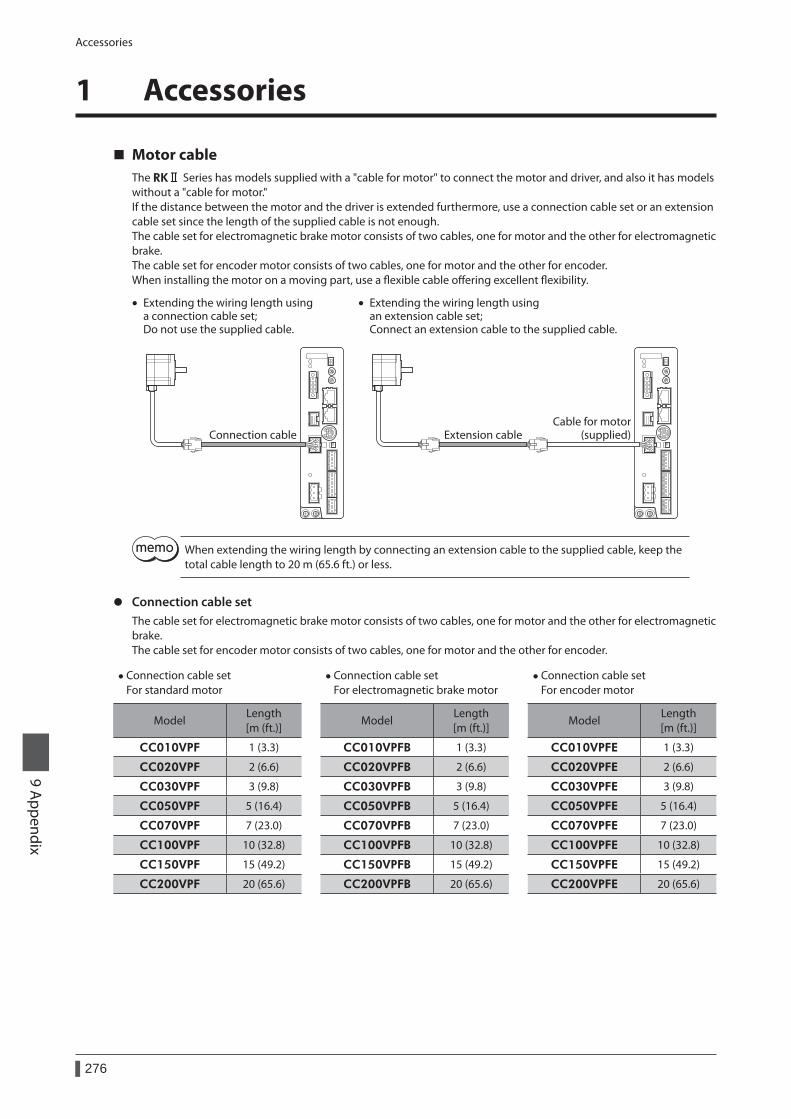
Accessories
276
9 Appendix
1 Accessories
Motor cableThe RKⅡ Series has models supplied with a "cable for motor" to connect the motor and driver, and also it has models without a "cable for motor." If the distance between the motor and the driver is extended furthermore, use a connection cable set or an extension cable set since the length of the supplied cable is not enough.The cable set for electromagnetic brake motor consists of two cables, one for motor and the other for electromagnetic brake.The cable set for encoder motor consists of two cables, one for motor and the other for encoder.When installing the motor on a moving part, use a flexible cable offering excellent flexibility.
Connection cableCable for motor
(supplied)Extension cable
• Extending the wiring length using a connection cable set; Do not use the supplied cable.
• Extending the wiring length using an extension cable set; Connect an extension cable to the supplied cable.
When extending the wiring length by connecting an extension cable to the supplied cable, keep the total cable length to 20 m (65.6 ft.) or less.
z Connection cable setThe cable set for electromagnetic brake motor consists of two cables, one for motor and the other for electromagnetic brake.The cable set for encoder motor consists of two cables, one for motor and the other for encoder.
• Connection cable set For standard motor
• Connection cable set For electromagnetic brake motor
• Connection cable set For encoder motor
ModelLength [m (ft.)]
ModelLength [m (ft.)]
ModelLength [m (ft.)]
CC010VPF 1 (3.3) CC010VPFB 1 (3.3) CC010VPFE 1 (3.3)
CC020VPF 2 (6.6) CC020VPFB 2 (6.6) CC020VPFE 2 (6.6)
CC030VPF 3 (9.8) CC030VPFB 3 (9.8) CC030VPFE 3 (9.8)
CC050VPF 5 (16.4) CC050VPFB 5 (16.4) CC050VPFE 5 (16.4)
CC070VPF 7 (23.0) CC070VPFB 7 (23.0) CC070VPFE 7 (23.0)
CC100VPF 10 (32.8) CC100VPFB 10 (32.8) CC100VPFE 10 (32.8)
CC150VPF 15 (49.2) CC150VPFB 15 (49.2) CC150VPFE 15 (49.2)
CC200VPF 20 (65.6) CC200VPFB 20 (65.6) CC200VPFE 20 (65.6)
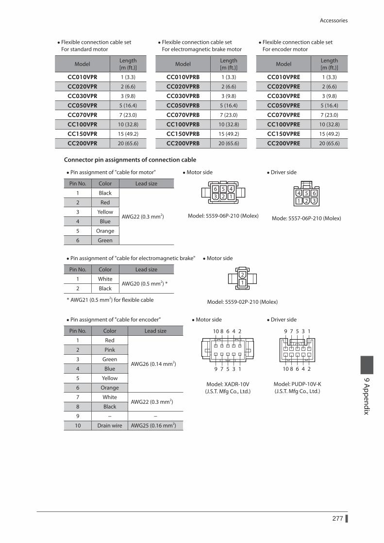
Accessories
277
9 Appendix
• Flexible connection cable set For standard motor
• Flexible connection cable set For electromagnetic brake motor
• Flexible connection cable set For encoder motor
ModelLength [m (ft.)]
ModelLength [m (ft.)]
ModelLength [m (ft.)]
CC010VPR 1 (3.3) CC010VPRB 1 (3.3) CC010VPRE 1 (3.3)
CC020VPR 2 (6.6) CC020VPRB 2 (6.6) CC020VPRE 2 (6.6)
CC030VPR 3 (9.8) CC030VPRB 3 (9.8) CC030VPRE 3 (9.8)
CC050VPR 5 (16.4) CC050VPRB 5 (16.4) CC050VPRE 5 (16.4)
CC070VPR 7 (23.0) CC070VPRB 7 (23.0) CC070VPRE 7 (23.0)
CC100VPR 10 (32.8) CC100VPRB 10 (32.8) CC100VPRE 10 (32.8)
CC150VPR 15 (49.2) CC150VPRB 15 (49.2) CC150VPRE 15 (49.2)
CC200VPR 20 (65.6) CC200VPRB 20 (65.6) CC200VPRE 20 (65.6)
Connector pin assignments of connection cable
• Pin assignment of "cable for motor" • Motor side
6 5 43 2 1
Model: 5559-06P-210 (Molex)
• Driver side
14
25
36
Mode: 5557-06P-210 (Molex)
Pin No. Color Lead size
1 Black
AWG22 (0.3 mm2)
2 Red
3 Yellow
4 Blue
5 Orange
6 Green
• Pin assignment of "cable for electromagnetic brake" • Motor side
21
Model: 5559-02P-210 (Molex)
Pin No. Color Lead size
1 WhiteAWG20 (0.5 mm2) *
2 Black
* AWG21 (0.5 mm2) for flexible cable
• Pin assignment of "cable for encoder" • Motor side
246810
13579
Model: XADR-10V (J.S.T. Mfg Co., Ltd.)
• Driver side
1
2
3
4
5
6
7
8
9
10
Model: PUDP-10V-K (J.S.T. Mfg Co., Ltd.)
Pin No. Color Lead size
1 Red
AWG26 (0.14 mm2)
2 Pink
3 Green
4 Blue
5 Yellow
6 Orange
7 WhiteAWG22 (0.3 mm2)
8 Black
9 − −
10 Drain wire AWG25 (0.16 mm2)
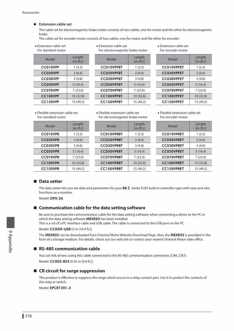
Accessories
278
9 Appendix
z Extension cable setThe cable set for electromagnetic brake motor consists of two cables, one for motor and the other for electromagnetic brake.The cable set for encoder motor consists of two cables, one for motor and the other for encoder.
• Extension cable set For standard motor
• Extension cable set For electromagnetic brake motor
• Extension cable set For encoder motor
ModelLength [m (ft.)]
ModelLength [m (ft.)]
ModelLength [m (ft.)]
CC010VPF 1 (3.3) CC010VPFBT 1 (3.3) CC010VPFET 1 (3.3)
CC020VPF 2 (6.6) CC020VPFBT 2 (6.6) CC020VPFET 2 (6.6)
CC030VPF 3 (9.8) CC030VPFBT 3 (9.8) CC030VPFET 3 (9.8)
CC050VPF 5 (16.4) CC050VPFBT 5 (16.4) CC050VPFET 5 (16.4)
CC070VPF 7 (23.0) CC070VPFBT 7 (23.0) CC070VPFET 7 (23.0)
CC100VPF 10 (32.8) CC100VPFBT 10 (32.8) CC100VPFET 10 (32.8)
CC150VPF 15 (49.2) CC150VPFBT 15 (49.2) CC150VPFET 15 (49.2)
• Flexible extension cable set For standard motor
• Flexible extension cable set For electromagnetic brake motor
• Flexible extension cable set For encoder motor
ModelLength [m (ft.)]
ModelLength [m (ft.)]
ModelLength [m (ft.)]
CC010VPR 1 (3.3) CC010VPRBT 1 (3.3) CC010VPRET 1 (3.3)
CC020VPR 2 (6.6) CC020VPRBT 2 (6.6) CC020VPRET 2 (6.6)
CC030VPR 3 (9.8) CC030VPRBT 3 (9.8) CC030VPRET 3 (9.8)
CC050VPR 5 (16.4) CC050VPRBT 5 (16.4) CC050VPRET 5 (16.4)
CC070VPR 7 (23.0) CC070VPRBT 7 (23.0) CC070VPRET 7 (23.0)
CC100VPR 10 (32.8) CC100VPRBT 10 (32.8) CC100VPRET 10 (32.8)
CC150VPR 15 (49.2) CC150VPRBT 15 (49.2) CC150VPRET 15 (49.2)
Data setterThe data setter lets you set data and parameters for your RKⅡ Series FLEX built-in controller type with ease and also functions as a monitor.
Model: OPX-2A
Communication cable for the data setting softwareBe sure to purchase the communication cable for the data setting software when connecting a driver to the PC in which the data setting software MEXE02 has been installed.This is a set of a PC interface cable and USB cable. The cable is connected to the USB port on the PC.
Model: CC05IF-USB [5 m (16.4 ft.)]
The MEXE02 can be downloaded from Oriental Motor Website Download Page. Also, the MEXE02 is provided in the form of a storage medium. For details, check out our web site or contact your nearest Oriental Motor sales office.
RS-485 communication cableYou can link drivers using this cable connected to the RS-485 communication connectors (CN6, CN7).
Model: CC002-RS4 [0.25 m (0.8 ft.)]
CR circuit for surge suppressionThis product is effective to suppress the serge which occurs in a relay contact part. Use it to protect the contacts of the relay or switch.
Model: EPCR1201-2

Accessories
279
9 Appendix
CR circuit moduleThis product is effective to suppress the surge which occurs in a relay contact part. Use this product to protect the contacts of the relay or switch.4 pieces of CR circuit for surge suppression are mounted on the compact circuit, and this product can be installed to the DIN rail. This product can make the wiring easily and securely since it also supports terminal block connection.
Model: VCS02
• Unauthorized reproduction or copying of all or part of this Operating Manual is prohibited. If a new copy is required to replace an original manual that has been damaged or lost, please contact your nearest Oriental Motor branch or sales office.
• Oriental Motor shall not be liable whatsoever for any problems relating to industrial property rights arising from use of any information, circuit, equipment or device provided or referenced in this manual.
• Characteristics, specifications and dimensions are subject to change without notice. • While we make every effort to offer accurate information in the manual, we welcome your input. Should you find unclear
descriptions, errors or omissions, please contact the nearest office. • and are registered trademark or trademark of Oriental Motor Co., Ltd., in Japan and other countries.
Modbus is a registered trademark of the Schneider Automation Inc. CC-Link is a registered trademark of the CC-Link Partner Association. MECHATROLINK is a registered trademark of the MECHATROLINK Members Association. EtherCAT® is registered trademark and patented technology, licensed by Beckhoff Automation GmbH, Germany. Other product names and company names mentioned in this manual may be registered trademarks or trademarks of their respective companies and are hereby acknowledged. The third-party products mentioned in this manual are recommended products, and references to their names shall not be construed as any form of performance guarantee. Oriental Motor is not liable whatsoever for the performance of these third-party products.
© Copyright ORIENTAL MOTOR CO., LTD. 2013
• Please contact your nearest Oriental Motor office for further information.
Technical Support Tel:(800)468-39828:30 A.M. to 5:00 P.M., P.S.T. (M-F)7:30 A.M. to 5:00 P.M., C.S.T. (M-F)www.orientalmotor.com
Schiessstraße 74, 40549 Düsseldorf, GermanyTechnical Support Tel:00 800/22 55 66 22www.orientalmotor.de
Tel:01256-347090www.oriental-motor.co.uk
Tel:01 47 86 97 50www.orientalmotor.fr
Tel:02-93906346www.orientalmotor.it
Tel:0800-060708www.orientalmotor.com.tw
SingaporeTel:1800-8420280www.orientalmotor.com.sg
Tel:1800-806161www.orientalmotor.com.my
KoreaTel:080-777-2042www.inaom.co.kr
4-8-1 Higashiueno, Taito-ku, Tokyo 110-8536 JapanTel:03-6744-0361www.orientalmotor.co.jp
Tel:1800-888-881www.orientalmotor.co.th
Tel:400-820-6516www.orientalmotor.com.cn
Tel:+55-11-3266-6018www.orientalmotor.com.br
Tel:+91-80-41125586www.orientalmotor.co.in
Hong Kong BranchTel:+852-2427-9800
Related Documents