COUNTIS E05/E06 Single-phase energy meter Direct - 40 A M-BUS EN INSTRUCTION MANUAL www.socomec.com/ en/countis-e0x COUNTIS E05 COUNTIS E06 - MID

Welcome message from author
This document is posted to help you gain knowledge. Please leave a comment to let me know what you think about it! Share it to your friends and learn new things together.
Transcript
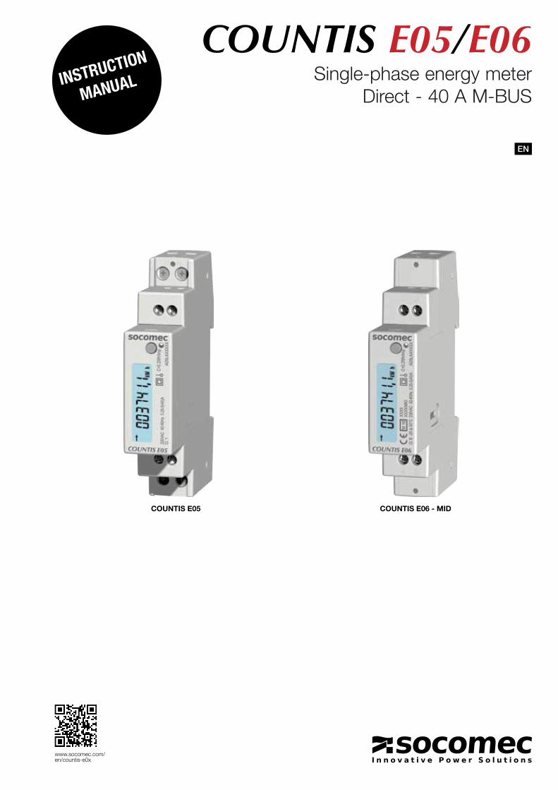
COUNTIS E05/E06Single-phase energy meter
Direct - 40 A M-BUS
EN
InstructIon
manual
www.socomec.com/en/countis-e0x
COUNTIS E05 COUNTIS E06 - MID
2 EN COUNTIS E05 / E06 - 545867A - SOCOMEC
1. DocumENtatioN . . . . . . . . . . . . . . . . . . . . . . . . . . . . . . . . . . . . . . . . . . . . . . . . . . . . . . . . . . . . .3
2. HazarDs aND warNiNgs . . . . . . . . . . . . . . . . . . . . . . . . . . . . . . . . . . . . . . . . . . . . . . . . . . . .4
2 .1 . Risk of electrocution, burns or explosion . . . . . . . . . . . . . . . . . . . . . . . . . . . . . . . .4
2 .2 . Risk of damaging the unit . . . . . . . . . . . . . . . . . . . . . . . . . . . . . . . . . . . . . . . . . . . . .4
2 .3 . Responsibility . . . . . . . . . . . . . . . . . . . . . . . . . . . . . . . . . . . . . . . . . . . . . . . . . . . . . . . .4
3. PrElimiNary oPEratioNs . . . . . . . . . . . . . . . . . . . . . . . . . . . . . . . . . . . . . . . . . . . . . . . . . . . .5
4. iNtroDuctioN . . . . . . . . . . . . . . . . . . . . . . . . . . . . . . . . . . . . . . . . . . . . . . . . . . . . . . . . . . . . . . .6
4 .1 . Introducing the COUNTIS E05 / E 06 . . . . . . . . . . . . . . . . . . . . . . . . . . . . . . . . . . .6
4 .2 . Functions . . . . . . . . . . . . . . . . . . . . . . . . . . . . . . . . . . . . . . . . . . . . . . . . . . . . . . . . . . .6
4 .3 . Front panels . . . . . . . . . . . . . . . . . . . . . . . . . . . . . . . . . . . . . . . . . . . . . . . . . . . . . . . . .6
4 .4 . LCD display . . . . . . . . . . . . . . . . . . . . . . . . . . . . . . . . . . . . . . . . . . . . . . . . . . . . . . . . .7
4 .5 . Dimensions . . . . . . . . . . . . . . . . . . . . . . . . . . . . . . . . . . . . . . . . . . . . . . . . . . . . . . . . . .7
4 .6 . Electrical readings . . . . . . . . . . . . . . . . . . . . . . . . . . . . . . . . . . . . . . . . . . . . . . . . . . . .84.6.1. Measurements . . . . . . . . . . . . . . . . . . . . . . . . . . . . . . . . . . . . . . . . . . . . .8
5. iNstallatioN . . . . . . . . . . . . . . . . . . . . . . . . . . . . . . . . . . . . . . . . . . . . . . . . . . . . . . . . . . . . . . . .9
5 .1 . Recommendations and safety . . . . . . . . . . . . . . . . . . . . . . . . . . . . . . . . . . . . . . . . .9
5 .2 . DIN rail mounting . . . . . . . . . . . . . . . . . . . . . . . . . . . . . . . . . . . . . . . . . . . . . . . . . . . .9
6. coNNEctioN . . . . . . . . . . . . . . . . . . . . . . . . . . . . . . . . . . . . . . . . . . . . . . . . . . . . . . . . . . . . . . . .10
6 .1 . Connecting the COUNTIS E05/E06 . . . . . . . . . . . . . . . . . . . . . . . . . . . . . . . . . . . .10
6 .2 . Connection to the electrical network and to the loads . . . . . . . . . . . . . . . . . . .10
7. miD comPliaNcE . . . . . . . . . . . . . . . . . . . . . . . . . . . . . . . . . . . . . . . . . . . . . . . . . . . . . . . . . . . .11
8. commuNicatioN . . . . . . . . . . . . . . . . . . . . . . . . . . . . . . . . . . . . . . . . . . . . . . . . . . . . . . . . . . . .12
8 .1 . General information . . . . . . . . . . . . . . . . . . . . . . . . . . . . . . . . . . . . . . . . . . . . . . . . .12
8 .2 . Recommendations . . . . . . . . . . . . . . . . . . . . . . . . . . . . . . . . . . . . . . . . . . . . . . . . . .12
8 .3 . Communication structure . . . . . . . . . . . . . . . . . . . . . . . . . . . . . . . . . . . . . . . . . . . .12
8 .4 . Communication tables . . . . . . . . . . . . . . . . . . . . . . . . . . . . . . . . . . . . . . . . . . . . . . .12
9. coNFiguratioN . . . . . . . . . . . . . . . . . . . . . . . . . . . . . . . . . . . . . . . . . . . . . . . . . . . . . . . . . . . . .13
9 .1 . Onscreen configuration . . . . . . . . . . . . . . . . . . . . . . . . . . . . . . . . . . . . . . . . . . . . . .139.1.1. View of the entire "SETUP" menu . . . . . . . . . . . . . . . . . . . . . . . . . . . .149.1.2. Detailed view of menu "SETUP" . . . . . . . . . . . . . . . . . . . . . . . . . . . . . .159.1.3. Example: setting the communication address . . . . . . . . . . . . . . . . . .16
10. usE . . . . . . . . . . . . . . . . . . . . . . . . . . . . . . . . . . . . . . . . . . . . . . . . . . . . . . . . . . . . . . . . . . . . . . . .17
10 .1 . Detailed view of the "Main” menu . . . . . . . . . . . . . . . . . . . . . . . . . . . . . . . . . . . .1810.1.1. Detailed view of the partial energy meter . . . . . . . . . . . . . . . . . . . . .1910.1.2. Starting up the partial energy meter . . . . . . . . . . . . . . . . . . . . . . . . .1910.1.3. Stopping the partial energy meter . . . . . . . . . . . . . . . . . . . . . . . . . . .1910.1.4. Resetting the partial energy meter to zero . . . . . . . . . . . . . . . . . . . .20
11. DiagNostics mEssagEs . . . . . . . . . . . . . . . . . . . . . . . . . . . . . . . . . . . . . . . . . . . . . . . . . . .21
12. assistaNcE . . . . . . . . . . . . . . . . . . . . . . . . . . . . . . . . . . . . . . . . . . . . . . . . . . . . . . . . . . . . . . . .21
13. cHaractEristics . . . . . . . . . . . . . . . . . . . . . . . . . . . . . . . . . . . . . . . . . . . . . . . . . . . . . . . . . .22
14. glossary oF abbrEviatioNs . . . . . . . . . . . . . . . . . . . . . . . . . . . . . . . . . . . . . . . . . . . . . .24
gb coNtENts

3ENCOUNTIS E05 / E06 - 545867A - SOCOMEC
1. DOCUMENTaTIONAll documentation on the COUNTIS E05 / E06 is available online at:www.socomec.com/en/countis-e0x
4 EN COUNTIS E05 / E06 - 545867A - SOCOMEC
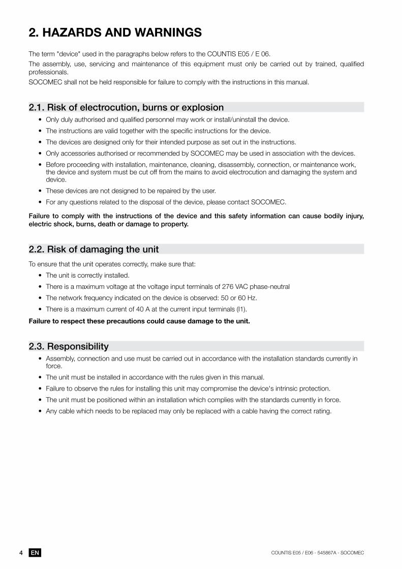
2. HazarDS aND warNINgS
The term "device" used in the paragraphs below refers to the COUNTIS E05 / E 06.
The assembly, use, servicing and maintenance of this equipment must only be carried out by trained, qualified professionals.
SOCOMEC shall not be held responsible for failure to comply with the instructions in this manual.
2.1. risk of electrocution, burns or explosion• Only duly authorised and qualified personnel may work or install/uninstall the device.
• The instructions are valid together with the specific instructions for the device.
• The devices are designed only for their intended purpose as set out in the instructions.
• Only accessories authorised or recommended by SOCOMEC may be used in association with the devices.
• Before proceeding with installation, maintenance, cleaning, disassembly, connection, or maintenance work, the device and system must be cut off from the mains to avoid electrocution and damaging the system and device.
• These devices are not designed to be repaired by the user.
• For any questions related to the disposal of the device, please contact SOCOMEC.
Failure to comply with the instructions of the device and this safety information can cause bodily injury, electric shock, burns, death or damage to property.
2.2. risk of damaging the unitTo ensure that the unit operates correctly, make sure that:
• The unit is correctly installed.
• There is a maximum voltage at the voltage input terminals of 276 VAC phase-neutral
• The network frequency indicated on the device is observed: 50 or 60 Hz.
• There is a maximum current of 40 A at the current input terminals (I1).
Failure to respect these precautions could cause damage to the unit.
2.3. responsibility• Assembly, connection and use must be carried out in accordance with the installation standards currently in
force.
• The unit must be installed in accordance with the rules given in this manual.
• Failure to observe the rules for installing this unit may compromise the device's intrinsic protection.
• The unit must be positioned within an installation which complies with the standards currently in force.
• Any cable which needs to be replaced may only be replaced with a cable having the correct rating.

5ENCOUNTIS E05 / E06 - 545867A - SOCOMEC
3. PrElIMINary OPEraTIONS
To ensure the safety of staff and the equipment, it is vital to read and absorb the contents of these instructions thoroughly before commissioning.
Check the following points as soon as you receive the package containing the unit:
• The packaging is in good condition
• The unit has not been damaged during transportation
• The device reference number conforms to your order
• The package includes: - 1 device - 1 sealing kit (for COUNTIS E06) - 1 Quick Start guide
6 EN COUNTIS E05 / E06 - 545867A - SOCOMEC
4. INTrODUCTION
4.1. introducing the couNtis E05 / E 06The COUNTIS E05 and E06 are modular active and reactive electrical energy meters that display consumed energy. They are designed for single-phase networks and allow a direct connection of up to 40 A. They are equipped with an M-BUS communication Bus.
4.2. Functions• Measures and displays total and partial energy• Dual tariff management: T1 / T2• Electrical parameter measurements: I, U, V, f• Power, power factor• M-Bus communication• MID version (according to reference)
Description Reference
COUNTIS E05 4850 3041
COUNTIS E06 - Version MID 4850 3042
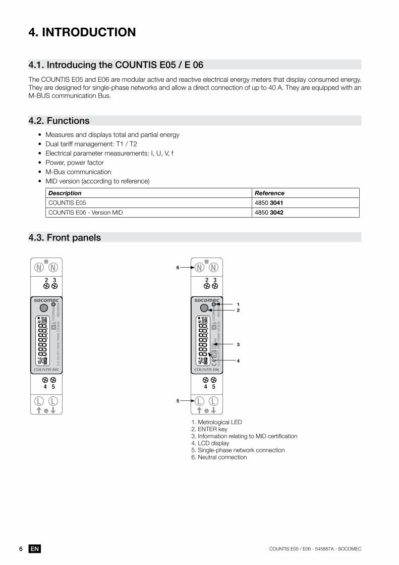
4.3. Front panels
1. Metrological LED 2. ENTER key3. Information relating to MID certification4. LCD display5. Single-phase network connection 6. Neutral connection
5LL
NN
4 5
2 3
LL
NN
4 5
2 3
2
4
3
1
6
7ENCOUNTIS E05 / E06 - 545867A - SOCOMEC
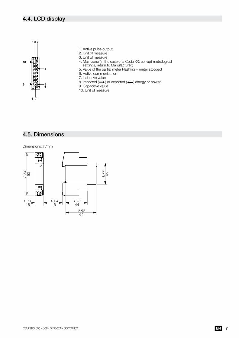
4.4. lcD display
1
4
59
10
6
2
78
3
1. Active pulse output2. Unit of measure3. Unit of measure4. Main zone (In the case of a Code XX: corrupt metrological
settings, return to Manufacturer.)5. Value of the partial meter Flashing = meter stopped6. Active communication7. Inductive value8. Imported ( ) or exported ( ) energy or power9. Capacitive value10. Unit of measure
4.5. Dimensions
Dimensions: in/mm
0.7118
0.246
1.7344
2.5264
3.54 90 1.77 45
8 EN COUNTIS E05 / E06 - 545867A - SOCOMEC
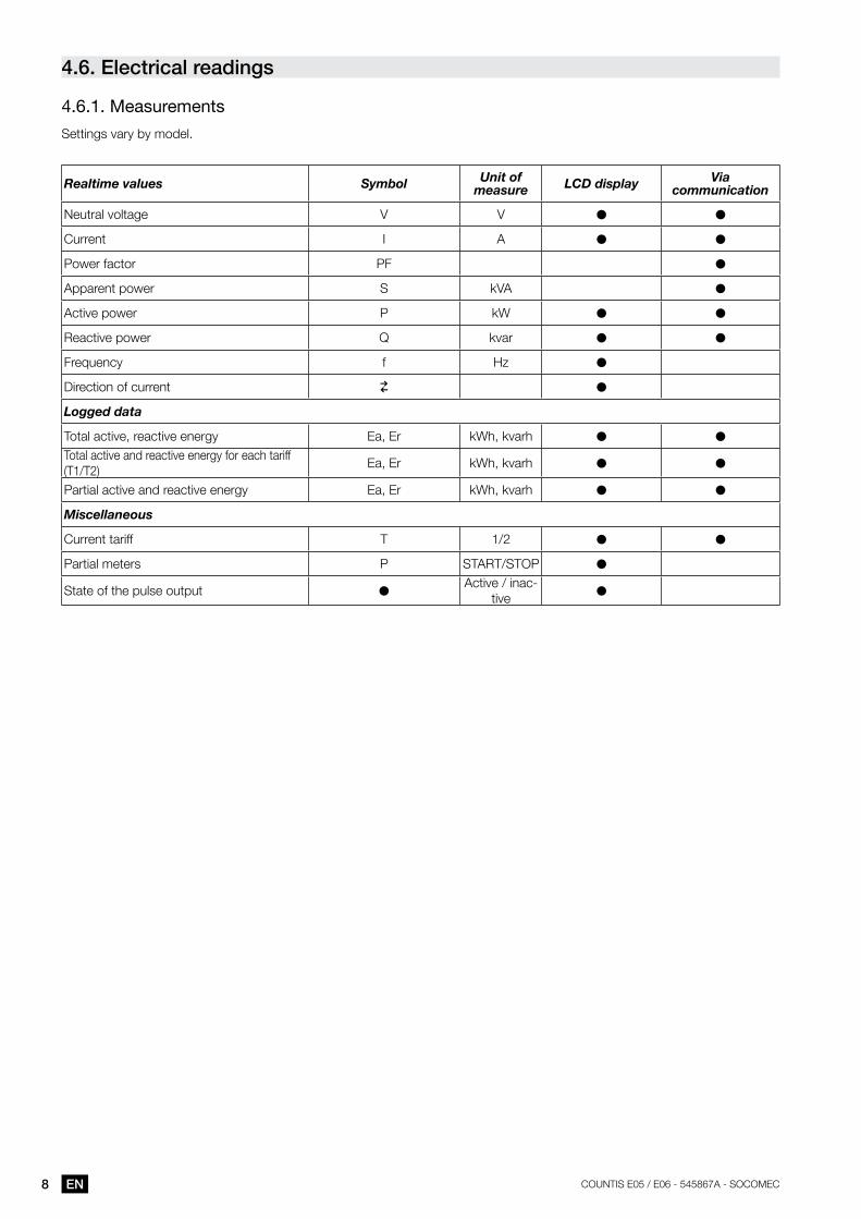
4.6. Electrical readings
4 .6 .1 . Measurements
Settings vary by model.
Realtime values Symbol Unit of measure LCD display Via
communication
Neutral voltage V V ● ●
Current I A ● ●
Power factor PF ●
Apparent power S kVA ●
Active power P kW ● ●
Reactive power Q kvar ● ●
Frequency f Hz ●
Direction of current ●
Logged data
Total active, reactive energy Ea, Er kWh, kvarh ● ●
Total active and reactive energy for each tariff (T1/T2)
Ea, Er kWh, kvarh ● ●
Partial active and reactive energy Ea, Er kWh, kvarh ● ●
Miscellaneous
Current tariff T 1/2 ● ●
Partial meters P START/STOP ●
State of the pulse output ●Active / inac-
tive ●
9ENCOUNTIS E05 / E06 - 545867A - SOCOMEC
5. INSTallaTION
The paragraphs below describe how to install the device.
5.1. recommendations and safetyRefer to the safety instructions (section "2. Hazards and warnings", page 4)
• Keep away from electromagnetic interference generator systems,
• Avoid vibrations with accelerations greater than 1 g for frequencies lower than 60 Hz.
5.2. DiN rail mountingThe COUNTIS E05/E06 can be mounted on a 35-mm DIN rail (EN 60715TM35). They must be used inside electrical cabinets.
10 EN COUNTIS E05 / E06 - 545867A - SOCOMEC
6. CONNECTION
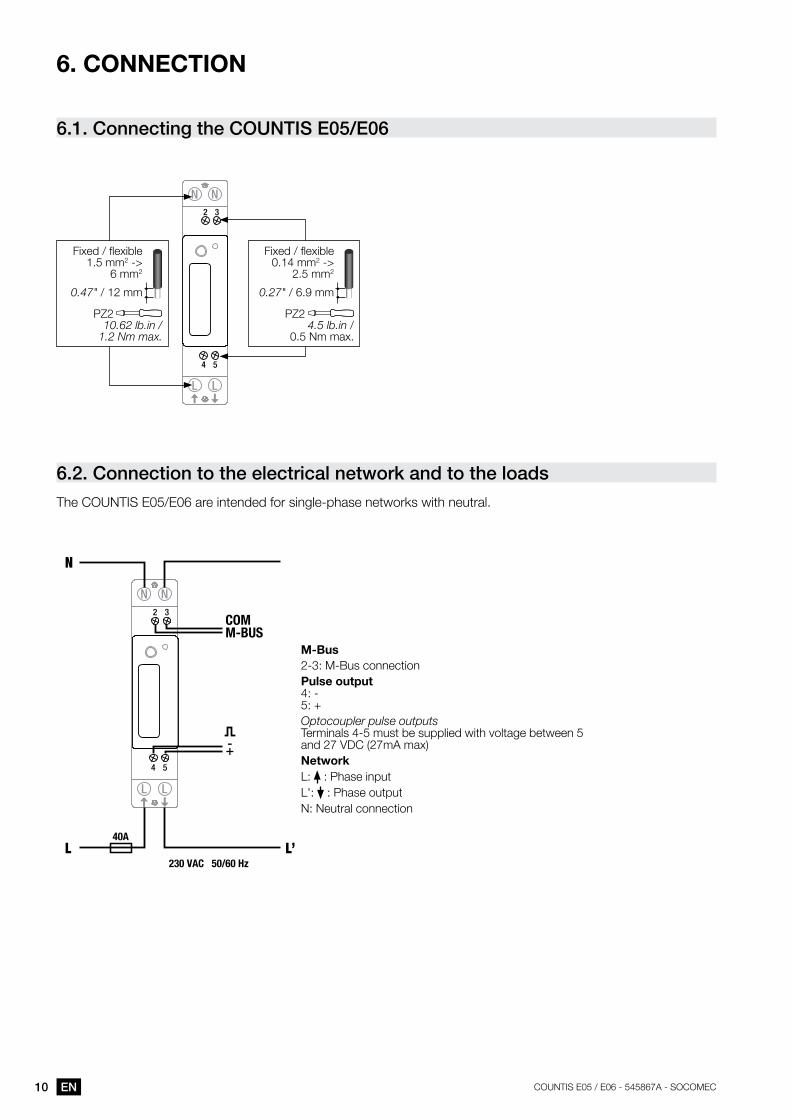
6.1. connecting the couNtis E05/E06
LL
NN
4 5
2 3
Fixed / flexible 0.14 mm2 ->
2.5 mm2
0.27" / 6.9 mm
PZ2 4.5 lb.in /
0.5 Nm max.
Fixed / flexible 1.5 mm2 ->
6 mm2
0.47" / 12 mm
PZ2 10.62 lb.in /
1.2 Nm max.
6.2. connection to the electrical network and to the loadsThe COUNTIS E05/E06 are intended for single-phase networks with neutral.
M-Bus2-3: M-Bus connection Pulse output4: -5: +Optocoupler pulse outputsTerminals 4-5 must be supplied with voltage between 5 and 27 VDC (27mA max)NetworkL: : Phase inputL': : Phase outputN: Neutral connection
LL
NN
4 5
L L’40A
N
230 VAC 50/60 Hz
2 3COM M-BUS
-+
11ENCOUNTIS E05 / E06 - 545867A - SOCOMEC
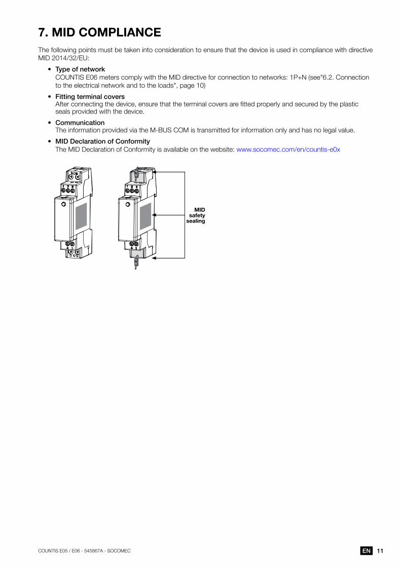
7. MID COMPlIaNCEThe following points must be taken into consideration to ensure that the device is used in compliance with directive MID 2014/32/EU:
• type of network COUNTIS E06 meters comply with the MID directive for connection to networks: 1P+N (see"6.2. Connection to the electrical network and to the loads", page 10)
• Fitting terminal covers After connecting the device, ensure that the terminal covers are fitted properly and secured by the plastic seals provided with the device.
• communication The information provided via the M-BUS COM is transmitted for information only and has no legal value.
• miD Declaration of conformity The MID Declaration of Conformity is available on the website: www.socomec.com/en/countis-e0x
MID safety
sealing
12 EN COUNTIS E05 / E06 - 545867A - SOCOMEC
8. COMMUNICaTION
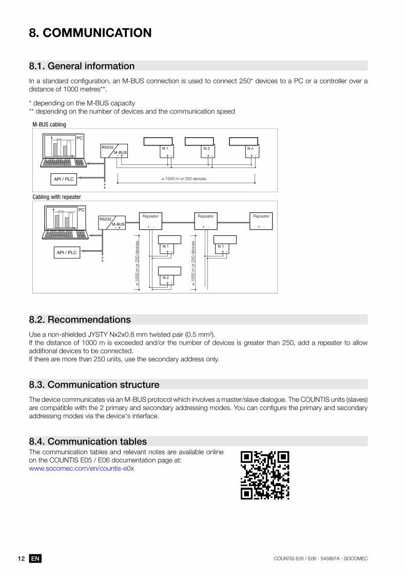
8.1. general informationIn a standard configuration, an M-BUS connection is used to connect 250* devices to a PC or a controller over a distance of 1000 metres**.
* depending on the M-BUS capacity** depending on the number of devices and the communication speed
M-BUS
M-BUS
N 1 N 1
N 2
N 1 N 2 N n
M-BUS cabling
Cabling with repeater
≈ 1000 m or 250 devices
≈ 1
000
m o
r 25
0 de
vice
s
≈ 1
000
m o
r 25
0 de
vice
s
Repeater Repeater Repeater
8.2. recommendationsUse a non-shielded JYSTY Nx2x0.8 mm twisted pair (0.5 mm²).If the distance of 1000 m is exceeded and/or the number of devices is greater than 250, add a repeater to allow additional devices to be connected.If there are more than 250 units, use the secondary address only.
8.3. communication structureThe device communicates via an M-BUS protocol which involves a master/slave dialogue. The COUNTIS units (slaves) are compatible with the 2 primary and secondary addressing modes. You can configure the primary and secondary addressing modes via the device's interface.
8.4. communication tablesThe communication tables and relevant notes are available online on the COUNTIS E05 / E06 documentation page at:www.socomec.com/en/countis-e0x
13ENCOUNTIS E05 / E06 - 545867A - SOCOMEC
9. CONFIgUraTION
The device can be configured directly from the COUNTIS E05 / E06 screen in programming mode or via the communication link. The paragraphs below describe configuring using the screen.
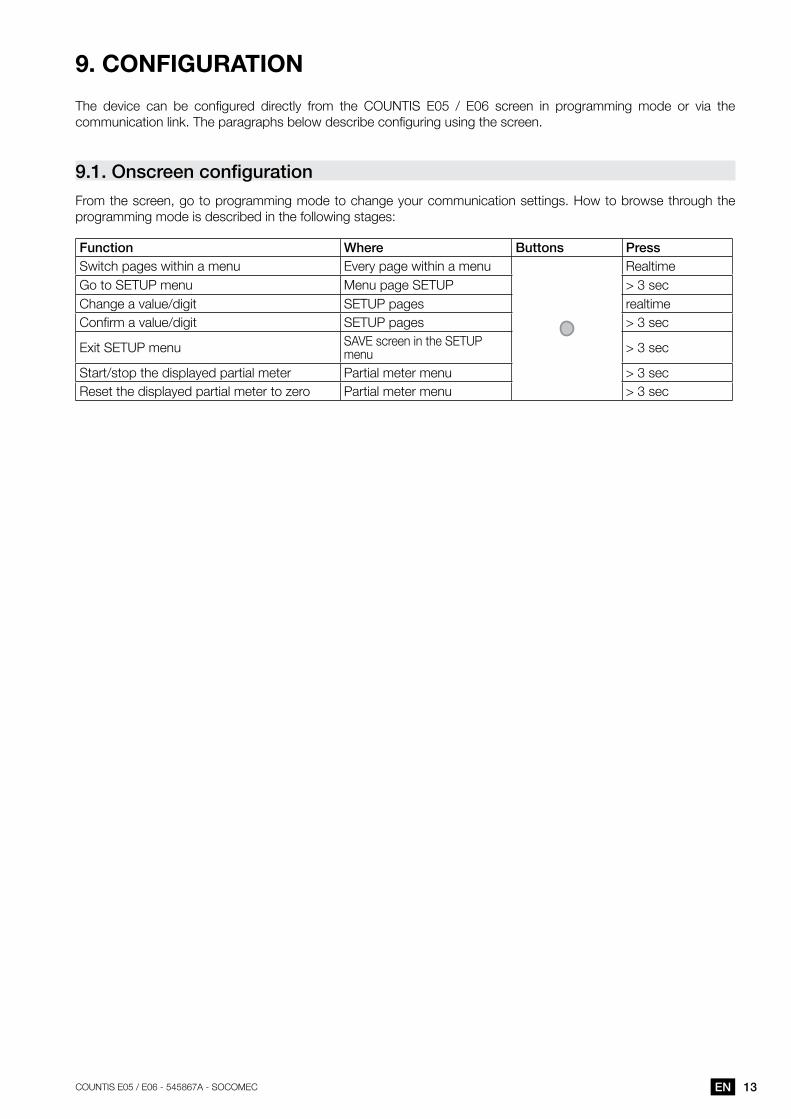
9.1. OnscreenconfigurationFrom the screen, go to programming mode to change your communication settings. How to browse through the programming mode is described in the following stages:
Function where buttons PressSwitch pages within a menu Every page within a menu RealtimeGo to SETUP menu Menu page SETUP > 3 secChange a value/digit SETUP pages realtimeConfirm a value/digit SETUP pages > 3 sec
Exit SETUP menu SAVE screen in the SETUP menu > 3 sec
Start/stop the displayed partial meter Partial meter menu > 3 secReset the displayed partial meter to zero Partial meter menu > 3 sec
14 EN COUNTIS E05 / E06 - 545867A - SOCOMEC
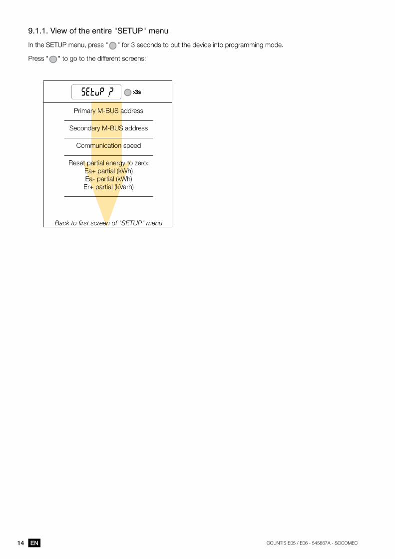
9 .1 .1 . View of the entire "SETUP" menu
In the SETUP menu, press " " for 3 seconds to put the device into programming mode.
Press " " to go to the different screens:
>3s
Primary M-BUS address
Secondary M-BUS address
Communication speed
Reset partial energy to zero: Ea+ partial (kWh) Ea- partial (kWh) Er+ partial (kVarh)
Back to first screen of "SETUP" menu

15ENCOUNTIS E05 / E06 - 545867A - SOCOMEC
9 .1 .2 . Detailed view of menu "SETUP"
>3s
Primary M-BUS address
000, 001, ..., 249, 250
Secondary M-BUS address
0, 1 ..., 99999998, 99999999 (the address is specific to each device)
Baudrate
300, 2400, 9600
reset energy
Ea+ partial; Ea- partial; Er+ partial;
Back to first screen of "SETUP" menu
XX = default value
16 EN COUNTIS E05 / E06 - 545867A - SOCOMEC
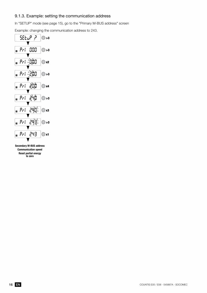
9 .1 .3 . Example: setting the communication address
In "SETUP" mode (see page 15), go to the "Primary M-BUS address" screen
Example: changing the communication address to 243.
>3
>3
x2
>3
x4
>3
x3
>3
x1
secondary m-Bus addresscommunication speedreset partial energy
to zero
17ENCOUNTIS E05 / E06 - 545867A - SOCOMEC
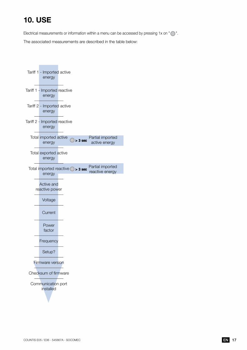
10. USE
Electrical measurements or information within a menu can be accessed by pressing 1x on " ".
The associated measurements are described in the table below:
Partial imported active energy
Partial imported reactive energy
> 3 sec
> 3 sec
Tariff 1 - Imported active energy
______________
Tariff 1 - Imported reactive energy
______________
Tariff 2 - Imported active energy
______________
Tariff 2 - Imported reactive energy
______________
Total imported active energy
______________
Total exported active energy
______________
Total imported reactive energy
______________
Active and reactive power
______________
Voltage______________
Current______________
Power factor
______________
Frequency______________
Setup?______________
Firmware version______________
Checksum of firmware______________
Communication port installed
18 EN COUNTIS E05 / E06 - 545867A - SOCOMEC
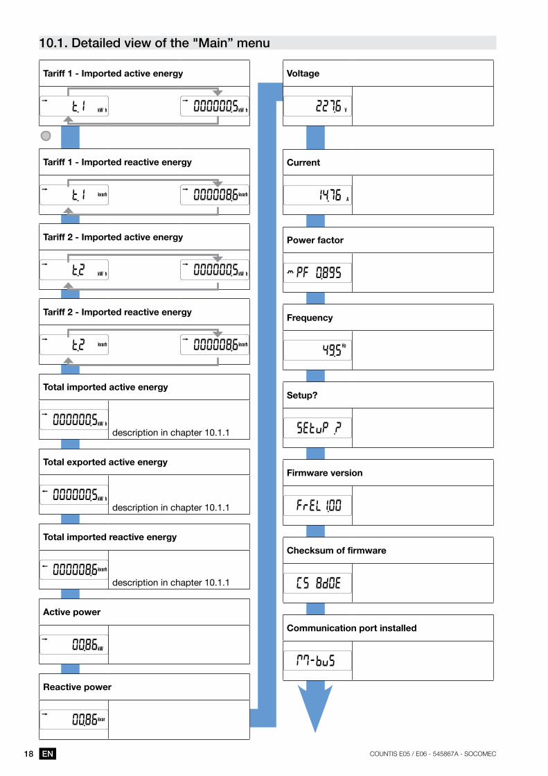
10.1. Detailed view of the "main” menu
Tariff 1 - Imported active energy
Tariff 1 - Imported reactive energy
Tariff 2 - Imported active energy
Tariff 2 - Imported reactive energy
Total imported active energy
description in chapter 10 .1 .1
Total exported active energy
description in chapter 10 .1 .1
Total imported reactive energy
description in chapter 10 .1 .1
active power
reactive power
Voltage
Current
Power factor
Frequency
Setup?
Firmware version
Checksum of firmware
Communication port installed
19ENCOUNTIS E05 / E06 - 545867A - SOCOMEC
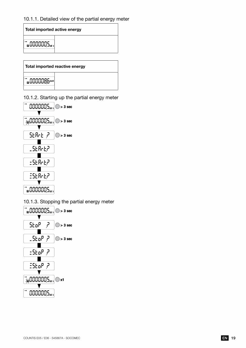
10 .1 .1 . Detailed view of the partial energy meter
Total imported active energy
Total imported reactive energy
10 .1 .2 . Starting up the partial energy meter
> 3 sec
> 3 sec
> 3 sec
10 .1 .3 . Stopping the partial energy meter
> 3 sec
> 3 sec
> 3 sec
x1
20 EN COUNTIS E05 / E06 - 545867A - SOCOMEC
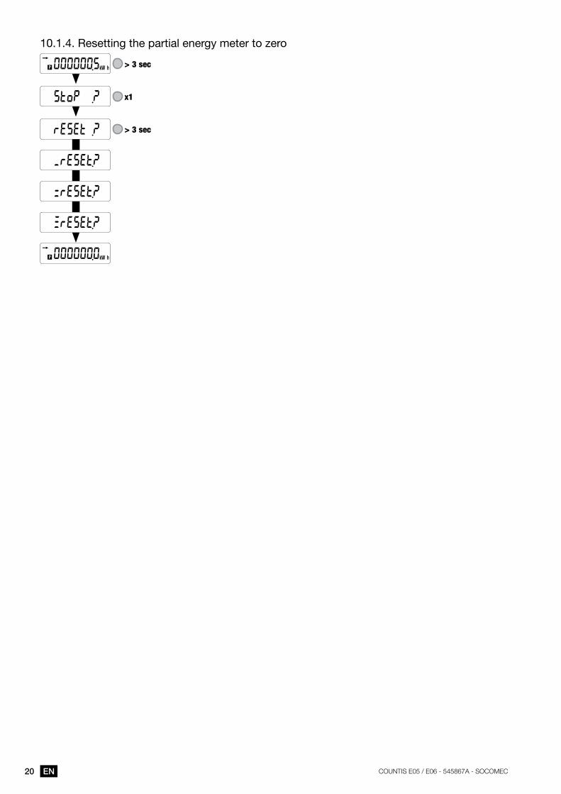
10 .1 .4 . Resetting the partial energy meter to zero
> 3 sec
x1
> 3 sec
21ENCOUNTIS E05 / E06 - 545867A - SOCOMEC
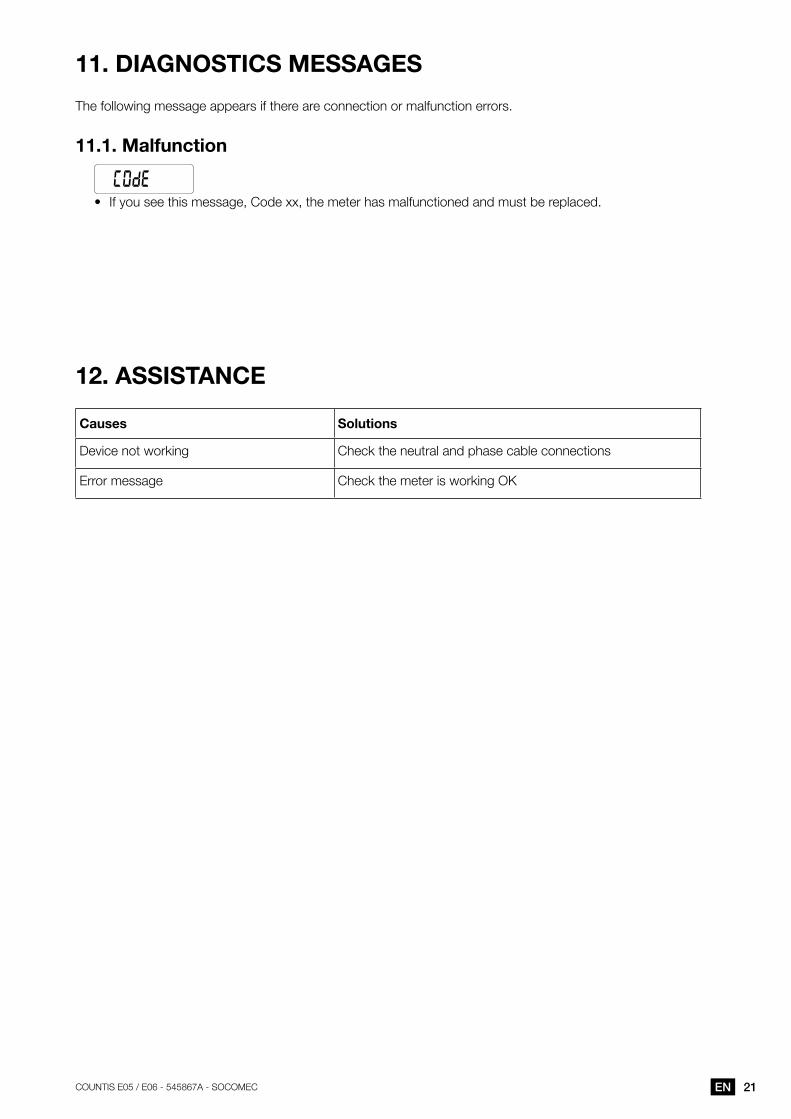
11. DIagNOSTICS MESSagES
The following message appears if there are connection or malfunction errors.
11.1. Malfunction
• If you see this message, Code xx, the meter has malfunctioned and must be replaced.
12. aSSISTaNCE
Causes Solutions
Device not working Check the neutral and phase cable connections
Error message Check the meter is working OK
22 EN COUNTIS E05 / E06 - 545867A - SOCOMEC
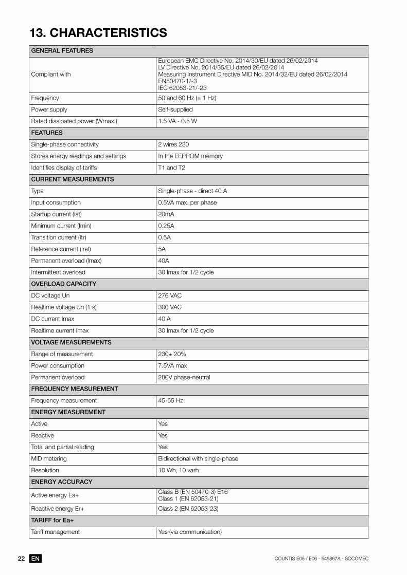
13. CHaraCTErISTICSgENEral FEaturEs
Compliant with
European EMC Directive No. 2014/30/EU dated 26/02/2014 LV Directive No. 2014/35/EU dated 26/02/2014Measuring Instrument Directive MID No. 2014/32/EU dated 26/02/2014EN50470-1/-3IEC 62053-21/-23
Frequency 50 and 60 Hz (± 1 Hz)
Power supply Self-supplied
Rated dissipated power (Wmax.) 1.5 VA - 0.5 W
FEaturEs
Single-phase connectivity 2 wires 230
Stores energy readings and settings In the EEPROM memory
Identifies display of tariffs T1 and T2
currENt mEasurEmENts
Type Single-phase - direct 40 A
Input consumption 0.5VA max. per phase
Startup current (Ist) 20mA
Minimum current (Imin) 0.25A
Transition current (Itr) 0.5A
Reference current (Iref) 5A
Permanent overload (lmax) 40A
Intermittent overload 30 Imax for 1/2 cycle
ovErloaD caPacity
DC voltage Un 276 VAC
Realtime voltage Un (1 s) 300 VAC
DC current Imax 40 A
Realtime current Imax 30 Imax for 1/2 cycle
voltagE mEasurEmENts
Range of measurement 230± 20%
Power consumption 7.5VA max
Permanent overload 280V phase-neutral
FrEQuENcy mEasurEmENt
Frequency measurement 45-65 Hz
ENErgy mEasurEmENt
Active Yes
Reactive Yes
Total and partial reading Yes
MID metering Bidirectional with single-phase
Resolution 10 Wh, 10 varh
ENErgy accuracy
Active energy Ea+ Class B (EN 50470-3) E16 Class 1 (EN 62053-21)
Reactive energy Er+ Class 2 (EN 62053-23)
tariFF for Ea+
Tariff management Yes (via communication)
23ENCOUNTIS E05 / E06 - 545867A - SOCOMEC
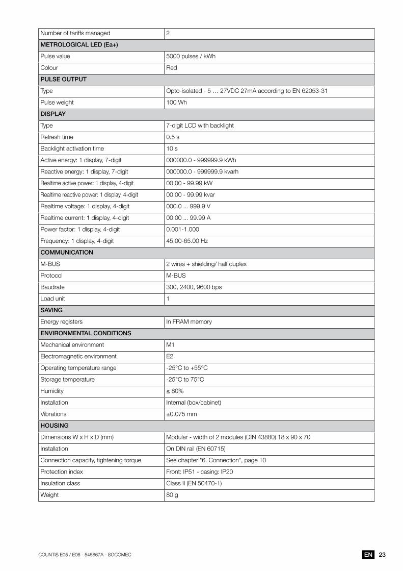
Number of tariffs managed 2
mEtrological lED (Ea+)
Pulse value 5000 pulses / kWh
Colour Red
PulsE outPut
Type Opto-isolated - 5 … 27VDC 27mA according to EN 62053-31
Pulse weight 100 Wh
DisPlay
Type 7-digit LCD with backlight
Refresh time 0.5 s
Backlight activation time 10 s
Active energy: 1 display, 7-digit 000000.0 - 999999.9 kWh
Reactive energy: 1 display, 7-digit 000000.0 - 999999.9 kvarh
Realtime active power: 1 display, 4-digit 00.00 - 99.99 kW
Realtime reactive power: 1 display, 4-digit 00.00 - 99.99 kvar
Realtime voltage: 1 display, 4-digit 000.0 ... 999.9 V
Realtime current: 1 display, 4-digit 00.00 ... 99.99 A
Power factor: 1 display, 4-digit 0.001-1.000
Frequency: 1 display, 4-digit 45.00-65.00 Hz
commuNicatioN
M-BUS 2 wires + shielding/ half duplex
Protocol M-BUS
Baudrate 300, 2400, 9600 bps
Load unit 1
saviNg
Energy registers In FRAM memory
ENviroNmENtal coNDitioNs
Mechanical environment M1
Electromagnetic environment E2
Operating temperature range -25°C to +55°C
Storage temperature -25°C to 75°C
Humidity ≤ 80%
Installation Internal (box/cabinet)
Vibrations ±0.075 mm
HousiNg
Dimensions W x H x D (mm) Modular - width of 2 modules (DIN 43880) 18 x 90 x 70
Installation On DIN rail (EN 60715)
Connection capacity, tightening torque See chapter "6. Connection", page 10
Protection index Front: IP51 - casing: IP20
Insulation class Class II (EN 50470-1)
Weight 80 g
24 EN COUNTIS E05 / E06 - 545867A - SOCOMEC
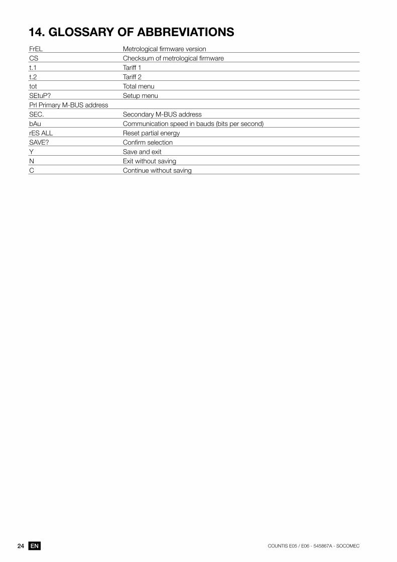
14. glOSSary OF aBBrEVIaTIONSFrEL Metrological firmware versionCS Checksum of metrological firmwaret.1 Tariff 1t.2 Tariff 2tot Total menuSEtuP? Setup menuPrl Primary M-BUS addressSEC. Secondary M-BUS addressbAu Communication speed in bauds (bits per second)rES ALL Reset partial energySAVE? Confirm selectionY Save and exitN Exit without savingC Continue without saving

25ENCOUNTIS E05 / E06 - 545867A - SOCOMEC

545867a - EN - 04/17 Non
-con
trac
tual
doc
umen
t. ©
201
6, S
ocom
ec S
AS
. All
right
s re
serv
ed.
CORPORATE HQ CONTACT: SOCOMEC SAS 1-4 RUE DE WESTHOUSE 67235 BENFELD, FRANCE
www.socomec.com
Related Documents