COUNTIS ECi2 ECi3 Operating instructions Multi-utility pulse concentrator GB F D I NL E P

Welcome message from author
This document is posted to help you gain knowledge. Please leave a comment to let me know what you think about it! Share it to your friends and learn new things together.
Transcript
COUNTIS ECi2ECi3
Operating instructionsMulti-utility pulse concentrator
GBF D I NL E P
2 COUNTIS ECi - Ref.: 538 470 A
HAZARDS AND WARNING .......................................3INITIAL CHECKS .......................................................3INTRODUCTION ........................................................4JBUS/MODBUS COMMUNICATION .........................6INSTALLATION ..........................................................7CONFIGURATION ...................................................10USE ........................................................................11PROGRAMMING .....................................................12TECHNICAL CHARACTERISTICS ...........................13TROUBLESHOOTING .............................................14
Con
tent
s
GB

3 COUNTIS ECi - Ref.: 538 470 A
HAZARDS AND WARNING
Qualified personnel and correct operationThe equipment described in this document may only be installed, commissioned and operated by trained, qualified personnel. Failure to follow the procedures given in these instructions does not imply liability on the part of the manufacturer.Standards, directives, legal provisions and local regulations must be complied with.
Risk of electrocution, burns or explosion• before working on the device, isolate all dangerous live components,• always use an appropriate voltage detection device to confirm the absence of voltage,• replace all components, doors and covers before reconnecting this device to the power supply,• always use the appropriate specified voltage to supply this device. Failure to comply with these precautions could result in serious injuries.
Risk of damage to the deviceEnsure the correct:• voltage across the AUX SUPPLY power supply terminals, 110- 400 Vac / 50-60 Hz,• voltage across the OUTPUT relay, 250 Vac or 30 Vdc.
For the safety of personnel and equipment, it is essential to read all of these instructions before using the device for the first time.Confirm the following points upon receipt of the package containing the COUNTIS ECi :• the packaging is in good condition,• the product is in good condition, • the device part number matches that specified on your order,• the contents of the package:
1 product, 1 resistance for line impedance ref: 48990019, 1 mini CD,1 quick start instructions.
INITIAL CHECKS

4 COUNTIS ECi - Ref.: 538 470 A
INTRODUCTION
The COUNTIS ECi is a pulse concentrator equipped with 7 digital inputs (logic or pulse signal), 2 ana-logues 0/4-20 mA inputs (model ECi3) and an RS485 connection to the JBUS/MODBUS protocol.It centralises and memorises pulses or logical signals in the output of electrical (COUNTIS E type), gas, heating oil, water and compressed air meters or measurement units (DIRIS type) in order to:• send them via the RS485 communication output to a remote energy management system (ENERGY REPORTING…),• display a large number of these items on its local display screen for direct reading of information,• generate event alarms (1 dedicated relay output).
The COUNTIS ECi enables advanced customisation of all items, facilitating direct reading of information concentrated in this way:• metering unit per input: kWh, m³• currency / input: €, K€, £, $, …• logical inputs (NO/NF, delay) or pulses (weight, synchronisation source, time intervals for load graphs),• logical output: configurable alarm, NO/NF and time delay,• analogue inputs: 0 or 4/20 mA, min/max in physical unit, time interval for load graphs. (ECi3 version)
It is also possible to display, at any time:• the physical status of each of the 7 digital inputs (contact open or closed, pulses present or not),• the physical and functional status of the logical output (contact open or closed, output active or inactive),• the status of 5 customisable events: date, activation time, duration, type (logical, threshold, or combination of 2 events), severity (4 information levels),• the relative value (%) and absolute value (in the chosen unit) of the 2 analogue inputs. (ECi3 version)
The communication interface of COUNTIS ECi is 2-wire RS485 type using JBUS/MODBUS protocol and enables:• remote access to all information produced by COUNTIS ECi units, above and beyond that displayed on its screen (cf. application note or JBUS/MODBUS table),• this COUNTIS to be operated from a PC or programmable logical controller (API/PLC).
This product can be configured locally (PROG menu) or by remote communication.
The COUNTIS ECi2 has the following functionalities, with direct reading on the display and values saved to memory:• Total and partial metering in the chosen unit with currency equivalent,• Daily, weekly, monthly or annual metering,• Partial metering from the last synchro trigger (in progress),• Metering on customised trigger (Perso),• For each input, it memorises pulses by integrating them over a programmable interval (from 1 to 60 min in 1 min steps) to reconstitute a load graph.
Whatever the chosen integration interval, the load graph is created over a sliding period of 17 days.• All information is accessible through JBUS/MODBUS.
5 COUNTIS ECi - Ref.: 538 470 A
A
B
C
D
E
F
G
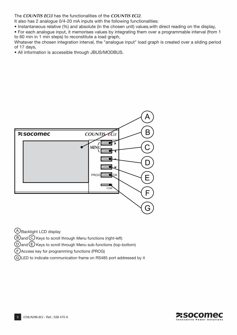
Backlight LCD display
and Keys to scroll through Menu functions (right-left)
and Keys to scroll through Menu sub-functions (top-bottom)
Access key for programming functions (PROG)
LED to indicate communication frame on RS485 port addressed by it
A
B C
D E
F
G
The COUNTIS ECi3 has the functionalities of the COUNTIS ECi2.It also has 2 analogue 0/4-20 mA inputs with the following functionalities:• Instantaneous relative (%) and absolute (in the chosen unit) values,with direct reading on the display,• For each analogue input, it memorises values by integrating them over a programmable interval (from 1 to 60 min in 1 min steps) to reconstitute a load graph,Whatever the chosen integration interval, the "analogue input" load graph is created over a sliding period of 17 days,• All information is accessible through JBUS/MODBUS.

6 COUNTIS ECi - Ref.: 538 470 A
RS485 MEDIAIn a standard configuration, one RS485 connection enables 32 UL* to be connected to a PC or PLC over 1200 metres using the JBUS/MODBUS® protocol.* 1 UL = 1 Countis ECi.
Recommendations:An LIYCY type shielded twisted pair must be used.In a disturbed environment, we recommend using a shielded twisted pair with general LIYCY-CY shielding.
If the distance is greater than 1200 m and/or there are more than 32 COUNTIS, it is necessary to con-nect a repeater (1 channel) or a spark arrester (2 channels) to enable the connection of additionalCOUNTIS. (with communication interface over more than 1200 m)
For more information on the connection procedure, refer to the technical bulletin available on the web site: www.socomec.com
Important:It is essential to connect a resistance of 120 Ohms to the 2 ends of the connection; thiscan be found in the product packaging. Other solutions are available (modem, fibre optic, etc.); please ask for details.
JBUS/MODBUS PROTOCOLThe JBUS/MODBUS protocol operates on a master/slave structure:• Reading (Function 3),• Writing (Function 6 or 16), broadcast option at address 0.The communication method is RTU (Remote Terminal Unit) with hexadecimal characters comprising a minimum of 8 bits.
JBUS/MODBUS TABLEFile Ref: 538471 Can be downloaded from the web site: www.socomec.fr
JBUS/MODBUS COMMUNICATION
R=120Ω
R=120Ω
R=120Ω
R=120Ω R=120Ω R=120Ω
7 COUNTIS ECi - Ref.: 538 470 A
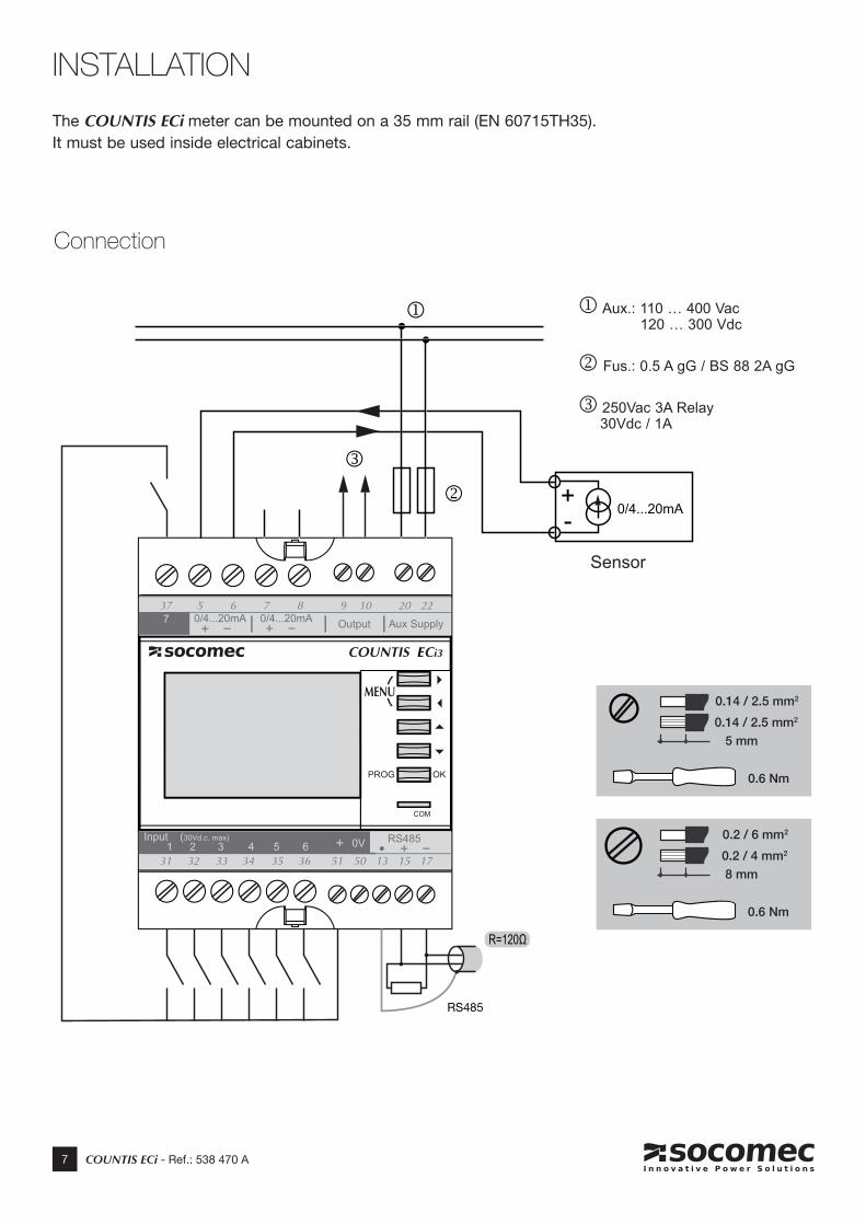
INSTALLATION
Connection
The COUNTIS ECi meter can be mounted on a 35 mm rail (EN 60715TH35). It must be used inside electrical cabinets.
0.6 Nm
5 mm
0.14 / 2.5 mm2
0.14 / 2.5 mm2
0.6 Nm
8 mm
0.2 / 6 mm2
0.2 / 4 mm2
+- 0/4...20mA
R=120Ω
RS485
Aux.: 110 … 400 Vac 120 … 300 Vdc
Fus.: 0.5 A gG / BS 88 2A gG
250Vac 3A Relay 30Vdc / 1A
Sensor
8 COUNTIS ECi - Ref.: 538 470 A
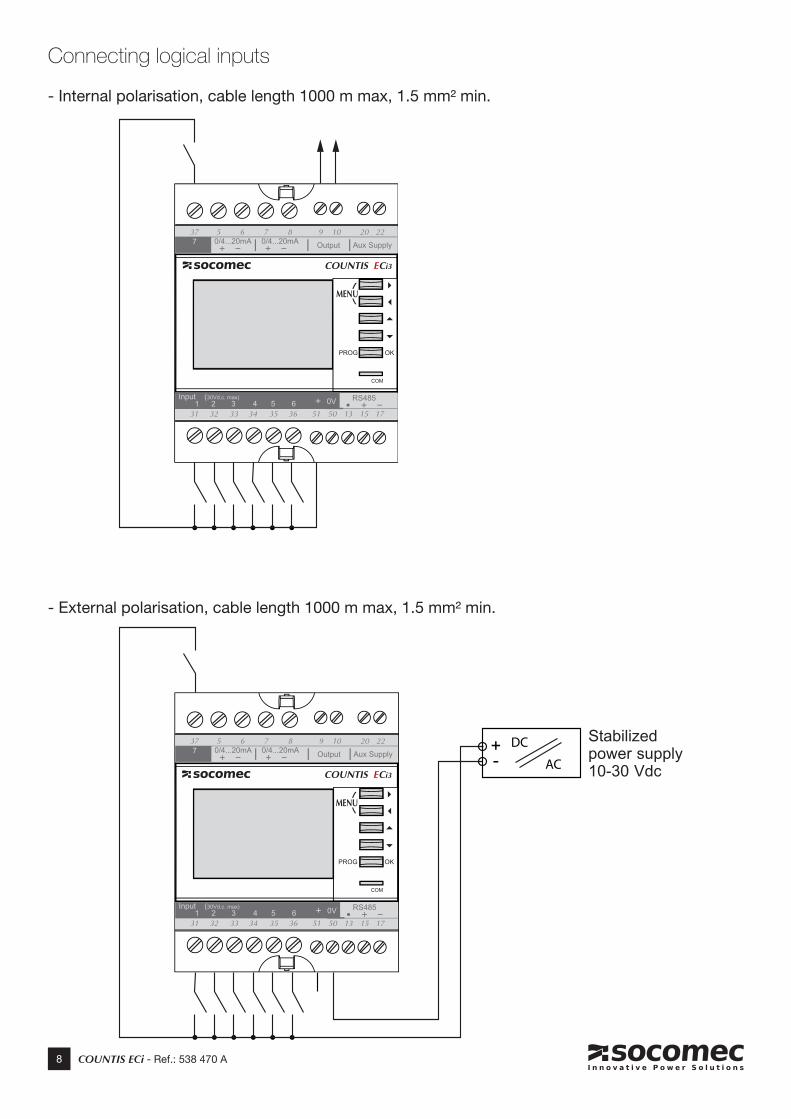
Connecting logical inputs
- Internal polarisation, cable length 1000 m max, 1.5 mm² min.
- External polarisation, cable length 1000 m max, 1.5 mm² min.
DC
AC+-
Stabilized power supply10-30 Vdc
9 COUNTIS ECi - Ref.: 538 470 A
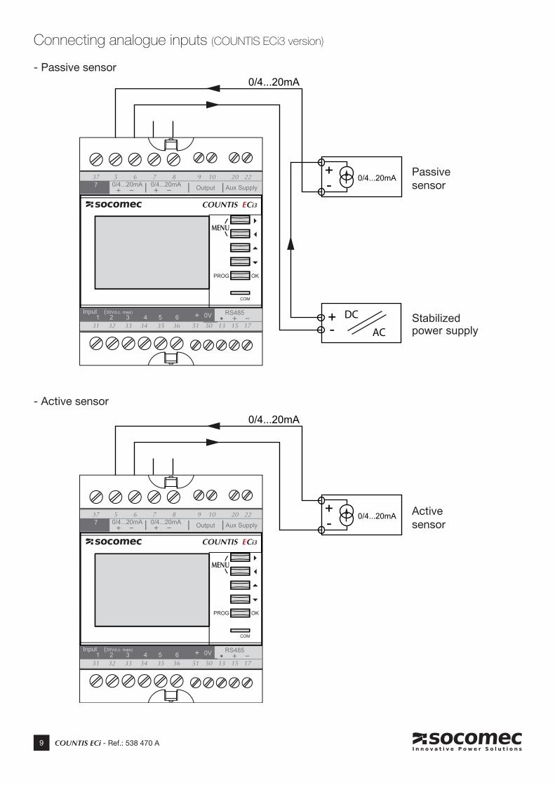
Connecting analogue inputs (COUNTIS ECi3 version)
0/4...20mA
DC
AC+-
0/4...20mA
+- 0/4...20mA
+- 0/4...20mA
- Passive sensor
- Active sensor
Stabilized power supply
Passive sensor
Active sensor

10 COUNTIS ECi - Ref.: 538 470 A
CONFIGURATION
To enter configuration mode, press the PROG key for 3 sec.You are asked for a code: • Normal user: code 1000 (default value, configurable number): all parameters can be modified EXCEPT those locked by the code 6825. • Advanced user: code 6825 (not configurable): allows access to all parameters accessible with the code 1000, as well as sensitive "maintenance" parameters: Factory settings and Input Reset.
After 1 min if a key is not pressed = automatic exit from programming mode.The configuration is not saved.To save and quit programming mode, press and hold PROG.
11 COUNTIS ECi - Ref.: 538 470 A
The
scre
ens
pres
ente
d in
the
US
AG
E /
PR
OG
RA
MM
ING
cha
rts a
re n
ot a
ll vi
sibl
e:
thei
r dis
play
dep
ends
on
the
vers
ion
of y
our C
OU
NTI
S EC
i and
thei
r con
figur
atio
n.
Inpu
t 1
Tota
l / P
artia
lA
na In
1R
el /
Abs
Log.
Inpu
tsIn
put/S
tate
/Pul
seA
larm
1Ty
pe /
Sev
er /
Sta
teD
ate
/ Tim
e
Tota
l and
par
tial m
eter
ing
Ana
logu
e in
put:
rela
tive
valu
e (%
) and
ab
solu
te v
alue
Dig
ital i
nput
:Lo
gica
l inp
ut, p
hysi
cal s
tatu
s an
d pr
esen
ce o
f pul
ses
Eve
nt 1
info
rmat
ion:
type
, se
rious
ness
, sta
tus
Dat
e an
d tim
e se
tting
Inpu
t 1
Day
/ W
eek
Ana
In 2
Rel
/ A
bs
Dai
ly a
nd w
eekl
y m
eter
ing
Ana
logu
e in
put:
rela
tive
valu
e (%
) and
ab
solu
te v
alue
Inpu
t 1
Mon
th /
Year
Inpu
t 1
Dig
. Sta
t/Phy
s/Fu
ncA
larm
1D
ate
/ Dur
atio
nTo
p S
ynch
roLa
st T
op
Mon
thly
and
yea
rly
met
erin
g
Inpu
ts 1
to 7
if lo
gica
l pro
gram
min
gD
ate
and
time
of s
tart
of
even
t 1 a
nd d
urat
ion
if co
mpl
eted
Dat
e an
d tim
e of
last
syn
c si
gnal
Inpu
t 1
OnG
oing
/ C
usto
m
Met
erin
g si
nce
the
last
sy
nc s
igna
l and
per
sona
l m
eter
ing
Inpu
t 1
Tot /
Par
t Cos
t
Out
put
Dig
. Sta
t/Phy
s/Fu
ncId
em
Ala
rm 2
> A
larm
5In
form
atio
nN
ame
/ Ver
/ S
N
Equ
ival
ent i
n cu
rren
cy o
f To
tal a
nd P
artia
l met
erin
g
Logi
cal o
utpu
t and
func
-tio
nal s
tatu
s.
Nam
e, s
oftw
are
vers
ion
and
prod
uct s
eria
l no.
Idem
Inp
ut 2
>
.
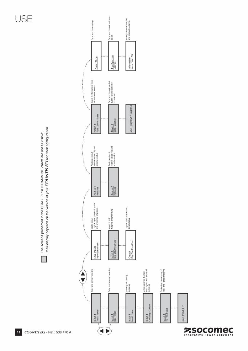
USE
12 COUNTIS ECi - Ref.: 538 470 A
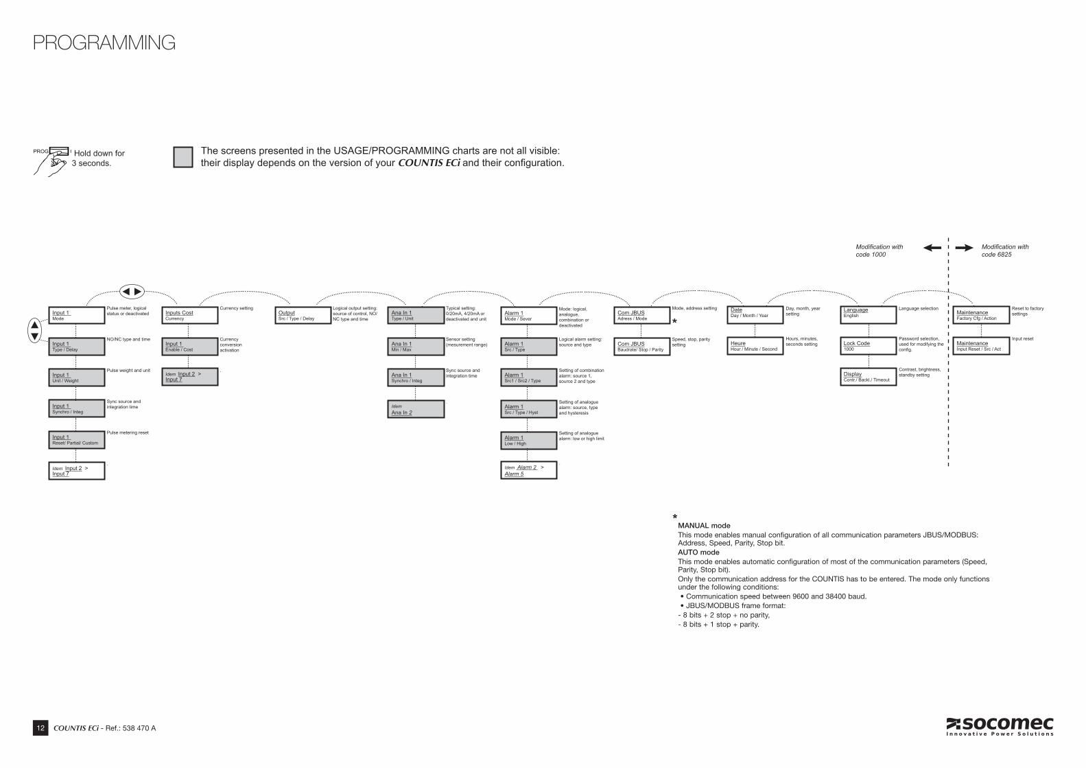
PROGRAMMING
Hold down for 3 seconds.
The screens presented in the USAGE/PROGRAMMING charts are not all visible: their display depends on the version of your COUNTIS ECi and their configuration.
MANUAL modeThis mode enables manual configuration of all communication parameters JBUS/MODBUS: Address, Speed, Parity, Stop bit.AUTO modeThis mode enables automatic configuration of most of the communication parameters (Speed, Parity, Stop bit).Only the communication address for the COUNTIS has to be entered. The mode only functions under the following conditions: • Communication speed between 9600 and 38400 baud. • JBUS/MODBUS frame format:- 8 bits + 2 stop + no parity,- 8 bits + 1 stop + parity.
*
Input 1 Mode
OutputSrc / Type / Delay
Inputs CostCurrency
Ana In 1Type / Unit
Com JBUSAdress / Mode
Alarm 1Mode / Sever
DateDay / Month / Year
LanguageEnglish Maintenance
Factory Cfg / Action
Pulse meter, logical status or deactivated
Logical output setting: source of control, NO/NC type and time
Currency setting Typical setting:0/20mA, 4/20mA or deactivated and unit
Mode, address settingMode: logical,analogue, combination or deactivated
Day, month, year setting
Language selection Reset to factory settings
Input 1 Type / Delay
NO/NC type and time
Input 1 Unit / Weight
Input 1 Enable / Cost
Ana In 1Min / Max
Com JBUSBaudrate/ Stop / Parity
Ana In 1Synchro / Integ
Alarm 1Src / Type
HeureHour / Minute / Second
Lock Code1000
DisplayContr./ Backl./ Timeout
MaintenanceInput Reset / Src / Act
Pulse weight and unit
Currency conversion activation
Sensor setting(mesurement range)
Speed, stop, parity setting
Sync source and integration time
Logical alarm setting: source and type
Hours, minutes, seconds setting
Password selection, used for modifying the config.
Contrast, brightness, standby setting
Input reset
Input 1 Synchro / Integ
Sync source and integration time
Input 1 Reset/ Partial/ Custom
Idem Ana In 2
Alarm 1Src1 / Src2 / Type
Alarm 1Src / Type / Hyst
Alarm 1Low / High
Idem Alarm 2 > Alarm 5
Pulse metering reset
.
.
Setting of combination alarm: source 1, source 2 and type
Setting of analogue alarm: source, type and hysteresis
Setting of analogue alarm: low or high limit
.Idem Input 2 > Input 7
.
Idem Input 2 > Input 7
Modification with code 6825
Modification withcode 1000
*
13 COUNTIS ECi - Ref.: 538 470 A
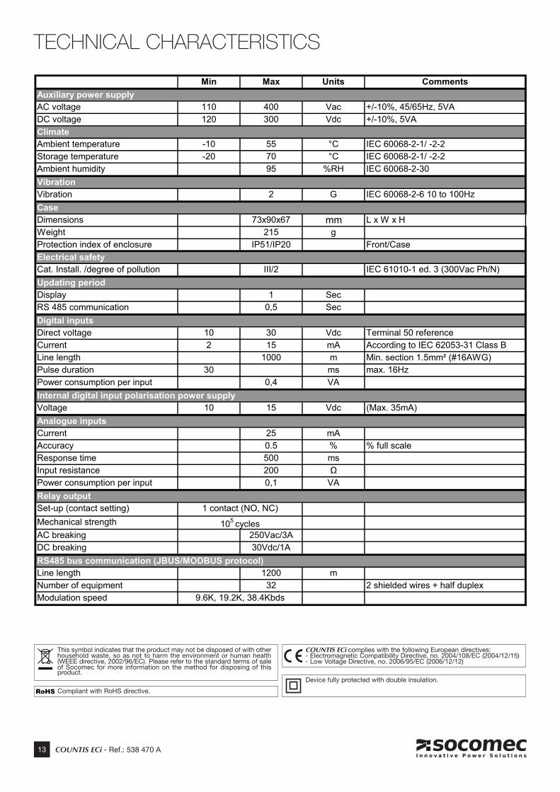
TECHNICAL CHARACTERISTICS
This symbol indicates that the product may not be disposed of with other household waste, so as not to harm the environment or human health (WEEE directive, 2002/96/EC). Please refer to the standard terms of sale of Socomec for more information on the method for disposing of this product.
COUNTIS ECi complies with the following European directives: - Electromagnetic Compatibility Directive, no. 2004/108/EC (2004/12/15) - Low Voltage Directive, no. 2006/95/EC (2006/12/12)
Compliant with RoHS directive.
Device fully protected with double insulation.
Min Max Units Comments
AC voltage 110 400 Vac +/-10%, 45/65Hz, 5VADC voltage 120 300 Vdc +/-10%, 5VA
Ambient temperature -10 55 °C IEC 60068-2-1/ -2-2Storage temperature -20 70 °C IEC 60068-2-1/ -2-2Ambient humidity 95 %RH IEC 60068-2-30
Vibration 2 G IEC 60068-2-6 10 to 100Hz
Dimensions 73x90x67 mm L x W x HWeight 215 gProtection index of enclosure IP51/IP20 Front/Case
Cat. Install. /degree of pollution III/2 IEC 61010-1 ed. 3 (300Vac Ph/N)
Display 1 SecRS 485 communication 0,5 Sec
Direct voltage 10 30 Vdc Terminal 50 referenceCurrent 2 15 mA According to IEC 62053-31 Class BLine length 1000 m Min. section 1.5mm² (#16AWG) Pulse duration 30 ms max. 16HzPower consumption per input 0,4 VA
Voltage 10 15 Vdc (Max. 35mA)
Current 25 mAAccuracy 0.5 % % full scaleResponse time 500 msInput resistance 200 ΩPower consumption per input 0,1 VA
Set-up (contact setting)Mechanical strengthAC breaking 250Vac/3ADC breaking 30Vdc/1A
Line length 1200 mNumber of equipment 32 2 shielded wires + half duplexModulation speed
Case
1 contact (NO, NC)
105 cycles
RS485 bus communication (JBUS/MODBUS protocol)
9.6K, 19.2K, 38.4Kbds
Auxiliary power supply
Climate
Updating period
Vibration
Electrical safety
Digital inputs
Internal digital input polarisation power supply
Analogue inputs
Relay output
14 COUNTIS ECi - Ref.: 538 470 A
TROUBLESHOOTING
• Device not switched onCheck the power supply cable.110…400 Vac or 120…300 Vdc between terminals 20 and 22, if there is voltage present and the device does not switch on, please return the device to us.
• Faulty communicationCheck configuration in MANUAL mode: address, speed, parity, stop bit (p.12) and cabling (p.6).For more information on the RS485 connection procedure, refer to the technical bulletin available on the web site: www.socomec.fr
• The meter does not advance incrementallyPoor connection. Go to the menu E. Digital. (p.11)Connect the input to be tested to terminal + 51 (p.8) to verify that the "pulse detected" pictogramchanges state correctly.

SOCOMEC - Ref.: 538 470 A - 02/11
This document is not a contract. SOCOMEC reserves the right to modify features without prior notice in view of continued improvement.
H E A D O F F I C E
SOCOMEC GROUP
S.A. capital 11 302 300 €
R.C. Strasbourg 548500 149 B
1, Rue de Westhouse - B.P. 60010 - F-67235 Benfeld Cedex - FRANCE
I N T E R N A T I O N A L S A L E S D E P A R T M E N TSOCOMEC
1, rue de Westhouse - B.P. 60010
F - 67235 Benfeld Cedex - FRANCE
Tél. +33 (0)3 88 57 41 41 - Fax +33 (0)3 88 74 08 00
Related Documents