These programs use dynamometers to check vehicle emissions under simulated driving conditions. So knowing how to diagnose the EGR system when a NOX failure occurs should reduce the unnecessary replacement of EGR valves. First, a little background: the basic concept of EGR hasn’t changed since it was introduced back in 1973 to meet federal emission regulations. An EGR valve is used to open a small passageway that connects the intake and exhaust manifolds. Intake vacuum then siphons some exhaust back into the engine to dilute the air/fuel mixture. This lowers combustion temperatures to reduce the formation of NOX. EGR also helps the engine resist detonation under load. (A typical earlier-style vacuum EGR valve is shown in Figure A.) When the EGR valve opens, it has much the same effect on engine performance as a vacuum leak (idle roughness, lean misfire and hesitation). For this reason, the EGR valve should not open until the engine is warm and above idle speed. On earlier vehicles with vacuum-operated EGR valves, a ported vacuum switch prevents vacuum from reaching the EGR valve until the engine is warm. In the 1980’s, computer-controlled solenoids began to replace vacuum switches in EGR systems. By monitoring engine speed, temperature, load, throttle position and vehicle speed, the computer varies the duty cycle (on time) of the EGR solenoid to vary the amount WHAT’S INSIDE: Diagnosing Digital EGR Valves…Page 1& 3 / FINE TUNING…Page 2 / QUALITY POINTS: These CAPS Are Lightweight & Tough …Page 2 & 3 / HOT OFF THE WIRE: WELLS Catalog Judged The Best…Page 4 / Publisher’s Information…Page 4 C ounter C ounter Point THE ELECTRONIC, DIAGNOSTIC AND DRIVEABILITY RESOURCE. Volume 3 Issue 4, October 1999 of EGR as well as when it occurs. Some EGR valves (Ford mostly) from this generation have a valve position sensor that provides additional feedback to the computer about how much EGR the engine is receiving. In the 1990’s, electronic (digital) EGR valves began to replace vacuum-actuated EGR valves because they can respond much faster to changes in operating conditions and work independent of intake vacuum. Several different types are used: • Single-stage (A single solenoid is used to open the exhaust passageway valve). The computer monitors various sensor inputs to determine when EGR is needed, then cycles the EGR valve solenoid on and off to control the amount of exhaust gas recirculation. • Multi-stage (Used on various late-model General Motors applications, this type has two or three solenoids that open separate exhaust passageway valves. See Figure B.) With this setup, the computer uses a step strategy to increase EGR in stages. If only a little EGR is needed, one solenoid is energized. As more EGR is needed, the second and third solenoids are energized. On the three-solenoid applications, up to seven different combinations may be used to control EGR flow. • Linear (Uses a small stepper motor instead of solenoids or a vacuum diaphragm to open the exhaust passageway valve). A linear EGR valve works much like an idle-speed control motor in that it moves in small increments. This allows the recirculation of exhaust gas to be increased or decreased with a higher degree of precision. continued on page 3 FIGURE A FIGURE B SOLENOID & MOUNTING PLATE ASSEMBLY EGR BASE PLATE EGR BASE GASKET INSULATOR GASKET SCREW ASSEMBLY ARMATURE ASSEMBLY EGR BASE E xhaust gas recirculation (EGR) is used on most engines to reduce the formation of oxides of nitrogen (NOX) in the exhaust. NOX is a pollutant that is now monitored by a growing number of “enhanced” emissions testing programs. Diagnosing Digital EGR Valves

Welcome message from author
This document is posted to help you gain knowledge. Please leave a comment to let me know what you think about it! Share it to your friends and learn new things together.
Transcript

These programs use dynamometers to checkvehicle emissions under simulated drivingconditions. So knowing how to diagnose theEGR system when a NOX failure occurs shouldreduce the unnecessary replacement of EGR valves.First, a little background: the basic concept of EGR hasn’t changed since it was introducedback in 1973 to meet federal emissionregulations. An EGR valve is used to open asmall passageway that connects the intake andexhaust manifolds. Intake vacuum then siphonssome exhaust back into the engine to dilute theair/fuel mixture. This lowers combustiontemperatures to reduce the formation of NOX.EGR also helps the engine resist detonationunder load. (A typical earlier-style vacuumEGR valve is shown in Figure A.)When the EGR valve opens, it has much the
same effect on engine performance as avacuum leak (idle roughness, leanmisfire and hesitation). For this reason,the EGR valve should not open until the
engine is warm and above idle speed. On earlier
vehicles with vacuum-operated EGR valves, a ported vacuum switch prevents vacuum from reaching the EGR valve until the engine is warm.In the 1980’s, computer-controlled solenoidsbegan to replace vacuum switches in EGRsystems. By monitoring engine speed,temperature, load, throttle position and vehiclespeed, the computer varies the duty cycle (ontime) of the EGR solenoid to vary the amount
WHAT’S INSIDE: Diagnosing Digital EGR Valves…Page 1 & 3 / FINE TUNING…Page 2 / QUALITY POINTS: These CAPS Are Lightweight & Tough …Page 2 & 3 / HOT OFF THE WIRE: WELLS Catalog Judged The Best…Page 4 / Publisher’s Information…Page 4
CounterCounter PointT H E E L E C T R O N I C, D I A G N O S T I C A N D D R I V E A B I L I T Y R E S O U R C E.
Volume 3 Issue 4, October 1999
of EGR as well as when it occurs. Some EGRvalves (Ford mostly) from this generation have avalve position sensor that provides additionalfeedback to the computer about how much EGRthe engine is receiving.In the 1990’s, electronic (digital) EGR valvesbegan to replace vacuum-actuated EGR valvesbecause they can respond much faster to changesin operating conditions and work independentof intake vacuum. Several different types are used:• Single-stage (A single solenoid is used to openthe exhaust passageway valve). The computermonitors various sensor inputs to determinewhen EGR is needed, then cycles the EGR valvesolenoid on and off to control the amount ofexhaust gas recirculation.• Multi-stage (Used on various late-modelGeneral Motors applications, this type has twoor three solenoids that open separate exhaustpassageway valves. See Figure B.) With thissetup, the computer uses a step strategy toincrease EGR in stages. If only a little EGR isneeded, one solenoid is energized. As more EGRis needed, the second and third solenoids areenergized. On the three-solenoid applications,up to seven different combinations may be usedto control EGR flow.
• Linear (Uses a small stepper motor instead ofsolenoids or a vacuum diaphragm to open theexhaust passageway valve). A linear EGR valveworks much like an idle-speed control motor inthat it moves in small increments. This allowsthe recirculation of exhaust gas to be increasedor decreased with a higher degree of precision.
continued on page 3
FIGURE A
FIGURE B
SOLENOID &MOUNTINGPLATE ASSEMBLY
EGR BASE PLATE
EGR BASE GASKET
INSULATORGASKET
SCREWASSEMBLY
ARMATUREASSEMBLY
EGR BASE
Exhaust gas recirculation
(EGR) is used on most
engines to reduce the
formation of oxides of nitrogen (NOX) in
the exhaust. NOX is a pollutant that is now monitored
by a growing number of “enhanced” emissions testing programs.
Diagnosing DigitalEGR Valves
These CAPS Are Lightweight & Tough
2
Distributor caps and rotors may seem like a“generic” product to some. After all, mostreplacement caps and rotors look pretty much the same. But appearances can bedeceiving because the performance of thematerials from which these parts are made can vary significantly.
As a leading supplier of original equipmentignition components, WELLS’ engineers havethe inside track on what works and what doesn’t.OEM caps and rotors must meet rigorous teststandards for performance and durability. That’s why WELLS uses a special lightweightthermoplastic polyester resin in its OEM and
Quality aftermarket distributor caps and rotors thatoutperforms the heavy, mica-filled componentsof yesterday.The thermoplastic polyester resin that WELLSuses has outstanding chemical resistance to oil,gasoline, underhood chemicals and otherautomotive fluids. It also has excellentdimensional stability. The dimensions remainstable regardless of temperature, humidity or chemical attack, so the parts fit correctlywhen they’re installed, and continue to fitperfectly for years to come.WELLS caps and rotors have very low moisture-absorption characteristics resulting in superiordielectric strength. This allows them to better
Q: “We have a supercharged 1995 PontiacBonneville 3.8 VIN 1 that has a surge atidle with codes P0131 and P0171. We havechecked the O2 sensor, fuel pressure,timing, and vacuum hoses and connectionsfor leaks. The ISC counts are low but seemto be okay at around 13 or 14. This cardoes this all the time and temperatureseems to have no effect.”
Stevens’ Shell, Elizabeth, NJ
With your scan tool connected, if the ISC counts stayless than 15, and the long/short-term fuel trim remainsgreater than 140, you should expect an air leak. Oneplace you didn’t mention checking was the superchargeroutlet gasket. Check for leaks, especially around thepulley end, as this is a common area for leakage to occur.
Q: “I have a 1996 Buick Skylark with the2.4L SFI that has a problem with a roughidle, repetitive stalling and hard starting.This problem is very intermittent and onlyseems to happen after the car has beensitting for a while, like overnight, andseems worse in colder weather. Scan tooldata seems to check out OK, but sometimes
there are misfire codes (P0300 throughP0304). Any suggestions?”
Bill Renton, Billings, MT
If you haven’t checked the oil pressure, you should do so,as there have been reports of the type of problem you arehaving due to excessive oil pressure caused by a stickingrelief valve. This would cause the lifters to raise the valvesoff of their seats, resulting in a loss of compression andengine misfire and/or stalling on initial start-up. Tocheck this, install an oil-pressure gauge that can read atleast 150 psi in an oil pressure port and check the oilpressure at 3000 rpm. The oil pressure should not exceed100 psi even in very cold operating conditions andshould not exceed 85 psi with the engine warmed up tooperating temperature. If the oil pressure exceeds theselimits, you will have to replace the oil pump cover thathas an improved pressure relief valve.
Q: “I am working on a 1997 Chevy Astrowith the 4.3 VIN W engine. This van has anintermittent stalling condition and lousyperformance and has a DTC P0300.Distributor cap, rotor, coil, plugs, plugwires, engine vacuum, compression, fuelpressure are all good. Cam and crankposition sensor signals are consistent. The primary wiring and connectors have all been checked as well. The engine runsgood at idle and in gear most of the time,but when driven, performance is poor. Any ideas?”
Brian Williams, St. Louis, MO
Check the ignition coil wires where they attach to theprimary terminals. These wires can get brittle near theconnector and the wire strands can break inside of the
insulation and not be easily detected. This can causereduced primary current flow, resulting in engine misfire under load. Eventually, all of the strands canbreak resulting in a no-start condition.
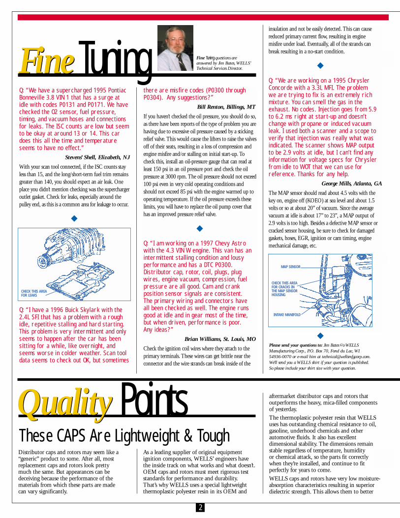
Q: “We are working on a 1995 ChryslerConcorde with a 3.3L MFI. The problem we are trying to fix is an extremely richmixture. You can smell the gas in theexhaust. No codes. Injection goes from 5.9to 6.2 ms right at start-up and doesn’tchange with propane or induced vacuumleak. I used both a scanner and a scope toverify that injection was really what wasindicated. The scanner shows MAP output to be 2.9 volts at idle, but I can’t find anyinformation for voltage specs for Chryslerfrom idle to WOT that we can use forreference. Thanks for any help.
George Mills, Atlanta, GA
The MAP sensor should read about 4.5 volts with thekey on, engine off (KOEO) at sea level and about 1.5volts or so at about 20” of vacuum. Since the averagevacuum at idle is about 17” to 23”, a MAP output of2.9 volts is too high. Besides a defective MAP sensor orcracked sensor housing, be sure to check for damagedgaskets, hoses, EGR, ignition or cam timing, enginemechanical damage, etc.
Fine Tuning questions are answered by Jim Bates, WELLS’Technical Services Director. FineFine Tuning
Quality Points
CHECK THIS AREA FOR LEAKS
MAP SENSOR
INTAKE MANIFOLD
CHECK THIS AREAFOR CRACKS INTHE MAP SENSORHOUSING
Please send your questions to: Jim Bates c⁄ o WELLS Manufacturing Corp., P.O. Box 70, Fond du Lac, WI 54936-0070 or e-mail him at [email protected]. We’ll send you a WELLS shirt if your question is published. So please include your shirt size with your question.

3
continued from page 1
Diagnosing Digital EGR Valves
EGR PROBLEMSWith earlier-style vacuum-operated EGRvalves, failure of the vacuum diaphragm
or carbon buildup on the pintle valve are themain causes of trouble. A leaky diaphragm willprevent the EGR valve from opening, causingnot only an increase in NOX emissions butoften detonation (spark knock) when the engineis under load. Carbon can also build up insidethe manifold passageway and block the flow ofexhaust. Carbon deposits that prevent the valvepintle from closing will produce driveabilitysymptoms like a vacuum leak (hard starting,rough idle, lean misfire, hesitation and possiblystalling after cold starting).With digital EGR valves, the driveabilitysymptoms are the same: elevated NOXemissions and detonation with loss of EGR, or idle problems if the valve fails to close.
HOW TO DIAGNOSEOn earlier vehicles, visually inspecting the EGRvalve to see that it moves when the engine isrevved is one way to check its operation.Another is to apply vacuum directly to the EGRvalve and listen for a drop in idle speed whenthe valve opens (but this only works if the valveis not a back-pressure-sensing type). Back-pressure-sensing EGR valves only open
when back-pressure exceeds a certainlevel, so be sure to raise the enginespeed to about 2000 rpm beforeapplying vacuum.
On vehicles that have a vacuum-type EGR valvewith a solenoid in the vacuum supply line,vacuum should pass to the EGR valve when theengine is warm and above idle. No vacuum?Check for voltage at the solenoid. No voltagewould indicate a wiring problem. The computershould energize (ground) the solenoid whenEGR conditions exist (engine warm, runningabove idle). If EGR is not occurring, theproblem may be a bad solenoid, wiring,computer or sensor problem. The solenoid itselfcan be checked by jumping it to battery voltage.No click will tell you the solenoid needs to bereplaced. The next most likely causes would be aloose wiring connector, faulty coolant sensor, or
failed driver circuit in the computer. With digital EGR valves, a “Check Engine” lightaccompanied by any of the following fault codes may indicate a problem in the EGR system:• Ford: 31, 32, 33, 34, 83, 84• Chrysler: 31• General Motors: 75, 76 and 77• All OBD II vehicles (1996 & up): Diagnostic
Trouble Code (DTC) P0401 insufficient flow, P1406 EGR sensor
On some vehicle applications, a scan tool canalso be used to access and display EGR valveposition and status.
BENCH TESTS FOR A DIGITAL EGR VALVETo check a three-solenoid GM digital EGRvalve, (Refer to Figure C) and measure theresistance of each solenoid:• Terminal A to B: 20 ohms• Terminal A to C: 10 to 17 ohms• Terminal A to D: 20 to 30 ohmsIf any resistance reading is outside the range ofspecifications, the unit is defective and needs tobe replaced.Using a 9-volt battery or sensor tester, runbattery positive (+) current to the “A” terminal,then ground each of the other terminals (B, C &D) one at a time (see Figure C). Each solenoidshould click and open its respective pintle valve.No click or movement would indicate a faultysolenoid.With the battery and jumpers disconnected,spray a small amount of carburetor cleaner intoeach orifice (Figure D), being careful not to getthe cleaner in the center hole. If the cleaner seepsout of any orifice hole into the center, the pintleis not seating properly and the EGR valve needsto be replaced.If a digital EGR valve passes the above tests butthere are fault codes present, the problem mayexist in one or more of the following: thepowertrain control module (PCM), manifold airpressure (MAP) sensor, the oxygen (O2) sensor,throttle position sensor (TPS), a plugged intakemanifold passageway, a clogged catalyticconverter, a blown fuse or a wiring problem.
TESTING A DIGITAL EGR VALVE ON THE VEHICLEThe same resistance checks can be made betweenthe terminals (A to B, A to C and A to D). If resistance is within specs, check the operationof the EGR valve by back-probing andgrounding each solenoid terminal (B, C & D).This must be done with the engine at normaloperating temperature, idling in closed loop.When each solenoid is grounded (energized),there should be a momentary drop in idle speedif the EGR valve is opening and the intakepassageways are unobstructed. The computer will immediately compensate for the drop in idle speed by opening up the idle air-controlvalve to increase rpm, so you may have to use a tachometer to detect the rpm drop. No changein idle speed would indicate a faulty EGR valveor blocked passageways.Note: This test can also be done with a bi-directional scan tool by selecting EGR output test and then energizing each solenoid to check for the rpm drop.If the EGR valve passes these tests but is notfunctioning, the problem is in the wiring, PCM or one of its sensor circuits (coolant, MAP, TPS or O2). These items should all bechecked to isolate the fault.
temperatures (which isn’t true of some lesserquality aftermarket caps and rotors). WELLScaps and rotors can withstand operatingtemperatures above 400 degrees F!Finally, WELLS caps and rotors have anextremely high strength-to-weight ratio and will not crack even under severe operatingconditions. This eliminates the risk of thermalcracking around inserts and vanes that mayoccur in lesser quality caps and rotors.
resist arcing and burning, which are the leadingcauses of many cap and rotor failures.The material also provides high heat resistance.Components will not distort at high underhood
SPRAY INTO THESE THREE HOLES
FIGURE D
FIGURE C
WELLS’ winning streak in the annual NationalCatalog Managers Association (NCMA)competition continues with the “President’sAward” for 1999.
WELLS MANUFACTURING CORP.P.O. Box 70Fond du Lac, WI 54936-0070
Hot off theHot off the Wire Publisher’s Information
WELLS President .............William AllenVice President Sales........Gavin SpenceTechnical Services Director .....Jim BatesNewsletter Editor ...............Ron RaposaCounter Point is a quarterly publication of WELLSManufacturing Corp., P.O. Box 70, Fond du Lac, WI54936-0070. Letters and comments should bedirected to: Counter Point Editor, c/o WELLSManufacturing Corp, P.O. Box 70, Fond du Lac, WI54936-0070.© COPYRIGHT 1999 WELLS MANUFACTURING CORP.All rights reserved. No reproduction in whole or part is permittedwithout the written consent of WELLS Manufacturing Corp.
WELLS‘ Catalog Judged The BestIn the past 14 years, WELLS has received awardseight times against some very stiff competition.
Catalogs from various aftermarket parts suppliersare judged by a panel of six industry experts
according to various criteria. Theseinclude the overall organization ofthe catalog, layout, appearance,print quality, paper quality,indexing and timeliness of listings.
This latest NCMA award provesthat WELLS is committed toproducing high-quality, easy-to-usecatalogs. If you don’t have the latestone, contact:
WELLS Manufacturing Corp., P.O. Box 70, Fond du Lac, WI 54936-0070
INSIDE:
DIAGNOSING DIGITAL
EGR VALVES
Related Documents