30 Recreational Flyer July - August 2009 T echnical Cotter Pins – Part Number MS24665 - are used to secure bolts, screws, nuts, and pins. Some cotter pins are made of low-carbon steel (Formerly AN380), while others consist of stainless steel (Formerly AN381), and thus are more resis- tant to corrosion or where heat- resisting qualities are desired, such as forward of rewall. Use stainless steel cotter pins in locations where nonmagnetic material is required. Regardless of shape or material, use all cotter pins for the same general purpose - safetying. Most Cotter Pins have uneven- prongs; the length measurement is to the end of the shorter prong. Cotter pin installation is shown in Figure 1. Castellated nuts are used with bolts that have been drilled for cotter pins. The cotter pin should t neatly into the hole, with very little side play . Fig. 1 (Alternate method) (Preferred method) The following general rules apply to cotter pin safetying. Do not bend the prong over the bolt end beyond the bolt diameter . (Cut it off if necessary as this end may interfere with other structure – Reference Fig. 5. This will also save excessive lacerations and scaring on your hands!) Do not bend the prong down against the surface of the washer. (Again, cut it off if necessa ry . Refer- ence Fig. 3) Do not extend the prongs out- ward from the sides of the nut if you use the optional wraparound method. Bend all prongs over a reason- able radius. Sharp angled bends invite breakage. Tap the prongs lightly with a mallet to bend them. Install cotter pins in rotat- ing parts such as propellers, rotor heads, and the like, with head in direction of rotation. Install cotter pins in stationary bolts with heads up or facing for- ward whenever possible. When installing a cotter pin in a station- ary bolt in a moving control (such as elevator control push rod end to elevator, carburetor mixture con- trol rod end to carburetor mixture arm, etc.) the head of the cotter pin should be up or facing forward throughout the range of that con- trol as much as possible. Fig. 2 (Correct Cotter Pin Installation) Fig 3 When safetying a clevis pin, install the cotter pin with the axis of the eye parallel to the shank of the clevis pin or rod end. Bend the prongs around the shank of the clevis pin or rod end, as shown in gure 4. Fig. 4 The cotter pin installation shown in Figure 5 is a photo is of an aileron trim tab pushrod attach bolt. This is incorrect, as the bent prongs were not cut to the proper length and due to this had caused holes to be worn through the lead- ing edge of the trim tab. Fig. 5 Related References: F AA Advisory Circular – AC 43.13-1B (Section 6) Standard Aircraft Handbook – Sixth Edition. Cotter Pins Michael Adams

Welcome message from author
This document is posted to help you gain knowledge. Please leave a comment to let me know what you think about it! Share it to your friends and learn new things together.
Transcript
7/27/2019 Cotter Pins
http://slidepdf.com/reader/full/cotter-pins 1/1
30 Recreational Flyer July - August 2009
Technical
Cotter Pins – Part NumberMS24665 - are used to secure bolts,screws, nuts, and pins. Some cotterpins are made of low-carbon steel(Formerly AN380), while othersconsist of stainless steel (FormerlyAN381), and thus are more resis-tant to corrosion or where heat-resisting qualities are desired, suchas forward of rewall. Use stainless
steel cotter pins in locations wherenonmagnetic material is required.Regardless of shape or material, useall cotter pins for the same generalpurpose - safetying.
Most Cotter Pins have uneven-prongs; the length measurement isto the end of the shorter prong.
Cotter pin installation is shownin Figure 1. Castellated nuts areused with bolts that have beendrilled for cotter pins. The cotterpin should t neatly into the hole,with very little side play.
Fig. 1(Alternate method) (Preferred method)
The following general rulesapply to cotter pin safetying.
Do not bend the prong over the bolt end beyond the bolt diameter.(Cut it off if necessary as this endmay interfere with other structure –Reference Fig. 5. This will also saveexcessive lacerations and scaring
on your hands!)Do not bend the prong down
against the surface of the washer.
(Again, cut it off if necessary. Refer-ence Fig. 3)Do not extend the prongs out-
ward from the sides of the nutif you use the optional wraparoundmethod.
Bend all prongs over a reason-able radius. Sharp angled bendsinvite breakage.
Tap the prongs lightly with amallet to bend them.
Install cotter pins in rotat-
ing parts such as propellers, rotorheads, and the like, with head indirection of rotation.
Install cotter pins in stationary bolts with heads up or facing for-ward whenever possible. Wheninstalling a cotter pin in a station-ary bolt in a moving control (suchas elevator control push rod end toelevator, carburetor mixture con-trol rod end to carburetor mixturearm, etc.) the head of the cotter pin
should be up or facing forwardthroughout the range of that con-trol as much as possible.
Fig. 2 (Correct Cotter Pin Installation)
Fig 3
When safetying a clevis pin,install the cotter pin with the axis
of the eye parallel to the shank ofthe clevis pin or rod end. Bend theprongs around the shank of the
clevis pin or rod end, as shown ingure 4.Fig. 4
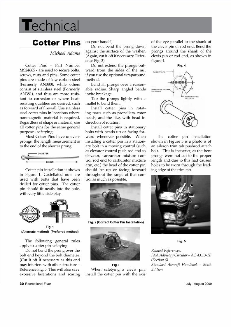
The cotter pin installationshown in Figure 5 is a photo is ofan aileron trim tab pushrod attach
bolt. This is incorrect, as the bentprongs were not cut to the properlength and due to this had causedholes to be worn through the lead-
ing edge of the trim tab.
Fig. 5
Related References:FAA Advisory Circular – AC 43.13-1B(Section 6)Standard Aircraft Handbook – SixthEdition.
Cotter Pins
Michael Adams
Related Documents