Technical Information and Product Range 2008 COOL-FIT TM Pipes, fittings, valves and accessories

Welcome message from author
This document is posted to help you gain knowledge. Please leave a comment to let me know what you think about it! Share it to your friends and learn new things together.
Transcript

Technical Information and Product Range
2008
COOL-FIT TM
Pipes, fittings,valves andaccessories
2
Innovation and technology.
GF Piping Systems, through fo
cussed research, is continually
developing new products and
technologies, setting new global
standards in quality and perfor
mance for our customers.
All from one source. GF Piping
Systems covers the growing de
mand for complete solutions from
a single source in a wide range of
applications.
Quality management. All system
components are stringently tested
in accredited test laboratories.
Management and production pro
cedures are certified to ISO 9001
and ISO 14001 to guarantee form,
fit, function and compliance in
whatever application they may be
used throughout the world.
Sales and service – worldwide.
Our local sales companies and
representatives in over 100 coun
tries provide „one stop“ shopping,
including planning support, trai
ning and product availability.
Facts and Figures. GF Piping
Systems with its 3200 employees
achieves an annual turnover of
about CHF 1100 million (Euros 650
million. GF Piping Systems is part
of the Georg Fischer Corporation,
which was founded in Schaffhau
sen, Switzerland in 1802. Today
the corporation has more than
13,000 employees and an annual
turnover of CHF 4.5 billion (Euros
3 billion).
Throughout the world everyone demands a secure supply of clean water.
GF Piping Systems is meeting this challenge by providing complete
piping systems suitable for safe operation in virtually all environments.
We have developed systems comprising of pipe, fittings, valves, and
measuring and control devices in high quality corrosion resistant thermo-
plastics for the transport of not only clean water, but also gas and other
industrial media.
Whether installed above or below ground, in industrial, commercial or
domestic applications, GF Piping Systems provides a solution.
> your benefits
• technological expertise• „one stop“ shopping• premier quality
and performance• system solutions• knowhow and experience• local support
GF Piping Systems
3
COOL-FIT ABS
Contents Page
General Information 4
Top Quality: Minimum On Site Time 5–7
System Advantages: Your Benefit 8–9
COOLFIT ABS Pipe Technical Details 10
COOLFIT ABS Fittings Technical Details 11
Accessory Equipment 12
Accessory Equipment for Solvent Cement Jointing, 13 Reducing Diameters and End Caps
COOLFIT ABS Reducing Diameters 14
PressureTemperature Parameters 15
Technical Data 16
General Comments 16
Pressure Drops 17–18
Pipe Support Distances 19
Pipe Supports and Fixed Point 20
Flexible Length 21
Plastic to Metal Connections 22
Measuring Equipment 22
Measuring Equipment, DeVenting and Curing Time 23–24
Internal Pressure Testing 25
Installation of metric industrial piping system 26
ABS Metric Piping System Specification 32
COOLFIT ABS Pipe and Fittings Specification 32
Instructions for Solvent Cement Jointing of ABS 33
ABS Tangit and Cleaner, Gap Filler, Sealing Tape: Amounts required 34–38Instruction for Solvent Cementing COOLFIT ABS 39
Jointing technique: Pipe preparation 40–41
Instruction for Insulating the Gap 42
ABS Product Range 43
The technical data is not binding and not an expressly warranted characteristic of the goods. It is subject to change. Please consult our General Conditions of Supply.
4
General Information
COOLFIT is a complete system solution for secondary cooling and refrigeration piping systems. The system is based on the tried and tested ABS plastic system from GF Piping Systems which contains pipe fittings valves and transition fittings, now with the option for preinsulated pipe and fittings with outer jackets in either black or white. You can adapt the system solution to your particular needs. For example white preinsulated for food production halls or standard plastic pipe with control valves for pump houses or OEM chillers.
Refrigeration and Cooling plants in general using plastic pipe as the carrier system offer complete corrosion resist-ance and a cost effective solution compared to traditional metal materials.
PipeThe ABS pipe and fittings are available in 2 versions. • standard uninsulated, to be insulated onsite with
traditional insulation • preinsulated with black PE jacket
FittingsA complete range of fittings compatible to the pipe is also available either as standard or as insulated with black outer jackets (white on request).The ABS range contains shutoff valves, control valves, automated valves pneumatic and electrical as well as a complete range of transition fittings for metal to plastic connections.
GF Piping Systems ABS Raw MaterialABS is a material used in a wide range of general engineering applications from general housings for vacuum cleaners for instance to car bumpers.GF Piping Systems ABS raw material has been specifically developed for longlife pressure bearing piping systems. For physical properties see ISO 15493 and GF Piping Systems literature GMST 5989, pages 28–30.Acrylonitrile Butadiene Styrene (ABS) is a styrne acrylonitrile copolymer grafted to polybutadiene to produce an homogeneous material with excellent impact and low temperature characterisitcs. ABS is halogen free with a low thermal conductivity and nontoxic. GF Piping Systems ABS has a range of internationally recognised approvals. Please ask if you require any details regarding approvals or raw material properties.
PUR InsulationCOOLFIT preinsulated pipe and fittings are delivered ready to install using high density PUR L 45 kg/m3 as the insulation material, the PUR is CFC free and recyclable.
Jacket Pipes in Black (Metal on request)The outer jacket in black (Metal on request) is manufactured from high density polyethylene (PE). PE offers extremely good impact resistance and a good resistance to oil splashes and grease or other external contamination. The PE is smooth, noncorroding and thus easy to clean with a long lifespan. Black PE is UV resistant and thus ideally suited to outdoor applications and for general use.
Typical Working ConditionsPreinsulated ABS has working temperatures from –50 °C to +40 °C and –40 °C to +60 °C for the standard ABS system with a maximum working pressure of 10 bar (water at +23 °C) COOLFIT.
Typical MediumsABS can be used for example with the following mediums:• chilled water and general water• salt solutions• glycol solutions• alcohol solutionsFor compatability of ABS to nonwater mediums please consult GF Piping Systems and see page 15.
Note: COOLFIT is not for use with primary gases such as Ammonia, Propane, R407, R22, and also not for use for compressed air systems.
5
COOL-FITfor Secondary
Cooling Systemsand Refrigeration
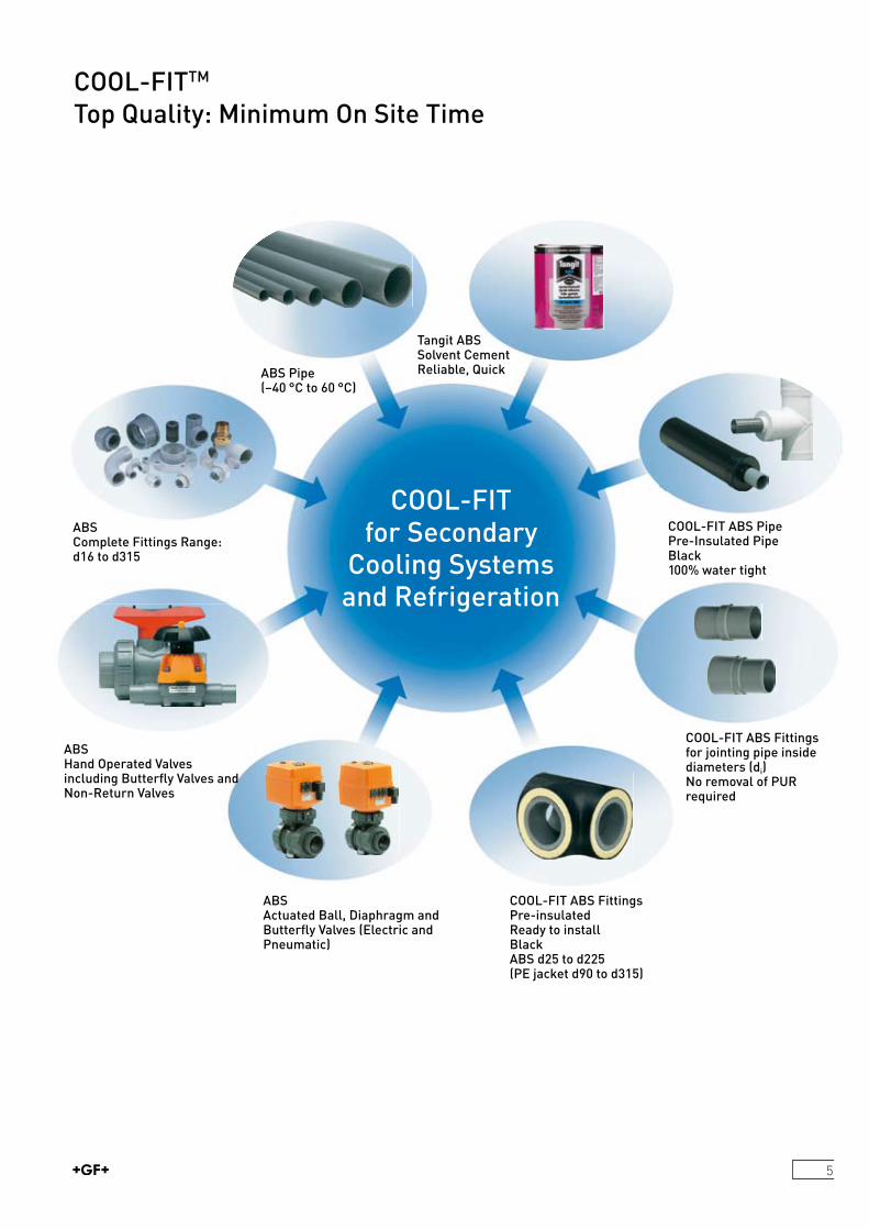
ABSComplete Fittings Range: d16 to d315
ABSHand Operated Valvesincluding Butterfly Valves andNon-Return Valves
ABSActuated Ball, Diaphragm and Butterfly Valves (Electric and Pneumatic)
COOL-FIT ABS Fittings Pre-insulated Ready to install BlackABS d25 to d225 (PE jacket d90 to d315)
COOL-FIT ABS Fittings for jointing pipe inside diameters (di) No removal of PUR required
ABS Pipe(–40 °C to 60 °C)
Tangit ABS Solvent CementReliable, Quick
COOL-FITTM
Top Quality: Minimum On Site Time
COOL-FIT ABS Pipe Pre-Insulated PipeBlack 100% water tight
6
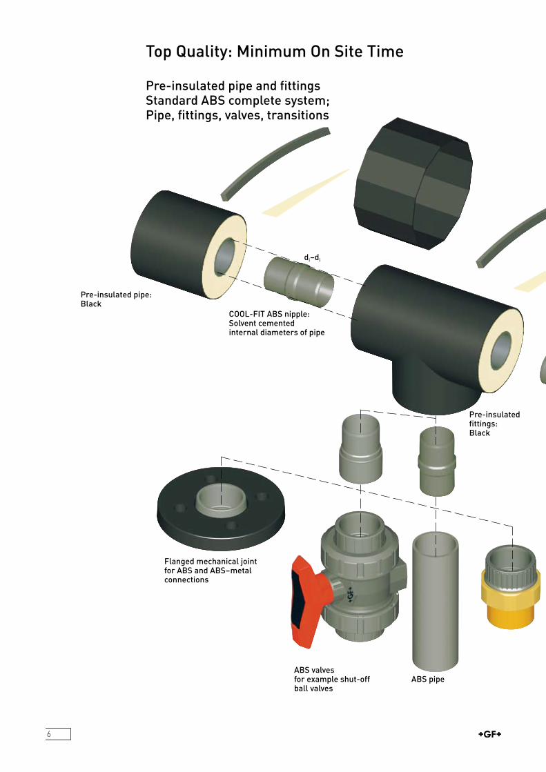
Top Quality: Minimum On Site Time
Pre-insulated pipe and fittingsStandard ABS complete system; Pipe, fittings, valves, transitions
Pre-insulated pipe: Black
COOL-FIT ABS nipple: Solvent cementedinternal diameters of pipe
Flanged mechanical jointfor ABS and ABS–metalconnections
ABS valvesfor example shut-off ball valves
ABS pipe
Pre-insulated fittings: Black
di–di
7
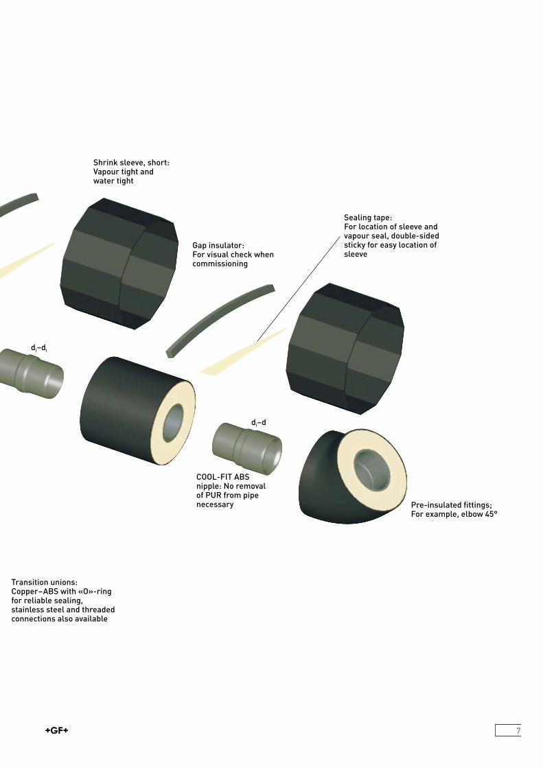
Transition unions: Copper–ABS with «O»-ring for reliable sealing, stainless steel and threaded connections also available
COOL-FIT ABS nipple: No removal of PUR from pipe necessary
Gap insulator:For visual check when commissioning
Sealing tape:For location of sleeve and vapour seal, double-sided sticky for easy location of sleeve
Pre-insulated fittings; For example, elbow 45°
Shrink sleeve, short:Vapour tight and water tight
di–di
di–d
8
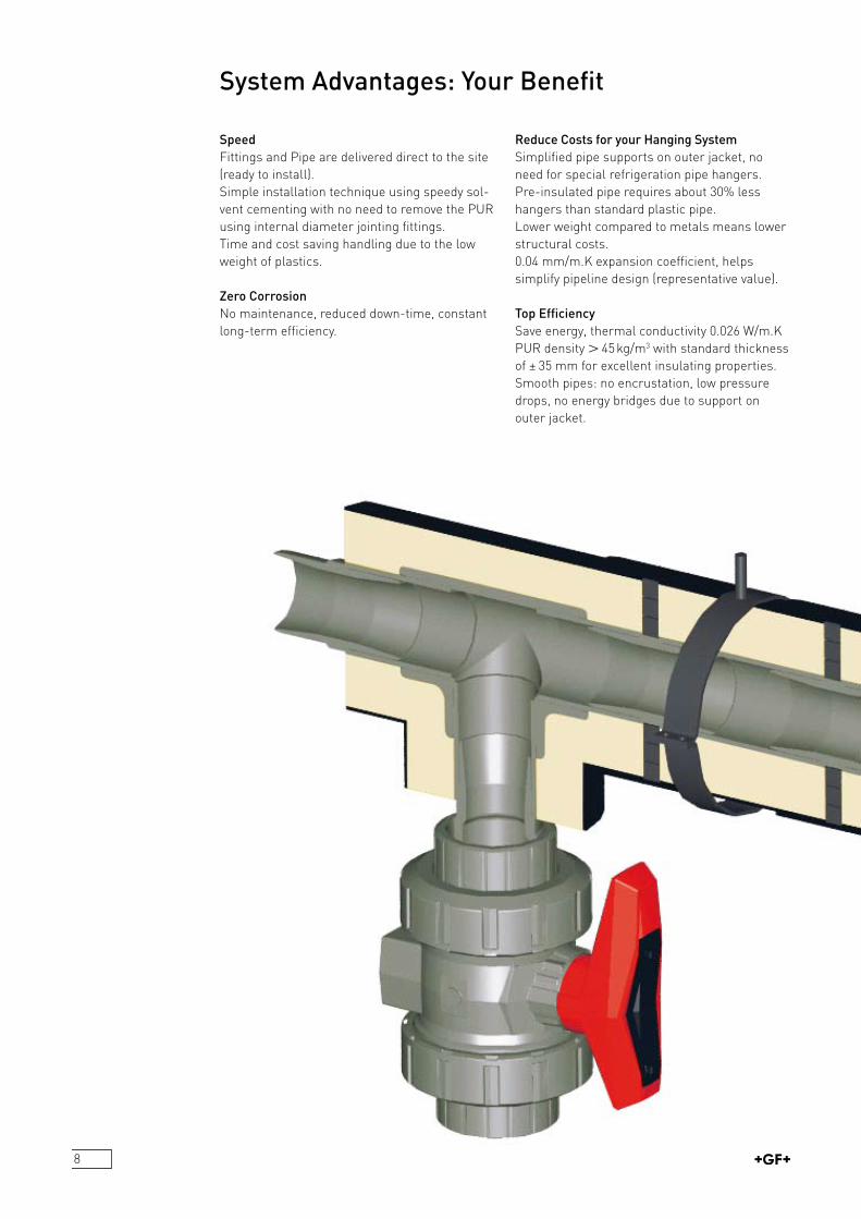
SpeedFittings and Pipe are delivered direct to the site (ready to install).Simple installation technique using speedy solvent cementing with no need to remove the PUR using internal diameter jointing fittings.Time and cost saving handling due to the low weight of plastics.
Zero CorrosionNo maintenance, reduced downtime, constant longterm efficiency.
Reduce Costs for your Hanging SystemSimplified pipe supports on outer jacket, no need for special refrigeration pipe hangers.Preinsulated pipe requires about 30% less hangers than standard plastic pipe.Lower weight compared to metals means lower structural costs.0.04 mm/m.K expansion coefficient, helps simplify pipeline design (representative value).
Top EfficiencySave energy, thermal conductivity 0.026 W/m.K PUR density L 45 kg/m3 with standard thickness of ± 35 mm for excellent insulating properties. Smooth pipes: no encrustation, low pressure drops, no energy bridges due to support on outer jacket.
System Advantages: Your Benefit

9
ReliabilityQuality GF Piping Systems products: the number 1 Plastics Industrial Piping system manufacturer in the world.Tried and Tested jointing technique with gap filling, cold welding TANGIT ABS cement.
Innovative: CleverDeveloped for your needs.Internal pipe connections means no need to remove the PUR insulation from the pipe or fitting.
Outdoor and Indoor Systems: Vapour SealedBlack shrink sleeve for 100% vapour sealing 100% water tight system.
Hygienic AestheticTop quality in performance and looks.Smooth outer surfaces for hygienic environments.No detrimental effects under high pressure cleaning.
Full Technical Design Support www.coolfit.georgfischer.com for online calculations of energy losses, temperature differences and more.CAD libraries for accurate and quicker drawing.Specialist guidelines for design and installation and design of venting equipment, measuring equipment, transitions.
Full Technical Support during InstallationOnsite advice and jointing technique training.Training Video for ABS jointing technique.
SubstainabilityReduce the carbon footprint of your plant and factory with recylable plastics. Lower ODP and GWP values compared to traditional metal systems.

10
COOLFIT ABS is produced using high grade ABS pressure piping raw material, in use for over 20 years together with high grade low temperature PUR produced in high density form to offer optimal insulating qualities.
COOL-FIT pre-insulated ABS Contraction Coefficient: 0.04 mm/m.K2)
Code Number Carrier Pipe Jacket Pipe Weight (PE + Volume Pipe Support Heat Transfer X max - ABS HDPE ABS + PUR) Distance1) Coefficient X minBlack d x e di D x e1 kg/m l/m m W/mK ≤
169 017 682 25 x 2.3 20.4 90 x 2.2 1.24 0.36 1.55 0.13 6169 017 683 32 x 1.9 28.2 90 x 2.2 1.29 0.61 1.55 0.162 6169 017 684 40 x 2.4 35.2 110 x 2.7 1.76 0.95 1.65 0.165 6
169 017 685 50 x 3.0 44 110 x 2.7 1.89 1.49 1.65 0.213 6169 017 686 63 x 3.8 55.4 125 x 3.0 2.48 2.34 1.75 0.245 6169 017 687 75 x 4.6 65.8 140 x 3.0 3.17 3.36 1.90 0.27 6169 017 688 90 x 5.4 79.2 160 x 3.0 4.11 4.80 2.05 0.293 6169 017 689 110 x 6.6 96.8 180 x 3.0 5.22 7.21 2.20 0.341 10
169 017 691 140 x 9.2 121.6 225 x 3.2 8.16 11.69 2.55 0.356 10169 017 692 160 x 10.5 139 250 x 3.9 10.34 15.22 2.75 0.381 10169 017 693 200 x 13.1 173.8 280 x 4.4 13.42 24.50 3.05 0.513 10169 017 694 225 x 14.8 195.4 315 x 4.9 17.97 30.05 3.30 0.515 10 COOLFIT ABS pipe d250, d280 and d315 available on request1) COOLFIT ABS support distance are the same from –50 °C to +40 °Cd: nominal outside diameter of ABS pipedi: nominal internal diameter of ABS pipeD: nominal outside diameter of PE pipee and e1: nominal wall thicknesses2) representative value, the ∆L must be calculated per installation (see www.coolfit.georgfischer.com/calculationtool)
Carrier Pipe ABS10 bar rated, cement jointed ABS plastic pipe.5 meter lengths. ABS Pipe to ISO 15493.
Hard Polyurethane Foam (PUR)Thermal Conductivity at 20 °C l 0.026 W/m.KAxial Shear Strength M 0.12 N/mm2 Tensile Strength M 0.2 N/mm2 Compressive Strength M 0.3 N/mm2
Foamed using polyol and isocynateExpansion Coefficient 0.04 mm/m.K2)
Core density L 45 kg/m3
Average Cell Sizes max. 0.5 mm
Jacket PipeHDPE to DIN 8075 in black. Functional requirements to EN 253. Black is UV resistant.
COOL-FIT Technical DetailsPre-insulated ABS Pipe
Pipe SpecificationProduct Identification; Colour, PN 10, Production Date, COOLFIT, ABS.
All three materials are bonded together deliberately to ensure expansion and contraction as one.)
Black RAL 9004
X
11
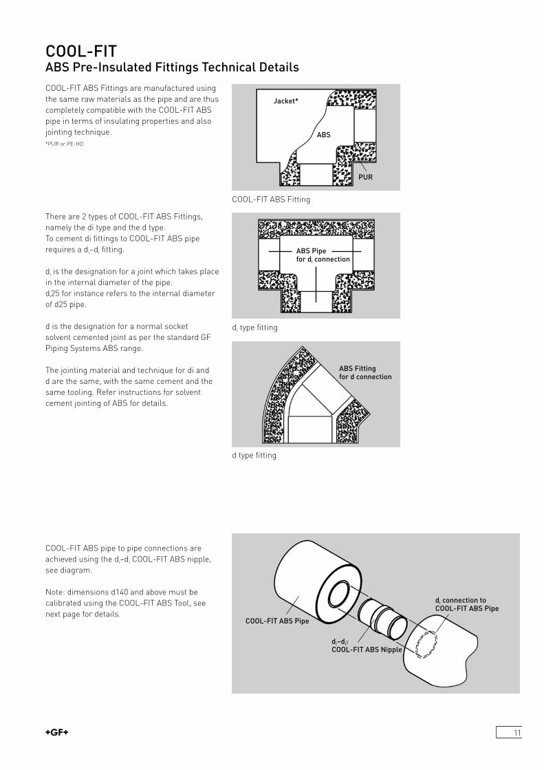
COOLFIT ABS Fittings are manufactured using the same raw materials as the pipe and are thus completely compatible with the COOLFIT ABS pipe in terms of insulating properties and also jointing technique. *PUR or PEHD
COOL-FIT ABS Pre-Insulated Fittings Technical Details
d type fitting
di type fitting
There are 2 types of COOLFIT ABS Fittings, namely the di type and the d type. To cement di fittings to COOLFIT ABS pipe requires a di–di fitting.
di is the designation for a joint which takes place in the internal diameter of the pipe.di25 for instance refers to the internal diameter of d25 pipe.
d is the designation for a normal socket solvent cemented joint as per the standard GF Piping Systems ABS range.
The jointing material and technique for di and d are the same, with the same cement and the same tooling. Refer instructions for solvent cement jointing of ABS for details.
COOLFIT ABS pipe to pipe connections are achieved using the di–di COOLFIT ABS nipple, see diagram.
Note: dimensions d140 and above must be calibrated using the COOLFIT ABS Tool, see next page for details.
COOLFIT ABS Fitting
Jacket*
ABS
PUR
ABS Pipe for di connection
ABS Fitting for d connection
di connection to COOL-FIT ABS Pipe
di–di: COOL-FIT ABS Nipple
COOL-FIT ABS Pipe
12
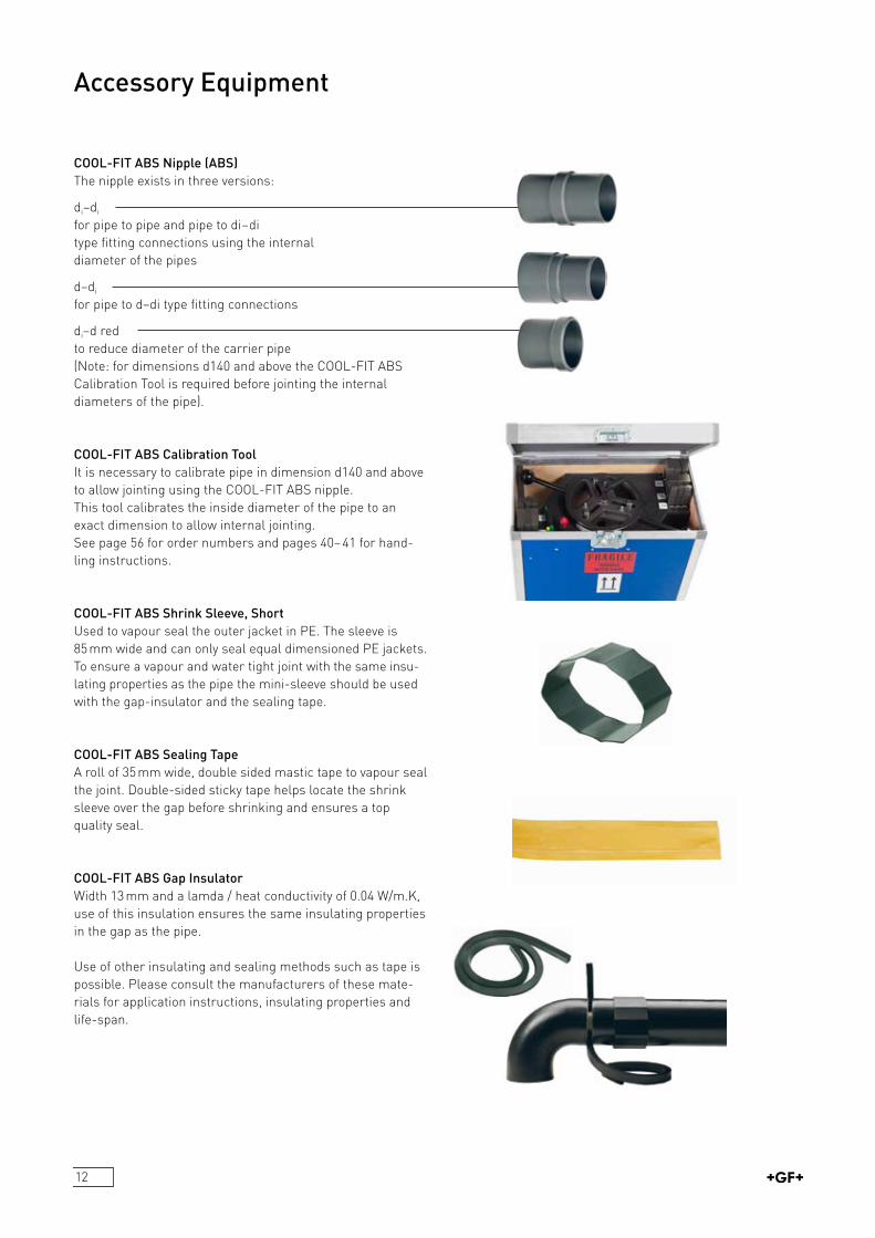
Accessory Equipment
COOL-FIT ABS Nipple (ABS)The nipple exists in three versions:
di–di
for pipe to pipe and pipe to di–di type fitting connections using the internal diameter of the pipes
d–di
for pipe to d–di type fitting connections
di–d redto reduce diameter of the carrier pipe(Note: for dimensions d140 and above the COOLFIT ABS Calibration Tool is required before jointing the internal diameters of the pipe).
COOL-FIT ABS Calibration ToolIt is necessary to calibrate pipe in dimension d140 and above to allow jointing using the COOLFIT ABS nipple.This tool calibrates the inside diameter of the pipe to an exact dimension to allow internal jointing.See page 56 for order numbers and pages 40–41 for handling instructions.
COOL-FIT ABS Shrink Sleeve, ShortUsed to vapour seal the outer jacket in PE. The sleeve is 85 mm wide and can only seal equal dimensioned PE jackets. To ensure a vapour and water tight joint with the same insulating properties as the pipe the minisleeve should be used with the gapinsulator and the sealing tape.
COOL-FIT ABS Sealing TapeA roll of 35 mm wide, double sided mastic tape to vapour seal the joint. Doublesided sticky tape helps locate the shrink sleeve over the gap before shrinking and ensures a top quality seal.
COOL-FIT ABS Gap InsulatorWidth 13 mm and a lamda / heat conductivity of 0.04 W/m.K, use of this insulation ensures the same insulating properties in the gap as the pipe.
Use of other insulating and sealing methods such as tape is possible. Please consult the manufacturers of these materials for application instructions, insulating properties and lifespan.

13
Tangit ABS and Cementing EquipmentThe solvent cementing equipment is exactly the same for internal di jointing as for standard d jointing using Tangit ABS. Code numbers can be found on page 36 in this document, see pages 33–38 for jointing instructions.
COOL-FIT Shrink Sleeve, LongThis sleeve is 285 mm long, only to be used when sealing PE to PE outer jackets, not for use on ABS. For exact reducing possibilities see below.
Shrink Sleeve, Long Reducing DiametersThe COOLFIT «shrink sleeve, short» can only seal equal dimensions of PE outer jacket. The table below shows which dimensions can be sealed using which long shrink sleeve.NOTE: the sealing tape should be applied to both outer diameters of the PE pipes.
Accessory Equipment for Solvent Cement Jointing, Reducing Diameters and End Caps
ABS Pipe
COOL-FIT ABS Pipe
Silicon Glue
PE Dims (D) 90 110 125 140 160 180 225 250 280 315
Shrink Sleeve, Long 738.011.167 (black)
black 738.011.170 (black)
738.011.173 (black)
Shrink capThe shrink cap is only to be used to seal PE to PE, not to be used on ABS pipe. The flame used to shrink the sleeve may damage the ABS pipe.Ideal for use with T90° reducers. For dimensions please refer to the product range in this brochure. No separate sealing tape is required, the sealant is integrated into the cap.If the length of the cap is longer than the surface to be sealed then the cap can be cut back but without removing any sealant.
End-CapsEndcaps are to be used for sealing the PUR against any water ingress at the transition to ABS standard.
Sealing the PUR should be achieved using a chemically compatible glue to ABS. GF Piping Systems offers silicon glue. If silicon products are prohibited then nonsolvent based glues can be used. Chemical compatability can also be checked by GF Piping Systems.
14
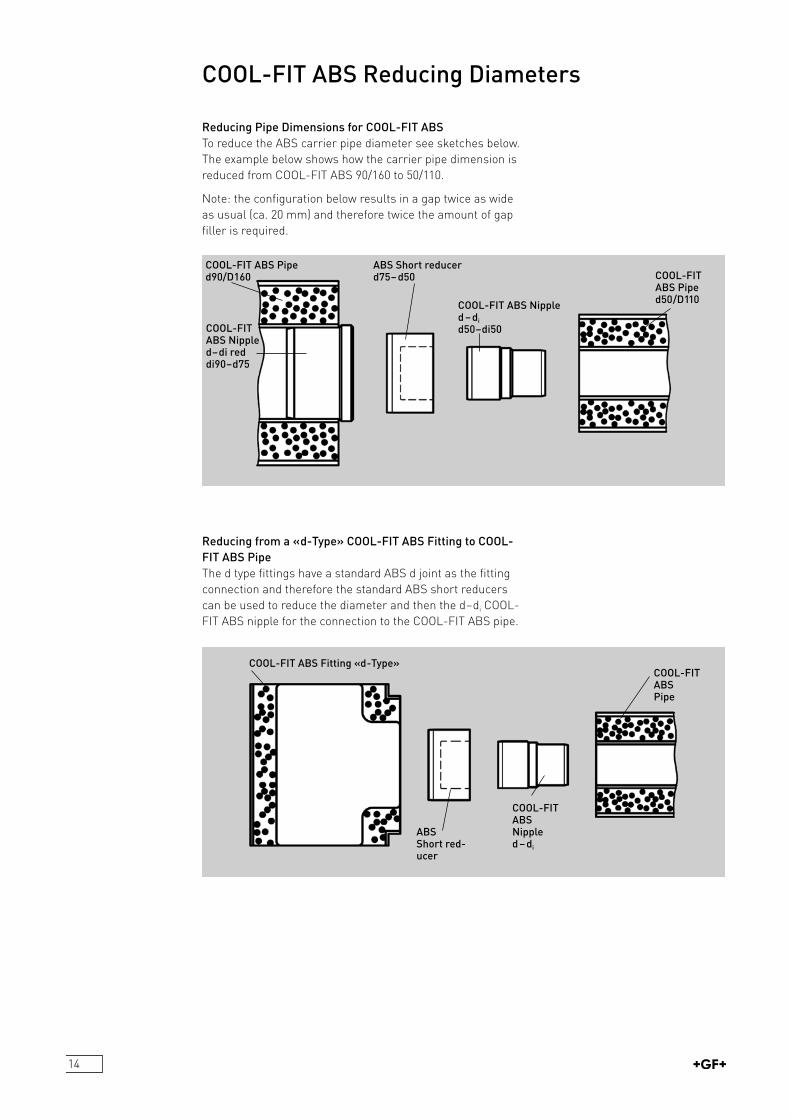
COOL-FIT ABS Pipe d90/D160
COOL-FIT ABS Nipple d–di red di90–d75
ABS Short reducer d75–d50
COOL-FIT ABS Nipple d–di
d50–di50
COOL-FIT ABS Pipe d50/D110
COOL-FIT ABS Fitting «d-Type»
ABS Short red-ucer
COOL-FIT ABS Nipple d–di
COOL-FIT ABS Pipe
COOL-FIT ABS Reducing Diameters
Reducing Pipe Dimensions for COOL-FIT ABSTo reduce the ABS carrier pipe diameter see sketches below. The example below shows how the carrier pipe dimension is reduced from COOLFIT ABS 90/160 to 50/110.
Note: the configuration below results in a gap twice as wide as usual (ca. 20 mm) and therefore twice the amount of gap filler is required.
Reducing from a «d-Type» COOL-FIT ABS Fitting to COOL-FIT ABS PipeThe d type fittings have a standard ABS d joint as the fitting connection and therefore the standard ABS short reducers can be used to reduce the diameter and then the d–di COOLFIT ABS nipple for the connection to the COOLFIT ABS pipe.

15
GeneralABS is generally resistant to most diluted inorganic acids, bases and salts and to most animal oils and fats. It is not resistant to organic solvents, pure alcohols, petrol, acetic acid and vegetable oils.
Ice SlurryIce slurry is a mixture of ice particles (0.01–0.03 mm width), water and an antifreeze agent, usually an alcohol, salt or glycol. GF Piping Systems has undertaken extensive testing of ice slurry with ABS and can give recommendations regarding for example pipeline layout, flow rates and pressure drops. Please ask your local GF Piping Systems representative for details.
Chemical ResistancePlease consult GF Piping Systems for detailed information regarding chemical resistance.GF Piping Systems offerswritten confirmation on material compatibility for all chemical applications.
Glycol SolutionsABS can be used with glycol solutions (eg. Antifrogen L, Dowfrost) however a derating factor applies to the standard water based temperature – pressure curve, see example.
Organic Salt SolutionsThese mediums are usually potassium formate or acetate water based solutions, with low viscosities at low temperatures. Tradename examples: HYCOOL, TEMPER, TYFOXIT, ANTIFROGEN KF. ABS can be used with these types of mediums however, a derating factor applies to the standard water based pressuretemperature curve. Please consult GF Piping Systems for details. It is important that the complete pipe, irrespective of pipe system material is properly devented both during filling and commissioning. It is very important to follow the manufacturers instructions for pipeline design and handling of these mediums.
Ice Slurry
Temperature °C PN 10 bar (145 psi)–50 11.8–20 11.8 0 11.8 20 10.5 30 8.9 40 7
Pressure ratings for thermoplastic pipe are always quoted for water at 20 °C. It can be used at higher temperatures but it is a fundamental principle in thermoplastic pipework that if the working temperature is increased then the working pressure must be reduced.The table below shows, for COOLFIT ABS, the maximum permissible pressures at various temperatures up to the maximum allowable working temperature of + 40 °C. The table is based on an ambient temperature of 20 °C with water as the medium. A safety factor of 1.8 is incorporated into all calculations with a minimum life span of 25 years.
For working temperatures below 0 °C an antifreeze has to be used in the water to prevent freezing. The above pressuretemperature curve applies only when the medium is water, therefore for non pure water mediums a derating factor has to be applied to the above curve. This is standard procedure for all plastic piping systems.For example if the medium is a waterdiluted glycol solutions m 50% (max. concentration allowable for ABS) then a derating factor of 0.6 applies to the standard pressure temperature curve. So at –10 °C for a minimum lifespan of 25 years the maximum allowable working pressure is 0.6 x 11.8 = 7.1 bar. For more details regarding these derating values for chemical solutions or trade named products please consult GF Piping Systems.
COOL-FIT ABS Pre-Insulated Pressure-Temperature Parameters
16
General Comments to Plastics Orientated Pipeline Design and InstallationThe design and installation of thermoplastic pipe systems requires designers and installers alike to take into account the fact that plastics have different physical characteristics to metal. Although GF Piping Systems ABS and preinsulated COOLFIT ABS are both very robust systems, nevertheless, care should be taken during handling and transport to avoid damage. Also thermoplastics have certain physical characteristics, such as a high expansion coefficient, which need to be taken into account in the design phase.
GF Piping Systems has been successfully developing and selling plastic pipe systems into a spectrum of high performance installations, such as highly concentrated chemicals, for over 40 years, and experience has shown that when engineers and installers take into account the advice given in our technical literature plastics are an economical and reliable alternative to metals.
As a general rule for designing and installing plastics one of the major differences is that plastics can and should be allowed to move after commissioning i.e. move under the influence of temperature fluctuation and pressure changes. For instance using pipe brackets that allow horizontal movement and not clamping the system in place is a must for plastic piping installations.
The following technical information covers the fundamental information required to ensure an economical and trouble free installation: Not all details however are published in this document, for more detailed information or if you have a specific question please ask your local GF Piping Systems company, consult www.coolfit.georgfischer.com or email us at info@coolfit.georgfischer.com for advice if you have any questions.
Technical Data
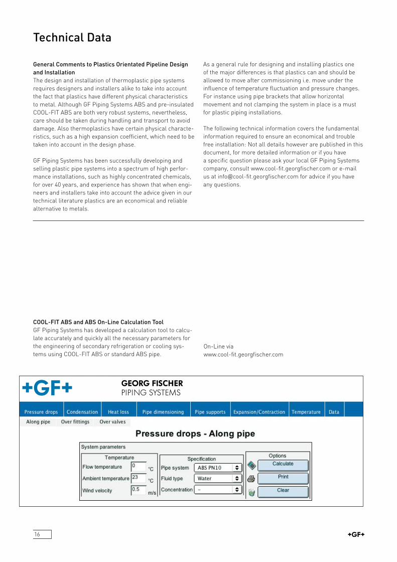
COOL-FIT ABS and ABS On-Line Calculation ToolGF Piping Systems has developed a calculation tool to calculate accurately and quickly all the necessary parameters for the engineering of secondary refrigeration or cooling systems using COOLFIT ABS or standard ABS pipe.
OnLine via www.coolfit.georgfischer.com
17
Pipe Pressure Drop (ABS and COOL-FIT ABS)When calculating the hydraulic pressure loss in m/m in a plastic pipe the excellent smoothness of ABS means that when using the standard Moody Diagram the smooth pipes curve can be used to derive the friction factor.
Imperically it is possible to use the following formulas and procedure to calculate pressure loss in the pipe for any type of fluid.
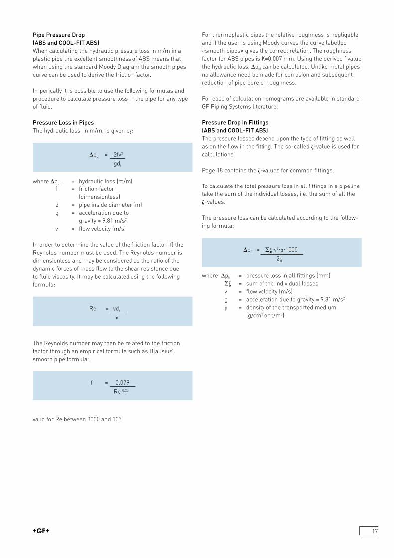
Pressure Loss in PipesThe hydraulic loss, in m/m, is given by:
ippi = 2fv2
gdi
where ippi = hydraulic loss (m/m) f = friction factor (dimensionless)
di = pipe inside diameter (m) g = acceleration due to
gravity = 9.81 m/s2
v = flow velocity (m/s)
In order to determine the value of the friction factor (f) the Reynolds number must be used. The Reynolds number is dimensionless and may be considered as the ratio of the dynamic forces of mass flow to the shear resistance due to fluid viscosity. It may be calculated using the following formula:
Re = vdi
The Reynolds number may then be related to the friction factor through an empirical formula such as Blausius’ smooth pipe formula:
f = 0.079 Re 0.25
valid for Re between 3000 and 105.
For thermoplastic pipes the relative roughness is negligable and if the user is using Moody curves the curve labelled «smooth pipes» gives the correct relation. The roughness factor for ABS pipes is K=0.007 mm. Using the derived f value the hydraulic loss, ippi can be calculated. Unlike metal pipes no allowance need be made for corrosion and subsequent reduction of pipe bore or roughness.
For ease of calculation nomograms are available in standard GF Piping Systems literature.
Pressure Drop in Fittings (ABS and COOL-FIT ABS)The pressure losses depend upon the type of fitting as well as on the flow in the fitting. The socalled value is used for calculations.
Page 18 contains the values for common fittings.
To calculate the total pressure loss in all fittings in a pipeline take the sum of the individual losses, i.e. the sum of all the values.
The pressure loss can be calculated according to the following formula:
ipfi = v21000 2g
where ipfi = pressure loss in all fittings (mm) = sum of the individual losses
v = flow velocity (m/s) g = acceleration due to gravity = 9.81 m/s2
= density of the transported medium (g/cm3 or t/m3)

18
Pressure Drop in Fittings Please note there is a slight difference in the coefficient of resistance factors for standard ABS fittings or for COOLFIT ABS preinsulated fittings. This is due to the extra fitting required, namely the internal special nipple and also as some COOLFIT ABS fittings have a piece of pipe in the fitting, namely the di fittings.
Coefficient of Resistance for ABS Fittings
Coefficient of Resistance for COOL-FIT ABS FittingsThe factors given below are for the COOLFIT ABS fittings inclusive COOLFIT ABS nipple.
Pressure Drop in Valves (ABS)
Flow Rate / Flow Factor
The kv factor is defined as the flow rate of water in litres per minute with a pressure drop of 1 kg/cm2 across the valve.
The relationships between kv factor, flow rate (Q) and pressure drop (i) are given in the following formula:
Liquids with kinematic viscosity less than 22 centistokese.g. water, hydraulic oil
i kv = Q ip or Q = kv
or ip = •Q2
kv2
where Q = flow rate (litres per minute) = density of the liquid (kg/dm3)
ip = pressure drop (kg/cm2)
Liquids with kinematic viscosity greater than 22 centistokesThe effect of viscosity, caused by friction between the particles of the fluid, is no longer negligable, and the flow rate is reduced. The flow factor must be multiplied by a correction factor, c, to give a new flow factor, kvn.
kvn = kv • c
The correction factor is given by:
c = 1 + kv valid for cm3 only
200•Q
where = kinematic viscosity (centistokes) kv = flow factor for water (dimensionless) Q = flow rate (litres per minute)
Pipe outside 20 32 50 O 63 diameter (d)Type of fitting Coefficient of Resistance 90° Bend 1.65 1.15 0.75 0.6545° Elbow 0.45Tee 90° 1.8Pipe to Pipe (di–di) 0.1 0.25Tee 45° 0.8 1.0
Pipe outside 20 32 50 O 63 diameter (d)Type of fitting Coefficient of Resistance 90° Bend 1.5 1.0 0.6 0.590° Elbow 2.0 1.7 1.1 0.845° Elbow 0.3Tee 90° 1.5Inlet 0.5Outlet 1.0
19
Pipe Support Distances HorizontalsFor ABS at temperatures L +20 °C refer to ABS specific literature
Standard ABS COOL-FIT ABS at 20 °C water, metres water, metres d16 0.7 –d20 0.8 –d25 0.85 1.55d32 1.0 1.55d40 1.1 1.65d50 1.15 1.65d63 1.3 1.75d75 1.5 1.90d90 1.6 2.05d110 1.8 2.20d140 2.05 2.55d160 2.2 2.75d200 2.3 3.05d225 2.4 3.30
The above values are for pipe supported using normal 360° pipe clamps. For values using complete axial support please consult the COOLFIT ABS online calculation tool at www.coolfit.georgfischer.com
Pipe supports for ABS should allow the system to move under the influence of temperature, see «Pipe Supports» page 21 for details.
Heat Transfer Coefficients – Pipe ABS and Pre-insulated ABS
ABS COOL-FIT ABS W/m.K W/m.Kd16 1.278 –d20 1.487 –d25 1.742 0.13d32 2.078 0.162d40 2.413 0.165d50 2.81 0.213d63 3.253 0.245d75 3.643 0.27d90 4.073 0.293d110 4.637 0.341d140 5.319 0.356d160 5.686 0.381d200 6.385 0.513d225 6.73 0.515
Pipeline Design and Layout Following are the formulas and information required to calculate change in length of the pipe and allowable flexible length.
iL = L • iT •
iL = change in length of pipeL = original length of pipe during installation= coefficient of expansion (ABS 0.1) iT = difference in temperatures between ambient temperature during installation and normal working temperature.
Expansion and contraction in a pipe line can only take place in a straight direction; It is therefore necessary to calculate the change in length and then design in compensation for this to avoid unnecessary stresses.
Example: Calculating iL for the sketch beside for the following assumed conditions would be done as follows.L = 15 metres (total straight length of pipe)Ambient temperature during installation = +25 °CWorking temperature of medium = –5 °CT = –30 (working temperature–installation temperature)= 0.1 mm/m.K (for ABS)iL = 15 x –30 x 0.1iL = –45 mm (minus designates a contraction of the length of pipe)
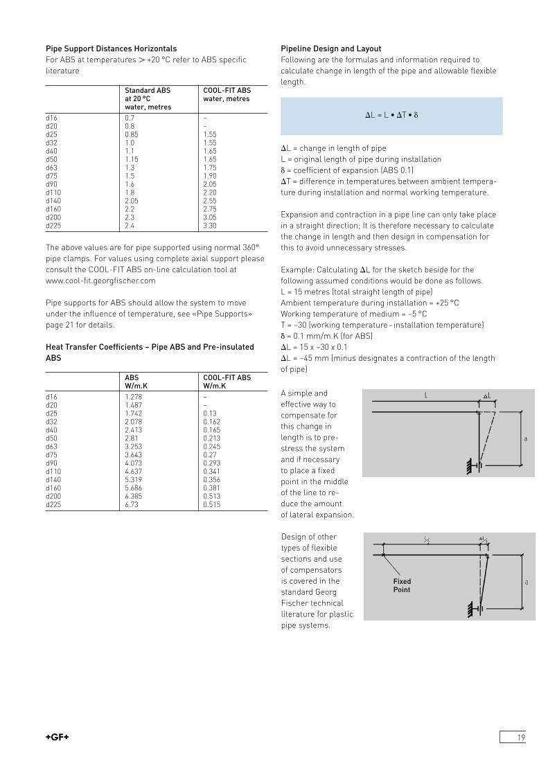
Fixed Point
A simple and effective way to compensate for this change in length is to prestress the system and if necessary to place a fixed point in the middleof the line to re duce the amount of lateral expansion.
Design of other types of flexible sections and use of compensators is covered in the standard Georg Fischer technical literature for plastic pipe systems.
20
Pipe Supports for ABSPlastic pipe systems should be installed using supports designed for use with plastics and should then be installed taking care not to damage or over stress the pipe.
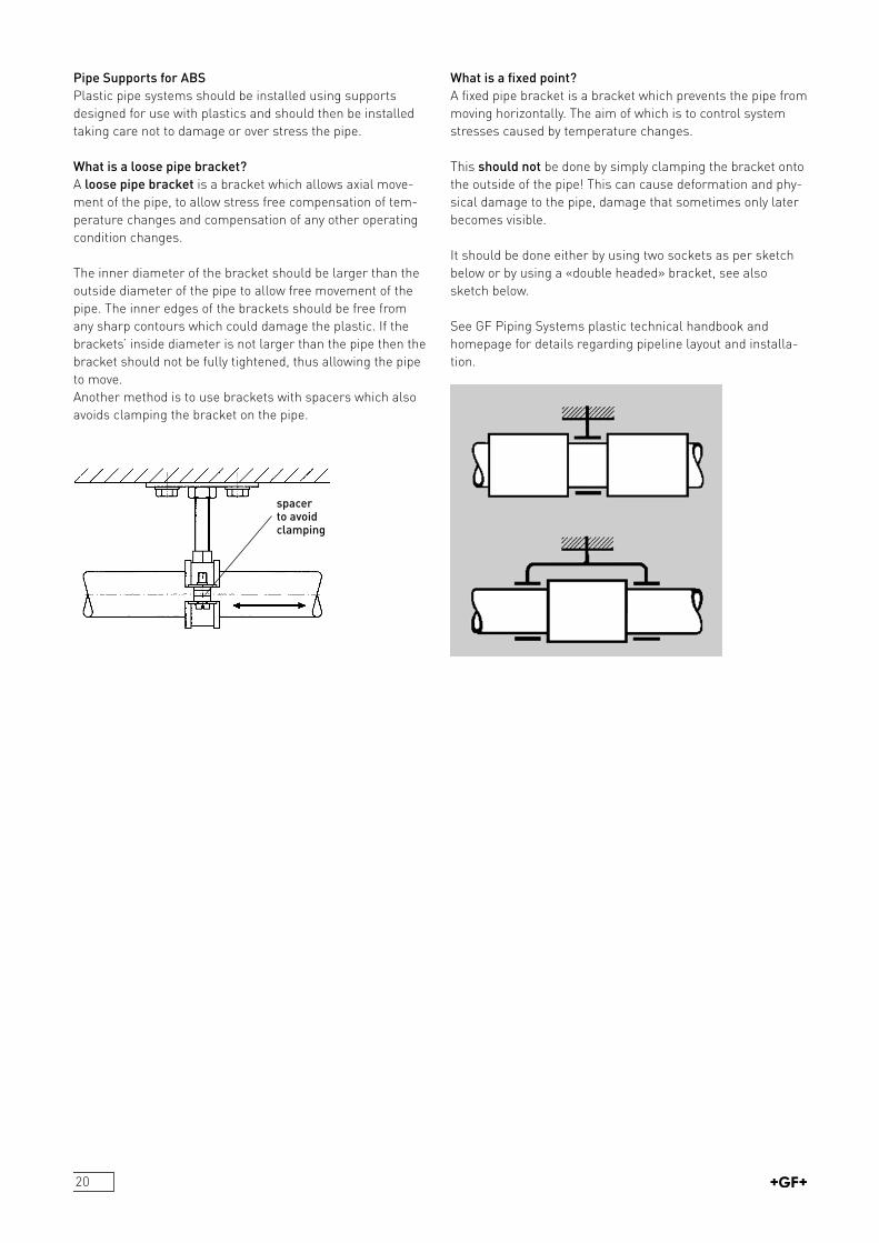
What is a loose pipe bracket?A loose pipe bracket is a bracket which allows axial movement of the pipe, to allow stress free compensation of temperature changes and compensation of any other operating condition changes.
The inner diameter of the bracket should be larger than the outside diameter of the pipe to allow free movement of the pipe. The inner edges of the brackets should be free from any sharp contours which could damage the plastic. If the brackets’ inside diameter is not larger than the pipe then the bracket should not be fully tightened, thus allowing the pipe to move.Another method is to use brackets with spacers which also avoids clamping the bracket on the pipe.
What is a fixed point?A fixed pipe bracket is a bracket which prevents the pipe from moving horizontally. The aim of which is to control system stresses caused by temperature changes.
This should not be done by simply clamping the bracket onto the outside of the pipe! This can cause deformation and physical damage to the pipe, damage that sometimes only later becomes visible.
It should be done either by using two sockets as per sketch below or by using a «double headed» bracket, see also sketch below.
See GF Piping Systems plastic technical handbook and homepage for details regarding pipeline layout and installation.
spacer to avoid clamping
21
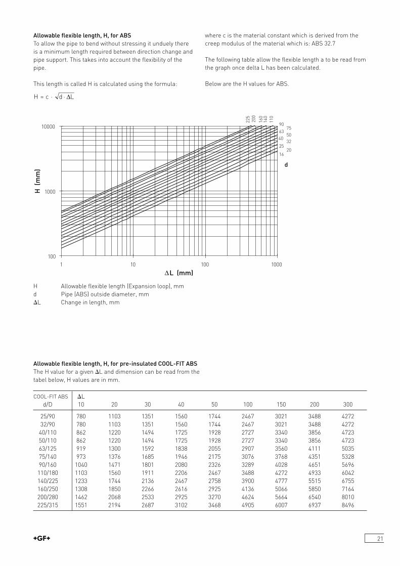
where c is the material constant which is derived from the creep modulus of the material which is: ABS 32.7
The following table allow the flexible length a to be read from the graph once delta L has been calculated.
Below are the H values for ABS.
H d L= · ·c ∆
Allowable flexible length, H, for ABSTo allow the pipe to bend without stressing it unduely there is a minimum length required between direction change and pipe support. This takes into account the flexibility of the pipe.
This length is called H is calculated using the formula:
100
1000
10000
1 10 100 1000
∆L (mm)
H (
mm
)
1620
2532
4050
6375
90
110
140
160
200
225
d
H Allowable flexible length (Expansion loop), mmd Pipe (ABS) outside diameter, mm iL Change in length, mm
COOLFIT ABS iL d/D 10 20 30 40 50 100 150 200 300
25/90 780 1103 1351 1560 1744 2467 3021 3488 4272 32/90 780 1103 1351 1560 1744 2467 3021 3488 4272 40/110 862 1220 1494 1725 1928 2727 3340 3856 4723 50/110 862 1220 1494 1725 1928 2727 3340 3856 4723 63/125 919 1300 1592 1838 2055 2907 3560 4111 5035 75/140 973 1376 1685 1946 2175 3076 3768 4351 5328 90/160 1040 1471 1801 2080 2326 3289 4028 4651 5696 110/180 1103 1560 1911 2206 2467 3488 4272 4933 6042 140/225 1233 1744 2136 2467 2758 3900 4777 5515 6755 160/250 1308 1850 2266 2616 2925 4136 5066 5850 7164 200/280 1462 2068 2533 2925 3270 4624 5664 6540 8010 225/315 1551 2194 2687 3102 3468 4905 6007 6937 8496
Allowable flexible length, H, for pre-insulated COOL-FIT ABSThe H value for a given iL and dimension can be read from the tabel below, H values are in mm.
22
Measuring Equipment in an ABS System
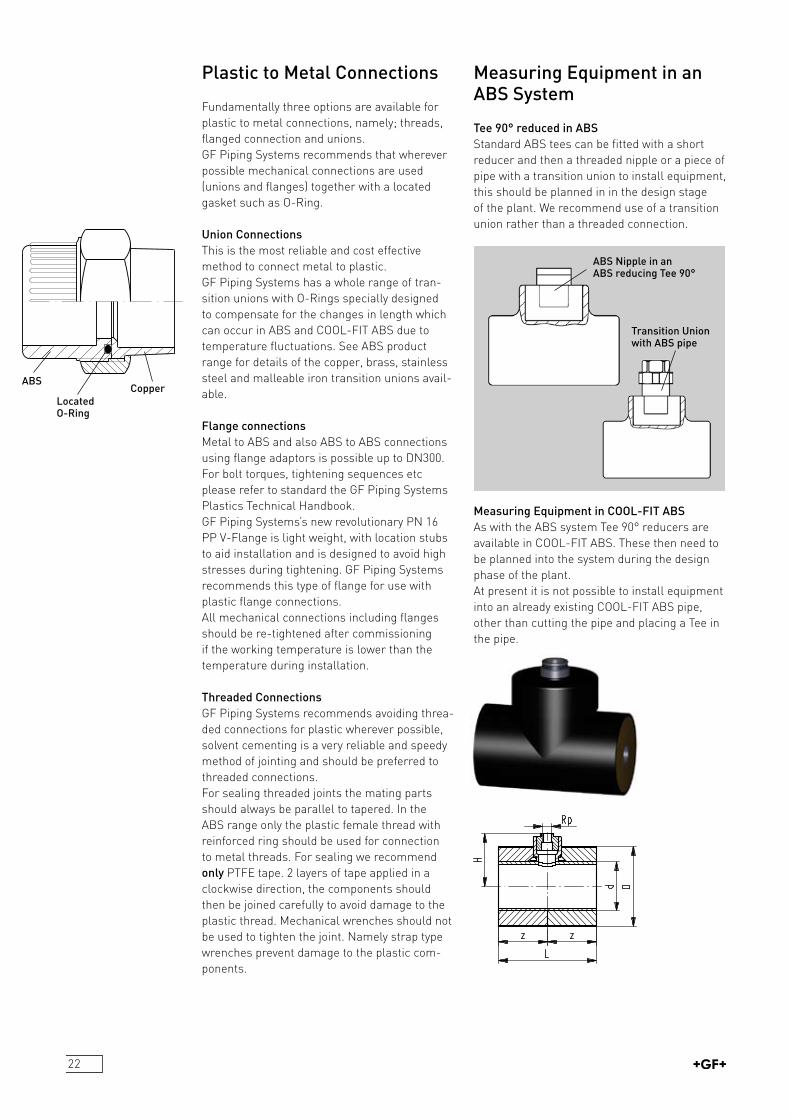
Tee 90° reduced in ABSStandard ABS tees can be fitted with a short reducer and then a threaded nipple or a piece of pipe with a transition union to install equipment, this should be planned in in the design stage of the plant. We recommend use of a transition union rather than a threaded connection.
Measuring Equipment in COOL-FIT ABSAs with the ABS system Tee 90° reducers are available in COOLFIT ABS. These then need to be planned into the system during the design phase of the plant.At present it is not possible to install equipment into an already existing COOLFIT ABS pipe, other than cutting the pipe and placing a Tee in the pipe.
Plastic to Metal Connections
Fundamentally three options are available for plastic to metal connections, namely; threads, flanged connection and unions.GF Piping Systems recommends that wherever possible mechanical connections are used (unions and flanges) together with a located gasket such as ORing.
Union ConnectionsThis is the most reliable and cost effective method to connect metal to plastic.GF Piping Systems has a whole range of transition unions with ORings specially designed to compensate for the changes in length which can occur in ABS and COOLFIT ABS due to temperature fluctuations. See ABS product range for details of the copper, brass, stainless steel and malleable iron transition unions available.
Flange connectionsMetal to ABS and also ABS to ABS connections using flange adaptors is possible up to DN300.For bolt torques, tightening sequences etc please refer to standard the GF Piping Systems Plastics Technical Handbook.GF Piping Systems’s new revolutionary PN 16 PP VFlange is light weight, with location stubs to aid installation and is designed to avoid high stresses during tightening. GF Piping Systems recommends this type of flange for use with plastic flange connections.All mechanical connections including flanges should be retightened after commissioning if the working temperature is lower than the temperature during installation.
Threaded ConnectionsGF Piping Systems recommends avoiding threaded connections for plastic wherever possible, solvent cementing is a very reliable and speedy method of jointing and should be preferred to threaded connections.For sealing threaded joints the mating parts should always be parallel to tapered. In the ABS range only the plastic female thread with reinforced ring should be used for connection to metal threads. For sealing we recommend only PTFE tape. 2 layers of tape applied in a clockwise direction, the components should then be joined carefully to avoid damage to the plastic thread. Mechanical wrenches should not be used to tighten the joint. Namely strap type wrenches prevent damage to the plastic components.
ABS Nipple in an ABS reducing Tee 90°
Transition Union with ABS pipe
ABS
Located O-Ring
Copper
23
Retro-Installation of Equipment: into an already existing systemFor dimensions L d90 it is possible to use the extra wall thickness in a cemented joint to bore through pipe and fitting and install a transition union. See www.coolfit.georgefischer.com for installation details.
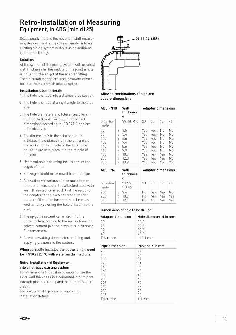
Retro-Installation of MeasuringEquipment, in ABS (min d125)
Occasionally there is the need to install measuring devices, venting devices or similar into an existing piping system without using additional installation fittings.
Solution:At the section of the piping system with greatest wall thickness (in the middle of the joint) a hole is drilled forthe spigot of the adapter fitting. Then a suitable adapterfitting is solvent cemented into the hole which acts as socket.
Installation steps in detail:1. The hole is drilled into a drained pipe section.
2. The hole is drilled at a right angle to the pipe axis.
3. The hole diameters and tolerances given in the attached table correspond to socket dimensions according to ISO 7271 and are to be observed.
4. The dimension X in the attached table indicates the distance from the entrance of the socket to the middle of the hole to be drilled in order to place it in the middle of the joint.
5. Use a suitable deburring tool to deburr the edges ofhole.
6. Shavings should be removed from the pipe.
7. Allowed combinations of pipe and adapter fitting are indicated in the attached table with yes . The selection is such that the spigot of the adapter fitting does not reach into the mediumfilled pipe formore than 1 mm as well as fully covering the hole drilled into the joint.
8. The spigot is solvent cemented into the drilled hole according to the instructions for solvent cement jointing given in our Planning Fundamentals.
9. Attend to waiting times before refilling and applying pressure to the system.
When correctly installed the above joint is good for PN10 at 20 °C with water as the medium.
Allowed combinations of pipe and adapterdimensions
ABS PN10 Wall Adapter dimensions thickness, e pipe dia S8, SDR17 20 25 32 40meter75 x 4.5 Yes Yes No No90 x 5.4 Yes Yes No No110 x 6.6 Yes Yes No No125 x 7.4 Yes Yes No No140 x 8.6 Yes Yes No No160 x 9.9 Yes Yes No No180 x 10.7 Yes Yes Yes No200 x 12.3 Yes Yes Yes No225 x 13.9 Yes Yes Yes Yes
ABS PN6 Wall Adapter dimensions thickness, e pipe dia S12.5, 20 25 32 40meter SDR26250 x 9.6 No Yes Yes No280 x 10.7 No Yes Yes Yes315 x 12.1 No No Yes Yes
Dimensions of hole to be drilled
Adapter dimension Hole diameter, d in mm20 20.2 25 25.2 32 32.240 40.2Tolerance ± 0.1 mm
Pipe dimension Position X in mm75 2290 26110 31125 34 140 38 160 43180 48200 53225 59250 66280 73 315 82Tolerance ± 1 mm
24
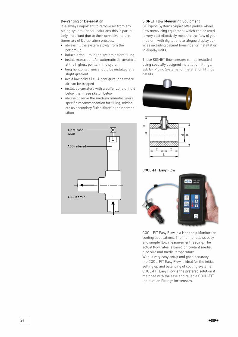
De-Venting or De-aerationIt is always important to remove air from any piping system, for salt solutions this is particularly important due to their corrosive nature. Summary of Deaeration process,• always fill the system slowly from the
bottom up• induce a vacuum in the system before filling• install manual and/or automatic deaerators
at the highest points in the system• long horizontal runs should be installed at a
slight gradient• avoid low points i.e. Uconfigurations where
air can be trapped• install deaerators with a buffer zone of fluid
below them, see sketch below• always observe the medium manufacturers
specific recommendation for filling, mixing etc as secondary fluids differ in their composition
SIGNET Flow Measuring EquipmentGF Piping Systems Signet offer paddle wheel flow measuring equipment which can be used to very cost effectively measure the flow of your medium, with digital and analogue display devices including cabinet housings for installation in display units.
These SIGNET flow sensors can be installed using specially designed installation fittings, ask GF Piping Systems for installation fittings details.
COOL-FIT Easy Flow
COOLFIT Easy Flow is a Handheld Monitor for cooling applications. The monitor allows easy and simple flow measurement reading. The actual flow rates is based on coolant media, pipe size and media temperature.With is very easy setup and good accuracy the COOLFIT Easy Flow is ideal for the initial setting up and balancing of cooling systems.COOLFIT Easy Flow is the prefered solution if matched with the save and reliable COOLFIT Inatallation Fittings for sensors.
ABS reduced
ABS Tee 90°
Air release valve

25
Medium: We recommend the use of water as testing medium. The solvent gases which may be left in the pipe after jointing dissolve in water and thus water also removes all excess solvents from the system. Water also has a very low compression ratio and is thus safer as a testing medium.If water is not practical then inert gases can be used with ABS and COOLFIT ABS. Compressed air should not be used with ABS or COOLFIT ABS.
Internal Pressure test and leak test
Pressures:For water 1.5 x working pressure, to a maximum of PN + 5 bar.
Time under Pressure Test:We recommend that the system is left at the test pressure for minimum 6 hours to ensure complete leak tightness control.
Overview of the different testing methods
Testing method Internal pressure test Leak test
Medium Water Gas/air* Compressedair* Gas/air Gas/air
Art incompressible compressible compressible compressible compressible
Testpressure pp(perm) PN, max. 10 bar max. 1.1xPN 0.5 bar 1.5 bar resp. 0.85xpp(perm)
Endangerment small high high small middle during pressuretest
Material all plastics ABS PB, PE all plastics ABS
Informative High: High: High: small middlevalue Proof of Proof of Proof of resistance to resistance to resistance to pressure pressure pressure including including including tightness against tightness against tightness against testmedium testmedium testmedium
*Please consider the applicable safety precautionsMore informationis available in DVS 22101 Suppl. 2.
26
GeneralThe internal pressure test is done when installation work has been completed and necessitates an operational pipeline or operational test sections. The test pressure load should furnish experimental proof of operational safety.The test pressure is not based on the working pressure, but rather on the internal pressure load capacity, derived from the pipe wall thickness. Supplement 2 of DVS 22101 forms the basis for the following information. This replaces the data in DVS 22101 entirely. The modifications became necessary because• the reference value nominal pressure (PN) is being used less and less to determine the test pressure (1.5xPN, or 1.3xPN) and is being replaced by SDR,• a shortterm overload or even a reduction in the service life can occur if in the course of the internal pressure test based on the nominal pressure the pipe wall temperature TR =20°C is exceeded by moret han 5°C.
Test pressures are therefore determined in relation to SDR and the pipe wall temperature. The 100h value from the longterm behaviour diagram is used for the test clamping.
Test ParametersThe following table indicates recommended methods of testing the internal pressure.
Object Pre-test Main test
Test pressure pp ≤ pp(perm) ≤ 0.85 pp(perm)
(depends on the pipe wall temperature or the permissible test pressure of the builtin components, see clause Determining the test pressure)
Pre-testThe pretest serves to prepare the piping system for the actual test (maintest). In the course of pretesting, a tensionexpansion equilibrium in relation to an increase in volume will develop in the piping system. A materialrelated drop in pressure will occur which will require repeated pumping to restore the test pressure and also frequently a retightening of the flange connection screws. The guidelines for an expansionrelated pressure.
Installation of metric industrial piping systemsInternal pressure test and leak test Internal pressure test with water or a similar incompressible test fluid
Main testIn the context of the main test, a much smaller drop in pressure can be expected at constant pipe wall temperatures so that it is not necessary to pump again.
Observe if using compensators
Test duration L ≤ 100 m: 3h L ≤ 100 m: 3h(depends on the 100 m < L ≤ 100 m < L ≤length of the 500 m: 6h 500 m: 6hpipeline, respectively the sections)
Checks during the At least 3 At least 2testing (test checks, checks, pressure and distributed over distributed overtemperature the test the test durationprogression should duration with withoutbe recorded) restoring the restoring the test pressure test pressure
decrease in pipes are:
Material Pressure drop
ABS 0.6 bar/h
The checks can focus primarily on leak detection at the flange joints and any position changes of the pipe.
If the pipeline to be tested contains compensators, this has an influence on the expected axial forces of the pipeline. Because the test pressure is higher than the working pressure, the axial forces on the fixed points become higher. This has to be taken into account when designing the fixed points.
Observe if using valvesWhen using a valve at the end of a pipeline (end or final valve), the valve and the pipe end should be closed by a dummy flange or cap. This prevents inadvertent opening of the valve or any pollution of the inside of the valve.

27
Filling the pipeline• Was installation done according to the available plans?• All pressure relief devices and flap traps mounted in the flow direction?• All end valves shut?• Valves in front of other devices are shut to protect against pressure.• Visual inspection of all joints, pumps, measurement de vices and tanks.• Has the waiting period after the last fusion cementing been observed?Now the pipeline can be filled from the geodetic lowest point. Special attention should be given to the air vent. If possible, vents should be provided at all the high points of the pipeline and these should be open when filling the system. Flushing velocity should be at least 1m/sec. Reference values for the filling volume are given in the table below.
DN V(l/sec) DN V(l/sec)
≤80 0.15 250 2.0100 0.3 300 3.0150 0.7 400 6.0200 1.5 500 >9.0
Adequate time should be allowed between filling and testing the pipeline, so that the air contained in the piping system can escape via the vents: ca. 612h, depending on the nominal diameter.
Applying the test pressure
The test pressure is applied according to the diagram. Here it is important that the pressure increase rate does not cause any water hammer!
DefinitionsY = test pressure in %X = time for pressure increase in min1) = pressure increase rate up to DN1002) = range of pressure increase rates > DN1004003) = reference values for pressure increase rate DN500 and greater is: 500/DN [bar/10min]
Determining the test pressureThe allowable test pressure is calculated according to the following formula:
withσ v(T,100h) Longterm creep strength for the pipe wall temperature TR (att = 100h) Sp Minimum safety factor for longterm creep strength AG Processing or geometrical specific factor that reduces the allow able test pressureTR Pipe wall temperature: average value of test medium temperature and pipe surface temperature
Attention: If the piping system contains diaphragm valves the maximum allowable test pressure is limited to the nominal pressure.
To make things easier, the permissible test pressures can be taken directly from the following diagrams.
Definitions:P = permissible test pressure in barT = pipe wall temperature in °C
Checks during testingThe following measurement values must be recorded consistently during testing:• Internal pressure at the absolute low point of the pipeline• Medium and ambient temperature• Water volume input• Water volume output• Pressure drop rates
PSDR S Ap perm
v T h
P G( )
( , )=1 20 100σ

28
IntroductionUsually the pressure test is done as a water pressure test and only in exceptional cases (with consideration of special safety precautions) as a gas pressure test with air or nitrogen (please consider also the general chapter Introduction into pressure testing).
Safety precautions
Attention: The test is carried out with a compressible medium, please obser ve the necessary safety precautions.
The area around the pipeline under test pressure is to be clearly restricted for access only by persons assigned with the testing.Necessary control equipement is to be placed at a safe distance.The testing should be timed so that there are as few persons as possible in the immediate area.In particular at the entrances to the endangered area additional signs are to be setup (Entry prohibited, Attention! Gas pressure tests!). If necessary persons in neighbouring buildings are to be informed.
Observe if using compensators If the pipeline to be tested contains compensators, this has an influence on the expected axial forces of the pipeline. Because the test pressure is higher than the working pressure, the axial forces on the fixed points become higher. This has to be taken into account when designing the fixed points.
Observe if using valves When using a valve at the end of a pipeline (end or final valve), the valve and the pipe end should be closed by a dummy flange or cap. This prevents inadvertent opening of the valve or any pollution of the inside of the valve.
Minimum waiting times for the internal pressure test Before carrying out the pressure test, observe the minimum waiting times after the last cementing given in the following table:
AmbientTemperature Waitingtime
10 to 30 °C min. 48 hours
Testing procedure of the internal pressure test The test pressure shall be equal to the PN of the installed piping system but with a maximum pressure of 10 bar. Any components with a lower PN than the rest of the piping systems shall be considered. The test temperature shall be between 10 to 30 °C.The pipelines must be free from any grease or paint.Only oil free air or inert gases such as nitrogen should be used as the test medium. No refrigerant gases, such as R22, may be used. Once the pressure in the system has stabilised hold the pipeline under the test pressure for at least 15 minutes. If a drop in pressure is observed and inspection of the joints is necessary this can be done using a foambuilding agent. Using a soap solution which can be removed simply with water after the test is recommended.
Attention: Commercial leak detection sprays can cause stress cracks in plastics. Using these sprays remove any residues after testing.
Note: For valves leak tightness using a gas is not representative of the valves leak tightness with a fluid.Therefore if a GF valve shows a leakage unde rinternal pressure test with a gas it is recommended to reduce the pressure to 1.5 bar and reinspect the valves.
Leak tightness test with gas/airFor checking the leak tightness shortly after installation a test pressure of up to 1.5 bar with a minimum waiting time of 3 hours applies.
Installation of metric industrial piping systemsInternal pressure test and leak testInternal pressure test and leak tightness test of ABS pipelines with gas/air as test fluid (compressible medium)
29
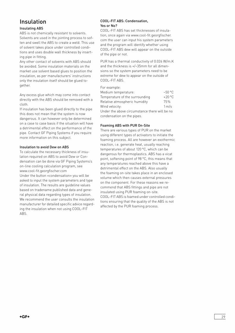
Insulation Insulating ABSABS is not chemically resistant to solvents. Solvents are used in the jointing process to soften and swell the ABS to create a weld. This use of solvent takes place under controlled condi tions and uses double wall thickness by inserting pipe in fitting.Any other contact of solvents with ABS should be avoided. Some insulation materials on the market use solvent based glues to position the insulation, as per manufacturers’ instructions only the insulation itself should be glued together.
Any excess glue which may come into contact directly with the ABS should be removed with a cloth.If insulation has been glued directly to the pipe this does not mean that the system is now dangerous. It can however only be determined on a case to case basis if the situation will have a detrimental effect on the performance of the pipe. Contact GF Piping Systems if you require more information on this subject.
Insulation to avoid Dew on ABSTo calculate the necessary thickness of insulation required on ABS to avoid Dew or Condensation can be done via GF Piping Systems’s online cooling calculation program, see www.coolfit.georgfischer.comUnder the button «condensation» you will be asked to input the system parameters and type of insulation. The results are guideline values based on tradename published data and general physical data regarding types of insulation.We recommend the user consults the insulation manufacturer for detailed specific advice regarding the insulation when not using COOLFIT ABS.
COOL-FIT ABS: Condensation, Yes or No?COOLFIT ABS has set thicknesses of insulation, once again via www.coolfit.georgfischer.com the user can input his system parameters and the program will identify whether using COOLFIT ABS dew will appear on the outside of the pipe or not.
PUR has a thermal conductivity of 0.026 W/m.K and the thickness is +/–35mm for all dimensions so the system parameters need to be extreme for dew to appear on the outside of COOLFIT ABS.
For example:Medium temperature: –50 °CTemperature of the surrounding +20 °CRelative atmospheric humidity 75%Wind velocity: 1 m/sUnder the above circumstance there will be no condensation on the pipes.
Foaming ABS with PUR On-SiteThere are various types of PUR on the market using different types of activators to initiate the foaming process. All are however an exothermic reaction, i.e. generate heat, usually reaching temperatures of about 120 °C, which can be dangerous for thermoplastics. ABS has a vicat point, softening point of 98 °C, this means that any temperatures reached above this have a detrimental effect on the ABS. Also usually the foaming onsite takes place in an enclosed volume which then causes external pressures on the component. For these reasons we recommend that ABS fittings and pipe are not insulated using PUR foaming onsite. COOLFIT ABS is foamed under controlled conditions ensuring that the quality of the ABS is not affected by the PUR foaming process.
30
De-FrostingMany secondary refrigeration loops are not only used for normal and low temperature cooling but are also used for defrosting. GF Piping Systems has many years of good experience with the use of ABS in such dual defrost / cooling systems without any detrimental effects to the system.
Long Term Life-Span of ABS PipesOne of the major differences in physical characteristics between plastics and metals is the physical characteristic creep. Creep is a time related physical property of plastics. Under a constant stress plastics strain and the amount of strain is time related.This characteristic is taken into account in the PressureTemperature curve which is based on a minimum LifeSpan of 25 years and with a safety factor of 1.8.This curve and further background data relating to creep, the long term hydrostatic curves, and other system defining criteria can be found in ISO 15493.
StorageAll plastic pipes including preinsulated plastic pipes, i.e. COOLFIT ABS should be stacked on a flat surface free from sharp edges, such as stones or building debris for instance. During handling care should be taken to avoid damage to the outside surface of the pipe, for instance no dragging along the ground. Avoid pipe overhangs when stored as this will cause the pipe to bend.
UV ResistanceMost plastics suffer some loss of physical properties when exposed to UV light, only PE Black, used also for the outer jacket of the COOLFIT ABS black, is UV resistant.The impact strength of ABS reduces under UV light over a time period of approximately one year, after which the oxidised layer on the outside surface of the ABS acts as a barrier and the impact strength does not deteriorate further. Although the ABS impact strength is reduced under UV light it still remains at a very high level.
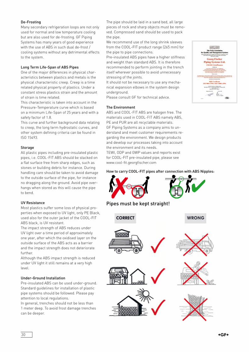
Under-Ground InstallationPreinsulated ABS can be used underground. Standard guidelines for installation of plastic pipe systems should be followed. Please pay attention to local regulations.In general, trenches should not be less than 1 meter deep. To avoid frost damage trenches can be deeper.
The pipe should be laid in a sand bed, all large pieces of rock and sharp objects must be removed. Compressed sand should be used to pack the pipe.We recommend use of the long shrink sleeves from the COOLFIT product range (265 mm) for the pipe to pipe connections.Preinsulated ABS pipes have a higher stiffness and weight than standard ABS. It is therefore recommended to perform jointing in the trench itself wherever possible to avoid unnecessary stressing of the joints.It should not be necessary to use any mechanical expansion elbows in the system design underground. Please consult GF for technical advice.
The EnvironmentABS and COOLFIT ABS are halogen free. The materials used in COOLFIT ABS namely ABS, PE and PUR are all recyclable materials. GF Piping Systems as a company aims to understand and meet customer requirements re garding the environment. We design products and develop our processes taking into account the environment and its needs.TEWI, ODP and GWP values and reports exist for COOLFIT preinsulated pipe, please seewww.coolfit.georgfischer.com
How to carry COOL-FIT pipes after connection with ABS Nipples:
Pipes must be kept straight!
31
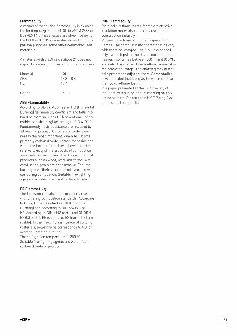
FlammabilityA means of measuring flammability is by using the limiting oxygen index (LOI) to ASTM 2863 or BS2782141. These values are shown below for the COOLFIT ABS raw materials and for comparison purposes some other commonly used materials.
A material with a LOI value above 21 does not support combustion in air at room temperature.
Material LOI ABS 18.3–18.8PE 17.4
Cotton 16 –17
ABS FlammabilityAccording to UL94, ABS has an HB (Horizontal Burning) flammability coefficient and falls into building material class B2 (conventional inflammable, nondripping) according to DIN 41021.Fundamently, toxic substance are released by all burning process. Carbon monoxide is generally the most important. When ABS burns, primarily carbon dioxide, carbon monoxide and water are formed. Tests have shown that the relative toxicity of the products of combustion are similar or even lower than those of natural products such as wood, wool and cotton. ABS combustion gases are not corrosive. That the burning nevertheless forms soot, smoke develops during combustion. Suitable firefighting agents are water, foam and carbon dioxide.
PE FlammabilityThe following classifications in accordance with differing combustion standards: According to UL94, PE is classified as HB (Horizontal Burning) and according to DIN 534381 as K2. According to DIN 4102 part 1 and ÖNORM B3800 part 1, PE is listed as B2 (normally flammable). In the French classification of building materials, polyethylene corresponds to M3 (of average flammable rating).The self ignition temperature is 350 °C.Suitable firefighting agents are water, foam, carbon dioxide or powder.
PUR FlammabilityRigid polyurethanebased foams are effective insulation materials commonly used in the construction industry. Polyurethane foam will burn if exposed to flames. The combustibility characteristics vary with chemical composition. Unlike expanded polystyrene (eps), polyurethane does not melt. It flashes into flames between 800 °F and 850 °F, and only chars rather than melts at temperatures below that range. The charring may in fact help protect the adjacent foam. Some studies have indicated that Douglas Fir was more toxic than polyurethane foam. In a paper presented at the 1985 Society of the Plastics Industry, annual meeting on poly urethane foam. Please consult GF Piping Systems for further details.
32
1 ScopeThis specification covers requirements for the GF Piping Systems ABS intended for a wide range of applications including water and wastewater treatment as well as process cooling water and secondary refrigeration. The components of the ABS pipe system are in accordance with the following standards.
2 Acrylonitrile Butadiene Styrene MaterialGF Piping Systems ABS pipes and fittings shall be manufactured from acrylonitrile butadiene styrene, ABS. The raw material used shall be material designed for use with pressure bearing piping systems with long term hydrostatic properties in accordance with ISO 15493, as supplied by GF Piping Systems. For detailed physical properties see GF Piping Systems literature reference Fi 9030, pages 28–30.
ABS Metric Piping System Specification
COOL-FIT ABS Pipe and Fittings Specification
3 ABS PipeAll ABS pipe shall be metric sizes manufactured in accordance with the requirements of ISO 15493, supplied by GF Piping Systems.
4 ABS FittingsAll ABS fittings shall be metric sizes manufactured by GF Piping Systems or equal, with dimensions and tolerances in accordance with ISO 727 and ISO 15493. All threaded connections shall have pipe threads in accordance with the requirements of ISO 71:1994.
5 ABS ValvesAll ABS valves shall be metric sizes manufactured by GF Piping Systems or equal in accordance with DIN 3441 Parts 1 to 4.
6 Solvent Cement Jointing and InstallationShould be in accordance with GF Piping Systems Guide to the Installation and Use of Plastic Pipelines.
1 ScopeThis specification covers requirements for GF Piping Systems COOLFIT ABS (preinsulated ABS pipe and fittings), intended primarily for use in refrigeration and cooling plants for the secondary piping systems. The system consists of preinsulated pipe and fittings using ABS carrier pipe and fittings, with insulation from PUR and outer jacket in PE.The components of the COOLFIT ABS pipe and fittings are in accordance with the following standards.
2 ABS Carrier Pipe and Fittings2.1 Raw MaterialGF Piping Systems ABS pipes and fittings shall be manufactured from acrylonitrile butadiene styrene, ABS. The raw material used shall be a material for use with pressure bearing plastic pipe systems in accordance to ISO 15493. For detailed physical properties see GF Piping Systems literature reference Fi 9030, pages 32–34.2.2 Physical PropertiesThe ABS carrier pipe and fittings shall be manufactured to metric sizes in accordance with the requirements of ISO 15493, supplied by GF Piping Systems.
3 PUR InsulationThe insulating material shall be hard poly urethane foam, PUR, with a thermal conductivity, landa value, of l 0.026 W/mK and a density of L 45 kg/m3.
4 HD-PE Outer JacketThe outer jacket shall be manufactured from HDPE, high density polyethylene, black and white. Colours of the jacket shall be black to RAL 9004 and white to RAL 9010. The black jacket shall be UV resistant in accordance to DIN 8075.
5 Solvent Cement Jointing and InstallationShould be in accordance with GF Piping Systems Guide to the Installation and Use of Plastic Pipelines.
33
Jointing technologyCement technologyInstructions for Tangit solvent cement jointing of ABS dimension d16 to d225
General
Solvent cement jointing calls for adequate technical know-how, which can be acquired in the appropriate training courses. Your GF representative will gladly provide you with information about training possibilities.
The dimensions of GF pipes, fittings and valves conform generally to the various national standards as well as to ISO 7271 concerning dimensions of sockets. Our fittings and valves can be used with any ABS pipes whose outside diameter tolerance conforms to ISO 119221.
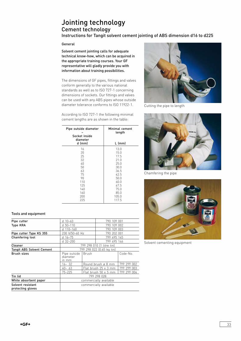
According to ISO 7271 the following minimal cement lengths are as shown in the table:
Pipe outside diameter Minimal cement – length Socket inside diameter d (mm) L (mm)
16 13.0 20 15.0 25 17.5 32 21.0 40 25.0 50 30.0 63 36.5 75 42.5 90 50.0 110 60.0 125 67.5 140 75.0 160 85.0 200 105.0 225 117.5
Tools and equipment
Pipe cutter d 10–63 790 109 001Type KRA d 50–110 790 109 002 d 110–160 790 109 003Pipe cutter Type KS 355 230 V/5060 Hz 790 202 001Chamfering tool d 16–75 799 495 145 d 32–200 799 495 146Cleaner 799 298 010 (1 litre tin)Tangit ABS Solvent Cement 799 298 022 (0.65 kg tin)Brush sizes Pipe outside Brush CodeNo. diameter in mm 16–132 Round brush ø 8 mm 799 299 002 40–163 Flat brush 25 x 3 mm 799 299 003 75–225 Flat brush 50 x 5 mm 799 299 004Tin lid 799 298 028White absorbent paper commercially availableSolvent resistant commercially availableprotecting gloves
Cutting the pipe to length
Chamfering the pipe
Solvent cementing equipment

34
Note: The quantities specified above are to be understood as practiceorientated maximum values. In principle the quantities depend on gap dimensions, temperatures, working technique.
PreparationsThe pipe must be cut off at right angles. Remove the inside edges and chamfer the outside ones as illustrated in the sketch. Only then is an optimal solvent cemented joint possible.
Important: Wellchamfered pipe ends prevent the layer of cement from being removed as the pipe is inserted into the fitting.
ABS Tangit and Cleaner: Amounts required Pipe ABS Tangit- ABS Tangit Pipe Tangit-Cleaner Tangit-Cleaner diameter Amount per Number of Joints diameter Amount per Number of Joints d (mm) 100 Joints per Tin d (mm) 100 Joints per Tin kg 0.650 kg litre (1 litre) 16 0,25 260 16 0,2 500 20 0,35 186 20 0,3 333 25 0,40 163 25 0,4 250 32 0,45 144 32 0,5 200 40 0,60 108 40 0,7 143 50 0,90 72 50 0,9 111 63 1,10 59 63 1,1 91 75 1,25 52 75 1,3 77 90 1,70 38 90 1,4 71 110 2,50 26 110 1,7 59 140 5,00 13 140 2,1 48 160 6,50 10 160 2,5 40 200 10,00 6 200 3,5 29 225 12,50 5 225 4,5 22
Pipe outside b diameter
16 mm 1–2 mm 20–50 mm 2–3 mm O 63 mm 3–6 mm
Wipe the outside of the pipe and the inside of the socket with a clean cloth to remove obvious dirt. Marking the jointing length on the pipe end makes it possible to check afterwards whether the pipe has been inserted to the full extent of the socket.
Note: If the outside diameter of the pipe and the inside diameter of the socket are at opposite extremes of their tolerances, then the pipe cannot be inserted dry into the fitting socket. This will only become possible once the cement has been applied. The Tangit ABS Cement is supplied ready for use. Stir thoroughly before using! Cement of the correct consistency will run evenly from a wooden spatula held at a slant. Cement which no longer runs smoothly is unusable. The cement must not be thinned. For more information please consult the safety datasheets under the following link:https://www.sdb.henkel.de/index.cfmCement and cleaner should be stored in a cool, dryplace (5–35 °C)! Under these conditions the cement andcleaner are durable for 24 months starting from the dateof filling (imprinted on the tin).
35
T Temperature in °C / °FY Opening time [sec]
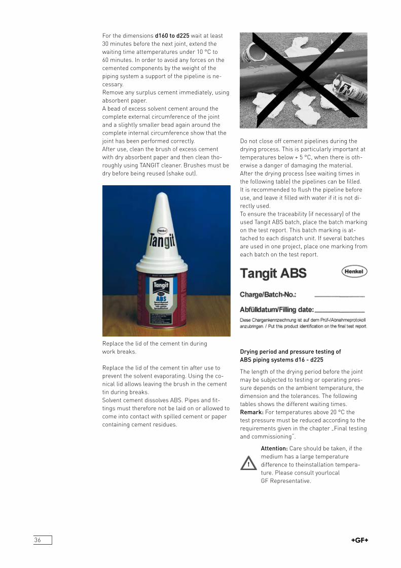
Begin by applying a normal layer of cement to the fitting and then a thicker one to the pipe end with firm brush pressure. Work in well. The brush strokes should always be in an axial direction.To ensure that both jointing surfaces are completely covered with a smooth, even layer of cement, the brush should be generously loaded with cement.To ensure that both jointing surfaces are completely covered with a smooth, even layer of cement, the brush should be generously loaded with cement.
The joints can be made singlehanded for pipes with diameters up to d63 mm.For d75 mm and larger pipes, two people are needed to apply the cement to the pipe end and fitting socket simultaneously in order to avoid exceeding the maximum opening time of the cement.After the cement has been applied, insert the pipe to the full depth of the socket immediately without twisting and bring them into the correct alignment. Ensure that the outlet of the fitting is in the correct position. Hold them in this position to allow the cement to set.Up to the dimension d140 wait at least 10 minutes before the next joint, extend the waiting time at temperatures under 10 °C to 15 minutes.
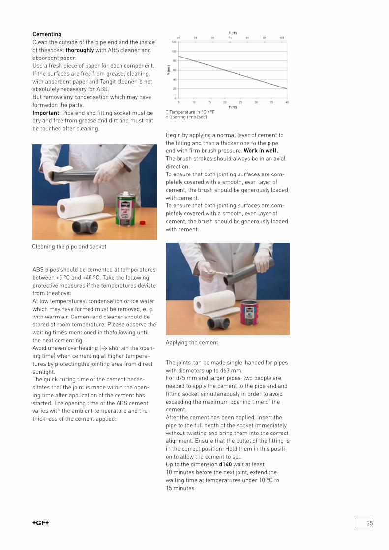
CementingClean the outside of the pipe end and the inside of thesocket thoroughly with ABS cleaner and absorbent paper. Use a fresh piece of paper for each component. If the surfaces are free from grease, cleaning with absorbent paper and Tangit cleaner is not absolutely necessary for ABS.But remove any condensation which may have formedon the parts.Important: Pipe end and fitting socket must be dry and free from grease and dirt and must not be touched after cleaning.
ABS pipes should be cemented at temperatures between +5 °C and +40 °C. Take the following protective measures if the temperatures deviate from theabove: At low temperatures, condensation or ice water which may have formed must be removed, e. g. with warm air. Cement and cleaner should be stored at room temperature. Please observe the waiting times mentioned in thefollowing until the next cementing. Avoid uneven overheating (> shorten the opening time) when cementing at higher temperatures by protectingthe jointing area from direct sunlight.The quick curing time of the cement necessitates that the joint is made within the opening time after application of the cement has started. The opening time of the ABS cement varies with the ambient temperature and the thickness of the cement applied:
Applying the cement
Cleaning the pipe and socket
36
Do not close off cement pipelines during the drying process. This is particularly important at temperatures below + 5 °C, when there is otherwise a danger of damaging the material.After the drying process (see waiting times in the following table) the pipelines can be filled. It is recommended to flush the pipeline before use, and leave it filled with water if it is not directly used.To ensure the traceability (if necessary) of the used Tangit ABS batch, place the batch marking on the test report. This batch marking is attached to each dispatch unit. If several batches are used in one project, place one marking from each batch on the test report.
Drying period and pressure testing of ABS piping systems d16 - d225
The length of the drying period before the joint may be subjected to testing or operating pressure depends on the ambient temperature, the dimension and the tolerances. The following tables shows the different waiting times.Remark: For temperatures above 20 °C the test pressure must be reduced according to the requirements given in the chapter „Final testing and commissioning“.
Attention: Care should be taken, if the medium has a large temperature difference to theinstallation tempera ture. Please consult yourlocal GF Representative.
For the dimensions d160 to d225 wait at least 30 minutes before the next joint, extend the waiting time attemperatures under 10 °C to 60 minutes. In order to avoid any forces on the cemented components by the weight of the piping system a support of the pipeline is necessary.Remove any surplus cement immediately, using absorbent paper.A bead of excess solvent cement around the complete external circumference of the joint and a slightly smaller bead again around the complete internal circumference show that the joint has been performed correctly.After use, clean the brush of excess cement with dry absorbent paper and then clean thoroughly using TANGIT cleaner. Brushes must be dry before being reused (shake out).
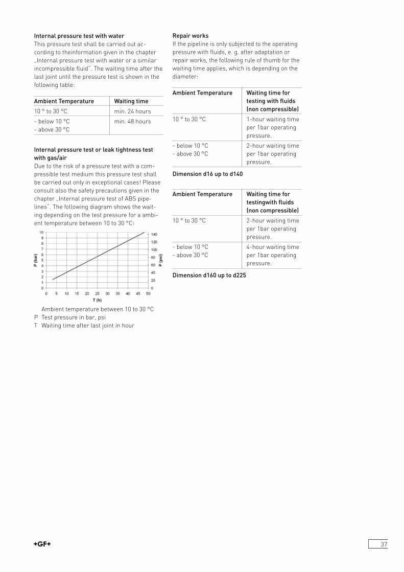
Replace the lid of the cement tin during work breaks.
Replace the lid of the cement tin after use to prevent the solvent evaporating. Using the conical lid allows leaving the brush in the cement tin during breaks.Solvent cement dissolves ABS. Pipes and fittings must therefore not be laid on or allowed to come into contact with spilled cement or paper containing cement residues.
37
Internal pressure test with waterThis pressure test shall be carried out according to theinformation given in the chapter „Internal pressure test with water or a similar incompressible fluid“. The waiting time after the last joint until the pressure test is shown in the following table:
Ambient Temperature Waiting time
10 ° to 30 °C min. 24 hours
below 10 °C min. 48 hours above 30 °C
Internal pressure test or leak tightness test with gas/airDue to the risk of a pressure test with a compressible test medium this pressure test shall be carried out only in exceptional cases! Please consult also the safety precautions given in the chapter „Internal pressure test of ABS pipelines“. The following diagram shows the waiting depending on the test pressure for a ambient temperature between 10 to 30 °C:
Ambient temperature between 10 to 30 °CP Test pressure in bar, psiT Waiting time after last joint in hour
Repair worksIf the pipeline is only subjected to the operating pressure with fluids, e. g. after adaptation or repair works, the following rule of thumb for the waiting time applies, which is depending on the diameter:
Ambient Temperature Waiting time for testing with fluids (non compressible)
10 ° to 30 °C 1hour waiting time per 1bar operating pressure.
below 10 °C 2hour waiting time above 30 °C per 1bar operating pressure.
Dimension d16 up to d140
Ambient Temperature Waiting time for testingwith fluids (non compressible)
10 ° to 30 °C 2hour waiting time per 1bar operating pressure.
below 10 °C 4hour waiting time above 30 °C per 1bar operating pressure.
Dimension d160 up to d225
38
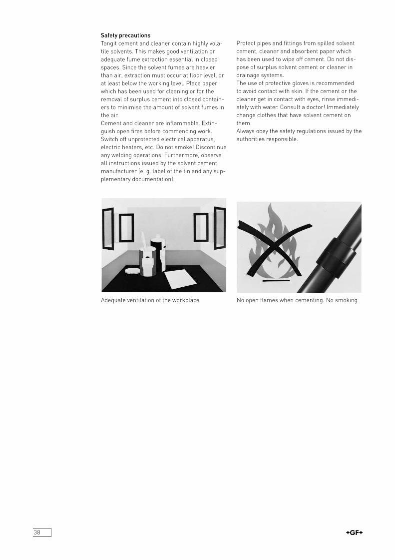
Adequate ventilation of the workplace No open flames when cementing. No smoking
Safety precautionsTangit cement and cleaner contain highly volatile solvents. This makes good ventilation or adequate fume extraction essential in closed spaces. Since the solvent fumes are heavier than air, extraction must occur at floor level, or at least below the working level. Place paper which has been used for cleaning or for the removal of surplus cement into closed containers to minimise the amount of solvent fumes in the air.Cement and cleaner are inflammable. Extinguish open fires before commencing work. Switch off unprotected electrical apparatus, electric heaters, etc. Do not smoke! Discontinue any welding operations. Furthermore, observe all instructions issued by the solvent cement manufacturer (e. g. label of the tin and any supplementary documentation).
Protect pipes and fittings from spilled solvent cement, cleaner and absorbent paper which has been used to wipe off cement. Do not dispose of surplus solvent cement or cleaner in drainage systems.The use of protective gloves is recommended to avoid contact with skin. If the cement or the cleaner get in contact with eyes, rinse immediately with water. Consult a doctor! Immediately change clothes that have solvent cement on them.Always obey the safety regulations issued by the authorities responsible.
39
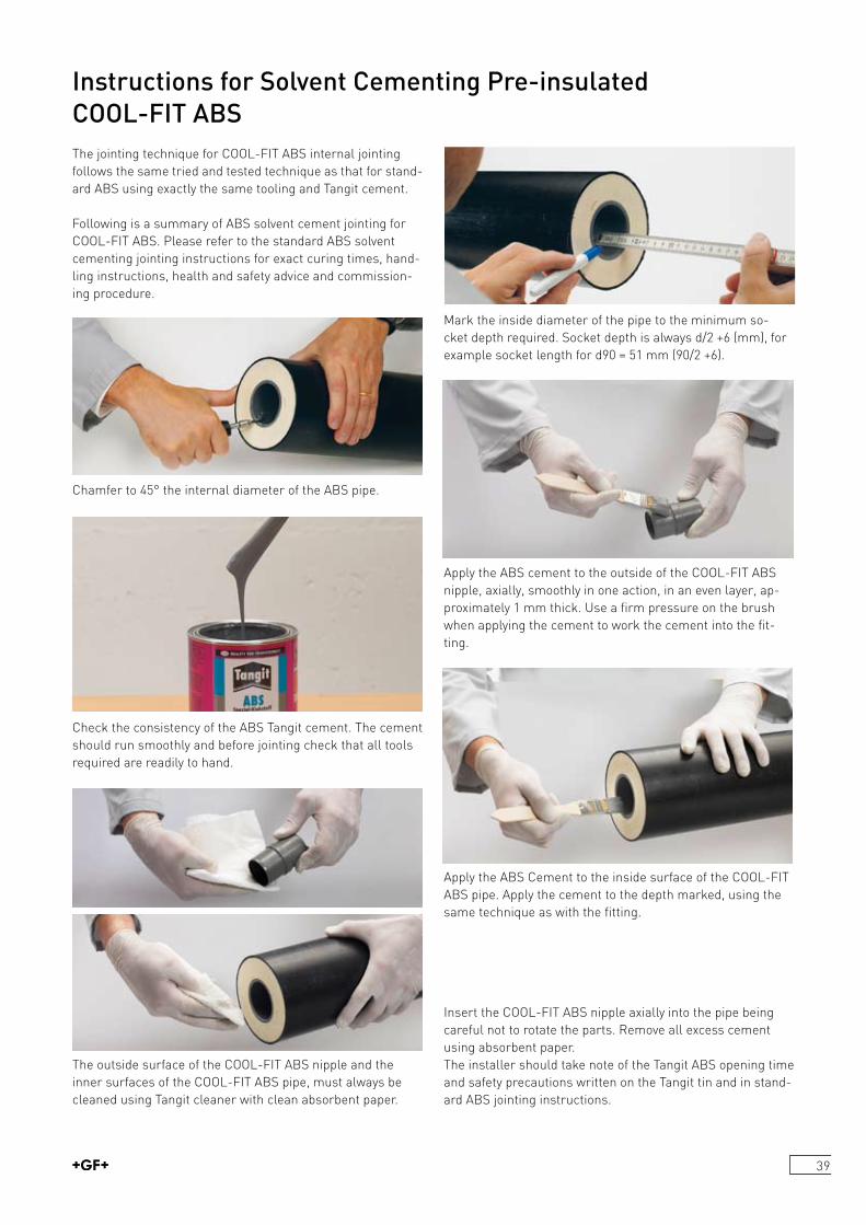
Instructions for Solvent Cementing Pre-insulated COOL-FIT ABSThe jointing technique for COOLFIT ABS internal jointing follows the same tried and tested technique as that for standard ABS using exactly the same tooling and Tangit cement.
Following is a summary of ABS solvent cement jointing for COOLFIT ABS. Please refer to the standard ABS solvent cementing jointing instructions for exact curing times, handling instructions, health and safety advice and commissioning procedure.
Check the consistency of the ABS Tangit cement. The cement should run smoothly and before jointing check that all tools required are readily to hand.
The outside surface of the COOLFIT ABS nipple and the inner surfaces of the COOLFIT ABS pipe, must always be cleaned using Tangit cleaner with clean absorbent paper.
Mark the inside diameter of the pipe to the minimum socket depth required. Socket depth is always d/2 +6 (mm), for example socket length for d90 = 51 mm (90/2 +6).
Apply the ABS cement to the outside of the COOLFIT ABS nipple, axially, smoothly in one action, in an even layer, approximately 1 mm thick. Use a firm pressure on the brush when applying the cement to work the cement into the fitting.
Apply the ABS Cement to the inside surface of the COOLFIT ABS pipe. Apply the cement to the depth marked, using the same technique as with the fitting.
Chamfer to 45° the internal diameter of the ABS pipe.
Insert the COOLFIT ABS nipple axially into the pipe being careful not to rotate the parts. Remove all excess cement using absorbent paper.The installer should take note of the Tangit ABS opening time and safety precautions written on the Tangit tin and in standard ABS jointing instructions.
40
7 Windin cutting head checking that the cutting knife and the other 2 locating heads are assembled in the correct location.
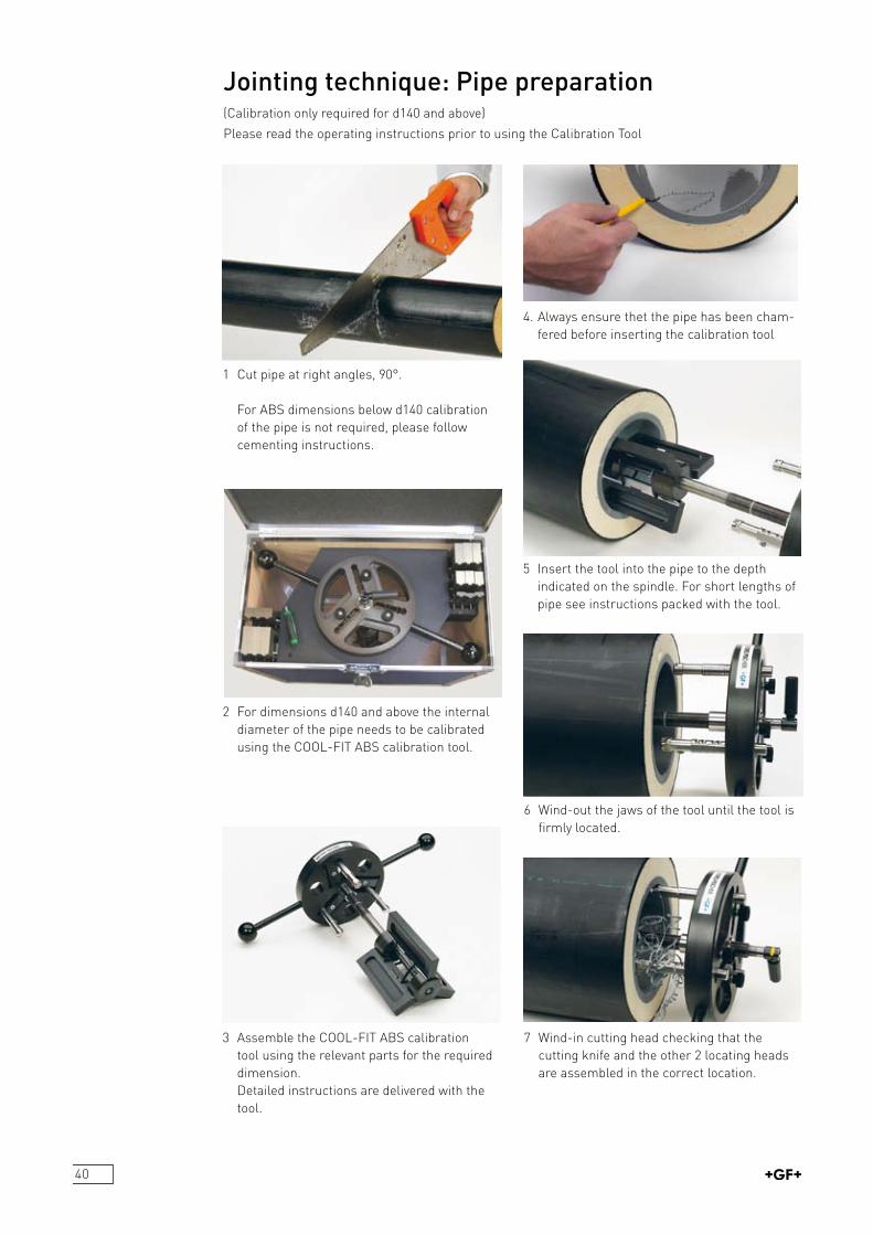
Jointing technique: Pipe preparation
1 Cut pipe at right angles, 90°.
For ABS dimensions below d140 calibration of the pipe is not required, please follow
cementing instructions.
2 For dimensions d140 and above the internal diameter of the pipe needs to be calibrated using the COOLFIT ABS calibration tool.
4. Always ensure thet the pipe has been cham fered before inserting the calibration tool
6 Windout the jaws of the tool until the tool is firmly located.
3 Assemble the COOLFIT ABS calibration tool using the relevant parts for the required dimension. Detailed instructions are delivered with the tool.
(Calibration only required for d140 and above)
Please read the operating instructions prior to using the Calibration Tool
5 Insert the tool into the pipe to the depth indicated on the spindle. For short lengths of pipe see instructions packed with the tool.
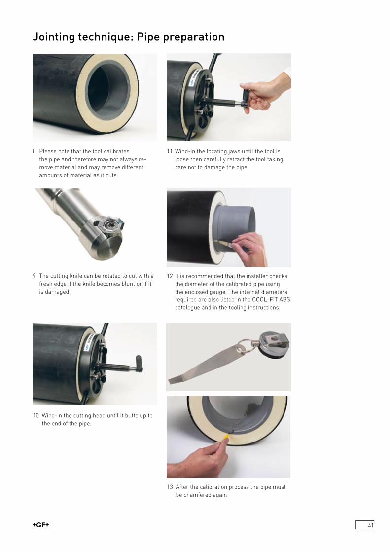
41
Jointing technique: Pipe preparation
8 Please note that the tool calibrates the pipe and therefore may not always remove material and may remove different amounts of material as it cuts.
10 Windin the cutting head until it butts up to the end of the pipe.
9 The cutting knife can be rotated to cut with a fresh edge if the knife becomes blunt or if it is damaged.
11 Windin the locating jaws until the tool is loose then carefully retract the tool taking care not to damage the pipe.
12 It is recommended that the installer checks the diameter of the calibrated pipe using the enclosed gauge. The internal diameters required are also listed in the COOLFIT ABS catalogue and in the tooling instructions.
13 After the calibration process the pipe must be chamfered again!
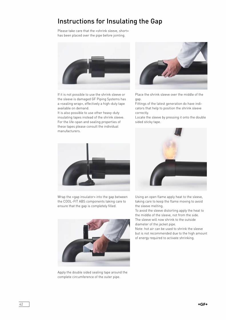
42
Instructions for Insulating the GapPlease take care that the «shrink sleeve, short» has been placed over the pipe before jointing.
Apply the double sided sealing tape around the complete circumference of the outer pipe.
Wrap the «gap insulator» into the gap between the COOLFIT ABS components taking care to ensure that the gap is completely filled.
Using an open flame apply heat to the sleeve, taking care to keep the flame moving to avoid the sleeve melting.To avoid the sleeve distorting apply the heat to the middle of the sleeve, not from the side. The sleeve will now shrink to the outside diameter of the jacket pipe.Note: hot air can be used to shrink the sleeve but is not recommended due to the high amount of energy required to activate shrinking.
Place the shrink sleeve over the middle of the gap. Fittings of the latest generation do have indicators that help to position the shrink sleeve correctly.Locate the sleeve by pressing it onto the double sided sticky tape.
If it is not possible to use the shrink sleeve or the sleeve is damaged GF Piping Systems has a «sealing wrap», effectively a highduty tape available on demand.It is also possible to use other heavyduty insulating tapes instead of the shrink sleeve. For the lifespan and sealing properties of these tapes please consult the individual manufacturers.
43
ABS from GF Piping Systems is a pressure bearing complete piping system that has been available from GF Piping Systems since the mid 80’s.GF Piping Systems offers 2 standard systems in ABS; firstly a BS Inch dimensioned system and secondly a metric mm dimensioned system. See ISO15493 for details.
ABS metric is available in dimensions from d16 to d315 with a complete range of fittings and transition fittings for metal to plastic connections as well as a complete range of manually and actuated valves. COOLFIT ABS is only available using the metric ABS system, d25d225. The ABS valves are completely corrosion resistant with no metal parts and can be actuated either pneumatically or electrically.
ABS Product Range
ABS metric can be used for mediums at temperatures between –40 °C to +60 °C and has a nominal pressure rating of PN10 (10 bar water at 20 °C).
Examples of application areas are: refrigeration secondary systems, for instance in supermarkets or breweries, icedwater or ice slurry systems in pharamaceutical plants, water treatment plants, for drinking and cooling water on ships. Many other application areas are possible. Please ask GF Piping Systems for recommendations of suitability.
Background Information to the ABS Product Range from GF Piping Systems

44

COOL-FITPage
Pipes 46
Fittings 47
Accessories 54
45
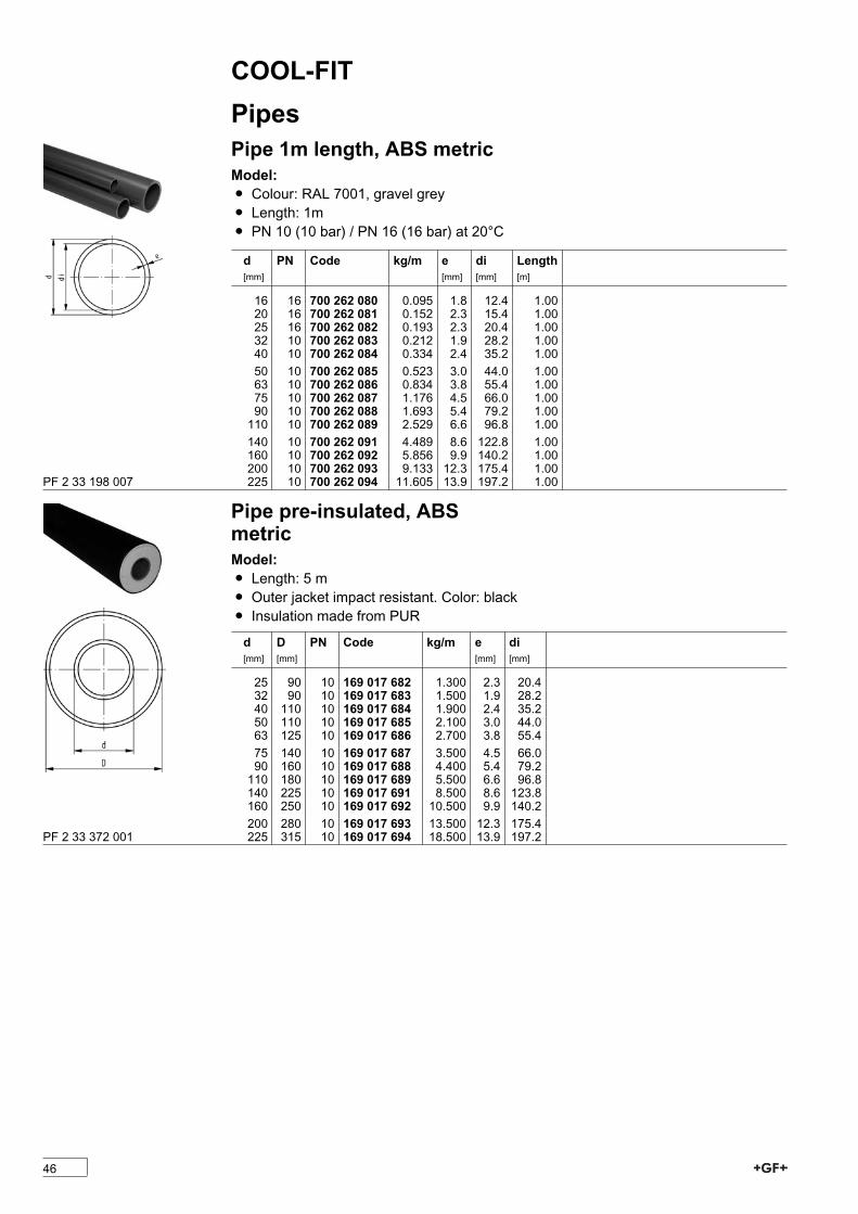
COOL-FITPipesPipe 1m length, ABS metricModel:Ï Colour: RAL 7001, gravel greyÏ Length: 1mÏ PN 10 (10 bar) / PN 16 (16 bar) at 20°C
d[mm]
PN Code kg/m e[mm]
di[mm]
Length[m]
16 16 700 262 080 0.095 1.8 12.4 1.0020 16 700 262 081 0.152 2.3 15.4 1.0025 16 700 262 082 0.193 2.3 20.4 1.0032 10 700 262 083 0.212 1.9 28.2 1.0040 10 700 262 084 0.334 2.4 35.2 1.0050 10 700 262 085 0.523 3.0 44.0 1.0063 10 700 262 086 0.834 3.8 55.4 1.0075 10 700 262 087 1.176 4.5 66.0 1.0090 10 700 262 088 1.693 5.4 79.2 1.00110 10 700 262 089 2.529 6.6 96.8 1.00140 10 700 262 091 4.489 8.6 122.8 1.00160 10 700 262 092 5.856 9.9 140.2 1.00200 10 700 262 093 9.133 12.3 175.4 1.00225 10 700 262 094 11.605 13.9 197.2 1.00PF 2 33 198 007
Pipe pre-insulated, ABSmetricModel:Ï Length: 5 mÏ Outer jacket impact resistant. Color: blackÏ Insulation made from PUR
d[mm]
D[mm]
PN Code kg/m e[mm]
di[mm]
25 90 10 169 017 682 1.300 2.3 20.432 90 10 169 017 683 1.500 1.9 28.240 110 10 169 017 684 1.900 2.4 35.250 110 10 169 017 685 2.100 3.0 44.063 125 10 169 017 686 2.700 3.8 55.475 140 10 169 017 687 3.500 4.5 66.090 160 10 169 017 688 4.400 5.4 79.2110 180 10 169 017 689 5.500 6.6 96.8140 225 10 169 017 691 8.500 8.6 123.8160 250 10 169 017 692 10.500 9.9 140.2200 280 10 169 017 693 13.500 12.3 175.4225 315 10 169 017 694 18.500 13.9 197.2PF 2 33 372 001
46

COOL-FITFittingsBend 90° pre-insulated, ABSmetricModel:Ï Insulation made from PURÏ Outer jacket impact resistant. Color: black
Connecting dimensions = Pipe outer diameter* Available as long as our stock will last
d[mm]
D[mm]
PN Code kg z[mm]
L[mm]
required Nipple
25 90 10 738 001 107 0.183 69 69 738 901 60732 90 10 738 001 108 0.234 86 86 738 901 60840 110 10 738 001 109 0.442 109 109 738 901 60950 110 10 738 001 110 0.520 131 131 738 901 61063 125 10 738 001 111 0.826 164 164 738 901 61175 140 10 738 001 112 1.188 194 194 738 901 61290 160 10 738 001 113 1.000 231 231 738 901 613110 180 10 738 001 114 2.500 281 281 738 901 614140 225 10 738 001 116 4.500 356 356 738 901 616*160 250 10 738 001 117 6.000 406 406 738 901 617225 315 10 738 001 120 6.000 287 287 738 901 620PF 2 33 372 020
Elbow 90° pre-insulated, ABSmetricModel:Ï Insulation made from PURÏ Outer jacket impact resistant. Color: blackÏ Compact design
Connecting dimensions = Pipe outer diameter
d[mm]
D[mm]
PN Code kg z[mm]
L[mm]
required Nipple
160 250 10 738 101 117 2.600 166 166 738901617200 280 10 738 101 119 3.700 207 207 738901619
PF 2 33 372 020
47
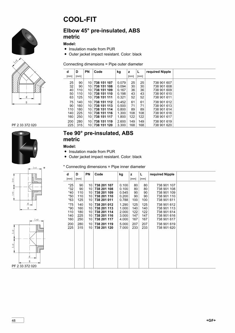
COOL-FITElbow 45° pre-insulated, ABSmetricModel:Ï Insulation made from PURÏ Outer jacket impact resistant. Color: black
Connecting dimensions = Pipe outer diameter
d[mm]
D[mm]
PN Code kg z[mm]
L[mm]
required Nipple
25 90 10 738 151 107 0.079 25 25 738 901 60732 90 10 738 151 108 0.094 30 30 738 901 60840 110 10 738 151 109 0.167 36 36 738 901 60950 110 10 738 151 110 0.198 43 43 738 901 61063 125 10 738 151 111 0.321 52 52 738 901 61175 140 10 738 151 112 0.452 61 61 738 901 61290 160 10 738 151 113 0.500 71 71 738 901 613110 180 10 738 151 114 0.800 89 89 738 901 614140 225 10 738 151 116 1.300 108 108 738 901 616160 250 10 738 151 117 1.800 122 122 738 901 617200 280 10 738 151 119 2.600 149 149 738 901 619225 315 10 738 151 120 3.300 168 168 738 901 620PF 2 33 372 020
Tee 90° pre-insulated, ABSmetricModel:Ï Insulation made from PURÏ Outer jacket impact resistant. Color: black
* Connecting dimensions = Pipe inner diameter
d[mm]
D[mm]
PN Code kg z[mm]
L[mm]
required Nipple
*25 90 10 738 201 107 0.100 80 80 738 901 107*32 90 10 738 201 108 0.100 80 80 738 901 108*40 110 10 738 201 109 0.545 90 90 738 901 109*50 110 10 738 201 110 0.200 90 90 738 901 110*63 125 10 738 201 011 0.788 100 100 738 901 611*75 140 10 738 201 012 1.290 125 125 738 901 612*90 160 10 738 201 113 1.000 140 140 738 901 113110 180 10 738 201 114 2.000 122 122 738 901 614140 225 10 738 201 116 3.000 147 147 738 901 616160 250 10 738 201 117 4.000 167 167 738 901 617200 280 10 738 201 119 5.000 207 207 738 901 619225 315 10 738 201 120 7.000 233 233 738 901 620
PF 2 33 372 020
48
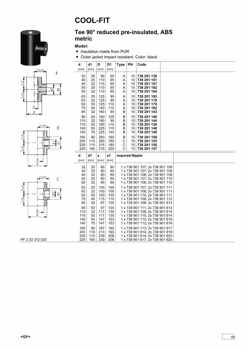
COOL-FITTee 90° reduced pre-insulated, ABSmetricModel:Ï Insulation made from PURÏ Outer jacket impact resistant. Color: black
d[mm]
d1[mm]
D[mm]
D1[mm]
Type PN Code
32 25 90 90 A 10 738 201 13840 25 110 90 A 10 738 201 15140 32 110 90 A 10 738 201 14750 25 110 90 A 10 738 201 19250 32 110 90 A 10 738 201 16463 25 125 90 A 10 738 201 19363 32 125 90 A 10 738 201 17863 50 125 110 A 10 738 201 17075 40 140 110 A 10 738 201 18290 32 160 90 B 10 738 201 14390 63 160 125 B 10 738 201 146110 32 180 90 B 10 738 201 144110 50 180 110 B 10 738 201 136140 50 225 110 B 10 738 201 148140 75 225 140 B 10 738 201 149160 90 250 160 B 10 738 201 158200 110 280 180 C 10 738 201 153225 110 315 180 C 10 738 201 156225 160 315 250 C 10 738 201 157
d[mm]
d1[mm]
z[mm]
z1[mm]
required Nipple
32 25 80 80 1 x 738 901 107; 2x 738 901 10840 25 90 90 1 x 738 901 107; 2x 738 901 10940 32 90 90 1 x 738 901 108; 2x 738 901 10950 25 90 90 1 x 738 901 107; 2x 738 901 11050 32 90 90 1 x 738 901 108; 2x 738 901 11063 25 100 100 1 x 738 901 107; 2x 738 901 11163 32 100 100 1 x 738 901 108; 2x 738 901 11163 50 100 100 1 x 738 901 110; 2x 738 901 11175 40 115 110 1 x 738 901 109; 2x 738 901 11290 32 97 120 1 x 738 901 108; 2x 738 901 61390 63 97 120 1 x 738 901 111; 2x 738 901 613110 32 117 130 1 x 738 901 108; 2x 738 901 614110 50 117 130 1 x 738 901 110; 2x 738 901 614140 50 147 153 1 x 738 901 110; 2x 738 901 616140 75 147 153 1 x 738 901 112; 2x 738 901 616160 90 167 165 1 x 738 901 113; 2x 738 901 617200 110 213 193 1 x 738 901 614; 2x 738 901 619225 110 239 206 1 x 738 901 614; 2x 738 901 620225 160 239 206 1 x 738 901 617; 2x 738 901 620PF 2 33 372 020
49

COOL-FITTee 45° pre-insulated, ABSmetricModel:Ï Insulation made from PURÏ Outer jacket impact resistant. Color: black
* Connecting dimensions = Pipe inner diameter
d[mm]
D[mm]
PN Code kg L[mm]
z[mm]
L1[mm]
z1[mm]
required Nipple
*25 90 10 738 251 107 0.100 160 160 80 80 738 901 107*32 90 10 738 251 108 0.200 160 160 80 80 738 901 108*40 110 10 738 251 109 0.200 180 180 90 90 738 901 109*50 110 10 738 251 110 0.300 180 180 90 90 738 901 110*63 125 10 738 251 111 0.500 200 200 100 100 738 901 111*75 140 10 738 251 112 0.800 240 240 120 120 738 901 112*90 160 10 738 251 113 1.200 250 250 125 125 738 901 113*110 180 10 738 251 114 2.200 300 300 150 150 738 901 114PF 2 33 372 020
Barrel Nipple di-di, ABSModel:Ï To connect pipe inner diameters di
d[mm]
PN Code kg di[mm]
L[mm]
z[mm]
25 10 738 901 107 0.008 20 52 1032 10 738 901 108 0.014 28 58 1040 10 738 901 109 0.022 35 66 1050 10 738 901 110 0.035 44 76 1063 10 738 901 111 0.060 55 90 1075 10 738 901 112 0.090 65 102 1090 10 738 901 113 0.127 79 104 10110 10 738 901 114 0.208 96 122 10140 10 738 901 116 0.422 123 150 10160 10 738 901 117 0.596 141 166 10200 10 738 901 119 1.086 176 202 10225 10 738 901 120 1.502 198 224 10PF 2 33 372 020
50

COOL-FITAdaptor Nipple d-di, ABSModel:Ï To connect d to pipe inner diameter di
* Can also be used as a reducer di 160 to di 140 d[mm]
PN Code kg di[mm]
L[mm]
z[mm]
25 10 738 901 607 0.009 20 50 1032 10 738 901 608 0.016 28 56 1040 10 738 901 609 0.026 35 64 1050 10 738 901 610 0.044 44 74 1063 10 738 901 611 0.080 55 88 1075 10 738 901 612 0.114 65 100 1090 10 738 901 613 0.179 79 108 10110 10 738 901 614 0.321 96 127 10*140 10 738 901 616 0.510 123 156 10160 10 738 901 617 0.780 141 174 10200 10 738 901 619 1.869 176 212 10225 10 738 901 620 1.930 198 236 10PF 2 33 372 020
Reducing Nipple di-dred, ABSModel:Ï To connect pipe inner diameter di to reduced dred
d[mm]
d1[mm]
PN Code kg di[mm]
L[mm]
z[mm]
32 25 10 738 911 341 0.006 28 34 1040 32 10 738 911 346 0.009 35 38 1050 40 10 738 911 352 0.014 44 43 1063 50 10 738 911 358 0.025 55 50 1075 63 10 738 911 364 0.022 65 56 1090 75 10 738 911 370 0.033 79 57 10110 90 10 738 911 376 0.073 96 66 10140 110 10 738 911 385 0.198 123 80 10200 160 10 738 911 392 0.453 176 106 10PF 2 33 372 020
Reducing Bush, pre-insulated, ABSmetricModel:Ï To connect di 225 to d 200Ï Insulation made from PURÏ Outer jacket impact resistant. Color: black
d[mm]
d1[mm]
PN Code kg di[mm]
L[mm]
z[mm]
225 200 10 738 911 396 3.924 198 220 220
PF 2 33 372 020
51
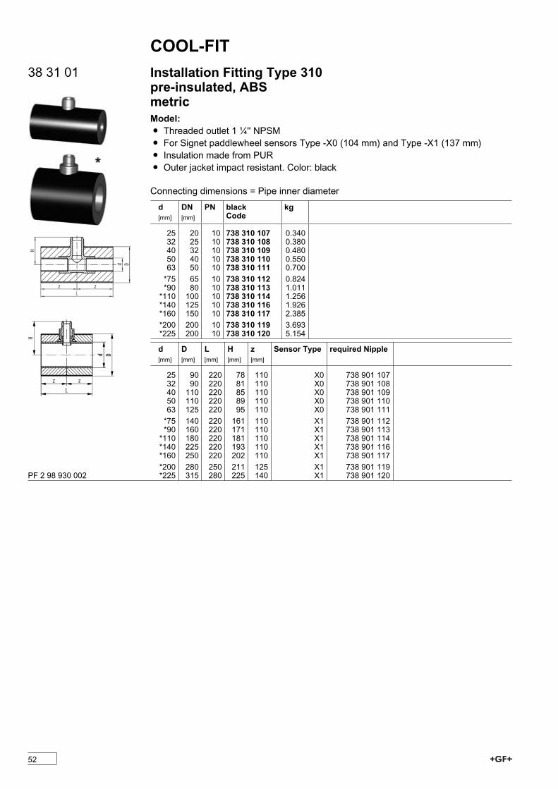
COOL-FIT38 31 01 Installation Fitting Type 310
pre-insulated, ABSmetricModel:Ï Threaded outlet 1 ¼'' NPSMÏ For Signet paddlewheel sensors Type -X0 (104 mm) and Type -X1 (137 mm)Ï Insulation made from PURÏ Outer jacket impact resistant. Color: black
Connecting dimensions = Pipe inner diameterd[mm]
DN[mm]
PN blackCode
kg
25 20 10 738 310 107 0.34032 25 10 738 310 108 0.38040 32 10 738 310 109 0.48050 40 10 738 310 110 0.55063 50 10 738 310 111 0.700*75 65 10 738 310 112 0.824*90 80 10 738 310 113 1.011*110 100 10 738 310 114 1.256*140 125 10 738 310 116 1.926*160 150 10 738 310 117 2.385*200 200 10 738 310 119 3.693*225 200 10 738 310 120 5.154
d[mm]
D[mm]
L[mm]
H[mm]
z[mm]
Sensor Type required Nipple
25 90 220 78 110 X0 738 901 10732 90 220 81 110 X0 738 901 10840 110 220 85 110 X0 738 901 10950 110 220 89 110 X0 738 901 11063 125 220 95 110 X0 738 901 111*75 140 220 161 110 X1 738 901 112*90 160 220 171 110 X1 738 901 113*110 180 220 181 110 X1 738 901 114*140 225 220 193 110 X1 738 901 116*160 250 220 202 110 X1 738 901 117*200 280 250 211 125 X1 738 901 119*225 315 280 225 140 X1 738 901 120PF 2 98 930 002
52
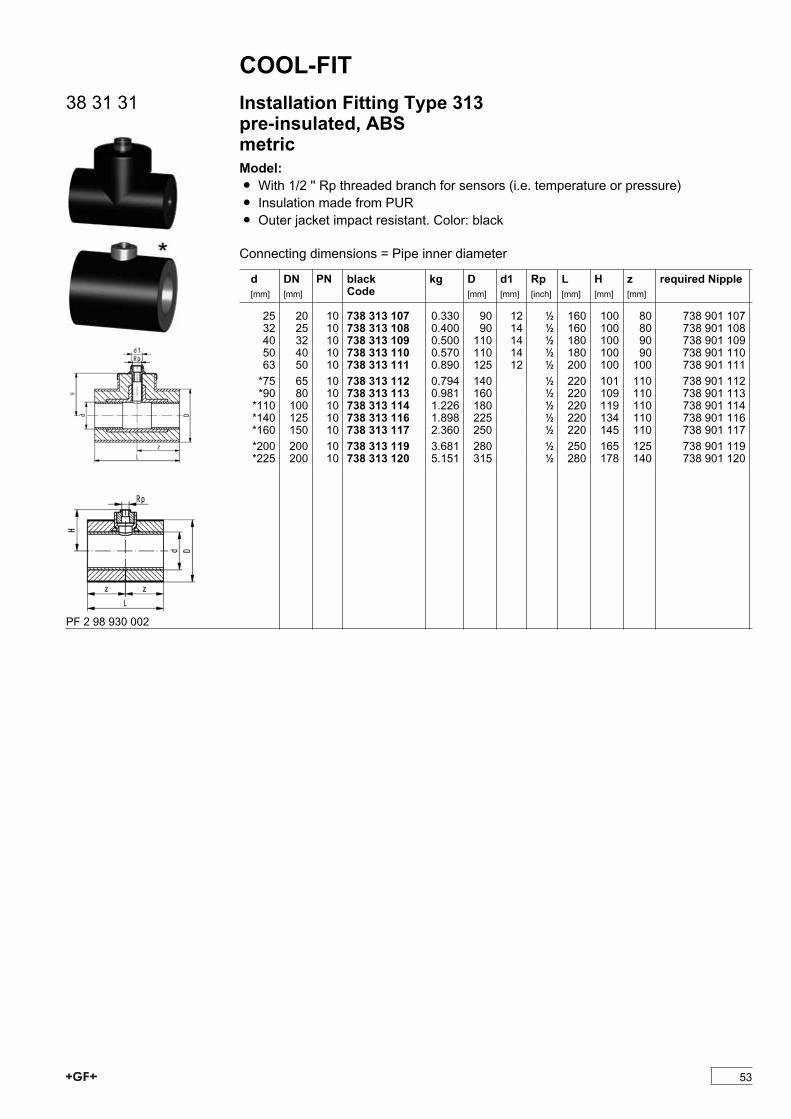
COOL-FIT38 31 31 Installation Fitting Type 313
pre-insulated, ABSmetricModel:Ï With 1/2 '' Rp threaded branch for sensors (i.e. temperature or pressure)Ï Insulation made from PURÏ Outer jacket impact resistant. Color: black
Connecting dimensions = Pipe inner diameter
d[mm]
DN[mm]
PN blackCode
kg D[mm]
d1[mm]
Rp[inch]
L[mm]
H[mm]
z[mm]
required Nipple
25 20 10 738 313 107 0.330 90 12 1/2 160 100 80 738 901 10732 25 10 738 313 108 0.400 90 14 1/2 160 100 80 738 901 10840 32 10 738 313 109 0.500 110 14 1/2 180 100 90 738 901 10950 40 10 738 313 110 0.570 110 14 1/2 180 100 90 738 901 11063 50 10 738 313 111 0.890 125 12 1/2 200 100 100 738 901 111*75 65 10 738 313 112 0.794 140 1/2 220 101 110 738 901 112*90 80 10 738 313 113 0.981 160 1/2 220 109 110 738 901 113*110 100 10 738 313 114 1.226 180 1/2 220 119 110 738 901 114*140 125 10 738 313 116 1.898 225 1/2 220 134 110 738 901 116*160 150 10 738 313 117 2.360 250 1/2 220 145 110 738 901 117*200 200 10 738 313 119 3.681 280 1/2 250 165 125 738 901 119*225 200 10 738 313 120 5.151 315 1/2 280 178 140 738 901 120
PF 2 98 930 002
53

COOL-FITAccessoriesCap, PE, blackModel:Ï to seal the end of a COOL-FIT pipe to ABS
d D[mm]
D1[mm]
Code kg L[mm]
25 90 24 733 960 171 0.032 3532 90 32 733 960 172 0.030 3540 110 39 733 960 173 0.041 3550 110 48 733 960 174 0.040 3563 125 59 733 960 175 0.045 3575 140 70 733 960 176 0.054 3590 160 83 733 960 177 0.064 35110 180 100 733 960 178 0.075 35140 225 127 733 960 180 0.102 35160 250 144 733 960 181 0.118 35200 280 187 733 960 183 0.128 35225 315 210 733 960 184 0.153 35PF 2 33 372 030
Silicon GlueModel:Ï For sealing and glueing capsÏ Tube à 50 mlÏ Cartdridge à 290 ml
Code kg
50 ml 738 011 102 0.100290 ml 738 011 103 0.400PF 2 33 372 030
Gap fillerÏ 13 x 13mm, 2.5 m on a rollÏ To insulate inspection gap at joints
d-d[mm]
Code kg
25 - 225 738 011 150 0.050
PF 2 33 372 030
54
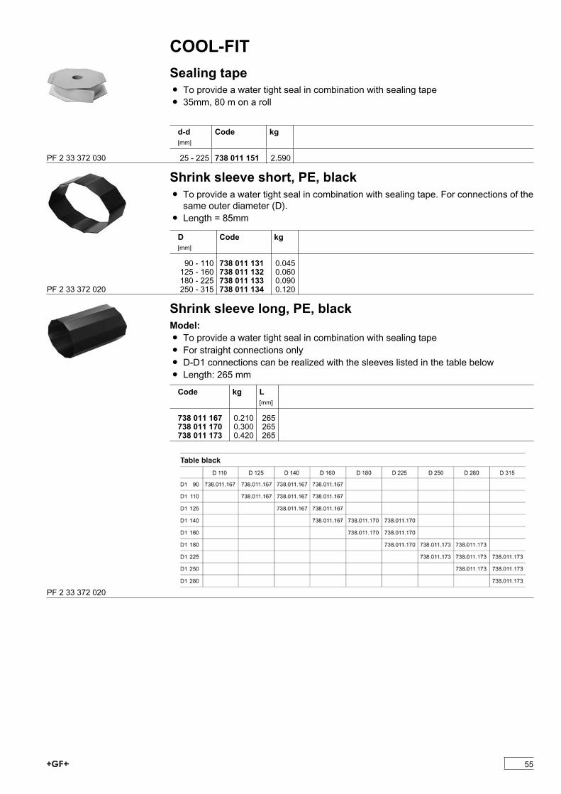
COOL-FITSealing tapeÏ To provide a water tight seal in combination with sealing tapeÏ 35mm, 80 m on a roll
d-d[mm]
Code kg
25 - 225 738 011 151 2.590PF 2 33 372 030
Shrink sleeve short, PE, blackÏ To provide a water tight seal in combination with sealing tape. For connections of thesame outer diameter (D).
Ï Length = 85mm
D[mm]
Code kg
90 - 110 738 011 131 0.045125 - 160 738 011 132 0.060180 - 225 738 011 133 0.090250 - 315 738 011 134 0.120PF 2 33 372 020
Shrink sleeve long, PE, blackModel:Ï To provide a water tight seal in combination with sealing tapeÏ For straight connections onlyÏ D-D1 connections can be realized with the sleeves listed in the table belowÏ Length: 265 mm
Code kg L[mm]
738 011 167 0.210 265738 011 170 0.300 265738 011 173 0.420 265
PF 2 33 372 020
55
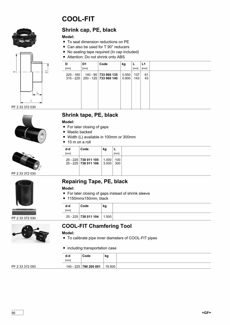
COOL-FITShrink cap, PE, blackModel:Ï To seal dimension reductions on PEÏ Can also be used for T 90° reducersÏ No sealing tape required (In cap included)Ï Attention: Do not shrink onto ABS
D[mm]
D1[mm]
Code kg L[mm]
L1[mm]
225 - 160 140 - 90 733 960 135 0.550 137 61315 - 225 250 - 125 733 960 140 0.900 143 43
PF 2 33 372 030
Shrink tape, PE, blackModel:Ï For later closing of gapsÏ Mastic backedÏ Width (L) available in 100mm or 300mmÏ 10 m on a roll
d-d[mm]
Code kg L[mm]
25 - 225 738 011 105 1.000 10025 - 225 738 011 106 3.000 300
PF 2 33 372 030
Repairing Tape, PE, blackModel:Ï For later closing of gaps instead of shrink sleeveÏ 1150mmx150mm, black
d-d[mm]
Code kg
25 - 225 738 011 104 1.500PF 2 33 372 030
COOL-FIT Chamfering ToolModel:Ï To calibrate pipe inner diameters of COOL-FIT pipes
Ï including transportation case
d-d[mm]
Code kg
140 - 225 790 205 001 19.500PF 2 33 372 050
56
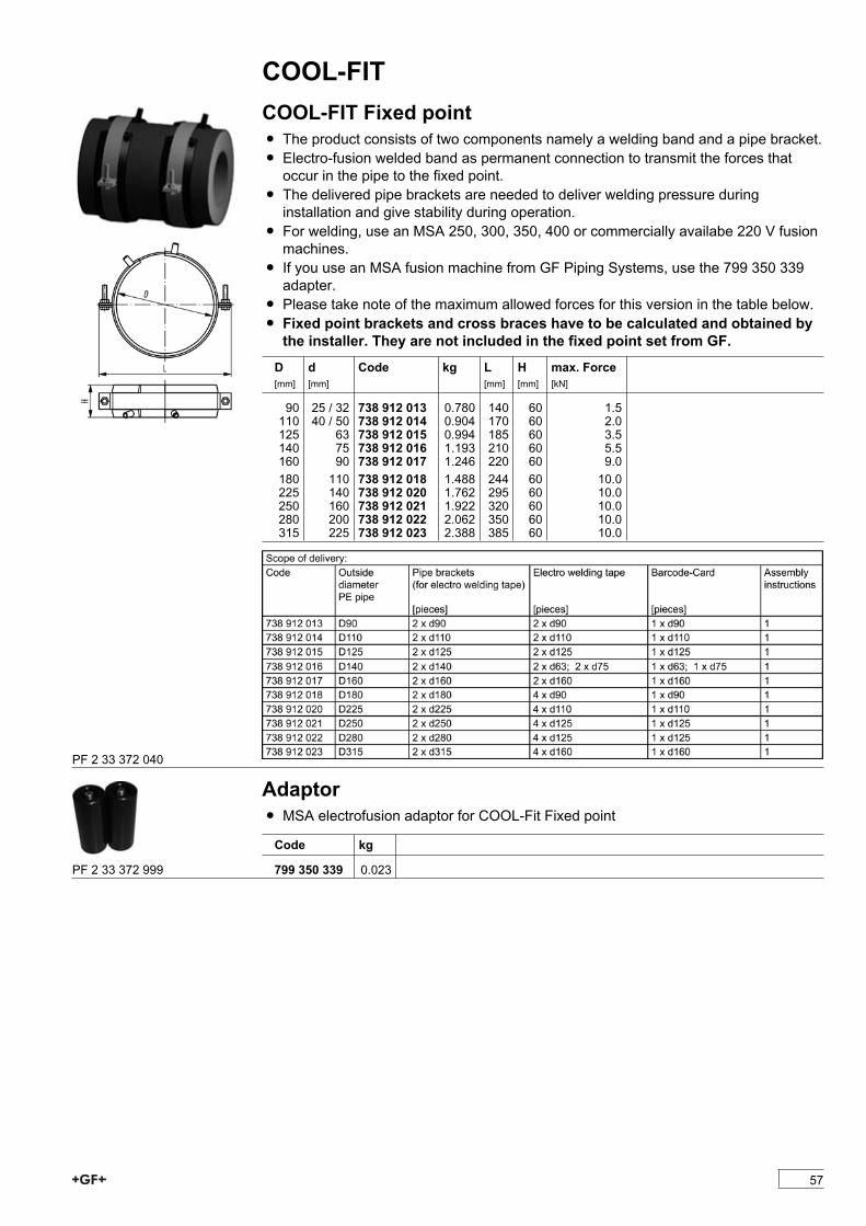
COOL-FITCOOL-FIT Fixed pointÏ The product consists of two components namely a welding band and a pipe bracket.Ï Electro-fusion welded band as permanent connection to transmit the forces thatoccur in the pipe to the fixed point.
Ï The delivered pipe brackets are needed to deliver welding pressure duringinstallation and give stability during operation.
Ï For welding, use an MSA 250, 300, 350, 400 or commercially availabe 220 V fusionmachines.
Ï If you use an MSA fusion machine from GF Piping Systems, use the 799 350 339adapter.
Ï Please take note of the maximum allowed forces for this version in the table below.Ï Fixed point brackets and cross braces have to be calculated and obtained bythe installer. They are not included in the fixed point set from GF.D[mm]
d[mm]
Code kg L[mm]
H[mm]
max. Force[kN]
90 25 / 32 738 912 013 0.780 140 60 1.5110 40 / 50 738 912 014 0.904 170 60 2.0125 63 738 912 015 0.994 185 60 3.5140 75 738 912 016 1.193 210 60 5.5160 90 738 912 017 1.246 220 60 9.0180 110 738 912 018 1.488 244 60 10.0225 140 738 912 020 1.762 295 60 10.0250 160 738 912 021 1.922 320 60 10.0280 200 738 912 022 2.062 350 60 10.0315 225 738 912 023 2.388 385 60 10.0
PF 2 33 372 040
AdaptorÏ MSA electrofusion adaptor for COOL-Fit Fixed point
Code kg
799 350 339 0.023PF 2 33 372 999
57

58
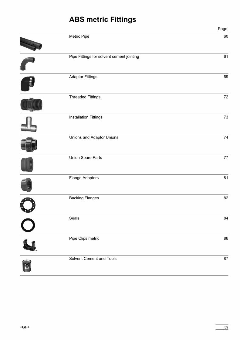
ABS metric FittingsPage
Metric Pipe 60
Pipe Fittings for solvent cement jointing 61
Adaptor Fittings 69
Threaded Fittings 72
Installation Fittings 73
Unions and Adaptor Unions 74
Union Spare Parts 77
Flange Adaptors 81
Backing Flanges 82
Seals 84
Pipe Clips metric 86
Solvent Cement and Tools 87
59

ABS metric FittingsMetric PipePipe 1m length, ABS metricModel:Ï Colour: RAL 7001, gravel greyÏ Length: 1mÏ PN 10 (10 bar) / PN 16 (16 bar) at 20°C
d[mm]
PN Code kg/m e[mm]
di[mm]
Length[m]
16 16 700 262 080 0.095 1.8 12.4 1.0020 16 700 262 081 0.152 2.3 15.4 1.0025 16 700 262 082 0.193 2.3 20.4 1.0032 10 700 262 083 0.212 1.9 28.2 1.0040 10 700 262 084 0.334 2.4 35.2 1.0050 10 700 262 085 0.523 3.0 44.0 1.0063 10 700 262 086 0.834 3.8 55.4 1.0075 10 700 262 087 1.176 4.5 66.0 1.0090 10 700 262 088 1.693 5.4 79.2 1.00110 10 700 262 089 2.529 6.6 96.8 1.00140 10 700 262 091 4.489 8.6 122.8 1.00160 10 700 262 092 5.856 9.9 140.2 1.00200 10 700 262 093 9.133 12.3 175.4 1.00225 10 700 262 094 11.605 13.9 197.2 1.00PF 2 33 198 007
Pipe 5m length, ABS metricModel:Ï Colour: RAL 7001, gravel greyÏ Length: 5 mÏ PN6 (6 bar) / PN10 (10 bar) / PN16 (16 bar) at 20°C
d[mm]
d[inch]
PN Code kg/m e[mm]
di[mm]
closestinch
16 16 169 017 080 0.475 1.8 12.4 3/820 16 169 017 081 0.760 2.3 15.4 1/225 16 169 017 082 0.975 2.3 20.4 3/432 10 169 017 083 1.065 1.9 28.2 140 10 169 017 084 1.685 2.4 35.2 1 1/450 10 169 017 085 2.630 3.0 44.0 1 1/263 10 169 017 086 4.195 3.8 55.4 275 2 1/2 10 169 017 087 5.915 4.5 66.0 2 1/290 10 169 017 088 8.520 5.4 79.2 3110 10 169 017 089 12.730 6.6 96.8 4140 5 10 169 017 091 20.295 8.6 122.8 5 1/4160 10 169 017 092 27.715 9.9 140.2 6200 10 169 017 093 43.060 12.3 175.4 8225 10 169 017 094 52.700 13.9 197.2 9250 6 169 017 095 14.800 9.6 230.8 10280 6 169 017 096 16.800 10.7 258.6 11315 6 169 017 097 20.500 12.1 290.8 12PF 2 33 472 001
60
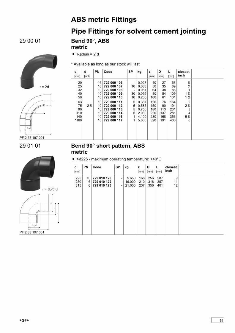
ABS metric FittingsPipe Fittings for solvent cement jointing
29 00 01 Bend 90°, ABSmetricÏ Radius = 2 d
* Available as long as our stock will last
d[mm]
d[inch]
PN Code SP kg z[mm]
D[mm]
L[mm]
closestinch
20 16 729 000 106 - 0.027 40 27 58 1/225 16 729 000 107 10 0.038 50 35 69 3/432 10 729 000 108 - 0.051 64 38 86 140 10 729 000 109 30 0.099 80 54 109 1 1/450 10 729 000 110 10 0.206 100 61 131 1 1/263 10 729 000 111 5 0.387 126 76 164 275 2 1/2 10 729 000 112 5 0.585 150 90 194 2 1/290 10 729 000 113 5 0.750 180 113 231 3110 10 729 000 114 5 2.030 220 137 281 4140 10 729 000 116 1 4.100 280 168 356 5 1/2*160 10 729 000 117 1 5.600 320 191 406 6
PF 2 33 197 001
29 01 01 Bend 90° short pattern, ABSmetricÏ >d225 - maximum operating temperature: +40°C
d[mm]
PN Code SP kg z[mm]
D[mm]
L[mm]
closestinch
225 10 729 010 120 - 5.650 168 256 287 9280 6 729 010 122 - 16.000 210 318 357 11315 6 729 010 123 - 21.000 237 356 401 12
PF 2 33 197 001
61

ABS metric Fittings29 10 01 Elbow 90°, ABS
metricÏ >d225 - maximum operating temperature: +40°C
d[mm]
d[inch]
PN Code SP kg z[mm]
D[mm]
L[mm]
closestinch
16 16 729 100 105 10 0.007 9 21 23 3/820 16 729 100 106 10 0.010 11 26 27 1/225 16 729 100 107 10 0.017 14 31 33 3/432 10 729 100 108 10 0.032 17 40 39 140 10 729 100 109 10 0.051 21 49 47 1 1/450 10 729 100 110 10 0.103 26 61 57 1 1/263 10 729 100 111 10 0.196 33 76 72 275 2 1/2 10 729 100 112 5 0.308 40 90 84 2 1/290 10 729 100 113 5 0.429 46 110 97 3110 10 729 100 114 2 0.786 61 136 122 4140 5 10 729 100 116 4 1.470 70 162 146 5 1/2160 10 729 100 117 1 2.150 80 185 166 6200 10 729 100 119 1 3.372 101 225 207 8250 6 729 100 121 - 8.200 131 282 263 9
PF 2 33 197 003
29 15 01 Elbow 45°, ABSmetricÏ >d225 - maximum operating temperature: +40°C
d[mm]
d[inch]
PN Code SP kg z[mm]
D[mm]
L[mm]
closestinch
20 16 729 150 106 10 0.008 5 25 21 1/225 16 729 150 107 10 0.013 6 31 25 3/432 10 729 150 108 10 0.046 8 40 30 140 10 729 150 109 10 0.082 10 49 36 1 1/450 10 729 150 110 5 0.121 12 61 43 1 1/263 10 729 150 111 10 0.144 14 76 52 275 2 1/2 10 729 150 112 5 0.228 17 89 61 2 1/290 10 729 150 113 5 0.362 20 107 71 3110 10 729 150 114 10 0.775 28 131 89 4140 5 10 729 150 116 1 1.190 32 162 108 5 1/2160 10 729 150 117 4 1.680 36 185 122 6200 10 729 150 119 1 2.506 43 225 149 8225 10 729 150 120 - 3.100 49 250 168 9250 6 729 150 121 - 7.200 60 282 192280 6 729 150 122 - 10.500 66 318 213315 6 729 150 123 - 14.600 74 356 239PF 2 33 197 004
62
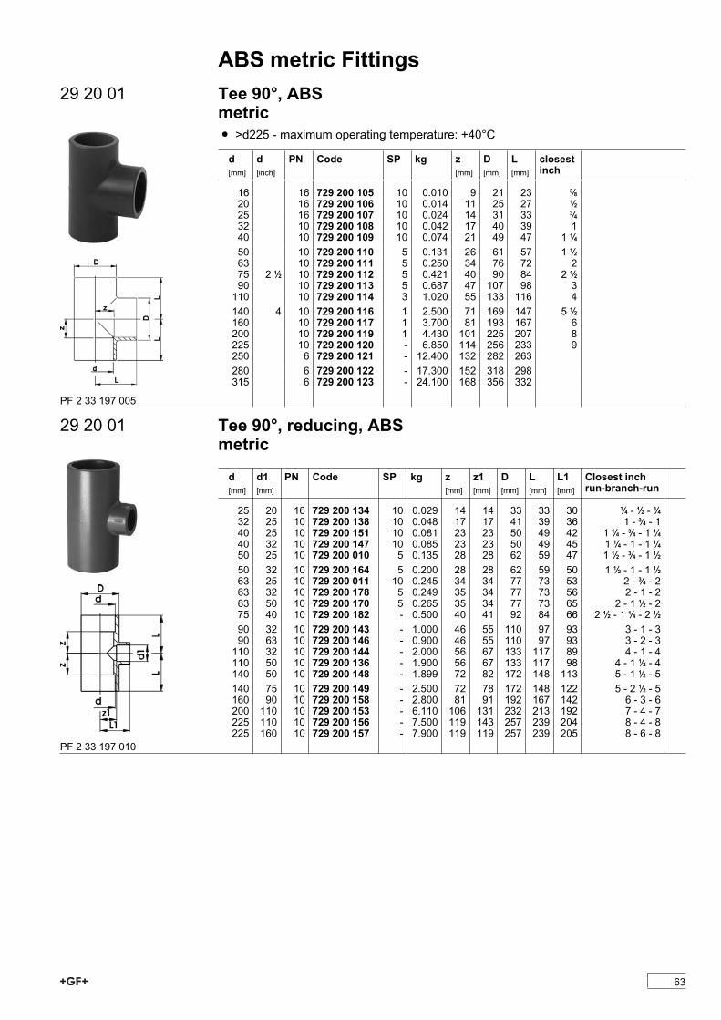
ABS metric Fittings29 20 01 Tee 90°, ABS
metricÏ >d225 - maximum operating temperature: +40°C
d[mm]
d[inch]
PN Code SP kg z[mm]
D[mm]
L[mm]
closestinch
16 16 729 200 105 10 0.010 9 21 23 3/820 16 729 200 106 10 0.014 11 25 27 1/225 16 729 200 107 10 0.024 14 31 33 3/432 10 729 200 108 10 0.042 17 40 39 140 10 729 200 109 10 0.074 21 49 47 1 1/450 10 729 200 110 5 0.131 26 61 57 1 1/263 10 729 200 111 5 0.250 34 76 72 275 2 1/2 10 729 200 112 5 0.421 40 90 84 2 1/290 10 729 200 113 5 0.687 47 107 98 3110 10 729 200 114 3 1.020 55 133 116 4140 4 10 729 200 116 1 2.500 71 169 147 5 1/2160 10 729 200 117 1 3.700 81 193 167 6200 10 729 200 119 1 4.430 101 225 207 8225 10 729 200 120 - 6.850 114 256 233 9250 6 729 200 121 - 12.400 132 282 263280 6 729 200 122 - 17.300 152 318 298315 6 729 200 123 - 24.100 168 356 332
PF 2 33 197 005
29 20 01 Tee 90°, reducing, ABSmetric
d[mm]
d1[mm]
PN Code SP kg z[mm]
z1[mm]
D[mm]
L[mm]
L1[mm]
Closest inchrun-branch-run
25 20 16 729 200 134 10 0.029 14 14 33 33 30 3/4 - 1/2 - 3/432 25 10 729 200 138 10 0.048 17 17 41 39 36 1 - 3/4 - 140 25 10 729 200 151 10 0.081 23 23 50 49 42 1 1/4 - 3/4 - 1 1/440 32 10 729 200 147 10 0.085 23 23 50 49 45 1 1/4 - 1 - 1 1/450 25 10 729 200 010 5 0.135 28 28 62 59 47 1 1/2 - 3/4 - 1 1/250 32 10 729 200 164 5 0.200 28 28 62 59 50 1 1/2 - 1 - 1 1/263 25 10 729 200 011 10 0.245 34 34 77 73 53 2 - 3/4 - 263 32 10 729 200 178 5 0.249 35 34 77 73 56 2 - 1 - 263 50 10 729 200 170 5 0.265 35 34 77 73 65 2 - 1 1/2 - 275 40 10 729 200 182 - 0.500 40 41 92 84 66 2 1/2 - 1 1/4 - 2 1/290 32 10 729 200 143 - 1.000 46 55 110 97 93 3 - 1 - 390 63 10 729 200 146 - 0.900 46 55 110 97 93 3 - 2 - 3110 32 10 729 200 144 - 2.000 56 67 133 117 89 4 - 1 - 4110 50 10 729 200 136 - 1.900 56 67 133 117 98 4 - 1 1/2 - 4140 50 10 729 200 148 - 1.899 72 82 172 148 113 5 - 1 1/2 - 5140 75 10 729 200 149 - 2.500 72 78 172 148 122 5 - 2 1/2 - 5160 90 10 729 200 158 - 2.800 81 91 192 167 142 6 - 3 - 6200 110 10 729 200 153 - 6.110 106 131 232 213 192 7 - 4 - 7225 110 10 729 200 156 - 7.500 119 143 257 239 204 8 - 4 - 8225 160 10 729 200 157 - 7.900 119 119 257 239 205 8 - 6 - 8
PF 2 33 197 010
63
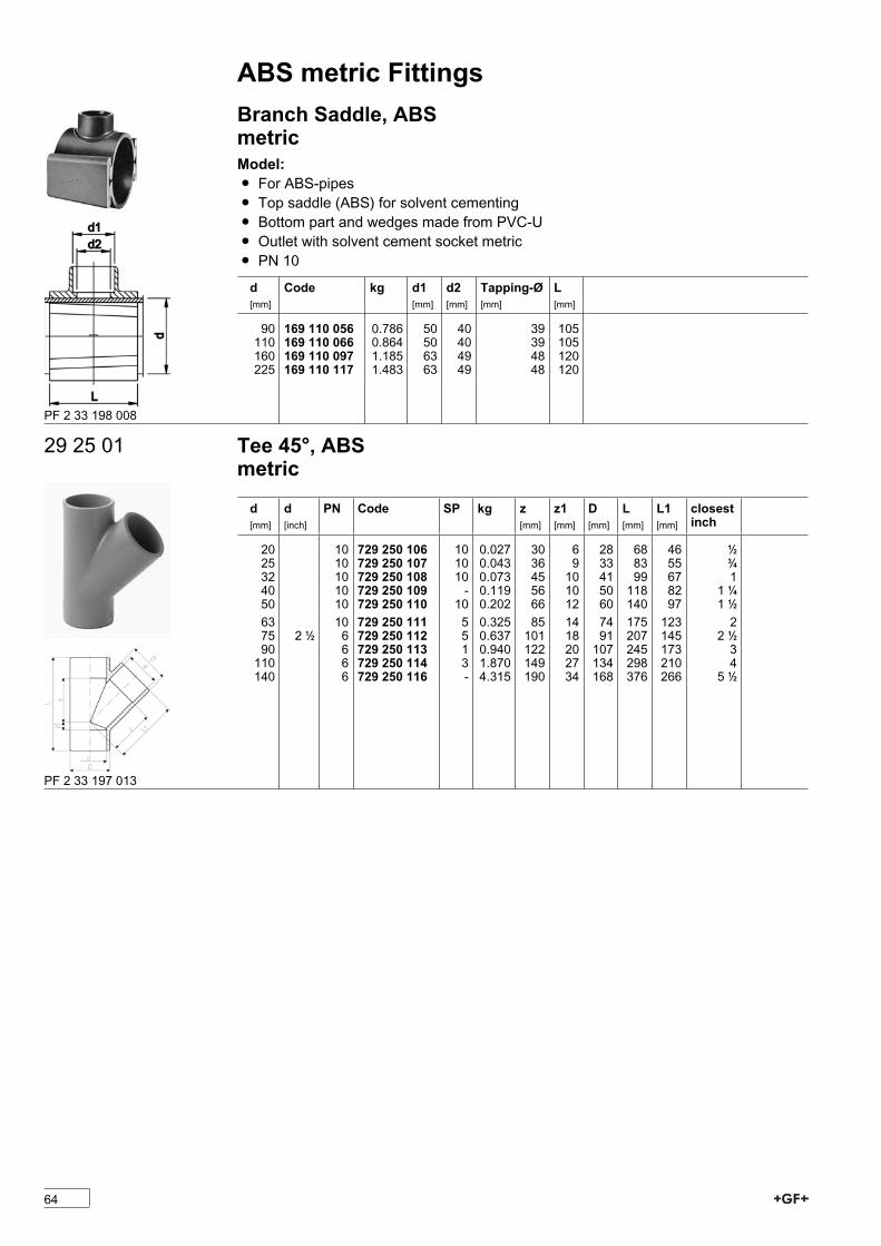
ABS metric FittingsBranch Saddle, ABSmetricModel:Ï For ABS-pipesÏ Top saddle (ABS) for solvent cementingÏ Bottom part and wedges made from PVC-UÏ Outlet with solvent cement socket metricÏ PN 10
d[mm]
Code kg d1[mm]
d2[mm]
Tapping-Ø[mm]
L[mm]
90 169 110 056 0.786 50 40 39 105110 169 110 066 0.864 50 40 39 105160 169 110 097 1.185 63 49 48 120225 169 110 117 1.483 63 49 48 120
PF 2 33 198 008
29 25 01 Tee 45°, ABSmetric
d[mm]
d[inch]
PN Code SP kg z[mm]
z1[mm]
D[mm]
L[mm]
L1[mm]
closestinch
20 10 729 250 106 10 0.027 30 6 28 68 46 1/225 10 729 250 107 10 0.043 36 9 33 83 55 3/432 10 729 250 108 10 0.073 45 10 41 99 67 140 10 729 250 109 - 0.119 56 10 50 118 82 1 1/450 10 729 250 110 10 0.202 66 12 60 140 97 1 1/263 10 729 250 111 5 0.325 85 14 74 175 123 275 2 1/2 6 729 250 112 5 0.637 101 18 91 207 145 2 1/290 6 729 250 113 1 0.940 122 20 107 245 173 3110 6 729 250 114 3 1.870 149 27 134 298 210 4140 6 729 250 116 - 4.315 190 34 168 376 266 5 1/2
PF 2 33 197 013
64
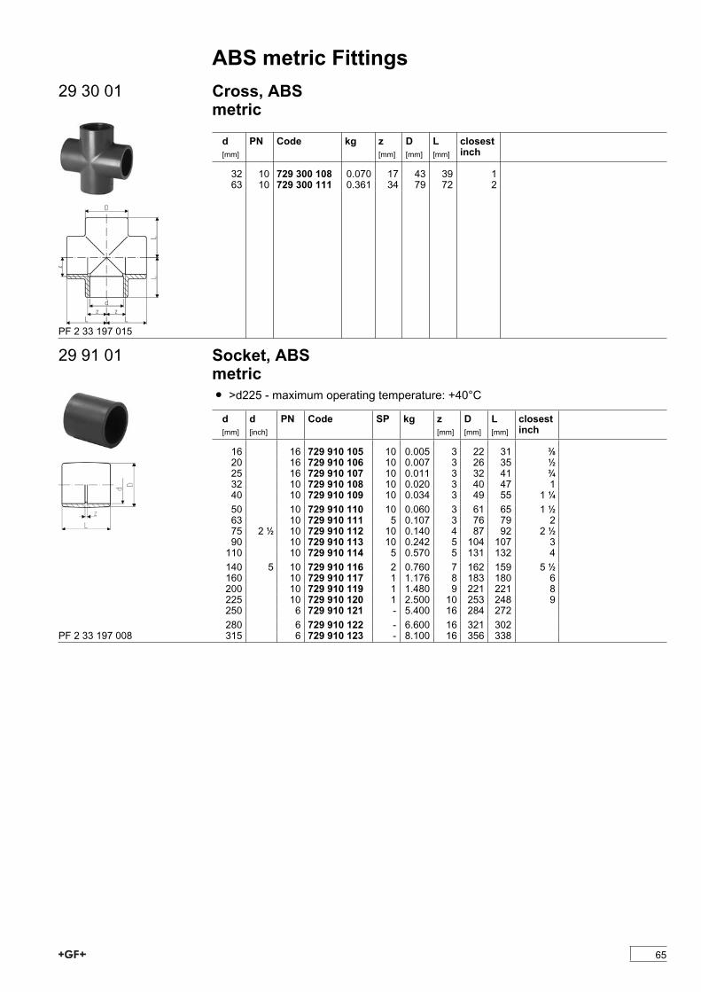
ABS metric Fittings29 30 01 Cross, ABS
metric
d[mm]
PN Code kg z[mm]
D[mm]
L[mm]
closestinch
32 10 729 300 108 0.070 17 43 39 163 10 729 300 111 0.361 34 79 72 2
PF 2 33 197 015
29 91 01 Socket, ABSmetricÏ >d225 - maximum operating temperature: +40°C
d[mm]
d[inch]
PN Code SP kg z[mm]
D[mm]
L[mm]
closestinch
16 16 729 910 105 10 0.005 3 22 31 3/820 16 729 910 106 10 0.007 3 26 35 1/225 16 729 910 107 10 0.011 3 32 41 3/432 10 729 910 108 10 0.020 3 40 47 140 10 729 910 109 10 0.034 3 49 55 1 1/450 10 729 910 110 10 0.060 3 61 65 1 1/263 10 729 910 111 5 0.107 3 76 79 275 2 1/2 10 729 910 112 10 0.140 4 87 92 2 1/290 10 729 910 113 10 0.242 5 104 107 3110 10 729 910 114 5 0.570 5 131 132 4140 5 10 729 910 116 2 0.760 7 162 159 5 1/2160 10 729 910 117 1 1.176 8 183 180 6200 10 729 910 119 1 1.480 9 221 221 8225 10 729 910 120 1 2.500 10 253 248 9250 6 729 910 121 - 5.400 16 284 272280 6 729 910 122 - 6.600 16 321 302315 6 729 910 123 - 8.100 16 356 338PF 2 33 197 008
65

ABS metric Fittings29 91 31 Adaptor Socket, ABS metric - Inch BS
Model:Ï with BS Inch and metric solvent cement sockets
d[mm]
d[inch]
PN Code SP kg z[mm]
L[mm]
D[mm]
16 3/8 10 729 913 105 - 0.007 5 35 2320 1/2 10 729 913 106 - 0.010 5 38 2725 3/4 10 729 913 107 - 0.016 5 45 3332 1 10 729 913 108 - 0.025 5 51 4140 1 1/4 10 729 913 109 - 0.045 5 60 5150 1 1/2 10 729 913 110 - 0.070 4 65 5963 2 10 729 913 111 - 0.130 5 79 7575 2 1/2 10 729 910 112 10 0.140 4 92 8790 3 10 729 913 113 - 0.365 6 108 104110 4 10 729 913 115 - 0.630 7 135 134
PF 2 33 172 001
29 90 09 Barrel Nipple, ABSmetricModel:Ï For quick connections between fittingsÏ For the shortest possible distance between fittingsÏ Overall length L = 2 x socket length
d[mm]
d[inch]
PN Code kg L[mm]
closestinch
16 16 729 900 905 0.003 28 3/820 16 729 900 906 0.004 32 1/225 16 729 900 907 0.007 38 3/432 10 729 900 908 0.009 44 140 10 729 900 909 0.017 52 1 1/450 10 729 900 910 0.032 62 1 1/263 10 729 900 911 0.063 76 275 2 1/2 10 729 900 912 0.102 88 2 1/290 10 729 900 913 0.173 102 3110 10 729 900 914 0.309 122 4PF 2 33 198 007
66

ABS metric Fittings29 90 03 Reducing Bush, ABS
metric
d[mm]
d1[mm]
PN Code SP kg z[mm]
L[mm]
Closest inch
20 16 16 729 900 334 10 0.003 2 16 1/2 - 3/825 20 16 729 900 337 10 0.005 3 19 3/4 - 1/232 20 10 729 900 342 10 0.012 6 22 1 - 1/232 25 10 729 900 341 10 0.009 4 22 1 - 3/440 20 10 729 900 348 10 0.016 10 26 1 1/4 - 1/240 25 10 729 900 347 10 0.016 7 26 1 1/2 - 3/440 32 10 729 900 346 10 0.012 4 26 1 1/4 - 150 20 10 729 900 355 10 0.024 15 31 1 1/2 - 1/250 25 10 729 900 354 10 0.025 12 31 1 1/2 - 3/450 32 10 729 900 353 10 0.035 9 31 1 1/2 - 150 40 10 729 900 352 10 0.038 5 3163 32 10 729 900 360 10 0.060 16 3863 40 10 729 900 359 10 0.067 12 3863 50 10 729 900 358 10 0.044 7 3675 50 10 729 900 365 10 0.105 13 4475 63 10 729 900 364 10 0.076 7 4490 50 10 729 900 372 10 0.136 20 5190 63 10 729 900 371 10 0.130 14 5190 75 10 729 900 370 5 0.133 7 51110 63 10 729 900 378 5 0.238 24 61110 90 10 729 900 376 5 0.196 10 61125 110 10 700 244 660 - 0.356 8 69140 110 10 729 900 385 5 0.454 15 76160 110 10 729 900 390 5 0.666 25 86160 140 10 729 900 388 5 0.416 10 86200 160 10 729 900 392 1 0.818 20 106225 160 10 729 900 396 2 1.640 33 119225 200 10 729 900 181 - 1.440 13 119250 225 6 729 900 303 - 1.000 12 131280 250 6 729 900 306 - 2.500 15 146315 280 6 729 900 312 - 3.350 17 164PF 2 33 197 006
29 91 03 Reducing Bush long, ABSmetricModel:Ï With spigot and solvent cement socket
d[mm]
d1[mm]
PN Code SP kg z[mm]
L[mm]
32 20 10 729 910 342 10 0.016 30 4640 25 10 729 910 347 10 0.026 36 5550 25 10 729 910 354 10 0.041 44 6363 32 10 729 910 360 5 0.077 54 7675 40 10 729 910 366 5 0.115 62 8890 63 10 729 910 371 5 0.218 74 112
PF 2 33 197 002
67

ABS metric Fittings29 96 01 Cap, ABS
metric
d[mm]
PN Code SP kg D[mm]
L[mm]
16 16 729 960 105 10 0.006 26 2420 16 729 960 106 10 0.008 30 2525 16 729 960 107 10 0.013 37 3032 10 729 960 108 10 0.020 44 3440 10 729 960 109 10 0.034 55 4150 10 729 960 110 10 0.034 64 4463 10 729 960 111 5 0.086 80 5475 10 729 960 112 5 0.115 87 6590 10 729 960 113 - 0.215 112 77110 10 729 960 114 5 0.480 145 101140 10 729 960 116 10 0.880 163 114160 10 729 960 117 2 1.130 188 130
PF 2 33 197 009
29 96 04 Hose Connector, ABSmetricModel:Ï With solvent cement spigot metric and parallel hose connection
d[mm]
PN Code SP kg D[mm]
L[mm]
closestinch
16 10 729 960 405 10 0.007 16 57 3/820 10 729 960 406 10 0.011 20 73 1/225 10 729 960 407 10 0.016 25 79 3/432 10 729 960 408 10 0.026 30 89 1PF 2 33 197 012
68

ABS metric FittingsAdaptor Fittings
29 10 02 Elbow 90°, ABSmetricModel:Ï With solvent cement socket metric and parallel female thread (Rp)Ï Reinforcing ring stainless (A2)Ï Connection to plastic or metalÏ Do not use thread sealing pastes that are harmful to ABSÏ Install with low mechanical stress and avoid large cyclic temperature changes
d[mm]
Rp[inch]
PN Code SP kg z1[mm]
z2[mm]
D[mm]
L[mm]
20 1/2 10 729 100 206 10 0.018 11 14 30 2725 3/4 10 729 100 207 10 0.028 14 17 35 3332 1 10 729 100 208 10 0.047 17 22 45 3940 1 1/4 10 729 100 209 10 0.088 23 27 55 5050 1 1/2 10 729 100 210 5 0.128 27 36 62 5863 2 10 729 100 211 5 0.233 33 46 75 73
PF 2 33 198 002
29 91 02 Socket, ABSmetricModel:Ï With solvent cement socket metric and parallel female thread RpÏ Reinforcing ring stainless (A2)Ï Connection to plastic or metalÏ Do not use thread sealing pastes that are harmful to ABSÏ Install with low mechanical stress and avoid large cyclic temperature changes
d[mm]
Rp[inch]
PN Code SP kg z[mm]
L[mm]
s[mm]
closestinch
20 1/2 10 729 910 206 10 0.020 4 35 32 1/225 3/4 10 729 910 207 10 0.030 3 40 36 3/432 1 10 729 910 208 10 0.040 3 45 46 140 1 1/4 10 729 910 209 10 0.069 5 51 55 1 1/450 1 1/2 10 729 910 210 10 0.100 7 59 65 1 1/263 2 10 729 910 211 5 0.162 7 69 80 2PF 2 33 172 001
69
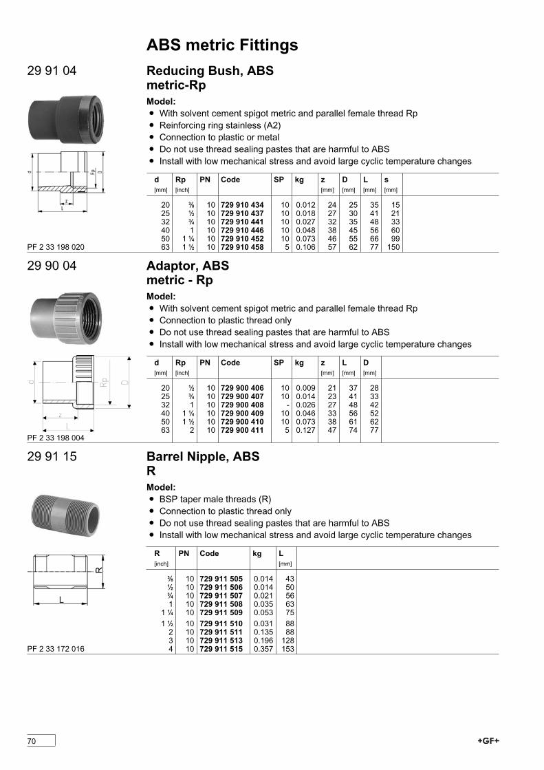
ABS metric Fittings29 91 04 Reducing Bush, ABS
metric-RpModel:Ï With solvent cement spigot metric and parallel female thread RpÏ Reinforcing ring stainless (A2)Ï Connection to plastic or metalÏ Do not use thread sealing pastes that are harmful to ABSÏ Install with low mechanical stress and avoid large cyclic temperature changes
d[mm]
Rp[inch]
PN Code SP kg z[mm]
D[mm]
L[mm]
s[mm]
20 3/8 10 729 910 434 10 0.012 24 25 35 1525 1/2 10 729 910 437 10 0.018 27 30 41 2132 3/4 10 729 910 441 10 0.027 32 35 48 3340 1 10 729 910 446 10 0.048 38 45 56 6050 1 1/4 10 729 910 452 10 0.073 46 55 66 9963 1 1/2 10 729 910 458 5 0.106 57 62 77 150PF 2 33 198 020
29 90 04 Adaptor, ABSmetric - RpModel:Ï With solvent cement spigot metric and parallel female thread RpÏ Connection to plastic thread onlyÏ Do not use thread sealing pastes that are harmful to ABSÏ Install with low mechanical stress and avoid large cyclic temperature changes
d[mm]
Rp[inch]
PN Code SP kg z[mm]
L[mm]
D[mm]
20 1/2 10 729 900 406 10 0.009 21 37 2825 3/4 10 729 900 407 10 0.014 23 41 3332 1 10 729 900 408 - 0.026 27 48 4240 1 1/4 10 729 900 409 10 0.046 33 56 5250 1 1/2 10 729 900 410 10 0.073 38 61 6263 2 10 729 900 411 5 0.127 47 74 77
PF 2 33 198 004
29 91 15 Barrel Nipple, ABSRModel:Ï BSP taper male threads (R)Ï Connection to plastic thread onlyÏ Do not use thread sealing pastes that are harmful to ABSÏ Install with low mechanical stress and avoid large cyclic temperature changes
R[inch]
PN Code kg L[mm]
3/8 10 729 911 505 0.014 431/2 10 729 911 506 0.014 503/4 10 729 911 507 0.021 561 10 729 911 508 0.035 631 1/4 10 729 911 509 0.053 751 1/2 10 729 911 510 0.031 882 10 729 911 511 0.135 883 10 729 911 513 0.196 1284 10 729 911 515 0.357 153PF 2 33 172 016
70
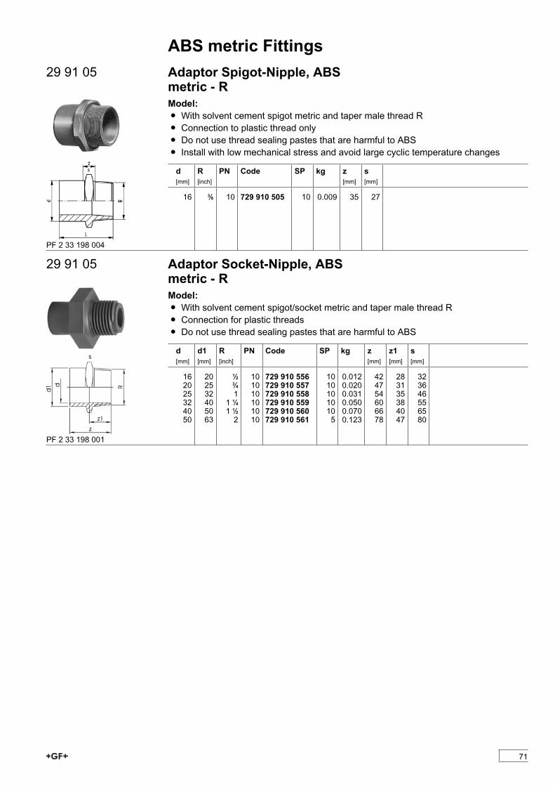
ABS metric Fittings29 91 05 Adaptor Spigot-Nipple, ABS
metric - RModel:Ï With solvent cement spigot metric and taper male thread RÏ Connection to plastic thread onlyÏ Do not use thread sealing pastes that are harmful to ABSÏ Install with low mechanical stress and avoid large cyclic temperature changes
d[mm]
R[inch]
PN Code SP kg z[mm]
s[mm]
16 3/8 10 729 910 505 10 0.009 35 27
PF 2 33 198 004
29 91 05 Adaptor Socket-Nipple, ABSmetric - RModel:Ï With solvent cement spigot/socket metric and taper male thread RÏ Connection for plastic threadsÏ Do not use thread sealing pastes that are harmful to ABS
d[mm]
d1[mm]
R[inch]
PN Code SP kg z[mm]
z1[mm]
s[mm]
16 20 1/2 10 729 910 556 10 0.012 42 28 3220 25 3/4 10 729 910 557 10 0.020 47 31 3625 32 1 10 729 910 558 10 0.031 54 35 4632 40 1 1/4 10 729 910 559 10 0.050 60 38 5540 50 1 1/2 10 729 910 560 10 0.070 66 40 6550 63 2 10 729 910 561 5 0.123 78 47 80
PF 2 33 198 001
71
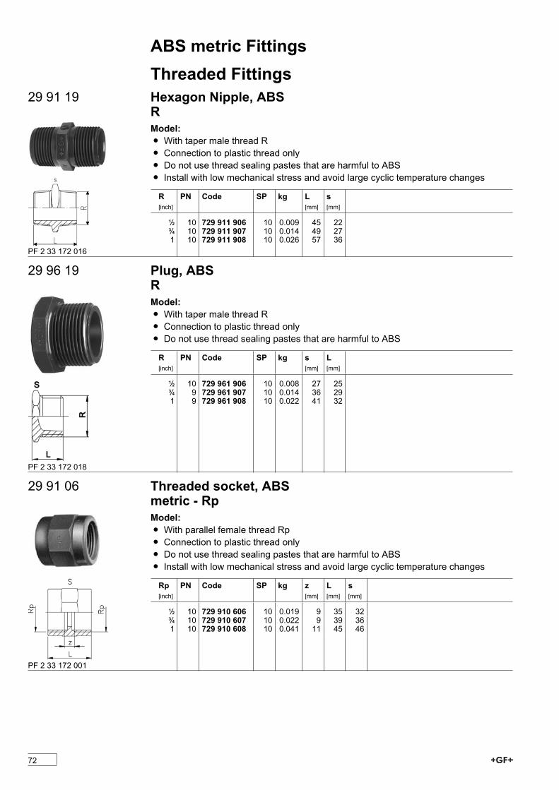
ABS metric FittingsThreaded Fittings
29 91 19 Hexagon Nipple, ABSRModel:Ï With taper male thread RÏ Connection to plastic thread onlyÏ Do not use thread sealing pastes that are harmful to ABSÏ Install with low mechanical stress and avoid large cyclic temperature changes
R[inch]
PN Code SP kg L[mm]
s[mm]
1/2 10 729 911 906 10 0.009 45 223/4 10 729 911 907 10 0.014 49 271 10 729 911 908 10 0.026 57 36
PF 2 33 172 016
29 96 19 Plug, ABSRModel:Ï With taper male thread RÏ Connection to plastic thread onlyÏ Do not use thread sealing pastes that are harmful to ABS
R[inch]
PN Code SP kg s[mm]
L[mm]
1/2 10 729 961 906 10 0.008 27 253/4 9 729 961 907 10 0.014 36 291 9 729 961 908 10 0.022 41 32
PF 2 33 172 018
29 91 06 Threaded socket, ABSmetric - RpModel:Ï With parallel female thread RpÏ Connection to plastic thread onlyÏ Do not use thread sealing pastes that are harmful to ABSÏ Install with low mechanical stress and avoid large cyclic temperature changes
Rp[inch]
PN Code SP kg z[mm]
L[mm]
s[mm]
1/2 10 729 910 606 10 0.019 9 35 323/4 10 729 910 607 10 0.022 9 39 361 10 729 910 608 10 0.041 11 45 46
PF 2 33 172 001
72

ABS metric FittingsInstallation Fittings
29 31 00 Installation Fitting Type 310, ABSmetricModel:Ï Threaded outlet 1 ¼'' NPSMÏ For Signet Paddlewheel Sensors Type -X0 (104 mm)Ï With solvent cement socket metric
d[mm]
DN[mm]
PN Code kg D[mm]
L[mm]
H[mm]
z[mm]
Sensor Type
25 20 10 729 310 007 0.107 35 100 78 32 X032 25 10 729 310 008 0.141 44 110 81 33 X040 32 10 729 310 009 0.143 51 110 85 29 X050 40 10 729 310 010 0.192 63 120 89 29 X063 50 10 729 310 011 0.273 78 130 95 28 X0
PF 2 98 930 001
29 31 20 Installation Fitting Type 312, ABSmetricModel:Ï For Signet paddlewheel sensors Type -X1 (137 mm)Ï Saddle with threaded outlet 1 ¼'' NPSM
d[mm]
DN[mm]
PN Code kg D[mm]
H[mm]
Sensor Type
75 65 10 729 312 012 0.165 38 91 X190 80 10 729 312 013 0.170 38 91 X1110 100 10 729 312 014 0.169 38 91 X1140 125 10 729 312 016 0.165 38 81 X1160 150 10 729 312 017 0.163 38 77 X1200 200 10 729 312 019 0.149 38 71 X1225 200 10 729 312 020 0.143 38 67 X1
PF 2 98 931 001
73
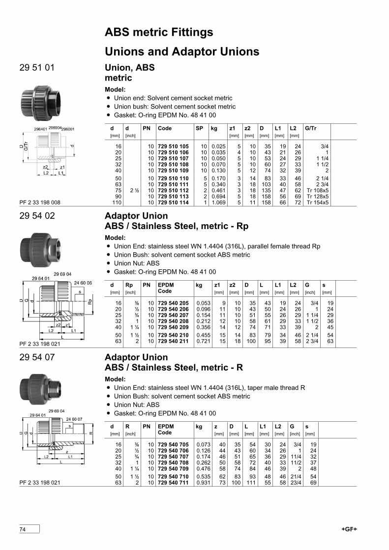
ABS metric FittingsUnions and Adaptor Unions
29 51 01 Union, ABSmetricModel:Ï Union end: Solvent cement socket metricÏ Union bush: Solvent cement socket metricÏ Gasket: O-ring EPDM No. 48 41 00
d[mm]
d[inch]
PN Code SP kg z1[mm]
z2[mm]
D[mm]
L1[mm]
L2[mm]
G/Tr
16 10 729 510 105 10 0.025 5 10 35 19 24 3/420 10 729 510 106 10 0.035 4 10 43 21 26 125 10 729 510 107 10 0.050 5 10 53 24 29 1 1/432 10 729 510 108 10 0.070 5 10 60 27 33 1 1/240 10 729 510 109 10 0.130 5 12 74 32 39 250 10 729 510 110 5 0.170 3 14 83 33 46 2 1/463 10 729 510 111 5 0.340 3 18 103 40 58 2 3/475 2 1/2 10 729 510 112 2 0.461 3 18 135 47 62 Tr 108x590 10 729 510 113 2 0.694 5 18 158 56 69 Tr 128x5110 10 729 510 114 1 1.069 5 11 158 66 72 Tr 154x5PF 2 33 198 008
29 54 02 Adaptor UnionABS / Stainless Steel, metric - RpModel:Ï Union End: stainless steel WN 1.4404 (316L), parallel female thread RpÏ Union Bush: solvent cement socket ABS metricÏ Union Nut: ABSÏ Gasket: O-ring EPDM No. 48 41 00
d[mm]
Rp[inch]
PN EPDMCode
kg z1[mm]
z2[mm]
D[mm]
L[mm]
L1[mm]
L2[mm]
G[inch]
s[mm]
16 3/8 10 729 540 205 0.053 9 10 35 43 19 24 3/4 1920 1/2 10 729 540 206 0.096 11 10 43 50 24 26 1 2425 3/4 10 729 540 207 0.154 11 10 51 55 26 29 1 1/4 2932 1 10 729 540 208 0.212 12 10 58 61 29 33 1 1/2 3640 1 1/4 10 729 540 209 0.356 14 12 74 71 33 39 2 4550 1 1/2 10 729 540 210 0.455 15 14 83 79 34 46 2 1/4 5463 2 10 729 540 211 0.721 15 18 100 95 39 58 2 3/4 63PF 2 33 198 021
29 54 07 Adaptor UnionABS / Stainless Steel, metric - RModel:Ï Union End: stainless steel WN 1.4404 (316L), taper male thread RÏ Union Bush: solvent cement socket ABS metricÏ Union Nut: ABSÏ Gasket: O-ring EPDM No. 48 41 00
d[mm]
R[inch]
PN EPDMCode
kg z[mm]
D[mm]
L[mm]
L1[mm]
L2[mm]
G[inch]
s[mm]
16 3/8 10 729 540 705 0.073 40 35 54 30 24 3/4 1920 1/2 10 729 540 706 0.126 44 43 60 34 26 1 2425 3/4 10 729 540 707 0.174 46 51 65 36 29 11/4 3232 1 10 729 540 708 0.262 50 58 72 40 33 11/2 3740 1 1/4 10 729 540 709 0.476 58 74 84 46 39 2 4850 1 1/2 10 729 540 710 0.535 62 83 93 48 46 21/4 5463 2 10 729 540 711 0.931 73 100 111 55 58 23/4 69PF 2 33 198 021
74

ABS metric Fittings29 54 55 Adaptor Union
ABS / Stainless Steel, metric - Welding EndModel:Ï Union End: stainless steel WN 1.4404 (316L) with welding endÏ Union Bush: solvent cement socket ABS metricÏ Union Nut: stainless steel WN 1.4404 (316L)Ï Gasket: O-ring EPDM No. 48 41 00
d[mm]
d1[mm]
PN EPDMCode
kg z[mm]
L[mm]
L1[mm]
L2[mm]
e[mm]
G[inch]
s[mm]
16 17 10 729 545 505 0.101 28 42 18 24 1.6 3/4 3220 21 10 729 545 506 0.176 32 48 22 26 2.0 1 4125 27 10 729 545 507 0.204 33 52 23 29 2.0 1 1/4 4632 34 10 729 545 508 0.313 36 58 26 33 2.0 1 1/2 5540 42 10 729 545 509 0.493 38 64 26 39 2.0 2 6850 48 10 729 545 510 0.566 42 73 28 46 2.0 2 1/4 7463 60 10 729 545 511 0.902 50 88 32 58 2.6 2 3/4 88
PF 2 33 198 021
20 51 01 Adaptor UnionABS / Copper for solderingmetricModel:Ï Union End: CopperÏ Union Bush: solvent cement socket ABS metricÏ Union Nut: brassÏ Gasket: O-ring EPDM No. 48 41 00
d[mm]
d1[mm]
PN Code kg L1[mm]
L2[mm]
z1[mm]
z2[mm]
G[inch]
s[mm]
16 18 10 720 510 105 0.079 25 17 11 4 3/4 3220 22 10 720 510 106 0.140 26 19 9 3 1 4025 28 10 720 510 107 0.269 29 28 9 6 1 1/4 5032 35 10 720 510 108 0.198 33 27 10 5 1 1/2 5240 42 10 720 510 109 0.350 39 35 12 6 2 6650 54 10 720 510 110 0.438 46 46 14 3 2 1/4 72PF 2 33 198 005
29 53 03 Adaptor UnionABS / Malleable Iron, metric - RpModel:Ï Union Nut: ABSÏ Union Bush: solvent cement socket ABS metricÏ Union End: malleable iron with parallel female thread RpÏ Gasket: O-Ring EPDM No. 48 41 00
d[mm]
Rp[inch]
Code SP kg D[mm]
L[mm]
L1[mm]
L2[mm]
z1[mm]
z2[mm]
G[inch]
s[mm]
20 1/2 729 530 306 - 0.064 43 48 22 26 9 10 1 2525 3/4 729 530 307 - 0.095 51 51 22 29 7 10 1 1/4 3132 1 729 530 308 - 0.139 58 58 26 33 9 10 1 1/2 3840 1 1/4 729 530 309 - 0.240 72 69 31 39 12 12 2 4850 1 1/2 729 530 310 - 0.339 83 78 33 46 14 14 2 1/4 5463 2 729 530 311 - 0.516 100 91 35 58 11 18 2 3/4 67
PF 2 33 198 012
75

ABS metric Fittings29 53 08 Adaptor Union
ABS / Malleable Iron, metric - RModel:Ï Union Nut: ABSÏ Union Bush: solvent cement socket ABS metricÏ Union End: malleable iron with taper male thread R Ï Gasket: O-Ring EPDM No. 48 41 00
d[mm]
R[inch]
Code SP kg D[mm]
L[mm]
L1[mm]
L2[mm]
z[mm]
G[inch]
s[mm]
20 1/2 729 530 806 - 0.100 43 66 40 26 50 1 2525 3/4 729 530 807 - 0.147 51 72 43 29 53 1 1/4 3132 1 729 530 808 - 0.198 58 80 48 33 58 1 1/2 3840 1 1/4 729 530 809 - 0.400 72 95 57 39 69 2 4850 1 1/2 729 530 810 - 0.490 83 104 59 46 73 2 1/4 5463 2 729 530 811 - 0.675 100 118 62 58 80 2 3/4 67
PF 2 33 198 013
29 55 03 Adaptor UnionABS / Brass, metric - RpModel:Ï Union Nut: ABSÏ Union Bush: solvent cement socket ABS metricÏ Union End: brass with parallel female thread RpÏ Gasket: O-Ring EPDM No. 48 41 00
d[mm]
Rp[inch]
Code SP kg D[mm]
L[mm]
L1[mm]
L2[mm]
z1[mm]
z2[mm]
G[inch]
s[mm]
20 1/2 729 550 306 - 0.077 43 48 22 26 10 10 1 2525 3/4 729 550 307 5 0.115 51 51 22 29 6 10 1 1/4 3132 1 729 550 308 5 0.170 58 58 27 33 8 10 1 1/2 3840 1 1/4 729 550 309 2 0.290 72 69 31 39 10 12 2 4850 1 1/2 729 550 310 2 0.377 83 75 30 46 9 14 2 1/4 5463 2 729 550 311 - 0.624 100 90 34 58 8 18 2 3/4 67
PF 2 33 198 015
29 55 08 Adaptor UnionABS / Brass, metric - RModel:Ï Union Nut: ABSÏ Union Bush: solvent cement socket ABS metricÏ Union End: brass with taper male thread RÏ Gasket: O-Ring EPDM No. 48 41 00
d[mm]
R[inch]
Code SP kg D[mm]
L[mm]
L1[mm]
L2[mm]
z[mm]
G[inch]
s[mm]
20 1/2 729 550 806 10 0.117 43 63 37 26 47 1 2525 3/4 729 550 807 5 0.166 51 69 40 29 50 1 1/4 3132 1 729 550 808 5 0.255 58 75 43 33 53 1 1/2 3840 1 1/4 729 550 809 2 0.360 72 86 48 39 60 2 4850 1 1/2 729 550 810 - 0.560 83 95 50 46 64 2 1/4 5463 2 729 550 811 - 0.894 100 113 57 58 75 2 3/4 67PF 2 33 198 016
76
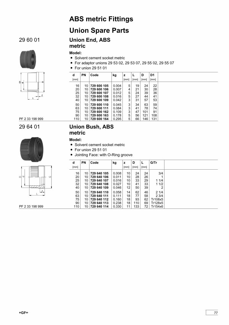
ABS metric FittingsUnion Spare Parts
29 60 01 Union End, ABSmetricModel:Ï Solvent cement socket metricÏ For adaptor unions 29 53 02, 29 53 07, 29 55 02, 29 55 07Ï For union 29 51 01
d[mm]
PN Code kg z[mm]
L[mm]
D[mm]
D1[mm]
16 10 729 600 105 0.004 5 19 24 2220 10 729 600 106 0.007 4 21 30 2825 10 729 600 107 0.012 5 24 39 3632 10 729 600 108 0.016 5 27 44 4140 10 729 600 109 0.042 3 31 57 5350 10 729 600 110 0.045 3 34 63 5963 10 729 600 111 0.084 3 41 78 7475 10 729 600 162 0.109 3 47 101 9190 10 729 600 163 0.178 5 56 121 108110 10 729 600 164 0.295 5 66 146 131PF 2 33 198 999
29 64 01 Union Bush, ABSmetricModel:Ï Solvent cement socket metricÏ For union 29 51 01Ï Jointing Face: with O-Ring groove
d[mm]
PN Code kg z[mm]
D[mm]
L[mm]
G/Tr
16 10 729 640 105 0.008 10 24 24 3/420 10 729 640 106 0.011 10 28 26 125 10 729 640 107 0.016 10 33 29 1 1/432 10 729 640 108 0.027 10 41 33 1 1/240 10 729 640 109 0.046 12 50 39 250 10 729 640 110 0.058 14 62 46 2 1/463 10 729 640 111 0.111 18 77 58 2 3/475 10 729 640 112 0.160 18 93 62 Tr108x590 10 729 640 113 0.238 18 110 69 Tr128x5110 10 729 640 114 0.330 11 133 72 Tr154x6PF 2 33 198 999
77
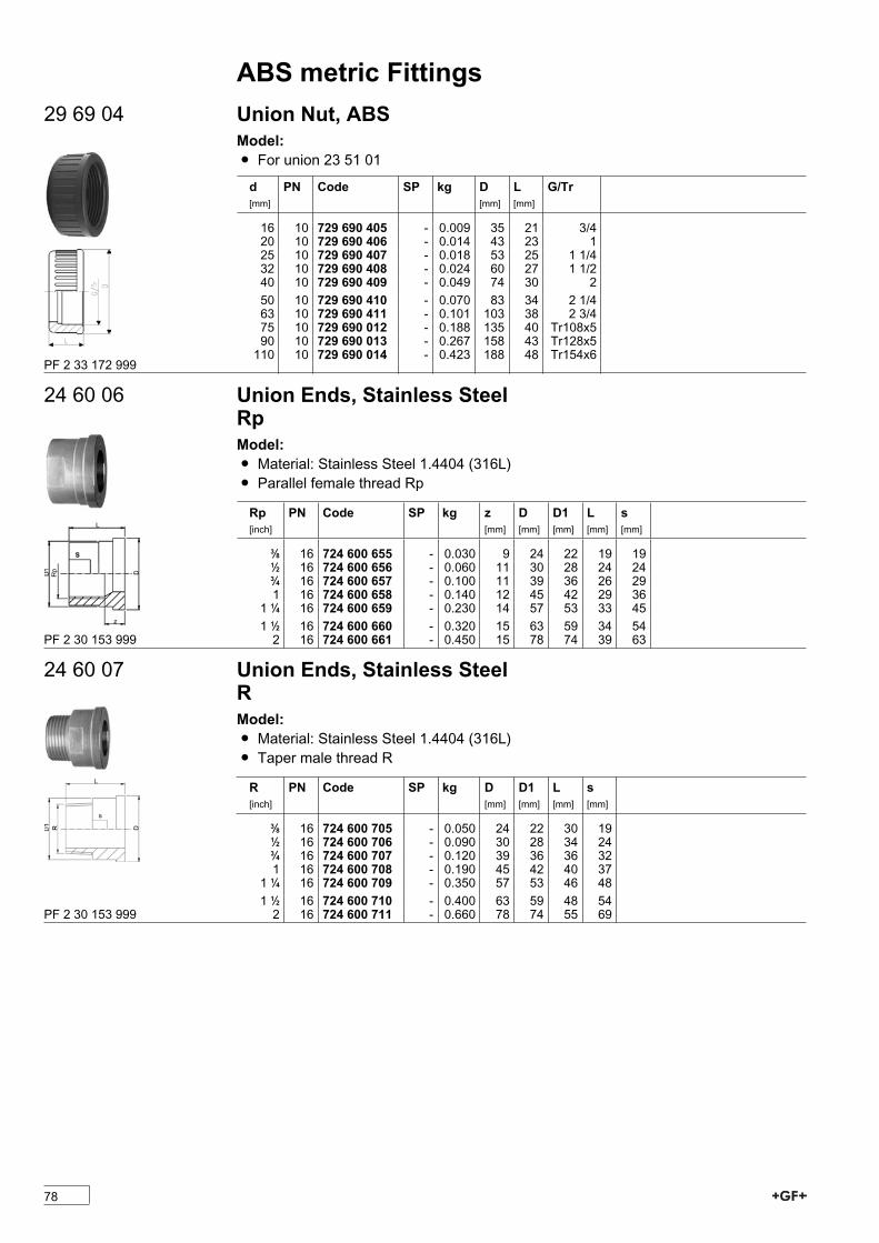
ABS metric Fittings29 69 04 Union Nut, ABS
Model:Ï For union 23 51 01
d[mm]
PN Code SP kg D[mm]
L[mm]
G/Tr
16 10 729 690 405 - 0.009 35 21 3/420 10 729 690 406 - 0.014 43 23 125 10 729 690 407 - 0.018 53 25 1 1/432 10 729 690 408 - 0.024 60 27 1 1/240 10 729 690 409 - 0.049 74 30 250 10 729 690 410 - 0.070 83 34 2 1/463 10 729 690 411 - 0.101 103 38 2 3/475 10 729 690 012 - 0.188 135 40 Tr108x590 10 729 690 013 - 0.267 158 43 Tr128x5110 10 729 690 014 - 0.423 188 48 Tr154x6
PF 2 33 172 999
24 60 06 Union Ends, Stainless SteelRpModel:Ï Material: Stainless Steel 1.4404 (316L)Ï Parallel female thread Rp
Rp[inch]
PN Code SP kg z[mm]
D[mm]
D1[mm]
L[mm]
s[mm]
3/8 16 724 600 655 - 0.030 9 24 22 19 191/2 16 724 600 656 - 0.060 11 30 28 24 243/4 16 724 600 657 - 0.100 11 39 36 26 291 16 724 600 658 - 0.140 12 45 42 29 361 1/4 16 724 600 659 - 0.230 14 57 53 33 451 1/2 16 724 600 660 - 0.320 15 63 59 34 542 16 724 600 661 - 0.450 15 78 74 39 63PF 2 30 153 999
24 60 07 Union Ends, Stainless SteelRModel:Ï Material: Stainless Steel 1.4404 (316L)Ï Taper male thread R
R[inch]
PN Code SP kg D[mm]
D1[mm]
L[mm]
s[mm]
3/8 16 724 600 705 - 0.050 24 22 30 191/2 16 724 600 706 - 0.090 30 28 34 243/4 16 724 600 707 - 0.120 39 36 36 321 16 724 600 708 - 0.190 45 42 40 371 1/4 16 724 600 709 - 0.350 57 53 46 481 1/2 16 724 600 710 - 0.400 63 59 48 542 16 724 600 711 - 0.660 78 74 55 69PF 2 30 153 999
78
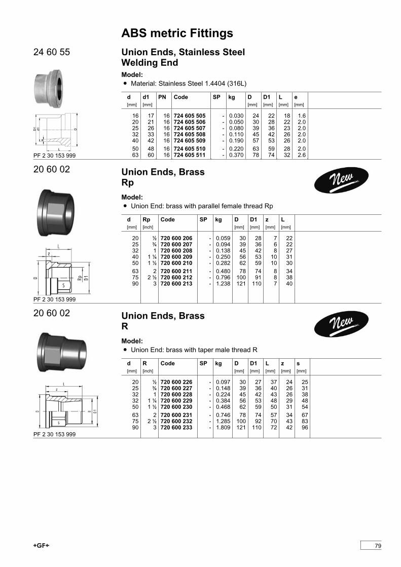
ABS metric Fittings24 60 55 Union Ends, Stainless Steel
Welding EndModel:Ï Material: Stainless Steel 1.4404 (316L)
d[mm]
d1[mm]
PN Code SP kg D[mm]
D1[mm]
L[mm]
e[mm]
16 17 16 724 605 505 - 0.030 24 22 18 1.620 21 16 724 605 506 - 0.050 30 28 22 2.025 26 16 724 605 507 - 0.080 39 36 23 2.032 33 16 724 605 508 - 0.110 45 42 26 2.040 42 16 724 605 509 - 0.190 57 53 26 2.050 48 16 724 605 510 - 0.220 63 59 28 2.063 60 16 724 605 511 - 0.370 78 74 32 2.6PF 2 30 153 999
20 60 02 Union Ends, BrassRpModel:Ï Union End: brass with parallel female thread Rp
d[mm]
Rp[inch]
Code SP kg D[mm]
D1[mm]
z[mm]
L[mm]
20 1/2 720 600 206 - 0.059 30 28 7 2225 3/4 720 600 207 - 0.094 39 36 6 2232 1 720 600 208 - 0.138 45 42 8 2740 1 1/4 720 600 209 - 0.250 56 53 10 3150 1 1/2 720 600 210 - 0.282 62 59 10 3063 2 720 600 211 - 0.480 78 74 8 3475 2 1/2 720 600 212 - 0.796 100 91 8 3890 3 720 600 213 - 1.238 121 110 7 40
PF 2 30 153 999
20 60 02 Union Ends, BrassRModel:Ï Union End: brass with taper male thread R
d[mm]
R[inch]
Code SP kg D[mm]
D1[mm]
L[mm]
z[mm]
s[mm]
20 1/2 720 600 226 - 0.097 30 27 37 24 2525 3/4 720 600 227 - 0.148 39 36 40 26 3132 1 720 600 228 - 0.224 45 42 43 26 3832 1 1/4 720 600 229 - 0.384 56 53 48 29 4850 1 1/2 720 600 230 - 0.468 62 59 50 31 5463 2 720 600 231 - 0.746 78 74 57 34 6775 2 1/2 720 600 232 - 1.285 100 92 70 43 8390 3 720 600 233 - 1.809 121 110 72 42 96
PF 2 30 153 999
79
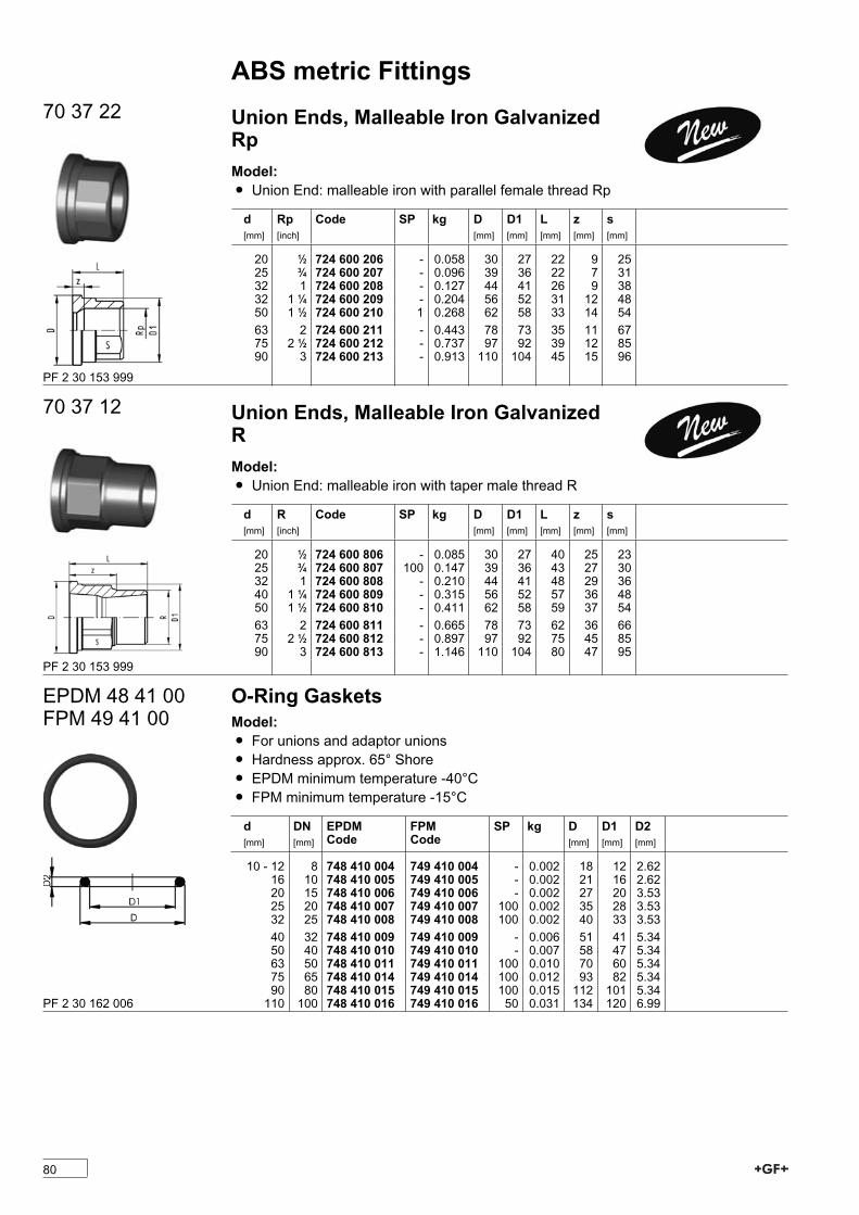
ABS metric Fittings70 37 22 Union Ends, Malleable Iron Galvanized
RpModel:Ï Union End: malleable iron with parallel female thread Rp
d[mm]
Rp[inch]
Code SP kg D[mm]
D1[mm]
L[mm]
z[mm]
s[mm]
20 1/2 724 600 206 - 0.058 30 27 22 9 2525 3/4 724 600 207 - 0.096 39 36 22 7 3132 1 724 600 208 - 0.127 44 41 26 9 3832 1 1/4 724 600 209 - 0.204 56 52 31 12 4850 1 1/2 724 600 210 1 0.268 62 58 33 14 5463 2 724 600 211 - 0.443 78 73 35 11 6775 2 1/2 724 600 212 - 0.737 97 92 39 12 8590 3 724 600 213 - 0.913 110 104 45 15 96
PF 2 30 153 999
70 37 12 Union Ends, Malleable Iron GalvanizedRModel:Ï Union End: malleable iron with taper male thread R
d[mm]
R[inch]
Code SP kg D[mm]
D1[mm]
L[mm]
z[mm]
s[mm]
20 1/2 724 600 806 - 0.085 30 27 40 25 2325 3/4 724 600 807 100 0.147 39 36 43 27 3032 1 724 600 808 - 0.210 44 41 48 29 3640 1 1/4 724 600 809 - 0.315 56 52 57 36 4850 1 1/2 724 600 810 - 0.411 62 58 59 37 5463 2 724 600 811 - 0.665 78 73 62 36 6675 2 1/2 724 600 812 - 0.897 97 92 75 45 8590 3 724 600 813 - 1.146 110 104 80 47 95
PF 2 30 153 999
EPDM 48 41 00FPM 49 41 00
O-Ring GasketsModel:Ï For unions and adaptor unionsÏ Hardness approx. 65° ShoreÏ EPDM minimum temperature -40°CÏ FPM minimum temperature -15°C
d[mm]
DN[mm]
EPDMCode
FPMCode
SP kg D[mm]
D1[mm]
D2[mm]
10 - 12 8 748 410 004 749 410 004 - 0.002 18 12 2.6216 10 748 410 005 749 410 005 - 0.002 21 16 2.6220 15 748 410 006 749 410 006 - 0.002 27 20 3.5325 20 748 410 007 749 410 007 100 0.002 35 28 3.5332 25 748 410 008 749 410 008 100 0.002 40 33 3.5340 32 748 410 009 749 410 009 - 0.006 51 41 5.3450 40 748 410 010 749 410 010 - 0.007 58 47 5.3463 50 748 410 011 749 410 011 100 0.010 70 60 5.3475 65 748 410 014 749 410 014 100 0.012 93 82 5.3490 80 748 410 015 749 410 015 100 0.015 112 101 5.34110 100 748 410 016 749 410 016 50 0.031 134 120 6.99PF 2 30 162 006
80
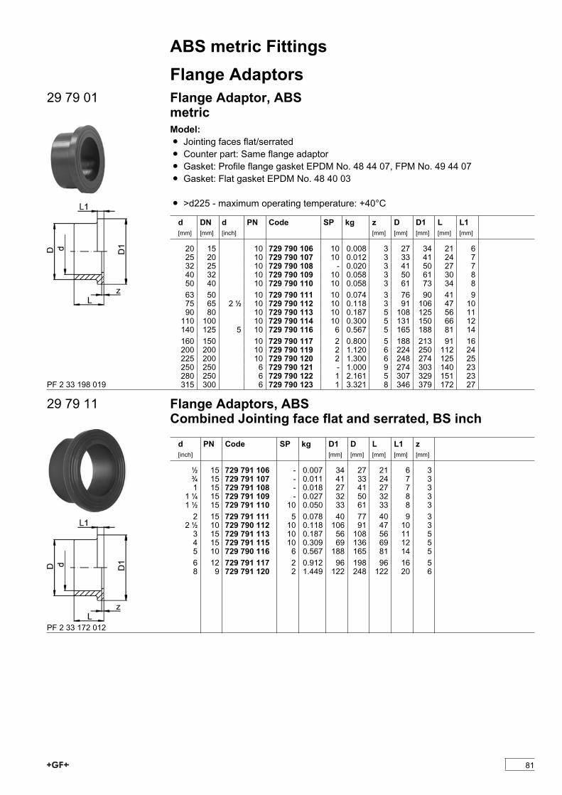
ABS metric FittingsFlange Adaptors
29 79 01 Flange Adaptor, ABSmetricModel:Ï Jointing faces flat/serratedÏ Counter part: Same flange adaptorÏ Gasket: Profile flange gasket EPDM No. 48 44 07, FPM No. 49 44 07Ï Gasket: Flat gasket EPDM No. 48 40 03
Ï >d225 - maximum operating temperature: +40°C
d[mm]
DN[mm]
d[inch]
PN Code SP kg z[mm]
D[mm]
D1[mm]
L[mm]
L1[mm]
20 15 10 729 790 106 10 0.008 3 27 34 21 625 20 10 729 790 107 10 0.012 3 33 41 24 732 25 10 729 790 108 - 0.020 3 41 50 27 740 32 10 729 790 109 10 0.058 3 50 61 30 850 40 10 729 790 110 10 0.058 3 61 73 34 863 50 10 729 790 111 10 0.074 3 76 90 41 975 65 2 1/2 10 729 790 112 10 0.118 3 91 106 47 1090 80 10 729 790 113 10 0.187 5 108 125 56 11110 100 10 729 790 114 10 0.300 5 131 150 66 12140 125 5 10 729 790 116 6 0.567 5 165 188 81 14160 150 10 729 790 117 2 0.800 5 188 213 91 16200 200 10 729 790 119 2 1.120 6 224 250 112 24225 200 10 729 790 120 2 1.300 6 248 274 125 25250 250 6 729 790 121 - 1.000 9 274 303 140 23280 250 6 729 790 122 1 2.161 5 307 329 151 23315 300 6 729 790 123 1 3.321 8 346 379 172 27PF 2 33 198 019
29 79 11 Flange Adaptors, ABSCombined Jointing face flat and serrated, BS inch
d[inch]
PN Code SP kg D1[mm]
D[mm]
L[mm]
L1[mm]
z[mm]
1/2 15 729 791 106 - 0.007 34 27 21 6 33/4 15 729 791 107 - 0.011 41 33 24 7 31 15 729 791 108 - 0.018 27 41 27 7 31 1/4 15 729 791 109 - 0.027 32 50 32 8 31 1/2 15 729 791 110 10 0.050 33 61 33 8 32 15 729 791 111 5 0.078 40 77 40 9 32 1/2 10 729 790 112 10 0.118 106 91 47 10 33 15 729 791 113 10 0.187 56 108 56 11 54 15 729 791 115 10 0.309 69 136 69 12 55 10 729 790 116 6 0.567 188 165 81 14 56 12 729 791 117 2 0.912 96 198 96 16 58 9 729 791 120 2 1.449 122 248 122 20 6
PF 2 33 172 012
81
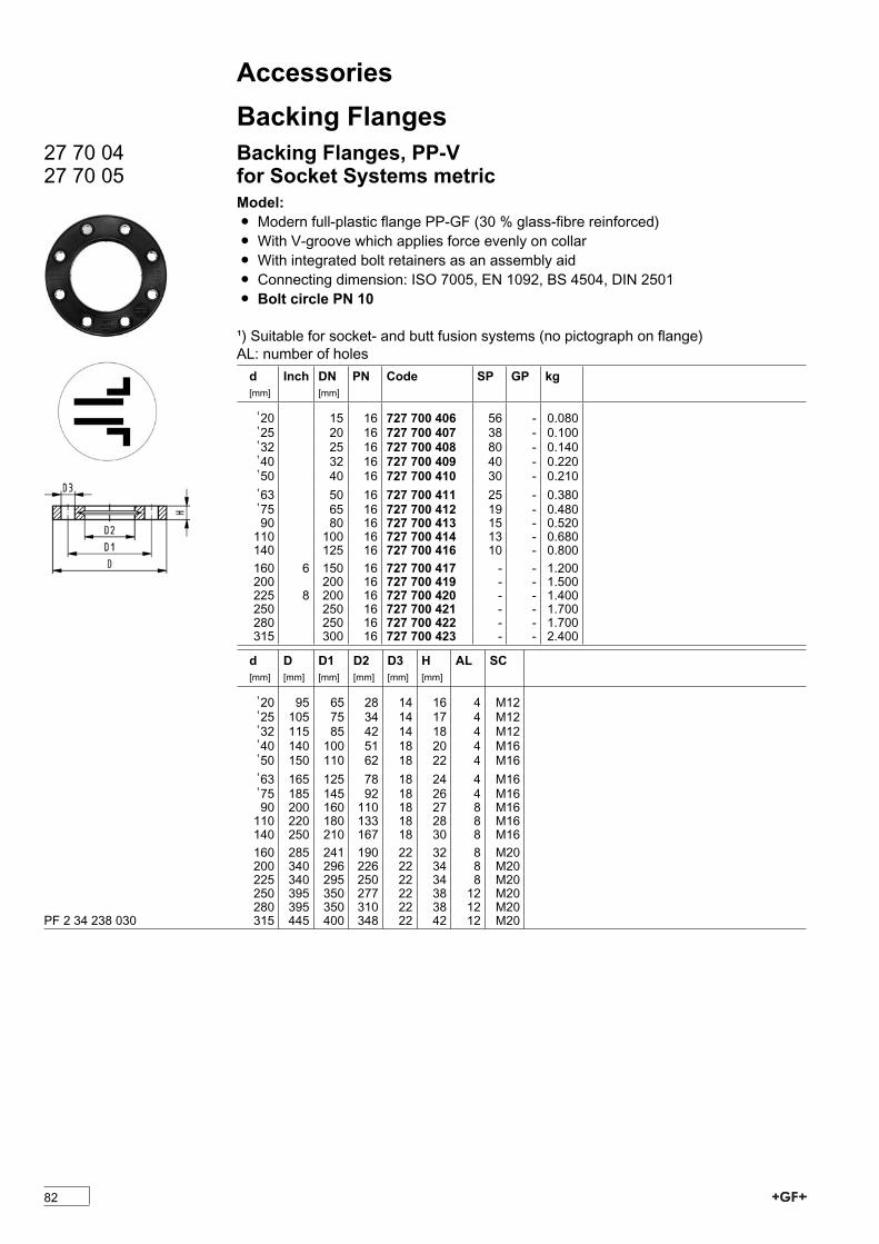
AccessoriesBacking Flanges
27 70 0427 70 05
Backing Flanges, PP-Vfor Socket Systems metricModel:Ï Modern full-plastic flange PP-GF (30 % glass-fibre reinforced)Ï With V-groove which applies force evenly on collarÏ With integrated bolt retainers as an assembly aidÏ Connecting dimension: ISO 7005, EN 1092, BS 4504, DIN 2501Ï Bolt circle PN 10
¹) Suitable for socket- and butt fusion systems (no pictograph on flange)AL: number of holesd[mm]
Inch DN[mm]
PN Code SP GP kg
¹20 15 16 727 700 406 56 - 0.080¹25 20 16 727 700 407 38 - 0.100¹32 25 16 727 700 408 80 - 0.140¹40 32 16 727 700 409 40 - 0.220¹50 40 16 727 700 410 30 - 0.210¹63 50 16 727 700 411 25 - 0.380¹75 65 16 727 700 412 19 - 0.48090 80 16 727 700 413 15 - 0.520110 100 16 727 700 414 13 - 0.680140 125 16 727 700 416 10 - 0.800160 6 150 16 727 700 417 - - 1.200200 200 16 727 700 419 - - 1.500225 8 200 16 727 700 420 - - 1.400250 250 16 727 700 421 - - 1.700280 250 16 727 700 422 - - 1.700315 300 16 727 700 423 - - 2.400
d[mm]
D[mm]
D1[mm]
D2[mm]
D3[mm]
H[mm]
AL SC
¹20 95 65 28 14 16 4 M12¹25 105 75 34 14 17 4 M12¹32 115 85 42 14 18 4 M12¹40 140 100 51 18 20 4 M16¹50 150 110 62 18 22 4 M16¹63 165 125 78 18 24 4 M16¹75 185 145 92 18 26 4 M1690 200 160 110 18 27 8 M16110 220 180 133 18 28 8 M16140 250 210 167 18 30 8 M16160 285 241 190 22 32 8 M20200 340 296 226 22 34 8 M20225 340 295 250 22 34 8 M20250 395 350 277 22 38 12 M20280 395 350 310 22 38 12 M20315 445 400 348 22 42 12 M20PF 2 34 238 030
82
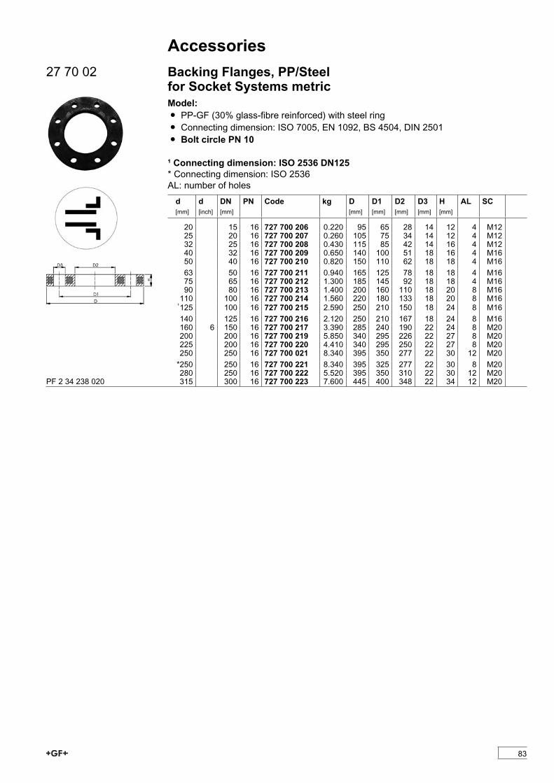
Accessories27 70 02 Backing Flanges, PP/Steel
for Socket Systems metricModel:Ï PP-GF (30% glass-fibre reinforced) with steel ringÏ Connecting dimension: ISO 7005, EN 1092, BS 4504, DIN 2501Ï Bolt circle PN 10
¹ Connecting dimension: ISO 2536 DN125* Connecting dimension: ISO 2536AL: number of holesd[mm]
d[inch]
DN[mm]
PN Code kg D[mm]
D1[mm]
D2[mm]
D3[mm]
H[mm]
AL SC
20 15 16 727 700 206 0.220 95 65 28 14 12 4 M1225 20 16 727 700 207 0.260 105 75 34 14 12 4 M1232 25 16 727 700 208 0.430 115 85 42 14 16 4 M1240 32 16 727 700 209 0.650 140 100 51 18 16 4 M1650 40 16 727 700 210 0.820 150 110 62 18 18 4 M1663 50 16 727 700 211 0.940 165 125 78 18 18 4 M1675 65 16 727 700 212 1.300 185 145 92 18 18 4 M1690 80 16 727 700 213 1.400 200 160 110 18 20 8 M16110 100 16 727 700 214 1.560 220 180 133 18 20 8 M16¹125 100 16 727 700 215 2.590 250 210 150 18 24 8 M16140 125 16 727 700 216 2.120 250 210 167 18 24 8 M16160 6 150 16 727 700 217 3.390 285 240 190 22 24 8 M20200 200 16 727 700 219 5.850 340 295 226 22 27 8 M20225 200 16 727 700 220 4.410 340 295 250 22 27 8 M20250 250 16 727 700 021 8.340 395 350 277 22 30 12 M20*250 250 16 727 700 221 8.340 395 325 277 22 30 8 M20280 250 16 727 700 222 5.520 395 350 310 22 30 12 M20315 300 16 727 700 223 7.600 445 400 348 22 34 12 M20PF 2 34 238 020
83
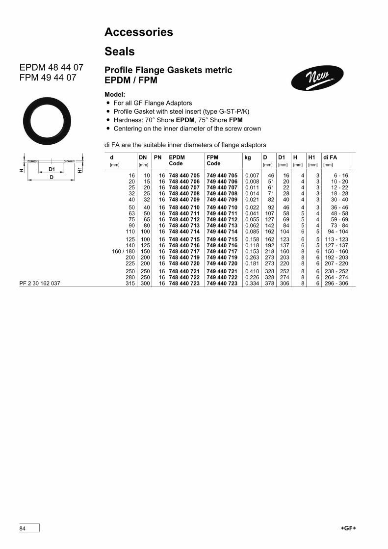
AccessoriesSeals
EPDM 48 44 07FPM 49 44 07
Profile Flange Gaskets metricEPDM / FPMModel:Ï For all GF Flange AdaptorsÏ Profile Gasket with steel insert (type G-ST-P/K)Ï Hardness: 70° Shore EPDM, 75° Shore FPM Ï Centering on the inner diameter of the screw crown
di FA are the suitable inner diameters of flange adaptors
d[mm]
DN[mm]
PN EPDMCode
FPMCode
kg D[mm]
D1[mm]
H[mm]
H1[mm]
di FA[mm]
16 10 16 748 440 705 749 440 705 0.007 46 16 4 3 6 - 1620 15 16 748 440 706 749 440 706 0.008 51 20 4 3 10 - 2025 20 16 748 440 707 749 440 707 0.011 61 22 4 3 12 - 2232 25 16 748 440 708 749 440 708 0.014 71 28 4 3 18 - 2840 32 16 748 440 709 749 440 709 0.021 82 40 4 3 30 - 4050 40 16 748 440 710 749 440 710 0.022 92 46 4 3 36 - 4663 50 16 748 440 711 749 440 711 0.041 107 58 5 4 48 - 5875 65 16 748 440 712 749 440 712 0.055 127 69 5 4 59 - 6990 80 16 748 440 713 749 440 713 0.062 142 84 5 4 73 - 84110 100 16 748 440 714 749 440 714 0.085 162 104 6 5 94 - 104125 100 16 748 440 715 749 440 715 0.158 162 123 6 5 113 - 123140 125 16 748 440 716 749 440 716 0.118 192 137 6 5 127 - 137
160 / 180 150 16 748 440 717 749 440 717 0.153 218 160 8 6 150 - 160200 200 16 748 440 719 749 440 719 0.263 273 203 8 6 192 - 203225 200 16 748 440 720 749 440 720 0.181 273 220 8 6 207 - 220250 250 16 748 440 721 749 440 721 0.410 328 252 8 6 238 - 252280 250 16 748 440 722 749 440 722 0.226 328 274 8 6 264 - 274315 300 16 748 440 723 749 440 723 0.334 378 306 8 6 296 - 306PF 2 30 162 037
84
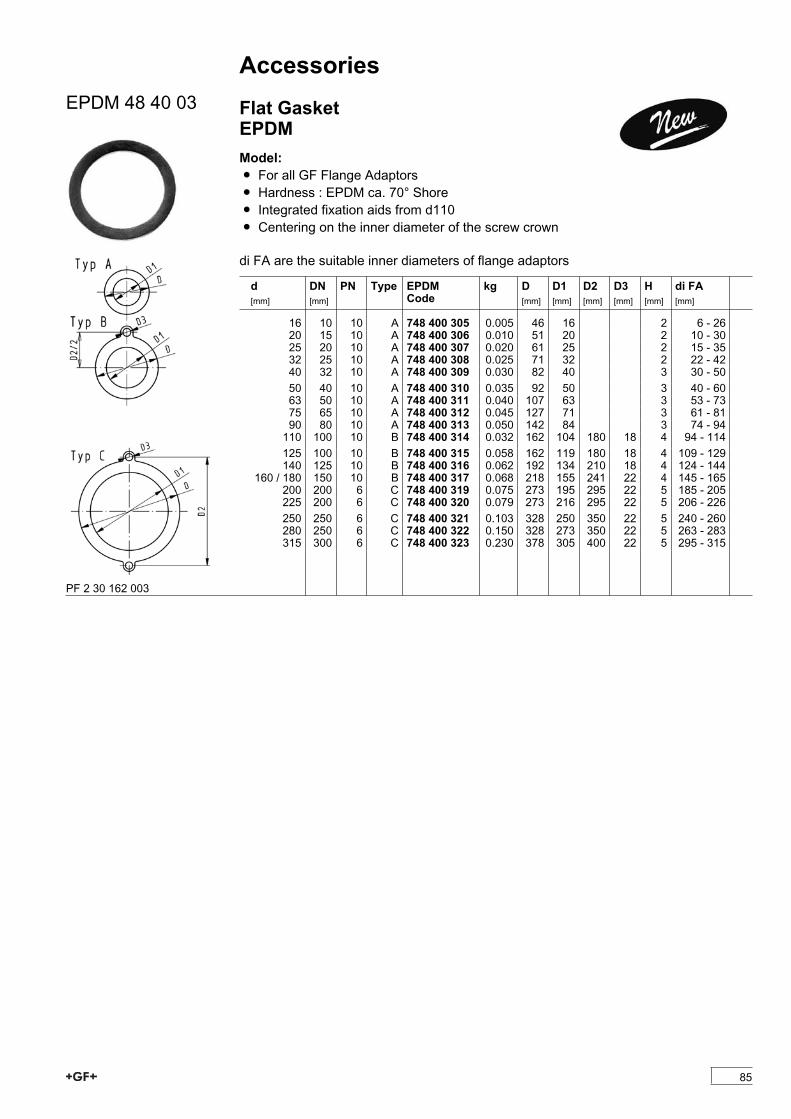
AccessoriesEPDM 48 40 03 Flat Gasket
EPDMModel:Ï For all GF Flange AdaptorsÏ Hardness : EPDM ca. 70° ShoreÏ Integrated fixation aids from d110 Ï Centering on the inner diameter of the screw crown
di FA are the suitable inner diameters of flange adaptors
d[mm]
DN[mm]
PN Type EPDMCode
kg D[mm]
D1[mm]
D2[mm]
D3[mm]
H[mm]
di FA[mm]
16 10 10 A 748 400 305 0.005 46 16 2 6 - 2620 15 10 A 748 400 306 0.010 51 20 2 10 - 3025 20 10 A 748 400 307 0.020 61 25 2 15 - 3532 25 10 A 748 400 308 0.025 71 32 2 22 - 4240 32 10 A 748 400 309 0.030 82 40 3 30 - 5050 40 10 A 748 400 310 0.035 92 50 3 40 - 6063 50 10 A 748 400 311 0.040 107 63 3 53 - 7375 65 10 A 748 400 312 0.045 127 71 3 61 - 8190 80 10 A 748 400 313 0.050 142 84 3 74 - 94110 100 10 B 748 400 314 0.032 162 104 180 18 4 94 - 114125 100 10 B 748 400 315 0.058 162 119 180 18 4 109 - 129140 125 10 B 748 400 316 0.062 192 134 210 18 4 124 - 144
160 / 180 150 10 B 748 400 317 0.068 218 155 241 22 4 145 - 165200 200 6 C 748 400 319 0.075 273 195 295 22 5 185 - 205225 200 6 C 748 400 320 0.079 273 216 295 22 5 206 - 226250 250 6 C 748 400 321 0.103 328 250 350 22 5 240 - 260280 250 6 C 748 400 322 0.150 328 273 350 22 5 263 - 283315 300 6 C 748 400 323 0.230 378 305 400 22 5 295 - 315
PF 2 30 162 003
85
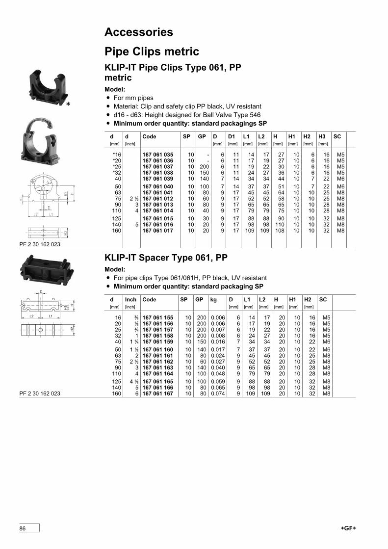
AccessoriesPipe Clips metricKLIP-IT Pipe Clips Type 061, PPmetricModel:Ï For mm pipesÏ Material: Clip and safety clip PP black, UV resistantÏ d16 - d63: Height designed for Ball Valve Type 546Ï Minimum order quantity: standard packagings SP
d[mm]
d[inch]
Code SP GP D[mm]
D1[mm]
L1[mm]
L2[mm]
H[mm]
H1[mm]
H2[mm]
H3[mm]
SC
*16 167 061 035 10 - 6 11 14 17 27 10 6 16 M5*20 167 061 036 10 - 6 11 17 19 27 10 6 16 M5*25 167 061 037 10 200 6 11 19 22 30 10 6 16 M5*32 167 061 038 10 150 6 11 24 27 36 10 6 16 M540 167 061 039 10 140 7 14 34 34 44 10 7 22 M650 167 061 040 10 100 7 14 37 37 51 10 7 22 M663 167 061 041 10 80 9 17 45 45 64 10 10 25 M875 2 1/2 167 061 012 10 60 9 17 52 52 58 10 10 25 M890 3 167 061 013 10 80 9 17 65 65 65 10 10 28 M8110 4 167 061 014 10 40 9 17 79 79 75 10 10 28 M8125 167 061 015 10 30 9 17 88 88 90 10 10 32 M8140 5 167 061 016 10 20 9 17 98 98 110 10 10 32 M8160 167 061 017 10 20 9 17 109 109 108 10 10 32 M8
PF 2 30 162 023
KLIP-IT Spacer Type 061, PPModel:Ï For pipe clips Type 061/061H, PP black, UV resistantÏ Minimum order quantity: standard packaging SP
d[mm]
Inch[inch]
Code SP GP kg D[mm]
L1[mm]
L2[mm]
H[mm]
H1[mm]
H2[mm]
SC
16 3/8 167 061 155 10 200 0.006 6 14 17 20 10 16 M520 1/2 167 061 156 10 200 0.006 6 17 19 20 10 16 M525 3/4 167 061 157 10 200 0.007 6 19 22 20 10 16 M532 1 167 061 158 10 200 0.008 6 24 27 20 10 16 M540 1 1/4 167 061 159 10 150 0.016 7 34 34 20 10 22 M650 1 1/2 167 061 160 10 140 0.017 7 37 37 20 10 22 M663 2 167 061 161 10 80 0.024 9 45 45 20 10 25 M875 2 1/2 167 061 162 10 60 0.027 9 52 52 20 10 25 M890 3 167 061 163 10 140 0.040 9 65 65 20 10 28 M8110 4 167 061 164 10 100 0.048 9 79 79 20 10 28 M8125 4 1/2 167 061 165 10 100 0.059 9 88 88 20 10 32 M8140 5 167 061 166 10 80 0.065 9 98 98 20 10 32 M8160 6 167 061 167 10 80 0.074 9 109 109 20 10 32 M8PF 2 30 162 023
86
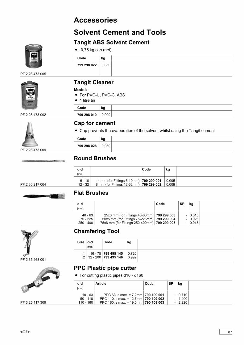
AccessoriesSolvent Cement and ToolsTangit ABS Solvent CementÏ 0,75 kg can (net)
Code kg
799 298 022 0.650
PF 2 28 473 005
Tangit CleanerModel:Ï For PVC-U, PVC-C, ABSÏ 1 litre tin
Code kg
799 298 010 0.900PF 2 28 473 002
Cap for cementÏ Cap prevents the evaporation of the solvent whilst using the Tangit cement
Code kg
799 298 028 0.030PF 2 28 473 009
Round Brushes
d-d[mm]
Code kg
6 - 10 4 mm (for Fittings 6-10mm) 799 299 001 0.00512 - 32 8 mm (for Fittings 12-32mm) 799 299 002 0.009PF 2 30 217 004
Flat Brushes
d-d[mm]
Code SP kg
40 - 63 25x3 mm (for Fittings 40-63mm) 799 299 003 - 0.01575 - 225 50x5 mm (for Fittings 75-225mm) 799 299 004 - 0.026250 - 400 75x6 mm (for Fittings 250-400mm) 799 299 005 - 0.045
Chamfering Tool
Size d-d[mm]
Code kg
1 16 - 75 799 495 145 0.7202 32 - 200 799 495 146 0.992PF 2 35 268 001
PPC Plastic pipe cutterÏ For cutting plastic pipes d10 - d160
d-d[mm]
Article Code SP kg
10 - 63 PPC 63, s max. = 7.2mm 790 109 001 - 0.71050 - 110 PPC 110, s max. = 12.7mm 790 109 002 - 1.400110 - 160 PPC 160, s max. = 19.0mm 790 109 003 - 2.220PF 3 25 117 309
87

88
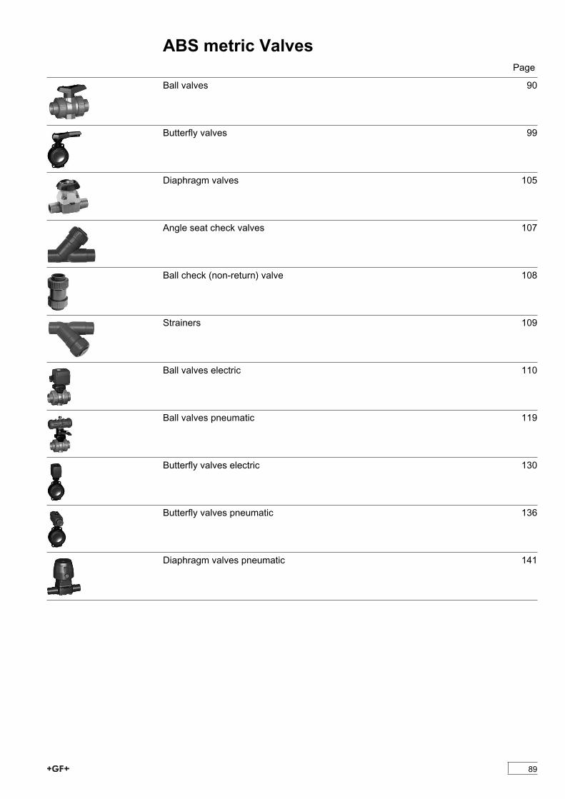
ABS metric ValvesPage
Ball valves 90
Butterfly valves 99
Diaphragm valves 105
Angle seat check valves 107
Ball check (non-return) valve 108
Strainers 109
Ball valves electric 110
Ball valves pneumatic 119
Butterfly valves electric 130
Butterfly valves pneumatic 136
Diaphragm valves pneumatic 141
89
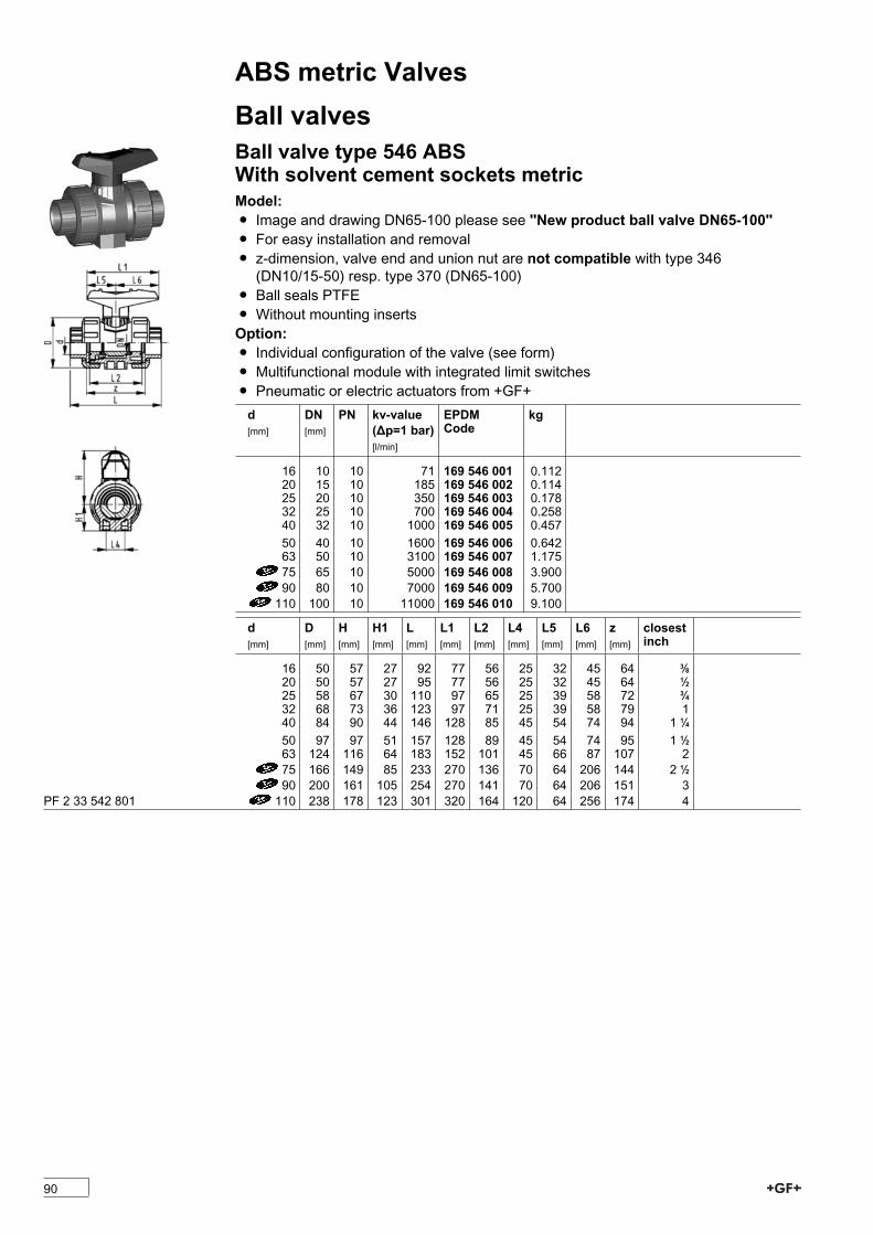
ABS metric ValvesBall valvesBall valve type 546 ABSWith solvent cement sockets metricModel:Ï Image and drawing DN65-100 please see ''New product ball valve DN65-100''Ï For easy installation and removalÏ z-dimension, valve end and union nut are not compatible with type 346(DN10/15-50) resp. type 370 (DN65-100)
Ï Ball seals PTFEÏ Without mounting insertsOption:Ï Individual configuration of the valve (see form)Ï Multifunctional module with integrated limit switchesÏ Pneumatic or electric actuators from +GF+d[mm]
DN[mm]
PN kv-value(�p=1 bar)[l/min]
EPDMCode
kg
16 10 10 71 169 546 001 0.11220 15 10 185 169 546 002 0.11425 20 10 350 169 546 003 0.17832 25 10 700 169 546 004 0.25840 32 10 1000 169 546 005 0.45750 40 10 1600 169 546 006 0.64263 50 10 3100 169 546 007 1.17575 65 10 5000 169 546 008 3.90090 80 10 7000 169 546 009 5.700110 100 10 11000 169 546 010 9.100
d[mm]
D[mm]
H[mm]
H1[mm]
L[mm]
L1[mm]
L2[mm]
L4[mm]
L5[mm]
L6[mm]
z[mm]
closestinch
16 50 57 27 92 77 56 25 32 45 64 3/820 50 57 27 95 77 56 25 32 45 64 1/225 58 67 30 110 97 65 25 39 58 72 3/432 68 73 36 123 97 71 25 39 58 79 140 84 90 44 146 128 85 45 54 74 94 1 1/450 97 97 51 157 128 89 45 54 74 95 1 1/263 124 116 64 183 152 101 45 66 87 107 275 166 149 85 233 270 136 70 64 206 144 2 1/290 200 161 105 254 270 141 70 64 206 151 3110 238 178 123 301 320 164 120 64 256 174 4PF 2 33 542 801
90
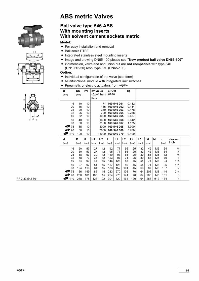
ABS metric ValvesBall valve type 546 ABSWith mounting insertsWith solvent cement sockets metricModel:Ï For easy installation and removalÏ Ball seals PTFEÏ Integrated stainless steel mounting insertsÏ Image and drawing DN65-100 please see ''New product ball valve DN65-100''Ï z-dimension, valve end and union nut are not compatible with type 346(DN10/15-50) resp. type 370 (DN65-100)
Option:Ï Individual configuration of the valve (see form)Ï Multifunctional module with integrated limit switchesÏ Pneumatic or electric actuators from +GF+d[mm]
DN[mm]
PN kv-value(�p=1 bar)[l/min]
EPDMCode
kg
16 10 10 71 169 546 061 0.11220 15 10 185 169 546 062 0.11425 20 10 350 169 546 063 0.17832 25 10 700 169 546 064 0.25840 32 10 1000 169 546 065 0.45750 40 10 1600 169 546 066 0.64263 50 10 3100 169 546 067 1.17575 65 10 5000 169 546 068 3.90090 80 10 7000 169 546 069 5.700110 100 10 11000 169 546 070 9.100
d[mm]
D[mm]
H[mm]
H1[mm]
H2[mm]
L[mm]
L1[mm]
L2[mm]
L4[mm]
L5[mm]
L6[mm]
M z[mm]
closestinch
16 50 57 27 12 92 77 56 25 32 45 M6 64 3/820 50 57 27 12 95 77 56 25 32 45 M6 64 1/225 58 67 30 12 110 97 65 25 39 58 M6 72 3/432 68 73 36 12 123 97 71 25 39 58 M6 79 140 84 90 44 15 146 128 85 45 54 74 M8 94 1 1/450 97 97 51 15 157 128 89 45 54 74 M8 95 1 1/263 124 116 64 15 183 152 101 45 66 87 M8 107 275 166 149 85 15 233 270 136 70 64 206 M8 144 2 1/290 200 161 105 15 254 270 141 70 64 206 M8 151 3110 238 178 123 22 301 320 164 120 64 256 M12 174 4PF 2 33 542 801
91
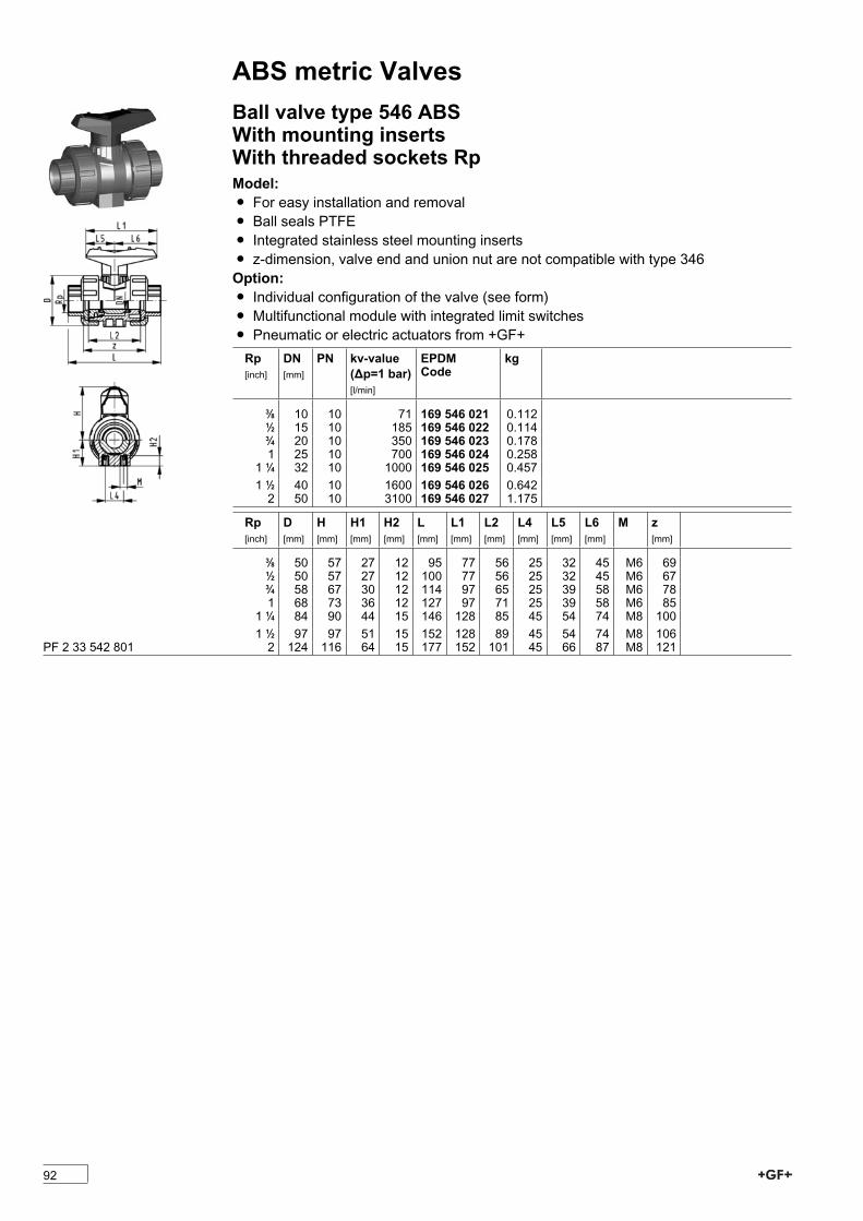
ABS metric ValvesBall valve type 546 ABSWith mounting insertsWith threaded sockets RpModel:Ï For easy installation and removalÏ Ball seals PTFEÏ Integrated stainless steel mounting insertsÏ z-dimension, valve end and union nut are not compatible with type 346Option:Ï Individual configuration of the valve (see form)Ï Multifunctional module with integrated limit switchesÏ Pneumatic or electric actuators from +GF+Rp[inch]
DN[mm]
PN kv-value(�p=1 bar)[l/min]
EPDMCode
kg
3/8 10 10 71 169 546 021 0.1121/2 15 10 185 169 546 022 0.1143/4 20 10 350 169 546 023 0.1781 25 10 700 169 546 024 0.2581 1/4 32 10 1000 169 546 025 0.4571 1/2 40 10 1600 169 546 026 0.6422 50 10 3100 169 546 027 1.175
Rp[inch]
D[mm]
H[mm]
H1[mm]
H2[mm]
L[mm]
L1[mm]
L2[mm]
L4[mm]
L5[mm]
L6[mm]
M z[mm]
3/8 50 57 27 12 95 77 56 25 32 45 M6 691/2 50 57 27 12 100 77 56 25 32 45 M6 673/4 58 67 30 12 114 97 65 25 39 58 M6 781 68 73 36 12 127 97 71 25 39 58 M6 851 1/4 84 90 44 15 146 128 85 45 54 74 M8 1001 1/2 97 97 51 15 152 128 89 45 54 74 M8 1062 124 116 64 15 177 152 101 45 66 87 M8 121PF 2 33 542 801
92
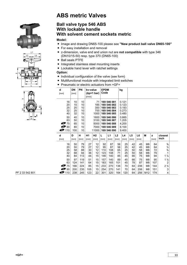
ABS metric ValvesBall valve type 546 ABSWith lockable handleWith solvent cement sockets metricModel:Ï Image and drawing DN65-100 please see ''New product ball valve DN65-100''Ï For easy installation and removalÏ z-dimension, valve end and union nut are not compatible with type 346(DN10/15-50) resp. type 370 (DN65-100)
Ï Ball seals PTFEÏ Integrated stainless steel mounting insertsÏ Lockable hand lever with ratchet settingsOption:Ï Individual configuration of the valve (see form)Ï Multifunctional module with integrated limit switchesÏ Pneumatic or electric actuators from +GF+d[mm]
DN[mm]
PN kv-value(�p=1 bar)[l/min]
EPDMCode
kg
16 10 10 71 169 546 081 0.12120 15 10 185 169 546 082 0.12325 20 10 350 169 546 083 0.19332 25 10 700 169 546 084 0.27340 32 10 1000 169 546 085 0.48050 40 10 1600 169 546 086 0.66563 50 10 3100 169 546 087 1.20575 65 10 5000 169 546 088 4.20090 80 10 7000 169 546 089 6.100110 100 10 11000 169 546 090 9.400
d[mm]
D[mm]
H[mm]
H1[mm]
H2[mm]
L[mm]
L1[mm]
L2[mm]
L4[mm]
L5[mm]
L6[mm]
M z[mm]
closestinch
16 50 79 27 12 92 87 56 25 42 45 M6 64 3/820 50 79 27 12 95 87 56 25 42 45 M6 64 1/225 58 88 30 12 110 108 65 25 50 58 M6 72 3/432 68 94 36 12 123 108 71 25 50 58 M6 79 140 84 113 44 15 146 140 85 45 66 75 M8 94 1 1/450 97 119 51 15 157 140 89 45 66 75 M8 95 1 1/263 124 141 64 15 183 165 101 45 78 87 M8 107 275 166 224 85 15 233 270 136 70 64 206 M8 144 2 1/290 200 235 105 15 254 270 141 70 64 206 M8 151 3110 238 245 123 22 301 320 164 120 64 256 M12 174 4PF 2 33 542 801
93

ABS metric ValvesValve end 546 and 543 ABS (G23)With threaded socket Rp reinforcedModel:Ï Connection to plastic or metalÏ Reinforcing ring stainless (A2)Ï Do not use thread sealing pastes that are harmful to ABS
Rp[inch]
PN Code kg D[mm]
D1[mm]
L[mm]
L1[mm]
z[mm]
3/8 16 169 480 925 0.008 38 24 20 4 71/2 16 169 480 926 0.010 38 28 22 4 63/4 16 169 480 927 0.014 44 34 25 5 71 16 169 480 928 0.023 53 42 28 5 71 1/4 16 169 480 929 0.035 65 52 30 5 71 1/2 16 169 480 930 0.060 77 63 32 6 92 16 169 480 931 0.110 99 78 38 7 10PF 2 33 542 999
Valve end 546 and 543 brassWith threaded spigot RModel:Ï Connection to metal threads
Inch Code kg D[mm]
D1[mm]
D2[mm]
z[mm]
L[mm]
L1[mm]
s[mm]
1/2 161 486 640 0.160 38 32 13 23 36 4 303/4 161 486 641 0.220 44 38 16 22 36 5 361 161 486 642 0.350 53 45 20 24 41 5 41
PF 2 33 542 999
Valve end 546 and 543 brassWith threaded socket RpModel:Ï Connection to metal threads
Inch Code kg D[mm]
D1[mm]
D2[mm]
z[mm]
L[mm]
L1[mm]
s[mm]
1/2 161 486 651 0.100 38 32 15 5 20 4 303/4 161 486 652 0.160 44 38 20 8 25 5 361 161 486 653 0.250 53 45 25 10 29 5 41
PF 2 33 542 999
94
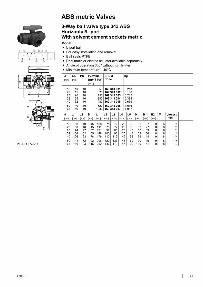
ABS metric Valves3-Way ball valve type 343 ABSHorizontal/L-portWith solvent cement sockets metricModel:Ï L-port ballÏ For easy installation and removalÏ Ball seals PTFEÏ Pneumatic or electric actuator available separatelyÏ Angle of operation 360° without turn limiterÏ Minimum temperature: - 40°C
d[mm]
DN[mm]
PN kv-value(�p=1 bar)[l/min]
EPDMCode
kg
16 10 10 50 169 343 001 0.21320 15 10 75 169 343 002 0.15625 20 10 150 169 343 003 0.28532 25 10 280 169 343 004 0.38840 32 10 480 169 343 005 0.63950 40 10 620 169 343 006 1.03663 50 10 1230 169 343 007 1.987
d[mm]
z[mm]
z1[mm]
D[mm]
L[mm]
L1[mm]
L2[mm]
L4[mm]
L5[mm]
H[mm]
H1[mm]
H2[mm]
M closestinch
16 80 40 45 108 78 72 25 36 50 27 8 6 3/820 80 40 45 111 78 72 25 36 50 27 8 6 1/225 94 47 52 131 92 86 25 43 60 33 8 6 3/432 104 52 65 148 100 96 25 48 68 36 8 6 140 126 63 78 176 110 116 45 58 79 44 9 8 1 1/450 144 72 92 206 120 137 45 69 90 49 9 8 1 1/263 186 93 116 262 146 179 45 90 109 61 9 8 2PF 2 33 173 014
95

ABS metric Valves3-Way ball valve type 343 ABSHorizontal/L-portWith threaded sockets RpModel:Ï L-port ballÏ For easy installation and removalÏ Ball seals PTFEÏ Pneumatic or electric actuator available separatelyÏ Angle of operation 360° without turn limiterÏ Minimum temperature: - 40°C
Rp[inch]
DN[mm]
PN kv-value(�p=1 bar)[l/min]
EPDMCode
kg
3/8 10 10 50 169 343 041 0.1561/2 15 10 75 169 343 042 0.1563/4 20 10 150 169 343 043 0.2851 25 10 280 169 343 044 0.3881 1/4 32 10 480 169 343 045 0.6391 1/2 40 10 620 169 343 046 1.0362 50 10 1230 169 343 047 1.987
Rp[inch]
z[mm]
z1[mm]
D[mm]
L[mm]
L1[mm]
L2[mm]
L4[mm]
L5[mm]
H[mm]
H1[mm]
H2[mm]
M
3/8 80 40 45 108 78 72 25 36 50 27 8 61/2 80 40 45 111 78 72 25 36 50 27 8 63/4 94 47 52 131 92 86 25 43 60 33 8 61 104 52 65 148 100 96 25 48 68 36 8 61 1/4 126 63 78 176 110 116 45 58 79 44 9 81 1/2 144 72 92 206 120 137 45 69 90 49 9 82 186 93 116 262 146 179 45 90 109 61 9 8PF 2 33 173 014
96
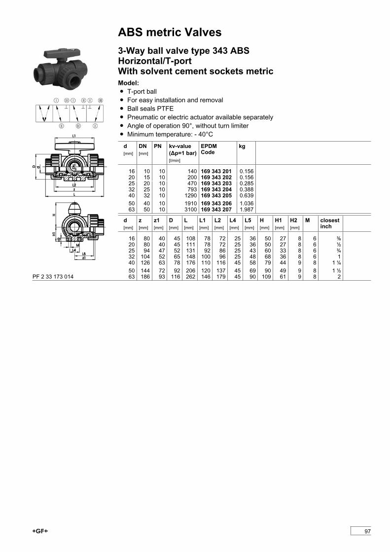
ABS metric Valves3-Way ball valve type 343 ABSHorizontal/T-portWith solvent cement sockets metricModel:Ï T-port ballÏ For easy installation and removalÏ Ball seals PTFEÏ Pneumatic or electric actuator available separatelyÏ Angle of operation 90°, without turn limiterÏ Minimum temperature: - 40°C
d[mm]
DN[mm]
PN kv-value(�p=1 bar)[l/min]
EPDMCode
kg
16 10 10 140 169 343 201 0.15620 15 10 200 169 343 202 0.15625 20 10 470 169 343 203 0.28532 25 10 793 169 343 204 0.38840 32 10 1290 169 343 205 0.63950 40 10 1910 169 343 206 1.03663 50 10 3100 169 343 207 1.987
d[mm]
z[mm]
z1[mm]
D[mm]
L[mm]
L1[mm]
L2[mm]
L4[mm]
L5[mm]
H[mm]
H1[mm]
H2[mm]
M closestinch
16 80 40 45 108 78 72 25 36 50 27 8 6 3/820 80 40 45 111 78 72 25 36 50 27 8 6 1/225 94 47 52 131 92 86 25 43 60 33 8 6 3/432 104 52 65 148 100 96 25 48 68 36 8 6 140 126 63 78 176 110 116 45 58 79 44 9 8 1 1/450 144 72 92 206 120 137 45 69 90 49 9 8 1 1/263 186 93 116 262 146 179 45 90 109 61 9 8 2PF 2 33 173 014
97
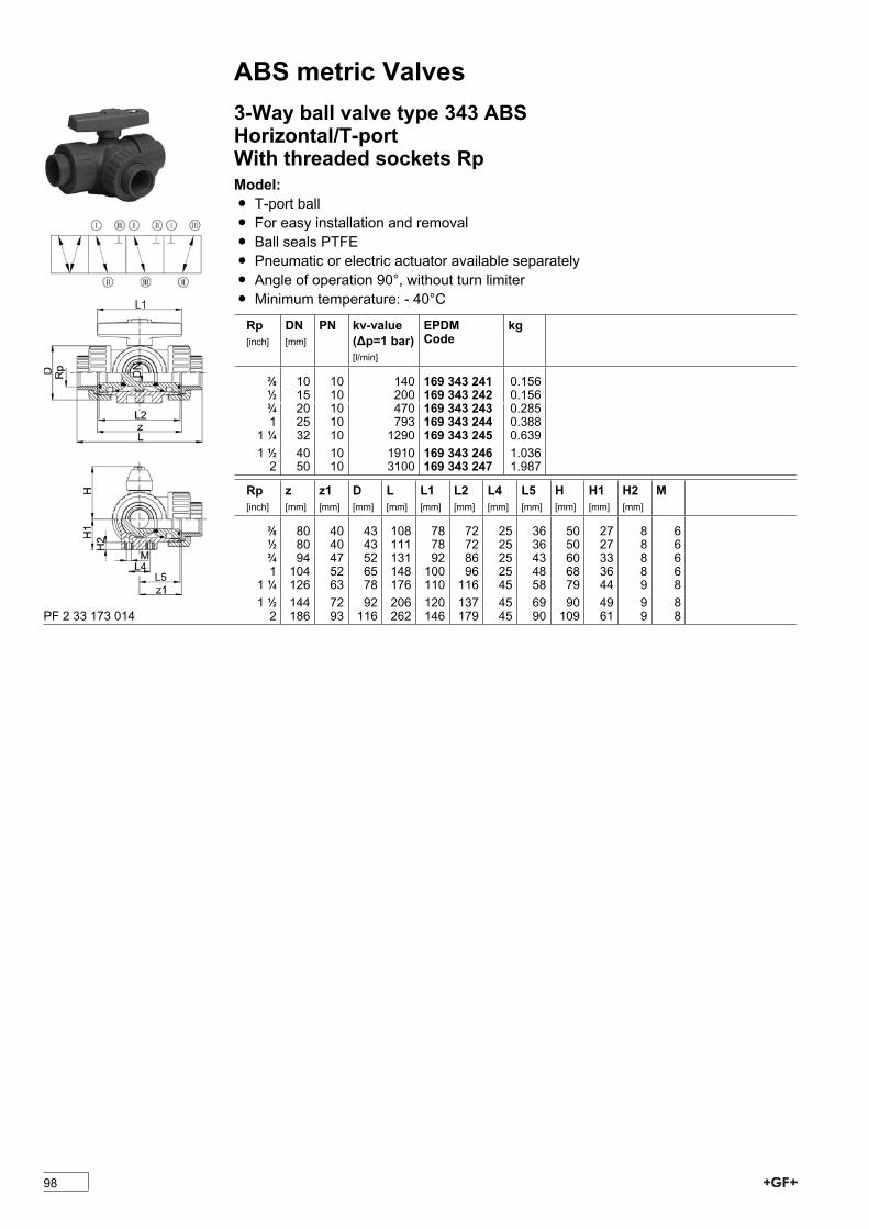
ABS metric Valves3-Way ball valve type 343 ABSHorizontal/T-portWith threaded sockets RpModel:Ï T-port ballÏ For easy installation and removalÏ Ball seals PTFEÏ Pneumatic or electric actuator available separatelyÏ Angle of operation 90°, without turn limiterÏ Minimum temperature: - 40°C
Rp[inch]
DN[mm]
PN kv-value(�p=1 bar)[l/min]
EPDMCode
kg
3/8 10 10 140 169 343 241 0.1561/2 15 10 200 169 343 242 0.1563/4 20 10 470 169 343 243 0.2851 25 10 793 169 343 244 0.3881 1/4 32 10 1290 169 343 245 0.6391 1/2 40 10 1910 169 343 246 1.0362 50 10 3100 169 343 247 1.987
Rp[inch]
z[mm]
z1[mm]
D[mm]
L[mm]
L1[mm]
L2[mm]
L4[mm]
L5[mm]
H[mm]
H1[mm]
H2[mm]
M
3/8 80 40 43 108 78 72 25 36 50 27 8 61/2 80 40 43 111 78 72 25 36 50 27 8 63/4 94 47 52 131 92 86 25 43 60 33 8 61 104 52 65 148 100 96 25 48 68 36 8 61 1/4 126 63 78 176 110 116 45 58 79 44 9 81 1/2 144 72 92 206 120 137 45 69 90 49 9 82 186 93 116 262 146 179 45 90 109 61 9 8PF 2 33 173 014
98
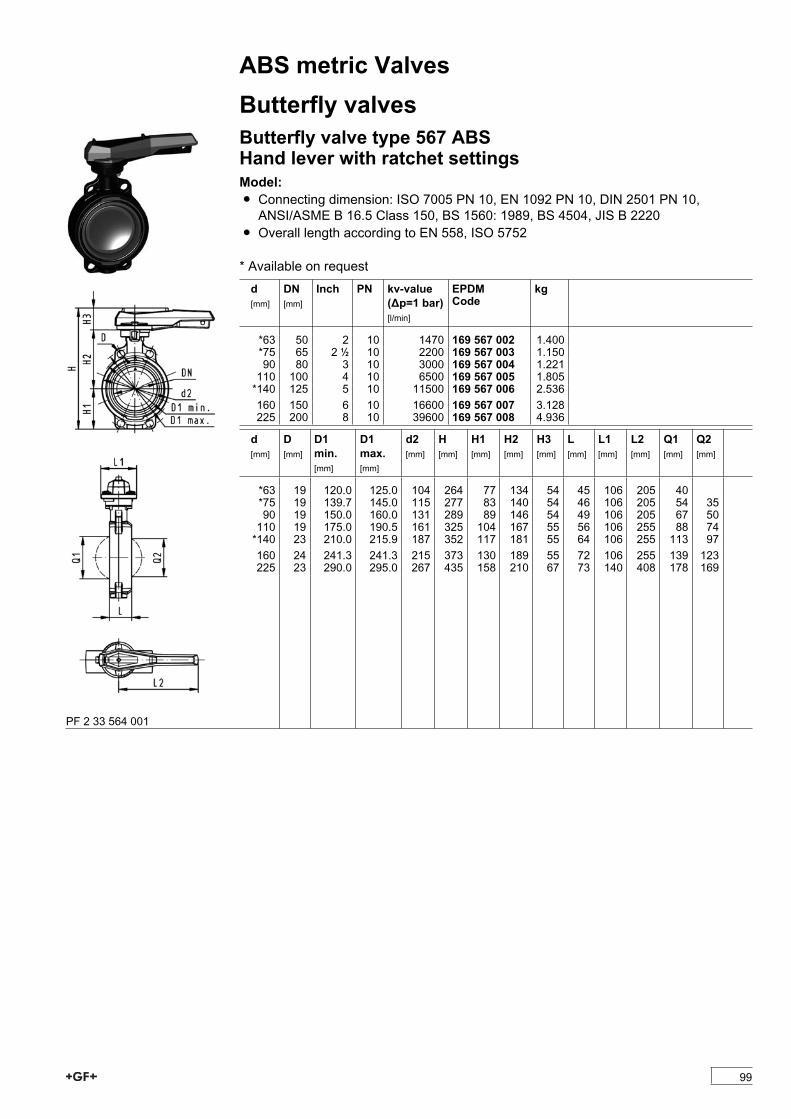
ABS metric ValvesButterfly valvesButterfly valve type 567 ABSHand lever with ratchet settingsModel:Ï Connecting dimension: ISO 7005 PN 10, EN 1092 PN 10, DIN 2501 PN 10,ANSI/ASME B 16.5 Class 150, BS 1560: 1989, BS 4504, JIS B 2220
Ï Overall length according to EN 558, ISO 5752
* Available on requestd[mm]
DN[mm]
Inch PN kv-value(�p=1 bar)[l/min]
EPDMCode
kg
*63 50 2 10 1470 169 567 002 1.400*75 65 2 1/2 10 2200 169 567 003 1.15090 80 3 10 3000 169 567 004 1.221110 100 4 10 6500 169 567 005 1.805*140 125 5 10 11500 169 567 006 2.536160 150 6 10 16600 169 567 007 3.128225 200 8 10 39600 169 567 008 4.936
d[mm]
D[mm]
D1min.[mm]
D1max.[mm]
d2[mm]
H[mm]
H1[mm]
H2[mm]
H3[mm]
L[mm]
L1[mm]
L2[mm]
Q1[mm]
Q2[mm]
*63 19 120.0 125.0 104 264 77 134 54 45 106 205 40*75 19 139.7 145.0 115 277 83 140 54 46 106 205 54 3590 19 150.0 160.0 131 289 89 146 54 49 106 205 67 50110 19 175.0 190.5 161 325 104 167 55 56 106 255 88 74*140 23 210.0 215.9 187 352 117 181 55 64 106 255 113 97160 24 241.3 241.3 215 373 130 189 55 72 106 255 139 123225 23 290.0 295.0 267 435 158 210 67 73 140 408 178 169
PF 2 33 564 001
99
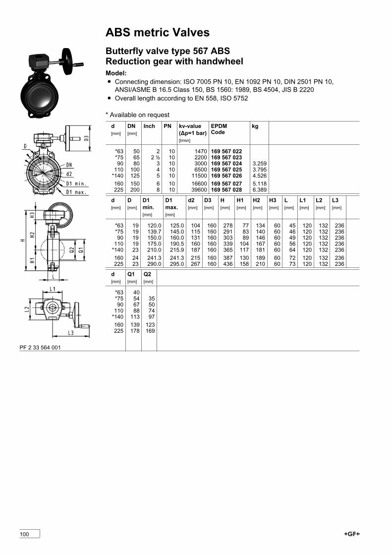
ABS metric ValvesButterfly valve type 567 ABSReduction gear with handwheelModel:Ï Connecting dimension: ISO 7005 PN 10, EN 1092 PN 10, DIN 2501 PN 10,ANSI/ASME B 16.5 Class 150, BS 1560: 1989, BS 4504, JIS B 2220
Ï Overall length according to EN 558, ISO 5752
* Available on requestd[mm]
DN[mm]
Inch PN kv-value(�p=1 bar)[l/min]
EPDMCode
kg
*63 50 2 10 1470 169 567 022*75 65 2 1/2 10 2200 169 567 02390 80 3 10 3000 169 567 024 3.259110 100 4 10 6500 169 567 025 3.795*140 125 5 10 11500 169 567 026 4.526160 150 6 10 16600 169 567 027 5.118225 200 8 10 39600 169 567 028 6.389
d[mm]
D[mm]
D1min.[mm]
D1max.[mm]
d2[mm]
D3[mm]
H[mm]
H1[mm]
H2[mm]
H3[mm]
L[mm]
L1[mm]
L2[mm]
L3[mm]
*63 19 120.0 125.0 104 160 278 77 134 60 45 120 132 236*75 19 139.7 145.0 115 160 291 83 140 60 46 120 132 23690 19 150.0 160.0 131 160 303 89 146 60 49 120 132 236110 19 175.0 190.5 160 160 339 104 167 60 56 120 132 236*140 23 210.0 215.9 187 160 365 117 181 60 64 120 132 236160 24 241.3 241.3 215 160 387 130 189 60 72 120 132 236225 23 290.0 295.0 267 160 436 158 210 60 73 120 132 236
d[mm]
Q1[mm]
Q2[mm]
*63 40*75 54 3590 67 50110 88 74*140 113 97160 139 123225 178 169
PF 2 33 564 001
100
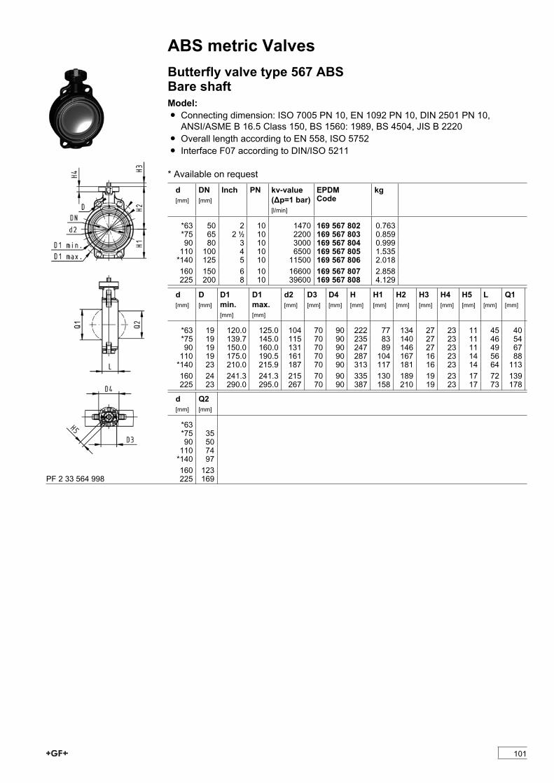
ABS metric ValvesButterfly valve type 567 ABSBare shaftModel:Ï Connecting dimension: ISO 7005 PN 10, EN 1092 PN 10, DIN 2501 PN 10,ANSI/ASME B 16.5 Class 150, BS 1560: 1989, BS 4504, JIS B 2220
Ï Overall length according to EN 558, ISO 5752Ï Interface F07 according to DIN/ISO 5211
* Available on requestd[mm]
DN[mm]
Inch PN kv-value(�p=1 bar)[l/min]
EPDMCode
kg
*63 50 2 10 1470 169 567 802 0.763*75 65 2 1/2 10 2200 169 567 803 0.85990 80 3 10 3000 169 567 804 0.999110 100 4 10 6500 169 567 805 1.535*140 125 5 10 11500 169 567 806 2.018160 150 6 10 16600 169 567 807 2.858225 200 8 10 39600 169 567 808 4.129
d[mm]
D[mm]
D1min.[mm]
D1max.[mm]
d2[mm]
D3[mm]
D4[mm]
H[mm]
H1[mm]
H2[mm]
H3[mm]
H4[mm]
H5[mm]
L[mm]
Q1[mm]
*63 19 120.0 125.0 104 70 90 222 77 134 27 23 11 45 40*75 19 139.7 145.0 115 70 90 235 83 140 27 23 11 46 5490 19 150.0 160.0 131 70 90 247 89 146 27 23 11 49 67110 19 175.0 190.5 161 70 90 287 104 167 16 23 14 56 88*140 23 210.0 215.9 187 70 90 313 117 181 16 23 14 64 113160 24 241.3 241.3 215 70 90 335 130 189 19 23 17 72 139225 23 290.0 295.0 267 70 90 387 158 210 19 23 17 73 178
d[mm]
Q2[mm]
*63*75 3590 50110 74*140 97160 123225 169PF 2 33 564 998
101

ABS metric ValvesLugstyle butterfly valve type 568 ABSBare shaftModel:Ï Outer body in GGG-40.3 epoxy-coatedÏ Connecting dimension: ISO 7005 PN10, EN 1092 PN10, DIN 2501 PN10Ï Overall length according to EN 558, ISO 5752Ï Interface F07 according to DIN/ISO 5211
* Available on requestd[mm]
DN[mm]
Inch PN kv-value(�p=1 bar)[l/min]
EPDMCode
kg
*63 50 2 10 1470 169 568 802 2.853*75 65 2 1/2 10 2200 169 568 803 3.20090 80 3 10 3000 169 568 804 4.217110 100 4 10 6500 169 568 805 5.633*140 125 5 10 11500 169 568 806 7.502160 150 6 10 16600 169 568 807 9.341225 200 8 10 39600 169 568 808 14.105
d[mm]
d2[mm]
D D1[mm]
D3[mm]
D4[mm]
H[mm]
H1[mm]
H2[mm]
H3[mm]
H4[mm]
L[mm]
Q1[mm]
Q2[mm]
*63 150 M16 125 70 90 222 77 134 27 23 45 40*75 170 M16 145 70 90 235 83 140 27 23 46 54 3590 184 M16 160 70 90 247 89 146 27 23 49 67 50110 216 M16 180 70 90 287 104 167 16 23 56 88 74*140 246 M16 210 70 90 313 117 181 16 23 64 113 97160 273 M20 240 70 90 335 130 189 19 23 72 139 123225 334 M20 295 70 90 387 158 210 19 23 73 178 169
PF 2 33 565 998
102
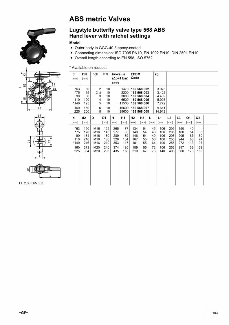
ABS metric ValvesLugstyle butterfly valve type 568 ABSHand lever with ratchet settingsModel:Ï Outer body in GGG-40.3 epoxy-coatedÏ Connecting dimension: ISO 7005 PN10, EN 1092 PN10, DIN 2501 PN10Ï Overall length according to EN 558, ISO 5752
* Available on requestd[mm]
DN[mm]
Inch PN kv-value(�p=1 bar)[l/min]
EPDMCode
kg
*63 50 2 10 1470 169 568 002 3.075*75 65 2 1/2 10 2200 169 568 003 3.42290 80 3 10 3000 169 568 004 4.439110 100 4 10 6500 169 568 005 5.903*140 125 5 10 11500 169 568 006 7.772160 150 6 10 16600 169 568 007 9.611225 200 8 10 39600 169 568 008 14.912
d[mm]
d2[mm]
D D1[mm]
H[mm]
H1[mm]
H2[mm]
H3[mm]
L[mm]
L1[mm]
L2[mm]
L3[mm]
Q1[mm]
Q2[mm]
*63 150 M16 125 265 77 134 54 45 106 205 150 40*75 170 M16 145 277 83 140 54 46 106 205 160 54 3590 184 M16 160 289 89 146 54 49 106 205 205 67 50110 216 M16 180 326 104 167 55 56 106 255 244 88 74*140 246 M16 210 353 117 181 55 64 106 255 272 113 97160 273 M20 240 374 130 189 55 72 106 255 297 139 123225 334 M20 295 435 158 210 67 73 140 408 360 178 169
PF 2 33 565 003
103
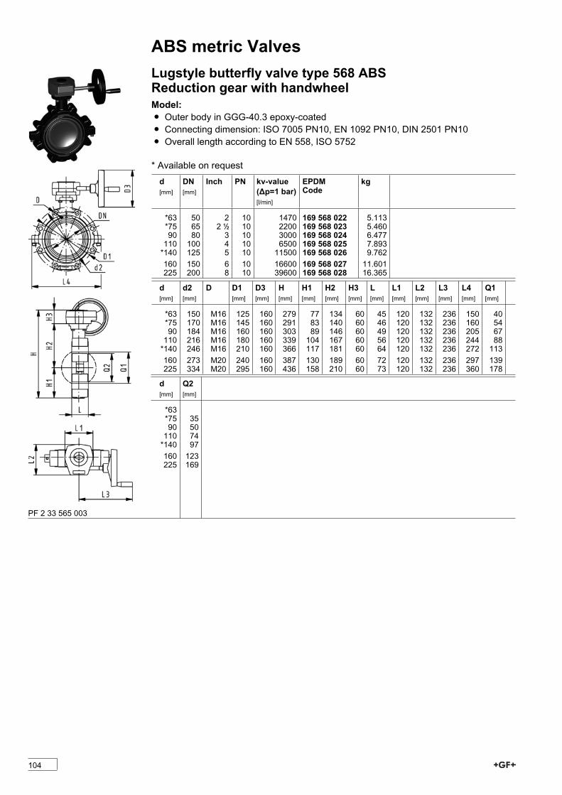
ABS metric ValvesLugstyle butterfly valve type 568 ABSReduction gear with handwheelModel:Ï Outer body in GGG-40.3 epoxy-coatedÏ Connecting dimension: ISO 7005 PN10, EN 1092 PN10, DIN 2501 PN10Ï Overall length according to EN 558, ISO 5752
* Available on requestd[mm]
DN[mm]
Inch PN kv-value(�p=1 bar)[l/min]
EPDMCode
kg
*63 50 2 10 1470 169 568 022 5.113*75 65 2 1/2 10 2200 169 568 023 5.46090 80 3 10 3000 169 568 024 6.477110 100 4 10 6500 169 568 025 7.893*140 125 5 10 11500 169 568 026 9.762160 150 6 10 16600 169 568 027 11.601225 200 8 10 39600 169 568 028 16.365
d[mm]
d2[mm]
D D1[mm]
D3[mm]
H[mm]
H1[mm]
H2[mm]
H3[mm]
L[mm]
L1[mm]
L2[mm]
L3[mm]
L4[mm]
Q1[mm]
*63 150 M16 125 160 279 77 134 60 45 120 132 236 150 40*75 170 M16 145 160 291 83 140 60 46 120 132 236 160 5490 184 M16 160 160 303 89 146 60 49 120 132 236 205 67110 216 M16 180 160 339 104 167 60 56 120 132 236 244 88*140 246 M16 210 160 366 117 181 60 64 120 132 236 272 113160 273 M20 240 160 387 130 189 60 72 120 132 236 297 139225 334 M20 295 160 436 158 210 60 73 120 132 236 360 178
d[mm]
Q2[mm]
*63*75 3590 50110 74*140 97160 123225 169
PF 2 33 565 003
104

ABS metric ValvesDiaphragm valvesDiaphragm valve type 315 ABSWith solvent cement spigots metricModel:Ï Overall length EN 558Ï Other dimensions available on requestÏ Minimum temperature: - 30°COption:Ï Handwheel with built-in locking mechanism (standard version is nonlockable)
d[mm]
DN[mm]
PN kv-value(�p=1 bar)[l/min]
EPDMCode
PTFE withEPDMCode
kg
20 15 10 72 169 315 417 169 315 432 0.29025 20 10 137 169 315 418 169 315 433 0.44032 25 10 207 169 315 419 169 315 434 0.71040 32 10 354 169 315 420 169 315 435 1.00050 40 10 517 169 315 421 169 315 436 1.30063 50 10 713 169 315 422 169 315 437 2.300
d[mm]
D2[mm]
L[mm]
L2[mm]
L3[mm]
H[mm]
H1[mm]
H2[mm]
M Lift =Hx[mm]
closestinch
20 80 124 25 130 90 14 12 M6 8 1/225 80 144 25 150 102 18 12 M6 11 3/432 94 154 25 160 119 21 12 M6 13 140 117 174 45 180 126 26 15 M8 16 1 1/450 117 194 45 200 139 33 15 M8 21 1 1/263 152 224 45 230 172 39 15 M8 28 2PF 2 33 174 010
Diaphragm valve type 314 ABSWith solvent cement socket metricModel:Ï Type 315 with two adhesive jointed unionsÏ Overall length not standardÏ For easy installation and removalÏ Minimum temperature: - 30°COption:Ï Handwheel with built-in locking mechanism (standard version is nonlockable)
d[mm]
DN[mm]
PN kv-value(�p=1 bar)[l/min]
EPDMCode
kg D2[mm]
L[mm]
Lift =Hx[mm]
closestinch
20 15 10 72 169 314 017 0.360 80 182 8 1/225 20 10 137 169 314 018 0.540 80 208 11 3/432 25 10 207 169 314 019 0.850 94 224 13 140 32 10 354 169 314 020 1.260 117 256 16 1 1/450 40 10 517 169 314 021 1.640 117 290 21 1 1/263 50 10 713 169 314 022 2.980 152 342 28 2PF 2 33 174 010
105
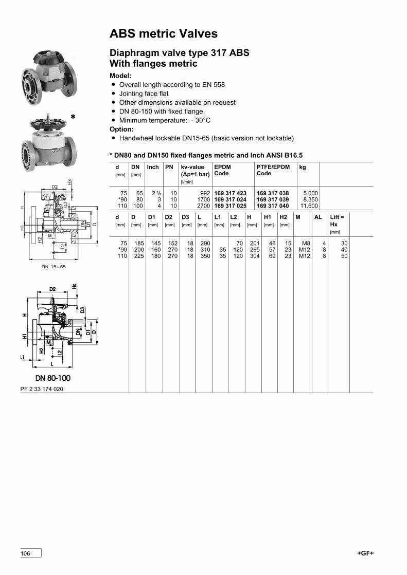
ABS metric ValvesDiaphragm valve type 317 ABSWith flanges metricModel:Ï Overall length according to EN 558Ï Jointing face flatÏ Other dimensions available on requestÏ DN 80-150 with fixed flangeÏ Minimum temperature: - 30°COption:Ï Handwheel lockable DN15-65 (basic version not lockable)
* DN80 and DN150 fixed flanges metric and Inch ANSI B16.5 d[mm]
DN[mm]
Inch PN kv-value(�p=1 bar)[l/min]
EPDMCode
PTFE/EPDMCode
kg
75 65 2 1/2 10 992 169 317 423 169 317 038 5.000*90 80 3 10 1700 169 317 024 169 317 039 8.350110 100 4 10 2700 169 317 025 169 317 040 11.600
d[mm]
D[mm]
D1[mm]
D2[mm]
D3[mm]
L[mm]
L1[mm]
L2[mm]
H[mm]
H1[mm]
H2[mm]
M AL Lift =Hx[mm]
75 185 145 152 18 290 70 201 46 15 M8 4 30*90 200 160 270 18 310 35 120 265 57 23 M12 8 40110 225 180 270 18 350 35 120 304 69 23 M12 8 50
PF 2 33 174 020
106
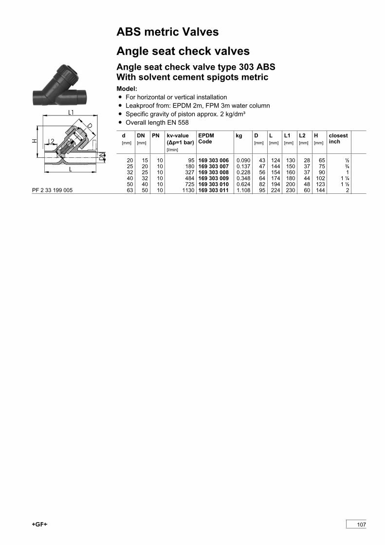
ABS metric ValvesAngle seat check valvesAngle seat check valve type 303 ABSWith solvent cement spigots metricModel:Ï For horizontal or vertical installationÏ Leakproof from: EPDM 2m, FPM 3m water columnÏ Specific gravity of piston approx. 2 kg/dm³Ï Overall length EN 558
d[mm]
DN[mm]
PN kv-value(�p=1 bar)[l/min]
EPDMCode
kg D[mm]
L[mm]
L1[mm]
L2[mm]
H[mm]
closestinch
20 15 10 95 169 303 006 0.090 43 124 130 28 65 1/225 20 10 180 169 303 007 0.137 47 144 150 37 75 3/432 25 10 327 169 303 008 0.228 56 154 160 37 90 140 32 10 484 169 303 009 0.348 64 174 180 44 102 1 1/450 40 10 725 169 303 010 0.624 82 194 200 48 123 1 1/263 50 10 1130 169 303 011 1.108 95 224 230 60 144 2PF 2 33 199 005
107
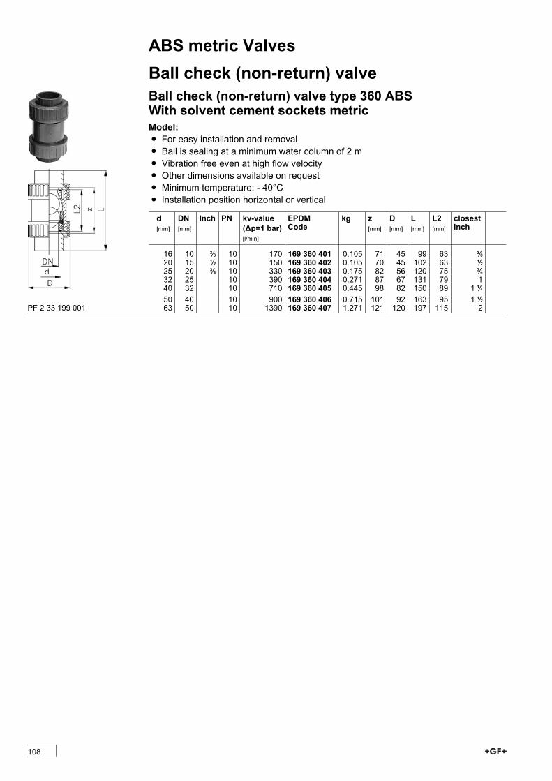
ABS metric ValvesBall check (non-return) valveBall check (non-return) valve type 360 ABSWith solvent cement sockets metricModel:Ï For easy installation and removalÏ Ball is sealing at a minimum water column of 2 mÏ Vibration free even at high flow velocityÏ Other dimensions available on requestÏ Minimum temperature: - 40°CÏ Installation position horizontal or vertical
d[mm]
DN[mm]
Inch PN kv-value(�p=1 bar)[l/min]
EPDMCode
kg z[mm]
D[mm]
L[mm]
L2[mm]
closestinch
16 10 3/8 10 170 169 360 401 0.105 71 45 99 63 3/820 15 1/2 10 150 169 360 402 0.105 70 45 102 63 1/225 20 3/4 10 330 169 360 403 0.175 82 56 120 75 3/432 25 10 390 169 360 404 0.271 87 67 131 79 140 32 10 710 169 360 405 0.445 98 82 150 89 1 1/450 40 10 900 169 360 406 0.715 101 92 163 95 1 1/263 50 10 1390 169 360 407 1.271 121 120 197 115 2PF 2 33 199 001
108
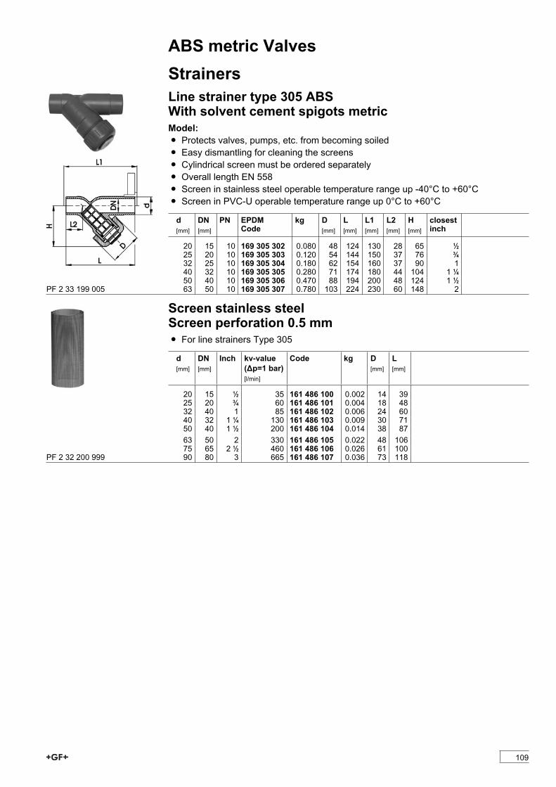
ABS metric ValvesStrainersLine strainer type 305 ABSWith solvent cement spigots metricModel:Ï Protects valves, pumps, etc. from becoming soiledÏ Easy dismantling for cleaning the screensÏ Cylindrical screen must be ordered separatelyÏ Overall length EN 558Ï Screen in stainless steel operable temperature range up -40°C to +60°C Ï Screen in PVC-U operable temperature range up 0°C to +60°C
d[mm]
DN[mm]
PN EPDMCode
kg D[mm]
L[mm]
L1[mm]
L2[mm]
H[mm]
closestinch
20 15 10 169 305 302 0.080 48 124 130 28 65 1/225 20 10 169 305 303 0.120 54 144 150 37 76 3/432 25 10 169 305 304 0.180 62 154 160 37 90 140 32 10 169 305 305 0.280 71 174 180 44 104 1 1/450 40 10 169 305 306 0.470 88 194 200 48 124 1 1/263 50 10 169 305 307 0.780 103 224 230 60 148 2PF 2 33 199 005
Screen stainless steelScreen perforation 0.5 mmÏ For line strainers Type 305
d[mm]
DN[mm]
Inch kv-value(�p=1 bar)[l/min]
Code kg D[mm]
L[mm]
20 15 1/2 35 161 486 100 0.002 14 3925 20 3/4 60 161 486 101 0.004 18 4832 40 1 85 161 486 102 0.006 24 6040 32 1 1/4 130 161 486 103 0.009 30 7150 40 1 1/2 200 161 486 104 0.014 38 8763 50 2 330 161 486 105 0.022 48 10675 65 2 1/2 460 161 486 106 0.026 61 10090 80 3 665 161 486 107 0.036 73 118PF 2 32 200 999
109

ABS metric ValvesBall valves electricBall valve type 107 ABS 100-230VWith manual emergency overrideWith solvent cement sockets metricModel:Ï Built on with electric actuator EA11Ï Voltage 100-230 V, 50-60 HzÏ Control range 90°<)Ï Control time 5 s/90°<)Ï For easy installation and removalÏ Integrated stainless steel mounting insertsOption:Ï Individual configuration of the valve (see form)
d[mm]
DN[mm]
PN kv-value(�p=1 bar)[l/min]
EPDMCode
kg
16 10 10 70 199 107 082 2.07220 15 10 185 199 107 083 2.07225 20 10 350 199 107 084 2.18932 25 10 700 199 107 085 2.18940 32 10 1000 199 107 086 2.59250 40 10 1600 199 107 087 2.91463 50 10 3100 199 107 088 3.772
d[mm]
D[mm]
H[mm]
H1[mm]
H2[mm]
H3[mm]
H5[mm]
L[mm]
L1[mm]
L2[mm]
L4[mm]
L5[mm]
L6[mm]
L7[mm]
L8[mm]
z[mm]
16 50 200 27 64 64 137 92 161 56 25 77 83 122 33 6420 50 200 27 64 64 137 95 161 56 25 77 83 122 33 6425 58 209 30 73 64 137 110 161 65 25 77 83 122 33 7232 68 209 36 73 64 137 123 161 71 25 77 83 122 33 7940 84 220 44 84 64 137 146 161 85 45 77 83 122 33 9450 97 220 51 84 64 137 157 161 89 45 77 83 122 33 9563 124 243 64 106 64 137 183 161 101 45 77 83 122 33 107
d[mm]
closestinch
16 3/820 1/225 3/432 140 1 1/450 1 1/263 2
PF 3 39 695 033
110
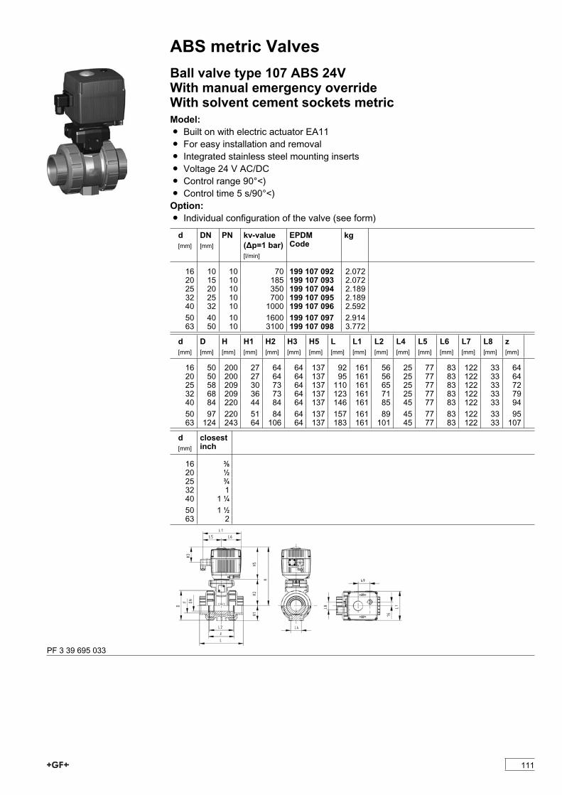
ABS metric ValvesBall valve type 107 ABS 24VWith manual emergency overrideWith solvent cement sockets metricModel:Ï Built on with electric actuator EA11Ï For easy installation and removalÏ Integrated stainless steel mounting insertsÏ Voltage 24 V AC/DCÏ Control range 90°<)Ï Control time 5 s/90°<)Option:Ï Individual configuration of the valve (see form)
d[mm]
DN[mm]
PN kv-value(�p=1 bar)[l/min]
EPDMCode
kg
16 10 10 70 199 107 092 2.07220 15 10 185 199 107 093 2.07225 20 10 350 199 107 094 2.18932 25 10 700 199 107 095 2.18940 32 10 1000 199 107 096 2.59250 40 10 1600 199 107 097 2.91463 50 10 3100 199 107 098 3.772
d[mm]
D[mm]
H[mm]
H1[mm]
H2[mm]
H3[mm]
H5[mm]
L[mm]
L1[mm]
L2[mm]
L4[mm]
L5[mm]
L6[mm]
L7[mm]
L8[mm]
z[mm]
16 50 200 27 64 64 137 92 161 56 25 77 83 122 33 6420 50 200 27 64 64 137 95 161 56 25 77 83 122 33 6425 58 209 30 73 64 137 110 161 65 25 77 83 122 33 7232 68 209 36 73 64 137 123 161 71 25 77 83 122 33 7940 84 220 44 84 64 137 146 161 85 45 77 83 122 33 9450 97 220 51 84 64 137 157 161 89 45 77 83 122 33 9563 124 243 64 106 64 137 183 161 101 45 77 83 122 33 107
d[mm]
closestinch
16 3/820 1/225 3/432 140 1 1/450 1 1/263 2
PF 3 39 695 033
111
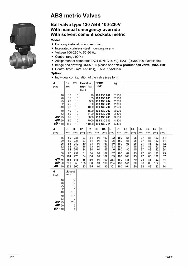
ABS metric ValvesBall valve type 130 ABS 100-230VWith manual emergency overrideWith solvent cement sockets metricModel:Ï For easy installation and removalÏ Integrated stainless steel mounting insertsÏ Voltage 100-230 V, 50-60 HzÏ Control range 90°<)Ï Assignment of actuators: EA21 (DN10/15-50), EA31 (DN65-100 if available)Ï Image and drawing DN65-100 please see ''New product ball valve DN65-100''Ï Control time: EA21: 5s/90°<), EA31: 15s/90°<)Option:Ï Individual configuration of the valve (see form)
d[mm]
DN[mm]
PN kv-value(�p=1 bar)[l/min]
EPDMCode
kg
16 10 10 70 199 130 702 2.10020 15 10 185 199 130 703 2.10025 20 10 350 199 130 704 2.20032 25 10 700 199 130 705 2.30040 32 10 1000 199 130 706 2.60050 40 10 1600 199 130 707 3.00063 50 10 3100 199 130 708 3.80075 65 10 5000 199 130 709 3.50090 80 10 7000 199 130 710 4.300110 100 10 11000 199 130 711 5.400
d[mm]
D[mm]
H[mm]
H1[mm]
H2[mm]
H3[mm]
H5[mm]
L[mm]
L1[mm]
L2[mm]
L4[mm]
L5[mm]
L6[mm]
L7[mm]
z[mm]
16 50 231 27 64 94 167 92 180 56 25 97 83 122 6420 50 231 27 64 94 167 95 180 56 25 97 83 122 6425 58 240 30 73 94 167 110 180 65 25 97 83 122 7232 68 240 36 73 94 167 123 180 71 25 97 83 122 7940 84 251 44 84 94 167 146 180 85 45 97 83 122 9450 97 251 51 84 94 167 157 180 89 45 97 83 122 9563 124 273 64 106 94 167 183 180 101 45 97 83 122 10775 166 346 85 156 94 190 233 180 136 70 98 83 122 14490 200 358 105 168 94 190 254 180 141 70 98 83 122 151110 238 365 123 175 94 190 301 180 164 120 98 83 122 174
d[mm]
closestinch
16 3/820 1/225 3/432 140 1 1/450 1 1/263 275 2 1/290 3110 4
112
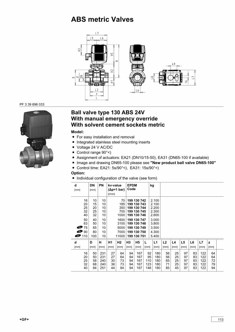
ABS metric Valves
PF 3 39 696 033
Ball valve type 130 ABS 24VWith manual emergency overrideWith solvent cement sockets metricModel:Ï For easy installation and removalÏ Integrated stainless steel mounting insertsÏ Voltage 24 V AC/DCÏ Control range 90°<)Ï Assignment of actuators: EA21 (DN10/15-50), EA31 (DN65-100 if available)Ï Image and drawing DN65-100 please see ''New product ball valve DN65-100''Ï Control time: EA21: 5s/90°<), EA31: 15s/90°<)Option:Ï Individual configuration of the valve (see form)
d[mm]
DN[mm]
PN kv-value(�p=1 bar)[l/min]
EPDMCode
kg
16 10 10 70 199 130 742 2.10020 15 10 185 199 130 743 2.10025 20 10 350 199 130 744 2.20032 25 10 700 199 130 745 2.30040 32 10 1000 199 130 746 2.60050 40 10 1600 199 130 747 3.00063 50 10 3100 199 130 748 3.80075 65 10 5000 199 130 749 3.50090 80 10 7000 199 130 750 4.300110 100 10 11000 199 130 751 5.400
d[mm]
D[mm]
H[mm]
H1[mm]
H2[mm]
H3[mm]
H5[mm]
L[mm]
L1[mm]
L2[mm]
L4[mm]
L5[mm]
L6[mm]
L7[mm]
z[mm]
16 50 231 27 64 94 167 92 180 56 25 97 83 122 6420 50 231 27 64 94 167 95 180 56 25 97 83 122 6425 58 240 30 73 94 167 110 180 65 25 97 83 122 7232 68 240 36 73 94 167 123 180 71 25 97 83 122 7940 84 251 44 84 94 167 146 180 85 45 97 83 122 94
113
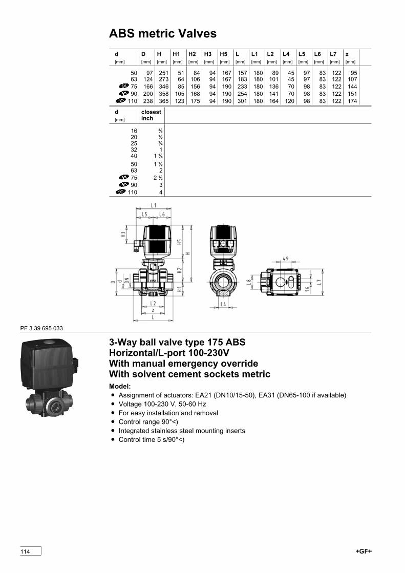
ABS metric Valvesd[mm]
D[mm]
H[mm]
H1[mm]
H2[mm]
H3[mm]
H5[mm]
L[mm]
L1[mm]
L2[mm]
L4[mm]
L5[mm]
L6[mm]
L7[mm]
z[mm]
50 97 251 51 84 94 167 157 180 89 45 97 83 122 9563 124 273 64 106 94 167 183 180 101 45 97 83 122 10775 166 346 85 156 94 190 233 180 136 70 98 83 122 14490 200 358 105 168 94 190 254 180 141 70 98 83 122 151110 238 365 123 175 94 190 301 180 164 120 98 83 122 174
d[mm]
closestinch
16 3/820 1/225 3/432 140 1 1/450 1 1/263 275 2 1/290 3110 4
PF 3 39 695 033
3-Way ball valve type 175 ABSHorizontal/L-port 100-230VWith manual emergency overrideWith solvent cement sockets metricModel:Ï Assignment of actuators: EA21 (DN10/15-50), EA31 (DN65-100 if available)Ï Voltage 100-230 V, 50-60 HzÏ For easy installation and removalÏ Control range 90°<)Ï Integrated stainless steel mounting insertsÏ Control time 5 s/90°<)
114

ABS metric Valvesd[mm]
DN[mm]
PN kv-value(�p=1 bar)[l/min]
EPDMCode
kg
16 10 10 50 199 175 162 2.07320 15 10 75 199 175 163 2.12125 20 10 150 199 175 164 2.30332 25 10 280 199 175 165 2.35240 32 10 480 199 175 166 2.61450 40 10 620 199 175 167 3.35963 50 10 1230 199 175 168 4.728
d[mm]
D[mm]
H[mm]
H1[mm]
H2[mm]
H3[mm]
H5[mm]
H6[mm]
L[mm]
L1[mm]
L2[mm]
L3[mm]
L4[mm]
L5[mm]
L6[mm]
L7[mm]
16 45 197 29 31 93 166 8 108 182 72 36 25 99 83 12220 45 197 29 31 93 166 8 111 182 72 36 25 99 83 12225 52 205 33 39 93 166 8 131 182 86 43 25 99 83 12232 65 210 38 44 93 166 8 148 182 96 48 25 99 83 12240 78 216 44 50 93 166 9 176 182 116 58 45 99 83 12250 92 229 50 63 93 166 9 206 182 137 69 45 99 83 12263 116 242 61 76 93 166 9 262 182 179 90 45 99 83 122
d[mm]
L8[mm]
M z[mm]
z1[mm]
closestinch
16 33 6 80 40 3/820 33 6 80 40 1/225 33 6 94 47 3/432 33 6 104 52 140 33 8 126 63 1 1/450 33 8 144 72 1 1/263 33 8 186 93 2
PF 3 39 749 200
115
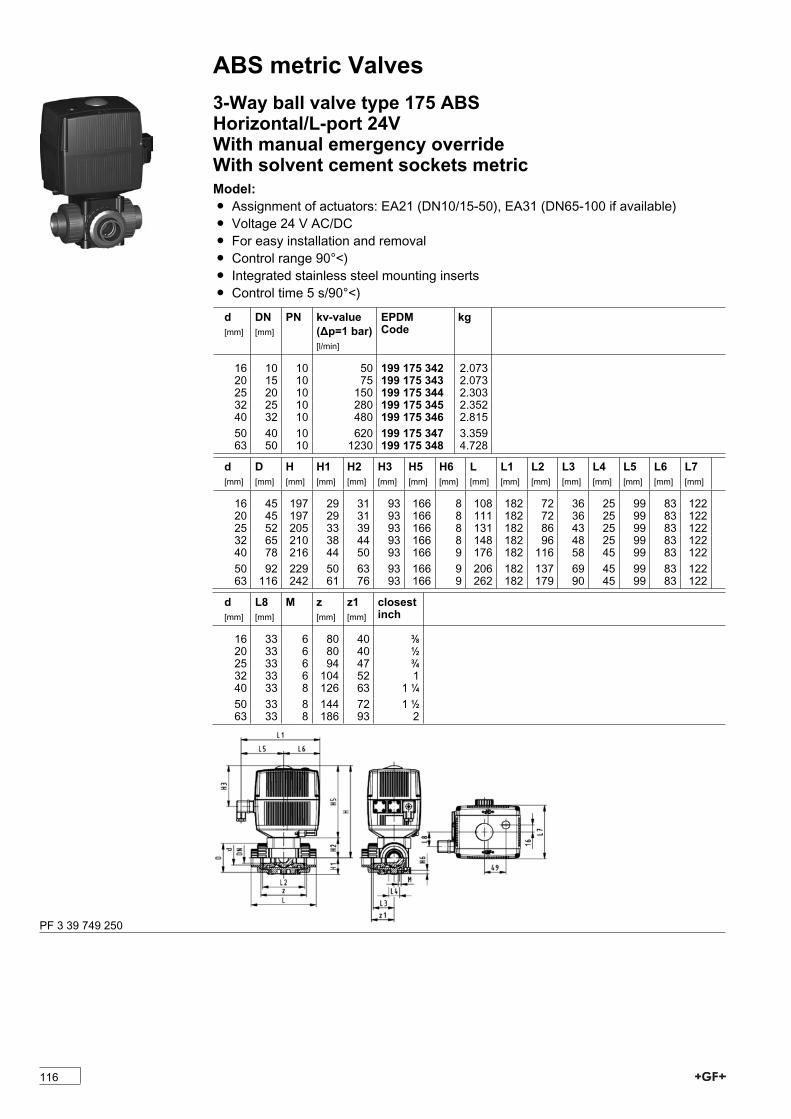
ABS metric Valves3-Way ball valve type 175 ABSHorizontal/L-port 24VWith manual emergency overrideWith solvent cement sockets metricModel:Ï Assignment of actuators: EA21 (DN10/15-50), EA31 (DN65-100 if available)Ï Voltage 24 V AC/DCÏ For easy installation and removalÏ Control range 90°<)Ï Integrated stainless steel mounting insertsÏ Control time 5 s/90°<)
d[mm]
DN[mm]
PN kv-value(�p=1 bar)[l/min]
EPDMCode
kg
16 10 10 50 199 175 342 2.07320 15 10 75 199 175 343 2.07325 20 10 150 199 175 344 2.30332 25 10 280 199 175 345 2.35240 32 10 480 199 175 346 2.81550 40 10 620 199 175 347 3.35963 50 10 1230 199 175 348 4.728
d[mm]
D[mm]
H[mm]
H1[mm]
H2[mm]
H3[mm]
H5[mm]
H6[mm]
L[mm]
L1[mm]
L2[mm]
L3[mm]
L4[mm]
L5[mm]
L6[mm]
L7[mm]
16 45 197 29 31 93 166 8 108 182 72 36 25 99 83 12220 45 197 29 31 93 166 8 111 182 72 36 25 99 83 12225 52 205 33 39 93 166 8 131 182 86 43 25 99 83 12232 65 210 38 44 93 166 8 148 182 96 48 25 99 83 12240 78 216 44 50 93 166 9 176 182 116 58 45 99 83 12250 92 229 50 63 93 166 9 206 182 137 69 45 99 83 12263 116 242 61 76 93 166 9 262 182 179 90 45 99 83 122
d[mm]
L8[mm]
M z[mm]
z1[mm]
closestinch
16 33 6 80 40 3/820 33 6 80 40 1/225 33 6 94 47 3/432 33 6 104 52 140 33 8 126 63 1 1/450 33 8 144 72 1 1/263 33 8 186 93 2
PF 3 39 749 250
116
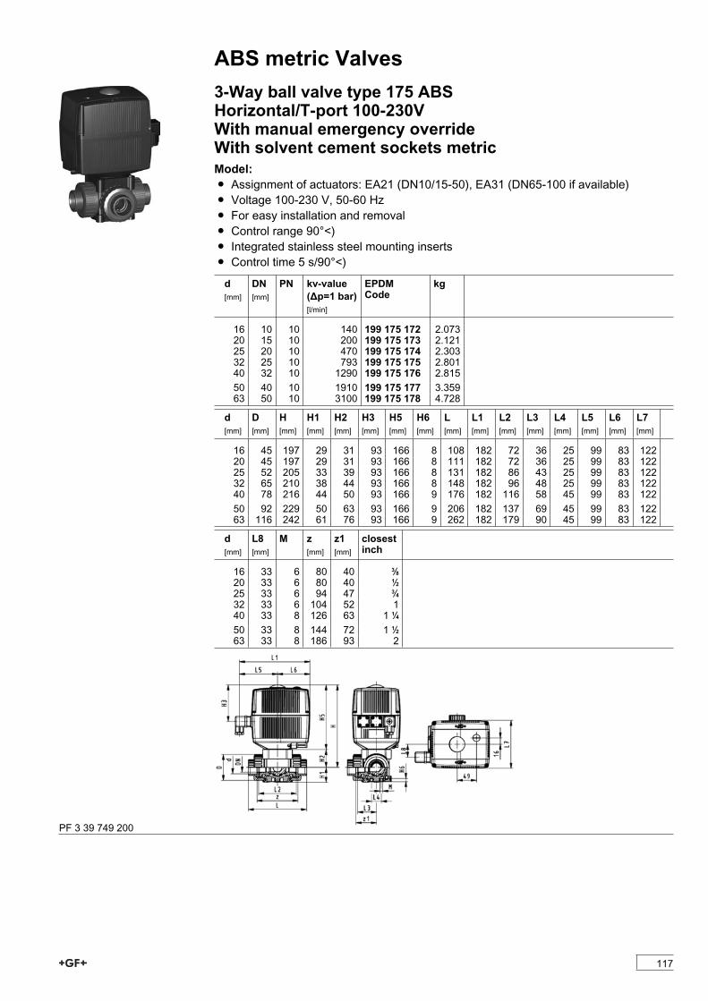
ABS metric Valves3-Way ball valve type 175 ABSHorizontal/T-port 100-230VWith manual emergency overrideWith solvent cement sockets metricModel:Ï Assignment of actuators: EA21 (DN10/15-50), EA31 (DN65-100 if available)Ï Voltage 100-230 V, 50-60 HzÏ For easy installation and removalÏ Control range 90°<)Ï Integrated stainless steel mounting insertsÏ Control time 5 s/90°<)
d[mm]
DN[mm]
PN kv-value(�p=1 bar)[l/min]
EPDMCode
kg
16 10 10 140 199 175 172 2.07320 15 10 200 199 175 173 2.12125 20 10 470 199 175 174 2.30332 25 10 793 199 175 175 2.80140 32 10 1290 199 175 176 2.81550 40 10 1910 199 175 177 3.35963 50 10 3100 199 175 178 4.728
d[mm]
D[mm]
H[mm]
H1[mm]
H2[mm]
H3[mm]
H5[mm]
H6[mm]
L[mm]
L1[mm]
L2[mm]
L3[mm]
L4[mm]
L5[mm]
L6[mm]
L7[mm]
16 45 197 29 31 93 166 8 108 182 72 36 25 99 83 12220 45 197 29 31 93 166 8 111 182 72 36 25 99 83 12225 52 205 33 39 93 166 8 131 182 86 43 25 99 83 12232 65 210 38 44 93 166 8 148 182 96 48 25 99 83 12240 78 216 44 50 93 166 9 176 182 116 58 45 99 83 12250 92 229 50 63 93 166 9 206 182 137 69 45 99 83 12263 116 242 61 76 93 166 9 262 182 179 90 45 99 83 122
d[mm]
L8[mm]
M z[mm]
z1[mm]
closestinch
16 33 6 80 40 3/820 33 6 80 40 1/225 33 6 94 47 3/432 33 6 104 52 140 33 8 126 63 1 1/450 33 8 144 72 1 1/263 33 8 186 93 2
PF 3 39 749 200
117

ABS metric Valves3-Way ball valve type 175 ABSHorizontal/T-port 24VWith manual emergency overrideWith solvent cement sockets metricModel:Ï Assignment of actuators: EA21 (DN10/15-50), EA31 (DN65-100 if available)Ï Voltage 24 V AC/DCÏ Control range 90°<)Ï Control time 5 s/90°<)Ï For easy installation and removalÏ Integrated stainless steel mounting inserts
d[mm]
DN[mm]
PN kv-value(�p=1 bar)[l/min]
EPDMCode
kg
16 10 10 140 199 175 352 2.07320 15 10 200 199 175 353 2.12125 20 10 470 199 175 354 2.30332 25 10 793 199 175 355 2.35040 32 10 1290 199 175 356 2.81550 40 10 1910 199 175 357 3.68063 50 10 3100 199 175 358 5.052
d[mm]
D[mm]
H[mm]
H1[mm]
H2[mm]
H3[mm]
H5[mm]
H6[mm]
L[mm]
L1[mm]
L2[mm]
L3[mm]
L4[mm]
L5[mm]
L6[mm]
L7[mm]
16 45 197 29 31 93 166 8 108 182 72 36 25 99 83 12220 45 197 29 31 93 166 8 111 182 72 36 25 99 83 12225 52 205 33 39 93 166 8 131 182 86 43 25 99 83 12232 65 210 38 44 93 166 8 148 182 96 48 25 99 83 12240 78 216 44 50 93 166 9 176 182 116 58 45 99 83 12250 92 229 50 63 93 166 9 206 182 137 69 45 99 83 12263 116 242 61 76 93 166 9 262 182 179 90 45 99 83 122
d[mm]
L8[mm]
M z[mm]
z1[mm]
closestinch
16 33 6 80 40 3/820 33 6 80 40 1/225 33 6 94 47 3/432 33 6 104 52 140 33 8 126 63 1 1/450 33 8 144 72 1 1/263 33 8 186 93 2
PF 3 39 749 250
118

ABS metric ValvesBall valves pneumaticBall valve type 230 ABS FC (Fail safe to close)With manual overrideWith solvent cement sockets metricModel:Ï Built on with pneumatic actuator PA11 (DN10/15-25), PA21 (DN32-50)Ï Control time 90°<) 1-2 sÏ For easy installation and removalÏ Integrated stainless steel mounting insertsOption:Ï Individual configuration of the valve (see form)
d[mm]
DN[mm]
PN kv-value(�p=1 bar)[l/min]
EPDMCode
kg
16 10 10 70 199 230 702 1.45920 15 10 185 199 230 703 1.45925 20 10 350 199 230 704 1.57632 25 10 700 199 230 705 1.70040 32 10 1000 199 230 706 2.75150 40 10 1600 199 230 707 3.07363 50 10 3100 199 230 708 3.931
d[mm]
D[mm]
H[mm]
H1[mm]
H2[mm]
H3[mm]
H4[mm]
H5[mm]
L[mm]
L1[mm]
L2[mm]
L4[mm]
L5[mm]
L6[mm]
L7[mm]
z[mm]
16 50 230 27 62 168 40 97 92 194 56 25 261 76 48 6420 50 230 27 62 168 40 97 95 194 56 25 261 76 48 6425 58 239 30 71 168 40 97 110 194 65 25 261 76 48 7232 68 239 36 71 168 40 97 123 194 71 25 261 76 48 7940 84 271 44 84 187 51 115 146 224 85 45 305 95 59 9450 97 271 51 84 187 51 115 157 224 89 45 305 95 59 9563 124 293 64 106 187 51 115 183 224 101 45 305 95 59 107
d[mm]
closestinch
16 3/820 1/225 3/432 140 1 1/450 1 1/263 2
PF 3 39 696 033
119
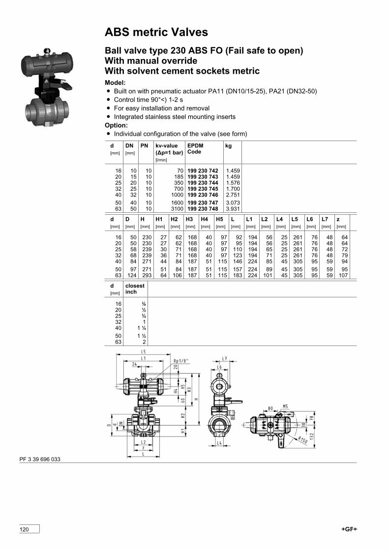
ABS metric ValvesBall valve type 230 ABS FO (Fail safe to open)With manual overrideWith solvent cement sockets metricModel:Ï Built on with pneumatic actuator PA11 (DN10/15-25), PA21 (DN32-50)Ï Control time 90°<) 1-2 sÏ For easy installation and removalÏ Integrated stainless steel mounting insertsOption:Ï Individual configuration of the valve (see form)
d[mm]
DN[mm]
PN kv-value(�p=1 bar)[l/min]
EPDMCode
kg
16 10 10 70 199 230 742 1.45920 15 10 185 199 230 743 1.45925 20 10 350 199 230 744 1.57632 25 10 700 199 230 745 1.70040 32 10 1000 199 230 746 2.75150 40 10 1600 199 230 747 3.07363 50 10 3100 199 230 748 3.931
d[mm]
D[mm]
H[mm]
H1[mm]
H2[mm]
H3[mm]
H4[mm]
H5[mm]
L[mm]
L1[mm]
L2[mm]
L4[mm]
L5[mm]
L6[mm]
L7[mm]
z[mm]
16 50 230 27 62 168 40 97 92 194 56 25 261 76 48 6420 50 230 27 62 168 40 97 95 194 56 25 261 76 48 6425 58 239 30 71 168 40 97 110 194 65 25 261 76 48 7232 68 239 36 71 168 40 97 123 194 71 25 261 76 48 7940 84 271 44 84 187 51 115 146 224 85 45 305 95 59 9450 97 271 51 84 187 51 115 157 224 89 45 305 95 59 9563 124 293 64 106 187 51 115 183 224 101 45 305 95 59 107
d[mm]
closestinch
16 3/820 1/225 3/432 140 1 1/450 1 1/263 2
PF 3 39 696 033
120
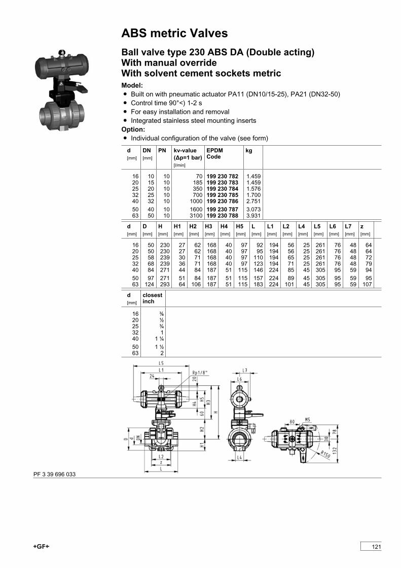
ABS metric ValvesBall valve type 230 ABS DA (Double acting)With manual overrideWith solvent cement sockets metricModel:Ï Built on with pneumatic actuator PA11 (DN10/15-25), PA21 (DN32-50)Ï Control time 90°<) 1-2 sÏ For easy installation and removalÏ Integrated stainless steel mounting insertsOption:Ï Individual configuration of the valve (see form)
d[mm]
DN[mm]
PN kv-value(�p=1 bar)[l/min]
EPDMCode
kg
16 10 10 70 199 230 782 1.45920 15 10 185 199 230 783 1.45925 20 10 350 199 230 784 1.57632 25 10 700 199 230 785 1.70040 32 10 1000 199 230 786 2.75150 40 10 1600 199 230 787 3.07363 50 10 3100 199 230 788 3.931
d[mm]
D[mm]
H[mm]
H1[mm]
H2[mm]
H3[mm]
H4[mm]
H5[mm]
L[mm]
L1[mm]
L2[mm]
L4[mm]
L5[mm]
L6[mm]
L7[mm]
z[mm]
16 50 230 27 62 168 40 97 92 194 56 25 261 76 48 6420 50 230 27 62 168 40 97 95 194 56 25 261 76 48 6425 58 239 30 71 168 40 97 110 194 65 25 261 76 48 7232 68 239 36 71 168 40 97 123 194 71 25 261 76 48 7940 84 271 44 84 187 51 115 146 224 85 45 305 95 59 9450 97 271 51 84 187 51 115 157 224 89 45 305 95 59 9563 124 293 64 106 187 51 115 183 224 101 45 305 95 59 107
d[mm]
closestinch
16 3/820 1/225 3/432 140 1 1/450 1 1/263 2
PF 3 39 696 033
121
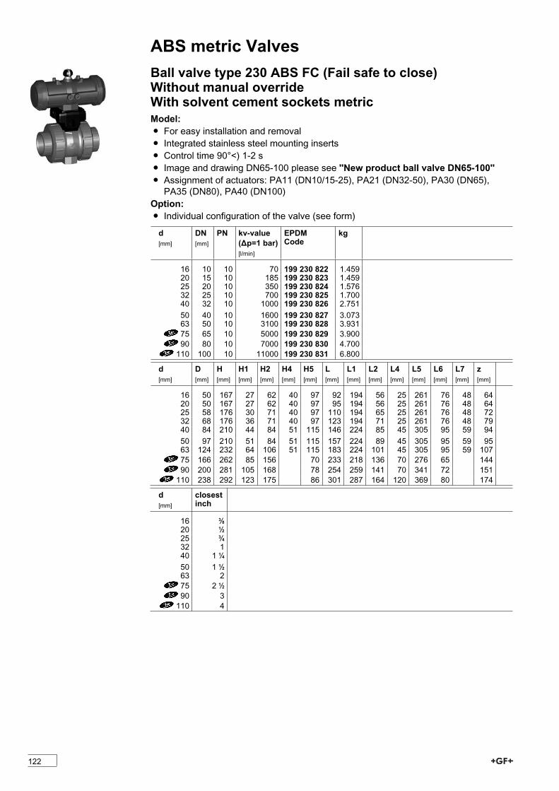
ABS metric ValvesBall valve type 230 ABS FC (Fail safe to close)Without manual overrideWith solvent cement sockets metricModel:Ï For easy installation and removalÏ Integrated stainless steel mounting insertsÏ Control time 90°<) 1-2 sÏ Image and drawing DN65-100 please see ''New product ball valve DN65-100''Ï Assignment of actuators: PA11 (DN10/15-25), PA21 (DN32-50), PA30 (DN65),PA35 (DN80), PA40 (DN100)
Option:Ï Individual configuration of the valve (see form)
d[mm]
DN[mm]
PN kv-value(�p=1 bar)[l/min]
EPDMCode
kg
16 10 10 70 199 230 822 1.45920 15 10 185 199 230 823 1.45925 20 10 350 199 230 824 1.57632 25 10 700 199 230 825 1.70040 32 10 1000 199 230 826 2.75150 40 10 1600 199 230 827 3.07363 50 10 3100 199 230 828 3.93175 65 10 5000 199 230 829 3.90090 80 10 7000 199 230 830 4.700110 100 10 11000 199 230 831 6.800
d[mm]
D[mm]
H[mm]
H1[mm]
H2[mm]
H4[mm]
H5[mm]
L[mm]
L1[mm]
L2[mm]
L4[mm]
L5[mm]
L6[mm]
L7[mm]
z[mm]
16 50 167 27 62 40 97 92 194 56 25 261 76 48 6420 50 167 27 62 40 97 95 194 56 25 261 76 48 6425 58 176 30 71 40 97 110 194 65 25 261 76 48 7232 68 176 36 71 40 97 123 194 71 25 261 76 48 7940 84 210 44 84 51 115 146 224 85 45 305 95 59 9450 97 210 51 84 51 115 157 224 89 45 305 95 59 9563 124 232 64 106 51 115 183 224 101 45 305 95 59 10775 166 262 85 156 70 233 218 136 70 276 65 14490 200 281 105 168 78 254 259 141 70 341 72 151110 238 292 123 175 86 301 287 164 120 369 80 174
d[mm]
closestinch
16 3/820 1/225 3/432 140 1 1/450 1 1/263 275 2 1/290 3110 4
122

ABS metric Valves
PF 3 39 696 633
Ball valve type 230 ABS FO (Fail safe to open)Without manual overrideWith solvent cement sockets metricModel:Ï For easy installation and removalÏ Integrated stainless steel mounting insertsÏ Control time 90°<) 1-2 sÏ Image and drawing DN65-100 please see ''New product ball valve DN65-100''Ï Assignment of actuators: PA11 (DN10/15-25), PA21 (DN32-50), PA30 (DN65),PA35 (DN80), PA40 (DN100)
Option:Ï Individual configuration of the valve (see form)
d[mm]
DN[mm]
PN kv-value(�p=1 bar)[l/min]
EPDMCode
kg
16 10 10 70 199 230 862 1.45920 15 10 185 199 230 863 1.45925 20 10 350 199 230 864 1.57632 25 10 700 199 230 865 1.70040 32 10 1000 199 230 866 2.75150 40 10 1600 199 230 867 3.07363 50 10 3100 199 230 868 3.93175 65 10 5000 199 230 869 3.90090 80 10 7000 199 230 870 4.700110 100 10 11000 199 230 871 6.800
d[mm]
D[mm]
H[mm]
H1[mm]
H2[mm]
H4[mm]
H5[mm]
L[mm]
L1[mm]
L2[mm]
L4[mm]
L5[mm]
L6[mm]
L7[mm]
z[mm]
16 50 167 27 62 40 97 92 194 56 25 261 76 48 6420 50 167 27 62 40 97 95 194 56 25 261 76 48 6425 58 176 30 71 40 97 110 194 65 25 261 76 48 7232 68 176 36 71 40 97 123 194 71 25 261 76 48 7940 84 210 44 84 51 115 146 224 85 45 305 95 59 9450 97 210 51 84 51 115 157 224 89 45 305 95 59 9563 124 232 64 106 51 115 183 224 101 45 305 95 59 10775 166 262 85 156 70 233 218 136 70 276 65 14490 200 281 105 168 78 254 259 141 70 341 72 151110 238 292 123 175 86 301 287 164 120 369 80 174
123

ABS metric Valvesd[mm]
closestinch
16 3/820 1/225 3/432 140 1 1/450 1 1/263 275 2 1/290 3110 4
PF 3 39 696 633
Ball valve type 230 ABS DA (Double acting)Without manual overrideWith solvent cement sockets metricModel:Ï For easy installation and removalÏ Integrated stainless steel mounting insertsÏ Control time 90°<) 1-2 sÏ Image and drawing DN65-100 please see ''New product ball valve DN65-100''Ï Assignment of actuators: PA11 (DN10/15-25), PA21 (DN32-50), PA35 (DN65),PA40 (DN80), PA45 (DN100)
Option:Ï Individual configuration of the valve (see form)
d[mm]
DN[mm]
PN kv-value(�p=1 bar)[l/min]
EPDMCode
kg
16 10 10 70 199 230 902 1.45920 15 10 185 199 230 903 1.45925 20 10 350 199 230 904 1.57632 25 10 700 199 230 905 1.70040 32 10 1000 199 230 906 2.75150 40 10 1600 199 230 907 3.07363 50 10 3100 199 230 908 3.93175 65 10 5000 199 230 909 2.80090 80 10 7000 199 230 910 4.000110 100 10 11000 199 230 911 5.000
124

ABS metric Valvesd[mm]
D[mm]
H[mm]
H1[mm]
H2[mm]
H4[mm]
H5[mm]
L[mm]
L1[mm]
L2[mm]
L4[mm]
L5[mm]
L6[mm]
L7[mm]
z[mm]
16 50 167 27 62 40 97 92 194 56 25 261 76 48 6420 50 167 27 62 40 97 95 194 56 25 261 76 48 6425 58 176 30 71 40 97 110 194 65 25 261 76 48 7232 68 176 36 71 40 97 123 194 71 25 261 76 48 7940 84 210 44 84 51 115 146 224 85 45 305 95 59 9450 97 210 51 84 51 115 157 224 89 45 305 95 59 9563 124 232 64 106 51 115 183 224 101 45 305 95 59 10775 166 257 85 156 66 233 144 136 70 190 60 14490 200 274 105 168 70 254 152 141 70 198 65 151110 238 273 123 175 78 301 169 164 120 235 72 174
d[mm]
closestinch
16 3/820 1/225 3/432 140 1 1/450 1 1/263 275 2 1/290 3110 4
PF 3 39 696 033
125

ABS metric Valves3-Way ball valve type 275 ABSHorizontal/L-portWithout manual overrideWith solvent cement sockets metricModel:Ï Built on with pneumatic actuator PA11 (DN10/15-25), PA21 (DN32-50)Ï Actuator fails safe to the closed position FCÏ Control time 90°<) 1-3 sÏ For easy installation and removalÏ Integrated stainless steel mounting inserts
d[mm]
DN[mm]
PN kv-value(�p=1 bar)[l/min]
EPDMCode
kg
16 10 10 50 199 275 162 1.06620 15 10 75 199 275 163 1.33725 20 10 150 199 275 164 1.20732 25 10 280 199 275 165 2.47440 32 10 480 199 275 166 2.28350 40 10 620 199 275 167 2.70363 50 10 1230 199 275 168 3.771
d[mm]
D[mm]
H[mm]
H1[mm]
H2[mm]
H3[mm]
H4[mm]
H5[mm]
H6[mm]
L[mm]
L1[mm]
L2[mm]
L3[mm]
L4[mm]
L5[mm]
L6[mm]
16 45 136 29 31 105 40 77 8 108 194 72 36 25 261 7320 45 136 29 31 105 40 77 8 111 194 72 36 25 261 7325 52 144 33 39 105 40 77 8 131 194 86 43 25 261 7332 65 149 38 44 105 40 77 8 148 194 96 48 25 261 7340 78 177 44 50 127 51 99 9 176 224 116 58 45 305 9450 92 190 50 63 127 51 99 9 206 224 137 69 45 305 9463 116 203 61 76 127 51 99 9 262 224 179 90 45 305 94
d[mm]
L7[mm]
M z[mm]
z1[mm]
closestinch
16 48 6 80 40 3/820 48 6 80 40 1/225 48 6 94 47 3/432 48 6 104 52 140 59 8 126 63 1 1/450 59 8 144 72 1 1/263 59 8 186 93 2
PF 3 39 749 200
126

ABS metric Valves3-Way ball valve type 275 ABSHorizontal/L-port DA (Double acting)Without manual overrideWith solvent cement sockets metricModel:Ï Built on with pneumatic actuator PA11 (DN10/15-25), PA21 (DN32-50)Ï Control time 90°<) 1-3 sÏ For easy installation and removalÏ Integrated stainless steel mounting inserts
d[mm]
DN[mm]
PN kv-value(�p=1 bar)[l/min]
EPDMCode
kg
16 10 10 50 199 275 342 0.87620 15 10 75 199 275 343 0.87625 20 10 150 199 275 344 1.01732 25 10 280 199 275 345 1.15540 32 10 480 199 275 346 2.06050 40 10 620 199 275 347 2.27963 50 10 1230 199 275 348 3.347
d[mm]
D[mm]
H[mm]
H1[mm]
H2[mm]
H3[mm]
H4[mm]
H5[mm]
H6[mm]
L[mm]
L1[mm]
L2[mm]
L3[mm]
L4[mm]
L5[mm]
L6[mm]
16 45 136 29 31 105 40 77 8 108 194 72 36 25 261 7320 45 136 29 31 105 40 77 8 111 194 72 36 25 261 7325 52 144 33 39 105 40 77 8 131 194 86 43 25 261 7332 65 149 38 44 105 40 77 8 148 194 96 48 25 261 7340 78 177 44 50 127 51 99 9 176 224 116 58 45 305 9450 92 190 50 63 127 51 99 9 206 224 137 69 45 305 9463 116 203 61 76 127 51 99 9 262 224 179 90 45 305 94
d[mm]
L7[mm]
M z[mm]
z1[mm]
closestinch
16 48 6 80 40 3/820 48 6 80 40 1/225 48 6 94 47 3/432 48 6 104 52 140 59 8 126 63 1 1/450 59 8 144 72 1 1/263 59 8 186 93 2
PF 3 39 750 250
127
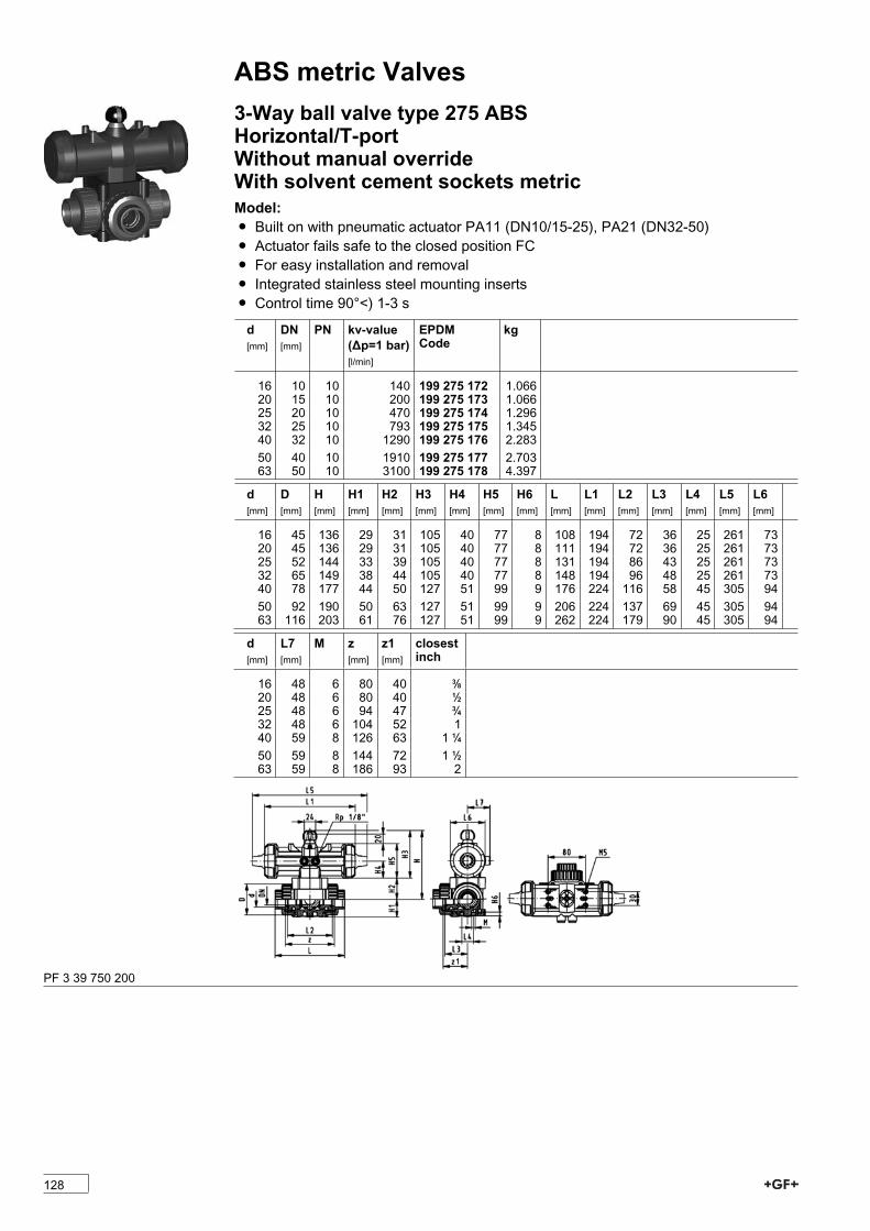
ABS metric Valves3-Way ball valve type 275 ABSHorizontal/T-portWithout manual overrideWith solvent cement sockets metricModel:Ï Built on with pneumatic actuator PA11 (DN10/15-25), PA21 (DN32-50)Ï Actuator fails safe to the closed position FCÏ For easy installation and removalÏ Integrated stainless steel mounting insertsÏ Control time 90°<) 1-3 s
d[mm]
DN[mm]
PN kv-value(�p=1 bar)[l/min]
EPDMCode
kg
16 10 10 140 199 275 172 1.06620 15 10 200 199 275 173 1.06625 20 10 470 199 275 174 1.29632 25 10 793 199 275 175 1.34540 32 10 1290 199 275 176 2.28350 40 10 1910 199 275 177 2.70363 50 10 3100 199 275 178 4.397
d[mm]
D[mm]
H[mm]
H1[mm]
H2[mm]
H3[mm]
H4[mm]
H5[mm]
H6[mm]
L[mm]
L1[mm]
L2[mm]
L3[mm]
L4[mm]
L5[mm]
L6[mm]
16 45 136 29 31 105 40 77 8 108 194 72 36 25 261 7320 45 136 29 31 105 40 77 8 111 194 72 36 25 261 7325 52 144 33 39 105 40 77 8 131 194 86 43 25 261 7332 65 149 38 44 105 40 77 8 148 194 96 48 25 261 7340 78 177 44 50 127 51 99 9 176 224 116 58 45 305 9450 92 190 50 63 127 51 99 9 206 224 137 69 45 305 9463 116 203 61 76 127 51 99 9 262 224 179 90 45 305 94
d[mm]
L7[mm]
M z[mm]
z1[mm]
closestinch
16 48 6 80 40 3/820 48 6 80 40 1/225 48 6 94 47 3/432 48 6 104 52 140 59 8 126 63 1 1/450 59 8 144 72 1 1/263 59 8 186 93 2
PF 3 39 750 200
128
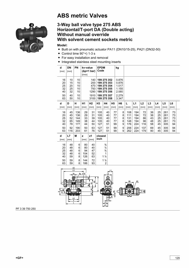
ABS metric Valves3-Way ball valve type 275 ABSHorizontal/T-port DA (Double acting)Without manual overrideWith solvent cement sockets metricModel:Ï Built on with pneumatic actuator PA11 (DN10/15-25), PA21 (DN32-50)Ï Control time 90°<) 1-3 sÏ For easy installation and removalÏ Integrated stainless steel mounting inserts
d[mm]
DN[mm]
PN kv-value(�p=1 bar)[l/min]
EPDMCode
kg
16 10 10 140 199 275 352 0.87620 15 10 200 199 275 353 0.87625 20 10 470 199 275 354 1.01732 25 10 793 199 275 355 1.15540 32 10 1290 199 275 356 2.06050 40 10 1910 199 275 357 2.27963 50 10 3100 199 275 358 3.347
d[mm]
D[mm]
H[mm]
H1[mm]
H2[mm]
H3[mm]
H4[mm]
H5[mm]
H6[mm]
L[mm]
L1[mm]
L2[mm]
L3[mm]
L4[mm]
L5[mm]
L6[mm]
16 45 136 29 31 105 40 77 8 108 194 72 36 25 261 7320 45 136 29 31 105 40 77 8 111 194 72 36 25 261 7325 52 144 33 39 105 40 77 8 131 194 86 43 25 261 7332 65 149 38 44 105 40 77 8 148 194 96 48 25 261 7340 78 177 44 50 127 51 99 9 176 224 116 58 45 305 9450 92 190 50 63 127 51 99 9 206 224 137 69 45 305 9463 116 203 61 76 127 51 99 9 262 224 179 90 45 305 94
d[mm]
L7[mm]
M z[mm]
z1[mm]
closestinch
16 48 6 80 40 3/820 48 6 80 40 1/225 48 6 94 47 3/432 48 6 104 52 140 59 8 126 63 1 1/450 59 8 144 72 1 1/263 59 8 186 93 2
PF 3 39 750 250
129

ABS metric ValvesButterfly valves electricButterfly valve type 140 ABS 100-230VWithout manual overrideModel:Ï Connecting dimension: ISO 7005 PN 10, EN 1092 PN 10, DIN 2501 PN 10,ANSI/ASME B 16.5 Class 150, BS 1560: 1989, BS 4504, JIS B 2220
Ï Overall length according to EN 558, ISO 5752Ï Voltage 100-230 V, 50-60 HzÏ Control time 15 s/90°<) EA31 Ï Control time 25s/90°<) EA42 Ï Control range 90°<)Ï Actuator with integrated emergency manual override standard
* Available on requestd[mm]
DN[mm]
Inch PN kv-value(�p=1 bar)[l/min]
EPDMCode
kg
*63 50 2 10 1470 199 140 502*75 65 2 1/2 10 2200 199 140 503 4.28190 80 3 10 3000 199 140 504 4.359110 100 4 10 6500 199 140 505 4.895*140 125 5 10 11500 199 140 506160 150 6 10 16600 199 140 507 6.218225 200 8 10 39600 199 140 508 12.029
d[mm]
Actuatorunit type
D[mm]
D1min.[mm]
D1max.[mm]
d2[mm]
H[mm]
H1[mm]
H2[mm]
H3[mm]
L[mm]
L1[mm]
L2[mm]
*63 EA-31 19 120.0 125.0 104 400 77 134 188 45 122 180*75 EA-31 19 139.7 145.0 115 413 83 140 188 46 122 18090 EA-31 19 150.0 160.0 131 428 89 146 188 49 122 180110 EA-31 19 175.0 190.5 161 460 104 167 188 56 122 180*140 EA-31 23 210.0 215.9 187 487 117 181 188 64 122 180160 EA-31 24 241.3 241.3 215 508 130 189 188 72 122 180225 EA-42 23 290.0 295.0 267 575 158 210 208 73 122 180
d[mm]
Q1[mm]
Q2[mm]
*63 40*75 54 3590 67 50110 88 74*140 113 97160 139 123225 178 169
PF 3 39 643 035
130

ABS metric ValvesButterfly valve type 140 ABS 100-230VWith manual overrideModel:Ï Connecting dimension: ISO 7005 PN 10, EN 1092 PN 10, DIN 2501 PN 10,ANSI/ASME B 16.5 Class 150, BS 1560: 1989, BS 4504, JIS B 2220
Ï Overall length according to EN 558, ISO 5752Ï Voltage 100-230 V, 50-60 HzÏ Control time 15 s/90°<) EA31 Ï Control time 25s/90°<) EA42 Ï Control range 90°<)Ï Actuator with integrated emergency manual override standard
* Available on requestd[mm]
DN[mm]
Inch PN kv-value(�p=1 bar)[l/min]
EPDMCode
kg
*63 50 2 10 1470 199 140 482 5.678*75 65 2 1/2 10 2200 199 140 483 5.78190 80 3 10 3000 199 140 484 5.859110 100 4 10 6500 199 140 485 6.395*140 125 5 10 11500 199 140 486160 150 6 10 16600 199 140 487 7.718225 200 8 10 39600 199 140 488 13.529
d[mm]
Actuatorunit type
D[mm]
D1min.[mm]
D1max.[mm]
d2[mm]
H[mm]
H1[mm]
H2[mm]
H3[mm]
H4[mm]
L[mm]
L1[mm]
*63 EA-31 19 120.0 125.0 104 460 77 134 188 60 45 122*75 EA-31 19 139.7 145.0 115 473 83 140 188 60 46 12290 EA-31 19 150.0 160.0 131 488 89 146 188 60 49 122110 EA-31 19 175.0 190.5 161 520 104 167 188 60 56 122*140 EA-31 23 210.0 215.9 187 547 117 181 188 60 64 122160 EA-31 24 241.3 241.3 215 568 130 189 188 60 72 122225 EA-42 23 290.0 295.0 267 635 158 210 208 60 73 122
d[mm]
L2[mm]
L3[mm]
Q1[mm]
Q2[mm]
*63 180 250 40*75 180 250 54 3590 180 250 67 50110 180 250 88 74*140 180 250 113 97160 180 250 139 123225 180 250 178 169
PF 3 39 643 035
131
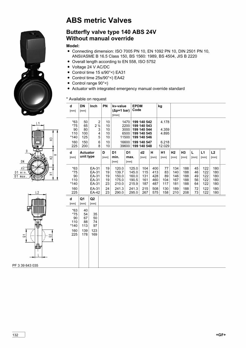
ABS metric ValvesButterfly valve type 140 ABS 24VWithout manual overrideModel:Ï Connecting dimension: ISO 7005 PN 10, EN 1092 PN 10, DIN 2501 PN 10,ANSI/ASME B 16.5 Class 150, BS 1560: 1989, BS 4504, JIS B 2220
Ï Overall length according to EN 558, ISO 5752Ï Voltage 24 V AC/DCÏ Control time 15 s/90°<) EA31 Ï Control time 25s/90°<) EA42 Ï Control range 90°<)Ï Actuator with integrated emergency manual override standard
* Available on requestd[mm]
DN[mm]
Inch PN kv-value(�p=1 bar)[l/min]
EPDMCode
kg
*63 50 2 10 1470 199 140 542 4.178*75 65 2 1/2 10 2200 199 140 54390 80 3 10 3000 199 140 544 4.359110 100 4 10 6500 199 140 545 4.895*140 125 5 10 11500 199 140 546160 150 6 10 16600 199 140 547 6.218225 200 8 10 39600 199 140 548 12.029
d[mm]
Actuatorunit type
D[mm]
D1min.[mm]
D1max.[mm]
d2[mm]
H[mm]
H1[mm]
H2[mm]
H3[mm]
L[mm]
L1[mm]
L2[mm]
*63 EA-31 19 120.0 125.0 104 400 77 134 188 45 122 180*75 EA-31 19 139.7 145.0 115 413 83 140 188 46 122 18090 EA-31 19 150.0 160.0 131 428 89 146 188 49 122 180110 EA-31 19 175.0 190.5 161 460 104 167 188 56 122 180*140 EA-31 23 210.0 215.9 187 487 117 181 188 64 122 180160 EA-31 24 241.3 241.3 215 508 130 189 188 72 122 180225 EA-42 23 290.0 295.0 267 575 158 210 208 73 122 180
d[mm]
Q1[mm]
Q2[mm]
*63 40*75 54 3590 67 50110 88 74*140 113 97160 139 123225 178 169
PF 3 39 643 035
132
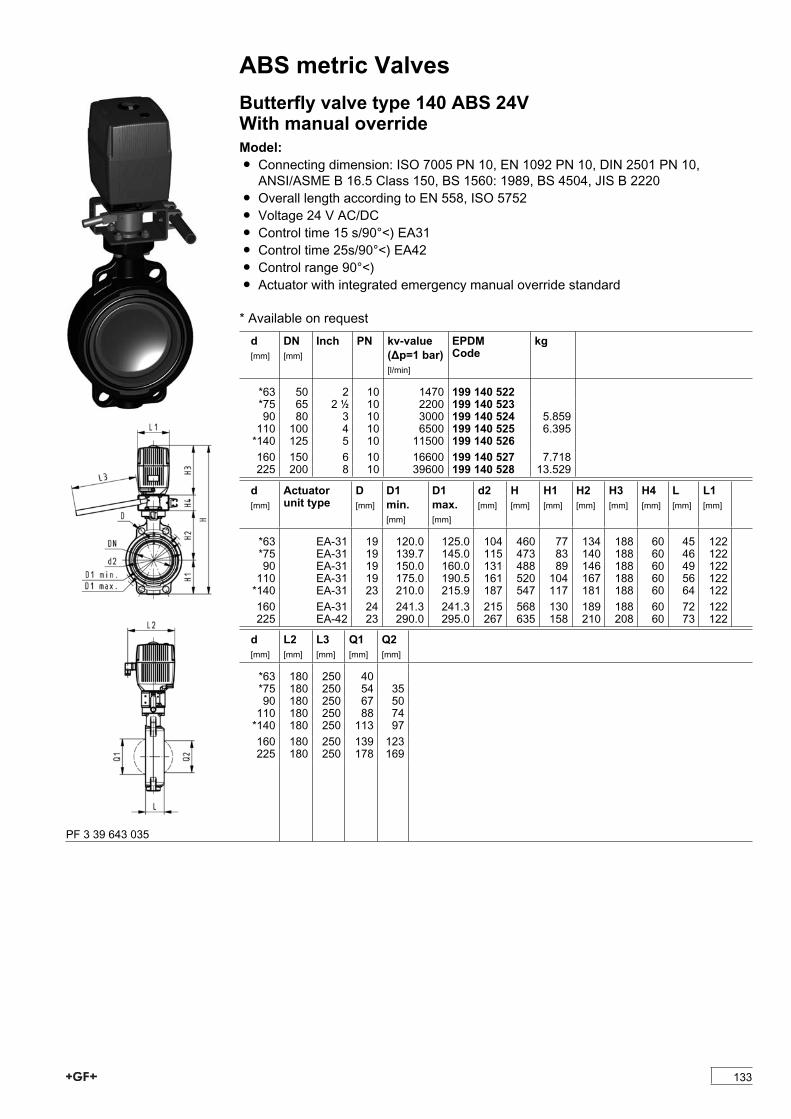
ABS metric ValvesButterfly valve type 140 ABS 24VWith manual overrideModel:Ï Connecting dimension: ISO 7005 PN 10, EN 1092 PN 10, DIN 2501 PN 10,ANSI/ASME B 16.5 Class 150, BS 1560: 1989, BS 4504, JIS B 2220
Ï Overall length according to EN 558, ISO 5752Ï Voltage 24 V AC/DCÏ Control time 15 s/90°<) EA31 Ï Control time 25s/90°<) EA42 Ï Control range 90°<)Ï Actuator with integrated emergency manual override standard
* Available on requestd[mm]
DN[mm]
Inch PN kv-value(�p=1 bar)[l/min]
EPDMCode
kg
*63 50 2 10 1470 199 140 522*75 65 2 1/2 10 2200 199 140 52390 80 3 10 3000 199 140 524 5.859110 100 4 10 6500 199 140 525 6.395*140 125 5 10 11500 199 140 526160 150 6 10 16600 199 140 527 7.718225 200 8 10 39600 199 140 528 13.529
d[mm]
Actuatorunit type
D[mm]
D1min.[mm]
D1max.[mm]
d2[mm]
H[mm]
H1[mm]
H2[mm]
H3[mm]
H4[mm]
L[mm]
L1[mm]
*63 EA-31 19 120.0 125.0 104 460 77 134 188 60 45 122*75 EA-31 19 139.7 145.0 115 473 83 140 188 60 46 12290 EA-31 19 150.0 160.0 131 488 89 146 188 60 49 122110 EA-31 19 175.0 190.5 161 520 104 167 188 60 56 122*140 EA-31 23 210.0 215.9 187 547 117 181 188 60 64 122160 EA-31 24 241.3 241.3 215 568 130 189 188 60 72 122225 EA-42 23 290.0 295.0 267 635 158 210 208 60 73 122
d[mm]
L2[mm]
L3[mm]
Q1[mm]
Q2[mm]
*63 180 250 40*75 180 250 54 3590 180 250 67 50110 180 250 88 74*140 180 250 113 97160 180 250 139 123225 180 250 178 169
PF 3 39 643 035
133

ABS metric ValvesLugstyle butterfly valve type 141 ABS 100-230VWith manual overrideModel:Ï Outer body in GGG-40.3 epoxy-coatedÏ Connecting dimension: ISO 7005 PN10, EN 1092 PN10, DIN 2501 PN10Ï Overall length according to EN 558, ISO 5752Ï Voltage 100-230 V, 50-60 HzÏ Control time 15 s/90°<) EA31 Ï Control time 25s/90°<) EA42 Ï Control range 90°<)Ï Actuator with integrated emergency manual override standard
* Available on requestd[mm]
DN[mm]
Inch PN kv-value(�p=1 bar)[l/min]
EPDMCode
kg
*63 50 2 10 1470 199 141 482 7.713*75 65 2 1/2 10 2200 199 141 483 8.06090 80 3 10 3000 199 141 484 9.077110 100 4 10 6500 199 141 485 10.493*140 125 5 10 11500 199 141 486 12.362160 150 6 10 16600 199 141 487 14.201225 200 8 10 39600 199 141 488 23.505
d[mm]
Actuatorunit type
D D1[mm]
d2[mm]
H[mm]
H1[mm]
H2[mm]
H3[mm]
H4[mm]
L[mm]
L1[mm]
L2[mm]
L3[mm]
*63 EA-31 M16 125 150 459 77 134 188 60 45 122 180 150*75 EA-31 M16 145 170 471 83 140 188 60 46 122 180 16090 EA-31 M16 160 184 483 89 146 188 60 49 122 180 205110 EA-31 M16 180 216 519 104 167 188 60 56 122 180 244*140 EA-31 M16 210 246 546 117 181 188 60 64 122 180 272160 EA-31 M20 240 273 567 130 189 188 60 72 122 180 297225 EA-42 M20 295 334 636 158 210 208 60 73 122 180 360
d[mm]
L4[mm]
Q1[mm]
Q2[mm]
*63 200 40*75 200 54 3590 200 67 50110 250 88 74*140 250 113 97160 250 139 123225 250 178 169PF 3 39 643 036
134
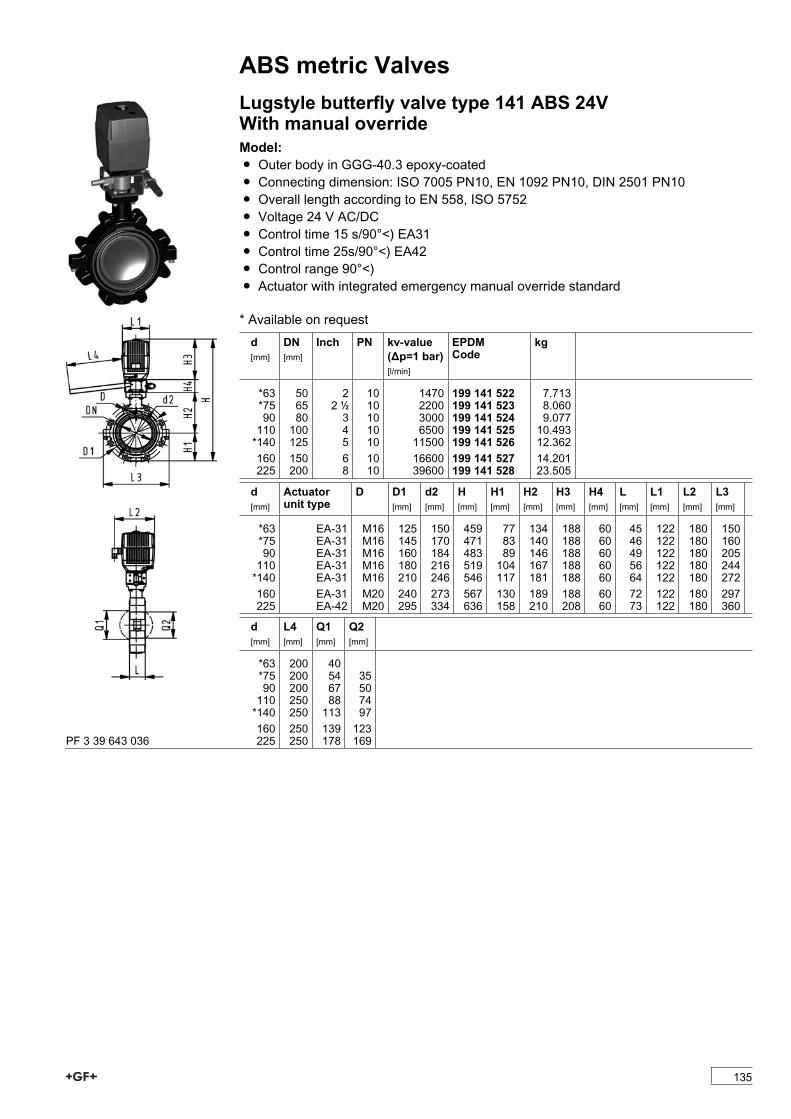
ABS metric ValvesLugstyle butterfly valve type 141 ABS 24VWith manual overrideModel:Ï Outer body in GGG-40.3 epoxy-coatedÏ Connecting dimension: ISO 7005 PN10, EN 1092 PN10, DIN 2501 PN10Ï Overall length according to EN 558, ISO 5752Ï Voltage 24 V AC/DCÏ Control time 15 s/90°<) EA31 Ï Control time 25s/90°<) EA42 Ï Control range 90°<)Ï Actuator with integrated emergency manual override standard
* Available on requestd[mm]
DN[mm]
Inch PN kv-value(�p=1 bar)[l/min]
EPDMCode
kg
*63 50 2 10 1470 199 141 522 7.713*75 65 2 1/2 10 2200 199 141 523 8.06090 80 3 10 3000 199 141 524 9.077110 100 4 10 6500 199 141 525 10.493*140 125 5 10 11500 199 141 526 12.362160 150 6 10 16600 199 141 527 14.201225 200 8 10 39600 199 141 528 23.505
d[mm]
Actuatorunit type
D D1[mm]
d2[mm]
H[mm]
H1[mm]
H2[mm]
H3[mm]
H4[mm]
L[mm]
L1[mm]
L2[mm]
L3[mm]
*63 EA-31 M16 125 150 459 77 134 188 60 45 122 180 150*75 EA-31 M16 145 170 471 83 140 188 60 46 122 180 16090 EA-31 M16 160 184 483 89 146 188 60 49 122 180 205110 EA-31 M16 180 216 519 104 167 188 60 56 122 180 244*140 EA-31 M16 210 246 546 117 181 188 60 64 122 180 272160 EA-31 M20 240 273 567 130 189 188 60 72 122 180 297225 EA-42 M20 295 334 636 158 210 208 60 73 122 180 360
d[mm]
L4[mm]
Q1[mm]
Q2[mm]
*63 200 40*75 200 54 3590 200 67 50110 250 88 74*140 250 113 97160 250 139 123225 250 178 169PF 3 39 643 036
135
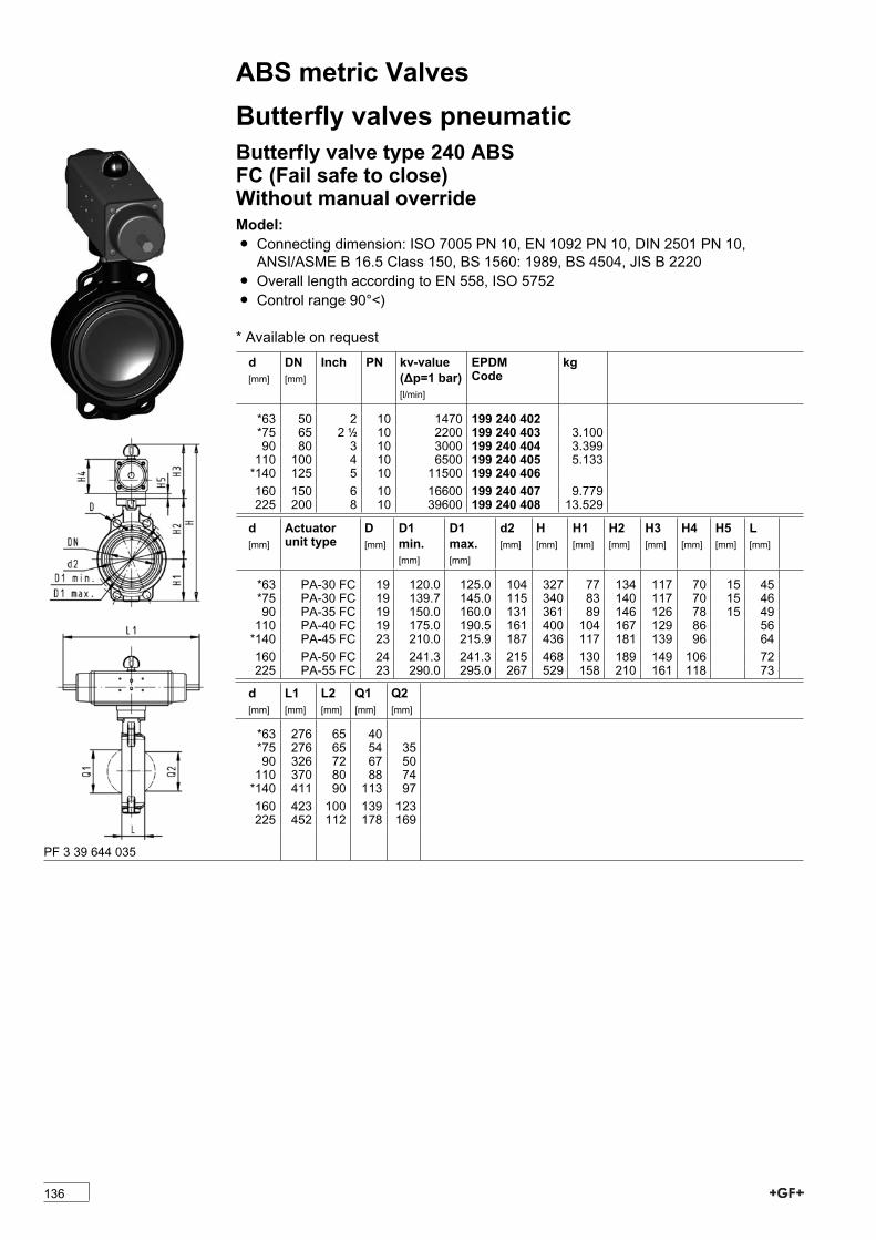
ABS metric ValvesButterfly valves pneumaticButterfly valve type 240 ABSFC (Fail safe to close)Without manual overrideModel:Ï Connecting dimension: ISO 7005 PN 10, EN 1092 PN 10, DIN 2501 PN 10,ANSI/ASME B 16.5 Class 150, BS 1560: 1989, BS 4504, JIS B 2220
Ï Overall length according to EN 558, ISO 5752Ï Control range 90°<)
* Available on requestd[mm]
DN[mm]
Inch PN kv-value(�p=1 bar)[l/min]
EPDMCode
kg
*63 50 2 10 1470 199 240 402*75 65 2 1/2 10 2200 199 240 403 3.10090 80 3 10 3000 199 240 404 3.399110 100 4 10 6500 199 240 405 5.133*140 125 5 10 11500 199 240 406160 150 6 10 16600 199 240 407 9.779225 200 8 10 39600 199 240 408 13.529
d[mm]
Actuatorunit type
D[mm]
D1min.[mm]
D1max.[mm]
d2[mm]
H[mm]
H1[mm]
H2[mm]
H3[mm]
H4[mm]
H5[mm]
L[mm]
*63 PA-30 FC 19 120.0 125.0 104 327 77 134 117 70 15 45*75 PA-30 FC 19 139.7 145.0 115 340 83 140 117 70 15 4690 PA-35 FC 19 150.0 160.0 131 361 89 146 126 78 15 49110 PA-40 FC 19 175.0 190.5 161 400 104 167 129 86 56*140 PA-45 FC 23 210.0 215.9 187 436 117 181 139 96 64160 PA-50 FC 24 241.3 241.3 215 468 130 189 149 106 72225 PA-55 FC 23 290.0 295.0 267 529 158 210 161 118 73
d[mm]
L1[mm]
L2[mm]
Q1[mm]
Q2[mm]
*63 276 65 40*75 276 65 54 3590 326 72 67 50110 370 80 88 74*140 411 90 113 97160 423 100 139 123225 452 112 178 169
PF 3 39 644 035
136
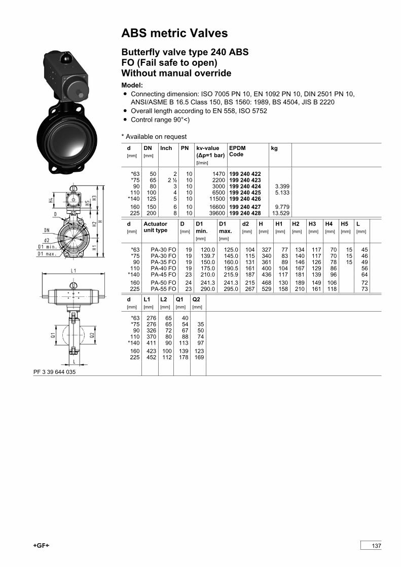
ABS metric ValvesButterfly valve type 240 ABSFO (Fail safe to open)Without manual overrideModel:Ï Connecting dimension: ISO 7005 PN 10, EN 1092 PN 10, DIN 2501 PN 10,ANSI/ASME B 16.5 Class 150, BS 1560: 1989, BS 4504, JIS B 2220
Ï Overall length according to EN 558, ISO 5752Ï Control range 90°<)
* Available on requestd[mm]
DN[mm]
Inch PN kv-value(�p=1 bar)[l/min]
EPDMCode
kg
*63 50 2 10 1470 199 240 422*75 65 2 1/2 10 2200 199 240 42390 80 3 10 3000 199 240 424 3.399110 100 4 10 6500 199 240 425 5.133*140 125 5 10 11500 199 240 426160 150 6 10 16600 199 240 427 9.779225 200 8 10 39600 199 240 428 13.529
d[mm]
Actuatorunit type
D[mm]
D1min.[mm]
D1max.[mm]
d2[mm]
H[mm]
H1[mm]
H2[mm]
H3[mm]
H4[mm]
H5[mm]
L[mm]
*63 PA-30 FO 19 120.0 125.0 104 327 77 134 117 70 15 45*75 PA-30 FO 19 139.7 145.0 115 340 83 140 117 70 15 4690 PA-35 FO 19 150.0 160.0 131 361 89 146 126 78 15 49110 PA-40 FO 19 175.0 190.5 161 400 104 167 129 86 56*140 PA-45 FO 23 210.0 215.9 187 436 117 181 139 96 64160 PA-50 FO 24 241.3 241.3 215 468 130 189 149 106 72225 PA-55 FO 23 290.0 295.0 267 529 158 210 161 118 73
d[mm]
L1[mm]
L2[mm]
Q1[mm]
Q2[mm]
*63 276 65 40*75 276 65 54 3590 326 72 67 50110 370 80 88 74*140 411 90 113 97160 423 100 139 123225 452 112 178 169
PF 3 39 644 035
137
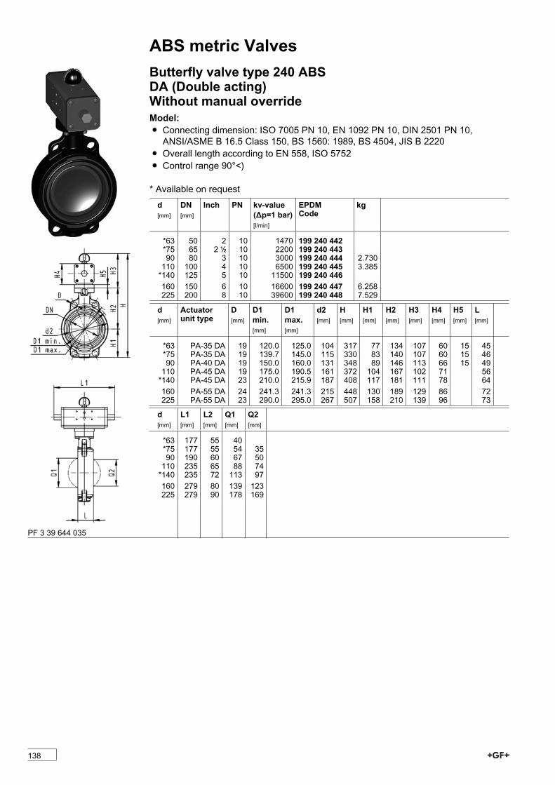
ABS metric ValvesButterfly valve type 240 ABSDA (Double acting)Without manual overrideModel:Ï Connecting dimension: ISO 7005 PN 10, EN 1092 PN 10, DIN 2501 PN 10,ANSI/ASME B 16.5 Class 150, BS 1560: 1989, BS 4504, JIS B 2220
Ï Overall length according to EN 558, ISO 5752Ï Control range 90°<)
* Available on requestd[mm]
DN[mm]
Inch PN kv-value(�p=1 bar)[l/min]
EPDMCode
kg
*63 50 2 10 1470 199 240 442*75 65 2 1/2 10 2200 199 240 44390 80 3 10 3000 199 240 444 2.730110 100 4 10 6500 199 240 445 3.385*140 125 5 10 11500 199 240 446160 150 6 10 16600 199 240 447 6.258225 200 8 10 39600 199 240 448 7.529
d[mm]
Actuatorunit type
D[mm]
D1min.[mm]
D1max.[mm]
d2[mm]
H[mm]
H1[mm]
H2[mm]
H3[mm]
H4[mm]
H5[mm]
L[mm]
*63 PA-35 DA 19 120.0 125.0 104 317 77 134 107 60 15 45*75 PA-35 DA 19 139.7 145.0 115 330 83 140 107 60 15 4690 PA-40 DA 19 150.0 160.0 131 348 89 146 113 66 15 49110 PA-45 DA 19 175.0 190.5 161 372 104 167 102 71 56*140 PA-45 DA 23 210.0 215.9 187 408 117 181 111 78 64160 PA-55 DA 24 241.3 241.3 215 448 130 189 129 86 72225 PA-55 DA 23 290.0 295.0 267 507 158 210 139 96 73
d[mm]
L1[mm]
L2[mm]
Q1[mm]
Q2[mm]
*63 177 55 40*75 177 55 54 3590 190 60 67 50110 235 65 88 74*140 235 72 113 97160 279 80 139 123225 279 90 178 169
PF 3 39 644 035
138
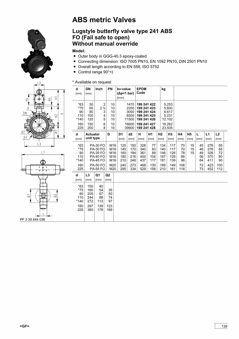
ABS metric ValvesLugstyle butterfly valve type 241 ABSFO (Fail safe to open)Without manual overrideModel:Ï Outer body in GGG-40.3 epoxy-coatedÏ Connecting dimension: ISO 7005 PN10, EN 1092 PN10, DIN 2501 PN10Ï Overall length according to EN 558, ISO 5752Ï Control range 90°<)
* Available on requestd[mm]
DN[mm]
Inch PN kv-value(�p=1 bar)[l/min]
EPDMCode
kg
*63 50 2 10 1470 199 241 422 5.253*75 65 2 1/2 10 2200 199 241 423 5.60090 80 3 10 3000 199 241 424 6.617110 100 4 10 6500 199 241 425 5.231*140 125 5 10 11500 199 241 426 12.102160 150 6 10 16600 199 241 427 16.262225 200 8 10 39600 199 241 428 23.505
d[mm]
Actuatorunit type
D D1[mm]
d2[mm]
H[mm]
H1[mm]
H2[mm]
H3[mm]
H4[mm]
H5[mm]
L[mm]
L1[mm]
L2[mm]
*63 PA-30 FO M16 125 150 328 77 134 117 70 15 45 276 65*75 PA-30 FO M16 145 170 340 83 140 117 70 15 46 276 6590 PA-35 FO M16 160 184 361 89 146 126 78 15 49 326 72110 PA-40 FO M16 180 216 400 104 167 129 86 56 370 80*140 PA-45 FO M16 210 246 437 117 181 139 96 64 411 90160 PA-50 FO M20 240 273 468 130 189 149 106 72 423 100225 PA-55 FO M20 295 334 529 158 210 161 118 73 452 112
d[mm]
L3[mm]
Q1[mm]
Q2[mm]
*63 150 40*75 160 54 3590 205 67 50110 244 88 74*140 272 113 97160 297 139 123225 360 178 169
PF 3 39 644 036
139
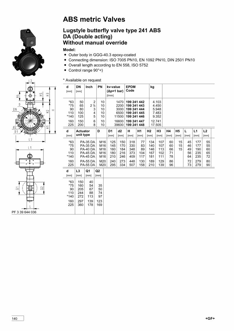
ABS metric ValvesLugstyle butterfly valve type 241 ABSDA (Double acting)Without manual overrideModel:Ï Outer body in GGG-40.3 epoxy-coatedÏ Connecting dimension: ISO 7005 PN10, EN 1092 PN10, DIN 2501 PN10Ï Overall length according to EN 558, ISO 5752Ï Control range 90°<)
* Available on requestd[mm]
DN[mm]
Inch PN kv-value(�p=1 bar)[l/min]
EPDMCode
kg
*63 50 2 10 1470 199 241 442 4.103*75 65 2 1/2 10 2200 199 241 443 4.45090 80 3 10 3000 199 241 444 5.948110 100 4 10 6500 199 241 445 7.483*140 125 5 10 11500 199 241 446 9.352160 150 6 10 16600 199 241 447 12.741225 200 8 10 39600 199 241 448 17.505
d[mm]
Actuatorunit type
D D1[mm]
d2[mm]
H[mm]
H1[mm]
H2[mm]
H3[mm]
H4[mm]
H5[mm]
L[mm]
L1[mm]
L2[mm]
*63 PA-35 DA M16 125 150 318 77 134 107 60 15 45 177 55*75 PA-35 DA M16 145 170 330 83 140 107 60 15 46 177 5590 PA-40 DA M16 160 184 348 89 146 113 66 15 49 190 60110 PA-45 DA M16 180 216 373 104 167 102 71 56 235 65*140 PA-45 DA M16 210 246 409 117 181 111 78 64 235 72160 PA-55 DA M20 240 273 448 130 189 129 86 72 279 80225 PA-55 DA M20 295 334 507 158 210 139 96 73 279 90
d[mm]
L3[mm]
Q1[mm]
Q2[mm]
*63 150 40*75 160 54 3590 205 67 50110 244 88 74*140 272 113 97160 297 139 123225 360 178 169
PF 3 39 644 036
140

ABS metric ValvesDiaphragm valves pneumaticDiaphragm valve type DIASTAR Eco ABSFC (Fail safe to close)With solvent cement spigots metricModel:Ï Working pressure 6 bar one sided[mm]
DN[mm]
PN kv-value(�p=1 bar)[l/min]
EPDMCode
kg
20 15 6 72 199 024 181 0.51025 20 6 120 199 024 182 1.03332 25 6 238 199 024 183 1.29140 32 6 341 199 024 184 1.90950 40 6 460 199 024 185 2.47763 50 6 685 199 024 186 3.103
d[mm]
D[mm]
D1_G[inch]
D2 (M) L[mm]
L1[mm]
H[mm]
H1[mm]
H2[mm]
H3[mm]
Lift =Hx[mm]
closestinch
20 68 1/8 M6 124 25 99 59 14 44 8 1/225 96 1/8 M6 144 25 130 71 18 56 10 3/432 96 1/8 M6 154 25 143 85 21 56 12 140 120 1/8 M8 174 45 170 97 26 68 14 1 1/450 120 1/8 M8 194 45 182 109 33 68 16 1 1/263 120 1/8 M8 224 45 199 126 39 68 16 2
PF 3 39 212 252
141
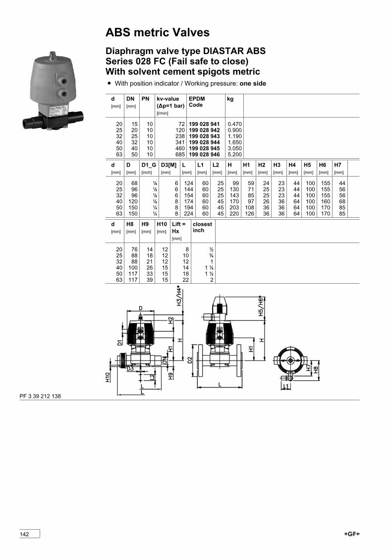
ABS metric ValvesDiaphragm valve type DIASTAR ABSSeries 028 FC (Fail safe to close)With solvent cement spigots metricÏ With position indicator / Working pressure: one side
d[mm]
DN[mm]
PN kv-value(�p=1 bar)[l/min]
EPDMCode
kg
20 15 10 72 199 028 941 0.47025 20 10 120 199 028 942 0.90032 25 10 238 199 028 943 1.19040 32 10 341 199 028 944 1.65050 40 10 460 199 028 945 3.05063 50 10 685 199 028 946 5.200
d[mm]
D[mm]
D1_G[inch]
D3[M][mm]
L[mm]
L1[mm]
L2[mm]
H[mm]
H1[mm]
H2[mm]
H3[mm]
H4[mm]
H5[mm]
H6[mm]
H7[mm]
20 68 1/8 6 124 60 25 99 59 24 23 44 100 155 4425 96 1/8 6 144 60 25 130 71 25 23 44 100 155 5632 96 1/8 6 154 60 25 143 85 25 23 44 100 155 5640 120 1/8 8 174 60 45 170 97 26 36 64 100 160 6850 150 1/4 8 194 60 45 203 108 36 36 64 100 170 8563 150 1/4 8 224 60 45 220 126 36 36 64 100 170 85
d[mm]
H8[mm]
H9[mm]
H10[mm]
Lift =Hx[mm]
closestinch
20 76 14 12 8 1/225 88 18 12 10 3/432 88 21 12 12 140 100 26 15 14 1 1/450 117 33 15 18 1 1/263 117 39 15 22 2
PF 3 39 212 138
142

ABS metric ValvesDiaphragm valve type DIASTAR ABSSeries 025 FC (Fail safe to close)With solvent cement spigots metricÏ With position indicator / Working pressure: both sides
d[mm]
DN[mm]
PN kv-value(�p=1 bar)[l/min]
EPDMCode
kg
20 15 10 72 199 025 941 0.60725 20 10 120 199 025 942 0.76632 25 10 238 199 025 943 1.32040 32 10 341 199 025 944 2.56250 40 10 460 199 025 945 3.50063 50 10 685 199 025 946 4.351
d[mm]
D[mm]
D1_G[inch]
D3[M][mm]
L[mm]
L1[mm]
L2[mm]
H[mm]
H1[mm]
H2[mm]
H3[mm]
H4[mm]
H5[mm]
H6[mm]
H7[mm]
20 96 1/8 6 124 60 25 128 69 25 23 44 100 155 5625 96 1/8 6 144 60 25 130 71 25 23 44 100 155 5632 120 1/8 6 154 60 25 166 93 26 36 64 100 155 6840 150 1/4 8 174 60 45 201 106 36 36 64 100 160 8550 180 1/4 8 194 60 45 233 119 37 36 64 100 170 10163 180 1/4 8 224 60 45 247 133 37 36 64 100 170 101
d[mm]
H8[mm]
H9[mm]
H10[mm]
Lift =Hx[mm]
closestinch
20 86 14 12 8 1/225 88 18 12 10 3/432 100 21 12 12 140 117 26 15 14 1 1/450 133 33 15 18 1 1/263 133 39 15 22 2
PF 3 39 212 051
143

ABS metric ValvesDiaphragm valve type DIASTAR ABSSeries 025 FC (Fail safe to close)With fixed flanges ABS metricModel:Ï Connecting dimensions: ISO 7005 / EN 1092 / DIN 2501 PN10 / BS4504
Ï With position indicator / Working pressure: one side
* with backing flanges PP-V metric** Connecting dimensions DN80 and DN150 metric and Inch ANSI B16.5d[mm]
DN[mm]
Inch PN kv-value(�p=1 bar)[l/min]
EPDMCode
kg
*75 65 2 1/2 10 992 199 025 947 13.600**90 80 3 10 1700 199 025 948 17.400110 100 4 8 2700 199 025 949 24.700d[mm]
D[mm]
D1_G[inch]
D2[mm]
D3[M][mm]
D4[mm]
L[mm]
L2[mm]
H[mm]
H1[mm]
H2[mm]
H3[mm]
H4[mm]
*75 280 1/4 185 8 145 290 70 344 148 24 46 100**90 280 1/4 200 12 160 310 120 348 150 24 46 100110 335 1/4 225 12 180 350 120 395 176 24 46 100d[mm]
H5[mm]
H6[mm]
H7[mm]
H9[mm]
H10[mm]
*75 129 195 298 46 15**90 129 195 302 57 15110 129 195 349 69 20
PF 3 39 212 051
144

ABS metric ValvesDiaphragm valve type DIASTAR ABSSeries 025 FO (Fail safe to open)With solvent cement spigots metricÏ With position indicator / Working pressure: both sides
d[mm]
DN[mm]
PN kv-value(�p=1 bar)[l/min]
EPDMCode
kg
20 15 10 72 199 025 951 0.40425 20 10 120 199 025 952 0.69032 25 10 238 199 025 953 0.98040 32 10 341 199 025 954 1.23050 40 10 460 199 025 955 2.21063 50 10 685 199 025 956 4.360
d[mm]
D[mm]
D1_G[inch]
D3[M][mm]
L[mm]
L1[mm]
L2[mm]
H[mm]
H1[mm]
H2[mm]
H3[mm]
H4[mm]
H5[mm]
H6[mm]
H7[mm]
20 68 1/8 6 124 60 25 99 59 24 23 44 100 155 4425 96 1/8 6 144 60 25 130 71 25 23 44 100 155 5632 96 1/8 6 154 60 25 143 85 25 23 44 100 155 5640 120 1/8 8 174 60 45 170 97 26 36 64 100 160 6850 150 1/4 8 194 60 45 203 108 36 36 64 100 170 8563 150 1/4 8 224 60 45 220 126 36 36 64 100 170 85
d[mm]
H8[mm]
H9[mm]
H10[mm]
Lift =Hx[mm]
closestinch
20 76 14 12 8 1/225 88 18 12 10 3/432 88 21 12 12 140 100 26 15 14 1 1/450 117 33 15 18 1 1/263 117 39 15 22 2
PF 3 39 212 053
145
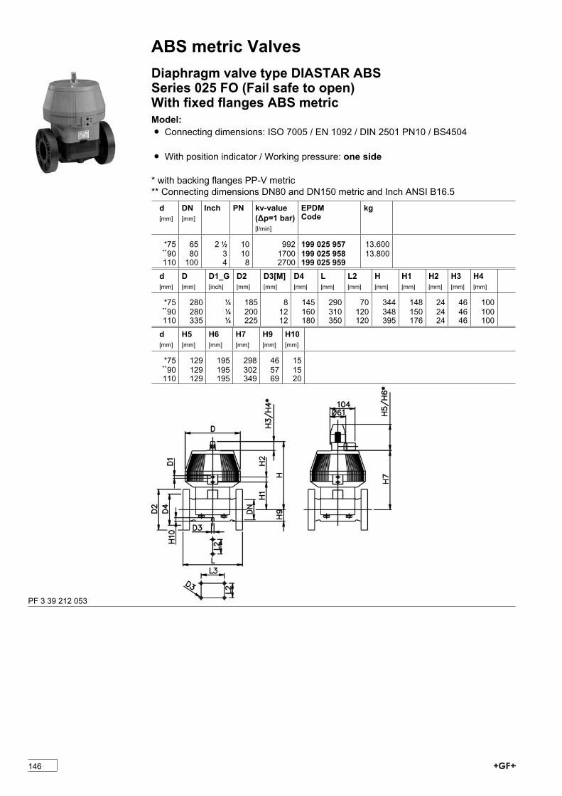
ABS metric ValvesDiaphragm valve type DIASTAR ABSSeries 025 FO (Fail safe to open)With fixed flanges ABS metricModel:Ï Connecting dimensions: ISO 7005 / EN 1092 / DIN 2501 PN10 / BS4504
Ï With position indicator / Working pressure: one side
* with backing flanges PP-V metric** Connecting dimensions DN80 and DN150 metric and Inch ANSI B16.5d[mm]
DN[mm]
Inch PN kv-value(�p=1 bar)[l/min]
EPDMCode
kg
*75 65 2 1/2 10 992 199 025 957 13.600**90 80 3 10 1700 199 025 958 13.800110 100 4 8 2700 199 025 959d[mm]
D[mm]
D1_G[inch]
D2[mm]
D3[M][mm]
D4[mm]
L[mm]
L2[mm]
H[mm]
H1[mm]
H2[mm]
H3[mm]
H4[mm]
*75 280 1/4 185 8 145 290 70 344 148 24 46 100**90 280 1/4 200 12 160 310 120 348 150 24 46 100110 335 1/4 225 12 180 350 120 395 176 24 46 100d[mm]
H5[mm]
H6[mm]
H7[mm]
H9[mm]
H10[mm]
*75 129 195 298 46 15**90 129 195 302 57 15110 129 195 349 69 20
PF 3 39 212 053
146
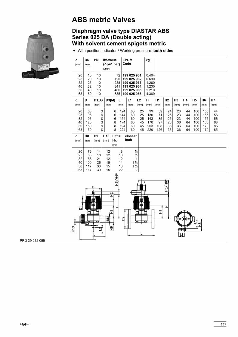
ABS metric ValvesDiaphragm valve type DIASTAR ABSSeries 025 DA (Double acting)With solvent cement spigots metricÏ With position indicator / Working pressure: both sides
d[mm]
DN[mm]
PN kv-value(�p=1 bar)[l/min]
EPDMCode
kg
20 15 10 72 199 025 961 0.40425 20 10 120 199 025 962 0.69032 25 10 238 199 025 963 1.26040 32 10 341 199 025 964 1.23050 40 10 460 199 025 965 2.21063 50 10 685 199 025 966 4.360
d[mm]
D[mm]
D1_G[inch]
D3[M][mm]
L[mm]
L1[mm]
L2[mm]
H[mm]
H1[mm]
H2[mm]
H3[mm]
H4[mm]
H5[mm]
H6[mm]
H7[mm]
20 68 1/8 6 124 60 25 99 59 24 23 44 100 155 4425 96 1/8 6 144 60 25 130 71 25 23 44 100 155 5632 96 1/8 6 154 60 25 143 85 25 23 44 100 155 5640 120 1/8 8 174 60 45 170 97 26 36 64 100 160 6850 150 1/4 8 194 60 45 203 108 36 36 64 100 170 8563 150 1/4 8 224 60 45 220 126 36 36 64 100 170 85
d[mm]
H8[mm]
H9[mm]
H10[mm]
Lift =Hx[mm]
closestinch
20 76 14 12 8 1/225 88 18 12 10 3/432 88 21 12 12 140 100 26 15 14 1 1/450 117 33 15 18 1 1/263 117 39 15 22 2
PF 3 39 212 055
147

ABS metric ValvesDiaphragm valve type DIASTAR ABSSeries 025 DA (Double acting)With fixed flanges ABS metricModel:Ï Connecting dimensions: ISO 7005 / EN 1092 / DIN 2501 PN10 / BS4504
Ï With position indicator / Working pressure: one side
* with backing flanges PP-V metric** Connecting dimensions DN80 and DN150 metric and Inch ANSI B16.5d[mm]
DN[mm]
Inch PN kv-value(�p=1 bar)[l/min]
EPDMCode
kg
*75 65 2 1/2 10 992 199 025 967**90 80 3 10 1700 199 025 968 17.400110 100 4 8 2700 199 025 969d[mm]
D[mm]
D1_G[inch]
D2[mm]
D3[M][mm]
D4[mm]
L[mm]
L2[mm]
H[mm]
H1[mm]
H2[mm]
H3[mm]
H4[mm]
*75 280 1/4 185 8 145 290 70 344 148 24 46 100**90 280 1/4 200 12 160 310 120 348 150 24 46 100110 335 1/4 225 12 180 350 120 395 176 24 46 100d[mm]
H5[mm]
H6[mm]
H7[mm]
H9[mm]
H10[mm]
*75 129 195 298 46 15**90 129 195 302 57 15110 129 195 349 69 20
PF 3 39 212 055
148
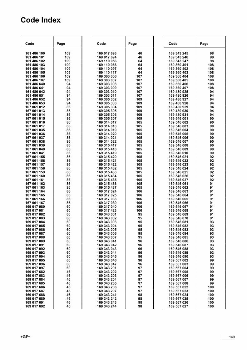
Code Index
Code Page
161 486 100 109161 486 101 109161 486 102 109161 486 103 109161 486 104 109161 486 105 109161 486 106 109161 486 107 109161 486 640 94161 486 641 94161 486 642 94161 486 651 94161 486 652 94161 486 653 94167 061 012 86167 061 013 86167 061 014 86167 061 015 86167 061 016 86167 061 017 86167 061 035 86167 061 036 86167 061 037 86167 061 038 86167 061 039 86167 061 040 86167 061 041 86167 061 155 86167 061 156 86167 061 157 86167 061 158 86167 061 159 86167 061 160 86167 061 161 86167 061 162 86167 061 163 86167 061 164 86167 061 165 86167 061 166 86167 061 167 86169 017 080 60169 017 081 60169 017 082 60169 017 083 60169 017 084 60169 017 085 60169 017 086 60169 017 087 60169 017 088 60169 017 089 60169 017 091 60169 017 092 60169 017 093 60169 017 094 60169 017 095 60169 017 096 60169 017 097 60169 017 682 46169 017 683 46169 017 684 46169 017 685 46169 017 686 46169 017 687 46169 017 688 46169 017 689 46169 017 691 46169 017 692 46
Code Page
169 017 693 46169 017 694 46169 110 056 64169 110 066 64169 110 097 64169 110 117 64169 303 006 107169 303 007 107169 303 008 107169 303 009 107169 303 010 107169 303 011 107169 305 302 109169 305 303 109169 305 304 109169 305 305 109169 305 306 109169 305 307 109169 314 017 105169 314 018 105169 314 019 105169 314 020 105169 314 021 105169 314 022 105169 315 417 105169 315 418 105169 315 419 105169 315 420 105169 315 421 105169 315 422 105169 315 432 105169 315 433 105169 315 434 105169 315 435 105169 315 436 105169 315 437 105169 317 024 106169 317 025 106169 317 038 106169 317 039 106169 317 040 106169 317 423 106169 343 001 95169 343 002 95169 343 003 95169 343 004 95169 343 005 95169 343 006 95169 343 007 95169 343 041 96169 343 042 96169 343 043 96169 343 044 96169 343 045 96169 343 046 96169 343 047 96169 343 201 97169 343 202 97169 343 203 97169 343 204 97169 343 205 97169 343 206 97169 343 207 97169 343 241 98169 343 242 98169 343 243 98169 343 244 98
Code Page
169 343 245 98169 343 246 98169 343 247 98169 360 401 108169 360 402 108169 360 403 108169 360 404 108169 360 405 108169 360 406 108169 360 407 108169 480 925 94169 480 926 94169 480 927 94169 480 928 94169 480 929 94169 480 930 94169 480 931 94169 546 001 90169 546 002 90169 546 003 90169 546 004 90169 546 005 90169 546 006 90169 546 007 90169 546 008 90169 546 009 90169 546 010 90169 546 021 92169 546 022 92169 546 023 92169 546 024 92169 546 025 92169 546 026 92169 546 027 92169 546 061 91169 546 062 91169 546 063 91169 546 064 91169 546 065 91169 546 066 91169 546 067 91169 546 068 91169 546 069 91169 546 070 91169 546 081 93169 546 082 93169 546 083 93169 546 084 93169 546 085 93169 546 086 93169 546 087 93169 546 088 93169 546 089 93169 546 090 93169 567 002 99169 567 003 99169 567 004 99169 567 005 99169 567 006 99169 567 007 99169 567 008 99169 567 022 100169 567 023 100169 567 024 100169 567 025 100169 567 026 100169 567 027 100
149
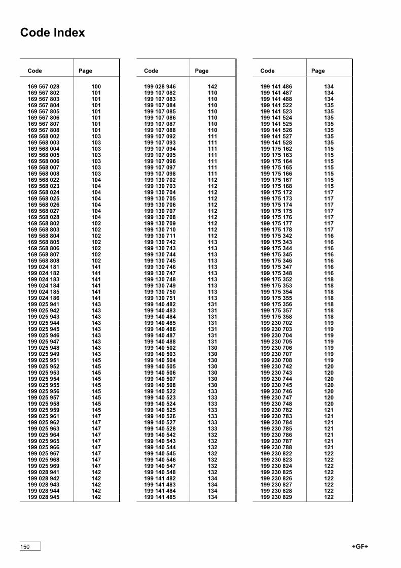
Code Index
Code Page
169 567 028 100169 567 802 101169 567 803 101169 567 804 101169 567 805 101169 567 806 101169 567 807 101169 567 808 101169 568 002 103169 568 003 103169 568 004 103169 568 005 103169 568 006 103169 568 007 103169 568 008 103169 568 022 104169 568 023 104169 568 024 104169 568 025 104169 568 026 104169 568 027 104169 568 028 104169 568 802 102169 568 803 102169 568 804 102169 568 805 102169 568 806 102169 568 807 102169 568 808 102199 024 181 141199 024 182 141199 024 183 141199 024 184 141199 024 185 141199 024 186 141199 025 941 143199 025 942 143199 025 943 143199 025 944 143199 025 945 143199 025 946 143199 025 947 143199 025 948 143199 025 949 143199 025 951 145199 025 952 145199 025 953 145199 025 954 145199 025 955 145199 025 956 145199 025 957 145199 025 958 145199 025 959 145199 025 961 147199 025 962 147199 025 963 147199 025 964 147199 025 965 147199 025 966 147199 025 967 147199 025 968 147199 025 969 147199 028 941 142199 028 942 142199 028 943 142199 028 944 142199 028 945 142
Code Page
199 028 946 142199 107 082 110199 107 083 110199 107 084 110199 107 085 110199 107 086 110199 107 087 110199 107 088 110199 107 092 111199 107 093 111199 107 094 111199 107 095 111199 107 096 111199 107 097 111199 107 098 111199 130 702 112199 130 703 112199 130 704 112199 130 705 112199 130 706 112199 130 707 112199 130 708 112199 130 709 112199 130 710 112199 130 711 112199 130 742 113199 130 743 113199 130 744 113199 130 745 113199 130 746 113199 130 747 113199 130 748 113199 130 749 113199 130 750 113199 130 751 113199 140 482 131199 140 483 131199 140 484 131199 140 485 131199 140 486 131199 140 487 131199 140 488 131199 140 502 130199 140 503 130199 140 504 130199 140 505 130199 140 506 130199 140 507 130199 140 508 130199 140 522 133199 140 523 133199 140 524 133199 140 525 133199 140 526 133199 140 527 133199 140 528 133199 140 542 132199 140 543 132199 140 544 132199 140 545 132199 140 546 132199 140 547 132199 140 548 132199 141 482 134199 141 483 134199 141 484 134199 141 485 134
Code Page
199 141 486 134199 141 487 134199 141 488 134199 141 522 135199 141 523 135199 141 524 135199 141 525 135199 141 526 135199 141 527 135199 141 528 135199 175 162 115199 175 163 115199 175 164 115199 175 165 115199 175 166 115199 175 167 115199 175 168 115199 175 172 117199 175 173 117199 175 174 117199 175 175 117199 175 176 117199 175 177 117199 175 178 117199 175 342 116199 175 343 116199 175 344 116199 175 345 116199 175 346 116199 175 347 116199 175 348 116199 175 352 118199 175 353 118199 175 354 118199 175 355 118199 175 356 118199 175 357 118199 175 358 118199 230 702 119199 230 703 119199 230 704 119199 230 705 119199 230 706 119199 230 707 119199 230 708 119199 230 742 120199 230 743 120199 230 744 120199 230 745 120199 230 746 120199 230 747 120199 230 748 120199 230 782 121199 230 783 121199 230 784 121199 230 785 121199 230 786 121199 230 787 121199 230 788 121199 230 822 122199 230 823 122199 230 824 122199 230 825 122199 230 826 122199 230 827 122199 230 828 122199 230 829 122
150

Code Index
Code Page
199 230 830 122199 230 831 122199 230 862 123199 230 863 123199 230 864 123199 230 865 123199 230 866 123199 230 867 123199 230 868 123199 230 869 123199 230 870 123199 230 871 123199 230 902 124199 230 903 124199 230 904 124199 230 905 124199 230 906 124199 230 907 124199 230 908 124199 230 909 124199 230 910 124199 230 911 124199 240 402 136199 240 403 136199 240 404 136199 240 405 136199 240 406 136199 240 407 136199 240 408 136199 240 422 137199 240 423 137199 240 424 137199 240 425 137199 240 426 137199 240 427 137199 240 428 137199 240 442 138199 240 443 138199 240 444 138199 240 445 138199 240 446 138199 240 447 138199 240 448 138199 241 422 139199 241 423 139199 241 424 139199 241 425 139199 241 426 139199 241 427 139199 241 428 139199 241 442 140199 241 443 140199 241 444 140199 241 445 140199 241 446 140199 241 447 140199 241 448 140199 275 162 126199 275 163 126199 275 164 126199 275 165 126199 275 166 126199 275 167 126199 275 168 126199 275 172 128199 275 173 128199 275 174 128
Code Page
199 275 175 128199 275 176 128199 275 177 128199 275 178 128199 275 342 127199 275 343 127199 275 344 127199 275 345 127199 275 346 127199 275 347 127199 275 348 127199 275 352 129199 275 353 129199 275 354 129199 275 355 129199 275 356 129199 275 357 129199 275 358 129700 244 660 67700 262 080 46700 262 081 46700 262 082 46700 262 083 46700 262 084 46700 262 085 46700 262 086 46700 262 087 46700 262 088 46700 262 089 46700 262 091 46700 262 092 46700 262 093 46700 262 094 46720 510 105 75720 510 106 75720 510 107 75720 510 108 75720 510 109 75720 510 110 75720 600 206 79720 600 207 79720 600 208 79720 600 209 79720 600 210 79720 600 211 79720 600 212 79720 600 213 79720 600 226 79720 600 227 79720 600 228 79720 600 229 79720 600 230 79720 600 231 79720 600 232 79720 600 233 79724 600 206 80724 600 207 80724 600 208 80724 600 209 80724 600 210 80724 600 211 80724 600 212 80724 600 213 80724 600 655 78724 600 656 78724 600 657 78724 600 658 78
Code Page
724 600 659 78724 600 660 78724 600 661 78724 600 705 78724 600 706 78724 600 707 78724 600 708 78724 600 709 78724 600 710 78724 600 711 78724 600 806 80724 600 807 80724 600 808 80724 600 809 80724 600 810 80724 600 811 80724 600 812 80724 600 813 80724 605 505 79724 605 506 79724 605 507 79724 605 508 79724 605 509 79724 605 510 79724 605 511 79727 700 021 83727 700 206 83727 700 207 83727 700 208 83727 700 209 83727 700 210 83727 700 211 83727 700 212 83727 700 213 83727 700 214 83727 700 215 83727 700 216 83727 700 217 83727 700 219 83727 700 220 83727 700 221 83727 700 222 83727 700 223 83727 700 406 82727 700 407 82727 700 408 82727 700 409 82727 700 410 82727 700 411 82727 700 412 82727 700 413 82727 700 414 82727 700 416 82727 700 417 82727 700 419 82727 700 420 82727 700 421 82727 700 422 82727 700 423 82729 000 106 61729 000 107 61729 000 108 61729 000 109 61729 000 110 61729 000 111 61729 000 112 61729 000 113 61
151

Code Index
Code Page
729 000 114 61729 000 116 61729 000 117 61729 010 120 61729 010 122 61729 010 123 61729 100 105 62729 100 106 62729 100 107 62729 100 108 62729 100 109 62729 100 110 62729 100 111 62729 100 112 62729 100 113 62729 100 114 62729 100 116 62729 100 117 62729 100 119 62729 100 121 62729 100 206 69729 100 207 69729 100 208 69729 100 209 69729 100 210 69729 100 211 69729 150 106 62729 150 107 62729 150 108 62729 150 109 62729 150 110 62729 150 111 62729 150 112 62729 150 113 62729 150 114 62729 150 116 62729 150 117 62729 150 119 62729 150 120 62729 150 121 62729 150 122 62729 150 123 62729 200 010 63729 200 011 63729 200 105 63729 200 106 63729 200 107 63729 200 108 63729 200 109 63729 200 110 63729 200 111 63729 200 112 63729 200 113 63729 200 114 63729 200 116 63729 200 117 63729 200 119 63729 200 120 63729 200 121 63729 200 122 63729 200 123 63729 200 134 63729 200 136 63729 200 138 63729 200 143 63729 200 144 63729 200 146 63
Code Page
729 200 147 63729 200 148 63729 200 149 63729 200 151 63729 200 153 63729 200 156 63729 200 157 63729 200 158 63729 200 164 63729 200 170 63729 200 178 63729 200 182 63729 250 106 64729 250 107 64729 250 108 64729 250 109 64729 250 110 64729 250 111 64729 250 112 64729 250 113 64729 250 114 64729 250 116 64729 300 108 65729 300 111 65729 310 007 73729 310 008 73729 310 009 73729 310 010 73729 310 011 73729 312 012 73729 312 013 73729 312 014 73729 312 016 73729 312 017 73729 312 019 73729 312 020 73729 510 105 74729 510 106 74729 510 107 74729 510 108 74729 510 109 74729 510 110 74729 510 111 74729 510 112 74729 510 113 74729 510 114 74729 530 306 75729 530 307 75729 530 308 75729 530 309 75729 530 310 75729 530 311 75729 530 806 76729 530 807 76729 530 808 76729 530 809 76729 530 810 76729 530 811 76729 540 205 74729 540 206 74729 540 207 74729 540 208 74729 540 209 74729 540 210 74729 540 211 74729 540 705 74729 540 706 74
Code Page
729 540 707 74729 540 708 74729 540 709 74729 540 710 74729 540 711 74729 545 505 75729 545 506 75729 545 507 75729 545 508 75729 545 509 75729 545 510 75729 545 511 75729 550 306 76729 550 307 76729 550 308 76729 550 309 76729 550 310 76729 550 311 76729 550 806 76729 550 807 76729 550 808 76729 550 809 76729 550 810 76729 550 811 76729 600 105 77729 600 106 77729 600 107 77729 600 108 77729 600 109 77729 600 110 77729 600 111 77729 600 162 77729 600 163 77729 600 164 77729 640 105 77729 640 106 77729 640 107 77729 640 108 77729 640 109 77729 640 110 77729 640 111 77729 640 112 77729 640 113 77729 640 114 77729 690 012 78729 690 013 78729 690 014 78729 690 405 78729 690 406 78729 690 407 78729 690 408 78729 690 409 78729 690 410 78729 690 411 78729 790 106 81729 790 107 81729 790 108 81729 790 109 81729 790 110 81729 790 111 81729 790 112 81729 790 113 81729 790 114 81729 790 116 81729 790 117 81729 790 119 81729 790 120 81
152

Code Index
Code Page
729 790 121 81729 790 122 81729 790 123 81729 791 106 81729 791 107 81729 791 108 81729 791 109 81729 791 110 81729 791 111 81729 791 113 81729 791 115 81729 791 117 81729 791 120 81729 900 181 67729 900 303 67729 900 306 67729 900 312 67729 900 334 67729 900 337 67729 900 341 67729 900 342 67729 900 346 67729 900 347 67729 900 348 67729 900 352 67729 900 353 67729 900 354 67729 900 355 67729 900 358 67729 900 359 67729 900 360 67729 900 364 67729 900 365 67729 900 370 67729 900 371 67729 900 372 67729 900 376 67729 900 378 67729 900 385 67729 900 388 67729 900 390 67729 900 392 67729 900 396 67729 900 406 70729 900 407 70729 900 408 70729 900 409 70729 900 410 70729 900 411 70729 900 905 66729 900 906 66729 900 907 66729 900 908 66729 900 909 66729 900 910 66729 900 911 66729 900 912 66729 900 913 66729 900 914 66729 910 105 65729 910 106 65729 910 107 65729 910 108 65729 910 109 65729 910 110 65729 910 111 65729 910 112 65
Code Page
729 910 113 65729 910 114 65729 910 116 65729 910 117 65729 910 119 65729 910 120 65729 910 121 65729 910 122 65729 910 123 65729 910 206 69729 910 207 69729 910 208 69729 910 209 69729 910 210 69729 910 211 69729 910 342 67729 910 347 67729 910 354 67729 910 360 67729 910 366 67729 910 371 67729 910 434 70729 910 437 70729 910 441 70729 910 446 70729 910 452 70729 910 458 70729 910 505 71729 910 556 71729 910 557 71729 910 558 71729 910 559 71729 910 560 71729 910 561 71729 910 606 72729 910 607 72729 910 608 72729 911 505 70729 911 506 70729 911 507 70729 911 508 70729 911 509 70729 911 510 70729 911 511 70729 911 513 70729 911 515 70729 911 906 72729 911 907 72729 911 908 72729 913 105 66729 913 106 66729 913 107 66729 913 108 66729 913 109 66729 913 110 66729 913 111 66729 913 113 66729 913 115 66729 960 105 68729 960 106 68729 960 107 68729 960 108 68729 960 109 68729 960 110 68729 960 111 68729 960 112 68729 960 113 68
Code Page
729 960 114 68729 960 116 68729 960 117 68729 960 405 68729 960 406 68729 960 407 68729 960 408 68729 961 906 72729 961 907 72729 961 908 72733 960 135 56733 960 140 56733 960 171 54733 960 172 54733 960 173 54733 960 174 54733 960 175 54733 960 176 54733 960 177 54733 960 178 54733 960 180 54733 960 181 54733 960 183 54733 960 184 54738 001 107 47738 001 108 47738 001 109 47738 001 110 47738 001 111 47738 001 112 47738 001 113 47738 001 114 47738 001 116 47738 001 117 47738 001 120 47738 011 102 54738 011 103 54738 011 104 56738 011 105 56738 011 106 56738 011 131 55738 011 132 55738 011 133 55738 011 134 55738 011 150 54738 011 151 55738 011 167 55738 011 170 55738 011 173 55738 101 117 47738 101 119 47738 151 107 48738 151 108 48738 151 109 48738 151 110 48738 151 111 48738 151 112 48738 151 113 48738 151 114 48738 151 116 48738 151 117 48738 151 119 48738 151 120 48738 201 011 48738 201 012 48738 201 107 48738 201 108 48
153
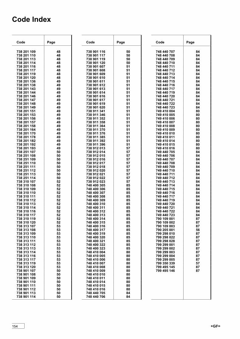
Code Index
Code Page
738 201 109 48738 201 110 48738 201 113 48738 201 114 48738 201 116 48738 201 117 48738 201 119 48738 201 120 48738 201 136 49738 201 138 49738 201 143 49738 201 144 49738 201 146 49738 201 147 49738 201 148 49738 201 149 49738 201 151 49738 201 153 49738 201 156 49738 201 157 49738 201 158 49738 201 164 49738 201 170 49738 201 178 49738 201 182 49738 201 192 49738 201 193 49738 251 107 50738 251 108 50738 251 109 50738 251 110 50738 251 111 50738 251 112 50738 251 113 50738 251 114 50738 310 107 52738 310 108 52738 310 109 52738 310 110 52738 310 111 52738 310 112 52738 310 113 52738 310 114 52738 310 116 52738 310 117 52738 310 119 52738 310 120 52738 313 107 53738 313 108 53738 313 109 53738 313 110 53738 313 111 53738 313 112 53738 313 113 53738 313 114 53738 313 116 53738 313 117 53738 313 119 53738 313 120 53738 901 107 50738 901 108 50738 901 109 50738 901 110 50738 901 111 50738 901 112 50738 901 113 50738 901 114 50
Code Page
738 901 116 50738 901 117 50738 901 119 50738 901 120 50738 901 607 51738 901 608 51738 901 609 51738 901 610 51738 901 611 51738 901 612 51738 901 613 51738 901 614 51738 901 616 51738 901 617 51738 901 619 51738 901 620 51738 911 341 51738 911 346 51738 911 352 51738 911 358 51738 911 364 51738 911 370 51738 911 376 51738 911 385 51738 911 392 51738 911 396 51738 912 013 57738 912 014 57738 912 015 57738 912 016 57738 912 017 57738 912 018 57738 912 020 57738 912 021 57738 912 022 57738 912 023 57748 400 305 85748 400 306 85748 400 307 85748 400 308 85748 400 309 85748 400 310 85748 400 311 85748 400 312 85748 400 313 85748 400 314 85748 400 315 85748 400 316 85748 400 317 85748 400 319 85748 400 320 85748 400 321 85748 400 322 85748 400 323 85748 410 004 80748 410 005 80748 410 006 80748 410 007 80748 410 008 80748 410 009 80748 410 010 80748 410 011 80748 410 014 80748 410 015 80748 410 016 80748 440 705 84748 440 706 84
Code Page
748 440 707 84748 440 708 84748 440 709 84748 440 710 84748 440 711 84748 440 712 84748 440 713 84748 440 714 84748 440 715 84748 440 716 84748 440 717 84748 440 719 84748 440 720 84748 440 721 84748 440 722 84748 440 723 84749 410 004 80749 410 005 80749 410 006 80749 410 007 80749 410 008 80749 410 009 80749 410 010 80749 410 011 80749 410 014 80749 410 015 80749 410 016 80749 440 705 84749 440 706 84749 440 707 84749 440 708 84749 440 709 84749 440 710 84749 440 711 84749 440 712 84749 440 713 84749 440 714 84749 440 715 84749 440 716 84749 440 717 84749 440 719 84749 440 720 84749 440 721 84749 440 722 84749 440 723 84790 109 001 87790 109 002 87790 109 003 87790 205 001 56799 298 010 87799 298 022 87799 298 028 87799 299 001 87799 299 002 87799 299 003 87799 299 004 87799 299 005 87799 350 339 57799 495 145 87799 495 146 87
154
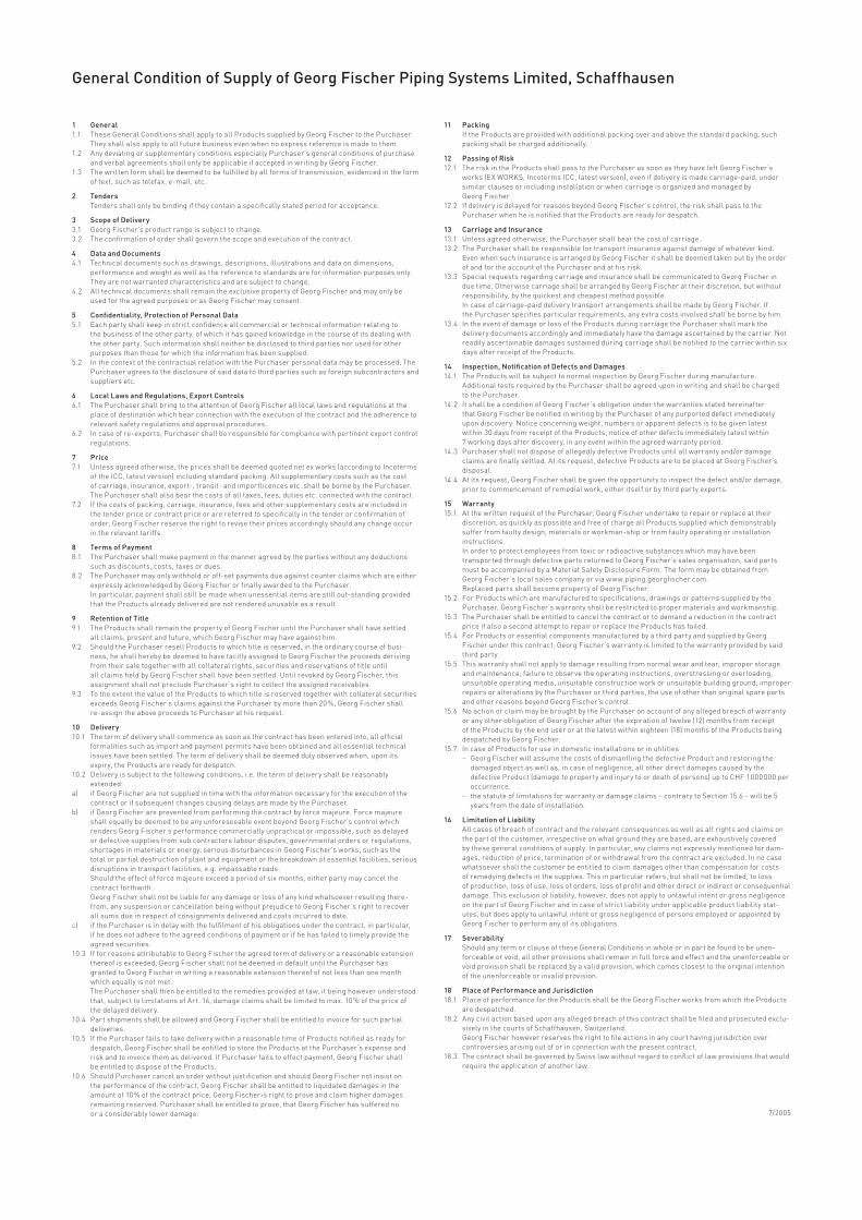
General Condition of Supply of Georg Fischer Piping Systems Limited, Schaffhausen
1 General1.1 TheseGeneralConditionsshallapplytoallProductssuppliedbyGeorgFischertothePurchaser Theyshallalsoapplytoallfuturebusinessevenwhennoexpressreferenceismadetothem1.2 AnydeviatingorsupplementaryconditionsespeciallyPurchaser’sgeneralconditionsofpurchase
andverbalagreementsshallonlybeapplicableifacceptedinwritingbyGeorgFischer.1.3 Thewrittenformshallbedeemedtobefulfilledbyallformsoftransmission,evidencedintheform
oftext,suchastelefax,e-mail,etc.
2 Tenders Tendersshallonlybebindingiftheycontainaspecificallystatedperiodforacceptance.
3 Scope of Delivery3.1 GeorgFischer’sproductrangeissubjecttochange.3.2 Theconfirmationofordershallgovernthescopeandexecutionofthecontract.
4 Data and Documents4.1 Technicaldocumentssuchasdrawings,descriptions,illustrationsanddataondimensions,
performanceandweightaswellasthereferencetostandardsareforinformationpurposesonly.Theyarenotwarrantedcharacteristicsandaresubjecttochange.
4.2 AlltechnicaldocumentsshallremaintheexclusivepropertyofGeorgFischerandmayonlybeusedfortheagreedpurposesorasGeorgFischermayconsent.
5 Confidentiality, Protection of Personal Data5.1 Eachpartyshallkeepinstrictconfidenceallcommercialortechnicalinformationrelatingto
thebusinessoftheotherparty,ofwhichithasgainedknowledgeinthecourseofitsdealingwiththeotherparty.Suchinformationshallneitherbedisclosedtothirdpartiesnorusedforotherpurposesthanthoseforwhichtheinformationhasbeensupplied.
5.2 InthecontextofthecontractualrelationwiththePurchaserpersonaldatamaybeprocessed.ThePurchaseragreestothedisclosureofsaiddatatothirdpartiessuchasforeignsubcontractorsandsuppliersetc.
6 Local Laws and Regulations, Export Controls6.1 ThePurchasershallbringtotheattentionofGeorgFischeralllocallawsandregulationsatthe
placeofdestinationwhichbearconnectionwiththeexecutionofthecontractandtheadherencetorelevantsafetyregulationsandapprovalprocedures.
6.2 Incaseofre-exports,Purchasershallberesponsibleforcompliancewithpertinentexportcontrolregulations.
7 Price7.1 Unlessagreedotherwise,thepricesshallbedeemedquotednetexworks(accordingtoIncoterms
oftheICC,latestversion)includingstandardpacking.Allsupplementarycostssuchasthecostofcarriage,insurance,export-,transit-andimportlicencesetc.shallbebornebythePurchaser.ThePurchasershallalsobearthecostsofalltaxes,fees,dutiesetc.connectedwiththecontract.
7.2 Ifthecostsofpacking,carriage,insurance,feesandothersupplementarycostsareincludedinthetenderpriceorcontractpriceorarereferredtospecificallyinthetenderorconfirmationoforder,GeorgFischerreservetherighttorevisetheirpricesaccordinglyshouldanychangeoccurintherelevanttariffs.
8 Terms of Payment8.1 ThePurchasershallmakepaymentinthemanneragreedbythepartieswithoutanydeductions
suchasdiscounts,costs,taxesordues.8.2 ThePurchasermayonlywithholdoroff-setpaymentsdueagainstcounterclaimswhichareeither
expresslyacknowledgedbyGeorgFischerorfinallyawardedtothePurchaser. Inparticular,paymentshallstillbemadewhenunessentialitemsarestillout-standingprovided
thattheProductsalreadydeliveredarenotrenderedunusableasaresult.
9 Retention of Title9.1 TheProductsshallremainthepropertyofGeorgFischeruntilthePurchasershallhavesettled
allclaims,presentandfuture,whichGeorgFischermayhaveagainsthim.9.2 ShouldthePurchaserresellProductstowhichtitleisreserved,intheordinarycourseofbusi-
ness,heshallherebybedeemedtohavetacitlyassignedtoGeorgFischertheproceedsderivingfromtheirsaletogetherwithallcollateralrights,securitiesandreservationsoftitleuntilallclaimsheldbyGeorgFischershallhavebeensettled.UntilrevokedbyGeorgFischer,thisassignmentshallnotprecludePurchaser’srighttocollecttheassignedreceivables.
9.3 TotheextentthevalueoftheProductstowhichtitleisreservedtogetherwithcollateralsecuritiesexceedsGeorgFischer’sclaimsagainstthePurchaserbymorethan20%,GeorgFischershallre-assigntheaboveproceedstoPurchaserathisrequest.
10 Delivery10.1 Thetermofdeliveryshallcommenceassoonasthecontracthasbeenenteredinto,allofficial
formalitiessuchasimportandpaymentpermitshavebeenobtainedandallessentialtechnicalissueshavebeensettled.Thetermofdeliveryshallbedeemeddulyobservedwhen,uponitsexpiry,theProductsarereadyfordespatch.
10.2 Deliveryissubjecttothefollowingconditions,i.e.thetermofdeliveryshallbereasonablyextended:
a) ifGeorgFischerarenotsuppliedintimewiththeinformationnecessaryfortheexecutionofthecontractorifsubsequentchangescausingdelaysaremadebythePurchaser.
b) ifGeorgFischerarepreventedfromperformingthecontractbyforcemajeure.ForcemajeureshallequallybedeemedtobeanyunforeseeableeventbeyondGeorgFischer’scontrolwhichrendersGeorgFischer’sperformancecommerciallyunpracticalorimpossible,suchasdelayedordefectivesuppliesfromsubcontractorslabourdisputes,governmentalordersorregulations,shortagesinmaterialsorenergy,seriousdisturbancesinGeorgFischer’sworks,suchasthetotalorpartialdestructionofplantandequipmentorthebreakdownofessentialfacilities,seriousdisruptionsintransportfacilities,e.g.impassableroads.
Shouldtheeffectofforcemajeureexceedaperiodofsixmonths,eitherpartymaycancelthecontractforthwith.
GeorgFischershallnotbeliableforanydamageorlossofanykindwhatsoeverresultingthere-from,anysuspensionorcancellationbeingwithoutprejudicetoGeorgFischer’srighttorecoverallsumsdueinrespectofconsignmentsdeliveredandcostsincurredtodate.
c) ifthePurchaserisindelaywiththefulfilmentofhisobligationsunderthecontract,inparticular,ifhedoesnotadheretotheagreedconditionsofpaymentorifhehasfailedtotimelyprovidetheagreedsecurities.
10.3 IfforreasonsattributabletoGeorgFischertheagreedtermofdeliveryorareasonableextensionthereofisexceeded,GeorgFischershallnotbedeemedindefaultuntilthePurchaserhasgrantedtoGeorgFischerinwritingareasonableextensionthereofofnotlessthanonemonthwhichequallyisnotmet.
ThePurchasershallthenbeentitledtotheremediesprovidedatlaw,itbeinghoweverunderstoodthat,subjecttolimitationsofArt.16,damageclaimsshallbelimitedtomax.10%ofthepriceofthedelayeddelivery.
10.4 PartshipmentsshallbeallowedandGeorgFischershallbeentitledtoinvoiceforsuchpartialdeliveries.
10.5 IfthePurchaserfailstotakedeliverywithinareasonabletimeofProductsnotifiedasreadyfordespatch,GeorgFischershallbeentitledtostoretheProductsatthePurchaser’sexpenseandriskandtoinvoicethemasdelivered.IfPurchaserfailstoeffectpayment,GeorgFischershallbeentitledtodisposeoftheProducts.
10.6 ShouldPurchasercancelanorderwithoutjustificationandshouldGeorgFischernotinsistontheperformanceofthecontract,GeorgFischershallbeentitledtoliquidateddamagesintheamountof10%ofthecontractprice,GeorgFischer›srighttoproveandclaimhigherdamagesremainingreserved.Purchasershallbeentitledtoprove,thatGeorgFischerhassufferednooraconsiderablylowerdamage.
11 Packing IftheProductsareprovidedwithadditionalpackingoverandabovethestandardpacking,such
packingshallbechargedadditionally.
12 Passing of Risk12.1 TheriskintheProductsshallpasstothePurchaserassoonastheyhaveleftGeorgFischer’s
works(EXWORKS,IncotermsICC,latestversion),evenifdeliveryismadecarriage-paid,undersimilarclausesorincludinginstallationorwhencarriageisorganizedandmanagedbyGeorgFischer.
12.2 IfdeliveryisdelayedforreasonsbeyondGeorgFischer’scontrol,theriskshallpasstothePurchaserwhenheisnotifiedthattheProductsarereadyfordespatch.
13 Carriage and Insurance13.1 Unlessagreedotherwise,thePurchasershallbearthecostofcarriage.13.2 ThePurchasershallberesponsiblefortransportinsuranceagainstdamageofwhateverkind. EvenwhensuchinsuranceisarrangedbyGeorgFischeritshallbedeemedtakenoutbytheorder
ofandfortheaccountofthePurchaserandathisrisk.13.3 SpecialrequestsregardingcarriageandinsuranceshallbecommunicatedtoGeorgFischerin
duetime.OtherwisecarriageshallbearrangedbyGeorgFischerattheirdiscretion,butwithoutresponsibility,bythequickestandcheapestmethodpossible.
Incaseofcarriage-paiddeliverytransportarrangementsshallbemadebyGeorgFischer.IfthePurchaserspecifiesparticularrequirements,anyextracostsinvolvedshallbebornebyhim.
13.4 IntheeventofdamageorlossoftheProductsduringcarriagethePurchasershallmarkthedeliverydocumentsaccordinglyandimmediatelyhavethedamageascertainedbythecarrier.NotreadilyascertainabledamagessustainedduringcarriageshallbenotifiedtothecarrierwithinsixdaysafterreceiptoftheProducts.
14 Inspection, Notification of Defects and Damages14.1 TheProductswillbesubjecttonormalinspectionbyGeorgFischerduringmanufacture. AdditionaltestsrequiredbythePurchasershallbeagreeduponinwritingandshallbecharged
tothePurchaser.14.2 ItshallbeaconditionofGeorgFischer’sobligationunderthewarrantiesstatedhereinafter
thatGeorgFischerbenotifiedinwritingbythePurchaserofanypurporteddefectimmediatelyupondiscovery.Noticeconcerningweight,numbersorapparentdefectsistobegivenlatestwithin30daysfromreceiptoftheProducts,noticeofotherdefectsimmediatelylatestwithin7workingdaysafterdiscovery,inanyeventwithintheagreedwarrantyperiod.
14.3 PurchasershallnotdisposeofallegedlydefectiveProductsuntilallwarrantyand/ordamageclaimsarefinallysettled.Atitsrequest,defectiveProductsaretobeplacedatGeorgFischer’sdisposal.
14.4 Atitsrequest,GeorgFischershallbegiventheopportunitytoinspectthedefectand/ordamage,priortocommencementofremedialwork,eitheritselforbythirdpartyexperts.
15 Warranty15.1 AtthewrittenrequestofthePurchaser,GeorgFischerundertaketorepairorreplaceattheir
discretion,asquicklyaspossibleandfreeofchargeallProductssuppliedwhichdemonstrablysufferfromfaultydesign,materialsorworkman-shiporfromfaultyoperatingorinstallationinstructions.
InordertoprotectemployeesfromtoxicorradioactivesubstanceswhichmayhavebeentransportedthroughdefectivepartsreturnedtoGeorgFischer’ssalesorganisation,saidpartsmustbeaccompaniedbyaMaterialSafetyDisclosureForm.TheformmaybeobtainedfromGeorgFischer’slocalsalescompanyorviawww.piping.georgfischer.com.
ReplacedpartsshallbecomepropertyofGeorgFischer.15.2 ForProductswhicharemanufacturedtospecifications,drawingsorpatternssuppliedbythe
Purchaser,GeorgFischer’swarrantyshallberestrictedtopropermaterialsandworkmanship.15.3 ThePurchasershallbeentitledtocancelthecontractortodemandareductioninthecontract
priceifalsoasecondattempttorepairorreplacetheProductshasfailed.15.4 ForProductsoressentialcomponentsmanufacturedbyathirdpartyandsuppliedbyGeorg
Fischerunderthiscontract,GeorgFischer’swarrantyislimitedtothewarrantyprovidedbysaidthirdparty.
15.5 Thiswarrantyshallnotapplytodamageresultingfromnormalwearandtear,improperstorageandmaintenance,failuretoobservetheoperatinginstructions,overstressingoroverloading,unsuitableoperatingmedia,unsuitableconstructionworkorunsuitablebuildingground,improperrepairsoralterationsbythePurchaserorthirdparties,theuseofotherthanoriginalsparepartsandotherreasonsbeyondGeorgFischer’scontrol.
15.6 NoactionorclaimmaybebroughtbythePurchaseronaccountofanyallegedbreachofwarrantyoranyotherobligationofGeorgFischeraftertheexpirationoftwelve(12)monthsfromreceiptoftheProductsbytheenduseroratthelatestwithineighteen(18)monthsoftheProductsbeingdespatchedbyGeorgFischer.
15.7 IncaseofProductsforuseindomesticinstallationsorinutilities – GeorgFischerwillassumethecostsofdismantlingthedefectiveProductandrestoringthe
damagedobjectaswellas,incaseofnegligence,allotherdirectdamagescausedbythedefectiveProduct(damagetopropertyandinjurytoordeathofpersons)uptoCHF1000000peroccurrence.
– thestatuteoflimitationsforwarrantyordamageclaims–contrarytoSection15.6–willbe5yearsfromthedateofinstallation.
16 Limitation of Liability Allcasesofbreachofcontractandtherelevantconsequencesaswellasallrightsandclaimson
thepartofthecustomer,irrespectiveonwhatgroundtheyarebased,areexhaustivelycoveredbythesegeneralconditionsofsupply.Inparticular,anyclaimsnotexpresslymentionedfordam-ages,reductionofprice,terminationoforwithdrawalfromthecontractareexcluded.Innocasewhatsoevershallthecustomerbeentitledtoclaimdamagesotherthancompensationforcostsofremedyingdefectsinthesupplies.Thisinparticularrefers,butshallnotbelimited,tolossofproduction,lossofuse,lossoforders,lossofprofitandotherdirectorindirectorconsequentialdamage.Thisexclusionofliability,however,doesnotapplytounlawfulintentorgrossnegligenceonthepartofGeorgFischerandincaseofstrictliabilityunderapplicableproductliabilitystat-utes,butdoesapplytounlawfulintentorgrossnegligenceofpersonsemployedorappointedbyGeorgFischertoperformanyofitsobligations.
17 Severability ShouldanytermorclauseoftheseGeneralConditionsinwholeorinpartbefoundtobeunen-
forceableorvoid,allotherprovisionsshallremaininfullforceandeffectandtheunenforceableorvoidprovisionshallbereplacedbyavalidprovision,whichcomesclosesttotheoriginalintentionoftheunenforceableorinvalidprovision.
18 Place of Performance and Jurisdiction18.1 PlaceofperformancefortheProductsshallbetheGeorgFischerworksfromwhichtheProducts
aredespatched.18.2 Anycivilactionbaseduponanyallegedbreachofthiscontractshallbefiledandprosecutedexclu-
sivelyinthecourtsofSchaffhausen,Switzerland. GeorgFischerhoweverreservestherighttofileactionsinanycourthavingjurisdictionover
controversiesarisingoutoforinconnectionwiththepresentcontract.18.3 ThecontractshallbegovernedbySwisslawwithoutregardtoconflictoflawprovisionsthatwould
requiretheapplicationofanotherlaw.
7/2005

GF Piping Systems > worldwide at home
Our sales companies and representatives
ensure local customer support in over 100 countries. www.piping.georgfischer.com
Adding Quality to People’s Lives
The technical data is not binding. They neither constitute expressly warranted characteristics nor guaranteed properties nor a guaranteed durability. They are subject to modification. Our General Terms of Sale apply.
AustraliaGeorge Fischer Pty LtdRiverwood NSW 2210 AustraliaPhone +61(0)2 9502 8000 [email protected]
Austria Georg Fischer Rohrleitungssysteme GmbH3130 HerzogenburgPhone +43(0)2782 856 [email protected]
Belgium / LuxembourgGeorg Fischer NV/SA1070 Bruxelles/BrüsselPhone +32(0)2 556 40 [email protected]
BrazilGeorge Fischer Ltda04795-100 São PauloPhone +55(0)11 5687 [email protected]
ChinaGeorg Fischer Piping Systems Ltd Shanghai Pudong, Shanghai 201319Phone +86(0)21 58 13 33 33 [email protected]
Denmark / IcelandGeorg Fischer A/S2630 TaastrupPhone +45 (0)70 22 19 [email protected]
FranceGeorg Fischer SAS95932 Roissy Charles de Gaulle CedexPhone +33(0)1 41 84 68 [email protected]
GermanyGeorg Fischer GmbH73095 Albershausen Phone +49(0)7161 [email protected]
IndiaGeorg Fischer Piping Systems Ltd400 076 MumbaiPhone +91 224007 [email protected]
ItalyGeorg Fischer S.p.A.20063 Cernusco S/N (MI)Phone +3902 921 [email protected]
JapanGeorg Fischer Ltd556-0011 Osaka, Phone +81(0)6 6635 [email protected]
Korea Georg Fischer Piping SystemsGuro-3 dong, Guro-gu, Seoul, KoreaPhone +82(0)2 2081 1450Fax +82(0)2 2081 1453 [email protected]
MalaysiaGeorg Fischer (M) Sdn. Bhd.40460 Shah Alam, SelangorPhone +60 (0)3 5122 [email protected]
MexicoGeorg Fischer S.A. de C.V.Apodaca, Nuevo LeonCP66636 MexicoPhone +52 (81)1340 8586Fax +52 (81)1522 8906
Middle EastGeorge Fischer Piping Systems Dubai, United Arab Emirates Phone +971 4 289 49 60 [email protected] www.export.georgfischer.com
NetherlandsGeorg Fischer N.V.8161 PA EpePhone +31(0)578 678 222 [email protected]
NorwayGeorg Fischer AS1351 Rud Phone +47(0)67 18 29 [email protected]
PolandGeorg Fischer Sp. z o.o.02-226 Warszawa Phone +48(0)22 313 10 50 [email protected]
RomaniaGeorg Fischer Piping Systems Ltd020257 Bucharest - Sector 2Phone +40(0)21 230 53 [email protected]
RussiaGeorg Fischer Piping SystemsMoscow 125047Tel. +7 495 258 60 [email protected]
SingaporeGeorge Fischer Pte Ltd528 872 SingaporePhone +65(0)67 47 06 [email protected]
Spain / PortugalGeorg Fischer S.A.28046 MadridPhone +34(0)91 781 98 [email protected]
Sweden / FinlandGeorg Fischer AB12523 Älvsjö-StockholmPhone +46(0)8 506 775 [email protected]
SwitzerlandGeorg Fischer Rohrleitungssysteme (Schweiz) AG8201 SchaffhausenPhone +41(0)52 631 30 [email protected]
TaiwanGeorg Fischer Piping SystemsSan Chung City, Taipei HsienPhone +886 2 8512 2822Fax +886 2 8512 2823
United Kingdom / IrelandGeorge Fischer Sales LimitedCoventry, CV2 2STPhone +44(0)2476 535 [email protected]
USA / Canada / Latin America / CaribbeanGeorg Fischer LLCTustin, CA 92780-7258Phone +1(714) 731 88 00 Toll Free 800 854 40 [email protected]
International Georg Fischer Piping Systems (Switzerland) Ltd.8201 SchaffhausenPhone +41(0)52 631 30 03Fax +41(0)52 631 28 [email protected]
GMST 5720/4d (6.08)© Georg Fischer Rohrleitungssysteme AGCH-8201 Schaffhausen/Schweiz, 2006Printed in Switzerland
Related Documents