CAV 2009: 7 th International Symposium on Cavitation August 16-22, 2009. Ann Arbor, Michigan, USA Controlled supercavitation formed by a ring type wing Vladislav P. Makhrov Moscow Aviation Institute (State Technical University) – “MAI” 4, Volokolamskoe Shosse, 125993, Moscow A-80, Russia. Tel/fax +7(499)1584827; E-mail: [email protected] The paper present the something results of theoretical and experimental research axisymmetric supercavity flow formed by a ring type wing. This flow is named “Lighthill-Shushpanov flow”. It has been solved by distributing vortices singularities on combination the “body- ring wing-cavity” surface. Numerical solutions of system integral-differential equations were obtained using a spline function for the cavity shape with positive and negative numbers of cavity. The results of the cavity experimental testing has been cited as an example of the new method formed cavity flow. Keywords: cavity, ring wing, flow, stream function, vortices singularities. INTRODUCTION The idea of supercavitation attracts the attention of crea- tors of high velocity underwater vehicles as a fundamental way to reduce hydrodynamic resistance, and first of all – friction resistance. Consequently, it may to increase the ve- locity of vehicle significantly. One of the main tasks the supercavitation researches are including problems organiza- tion and calculations flows, cavitational drag forming and it is decreasing. The mover system as whole is complicated different aggregates using for energy consumption for drag overcoming and quantity of gas injection for ventilated cav- ern. But in spite of there are many theoretically research of cavity the fact that since the research by H. Reikhardt [1] does not active proceeding in the using cavity for underwa- ter moving with high velocity. He obtained the basic tenet and equations for the formation of the supercavity. It is well known that the usual supercavity shape is repre- sented as ellipsoid. Velocity on it surface is follows: V σ = V ∞ (1 + σ) 1/2 = const (1) The body-cavity drag coefficient is proportional to number of cavity C d ∼ σ. It is taken that for ordinary supercavity this coefficient follows: C d = C do (1 + σ) , (2) where C do – coefficient of drag when σ = 0; σ = (p ∞ – p σ ) /q, (3) The basic formulas by Reikhardt alone had been refined for the various test conditions. An expanded concept about the current status of research supercavitation presented by V. Serebryakov [2] and E. Paryshev [3] well. The practical use science research of supercavitation are realized at the first high-speed Russian underwater rocket “Shkval” [4,5]. But until the present time no evidence that the cavity may be controllable yet. The paper an overview of an investigation of controlled cavity flow and it boundary formed by a hydrodynamic sin- gularities. In the late (19)40s M.J. Lighthill [6] has been proposed to use the hydrodynamic singularities for formed boundary cavity with negative cavitation number. Several of plane problems solved about cavity under the effect of vortex more recently. For example, V. Migachev [7] solved such a problem under of the pairs of vortex. In Moscow State University (MSU) V. Prokofiev [8] solved a problem about cavity past a flat plane with using the Lighthill`s method. In MAI E. Maraqulin [9] solved the analogous problems using scheme by Afros method. For cavity with positive and negative cavitation number was solved problems about the horizontal cavity flow past a body of revolution formed by axisymmetric ring vortex for con- firm theoretical Lighthill`s idea in [10]. Systematic physical experiments of cavitation flows formed according to Lighthill method were conducted in Moscow State University (MSU) by Professor Vladimir F. Shushpanov and his colleagues in MAI [11]. Shushpanov showed the first that cavity formed by the hydrodynamic singularities – ring type wing (annular airfoil) and others hydrodynamic singularities is mach-parametric flow and depend on the geometrical ring wing, cavitator and they in- terrelated. Fig.1 Cavern by Lighthill with negativ cavitation number (Experiment by Sushpanov) 1

Welcome message from author
This document is posted to help you gain knowledge. Please leave a comment to let me know what you think about it! Share it to your friends and learn new things together.
Transcript
CAV 2009: 7th International Symposium on Cavitation August 16-22, 2009. Ann Arbor, Michigan, USA Controlled supercavitation formed by a ring type wing Vladislav P. Makhrov Moscow Aviation Institute (State Technical University) – “MAI” 4, Volokolamskoe Shosse, 125993, Moscow A-80, Russia. Tel/fax +7(499)1584827; E-mail: [email protected] The paper present the something results of theoretical and experimental research axisymmetric supercavity flow formed by a ring type wing. This flow is named “Lighthill-Shushpanov flow”. It has been solved by distributing vortices singularities on combination the “body-ring wing-cavity” surface. Numerical solutions of system integral-differential equations were obtained using a spline function for the cavity shape with positive and negative numbers of cavity. The results of the cavity experimental testing has been cited as an example of the new method formed cavity flow. Keywords: cavity, ring wing, flow, stream function, vortices singularities.
INTRODUCTION
The idea of supercavitation attracts the attention of crea-tors of high velocity underwater vehicles as a fundamental way to reduce hydrodynamic resistance, and first of all – friction resistance. Consequently, it may to increase the ve-locity of vehicle significantly. One of the main tasks the supercavitation researches are including problems organiza-tion and calculations flows, cavitational drag forming and it is decreasing. The mover system as whole is complicated different aggregates using for energy consumption for drag overcoming and quantity of gas injection for ventilated cav-ern. But in spite of there are many theoretically research of cavity the fact that since the research by H. Reikhardt [1] does not active proceeding in the using cavity for underwa-ter moving with high velocity. He obtained the basic tenet and equations for the formation of the supercavity. It is well known that the usual supercavity shape is repre- sented as ellipsoid. Velocity on it surface is follows: Vσ = V∞ (1 + σ)1/2 = const (1) The body-cavity drag coefficient is proportional to number of cavity Cd ∼ σ. It is taken that for ordinary supercavity this coefficient follows: Cd = Cdo (1 + σ) , (2) where Cdo – coefficient of drag when σ = 0; σ = (p∞ – pσ ) /q, (3) The basic formulas by Reikhardt alone had been refined for the various test conditions. An expanded concept about the current status of research supercavitation presented by V. Serebryakov [2] and E. Paryshev [3] well. The practical use science research of supercavitation are realized at the first high-speed Russian underwater rocket “Shkval” [4,5]. But until the present time no evidence that the cavity may be controllable yet.
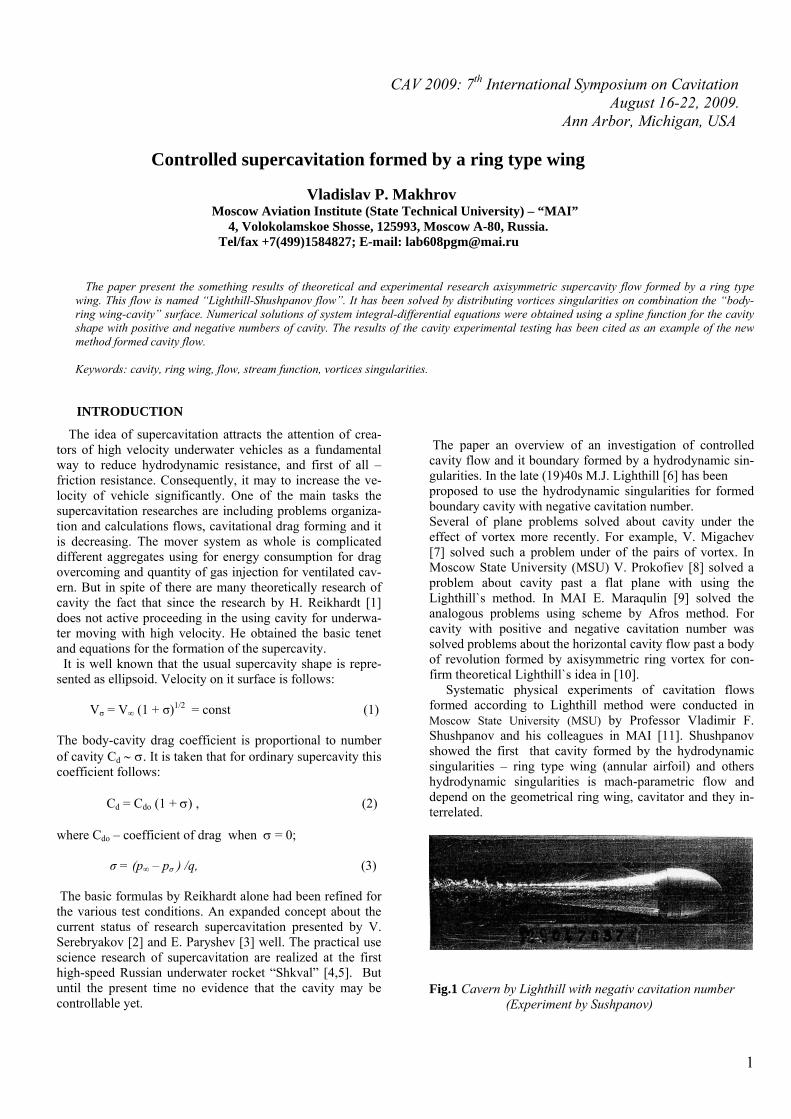
The paper an overview of an investigation of controlled cavity flow and it boundary formed by a hydrodynamic sin-gularities. In the late (19)40s M.J. Lighthill [6] has been proposed to use the hydrodynamic singularities for formed boundary cavity with negative cavitation number. Several of plane problems solved about cavity under the effect of vortex more recently. For example, V. Migachev [7] solved such a problem under of the pairs of vortex. In Moscow State University (MSU) V. Prokofiev [8] solved a problem about cavity past a flat plane with using the Lighthill`s method. In MAI E. Maraqulin [9] solved the analogous problems using scheme by Afros method. For cavity with positive and negative cavitation number was solved problems about the horizontal cavity flow past a body of revolution formed by axisymmetric ring vortex for con-firm theoretical Lighthill`s idea in [10]. Systematic physical experiments of cavitation flows formed according to Lighthill method were conducted in Moscow State University (MSU) by Professor Vladimir F. Shushpanov and his colleagues in MAI [11]. Shushpanov showed the first that cavity formed by the hydrodynamic singularities – ring type wing (annular airfoil) and others hydrodynamic singularities is mach-parametric flow and depend on the geometrical ring wing, cavitator and they in-terrelated.
Fig.1 Cavern by Lighthill with negativ cavitation number (Experiment by Sushpanov)
1
Theoretically and experimentally the similar flows were received with use a ring type wing [12,13]. We named such cavitation flows as “Lighthill-Shushpanov flows”. Figure 1 shows the first Lighthill΄s practical cavern. It received by the use the practical ring hydrodynamic singularities – a ring water scoop.
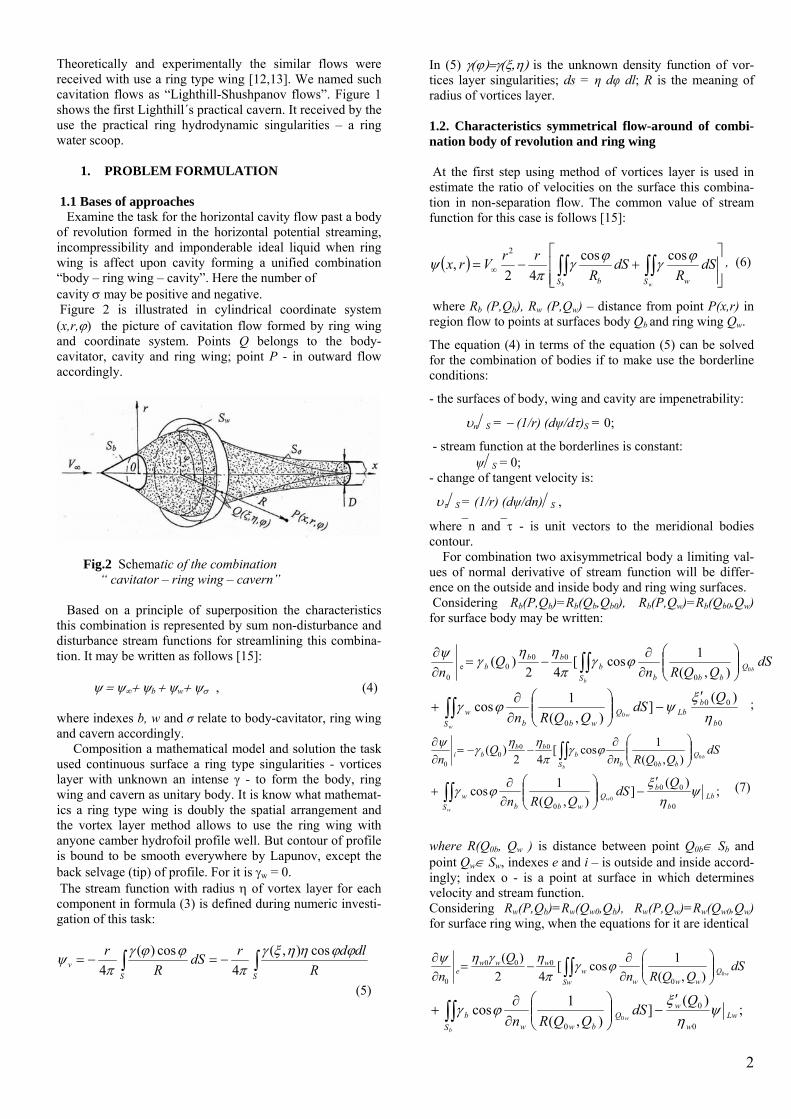
1. PROBLEM FORMULATION 1.1 Bases of approaches Examine the task for the horizontal cavity flow past a body of revolution formed in the horizontal potential streaming, incompressibility and imponderable ideal liquid when ring wing is affect upon cavity forming a unified combination “body – ring wing – cavity”. Here the number of cavity σ may be positive and negative. Figure 2 is illustrated in cylindrical coordinate system (x,r,ϕ) the picture of cavitation flow formed by ring wing and coordinate system. Points Q belongs to the body-cavitator, cavity and ring wing; point P - in outward flow accordingly.
Fig.2 Schematic of the combination “ cavitator – ring wing – cavern” Based on a principle of superposition the characteristics this combination is represented by sum non-disturbance and disturbance stream functions for streamlining this combina-tion. It may be written as follows [15]: ψ = ψ∞+ ψb + ψw+ ψσ , (4) where indexes b, w and σ relate to body-cavitator, ring wing and cavern accordingly. Composition a mathematical model and solution the task used continuous surface a ring type singularities - vortices layer with unknown an intense γ - to form the body, ring wing and cavern as unitary body. It is know what mathemat-ics a ring type wing is doubly the spatial arrangement and the vortex layer method allows to use the ring wing with anyone camber hydrofoil profile well. But contour of profile is bound to be smooth everywhere by Lapunov, except the back selvage (tip) of profile. For it is γw = 0. The stream function with radius η of vortex layer for each component in formula (3) is defined during numeric investi-gation of this task:
∫∫ −=−=SS
v RdldrdS
Rr ϕϕηηξγ
πϕϕγ
πψ cos),(
4cos)(
4
(5)
In (5) γ(ϕ)=γ(ξ,η) is the unknown density function of vor-tices layer singularities; ds = η dφ dl; R is the meaning of radius of vortices layer. 1.2. Characteristics symmetrical flow-around of combi-nation body of revolution and ring wing At the first step using method of vortices layer is used in estimate the ratio of velocities on the surface this combina-tion in non-separation flow. The common value of stream function for this case is follows [15]:
( )⎥⎥⎦
⎤
⎢⎢⎣
⎡+−= ∫∫ ∫∫∞
b wS S wb
dSR
dSR
rrVrx ϕγϕγπ
ψ coscos42
,2
, (6)
where Rb (P,Qb), Rw (P,Qw) – distance from point Р(х,r) in region flow to points at surfaces body Qb and ring wing Qw.
The equation (4) in terms of the equation (5) can be solved for the combination of bodies if to make use the borderline conditions:
- the surfaces of body, wing and cavity are impenetrability:
υn⏐S = − (1/r) (dψ/dτ)S = 0;
- stream function at the borderlines is constant: ψ⏐S = 0; - change of tangent velocity is:
υτ⏐S = (1/r) (dψ/dn)⏐S ,
where⎯n and⎯τ - is unit vectors to the meridional bodies contour. For combination two axisymmetrical body a limiting val-ues of normal derivative of stream function will be differ-ence on the outside and inside body and ring wing surfaces. Considering Rb(P,Qb)=Rb(Qb,Qb0), Rb(P,Qw)=Rb(Qb0,Qw) for surface body may be written:
∫∫ ⎟⎟⎠
⎞⎜⎜⎝
⎛∂∂
−=∂∂
b
bS
Qbbb
bbb
b dSQQRn
Qn 0),(
1cos[42
)(0
000е
0
ϕγπ
ηηγψ
0
00
0
)(]
),(1cos
0b
bLb
SQ
wbbw
QdS
QQRnw
w ηξ
ψϕγ′
−⎟⎟⎠
⎞⎜⎜⎝
⎛∂∂
+ ∫∫ ;
∫∫ ⎟⎟⎠
⎞⎜⎜⎝
⎛∂∂
−−=∂∂
b
b
SQ
bbbb
bbbi dS
QQRnQ
n 0),(1cos[
42)(
0
000
0
ϕγπ
ηηγψ
∫∫′
−⎟⎟⎠
⎞⎜⎜⎝
⎛∂∂
+w
w
SLb
b
bQ
wbbw
QdS
QQRn;
)(]
),(1cos
0
00
00
ψη
ξϕγ (7)
where R(Q0b, Qw ) is distance between point Q0b∈ Sb and point Qw∈ Sw, indexes e and i – is outside and inside accord-ingly; index o - is a point at surface in which determines velocity and stream function. Considering Rw(P,Qb)=Rw(Qw0,Qb), Rw(P,Qw)=Rw(Qw0,Qw) for surface ring wing, when the equations for it are identical
∫∫ ⎟⎟⎠
⎞⎜⎜⎝
⎛∂∂
−=∂∂
SwQ
wwww
wwwе dS
QQRnQ
n w0),(1cos[
42)(
0
000
0
ϕγπ
ηγηψ
∫∫′
−⎟⎟⎠
⎞⎜⎜⎝
⎛∂∂
+b
w
SLw
w
wQ
bwwb
QdS
QQRn;
)(]
),(1cos
0
0
00
ψη
ξϕγ
2
∫∫ ⎟⎟⎠
⎞⎜⎜⎝
⎛∂∂
−−=∂∂
w
w
SQ
wwww
wwwi dS
QQRnQ
n 0),(1cos[
42)(
0
000
0
ϕγπ
ηγηψ
∫∫′
−⎟⎟⎠
⎞⎜⎜⎝
⎛∂∂
+b
w
SLw
w
wQ
bwwb
QdS
QQRn;
)(]
),(1cos
0
0
00
ψη
ξϕγ (8)
In cylindrical coordinate system distance between Q0 and Q
is: Ro = R (Qo,Q) = [(ξ - ξo)2 + η2 +ηo2 – 2ηηocosϕ]1/2, where
ηo = η(ξo); Qo (ξo,ηo) ∈ Sa; Q (ξ,η) ∈ S.
If mark: ,)(1)(0
0
00
)(0 ee
nQQV
∂∂⋅=ψ
ητ
,)(1)(0
0
00
)(0 ii
nQQV
∂∂⋅=ψ
ητ
and except ηо , when is follows (inside flow is absent):
).()( 00)(
0QQV e γτ =
On condition that vortices intensity are equal the sum tan-gent speed in points on surfaces body and ring wing and there is jump in going over of vortex layer surfaces may be present equations for distribution of velocity γ(Q) on surface for body and ring wing are follows [16]:
∫∫ ⎟⎟⎠
⎞⎜⎜⎝
⎛∂∂
−=b
b
SQ
bbbbb dS
QQRnQ
0),(1cos[
21)(
00 ϕγ
πγ
;)(]),(
1cos 00
0∫∫ ′+⎟⎟⎠
⎞⎜⎜⎝
⎛∂∂
+ ∞
w
b
SbQ
bbbw QVdS
QQRnξϕγ
(9a)
∫∫
∫∫
⎟⎟⎠
⎞⎜⎜⎝
⎛∂∂
+
⎟⎟⎠
⎞⎜⎜⎝
⎛∂∂
−=
w
w
w
w
SQ
wwww
SQ
bbwbw
dSQQRn
QQRnQ
0),(1cos
),(1cos[
21)(
0
00
ϕγ
ϕγπ
γ
] )(2),(
)(cos
),()(
cos[21
000
0
00
0
QVQQRdSQ
QQRdSQ
wS www
ww
S bbw
wb
w
b
ξηξ
ϕγ
ηξ
ϕγπ
′+′
−
′+
∞∫∫
∫∫
, (9b)
where γb and γw - identical by the velocity of flows at the surfaces body and a ring wing accordingly. Here: integral of Sw in equation (9a) allows for influence of ring wing at flow-around of central body analogous integral of Sb in equation (9b) allows for influence central body at ring wing. It equations are makes possible to determine ve-locity and pressure on surfaces of this combination. So this result are applied for further consideration as base for re-ceiving more necessary dependencies in the following calcu-lations of supercavitation flows formed by a ring wing. Hereafter application of the method of vortex layer allows estimate the ratio of velocities on combination the body of revolution (cavitator) and a ring type wing.
1.3 Characteristics symmetrical flow-around of Combination: “body - ring wing - cavern”
Let’s assume that the cavitation flow formed by the ring type wing may correspond to cavitation figures σ > 0 and σ < 0; that cavern boundaries lock at flow axis or on body surface may be taken the additional condition. When using equation (1) for cavitation velocity and it is felt that V∞ ≡ 1, interdependencies derivable from (9), we can compose the system of integral-differential equations for solution the task (4). It may be written as follows:
∫∫
∫∫
⎟⎟⎠
⎞⎜⎜⎝
⎛∂∂
−
⎟⎟⎠
⎞⎜⎜⎝
⎛∂∂
−′=
σ σσσ ϕγ
ϕγπ
ξγ
SQ
b
SQ
bbbbbbbb
dSQQRn
dSQQRn
QQQ
b
b
b
0
0
),(1cos
),(1cos)([
21)()(
0
000
;]),(
1cos)(0
0∫∫ ⎟⎟
⎠
⎞⎜⎜⎝
⎛∂∂
−w
b
SQ
bwww dS
QQRnQ ϕγ (10a)
dsQQRn
QQRQ
w
b
Qbbkw
S bww
wbww
]),(
1
),()(
[cos)({21)(
00
00
00
⎟⎟⎠
⎞⎜⎜⎝
⎛∂∂
−
′−= ∫∫ η
ξϕγ
πγ
),()([cos)(
]),(
1),(
)([cos
00
0
00
00
σ
σσσσ
ηξϕγ
ηξϕγ
σ
QQRQQ
dSQQRnQQR
Q
ww
wkw
Sww
SQ
wkww
wwb
′+
⎟⎟⎠
⎞⎜⎜⎝
⎛∂∂
−′
+
∫∫
∫∫
);(2}]),(
10
0ww
www
QdSQQRn
ξ ′−⎟⎟⎠
⎞⎜⎜⎝
⎛∂∂
− (10b)
∫∫
∫∫
+
=
σ σσσ
σσσ
ϕγ
ϕγπ
S
S bb
dSQQR
dSQQR
QQrb
),(1cos
),(1cos)([
21)(
0
00
;],(1cos)(
0wS w QQQ
σ )∫∫+ w dSR
ϕγ (10c)
The solution this system is uniquely determined if it is comple-mented by close boundary condition cavern: ξσ (L) = 0 and ξσ′(L) = 1 – in case for closing of boundaries in point at the axis; ξσ (L) = D – in case for closing of boundaries on the half-infinite cylinder with diameter D − analog of scheme by Roshko - Zhukovsky; ξσ (L) − it is abscissa of cavern closing point. In this task diameter D (see Fig.2) may be unknown, on it surface velocity is variable from γσ ≡ Vσ to velocity stream V∞..In practice diameter D is given, when the length of cav-ern and number of cavity is determined. If should be given the length of cavern Lσ , when defined number of cavity σ for this length.
3
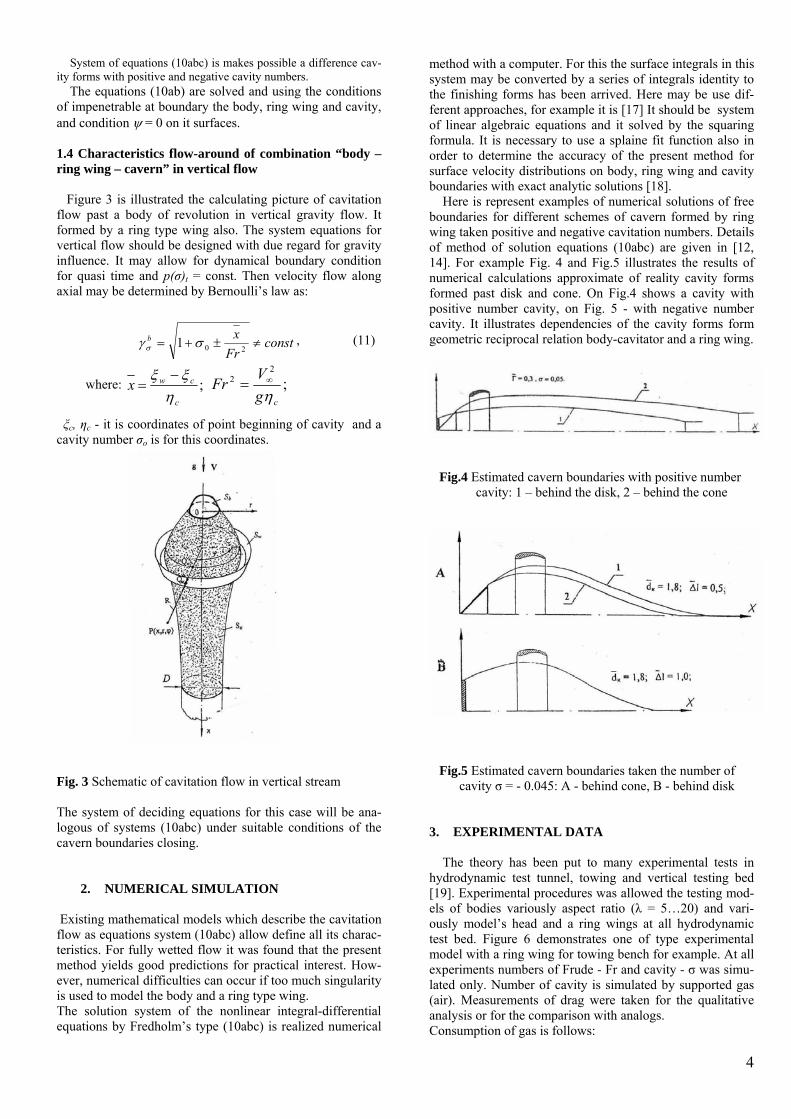
System of equations (10abc) is makes possible a difference cav-ity forms with positive and negative cavity numbers. The equations (10ab) are solved and using the conditions of impenetrable at boundary the body, ring wing and cavity, and condition ψ = 0 on it surfaces. 1.4 Characteristics flow-around of combination “body – ring wing – cavern” in vertical flow Figure 3 is illustrated the calculating picture of cavitation flow past a body of revolution in vertical gravity flow. It formed by a ring type wing also. The system equations for vertical flow should be designed with due regard for gravity influence. It may allow for dynamical boundary condition for quasi time and p(σ)t = const. Then velocity flow along axial may be determined by Bernoulli’s law as:
constFr
xb ≠±+= 201 σγ σ, (11)
where: ;c
cwxη
ξξ −= ;
22
cgVFrη∞=
ξc, ηc - it is coordinates of point beginning of cavity and a cavity number σо is for this coordinates.
Fig. 3 Schematic of cavitation flow in vertical stream The system of deciding equations for this case will be ana-logous of systems (10abc) under suitable conditions of the cavern boundaries closing.
2. NUMERICAL SIMULATION
Existing mathematical models which describe the cavitation flow as equations system (10abc) allow define all its charac-teristics. For fully wetted flow it was found that the present method yields good predictions for practical interest. How-ever, numerical difficulties can occur if too much singularity is used to model the body and a ring type wing. The solution system of the nonlinear integral-differential equations by Fredholm’s type (10abc) is realized numerical
method with a computer. For this the surface integrals in this system may be converted by a series of integrals identity to the finishing forms has been arrived. Here may be use dif-ferent approaches, for example it is [17] It should be system of linear algebraic equations and it solved by the squaring formula. It is necessary to use a splaine fit function also in order to determine the accuracy of the present method for surface velocity distributions on body, ring wing and cavity boundaries with exact analytic solutions [18]. Here is represent examples of numerical solutions of free boundaries for different schemes of cavern formed by ring wing taken positive and negative cavitation numbers. Details of method of solution equations (10abc) are given in [12, 14]. For example Fig. 4 and Fig.5 illustrates the results of numerical calculations approximate of reality cavity forms formed past disk and cone. On Fig.4 shows a cavity with positive number cavity, on Fig. 5 - with negative number cavity. It illustrates dependencies of the cavity forms form geometric reciprocal relation body-cavitator and a ring wing.
Fig.4 Estimated cavern boundaries with positive number cavity: 1 – behind the disk, 2 – behind the cone
Fig.5 Estimated cavern boundaries taken the number of cavity σ = - 0.045: A - behind cone, B - behind disk 3. EXPERIMENTAL DATA The theory has been put to many experimental tests in hydrodynamic test tunnel, towing and vertical testing bed [19]. Experimental procedures was allowed the testing mod-els of bodies variously aspect ratio (λ = 5…20) and vari-ously model’s head and a ring wings at all hydrodynamic test bed. Figure 6 demonstrates one of type experimental model with a ring wing for towing bench for example. At all experiments numbers of Frude - Fr and cavity - σ was simu-lated only. Number of cavity is simulated by supported gas (air). Measurements of drag were taken for the qualitative analysis or for the comparison with analogs. Consumption of gas is follows:
4
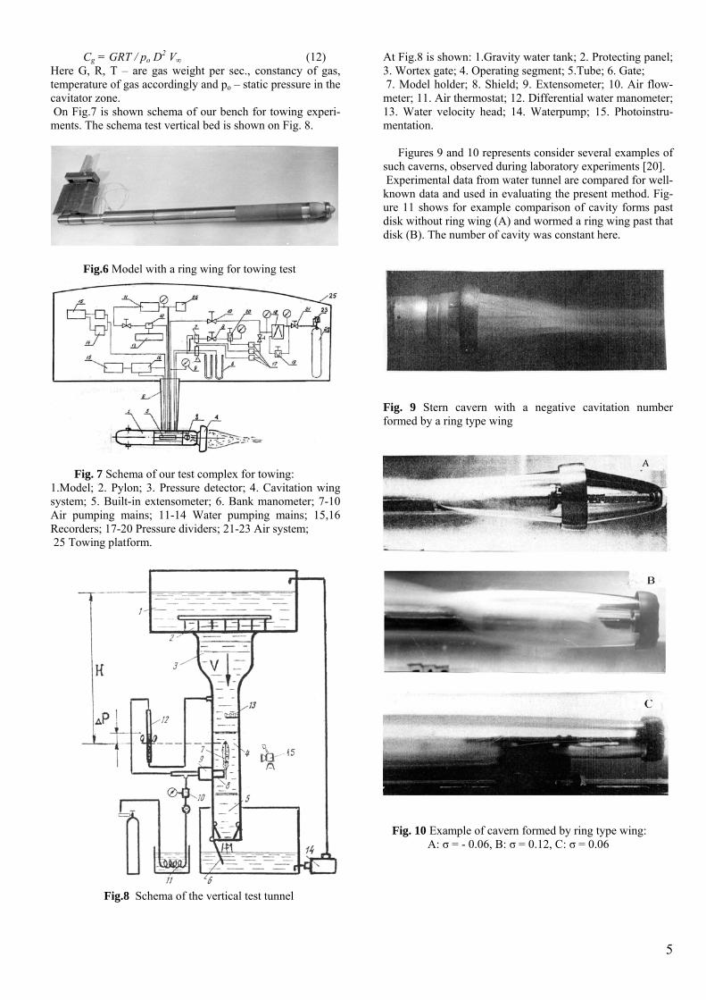
Cg = GRT / po D2 V∞ (12) Here G, R, T – are gas weight per sec., constancy of gas, temperature of gas accordingly and po – static pressure in the cavitator zone. On Fig.7 is shown schema of our bench for towing experi-ments. The schema test vertical bed is shown on Fig. 8.
Fig.6 Model with a ring wing for towing test
Fig. 7 Schema of our test complex for towing: 1.Model; 2. Pylon; 3. Pressure detector; 4. Cavitation wing system; 5. Built-in extensometer; 6. Bank manometer; 7-10 Air pumping mains; 11-14 Water pumping mains; 15,16 Recorders; 17-20 Pressure dividers; 21-23 Air system; 25 Towing platform.
Fig.8 Schema of the vertical test tunnel
At Fig.8 is shown: 1.Gravity water tank; 2. Protecting panel; 3. Wortex gate; 4. Operating segment; 5.Tube; 6. Gate; 7. Model holder; 8. Shield; 9. Extensometer; 10. Air flow-meter; 11. Air thermostat; 12. Differential water manometer; 13. Water velocity head; 14. Waterpump; 15. Photoinstru-mentation. Figures 9 and 10 represents consider several examples of such caverns, observed during laboratory experiments [20]. Experimental data from water tunnel are compared for well-known data and used in evaluating the present method. Fig-ure 11 shows for example comparison of cavity forms past disk without ring wing (A) and wormed a ring wing past that disk (B). The number of cavity was constant here.
Fig. 9 Stern cavern with a negative cavitation number formed by a ring type wing
Fig. 10 Example of cavern formed by ring type wing: A: σ = - 0.06, B: σ = 0.12, C: σ = 0.06
5
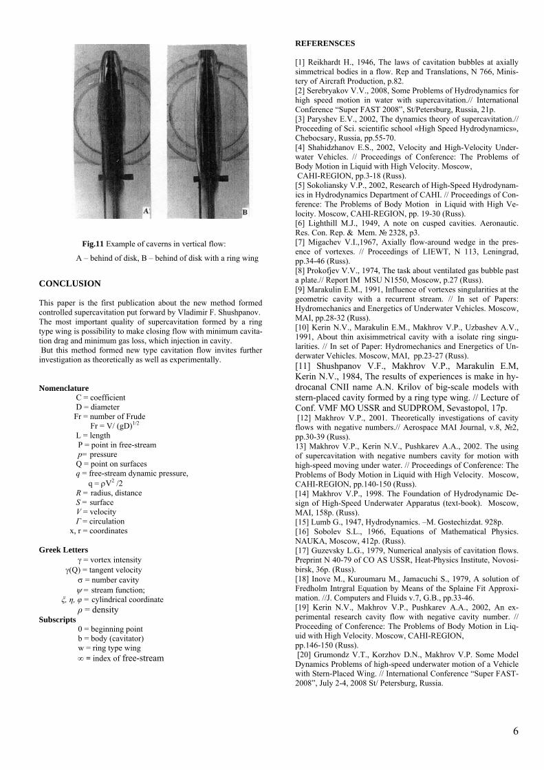
Fig.11 Example of caverns in vertical flow:
A – behind of disk, B – behind of disk with a ring wing
CONCLUSION This paper is the first publication about the new method formed controlled supercavitation put forward by Vladimir F. Shushpanov. The most important quality of supercavitation formed by a ring type wing is possibility to make closing flow with minimum cavita-tion drag and minimum gas loss, which injection in cavity. But this method formed new type cavitation flow invites further investigation as theoretically as well as experimentally. Nomenclature C = coefficient D = diameter Fr = number of Frude Fr = V/ (gD)1/2
L = length P = point in free-stream p= pressure Q = point on surfaces q = free-stream dynamic pressure, q = ρV2 /2 R = radius, distance S = surface V = velocity Г = сirculation x, r = coordinates Greek Letters γ = vortex intensity γ(Q) = tangent velocity σ = number cavity ψ = stream function; ξ, η, φ = cylindrical coordinate ρ = density Subscripts 0 = beginning point b = body (cavitator) w = ring type wing ∞ = index of free-stream
REFERENSCES
and Translations, N 766, Minis-
ional
ool «High Speed Hydrodynamics»,
Problems of ity. Moscow,
with High Ve-
usped cavities. Aeronautic.
// Proceedings of LIEWT, N 113, Leningrad,
ble past
getics of Underwater Vehicles. Moscow,
etics of Un-
e numbers.// Aerospace MAI Journal, v.8, №2,
ith High Velocity. Moscow,
Underwater Apparatus (text-book). Moscow,
of Mathematical Physics.
CO AS USSR, Heat-Physics Institute, Novosi-
it Approxi-
otion in Liq-y. Moscow, CAHI-REGION,
ce “Super FAST-2008”, July 2-4, 2008 St/ Petersburg, Russia.
[1] Reikhardt H., 1946, The laws of cavitation bubbles at axially simmetrical bodies in a flow. Rep tery of Aircraft Production, p.82. [2] Serebryakov V.V., 2008, Some Problems of Hydrodynamics for high speed motion in water with supercavitation.// InternatConference “Super FAST 2008”, St/Petersburg, Russia, 21p. [3] Paryshev E.V., 2002, The dynamics theory of supercavitation.// Proceeding of Sci. scientific schChebocsary, Russia, pp.55-70. [4] Shahidzhanov E.S., 2002, Velocity and High-Velocity Under-water Vehicles. // Proceedings of Conference: The Body Motion in Liquid with High Veloc CAHI-REGION, pp.3-18 (Russ). [5] Sokoliansky V.P., 2002, Research of High-Speed Hydrodynam-ics in Hydrodynamics Department of CAHI. // Proceedings of Con-ference: The Problems of Body Motion in Liquid locity. Moscow, CAHI-REGION, pp. 19-30 (Russ). [6] Lighthill M.J., 1949, A note on cRes. Con. Rep. & Mem. № 2328, p3. [7] Migachev V.I.,1967, Axially flow-around wedge in the pres-ence of vortexes.pp.34-46 (Russ). [8] Prokofjev V.V., 1974, The task about ventilated gas buba plate.// Report IM MSU N1550, Moscow, p.27 (Russ). [9] Marakulin E.M., 1991, Influence of vortexes singularities at the geometric cavity with a recurrent stream. // In set of Papers: Hydromechanics and EnerMAI, pp.28-32 (Russ). [10] Kerin N.V., Marakulin E.M., Makhrov V.P., Uzbashev A.V., 1991, About thin axisimmetrical cavity with a isolate ring singu-larities. // In set of Paper: Hydromechanics and Energderwater Vehicles. Moscow, MAI, pp.23-27 (Russ). [11] Shushpanov V.F., Makhrov V.P., Marakulin E.M, Kerin N.V., 1984, The results of experiences is make in hy-drocanal CNII name A.N. Krilov of big-scale models with stern-placed cavity formed by a ring type wing. // Lecture of Conf. VMF MO USSR and SUDPROM, Sevastopol, 17p. [12] Makhrov V.P., 2001. Theoretically investigations of cavity flows with negativpp.30-39 (Russ). 13] Makhrov V.P., Kerin N.V., Pushkarev A.A., 2002. The using of supercavitation with negative numbers cavity for motion with high-speed moving under water. // Proceedings of Conference: The Problems of Body Motion in Liquid wCAHI-REGION, pp.140-150 (Russ). [14] Makhrov V.P., 1998. The Foundation of Hydrodynamic De-sign of High-Speed MAI, 158p. (Russ). [15] Lumb G., 1947, Hydrodynamics. –M. Gostechizdat. 928p. [16] Sobolev S.L., 1966, EquationsNAUKA, Moscow, 412p. (Russ). [17] Guzevsky L.G., 1979, Numerical analysis of cavitation flows. Preprint N 40-79 ofbirsk, 36p. (Russ). [18] Inove M., Kuroumaru M., Jamacuchi S., 1979, A solution of Fredholm Intrgral Equation by Means of the Splaine Fmation. //J. Computers and Fluids v.7, G.B., pp.33-46. [19] Kerin N.V., Makhrov V.P., Pushkarev A.A., 2002, An ex-perimental research cavity flow with negative cavity number. // Proceeding of Conference: The Problems of Body Muid with High Velocitpp.146-150 (Russ). [20] Grumondz V.T., Korzhov D.N., Makhrov V.P. Some Model Dynamics Problems of high-speed underwater motion of a Vehicle with Stern-Placed Wing. // International Conferen
6
Related Documents