Control Engineering Major 2-Automation Section, DT021, First Semester © Dr J.McGrory & Mr David Berber as exerted in Copyright and Related Rights Acts 2000 and 2004. Page 1 of 48 File Ref: dt021_ControlEngineeringVersion1_CONT4602 Bachelor of Engineering (Honours) Degree in Electrical/Electronic Engineering School of Electrical Engineering Systems Dublin Institute of Technology Kevin Street Dublin 8 Control Engineering Major 2 Module Automation Section DT021 Year 4, First Semester Version 1.0 Optimist: "The glass is half full." Pessimist: "The glass is half empty." Engineer: "That glass is twice as large as it needs to be." Prepared by: Dr. John McGrory & Mr David Berber School of Control Systems and Electrical Engineering, Dublin Institute of Technology, Kevin Street, Dublin 8.

Welcome message from author
This document is posted to help you gain knowledge. Please leave a comment to let me know what you think about it! Share it to your friends and learn new things together.
Transcript
Control Engineering Major 2-Automation Section, DT021, First Semester
© Dr J.McGrory & Mr David Berber as exerted in Copyright and Related Rights Acts 2000 and 2004. Page 1 of 48 File Ref: dt021_ControlEngineeringVersion1_CONT4602
Bachelor of Engineering (Honours) Degree in
Electrical/Electronic Engineering
School of Electrical Engineering Systems
Dublin Institute of Technology
Kevin Street
Dublin 8
Control Engineering Major 2 Module
Automation Section
DT021 Year 4, First Semester
Version 1.0
Optimist: "The glass is half full."
Pessimist: "The glass is half empty." Engineer: "That glass is twice as large as it needs to be."
Prepared by: Dr. John McGrory & Mr David Berber School of Control Systems and Electrical Engineering,
Dublin Institute of Technology,
Kevin Street,
Dublin 8.
Control Engineering Major 2-Automation Section, DT021, First Semester
© Dr J.McGrory & Mr David Berber as exerted in Copyright and Related Rights Acts 2000 and 2004. Page 2 of 48 File Ref: dt021_ControlEngineeringVersion1_CONT4602
Notes from the authors.
It is important to emphasise that this module is an integral part of all the others
modules given this year. It should not be viewed in isolation, but in parallel, in the
context of the material covered in other lectures and laboratories. The authors
exonerate themselves from liability in regard to the use of concepts and ideas
discussed in this course. Since the ideas and concepts given are as illustration
examples and include where possible all obvious issues involved, but not all factors.
However, more investigation is needed to ensure any idea is plausible on a case by
case basis.
A semester module is 15 weeks long and includes one week revision and two weeks for
exams. This calculates to 12 weeks for new material to be presented. Assuming this
course disseminated using one lecture and one (averaged) laboratory hours per week,
this means that there are only 24 contact hours (not including your private study
time for this subject). Therefore, onus is on you from the beginning to perform to
the best of your ability. Remember, woulda coulda shoulda are the last words of a
fool.
So keep up to date with all the material and don’t slip behind, and the best of luck in
getting on with it.
John & David.
Control Engineering Major 2-Automation Section, DT021, First Semester
© Dr J.McGrory & Mr David Berber as exerted in Copyright and Related Rights Acts 2000 and 2004. Page 3 of 48 File Ref: dt021_ControlEngineeringVersion1_CONT4602
Table of Contents
NOTES FROM THE AUTHORS. ...............................................................................................................................2
OBJECTIVES OF THIS COURSE:...........................................................................................................................5
MODULE DESCRIPTION: ................................................................................................................................................5
MODULE AIM:.................................................................................................................................................................5
LEARNING OUTCOMES:..................................................................................................................................................5
LEARNING AND TEACHING METHODS:.........................................................................................................................5
MODULE CONTENT: ........................................................................................................................................................6
MODULE ASSESSMENT..................................................................................................................................................6
CHAPTER 1, DESIGN FILE BASICS AND DOCUMENT REQUIREMENTS ...............................................8
INTRODUCTION .............................................................................................................................................................8
CHANGES TO THE FORM-FIT-FUNCTION (FFF)..........................................................................................................9
CHAPTER 2, LABORATORY 1, PROPORTIONAL-CONTROL AND MANUAL RESET...........................11
INTRODUCTION ...........................................................................................................................................................11
AIM:..............................................................................................................................................................................11
OBJECTIVE: ..................................................................................................................................................................11
CONTROL PHILOSOPHY: ...............................................................................................................................................11
CHAPTER 3, LABORATORY 2, PROPORTIONAL-CONTROL, MANUAL RESET & ALARMS .............13
AIM:..............................................................................................................................................................................13
OBJECTIVE: ..................................................................................................................................................................13
CONTROL PHILOSOPHY: ...............................................................................................................................................13
CHAPTER 4, WHAT IS THE STANDARD FOR PROGRAMMING PLC’S....................................................14
INTRODUCTION ...........................................................................................................................................................14
WHAT IS IEC 61131? .................................................................................................................................................14
IEC 61131 LADDER DIAGRAM .....................................................................................................................................15
IEC 61131 SEQUENTIAL FUNCTION CHARTS ...........................................................................................................15
IEC 61131 FUNCTION BLOCK DIAGRAM OVERVIEW .................................................................................................18
IEC 61131 STRUCTURED TEXT OVERVIEW................................................................................................................18
IEC 61131 INSTRUCTION LIST OVERVIEW ..............................................................................................................22
SFC PROGRAM EDITING PROCEDURE OUTLINE, FOR FX PLC ...................................................................................23
CHAPTER 5, LABORATORY 2, CONTROLLING SEQUENCES ©DAVIDBERBER....................................25
AIM:..............................................................................................................................................................................25
OBJECTIVE: ..................................................................................................................................................................25
SYSTEM DESCRIPTION: ...............................................................................................................................................25
INPUT / OUTPUT LIST:................................................................................................................................................25
SYSTEM SCHEMATIC ...................................................................................................................................................26
CONTROL PHILOSOPHY: ...............................................................................................................................................27
PROGRAMMING EXERCISE: ..........................................................................................................................................27
CHAPTER 6, LABORATORY 3, SEQUENCE CONTROL OF AN AUTOMATIC PALLETISING
MACHINE ©DAVIDBERBER .....................................................................................................................................29
AIM:..............................................................................................................................................................................29
Control Engineering Major 2-Automation Section, DT021, First Semester
© Dr J.McGrory & Mr David Berber as exerted in Copyright and Related Rights Acts 2000 and 2004. Page 4 of 48 File Ref: dt021_ControlEngineeringVersion1_CONT4602
OBJECTIVE: ..................................................................................................................................................................29
SYSTEM DESCRIPTION: ...............................................................................................................................................29
INPUT / OUTPUT LIST:................................................................................................................................................29
SYSTEM SCHEMATIC ...................................................................................................................................................30
SYSTEM OPERATION:...................................................................................................................................................31
PROGRAMMING EXERCISE: ..........................................................................................................................................32
CHAPTER 7, LABORATORY 4, SEQUENCE CONTROL OF A BOTTLE CAPPING AND LABELLING
MACHINE ©DAVIDBERBER .....................................................................................................................................33
AIM:..............................................................................................................................................................................33
OBJECTIVE: ..................................................................................................................................................................33
SYSTEM DESCRIPTION: ...............................................................................................................................................33
INPUT / OUTPUT LIST:................................................................................................................................................33
SYSTEM SCHEMATIC ...................................................................................................................................................35
SYSTEM OPERATION:...................................................................................................................................................36
PROGRAMMING EXERCISE: ..........................................................................................................................................36
CHAPTER 8, HUMAN MACHINE INTERFACE (HMI).....................................................................................38
INTRODUCTION ...........................................................................................................................................................38
HOW THE BRAIN PROCESSES IMAGES .......................................................................................................................38
1. Attention Phase.............................................................................................................................................38
2. Filter and Focus Phase.............................................................................................................................39
3. Identification Phase.................................................................................................................................40
HOW THE EYES SCAN AND BRAIN INTERPRETS..........................................................................................................42
CHAPTER 9, HIGH SPEED CONTROL..................................................................................................................47
INTRODUCTION ...........................................................................................................................................................47

Control Engineering Major 2-Automation Section, DT021, First Semester
© Dr J.McGrory & Mr David Berber as exerted in Copyright and Related Rights Acts 2000 and 2004. Page 5 of 48 File Ref: dt021_ControlEngineeringVersion1_CONT4602
Objectives of this course:
Module Description: This module is composed of two portions: Control Engineering and Automation. This
document only focuses on the Automation aspect of the module. The Automation
portion of the module builds on the work done in the Control Engineering Major
module (Year 3, Semester 1). On completion of this module, the learner will implement
control of analogue, high speed and complex sequential processes. On this half module
24 contact hours are devoted to Automation and complements the other half of the
module on control engineering.
Module aim: The aim of the Automation portion of the module is to enable the students to
implement safe control on real and complex industrial processes using automation
computers.
Learning Outcomes: Automation (1) Design and implement a sequence control system of an automated industrial
process with fault finding exercises to demonstrate the ability to problem solve
in a real manufacturing environment. Control complex sequential processes.
(2) Carry out faultfinding techniques of complex sequential processes.
(3) Develop a safety-conscious mindset in all control solutions.
(4) Implement Analogue control algorithms on industrial processes.
(5) Understand the complexity of high speed control and Implement control of a
high speed process.
Learning and Teaching Methods: This course development is based on the cognitivists theory of education, one of the
main exponents of this theory, Bruner sees the teaching role as one of facilitating
the student's own discovery, known as 'enquiry training.' Bruner was insistent that
students must be taught how to analyse problems and how to think for themselves, to
become independent learners. The learning process is the acquiring of new knowledge
and information and transforming that learning with their existing knowledge and
utilising it in a new situation. Knowledge is a process rather than a product. The
cognitivists theory is of the active engagement of the mind in relation to the subject
matter. In order to learn, understanding is necessary; the setting of tasks related to
new material and feedback is an essential element in the process of learning.
The key points to the structure of this course are:
Control Engineering Major 2-Automation Section, DT021, First Semester
© Dr J.McGrory & Mr David Berber as exerted in Copyright and Related Rights Acts 2000 and 2004. Page 6 of 48 File Ref: dt021_ControlEngineeringVersion1_CONT4602
• Utilise the structure of the subject, stressing the relationships in
what material is presented, encourage students to seek solutions of
their own.
• Arrange the structure so the students discover things themselves.
• Utilise and take advantage of students wanting to find answers to
problems that have personal significance to them, this relates the
learning to their own personal situation or task.
• Facilitate discussions by posing specific relevant questions.
• Allow the students to take a significant role and responsibility in
leading the discussions.
In summary the important point to note is that students learn best when they
discover concepts and principles for themselves. The objective of this course is to
facilitate that process.
Module content: • Introduction to IEC 61131-3 Simple Sequence and Step Ladder
programming.
• Sequence control of Series and Parallel and multi loop tasks.
• Mini Project involving Sequence control of a sequential process.
• Analogue to digital and Digital To Analogue control.
• Analogue control On/Off and Proportional Control PID and Self
tuning control.
• Application of HMI’s to Automated systems.
• Mini Project utilising analogue modules to interface to and control
industrial process, monitoring using a high level human machine
interface.
• Fault finding of computer controlled processes.
Module Assessment This half module is designed to have a clear alignment between the learning outcomes
and the assessment method chosen. The course implements a student centred
teaching approach and to give the student confidence to apply the knowledge they
have gained by their own endeavours, working as individuals and as part of a group.
The students will be presented with carefully designed mini projects, which they will
undertake to come up with solutions to solve automation and control problems to
achieve the goals and objectives of the project.
The projects will be related to the real industrial problems that they can relate to,
and in the process of solving the problems, they will gain confidence and enjoyment
from applying their new knowledge through practical means and see the results.

Control Engineering Major 2-Automation Section, DT021, First Semester
© Dr J.McGrory & Mr David Berber as exerted in Copyright and Related Rights Acts 2000 and 2004. Page 7 of 48 File Ref: dt021_ControlEngineeringVersion1_CONT4602
The assessment will be on the project based learning exercises with formative /
continuous assessment being carried out at regular review and design meetings, as
well as using a creative Design File approach (also known as reflective diary or web
based Blog) to allow course participants to document and reflect upon their learning
process. The appropriate assessment method with the correct choice of projects will
lead to good alignment between the learning outcomes and the assessment method
where the ‘assessment will drive the learning’.
The project based learning exercises will also incorporate a task of self learning that
the students may choose from a choice of several relevant topics, which should be of
interest to their future chosen career. (This subject is their chosen Major option)
The designed attached marking scheme reflects the effort and abilities of the
students. The overall break down of the marks is: 70% for Continuous/Formative
assessment and 30% for the reflective writing, portfolio and self assessment. This is
a fourth-year course at NQAI level 8, the formative/continuous assessment is
required to drive the learning. The major concern is that without regularly
assessment and provided feedback the weaker students may not be driven to
complete the prescribed projects. The regular continuous/formative assessments will
provide the learners a plan of work with clear milestone objectives. This will enable
and make it easier to check the learner’s progress at their regular design and
continuous/formative assessment meetings. The reflective diary / Blog will be used as
a diary of the learners’ progress and should map the learners learning achievements
throughout the course of the project task.
The learner will document the following:
• Self Assessment of produced work and role within an informal group
(if any)
• How far did I get with respect to solving the problems
• How much did I interact with my peers to give assistance and
contribute to development ideas?
• To document new knowledge, ideas and concepts
• What have I learnt?
• What I am unclear or unsure about
• What I do not understand
• What I will do next to achieve my stated goals
• What questions I asked my peers or lecture
• What questions I answered my peers and tutor
• Self Assessment and role within an informal group (if any)

Control Engineering Major 2-Automation Section, DT021, First Semester
© Dr J.McGrory & Mr David Berber as exerted in Copyright and Related Rights Acts 2000 and 2004. Page 8 of 48 File Ref: dt021_ControlEngineeringVersion1_CONT4602
Chapter 1, Design File basics and document requirements Introduction
Each laboratory will require a Design File (also known as the reflective diary/blog) to
be produced, which will be used guide and act as an indicator of the learners’ progress
during the laboratory and should map the learners learning achievements throughout
the course of the project task. The learner will document the following:
• Self Assessment of produced work and role within an informal group
(if any).
• How far did I get with respect to solving the problems.
• How much did I interact with my peers to give assistance and
contribute to development ideas?
• To document new knowledge, ideas and concepts.
• What have I learnt?
• What I am unclear or unsure about.
• What I do not understand.
• What I will do next to achieve my stated goals.
• What questions I asked my peers or lecturer.
• What questions I answered for my peers and tutor.
• Self Assessment and role within an informal group (if any).
At the end of the laboratory session the learner must save and submit their files for
marking and be made available to the external examiners. Please save your PLC
program (make sure to zip the resource folder and all its contents) in a folder
DT021_4_YR201?_Lab??_Surname_FirstName. Place within the root of that
directory your design file as an MSWord document (or PDF) using the following title
DT021_4_YR201?_Lab??_DF_Surname_FirstName.doc. Then zip the entire folder
and contents into a single zipped file titled
DT021_4_YR201?_Lab??_Surname_FirstName.zip submit it using web courses on or
before the specific date and time.
Every student must have an electronic copy of the following Mitsubishi documents:
FX PLC Programming Manual, this contains all the available commands and a lot of
other information.
• FX PLC 4AD Manual, Analogue to Digital converter with all the wiring and
buffer location details.
• FX PLC 4DA Manual, Analogue to Digital converter with all the wiring and
buffer location details.
• FX PLC SFC Programming Manual, a specialist document to illustrate the
Mitsubishi SFC
Control Engineering Major 2-Automation Section, DT021, First Semester
© Dr J.McGrory & Mr David Berber as exerted in Copyright and Related Rights Acts 2000 and 2004. Page 9 of 48 File Ref: dt021_ControlEngineeringVersion1_CONT4602
As we as a group progress through the course this design file structure will be
revisited and techniques on how to share information through documentation, make it
easier to scan and identify key issues will be shown.
Changes to the Form-Fit-Function (FFF). These are the generic terms where:
• “Form” relates to the structure which is a perceptual structure. It could be an
animal body, music composition, house, apartments or instruments, recognisable
entity etc.
• “Fit” relates to be the right size or shape; fit correctly or as desired, but
could also suitability where it would be agreeable or acceptable, or provide
something usually for a specific purpose etc.
• “Function” relates to a mathematical relationship of one thing is dependent on
another, what something is used for, routine set of sequences, the actions and
activities assigned to or required or expected etc.
By nesting and grouping the entries it is possible to see how the end product was
developed, how long each part took to complete, understand the students
interpretation of Form Fit and Function and who was responsible for the task.
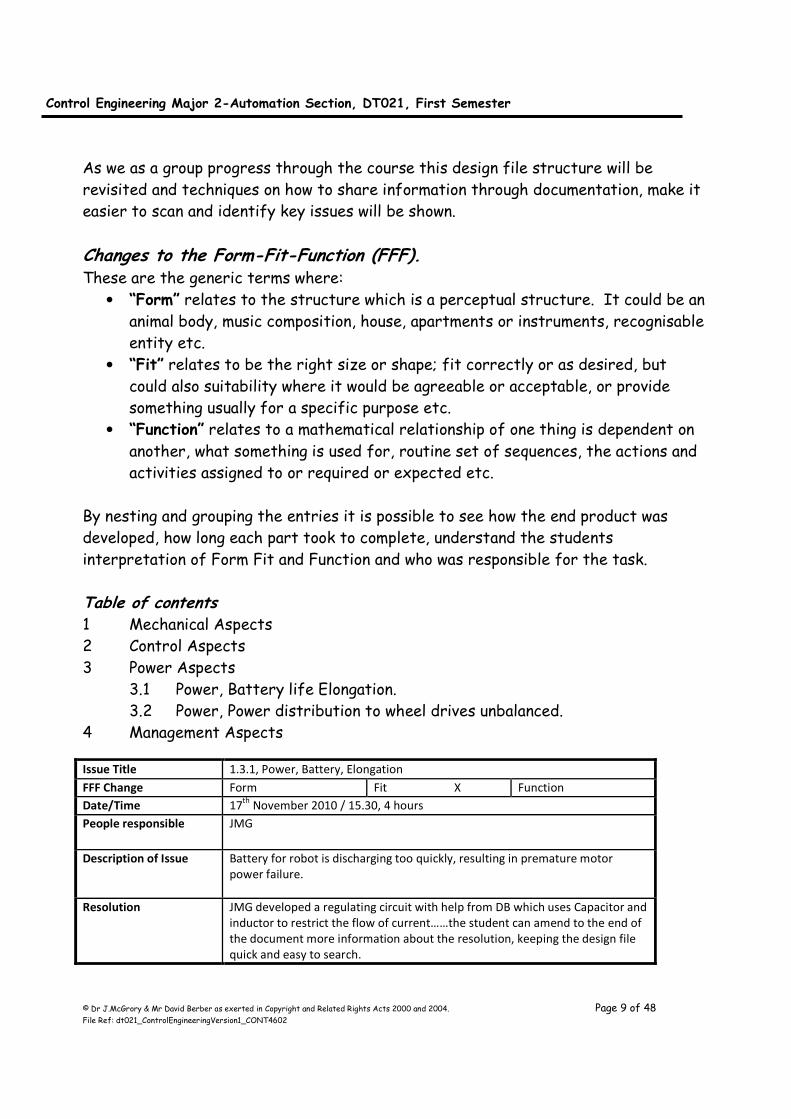
Table of contents 1 Mechanical Aspects
2 Control Aspects
3 Power Aspects
3.1 Power, Battery life Elongation.
3.2 Power, Power distribution to wheel drives unbalanced.
4 Management Aspects
Issue Title 1.3.1, Power, Battery, Elongation
FFF Change Form Fit X Function
Date/Time 17th
November 2010 / 15.30, 4 hours
People responsible JMG
Description of Issue Battery for robot is discharging too quickly, resulting in premature motor
power failure.
Resolution JMG developed a regulating circuit with help from DB which uses Capacitor and
inductor to restrict the flow of current……the student can amend to the end of
the document more information about the resolution, keeping the design file
quick and easy to search.

Control Engineering Major 2-Automation Section, DT021, First Semester
© Dr J.McGrory & Mr David Berber as exerted in Copyright and Related Rights Acts 2000 and 2004. Page 10 of 48 File Ref: dt021_ControlEngineeringVersion1_CONT4602
Table of contents 1 Mechanical Aspects 2 Control Aspects
3 Power Aspects
3.1 Power, Battery life Elongation.
3.2 Power, Power distribution to wheel drives unbalanced.
4 Management Aspects
When I was the manager of a project I would keep an eye on the entries and see which group was doing the majority of the work and who is not.
Issue Title 3.1, Power, Battery, Elongation
FFF Change Form Fit X Function
Date/Time 17th
November 2010 / 15.30, 4 hours
People responsible JMG
Description of Issue Battery for robot is discharging too quickly, resulting in premature motor
power failure.
Resolution JMG developed a regulating circuit with help from DB which uses Capacitor and
inductor to restrict the flow of current……the student can amend to the end of
the document more information about the resolution, keeping the core design
file information quick and easy to search.
Issue Title 3.2, Power, Power distribution to wheel drives unbalanced
FFF Change Form Fit X Function
Date/Time 19th
November 2010 / 15.30, 0.45 hours
People responsible TB
Description of Issue The left drive motor is rotating 1.2 times the speed of the right drive motor and
so the robot is travelling to the right.
Resolution TB checked the voltage and taco speed and identified a weakness in the cable
connection of the drive. The connections were remade and the problem was
resolved
Control Engineering Major 2-Automation Section, DT021, First Semester
© Dr J.McGrory & Mr David Berber as exerted in Copyright and Related Rights Acts 2000 and 2004. Page 11 of 48 File Ref: dt021_ControlEngineeringVersion1_CONT4602
Chapter 2, Laboratory 1, Proportional-Control and Manual Reset Introduction The purpose of this laboratory is to identify weaknesses in the students
understanding and competency of industrial computers and slowly ease them back into
the mode of self directed learning.
Aim: This laboratory focuses on the use of P-control (proportional control) in PLC
ladder logic and the inclusion of the manual reset component.
Objective: (1) A PLC is an industrial computer and so is not identical to the academic
software used elsewhere to show proofs of academic concepts. The pupil
must demonstrate how to clamp signals, to ensure the process remains safe
at all times if the control variable wanders in an industrial application.
(2) The pupil should correlate the process of the PLC to a control diagram.
Ensure to use SUB for a comparator and MUL when passing through
Transfer Functions.
(3) The student must use the double compare (DCMP) function.
(4) The pupil should be able to ask questions to clarify the requirements where
ambiguity exists in the control philosophy text.
Control Philosophy: Using the analogue to digital rig’s in Room KEG012. Configure the A/D card so channel
1 is set to 0-10vDC. Setup a selectable access to the averaged and actual A/D buffer
location for channel 1 using the input X1. Deposit the channel 1 value (either averaged
or actual) into D200 in the PLC’s memory. The averaged sample amount should be set
at 50.
The output of channel 1 of the D/A card should be configured. When the input drops
below 0 volts or 0, the output should be clamped to 0. When the input goes above 5
volts or 1000 the output should be clamped to 1000.
When the input is between 0 and 1000 the output should be proportional to the input.
Only when the above is complete continue to add in the manual reset aspect. If there
is an error signal that is large or exists for a long period of time it can cause the
control element reach its “fully open” or “fully closed” position before the error is
reduced to zero. If this occurs the final control element remains at the extreme and
the error must be reduced by means of a manual reset. Program this manual reset
component into your existing application.

Control Engineering Major 2-Automation Section, DT021, First Semester
© Dr J.McGrory & Mr David Berber as exerted in Copyright and Related Rights Acts 2000 and 2004. Page 12 of 48 File Ref: dt021_ControlEngineeringVersion1_CONT4602
Ensure to use the following variables and declare them at the beginning of the
program:
D200 = Tank Level (PV)
D1 = Desired Level (SP)
D2 = Error
P Gain Term K (D10)
U Controller Output (D3)
KxE Term (D12)
b Manual Reset (D20)
Control Engineering Major 2-Automation Section, DT021, First Semester
© Dr J.McGrory & Mr David Berber as exerted in Copyright and Related Rights Acts 2000 and 2004. Page 13 of 48 File Ref: dt021_ControlEngineeringVersion1_CONT4602
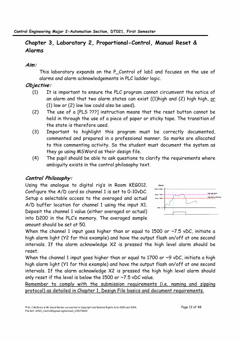
0vdc = 0
10vdc = 2048
7vdc = 1500
Alarm
8vdc = 1700High High Alarm
High Alarm or Warning
0vdc = 0
10vdc = 2048
7vdc = 1500
Alarm
8vdc = 1700High High Alarm
High Alarm or Warning
Chapter 3, Laboratory 2, Proportional-Control, Manual Reset &
Alarms Aim:
This laboratory expands on the P_Control of lab1 and focuses on the use of
alarms and alarm acknowledgements in PLC ladder logic.
Objective: (1) It is important to ensure the PLC program cannot circumvent the notice of
an alarm and that two alarm states can exist ((1)high and (2) high high, or
(1) low or (2) low low could also be used).
(2) The use of a [PLS ???] instruction means that the reset button cannot be
held in through the use of a piece of paper or sticky tape. The transition of
the state is therefore used.
(3) Important to highlight this program must be correctly documented,
commented and prepared in a professional manner. So marks are allocated
to this commenting activity. So the student must document the system as
they go using MSWord as their design file.
(4) The pupil should be able to ask questions to clarify the requirements where
ambiguity exists in the control philosophy text.
Control Philosophy: Using the analogue to digital rig’s in Room KEG012.
Configure the A/D card so channel 1 is set to 0-10vDC.
Setup a selectable access to the averaged and actual
A/D buffer location for channel 1 using the input X1.
Deposit the channel 1 value (either averaged or actual)
into D200 in the PLC’s memory. The averaged sample
amount should be set at 50.
When the channel 1 input goes higher than or equal to 1500 or ~7.5 vDC, initiate a
high alarm light (Y2 for this example) and have the output flash on/off at one second
intervals. If the alarm acknowledge X2 is pressed the high level alarm should be
reset.
When the channel 1 input goes higher than or equal to 1700 or ~9 vDC, initiate a high
high alarm light (Y1 for this example) and have the output flash on/off at one second
intervals. If the alarm acknowledge X2 is pressed the high high level alarm should
only reset if the level is below the 1500 or ~7.5 vDC value.
Remember to comply with the submission requirements (i.e. naming and zipping
protocol) as detailed in Chapter 1, Design File basics and document requirements.
Control Engineering Major 2-Automation Section, DT021, First Semester
© Dr J.McGrory & Mr David Berber as exerted in Copyright and Related Rights Acts 2000 and 2004. Page 14 of 48 File Ref: dt021_ControlEngineeringVersion1_CONT4602
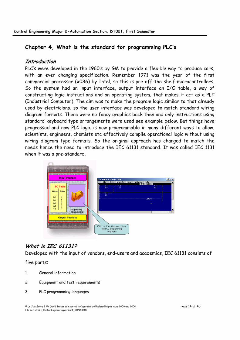
Chapter 4, What is the standard for programming PLC’s Introduction PLC’s were developed in the 1960’s by GM to provide a flexible way to produce cars,
with an ever changing specification. Remember 1971 was the year of the first
commercial processor (x086) by Intel, so this is pre-off-the-shelf-microcontrollers.
So the system had an input interface, output interface an I/O table, a way of
constructing logic instructions and an operating system, that makes it act as a PLC
(Industrial Computer). The aim was to make the program logic similar to that already
used by electricians, so the user interface was developed to match standard wiring
diagram formats. There were no fancy graphics back then and only instructions using
standard keyboard type arrangements were used see example below. But things have
progressed and now PLC logic is now programmable in many different ways to allow,
scientists, engineers, chemists etc effectively compile operational logic without using
wiring diagram type formats. So the original approach has changed to match the
needs hence the need to introduce the IEC 61131 standard. It was called IEC 1131
when it was a pre-standard.
What is IEC 61131? Developed with the input of vendors, end-users and academics, IEC 61131 consists of
five parts:
1. General information
2. Equipment and test requirements
3. PLC programming languages
I/O Table
Address Status
X7
X6
X3
X5
Y1
0
1
0
0
0
Input Interface
Output Interface
Operating
System (OS)
IEC 1131 Part 3 focuses only on
the PLC programming
languages
I/O Table
Address Status
X7
X6
X3
X5
Y1
0
1
0
0
0
Input Interface
Output Interface
Operating
System (OS)
I/O Table
Address Status
X7
X6
X3
X5
Y1
0
1
0
0
0
I/O Table
Address Status
X7
X6
X3
X5
Y1
0
1
0
0
0
Input Interface
Output Interface
Operating
System (OS)
IEC 1131 Part 3 focuses only on
the PLC programming
languages

Control Engineering Major 2-Automation Section, DT021, First Semester
© Dr J.McGrory & Mr David Berber as exerted in Copyright and Related Rights Acts 2000 and 2004. Page 15 of 48 File Ref: dt021_ControlEngineeringVersion1_CONT4602
4. User guidelines
5. Communications
IEC 61131-3 is the international standard for programmable controller programming
languages. As such, it specifies the syntax, semantics and display for the following
suite of PLC programming languages:
• Ladder diagram (LD)
• Sequential Function Charts (SFC)
• Function Block Diagram (FBD)
• Structured Text (ST)
• Instruction List (IL)
One of the primary benefits of the standard is that it allows multiple languages to be
used within the same programmable controller. This allows the program developer to
select the language best suited to each particular task. An analogy is that a mechanic
wouldn't attempt to repair an automobile using only a screwdriver. The mechanic has
a variety of tools available and chooses the best one for each task. Follow the above
links for a description of each of the IEC 61131-3 languages and the types of
applications they are best suited to.
IEC 61131 Ladder Diagram
For people who understand relay controls, LD continues to be an advantage in terms of usability.
Although it is possible to program all control logic in LD, supplementing LD with other languages allows
users access to the language best suited for a particular control task. The standard's implementation
of LD appears below.
IEC 61131 Sequential Function Charts SFC programming offers a graphical method of organizing the program. SFC is one of the methods
that can be used for programming the A series and QCPU (Q mode)/QnA series and FX series CPUs
Control Engineering Major 2-Automation Section, DT021, First Semester
© Dr J.McGrory & Mr David Berber as exerted in Copyright and Related Rights Acts 2000 and 2004. Page 16 of 48 File Ref: dt021_ControlEngineeringVersion1_CONT4602
and it stands for Sequential Function Chart. The three main components of an SFC are steps, actions
and transitions. Steps are merely chunks of logic, i.e., a unit of programming logic that accomplishes a
particular control task. Actions are the individual aspects of that task. Transitions are the mechanisms
used to move from one task to another. Control logic for each Step, Action and Transition is
programmed in one of the other languages such as Ladder Diagram or Structured Text.
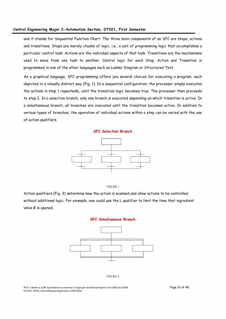
As a graphical language, SFC programming offers you several choices for executing a program, each
depicted in a visually distinct way (Fig. 1). In a sequential configuration, the processor simply executes
the actions in step 1 repeatedly, until the transition logic becomes true. The processor then proceeds
to step 2. In a selection branch, only one branch is executed depending on which transition is active. In
a simultaneous branch, all branches are executed until the transition becomes active. In addition to
various types of branches, the operation of individual actions within a step can be varied with the use
of action qualifiers.
SFC Selection Branch
FIGURE 1
Action qualifiers (Fig. 2) determine how the action is scanned and allow actions to be controlled
without additional logic. For example, one could use the L qualifier to limit the time that ingredient
valve B is opened.
SFC Simultaneous Branch
FIGURE 2

Control Engineering Major 2-Automation Section, DT021, First Semester
© Dr J.McGrory & Mr David Berber as exerted in Copyright and Related Rights Acts 2000 and 2004. Page 17 of 48 File Ref: dt021_ControlEngineeringVersion1_CONT4602
In practice, an active step is highlighted to signal to the programmer which part of the program is
executing - a useful feature for troubleshooting. This highlighting is an example of the standard's
extensibility - the ability of a vendor to add a feature not specified in the standard.
Note that the standard offers SFC programming as an organizing tool. The user chooses whether to
use it or not, based on whether the process being controlled is sequential in nature. And even if SFC
programming is used, the actions will be written in one of the four programming languages described
below. Figure 3 shows a sample net weight calculation as it would be performed in each of these
languages. In each example, net weight is calculated by subtracting tare weight from the gross weight.
SFC Sequential configuration
FIGURE 3
SFC Action Qualifiers
Control Engineering Major 2-Automation Section, DT021, First Semester
© Dr J.McGrory & Mr David Berber as exerted in Copyright and Related Rights Acts 2000 and 2004. Page 18 of 48 File Ref: dt021_ControlEngineeringVersion1_CONT4602
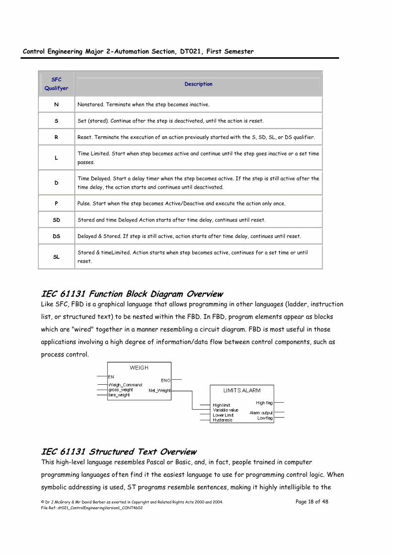
SFC
Qualifyer Description
N Nonstored. Terminate when the step becomes inactive.
S Set (stored). Continue after the step is deactivated, until the action is reset.
R Reset. Terminate the execution of an action previously started with the S, SD, SL, or DS qualifier.
L Time Limited. Start when step becomes active and continue until the step goes inactive or a set time
passes.
D Time Delayed. Start a delay timer when the step becomes active. If the step is still active after the
time delay, the action starts and continues until deactivated.
P Pulse. Start when the step becomes Active/Deactive and execute the action only once.
SD Stored and time Delayed Action starts after time delay, continues until reset.
DS Delayed & Stored. If step is still active, action starts after time delay, continues until reset.
SL Stored & timeLimited. Action starts when step becomes active, continues for a set time or until
reset.
IEC 61131 Function Block Diagram Overview Like SFC, FBD is a graphical language that allows programming in other languages (ladder, instruction
list, or structured text) to be nested within the FBD. In FBD, program elements appear as blocks
which are "wired" together in a manner resembling a circuit diagram. FBD is most useful in those
applications involving a high degree of information/data flow between control components, such as
process control.
IEC 61131 Structured Text Overview This high-level language resembles Pascal or Basic, and, in fact, people trained in computer
programming languages often find it the easiest language to use for programming control logic. When
symbolic addressing is used, ST programs resemble sentences, making it highly intelligible to the

Control Engineering Major 2-Automation Section, DT021, First Semester
© Dr J.McGrory & Mr David Berber as exerted in Copyright and Related Rights Acts 2000 and 2004. Page 19 of 48 File Ref: dt021_ControlEngineeringVersion1_CONT4602
novice user as well. ST is ideal for tasks requiring complex math, algorithms or decision-making. Its
concise format allows a large algorighm to be displayed on a single page (vs multiple pages of ladder
logic).
The IEC 61131-3 standard is extensible. I.E. Vendors may augment their offerings to meet the needs
of specific markets. As an example of this extensibility Rockwell Software augments ST with an
exclusive feature called "PowerText™". It supplements standard ST with real-time display of discrete
status, force status, analog values and floating-point values. This PowerText information is
automatically integrated into the source code, and is invaluable for debugging and application
commissioning.
Benefits of Structured Text
• People trained in computer languages can easily program control logic
• Symbols make the programs easy to understand
• PowerText facilitates system debugging and application commissioning
• Programs can be created in any text editor
• Runs as fast as ladder logic
Structured Text Constructs
• Bit / Word assignment
• IF-THEN-ELSE
• CASE
• FOR-NEXT
• WHILE
• REPEAT
• Ladder equivalent instructions
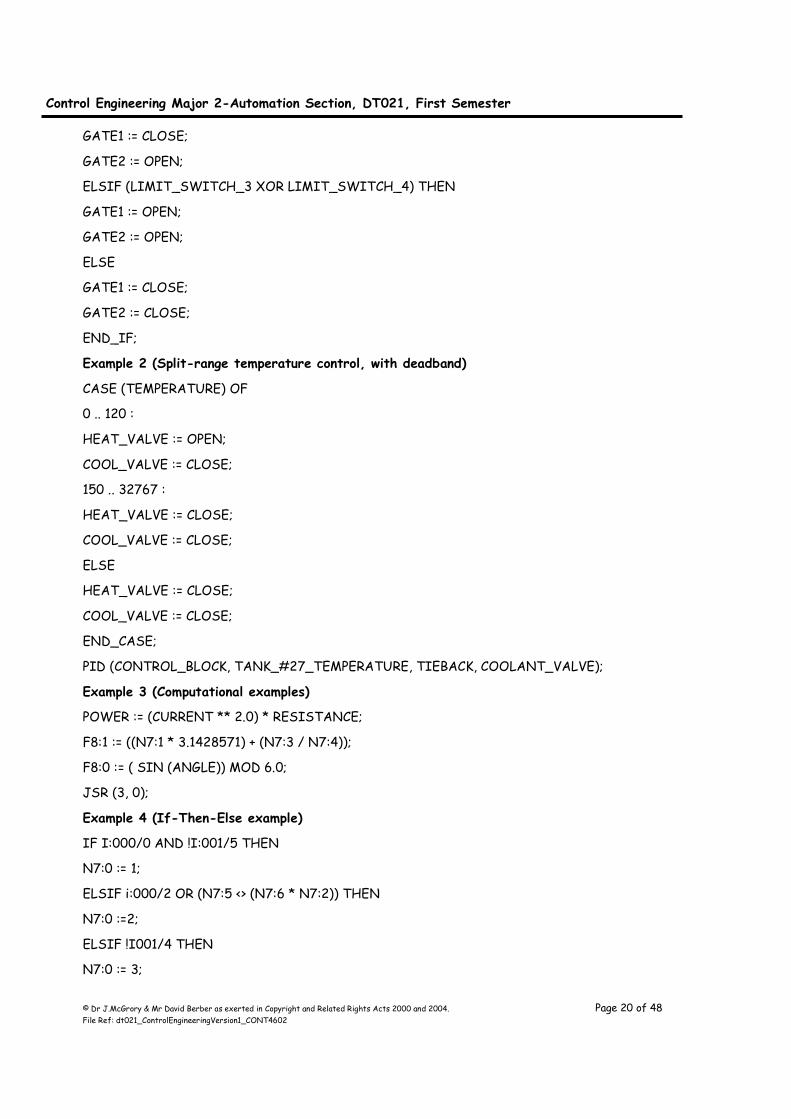
Structured Text Examples
Example 1 (Sorting machine)
IF (LIMIT_SWITCH_1 AND BOX_PRESENT) THEN
GATE1 := OPEN;
GATE2 := CLOSE;
ELSIF ((LIMIT_SWITCH_2 OR (WEIGHT <> SETPOINT))) THEN
Control Engineering Major 2-Automation Section, DT021, First Semester
© Dr J.McGrory & Mr David Berber as exerted in Copyright and Related Rights Acts 2000 and 2004. Page 20 of 48 File Ref: dt021_ControlEngineeringVersion1_CONT4602
GATE1 := CLOSE;
GATE2 := OPEN;
ELSIF (LIMIT_SWITCH_3 XOR LIMIT_SWITCH_4) THEN
GATE1 := OPEN;
GATE2 := OPEN;
ELSE
GATE1 := CLOSE;
GATE2 := CLOSE;
END_IF;
Example 2 (Split-range temperature control, with deadband)
CASE (TEMPERATURE) OF
0 .. 120 :
HEAT_VALVE := OPEN;
COOL_VALVE := CLOSE;
150 .. 32767 :
HEAT_VALVE := CLOSE;
COOL_VALVE := CLOSE;
ELSE
HEAT_VALVE := CLOSE;
COOL_VALVE := CLOSE;
END_CASE;
PID (CONTROL_BLOCK, TANK_#27_TEMPERATURE, TIEBACK, COOLANT_VALVE);
Example 3 (Computational examples)
POWER := (CURRENT ** 2.0) * RESISTANCE;
F8:1 := ((N7:1 * 3.1428571) + (N7:3 / N7:4));
F8:0 := ( SIN (ANGLE)) MOD 6.0;
JSR (3, 0);
Example 4 (If-Then-Else example)
IF I:000/0 AND !I:001/5 THEN
N7:0 := 1;
ELSIF i:000/2 OR (N7:5 <> (N7:6 * N7:2)) THEN
N7:0 :=2;
ELSIF !I001/4 THEN
N7:0 := 3;
Control Engineering Major 2-Automation Section, DT021, First Semester
© Dr J.McGrory & Mr David Berber as exerted in Copyright and Related Rights Acts 2000 and 2004. Page 21 of 48 File Ref: dt021_ControlEngineeringVersion1_CONT4602
ELSE
N7:0 :=4;
END_IF;
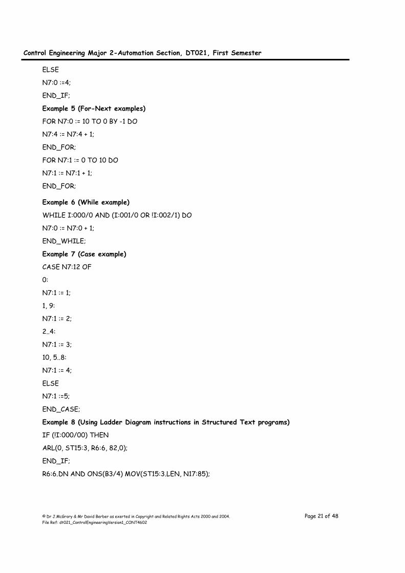
Example 5 (For-Next examples)
FOR N7:0 := 10 TO 0 BY -1 DO
N7:4 := N7:4 + 1;
END_FOR;
FOR N7:1 := 0 TO 10 DO
N7:1 := N7:1 + 1;
END_FOR;
Example 6 (While example)
WHILE I:000/0 AND (I:001/0 OR !I:002/1) DO
N7:0 := N7:0 + 1;
END_WHILE;
Example 7 (Case example)
CASE N7:12 OF
0:
N7:1 := 1;
1, 9:
N7:1 := 2;
2..4:
N7:1 := 3;
10, 5..8:
N7:1 := 4;
ELSE
N7:1 :=5;
END_CASE;
Example 8 (Using Ladder Diagram instructions in Structured Text programs)
IF (!I:000/00) THEN
ARL(0, ST15:3, R6:6, 82,0);
END_IF;
R6:6.DN AND ONS(B3/4) MOV(ST15:3.LEN, N17:85);

Control Engineering Major 2-Automation Section, DT021, First Semester
© Dr J.McGrory & Mr David Berber as exerted in Copyright and Related Rights Acts 2000 and 2004. Page 22 of 48 File Ref: dt021_ControlEngineeringVersion1_CONT4602
IEC 61131 Instruction List Overview This low-level language is similar to Assembly language and is useful in cases where small functions are
repeated often. Although it is powerful, it is considered to be difficult to learn.
Instruction List example (Calculate new weight by subtracting tare weight from net weight)
LD weigh_command
JMPC WEIGH_NOW
ST ENO
RET
WEIGH_NOW: LD gross_weight
SUB tare_weight
Control Engineering Major 2-Automation Section, DT021, First Semester
© Dr J.McGrory & Mr David Berber as exerted in Copyright and Related Rights Acts 2000 and 2004. Page 23 of 48 File Ref: dt021_ControlEngineeringVersion1_CONT4602
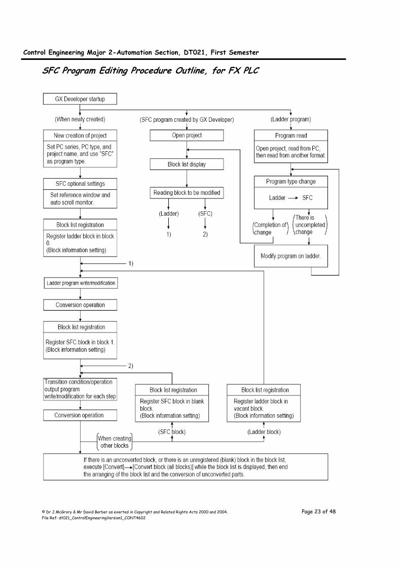
SFC Program Editing Procedure Outline, for FX PLC
Control Engineering Major 2-Automation Section, DT021, First Semester
© Dr J.McGrory & Mr David Berber as exerted in Copyright and Related Rights Acts 2000 and 2004. Page 24 of 48 File Ref: dt021_ControlEngineeringVersion1_CONT4602
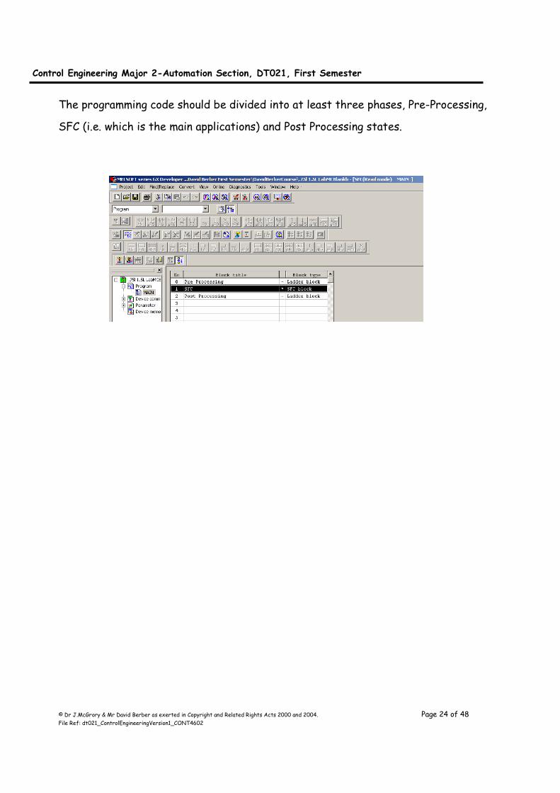
The programming code should be divided into at least three phases, Pre-Processing,
SFC (i.e. which is the main applications) and Post Processing states.
Control Engineering Major 2-Automation Section, DT021, First Semester
© Dr J.McGrory & Mr David Berber as exerted in Copyright and Related Rights Acts 2000 and 2004. Page 25 of 48 File Ref: dt021_ControlEngineeringVersion1_CONT4602
Chapter 5, Laboratory 2, Controlling Sequences ©DavidBerber Aim:
Sequence control of a 0.75 l and 1.5 l bottle labelling machine, thus control of a
parallel sequence. This laboratory explores the use of sequence flow diagrams
but focuses on the parallel decision branch aspect.
Objective: (1) Develop using an example an understanding of “What is a sequence”?
(2) How do we control a sequence (i.e. design the system, enter it into the
software, document it, parallel sequence, multiple loops etc)?
(3) How do we fault find.
(4) What are the advantages of IEC 61131-Part 3 for controlling sequences
(declare in your design file your list)
(5) What are the components of IEC 61131-part 3
System description:
The system consists of a Mitsubishi FX1S 20 PLC, three pneumatic actuators and
electro pneumatic interfaces to the PLC. The object of the system is to label
correctly 0.75 litre and 1.5 litre bottles. The bottles are detected by the Blue push
button and the size is determined by the position of the X13 selector switch (X13 Off
=0.75 l and X13 On = 1.5L).
The following information describes the PLC Input's and Outputs, system schematic
and required programming exercises.
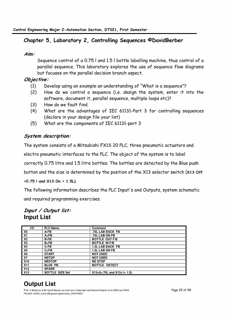
Input / Output list: Input List
I/O PLC Name Comment
X0 A-FB .75L LAB BACK FB
X1 A+FB .75L LAB ON FB
X2 B-FB BOTTLE OUT F/B
X3 B+FB BOTTLE IN F/B
X4 C-FB 1.5L LAB BACK FB
X5 C+FB 1.5L LAB ON FB
X6 START NOT USED
X7 NSTOP NOT USED
X10 NESTOP NE STOP
X11 BLUE PB BOTTLE DETECT
X12 SPARE
X13 BOTTLE SIZE Sel X13=0=.75L and X13=1= 1.5L
Output List
Control Engineering Major 2-Automation Section, DT021, First Semester
© Dr J.McGrory & Mr David Berber as exerted in Copyright and Related Rights Acts 2000 and 2004. Page 26 of 48 File Ref: dt021_ControlEngineeringVersion1_CONT4602
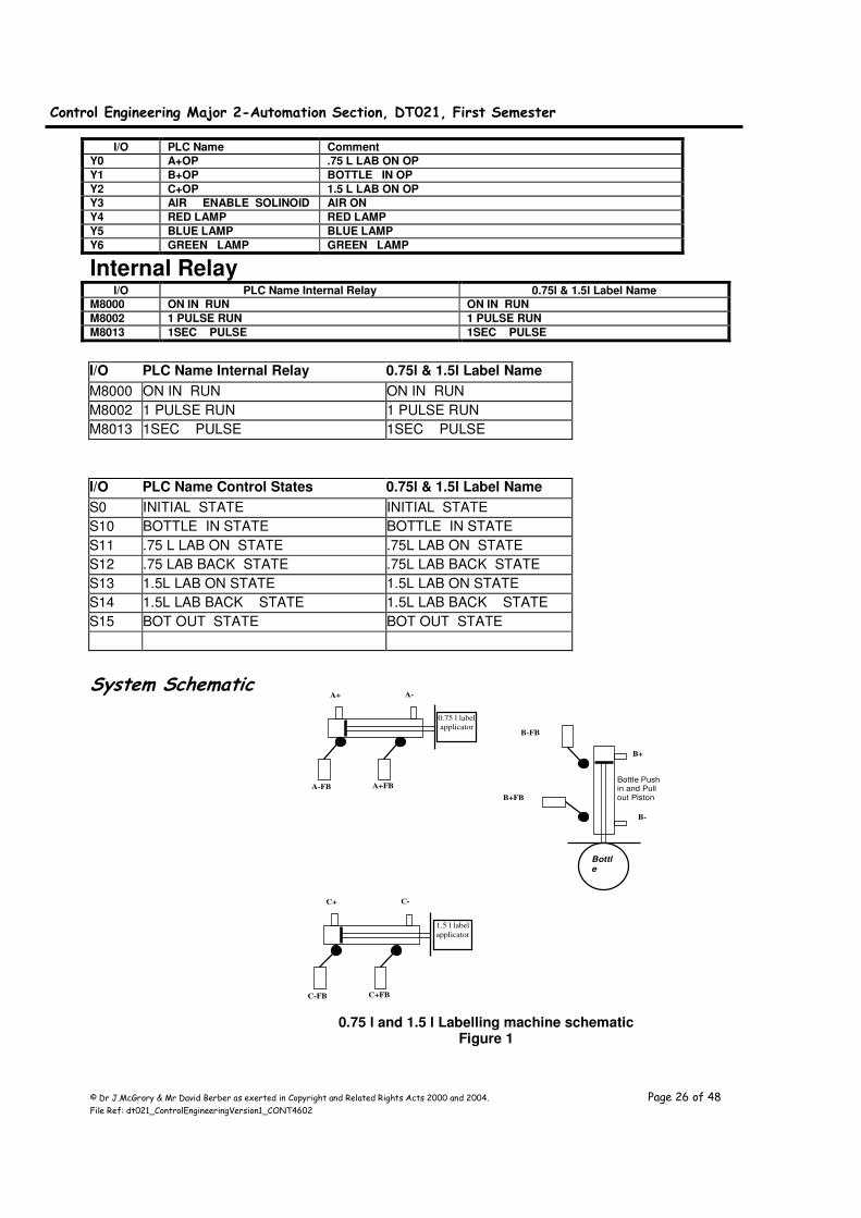
I/O PLC Name Comment
Y0 A+OP .75 L LAB ON OP
Y1 B+OP BOTTLE IN OP
Y2 C+OP 1.5 L LAB ON OP
Y3 AIR ENABLE SOLINOID AIR ON
Y4 RED LAMP RED LAMP
Y5 BLUE LAMP BLUE LAMP
Y6 GREEN LAMP GREEN LAMP
Internal Relay I/O PLC Name Internal Relay 0.75l & 1.5l Label Name
M8000 ON IN RUN ON IN RUN
M8002 1 PULSE RUN 1 PULSE RUN
M8013 1SEC PULSE 1SEC PULSE
I/O PLC Name Internal Relay 0.75l & 1.5l Label Name
M8000 ON IN RUN ON IN RUN
M8002 1 PULSE RUN 1 PULSE RUN
M8013 1SEC PULSE 1SEC PULSE
I/O PLC Name Control States 0.75l & 1.5l Label Name
S0 INITIAL STATE INITIAL STATE
S10 BOTTLE IN STATE BOTTLE IN STATE
S11 .75 L LAB ON STATE .75L LAB ON STATE
S12 .75 LAB BACK STATE .75L LAB BACK STATE
S13 1.5L LAB ON STATE 1.5L LAB ON STATE
S14 1.5L LAB BACK STATE 1.5L LAB BACK STATE
S15 BOT OUT STATE BOT OUT STATE
System Schematic
A- A+
0.75 l label
applicator
A-FB A+FB
C- C+
1.5 l label
applicator
C-FB C+FB
Bottle Push in and Pull out Piston
B+
B-
B+FB
B-FB
Bottle
0.75 l and 1.5 l Labelling machine schematic
Figure 1
Control Engineering Major 2-Automation Section, DT021, First Semester
© Dr J.McGrory & Mr David Berber as exerted in Copyright and Related Rights Acts 2000 and 2004. Page 27 of 48 File Ref: dt021_ControlEngineeringVersion1_CONT4602
Control Philosophy: Piston A is the 0.75 litre label applicator piston, Piston B is the Bottle push in and
pulls out of the label machine piston and Piston C is the 1.5 litre label applicator
piston.
Initially the system should start with A-, B- and C- and if the machine is correctly
initialised to accept a bottle the Green indicator lamp should illuminate. If the
machine is not correctly initialised it should not start and the operator should
manually initialise the machine.
When all the initial conditions are true and a bottle detection signal is received, the
PLC operates Piston B in the B+ direction until the signal B+FB activates, this puts the
bottle into the labelling machine. The PLC will detect if the bottle is a 0.75 l or 1.5 l
bottle. If the bottle is a 0.75 l bottle then the next step is to operate Piston A is in
the A+ direction until the signal A+FB activates, this allows the 0.75 l labeller to
apply the correct label to the bottle. Then the 0.75 l labeller is withdrawn from the
bottle by operating Piston A is in the A- direction until the signal A-FB activates. The
bottle should now be withdrawn form the labelling machine. This is carried out by
Piston B in the B- direction until the signal B-FB activates; this pulls the bottle out of
the labelling machine.
If the bottle is a 1.5l bottle then the next step is to operate Piston C is in the C+
direction until the signal C+FB activates, this allows the 1.5 l labeller to apply the
correct label to the bottle. Then the 1.5 l labeller is withdrawn from the bottle by
operating Piston C is in the C- direction until the signal C-FB activates. The bottle
should now be withdrawn from the labelling machine. This is carried out by Piston B in
the B- direction until the signal B-FB activates; this pulls the bottle out of the
labelling machine.
The machine is now ready to accept the next bottle for labelling. The Selector switch
X13 will inform the PLC to the size of the bottle X13 input OFF is a 0.75 l bottle and
X13 input ON is a 1.5 l bottle.
Programming Exercise: 1. Draw a fully labelled Sequence Function Chart for the required operation
incorporating the following features.
2. The Green Indicator lamp should illuminate when the process is at the initial
conditions and is ready to start. The green indicator should stay on during
normal operation.

Control Engineering Major 2-Automation Section, DT021, First Semester
© Dr J.McGrory & Mr David Berber as exerted in Copyright and Related Rights Acts 2000 and 2004. Page 28 of 48 File Ref: dt021_ControlEngineeringVersion1_CONT4602
3. If the Emergency Stop is pressed the machine should commence operation on
removal of the Emergency Stop at the initial condition. The Red indicator lamp
should flash while the Emergency Stop is activated.
4. Test and debug your program
5. Print out the final version of your program, make sure that the printout has
the relevant information. DO NOT PRINT until your printer settings have been
checked by staff in lab. Incorrect settings will result in lots of unwanted
pages.
Control Engineering Major 2-Automation Section, DT021, First Semester
© Dr J.McGrory & Mr David Berber as exerted in Copyright and Related Rights Acts 2000 and 2004. Page 29 of 48 File Ref: dt021_ControlEngineeringVersion1_CONT4602
Chapter 6, Laboratory 3, Sequence control of an automatic palletising
machine ©DavidBerber Aim:
This laboratory focuses on the challenges associated with sequencing key
activities of a process. An application with multiple loops is used to
demonstrate to the learner some of the complications that can occur.
Objective: (1) Enhance the understanding of “What is a sequence”?
(2) How do we control a sequence with multiple loops?
(3) Demonstrate a single increment step button, used for maintenance and
testing of the system.
(4) What are the advantages of IEC 61131-Part 3 for controlling sequences
(declare in your design file your list)
(5) Are their alternatives in doing multiple loops in SFC?
System description: The system consists of a Mitsubishi FX1S 20 PLC, three pneumatic actuators and
electro pneumatic interfaces to the PLC. The object of the system is to place 9 bags
of cement onto a palate in a required sequence.
The following information describes the PLC Input's and Outputs, system schematic
and required programming exercises.
Input / Output list: Input List
I/O PLC Name Comment
X0 A-FB Piston A Reverse Feedback Limit switch Bag Drop Actuator
X1 A+FB Piston A Forward Feedback Limit switch Bag Drop Actuator
X2 B-FB Piston B Reverse Feedback Limit switch Bag Push Actuator
X3 B+FB Piston B Forward Feedback Limit switch Bag Push Actuator
X4 C-FB Piston C Reverse Feedback Limit switch Row Push Actuator
X5 C+FB Piston C Forward Feedback Limit switch Row Push Actuator
X6 START Start Push Button
X7 NSTOP Stop Push Button Normally Closed
X10 NESTOP Emergency Stop Push Button Normally Closed
X11 SINGLE STEP PB Single Step through the program
Control Engineering Major 2-Automation Section, DT021, First Semester
© Dr J.McGrory & Mr David Berber as exerted in Copyright and Related Rights Acts 2000 and 2004. Page 30 of 48 File Ref: dt021_ControlEngineeringVersion1_CONT4602
X12 Spare
X13 SINGLE STEP SELECT Single Step mode On = 1 , Off = 0
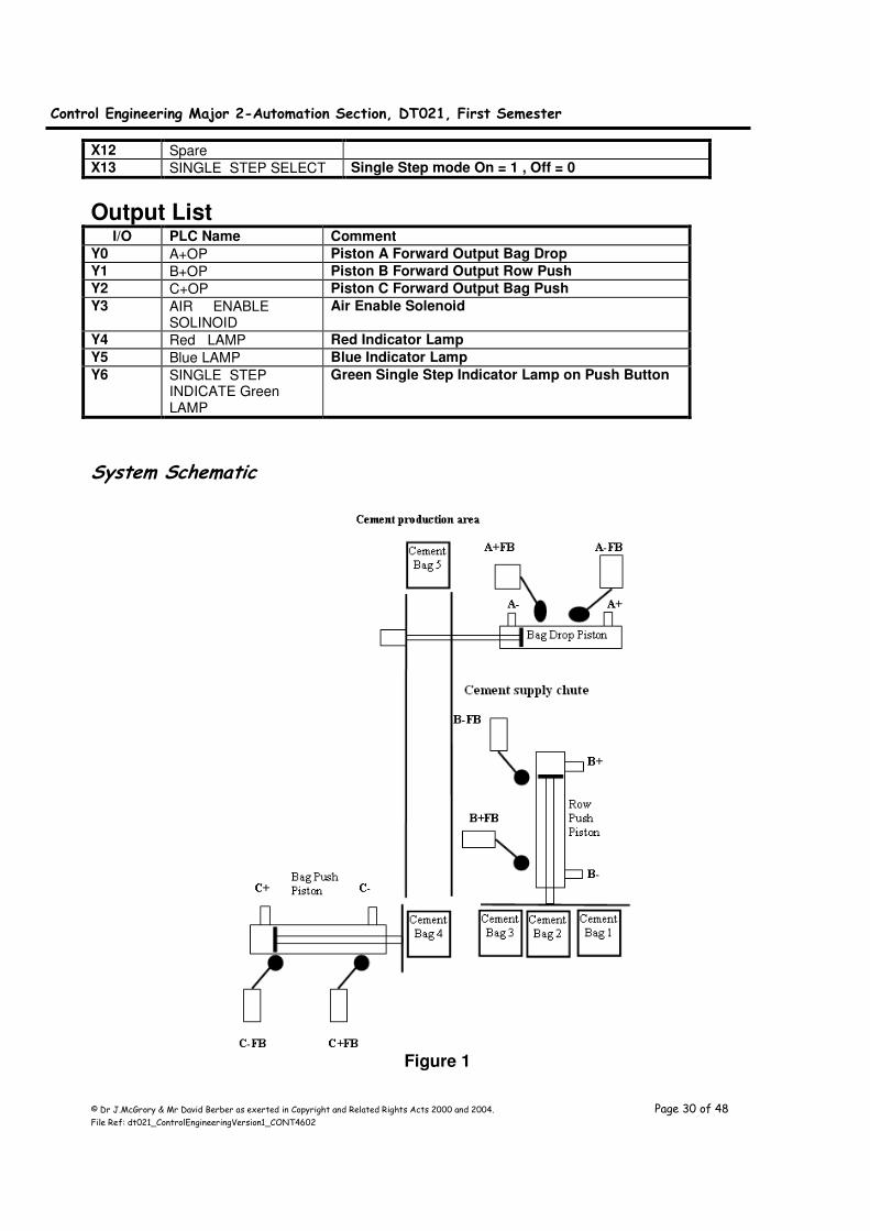
Output List I/O PLC Name Comment
Y0 A+OP Piston A Forward Output Bag Drop
Y1 B+OP Piston B Forward Output Row Push
Y2 C+OP Piston C Forward Output Bag Push
Y3 AIR ENABLE SOLINOID
Air Enable Solenoid
Y4 Red LAMP Red Indicator Lamp
Y5 Blue LAMP Blue Indicator Lamp
Y6 SINGLE STEP INDICATE Green LAMP
Green Single Step Indicator Lamp on Push Button
System Schematic
Figure 1
Control Engineering Major 2-Automation Section, DT021, First Semester
© Dr J.McGrory & Mr David Berber as exerted in Copyright and Related Rights Acts 2000 and 2004. Page 31 of 48 File Ref: dt021_ControlEngineeringVersion1_CONT4602
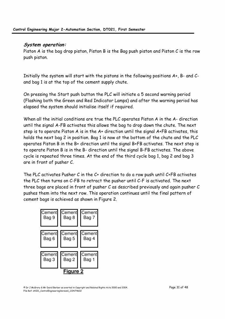
System operation: Piston A is the bag drop piston, Piston B is the Bag push piston and Piston C is the row
push piston.
Initially the system will start with the pistons in the following positions A+, B- and C-
and bag 1 is at the top of the cement supply chute.
On pressing the Start push button the PLC will initiate a 5 second warning period
(Flashing both the Green and Red Indicator Lamps) and after the warning period has
elapsed the system should initialise itself if required.
When all the initial conditions are true the PLC operates Piston A in the A- direction
until the signal A-FB activates this allows the bag to drop down the chute. The next
step is to operate Piston A is in the A+ direction until the signal A+FB activates, this
holds the next bag 2 in position. Bag 1 is now at the bottom of the chute and the PLC
operates Piston B in the B+ direction until the signal B+FB activates. The next step is
to operate Piston B is in the B- direction until the signal B-FB activates. The above
cycle is repeated three times. At the end of the third cycle bag 1, bag 2 and bag 3
are in front of pusher C.
The PLC activates Pusher C in the C+ direction to do a row push until C+FB activates
the PLC then turns on C-FB to retract the pusher until C-F is activated. The next
three bags are placed in front of pusher C as described previously and again pusher C
pushes them into the next row. This operation continues until the final pattern of
cement bags is achieved as shown in Figure 2.
Figure 2
Cement Bag 9
Cement Bag 8
Cement Bag 7
Cement Bag 6
Cement Bag 5
Cement Bag 4
Cement Bag 3
Cement Bag 2
Cement Bag 1
Control Engineering Major 2-Automation Section, DT021, First Semester
© Dr J.McGrory & Mr David Berber as exerted in Copyright and Related Rights Acts 2000 and 2004. Page 32 of 48 File Ref: dt021_ControlEngineeringVersion1_CONT4602
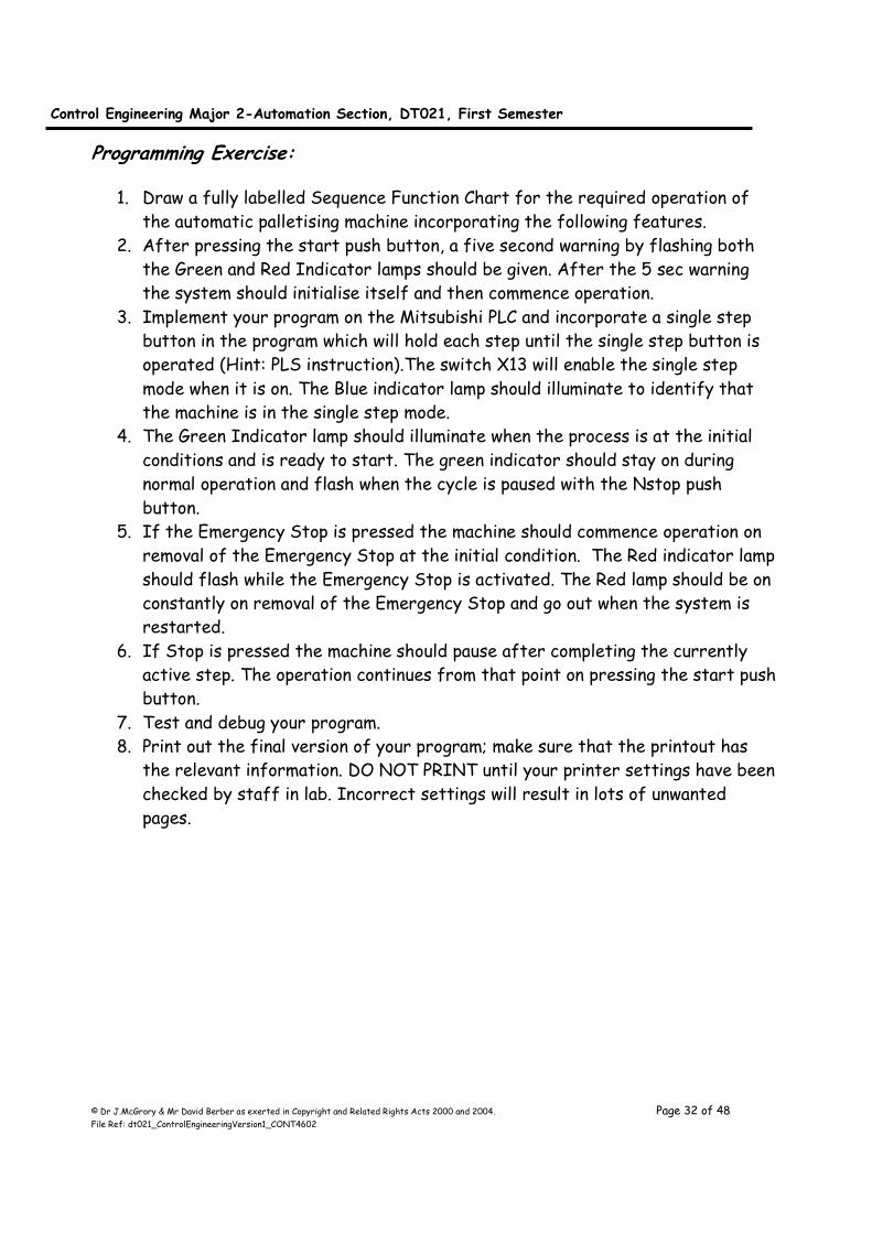
Programming Exercise:
1. Draw a fully labelled Sequence Function Chart for the required operation of
the automatic palletising machine incorporating the following features.
2. After pressing the start push button, a five second warning by flashing both
the Green and Red Indicator lamps should be given. After the 5 sec warning
the system should initialise itself and then commence operation.
3. Implement your program on the Mitsubishi PLC and incorporate a single step
button in the program which will hold each step until the single step button is
operated (Hint: PLS instruction).The switch X13 will enable the single step
mode when it is on. The Blue indicator lamp should illuminate to identify that
the machine is in the single step mode.
4. The Green Indicator lamp should illuminate when the process is at the initial
conditions and is ready to start. The green indicator should stay on during
normal operation and flash when the cycle is paused with the Nstop push
button.
5. If the Emergency Stop is pressed the machine should commence operation on
removal of the Emergency Stop at the initial condition. The Red indicator lamp
should flash while the Emergency Stop is activated. The Red lamp should be on
constantly on removal of the Emergency Stop and go out when the system is
restarted.
6. If Stop is pressed the machine should pause after completing the currently
active step. The operation continues from that point on pressing the start push
button.
7. Test and debug your program.
8. Print out the final version of your program; make sure that the printout has
the relevant information. DO NOT PRINT until your printer settings have been
checked by staff in lab. Incorrect settings will result in lots of unwanted
pages.
Control Engineering Major 2-Automation Section, DT021, First Semester
© Dr J.McGrory & Mr David Berber as exerted in Copyright and Related Rights Acts 2000 and 2004. Page 33 of 48 File Ref: dt021_ControlEngineeringVersion1_CONT4602
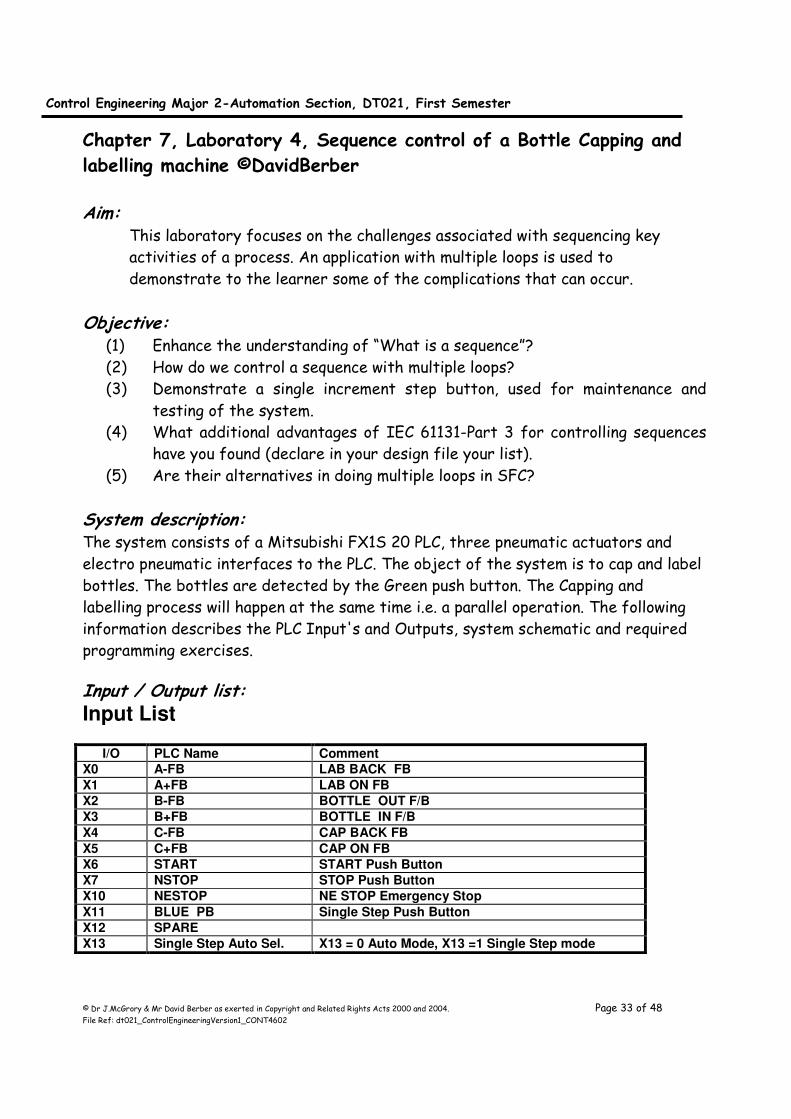
Chapter 7, Laboratory 4, Sequence control of a Bottle Capping and
labelling machine ©DavidBerber Aim:
This laboratory focuses on the challenges associated with sequencing key
activities of a process. An application with multiple loops is used to
demonstrate to the learner some of the complications that can occur.
Objective: (1) Enhance the understanding of “What is a sequence”?
(2) How do we control a sequence with multiple loops?
(3) Demonstrate a single increment step button, used for maintenance and
testing of the system.
(4) What additional advantages of IEC 61131-Part 3 for controlling sequences
have you found (declare in your design file your list).
(5) Are their alternatives in doing multiple loops in SFC?
System description: The system consists of a Mitsubishi FX1S 20 PLC, three pneumatic actuators and
electro pneumatic interfaces to the PLC. The object of the system is to cap and label
bottles. The bottles are detected by the Green push button. The Capping and
labelling process will happen at the same time i.e. a parallel operation. The following
information describes the PLC Input's and Outputs, system schematic and required
programming exercises.
Input / Output list: Input List
I/O PLC Name Comment
X0 A-FB LAB BACK FB
X1 A+FB LAB ON FB
X2 B-FB BOTTLE OUT F/B
X3 B+FB BOTTLE IN F/B
X4 C-FB CAP BACK FB
X5 C+FB CAP ON FB
X6 START START Push Button
X7 NSTOP STOP Push Button
X10 NESTOP NE STOP Emergency Stop
X11 BLUE PB Single Step Push Button
X12 SPARE
X13 Single Step Auto Sel. X13 = 0 Auto Mode, X13 =1 Single Step mode
Control Engineering Major 2-Automation Section, DT021, First Semester
© Dr J.McGrory & Mr David Berber as exerted in Copyright and Related Rights Acts 2000 and 2004. Page 34 of 48 File Ref: dt021_ControlEngineeringVersion1_CONT4602
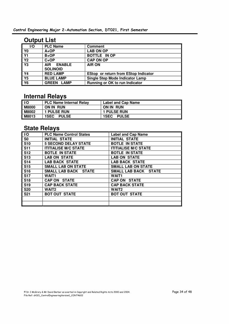
Output List I/O PLC Name Comment
Y0 A+OP LAB ON OP
Y1 B+OP BOTTLE IN OP
Y2 C+OP CAP ON OP
Y3 AIR ENABLE SOLINOID
AIR ON
Y4 RED LAMP EStop or return from EStop Indicator
Y5 BLUE LAMP Single Step Mode Indicator Lamp
Y6 GREEN LAMP Running or OK to run Indicator
Internal Relays I/O PLC Name Internal Relay Label and Cap Name
M8000 ON IN RUN ON IN RUN
M8002 1 PULSE RUN 1 PULSE RUN
M8013 1SEC PULSE 1SEC PULSE
State Relays
I/O PLC Name Control States Label and Cap Name
S0 INITIAL STATE INITIAL STATE
S10 5 SECOND DELAY STATE BOTLE IN STATE
S11 ITITIALISE M/C STATE ITITIALISE M/C STATE
S12 BOTLE IN STATE BOTLE IN STATE
S13 LAB ON STATE LAB ON STATE
S14 LAB BACK STATE LAB BACK STATE
S15 SMALL LAB ON STATE SMALL LAB ON STATE
S16 SMALL LAB BACK STATE SMALL LAB BACK STATE
S17 WAIT1 WAIT1
S18 CAP ON STATE CAP ON STATE
S19 CAP BACK STATE CAP BACK STATE
S20 WAIT2 WAIT2
S21 BOT OUT STATE BOT OUT STATE
Control Engineering Major 2-Automation Section, DT021, First Semester
© Dr J.McGrory & Mr David Berber as exerted in Copyright and Related Rights Acts 2000 and 2004. Page 35 of 48 File Ref: dt021_ControlEngineeringVersion1_CONT4602
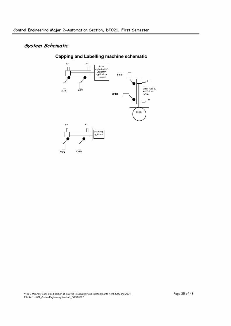
System Schematic
Capping and Labelling machine schematic
Control Engineering Major 2-Automation Section, DT021, First Semester
© Dr J.McGrory & Mr David Berber as exerted in Copyright and Related Rights Acts 2000 and 2004. Page 36 of 48 File Ref: dt021_ControlEngineeringVersion1_CONT4602
System operation:
Piston A is the label applicator piston, Piston B is the Bottle push in and pull out of
the label and capping machine piston and Piston C is the bottle cap applicator piston.
Upon pressing the Start push button the PLC should implement a five second warning
period indicated by flashing the Red and Green indicator lamps. After the five
seconds warning period, if the machine is not correctly initialised it will automatically
initialise the system with A-, B- and C-. When the machine is correctly initialised to
accept a bottle the Green indicator lamp should illuminate.
When all the initial conditions are true and a bottle detection signal is received by
pressing the Green start push button, the PLC operates Piston B in the B+ direction
until the signal B+FB activates, this puts the bottle into the labelling machine. The
PLC then commences a parallel operation of capping and labelling the bottle at the
same time.
The capper requires one operation but the label applicator is required to apply two
labels requiring two operations. The first label application applies the bottle size label
and the second application applies a special offer label.
The label applicator will operate Piston A is in the A+ direction until the signal A+FB
activates, this applies the first label to the bottle. Then labeller is withdrawn from
the bottle by operating Piston A is in the A- direction until the signal A-FB activates.
This operation is repeated for the second label.
At the same time the labeller is operating the cap is placed on the bottle with the C
piston. The cap applicator will operate Piston C is in the C+ direction until the signal
C+FB activates, this applies the cap to the bottle. Then cap applicator is withdrawn
from the bottle by operating Piston C is in the C- direction until the signal C-FB
activates.
When both labels and the cap are applied then the bottle should be withdrawn from
the capping and labelling machine. This is carried out by Piston B in the B- direction
until the signal B-FB activates; this pulls the bottle out of the labelling machine.
The machine is now ready to accept the next bottle for capping and labelling.
Programming Exercise:
1. Draw a fully labelled Sequence Function Chart for the required operation of
the capping and labelling machine incorporating the following features.

Control Engineering Major 2-Automation Section, DT021, First Semester
© Dr J.McGrory & Mr David Berber as exerted in Copyright and Related Rights Acts 2000 and 2004. Page 37 of 48 File Ref: dt021_ControlEngineeringVersion1_CONT4602
2. After pressing the start push button, a five second warning by flashing both
the Green and Red Indicator lamps should be given. After the 5 s warning the
system should initialise its self and then commence operation.
3. Implement your program on the Mitsubishi PLC and incorporate a single step
button in the program which will hold each step until the single step button is
operated (Hint: PLS instruction).The switch X13 will enable the single step
mode when it is on. The Blue indicator lamp should illuminate to identify that
the machine is in the single step mode.
4. The Green Indicator lamp should illuminate when the process is at the initial
conditions and is ready to start. The green indicator should stay on during
normal operation and flash when the cycle is paused with the Nstop push
button.
5. If the Emergency Stop is pressed the machine should commence operation on
removal of the Emergency Stop at the initial condition. The Red indicator lamp
should flash while the Emergency Stop is activated. The Red lamp should be on
constantly on removal of the Emergency Stop and go out when the system is
restarted.
6. If Stop is pressed the machine should pause after completing the currently
active step. The operation continues from that point on pressing the start push
button.
7. Test and debug your program.
8. Print out the final version of your program, make sure that the printout has
the relevant information. DO NOT PRINT until staff in lab has checked your
printer settings. Incorrect settings will result in lots of unwanted pages.
Control Engineering Major 2-Automation Section, DT021, First Semester
© Dr J.McGrory & Mr David Berber as exerted in Copyright and Related Rights Acts 2000 and 2004. Page 38 of 48 File Ref: dt021_ControlEngineeringVersion1_CONT4602
Chapter 8, Human Machine Interface (HMI)
Introduction The term Human Machine Interface (HMI) is also known by a number of different
names, Operator Machine Interface (OMI) and the less politically correct Man
Machine Interface (MMI). But in essence they are all the same device. They permit a
person who is responsible for a machine to interface (or operate or manage) with that
machine. Before we begin to develop the interface it is important to ensure we design
the screens and layouts carefully and methodically.
How the Brain Processes Images
This chapter focuses on how the brain connects the visual information to information
stored in memory. In order to correctly direct the person to complete a task it is
critical that the way the person interprets the information is taken into account.
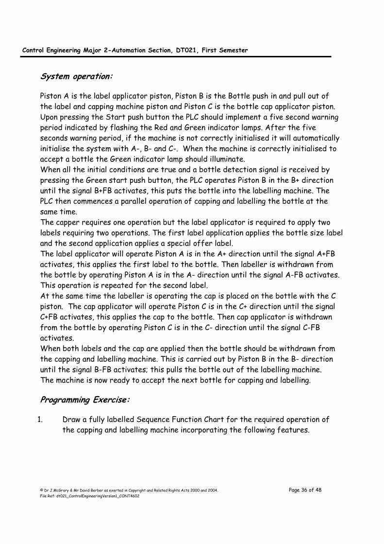
Consider the example of driving a car or bike and trying to find a house. As the
person travels down the road (being careful to ensure they are focused on the road,
after all it is the law), the fields of vision to the left and right are scanned in a
sweeping motion. As shown in the Figure below. But how is information processed
within the brain.
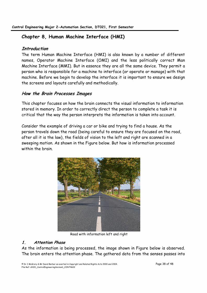
1. Attention Phase As the information is being processed, the image shown in Figure below is observed.
The brain enters the attention phase. The gathered data from the senses passes into
Road with information left and right
Control Engineering Major 2-Automation Section, DT021, First Semester
© Dr J.McGrory & Mr David Berber as exerted in Copyright and Related Rights Acts 2000 and 2004. Page 39 of 48 File Ref: dt021_ControlEngineeringVersion1_CONT4602
the sensory memory. Visual data is held there for less than a second, before being
deleted or lost if the brain does not pay attention to it. Attention is the vital first
stage in the metal processing of any sensory input. If attention is not given to the
artefact it is lost from memory.
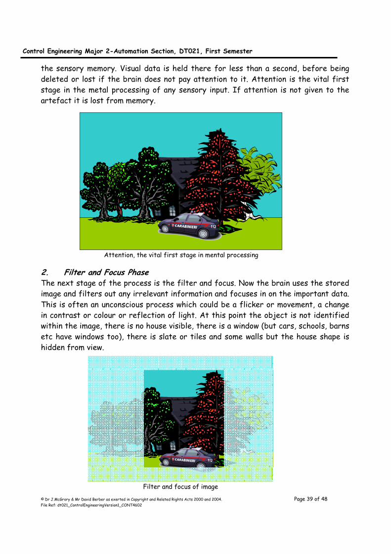
2. Filter and Focus Phase The next stage of the process is the filter and focus. Now the brain uses the stored
image and filters out any irrelevant information and focuses in on the important data.
This is often an unconscious process which could be a flicker or movement, a change
in contrast or colour or reflection of light. At this point the object is not identified
within the image, there is no house visible, there is a window (but cars, schools, barns
etc have windows too), there is slate or tiles and some walls but the house shape is
hidden from view.
Attention, the vital first stage in mental processing
Filter and focus of image
Control Engineering Major 2-Automation Section, DT021, First Semester
© Dr J.McGrory & Mr David Berber as exerted in Copyright and Related Rights Acts 2000 and 2004. Page 40 of 48 File Ref: dt021_ControlEngineeringVersion1_CONT4602
3. Identification Phase The brain now enters the identification phase of the process also know as the
labelling phase of the process. It is very often in the real-world that the key
information is partially obscured form the current location. The use of both eyes
here makes identifying shapes slightly quicker than a person with single eye vision as
a type of three dimensional aspects helps process the key objects more efficiently.
If this observation is via a computer screen then the three dimensional aspect is not
so reliant unless the images were heavily based on three-dimensional imagery. This is
because the single eyed person would have lost some of the ability or knack of
processing these types of images. So, all the key information artefacts in the
focused and filtered image are identified.
So far in the process the brain has been acting in a bottom up capacity. This is where
all the senses have been used and an image has been captured, attention given to the
image, the image has been filtered and focused. But in this example this is not
enough. The brain now needs to work from them top down. It must hypostasise on
what the labelled artefacts are and are they important. So the brain in its long term
memory creates a model of all kinds of things from cars to houses, friends, animals,
social groups and many more all at different levels of abstraction. These are called
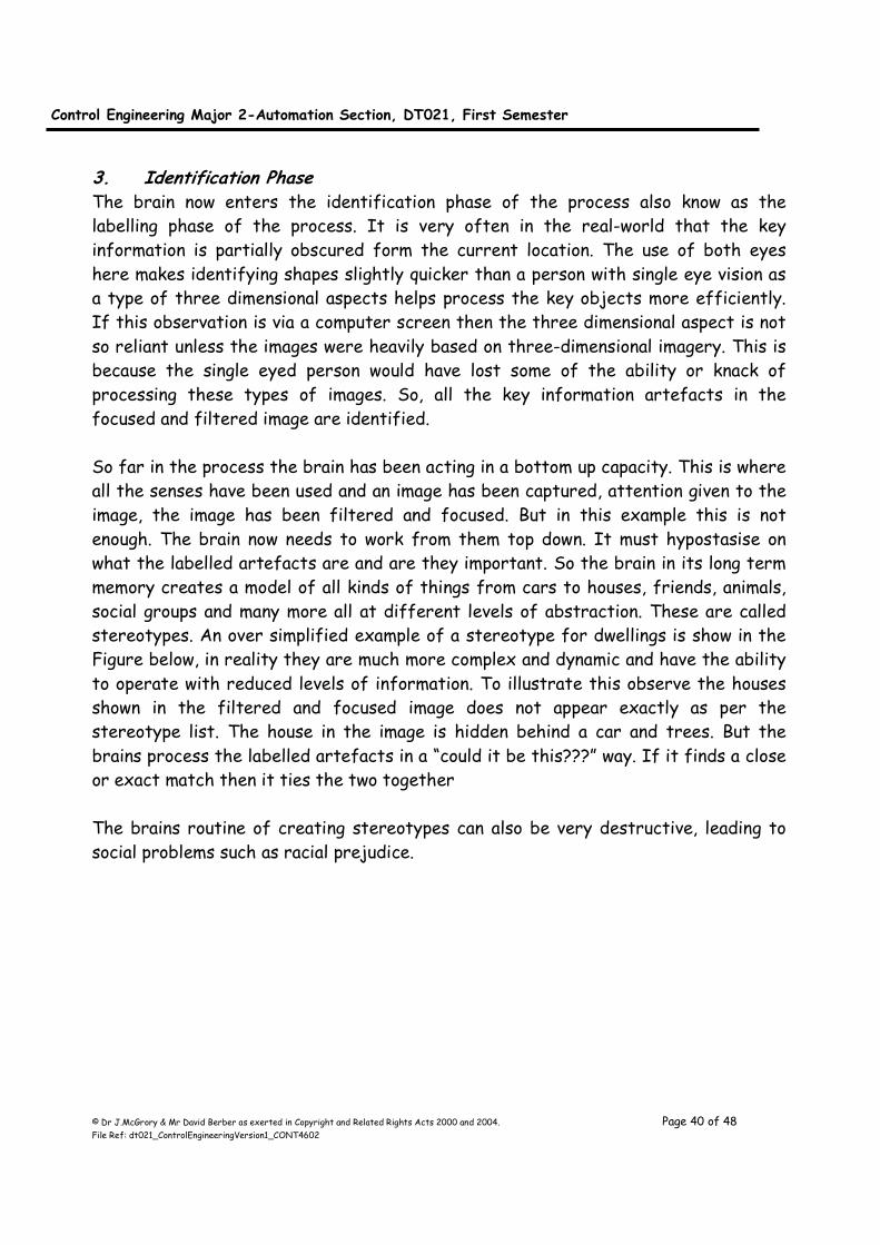
stereotypes. An over simplified example of a stereotype for dwellings is show in the
Figure below, in reality they are much more complex and dynamic and have the ability
to operate with reduced levels of information. To illustrate this observe the houses
shown in the filtered and focused image does not appear exactly as per the
stereotype list. The house in the image is hidden behind a car and trees. But the
brains process the labelled artefacts in a “could it be this???” way. If it finds a close
or exact match then it ties the two together
The brains routine of creating stereotypes can also be very destructive, leading to
social problems such as racial prejudice.
Control Engineering Major 2-Automation Section, DT021, First Semester
© Dr J.McGrory & Mr David Berber as exerted in Copyright and Related Rights Acts 2000 and 2004. Page 41 of 48 File Ref: dt021_ControlEngineeringVersion1_CONT4602
Now all the details are identified, the person does some more brain processing to see
if that is the house of interest or not and act accordingly.
Name: Bungalow
Style: Single-Story
Colour: White wall & Brown Roof
Name: HouseStyle: Two-story
Colour: Dark, black and charcoal
Name: Condo
Style: Multi-storey
Colour: Dark, black and charcoal
Name: House
Style: Single-storey with porchColour: Bright, Terracotta walls grey roof
Stereotype: Dwelling
Name: Bungalow
Style: Single-Story
Colour: White wall & Brown Roof
Name: HouseStyle: Two-story
Colour: Dark, black and charcoal
Name: Condo
Style: Multi-storey
Colour: Dark, black and charcoal
Name: House
Style: Single-storey with porchColour: Bright, Terracotta walls grey roof
Stereotype: Dwelling
Stereotypes options for dwellings
Stereotype bottom up processing
Control Engineering Major 2-Automation Section, DT021, First Semester
© Dr J.McGrory & Mr David Berber as exerted in Copyright and Related Rights Acts 2000 and 2004. Page 42 of 48 File Ref: dt021_ControlEngineeringVersion1_CONT4602
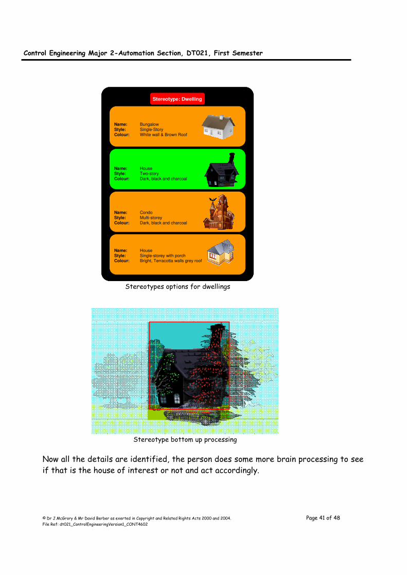
How the eyes scan and brain interprets From the age of one, a child can find two objects the same in a pack of visual cue
cards. So from a very young age the iconic image is formed in the brain. This is done
in the Right side of the brain as illustrated in the diagram below. When the child goes
to school for the first time at the age of four or five the child begins to see shapes
of letters of the alphabet and eventually in the form of words. This is accomplished
in the Left side of the brain. So there is fundamental separation in the brain in
regard to images and text. But as the brain develops connections between the two
individual sides begin to be made.
As a result of this user interfaces that use images have faster and usually more
accurate identification than the text based versions.
LEFT Brain RIGHT BrainThe left side of the brain is responsible for the logical and rational as aspects of thinking as
well as verbal and mathematical skills
Language: Your ability to
express yourself in words is
usually controlled by the
frontal lobe of the left cerebral
hemisphere
Methodical thinking: Logical,
technical thinking, although
most science also involves
being creative which is an
activity of the right side of
brain.
Rational thought: Thinking
and reacting in a judicious
way is a left-brain activity. It
allows forward problem
solving abilities.
Mathematical skill: Research
highlights the left-brain is
much better at dealing with
numbers and algorithmic
patterns necessary for
mathematical skills.
Writing skills: Like spoken language, writing skills that
involve organising ideas and
expressing them in words are
largely controlled by the left
hemisphere.
The right side of the brain focuses on creative thoughts,
emotional and intuitive responses. It is also important
for spatial awareness.
Spatial skills: Ability to
visualise and work with three-
dimensional shapes
Art: Visual art is related to
spatial skills i.e. drawing,
painting or looking at art.
Imagination: Creative
imagination is mainly directed by
the right hemisphere. Although
expressing imagination involves
left-brain skills.
Perception: Ability to see clearly
and intuitively into the nature of
a complex person, situation, or subject. Understanding and
Comprehension. But this is tied
to rational thought which is an
activity of the left brain.
Music: Live visual art, music
involves a lot of right-brain
activity, but trained musicians
also use their left brains to
master musical theory which
is mathematically based.
Left and Right operation

Control Engineering Major 2-Automation Section, DT021, First Semester
© Dr J.McGrory & Mr David Berber as exerted in Copyright and Related Rights Acts 2000 and 2004. Page 43 of 48 File Ref: dt021_ControlEngineeringVersion1_CONT4602
From our early education we have been taught to read from left to right and from
top down. This is illustrated by the gaze hot spots on this sample web sight published
in a paper by Nielsen in 2006. This is assuming that there are no other obvious stimuli
which would immediately attract the attention of the observer.
Now using that concept it has been shown that it important that screen layouts
assimilate to use these natural visual cues.
Eye Gaze illustrated using hot spots Nielsen, J. (2006)
Screen Layout
Assuming our culture of reading from left to right and top to bottom
Most looked at zone
With high awareness of stimuli
Least looked at zoneWith low awareness of stimuli
Normal activity zone
Normal awareness of stimuli
Normal activity zoneNormal awareness of stimuli
Screen Layout
Assuming our culture of reading from left to right and top to bottom
Most looked at zone
With high awareness of stimuli
Least looked at zoneWith low awareness of stimuli
Normal activity zone
Normal awareness of stimuli
Normal activity zoneNormal awareness of stimuli
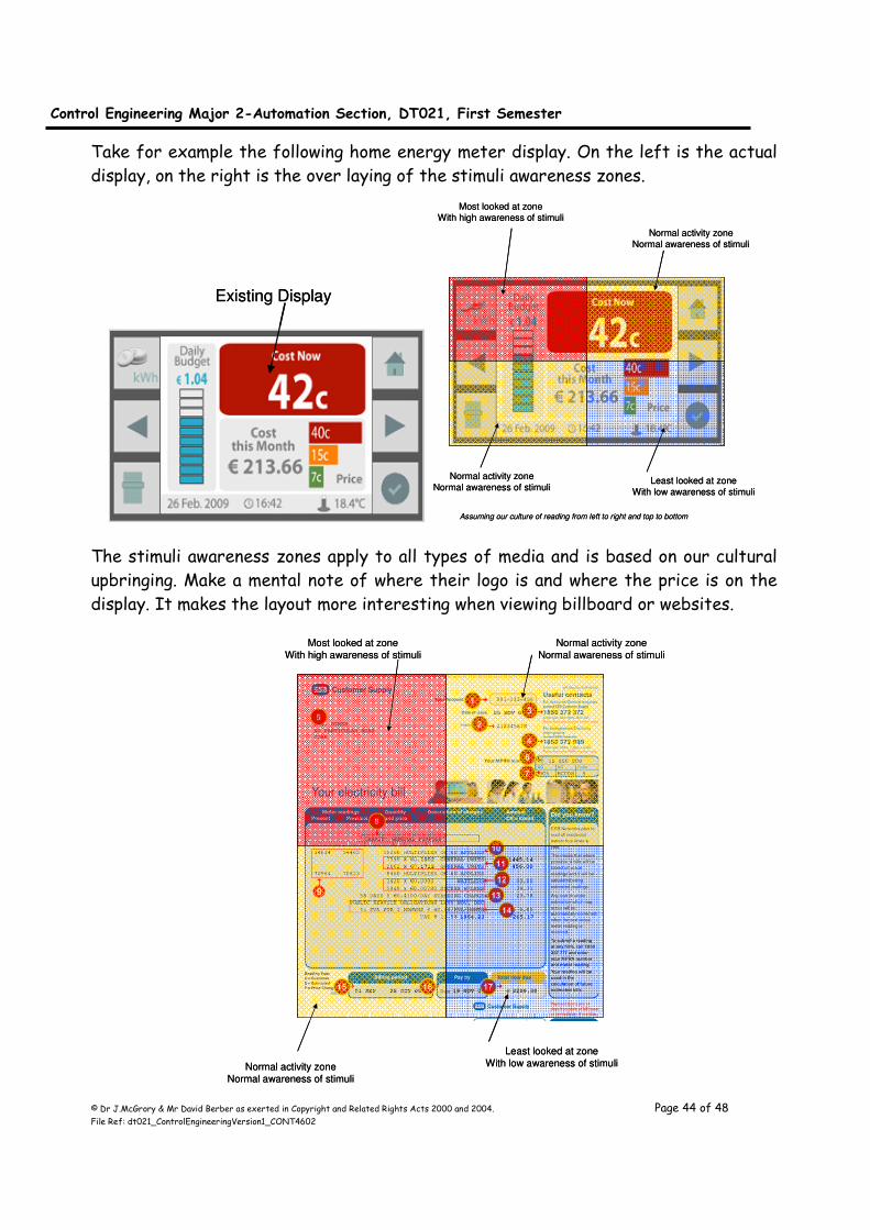
Control Engineering Major 2-Automation Section, DT021, First Semester
© Dr J.McGrory & Mr David Berber as exerted in Copyright and Related Rights Acts 2000 and 2004. Page 44 of 48 File Ref: dt021_ControlEngineeringVersion1_CONT4602
Take for example the following home energy meter display. On the left is the actual
display, on the right is the over laying of the stimuli awareness zones.
The stimuli awareness zones apply to all types of media and is based on our cultural
upbringing. Make a mental note of where their logo is and where the price is on the
display. It makes the layout more interesting when viewing billboard or websites.
Existing DisplayExisting Display
Most looked at zone
With high awareness of stimuli
Normal activity zone
Normal awareness of stimuli
Normal activity zone
Normal awareness of stimuliLeast looked at zone
With low awareness of stimuli
Assuming our culture of reading from left to right and top to bottom
Most looked at zone
With high awareness of stimuli
Normal activity zone
Normal awareness of stimuli
Normal activity zone
Normal awareness of stimuliLeast looked at zone
With low awareness of stimuli
Assuming our culture of reading from left to right and top to bottom
Most looked at zone
With high awareness of stimuli
Normal activity zone
Normal awareness of stimuli
Normal activity zone
Normal awareness of stimuli
Least looked at zone
With low awareness of stimuli
Most looked at zone
With high awareness of stimuli
Normal activity zone
Normal awareness of stimuli
Normal activity zone
Normal awareness of stimuli
Least looked at zone
With low awareness of stimuli
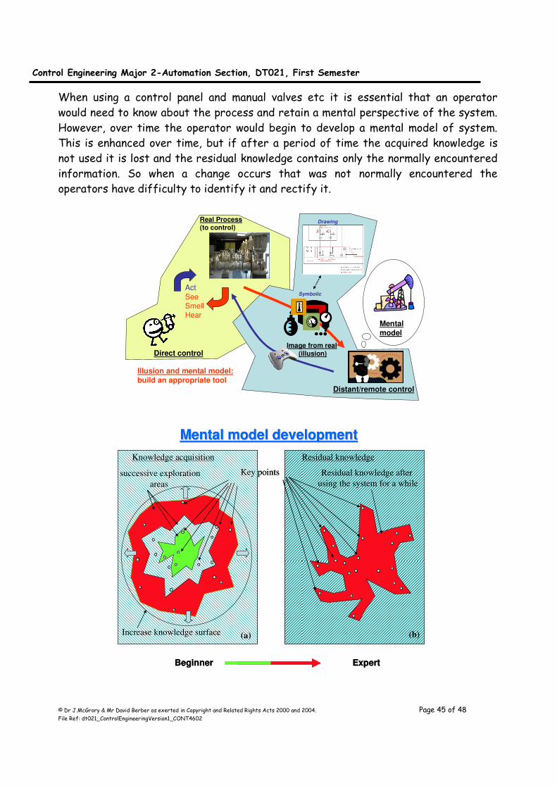
Control Engineering Major 2-Automation Section, DT021, First Semester
© Dr J.McGrory & Mr David Berber as exerted in Copyright and Related Rights Acts 2000 and 2004. Page 45 of 48 File Ref: dt021_ControlEngineeringVersion1_CONT4602
When using a control panel and manual valves etc it is essential that an operator
would need to know about the process and retain a mental perspective of the system.
However, over time the operator would begin to develop a mental model of system.
This is enhanced over time, but if after a period of time the acquired knowledge is
not used it is lost and the residual knowledge contains only the normally encountered
information. So when a change occurs that was not normally encountered the
operators have difficulty to identify it and rectify it.
Act
SeeSmellHear
Direct control
Real Process(to control)
Mental
model
Image from real (illusion)
Distant/remote control
Drawing
Symbolic
Illusion and mental model:
build an appropriate tool
successive exploration
areas
Increase knowledge surface
Key points Residual knowledge after
using the system for a while
Knowledge acquisition Residual knowledge
(a) (b)
Mental model developmentMental model development
Beginner Expert
successive exploration
areas
Increase knowledge surface
Key points Residual knowledge after
using the system for a while
Knowledge acquisition Residual knowledge
(a) (b)
Mental model developmentMental model development
Beginner Expert
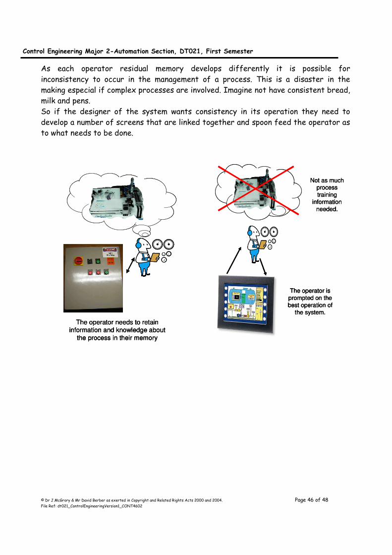
Control Engineering Major 2-Automation Section, DT021, First Semester
© Dr J.McGrory & Mr David Berber as exerted in Copyright and Related Rights Acts 2000 and 2004. Page 46 of 48 File Ref: dt021_ControlEngineeringVersion1_CONT4602
As each operator residual memory develops differently it is possible for
inconsistency to occur in the management of a process. This is a disaster in the
making especial if complex processes are involved. Imagine not have consistent bread,
milk and pens.
So if the designer of the system wants consistency in its operation they need to
develop a number of screens that are linked together and spoon feed the operator as
to what needs to be done.
The operator is
prompted on the
best operation of
the system.
Not as much process
training
information
needed.
The operator needs to retain
information and knowledge about
the process in their memory
The operator is
prompted on the
best operation of
the system.
Not as much process
training
information
needed.
The operator is
prompted on the
best operation of
the system.
Not as much process
training
information
needed.
The operator needs to retain
information and knowledge about
the process in their memory
The operator needs to retain
information and knowledge about
the process in their memory
Control Engineering Major 2-Automation Section, DT021, First Semester
© Dr J.McGrory & Mr David Berber as exerted in Copyright and Related Rights Acts 2000 and 2004. Page 47 of 48 File Ref: dt021_ControlEngineeringVersion1_CONT4602
Chapter 9, High Speed Control
Introduction As discussed in previous lectures the PLC is designed using the latest processers and
components; however the clock speeds for these devices is normally slower, so they
can be used reliably in harsh environments. The inputs are opto-isolated and the
components are normally encapsulated in a faradays type cage structure. In addition
to this the manufacture only allows the devices to be programmed using their own
software. This is different to the PC market where many third party suppliers can
provide software. But a caveat to this scheme is that the computer system is at the
mercy of the programmers and some are poor and some are very good. The poorly
constructed software application however, holds the whole PC to ransom.
This is avoided in the PLC as only one software application can be used. The
manufacture ensures the program is accurate and appropriate for the attached
device. Any problems and the user will receive an error.
The high speed function of a PLC is achieved by altering the scan cycle and including
the concept of interrupts. If you have done any microcontroller courses, interrupts
are one of the main backbone facilities employed. Most peripheral devices can
generate interrupts in order to receive service from the operating system (OS).
Some examples of devices that can use interrupts are PC cards, onboard timers, audio
input devices, keyboards, touch screens, and pointing devices. Nearly any type of
peripheral device might use interrupts as the principle method of initiating servicing
actions by the OS. On the PLC side this interrupt is accomplished within the OS of
the PLC and is used on Counters, Inputs, Reads, compare instructions.
In addition to this the peripheral devices such as the Analogue to Digital also have
their own high speed facility.
• When an interrupt occurs, continuation of the execution of the current
program is meaningless.
– Execution of the Current program needs to be stopped.
• In a controller, PLC or Industrial Computer system, there are many sources of
interrupts:
– Needs to prepare interrupt processing routines for each source of
interrupts.
– Source of interrupt needs to be identified.
– Needs to initiate execution of the interrupt processing routine
associated with the identified interrupt.
Control Engineering Major 2-Automation Section, DT021, First Semester
© Dr J.McGrory & Mr David Berber as exerted in Copyright and Related Rights Acts 2000 and 2004. Page 48 of 48 File Ref: dt021_ControlEngineeringVersion1_CONT4602
• When the interrupt is resolved, the interrupted program needs to be continued
for the efficiency reason:
– Needs to resume execution of the interrupted program
Interrupt process:
(a) Program ceases to execute, When ?
– At the completion of the current instruction in the CPU
– Not at the end of current memory(machine) SCAN cycle
(b) Save Information, Where ?
– Stack, Memory
(c) Execute interrupt preprocessing
– Identify the source of interrupt
» Initiate the execution of the Interrupt Processing Routine of the identified interrupt source
(d) Execution of the interrupt processing routine
– Save the state of the interrupted program, Where ?
– Resolve the interrupt
(e) Restore Information and the status of the interrupted program, and
resume execution of the interrupted program.
When an interrupt is processed, a specific sequence of events takes place. You write
the interrupt service request (ISR) and interrupt service thread (IST) for the
device driver with the following sequence of events in mind:
1. When an interrupt occurs, the microprocessor jumps to the kernel exception handler.
2. The exception handler disables all interrupts of an equal and lower priority at the
microprocessor, and then calls the appropriate ISR for the physical interrupt request (IRQ).
3. The ISR returns a logical interrupt, in the form of an interrupt identifier, to the interrupt
handler and typically masks the board-level device interrupt.
4. The interrupt handler re-enables all interrupts at the microprocessor, with the exception of
the current interrupt, which is left masked at the board, and then signals the appropriate IST
event.
5. The IST is scheduled, services the hardware, and then finishes processing the interrupt.
6. The IST calls the InterruptDone function, which in turn calls the OEMInterruptDone function.
Related Documents