Engineering Structures 30 (2008) 976–989 www.elsevier.com/locate/engstruct Contribution to transient analysis of inelastic steel frames with semi-rigid connections M. Sekulovic, M. Nefovska-Danilovic * Faculty of Civil Engineering, University of Belgrade, Bulevar kralja Aleksandra 73, 11000 Belgrade, Serbia Received 15 September 2006; received in revised form 8 June 2007; accepted 11 June 2007 Available online 6 August 2007 Abstract Dynamic behavior of multistory flexibly connected steel frames under earthquake excitations is studied in this paper. The numerical model that simultaneously includes nonlinear connection behavior, member yielding and geometrical nonlinearity of the structure is developed. Flexibility of connection is idealized by nonlinear rotational spring and dashpot in parallel. The refined-plastic hinge method is adopted to simulate member plasticity, for which it is assumed to be lumped at the ends of beam elements and base end of columns. A plastic hinge is idealized by nonlinear rotational spring, which is then combined with connection spring to form a resultant spring (spring-in-series). Transient response of the ductile seven-story steel frame under different intensities of the earthquake excitation is investigated. Characteristic results are presented and discussed. c 2007 Elsevier Ltd. All rights reserved. Keywords: Steel frame; Semi-rigid connections; Inelastic dynamic analysis 1. Introduction Most connections in real steel structures are more or less flexible or semi-rigid. It has been proven so by numerous experimental investigations that have been carried out in the past [1–3]. Dynamic behavior of frames with semi- rigid connections may be significantly different from rigidly connected frames, particularly those subjected to strong earthquake excitations. Therefore, the conventional methods of analysis and design of frame structures with ideal connections (fully rigid or pinned) are inadequate, as these often cannot represent real structural behavior. Flexible connection has an ability to take over a part of input energy imparted to the structure when subjected to an earthquake excitation and dissipate it through hysteretic loop, without remarkable damage, like friction. In such a way, semi- rigid connections may reduce and improve seismic response of the structure. Therefore, significant potential for passive control of seismic response of frame structures exists in semi-rigid connections, such as lumped dissipative elements. * Corresponding author. Tel.: +381 11 3218581; fax: +381 11 3370223. E-mail address: [email protected] (M. Nefovska-Danilovic). Behavior of steel frames under earthquake excitations generally is nonlinear. Only for a low-intensity excitation, behavior may be linear. Primary sources of nonlinearity are: connection behavior, material yielding and geometrical nonlinearity of the structure and its members. These three types of nonlinearity are generally coupled and interactive, so it is necessary to take care of combined effects of these sources on the frame structures dynamic response. The first two sources, connections and material yielding are located in the joints or at the ends of beam members as lumped dissipative elements, while the third, geometrical nonlinearity, is a combined result of both external loads and deformed geometry of the frame. The purpose of our investigation is the development of a nonlinear numerical model for simulating the dynamic (seis- mic) behavior of steel frames according to the aforementioned major sources of nonlinearity. The present study relies on the author’s former papers, Sekulovic et al. [4–7]. This paper is an extension of the author’s work [5] regarding dynamic analysis of elastic steel frames with semi-rigid connections on the more general case of inelastic dynamic analysis. In the former paper [5], a new beam element with flexible eccentric and viscous damping connection has been presented. For a uniform beam with nonlinear rotational springs and dashpots attached at its ends, complex dynamic stiffness matrix 0141-0296/$ - see front matter c 2007 Elsevier Ltd. All rights reserved. doi:10.1016/j.engstruct.2007.06.004

Welcome message from author
This document is posted to help you gain knowledge. Please leave a comment to let me know what you think about it! Share it to your friends and learn new things together.
Transcript
Engineering Structures 30 (2008) 976–989www.elsevier.com/locate/engstruct
Contribution to transient analysis of inelastic steel frames withsemi-rigid connections
M. Sekulovic, M. Nefovska-Danilovic∗
Faculty of Civil Engineering, University of Belgrade, Bulevar kralja Aleksandra 73, 11000 Belgrade, Serbia
Received 15 September 2006; received in revised form 8 June 2007; accepted 11 June 2007Available online 6 August 2007
Abstract
Dynamic behavior of multistory flexibly connected steel frames under earthquake excitations is studied in this paper. The numerical model thatsimultaneously includes nonlinear connection behavior, member yielding and geometrical nonlinearity of the structure is developed. Flexibilityof connection is idealized by nonlinear rotational spring and dashpot in parallel. The refined-plastic hinge method is adopted to simulate memberplasticity, for which it is assumed to be lumped at the ends of beam elements and base end of columns. A plastic hinge is idealized by nonlinearrotational spring, which is then combined with connection spring to form a resultant spring (spring-in-series). Transient response of the ductileseven-story steel frame under different intensities of the earthquake excitation is investigated. Characteristic results are presented and discussed.c© 2007 Elsevier Ltd. All rights reserved.
Keywords: Steel frame; Semi-rigid connections; Inelastic dynamic analysis
1. Introduction
Most connections in real steel structures are more or lessflexible or semi-rigid. It has been proven so by numerousexperimental investigations that have been carried out inthe past [1–3]. Dynamic behavior of frames with semi-rigid connections may be significantly different from rigidlyconnected frames, particularly those subjected to strongearthquake excitations. Therefore, the conventional methods ofanalysis and design of frame structures with ideal connections(fully rigid or pinned) are inadequate, as these often cannotrepresent real structural behavior.
Flexible connection has an ability to take over a part ofinput energy imparted to the structure when subjected to anearthquake excitation and dissipate it through hysteretic loop,without remarkable damage, like friction. In such a way, semi-rigid connections may reduce and improve seismic response ofthe structure. Therefore, significant potential for passive controlof seismic response of frame structures exists in semi-rigidconnections, such as lumped dissipative elements.
∗ Corresponding author. Tel.: +381 11 3218581; fax: +381 11 3370223.E-mail address: [email protected] (M. Nefovska-Danilovic).
0141-0296/$ - see front matter c© 2007 Elsevier Ltd. All rights reserved.doi:10.1016/j.engstruct.2007.06.004
Behavior of steel frames under earthquake excitationsgenerally is nonlinear. Only for a low-intensity excitation,behavior may be linear. Primary sources of nonlinearityare: connection behavior, material yielding and geometricalnonlinearity of the structure and its members. These three typesof nonlinearity are generally coupled and interactive, so it isnecessary to take care of combined effects of these sources onthe frame structures dynamic response. The first two sources,connections and material yielding are located in the joints orat the ends of beam members as lumped dissipative elements,while the third, geometrical nonlinearity, is a combined resultof both external loads and deformed geometry of the frame.
The purpose of our investigation is the development of anonlinear numerical model for simulating the dynamic (seis-mic) behavior of steel frames according to the aforementionedmajor sources of nonlinearity. The present study relies on theauthor’s former papers, Sekulovic et al. [4–7]. This paper is anextension of the author’s work [5] regarding dynamic analysisof elastic steel frames with semi-rigid connections on the moregeneral case of inelastic dynamic analysis.
In the former paper [5], a new beam element with flexibleeccentric and viscous damping connection has been presented.For a uniform beam with nonlinear rotational springs anddashpots attached at its ends, complex dynamic stiffness matrix
M. Sekulovic, M. Nefovska-Danilovic / Engineering Structures 30 (2008) 976–989 977
has been obtained based on analytical solutions of the second-order equations, so each beam corresponds to one finiteelement. Nodal displacements and rotations of element endsare eliminated via static condensation procedure. Thus, numberof degrees of freedom is the same as for a beam elementwith fully rigid connections. Consistent mass and dampingmatrices have also been derived based on physical propertiesof the member. The numerical model and computer programfor dynamic analysis of frames that includes both nonlinearconnection behavior and geometric nonlinearity of the structurehave been developed. The program has been tested and verifiedto be valid and efficient through the comparison with otheranalysis results and the benchmark solutions [5,7].
In this paper, the refined-plastic hinge model proposed byChan and Chui [8] is adopted and incorporated into previouslydeveloped computer program in order to enable transientanalysis of flexibly connected inelastic frames. The combinedeffect of material yielding and connection flexibility on seismicresponse of multistory frames when subjected to differentintensities of earthquake ground motion is investigated.
Two types of nonlinear analysis are applied, conventionaldirect structural response analysis and energy responseanalysis. They are in correlation as two complementary andcomparable approaches. In recent years, energy approach hasgained great attention used for identifying where and how theenergy is dissipated within the structural system. Moreover, apart of the external (input) energy dissipated through hystereticinelastic behavior is directly related to damage of the structure,thus the energy approach may be rational and reliable way toestimate damage that can be used as a design parameter. Onthe other hand, connection hysteretic energy, like friction, mayeven be present since joints of real structures are always moreor less flexible.
2. Semi-rigid connection modeling
Numerous experimental results have shown that theconnection moment–rotation relationships are nonlinear overthe entire range of loading for almost all types ofconnections. To describe nonlinear connection behaviordifferent mathematical models have been proposed. In thisstudy, the three-parameter power model proposed by Richardand Abbott [9] is used for representing moment–rotationbehavior of connection under monotonic loading. The modelcan be formulated as:
M =koθ
[1 + (θ/θo)n]1/n, (1)
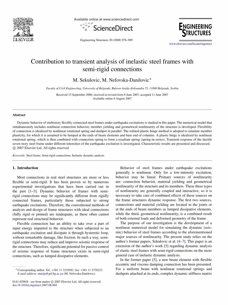
where ko is initial connection stiffness, n is shape parameterof M–θ curve, θo = Mu/ko is reference connection plasticrotation and Mu is ultimate moment capacity of the connection,as it is shown in Fig. 1(a). Connection stiffness kc which istangent slope of M–θ curve according to (1) is given by
kc =dM
dθ=
ko
[1 + (θ/θo)n](1+n)/n. (2)
Connection stiffness kc decreases from the initial values ko
Fig. 1. Connection modeling. (a) Richard–Abbott model, (b) independenthardening model.
to zero, when moment M reaches ultimate capacity momentMu . Values for initial connection stiffness ko, ultimate capacitymoment Mu , and shape parameter n are determined fromempirical expressions, Kishi and Chen [10]. The independenthardening model has been adopted to simulate inelasticconnection behavior under cyclic loading. In this model,characteristics of connection are assumed to be unchangedthroughout loading cycles. Moment–rotation curve underthe first cycle of loading, unloading and reverse loadingremains unchanged under the repetition of loading cycle.Skeleton curve used in the model is obtained from three-parameter power model, which provides a smooth M–θ
function with its positive first-derivative (i.e. a value ofconnection stiffness). Cyclic moment–rotation curve based onthis model is schematically shown in Fig. 1(b). The independenthardening model is simple and easily applicable to all typesof steel frames connection models. Experiments carried outby Popov and associates [11–13] show that hysteretic loopsunder cyclic loading are very stable so the moment–rotationfunctions obtained by static tests may be extended to dynamicanalysis. More recently, experimental studies [14,15] onflexibly connected frames show that properly designed semi-rigid connections can exhibit reliable hysteretic response thusmaking flexibly connected frames suitable for use in seismicregions.
3. Plasticity modeling
To simulate inelastic frame behavior, two approaches exist:distributed plasticity approach or plasticity zone method andlumped plasticity approach or plastic hinge method. Althoughplastic zone method is generally more accurate than plastichinge method, it is less suitable for inelastic analysis of complexmultistory frames due to extensive computational time required.

978 M. Sekulovic, M. Nefovska-Danilovic / Engineering Structures 30 (2008) 976–989
Fig. 2. (a) Initial yield and full yield surfaces of a section, (b) moment and curvature, M–κ , and (c) moment–rotation, M–θ p , curves.
Thus, the plastic hinge method controlling cross-section plasticyielding at element ends is more efficient for inelastic frameanalysis. Besides, plastic hinge model corresponds to realseismic behavior of properly designed framed structures inwhich plastic yielding may take place only at ends of beamelements and base end of columns.
In the present study, refined-plastic hinge method thatprovides a smooth transition from elastic to plastic state,proposed by Chan and Chui [8] is adopted and incorporated intopreviously developed program for nonlinear dynamic analysisof elastic frame with semi-rigid connections. Material yieldingis accounted by zero-length plastic hinge that is assumed tobe lumped at the ends of each beam member, while a portionwithin the member is assumed to remain elastic throughoutthe analysis. To control gradual yielding and formation ofa plastic hinge, the section assemblage method adopted bySteel Constructional Institute (SCI, 1987) [16] is applied. Inthis method, it is assumed that the web (or central part of
cross-section) takes the axial force, while the remainingunyielding part of the cross-section resists the bending moment.Presence of member residual stress may cause early yielding ofcross-section, so moment My should be reduced to:
Myr =
(σy − σr −
N
A
)Wy, (3)
where Myr is reduced initial (first yield) moment, N is axialforce, σr is maximum residual stress, A is cross-section areaand Wy is elastic modulus. Residual stresses can be obtainedby the ECCS recommendation (European Convention forConstruction Steelwork, 1983). Formulation of section strengthequations and consequently plastic moment capacity of thesection are based only on fundamental section properties, so thesection assemblage concept is considered simple and efficient.Based on section strength equations, interaction surfaces ofcross-section (initial and full yield surfaces) are determinedand shown in Fig. 2(a). The refined-plastic hinge model under

M. Sekulovic, M. Nefovska-Danilovic / Engineering Structures 30 (2008) 976–989 979
cyclic loading, expressed in force–deformation relationship(moment–curvature, M–θ ) is shown in Fig. 2(b).
Plastic hinge is modeled by rotational spring of degradablestiffness to simulate gradual cross-section yielding at themember end. Spring stiffness is determined from the followingexpression [8]:
kp =6E I
l·
∣∣Mpr − M∣∣∣∣M − Myr∣∣ , for Myr ≤ M ≤ Mpr , (4)
where E I is the flexural constant, l is the member length, Myrand Mpr are the reduced initial yield and plastic moments inpresence of axial force and residual stress. According to Eq. (4),spring stiffness varies from infinity to zero, representing twoextreme states of cross-section: elastic and full plastic states.Stiffness, which is in between these extreme values, representsa degree of section plastic yielding.
4. Combined effect of connection flexibility and memberplasticity
From two previous sections it can be seen that bothconnection flexibility and plastic member yielding aresimulated in the same way, by rotational springs of degradablestiffness attached at the member ends. Two springs, connectionspring kc and plastic yielding (hinge) spring kp, can becombined together to form a resultant spring (spring-in-series)kcp which has a capability to simulate a combined effectof connection flexibility and material yielding in dynamicresponse of frame structures [17]. Stiffness of combined springcan be determined as
1kcp
=1kc
+1
kp, (5)
or
kcp =kckp
kc + kp. (6)
Stiffness of resultant spring kcp depends on both connectiontypes and member cross-section. Connection stiffness existswithin 0 < M < Mu interval, where Mu is connection ultimatemoment, while plastic yielding stiffness exists within Myr <
M < Mpr interval, from initial yield and full yield surfaces, asit is shown in Fig. 3. Therefore, combined effects of connectionflexibility and member plasticity are possible only if connectionultimate moment Mu is larger than initial yield moment Myr(curves A and B in Fig. 3). In that general case, behavior ofthe flexibly connected frame is simultaneously controlled bycombined effect of connection flexibility and member plasticity.As ultimate moment curve A is larger than the beam momentcapacity Mpr , plastic hinge may be formed, and moments atjoints are limited by moment capacity of the beam. As ultimatemoment curve B is in between the initial yield moment andthe beam moment capacity, Myr < Mu B < Mpr , the memberyielding is possible, but full plastic hinge cannot be formed.Thus moments at joints are limited by the connection ultimatemoment.
In a special case, very weak connections (C in Fig. 3.) whereultimate moment is under initial yield moment, Mu < Myr ,
Fig. 3. Moment–rotation, M–θc , curve types with regard to initial yieldmoment and full moment capacity of beam section.
as member yielding does not exist, kp → ∞, stiffnesskcp is equal to kc so connections take responsibility for theframe behavior. Consequently, moments at joints are limitedby connections ultimate moments. On the contrary, in the caseof very stiff connections, when connection stiffness approachesinfinity, kc → ∞, from Eq. (5) follows kcp = kp, so behavior offlexibly connected frame becomes equal to inelastic behavior ofthe same frame with fully rigid connections. The yielding andformation plastic hinges at base clamped end of columns arealso contained as a particular case.
5. Formulation of structural element
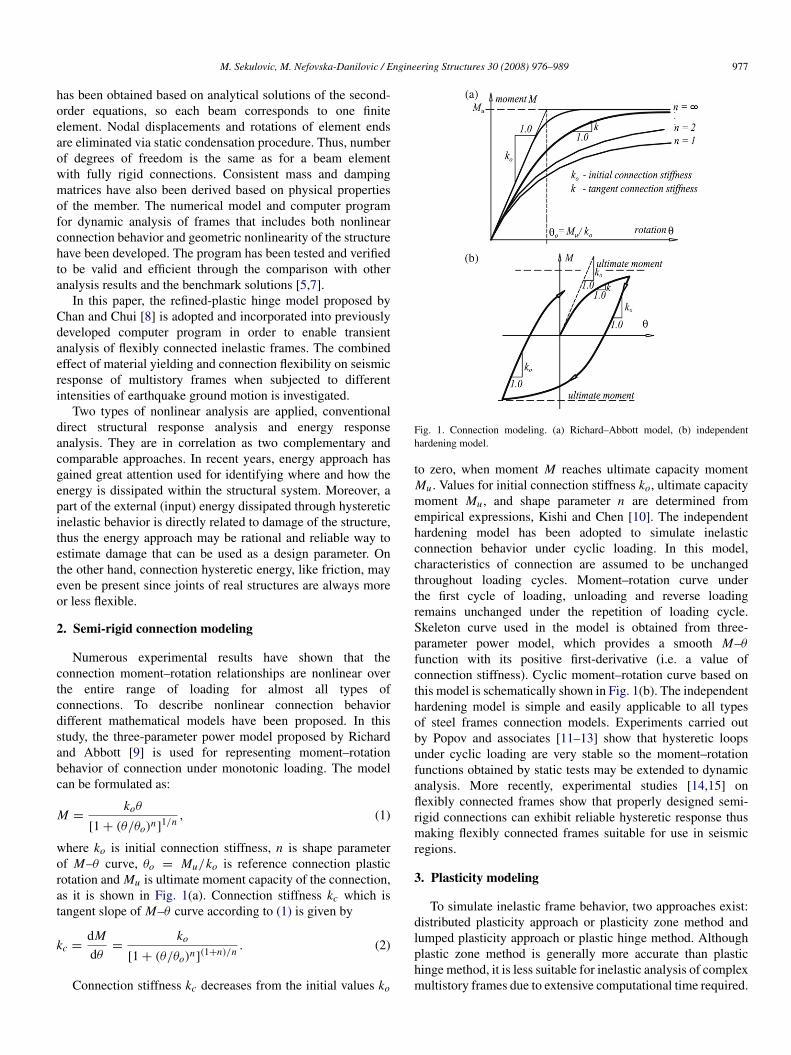
A beam element with flexible eccentric and viscous dampingconnections is shown in Fig. 4. Flexible connections arerepresented by nonlinear rotational springs at beam ends.Thus, only the influence of bending moment on connectiondeformation is considered, while the influences of axial andshear forces are neglected. Connection spring element isassumed to be massless and dimensionless in size. Eccentricityis represented by short infinitely stiff elements. Linear viscousdamping at nodal connections is simulated by dashpots actingat beam ends. Stiffness equations for element, obtained inaccordance to second-order analysis, and the correspondingelement matrices (stiffness damping and mass) have beenpresented in author’s former paper [5].
Resultant spring elements (springs-in-series) accounting forjoint flexibility and material yielding at beam ends are shownin Fig. 4(b). These elements are incorporated into existinghybrid beam element shown in Fig. 4(a). It has been donequite simply. Instead of connection spring elements ki =
kci , i = 1, 2, resultant spring elements ki = kcpi , i = 1, 2,are included into the existing model. Stiffness of resultantspring elements are determined according to Eq. (6), thuscombined action connection flexibility and member plasticityat beam ends are included in a new hybrid beam element.Formally, the element is the same as previous element withflexible connections. However, significant difference exists,since the present element is now extended from elastic toinelastic domain of dynamic frame analysis. Consequently, inthe element stiffness matrix, besides geometrical nonlinearityand connection flexibility, material yielding at beam ends isincluded. The element stiffness matrix formulation accountingfor these effects simultaneously is outlined in Appendix A. The
980 M. Sekulovic, M. Nefovska-Danilovic / Engineering Structures 30 (2008) 976–989
Fig. 4. (a) A beam with flexible eccentric and viscous damping connections,(b) the springs-in-series model.
flexural stiffness matrix has the following form:
k f = kII + ke f + ks (7)
where kII is the second-order beam stiffness matrix, whileke f and ks are the correction matrix and spring stiffnessmatrix respectively, whose elements contain combined effectof connection flexibility and plastic yielding.
Simplified and more compact form of matrix k f corre-sponding to the first-order analysis, from which it can beclearly seen aforementioned effects contribution to the stiffnessmatrix, is also given in Appendix A. It can be seen that theelements of this matrix depend on dimensionless parametersgi = E I/ lkcpi , i = 1, 2, which simultaneously include bothconnection flexibility and plastic yielding at beam ends. Inthe case of the beam with flexible connections without plasticyielding at beam ends (ki = kci , kpi → ∞) the correspond-ing stiffness matrix can be obtained from Eq. (A.12) puttinggi = E I/ lkci , i = 1, 2, while in the case of the inelastic beamwith fully rigid connections and plastic yielding at its ends(kci → ∞, ki = kpi ) the corresponding stiffness matrix can beobtained from Eq. (A.12) putting gi = E I/ lkpi , i = 1, 2. Ne-glecting both connection flexibility and plastic yielding (kci →
∞, kpi → ∞) the dimensionless parameters gi , i = 1, 2,
become zero, so matrix k f transforms to the conventional elas-tic uniform beam stiffness matrix.
6. Method of analysis
Equations of motion of a frame subjected to dynamicloading can be expressed by the following set of second-orderdifferential equations:
Mu(t) + Cu(t) + Ku(t) = F(t), (8)
where M, C and K are mass, damping and stiffness matrices,respectively and time dependent vector u(t), u(t) and u(t)are absolute node accelerations, velocities and displacements,while F(t) is a vector of external nodal forces. If an externalaction is due to earthquake ground motion, the term onthe right-hand side of Eq. (8) is equal to−MLug(t), whereL is a unit vector and ug(t) is ground acceleration, whilevectors u(t), u(t) and u(t) are relative nodal accelerations,velocities and displacements, respectively. Mass and dampingmatrices are linear, while stiffness matrix is nonlinear sinceit includes the nonlinear effects of connection flexibilityand member plasticity as well as geometrical nonlinearity.Therefore, for the N -story frame Eq. (8) is a set of N -coupled nonlinear differential equations. Various methods andprocedures that can be used for solving Eq. (8) are dividedinto two primary methods: mode superposition and directintegration. In this study, in accordance with inherent nonlinearnature of the problem, direct integration method is applied.The equations of motion are integrated using step-by-stepintegration, with a constant acceleration assumption within anytime increment, [5]. To solve the nonlinear equations, whichare nonlinear in terms of displacements as well as axial forces,Newton–Raphson’s method is used. The iterative algorithm ineach increment is based on evaluating tangent stiffness matrix,which depends on the connection spring stiffness kci and plastichinge spring stiffness kpi , i = 1, 2. At the beginning ofincremental-iterative procedure it is assumed that all membersexhibit elastic behavior and all semi-rigid connections behavelinearly, i.e ki = kci , kpi → ∞ (1010 E I/ l). Connectionspring stiffness kci are updated in each iteration within a loadincrement and are calculated from Eq. (2). For M ≤ M yr onlyrotations θci due to connection flexibility exist (θci 6= 0, θpi =
0). Moreover, within each load increment a yielding criterionis checked and corresponding spring stiffness kpi are evaluatedfrom Eq. (4) (kci 6= 0, kpi 6= 0, ki = kcpi ). When the plasticmoment is reached, plastic hinge is formed and kci 6= 0, kpi =
0 (10−10 E I/ l), ki = kcpi = 0. For Myr < M ≤ M pr bothconnection and plastic yielding rotations exist (θci 6= 0, θpi 6=
0), and can be obtained from Eqs. (A.13) and (A.14) given inthe Appendix. Relation between bending moment and plasticyielding rotation is given in Fig. 2(b).
Iterative procedure is stopped when the convergence criteriaare satisfied (when the unbalanced forces and unbalanceddisplacements are less than a certain tolerance) [7]. Two typesof direct nonlinear analysis, the time history analysis withconventional response parameters (displacements and internalforces) and energy response analysis with various energy typesas response parameters, carried out in parallel.
M. Sekulovic, M. Nefovska-Danilovic / Engineering Structures 30 (2008) 976–989 981
Energy response analysisEnergy response equation can be derived by integrating the
equation of motion, Eq. (8), taking into account du = uTdt , asfollows:
Ek(t) + Ee(t) + ED(t) + EH (t) = E I (t), (9)
where:
Ek(t) =
∫ u
oMudu =
12
uTMu, (10a)
Ee(t) =12
uTe Koue, (10b)
ED(t) =
∫ u
oCudu =
∫ t
ouTCudt, (10c)
EH (t) =
∫ u
oKudu − Ee(t) =
∫ t
ouTKudt − Ee(t), (10d)
E I (t) = −
∫ u
oMLugdu = −
∫ t
ouTMLugdt, (10e)
where Ek(t) is kinetic energy, Ee(t) is elastic strain energy,ED(t) is damping energy, EH (t) is hysteretic energy and E I (t)is seismic input energy; Ko and ue are the elastic stiffnessmatrix and nodal vector of elastic displacement, while du isan increment of displacement vector.
Kinetic energy Ek , which is proportional to the square ofrelative velocities of mass at time t and elastic strain energy Ee,that is proportional to the square of relative displacements areinstant quantities. Damping energy ED , which is dissipated byinherent viscous damping, is a cumulative quantity continuallyincreasing with time during vibration. Hysteretic energy EH ,is also a cumulative quantity over nonlinear connections andplastic hinge deformations throughout duration of vibration thatcan be expressed as:
EH (t) = EHc(t) + EH p(t), (11)
EHc(t) =
nc∑i=1
(∫ θc
oMi dθci
)=
nc∑i=1
(∫ t
oMi θci dt
), (12a)
EH p(t) =
np∑i=1
(∫ θc
oMi dθpi
)=
np∑i=1
(∫ t
oMi θpi dt
), (12b)
where EHc is connection hysteretic energy, EH p is plasticyielding hysteretic energy, θci and θpi are velocities of theconnection and plastic hinge rotations, Mi is beam end moment,while nc and np are numbers of nonlinear connections andplastic hinges. Hysteretic energy and its distribution dependsupon both structural system and ground motion.
Terms on the left-hand side of Eq. (9) represent energyresponse of the frame, while a term on the right-hand sideis input energy, imparted to the frame subjected to groundmotion. Seismic input energy E I (t)is dependent on the frameproperties. It can be seen from Eq. (10e) that E I (t) isproportional to relative velocities u(t), increasing with them,and consequently, with stiffness of the frame. However, inthe case of low-rise ductile steel frames, input energy mainlydepends on ground motion characteristics.
In the case an inelastic response analysis, hysteretic anddamping energies consist of a major portion of input energy,while kinetic and elastic strain energies consist of remaining,relatively small part of input energy, at any time duringvibration and vanish at the end of vibration. Therefore, Ek andEe may be neglected so Eq. (9) can be reduced and shown as
ED(t) + EHc(t) + EH p(t) = E I (t). (13)
Energy response of the frame defined by Eqs. (9) and (13)depends on both characteristics of ground motion and dynamicand geometrical characteristics of the frame. As a result ofsolution of Eq. (9) quantities of particular energy terms can beobtained, and consequently distribution of dissipative energyamong structural elements. Energy dissipation capacity anddistribution of dissipative energy, particularly hysteretic energy,have a great importance for optimal earthquake resistant designof structures according to ductile design philosophy basedon the new limit state requirements: serviceability limit state,damage control state and survival limit state.
7. Numerical study
Based on the above theoretical consideration, the previouslydeveloped computer program [5] is extended by includingdynamic yielding effects. The obtained program is capableto simulate the dynamic behavior of plane steel framestructures with nonlinearities in deformed geometry, hystereticconnection flexibility and hysteretic material yielding. Theeffects of connection eccentricity and viscous damping atconnections are also included. The main advantage of theproposed numerical model is on its simplicity and efficiency,as the number of degrees of freedom is the same as forthe conventional system with fully rigid connections. Forillustration, only the some characteristic results of transientinelastic frame analysis are herein presented.
7.1. Seven-story single bay frame
The geometrical and material properties of the frame areshown in Fig. 5. The members’ cross-sections are takenaccording to a primary assumption that plastic hinges may beformed at the ends of beam elements and base end of columns,but not at other locations in the columns. Top and seat anglewith double web angle (TSDWA) type of connection, is used.Connections stiffness and ultimate moments are determinedusing the database developed by Chen and Kishi [18]. Arelatively weak connection type is taken so that connectionultimate moment is comparable to plastic moment capacity ofthe beam section, because behavior of the frame can then becontrolled by both connection flexibility and member plasticityeffects. The frame is assumed to be subjected to the firstten seconds of 1940. El Centro earthquake ground motionand gravity load. Results for three characteristic intensitiesof ground motion: 0.25g, 0.5g and 0.75g, which may beconsidered as low, medium and high-intensity for the chosenframe and which are in relation with aforementioned limit state
982 M. Sekulovic, M. Nefovska-Danilovic / Engineering Structures 30 (2008) 976–989
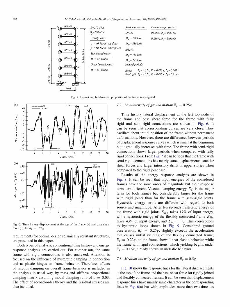
Fig. 5. Layout and fundamental properties of the frame investigated.
Fig. 6. Time history displacement at the top of the frame (a) and base shearforce (b), for ug = 0.25g.
requirements for optimal design seismically resistant structures,are presented in this paper.
Both types of analysis, conventional time history and energyresponse analysis are carried out. For comparison, the sameframe with rigid connections is also analyzed. Attention isfocused on the influence of hysteretic damping in connectionand at plastic hinges on frame behavior. Therefore, effectsof viscous damping on overall frame behavior is included inthe analysis in usual way, by mass and stiffness proportionaldamping matrix assuming modal damping ratio of ζ = 0.03.The effect of second-order theory and the residual stresses arealso included.
7.2. Low-intensity of ground motion ug = 0.25g
Time history lateral displacement at the left top node ofthe frame and base shear force for the frame with fullyrigid and semi-rigid connections are shown in Fig. 6. Itcan be seen that corresponding curves are very close. Theyoscillate about initial position of the frame without permanentdeformations. However, there are differences between periodsof displacement response curves which is small at the beginningbut it gradually increases with time. The frame with semi-rigidconnections shows larger periods when compared with fullyrigid connections. From Fig. 7 it can be seen that the frame withsemi-rigid connections has nearly same displacements, smallershear forces and larger interstory drifts in upper stories whencompared to the rigid joint case.
Results of the energy response analysis are shown inFig. 8. It can be seen that input energies of the consideredframes have the same order of magnitude but their responseterms are different. Viscous damping energy ED is the majorterm for both frames but considerably larger for the framewith rigid joints than for the frame with semi-rigid joints.Hysteretic energy terms are different with regard to bothsource and magnitude. After ten seconds hysteretic energy ofthe frame with rigid joints EH p takes 17% of input energy,while hysteretic energy of the flexibly connected frame EHctakes 43% of input energy, and EH p = 0. This correspondsto hysteretic loops shown in Fig. 9. Considered groundacceleration, ug = 0.25g, slightly exceeds the accelerationthat causes initial yielding of the flexibly connected frame,ug = 0.22g, so the frame shows linear elastic behavior whilethe frame with rigid connections, which yielding begins underug = 0.16g, already shows an inelastic behavior.
7.3. Medium-intensity of ground motion ug = 0.5g
Fig. 10 shows the response lines for the lateral displacementsat the top of the frame and the base shear force for rigidly joinedand flexibly connected frames. It can be seen that displacementresponse lines have mainly same character as the correspondinglines in Fig. 6(a) but with amplitudes more than two times as

M. Sekulovic, M. Nefovska-Danilovic / Engineering Structures 30 (2008) 976–989 983
Fig. 7. Envelopes: (a) lateral displacements, (b) shear force and (c) interstory drifts, for ug = 0.25g.
Fig. 8. Energy input and energy response terms: (a) rigid connections, (b) semi-rigid connections, for ug = 0.25g.
high. Besides, Fig. 10(a) shows that in both rigidly and flexiblyconnected frames there are permanent deflection drifts due toplastic rotations at the rigidly joined frame, and large permanentconnection rotations in the flexibly connected frames. Thus, theframes after two seconds oscillate about their permanent driftpositions. Consequently, the lateral displacement envelopes
plotted in Fig. 11(a) are noticeably nonsymmetrical. Theflexibly joined frame has smaller shear forces and a bit largeinterstory drifts than their rigid counterpart.
The Fig. 10(a) shows a considerable difference betweendisplacement responses of the frame with rigid connectionsobtained by nonlinear elastic and inelastic analyses due to thepresence of member plastic deformations. However, differencebetween the corresponding responses of the same frame withflexible connections is insignificant, as the member plasticdeformations are negligible. It makes it possible to concludethat nonlinear elastic analysis overestimating the real responseis inadequate for the frame with rigid connections due to thepresence of considerable inelastic deformations, while for theframe with flexible connections it may be acceptable, sincemember yielding practically does not exist.
The input energy lines and corresponding energy responselines are shown in Fig. 12. It is obvious that there is significantdifference between energy response terms for rigidly andflexibly connected frames. The major response terms after 10 sare as follows: hysteretic energy at plastic hinge EH p, (61% ofinput energy) in the rigidly joined frame case and hystereticenergy in connections EHc, (55% of input energy) in theflexibly connected frame case. Viscous damping energy ED isthe second response term, that takes 36% and 32% of inputenergy, rigidly and flexibly connected frames, respectively.Moreover, in the flexibly connected frame hysteretic energyEH p participates with 5% of input energy, as a result ofbeginning of plastic member yielding, so the ratio of totalhysteretic energy to the total input energy is nearly the sameas in the rigidly connected frame case.
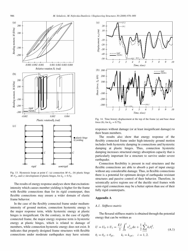
The hysteretic loops at the node C in which the memberyielding begins are shown in Fig. 13. It can be seen that thebeams end moment in the rigidly joined frame nearly reachesthe beam moment capacity, thus a plastic hinge is formed.However, the beams end moment in the flexibly connectedframe, that is equal to the moment in connection is farunder the beam moment capacity, so a plastic hinge is notformed. The hysteretic connection loop is almost symmetrical,Fig. 13(a), while the member yielding loops are noticeably

984 M. Sekulovic, M. Nefovska-Danilovic / Engineering Structures 30 (2008) 976–989
Fig. 9. Hysteresis loops at point C : (a) connection M–θc , (b) plastic hingeM–θ p , and (c) development of plastic hinges, for ug = 0.25g.
nonsymmetrical, Fig. 13(b). The largest connection and plastichinge rotations are nearly the same.
It can be concluded that the flexibly connected frameunder moderate ground acceleration, ug = 0.5g, absorbsgreat part of input energy through the connections and quitesmall part through member yielding. Consequently, damageof beam members can be almost negligible. On the contrary,the rigidly joined frame absorbs great part of input energythrough the plastic deformations and plastic hinges formation,and consequently undergoes considerable damage at the endsof the beam elements.
7.4. High-intensity of ground motion, ug = 0.75g
From Fig. 14 it can be seen that response curves fordisplacements at the top of the frame and the base shear force
Fig. 10. Time history displacement at the top of the frame (a) and base shearforce (b), for ug = 0.5g.
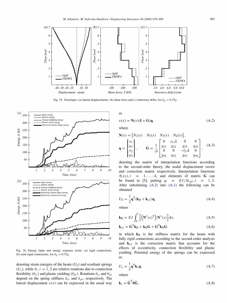
have retained very similar form with corresponding curvesshown in Fig. 10 but with considerable increase in theiramplitudes. Permanent deflection drift due to large connectionrotations and plastic deformations is significantly magnified,thus the frames oscillate about their new permanent driftpositions. Envelopes of lateral displacement in both frame withrigid connections and frame with semi-rigid connections havemarkedly nonsymmetrical form with the largest values −49 cmand 23 cm. The frame with semi-rigid connections has smallerboth shear forces in lower stories and interstory drifts in upperstories than its rigid counterpart, as shown in Fig. 15.
Energy response curves shown in Fig. 16 are characterizedwith further increase in hysteretic plastic energy terms anddecrease viscous damping terms in both frame with rigidconnections and frame with semi-rigid connections, whencompared to corresponding curves for ug = 0.5g shownin Fig. 12. In case of rigid connections, dissipation energyresponse terms are, EH p = 71 and ED = 25 (in percentof input energy), while in the case of semi-rigid connections,energy terms are: EHc = 58, ED = 25 and EH p =
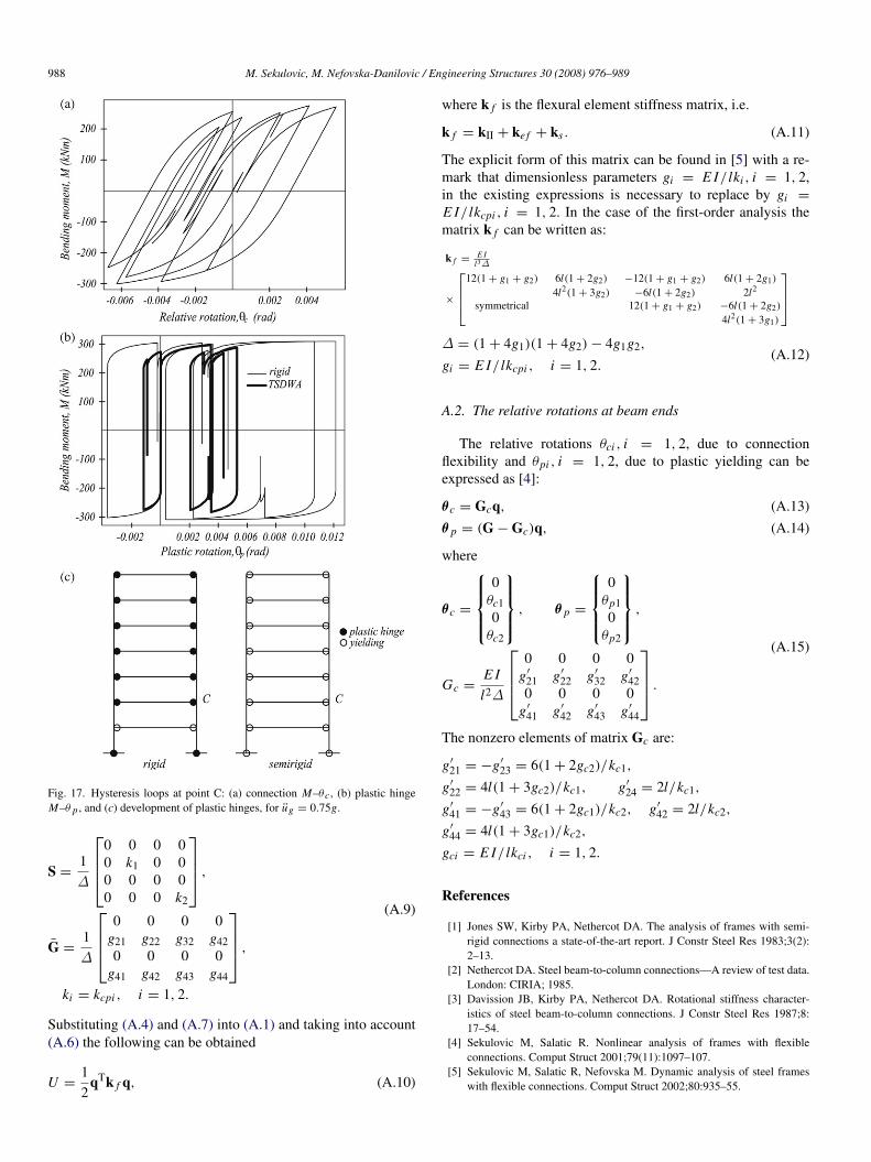
14. Consequently, considerable damage at the ends of beammembers in the rigid connection case can be expected and stillinconsiderable damage in the semi-rigid connection case, asshown in Fig. 17.
From Fig. 17, it can be seen that the hysteretic loops havemainly the same form as the corresponding loops in Fig. 13but those are considerably enlarged. The plastic rotations in
M. Sekulovic, M. Nefovska-Danilovic / Engineering Structures 30 (2008) 976–989 985
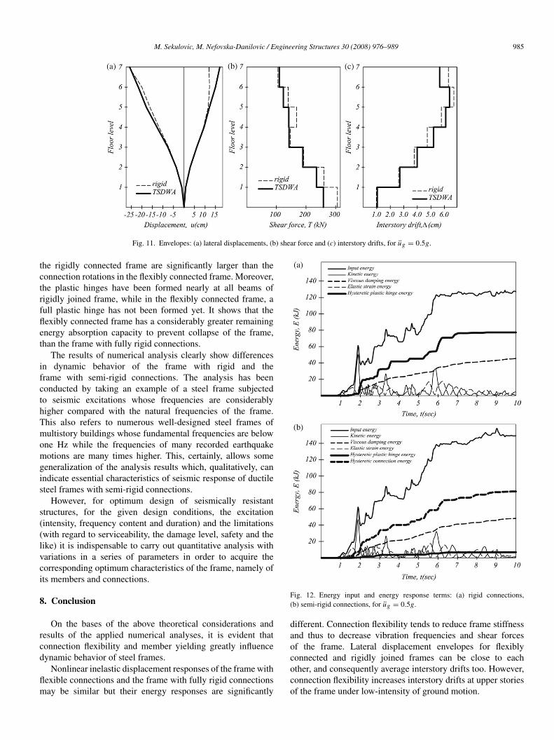
Fig. 11. Envelopes: (a) lateral displacements, (b) shear force and (c) interstory drifts, for ug = 0.5g.
the rigidly connected frame are significantly larger than theconnection rotations in the flexibly connected frame. Moreover,the plastic hinges have been formed nearly at all beams ofrigidly joined frame, while in the flexibly connected frame, afull plastic hinge has not been formed yet. It shows that theflexibly connected frame has a considerably greater remainingenergy absorption capacity to prevent collapse of the frame,than the frame with fully rigid connections.
The results of numerical analysis clearly show differencesin dynamic behavior of the frame with rigid and theframe with semi-rigid connections. The analysis has beenconducted by taking an example of a steel frame subjectedto seismic excitations whose frequencies are considerablyhigher compared with the natural frequencies of the frame.This also refers to numerous well-designed steel frames ofmultistory buildings whose fundamental frequencies are belowone Hz while the frequencies of many recorded earthquakemotions are many times higher. This, certainly, allows somegeneralization of the analysis results which, qualitatively, canindicate essential characteristics of seismic response of ductilesteel frames with semi-rigid connections.
However, for optimum design of seismically resistantstructures, for the given design conditions, the excitation(intensity, frequency content and duration) and the limitations(with regard to serviceability, the damage level, safety and thelike) it is indispensable to carry out quantitative analysis withvariations in a series of parameters in order to acquire thecorresponding optimum characteristics of the frame, namely ofits members and connections.
8. Conclusion
On the bases of the above theoretical considerations andresults of the applied numerical analyses, it is evident thatconnection flexibility and member yielding greatly influencedynamic behavior of steel frames.
Nonlinear inelastic displacement responses of the frame withflexible connections and the frame with fully rigid connectionsmay be similar but their energy responses are significantly
Fig. 12. Energy input and energy response terms: (a) rigid connections,(b) semi-rigid connections, for ug = 0.5g.
different. Connection flexibility tends to reduce frame stiffnessand thus to decrease vibration frequencies and shear forcesof the frame. Lateral displacement envelopes for flexiblyconnected and rigidly joined frames can be close to eachother, and consequently average interstory drifts too. However,connection flexibility increases interstory drifts at upper storiesof the frame under low-intensity of ground motion.
986 M. Sekulovic, M. Nefovska-Danilovic / Engineering Structures 30 (2008) 976–989
Fig. 13. Hysteresis loops at point C : (a) connection M–θc , (b) plastic hingeM–θ p , and (c) development of plastic hinges, for ug = 0.5g.
The results of energy response analyses show that excitation-intensity which causes member yielding is higher for the framewith flexible connections than for its rigid counterpart, thusflexible connections may ensure a wider domain of elasticframe behavior.
In the case of the flexibly connected frame under medium-intensity of ground motion, connection hysteretic energy isthe major response term, while hysteretic energy at plastichinges is insignificant. On the contrary, in the case of rigidlyconnected frame, the major energy response term is hystereticenergy at plastic hinges, which is related to damage ofmembers, while connection hysteretic energy does not exist. Itindicates that properly designed frame structures with flexibleconnections under moderate earthquakes may have seismic
Fig. 14. Time history displacement at the top of the frame (a) and base shearforce (b), for ug = 0.75g.
responses without damage (or at least insignificant damage) totheir beam members.
The results also show that energy response of theflexibly connected frame under high-intensity ground motionincludes both hysteretic damping in connections and hystereticdamping at plastic hinges. Thus, connection hystereticdamping increases structural energy absorption capacity that isparticularly important for a structure to survive under severeearthquake.
Connection flexibility is present in real structures and theflexible connections are able to absorb a part of input energywithout any considerable damage. Thus, in flexible connectionsthere is a potential for optimum design of earthquake resistantstructures and passive control of their behavior. Therefore, inseismically active regions use of the ductile steel frames withsemi-rigid connections may be a better option than use of theirfully rigid counterparts.
Appendix A
A.1. Stiffness matrix
The flexural stiffness matrix is obtained through the potentialenergy that can be written as
U = Ub + Us =E I
2
∫ l
0v2,xx dx +
12
2∑i=1
kiθ2i ,
θi = θci + θpi , ki = kcpi , i = 1, 2.
(A.1)
M. Sekulovic, M. Nefovska-Danilovic / Engineering Structures 30 (2008) 976–989 987
Fig. 15. Envelopes: (a) lateral displacements, (b) shear force and (c) interstory drifts, for ug = 0.75g.
Fig. 16. Energy input and energy response terms: (a) rigid connections,(b) semi-rigid connections, for ug = 0.75g.
denoting strain energies of the beam (Ub) and resultant springs(Us), while θi , i = 1, 2 are relative rotations due to connectionflexibility (θci ) and plastic yielding (θpi ). Rotations θci and θpi
depend on the spring stiffness kci and kpi , respectively. Thelateral displacement v(x) can be expressed in the usual way
as
v(x) = N(x)(I + G)q, (A.2)
where
N(x) =[N1(x) N2(x) N3(x) N4(x)
],
q =
v1ϕ1v2ϕ2
, G =1∆
0 e1∆ 0 0
g21 g22 g23 g240 0 −l2∆ 0
g41 g42 g43 g44
,(A.3)
denoting the matrix of interpolation functions accordingto the second-order theory, the nodal displacement vectorand correction matrix respectively. Interpolation functionsNi (x), i = 1, . . . , 4, and elements of matrix G canbe found in [5], putting gi = E I/ lkcpi , i = 1, 2.After substituting (A.2) into (A.1) the following can beobtained
Ub =12
qT(kII + ke f )q, (A.4)
where
kII = E I∫ l
0
[(N′′(x)T
)N′′(x)
]dx, (A.5)
ke f = GTkII + kIIG + GTkIIG. (A.6)
in which kII is the stiffness matrix for the beam withfully rigid connections according to the second-order analysisand ke f is the correction matrix that accounts for theeffects of eccentricity, connection flexibility and plasticyielding. Potential energy of the springs can be expressedas
Us =12
qTksq, (A.7)
where
ks = GT
SG, (A.8)
988 M. Sekulovic, M. Nefovska-Danilovic / Engineering Structures 30 (2008) 976–989
Fig. 17. Hysteresis loops at point C: (a) connection M–θc , (b) plastic hingeM–θ p , and (c) development of plastic hinges, for ug = 0.75g.
S =1∆
0 0 0 00 k1 0 00 0 0 00 0 0 k2
,
G =1∆
0 0 0 0
g21 g22 g32 g420 0 0 0
g41 g42 g43 g44
,
(A.9)
ki = kcpi , i = 1, 2.
Substituting (A.4) and (A.7) into (A.1) and taking into account(A.6) the following can be obtained
U =12
qTk f q, (A.10)
where k f is the flexural element stiffness matrix, i.e.
k f = kII + ke f + ks . (A.11)
The explicit form of this matrix can be found in [5] with a re-mark that dimensionless parameters gi = E I/ lki , i = 1, 2,in the existing expressions is necessary to replace by gi =
E I/ lkcpi , i = 1, 2. In the case of the first-order analysis thematrix k f can be written as:
k f =E I
l3∆
×
12(1 + g1 + g2) 6l(1 + 2g2) −12(1 + g1 + g2) 6l(1 + 2g1)
4l2(1 + 3g2) −6l(1 + 2g2) 2l2
symmetrical 12(1 + g1 + g2) −6l(1 + 2g2)
4l2(1 + 3g1)
∆ = (1 + 4g1)(1 + 4g2) − 4g1g2,
gi = E I/ lkcpi , i = 1, 2.(A.12)
A.2. The relative rotations at beam ends
The relative rotations θci , i = 1, 2, due to connectionflexibility and θpi , i = 1, 2, due to plastic yielding can beexpressed as [4]:
θc = Gcq, (A.13)
θ p = (G − Gc)q, (A.14)
where
θc =
0
θc10
θc2
, θ p =
0
θp10
θp2
,
Gc =E I
l2∆
0 0 0 0
g′
21 g′
22 g′
32 g′
420 0 0 0
g′
41 g′
42 g′
43 g′
44
.
(A.15)
The nonzero elements of matrix Gc are:
g′
21 = −g′
23 = 6(1 + 2gc2)/kc1,
g′
22 = 4l(1 + 3gc2)/kc1, g′
24 = 2l/kc1,
g′
41 = −g′
43 = 6(1 + 2gc1)/kc2, g′
42 = 2l/kc2,
g′
44 = 4l(1 + 3gc1)/kc2,
gci = E I/ lkci , i = 1, 2.
References
[1] Jones SW, Kirby PA, Nethercot DA. The analysis of frames with semi-rigid connections a state-of-the-art report. J Constr Steel Res 1983;3(2):2–13.
[2] Nethercot DA. Steel beam-to-column connections—A review of test data.London: CIRIA; 1985.
[3] Davission JB, Kirby PA, Nethercot DA. Rotational stiffness character-istics of steel beam-to-column connections. J Constr Steel Res 1987;8:17–54.
[4] Sekulovic M, Salatic R. Nonlinear analysis of frames with flexibleconnections. Comput Struct 2001;79(11):1097–107.
[5] Sekulovic M, Salatic R, Nefovska M. Dynamic analysis of steel frameswith flexible connections. Comput Struct 2002;80:935–55.

M. Sekulovic, M. Nefovska-Danilovic / Engineering Structures 30 (2008) 976–989 989
[6] Sekulovic M, Salatic R, Mandic R, Nefovska M. Energy dissipation insteel frames with semi-rigid connection. In: 12th European conference onearthquake engng. 2002. Paper no. 105.
[7] Sekulovic M, Nefovska-Danilovic M. Static inelastic analysis of steelframes with flexible connections. Theoret Appl Mech 2004;31(11):101–34.
[8] Chan SL, Chui PPT. Nonlinear static and cyclic analysis of steel frameswith semi-rigid connections. Kinlington (UK): Elsevier; 2000.
[9] Richard RM, Abbott BJ. Versatile elastic–plastic stress–strain formula. JEng Mech Div, ASCE 1975;101(EM4):511–5.
[10] Kishi N, Chen WF. Moment–rotation relations of semi-rigid connectionswith angles. J Struct Eng, ASCE 1990;116(ST7):1813–8.
[11] Popov EP, Pinkey RB. Cyclic yield reversal in steel building connections.J Struct Div, ASCE 1969;95(3):327–53.
[12] Vedero VT, Popov EP. Beam–column sub assemblages under repeated
loading. J Struct Div, ASCE 1972;98(3):1137–59.[13] Popov EP, Bertero VV. Cyclic loading of steel beams and connections. J
Struct Div, ASCE 1973;99(6):1189–204.[14] Nader MN, Astaneh A. Dynamic behavior of flexible, semi-rigid and rigid
steel frames. J Constr Steel Res 1991;18:179–92.[15] Nader MN, Astaneh A. Shaking table tests of rigid, semi-rigid and flexible
steel frames. J Struct Eng, ASCE 1996;122(6):589–96.[16] Steelwork design guide to B55950, Part 1, Vol. 1. Section properties and
member capacities. 2nd ed. The Steel Construction Institute; 1985.[17] Yau CY, Chan SL. Inelastic and stability analysis of flexibly connected
steel frames by spring-in-series model. J Struct Eng, ASCE 1994;120(10):2803–20.
[18] Chen WF, Kishi NN. Semi-rigid steel beam-to-column connec-tions data base and modeling. J Struct Eng, ASCE 1989;120(6):1703–1717.
Related Documents