ARCHIVES of FOUNDRY ENGINEERING Published quarterly as the organ of the Foundry Commission of the Polish Academy of Sciences ISSN (1897-3310) Volume 15 Issue 1/2015 143 – 151 26/1 ARCHIVES of FOUNDRY ENGINEERING Volume 15, Issue 1/2015, 143-151 143 Contribution to the Identification of Porosity Type in AlSiCu High-Pressure-Die-Castings by Experimental and Virtual Way Z. Ignaszak *, J. Hajkowski CAD/CAE Laboratory of Materials Technology in Institute of Material Technology, Poznan University of Technology, 3 Piotrowo Street, 60-965 Poznan, Poland *Corresponding author. E-mail address: [email protected] Received 14.07.2014; accepted in revised form 22.07.2014 Abstract The paper concerns the problem of discontinuity in high pressure die castings (HPDC). The compactness of their structure is not perfect, as it is sometimes believed. The discontinuities present in these castings are the porosity as follow: shrinkage and gas (hydrogen and gas-air occlusions) origin. The mixed gas and shrinkage nature of porosity makes it difficult to identify and indicate the dominant source. The selected parameters of metallurgical quality of AlSi9Cu3 alloy before and after refining and the gravity castings samples (as DI - density index method), were tested and evaluated. This alloy was served to cast the test casting by HPDC method. The penetrating testing (PT) and metallographic study of both kinds of castings were realized. The application of the NF&S simulation system allowed virtually to indicate the porosity zones at risk of a particular type in gravity and high-pressure-die-castings. The comparing of these results with the experiment allowed to conclude about NF&S models validation. The validity of hypotheses concerning the mechanisms of formation and development of porosity in HPDC casting were also analyzed. Keywords: Al-Si alloys, Gravity and high-pressure-die-castings, Microstructure, Gas and shrinkage porosity, Process virtualization, Complementary model validation 1. Introduction The occurrence of porosities in the casting structure is assigned to change its state of matter (liquid/solid). These voids with the size of the order from microns to millimeters depend on the metallic alloy type and the solidification process of castings. Simultaneously, these voids (local micro cavities) are impossible to be totally eliminated in the cast structures of ingots, not subjected to plastic forming (by forging or rolling). Of course, the presence of voids in matrix structure affects on the local deterioration of mechanical properties of casting. These discontinuities can be shrinkage, gas or mixed (gas-shrinkage) origin [1] including gas porosity caused by air entrapment during introducing the liquid alloy in high-pressure-die-casting process – HPDC (vary speed forced by piston injection). The shrinkage porosity is caused by the variability of alloy density from liquid to solid state phase. Practically all castings of hypoeutectic aluminum alloys have a tendency to the volumetric solidification (with mushy front morphology in solidifying zone) and form in most cases a kind of the scattering porosities in the region of walls joints, so-called hot spots. Typical gas porosities result from hydrogen contained in the liquid Al-Si alloy among others according the following chemical reaction: 2 Al + 3H 2 O → Al 2 O 3 + 6H or/and from decomposition

Welcome message from author
This document is posted to help you gain knowledge. Please leave a comment to let me know what you think about it! Share it to your friends and learn new things together.
Transcript
A R C H I V E S o f
F O U N D R Y E N G I N E E R I N G
Published quarterly as the organ of the Foundry Commission of the Polish Academy of Sciences
ISSN (1897-3310) Volume 15
Issue 1/2015
143 – 151
26/1
A R C H I V E S o f F O U N D R Y E N G I N E E R I N G V o l u m e 1 5 , I s s u e 1 / 2 0 1 5 , 1 4 3 - 1 5 1 143
Contribution to the Identification of Porosity Type in AlSiCu High-Pressure-Die-Castings
by Experimental and Virtual Way
Z. Ignaszak *, J. Hajkowski
CAD/CAE Laboratory of Materials Technology in Institute of Material Technology, Poznan University of Technology, 3 Piotrowo Street, 60-965 Poznan, Poland
*Corresponding author. E-mail address: [email protected]
Received 14.07.2014; accepted in revised form 22.07.2014
Abstract The paper concerns the problem of discontinuity in high pressure die castings (HPDC). The compactness of their structure is not perfect, as it is sometimes believed. The discontinuities present in these castings are the porosity as follow: shrinkage and gas (hydrogen and gas-air occlusions) origin. The mixed gas and shrinkage nature of porosity makes it difficult to identify and indicate the dominant source. The selected parameters of metallurgical quality of AlSi9Cu3 alloy before and after refining and the gravity castings samples (as DI - density index method), were tested and evaluated. This alloy was served to cast the test casting by HPDC method. The penetrating testing (PT) and metallographic study of both kinds of castings were realized. The application of the NF&S simulation system allowed virtually to indicate the porosity zones at risk of a particular type in gravity and high-pressure-die-castings. The comparing of these results with the experiment allowed to conclude about NF&S models validation. The validity of hypotheses concerning the mechanisms of formation and development of porosity in HPDC casting were also analyzed. Keywords: Al-Si alloys, Gravity and high-pressure-die-castings, Microstructure, Gas and shrinkage porosity, Process virtualization,
Complementary model validation
1. Introduction The occurrence of porosities in the casting structure is
assigned to change its state of matter (liquid/solid). These voids with the size of the order from microns to millimeters depend on the metallic alloy type and the solidification process of castings. Simultaneously, these voids (local micro cavities) are impossible to be totally eliminated in the cast structures of ingots, not subjected to plastic forming (by forging or rolling). Of course, the presence of voids in matrix structure affects on the local deterioration of mechanical properties of casting. These discontinuities can be shrinkage, gas or mixed (gas-shrinkage)
origin [1] including gas porosity caused by air entrapment during introducing the liquid alloy in high-pressure-die-casting process – HPDC (vary speed forced by piston injection).
The shrinkage porosity is caused by the variability of alloy density from liquid to solid state phase. Practically all castings of hypoeutectic aluminum alloys have a tendency to the volumetric solidification (with mushy front morphology in solidifying zone) and form in most cases a kind of the scattering porosities in the region of walls joints, so-called hot spots.
Typical gas porosities result from hydrogen contained in the liquid Al-Si alloy among others according the following chemical reaction: 2 Al + 3H2O → Al2O3 + 6H or/and from decomposition
144 A R C H I V E S o f F O U N D R Y E N G I N E E R I N G V o l u m e 1 5 , I s s u e 1 / 2 0 1 5 , 1 4 3 - 1 5 1
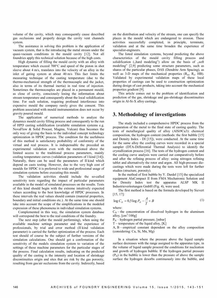
of hydrocarbons (coatings, lubricants). The solubility of hydrogen in aluminum decreases drastically during solidification (Fig.2b).
One of technology of Al-Si alloys casting, which is expected to lead to minimize porosities and improve the quality of casting is high-pressure-die-casting, especially the parts for the automotive and precision industry. By definition, this approach should give the higher surface quality, better dimensional accuracy and compacted structure. Comparing three technologies: Ra=0,32÷2,5 μm for HPDC, Ra=5÷40 μm for GDC – gravity die casting and Ra=20÷100 μm for sand mould casting); dimensional accuracy – +/-0,1 mm for HPDC, +/-0,3 mm for GDC +/-1 mm for sand mould casting and compactness of internal structure – DAS <15µm for HPDC, <30µm for gravity die casting and >50µm for sand mould casting).
For above reason sometimes there is done so called technology conversion, i.e. the replacement of the GDC by HPDC technology (under pressure during casting exceeding 100 MPa) especially for liable and higher reliable products. The main role of casting design virtualization in this approach to predict the structure continuity & phases and also the local mechanical properties is irreplaceable.
As result also from our experimental studies despite such high pressure on the solidifying alloy (pressure multiplication phase known as third phase of HPDC process) still does not manage to completely eliminate described above porosities (voids).
In the first place, it is important to effectively interact with the decreasing of the hydrogen content in the liquid alloy before it is introduced into the shot sleeve of HPDC machine, maintaining the stable, controlled conditions of the process of refining and casting.
The modeling of solidification (by codes dedicated to foundry usage) enables to indicate with certain probability, as in the case of conventional casting technology, the dangerous regions where the shrinkage origin porosities can appear. While the modeling of gas origin porosities (as separated phenomenon resulting from hydrogen content) hasn’t been still controlled effectively and usefully (certain codes e.g. Calcosoft, Magma and Procast dispose the special gas module but the prediction practice of presence of gas bubbles in casting structure requires knowledge of the hydrogen content in the liquid alloy and validation works [2]). The experimental validation of formed discontinuities in casting should be done with great care considering the porosity origin. The validation process includes a variation of the material parameters in database i.e. Al-Si alloy density for shrinkage discontinuities and variation of hydrogen quantity for gas porosity. But as indicated above, the modeling of gas porosity formation phenomena are rarely used in industrial applications of virtualization yet [8] and still not available in most foundry codes.
The main aim of this paper is to identify both discontinuities origin (i.e. shrinkage and gas) by experimental validation of HPDC modeling applied in NovaFlow&Solid code. These two types of porosities will be treated separately.
This paper describes experimental and simulation tests of the high-pressure-die-casting housing liable automotive engine component. The cast alloy was AlSi9Cu3 (EN AC-46000 or A226). The tests were preceded by metallurgical quality testing of liquid alloy, also in the terms of its stability.
2. State of art
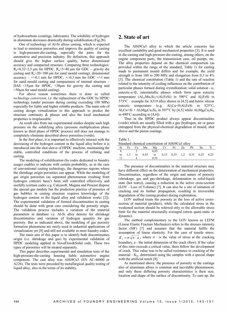
The AlSi9Cu3 alloy to which the article concerns has excellent castability and good mechanical properties [3]. It is used in die-casting and high-pressure-die-casting, among others, on the engine component parts, the transmission case, oil pumps, etc. The alloy properties depend on the chemical composition (as provided within the range of the standard, Table 1) for casting made to permanent mould differs and for example, the yield strength is from 100 to 200 MPa and elongation from 0,3 to 4% [3]. The chemical constitution (Table 1) and the rate of reaction related to the intensity of cooling influences on the contribution of particular phases formed during crystallization: solid solution - , eutectic +, intermetallic phases which form upon eutectic temperature (Al15Mn3Si2+(Al5FeSi) in 590C and Al5FeSi in 575C – example for A319 alloy shown in [4,5] and below silicon eutectic temperature (e.g. Al2Cu+SiAl5FeSi in 525C, Al2Cu+Si + Al5Mg8Cu2Si6 in 507C by [4,5] while Al5Mg8Cu2Si6 in 490C according to [4,6]).
Thus in the HPDC product always appear discontinuities (voids) which are usually filled with a gas (hydrogen, air or gases entrapped from the physical-chemical degradation of mould, shot sleeve and the piston coatings. Table 1. Standard chemical constitution of AlSi9Cu3 alloy Si Fe Cu Mn Mg Cr Ni Zn Pb Sn Ti 8 to 11
1,3 2 to 4
0,55 0,05 to
0,55 0,15 0,55 1,2 0,35 0,25 0,25
The presence of discontinuities in the material structure may
have different effect on the deterioration of mechanical properties. Discontinuities, regardless of the origin and nature of porosity (shrinkage, gas and gas-shrinkage, delamination in solid-liquid state (hot tears)), causing a reduction in the active cross-section (LOV - Loss of Volume) [7]. It can also be a site of initiation of cracking and its further propagation, resulting in irreversible degradation of the casting product during exploitation.
LOV method treats the porosity as the loss of active cross-section of material (product), while the calculated stress in the weakened section should be referred only to the allowable stress limit for the material structurally averaged (stress quasi-static or dynamic).
The method complementary to the LOV known as LEFM (Linear Elastic Fracture Mechanics) refers to the stresses intensity factor (SIF) [7] and assumes that the material fulfils the assumption of linear elasticity. For the case of tensile stress:
aK I , where σ - is the value of stress at the cracking boundary, a - the initial dimension of the crack (flaw). If the value of this ratio exceeds a critical value, there follow the development of crack. This value was to be called resistance to cracking of the material - KIc, determined using the samples with a special shape with the artificial notch [8].
As mentioned above, the presence of porosity in the castings also of aluminum alloys is common and inevitable phenomenon, and only these differing porosity characteristics is their size, location and shape of the surface of discontinuity. To sum up, the
A R C H I V E S o f F O U N D R Y E N G I N E E R I N G V o l u m e 1 5 , I s s u e 1 / 2 0 1 5 , 1 4 3 - 1 5 1 145
discontinuity listed above resulting from different mechanisms influence:
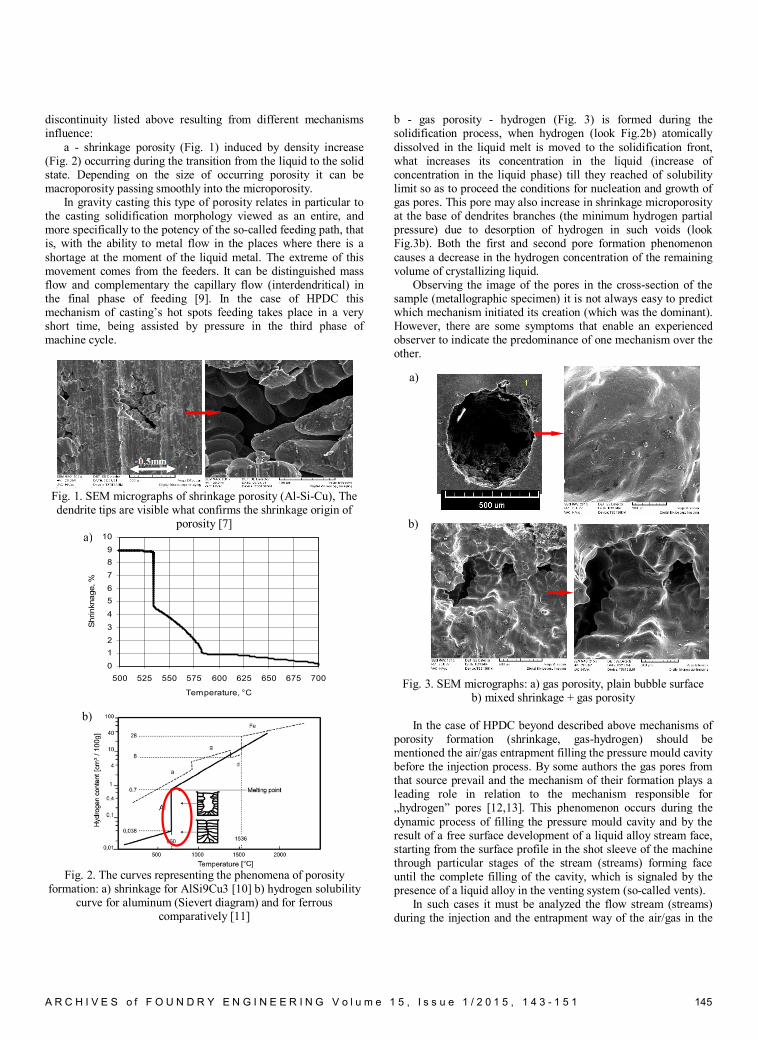
a - shrinkage porosity (Fig. 1) induced by density increase (Fig. 2) occurring during the transition from the liquid to the solid state. Depending on the size of occurring porosity it can be macroporosity passing smoothly into the microporosity.
In gravity casting this type of porosity relates in particular to the casting solidification morphology viewed as an entire, and more specifically to the potency of the so-called feeding path, that is, with the ability to metal flow in the places where there is a shortage at the moment of the liquid metal. The extreme of this movement comes from the feeders. It can be distinguished mass flow and complementary the capillary flow (interdendritical) in the final phase of feeding [9]. In the case of HPDC this mechanism of casting’s hot spots feeding takes place in a very short time, being assisted by pressure in the third phase of machine cycle.
Fig. 1. SEM micrographs of shrinkage porosity (Al-Si-Cu), The dendrite tips are visible what confirms the shrinkage origin of
porosity [7]
Fig. 2. The curves representing the phenomena of porosity
formation: a) shrinkage for AlSi9Cu3 [10] b) hydrogen solubility curve for aluminum (Sievert diagram) and for ferrous
comparatively [11]
b - gas porosity - hydrogen (Fig. 3) is formed during the solidification process, when hydrogen (look Fig.2b) atomically dissolved in the liquid melt is moved to the solidification front, what increases its concentration in the liquid (increase of concentration in the liquid phase) till they reached of solubility limit so as to proceed the conditions for nucleation and growth of gas pores. This pore may also increase in shrinkage microporosity at the base of dendrites branches (the minimum hydrogen partial pressure) due to desorption of hydrogen in such voids (look Fig.3b). Both the first and second pore formation phenomenon causes a decrease in the hydrogen concentration of the remaining volume of crystallizing liquid.
Observing the image of the pores in the cross-section of the sample (metallographic specimen) it is not always easy to predict which mechanism initiated its creation (which was the dominant). However, there are some symptoms that enable an experienced observer to indicate the predominance of one mechanism over the other.
Fig. 3. SEM micrographs: a) gas porosity, plain bubble surface b) mixed shrinkage + gas porosity
In the case of HPDC beyond described above mechanisms of
porosity formation (shrinkage, gas-hydrogen) should be mentioned the air/gas entrapment filling the pressure mould cavity before the injection process. By some authors the gas pores from that source prevail and the mechanism of their formation plays a leading role in relation to the mechanism responsible for „hydrogen” pores [12,13]. This phenomenon occurs during the dynamic process of filling the pressure mould cavity and by the result of a free surface development of a liquid alloy stream face, starting from the surface profile in the shot sleeve of the machine through particular stages of the stream (streams) forming face until the complete filling of the cavity, which is signaled by the presence of a liquid alloy in the venting system (so-called vents).
In such cases it must be analyzed the flow stream (streams) during the injection and the entrapment way of the air/gas in the
01234
56789
10
500 525 550 575 600 625 650 675 700
Temperature, °C
Shrin
knag
e, %
b)
a) b)
a)
146 A R C H I V E S o f F O U N D R Y E N G I N E E R I N G V o l u m e 1 5 , I s s u e 1 / 2 0 1 5 , 1 4 3 - 1 5 1
volume of the cavity, which may consequently cause described gas occlusions and properly design the cavity vent channels system.
The assistance in solving this problem is the application of vacuum system, that is the introducing the metal stream under the quasi-vacuum conditions in the mould cavity [12]. Not all foundries apply this technical solution because of the high costs.
High dynamic of filling the mould cavity with an alloy with temperature which exceed 700C and speed of the piston in shot sleeve about 4 m/s, translates into the velocity of an alloy in the inlet of gating system at about 40 m/s This fact limits the measuring technique of the casting temperature (due to the thermo-mechanical strength of the thermocouple and the jacket, also in terms of its thermal inertia) in real time of injection. Sometimes the thermocouples are placed in a permanent mould, as close of cavity, consciously losing the information about stream temperature and consequently about the local solidification time. For such solution, requiring profound interference into expensive mould the company rarely gives the consent. This problem associated with mould instrumentation does not occur by gravity poured mould.
The application of numerical methods to analyze the dynamics mould cavity filling process and consequently to the run of HPD casting solidification (available simulation systems e.g. NovaFlow & Solid Procast, Magma, Vulcan) thus becomes the only way of giving the basis to the individual concept technology optimization in HPDC process. The condition for the usefulness of this method is satisfactory probability of conformity of the virtual and real process. It is indispensable the preceded an experimental validation even with the mentioned above the limited access to the traditional process parameters, mainly cooling temperature curves (validation parameters of I kind [14]). Naturally, there can be used the parameters of II kind which depend on casts testing. However, due to the very high cost of moulds for HPDC it is preferred to wide and professional usage of simulation systems before executing this mould.
The validation activities should include the so-called sensitivity tests regarding the impact of particular parameters available in the model of simulated processes on the results. Tests of this kind should begin with the extreme intuitively expected values according to the best knowledge of HPDC processes. In these intervals the real values should contain (material properties, boundary and initial conditions etc.). At the same time one should take into account the scope of the simplifications in the modeled expression of these phenomena in individual simulation systems.
Complemented in this way, the simulation system database will correspond the best to the real conditions of the foundry.
The next step (after the mould performing), when using the available machine settings parameter and the experience of professionals, by trial and error method (II kind validation parameter) is carried the further optimization of the process. Each test should of course be the subject of further versions of the simulation calculations. One should get a confirmation of the sensitivity of the models simulation system to variation of the settings of these machine parameters for the particular stages of the process. Final calculation results, indicating on the predicted quality of the casting is the intensity and location of shrinkage discontinuities origin and sites that are risk by the gas porosity, resulting from gas/air occlusions from the cavity. Indirectly, based
on the distribution and velocity of the stream, one can specify the places in the mould which are endangered to erosion. These activities successfully completed, in principle, terminate, validation and at the same time broaden the experience of specialist-engineers.
The listed simulation systems, beyond predicting the above characteristics of the mould cavity filling process and solidification („hard modeling”) allow on the basis of „soft modeling” [2,9] predicting some structure parameters, such as shares of the particular phases, DAS (Dendrite Arm Spacing), as well as 3-D maps of the mechanical properties (Rm, Re, HB). Validated by experimental validation maps of these local properties of castings can be used to construction optimization during design of cast products, taking into account the mechanical properties gradient [9].
This article comes out to the problem of identification and prediction of the gas, shrinkage and gas-shrinkage discontinuities origin in Al-Si-X alloy castings.
3. Methodology of investigations
The study included a comprehensive HPDC process from the preparation of the metal to the final state of casting quality. The tests of metallurgical quality of alloy (AlSi9Cu3): chemical composition, the hydrogen content (methods: the first bubble [15] and Density Index - DI [15]), were conducted. At the same time for the same alloy the cooling curves were recorded in a special sampler (DTA-Differential Thermal Analysis) to identify the crystallization process [16]. The tests of the hydrogen content and the cooling curve analysis were carried out comparatively before and after the refining process of alloy: using nitrogen refining tablet and alternatively the rotor and argon. All high-pressure die-castings which were made during the tests were left for further studies (structure, porosity).
In the method of first bubble by Y. Dardel [15] the specialized equipment AluCompact II from FMA Mechatronic Solution and for Density Index test the apparatus ALSP MK II Industrievertretungen GmbH (Fig. 4), were used.
The first method is based on the formula developed by Sievert [15, 17]:
BTAPC HH log5,0log (1)
where: CH – the concentration of dissolved hydrogen in the aluminum alloy, [cm3/100g] PH – hydrogen partial pressure, [mbar] T – temperature of the liquid alloy, [K] A, B – empirical constant dependent on the alloy composition (considering: Cu, Si, Mn, Mg)
In a situation where the pressure above the liquid sample surface decreases with the range assigned to the apparatus type, in the volume of liquid sample proceed the conditions for nucleation and growth of hydrogen bubble. If the hydrogen partial pressure (PH) in the bubble is lower than the pressure of above the sample surface the hydrogen desorbs continuously into the bubble, and

A R C H I V E S o f F O U N D R Y E N G I N E E R I N G V o l u m e 1 5 , I s s u e 1 / 2 0 1 5 , 1 4 3 - 1 5 1 147
after reaching a critical diameter escapes to the surface. It is then visible as a bubble on the still liquid alloy surface.
Fig. 4. Test stands used for testing: a) apparatus DTA-
Cristaldigraph, DI-MK and FMA, b) rotor (refining process with argon)
The second method of estimating the degree of gassing (using
the Index Density) consists in casting of two samples (to cups): the first solidifies at atmospheric pressure, and a second in an apparatus chamber at reduced pressure to 80 mbar. Density Index is calculated from the following equation (the corresponding density values are determined with a precision analytical balance, weighing the sample in air and water) [by 15]:
%100.
80.
atm
mbaratm
DDDDI
where: Datm. – density of the sample at atmospheric pressure D80mbar - density of the sample at a pressure of 80 mbar
The refining process was carried out using Degasal T200 tablets and rotor (Fig.4b) and argon (degassing time 210 s, stirrer speed 330 rpm, argon flow rate about 31 dm3/min).
4. Results of experimental and virtual tests
The selected results of the metallurgical quality tests (degree of gassing) show a significant reduction of hydrogen content (Table 2). The usage of nitrogen degassing tablets is considerably less effective. Table 2. The chosen density index and hydrogen content data (pairs before and after refining process)
Sample No DI [%]
Hydrogen content
[cm3/100g]
Initial alloy temp. [°C]
1 initial 8,68 0,23 716 1 after refining 0,4 0,04 673
2 initial 8,87 0,22 727 2 after refining 0,19 0,02 696
3 initial 7,96 0,22 728 3 after refining 0,31 0,06 692
4 initial 9,25 0,20 737 4 after refining 0,22 0,07 697
5 initial 8,17 0,20 722 5 after refining 0,07 0,08 686
6 initial 8,00 0,17 712 6 after refining 0,13 0,05 682
7 initial 8,42 0,20 743 7 after refining 0,18 0,03 702
8 initial 15,09 0,24 744 8 after tablet refining 9,02 0,21 717
The improvement of alloy metallurgical quality was also
confirmed by penetrating testing and microscopic one which were carried out on gravity cast samples for DI test. These samples were solidified under atmospheric pressure conditions. The results of these tests were shown in Fig. 5. The tests were supplemented by DAS measurements to determine the refinement of the solidifying casting structure under gravity and pressure casting. There was at least quadruple reduction of the structure (DAS), which obviously influences into the better compactness of the structure of HPDC solidification under correct feeding conditions.
The porosity occurring in gravity casting samples can only be the shrinkage and „hydrogen” origin. The latter one is rather evenly distributed in the whole volume of the sample casting and its diameters are less than 200μm. Its gradual developing during penetrating testing proves their diversity dimension. The comparison of photographs (Fig.5b and 5c) shows that the effective refining (rotor + argon) there is a clear agglomeration of shrinkage porosity in the vicinity of the thermal center of the sample. It is confirmed by the shape of the porosity in selected locations on the cross-sections of the samples. The obvious developed dendrites arms are present in this shrinkage discontinuities origin.
Thus confirmed the direction which can be noticed in die-casting of aluminum alloys, namely to intentional and controlled introduction of hydrogen (originating from the decomposition of
DI-MK Dardel-FMA
DTA
b)
a)

148 A R C H I V E S o f F O U N D R Y E N G I N E E R I N G V o l u m e 1 5 , I s s u e 1 / 2 0 1 5 , 1 4 3 - 1 5 1
the powder or tablet which are introduced into the liquid alloy), resulting the way of shrinkage compensation and its scattering in the entire volume of the casting [18].
The Fig.6 shows the results of the prediction for the shrinkage porosity test casting (DI sample), including the influence of the critical fraction which determine the flows balancing contraction: the mass flow (criterion of limited fraction of the liquid phase CLFu) and capillary flow (criterion of limited fraction of the liquid phase). It was consistent with the expectations responses of shrinkage porosity predictions for the both critical values of fractions and for reduction of shrinkage coefficient (sensitivity study for these parameters, the others were admitted as stable and unchanged in the simulation). The best approximation was obtained for refined alloy and combinations of tested parameters: CLFu = 40% = 30% CLFd, global shrinkage = 6,7%.
The lowering of porosity zone location in relation of top sample surface can be achieved by increasing the Heat Transfer Coefficient on the top interface (uncovered surface of the DI sample). The NF&S does not allow to take into account the hydrogen content in the alloy.
A similar scenario was used for testing of the alloy before and after refining under pressure casting.
From literature reports and own observations do not follow that maintaining a high content of hydrogen in the HPDC translates in an identical manner to the problem of distribution and size of gas - shrinkage porosity. The number of these porosities is practically impossible to identification and quantification towards the appearance (as described previously) the additional porosity as the gas occlusions.
The Fig.7 shows the results of penetrating testing and structure tests of HPDC made of identical AlSi9Cu3 alloy. The selected cross-section which was tested ran through the hot spot, so the observations include the final solidification of the casting region. The visual testing before PT and PT test results confirm that the zone surrounding the test section spot 3-4mm from the mould contact and thin walls are devoid of porosity detectable by used methods. The central cross-section zone has the porosities of different sizes. It is inferred, the largest with a diameter of about 0,5 mm are the gas occlusions, which formed and were entrapped during injection. Then, they were probably to be increased due to the contraction (with a decrease of pressure in the occlusion) and due to the desorption of hydrogen into the occlusion interior. The occurring next to the occlusion the „hydrogen” porosity with a smaller diameter greatly below the 0,2 mm and interdendritic porosity which have developed surface being initiated by the shrinkage void.
The described phenomena are a certain extent hypothesis, knowing that the maximum occlusion diameters exceeding 0,2 mm, agglomerated in the region of the thermal wall casting axis (hot spots) may cause masking other mentioned discontinuities.
The question is how, in relation to the limited possibilities of porosity prediction for GDC the NF&S system meets the specifics of HPDC. The simulation was carried out for the entire casting process from the movement of metal in shot sleeve under the influence of a piston and its introduction into the mould cavity (Fig.8) until the end of casting solidification (Fig.9). Analyzing the successive stages of filling the shot sleeve and the cavity (Fig.8) may indicate that the air/gas during movement of the
piston is introduced into the mould in front the stream closing gating system inlets, which increases the probability of occlusion occurrence. The prediction of their occurrence is in accordance with the area which was indicated above, based on experimental studies. At the same area (hot spot) according to NF&S prediction there will occur shrinkage porosity (a few %). As follow from Fig.8b, the piston speed variation of 4 to 10 m/s, in the filling phase of the mould cavity does not influence practically on the predicted position of the gas/air occlusions. Interpretation of these occlusions in the case of NF&S is based on the temperature map of occluded gas (filled before the metal fraction of the cavity is highlighted as white color).
1
2
3 4
5 6
1
2
3 4
5 6
Sample castings (density index test) before refining after refining
a)
Penetrating Testing Sequences - normal conditions - before refining
200µm 200µm
200µm
200µm
200µm
200µm
after 5sec. 15sec. 30sec. 1min.
1
4 3
5 6
2 DAS45µm
DAS65µm DAS50µm
b)

A R C H I V E S o f F O U N D R Y E N G I N E E R I N G V o l u m e 1 5 , I s s u e 1 / 2 0 1 5 , 1 4 3 - 1 5 1 149
Fig. 5. Penetrating testing (PT) and microstructure in selected sites in cup casting: a) plan of both samples, b) before refining, b)
after refining
Fig. 6. Shrinkage porosity prediction in NFS system for DI cup casting with feeding parameters variation: CLFu and CLFd (a - e), f - the best agreement for CLFu/CLFd=40%/30% after validation of thermal flux of uppon surface. The final shrinkage values were calculated (cumulatively) by NF&S shrinkage model (theoretical
feeding shrinkage value based on NF&S database is: (ρTini- ρTsol)/ρTini)*100%=8,8%)
Fig. 7. Penetrating testing (PT) and microstructure in selected sites in HPDC casting
20µm
20µm
100µm
after 5sec. 15sec. 30sec. 1min.
1 2
3
4 5
6 7
8
20µm
20µm
200µm
200µm 20µm
1 2
3 4
5 6
7
7’
8
DAS10µm
DAS15µm
DAS15µm
200µm
1
5
4
2
3
6
200µm
200µm 200µm
200µm 200µm
after 5sec. 15sec. 30sec. 1min.
PT - normal conditions - after refining
DAS50µm
c)
CLFu=70% CLFd=30%
*Shrinkage=7,0%
CLFu=70% CLFd=70%
*Shrinkage=7,0
CLFu=90% CLFd=90%
*Shrinkage=7,1%
CLFu=30% CLFd=30%
*Shrinkage=6,7%
CLFu=40% CLFd=30%
*Shrinkage=6,7%
CLFu=40% CLFd=30%
*Shrinkage=6,9%
15% 5%
100%
15%
15% 2%
15% 30%
100%
35% 10%
35% 8%
35%
a) b) c)
d) e) f)

150 A R C H I V E S o f F O U N D R Y E N G I N E E R I N G V o l u m e 1 5 , I s s u e 1 / 2 0 1 5 , 1 4 3 - 1 5 1
Fig. 8. Simulation results of air entrapment phenomena corresponding to chosen stages of piston positions in shot sleeve. a – in shot sleeve from beginning to final piston position, b – two chosen stages (70 step and 89 step) connecting the piston position
with air entrapment map inside of casting (for different piston speed)
Similarly, the changing the speed of the piston from 4 to 10 m/s, in the phase of filling of the mould cavity does not significantly affect the distribution and intensity of shrinkage defects (Fig. 9). It can be stated that this prediction satisfactorily corresponds to the interpretation of porosity determined using the described test.
Fig. 9. Shrinkage porosity for two piston speed
The results of simulation calculations using NF&S system are a base to predict porosity from two sources. NF&S does not include the hydrogen content in the alloy (there is no appropriate module in the system). Previous tests elaborated by the authors [2,19] show that such „hydrogen” models are represented in other systems such as Calcosoft Porosity and Procast Advance Porosity Module. The both of these models show correct qualitative response on the change in hydrogen concentration in the liquid melt, but require quantitative experimental validation, as it was stated in [2,19].
6. Conclusions
Upon the validation of experimental-simulation study of HPDC process it can be formulated the following conclusions: The hydrogen concentration in the liquid alloy is possible to
estimate using the “density index” - DI (solidification of test cup at 80mbar). DI factor for the well refined alloy should be less than 3,0 %. This guarantees the good metallurgical quality of alloy.
The most effective reduction of hydrogen content is possible by means of the rotor and argon (foundries usually apply nitrogen considering costs but argon is more effective) blowing (result: significant reducing of the hydrogen amount).
In the gravity casting case (GDC technology) as well high-pressure case (HPDC) the degassed liquid Al-Si alloy does not ensure the complete elimination of gas porosity.
Another important source of gas porosities in HPDC technology is air entrapment (mixture of air and gases from
Step 70 (68% of filling, 2,563 s) Step 89 (87,1% of filling, 2,580 s) b. piston speed during filling of mould cavity – 4 m/s
c) piston speed during filling of mould cavity – 10 m/s Step 70 (69,1% of filling, 2,552 s) Step 89 (88% of filling, 2,558 s)
Step 1 (0,2% of filling, 0,003 s)
Step 19 (18,1% of filling, 0,326 s)
Step 101 (99,5% of filling, 2,579 s)
Step 35 (34% of filling, 1,829 s)
Air/gas temperature
Liquid alloy Mould inlet
Piston position
a. shot sleeve filling and injection process
Piston speed 4 m/s Piston speed 10 m/s

A R C H I V E S o f F O U N D R Y E N G I N E E R I N G V o l u m e 1 5 , I s s u e 1 / 2 0 1 5 , 1 4 3 - 1 5 1 151
the decomposition of shot sleeve and the mould cavity coating or piston lubricants). The distribution of porosities depends on the turbulence of jet stream and free surface jet face.
The identification of the origin of porosity in real GDC castings, especially for refined alloy (low hydrogen content) is easier (shrinkage porosity dominates, and it can be assumed that hydrogen is desorbed to shrinkage micro-cavities). Developed pore shape (boundaries) corresponds to the position corresponding to the branches of dendrites. For this case, predicting of places endangered by porosity has the higher reliability.
Due to the significant porosity and varying origin share air entrapment in the shrinkage and hydrogen pores, identification of the type of porosity in castings HPDC, is difficult.
Only the comprehensive and comparative validation of simulation systems in the domain of this various porosity origin will lead to complementary deduction about casting properties. The identification of variation of mechanical properties should be done with high circumspection being result of researcher experience or/and future validation works.
Some simulation systems (e.g. NovaFlow&Solid) have the potential links of HPDC process simulation predictions (shrinkage porosity prediction and air entrapment). An experienced specialist can indicate on this basis the zones most endangered by particular porosity.
The intentional introduction of hydrogen into the liquid Al-Si alloy (for GDC) and relatively rapid solidification means that the predominance of the gas-rounded pores in relation to the shrinkage pores having the unfavorable dendritic boundaries. This is advantageous in view of fatigue strength of HPDC Al-Si alloys casting, for example closer to the formal structure of the naturally textured cast iron containing spheroidal graphite.
Acknowledgements The work was partially supported by POIG.01.04.00-30-110/12 project.
References [1] Campbell, J. (2000), Castings, Butterworth-Heinemann. [2] Ignaszak, Z., Hajkowski, J. & Popielarski, P. (2013).
Examples of new models applied in selected simulation systems with respect to database. Archives of Foundry Engineering. 13(1), 45- 50.
[3] Pucher, P., Böttcher, H., Kaufmann, H., Antrekowitsch, H., Uggowitzer, P.J. (2011). Mechanical properties and casting characteristics of the secondary aluminum alloy
AlSi9Cu3(Fe) (A226). Supplemental Proceedings: Volume 2: Materials Fabrication, Properties, Characterization, and Modeling TMS (The Minerals, Metals&Materials Society). 237-244.
[4] Martinez, D., E. ., Cisneros G., M.A., Valtierra, S. & Lacaze, J. (2005). Effect of strontium and cooling rate upon eutectic temperatures of A319 aluminum alloy. Scripta Materialia. 52, 439-443.
[5] Bäckerud, L., Chai, G. & Tamminen, J. (1990). Solidification Characteristics of Aluminium Alloys. Foundry Alloys, AFS/Skanaluminum. 2, 71-84.
[6] Samuel, F.H., Samuel, A.M., & Doty, H.W. (1996). Factors controlling the type and morphology of Cu-containing phases in 319 Al alloy. AFS Trans, 104, 893.
[7] Ignaszak, Z., Popielarski, P., Hajkowski, J., Prunier, J-B. (2012). Problem of acceptability of internal porosity in semi-finished cast product as new trend – “tolerance of damage” present in modern design office. Defect and Diffusion Forum. 326-328, 612-619. DOI: 10.4028/www.scientific.net/ DDF.326-328.612.
[8] Dobrzański, L.A., Nowosielski, R. (1987). Methods of test for metals and alloys. The study of physical properties. Warszawa: WNT. (in Polish).
[9] Ignaszak, Z., Hajkowski, J., Popielarski, P. (2013). Mechanical properties gradient existing in real castings taken into account during design of cast components. Defect and Diffusion Forum. 334-335, 314-321. DOI: 10.4028/www.scientific.net/DDF.334-335.314.
[10] NovaFlow&Solid ver.4.5.5. system. Calibrate module. [11] http://www.migweld.de. [12] Niu, X.P., Hu, B.,Pinwill, I. & Li, H. (2000). Vacuum
assisted high pressure die casting of aluminium alloys. Journal of Materials Processing Technology. 105, 119-127.
[13] Verrana, G.O., Mendes, R.P.K. & Rossi, M.A. (2006). Influence of injection parameters on defects formation in die casting Al12Si1,3Cu alloy: Experimental results and numeric simulation. Journal of Materials Processing Technology. 179, 190-195.
[14] Ignaszak, Z. (2002). Virtual prototyping foundry: database and validation. Poznań. Wyd. Politechniki Poznańskiej. (in Polish)
[15] Eigenfeld, K., Klan, S. & Wechselberger, O. (2001). The hydrogen content in aluminum alloys - comparative measurements using the "CHAPEL" and device "Alu Speed Test”. Biuletyn Metals&Minerals, Technika Pomiarowa. 2, 42-46.
[16] Jura, Z., Jura, J. (2005). ATD-Crystaldigraph, Gliwice. [17] Hufnale, W. (1983), Aluminium-Taschenbuch. Dusseldorf [18] http://www.foseco.com. [19] Hajkowski, J., Ignaszak, Z., Hajkowski, M., Popielarski, P.
(2012). Report. Unpublished work sponsored by Polish Ministry of Science and High Education, grant no N N508 444436, Poznan University of Technology.
Related Documents