1/36 Siemens AP 01 · 2016 Continuous Gas Analyzers, extractive ULTRAMAT 23 General information 1 ■ Overview Up to four gas components can be measured simultaneously with the ULTRAMAT 23 gas analyzer: up to three infrared-active gases such as CO, CO 2 , NO, SO 2 , CH 4 , plus O 2 with an electro- chemical oxygen sensor. ULTRAMAT 23 basic versions for: • 1 infrared gas component with/without oxygen measurement • 2 infrared gas components with/without oxygen measurement • 3 infrared gas components with/without oxygen measurement • With the ULTRAMAT 23 gas analyzer for use in biogas plants, up to four gas components can be measured continuously: two infrared-sensitive gases (CO 2 and CH 4 ), plus O 2 and H 2 S with electrochemical measuring cells. • With the ULTRAMAT 23 gas analyzer with paramagnetic oxygen cell, up to four gas components can be measured continuously: three infrared-active gases, plus O 2 ("dumbbell" measuring cell). ■ Benefits • AUTOCAL with ambient air (dependent on the measured component) Highly cost effective because calibration gases are not required • High selectivity thanks to multi-layer detectors, e.g. low cross-sensitivity to water vapor • Sample chambers can be cleaned as required on site Cost savings due to reuse after contamination • Menu-assisted operation in plaintext Operator control without manual, high level of operator safety • Service information and logbook Preventive maintenance; help for service and maintenance personnel, cost savings • Coded operator level against unauthorized access Increased safety • Open interface architecture (RS 485, RS 232, PROFIBUS, SIPROM GA) • Simplified process integration; remote operation and control Special benefits when used in biogas plants • Continuous measurement of all four important components, including H 2 S • Long service life of the H 2 S sensor even at increased concen- trations; no diluting or backflushing necessary • Introduction and measurement of flammable gases as occurring in biogas plants (e.g. 70 % CH 4 ), is permissible (TÜV certificate) © Siemens AG 2016

Welcome message from author
This document is posted to help you gain knowledge. Please leave a comment to let me know what you think about it! Share it to your friends and learn new things together.
Transcript

1/36 Siemens AP 01 · 2016
Continuous Gas Analyzers, extractiveULTRAMAT 23
General information1
■ Overview
Up to four gas components can be measured simultaneously with the ULTRAMAT 23 gas analyzer: up to three infrared-active gases such as CO, CO2, NO, SO2, CH4, plus O2 with an electro-chemical oxygen sensor.
ULTRAMAT 23 basic versions for:• 1 infrared gas component with/without oxygen measurement• 2 infrared gas components with/without oxygen measurement• 3 infrared gas components with/without oxygen measurement• With the ULTRAMAT 23 gas analyzer for use in biogas plants,
up to four gas components can be measured continuously: two infrared-sensitive gases (CO2 and CH4), plus O2 and H2S with electrochemical measuring cells.
• With the ULTRAMAT 23 gas analyzer with paramagnetic oxygen cell, up to four gas components can be measured continuously: three infrared-active gases, plus O2 ("dumbbell" measuring cell).
■ Benefits
• AUTOCAL with ambient air (dependent on the measured component)Highly cost effective because calibration gases are not required
• High selectivity thanks to multi-layer detectors, e.g. low cross-sensitivity to water vapor
• Sample chambers can be cleaned as required on siteCost savings due to reuse after contamination
• Menu-assisted operation in plaintextOperator control without manual, high level of operator safety
• Service information and logbookPreventive maintenance; help for service and maintenance personnel, cost savings
• Coded operator level against unauthorized accessIncreased safety
• Open interface architecture (RS 485, RS 232, PROFIBUS, SIPROM GA)
• Simplified process integration; remote operation and control
Special benefits when used in biogas plants• Continuous measurement of all four important components,
including H2S• Long service life of the H2S sensor even at increased concen-
trations; no diluting or backflushing necessary• Introduction and measurement of flammable gases as
occurring in biogas plants (e.g. 70 % CH4), is permissible (TÜV certificate)
© Siemens AG 2016
1/37Siemens AP 01 · 2016
Continuous Gas Analyzers, extractiveULTRAMAT 23
General information1
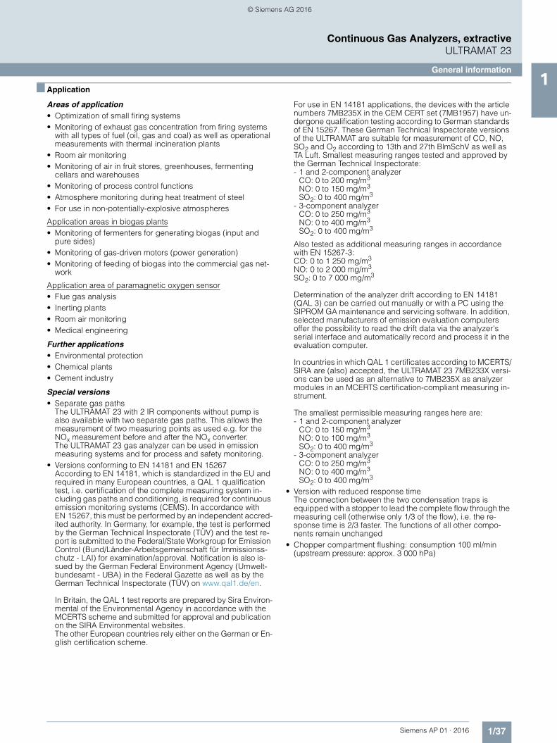
■ Application
Areas of application• Optimization of small firing systems• Monitoring of exhaust gas concentration from firing systems
with all types of fuel (oil, gas and coal) as well as operational measurements with thermal incineration plants
• Room air monitoring• Monitoring of air in fruit stores, greenhouses, fermenting
cellars and warehouses• Monitoring of process control functions• Atmosphere monitoring during heat treatment of steel• For use in non-potentially-explosive atmospheres
Application areas in biogas plants• Monitoring of fermenters for generating biogas (input and
pure sides)• Monitoring of gas-driven motors (power generation)• Monitoring of feeding of biogas into the commercial gas net-
work
Application area of paramagnetic oxygen sensor• Flue gas analysis• Inerting plants• Room air monitoring• Medical engineering
Further applications• Environmental protection• Chemical plants• Cement industry
Special versions• Separate gas paths
The ULTRAMAT 23 with 2 IR components without pump is also available with two separate gas paths. This allows the measurement of two measuring points as used e.g. for the NOx measurement before and after the NOx converter.The ULTRAMAT 23 gas analyzer can be used in emission measuring systems and for process and safety monitoring.
• Versions conforming to EN 14181 and EN 15267 According to EN 14181, which is standardized in the EU and required in many European countries, a QAL 1 qualification test, i.e. certification of the complete measuring system in-cluding gas paths and conditioning, is required for continuous emission monitoring systems (CEMS). In accordance with EN 15267, this must be performed by an independent accred-ited authority. In Germany, for example, the test is performed by the German Technical Inspectorate (TÜV) and the test re-port is submitted to the Federal/State Workgroup for Emission Control (Bund/Länder-Arbeitsgemeinschaft für Immissionss-chutz - LAI) for examination/approval. Notification is also is-sued by the German Federal Environment Agency (Umwelt-bundesamt - UBA) in the Federal Gazette as well as by the German Technical Inspectorate (TÜV) on www.qal1.de/en.
In Britain, the QAL 1 test reports are prepared by Sira Environ-mental of the Environmental Agency in accordance with the MCERTS scheme and submitted for approval and publication on the SIRA Environmental websites. The other European countries rely either on the German or En-glish certification scheme.
For use in EN 14181 applications, the devices with the article numbers 7MB235X in the CEM CERT set (7MB1957) have un-dergone qualification testing according to German standards of EN 15267. These German Technical Inspectorate versions of the ULTRAMAT are suitable for measurement of CO, NO, SO2 and O2 according to 13th and 27th BlmSchV as well as TA Luft. Smallest measuring ranges tested and approved by the German Technical Inspectorate: - 1 and 2-component analyzer
CO: 0 to 200 mg/m3
NO: 0 to 150 mg/m3
SO2: 0 to 400 mg/m3
- 3-component analyzerCO: 0 to 250 mg/m3
NO: 0 to 400 mg/m3
SO2: 0 to 400 mg/m3
Also tested as additional measuring ranges in accordance with EN 15267-3: CO: 0 to 1 250 mg/m3
NO: 0 to 2 000 mg/m3
SO2: 0 to 7 000 mg/m3
Determination of the analyzer drift according to EN 14181 (QAL 3) can be carried out manually or with a PC using the SIPROM GA maintenance and servicing software. In addition, selected manufacturers of emission evaluation computers offer the possibility to read the drift data via the analyzer's serial interface and automatically record and process it in the evaluation computer.
In countries in which QAL 1 certificates according to MCERTS/SIRA are (also) accepted, the ULTRAMAT 23 7MB233X versi-ons can be used as an alternative to 7MB235X as analyzer modules in an MCERTS certification-compliant measuring in-strument.
The smallest permissible measuring ranges here are: - 1 and 2-component analyzer
CO: 0 to 150 mg/m3
NO: 0 to 100 mg/m3
SO2: 0 to 400 mg/m3
- 3-component analyzerCO: 0 to 250 mg/m3
NO: 0 to 400 mg/m3
SO2: 0 to 400 mg/m3
• Version with reduced response timeThe connection between the two condensation traps is equipped with a stopper to lead the complete flow through the measuring cell (otherwise only 1/3 of the flow), i.e. the re-sponse time is 2/3 faster. The functions of all other compo-nents remain unchanged
• Chopper compartment flushing: consumption 100 ml/min (upstream pressure: approx. 3 000 hPa)
© Siemens AG 2016

1/38 Siemens AP 01 · 2016
Continuous Gas Analyzers, extractiveULTRAMAT 23
General information1
■ Design
• 19" rack unit with 4 HU for installation - in hinged frame- in cabinets, with or without telescopic rails
• Flow indicator for sample gas on front plate; option: integrated sample gas pump (standard for bench-top version)
• Gas connections for sample gas inlet and outlet as well as zero gas; pipe diameter 6 mm or ¼"
• Gas and electrical connections at the rear (portable version: sample gas inlet at front)
Display and control panel• Operation based on NAMUR recommendation• Simple, fast parameterization and commissioning of analyzer• Large, backlit LCD for measured values• Menu-driven inputs for parameterization, test functions and
calibration• Washable membrane keyboard• User help in plain text• 6-language operating software
Inputs/outputs• Three binary inputs for sample gas pump On/Off, triggering of
AUTOCAL and synchronization of several devices• Eight relay outputs can be freely configured for fault, mainte-
nance request, maintenance switch, limits, measuring range identification and external solenoid valves
• Eight additional binary inputs and relay outputs as an option• Galvanically isolated analog outputs
Communication
RS 485 present in basic unit (connection from the rear).
Options• RS 485/RS 232 converter• RS 485/Ethernet converter• RS 485/USB converter• Incorporation in networks via PROFIBUS DP/PA interface• SIPROM GA software as service and maintenance tool
ULTRAMAT 23, membrane keyboard and graphic display
Immediate return tomeasurement mode
CAL key to start AUTOCALwith ambient air or N2
or air without CO2
Switch internal pump on and off;pump flowrate adjustable via menu
ENTER key to call themain menu or to saveentered values
↑↓ → Keys for menu control;increasing/decreasing numerical values
Scroll back in menu orcancel an input
Two columns reservedfor status displays
One line per component formeasured value, dimension
and component name
LED backlit display;brightness adjustable via menu
Dimension freely selectable(ppm, vpm, %, mg/m3)
© Siemens AG 2016
1/39Siemens AP 01 · 2016
Continuous Gas Analyzers, extractiveULTRAMAT 23
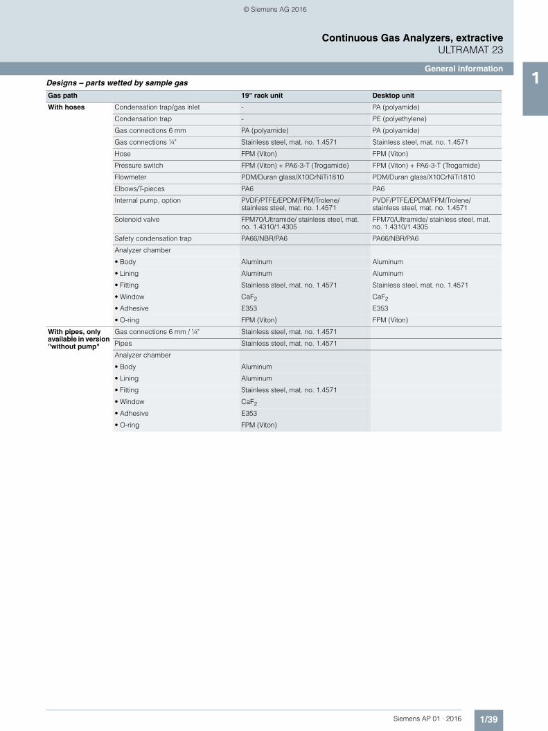
General information1Designs – parts wetted by sample gas
Gas path 19" rack unit Desktop unit
With hoses Condensation trap/gas inlet - PA (polyamide)
Condensation trap - PE (polyethylene)
Gas connections 6 mm PA (polyamide) PA (polyamide)
Gas connections ¼" Stainless steel, mat. no. 1.4571 Stainless steel, mat. no. 1.4571
Hose FPM (Viton) FPM (Viton)
Pressure switch FPM (Viton) + PA6-3-T (Trogamide) FPM (Viton) + PA6-3-T (Trogamide)
Flowmeter PDM/Duran glass/X10CrNiTi1810 PDM/Duran glass/X10CrNiTi1810
Elbows/T-pieces PA6 PA6
Internal pump, option PVDF/PTFE/EPDM/FPM/Trolene/ stainless steel, mat. no. 1.4571
PVDF/PTFE/EPDM/FPM/Trolene/ stainless steel, mat. no. 1.4571
Solenoid valve FPM70/Ultramide/ stainless steel, mat. no. 1.4310/1.4305
FPM70/Ultramide/ stainless steel, mat. no. 1.4310/1.4305
Safety condensation trap PA66/NBR/PA6 PA66/NBR/PA6
Analyzer chamber
• Body Aluminum Aluminum
• Lining Aluminum Aluminum
• Fitting Stainless steel, mat. no. 1.4571 Stainless steel, mat. no. 1.4571
• Window CaF2 CaF2
• Adhesive E353 E353
• O-ring FPM (Viton) FPM (Viton)
With pipes, only available in version "without pump"
Gas connections 6 mm / ¼" Stainless steel, mat. no. 1.4571
Pipes Stainless steel, mat. no. 1.4571
Analyzer chamber
• Body Aluminum
• Lining Aluminum
• Fitting Stainless steel, mat. no. 1.4571
• Window CaF2
• Adhesive E353
• O-ring FPM (Viton)
© Siemens AG 2016

1/40 Siemens AP 01 · 2016
Continuous Gas Analyzers, extractiveULTRAMAT 23
General information1
ULTRAMAT 23, design
Control keysfor menus
Optional O2 sensor, removable from front
Gas and electricalconnections on rearpanel (portable versionsimple gas at front)
Also availablewith slide rails
80-digit display(4 lines/20 characters)
Flowmeter in conjunction withpressure switch for monitoringthe sample gas flow
3 function keys formeasurement, pump On/Offand AUTOCAL
Dust-tight and washablemembrane keypad
ULTRAMAT 23 also available as bench-top unit:● 2 handles on top cover● 4 rubber feet for setting up● No mounting frame
© Siemens AG 2016
1/41Siemens AP 01 · 2016
Continuous Gas Analyzers, extractiveULTRAMAT 23
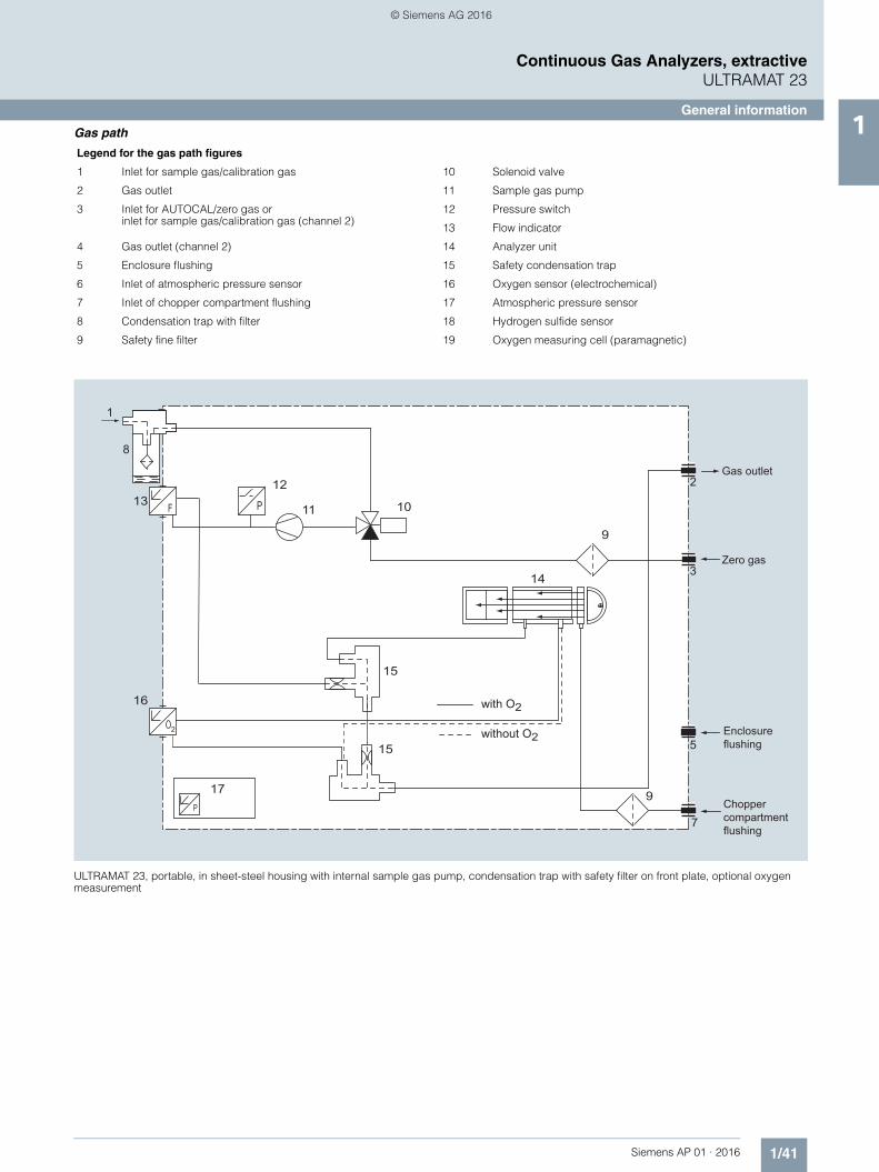
General information1Gas path
ULTRAMAT 23, portable, in sheet-steel housing with internal sample gas pump, condensation trap with safety filter on front plate, optional oxygen measurement
Legend for the gas path figures
1 Inlet for sample gas/calibration gas 10 Solenoid valve
2 Gas outlet 11 Sample gas pump
3 Inlet for AUTOCAL/zero gas or inlet for sample gas/calibration gas (channel 2)
12 Pressure switch
13 Flow indicator
4 Gas outlet (channel 2) 14 Analyzer unit
5 Enclosure flushing 15 Safety condensation trap
6 Inlet of atmospheric pressure sensor 16 Oxygen sensor (electrochemical)
7 Inlet of chopper compartment flushing 17 Atmospheric pressure sensor
8 Condensation trap with filter 18 Hydrogen sulfide sensor
9 Safety fine filter 19 Oxygen measuring cell (paramagnetic)
P
2
F
2
3
5
7
13
16
15
15
14
9
12
10
1
8
11
P
17 9
Gas outlet
Zero gas
Enclosureflushing
Choppercompartmentflushing
with O2
without O2
© Siemens AG 2016
1/42 Siemens AP 01 · 2016
Continuous Gas Analyzers, extractiveULTRAMAT 23
General information1
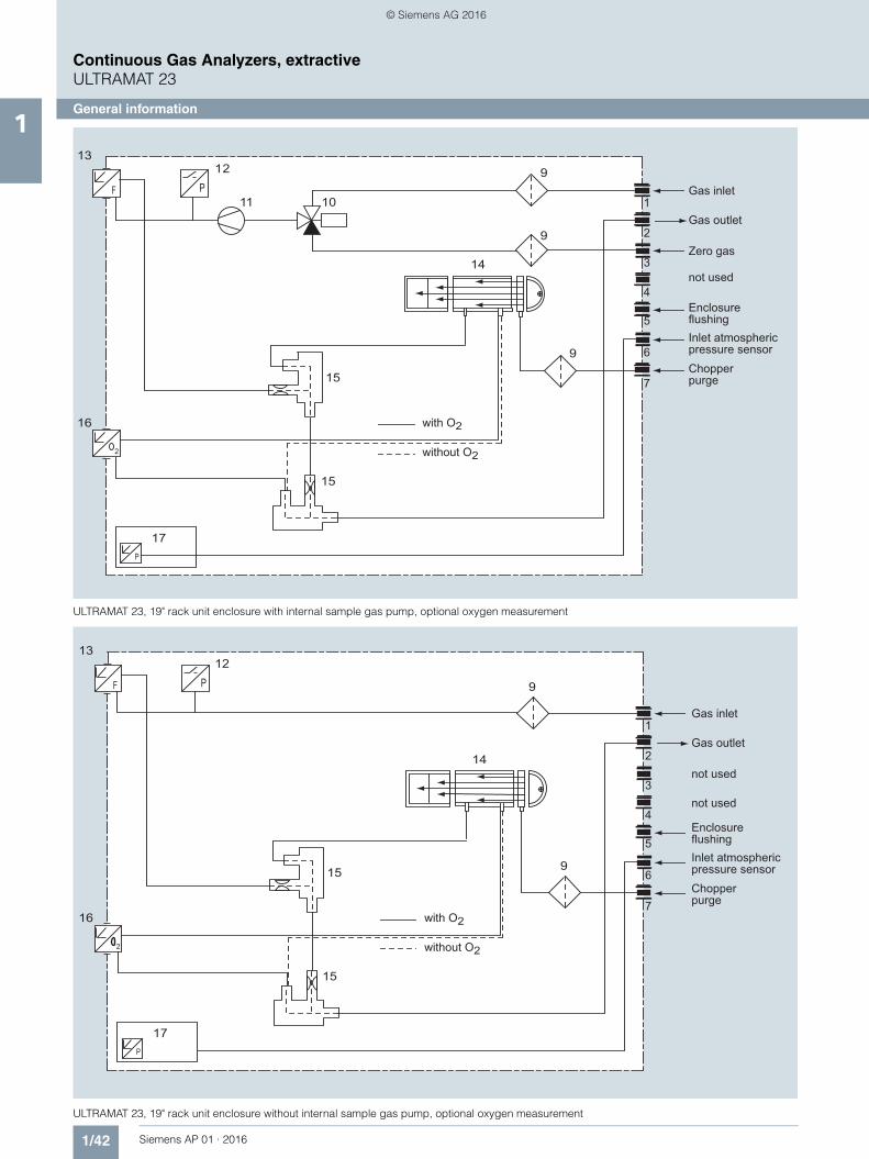
ULTRAMAT 23, 19" rack unit enclosure with internal sample gas pump, optional oxygen measurement
ULTRAMAT 23, 19" rack unit enclosure without internal sample gas pump, optional oxygen measurement
2
P
P
F1
2
3
4
5
6
7
13
16
17
15
14
9
9
9
12
1011
15
Gas inlet
Gas outlet
Zero gas
not used
EnclosureflushingInlet atmosphericpressure sensorChopperpurge
with O2
without O2
2
P
P
F
1
2
3
4
5
6
7
13
17
15
15
14
9
9
12
16
Gas inlet
Gas outlet
not used
not used
with O2
without O2
EnclosureflushingInlet atmosphericpressure sensorChopperpurge
© Siemens AG 2016

1/43Siemens AP 01 · 2016
Continuous Gas Analyzers, extractiveULTRAMAT 23
General information1
ULTRAMAT 23, 19" rack unit enclosure without internal sample gas pump, with separate gas path for the 2nd measured component or for the 2nd and 3rd measured components, optional oxygen measurement
ULTRAMAT 23, 19" rack unit enclosure, sample gas path version in pipes, separate gas path, always without sample gas pump, without safety filter and without safety condensation trap
2
P
P
F
PF
1
23
4
5
6
7
13
13
16
17
15
15
14
15
15
14
9
9
9
12
12
Gas inlet 1
Gas outlet 1 Gas inlet 2
Gas outlet 2
with O2
without O2
Enclosureflushing
Inlet atmosphericpressure sensor
Chopperpurge
P
1
2
3
4
5
6
7
17
14
14
9
Gas inlet 1
Gas outlet 1
Gas inlet 2
Gas outlet 2
Enclosure flushing
Inlet atmosphericpressure sensorChopperpurge
© Siemens AG 2016

1/44 Siemens AP 01 · 2016
Continuous Gas Analyzers, extractiveULTRAMAT 23
General information1
ULTRAMAT 23, 19" rack unit enclosure with internal sample gas pump and H2S sensor
ULTRAMAT 23, 19" rack unit enclosure with internal sample gas pump and paramagnetic oxygen measurement
2
P
P
F1
2
3
4
5
6
7
13
16
17
15
14
9
9
9
12
1011
15
18
Not used
Sample/calibration gas inlet
Gas outlet
Zero gas inlet
Enclosure flushing
Inlet of atmospheric pressure sensor
Inlet of chopper compartment flushing (option)
P
P
F1
2
3
4
5
6
7
13
19
17
15
14
9
9
9
12
1011
15
Not used
Sample/calibration gas inletGas outlet
Zero gas inlet
Enclosure flushing
Inlet of atmospheric pressure sensor
Inlet of chopper compartment flushing (option)
© Siemens AG 2016
1/45Siemens AP 01 · 2016
Continuous Gas Analyzers, extractiveULTRAMAT 23
General information1
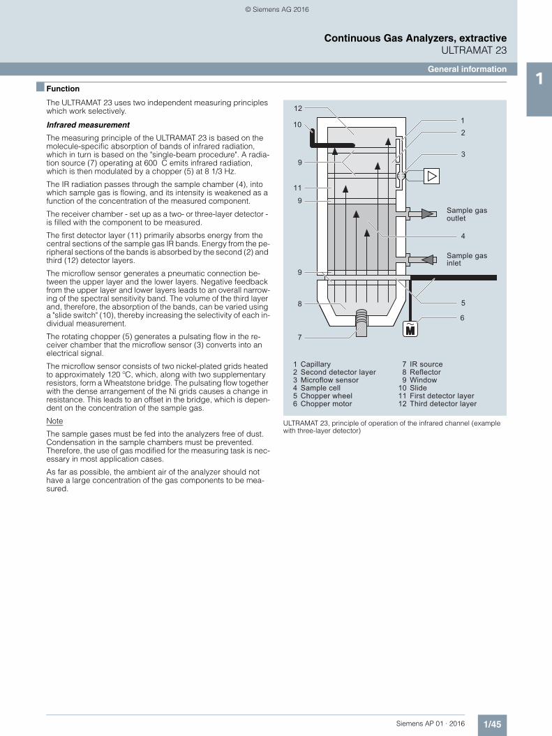
■ Function
The ULTRAMAT 23 uses two independent measuring principles which work selectively.
Infrared measurement
The measuring principle of the ULTRAMAT 23 is based on the molecule-specific absorption of bands of infrared radiation, which in turn is based on the "single-beam procedure". A radia-tion source (7) operating at 600 C emits infrared radiation, which is then modulated by a chopper (5) at 8 1/3 Hz.
The IR radiation passes through the sample chamber (4), into which sample gas is flowing, and its intensity is weakened as a function of the concentration of the measured component.
The receiver chamber - set up as a two- or three-layer detector - is filled with the component to be measured.
The first detector layer (11) primarily absorbs energy from the central sections of the sample gas IR bands. Energy from the pe-ripheral sections of the bands is absorbed by the second (2) and third (12) detector layers.
The microflow sensor generates a pneumatic connection be-tween the upper layer and the lower layers. Negative feedback from the upper layer and lower layers leads to an overall narrow-ing of the spectral sensitivity band. The volume of the third layer and, therefore, the absorption of the bands, can be varied using a "slide switch" (10), thereby increasing the selectivity of each in-dividual measurement.
The rotating chopper (5) generates a pulsating flow in the re-ceiver chamber that the microflow sensor (3) converts into an electrical signal.
The microflow sensor consists of two nickel-plated grids heated to approximately 120 ºC, which, along with two supplementary resistors, form a Wheatstone bridge. The pulsating flow together with the dense arrangement of the Ni grids causes a change in resistance. This leads to an offset in the bridge, which is depen-dent on the concentration of the sample gas.
Note
The sample gases must be fed into the analyzers free of dust. Condensation in the sample chambers must be prevented. Therefore, the use of gas modified for the measuring task is nec-essary in most application cases.
As far as possible, the ambient air of the analyzer should not have a large concentration of the gas components to be mea-sured.
ULTRAMAT 23, principle of operation of the infrared channel (example with three-layer detector)
12
3
10
9
11
9
12
9
8
7
4
5
6
1 2 3 4 5 6
7 8 9 10 1112
Sample gasinlet
Sample gasoutlet
Capillary Second detector layer Microflow sensor Sample cell Chopper wheel Chopper motor
IR source Reflector Window Slide First detector layer Third detector layer
© Siemens AG 2016

1/46 Siemens AP 01 · 2016
Continuous Gas Analyzers, extractiveULTRAMAT 23
General information1 Automatic calibration with air (AUTOCAL)
The ULTRAMAT 23 can be calibrated using, for example, ambi-ent air. During this process (between 1 and 24 hours (adjust-able), 0 = no AUTOCAL), the chamber is purged with air. The de-tector then generates the largest signal U0 (no pre-absorption in the sample chamber). This signal is used as the reference signal for zero point calibration, and also serves as the initial value for calculating the full-scale value in the manner described below.
As the concentration of the measured component increases, so too does absorption in the sample chamber. As a result of this preabsorption, the detectable radiation energy in the detector decreases, and thus also the signal voltage. For the single-beam procedure of the ULTRAMAT 23, the mathematical relationship between the concentration of the measured component and the measured voltage can be approximately expressed as the fol-lowing exponential function:
U = U0 e-kc
c Concentrationk Device-specific constantU0 Basic signal with zero gas (sample gas without measured component)U Detector signal
Changes in the radiation power, contamination of the sample chamber, or aging of the detector components have the same effect on both U0 and U, and result in the following:
U’ = U’0 e-kc
Apart from being dependent on concentration c, the measured voltage thus changes continuously as the IR source ages, or with persistent contamination.
Each AUTOCAL tracks the total characteristic until the currently valid value, thereby compensating for temperature and pressure influences.
The influences of contamination and aging, as mentioned above, will have a negligible influence on the measurement as long as U’ remains in a certain tolerance range monitored by the unit.
The tolerance "clamping width" between two or more AUTOCALs can be individually parameterized on the ULTRAMAT 23 and an alarm message output. A fault message is output when the value falls below the original factory setting of U0 < 50 % U. In most cases, this is due to the sample chamber being contaminated.
Calibration
The units can be set to automatically calibrate the zero point ev-ery 1 to 24 hours, using ambient air or nitrogen. The calibration point for the IR-sensitive components is calculated mathemati-cally from the newly determined U’o and the device-specific pa-rameters stored as default values. It is recommendable to check the calibration point once a year using a calibration gas. (For de-tails on TÜV measurements, see Table "Calibration intervals (TÜV versions)" under Selection and ordering data).
If an electrochemical sensor is installed, it is recommendable to use air for the AUTOCAL. In addition to calibration of the zero point of the IR-sensitive components, it is then also possible to simultaneously calibrate the calibration point of the electrochem-ical O2 sensor automatically. The characteristic of the O2 sensor is sufficiently stable following the single-point calibration such that the zero point of the electrochemical sensor needs only be checked once a year by connecting nitrogen.
Calibration
Oxygen measurement
The oxygen sensor operates according to the principle of a fuel cell. The oxygen is converted at the boundary layer between the cathode and electrolyte. An electron emission current flows be-tween the lead anode and cathode and via a resistor, where a measured voltage is present. This measured voltage is propor-tional to the concentration of oxygen in the sample gas.
The oxygen electrolyte used is less influenced by interference influences (particularly CO2, CO, H2 and CH4) than other sensor types.
Note: The oxygen sensor can be used for concentrations of both > 1 % and < 1 % O2. In the event of sudden changes from high concentrations to low concentrations (< 1 %), the sensor will, however, require longer running-in times to get a constant mea-sured value. This is to be taken into consideration when switch-ing between measuring points in particular, and appropriate rinsing times are to be set.
ULTRAMAT 23, principle of operation of the oxygen sensor
© Siemens AG 2016
1/47Siemens AP 01 · 2016
Continuous Gas Analyzers, extractiveULTRAMAT 23
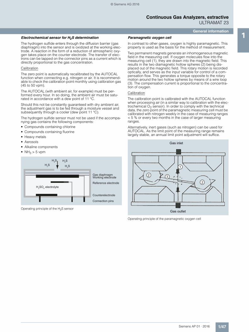
General information1Electrochemical sensor for H2S determination
The hydrogen sulfide enters through the diffusion barrier (gas diaphragm) into the sensor and is oxidized at the working elec-trode. A reaction in the form of a reduction of atmospheric oxy-gen takes place on the counter electrode. The transfer of elec-trons can be tapped on the connector pins as a current which is directly proportional to the gas concentration.
Calibration
The zero point is automatically recalibrated by the AUTOCAL function when connecting e.g. nitrogen or air. It is recommend-able to check the calibration point monthly using calibration gas (45 to 50 vpm).
The AUTOCAL (with ambient air, for example) must be per-formed every hour. In so doing, the ambient air must be satu-rated in accordance with a dew point of 11 °C.
Should this not be constantly guaranteed with dry ambient air, the adjustment gas is to be fed through a moisture vessel and subsequently through a cooler (dew point 11 °C).
The hydrogen sulfide sensor must not be used if the accompa-nying gas contains the following components:• Compounds containing chlorine• Compounds containing fluorine• Heavy metals• Aerosols• Alkaline components• NH3 > 5 vpm
Operating principle of the H2S sensor
Paramagnetic oxygen cell
In contrast to other gases, oxygen is highly paramagnetic. This property is used as the basis for the method of measurement.
Two permanent magnets generate an inhomogeneous magnetic field in the measuring cell. If oxygen molecules flow into the measuring cell (1), they are drawn into the magnetic field. This results in the two diamagnetic hollow spheres (2) being dis-placed out of the magnetic field. This rotary motion is recorded optically, and serves as the input variable for control of a com-pensation flow. This generates a torque opposite to the rotary motion around the two hollow spheres by means of a wire loop (3). The compensation current is proportional to the concentra-tion of oxygen.
Calibration
The calibration point is calibrated with the AUTOCAL function when processing air (in a similar way to calibration with the elec-trochemical O2 sensor). In order to comply with the technical data, the zero point of the paramagnetic measuring cell must be calibrated with nitrogen weekly in the case of measuring ranges < 5 % or every two months in the case of larger measuring ranges.
Alternatively, inert gases (such as nitrogen) can be used for AUTOCAL. As the limit point of the measuring range remains largely stable, an annual limit point adjustment will suffice.
Operating principle of the paramagnetic oxygen cell
H2S H2S
H2S H2S
H2SO4
Working electrode
Counterelectrode
Reference electrode
Connection pins
Gas diaphragm
electrolyte
© Siemens AG 2016

1/48 Siemens AP 01 · 2016
Continuous Gas Analyzers, extractiveULTRAMAT 23
General information1 Cross-interferences, paramagnetic oxygen cells
Cross-sensitivities (with accompanying gas concentration 100 %)
ULTRAMAT 23 essential characteristics• Practically maintenance-free thanks to AUTOCAL with ambi-
ent air (or with N2, only for units without an oxygen sensor); both the zero point and the sensitivity are calibrated in the pro-cess
• Calibration with calibration gas only required every twelve months, depending on the application
• Two measuring ranges per component can be set within specified limits; all measuring ranges linearized; autoranging with measuring range identification
• Automatic correction of variations in atmospheric pressure• Sample gas flow monitoring;
error message output if flow < 1 l/min (only with Viton sample gas path)
• Maintenance request alert• Two freely configurable undershooting or overshooting limit
values per measured component
Accompanying gas Formula Deviation at 20 °C
Deviation at 50 °C
Acetaldehyde C2H4O -0.31 -0.34
Acetone C3H6O -0.63 -0.69
Acetylene, ethyne C2H2 -0.26 -0.28
Ammonia NH3 -0.17 -0.19
Argon Ar -0.23 -0.25
Benzene C6H6 -1.24 -1.34
Bromine Br2 -1.78 -1.97
Butadiene C4H6 -0.85 -0.93
n-butane C4H10 -1.1 -1.22
Iso-butylene C4H8 -0.94 -1.06
Chlorine Cl2 -0.83 -0.91
Diacetylene C4H2 -1.09 -1.2
Dinitrogen monoxide N2O -0.2 -0.22
Ethane C2H6 -0.43 -0.47
Ethyl benzene C8H10 -1.89 -2.08
Ethylene, ethene C2H4 -0.2 -0.22
Ethylene glycol C2H6O2 -0.78 -0.88
Ethylene oxide C2H4O -0.54 -0.6
Furan C4H4O -0.9 -0.99
Helium He 0.29 0.32
n-hexane C6H14 -1.78 -1.97
Hydrogen chloride, hydrochloric acid
HCl -0.31 -0.34
Hydrogen fluoride, hydrofluoric acid
HF 0.12 0.14
Carbon dioxide CO2 -0.27 -0.29
Carbon monoxide CO -0.06 -0.07
Krypton Kr -0.49 -0.54
Methane CH4 -0.16 -0.17
Methanol CH4O -0.27 -0.31
Methylene chloride CH2Cl2 -1 -1.1
Monosilane, silane SiH4 -0.24 -0.27
Neon Ne 0.16 0.17
n-octane C8H18 -2.45 -2.7
Phenol C6H6O -1.4 -1.54
Propane C3H8 -0.77 -0.85
Propylene, propene C3H6 -0.57 -0.62
Propylene chloride C3H7Cl -1.42 -1.44
Propylene oxide C3H6O -0.9 -1
Oxygen O2 100 100
Sulfur dioxide SO2 -0.18 -0.2
Sulfur hexafluoride SF6 -0.98 -1.05
Hydrogen sulfide H2S -0.41 -0.43
Nitrogen N2 0 0
Nitrogen dioxide NO2 5 16
Nitrogen monoxide NO 42.7 43
Styrene C8H8 -1.63 -1.8
Toluene C7H8 -1.57 -1.73
Vinyl chloride C2H3Cl -0.68 -0.74
Vinyl fluoride C2H3F -0.49 -0.54
Water (vapor) H2O -0.03 -0.03
Hydrogen H2 0.23 0.26
Xenon Xe -0.95 -1.02
Accompanying gas Formula Deviation at 20 °C
Deviation at 50 °C
© Siemens AG 2016

1/49Siemens AP 01 · 2016
Continuous Gas Analyzers, extractiveULTRAMAT 23
19" rack unit and portable version1
■ Technical specifications
General information
Measured components Maximum of 4, comprising three infrared-sensitive gases and oxy-gen
Measuring ranges Two per measured component
Display LCD with LED backlighting and contrast control; function keys; 80 characters (4 lines/20 charac-ters)
Operating position Front wall, vertical
Conformity CE symbol EN 61000-6-2, EN 61000-6-4
Design, enclosure
Weight Approximately 10 kg
Degree of protection, 19" rack unit and desktop model
IP20 according to EN 60529
Electrical characteristics
EMC (Electromagnetic Compatibility) (safety extra-low voltage (SELV) with safety isolation)
In accordance with standard requirements of NAMUR NE21 (08/98) or EN 50081-1, EN 50082-2
Power supply 100 V AC, +10 %/-15 %, 50 Hz, 120 V AC, +10 %/-15 %, 50 Hz, 200 V AC, +10 %/-15 %, 50 Hz, 230 V AC, +10 %/-15 %, 50 Hz, 100 V AC, +10 %/-15 %, 60 Hz, 120 V AC, +10 %/-15 %, 60 Hz, 230 V AC, +10 %/-15 %, 60 Hz
Power consumption Approx. 60 VA
Electrical inputs and outputs
Analog output Per component, 0/2/4 up to 20 mA, NAMUR, isolated, max. load 750
Relay outputs 8, with changeover contacts, freely parameterizable, e.g. for measuring range identification; 24 V AC/DC/1 A load, potential-free, non-sparking
Digital inputs 3, dimensioned for 24 V, potential-free
• Pump
• AUTOCAL
• Synchronization
Serial interface RS 485
AUTOCAL function Automatic unit calibration with ambient air (depending on mea-sured component); adjustable cycle time from 0 (1) … 24 hours
Options Add-on electronics, each with 8 additional digital inputs and relay outputs for e.g. triggering of auto-matic calibration and for PROFIBUS PA or PROFIBUS DP
Climatic conditions
Permissible ambient temperature
• During operation 5 … 45 °C
• During storage and transportation -20 ... +60 °C
Permissible ambient humidity < 90 % RH (relative humidity) during storage and transportation
Permissible pressure fluctuations 600 … 1 200 hPa
Gas inlet conditions
Sample gas pressure
• Without pump Unpressurized (< 1 200 hPa, absolute)
• With pump Depressurized suction mode, set in factory with 2 m hose at sample gas outlet; full-scale value cali-bration necessary under different venting conditions (800 ... 1 050 hPa, absolute)
Sample gas flow 72 … 120 l/h (1.2 … 2 l/min)
Sample gas temperature Min. 0 to max. 50 °C, but above the dew point
Sample gas humidity < 90 % RH (relative humidity), non-condensing
Technical data, infrared channel
So that the technical data can be complied with, a cycle time of 24 hours must be activated for the AUTOCAL. The cycle time of the AUTOCAL function must be 6 hours when measuring small NO and SO2 measuring ranges ( 400 mg/m³) on TÜV/QAL-certified systems.
Measuring ranges See ordering data
Chopper compartment flushing Upstream pressure approximately 3 000 hPa; purging gas con-sumption approximately 100 ml/min
Time response
Warm-up period Approximately 30 min (at room temperature) (the technical speci-fication will be met after 2 hours)
Delayed display (T90 time) Dependent on length of analyzer chamber, sample gas line and parameterizable attenuation
Attenuation(electrical time constant) Parameterizable from 0 … 99.9 s
Measuring response(relating to sample gas pressure 1 013 hPa absolute, 1.0 l/min sample gas flow and 25 °C ambient temperature)
Output signal fluctuation < 1 % of the current measuring range (see rating plate)
Detection limit 1 % of the current measuring range
Linearity error • In largest possible measuring range: < 1 % of the full-scale value
• In smallest possible measuring range: < 2 % of the full-scale value
Repeatability 1 % of the current measuring range
Drift
Zero point
• With AUTOCAL Negligible
• Without AUTOCAL < 2 % of the current measuring range/week
Full-scale value drift
• With AUTOCAL Negligible
• Without AUTOCAL < 2 % of the current measuring range/week
© Siemens AG 2016

1/50 Siemens AP 01 · 2016
Continuous Gas Analyzers, extractiveULTRAMAT 23
19" rack unit and portable version1
Influencing variables(relating to sample gas pressure 1 013 hPa absolute, 1.0 l/min sample gas flow and 25 °C ambient temperature)
Temperature Max. 2 % of the smallest possible measuring range according to rating plate per 10 K with an AUTOCAL cycle time of 6 h
Atmospheric pressure < 0.2 % of the current measuring range per 1 % pressure variation
Power supply < 0.1 % of the current measuring range with a change of 10 %
Technical data, oxygen channel (electrochemical)
Measuring ranges 0 … 5 % … 0 … 25 % O2, parameterizable
Service life Approximately 2 years at 21 % O2
Detection limit 1 % of the current measuring range
Time response
Delayed display (T90 time) Dependent on dead time and parameterizable attenuation, not > 30 s at approximately 1.2 l/min sample gas flow
Measuring response(relating to sample gas pressure 1 013 hPa absolute, 1.0 l/min sample gas flow and 25 °C ambient temperature)
Output signal fluctuation < 0.5 % of the current measur-ing range
Linearity error < 0.2 % of the current measur-ing range
Repeatability 0.05 % O2
Drift
• With AUTOCAL Negligible
• Without AUTOCAL 1 % O2/year in air, typical
Influencing variables(relating to sample gas pressure 1 013 hPa absolute, 1.0 l/min sample gas flow and 25 °C ambient temperature)
Temperature < 0.5 % O2 per 20 K, relating to a measured value at 20 °C
Atmospheric pressure < 0.2 % of the measured value per 1 % pressure variation
Carrier gases The oxygen sensor must not be used if the accompanying gas contains the following compo-nents: Chlorine or fluorine com-pounds, heavy metals, aerosols, mercaptans, alkaline components (such as NH3 in % range)
Typical combustion exhaust gases Influence: < 0.05 % O2
Humidity H2O dew point 2 °C; the oxygen sensor must not be used with dry sample gases (however, no con-densation either)
Technical data, H2S channel for measuring ranges of 5 ... 50 vpm
Measured components Maximum of 4, comprising 1 or 2 infrared-sensitive gases, 1 oxy-gen component and 1 hydrogen sulfide component
Measuring ranges
• Smallest measuring range 0 ... 5 vpm
• Largest measuring range 0 ... 50 vpm
Service life of the sensor Approx. 12 months
Permissible atmospheric pressure 750 ... 1 200 hPa
Permissible operating temperature 5 ... 40 °C (41 ... 104 °F)
Operating mode Continuous measurement between 0 and 12.5 vpmDiscontinuous measurement between 12.5 and 50 vpm
Influencing variables
Carrier gases The hydrogen sulfide sensor must not be used if the accompanying gas contains the following com-ponents:• Compounds containing chlorine• Compounds containing fluorine• Heavy metals • Aerosols • Alkaline components
(e.g. NH3 > 5 %)
Cross-inferences (interfering gases)
1 360 vpm SO2 result in a cross-interference of < 20 vpm H2S
180 vpm NO result in a cross-interference of < 150 vpm H2S
No cross-interference of CH4, CO2 and H2 (1 000 vpm)
Drift < 1 % of the current measuring range per month
Temperature < 3 %/10 K relating to full-scale value
Atmospheric pressure < 0.2 % of the measured value per 1 % pressure variation
Measuring response
Delayed display (T90 time) < 40 s with sample gas flow of approx. 1 ... 1.2 l/min
Output signal noise < 2 % of smallest measuring range with an attenuation con-stant of 30 s
Display resolution < 0.01 vpm H2S
Output signal resolution < 1 % of smallest measuring range with an attenuation con-stant of 30 s
Repeatability < 4 % of smallest measuring range
© Siemens AG 2016
1/51Siemens AP 01 · 2016
Continuous Gas Analyzers, extractiveULTRAMAT 23
19" rack unit and portable version1
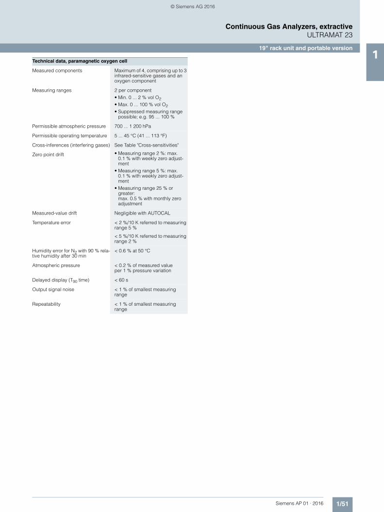
Technical data, paramagnetic oxygen cell
Measured components Maximum of 4, comprising up to 3 infrared-sensitive gases and an oxygen component
Measuring ranges 2 per component • Min. 0 ... 2 % vol O2
• Max. 0 ... 100 % vol O2
• Suppressed measuring range possible; e.g. 95 ... 100 %
Permissible atmospheric pressure 700 ... 1 200 hPa
Permissible operating temperature 5 ... 45 °C (41 ... 113 °F)
Cross-inferences (interfering gases) See Table "Cross-sensitivities"
Zero point drift • Measuring range 2 %: max. 0.1 % with weekly zero adjust-ment
• Measuring range 5 %: max. 0.1 % with weekly zero adjust-ment
• Measuring range 25 % or greater:max. 0.5 % with monthly zero adjustment
Measured-value drift Negligible with AUTOCAL
Temperature error < 2 %/10 K referred to measuring range 5 %
< 5 %/10 K referred to measuring range 2 %
Humidity error for N2 with 90 % rela-tive humidity after 30 min
< 0.6 % at 50 °C
Atmospheric pressure < 0.2 % of measured valueper 1 % pressure variation
Delayed display (T90 time) < 60 s
Output signal noise < 1 % of smallest measuring range
Repeatability < 1 % of smallest measuring range
© Siemens AG 2016

1/52 Siemens AP 01 · 2016
Continuous Gas Analyzers, extractiveULTRAMAT 23
19" rack unit and portable version1
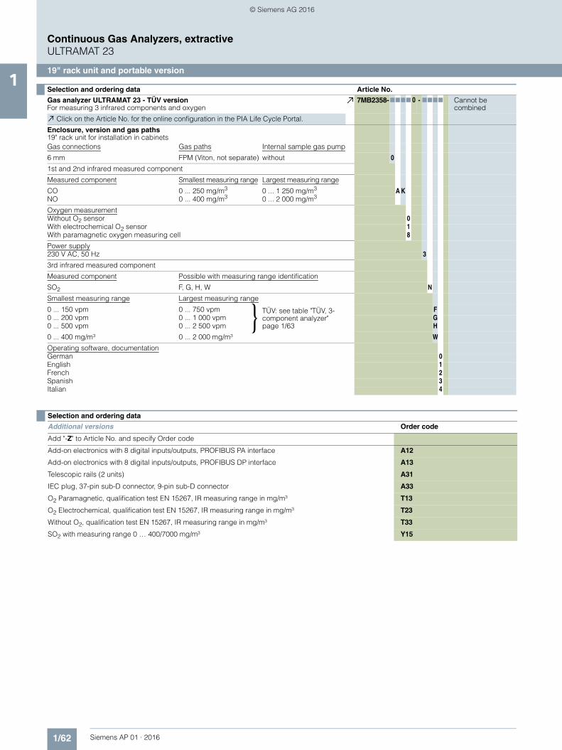
Selection and ordering data Article No.
ULTRAMAT 23 gas analyzerFor measuring 1 infrared component, oxygen and hydrogen sulfide
7MB2335-77777 - 7A A7 Cannot be combined
Click on the Article No. for the online configuration in the PIA Life Cycle Portal.
Enclosure, version and gas paths19" rack unit for installation in cabinetsGas connections Gas path Internal sample gas pump
6 mm pipe Viton Without2) 0¼" pipe Viton Without2) 1
6 mm pipe Viton With 2¼" pipe Viton With 3
6 mm pipe Stainless steel, mat. no. 1.4571 Without2) 6 6 6¼" pipe Stainless steel, mat. no. 1.4571 Without2) 7 7 7
Portable, in sheet steel enclosure, 6 mm gas connections, Viton gas path,with integrated sample gas pump, condensation trap with safety filter on the front plate
8 8 8 8 E20
Measured component Possible with measuring range identificationCO D, E, F, G ... R, U, X ACO2
1) D6), G6), H6), J6), K ... R CCH4 E, H, L, N, P, R D
C2H4 K FC6H14 K MSO2 B10), F ... L, T11), W N N
NO E, G ... J, T, V, W P PN2O7) E SSF6 H V
Smallest measuring range Largest measuring range
0 ... 200 mg/m3 0 ... 1 000 mg/m3 B0 ... 50 vpm 0 ... 250 vpm D0 ... 100 vpm 0 ... 500 vpm E0 ... 150 vpm 0 ... 750 vpm F0 ... 200 vpm 0 ... 1 000 vpm G0 ... 500 vpm 0 ... 2 500 vpm H0 ... 1 000 vpm 0 ... 5 000 vpm J0 ... 2 000 vpm 0 ... 10 000 vpm K
0 ... 0.5 % 0 ... 2.5 % L0 ... 1 % 0 ... 5 % M0 ... 2 % 0 ... 10 % N0 ... 5 % 0 ... 25 % P0 ... 10 % 0 ... 50 % Q0 ... 20 % 0 ... 100 % R
0 ... 100 mg/m³ 0 ... 750 mg/m³Prepared for QAL1 (MCERTS)
T0 ... 150 mg/m³ 0 ... 750 mg/m³ U0 ... 250 mg/m³ 0 ... 1 250 mg/m³ V0 ... 400 mg/m³ 0 ... 2 000 mg/m³ W
0 ... 50 vpm 0 ... 2 500 vpm X
Oxygen measurement5)
Without O2 sensor 0With electrochemical O2 sensor 1 1With paramagnetic oxygen measuring cell 8 8 8 8
Hydrogen sulfide measurementWithout 0With H2S sensor 0 ... 5/50 vpm 1 1 1 1
Power supply100 V AC, 50 Hz 0120 V AC, 50 Hz 1
200 V AC, 50 Hz 2230 V AC, 50 Hz 3
100 V AC, 60 Hz 4120 V AC, 60 Hz 5
230 V AC, 60 Hz 6
Operating software, documentation3)
German 0English 1French 2Spanish 3Italian 4
Footnotes: See next page.
}
© Siemens AG 2016

1/53Siemens AP 01 · 2016
Continuous Gas Analyzers, extractiveULTRAMAT 23
19" rack unit and portable version1
1) For measuring ranges below 1 %, a CO2 absorber cartridge can be used for setting the zero point (see accessories)2) Without separate zero gas input or solenoid valve3) User language can be changed4) Standard setting: smallest measuring range, largest measuring range5) O2 sensor/O2 measuring cell in gas path of infrared measured component 16) With chopper compartment purging (N2 approx. 3 000 hPa required for measuring ranges below 0.1 % CO2),
to be ordered separately (see order code C02 or C03)7) Not suitable for use with emission measurements since the cross-sensitivity is too high8) CO2 measurement in accompanying gas Ar or Ar/He (3:1); forming gas9) Only for version with Viton hose10)Not checked for suitability, maximum possible AUTOCAL cycle 6 h, constant ambient conditions (max. deviation ±1 °C (1.8 °F))11)Not checked for suitability, maximum possible AUTOCAL cycle 3 h, constant ambient conditions (max. deviation ±1 °C (1.8 °F))
Selection and ordering data
Additional versions Order code
Add "-Z" to Article No. and specify Order code
Add-on electronics with 8 digital inputs/outputs, PROFIBUS PA interface A12
Add-on electronics with 8 digital inputs/outputs, PROFIBUS DP interface A13
Telescopic rails (2 units), 19" rack unit version only A31
IEC plug, 37-pin sub-D connector, 9-pin sub-D connector A33
TAG labels (specific lettering based on customer information) B03
Gas path for short response time9) C01
Chopper compartment purging for 6 mm gas connection C02
Chopper compartment purging for ¼" gas connection C03
Presetting to reference temperature 0 °C for conversion into mg/m³, applies to all components D15
Certificate FM/CSA Class I, Div. 2, ATEX II 3 G E20
Calibration interval 5 months (QAL), measuring ranges: CO: 0 ... 150/750 mg/m³NO: 0 ... 100/750 mg/m³
E50
Measuring range indication in plain text4) Y11
Measurement of CO2 in forming gas8) (only in conjunction with measuring range 0 to 20/0 to 100 %) Y14
Accessories Article No.
CO2 absorber cartridge 7MB1933-8AA
RS 485/Ethernet converter A5E00852383
RS 485/RS 232 converter C79451-Z1589-U1
RS 485/USB converter A5E00852382
Add-on electronics with 8 digital inputs/outputs and PROFIBUS PA A5E00056834
Add-on electronics with 8 digital inputs/outputs and PROFIBUS DP A5E00057159
Set of Torx screwdrivers A5E34821625
© Siemens AG 2016

1/54 Siemens AP 01 · 2016
Continuous Gas Analyzers, extractiveULTRAMAT 23
19" rack unit and portable version1
Selection and ordering data Article No.
ULTRAMAT 23 gas analyzerFor measuring 2 infrared components, oxygen and hydrogen sulfide
7MB2337- 77777 - 7777 Cannot be combined
Click on the Article No. for the online configuration in the PIA Life Cycle Portal.
Enclosure, version and gas paths19" rack unit for installation in cabinets
Gas connections Gas paths Internal sample gas pump
6 mm pipe Viton, not separate Without2) 0¼" pipe Viton, not separate Without2) 16 mm pipe Viton, not separate With 2
¼" pipe Viton, not separate With 36 mm pipe Viton, separate Without2) 4 4 A27, A29¼" pipe Viton, separate Without2) 5 5 A27, A29
6 mm pipe Stainless steel, mat. no. 1.4571, separate Without2) 6 6 6¼" pipe Stainless steel, mat. no. 1.4571, separate Without2) 7 7 7
Portable, in sheet steel enclosure, 6 mm gas connections, Viton gas path,with integrated sample gas pump, condensation trap with safety filter on the front plate
8 8 8 8 E20
1. infrared measured component
Measured component Possible with measuring range identificationCO D, E, F, G ... R, U, X ACO2
1) D6), G6), H6), J6), K ... R CCH4 E, H, L, N, P, R D
C2H4 K FC6H14 K MSO2 B11), F ... L, T12), W N N
NO E, G ... J, T, V, W P PN2O7) E SSF6 H V
Smallest measuring range Largest measuring range
0 ... 200 mg/m3 0 ... 1 000 mg/m3 B0 ... 50 vpm 0 ... 250 vpm D0 ... 100 vpm 0 ... 500 vpm E0 ... 150 vpm 0 ... 750 vpm F0 ... 200 vpm 0 ... 1 000 vpm G0 ... 500 vpm 0 ... 2 500 vpm H0 ... 1 000 vpm 0 ... 5 000 vpm J0 ... 2 000 vpm 0 ... 10 000 vpm K
0 ... 0.5 % 0 ... 2.5 % L0 ... 1 % 0 ... 5 % M0 ... 2 % 0 ... 10 % N0 ... 5 % 0 ... 25 % P0 ... 10 % 0 ... 50 % Q0 ... 20 % 0 ... 100 % R
0 ... 100 mg/m³ 0 ... 750 mg/m³Prepared for QAL1 (MCERTS)
T0 ... 150 mg/m³ 0 ... 750 mg/m³ U0 ... 250 mg/m³ 0 ... 1 250 mg/m³ V0 ... 400 mg/m³ 0 ... 2 000 mg/m³ W
0 ... 50 vpm 0 ... 2 500 vpm X
Oxygen measurement5)
Without O2 sensor 0With electrochemical O2 sensor 1 1With paramagnetic oxygen measuring cell 8 8 8 8
Hydrogen sulfide measurementWithout 0With H2S sensor 0 ... 5/50 vpm 1 1 1 1
Power supply100 V AC, 50 Hz 0120 V AC, 50 Hz 1
200 V AC, 50 Hz 2230 V AC, 50 Hz 3
100 V AC, 60 Hz 4120 V AC, 60 Hz 5
230 V AC, 60 Hz 6
}
© Siemens AG 2016
1/55Siemens AP 01 · 2016
Continuous Gas Analyzers, extractiveULTRAMAT 23
19" rack unit and portable version1
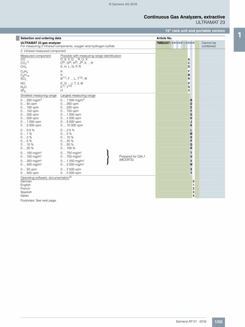
2. infrared measured component
Measured component Possible with measuring range identificationCO D, E, F, G ... R, U, X ACO2
1) D6), G6), H6), J6), K ... R CCH4 E, H, L, N, P, R D
C2H4 K FC6H14 K MSO2 B11), F ... L, T12), W N
NO E, G ... J, T, V, W PN2O E7), Y10) SSF6 H V
Smallest measuring range Largest measuring range
0 ... 200 mg/m3 0 ... 1 000 mg/m3 B0 ... 50 vpm 0 ... 250 vpm D0 ... 100 vpm 0 ... 500 vpm E0 ... 150 vpm 0 ... 750 vpm F0 ... 200 vpm 0 ... 1 000 vpm G0 ... 500 vpm 0 ... 2 500 vpm H0 ... 1 000 vpm 0 ... 5 000 vpm J0 ... 2 000 vpm 0 ... 10 000 vpm K
0 ... 0.5 % 0 ... 2.5 % L0 ... 1 % 0 ... 5 % M0 ... 2 % 0 ... 10 % N0 ... 5 % 0 ... 25 % P0 ... 10 % 0 ... 50 % Q0 ... 20 % 0 ... 100 % R
0 ... 100 mg/m³ 0 ... 750 mg/m³Prepared for QAL1 (MCERTS)
T0 ... 150 mg/m³ 0 ... 750 mg/m³ U0 ... 250 mg/m³ 0 ... 1 250 mg/m³ V0 ... 400 mg/m³ 0 ... 2 000 mg/m³ W
0 ... 50 vpm 0 ... 2 500 vpm X0 ... 500 vpm 0 ... 5 000 vpm Y
Operating software, documentation3)
German 0English 1French 2Spanish 3Italian 4
Footnotes: See next page.
Selection and ordering data Article No.
ULTRAMAT 23 gas analyzerFor measuring 2 infrared components, oxygen and hydrogen sulfide
7MB2337- 77777 - 7777 Cannot be combined
}
© Siemens AG 2016

1/56 Siemens AP 01 · 2016
Continuous Gas Analyzers, extractiveULTRAMAT 23
19" rack unit and portable version1
■ Selection and ordering data
1) For measuring ranges below 1 %, a CO2 absorber cartridge can be used for setting the zero point (see accessories)2) Without separate zero gas input or solenoid valve3) User language can be changed4) Standard setting: smallest measuring range, largest measuring range5) O2 sensor/O2 measuring cell in gas path of infrared measured component 16) With chopper compartment purging (N2 approx. 3 000 hPa required for measuring ranges below 0.1 % CO2),
to be ordered separately (see order code C02 or C03)7) Not suitable for use with emission measurements since the cross-sensitivity is too high8) CO2 measurement in accompanying gas Ar or Ar/He (3:1); forming gas 9) Only for version with Viton hose10)Only in conjunction with CO2 measuring range 0 to 5 % to 0 to 25 % (CP)11)Not checked for suitability, maximum possible AUTOCAL cycle 6 h, constant ambient conditions (max. deviation ±1 °C (1.8 °F)12)Not checked for suitability, maximum possible AUTOCAL cycle 3 h, constant ambient conditions (max. deviation ±1 °C (1.8 °F))
Additional versions Order code
Add "-Z" to Article No. and specify Order code
Add-on electronics with 8 digital inputs/outputs, PROFIBUS PA interface A12
Add-on electronics with 8 digital inputs/outputs, PROFIBUS DP interface A13
Stainless steel (mat. no. 1.4571) connection pipe, 6 mm, complete with screwed gland(cannot be combined with Viton hose)
A27
Stainless steel (mat. no. 1.4571) connection pipe, ¼", complete with screwed gland(cannot be combined with Viton hose)
A29
Telescopic rails (2 units, 19" rack unit version only) A31
IEC plug, 37-pin sub-D connector, 9-pin sub-D connector A33
TAG labels (specific lettering based on customer information) B03
Gas path for short response time9) C01
Chopper compartment purging for 6 mm gas connection C02
Chopper compartment purging for ¼" gas connection C03
Application with paramagnetic oxygen measuring cell and separate gas path C11
Presetting to reference temperature 0 °C for conversion into mg/m³, applies to all components D15
Measuring range indication in plain text4) Y11
Measurement of CO2 in forming gas8) (only in conjunction with measuring range 0 to 20/0 to 100 %)
Y14
Certificate FM/CSA Class I, Div. 2, ATEX II 3 G E20
Calibration interval 5 months (QAL), measuring ranges: CO: 0 ... 150/750 mg/m³NO: 0 ... 100/750 mg/m³
E50
Accessories Article No.
CO2 absorber cartridge 7MB1933-8AA
RS 485/Ethernet converter A5E00852383RS 485/RS 232 converter C79451-Z1589-U1RS 485/USB converter A5E00852382
Add-on electronics with 8 digital inputs/outputs and PROFIBUS PA A5E00056834
Add-on electronics with 8 digital inputs/outputs and PROFIBUS DP A5E00057159
Set of Torx screwdrivers A5E34821625
© Siemens AG 2016
1/57Siemens AP 01 · 2016
Continuous Gas Analyzers, extractiveULTRAMAT 23
19" rack unit and portable version1
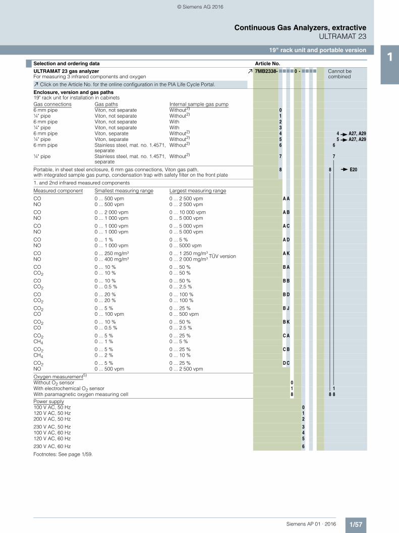
Selection and ordering data Article No.
ULTRAMAT 23 gas analyzerFor measuring 3 infrared components and oxygen
7MB2338- 7777 0 - 7777 Cannot be combined
Click on the Article No. for the online configuration in the PIA Life Cycle Portal.
Enclosure, version and gas paths19" rack unit for installation in cabinetsGas connections Gas paths Internal sample gas pump6 mm pipe Viton, not separate Without2) 0¼" pipe Viton, not separate Without2) 16 mm pipe Viton, not separate With 2¼" pipe Viton, not separate With 36 mm pipe Viton, separate Without2) 4 4 A27, A29¼" pipe Viton, separate Without2) 5 5 A27, A296 mm pipe Stainless steel, mat. no. 1.4571,
separateWithout2) 6 6
¼" pipe Stainless steel, mat. no. 1.4571, separate
Without2) 7 7
Portable, in sheet steel enclosure, 6 mm gas connections, Viton gas path,with integrated sample gas pump, condensation trap with safety filter on the front plate
8 8 E20
1. and 2nd infrared measured components
Measured component Smallest measuring range Largest measuring range
CO 0 ... 500 vpm 0 ... 2 500 vpm A ANO 0 ... 500 vpm 0 ... 2 500 vpm
CO 0 ... 2 000 vpm 0 ... 10 000 vpm A BNO 0 ... 1 000 vpm 0 ... 5 000 vpm
CO 0 ... 1 000 vpm 0 ... 5 000 vpm A CNO 0 ... 1 000 vpm 0 ... 5 000 vpm
CO 0 ... 1 % 0 ... 5 % A DNO 0 ... 1 000 vpm 0 ... 5000 vpm
CO 0 ... 250 mg/m³ 0 ... 1 250 mg/m³ TÜV version A KNO 0 ... 400 mg/m³ 0 ... 2 000 mg/m³
CO 0 ... 10 % 0 ... 50 % B ACO2 0 ... 10 % 0 ... 50 %
CO 0 ... 10 % 0 ... 50 % B BCO2 0 ... 0.5 % 0 ... 2,5 %
CO 0 ... 20 % 0 ... 100 % B DCO2 0 ... 20 % 0 ... 100 %
CO2 0 ... 5 % 0 ... 25 % B JCO 0 ... 100 vpm 0 ... 500 vpm
CO2 0 ... 10 % 0 ... 50 % B KCO 0 ... 0.5 % 0 ... 2.5 %
CO2 0 ... 5 % 0 ... 25 % C ACH4 0 ... 1 % 0 ... 5 %
CO2 0 ... 5 % 0 ... 25 % C BCH4 0 ... 2 % 0 ... 10 %
CO2 0 ... 5 % 0 ... 25 % D CNO 0 ... 500 vpm 0 ... 2 500 vpm
Oxygen measurement5)
Without O2 sensor 0With electrochemical O2 sensor 1 1With paramagnetic oxygen measuring cell 8 8 8Power supply100 V AC, 50 Hz 0120 V AC, 50 Hz 1200 V AC, 50 Hz 2
230 V AC, 50 Hz 3100 V AC, 60 Hz 4120 V AC, 60 Hz 5
230 V AC, 60 Hz 6
Footnotes: See page 1/59.
© Siemens AG 2016
1/58 Siemens AP 01 · 2016
Continuous Gas Analyzers, extractiveULTRAMAT 23
19" rack unit and portable version1
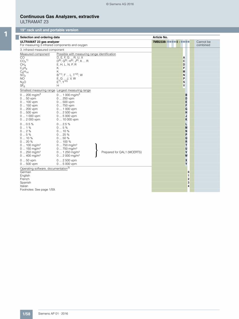
3. infrared measured componentMeasured component Possible with measuring range identificationCO D, E, F, G ... R, U, X ACO2
1) D6), G6), H6), J6), K ... R CCH4 E, H, L, N, P, R DC2H4 K FC6H14 K MSO2 B11), F ... L, T12), W NNO E, G ... J, V, W PN2O E7), Y10) SSF6 H V
Smallest measuring range Largest measuring range
0 ... 200 mg/m3 0 ... 1 000 mg/m3 B0 ... 50 vpm 0 ... 250 vpm D0 ... 100 vpm 0 ... 500 vpm E0 ... 150 vpm 0 ... 750 vpm F0 ... 200 vpm 0 ... 1 000 vpm G0 ... 500 vpm 0 ... 2 500 vpm H0 ... 1 000 vpm 0 ... 5 000 vpm J0 ... 2 000 vpm 0 ... 10 000 vpm K
0 ... 0.5 % 0 ... 2.5 % L0 ... 1 % 0 ... 5 % M0 ... 2 % 0 ... 10 % N0 ... 5 % 0 ... 25 % P0 ... 10 % 0 ... 50 % Q0 ... 20 % 0 ... 100 % R0 ... 100 mg/m³ 0 ... 750 mg/m³ T0 ... 150 mg/m³ 0 ... 750 mg/m³
Prepared for QAL1 (MCERTS) U
0 ... 250 mg/m³ 0 ... 1 250 mg/m³ V0 ... 400 mg/m³ 0 ... 2 000 mg/m³ W
0 ... 50 vpm 0 ... 2 500 vpm X0 ... 500 vpm 0 ... 5 000 vpm Y
Operating software, documentation3)
German 0English 1French 2Spanish 3Italian 4Footnotes: See page 1/59.
Selection and ordering data Article No.
ULTRAMAT 23 gas analyzerFor measuring 3 infrared components and oxygen
7MB2338- 7777 0 - 7777 Cannot be combined
}
© Siemens AG 2016

1/59Siemens AP 01 · 2016
Continuous Gas Analyzers, extractiveULTRAMAT 23
19" rack unit and portable version1
■ Selection and ordering data
1) For measuring ranges below 1 %, a CO2 absorber cartridge can be used for setting the zero point (see accessories)2) Without separate zero gas input or solenoid valve3) User language can be changed4) Standard setting: smallest measuring range, largest measuring range5) O2 sensor/O2 measuring cell in gas path of infrared measured component 16) With chopper compartment purging (N2 approx. 3 000 hPa required for measuring ranges below 0.1 % CO2),
to be ordered separately (see order code C02 or C03)7) Not suitable for use with emission measurements since the cross-sensitivity is too high8) CO2 measurement in accompanying gas Ar or Ar/He (3:1); forming gas9) Only for version with Viton hose10)Only in combination with CO2/NO, measuring range 0 to 5/25 %, 0 to 500/5 000 vpm [-DC-]11)Not checked for suitability, maximum possible AUTOCAL cycle 6 h, constant ambient conditions (max. deviation ±1 °C (1.8 °F))12)Not checked for suitability, maximum possible AUTOCAL cycle 3 h, constant ambient conditions (max. deviation ±1 °C (1.8 °F))
Additional versions Order code
Add "-Z" to Article No. and specify Order code
Add-on electronics with 8 digital inputs/outputs, PROFIBUS PA interface A12
Add-on electronics with 8 digital inputs/outputs, PROFIBUS DP interface A13
Stainless steel (mat. no. 1.4571) connection pipe, 6 mm, complete with screwed gland(cannot be combined with Viton hose)
A27
Stainless steel (mat. no. 1.4571) connection pipe, ¼", complete with screwed gland(cannot be combined with Viton hose)
A29
Telescopic rails (2 units, 19" rack unit version only) A31
IEC plug, 37-pin sub-D connector, 9-pin sub-D connector A33
TAG labels (specific lettering based on customer information) B03Gas path for short response time9) C01
Chopper compartment purging for 6 mm gas connection C02
Chopper compartment purging for ¼" gas connection C03
Application with paramagnetic oxygen measuring cell and separate gas path C11
Presetting to reference temperature 0 °C for conversion into mg/m³, applies to all components D15
Certificate FM/CSA Class I, Div. 2, ATEX II 3 G E20
Measuring range indication in plain text4) Y11
Measurement of CO2 in forming gas8) (only in conjunction with measuring range 0 to 20/0 to 100 %)
Y14
Accessories Article No.
CO2 absorber cartridge 7MB1933-8AA
RS 485/Ethernet converter A5E00852383
RS 485/RS 232 converter C79451-Z1589-U1
RS 485/USB converter A5E00852382
Add-on electronics with 8 digital inputs/outputs and PROFIBUS PA A5E00056834
Add-on electronics with 8 digital inputs/outputs and PROFIBUS DP A5E00057159
Set of Torx screwdrivers A5E34821625
© Siemens AG 2016
1/60 Siemens AP 01 · 2016
Continuous Gas Analyzers, extractiveULTRAMAT 23
19" rack unit and portable version1
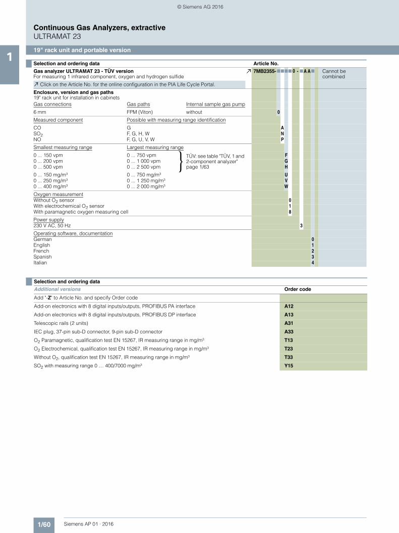
Selection and ordering data Article No.
Gas analyzer ULTRAMAT 23 - TÜV versionFor measuring 1 infrared component, oxygen and hydrogen sulfide
7MB2355-7777 00 - 7A A7 Cannot be combined
Click on the Article No. for the online configuration in the PIA Life Cycle Portal.
Enclosure, version and gas paths19" rack unit for installation in cabinetsGas connections Gas paths Internal sample gas pump
6 mm FPM (Viton) without 0
Measured component Possible with measuring range identification
CO G ASO2 F, G, H, W NNO F, G, U, V, W P
Smallest measuring range Largest measuring range
0 ... 150 vpm 0 ... 750 vpm TÜV: see table "TÜV, 1 and 2-component analyzer" page 1/63
F0 ... 200 vpm 0 ... 1 000 vpm G0 ... 500 vpm 0 ... 2 500 vpm H
0 ... 150 mg/m³ 0 ... 750 mg/m³ U0 ... 250 mg/m³ 0 ... 1 250 mg/m³ V0 ... 400 mg/m³ 0 ... 2 000 mg/m³ W
Oxygen measurementWithout O2 sensor 0With electrochemical O2 sensor 1With paramagnetic oxygen measuring cell 8
Power supply230 V AC, 50 Hz 3
Operating software, documentationGerman 0English 1French 2Spanish 3Italian 4
}
Selection and ordering data
Additional versions Order code
Add "-Z" to Article No. and specify Order code
Add-on electronics with 8 digital inputs/outputs, PROFIBUS PA interface A12
Add-on electronics with 8 digital inputs/outputs, PROFIBUS DP interface A13
Telescopic rails (2 units) A31
IEC plug, 37-pin sub-D connector, 9-pin sub-D connector A33
O2 Paramagnetic, qualification test EN 15267, IR measuring range in mg/m³ T13
O2 Electrochemical, qualification test EN 15267, IR measuring range in mg/m³ T23
Without O2, qualification test EN 15267, IR measuring range in mg/m³ T33
SO2 with measuring range 0 … 400/7000 mg/m³ Y15
© Siemens AG 2016
1/61Siemens AP 01 · 2016
Continuous Gas Analyzers, extractiveULTRAMAT 23
19" rack unit and portable version1
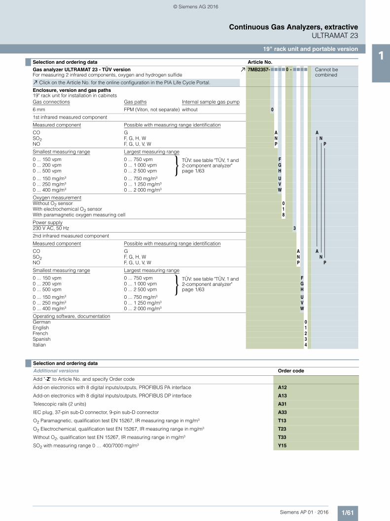
Selection and ordering data Article No.
Gas analyzer ULTRAMAT 23 - TÜV versionFor measuring 2 infrared components, oxygen and hydrogen sulfide
7MB2357-7777 00 - 7777 Cannot be combined
Click on the Article No. for the online configuration in the PIA Life Cycle Portal.
Enclosure, version and gas paths19" rack unit for installation in cabinetsGas connections Gas paths Internal sample gas pump
6 mm FPM (Viton, not separate) without 0
1st infrared measured component
Measured component Possible with measuring range identification
CO G A ASO2 F, G, H, W N NNO F, G, U, V, W P P
Smallest measuring range Largest measuring range
0 ... 150 vpm 0 ... 750 vpm TÜV: see table "TÜV, 1 and 2-component analyzer" page 1/63
F0 ... 200 vpm 0 ... 1 000 vpm G0 ... 500 vpm 0 ... 2 500 vpm H
0 ... 150 mg/m³ 0 ... 750 mg/m³ U0 ... 250 mg/m³ 0 ... 1 250 mg/m³ V0 ... 400 mg/m³ 0 ... 2 000 mg/m³ W
Oxygen measurementWithout O2 sensor 0With electrochemical O2 sensor 1With paramagnetic oxygen measuring cell 8
Power supply230 V AC, 50 Hz 3
2nd infrared measured component
Measured component Possible with measuring range identification
CO G A ASO2 F, G, H, W N NNO F, G, U, V, W P P
Smallest measuring range Largest measuring range
0 ... 150 vpm 0 ... 750 vpm TÜV: see table "TÜV, 1 and 2-component analyzer" page 1/63
F0 ... 200 vpm 0 ... 1 000 vpm G0 ... 500 vpm 0 ... 2 500 vpm H
0 ... 150 mg/m³ 0 ... 750 mg/m³ U0 ... 250 mg/m³ 0 ... 1 250 mg/m³ V0 ... 400 mg/m³ 0 ... 2 000 mg/m³ W
Operating software, documentationGerman 0English 1French 2Spanish 3Italian 4
}
}
Selection and ordering data
Additional versions Order code
Add "-Z" to Article No. and specify Order code
Add-on electronics with 8 digital inputs/outputs, PROFIBUS PA interface A12
Add-on electronics with 8 digital inputs/outputs, PROFIBUS DP interface A13
Telescopic rails (2 units) A31
IEC plug, 37-pin sub-D connector, 9-pin sub-D connector A33
O2 Paramagnetic, qualification test EN 15267, IR measuring range in mg/m³ T13
O2 Electrochemical, qualification test EN 15267, IR measuring range in mg/m³ T23
Without O2, qualification test EN 15267, IR measuring range in mg/m³ T33
SO2 with measuring range 0 … 400/7000 mg/m³ Y15
© Siemens AG 2016
1/62 Siemens AP 01 · 2016
Continuous Gas Analyzers, extractiveULTRAMAT 23
19" rack unit and portable version1
Selection and ordering data Article No.
Gas analyzer ULTRAMAT 23 - TÜV versionFor measuring 3 infrared components and oxygen
7MB2358-7777 00 - 7777 Cannot be combined
Click on the Article No. for the online configuration in the PIA Life Cycle Portal.
Enclosure, version and gas paths19" rack unit for installation in cabinetsGas connections Gas paths Internal sample gas pump
6 mm FPM (Viton, not separate) without 0
1st and 2nd infrared measured component
Measured component Smallest measuring range Largest measuring range
CO 0 ... 250 mg/m3 0 ... 1 250 mg/m3 A KNO 0 ... 400 mg/m3 0 ... 2 000 mg/m3
Oxygen measurementWithout O2 sensor 0With electrochemical O2 sensor 1With paramagnetic oxygen measuring cell 8
Power supply230 V AC, 50 Hz 3
3rd infrared measured component
Measured component Possible with measuring range identification
SO2 F, G, H, W N
Smallest measuring range Largest measuring range
0 ... 150 vpm 0 ... 750 vpm TÜV: see table "TÜV, 3-component analyzer" page 1/63
F0 ... 200 vpm 0 ... 1 000 vpm G0 ... 500 vpm 0 ... 2 500 vpm H
0 ... 400 mg/m³ 0 ... 2 000 mg/m³ W
Operating software, documentationGerman 0English 1French 2Spanish 3Italian 4
}
Selection and ordering data
Additional versions Order code
Add "-Z" to Article No. and specify Order code
Add-on electronics with 8 digital inputs/outputs, PROFIBUS PA interface A12
Add-on electronics with 8 digital inputs/outputs, PROFIBUS DP interface A13
Telescopic rails (2 units) A31
IEC plug, 37-pin sub-D connector, 9-pin sub-D connector A33
O2 Paramagnetic, qualification test EN 15267, IR measuring range in mg/m³ T13
O2 Electrochemical, qualification test EN 15267, IR measuring range in mg/m³ T23
Without O2, qualification test EN 15267, IR measuring range in mg/m³ T33
SO2 with measuring range 0 … 400/7000 mg/m³ Y15
© Siemens AG 2016
1/63Siemens AP 01 · 2016
Continuous Gas Analyzers, extractiveULTRAMAT 23
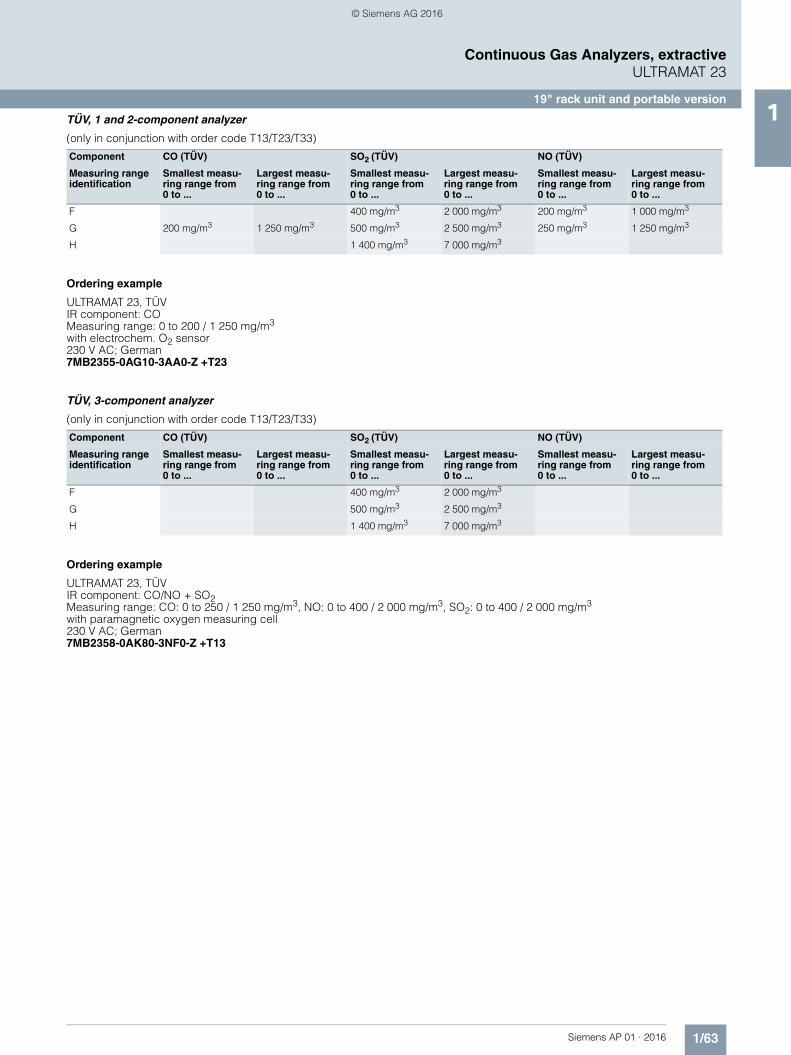
19" rack unit and portable version1TÜV, 1 and 2-component analyzer
(only in conjunction with order code T13/T23/T33)
Ordering example
ULTRAMAT 23, TÜVIR component: COMeasuring range: 0 to 200 / 1 250 mg/m3
with electrochem. O2 sensor230 V AC; German7MB2355-0AG10-3AA0-Z +T23
TÜV, 3-component analyzer
(only in conjunction with order code T13/T23/T33)
Ordering example
ULTRAMAT 23, TÜVIR component: CO/NO + SO2Measuring range: CO: 0 to 250 / 1 250 mg/m3, NO: 0 to 400 / 2 000 mg/m3, SO2: 0 to 400 / 2 000 mg/m3
with paramagnetic oxygen measuring cell230 V AC; German7MB2358-0AK80-3NF0-Z +T13
Component CO (TÜV) SO2 (TÜV) NO (TÜV)
Measuring range identification
Smallest measu-ring range from 0 to ...
Largest measu-ring range from 0 to ...
Smallest measu-ring range from 0 to ...
Largest measu-ring range from 0 to ...
Smallest measu-ring range from 0 to ...
Largest measu-ring range from 0 to ...
F 400 mg/m3 2 000 mg/m3 200 mg/m3 1 000 mg/m3
G 200 mg/m3 1 250 mg/m3 500 mg/m3 2 500 mg/m3 250 mg/m3 1 250 mg/m3
H 1 400 mg/m3 7 000 mg/m3
Component CO (TÜV) SO2 (TÜV) NO (TÜV)
Measuring range identification
Smallest measu-ring range from 0 to ...
Largest measu-ring range from 0 to ...
Smallest measu-ring range from 0 to ...
Largest measu-ring range from 0 to ...
Smallest measu-ring range from 0 to ...
Largest measu-ring range from 0 to ...
F 400 mg/m3 2 000 mg/m3
G 500 mg/m3 2 500 mg/m3
H 1 400 mg/m3 7 000 mg/m3
© Siemens AG 2016

1/64 Siemens AP 01 · 2016
Continuous Gas Analyzers, extractiveULTRAMAT 23
19" rack unit and portable version1 Ordering notes
Special selection rules must be observed when measuring some components.
Measured component N2O
7MB2335, 7MB2337 and 7MB2338 (application: Si chip production)• Measuring range 0 to 100 / 500 vpm (MB designation "E")• Can only be used to measure N2O in ultra-pure gases
7MB2337 and 7MB2338 (application: measurement in accordance with the requirements of the Kyoto protocol)• Measuring range 0 to 500 / 5 000 vpm (MB designation "Y")• Requires simultaneous measurement of CO2 for correction of
cross-interference
7MB2337-*CP*0-*SY* or7MB2338-*DC*0-*SY* (including NO measurement)
7MB2337 and 7MB2338 (application with paramagnetic oxygen measuring cell and separate gas path)
7MB2337-4**80-**** - Z + C117MB2337-5**80-**** - Z + C11
7MB2338-4**80-**** - Z + C117MB2338-5**80-**** - Z + C11
Measured component SF6
7MB2335, 7MB2337 and 7MB2338 (application: SI chip production)• Measuring range 0 to 500 / 2 500 vpm (MB designation "H")• Can only be used to measure SF6 in inert gases
Calibration interval ((MCERTS versions 7MB2335, 7MB2337, 7MB2338)
Calibration interval (TÜV versions 7MB2355, 7MB2357, 7MB2358)
Calibration intervals, standard devices
Component Smallest measuring range Calibration interval Remarks Z suffix
CO 0 … 150 mg/m³ 5 months IED 2010/75/EC E50
CO 0 … 250 mg/m³ 12 months IED 2010/75/EC
NO 0 … 100 mg/m³ 5 months IED 2010/75/EC
NO 0 … 250 mg/m³ 12 months IED 2010/75/EC
SO2 0 … 400 mg/m³ 12 months IED 2010/75/EC
N2O 0 … 500 vpm Kyoto protocol
N2O 0 … 50 mg/m³ 6 months IED 2010/75/EC
Component Smallest measuring range Calibration interval Remarks Z suffix
CO 0 … 200 mg/m³ 1 month 13th/27th BImSchV T13/T23/T33
NO 0 … 150 mg/m³ 1 month 13th/27th BImSchV T13/T23/T33
SO2 0 … 400 mg/m³ 1 month 13th/27th BImSchV T13/T23/T33
AUTOCAL(ambient air)
AUTOCAL(inert gas e.g. N2)
Calibration with calibration gas Comment (keep to technical
specs)Zero point Calibration point Zero point Calibration point Zero point Calibration point
Hours Weeks
IR components 3 ... 24 3 ... 24 o 52
O2 - electrical chemical sensor
Stable 3 ... 24 Stable - 52 o
O2 paramagnetic Cell
- 3 ... 24 x x 1 o at MB < 5 %
- 3 ... 24 x x 8 o at MB > 5 %
O2 paramagnetic Cell
x x 3 ... 24 - o 52 at MB < 5 %
x x 3 ... 24 - o 52 at MB > 5 %
H2S sensor 3 - 3 - o 4
o = with AUTOCAL, x = not applicable
© Siemens AG 2016
1/65Siemens AP 01 · 2016
Continuous Gas Analyzers, extractiveULTRAMAT 23
19" rack unit and portable version1
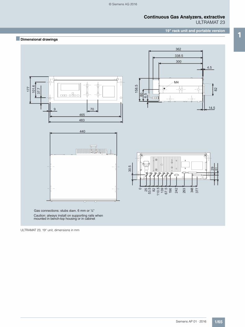
■ Dimensional drawings
ULTRAMAT 23, 19“ unit, dimensions in mm
© Siemens AG 2016

1/66 Siemens AP 01 · 2016
Continuous Gas Analyzers, extractiveULTRAMAT 23
19" rack unit and portable version1
ULTRAMAT 23, desktop unit, dimensions in mm
2357
© Siemens AG 2016
1/67Siemens AP 01 · 2016
Continuous Gas Analyzers, extractiveULTRAMAT 23
19" rack unit and portable version1
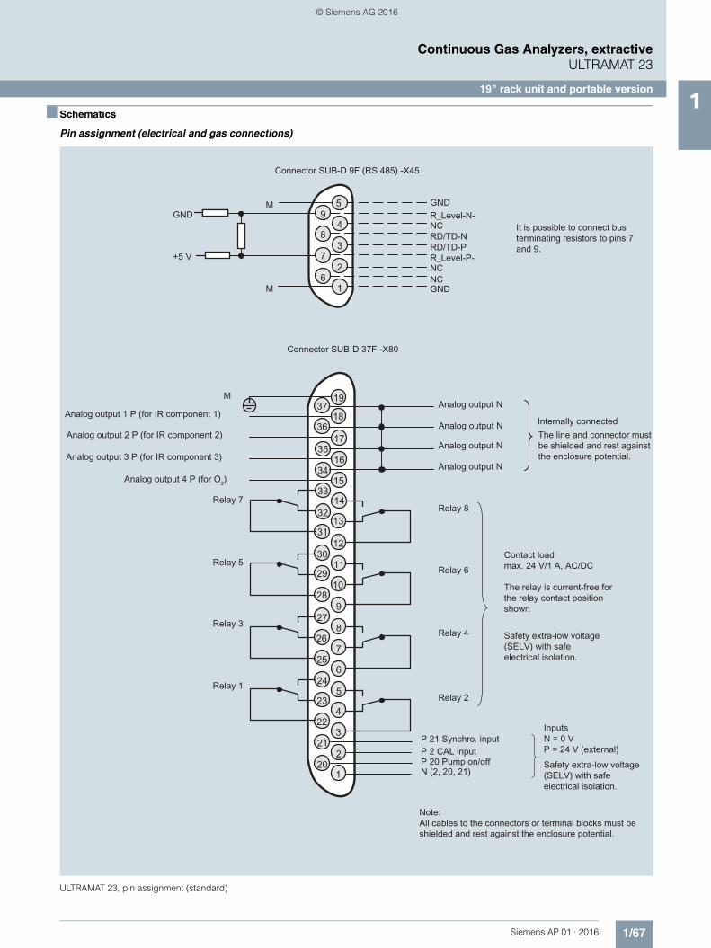
■ Schematics
Pin assignment (electrical and gas connections)
ULTRAMAT 23, pin assignment (standard)
© Siemens AG 2016
1/68 Siemens AP 01 · 2016
Continuous Gas Analyzers, extractiveULTRAMAT 23
19" rack unit and portable version1
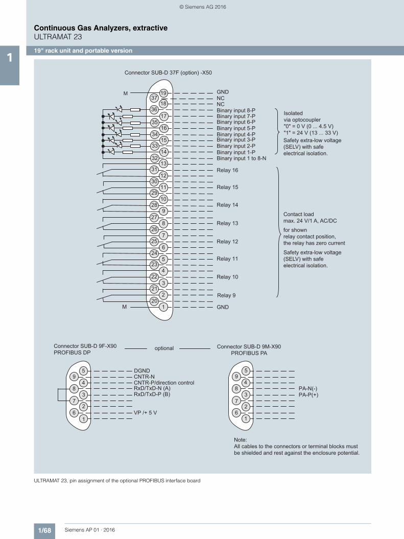
ULTRAMAT 23, pin assignment of the optional PROFIBUS interface board
37
36
35
34
33
29
30
31
32
18
17
16
14
13
12
11
10
9
8
7
6
5
28
27
26
25
24
4
3
2
1
23
22
21
20
19
15
1
2
3
4
5
6
7
8
9
1
2
3
4
5
6
7
8
9
M
M
Connector SUB-D 9F-X90PROFIBUS DP
VP /+ 5 V
DGND
RxD/TxD-P (B)
CNTR-P/direction control
Connector SUB-D 9M-X90PROFIBUS PA
PA-P(+)PA-N(-)
optional
Contact loadmax. 24 V/1 A, AC/DC
for shownrelay contact position,the relay has zero current
Isolatedvia optocoupler"0" = 0 V (0 ... 4.5 V)"1" = 24 V (13 ... 33 V)
Safety extra-low voltage (SELV) with safe electrical isolation.
Safety extra-low voltage (SELV) with safe electrical isolation.
GND
Relay 11
Relay 12
Relay 13
Relay 14
Relay 15
Relay 16
Relay 9
Relay 10
Binary input 8-PNCNC
GND
Binary input 7-PBinary input 6-PBinary input 5-PBinary input 4-PBinary input 3-PBinary input 2-PBinary input 1-PBinary input 1 to 8-N
Connector SUB-D 37F (option) -X50
CNTR-N
RxD/TxD-N (A)
Note:All cables to the connectors or terminal blocks must be shielded and rest against the enclosure potential.
© Siemens AG 2016
1/69Siemens AP 01 · 2016
Continuous Gas Analyzers, extractiveULTRAMAT 23
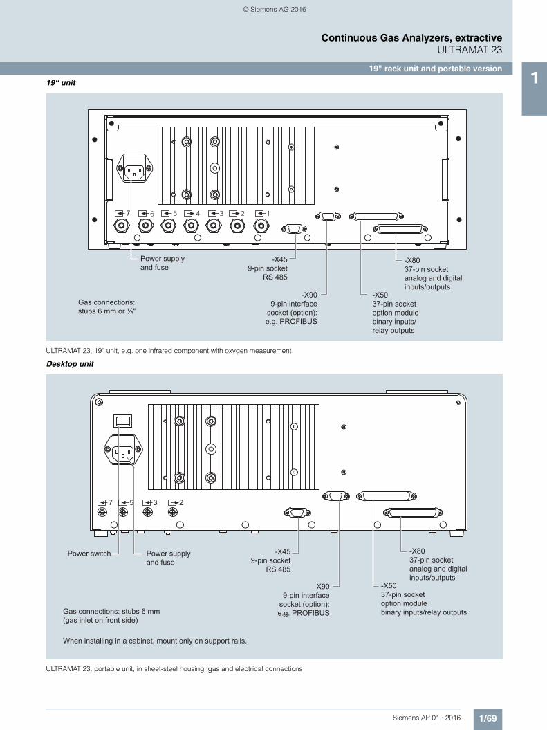
19" rack unit and portable version119“ unit
ULTRAMAT 23, 19“ unit, e.g. one infrared component with oxygen measurement
Desktop unit
ULTRAMAT 23, portable unit, in sheet-steel housing, gas and electrical connections
2 134567
Power supplyand fuse
Gas connections: stubs 6 mm or ¼"
-X459-pin socket
RS 485
-X909-pin interface
socket (option): e.g. PROFIBUS
-X5037-pin socketoption modulebinary inputs/relay outputs
-X8037-pin socketanalog and digitalinputs/outputs
57 3 2
-X8037-pin socketanalog and digitalinputs/outputs
-X5037-pin socketoption modulebinary inputs/relay outputs
-X459-pin socket
RS 485
Power switch Power supplyand fuse
-X909-pin interface
socket (option): e.g. PROFIBUSGas connections: stubs 6 mm
(gas inlet on front side)
When installing in a cabinet, mount only on support rails.
© Siemens AG 2016

1/70 Siemens AP 01 · 2016
Continuous Gas Analyzers, extractiveULTRAMAT 23
19" rack unit and portable version1
ULTRAMAT 23, designation of the different labels
1
2
3
4
5
6
7
1
2
3
4
5
6
7
1
2
3
4
5
6
7
2
3
5
7
Messgas/Prüfgas 1Sample gas/Span gasGaz de mesure/d’ajustage 1
Messgas/Prüfgas 2Sample gas/Span gas 2Gaz de mesure/d’ajustage 2
GehäusebespülungEnclosure purgeBalayage de l’appareilatmosphärischer Druckaufnehmeratmospherical pressure transducercapteur de pression atmosphériqueChopperraumbespülungChopper purgeBalayage de l’obturateur
Messgas/PrüfgasSample gas/Span gasGaz de mesure/d’ajustage
nicht belegtnot usednon utilisé
GehäusebespülungEnclosure purgeBalayage de l’appareilatmosphärischer Druckaufnehmeratmospherical pressure transducercapteur de pression atmosphériqueChopperraumbespülungChopper purgeBalayage de l’obturateur
Messgas/PrüfgasSample gas/Span gasGaz de mesure/d’ajustage
nicht belegtnot usednon utilisé
GehäusebespülungEnclosure purgeBalayage de l’appareilatmosphärischer Druckaufnehmeratmospherical pressure transducercapteur de pression atmosphériqueChopperraumbespülungChopper purgeBalayage de l’obturateur
AUTOCAL-Gas/NullgasAUTOCAL gas/Zero gasGaz AUTOCAL/zéro
Messgas/PrüfgasSample gas/Span gasGaz de mesure/d’ajustage
GehäusebespülungEnclosure purgeBalayage de l’appareil
ChopperraumbespülungChopper purgeBalayage de l’obturateur
AUTOCAL-Gas/NullgasAUTOCAL gas/Zero gasGaz AUTOCAL/zéro
Key to symbolsULTRAMAT 2319” rack unitwith two separategas paths or pipe version
Key to symbolsULTRAMAT 2319” rack unitwithout sample gas pump
Key to symbolsULTRAMAT 2319” rack unitwith sample gas pump
Key to symbolsULTRAMAT 23portable, in sheet-steel housing
© Siemens AG 2016

1/71Siemens AP 01 · 2016
Continuous Gas Analyzers, extractiveULTRAMAT 23
Documentation1
■ Selection and ordering data
■ Selection and ordering data
Operating instructions Article No.
ULTRAMAT 23Gas analyzer for IR-absorbing gases and oxygen
• German C79000-B5200-C216
• English C79000-B5276-C216
• French C79000-B5277-C216
• Spanish C79000-B5278-C216
• Italian C79000-B5272-C216
Suggestions for spare parts
Description Quantity for 2 years
Quantity for 5 years
Article No.
Analyzer unit
O-ring for analyzer chamber: 180, 90, 60, 20 mm 2 4 C71121-Z100-A99
Chopper
• With motor, for 1 IR channel (7MB2335-...) 1 1 C79451-A3468-B515
• With motor, for 2 IR channels (7MB2337-..., 7MB2338-...) 1 1 C79451-A3468-B516
Electronics
Motherboard, with firmware - 1 C79451-A3494-D501
Keypad 1 1 C79451-A3492-B605
LCD module 1 1 C79451-A3494-B16
Connector filter - 1 W75041-E5602-K2
Line switch (portable analyzer) - 1 W75050-T1201-U101
Fusible element 220 ... 240 V 2 4 W79054-L1010-T630
Fusible element 100 ... 120 V 2 4 W79054-L1011-T125
Other
Safety filter (zero gas), internal 2 2 C79127-Z400-A1
Safety filter (sample gas), internal 2 3 C79127-Z400-A1
Pressure switch 1 2 C79302-Z1210-A2
Flowmeter 1 2 C79402-Z560-T1
Set of gaskets for sample gas pump 2 5 C79402-Z666-E20
Condensation trap (for portable unit, in sheet steel enclosure) 1 2 C79451-A3008-B43
Filter (for portable unit, in sheet steel enclosure) 1 2 C79451-A3008-B60
Oxygen sensor 1 1 C79451-A3458-B55
Sample gas pump 50 Hz 1 1 C79451-A3494-B10
Sample gas pump 60 Hz 1 1 C79451-A3494-B11
Solenoid valve 1 1 C79451-A3494-B33
© Siemens AG 2016
Related Documents