1/71 Siemens AP 01 · 2018 Extractive continuous process gas analysis Series 6 ULTRAMAT/OXYMAT 6 General information 1 ■ Overview The ULTRAMAT/OXYMAT 6 gas analyzer is a practical combina- tion of the ULTRAMAT 6 and OXYMAT 6 analyzers in a single en- closure. The ULTRAMAT 6 channel operates according to the NDIR two- beam alternating light principle and measures one or two gases highly selectively whose absorption bands lie in the infrared wavelength range from 2 to 9 m, such as CO, CO 2 , NO, SO 2 , NH 3 , H 2 O as well as CH 4 and other hydrocarbons. The OXYMAT 6 channel is based on the paramagnetic alternat- ing pressure method and is used to measure oxygen in gases. ■ Benefits • Corrosion-resistant materials in gas path (option) - Measurement possible in highly corrosive sample gases • Sample chambers can be cleaned as required on site - Cost savings due to reuse after contamination • Open interface architecture (RS 485, RS 232, PROFIBUS) • SIPROM GA network for maintenance and servicing infor- mation (option) ULTRAMAT channel • High selectivity with double-layer detector and optical coupler - Reliable measurements even in complex gas mixtures • Low detection limits - Measurements with low concentrations OXYMAT channel • Paramagnetic alternating pressure principle - Small measuring ranges (0 to 0.5% or 99.5 to 100% O 2 ) - Absolute linearity • Detector element has no contact with the sample gas - Can be used to measure corrosive gases - Long service life • Physically suppressed zero through suitable selection of reference gas (air or O 2 ), e.g. 98 to 100% O 2 for purity monitoring/air separation ■ Application Fields of application • Measurement for boiler control in incineration plants • Emission measurements in incineration plants • Measurement in the automotive industry (test benches) • Process gas concentrations in chemical plants • Trace measurements in pure gas processes • Environmental protection • TLV (Threshold Limit Value) monitoring at the workplace • Quality monitoring Special versions Special applications Besides the standard combinations, special applications con- cerning material in the gas path, material in the sample cham- bers (e.g. titanium, Hastelloy C22) and measured components are available on request. Performance-tested version / QAL For measurements of CO, NO, SO 2 and O 2 according to 13th and 27th BlmSchV and TA Luft, performance-tested versions according to EN 15267 of the ULTRAMAT/OXYMAT 6 are avail- able. Certified measuring ranges: • 1-component analyzer CO: 0 to 75 mg/m³; 0 to 10 000 mg/m³ NO: 0 to 100 mg/m 3 ; 0 to 10 000 mg/m³ SO 2 : 0 to 75 mg/m 3 ; 0 to 1 500 mg/m³ •O 2 : 0 to 5 vol.%; 0 to 25 vol.% All larger measuring ranges are also approved. In addition, performance-tested versions of the ULTRAMAT/ OXYMAT 6 meet the requirements set forth in EN 14956 and QAL 1 according to EN 14181. Conformity of the analyzers with both standards is TÜV-certified. Determination of the analyzer drift according to EN 14181 (QAL 3) can be carried out manually or also with a PC using the SIPROM GA maintenance and servicing software. In addition, selected manufacturers of emission evaluation computers offer the possibility for downloading the drift data via the analyzer's serial interface and to automatically record and process it in the evaluation computer. Flow-type reference compartment • The flow through the reference compartment should be adapted to the sample gas flow • The gas supply of the reduced flow-type reference compartment should have an upstream pressure of 3 000 to 5 000 hPa (abs.). Then a restrictor will automatically adjust the flow to approximately 8 hPa ■ Design 19" rack unit • 19" rack unit with 4 HU for installation - In hinged frame - In cabinets with or without telescope rails • Front plate can be swung down for servicing purposes (laptop connection) • Internal gas paths: hose made of FKM (Viton) or pipe made of titanium or stainless steel • Gas connections for sample gas inlet and outlet: pipe diameter 6 mm or 1/4" • Flow indicator for sample gas on front plate (option) • Sample chamber (OXYMAT channel) – with or without flow- type compensation branch – made of stainless steel (mat. no. 1.4571) or of tantalum for highly corrosive sample gases (e.g. HCl, Cl 2 , SO 2 , SO 3 , etc.) • Monitoring (option) of sample gas and/or reference gas (both channels) © Siemens AG 2018

Welcome message from author
This document is posted to help you gain knowledge. Please leave a comment to let me know what you think about it! Share it to your friends and learn new things together.
Transcript

1/71Siemens AP 01 · 2018
Extractive continuous process gas analysisSeries 6
ULTRAMAT/OXYMAT 6
General information1
■ Overview
The ULTRAMAT/OXYMAT 6 gas analyzer is a practical combina-tion of the ULTRAMAT 6 and OXYMAT 6 analyzers in a single en-closure.
The ULTRAMAT 6 channel operates according to the NDIR two-beam alternating light principle and measures one or two gases highly selectively whose absorption bands lie in the infrared wavelength range from 2 to 9 m, such as CO, CO2, NO, SO2, NH3, H2O as well as CH4 and other hydrocarbons.
The OXYMAT 6 channel is based on the paramagnetic alternat-ing pressure method and is used to measure oxygen in gases.
■ Benefits
• Corrosion-resistant materials in gas path (option)- Measurement possible in highly corrosive sample gases
• Sample chambers can be cleaned as required on site- Cost savings due to reuse after contamination
• Open interface architecture (RS 485, RS 232, PROFIBUS)• SIPROM GA network for maintenance and servicing infor-
mation (option)
ULTRAMAT channel• High selectivity with double-layer detector and optical coupler
- Reliable measurements even in complex gas mixtures• Low detection limits
- Measurements with low concentrations
OXYMAT channel• Paramagnetic alternating pressure principle
- Small measuring ranges (0 to 0.5% or 99.5 to 100% O2)- Absolute linearity
• Detector element has no contact with the sample gas - Can be used to measure corrosive gases- Long service life
• Physically suppressed zero through suitable selection of reference gas (air or O2), e.g. 98 to 100% O2 for purity monitoring/air separation
■ Application
Fields of application• Measurement for boiler control in incineration plants• Emission measurements in incineration plants• Measurement in the automotive industry (test benches)• Process gas concentrations in chemical plants
• Trace measurements in pure gas processes• Environmental protection• TLV (Threshold Limit Value) monitoring at the workplace• Quality monitoring
Special versions
Special applications
Besides the standard combinations, special applications con-cerning material in the gas path, material in the sample cham-bers (e.g. titanium, Hastelloy C22) and measured components are available on request.
Performance-tested version / QAL
For measurements of CO, NO, SO2 and O2 according to 13th and 27th BlmSchV and TA Luft, performance-tested versions according to EN 15267 of the ULTRAMAT/OXYMAT 6 are avail-able.Certified measuring ranges:• 1-component analyzer
CO: 0 to 75 mg/m³; 0 to 10 000 mg/m³NO: 0 to 100 mg/m3; 0 to 10 000 mg/m³SO2: 0 to 75 mg/m3; 0 to 1 500 mg/m³
• O2: 0 to 5 vol.%; 0 to 25 vol.%
All larger measuring ranges are also approved.
In addition, performance-tested versions of the ULTRAMAT/OXYMAT 6 meet the requirements set forth in EN 14956 and QAL 1 according to EN 14181. Conformity of the analyzers with both standards is TÜV-certified.
Determination of the analyzer drift according to EN 14181 (QAL 3) can be carried out manually or also with a PC using the SIPROM GA maintenance and servicing software. In addition, selected manufacturers of emission evaluation computers offer the possibility for downloading the drift data via the analyzer's serial interface and to automatically record and process it in the evaluation computer.
Flow-type reference compartment• The flow through the reference compartment should be
adapted to the sample gas flow• The gas supply of the reduced flow-type reference
compartment should have an upstream pressure of 3 000 to 5 000 hPa (abs.). Then a restrictor will automatically adjust the flow to approximately 8 hPa
■ Design
19" rack unit• 19" rack unit with 4 HU for installation
- In hinged frame- In cabinets with or without telescope rails
• Front plate can be swung down for servicing purposes (laptop connection)
• Internal gas paths: hose made of FKM (Viton) or pipe made of titanium or stainless steel
• Gas connections for sample gas inlet and outlet: pipe diameter 6 mm or 1/4"
• Flow indicator for sample gas on front plate (option)• Sample chamber (OXYMAT channel) – with or without flow-
type compensation branch – made of stainless steel (mat. no. 1.4571) or of tantalum for highly corrosive sample gases (e.g. HCl, Cl2, SO2, SO3, etc.)
• Monitoring (option) of sample gas and/or reference gas (both channels)
© Siemens AG 2018
1/72 Siemens AP 01 · 2018
Extractive continuous process gas analysisSeries 6ULTRAMAT/OXYMAT 6
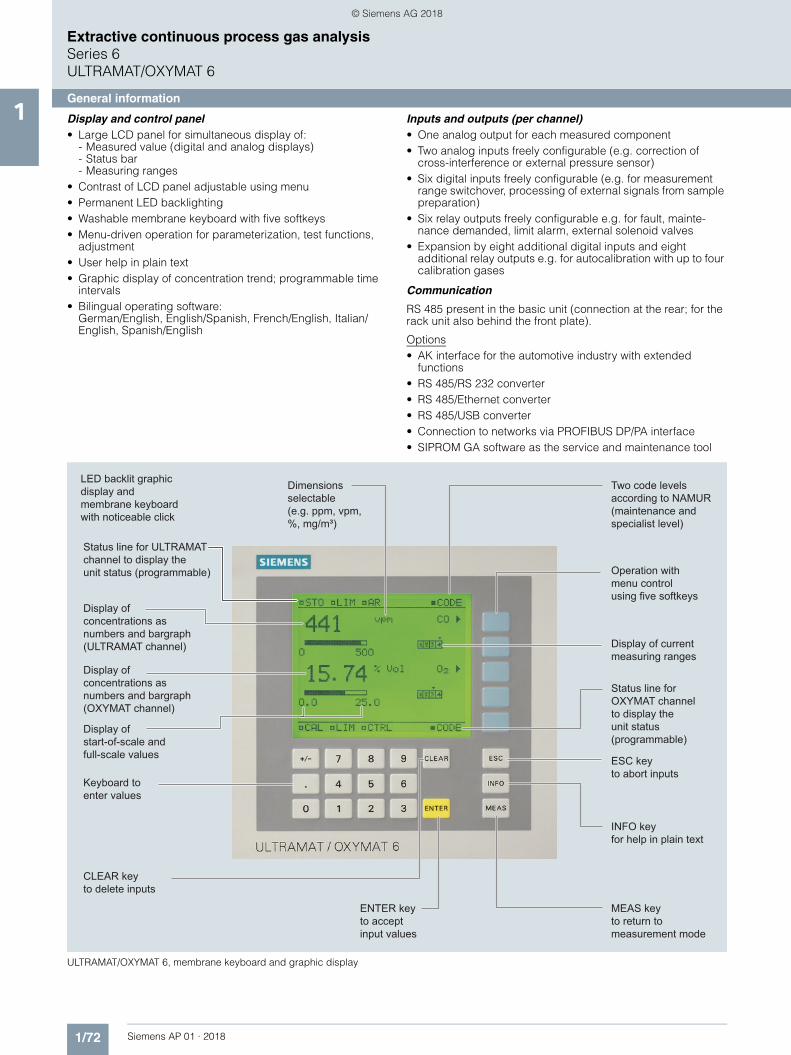
General information1 Display and control panel
• Large LCD panel for simultaneous display of:- Measured value (digital and analog displays)- Status bar- Measuring ranges
• Contrast of LCD panel adjustable using menu• Permanent LED backlighting• Washable membrane keyboard with five softkeys• Menu-driven operation for parameterization, test functions,
adjustment• User help in plain text• Graphic display of concentration trend; programmable time
intervals• Bilingual operating software:
German/English, English/Spanish, French/English, Italian/English, Spanish/English
Inputs and outputs (per channel)• One analog output for each measured component• Two analog inputs freely configurable (e.g. correction of
cross-interference or external pressure sensor)• Six digital inputs freely configurable (e.g. for measurement
range switchover, processing of external signals from sample preparation)
• Six relay outputs freely configurable e.g. for fault, mainte-nance demanded, limit alarm, external solenoid valves
• Expansion by eight additional digital inputs and eight additional relay outputs e.g. for autocalibration with up to four calibration gases
Communication
RS 485 present in the basic unit (connection at the rear; for the rack unit also behind the front plate).
Options• AK interface for the automotive industry with extended
functions• RS 485/RS 232 converter• RS 485/Ethernet converter• RS 485/USB converter• Connection to networks via PROFIBUS DP/PA interface• SIPROM GA software as the service and maintenance tool
ULTRAMAT/OXYMAT 6, membrane keyboard and graphic display
LED backlit graphicdisplay and membrane keyboardwith noticeable click
Two code levelsaccording to NAMUR(maintenance andspecialist level)
MEAS key to return tomeasurement mode
Operation with menu controlusing five softkeys
Display of currentmeasuring ranges
ESC keyto abort inputs
INFO keyfor help in plain text
CLEAR key to delete inputs
Keyboard toenter values
Display of start-of-scale and full-scale values
Display ofconcentrations asnumbers and bargraph(OXYMAT channel)
ENTER key to accept input values
Status line for OXYMAT channelto display theunit status(programmable)
Dimensionsselectable(e.g. ppm, vpm,%, mg/m³)
Display ofconcentrations asnumbers and bargraph(ULTRAMAT channel)
Status line for ULTRAMAT channel to display theunit status (programmable)
© Siemens AG 2018

1/73Siemens AP 01 · 2018
Extractive continuous process gas analysisSeries 6
ULTRAMAT/OXYMAT 6
General information1Designs – Parts wetted by sample gas, standard
Options
Versions – Parts wetted by sample gas, special applications (examples)
Gas path ULTRAMAT channel 19" rack unit
With hoses Bushing Stainless steel, mat. no. 1.4571
Hose FKM (e.g. Viton)
Sample chamber:
• Body Aluminum
• Lining Aluminum
• Fitting Stainless steel, mat. no. 1.4571,
O-ring: FKM (e.g. Viton) or FFKM (Kalrez)
• Window CaF2, adhesive: E353,
O-ring: FKM (e.g. Viton) or FFKM (Kalrez)
With pipes Bushing Titanium
Pipe Titanium,
O-ring: FKM (e.g. Viton) or FFKM (Kalrez)
Sample chamber:
• Body Aluminum
• Lining Tantalum (only for cell length 20 mm to 180 mm)
• Window CaF2, adhesive: E353,
O-ring: FKM (e.g. Viton) or FFKM (Kalrez)
With pipes Bushing Stainless steel, mat. no. 1.4571
Pipe Stainless steel, mat. no. 1.4571,
O-ring: FKM (e.g. Viton) or FFKM (Kalrez)
Sample chamber:
• Body Aluminum
• Lining Aluminum or tantalum (Ta: only for cell length 20 mm to 180 mm)
• Window CaF2, adhesive: E353,
O-ring: FKM (e.g. Viton) or FFKM (Kalrez)
Flow indicator Measurement pipe Duran glass
Variable area Duran glass
Suspension boundary PTFE (Teflon)
Angle pieces FKM (e.g. Viton)
Pressure switch Diaphragm FKM (e.g. Viton)
Enclosure PA 6.3T
Gas path ULTRAMAT channel 19" rack unit
Flow indicator Measurement pipe Duran glass
Variable area Duran glass
Suspension boundary PTFE (Teflon)
Angle pieces FKM (e.g. Viton)
Pressure switch Diaphragm FKM (e.g. Viton)
Enclosure PA 6.3T
Gas path ULTRAMAT channel 19" rack unit
With pipes Bushing e.g. Hastelloy C22
Pipe e.g. Hastelloy C22,
O-ring: FKM (e.g. Viton) or FFKM (Kalrez)
Sample chamber:
• Body e.g. Hastelloy C22
• Window CaF2, without adhesive
O-ring: FKM (e.g. Viton) or FFKM (Kalrez)
© Siemens AG 2018

1/74 Siemens AP 01 · 2018
Extractive continuous process gas analysisSeries 6ULTRAMAT/OXYMAT 6
General information1 Designs – Parts wetted by sample gas, standard
Options
Gas path OXYMAT channel 19" rack unit
With hoses Bushing
Hose
Sample chamber
Fittings for sample chamber
Restrictor
O-rings
Stainless steel, mat. no. 1.4571
FKM (e.g. Viton)
Stainless steel, mat. no. 1.4571 or tantalum
Stainless steel, mat. no. 1.4571
PTFE (e.g. Teflon)
FKM (e.g. Viton)
With pipes Bushing
Pipe
Sample chamber
Restrictor
O-rings
Titanium
Titanium
Stainless steel, mat. no. 1.4571 or Tantalum
Titanium
FKM (Viton) or FFKM (Kalrez)
With pipes Bushing
Pipe
Sample chamber
Restrictor
O-rings
Stainless steel, mat. no. 1.4571
Stainless steel, mat. no. 1.4571
Stainless steel, mat. no. 1.4571 or Tantalum
Stainless steel, mat. no. 1.4571
FKM (Viton) or FFKM (Kalrez)
With pipes Bushing
Pipe
Sample chamber
Restrictor
O-rings
Hastelloy C 22
Hastelloy C 22
Stainless steel, mat. no. 1.4571 or Tantalum
Hastelloy C 22
FKM (e.g. Viton) or FFKM (e.g. Kalrez)
Gas path ULTRAMAT channel and OXYMAT channel
19" rack unit
Flow indicator Measurement pipe Duran glass
Variable area Duran glass
Suspension boundary PTFE (Teflon)
Angle pieces FKM (e.g. Viton)
Pressure switch Diaphragm FKM (e.g. Viton)
Enclosure PA 6.3T
© Siemens AG 2018

1/75Siemens AP 01 · 2018
Extractive continuous process gas analysisSeries 6
ULTRAMAT/OXYMAT 6
General information1Gas path
ULTRAMAT/OXYMAT 6, gas path (example) IR channel without flow-type reference side
ULTRAMAT/OXYMAT 6, gas path (example) IR channel with flow-type reference side
Legend for the gas path figures
1 Sample gas inlet (OXYMAT channel) 11 Restrictor (in reference gas inlet)2 Sample gas outlet (OXYMAT channel) 12 O2 physical system3 Not used 13 Pressure sensor4 Reference gas inlet 14 Pressure switch in sample gas path (option)5 Sample gas inlet (ULTRAMAT channel) 15 Flow indicator in sample gas path (option)6 Sample gas outlet (ULTRAMAT channel) 16 IR hardware7 Reference gas outlet (ULTRAMAT channel, option) 17 Filter8 Reference gas inlet (ULTRAMAT channel, option) 18 Pressure switch (reference gas) (option)9 Purging gas 19 Restrictor in sample gas path (option)10 Pressure sensor connection (ULTRAMAT channel)
PF F
PP
P
P
9 10 5 6 1 2 4
13
15 15
14
16
1919
18
11
1213
14
17
PF F
PP
P
P
9 10 5 6 1 2 4
13
15 15
14
16
1919
18
11
12
13
14
17
8 7
© Siemens AG 2018
1/76 Siemens AP 01 · 2018
Extractive continuous process gas analysisSeries 6ULTRAMAT/OXYMAT 6
General information1
■ Function
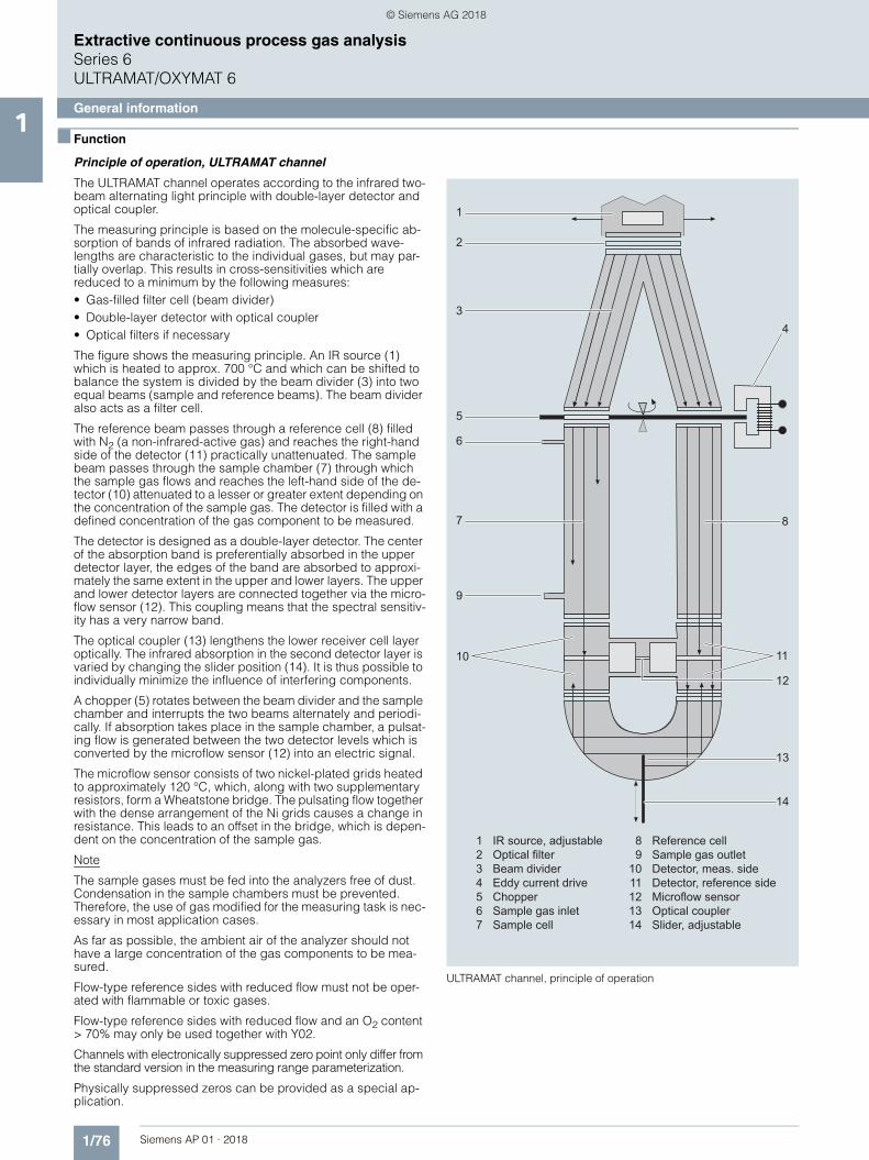
Principle of operation, ULTRAMAT channel
The ULTRAMAT channel operates according to the infrared two-beam alternating light principle with double-layer detector and optical coupler.
The measuring principle is based on the molecule-specific ab-sorption of bands of infrared radiation. The absorbed wave-lengths are characteristic to the individual gases, but may par-tially overlap. This results in cross-sensitivities which are reduced to a minimum by the following measures:• Gas-filled filter cell (beam divider)• Double-layer detector with optical coupler• Optical filters if necessary
The figure shows the measuring principle. An IR source (1) which is heated to approx. 700 °C and which can be shifted to balance the system is divided by the beam divider (3) into two equal beams (sample and reference beams). The beam divider also acts as a filter cell.
The reference beam passes through a reference cell (8) filled with N2 (a non-infrared-active gas) and reaches the right-hand side of the detector (11) practically unattenuated. The sample beam passes through the sample chamber (7) through which the sample gas flows and reaches the left-hand side of the de-tector (10) attenuated to a lesser or greater extent depending on the concentration of the sample gas. The detector is filled with a defined concentration of the gas component to be measured.
The detector is designed as a double-layer detector. The center of the absorption band is preferentially absorbed in the upper detector layer, the edges of the band are absorbed to approxi-mately the same extent in the upper and lower layers. The upper and lower detector layers are connected together via the micro-flow sensor (12). This coupling means that the spectral sensitiv-ity has a very narrow band.
The optical coupler (13) lengthens the lower receiver cell layer optically. The infrared absorption in the second detector layer is varied by changing the slider position (14). It is thus possible to individually minimize the influence of interfering components.
A chopper (5) rotates between the beam divider and the sample chamber and interrupts the two beams alternately and periodi-cally. If absorption takes place in the sample chamber, a pulsat-ing flow is generated between the two detector levels which is converted by the microflow sensor (12) into an electric signal.
The microflow sensor consists of two nickel-plated grids heated to approximately 120 °C, which, along with two supplementary resistors, form a Wheatstone bridge. The pulsating flow together with the dense arrangement of the Ni grids causes a change in resistance. This leads to an offset in the bridge, which is depen-dent on the concentration of the sample gas.
Note
The sample gases must be fed into the analyzers free of dust. Condensation in the sample chambers must be prevented. Therefore, the use of gas modified for the measuring task is nec-essary in most application cases.
As far as possible, the ambient air of the analyzer should not have a large concentration of the gas components to be mea-sured.
Flow-type reference sides with reduced flow must not be oper-ated with flammable or toxic gases.
Flow-type reference sides with reduced flow and an O2 content > 70% may only be used together with Y02.
Channels with electronically suppressed zero point only differ from the standard version in the measuring range parameterization.
Physically suppressed zeros can be provided as a special ap-plication.
ULTRAMAT channel, principle of operation
1
2
3
5
6
7
4
8
9
10 11
13
14
12
1 IR source, adjustable 8 Reference cell 2 Optical filter 9 Sample gas outlet 3 Beam divider 10 Detector, meas. side 4 Eddy current drive 11 Detector, reference side 5 Chopper 12 Microflow sensor 6 Sample gas inlet 13 Optical coupler 7 Sample cell 14 Slider, adjustable
© Siemens AG 2018

1/77Siemens AP 01 · 2018
Extractive continuous process gas analysisSeries 6
ULTRAMAT/OXYMAT 6
General information1Principle of operation, OXYMAT channel
In contrast to almost all other gases, oxygen is paramagnetic. This property is utilized as the measuring principle by the OXY-MAT channel.
Oxygen molecules in an inhomogeneous magnetic field are drawn in the direction of increased field strength due to their paramagnetism. When two gases with different oxygen contents meet in a magnetic field, a pressure difference is produced be-tween them.
One gas (1) is a reference gas (N2, O2 or air), the other is the sample gas (5). The reference gas is introduced into the sample chamber (6) through two channels (3). One of these reference gas streams meets the sample gas within the area of a magnetic field (7). Because the two channels are connected, the pressure, which is proportional to the oxygen content, causes a cross flow. This flow is converted into an electric signal by a microflow sen-sor (4).
The microflow sensor consists of two nickel-plated grids heated to approximately 120 °C, which, along with two supplementary resistors, form a Wheatstone bridge. The pulsating flow results in a change in the resistance of the Ni grids. This leads to an off-set in the bridge which is dependent on the oxygen concentra-tion of the sample gas.
Because the microflow sensor is located in the reference gas stream, the measurement is not influenced by the thermal con-ductivity, the specific heat or the internal friction of the sample gas. This also provides a high degree of corrosion resistance because the microflow sensor is not exposed to the direct influ-ence of the sample gas.
By using a magnetic field with alternating strength (8), the effect of the background flow in the microflow sensor is not detected, and the measurement is thus independent of the instrument's operating position.
The sample chamber is directly in the sample path and has a small volume, and the microflow sensor is a low-lag sensor. This results in a very short response time.
Vibrations frequently occur at the place of installation and may falsify the measured signal (noise). A further microflow sensor (10) through which no gas passes acts as a vibration sensor. Its signal is applied to the measured signal as compensation.
If the density of the sample gas deviates by more than 50% from that of the reference gas, the compensation microflow sensor (10) is flushed with reference gas just like the measuring sensor (4) (option).
Note
The sample gases must be fed into the analyzers free of dust. Condensation in the sample chambers must be prevented. Therefore, gas modified for the measuring tasks is necessary in most application cases.
OXYMAT channel, principle of operation
D
1 Reference gas inlet2 Restrictors3 Reference gas channels4 Microflow sensor for measurement5 Sample gas inlet6 Sample cell7 Paramagnetic effect8 Electromagnet with alternating field strength9 Sample gas and reference gas outlet10 Microflow sensor in compensation system (without flow)
© Siemens AG 2018

1/78 Siemens AP 01 · 2018
Extractive continuous process gas analysisSeries 6ULTRAMAT/OXYMAT 6
General information1 Essential characteristics
• Dimension of measured value freely selectable (e.g. vpm, mg/m3)
• Four freely-configurable measuring ranges per component • Measuring ranges with suppressed zero point possible• Measuring range identification• Galvanically isolated signal output 0/2/4 to 20 mA per
component• Automatic or manual measuring range switchover selectable;
remote switching is also possible• Storage of measured values possible during adjustments• Time constants selectable within wide limits (static/dynamic
noise suppression); i.e. the response time of the analyzer or component can be matched to the respective measuring task
• Short response time• Low long-term drift• Measuring point switchover for up to 6 measuring points
(programmable)• Measuring point identification• Monitoring of sample gas flow (option)• Two control levels with separate authorization codes to
prevent unintentional and unauthorized inputs• Automatic measuring range calibration can be configured• Simple handling using a numerical membrane keyboard and
operator prompting• Operation based on NAMUR recommendation• Customer-specific analyzer options such as:
- Customer acceptance- TAG labels- Drift recording
ULTRAMAT channel• Differential measuring ranges with flow-type reference cell• Internal pressure sensor for correction of variations in
atmospheric pressure in the range 700 to 1 200 hPa absolute• External pressure sensor - only with piping as the gas path -
can be connected for correction of variations in the process gas pressure in the range 700 to 1 500 hPa absolute (option)
• Sample chambers for use in presence of highly corrosive sample gases (e.g. tantalum layer or Hastelloy C22)
OXYMAT channel• Monitoring of sample gas and/or reference gas (option)• Different smallest measuring ranges (0.5%, 2.0% or 5.0% O2)• Analyzer unit with flow-type compensation circuit (option): a
flow is passed through the compensation branch to reduce the vibration dependency in the case of highly different densities of the sample and reference gases
• Internal pressure sensor for correction of pressure variations in sample gas (range 500 to 2 000 hPa absolute)
• External pressure sensor - only with piping as the gas path - can be connected for correction of variations in the sample gas pressure up to 3 000 hPa absolute (option)
• Monitoring of reference gas with reference gas connection 3 000 to 5 000 hPa (option), absolute
• Sample chamber for use in presence of highly corrosive sample gases
© Siemens AG 2018

1/79Siemens AP 01 · 2018
Extractive continuous process gas analysisSeries 6
ULTRAMAT/OXYMAT 6
General information1Reference gases
Table 1: Reference gases for OXYMAT channel
Correction of zero error / cross-sensitivities (OXYMAT channel)
Table 2: Zero point error due to diamagnetism or paramagnetism of some accompanying gases with reference to nitrogen at 60 °C and 1 000 hPa absolute (according to IEC 61207/3)
Conversion to other temperatures:
The deviations from the zero point listed in Table 2 must be multiplied by a correction factor (k):• with diamagnetic gases: k = 333 K / ( [°C] + 273 K)• with paramagnetic gases: k = [333 K / ( [°C] + 273 K)]2
All diamagnetic gases have a negative deviation from zero point.
Measuring range Recommended reference gas Reference gas connection pressure Remarks
0 to ... vol.% O2 N2 2 000 … 4 000 hPa above sample gas pressure (max. 5 000 hPa absolute)
The reference gas flow is set automati-cally to 5 … 10 ml/min (up to 20 ml/min with flow-type compensation branch)... to 100 vol.% O2 (suppressed zero
point with full-scale value 100 vol.% O2)
O2
Around 21 vol.% O2 (suppressed zero point with 21 vol.% O2 within the mea-suring span)
Air 100 hPa with respect to sample gas pressure, which may vary by max. 50 hPa around the atmospheric pres-sure
Accompanying gas (concentration 100 vol.%)
Deviation from zero point in vol. % O2 absolute
Organic gases
Ethane C2H6 -0.49
Ethene (ethylene) C2H4 -0.22
Ethine (acetylene) C2H2 -0.29
1.2 butadiene C4H6 -0.65
1.3 butadiene C4H6 -0.49
n-butane C4H10 -1.26
iso-butane C4H10 -1.30
1-butene C4H8 -0.96
iso-butene C4H8 -1.06
Dichlorodifluoromethane (R12) CCl2F2 -1.32
Acetic acid CH3COOH -0.64
n-heptane C7H16 -2.40
n-hexane C6H14 -2.02
Cyclo-hexane C6H12 -1.84
Methane CH4 -0.18
Methanol CH3OH -0.31
n-octane C8H18 -2.78
n-pentane C5H12 -1.68
iso-pentane C5H12 -1.49
Propane C3H8 -0.87
Propylene C3H6 -0.64
Trichlorofluoromethane (R11) CCl3F -1.63
Vinyl chloride C2H3Cl -0.77
Vinyl fluoride C2H3F -0.55
1.1 vinylidene chloride C2H2Cl2 -1.22
Inert gases
Helium He +0.33
Neon Ne +0.17
Argon Ar -0.25
Krypton Kr -0.55
Xenon Xe -1.05
Inorganic gases
Ammonia NH3 -0.20
Hydrogen bromide HBr -0.76
Chlorine Cl2 -0.94
Hydrogen chloride HCl -0.35
Dinitrogen monoxide N2O -0.23
Hydrogen fluoride HF +0.10
Hydrogen iodide HI -1.19
Carbon dioxide CO2 -0.30
Carbon monoxide CO +0.07
Nitrogen oxide NO +42.94
Nitrogen N2 0.00
Nitrogen dioxide NO2 +20.00
Sulfur dioxide SO2 -0.20
Sulfur hexafluoride SF6 -1.05
Hydrogen sulfide H2S -0.44
Water H2O -0.03
Hydrogen H2 +0.26
Accompanying gas (concentration 100 vol.%)
Deviation from zero point in vol. % O2 absolute
© Siemens AG 2018

1/80 Siemens AP 01 · 2018
Extractive continuous process gas analysisSeries 6ULTRAMAT/OXYMAT 6
19" rack unit1
■ Technical specifications
19" rack unit
ULTRAMAT channel
General information
Operating position Front wall, vertical
Conformity CE mark in accordance with EN 50081-1 and EN 50082-2
Design, enclosure
Weight Approx. 21 kg
Degree of protection IP20 according to EN 60529
Electrical characteristics
EMC (electromagnetic compatibility) In accordance with standard require-ments of NAMUR NE21 (08/98)
Electrical safety According to EN 61010-1, overvolt-age category III
Auxiliary power 100 ... 120 V AC (nominal range of use 90 ... 132 V), 48 ... 63 Hz or200 ... 240 V AC (nominal range of use 180 ... 264 V), 48 ... 63 Hz
Power consumption Approx. 70 VA
Fuse values 120 ... 120 V: F1/F2 = T 1.6 A200 ... 240 V: F1/F2 = T 1 A
Electrical inputs and outputs (per channel)
Analog output 0/2/4 ... 20 mA, floating; max. load 750
Relay outputs 6, with changeover contacts, freely configurable, e.g. for measuring range identification; load: 24 V AC/DC/1 A, floating, non-sparking
Analog inputs 2, dimensioned for 0/2/4 … 20 mA for external pressure sensor and correc-tion of influence of accompanying gas (correction of cross-interference)
Digital inputs 6, designed for 24 V, floating, freely configurable, e.g. for measuring range switchover
Serial interface RS 485
Options AUTOCAL function each with 8 addi-tional digital inputs and relay outputs; also with PROFIBUS PA or PROFIBUS DP
Climatic conditions
Permissible ambient temperature -30 ... +70 °C during storage and transportation, 5 ... 45 °C during operation
Permissible humidity < 90% relative humidity, during stor-age and transportation (dew point must not be undershot)
Measuring ranges 4, internally and externally switch-able; autoranging is also possible
Smallest possible measuring range Dependent on the application, e.g.CO: 0 ... 10 vpmCO2: 0 ... 5 vpm
Largest possible measuring range Dependent on the application
Measuring ranges with suppressed zero point
Any zero point within 0 ... 100 vol.% can be implemented; smallest possi-ble span 20%
Characteristic Linearized
Influence of interfering gases must be considered separately
Gas inlet conditions
Permissible sample gas pressure• Without pressure switch 700 ... 1 500 hPa (absolute)• With integrated pressure switch 700 ... 1 300 hPa (absolute)
Sample gas flow 18 ... 90 l/h (0.3 ... 1.5 l/min)
Sample gas temperature Min. 0 to max. 50 °C, but above the dew point
Sample gas humidity < 90% (relative humidity), or depen-dent on measuring task, non-con-densing
Dynamic response
Warm-up period At room temperature < 30 min (the technical specification will be met after 2 hours)
Delayed display (T90-time) Dependent on length of analyzer chamber, sample gas line and config-urable damping
Damping (electrical time constant) 0 ... 100 s, configurable
Dead time (purging time of the gas path in the unit at 1 l/min)
Approx. 0.5 ... 5 s, depending on ver-sion
Time for device-internal signal pro-cessing
< 1 s
Pressure correction range
Pressure sensor• Internal 700 ... 1 200 hPa absolute• External 700 ... 1 500 hPa absolute
Measuring response Based on sample gas pressure 1 013 hPa absolute, 0.5 l/min sample gas flow and 25 °C ambient tempera-ture
Output signal fluctuation < ± 1% of the smallest possible mea-suring range according to rating plate
Zero point drift <± 1% of the current measuring range/week
Measured-value drift <± 1% of the current measuring range/week
Repeatability 1% of the current measuring range
Detection limit 1% of the smallest possible measur-ing range
Linearity error < 0.5% of the full-scale value
Influencing variables Based on sample gas pressure 1 013 hPa absolute, 0.5 l/min sample gas flow and 25 °C ambient tempera-ture
Ambient temperature < 1% of current measuring range/10 K (with constant receiver cell tem-perature)
Sample gas pressure • With disabled pressure compensa-tion: < 0.15% of the span/1% change in atmospheric pressure
• With disabled pressure compensa-tion: < 1.5% of the span/1% change in atmospheric pressure
Sample gas flow Negligible
Auxiliary power < 0.1% of the current measuring range with rated voltage ± 10%
Environmental conditions Application-specific measuring influ-ences possible if ambient air contains measured component or cross inter-ference-sensitive gases
© Siemens AG 2018

1/81Siemens AP 01 · 2018
Extractive continuous process gas analysisSeries 6
ULTRAMAT/OXYMAT 6
19" rack unit1OXYMAT channel
Measuring ranges 4, internally and externally switch-able; automatic measuring range swi-tchover also possible
Smallest possible span (relating to sample gas pressure 1 000 hPa abso-lute, 0.5 l/min sample gas flow and 25 °C ambient temperature)
0.5 vol.%, 2 vol.% or 5 vol.% O2
Largest possible measuring range 100 vol.% O2
Measuring ranges with suppressed zero point
Any zero point within 0 ... 100 vol.% can be implemented, provided that a suitable reference gas is used
Gas inlet conditions
Permissible sample gas pressure• With pipes 500 ... 3 000 hPa absolute• With hoses
- Without pressure switch 500 ... 1 500 hPa absolute- With pressure switch 500 ... 1 300 hPa absolute
Sample gas flow 18 ... 60 l/h (0.3 ... 1 l/min)
Sample gas temperature 0 ... 50 ºC
Sample gas humidity < 90% RH (relative humidity)
Reference gas pressure (high-pres-sure version)
2 000 ... 4 000 hPa above sample gas pressure, but max. 5 000 hPa
Reference gas pressure (low-pres-sure version)
Min. 100 hPa above sample gas pres-sure
Dynamic response
Warm-up period At room temperature < 30 min (the technical specification will be met after 2 hours)
Delayed display (T90-time) Min. 1.5 ... 3.5 s, depending on ver-sion
Damping (electrical time constant) 0 ... 100 s, configurable
Dead time (purging time of the gas path in the unit at 1 l/min)
Approx. 0.5 ... 2.5 s, depending on version
Time for device-internal signal pro-cessing
< 1 s
Pressure correction range
Pressure sensor• Internal 500 ... 2 000 hPa absolute• External 500 ... 3 000 hPa absolute
Measuring response Based on sample gas pressure 1 013 hPa absolute, 0.5 l/min sample gas flow and 25 °C ambient tempera-ture
Output signal fluctuation < 0.75% of the smallest possible measuring range according to rating plate, with electronic damping con-stant of 1 s (corresponds to ± 0.25% at 2)
Zero point drift < 0.5%/month of the smallest possi-ble measuring span according to rat-ing plate
Measured-value drift 0.5%/month of the current measur-ing range
Repeatability 1%/month of the current measuring range
Detection limit 1% of the current measuring range
Linearity error 1% of the current measuring range
Influencing variables Based on sample gas pressure 1 013 hPa absolute, 0.5 l/min sample gas flow and 25 °C ambient tempera-ture
Ambient temperature • < 0.5%/10 K referred to smallest possible span according to rating plate
• With measuring span 0.5%: 1%/10 K
Sample gas pressure (with air (100 hPa) as reference gas, correc-tion of the atmospheric pressure fluc-tuations is only possible if the sample gas can vent to ambient air)
• With disabled pressure compensa-tion: < 2% of the current measuring range /1 % change in atmospheric pressure
• With disabled pressure compensa-tion: < 0.2% of the current measur-ing range /1 % change in atmospheric pressure
Accompanying gases Deviation from zero point correspond-ing to paramagnetic or diamagnetic deviation of accompanying gas
Sample gas flow < 1% of the smallest possible span according to rating plate with a change in flow of 0.1 l/min within the permissible flow range
Auxiliary power < 0.1% of the current measuring range with rated voltage ± 10%
© Siemens AG 2018
1/82 Siemens AP 01 · 2018
Extractive continuous process gas analysisSeries 6ULTRAMAT/OXYMAT 6
19" rack unit1
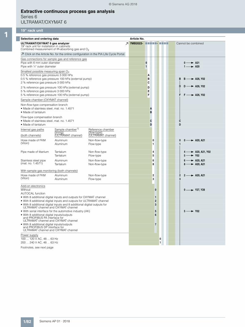
■ Selection and ordering data Article No.
ULTRAMAT/OXYMAT 6 gas analyzer19" rack unit for installation in cabinetsCombined measurement of IR-absorbing gas and O2
7MB2023- 77777- 7777 Cannot be combined
Click on the Article No. for the online configuration in the PIA Life Cycle Portal.
Gas connections for sample gas and reference gasPipe with 6 mm outer diameter 0 0 A21Pipe with ¼" outer diameter 1 1 A20
Smallest possible measuring span O20.5 % reference gas pressure 3 000 hPa A0.5 % reference gas pressure 100 hPa (external pump) B B B A26, Y022 % reference gas pressure 3 000 hPa C
2 % reference gas pressure 100 hPa (external pump) D D D A26, Y02
5 % reference gas pressure 3 000 hPa E5 % reference gas pressure 100 hPa (external pump) F F F A26, Y02
Sample chamber (OXYMAT channel)
Non-flow-type compensation branch• Made of stainless steel, mat. no. 1.4571 A• Made of tantalum B
Flow-type compensation branch• Made of stainless steel, mat. no. 1.4571 C C• Made of tantalum D D
Internal gas paths
(both channels)
Sample chamber1)
(lining) (ULTRAMAT channel)
Reference chamber(flow-type) (ULTRAMAT channel)
Hose made of FKM(Viton)
Aluminum Non-flow-type 0 0 0 A20, A21Aluminum Flow-type 1 1
Pipe made of titanium Tantalum Non-flow-type 4 4 A20, A21, Y02Tantalum Flow-type 5 5 Y02
Stainless steel pipe(mat. no. 1.4571)
Aluminum Non-flow-type 6 6 A20, A21Tantalum Non-flow-type 8 8 A20, A21
With sample gas monitoring (both channels)
Hose made of FKM(Viton)
Aluminum Non-flow-type 2 2 2 A20, A21Aluminum Flow-type 3 3
Add-on electronicsWithout 0 0 Y27, Y28AUTOCAL function• With 8 additional digital inputs and outputs for OXYMAT channel 1• With 8 additional digital inputs and outputs for ULTRAMAT channel 2• With 8 additional digital inputs and 8 additional digital outputs for
ULTRAMAT channel and OXYMAT channel3
• With serial interface for the automotive industry (AK) 5 5 Y02• With 8 additional digital inputs/outputs
and PROFIBUS PA interface forULTRAMAT channel and OXYMAT channel
6
• With 8 additional digital inputs/outputs and PROFIBUS DP interface forULTRAMAT channel and OXYMAT channel
7
Power supply100 ... 120 V AC, 48 ... 63 Hz 0200 ... 240 V AC, 48 ... 63 Hz 1
Footnotes, see next page
© Siemens AG 2018

1/83Siemens AP 01 · 2018
Extractive continuous process gas analysisSeries 6
ULTRAMAT/OXYMAT 6
19" rack unit1
1) Only for cell length 20 to 180 mm2) Can be ordered as special application (no. 3100 with order code Y12)3) QAL1: see table "Performance tested according to EN 15267 (single component)", page 1/884) QAL1: See table "Based on QAL1 according to SIRA/MCERTS (single component)", page 1/885) QAL1: See table "Based on QAL1 according to SIRA/MCERTS (single component) and performance-tested according to EN 15267 (single component)",
page 1/88
ULTRAMAT channelMeasured component
Possible with measuring range identification
CO 112), 12 ... 30 ACO highly selective (with optical filter)3) 122), 13 ... 30 BCO4) X
CO2 102), 11 ... 30 CCH4 132), 14 ... 30 DC2H2 152), 16 ... 30 E
C2H4 152), 16 ... 30 FC2H6 142), 15 ... 30 GC3H6 142), 15 ... 30 H
C3H8 132), 14 ... 30 JC4H6 152), 16 ... 30 KC4H10 142), 15 ... 30 L
C6H14 142), 15 ... 30 MSO2
5) 132), 14 ... 30 NNO5) 142), 15 ... 20, 22 P
NH3 (dry) 142), 15 ... 30 Q QH2O 172), 18 ... 20, 22 R RN2O 132), 14 ... 30 S
Smallest measuring rangeLargest measuring range Measuring range identification
0 ... 5 vpm 0 ... 100 vpm 10 A0 ... 10 vpm 0 ... 200 vpm 11 B0 ... 20 vpm 0 ... 400 vpm 12 C
0 ... 50 vpm 0 ... 1 000 vpm 13 D0 ... 100 vpm 0 ... 1 000 vpm 14 E0 ... 300 vpm 0 ... 3 000 vpm 15 F
0 ... 500 vpm 0 ... 5 000 vpm 16 G0 ... 1 000 vpm 0 ... 10 000 vpm 17 H0 ... 3 000 vpm 0 ... 10 000 vpm 18 J
0 ... 3 000 vpm 0 ... 30 000 vpm 19 K0 ... 5 000 vpm 0 ... 15 000 vpm 20 L0 ... 5 000 vpm 0 ... 50 000 vpm 21 M
0 ... 1 % 0 ... 3 % 22 N0 ... 1 % 0 ... 10 % 23 P0 ... 3 % 0 ... 10 % 24 Q
0 ... 3 % 0 ... 30 % 25 R
0 ... 5 % 0 ... 15 % 26 S0 ... 5 % 0 ... 50 % 27 T
0 ... 10 % 0 ... 30 % 28 U0 ... 10 % 0 ... 100 % 29 V0 ... 30 % 0 ... 100 % 30 W
Operating software and documentationGerman 0English 1French 2Spanish 3Italian 4
■ Selection and ordering data Article No.
ULTRAMAT/OXYMAT 6 gas analyzer19" rack unit for installation in cabinetsCombined measurement of IR-absorbing gas and O2
7MB2023- 77777- 7777 Cannot be combined
© Siemens AG 2018

1/84 Siemens AP 01 · 2018
Extractive continuous process gas analysisSeries 6ULTRAMAT/OXYMAT 6
19" rack unit1
■ Selection and ordering data
1) Cannot be combined with non-flow-type reference cell.2) Standard setting: Smallest measuring range
25 % of largest measuring range in % or50 % of largest measuring range ppm (vpm)Largest measuring range
Additional versions Order code Cannot be combined
Add "-Z" to Article No. and specify Order codes.
Flow-type reference cell with reduced flow, 6 mm (ULTRAMAT channel)1)
A20
Flow-type reference cell with reduced flow, ¼" (ULTRAMAT channel)1)
A21
Reference gas monitoring (pressure switch ... 3 000 hPa), for OXYMAT channel only
A26
Connection pipes (can only be combined with the appropriate gas connection diameter and internal gas path materials)
• Titanium connection pipe, 6 mm, complete with screwed gland, for sample gas side
A22
• Titanium connection pipe, ¼", complete with screwed gland, for sample gas side
A24
• Stainless steel connection pipe (mat. no. 1.4571), 6 mm, complete with screwed gland, for sample gas side
A27
• Stainless steel connection pipe (mat. no. 1.4571), ¼", complete with screwed gland, for sample gas side
A29
Telescopic rails (2 units) A31
Kalrez gaskets in sample gas path (O2 side) B01
TAG labels (specific lettering based on customer information) B03
Kalrez gaskets in sample gas path (IR side) B04
SIL conformity declaration (SIL 2) Functional Safety according to IEC 61508 and IEC 61511 C20
FM/CSA certificate – Class I Div 2 E20
Clean for O2 service (specially cleaned gas path) (ULTRAMAT channel and OXYMAT channel)
Y02
Measuring range indication in plain text2), if different from the standard setting Y11
Special setting (only in conjunction with an application no., e.g. extended measuring range, only ULTRAMAT channel)
Y12
Extended special setting (only in conjunction with an application no., e.g. determination of interference influences, only ULTRAMAT channel)
Y13
QAL1 according to SIRA/MCERTS (ULTRAMAT channel only) Y17 E20
Performance-tested according to EN 15267 (1st channel) Y27
Performance-tested according to EN 15267 (2nd channel) Y28
Accessories Article No.
RS 485/Ethernet converter A5E00852383
RS 485/RS 232 converter C79451-Z1589-U1
RS 485/USB converter A5E00852382
AUTOCAL function with serial interfaces for the automotive industry (AK) C79451-A3480-D33
AUTOCAL function with 8 digital inputs/outputs for ULTRAMAT channel or OXYMAT channel
C79451-A3480-D511
AUTOCAL function with 8 digital inputs/outputs and PROFIBUS PA for ULTRAMAT channel or OXYMAT channel
A5E00057307
AUTOCAL function with 8 digital inputs/outputs and PROFIBUS DP for ULTRAMAT channel or OXYMAT channel
A5E00057312
Set of Torx screwdrivers A5E34821625
}
© Siemens AG 2018

1/85Siemens AP 01 · 2018
Extractive continuous process gas analysisSeries 6
ULTRAMAT/OXYMAT 6
19" rack unit1
■ Selection and ordering data Article No.
ULTRAMAT/OXYMAT 6 gas analyzer19" rack unit for installation in cabinetsCombined measurement of IR-absorbing gas and O2
7MB2024- 77777 - 7777 Cannot be combined
Click on the Article No. for the online configuration in the PIA Life Cycle Portal.
Gas connections for sample gas and reference gasPipe with 6 mm outer diameter 0 0 A21Pipe with ¼" outer diameter 1 1 A20
Smallest possible measuring span O20.5 % reference gas pressure 3 000 hPa A0.5 % reference gas pressure 100 hPa (external pump) B B B A26, Y02
2 % reference gas pressure 3 000 hPa C2 % reference gas pressure 100 hPa (external pump) D D D A26, Y02
5 % reference gas pressure 3 000 hPa5 % reference gas pressure 100 hPa (external pump)
EF F F A26, Y02
Sample chamber (OXYMAT channel)
Non-flow-type compensation branch• Made of stainless steel, mat. no. 1.4571 A• Made of tantalum B
Flow-type compensation branch• Made of stainless steel, mat. no. 1.4571 C C• Made of tantalum D D
Internal gas paths
(both channels)
Sample chamber1)
(lining)(ULTRAMAT channel)
Reference chamber(flow-type) (ULTRAMAT channel)
Hose made of FKM(Viton)
Aluminum Non-flow-type 0 0 A20, A21Aluminum Flow-type 1
Pipe made of titanium Tantalum Non-flow-type 4 4 A20, A21, Y02Tantalum Flow-type 5 5 Y02
Stainless steel pipe(mat. no. 1.4571)
Aluminum Non-flow-type 6 6 A20, A21Tantalum Non-flow-type 8 8 A20, A21
With sample gas monitoring (both channels)
Hose made of FKM(Viton)
Aluminum Non-flow-type 2 2 A20, A21Aluminum Flow-type 3
Add-on electronicsWithout 0AUTOCAL function• With 8 additional digital inputs and outputs for
ULTRAMAT channel and OXYMAT channel1
• With serial interface for the automotive industry (AK) 5 5 Y02• With 8 additional digital inputs/outputs and PROFIBUS PA interface for
ULTRAMAT channel and OXYMAT channel6
• With 8 additional digital inputs/outputs and PROFIBUS DP interface forULTRAMAT channel and OXYMAT channel
7
Power supply100 ... 120 V AC, 48 ... 63 Hz 0200 ... 240 V AC, 48 ... 63 Hz 1
Footnote, see next page
© Siemens AG 2018

1/86 Siemens AP 01 · 2018
Extractive continuous process gas analysisSeries 6ULTRAMAT/OXYMAT 6
19" rack unit1
1) Only for cell length 20 to 180 mm
ULTRAMAT channelMeasured component
Smallest measuring range Largest measuring range
CO/NO CO 0 ... 100 vpm 0 ... 1 000 vpm A HNO 0 ... 300 vpm 0 ... 1 000 vpm
CO/NO CO 0 ... 300 vpm 0 ... 3 000 vpm A JNO 0 ... 500 vpm 0 ... 3 000 vpm
CO/NO CO 0 ... 1 000 vpm 0 ... 10 000 vpm A CNO 0 ... 1 000 vpm 0 ... 10 000 vpm
For CO/NO (QAL1; see table "Based on QAL1 according to SIRA/MCERTS (2 components in series)", page 1/88)
CO2/CO CO2 0 ... 100 vpm 0 ... 1 000 vpm B ACO 0 ... 100 vpm 0 ... 1 000 vpm
CO2/CO CO2 0 ... 300 vpm 0 ... 3 000 vpm B BCO 0 ... 300 vpm 0 ... 3 000 vpm
CO2/CO CO2 0 ... 1 000 vpm 0 ... 10 000 vpm B CCO 0 ... 1 000 vpm 0 ... 10 000 vpm
CO2/CO CO2 0 ... 3 000 vpm 0 ... 30 000 vpm B DCO 0 ... 3 000 vpm 0 ... 30 000 vpm
CO2/CO CO2 0 ... 1 % 0 ... 10 % B ECO 0 ... 1 % 0 ... 10 %
CO2/CO CO2 0 ... 3 % 0 ... 30 % B FCO 0 ... 3 % 0 ... 30 %
CO2/CO CO2 0 ... 10 % 0 ... 100 % B GCO 0 ... 10 % 0 ... 100 %
CO2/CH4 CO2 0 ... 10 % 0 ... 100 % C GCH4 0 ... 10 % 0 ... 100 %
CO2/NO CO2 0 ... 300 vpm 0 ... 3 000 vpm D JNO 0 ... 500 vpm 0 ... 3 000 vpm
Operating software and documentationGerman 0English 1French 2Spanish 3Italian 4
■ Selection and ordering data Article No.
ULTRAMAT/OXYMAT 6 gas analyzer19" rack unit for installation in cabinetsCombined measurement of IR-absorbing gas and O2
7MB2024- 77777 - 7777 Cannot be combined
© Siemens AG 2018

1/87Siemens AP 01 · 2018
Extractive continuous process gas analysisSeries 6
ULTRAMAT/OXYMAT 6
19" rack unit1
■ Selection and ordering data
1) Cannot be combined with non-flow-type reference cell.2) Standard setting: Smallest measuring range
25 % of largest measuring range in % or50 % of largest measuring range ppm (vpm)Largest measuring range
Additional versions Order code Cannot be combined
Add "-Z" to Article No. and specify Order codes.
Flow-type reference cell with reduced flow, 6 mm (ULTRAMAT channel)1) A20
Flow-type reference cell with reduced flow, ¼" (ULTRAMAT channel)1) A21
Reference gas monitoring (pressure switch ... 3 000 hPa), for OXYMAT channel only A26
Connection pipes (can only be combined with the appropriate gas connection diameter and internal gas path materials)
• Titanium connection pipe, 6 mm, complete with screwed gland, for sample gas side A22
• Titanium connection pipe, ¼", complete with screwed gland, for sample gas side A24
• Stainless steel connection pipe (mat. no. 1.4571), 6 mm, complete with screwed gland, for sam-ple gas side
A27
• Stainless steel connection pipe (mat. no. 1.4571), ¼", complete with screwed gland,for sample gas side
A29
Telescopic rails (2 units) A31
Kalrez gaskets in sample gas path (O2 side) B01
TAG labels (specific lettering based on customer information) B03
Kalrez gaskets in sample gas path (IR side) B04
SIL conformity declaration (SIL 2) Functional Safety according to IEC 61508 and IEC 61511 C20
FM/CSA certificate – Class I Div 2 E20
Clean for O2 service (specially cleaned gas path) (ULTRAMAT channel and OXYMAT channel)
Y02
Measuring range indication in plain text2), if different from the standard setting Y11
Special setting (only in conjunction with an application no., e.g. extended measuring range, only ULTRAMAT channel)
Y12
Extended special setting (only in conjunction with an application no., e.g. determination of interference influences, only ULTRAMAT channel)
Y13
QAL1 according to SIRA/MCERTS (ULTRAMAT channel only) Y17 E20
Accessories Article No.
RS 485/Ethernet converter A5E00852383
RS 485/RS 232 converter C79451-Z1589-U1
RS 485/USB converter A5E00852382
AUTOCAL function with serial interfaces for the automotive industry (AK)
C79451-A3480-D33
AUTOCAL function with 8 digital inputs/outputs for ULTRAMAT channel or OXYMAT channel
C79451-A3480-D511
AUTOCAL function with 8 digital inputs/outputs and PROFIBUS PA for ULTRAMAT channel or OXYMAT channel
A5E00057307
AUTOCAL function with 8 digital inputs/outputs and PROFIBUS DP for ULTRAMAT channel or OXYMAT channel
A5E00057312
Set of Torx screwdrivers A5E34821625
}
© Siemens AG 2018

1/88 Siemens AP 01 · 2018
Extractive continuous process gas analysisSeries 6ULTRAMAT/OXYMAT 6
19" rack unit1 Based on QAL1 according to SIRA/MCERTS (single component)
Only in conjunction with order code Y17
Performance-tested according to EN 15267 (single component)
Only in conjunction with order code Y27/Y28
Example for ordering
ULTRAMAT/OXYMAT 6, performance-tested according to EN 15267IR channelComponent: COMeasuring range: 0 to 75/1 250 mg/m3
with hoses, non-flow-type reference compartmentwith automatic adjustment (AUTOCAL)230 V AC; German7MB2023-0EA03-1BD0-Z Y27+Y28
Based on QAL1 according to SIRA/MCERTS (2 components in series)
Example for ordering
ULTRAMAT/OXYMAT 6, QAL1IR channelComponents: CO/NOMeasuring range CO: 0 to 75 / 1 000 mg/m3, NO: 0 to 200/2 000 mg/m3
with hoses, non-flow-type reference cellwithout automatic adjustment (AUTOCAL)230 V AC; German7MB2024-0EA00-1AH0-Z +Y17
Component CO (QAL1) SO2 (QAL1) NO (QAL1)
Measuring range identification
Smallest measuring range from 0 to ...
Largest measuring range from 0 to ...
Smallest measuring range from 0 to ...
Largest measuring range from 0 to ...
Smallest measuring range from 0 to ...
Largest measuring range from 0 to ...
C 75 mg/m3 1 500 mg/m3
D 50 mg/m3 1 000 mg/m3 300 mg/m3 3 000 mg/m3
E 500 mg/m3 5 000 mg/m3 100 mg/m3 2 000 mg/m3
F 300 mg/m3 3 000 mg/m3 1 000 mg/m3 10 000 mg/m3 300 mg/m3 3 000 mg/m3
G 500 mg/m3 5 000 mg/m3 500 mg/m3 5 000 mg/m3
H 1 000 mg/m3 10 000 mg/m3 3 000 mg/m3 30 000 mg/m3 1 000 mg/m3 10 000 mg/m3
K 3 000 mg/m3 30 000 mg/m3 10 g/m3 100 g/m3 3 000 mg/m3 30 000 mg/m3
Component CO (QAL1) SO2 (QAL1) NO (QAL1)
Measuring range identification
Smallest measuring range from 0 to ...
Largest measuring range from 0 to ...
Smallest measuring range from 0 to ...
Largest measuring range from 0 to ...
Smallest measuring range from 0 to ...
Largest measuring range from 0 to ...
C 75 mg/m3 1 500 mg/m3
D 75 mg/m3 1 250 mg/m3
E 125 mg/m3 1 250 mg/m3 100 mg/m3 2 000 mg/m3
F 300 mg/m3 3 000 mg/m3 300 mg/m3 3 000 mg/m3
G 500 mg/m3 5 000 mg/m3 500 mg/m3 5 000 mg/m3
H 1 000 mg/m3 10 000 mg/m3 1 000 mg/m3 10 000 mg/m3
J 3 000 mg/m3 10 000 mg/m3 3 000 mg/m3 10 000 mg/m3
Component CO (QAL1) NO (QAL1)
Measuring range identification
Smallest measuring range from 0 to ...
Largest measuring range from 0 to ...
Smallest measuring range from 0 to ...
Largest measuring range from 0 to ...
AH 75 mg/m3 1 000 mg/m3 200 mg/m3 2 000 mg/m3
AJ 300 mg/m3 3 000 mg/m3 500 mg/m3 3 000 mg/m3
AC 1 000 mg/m3 10 000 mg/m3 1 000 mg/m3 10 000 mg/m3
© Siemens AG 2018
1/89Siemens AP 01 · 2018
Extractive continuous process gas analysisSeries 6
ULTRAMAT/OXYMAT 6
19" rack unit1
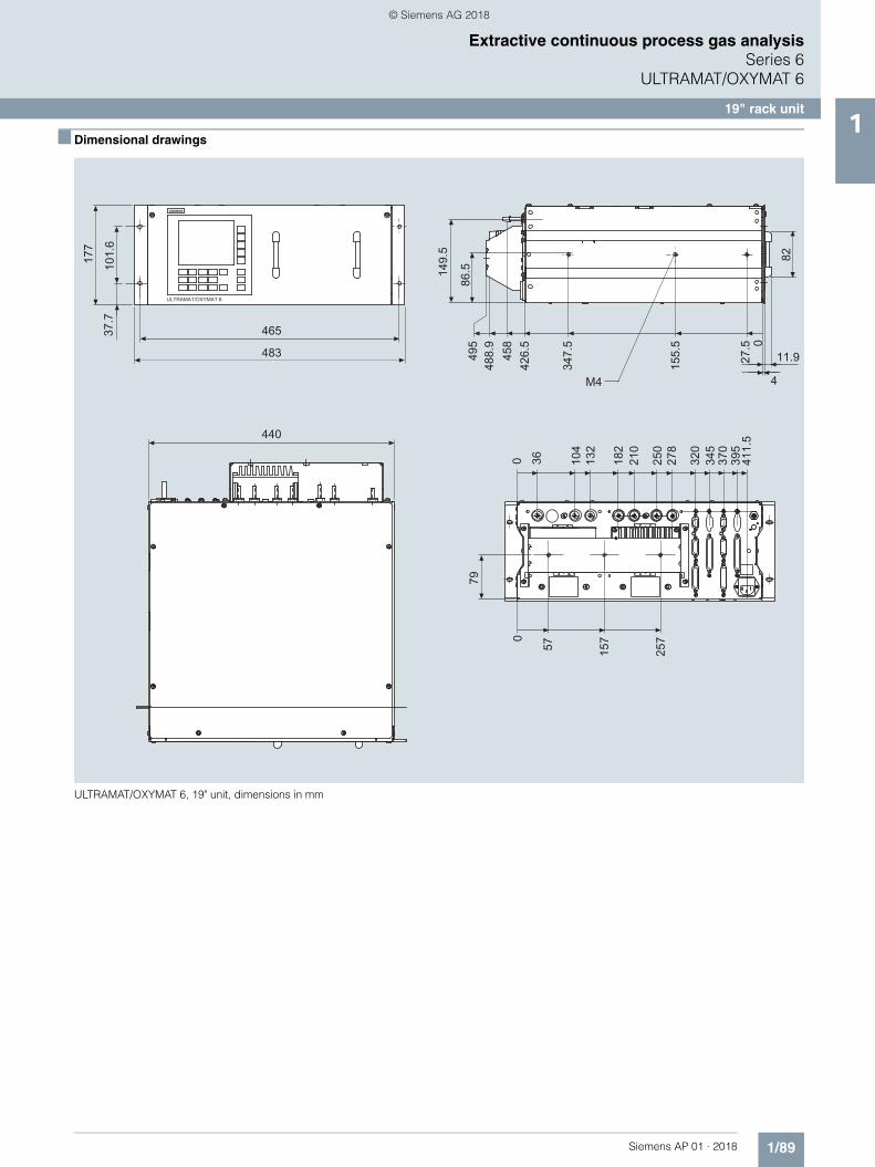
■ Dimensional drawings
ULTRAMAT/OXYMAT 6, 19" unit, dimensions in mm
s
© Siemens AG 2018

1/90 Siemens AP 01 · 2018
Extractive continuous process gas analysisSeries 6ULTRAMAT/OXYMAT 6
19" rack unit1
■ Circuit diagrams
Pin assignment (electrical and gas connections)
ULTRAMAT/OXYMAT 6, 19" unit, pin assignment
M
GND
GND
M
GND
NCNC
GND
M
M
M
M
NC
RD/TD-PRD/TD-N
NC
GNDNC
GNDM
M
GND
+5 V
4
512
13
14
15
1
2
3
6
7
8
9
10
11
12
13
7
8
9
10
11
4
517
18
19
1
2
3
6
16
21
14
20
15
22
23
24
25
1
2
3
4
5
6
7
8
9
Isolated via optocoupler"0" = 0 V (0 ... 4.5 V)"1" = 24 V (13 ... 33 V)
Digital input 1 to 4-NDigital input 1-PDigital input 2-PDigital input 3-PDigital input 4-P
Relay 1
Relay 2
Relay 3
Relay 4
Relay 5
Relay 6
SUB-D 25F connector
Correction of cross-interferenceCorrection of cross-interference
Pressure correctionPressure correction
Analog outputs isolated(also from each other), RL: ≤ 750 Ω
Analog inputsnon-isolated,0 ... 20 mA/500 Ωor 0 ... 10 V(low-resistance)
Analog output 2-P
Analog output 1-NAnalog output 1-PAnalog output 2-N
Analog input 2-PAnalog input 2-NAnalog input 1-PAnalog input 1-NDigital input 6-PDigital input 5-PDigital input 5 to 6-N
SUB-D 15F connector
R_Level-P-
R_Level-N-It is possible to connect bus terminating resistorsto pins 7 and 9.
SUB-D 9F connector (RS 485)
For 2-component version onlyof the ULTRAMAT part
Isolated via optocoupler"0" = 0 V (0 ... 4.5 V)"1" = 24 V (13 ... 33 V)
Contact load max. 24 V/1 A, AC/DC; relay contacts shown: relay coil has zero current
© Siemens AG 2018
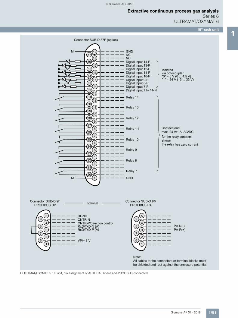
1/91Siemens AP 01 · 2018
Extractive continuous process gas analysisSeries 6
ULTRAMAT/OXYMAT 6
19" rack unit1
ULTRAMAT/OXYMAT 6, 19" unit, pin assignment of AUTOCAL board and PROFIBUS connectors
© Siemens AG 2018

1/92 Siemens AP 01 · 2018
Extractive continuous process gas analysisSeries 6ULTRAMAT/OXYMAT 6
19" rack unit1
ULTRAMAT/OXYMAT 6, 19" unit, gas and electrical connections
124 8 7 6 5
Gas connections: stubs 6 mm or ¼"
9-pin interfaceconnector (option): e.g.PROFIBUS
Power supplyand miniaturefuses
37-pin connector:digital inputs andrelay outputs(optional board)
25-pin connector:digital inputs andrelay outputs
OXYMAT channel ULTRAMAT channelOXYMATchannel
9-pin connector:RS 485
15-pin connector:digital inputs andanalog inputs/outputs
Sample gas inlet
Referencegas inlet
Sample gas outlet Reference gas outlet
Referencegas inlet
Samplegas outlet
Samplegas inlet
ULTRAMATchannel
Purging gasinlet
Connection of atmospheric pressure sensor
© Siemens AG 2018

1/93Siemens AP 01 · 2018
Extractive continuous process gas analysisSeries 6
ULTRAMAT/OXYMAT 6
Documentation1
■ Selection and ordering data
■ More information
The complete documentation is available in various languages for downloading free of charge:http://www.siemens.com/processanalytics/documentation
Operating instructions Article No.
ULTRAMAT 6 / OXYMAT 6Gas analyzer for IR-absorbing gases and oxygen
• German C79000-G5200-C143
• English C79000-G5276-C143
• French C79000-G5277-C143
• Spanish C79000-G5278-C143
• Italian C79000-G5272-C143
© Siemens AG 2018

1/94 Siemens AP 01 · 2018
Extractive continuous process gas analysisSeries 6ULTRAMAT/OXYMAT 6
Suggestions for spare parts1
■ Selection and ordering data
If the device was supplied with a specially cleaned gas path for high oxygen context ("Clean for O2 service"), please ensure that you specify this when ordering spare parts. This is the only way to guarantee that the gas path will continue to comply with the special requirements for this version.
Description 7MB2023 7MB2024 2 years (quantity)
5 years (quantity)
Article No.
Analyzer unit
ULTRAMAT channel
• O-ring for cover (window, rear) x x 2 2 C79121-Z100-A24
• Cover (cell length 20 ... 180 mm) x x 2 2 C79451-A3462-B151
• Cover (cell length 0.2 ... 6 mm) x x 2 2 C79451-A3462-B152
• O-rings, set (ULTRAMAT) x x — 1 C79451-A3462-D501
OXYMAT channel
• O-ring x x 1 2 C74121-Z100-A6
• O-ring (measuring head) x x 2 4 C79121-Z100-A32
• O-ring x x 2 4 C71121-Z100-A159
• Sample chamber, stainless steel, mat. no. 1.4571; non-flow-type compensation branch
x x — 1 C79451-A3277-B535
• Sample chamber, tantalum,non-flow-type compensation branch
x x — 1 C79451-A3277-B536
• Sample chamber, stainless steel, mat. no. 1.4571; flow-type compensation branch
x x — 1 C79451-A3277-B537
• Sample chamber, tantalum,flow-type compensation branch
x x — 1 C79451-A3277-B538
• Measuring head,non-flow-type compensation branch
x x 1 1 C79451-A3460-B525
• Measuring head, flow-type compensation branch x x 1 1 C79451-A3460-B526
Sample gas path
Pressure switch x x 1 2 C79302-Z1210-A2
Restrictor, stainless steel, mat. no. 1.4571;hose gas path
x x 2 2 C79451-A3480-C10
Flow indicator x x 1 2 C79402-Z560-T1
ULTRAMAT channel
• Hose clip x x — 1 C79451-A3478-C9
OXYMAT channel
• Restrictor, titanium, pipe gas path x x 2 2 C79451-A3480-C37
• Reference gas path, 3000 hPa x x 1 1 C79451-A3480-D518
• Capillary, 100 hPa, connection set x x 1 1 C79451-A3480-D519
• Restrictor, stainless steel, mat. no. 1.4571;pipe gas path
x x 1 1 C79451-A3520-C5
Electronics
Front plate with keyboard x x 1 1 C79165-A3042-B506
Adapter plate, LCD/keyboard x x 1 1 C79451-A3474-B605
LC display x x 1 1 A5E31474846
Connector filter x x — 1 W75041-E5602-K2
Fusible element, T 0.63 A/250 V x x 2 3 W79054-L1010-T630
Fusible element, T 1 A/250 V x x 2 3 W79054-L1011-T100
Fusible element, T 2.5 A/250 V x x 2 3 W79054-L1011-T250
ULTRAMAT channel
• Motherboard, with firmware: see spare parts list x x — 1
OXYMAT channel
• Motherboard, with firmware: see spare parts list x x — 1
© Siemens AG 2018
Related Documents