CONFORMANCE STANDARDS MATERIAL COMPARISONS FOR ASTM AND JIS MATERIAL PROPERTIES BUTT-WELDING ENDS FLANGE DIMENSION & TEMPLATES FOR DRILLING RELATIONSHIP BETWEEN NOMINAL PIPE SIZE & INSIDE DIAMETER VALVE BODY MINIMUM WALL THICKNESS TEMPERATURE CONVERSION ANSI PRESSURE TEMPERATURE RATINGS HYDROSTATIC TEST PRESSURE TO ANSI B16.34 CONVERSION TABLES DATA FOR CALCULATION OF FLOW AND/OR PRESSURE DROP HARDNESS CONVERSION CORROSION TABLES

Welcome message from author
This document is posted to help you gain knowledge. Please leave a comment to let me know what you think about it! Share it to your friends and learn new things together.
Transcript

CONFORMANCE STANDARDSMATERIAL COMPARISONS FOR ASTM AND JISMATERIAL PROPERTIESBUTT-WELDING ENDSFLANGE DIMENSION & TEMPLATES FOR DRILLINGRELATIONSHIP BETWEEN NOMINAL PIPE SIZE & INSIDEDIAMETERVALVE BODY MINIMUM WALL THICKNESSTEMPERATURE CONVERSIONANSI PRESSURE TEMPERATURE RATINGSHYDROSTATIC TEST PRESSURE TO ANSI B16.34CONVERSION TABLESDATA FOR CALCULATION OF FLOW AND/OR PRESSURE DROPHARDNESS CONVERSIONCORROSION TABLES
0302플디-삼우카다록02 2012.3.2 9:6 PM 페이지158

SSAAMMWWOOOO KKJJSS TTEECC CCOO..,, LLTTDD.. 159
KJS VALVES CONFORM TO THE FOLLOWING STANDARDS ASAPPLICABLE TO CUSTOMER REQUIREMENTS.
: API Specification for Pipeline Valves: Valve Inspection and Test: Steel Gate Valves, Flanged and Butt-welding Ends: Class 150, Cast Corrosion-Resistant Flanged-End Gate Valves: Large-Diameter Carbon Steel Flanges
: Steel Pipe Flanges and Flanged Fittings: Face-to-Face and End-to-End Dimensions of Ferrous Valves : Butt-welding Ends: Valves-Flanged, Threaded, And Welding End: Standard Finishes for Contact Faces of Pipe Flanges and Connecting-End Flanges of Valvesand Fittings
: Standard Marking System for Valves, Fittings, Flanges and Unions: Steel Pipe Line Flanges: By-Pass and Drain Connection Standard
: Steel wedge gate valves (flange and butt-welding ends): Steel check valves (flange and butt-welding ends): Steel globe and globe stop and check valves (flange and butt-welding ends): Steel wedge gate, globe and check valves (50mm & smaller): Valve for cryogenic service
: General Rules for Inspection of Valves: Pressure Ratings for Ferrous Material Pipe Flanges: Tolerances for Pipe Flanges: Basic Dimensions of Ferrous Material Pipe Flanges: 10 kgf/㎠ Cast Steel Flanged Glove Valves: 10 kgf/㎠ Cast Steel Flanged Gate Valves (Outside Screw Type): 10 kgf/㎠ Cast Steel Flanged Swing Check Valves: 20 kgf/㎠ Cast Steel Flanged Glove Valves: 20 kgf/㎠ Cast Steel Flanged Gate Valves (Outside Screw Type): 20 kgf/㎠ Cast Steel Flanged Swing Check Valves: Steel Pipe Flanges for The Petroleum Industry: Ring Joint Gaskets and Grooves for Petroleum Industry: Standard Marking System for valves: Valve Inspection and Test: Cast Steel Flanged Valves for the Petroleum Industry (Class 150,300): Cast Steel Valves for the Petroleum Industry, Flanged or Butt-welding Ends (Class 600 to 2500)
: American Petroleum Institute: American National Standards Institute: American Society for Testing and Materials: American Society of Mechanical Engineers: Manufacturers Standardization society of the Valve and Fitting Industry: British Standards Institution: Japanese Industrial Standards: Japan Petroleum Institute: National Association of corrosion Engineers: American welding Society
API Spec 6D Latest EditionAPI Standard 598 Latest EditionAPI Standard 600 Latest EditionAPI Standard 603 Latest EditionAPI Standard 605 Latest Edition
ASME B16.5 Latest EditionASME B16.10 Latest EditionASME B16.25 Latest EditionASME B16.34 Latest EditionMSS Standard Practice SP-6 Latest Edition
MSS Standard Practice SP-25 Latest EditionMSS Standard Practice SP-44 Latest EditionMSS Standard Practice SP-45 Latest Edition
BS 1414 Latest EditionBS 1868 Latest EditionBS 1873 Latest EditionBS 5352 Latest EditionBS 6364 Latest Edition
JIS B2003 Latest EditionJIS B2201 Latest EditionJIS B2203 Latest EditionJIS B2210 Latest EditionJIS B2071 Latest EditionJIS B2073 Latest EditionJIS B2074 Latest EditionJIS B2081 Latest EditionJIS B2083 Latest EditionJIS B2084 Latest EditionJPI-7S-15 Latest EditionJPI-7S-23 Latest EditionJPI-7S-24 Latest EditionJPI-7S-39 Latest EditionJPI-7S-46 Latest EditionJPI-7S-47 Latest Edition
APIANSIASTMASMEASSBSJISJPINACEAWS
CONFORMANCE STANDARDS
0302플디-삼우카다록02 2012.3.2 9:6 PM 페이지159

MATERIAL COMPARISONS FOR ASTM & JIS(CASTING & FORGING)
SSAAMMWWOOOO KKJJSS TTEECC CCOO..,, LLTTDD..160
General ClassificationCastings Forgings Castings Forgings
Service Temp“ASTM” Symbols “JIS” Symbols
Cast IronCast IronCarbon SteelCarbon Steel½½ Mo Steel1¼¼ Cr - ½½Mo2¼¼ Cr - 1Mo5Cr - ½½Mo9Cr - 1MoAl Steel½½ Mo Steel2½½ Ni Steel3½½ Ni Steel13Cr - ½½Mo18Cr - 8Ni(CO.03)18Cr - 8Ni(CO.08)18Cr - 8Ni - 2Mo(CO.03)18Cr - 8Ni - 2Mo(CO.08)18Cr - 8Ni - Ti18Cr - 8Ni - Cb22Cr - 12Ni23Cr - 19Ni19Cr - 27Ni - 2Mo - 3Cu
A126 - Class BA126 - Class CA216 - WCAA216 - WCBA217 - WC1A217 - WC6A217 - WC9A217 - C5A217 - C12A352 - LCB, LCCA352 - LC1A352 - LC2A352 - LC3A217 - CA15A351 - CF3A351 - CF8A351 - CF3MA351 - CF8M
A351 - CF8CA351 - CH20A351 - CK20A351 - CN7M
A105A182 - F1A182 - F11A182 - F22A182 - F5aA182 - F9A350 - LF2
A350 - LF3A182 - F6aA182 - F304LA182 - F304A182 - F316LA182 - F316A182 - F321A182 - F347
G5501 - FC20G5501 - FC25G5151 - SCPH1G5151 - SCPH2G5151 - SCPH11G5151 - SCPH21G5151 - SCPH32G5151 - SCPH61
G5121 - SCPL1G5121 - SCPL11G5121 - SCPL21G5121 - SCPL31G5121 - SCS1G5121 - SCS19AG5121 - SCS13AG5121 - SCS16AG5121 - SCS14A
G5121 - SCS21G5121 - SCS17G5121 - SCS18G5121 - SCS23
G3202 - SFVC 2AG3203 - SFVA F1G3203 - SFVA F11AG3203 - SFCA F22AG3203 - SFVA F5DG3203 - SFVA F9G3205 - SFL2
G3205 - SFL3G4303 - 410G3214 - SUS F304LG3214 - SUS F304G3214 - SUS F316LG3214 - SUS F316G3214 - SUS F321G3214 - SUS F347
205℃250℃420℃
425℃
455℃
593℃
593℃
650℃
650℃
-46℃
-59℃
-73℃
-101℃
550℃
800℃
800℃
800℃
800℃
800℃
800℃
1200℃
1200℃
1200℃
HIGH - TEMPERATURE
LOW - TEMPERATURE
STAINLESS STEEL
General Classification “ASTM” Symbols “JIS” Symbols Service Temp
A307 - BA193 - B5A193 - B7A193 - B16A193 - B8A193 - B8CA193 - B8TA193 - B8MA453 - 660
G3101 - SS41G4051 - S25CG4107 - SNB5G4107 - SNB7G4107 - SNB16G4303 - SUS304G4303 - SUS347G4303 - SUS321G4303 - SUS316
260℃204℃600℃550℃600℃800℃800℃800℃800℃540℃
Mild SteelCarbon Steel
5Cr - ½½Mo1Cr - ????MoCr - Mo - Va18Cr - 8Ni
18Cr - 10Ni - Cb18Cr - 10Ni - Ti
18Cr - 12Ni - 2Mo15Cr - 25Ni - Mo - Ti - V - B
●● HIGH - TEMPERATURE(BOLT)
Body Materials Temperature Degress F. Bolts Material Specifications NutsCarbon Steel(Grade WCB)Carbon Steel(Grade LCB)Carbon Moly(Grade WC1)1¼¼Cr - ½½Mo(Grade WC6)
2¼¼Cr - 1Mo(Grade WC9)
5Cr - ½½Mo(Grade C5)
9Cr - 1Mo(Grade C12)
Type 304(Grade CF8)
Type 316(Grade CF8M)
3½½Ni(Grade LC3)
-20 to 800-50 to 650-20 to 850-20 to 1000-20 to 1000
1000 to 1050-20 to 1000
1000 to 1100-20 to 1000
1000 to 1100-425 to 100100 to 1500
-425 to 100100 to 1500
-150 to -50
-50 to 650
ASTM A193 Gr B7ASTM A320 Gr L7ASTM A193 Gr B7ASTM A193 Gr B7ASTM A193 Gr B7ASTM A193 Gr B16ASTM A193 Gr B7ASTM A193 Gr B16ASTM A193 Gr B7ASTM A193 Gr B16ASTM A320 Gr B8ASTM A193 Gr B8ASTM A320 Gr B8ASTM A193 Gr B8MASTM A320 Gr B7With Charpy Test or 8MASTM A193 Gr B7
ASTM A194 Gr 2HASTM A194 Gr 4ASTM A194 Gr 2HASTM A194 Gr 2HASTM A193 Gr B7ASTM A194 Gr 4ASTM A194 Gr 2HASTM A194 Gr 4ASTM A194 Gr 8HASTM A194 Gr 2ASTM A194 Gr 8ASTM A194 Gr 8ASTM A194 Gr 8ASTM A194 Gr 8MASTM A194 Gr 8
ASTM A194 Gr 2H
General Classification “ASTM” Symbols “JIS” Symbols Service Temp
A320 - L7A320 - B8A320 - B8CA320 - B8TA320 - B8M
A194 - 2HA194 - 4A194 - 8A194 - 8CA194 - 8TA194 - 8M
G4303 - SUS304G4303 - SUS347G4303 - SUS321G4303 - SUS316
G4051 - S20CG4051 - S45C
G4303 - SUS304G4303 - SUS347G4303 - SUS321G4303 - SUS316
-101℃-196℃-196℃-196℃-196℃
420℃550℃600℃800℃800℃800℃800℃
Cr - Mo18Cr - 8Ni
18Cr - 10Ni - Cb18Cr - 10Ni - Ti
18Cr - 12Ni - 2Mo
Carbon Steel(C 0.15)Carbon Steel(C 0.40)
Carbon Mo Steel18Cr - 8Ni
18Cr - 10Ni - Cb18Cr - 10Ni - Ti
18Cr - 12Ni - 2Mo
●● HIGH - TEMPERATURE(BOLT)
●● NUT
0302플디-삼우카다록02 2012.3.2 9:6 PM 페이지160

MATERIAL PROPERTIES
SSAAMMWWOOOO KKJJSS TTEECC CCOO..,, LLTTDD.. 161
TensileStrengthMin. Ksi
Mpa
Yield PointMin. Ksi
Mpa
Elongationin 2 inch(50mm)% Min.
Reductionof Area% Min.
70485
30205
22
35
90-115621-793
65448
18
30
70485
40275
20
35
70485
40275
20
35
70485
28195
35
-
70485
30205
30
-
76525
40275
6
-
70485
30205
35
-
70485
30205
30
-
65450
35240
24
35
90-115621-793
60414
18
35
90-115621-793
60414
18
35
CHEMICAL PROPERTIES
PHYSICAL PROPERTIES
A-216WCB0.30
1.00Max0.040.0450.500.400.250.00.30
-
A-217CA-150.151.00
0.0400.0401.00
11.5-14.0--
1.50--
A-217WC60.20
0.50-0.800.040.045
-1.00-1.500.45-0.65
-0.60
--
A-217WC90.18
0.40-0.700.04
0.045-
2.00-2.750.90-1.20
-0.60
--
A-351CF80.081.500.040.048.00
18.0-21.0--
2.00--
A-351CF8M0.081.500.040.049.00
18.0-21.02.00-3.00
-2.00
--
A-494N-12MV
0.121.000.0400.030Bal1.00
26.0-30.0-
1.004.0-6.0
0.20-0.60
A-351CF30.031.500.040.04
8.00-12.017.0-21.0
--
2.00--
A-351CF3M0.031.500.040.04
9.00-13.017.0-21.02.00-3.00
-1.50
--
A-352LCB0.031.000.050.06
----
0.60--
A-217C-50.20
0.40-0.700.0400.045
-4.0-6.500.45-0.65
-0.75
--
A-217C-120.20
0.35-0.650.0400.045
-8.00-10.000.90-1.20
-1.00
--
Carbon Steel CA-15 High Temp. High Temp. 304-S. S. 316-S. S. HASTESSOY-B 304L-S. S. 316L-S. S. Low Temp. HIGH TEMP
CASTING MATERIALS
TensileStrengthMin. Ksi
Mpa
Yield PointMin. Ksi
Mpa
Elongationin 2 inch(50mm)% Min
Reductionof Area% Min.
85586
55379
18
35
58400
28193
20
45
70483
36248
22
30
75517
30207
35
50
75517
30207
45
50
75517
30207
30
50
75517
30207
30
50
70483
25172
30
50
70493
25172
30
30
--
--
-
-
125862
105724
16
50
175-
--
-
-
CHEMICAL PROPERTIES
PHYSICAL PROPERTIES
A-182F6a0.151.001.000.040.030.50
11.5-14.5--
Bal.--
A-439D2C0.29
1.00-3.001.80-2.40
0.08-
21.0-24.00.50
-----
11-13% Cr Ductile Carbon Steel B - 8F 321 - S. S. 304 - S. S. 316 - S. S. 304L - S. S. 316L - S. S. Hard Facing Bolts NutsASTM Std.
GradeC% Max.Si% MaxMn% Maxp% Max.S% Max.
Ni%Cr%Mo%Ti%Fe%W%Co%
ASTMA-105
0.22-0.350.35
0.60-1.050.040.05
-------
A-320B-8F0.151.002.000.20
0.150-0.3508.00-10.0017.00-19.00
-----
A-182F-3210.081.002.000.0300.030
9.00-12.0017.00Min
-C%×5-0.06
---
A-182F-3040.081.002.000.040.03
8.0-11.018.0-20.0
-----
A-182F-3160.081.002.000.040.03
10.0-14.016.0-18.02.00-3.00
----
A-182F-304L0.0351.002.00
0.0400.030
8.00-13.018.0-20.0
-----
A-182F-316L0.0351.002.000.0400.030
10.00-15.0016.00-18.00
2.00-3.00----
KLSHF-6R1.051.11
-28.3
--
0.304.20Bal.
A-193B7
0.38-0.480.15-0.350.75-1.00
0.040.04
-0.80-1.100.15-0.25
-Bal.
--
A-1942H
0.04--
0.040.05
----
Bal.--
WROUGHT MATERIALS
ASTM SteelGrade
C% Max.Mn%
p% Max.S% Max.
Ni%Cr%Mo%CuSiFeV
0302플디-삼우카다록02 2012.3.2 9:6 PM 페이지161

BUTT-WELDING ENDS
SSAAMMWWOOOO KKJJSS TTEECC CCOO..,, LLTTDD..162
Dimensions of Butt - Welding Ends
Nominal Pipe Size Schedule Numberor Wall
Outside Diameter(Cast Steel Valves)A
inch inch inch inchmm mm mm mm
Nominal Inside DiameterB
Machined Inside DiameterC
Nominal Wall ThicknessT
4080
160XXS4080
160XXS40804080
120160XXS4080
120160XXS4080
120160XXS406080
100120140XXS160406080
100120140160STD40XS6080
100120140160
STD40XS6080
100120140160STD406080
100120140160
2.96
3.59
4.12
4.62
5.69
6.78
8.78
10.94
12.97
14.25
16.25
75
91
105
117
144
172
223
278
329
362
413
2.4692.3232.1251.7713.0682.9002.6242.3003.5483.3644.0263.8263.6243.4383.1525.0474.8134.5634.3134.0636.0655.7615.5015.1874.8977.9817.8137.6257.4377.1877.0016.8756.813
10.0209.7509.5629.3129.0628.7508.500
12.00011.93811.75011.62611.37411.06210.75010.50010.126
13.25013.12413.00012.81212.50012.12411.81211.50011.18815.25015.00014.68814.31213.93813.56213.12412.812
63595445787467589085
10297928780
128122116110103154146140132124203198194189183178175173255248243237230222216305303298295289281273267257
337333330325318308300292284387381373364354344333325
2.4792.3512.1781.8683.0812.9342.6922.4093.5643.4024.0443.8693.6923.5303.2795.0704.8664.6474.4284.2096.0945.8285.6005.3265.0728.0207.8737.7097.5447.3267.1637.0536.998
10.0709.8349.6709.4519.2328.9598.740
12.05311.99911.83411.72511.50511.23210.95910.74010.413
13.30313.19213.08412.92012.64612.31812.04411.77111.49815.30315.08414.81114.48214.15513.82613.44213.170
62.9559.7055.3047.4578.2574.5068.4061.2090.5586.40
102.7098.2593.8089.6583.30
128.80123.60118.05112.45106.90154.80148.05142.25135.30128.85203.70199.95195.80191.60186.10181.95179.15177.75255.80249.80245.60240.05234.50227.55222.00306.15304.75300.60297.80292.25285.30278.35272.80264.50
337.90335.10332.35328.15321.20312.90305.90299.00292.05388.70383.15376.20367.85359.55351.20341.45334.50
0.2030.2760.3750.5520.2160.3000.4380.6000.2260.3180.2370.3370.4380.5310.6740.2580.3750.5000.6250.7500.2800.4320.5620.7190.8640.3220.4060.5000.5940.7190.8120.8750.9060.3650.5000.5940.7190.8441.0001.1250.3750.4060.5000.5620.6880.8441.0001.1251.312
0.3750.4380.5000.5940.7500.9381.0941.2501.4060.3750.5000.6560.8441.0311.2191.4381.594
5.157.009.5514.00
ASME B16.25 - 2004
5.507.6011.1515.255.758.106.008.5511.1513.5017.06.559.5512.7015.9019.057.1010.9514.2518.2521.958.2010.3012.7015.1018.2520.6022.2523.009.2512.7015.1018.2521.4525.4028.609.5510.3012.7014.2517.5021.4525.4028.6033.30
9.5511.1512.7015.1019.0523.8527.8031.7535.709.5512.7016.6521.4526.2030.9536.5540.50
2½½
3
3½½
4
5
6
8
10
12
14
16
0302플디-삼우카다록02 2012.3.2 9:6 PM 페이지162

BUTT-WELDING ENDS
SSAAMMWWOOOO KKJJSS TTEECC CCOO..,, LLTTDD.. 163
Dimensions of Butt - Welding Ends
Nominal Pipe Size Schedule Numberor Wall
Outside Diameter(Cast Steel Valves)A
inch inch inch inchmm mm mm mm
Nominal Inside DiameterB
Machined Inside DiameterC
Nominal Wall ThicknessT
ASME B16.25 - 2004
18
20
22
24
26
28
30
32
34
36
NOTESSTC - standard wall thickness
XS - estra - strong wall thicknessXXS - double extra - strong wall thickness
STDXS406080
100120140160
STDXS406080
100120140160
STDXS6080
100120140160
STDXS30406080
100120140160
1020
102030
102030
10203040
10203040
10203040
18.28
20.31
22.34
24.38
26.38
28.38
30.38
32.50
34.50
36.50
464
516
567
619
670
721
772
825
876
927
17.25017.00016.87616.50016.12415.68815.25014.87614.438
19.25019.00018.81218.37617.93817.43817.00016.50016.062
21.25021.00020.25019.75019.25018.75018.25017.750
23.25023.00022.87622.62422.06221.56220.93820.37619.87619.312
25.37625.000
27.37627.00026.750
29.37629.00028.750
31.37631.00030.75030.624
33.37633.00032.75032.624
35.37635.00034.75034.500
438432429419410398387378367
489483478467456443432419408
540533514502489476464451
591584581575560548532518505491
645635
695686679
746737730
797787781778
848838832829
899889883876
17.30317.08416.97516.64616.31815.93615.55315.22514.842
19.30319.08418.92018.53818.15517.71717.33416.89616.513
21.30321.08420.42819.99019.55319.11518.67818.240
23.30323.08422.97522.75522.26321.82621.28020.78820.35019.857
25.41325.084
27.41327.08426.865
29.41329.08428.865
31.41331.08430.86530.755
33.41333.08432.86532.755
35.41335.08434.86534.646
439.50433.95431.15422.80414.50404.75395.05386.70377.00
490.30484.75480.55470.85461.15450.00440.30429.15419.45
541.10535.55518.85507.75496.65485.50474.40463.30
591.90586.35583.55578.00565.50554.40540.50528.00516.90504.35
645.50637.15
696.30687.95682.35
747.10738.75733.15
797.90789.55783.95781.20
848.70840.35833.75832.00
899.50891.15885.55880.00
0.3750.5000.5620.7500.9381.1561.3751.5621.781
0.3750.5000.5940.8121.0311.2811.5001.7501.969
0.3750.5000.8751.1251.3751.6251.8752.125
0.3750.5000.5620.6880.9691.2191.5311.8122.0622.344
0.3120.500
0.3120.5000.625
0.3120.5000.625
0.3120.5000.6250.688
0.3120.5000.6250.688
0.3120.5000.6250.750
9.5512.7014.2519.0523.8529.3534.9539.6545.25
9.5512.7015.1020.6026.2032.5538.1044.4550.00
9.5512.7022.2528.6034.9541.3047.6554.00
9.5512.7014.2517.5024.6030.9538.9046.0052.3559.55
7.9012.70
7.9012.7015.90
7.9012.7015.90
7.9012.7015.9017.50
7.9012.7015.9017.50
7.9012.7015.9019.05
0302플디-삼우카다록02 2012.3.2 9:6 PM 페이지163

BUTT-WELDING ENDS
SSAAMMWWOOOO KKJJSS TTEECC CCOO..,, LLTTDD..164
FORMULADimension C for the bore of pipe, valve, welding neck flanges and pipe fittings when using continuous rectangular or taper backing rings isdetermined by the following formula:
C = A -0.031(0.787) - 1.75t -0.010(0.254)where
A = Nominal outside dimeter of pipe0.031(0.785) = Minus tolerance on OD of pipe (As covered by ASTM Specification having the more restrictive requirements
such as A106, A335, etc.)1.75 = Munimum wall of 87 ½ percent of nominal wall (permitted by ASTM specification having the more restrictive
requirements such as A106, A335, etc.) multiplied by two to convert into terms of diameter.t = Nominal wall thickness of pipe in nches
0.010(0.254) = Plus machining tolerance on Bore C.
Linear dimensions are in inches with metric valves shown in millimeters in parenthesis.
ASME B16.25 - 2004
TYPE_ A
For Wall Thickness(t) 0.188(4.8) to 0.875(22.2) Inclusive
Inside Contour for Use with Rectangular Backing Ring
For Wall Thickness(t) Greater Than 0.875(22.2)
Inside Contour for Use with Taper Backing Ring
TYPE_ C
TYPE_ B
TYPE_ D
STANDARD PREPARATION OF VALVE BUTT WELDING ENDS
0302플디-삼우카다록02 2012.3.2 9:6 PM 페이지164

FLANGE DIMENSION & TEMPLATES FOR DRILLING
SSAAMMWWOOOO KKJJSS TTEECC CCOO..,, LLTTDD.. 165
Dimensions of Class 150 Steel Flange Valves and Fittings
Nominal Size
InsideDiam
OD ofFlange
RaisedFace Diam.
Thicknessof Flange
Diam. ofBolt Circle
Diam. ofBolt Holes
d D g T C h K P E F r
ASME B16.5 - 2004
inchmm
inchmm
inchmm
inchmm
inchmm
inchmm
inchmm
inchmm
inchmm
inchmm
inchmm
0.5013
3.5089
1.3834.9
--
0.4411.5
2.3860.3
0.6216
--
--
--
--
--
0.7519
3.8898
1.6942.9
--
0.5013.0
2.7569.9
0.6216
--
--
--
--
--
1.0025
4.25108
2.0050.8
0.441
11.31
0.5614.5
3.1279.4
0.6216
1.87547.63
0.256.35
0.3448.74
0.030.8
2.5063.5
1.2532
4.62117
2.5063.5
0.501
13.01
0.6216.0
3.5088.9
0.6216
2.25057.15
0.256.35
0.3448.74
0.030.8
2.8873.0
1.5038
5.00127
2.8873.0
0.561
14.51
0.6917.5
3.8898.4
0.6216
2.56265.09
0.256.35
0.3448.74
0.030.8
3.2582.5
2.0051
6.00152
3.6292.1
0.621
16.01
0.7519.5
4.75120.6
0.7520
3.25082.55
0.256.35
0.3448.74
0.030.8
4.00102
2.5064
7.00178
4.12104.8
0.691
17.51
0.8822.5
5.50139.7
0.7520
4.00101.60
0.256.35
0.3448.74
0.030.8
4.75121
3.0076
7.50191
5.00127.0
0.751
19.51
0.9424.0
6.00152.4
0.7520
4.50144.30
0.256.35
0.3448.74
0.030.8
5.25133
3.5089
8.50216
5.50139.7
0.81
20.51
0.9424.0
7.00177.8
0.7520
5.188131.76
0.256.35
0.3448.74
0.030.8
6.06154
4.00102
9.00229
6.19157.2
0.9424.0
7.50190.5
0.7520
5.875149.23
0.256.35
0.3448.74
0.030.8
6.75171
5.00127
10.000254
7.31185.7
0.9424.0
8.50215.9
0.8823
6.750171.45
0.756.35
0.3448.74
0.030.8
7.62194
6.00152
11.00279
8.50215.9
1.0025.5
9.50241.3
0.8823
7.625193.68
0.256.35
0.3448.74
0.030.8
8.62219
8.00203
13.50343
10.62269.9
1.1229.0
11.75298.4
0.8823
9.750247.65
0.256.35
0.3448.74
0.030.8
10.75273
10.00254
16.00406
12.75323.8
1.1930.5
14.25361.9
1.0026
12.000304.80
0.256.35
0.3448.74
0.030.8
13.00330
12.00305
19.00483
15.00381.0
1.2532.0
17.00431.8
1.0026
15.000381.00
0.256.35
0.3448.74
0.030.8
16.00406
13.25337
21.00535
16.25412.8
1.3835.0
18.75476.2
1.1229
15.625396.88
0.256.35
0.3448.74
0.030.8
16.75425
15.25387
23.50595
18.50469.9
1.4437.0
21.25539.7
1.1229
17.875454.03
0.256.35
0.3448.74
0.030.8
19.00483
17.25438
25.00635
21.00533.4
1.5640.0
22.75577.8
1.2532
20.375517.53
0.256.35
0.3448.74
0.030.8
21.50546
19.25489
27.50700
23.00584.2
1.6943.0
25.00635.0
1.2532
22.000558.80
0.256.35
0.3448.74
0.030.8
23.50597
23.25591
32.00815
27.25692.2
1.8848.0
29.50749.3
1.3835
26.500673.10
0.256.35
0.3448.74
0.030.8
28.00711
inchmm
½½15
¾¾20
125
1¼¼32
1½½40
250
2½½65
380
3½½90
4100
5125
6150
8200
10250
12300
14350
16400
18450
20500
24600
No.of
Bolt
4
4
4
4
4
4
4
4
8
8
8
8
8
12
12
12
16
16
20
20
Diamof
Bolt
½
½
½
½
½
⅝
⅝
⅝
⅝
⅝
¾
¾
¾
⅞
⅞
1
1
1⅛
1⅛
1¼
RingNo.
-
-
R15
R17
R19
R22
R25
R29
R33
R36
R40
R43
R48
R52
R56
R59
R64
R68
R72
R76
FacingDiam.
PitchDiam.
DepthGroove
Width ofGroove
Groove FilletRadius
0302플디-삼우카다록02 2012.3.2 9:6 PM 페이지165
FLANGE DIMENSION & TEMPLATES FOR DRILLING
SSAAMMWWOOOO KKJJSS TTEECC CCOO..,, LLTTDD..166
Nominal Size
InsideDiam
OD ofFlange
RaisedFace Diam.
Thicknessof Flange
Diam. ofBolt Circle
Diam. ofBolt Holes
d D g T C h K P E F r
ASME B16.5 - 2004
inchmm
inchmm
inchmm
inchmm
inchmm
inchmm
inchmm
inchmm
inchmm
inchmm
inchmm
0.5013
3.7595
1.3834.9
0.5614.5
2.6266.7
0.6216
1.34434.13
0.2195.56
0.2817.14
0.030.8
2.0051.0
0.7519
4.62117
1.6942.9
0.6216.0
3.2582.5
0.7520
1.68842.86
0.2506.35
0.3448.74
0.030.8
2.5063.5
1.0025
4.88124
2.0050.8
0.6917.5
3.5088.9
0.7520
2.00050.80
0.7506.35
0.3448.74
0.030.8
2.7570.0
1.2532
5.25133
2.5063.5
0.7519.5
3.8898.4
0.7520
2.37560.33
0.2506.35
0.3448.74
0.030.8
3.1279.5
1.5038
6.12156
2.8873.0
0.8121.0
4.50114.3
0.8823
2.68868.26
0.2506.35
0.3448.74
0.030.8
3.5690.5
2.0051
6.50165
3.6292.1
0.8822.5
5.00127.0
0.7520
3.25082.55
0.3127.92
0.46911.91
0.030.8
4.25108
2.5064
7.50191
4.12104.8
1.0025.5
5.88149.2
0.8823
4.000101.60
0.3127.92
0.46911.91
0.030.8
5.00127
3.0076
8.25210
4.00127.0
1.1229.0
6.62168.3
0.8823
4.875123.83
0.3127.92
0.46911.91
0.030.8
5.75146
3.5089
9.00229
5.50139.7
1.1930.5
7.25184.1
0.8823
5.188131.76
0.3127.92
0.46911.91
0.030.8
6.25159
4.00102
10.00254
6.19157.2
1.2532.0
7.88200.0
0.8823
5.875149.23
0.3127.92
0.46911.91
0.030.8
6.88175
5.00127
11.00279
7.31185.7
1.3835.0
9.25234.9
0.8823
7.125180.98
0.3127.92
0.46911.91
0.030.8
8.25210
6.00152
12.50318
8.50215.9
1.4437.0
10.62269.9
0.8823
8.312211.14
0.3127.92
0.46911.91
0.030.8
9.50241
8.00203
15.00381
10.62269.9
1.6241.5
13.00330.2
1.0026
10.265269.88
0.3127.92
0.46911.91
0.030.8
11.88302
10.00254
17.50445
12.75323.8
1.8848.0
15.25387.3
1.1229
12.750323.85
0.3127.92
0.46911.91
0.030.8
14.00356
12.00305
20.50520
15.00381.0
2.0051.0
17.75450.8
1.2532
15.000381.00
0.3127.92
0.46911.91
0.030.8
16.25413
13.25337
23.00585
16.25412.8
2.1254.0
20.25514.3
1.2532
16.500419.10
0.3127.92
0.46911.91
0.030.8
18.00457
15.25387
25.50650
18.50469.9
2.2557.5
22.50571.5
1.3835
18.500469.90
0.3127.92
0.46911.91
0.030.8
20.00508
17.00432
28.00710
21.00533.4
2.3860.5
24.75628.6
1.3835
21.000533.40
0.3127.92
0.46911.91
0.030.8
22.62575
19.00483
30.50775
23.00584.2
2.5063.5
27.00685.8
1.3835
23.000584.20
0.3759.52
0.53113.49
0.061.5
25.00635
23.00584
36.00915
27.25692.2
2.7570.0
32.00812.8
1.6242
27.250692.15
0.43811.13
0.65616.66
0.061.5
30.38749
inchmm
½½15
¾¾20
125
1¼¼32
1½½40
250
2½½65
380
3½½90
4100
5125
6150
8200
10250
12300
14350
16400
18450
20500
24600
No.of
Bolt
4
4
4
4
4
8
8
8
8
8
8
12
12
16
16
20
20
24
24
24
Diamof
Bolt
½
⅝
⅝
⅝
¾
⅝
¾
¾
¾
¾
¾
¾
⅞
1
1⅛
1⅛
1¼
1¼
1¼
1½
RingNo.
R11
R13
R16
R18
R20
R23
R26
R31
R34
R37
R41
R45
R49
R53
R57
R61
R65
R69
R73
R77
FacingDiam.
PitchDiam.
DepthGroove
Width ofGroove
Groove FilletRadius
Dimensions of Class 300 Steel Flange Valves and Fittings
0302플디-삼우카다록02 2012.3.2 9:6 PM 페이지166

FLANGE DIMENSION & TEMPLATES FOR DRILLING
SSAAMMWWOOOO KKJJSS TTEECC CCOO..,, LLTTDD.. 167
Dimensions of Class 600 Steel Flange Valves and Fittings
Nominal Size
InsideDiam
OD ofFlange
RaisedFace Diam.
Thicknessof Flange
Diam. ofBolt Circle
Diam. ofBolt Holes
d D g T C h K P E F r
ASME B16.5 - 2004
inchmm
inchmm
inchmm
inchmm
inchmm
inchmm
inchmm
inchmm
inchmm
inchmm
inchmm
0.5013
3.7595
1.3834.9
0.5614.5
2.6266.7
0.6216
1.34434.13
0.2195.56
0.2817.14
0.030.8
2.0051.0
0.7519
4.62117
1.6942.9
0.6216.0
3.2582.5
0.7520
1.68842.86
0.2506.35
0.3448.74
0.030.8
2.5063.5
1.0025
4.88124
2.0050.8
0.6917.5
3.5088.9
0.7520
2.00050.80
0.2506.35
0.3448.74
0.030.8
2.7570.0
1.2532
5.25133
2.5063.5
0.8121.0
3.8898.4
0.7520
2.37560.33
0.2506.35
0.3448.74
0.030.8
3.1279.5
1.5038
6.12156
2.8873.0
0.8822.5
4.50114.3
0.8823
2.68868.26
0.2506.35
0.3448.74
0.030.8
3.5690.5
2.0051
6.50165
3.6292.1
1.0025.5
5.00127.0
0.7520
3.25082.55
0.3127.92
0.46911.91
0.030.8
4.25108
2.5064
7.50191
4.12104.8
1.1229.0
5.88149.2
0.8823
4.000101.60
0.3127.92
0.46911.91
0.030.8
5.00127
3.0076
8.25210
5.00127.0
1.2532.0
6.62168.3
0.8823
4.875123.83
0.3127.92
0.46911.91
0.030.8
5.75146
3.5089
9.00229
5.50139.7
1.3835.0
7.25184.1
1.0026
5.188131.76
0.3127.92
0.46911.91
0.030.8
6.25159
4.00102
10.75273
6.19157.2
1.5038.5
8.50215.9
1.0026
5.875149.23
0.3127.92
0.46911.91
0.030.8
6.88175
5.00127
13.00330
7.31185.7
1.7544.5
10.50266.7
1.1229
7.125180.98
0.3127.92
0.46911.91
0.030.8
8.25210
6.00152
14.00356
8.50215.9
1.8848.0
11.50292.1
1.1229
8.312211.14
0.3127.92
0.46911.91
0.030.8
9.50241
7.88200
16.50419
10.62269.9
2.1956.0
13.75349.2
1.2532
10.265269.88
0.3127.92
0.46911.91
0.030.8
11.88302
9.75248
20.00510
12.75328.8
2.5063.5
17.00431.8
1.3835
12.750323.85
0.3127.92
0.46911.91
0.030.8
14.00356
11.75298
22.00560
15.00381.0
2.6267.0
19.25488.9
1.3835
15.000381.00
0.3127.92
0.46911.91
0.030.8
16.25413
12.88327
23.75605
16.25412.8
2.7570.0
20.75527.0
1.539
16.500419.10
0.3127.92
0.46911.91
0.030.8
18.00457
14.75375
27.00685
18.50469.9
3.0076.5
23.75603.2
1.6242
18.500469.90
0.3127.92
0.46911.91
0.030.8
20.00508
16.50419
29.25745
21.00533.4
3.2583.0
25.75654.0
1.7545
21.000533.40
0.3127.92
0.46911.91
0.030.8
22.62575
18.25464
32.00815
23.00584.2
3.5089.0
28.50723.9
1.7545
23.000584.20
0.3759.52
0.53113.49
0.061.5
25.00635
22.00559
37.00940
27.25692.2
4.00102.0
33.00838.2
2.0051
27.250692.15
0.43811.13
0.65616.66
0.061.5
30.38749
inchmm
½½15
¾¾20
125
1¼¼32
1½½40
250
2½½65
380
3½½90
4100
5125
6150
8200
10250
12300
14350
16400
18450
20500
24600
No.of
Bolt
4
4
4
4
4
8
8
8
8
8
8
12
12
16
20
20
20
20
24
24
Diamof
Bolt
½
⅝
⅝
⅝
¾
⅝
¾
¾
⅞
⅞
1
1
1⅛
1¼
1¼
1⅜1
½
1⅝
1⅝
1⅞
RingNo.
R11
R13
R16
R18
R20
R23
R26
R31
R34
R37
R41
R45
R49
R53
R57
R61
R65
R69
R73
R77
FacingDiam.
PitchDiam.
DepthGroove
Width ofGroove
Groove FilletRadius
0.25
(6.4
)
0302플디-삼우카다록02 2012.3.2 9:6 PM 페이지167

FLANGE DIMENSION & TEMPLATES FOR DRILLING
SSAAMMWWOOOO KKJJSS TTEECC CCOO..,, LLTTDD..168
Nominal Size
InsideDiam
OD ofFlange
RaisedFace Diam.
Thicknessof Flange
Diam. ofBolt Circle
Diam. ofBolt Holes
d D g T C h K P E F r
ASME B16.5 - 2004
inchmm
inchmm
inchmm
inchmm
inchmm
inchmm
inchmm
inchmm
inchmm
inchmm
inchmm
2.8873
9.50241
5.00127.0
1.5038.5
7.50190.5
1.0026
3.8898
11.50292
6.19157.2
1.7544.5
9.25234.9
1.2532
4.75121
13.75349
7.31185.7
2.0051.0
11.00279.4
1.3835
5.75146
15.00381
8.50215.9
2.1956.0
12.50317.5
1.2532
7.50191
18.50470
10.62269.9
2.5063.5
15.50393.7
1.5039
9.38238
21.50545
12.75323.8
2.7570.0
18.50469.9
1.5039
11.12283
24.00610
15.00381.0
3.1279.5
21.00533.4
1.5039
12.25311
25.25640
16.25412.8
3.3886.0
22.00558.8
1.6242
14.00356
27.75705
18.50469.9
3.5089.0
24.25615.9
1.7545
15.75400
31.00785
21.00533.4
4.00102.0
27.00685.8
2.0051
17.50445
33.75855
23.00584.2
4.25108.0
29.50749.3
2.1254
21.00533
41.00104.0
27.25692.2
5.50140.0
35.50901.7
2.6267
0.3127.92
0.46911.91
0.030.8
0.3127.92
0.46911.91
0.030.8
0.3127.92
0.46911.91
0.0308
0.3127.92
0.46911.91
0.0308
0.3127.92
0.46911.91
0.030.8
0.3127.92
0.46911.91
0.030.8
0.3127.92
0.46911.91
0.030.8
0.43811.13
0.65616.66
0.061.5
0.43811.13
0.65616.66
0.061.5
0.50012.70
0.78119.84
0.061.5
0.50012.70
0.78119.84
0.061.5
0.62515.88
1.06226.97
0.092.4
4.875123.83
6.12156
5.875149.23
7.12181
7.125180.98
8.50216
8.312211.14
9.50241
10.625269.88
12.12308
12.750323.85
14.25362
15.000381.00
16.50419
16.500419.10
18.38467
18.500469.90
20.62524
21.000533.40
23.38594
23.000584.20
25.50648
27.250692.15
30.38772
inchmm
½½15
¾¾20
125
1¼¼32
1½½40
250
2½½65
380
4100
5125
6150
8200
10250
12300
14350
16400
18450
20500
24600
No.of
Bolt
8
8
8
12
12
16
20
20
20
20
20
20
Diamof
Bolt
⅞
1⅛
1¼
1⅛
1⅜
1⅜
1⅜
1½
1⅝
1⅞
2
2½
RingNo.
R31
R37
R41
R45
R49
R53
R57
R62
R66
R70
R74
R78
FacingDiam.
PitchDiam.
DepthGroove
Width ofGroove
Groove FilletRadius
Use Class 1500 dimensions in these sizes.
Dimensions of Class 900 Steel Flange Valves and Fittings
0.25
(6.4
)
0302플디-삼우카다록02 2012.3.2 9:6 PM 페이지168

FLANGE DIMENSION & TEMPLATES FOR DRILLING
SSAAMMWWOOOO KKJJSS TTEECC CCOO..,, LLTTDD.. 169
Dimensions of Class 1500 Steel Flange Valves and Fittings
0.25
(6.4
)
Nominal Size
InsideDiam
OD ofFlange
RaisedFace Diam.
Thicknessof Flange
Diam. ofBolt Circle
Diam. ofBolt Holes
d D g T C h K P E F r
ASME B16.5 - 2004
inchmm
inchmm
inchmm
inchmm
inchmm
inchmm
inchmm
inchmm
inchmm
inchmm
inchmm
0.5013
4.75121
1.3834.9
0.8822.5
3.2582.5
0.8823
1.56239.69
0.2506.35
0.3448.74
0.030.8
2.3860.5
0.6917
4.12130
1.6942.9
1.0025.5
3.5088.9
0.8823
1.75044.45
0.2506.35
0.3448.74
0.030.8
2.6266.5
0.8822
5.88149
2.0050.8
1.1229.0
4.00101.6
1.0026
2.00050.80
0.2506.35
0.3448.74
0.030.8
2.8171.5
1.1229
6.25159
2.5063.5
1.1229.0
4.38111.1
1.0026
2.37560.33
0.2506.35
0.3448.74
0.030.8
3.1981.0
1.3835
7.00178
2.8873.0
1.2532.0
4.88123.8
1.1229
2.68868.26
0.2506.35
0.3448.74
0.030.8
3.6292.0
1.8848
8.50216
3.6292.1
1.5038.5
6.50165.1
1.0026
3.75095.25
0.3127.92
0.46911.91
0.030.8
4.88124
2.2557
9.62244
4.12104.8
1.6241.5
7.50190.5
1.1229
4.250107.95
0.3127.92
0.46911.91
0.030.8
5.38137
2.7570
10.50267
5.00127.0
1.8848.0
8.00203.2
1.2532
5.375136.53
0.3127.92
0.46911.91
0.030.8
6.62168
3.6292
12.25311
6.19157.2
2.1254.0
9.50241.3
1.3835
6.375161.93
0.3127.92
0.46911.91
0.030.8
7.62194
4.38111
14.75375
7.31185.7
2.8873.5
11.5292.1
1.6242
7.625193.68
0.3127.92
0.46911.91
0.030.8
9.00229
5.38137
15.50394
8.50215.9
3.2583.0
12.50317.5
1.5039
8.312211.14
0.3759.52
0.53113.49
0.061.5
9.75248
7.00178
19.00483
10.62269.9
3.6292.0
15.50393.7
1.7545
10.625269.88
0.43811.13
0.65616.66
0.061.5
12.50318
8.75222
23.00585
12.75328.8
4.25108.0
19.00482.6
2.0051
12.750323.85
0.43811.13
0.65616.66
0.061.5
14.62371
10.38264
26.50675
15.00381.0
4.88124.0
22.50571.5
2.1254
15.00381.00
0.56214.27
0.90623.01
0.061.5
17.25438
11.38289
29.50750
16.25412.8
5.25133.5
25.00635.0
2.3861
16.500419.10
0.62515.88
1.06226.97
0.092.4
19.25489
13.00330
32.50825
18.50469.9
5.75146.5
27.75704.8
2.6267
18.500469.90
0.68817.48
1.18830.18
0.092.4
21.50546
14.62371
36.00915
21.00533.4
6.38162.0
30.50774.7
2.8874
21.000533.40
0.68817.48
1.18830.18
0.092.4
24.12613
16.38416
38.75985
23.00584.2
7.00178.0
32.75831.8
3.1280
23.000584.20
0.68817.48
1.31233.32
0.092.4
26.50673
19.62498
46.00117.0
27.25692.2
8.00203.5
39.00990.6
3.6293
27.250692.15
0.81220.62
1.43836.53
0.092.4
31.25794
inchmm
½½15
¾¾20
125
1¼¼32
1½½40
250
2½½65
380
4100
5125
6150
8200
10250
12300
14350
16400
18450
20500
24600
No.of
Bolt
4
4
4
4
4
8
8
8
8
8
12
12
12
16
16
16
16
16
16
Diamof
Bolt
¾
¾
⅞
⅞
1
⅞
1
1⅛
1¼
1½
1⅜
1⅝
1⅞
2
2¼
2½
2¾
3
3½
RingNo.
R12
R14
R16
R18
R20
R24
R27
R35
R39
R44
R46
R50
R54
R58
R63
R67
R71
R75
R79
FacingDiam.
PitchDiam.
DepthGroove
Width ofGroove
Groove FilletRadius
0302플디-삼우카다록02 2012.3.2 9:6 PM 페이지169

FLANGE DIMENSION & TEMPLATES FOR DRILLING
SSAAMMWWOOOO KKJJSS TTEECC CCOO..,, LLTTDD..170
Nominal Size
InsideDiam
OD ofFlange
RaisedFace Diam.
Thicknessof Flange
Diam. ofBolt Circle
Diam. ofBolt Holes
d D g T C h K P E F r
ASME B16.5 - 2004
inchmm
inchmm
inchmm
inchmm
inchmm
inchmm
inchmm
inchmm
inchmm
inchmm
inchmm
0.4411
5.25133
1.3934.9
1.1930.5
3.5088.9
0.8823
1.68842.86
0.2506.35
0.3448.74
0.030.8
2.5665.0
0.5614
5.50140
1.6942.9
1.2532.0
3.7595.2
0.8823
2.00050.80
0.2506.35
0.3448.74
0.030.8
2.8873.0
0.7519
6.25159
2.0050.8
1.3835.0
4.25107.9
1.0026
2.37560.33
0.2506.35
0.3448.74
0.0308
3.2582.5
1.0025
7.25184
2.5063.5
1.5038.5
5.12130.2
1.1229
2.84472.23
0.3127.92
0.46911.91
0.0308
4.00102
1.1229
8.00203
2.8873.0
1.7544.5
5.75146.0
1.2532
3.25082.55
0.3127.92
0.46911.91
0.030.8
4.50114
1.5038
9.25235
3.6292.1
2.0051.0
6.75171.4
1.1229
4.000101.60
0.3127.92
0.46911.91
0.030.8
5.25133
1.8848
10.50267
4.12104.8
2.2557.5
7.75196.8
1.2532
4.375111.13
0.3759.52
0.53113.49
0.061.5
5.88149
2.2557
12.00305
5.00127.0
2.6267.0
9.00228.6
1.3835
5.000127.00
0.3759.52
0.53113.49
0.061.5
6.62168
2.8873
14.00356
6.19157.2
3.0076.5
10.75273.0
1.6242
6.188157.16
0.43811.13
0.65616.66
0.061.5
8.00203
3.6292
16.50419
7.31185.7
3.6292.5
12.75323.8
1.8848
7.500190.50
0.50012.70
0.78119.84
0.061.5
9.50241
4.38111
19.00483
8.50215.9
4.25108.0
14.5368.3
2.1254
9.000228.600
0.50012.700
0.78119.84
0.061.5
11.00279
5.75146
21.75550
10.62269.9
5.00127.0
17.25438.1
2.1254
11.000279.40
0.56214.27
0.90623.01
0.061.5
13.38340
7.25184
26.50675
12.75323.8
6.50165.5
21.25539.7
2.6267
13.500342.90
0.68817.48
1.18830.18
0.092.4
16.75425
8.62219
30.00760
15.00381.0
7.25184.5
24.38619.1
2.8874
16.000406.40
0.68817.48
1.31233.32
0.092.4
19.50495
inchmm
½½15
¾¾20
125
1¼¼32
1½½40
250
2½½65
380
4100
5125
6150
8200
10250
12300
No.of
Bolt
4
4
4
4
4
8
8
8
8
8
8
12
12
12
Diamof
Bolt
¾
¾
⅞
1
1⅛
1
1⅛
1¼
1½
1¾
2
2
2½
2¾
RingNo.
R13
R16
R18
R21
R23
R26
R28
R32
R38
R42
R47
R51
R55
R60
FacingDiam.
PitchDiam.
DepthGroove
Width ofGroove
Groove FilletRadius
Dimensions of Class 2500 Steel Flange Valves and Fittings
0302플디-삼우카다록02 2012.3.2 9:6 PM 페이지170

RELATONSHIP BETWEEN NOMINAL PIPE SIZE AND INSIDE DIAMETER
SSAAMMWWOOOO KKJJSS TTEECC CCOO..,, LLTTDD.. 171
This Annex is a nonmandatory part of ASME/ANSI B16.34-2004 and is provided for information purposes only.
The relationship between wall thickness and inside diametershown in Table 3 is the basis for pressure rating of valves.By interpolation, a definitive design basis can be determinedfor any pressure-diameter -material combination.Following the evolution of standard dimensions for flanges in aseries of rating classes, corresponding standard relationshipswere established between nominal pipe sizes and the insidediameter of fittings matching the rating class of the flanges.
These provided a useful design basis for the correspondingflanged end valves, subsequently extended in application towelding end valves, which in many cases are identical exceptfor the pipe ends. Table A1 is based on the dimensions givenin B16.5 dimensional tables as “ Inside Diameter of Fitting.”The values above nominal pipe size 24 for the lowerpressure classes and above nominal pipe size 12 for Class2500 are obtained by linear extrapolation.
TABLE A1 INSIDE DIAMETER d.
Class150 300 400 600 900 1500 2500
inch
0.50
0.75
1.00
1.25
1.50
2.00
2.50
3.00
4.00
5.00
6.00
8.00
10.00
12.00
13.25
15.25
17.25
19.25
21.25
23.25
25.25
27.25
29.25
mm
12.70
19.05
25.40
31.75
38.10
50.80
63.50
76.20
101.60
127.00
152.40
203.20
254.00
304.80
336.55
387.35
438.15
488.95
539.75
590.55
641.35
692.15
742.95
inch
0.50
0.75
1.00
1.25
1.50
2.00
2.50
3.00
4.00
5.00
6.00
8.00
10.00
12.00
13.25
15.25
17.00
19.00
21.00
23.00
25.00
27.00
29.00
mm
12.70
19.05
25.40
31.75
38.10
50.80
63.50
76.20
101.60
127.00
152.40
203.20
254.00
304.80
336.55
387.35
431.80
482.60
533.40
584.20
635.00
685.80
736.60
inch
0.50
0.75
1.00
1.25
1.50
2.00
2.50
3.00
4.00
5.00
6.00
8.00
10.00
12.00
13.12
15.00
17.00
18.87
20.75
22.62
24.50
26.37
28.25
mm
12.70
19.05
25.40
31.75
38.10
50.80
63.50
76.20
101.60
127.00
152.40
203.20
254.00
304.80
333.24
381.00
431.80
479.29
527.05
574.54
622.30
669.79
717.55
inch
0.50
0.75
1.00
1.25
1.50
2.00
2.50
3.00
4.00
5.00
6.00
7.87
9.75
11.75
12.87
14.75
16.50
18.25
20.12
22.00
23.75
25.50
27.37
mm
12.70
19.05
25.40
31.75
38.10
50.80
63.50
76.20
101.60
127.00
152.40
199.89
247.65
298.45
326.89
374.65
419.10
463.55
511.81
558.80
603.25
647.70
695.19
inch
0.50
0.69
0.87
1.12
1.37
1.87
2.25
2.87
3.87
4.75
5.75
7.50
9.37
11.12
12.25
14.00
15.75
17.50
19.25
21.00
22.75
24.50
26.25
mm
12.70
17.52
22.09
28.44
34.79
47.49
57.15
72.89
98.29
120.65
146.05
190.50
237.99
282.44
311.15
355.60
400.05
444.50
488.95
533.40
577.85
622.30
666.75
inch
0.50
0.69
0.87
1.12
1.37
1.87
2.25
2.75
3.62
4.37
5.37
7.00
8.75
10.37
11.37
13.00
14.62
16.37
18.00
19.62
21.25
23.00
24.62
mm
12.70
17.52
22.09
28.44
34.79
47.49
57.15
69.85
91.94
110.99
136.39
177.80
222.25
263.39
288.79
330.20
371.34
415.79
457.20
498.34
539.75
584.20
625.34
inch
0.44
0.56
0.75
1.00
1.12
1.50
1.87
2.25
2.87
3.62
4.37
5.75
7.25
8.62
9.50
10.87
12.25
13.50
14.87
16.25
17.62
19.00
20.37
mm
11.17
14.22
19.05
25.40
28.44
38.10
47.49
57.15
72.89
91.94
110.99
146.05
184.15
218.94
241.30
276.09
311.15
342.90
377.69
412.75
447.54
482.60
517.39
½½
¾¾
1
1¼¼
1½½
2
2½½
3
4
5
6
8
10
12
14
16
18
20
22
24
26
28
30
Nominal Pipe Size
0302플디-삼우카다록02 2012.3.2 9:8 PM 페이지171

VALVE BODY MINIMUM WALL THICKNESS
SSAAMMWWOOOO KKJJSS TTEECC CCOO..,, LLTTDD..172
300 400 600 900 1500 2500 4500
0.100.100.110.110.11
2.542.542.792.792.79
0.100.110.110.110.12
2.542.792.792.793.04
0.110.110.120.120.12
2.792.793.043.043.04
0.110.120.130.130.13
2.793.043.303.303.30
0.110.130.140.150.16
2.793.303.553.814.06
0.120.150.170.180.19
3.043.814.314.574.82
0.140.190.230.250.27
3.554.825.846.346.85
0.200.300.400.440.50
5.087.6210.1611.1712.70
0.110.110.110.120.15
2.792.792.793.043.81
0.120.120.130.150.17
3.043.043.303.814.31
0.120.130.140.160.18
3.043.303.554.064.57
0.140.140.150.160.18
3.553.553.814.064.57
0.160.170.180.200.22
4.064.314.575.085.58
0.200.220.230.240.26
5.085.585.846.096.60
0.290.310.330.350.39
7.367.878.388.899.90
0.540.590.640.690.79
13.7114.9816.2517.5220.06
0.160.170.190.190.19
4.064.314.824.824.82
0.190.190.190.190.19
4.824.824.824.824.82
0.190.190.190.200.22
4.824.824.825.085.58
0.190.190.190.200.22
4.824.824.825.085.58
0.250.250.260.280.29
6.356.356.607.117.36
0.280.310.340.380.39
7.117.878.639.659.90
0.440.500.530.570.62
11.1712.7013.4614.4715.74
0.880.981.081.181.28
22.3524.8927.4329.9732.51
0.210.220.220.220.22
5.335.585.585.585.58
0.220.250.250.250.27
5.586.356.356.356.85
0.230.250.260.280.29
5.846.356.607.117.36
0.240.250.260.280.29
6.096.356.607.117.36
0.310.310.340.360.39
7.877.878.639.149.90
0.440.460.500.560.62
11.1711.6812.7014.2215.74
0.750.790.880.951.04
19.0520.0622.3524.1326.41
1.571.671.872.062.26
39.8742.4147.4952.3257.40
0.220.220.250.250.25
5.585.586.356.356.35
0.270.280.290.290.30
6.857.117.367.367.62
0.300.310.340.350.36
7.627.878.638.899.14
0.300.310.340.360.37
7.627.878.639.149.39
0.410.420.470.480.50
10.4110.6611.9312.1912.70
0.630.660.750.750.81
16.0016.7619.0519.0520.57
1.091.141.291.341.42
27.6828.9532.7634.0336.06
2.362.452.852.953.14
59.9462.2372.3974.9379.75
0.250.250.260.280.28
6.356.356.607.117.11
0.310.320.340.340.36
7.878.128.638.639.14
0.380.390.420.440.44
9.659.90
10.6611.1711.17
0.380.410.430.440.46
9.6510.4110.9211.1711.68
0.510.560.590.630.66
12.9514.2214.9816.0016.76
0.830.910.981.021.09
21.0823.1124.8925.9027.68
1.471.591.721.811.93
37.3340.3843.6845.9749.02
3.243.533.834.024.31
82.2989.6697.28102.10109.47
0.280.280.300.300.30
7.117.117.627.627.62
0.370.380.410.420.43
9.399.65
10.4110.6610.92
0.440.440.500.510.53
11.1711.1712.7012.9513.46
0.490.500.570.590.61
12.4412.7014.4714.9815.49
0.720.740.830.860.88
18.2818.7921.0821.8422.35
1.161.211.411.441.48
29.4630.7335.8136.5737.59
2.062.152.512.592.66
52.3254.6163.7565.7867.56
4.614.815.595.795.99
117.09122.17141.98147.06152.14
0.310.310.320.320.33
7.877.878.128.128.38
0.440.440.460.470.47
11.1711.1711.6811.9311.93
0.550.560.600.610.63
13.9714.2215.2415.4916.00
0.620.630.680.690.70
15.7416.0017.2717.5217.78
0.920.931.001.011.03
23.3623.6225.4025.6526.16
1.551.591.691.721.76
39.3740.3842.9243.6844.70
2.782.833.033.083.17
70.6171.8876.9678.2380.51
6.286.386.876.977.16
159.51162.05174.49177.03181.86
0.330.330.340.340.35
8.388.388.638.638.89
0.480.480.490.500.51
12.1912.1912.4412.7012.95
0.650.650.670.690.70
16.5116.5117.0117.5217.78
0.740.740.750.770.80
18.7918.7919.0519.5520.32
1.061.091.121.131.18
26.9227.6828.4428.7029.97
1.831.851.901.942.00
46.4846.9948.2649.2750.80
3.293.343.423.513.64
83.5684.8386.8689.1592.45
7.457.567.757.958.24
189.23192.02196.85201.93209.29
0.360.360.360.370.37
9.149.149.149.399.39
0.530.530.540.550.56
13.4613.4613.7113.9714.22
0.710.720.720.730.75
18.0318.2818.2818.5419.05
0.840.850.850.870.91
21.3321.5921.5922.0923.11
1.241.241.251.291.33
31.4931.4931.7532.7633.78
2.102.122.152.192.27
53.3453.8454.6155.6257.65
3.813.853.893.984.11
96.7797.7998.80
101.09104.39
8.648.738.839.029.32
219.45221.74224.28229.10236.72
0.380.380.390.400.40
9.659.659.90
10.1610.16
0.560.570.590.610.61
14.2214.4714.9815.4915.49
0.750.760.790.810.81
19.0519.3020.0620.5720.57
0.920.930.970.970.99
23.3623.6224.6324.6325.14
1.351.381.441.461.47
34.2935.0536.5737.0837.33
2.312.362.472.502.52
58.6759.9462.7363.5064.00
4.194.274.494.524.57
106.42108.45114.04114.80116.07
9.529.7110.2110.3010.40
241.80246.63259.33261.62264.16
0.410.410.420.430.43
10.4110.4110.6610.9210.92
0.620.630.650.660.67
15.7416.0016.5116.7617.01
0.810.820.840.860.87
20.5720.8221.3321.8422.09
1.001.011.031.091.09
25.4025.6526.1627.6827.68
1.481.511.561.631.64
37.5938.3539.6241.4041.65
2.542.592.692.812.82
64.5165.7868.3271.3771.62
4.624.694.865.085.13
117.34119.12123.44129.03130.30
10.5010.7011.0911.5811.68
266.70271.78281.68294.13296.67
0.430.430.440.45
10.9210.9211.1711.43
0.670.680.690.70
17.0117.2717.5217.78
0.880.890.890.90
22.3522.3522.6022.86
1.111.111.131.17
28.1928.1928.7029.71
1.651.671.691.75
41.9142.4142.9244.45
2.842.882.913.00
72.1373.1573.9176.20
5.165.205.305.47
131.06132.08134.62138.93
11.7811.8712.0712.46
299.21301.49306.57316.48
0.120.250.370.440.500.560.620.690.750.871.001.121.251.371.501.872.002.252.502.752.873.003.503.623.874.004.374.755.005.375.756.007.007.257.507.878.008.628.759.009.379.509.7510.0010.3710.8711.0011.1211.3711.7512.0012.2512.8713.0013.1213.2513.5014.0014.6214.7514.8715.0015.2515.75
InsideDiameterd. inch
150inch inch inch inch inch inch inch inchmm mm mm mm mm mm mm mm
Class
0302플디-삼우카다록02 2012.3.2 9:8 PM 페이지172

VALVE BODY MINIMUM WALL THICKNESS
SSAAMMWWOOOO KKJJSS TTEECC CCOO..,, LLTTDD.. 173
300 400 600 900 1500 2500 4500
0.450.460.460.460.47
11.4311.6811.6811.6811.93
0.710.720.730.750.75
18.0318.2818.5419.0519.05
0.910.930.930.940.97
23.1123.6223.6223.8724.63
1.181.211.221.251.27
29.9730.3730.9831.7532.25
1.771.811.821.861.90
44.9545.9746.2247.2448.26
3.063.123.143.243.28
77.7279.2479.7582.2983.31
5.545.685.725.905.98
140.71144.27145.28149.86151.89
12.6612.9513.0513.4413.64
321.56328.93331.47341.37346.45
0.470.480.480.490.50
11.9312.1912.1912.4412.70
0.760.760.780.780.80
19.3019.3019.8119.8120.32
0.980.981.001.021.06
24.8924.8925.4025.9026.92
1.291.291.311.341.38
32.7632.7633.2734.0335.05
1.911.941.962.012.07
48.5149.2749.7851.0552.57
3.333.353.423.473.58
84.5885.0986.8688.1390.93
6.076.116.246.326.53
154.17155.19158.49160.52165.86
13.8413.9314.2314.4214.91
351.53353.82361.44366.26378.71
0.500.500.510.510.51
12.7012.7012.9512.9512.95
0.810.820.830.840.84
20.5720.8221.0821.3321.33
1.071.071.091.101.10
27.1727.1727.6827.9427.94
1.391.401.431.461.47
35.3035.5636.3237.0837.33
2.072.102.152.172.20
52.5753.3454.6155.1155.88
3.613.653.723.793.81
91.6992.7194.4896.2696.77
6.586.666.796.926.96
167.13169.16172.46175.76176.78
15.0115.2115.5015.8015.89
381.25386.33393.70401.31403.60
0.510.520.530.530.54
12.9513.2013.4613.4613.71
0.850.860.880.880.91
21.5921.8422.3522.3523.11
1.111.121.131.141.17
28.1928.4428.7028.9529.71
1.481.511.531.541.59
37.5938.3538.8639.1140.38
2.232.272.282.322.40
56.6457.6557.9158.9260.96
3.863.933.974.024.15
98.0499.82
100.83102.10105.41
7.057.177.267.347.60
179.07182.11184.40186.43193.04
16.0916.3916.5816.7817.37
408.68416.30421.13426.21441.19
0.550.550.560.570.58
13.9713.9714.2214.4714.73
0.930.930.940.950.96
23.6223.6223.8724.1324.38
1.191.201.201.211.23
30.2230.4830.4830.7331.24
1.631.641.661.681.70
41.4041.6542.1642.6743.18
2.462.482.502.532.58
62.4862.9963.5064.2665.53
4.274.304.334.394.40
108.45109.22109.98111.50113.79
7.817.867.948.038.20
198.37199.64201.67203.96208.28
17.8517.9618.1518.3518.74
453.39456.18461.01466.09475.99
0.580.580.590.590.60
14.7314.7314.9314.9814.98
0.970.980.991.001.01
24.6324.8925.1425.4025.65
1.241.261.271.281.29
31.4932.0032.2532.5132.76
1.721.741.771.791.81
43.6844.1944.9545.4645.97
2.612.642.672.712.74
66.2967.0567.8168.8369.59
4.534.574.644.714.76
115.06116.07117.85119.63120.90
8.288.378.498.628.71
210.31212.59215.64218.94221.23
18.9419.1319.4319.9719.92
481.07485.90493.52507.23505.96
0.610.610.620.620.62
15.4915.4915.7415.7415.74
1.021.041.051.051.07
25.9026.4126.6726.6727.17
1.301.321.331.341.36
33.0233.5233.7834.0334.54
1.821.851.881.891.93
46.2246.9947.7548.0049.02
2.762.822.842.862.92
70.1071.6272.1372.6474.16
4.804.904.944.965.08
121.92124.46125.47125.98129.03
8.798.969.059.099.30
223.26227.58229.87230.88236.22
20.1120.5120.7020.8021.29
510.79520.95525.78528.32540.76
0.620.630.640.650.66
15.7416.0016.2516.5116.76
1.081.081.101.111.14
27.4327.4327.9428.1928.95
1.371.371.391.401.43
34.7934.7935.3035.5636.32
1.951.962.002.012.07
49.5349.7850.8051.0552.57
2.952.963.033.053.13
74.9375.1876.9677.4779.50
5.135.155.265.315.45
130.30130.18133.60134.87138.43
9.399.439.659.739.99
238.50239.52245.11247.14253.74
21.4921.5922.0822.2722.86
545.84548.38560.83565.65580.64
0.660.670.690.710.72
16.7617.0117.5218.0318.28
1.141.171.201.231.27
28.9529.7130.4831.2432.25
1.441.471.511.541.58
36.5737.3338.3539.1140.13
2.082.132.202.272.34
52.8354.1055.8857.6559.43
3.163.233.343.443.55
80.2682.0484.8387.3790.17
5.495.635.826.006.19
139.44143.00147.82152.40157.22
10.0710.3310.6711.0111.35
255.77262.38271.01279.65288.29
23.0623.6524.4325.2226.00
585.72600.71620.52640.58660.40
0.740.750.770.790.80
18.7919.0519.5520.0620.32
1.301.331.371.401.43
33.0233.7834.7935.5636.32
1.621.651.691.731.79
41.1441.9142.9243.9445.46
2.402.472.542.612.68
60.9662.7364.5166.2968.07
3.653.763.863.974.07
92.1795.5098.04
100.83103.37
6.376.556.746.927.11
161.79166.37171.19175.76180.59
11.6912.0312.3712.7113.05
296.92305.56314.19322.83331.47
26.7927.5728.3629.1429.93
680.46700.27720.34740.15760.22
0.820.840.850.870.88
20.8221.3321.5922.0922.35
1.471.501.531.561.60
37.3338.1038.8639.6240.64
1.831.881.921.962.01
46.4847.7548.7649.7851.05
2.742.812.882.953.01
69.5971.3773.1574.9376.45
4.184.284.384.494.59
106.17108.71111.25114.04116.58
7.297.487.667.858.03
185.16189.99194.56199.39203.96
13.4013.7414.0814.4214.76
340.36348.99357.63366.26374.90
30.7131.5032.2833.0733.85
780.03800.10819.91839.97859.79
0.900.920.9
0.950.97
22.8623.3623.6224.1324.63
1.631.661.701.731.76
41.4042.1643.1843.9444.70
2.052.102.142.192.23
52.0753.3454.3555.6256.64
3.083.153.223.293.35
78.2380.0181.7883.5685.09
4.704.804.915.015.12
119.38121.92124.71127.35130.04
8.218.408.588.778.95
208.53213.36217.93222.75227.33
15.1015.4415.7816.1216.46
383.54392.17400.81409.44418.08
34.6335.4236.2036.9937.77
879.60899.66919.48939.54959.35
0.981.00
24.8925.40
1.801.83
45.7246.48
45.7246.48
57.6558.92
3.423.49
86.8688.64
5.225.32
132.58135.12
9.149.32
232.15236.72
16.8017.15
426.72435.61
38.5639.34
979.42999.23
27.2527.3728.0028.2529.00
InsideDiameterd. inch
150inch inch inch inch inch inch inch inchmm mm mm mm mm mm mm mm
Class
16.0016.3716.5017.0017.25
17.5017.6218.0018.2518.87
19.0019.2519.6220.0020.12
20.3720.7521.0021.2522.00
24.0024.2524.6225.0025.25
22.6222.7523.0023.2523.75
25.5026.0026.2526.3727.00
29.2530.0031.0032.0033.00
34.0035.0036.0037.0038.00
39.0040.0041.0042.0043.00
44.0045.0046.0047.0048.0049.0050.00
0302플디-삼우카다록02 2012.3.2 9:9 PM 페이지173

TEMPERATURE CONVERSION
SSAAMMWWOOOO KKJJSS TTEECC CCOO..,, LLTTDD..174
C = 5 (F - 32) F = 9 C + 329 5
-273-268-262-257-251
-459.4-450-440-430-420
-17.2-16.7-16.1-15.6-15.0
12345
33.835.637.439.241.0
16.116.717.217.818.3
6162636465
141.8143.6145.4147.2149.0
149154160166171
300310320330340
572590608626644
482488493499504
900910920930940
16521670168817061724
-246-240-234-229-223
-410-400-390-380-370
-14.4-13.9-13.3-12.8-12.2
678910
42.844.646.448.250.5
18.919.420.020.621.1
6667686970
150.8152.6154.4156.2158.0
177182188193199
350360370380390
662680698716734
510516521527532
950960970980990
17421760177817961814
-190-184-179-173-169
-310-300-290-280-273 -459.4
-8.9-8.3-7.8-7.2-6.7
1617181920
60.862.664.466.268.0
24.425.025.626.126.7
7677787980
168.8170.6172.4174.2176.0
232238243249254
450460470480490
842860878896914
593604616627638
11001120114011601180
20122048208421202156
-140-134-129-123-118
-220-210-200-190-180
-364-346-328-310-292
-3.3-2.8-2.2-1.7-1.1
2627282930
78.880.682.484.286.0
30.030.631.131.732.2
8687888990
186.8188.6190.4192.2194.0
288293299304310
550560570580590
10221040105810761094
704732760788816
13001350140014501500
23722462255226422732
-84-79-73-68-62
-120-110-100-90-80
-184-166-148-130-112
2.22.83.33.94.4
3637383940
96.898.6
100.4102.2104.0
35.636.136.737.237.8
96979899
100
204.8206.6208.4210.2212.0
343349354360366
650660670680690
12021220123812561274
9821010103810661093
18001850190019502000
32723362345235423632
-29-23
-17.8
-20-100
-41432
7.88.38.99.4
10.0
4647484950
114.8116.6118.4120.2122.0
7177828893
160170180190200
320338356374392
399404410416421
750760770780790
13821400141814361454
12601288131613431371
23002350240024502500
41224212435244424532
13.313.914.415.015.6
5657585960
132.8134.6136.4138.2140.0
121127132138143
250260270280290
482500518536554
454460466471477
850860870880890
15621580159816161634
15381566159316211649
28002850290029503000
50725162525253425432
C F C F C F C F C FFC
FC
FC
FC
FC
-218-212-207-201-196
-360-350-340-330-320
-11.7-11.1-10.6-10.0-9.4
1112131415
51.853655.457.259.0
21.722.222.823.323.9
7172737475
159.8161.6163.4165.2167.0
204210216221227
400410420430440
752770788806844
538549560571582
10001010104010601080
18321868190419401976
-168-162-157-151-146
-270-260-250-240-230
-454-436-418-400-382
-6.1-5.6-5.0-4.4-3.9
2122232425
69.871.673.475.277.0
27.227.828.328.929.4
8182838485
177.8179.6181.4183.2185.0
260266271277282
500510520530540
932950968986
1004
649660671682693
12001220124012601280
21922228226423002336
-112-107-101-96-90
-170-160-150-140-130
-274-256-238-220-202
-0.60.00.61.11.7
3132333435
87.889.691.493.295.0
32.833.333.934.435.0
9192939495
195.8197.6199.4201.2203.0
316321327331338
600610620630640
11121130114811661184
843871899927954
15501600165017001750
28222912300230923182
-57-51-46-40-34
-70-60-50-40-30
-94-76-58-40-22
5.05.66.16.77.2
4142434445
105.8107.6109.4111.2113.0
4349546066
110120130140150
230248266284302
371377382388393
700710720730740
12921310132813461364
11211149117712041232
20502100215022002250
37223812390239924082
10.611.111.712.212.8
5152535455
123.8125.6127.4129.2131.0
99100104110116
210212220230240
410414428446464
427432438443449
800810820830840
14721490150815261544
13991427145414821510
25502600265027002750
46224712480248924982
0302플디-삼우카다록02 2012.3.2 9:9 PM 페이지174

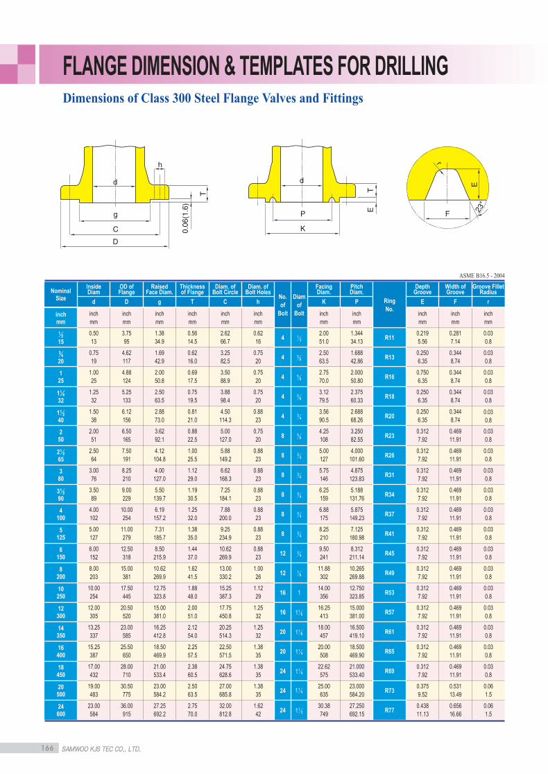
ANSI PRESSURE TEMPERATURE RATINGS
SSAAMMWWOOOO KKJJSS TTEECC CCOO..,, LLTTDD.. 175
CLASS 150/PN 20
Notes (1) Upon prolonged exposure to temperatures above about 800℉(425℃), the carbidephase of carbon steel may be converted to graphite.
(2) Upon prolonged exposure to temperatures above about 875℉(470℃), the carbidephase of carbon molybdenum steel may be converted to graphite.
(3) Only killed steel shall be used above 850℉(455℃)(4) Use normalized and tempered material only.(5) Permissible, but not recommended for prolonged usage above about 800℉(425℃)(6) At temperatures over 1000℉(540℃)use only when the carbon is 0.04% or highter.(7) For service temperatures of 1050℉(565℃) and above, assurance must be provided
that grain size is not finer than ASTM No.6(8) Use annealed material only(9) Use solution annealed material only
(10) Not to be used over 650℉(345℃)(11) Permisible, but not recommended for prolonged upon above about 850℉(455℃)(12) Not to be used over 1000℉(540℃)(13) Not to be used over 1050℉(565℃)(14) Permisible, but not recommended for prolonged upon above about 1100℉(595℃)(15) Not to be used over 1100℉(595℃)(16) Not to be used over 800℉(425℃)(17) Not to be used over 850℉(455℃)(18) For welding end valves Flanged end ratings terminate at 1000℉(540℃)
GENERAL NOTE : a) Flanged end valve ratings terminate at 538℃
Material Group No. 1.1 1.2 1.3 1.4 1.5 1.7 1.9 1.10 1.11 1.13A105(1) (3) (5)A350-LF2(10)
Forgings
Castings
Temperature, ℃℃
A350-LF3(10) A350-LF1(10) A182-F1(2) (11) A182-F2(12) A182-F12(4) (14)A182-F11(4) (14)
A182-F22(14) A182-F21(14) A182-F5a
A216-WCB(1) A216-WCC(1)A352-LC2(10)A352-LC3(10)
A352-LCB(10)A217-WC1(2) (11)
A352-LC1(10)
A217-WC4(4) (12)A217-WC5(4) (13)
A217-WC6(4) (15) A217-WC9(4) (15) A217-C5(4)
(℃/Bar)
19.619.217.715.813.812.110.28.47.46.55.54.63.72.81.4
19.819.517.715.813.812.110.28.47.46.55.54.63.72.81.4
18.418.217.415.813.812.110.28.47.46.55.54.63.72.81.4
16.316.014.914.413.812.110.28.47.46.55.54.63.72.81.4
18.418.417.715.813.812.110.28.47.46.55.54.63.72.81.4
19.819.517.715.813.812.110.28.47.46.55.54.63.72.81.4
1.4(a)1.4(a)
19.819.517.715.813.812.110.28.47.46.55.54.63.72.81.4
1.4(a)1.4(a)1.4(a)1.4(a)1.1(a)
19.819.517.715.813.812.110.28.47.46.55.54.63.72.81.4
1.4(a)1.4(a)1.4(a)1.4(a)1.1(a)
20.019.517.715.813.812.110.28.47.46.55.54.63.72.81.4
1.4(a)1.4(a)1.4(a)1.4(a)1.2(a)
20.019.517.715.813.812.110.28.47.46.55.54.63.72.81.4
1.4(a)1.4(a)1.4(a)1.4(a)0.9(a)
-29 to 3850
100150200250300350375400425450475500538550575600625650
Material Group No. 1.14 1.15 2.1 2.2 2.3 2.4 2.5 2.6 2.7A182-F9 A182-F91
A335-P91A182-F304(6)A182-F304H
A182-F316(6)A182-F316H
A182-F304L(16)A182-F316L
A182-F321(6) (12)A182-F321H
A182-F347(6) (12)A182-F347HA182-F348(6) (12)A182-F348H
A182-F310(6) (7)Forgings
Castings
Temperature, ℃℃
A217-C12(4) A217-C12AA387-91-CL2
A351-CF3(16)A351-CF8(6)
A351-CF3A(10)A351-CF8A(10)A351-CF3M(17)A351-CF8M(6)
A351-CF8(6) A351-CH8(6)A351-CH20(6)
A351-CK20(6)
(℃/Bar)
20.019.517.715.813.812.110.28.47.46.55.54.63.72.81.4
1.4(a)1.4(a)1.4(a)1.4(a)1.4(a)
20.019.517.715.813.812.110.28.47.46.55.54.63.72.81.4
1.4(a)1.4(a)1.4(a)1.4(a)1.4(a)
19.018.315.714.213.212.110.28.47.46.55.54.63.72.81.4
1.4(a)1.4(a)1.4(a)1.4(a)1.4(a)1.4(a)1.4(a)1.4(a)1.4(a)1.4(a)1.2(a)
19.018.416.214.813.712.110.28.47.46.55.54.63.72.81.4
1.4(a)1.4(a)1.4(a)1.4(a)1.4(a)1.4(a)1.4(a)1.4(a)1.4(a)1.4(a)1.2(a)
15.915.313.312.011.210.510.08.47.46.55.54.6
19.018.617.015.713.812.110.28.47.46.55.54.63.72.81.4
1.4(a)1.4(a)1.4(a)1.4(a)1.4(a)1.4(a)1.4(a)1.4(a)1.4(a)1.4(a)1.2(a)
19.018.717.415.813.812.110.28.47.46.55.54.63.72.81.4
1.4(a)1.4(a)1.4(a)1.4(a)1.4(a)1.4(a)1.4(a)1.4(a)1.4(a)1.4(a)1.2(a)
19.018.516.515.313.812.110.28.47.46.55.54.63.72.81.4
1.4(a)1.4(a)1.4(a)1.4(a)1.4(a)1.4(a)1.4(a)1.4(a)1.3(a)1.0(a)0.8(a)
19.018.516.615.313.812.110.28.47.46.55.54.63.72.81.4
1.4(a)1.4(a)1.4(a)1.4(a)1.4(a)1.4(a)1.4(a)1.4(a)1.3(a)1.0(a)0.8(a)
-29 to 3850
100150200250300350375400425450475500538550575600625650675700725750775800
0302플디-삼우카다록02 2012.3.2 9:9 PM 페이지175
ANSI PRESSURE TEMPERATURE RATINGS
SSAAMMWWOOOO KKJJSS TTEECC CCOO..,, LLTTDD..176
Notes (1) Upon prolonged exposure to temperatures above about 800℉(425℃), the carbidephase of carbon steel may be converted to graphite.
(2) Upon prolonged exposure to temperatures above about 875℉(470℃), the carbidephase of carbon molybdenum steel may be converted to graphite.
(3) Only killed steel shall be used above 850℉(455℃)(4) Use normalized and tempered material only.(5) Permissible, but not recommended for prolonged usage above about 800℉(425℃)(6) At temperatures over 1000℉(540℃)use only when the carbon is 0.04% or highter.(7) For service temperatures of 1050℉(565℃) and above, assurance must be provided
that grain size is not finer than ASTM No.6
(8) Use annealed material only(9) Use solution annealed material only(10) Not to be used over 650℉(345℃)(11) Permisible, but not recommended for prolonged upon above about 850℉(455℃)(12) Not to be used over 1000℉(540℃)(13) Not to be used over 1050℉(565℃)(14) Permisible, but not recommended for prolonged upon above about 1100℉(595℃)(15) Not to be used over 1100℉(595℃)(16) Not to be used over 800℉(425℃)(17) Not to be used over 850℉(455℃)
CLASS 300/PN 50
Material Group No. 1.1 1.2 1.3 1.4 1.5 1.7 1.9 1.10 1.11 1.13A105(1) (3) (5)A350-LF2(10)
Forgings
Castings
Temperature, ℃℃
A350-LF3(10) A350-LF1(10) A182-F1(2) (11) A182-F2(12) A182-F12(4) (14)A182-F11(4) (14)
A182-F22(14) A182-F21(14) A182-F5a
A216-WCB(1) A216-WCC(1)A352-LC2(10)A352-LC3(10)
A352-LCB(10)A217-WC1(2) (11)
A352-LC1(10)
A217-WC4(4) (12)A217-WC5(4) (13)
A217-WC6(4) (15) A217-WC9(4) (15) A217-C5(4)
(℃/Bar)
51.150.146.645.143.841.939.837.636.434.728.823.017.411.85.9
51.751.751.550.248.646.342.940.037834.728.823.017.111.65.9
48.047.545.343.942.540.838.736.435.032.627.321.615.711.15.9
42.641.838.837.636.434.933.231.230.429.325.821.414.110.35.9
48.048.047.947.345.844.542.940.338.936.535.233.731.724.111.3
51.751.751.550.348.646.342.940.338.936.535.233.731.726.713.9
12.67.2
51.751.751.549.748.046.342.940.338.936.535.233.731.725.714.912.78.86.14.32.8
51.751.751.550.348.646.342.940.338.936.535.233.731.728.218.415.610.56.94.52.8
51.751.751.550.348.646.342.940.338.936.535.233.731.723.611.311.310.17.15.33.1
51.751.751.550.348.646.342.940.338.936.535.233.727.921.413.712.08.96.24.02.4
-29 to 3850
100150200250300350375400425450475500538550575600625650
Material Group No. 1.14 1.15 2.1 2.2 2.3 2.4 2.5 2.6 2.7A182-F9 A182-F91
A335-P91A182-F304(6)A182-F304H
A182-F316(6)A182-F316H
A182-F304L(16)A182-F316L
A182-F321(6) (12)A182-F321H
A182-F347(6) (12)A182-F347HA182-F348(6) (12)A182-F348H
A182-F310(6) (7)Forgings
Castings
Temperature, ℃℃
A217-C12(4) A217-C12AA387-91-CL2
A351-CF3(16)A351-CF8(6)
A351-CF3A(10)A351-CF8A(10)A351-CF3M(17)A351-CF8M(6)
A351-CF8(6) A351-CH8(6)A351-CH20(6)
A351-CK20(6)
(℃/Bar)
51.751.751.550.348.646.342.940.338.936.535.233.731.728.217.515.010.57.25.03.5
51.751.751.550.348.646.342.940.338.936.535.233.731.728.225.225.024.019.514.69.9
49.647.840.937.034.532.530.929.629.028.428.027.426.926.524.423.620.816.913.811.39.38.06.85.84.63.5
49.648.142.238.535.733.431.630.329.929.429.128.828.728.225.225.024.019.915.812.710.38.47.05.94.63.5
41.440.034.831.429.227.526.125.124.824.323.923.4
49.648.644.241.038.336.034.132.632.031.631.130.830.528.225.225.024.020.315.812.69.97.96.35.04.03.1
49.648.845.342.539.937.836.134.834.233.933.633.531.728.225.225.024.021.618.314.112.410.17.95.94.63.5
49.648.343.140.037.836.134.833.833.433.132.632.231.728.225.225.022.216.812.59.47.25.54.33.42.72.1
49.648.443.440.037.635.834.533.332.932.432.131.731.228.225.225.022.216.812.59.47.25.54.33.42.72.1
-29 to 3850
100150200250300350375400425450475500538550575600625650675700725750775800
0302플디-삼우카다록02 2012.3.2 9:9 PM 페이지176
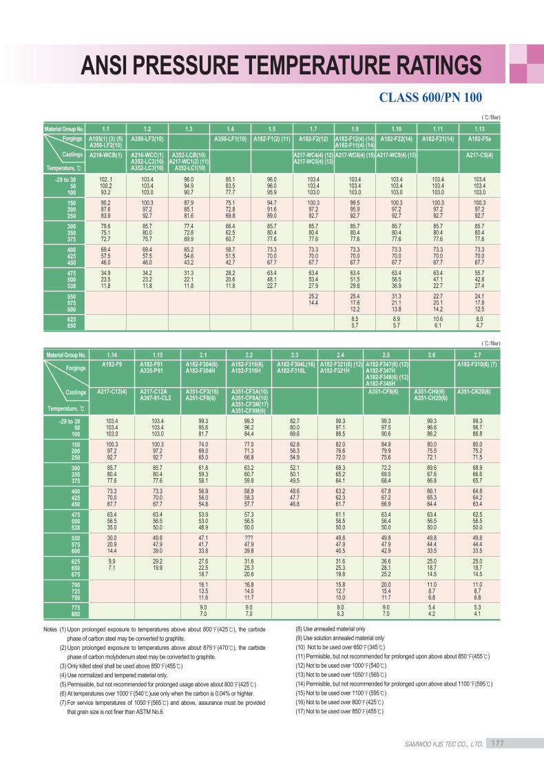
ANSI PRESSURE TEMPERATURE RATINGS
SSAAMMWWOOOO KKJJSS TTEECC CCOO..,, LLTTDD.. 177
CLASS 600/PN 100
Notes (1) Upon prolonged exposure to temperatures above about 800℉(425℃), the carbidephase of carbon steel may be converted to graphite.
(2) Upon prolonged exposure to temperatures above about 875℉(470℃), the carbidephase of carbon molybdenum steel may be converted to graphite.
(3) Only killed steel shall be used above 850℉(455℃)(4) Use normalized and tempered material only.(5) Permissible, but not recommended for prolonged usage above about 800℉(425℃)(6) At temperatures over 1000℉(540℃)use only when the carbon is 0.04% or highter.(7) For service temperatures of 1050℉(565℃) and above, assurance must be provided
that grain size is not finer than ASTM No.6
(8) Use annealed material only(9) Use solution annealed material only(10) Not to be used over 650℉(345℃)(11) Permisible, but not recommended for prolonged upon above about 850℉(455℃)(12) Not to be used over 1000℉(540℃)(13) Not to be used over 1050℉(565℃)(14) Permisible, but not recommended for prolonged upon above about 1100℉(595℃)(15) Not to be used over 1100℉(595℃)(16) Not to be used over 800℉(425℃)(17) Not to be used over 850℉(455℃)
Material Group No. 1.1 1.2 1.3 1.4 1.5 1.7 1.9 1.10 1.11 1.13A105(1) (3) (5)A350-LF2(10)
Forgings
Castings
Temperature, ℃℃
A350-LF3(10) A350-LF1(10) A182-F1(2) (11) A182-F2(12) A182-F12(4) (14)A182-F11(4) (14)
A182-F22(14) A182-F21(14) A182-F5a
A216-WCB(1) A216-WCC(1)A352-LC2(10)A352-LC3(10)
A352-LCB(10)A217-WC1(2) (11)
A352-LC1(10)
A217-WC4(4) (12)A217-WC5(4) (13)
A217-WC6(4) (15) A217-WC9(4) (15) A217-C5(4)
(℃/Bar)
102..1100.293.290.287.683.979.675.172.769.457.546.034.923.511.8
103.4103.4103.0100.397.292.785.780.075.769.457.546.034.223.211.8
96.094.990.787.985.181.677.472.869.965.254.643.231.322.111.8
85.183.577.775.172.869.866.462.560.758.751.542.728.220.611.8
96.096.095.994.791.689.085.780.477.673.370.067.763.448.122.7
103.4103.4103.0100.397.292.785.780.477.673.370.067.763.453.427.925.214.4
103.4103.4103.099.595.992.785.780.477.673.370.067.763.451.529.825.417.612.28.55.7
103.4103.4103.0100.397.292.785.780.477.673.370.067.763.456.536.931.321.113.88.95.7
103.4103.4103.0100.397.292.785.780.477.673.370.067.763.447.122.722.720.114.210.66.1
103.4103.4103.0100.397.292.785.780.477.673.370.067.755.742.827.424.117.812.58.04.7
-29 to 3850
100150200250300350375400425450475500538550575600625650
Material Group No. 1.14 1.15 2.1 2.2 2.3 2.4 2.5 2.6 2.7A182-F9 A182-F91
A335-P91A182-F304(6)A182-F304H
A182-F316(6)A182-F316H
A182-F304L(16)A182-F316L
A182-F321(6) (12)A182-F321H
A182-F347(6) (12)A182-F347HA182-F348(6) (12)A182-F348H
A182-F310(6) (7)Forgings
Castings
Temperature, ℃℃
A217-C12(4) A217-C12AA387-91-CL2
A351-CF3(16)A351-CF8(6)
A351-CF3A(10)A351-CF8A(10)A351-CF3M(17)A351-CF8M(6)
A351-CF8(6) A351-CH8(6)A351-CH20(6)
A351-CK20(6)
(℃/Bar)
103.4103.4103.0100.397.292.785.780.477.673.370.067.763.456.535.030.020.914.49.97.1
103.4103.4103.0100.397.292.785.780.477.673.370.067.763.456.550.049.847.939.029.219.9
99.395.681.774.069.065.061.859.358.156.956.054.853.953.048.947.141.733.827.622.518.716.113.511.69.07.0
99.396.284.477.071.366.863.260.759.858.958.357.757.356.550.0???47.939.831.625.320.616.814.011.79.07.0
82.780.069.662.858.354.952.150.149.548.647.746.8
99.397.188.582.076.672.068.365.264.163.262.361.761.156.550.049.847.940.531.625.319.815.812.710.08.06.3
99.397.590.684.979.975.672.269.568.467.867.266.963.456.450.049.847.942.936.628.125.220.015.411.79.07.0
99.396.686.280.075.572.169.667.666.866.165.364.463.456.550.049.844.433.525.018.714.511.08.76.85.44.2
99.396.786.880.075.271.568.966.665.764.864.263.462.556.550.049.844.433.525.018.714.511.08.76.85.34.1
-29 to 3850
100150200250300350375400425450475500538550575600625650675700725750775800
0302플디-삼우카다록02 2012.3.2 9:9 PM 페이지177

ANSI PRESSURE TEMPERATURE RATINGS
SSAAMMWWOOOO KKJJSS TTEECC CCOO..,, LLTTDD..178
Notes (1) Upon prolonged exposure to temperatures above about 800℉(425℃), the carbidephase of carbon steel may be converted to graphite.
(2) Upon prolonged exposure to temperatures above about 875℉(470℃), the carbidephase of carbon molybdenum steel may be converted to graphite.
(3) Only killed steel shall be used above 850℉(455℃)(4) Use normalized and tempered material only.(5) Permissible, but not recommended for prolonged usage above about 800℉(425℃)(6) At temperatures over 1000℉(540℃)use only when the carbon is 0.04% or highter.(7) For service temperatures of 1050℉(565℃) and above, assurance must be provided
that grain size is not finer than ASTM No.6
(8) Use annealed material only(9) Use solution annealed material only(10) Not to be used over 650℉(345℃)(11) Permisible, but not recommended for prolonged upon above about 850℉(455℃)(12) Not to be used over 1000℉(540℃)(13) Not to be used over 1050℉(565℃)(14) Permisible, but not recommended for prolonged upon above about 1100℉(595℃)(15) Not to be used over 1100℉(595℃)(16) Not to be used over 800℉(425℃)(17) Not to be used over 850℉(455℃)
CLASS 900/PN 150
Material Group No. 1.1 1.2 1.3 1.4 1.5 1.7 1.9 1.10 1.11 1.13A105(1) (3) (5)A350-LF2(10)
Forgings
Castings
Temperature, ℃℃
A350-LF3(10) A350-LF1(10) A182-F1(2) (11) A182-F2(12) A182-F12(4) (14)A182-F11(4) (14)
A182-F22(14) A182-F21(14) A182-F5a
A216-WCB(1) A216-WCC(1)A352-LC2(10)A352-LC3(10)
A352-LCB(10)A217-WC1(2) (11)
A352-LC1(10)
A217-WC4(4) (12)A217-WC5(4) (13)
A217-WC6(4) (15) A217-WC9(4) (15) A217-C5(4)
(℃/Bar)
153.2150.4139.8135.2131.4125.8119.5112.7109.1104.286.369.052.335.317.7
155.1155.1154.6150.5145.8139.0128.6120.1113.5104.286.369.051.334.717.7
144.1142.4136.0131.8127.6122.3116.1109.2104.997.981.964.847.033.217.7
127.7125.3116.5112.7109.2104.799.593.791.188.077.364.142.330.917.7
144.1144.1143.8142.0137.4133.5128.6120.7116.5109.8105.1101.495.172.234.0
155.1155.1154.6150.6145.8139.0128.6120.7116.5109.8105.1101.495.180.141.837.821.5
155.1155.1154.4149.2143.9139.0128.6120.7116.5109.8105.1101.495.177.244.738.126.418.312.88.5
155.1155.1154.6150.6145.8139.0128.6120.7116.5109.8105.1101.495.184.755.346.931.620.713.48.5
155.1155.1154.6150.6145.8139.0128.6120.7116.5109.8105.1101.495.170.734.034.030.221.315.99.2
155.1155.1154.6150.6145.8139.0128.6120.7116.5109.8105.1101.483.664.141.136.126.718.712.07.1
-29 to 3850
100150200250300350375400425450475500538550575600625650
Material Group No. 1.14 1.15 2.1 2.2 2.3 2.4 2.5 2.6 2.7A182-F9 A182-F91
A335-P91A182-F304(6)A182-F304H
A182-F316(6)A182-F316H
A182-F304L(16)A182-F316L
A182-F321(6) (12)A182-F321H
A182-F347(6) (12)A182-F347HA182-F348(6) (12)A182-F348H
A182-F310(6) (7)Forgings
Castings
Temperature, ℃℃
A217-C12(4) A217-C12AA387-91-CL2
A351-CF3(16)A351-CF8(6)
A351-CF3A(10)A351-CF8A(10)A351-CF3M(17)A351-CF8M(6)
A351-CF8(6) A351-CH8(6)A351-CH20(6)
A351-CK20(6)
(℃/Bar)
155.1155.1154.6150.6145.8139.0128.6120.7116.5109.8105.1101.495.184.752.545.031.421.514.910.6
155.1155.1154.6150.6145.8139.0128.6120.7116.5109.8105.1101.495.184.775.274.871.858.5
43.829.8
99.395.681.774.069.065.061.859.358.156.956.054.853.953.048.947.141.733.827.622.518.716.113.511.69.07.0
148.9144.3126.6115.3107.0100.194.991.089.688.387.486.586.084.775.274.8???59.747.438.031.025.121.017.613.710.5
124.1120.1104.494.287.582.478.275.274.372.971.670.2
148.9145.7132.7122.9114.9108.1102.497.896.194.893.492.591.684.775.274.871.860.847.437.929.623.719.015.011.99.4
148.9146.3135.9127.4119.8113.4108.3104.3102.6101.7100.8100.495.184.775.274.871.864.254.942.537.629.823.217.613.710.5
148.9144.9129.3120.0113.3108.2104.4101.4100.199.297.996.595.184.775.274.866.550.337.528.121.716.513.010.28.16.3
148.9145.1130.2120.0112.8107.3103.499.998.697.396.495.193.784.775.274.866.550.337.528.121.716.513.010.28.06.2
-29 to 3850
100150200250300350375400425450475500538550575600625650675700725750775800
0302플디-삼우카다록02 2012.3.2 9:9 PM 페이지178
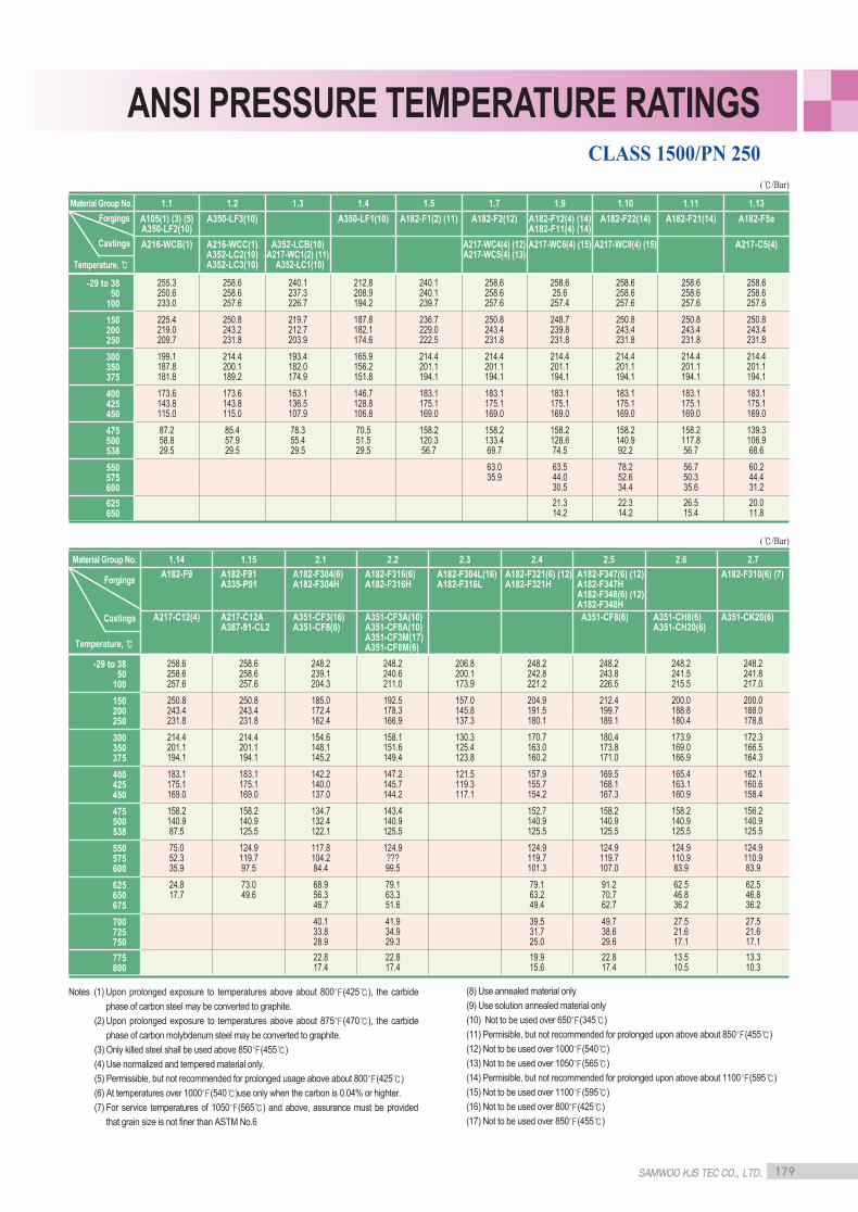
ANSI PRESSURE TEMPERATURE RATINGS
SSAAMMWWOOOO KKJJSS TTEECC CCOO..,, LLTTDD.. 179
CLASS 1500/PN 250
Material Group No. 1.1 1.2 1.3 1.4 1.5 1.7 1.9 1.10 1.11 1.13A105(1) (3) (5)A350-LF2(10)
Forgings
Castings
Temperature, ℃℃
A350-LF3(10) A350-LF1(10) A182-F1(2) (11) A182-F2(12) A182-F12(4) (14)A182-F11(4) (14)
A182-F22(14) A182-F21(14) A182-F5a
A216-WCB(1) A216-WCC(1)A352-LC2(10)A352-LC3(10)
A352-LCB(10)A217-WC1(2) (11)
A352-LC1(10)
A217-WC4(4) (12)A217-WC5(4) (13)
A217-WC6(4) (15) A217-WC9(4) (15) A217-C5(4)
(℃/Bar)
255.3250.6233.0225.4219.0209.7199.1187.8181.8173.6143.8115.087.258.829.5
258.6258.6257.6250.8243.2231.8214.4200.1189.2173.6143.8115.085.457.929.5
240.1237.3226.7219.7212.7203.9193.4182.0174.9163.1136.5107.978.355.429.5
212.8208.9194.2187.8182.1174.6165.9156.2151.8146.7128.8106.870.551.529.5
240.1240.1239.7236.7229.0222.5214.4201.1194.1183.1175.1169.0158.2120.356.7
258.6258.6257.6250.8243.4231.8214.4201.1194.1183.1175.1169.0158.2133.469.763.035.9
258.625.6
257.4248.7239.8231.8214.4201.1194.1183.1175.1169.0158.2128.674.563.544.030.521.314.2
258.6258.6257.6250.8243.4231.8214.4201.1194.1183.1175.1169.0158.2140.992.278.252.634.422.314.2
258.6258.6257.6250.8243.4231.8214.4201.1194.1183.1175.1169.0158.2117.856.756.750.335.626.515.4
258.6258.6257.6250.8243.4231.8214.4201.1194.1183.1175.1169.0139.3106.968.660.244.431.220.011.8
-29 to 3850
100150200250300350375400425450475500538550575600625650
Notes (1) Upon prolonged exposure to temperatures above about 800℉(425℃), the carbidephase of carbon steel may be converted to graphite.
(2) Upon prolonged exposure to temperatures above about 875℉(470℃), the carbidephase of carbon molybdenum steel may be converted to graphite.
(3) Only killed steel shall be used above 850℉(455℃)(4) Use normalized and tempered material only.(5) Permissible, but not recommended for prolonged usage above about 800℉(425℃)(6) At temperatures over 1000℉(540℃)use only when the carbon is 0.04% or highter.(7) For service temperatures of 1050℉(565℃) and above, assurance must be provided
that grain size is not finer than ASTM No.6
(8) Use annealed material only(9) Use solution annealed material only(10) Not to be used over 650℉(345℃)(11) Permisible, but not recommended for prolonged upon above about 850℉(455℃)(12) Not to be used over 1000℉(540℃)(13) Not to be used over 1050℉(565℃)(14) Permisible, but not recommended for prolonged upon above about 1100℉(595℃)(15) Not to be used over 1100℉(595℃)(16) Not to be used over 800℉(425℃)(17) Not to be used over 850℉(455℃)
Material Group No. 1.14 1.15 2.1 2.2 2.3 2.4 2.5 2.6 2.7A182-F9 A182-F91
A335-P91A182-F304(6)A182-F304H
A182-F316(6)A182-F316H
A182-F304L(16)A182-F316L
A182-F321(6) (12)A182-F321H
A182-F347(6) (12)A182-F347HA182-F348(6) (12)A182-F348H
A182-F310(6) (7)Forgings
Castings
Temperature, ℃℃
A217-C12(4) A217-C12AA387-91-CL2
A351-CF3(16)A351-CF8(6)
A351-CF3A(10)A351-CF8A(10)A351-CF3M(17)A351-CF8M(6)
A351-CF8(6) A351-CH8(6)A351-CH20(6)
A351-CK20(6)
(℃/Bar)
258.6258.6257.6250.8243.4231.8214.4201.1194.1183.1175.1169.0158.2140.987.575.052.335.924.817.7
258.6258.6257.6250.8243.4231.8214.4201.1194.1183.1175.1169.0158.2140.9125.5124.9119.797.573.049.6
248.2239.1204.3185.0172.4162.4154.6148.1145.2142.2140.0137.0134.7132.4122.1117.8104.284.468.956.346.740.133.828.922.817.4
248.2240.6211.0192.5178.3166.9158.1151.6149.4147.2145.7144.2143.4140.9125.5124.9???99.579.163.351.641.934.929.322.817.4
206.8200.1173.9157.0145.8137.3130.3125.4123.8121.5119.3117.1
248.2242.8221.2204.9191.5180.1170.7163.0160.2157.9155.7154.2152.7140.9125.5124.9119.7101.379.163.249.439.531.725.019.915.6
248.2243.8226.5212.4199.7189.1180.4173.8171.0169.5168.1167.3158.2140.9125.5124.9119.7107.091.270.762.749.738.629.622.817.4
248.2241.5215.5200.0188.8180.4173.9169.0166.9165.4163.1160.9158.2140.9125.5124.9110.983.962.546.836.227.521.617.113.510.5
248.2241.8217.0200.0188.0178.8172.3166.5164.3162.1160.6158.4156.2140.9125.5124.9110.983.962.546.836.227.521.617.113.310.3
-29 to 3850
100150200250300350375400425450475500538550575600625650675700725750775800
0302플디-삼우카다록02 2012.3.2 9:9 PM 페이지179
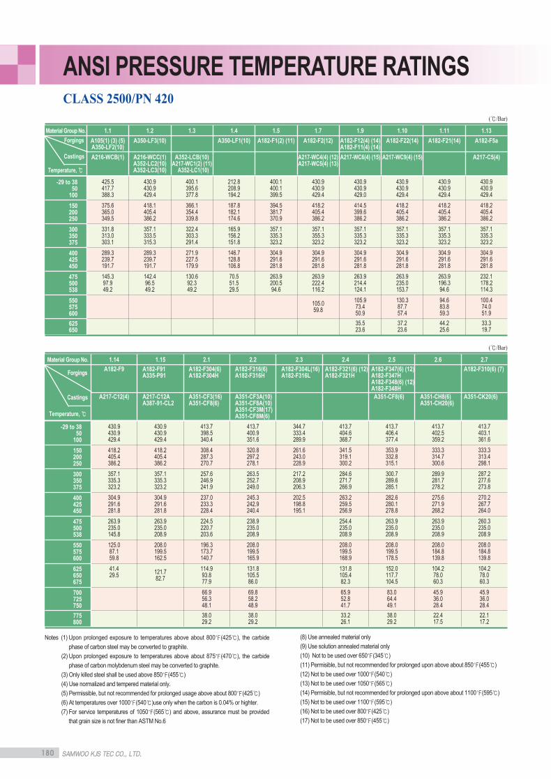
ANSI PRESSURE TEMPERATURE RATINGS
SSAAMMWWOOOO KKJJSS TTEECC CCOO..,, LLTTDD..180
Notes (1) Upon prolonged exposure to temperatures above about 800℉(425℃), the carbidephase of carbon steel may be converted to graphite.
(2) Upon prolonged exposure to temperatures above about 875℉(470℃), the carbidephase of carbon molybdenum steel may be converted to graphite.
(3) Only killed steel shall be used above 850℉(455℃)(4) Use normalized and tempered material only.(5) Permissible, but not recommended for prolonged usage above about 800℉(425℃)(6) At temperatures over 1000℉(540℃)use only when the carbon is 0.04% or highter.(7) For service temperatures of 1050℉(565℃) and above, assurance must be provided
that grain size is not finer than ASTM No.6
(8) Use annealed material only(9) Use solution annealed material only(10) Not to be used over 650℉(345℃)(11) Permisible, but not recommended for prolonged upon above about 850℉(455℃)(12) Not to be used over 1000℉(540℃)(13) Not to be used over 1050℉(565℃)(14) Permisible, but not recommended for prolonged upon above about 1100℉(595℃)(15) Not to be used over 1100℉(595℃)(16) Not to be used over 800℉(425℃)(17) Not to be used over 850℉(455℃)
CLASS 2500/PN 420
Material Group No. 1.1 1.2 1.3 1.4 1.5 1.7 1.9 1.10 1.11 1.13A105(1) (3) (5)A350-LF2(10)
Forgings
Castings
Temperature, ℃℃
A350-LF3(10) A350-LF1(10) A182-F1(2) (11) A182-F2(12) A182-F12(4) (14)A182-F11(4) (14)
A182-F22(14) A182-F21(14) A182-F5a
A216-WCB(1) A216-WCC(1)A352-LC2(10)A352-LC3(10)
A352-LCB(10)A217-WC1(2) (11)
A352-LC1(10)
A217-WC4(4) (12)A217-WC5(4) (13)
A217-WC6(4) (15) A217-WC9(4) (15) A217-C5(4)
(℃/Bar)
425.5417.7388.3375.6365.0349.5331.8313.0303.1289.3239.7191.7145.397.949.2
430.9430.9429.4418.1405.4386.2357.1333.5315.3289.3239.7191.7142.496.549.2
400.1395.6377.8366.1354.4339.8322.4303.3291.4271.9227.5179.9130.692.349.2
212.8208.9194.2187.8182.1174.6165.9156.2151.8146.7128.8106.870.551.529.5
400.1400.1399.5394.5381.7370.9357.1335.3323.2304.9291.6281.8263.9200.594.6
430.9430.9429.4418.2405.4386.2357.1355.3323.2304.9291.6281.8263.9222.4116.2
105.059.8
430.9430.9429.0414.5399.6386.2357.1335.3323.2304.9291.6281.8263.9214.4124.1105.973.450.935.523.6
430.9430.9429.4418.2405.4386.2357.1335.3323.2304.9291.6281.8263.9235.0153.7130.387.757.437.223.6
430.9430.9429.4418.2405.4386.2357.1335.3323.2304.9291.6281.8263.9196.394.694.683.859.344.225.6
430.9430.9429.4418.2405.4386.2357.1335.3323.2304.9291.6281.8232.1178.2114.3100.474.051.933.319.7
-29 to 3850
100150200250300350375400425450475500538550575600625650
Material Group No. 1.14 1.15 2.1 2.2 2.3 2.4 2.5 2.6 2.7A182-F9 A182-F91
A335-P91A182-F304(6)A182-F304H
A182-F316(6)A182-F316H
A182-F304L(16)A182-F316L
A182-F321(6) (12)A182-F321H
A182-F347(6) (12)A182-F347HA182-F348(6) (12)A182-F348H
A182-F310(6) (7)Forgings
Castings
Temperature, ℃℃
A217-C12(4) A217-C12AA387-91-CL2
A351-CF3(16)A351-CF8(6)
A351-CF3A(10)A351-CF8A(10)A351-CF3M(17)A351-CF8M(6)
A351-CF8(6) A351-CH8(6)A351-CH20(6)
A351-CK20(6)
(℃/Bar)
430.9430.9429.4418.2405.4386.2357.1335.3323.2304.9291.6281.8263.9235.0145.8125.087.159.841.429.5
430.9430.9429.4418.2405.4386.2357.1335.3323.2304.9291.6281.8263.9235.0208.9208.0199.5162.5
121.782.7
413.7398.5340.4308.4287.3270.7257.6246.9241.9237.0233.3228.4224.5220.7203.6196.3173.7140.7114.993.877.966.956.348.138.029.2
413.7400.9351.6320.8297.2278.1263.5252.7249.0245.3242.9240.4238.9235.0208.9208.0199.5165.9131.8105.586.069.858.248.938.029.2
344.7333.4289.9261.6243.0228.9217.2208.9206.3202.5198.8195.1
413.7404.6368.7341.5319.1300.2284.6271.7266.9263.2259.5256.9254.4235.0208.9208.0199.5168.9131.8105.482.365.952.841.733.226.1
413.7406.4377.4353.9332.8315.1300.7289.6285.1282.6280.1278.8263.9235.0208.9208.0199.5178.5152.0117.7104.583.064.449.138.029.2
413.7402.5359.2333.3314.7300.6289.9281.7278.2275.6271.9268.2263.9235.0208.9208.0184.8139.8104.278.060.345.936.028.422.417.5
413.7403.1361.6333.3313.4298.1287.2277.6273.8270.2267.7264.0260.3235.0208.9208.0184.8139.8104.278.060.345.936.028.422.117.2
-29 to 3850
100150200250300350375400425450475500538550575600625650675700725750775800
0302플디-삼우카다록02 2012.3.2 9:9 PM 페이지180

HYDROSTATIC TEST PRESSURE TO ASME B16.34
SSAAMMWWOOOO KKJJSS TTEECC CCOO..,, LLTTDD.. 181
GroupNo
Forging Casting150
Shell Seat /Backseat Shell Seat /
Backseat Shell Seat /Backseat Shell Seat /
Backseat Shell Seat /Backseat Shell Seat /
Backseat Shell Seat /Backseat
㎏㎏//㎠㎠ ㎏㎏//㎠㎠ ㎏㎏//㎠㎠ ㎏㎏//㎠㎠ ㎏㎏//㎠㎠ ㎏㎏//㎠㎠ ㎏㎏//㎠㎠ ㎏㎏//㎠㎠ ㎏㎏//㎠㎠ ㎏㎏//㎠㎠ ㎏㎏//㎠㎠ ㎏㎏//㎠㎠ ㎏㎏//㎠㎠ ㎏㎏//㎠㎠psi psi psi psi psi psi psi psi psi psi psi psi psi psi
300 600 900 1500 2500 4500Material Test Pressures by Classes
16.0016.3716.5017.0017.25
Notes. All pressures are given as gauge pressure.
1.1
1.2
1.31.4
1.5
1.7
1.9
1.101.111.131.14
2.1
2.2
2.3
2.4
2.5
2.62.73.1
A105
A350-LF2
A350-LF3
A350-LF1
A182-LF1
A182-F2
A182-F12
A182-F11
A182-F22A182-F21A182-F5aA182-F9
A182-F304
A182-F304H
A182-F316
A182-F316H
A182-F304L
A182-F316L
A182-F321
A182-F321H
A182-F347
A182-F347H
A182-F348
A182-F348
A351-CH20A182-F310
B462
A216-WCB
A216-WCC
A352-LC2
A352-LC3
A352-LCB
A217-WC1
A352-LC1
A217-WC4
A217-WC5
A217-WC6
A217-WC9
A217-C12A217-C5
A351-CF3
A351-CF8
A351-CF3A
A351-CF8A
A351-CF3M
A351-CF8M
A351-CF8C
A351-CH20A351-CK20A351-CM7M
32.0
32.0
30
26.5
28.5
32.0
32.0
32.0
32.0
32.0
32.0
30.0
30.0
25.0
30.0
30.0
28.5
28.5
25.0
450
450
400
375
400
450
450
450
450
450
450
425
425
350
425
425
400
400
350
23.0
23.0
21
19.5
21.5
23.0
23.0
23.0
23.0
23.0
23.0
23.0
23.0
19.5
23.0
23.0
21.5
21.5
19.5
325
325
295
275
300
325
325
325
325
325
325
325
325
275
325
325
300
300
275
79.5
79.5
74
67.0
74.0
79.5
79.5
79.5
79.5
79.5
79.5
77.5
77.5
63.5
77.5
77.5
72.5
72.5
63.5
1125
1125
1050
950
1050
1125
1125
1125
1125
1125
1125
1100
1100
900
1100
1100
1025
1025
900
58.5
58.5
54
49.5
54.5
58.5
58.5
58.5
58.5
58.5
58.5
56.5
56.5
49.5
56.5
56.5
53.0
53.0
47.5
825
825
775
700
775
825
825
825
825
825
825
800
800
675
800
800
750
750
675
156.5
158.5
148
133.0
148.0
158.5
158.5
158.5
158.5
158.5
158.5
153.0
153.0
127.0
153.0
153.0
143.0
143.0
127.0
2225
2250
2100
1875
2100
2250
2250
2250
2250
2250
2250
2175
2175
1800
2175
2175
2025
2025
1800
116.5
116.5
108
97.0
109.0
116.5
116.5
116.5
116.5
116.5
116.5
112.5
112.5
93.5
112.5
112.5
106.0
106.0
93.5
1650
1650
1535
1375
1550
1650
1650
1650
1650
1650
1650
1600
1600
1325
1600
1600
1500
1500
1325
236.0
237.5
222
195.5
221.5
237.5
237.5
237.5
237.5
237.5
237.5
229.0
229.0
190.0
229.0
229.0
213.5
213.5
190.0
3350
3375
3150
2275
3150
3375
3375
3375
3375
3375
3375
3250
3250
2700
3250
3250
3025
3025
2700
172.5
174.5
162
144.5
162.0
174.5
174.5
174.5
174.5
174.5
174.5
169.0
169.0
141.0
169.0
169.0
157.0
157.0
141.0
2450
2475
2299
2050
2300
2475
2475
2475
2475
2475
2475
2400
2400
2000
2400
2400
2225
2225
2000
392.0
395.5
368
327.0
367.5
395.5
395.5
395.5
395.5
395.5
395.5
380.0
380.0
316.5
380.0
380.0
356.0
356.0
316.5
5515
5625
5225
4650
5225
5625
5625
5625
5625
5625
5625
5400
5400
4500
5400
5400
5050
5050
4500
288.5
290.5
270
239.5
269.0
290.5
290.5
290.5
290.5
290.5
290.5
279.5
279.5
232.5
279.5
279.5
261.0
261.0
232.5
4100
4125
3828
3400
3825
4125
4125
4125
4125
4125
4125
3975
3975
3300
3975
3975
3700
3700
3300
652.5
659.5
615
543.5
612.0
659.5
659.5
659.5
659.5
659.5
659.5
633.0
633.0
527.5
633.0
633.0
592.0
592.0
527.5
9275
9375
8725
7125
8700
9375
9375
9375
9375
9375
9375
9000
9000
7500
9000
9000
8400
8400
7500
478.5
483.5
449
399.5
448.5
483.5
483.5
483.5
483.5
483.5
483.5
464.5
464.5
387.0
464.5
464.5
435.0
435.0
387.0
6800
6875
6386
5675
6375
6875
6875
6875
6875
6875
6875
6600
6600
5500
6600
6600
6175
6175
5500
1172.5
1186.5
1099.0
977.5
1099.0
1186.5
1186.5
1186.5
1186.5
1186.5
1186.5
1139.5
1139.5
349.5
1139.5
1139.5
1065.5
1065.5
949.5
16675
16875
15625
13900
15625
16875
16875
16875
16875
16875
16875
16200
16200
13500
16200
16200
15125
15125
13500
860.0
870.5
806.5
717.5
806.5
870.5
870.5
870.5
870.5
870.5
870.5
837.0
837.0
696.5
837.0
837.0
782.0
782.0
696.5
12225
12375
11470
10200
11470
12375
12375
12375
12375
12375
12375
11900
11900
9900
11900
11900
11100
11100
9900
0302플디-삼우카다록02 2012.3.2 9:9 PM 페이지181

CONVERSION TABLES
SSAAMMWWOOOO KKJJSS TTEECC CCOO..,, LLTTDD..182
kgf/㎡㎡ kgf/㎠㎠ Ibf/ft2 pa Mpa(㎜㎜ /㎟㎟)
11×10 -2
4.882×10 -6
1.01972×10 -2
1.0972×10 -1
1×10 2
14.882×101.01972×10 5
1.01972×10
2.048×10 5
2.048×10 3
12.089×10 2
2.089×10 4
9.80665×10 6
9.80665×10 4
4.786×1011×10 6
9.806659.80665×10 2
4.786×10 5
1×10 6
1
m cm in ft yd km mile Nautical Mile
10.010.02540.30480.9144
10012.51030.4891.44
39.370.393711236
3.2810.031 810.083 3313
1.0940.010 940.027 780.333 31
11.6091.852
0.621411.151
0.54000.86901
STRESS IN/㎡=1MPa LENGTH
Poise=g/cm.s(CGS UNIT) centipose. cP kg/m.h kg/m.s Ib/ft.s
10.01100.0027814.88
10011000.00.2781488.0
0.10.00110.032781.488
3603.63600.015356.8
0.06720.0006720.6720.0001871
K/W PS HP(British) kgf-m/s ft-Ibf/s Kcal/s BTU/s(British)
10.735 50.7460.009 8070.001 3564.1861.055
1.36011.0140.013 330.001 8435.6911.434
1.3400.985 910.013 150.001 8175.6111.414
102.07576.0710.138.3426.9107.6
737.6542.5550.27.2331.03087.0778.0
0.238 90.175 70.178 20.002 3430.003 23910.252 0
0.918 00.697 30.707 20.009 2970.001 2853.9681
VISCOSITY POWER
ℓℓ/S ㎥㎥/h ㎥㎥/S British gal/min U.S gal/min ft3/h ft3/s
10.27781.0000.0757750.063090.02786528.3153
3.613600.00.272790.22710.02832101.935
0.0010.03277810.04757750.0463040.0578650.02832
13.1973.665813197.010.83250.1038373.672
15.85144.403215851.01.201110.1247448.833
127.1435.317127150.09.63428.020813600.0
0.035320.09280135.31600.0226760.0222280.0327781
FLOW
m/s km/h kn ft/s mil/h
10.277 80.514 40.304 80.447 0
3.611511.0971.609
1.9440.540 010.592 50.869 0
3.2810.911 31.68811.467
2.2370.621 41.1510.681 81
VELOCITY
㎡㎡/s ft2/s cst st
19.290×10 -2
1×10 -6
1×10 -4
1.076×1011.076×10 5
1.076×10 -3
1×10 6
9.2900×10 4
11×10 2
1×10 4
9.290×10 2
1×10 2
1
m2 in2 ft2 yd2 km2 acre mile2 ha
16.452×10 -4
0.092900.8361
15501
1441296
10.766.944×10 -2
19
1.1967.716×10 4
0.11111
14.047×10 -3
2.5900.01
247.11
6402.471
0.386 11.562×10 -3
13.861×10 -3
1000.4047259.0
1
KINEMATIC VISCOSITY 1St=1 ㎠/s AREA
m3 in3 ft3 yd3 dm3 gal(British) gal(U.S) in3
11.639×10 -5
0.028320.7646
61 02411 72846 656
35.315.787×10 -4
127
1.3082.143×10 -5
0.037041
14.5463.7850.016 39
0.220 010.832 73.605×10 -4
0.264 21.20114.329×10 -3
61.02277.42311
VOLUME
Mpa kg f/㎤㎤ Ibf / in2 atm mHg in Hg mH20 ftH20
10.098 070.006 8950.101 30.133 30.003 3860.0098060.002989
10.2010.070 311.0331.3600.034 530.010.030 48
145.014.22114.7019.340.49121.4220.4335
9.8690.967 80.068 0511.3160.033 420.096 780.029 50
7.5010.735 60.051 710.7610.025 40.073 550.022 42
295.328.962.03629.9239.3712.8960.882 7
102.0100.703 110.3313.600.345 310.304 8
334.632.812.30733.9044.601.1333.2811
PRESSURE 1Pa=IN/㎡
g/㎠㎠ kg/㎤㎤ Ib/in Ib/ft3 H./U.S.gat
11×10 -3
2.768×10 1.602×10 -2
1.198×10 -1
1×10 -3
12.768×10 4
1.602×101.198×10 3
3.613×10 2
3.613×10 5
15.787×10 4
4.329×10 3
6.243×106.243×10 2
1.728×10 3
17.481
8.3458.345×10 3
2311.337×10 -1
1
kgf Ibf N dyn
14.536×10 -1
1.01972×10 -1
1.01972×10 -6
2.20512.248×10 -1
2.248×10 -6
9.806554.4482211×10 -5
9.80665×10 5
4.44822×10 5
1×10 5
1
DENSITY 1g/㎠=1/t㎡ FORCE 1dny=10N
kgf-m Ibf-ft j kw-h
11.383×10 -1
1.0197×10 -1
3.671×10 5
4.269×10 2
7.23117.376×10 1
2.665×10 6
3.087×10 3
9.8071.35613.600×10 6
4.186×10 3
2.724×10 -6
3.766×10 -7
2.778×10 -7
11.163×10 3
2.343×10 3
3.239×10 4
2.389×10 4
8.600×10 2
1
kg g t(tone)France Ib British ton U.S ton
0.00111,0000.45361,016.05907.185
11,0001×10 6
453.61,016,047907,185
0.0510.00110.0345361.016050.90719
0.0022052.20462,204.612,2402,000
0.069840.039840.98420.0344610.86289
0.0511020.0211021.10230.03511.121
ENERGY 1J=1Ws, 1wh=3600Ws, 1cal=4.18605J WEIGHT
0302플디-삼우카다록02 2012.3.2 9:9 PM 페이지182

DATA FOR CALCULATION OF FLOW AND / OR PRESSURE DROP
SSAAMMWWOOOO KKJJSS TTEECC CCOO..,, LLTTDD.. 183
FOR LIQUIDS
FOR GASES
FOR STEAM
A valve coefficient Cv is used to calculate pressure drop through a particular valve for a given flow rate.The coefficient of flow Cv expresses the rate of flow in gallons per minute at 60℉ water with a pressure drop of 1 psig.across the valve.The Cv coefficients for the various types and sizes, shown in table, have been determined from calculations and actualflow tests.
WHERE : QL = Flow in U.S.Gallons per minute.△P = (P1 -P2) Pressure Drop in psi
GL = Specific Gravity of Liquid (Water = 1 at 60℉)QL = CV
△PGL
2
( )△P = GL
WHERE : Qg = Volumetric Flow of Gas(SCFH)Gg = Specific Gravity of Gas at Standard Conditions
(Air at atm. and 60℉= 1)Gg = Absolute Temperature of Gas (℉+ 460)
WHERE : K = 1+0.0007Ts ·W
2.1 Cv
AND W = Pounds per hour of Steam△P = (P1 - P2) Pressure Drop in psi
Ts = Degree of Superheat(℉)
NOTE = For Saturated Steam Ts = 0
( )
NOTE : For Gas and Steam Max. △ P=½ P1, and Min P2=½ P1 and P1, P2 are absolutepressures(PSIA)P1 = Inlet Pressure P20 = Outlet Pressure
Kv = Cv×0.85
QL
CV
Qg = 1360 CV
△PGL T
P1+P2
2·
△P = P1 -2
( )P12 - 2Gg T
Qg
1360 CV
W = CV △P(P1 + P2)2.1
1+0.0007 TS
△P = P1 - P12 - K2
kg / ㎠㎥ / n
0302플디-삼우카다록02 2012.3.2 9:9 PM 페이지183

SSAAMMWWOOOO KKJJSS TTEECC CCOO..,, LLTTDD..184
Cv Value(BB TYPE)TYPE
CLASS
SIZE
2″″
2 ½½″″
3″″
4″″
6″″
8″″
10″″
12″″
14″″
16″″
18″″
20″″
22″″
24″″
26″″
28″″
30″″
32″″
34″″
36″″
42″″
306
492
709
1297
3107
5718
8934
13351
16282
21567
28721
35767
43584
52174
64271
74855
86246
102780
N/A
129964
186201
306
492
709
1297
3107
5718
8934
13351
16282
21567
27889
34837
42557
51049
62995
73520
84766
N/A
113424
125824
179695
306
492
709
1297
3107
5718
8496
12804
15357
20176
26260
32203
39057
46740
56806
65601
75462
262
396
650
1206
2851
4999
7844
11460
13917
18172
23932
29487
35767
42493
52193
60442
69504
262
396
598
1063
2474
4387
6824
9970
12002
15650
20588
25885
31239
37095
45556
53282
61027
47
75
108
198
476
877
1370
2047
2503
3301
4401
47
75
108
198
476
877
1370
2047
2503
3301
4281
47
75
108
198
476
848
1295
1957
2357
3099
41
57
99
186
437
770
1203
1753
2132
2793
41
57
91
162
379
671
1046
1524
1841
2400
122
197
283
519
1242
2287
3573
5340
6513
8627
11488
14307
17434
20869
25708
29942
34498
41112
51985
74480
122
197
283
519
1242
2287
3573
5340
6513
8627
11155
13934
17022
20419
25198
29408
33943
50329
122
197
283
519
1242
2215
3398
5122
6143
8070
10509
12859
15623
18682
19513
26240
30185
66080
107
158
260
482
1140
2000
3137
4571
5560
7285
9573
11794
14306
16997
107
158
239
425
989
1755
2729
3976
4801
6260
8235
10354
12495
14838
68
106
158
267
659
1180
1875
2757
3338
4378
5787
GATE GLOBE CHECK
150# 300# 600# 900# 1500# 150# 300# 600# 900# 1500# 150# 300# 600# 900# 1500# 2500#
0302플디-삼우카다록02 2012.3.2 9:9 PM 페이지184

HARDNESS CONVERSION
SSAAMMWWOOOO KKJJSS TTEECC CCOO..,, LLTTDD.. 185
1. The bottom HARDNESS CONVERSION TABLE(hereinafter referedas THE TABLE) is made according to SAE 417b and quoted asinformation only.
2. The table gives the approximate relationship of hardness ofBRINELL and ROCKWELL. It is impossible to give the exactrelationship, because of the inevitable influence of size, mass,composition and method of heat treatment.Where more precise conversion is required, it should be developedspecially to chemical composition, heat treatment and part for eachsteel.
3. The table is based on extensive tests on carbon and alloy steels,mostly in the heat treated condition, but have been found to bereliable on practically all constructional alloy steel and tool steels inthe as-forged, annealed, normalized and quenched and temperedconditions, provided they are homogenous.Such special cases as high manganess steel, 18% chromium 8%nickel steel and other austenitic steels, and nickel base alloys, aswell as constructional alloy steels and tool steels in the cold workedcondition, may not conform to the relationships given with the degreeof accuracy as the steels for which the table are intended
BrinellIndentationDiameter,
mm
Brinell HardnessNumber
Rockwell HardnessNumber
Tensile Strength(Approximate)
StandardBall
Tungsten-Carbide
BallB Scale C Scale ××1000
psikgf/mm2
(N/mm2)
10mm Ball3000kg
1/16” Ball1000kgLoad
Brale150kgLoad
-----
2.25--
2.30---
2.35--
2.40---
2.452.502.502.552.552.602.602.652.652.702.702.752.752.752.802.802.802.852.852.852.902.902.90
------------------------------
495--
477--
461--
444--
---
(767)(757)(745)(733)(722)(712)(710)(698)(684)(682)(670)(656)(653)(647)(638)630627
-601
-578
-555
-534
-514
--
495--
477--
461--
444
------------------------------------------
68.067.567.066.465.965.364.764.0
-63.362.561.861.761.060.160.059.759.258.858.759.157.357.356.055.654.754.053.552.552.151.651.151.050.349.649.648.848.548.547.247.147.1
-------------------------
298292288278274269264264258252252244242242230230230
-------------------------
210(2095)205(2010)202(1981)195(1912)193(1893)189(1854)186(1824)186(1824)181(1775)177(1736)177(1736)172(1687)170(1667)170(1667)162(1589)162(1589)162(1589)
BrinellIndentationDiameter,
mm
Brinell HardnessNumber
Rockwell HardnessNumber
Tensile Strength(Approximate)
StandardBall
Tungsten-Carbide
BallB Scale C Scale ××1000
psikgf/mm2
(N/mm2)
10mm Ball3000kg
1/16” Ball1000kgLoad
Brale150kgLoad
2.953.003.053.103.153.203.253.303.353.403.453.503.553.603.653.703.753.803.853.903.954.004.054.104.154.204.254.304.354.404.454.504.554.604.654.704.804.905.005.105.205.305.405.505.60
429415401388375363352341331321311302293285277269262255248241235229223217212207201197192187183179174170167163156149143137131126121116111
429415401388375363352341331321311302293285277269262255248241235229223217212207201197192187183179174170167163156149143137131126121116111
------
(110.0)(109.0)(108.5)(108.0)(107.5)(107.0)(106.0)(105.5)(104.5)(104.0)(103.0)(102.0)(101.0)100.099.098.297.396.495.594.693.892.891.990.790.089.087.886.886.085.082.980.878.776.474.072.069.867.665.7
45.744.543.141.840.439.137.936.635.534.333.132.130.929.928.827.626.625.424.222.821.720.5
(18.8)(17.5)(16.0)(15.2)(13.8)(12.7)(11.5)(10.0)(9.0)(8.0)(6.4)(5.4)(4.4)(3.3)(0.9)
--------
219212202193184177171164159154149146141138134130127123120116114111
-10510210098959390898785838179767371676563605856
154(1510)149(1461)142(1392)136(1334)129(1265)124(1216)120(1177)115(1128)112(1098)108(1059)105(1030)103(1010)
99(971)97(951)94(922)91(892)89(873)86(843)84(824)82(804)80(785)78(765)
-74(726)72(706)70(686)69(677)67(657)65(637)63(618)63(618)61(598)60(588)58(569)57(559)56(549)53(520)51(500)50(490)47(461)46(451)44(431)42(412)40(402)39(382)
0302플디-삼우카다록02 2012.3.2 9:9 PM 페이지185

CARBON STEEL AND BRONZE ARE SHOWN FOR COMPARISION PURPOSES
CORROSION TABLES
SSAAMMWWOOOO KKJJSS TTEECC CCOO..,, LLTTDD..186
CORROSIVEMEDIA CA
RBON
STEE
L
O
O
O
O
G
O
O
O
O
O
O
O
O
G
G
F
G
O
O
O
O
O
O
F
F
F
F
O
O
O
G
G
G
F
F
F
F
O
G
G
O
F
E
E
E
E
O
O
O
F
G
G
O
O
O
O
O
O
O
F
O
O
O
O
O
O
O
O
O
O
G
G
F
O
O
O
O
G
G
G
G
O
F
F
G
O
O
E
E
E
E
E
G
O
O
G
F
G
G
G
F
G
G
G
G
G
G
G
G
O
G
G
G
G
G
E
E
E
E
E
E
E
E
E
E
E
E
E
E
E
E
E
E
E
E
E
E
G
O
O
G
G
G
G
G
F
G
G
G
G
G
G
G
G
O
O
G
G
G
G
E
E
E
E
E
E
E
E
E
E
E
E
E
E
E
E
E
E
E
E
E
E
F
G
G
G
G
O
O
G
F
G
G
G
E
E
E
E
E
E
E
E
E
E
E
E
E
E
E
E
E
E
E
E
E
E
E
E
E
E
E
E
E
E
E
E
E
E
O
O
G
G
G
G
G
G
G
G
G
G
G
G
E
E
E
E
E
E
E
E
E
E
E
E
E
E
E
E
E
E
E
E
E
G
G
F
G
G
G
G
G
G
G
F
G
G
G
E
E
E
E
E
E
E
E
E
E
E
BRON
ZE
AISI
304
AISI
316,
347,
321
ALLO
Y20
HAST
ELLO
Y
MONE
L-IN
CONE
L
acetaldehydeacetic acid aeratedacetic acid(air free)acetic anhydrideacetoneacetyleneairalcoholsaluminium acetatealuminium chloride 10%aluminium chloride 10%aluminium fluoridealuminium hydroxidealuminium oxalatealuminium potassium sulphatealuminium sulfate(alums)aminesammonia(aqueous)ammonia(anhydrous liquid)ammonium bicarbonateammonium carbonateammonium chlorideammonium hydroxice(28%)ammonium hydroxide(conc)ammonium monophosphateammonium nitrateammonium phosphateammonium sulfateamyl acetateanilineaniline dyesantimony trichlorideapple juicearsenic acidasphalt emulsionasphalt liquidbarium carbonatebarium chloridebarium hydroxidebarium sulfatebarium sulfidebeerbeet sugar liquorsbenzene(benzol)benzoid acidborax liquors
CORROSIVEMEDIA CA
RBON
STEE
L
O
O
O
F
G
O
O
O
O
F
F
O
O
O
G
F
O
O
G
F
F
G
O
F
O
O
O
O
O
O
O
O
O
F
F
G
F
O
G
F
G
G
G
G
E
G
O
O
O
O
O
G
F
G
O
O
G
F
F
G
O
F
F
F
O
F
G
O
O
O
O
F
G
O
O
G
F
O
G
G
F
G
G
E
E
E
E
G
O
O
G
G
G
F
F
F
G
G
G
G
G
O
G
O
G
G
G
G
G
O
G
G
G
GE
E
E
E
E
E
E
E
E
E
E
E
E
E
E
E
E
E
E
G
O
O
O
G
G
G
G
F
G
G
G
G
O
G
O
G
G
G
G
G
O
G
G
G
GE
E
E
E
E
E
E
E
E
E
E
E
E
E
E
E
E
E
E
E
O
G
G
F
O
F
G
G
G
G
G
O
G
G
G
GE
E
E
E
E
E
E
E
E
E
E
E
E
E
E
E
E
E
E
E
E
E
E
G
G
G
G
G
O
G
G
G
G
E
E
E
E
E
E
E
E
E
E
E
E
E
E
E
E
E
E
E
E
E
E
E G
G
G
G
G
G
G
G
G
G
G
G
G
F
G
G
G
O
G
G
G
E
E
E
E
E
E
E
E
E
E
E
E
E
E
BRON
ZE
AISI
304
AISI
316,
347,
321
ALLO
Y20
HAST
ELLO
Y
MONE
L-IN
CONE
L
borac acidbromine(dry)bromine(wet)butadienebutanebuttermilkbutyric acidcalclum bisulfitecalclum carbonatecalclum chloridecalclum hydroxidecalclum hypochloritecalclum sulfatecarbolic acidcarbon blsulfidecarbon tetrachloride(dry)carbonated watercarbonic acidcastor oilchina wood oil(tung)chlorinated solventschlorine gas(dry)chloroacetic acidchlorobenzene(dry)chloroform(dry)chromic acidcitrus juicescoca-cola syrup(pure)coconut oilcopper chloridecooking oilcopper nitratecopper sulfatecorn oilcottonseed oilcreosote oilcresylic acidcupric chloridediesel fuelsdowthermdrying oilepsom saltethersethyl acetateethyl alcoholethyl chloride(dry)
CODEE - Excellent F - Fair G - Good O - Not recommended Blank - No data
0302플디-삼우카다록02 2012.3.2 9:9 PM 페이지186
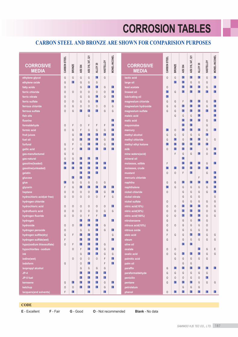
CARBON STEEL AND BRONZE ARE SHOWN FOR COMPARISION PURPOSES
CORROSION TABLES
SSAAMMWWOOOO KKJJSS TTEECC CCOO..,, LLTTDD.. 187
CORROSIVEMEDIA CA
RBON
STEE
L
G
G
O
O
O
O
O
O
O
O
G
O
G
G
F
O
O
O
O
O
O
O
G
F
O
G
G
O
F
E
E
E
G
O
O
G
G
F
G
G
G
F
F
G
G
G
G
O
O
O
O
O
O
F
F
O
O
OE
E
E
E
E
E
G
G
G
O
G
G
O
O
F
G
G
O
O
O
O
O
G
F
G
O
O
G
E
E
E
E
E
E
E
E
E
E
E
E
E
E
E
E
E
E
E
G
G
O
G
G
O
G
F
G
G
O
O
O
O
F
G
O
G
E
E
E
E
E
E
E
E
E
E
E
E
E
E
E
E
E
E
E
E
E
E
E
E
E
G
O
O
F
G
G
O
O
O
F
O
G
E
E
E
E
E
E
E
E
E
E
E
E
E
E
E
E
E
E
E
E
E
E
E
E
E
E
E G
G
O
O
O
G
F
G
G
G
G
G
F
O
G
G
G
G
G
G
F
F
G
G
GE
E
E
E
E
E
E
E
E
G
G
G
G
G
G
E
E
E
E
E
E
E
E
E
E
E
E
E
E
E
E
E
E
E
E
E
E
BRON
ZE
AISI
304
AISI
316,
347,
321
ALLO
Y20
HAST
ELLO
Y
MONE
L-IN
CONE
L
ethylene glycolethylene oxidefatty acidsferric chlorideferric nitrateferric sulfateferrous chlorideferrous sulfatefish oilsfluorineformaldehydeformic acidfruit juicesfuel oilfurfuralgallic acidgas-manufacturedgas-naturalgasoline(leaded)gasoline(unleaded)gelatinglucoseglueglycerinheptanehydrochloric acid(air free)hydrogen chloridehydrochloric acidhydrofluoric acidhydrogen fluoridehydrogenhydroxidehydrogen peroxidehydrogen sulfite(dry)hydrogen sulfide(wet)hypo(sodium thisosulfate)hypochlorites - sodiuminkiodine(wet)iodoformisopropyl alcoholJP-4JP-5 fuelkeroseneketchuplacquers(and solvents)
CORROSIVEMEDIA CA
RBON
STEE
L
O
O
G
G
G
G
G
O
F
O
G
O
O
O
O
O
G
O
G
F
G
O
O
G
G
O
G
O
E
E
E
E
E
E
G
G
G
G
G
G
O
G
F
O
G
G
O
O
O
O
G
O
G
G
G
O
E
E
E
E
E
E
E
E
F
G
G
G
G
F
G
G
G
G
G
G
G
G
G
G
G
G
O
GE
E
E
E
E
E
E
E
E
E
E
E
E
E
E
E
E
E
E
E
E
E
E
G
G
G
G
G
G
G
G
G
G
G
G
G
G
G
G
GE
E
E
E
E
E
E
E
E
E
E
E
E
E
E
E
E
E
E
E
E
E
E
E
E
G
G
F
G
G
G
G
G
G
G
G
G
O
G
GE
E
E
E
E
E
E
E
E
E
E
E
E
E
E
E
E
E
E
E
E
E
E
E G
G
G
G
G
G
G
G
G
G
O
G
G
G
G
G
O
O
O
G
O
O
G
G
G
G
G
G
G
E
E
E
E
E
E
E
E
E
G
G
G
G
G
G
G
G
E
G
G
E
E
E
E
E
E
E
E
E
E
E
E
E
E
E
E
E
E
E
BRON
ZE
AISI
304
AISI
316,
347,
321
ALLO
Y20
HAST
ELLO
Y
MONE
L-IN
CONE
L
lactic acidlarge oillead acetatelinseed oillubricating oilmagneslum chloridemagneslum hydroxidemagneslum sulfatemaleic acidmalic acidmayonnaisemercurymethyl alcoholmethyl chloridemethyl ethyl ketonemilkmine waters(acid)mineral oilmolasses, ediblemolasses, crudemustardmercuric chloridenaphthanaphthalenenickel chloridenickel nitratenickel sulfatenitric acid(10%)nitric acid(30%)nitric acid(100%)nitrobenzenenitrous acid(10%)nitrous oxideoleic acidoleumolive oiloxalateoxalic acidpalmitic acidpalm oilparaffinparaformaldehydepenicilinpentanepetrolatumphenol
CODEE - Excellent F - Fair G - Good O - Not recommended Blank - No data
0302플디-삼우카다록02 2012.3.2 9:9 PM 페이지187

CARBON STEEL AND BRONZE ARE SHOWN FOR COMPARISION PURPOSES
CORROSION TABLES
SSAAMMWWOOOO KKJJSS TTEECC CCOO..,, LLTTDD..188
CORROSIVEMEDIA CA
RBON
STEE
L
O
O
O
G
O
O
G
G
F
G
F
F
F
F
F
G
G
G
G
F
F
O
O
O
F
F
O
O
G
G
F
G
G
O
F
O
G
G
F
E
G
G
O
O
O
G
G
G
E
G
G
G
F
O
G
G
G
G
G
G
F
O
G
O
G
O
G
G
G
G
G
G
F
G
G
G
G
G
G
G
G
G
G
G
G
G
G
G
G
G
G
F
G
G
G
G
F
G
O
G
G
G
E
E
E
E
E
E
E
G
G
G
G
G
G
F
G
G
G
G
G
G
G
G
G
G
G
G
G
G
G
G
G
G
G
G
G
G
G
G
G
G
G
G
G
E
E
E
E
E
E
E
E
E
G
G
G
G
F
G
G
G
G
G
G
G
G
G
G
G
G
G
G
G
G
G
G
G
G
G
G
G
G
G
G
E
E
E
E
E
E
E
E
E G
G
G
O
G
G
G
G
G
G
G
G
G
G
G
G
G
O
F
G
G
G
G
G
G
G
G
G
O
G
G
G
E
E
E
E
E
G
G
G
G
G
G
G
G
G
G
G
G
G
G
G
G
G
G
G
F
G
G
G
E
E
E
E
E
E
E
E
E
BRON
ZE
AISI
304
AISI
316,
347,
321
ALLO
Y20
HAST
ELLO
Y
MONE
L-IN
CONE
L
phosphoric acid(10%)phosphoric acid(25%)phthalic acidpicric acidpine oilpineapple juicepotassium bisulfitepotassium bromidepotassium carbonatepotassium chloratepotassium chloridepotassium cyanidepotassium dichromatepotassium diphosphatepotassium ferricyanidepotassium ferrocyanidepotassium hydroxidepotassium lodidepotassium nitratepotassium permanganatepotassium sulfatepropanepyrogallic acidrosin emulsionsalad oilsalicylic acidsea watersilver nitratesodium acetatesodium aluminatesodium bicarbonatesodium bisulfate(10%)sodium bisulfitesodium boratesodium bromide(10%)sodium carbonatesodium chloratesodium chloridesodium chromatesodium cyanidesodium fluoridesodium hydroxidesodium hypochloritesodium nitratesodium perboratesodium peroxide
CORROSIVEMEDIA CA
RBON
STEE
L
F
G
G
G
F
O
O
O
G
G
O
O
F
O
F
O
G
G
O
O
O
O
O
O
O
G
O
O
E
E
E
F
G
G
O
O
O
F
O
F
F
G
G
G
F
G
G
G
O
O
F
F
O
G
E
E
E
E
E
E
G
G
G
G
O
O
G
G
G
G
G
O
O
O
F
F
G
G
G
O
O
G
E
E
E
E
E
E
E
E
E
E
E
E
E
E
E
E
E
E
E
G
G
G
G
G
G
G
G
G
O
O
G
O
G
G
G
G
G
G
G
O
G
E
E
E
E
E
E
E
E
E
E
E
E
E
E
E
E
E
E
E
E
E
E
E
G
G
G
G
G
G
G
G
G
G
G
O
G
G
E
E
E
E
E
E
E
E
E
E
E
E
E
E
E
E
E
E
E
E
E
E
G
F
F
G
G
G
F
G
G
O
O
G
G
G
G
G
G
G
G
G
G
E
E
E
E
E
E
E
E
E
E
E
E
E
G
G
G
G
G
G
G
G
E
E
E
E
E
E
E
E
E
E
E
E
E
E
E
E
E
E
E
BRON
ZE
AISI
304
AISI
316,
347,
321
ALLO
Y20
HAST
ELLO
Y
MONE
L-IN
CONE
L
sodium phosphatesodium silicatesodium sulfatesodium sulfidesodium thiosulfatesoybean oilstannic chloridestannous chloridestarchsteam(212℉℉)stearic acidsugar liquidssulfate - black liquorsulfate - green liquorsulfate - white liquorsulfur dioxide(dry)sulfur trioxide(dry)sulfuric acid(20%)sulfuric acid(50%)sulfuric acid(100%)sulfurous acidtall oiltannic acidtartaric acidtetraethyl leadtoluenetomato juicetrichloroethylenetung oilturpentinetitanium “E”ureavarnishvegetable oil, ediblevegetable oil, non - ediblevinegarvitaminswater - distilled(aerated)water - freshwater - seawhiskeywinexylene(dry)zinc chloridezinc hydrosulfitezinc sulfate
CODEE - Excellent F - Fair G - Good O - Not recommended Blank - No data
0302플디-삼우카다록02 2012.3.2 9:9 PM 페이지188

SSAAMMWWOOOO KKJJSS TTEECC CCOO..,, LLTTDD.. 189
0302플디-삼우카다록02 2012.3.2 9:9 PM 페이지189

SSAAMMWWOOOO KKJJSS TTEECC CCOO..,, LLTTDD..190
0302플디-삼우카다록02 2012.3.2 9:9 PM 페이지190

SSAAMMWWOOOO KKJJSS TTEECC CCOO..,, LLTTDD.. 191
0302플디-삼우카다록02 2012.3.2 9:9 PM 페이지191

SSAAMMWWOOOO KKJJSS TTEECC CCOO..,, LLTTDD..192
0302플디-삼우카다록02 2012.3.2 9:9 PM 페이지192

SSAAMMWWOOOO KKJJSS TTEECC CCOO..,, LLTTDD.. 193
0302플디-삼우카다록02 2012.3.2 9:9 PM 페이지193

SSAAMMWWOOOO KKJJSS TTEECC CCOO..,, LLTTDD..194
0302플디-삼우카다록02 2012.3.2 9:9 PM 페이지194
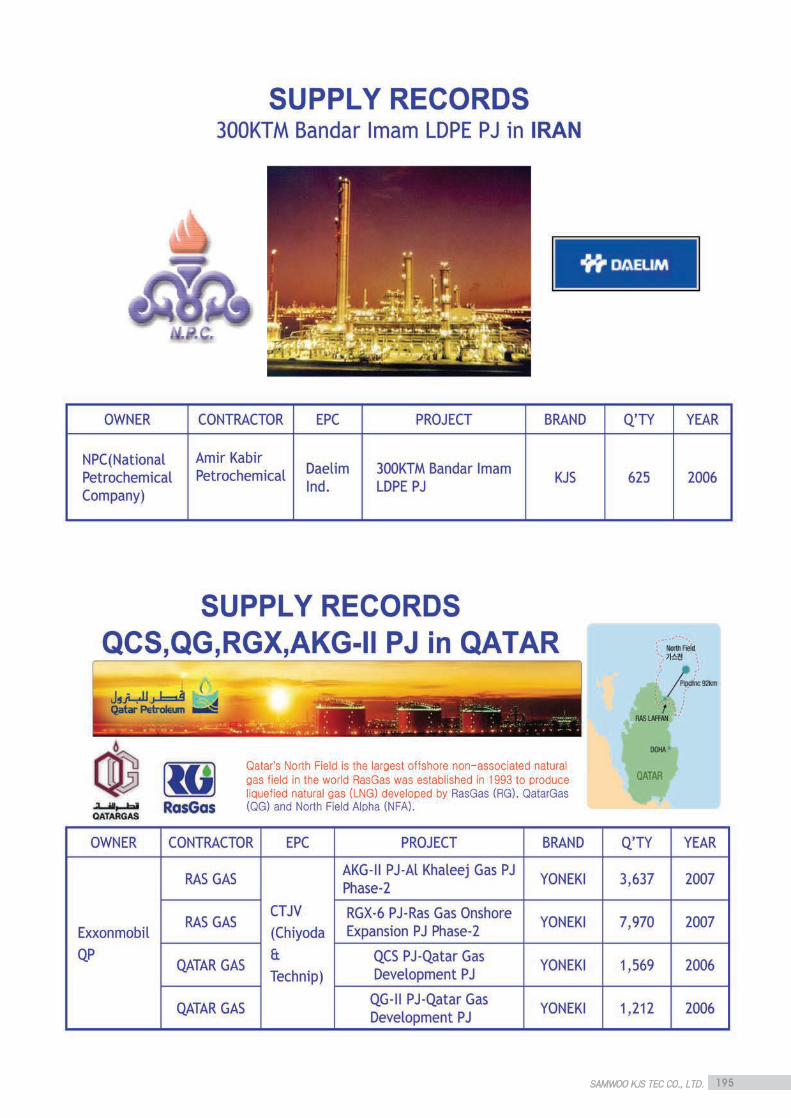
CARBON & ALLOY STEEL VALVES
STAINLESS STEEL VALVES
CRYOGENIC VALVES
BELLOWS VALVES
GATE, GLOBE, CHECK,
THROUGH CONDUIT GATE
BALL VALVES
WARRANTY
S
AMWOO KJS TEC CO.,LTD(SAMWOO HEREAFTER) WARRANTS ITS PRODUCTS (INCLUDED PARTS) TO THE
ORIGINAL PURCHASER FOR A PERIOD OF ONE YEAR FROM AND AFTER THE DATE OF DELIVERY TO THE
ORIGINAL CUSTOMER, AGAINST DEFECTS IN MATERIAL AND WORKMANSHIP UNDER PROPER AND NORMAL
USE AND SERVICE AND NOT CAUSED OF INSTALLATIONS, IMPROPER MAINTENANCE AND REPAIRS,
MODIFICATIONS OR ALTERNATIONS. PURCHASER SHALL GIVE NOTICE TO SAMWOO UPON FINDING OF ANY
DEFECT OR ASSUMING DEFECT AND SAMWOO HAS PRIVILEGE TO CHECK THE FACTS OF THE DEFECT.
THIS WARRANTY SHALL BE LIMTED TO THE FOLLOWINGS.
1) REPAIR OF THE MATERIALS OR,
2) REPLACEMENT OF THE PARTS AND MATERIALS OR,
3) REFUND THE PURCHASE PRICE OR COLLECT THE DEFECTED PRODUCTS FROM THE ORIGINAL
PURCHASER.
SAMWOO IS NOT RESPONSIBLE TO CLAIMS FOR CONSEQUENTIAL DAMAGE, LOSS OR EXPENSE OF ANY
KIND ARISING OUT OF THE DEFECT.
THE SCOPE AND LIMITATION OF WARRANTY CAN BE CHANGED THROUGH THE AGREEMENT BETWEEN
SAMWOO AND PURCHASER.
SAMWOO KJS TEC CO., LTD.
■
HEAD OFFICE(FACTORY)
45-2, WOONGNAM-DONG, CHANGWON-CITY, GYEONGNAM, KOREA.
T EL : +82-55-285-7331~7 F A X : +82-55-285-1666
E-mail : [email protected]
http://www.kjs.co.kr
SAMWOO KJS TEC CO., LTD.
»Òåä²ÑKJS TEC
CARBON & ALLOY STEEL VALVES
STAINLESS STEEL VALVES
CRYOGENIC VALVES
BELLOWS VALVES
GATE, GLOBE, CHECK,
THROUGH CONDUIT GATE
BALL VALVES
GL
OB
AL
CH
AM
PIO
NK
JS
VA
LV
ES
SA
MW
OO
KJ
ST
EC
CO
.,LT
D.
SAMWOO KJS TEC CO., LTD.
2
_INTRODUCTION
CEO Mr. Bang
DIRECTOR Mr. Heu
SAMWOO KJS TEC CO., LTD. 195
K 플러스 462-0678YMC
오시선오시선K플러스462-0678 Y MC
오버
프린트
녹아웃
Bla
ck
Only
1%
2%
Related Documents