CHAPTER -1 Cisco MWR 1941-DC Mobile Wireless Edge Router Software Configuration Guide OL-11503-01 Configuring the MWR 1941-DC in an IP-RAN Note Cisco IOS Release 12.3(11)T supports the Cisco IOS IP-RAN feature set (software image) for the MWR 1941-DC router. This chapter describes how to use the Cisco IOS software command-line interface (CLI) to configure the following features of the Cisco MWR 1941-DC in an IP-RAN: • Before You Begin, page -2 Verifying the Version of Cisco IOS Software, page -2 Configuring the Host Name and Password, page -2 Configuring Multilink Interfaces, page -8 Configuring Fast Ethernet Interfaces, page -4 Configuring Multilink Interfaces, page -8 Configuring T1 and E1 Interfaces, page -13 Configuring QoS Attributes, page -16 Configuring Redundancy, page -18 Configuring the Link Noise Monitor, page -20 Saving Configuration Changes, page -22 Verifying the Configuration, page -22 Monitoring and Managing the MWR 1941-DC, page -26 Where to Go Next, page -28 Follow the procedures in this chapter to configure the router manually or if you want to change the configuration after you have run the setup command facility (described in Chapter 1, “First-Time Configuration”). This chapter describes how to configure features related to the use of the MWR 1941-DC in an IP-RAN. For additional configuration topics, refer to the Cisco IOS configuration guide and command reference publications. These publications are available on the Documentation CD-ROM that came with your router, on the World Wide Web from Cisco’s home page, or you can order printed copies separately. If you skipped the previous chapter, Chapter 1, “Cisco IOS Software Basics,” and you have never configured a Cisco router, go back to that chapter and read it now. The chapter contains important information you need to successfully configure your router.

Welcome message from author
This document is posted to help you gain knowledge. Please leave a comment to let me know what you think about it! Share it to your friends and learn new things together.
Transcript

Cisco MWR 1941-DC Mobile Wireless EdOL-11503-01
C H A P T E R
Configuring the MWR 1941-DC in an IP-RAN
Note Cisco IOS Release 12.3(11)T supports the Cisco IOS IP-RAN feature set (software image) for the MWR 1941-DC router.
This chapter describes how to use the Cisco IOS software command-line interface (CLI) to configure the following features of the Cisco MWR 1941-DC in an IP-RAN:
• Before You Begin, page -2
Verifying the Version of Cisco IOS Software, page -2
Configuring the Host Name and Password, page -2
Configuring Multilink Interfaces, page -8
Configuring Fast Ethernet Interfaces, page -4
Configuring Multilink Interfaces, page -8
Configuring T1 and E1 Interfaces, page -13
Configuring QoS Attributes, page -16
Configuring Redundancy, page -18
Configuring the Link Noise Monitor, page -20
Saving Configuration Changes, page -22
Verifying the Configuration, page -22
Monitoring and Managing the MWR 1941-DC, page -26
Where to Go Next, page -28
Follow the procedures in this chapter to configure the router manually or if you want to change the configuration after you have run the setup command facility (described in Chapter 1, “First-Time Configuration”).
This chapter describes how to configure features related to the use of the MWR 1941-DC in an IP-RAN. For additional configuration topics, refer to the Cisco IOS configuration guide and command reference publications. These publications are available on the Documentation CD-ROM that came with your router, on the World Wide Web from Cisco’s home page, or you can order printed copies separately.
If you skipped the previous chapter, Chapter 1, “Cisco IOS Software Basics,” and you have never configured a Cisco router, go back to that chapter and read it now. The chapter contains important information you need to successfully configure your router.
-1ge Router Software Configuration Guide

Chapter Configuring the MWR 1941-DC in an IP-RAN Before You Begin
Before You Begin
• Cisco IOS Release 12.2(8)MC2 or later “mwr1900-i-mz” image must be installed on the Cisco MWR 1941-DC router.
• You cannot disable Cisco Express Forwarding (CEF) on the MWR 1941-DC. Commands such as no ip cef will display an error message “%Cannot disable CEF on this platform.” Some commands, such as no ip route-cache cef not
should ensure that the order of the IP addresses of the E1/T1 interfaces of the active router corresponds to the order of the IP addresses of the E1/T1 interfaces of the standby router.
Verifying the Version of Cisco IOS Software
show version
show version
Configuring the Host Name and Password
Command Purpose
Step 1 Router> enable
Password: password
Router#Router#
Step 2 configure terminal
Enter configuration commands, one per line.
End with CNTL/Z.
Router(config)#
Router(config)#.
Step 3 Router(config)# hostname Router
-2Cisco MWR 1941-DC Mobile Wireless Edge Router Software Configuration Guide
OL-11503-01
Chapter Configuring the MWR 1941-DC in an IP-RAN Configuring the Host Name and Password
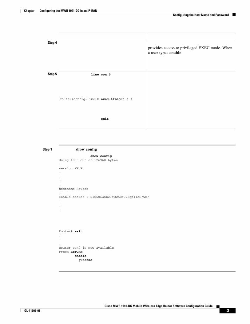
Step 1 show config
show configUsing 1888 out of 126968 bytes!version XX.X...!hostname Router!enable secret 5 $1$60L4$X2JYOwoDc0.kqa1loO/w8/...
Router# exit...Router con0 is now availablePress RETURN
enableguessme
Step 4provides access to privileged EXEC mode. When a user types enable
Step 5 line con 0
Router(config-line)# exec-timeout 0 0
exit
-3Cisco MWR 1941-DC Mobile Wireless Edge Router Software Configuration Guide
OL-11503-01

Chapter Configuring the MWR 1941-DC in an IP-RAN Configuring Loopback Interfaces
Configuring Loopback Interfaces
router. The revertive interface is required to ensure that the switchover takes place. We recommend that you use 101 for the health interface and 102 for the revertive interface.
To configure a loopback interface, do the following beginning in global configuration mode:
Step 1 Create a loopback interface for each multilink interface:
interface loopback numberip address ip_address subnet_mask
Configuring Fast Ethernet Interfaces
•
•
•
•
•
•
Configuring the FE Interface IP Address
Step 1
slot port
-4Cisco MWR 1941-DC Mobile Wireless Edge Router Software Configuration Guide
OL-11503-01

Configuring Fast Ethernet Interfaces
slot port
Setting the Speed and Duplex Mode
•
•
•both interfaces; do not use the auto setting on the supported side or the duplex setting will be half.
To configure speed and duplex operation, do the following while still in interface configuration mode:
Step 1 Specify the duplex operation.
[ | | ]
Router(config-if)# [ | 100 | 10]
Configuring Routing Protocol Attributes
Step 1 Enable OSPF Message Digest 5 (MD5) authentication.
message-digest-key key-id md5 key
ip ospf hello-interval seconds
seconds
-5

{ | | [ { | }]}
Configuring HSRP Support
Note
Step 1
Router(config-if)# group group-name
standby 1 name one standby 2 name two
Tip group-name
-6

hellotime holdtime
must
number decrement_value
group number decrement_value
group number decrement_value
standby track
Step 6
Note
Enabling the FE Interface
Step 1
-7

Configuring Multilink Interfaces
•
•
•
• Configuring RTP/UDP Compression, page -11
• Configuring the RTP/UDP Compression Flow Expiration Timeout Duration, page -11
• Configuring Routing Protocol Attributes, page -12
• Configuring PIM, page -12
Configuring Multilink PPP
multilink interface serves to coordinate the configuration of the bundled link, and presents a single object for the aggregate links. However, the individual PPP links that are aggregated together, must also be configured. Therefore, to enable Multilink PPP on multiple serial interfaces, you need to first set up the multilink interface, and then configure each of the serial interfaces and add them to the same multilink interface.
The MWR 1941-DC router can support up to 16 T1 interfaces through the multilink interface.
To set up the multilink interface, do the following beginning in global configuration mode:
Specify the multilink interface to be configured.
RPM-3(config)#
RPM-3(config-if)#
RPM-3(config-if)# umber
RPM-3(config-if)# umber
RPM-3(config-if)# umber
-8

number
Configuring IP Address Assignment
command, provided by TACACS+ or the Dynamic Host Configuration Protocol (DHCP), or from a locally administered pool.
IP address pooling uses a pool of IP addresses from which an incoming interface can provide an IP address to a remote node through IPCP address negotiation process. IP address pooling also enhances configuration flexibility by allowing multiple types of pooling to be active simultaneously.
To configure IP address assignment, do the following do the following while still in multilink interface configuration mode:
Specify an IP address, an address from a specific IP address pool, or an address from the Dynamic Host Configuration Protocol (DHCP) mechanism to be returned to a remote peer connecting to this interface:
To enable and control the multiplexing of PPP frames, do the following while still in multilink interface configuration mode:
Enable PPP multiplexing:
Specify the parameters of multiplexing.
To set the maximum time delay, enter:
To set the maximum length of the subframe, enter:
To set maximum length of the superframe, enter:
To set the maximum number of subframes in a superframe, enter:
To set the default PPP protocol ID, enter:
-9

Configuring ACFC and PFC Handling During PPP Negotiation
Note
Step 1
reject ignore
—ACFC options are accepted and ACFC may be performed on frames sent to the remote peer.
reject
ignore
request forbid
request
forbid
apply
reject
ignore
-10

request
forbid
Configuring RTP/UDP Compression
Step 1
SRPM-3(config-if)#
SRPM-3(config-if)#
Step 2
RPM-3(config-if)#
Note
Configuring the RTP/UDP Compression Flow Expiration Timeout Duration

Chapter Configuring the MWR 1941-DC in an IP-RAN Configuring Multilink Interfaces
Caution
Step 1
Configuring Routing Protocol Attributes
Step 1
Step 2
Step 3
Configuring PIM
Step 1
Cisco MWR 1941-DC Mobile Wireless Edge Router Software Configuration GuideOL-11503-01

Chapter Configuring the MWR 1941-DC in an IP-RAN Configuring T1 and E1 Interfaces
Configuring T1 and E1 Interfaces
Note
Configuring T1 Interfaces
Step 1
Step 2
Step 3
linecode b8zs
channel-group 0 timeslots 1-24 speed 64
cablelength feet
exit
Step 7
Cisco MWR 1941-DC Mobile Wireless Edge Router Software Configuration GuideOL-11503-01

Chapter Configuring the MWR 1941-DC in an IP-RAN Configuring T1 and E1 Interfaces
slot/port
Step 8
Step 9
Step 10
Note
Step 11
Step 12
Step 13
Configuring E1 Interfaces
Step 1
Step 2
Step 3
linecode hdb3
Step 4
channel-group 0 timeslots 1-24 speed 64
Cisco MWR 1941-DC Mobile Wireless Edge Router Software Configuration GuideOL-11503-01

Chapter Configuring the MWR 1941-DC in an IP-RAN Configuring T1 and E1 Interfaces
Note
Step 5
interface serial :0
cablelenth
ip address
encapsulation ppp
keepalive
carrier-delay
exit
Cisco MWR 1941-DC Mobile Wireless Edge Router Software Configuration GuideOL-11503-01

Configuring QoS Attributes
Configuring QoS Attributes
Note
http://www.cisco.com/univercd/cc/td/doc/product/aggr/10000/10kfm/fm_qos.htm), as well as the “Cisco IOS Quality of Service Solutions Configuration Guide” and the “Cisco IOS Quality of Service Solutions Command Reference.”
Creating a Class MapFor each class map that you want to create, do the following in global configuration mode:
Step 1 Assign a name to your class map.
Where means a single match rule is sufficient for class membership and means only those packets that have all the attributes you specify are part of the class.
When you enter the class-map command, you are placed in class map configuration mode.
Step 2 Describe the characteristics of the packets that are subject to QoS using one or more of the following.
• specifies access control list (ACL) that a packet must match.
• specifies the IP differentiated service code point (DSCP) that a packet must match.
• specifies the precedence values (0-7) that a packet must match.
specifies the name of the input interface used as a match criterion.
specifies the protocol that a packet must match.
For more information about these commands, see the “Cisco IOS Quality of Service Solutions Command Reference.”
Exit class map configuration mode.

Creating a Policy Map
Step 1
Step 2
class_name
shape max-buffers
bandwidth percent priority percent

Configuring Redundancy
qos-group-value
Assigning a QoS Boilerplate to an Interface
Step 1
Step 2
Configuring Redundancy
Note
Redundant MWR 1941-DCs

Chapter Configuring the MWR 1941-DC in an IP-RAN Configuring Redundancy
Step 1
Step 2
Step 3
Note
Step 4
Note
Step 5
Stand-Alone MWR 1941-DC
Step 1
Step 2
Step 3
Cisco MWR 1941-DC Mobile Wireless Edge Router Software Configuration GuideOL-11503-01
Chapter Configuring the MWR 1941-DC in an IP-RAN Configuring the Link Noise Monitor
Step 4
Configuring the Link Noise Monitor
Note
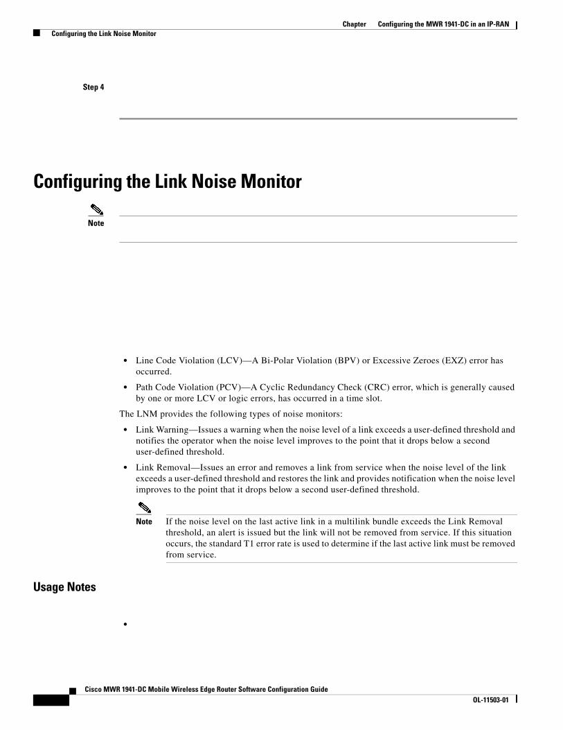
• Line Code Violation (LCV)—A Bi-Polar Violation (BPV) or Excessive Zeroes (EXZ) error has occurred.
• Path Code Violation (PCV)—A Cyclic Redundancy Check (CRC) error, which is generally caused by one or more LCV or logic errors, has occurred in a time slot.
The LNM provides the following types of noise monitors:
• Link Warning—Issues a warning when the noise level of a link exceeds a user-defined threshold and notifies the operator when the noise level improves to the point that it drops below a second user-defined threshold.
• Link Removal—Issues an error and removes a link from service when the noise level of the link exceeds a user-defined threshold and restores the link and provides notification when the noise level improves to the point that it drops below a second user-defined threshold.
Note If the noise level on the last active link in a multilink bundle exceeds the Link Removal threshold, an alert is issued but the link will not be removed from service. If this situation occurs, the standard T1 error rate is used to determine if the last active link must be removed from service.
Usage Notes
•
Cisco MWR 1941-DC Mobile Wireless Edge Router Software Configuration GuideOL-11503-01

Chapter Configuring the MWR 1941-DC in an IP-RAN Configuring the Link Noise Monitor
•
•
•
•
•
- %LNM-4- WARNEXCEED:Controller <Controller IF>, exceeded noise warning threshold <int>, duration <int>
- %LNM-4- WARNIMPROVE:Controller <Controller IF>, noise improved below threshold <int>, duration <int>
- %LNM-2-REMOVE:Interface <Serial IF> removed, noise exceeded threshold <int>, duration <int>
- %LNM-2- RESTORE:Interface <Serial IF> restored, noise improved below threshold <int>, duration <int>
- %LNM-2- REMEXCEED:Interface <Serial IF>, noise exceeded threshold <int>, duration <int>
- %LNM-2- REMIMPROVE:Interface <Serial IF>, noise improved below threshold <int>, duration <int>
Configuring LNM
{ | remove } [ { [ value value ]] [ seconds ] } | ]
where:
—Enables Link Warning monitoring on the link.
—Enables Link Removal monitoring on the link.
—Threshold (in bit errors per second) that when exceeded for the configured duration when the keyword has been specified, creates a condition (warning or link removal), or when fallen below for the configured duration when the keyword has been specified, clears the condition.
For T1 links:
–
–
–
–
–
–
Cisco MWR 1941-DC Mobile Wireless Edge Router Software Configuration GuideOL-11503-01

Saving Configuration Changes
–
–
–
–
–
–
•
span warn lcv 55 duration 20 pan warn duration 20 lcv 55
set span
clear span
Saving Configuration Changes
Step 1
Note Ctrl-zexit
-22

Verifying the Configuration
! description Loopback IP for O & M!interface loopback 0ip address 10.1.170.3 255.255.255.255
!! description Loopback IP for IP Unnumbered!interface loopback 2ip address 192.168.170.2 255.255.255.255
!interface loopback101description Health Loopback Interfaceno ip address
!interface loopback102description Revertive Loopback Interfaceno ip address
!enable password cisco !memory-size iomem 25!redundancy mode y-cable standby use-interface Loopback101 health standby use-interface Loopback102 revertive standby use-interface Multilink2 backhaul!controller T1 0/0 framing esfcablelength short 133ft
clock source internal linecode b8zs channel-group 0 timeslots 1-1 speed 64channel-group 1 timeslots 2-24 speed 64
!controller T1 0/1 framing esf clock source internal linecode b8zs cablelength short 133ft!!class-map match-all class1_fchmatch ip dscp cs5
class-map match-all class2_schmatch ip dscp cs4
class-map match-any class3_paging_ospfmatch ip dscp cs3
match access-group 101!policy-map llq-policyclass class1_fchpriority percent 68
class class2_schbandwidth percent 20 queue-limit 128
class class3_paging_ospfbandwidth percent 2 queue-limit 128
class class-defaultqueue-limit 512
!ip dhcp excluded-address 192.168.146.1 192.168.146.3

ip dhcp ping packets 0 !ip dhcp pool pbtsnetwork 192.168.146.0 255.255.255.0bootfile CENOMIbts.imgnext-server OMCR-IPaddroption 43 ascii "Logical-IPaddr CENOMI-IPaddr another-IPaddr
OMCR-IPaddr
OMCR_ip_addressOMCIP_ip_addressCW4MW_ip_address
description Backhaul Interfaceip unnumbered loopback 2cdp enableppp multilinkip ospf hello-interval 1ip ospf dead-interval 3ip ospf message-digest-key 1 md5 mymd5pw
!interface Multilink2description ip unnumbered loopback 2ip mroute-cacheip mtu 256cdp enable ppp multilink ip rtp header-compression ignore-idip rtp compression-connections 700 ppp muxppp mux subframe length 64ppp mux subrame count 15ppp mux frame 256
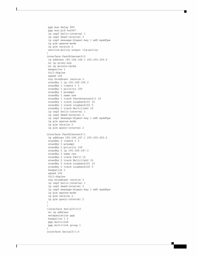
ppp mux delay 800ppp mux pid 0x2067 ip ospf hello-interval 1ip ospf dead-interval 3 ip ospf message-digest-key 1 md5 mymd5pw ip pim sparse-modeip pim version 2service-policy output llq-policy
!interface FastEthernet0/0 ip address 192.168.146.1 255.255.255.0 no ip proxy-arp no ip mroute-cache keepalive 1 full-duplex speed 100ntp broadcast version 3
standby 1 ip 192.168.146.3 standby 1 timers 1 3 standby 1 priority 100 standby 1 preempt standby 1 name one standby 1 track FastEthernet0/1 10 standby 1 track Loopback101 10 standby 1 track Loopback102 5 standby 1 track Multilink2 10ip ospf hello-interval 1ip ospf dead-interval 3ip ospf message-digest-key 1 md5 mymd5pw ip pim sparse-mode ip pim version 2ip pim query-interval 2
interface FastEthernet0/1ip address 192.168.147.1 255.255.255.0 standby 2 timers 1 3standby 2 preemptstandby 2 priority 100standby 2 ip 192.168.147.3standby 2 name two standby 2 track Fa0/0 10standby 2 track Multilink2 10standby 2 track Loopback101 10standby 2 track Loopback102 5keepalive 1speed 100full-duplexntp broadcast version 3ip ospf hello-interval 1ip ospf dead-interval 3ip ospf message-digest-key 1 md5 mymd5pwip pim sparse-mode ip pim version 2ip pim query-interval 2
!!!interface Serial0/0:0 no ip address encapsulation ppp keepalive 1 2 ppp multilink ppp multilink group 1!interface Serial0/1:0

no ip address encapsulation ppp keepalive 1 2 ppp multilink ppp multilink group 2!router ospf 1log-adjacency-changesarea 2 nssaarea 2 authentication message-digest auto-cost reference-bandwidth 10240timers spf 1 10redistribute ospf 2 metric-type 1 subnetsredistribute static metric-type 1 subnetsnetwork 192.168.170.2 0.0.0.3 area 2 distribute-list 10 outdistance ospf external 125summary-address area-51-prefix mask
Keepalives must be set for all Ethernet interfaces to ensure proper redundant behavior. A keepalive value of 1 has been selected for maximum responsiveness.
Configuring is helpful to avoid confusion with routes and ARP caches.
In a redundant configuration, both MWR 1941-DCs share a common IP address for their Multilink interface.
Monitoring and Managing the MWR 1941-DC
Step 1

Chapter Configuring the MWR 1941-DC in an IP-RAN Monitoring and Managing the MWR 1941-DC
Step 2
hostname is the name assigned to the Operations and Maintenance (O&M) workstation and ip_address
hostname
ROsnmp-server community RW
snmp-server enable traps
snmp-server trap-source loopback
copy running-config startup-config
Cisco MWR 1941-DC Mobile Wireless Edge Router Software Configuration GuideOL-11503-01

Where to Go Next
Where to Go Next
•
• System Error Messages Debug Command Reference
interface
slot port
slot port
interface
type slot port
Related Documents