CHAPTER -1 Cisco MWR 1941-DC Mobile Wireless Edge Router Software Configuration Guide OL-11503-01 Configuring the MWR 1941-DC in a Cell Site DCN Note Cisco IOS Release 12.3(11)T does not support the Cisco IOS Cell Site DCN feature set (software image) for the MWR 1941-DC router. This chapter describes how to use the Cisco IOS software command-line interface (CLI) to configure the following features of the MWR 1941-DC router in a Cell Site DCN: • Before You Begin, page -2 Configuring the Host Name and Password, page -3 Configuring Fast Ethernet Interfaces, page -5 Configuring the Ethernet Switch Network Module, page -5 Configuring Asynchronous/Synchronous Serial Network Modules or WAN Interface Cards, page -8 Configuring 16-Port Asynchronous Network Module, page -11 Configuring T1 and E1 Interfaces, page -12 Configuring the 1 T3/E3 Module, page -17 Configuring the NM-AIC-64, Contact Closure Network Module, page -22 Configuring QoS Attributes, page -41 Filtering IP Packets Using Access Lists, page -44 Saving Configuration Changes, page -60 Verifying the Configuration, page -60 Monitoring and Managing the MWR 1941-DC Router, page -64 Where to Go Next, page -65 Follow the procedures in this chapter to configure the router manually, or if you want to change the configuration after you have run the setup command facility “Using the Setup Command Facility” section on page -3. This chapter describe only a small portion of commonly used configuration procedures. For detailed configuration topics, refer to the Cisco IOS configuration guide and command reference publications. These publications are available on the Documentation CD-ROM that came with your router, on the World Wide Web from Cisco’s home page, or you can order printed copies separately.

Welcome message from author
This document is posted to help you gain knowledge. Please leave a comment to let me know what you think about it! Share it to your friends and learn new things together.
Transcript

Cisco MWR 1941-DC Mobile Wireless EdOL-11503-01
C H A P T E R
Configuring the MWR 1941-DC in a Cell Site DCN
Note Cisco IOS Release 12.3(11)T does not support the Cisco IOS Cell Site DCN feature set (software image) for the MWR 1941-DC router.
This chapter describes how to use the Cisco IOS software command-line interface (CLI) to configure the following features of the MWR 1941-DC router in a Cell Site DCN:
• Before You Begin, page -2
Configuring the Host Name and Password, page -3
Configuring Fast Ethernet Interfaces, page -5
Configuring the Ethernet Switch Network Module, page -5
Configuring Asynchronous/Synchronous Serial Network Modules or WAN Interface Cards, page -8
Configuring 16-Port Asynchronous Network Module, page -11
Configuring T1 and E1 Interfaces, page -12
Configuring the 1 T3/E3 Module, page -17
Configuring the NM-AIC-64, Contact Closure Network Module, page -22
Configuring QoS Attributes, page -41
Filtering IP Packets Using Access Lists, page -44
Saving Configuration Changes, page -60
Verifying the Configuration, page -60
Monitoring and Managing the MWR 1941-DC Router, page -64
Where to Go Next, page -65
Follow the procedures in this chapter to configure the router manually, or if you want to change the configuration after you have run the setup command facility “Using the Setup Command Facility” section on page -3.
This chapter describe only a small portion of commonly used configuration procedures. For detailed configuration topics, refer to the Cisco IOS configuration guide and command reference publications. These publications are available on the Documentation CD-ROM that came with your router, on the World Wide Web from Cisco’s home page, or you can order printed copies separately.
-1ge Router Software Configuration Guide
Chapter Configuring the MWR 1941-DC in a Cell Site DCN Before You Begin
Note
Before You Begin
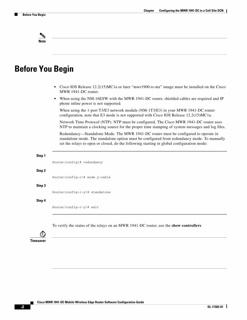
• Cisco IOS Release 12.2(15)MC1a or later “mwr1900-is-mz” image must be installed on the Cisco MWR 1941-DC router.
• When using the NM-16ESW with the MWR 1941-DC router, shielded cables are required and IP phone inline power is not supported.
When using the 1-port T3/E3 network module (NM-1T3/E3) in your MWR 1941-DC router configuration, note that E3 mode is not supported with Cisco IOS Release 12.2(15)MC1a.
Network Time Protocol (NTP). NTP must be configured. The Cisco MWR 1941-DC router uses NTP to maintain a clocking source for the proper time stamping of system messages and log files.
Redundancy—Standalone Mode. The MWR 1941-DC router must be configured to operate in standalone mode. The standalone option must be configured from redundancy mode. To manually set the relays to open or closed, do the following starting in global configuration mode:
Step 1
Router(config)# redundancy
Step 2
Router(config-r)# mode y-cable
Step 3
Router(config-r-y)# standalone
Step 4
Router(config-r-y)# exit
To verify the status of the relays on an MWR 1941-DC router, use the show controllers
Timesaver
-2Cisco MWR 1941-DC Mobile Wireless Edge Router Software Configuration Guide
OL-11503-01
Verifying the Version of Cisco IOS Software
Caution
Caution
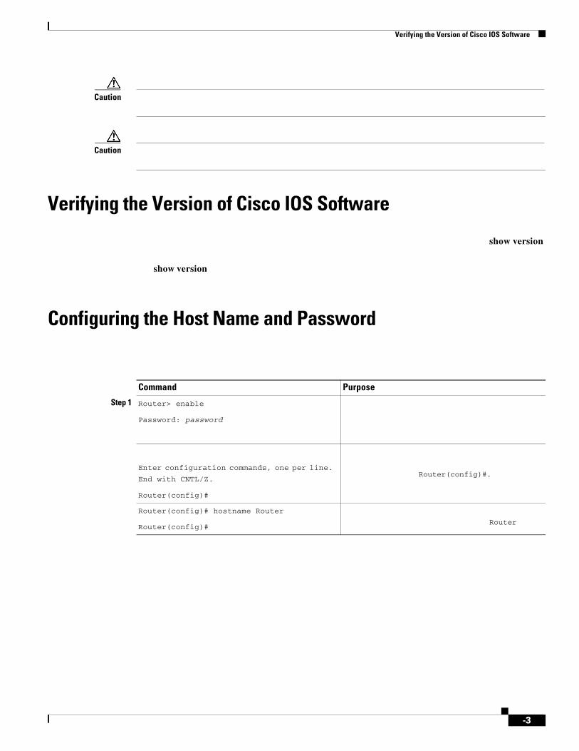
Verifying the Version of Cisco IOS Software
show version
show version
Configuring the Host Name and Password
Command Purpose
Step 1 Router> enable
Password: password
Enter configuration commands, one per line.
End with CNTL/Z.
Router(config)#
Router(config)#.
Router(config)# hostname Router
Router(config)#Router
-3

Chapter Configuring the MWR 1941-DC in a Cell Site DCN Configuring the Host Name and Password
Verifying the Host Name and Password
Step 1 show config
show configUsing 1888 out of 126968 bytes!version XX.X...!hostname Router!enable secret 5 $1$60L4$X2JYOwoDc0.kqa1loO/w8/...
Router# exit
RETURNenableguessme
provides access to privileged EXEC mode. When a user types enable
Step 5
Command Purpose
-4Cisco MWR 1941-DC Mobile Wireless Edge Router Software Configuration Guide
OL-11503-01

Configuring Fast Ethernet Interfaces
Tip
• Caps Lock
Configuring Fast Ethernet Interfaces
Configuration Exampleshow running-config
interface FastEthernet0/0 ip address 172.18.28.202 255.255.255.128 ip helper-address 99.1.1.2 no ip mroute-cache speed 100 full-duplex
Configuring the Ethernet Switch Network Module
Command Purpose
Step 1
Step 2 Router(config-if)# ip address 172.16.74.3
255.255.255.0
Step 3 Router(config-if)# ip helper address
99.1.1.2
Step 4 Router(config-if)# speed [auto | 100 10]
Router(config-if)# duplex [auto | half | full]
Step 6
Step 7 Router(config-if)# Ctrl-z
Router#
-5

Configuring the Ethernet Switch Network Module
16- and 36-Port Ethernet Switch Module for Cisco 2600 Series, Cisco 3600 Series, and Cisco 3700 Series
interface Serial0/1:0 ip address 100.50.0.206 255.255.255.0 no ip proxy-arp encapsulation ppp load-interval 30 keepalive 1 no fair-queue no cdp enable!interface Serial0/2 no ip address shutdown clockrate 125000!interface Serial0/3 no ip address shutdown clockrate 125000!interface FastEthernet1/0 no ip address duplex full speed 100!interface FastEthernet1/1 no ip address duplex full speed 100!interface FastEthernet1/2 no ip address duplex full speed 100!interface FastEthernet1/3 no ip address
-6

-7

Configuring Asynchronous/Synchronous Serial Network Modules or WAN Interface Cards
interface Vlan1 no ip address shutdown!interface Vlan10 no ip address!interface Vlan11 ip address 41.42.43.206 255.255.255.0 no ip proxy-arp load-interval 30!interface Vlan12 no ip address no ip proxy-arp no ip mroute-cache load-interval 30 shutdown!interface Vlan20 no ip address!
Configuring Asynchronous/Synchronous Serial Network Modules or WAN Interface Cards
Note Configuring Serial InterfacesCisco IOS Interface Configuration Guide, Release 12.2
http://www.cisco.com/univercd/cc/td/doc/product/software/ios122/122cgcr/finter_c/index.htm
-8

encapsulation_type
Router(config-if)# line async <#>
Router(config-if)# clockrate 7200
Step 8(NRZ) and nonreturn to zero inverted (NRZI) formats. NRZ is the default; NRZI is commonly used with EIA/TIA-232 connections in IBM environments. To enable NRZI encoding on an interface, enter this command.
Step 9 Exit back to global configuration mode.
Repeat Step 4 through Step 14 if your router has more that one serial interface that you need to configure.
Step 10
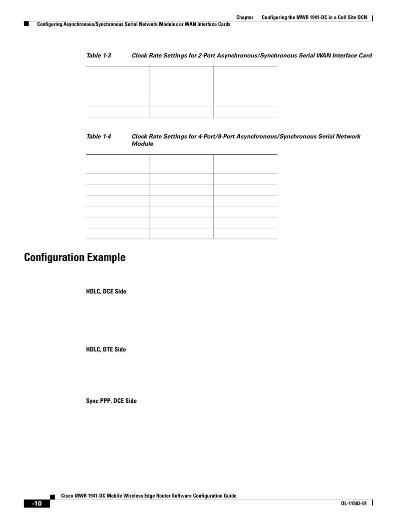
Table 1-3 Clock Rate Settings for 2-Port Asynchronous/Synchronous Serial WAN Interface Card
Timer (bits per second)
Syntax (bits per second)
Default Setting (bits per second)
-9
Chapter Configuring the MWR 1941-DC in a Cell Site DCN Configuring Asynchronous/Synchronous Serial Network Modules or WAN Interface Cards
Configuration Example
HDLC, DCE Side
HDLC, DTE Side
Sync PPP, DCE Side
Table 1-4 Clock Rate Settings for 4-Port/8-Port Asynchronous/Synchronous Serial Network
Module
Table 1-3 Clock Rate Settings for 2-Port Asynchronous/Synchronous Serial WAN Interface Card
-10Cisco MWR 1941-DC Mobile Wireless Edge Router Software Configuration Guide
OL-11503-01

Configuring 16-Port Asynchronous Network Module
Sync PPP, DTE Side
Async PPP (same configuration for either side, must set line speed via line interface)
Configuring 16-Port Asynchronous Network Module
Note Configuring a Terminal/Comm Server
Chapter Configuring the MWR 1941-DC in a Cell Site DCN Configuring T1 and E1 Interfaces
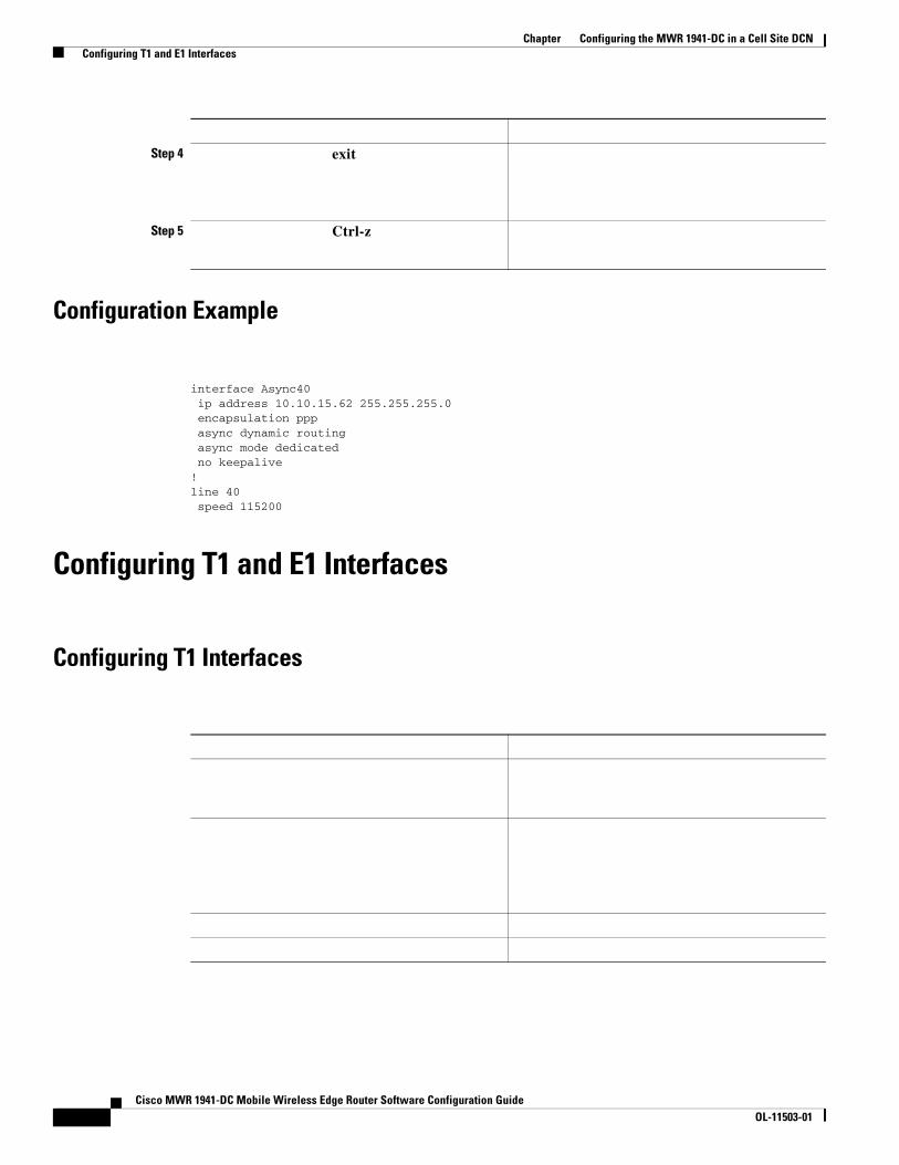
Configuration Example
interface Async40 ip address 10.10.15.62 255.255.255.0 encapsulation ppp async dynamic routing async mode dedicated no keepalive!line 40 speed 115200
Configuring T1 and E1 Interfaces
Configuring T1 Interfaces
Step 4 exit
Step 5 Ctrl-z
Cisco MWR 1941-DC Mobile Wireless Edge Router Software Configuration GuideOL-11503-01

feet
interface serial slot/port
carrier-delay number

Configuring Drop and Insert
Drop-and-Insert capabilities allow individual 64Kb DS0 channels to be transparently passed, uncompressed, between two ports on the same VWIC without passing through a digital signal processor (DSP).
T1/E1 channels can be used either for Drop and Insert or VoIP, but not both

tdm-grouptdm-group-no
timeslot-list e&m fxsloop-start
ground-start fxo loop-startground-start
tdm-group-no
timeslot-list
type fxs
fxo
Voice, Video, and Home Applications Command Reference
channel-group-no timeslot-list56 64
speed
no shutdown
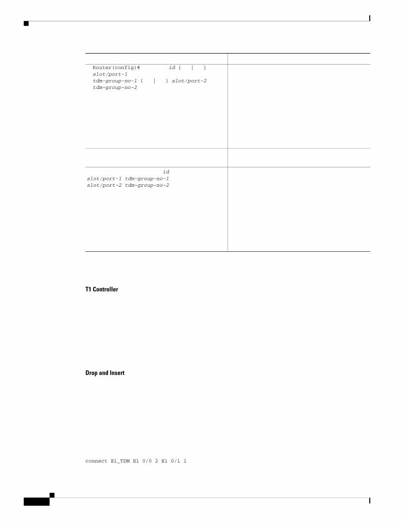
T1 Controller
Drop and Insert
connect E1_TDM E1 0/0 2 E1 0/1 1
Router(config)# id { | }slot/port-1tdm-group-no-1 { | } slot/port-2 tdm-group-no-2
id slot/port-1 tdm-group-no-1 slot/port-2 tdm-group-no-2
Chapter Configuring the MWR 1941-DC in a Cell Site DCN Configuring the 1 T3/E3 Module
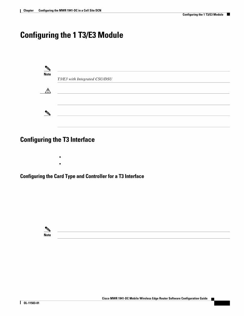
Configuring the 1 T3/E3 Module
NoteT3/E3 with Integrated CSU/DSU
Configuring the T3 Interface
•
•
Configuring the Card Type and Controller for a T3 Interface
Note
Cisco MWR 1941-DC Mobile Wireless Edge Router Software Configuration GuideOL-11503-01

Chapter Configuring the MWR 1941-DC in a Cell Site DCN Configuring the 1 T3/E3 Module
Command or Action Purpose
Step 1 card type t3
Example:•
• t3
•
• show running-config
Step 2 /
/
m23
c-bit—
m23—
Specifies the distance from the routers to the network equipment.
feet
clock source {internal | line} Selects the clock source.
internal
line—
Cisco MWR 1941-DC Mobile Wireless Edge Router Software Configuration GuideOL-11503-01

Configuring DSU Mode and Bandwidth for T3
Configuring the E3 Interface
•
•
•
Configuring the Card Type and Controller for an E3 Interface
Note
Command Purpose
Step 1
Example:
Step 2 { | | | | }
Example:
Specifies the interoperability mode used by a T3 controller.
• 0—
1—
2—
3—
4—
kbps

slot
e3
show running config
slot/port
g751
g751—
g751
Selects the clock source.
internal
line—

Configuring Scrambling for E3
Command Purpose
Step 1
Example:
Step 2
Example:•
Note
•
Step 3
Example: •
Step 4
Example:
Command Purpose
Step 1
Example:
Chapter Configuring the MWR 1941-DC in a Cell Site DCN Configuring the NM-AIC-64, Contact Closure Network Module
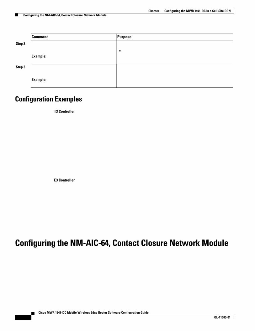
Configuration Examples
T3 Controller
E3 Controller
Configuring the NM-AIC-64, Contact Closure Network Module
Step 2
Example:•
Step 3
Example:
Command Purpose
Cisco MWR 1941-DC Mobile Wireless Edge Router Software Configuration GuideOL-11503-01

The AIC provides a total of 64 alarm inputs. Eight of the 64 point are software configurable for measuring either analog inputs or discrete inputs. The remaining 56 points are fixed to measure discrete points only. The AIC also provides 16 control relay outputs.
The discrete alarm input can be activated through ground or negative battery input. The negative battery range is -36V to -72V. The analog alarm is software configurable for either DC voltage or current. It can measure voltage from -60 to 60V or current from 0 to 20mA, but the configurable range is 4 mA to 20mA. The standard 16 control relays can be configured to turn on or turn off an external device.
The AIC’s 64 input contact points can control and monitor network elements and other non-intelligent interfaces, permitting the detection and report of alarms such as the following:
Network element alarm states
Building security (door and window open and close)
Fire and smoke indication
Building environmentals (temperature and humidity)
Utility power readings
When an event occurs, such as a door alarm or an open gate, the AIC maps the simple discrete and analog alarms to preprogrammed intelligent messages and transports the messages to destinations in the IP network, typically to a Network Operations Center (NOC). These messages are generated either in Transaction Language 1 (TL1) or in Simple Network Management Protocol (SNMP), which are used by a NOC’s Operations Support System (OSS).
When the AIC is incorporated into the Cisco DCN solution platforms, all the AIC’s contact-closure alarms are routed and reported through the same network and systems as the intelligent network elements (NEs). This facilitates continued use of the existing OSS and its associated networks. A Cisco router with an AIC sends TL1 or SNMP messages to the OSS autonomously or in response to TL1 or SNMP commands from the OSS, as shown in Figure 1-1. TL1 supports two sessions, with the port numbers 5011 and 5012, respectively, and SNMP supports four sessions.
Figure 1-1 TL1 and SNMP Message Flow in a DCN Application
Serial Communication Channels
•
•

Chapter Configuring the MWR 1941-DC in a Cell Site DCN Configuring the NM-AIC-64, Contact Closure Network Module
Figure 1-2 OS Boundary into the AIC
Asynchronous Craft Port
Configuring the AIC
Cisco MWR 1941-DC Mobile Wireless Edge Router Software Configuration GuideOL-11503-01

Configuring a Discrete Alarm
description "west door"normally closeddescription normal "door closed"description alarm "door open"level 2exit
Configuring an Analog Alarm as an Analog Monitoring Voltage
Configuring an Analog Alarm as a Discrete Monitoring Current
Configuring an Analog Alarm as a Discrete Monitoring Voltage
Configuring an Analog Alarm to Act Like a Discrete Alarm (Minimal Configuration Method)
Configuration Tasks
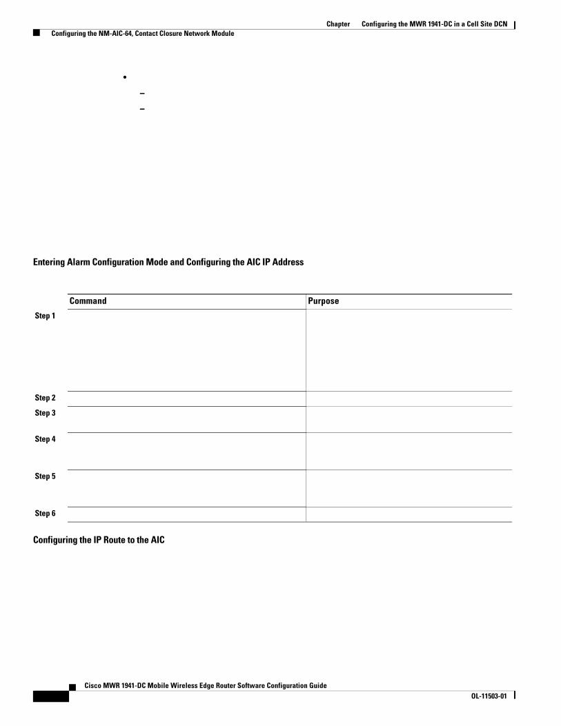
Chapter Configuring the MWR 1941-DC in a Cell Site DCN Configuring the NM-AIC-64, Contact Closure Network Module
•
–
–
Entering Alarm Configuration Mode and Configuring the AIC IP Address
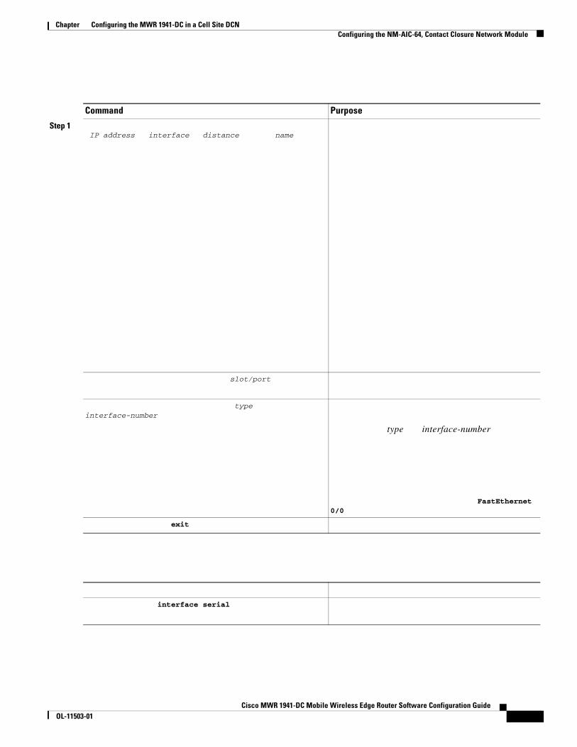
Configuring the IP Route to the AIC
Command Purpose
Step 1
Step 2
Step 3
Step 4
Step 5
Step 6
Cisco MWR 1941-DC Mobile Wireless Edge Router Software Configuration GuideOL-11503-01
Chapter Configuring the MWR 1941-DC in a Cell Site DCN Configuring the NM-AIC-64, Contact Closure Network Module
Command Purpose
Step 1IP address interface distance name
slot/port
type interface-number
type interface-number
FastEthernet 0/0
exit
interface serial
Cisco MWR 1941-DC Mobile Wireless Edge Router Software Configuration GuideOL-11503-01

telnet 10.5.5.
Configuring the NOC IP Address
Note
Step 2
Step 3
Command Purpose
Table 1-5 TCP Port Number Allocation for the AIC on the Cisco 2600 and Cisco 3600 Series
Slot Number Terminal Line Number for the AIC’s Asynchronous Craft Port TCP Port Number
0 1 20011 33 20332 65 20653 97 20974 129 21295 161 21616 193 2193
Command Purpose
Step 1
Step 2
Step 3

Chapter Configuring the MWR 1941-DC in a Cell Site DCN Configuring the NM-AIC-64, Contact Closure Network Module
Configuring Alarms
Network Maintenance: Network Element and Transport Surveillance Messages
Operations Applications Messages-Network Element and Network System Security Admin MessagesTR-NWT-000835, Issue 2, January 1993. The following TL1 messages and commands are supported by the AIC:
TL1 Messages
REPT-ALM-ENV
REPT-ALM-EQPT
REPT-EVT
TL1 Commands
ACT-USER
CANC-USER
OPR-EXT-CONT
RLS-EXT-CONT
RTRV-ALM
RTRV-ALM-ENV
RTRV-ATTR
RTRV-ATTR-CONT
RTRV-ATTR-ENV
RTRV-ATTR-LOG
RTRV-HDR
RTRV-LOG
RTRV-EXT-CONT
SET-ATTR-ENV
SET-ATTR-EQPT
SET-ATTR-LOG
STA-LOG
STP-LOG
Alarm points 57 through 64 are analog inputs, which are configurable as discrete inputs. When configured as an analog input, the user must select whether the point is monitoring voltage or current. The user must also define five ranges by selecting four values for a point monitoring voltage or six ranges for a point monitoring current. For current-monitoring points, the lowest and highest values define the
Cisco MWR 1941-DC Mobile Wireless Edge Router Software Configuration GuideOL-11503-01

range of possible values. (Valid values are from –9999999.9 to 9999999.9.) For voltage-monitoring alarms, the range of possible values is always –60V to 60V. The other four values must be within the defined range, and they partition the range into low-low, low, high, and high-high ranges. Except for the normal range, each range is associated with an alarm condition.
Analog points have four unique alarm states. Each alarm state has its own alarm description string. Only one alarm state per point may be active at any given time. In other words, when a threshold is crossed, the previous alarm state is cleared and the new alarm state is active.
When an analog input is configured as discrete, the user must select whether the point is monitoring voltage or current. Similar to the analog configuration, the user must also select the range of acceptable values for a current-monitoring alarm. (Valid values are from –9999999.9 to 9999999.9.) The voltage range is always –60V to 60V. The user must define the threshold that will cause the alarm condition and whether the normal state of the alarm is the higher or lower range.
For the current analog point, the lower boundary is 4 mA and the upper boundary is 20 mA. For example,
has 16 units between 10 and 26. If the AIC measures 4 mA, then it will factor that the point is registering at the lower boundary. The AIC will interpret 13 as 7 mA, 16 as 10 mA, 17 as 11 mA, 20 as 14 mA, and 26 as the upper boundary, which is 20 mA.
Following are examples:
Point 57 is monitoring the ambient temperature of a building and the sensor range is –20 to 75 degrees Celsius. Below 0 degrees is a critical alarm, 0 to 10 degrees is a major alarm, 10 to 35 degrees is the normal range, 35 to 45 degrees is a minor alarm, and above 45 degrees is a major alarm. The configuration for this point follows:
analog current-loop –20 0 10 35 45 75level low-low 1level low 2level high 3level high-high 2
Point 58 is monitoring a fuel tank level with a resistive sensor. Below –46 volts is a critical alarm, –46 to –40 volts is a minor alarm, and above –40 volts is the normal range. This is a unidirectional alarm, so the high thresholds are set equal to the high bound (since this threshold cannot be crossed). The configuration for this point follows:
alarm 58analog voltage –46 –40 60 60 level low-low 1level low 3
Point 59 is monitoring a battery bank. Below –42 volts is a critical alarm and above –42 volts is the normal range. The configuration for this point follows:
alarm 59discrete voltage –42 high level 1
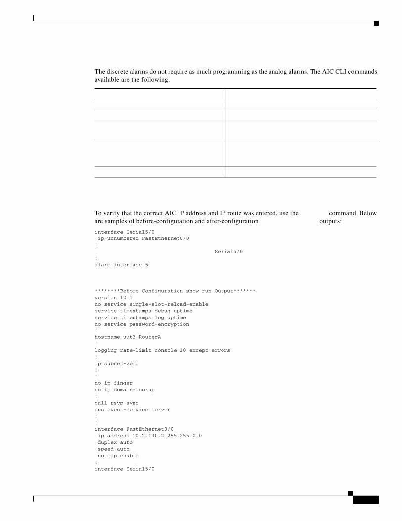
The discrete alarms do not require as much programming as the analog alarms. The AIC CLI commands available are the following:
To verify that the correct AIC IP address and IP route was entered, use the command. Below are samples of before-configuration and after-configuration outputs:
interface Serial5/0 ip unnumbered FastEthernet0/0!
Serial5/0!alarm-interface 5
********Before Configuration show run Output*******version 12.1no service single-slot-reload-enableservice timestamps debug uptimeservice timestamps log uptimeno service password-encryption!hostname uut2-RouterA!logging rate-limit console 10 except errors!ip subnet-zero!!no ip fingerno ip domain-lookup!call rsvp-synccns event-service server!!interface FastEthernet0/0 ip address 10.2.130.2 255.255.0.0 duplex auto speed auto no cdp enable!interface Serial5/0

no ip address!ip kerberos source-interface anyip classlessip route 0.0.0.0 0.0.0.0 10.2.0.1ip http server!no cdp run!!dial-peer cor custom!!line con 0 exec-timeout 0 0 transport input noneline 161 no exec transport preferred none transport input telnet transport output none stopbits 1line aux 0line vty 0 4 password lab login!end
*****After Configuration show run Output*******
version 12.1no service single-slot-reload-enableservice timestamps debug uptimeservice timestamps log uptimeno service password-encryption!hostname uut2-3660!logging rate-limit console 10 except errorsno logging console!ip subnet-zero!no ip fingerno ip domain-lookup!call rsvp-synccns event-service server!interface FastEthernet0/0 ip address 10.2.130.2 255.255.0.0 duplex auto speed auto no cdp enable!interface Serial5/0ip unnumbered FastEthernet0/0!ip kerberos source-interface anyip classlessip route 0.0.0.0 0.0.0.0 10.2.0.1ip route 10.2.130.102 255.255.255.255 Serial5/0

ip http server!no cdp run!!alarm-interface 5 ip address 10.2.130.102!dial-peer cor custom!!!line con 0 exec-timeout 0 0 transport input noneline 161 no exec transport preferred none transport input telnet transport output none stopbits 1line aux 0line vty 0 4 password lab login!end
Monitoring and Maintaining the NM-AIC-64 Contact Closure Network Module
Software Upgrade

Chapter Configuring the MWR 1941-DC in a Cell Site DCN Configuring the NM-AIC-64, Contact Closure Network Module
Configuration Backup
Override
AIC Boot]:can enter “?” to see the available commands, “g” to get a new application image, or “d” to delete the current configuration and return to the defaults. (All commands require a carriage return.) In the case of the get command, the user will be prompted for the name of the file, the IP address of the TFTP server, and a confirmation.
The following example shows a Cisco router configured for AIC IP address:
Cisco MWR 1941-DC Mobile Wireless Edge Router Software Configuration GuideOL-11503-01


IP Route to the AIC Configuration Examples
With an Unnumbered IP Address

Chapter Configuring the MWR 1941-DC in a Cell Site DCN Configuring the NM-AIC-64, Contact Closure Network Module
Without an Unnumbered IP Address
Cisco MWR 1941-DC Mobile Wireless Edge Router Software Configuration GuideOL-11503-01

Chapter Configuring the MWR 1941-DC in a Cell Site DCN Configuring the NM-AIC-64, Contact Closure Network Module
AIC CLI Configuration for Alarms
show alarm config #
Discrete Alarm
Analog Alarm Monitoring Current
normal state description:just rightlow state description:coldlow-low state description:very coldcurrent-loop -5.2 5.4 15.0 25.0 35.1 45.6SNMP trap:enabled
Cisco MWR 1941-DC Mobile Wireless Edge Router Software Configuration GuideOL-11503-01

Configuring QoS Attributes
Analog Alarm Monitoring Current Configured as a Discrete
Configuring QoS Attributes
Note
Creating a Class Map
Step 1
Step 2
•
•
•
•

Chapter Configuring the MWR 1941-DC in a Cell Site DCN Configuring QoS Attributes
•
Step 3
Creating a Policy Map
Step 1
Step 2
class_name
Step 3
queue-limit
priority
shape average peak
shape max-buffers
queue-limit
priority
shape shape max-buffers
Cisco MWR 1941-DC Mobile Wireless Edge Router Software Configuration GuideOL-11503-01

bandwidth percent priority percent
exitexit
Assigning a QoS Boilerplate to an Interface
Step 1
Step 2
Configuration Example
Filtering IP Packets Using Access Lists
Filtering IP Packets Using Access Lists
•
•
•
1.
2.
•
•
•
•
•
•
•
•
Creating Standard and Extended Access Lists Using Numbers
•
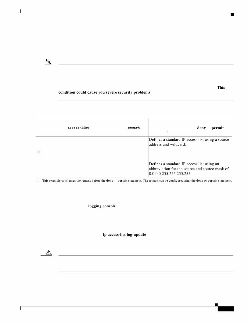
This condition could cause you severe security problems
logging console
ip access-list log-update
access-list remark deny permit 1
1. This example configures the remark before the deny permit statement. The remark can be configured after the deny or permit statement.
or
Defines a standard IP access list using a source address and wildcard.
Defines a standard IP access list using an abbreviation for the source and source mask of 0.0.0.0 255.255.255.255.

Even if you use the ip access-list log-update command, the 5-minute timer remains in effect, so each cache is emptied at the end of 5 minutes, regardless of the count of messages in each cache. Regardless of when the log message is sent, the cache is flushed and the count reset to 0 for that message the same way it is when a threshold is not specified.
The logging facility might drop some logging message packets if there are too many to be handled or if there is more than one logging message to be handled in 1 second. This behavior prevents the router from crashing due to too many logging packets. Therefore, the logging facility should not be used as a billing tool or an accurate source of the number of matches to an access list.
If you enable CEF and then create an access list that uses the log keyword, the packets that match the access list are not CEF switched. They are fast switched. Logging disables CEF.
For an example of a standard IP access list using logs, see the “Numbered Access List Examples” section on page -57.
To create an extended access list, use the following commands in global configuration mode:

The fragments keyword is described in the “Specifying IP Extended Access Lists with Fragment Control” section on page -50.
After you create an access list, you place any subsequent additions (possibly entered from the terminal) at the end of the list. In other words, you cannot selectively add or remove access list command lines from a specific access list.
When creating an access list, remember that, by default, the end of the access list contains an implicit deny statement for everything if it did not find a match before reaching the end.
Indicates the purpose of the deny or permit statement.1
1. This example configures the remark before the deny or permit statement. The remark can be configured after the deny or permit statement.
precedence log | log-input time-range fragments
access-list deny permit any any log | log-input time-range fragments
access-list deny permit host host log
| log-input time-range fragments
access-listdynamic timeout deny
permitprecedence tos
established log | log-input time-range fragments

ip access-list standard
remark
deny any log
permit any log
Router(config-std-nacl)# Exits access-list configuration mode.

Autonomous switching is not used when you have extended access lists.
The keyword is described in the “Specifying IP Extended Access Lists with Fragment Control” section on page -50.
Defines an extended IP access list using a name and enters extended named access list configuration mode.
Allows you to comment about the following or tatement in a named access list.1
1. This example configures the remark before the or statement. The remark can be configured after the or statement.
and
or
or
In access-list configuration mode, specifies the conditions allowed or denied. Specifies a time range to restrict when the or statement is in effect. Use the keyword to get access list logging messages, including violations. Use the keyword to include input interface, source MAC address, or VC in the logging output.
or
Defines an extended IP access list using an abbreviation for a source and source wildcard of 0.0.0.0 255.255.255.255, and an abbreviation for a destination and destination wildcard of 0.0.0.0 255.255.255.255.
or
Defines an extended IP access list using an abbreviation for a source and source wildcard of
0.0.0.0, and an abbreviation for a destination and destination wildcard of 0.0.0.0.
or
Defines a dynamic access list.
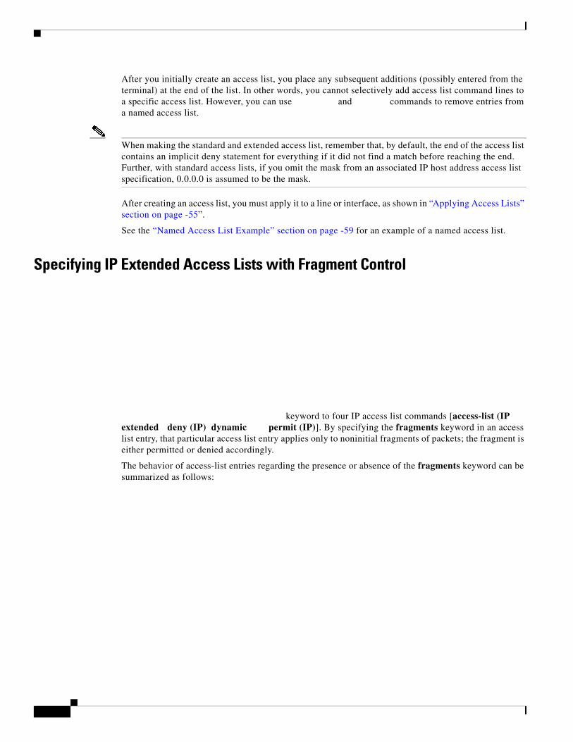
After you initially create an access list, you place any subsequent additions (possibly entered from the terminal) at the end of the list. In other words, you cannot selectively add access list command lines to a specific access list. However, you can use and commands to remove entries from a named access list.
When making the standard and extended access list, remember that, by default, the end of the access list contains an implicit deny statement for everything if it did not find a match before reaching the end. Further, with standard access lists, if you omit the mask from an associated IP host address access list specification, 0.0.0.0 is assumed to be the mask.
After creating an access list, you must apply it to a line or interface, as shown in “Applying Access Lists” section on page -55”.
See the “Named Access List Example” section on page -59 for an example of a named access list.
Specifying IP Extended Access Lists with Fragment Control
keyword to four IP access list commands [access-list (IP extended deny (IP) dynamic permit (IP)]. By specifying the fragments keyword in an access list entry, that particular access list entry applies only to noninitial fragments of packets; the fragment is either permitted or denied accordingly.
The behavior of access-list entries regarding the presence or absence of the fragments keyword can be summarized as follows:

Be aware that you should not simply add the fragments keyword to every access list entry because the first fragment of the IP packet is considered a nonfragment and is treated independently of the subsequent fragments. An initial fragment will not match an access list permit or deny entry that contains the fragments keyword, the packet is compared to the next access list entry, and so on, until it is either permitted or denied by an access list entry that does not contain the fragments keyword. Therefore, you may need two access list entries for every deny entry. The first deny entry of the pair will not include the fragments keyword, and applies to the initial fragment. The second deny entry of the pair will include the fragments keyword and applies to the subsequent fragments. In the cases where there are multiple deny access list entries for the same host but with different Layer 4 ports, a single deny access-list entry with the fragments keyword for that host is all that needs to be added. Thus all the fragments of a packet are handled in the same manner by the access list.
The fragments keyword can be applied to dynamic access lists also.
If the Access-List Entry has... Then..
•
•
•
Note
Note

Chapter Configuring the MWR 1941-DC in a Cell Site DCN Filtering IP Packets Using Access Lists
Note
Turbo Access Lists
Policy Routing
Benefits of Fragment Control in an IP Extended Access List
Additional Security
Reduced Cost
Reduced Storage
Expected Behavior is Achieved
Cisco MWR 1941-DC Mobile Wireless Edge Router Software Configuration GuideOL-11503-01

Chapter Configuring the MWR 1941-DC in a Cell Site DCN Filtering IP Packets Using Access Lists
Enabling Turbo Access Control Lists
•
•
Note
•
•
Configuring Turbo ACLs
Command Purpose
Cisco MWR 1941-DC Mobile Wireless Edge Router Software Configuration GuideOL-11503-01

Chapter Configuring the MWR 1941-DC in a Cell Site DCN Filtering IP Packets Using Access Lists
Verifying Turbo ACLs
•
•
•
•
•
1 Operational 1 2 1 0 0 1Kb2 Operational 1 3 2 0 0 1Kb3 Operational 1 4 3 0 0 1Kb4 Operational 1 3 2 0 0 1Kb5 Operational 1 5 4 0 0 1Kb9 Operational 1 3 2 0 0 1Kb20 Operational 1 9 8 0 0 1Kb21 Operational 1 5 4 0 0 1Kb101 Operational 1 15 9 7 2 1Kb102 Operational 1 13 6 6 0 1Kb120 Operational 1 2 1 0 0 1Kb199 Operational 1 4 3 0 0 1KbFirst level lookup tables:Block Use Rows Columns Memory used 0 TOS/Protocol 6/16 12/16 66048 1 IP Source (MS) 10/16 12/16 66048 2 IP Source (LS) 27/32 12/16 132096 3 IP Dest (MS) 3/16 12/16 66048 4 IP Dest (LS) 9/16 12/16 66048 5 TCP/UDP Src Port 1/16 12/16 66048 6 TCP/UDP Dest Port 3/16 12/16 66048 7 TCP Flags/Fragment 3/16 12/16 66048
Ranges to Access Lists
Cisco MWR 1941-DC Mobile Wireless Edge Router Software Configuration GuideOL-11503-01
Chapter Configuring the MWR 1941-DC in a Cell Site DCN Filtering IP Packets Using Access Lists
Cisco IOS Configuration Fundamentals Configuration Guide
•
•
•
•
•
•
Including Comments About Entries in Access Lists
beforeafter
Applying Access Lists
•
•
•
Cisco MWR 1941-DC Mobile Wireless Edge Router Software Configuration GuideOL-11503-01
Chapter Configuring the MWR 1941-DC in a Cell Site DCN Filtering IP Packets Using Access Lists
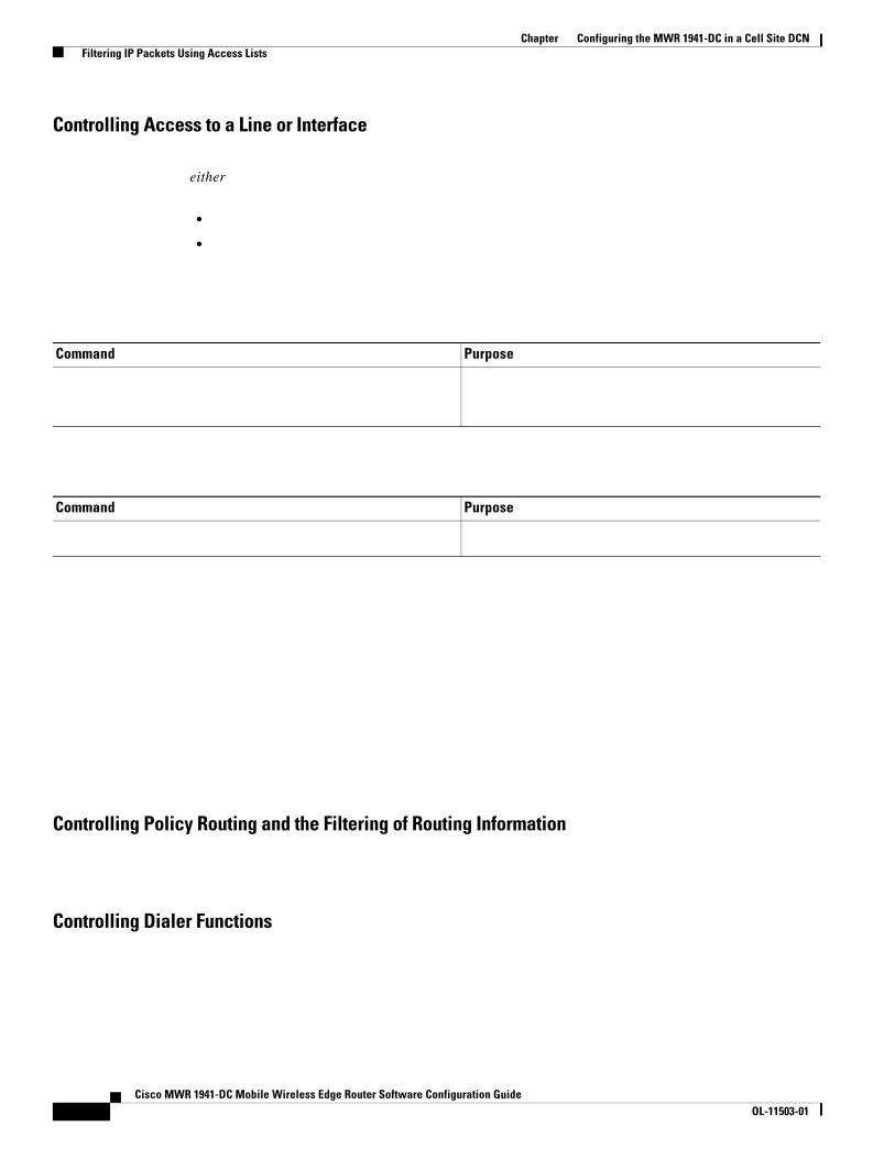
Controlling Access to a Line or Interface
either
•
•
Controlling Policy Routing and the Filtering of Routing Information
Controlling Dialer Functions
Command Purpose
Command Purpose
Cisco MWR 1941-DC Mobile Wireless Edge Router Software Configuration GuideOL-11503-01

Chapter Configuring the MWR 1941-DC in a Cell Site DCN Filtering IP Packets Using Access Lists
Configuration Examples
Numbered Access List Examples
Turbo Access Control List Example
Cisco MWR 1941-DC Mobile Wireless Edge Router Software Configuration GuideOL-11503-01

Chapter Configuring the MWR 1941-DC in a Cell Site DCN Filtering IP Packets Using Access Lists
Implicit Masks in Access Lists Examples
Extended Access List Examples
Cisco MWR 1941-DC Mobile Wireless Edge Router Software Configuration GuideOL-11503-01

Chapter Configuring the MWR 1941-DC in a Cell Site DCN Filtering IP Packets Using Access Lists
Named Access List Example
IP Extended Access List with Fragment Control Example
Time Range Applied to an IP Access List Example
Cisco MWR 1941-DC Mobile Wireless Edge Router Software Configuration GuideOL-11503-01

Chapter Configuring the MWR 1941-DC in a Cell Site DCN Saving Configuration Changes
Commented IP Access List Entry Examples
access-list 100 remark Do not allow Winter to browse the webaccess-list 100 deny host 171.69.3.85 any eq httpaccess-list 100 remark Do not allow Smith to browse the webaccess-list 100 deny host 171.69.3.13 any eq http
ip access-list standard preventionremark Do not allow Jones subnet throughdeny 171.69.0.0 0.0.255.255
ip access-list extended telnettingremark Do not allow Jones subnet to telnet outdeny tcp 171.69.0.0 0.0.255.255 any eq telnet
Saving Configuration Changes
Verifying the Configuration
Command Purpose
Step 1
Step 2
Step 3
%SYS-5-CONFIG_I: Configured from console by
console
Cisco MWR 1941-DC Mobile Wireless Edge Router Software Configuration GuideOL-11503-01
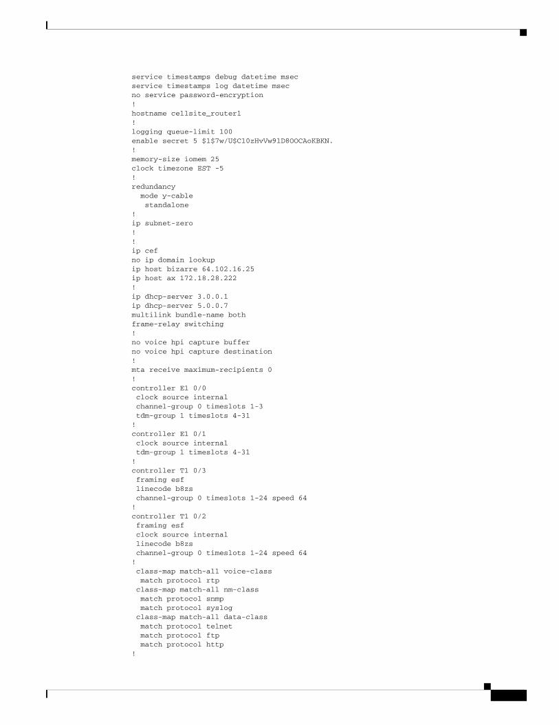
service timestamps debug datetime msecservice timestamps log datetime msecno service password-encryption!hostname cellsite_router1!logging queue-limit 100enable secret 5 $1$7w/U$C10zHvVw9lD8OOCAoKBKN.!memory-size iomem 25clock timezone EST -5!redundancy mode y-cable standalone!ip subnet-zero!!ip cefno ip domain lookupip host bizarre 64.102.16.25ip host ax 172.18.28.222!ip dhcp-server 3.0.0.1ip dhcp-server 5.0.0.7multilink bundle-name bothframe-relay switching!no voice hpi capture bufferno voice hpi capture destination !mta receive maximum-recipients 0!controller E1 0/0 clock source internal channel-group 0 timeslots 1-3 tdm-group 1 timeslots 4-31!controller E1 0/1 clock source internal tdm-group 1 timeslots 4-31!controller T1 0/3 framing esf linecode b8zs channel-group 0 timeslots 1-24 speed 64!controller T1 0/2 framing esf clock source internal linecode b8zs channel-group 0 timeslots 1-24 speed 64! class-map match-all voice-class match protocol rtp class-map match-all nm-class match protocol snmp match protocol syslog class-map match-all data-class match protocol telnet match protocol ftp match protocol http!

policy-map proto class nm-class bandwidth percent 20 queue-limit 300 class data-class bandwidth percent 40 queue-limit 300 class voice-class bandwidth percent 40 queue-limit 300!interface FastEthernet0/0 ip address 172.18.28.202 255.255.255.128 ip helper-address 99.1.1.2 no ip mroute-cache speed 100 full-duplex!interface Serial0/0:0 description backhaul interface ip address 4.0.0.8 255.0.0.0 no ip proxy-arp max-reserved-bandwidth 100 service-policy output proto encapsulation ppp ip tcp header-compression iphc-format ip tcp compression-connections 256 load-interval 30 no keepalive ip rtp header-compression iphc-format ip rtp compression-connections 256!interface FastEthernet0/1 ip address 100.0.0.2 255.0.0.0 ip helper-address 3.0.0.1 no ip proxy-arp no ip mroute-cache load-interval 30 speed 100 full-duplex no cdp enable!interface Serial0/2:0 ip address 44.0.0.2 255.255.255.0 encapsulation ppp!interface Serial0/3:0 ip address 55.0.0.2 255.255.255.0 encapsulation ppp shutdown!interface Serial0/4 no ip address shutdown clockrate 125000!interface Serial0/5 no ip address shutdown clockrate 125000!interface Serial1/0 ip address 99.1.1.1 255.0.0.0 ip helper-address 99.1.1.2

ip helper-address 172.18.61.23 no ip mroute-cache!ip http serverip classlessip route 0.0.0.0 0.0.0.0 172.18.28.129ip route 4.0.0.8 255.255.255.255 Serial1/0ip route 23.0.0.0 255.255.255.0 4.0.0.9ip route 125.0.0.0 255.255.255.0 4.0.0.9ip route 126.0.0.0 255.255.255.0 2.0.0.7ip route 129.0.0.0 255.255.255.0 126.0.0.10ip route 172.18.28.204 255.255.255.255 Serial1/0ip route 200.0.0.0 255.255.255.0 4.0.0.9!logging 172.18.61.23access-list 151 permit icmp host 1.1.1.1 host 23.0.0.7access-list 151 permit icmp host 31.0.0.7 host 23.0.0.7access-list 151 permit icmp host 10.0.0.7 host 23.0.0.7access-list 151 permit tcp host 31.0.0.7 eq telnet host 23.0.0.7 gt 1024access-list 151 permit tcp host 31.0.0.7 eq ftp host 23.0.0.7 gt 1024access-list 151 permit tcp host 31.0.0.7 eq www host 23.0.0.7 gt 1024access-list 151 permit udp host 1.1.1.1 eq snmp host 23.0.0.7 gt 1024access-list 151 permit udp host 1.1.1.1 eq syslog host 23.0.0.7 gt 1024access-list 151 permit udp host 10.0.0.7 gt 16000 host 23.0.0.7 gt 1024access-list 151 permit tcp host 31.0.0.7 eq ftp-data host 23.0.0.7 gt 1024access-list 151 permit udp host 1.1.1.1 eq snmptrap host 23.0.0.7 gt 1024connect TDM E1 0/0 1 E1 0/1 1!!tftp-server nvram:/startup-configsnmp-server community public ROsnmp-server community private RWsnmp-server enable traps snmp authentication linkdown linkup coldstart warmstartsnmp-server enable traps ttysnmp-server enable traps isdn call-informationsnmp-server enable traps isdn layer2snmp-server enable traps isdn chan-not-availsnmp-server enable traps isdn ietfsnmp-server enable traps hsrpsnmp-server enable traps configsnmp-server enable traps entitysnmp-server enable traps envmonsnmp-server enable traps ds0-busyoutsnmp-server enable traps ds1-loopbacksnmp-server enable traps bgpsnmp-server enable traps ipmulticastsnmp-server enable traps msdpsnmp-server enable traps rsvpsnmp-server enable traps frame-relaysnmp-server enable traps frame-relay subifsnmp-server enable traps rtrsnmp-server enable traps syslogsnmp-server host 172.18.61.23 public !alarm-interface 1 ip address 99.1.1.2call rsvp-sync!!line con 0 exec-timeout 0 0line 33 session-timeout 1 flush-at-activation

no exec transport preferred none transport input telnet transport output none stopbits 1line aux 0line vty 0 4 password lab login! end
Monitoring and Managing the MWR 1941-DC Router
Step 1
Step 2
is the name assigned to the Operations and Maintenance (O&M) workstation and is the address of the network management workstation.
Step 3 Enter the following commands to create a loopback interface for O&M:
Step 4 Exit interface configuration mode:
Step 5 At the configuration prompt, enter the following command to specify the recipient of a Simple Network Management Protocol (SNMP) notification operation:
Where is the name assigned to the CW4MW workstation with the command in Step 2.
Step 6 Enter the following commands to specify the public and private SNMP community names:
ROsnmp-server community private RW
snmp-server enable traps

Where to Go Next
Step 8
Step 9
Step 10
Show Commands for Monitoring the MWR 1941-DC
Where to Go Next
•
•
•
Command Purpose

Chapter Configuring the MWR 1941-DC in a Cell Site DCN Where to Go Next
Cisco MWR 1941-DC Mobile Wireless Edge Router Software Configuration GuideOL-11503-01
Related Documents