1 NEW EMC TEST REQUIREMENTS For Electric Vehicles CONDUCTED RF EQUIPMENT POWER AMPLIFIERS Markus Fuhrer 27.03.2015

Welcome message from author
This document is posted to help you gain knowledge. Please leave a comment to let me know what you think about it! Share it to your friends and learn new things together.
Transcript

1
NEW EMC TEST REQUIREMENTS
For Electric Vehicles
CONDUCTED RF EQUIPMENT POWER AMPLIFIERS
Markus Fuhrer 27.03.2015

E/ECE/324/Add.9/Rev.5
Addendum 9: Regulation No. 10 Revision 5
Uniform provisions concerning the
approval of vehicles with regard to
electromagnetic compatibility
16 October 2014
ECE=Economic Commission for Europe
Inland Transport Committee
World Forum for Harmonization of Vehicle Regulations
Working Party on Lighting and Light-signaling
www.unece.org
2
IEC Product standards for vehicle
IEC/EN 61851-1 Part 1: General requirements
IEC 61851-21: 2001 Electric vehicle conductive charging system
-Part 21-1: Electric vehicle on board charger emc
requirements for conductive connection to
an a.c/d.c. supply
IEC 61851-22: 2001 Electric vehicle conductive charging system
- Part 22: AC electric vehicle charging station
(IEC 69/184/CD:2010)
IEC/EN 61851-23 Part 23: DC electric vehicle charging station (2014)
IEC/EN 61851-24
-Part 24: Digital communication between a d.c.
EV charging station and an electric vehicle for control of
d.c. charging (2014)
There are other not mentioned product standards for
EMC testing of electric vehicles.
3
Special definitions in Chapter 2
ESA electronic sub-assemblies an electrical and/or electronic device or set(s) of devices intended to be part
of a vehicle, together with any associated electrical connections and wiring,
which performs one or more specialized functions.
RESS rechargeable energy storage system
that provides electric energy for electric propulsion of the vehicle.
Definitions and terms Chapter 2

Overview ECE R-10 Annexes for Chapter 7
1 Examples of approval marks
2A Vehicles 2B Sub-assembliy
3 ECE Marks for Vehicle / Sub-assembly
RE (Emission) RI (Immunity)
4 BBRE 5 NBRE
Sub-Assembly ESA
9 RI (Immunity) RE ( Emission)
8 NBRE 7 BBRE Chamber
TEM, BCI
Stripline
10 Transients
11 Harmonic
12 Flicker
6 RI
Vehicles
ISO 7627-2
Immunity
Emission
CE (Emission) CI (Immunity)
13 CERF(ac/dc)
14 CERF(telecom)
15 EFT
16 Surge
ECE R-10 EMC
17 Harmonic
18 Flicker
CI (Immunity)
19 CERF(ac/dc)
20 CERF(telecom)
21 EFT
22 Surge
CE (Emission)
4

General information (administrative)
Annex 1 Examples of approval marks
Annex 2A Information document for type approval of a vehicle with respect to
electromagnetic compatibility
Annex 2B Information document for type approval of an electric/electronic
sub-assembly with respect to electromagnetic compatibility .
Annex 3A Communication concerning the approval or extension or refusal or withdrawal of
approval or production definitively discontinued of a type of
vehicle/component/separate technical unit with regard to Regulation No. 10
Annex 3B Communication concerning the approval or extension or refusal or withdrawal of
approval or production definitively discontinued of a type of electrical/electronic sub-
assembly with regard to Regulation No. 10
5
ECE R-10

Annex 4 Method of measurement of radiated broadband electromagnetic emissions from vehicles
Annex 5 Method of measurement of radiated narrowband electromagnetic emissions from vehicles
Annex 6 Method of testing for immunity of vehicles to electromagnetic radiation
Annex 7 Method of measurement of radiated broadband electromagnetic emissions from
electrical / electronic sub-assemblies (ESAs)
Annex 8 Method of measurement of radiated narrowband electromagnetic emissions from
electrical/electronic sub-assemblies
Annex 9 Method(s) of testing for immunity of electrical/electronic sub-assemblies to electromagnetic
radiation
Annex 13 Method(s) of testing for emission of radiofrequency conducted disturbances on AC or DC power
lines from vehicles .
Annex 14 Method(s) of testing for emission of radiofrequency conducted disturbances on network and
telecommunication access from vehicles
Radiated measurements and tests for vehicles and ESA
6
ECE R-10

Immunity measurements and tests for vehicles and ESA
Annex 10 Method(s) of testing for immunity to and emission of transients of electrical/electronic sub-
assemblies .
ISO 7637-2 Testimpulses 1, 2a, 2b, 3a, 3b and 4, interferences from transient emission
Annex 11 Method(s) of testing for emission of harmonics generated on AC power lines from vehicle
IEC 61000-3-2 // IEC 61000-3-12
Annex 12 Method(s) of testing for emission of voltage changes, voltage fluctuations and flicker on AC power
lines from vehicle
IEC 61000-3-3 // IEC 61000-3-11
Annex 15 Method of testing for immunity of vehicles to Electrical Fast Transient/Burst disturbances conducted
along AC and DC power lines
IEC 61000-4-4
Annex 16 Method of testing for immunity of vehicles to surges conducted along AC and DC power lines
IEC 61000-4-5
New Test requirements on car manufacturers
7
ECE R-10

Immunity measurements and tests for vehicles and ESA
Annex 19 Method(s) of testing for emission of radiofrequency conducted disturbances on AC or DC power
lines from an ESA
Annex 20 Method(s) of testing for emission of radiofrequency conducted disturbances on network and
telecommunication access from an ESA
Annex 17 Method(s) of testing for emission of harmonics generated on AC power lines from an ESA
IEC 61000-3-2 // IEC 61000-3-12
Annex 18 Method(s) of testing for emission of voltage changes, voltage fluctuations and flicker on AC power
lines from an ESA
IEC 61000-3-3 // IEC 61000-3-11
Annex 21 Method of testing for immunity of an ESA to Electrical Fast Transient/Burst disturbances
conducted along AC and DC power lines
IEC 61000-4-4
Annex 22 Method of testing for immunity of ESAs to surges conducted along AC and DC power lines
IEC 61000-4-5
New Test requirements on car manufacturers
8
ECE R-10

IEC/EN 61851-21 - 22: Standards for vehicle charging
Charging at home 120 V 15 A – 20 A 1.8 – 2.4 kW 8 – 20 hours
Charging in Public Slow charging 240 V 30 – 40 A 7.2 – 9.6 kW 3 – 8 hours Fast charging 480V 3 phases 60 – 150 kW DC fast charging < 30 min.
IEC Product standards IEC 61581-21 / -22

IEC 61851-21 Ed. 1.0 part 21
EMC requirements on board chargers for electric vehicles for conductive connection to an ac / dc supply
Tabelle 1 – Störfestigkeitsprüfungen
Ambient
Phenomenas Test spez. Unit
Basic
Standards Remarks
Test
criteria
1.1 Electrost.
Discharge
CD ± 8 kV (charge voltage) ISO 10605.2:
2008
See test procedure in ISO
10605.2:2008.
„Vehicle test method“
B
Air discharge ± 15 kV (charge voltage) B
1.2
Radio-frequency
electromagnetic field.
Amplitude modulated
20 to 800
30
80
MHz
V/m (r.m.s.)
% AM (1 kHz)
ISO 11451-2:
2005
Vehicle test
Vert. polarisation of the E field a
NOTE 1& 4
A
1.3
Radio-frequency
electromagnetic field.
Pulse modulated
800 to 2000
25
ton: 577
T: 4600
MHz
V/m (r.m.s.)
µs
µs
ISO 11451-2:
2005
Vehicle test
Vert. polarisation of the E field a
NOTE 1
A
1.4 Fast transients
(a.c. or d.c. power lines)
± 2
5/50
5
kV (open circuit test voltage)
Tr/Th ns
Repetition frequency kHz
IEC 61000-4-4:
2004 NOTE 2 B
1.5 Fast transients (pilot line)
± 1
5/50
5
kV (open circuit test voltage)
Tr/Th ns
Repetition frequency kHz
IEC 61000-4-4:
2004 Capacative clamp is used. B
1.6
Surge (a.c. power lines)
line-to-earth
line-to line
1.2/50 (8/20)
± 2
± 1
Tr/Th µs
kV (open circuit test voltage)
kV (open circuit test voltage)
IEC 61000-4-5:
2005
Each surge shall be applied 5 times at
1mn (or less, minimum 10 s) interval for
each of the following angles: 0, 90, 180
and 270°
B
1.7
Surge (d.c. power lines)
line-to-earth
line-to line
1.2/50 (8/20)
± 0.5
± 0.5
Tr/Th µs
kV (open circuit test voltage)
kV (open circuit test voltage)
IEC 61000-4-5:
2005 Each surge shall be applied 5 times at
1min (or less, minimum 10 s) interval. B
IEC Product standards IEC 61581-21
10

The Standard requires Power Fail tests acc. IEC 61000-4-11 and Harmonic Immunity acc. IEC 61000-4-13
1.8 Supply voltage
harmonics
Class 2 in Tab 1to3 of
IEC 61000-4-13
IEC 61000-4-13:
2009 B
1.9 Voltage dips
0
1
% residual voltage
Cycle
IEC 61000-4-11 Voltage shift at zero crossing
NOTE 3
B
40
10/12 at
50/60Hz
70
25/30 at
50/60Hz
% residual voltage
Cycle C
1.10 Voltage interruptions 0
250/300 at 50/60Hz
% residual voltage
Cycle IEC 61000-4-11
Voltage shift at zero crossing
NOTE 3 C
See Note 4
1.11 BCI
Amplitude modulated
20 to 200
60
80
MHz
mA (r.m.s)
% AM (1 kHz)
ISO 11452-4:
2005 + Amd
2009
Stand alone test
Vert. polarisation of the E field a
NOTE 1 & 4
A
1.12
Radio-frequency
electromagnetic field.
Amplitude modulated.
200 to 800
30
80
MHz
V/m (r.m.s)
% AM (1 kHz)
ISO 11452-2:
2004
Stand alone test
Vert. polarisation of the E field a
NOTE 1 & 4
A
1.13
Radio-frequency
electromagnetic field.
Pulse modulated.
800 to 2000
25
ton: 577
T: 4600
MHz
V/m (r.m.s)
µs
µs
ISO 11452-2:
2004
Stand alone test
Vert. polarisation of the E field a
NOTE 1
A
NOTE 1 The articles mains network to be used for this test on vehicle is defined in CISPR 16-1-2 Clause 4.3.
NOTE 2 When the CDN network cannot be used on a.c. or d.c. power lines, the capacitive coupling clamp defined in 6.3 of IEC 61000-4-4:2004, may be used
NOTE 3 Applicable only to input ports
NOTE 4 AM is peak conservation according to ISO 11451-1 or ISO 11452-1
a The field strength shall be 30 V/m rms in over 90% of the 20 to 2000 MHz frequency range and a minimum of 25 V/m over the whole 20 to 2000 MHz frequenccy range.
IEC 61851-21 Ed. 1.0 Part 21
11
IEC Product standards IEC 61581-21
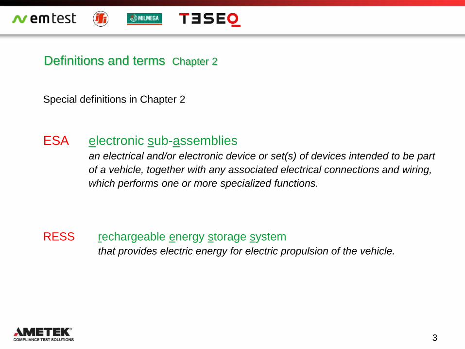
With the mains plug the car manufacturer enter into a new world
Emission
Harmonic & Flicker
Conducted RF
Immunity
Burst , Surge, Power Fail
Public mains
New requirements
for car manufacturers
Chapter 7 for RESS (Vehicles and ESAs)
"RESS charging mode coupled to the power grid"
ECE
Regulation
Chapter 7 of ECE R-10 for RESS vehicles
12
Charging station
Onboard charger

Radiated Broaband electromagnetic emission
RESS Chapter 7.2, Annex 4; ESA: Chapter 7.10, Annex 7
Radiated broadband electromagnetic emissions from vehicles resp. ESAs
Test method: CISPR 12 Frequency range 30… 1000MHz.
Operating status: Vehicle in configuration "RESS charging mode coupled to the power grid". The state of charge
(SOC) of the traction battery shall be kept between 20 per cent and 80 per cent of the maximum
SOC. The current shall be set to at least 80 per cent of its nominal value.
Limits: acc. CISPR 12 for 3 m and 10 m measuring distance and Quasi‐Peak Detector.
Test setup:
State of charge (SOC):
20% - 80%
Charging current:
min. 80% of nominal current
Note: There are different setup
pictures in annex 4
Radiated Emission
13

EMC tests as per Chapter 7
RESS Chapter 7.3, Annex 11; ESA: Chapter 7.11, Annex 17
Emission of harmonics on AC power lines from vehicles resp. ESAs
Test method: Acc. IEC 61000‐3‐2 (for I ≤ 16 A /Phase) and
IEC 61000‐3‐12 (for I > 16 A and ≤ 75 A /Phase).
Operating status: Vehicle in configuration "RESS charging mode coupled to the power grid". The engine and all
devices which the driver could operate must be in OFF STATUS.
Battery charging : SOC (20% - 80% ), Charging current: min. 80% of nominal current.
Requirements: Measuring of even and odd harmonics up to 40th (I up to 16 A), resp . 13th ( I>16 A)
• Test setup:
AC Source with Impedance Zs and open circuit voltage G
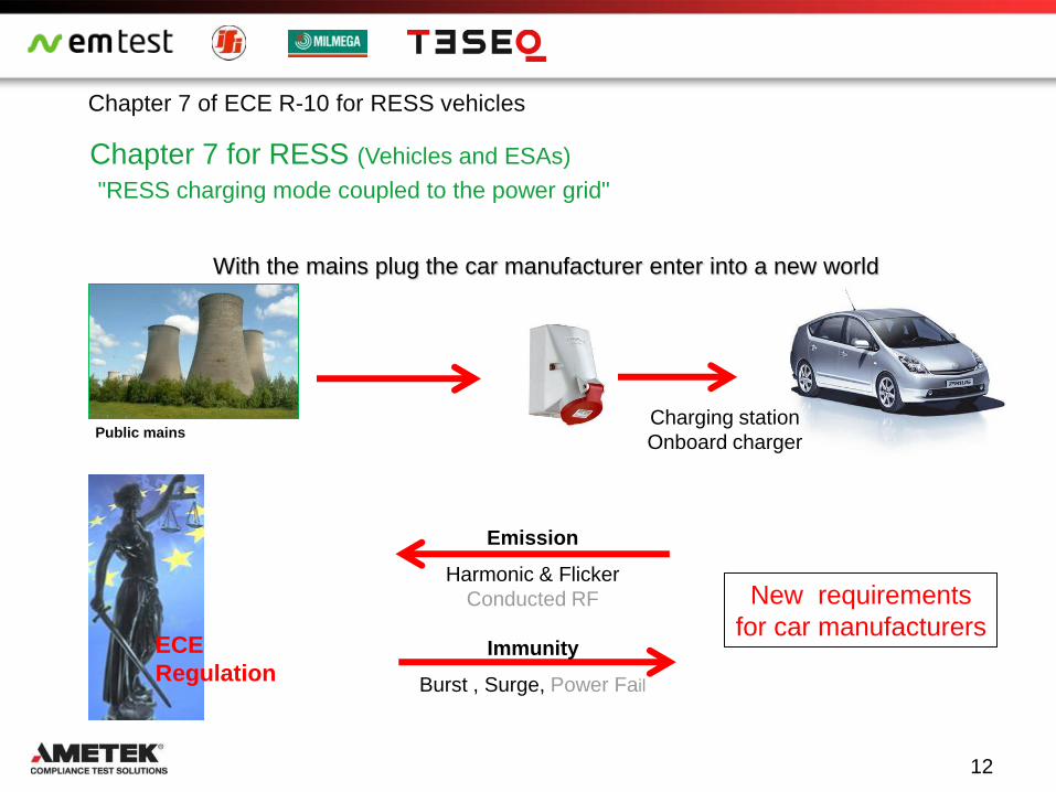
Harmonics and conducted Emission
14
Example DC rectifier Voltage & Current flow in the capacitor
Frequency spectrum Time domain
Origin of harmonic currents
U
I
15
Harmonics and conducted Emission

For electric vehicle charging systems with a rated current of less than 16 A, the limits on the IEC 610003-2 for
Class A (Table 2) are defined.
The Limits for Harmonics of AC power supplies of charging systems for electric vehicles with a rated input current
more than 16 A and less than 75 A is covered by to IEC 61000-3-12 with the general test conditions.
IEC 61000-3-2 (IEC 61851-21 Ed. 2.0 Teil 21)
Table 2 – Maximum harmonic currents
(Nominal current ≤16A /Phase)
Harmonics n Limit of harmonic current [A]
Odd Harmonics
3 2,3
5 1,14
7 0,77
9 0,40
11 0,33
13 0,21
15 ≤ n ≤ 39 0,15x15/n
Even Harmonics
2 1,08
4 0,43
6 0,30
8 ≤ n ≤ 40 0,23x8/n
NetWave
3--Phasen AC/DC
programmable source
3-phase Flickerimpedance
AIF 503N75 with DPA 503
Analyser for Flicker and Harmonics
16
Harmonics and conducted Emission
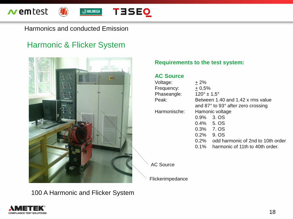
Harmonic & Flicker System
100 A Harmonic and Flicker System
AC Source
Flickerimpedance
Requirements to the test system:
AC Source Voltage: + 2%
Frequency: + 0,5%
Phaseangle: 120° ± 1,5°
Peak: Between 1.40 and 1.42 x rms value
and 87° to 93° after zero crossing
Harmonische: Hamonic voltage
0.9% 3. OS
0.4% 5. OS
0.3% 7. OS
0.2% 9. OS
0.2% odd harmonic of 2nd to 10th order
0.1% harmonic of 11th to 40th order.
18
Harmonics and conducted Emission

Phänomen & Definition
Voltage fluctuations caused by varying load currents may also influence luminance or spectral distribution of
lightning systems.
The impression of unsteadies of visual sensation induced by this light stimulus is called flicker. Whereby the limits on
the voltage fluctuations are based on the equivalent levels of light flicker in a 60W incandescent bulb which is
perceived as disturbing.
The higher the voltage changes, the less frequently they may occur A.
At low voltage fluctuations flicker can high rates of change to B.
Mains voltage fluctuations, which are caused by non-
stationary operating conditions of loads, luminance
changes or changing the brightness of lighting devices
can cause.
Due to the high frequency of use, a light bulb 230V / 60W
was internationally defined as a reference lamp for flicker.
The so called flicker curve defines the graphic
representation permissible combinations relative
voltage change (V/V in %) to number changes
per minute. B
A
19
Fllicker and Voltage variations of AC power lines

Flickerimpedances
Zref: Impedance specs in IEC 61000-3-3
RA = 0,24 jXA = 0,15 at 50 Hz
RN = 0,16 jXN = 0,10 at 50 Hz
Ztest: For measurement as per IEC 61000-3-11
RA = 0,15 jXA = 0,15 at 50 Hz
RN = 0,10 jXN = 0,10 at 50 Hz
20
AIF 503N75 3-phase
Flickerimpedance with
DPA 503 Analyser
Fllicker and Voltage variations of AC power lines
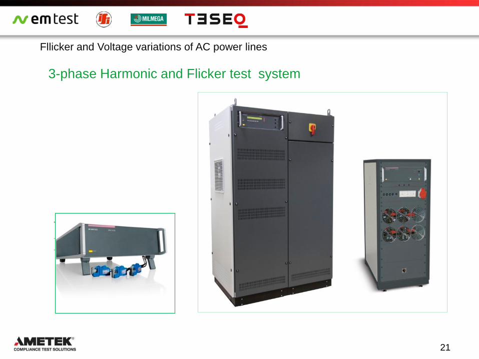
3-phase Harmonic and Flicker test system
– 3- Phasen Analyser
– 3- Phasen Impedanz 32 A
– 3- Phasen Quelle 32 A
21
Fllicker and Voltage variations of AC power lines

EMC Tests as per Chapter 7
23
Emission of radiofrequency conducted disturbances on vehicle AC / DC lines
RESS Chapter 7.5, Annex 13; // ESA: Chapter 7.13, Annex 19
Emission of radiofrequency conducted disturbances on AC or DC power lines from vehicles
The test includes the requirements for residential, commercial and industrial areas.
Test method : As per. CISPR 16‐2‐1 as standard device.
Operating status: Vehicle in configuration "RESS charging mode coupled to the power grid". Engine OFF and
Motor and all other equipment which can be switched on permanently by the driver or
passenger should be OFF.
The state of charge (SOC) of the traction battery : 20% - 80%
Charging current: Rated current or at least 80% of its nominal value if adjustable.
Limits : as per IEC 61000‐6‐3 table 7 (ac) or table 8 (dc)
Different
test setup:
For RESS
application

RESS Chapter 7.6, Annex 14; ESA: Chapter 7.14, Annex 20
Emission of radiofrequency conducted disturbances on network and telecommunication access from vehicles
The test includes the requirements for residential, commercial and industrial areas.
Test method : As per CISPR 22 if not otherwise ststed
Operating status: Vehicle in configuration "RESS charging mode coupled to the power grid". Engine OFF and Motor
and all other equipment which can be switched on by the driver or passenger should be OFF.
The state of charge (SOC) of the traction battery : 20% - 80%
Charging current: Rated current or at least 80% of its nominal value if adjustable.
Limits : As per IEC 61000‐6‐3 for voltage and current, with QP and AVG‐Detector.
Ausnahme : No application of annex 14/20 if no direct connection to the telecom network exist
Test setup:
24
Different test setup
Emission of conducted RF disturbances on network and telecommunication access from
vehicles

26
Radiated Immunity
RESS Chapter 7.7, Annex 6; ESA: Chapter 7.18, Annex 9
Immunity of vehicles to electromagnetic radiation
Test method : As per ISO 11451‐2, alternativ with ESA: as per ISO 11452-2, ISO 11451‐4 (BCI).
Operating status: Vehicle in configuration "RESS charging mode coupled to the power grid". Engine OFF and
Motor and all other equipment which can be switched on by the driver or passenger should be
OFF.
The state of charge (SOC) of the traction battery : 20% - 80%
Charging current: Rated current or at least 20% of its nominal value if adjustable.
Criteria: no degradation of performance of "immunity related functions", Vehicle sets in motion.
Test: with and without charging mode
Different
test setup:
For RESS
application

RESS Chapter 7.8 Annex 15; ESA: Chapter 7.15 Annex 21
Immunität of vehicles to electrical fast transient/burst disturbances conducted along AC and DC power lines.
Test method : As per IEC 61000‐4‐4 (immunity for electric fast transients EFT/Burst).
Operating status: Vehicle in configuration "RESS charging mode coupled to the power grid". Engine OFF and Motor
and all other equipment which can be switched on by the driver or passenger should be OFF.
The state of charge (SOC) of the traction battery : 20% - 80%
Charging current: Rated current or at least 80% of its nominal value if adjustable.
Criteria: no degradation of performance of "immunity related functions", Vehicle sets in motion.
Test setup:
Immunity to electrioc fast transients EFT / Burst
27
Different test setup

Burst Test setup for vehicles in charging mode (RESS)
The vehicle shall be placed directly on the ground plane. The vehicle shall be immobilized, engine OFF and in
charging mode. All other equipment which can be switched on permanently by the driver or passenger should be
OFF.
Failure criteria: Vehicle sets in motion.
Testlevel : ± 2 kV, minimum 1 minute with all couplings at same time.
EFT Generator
AC/DC
mains
Entkoppelnetzwerk
Bezugsmasse
Cc
28
Immunity to electrioc fast transients EFT / Burst

230 V power relays
Equivalent diagram of a switching circuit
Us
Uo
S
I
R2
L2
C2 U1
L1
C1
R1
Typical voltage waveform across an opening switch
29
Burst phenomenom open a contact
Immunity to electrioc fast transients EFT / Burst

Definition of Burst impulse as per IEC 61000-4-4
30
Single pulse
Rise time tr = 5 ns
Pulse duration td = 50 ns
Pulse packet (Burst)
Repetition time tREP = 300 ms
75 pulses/Burst
Duration Burst packet tDURATTION = 15 ms
Spike frequency f = 5 kHz
Duration Burst packet tDURATION = 0,75 ms
Spike frequency f = 100 kHz
Immunity to electrioc fast transients EFT / Burst

ISO 7637-2 12 V System
Pulse 3a / 3b 220 V max.
IEC 61000-4-4
Burst EFT 2000 V
Test levels as per IEC 61000-4-4
31
Immunity to electrioc fast transients EFT / Burst

Test system for vehicles – for RESS testing
IEC 61000-4-4 (EFT/Burst)
IEC 61000-4-5 (Surge)
Coupling network for,
- AC: 3-ph. 480 V / 32 A up to 100 A
- DC: 1000V DC
- Switch AC/DC operation
- Mainswitch for AC/DC
Note: for the traditional ISO tests for the vehicle electronics
with (micro pulses, EFT, load dump), no new specific
requirements were introduced.
UCS 500N7
CNI 503x
32
Immunity to electrioc fast transients EFT / Burst

EMC tests as per Chapter 7 RESS Chapter 7.9, Annex 16; ESA: Chapter 7.16, Annex 22
Immunity of vehicles/ESAs to surge conducted along AC or DC power lines.
Test method : Gem. IEC 61000‐4‐5 (Immunity to surge impulses).
Requirements: for AC: ± 1 kV (line-line), 2 kv (lines-PE); DC: 0.5 kV. (line-line, line-PE)
Operating status: Vehicle in configuration "RESS charging mode coupled to the power grid". Engine OFF and Motor
and all other equipment which can be switched on by the driver or passenger should be OFF.
The state of charge (SOC) of the traction battery : 20% - 80%
Charging current: Current at least 20% of its nominal value if adjustable.
Failure Criteria: Vehicle sets in motion.
Coupling: The surge impulse is coupled to the AC/DC lines with :
a) coupling between lines and
b) coupling between line and earth
Test setup:
33
0.8 (+0.2 / -0) m
Cable shall be z-folded if longer
than 1m, 100 ± 25 mm above
ground and at least 100mm from
the car body
Cable shall be z-folded if
longer than 1m, 100 ±
25mm above ground and at
least 100mm from the car
body
0.8 (+0.2 / -0) m
Cable shall be z-folded if longer
than 1m, 100 ± 25 mm above
ground and at least 100mm from
the car body
Immunity to surge
Different test setup

EMC tests as per Chapter 7
RESS Chapter 7.9, Annex 16; ESA: Chapter 7.16, Annex 22
Test setup:
34
0.8 (+0.2 / -0) m
Cable shall be z-folded if longer
than 1m, 100 ± 25 mm above
ground and at least 100mm from
the car body
Cable shall be z-folded if longer
than 1m ,
(100 ± 25) mm above ground and
at least 100 mm from the car
body.
Cable shall be shortened to appropriate length,
(100 ± 25) mm above ground and
at least 100 mm from the ESA body.
Immunity to surge

Surgeimpulse definition as per IEC 61000-4-5 :Ed. 3
Open circuit voltage: 1.2/50 s
Stirnzeit: Tf = 1.67 x T= 1.2 s ± 30%
Pulsdauer: Td = Tw = 50 s ± 20%
NOTE: The pulse shape of the open circuit voltage at
the output of the coupling / decoupling network may
have a significant undershoot.
Short circuit current: 8/20 s
Front Time : Tf = 1.25xTr = 8 s 20%
Duration: Td = 1.18 x Tw =20 s 20%
NOTE: The setting for the undershoot by 30% applies
only at the generator output. For the output of the
coupling / decoupling network there is no limit in terms
of the under- or overshooting.
35
Immunity to surge
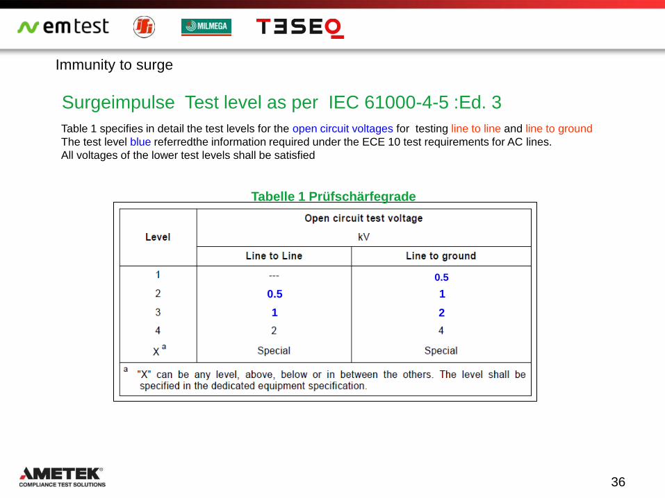
Surgeimpulse Test level as per IEC 61000-4-5 :Ed. 3
Tabelle 1 Prüfschärfegrade
0.5
0.5
1 2
1
36
Immunity to surge
Table 1 specifies in detail the test levels for the open circuit voltages for testing line to line and line to ground
The test level blue referredthe information required under the ECE 10 test requirements for AC lines.
All voltages of the lower test levels shall be satisfied

Surge Test setup for vehicles in charging mode (RESS)
If not otherwise stated in this annex the test shall be performed according to IEC 61000-4-5.
Vehicle state during tests in configuration "RESS in charging mode coupled to the power grid". The vehicle shall
be placed directly on the ground plane.
Coupling line to line
Hybrid Generator
Combination wave
Entkoppelnetzwerk
Bezugsmasse
Hybrid Generator
Combination wave
Entkopelnetzwerk
Bezugsmasse
R = 10Ω
C = 9µF
Coupling line to earth
37
Immunity to surge

39
Components in the Electrical Vehicle
Mains Supply Voltage 240 V / 16A AC
480 V / 32A AC
400 V / 125 A DC
500 V / 100A DC
HV lines
300 V up to 800 V DC
30 A up to 100 A

Simplified circuit of Electrical Vehicle
Charger (built-in)
HV Battery .
(400 Volt) .
Elec-tronic
Motor
Compressor
(Aircondition)
Inverter
DC / DC
12V
1Hz bis 150kHz
Mains Supply Voltage 230 V / 16A AC 480 V / 32A AC 400 V / 125 A DC 500 V / 100A DC
HV lines 300 V up to 800 V DC 30 A up to 100 A
ISO 7637-4
ISO 7637-4 Electrical transient conduction along shielded high voltage
supply lines only (Proposal/Early Draft)
This part of ISO 7637 specifies test methods and procedures to ensure the compatibility to
conducted electrical transients of equipment installed on passenger cars and commercial
vehicles fitted with electrical systems with voltages higher than 60 VDC and lower than
1.500 VDC and a power-supply isolated from the vehicle-body.
It describes bench tests injection of transients:
Voltage ripple (square wave) (Pulse A)
Pulsed sinusoidal disturbances (Pulse B)
Low frequency sinusoidal disturbances (Pulse C)
It is applicable to all types of electrical independent driven, road vehicles (e. g. battery
electrical vehicle [BEV] or hybrid electrical vehicle [HEV], plugin hybrid vehicle [PHEV]).

ISO 7637-4
Voltage ripple on high voltage supply lines This square wave perturbation is typically caused by switching of high currents e. g. in IGBT -
stages of electrical engine systems or DC-DC-converters. Voltage ripple produce both, line-to-
ground (HV+ or/and HV- to ground) and line-to-line (HV+ to HV-) disturbances. They can
interfere with adjacent high voltage systems like battery-controller and climate compressor.
Figure 2a ISO 7637-4: test setup for coupling between HV+ and HV-.
Generator Pulse A
Frequency range: 1kHz up - 300kHz
Frequency step: 1kHz / 10kHz
TRise and TFall <1us @ oc voltage
TRise and TFall <2.5us @ sc current
Zi = Vpp / Ipp ≤ 0.5 Ω generator output
Current capacity: ≥ 32 A(rms), ≥ 70 V(peak)

ISO 7637-4
Interferences from the inverter (rectangular signals)

ISO 7637-4
Interferences from the inverter RF interferences
ISO 7637-4
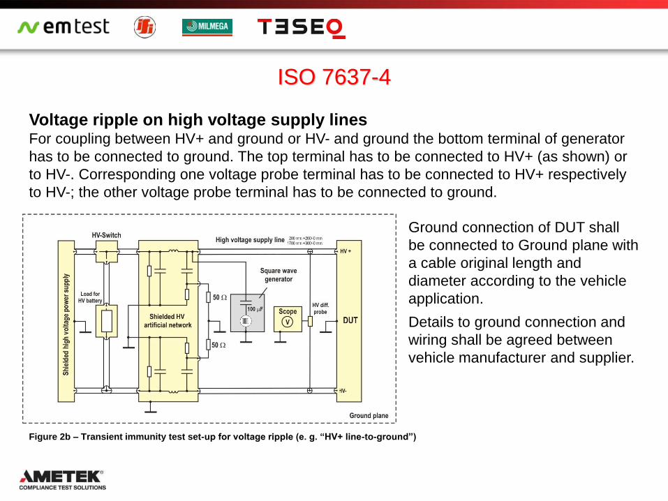
Ground connection of DUT shall
be connected to Ground plane with
a cable original length and
diameter according to the vehicle
application.
Details to ground connection and
wiring shall be agreed between
vehicle manufacturer and supplier.
Figure 2b – Transient immunity test set-up for voltage ripple (e. g. “HV+ line-to-ground”)
Voltage ripple on high voltage supply lines For coupling between HV+ and ground or HV- and ground the bottom terminal of generator
has to be connected to ground. The top terminal has to be connected to HV+ (as shown) or
to HV-. Corresponding one voltage probe terminal has to be connected to HV+ respectively
to HV-; the other voltage probe terminal has to be connected to ground.

ISO 7637-4
Pulsed sinusoidal disturbances on high voltage supply lines These disturbances come from overshoots on square wave signals caused e. g. by
interaction of switching IGBTs in high voltage systems with parasitic capacities and
inductivities of electrical engines, by DC-DC-converters and any other kind of high voltage
switching / commutation.
Generator Pulse B
Frequency range: 1-10 MHz
Impedance: 50 Ohm
Output power: 25W for 100 Vpp
225W for 300 Vpp
CNE-Balun Figure 3a – Test set-up for pulsed sinusoidal disturbances (e. g. “line-to-line”)

ISO 7637-4
Pulsed sinusoidal disturbances on high voltage supply lines For coupling between HV+ and ground or HV- and ground the bottom terminal of generator
has to be connected to ground. The top terminal has to be connected to HV+ (as shown) or
to HV-. Corresponding one voltage probe terminal has to be connected to HV+ respectively
to HV-; the other voltage probe terminal has to be connected to ground.
Ground connection of DUT shall be connected to Ground plane with a cable original length
and diameter according to the vehicle application.
Figure 3b –Set-up for pulsed sinusoidal disturbances (e. g. “HV+ line-to-ground”)

ISO 7637-4
Low frequency sinusoidal disturbances This test determines whether the equipment will accept superposed sinusoidal frequency
components.
The Figure below shows the test setup for coupling between HV+ and HV-.
A capacitor of 100uF or more shall be connected across the high voltage dc power supply.
Generator Pulse C
Frequency range: 15Hz - 400kHz
Frequency step: Linear or
logarithmic or several frequencies
per decade (dwell time 2s)
Voltage: 30VRMS up to 250kHz
20VRMS up to 400kHz
Current: 16ARMS
Figure 4a –Test set-up for low frequency sinusoidal disturbances (e. g. “line-to- line”)

ISO 7637-4
Low frequency sinusoidal disturbances This test determines whether the equipment will accept superposed sinusoidal frequency
components.
The Figure below shows the test setup for coupling between HV+ and ground or HV- and
ground the bottom terminal of the coupling transformer has to be connected to ground.
Generator Pulse C
Frequency range: 15Hz - 400kHz
Frequency step: Linear or
logarithmic or several frequencies
per decade (dwell time 2s)
Voltage: 30VRMS up to 250kHz
20VRMS up to 400kHz
Current: 16ARMS
Figure 4b –Test set-up for low frequency sinusoidal disturbances (e. g. “HV line-to- ground”)
50
Thank you!
CONDUCTED RF EQUIPMENT POWER AMPLIFIERS
Related Documents