Concrete Overlay Field Application Program Final Report: Volume I Sponsored through Federal Highway Administration (DTFH-61-06-H-00011 (Work Plan 13)) July 2012

Welcome message from author
This document is posted to help you gain knowledge. Please leave a comment to let me know what you think about it! Share it to your friends and learn new things together.
Transcript
Concrete Overlay Field Application Program Final Report: Volume I
Sponsored throughFederal Highway Administration (DTFH-61-06-H-00011 (Work Plan 13))
July 2012

About the National CP Tech Center
The mission of the National Concrete Pavement Technology Center is to unite key transportation stakeholders around the central goal of advancing concrete pavement technology through research, tech transfer, and technology implementation.
Disclaimer Notice
The contents of this report refl ect the views of the authors, who are responsible for the facts and the accuracy of the information presented herein. The opinions, fi ndings and conclusions expressed in this publication are those of the authors and not necessarily those of the sponsors.
The sponsors assume no liability for the contents or use of the information contained in this document. This report does not constitute a standard, specifi cation, or regulation.
The sponsors do not endorse products or manufacturers. Trademarks or manufacturers’ names appear in this report only because they are considered essential to the objective of the document.
Iowa State University Non-Discrimination Statement
Iowa State University does not discriminate on the basis of race, color, age, religion, national origin, sexual orientation, gender identity, genetic information, sex, marital status, disability, or status as a U.S. veteran. Inquiries can be directed to the Director of Equal Opportunity and Compliance, 3280 Beardshear Hall, (515) 294-7612.

Technical Report Documentation Page
1. Report No. 2. Government Accession No. 3. Recipient’s Catalog No.
DTFH61-06-H-00011 (Work Plan 13)
4. Title and Subtitle 5. Report Date
Concrete Overlay Field Application Program Final Report: Volume I
July 2012
6. Performing Organization Code
7. Author(s)
Gary Fick, Dale Harrington
8. Performing Organization Report No.
9. Performing Organization Name and Address 10. Work Unit No. (TRAIS)
National Concrete Pavement Technology Center
Iowa State University
2711 South Loop Drive, Suite 4700
Ames, IA 50010-8664
11. Contract or Grant No.
12. Sponsoring Organization Name and Address 13. Type of Report and Period Covered
Federal Highway Administration (FHWA) U.S. Department of Transportation 1200 New Jersey Avenue SE Washington, DC 20590
Final Report: Volume I
14. Sponsoring Agency Code
DTFH61-06-H-00011 (Work Plan 13)
15. Supplementary Notes
16. Abstract
The National Concrete Pavement Technology Center (CP Tech Center) at Iowa State University conducted a four-year, multi-state concrete overlay construction program to demonstrate and document the concept and benefits of various concrete overlay applications and provide real-world lessons. Teams of CP Tech Center / FHWA experts completed 26 field site visits in 18 states and provided workshops or technical assistance on overlay projects in six additional states. The site visits included four open house demonstration projects. A report with recommendations was prepared for each of the site visits. As a result of the site visits and recommendations, concrete overlays were either constructed or scheduled for construction in nine states, and the teams provided additional advice and assistance as requested during the course of these projects. During the site visits, workshops, project planning, and construction, the teams recognized opportunities to improve concrete overlay projects for a variety of applications, and the final report includes an overview of these lessons learned. Volume I of this final report outlines the field applications program purpose, activities, and results/lessons learned. Volume II includes copies of all documents prepared during the course of the program.
17. Key Words 18. Distribution Statement
concrete pavement — concrete overlays — overlay demonstrations No restrictions.
19. Security Classification (of this report)
20. Security Classification (of this page)
21. No. of Pages 22. Price
Unclassified. Unclassified. 92
Form DOT F 1700.7 (8-72) Reproduction of completed page authorized

Concrete Overlay Field Application Program Final Report: Volume I iii
Concrete Overlay Field Application Program
Final Report: Volume I
Authors Gary Fick, Trinity Construction Management Services
Dale Harrington, Snyder & Associates, Inc.
Prepared by the National Concrete Pavement Technology Center
Institute for Transportation Iowa State University Research Park
2711 S. Loop Drive, Suite 4700 Ames, IA 50010-8664
515-294-8103 www.cptechcenter.org
Prepared for Federal Highway Administration
U.S. Department of Transportation 1200 New Jersey Avenue SE
Washington, D.C. 20590 under
DTFH61-06-H-00011 (Work Plan 13)
July 2012
Concrete Overlay Field Application Program Final Report: Volume I iv
The National Concrete Pavement Technology Center (CP Tech Center) and the authors wish to thank the Federal Highway Administration (FHWA) for sponsoring this project and thereby improving the state of the practice of concrete overlay design and construction. We particularly appreciate the help of Gina Ahlstrom, who managed this contract for the FHWA. In addition, we gratefully acknowledge the contributions of the technical advisory committee, which helped establish the direction of this project and develop contacts with appropriate State highway agencies (SHAs); the committee’s feedback and suggestions were invaluable. Finally, we appreciate the active contributions of expert team members who visited SHAs around the country, made presentations, visited potential sites, helped develop detailed recommendations regarding the various sites, and provided on-site or distance advice regarding projects under construction. Participation of the expert teams greatly enhanced the concrete overlay applications that were planned and constructed through this project as well as the lessons learned. Thank you, all.
Members of Technical Advisory Committee and Expert Teams
Andy Bennett, Michigan Department of Transportation (DOT) Jim Cable, Iowa State University (retired) Dan DeGraaf, Michigan Concrete Paving Association Jim Duit, Duit Construction Co., Inc., Oklahoma Todd Hanson, Iowa DOT Randell Riley, Illinois Chapter, American Concrete Pavement Association (ACPA) Matt Ross, Missouri/Kansas Chapter, ACPA Doug Schwartz, Minnesota DOT (retired) Sam Tyson, FHWA Jeff Uhlmeyer, Washington State DOT Leif Wathne, ACPA Matt Zeller, Concrete Paving Association of Minnesota
Additional Technical Advisory Committee Members
Jim Grove, FHWA Kevin Maillard, OHM Advisors Robert Rodden, ACPA Jim Shea, New York State Chapter, ACPA Gordon Smith, Iowa Concrete Paving Association Shannon Sweitzer, North Carolina Turnpike Authority
Additional Expert Team Members
Ahmad Ardani (former ARA) Gary Fick, Trinity Construction Consultants, Inc. (team leader) Rob Rasmussen, The Transtec Group (team leader) Kurt Smith, APTech
ACKNOWLEDGMENTS

Concrete Overlay Field Application Program Final Report: Volume I v
ACKNOWLEDGMENTS ................................................................................................................................. iv
LIST OF FIGURES ........................................................................................................................................ viii
LIST OF TABLES ............................................................................................................................................. x
EXECUTIVE SUMMARY ................................................................................................................................ xi
ACTIVITIES ............................................................................................................................................... xi
LESSONS LEARNED / RECOMMENDATIONS ............................................................................................ xi
Project Evaluation and Selection ........................................................................................................ xi
Concrete Overlay Design .................................................................................................................... xii
Plans and Specifications .................................................................................................................... xiii
Sequence of Construction and Maintenance of Traffic ................................................................... xiiii
Concrete Overlay Construction ......................................................................................................... xiv
1. PROJECT BACKGROUND .......................................................................................................................... 1
OBJECTIVES ............................................................................................................................................. 1
PROJECT TEAM MEMBERS ...................................................................................................................... 1
WORK PLAN............................................................................................................................................. 3
2. PROJECT OUTCOMES .............................................................................................................................. 8
SOUTH DAKOTA ...................................................................................................................................... 8
Existing Conditions .............................................................................................................................. 9
Concrete Overlay Recommendations ............................................................................................... 10
Final Concrete Overlay Design .......................................................................................................... 10
Concrete Overlay Construction and Lessons Learned ...................................................................... 10
Additional Concrete Overlay Activities ............................................................................................. 13
PENNSYLVANIA ..................................................................................................................................... 13
Existing Conditions ............................................................................................................................ 14
Concrete Overlay Recommendations ............................................................................................... 15
Final Concrete Overlay Design .......................................................................................................... 15
Concrete Overlay Construction and Lessons Learned ...................................................................... 16
Consideration of geotextile fabric for use as a separation layer for unbonded overlays ......... 18
Construction surveying .............................................................................................................. 18
Transitions from existing pavement to overlay sections ........................................................... 19
TABLE OF CONTENTS
Concrete Overlay Field Application Program Final Report: Volume I vi
Table of Contents, continued
Accelerated concrete mixtures .................................................................................................. 19
Curing of thinner concrete overlay sections .............................................................................. 19
Tiebars ........................................................................................................................................ 19
Matching existing features ........................................................................................................ 19
Pre-overlay preparation ............................................................................................................. 20
Miscellaneous Items .................................................................................................................. 20
Additional Concrete Overlay Activities................................................................................... 20
DELAWARE ............................................................................................................................................ 21
Existing Conditions ............................................................................................................................ 21
Concrete Overlay Recommendations ............................................................................................... 22
Final Concrete Overlay Design ................................................................................................... 23
Concrete Overlay Construction ................................................................................................. 24
Additional Concrete Overlay Activities ............................................................................................. 25
NORTH DAKOTA .................................................................................................................................... 26
2008 Route 200 North of Hillsboro ................................................................................................... 26
2008 Cass County Route 11 near Mapleton ..................................................................................... 27
2008 Cass County Route 4 ................................................................................................................ 29
2008 Fargo, North Dakota South 25th Street ................................................................................... 29
2008 US-83 North of Bismarck .......................................................................................................... 30
2008 Bismarck Expressway ............................................................................................................... 30
2010 Western North Dakota Oil Field Roadway Survey ................................................................... 31
Additional Concrete Overlay Activities ............................................................................................. 34
VIRGINIA ................................................................................................................................................ 34
Existing Conditions ........................................................................................................................... 35
Concrete Overlay Recommendations ...................................................................................... 36
Final Concrete Overlay Design .................................................................................................. 36
Concrete Overlay Construction ........................................................................................................ 37
NEVADA ................................................................................................................................................. 38
2009 I-15, Sahara Ave. to Spaghetti Bowl interchange .................................................................... 38
2009 I-15 Southbound, south of Lamb Blvd. interchange ................................................................ 39
2009 I-15, Russell Rd vicinity, approx. milepost 36 .......................................................................... 39

Concrete Overlay Field Application Program Final Report: Volume I vii
Table of Contents, continued
2011 Las Vegas Urban Intersection Projects .................................................................................... 40
2011 I-80 Elko, NV Site ...................................................................................................................... 42
Nevada Concrete Overlay Outcomes ................................................................................................ 43
IOWA ..................................................................................................................................................... 43
US-18 Concrete Overlay Summary ................................................................................................... 44
WYOMING ............................................................................................................................................. 49
KANSAS .................................................................................................................................................. 50
CONCRETE OVERLAY DOCUMENTS ....................................................................................................... 51
3. OPPORTUNITIES AND BARRIERS ........................................................................................................... 53
GEOTEXTILE SEPARATION LAYER .......................................................................................................... 53
THICKNESS DESIGN ............................................................................................................................... 54
MILLING ................................................................................................................................................. 54
Potential Delamination of Existing Asphalt Layers .......................................................................... 54
Milling of Existing Concrete ............................................................................................................. 55
Profile Milling ............................................................................................................................... 56
MAINTENANCE OF TRAFFIC .................................................................................................................. 56
Stringless Construction .............................................................................................................. 57
Safety Edge .................................................................................................................................... 57
Innovative Approaches ............................................................................................................... 57
REFERENCES .............................................................................................................................................. 58
APPENDIX: Technical Working Group Minutes ........................................................................................ A-1
Concrete Overlay Field Application Program Final Report: Volume I viii
Figure 1 – Project Management Organizational Chart ............................................................................... 2
Figure 2 – States in Which Concrete Overlay Workshops were Held and/or Site Visits Conducted .......... 4
Figure 3 – Approximate Location of SD Route 50 Site Investigation .......................................................... 9
Figure 4 – Typical Existing Condition of SD Route 50 (westbound lanes looking west) ............................. 9
Figure 5 – SD Route 50 Dowel Bar Configuration (note omitted dowels between the wheel paths) ..... 10
Figure 6 – SD Route 50 Typical Section ..................................................................................................... 11
Figure 7 – SD Route 50 Concrete Head In Front of the Paver .................................................................. 12
Figure 8 – Approximate Location of PA SR-119 Concrete Overlay ........................................................... 13
Figure 9 – Existing Condition of Pennsylvania SR-119 Looking South ...................................................... 14
Figure 10 – Pennsylvania SR-119 Existing Typical Section ........................................................................ 14
Figure 11 – Typical Existing Distresses on Pennsylvania SR-119 (fatigue cracking, moderate rutting) ... 15
Figure 12 – Pennsylvania SR-119 Partial Typical Section .......................................................................... 16
Figure 13 – Placement of the 6” Bonded Concrete Overlay on Pennsylvania SR-119 ............................. 16
Figure 14 – Approximate Location of US-13 Bonded Concrete Overlay in Delaware .............................. 21
Figure 15 – US-13 Southbound Lanes Existing Typical Section ................................................................ 22
Figure 16 – US-13 Existing Pavement Condition ....................................................................................... 22
Figure 17 – US-13 Bonded Overlay Typical Section .................................................................................. 23
Figure 18 – US-13 Bonded Concrete Overlay Construction ...................................................................... 24
Figure 19 – North Dakota Route 200 Existing Pavement Condition ......................................................... 26
Figure 20 – North Dakota Route 200 Bonded Concrete Overlay.............................................................. 27
Figure 21 – North Dakota, Cass County Route 11 Existing Condition ...................................................... 28
Figure 22 – North Dakota, Cass County Route 11 Concrete Overlay Construction .................................. 28
Figure 23 – North Dakota, Cass County Route 11 Existing Condition ...................................................... 29
Figure 24 – Fargo, North Dakota; South 25th Street Existing Condition ................................................... 29
Figure 25 – Existing Condition of US-83 North of Bismarck, ND .............................................................. 30
Figure 26 – Existing Conditions, Bismarck Expressway (ND) .................................................................... 31
Figure 27 – Routes Reviewed For Potential Concrete Overlays in July 2010 ........................................... 32
Figure 28 – ND Route 85 Watford City to Alexander, Representative Pavement Condition ................... 33
Figure 29 – ND Route 85 Existing Pavement Typical Section ................................................................... 33
Figure 30 – Concrete Overlay Construction Near Devils Lake, ND ........................................................... 34
Figure 31 – Approximate Location of Overlay Candidate on US-58 in Southhampton County Virginia ............................................................................................. 35
Figure 32 – Typical Section of Existing Pavement; US-58, Southhampton County, VA ............................ 35
Figure 33 – Distressed Pavement on US-58 in Southhampton County, Virginia ...................................... 36
Figure 34 – US-58 Unbonded Overlay Typical Section ............................................................................. 37
LIST OF FIGURES

Concrete Overlay Field Application Program Final Report: Volume I ix
List of Figures, continued
Figure 35 – Approximate Location of the I-15 Sahara Ave. to Spaghetti Bowl Interchange Project ....... 38
Figure 36 – Nevada I-15 Typical Pavement Condition Requiring Minimal Repair .................................... 39
Figure 37 – Las Vegas, NV Approximate Location of 2011 Site Visit Reviews .......................................... 40
Figure 38 – Sahara Avenue Looking East .................................................................................................. 41
Figure 39 – Lake Mead Boulevard Typical Pavement Condition .............................................................. 42
Figure 40 – Nevada, I-80 Typical Distress and Repair ............................................................................... 43
Figure 41 – US 18 Unbonded Concrete Overlay Improvement ................................................................ 44
Figure 42 - Roadway Location and Site Map (inset) ................................................................................. 45
Figure 43 – Wyoming US-30 Existing Roadway Condition ........................................................................ 49
Figure 44 – US 30 Typical Section Mainline .............................................................................................. 50
Figure 45 – Open House Participants Viewing I-70 Overlay ..................................................................... 51
Figure 46 – Kansas, I-70 Bonded Overlay Construction ............................................................................ 51
Figure 47 – Geotextile Separation Layer Used in Missouri ....................................................................... 53
Figure 48 – Milling Concrete Prior to Placing a 4” Thick Unbonded Concrete Overlay ........................... 55
Figure 49 – Placing the 4” Thick Unbonded Concrete Overlay ................................................................. 55
Figure 50 – Milling to Grade Using Automatic Machine Control .............................................................. 56
Figure 51 – Iowa US-18, Construction of the Temporary Safety Edge ..................................................... 57

Concrete Overlay Field Application Program Final Report: Volume I x
Table 1 – Overview of Activities by State ................................................................................................... 5
Table 2 – SD Route 50 Summary of Fresh Concrete Testing .................................................................... 11
Table 3 – Pennsylvania SR-119 Fresh Concrete Test Results .................................................................... 17
Table 4 – Pennsylvania SR-119 Hardened Concrete Test Results ............................................................. 18
Table 5 – US-13 Concrete Mixture Proportions ........................................................................................ 25
Table 6 – US-13 Hardened Concrete Properties ....................................................................................... 25
Table 7 – Las Vegas, NV Potential Concrete Overlay Projects Reviewed in 2011 .................................... 40
Table 8 – Iowa DOT’s Six-Stage Project Construction Plan ....................................................................... 46
Table 9 – Iowa US-18 Project Staging ....................................................................................................... 46
LIST OF TABLES

Concrete Overlay Field Application Program Final Report: Volume I xi
On June 3, 2008, the Concrete Overlay Field Application Program began. The National Concrete Pavement Technology Center (CP Tech Center) at Iowa State University’s Institute for Transportation conducted the program through a cooperative agreement with the Federal Highway Administration (FHWA). The objective was to develop a concrete overlay construction program across the country with as many interested states as possible that wanted to learn about concrete overlays, and to demonstrate and document the concept and benefits of concrete overlays in various applications. The multi-state projects would provide real-world lessons learned.
ACTIVITIES
Since the program’s inception, the CP Tech Center, together with teams of FHWA and industry experts, have completed 26 site visits in 18 states, conducted workshops or provided technical assistance in six additional states, written 28 reports and/or recommendations, and provided occasional isolated recommendations requested by the states. The site visits included four open house demonstration projects. As a direct result of the concrete overlay field application program, concrete overlay projects were either constructed or scheduled for construction in nine states.
LESSONS LEARNED / RECOMMENDATIONS
During the course of these activities and related research projects, many circumstances arose in which the program team recognized opportunities for improvement. As a result, many lessons were learned that have resulted in improved practices at various stages of concrete overlay projects. Following is a summary of recommendations based on these lessons learned:
PROJECT EVALUATION AND SELECTION
Utilize coring, falling weight deflectometers, and “as built” plans to investigate existing pavement layer conditions and thicknesses to determine what type of overlay is appropriate for a given roadway.
If existing asphalt will be milled, take cores of asphalt to ensure that adequate (3–4-in.) asphalt depth will remain after milling as a design minimum and to allow concrete loaded trucks to travel on it with minimal damage to the milled surface.
In freeze-thaw climates and/or areas with expansive soils, evaluate existing pavement in spring and summer to identify critical pavement distresses that need to be accounted for in the overlay design.
Identify all vertical constraints (bridges, utilities, loop vehicle detectors, curbs, barriers, ramps and driveways, guard rail, and other structures) that may impact construction and a plan to mitigate them.
EXECUTIVE SUMMARY - LESSONS LEARNED

Concrete Overlay Field Application Program Final Report: Volume I xii
CONCRETE OVERLAY DESIGN
During the early phases of design, consider all partial and full detour options and their impact on construction.
Choose the most appropriate overlay type (bonded or unbonded) to meet existing pavement conditions and anticipated future traffic loadings.
For unbonded overlays over concrete in non-arid climates, provide a positive drainage path for surface moisture to exit the interlayer bond breaker (separation layer), to prevent interlayer erosion under heavy traffic loadings.
In designs for unbonded overlays over concrete, compare asphalt or geotextile interlayer (separation layer) costs, construction time, and performance.
Determine transition lengths from the existing profile elevation to the top of the concrete overlay profile elevation on existing profile constraints, final roadway design speeds, length and type of traffic control to be used, and final open-to-traffic speeds.
Utilize cubic yard and square yard payment items. Square yard covers placement, and cubic yard covers material, which reduces contractor risk and cost while paying for concrete used to fill surface irregularities.
Based on construction economics and expected overlay performance, in designs for unbonded overlays over concrete, correct irregularities in cross-slope and profile by varying the thickness of concrete, not the depth of the asphalt bond breaker (separator layer). Deeper transverse joint sawing may be necessary to achieve T/3, but final overlay performance will be enhanced.
In designs for bonded overlays over asphalt, exercise care when milling the asphalt to prevent leaving a thin asphalt lift, which can cause delamination.
Consider two potential overlay quantity design options: 1. For minimal preliminary work and cost,
Do no preliminary survey other than measuring wheel rut depth and pavement cross-slope at 500-ft intervals.
Develop design profiles of centerline and pavement edges. Estimate the quantity of concrete required to meet the profiles and provide minimum
thickness at centerline and edges of pavement. Add a reasonable percentage to the concrete quantity to account for placement
tolerance, construction losses, and surface/cross-section irregularities and establish the “new theoretical” plan quantity. Some states use 15 to 20 percent, depending on the thickness of the overlay and the amount of pavement cross-slope correction desired. The thinner the overlay and the higher the cross-slope correction, the higher the percentage. Some states add a maximum overrun of 2 to 3 percent to the “new theoretical” plan quantity.
2. For optimization of concrete quantities, Conduct nine-shot cross-sections at 50-ft intervals to map the existing surface. Develop a design centerline profile and cross-slope that optimizes pavement
smoothness, maintains minimum overlay depth at centerline, and optimizes concrete quantities.
Limit the contractor to an additional percent of the quantity identified by the desired cross-section and design profile. Some states use 6 to 8 percent, depending on the thickness of the overlay.

Concrete Overlay Field Application Program Final Report: Volume I xiii
Evaluate the impacts of removing/replacing medians or existing curbs versus their retention in terms of construction time, cost, and future performance.
Carefully review the construction sequence and maintenance of traffic in conjunction with joint layout. In some cases, tied longitudinal construction joints can interfere with the maintenance of both public and contractor traffic.
Develop the construction sequence to meet closed road or through traffic maintenance in conjunction with joint layout and design for turn lanes and shoulder concrete work.
Develop staging plans that allow for the use of paving equipment between existing concrete railings and temporary safety-related barrier walls.
Design transitions and bridge approach pavement sections to minimize hand placement and detailed jointing plans.
Determine the type and amount of surface preparation required based on agency prioritization of the following goals: 1. Pavement smoothness. 2. Concrete quantity. 3. Matching existing surface features. 4. Maintaining minimum cross-slopes. 5. Removal of unstable existing pavement layers. 6. Vertical clearance site conditions. 7. Bond enhancement between existing and overlay pavement layers.
PLANS AND SPECIFICATIONS
Reduce plan sets to necessary quantities, design details, plan/profile data (not sheets), and survey control information.
Require the use of vibrator frequency monitor recorders on the paver. Utilize standard concrete mixes and maturity measurements to control opening of intersections
and access points. Use accelerated concrete mixtures only when necessary.
When existing surface milling is required, clearly define the purpose, vertical and cross-slope limits, and the required existing surface survey accuracy.
SEQUENCE OF CONSTRUCTION AND MAINTENANCE OF TRAFFIC
Hold a public preconstruction meeting to communicate traffic control impacts and identify public concerns that should be addressed by the contractor and highway agency during construction.
Minimize the number of gaps for intersections and driveways, to provide for uninterrupted paving.
Consider paving plans that allow temporary access for adjacent property owners where possible and accommodate their daily needs.
Clearly state the criteria for lane closures and allow for contractor alternative suggestions to meet the criteria.

Concrete Overlay Field Application Program Final Report: Volume I xiv
Provide for alternative detour routes to be used in the case of unforeseen circumstances (crashes, wide loads, equipment breakdowns, etc.).
Jointly with the contractor, develop a traffic control plan that allows sufficient room for construction operations and keeps the traveling public and pedestrians safe.
Anticipate and mitigate temporary drainage issues caused by milling operations. In the case of construction of single-lane overlays with 24-hr pilot car operations on a two-lane
road, apply the following construction suggestions: 1. Allow multiple construction zones separated by two miles between flagger stations. The 2-
mi. work zone area requirement is the distance between flagger stations versus the outermost warning signs.
2. Consider using a 3.5-mi paving work zone and allow the contractor to close local crossings in the work zone only when those in the adjacent zone are open.
3. Allow the contractor to propose methods and materials to construct temporary access ramps (in use for less than one month).
4. Encourage construction of bridge work, transition sections, subdrains, pavement patching, side ditch drainage work, and earthwork prior to staged surface preparation and paving operations.
5. Delete centerline safety wedge construction where pilot car operations are used 24/7 through the work area.
6. Allow for equipment work on shoulders and side ditches to proceed in the same area as a lane closure employed for other pre-paving work.
7. Where bridge approaches and road intersections are immediately adjacent to each other, encourage use of extended temporary barrier rail lengths and three-leg traffic signal setups to reduce construction/traffic delays.
CONCRETE OVERLAY CONSTRUCTION
Require contractor development of a comprehensive paving plan to address construction and public impacts.
When necessary, accelerate all construction processes to minimize public impact. Limit contract stage work times to emphasize the need for accelerated work if that is the goal of the contract.
Where load transfer is called for in wheel paths only, use separate partial dowel baskets for each wheel path and do NOT cut the basket shipping wires.
When anchoring dowel baskets consider the use of uniform thicknesses of separation layer, adequate numbers of anchors, and the relationship of anchor length and shot force to the separation layer depth and material, and minimize the head of concrete in front of the paver. Monitor dowels behind the paver for location, orientation, and depth.
Utilize software such as HIPERPAV to anticipate paving or curing problems and mitigate their impact on operations.
Minimize the temperature differential between the existing pavement surface and the concrete overlay during placement and curing. This is especially critical during cool-weather-paving for the following reasons:
When a bonded concrete overlay is placed in cooler weather, the day/night temperature differential will cause movement in the existing pavement; it will expand during the day and contract at night. To prevent cracking in the overlay, the overlay must reach saw strength
Concrete Overlay Field Application Program Final Report: Volume I xv
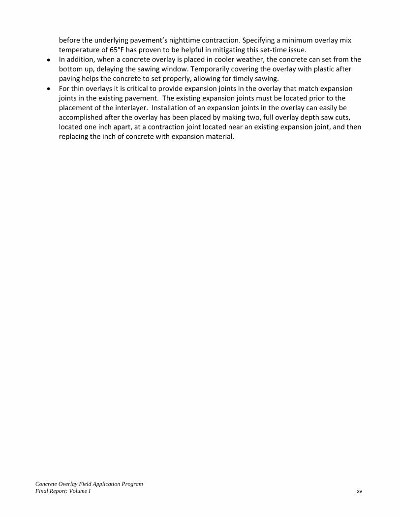
before the underlying pavement’s nighttime contraction. Specifying a minimum overlay mix temperature of 65°F has proven to be helpful in mitigating this set-time issue.
In addition, when a concrete overlay is placed in cooler weather, the concrete can set from the bottom up, delaying the sawing window. Temporarily covering the overlay with plastic after paving helps the concrete to set properly, allowing for timely sawing.
For thin overlays it is critical to provide expansion joints in the overlay that match expansion joints in the existing pavement. The existing expansion joints must be located prior to the placement of the interlayer. Installation of an expansion joints in the overlay can easily be accomplished after the overlay has been placed by making two, full overlay depth saw cuts, located one inch apart, at a contraction joint located near an existing expansion joint, and then replacing the inch of concrete with expansion material.

Concrete Overlay Field Application Program Final Report: Volume I xvi
[page blank]

Concrete Overlay Field Application Program Final Report: Volume I 1
Concrete overlays can serve as cost-effective maintenance and rehabilitation solutions for nearly all combinations of existing pavement types and conditions. They have been used successfully in the United States since 1913 (1). Despite this long history of performance, some state transportation agencies (STAs) have yet to embrace the design and construction of concrete overlays as a standard practice. There are many factors that have contributed to this lack of widespread adoption by STAs; not the least of which is the mistaken perception that concrete overlays are expensive and difficult to construct. Many factors make concrete overlays an attractive choice for pavement resurfacing and rehabilitation. They include the following:
Sustainability – concrete overlays provide cost effective, long-life solutions and are 100% recyclable
Asset Management – existing pavements are fully utilized as a supporting layer Economics – On a volume basis, concrete overlays costs are very competitive with alternative
pavement solutions Maintenance of Traffic – when necessary, concrete overlays can be constructed without closing
the roadway to traffic and/or adjacent to open lanes
OBJECTIVES
In an effort to clearly explain concrete overlays, their design features and construction requirements; the National Concrete Pavement Technology Center (CP Tech Center) published the Guide to Concrete Overlays (2) in September of 2008. This guide generated a great deal of interest in concrete overlays. To capitalize on this momentum, the “Concrete Overlay Field Application Program” was funded by FHWA and managed by the CP Tech Center. The primary objective of the program is to develop a concrete overlay construction program across the United States. To accomplish this, STAs are led through the scoping, design and construction phases of a concrete overlay by a team of experts. These projects provide hands-on experience to the STAs and contractors, which can then be utilized on future concrete overlay projects.
PROJECT TEAM MEMBERS
The organizational chart shown in Figure 1 illustrates the management approach used by the CP Tech Center.
1. PROJECT BACKGROUND

Concrete Overlay Field Application Program Final Report: Volume I 2
Note: FHWA representative from each state were requested to attend each site visit of the state.
Figure 1 – Project Management Organizational Chart
Tom Cackler, Project Administrator and Principal Investigator is the Director of the CP Tech Center and former Chief Engineer of the Iowa Department of Transportation. As project administrator and principal investigator, he provided the overall leadership and vision for the project. Dale Harrington, Project Manager and Co-Principal Investigator is Principal Engineer at Snyder and Associates, Inc. and former Director of the Center for Portland Cement Concrete Pavement Technology. His project responsibilities included project scheduling, coordination with the technical advisory committee and task management. Gina Ahlstrom managed the Concrete Overlay Field Application Program for FHWA. Technical Advisory Committee members are highly respected and highly qualified individuals with unparalleled experience in the design and construction of concrete overlays; the members were
Andy Bennett, Michigan Department of Transportation Jim Cable, P.E., Iowa State University (retired) Dan DeGraaf, P.E., Michigan Concrete Paving Association Jim Duit, Duit Construction Co., Inc., Oklahoma Jim Grove, P.E., Senior Project Engineer, FHWA
Tom Cackler – Project Administratorand
Principal Investigator
Dale Harrington – Project Managerand
Co-Principal Investigator
FHWA – COTRGina Ahlstrom
Technical Advisory Committee
Team LeadersGary Fick
and Rob Rasmussen
Expert Team Ahmad Ardani (former ARA)
Andy Bennett (MDOT) Dr. Jim Cable (ISU – Retired)
Dan DeGraaf (MCPA Jim Duit (Duit Construction)
Expert TeamTodd Hanson (IDOT) Randy Riley (IACP)
Matt Ross (MKACPA) Doug Schwartz (MDOT – Retired)
Matt Zeller (CPAM)
Expert TeamKurt Smith (AP Tech)
Jeff Uhlmeyer (WDOT) Leif Wathne (ACPA) Sam Tyson (FHWA)

Concrete Overlay Field Application Program Final Report: Volume I 3
Todd Hanson, P.E., Iowa Department of Transportation Kevin Maillard, P.E., OHM Advisors, Michigan Randell Riley, P.E., Illinois Chapter ACPA Robert Rodden, ACPA National Matt Ross, P.E., Missouri/Kansas Chapter ACPA Doug Schwartz, P.E., Minnesota DOT (retired) Jim Shea, New York State Chapter ACPA Gordon Smith, P.E., Iowa Concrete Paving Association Shannon Sweitzer, P.E., North Carolina Turnpike Authority Sam Tyson, P.E., Federal Highway Association Jeff Uhlmeyer, P.E., Washington State Department of Transportation Leif Wathne, P.E., American Concrete Pavement Associations Matt Zeller, P.E., Concrete Paving Association of Minnesota
Gary Fick, Team Leader is the Owner/Vice-President of Trinity Construction Management Services, Inc. From 1988 to 2003, he was involved in the construction of over 25 concrete overlays. As a team leader, he is responsible for all expert team activities which include site visits, recommendations and reports. Rob Rasmussen, Team Leader is Vice-President of The Transtec Group, Inc. He is recognized internationally for his technical abilities in all aspects of concrete pavements, from design to materials to construction. As a team leader, he is responsible for all expert team activities which include site visits, recommendations and reports. Expert Team Members shown in the organizational chart (Figure 1) were chosen for their knowledge and experience with concrete overlays. They come from a diverse background and were instrumental in providing detailed recommendations for the design and construction of concrete overlays.
WORK PLAN
Soon after initiation of the overlay implementation program, STAs and industry representatives were contacted through various channels. A combination of direct phone calls, e-mails and announcements at industry meetings were made to solicit participation in the field application program. A concerted effort was made to target states that either had no experience or limited experience with the design and construction of concrete overlays. Once interested, STAs were encouraged to demonstrate their commitment to participating by scheduling a concrete overlay workshop and coordinating an expert team site visit to their state. The typical steps for proceeding in the project were:
Initial contact with the STA Follow-up with project objectives and proposed activities Concrete overlay workshop conducted to educate stakeholders Commitment from the STA to schedule an expert team site visit Expert team site visit to review potential projects A site visit report was prepared by the expert team, detailing recommendations for the
projects reviewed and listing the next steps to overlay implementation

Concrete Overlay Field Application Program Final Report: Volume I 4
STAs that chose to proceed with implementation then received additional guidance from the expert team throughout the design, bidding and construction phases of the project
At the STA’s request, the CP Tech Center’s mobile concrete laboratory was mobilized during construction for materials testing and documentation of the construction process
A final report was prepared documenting the entire concrete overlay implementation process A total of 24 states had workshops, site visits, or consultation on projects under the Field Application Program. Eighteen states had one or more site visits which were conducted by expert teams as shown below:
Arkansas Delaware Georgia Illinois Iowa Louisiana Maryland Minnesota New Mexico Nevada North Dakota Pennsylvania South Dakota Texas Virginia Washington West Virginia Wyoming
Thirteen states received concrete overlay workshops as shown in Figure 2. The workshops held in Alabama, North Carolina and Indiana represent the full extent of work performed in those states. Consultation on future overlay projects was provided to Nebraska, Kansas and New York Toll Authority. The remainder of the workshops led to further concrete overlay implementation activities. The following nine states have constructed or are constructing overlay projects: Delaware, Iowa, Maryland, Nebraska, North Dakota, Pennsylvania, South Dakota, Virginia and Wyoming.
Figure 2 – States in Which Concrete Overlay Workshops were Held and/or Site Visits Conducted

Concrete Overlay Field Application Program Final Report: Volume I 5
In addition, the four states of Delaware, Kansas, Pennsylvania and Wyoming held Open Houses on their overlay projects with the assistance of members of the expert team. The CP Tech Center mobile concrete laboratory conducted three site visits during overlay construction in the states of Delaware, Pennsylvania and South Dakota. The activities and outcomes of states that participated in the concrete overlay field application program are summarized in Table 1.
Table 1. Overview of Activities by State
No. State Concrete Overlay
Workshop
Expert Team Site
Visit(s) Existing Pavement Proposed Overlay Comments
1 Alabama September 1&2, 2009
FHWA sponsored workshop with CP Tech Center in
attendance. Coincided with concrete pavement
construction project started in October 2009.
2 Arkansas May 22,
2012 April 1, 2010
US 64: Divided 4-lane composite pavement with approximately
1,400 trucks/day.
8” unbonded overlay through the 300’ WIM
section and a 6” bonded overlay for the remaining 700’
Site visit of a planned WIM site on US 63. Overlay
recommendations provided. Held workshop
for ADOT.
3 Delaware None
Sept 12, 2008 and
Nov 19, 2009
Variable HMA overlays (12in +/-) over existing 9 in.
PCC
Mill 4 in. of HMA - place 6 in. PCC
bonded concrete overlay
Provided report of initial site visit which lead to
overlay project on US 113. Also attended a prepour meeting on Oct 26, 2009;
mobile lab used during paving. Conducted Open
House November 16, 2009.
4 Georgia February
2009 March 2010
1. Brandon Rd 7.5" HMA over
stabilized base-3 lanes
2. GA SR 21 16-19" HMA over
12" Agg. Base
1. Mill 4" HMA & replace w/4"
concrete bonded overlay
2. Mill HMA & replace w/4"-6" bonded overlay
Overlay projects at seven intersections were field reviewed and reports
written. Held workshop for GDOT.
5 Illinois July 26,
2010 July 27,
2010
9 mile 10" PCC Concrete (1965-67)
w/7" HMA
6" unbonded w/6'x6' panels mill
out 3" HMA & build under traffic
Field review of I-80 potential projects and held
workshop with IDOT.
6 Iowa
August thru September 2011 Drive Thru with
state DOTs
August 2011
1938 PCC pavement of 18’ & 20’ wide,
widened to 24’ with 6” HMA overlay.
4.5” concrete overlay with 4’ concrete wide unit on each side, for 32’ pavement width.
Existing 6” HMA milled 1” – 1.5”.
Jointing was 4.5’ x 5’ panels.
Demonstrate design and construction of PCC overlays on 2-lane roadways under 2-way traffic. 18.9-mi project
constructed in 2011 in NE Iowa (US 18 between Fredericksburg
and West Union).
Concrete Overlay Field Application Program Final Report: Volume I 6
No. State Concrete Overlay
Workshop
Expert Team Site
Visit(s) Existing Pavement Proposed Overlay Comments
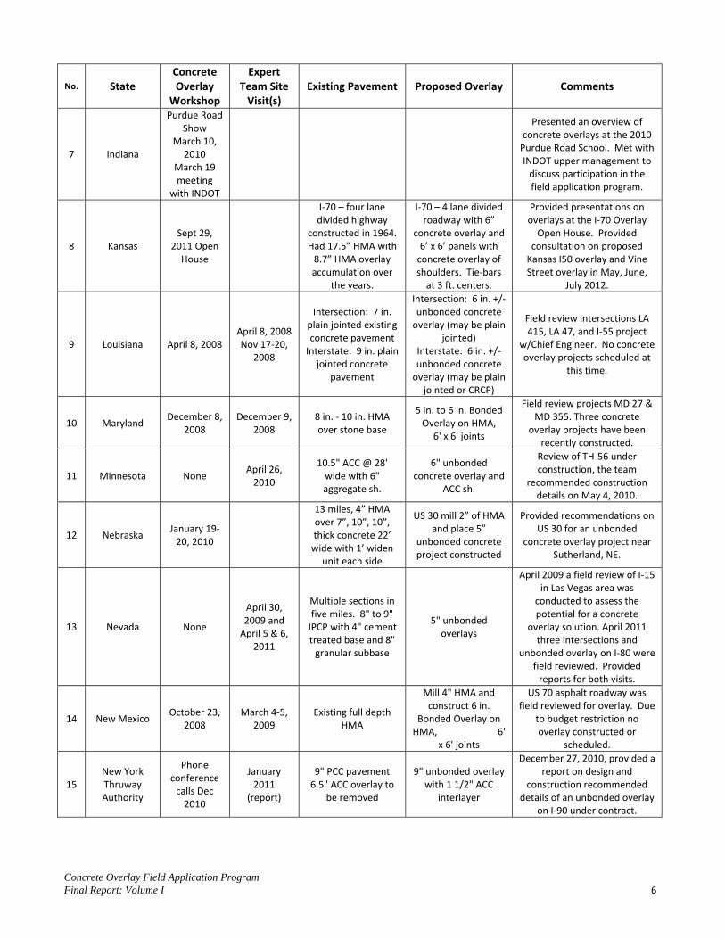
7 Indiana
Purdue Road Show
March 10, 2010
March 19 meeting
with INDOT
Presented an overview of concrete overlays at the 2010
Purdue Road School. Met with INDOT upper management to
discuss participation in the field application program.
8 Kansas Sept 29,
2011 Open House
I-70 – four lane divided highway
constructed in 1964. Had 17.5” HMA with
8.7” HMA overlay accumulation over
the years.
I-70 – 4 lane divided roadway with 6”
concrete overlay and 6’ x 6’ panels with
concrete overlay of shoulders. Tie-bars
at 3 ft. centers.
Provided presentations on overlays at the I-70 Overlay
Open House. Provided consultation on proposed
Kansas I50 overlay and Vine Street overlay in May, June,
July 2012.
9 Louisiana April 8, 2008 April 8, 2008 Nov 17-20,
2008
Intersection: 7 in. plain jointed existing concrete pavement
Interstate: 9 in. plain jointed concrete
pavement
Intersection: 6 in. +/- unbonded concrete
overlay (may be plain jointed)
Interstate: 6 in. +/- unbonded concrete
overlay (may be plain jointed or CRCP)
Field review intersections LA 415, LA 47, and I-55 project
w/Chief Engineer. No concrete overlay projects scheduled at
this time.
10 Maryland December 8,
2008 December 9,
2008 8 in. - 10 in. HMA over stone base
5 in. to 6 in. Bonded Overlay on HMA,
6' x 6' joints
Field review projects MD 27 & MD 355. Three concrete
overlay projects have been recently constructed.
11 Minnesota None April 26,
2010
10.5" ACC @ 28' wide with 6" aggregate sh.
6" unbonded concrete overlay and
ACC sh.
Review of TH-56 under construction, the team
recommended construction details on May 4, 2010.
12 Nebraska January 19-
20, 2010
13 miles, 4” HMA over 7”, 10”, 10”, thick concrete 22’
wide with 1’ widen unit each side
US 30 mill 2” of HMA and place 5”
unbonded concrete project constructed
Provided recommendations on US 30 for an unbonded
concrete overlay project near Sutherland, NE.
13 Nevada None
April 30, 2009 and
April 5 & 6, 2011
Multiple sections in five miles. 8" to 9"
JPCP with 4" cement treated base and 8"
granular subbase
5" unbonded overlays
April 2009 a field review of I-15 in Las Vegas area was
conducted to assess the potential for a concrete
overlay solution. April 2011 three intersections and
unbonded overlay on I-80 were field reviewed. Provided
reports for both visits.
14 New Mexico October 23,
2008 March 4-5,
2009 Existing full depth
HMA
Mill 4" HMA and construct 6 in.
Bonded Overlay on HMA, 6'
x 6' joints
US 70 asphalt roadway was field reviewed for overlay. Due
to budget restriction no overlay constructed or
scheduled.
15 New York Thruway Authority
Phone conference
calls Dec 2010
January 2011
(report)
9" PCC pavement 6.5" ACC overlay to
be removed
9" unbonded overlay with 1 1/2" ACC
interlayer
December 27, 2010, provided a report on design and
construction recommended details of an unbonded overlay
on I-90 under contract.
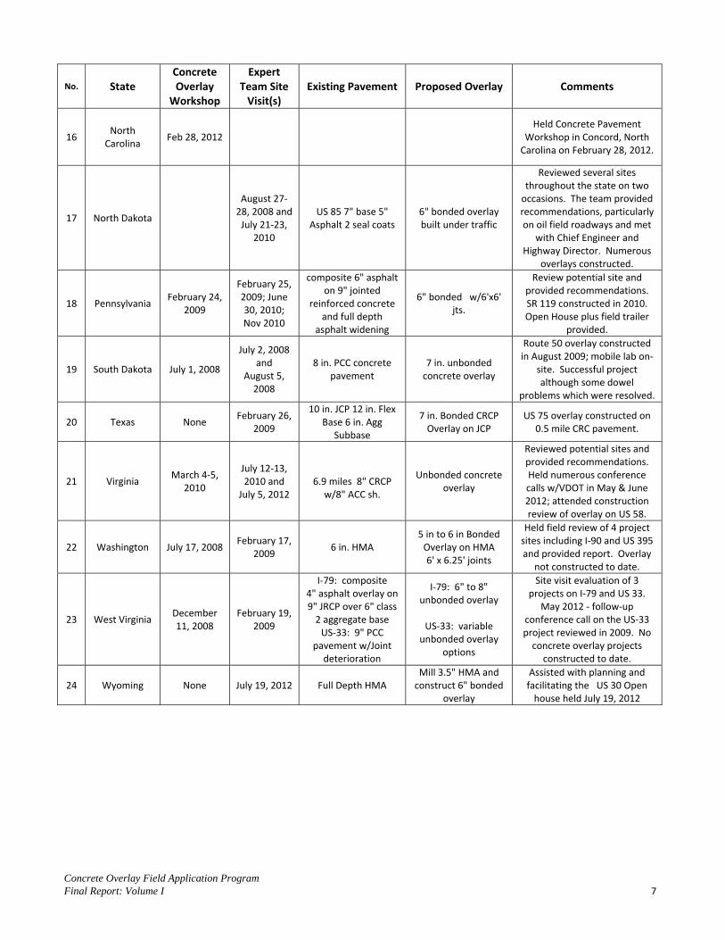
Concrete Overlay Field Application Program Final Report: Volume I 7
No. State Concrete Overlay
Workshop
Expert Team Site
Visit(s) Existing Pavement Proposed Overlay Comments
16 North
Carolina Feb 28, 2012
Held Concrete Pavement Workshop in Concord, North
Carolina on February 28, 2012.
17 North Dakota
August 27-28, 2008 and
July 21-23, 2010
US 85 7" base 5" Asphalt 2 seal coats
6" bonded overlay built under traffic
Reviewed several sites throughout the state on two
occasions. The team provided recommendations, particularly on oil field roadways and met
with Chief Engineer and Highway Director. Numerous
overlays constructed.
18 Pennsylvania February 24,
2009
February 25, 2009; June 30, 2010; Nov 2010
composite 6" asphalt on 9" jointed
reinforced concrete and full depth
asphalt widening
6" bonded w/6'x6' jts.
Review potential site and provided recommendations. SR 119 constructed in 2010. Open House plus field trailer
provided.
19 South Dakota July 1, 2008
July 2, 2008 and
August 5, 2008
8 in. PCC concrete pavement
7 in. unbonded concrete overlay
Route 50 overlay constructed in August 2009; mobile lab on-
site. Successful project although some dowel
problems which were resolved.
20 Texas None February 26,
2009
10 in. JCP 12 in. Flex Base 6 in. Agg
Subbase
7 in. Bonded CRCP Overlay on JCP
US 75 overlay constructed on 0.5 mile CRC pavement.
21 Virginia March 4-5,
2010
July 12-13, 2010 and
July 5, 2012
6.9 miles 8" CRCP
w/8" ACC sh.
Unbonded concrete overlay
Reviewed potential sites and provided recommendations. Held numerous conference calls w/VDOT in May & June 2012; attended construction review of overlay on US 58.
22 Washington July 17, 2008 February 17,
2009 6 in. HMA
5 in to 6 in Bonded Overlay on HMA 6' x 6.25' joints
Held field review of 4 project sites including I-90 and US 395 and provided report. Overlay
not constructed to date.
23 West Virginia December 11, 2008
February 19, 2009
I-79: composite 4" asphalt overlay on 9" JRCP over 6" class
2 aggregate base US-33: 9" PCC
pavement w/Joint deterioration
I-79: 6" to 8" unbonded overlay
US-33: variable
unbonded overlay options
Site visit evaluation of 3 projects on I-79 and US 33.
May 2012 - follow-up conference call on the US-33 project reviewed in 2009. No
concrete overlay projects constructed to date.
24 Wyoming None July 19, 2012 Full Depth HMA Mill 3.5" HMA and
construct 6" bonded overlay
Assisted with planning and facilitating the US 30 Open
house held July 19, 2012
Concrete Overlay Field Application Program Final Report: Volume I 8
The activities conducted by the concrete overlay field application project team led to a range of outcomes, from initial training through the conduct of a workshop to the construction of multiple concrete overlays. A brief list of the project’s accomplishments includes the following:
Concrete overlays constructed in eight states One concrete overlay in the design stages, awaiting construction funding Concrete overlay open houses hosted or co-hosted in Delaware, Iowa, Kansas and Wyoming Published multiple documents for support of the concrete overlay implementation program
Summaries of each STA’s overlay implementation process are provided in this report. For further details, consult the Final Report: Volume 2 which includes a copy of all documents produced as a part of this project. The following discussion of the concrete overlay field application program have detailed the efforts and outcomes from nine states (South Dakota, Pennsylvania, Delaware, North Dakota, Virginia, Nevada, Iowa, Wyoming and Kansas) that either constructed or designed concrete overlays during the term of the program. Besides, these nine states which resulted in tangible outcomes, there were many other states that participated in the concrete overlay field application program. Although the results of efforts in these states may not be as measurable as those that constructed concrete overlays, the continued exposure to the concrete overlay successes in other states will eventually pay dividends. These summaries are ordered by the perceived significance of the outcomes.
SOUTH DAKOTA
A concrete overlay workshop was conducted on July 1, 2008, followed the next day by an informal review of potential concrete overlay projects. A thorough site visit was conducted on August 5, 2008 to evaluate a section of westbound SD Route 50 in Clay and Yankton counties (Figure 3). An expert team of five met with representatives from the South Dakota DOT (SD DOT), Federal Highway Administration and the American Concrete Pavement Association, South Dakota Chapter.
2. PROJECT OUTCOMES
Concrete Overlay Field Application Program Final Report: Volume I 9
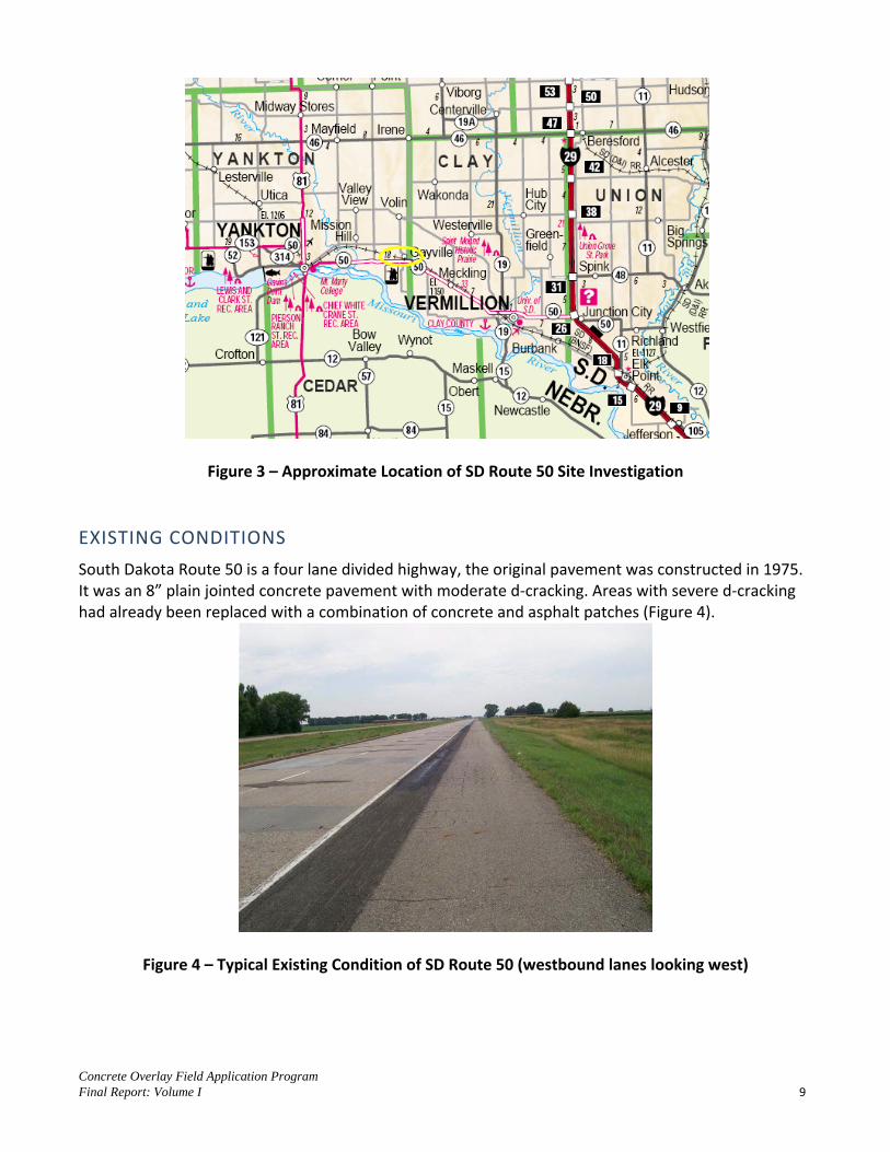
Figure 3 – Approximate Location of SD Route 50 Site Investigation
EXISTING CONDITIONS
South Dakota Route 50 is a four lane divided highway, the original pavement was constructed in 1975. It was an 8” plain jointed concrete pavement with moderate d-cracking. Areas with severe d-cracking had already been replaced with a combination of concrete and asphalt patches (Figure 4).
Figure 4 – Typical Existing Condition of SD Route 50 (westbound lanes looking west)

Concrete Overlay Field Application Program Final Report: Volume I 10
CONCRETE OVERLAY RECOMMENDATIONS
Two unbonded concrete overlay options were presented to the South Dakota Department of Transportation. First was a 7” thick dowel jointed design with 12’ x 12’ slabs. Second was a 6” thick plain jointed design with 6’ x 6’ slabs. Both recommendations included a 1” nominal thickness asphalt separation layer on top of the existing concrete pavement. Additional recommendations were provided regarding miscellaneous design and construction details.
FINAL CONCRETE OVERLAY DESIGN
The expert team provided feedback throughout the design process. The South Dakota Department of Transportation opted to pursue a 7” thick dowel jointed unbonded overlay with a variable thickness asphalt separation layer. The design called for 1” diameter dowel bars at 12” c/c spacing in the transverse joints. A unique design feature was the omission of dowel bars between the wheel paths (Figure 5).
Figure 5 – SD Route 50 Dowel Bar Configuration (note omitted dowels between the wheel paths)
CONCRETE OVERLAY CONSTRUCTION AND LESSONS LEARNED
Construction of the unbonded overlay took place in August of 2009. A sketch of the overlay typical section is shown in Figure 6. Load transfer dowels (1” diameter) were placed in the wheel paths (5 bars in the outside wheel paths and 4 bars in the inside wheel paths) at transverse joint locations. Tie bars
Concrete Overlay Field Application Program Final Report: Volume I 11
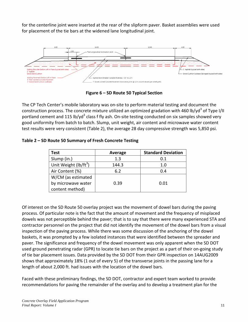
for the centerline joint were inserted at the rear of the slipform paver. Basket assemblies were used for placement of the tie bars at the widened lane longitudinal joint.
Figure 6 – SD Route 50 Typical Section The CP Tech Center’s mobile laboratory was on-site to perform material testing and document the construction process. The concrete mixture utilized an optimized gradation with 460 lb/yd3 of Type I/II portland cement and 115 lb/yd3 class f fly ash. On-site testing conducted on six samples showed very good uniformity from batch to batch. Slump, unit weight, air content and microwave water content test results were very consistent (Table 2), the average 28 day compressive strength was 5,850 psi. Table 2 – SD Route 50 Summary of Fresh Concrete Testing
Test Average Standard Deviation Slump (in.) 1.3 0.1 Unit Weight (lb/ft3) 144.3 1.0 Air Content (%) 6.2 0.4 W/CM (as estimated by microwave water content method)
0.39 0.01
Of interest on the SD Route 50 overlay project was the movement of dowel bars during the paving process. Of particular note is the fact that the amount of movement and the frequency of misplaced dowels was not perceptible behind the paver; that is to say that there were many experienced STA and contractor personnel on the project that did not identify the movement of the dowel bars from a visual inspection of the paving process. While there was some discussion of the anchoring of the dowel baskets, it was prompted by a few isolated instances that were identified between the spreader and paver. The significance and frequency of the dowel movement was only apparent when the SD DOT used ground penetrating radar (GPR) to locate tie bars on the project as a part of their on-going study of tie bar placement issues. Data provided by the SD DOT from their GPR inspection on 14AUG2009 shows that approximately 18% (1 out of every 5) of the transverse joints in the passing lane for a length of about 2,000 ft. had issues with the location of the dowel bars. Faced with these preliminary findings, the SD DOT, contractor and expert team worked to provide recommendations for paving the remainder of the overlay and to develop a treatment plan for the

Concrete Overlay Field Application Program Final Report: Volume I 12
sections of overlay with misplaced dowels. There were many contributing factors for the movement of the dowels during paving, these included:
Dowel baskets contained dowels only in the wheel paths, which left a weak section in the middle section of the basket where there were no dowels.
The variable thickness asphalt (0.5” to 1.8”) made it difficult to find an anchoring system which was effective across the width of the lane. In some cases, the anchor needed to have enough force to penetrate into the concrete; where the asphalt was thicker, a shot with less force was needed to keep the anchor embedded in the asphalt.
Clipping the shipping wires which is specified by SD DOT likely contributed to the instability of the baskets.
The instability of the baskets and the difficulty in effectively anchoring the baskets made the process sensitive to the amount of concrete being maintained in front of the paver.
At times, the combination of a stiff concrete mixture and the concrete head in front of the paver may have contributed to movement of the dowels (Figure 7).
Figure 7 – SD Route 50 Concrete Head In Front of the Paver The following actions taken by the contractor were successful in maintaining the placement of the dowels for the remaining concrete overlay placement of approximately 2.25 miles.
The center section of the baskets that did not have any dowels was removed. Four individual baskets were placed instead of two.
The contractor used approximately twice the number of anchors per basket than was originally used.
Shipping wires were left intact.
Concrete Overlay Field Application Program Final Report: Volume I 13
The amount of concrete head in front of the paver was monitored more closely by the contractor.
Some of the options for the treatment of the concrete overlay with misaligned dowels that were considered included: removal and replacement, dowel bar retrofit and sawing intermediate transverse and longitudinal joints. Based upon recommendations from the expert team, the SD DOT opted to cut intermediate joints in the overlay. Creating smaller slabs will reduce the movement, thereby increasing load transfer through aggregate interlock, combined with the support from the existing pavement, this approach should provide a long term solution.
ADDITIONAL CONCRETE OVERLAY ACTIVITIES
One of the primary objectives of this project was to develop in-house expertise by walking an STA through the scoping, design and construction of a concrete overlay. In March of 2011, the overlay field application team was asked to provide recommendations on two additional potential concrete overlay projects near Huron, SD. After thoroughly reviewing the information provided, an expert team prepared a memorandum recommending unbonded overlays for both projects. One of the projects was constructed in 2012 without any further involvement from the project team. This is a clear demonstration of the effectiveness of the overlay field application project.
PENNSYLVANIA
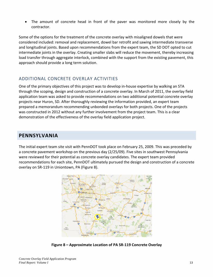
The initial expert team site visit with PennDOT took place on February 25, 2009. This was preceded by a concrete pavement workshop on the previous day (2/25/09). Five sites in southwest Pennsylvania were reviewed for their potential as concrete overlay candidates. The expert team provided recommendations for each site, PennDOT ultimately pursued the design and construction of a concrete overlay on SR-119 in Uniontown, PA (Figure 8).
Figure 8 – Approximate Location of PA SR-119 Concrete Overlay

Concrete Overlay Field Application Program Final Report: Volume I 14
EXISTING CONDITIONS
Pennsylvania SR-119 is an urban arterial roadway that transitions from a divided facility to a five lane roadway (Figure 9) with a raised median in some areas.
Figure 9 – Existing Condition of Pennsylvania SR-119 Looking South
This section of roadway was originally constructed in 1947 and 1955 as a two lane facility and later widened and overlaid to its current state as a five lane roadway (Figure 10).
Figure 10 – Pennsylvania SR-119 Existing Typical Section
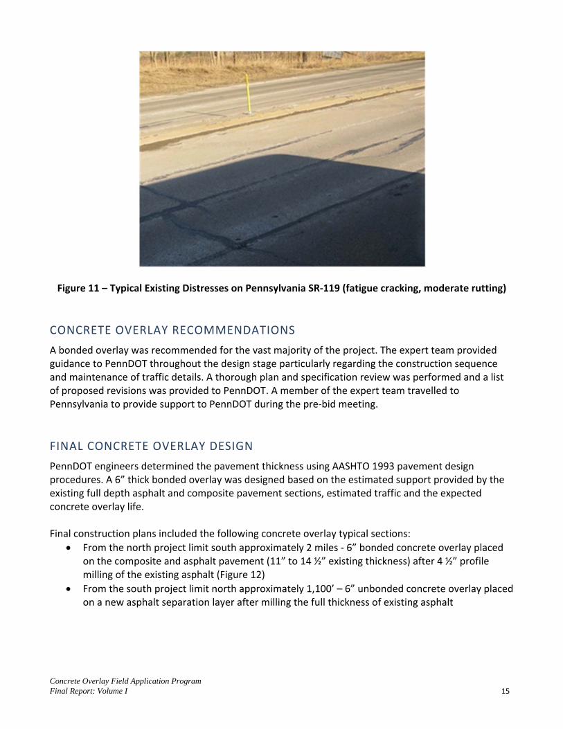
Descriptions of the original construction and maintenance history suggest that there was considerable variability in the existing pavement section throughout the length of the project. The existing pavement was exhibiting distress (Figure 11), and was due for a major rehabilitation.
CL38.00
24.00
Approx. 13.8" Asphalt Pavement
12" Slag Aggregate Subbase
6" Special Subbase
1955 to 1997
9" Jointed Reinforced Concrete Pavement (1947)
8" Subbase
Approx. 6" Bituminous (1955 to 1997)
6.00
Concrete Overlay Field Application Program Final Report: Volume I 15
Figure 11 – Typical Existing Distresses on Pennsylvania SR-119 (fatigue cracking, moderate rutting)
CONCRETE OVERLAY RECOMMENDATIONS
A bonded overlay was recommended for the vast majority of the project. The expert team provided guidance to PennDOT throughout the design stage particularly regarding the construction sequence and maintenance of traffic details. A thorough plan and specification review was performed and a list of proposed revisions was provided to PennDOT. A member of the expert team travelled to Pennsylvania to provide support to PennDOT during the pre-bid meeting.
FINAL CONCRETE OVERLAY DESIGN
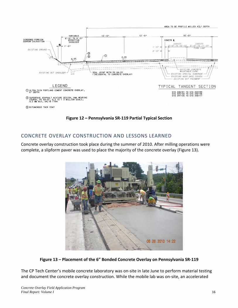
PennDOT engineers determined the pavement thickness using AASHTO 1993 pavement design procedures. A 6” thick bonded overlay was designed based on the estimated support provided by the existing full depth asphalt and composite pavement sections, estimated traffic and the expected concrete overlay life. Final construction plans included the following concrete overlay typical sections:
From the north project limit south approximately 2 miles - 6” bonded concrete overlay placed on the composite and asphalt pavement (11” to 14 ½” existing thickness) after 4 ½” profile milling of the existing asphalt (Figure 12)
From the south project limit north approximately 1,100’ – 6” unbonded concrete overlay placed on a new asphalt separation layer after milling the full thickness of existing asphalt
Concrete Overlay Field Application Program Final Report: Volume I 16
Figure 12 – Pennsylvania SR-119 Partial Typical Section
CONCRETE OVERLAY CONSTRUCTION AND LESSONS LEARNED
Concrete overlay construction took place during the summer of 2010. After milling operations were complete, a slipform paver was used to place the majority of the concrete overlay (Figure 13).
Figure 13 – Placement of the 6” Bonded Concrete Overlay on Pennsylvania SR-119
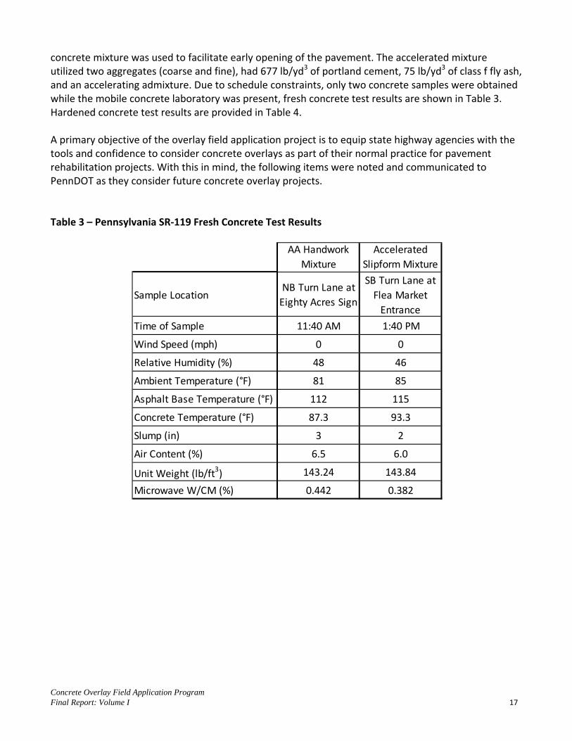
The CP Tech Center’s mobile concrete laboratory was on-site in late June to perform material testing and document the concrete overlay construction. While the mobile lab was on-site, an accelerated
Concrete Overlay Field Application Program Final Report: Volume I 17
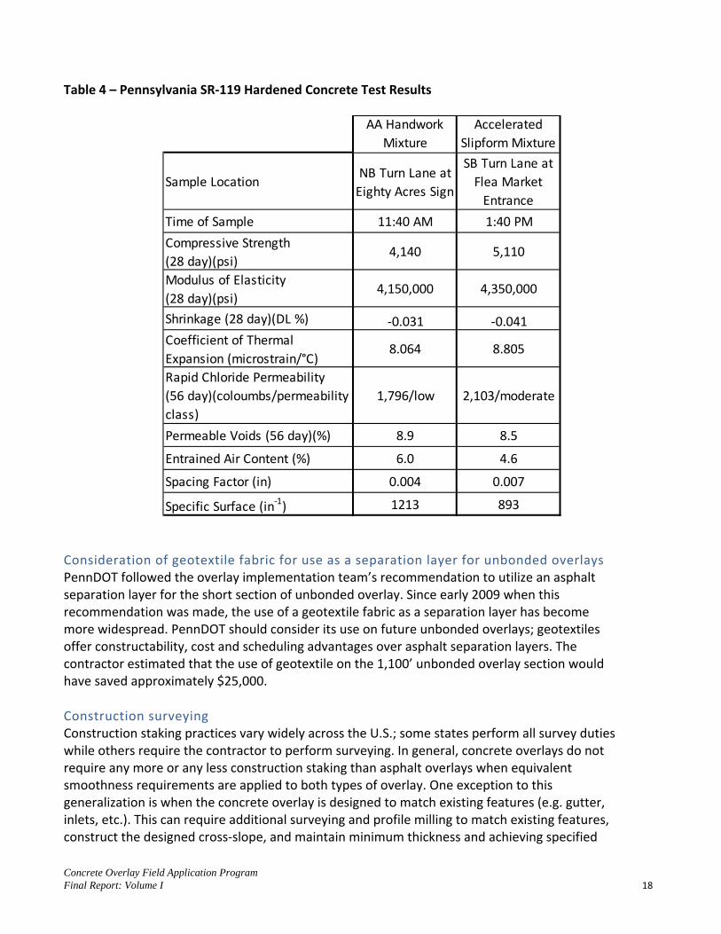
concrete mixture was used to facilitate early opening of the pavement. The accelerated mixture utilized two aggregates (coarse and fine), had 677 lb/yd3 of portland cement, 75 lb/yd3 of class f fly ash, and an accelerating admixture. Due to schedule constraints, only two concrete samples were obtained while the mobile concrete laboratory was present, fresh concrete test results are shown in Table 3. Hardened concrete test results are provided in Table 4. A primary objective of the overlay field application project is to equip state highway agencies with the tools and confidence to consider concrete overlays as part of their normal practice for pavement rehabilitation projects. With this in mind, the following items were noted and communicated to PennDOT as they consider future concrete overlay projects. Table 3 – Pennsylvania SR-119 Fresh Concrete Test Results
AA Handwork Mixture
Accelerated Slipform Mixture
Sample LocationNB Turn Lane at
Eighty Acres Sign
SB Turn Lane at Flea Market
Entrance
Time of Sample 11:40 AM 1:40 PM
Wind Speed (mph) 0 0
Relative Humidity (%) 48 46
Ambient Temperature (°F) 81 85
Asphalt Base Temperature (°F) 112 115
Concrete Temperature (°F) 87.3 93.3
Slump (in) 3 2
Air Content (%) 6.5 6.0
Unit Weight (lb/ft3) 143.24 143.84
Microwave W/CM (%) 0.442 0.382
Concrete Overlay Field Application Program Final Report: Volume I 18
Table 4 – Pennsylvania SR-119 Hardened Concrete Test Results
Consideration of geotextile fabric for use as a separation layer for unbonded overlays PennDOT followed the overlay implementation team’s recommendation to utilize an asphalt separation layer for the short section of unbonded overlay. Since early 2009 when this recommendation was made, the use of a geotextile fabric as a separation layer has become more widespread. PennDOT should consider its use on future unbonded overlays; geotextiles offer constructability, cost and scheduling advantages over asphalt separation layers. The contractor estimated that the use of geotextile on the 1,100’ unbonded overlay section would have saved approximately $25,000.
Construction surveying Construction staking practices vary widely across the U.S.; some states perform all survey duties while others require the contractor to perform surveying. In general, concrete overlays do not require any more or any less construction staking than asphalt overlays when equivalent smoothness requirements are applied to both types of overlay. One exception to this generalization is when the concrete overlay is designed to match existing features (e.g. gutter, inlets, etc.). This can require additional surveying and profile milling to match existing features, construct the designed cross-slope, and maintain minimum thickness and achieving specified
AA Handwork Mixture
Accelerated Slipform Mixture
Sample LocationNB Turn Lane at
Eighty Acres Sign
SB Turn Lane at Flea Market
Entrance
Time of Sample 11:40 AM 1:40 PM
Compressive Strength (28 day)(psi)
4,140 5,110
Modulus of Elasticity (28 day)(psi)
4,150,000 4,350,000
Shrinkage (28 day)(DL %) -0.031 -0.041Coefficient of Thermal Expansion (microstrain/°C)
8.064 8.805
Rapid Chloride Permeability (56 day)(coloumbs/permeability class)
1,796/low 2,103/moderate
Permeable Voids (56 day)(%) 8.9 8.5
Entrained Air Content (%) 6.0 4.6
Spacing Factor (in) 0.004 0.007
Specific Surface (in-1) 1213 893

Concrete Overlay Field Application Program Final Report: Volume I 19
smoothness criteria. Often these objectives require compromises in the field. It is a learning process between the DOT and contractors. When these conditions occur, it is advisable to include the appropriate survey bid item so that all parties are clear on the scope of construction staking.
Transitions from existing pavement to overlay sections The length of transitions was recommended as per the “Guide to Concrete Overlays”. The next revision of the “Guide” will note that transition lengths can be reduced for design speeds less than 70 mph.
Accelerated concrete mixtures In many cases, high early strength mixtures that included high dosages of accelerating admixtures have had poor performance histories. Maintenance of traffic plans should be carefully developed to allow for the placement of normal mixtures whenever possible. When accelerated mixtures are necessary to maintain reasonable roadway closure times the mixtures should be designed to meet the accelerated opening with increased cement content. If this is not possible, the use of non-chloride accelerating admixtures should be considered.
Curing of thinner concrete overlay sections Proper curing of thinner sections is critical. Application of the curing compound should occur before any surface evaporation occurs and should also provide full coverage of the concrete overlay pavement (rates vary depending on specified curing material). Multiple coats of cure can be applied in stages in areas of steep profile grade and/or super elevated cross-slopes that can cause saws to slide on the heavily cured pavement surface.
Tiebars PennDOT followed the overlay implementation team’s recommendations regarding the use of tie bars. During the open house, the contractor explained that the tie-bars were presenting some constructability and maintenance of traffic issues because the width of milling had to be wider than the width of overlay placement to allow placement of the tie bars due to the 4.5” milling depth and the 6” concrete overlay depth. This complicated the maintenance of traffic throughout the project. The team’s recommendation was conservative, as the bonded overlay is restrained by the bond to a milled surface and the median curb and the outside shoulders. In hindsight, tie bars were not necessary on this project because of the restraint provided by the bond. Thus, tie-bars were not an absolute requirement and, considering the constructability issues, could be eliminated or reduced if similar conditions are found on future projects.
Matching existing features Matching existing features such as median curb, shoulders and drives was complicated by requiring cross-slope correction and strict adherence to the cross-slope depicted on the typical section. Regardless of pavement type, adherence to a constant cross-slope is nearly impossible when constraints are placed on one or both sides of the pavement. Two options exist when designing concrete overlays. First, when existing features are left in place, a minimum and variable cross-slope should be allowed (e.g. cross-slope = variable [1% minimum]). Second is the removal of existing features that constrain the elevation at pavement edges; although this
Concrete Overlay Field Application Program Final Report: Volume I 20
method allows full adjustment of the cross-slope, construction costs can be significantly higher when there are multiple storm sewer inlets and driveways to remove and replace.
Cost comparisons should continue to be made during the design stage to determine whether it is cost-effective to preserve existing gutter, curbs, inlets, etc. When existing gutters are matched, matching the joints when possible is the preferred option over installation of an expansion/isolation joint. Expansion/Isolation joints are prone to higher maintenance costs.
Inlet design and construction for concrete overlay projects should be considered early in the design stage. Construction staging, equipment and maintenance of traffic may impact the inlet design.
Pre-overlay preparation Ideally, placement of the concrete overlay should follow the milling operations by only a few days. This is often affected by the maintenance of traffic plans. The need to coordinate the concrete overlay design with a sound maintenance of traffic plan is important.
Miscellaneous Items Existing shoulders were not milled on this project which did create some surface drainage issues while maintaining traffic as well as constructability issues. Future overlay projects should allow for weep holes in the shoulders to prevent ponding of water in the traffic lanes. The use of early-entry saws appeared to be successful regarding the prevention of random cracking. Saw timing is especially critical for thinner concrete pavements which have a higher surface area to volume ratio. While PennDOT opted for sealed joints on this project, this is not typically recommended for slab dimensions equal to or less than 6’; unless there is poor drainage and/or heavy truck traffic. This recommendation may change in the future as evidence from Michigan and Minnesota showing that bonded concrete overlays with sealed joints are outperforming those with unsealed joints is fully analyzed. In general, urban concrete overlays (such as was constructed on U.S.119) require a well-conceived construction sequence and maintenance of traffic plan. Many agencies have adopted the use of lane rental and/or “A+B” incentive/disincentive provisions to encourage accelerated construction of concrete overlays. PennDOT should consider including a special provision requiring the use of automatic vibrator monitors on future projects.
ADDITIONAL CONCRETE OVERLAY ACTIVITIES
Following the successful construction of Pennsylvania SR-119 in 2012 and a thorough review noting lessons learned, PennDOT has continued to look at concrete overlays as a viable pavement

Concrete Overlay Field Application Program Final Report: Volume I 21
rehabilitation method. Recently a significant portion of a project designed to reconstruct PA-465 near Carlisle, PA showed signs of early deterioration in the bituminous binder and surface courses due to heavy truck traffic. PennDOT opted to use a 6” thick bonded concrete overlay in the areas of concentrated truck traffic. Also, PennDOT is planning a $10 MM concrete overlay on Pennsylvania SR-119 in Fayette County. These projects demonstrate the success of the overlay field application program.
DELAWARE
An expert team reviewed two potential concrete overlay sites near Dover, De on September 12, 2008. Following the recommendations of the expert team, DelDOT chose to design and construct a bonded concrete overlay of a composite pavement section on US-13 (Figure 14).
Figure 14 – Approximate Location of US-13 Bonded Concrete Overlay in Delaware
EXISTING CONDITIONS
The exact history of the existing pavement is not known. However, the original concrete pavement is believed to be at least 50 years old. The pavement had been overlaid with asphalt numerous times (Figure 15).

Concrete Overlay Field Application Program Final Report: Volume I 22
Figure 15 – US-13 Southbound Lanes Existing Typical Section
This portion of US-13 is a four lane divided roadway in a suburban area, the existing pavement was in fair condition with moderate rutting and some fatigue cracking (Figure 16).
Figure 16 – US-13 Existing Pavement Condition
CONCRETE OVERLAY RECOMMENDATIONS
The following recommendations were provided to DelDOT for the implementation of a concrete overlay on US Route 13. Design and construct an approximately 2,500’ long bonded overlay on the southbound lanes.

Concrete Overlay Field Application Program Final Report: Volume I 23
1. A nominal milling depth should be specified. However, milling depth should be adjusted in the field to avoid leaving a thin layer of an existing lift of asphalt that may become unbonded. Ideally, milling operations should remove the entire thickness of an asphalt layer along with the top portion (½”) of the underlying asphalt layer.
2. If the width of the existing PCCP is less than 24’, it may be necessary to provide reinforcement over the edge of the existing PCCP (see P. 33, Figure 32 of the “Guide to Concrete Overlays”, 2nd Edition).
3. Perform a pavement design for a bonded overlay using AASHTO 1993, 1998 and/or M-E Design Guide procedures.
4. The contract should include a detail and pay quantities for full depth patching areas that exhibit vertical movement in the existing layer of PCCP (e.g. joint replacement in severely tented locations). Subsequent to milling, these areas should be evaluated and marked for full depth patching prior to construction of the concrete overlay (see P. 17 of the “Guide to Concrete Overlays”, 2nd Edition).
FINAL CONCRETE OVERLAY DESIGN
Based on these recommendations, DelDOT designed a 2,500’ long x 12’ wide x 6” thick bonded overlay (Figure 17).
Figure 17 – US-13 Bonded Overlay Typical Section
Traffic control plans required that the overlay in the 12’ wide driving lane of southbound US-13 be constructed adjacent to single lane traffic that would be maintained in the passing lane. A high early strength concrete mixture was specified to accelerate re-opening the roadway to unrestricted traffic flow. A milling depth of 4” combined with the 6” concrete overlay was used to match the elevation of the 2” asphalt surface course that was placed on the outside shoulder and passing lane prior to construction of the concrete overlay. There were no areas that required full depth patching prior to overlay placement. Due to the single lane width of the bonded concrete overlay, tie bars were not required.
16.00 ft 12.00 ft
6.00 ft
10.00 ft
Mill 4" Depth
Sawcut 6" (both sides)
2" Type C Asphalt Overlay 2" Type C Asphalt OverlSawcut T/3 x 1/8" Wide
6" Concrete Overlay

Concrete Overlay Field Application Program Final Report: Volume I 24
CONCRETE OVERLAY CONSTRUCTION
Concrete overlay placement commenced at approximately 6:15 am on November 16, 2009, proceeding from the south end to the north. Transit mixed concrete was delivered via front discharge trucks. Pavement was placed using hand vibrators and a roller screed onto a dampened surface (Figure 18). Hand finishing behind the roller screed consisted of a straightedge, bull float, hand floats, edging and transverse tining. Prior to constructing the concrete overlay, the 2” Type C asphalt overlay was placed to profile grade on the passing lane and shoulders. Milling and sawcutting the vertical edges for the concrete overlay were performed the night before concrete placement.
Figure 18 – US-13 Bonded Concrete Overlay Construction A high early strength concrete mixture (Table 5) was specified to accelerate re-opening the roadway to unrestricted traffic flow. Hardened concrete testing was performed by the CP Tech Center on cores provided by DelDOT, a summary of test results is provided in Table 6. The construction of a bonded concrete overlay on US-13 in Delaware was a success and demonstrated that concrete overlays are appropriate for small to medium sized projects where transit mixed concrete and hand placement methods are used.

Concrete Overlay Field Application Program Final Report: Volume I 25
Table 5 – US-13 Concrete Mixture Proportions
Material - Supplier 1 yd3 Yard Batch Quantity (SSD) Unit
Portland Cement, Type I/II, Low Alkali – Lehigh 599 lb Fly Ash, Type F – Separation Technologies 106 lb Coarse Aggregate, #57 – Independence 1886 lb Fine Aggregate – Tilcon 1070 lb Water 267 lb High/Mid-Range Water Reducer, ASTM C 494 Type A & F – Sika 686 42.3 – 56.4 oz Accelerating Admixture, ASTM C 494 Type C – Sika Rapid-1 56.4 – 451 oz Air Entraining Admixture, ASTM C 260 – Sika AEA 3.5 – 7.05 oz Fiber Reinforcement, ASTM C 1116 – Sika PPM 1.5 lb
Table 6 – US-13 Hardened Concrete Properties
ADDITIONAL CONCRETE OVERLAY ACTIVITIES
During construction of the overlay, an open house was hosted by DelDOT, in cooperation with the American Concrete Pavement Association Mid-Atlantic Chapter, the Federal Highway Administration, and the CP Tech Center. More than 60 people from 6 states attended the open house and visited the site during overlay construction to learn more about concrete overlays. One of the objectives of the overlay field application program was to states surrounding those participating to concrete overlay technologies. The US-13 project in Delaware was successful in this regard; since attending the construction open house in Delaware, the Maryland Department of Transportation has designed and constructed three concrete overlay projects.
Concrete Property Tested Result Unit
7 Day Compressive Strength 4,180 psi
28 Day Compressive Strength 5,400 psi
Entrained Air (core specimens from 21+50) 3.6 %
Air Void Spacing Factor (core specimens from 21+50)
0.010 in
Air Void Specific Surface (core specimen from 21+50)
661 in-1
Entrained Air (core specimens from 1+50) 5.0 %
Air Void Spacing Factor (core specimens from 1+50)
0.010 in
Air Void Specific Surface (core specimen from 1+50)
555 in-1
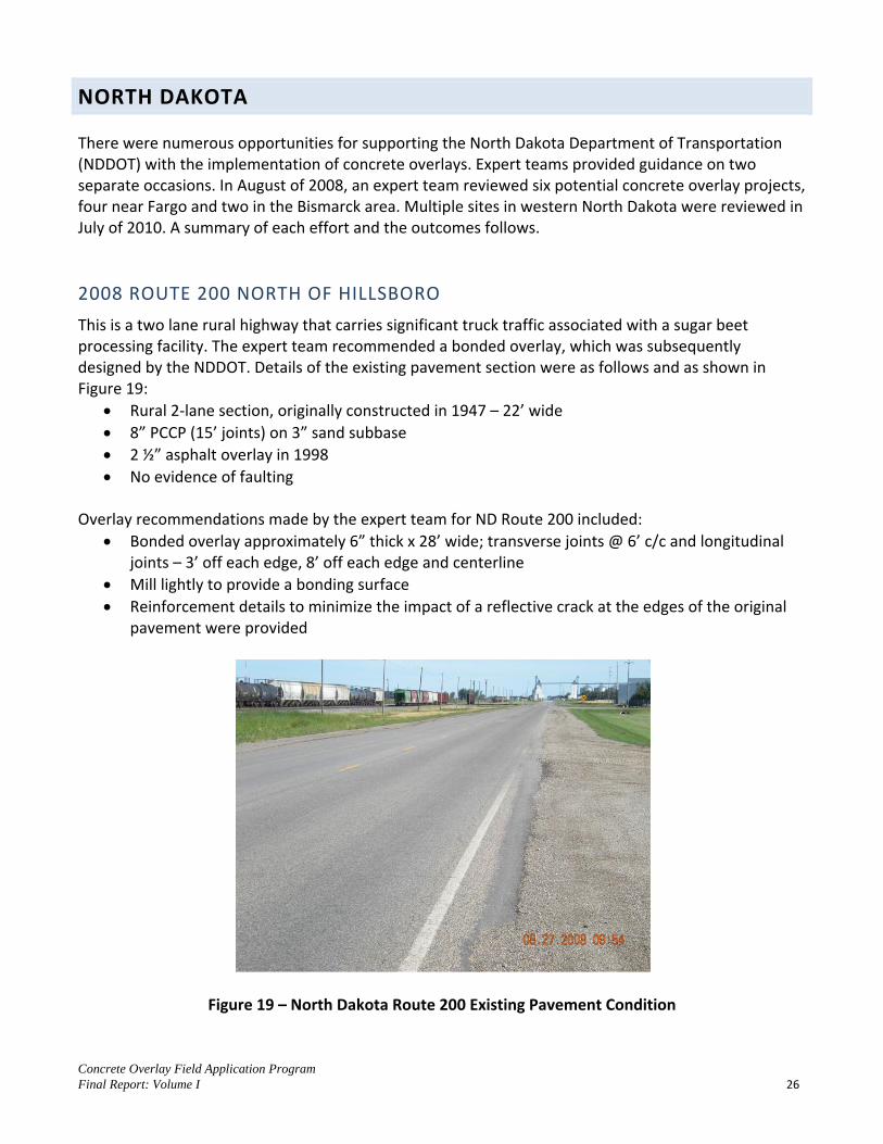
Concrete Overlay Field Application Program Final Report: Volume I 26
NORTH DAKOTA
There were numerous opportunities for supporting the North Dakota Department of Transportation (NDDOT) with the implementation of concrete overlays. Expert teams provided guidance on two separate occasions. In August of 2008, an expert team reviewed six potential concrete overlay projects, four near Fargo and two in the Bismarck area. Multiple sites in western North Dakota were reviewed in July of 2010. A summary of each effort and the outcomes follows.
2008 ROUTE 200 NORTH OF HILLSBORO
This is a two lane rural highway that carries significant truck traffic associated with a sugar beet processing facility. The expert team recommended a bonded overlay, which was subsequently designed by the NDDOT. Details of the existing pavement section were as follows and as shown in Figure 19:
Rural 2-lane section, originally constructed in 1947 – 22’ wide 8” PCCP (15’ joints) on 3” sand subbase 2 ½” asphalt overlay in 1998 No evidence of faulting
Overlay recommendations made by the expert team for ND Route 200 included:
Bonded overlay approximately 6” thick x 28’ wide; transverse joints @ 6’ c/c and longitudinal joints – 3’ off each edge, 8’ off each edge and centerline
Mill lightly to provide a bonding surface Reinforcement details to minimize the impact of a reflective crack at the edges of the original
pavement were provided
Figure 19 – North Dakota Route 200 Existing Pavement Condition

Concrete Overlay Field Application Program Final Report: Volume I 27
A 5” and 6” thick concrete overlay was designed by the NDDOT and successfully constructed in 2010 (Figure 20).
Figure 20 – North Dakota Route 200 Bonded Concrete Overlay
2008 CASS COUNTY ROUTE 11 NEAR MAPLETON
This project was reviewed with the county commissioner; existing conditions were as listed below and shown in Figure 21:
Originally constructed in 1994 7” asphalt on 6” granular subbase South 1 mile recently overlaid with 3” asphalt for industrial access Surfaced shoulders from I-94 north 2 miles (through Mapleton) Aggregate shoulders extending north another 4 miles Some distress visible from commercial/agricultural truck traffic

Concrete Overlay Field Application Program Final Report: Volume I 28
Figure 21 – North Dakota, Cass County Route 11 Existing Condition
Overlay recommendations provided by the expert team were:
Maximize pavement life (30 – 40 year) and take advantage of the existing roadway structure Bonded overlay approximately 3” to 4” thickness 6’ x 6’ joint pattern (4’ x 6’ on shoulders) 32’ wide concrete overlay through section with surfaced shoulders 24’ wide concrete overlay with aggregate shoulders extending north
The county evaluated alternative rehabilitation strategies and ultimately chose to construct a 5” thick concrete overlay in 2010 (Figure 22).
Figure 22 – North Dakota, Cass County Route 11 Concrete Overlay Construction

Concrete Overlay Field Application Program Final Report: Volume I 29
2008 CASS COUNTY ROUTE 4
Similar to route 11 but with less truck traffic (Figure 23), the expert team recommended a 3” to 4” thick bonded overlay. No further action has been taken on this roadway.
Figure 23 – North Dakota, Cass County Route 11 Existing Condition
2008 FARGO, NORTH DAKOTA SOUTH 25TH STREET
A four lane urban arterial street (Figure 24), the expert team recommended milling the existing asphalt roadway and placing a bonded concrete overlay. No further action has been taken on this roadway.
Figure 24 – Fargo, North Dakota; South 25th Street Existing Condition

Concrete Overlay Field Application Program Final Report: Volume I 30
2008 US-83 NORTH OF BISMARCK
This is a divided four lane roadway linking Bismarck and Minot. The existing roadway conditions are listed below and shown in Figure 25:
Originally constructed in 1964 7 ½” asphalt on 5” granular subbase Plant mix seal coat in 1975 1 ½” asphalt overlay in 1983 1 ½” asphalt overlay in 2002
Figure 25 – Existing Condition of US-83 North of Bismarck, ND
A bonded overlay was recommended by the expert team. No further action was taken on this project.
2008 BISMARCK EXPRESSWAY
This is a divided four lane route originally constructed in 1981, it carries over 30,000 AADT. The existing pavement details are listed below and shown in Figure 26:
8” asphalt on 2” granular subbase Core thickness results indicate asphalt maintenance activities have added approximately 2” to
4” asphalt thickness
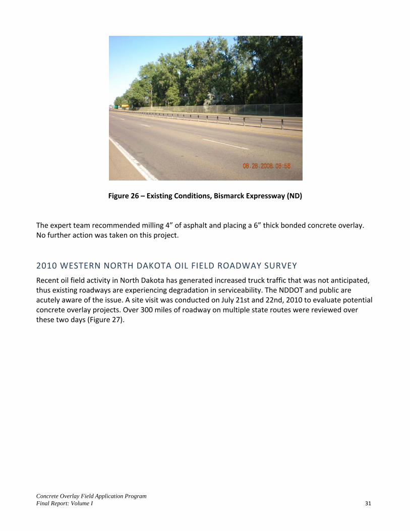
Concrete Overlay Field Application Program Final Report: Volume I 31
Figure 26 – Existing Conditions, Bismarck Expressway (ND)
The expert team recommended milling 4” of asphalt and placing a 6” thick bonded concrete overlay. No further action was taken on this project.
2010 WESTERN NORTH DAKOTA OIL FIELD ROADWAY SURVEY
Recent oil field activity in North Dakota has generated increased truck traffic that was not anticipated, thus existing roadways are experiencing degradation in serviceability. The NDDOT and public are acutely aware of the issue. A site visit was conducted on July 21st and 22nd, 2010 to evaluate potential concrete overlay projects. Over 300 miles of roadway on multiple state routes were reviewed over these two days (Figure 27).

Concrete Overlay Field Application Program Final Report: Volume I 32
Figure 27 – Routes Reviewed For Potential Concrete Overlays in July 2010
Except for a few minor exceptions, the vast majority of the pavements reviewed were similar in nature, consisting of approximately 24’ to 26’ wide asphalt surfacing (5” to 7” depth), granular base, and granular/soil shoulders (Figure 28). Traffic volumes ranged from approximately 100 ADT to just under 3,000 ADT.

Concrete Overlay Field Application Program Final Report: Volume I 33
Figure 28 – ND Route 85 Watford City to Alexander, Representative Pavement Condition
As a result of meetings with NDDOT, implementation efforts were focused on the US-85 section from Watford City to Alexander. Other than a few isolated areas of subgrade and base failure, the pavements reviewed were in good condition. An existing typical half section representative of Route 85 is shown in Figure 29.
Figure 29 – ND Route 85 Existing Pavement Typical Section The expert team recommended an approximately 6” thick bonded concrete overlay. Specific guidance was given regarding: construction sequence (maintenance of traffic), thickness design and pavement transitions. An additional meeting was held between the expert team and NDDOT upper management on August 25, 2010; concrete overlay solutions were presented by the expert team followed by a
18 ft
Seal Coats (2)
Asphalt (approx. 5")
Base (7")
12 ftTravel Lane
Painted Lane Marking
6 ftShoulder

Concrete Overlay Field Application Program Final Report: Volume I 34
general question and answer session. Ultimately, a bonded concrete overlay was designed and is scheduled for construction in 2012.
ADDITIONAL CONCRETE OVERLAY ACTIVITIES
With a primary goal of providing STAs with the knowledge and experience to feel confident in designing and constructing concrete overlays, the field application program was a resounding success in North Dakota. Besides the projects previously discussed, which all had initial involvement by the concrete overlay field application team; a concrete overlay project near Devils Lake (Figure 30) has been designed and constructed independent from the expert team’s involvement.
Figure 30 – Concrete Overlay Construction Near Devils Lake, ND In total, four concrete overlays have been constructed in North Dakota since 2008 as a direct result of the concrete overlay field application program.
VIRGINIA
A concrete overlay workshop was held on June 9, 2009. An expert team travelled to Virginia to review three potential projects in the Norfolk, VA area. The site visits were attended by representatives from the Virginia Department of Transportation (VDOT), Federal Highway Administration and the American Concrete Pavement Association, Mid-Atlantic Chapter. Although each of the sites was determined to be a candidate for a concrete overlay, the expert team encouraged VDOT to concentrate on the project located on US-58 in Southhampton County (Figure 31).

Concrete Overlay Field Application Program Final Report: Volume I 35
Figure 31 – Approximate Location of Overlay Candidate on US-58 in Southhampton County Virginia
EXISTING CONDITIONS
The proposed project is located on the westbound lanes of US-58 in a rural/suburban area. The original 8” thick continuously reinforced concrete pavement (CRCP) was constructed in 1988. A sketch of the existing pavement is shown in Figure 32.
Figure 32 – Typical Section of Existing Pavement; US-58, Southhampton County, VA
This section of pavement has experienced significant distresses (Figure 33). Full depth and/or partial depth patching has been performed in a number of areas at various points in time. Longitudinal edge drains have been retrofitted, however the lack of depth in the existing ditches appears to have made them ineffective in some locations.
38.00
4.00 ft 10.00
6" Cement Treated Aggregate
8" CRCP (1988)
8" Asphalt Shoulder (Typical)
Retrofitted Edge Drain (Typical)
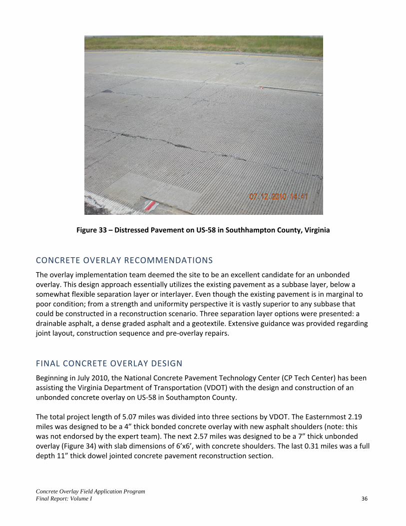
Concrete Overlay Field Application Program Final Report: Volume I 36
Figure 33 – Distressed Pavement on US-58 in Southhampton County, Virginia
CONCRETE OVERLAY RECOMMENDATIONS
The overlay implementation team deemed the site to be an excellent candidate for an unbonded overlay. This design approach essentially utilizes the existing pavement as a subbase layer, below a somewhat flexible separation layer or interlayer. Even though the existing pavement is in marginal to poor condition; from a strength and uniformity perspective it is vastly superior to any subbase that could be constructed in a reconstruction scenario. Three separation layer options were presented: a drainable asphalt, a dense graded asphalt and a geotextile. Extensive guidance was provided regarding joint layout, construction sequence and pre-overlay repairs.
FINAL CONCRETE OVERLAY DESIGN
Beginning in July 2010, the National Concrete Pavement Technology Center (CP Tech Center) has been assisting the Virginia Department of Transportation (VDOT) with the design and construction of an unbonded concrete overlay on US-58 in Southampton County. The total project length of 5.07 miles was divided into three sections by VDOT. The Easternmost 2.19 miles was designed to be a 4” thick bonded concrete overlay with new asphalt shoulders (note: this was not endorsed by the expert team). The next 2.57 miles was designed to be a 7” thick unbonded overlay (Figure 34) with slab dimensions of 6’x6’, with concrete shoulders. The last 0.31 miles was a full depth 11” thick dowel jointed concrete pavement reconstruction section.

Concrete Overlay Field Application Program Final Report: Volume I 37
Figure 34 – US-58 Unbonded Overlay Typical Section
CONCRETE OVERLAY CONSTRUCTION
A representative of the CP Tech Center was on-site for the first two days of unbonded overlay placement. Construction of the unbonded overlay segment of this project started on July 5th, 2012. Due to hot temperatures, the contractor elected to pave at night. The paving operation consisted of a central mix batch plant located approximately 2 miles west of the project. Based on the two nights of paving observed, the unbonded overlay designed and constructed by VDOT on US-58 should be considered a success.

Concrete Overlay Field Application Program Final Report: Volume I 38
NEVADA
Expert teams visited Nevada on two separate occasions to assist with the implementation of concrete overlays. The first site visit took place April 30th, 2009 when three sites on I-15 in the Las Vegas metropolitan area were reviewed. The second site visit in April of 2011, looked at multiple urban intersections in Las Vegas and then travelled to Elko, NV to review a section of I-80 in northeast Nevada.
2009 I-15, SAHARA AVE. TO SPAGHETTI BOWL INTERCHANGE
This section of I-15 in Las Vegas was originally constructed in the late 1960s and early 1970s (Figure 35). The 8” plain jointed concrete pavement has performed very well (Figure 36). There have been six widening projects from 1998 through 2007 aimed at increasing capacity to accommodate the over 250,000 vehicles per day using the facility.
Figure 35 – Approximate Location of the I-15 Sahara Ave. to Spaghetti Bowl Interchange Project

Concrete Overlay Field Application Program Final Report: Volume I 39
Figure 36 – Nevada I-15 Typical Pavement Condition Requiring Minimal Repair
The Nevada Department of Transportation desired a rehabilitation solution that would provide a 10 to 15 year life, as the location was programmed for a major rehabilitation in the future. With this in mind, the expert team offered recommendations on two alternatives. First, was concrete pavement restoration using full depth patching and other pavement preservation techniques; second was an unbonded concrete overlay. Detailed recommendations were provided for the unbonded overlay approach as well as cautionary advice. Although the field application project is aimed at increasing the use of concrete overlays, the expert teams were never hesitant to recommend alternative solutions that would be more cost effective. Ultimately, the Nevada Department of Transportation opted to not pursue a concrete overlay on this section of pavement.
2009 I-15 SOUTHBOUND, SOUTH OF LAMB BLVD. INTERCHANGE
In summary, this short section of pavement had a longitudinal crack with some vertical displacement. The expert team recommended that further coring and falling weight deflectometer testing be performed to determine the support conditions below the pavement. The team’s preliminary recommendation was full depth reconstruction of a 300’ long section of the driving lane and outside shoulder.
2009 I-15, RUSSELL RD VICINITY, APPROX. MILEPOST 36
During the site visit, the team stopped briefly at this location to observe some typical distresses in the portland cement concrete pavement. Again, the pavement had performed exceedingly well, with the

Concrete Overlay Field Application Program Final Report: Volume I 40
exception of some longitudinal fatigue cracking and minor spalling. The team recommended maintaining the joints and full depth patching where necessary.
2011 LAS VEGAS URBAN INTERSECTION PROJECTS
A site visit was conducted on March 5th, 2011 to evaluate four potential concrete overlay projects in the Las Vegas area (Table 7 and Figure 37). Table 7 – Las Vegas, NV Potential Concrete Overlay Projects Reviewed in 2011
Project Name Project Description Length (mi.)
AADT (2009)
No. of Lanes
#1. Nellis Blvd @ Desert Inn Road
Urban intersection n/a 19,000
(1% trucks) 6+
#2. Sahara Ave @ Nellis Blvd
Urban intersection n/a 14,500
(2% trucks) 6+
#3. Sahara Avenue @ Las Vegas Blvd
Urban intersection n/a 37,000
(2% trucks) 6+
#4. Lake Mead Blvd @ Las Vegas Blvd
Urban intersection n/a 25,000
(5% trucks) 6+
Figure 37 – Las Vegas, NV Approximate Location of 2011 Site Visit Reviews
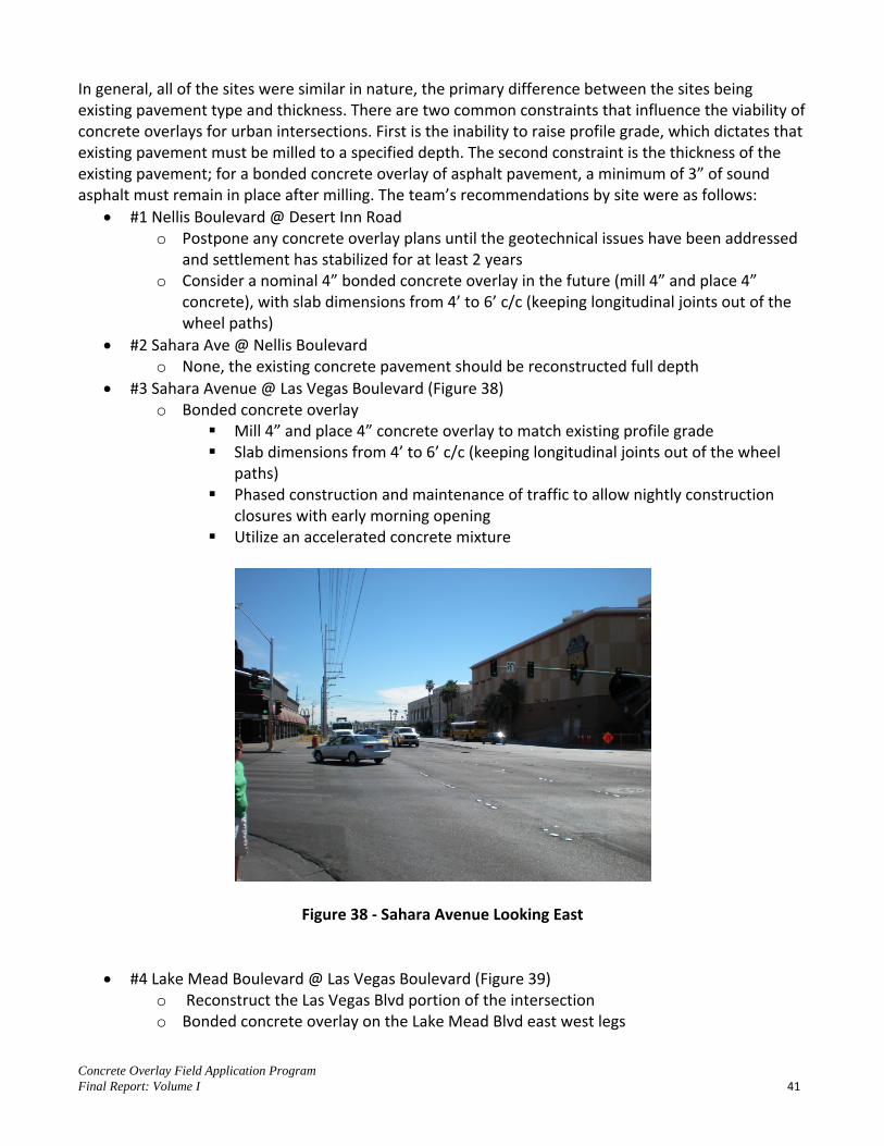
Concrete Overlay Field Application Program Final Report: Volume I 41
In general, all of the sites were similar in nature, the primary difference between the sites being existing pavement type and thickness. There are two common constraints that influence the viability of concrete overlays for urban intersections. First is the inability to raise profile grade, which dictates that existing pavement must be milled to a specified depth. The second constraint is the thickness of the existing pavement; for a bonded concrete overlay of asphalt pavement, a minimum of 3” of sound asphalt must remain in place after milling. The team’s recommendations by site were as follows:
#1 Nellis Boulevard @ Desert Inn Road o Postpone any concrete overlay plans until the geotechnical issues have been addressed
and settlement has stabilized for at least 2 years o Consider a nominal 4” bonded concrete overlay in the future (mill 4” and place 4”
concrete), with slab dimensions from 4’ to 6’ c/c (keeping longitudinal joints out of the wheel paths)
#2 Sahara Ave @ Nellis Boulevard o None, the existing concrete pavement should be reconstructed full depth
#3 Sahara Avenue @ Las Vegas Boulevard (Figure 38) o Bonded concrete overlay
Mill 4” and place 4” concrete overlay to match existing profile grade Slab dimensions from 4’ to 6’ c/c (keeping longitudinal joints out of the wheel
paths) Phased construction and maintenance of traffic to allow nightly construction
closures with early morning opening Utilize an accelerated concrete mixture
Figure 38 - Sahara Avenue Looking East
#4 Lake Mead Boulevard @ Las Vegas Boulevard (Figure 39) o Reconstruct the Las Vegas Blvd portion of the intersection o Bonded concrete overlay on the Lake Mead Blvd east west legs

Concrete Overlay Field Application Program Final Report: Volume I 42
Mill 4” and place 4” concrete overlay to match existing profile grade Slab dimensions from 4’ to 6’ c/c (keeping longitudinal joints out of the wheel
paths) Phased construction and maintenance of traffic to allow nightly construction
closures with early morning opening Utilize an accelerated concrete mixture
Figure 39 - Lake Mead Boulevard Typical Pavement Condition
2011 I-80 ELKO, NV SITE
This section of pavement is a 10” thick plain jointed concrete pavement constructed in 1991 atop the original asphalt pavement constructed in 1969. Approximately 20% of the slabs had cracking and deterioration ranging from longitudinal cracking to high severity corner cracking (Figure 40).

Concrete Overlay Field Application Program Final Report: Volume I 43
Figure 40 – Nevada, I-80 Typical Distress and Repair The expert team recommended an unbonded overlay for this rural section of I-80. Details of these recommendations are as follows:
Thickness to be determined by NDOT using AASHTO design procedures Doweled transverse joints in the travel lanes at approximately 15’ c/c, tied longitudinal
contraction/construction joints at the 4’ shoulder, centerline of mainline and at the 10’ shoulder and plain transverse joints in the tied concrete shoulders
The unbonded concrete overlay can be constructed with traffic in adjacent lanes, or traffic can be moved to one side of the median to allow full width construction
1 ½” asphalt separation layer placed after pre-overlay repairs are completed
NEVADA CONCRETE OVERLAY OUTCOMES
In total, eight locations in Nevada were reviewed by expert teams. The Nevada Department of Transportation is pursuing a bonded concrete overlay at the intersection of Sahara Boulevard and Las Vegas Boulevard. As of June, 2012, the project is in final design stages and is programmed for construction in 2013. Considering the relative lack of experience in Nevada with concrete pavements, the field application program was successful in supporting the Nevada Department of Transportation through the scoping and preliminary design of a concrete overlay.
IOWA
Even though Iowa has been a leader in constructing concrete overlays, the Iowa Department of Transportation played a significant role in the field application program. The project team drew on Iowa’s experience in designing and constructing concrete overlays to demonstrate and document the design and construction of a concrete overlay on a two lane roadway while maintaining traffic. The

Concrete Overlay Field Application Program Final Report: Volume I 44
following summary of the project is copied directly from the task report published in May 2012 and titled “Concrete Overlay Field Application Program, US 18 Concrete Overlay Construction Under Traffic: Current Process Documentation and Future Recommendations” (3). This report can be obtained from the CP Tech Center or downloaded at www.cptechcenter.org. The CP Tech Center hosted eight states at the site during construction to further the knowledge of constructing concrete overlays on two lane roadways while maintaining traffic.
US-18 CONCRETE OVERLAY SUMMARY
In 2011 Iowa DOT constructed the first unbonded PCC overlay on a two lane roadway under traffic. The traffic averaged 2,060 VPD with 18% trucks (Figure 41). The work was scheduled for an 18.82 mile section of US 18 in northeastern Iowa in the summer of 2011 (Figure 42). The existing pavement on this project consisted of an existing 1938, 1” thick PCC pavement of 18 or 20 foot in width that had been overlaid with asphaltic concrete multiple ties to form a 6 inch overlay of the original surface and asphalt or PCC widening units that formed the 24 foot wide roadway. The plans called for the removal of the surface to a depth of 0.5 inches to remove the surface treatment. The project milling was later changed to allow for a milling depth of up to 1.5 inches at centerline and a 2% cross slope to correct cross-section irregularities. This project called for widening of the existing pavement 4 feet on each side with PCC, and the placement of a 4.5 inch PCC overlay across the entire new pavement width.
Figure 41 – US 18 Unbonded Concrete Overlay Improvement
The results of this project verify that one lane PCC overlay paving under traffic is feasible. It illustrated how project operations can be scheduled to achieve the desired results in less than the 120 working days allowed.
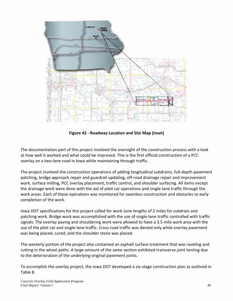
Concrete Overlay Field Application Program Final Report: Volume I 45
Figure 42 - Roadway Location and Site Map (inset)
The documentation part of this project involved the oversight of the construction process with a look at how well it worked and what could be improved. This is the first official construction of a PCC overlay on a two-lane road in Iowa while maintaining through traffic. The project involved the construction operations of adding longitudinal subdrains, full-depth pavement patching, bridge approach repair and guardrail updating, off-road drainage repair and improvement work, surface milling, PCC overlay placement, traffic control, and shoulder surfacing. All items except the drainage work were done with the aid of pilot car operations and single-lane traffic through the work areas. Each of these operations was monitored for seamless construction and obstacles to early completion of the work. Iowa DOT specifications for this project called for work zone lengths of 2 miles for subdrain and patching work. Bridge work was accomplished with the use of single-lane traffic controlled with traffic signals. The overlay paving and shouldering work were allowed to have a 3.5 mile work area with the use of the pilot car and single-lane traffic. Cross road traffic was denied only while overlay pavement was being placed, cured, and the shoulder stone was placed. The westerly portion of the project also contained an asphalt surface treatment that was raveling and rutting in the wheel paths. A large amount of the same section exhibited transverse joint tenting due to the deterioration of the underlying original pavement joints. To accomplish the overlay project, the Iowa DOT developed a six-stage construction plan as outlined in Table 8.
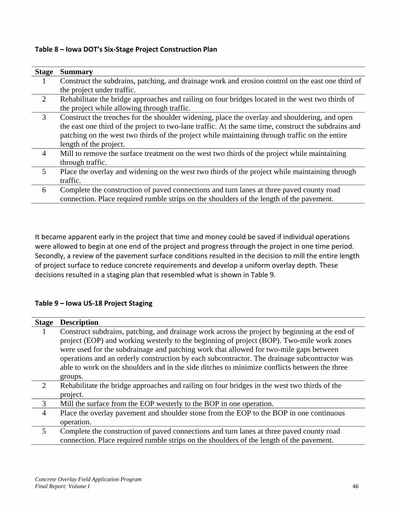
Concrete Overlay Field Application Program Final Report: Volume I 46
Table 8 – Iowa DOT’s Six-Stage Project Construction Plan
Stage Summary 1 Construct the subdrains, patching, and drainage work and erosion control on the east one third of
the project under traffic. 2 Rehabilitate the bridge approaches and railing on four bridges located in the west two thirds of
the project while allowing through traffic. 3 Construct the trenches for the shoulder widening, place the overlay and shouldering, and open
the east one third of the project to two-lane traffic. At the same time, construct the subdrains and patching on the west two thirds of the project while maintaining through traffic on the entire length of the project.
4 Mill to remove the surface treatment on the west two thirds of the project while maintaining through traffic.
5 Place the overlay and widening on the west two thirds of the project while maintaining through traffic.
6 Complete the construction of paved connections and turn lanes at three paved county road connection. Place required rumble strips on the shoulders of the length of the pavement.
It became apparent early in the project that time and money could be saved if individual operations were allowed to begin at one end of the project and progress through the project in one time period. Secondly, a review of the pavement surface conditions resulted in the decision to mill the entire length of project surface to reduce concrete requirements and develop a uniform overlay depth. These decisions resulted in a staging plan that resembled what is shown in Table 9. Table 9 – Iowa US-18 Project Staging Stage Description
1 Construct subdrains, patching, and drainage work across the project by beginning at the end of project (EOP) and working westerly to the beginning of project (BOP). Two-mile work zones were used for the subdrainage and patching work that allowed for two-mile gaps between operations and an orderly construction by each subcontractor. The drainage subcontractor was able to work on the shoulders and in the side ditches to minimize conflicts between the three groups.
2 Rehabilitate the bridge approaches and railing on four bridges in the west two thirds of the project.
3 Mill the surface from the EOP westerly to the BOP in one operation. 4 Place the overlay pavement and shoulder stone from the EOP to the BOP in one continuous
operation. 5 Complete the construction of paved connections and turn lanes at three paved county road
connection. Place required rumble strips on the shoulders of the length of the pavement.

Concrete Overlay Field Application Program Final Report: Volume I 47
Future staging plans are recommended by the highway owner with the allowance for consideration of contractor plans that can meet the agency goals while saving time and money for all. The project included the installation of some 48,422 feet of longitudinal subdrain along the edge of the existing pavement at 113 locations in the west two thirds of the project. At the same time, the project called for 641 full-depth patches along 13 of the 18.82 miles of project. These two operations identified the reason for operations to work from the EOP to the BOP. Both the subdrain and patching work could follow each other with only minor conflicting times and locations. Longitudinal joint patching of the joint between the original pavement and the existing widening units could be eliminated if the existing widening is milled to all for a single widening unit of uniform depth for the new pavement. Bridge rehabilitation and guardrail upgrades proved to be a key item in the overall scheduling of the project. The work included the replacement of bridge approach slabs and the notches on the back of the abutments. This is a time-consuming and labor-intensive item of work. Work zones for this work can conflict with those for the other items of work previously discussed. Recommendations for improvement include placement of the pavement with a slipform paver and longer work site delineation to allow for both ends of the bridge in one lane to be placed at once. Bridge approach slabs and transition slabs (transition in elevation from the existing pavement to the top of the new overlay) form a natural length of pavement that can be done with conventional paving equipment. The result is more efficient and smoother transitions between the overlay and the bridge elevations. These sections of pavement can be built the season or months before the overlay is to be constructed. A simple asphaltic concrete wedge at the end of the transitions allows them to be used until the overlay reaches this point in the project. Highway agencies and contractors are interested in managing the amount of concrete required for the overlay. Milling of the entire asphaltic concrete surface to a uniform longitudinal profile and transverse slope helps reduce the risk of concrete overruns and improves the uniformity of the overlay depth. Milling depths must not reduce the structure of the existing pavement beyond that required by the overlay designer. Milling the existing widening unit to a depth of the new widening unit reduces the number of longitudinal joints in this area from two to one. The milling on this project was conducted with control from total robotic stations (stringless milling) from a computer model of the longitudinal centerline profile and given 2% cross slope on the final overlay surface. The same model and equipment guided the slipform paver on this project. Concrete quantity overrun was reduced from 126% on the plans to 104% in actual placement. The reduction was the result of a project developed computer surface model based on a 9 shot cross section at 50 foot intervals along the existing surface prior to milling. Paving and traffic control plans for this project allowed the contractor to place up to 3.5 miles of single-lane pavement and then stop paving until this section reached opening strength, was shouldered, and traffic striping was applied. This proved to require 7.5 days to complete the work in the first lane and prepare the second lane for paving.

Concrete Overlay Field Application Program Final Report: Volume I 48
At the end of that time, the paving operation backed up to the beginning of the work and placed the second lane for a distance of 3.5 miles. Paving stopped at this point to wait for pavement cure time, shouldering, and traffic stripping. Concrete placement could then proceed 3.5 miles in the second lane and repeat the process. This process proved to be very time-consuming and costly for the paving crew. Decisions were made to open a second paving work area near the middle of the project and operate two paving areas at the same time. In this way, the paving crew is working approximately 6 out of 7 days a week. Current equipment design allows the contractor to move the paving spread from one site to the other in less than one day. The addition of the stringless paving equipment and model allows the contractor to make these moves quickly without limitations of stringline placement and removal. Traffic control was a major issue in the design of this project. The intent was to allow for through traffic at all times with the use of minimal delays and pilot car operations 24 hours a day and 7 days a week (24/7). The system on this project included manual traffic controls and flaggers at each end of the work zone. The addition of the flaggers was a very effective deterrent to impatient drivers. Side roads were blocked during the actual paving operations until the opening concrete strength was reached. The overlay was cured with conventional “white pigmented” spray on cure. This was placed immediately behind the finishing operations. Some six early entry saws were employed on the project simultaneously. Four were used to cut transverse joints on 4.5 or 5 foot intervals (based on underlying pavement dimensions) and two were used to cut the longitudinal joints. Longitudinal joints were placed at the middle of the original PCC slab (4.5 or 5 feet) from centerline, and the second joint was placed at the edge of the original pavement (9 or 10 feet) from centerline. Joints were also cut around full-depth patches on this project, due to the fact that the patch was not dowelled into the surrounding pavement, but allowed to move up and down. Future projects will require some additional traffic considerations at paved local road connections. Designers are encouraged to look at inlay versus overlay alternatives at these locations to minimize construction and delay time to cross traffic. The use of the stringless technology also aided in the paving process. It provided the way to achieve accurate placement of the concrete quantity to profile and cross slope. Removal of the centerline stringline allowed for two-way construction traffic and a single lane of the through traffic and pilot car on the shoulder/edge of pavement simultaneously. Timely delivery of concrete to the ends of the project would have been very difficult without this control system. The results of this project verify that one-lane PCC overlay paving under traffic is feasible. It illustrated how project sub-operations can be scheduled to achieve the desired results in less than the 120 working days allowed.

Concrete Overlay Field Application Program Final Report: Volume I 49
This report contains 71 recommendations from the design through construction on how to improve future projects of this type. Work is also ongoing with the design team of the Iowa DOT to streamline overlay plans to reduce the design time for these types of projects. Single-lane PCC overlays being built under traffic are now a reality in Iowa. The process provides a valuable option to the pavement rehabilitation strategies available for use.
WYOMING
The CP Tech Center was co-sponsor of a national open house highlighting the design and construction of a bonded concrete overlay on US-30 near Kemmerer, WY on July 19, 2012. Representatives from the field application program gave presentations at the open house and answered questions regarding concrete overlays. Attendance at the open house included 54 people from 12 states. This project involves approximately nine miles of pavement rehabilitation on US-30 located north of Cokeville, Wyoming. The purpose of this project is to rehabilitate the surface, which currently has an average surface roughness of 95 inches/mile and an average rut depth of 0.2 inches (Figure 43). There are several areas with a surface roughness exceeding 150 inches/mile and an average rut depth greater than 0.3 inches. The goal is to provide a smooth, durable surface for users of this highway. The existing HMA surfacing is very thick and was milled 3.5” to accommodate the concrete overlay. The bonded concrete overlay will be integral with the underlying HMA structure. The existing HMA surface of this highway carries approximately 2,000 vehicles per day with heavy truck traffic (900± trucks per day). The pavement rehabilitation is designed as a 6” thick bonded concrete overlay of a full depth asphalt pavement (See Figure 44) and construction of at one lane at a time with a 24 hour per day pilot car operation. The jointing pattern is 6’ x 6’ panels with longitudinal tie-bars.
Figure 43 – Wyoming US-30 Existing Roadway Condition

Concrete Overlay Field Application Program Final Report: Volume I 50
Figure 44 – US 30 Typical Section Mainline
KANSAS
A 6” thick concrete overlay on Interstate 70 in Central Kansas attracted approximately 90 engineers and transportation officials from eight states on September 29th. The attendees were given presentations from the Concrete Pavement Technology Center, Kansas Department of Transportation, Koss Construction Company, and a dynamic question and answer period. The group then traveled to a section of the completed pavement to “inspect” the 6” x 6’ x 6’ concrete panels. The existing 1964 pavement consisted of a 17.5” HMA with 8.7” thick HMA built up of overlays over the many years. The cross-section was 6’ inside HMA shoulder, 24’ HMA pavement and 10’ outside HMA shoulders. The existing pavement was milled 6” and a 6” concrete overlay with 6’x6’ panels was constructed. Upon completion in 2012, the four overlay projects will total approximately 1.5 million square yards and result in 30 miles of continuous concrete overlay in each direction. The DOT chose to overlay with concrete pavement after the previous 3 asphalt overlays averaged 5 to 7 years of service each. The concrete overlay promises an economical long lasting durable pavement that will serve the travelling public for decades to come.

Concrete Overlay Field Application Program Final Report: Volume I 51
Figure 45 – Open House Participants Viewing I-70 Overlay
Figure 46 – Kansas, I-70 Bonded Overlay Construction
CONCRETE OVERLAY DOCUMENTS
During the course of the field application program, the project team identified areas of repetitive questions that dictated the need for supporting documents that would clarify repetitive issues. Three documents of note were produced. A summary of these work products is as follows:

Concrete Overlay Field Application Program Final Report: Volume I 52
Concrete Overlay Cost: Frequently Asked Questions – A four page tech brief providing information related to the construction cost of concrete overlays (see Volume 2 for a full text copy)
Concrete Overlay Field Application Program Chief Engineer Packet – A sixteen page summary of the field application program designed for upper management of state transportation agencies; presents the objectives of the program and provides examples of successful concrete overlays (see Volume 2 for a full text copy)
Concrete Overlay Field Application Program Engineer Packet – A thirty-two page summary of the field application program designed for middle managers at state transportation agencies; builds on the information in the Chief Engineer packet and provides highlights of design details such as quantity estimates, plan development and construction sequence/maintenance of traffic (see Volume 2 for a full text copy).

Concrete Overlay Field Application Program Final Report: Volume I 53
Throughout the duration of the concrete overlay field application program the project team encountered some recurring issues that need continued efforts to either resolve or move concrete overlay technology forward.
GEOTEXTILE SEPARATION LAYER
There have been numerous jobs in the US that have utilized a geotextile separation layer for unbonded concrete overlays (Figure 47). To date, these projects have performed well. The expert teams discussed whether to recommend a geotextile separation layer for unbonded overlay candidates, but in the end primarily recommended an asphalt separation layer. These recommendations were principally a matter of trying not to introduce too many “new” things to agencies that were just beginning to design and construct concrete overlays.
Figure 47 – Geotextile Separation Layer Used in Missouri
Geotextile separation layers offer advantages over conventional asphalt separation layers, specifically lower cost and higher production rates. But, there are some questions that need to be answered more fully before geotextiles can be considered as the default preferred solution for unbonded concrete overlays. First is the question of the geotextile’s drainage characteristics and how to remove any water that may saturate the geotextile. For open ditch roadways, this is as simple as “daylighting” the
3. OPPORTUNITIES AND BARRIERS

Concrete Overlay Field Application Program Final Report: Volume I 54
geotextile. This is more complicated for urban projects where the geotextile should be extended into storm sewer inlets (Figure 48). Also of concern is the potential for slab movement which can create unwanted noise. There has been at least one project that utilized a geotextile separation layer for a 4” unbonded overlay in an urban area where this occurred. No conclusive study was done to determine the root cause of the noise; however it is hypothesized that during cooler times of the day when the joints were open, slabs were “knocking” into each other and the noise was resonating through the slabs. It is encouraging to note that the noise abated over time, but extremely important that a root cause and solution be identified to confidently use geotextile separation layers for thin (4” or less) unbonded concrete overlays.
THICKNESS DESIGN
Over the years, concrete overlay design procedures have been developed by a number of agencies, including the American Association of State Highway and Transportation Officials (AASHTO), the National Cooperative Highway Research Program (NCHRP), the Portland Cement Association (PCA), the American Concrete Pavement Association (ACPA), and various state departments of transportation (DOTs). Each method addresses different types of concrete overlays and involves different inputs, software, strengths, and deficiencies. Recognizing that there needed to be clarification regarding the applicability of the numerous design procedures, the CP Tech Center developed two products concurrent with the concrete overlay field application program. Entitled “Design of Concrete Overlays Using Existing Methodologies”, a Tech Summary was released in 2011 as an overview and documentation of preliminary tasks. This document is available for download at: http://www.cptechcenter.org/publications/overlay_design_TS_Jul2011.pdf. The full guide is scheduled to be published in the fall of 2012 and should be available at: http://www.cptechcenter.org.
MILLING
The project team recognized early in the process of assisting states with the implementation of concrete overlays that milling the existing pavement was a critical factor in many concrete overlay applications. It is important for designers and constructors to understand the potential problems and the potential benefits associated with milling.
POTENTIAL DELAMINATION OF EXISTING ASPHALT LAYERS
When bonded overlays of asphalt or composite pavements are designed and constructed, it is often desirable to mill the existing pavement to reduce the change in profile grade and to enhance the bond. One issue that continues to occur is the delamination of a partial lift of asphalt after milling. Because of construction variability, it is impractical to think that the existing pavement can be milled exactly to a lift line. Therefore, the milled surface should be exposed to construction traffic to identify weak areas

Concrete Overlay Field Application Program Final Report: Volume I 55
which may inhibit bonding of the concrete overlay. These weak areas must be removed down to a sound surface for bonding before placement of the concrete overlay.
MILLING EXISTING CONCRETE
Further efforts need to be made to demonstrate the techniques and effectiveness of milling existing concrete. Many opportunities exist for milling partially deteriorated concrete and applying either an unbonded or bonded concrete overlay. A prime example of this application was constructed in the Detroit, MI area in 2011 (Figure 48 and 49).
Figure 48 – Milling Concrete Prior to Placing a 4” Thick Unbonded Concrete Overlay
Figure 49 – Placing the 4” Thick Unbonded Concrete Overlay (existing concrete was milled and a
geotextile separation layer used)
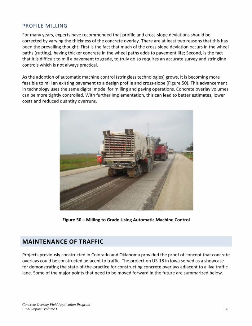
Concrete Overlay Field Application Program Final Report: Volume I 56
PROFILE MILLING
For many years, experts have recommended that profile and cross-slope deviations should be corrected by varying the thickness of the concrete overlay. There are at least two reasons that this has been the prevailing thought: First is the fact that much of the cross-slope deviation occurs in the wheel paths (rutting), having thicker concrete in the wheel paths adds to pavement life; Second, is the fact that it is difficult to mill a pavement to grade, to truly do so requires an accurate survey and stringline controls which is not always practical. As the adoption of automatic machine control (stringless technologies) grows, it is becoming more feasible to mill an existing pavement to a design profile and cross-slope (Figure 50). This advancement in technology uses the same digital model for milling and paving operations. Concrete overlay volumes can be more tightly controlled. With further implementation, this can lead to better estimates, lower costs and reduced quantity overruns.
Figure 50 – Milling to Grade Using Automatic Machine Control
MAINTENANCE OF TRAFFIC
Projects previously constructed in Colorado and Oklahoma provided the proof of concept that concrete overlays could be constructed adjacent to traffic. The project on US-18 in Iowa served as a showcase for demonstrating the state-of-the-practice for constructing concrete overlays adjacent to a live traffic lane. Some of the major points that need to be moved forward in the future are summarized below.

Concrete Overlay Field Application Program Final Report: Volume I 57
STRINGLESS CONSTRUCTION
From milling to paving, stringless construction technologies decrease the width of roadway needed for construction equipment. This can often eliminate the need for detour widening. The maintenance of traffic plans for future concrete overlay projects should be designed around clearances that are standard for stringless construction. This is not meant as a means to force contractors to purchase automatic machine controls, alternative methods are available (detour widening, sensor ski(s), etc.), but should encourage the continued adoption of stringless technologies for concrete paving.
SAFETY EDGE
The US-18 project constructed in Iowa required a temporary safety edge during one way traffic operations (Figure 51). Observations made on the project deemed the cost and time associated with construction and removal of the safety wedge to be inconsistent with the perceived safety benefits. In no way does the project team advocate compromising safety, however there appears to be non-uniform interpretation of the edge drop-off requirements set by the Federal Highway Administration. There is a need for clarification on the requirements for providing a temporary safety edge.
Figure 51 – Iowa US-18, Construction of the Temporary Safety Edge
INNOVATIVE APPROACHES
Accelerated construction techniques such as lane rental, A+B and incentive/disincentive provisions should always be considered in conjunction with concrete overlays. These may not be appropriate for the first few projects designed and constructed by a STA, but can be effective once the industry has experience with constructing concrete overlays. Future efforts should demonstrate accelerated construction of concrete overlays.

Concrete Overlay Field Application Program Final Report: Volume I 58
1. McGhee, Kenneth, Portland Cement Concrete Resurfacing, National Cooperative Highway
Research Program, Synthesis 204, 1994. 2. Harrington, Dale, et al., Guide to Concrete Overlays, Second Edition, National Concrete
Pavement Technology Center, Iowa State University, 2008. 3. Cable, James, “Concrete Overlay Field Application Program, US 18 Concrete Overlay
Construction Under Traffic: Current Process Documentation and Future Recommendations”, National Concrete Pavement Technology Center, Iowa State University, 2012.
REFERENCES

Concrete Overlay Field Application Program Final Report: Volume I A-1
Technical Working Group (TWG) Meeting Minutes
May 18, 2009 – States Attended: Delaware Louisiana Maryland Nevada Pennsylvania South Dakota Texas Washington West Virginia October 14, 2009 – States Attended: Louisiana Nevada North Dakota Pennsylvania Washington April 22, 2010 – States Attended: Delaware Georgia Louisiana Maryland Nebraska Nevada New Mexico North Carolina North Dakota Pennsylvania Texas Virginia Washington West Virginia
January 20, 2011 – States Attended: Arkansas Colorado/Wyoming Delaware Georgia Illinois Louisiana Maryland Nebraska Nevada New Mexico Pennsylvania South Dakota Virginia July 23, 2012 – States Attended: Delaware Georgia Minnesota Nebraska New Mexico Pennsylvania South Dakota Washington West Virginia
APPENDIX: TECHNICAL WORKING GROUP MINUTES

Concrete Overlay Field Application Program Final Report: Volume I A-2
Technical Working Group for Concrete Overlays Conference Call
Meeting Minutes May 18, 2009
Attendees: James Papas, Simone Ardoin, Geoff Hall, Larry Engbrecht, Brian Rieck , Darin Hodges, Greg Fuller, Mark Snyder, Bill Miller, Mike Griswold, Bob Long, Gina Ahlstrom, Suneel Vanikar, Dan Dawood, Rob Rasmussen, Jeff Uhlmeyer, Peggy Armstrong, Denny Alderson, Mike Mance, Aaron Gillespie, Parviz Noori, Moon Won, Dale Harrington Dale Harrington stated the purpose of the call is to discuss the Concrete Overlay Field Application Program, how we can assist each state more and to talk about what the states would like to accomplish. He mentioned the program goal is to advance concrete overlay technology throughout the country. In the last 12 months the expert team has visited 11 states and they have submitted implementation site visit reports to all states except for Nevada which is currently being prepared. Dale asked the group if the reports were useful and if they needed to include more information. The states’ representatives stated the reports were fine. Dale stated that they expert team needed to follow-up with the states to let them know who to call to help walk them through the next phase. Dale asked the states if they would like the expert team leaders to contact them individual on a routine basis to see if they needed assistance. Each state provided the following comments. Pennsylvania Bill Miller stated they would like to talk to someone about specifications and they are moving ahead with their project which should bid in mid July 2009 and they will put in the request for the Federal funding money. He said they need technical advice on their project. Bill stated they will contact Gary Fick to get his input on the plans and specifications. They would like the expert team at the pre-bid and pre-construction meetings. Maryland Geoff Hall stated the implementation site visit report was good but it didn’t add any new information that they didn’t already know. He stated they need help with specific details and specifications. Geoff Hall stated their project is on hold due to funding issues. He said they would like to have the expert team review the specs or special provisions once they get funding again. He stated they are not sure when they will have the funding available. West Virginia Peggy Armstrong said they have been given wonderful feedback by the team, concrete association and FHWA. She said they had selected a project and they are in the process of gathering data and doing testing. They have been given notice to proceed and have the paperwork in for the funding. She said they aren’t sure when the project will be built. Delaware Jim Pappas stated that on May 28th they will be taking bids on their project and construction should start sometime in July. Prior to the pre-construction meeting they will have a pre-pour meeting that they would like the expert team to attend. He said they would contact Gary Fick to ask him to attend

Concrete Overlay Field Application Program Final Report: Volume I A-3
the pre-pour meeting and a time during construction. He asked the team to send them a listing of items that should be included in the pre-pour meeting. Louisiana Simone Ardoin stated their project is on hold due to funding limitations. It may be a year or two out if the funding is available at that time. She stated they may want to switch projects for funding once they are able to start and if that happens she would contact Rob Rasmussen for his assistance. She said they have two good candidates for an overlay and once the project starts up they will contact the Rob. Nevada Parviz Noori felt it would be useful to have the expert team attend the preconstruction meeting and during construction. He said the field trip was very good. He stated they are waiting for the site visit report and once they receive the expert team’s recommendations he will discuss them with the Nevada District engineer and other staff to decide how they will proceed. He stated they would like the ACTP training and that they have requested it from Sam Tyson and Shiraz Tayabji. Washington Jeff Uhlmeyer felt it would be useful to have the expert team at the pre-pour meeting and during construction. He stated their project did not make it on the stimulus list. When funding is available they will contact the expert team as they provided very good input. He will contact Rob Rasmussen when they need assistance. South Dakota Larry Engbrecht stated their project has been let to contract and construction should begin the end of July or the first part of August. He said the project was not very difficult however they would like the expert team to attend a day before the pour, during the pour and during the sawing. New Mexico Rob Rasmussen stated he would contact New Mexico to see if they needed any assistance. Texas Won Moon stated the construction on their project has been postponed until next fiscal year. He said it should be let in October or November 2009 and that the design has not been completed yet however it is almost finished. He briefly explained the Texas project and stated they wanted something that would have little or no maintenance. The project involves putting CRCP over plain jointed concrete pavement. Dale asked the group if the expert team was accomplishing what they want on the field trips. Dale said the site trips allows the expert team members to meet the state staff and helps with developing relationships and gaining knowledge of their roadway system. It allows the expert team to assist with the process of how to accomplish the goals of their project. Dale stated that FHWA would like to provide training on overlays through the ACTP. He asked the group if the states that have already received the training felt it was helpful and did they feel that they

Concrete Overlay Field Application Program Final Report: Volume I A-4
needed more training? Larry Engbrecht (South Dakota) felt the training was very good but did not feel they needed more at this time. Bill Miller (Pennsylvania) stated the training was good and that they would need help with the design phase of their project. Dale felt that design is probably the biggest task that people face at this point and that the expert team would assist states with their design. He stated that the expert team could not take on the liability of the design but they could help walk them through the design phase. Bob Long (ACPA mid-Atlantic states) stated that the mid-Atlantic states are looking for help with additional training. They also need assistance with the design and construction specifications. Simone Ardoin (Louisiana) stated they do not have the money to do the project at this time. If the team calls on a regular basis she wouldn’t have anything to add at this point. The group agreed that it would be best for the states to contact their expert team leader when they needed assistance. Dale stated the team leaders are Rob Rasmussen and Gary Fick. Dale asked the group if they would like the expert team to attend the pre-bid or preconstruction meeting with them. He stated they would contact the team leader and would like them during the construction phase also. They would like the overlay team to send them a listing of items that should be included in the meetings. Dale encouraged the states to contact the team leaders when they need their input. Dale stated he would send an email to the states on contacting the team leaders. Dale asked the group if they needed the Mobile lab. Larry Engbrecht (South Dakota) stated they would not need the mobile lab. Jim Pappas (Delaware) asked what are the capabilities of the mobile lab? Dale stated he would send the capabilities of the specific tests to the states representatives and then they could decide if they need the service. Dale asked the group if they had any general questions on funding. Gina Ahlstrom (FHWA) stated that the end of this fiscal year which is October 1st is the cutoff for the funds. She stated if there are states interested they need to contact FHWA right away to get the process going. Gina told the group that the deadline for getting the funding memo into FHWA is July 2009. Gina stated she would look into the Louisiana and Maryland situation and would let them and Dale know. Gina explained to the group that FHWA provides a sample work plan to the states so they can develop their work plan. It should include the contract number and project limits. They should send it to their local district FHWA representative to request the additional funding and once that it is approved the local FHWA representative will send it to FHWA headquarters for review and processing. Dale stated that California, Maine, Nebraska, and Georgia have all shown interest in the overlays however due to funding issues they are not moving forward at this point. Dale asked the group what information they would you like for exchange of information between the states? Simone Ardoin (Louisiana) stated they would like to see the description of the project, what they are doing and the cost associated with the project. Geoff Hall (Maryland) stated he would like to know what to do and what not to do on project from past experiences from the expert team. South Dakota would like to know what other states are doing on their overlay. All they need is a short description, nothing too detailed and if they need more information they could contact the state. Dale stated to the group that he would develop a 1 – 1 ½ page form on project information and send it out to the TWG for them to complete.

Concrete Overlay Field Application Program Final Report: Volume I A-5
Rob Rasmussen and Gina Ahlstrom stated to the group to contact them if they need any further information. Dale thanked the group for attending the call. The next call will be set for the latter part of July 2009.

Concrete Overlay Field Application Program Final Report: Volume I A-6
Technical Working Group for Concrete Overlays Conference Call
Meeting Minutes October 14, 2009
Attendees: Gary Fick, John Becker, Rob Rasmussen, Sabrina Garber, Doug Schwartz, Simone Ardoin (LA), Lita Petticord (PA), Clayton Schumaker (ND), Bob Long, Charlie Penn, Anthony Sarham (WA), Sam Tyson, Parviz Noori (NV) 1. Status of Your Overlay Projects
Delaware – To pave early to mid November; pre-pour meeting to be held on October 26th ; mobile lab will be there during paving to document and test. Pennsylvania – Currently on a hold; paving next spring. Dale stated CP Tech Center has a program that is looking for demo projects for concrete overlays and they would like Pennsylvania to be considered. They would use their overlay project for an open house for other states to observe the construction. John Becker will talk with the DOT District Office and the contractor to discuss having the Pennsylvania project as an open house. Louisiana – next two years there are no overlay projects. The earlier proposed Interstate project will now be rubblized and an HMA surface placed. The other project was repaired for now but will need to be looked at later. New Mexico – No funding available; no longer on their list. However, Don Clem will be meeting with New Mexico to try to renew their interest. North Dakota – The Hwy 200 concrete overlay project which is north of Hillsborough is being strongly considered, however the decision has not been made to proceed. South Dakota – The overlay construction was in August; mobile lab was on site. Successful project although it had some dowel problems. It was a 7 inch unbonded overlay over concrete; issue was too thin of an interlayer, which caused dowel basket fastening problems. Also the concrete pile in front of the paver was too high. Solution was reached by reducing the pile, and cutting the baskets out that did not have dowels. Also increased the number of fasteners. Gary Fick stated he should have the final report in the next two weeks. Gary explained to the group what issues the project encountered with the dowel bars. Washington – still interested in moving forward. No funding this year; on hold until 2010. Nevada – No progress – does not appear they will be moving forward. Parviz Noori suggested talking to Mohamed Ross (District Engineer) to discuss options. Dale will contact Anita Bush of Nevada DOT for an overlay on highway in Las Vegas.

Concrete Overlay Field Application Program Final Report: Volume I A-7
West Virginia – Funding has not been secured to move forward with the project between now and July 1, 2010. Not cancelled but have work to do to secure funding. All the testing has been done. Need photos of the cores and those will be sent to Gary Fick. Texas – No new information; Rob Rasmussen will follow-up with Texas. Maryland – no funding available for the project and the overlay project has been put on indefinite hold.
2. Overlay Research & Tech Transfer
Minnesota is doing some research at MnRoads; 1 year, old 5” overlay constructed as an unbonded overlay. Determining maximum length for spacing on transverse joints verses the thickness of the overlay. Experienced cracks at the corners because of curling and warping for overlays 5” thick with 15’ transverse joint spacing. Going up to 6 inches have some cracks but a lot fewer for the 15’joint spacing. Dale said the overlay manual uses a lot similar panels for these thicknesses, which confirms the manual. Held an Open house west of Duluth; 5 in overlay; 12 x 12 panels with an interlayer; 9 miles long. They have several projects they are testing for cracking with the panel lengths. Iowa had 4 projects – one was an open house on US65 – stringless paving project. The project went well with GPS; looking at evaluation of the fabric bonding breakers; different methods for traffic control; opening strength with maturity data with sawing. If they want more information we can send it to the TWG when the report comes out.
3. Future Approach to the Field Application Program
We have had initial good responses from states but lately but have had disappointments because of funding cutbacks. Looking at other ways to move the program forward. CP Tech Center and FHWA held conference call to discuss options. We need to meet with upper management in DOTs to help move projects along and educate
them on choices. Will be evaluating other items to encourage considerations of overlays and educate them on
options. One idea from the NC2 meeting was to develop a video of an overlay project which was 10
years old. Getting videos from other states to show what concrete overlays can do. Simone suggested doing regional overlays and getting the surrounding states involved. Once
they have successes the program will grow. Dale stated they will contact California, New York and Indiana to try to meet with their Chief
Engineers to discuss concrete overlays and the program benefits. Committee felt it was a good idea to get senior management support and to develop videos. Need to get bid tabs from states that have done overlays to show the cost differences between
concrete and HMA. Missouri is a state that may have the bid tab information. Need to have good specifications available for overlay projects; the Guide only has items to
consider. Will send specifications from Iowa, Oklahoma, Colorado, Minnesota and put them on a CD for states to review.

Concrete Overlay Field Application Program Final Report: Volume I A-8
Dale stated the project has been funded by FHWA to continue with the program up to July 2011. They will continue to contact states and meet with them to consider concrete overlays.

Concrete Overlay Field Application Program Final Report: Volume I A-9
4. Troubleshooting for Overlays Dale Harrington and Julie Vanderbrosse, with the help of several others from across the country, developed a 90 minute presentation on troubleshooting based which was presented on the ACPA webinar. CP Tech Center would like to develop the presentation into four modules for training on demand web-based training. The presentation covers evaluation, design and construction of overlays. The committee felt “troubleshooting” as a title was misleading. Suggested a new title but have troubleshooting as a segment title.
5. The Overlay Design Project
Rob Rasmussen summarized the Overlay Design project. FHWA funded the development of an overlay guide for design. It will work along with other existing guides. Give step by step guidance with specific examples. They are just getting started on the project and should have it done in 12 months; however they may have some results by spring 2010.
Concrete Overlay Field Application Program Final Report: Volume I A-10
Technical Working Group for Concrete Overlays Field Application Program
Conference Call Meeting Minutes
April 22, 2010
Attendees: Bill Cook, Judith Corley-Lay (NC), James Pappas (DE), Andy Babish (VA), Andy Dearmont (NE), David Jarvis (PA), Helga Torres (Transtec), Rob Rasmussen (Transtec), Gina Ahlstrom (FHWA), Jerry Reece (NC), Marion Banks (GA), AJ Jabron (GA), Georgene Geary (GA); Jeff Mann (NM), Lydia Peddicord (PA), Hua Chen (TX); Mike Mance (WV), Sam Tyson (FHWA), Don Clem (NW), Jeff Uhlmeyer (WA), Simone Ardoin (LA), Jeff Hall (MD), Craig Hennings, Dave Sethre (ND), Clayton Schumaker (ND), Parviz Noori (NV), Bob Long Dale Harrington opened the conference call and stated there are three sets of documents that would be coming out in the near future. They are as follows:
1. Concrete Overlay Field Application Program – Cost Tech Brief – Draft was sent to the TWG Dale explained it is a draft and is currently under review. Steve Trisch provided comments on Figure 6 which are being considered. He told the group to not use it as a final document as it is a draft. Simone Ardoin thought it would be good for comparing costs. Dale asked the group to provide him with any questions or comments and before the tech brief is published their comments will be considered for the final document. Bob Long felt the tech brief had very good information and will help with questions that come up during overlay projects.
2. Guide for Overlay Design Methodology Dale explained when designing overlays there is a need to have a document that summaries some of the 5 or 6 existing software programs which explain the strength and weaknesses of each program. Also there is a need to provide design examples of recommended existing programs for each type of overlay. The proposed guide will address these needs. Helga Torres (Transtec) explained to the group that the Design Guide will provide simple straightforward guidance for overlay design of existing software programs. Helga stated an outline for the Guide has been developed and reviewed by the ETG and a tech bulletin was prepared and is also being reviewed by the ETG. Examples of difficult cases to follow are currently being prepared for the Guide. The Tech Bulletin is currently being reviewed and is 13 pages in length. It gives a good summary of the overlay programs and some of their nuisances. The Tech Bulletin was prepared first to quickly get information out to the public and then the Design Guide will be developed with more in-depth information. The group felt the Guide and Tech Bulletin would be very helpful.
3. Overlay Packet for the Concrete Overlay Field Application Program Dale explained this is a packet which is a supplement from the overlay manual and is a response to questions from the different states that have had field visits. The packet describes the concrete overlay program, some of the benefits, types of overlays and includes costs for overlays from the tech brief. The packet will be developed in three different versions; the first

Concrete Overlay Field Application Program Final Report: Volume I A-11
level is for upper management DOT personnel to help explain concrete overlays to them including costs and elements pertaining to quantity estimates such as how to deal with overruns. The Second level of the packet is for practicing engineers and will also include cost information, quantity, plan development and engineering survey for overlays. The third level is for contractors who construct the overlay and will contain all the information in the first and second levels plus an example field application report including the test runs that have been done by the mobile lab. These tests are not for pay items, but are for information to help other states. The Overlay Packet should be available within the next 5-6 weeks. Every state will receive all three levels of packet. Dale stated we can also provide electronic copies if of the packet. The group felt it would be very useful information.
Simone Ardoin (Louisiana) stated at the Concrete Pavement Preservation conference last week they talked about the greenhouse gases and carbon output pertaining to concrete and the reports were not good. She suggested we look into these reports to see how to improve concrete and sustainability. One of the reports was done by the National Pavement Preservation Center with Craftco. Craig Hennings stated he was at the conference and heard some of the Colas company report. Craig suggested we add a section to the overlay information that talks about life cycle costs verses constant repair of the mill and fill of flexible pavement. He stated that long life over the life of the project gives a lower carbon footprint per year. This will demonstrate it is a sustainable technology. Dale stated he will look at the information that was presented at the National Pavement Preservation Center speeches and will ask the sustainable group from the CP Tech Center to look at this information. Georgene Geary (Georgia) stated they may have some of these reports at the sustainable conference being held this fall. It was stated that the operational phase of concrete has the most benefit for sustainability. One of HMA’s biggest problems is user (operational) costs and environmental impact from the wheel resistance of the softer surface as compared to PCC.
State Updates: Delaware – Project completed last fall and it is performing well. Dale stated the final report will be sent to Delaware DOT shortly. Bob Long stated they had an outstanding open house; the construction went great with the assistance of Gary Fick from CP Tech Center. The open houses are a great opportunity for people to learn and see what is going on in the field. Indiana – Tom Cackler met with DOT in March. The Overlay Field Application team is in the process of working with Indiana DOT to set up a field review of candidate projects. New Mexico – had a field review last year. They are trying to sell overlays to their districts however they need funding to proceed. North Dakota – The Hwy 200 north of Hillsboro project has been selected and is in the design process. It is scheduled for 2011 construction depending on funding for letting date.

Concrete Overlay Field Application Program Final Report: Volume I A-12
Pennsylvania – project underway, milling off old pavement in preparation for the overlay. An open house is planned for the later part of May or June 2010. They will get the date to Dale so a flyer can be prepared for the open house. South Dakota – the project is complete and was a good project. The final comprehensive overlay report including South Dakota’s report, will be sent to SD DOT. Washington – US 395 project – funding not available. They may go to HMA as it needs something done soon. They are still considering options for overlays however they need funding. Cost information not needed yet as they need funds for the project. Nevada – No project currently as the I-15 project was not suitable for an overlay. Nevada DOT has not heard anything on the intersection projects however they will check and let Dale know the status. West Virginia – Nothing has changes in status since last time. All data collected but because of funding it has not proceeded, although it has not been cancelled. The tech brief will help with information. Another issue is they are looking for a place to try a pavement warranty on an overlay. They may look at it as a warranty bid job which would make it complicated as an overlay demo project. They may consider having both sections. This is in discussion at the DOT. Need to work more with getting alternate designs. Texas – Looking at construction possibly May 17, 2010. Data will be collected for research on the bonded concrete overlay; it is a 7 in. bonded CRCP overlay on JCP. It will be a project that everyone can learn from. Arkansas – Overlay teams has had some discussions on scheduling a field review for an overlay project. California – interested in doing an overlay project. We need to find a district and come up with a demo or pilot project. Funding is also an issue. Craig Hennings is working on it. Georgia – Recently, two intersections were reviewed with the concrete overlay field application project team. Other districts are looking at potential projects for overlays. Overlays in the intersections are working well and they are looking at doing more. They are considering going thicker overlays in the heavily traveled intersections. The overlay field report form the CP Tech Center is currently being reviewed. Kentucky – have had very little discussions. Maine – has shown some interest. Minnesota – will complete an overlay field review with MnDOT on April 26, 2010 for Hwy 56 near Rochester, the overlay team will be at the review with MnDOT. Nebraska – proposed project on Hwy 30 at the winter Nebraska Concrete conference. Dale had lunch with the DOT roadway design group to discuss potential overlays. Nebraska has a rural project planned

Concrete Overlay Field Application Program Final Report: Volume I A-13
for 2010. It is a 10” HMA with 4 – 5 inch overlay proposed. The project will be let either May 20 or 27, 2010. Andy Dearmont will check with the DOT district to see if they would like the overlay team at the preconstruction meeting and they are also available to review the plans. North Carolina – finically not currently building anything. In the past they have built five unbonded overlay projects which are performing very well. The first one was completed over 10 years ago. Dale stated the North Carolina preservation workshop will be the last workshop for the current program. If states would like training on concrete overlays there are programs available through FHWA. Sam Tyson stated they have a lot of training available on a number of topics. Virginia – DOT is compiling a list of sites for potential candidates for an overlay project. Things are moving forward and they have some good candidates to review. The DOT would like to have the overlay team come to Virginia to look at sites for additional assistance. Louisiana – currently there are no candidates for overlays. Industry met recently with Louisiana DOT. They are considering doing an HMA/concrete overlay life cycle costs option for a project. Districts are aware of the benefits of overlays. Louisiana has overlay projects that have been done in the past and they are all performing well. Maryland – the intersection overlay project is currently on hold and the earliest it could be considered is FY 2012. Industry is going to do an unbonded demonstration project next month in a parking lot to show the process. They will demo construction techniques simulated under traffic. Dale stated he has a film provided by Michigan DOT that contains a before and after overlay project. This will be put on a DVD and distributed to the TWG. The TWG felt the conference calls are helpful for sharing information. Dale stated we will continue to provide any information to the TWG as they need. Minutes by Melisse Leopold
Concrete Overlay Field Application Program Final Report: Volume I A-14
Technical Working Group for Concrete Overlays Field Application Program
Conference Call Meeting Minutes January 20, 2011
Attendees: Andy Babish (VA), Bill Cook (NE), Brent Burwell (AR), David Painter, Myron Banks, JT Raven, Peter Woo (GA), Don Clem (CO/WY), Geoff Hall (MD), James Pappas (DE), Larry Engbrecht (SD), Simone Ardoin (LA), Parviz Noori (NV), Jimmy Camp (NM), Randy Riley (IL), Mark Snyder (PA), Tom, Cackler, Gary Fick, Rob Rasmussen, Dale Harrington Dale Harrington opened the conference call. He asked the group to speak about their state’s update on overlay projects. Dale stated 2011 would be the last year for the field application program. He stated those states that would like to have a field review or a second go around on their project this is the time to do it. State Updates: Arkansas: Brent Burwell stated US 64 is being funded under the research branch. A short section along US 64 will be a new weigh and motion station where the overlay will be constructed. Funds are currently limited and they are waiting to get more funding. It should happen this year or next year. Delaware: The US 113 project was complete and performing very well. Dale stated all members will get a copy of the Delaware report. If you want any other individual reports let Dale know and he will send it to you. If you have any direct questions for Delaware contact Brent Burwell. Brent stated one of the lessons learned from the project was to make sure you have the contractor on board early on and have planning in advance. Georgia: Myron Banks reported on the SR21, I 95 intersections they are looking into for an overlay project. It is a safety/operational improvement project and may be done this year or next year. District 3 has a list of projects with some potential intersections that they are interested in looking at for future overlays. Dave Painter stated Georgia needs to make overlays an actual program rather than an experimental program. He will go to the DOT and suggest to the leadership that as a part of the asset management, overlays needs to be one of the techniques they should use. He stated they have 15 years of experience that should be good enough. Dale stated Rob Rasmussen would be happy to come out for a field review on any potential projects. Illinois: Randy Riley stated they have developed a standardized design procedure for bonded concrete on asphalt. Also, they are working with District 2 on an overlay project for I-80. They have already built 22 miles of bonded concrete system. Dale stated one of the issues they are trying to solve is on a two-lane roadway constructed under traffic. For a four lane divided roadway without head to head traffic it is not a matter of clearance, but with just a two lane roadway it is a matter of clearance and pilot car control. It is not easy to do but

Concrete Overlay Field Application Program Final Report: Volume I A-15
they have a couple of ideas they are going to try on a 19 mile project in Iowa on US 18. They want to utilize the benefits on the standardized design procedures. Randy stated he will send Dale photos of the US 36 east of I-57 photos. Minnesota – Dale stated they have had some field reviews of the TH56 project. It was an unbonded overlay on a fairly poor asphalt roadway. The report has been sent in and the project has been constructed. Nevada: Don’t have any projects yet. There are three intersections in Las Vegas that they are looking at to possibly overlay sometime. Anita Bush has information on a design build project in Reno on I-80 that may be constructed and the three intersections. Kevin with DOT stated the Las Vegas project is being programmed for funding for the design phase. Dale stated the team would be happy to help with the field reviews. New Mexico: Jimmy Camp stated the US 70 project is a viable project for an overlay however the big issue is funding. They would like to do the project however they do not have any funding. Very doubtful it will be done this year. Dale stated the team was available if they would like them to come out with the mobile lab. There is a project on US 64 they have identified as a potential project. PCA has looked at the roadway however it may not be done for a few years. North Dakota: Dale stated a field reviews were completed in North Dakota over a three days period. They also met with the Chief Engineer on some of the oil field roads. They were looking at building bonded overlays under traffic. NDOT wanted more experience on the two-lane roadway under traffic. After doing the Iowa US 18 project this year it may help them out with this information. Pennsylvania: This summer a bonded concrete overlay was placed on US 119. Everyone is very pleased with how it turned out. The final report should be out soon after the final comments are received. Open House in June 2010 was well received. One project came out of the Open house. Dale stated the lessons learned are in the report and are very helpful and well done. If anyone would like a copy of the report let Dale know and he will send it to them. Dale will send the TWG the Delaware, Pennsylvania and South Dakota reports. South Dakota: First one to build an overlay from the Field Application program group constructed in 2009. The roadway in early fall 2010 looked very good. No random cracks. There was an issue on the construction phase on the unbonded overlay. There was trouble with anchoring the dowel bar assembly. They were able to realign the bars and fix the anchoring of the bars. If you do an asphalt interlayer it should be 1 ¼ or 1 ½ for better anchoring of the dowel baskets and not varying in depth because the variable for the anchor system. This was a 4-lane road with no traffic and it went well. The next piece of this segment will be done the same way. Virginia: VDOT is working on finalizing the design probably next month. Goal is to advertise this year. Most likely it will be later in the year. May not get built until 2012. They would like the mobile lab during construction in 2012. Andy Babish stated they did extensive field review as they had drainage issues and desire a sustainable overlay so they want to capture all the surface issues.

Concrete Overlay Field Application Program Final Report: Volume I A-16
Tom Cackler asked them to send the Center a note requesting the lab as this may help with extending the program beyond 2011. They are under discussions now on extending the program. Louisiana: Simon stated they have not done any overlays recently. They did an asphalt overlay was placed on one of the projects they were looking at previously. They still may want to do a concrete overlay for the project for a long term solution. They still have the information from the site visit the team did. Will probably be built after 2012. Dale stated the Center was willing to help them. Indiana: Tommy Nantung stated the US 161 overlay was milled out and then a concrete overlay on the top. The materials testing failed. It is still under investigation. The pavement looks good from the surface, no deterioration. Maintenance of the traffic during construction is a challenge and the delivery of the materials. The concrete was delivered too soon and it was dry and hot when they took the samples. Dale talked with David Andrewski and he will talk to him further on potential concrete overlays. Nebraska: Dale stated they let a project on Highway 30, which a 12 mile unbonded overlay on asphalt. Bill Cook stated the US 30 project was done and it was successful. There will be more overlays in Nebraska this year. Once the design guide is complete it will be a big help in Nebraska. North Carolina: Jerry Reece sent the following email prior to the call: “Unbonded overlays have been performed on the interstate system and the NC DOT is happy with the results. One bonded project was unsuccessful on the interstate and this practice will not likely be considered again. Thin-lift overlays have not been given serious consideration to date due to internal policy regarding structural number, but recent alternate bidding with alternate technical proposals may open this door slightly. At a Division level, more intersections are being considered and one project has been let and awarded. The culture of our department is changing and I expect more consideration for future overlay projects.”
Texas: Rob Rasmussen stated they have constructed their project and it was very successful. They had an innovative design and the construction went well also. The project was a CRCP overlay on top of a jointed pavement. There is a pending report and once it is released it will Rob will distribute it to the TWG. Dale asked for a copy of the report. Washington: Nothing has changed, still having funding issues. West Virginia: Funding issues, project sill on hold. Maryland: Intersection project on hold could be included in the 2012 program. Also looking at their clover leaf ramps to perform overlays. Dale stated if the program is still going in 2012 they would be happy to help.
Concrete Overlay Field Application Program Final Report: Volume I A-17
Iowa: Dale stated they are conducting research on how to improve construction operations under traffic. Four projects completed recently in Iowa were done partially under traffic and the report is out. Dale will send the report to the TWG. Dale stated they have had workshops and he encouraged the TWG to contact the Center if they would like a workshop. Dale stated the Center is working with FHWA on developing a design guide and it should be available late summer early fall. Rob Rasmussen stated the guide goes through all the design methodologies that are most commonly used in the industry. Includes design examples. It is an easy to follow guide. Dale stated at the end of February 2011 the 16 page tech summary will come out on the Design Guide. Dale sated the full Design Guide should be out this early fall. He told the TWG to let him know if they would like the team to come out to discuss the Guide as they would be happy to go over it with them. Dale stated the Center is looking at updating the lessons learned on the 2008 Overlay Guide. Dale asked the TWG if they have construction issues they would like assistance with to give him a two week notice and he would put a team together from the Field Application program expert team members and they would be happy to help during design and construction. Dale stated the Overlay Field Application program ends December 2011 however they are working on getting it extended in 2012. Dave Painter – (Georgia) asked would it be possible to extend the ability to convert the projects from 80/20 to 100% federally funded projects. Dale will ask FHWA and get back to the committee. Tom Cackler thanked everyone for being a part of the program and encouraged them to contact the Center if they need any assistance.

Concrete Overlay Field Application Program Final Report: Volume I A-18
Technical Working Group for Concrete Overlays Field Application Program
Conference Call Meeting Minutes
July 23, 2012
Attendees: Brandon Varilek Dave Jarvis, Pennsylvania DOT Gina Ahlstrom, FHWA Jeff Uhlmeyer, Washington DOT Jim Pappas, Delaware DOT Jimmy Camp – New Mexico DOT Larry Engbrecht, South Dakota ACPA Maria Masten, Minnesota DOT William Cook, Nebraska DOT Georgene Geary, GA DOT Matt Zeller, CPAM Mike Mance, West Virginia DOT John Becker, Pennsylvania Chapter ACPA Gary Fick, Representing CP Tech Center Dale Harrington, Representing CP Tech Center Dale Harrington opened the meeting and explained the Field Application program which was started in 2008 was now complete and is described in two volumes, Volume 1 is a summary of findings and Volume 2 contains all of the written reports.
1. Dale showed sides of the outcomes of the Overlay Field Application Program as described in Volume 1.
2. Dale and Gary Fick answered general questions and the attendees seemed satisfied with the report.
3. Dale Harrington and Gary Fick reviewed the Lessons Learned section of the Concrete Overlay Field Application Final Report with the TWG (Technical Working Group).
4. Dale gave a general review of the Concrete Overlay Field Application Final Report. 5. Dale reviewed with the TWG the Concrete Overlays – Opportunities and Barriers section of the
Concrete Overlay Field Application Final Report. 6. The TWG asked for a listing of the type of existing roadway and overlay types for each state
project. Dale said we would add it to the Volume 1 report. 7. The TWG thanked Dale and Gary for the hard work that the project team accomplished and
asked if the program will be available in the future. Dale stated there are no funds currently available for the program, but Gina Ahlstrom from FHWA is on the call and he was sure she would take the message forward.
Related Documents